Embed Size (px)
Citation preview
Industry Leader Since 1969Made in the USA
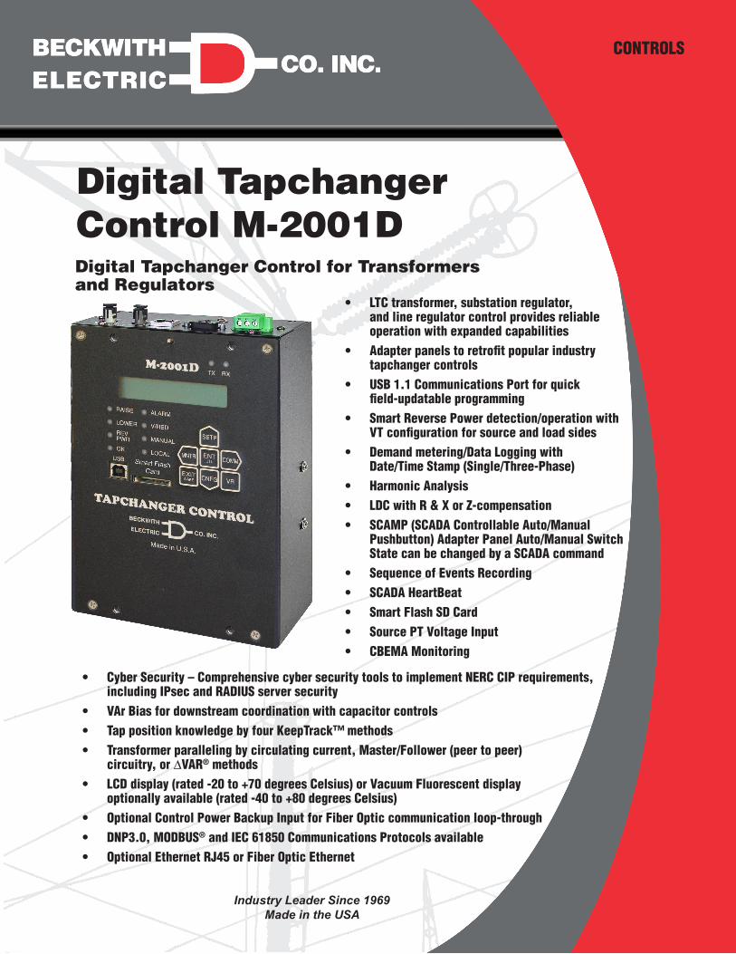
Digital Tapchanger Control M-2001DDigital Tapchanger Control for Transformers and Regulators
CONTROLS
• LTC transformer, substation regulator, and line regulator control provides reliable operation with expanded capabilities
• Adapter panels to retrofit popular industry tapchanger controls
• USB 1.1 Communications Port for quick field‑updatable programming
• Smart Reverse Power detection/operation with VT configuration for source and load sides
• Demand metering/Data Logging with Date/Time Stamp (Single/Three‑Phase)
• Harmonic Analysis • LDC with R & X or Z‑compensation • SCAMP (SCADA Controllable Auto/Manual
Pushbutton) Adapter Panel Auto/Manual Switch State can be changed by a SCADA command
• Sequence of Events Recording • SCADA HeartBeat • Smart Flash SD Card • Source PT Voltage Input • CBEMA Monitoring
• Cyber Security – Comprehensive cyber security tools to implement NERC CIP requirements, including IPsec and RADIUS server security
• VAr Bias for downstream coordination with capacitor controls • Tap position knowledge by four KeepTrack™ methods • Transformer paralleling by circulating current, Master/Follower (peer to peer)
circuitry, or ∆VAR® methods • LCD display (rated ‑20 to +70 degrees Celsius) or Vacuum Fluorescent display
optionally available (rated ‑40 to +80 degrees Celsius) • Optional Control Power Backup Input for Fiber Optic communication loop‑through • DNP3.0, MODBUS® and IEC 61850 Communications Protocols available • Optional Ethernet RJ45 or Fiber Optic Ethernet
–2–
M‑2001D Digital Tapchanger Control – Brochure
FeaturesThe M‑2001D includes the following features and can be used for LTCs or regulators where SCADA communications are desired.
• Adjustable Bandcenter • Adjustable Bandwidth • Adjustable VAr Bias (Step and Linear
Methods) • Line Drop Compensation, R, X and Z
Compensation with ±72 Volt range • Time Delay, Definite and Inverse • Intertap Time Delay • Four Settings Profiles • Compare Settings Tool • Profile Switching Triggerable by Seasonal
Time • Selectable Outputs, Continuous or Pulsed • Reverse Power Operation with eight control
selections including a distributed generation mode and Smart Reverse Power Operation with two Auto Determination modes
• CT to VT Phasing Correction • Real‑Time Metering of measured and
calculated parameters (Single/Three‑Phase)
• Demand Metering with selectable time interval
• Drag Hands Operation • Adjustable Line Overcurrent Tapchange
Inhibit • Voltage Limits • Tap Position Limits • Auto Runback (due to overvoltage) • Auto Runup (due to undervoltage) • Three independent Voltage Reduction Steps • Smart Voltage Reduction • Fast Voltage Recovery • Sequential and Non‑Sequential Operation • VT Ratio Correction • Self‑Test Alarm Output Contacts • User Programmable Alarm Contacts • Tap Position Knowledge by:
– Contact KeepTrack™
– Shaft Coupled KeepTrack™
– Resistor Divider KeepTrack™
– Motor Direct Drive KeepTrack™
• Operations Counter
• Resettable Operations Counter
• Tap Position Record
• Auto/Off/Manual Switch Status via SCADA • A or B Regulator Type Selection • Control Voltage Input • Motor Power Input • Source Voltage Input • Line Current Input • Raise Output • Lower Output • Motor Current Profiling • Up to 30 unique 15 character User Access
Codes (Level 1 or Level 2)
• 20 Character by 2 Row LCD or optional Vacuum Fluorescent Display
• "Hot Buttons" provide quick access to setpoints, configuration and communications
• S‑2001D TapTalk® Communications Software
• Adapter Panel Auto/Manual Switch Manual control outside of microprocessor
• Front USB 1.1 Communications Port • External Inhibit of Auto Tapchange • Circulating Current Input with Circulating
Current, optional ∆VAR® Paralleling Methods including Peer to Peer ∆VAR Paralleling, and optional Master/Follower (peer to peer) Paralleling (requires Ethernet)
• Front Panel LEDs for Out‑of‑Band Raise, Out‑of‑Band Lower, Reverse Power Flow Rev Pwr Detected, ALARM in effect, Voltage Reduction V/RED in Effect, CPU OK, Auto Operation Block MANUAL, SCADA Control blocked LOCAL and Com1 TX and RX
• Front‑Panel Voltage Reduction 1 & 2 Inputs as well as (Binary) inputs (3 Steps Total)
• Neutral Position Detect (Binary) and Counter
• Counter Input (Binary) for Regulator applications/Complete Sequence Input for Transformer applications
• Seal‑in/Switch Status Input (Binary) • Motor Seal‑In Block/Alarm • Non‑Sequential/SCADA Block Input
(Binary) • Seal‑in Output (Cooper Applications) • COM1 (top), RS‑485 and Fiber Optic Port
(ST and V‑pin connectors available with 62.5 and 200 micro fiber supported)
• COM2 (top), RS‑232 and optional Bluetooth® (user selectable if Bluetooth is installed)
–3–
M‑2001D Digital Tapchanger Control – Brochure
Features (Cont.) • Communication Protocols include DNP3.0,
MODBUS® and IEC 61850 (IEC 61850 only available with optional ethernet port)
• Smart Flash SD Card Slot supporting SD and SDHC SD cards
• Smart Flash SD Card can be linked to one or multiple controls providing a physical security "Key" which provides Level 2 User Access to the control when the SD Card is inserted for settings manipulation
• Supports Station and Feeder Level DNP addressing in addition to individual addressing for Smart Grid applications
• One pushbutton access to user configurable Wakeup screen for manual data recording with Smart Flash SD Card saving feature
• Power Quality which consists of:
– Sequence of Events Recorder (132 events)
– Data Logging
– Harmonic Analysis
– Oscillography
– CBEMA monitoring to detect sags and swells and trigger data collection and alarming functions
• TapPlot® Oscillograph Data Analysis Software
• Individual Tap Wear Alarm
• Run Through Neutral, Automatic reversing switch swiping
• Remote Voltage Bias
• IEEE 1686 Standard Compliant Cyber Security
• IPsec (Internet Protocol Security)
• RADIUS Client Capability to manage local and remote access to the control
Optional Features • Ethernet Port (10/100 BaseT) is available
through a RJ45 jack or ST Fiber on the top of the control. This port supports DNP over TCP/IP, MODBUS® over TCP/IP, and IEC 61850 over TCP/IP
• Local Wireless Bluetooth capability**Bluetooth option is not available in 50 Hz units shipped to locations subject to Radio Equipment Directive RE‑D 2014/53/EU.Contact the factory for more information.
• Vacuum Fluorescent Display (rated ‑40 to +80 degrees Celsius)
• Control Power Back‑Up Input – input (+12 Vdc) for backup of Fiber Optic communication loop‑through
• IEC 61850 Communications
• ∆VAR® Paralleling:
– ∆VAR1
– ∆VAR2
– ∆VAR2 KeepTrack
– ∆VAR Peer to Peer
• Master/Follower Paralleling (peer to peer)
Accessories • M‑2025B(D) Current Loop Interface Module
– Current‑To‑Voltage analog converter for tap position sensors
• M‑2026 AC‑DC Control Power Backup Supply
• M‑2027 Control Power Backup Supply–AC Only
• M‑2948 Tap Position Sensor
TRADEMARKSAll brand or product names referenced in this document may be trademarks or registered trademarks of their respective holders.
Specification subject to change without notice. Beckwith Electric Co., Inc. has approved only the English version of this document.
M‑2001D Digital Tapchanger Control – Brochure
800‑2001D‑BR‑03MC2 02/18© 2008 Beckwith Electric Co. All Rights Reserved.Printed in U.S.A. (09.24.02)
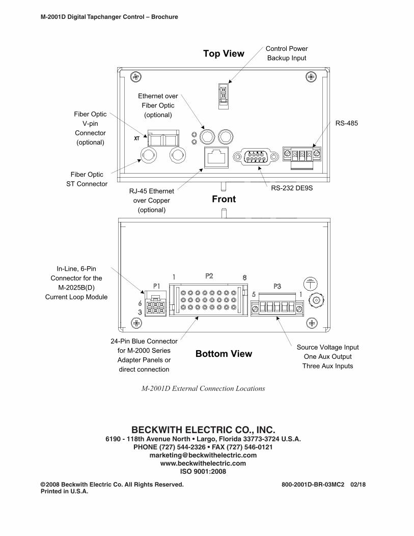
TX
In-Line, 6-PinConnector for the
M-2025B(D)Current Loop Module
24-Pin Blue Connectorfor M-2000 SeriesAdapter Panels ordirect connection
Bottom View
Top View
Source Voltage InputOne Aux OutputThree Aux Inputs
Front
Fiber OpticST Connector
RJ-45 Ethernetover Copper
(optional)
RS-232 DE9S
RS-485
Control PowerBackup Input
Ethernet overFiber Optic(optional)Fiber Optic
V-pinConnector(optional)
M-2001D External Connection Locations
BECKWITH ELECTRIC CO., INC.6190 ‑ 118th Avenue North • Largo, Florida 33773‑3724 U.S.A.
PHONE (727) 544‑2326 • FAX (727) 546‑[email protected]
www.beckwithelectric.comISO 9001:2008


![Finale 2001d - [Perpetuum Mobile Soprano Saxophone.MUS]bruceevans.net/asax/perpmob.pdfPERPETUUM MOBILE Johann Strauss Arr. Bruce A. Evans For Sax Quartet SATB & ## 55](https://img.pdfslide.net/doc/110x75/5e3e4782fd989666f4181dd4/finale-2001d-perpetuum-mobile-soprano-bruceevansnetasaxperpmobpdf-perpetuum.jpg)