Embed Size (px)
Citation preview
DIGITAL TEMPERATURE MONITOR – MASTERTEMP ANSI - 23 – 26 – 45 – 49 – 49I – 62 – 74 – 77 – 94
1
Rev 1.1
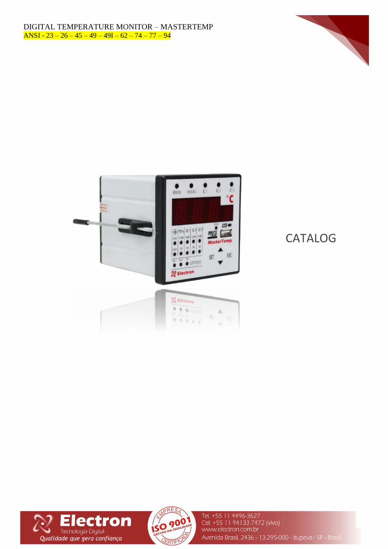
CATALOG
DIGITAL TEMPERATURE MONITOR – MASTERTEMP ANSI - 23 – 26 – 45 – 49 – 49I – 62 – 74 – 77 – 94
2
Rev 1.1
INTRODUCTION
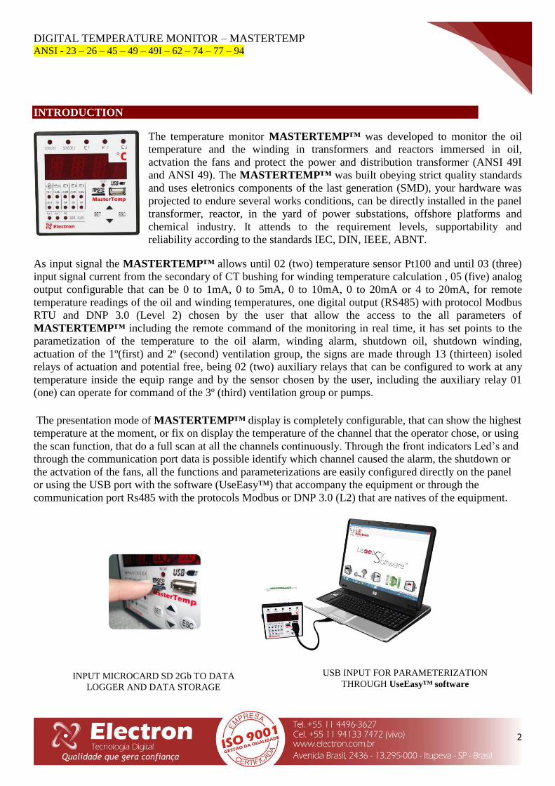
The temperature monitor MASTERTEMP™ was developed to monitor the oil
temperature and the winding in transformers and reactors immersed in oil,
actvation the fans and protect the power and distribution transformer (ANSI 49I
and ANSI 49). The MASTERTEMP™ was built obeying strict quality standards
and uses eletronics components of the last generation (SMD), your hardware was
projected to endure several works conditions, can be directly installed in the panel
transformer, reactor, in the yard of power substations, offshore platforms and
chemical industry. It attends to the requirement levels, supportability and
reliability according to the standards IEC, DIN, IEEE, ABNT.
As input signal the MASTERTEMP™ allows until 02 (two) temperature sensor Pt100 and until 03 (three)
input signal current from the secondary of CT bushing for winding temperature calculation , 05 (five) analog
output configurable that can be 0 to 1mA, 0 to 5mA, 0 to 10mA, 0 to 20mA or 4 to 20mA, for remote
temperature readings of the oil and winding temperatures, one digital output (RS485) with protocol Modbus
RTU and DNP 3.0 (Level 2) chosen by the user that allow the access to the all parameters of
MASTERTEMP™ including the remote command of the monitoring in real time, it has set points to the
parametization of the temperature to the oil alarm, winding alarm, shutdown oil, shutdown winding,
actuation of the 1º(first) and 2º (second) ventilation group, the signs are made through 13 (thirteen) isoled
relays of actuation and potential free, being 02 (two) auxiliary relays that can be configured to work at any
temperature inside the equip range and by the sensor chosen by the user, including the auxiliary relay 01
(one) can operate for command of the 3º (third) ventilation group or pumps.
The presentation mode of MASTERTEMP™ display is completely configurable, that can show the highest
temperature at the moment, or fix on display the temperature of the channel that the operator chose, or using
the scan function, that do a full scan at all the channels continuously. Through the front indicators Led’s and
through the communication port data is possible identify which channel caused the alarm, the shutdown or
the actvation of the fans, all the functions and parameterizations are easily configured directly on the panel
or using the USB port with the software (UseEasy™) that accompany the equipment or through the
communication port Rs485 with the protocols Modbus or DNP 3.0 (L2) that are natives of the equipment.
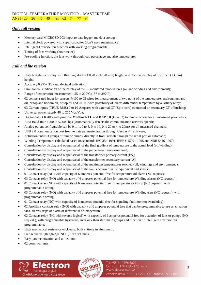
USB INPUT FOR PARAMETERIZATION
THROUGH UseEasy™ software
ENTRADA DE CARTÃO DE MEMÓRIA MICRO SDCARD
(Versão Full)
INPUT MICROCARD SD 2Gb TO DATA
LOGGER AND DATA STORAGE
DIGITAL TEMPERATURE MONITOR – MASTERTEMP ANSI - 23 – 26 – 45 – 49 – 49I – 62 – 74 – 77 – 94
3
Rev 1.1
Only full version
Memory card MICROSD 2Gb input to data logger and data storage;
Internal clock powered with super-capacitor (don’t need maintenance);
Intelligent Exercise fan function with working programmable;
Timing of fans working (hour meter);
Pre-cooling function, the fans work through load percentage and also temperature;
Full and lite version
High brightness display with 04 (four) digits of 0,78 inch (20 mm) height, and decimal display of 0,51 inch (13 mm)
height;
Accuracy 0,25% (FS) and decimal indication;
Simultaneous indication of the display of the 05 monitored temperatures (oil and winding and environment);
Range of temperature measurement -55 to 200ºC (-67 to 392ºF);
02 compensated input for sensors Pt100 to 03 wires for measurement of two point of the temperature, environment and
oil, or top and bottom oil, or top oil and OLTC with possibility of alarm differential temperature by auxiliary relay;
03 Current inputs (TRUE RMS) 0 to 10 Amperes with external CT (Split-core) connected on secondary CT of bushing;
Universal power supply 48 to 265 Vcc/Vca;
Digital output Rs485 with protocol Modbus RTU and DNP 3.0 (Level 2) to remote access for all measured parameters;
Auto Baud Rate 1200 to 57.600 bps (Automatically detects the communication network speed);
Analog output configurable can be 0 to 1, 0 to 5, 0 to 10, 0 to 20 or 4 to 20mA for all measured channels;
USB 2.0 communication port front to data parameterization through UseEasy™ software;
Actuation until 03 groups of fans or pumps, directly in front, remote through the serial port or automatic;
Winding Temperature calculated based on standards IEC 354-1991, IEEE C 57.91-1995 and NBR 5416-1997;
Consultation by display and output serial of the final gradient of temperature to the actual load (oil/winding);
Consultation by display and output serial of the percentage transformer load;
Consultation by display and output serial of the transformer primary current (kA);
Consultation by display and output serial of the transformer secondary current (A);
Consultation by display and output serial of the maximum temperatures reached (oil, windings and environment );
Consultation by display and output serial of the faults occurred in the equipment and sensors;
01 Contact relay (NO) with capacity of 6 amperes potential free for temperature oil alarm (NC request);
03 Contacts relay (NO) with capacity of 6 amperes potential free for temperature Winding alarms (NC request )
01 Contact relay (NO) with capacity of 6 amperes potential free for temperature Oil trip (NC request ), with
programmable timing;
03 Contacts relay (NO) with capacity of 6 amperes potential free for temperature Winding trips (NC request ), with
programmable timing;
01 Contact relay (NC) with capacity of 6 amperes potential free for signaling fault monitor (watchdog);
02 Auxiliary contacts relay (NO) with capacity of 6 amperes potential free that can be programmable to use as actuation
fans, alarms, trips or alarm of differential of temperature;
02 Contacts relay (NC with reverse logical) with capacity of 6 amperes potential free for actuation of fans or pumps (NO
request ), with programmable hysteresis, interlock than start the 2 groups and function of Intelligent Exercise fan
programmable;
High mechanical resistance enclosure, built entirely in aluminum ;
Size reduced 3,8x3,8x3,8 INCH(98x98x98mm);
Easy parameterization and utilization;
02 years warranty;

DIGITAL TEMPERATURE MONITOR – MASTERTEMP ANSI - 23 – 26 – 45 – 49 – 49I – 62 – 74 – 77 – 94
4
Rev 1.1
TECHINCAL DATA
Temperature Monitor
Power Supply 48 to 265 Vdc/Vac 50/60 Hz
Operation Temperature -40°C to + 85°C (-40º to 185ºF)
Power Consumption < 15 W
Temperature measuring input 2 – Pt100 Ohm to 0°C 3 wires
Measurement Range -55 to 200°C (-67 to 392ºF)
Input to Current Measurement TC Split Core de 0 a 10A (True RMS)
Analog Output / Max. Loop Resistence
0 ... 1mA - 8000 Ohms
0 ... 5mA - 1600 Ohms
0 ... 10mA - 800 Ohms
0 ... 20mA - 400 Ohms
4 ... 20mA - 400 Ohms
Maximum Error Measurement Temperature 0,25% end of the scale
Maximum Error Analog Output 0,25% end of the scale
Output Contact 13 relays – Potential free
Maximum Switching Power 70 W / 250 VA
Maximum Switching Voltage 250 Vac/Vdc
Maximum Conduction Current 6,0 Amperes
Serial Communication Port RS 485 – 2 wire
Communication Protocols Modbus RTU and DNP 3.0 Level 2 (Slave)
Auto Baud Rate 1200 a 57.600 bps
USB Front Port USB Serial – 2.0
Enclosure 98 x 98 x 98 mm – Aluminum
Fixation Fixed at the door panel
Current Transformer - TC Split core
Output Signal 4 to 20mA
Measurement Range 0 to10 A
Maximum Error of Measurement Inputs 1% end of the scale
Linearity 1% end of the scale
Operation Temperature -40°C to +85°C (-40º to 185ºF)
Storage temperature -50°C to 60°C (-58º to + 140ºF)
TYPE TEST
Insulation Voltage (IEC 60255-5): 2kV / 60Hz / 1 min. (to ground);
Voltage Impulse (IEC 60255-5): 1,2/50 seg. / 5kV / 3 neg. e 3 pos. / 5 seg. Interval;
Electrostatic Discharge (IEC 60255-22-2): Air mode = 8kV / Contact mode = 6 kV;
Irradiated electromagnetic field immunity (IEC61000-4-3): 80 a 1000 MHz / 10V/m;
Fast electrical transient immunity (IEC60255-22-4): Power./Input./Output=4KV/Serial port. 2kV;
Surge immunity (IEC60255-22-5): phase/neutral 1kV, 5 per polar. (±) - phase-ground/neutral-ground 2kV, 5 per
polar (±);
Conduced electromagnetic perturbations immunity (IEC61000-4-6): 0,15 a 80 MHz / 10V/m;
Climatic test (IEC60068-21-14): -40ºC + 85ºC / 72 hours;
Vibration resistance (IEC60255-21-1): 3 axis / 10 a 150Hz / 2G / 160min/axis;
Vibration response (IEC60255-21-1): 3 axis / 0,075mm-10 a 58 Hz / 1G de 58 a 150 Hz / 8min/axis;
DIGITAL TEMPERATURE MONITOR – MASTERTEMP ANSI - 23 – 26 – 45 – 49 – 49I – 62 – 74 – 77 – 94
5
Rev 1.1
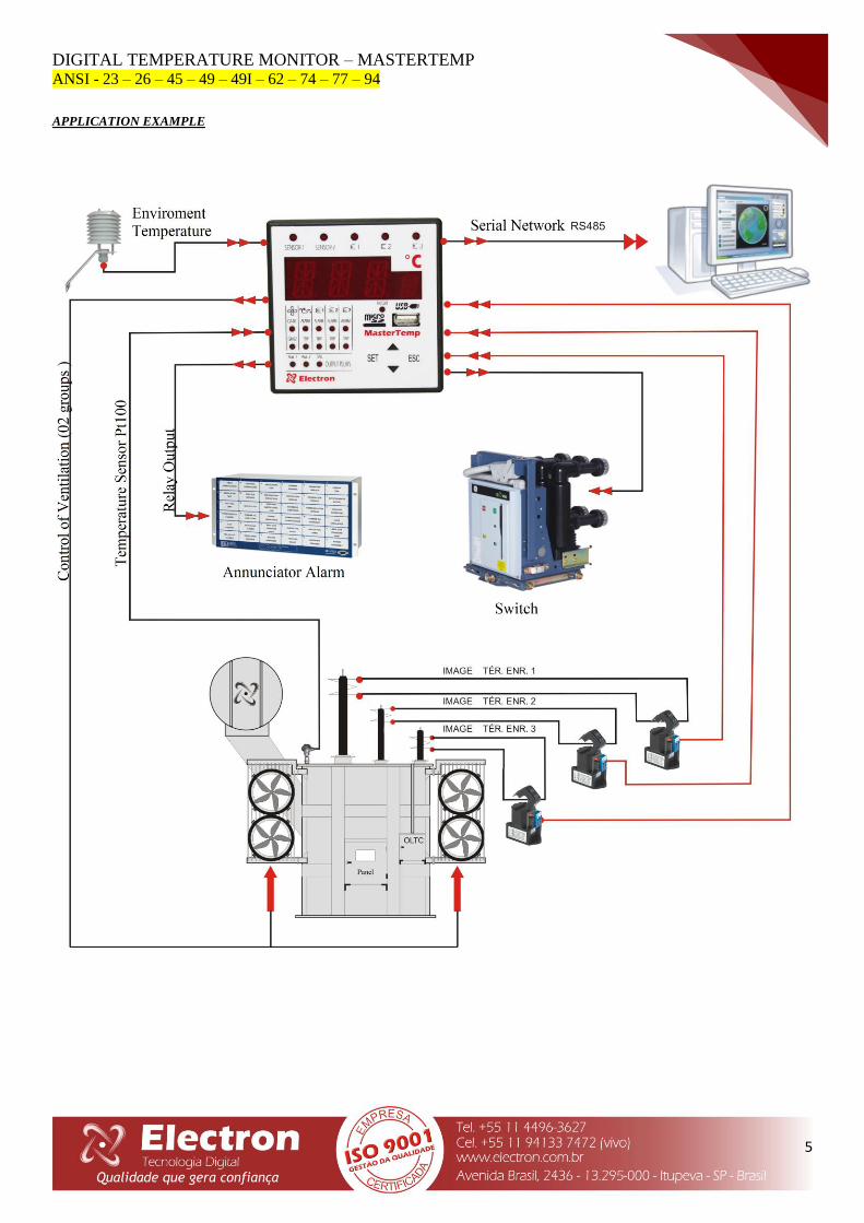
APPLICATION EXAMPLE
DIGITAL TEMPERATURE MONITOR – MASTERTEMP ANSI - 23 – 26 – 45 – 49 – 49I – 62 – 74 – 77 – 94
6
Rev 1.1
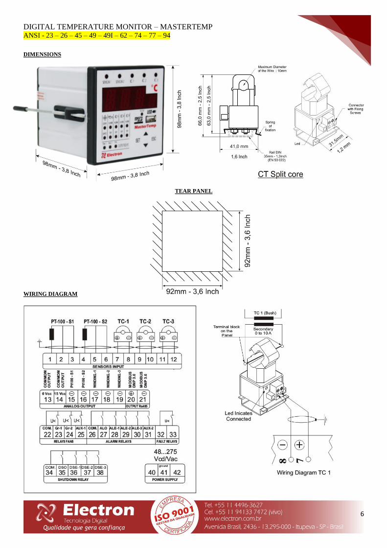
DIMENSIONS
TEAR PANEL
WIRING DIAGRAM
DIGITAL TEMPERATURE MONITOR – MASTERTEMP ANSI - 23 – 26 – 45 – 49 – 49I – 62 – 74 – 77 – 94
7
Rev 1.1
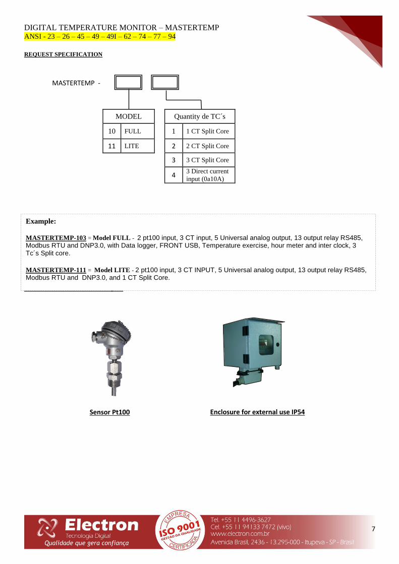
REQUEST SPECIFICATION
4
ACESSÓRIOS PARA INSTALAÇÃO
Sensor Pt100 Enclosure for external use IP54
MODEL
10 FULL
11 LITE
MASTERTEMP -
Example:
MASTERTEMP-103 = Model FULL - 2 pt100 input, 3 CT input, 5 Universal analog output, 13 output relay RS485, Modbus RTU and DNP3.0, with Data logger, FRONT USB, Temperature exercise, hour meter and inter clock, 3 Tc´s Split core.
MASTERTEMP-111 = Model LITE - 2 pt100 input, 3 CT INPUT, 5 Universal analog output, 13 output relay RS485, Modbus RTU and DNP3.0, and 1 CT Split Core.
Quantity de TC´s
1 1 CT Split Core
2 2 CT Split Core
3 3 CT Split Core
4 3 Direct current
input (0a10A)

DIGITAL TEMPERATURE MONITOR – MASTERTEMP ANSI - 23 – 26 – 45 – 49 – 49I – 62 – 74 – 77 – 94
8
Rev 1.1
REVIEW CONTROL
Review Nº 0 November 2012.
- Emission.
Review Nº 1 May de 2013.
- Added TC’s buy code
- Right scale of some variable table
Review Nº 1.1 May de 2014.
- Added key to configure the equipment
- Added menu key change
- Register map update