Embed Size (px)
Citation preview
CSM_H5CN_DS_E_2_1
1
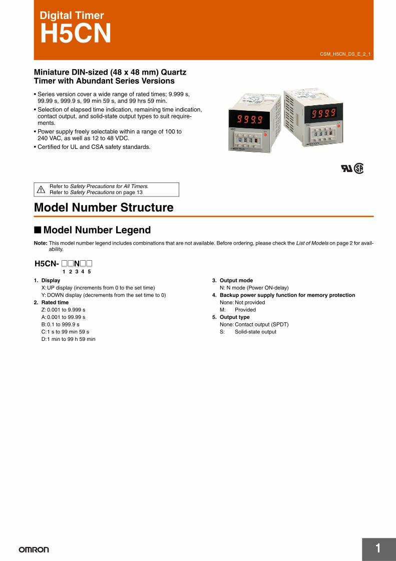
Digital Timer
H5CNMiniature DIN-sized (48 x 48 mm) Quartz Timer with Abundant Series Versions
• Series version cover a wide range of rated times; 9.999 s, 99.99 s, 999.9 s, 99 min 59 s, and 99 hrs 59 min.
• Selection of elapsed time indication, remaining time indication, contact output, and solid-state output types to suit require-ments.
• Power supply freely selectable within a range of 100 to 240 VAC, as well as 12 to 48 VDC.
• Certified for UL and CSA safety standards.
Refer to Safety Precautions for All Timers.Refer to Safety Precautions on page 13
Model Number Structure
Model Number LegendNote: This model number legend includes combinations that are not available. Before ordering, please check the List of Models on page 2 for avail-
ability.
1. DisplayX:UP display (increments from 0 to the set time)Y: DOWN display (decrements from the set time to 0)
2. Rated timeZ: 0.001 to 9.999 sA:0.001 to 99.99 sB:0.1 to 999.9 sC:1 s to 99 min 59 sD:1 min to 99 h 59 min
3. Output modeN: N mode (Power ON-delay)
4. Backup power supply function for memory protectionNone: Not providedM: Provided
5. Output typeNone: Contact output (SPDT)S: Solid-state output
21 3 4 5H5CN- @@N@@
H5CN
2
Ordering Information
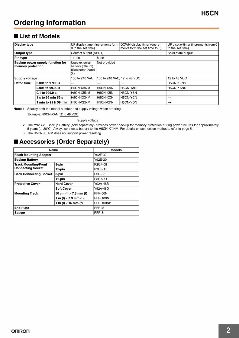
List of Models
Note: 1. Specify both the model number and supply voltage when ordering.
2. The Y92S-20 Backup Battery (sold separately) provides power backup for memory protection during power failures for approximately5 years (at 20°C). Always connect a battery to the H5CN-X@NM. For details on connection methods, refer to page 5.
3. The H5CN-X@NM does not support power resetting.
Accessories (Order Separately)
Display type UP display timer (increments form 0 to the set time)
DOWN display timer (decre-ments form the set time to 0)
UP display timer (increments from 0 to the set time)
Output type Contact output (SPDT) Solid-state output
Pin type 11-pin 8-pin
Backup power supply function for memory protection
Uses external battery (lithium). (See notes 2 and 3.)
Not provided
Supply voltage 100 to 240 VAC 100 to 240 VAC, 12 to 48 VDC 12 to 48 VDC
Rated time 0.001 to 9.999 s --- --- --- H5CN-XZNS
0.001 to 99.99 s H5CN-XANM H5CN-XAN H5CN-YAN H5CN-XANS
0.1 to 999.9 s H5CN-XBNM H5CN-XBN H5CN-YBN ---
1 s to 99 min 59 s H5CN-XCNM H5CN-XCN H5CN-YCN ---
1 min to 99 h 59 min H5CN-XDNM H5CN-XDN H5CN-YDN ---
Supply voltage
Example: H5CN-XAN 12 to 48 VDC
Name Models
Flush Mounting Adapter Y92F-30
Backup Battery Y92S-20
Track Mounting/Front Connecting Socket
8-pin P2CF-08
11-pin P2CF-11
Back Connecting Socket 8-pin P3G-08
11-pin P3GA-11
Protective Cover Hard Cover Y92A-48B
Soft Cover Y92A-48D
Mounting Track 50 cm (I) × 7.3 mm (t) PFP-50N
1 m (I) × 7.3 mm (t) PFP-100N
1 m (I) × 16 mm (t) PFP-100N2
End Plate PFP-M
Spacer PFP-S
H5CN
3
Specifications
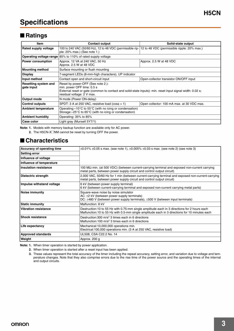
Ratings
Note: 1. Models with memory backup function are available only for AC power.2. The H5CN-X@NM cannot be reset by turning OFF the power.
Characteristics
Note: 1. When timer operation is started by power application.2. When timer operation is started after a reset input has been applied.3. These values represent the total accuracy of the timer including the repeat accuracy, setting error, and variation due to voltage and tem-
perature changes. Note that they also comprise errors due to the rise time of the power source and the operating times of the internaland output circuits.
Item Contact output Solid-state output
Rated supply voltage 100 to 240 VAC (50/60 Hz), 12 to 48 VDC (permissible rip-ple: 20% max.) (See note 1.)
12 to 48 VDC (permissible ripple: 20% max.)
Operating voltage range 85% to 110% of rated supply voltage
Power consumption Approx. 12 VA at 240 VAC, 50 HzApprox. 2.5 W at 48 VDC
Approx. 2.5 W at 48 VDC
Mounting method Surface mounting or flush mounting
Display 7-segment LEDs (8-mm-high characters), UP indicator
Input method Contact open and short-circuit input Open-collector transistor ON/OFF input
Resetting system and gate input
Reset by power-OFF (See note 2.):min. power OFF time: 0.5 sExternal reset or gate (common to contact and solid-state inputs): min. reset input signal width: 0.02 s; residual voltage: 2 V max.
Output mode N mode (Power ON-delay)
Control outputs SPDT: 3 A at 250 VAC, resistive load (cosφ = 1) Open collector: 100 mA max. at 30 VDC max.
Ambient temperature Operating:–10°C to 55°C (with no icing or condensation)Storage:–25°C to 65°C (with no icing or condensation)
Ambient humidity Operating: 35% to 85%
Case color Light gray (Munsell 5Y7/1)
Accuracy of operating time ±0.01% ±0.05 s max. (see note 1), ±0.005% ±0.03 s max. (see note 2) (see note 3)
Setting error
Influence of voltage
Influence of temperature
Insulation resistance 100 MΩ min. (at 500 VDC) (between current-carrying terminal and exposed non-current carrying metal parts, between power supply circuit and control output circuit)
Dielectric strength 2,000 VAC, 50/60 Hz for 1 min (between current-carrying terminal and exposed non-current-carrying metal parts, between power supply circuit and control output circuit)
Impulse withstand voltage 6 kV (between power supply terminal)6 kV (between current-carrying terminal and exposed non-current carrying metal parts)
Noise immunity Square-wave noise by noise simulatorAC: ±2 kV (between power supply terminals)DC: ±480 V (between power supply terminals), ±500 V (between input terminals)
Static immunity Malfunction: 8 kV
Vibration resistance Destruction:10 to 55 Hz with 0.75-mm single amplitude each in 3 directions for 2 hours eachMalfunction:10 to 55 Hz with 0.5-mm single amplitude each in 3 directions for 10 minutes each
Shock resistance Destruction:300 m/s2 3 times each in 6 directionsMalfunction:100 m/s2 3 times each in 6 directions
Life expectancy Mechanical:10,000,000 operations min.Electrical:100,000 operations min. (3 A at 250 VAC, resistive load)
Approved standards UL508, CSA C22.2 No. 14
Weight Approx. 200 g
H5CN
4
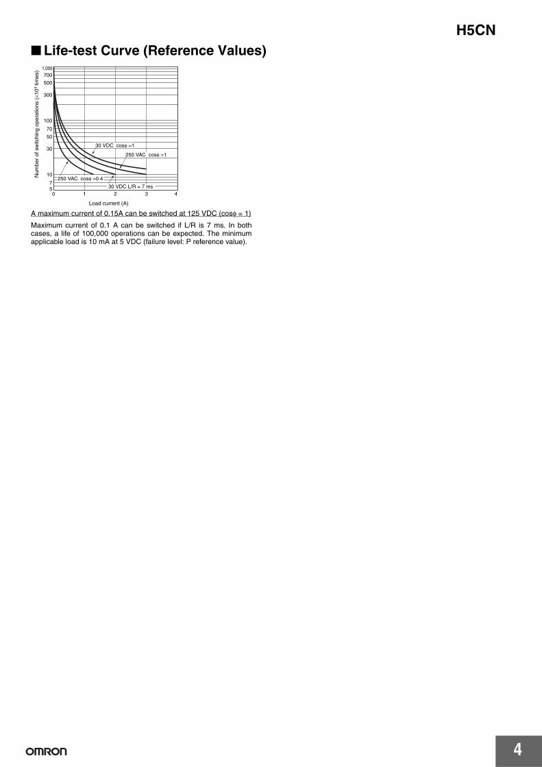
Life-test Curve (Reference Values)
A maximum current of 0.15A can be switched at 125 VDC (cosφ = 1)
Maximum current of 0.1 A can be switched if L/R is 7 ms. In bothcases, a life of 100,000 operations can be expected. The minimumapplicable load is 10 mA at 5 VDC (failure level: P reference value).
Load current (A)
1,000700
500
300
100
70
50
30
10
50 1 2 3 4
7
30 VDC cosφ =1
250 VAC cosφ =1
30 VDC L/R = 7 ms
250 VAC cosφ =0.4Num
ber
of s
witc
hing
ope
ratio
ns (
×104
times
)
H5CN
5
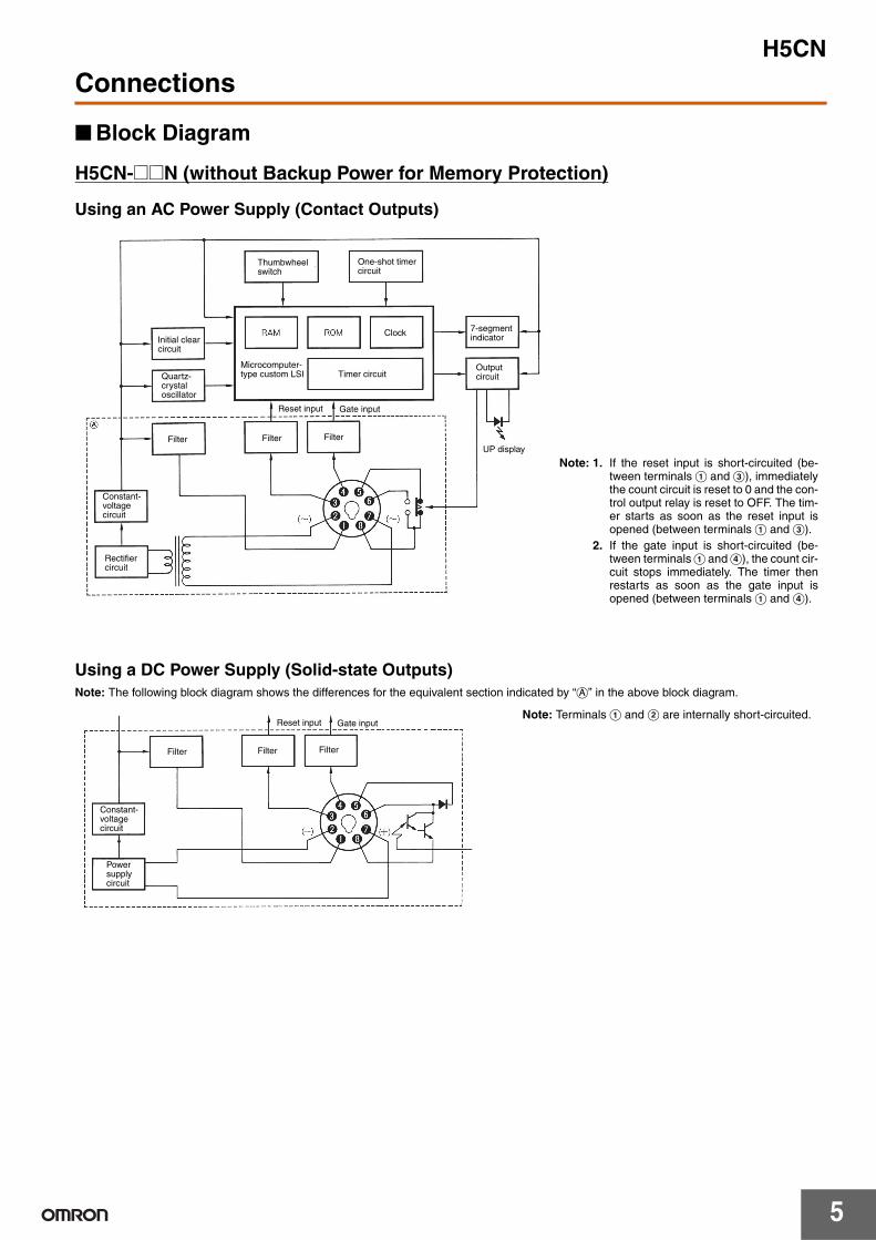
Connections
Block Diagram
H5CN-@@N (without Backup Power for Memory Protection)
Using an AC Power Supply (Contact Outputs)
Using a DC Power Supply (Solid-state Outputs)Note: The following block diagram shows the differences for the equivalent section indicated by “a” in the above block diagram.
Thumbwheel switch
One-shot timer circuit
Initial clear circuit
Quartz-crystal oscillator
Microcomputer-type custom LSI
Filter Filter
Timer circuit
Filter
Reset input Gate input
Clock 7-segment indicator
Output circuit
UP display
Constant-voltage circuit
Rectifier circuit
Note: 1. If the reset input is short-circuited (be-tween terminals A and C), immediatelythe count circuit is reset to 0 and the con-trol output relay is reset to OFF. The tim-er starts as soon as the reset input isopened (between terminals A and C).
2. If the gate input is short-circuited (be-tween terminals A and D), the count cir-cuit stops immediately. The timer thenrestarts as soon as the gate input isopened (between terminals A and D).
Filter
Constant-voltage circuit
Power supply circuit
Filter Filter
Reset input Gate inputNote: Terminals A and B are internally short-circuited.
H5CN
6
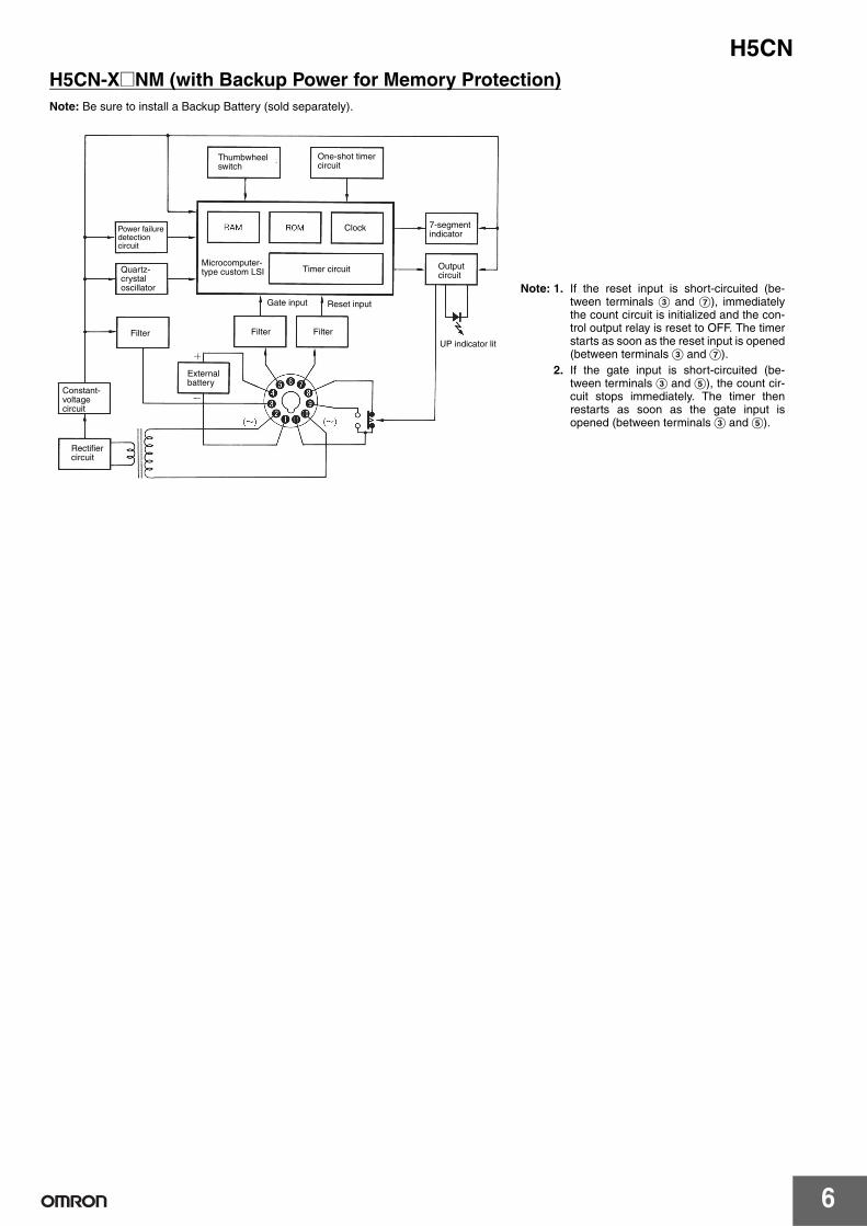
H5CN-X@NM (with Backup Power for Memory Protection)Note: Be sure to install a Backup Battery (sold separately).
Thumbwheel switch
One-shot timer circuit
Clock 7-segment indicator
Output circuit
Timer circuit
Filter Filter
Gate input Reset input
Power failure detection circuit
Quartz-crystal oscillator
Filter
Microcomputer-type custom LSI
Constant-voltage circuit
Rectifier circuit
External battery
UP indicator lit
Note: 1. If the reset input is short-circuited (be-tween terminals C and G), immediatelythe count circuit is initialized and the con-trol output relay is reset to OFF. The timerstarts as soon as the reset input is opened(between terminals C and G).
2. If the gate input is short-circuited (be-tween terminals C and E), the count cir-cuit stops immediately. The timer thenrestarts as soon as the gate input isopened (between terminals C and E).
H5CN
7
Installation
Connections
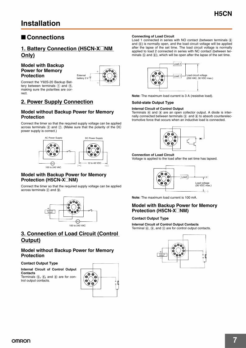
1. Battery Connection (H5CN-X@NM Only)
Model with Backup Power for Memory ProtectionConnect the Y92S-20 Backup Bat-tery between terminals A and D,making sure the polarities are cor-rect.
2. Power Supply Connection
Model without Backup Power for Memory Protection Connect the timer so that the required supply voltage can be appliedacross terminals B and G. (Make sure that the polarity of the DCpower supply is correct.)
Model with Backup Power for Memory Protection (H5CN-X@NM)Connect the timer so that the required supply voltage can be appliedacross terminals B and J.
3. Connection of Load Circuit (Control Output)
Model without Backup Power for Memory Protection
Contact Output Type
Internal Circuit of Control OutputContactsTerminals E, F, and H are for con-trol output contacts.
Connecting of Load CircuitLoad 1 connected in series with NO contact (between terminals Fand H) is normally open, and the load circuit voltage will be appliedafter the lapse of the set time. The load circuit voltage is normallyapplied to load 2 connected in series with NC contact (between ter-minals E and H), which will be open after the lapse of the set time.
Note: The maximum load current is 3 A (resistive load).
Solid-state Output Type
Internal Circuit of Control OutputTerminals F and H are an open collector output. A diode is inter-nally connected between terminals E and F to absorb counterelec-tromotive force that occurs when an inductive load is connected.
Connection of Load CircuitVoltage is applied to the load after the set time has lapsed.
Note: The maximum load current is 100 mA.
Model with Backup Power for Memory Protection (H5CN-X@NM)
Contact Output Type
Internal Circuit of Control Output ContactsTerminal H, I, and K are for control output contacts.
Externalbattery 3 V
AC Power Supply
100 to 240 VAC
DC Power Supply
12 to 48 VDC
External battery
100 to 240 VAC
Load circuit voltage (250 VAC, 30 VDC max.)
Load 2
Load 1
Load
Load voltage(30 VDC max.)
Externalbattery
H5CN
8
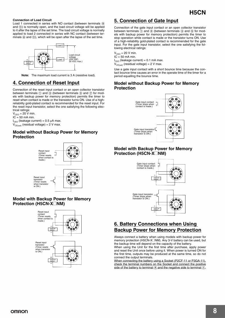
Connection of Load CircuitLoad 1 connected in series with NO contact (between terminals Iand K) is normally open, and the load circuit voltage will be appliedto it after the lapse of the set time. The load circuit voltage is normallyapplied to load 2 connected in series with NC contact (between ter-minals H and K), which will be open after the lapse of the set time.
4. Connection of Reset InputConnection of the reset input contact or an open collector transistorbetween terminals A and C (between terminals C and G for mod-els with backup power for memory protection) permits the timer toreset when contact is made or the transistor turns ON. Use of a high-reliability gold-plated contact is recommended for the reset input. Forthe reset input transistor, select the one satisfying the following elec-trical ratings:VCEO = 20 V min.IC = 50 mA min.ICEO (leakage current) = 0.5 µA max.VCE(sat) (residual voltage) = 2 V max.
Model without Backup Power for Memory Protection
Model with Backup Power for Memory Protection (H5CN-X@NM)
5. Connection of Gate InputConnection of the gate input contact or an open collector transistorbetween terminals A and D (between terminals C and E for mod-els with backup power for memory protection) permits the timer tostop operation while contact is made or the transistor turns ON. Useof a high-reliability gold-plated contact is recommended for the gateinput. For the gate input transistor, select the one satisfying the fol-lowing electrical ratings:
VCEO = 20 V min.IC = 50 mA min.ICEO (leakage current) = 0.1 mA max.VCE(sat) (residual voltage) = 2 V max.
Use a gate input contact with a short bounce time because the con-tact bounce time causes an error in the operate time of the timer for aperiod equalling the bounce time.
Model without Backup Power for Memory Protection
Model with Backup Power for Memory Protection (H5CN-X@NM)
6. Battery Connections when Using Backup Power for Memory ProtectionAlways connect a battery when using models with backup power formemory protection (H5CN-X@NM). Any 3-V battery can be used, butthe backup time will depend on the capacity of the battery.When using the Unit for the first time after purchase, apply powerand reset the Unit once before using it. When power is turned ON forthe first time, outputs may be produced at the same time, so do notconnect the output terminals.When connecting the battery using a Socket (P2CF-11 or P3GA-11),check the terminal numbers on the Socket and connect the positiveside of the battery to terminal D and the negative side to terminal A.
Note: The maximum load current is 3 A (resistive load).
Load circuit voltage(250 VAC, 30 VDC max.)
Load 2
Load 1Externalbattery
Reset input transistor(Timer resets when transistor is ON.)
Reset input contact (Timer resets when contact is made.)
Reset input transistor(Timer resets when transistor is ON.)
Reset input contact (Timer resets when contact is made.)
Externalbattery
Externalbattery
Gate input contact(Timer stops when contact is made.)
Gate input transistor(Timer stops when transistor is ON.)
Gate input transistor(Timer stops when transistor is ON.)
Gate input contact(Timer stops when contact is made.)
Externalbattery
Externalbattery
H5CN
9
Operation
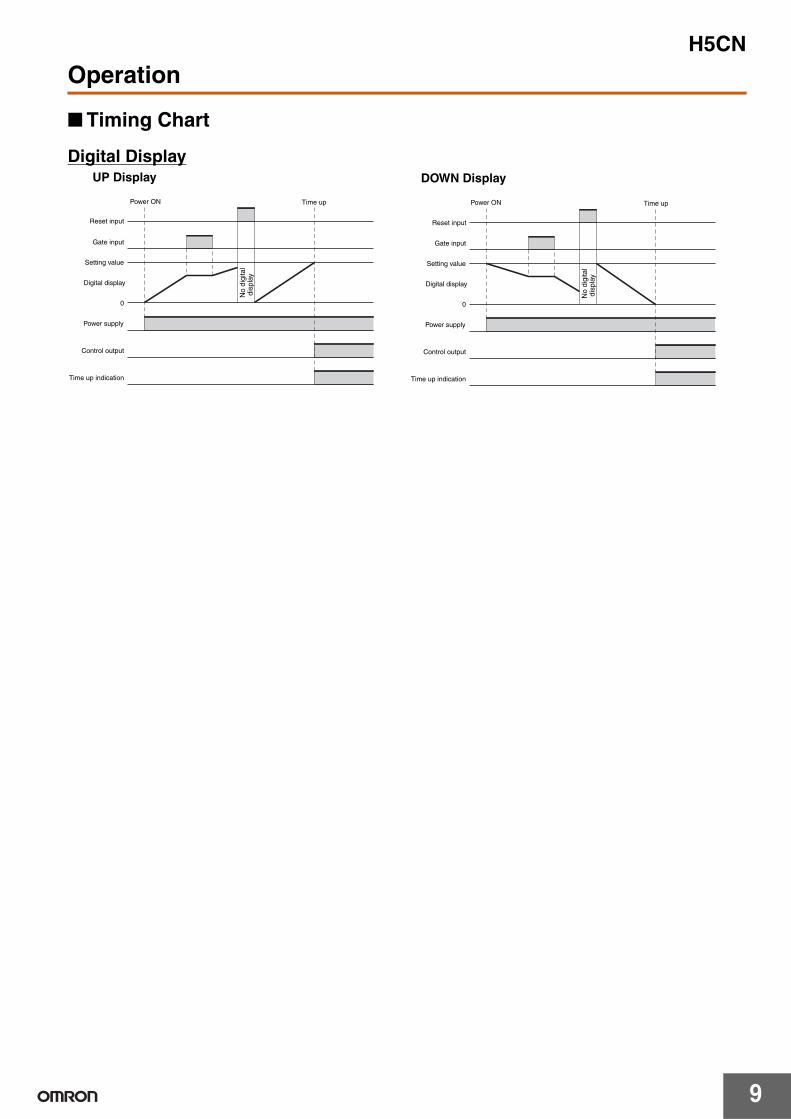
Timing Chart
Digital DisplayUP Display DOWN Display
Reset input
Gate input
Time up
Setting value
0
Control output
Power supply
Time up indication
Digital display
Reset input
Gate input
Time up
Setting value
0
Control output
Time up indication
Digital display
Power supply
No
digi
tal
dis
play
No
digi
tal
dis
play
Power ON Power ON
H5CN
10
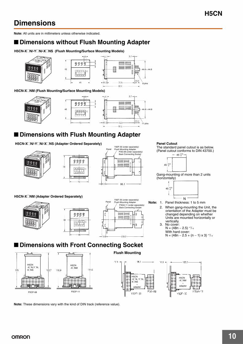
DimensionsNote: All units are in millimeters unless otherwise indicated.
Dimensions without Flush Mounting Adapter
Dimensions with Flush Mounting Adapter
Dimensions with Front Connecting Socket
Note: These dimensions vary with the kind of DIN track (reference value).
H5CN-X@N/-Y@N/-X@NS (Flush Mounting/Surface Mounting Models)
H5CN-X@NM (Flush Mounting/Surface Mounting Models)
44.8 × 44.8
44.8 × 44.8
8 pins
11 pins
PanelY92F-30 (order separately)Flush Mounting Adapter
H5CN-X@N/-Y@N/-X@NS (Adapter Ordered Separately)
H5CN-X@NM (Adapter Ordered Separately)
P3GA-11 (order separately)Back Connecting Socket
PanelY92F-30 (order separately)Flush Mounting Adapter
95.1
P3G-08 (order separately)Back Connecting Socket
Panel Cutout
Note: 1. Panel thickness: 1 to 5 mm
3. No cover: N = (48n − 2.5) +1/−0
With hard cover: N = 48n − 2.5 + (n − 1) x 3 +1/−0
N
2. When gang-mounting the Unit, the orientation of the Adapter must be changed depending on whether Units are mounted horizontally or vertically.
45 +0.6−0
45 +0.6−0
45 +0.6−0
The standard panel cutout is as below. (Panel cutout conforms to DIN 43700.)
Gang-mounting of more than 2 units (horizontally)
H5CN-X@N,Y@N,X@NS
H5CN-X@NM
P2CF-08 P2CF-11
H5CN-X@N, Y@N,X@NS
+adapter
H5CN-X@NM
+adapter
Flush Mounting
H5CN
11
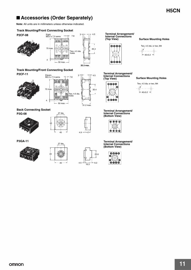
Accessories (Order Separately)Note: All units are in millimeters unless otherwise indicated.
20.3 max.
7.83 4.5
35.4
4
40±0.2
70 max.
50 max.
20.3 max.
Track Mounting/Front Connecting Socket
P2CF-08Surface Mounting Holes
Two, 4.5 dia. or two, M4
Terminal Arrangement/ Internal Connections (Top View)
Eight, M3.5 x 7.5 sems
Two, 4.5 dia. holes
40±0.2
7.83 4.5
35.4
4
Track Mounting/Front Connecting SocketP2CF-11
Surface Mounting Holes
Two, 4.5 dia. or two, M4
70 max.
50 max.31.2 max.
Terminal Arrangement/ Internal Connections (Top View)
Eleven, M3.5 x 7.5 sems
Two, 4.5 dia. holes
45
45 4.9 17
45
45
25.6
4.516.3
6.2
27 dia.
Back Connecting SocketP3G-08
P3GA-1127 dia.
Terminal Arrangement/ Internal Connections (Bottom View)
Terminal Arrangement/ Internal Connections (Bottom View)
H5CN
12
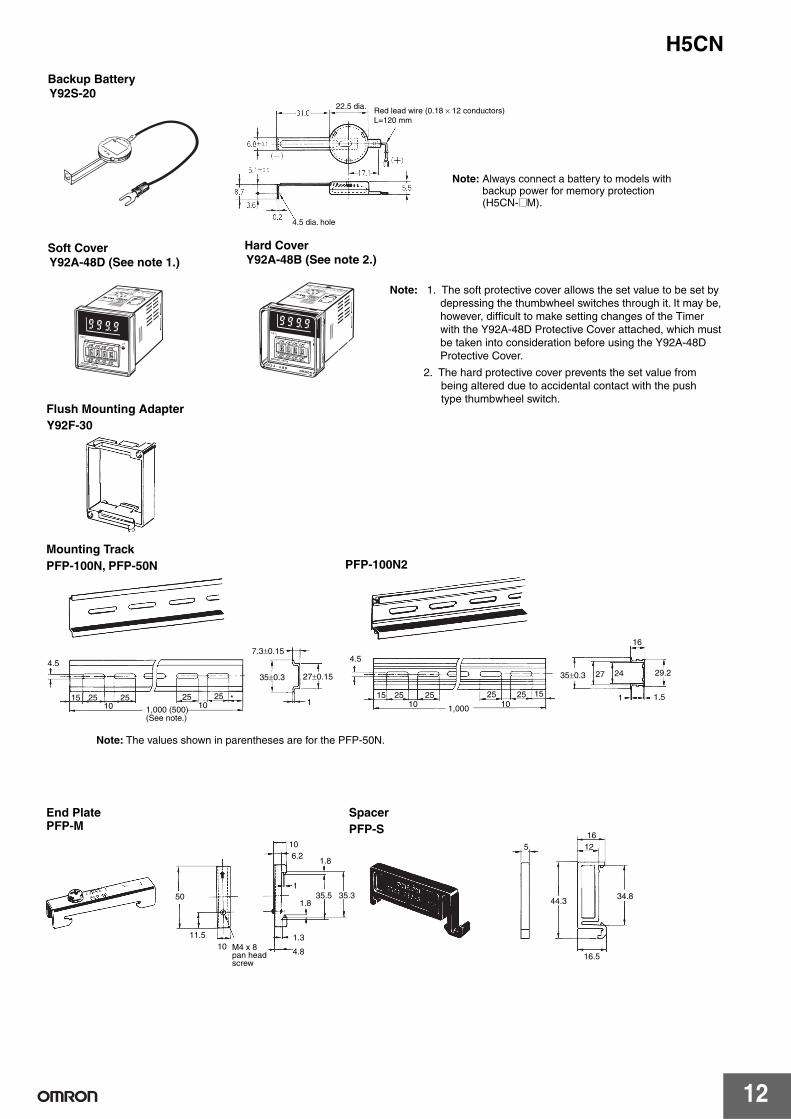
Y92F-30Flush Mounting Adapter
Y92S-20Backup Battery
Y92A-48D (See note 1.)Soft Cover
Y92A-48B (See note 2.)Hard Cover
Note: 1. The soft protective cover allows the set value to be set by depressing the thumbwheel switches through it. It may be, however, difficult to make setting changes of the Timer with the Y92A-48D Protective Cover attached, which must be taken into consideration before using the Y92A-48D Protective Cover.
2. The hard protective cover prevents the set value from being altered due to accidental contact with the push type thumbwheel switch.
4.5 dia. hole
22.5 dia. Red lead wire (0.18 × 12 conductors)L=120 mm
Note: Always connect a battery to models with backup power for memory protection (H5CN-@M).
4.5
15 25 25 25 25 *10 10
7.3±0.15
35±0.3 27±0.15
1
4.5
15 25 25 25 25 1510 101,000
27 24
16
29.2
1 1.5
50
11.5
106.2
1.8
135.5 35.3
1.8
1.3
4.8
516
12
44.3
16.510
34.8
35±0.3
Mounting Track PFP-100N, PFP-50N PFP-100N2
End PlatePFP-M
SpacerPFP-S
1,000 (500)(See note.)
Note: The values shown in parentheses are for the PFP-50N.
M4 x 8 pan head screw
H5CN
13
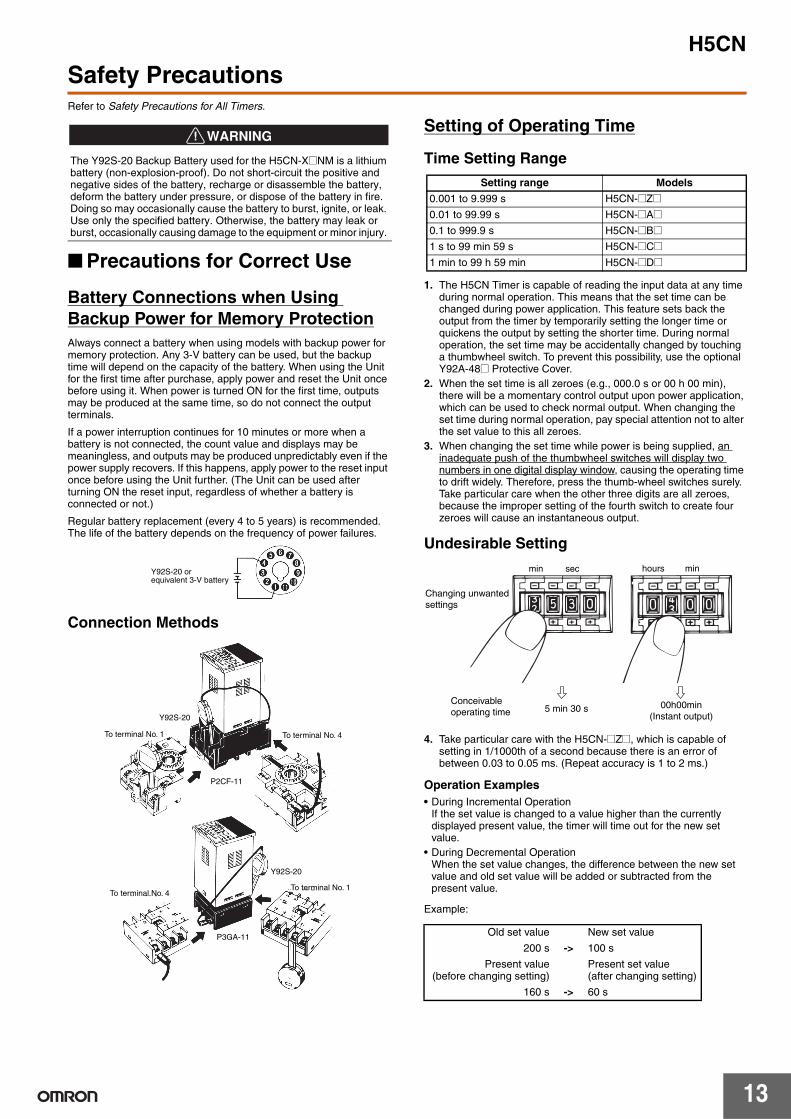
Safety PrecautionsRefer to Safety Precautions for All Timers.
Precautions for Correct Use
Battery Connections when Using Backup Power for Memory ProtectionAlways connect a battery when using models with backup power for memory protection. Any 3-V battery can be used, but the backup time will depend on the capacity of the battery. When using the Unit for the first time after purchase, apply power and reset the Unit once before using it. When power is turned ON for the first time, outputs may be produced at the same time, so do not connect the output terminals.
If a power interruption continues for 10 minutes or more when a battery is not connected, the count value and displays may be meaningless, and outputs may be produced unpredictably even if the power supply recovers. If this happens, apply power to the reset input once before using the Unit further. (The Unit can be used after turning ON the reset input, regardless of whether a battery is connected or not.)
Regular battery replacement (every 4 to 5 years) is recommended. The life of the battery depends on the frequency of power failures.
Connection Methods
Setting of Operating Time
Time Setting Range
1. The H5CN Timer is capable of reading the input data at any time during normal operation. This means that the set time can be changed during power application. This feature sets back the output from the timer by temporarily setting the longer time or quickens the output by setting the shorter time. During normal operation, the set time may be accidentally changed by touching a thumbwheel switch. To prevent this possibility, use the optional Y92A-48@ Protective Cover.
2. When the set time is all zeroes (e.g., 000.0 s or 00 h 00 min), there will be a momentary control output upon power application, which can be used to check normal output. When changing the set time during normal operation, pay special attention not to alter the set value to this all zeroes.
3. When changing the set time while power is being supplied, an inadequate push of the thumbwheel switches will display two numbers in one digital display window, causing the operating time to drift widely. Therefore, press the thumb-wheel switches surely. Take particular care when the other three digits are all zeroes, because the improper setting of the fourth switch to create four zeroes will cause an instantaneous output.
Undesirable Setting
4. Take particular care with the H5CN-@Z@, which is capable of setting in 1/1000th of a second because there is an error of between 0.03 to 0.05 ms. (Repeat accuracy is 1 to 2 ms.)
Operation Examples• During Incremental Operation
If the set value is changed to a value higher than the currently displayed present value, the timer will time out for the new set value.
• During Decremental OperationWhen the set value changes, the difference between the new set value and old set value will be added or subtracted from the present value.
Example:
The Y92S-20 Backup Battery used for the H5CN-X@NM is a lithium battery (non-explosion-proof). Do not short-circuit the positive and negative sides of the battery, recharge or disassemble the battery, deform the battery under pressure, or dispose of the battery in fire. Doing so may occasionally cause the battery to burst, ignite, or leak. Use only the specified battery. Otherwise, the battery may leak or burst, occasionally causing damage to the equipment or minor injury.
!WARNING
Y92S-20 or equivalent 3-V battery
To terminal No. 4
To terminal No. 1
Y92S-20
P2CF-11
To terminal No. 1
Y92S-20
P3GA-11
To terminal No. 4
Setting range Models
0.001 to 9.999 s H5CN-@[email protected] to 99.99 s H5CN-@[email protected] to 999.9 s H5CN-@B@1 s to 99 min 59 s H5CN-@C@1 min to 99 h 59 min H5CN-@D@
Old set value New set value
200 s -> 100 s
Present value(before changing setting)
Present set value (after changing setting)
160 s -> 60 s
min sec
5 min 30 s
hours min
00h00min(Instant output)
Changing unwanted settings
Conceivable operating time
H5CN
14
Power SupplyLeave the power supply OFF for at least 0.5 s before turning it back ON (power supply reset).
Inputs and Outputs• Do not apply voltage externally to input terminals A, C, and D.• When using contacts for the reset input and gate input, use gold-
plated contacts with good contact reliability. Use gate input contacts with short contact bounce (chattering).
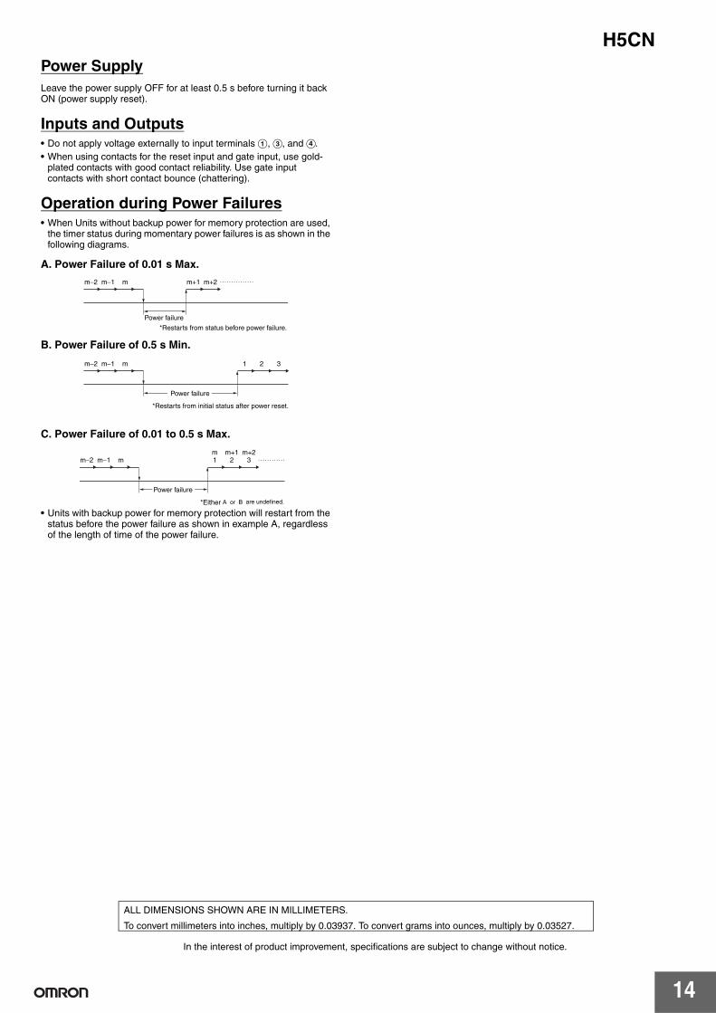
Operation during Power Failures• When Units without backup power for memory protection are used,
the timer status during momentary power failures is as shown in the following diagrams.
A. Power Failure of 0.01 s Max.
B. Power Failure of 0.5 s Min.
C. Power Failure of 0.01 to 0.5 s Max.
• Units with backup power for memory protection will restart from the status before the power failure as shown in example A, regardless of the length of time of the power failure.
Power failure
*Restarts from status before power failure.
m m+1 m+2m−1m−2
*Restarts from initial status after power reset.
m 1 2 3m−1m−2
Power failure
*Either A or B are undefined.
m 1 2 3m m+1 m+2
m−1m−2
Power failure
In the interest of product improvement, specifications are subject to change without notice.
ALL DIMENSIONS SHOWN ARE IN MILLIMETERS.
To convert millimeters into inches, multiply by 0.03937. To convert grams into ounces, multiply by 0.03527.
Read and Understand This Catalog Please read and understand this catalog before purchasing the products. Please consult your OMRON representative if you have any questions or comments.
Warranty and Limitations of Liability WARRANTY OMRON's exclusive warranty is that the products are free from defects in materials and workmanship for a period of one year (or other period if specified) from date of sale by OMRON. OMRON MAKES NO WARRANTY OR REPRESENTATION, EXPRESS OR IMPLIED, REGARDING NON-INFRINGEMENT, MERCHANTABILITY, OR FITNESS FOR PARTICULAR PURPOSE OF THE PRODUCTS. ANY BUYER OR USER ACKNOWLEDGES THAT THE BUYER OR USER ALONE HAS DETERMINED THAT THE PRODUCTS WILL SUITABLY MEET THE REQUIREMENTS OF THEIR INTENDED USE. OMRON DISCLAIMS ALL OTHER WARRANTIES, EXPRESS OR IMPLIED. LIMITATIONS OF LIABILITY OMRON SHALL NOT BE RESPONSIBLE FOR SPECIAL, INDIRECT, OR CONSEQUENTIAL DAMAGES, LOSS OF PROFITS OR COMMERCIAL LOSS IN ANY WAY CONNECTED WITH THE PRODUCTS, WHETHER SUCH CLAIM IS BASED ON CONTRACT, WARRANTY, NEGLIGENCE, OR STRICT LIABILITY. In no event shall the responsibility of OMRON for any act exceed the individual price of the product on which liability is asserted. IN NO EVENT SHALL OMRON BE RESPONSIBLE FOR WARRANTY, REPAIR, OR OTHER CLAIMS REGARDING THE PRODUCTS UNLESS OMRON'S ANALYSIS CONFIRMS THAT THE PRODUCTS WERE PROPERLY HANDLED, STORED, INSTALLED, AND MAINTAINED AND NOT SUBJECT TO CONTAMINATION, ABUSE, MISUSE, OR INAPPROPRIATE MODIFICATION OR REPAIR.
Application Considerations SUITABILITY FOR USE OMRON shall not be responsible for conformity with any standards, codes, or regulations that apply to the combination of products in the customer's application or use of the products. At the customer's request, OMRON will provide applicable third party certification documents identifying ratings and limitations of use that apply to the products. This information by itself is not sufficient for a complete determination of the suitability of the products in combination with the end product, machine, system, or other application or use. The following are some examples of applications for which particular attention must be given. This is not intended to be an exhaustive list of all possible uses of the products, nor is it intended to imply that the uses listed may be suitable for the products:
• Outdoor use, uses involving potential chemical contamination or electrical interference, or conditions or uses not described in this catalog. • Nuclear energy control systems, combustion systems, railroad systems, aviation systems, medical equipment, amusement machines, vehicles,
safety equipment, and installations subject to separate industry or government regulations. • Systems, machines, and equipment that could present a risk to life or property.
Please know and observe all prohibitions of use applicable to the products. NEVER USE THE PRODUCTS FOR AN APPLICATION INVOLVING SERIOUS RISK TO LIFE OR PROPERTY WITHOUT ENSURING THAT THE SYSTEM AS A WHOLE HAS BEEN DESIGNED TO ADDRESS THE RISKS, AND THAT THE OMRON PRODUCTS ARE PROPERLY RATED AND INSTALLED FOR THE INTENDED USE WITHIN THE OVERALL EQUIPMENT OR SYSTEM. PROGRAMMABLE PRODUCTS OMRON shall not be responsible for the user's programming of a programmable product, or any consequence thereof.
Disclaimers CHANGE IN SPECIFICATIONS Product specifications and accessories may be changed at any time based on improvements and other reasons. It is our practice to change model numbers when published ratings or features are changed, or when significant construction changes are made. However, some specifications of the products may be changed without any notice. When in doubt, special model numbers may be assigned to fix or establish key specifications for your application on your request. Please consult with your OMRON representative at any time to confirm actual specifications of purchased products. DIMENSIONS AND WEIGHTS Dimensions and weights are nominal and are not to be used for manufacturing purposes, even when tolerances are shown. PERFORMANCE DATA Performance data given in this catalog is provided as a guide for the user in determining suitability and does not constitute a warranty. It may represent the result of OMRON’s test conditions, and the users must correlate it to actual application requirements. Actual performance is subject to the OMRON Warranty and Limitations of Liability. ERRORS AND OMISSIONS The information in this document has been carefully checked and is believed to be accurate; however, no responsibility is assumed for clerical, typographical, or proofreading errors, or omissions.
2008.11
In the interest of product improvement, specifications are subject to change without notice.
OMRON Corporation Industrial Automation Company http://www.ia.omron.com/
(c)Copyright OMRON Corporation 2008 All Right Reserved.