Embed Size (px)
Citation preview

omega.com e-mail: [email protected]
For latest product manuals:omegamanual.info
User’s Guide
D5000 SeriesFour Channel Digital Transmitters
MADE IN
Shop online at

Servicing North America:U.S.A.: Omega Engineering, Inc., One Omega Drive, P.O. Box 4047ISO 9001 Certified Stamford, CT 06907-0047
Toll-Free: 1-800-826-6342 Tel: (203) 359-1660FAX: (203) 359-7700 e-mail: [email protected]
Canada: 976 BergarLaval (Quebec), H7L 5A1 Canada Toll-Free: 1-800-826-6342 TEL: (514) 856-6928FAX: (514) 856-6886 e-mail: [email protected]
For immediate technical or application assistance:U.S.A. and Canada: Sales Service: 1-800-826-6342/1-800-TC-OMEGA®
Customer Service: 1-800-622-2378/1-800-622-BEST®
Engineering Service: 1-800-872-9436/1-800-USA-WHEN®
Mexico En Español: 001 (203) 359-7803 FAX: 001 (203) 359-7807Latin America [email protected] e-mail: [email protected]
Servicing Europe:Benelux: Managed by the United Kingdom Office
Toll-Free: 0800 099 3344 TEL: +31 20 347 21 21FAX: +31 20 643 46 43 e-mail: [email protected]
Czech Republic: Frystatska 184733 01 Karviná, Czech RepublicToll-Free: 0800-1-66342 TEL: +420-59-6311899FAX: +420-59-6311114 e-mail: [email protected]
France: Managed by the United Kingdom OfficeToll-Free: 0800 466 342 TEL: +33 (0) 161 37 29 00FAX: +33 (0) 130 57 54 27 e-mail: [email protected]
Germany/Austria: Daimlerstrasse 26D-75392 Deckenpfronn, GermanyToll-Free: 0800 6397678 TEL: +49 (0) 7056 9398-0FAX: +49 (0) 7056 9398-29 e-mail: [email protected]
United Kingdom: OMEGA Engineering Ltd.ISO 9001 Certified One Omega Drive, River Bend Technology Centre, Northbank
Irlam, Manchester M44 5BD United KingdomToll-Free: 0800-488-488 TEL: +44 (0) 161 777-6611FAX: +44 (0) 161 777-6622 e-mail: [email protected]
OMEGAnet® Online Service Internet e-mailomega.com [email protected]
It is the policy of OMEGA Engineering, Inc. to comply with all worldwide safety and EMC/EMIregulations that apply. OMEGA is constantly pursuing certification of its products to the European NewApproach Directives. OMEGA will add the CE mark to every appropriate device upon certification.The information contained in this document is believed to be correct, but OMEGA accepts no liability for anyerrors it contains, and reserves the right to alter specifications without notice.WARNING: These products are not designed for use in, and should not be used for, human applications.

D5000 SERIES USERS MANUAL
REVISED: 2/1/11
Omega EngineeringOne Omega DriveP O Box 4047Stamford, CT 06907Phone: 1-800-DAS-IEEEFax: 203-359-7990e-mail: [email protected]
The information in this publication has been carefully checked and isbelieved to be accurate; however, no responsibility is assumed for possibleinaccuracies or omissions. Applications information in this manual is in-tended as suggestions for possible use of the products and not as explicitperformance in a specific application. Specifications may be subject tochange without notice.
D5000 modules are not intrinsically safe devices and should not be used inan explosive environment unless enclosed in approved explosion-proofhousings.

TABLE OF CONTENTS
Warranty 4CHAPTER 1 Getting Started
Default Mode 1-1Quick Hook-Up 1-2
CHAPTER 2 Functional DescriptionBlock Diagram 2-2
CHAPTER 3 CommunicationsData Format 3-2RS-232 3-2Multi-party Connection 3-3Software Considerations 3-4Changing Baud Rate 3-5Using a Daisy-Chain With a Dumb Terminal 3-5RS-485 3-6RS-485 Multidrop System 3-8
CHAPTER 4 Command SetTable of Commands 4-6User Commands 4-6Error Messages 4-14
CHAPTER 5 Setup Information and CommandCommand Syntax 5-1Setup Hints 5-11
CHAPTER 6 Power SupplyCHAPTER 7 TroubleshootingCHAPTER 8 CalibrationCHAPTER 9 Extended AddressingAppendix A (ASCII TABLE )Appendix B D5000 SpecificationsAppendix C Factory Values

Chapter 1Getting Started
Default ModeAll D5000 modules contain an EEPROM (Electrically Erasable Program-mable Read Only Memory) to store setup information and calibrationconstants. The EEPROM replaces the usual array of switches and potsnecessary to specify baud rate, address, parity, etc. The memory isnonvolatile which means that the information is retained even if power isremoved. No batteries are used so it is never necessary to open the modulecase.
The EEPROM provides tremendous system flexibility since all of themodule’s setup parameters may be configured remotely through the com-munications port without having to physically change switch and potsettings. There is one minor drawback in using EEPROM instead ofswitches; there is no visual indication of the setup information in the module.It is impossible to tell just by looking at the module what the baud rate,address, parity and other settings are. It is difficult to establish communica-tions with a module whose address and baud rate are unknown. Toovercome this, each module has an input pin labeled DEFAULT*. Byconnecting this pin to Ground, the module is put in a known communicationssetup called Default Mode.
The Default Mode setup is: 300 baud, one start bit, eight data bits, onestop bit, no parity, any address is recognized.
Grounding the DEFAULT* pin does not change any of the setups stored inEEPROM. The setup may be read back with the Read Setup (RS) commandto determine all of the setups stored in the module. In Default Mode, allcommands are available.
Each channel of the D5000 has its own channel address and all fourchannels are enabled in Default Mode. The addresses assigned to a modulemust be four consecutive ASCII values, such as 0, 1, 2, 3. A module inDefault Mode will respond to any address except the six identified illegalvalues (NULL, CR, $, #, , ). A dummy address must be included in everycommand for proper responses. The ASCII value of the module's firstchannel address may be read back with the RS command. A properlyaddressed channel can read data values and can modify calibration values,such as trim span in the Default Mode. However it must be noted that inDefault Mode a module that is addressed with any value other than the fourproper addresss values assigned to it will always respond with the data fromits first channel. For example if a module as described above is addresseswith any character other than 0, 1, 2, 3, it will respond with or modify datafrom channel 0.
Setup information in a module may be changed at will with the SetUp (SU)

command. Baud rate and parity setups may be changed without affectingthe Default values of 300 baud and no parity. When the DEFAULT* pin isreleased, the module automatically performs a program reset and config-ures itself to the baud rate and parity stored in the setup information.
The Default Mode is intended to be used with a single module connected toa terminal or computer for the purpose of identifying and modifying setupvalues. In most cases, a module in Default Mode may not be used in a stringwith other modules.
RS-232 & RS-485 Quick Hook-UpSoftware is not required to begin using your D5000 module. We recommendthat you begin to get familiar with the module by setting it up on the bench.Start by using a dumb terminal or a computer that acts like a dumb terminal.Make the connections shown in the quick hook-up drawings, Figures 1.1 or1.2. Put the module in the Default Mode by grounding the Default* terminal.Initialize the terminal communications package on your computer to put itinto the “terminal” mode. Since this step varies from computer to computer,refer to your computer manual for instructions.
Begin by typing $1RD and pressing the Enter or Return key. The module willrespond with an * followed by the data reading at the input. The data includessign, seven digits and a decimal point. For example, if you are using athermocouple module and measuring room temperature your reading mightbe *+00025.00. The temperature reading will initially be in °C which has
Figure 1.1 RS-232C Quick Hook-Up.

Figure 1.2 RS-485 Quick Hook-Up.
been preset at the factory. Once you have a response from the module youcan turn to the Chapter 4 and get familiar with the command set.
All modules are shipped from the factory with a setup that includes a channeladdress of 1, 300 baud rate, no linefeeds, no parity, alarms off, no echo andtwo-character delay. Refer to the Chapter 5 to configure the module to yourapplication.
RS-485 Quick Hook-up to a RS-232 portAn RS-485 module may be easily interfaced to an RS-232C terminal forevaluation purposes. This connection is only suitable for benchtop operationand should never be used for a permanent installation. Figure 1.3 shows thehook-up. This connection will work provided the RS-232C transmit output iscurrent limited to less than 50mA and the RS-232C receive threshold isgreater than 0V. All terminals that use 1488 and 1489 style interface IC’s willsatisfy this requirement. With this connection, characters generated by theterminal will be echoed back. To avoid double characters, the local echo onthe terminal should be turned off.
If the current limiting capability of the RS-232C output is uncertain, insert a100Ω to 1kΩ resistor in series with the RS-232 output.
In some rare cases it may be necessary to connect the module’s DATApin to ground through a 100Ω to 1kΩ resistor.

Figure 1.3 RS-485 Quick Hook-Up with RS-232C Port.

A functional diagram of a typical module is shown in Figure 2.1. It is a usefulreference that shows the data path in the module and to explain the functionof many of the module’s commands.
The first step is to acquire the sensor signal and convert it to digital data. InFigure 2.1, all the signal conditioning circuitry has been lumped into oneblock, the analog/digital converter (A/D). Autozero and autocalibration isperformed internally and is transparent to the user.
The full-scale output of each channel may be trimmed using the Trim Span(TS) command. The TS command adjusts the calibration values for eachchannel that stored in the internal EEPROM. The TS command should onlybe used to trim the accuracy of the unit with a laboratory standard referenceapplied to the sensor input.
The trimmed data flows into either of two digital filters. The filter selection isperformed automatically by the microprocessor after every A/D conversion.The filter selection depends on the difference of the current A/D output dataand the previous data stored in the output data register. If the least significantdecimal digit from the A/D differs from the old output data by more than 10counts, the large signal filter is selected. If the change is less than 10 counts,the small signal filter is used.
The two-filter system allows for different degrees of filtering depending onthe rate of the input change. For steady-state signals, the small-signal filteraverages out noise and small input changes to give a stable steady-stateoutput. The large-signal filter is activated by step changes or very noisy inputsignals. The time constants for the two filters can be specified independentlywith the SetUp (SU) command. The filter values are stored in nonvolatilememory. Typically, the small-signal filter is set to a larger time constant thanthe large-signal filter. This gives very good noise rejection along with fastresponse to step inputs.
The modules allow user selectable output scaling in °C or °F on temperaturedata. This selection is shown in Figure 2.1 as a switch following the digitalfilters. The default scaling in the modules is °C, but this may be convertedto °F by feeding the data through a conversion routine. The switch positionis controlled by a bit in the setup data and may be changed with the SetUp(SU) command. The scaling selection is nonvolatile. In non-temperatureapplications, °C should always be selected.
The scaled data is summed with data stored in the Output Offset Registerto obtain the final output value. The output offset is controlled by the user andhas many purposes. The data in the Output Offset Register may be used to
Chapter 2Functional Description

trim any offsets caused by the input sensor. It may be used to null outundesired signal such as a tare weight. The Trim Zero (TZ) command is usedto adjust the output to any desired value by loading the appropriate value inthe offset register. The offset register data is nonvolatile.
The output data may be read with the Read Data (RD) command.

IntroductionThe D5000 modules has been carefully designed to be easy to interface toall popular computers and terminals. All communications to and from themodules are performed with printable ASCII characters. This allows theinformation to be processed with string functions common to most high-levellanguages such as BASIC. For computers that support RS-232C, no specialmachine language software drivers are necessary for operation. Themodules can be connected to auto-answer modems for long-distanceoperation without the need for a supervisory computer. The ASCII formatmakes system debugging easy with a dumb terminal.
This system allows multiple modules to be connected to a communicationsport with a single 4-wire cable. Up to 30 RS-485 modules may be strungtogether on one cable. A practical limit for RS-232C units is about ten,although a string of 30 units is possible. Extended Addressing Mode allowsmany more modules to be connected into high channel count systems.Refer to Extended Addressing Mode in Chapter 9.
The modules communicate with the host on a polling system; that is, eachmodule responds to its own unique address and must be interrogated by thehost. A module can never initiate a communications sequence. A simplecommand/response protocol must be strictly observed to avoid communi-cations collisions and data errors.
Communications to the D5000 modules is performed with two-characterASCII command codes such as RD to Read Data from the analog input. Acomplete description of all commands is given in the Chapter 4. A typicalcommand/response sequence would look like this:
Command: $1RDResponse: *+00123.00
A command/response sequence is not complete until a valid response isreceived. The host may not initiate a new command until the response froma previous command is complete. Failure to observe this rule will result incommunications collisions. A valid response can be in one of three forms:
1) a normal response indicated by a ‘ * ‘ prompt2) an error message indicated by a ‘ ? ‘ prompt3) a communications time-out error
When a module receives a valid command, it must interpret the command,perform the desired function, and then communicate the response back tothe host. Each command has an associated delay time in which the moduleis busy calculating the response. If the host does not receive a response in
Chapter 3Communications
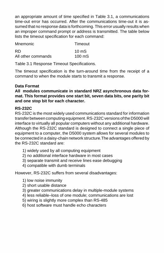
an appropriate amount of time specified in Table 3.1, a communicationstime-out error has occurred. After the communications time-out it is as-sumed that no response data is forthcoming. This error usually results whenan improper command prompt or address is transmitted. The table belowlists the timeout specification for each command:
Mnemonic Timeout
RD 10 mSAll other commands 100 mS
Table 3.1 Response Timeout Specifications.
The timeout specification is the turn-around time from the receipt of acommand to when the module starts to transmit a response.
Data FormatAll modules communicate in standard NRZ asynchronous data for-mat. This format provides one start bit, seven data bits, one parity bitand one stop bit for each character.
RS-232CRS-232C is the most widely used communications standard for informationtransfer between computing equipment. RS-232C versions of the D5000 willinterface to virtually all popular computers without any additional hardware.Although the RS-232C standard is designed to connect a single piece ofequipment to a computer, the D5000 system allows for several modules tobe connected in a daisy-chain network structure.The advantages offered bythe RS-232C standard are:
1) widely used by all computing equipment2) no additional interface hardware in most cases3) separate transmit and receive lines ease debugging4) compatible with dumb terminals
However, RS-232C suffers from several disadvantages:
1) low noise immunity2) short usable distance3) greater communications delay in multiple-module systems4) less reliable–loss of one module; communications are lost5) wiring is slightly more complex than RS-4856) host software must handle echo characters

Single Module ConnectionFigure 1.1 shows the connections necessary to attach one module to a host.Use the Default Mode to enter the desired address, baud rate, and othersetups (see Setups). The use of echo is not necessary when using a singlemodule on the communications line.
Multi-party ConnectionRS-232C is not designed to be used in a multiparty system; however theD5000 modules can be daisy-chained to allow many modules to beconnected to a single communications port. The wiring necessary to createthe daisy-chain is shown in Figure 3.1. Notice that starting with the host,each Transmit output is wired to the Receive input of the next module in thedaisy chain. This wiring sequence must be followed until the output of the lastmodule in the chain is wired to the Receive input of the host. All modules inthe chain must be setup to the same baud rate and must echo all receiveddata (see Setups). Each module must be setup with its own unique addressto avoid communications collisions (see Setups). In this network, anycharacters transmitted by the host are received by each module in the chainand passed on to the next station until the information is echoed back to theReceive input of the host. In this manner all the commands given by the hostare examined by every module. If a module in the chain is correctlyaddressed and receives a valid command, it will respond by transmitting theresponse on the daisy chain network. The response data will be ripplethrough any other modules in the chain until it reaches its final destination,the Receive input of the host.
Figure 3.1 RS-232 Daisy Chain Network.

The daisy chain network must be carefully implemented to avoid the pitfallsinherent in its structure. The daisy-chain is a series-connected structure andany break in the communications link will bring down the whole system.Several rules must be observed to create a working chain:
1. All wiring connections must be secure; any break in the wiring,power, ground or communications breaks the chain.2. All modules must be plugged into their own connectors.3. All modules must be setup for the same baud rate.4. All modules must be setup for echo.
Software ConsiderationsIf the host device is a computer, it must be able to handle the echoedcommand messages on its Receive input along with the responses from themodule. This can be handled by software string functions by observing thata module response always begins with a ‘ * ‘ or ‘ ? ‘ character and ends witha carriage return.
A properly addressed D5000 module in a daisy chain will echo all of thecharacters in the command including the terminating carriage return. Uponreceiving the carriage return, the module will immediately calculate andtransmit the response to the command. During this time, the module will notecho any characters that appear on its receive input. However, if a characteris received during this computation period, it will be stored in the module’sinternal receive buffer. This character will be echoed after the responsestring is transmitted by the module. This situation will occur if the hostcomputer appends a linefeed character on the command carriage return. Inthis case the linefeed character will be echoed after the response string hasbeen transmitted.
The daisy chain also affects the command timeout specifications. When amodule in the chain receives a character it is echoed by retransmitting thecharacter through the module’s internal UART. This method is used toprovide more reliable communications since the UART eliminates anyslewing errors caused by the transmission lines. However, this methodcreates a delay in propagating the character through the chain. The delayis equal to the time necessary to retransmit one character using the baudrate setup in the module:
Baud Rate Delay Baud Rate Delay300 33.30ms 9600 1.04ms600 16.70ms 19200 0.52ms1200 8.33ms 38400 0.26ms2400 4.17ms 57600 173.6µs4800 2.08ms 115200 86.8µs

One delay time is accumulated for each module in the chain. For example,if four modules are used in a chain operating at 1200 baud, the accumulateddelay time is 4 X 8.33 mS = 33.3 mS This time must be added to the timeslisted in Table 3.1 to calculate the correct communications time-out error.
For modules with RS-232C outputs, the programmed communicationsdelay specified in the setup data (see Chapter 5) is implemented by sendinga NULL character (00) followed by an idle line condition for one charactertime. This results in a delay of two character periods. For longer delay timesspecified in the setup data, this sequence is repeated. Programmedcommunications delay is seldom necessary in an RS-232C daisy chainsince each module in the chain adds one character of communicationsdelay.
Changing Baud RateIt is possible to change the baud rate of an RS-232C daisy chain on-line. Thisprocess must be done carefully to avoid breaking the communications link.
1. Use the SetUp (SU) command to change the baud rate setup on eachmodule in the chain. Be careful not to generate a reset during this process.A reset can be caused by the Remote Reset (RR) command or powerinterruptions.
2. Verify that all the modules in the chain contain the new baud rate setupusing the Read Setup (RS) command. Every module in the chain must besetup for the same baud rate.
3. Remove power from all the modules for at least 10 seconds. Restorepower to the modules. This generates a power-up reset in each module andloads in the new baud rate.
4. Change the host baud rate to the new value and check communica-tions.
5. Be sure to compensate for a different communications delay as aresult of the new baud rate.
Using A Daisy-Chain With A Dumb TerminalA dumb terminal can be used to communicate to a daisy-chained system.The terminal is connected in the same manner as a computer used as a host.Any commands typed into the dumb terminal will be echoed by the daisychain. To avoid double characters when typing commands, set the terminalto full duplex mode or turn off the local echo. The daisy chain will provide theinput command echo.

RS-485RS-485 is a recently developed communications standard to satisfy theneed for multidropped systems that can communicate at high data ratesover long distances. RS-485 is similar to RS-422 in that it uses a balanceddifferential pair of wires switching from 0 to 5V to communicate data. RS-485receivers can handle common mode voltages from -7V to +12V without lossof data, making them ideal for transmission over great distances. RS-485differs from RS-422 by using one balanced pair of wires for both transmittingand receiving. Since an RS-485 system cannot transmit and receive at thesame time it is inherently a half-duplex system. RS-485 offers manyadvantages over RS-232C:
1) balanced line gives excellent noise immunity2) can communicate with D5000 modules at 115200 baud3) communications distances up to 4,000 feet.4) true multidrop; modules are connected in parallel5) can disconnect modules without losing communications6) up to 30 modules on one line or up to 3721 using Extended Address Mode and RS-485 repeaters7) no communications delay due to multiple modules8) simplified wiring using standard telephone cable
RS-485 does have disadvantages. Very few computers or terminals havebuilt-in support for this new standard. Interface boards are available for theIBM PC and compatibles and other RS-485 equipment will become avail-able as the standard gains popularity. An RS-485 system usually requiresan interface.
We offer the A1000 and A2000 interface converters that will convert RS-232signals to RS-485 or repeat RS-485 signals. The A1000 converters alsoinclude a +24Vdc, one amp power supply for powering D5000 seriesmodules. The A1000 or A2000 connected as an RS-485 repeater can beused to extend an existing RS-485 network on one serial port.


RS-485 Multidrop SystemFigure 3.2 illustrates the wiring required for multiple-module RS-485 sys-tem. Notice that every module has a direct connection to the host system.Any number of modules may be unplugged without affecting the remainingmodules. Each module must be setup with a unique address and theaddresses can be in any order. All RS-485 modules must be setup for noecho to avoid bus conflicts (see Setup). Also note that the connector pins oneach module are labelled with notations (B), (R), (G), and (Y). Thisdesignates the colors used on standard 4-wire telephone cable:
Label Color
(B) GND Black(R) V+ Red(G) DATA* (-) Green(Y) DATA (+) Yellow
This color convention is used to simplify installation. If standard 4-wiretelephone cable is used, it is only necessary to match the labeled pins withthe wire color to guarantee correct installation.
DATA* on the label is the complement of DATA (negative true).
To minimize unwanted reflections on the transmission line, the bus shouldbe arranged as a line going from one module to the next. ‘Tree’ or randomstructures of the transmission line should be avoided. When using longtransmission lines and/or high baud rates, the data lines should be termi-nated at each end with 200 ohm resistors. Standard values of 180 ohms or220 ohms are acceptable.
During normal operation, there are periods of time where all RS-485 driversare off and the communications lines are in an 'idle' high impedancecondition. During this condition, the lines are susceptible to noise pickupwhich may be interpreted as random characters on the communicationsline. To prevent noise pickup, all RS-485 systems should incorporate 1Kohm bias resistors as shown in Figure 3.2. The resistors will maintain thedata lines in a 'mark' condition when all drivers are off.
A1000 series converter boxes have the 1KΩ resistors built-in. The resistorsare user-selectable via dip switch located on the rear panel of the A1000.
Special care must be taken with very long busses (greater than 1000 feet)to ensure error-free operation. Long busses must be terminated as de-scribed above. The use of twisted cable for the DATA and DATA* lines willgreatly enhance signal fidelity. Use parity and checksums along with the ‘#’form of all commands to detect transmission errors. In situations wheremany modules are used on a long line, voltage drops in the power leads

becomes an important consideration. The GND wire is used both as a powerconnection and the common reference for the transmission line receivers inthe modules. Voltage drops in the GND leads appear as a common-modevoltage to the receivers. The receivers are rated for a maximum of -7V. ofcommon-mode voltage. For reliable operation, the common mode voltageshould be kept below -5V.
To avoid problems with voltage drops, modules may be powered locallyrather than transmitting the power from the host. Inexpensive 'calculator'type power supplies are useful in remote locations. When local supplies areused, be sure to provide a ground reference with a third wire to the host orthrough a good earth ground. With local supplies and an earth ground, onlytwo wires for the data connections are necessary.
Communications Delay
All D5000 modules with RS-485 outputs are setup at the factory to providetwo units of communications delay after a command has been received (seeChapter 5). This delay is necessary when using host computers that transmita carriage return as a carriage return-linefeed string. Without the delay, thelinefeed character may collide with the first transmitted character from themodule, resulting in garbled data. If the host computer transmits a carriagereturn as a single character, the delay may be set to zero to improvecommunications response time.

The D5000 modules operate with a simple command/response protocol tocontrol all module functions. A command must be transmitted to the moduleby the host computer or terminal before the module will respond with usefuldata. A module can never initiate a communications sequence. A variety ofcommands exists to exploit the full functionality of the modules. A list ofavailable commands and a sample format for each command is listed inTable 4.1.
Command StructureEach command message from the host must begin with a command promptcharacter to signal to the modules that a command message is to follow.There are four valid prompt characters; a dollar sign character ($) is used togenerate a short response message from the module. A short response isthe minimum amount of data necessary to complete the command. Thesecond prompt character is the pound sign character (#) which generateslong responses (will be covered later in this chapter). The other two promptcharacters: left curly brace ( ) and right curly brace ( ) are part of theExtended Addressing mode described in chapter 10.
The prompt character must be followed by a single address characteridentifying the channel of the module to which the command is directed.Each module attached to a common communications port must be setupwith its own unique addresses so that commands may be directed to theproper unit. Module addresses are assigned by the user with the SetUp (SU)command. Printable ASCII characters such as ‘1’ (ASCII $31) or ‘A’ (ASCII$41) are the best choices for address characters. Each D5000 modulerequires from one to four addresses.
The address character is followed by a two or three-character command thatidentifies the function to be performed by the module. All of the availablecommands are listed in Table 4.1 along with a short function definition. Allcommands are described in Chapter 4. Commands must be transmitted asupper-case characters.
A two-character checksum may be appended to any command message asa user option. See ‘Checksum’ in Chapter 4 .
All commands must be terminated by a Carriage Return character (ASCII$0D). (In all command examples in this text the Carriage Return is eitherimplied or denoted by the symbol ‘CR’.)
In addition to the commmand structure discussed above there is a specialcommand format called Extended Addressing. This mode uses a differentprompt, either '' or '' to distinguish it from the regular command syntax. TheExtended Addressing mode is described in chapter 10.
Chapter 4Command Set

Data StructureMany commands require additional data values to complete the commanddefinition as shown in the example commands in Table 4.1. The particulardata necessary for these commands is described in full in the completecommand descriptions.
The most common type of data used in commands and responses is analogdata. Analog data is always represented in the same format for all modelsin the D5000 series. Analog data is represented as a nine-character stringconsisting of a sign, five digits, decimal point, and two additional digits. Thestring represents a decimal value in engineering units. Examples:
+12345.68+00100.00-00072.10-00000.00
When using commands that require analog data as an argument, the fullnine-character string must be used, even if some digits are not significant.Failure to do this results in a SYNTAX ERROR.
Analog data responses from the module will always be transmitted in thenine-character format. This greatly simplifies software parsing routinessince all analog data is in the same format for all module types.
In many cases, some of the digits in the analog data may not be significant.For instance, the D5300 thermocouple input modules feature 1 degreeoutput resolution. A typical analog data value from this type of module couldbe +00123.00. The two digits to the right of the decimal point have nosignificance in this particular model. However, the data format is alwaysadhered to in order to maintain compatibility with other module types.
The Setup command uses hexadecimal representations of data. The datastructure for this command is detailed in the command description.
Write ProtectionMany of the commands listed in Table 4.1 are under the heading of ‘WriteProtected Commands’. These commands are used to alter setup data in themodule’s EEPROM. They are write protected to guard against accidentalloss of setup data. All write-protected commands must be preceded by aWrite Enable (WE) command before the protected command may beexecuted.
Miscellaneous Protocol NotesThe address character must transmitted immediately after the commandprompt character. After the address character the module will ignore any

character below ASCII $23 (except CR). This allows the use of spaces(ASCII $20) within the command message for better readability if desired.
The length of a command message is limited to 20 printable characters. Ifa properly addressed module receives a command message of more than20 characters the module will abort the whole command sequence and noresponse will result.
If a properly addressed module receives a second command prompt beforeit receives a CR, the command will be aborted and no response will result.
Response StructureResponse messages from the module begin with either an asterisk ‘ * ‘(ASCII $2A) or a question mark ‘ ? ‘ (ASCII $3F) prompt. The ‘ * ‘ promptindicates acknowledgment of a valid command. The ‘ ? ‘ prompt precedesan error message. All response messages are terminated with a CR. Manycommands simply return a ‘ * ‘ character to acknowledge that the commandhas been executed by the module. Other commands send data informationfollowing the ‘ * ‘ prompt. The response format of all commands may be foundin the detailed command description.
The maximum response message length is 20 characters.
A command/response sequence is not complete until a valid response isreceived. The host may not initiate a new command until the response froma previous command is complete. Failure to observe this rule will result incommunications collisions. A valid response can be in one of three forms:
1) a normal response indicated by a ‘ * ‘ prompt2) an error message indicated by a ‘ ? ‘ prompt3) a communications time-out error
When a module receives a valid command, it must interpret the command,perform the desired function, and the communicate the response back to thehost. Each command has an associated delay time in which the module isbusy calculating the response. If the host does not receive a response in anappropriate amount of time specified in Table 3.1, a communications time-out error has occurred. After the communications time-out it is assumed thatno response data is forthcoming. This error usually results when animproper command prompt or address is transmitted.
Long Form ResponsesWhen the pound sign ‘ # ‘ command prompt is used, the module respondswith a ‘long form’ response. This type of response will echo the commandmessage, supply the necessary response data and will add a two-characterchecksum to the end of the message. Long form responses are used when
the host wishes to verify the command received by the module. Thechecksum is included to verify the integrity of the response data. The ‘ # ‘command prompt may be used with any command. For example:
Command: $1RD (short form)Response: *+00072.10
Command: #1RD (long form)Response: *1RD+00072.10A4 (A4=checksum)
ChecksumChecksum is a two character hexadecimal value appended to the end of amessage. It verifies that the message received is exactly the same as themessage sent. The checksum ensures the integrity of the informationcommunicated.
Command ChecksumA two-character cumulative checksum may be appended to any commandtransmitted to the module as a user option. When a module interprets acommand, it looks for the two extra characters and assumes that it is achecksum. If the checksum is not present, the module will perform thecommand normally. If the two extra characters are present, the modulecalculates the checksum for the message. If the calculated checksum doesnot agree with the transmitted checksum, the module responds with a ‘BADCHECKSUM’ error message and the command is aborted. If the checksumsagree, the command is executed. If the module receives a single extracharacter, it responds with ‘SYNTAX ERROR’ and the command is abortedFor example:
Command: $1RD (no checksum)Response: *+00072.10
Command: $1RDEB (with checksum)Response: *+00072.10
Command: $1RDAB (incorrect checksum)Response: ?1 BAD CHECKSUM
Command: $1RDE (one extra character)Response: ?1 SYNTAX ERROR
Response ChecksumsIf the long form ‘ # ‘ version of a command is transmitted to a module, achecksum will be appended to the end of the response. For example:

Command: $1RD (short form)Response: *+00072.10
Command: #1RD (long form)Response: *1RD+00072.10A4 (A4=checksum)
Checksum CalculationThe checksum is calculated by summing the hexadecimal values of all theASCII characters in the message. The lowest order two hex digits of the sumare used as the checksum. These two digits are then converted to theirASCII character equivalents and appended to the message. This ensuresthat the checksum is in the form of printable characters.
Example: Append a checksum to the command #1RD
Characters: # 1 R DASCII hex values: 23 31 52 44Sum (hex addition) 23 + 31 + 52 + 44 = EA
The checksum is EA (hex). Append the characters E and Ato the end ofthe message: #1RDEA
Example: Verify the checksum of a module response *1RD+00072.10A4
The checksum is the two characters preceding the CR: A4
Add the remaining character values:
* 1 R D + 0 0 0 7 2 . 1 02A + 31 + 52 + 44 + 2B + 30 + 30 + 30 + 37 + 32 + 2E + 31 + 30 = A4
The two lowest-order hex digits of the sum are A4 which agrees with thetransmitted checksum.
The transmitted checksum is the character string equivalent to the calcu-lated hex integer. The variables must be converted to like types in the hostsoftware to determine equivalency.
If checksums do not agree, a communications error has occurred.
If a module is setup to provide linefeeds, the linefeed characters are notincluded in the checksum calculation.
Parity bits are never included in the checksum calculation.

Table 4.1 D5000 Command SetCommand and Definition Typical Typical
Command ResponseMessage Message
($ prompt)
RB Read Block of data $1RB *+00072.00*+00836.00*+01234.00*-00932.00
RD Read Data $1RD *+00072.00REA Read Extended Address $1REA *3031RID Read IDentification $1RID * BOILERRMN Read displayed MiNimum $1RMN *-00100.00RMX Read displayed MaXimum $1RMX *+00025.00RS Read Setup $1RS *31070142RZ Read Zero $1RZ *+00000.00WE Write Enable $1WE *
Write Protected Commands
CZ Clear Zero $1CZ *ID IDentification $1IDBOILER ROOM *RR Remote Reset $1RR *SU Setup Module $1SU31070142 *TS Trim Span $1TS+00600.00 *TZ Trim Zero $1TZ+00000.00 *WEA Write Extended Address $1WEA3031 *WMN Write displayed MiNimum $1WMN *WMX Write displayed MaXimum $1WMX *
D5000 User CommandsNote that in all command and response examples given below, a carriagereturn is implied after every character string.
Clear Zero (CZ)The Clear Zero command clears the channel output offset register value to+00000.00. The D5000 series modules contain an output offset register foreach channel. Specify the correct channel address with this command toclear the proper output offset register. This command clears any dataresulting from a Trim Zero (TZ).
Command: $1CZResponse: *
Command: #1CZResponse: *1CZF8

IDentification (ID)The IDentification command allows the user to write a message into theinternal nonvolatile memory which may be read back at any time using theRead IDentification (RID) command. The message may be up to 16characters long and has no affect on the module operation. Useful informa-tion such as the module location, calibration date or model number may bestored for later retrieval.
The ID command is write protected and checksums are not supported. Themodule will abandon any ID command with a message length in excess of16 characters.
Command: $1IDBOILER ROOMResponse: *
Command: #1IDBOILER ROOMResponse: *1IDBOILER ROOM02
Read Block of dataThe Read Block of data command is used to read data values from all usedchannels in a D5000 series module. Since the read data command is themost frequently used command in normal operation the read block of datacommand provides a special "shorthand" way of reading data. The readblock of data command decreases communications time by removing theneed to send a command for every response. The data from each channelis seperated by a carriage return or carriage return and line feed (if lines feedis enabled) used as a delimiter. This command can be very useful inspreadsheet applications.
In order to properly parse the data values from each channel the Read Blockcommand returns an asterisk ("*") followed by a carriage return as responsemessage for any disabled channel(s). The asterisk response messageapplies to both same the long form and short form prompts.
Command: $1RBResponse: *+00072.00
*+00123.00*+78900.00*-00072.00
Command: #1RBResponse: *1RB+00072.10A2
*2RB+00123.009F*3RB+78900.00B2*4RB-00072.00A6

Read Data (RD)The Read Data command is the basic command used to read the bufferedsensor data. The output buffer (Figure 2.1) allows the data to be readimmediately without waiting for an input A/D conversion. For example:
Command: $1RDResponse: *+00072.00
Command: #1RDResponse: *1RD+00072.10A4
Since the RD command is the most frequently used command in normaloperation, a special shortened version of the command is available. If amodule is addressed without a two-letter command, the module interpretsthe string as an RD command.
Command: $1Response: *+00072.10
Command: #1Response: *1RD+00072.10A4
Read Extended Address (REA)The Read Extended Address is used to read back two character addressstored by the Extended Address (EA) command. The response message isfour characters representing the hex ASCII codes for the two-characteraddress :
Command: $1REAResponse: *3031
Command: #1REAResponse: *1REA3031FA
In this example the '30' and '31' are the hex ASCII codes for the characters'0' and '1' respectively. The Extended Address is '01'.
Read IDentification (RID)The Read Identification (RID) command is used to read data previouslystored by the ID command. The RID command response message lengthis variable depending on the stored message length. The maximum re-sponse length can be up to 25 characters using the long form prompt andlinefeeds enabled.
Command: $1RIDResponse: *BOILER ROOM
Command: #1RIDResponse: *1RIDBOILER ROOM54

Read MaXimum (RMX)The Read MaXimum (RMX) command reads the displayed output valuecorresponding to analog input + full scale. The + full scale displayed datavalue may be changed by using the WMX command.
Command: $1RMXResponse: *+00020.00
Command: #1RMXResponse: *1RMX+00020.00FD
Read MiNimum (RMN)The Read MiNimum (RMN) command reads the displayed output valuecorresponding to the analog input - full scale. The - full scale displayed datavalue may be changed with the WMN command.
Command: $1RMNResponse: *+00000.00
Command: #1RMNResponse: *1RMN+00000.00F1
Remote Reset (RR)The reset command allows the host to perform a program reset on themodule’s microprocessor. This may be necessary if the module’s internalprogram is disrupted by static or other electrical disturbances. Once a resetcommand is received, the module will recalibrate itself. The calibrationprocess takes approximately 3 seconds. For example:
Command: $1RRResponse: *
Command: #1RRResponse: *1RRFF
Any commands sent to the module during the self-calibration sequence willresult in a NOT READY error.
Read Setup (RS)The read setup command reads back the setup information loaded into themodule’s nonvolatile memory with the SetUp (SU) command. The responseto the RS command is four bytes of information formatted as eight hexcharacters.
Command: $1RSResponse: *31070142

Command: #1RSResponse: *1RS3107014292
The response contains the module’s channel address, baud rate and otherparameters. Refer to the setup command (SU), and Chapter 5 for a list ofparameters in the setup information.
When reading the setup with a checksum, be sure not to confuse thechecksum with the setup information.
Read Zero (RZ)The Read Zero command reads back the value stored in the Output OffsetRegister.
Command: $1RZResponse: *+00000.00
Command: #1RZResponse: *1RZ+00000.00B0
The data read back from the Output Offset Register may be interpreted inseveral ways. The commands that affect this value are: Trim Zero (TZ) andClear Zero (CZ).
Setup Command (SU)Each D5000 module contains an EEPROM (Electrically Erasable Program-mable Read Only Memory) which is used to store module setup informationsuch as address, baud rate, parity, etc. The EEPROM is a special type ofmemory that will retain information even if power is removed from themodule. The EEPROM is used to replace the usual array of DIP switchesnormally used to configure electronic equipment.
The SetUp command is used to modify the user-specified parameterscontained in the EEPROM to tailor the module to your application. Since theSetUp command is so important to the proper operation of a module, a wholesection of this manual has been devoted to its description. See Chapter 5.
The SU command requires an argument of eight hexadecimal digits todescribe four bytes of setup information:
Command: $1SU31070182Response: *
Command: #1SU31070182Response: *1SU3107018299

Trim Span (TS)The Trim Span command is the basic means of trimming the accuracy of aD5000 module. The TS command loads a calibration factor into nonvolatilememory to trim the full-scale output of an analog input channel. The D5000series modules contain a seperate calibration span trim for each channel.This command is intended only to compensate for long-term drifts due toaging of the analog circuits, and has a useful trim value of ±10% of thenominal calibration set at the factory. It is not to be used to change the basictransfer function of the module. Full information on the use of the TScommand may be found in Chapter 8.
Command: $1TS+00500.00Response: *
Command: #1TS+00500.00Response: *1TS+00500.00B0
Caution! TS is the only command associated with the span trim. There is noprovision to read back or clear errors loaded by the TS command. Misuseof the TS command may destroy the calibration of the unit which can onlybe restored by using laboratory calibration instruments in a controlledenvironment. An input signal must be applied when using this command.
Trim Zero (TZ)The Trim Zero command is used to load a value into a channel Output OffsetRegister and null out an offset errors in the output data. Each D5000 seriesmodule contains four output offset registers. Specifiy the correct channeladdress in the command string for trim values to be loaded into the properoutput offset register and trim offsets created by sensors. It may also beused to null out data to create a deviation output.
Example: Assume a D5111 voltage input module is being used and an initialreading with no input signal applied reveals an initial offset error:
Command: $1RDResponse: *+00005.00
With no signal applied, trim the output to read zero. To trim, use the TZcommand and specify the desired output reading:
Command: $1TZ+00000.00 (zero output)Response: *
The TZ command will load a data value into the Output Offset Register toforce the output to read zero. The module will compensate for any previousvalue loaded into the Output Offset Register. If another output reading istaken, it will show that the offset has been eliminated:
Command: $1RDResponse: *+00000.00

Although the TZ command is most commonly used to null an output to zero,it may be used to offset the output to any specified value. Assume that withthe previously nulled system we performed this command:
Command: $1TZ-00100.00Response: *
The new data output with no signal applied would be:
Command: $1RDResponse: *-00100.00
The output is now offset by -100.
The offset value stored by the TZ command is stored in nonvolatile memoryand may be read back with the Read Zero (RZ) command and cleared withthe Clear Zero (CZ) command.
Write Enable (WE)Each module is write protected against accidental changing of setup, orspan and zero trims. To change any of these write protected parameters, theWE command must precede the write-protected command. The responseto the WE command is an asterisk indicating that the module is ready toaccept a write-protected command. After the write-protected command issuccessfully completed, the module becomes automatically write disabled.Each write-protected command must be preceded individually with a WEcommand. For example:
Command: $1WEResponse: *
Command: #1WEResponse: *1WEF7
If a module is write enabled and the execution of a command results in anerror message other than WRITE PROTECTED, the module will remainwrite enabled until a command is successfully completed resulting in an ‘ *‘ prompt. This allows the user to correct the command error without havingto execute another WE command.
Write Extended Address (WEA)The Write Extended Address (WEA) command allows the user to set thetwo-byte address to be used with Extended Addressing (see Chapter 7). Theargument of the command specifies the hex ASCII values of the twocharacters to be used as the Extended Address. For example, if the addressis to be set for characters '01':
Command: $1WEA3031Response: *

Command: #1WEA3031Response: *1WEA3031FF
Note that '30' and '31' are the hex ASCII values for characters '0' and '1'respectively.
The EA command is write-protected and must be preceded with a WEcommand.
The address data may be read back with the Read Extended Address (REA)command.
Write MaXimum displayed value (WMX)Write MiNimumdisplayed value (WMN)The MaXimum (MX) and MiNimum (MN) commands are used to rescale theinput ranges of D5000 modules to units that may be more appropriate to aparticular application.
Command: $1WMX+00020.00Response: *
Command: #1WMX+00020.00Response: *1WMX+00020.00AB
Command: $1WMN+00000.00Response: *
Command: #1WMN+00000.00Response: *1WMN+00000.009F
The Write MiNimum displayed value (WMN) command assigns an outputdata value corresponding to the -full scale analog output value.
The Write MaXimum displayed value (MX) command assigns an output datavalue corresponding to the +full scale analog output value.
Lets say that you want to scale an input to desired engineering units.For example, many sensor output signals are transmitted as 4 to 20mAsignals. The following example demonstrates scaling a 4 to 20mA signalto 0 to 100% using a D5251 or D5252 module. The actual input range ofthese modules is 0 to 25mA to make it easier to adjust for zero and spanand to allow for drift in the end points of the input.
Since the input range is 0 to 25mA and you want to use a portion of thatrange, you must determine the new minimum and maximum values. Thetwo desired values: 4mA, 0% and 20mA, 100% determine the desiredtransfer function. Extrapolate this function to the full-scale range of themodule, which is 0-25mA. This results in endpoints at 0mA, -25% and25mA, 131.25%.
To input the new minimum and maximum values send a Write Enablecommand, $1WE, followed by a Write MiNmum displayed value com-mand, $1WMN-00025.00. The response to both commands should be an*. Send a $1WE command followed by a Write MaXimum displayedvalue command, $1WMX+00131.25. The response to both commandsshould be an *.
The entire range for all four input channels of the module are rescaledand all values are read in percent.
ERROR MESSAGESThe D5000 modules feature extensive error checking on input commandsto avoid erroneous operation. Any errors detected will result in an errormessage and the command will be aborted.
All error messages begin with “?” , followed by the channel address, a spaceand error description. The error messages have the same format for eitherthe ‘ $ ‘ or ‘ # ‘ prompts. For example:
?1 SYNTAX ERROR
There are eight error messages, and each error message begins with adifferent character. It is easy for a computer program to identify the errorwithout having to read the entire string.
ADDRESS ERRORThere are six ASCII values that are illegal for use as a module address:NULL ($00), CR ($0D), $ ($24), # ($23), ($7B) and ($7D). The ADDRESSERROR will occur when an attempt is made to load an illegal address intoa module with the SetUp (SU) command. An attempt to load an addressgreater than $7F will produce an error.
BAD CHECKSUMThis error is caused by an incorrect checksum included in the commandstring. The module recognizes any two hex characters appended to acommand string as a checksum. Usually a BAD CHECKSUM error is due tonoise or interference on the communications line. Often, repeating thecommand solves the problem. If the error persists, either the checksum iscalculated incorrectly or there is a problem with the communicationschannel. More reliable transmissions might be obtained by using a lowerbaud rate.
COMMAND ERRORThis error occurs when the command is not recognized by the module. Oftenthis error results when the command is sent with lower-case letters. All validcommands are upper-case.

NOT READYIf a module is reset, it performs a self-calibration routine which takes 2-3seconds to complete. Any commands sent to the module during the self-calibration period will result in a NOT READY error. When this occurs, simplywait a couple seconds and repeat the command.
The module may be reset in three ways: a power-up reset, a Remote Reset(RR) command, or an internal reset. All modules contain a ‘watchdog’ timerto ensure proper operation of the microprocessor. The timer may be trippedif the microprocessor is executing its program improperly due to powertransients or static discharge.
If the NOT READY error persists for more than 30 seconds, check the powersupply to be sure it is within specifications.
PARITY ERRORA parity error can only occur if the module is setup for 'even' or 'odd' parity.Usually a parity error results from a bit error caused by interference on thecommunications line. Random parity errors are usually overcome by simplyrepeating the command. If too many errors occur, the communicationschannel may have to be improved or a slower baud rate may be used.
A consistent parity error will result if the host parity does not match themodule parity. In this situation, the easiest solution may be to change theparity in the host to obtain communication. At this point the parity in themodule may be changed to the desired value with the SetUp (SU) command.
The parity may be changed or turned off by using Default Mode.
SYNTAX ERRORA SYNTAX ERROR will result if the structure of the command is not correct.This is caused by having too few or too many characters, signs or decimalpoints missing or in the wrong place. Table 4.1 lists the correct syntax for allthe commands.
VALUE ERRORThis error results when an incorrect character is used as a numerical value.Data values can only contain decimal digits 0-9. Hex values used in theSetUp (SU) can range from 0-F.
WRITE PROTECTEDAll commands that write data into nonvolatile memory are write-protected toprevent accidental erasures. These commands must be preceded with aWrite Enable (WE) command or else a WRITE PROTECTED error willresult.

The D5000 modules feature a wide choice of user configurable optionswhich gives them the flexibility to operate on virtually any computer orterminal based system. The user options include a choice of baud rate,parity, address, and many other parameters. The particular choice ofoptions for a module is referred to as the setup information.
The setup information is loaded into the module using the SetUp (SU)command. The SU command stores 4 bytes (32 bits) of setup informationinto a nonvolatile memory contained in the module. Once the information isstored, the module can be powered down indefinitely (10 years minimum)without losing the setup data. The nonvolatile memory is implemented withEEPROM so there are no batteries to replace.
The EEPROM has many advantages over DIP switches or jumpers normallyused for option selection. The module never has to be opened because allof the options are selected through the communications port. This allows thesetup to be changed at any time even though the module may be locatedthousands of feet away from the host computer or terminal. The setupinformation stored in a module may be read back at any time using the ReadSetup command (RS).
The following options can be specified by the SetUp command:
Channel addressLinefeedsParity (odd, even, none)Baud rate (300 to 115,200)Addressing Mode: Extended/NormalFahrenheit / CelsiusEchoCommunication delay (0-6 characters)Number of displayed digitsLarge-signal filter constantSmall-signal filter constant
Each of these options will be described in detail below. For a quick look-upchart on all options, refer to Tables 5.1-4.
Command SyntaxThe general format for the SetUp (SU) command is:
$1SU[byte1][byte 2][byte 3][byte 4]
A typical SetUp command would look like: $1SU31070182.
Notice that each byte is represented by its two-character ASCII equivalent.In this example, byte 1 is described by the ASCII characters ‘31’ which is the
Chapter 5Setup Information/SetUp Command

equivalent of binary 0011 0001 (31 hex). The operand of a SU commandmust contain exactly 8 hex (0-F) characters. Any deviation from this formatwill result in a SYNTAX ERROR. The Appendix contains a convenient hex-to-binary conversion chart.
For the purposes of describing the SetUp command, ‘bit 7’ refers to thehighest-order bit of a byte of data. ‘Bit 0’ refers to lowest-order bit:
‘bit number’: 7 6 5 4 3 2 1 0binary data: 0 0 1 1 0 0 0 1 = $31 (hex)
The SU command is write protected to guard against erroneous changes inthe setup data; therefore each SU command must be preceded by a WriteEnable (WE) command. To abort an SU command in progress, simply senda non-hex character (an ‘X’ for example) to generate a SYNTAX ERROR,and try again.
CAUTION: Care must be exercised in using the SU command. Improper usemay result in changing communications parameters (address, baud rate,parity) which will result in a loss of communications between the host andthe module. In some cases the user may have to resort to using DefaultMode to restore the proper setups. The recommended procedure is to firstuse the Read Setup (RS) command to examine the existing setup databefore proceeding with the SU command.
Byte 1Byte 1 contains the module (base-channel) address. The module containsfour channels but only the base channel or channel 0 address is specifiedin the SetUp message. The microprocessor automatically assigns the nextthree consecutive ASCII values as channel addresses for channels one thru3. The address is stored as the ASCII code for the string character used toaddress channel 0 of the module. In our example command $1SU31070080, the first byte ‘31’ is the ASCII code for the character ‘1’. If our samplecommand is sent to a module, the EEPROM will be loaded with the address‘1’, which in this particular case remains unchanged. To change the modulebase-channel address to ‘2’ , byte 1 of the SetUp command becomes ‘32’,which is the ASCII code for the character ‘2’. Now the command will look likethis: $1SU32070080. When this command is sent, the module base-channel address is changed from ‘1’ to ‘2’ and will no longer respond toaddress ‘1’. Keep record of module addresses in order to avoid overlaps inchannel addressing.
When using the SU command to change the address of a module, be sureto record the new address in a place that is easily retrievable. The only wayto communicate with a module with an unknown address is with the DefaultMode. Note that when communicating with a D5000 module in Default Mode

the module will respond with the address value of channel 0 unless thechannel was properly addressed. Therefore if address 'a' is sent to a modulein default mode that is addressed as 0 thru 3, channel 0 data is returned. Butif the same module is addressed as '2', channel 2 data is returned.
The most significant bit of byte 1 (bit 7) must be set to ‘0’. In addition, thereare six ASCII codes that are illegal for use as an address to any channel.These codes are $00, $0D, $24, $23, $7B, $7D which are ASCII codes forthe characters NUL, CR, $, #, and . Using these codes for an address willcause an ADDRESS ERROR and the setup data will remain unchanged.This leaves a total of 122 possible addresses that can be loaded with the SUcommand. Take care not to assign channel 0 values within three values ofan illegal address value as the microprosser automatically assigns the nextthree consecutive vales to the channel 0 value. It is highly recommendedthat only ASCII codes for printable characters be used ($21 to $7E) whichgreatly simplifies system debugging with a dumb terminal. Refer to Appen-dix A for a list of ASCII codes. Table 5.1 lists the printable ASCII codes thatmay be used as addresses.
Table 5.1 Byte 1 ASCII Printable Characters.
HEX ASCII HEX ASCII HEX ASCII HEX ASCII
21 ! 3A : 51 Q 68 h22 “ 3B ; 52 R 69 i25 % 3C < 53 S 6A j26 & 3D = 54 T 6B k27 ‘ 3E > 55 U 6C l28 ( 3F ? 56 V 6D m29 ) 40 @ 57 W 6E n2A * 41 A 58 X 6F o2B + 42 B 59 Y 70 p2C , 43 C 5A Z 71 q2D - 44 D 5B [ 72 r2E . 45 E 5C \ 73 s2F / 46 F 5D ] 74 t30 0 47 G 5E ^ 75 u31 1 48 H 5F _ 76 v32 2 49 I 60 ‘ 77 w33 3 4A J 61 a 78 x34 4 4B K 62 b 79 y35 5 4C L 63 c 7A z36 6 4D M 64 d 7B 37 7 4E N 65 e 7C |38 8 4F O 66 f 7D 39 9 50 P 67 g 7E ~
Byte 2Byte 2 is used to configure some of the characteristics of the communica-tions channel; linefeeds, parity, and baud rate.
LinefeedsThe most significant bit of byte 2 (bit 7) controls linefeed generation by themodule. This option can be useful when using the module with a dumbterminal. All responses from the D5000 are terminated with a carriage return(ASCII $0D). Most terminals will generate a automatic linefeed when acarriage return is detected. However, for terminals that do not have thiscapability, the D5000 module can generate the linefeed if desired. By settingbit 7 to ‘1’ the module will send a linefeed (ASCII $0A) before and after eachresponse. If bit 7 is cleared (0), no linefeeds are transmitted.
When using the ‘#’ command prompt, the linefeed characters are notincluded in the checksum calculation.
ParityBits 5 and 6 select the parity to be used by the module. Bit 5 turns the parityon and off. If bit 5 is ‘0’, the parity of the command string is ignored and theparity bit of characters transmitted by the module is set to ‘1’.
If bit 5 is ‘1’, the parity of command strings is checked and the parity ofcharacters output by the module is calculated as specified by bit 6.
If bit 6 is ‘0’, parity is even; if bit 6 is ‘1’, parity is odd.
If a parity error is detected by the module, it will respond with a PARITYERROR message. This is usually caused by noise on the communicationsline.
If parity setup values are changed with the SU command, the response tothe SU command will be transmitted with the old parity setup. The new paritysetup becomes effective immediately after the response message from theSU command.
Baud Rate
Bits 0-3 specify the communications baud rate. The baud rate can beselected from ten values between 300 and 115200 baud. Refer to Table 5.2for the desired code.
The baud rate selection is the only setup data that is not implementeddirectly after an SU command. In order for the baud rate to be actuallychanged, a module reset must occur. A reset is performed by sending aRemote Reset (RR) command (see Communications) or powering down.This extra level of write protection is necessary to ensure that communica-tions to the module is not accidently lost. This is very important when

changing the baud rate of an RS-232C string. For more information onchanging baud rate, refer to Chapter 3.
Let’s run through an example of changing the baud rate. Assume our samplemodule contains the setup data value of ‘31070080’. Byte 2 is ‘07’. Byreferring to the SU command chart we can determine that the module is setfor no linefeeds, no parity, and baud rate 300. If we perform the Read Setupcommand with this module we would get:
Command: $1RSResponse: *31070080
Let’s say we wish to change the baud rate to 9600 baud. The code for 9600baud is ‘0010’ (from Table 5.2). This would change byte 2 to ‘02’. To performthe SU command we must first send a Write Enable command because SUis write protected:
Command: $1WEResponse: *
Command: $1SU31020080Response: *
This sequence of messages is done in 300 baud because that was theoriginal baud rate of the module. The module remains in 300 baud after thissequence. We can use the Read Setup (RS) command to check the setupdata:
Command: $1RSResponse: *31020080
Notice that although the module is communicating in 300 baud, the setupdata indicates a baud rate of 9600 (byte 2 = ‘02’). To actually change thebaud rate to 9600, send a Remote Reset (RR) command (RR is writeprotected):
Command: $1WEResponse: *
Command: $1RRResponse: *
Up to this point all communications have been sent at 300 baud. The modulewill not respond to any further communications at 300 baud because it is nowrunning at 9600 baud. At this point the host computer or terminal must be setto 9600 baud to continue operation.
If the module does not respond to the new baud rate, most likely the setupdata is incorrect. Try various baud rates from the host until the module

responds. The last resort is to set the module to Default Mode where thebaud rate is always 300.
Setting a string of RS-232C modules to a new baud rate requires specialconsideration. Refer to Chapter 3 for instructions.
Bit 4Bit 4 is used to enable or disable extended addressing mode.
Table 5.2 Byte 2: Linefeed, Parity, Addressing and Baud Rate.
FUNCTION DATA BIT7 6 5 4 3 2 1 0
LINEFEED 1NO LINEFEED 0NO PARITY 0 0NO PARITY 1 0EVEN PARITY 0 1ODD PARITY 1 1NORMAL ADDRESSING 0EXTENDED ADDRESSING 1115200 BAUD 1 0 0 057600 BAUD 1 0 0 138400 BAUD 0 0 0 019200 BAUD 0 0 0 19600 BAUD 0 0 1 04800 BAUD 0 0 1 12400 BAUD 0 1 0 01200 BAUD 0 1 0 1600 BAUD 0 1 1 0300 BAUD 0 1 1 1
Byte 3The default value for this byte is ‘01’.
Channel Enable/DisableInput channels may be enabled and disabled at will by using the SetUpcommand. The factory setting for the D5000 series is all four channelsenabled. However the user can choose to disable one to three unnecessarychannels (channel 0 is always enabled). Disabling channels increases thesampling rate, for example two channels sample at four times per secondinstead of twice per second for four channels. Disabling channels effects thedigital filter, see byte 4 four details. This feature can also be useful in longterm experiments where one or two inputs may not need to be monitored fora length of time those inputs could simply be disabled until such time as theywere needed again. Note that if a disabled channel in a D5000 is addressedwith a valid command it will not respond.

Disable CJCThis function pertains only to the D5300 series of thermocouple inputmodules. If the bit is set to ‘1’ the Cold Junction Compensation is disabled.The module calculates the temperature output with a fixed cold junctiontemperature of 0 degrees Celsius. This setup is useful for calibrating themodule or in cases where remote CJC is used. Normally this bit is clearedto ‘0’.
Celsius/FahrenheitThe default scaling for temperature output modules is Celsius which isselected by making bit 3 = 0. To change the scaling to Fahrenheit, set bit 3to ‘1’. All modules that do not have temperature output must have bit 3cleared to zero. The scaling factors are operative only on the sensor data;HI and LO limits and setpoints must be modified by appropriate commandsto reflect a scaling change (see Figure 2.1).
EchoWhen bit 2 is set to ‘1’, the D5000 module will retransmit any characters ithas received on the communications line. This option is necessary to ‘daisy-chain’ multiple RS-232C modules. Echo is optional for systems with a singleRS-232C module. Bit 2 must be cleared to ‘0’ on RS-485 models. SeeChapter 3 for a more complete description.
DelayBits 0 and 1 specify a minimum turn-around delay between a command andthe module response. This delay time is useful on host systems that are notfast enough to capture data from quick-responding commands such as RD.This is particularly true for systems that use software UART’s. The specifieddelay is added to the typical command delays listed in the SoftwareConsiderations section of Chapter 3. Each unit of delay specified by bits 0and 1 is equal to the amount of time required to transmit one character withthe baud rate specified in byte 2. For example, one unit of delay at 300 baudis 33.3 mS; for 38.4 kilobaud the delay is 0.26 mS. The number of delay unitsis selectable from 0 to 6 as shown in Table 5.3.
In some systems, such as IBM BASIC, a carriage return (CR) is alwaysfollowed by a linefeed (LF). The D5000 modules will respond immediatelyafter a command terminated by a CR and will ignore the linefeed. To avoida communications collision between the linefeed and the module response,the module should be setup to delay by 2 units.

Table 5.3 Byte 3 Options.
FUNCTION DATA BIT7 6 5 4 3 2 1 0
CHANNEL 3 DISABLE 0CHANNEL 3 ENABLE 1CHANNEL 2 DISABLE 0CHANNEL 2 ENABLE 1CHANNEL 1 DISABLE 0CHANNEL 1 ENABLE 1CJC (D5300'S) 0NO CJC (D5300'S) 1CELSIUS 0FAHRENHEIT 1NO ECHO 0ECHO 1NO DELAYS 0 02 BYTE TIME DELAYS 0 14 BYTE TIME DELAYS 1 06 BYTE TIME DELAYS 1 1
Byte 4This setup byte specifies the number of displayed digits and the digital filtertime constants.
Number of displayed digitsFor ease of use, the data outputs of all modules are standardized to acommon 7-digit output consisting of sign, 5 digits, decimal point, and twomore digits. Typical output data looks like: +00100.00. However, best-caseresolution of the A/D converter is 1 part in 32,768. In some cases, theresolution of the output format is much greater than the resolution of themeasurement system. In such cases, the trailing digits of the responsewould display meaningless information. Bits 6 and 7 are used to inserttrailing zeros into the output data to limit the output resolution and mask offmeaningless digits.
Bit 7 Bit 6
0 0 XXXX0.00 (4 displayed digits)0 1 XXXXX.00 (5 displayed digits)1 0 XXXXX.X0 (6 displayed digits)1 1 XXXXX.XX (7 displayed digits)
For example, the D5311 model for thermocouples has 1.0 degree outputresolution. The appropriate number of digits for this module is 5, to mask offthe 0.xx digits which have no meaningful data. In some cases, the user maywant to limit the output resolution to 10 degrees. To do this, select bits 6 and

7 to display 4 digits. With this selection, the right-most three digits will alwaysbe set to ‘0’.
The number of displayed digits affects only data received from an RD or NDcommand.
Large Signal Filter, Bits 3,4,5Small Signal Filter, Bits 0,1,2The modules contain a versatile single-pole, low-pass digital filter to smoothout unwanted noise caused by interference or small signal variations. Thedigital filter offers many advantages over traditional analog filters. Thefiltering action is done completely in firmware and is not affected bycomponent drifts, offsets, and circuit noise typically found in analog filters.The filter time constant is programmable through the SetUp (SU) commandand can be changed at any time, even if the module is remote from the host.
The digital filter features separate time constants for large and small signalvariations. The Large Signal Filter time constant is controlled by bits 3,4,5.This time constant is used when large signal variations are present on theinput. The Small Signal Filter time constant is controlled by bits 0,1,2. Thisfilter time constant is automatically selected when input signal variations aresmall. The microprocessor in the module automatically selects the correctfilter constant after every A/D conversion. The constant selected dependson the magnitude of the change of the input signal and the setup for thenumber of digits displayed. The microprocessor always keeps the value ofthe last calculated output to compare to a new data conversion. If the newdata differs from the last output by more than ten counts of the last displayeddigit, the large signal time constant is used in the digital filter. If the result ofthe most recent A/D conversion differs from the last output value by less thanten counts of the last displayed digit, the small signal time constant is used.Let’s look at an example:
The D5451 thermistor module has been changed from a standard resolutionof 0.01 degrees to an output resolution of 0.1 degrees. The number-of-displayed-digits setup for this module is now 6 digits, from byte 4 of thesetup data. Therefore, the large signal filter will be selected if a new inputconversion differs from the previous value by > 1.0 degree:
Previous data New data Filter selected+00098.00 +00098.50 small+00098.00 +00099.50 large+00099.00 +00099.90 small+00099.00 +00097.90 large-00050.50 -00050.00 small-00050.50 -00060.00 small

If the number of displayed digits is changed to reduce output resolution, filterselection is also affected. If the number of displayed digits in the previousexample is changed to 5, the output resolution becomes 1.0 degree.
In this case the large signal time constant is used if the new reading differsfrom the old by more than 10.0 degrees:
Previous data New data Filter selected+00090.00 +00095.00 small+00089.00 +00100.00 large+00090.00 +00091.00 small+00090.00 +00075.00 large-00050.00 -00045.00 small-00050.00 -00039.00 large
Large Signal Time ConstantThe large signal filter time constant is specified by bits 3,4,5 of byte 4. It maybe specified from 0 (no filter) to 64 seconds. The time constant for a first-order filter is the time required for the output to reach 63% of its final valuefor a step input.
Small Signal Time ConstantBits 0,1, 2 specify the filter time constant for small signals. Its values aresimilar to the ones for the large signal filter. Most sensors can benefit froma small amount of small signal filtering such as T = 1 second. In mostapplications, the small signal time constant should be larger than the largesignal time constant. This gives stable readings for steady-state inputs whileproviding fast response to large signal changes.
Disabled channels and filtering time constantsDisabling channels will change the digital filter time constants the tablebelow describes the changes.
Large and Small Signal Channels EnabledFilter Time Constants 1 2 3 4
0 0 0 0 01 .25 .5 .65 12 .5 1 1.3 23 1 2 2.6 44 2 4 5.2 85 4 8 10.4 166 8 16 20.8 327 16 32 41.6 64

Table 5.4 Byte 4 Displayed Digits and Filter Time Constants.
BYTE 4FUNCTION DATA BIT
7 6 5 4 3 2 1 0+XXXX0.00 DISPLAYED DIGITS 0 0+XXXXX.00 DISPLAYED DIGITS 0 1+XXXXX.X0 DISPLAYED DIGITS 1 0+XXXXX.XX DISPLAYED DIGITS 1 1NO LARGE SIGNAL FILTERING 0 0 01 SECOND TIME CONSTANT 0 0 12 SECOND TIME CONSTANT 0 1 04 SECOND TIME CONSTANT 0 1 18 SECOND TIME CONSTANT 1 0 016 SECOND TIME CONSTANT 1 0 132 SECOND TIME CONSTANT 1 1 064 SECOND TIME CONSTANT 1 1 1NO SMALL SIGNAL FILTERING 0 0 01 SECOND TIME CONSTANT 0 0 12 SECOND TIME CONSTANT 0 1 04 SECOND TIME CONSTANT 0 1 18 SECOND TIME CONSTANT 1 0 016 SECOND TIME CONSTANT 1 0 132 SECOND TIME CONSTANT 1 1 064 SECOND TIME CONSTANT 1 1 1
Setup HintsUntil you become completely familiar with the SetUp command, the bestmethod of changing setups is to change one parameter at a time and to verifythat the change has been made correctly. Attempting to modify all the setupsat once can often lead to confusion. If you reach a state of total confusion,the best recourse is to reload the factory setup shown in Table 5.5 and tryagain, changing one parameter at a time. Use the Read Setup (RS)command to examine the setup information currently in the module as abasis for creating a new setup.
For example: Assume you have a D5111 unit and you wish to set the unitto echo so that it may be used in a daisy-chain (See Communications). Readout the current setup with the Read Setup command:
Command: $1RSResponse: *310701C2
By referring to Table 5.3, we find that the echo is controlled by bit 2 of byte3. From the RS command we see that byte 3 is currently set to 01. This is

the hexadecimal representation of binary 0000 0001. To set echo, bit 2 mustbe set to ‘1’. This results in binary 0000 0101. The new hexadecimal valueof byte 3 is 05. To perform the SU command, use the data read out with theRS command, changing only byte 3:
Command: $1WE (SU is write-protected)Response: *
Command: $1SU310705C2Response: *
Verify that the module is echoing characters and the setup is correct.
By using the RS command and changing one setup parameter at a time, anyproblems associated with incorrect setups may be identified immediately.Once a satisfactory setup has been developed, record the setup value anduse it to configure similar modules.
If you commit an error in using the SetUp command, it is possible to losecommunications with the module. In this case, it may be necessary to usethe Default Mode to re-establish communications.
Table 5.5 Factory Setups by Model.(All modules from the factory are set for address ‘1’, 300 baud, no parity)
Model Setup Message
D511X, D515X, D525X 310701C2D512X 31070182D513X, D514X 31070142D53XX, 31070142D545X 31070182

D5000 modules may be powered with an unregulated +10 to +30Vdc.Power-supply ripple must be limited to 5V peak-to-peak, and the instanta-neous ripple voltage must be maintained between the 10 and 30 volt limitsat all times. The modules contain a low voltage detection circuit that shutsdown all circuits in the module at approximately 9.5 Vdc. All power supplyspecifications are referred to the module connector; the effects of linevoltage drops must be considered when the module is powered remotely.
All D5000 modules employ an on-board switching regulator to maintaingood efficiency over the 10 to 30 volt input range; therefore the actual currentdraw is inversely proportional to the line voltage. D5000 modules withoutsensor excitation consume a maximum of .75 watts and this figure shouldbe used in determining the power supply current requirement. For example,assume a 24 volt power supply will be used to power four modules. The totalpower requirement is 4 X .75 = 3 watts. The power supply must be able toprovide 3 / 24 = 0.125 amps.
The low voltage detection circuit shuts down the module at approximately9.5Vdc. If the module is interrogated while in a low power supply condition,the module will not respond. Random NOT READY error messages couldindicate that the power supply voltage is periodically drooping below the 10Vminimum.
Small systems may be powered by using wall-mounted calculator-typemodular power supplies. These units are inexpensive and may be obtainedfrom many retail electronics outlets.
For best reliability, modules operated on long communications lines (>500feet) should be powered locally using small calculator-type power units. Thiseliminates the voltage drops on the Ground lead which may interfere withcommunications signals. In this case the V+ terminal is connected only to thelocal power supply. The Ground terminal must be connected back to the host
Chapter 6Power Supply

Symptom:RS-232 Module is not responding to commandsRS-485 Module is not responding to commandsError in displayed value.Read Data (RD) values are factor of two times normal values.Module responds with ?1 COMMAND ERROR to every command.Characters in each response message appear as graphics charactersRS-232 Module response message preceeded by <NULL> character.
• RS-232 Module is not responding to commands1. Using a voltmeter, measure the power supply voltage at the+Vs and GND terminals to verify the power supply voltage is constantlybetween +10 and +30Vdc.
2. Verify using an ohmmeter that there are no breaks in thecommunications data lines.
3. Connect the module to the host computer and power-up each device(module and computer) then using a voltmeter measure the voltage be-tween RECEIVE and GND. This voltage should be approximately - 10Vdc.Repeat the measurement between TRANSMIT and GND terminals andconfirm the voltage value to be approximately -10Vdc. If either of the tworeadings is approximately 0.0Vdc then the communications data lines arewired backwards. Proper communications levels on both TRANSMIT andRECEIVE terminals should idle at -10Vdc.
4. If you are using a serial communications converter (A1000) ensure thatthe communications Baud Rate switch is set to the proper Baud Rate value.
5. Confirm software communications settings in Host computer matchthose values being used by the connected module(s).
6. If the Baud Rate value being used in the application is greater than 300Baud and the module will only communicate 300 Baud then make sure thatthe DEFAULT* terminal is not connected to Ground (GND).
7. If the module(s) are being used in a RS-232 daisy-chain communica-tions configuration then ensure that the "Echo Bit" is enabled in thesetup(SU) message of each module.
8. If the problem is not corrected after completing the steps above thenconnect the module by itself to a Host computer as outlined in Chapter 1.0under "Quick Hook-up". Start the supplied Utility software and please call thefactory for further assistance.
Chapter 7Troubleshooting

• RS-485 Module is not responding to commands
1. Perform steps 1, 2, 4, 5 and 6 listed above.
2. Ensure that module RS-485 "Data" line (module terminal pin #7) isconnected to the Host RS-485 "Data+" line.
3. Ensure that module RS-485 "Data*" line (module terminal pin #8) isconnected to the Host RS-485 "Data-" line.
4. If the problem is not corrected after completing the steps above thenconnect the module by itself to a Host computer as outlined in Chapter 1.0under "Quick Hook-up". Start the supplied Utility software and please call thefactory for further assistance.
• Error in displayed valueMake sure that the °C/°F bit is set to a 0. Otherwise the values will be
scaled by the °F equation.
• Read Data (RD) values are factor of two times normal valuesEnsure that the Degree C/Degree F bit in the setup (SU) message is set
to Degree C.
• Module responds with ?1 COMMAND ERROR to every commandEnsure that characters in the command message are uppercase char-
acters. All commands consist of uppercase characters only.
• Characters in each response message appear as graphics characters1. Set the communications software parity setting to "M" for 'MARK' paritytype and 7 data bits. Or, utilize any parity type in both the module andsoftware other than "NO" parity.
2. In custom written software routines, mask off the most significant bit ofeach received character to logic "0". Thus forcing the received character to7-bit ASCII value.
• RS-232 Module response message preceeded by <NULL> characterSet "Delay" value to "NO DELAYS" in setup message.

Chapter 8Calibration
The D5000 module is initially calibrated at the factory and has a recom-mended calibration interval of one year. Seperate calibration constants foreach channel are stored in the EEPROM and may be trimmed using the TrimSpan (TS) and Trim Zero (TZ) commands. There are no pots to adjust.Calibration procedure is as follows.
Voltage and current inputs: clear the output offset register using the ClearZero (CZ) command. Zero trims are not neccessary due to the built-in auto-zero function. Apply a known calibrated voltage or current to the input of themodule. The calibrated stimulus should be adjusted to be near 90% of thefull scale output of the modules for best results. Obviously, the accuracy ofthe calibrated voltage or current must be better than the rated accuracy ofthe module, which in most cases is 0.02% of full scale. Use the Read Data(RD) command to obtain an output reading. If the output corresponds to theapplied input, no calibration is necessary. If the output is in overload, checkthe circuit connections or use a different input value to obtain an output withinthe operating range of the module.
To trim the output, use the Trim Span (TS) command. The argument of theTS command should correspond to the desired module output. Afterperforming the TS command, verify the trim with the RD command. Forexample to trim a channel in a D5121 module:
1. Clear the output offset register.
Command: $1WEResponse: * (CZ is write protected)
Command: $1CZResponse: *
2. Apply an input voltage near 90% of rated full scale. In this case we will usea +900mV input voltage that is accurate to at least 0.02%. Obtain an outputreading.
Command: $1RDResponse: *+00900.30
In this case, the output of the module is off by 300µV. To trim:
Command: $1WEResponse: * (TS is write protected)
Command: $1TS+00900.00Response: *

This sequence will trim the output to +00900.00. Verify:
Command: $1RDResponse: *+00900.00
This same procedure should be repeated for all four channels in the module.The calibration procedure is complete when all four channels have beencalibrated.
Table 9.1 Calibration Values
Model Input Stimulus Output Data °FD511X +90mV +00090.00D512X +900mV +00900.00D513X +4.5V +04500.00D514X +9V +09000.00D515X +90V +00090.00D525X +20mA +00020.00D531X +39.13mV +00700.00 +01292.00D532X +41.269mV +01000.00 +01832.00D533X +17.816mV +00350.00 +00662.00D534X +68.783mV +01000.00 +01832.00D545X 206.1Ω +00090.00 +00194.00

Chapter 9Extended Addressing
The D5000 may be configured to a special command format calledExtended Addressing. This mode uses a different prompt, either '' or ''to distinguish it from the regular command syntax. The major differencein syntax for the Extended Addressing mode is that it uses a two-charac-ter address. A typical command in Extended Address mode would looklike this:
Command: 01WEResponse: *
Both the command and response messages are terminated with acarriage return. Note that the command uses a two-character address,'01.'
There are two benefits to using Extended Addressing with the D5000:
1) Greatly expanded addressing capability.
2) Allow for a more structured addressing method inlarge systems.
With single-byte addressing of the normal command structure, addressspace is limited to 122 address values. Extended addressing mode usesa two-byte address and each byte has 122 possible address values.Therefore, the Extended Addressing mode supports 14884 channeladdresses or 3721 D5000 series modules (14884/4 chans per module).
Extended Address SyntaxThe command syntax used with Extended Addressing is quite similar tothe normal protocol. The Extended Address commands are initiated witha '' character (left curly brace, ASCII $7B), or a '' character (right curlybrace, ASCII $7E). The '' prompt is analogous to the '$' prompt in that itreturns the shortest possible response to complete the command. The ''prompt is similar to the '#' prompt in that the command is echoed and achecksum is generated along with the other data necessary to completethe response. The '*' response prompt is used in all command forms.
The Extended Address commands use a two-character ASCII address,each character may be one of 122 legal possibilities. Illegal charactersare: NULL ($00), CR ($0D), $ ($24), # ($23), ($7B), and ($7E).

Command examples with Extended Address '01':
Command: 01WEResponse: *
Command: 01WEResponse: *01WE27
Command: 01RSResponse: *31070000 (typical)
Command: 01RSResponse: *01RS31070000BB (typical)
Checksums may be appended to commands:
Command: 01WE78Response: *
All commands that are available with single-byte addressing may beaccessed with Extended Addressing, and vice-versa.

Table of ASCII characters (A) and their equivalent values in Decimal (D),Hexadecimal (Hex), andBinary.Claret (^) represents Control function.
A D Hex Binary D Hex Binary^@ 0 00 00000000 128 80 10000000^A 1 01 00000001 129 81 10000001^B 2 02 00000010 130 82 10000010^C 3 03 00000011 131 83 10000011^D 4 04 00000100 132 84 10000100^E 5 05 00000101 133 85 10000101^F 6 06 00000110 134 86 10000110^G 7 07 00000111 135 87 10000111^H 8 08 00001000 136 88 10001000^I 9 09 00001001 137 89 10001001^J 10 0A 00001010 138 8A 10001010^K 11 0B 00001011 139 8B 10001011^L 12 0C 00001100 140 8C 10001100^M 13 0D 00001101 141 8D 10001101^N 14 0E 00001110 142 8E 10001110^O 15 0F 00001111 143 8F 10001111^P 16 10 00010000 144 90 10010000^Q 17 11 00010001 145 91 10010001^R 18 12 00010010 146 92 10010010^S 19 13 00010011 147 93 10010011^T 20 14 00010100 148 94 10010100^U 21 15 00010101 149 95 10010101^V 22 16 00010110 150 96 10010110^W 23 17 00010111 151 97 10010111^X 24 18 00011000 152 98 10011000^Y 25 19 00011001 153 99 10011001^Z 26 1A 00011010 154 9A 10011010^[ 27 1B 00011011 155 9B 10011011^\ 28 1C 00011100 156 9C 10011100^] 29 1D 00011101 157 9D 10011101^^ 30 1E 00011110 158 9E 10011110^_ 31 1F 00011111 159 9F 10011111
32 20 00100000 160 A0 10100000! 33 21 00100001 161 A1 10100001“ 34 22 00100010 162 A2 10100010
Appendix AASCII Table

A D Hex Binary D Hex Binary# 35 23 00100011 163 A3 10100011$ 36 24 00100100 164 A4 10100100% 37 25 00100101 165 A5 10100101& 38 26 00100110 166 A6 10100110‘ 39 27 00100111 167 A7 10100111( 40 28 00101000 168 A8 10101000) 41 29 00101001 169 A9 10101001* 42 2A 00101010 170 AA 10101010+ 43 2B 00101011 171 AB 10101011, 44 2C 00101100 172 AC 10101100- 45 2D 00101101 173 AD 10101101. 46 2E 00101110 174 AE 10101110/ 47 2F 00101111 175 AF 101011110 48 30 00110000 176 B0 101100001 49 31 00110001 177 B1 101100012 50 32 00110010 178 B2 101100103 51 33 00110011 179 B3 101100114 52 34 00110100 180 B4 101101005 53 35 00110101 181 B5 101101016 54 36 00110110 182 B6 101101107 55 37 00110111 183 B7 101101118 56 38 00111000 184 B8 101110009 57 39 00111001 185 B9 10111001: 58 3A 00111010 186 BA 10111010; 59 3B 00111011 187 BB 10111011< 60 3C 00111100 188 BC 10111100= 61 3D 00111101 189 BD 10111101> 62 3E 00111110 190 BE 10111110? 63 3F 00111111 191 BF 10111111@ 64 40 01000000 192 C0 11000000A 65 41 01000001 193 C1 11000001B 66 42 01000010 194 C2 11000010C 67 43 01000011 195 C3 11000011D 68 44 01000100 196 C4 11000100E 69 45 01000101 197 C5 11000101F 70 46 01000110 198 C6 11000110G 71 47 01000111 199 C7 11000111H 72 48 01001000 200 C8 11001000I 73 49 01001001 201 C9 11001001J 74 4A 01001010 202 CA 11001010K 75 4B 01001011 203 CB 11001011
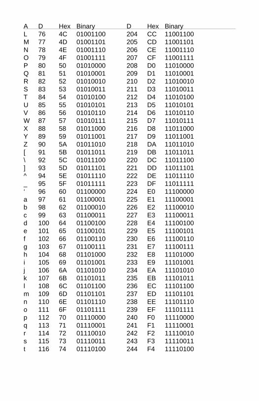
A D Hex Binary D Hex BinaryL 76 4C 01001100 204 CC 11001100M 77 4D 01001101 205 CD 11001101N 78 4E 01001110 206 CE 11001110O 79 4F 01001111 207 CF 11001111P 80 50 01010000 208 D0 11010000Q 81 51 01010001 209 D1 11010001R 82 52 01010010 210 D2 11010010S 83 53 01010011 211 D3 11010011T 84 54 01010100 212 D4 11010100U 85 55 01010101 213 D5 11010101V 86 56 01010110 214 D6 11010110W 87 57 01010111 215 D7 11010111X 88 58 01011000 216 D8 11011000Y 89 59 01011001 217 D9 11011001Z 90 5A 01011010 218 DA 11011010[ 91 5B 01011011 219 DB 11011011\ 92 5C 01011100 220 DC 11011100] 93 5D 01011101 221 DD 11011101^ 94 5E 01011110 222 DE 11011110_ 95 5F 01011111 223 DF 11011111‘ 96 60 01100000 224 E0 11100000a 97 61 01100001 225 E1 11100001b 98 62 01100010 226 E2 11100010c 99 63 01100011 227 E3 11100011d 100 64 01100100 228 E4 11100100e 101 65 01100101 229 E5 11100101f 102 66 01100110 230 E6 11100110g 103 67 01100111 231 E7 11100111h 104 68 01101000 232 E8 11101000i 105 69 01101001 233 E9 11101001j 106 6A 01101010 234 EA 11101010k 107 6B 01101011 235 EB 11101011l 108 6C 01101100 236 EC 11101100m 109 6D 01101101 237 ED 11101101n 110 6E 01101110 238 EE 11101110o 111 6F 01101111 239 EF 11101111p 112 70 01110000 240 F0 11110000q 113 71 01110001 241 F1 11110001r 114 72 01110010 242 F2 11110010s 115 73 01110011 243 F3 11110011t 116 74 01110100 244 F4 11110100

A D Hex Binary D Hex Binaryu 117 75 01110101 245 F5 11110101v 118 76 01110110 246 F6 11110110w 119 77 01110111 247 F7 11110111x 120 78 01111000 248 F8 11111000y 121 79 01111001 249 F9 11111001z 122 7A 01111010 250 FA 11111010 123 7B 01111011 251 FB 11111011| 124 7C 01111100 252 FC 11111100 125 7D 01111101 253 FD 11111101~ 126 7E 01111110 254 FE 11111110
127 7F 01111111 255 FF 11111111

Appendix BD5000 Specifications
Specifications (typical @ +25° C and nominal power supply unlessotherwise noted.)
Analog• Four analog input channels.• Maximum CMV, input to output at 60Hz: 500V rms.• Leakage current, input to output at 115Vrms, 60Hz: <2µA rms.• 15 bit measurement resolution.• 8 conversions per second.• Autozero & autocalibration—no adjustment pots.
Digital• 8-bit CMOS microcomputer.• Digital scaling, linearization and calibration.• Nonvolatile memory eliminates pots and switches.
Digital filtering• Small and large signal with user selectable time constants from 0 to 64 seconds.
Communications• Communications in ASCII via RS-232C, RS-485 ports.• Selectable baud rates: 300, 600, 1200, 2400, 4800, 9600, 19200,38400, 57600, 115200.• NRZ asynchronous data format; 1 start bit, 7 data bits, 1 parity bit and 1stop bit.• Parity: odd, even, none.• User selectable channel address.• ASCII format command/response protocol.• Communications distance up to 4,000 feet (RS-485).• Transient suppression on RS-485 communications lines.• Communications error checking via checksum.• Can be used with "dumb terminal".• Scan up to 250 channels per second.• All communications setups stored in EEPROM.
PowerRequirements: Unregulated +10V to +30Vdc, 0.75W maxInternal switching regulator.Protected against power supply reversals.

EnvironmentalTemperature Range: Operating -25°C to +70°C.
Storage -25°C to +85°C.Relative Humidity: 0 to 95% noncondensing.
Warranty12 months on workmanship and material.
D5100 Voltage Inputs• Voltage ranges: ±100mV, ±1V, ±5V, ±10V, ±100Vdc.• Resolution: 0.01% of FS (4 digits).• Accuracy: ±0.02% of FS max.• Common mode rejection: 100dB at 50/60Hz.• Zero drift: ±1 count max (autozero).• Span tempco: ±50ppm/°C max.• Input burnout protection to 250Vac .• Input impedance: ≤ ±1V input = 100MΩ min.
≥ ±5V input = 1MΩ min.
D5200 Current Inputs• Current ranges: 4-20mAdc.• Resolution: 0.04% of FS.• Accuracy: 0.04% of FS.• Common mode rejection: 100dB at 50/60Hz.• Zero drift: ±1 count max (autozero).• Span tempco: ±50ppm/°C max.• Voltage drop: 1.0V max.
D5300 Thermocouple Inputs• Thermocouple types: J, K, T, E (factory set).• Ranges: J = -200°C to +760°C
K = -150°C to +1250°CT = -200°C to +400°CE = -100°C to +1000°C
• Resolution: ±1°.• Overall Accuracy (error from all sources) from 0 to +40°C ambient:±1.0 °C.• Common mode rejection: 100dB at 50/60Hz.• Input impedance: 100MΩ min.• Lead resistance effect: <20µV per 350Ω.• Open thermocouple indication.• Input burnout protection to 250Vac.• User selectable °C or °F.• Overrange indication.• Automatic cold junction compensation and linearization.

D5450 Thermistor Inputs• Thermistor types: 2252Ω at 25°C• Range: -0°C to +100°C.• Resolution: 0.01°C or F.• Accuracy: ±0.1°C.• Common mode rejection: 100dB at 50/60Hz.• Input protection to 30Vdc .• User selectable °C or °F.

Appendix CFactory Values
Listed below is a table of factory installed values for minimum andmaximum displayed values for each model. This information can be usedto reinstall the factory scaling vaues to a module using the WMN andWMX commands (see Chapter 4)
Model Factory FactoryMininmum MaximumValue Value
511x -00100.00 +00100.00512x -01000.00 +01000.00513x -05000.00 +05000.00514x -10000.00 +10000.00515x -00100.00 +00100.00525x +00000.00 +00025.00531x -00200.50 +00760.50532x -00150.50 +01250.50533x -00200.50 +00400.50534x -00100.00 +01000.00545x +00000.00 +00100.00

WARRANTY/DISCLAIMEROMEGA ENGINEERING, INC. warrants this unit to be free of defects in materials andworkmanship for a period of 13 months from date of purchase. OMEGA’s WARRANTY addsan additional one (1) month grace period to the normal one (1) year product warranty tocover handling and shipping time. This ensures that OMEGA’s customers receive maximumcoverage on each product. If the unit malfunctions, it must be returned to the factory for evaluation. OMEGA’s CustomerService Department will issue an Authorized Return (AR) number immediately upon phone orwritten request. Upon examination by OMEGA, if the unit is found to be defective, it will berepaired or replaced at no charge. OMEGA’s WARRANTY does not apply to defects resultingfrom any action of the purchaser, including but not limited to mishandling, improperinterfacing, operation outside of design limits, improper repair, or unauthorized modification.This WARRANTY is VOID if the unit shows evidence of having been tampered with or showsevidence of having been damaged as a result of excessive corrosion; or current, heat, moistureor vibration; improper specification; misapplication; misuse or other operating conditionsoutside of OMEGA’s control. Components in which wear is not warranted, include but are notlimited to contact points, fuses, and triacs.OMEGA is pleased to offer suggestions on the use of its various products. However, OMEGA neither assumes responsibility for any omissions or errors nor assumesliability for any damages that result from the use of its products in accordance withinformation provided by OMEGA, either verbal or written. OMEGA warrants onlythat the parts manufactured by the company will be as specified and free ofdefects. OMEGA MAKES NO OTHER WARRANTIES OR REPRESENTATIONS OF ANYKIND WHATSOEVER, EXPRESSED OR IMPLIED, EXCEPT THAT OF TITLE, AND ALLIMPLIED WARRANTIES INCLUDING ANY WARRANTY OF MERCHANTABILITY ANDFITNESS FOR A PARTICULAR PURPOSE ARE HEREBY DISCLAIMED. LIMITATION OFLIABILITY: The remedies of purchaser set forth herein are exclusive, and the totalliability of OMEGA with respect to this order, whether based on contract, warranty,negligence, indemnification, strict liability or otherwise, shall not exceed thepurchase price of the component upon which liability is based. In no event shallOMEGA be liable for consequential, incidental or special damages.CONDITIONS: Equipment sold by OMEGA is not intended to be used, nor shall it be used: (1)as a “Basic Component” under 10 CFR 21 (NRC), used in or with any nuclear installation oractivity; or (2) in medical applications or used on humans. Should any Product(s) be used in orwith any nuclear installation or activity, medical application, used on humans, or misused inany way, OMEGA assumes no responsibility as set forth in our basic WARRANTY/ DISCLAIMERlanguage, and, additionally, purchaser will indemnify OMEGA and hold OMEGA harmless fromany liability or damage whatsoever arising out of the use of the Product(s) in such a manner.
RETURN REQUESTS/INQUIRIESDirect all warranty and repair requests/inquiries to the OMEGA Customer Service Department.BEFORE RETURNING ANY PRODUCT(S) TO OMEGA, PURCHASER MUST OBTAIN ANAUTHORIZED RETURN (AR) NUMBER FROM OMEGA’S CUSTOMER SERVICE DEPARTMENT(IN ORDER TO AVOID PROCESSING DELAYS). The assigned AR number should then bemarked on the outside of the return package and on any correspondence.The purchaser is responsible for shipping charges, freight, insurance and proper packaging toprevent breakage in transit.
FOR WARRANTY RETURNS, please havethe following information available BEFORE contacting OMEGA:1. Purchase Order number under which
the product was PURCHASED,2. Model and serial number of the product
under warranty, and3. Repair instructions and/or specific
problems relative to the product.
FOR NON-WARRANTY REPAIRS, consultOMEGA for current repair charges. Have thefollowing information available BEFORE contacting OMEGA:1. Purchase Order number to cover the
COST of the repair,2. Model and serial number of theproduct, and3. Repair instructions and/or specific problems
relative to the product.OMEGA’s policy is to make running changes, not model changes, whenever an improvement is possible. This affords our customers the latest in technology and engineering.OMEGA is a registered trademark of OMEGA ENGINEERING, INC.© Copyright 2011 OMEGA ENGINEERING, INC. All rights reserved. This document may not be copied, photocopied,reproduced, translated, or reduced to any electronic medium or machine-readable form, in whole or in part, withoutthe prior written consent of OMEGA ENGINEERING, INC.

Where Do I Find Everything I Need for Process Measurement and Control?
OMEGA…Of Course!Shop online at omega.com SM
TEMPERATURE Thermocouple, RTD & Thermistor Probes, Connectors, Panels & Assemblies Wire: Thermocouple, RTD & Thermistor Calibrators & Ice Point References Recorders, Controllers & Process Monitors Infrared Pyrometers
PRESSURE, STRAIN AND FORCE Transducers & Strain Gages Load Cells & Pressure Gages Displacement Transducers Instrumentation & Accessories
FLOW/LEVEL Rotameters, Gas Mass Flowmeters & Flow Computers Air Velocity Indicators Turbine/Paddlewheel Systems Totalizers & Batch Controllers
pH/CONDUCTIVITY pH Electrodes, Testers & Accessories Benchtop/Laboratory Meters Controllers, Calibrators, Simulators & Pumps Industrial pH & Conductivity Equipment
DATA ACQUISITION Data Acquisition & Engineering Software Communications-Based Acquisition Systems Plug-in Cards for Apple, IBM & Compatibles Data Logging Systems Recorders, Printers & Plotters
HEATERS Heating Cable Cartridge & Strip Heaters Immersion & Band Heaters Flexible Heaters Laboratory Heaters
ENVIRONMENTALMONITORING AND CONTROL Metering & Control Instrumentation Refractometers Pumps & Tubing Air, Soil & Water Monitors Industrial Water & Wastewater Treatment pH, Conductivity & Dissolved Oxygen Instruments M3130/0211