Embed Size (px)
Citation preview

8M0
M
083X25 R3
OBE
A
Ins
EXCDIG
APX Ser
stallati
COMGITAL
ries Mob
on & P
M P2L VE
REbile Rad
Progra Dece
25 EHICUEPEAios P25
mmingember 2014
ULARATER
Interfac
g Guid
RRce
de

8M083X25 R3 ii
NOTES

8M083X25 R3 iii
Related Publications
Publication Number
Description
8A083X30 DVRS User’s Manual, APX Series Interface 8A083X20 DVRS User’s Manual, XTL2500 / XTL5000 Interface 8A083X21 Tactical DVR User’s Manual 8M083X02 Tactical DVR Installation and Programming Guide 8F083X03 DVRS - Product & RF Safety Booklet 8F083X14 Indoor Fixed Mount DVRS – Installation Guide, APX Interface 8F083X15 Outdoor Fixed Mount DVRS – Installation Guide, APX Interface 8F083X16 Transportable DVRS – Installation Guide, APX Interface 8F083X04 Flash Loader and Tweaker Programmer Installation Guide
Manual Revisions Rev # Date ECN Notes & References
0 July 5 2013 na Original Release 1 August 7, 2013 13031 Encryption restrictions update 2 November 22, 2013 13041 Firmware R1.01 / Tweaker 1.02 update 3 December 8, 2014 14062 Firmware R1.10 Update

8M083X25 R3 iv
Foreword The P25 Digital Vehicular Repeater (DVR) is designed to be seamlessly interfaced to:
Remote Mount XTL2500 or XTL5000 Digital Mobile Subscriber Unit (MSU) with M5, O3 or O5 Control Head
Remote Mount APX Series MSU with or without control head This manual provides Installation and Programming guidelines for the Futurecom Mobexcom P25 DVR that is interfaced to the following remote mount APX Series Mobile radios: Mobile Radio Model Firmware Requirements Notes APX2500 R13.00.00 or later Requires option GA00631 APX4500 R13.00.00 or later Requires option GA00631 APX5500 R10.00.00 or later Requires option GA00631 APX6500 R10.00.00 or later Requires option GA00631 APX7500 R10.00.00 or later Requires option GA00631 NOTE: Mobile Radio must be configured as Remote Mount in order to be compatible with the DVRS. For Installation and Programming guidelines of the XTL interfaced DVRS models, please refer to publication 8M083X01. When the DVR is interfaced to a Remote Mount Motorola Mobile Radio, the complete equipment package is referred to as Digital Vehicular Repeater System (DVRS). The DVR may also be used as a stand alone (Tactical) repeater. The operation of the Tactical DVR is described in publication 8A083X21. The Installation & Programming Guidelines referring to the Tactical DVR Model are described in document 8M083X02. For details on the DVRS Operation, please refer to the DVRS User’s Guides 8A083X20 (XTL interface) or 8A083X30 (APX interface). For details on the APXTM6500 or APXTM7500 Mobile Radio operation, please refer to the applicable Manuals available from Motorola.

8M083X25 R3 v
The DVRS Operation described in this Document requires the following Firmware: APX Series Mobile Radios - firmware release: Host R13.00.00 or later. APX Mobile Radio Control Head - firmware release R19.00.00 or later. APX Mobile Radios operating as the host mobile for the DVR require subscriber option GA00631 for operation. XTS1500 / XTS2500 / XTS5000 - firmware release R17.01.01 or later. APX2000 / APX4000 / APX6000 / APX7000 – firmware release R09.00.00 or later. APX Portable Radios operating through a DVR, utilizing the enhanced DVR digital feature set require subscriber option QA00631. DVR must be loaded with firmware release: Application 4C083X11 R01.10 or later. Tweaker Programming software 6A083X05 – Version 1.04 or later.
Computer Software Copyrights The products described in this manual include copyrighted Futurecom computer programs stored in semiconductor memories or other media. Laws in the United States, Canada and other countries preserve for Futurecom certain exclusive rights for copyrighted computer programs, including but not limited to, the exclusive right to copy or reproduce in any form the copyrighted computer programs. Any copyrighted computer program contained in the Futurecom products described in this manual may not be copied, reproduced, modified, reverse-engineered, or distributed in any manner without the express written permission of Futurecom. The purchase of Futurecom products shall not be deemed to grant either directly or by implication, estoppels, or otherwise, any license under the copyrights, patents or patent applications of Futurecom, except for the normal non-exclusive license to use that arises by operation of law in the sale of a product.

8M083X25 R3 vi
The Tweaker Programming Software provided by Futurecom Systems Group ULC includes the following Publicly Available Software.
Publicly Available Software List
Name: MFC Grid Control
Version: 2.24
Modified: Yes
Software Site: http://www.codeproject.com/KB/miscctrl/gridctrl.aspx
Source Code: No Source Code Distribution Obligations. The Source Code may be obtained from the original Software Site.
License: The Article associated with the Source Code is licensed under the Code Project Open License (CPOL), version 1.02. Reference the Common Licenses Section for the terms of the CPOL. The Source Code licensed is under Custom Freeware / Open Source Software License, see below:
Written by Chris Maunder <[email protected]>
Copyright (c) 1998-2002. All Rights Reserved.
This code may be used in compiled form in any way you desire. This file may be redistributed unmodified by any means PROVIDING it is not sold for profit without the authors written consent, and providing that this notice and the authors name and all copyright notices remains intact.
An email letting me know how you are using it would be nice as well.
This file is provided "as is" with no expressed or implied warranty.
The author accepts no liability for any damage/loss of business that this product may cause.
Additional Notices:
CInPlaceEdit, http://www.codeguru.com/listview/edit_subitems.shtml, licensed under the CodeGuru License.
Refer to the Common Licenses Section for the terms of the CodeGuru License.
Credits:
Zafir Anjum Eric Woodruff Ken Bertelson Joe Willcoxson

8M083X25 R3 vii
Publicly Available Software – Common Licenses
The Code Project Open License (CPOL) 1.02
Preamble
This License governs Your use of the Work. This License is intended to allow developers to use the Source Code and Executable Files provided as part of the Work in any application in any form.
The main points subject to the terms of the License are:
Source Code and Executable Files can be used in commercial applications; Source Code and Executable Files can be redistributed; and Source Code can be modified to create derivative works. No claim of suitability, guarantee, or any warranty whatsoever is provided. The software is provided
"as-is". The Article accompanying the Work may not be distributed or republished without the Author's
consent
This License is entered between You, the individual or other entity reading or otherwise making use of the Work licensed pursuant to this License and the individual or other entity which offers the Work under the terms of this License ("Author").
License
THE WORK (AS DEFINED BELOW) IS PROVIDED UNDER THE TERMS OF THIS CODE PROJECT OPEN LICENSE ("LICENSE"). THE WORK IS PROTECTED BY COPYRIGHT AND/OR OTHER APPLICABLE LAW. ANY USE OF THE WORK OTHER THAN AS AUTHORIZED UNDER THIS LICENSE OR COPYRIGHT LAW IS PROHIBITED.
BY EXERCISING ANY RIGHTS TO THE WORK PROVIDED HEREIN, YOU ACCEPT AND AGREE TO BE BOUND BY THE TERMS OF THIS LICENSE. THE AUTHOR GRANTS YOU THE RIGHTS CONTAINED HEREIN IN CONSIDERATION OF YOUR ACCEPTANCE OF SUCH TERMS AND CONDITIONS. IF YOU DO NOT AGREE TO ACCEPT AND BE BOUND BY THE TERMS OF THIS LICENSE, YOU CANNOT MAKE ANY USE OF THE WORK.
1. Definitions. a. "Articles" means, collectively, all articles written by Author which describes how the
Source Code and Executable Files for the Work may be used by a user. b. "Author" means the individual or entity that offers the Work under the terms of this
License. c. "Derivative Work" means a work based upon the Work or upon the Work and other pre-
existing works. d. "Executable Files" refer to the executable files, binary files, configuration and any required
data files included in the Work. e. "Publisher" means the provider of the website, magazine, CD-ROM, DVD or other medium
from or by which the Work is obtained by You. f. "Source Code" refers to the collection of source code and configuration files used to
create the Executable Files. g. "Standard Version" refers to such a Work if it has not been modified, or has been modified
in accordance with the consent of the Author, such consent being in the full discretion of the Author.
h. "Work" refers to the collection of files distributed by the Publisher, including the Source Code, Executable Files, binaries, data files, documentation, whitepapers and the Articles.
i. "You" is you, an individual or entity wishing to use the Work and exercise your rights under this License.

8M083X25 R3 viii
2. Fair Use/Fair Use Rights. Nothing in this License is intended to reduce, limit, or restrict any rights arising from fair use, fair dealing, first sale or other limitations on the exclusive rights of the copyright owner under copyright law or other applicable laws.
3. License Grant. Subject to the terms and conditions of this License, the Author hereby grants You a worldwide, royalty-free, non-exclusive, perpetual (for the duration of the applicable copyright) license to exercise the rights in the Work as stated below:
a. You may use the standard version of the Source Code or Executable Files in Your own applications.
b. You may apply bug fixes, portability fixes and other modifications obtained from the Public Domain or from the Author. A Work modified in such a way shall still be considered the standard version and will be subject to this License.
c. You may otherwise modify Your copy of this Work (excluding the Articles) in any way to create a Derivative Work, provided that You insert a prominent notice in each changed file stating how, when and where You changed that file.
d. You may distribute the standard version of the Executable Files and Source Code or Derivative Work in aggregate with other (possibly commercial) programs as part of a larger (possibly commercial) software distribution.
e. The Articles discussing the Work published in any form by the author may not be distributed or republished without the Author's consent. The author retains copyright to any such Articles. You may use the Executable Files and Source Code pursuant to this License but you may not repost or republish or otherwise distribute or make available the Articles, without the prior written consent of the Author.
Any subroutines or modules supplied by You and linked into the Source Code or Executable Files of this Work shall not be considered part of this Work and will not be subject to the terms of this License.
4. Patent License. Subject to the terms and conditions of this License, each Author hereby grants to You a perpetual, worldwide, non-exclusive, no-charge, royalty-free, irrevocable (except as stated in this section) patent license to make, have made, use, import, and otherwise transfer the Work.
5. Restrictions. The license granted in Section 3 above is expressly made subject to and limited by the following restrictions:
a. You agree not to remove any of the original copyright, patent, trademark, and attribution notices and associated disclaimers that may appear in the Source Code or Executable Files.
b. You agree not to advertise or in any way imply that this Work is a product of Your own. c. The name of the Author may not be used to endorse or promote products derived from the
Work without the prior written consent of the Author. d. You agree not to sell, lease, or rent any part of the Work. This does not restrict you from
including the Work or any part of the Work inside a larger software distribution that itself is being sold. The Work by itself, though, cannot be sold, leased or rented.
e. You may distribute the Executable Files and Source Code only under the terms of this License, and You must include a copy of, or the Uniform Resource Identifier for, this License with every copy of the Executable Files or Source Code You distribute and ensure that anyone receiving such Executable Files and Source Code agrees that the terms of this License apply to such Executable Files and/or Source Code. You may not offer or impose any terms on the Work that alter or restrict the terms of this License or the recipients' exercise of the rights granted hereunder. You may not sublicense the Work. You must keep intact all notices that refer to this License and to the disclaimer of warranties. You may not distribute the Executable Files or Source Code with any technological measures that control access or use of the Work in a manner inconsistent with the terms of this License.
f. You agree not to use the Work for illegal, immoral or improper purposes, or on pages containing illegal, immoral or improper material. The Work is subject to applicable export laws. You agree to comply with all such laws and regulations that may apply to the Work after Your receipt of the Work.
6. Representations, Warranties and Disclaimer. THIS WORK IS PROVIDED "AS IS", "WHERE IS" AND "AS AVAILABLE", WITHOUT ANY EXPRESS OR IMPLIED WARRANTIES OR CONDITIONS OR GUARANTEES. YOU, THE USER, ASSUME ALL RISK IN ITS USE, INCLUDING COPYRIGHT INFRINGEMENT, PATENT INFRINGEMENT, SUITABILITY, ETC. AUTHOR EXPRESSLY DISCLAIMS ALL EXPRESS, IMPLIED OR STATUTORY WARRANTIES OR

8M083X25 R3 ix
CONDITIONS, INCLUDING WITHOUT LIMITATION, WARRANTIES OR CONDITIONS OF MERCHANTABILITY, MERCHANTABLE QUALITY OR FITNESS FOR A PARTICULAR PURPOSE, OR ANY WARRANTY OF TITLE OR NON-INFRINGEMENT, OR THAT THE WORK (OR ANY PORTION THEREOF) IS CORRECT, USEFUL, BUG-FREE OR FREE OF VIRUSES. YOU MUST PASS THIS DISCLAIMER ON WHENEVER YOU DISTRIBUTE THE WORK OR DERIVATIVE WORKS.
7. Indemnity. You agree to defend, indemnify and hold harmless the Author and the Publisher from and against any claims, suits, losses, damages, liabilities, costs, and expenses (including reasonable legal or attorneys’ fees) resulting from or relating to any use of the Work by You.
8. Limitation on Liability. EXCEPT TO THE EXTENT REQUIRED BY APPLICABLE LAW, IN NO EVENT WILL THE AUTHOR OR THE PUBLISHER BE LIABLE TO YOU ON ANY LEGAL THEORY FOR ANY SPECIAL, INCIDENTAL, CONSEQUENTIAL, PUNITIVE OR EXEMPLARY DAMAGES ARISING OUT OF THIS LICENSE OR THE USE OF THE WORK OR OTHERWISE, EVEN IF THE AUTHOR OR THE PUBLISHER HAS BEEN ADVISED OF THE POSSIBILITY OF SUCH DAMAGES.
9. Termination. a. This License and the rights granted hereunder will terminate automatically upon any
breach by You of any term of this License. Individuals or entities who have received Derivative Works from You under this License, however, will not have their licenses terminated provided such individuals or entities remain in full compliance with those licenses. Sections 1, 2, 6, 7, 8, 9, 10 and 11 will survive any termination of this License.
b. If You bring a copyright, trademark, patent or any other infringement claim against any contributor over infringements You claim are made by the Work, your License from such contributor to the Work ends automatically.
c. Subject to the above terms and conditions, this License is perpetual (for the duration of the applicable copyright in the Work). Notwithstanding the above, the Author reserves the right to release the Work under different license terms or to stop distributing the Work at any time; provided, however that any such election will not serve to withdraw this License (or any other license that has been, or is required to be, granted under the terms of this License), and this License will continue in full force and effect unless terminated as stated above.
10. Publisher. The parties hereby confirm that the Publisher shall not, under any circumstances, be responsible for and shall not have any liability in respect of the subject matter of this License. The Publisher makes no warranty whatsoever in connection with the Work and shall not be liable to You or any party on any legal theory for any damages whatsoever, including without limitation any general, special, incidental or consequential damages arising in connection to this license. The Publisher reserves the right to cease making the Work available to You at any time without notice
11. Miscellaneous a. This License shall be governed by the laws of the location of the head office of the Author
or if the Author is an individual, the laws of location of the principal place of residence of the Author.
b. If any provision of this License is invalid or unenforceable under applicable law, it shall not affect the validity or enforceability of the remainder of the terms of this License, and without further action by the parties to this License, such provision shall be reformed to the minimum extent necessary to make such provision valid and enforceable.
c. No term or provision of this License shall be deemed waived and no breach consented to unless such waiver or consent shall be in writing and signed by the party to be charged with such waiver or consent.
d. This License constitutes the entire agreement between the parties with respect to the Work licensed herein. There are no understandings, agreements or representations with respect to the Work not specified herein. The Author shall not be bound by any additional provisions that may appear in any communication from You. This License may not be modified without the mutual written agreement of the Author and You.

8M083X25 R3 x
CodeGuru License http://www.codeguru.com/submission-guidelines.php#permission
As you know, this site is a valuable resource for the developer community. Please note, however, that to avoid legal complications, we need to obtain your permission to use any computer code and any related materials ("resources") that you are providing to us. Accordingly, by submitting any such resource to CodeGuru, you grant to QuinStreet a nonexclusive, worldwide, perpetual license to reproduce, distribute, adapt, perform, display, and sublicense the submitted resource (in both object and source code formats, as well as on and off the Web), and you acknowledge that you have the authority to grant such rights to QuinStreet.
By submitting the resource, you also grant your article's readers the permission to use any source code in the resource for commercial or noncommercial software. PLEASE NOTE THAT YOU RETAIN OWNERSHIP OF ANY COPYRIGHTS IN ANY RESOURCES SUBMITTED!
ALSO, IN MAKING THE RESOURCE AVAILABLE TO OTHER SITE VISITORS FOR DOWNLOADING, QUINSTREET WILL INFORM SUCH OTHER VISITORS THAT, ALTHOUGH THEY MAY DOWNLOAD ANY RESOURCES FOR COMMERCIAL OR NONCOMMERCIAL USES, THEY MAY NOT REPUBLISH THE SOURCE CODE SO THAT IT IS ACCESSIBLE TO THE PUBLIC WITHOUT FIRST OBTAINING THE COPYRIGHT OWNER'S PERMISSION.
Document Copyrights No part of this manual may be reproduced, distributed or transmitted in any form or by any means, for any purpose without written permission of Futurecom.
Disclaimer The information in this document is carefully examined and is believed to be entirely reliable. However, no responsibility is assumed for inaccuracies. Futurecom Systems Group, ULC reserves the right to make changes to any products herein to improve readability, function or design. Futurecom does not assume any liability arising out of the application or use of any product or circuit described herein.
Trademarks MOTOROLA, ASTRO, XTLTM2500, XTLTM5000, XTSTM1500, XTSTM2500, XTSTM5000, APXTM4000, APXTM6000, APXTM7000, APXTM2500, APXTM4500, APXTM5500, APXTM6500, APXTM7500, MDC1200 are trademarks of Motorola Solutions Inc.

8M083X25 R3 xi
Commercial Warranty Futurecom Systems Group, ULC. warrants to the original purchaser all standard products sold by Futurecom Systems Group, ULC to be free of defects in material and workmanship for one (1) year from the date of shipment from Futurecom Systems Group, ULC. Futurecom’s warranty hereunder DOES NOT cover the following:
(i) Defects or damage resulting from use of the product in other than its normal and customary manner.
(ii) Defects or damage from improper installation, testing, operation, or maintenance.
(iii) Defects or damage due to alterations, modifications or adjustments carried out by the Buyer without Futurecom’s explicit approval.
(iv) Defects or damage from misuse, accident, water or neglect. (v) Freight costs to the repair depot. (vi) Scratches or other cosmetic damage to the product surfaces that does not
affect the operation of the product. (vii) Normal wear and tear.
The warranty set forth herein is conditioned upon proper storage, installation, use and maintenance in accordance with applicable written recommendation of Futurecom. The warranty furnished hereunder does not extend to damage to items purchased hereunder resulting in whole or in part from the use of components, accessories, parts of supplies not furnished by Futurecom Systems Group, ULC. Futurecom’s sole obligation shall be to repair or replace, at Futurecom’s option, any defective component or item and pay transportation expenses for such replacement at no charge to Buyer who shall provide labor for the removal of the defective component or item and installation of its replacement at no charge to Futurecom. Buyer shall bear all risk of loss or damage to returned goods while in transit. In the event no defect or breach of warranty is discovered by Futurecom upon receipt of any returned item, the item will be returned to Buyer at Buyer’s expense and Buyer will reimburse Futurecom for the transportation charges, labor and associated charges incurred in testing the allegedly defective item. Except as expressly provided herein, Futurecom makes no warranty of any kind, expressed or implied, with respect to any goods, parts and service provided by Futurecom including, but not limited to, the implied warranties or merchantability and fitness for a particular purpose. The sole and exclusive remedy for breach of any warranty is limited to the remedies provided in the paragraph above. Futurecom shall not in any event be liable for any other damages arising out of or in connection with furnishing of goods, parts or service hereunder, or the performance, use of, or inability to use any goods, parts or service, or otherwise, whether based on contract, tort or any other legal theory. To exercise this warranty, please contact Futurecom’s Administration Department in Concord, Ontario, Canada at 1-800 701 9180 to obtain a return material authorization (RMA) and shipping instructions. No product will be accepted for return without an RMA. The repair of a product by Futurecom pursuant to this warranty is warranted for the balance of the original warranty period, or at least 90 days from date of shipment to Buyer of the repaired product. If Extended Warranty is required, it must be purchased either at the time of original purchase or while the unit is under the standard first year warranty coverage.

Part I – DVRS INSTALLATION

Decem
Par
RF EOper
Intro
Ide
DVRS
Pla
Ins
Mo
Mo
Co
DV
A
DV
Index
mber 2014
rt I - Ins
Energy Exporational Inst
duction .....
entifying YouFrequency BaCross-Band .....................In-Band........DVR Dimens
Cross-BandIn-Band DV
S Installatio
anning the In
stallation Too
ounting the DCross-Band DIn-Band DVR
ounting the M
onnecting thePower Cable RF Cables ...Control CableOption Cable
In-Band DVCross-Band
VR Options .DVR AuxiliaryAVRA ..........Status LightsExternal Alar
VRS Antenna
x .................
stallation
osure Comptructions ....
...................
ur DVRS Moand of Opera...............................................................ions ..............
d DVR DimensVR Dimension
on Basics ...
nstallation ...
ols Required
DVR ............DVRS Mounti
RS Mounting ..
Mobile Radio
e DVRS Cab.........................................es .................es ..................VRS Option Cad DVRS Option
...................y Cable ............................. ....................m .................
a Installation
...................
n
pliance, Aw...................
...................
odel .............tion ...................................................................................................
sions ...............s .....................
...................
...................
d ..................
...................ing .....................................
o .................
bles .................................................................................................ables ...............n Cables .........
...................
.....................
.....................
.....................
.....................
n ..................
...................
DVRS Inst
wareness an...................
...................
...................
......................
......................
......................
......................
......................
.......................
.......................
...................
...................
...................
...................
......................
......................
...................
...................
......................
......................
......................
......................
.......................
.......................
...................
......................
......................
......................
......................
...................
...................
tallation & Pro
nd Control In...................
...................
...................
.....................
.....................
.....................
.....................
.....................
.......................
.......................
...................
...................
...................
...................
.....................
.....................
...................
...................
.....................
.....................
.....................
.....................
.......................
.......................
...................
.....................
.....................
.....................
.....................
...................
...................
8MAPX Serie
ogramming G
nformation ....................
....................
...................
.....................
.....................
.....................
.....................
.....................................................................
....................
...................
...................
...................
.....................
.....................
...................
...................
.....................
.....................
.....................
.....................................................................
...................
.....................
.....................
.....................
.....................
...................
....................
M083X25 Rev.es P25 InterfacGuide – PART
Page 2 of 3
and ...................
...................
...................
.....................
.....................
.....................
................... 1
................... 1..................... 1..................... 1
................. 1
................. 1
................. 1
................. 2
................... 2
................... 2
................. 2
................. 2
................... 2
................... 2
................... 2
................... 2..................... 2..................... 2
................. 3
................... 3
................... 3
................... 3
................... 3
................. 3
................. 3
3 ce T I
35
4
5
7 7 7 9
10 17 17 18
9
9
9
20 20 22
23
23 23 24 24 26 26 26
32 32 33 33 33
34
35

Decem
List TableTableTableTableTableTableTableTable
List FigurFigurFigurFigurFigurFigurFigur
CFigur
CFigurFigurFigur
[Figur
.FigurFigurFigurFigurFigurFigurFigurFigurFigurFigurFigur
FFigur
BFigurFigurFigur
mber 2014
t of Table
e 1 DVRS vse 2 VHF DVRe 3 UHF DVRe 4 700MHz e 5 800MHz e 6 DVRS Re 7 DVRS Ce 8 Summary
t of Figure
re 1 Cross-Bre 2 Cross-Bre 3 Vehiculare 4 Vehiculare 5 In-Bandre 6 In-Bandre 7 VehiculaCapable......re 8 VehiculCapable......re 9 Cross-Bre 10 Cross-re 11 Typica[in] ..............re 12 Typica...................re 13 DVR Mre 14 DVR Mre 15 DVR Cre 16 DVR-tore 17 DVR-tore 18 DVR Are 19 In-Banre 20 In-Banre 21 In-Banre 22 In-Banre 23 CrossFront...........re 24 CrossBack ...........re 25 Cross-re 26 Cross-re 27 Auxilia
es
s InfrastructuRS ConfigurRS ConfigurDVRS ConfDVRS ConfF Cables ....ontrol Cabley of DVRS C
es
Band Full DuBand Simplexar Mount Croar Mount Cro Full Duplex Simplex Onar Mount In-...................ar Mount In...................
Band DVR (FBand Simple
al VHF/UHF ...................l 700 / 800 I...................
Mounting DetMounting DetConnectors - o- MSU Cono- MSU (with
Auxiliary Cabd VHF or UHd VHF or UHd DVRS (70d DVRS (70
s-Band Full ...................
s-Band Full ...................Band SimpleBand Simplery Cable (7W
ure Compatirations .........rations .........figurations ...figurations ......................
e Types .......Control and
plex & Simpx Only Capaoss Band DVoss Band DV
x / Simplex Cnly Capable -Band 700 o...................
n-Band VHF...................
Full Duplex aex Only CapIn-Band DV
...................n-Band DVR...................tails – Full Dtails – SimplFront and B
ntrol Cable 7h Siren) Conble - 7W083XHF DVRS InHF DVRS In00 or 800MH00 or 800MH
Duplex & S...................Duplex & S...................ex Only Capex Only CapW083X06-01
DVRS Inst
bility .............................................................................................................................RF Cables .
plex Capableable DVRS -VRS Model –VRS Model
Capable DVRDVRS - Con
or 800MHz D................... or UHF DV...................and Simplex pable - DimeVR (Full Du...................R (Full Duple...................
Duplex (Withlex Only Cap
Back View (WW083X05-0
ntrol Cable 1X06-01 .......nterconnect Cnterconnect CHz) InterconnHz) InterconnSimplex Cap...................Simplex Cap...................pable DVRS pable DVRS 1) DB15 Pin
tallation & Pro
...................
...................
...................
...................
...................
...................
...................
...................
e DVRS - Co- Conceptua– Full Duple- Simplex ORS - Concepnceptual DiaDVRS Mode...................VRS Model ...................
x Capable) -ensions mm plex & Simp...................ex & Simple...................
h Duplexer) ..pable (No DWith Duplexe01 ................
W083B09-0...................Cabling - FroCabling - Banect Cablingnect Cablingpable DVRS...................pable DVRS................... Interconnec Interconnecout .............
8MAPX Serie
ogramming G
...................
...................
...................
...................
...................
...................
...................
...................
onceptual Dil Diagram ...
ex & SimplexOnly Capableptual Diagraagram ..........l - Full Dupl...................- Full Duple...................Dimensions/ [in] ............plex) - Dime...................x) - Dimens......................................
Duplexer) ......er) ..................................
01 ...................................ont ..............
ack ..............g - Front .......g - Back .......S Interconne...................
S Interconne...................ct Cabling – ct Cabling – ...................
M083X25 Rev.es P25 InterfacGuide – PART
Page 3 of 3
...................
................. 1
................. 1
................. 1
................. 1
................. 2
................. 2
................. 3
iagram ..........................x Capable ...e ..................m ............. 1................. 1ex & Simple................. 1ex & Simple................. 1
s mm / [in] . 1................. 1ensions mm................. 1ions mm / [in................. 1................. 2................. 2................. 2................. 2................. 2................. 2................. 2................. 2................. 2................. 2ect Cabling ................. 2ect Cabling ................. 2Front ....... 3Back ....... 3
................. 3
3 ce T I
35
6 3 4 5 6
24 24 31
7 8 9 9 1 1
ex 2
ex 2 7 7 / 8 n]8
21 21 23 25 25 26 27 27 28 28
- 29
– 29 30 30 32

Decem
RF Co
This whertheir popu ATTEChanULC.RF sepathe Dthis d ATTEFutuRadipersoSafetExpowithi(genelimitsoperathe v
ATTEThe TAPX 8F08for vAnte
mber 2014
Energyntrol In
radio equipre users haexposure t
ulation, con
ENTION! nges or mo. could voidexposure
aration distaDVRS) shoudistance is
ENTION! recom requo Frequenconnel and ty” book sh
osure (MPE)n this areeral populas are obseator must e
vehicle body
ENTION! TransportaMobile rad
83X03 enclovehicle instnnas sectio
y Exponformat
pment is inve full knowto meet FCCsumer or a
difications d the User’srequiremenances speculd be maintnot allowed
uires the Pcy Exposurthe body o
hipped with) distance ea to RF etion). It is th
erved at alensure at aly.
ble (suitcasio is installe
osed with ytallation. Foon.
osure Ction and
ntended for wledge of tC limits. Thny other us
not express authority nts for mcified in thetained. To ed.
P25 DVRSe are met. of the DVRh the DVR. Fexclusion anergy abovhe responsll times dul times that
se) DVRS sed, refer to
your DVRS.or fixed sit
DVRS Inst
Compliad Opera
use in occ
their exposuis radio dev
se.
ssly approveto operate obile transe “RF Safetensure com
operator tThe minim
RS equippedFailure to orea aroundve the FCCibility of the
uring repeat no person
ships withothe Produc Refer to tte installati
tallation & Pro
ance, Aational
cupational /ure and canvice is NOT
ed by Fututhe equipm
smitting dty” Book 8
mpliance, op
to ensure Fum distancd vehicle i
observe the the antennC exposuree repeater oater transmn comes wit
ut an APX ct Safety anthe vehicleion, refer to
8MAPX Serie
ogramming G
Awarene Instruc
/ controlledn exercise
T authorized
recom Systment. To sadevices, thF083X03 (sperations at
FCC Requice between s specified
e Maximum na may expe limit for operator to
missions. Tthin MPE di
Mobile radnd RF Expos installationo the Fixed
M083X25 Rev.es P25 InterfacGuide – PART
Page 4 of 3
ess andctions
d conditionscontrol oved for genera
tems Groupatisfy FCC/Ie minimum
shipped witt closer tha
irements foall possibl
d in the “RPermissibl
ose personbystander
ensure MPThe repeateistance from
io. Once asure booklen guidelined DVRS Sit
3 ce T I
35
d
s, er al
p, C m th an
or le
RF le
ns rs E er m
an et es te

Decem
IntrThe P
MobiAPX2APX4APX5APX6APX7NOTEMobiDVRS IMPOThis Mobisupp The PMobieithevehicwho acovercommconfig
mber 2014
roductiP25 Digital V
Remote MOr Remote MOr Remote MO5, O7 or
ile Radio Mo2500 4500 5500 6500 7500 E: le Radio muS.
ORTANT! manual de
ile Radios port up to tw
P25 DVRS ale Subscriber intermitten
cle, ambulanare outside rage areas.munications gured to pro
ion Vehicular ReMount XTL50
Mount XTL25
Mount APX Sr O9): odel
ust be config
escribed thvia P25 Int
wo Control
allows Portaer Unit (MSt or complet
nce, the P25of the vehic. The DVR
and suppoovide various
epeater (DVR000 Digital M
500 Digital M
Series Mobil
FirmwareR13.00.00R13.00.00R10.00.00R10.00.00R10.00.00
gured as Re
he DVR moterface. ThHeads.
able SubscriSU) coveragtely absent.5 DVRS exle, inside a n
RS extends orts key trus advanced o
DVRS Inst
R) is designeMobile Radio
Mobile Radio
e Radios wi
Requireme0 or later 0 or later 0 or later 0 or later 0 or later
emote Moun
odels that ae MSU con
ber Units (Pge is availaInstalled in t
xtends radio nearby buildvoice (ana
unking systoptions to th
tallation & Pro
ed to be seao with O5 or
o with M5 Co
ith or withou
ents NotReqReqReqReqReq
nt in order to
are interfacnfigured fo
PSU) to be uble and pothe trunk of communica
ding or in analog or digitem feature
he users.
8MAPX Serie
ogramming G
amlessly inter O3 Control
ontrol Head
ut a control h
tes quires optionquires optionquires optionquires optionquires option
o be compa
ced to the or DVRS op
used in areartable radioa car, fire trations to they marginal ptal, clear o
es. The DV
M083X25 Rev.es P25 InterfacGuide – PART
Page 5 of 3
erfaced to: Head
head (O2, O3
n GA00631n GA00631n GA00631n GA00631n GA00631
atible with th
APX Serieperation ca
as where on coverage
ruck, armoree PSU userportable radior encryptedVRS can b
3 ce T I
35
3,
he
es an
ly is
ed rs io d) be

Decem
Table
PoRadi
MConv
A
GenConv
Conv‘D
En
Table
DVRSA = A
mber 2014
e 1 provides
ortable o Type /
Mode
C
M
ventional Analog
eric P25 ventional
P25 ventional DVRS nabled’
e 1 DVRS vs
S Channel TAnalog, D =
s information
FIXED NE
Conventional Analog incl.
Mixed Receive
YES A
NO
YES FA
Infrastructur
Types: Digital, M =
n on the DVR
ETWORK TY
e
ConventioP25 incl
Mixed Rece
YESA/MYESD/M
YESD/FA/M
re Compatib
Mixed, FA =
DVRS Inst
RS infrastruc
YPE / MOBI
onal l. eive
3600 ADig
Trun
YEA
N
M YEF
ility
= Forced Ana
tallation & Pro
cture compa
LE RADIO M
Analog / gital nking
9T
ES A
NO
ES FA D
alog (see Pa
8MAPX Serie
ogramming G
atibility option
MODE
9600 P25 Trunking
FDMA
YES A/MYES D/M
YES D/FA/M
art II of this m
M083X25 Rev.es P25 InterfacGuide – PART
Page 6 of 3
ns.
9600 P25 Trunking
TDMA
YES A
NO
YES FA
manual)
3 ce T I
35

Decem
Iden
FreqDepeSubs
CrosCrossand DsingleIn dubandas sh
Figur
The Cand shas apurchAs ashow
mber 2014
ntifying Yo
quency Banending on thscriber Unit (
In-Band –Cross-Babands.
ss-Band s-Band DVRDVR are noe band MSUal band MSs or one of t
hown on Fig
re 1 Cross-Ba
Cross-Band simplex DVRa limited pashase order. n option, a
wn on Figure
our DVRS
nd of Operhe frequencMSU) and D– when the Mand – when
RS models dot intended U configuratio
U configurathe MSU freure 1.
and Full Dup
DVRS typicR operation ss-band win
cross-bande 2. In this ca
S Model
ration cy band of DVR, the DVMSU and DVn the MSU
do not incluto simultaneons the MSUtion either th
equency ban
plex & Simple
cally includesas shown o
ndow and is
d DVRS canase the DVR
DVRS Inst
operation oVRS models VR operate i
and DVR
ude any filteeously operaU and DVR ohe MSU & Dds is locked
ex Capable D
s a duplexeron Figure 1
tuned to th
n be configuRS does not
tallation & Pro
of the APX6are classifiein the same operate in
rs on the Mate in the soperate in dDVR operated out when D
DVRS - Conc
r which can . The cross
he DVR freq
ured for simutilize any f
8MAPX Serie
ogramming G
6500 / APXed as followsfrequency btwo differe
MSU side sinsame frequeifferent freque in 3 differeDVR operatio
ceptual Diagr
accommodas-band duplequencies pro
mplex only filters.
M083X25 Rev.es P25 InterfacGuide – PART
Page 7 of 3
X7500 Mobils: band. ent frequenc
nce the MSency band. Iuency bandsent frequencon is enable
ram
ate full dupleexer howeveovided on th
operation a
3 ce T I
35
le
cy
U In s. cy ed
ex er he
as

Decem
Figur
NOTEThe vMSUmaximprovid IMPOThe frequoperainterfilter
mber 2014
re 2 Cross-Ba
E: vehicular (si, however, mum powerded with the
ORTANT! DVRS is
uency rangate on freqmittent or cretuning or
and Simplex
de-by-side) the transmi
r restrictionse DVR.
shipped ege providedquencies ocomplete lor replaceme
x Only Capab
mount Crost power of
s described
quipped wd by the coutside of oss of comment.
DVRS Inst
ble DVRS - Co
ss-Band DVthe MSU min the RF S
with customcustomer. Pthe origina
munications
tallation & Pro
onceptual D
R can be inmust be reduSafety Book
m filters tuProgramminal specifieds. Frequenc
8MAPX Serie
ogramming G
iagram
nterfaced to uced to comklet 8F083X
uned to thng the DVd bands mcy changes
M083X25 Rev.es P25 InterfacGuide – PART
Page 8 of 3
a high powemply with thX03, which
he specifieR / MSU tay result imay requir
3 ce T I
35
er he is
ed to in re

Decem
Figur
Figu
mber 2014
re 4 Vehicula
ure 3 Vehicu
ar Mount Cro
lar Mount Cr
oss Band DVR
ross Band DV
DVRS Inst
RS Model - S
VRS Model –
tallation & Pro
Simplex Only
– Full Duplex
8MAPX Serie
ogramming G
y Capable
x & Simplex C
M083X25 Rev.es P25 InterfacGuide – PART
Page 9 of 3
Capable
3 ce T I
35
Decem
In-BaThe iordertransduplepreveisolatoutpureceiv IMPOThe isolainterfmountrunkfrequProgorigicomm The bypason th WhenextrainterffrequassocFor mGuidAs ansimpl NOTEThe anten IMPOIn allWattsThe i
mber 2014
and in-band DVRr to ensuremitting and
ex capable rent desensetion on the ut of the MSve frequenc
ORTANT! above filte
ation (betweference-freented on thek. Each DVRuency bandramming tnal specifmunication
In-Band DVsses the filtee MSU Cont
n a “DVR – E filters betference-free ency gap iciated with t
more informaes. n option, an lex in-band c
E: DVR and M
nnas.
ORTANT! l In-Band Ds on DVRS in-band filte
RS models e interferenreceiving sim
repeater, eque during DVRMobile radioSU are desiies.
er isolationeen the DVe operatione roof top oRS is shippds – note he DVR /
fied bandss. Frequenc
VRS modelsering at the trol Head (se
Enabled” motween the
operation. s present bhe “DVR - E
ation on the
in-band DVconfiguration
MSU require
DVRS configEnabled MS
ers connect
are equippence-free opemultaneousluipped with R repeat acto transmit / igned to pro
must be VR and M
n. It is recoof the vehicped equippe
the frequMSU radio
s may rescy changes
s are also output of theee Figure 5
ode is selectMSU AnteThe comple
between theEnabled” TGsfeasible filte
VRS can alson however s
e two or thr
gurations, tSU Modes dted to the M
DVRS Inst
ed with two eration whey in the sama duplexer, tivation. Thereceive freq
ovide 40 dB
complemenobile Radi
ommended cle while theed with cusency range
o to operatsult in ints may requir
equipped we MSU when).
ted on the Mnna port aex in-band e DVR freqs.
ering options
o be configutill requires
ree (in the
he MSU Tradue to the i
MSU have ty
tallation & Pro
sets of filteen both th
me frequencywhich provi
e DVR duplequencies. T
B isolation o
nted by 30o antennasthat the M
e DVR antestom filterse specifiedte on frequtermittent re filter retu
with an RFn a “DVR –
MSU CH, theand the MSfiltering is o
quencies an
s, please refe
ured as simpDVR and In-
case of du
ansmit pown-band filte
ypical insert
8MAPX Serie
ogramming G
rs, which are MSU any band. Theides sufficieexer also pro
The filters inson the DVR
0dB minims) in orde
MSU in-bandenna is mous tuned to td on the fuencies outor comple
uning or rep
F Bypass SDisabled” T
e RF Switch SU antennaonly feasibled the MSU
er to the DV
plex only (Fi-Band filters
ual band MS
wer must noers power ration loss of
M083X25 Rev.es P25 InterfacGuide – PART
Page 10 of 3
re required nd DVR ar DVR is a funt isolation tovides 40 dstalled at thtransmit an
um antennr to ensurd antenna iunted on ththe specifiefilter labelstside of thete loss oplacement.
Switch, whicTG is selecte
connects tha to ensure if sufficien
U frequencie
VRS Orderin
igure 6). Ths.
SU) separat
ot exceed 5ating. f 1.5dB.
3 ce T I
35
in re ull to B
he nd
na re is
he ed s.
he of
ch ed
he re nt es
ng
he
te
50

Decem
Figur
Figur
mber 2014
re 5 In-Band
re 6 In-Band
Full Duplex /
Simplex Onl
/ Simplex Ca
y Capable D
DVRS Inst
apable DVRS
DVRS - Conce
tallation & Pro
S - Conceptua
eptual Diagra
8MAPX Serie
ogramming G
al Diagram
am
M083X25 Rev.es P25 InterfacGuide – PART
Page 11 of 3
3 ce T I
35

Decem
FigurCapa
FigurCapa
mber 2014
re 7 Vehiculable
re 8 Vehiculble
ar Mount In-
lar Mount In
-Band 700 o
n-Band VHF
DVRS Inst
or 800MHz D
or UHF DV
tallation & Pro
DVRS Model
VRS Model
8MAPX Serie
ogramming G
- Full Duple
- Full Duple
M083X25 Rev.es P25 InterfacGuide – PART
Page 12 of 3
ex & Simple
ex & Simple
3 ce T I
35
ex
ex

Decem
A
Dual 700/8
Dual 700/8Dual 700/8
Dual UHF R
Dual UHF R
Dual UHF RSinglVHF SinglUHF RSinglUHF RSingl700 /
Table
mber 2014
PX MSU Mo
Band APX M800MHz & VH
Band APX M800MHz & UHBand APX M
800MHz & UH
Band APX MR1 & VHF
Band APX MR2 & VHF
Band APX MR1 & UHF R2e Band APX
e Band APX R1 e Band APX R2 e Band APX 800MHz
e 2 VHF DVR
odel
MSU HF
MSU HF R1 MSU HF R2
MSU
MSU
MSU 2 MSU
MSU
MSU
MSU
S Configurat
V
X-Band X-Band In-Band In-Band X-Band X-Band X-Band X-Band X-Band X-Band In-Band In-Band X-Band X-Band In-Band In-Band X-Band X-Band In-Band In-Band X-Band X-Band X-Band X-Band X-Band X-Band
tions
DVRS Inst
HF (136-1DVRS M
with band loc with band loc
d & X-Band Cd & X-Band C Full Duplex Simplex Full Duplex Simplex with band loc with band loc
d & X-Band Cd & X-Band C with band loc with band loc
d & X-Band Cd & X-Band C Full Duplex Simplex
d Full Duplexd Simplex Full Duplex Simplex Full Duplex Simplex Full Duplex Simplex
tallation & Pro
174MHz) Models
cked VHF, Fucked VHF, Si
Capable, Full DCapable, Simp
cked VHF, Fucked VHF, Si
Capable, Full DCapable, Simp
cked VHF, Fucked VHF, Si
Capable, Full DCapable, Simp
8MAPX Serie
ogramming G
ull Duplex implex Duplex plex
ull Duplex implex Duplex plex ull Duplex implex Duplex plex
M083X25 Rev.es P25 InterfacGuide – PART
Page 13 of 3
Referenc
Fig. 1 & 3Fig. 2 & 4Fig. 5 & 7Fig. 6 & 8
Fig. 1 & 3Fig. 2 & 4Fig. 1 & 3Fig. 2 & 4Fig. 1 & 3Fig. 2 & 4Fig. 5 & 7Fig. 6 & 8
Fig. 1 & 3Fig. 2 & 4Fig. 5 & 7Fig. 6 & 8
Fig. 1 & 3Fig. 2 & 4Fig. 5 & 7Fig. 6 & 8Fig. 1 & 3Fig. 2 & 4Fig. 1 & 3Fig. 2 & 4Fig. 1 & 3Fig. 2 & 4
3 ce T I
35
ce

Decem
A
Dual 700/8Dual 700/8
Dual 700/8
Dual UHF R
Dual UHF R
Dual UHF RSinglVHF SinglUHF RSinglUHF RSingl700 /
Table
mber 2014
PX MSU Mo
Band APX M800MHz & VHBand APX M
800MHz & UH
Band APX M800MHz & UH
Band APX MR1 & VHF
Band APX MR2 & VHF
Band APX MR1 & UHF R2e Band APX
e Band APX R1 e Band APX R2 e Band APX 800MHz
e 3 UHF DVR
odel
MSU HF MSU HF R1
MSU HF R2
MSU
MSU
MSU 2 MSU
MSU
MSU
MSU
S Configurat
UHF (380-
X-Band X-Band X-Band X-Band In-Band In-Band X-Band X-Band In-Band In-Band X-Band X-Band In-Band In-Band X-Band X-Band In-Band In-Band In-Band In-Band X-Band X-Band In-Band In-Band In-Band In-Band X-Band X-Band
tions
DVRS Inst
-430; 450-4DVRS M
Full Duplex Simplex with band loc with band loc
d & X-Band Cd & X-Band C with band loc with band loc
d & X-Band Cd & X-Band C with band loc with band loc
d & X-Band Cd & X-Band C with band loc with band loc
d & X-Band Cd & X-Band Cd Full Duplexd Simplex Full Duplex Simplex
d Full Duplexd Simplex d Full Duplexd Simplex Full Duplex Simplex
tallation & Pro
470; 470-51Models
cked UHF, Fucked UHF, Si
Capable, Full DCapable, Simp
cked UHF, Fucked UHF, Si
Capable, Full DCapable, Simp
cked UHF, Fucked UHF, Si
Capable, Full DCapable, Simp
cked UHF, Fucked UHF, Si
Capable, Full DCapable, Simp
8MAPX Serie
ogramming G
12MHz)
ull Duplex implex Duplex plex ull Duplex implex Duplex plex ull Duplex implex Duplex plex ull Duplex implex Duplex plex
M083X25 Rev.es P25 InterfacGuide – PART
Page 14 of 3
Referenc
Fig. 1 & 3Fig. 2 & 4Fig. 1 & 3Fig. 2 & 4Fig. 5 & 7Fig. 6 & 8
Fig. 1 & 3Fig. 2 & 4Fig. 5 & 7Fig. 6 & 8
Fig. 1 & 3Fig. 2 & 4Fig. 5 & 7Fig. 6 & 8
Fig. 1 & 3Fig. 2 & 4Fig. 5 & 7Fig. 6 & 8
Fig. 5 & 7Fig. 6 & 8Fig. 1 & 3Fig. 2 & 4Fig. 5 & 7Fig. 6 & 8Fig. 5 & 7Fig. 6 & 8Fig. 1 & 3Fig. 2 & 4
3 ce T I
35
ce

Decem
A
Dual 700/8
Dual 700/8
Dual 700/8
Dual UHF RDual UHF RDual UHF RSinglVHF SinglUHF RSinglUHF RSingl700 /
Table
mber 2014
PX MSU Mo
Band APX M800MHz & VH
Band APX M800MHz & UH
Band APX M800MHz & UH
Band APX MR1 & VHF Band APX MR2 & VHF Band APX MR1 & UHF R2e Band APX
e Band APX R1 e Band APX R2 e Band APX 800MHz
e 4 700MHz D
odel
MSU HF
MSU HF R1
MSU HF R2
MSU
MSU
MSU 2 MSU
MSU
MSU
MSU
DVRS Config
X-Band X-Band In-Band In-Band X-Band X-Band In-Band In-Band X-Band X-Band In-Band In-Band X-Band X-Band X-Band X-Band X-Band X-Band X-Band X-Band X-Band X-Band X-Band X-Band In-Band In-Band
gurations
DVRS Inst
700MDVRS M
with band loc with band loc
d & X-Band Cd & X-Band C with band loc with band loc
d & X-Band Cd & X-Band C with band loc with band loc
d & X-Band Cd & X-Band C Full Duplex Simplex Full Duplex Simplex Full Duplex Simplex Full Duplex Simplex Full Duplex Simplex Full Duplex Simplex
d Full Duplexd Simplex
tallation & Pro
MHz Models
cked 700/800cked 700/800
Capable, Full DCapable, Simp
cked 700/800cked 700/800
Capable, Full DCapable, Simp
cked 700/800cked 700/800
Capable, Full DCapable, Simp
8MAPX Serie
ogramming G
0, Full Duplex0, Simplex Duplex plex 0, Full Duplex0, Simplex Duplex plex 0, Full Duplex0, Simplex Duplex plex
M083X25 Rev.es P25 InterfacGuide – PART
Page 15 of 3
Referenc
x Fig. 1 & 3Fig. 2 & 4Fig. 5 & 7Fig. 6 & 7
x Fig. 1 & 3Fig. 2 & 4Fig. 5 & 7Fig. 6 & 7
x Fig. 1 & 3Fig. 2 & 4Fig. 5 & 7Fig. 6 & 7
Fig. 1 & 3Fig. 2 & 4Fig. 1 & 3Fig. 2 & 4Fig. 1 & 3Fig. 2 & 4Fig. 1 & 3Fig. 2 & 4Fig. 1 & 3Fig. 2 & 4Fig. 1 & 3Fig. 2 & 4Fig. 5 & 7Fig. 6 & 7
3 ce T I
35
ce

Decem
A
Dual 700/8
Dual 700/8
Dual 700/8
Dual UHF RDual UHF RDual UHF RSinglVHF SinglUHF RSinglUHF RSingl700 /
Table
mber 2014
PX MSU Mo
Band APX M800MHz & VH
Band APX M800MHz & UH
Band APX M800MHz & UH
Band APX MR1 & VHF Band APX MR2 & VHF Band APX MR1 & UHF R2e Band APX
e Band APX R1 e Band APX R2 e Band APX 800MHz
e 5 800MHz D
odel
MSU HF
MSU HF R1
MSU HF R2
MSU
MSU
MSU 2 MSU
MSU
MSU
MSU
DVRS Config
X-Band X-Band In-Band In-Band X-Band X-Band In-Band In-Band X-Band X-Band In-Band In-Band X-Band X-Band X-Band X-Band X-Band X-Band X-Band X-Band X-Band X-Band X-Band X-Band In-Band In-Band
gurations
DVRS Inst
800MDVRS M
with band loc with band loc
d & X-Band Cd & X-Band C with band loc with band loc
d & X-Band Cd & X-Band C with band loc with band loc
d & X-Band Cd & X-Band C Full Duplex Simplex Full Duplex Simplex Full Duplex Simplex Full Duplex Simplex Full Duplex Simplex Full Duplex Simplex
d Full Duplexd Simplex
tallation & Pro
MHz Models
cked 700/800cked 700/800
Capable, Full DCapable, Simp
cked 700/800cked 700/800
Capable, Full DCapable, Simp
cked 700/800cked 700/800
Capable, Full DCapable, Simp
8MAPX Serie
ogramming G
0, Full Duplex0, Simplex Duplex plex 0, Full Duplex0, Simplex Duplex plex 0, Full Duplex0, Simplex Duplex plex
M083X25 Rev.es P25 InterfacGuide – PART
Page 16 of 3
Referenc
x Fig. 1 & 3Fig. 2 & 4Fig. 5 & 7Fig. 6 & 7
x Fig. 1 & 3Fig. 2 & 4Fig. 5 & 7Fig. 6 & 7
x Fig. 1 & 3Fig. 2 & 4Fig. 5 & 7Fig. 6 & 7
Fig. 1 & 3Fig. 2 & 4Fig. 1 & 3Fig. 2 & 4Fig. 1 & 3Fig. 2 & 4Fig. 1 & 3Fig. 2 & 4Fig. 1 & 3Fig. 2 & 4Fig. 1 & 3Fig. 2 & 4Fig. 5 & 7Fig. 6 & 7
3 ce T I
35
ce

Decem
DVR
Cros
Fi
Figur
mber 2014
R Dimensio
s-Band DVR
igure 9 Cross
re 10 Cross-B
ons
R Dimensio
s-Band DVR
Band Simple
ons
(Full Duplex
ex Only Capa
DVRS Inst
x and Simple
able - Dimens
tallation & Pro
ex Capable) -
sions mm / [i
8MAPX Serie
ogramming G
- Dimensions
in]
M083X25 Rev.es P25 InterfacGuide – PART
Page 17 of 3
s mm / [in]
3 ce T I
35

Decem
In-Ba
Figur
Fig
mber 2014
and DVR D
re 11 Typical
ure 12 Typic
Dimensions
VHF/UHF In
cal 700 / 800 I
-Band DVR (
In-Band DVR
DVRS Inst
(Full Duplex
R (Full Duplex
tallation & Pro
& Simplex) -
x & Simplex
8MAPX Serie
ogramming G
- Dimensions
) - Dimensio
M083X25 Rev.es P25 InterfacGuide – PART
Page 18 of 3
s mm / [in]
ns mm / [in]
3 ce T I
35

Decem
DV
PlanBeforintenone tto pranten WhenDVRSprogrDVR Ensu The Dthe inrever CAUTBefoManu
InstaDescDrill Cente
6mm
Wire Crimp#1 Ph3/16”
mber 2014
VRS Inst
nning the re starting thd to mount tto the DVR)rovide adeqnna, especia
n planning tS modules ramming / remounting sc
re all DVRS
DVRS operanstallation, mrsing the pol
TION! re installingual.
allation Tocription
er Punch
Allen Key
Cutters andping Tool hilips Screw” Flat Screwd
tallatio
Installatiohe installatiothe two DVR, the DVR c
quate separally in in-ban
the DVRS ito allow fo
e-flashing acrews.
S component
ates only in nmake sure tharity will not
g any elect
ools RequNeeMouMouTighto th
d DC
driver Tighdriver Tigh
n Basic
on on, inspect
RS antennascomponents,ation betwed configurat
nstallation, or easy RFccess to bo
ts are mount
negative grohat the groudamage the
rical equipm
uired eded for: unting base unting base htening the heir mountinpower cable
htening of cohtening of co
DVRS Inst
cs
the vehicle s (one or two MSU, Cont
een the Motions.
make sure F and Contoth the DVR
ted within th
ound, +12VDnd polarity oe radio, but w
ment, chec
installation sinstallation s8mm mach
ng bases. e installation
over screwsonnector scr
tallation & Pro
and determo connectedtrol Head, M
obile radio
to leave adtrol cabling
R and MSU
he interconne
DC electricalof the vehiclwill cause th
k the vehic
screws. screws.
hine screws
n.
. rews.
8MAPX Serie
ogramming G
mine how and to the MobMSU accessoantennas a
dequate rooconnectionports and a
ecting cable
systems. Ble is correct
he cable fuse
cle manufac
for securing
M083X25 Rev.es P25 InterfacGuide – PART
Page 19 of 3
nd where yoile Radio anories. Ensur
and the DV
m around as, to enabl
access to th
s range.
Before startin. Accidentales to blow.
cturer’s Use
g DVR/Filter
3 ce T I
35
ou nd re R
all le
he
ng ly
er
rs

Decem
Mou
Cros1. S
re2. U
m3. C4. S
re5. L6. R7. D8. S
w9. T
to10. C
th
mber 2014
unting the
ss-Band DVSelect the loeach and the
Using the momounting surCenter-punchSecure the mecommendeeave enoug
Route the cabDrop the DVRSecure the Dwashers provTighten the 8orque is 21.7
Connect all chumbscrews
DVR
VRS Mouncations of there is enougounting basrface. h the spots ymounting ba
ed. h room for ables throughR Assembly DVR assembvided. 8mm machin7 Nm (16 lb ables and th
s provided.
nting he DVR and
gh space for e as a temp
you have maase with six
adequate acch the mountiinto the mou
bly with the
ne screws win). hen secure t
DVRS Inst
d MSU suchsecuring theplate, mark
arked and rex self-drillin
cess to the Dng base as runting base two 8mm m
with the 6mm
he front and
tallation & Pro
h that the ine side thumbthe position
ealign the mong screws.
DVR connecrequired. and slide it
machine scre
m Allen Key
d rear DVR c
8MAPX Serie
ogramming G
nterconnectibscrews of tns of the 6
ounting base6mm or ¼”
ctors and sc
back. ews and spl
. The requir
covers by tig
M083X25 Rev.es P25 InterfacGuide – PART
Page 20 of 3
ng cable cahe DVR. holes on th
e in position” screws ar
rews.
lit spring loc
red tightenin
ghtening the
3 ce T I
35
an
he
. re
ck
ng
4

Decem
mber 2014
Fig
Figure 14
gure 13 DVR
DVR Mounti
Mounting De
ing Details –
DVRS Inst
etails – Full
Simplex On
tallation & Pro
Duplex (With
nly Capable (
8MAPX Serie
ogramming G
h Duplexer)
No Duplexer
M083X25 Rev.es P25 InterfacGuide – PART
Page 21 of 3
r)
3 ce T I
35

Decem
In-Ba1. S
inth
2. Um
3. C4. S
re5. L6. R7. D
e8. S
w9. T
tig10. R11. C
th12. S
mber 2014
and DVRS Select the nterconnectinhumbscrews
Using the momounting surCenter-punchSecure the mecommendeeave enoug
Route the cabDrop the DV
ach back. Secure the Dwashers provTighten the ghtening tor
Repeat step 9Connect all chumbscrews
Secure the re
Mounting locations ong cables c
s. ounting baserface. h the spots ymounting ba
ed. h room for ables throughR and the N
DVR assembvided. two 8mm
rque is 21.7 9 to install thables and th
s provided. ear Notch Fil
of the DVRcan reach an
e as a temp
you have maases with s
adequate acch the mountiNotch Filter
bly with the
machine scNm (16 lb inhe Notch filtehen secure t
lter cover by
DVRS Inst
R, in-band nd there is
plate, mark t
arked and resix self-drillin
cess to the Dng bases asAssemblies
two 8mm m
crews with n). er assemblyhe front and
y tightening t
tallation & Pro
filters andenough spa
the position
ealign the mong screws.
DVRS connes required. s into the m
machine scre
the 6mm A
y. d rear DVR c
the 4 thumbs
8MAPX Serie
ogramming G
d MSU suace for secu
s of the 12
ounting base6mm or ¼”
ectors and s
mounting bas
ews and spl
Allen Key. T
covers by tig
screws prov
M083X25 Rev.es P25 InterfacGuide – PART
Page 22 of 3
uch that thuring the sid
holes on th
e in position” screws ar
screws.
ses and slid
lit spring loc
The require
ghtening the
vided.
3 ce T I
35
he de
he
. re
de
ck
ed
4

Decem
MouFor dInstamoun NOTEUnlesa sta
ConNOTEThe Danten(witho
Figur
Pow
IMPOThe startcorre
1. D
b2. L
nth
3. Fa
4. F
mber 2014
unting the detailed Mobllation Mannted beside
E: ss special candard 3ft-lon
nnecting thE: DVRS antennnas with mout any filter
re 15 DVR Co
wer Cable
ORTANT! DVRS opering the insect.
Determine poattery. ocate an exot exist, dril
he hole to avrom the insccess hole iind a ground
RADIO U
Mobile Rbile Radio auals availabthe DVR wit
abling lengthng interconn
he DVRS
nna ports (bmatching mrs) require a
onnectors - F
rates only istallation, m
ower cable r
xisting hole wl an access
void damageide of the vento the engiding point cl
DVR USB AUX
Radio and accessoble from Mthin the rang
h is specifiednect cable be
Cables
both DVR anini UHF man antenna w
Front and Ba
in negativemake sure
routing betw
with a grommhole in the
e to the poweehicle, feed ne compartmose to the V
POWER
DVRS Inst
ories InstallaMotorola. Enge of the DV
d upon placietween the M
nd APX sideale terminat
with TNC ma
ack View (Wit
ground, +that the g
ween the VR
met in the vefirewall for
er cable. the red lea
ment. VRS location
tallation & Pro
ation Instructnsure the RRS cabling.
ng an order,MSU and DV
es) are mini tions. Simp
ale connecto
th Duplexer)
12VDC elecground pol
RS mounting
ehicle firewacable passa
ad (without lu
. Shorten th
RX
RX
8MAPX Serie
ogramming G
tions, pleaseRemote Mo
, the DVR isVR.
UHF femaleplex Cross-Bor.
)
ctrical systarity of th
location an
all. If a firewage. Install a
ug attached
e black lead
TX
ANTENNA
TX
M083X25 Rev.es P25 InterfacGuide – PART
Page 23 of 3
e refer to thount MSU
s shipped wit
e and requirBand Mode
tems. Before vehicle i
nd the vehicl
wall hole doea grommet i
) through th
d.
3 ce T I
35
he is
th
re ls
re is
le
es in
he

Decem
5. Sco
6. TC
7. Lphfu
8. C
RF CThe f
7W08
7W08
Table
ContThe f
Con
C
Table
mber 2014
Strip the end onnect it to t
Trim the red Crimp the larg
ocate the fuarts. Cut theoles. Strip b
use and closConnect the r
Cables following RF
PN
83X17-01
83X16-01
e 6 DVRS RF
trol Cablesfollowing Co
PartOD
nnector Typ
Connector T
e 7 DVRS Co
of the blackthe vehicle clead to the
ge lug on theuse holder ase red lead atboth ends anse the fuse hred lead lug
F cables are
Order Code
DDN9034
DDN9033
Cables
s ntrol Cable t
t Number: Order Code Description
pe - Mobile Radio End
Type - DVR End
Length
ntrol Cable T
k lead as reqchassis groue proper lene red lead.s close to tht this locatio
nd crimp the holder.
to the batte
provided wit
Descri
MSU to in-bfiltering
DVR Ant toFiltering
types are av
7WD
Standard MCable
DB25 Male
Over-molde
915mm (36(Custom le7620mm =
Types
DVRS Inst
quired. Crimund. ngth. Strip th
he battery asn and pull bmetal fuse
ry positive (+
th the respe
ption
and 3
In-Band 3
vailable:
083X05-01DDN9028
MSU – DVR C
e
ed 20-PIN Fe
6”) ngths up to 300” are ava
tallation & Pro
p the large l
he end of th
s possible aboth cut endsholder ends
+) terminal.
ctive In-Ban
Length Co
3 feet Mima
3 feet Mima
Control OptCabUseinteDB2DB2Cab
emale Ove
ailable)
915
8MAPX Serie
ogramming G
lug on the b
he red lead
nd away fros through th
s on both end
nd DVR Mod
onnectors
ini UHF ale
ini UHF ale
1W083BDDN9
tional MSU – ble. ed when the Merfaced to Sire25 Male to25 Female ble er-molded 20
5mm (36”)
M083X25 Rev.es P25 InterfacGuide – PART
Page 24 of 3
lack lead an
as required
m hot enginhe fuse holdeds. Install th
dels:
DVR Mode
All In-Band Models. VHF & UHFIn-Band Models.
B09-01 9029 DVR Control
MSU is en HLN1439Co MSU to Siren
-PIN Female
3 ce T I
35
nd
d.
ne er he
els
F
C

Decem
Figur
Figur
NOTEOnly per D
mber 2014
re 16 DVR-to-
re 17 DVR-to-
E: one of the a
DVRS Install
- MSU Contr
- MSU (with S
above Contration.
rol Cable 7W0
Siren) Contr
rol Cables (s
DVRS Inst
083X05-01
rol Cable 1W0
shown on F
tallation & Pro
083B09-01
Figure 16 an
8MAPX Serie
ogramming G
nd Figure 17
M083X25 Rev.es P25 InterfacGuide – PART
Page 25 of 3
7) is require
3 ce T I
35
ed

Decem
OptiThe DInputexten
Figur
In-Ba
RF S
ConnlabeleConn7W08ConnlabeleTo eHardw
Othe
To co7W08descr
CrosConnconnTermconn7W08The eDVR
mber 2014
ion Cables DVR Auxiliat Ports, whinded by the
re 18 DVR Au
and DVRS
Switch Cable
nect the DBed ‘TO AUX
nect the othe83X06 cablenect the overed ‘AUX’. nable the Rware Setup
r Option Cab
onnect other83X09 can ribed in the
s-Band DVRnect the oveector labeled
minate the reqector with th83X06 cableexternal logOptions se
ry port proviich can be DVR Auxilia
uxiliary Cable
Option Cab
B9 Female cX’ which is loer end of the. r-molded 9-p
RF Switch omenu must
bles
r external lobe opened
DVR Option
RS Option Cr-molded 9-d ‘AUX’. quired exterhe required e. ic options m
ection of this
des three Rinterfaced
ary jumper ca
e - 7W083X0
bles
connector oocated on thee 7W083X0
pin connecto
peration, thbe checked
gic to the DVd and extrans section of
Cables pin connecto
rnal logic optpin out and
must be enabdocument.
DVRS Inst
elay Driver Oto externa
able PN 7W
6-01
of the 7W08e DVRS In-B09 cable to t
or of 7W083
e ‘MSU RF .
VR, the DB1a wires addf this docum
or of cable P
tion cable (pconnect it t
bled in the D
tallation & Pro
Output Portsl logic. The
W083X06.
83X09 cableBand filteringthe matching
3X06 to the m
F Bypass S
15 connectoded to the
ment.
PN 7W083X
provided by oto the DB15
DVR person
8MAPX Serie
ogramming G
s and two Swe DVR Aux
e to the DBg shelf. g DB15 con
matching DV
witch’ box
or of the RF correspond
X06 to the m
others) with 5 female con
nality as des
M083X25 Rev.es P25 InterfacGuide – PART
Page 26 of 3
witch Contacxiliary port
B9 male po
nnector of th
VR connecto
in the DVR
Switch cablding pins a
matching DV
a DB15 malnnector of th
scribed in th
3 ce T I
35
ct is
ort
he
or
RS
le as
R
le he
he

Decem
mber 2014
Figu
Figu
4
2
re 19 In-Ban
ure 20 In-Ban
1
5
d VHF or UH
nd VHF or UH
DVRS Inst
HF DVRS Inte
HF DVRS Inte
6
tallation & Pro
erconnect Ca
erconnect Ca
3
8MAPX Serie
ogramming G
abling - Fron
abling - Back
2
4
M083X25 Rev.es P25 InterfacGuide – PART
Page 27 of 3
nt
k
3 ce T I
35

Decem
Figur
Figur
mber 2014
re 21 In-Band
re 22 In-Band
2
4
d DVRS (700
d DVRS (700
1
5
or 800MHz)
or 800MHz)
DVRS Inst
Interconnec
Interconnec
3
tallation & Pro
ct Cabling - F
ct Cabling - B
8MAPX Serie
ogramming G
Front
Back
2
M083X25 Rev.es P25 InterfacGuide – PART
Page 28 of 3
3 ce T I
35

Decem
Figur
Figur
mber 2014
re 23 Cross-B
re 24 Cross-B
2
Band Full Du
Band Full Du
1
uplex & Simp
uplex & Simp
DVRS Inst
plex Capable
plex Capable
tallation & Pro
e DVRS Interc
e DVRS Interc
2
8MAPX Serie
ogramming G
connect Cab
connect Cab
2
M083X25 Rev.es P25 InterfacGuide – PART
Page 29 of 3
bling - Front
bling – Back
3 ce T I
35

Decem
Figur
Figur
mber 2014
re 25 Cross-B
re 26 Cross-B
2
Band Simple
Band Simple
ex Only Capa
ex Only Capa
1
DVRS Inst
able DVRS In
able DVRS In
tallation & Pro
nterconnect C
nterconnect C
8MAPX Serie
ogramming G
Cabling – Fro
Cabling – Ba
2
M083X25 Rev.es P25 InterfacGuide – PART
Page 30 of 3
ont
ack
3 ce T I
35

Decem
Ref #
1a
1b
2 3 4 5 6 -
Table
mber 2014
PN
7W083X05
1W083B09
Control Hea7W083X067W083X177W083X097W083X161W083A01
e 8 Summary
Length
-01 3ft
-01 3ft
ad cable provid-01 2.5ft -01 3ft -01 1ft -01 3ft -01 18ft
y of DVRS Co
h Order C
DDN9028
DDN9029
ded by MotorolaDDN9031DDN9034DDN9032DDN9033DDN9030
ontrol and RF
DVRS Inst
ode
DVR tCustoReplato the
a AuxiliaMSU tRF swDVR tDVR P
F Cables
tallation & Pro
to MSU Controom lengths avaaces 1a if a Mot
MSU.
ary Cable. to In-Band Filte
witch option cabto In-Band FiltePower cable
8MAPX Serie
ogramming G
Notes
ol Cable ilable – up to 2torola Siren is
ering RF Cableble ering RF Cable
M083X25 Rev.es P25 InterfacGuide – PART
Page 31 of 3
25ft. to be interface
e
e
3 ce T I
35
d

Decem
DVR The Dinput by thconnparag
DVRThe Dconnbelow
Figur
mber 2014
R Options
DVR Auxiliaports, whiche DVR jumpecting to thgraph.
R Auxiliary DVR Auxiliaector for eas
w.
re 27 Auxiliar
ary port provh can be inteper cable PNhe correct
Cable ary Cable (Psy connectio
ry Cable (7W
P
vides three rerfaced to exN 7W083X06pins on th
PN 7W083X0on to the req
W083X06-01)
Pin # Des1 SWIT
2 RXD23 TXD24 RELA5 GND6 RELA7 NOT 8 RELA
9 GND10 NOT 11 NOT 12 SWIT13 RELA14 NOT 15 RELA
DVRS Inst
relay driver xternal logic6. The extere DB15 co
06) extendsquired exter
DB15 Pinout
signation TCH 1
2 2 AY 2
AY 1 USED
AY_12VDC
/SHIELD USED USED
TCH 2 AY 3 USED
AY_12VDC
tallation & Pro
output portsc. The DVR Arnal logic caonnector as
s the DVR Arnal logic. Th
t
Alternative Aprogrammed Setup Scree.nRS232 InputRS232 OutpuPrimary Light Ground RF Switch Ou- 12VDC for pcurrent draw pins 8 & 15. Ground / Shie- - For future useAs programm- 12VDC for pcurrent drawpins 8 & 15.
8MAPX Serie
ogramming G
s and two sAuxiliary por
an be easily s described
AUX port pinhe DB15 pin
Note AVRA Input,
in the Twen
ut Output / as pro
utput / as progr
powering up is 750mA TO
eld
e med
powering up is 750mA TO
M083X25 Rev.es P25 InterfacGuide – PART
Page 32 of 3
witch contacrt is extendeinterfaced bin the nex
ns to a DB1nout is show
operating aeaker Hardwa
rogrammed
rammed
relay coil. MaOTAL from bo
relay coil. MaOTAL from bo
3 ce T I
35
ct ed by xt
5 wn
as re
ax oth
ax oth

Decem
AVRThe Atrigge If thisof the A ded
For davaila
‘Switc
StatuThe Sthe D‘LOCThe exterThe eThe corre7W08
ExteIn apcan bfor m
mber 2014
RA Automated Vered by an e
s option is dee following:
dicated VIP o Th
boo Th
prdetailed instable from Mo
ch 1 Input’ oo Th
Meo Th
meo Th
th
us Lights Status LightDVRS can b
C Mode LightDVR then p
rnal light. external switLight Switc
esponding R83X06 (500m
ernal Alarmpplications wbe enabled aonitoring an
VR Activatioexternal switc
esired, the e
Input on thehe ‘Automatoxes in the Dhe corresporogramming tructions on otorola.
on the DB15 he ‘Automatienu must behe ‘AVRA Usenu must behe MSU doeis option.
ts option probe programmt’, ‘SYS Modprovides co
tch and lightch Relay CRelay OutpumA Max).
m where the DVand the corr
nd reporting o
on (AVRA) och – portable
external switc
e MSU Contrtic VR ActivDVRS Hardwnding VIP Iguide providVIP wiring
of the DVR ic VR Activae checked. ses VIP on e left blank (es not require
ovides statusmed to provde Light’ or ‘Dntrol input t
t are not inclCoil “+” mus
t on the DB
VR is installeresponding rof ‘low powe
DVRS Inst
option enable charger, d
ch (provided
rol Head or Dvation’ and ware Setup m/P must be ded by Moto, please ref
Auxiliary Caation’ selectio
CH’ selectiounchecked)e special pro
s identificativide severalDVR ON Ligto an extern
uded with thst be wiredB15 connec
ed in a fixedrelay output er’ or ‘overt t
tallation & Pro
les automateoor switch e
d by others)
DEK. ‘AVRA Use
menu must benabled in
orola for detafer to the M
able (PN 7Won box in the
on box in the. ogramming
ion capabilitl status indi
ght’. nal switch w
he DVR. d to +12V ctor of the D
19” rack, thwired up to
temperature
8MAPX Serie
ogramming G
ed DVR ONetc.
needs to be
es VIP on Cbe checked.
the MSU –ailed instruct
MSU installa
W083X06). e DVRS Har
e DVRS Har
related to th
ties. The relcations – ‘M
which in tur
DC and thDVR Auxilia
he external aan external’ combined a
M083X25 Rev.es P25 InterfacGuide – PART
Page 33 of 3
N/OFF contro
e wired to on
CH’ selectio
– refer to thtions. tion manua
rdware Setu
rdware Setu
he enabling o
ay outputs iMaster Light
rn toggles a
he “-“ to thary cable P
alarms optio logic systemalarms.
3 ce T I
35
ol
ne
on
he
ls
up
up
of
in t’,
an
he N
on m

Decem
DVRAny Dthe Mrefer IMPOTo astandwith back The M IMPOAll DMSU Befor E
gfo
Elid
To enmaxim“Prod NOTEThe DUHF conn
mber 2014
RS AntennDVRS mode
MSU and onto Appendi
ORTANT! assure optdards, thesappropriate
k seat passe
MSU and DV
ORTANT! DVRS mode
Antennas.
re installing
Ensure the dreater than
or the specifEnsure the trd and the ve
nsure complmum transmduct and RF
E: DVRS anten
male termector on the
na Installael requires the connectedx 12.
timum pere antenna ie ground pengers and
VR antennas
ls require 3
an antenna
distance fromthe minimumic DVRS morunk lid is grehicle chassi
iance with Rmit power (fo
Safety” Boo
nna ports areminations. S
DVR side.
ation he use of twd to the DVR
rformance nstallation
planes and bystanders
s must be in
30dB minim
on the trunk
m the antenm distance sodel and freqrounded by is.
RF Energy Sor both the Moklet shipped
e mini UHF implex ONL
DVRS Inst
wo or three aR. For a list
and compguidelines take into a
s outside th
stalled in su
mum Antenn
k lid:
na to the frspecified in quency bandconnecting
Safety standaMSU and thd with the DV
female and LY DVRS c
tallation & Pro
antennas –t of approve
pliance witare limited
account thehe vehicle.
uch way as n
na Isolation
ront surface the “Produc
d. grounding s
ards, the anthe DVR) muVR.
require anteconfiguration
8MAPX Serie
ogramming G
one or two d DVR ante
th RF Ene to metal-bo
e potential
not to cause
n between t
of the rear ct and RF Sa
straps betwe
tenna locatioust be as sp
ennas with mns feature
M083X25 Rev.es P25 InterfacGuide – PART
Page 34 of 3
connected tennas, pleas
ergy Safetody vehicleexposure o
interference
the DVR an
back seat afety” bookle
een the trun
ons, gain anpecified in th
matching minTNC femal
3 ce T I
35
to se
ty es of
e.
nd
is et
nk
nd he
ni le

Decem
Ind
AVRA
ControCross-B
DVR ADVR DDVRS DVRS
In-Ban
mber 2014
dex
A ........................
ol Cables ...........Band ................
Auxiliary Cable Dimensions .......
Antenna InstallInstallation Bas
nd ......................
A
..........................
C
..........................
..........................
D
..........................
..........................ation .................
sics ....................
I ..........................
...................... 33
...................... 24
........................ 7
...................... 32
...................... 17
...................... 34
...................... 19
...................... 10
DVRS Inst
3
4 7
2 7 4 9
0
Instal
MasteMoun
Optio
Powe
RF C
tallation & Pro
llation Tools ......
er Light .............nting the DVR ...
on Cables ...........
er Cable .............
ables .................
8MAPX Serie
ogramming G
..........................
M
..........................
..........................
O
..........................
P ..........................
R
..........................
M083X25 Rev.es P25 InterfacGuide – PART
Page 35 of 3
........................ 1
........................ 3
........................ 2
........................ 2
........................ 2
........................ 2
3 ce T I
35
19
33 20
26
23
24

Part II – DVRS PROGRAMMING

Decem
DVR
Ins
UsV
Us
W
DVRS
Pro
Pro
A
Ex
T
DV
mber 2014
Programm
stalling and U
sing the TweViewing DVRModifying DVSaving DVR
sing the TweSetting up CoPorts ............Reading the DReading fromWriting to the
Applying dpWriting Sel
S Programm
ogramming
ogramming tEnabling the DVRS ButtonAutomated VIn Car MonitoDVRS ProfileP25 TrunkingMSU Scan P
xporting MSProgramming
XTS SeriesAPX Series
ProgrammingProgrammingConventionalProgrammingTakeover .....Programming
VR ProgrammRepeater Set
RF/Analog Frequency BUser Text ..DVR Info ..
Personality DRepeater ChMobile RadHardware SMSU Data PSU IDs AlDVR RemoTalkgroup TAnalog SetuDVR Comm
ing Basics .
Uninstalling
eaker PrograR Personality FVR PersonalityPersonality F
eaker Prograommunication.....................DVR Electron
m the DVR (Upe DVR (Downpd File (‘Clonilected Changes
ming Guide
Steps Overv
the APX MSDVR in the A
n Assignment VR Activation (or (ICM) Proge Settings Prog OTAR via Drogramming R
SU data (.xmg the P25 ‘DV ‘DVRS Enabl
s ‘DVRS Enablg of Generic Pg of the P25 Pl P25 MSU Syg of the P25 X.....................g of Analog C
ming ...........tup ................Setup .............Band Setup ..................................................
Data Setup ....hannel Setup Mdio Channel SeSetup Menu ............................llowed ............
ote Activation ITranslation Tabup ...................mon Setup ......
...................
the Tweake
amming SoftwFiles Off-Liney Files Off-Lin
Files Off-Line .
amming Softwns with the DV.....................
nic Label .......ploading Dataloading Data)ing’) ...............s to the DVR ...
elines ..........
view ............
SU for DVRSAPX MSU ...........................(AVRA) Programming of th
ogrammable inDVRS .............Requirements
ml file) .........VRS Enabled’ led’ PSUs .......led’ PSUs .......
P25 PSU for DPSU (Genericystem ...........XTS PSU (Ge.....................onventional P
...................
.....................
.......................
.......................
.......................
.......................
.....................Menu ...............etup ......................................................................................IDs .................ble ................................................................
DVRS Insta
...................
er Programm
ware Off-Line ....................ne ........................................
ware On-LinVR .............................................................a) ..................) ..................................................................
...................
...................
S Operation ............................................ramming in thhe APX MSUn the APX MS......................s ....................
...................PSU.............
.......................
.......................Digital DVRS c P25 or DVR......................eneric P25 or ......................PSU for Analo
...................
......................
.......................
.......................
.......................
.......................
......................
.......................
.......................
.......................
.......................
.......................
.......................
.......................
.......................
.......................
allation & Pro
...................
ming Softwar
ne ...............................................................................
ne .......................................................................................................................................................................
...................
...................
...................
.....................
.....................he APX MSU ....................SU ..........................................................
...................
.....................
.......................
.......................Mode ..........S enabled) fo.....................DVRS enable.....................og DVRS Mod
...................
.....................
.......................
.......................
.......................
.......................
.....................
.......................
.......................
.......................
.......................
.......................
.......................
.......................
.......................
.......................
8MAPX Serie
ogramming Gu
....................
re .................
...................
.....................
.....................
.....................
...................
.....................
.....................
.....................
.....................
.....................................................................
....................
...................
...................
.....................
.....................
.....................
.....................
.....................
.....................
.....................
...................
..........................................................................................
or operation o.....................ed) for Inboun.....................de .................
...................
..................................................................................................................................................................................................................................................................................................................................................................
M083X25 Rev.es P25 Interfacuide – PART
Page 2 of 10
...................
...................
...................
.....................
.....................
.....................
...................
.....................
.....................
.....................
.....................
...................................................................
...................
...................
................. 1
................... 1
................... 1
................... 1
................... 1
................... 1
................... 1
................... 1
................. 1
................... 1..................... 1..................... 1................... 1on ................... 1nd Digital ................... 1................... 1
................. 1
................... 1..................... 1..................... 1..................... 1..................... 1................... 1..................... 1..................... 2..................... 2..................... 2..................... 2..................... 2..................... 2..................... 3..................... 3
3 ce
II
00
6
6
6 6 6 6
7 7 7 7 8 8 8 8
9
9
0 10 10 10 10 11 13 13
3 14 15 15 16
16
16 17
8 18 18 18 18 18 19 19 23 26 28 28 28 29 30 33
Decem
DV
GloA
Dig
V
TT
A
A
Fo
An
mber 2014
Tone SetupMorse CodeDigital SystPrimary / SMSU Interf
VR System T
obal DVRS FAutomated VBand LockingIn Car MonitoPrimary / SecRemote ModUnsupported
gital DVR MoPSU AffiliatioGroup Calls .MSU PrioritiePSU Proxy RSignaling ReqVoice RequeMSU Voice aTalk Group PTalk Group TPrivate Calls PSU Talk PeStatus BroadLocal Mode IRadio Check P25 TrunkingPatch ...........Dynamic RegPhone IntercoAdaptive PowDigital Audio P25 EncryptioEmergency in
Emergency Emergency Emergency Emergency Emergency
Fireground (FPSU Call AlePSU MessagPSU Status UPSU IV&D ...PSU LocationAutomatic PS
orced Analog
nalog DVR MDVR ChanneGroup Calls .
Menu ............e Menu ...........tem Setup Menecondary Setupface Setup .......
Topologies ..
Features .....VR Activation (g ...................or (ICM) ........condary - Opee change of DPSU Feature
ode - Operaon .......................................
es ..................Request Prioriquest Interactst Interaction
and Signaling Proxing ..........Translation .........................rmit Tones ...cast ..............ndication ....../ Inhibit ........
g OTAR ..............................grouping .......onnect ..........wer Control ...Buffering .....on .................n Digital ModeAlarm ...........Call ...............Revert througRevert througoperation duri
FG) Signalingrt ..................
ge ..................Update and S.....................n Reporting GSU Revert to T
g DVR Mode
Mode - Operael Setup for An.....................
.......................
.......................nu ....................p ............................................
...................
...................(AVRA) ...................................................eration and PDVRS by FNEes ..................
ation and Pro...............................................................ties ...............tions with Voiwith SignalinProxy Interac......................................................................................................................................................................................................................................................................................................e .................................................................
gh DVR ...........gh PSU ............ing TG Transla
g ..............................................................
Status Reques.....................
GPS ...............Talk Around (
e - Operation
ation and Prnalog Mode .......................
DVRS Insta
.......................
.......................
.......................
.......................
.......................
...................
...................
......................
......................
......................rogramming O
E / Dispatche......................
ogramming O........................................................................................ice and Signa
ng and Voice ctions ..................................................................................................................................................................................................................................................................................................................................................................................................................................................ation .................................................................................st ...............................................................(TA) ..............
n and Progra
rogramming ............................................
allation & Pro
.......................
.......................
.......................
.......................
.......................
...................
...................
.....................
.....................
.....................Overview .....r ........................................
Overview ........................................................................................aling Proxy ...Proxy .................................................................................................................................................................................................................................................................................................................................................................................................................................................................................................................................................................................................................................
amming Ove
Overview .............................................
8MAPX Serie
ogramming Gu
........................
........................
........................
........................
........................
...................
...................
.....................
.....................
.....................
.....................
.....................
.....................
...................
.....................
.....................
.....................
.....................
.....................
.....................
.....................
.....................
.....................
.....................
.....................
.....................
.....................
.....................
.....................
.....................
.....................
.....................
.....................
.....................
.....................
................................................................................................................................................................................................................................................................................................
erview ..........
...................
.....................
.....................
M083X25 Rev.es P25 Interfacuide – PART
Page 3 of 10
..................... 3
..................... 3
..................... 3
..................... 4
..................... 4
................. 4
................. 4
................... 4
................... 4
................... 4
................... 4
................... 5
................... 5
................. 5
................... 5
................... 5
................... 5
................... 5
................... 5
................... 5
................... 5
................... 5
................... 5
................... 5
................... 5
................... 5
................... 5
................... 5
................... 5
................... 5
................... 5
................... 5
................... 5
................... 6
................... 6
................... 6..................... 6..................... 6..................... 6..................... 6..................... 6................... 6................... 6................... 6................... 6................... 6................... 6................... 6
................. 6
................. 6
................... 6
................... 6
3 ce
II
00
38 38 39 42 43
44
45 45 46 46 48 50 51
52 52 52 53 53 54 55 56 57 57 57 58 58 58 58 58 59 59 59 59 60 60 63 63 64 64 65 65 65 66 66 66 66 66 66
67
68 68 68

Decem
AT
Mix
Us
Us
Tro
Appe
Appe
Appe
Appe
Appe
AppeMobi
Appe(Ana
Appe
Appe ........
AppeMode
mber 2014
PSU AffiliatioEmergency in
Emergency Emergency Emergency
Analog AudioTactical PublFireground (FRemote DVRP25 EncryptioIf the MSU is PSUs. ..........Leading & TrMobile Mode
Steering anMSU Operati
xed DVR Mo
sing the TweSetting up theSetting up the
sing the TweBER Test Se
oubleshootinSoftware / PrFirmware Up
endix 1 – DV
endix 2 – DV
endix 3 – DV
endix 4 DVR
endix 5 DVR
endix 6 DVRile Mode ....
endix 7 DVRlog or Digit
endix 8 DVR
endix 9 DVR...................
endix 10 DVe .................
on ..................n Analog ModAlarm ...........Call ...............Revert throug
o Buffering ....ic Safety (TPFG) Signaling
RS Activation von in Analog operating on
.....................ailing Tones .Steering via
d Emergency..ng on TDMA
ode .............
eaker’s RSSIe RSSI ON rae Voting Para
eaker Monitotup ...............
ng ...............rogramming Rgrade ...........
VR Specific
VR Status D
VRS Featur
RS Features
RS Features
RS Features...................
RS Featurestal) Mobile M
RS Features
RS Features...................
VRS Feature...................
.....................de ................................................................
gh DVR ................................S) .................
g ....................via DTMF .....Mode ...........
n a TDMA mo..........................................PL/DPL ...............................(P25, Phase
...................
I Setup Applange ..............ameters (Prim
oring Screen.....................
...................Related Proble.....................
cations ........
Display .......
es vs PSU T
s – P25 DVR
s in P25 DV
s in Forced ...................
s in Forced Mode ..........
s in Analog
s in Analog ...................
es in Analog...................
DVRS Insta
......................
......................
.......................
.......................
.......................
......................
......................
......................
......................
......................de, the DVR .........................................................................................2) .................
...................
lication .............................
mary / Second
........................................
...................ems ....................................
...................
...................
Type ..........
R Mode & P2
R Mode & P
Analog DV...................
Analog DV...................
DVR Mode
DVR Mode ...................
g DVR Mode...................
allation & Pro
.....................
.....................
.......................
.......................
.......................
.....................
.....................
.....................
.....................
.....................cannot transm...........................................................................................................
...................
...................
.....................dary Range) ..
...................
.....................
...................
.....................
.....................
...................
...................
...................
25 Trunking
P25 Conven
R Mode & C...................
R Mode & 3...................
& P25 Trun
& P25 Con...................
e & Conven...................
8MAPX Serie
ogramming Gu
.....................
......................................................................................................................................................................................................mit Encrypted............................................................................................................
...................
...................
.....................
.....................
...................
.....................
...................
.....................
.....................
....................
....................
....................
g Mobile Mo
ntional Mob
Convention....................
3600 Baud T....................
nking Mobil
nventional M....................
ntional Ana....................
M083X25 Rev.es P25 Interfacuide – PART
Page 4 of 10
................... 6
................... 6..................... 6..................... 6..................... 6................... 6................... 7................... 7................... 7................... 7d Audio to the................... 7................... 7................... 7..................... 7................... 7
................. 7
................. 7
................... 7
................... 7
................. 7
................... 7
................. 7
................... 7
................... 7
................. 8
................. 8
................. 8
ode .......... 8
ile Mode .. 8
al Analog ................. 8
Trunking ................. 8
le Mode ... 8
Mobile Mode................. 8
log Mobile ................. 8
3 ce
II
00
68 68 68 69 69 69 70 70 70 71 e 71 71 71 72 72
73
74 74 74
76 77
78 78 79
80
81
82
83
84
85
86
87
e88
89

Decem
AppeTrun
AppeTrun
AppeTrun
Appe
Cont
Index
Glos
LIST TableTableTable
.TableTableTableTableTableTableTableTableTableTableTableTableTableTable
mber 2014
endix 11 DVking Mobile
endix 12 DVking Mobile
endix 13 DVked Mobile
endix 14 – A
tact Informa
x .................
sary ...........
T OF TABL
e 1 Recomme 2 DVRS Ene 3 Summar...................e 4 DVR Syse 5 AVRA Fue 6 MSU Proe 7 PSU Proe 8 Signalinge 9 Signalinge 10 Voice Re 11 Voice Pe 12 Inbounde 13 Outboue 14 MSU Me 15 Typical e 16 Programe 17 DVRS F
VRS Featuree Mode .......
VRS Featuree Mode .......
VRS FeatureRadio Mod
Accessories
ation ...........
...................
...................
ES
mended Prognabled PSUry of Local M...................stem Topolounctionality .oxy Requestoxy Request g Request Ing Request InRequest InteProxy Interacd P25 Encrynd P25 EncIC PTT P25Remote Ste
mming ExamFeatures vs
es in Analog...................
es in Analog...................
es in Forcedde ................
s ..................
...................
...................
...................
gramming Se Models ......Mode Micro...................
ogies ...............................
t Priorities ....Priorities ....
nteraction winteraction wiractions with
ction with Voyption Rules .ryption Rule
5 Encryption eering Scenample - RemoType of PSU
DVRS Insta
g DVR Mode...................
g DVR Mode...................
d Analog DV...................
...................
...................
...................
...................
equence ........................phone Audio...............................................................................................th Signalingth Voice Proh Signaling Poice Proxy ......................
es ................Rules ........
arios ...........ote Steering U ................
allation & Pro
e & 3600 Ba...................
e and P25 P...................
VR Mode an...................
...................
...................
...................
...................
...................
...................o Handling ...............................................................................................
g Proxy ........oxy ..............Proxy ...............................................................................................................................................
8MAPX Serie
ogramming Gu
aud (Analog....................
Phase II TD....................
nd P25 Pha....................
....................
....................
....................
....................
...................
...................- Programm.............................................................................................................................................................................................................................................................................................
M083X25 Rev.es P25 Interfacuide – PART
Page 5 of 10
g or Digital)................. 9
MA ................. 9
se II TDMA ................. 9
................. 9
................. 9
................. 9
................. 9
...................
................. 1mable Option................. 3................. 4................. 4................. 5................. 5................. 5................. 5................. 5................. 5................. 6................. 6................. 6................. 6................. 6................. 8
3 ce
II
00
) 90
91
92
93
94
95
97
9 4
ns35 44 45 53 53 54 54 55 56 60 60 60 62 63 82

Decem
DV
Insta
If youyou c InserTweadoes file. To uDVRS
UsinThe Tnew p
ViewRun tSeleclocati
ModOncesettin
SaviAfter Filesand l
OperaSysteProcePerip
mber 2014
VR Prog
alling and
u have oldecan simply in
rt the provideaker program
not start au
ninstall TweS Tweaker a
ng the TwTweaker propersonality t
wing DVR Pthe Tweakerct File Dion and nam
difying DVRe a dpd file ngs are avail
ing DVR Peediting the
s (Templatesocation.
ating ems essor
pherals
grammi
Uninstall
r Tweaker vnstall the new
ed CD in yomming softwutomatically
eaker – go tand select th
eaker Proogramming templates (.d
Personalityr. DPD Files (
me when pro
R Personalis successfulable for revi
ersonality personality s) Save
Windows XWindows 7400MHz orCD Drive foUSB Port
ng Bas
ling the Tw
version alreaw Tweaker i
our PC’s CDware in the , please ope
to the Contrhe Remove o
ogramminsoftware ca
dpd) files.
y Files Off-
(Templates)mpted.
lity Files Oully opened iewing and m
Files Off-Lsetting, the DPD File a
XP
r higher Pentiuor software in
DVRS Insta
sics
weaker P
ady installedn a new fold
D/DVD drive desired loca
en the provi
rol Panel, Aoption.
g Softwaran be used
-Line
) Load
Off-Line (as describ
modification
Line dpd file cannd specifyin
um grade prostallation
allation & Pro
rogrammi
d, you can eder.
and follow tation on yoided CD an
Add and Rem
re Off-Linoff-line to r
DPD File a
bed in the proff-line.
n be saved bng a new or
ocessor
8MAPX Serie
ogramming Gu
ing Softw
either uninst
the promptsour PC. If thd click on th
move Progra
e review, mod
and specify
revious sect
by selectingthe same d
M083X25 Rev.es P25 Interfacuide – PART
Page 6 of 10
are
tall it first O
s to install thhe installatiohe Setup.ex
ams, find th
dify and sav
the dpd fil
tion), the dp
File DPdpd file nam
3 ce
II
00
R
he on xe
he
ve
le
pd
PD me

Decem
UsinTo us1. T2. P3. P
p
Setti1. E
D2. E
b3. If
C
Port
FiCOM
ConnCont
MSU
DVR
DVRProgMode
ReadThe loadeTo re The e.dpd NOTEAn .efile co
mber 2014
ng the Twse the Twea
Tweaker softwPowered up DProgramming
rogramming
ing up ComEnsure the UDVR. Ensure the D
ut will powef connecting
Control Head
ts
ield Name M Port
nect to trol Head
U IP
S IP
S Port gramming e for MSU
ding the DElectronic Led in the DVead the DVR
electronic lafile.
E: epr file contaontains the p
eaker Proker on-line tware installeDVRS. g cable (Ug cable conn
mmunicatioSB cable is
DVRS is powr up only wh
g to the MSd’ field on the
Range na
Yes No
Read Only
Read Only
Read Only Yes No
VR ElectroLabel of the R, the hardw
R Electronic L
abel can be
ains the perpersonality s
ogramminthe followinged on the PC
SB cable ected to the
ons with thplugged into
wered up. Nohen the MSUSU control he Ports scree
Automaticwhen conUSB Port.Set to ‘Yethe MSU port. Set to ‘Noto the DVRApplicablethe MSU CApplicablethe MSU CAutomaticWhen set into progthe DVR isWhen set functional programm
onic LabelDVR contai
ware model Label, select
read either
rsonality andsettings of a
DVRS Insta
g Softwarg is required:C.
directly con MSU contro
he DVR o your PC a
ote that the DU interfaced thead IP Ethen in Tweak
Descriptiocally selected anecting directly. es’ when PC is
Control head
o’ when conneR USB Port. e only when Control Head. e only when Control Head.cally assigned f
to ‘Yes’ the Mgramming mods being prograto ‘No’ the MSwhile the D
med.
ins informatand serial nut DVR Info f
on-line or b
d calibration DVR unit. U
allation & Pro
re On-Lin:
nnected to ol head).
nd connecte
DVR may beto it is powe
hernet port, ker is set to ‘
on and used y to the DVR
s connected to d IP Ethernet
ecting directly
connecting to
connecting to
field. MSU is placed de whenever mmed. SU is still fully
DVR is being
tion regardinumber. from the Rep
by loading a
data of a sUsed for ‘clon
8MAPX Serie
ogramming Gu
e
the DVR
ed to the US
e connectedered up.
ensure theYes’.
N
Default setti
Default and setting is ‘Ye
ng the firmw
peater Setu
previously s
specific DVRning’.
M083X25 Rev.es P25 Interfacuide – PART
Page 7 of 10
or Motorol
SB port on th
to DC powe
e ‘Connect t
otes
ng is ‘No’
recommendedes’.
ware current
up Menu:
saved .epr o
R unit. A .dp
3 ce
II
00
la
he
er
to
d
ly
or
pd

Decem
The conta
ReadTo re1. E2. S3. T
T
Writi
ApplSelecdesir
WritIf anyfieldsare nrepeaAfter the n
Reseeffect
Whendetecopenand rred amarkare e
mber 2014
Electronic ained in it do
ding from ead a DVR uEstablish On-Select RepeaThe personaTweaker mem
ing to the D
lying dpd Fict File Ded .dpd file n
ting Selectedy changes as containing not valid, theater. making the ew persona
F4 OR RepeaterOR RepeaterOR Click on t
et the repeatt. Resetting
RepeaterOR F3 OR EEPROMOR Power OF
n the DVR cted errors, s the EEproresetting theand the scre. In this cas
eliminated.
Label is alsoes not overw
the DVR (Uunit: -Line commuater Loadlity data of
mory for revi
DVR (Dow
ile (‘CloningDPD Files (Tname and lo
d Changes tare made whchanges are
e fields will b
necessary clity can be s
r Save Ch
r EEPRO
he EEPROM
ter (after theof the DVR
r Reset R
M Maintenan
FF and ON tpersonality the EEprom
om screen we DVR. If theens containse, the chang
so stored iwrite the ele
Uploading
unication witd Data from
the currentewing and /
wnloading D
g’) Templates)ocation when
to the DVRhile reviewine shaded inbe marked re
changes to saved to the
hanges to R
M Maintena
M Maintenan
e changes acan be done
Repeater
nce Rese
the MSU has been c
m maintenanwhich offers he data channing conflictiges cannot
DVRS Insta
n the .dpd ectronic labe
Data)
th the DVR. Repeater Otly connecteor editing.
Data)
Apply Dn prompted.
ng the perso green (if thed and the n
all the settinDVR by exe
Repeater
ance (Ctrl+E
nce Icon C
re saved) ine by executin
et Repeater
changed andnce icon is f
the optionsnges containing data wilbe written to
allation & Pro
file, even ls of the DV
OR Press F2ed DVR unit
DPD to The
onality data he changes anew settings
ngs on the vecuting any o
E) Chang
Changes ->
n order to enng any of th
d the changflashing yells of saving tn errors, thel be markedo the DVR E
8MAPX Serie
ogramming Gu
though theVRs during ‘c
2. t will be loa
e Repeater
of a DVR (are valid). Ifs cannot be
various Tweaof the follow
ges ->Repea
> Repeater
nsure the che following m
ges are not ow. Clickingthe changes
e EEprom icod with a redEEPROM un
M083X25 Rev.es P25 Interfacuide – PART
Page 8 of 10
e informatiocloning’.
aded into th
r. Specify th
On-Line), thf the change saved to th
aker screenswing:
ater
hanges are imethods:
causing ang on the icos to the DVon is flashin
d exclamationtil the error
3 ce
II
00
on
he
he
he es he
s,
in
ny on R
ng on rs

Decem
DV
ProgThe D
To enand m IMPOChanadjus To esequ Step
1
2
3
4 5
6
7 8
9 10
Table
mber 2014
VRS Pro
grammingDVRS opera
DVR firmwMSU firmPSU typeSystem in
nable a givematched to s
ORTANT! nges to astments to t
ensure consence is reco
p Create theOperation Talk Groupand there models onExport an option in thSave the xCreate a .dchannels. the ordereImport theProgram threquired. Program thfeatures in Save the .Create theOperation those progSave the PEnsure aTX/RX NIDDVRS ope
e 1 Recomme
ogramm
g Steps Ovation depend
ware and prware and pr
e, firmware anfrastructure
en DVR featusupport it.
ny of thethe persona
sistent progommended:
Ace MSU templa
and save it. Eps / modes arare no freque
nly). .xml file by ushe Motorola Cxml file on youdpd file and pEnsure the D
ed filtering spe saved .xml fihe Mobile Ch
he desired ann the DVR.
dpd templatee PSU templa
is Enabled agrammed in thPSU codeplugll personalitDs, enabled eration befor
ended Progra
ming Gu
verview ds on the foll
ogramming rogrammed and programe
ure, all of th
e personaliality templa
gramming of
ction ate with enablEnsure the dere set to ‘DVRency plan issu
sing the “DVRCPS (Codepluur PC. program the liDVR frequencecification. ile.
hannel attribut
nalog / digital
e. ate. Ensure DVnd the settinghe DVRS. g. y templates and disable
re field deplo
amming Seq
DVRS Insta
uideline
lowing:
settings personalitymed person
he above com
ity templatates of the r
f all compo
led DVR esired MSU RS Enabled’ ues (In-Band
RS Export” ug Menu).
censed DVR cies are within
tes as
mode
VR gs match
are matcheed features eoyment.
quence
allation & Pro
es
nality
mponents m
tes may rrest of the s
onents, the
SoftwMobile CP
Mobile CP
n Tweaker (
Tweaker (Tweaker (
Tweaker (
Tweaker (Portable R
Portable Red in terms etc. and con
8MAPX Serie
ogramming Gu
must be adeq
require cosystem com
following
ware PrograPS (Motorola
PS (Motorola
(Futurecom)
(Futurecom)(Futurecom)
(Futurecom)
(Futurecom)Radio CPS (
Radio CPS (of frequenc
nfirm through
M083X25 Rev.es P25 Interfacuide – PART
Page 9 of 10
quately setu
orrespondinmponents.
programmin
am Used a)
a)
Motorola)
Motorola) ies, PL/DPLh testing the
3 ce
II
00
up
ng
ng
, e

Decem
Prog
EnabWhenenabEnabDVRSpersoPers Ge NOTEThe M
DVRTo beheadConfassig
AutoThe DswitcassigCo NOTEThe D ‘A
In CaThe IMenuAPX correICM ocheck Pr
mber 2014
gramming
bling the Dn interfacingled (DVRS
ble’). S Operationonalities byonality ‘X’ eneral ‘D
E: MSU require
RS Button Ae able to co, a DVRS
figuration gned to a sid
omated VRDVR can beh, portable
gned for the ontrols Ra
E: DVR must b
AVRA uses V
ar Monitor ICM functionu ControlledMSU code
esponding ICoperation (Eking / uncherofile ‘X’
g the APX
DVR in the g a DVR to a
Configura
can then bey selecting General
DVRS Profile
es H-Option
Assignmenontrol and c
button muControls de button on
R Activatione automaticacharger etc)AVRA func
adio VIPs
be programmVIP on CH’
r (ICM) Progn can be prod’ in the DVplug. If ‘ICM
CM button / Enabled or Decking the ‘ICGeneral).
X MSU for
APX MSUan APX MS
ation DV
e enabled ing correspon ‘DVRS Pre Selection’
GA00631AA
nt change the ust be pro Menu Itethe keypad
n (AVRA) Pally activated) wired to a ction is spec General m
med for VIP in the DVRS
gramming ogrammed t
VRS ConfiguM Button /
Menu item Disabled) neeCM Allowed
DVRS Insta
DVRS Op
U, the ‘DVRVRS Wide
n the desirednding ‘DVRrofile Selec’).
A in order to
DVR mode ogrammed iems). The ‘microphone
Programmid by externadedicated M
cified in the menu.
type activatiS Tweaker.
g of the APXto be either uration DMenu Conneeds to b
eds to be prd’ box (DVR
allation & Pro
peration
RS Hardware Genera
d MSU convRS Profile
ction’; Conv
o support DV
and channein the MS‘DVRS’ butt
e.
ing in the Aal logic (carMSU VIP InRadio Erg
ion by check
X MSU ‘HUB Cont
DVRS Wide ntrolled’ optbe programmrogrammed fRS Configur
8MAPX Serie
ogramming Gu
e Enable’ opal ‘DVR
ventional and Selection
ventional Pe
VRS operatio
el from the U (Radio ton function
APX MSU r door switchnput. The MSonomics C
king the Har
trolled’ or ‘I General
tion is selecmed as wellfor each DVration DV
M083X25 Rev.es P25 Interfacuide – PART
Page 10 of 10
ption must bRS Hardwar
d / or trunke’ (Trunkin
ersonality ‘Y
on.
MSU controErgonomiccan also b
h, park brakSU VIP Inpu
Configuratio
rdware Setu
ICM Buttonl menu of thcted then thl. In addition
VRS Profile bVRS Profile
3 ce
II
00
be re
ed ng Y’
ol cs be
ke ut
on
up
n / he he n, by es

Decem
DVRThe fMSU MSUDVRS
DVRSActiva
GeneDVRSChan
ICM A
mber 2014
RS Profile Sfollowing fea:
Field NameS Profile Na
S Remote ation
erate Status S Mode nge
Allowed
Settings Pratures are p
e Optiome Name
‘Disab‘Via C
on EnablCheck
EnablCheck
rogrammabrogrammed
ons/Units e
bled’ Call Alert’
e / Disable k Box
e / Disable k Box
DVRS Insta
ble in the Ain the corre
DescriDesireName
‘DisablAlerts faddresMSU'shandleway thCall Alhandle
‘Via CaAlerts faddresMSU'scause cycle tModesLocal a
Enablethe MSStatus the FNthe curmode aDVR mregardtrigger or remby PSU
Enablethe In CFunctiogiven DPerson
allation & Pro
APX MSUesponding D
iption d Profile
led’: Call from the FN
ssed to the Radio ID ar
ed in the samat a regular ert is
ed.
all Alert’: Cafrom the FN
ssed to the Radio ID the DVR to hrough its
s: System, and Off.
es / DisablesSU sending
message toNE to indicaterrent DVRS after EVERY
mode changeless of the (CH button ote change U or by FNE
es / DisablesCar Monitor onality for a DVR nality
8MAPX Serie
ogramming Gu
DVRS Profile
Notes
E
re me
ll E
When tEnabledcan no initiate regular
s
o e
Y e
E).
The MSfollowinupdatesfeature Status Status 2Status 3 When eMSU caany othmessag
s Refer toDVRS FSectiondocumeon ICM
M083X25 Rev.es P25 Interfacuide – PART
Page 11 of 10
es in the AP
his feature isd, the MSU longer or receive aCall Alert.
SU sends theng Status s when this is Enabled:
1 = OFF 2 = LOCAL3 = SYSTEM
enabled the an’t generateher Status ges. o the GlobaFeatures n of this ent for detail operation.
3 ce
II
00
X
s
e
M
e
l
ls

Decem
MSULocaOutboRepeMode
LocaSysteLoca
SysteLoca
mber 2014
Field Namel Mode – ound System
eat in Local e
l Mode – MSem PTT in l Mode
em Mode – l Tx Fallback
e Optio
m EnablCheck
SU EnablCheck
k EnablCheck
ons/Units e / Disable k Box
e / Disable k Box
e / Disable k Box
DVRS Insta
DescriWhen in the Lthis sedetermoutboucalls aby the Local PEnable(when If Enabis keyeMSU Mif the DLocal MDisableDVR iswhen tis PTT
If uponPTT thtransmthen if enableMIC aurouted transmby the If DisabMSU wdeny euntil thtransm
allation & Pro
iption the DVRS isLOCAL modtting
mines if und system re transmitteDVR to the
PSUs (whened) or not Disabled).
bled, the MSed up upon MIC PTT eveDVR is in theMode. Whened, only the s keyed up the MSU MIC-ed.
n MSU MIC he MSU can’mit to the FNE
this field is ed, the MSU udio will be and
mitted locally DVR only. bled, the
will sound ergonomics he MSU can mit to the FNE
8MAPX Serie
ogramming Gu
Notes s de,
ed
n
SU
en e n
C
When tDisableSystemLocal Tfield is aThis fieenabledwhen thMode –SystemLocal MEnabledWhen tEnabledSystemLocal Tfield caenabled
’t E
E.
The locnot supcase ofFNE buconvenPTT anmismatkey erro
M083X25 Rev.es P25 Interfacuide – PART
Page 12 of 10
his setting ised, the
m Mode – Tx Fallback accessible.
eld can be d ONLY he Local – Outboundm Repeat in Mode is d. his setting isd, the
m Mode – Tx Fallback n’t be d.
cal transmit ipported in thef Trunked usy, tional smart
nd secure ketch / secure ors.
3 ce
II
00
s
d
s
s e
t ey

Decem
MSUProxyTime
ProxyPatie
P25 In ordP25 Tbe co
MSUThe MVote enaboperaautommode
ExpoOnceusingCPS
mber 2014
Field Namey Time Out r (sec)
y Limited ence (sec)
Trunking Oder for the Trunking sysontext activa
U Scan ProMSU suppoScan operale it in a DVation while matically suse of operatio
orting MSUe the MSU ig the Motoro
Export D
e Optio15 sec15 secincrem
1 sec
OTAR via DDVRS MSUstem, the M
ated on the s
ogrammingrts Vote Scaation is enaVRS deploym
operating spend scan
on and resum
U data (.xms programmola CPS “Data option
ons/Units c to Infinite iconds
ments
– 60 secs
DVRS U to provide MSU must besystem.
g Requireman operationbled on thement. The Min a DVRS operation w
me it when th
ml file) med for DVR
VRS Exportcannot b
DVRS Insta
Descrin Selects
of timeMSU istransmaudio cwords,group vindividuaudio f(via thethe FNSelectsof timeMSU wbusy Cchanneavailab(Proxytransmrequesfailing transm
packet datae configured
ments n while oper
e MSU, no fMSU does nS SYSTEMwhen the Dhe DVR is O
RS operationt” option in e used fo
allation & Pro
iption s the amoun
e that the s able to
mit a "proxiedcall, in other continuous voice or ual voice from a PSU e DVRS) to
NE system. s the amoun
e that the waits for a Conventionael to becomeble for a PSUy) mission st before the
mission.
a services tod for packet
rating on a further confiot support aor LOCAL
DVRS is setOFF.
n, the data nthe Codepl
or DVRS p
8MAPX Serie
ogramming Gu
Notes nt
d" r
Infinite that no occurs the duraPSU ca
nt
l e U
Appliesto proxytransmias statucall ale
o associateddata operat
DVRS persoguration is
any other mL mode. Tht to SYSTE
needs to belug menu. Tprogrammin
M083X25 Rev.es P25 Interfacuide – PART
Page 13 of 10
indicates timeout regardless oation of the
all.
s specificallyy signaling issions, suchus, messagert etc.
d PSUs on tion and mus
onality. Oncnecessary todes of scahe MSU wM or LOCA
e exported bThe standarg purposes
3 ce
II
00
of
y
h e.
a st
ce to an
will AL
by rd s.

Decem
ProgThe followthe 3 The fEnab PSU
Table
All otonly comm NOTEXTL comm
ProgThe PthereTypicsysteID mthrou If FirVoicechan Remchanthe D
mber 2014
grammingprogrammin
wing paragra main types
following PSbled:
Models thaEnab
XTSXTSXTS
APXAPXAPX
e 2 DVRS Ena
ther P25 capbe program
munications
E: and APX
municate thr
gramming P25 DVRS E
efore its ASTcally the conem PSU ID iust be enabgh the DVR
reground (Fe Type” (annel (analog
ote Talk Gnel currently
DVR ID) and
g the PSUg of the PS
aph describeof PSUs – A
SU models h
at can be ‘Dbled’ 1500 2500 5000
4000 6000 7000
abled PSU M
pable PSU mmmed as ‘with the DV
MSUs can ough a DVR
the P25 ‘DEnabled PS
TRO Unit ID nventional Ain in-band a
bled in the PRS.
FG) signalingnalog or digor digital).
Group Steery selected otransmitting
Us for DVRSU dependses the progrAnalog, P25
ave modified
DVRS
R9.0 Notereleaare in
R7.0 Notereleaare in APXutilizrequ
Models
models or theP25 GenerRS.
also be prRS provided
DVRS EnabU needs to and TG ID mASTRO PSUapplications.25 system i
g is enabledital) matche
ring allows n the MSU
g a specific N
DVRS Insta
RS Operats on the PSramming op Digital (Gen
d firmware t
PSU Fir
00.00 and la
e: It is highly ased PSU firmncluded.
00.05 and la
e: It is highly reased PSU firmncluded.
X portable zing the euire subscrib
e above modric’ since th
rogrammed they are NO
bled’ PSU be affiliated
must be validU Unit ID isIn cross-ba
n order to b
d in the PSUs the type o
local PSU by sending
NID.
allation & Pro
tion U type and
ptions relatedneric), P25 D
that allows th
rmware Rev
ater
y recommendemware to ensu
ater
recommendedmware to ensur
radios openhanced D
ber option QA
dels with oldhey are no
as ‘DVRS OT interfaced
d on the P25d and allowes set to ma
and applicatie able to aff
U, ensure thof correspon
user to rema call alert /
8MAPX Serie
ogramming Gu
user requird to DVRS DVRS Enab
hem to oper
vision Requ
ed to always ure all fixes an
d to always usere all fixes and
erating throuDVR digital A00631.
der firmwareot capable
Enabled’ d to a DVRS
5 FNE througed on the FNatch that of on the ASTfiliate and co
hat the prognding DVR “
motely chan/ page to the
M083X25 Rev.es P25 Interfacuide – PART
Page 14 of 10
rements. Thoperation foled.
rate as DVR
uired
use the latesnd new feature
e the latest d new features
ugh a DVRfeature se
versions caof enhance
and used tS.
gh the DVRNE side.
the trunkinRO PSU unommunicate
grammed “T“FG Enabled
nge the TG e DVR (usin
3 ce
II
00
he or
RS
st es
s
R, et
an ed
to
RS
ng nit ed
Tx d”
/ ng
Decem
If Reon thdesirWhenassocthe Psteerthe P
XTS If theneeddesigstrappersolistingprogrAlterntransthe ID NOTETG Idecim
APXIf thePSU Convtable are sConvDVR ConvPersoassigcan bin thethe M
mber 2014
mote Talk Ghe same DVed MSU mon the DVR rciated with t
PSU Rx NIDring) but the PSU Tx NID
Series ‘DVRe XTS ‘DVRSs to be prog
gnated DVRped to the
onality is theg. The PSramming thenatively the slation can D of the TG
E: Ds are pro
mal format.
X Series ‘DVe APX ‘DVR
may be prventional Sys
will containspecified in ventional Pe
channel, isventional Syonality (usingned to a PSbe programme DVR so th
MSU Control
Group SteeVR channel des in the Teceives a cathis NID. TheD! The PSUsame Receprogrammin
RS EnabledS Enabled’ Pgrammed wi
RS Enabled correspond
en assigned U behaviore desired fe
PSU can bbe enabled selected on
grammed in
VRS EnabledS Enabled’ rogrammed stem of ‘DV
n 10 entries,the design
rsonality (‘As specified bystem ‘DVRng desired TSU mode in med with jushat the PSU
Head.
ering is requwith differe
Tweaker Moball alert pagee DVR Tx N is programive NID (or F
ng when no r
d’ PSUs PSU needs ith 10 differeASTRO sy
ing TG ID to a desired
r, when sweatures in thbe programin the DVRthe MSU co
n the XTS
d’ PSUs PSU needswith a singRS’ type. Th which are
nated Astro stro Talkgroby programmRS’ Tab. ETG ID and the Zone Ch
st one (or a fTG ID is alw
DVRS Insta
uired, the PSent NIDs, whbile Radio Ce with givenID is as prog
mmed with vF7E). The Dremote mode
to support sent conventiystem. Eachfrom the spd PSU mod
witched to he correspomed with ju
R so that theontrol head.
PSU conve
to support gle Conventhe Conventistrapped to Talk Group
oup’ tab). Thming the deEach Frequ
a ‘DVRS’ hannel Assigfew TG IDs) ways transla
allation & Pro
SU must be hich NIDs ahannel Setu
n NID, it steegrammed an
various TranDVR Rx NID e steering is
say 10 TGs ional ASTROh conventiopecified TG e in the Zona DVR ch
onding ASTRust one (or e PSU TG ID
entional AST
say 10 TGstional Persoonal Persondesired TG
p List, whice PSU beha
esired featuruency optiotype Convegnment listinand TG tra
ated to the I
8MAPX Serie
ogramming Gu
programmeare then straup screen. ers the MSUnd must be nsmit NIDs
is programms needed.
via DVRS, tO personalitnal personaList. Each
ne / Channehannel, is RO system a few TG
D is always
TRO Talk G
s via the DVonality, whicnality’s Freq
G IDs. The ach is then lavior, when res in the c
on of the entional Sysng. Alternati
anslation caID of the TG
M083X25 Rev.es P25 Interfacuide – PART
Page 15 of 10
ed to transmapped to th
U to the modmatched wit(used for thmed to matc
then the PSties using thality must b
conventionael assignmenspecified b‘DVRS’ TabIDs) and TGtranslated t
Group List i
VRS, then thch is using uency Optio
actual TG IDlinked to thswitched to
correspondinConventiona
stem) is thevely the PS
an be enableG selected o
3 ce
II
00
mit he
de th
he ch
U he be al nt by b. G to
in
he a
on Ds he a
ng al
en U
ed on

Decem
ProgThe p
In adallow
Progon CBoth DVR.radioWhenthe gsysteTalkgXTS of thesysterest o NOTETG IDGenethe Mselec If theGeneusing
ProgInboA GeVoice
mber 2014
gramming programming
DVR Tx a Tx and R
dition, the pwed on the P
gramming Convention
PSU types . If the P25s transmit wn the XTS Piven conven
em radios agroups, all raPSU prograe system ra
em PSUs. Thof the system
E: D 1 can be eric P25 PSMSU, while cted TG IDs.
e conventioneric P25 PSg the require
gramming ound Digitaeneric P25 Xe Allowed” is
of Genericg of a Gene
and Rx FreqRx NIDs (NA
programmed 25 system.
of the P25nal P25 MSmust have t
5 conventionwith the defauPSU is progntional persoare operatinadios still traamming maydios so thathe Generic Pm radios and
added to thUs (with TG‘DVRS Ena
nal P25 systeU must be d TG IDs.
of the P2al TakeoveXTS PSU m
s enabled in
c P25 PSU ric P25 PSU
quencies Cs)
PSU ASTR
5 PSU (GenSU Systemthe Tx and Rnal system iult TG ID = 1rammed as onality, the Png on a coansmit with dy need to bet communicaP25 PSU trad its program
he DVRS TrG ID 1) will babled’ PSU
em is using programmed
25 XTS PSr must have Sthe DVR.
DVRS Insta
for Digital U requires m
RO Unit ID an
neric P25 o
Rx NIDs mais not using1. ‘DVRS Ena
PSU transmonventional default TG Ie changed toations can bansmits with
mming does
ranslation tabe translateds will be a
dedicated Td with corre
SU (Gener
Smart PTT
allation & Pro
l DVRS Moatched DVR
nd selected
or DVRS e
atched with tg dedicated
abled’, and ‘its with defa
P25 systeD = 1. Thero TG ID=1 inbe heard be
h default TG not need to
ables so thatd to the TG ble to mak
TG IDs, thenesponding co
ric P25 or
disabled if
8MAPX Serie
ogramming Gu
de R – PSU prog
TG ID must
enabled) fo
those prograTG IDs the
‘Talkgroup’ iault TG ID =em, which refore the DVn order to metween DVR
ID = 1 so itbe changed
t PSU calls ID currently
ke proxied c
n the ‘DVRSonventional
r DVRS e
“Outbound
M083X25 Rev.es P25 Interfacuide – PART
Page 16 of 10
gramming o
t be valid an
or operatio
ammed in then all system
is checked i= 2. When this not usinVRS Enable
match the resRS PSUs ant matches thd.
coming fromy selected ocalls on the
S Enabled’ opersonalitie
nabled) fo
Takeover b
3 ce
II
00
f:
nd
on
he m
in he ng ed st
nd he
m on eir
or es
or
by

Decem
ProgThe p P
P P
P A
sa If
sEMd
P If
th If
w
mber 2014
gramming programming
PSU Tx freqPL/DPL. PSU Rx freqPL/DPL. Adjacent chaame i.e. eithf MDC Emeignaling ena
Emergency IDMSU has the
isplayed on Preamble duf MDC1200 Ehe MDC ID (f DTMF sign
with a ‘*’ i.e. 1
of Analog g of any PSU
quency and
quency and
annel spacinher 12.5kHz ergency is tabled. The MD is to be se
e default Systhe Dispatch
uring pretimEmergency a(hex) must bnaling is use123*.
ConventioU for analog
Tx PL/DPL
Rx PL/DP
ng programmor 25kHz. to be used MDC1200 Seen on othestem Pretimeher Console
me must NOalarm is to b
be allowed oned, the DTM
DVRS Insta
onal PSU fog mode invol
L must mat
L must mat
ming of the D
by the PSystem Preti
er System rae of 700ms,
e. T be enable
be used when the Trunki
MF sequence
allation & Pro
for Analog ves the follo
ch the DVR
tch the DV
DVR channe
SU, the PSUme must be
adios that ar, the PSU E
ed. en the MSU ng system s
e programm
8MAPX Serie
ogramming Gu
DVRS Modowing:
R Rx freque
R Tx freque
el and PSU
U must have set to 50mre on the sammergency ID
is on a trunkside. ed in the PS
M083X25 Rev.es P25 Interfacuide – PART
Page 17 of 10
de
ency and R
ency and T
must be th
ve MDC120ms if the PSme TG. If thD will only b
ked channels
SU must en
3 ce
II
00
Rx
Tx
he
00 U
he be
s,
nd

Decem
DVRThe f IMPODo noptioinvalrepoundeUsermatctempmay
Repe
RF/AThe vfactoFutur
FreqThis possi(25kHradio‘Band
User This temptemp
DVRThis seria
mber 2014
R Programfollowing par
ORTANT! not change on. The Twid data to rted by th
erstanding r / System ched, the Dplate may rrequire upd
eater Setup
Analog Setuvalues in thisry. No charecom.
quency Bandscreen is uible – Set 1Hz). Ensure programmidwidth’ field.
Text screen is
lates can belate / projec
R Info screen is fol number of
mming ragraphs pro
DVR settinweaker prog
be saved he Tweakerof the DVRrequiremen
DVRS will oequire corrdate of the P
p
p s menu are snges to tho
d Setup sed for sele and Set 2the correct
ing on each
provided foe dated and t description
or informatiothe DVR.
ovide detaile
ngs unless gram reporto the DVR
r. SuccessfR, MSU andnts. Only woperate proprespondingPSU templa
set to the coose values
ecting the ad, which canspacing (Se
h DVR chan
or template referenced
n and revisio
on only and
DVRS Insta
ed DVR prog
fully familirts any obvR, howeverful DVRS d PSU prog
when all temperly. For i update of
ate.
orrect settingare requir
djacent chan be either Net 1 or Set nnel – see
maintenancfrom this Me
on.
d it displays
allation & Pro
gramming inf
ar with thevious errorr, not all inprogrammi
gramming amplates (DVinstance, cthe DVR t
gs upon shipred unless
nnel separaNarrowband2) is selecte“Repeater
ce purposesenu screen b
s the firmwa
8MAPX Serie
ogramming Gu
formation.
e meaning ors and doenconsistening requireas well as VR, MSU anchanging thtemplate, w
pping from thinstructed o
ation. Two sd (12.5kHz) ed to matchChannel Se
s. The DVRby entering
are revisions
M083X25 Rev.es P25 Interfacuide – PART
Page 18 of 10
of a specifies not allowcies can b
es thorougthe specifi
nd PSU) arhe APX MSwhich in tur
he Futurecomotherwise b
selections aror Wideban
h the portabletup” screen
R personalitan applicabl
s, model an
3 ce
II
00
ic w
be gh ic re U
rn
m by
re nd le n,
ty le
nd

Decem
Pers
Repe
Fie
Ch #
Nam
Chan
Fire
Chan
Rx F
Rx P
Tx F
Tx P
PL S
VR M
ManuChan
Tx P
mber 2014
sonality Da
eater Chann
eld Name
#
e
nnel Mode
Ground
nnel Type
Freq
PL
req
L
STE
Mode
ual Mode nge
wr
ata Setup
nel Setup M
Options / Units
1-192
Seven (7) character string F. Duplex Simplex Yes / No
Digital Analog Mixed F.Analog TPS [MHz]
[Hz] / DPL
[MHz]
[Hz] / DPL
[deg] / DPL
System Local User
Enabled Disabled
30-40 dBm
Menu
De
DVR Channein the Mobile when associaMobile RadioDVR Channedisplayed on when the DVDetermines toperation for Full Duplex oEnables or DSignalling Caselected DVRDefines the DMixed Mode same DVR chAnalog and P
DVR Rx Freqthe PSU Tx FDVR Rx PL / Analog PSU DVR Tx FreqPSU Rx FreqDVR Tx PL / Analog PSU Analog PSU Elimination –to match the Determines twhen this DVTG Mode (MoSetup) overwEnables / Dischange from Control HeadDisabled, thetoggles betwemode and OFSpecifies thePower at the the DVR Tx f
DVRS Insta
escription
el Number – refRadio Channe
ating DVR chano Modes. el name (alias) the Control He
VR is enabled.he DVR mode the specific ch
or Simplex. Disables Firegroapabilities on thR channel. DVR Channel Tis selected whehannel will be uP25 PSUs.
quency (Must mFrequency). DPL (Must maTx PL/DPL).
quency (Must mquency). DPL (Must maRx PL/DPL). PL/DPL Squelc
– must be progrPSU. he Default DVR
VR channel is sobile Radio Ch
writes this settinsables the DVRthe VRS butto
d. If this field is e VRS button steen the defaultFF mode. selected Tx ODVR Antenna
frequency.
allation & Pro
ferenced el Setup nnels to
Re
ead
of hannel –
ound he
Firenacha
Type. en the used by
match
atch the ApAn
match the
atch the ApAn
ch Tail rammed
ApAn
R mode selected. hannel ng.
R mode on on the
set to till t DVR
ThEnto
Output Port on
Thas MocomOuproAn
8MAPX Serie
ogramming Gu
No
ead Only Field.
reground (FG) sabled on analoannels only.
pplies to Analognalog Mode On
pplies to Analognalog Mode Onpplies to Analognalog Mode On
is field is automnabled when theUser.
e Duplexer Tx entered in the
obile Setup scmpensated by utput to produceogrammed Tx Pntenna Port.
M083X25 Rev.es P25 Interfacuide – PART
Page 19 of 10
otes
signaling can bog or digital DV
g, Mixed and Fly.
g, Mixed and Fly.
g, Mixed and Fly.
matically set to e VR Mode is s
Insertion LossInterface to
creen are the DVR PA e the Power at the
3 ce
II
00
be VR
.
.
.
set
ses

Decem
Fie
R-Tx
CCT
ON/O
RSS
Busy
Rx N
Tx N
Tx R
mber 2014
eld Name
x Pwr
OFF Trigger
I Thresh
y Lc Th
NID (h)
ID (h)
RSSI Th
Options / Units
30-39 dBm
0-60 min
RSSI Squelch Sq&RSSI
-50 to -127dBm
-65 to -105 dBm
Hex #
Hex #
-60 to -110dBm
De
Specifies thePower at the when the DVfrequency to Refer to the POperation Pdetails.
Continuous Cspecifies the can be transmfunction is disset to 0 (OFFcontinuous dAnalog Modecan be selectDigital Mode Mixed Mode Default Settin
Threshold usBusy LockouSecondary EComm is enaMode SettinMust match tServes as CAMode (equivaAnalog ModeF7E Enableson any NID.Must match tServes as CAMode (equivaAnalog ModeWhen a Secorequest for Dnot detect anfrom the currSecondary Don its Tx freqTx RSSI Th) of Heart BeatDVR already no activity is RSSI Th the and if 3 heartDVR will negPrimary.
DVRS Insta
escription
selected Tx ODVR Antenna
VR transmits onother DVRs.
Primary /Secoaragraph for m
Carrier Timer –maximum time
mitting before isabled. If the CF), the DVR opeuty mode.
e – any ON/OFted. – RSSI only al– RSSI only alng is -115dBm.
sed during the dt Phase if Prim
Enable BL for abled (see Diggs menu). the P25 PSU TAS validation inalent to Rx PL/e). s the DVR to re
the P25 PSU RAS validation inalent to Tx PL/De). ondary DVR de
DVR repeat andny Heart Beats ent Primary DV
DVR checks for quency (exceedto determine ift is due to the Prepeating the found to exceeDVR will checkt beats are misotiate becomin
allation & Pro
Output Port
n its Rx
ondary more
Thas MocomOuproAn
– e a DVR ts Tx
CCT is erates in
DoIntehavin t
FF trigger
llowed. lowed.
SqF. Ch
. Thas Mointoat t
dynamic mary / Voice ital
ReOpdet
Tx NID. n Digital /DPL in
receive
ApF.A
Rx NID. n Digital DPL in
ApF.A
etects a d it does coming
VR, the r activity ding the f the lack Primary Call. If
ed the Tx k again
ssed, the ng a
ReOpdet
8MAPX Serie
ogramming Gu
No
e Duplexer Rxentered in the
obile Setup scmpensated by utput to produceogrammed Tx Pntenna Port.
oes not affect Terconnect Callve a separate the Digital Syst
quelch is invalidAnalog or Mixe
hannels.
e Duplexer Rxentered in the
obile Setup sco account to cathe Antenna Po
efer to the Primperation Paragtails.
pplies to DigitalAnalog Mode.
pplies to DigitalAnalog Mode.
efer to the Primperation Paragtails.
M083X25 Rev.es P25 Interfacuide – PART
Page 20 of 10
otes
x Insertion LossInterface to
creen are the DVR PA e the Power at the
Telephone s. Phone calls CTT programmtem Setup.
d setting in Diged Mode DVR
x Insertion LossInterface to
creen are takenalculate the RSort.
mary /Secondagraph for more
, Mixed and
, Mixed and
mary /Secondagraph for more
3 ce
II
00
ses
med
ital,
ses
n SSI
ary
ary

Decem
Fie
Rx R
Band
Stee
Stee
mber 2014
eld Name
RSSI Th
dwidth
ring
ring Table
Options / Units
-60 to -110dBm
Set 1 Set 2
Yes No
screen
De
The DVRs exPrimary/Secotheir Rx frequBefore a PrimPrimary Hearfor RF activitythe programmthe Rx frequeDVR does noactivity or HBRSSI Th’, it wsending a PriHB exceedinRSSI Th’, theoff and becomstand-by. If alevel is belowRSSI Th’ the Primary and detects RF afrequency, thpostpone thethe Rx frequethe HB can binterference) DVRS. Selects the Aspacing (12.5programmed Band Setup’ Enables (‘Yeportable initiaMSU mode (zon the PL/DPPSU and recDVR steers tzone/channewith a specifiprogrammed Table. Opens a steeenables the u14 different mchannel and PL/DPL codesteering triggreceives a LPthe programmsteer the MSMSU mode.
DVRS Insta
escription
xchange ondary messaguency while idlemary DVR sendrt Beat (HB), it y and HB excemed ‘Rx RSSI Tency. If the Primot detect any RB exceeding thewill proceed witimary HB. If it dg the programme Primary DVRmes non-Primaa HB is detectedw the programm
DVR will stay send its HB. If ctivity on the R
he Primary DVRe sending of its ency is clear tobe successfully
received by th
Adjacent chann5kHz or 25KHzin the ‘Frequemenu. s’) or Disables ated steering ofzone/channel).
PL programmedeived by the Dhe MSU to thel that is associac Rx PL/DPL in the DVR St
ering Table thauser to programmobile modes pthe correspond
es that are usedgers. When the PSU transmissmed PL/DPL, itU to the corres
allation & Pro
ges on e. ds out a checks
eeding Th’ on mary
RF e ‘Rx th detects med ‘RX
R backs ary, on d but its
med ‘Rx a it
Rx R will HB until
o ensure (without
he other
ReOpdet
nel z) as ency
SeSc
(‘No’) f the . Based d in the VR. The
e ated
teering
Apon
at m up to per DVR ding Rx d as DVR
ion with t will sponding
Apon
8MAPX Serie
ogramming Gu
No
efer to the Primperation Paragtails.
ee ‘Frequency creen.
pplicable to Analy.
pplicable to Analy.
M083X25 Rev.es P25 Interfacuide – PART
Page 21 of 10
otes
mary /Secondagraph for more
Band Setup’
alog DVR Mode
alog DVR Mode
3 ce
II
00
ary
es
es

Decem
Fie
SteeEme
Stee
mber 2014
eld Name
ring in rgency
ring Revert
Options / Units
Yes No
Yes No
De
Default settinWhen steerinDisabled, thesteering until cleared. The programmed repeats all traIf enabled (sesteering doesemergency hEnables (‘YeMSU revert toselected zonesteering inboand the Steeexpired.
DVRS Insta
escription
ng is ‘No’ (Disang in emergence DVR suspend
the emergencDVR disregardRX PL/DPL an
affic to the Syset to ‘Yes’) the s not change w
has been declas’) or Disables o the originallye/channel afterund call is comring Hang Tim
allation & Pro
bled). cy is d cy is ds the nd
stem. VR
when red.
Apon
(‘No”) y r the
mplete mer has
Apon
8MAPX Serie
ogramming Gu
No
pplicable to Analy.
pplicable to Analy.
M083X25 Rev.es P25 Interfacuide – PART
Page 22 of 10
otes
alog DVR Mode
alog DVR Mode
3 ce
II
00
es
es

Decem
MobThe DselecThe DDisabChanextrathe dthe n
Impo
After file uImpoprogrthe D
Confi
Fi
Zone
Ch. #
Nam
Pers
TG #
Eme
mber 2014
ile Radio CDVR operat
cted and proDVR must bbled’. The Dnnel Setup scted by firstata by usingext paragrap
rting Motoro
programminsing the Mo
ort Motoramming ma
DVR program
iguring the M
ield Name e #
#
e
s. Type
#
rgency Rever
hannel Setution may be grammed ine ‘made awa
DVR can becreen accest exporting tg the Imporph.
ola XML File
ng the APX6otorola CPS,orola XML ay require exmming perso
Mobile Radio
Range Read Only
Read Only
Read Only
Read Only
Read Only
t Read Only
up enabled on
the personaare’ as to wh
e used only ssible via Twhe MSU dat
rt Motoro
6500 / APX7, the data nfile functio
xporting andonality to ma
o Channel S
This field “Import Mprocess.This field“Import process.This field“Import process.
This field“Import process.This field“Import process.This field“Import Mo
DVRS Insta
n some MSUality of the Mhich TGs areon the MSU
weaker. The ta (using the
ola XML func
7500 for DVReeds to be
on of the Td importing otch that of th
ettings in the
Descriptiois extracted du
Motorola XML
d is extractedMotorola
d is extractedMotorola
d is extractedMotorola
d is extractedMotorola
d is extractedotorola XML Fi
allation & Pro
U modes anMSU interface ‘DVR EnabU modes lisMobile Rad
e Motorola Cction of the
RS operatioimported in
Tweaker. Anof a new XMhe MSU.
e DVR
on uring the
File”
d during the XML File”
d during the XML File”
d during the XML File”
d during the XML File”
d during the ile” process.
8MAPX Serie
ogramming Gu
nd disabled ced to the DVbled’ and whsted in the Mdio Channel CPS) and thTweaker as
on and exporto the DVR ny change ML file in ord
N
This field wilred (invalid) Points t
channeMode is
Points tDisablechanne
Points tchannenot haveVR chaof allowchanne
M083X25 Rev.es P25 Interfacuide – PART
Page 23 of 10
on others aVR. hich are ‘DVMobile RadSetup data hen importins described
rting the XMby using thto the MS
der to updat
otes
ll be marked if it:
to MSU l, which TG
s "Disabled" to a ‘VR d’ zone and l to an MSU l, which does e the current nnel in the list
wed VR ls
3 ce
II
00
as
R io is
ng in
ML he U te

Decem
FiEmeItem
Emetype
Stee
VRch
mber 2014
ield Name rgency Rev #
rgency ACK
r NID (h)
h
Range Item # (on the same screen)
‘VR ACK’ ‘Site ACK’ ‘Console ACK’ ‘Uncond. VACK’
Hex numbe
number
The correMode refebe programode theissue the ImportantItem # in loss of Emsubsequecommuni Entering equivalen
VR
If set to ‘Vby the locDVR is imthe DVR.The DVR after FNEwhen this‘Console AWhen ‘Unand the MDVR is Emergencsend an Asubseque
er Hex numbof MSU TGNID progrIf IndepenDisabled (enabled), DVR Chanselected uspecified MChannel).
DVRS Insta
Descriptioect Emergencyerenced by itsammed to in
e MSU must rPSU emergenct: Specifying athis field maymergency andent Emergencications!
‘0’ in this fieldnt to ‘No rever
VR ACK’ – emcal PSU and remmediately ackn
sends ACK to E Site ACK o
field is set to ACK’ respectivncond. VR AcMSU is Out o
unable to cy Alarm and ACK to the PSnt emergency
ber used for remG/channel. Murammed in the ndent Channe(i.e. DVR Ch Sthis field deternnel will be autupon selection Mobile Radio M
allation & Pro
on y Revert MSU s Item # must ndicate which revert to and cy on. an incorrect
y result in the d cy
d is rt’.
mergency sent eceived by the nowledged by
the PSU only or RCM ACK
‘Site ACK’ or vely. k’ is selected
of Range, the transmit the the DVR will
SU to stop the retries. mote change
ust match the PSU.
el Change is Strapping is rmines which tomatically of the
Mode (TG or
8MAPX Serie
ogramming Gu
NApplicable toP25 PSU opas during TGanalog PSUAnalog PSUwhen the semode is TypP25 TrunkedTDMA). This field wilred (invalid) Points t Points t
channe‘TG Moprogram"Disable
Points tgreater Items
Points channenot haveVR chaof allowchanneRevert Mmust hachanneoriginatchanne
Applicable o‘Portable Acthe EmergenSetup scree(checked).
Refer to the Control / TGParagraph. ‘Strapping’ isDisabled by IndependenChange FieCommon Se
M083X25 Rev.es P25 Interfacuide – PART
Page 24 of 10
otes o non-proxied peration (such G translation), or Forced
U operation elected MSU pe 2 Trunked od (FDMA or
ll be marked if it:
to zone entry to MSU l, which has de’
mmed as ed" to value that isthan Num. of
to an MSU l, which does e proper set ofnnels in the list
wed VR ls (Emergency MSU channel ave all VR ls that the ing MSU l has)
only when the ck Rq’ field on ncy Mode n is enabled
“Remote DVRG Steering”
s Enabled / the
nt Channel ld in the DVR etup Menu.
3 ce
II
00
r
f t
R

Decem
FiTG M
Manu
VR C
VR C
RCM
PTT
Sys
Non
Freq
TDM
TDM
mber 2014
ield Name Mode
ual Mode Chg
Ch All Alwd
Ch List
M (hex)
ID
Repeat
ASTRO Sign
Band
A X2
A Ph2
Range None Local System User Disabled OFF
g Enabled Disabled
Yes / No
0 - max # oprogrammeDVR channels Read Only
Enabled Disabled
Read Only
Read Only
Read Only
Read Only
Read Only
Enables oDVR Mod‘None’ specific DTG. The Dor the ModChannel.‘Local’ / ‘forces theeither Locupon sele‘User’ was selecand the Urequired.‘Disabledthis TG is ‘OFF’ Dthis TG is Enables ochange (Sbutton whselected. This field sselect fromchannel oStrapping steer to thDVR chanbe able tomore thenthe ‘VR C
of ed
Enables thchannels specific Mselected oThis field“Import process.Enables oof the PSUDVRS. This field “Import Mprocess.This field “Import Mprocess.This field “Import MoThis field “Import MoThis field “Import Mo
DVRS Insta
Descriptioor Disables Slave to the selecte this selection VR Mode is lin
DVR stays in thde associated
System’ The DVR Mode to cal or System rection of the TGThe Last DVR
cted by the Useser can change
d’ DVR is Disselected.
DVR is in OFF selected.
or Disables the SYS / LOC) via en a specific T
specifies if the m any programr from a short lis Enabled, the
he programmednnel, yet the Uso select a differen one entries arh List’. he selection of are selectable
MSU TG / Chanon the MSU CHd is extracted
Motorola
or Disables the U PTT ID throu
is extracted duMotorola XML
is extracted duMotorola XML
is extracted duotorola XML Fiis extracted duotorola XML Fiis extracted duotorola XML Fi
allation & Pro
on ving of the ed TG. assumes no
nked to the he last mode with the DVR
his selection change to espectively
G. Mode that
er is in effect e it as
sabled when
mode when
Mode the VRS
TG is
User can mmed DVR
list. If e DVR will d strapped ser may still ent channel if re enabled in
f which DVR when a
nnel is H. d during the XML File”
pass through ugh the
uring the File”
uring the File”
uring the ile” process.
uring the ile” process.
uring the ile” process.
8MAPX Serie
ogramming Gu
N The ‘Disablprovided for
Applicable oCh All Alwd“No”.
Applies to an(MDC PTT I
Refers to X2MSU Mode. Refers to PhTDMA MSU
M083X25 Rev.es P25 Interfacuide – PART
Page 25 of 10
otes
ed’ setting is test purposes.
only if the “VR d” field is set to
nalog mode D).
2 type of TDMA
hase 2 type of Mode
3 ce
II
00
.
o
A

Decem
Hard
FielRSSOFF Hyst Spee
SqueON TOFF Thre SpeeReptLimit
PL FDevi
PL S
AutoActiv(AVRAVRFunc
AVRVIP o
AVRActivTone
mber 2014
dware Setup
ld Name I
teresis
ed
2 1
elch Threshold
eshold
ed
43 1
tr FM Dev. t
12.5kHz 25kHz
01
FM ation
12.5kHz 25kHz
000
STE Delay 1
omatic VR vation RA)
EDc
A ction
AO AD T
A uses on CH
EDc
A vation e
ED
p Menu
Range 2-20dB
-10ms
4-28dB 3-25dB
0-150ms
0.75–2.5kHz .5 - 5kHz
0.19-0.75kHz 0.38-1.5kHz 20-250ms
Enable / Disable check box Activate Only
Activate / Deactivate
Toggle
Enable / Disable check box
Enabled or Disabled
DSets the RSSIdB below the R(see Repeater Sets the RSSITime. Sets the Squethresholds. Squelch Avera Typically set tochannel spacinchannel spacinTypically set tochannel spacinchannel spacin
PL Squelch Tabe set to matcTypical setting
Enables or DisActivation (AV
If AVRA is Enabe set to one o‘Activate Onlyit can not be sAVRA trigger. OFF from the ‘Activate / Detrigger is de-asautomatically s‘Toggle’ Thevery second asserted.
This field mustthe AVRA triggI/P on the Mobor DEK. This option en‘beep’ heard oDVRS mode cAVRA.
DVRS Insta
Description CAS OFF threRSSI CAS ON r Channel Set
Averaging Inte
elch ON and OF
aging Integratio
o 2.12kHz (12.ng) or 4.25kHzng. o 0.38kHz (12.ng) or 0.75kHzng.
ail Elimination Dch the portable g is 150ms.
sables the AutoVRA) Option.
abled then thisof the followingy’ Once the witched OFF vIt can only be MSU CH.
eactivate’ If sserted, the DVswitches ON ohe DVR is switctime the AVRA
t be set to Enager is wired upbile Radio Cont
nables or disabon the MSU spechange when tr
allation & Pro
eshold in Threshold
tup Menu).
egration
FF
on Time.
5kHz z (25kHz
5kHz z (25kHz
Delay. Must setting.
omated VR
s field can g: DVR is ON
via the switched
the AVRA VR
or OFF. ched OFF
A trigger is
abled when p to a VIP trol Head
les the eaker upon riggered by
8MAPX Serie
ogramming Gu
N Typically set to Typically set to
Affects AnalogTypical recomare ON: 16dB OFF: 10dB SI Typical settingAffects AnalogDepends on thChannel SpacFrequency BaAffects AnalogDepends on thChannel SpacFrequency Ba
Affects AnalogIf this field is pshort the squefully eliminatedprogrammed tportable may uunnecessarily
Only applicablEnabled. The ‘Activate setting is typicthe AVRA triggcharger. Remofrom the chargDVR ON (SysPlacing the Pocharger switchOFF. The ‘Toggle’ sused when thea car door swidoor the first tdeactivate the
The same ‘beethe DVRS modpressing the Vcontrol head.
M083X25 Rev.es P25 Interfacuide – PART
Page 26 of 10
otes
o 5dB.
o 2ms.
g Mode only. mended settinSINAD
NAD.
g is 25ms. g Mode only. he selected cing – refer to thand Setup meg Mode only. he selected cing – refer to thand Setup me
g Mode only. programmed toelch tail will not d. If it is too long, the unmute .
le if AVRA is
/ Deactivate’cally used whenger is a Portaboving the portager switches thtem Mode). ortable back in hes the DVR
setting is typicae AVRA triggertch. Closing thime does not
e DVR.
ep’ is heard whde is changed
VRS button on
3 ce
II
00
gs
he enu.
he enu.
oo be
n ble able e
the
ally r is e
hen by the
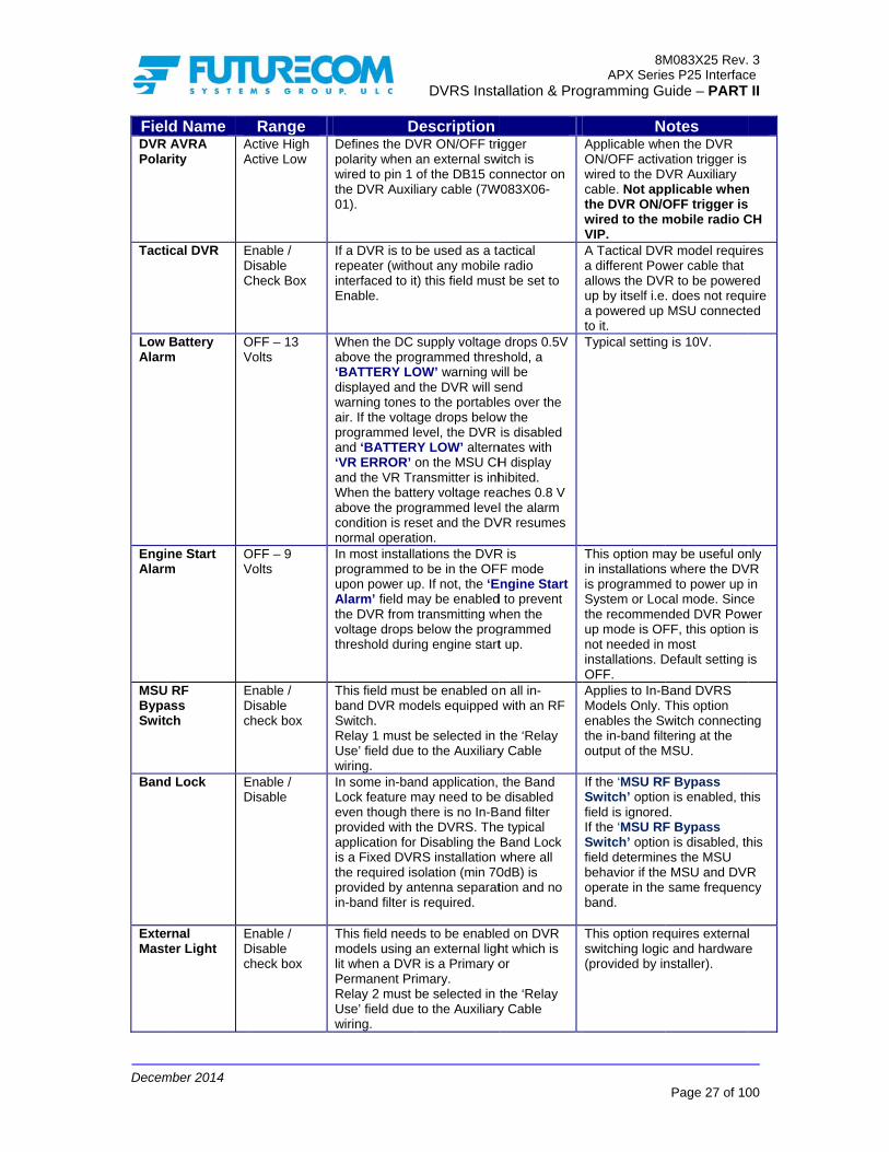
Decem
FielDVRPola
Tact
Low Alarm
EngiAlarm
MSUBypaSwit
Band
ExteMast
mber 2014
ld Name AVRA rity
AA
ical DVR EDC
Battery m
OV
ne Start m
OV
U RF ass ch
EDc
d Lock ED
rnal ter Light
EDc
Range Active High Active Low
Enable / Disable Check Box
OFF – 13 Volts
OFF – 9 Volts
Enable / Disable check box
Enable / Disable
Enable / Disable check box
DDefines the DVpolarity when wired to pin 1 the DVR Auxil01).
If a DVR is to repeater (withointerfaced to itEnable.
When the DC above the prog‘BATTERY LOdisplayed and warning tonesair. If the voltaprogrammed land ‘BATTER‘VR ERROR’ oand the VR TrWhen the battabove the progcondition is renormal operatIn most installaprogrammed tupon power upAlarm’ field mthe DVR from voltage drops threshold durin
This field mustband DVR moSwitch. Relay 1 must bUse’ field due wiring. In some in-banLock feature meven though thprovided with tapplication foris a Fixed DVRthe required isprovided by anin-band filter is
This field needmodels using lit when a DVRPermanent PrRelay 2 must bUse’ field due wiring.
DVRS Insta
DescriptionVR ON/OFF trian external swof the DB15 coiary cable (7W
be used as a taout any mobilet) this field mus
supply voltagegrammed thresOW’ warning w
the DVR will s to the portable
age drops belowevel, the DVR
RY LOW’ alternon the MSU CHransmitter is inhtery voltage reagrammed levelset and the DVion. ations the DVRto be in the OFp. If not, the ‘E
may be enabledtransmitting wbelow the progng engine start
t be enabled oodels equipped
be selected in to the Auxiliary
nd application, may need to behere is no In-Bthe DVRS. The
r Disabling the RS installation solation (min 70ntenna separats required.
ds to be enablean external ligh
R is a Primary oimary. be selected in to the Auxiliary
allation & Pro
igger witch is onnector on
W083X06-
actical e radio st be set to
e drops 0.5V shold, a
will be send es over the w the is disabled
nates with H display hibited. aches 0.8 V l the alarm
VR resumes
R is FF mode Engine Start d to prevent hen the grammed t up.
n all in-with an RF
the ‘Relay y Cable
the Band e disabled and filter e typical Band Lock where all
0dB) is tion and no
ed on DVR ht which is or
the ‘Relay y Cable
8MAPX Serie
ogramming Gu
NApplicable whON/OFF activawired to the DVcable. Not appthe DVR ON/Owired to the mVIP. A Tactical DVRa different Powallows the DVup by itself i.ea powered up to it. Typical setting
This option main installationsis programmedSystem or Locthe recommenup mode is OFnot needed in installations. DOFF. Applies to In-BModels Only. Tenables the Swthe in-band filtoutput of the M
If the ‘MSU RFSwitch’ optionfield is ignoredIf the ‘MSU RFSwitch’ optionfield determinebehavior if theoperate in the band. This option reqswitching logic(provided by in
M083X25 Rev.es P25 Interfacuide – PART
Page 27 of 10
otes en the DVR ation trigger is VR Auxiliary plicable whenOFF trigger is mobile radio C
R model requirwer cable that R to be powere. does not requMSU connecte
g is 10V.
ay be useful ons where the DVd to power up ical mode. Sincended DVR PowFF, this option most
Default setting i
Band DVRS This option witch connectintering at the MSU.
F Bypass n is enabled, thd. F Bypass n is disabled, thes the MSU
e MSU and DVRsame frequen
quires externalc and hardwarenstaller).
3 ce
II
00
n
CH
res
ed uire ed
nly VR in e
wer is
is
ng
his
his
R cy
l e

Decem
FielRela
AFC Cum
AFC
MSUThis s
PSU This affiliathrouin theID is rangeneed
DVRThis pageis pagactivaunit Ichangmode
mber 2014
ld Name y Use ‘N
‘MB ‘DB ‘ML ‘LL ‘SL ‘Dli ‘EA
mulative ED
Fast ED
U Data screen prov
IDs Allowemenu scree
ated on the gh is require
e PSU ID Daallowed to t
e of IDs the s to log in as
R Remote Acscreen allow the MSU aged, the DVation enableD is programge. In addite as describe
Range Not Used’
MSU RF Bypass SW’
Duplexer Bypass SW’
Master Light’
LOC Mode Light’
SYS Mode Light’
DVR ON ght’
External Alarm’ Enable Disable
Enable Disable
ides MSU da
d en is used to
system viaed, then the ata list of thetalk through
User needss Admin (req
ctivation IDws the user nd toggle thRS mode is
ed, then anymmed in theion, a Grouped above.
DRelay 1 must bSwitch OR theif the correspo Relay 2 must bLight if this opt The MSU RF Swith all side-byin-band model
Enables or DisAutomated Fretuning. Enables or Distuning.
ata for inform
o specify PSa DVRS. If
PSU MDC e DVR. If thethe DVRS. Ts to enter a quires passw
Ds to enter the
he DVRS monot change
y Call Alert Pe DVRS Remp Page to a
DVRS Insta
Descriptionbe assigned to
e Duplexer Byponding option is
be assigned totion is installed
Switch option iy-side and Tranls.
sables the Cumequency Contr
sables the Fast
mation purpo
SU IDs (or ranalog portID must be
e range is seThis screen password.
word).
e console oode. The ded. If the MSPage to themote activata TG the MS
allation & Pro
o the RF pass Switch s installed.
o the Master d.
s included nsportable
mulative rol (AFC)
t AFC
oses only.
range of IDstables are uenabled on
et to be from is PassworTo change
or system rafault list is eU is program
e MSU ID froion ID tableSU belongs
8MAPX Serie
ogramming Gu
NAll Lights, Alarassociated extbe provided by
Default settingDisable during
Default settingDisable during
s) that are aused and Mthe System
m ‘0’ to ‘- -‘, trd protected.the PSU ID
adio IDs of uempty i.e. wmmed to havom a system, will trigger to will togg
M083X25 Rev.es P25 Interfacuide – PART
Page 28 of 10
otes rm relays and ternal logic arey installer.
g is Enable. Seg calibration.
g is Enable. Seg calibration.
allowed to bMDC ID pas
and includehen any PS. To view th
D list the Use
units that cahen the MSve the remotm unit whosDVRS mod
gle the DVR
3 ce
II
00
e to
et to
et to
be ss ed U
he er
an U te se de
RS

Decem
TalkWhenbe tramust outboTransfor TG IMPOEncr
IMPOThe conta
mber 2014
group Trann the local Pansmitted obe program
ound (systemslation TabG Translatio
ORTANT! ryption Key
ORTANT! DVRS Tranain TG IDs t
nslation TabPSU transmin the TG cu
mmed with Nm) or MSU
ble allows thon. The defa
Translation
nslation tabthat are use
ble its on a TG urrently seleNormal sque
Mic PTT ce user to prult list is em
n is not sup
ble (and coed by the tr
DVRS Insta
that is in thected on the
elch or NACcalls when Trogram the pty, i.e. TG t
pported by t
orrespondiunked FNE
allation & Pro
e DVR TranMSU contr
C=F7E in ordTG TranslatLocal PSU translation is
the DVRS.
ng PSU pr side.
8MAPX Serie
ogramming Gu
nslation tablerol head. Thder to be abtion is enabTG IDs thats disabled.
rogramming
M083X25 Rev.es P25 Interfacuide – PART
Page 29 of 10
e, the call we local PSUble to receivbled. The TGt are enable
g) must no
3 ce
II
00
will Us ve G
ed
ot

Decem
Anal
FieSystTone
SystTone
LocaTone
LocaTone
PortaSimuAcceBusyMBXComBusyID
BusyMastTime
DTMCont
mber 2014
log Setup
eld Name em Mode es – Trailing
em Mode es – Lead
al Mode es – Trailing
al Mode es – Lead
able Trunk ulated ess y Lockout
X2 mpatibility
y Lockout
y Lockout ter Bit Clr e
F Remote trol Code
Range Enable / Disable Chebox.
Enable / Disable Chebox.
Enable / Disable Chebox.
Enable / Disable Chebox.
Enable / Disable Chebox. Enable / Disable Chebox. 0 - 127
0 – 180 minutes
Up to 5 digits
eck Enables sent by tindicate The tonetransmis
eck Enables Tones sePSUs to unsucceThe toneLPSU traneeds toable to h
eck Enables sent by tindicate transmisend of LP
eck Enables Tones sePSUs to unsuccetones aretransmisdo ‘doubhear the
eck Enabled expectedLeading
eck When Envoting alMobexcoIf MBX CDVR/VRdifferent duplicatedifferent If enablewas votein the netimer. ThDVR is v
s. Upon recsequencfrom OFDVR andthe same
DVRS Insta
Descripor Disables the
the DVR to thestate of the tra
es are sent at tssion.
or Disables theent by the DVRindicate successful system c
es are sent at tansmission. Tho do ‘double PThear the Lead to
or Disables thethe DVR to the successful / u
ssion. The tonePSU transmiss
or Disables theent by the DVRindicate successful DVR trane sent at the be
ssion. The LPSble PTT’ in orde
Lead tones.
only when thed to do ‘DoubleTones are ena
nabled, the DVgorithm so it isom II VRs. Compatibility is R needs to be p
ID. Larger fleee IDs programmoperation area
ed (set to >0), ted a Primary wext voting for thhe timer is resevoted a Primary
ceiving a matchce from a PSU,F or Local to Sd PSU must bee DTMF seque
allation & Pro
ption e Trailing Tone
e Local PSUs toansmission. he end of LPS
e Lead Go AheR to the Local essful / hannel accesshe beginning o
he LPSU user TT’ in order to bones.
e Trailing Tonee Local PSUs tonsuccessful DV
es are sent at thsion.
e Lead Go AheR to the Local essful / nsmission. The eginning of LPU user needs ter to be able to
e PSU user is e PTT’ and abled. VR changes its s compatible wi
Enabled, eachprogrammed wiets may have med, preferablyas. the last DVR th
will have a priorihe duration of thet every time a y.
hing DTMF the DVR switc
System Mode. Te programmed ence.
8MAPX Serie
ogramming Gu
es o
U
Affects Mode wTrunkedonly. Thheard bthat areDVR chare sengenerat
ead
s. of
be
Affects Mode wTrunkedonly. Thheard bthat areDVR chare sengenerat
es o VR he
The tonall LPSon the schannesent ovgenerat
ead
SU to
o
Affects Mode wTrunkedonly. Thheard bthat areDVR chare sengenerat
ith
h ith a
y in
hat ity he
Default Disableunits hachancePrimaryvoting. when Mis enab
ches The with
The PSprogramthe lastexampl
M083X25 Rev.es P25 Interfacuide – PART
Page 30 of 10
Notes Analog DVR
when used withd MSU mode he tones are by all LPSU usee on the selectehannel since thnt over the air (ted in the LPSUAnalog DVR
when used withd MSU mode he tones are by all LPSU usee on the selectehannel since thnt over the air (ted in the LPSUnes are heard bU users that arselected DVR
el since they arever the air (not ted in the LPSUAnalog DVR
when used withd MSU mode he tones are by all LPSU usee on the selectehannel since thnt over the air (ted in the LPSU
setting is 0 i.eed and all DVRave the same e of becoming ay during every Applicable only
MBX2 compatibbled. SU must be mmed with * ast DTMF sign, foe 1234*.
3 ce
II
00
h
ers ed
hey not U).
h
ers ed
hey not U). by re
e
U).
h
ers ed
hey not U).
. S
a
y bility
s or
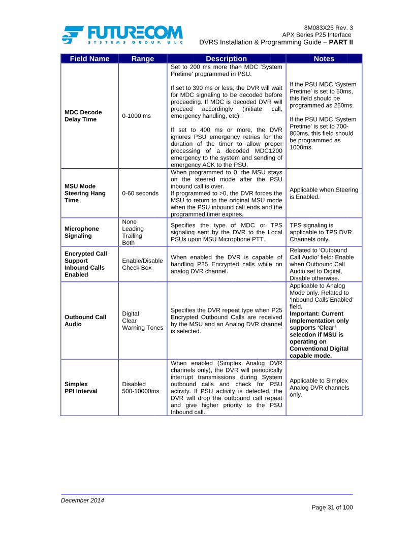
Decem
Fie
MDCDela
MSUSteeTime
MicroSign
EncrSuppInboEnab
OutbAudi
SimpPPI I
mber 2014
eld Name
C Decode y Time
U Mode ring Hang
e
ophone aling
rypted Call port und Calls
bled
bound Call io
plex nterval
Range
0-1000 ms
0-60 second
None Leading Trailing Both
Enable/DisaCheck Box
Digital Clear Warning Ton
Disabled 500-10000m
Set to 2Pretime’ If set to 3for MDCproceediproceed emergen If set toignores duration processiemergenemergen
ds
When pron the inbound If prograMSU to when theprogram
SpecifiessignalingPSUs up
able When ehandlinganalog D
nes
SpecifiesEncrypteby the Mis selecte
ms
When echannelsinterrupt outboundactivity. DVR wiland givInbound
DVRS Insta
Descrip00 ms more thprogrammed i
390 ms or lessC signaling to bing. If MDC is
accordinglyncy handling, e
o 400 ms orPSU emergenof the timer
ng of a dency to the systency ACK to therogrammed to steered modcall is over.
ammed to >0, treturn to the oe PSU inboundmed timer exp
s the type og sent by the pon MSU Micro
enabled the Dg P25 EncryptDVR channel.
s the DVR repeed Outbound C
MSU and an Aned.
enabled (Simps only), the DV
transmissiond calls and If PSU activitl drop the out
ve higher priocall.
allation & Pro
ption han MDC ‘Sysin PSU.
s, the DVR will be decoded bedecoded DVR
y (initiate etc).
r more, the Dncy retries forr to allow proecoded MDC1em and sendin
e PSU. 0, the MSU s
e after the P
he DVR forcesoriginal MSU md call ends andpires.
of MDC or DVR to the L
ophone PTT.
DVR is capableted calls while
eat type when Calls are recenalog DVR cha
plex Analog DVR will periodics during Syscheck for P
ty is detected,tbound call reority to the P
8MAPX Serie
ogramming Gu
stem
wait efore R will
call,
DVR r the oper 1200 ng of
If the PPretimethis fieldprogram If the PPretime800ms,be prog1000ms
stays PSU
s the mode d the
Applicais Enab
TPS Local
TPS sigapplicaChanne
e of e on
RelatedCall Auwhen OAudio sDisable
P25 eived annel
ApplicaMode o‘Inbounfield. ImportaimplemsupporselectiooperatiConvencapabl
DVR cally stem PSU the peat PSU
ApplicaAnalog only.
M083X25 Rev.es P25 Interfacuide – PART
Page 31 of 10
Notes
SU MDC ‘Syste’ is set to 50md should be mmed as 250m
SU MDC ‘Syste’ is set to 700-, this field shougrammed as s.
able when Steebled.
gnaling is ble to TPS DVels only.
d to ‘Outbound dio’ field: Enab
Outbound Call set to Digital, e otherwise. able to Analog only. Related tond Calls Enable
ant: Current mentation onlyrts ‘Clear’ on if MSU is ing on ntional Digitale mode.
able to SimplexDVR channels
3 ce
II
00
tem ms,
ms.
tem -uld
ering
R
ble
o ed’
y
l
x s

Decem
Fie
FallbAnalMode
PSU Audi
MDCOffsePSU OutbTakeVoicPSU OutbTakeSignAllow
PSU LocaCall Enab
mber 2014
eld Name
back in og Simplex e Enabled
Analog io Queuing
C PTT ID et Priority
bound eover By e Allowed Priority
bound eover By aling
wed
Priority al to System Upgrade
bled
Range
Enable / Disable checbox.
500 – 1300m
0 - 1677721
Enable / Disable checbox.
Enable / Disable checbox.
Enable / Disable checbox.
ck
If enabldetects awill monthe call non-PrimThe nonrepeats Primary detectedInbound lost whcheckingif fallbackey up b
ms
Defines preventsbeginninis acquirvalue mthe tail e
5 For futur
ck Enables takeoveroutbound
ck Enables takeoveroutbound
ck
Enables upgradeMSU is call andFNE.
DVRS Insta
Descripled, a non-Pa valid Inboundnitor for Primaand if such is
mary DVR wiln-primary DVRthe call and dowhen Prima
d. The first fewor Outbound
hile the non-g for Primary reck is needed. Mboth the DVR a
the analog aus the loss ong of transmissring channel gay cause the
end of his own t
re use
/ Disables r when the MSd call.
/ Disables thr when the MSd call.
/ Disables thd from Local tono longer rece
d is allowed t
allation & Pro
ption Primary DVR d or Outbound ary DVR repeas not detected,l repeat the
R only temporoes not becom
ary repeat is w seconds of
d Call are alw-Primary DVRepeat and deciMSU MIC PTT
and the MSU. udio buffer, wof audio at
sion while the Mgrant. Longer PSU user to transmission.
the PSU VSU is receiving
he PSU SignaSU is receiving
he PSU call too System wheneiving an outboto transmit to
8MAPX Serie
ogramming Gu
that Call
ating , the call.
rarily me a
not f the ways R is iding T will
ApplicaAnalog
which the
MSU time hear
Default 1000mstrunkingsystem grant m1500ms
Voice g an
aling g an
o be n the ound
the
M083X25 Rev.es P25 Interfacuide – PART
Page 32 of 10
Notes
able to SimplexDVR Mode on
setting is s. Applicable tog systems wheaccess chann
may take 1000 –s.
3 ce
II
00
x nly.
o ere el –

Decem
DVR
FieLocaAllow
Rptr IndeChan
Pow
Fixed
Chan
No A- Rep
DispPTT TG ID Hang
RepeTone
mber 2014
R Common S
eld Name al Mode wed
pendent nnel Change
er Up Mode
d Mode
nnel
Activity Timer peater
play ID
D
g Time
eater Active es
Setup
Range Enable / Disable Check box.
Enable / Disable Check box.
Fixed Last Programmed
System Local OFF
Disable – max # of programmedDVR channels Disable – 120 min
Enable / Disable check box. 0-5 sec
Enable / Disable check box
DEnables / DMode selec
When Enabcan be selethe selecteDisabled, tstrapped tochannel.
d
Specifies thPower Up.selected, thprogrammechannel or Specifies thFixed PoweTypical recOFF.
d
Specifies thup ChanneDVR revertchannel up If the DVR receive anyprogrammeautomaticaor Local to sends warnLocal PSU during the switching OEnables / DPortable PTControl HeOutbound c(when enabas well. Determineswhich the Iafter the caEnables / tones whenSystem (Mode. Theare transmLocal PSUDVR conve
DVRS Insta
DescriptionDisables Local ction by the Us
bled the DVR cected independ
ed MSU channehe DVR chann
o the selected M
he DVR Mode When ‘Progra
he DVR Mode ed for the selecMSU Mode.
he DVR Mode er up option is
commended se
he Default DVRel. If set to Disats to the last us
pon Power up.
is not active (dy local PSU caed period of timally switch from
OFF Mode. Thning tones to ausers every m
last 5 minutes OFF. Disables the disTT ID and TG ad. calls TG ID is dbled) during pr
s the hang timeD remains disp
all has ended.Disables the sn the DVR is s(and optionale repeater ac
mitted over theUs tuned to entional channe
allation & Pro
n DVR
ser. Ttethif
channel dently from el. When nel is MSU
upon mmed’ is is as cted DVR
DIfPA
when selected.
etting is
Dm
R Power able, the sed
does not alls) for the me, it will
m System he DVR
alert the minute
prior to
OMw
splay of ID on the
displayed roxied calls
e during played
sending of switched to lly Local)
ctive tones e air to all the same el.
TfrosS
8MAPX Serie
ogramming Gu
NoThe DVR can semporarily to Lhe System is nf Local mode is
Default setting f AVRA is Enab
Power Up modeAVRA input.
Default setting fmount models i
Outbound callsMSU and repeawill not reset the
Tones are sent rom OFF to LO
occurs. Tones aswitching SYS tSYS.
M083X25 Rev.es P25 Interfacuide – PART
Page 33 of 10
otes still revert Local mode (whnot available) es Disabled.
is Fixed. bled then the e is driven by t
for vehicular is OFF
, received by thated by the DVe timer.
when switchinOC or OFF to Sare not sent whto LOC or LOC
3 ce
II
00
hen ven
he
he R
ng SYS hen C to

Decem
Fie
LocaActiv
DVRWarnInter
MSURepeMode
MSURepeMode
mber 2014
eld Name
al Mode ve Tones
Active ning Tone rval
U Mic call eat in LOC e
U Mic call eat in SYS e
Range
Enable / Disable check box
0-255 sec
Enable / Disable check box
Enable / Disable check box.
DEnables / tones whenin Local Mtones are tall Local PDVR cRequires eActive TonWhen the System programmeActive” TonThis field interval bet
When the Dmode, this MSU Mic cDVRS to thEnabled) o
This optionSystem PTin the MSUMSU Mic cwhile DVRSTypically inare repeatedisabling ‘MLocal ModeMic Call LoMode’ optio
Warning: ifdisabled, fumicrophonedisabled
When the Dmode, this MSU Mic cDVRS to th
When disaDVRS doeto the LPSPTT-ed anSYSTEM m
When enabcall audio iMSU and tis in SYSToption for D
DVRS Insta
DescriptionDisables the sn the DVR is swode. The reperansmitted ove
PSUs tuned to conventional enabling of the nes’ Field. DVR is in eitheMode, it
ed to sounnes in the MSU
specifies thtween those to
DVRS is in the setting determ
calls are repeathe Local PSUs or not (when Dis
n is related to ‘MTT in Local ModU CPS which encall repeat to syS is in LOCAL n LOCAL modeed only to LocaMSU System Pe’ and enablingocal Repeat in on.
f both options aunctionality of te in LOCAL mo
DVRS is in the setting determ
calls are repeathe Local PSUs
bled (uncheckes not transmit MUs when the Md the DVRS is
mode.
bled (checked)s transmitted bhe DVR when EM Mode. ThisDVR.
allation & Pro
n sending of witched on
eater active er the air to the same
channel. ‘Repeater
TfrosS
er Local or can be
nd “DVR U Speaker. he repeat
ones.
LOCAL mines if ted by the (when
sabled).
MSU de’ option nables ystem mode.
e Mic calls al PSUs by PTT in g ‘MSU LOC
are the MSU ode will be
Inthdaain
IfMMs
SMHO
SYSTEM mines if ted by the .
ed) the Mic audio
MSU Mic is in the
), MSU Mic by both the the DVR s is default
Inthdaain
8MAPX Serie
ogramming Gu
No
Tones are sent rom OFF to LO
occurs. Tones aswitching SYS tSYS.
n single DVRShis option coul
disable local reaudio feedbackand LPSU whenside the vehic
f ‘MSU SystemMode’ option inMIC audio is trasystem.
See Table 3 SMode MicrophHandling - ProOptions
n single DVR uhis option coul
disable local reaudio feedbackand LPSU whenside the vehic
M083X25 Rev.es P25 Interfacuide – PART
Page 34 of 10
otes
when switchinOC or OFF to Sare not sent whto LOC or LOC
S user applicatiod be used to peat and preve
k from MSU Micn the user is
cle.
m PTT in Local n MSU is enableansmitted to
ummary of Lohone Audio ogrammable
user applicationd be used to peat and preve
k from MSU Micn the user is
cle.
3 ce
II
00
ng SYS hen C to
ons
ent c
ed,
ocal
ns
ent c

Decem
FieDVRvia MChan
SystAcqu
This
MMSUPTT
Table
mber 2014
eld Name Activation
MSU Mode nge
em Channel uisition Time
VR ID
SU CPS U System T in Local Mode
e 3 Summary
Range Enable / Disable check box.
600 – 6000 ms
number
DVRSTweak
MSU MicLocal Rein LOC M
y of Local Mo
DEnables / Dactivation bMSU ModeDVR is in OMSU selecprogrammeLOCAL wilto the DVROFF). If enmode is chprogrammeLOCAL thefrom OFF trespectivelDeterminesthe systemdecides whmust be seand starts l
Specifies this used for TG changeDVR will ascurrently in
S ker c Call epeat Mode
Tx M
FN
ode Micropho
DVRS Insta
DescriptionDisables the DVby changing thee. If disabled anOFF mode, chaction to a new med for SYSTEMl not cause any
R mode (DVR snabled and the hanged to a newed for SYSTEMen the DVR willto SYSTEM or y. s the DVR wait
m grant before that tones (ACKent to the Locallocal repeat.
he ID of the DVremote DVR m
e. If not specifiessume the ID onterfaced MSU.
Mic Audioto
E/system
No
No
YesYes
one Audio H
allation & Pro
n VR e selected nd the anging the mode M or y change
stays MSU w one
M or l switch LOCAL
t time for he DVR
K or NACK) l PSUs
Tmwoceabtore
VR, which mode and ed, the of the .
RCth
Tx Mic Audio
To Local PSUs
No
Yes
NoYes
andling - Pro
8MAPX Serie
ogramming Gu
No
This timer also maximum numbwill be made byorder to acquirechannel. Theseevery second sallow 2 retries, be set to 1800 –o allow sufficieesponse time.
Refer to the ReControl / TG Shis Document.
Com
Warnfunctionaaudio no
TypicalD
ogrammable
M083X25 Rev.es P25 Interfacuide – PART
Page 35 of 10
otes
determines theber of retries thy the DVRS in e a system e retries are seno if the intent isthe timer need– 2000ms in or
ent system
emote DVR teering Sectio
mment
ning: MIC ality disabledt transmittedl setting for DVR
e Options
3 ce
II
00
e hat
nt s to s to rder
on of
d, d

Decem
Emer
FieAnalEmeSign
DispEme
SendAck.
PortaRequ
AttemTime
AttemCoun
ANI 5
mber 2014
rgency Setup
eld Name og rgency aling Type
play PSU rgency ID
d Emergency Tones
able Ack uired
mpts eout
mpts nter
5 Tone Type
p Menu
Range Disable MDC1200 ANI-5 Tones
Enable / Disable Check box.
Enable / Disable Check box.
Enable / Disable Check box.
30-255 s
0-10
EEA CCIR EIA
D
s
DeterminesemergencyLocal AnalWhen ANI-the PSU mtransmit 4 for examplEmergencyto the PSUtones follow Enables / DID display of an Emer
Enables / DEmergencythe DVR to
Enables / DEmergencyby the DVRDVR receivAlarm. After decodrequest froDVR waits timer and ifrequest is rthe counteanother emreceived, ththe countethe AttempDeterminesEmergencySecondarydetect befoPrimary Syprocesses System. Thwhen the Dthe PSU orTimeout tiWhen set tDVR will noEmergencyPrimary DVDeterminesMust matchprogrammi
DVRS Insta
Descriptions the type of y signaling useog PSUs. -5 Tones is sel
must be programTones followede 1234B. The y ACK sent by
Us will be the sawed by A i.e. 1
Disables the Loduring the procrgency by the D
Disables the y ACK Tones so Analog PSUs
Disables the y ACK signalinR to the PSU wves a PSU Em
ding an Emergom a PSU, a Se
for the duratiof no other emereceived from tr will be cleare
mergency requehe DVR will incr accordingly –pts Counter Ss the number oy attempts a
y DVR will needore it switches tystem Mode anthe Emergenc
his counter is reDVR sends an r when the Attemer expires. to 0 – the Secoot monitor if they is being serviVR or not. s the ANI 5-Toh the Analog Ping.
allation & Pro
ed by the
ected, mmed to d by B -
the DVR ame 234A.
Aff
ocal PSU cessing DVR.
In disLocDisIn AANHe
sent by s.
AffAll AnPSChthe
g sent when the ergency
De
ency econdary
on of this ergency the PSU,
ed. If est is crement – refer to Setting.
of PSU
d to to
nd cy to the eset ACK to empts
ondary e PSU iced by a
one Type. PSU
Aff
8MAPX Serie
ogramming Gu
Nofects Analog M
Digital Mode –splayed on the cal PSUs, Systspatcher ConsoAnalog Mode –
NI ID is displayeead. fects Analog MTones sent by
nalog Mode areSUs tuned to thhannel, which Pe DVR radio coefault setting is
fects Analog M
M083X25 Rev.es P25 Interfacuide – PART
Page 36 of 10
otes Mode only.
– the P25 Unit IControl Head, tem Radios anole. – the MDC1200ed on the Cont
Mode only. y the DVR in e heard by all he same DVR PSUs are withinoverage area.
Enabled.
Mode only.
3 ce
II
00
D is
d
0 or trol
n

Decem
FieEmeCanc AnalType EmeCancTime
EmeCancANI C
FG EDest
DisaEmeState
DigitEmeDVREchoEnab
DigitEmePortaRequ
mber 2014
eld Name rgency cel
og Signaling e
rgency cel eout
rgency cel Code
Emergency tination
ble DVR rgency Call e
tal rgency Emergency o ACK bled
tal rgency able Ack uired
Range Disable ANI 5-TonesDTMF OFF-600sec
number
Local System Both
Yes / No
Enable / Disable check box
Enable / Disable check box
D
s
If enabled, emergencyprogrammeCode.
c If programmautomaticaemergencyprogrammeThis field sEmergencyCode sequAnalog PS
DeterminesEmergencythe DVR frFG enableWhen enabalarm or caanalog PSEmergencyremains in MDC PSU cancelled bWhile in EmDVRS woureceived frwithout leaemergencyfrom analoleading PTaccordinglyEmergencycancelled bbutton, by emergencyremotely viANI code.Must be Generic P2treat signapplicationEnabled Enabled Ack’.
Enables / Dlow level Athe PSU Emergency
DVRS Insta
Description
the DVR will cy upon detectioed Emergency
med, the DVR ally clear the y upon expiratioed timer. specifies the y Cancel ANI /D
uence. Must maU programmin
s the routing ofy message recom a Local PSd DVR channebled, if emergeall was declareU, the DVR eny Call State anthis state until emergencies a
by the PSU or mergency Call uld forward all com the analog
ading PTT ID asy calls. Calls reg PSUs with th
TT ID would be y. The DVR y Call State is by pressing thepreprogrammey cancel timer oia Emergency
Disabled whe25 PSUs sincenaling level n level Ack.
when using PSUs and
Disables the seACK by the Dupon receipt
y Alarm.
allation & Pro
clear the on of the
Cancel
Aff
will
on of the
Aff
DTMF atch the g.
AffApCaEnThwitexa
f ceived by SU on a el.
Aphav
ency ed by an ters d all the
are DVR. State
calls PSUs
s eceived he handled
e DVRS ed or Cancel
Apand
en using e they will
Ack as Must be
DVRS ‘Console
RePoEn
ending of DVRS to t of an
Thby pro(FNDe
8MAPX Serie
ogramming Gu
Nofects Analog M
fects all modes
fects Analog Mpplicable only ifancel Signalingnabled. e PSU must beth * as the last ample 456*.
pplicable to DVRve FG signalin
pplicable to Anad analog PSUs
equires ‘Digital ortable Ack Reqnabled.
e Emergency Athe DVR depe
ogramming – VNE) ACK or Coefault setting is
M083X25 Rev.es P25 Interfacuide – PART
Page 37 of 10
otes Mode only.
s.
Mode only. f the Emergenc Type Field is
e programmed DTMF sign, fo
R channels whg enabled.
alog DVR modes only.
Emergency quired’ to be
ACK type is seending on its VR ACK / Site onsole ACK. Enabled.
3 ce
II
00
cy
r
hich
e
ent

Decem
Fie
TG1 Disa
SwitLOCMSUEme
ToneThe tare sIf no NOTEThe ttuned
MorsThe Mfixed
mber 2014
eld Name
Translation bled
ch DVR from to SYS if
U in rgency
e Setup Mentones setup ent by the Dcustom tone
E: tones sent bd to the sam
se Code MeMorse code repeater an
Range
Enable / Disable check box
Enable / Disable check box
nu screen allo
DVR to the Aes are progra
by the DVRe DVR chan
enu option need
nd the FCC r
DDefault s(TG1 transthis casemergencydefault TGthe TG ID selected Mthe emergthe selecte1, which mthe specificWhen the mode andEmergencyCH the DVto SYS moenabled (boption is nstays in EmergencyMSU.
ows programAnalog PSUsammed, the
in analog mnnel and are
ds to be progrules require
DVRS Insta
Descriptionsetting is unslation is enae when ay is receiv
G1), the DVR trto match the
MSU TG ID. Tency is annou
ed MSU TG, nomay not evenc trunking syste
DVR is in tthe user pre
y button on tVR will switch frode when this box is checkednot enabled, t
LOC mody is declared
mming of cuss during Ana
DVR will se
mode are he within the D
grammed one transmissio
allation & Pro
nchecked abled). In a PSU ved (on ranslates currently
This way unced on ot on TG exist in em.
ApMixcha
the LOC sses the the MSU rom LOC option is
d). If the the DVR
de after on the
stom tones alog Mode ofend the defa
eard by all DVR RF cov
nly when a Don of Repeat
8MAPX Serie
ogramming Gu
No
pplicable to Firexed and TPS tyannels.
/ tone sequf operation oult sets of to
analog PSUerage area.
DVRS is to ter ID via Mo
M083X25 Rev.es P25 Interfacuide – PART
Page 38 of 10
otes
eground Analogype DVR
ences, whiconly. ones.
Us, which ar
be used as orse Code.
3 ce
II
00
g,
ch
re
a

Decem
Digit
FieCall PassRespPSU
Call LocaCall Enab
Call PassRespPSU
IndivSetuPrivaSetu
mber 2014
tal System S
eld Name Setup –
s Queue ponse to
Setup – al To System Upgrade
bled
Setup – s Deny ponse to
vidual Call p
ate Call p Timeout
Setup Menu
Range Enable / Disable CheBox
Enable / Disable CheBox
Enable / Disable CheBox
5-60 sec
u
eck If a LocaDVR) PTthe Trunof the fol* if the Pcheckedmessageto wait u* if the PuncheckPSU Calother Loon the S
eck When a through tQueue bMSU congrant is rrepeat offollowing* if the ScheckedCall to Sthe PSUUsers or* if the SuncheckLocally o
eck If a LocaDVR) PTa Deny rthe follow* if the Pcheckedmessagecancelle* if the PuncheckPSU callother LoDeterminafter initiLocal PSdestinatiexpires breplies, tMust be PSU.
DVRS Insta
Descripal PSU (affiliateTTs and the Caking System, tllowing:
Pass Queue Red the DVR se to the PSU antil System gra
Pass Queue Reked the DVRll to be repeatecal PSUs whileystem side). Call from a Locthe DVR) has b
by the System onflicting servicereceived duringf the PSU Call,
g will occur: System Busy C
the DVR prSystem so that t
Call is repeater
System Busy Cked the DVRonly until the Caal PSU (affiliateTTs and the Syresponse, the Dwing:
Pass Deny Resd the DVR se to the PSU ad;
Pass Deny Resked the DVRl to be repeatedcal PSUs) but nes the time a iating a PrivateSU to receive aon Local PSU.before the destthe DVR canceset to match th
allation & Pro
ption ed through the all is Queued bhe DVR does o
esponse Box sends a Queuend forces the Pant is received esponse Box R enables the ed locally (to the it is not repea
cal PSU (affiliabeen put in theor blocked by e, and System g the DVR’s Lo, one of the
Channel Grantromotes the Lothe remainder ed to the Syste
Channel GrantR repeats the C
all is completeed through the ystem sends baDVR does one
sponse Box issends a Deny nd the call is
sponse Box isR enables the d locally (to thenot to the SystLocal PSU wa
e Call to anothea reply from the. If the timer tination PSU els the Private Che settings of t
8MAPX Serie
ogramming Gu
by one
is e PSU or is
e ated
ated e
ocal
t is ocal of
em
t is Call ed.
This seif the PaResponDisableor the SAcquisSystembeen ex
ack of
s
s
e tem.
its er e
Call. he
Affects betweeonly. The DVPrivate Local ais basesettingsSystem
M083X25 Rev.es P25 Interfacuide – PART
Page 39 of 10
Notes
etting is applicaass Queue nse to PSU is
ed i.e. UncheckSystem Channsition time (see
m Setup 2) has xceeded.
Private Calls en Local PSUs
VRS handling oCalls betweennd System PSd on the Timeos of the P25
m.
3 ce
II
00
ble
ked nel e
of n Us
out

Decem
FieIndivSetuPrivaTime
IndivSetuTelepInterCCT
IndivSetuTelepInterHang
P25 Dete
VR CMode
mber 2014
eld Name vidual Call p
ate Call Hang eout
vidual Call p phone rconnect
vidual Call p phone rconnect g Timeout
Frame Sync ection Timer
Ch Mixed e Hold Timer
Range 10-60 sec
OFF – 60 minutes
10-60 sec
30-255ms
0-255 sec
If no PSUduration the Privaother cal
If a telepand the ta given Dprogramautomatiapplies t
If no callduration the phon
Upon Caactivatiodoes notthis timedecodersPL/DPL,
This timeHang Timfrom an AAnalog mSystem rthe timerin Analogwhen theOFF. Upon exswitches
DVRS Insta
DescripU activity is detof this timer, th
ate Call and is lls.
phone call betwtrunking systemDVRS and the med timer, theically disconneto phone calls o
activity is deteof this timer, th
ne call.
arrier Activatedn, if the DVR dt detect P25 Frr expires, the Ds will be switch DTMF, MDC1
er determines tme. If the DVRAnalog PSU, th
mode until this reply which is rr’s expiration wg Mode. The tie originating An
xpiration of the s to digital repe
allation & Pro
ption tected for the he DVR canceready for servi
ween a local PSm is processedcall exceeds th
e call will be ected. This timeonly.
ected for the he DVR cance
d Squelch (CASdigital decoder rame sync befoDVR analog hed on (i.e. 200…).
the DVR ModeR receives a cal
he DVR will statimer expires. received before
will be transmittmer is started nalog PSU key
timer, the DVReat mode.
8MAPX Serie
ogramming Gu
ls cing
Typical setting
SU d by he
er
ls Typical setting
S)
ore
ApplicaMode Donly. Derecommset to 1
e ll ay in Any e ted
ys
R
ApplicaMode Donly. WMode DselecteDVR m
M083X25 Rev.es P25 Interfacuide – PART
Page 40 of 10
Notes recommendedis 30 seconds.
recommendedis 30 seconds.
able to Mixed DVR Channels efault
mended value i00ms.
able to Mixed DVR Channels
When a Mixed DVR channel isd, the default ode is P25 Dig
3 ce
II
00
d
d
s
s
gital.

Decem
FiePSU Disa
PSU InboTakeAllowPSU OutbTakeVoicPSU OutbTakeSignAllow
NetwRepoInter
PSU Time
PSU Audi
P25 Leng
AdapContEnab
mber 2014
eld Name Proxy bled
Priority und
eover wed Priority
bound eover by e Allowed Priority
bound eover by aling
wed
work Status orting rval
Affiliation eout
Digital io Queuing
Preamble gth
ptive Power trol bled
Range Check box
Check box
Enable / Disable Chebox
Enable / Disable Chebox
0-255 sec
0-72 hrs
700 – 1800m
0 – 400ms
Check box
If this bofeature isand MSUorder to Local PSTGs, theaffiliate ato make matched
When enpriority toongoing
eck Enables takeoverDVR rep
eck Enables takeoverDVR rep
DeterminTrunking(Failsoft,as well aLocal PSDeterminkept in tdetectingthe timderegistederegistr
ms
Defines preventsbeginninis acquirtrunking channel
This settAPX PSUadequateIf this boP25 mesadjust ththe receiEnablingrecommemore thasingle simthe PSUIf this bopower ledefault.
DVRS Insta
Descripox is checked, ts disabled andU must be on thestablish comm
SU and the MSe Local PSU wiand as a result calls until the T
d.
nabled, the DVo a LPSU call iLPSU call.
/ Disables r when the MSpeating an outb
/ Disables thr when the MSpeating an outb
nes the interg Network S, Out of Rangeas ‘Local ModeSUs. nes the time he DVRS affilig any activity fr
mer has expers the PSUration request t
the digital aus the loss ong of transmissring channel g
systems whegrant may take
ting must be mU programminge PSU unmutin
ox is checked thssages to the Lheir transmit poived signal streg this feature isended in applican one PSU aremplex DVRS s-to-PSU comm
ox is uncheckedevels will be set
allation & Pro
ption the TG Proxing the Local PSUhe same TG inmunications. If
SU are on differll not be able toit will not be a
TG selection is
VR gives higherinitiated during
the PSU VSU is receiving bound call.
he PSU SignaSU is receiving bound call.
rvals for senStatus messae or Site Trunke’ Indication to
a PSU ID wilation table witrom the PSU. Aired, the DV
U and sendsto the system.
udio buffer, wof audio at
sion while the Mrant. Applicabl
ere system acce 1000 – 1500m
atched with theg to ensure ng. he DVRS sendLocal PSUs to ower dependingength. s NOT cations where e used with a
since it will affemunications rand the Portable t to the codeplu
8MAPX Serie
ogramming Gu
g U n
the rent o ble
s
ApplicaMixed MAllows to switcand theproxiedregardleselectelong asEnabled
r an
Voice and
aling and
nding ages king) o the
The Loctwo timprogrambefore iOut Of
ll be thout After VRS s a
Recomshould ‘AffiliatiTimeou(default
which the
MSU le to cess ms.
Default 1000msbufferinlower thhowevetruncateaccessidue to ptakes lo
e Default
ds
g on
ct nge.
ug
Extendsthe XTSand ‘DVPortabloperate
M083X25 Rev.es P25 Interfacuide – PART
Page 41 of 10
Notes able to Digital &Mode only. Local PSU use
ch to different Teir calls to be d by the DVRS ess of the d MSU TG (as
s it is ‘DVR d’).
cal PSU will waes the mmed interval it declares beinRange.
mended settingmatch that of ton Inactivity
ut’ of the Systemt is 12 hrs).
setting is s. Reducing the
ng time providehroughput delaer may result ined audio whening the systempoor coverage onger.
setting is 40m
s the battery lifS/APX GenericVRS Enabled’ es when they a
ed in digital mo
3 ce
II
00
&
ers TGs
ait
ng
g the
m
e es ay, n
ms.
fe of c
are de.

Decem
Prim
FieDisaSecoProc
DisaSecoProcAnalChan
EnabOutbComBeat
EnabInboCom
PermPrimEnab
PermPrimDisa
HearInter
mber 2014
mary / Secon
eld Name ble Primary /
ondary cessing
ble Primary / ondary cessing On og VR nnels
ble BL for bound Voice
mm. and Heart t
ble BL for und Voice
mm.
manent mary Status bled
manent mary Control
bled
rt Beat rval
ndary Setup
Range Enable / Disable CheBox
Enable / Disable CheBox
Enable / Disable CheBox
Enable / Disable CheBox
Enable / Disable CheBox
Enable / Disable CheBox
3-60 sec
eck Enables Seconda
eck Enables Secondachannels
eck Enables the BusyVoice ca
eck Enables the BusyVoice ca
eck If this boalways bState.
eck If this bonot be chpressingHead of DeterminPrimary transmitsother DV
DVRS Insta
Descrip/ Disables the
ary Processing
/ Disables the ary processing s only.
/ Disables the y Lockout Algoralls and sending
/ Disables the y Lockout Algoralls.
ox is checked thbe forced into P
ox is checked thhanged to Perm
g the VRS buttothe MSU.
nes the time intor Permanent s Heart Beat m
VRs in the area
allation & Pro
ption Primary / globally.
Primary / on analog
dynamic phasrithm for Outbog of Heart Bea
dynamic phasrithm for Inbou
he DVR will Permanent Prim
he DVR status manent Primaron on the Contr
tervals at whicPrimary DVR
messages to all a.
8MAPX Serie
ogramming Gu
Refer toSecondParagraDocumIf M/S ianalogBL muselse thsimulcproces
se of ound ats.
Refer toSecondParagraDocumApplicaAnalog Mode.
se of nd
Refer toSecondParagraDocumApplicaAnalog Mode.
mary The DeDisablemore thas a PePrimarysysteminterfercommu
can ry by rol
The Decheckeis allow
h a
Refer toSecondParagraDocum‘Heart Bare partAlgorithtransmiRx freq
M083X25 Rev.es P25 Interfacuide – PART
Page 42 of 10
Notes o the Primary /dary Operatioaph of this ent. s disabled on channels, thest be enabled ere will be no ast prevention
ssing. o the Primary /dary Operatioaph of this ent.
able to both and Digital DV
o the Primary /dary Operatioaph of this ent.
able to both and Digital DV
efault setting is ed. Programmihan one DVRSermanent y in a given
m may result inrence and lossunications. efault setting is d i.e. User Con
wed.
o the Primary /dary Operatioaph of this ent. Beat’ messaget of the Static B
hm Phase and itted on the DVuency.
3 ce
II
00
/ n
n e or
n
/ n
VR
/ n
VR
ing S
n s of
not ntrol
/ n
s BL are
VR

Decem
MSU
FieDVRSele
NumImpo
NumRetri
NumEmeRetri
Fast Time
SlowTime
RespPend
Menu
ShorButto
LongButto
mber 2014
U Interface S
eld Name Language ction
mber of olite Retries
mber of Polite ies
mber of rgency ies
Retries er
w Retries er
ponse ding Timer
u Timeout
rt DVRS on Press
g DVRS on Press
Setup
Range
‘English’ ‘French’
0 - 15
0 - 15
0 - 15
500 –1500 m
1000- 5000
500-2000 m
0 – 120 s
‘DVR Menu’ ‘DVR ActivaDeactivation‘None’ ‘DVR ActivaDeactivation ‘Permanent Primary Con
e SpecifSelectMSU l
Specifsent breceivthe PS
Specifsent breceivthe PS
SpecifretriesSystemAlarm
ms Amounresponprevio
ms Amounallow cto a pr
s
Amounan <AreceivAcknoretriesother Pan <Athe FNperiodSpecifTimeo
tion / n’
Specifpress
tion / n’
ntrol’
Specifselecti
DVRS Insta
Descrifies the DVR Lation, which shoanguage selec
fies the numbey the DVRS toing an Emerge
SU.
fies the numbey the DVRS toing an Emerge
SU.
fies the numbes sent by the DVm upon receivifrom the PSU.
nt of time the Dnse from trunkius request. nt of time the Dconventional syrevious requesnt of time the Dpplication Leveing a <Signalin
owledgement>. s but hold off froProxy Requestpplication Leve
NE or the DVRd expires. fies the DVR Sout fies the Short Dselection assig
fies the Long Dion assignmen
allation & Pro
ption anguage
ould match the ction.
er of impolite reo the System upency Alarm from
er of polite retrieo the System upency Alarm from
er of EmergencyVRS to the ng an Emergen. DVR will wait foing system to a
DVR will wait toystem to respo
st. DVR will wait foel Response> ang Level DVR will stopom sending ants until it receivel Response> fresponse pend
Selection Menu
DVRS Button gnment.
DVRS Button prt.
8MAPX Serie
ogramming Gu
If the Mdifferenselectioor Frenshould English
etries pon m
ApplicaConvenMode. Ithat a loprogramcomparprogram
es pon m
ApplicaConvenMode. Ithat a loprogramcomparprogram
y
ncy
ApplicaMSU M
or a a
Set to 7
o ond
Default ms.
or after
p ny ves from ding
Set to 7
0 = No
ress
M083X25 Rev.es P25 Interfacuide – PART
Page 43 of 10
Notes MSU is using a nt language on besides Engch, the DVR be set up for
h. able to ntional MSU It is recommenonger sequencmmed in the DVred to what is mmed in the PSable to ntional MSU It is recommenonger sequencmmed in the DVred to what is mmed in the PSable to TrunkedMode
750ms as defau
setting is 3000
750ms as defau
Timeout
3 ce
II
00
glish
nded ce is VR
SU.
nded ce is VR
SU. d
ult
0
ult

Decem
DVRThe fwhethsupp
PSU
Ana
P2Gen
P2DV
Ena
Table
mber 2014
R System following tabher or not eorted system
Type DV
alog
AnaDigiMixeForcAna
25 neric
AnaDigiMixe
25 VRS bled
AnaDigiMixeForcAna
e 4 DVR Syst
Topologieble provides each is supm topologies
VR Ch CA
alog ital ed ced
alog alog ital ed
alog ital ed ced
alog
tem Topolog
es an overview
pported. Thes.
Conv. Analog
Yes No Yes
Yes
No No No No No No
Yes
ies
DVRS Insta
w of all posse rest of the
MSU / Conv.P25
Yes No Yes
No
No Yes Yes No Yes Yes
Yes
allation & Pro
sible DVR sye document
System TyType II
Trunked
Yes No Yes
Yes
No No No No No No
Yes
8MAPX Serie
ogramming Gu
ystem configt provides d
ype P25 FDMA Trunked
Yes No Yes
No
No Yes Yes No Yes Yes
Yes
M083X25 Rev.es P25 Interfacuide – PART
Page 44 of 10
gurations andetails on th
P25 TDMATrunked
Yes No Yes
Yes
No No No No No No
Yes
3 ce
II
00
nd he
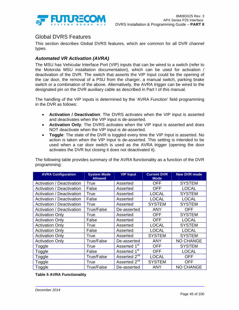
Decem
GlobThis types
AutoThe Mthe Mdeactthe cswitcdesig The hin the
The fprogr
AV
ActivaActivaActivaActivaActivaActivaActivaActivaActivaActivaActivaActivaToggToggToggToggTogg
Table
mber 2014
bal DVRSsection des
s.
omated VRMSU has VeMotorola MStivation of th
car door, theh or a comb
gnated pin on
handling of te DVR as fol
Activatioand deactActivatioNOT deacToggle: Taction is tused wheactivates
following tabramming:
VRA Configur
ation / Deacation / Deacation / Deacation / Deacation / Deacation / Deacation Only ation Only ation Only ation Only ation Only ation Only le le le le le
e 5 AVRA Fun
S Featuresscribes Glob
R Activationehicular InteSU installathe DVR. Thee removal ofbination of thn the DVR a
the VIP inpullows:
on / Deactivtivates when
on Only: Thectivate whenThe state of taken when en a car dothe DVR bu
ble provides
ration S
ctivation Trctivation Factivation Trctivation Factivation Trctivation Tr
TrFaTrFaTrTrTrFaTrTrTr
nctionality
s al DVRS fe
n (AVRA) rface Port (Vtion documee switch thaf a PSU fro
he above. Altauxiliary cab
uts is determ
vation: The n the VIP inpe DVRS actn the VIP inpthe DVR is the VIP Inp
oor switch ist closing it d
summary of
System Mode Allowed
rue alse rue alse rue rue/False rue alse rue alse rue rue/False rue alse rue/False rue rue/False
DVRS Insta
atures, whic
VIP) inputs tentation), wat asserts thm the chargternatively, tle as describ
mined by the
DVRS activput is de-asstivates whenput is de-asstoggled eve
put is de-asss used as tdoes not dea
f the AVRA f
VIP Inpu
AssertedAssertedAssertedAssertedAssertedDe-assertAssertedAssertedAssertedAssertedAssertedDe-assertAssertedAssertedAssertedAssertedDe-assert
allation & Pro
ch are comm
that can be wwhich can b
e VIP Input ger, a manuthe AVRA trbed in Part I
e ‘AVRA Fun
vates when tserted. n the VIP inpserted. ery time the Vserted. This he AVRA tr
activated it).
functionality
ut CurrenMo
OFOF
LOCLOC
SYSted AN
OFOF
LOCLOC
SYSted AN1st OF1st OF2nd LOC2nd SYSted AN
8MAPX Serie
ogramming Gu
mon for all D
wired to a swbe used for could be th
ual switch, prigger can be of this man
nction’ field
the VIP inpu
put is assert
VIP Input is setting is in
rigger (open
as a functio
nt DVR ode
Ne
FF FF CAL CAL
STEM NY FF FF CAL CAL
STEM NY NFF FF CAL
STEM NY N
M083X25 Rev.es P25 Interfacuide – PART
Page 45 of 10
DVR channe
witch (refer tr activation he opening oparking brake wired to thual.
programmin
ut is asserte
ted and doe
asserted. Nntended to bning the doo
on of the DV
ew DVR mode
SYSTEM LOCAL
SYSTEM LOCAL
SYSTEM OFF
SYSTEM LOCAL
SYSTEM LOCAL
SYSTEM O CHANGESYSTEM LOCAL
OFF OFF
O CHANGE
3 ce
II
00
el
to /
of ke he
ng
ed
es
No be or
R
e
E
E

Decem
BandWhenthe Dantenwhenpresethe Bon MMSUtrunkwhilelongetrunksites (OFF If BaregarLockiare mnot re For Macces
In CaThe IMSU
Whenoperawill ta For dto the Whenconfig
mber 2014
d Locking n both the M
DVRS requirnna port. Thn the DVR aent (‘MSU RBand Lock feMSU channe
channels wking systemse the DVR iser allow roaking site that
are availabF mode), the
nd Locking rdless of theing to be dis
mounted in sequired.
MSU convenss to channe
ar Monitor ICM feature codeplug a
ICM is enIf ‘ICM AconfigureICM functransitions
n ICM functiation takes pake place wh
details on hoe correspond
n the MSUgurations ar
‘ICM SeleTG ID (dchannel).
MSU and DVres a speciahe special inand MSU areF Bypass sweature is en
els that are where the frs, the MSU ws active (i.e. ming to siteuses the loc
ble, the MSUMSU freque
is disablede frequency sabled is thesuch way as
ntional chanels using the
r (ICM) allows the
s follows:
nabled / disaAllowed’ is d on a per M
ctionality is s OR via Me
ionality is coplace when hen the MSU
ow to programding Motorol
is operatine available:
ected’ – the digital DVR
VR are confal set of filten-band filtere activated witch’ in the
nabled by deexplicitly usrequency bawill be prevein SYSTEM
es using thecked out banU will becomency band is
in the Tweband. A typ
e Fixed DVRto provide m
nels where e locked out
MSU to mon
bled globallyprogramme
MSU channefurther conf
enu Item / Bu
onfigured to the MSU m
U microphon
m the ICM fula document
ng on a T
MSU speakchannel) or
DVRS Insta
figured to ors including rs are requiat the sameTweaker Ha
efault and thing the sam
and is not eented from
M or LOCAL e locked out nd, the MSUme ‘Out Of s unlocked.
eaker, the Mpical in-band
RS applicatiominimum 70d
the band isfrequency b
nitor PSU vo
y in the MSUed in the Mel basis via thfigured to button on the
be triggeredicrophone is
ne is taken o
unctionality atation.
runking FN
ker unmutesr all qualifie
allation & Pro
perate in than in-band
red in ordere time. Wheardware setuhe Tweaker me frequencexplicitly knousing frequemode). In th band. If the
U will roam toRange’. W
MSU is allowd application
on when the db of isolatio
s known andband.
oice traffic a
U via the ‘ICMMSU then IChe ‘ICM Allo
be triggered MSU contro
d via HUB os placed on off HUB.
and options
E with ICM
s to PSU auded analog P
8MAPX Serie
ogramming Gu
e same freqfilter placed
r to preventn the in-banup screen isprevents DV
cy band as town such asencies in thehis case thee MSU is co another sithen the DV
wed to roamn that may MSU and Don and in-ba
d fixed, the D
and is config
M Allowed’ fCM operatio
owed’ codepby either H
ol head or ke
on/off then ‘ICHUB, ‘ICM
in the MSU
M enabled
dio matchingPSU audio
M083X25 Rev.es P25 Interfacuide – PART
Page 46 of 10
quency bandd at the MSt interferencnd filter is nos uncheckedVR operatiothe DVR. Os in multi-site same ban
e MSU will ncurrently on te. If no othe
VR is inactiv
m to any sitrequire Ban
DVR antennaand filtering
DVR restrict
gurable in th
field on is furthelug field. HUB on / oeypad Mic.
CM SelectedAll’ operatio
, please refe
the followin
g its selecte(analog DV
3 ce
II
00
d, U
ce ot
d), on On te
nd no a
er ve
te nd as is
ts
he
er
off
d’ on
er
ng
ed R

Decem
Whenconfig
ProxiBox ( NOTEInbouare h
mber 2014
‘ICM All’ –(digital DV
n the MSU gurations ar
‘ICM Selewill unmuqualified a‘ICM Seleunmute toaudio (an‘ICM All’ –
ed Private C(HUB) status
E: und Private ceard on the
– the MSU VR channel)
is operatinge available:
ected’ and Mte only to PSanalog audioected’ and Mo any PSU alog DVR ch– the MSU s
Calls are nes.
calls to the MMSU Speak
speaker unm) or all analo
g on a con
MSU configuSU audio mao (analog DV
MSU configuTG audio (
hannels). speaker unm
ever heard o
MSU are noker.
DVRS Insta
mutes to all og PSU audio
ventional F
ured for Selatching its seVR channelsured for Norm(digital DVR
mutes to all P
on the MSU
ot supported
allation & Pro
PSU audio o (analog DV
NE with ICM
lective Squeelected TG s) mal Squelch
R channels)
PSU audio
speaker reg
. Outbound
8MAPX Serie
ogramming Gu
regardless VR channel)
M enabled
elch – the M(digital DVR
h – the MSUor qualified
gardless of
Private Call
M083X25 Rev.es P25 Interfacuide – PART
Page 47 of 10
of the TG I).
the followin
MSU speakeR channels) o
U speaker wanalog PS
the Hang U
s to the MS
3 ce
II
00
D
ng
er or
will U
Up
U

Decem
PrimThe one locati IMPOThe deploDVRSmode The Da Primlong The s
DurinfreququeryBeat’DVR DVRsThe ‘execuThe ‘commThe Bonly frequrepea In orarriviPrimasever The tthe Rthen Beforfrequprogrits ‘Hchecktrans
mber 2014
mary / SecoDVRS has DVRS from ion.
ORTANT! DVRS vot
oyment sceS! Moving e.
DVRs are camary i.e. eleas there is a
simulcast pre
Primary / Busy Loc
ng the ‘Primaency. When
y – “Is there, then the Dbecomes t
s of its statuSecondary’ ute Primary/‘Primary’ DVmunicates’ iBusy Lockouto periodicency) but a
at.
rder to accong or leavinary activatioral built-in la
transmit powRepeater Chthe ‘Tx Pwrre a Primaryency to ens
rammed ‘RxHeart Beat’. k for any acmitting. If th
ondary - Opa built-in simtransmitting
ting algoritenarios onlvehicles m
apable of coected to repea Primary.
evention alg
Secondary kout Phase
ary / Secondn a DVR is ae a Primary
DVR assumethe Primary s. DVRs moni
/Secondary cVR servicests status to tut phase sercally commualso to chec
ommodate thg the scene
on, remote Dayers, config
wer during Dhannel Setur’ setting. y DVR sendsure the chax RSSI Th’, t
When a Setivity on the ere is a tran
peration anmulcast preg on the sa
thm is desy. It canno
must have t
ommunicatineat and whic
gorithm has t
Phase
dary’ Phase,activated (swy?” If it recees Secondary
and starts
tor any DVRchecks perio
s any commthe other DVrves as an aunicate withck for any a
he dynamicae at random DVR steerinurable in the
DVRS-to-DVRup Menu. T
s out a ‘Heaannel is freethe DVR wilecondary DVtransmit fre
nsmission de
DVRS Insta
nd Programvention mec
ame frequen
signed to ot be applieheir DVRS
ng with eachch DVRs are
two phases:
the DVRs ewitched to SYeives a Primy state. If nosending ‘P
R-related actodically.
munication reVRs. added protech the other activity on it
ally changintime, DVR c
ng etc., the e DVR progr
RS transmisypically this
art Beat’, it e. If an RF sl wait until thVR stops re
equency to detected on th
allation & Pro
mming Ovechanism, whncy, at the
handle sted to movin
switched t
h other and ne Secondary
exchange P2YSTEM or L
mary (or Peo Primary HePrimary Hea
tivity while in
equests in t
ction by forcDVRs in
ts transmit f
ng “real life”channel / moPrimary / S
rammed per
ssion is set bs field is sel
checks for Rsignal is prehe channel eceiving ‘Hedetermine if he transmit f
8MAPX Serie
ogramming Gu
erview hich prevensame time,
tationary, sng vehiclesto OFF or V
negotiating wy (i.e. on sta
25 messageLOCAL Modrmanent Preart Beat is
art Beats’ no
n a Seconda
he area and
cing the Primthe area (frequency p
” environmeode changesSecondary arsonality.
by the ‘R-Txected to be
RF activity oesent and it is free befor
eart Beats’, the Primary frequency a
M083X25 Rev.es P25 Interfacuide – PART
Page 48 of 10
ts more thain the sam
same scens with activVR Disable
which DVR and-by) for a
es on their Re), it sends imary) ‘Heareceived, thotifying othe
ary mode an
d periodical
mary DVR nousing its R
prior to ever
ent i.e. DVRs, Permanenalgorithm ha
x Pwr’ field 4-5dB lowe
on its receivexceeds th
re it transmitthe DVR w DVR is busnd it exceed
3 ce
II
00
an me
ne ve ed
is as
Rx a
art he er
nd
ly
ot Rx ry
Rs nt as
in er
ve he ts
will sy ds

Decem
the pcontinTh’ aPrima IMPOThe D The PrimseconSetupreve(on tChanfrequdetectranstransPrimin aPrimremoChanPrimathe Das wdurinnorminstal If Lealgorfeatuthe d
mber 2014
programmednue waiting
and 3 Heart ary.
ORTANT! DVR cannot
‘Heart Beatary/Secondnds. When tp Screen) ention checkhe DVR Tx nnel Setup ency, the P
cted, the DVmitting and mission is pary/Second
a fixed locary/Second
ote, fixed DVnnel Setup sary Heart Be
DVR will ignoell. The “Dig bench tesal DVR opllations (tunn
gacy Mobexrithm is comre allows seeployment o
d ‘Tx RSSI Tfor a ‘PrimaBeats are m
t transmit H
t’ Interval (3dary Setup.the ‘Enable is enabled
k step. Prior frequency) Menu). If
Primary DVVR transmiteither back
present. Disdary Setup Mcation. Thedary Setup VR installatioscreen detereat from anoore the Primisable Primsting. Primarperation exnels or in-bu
xcom II votmpatible witheamless repof both types
Th’, the DVary Heart Bemissed, the S
Heart Beats
3-60 sec) is The defauBL For Vo(checked), to transmittexceeding no such R
R starts trats momentas off (if the
sabling the DMenu is inte ‘PermaneMenu) is d
ons or duringrmines the Pother DVR aary Heart Be
mary / Secory / Secondacept during
uilding system
ting compath older stylelacement of
s of units in t
DVRS Insta
VR will contieat’. If no actSecondary D
while it is b
s set by theult programmice Commu
the DVRSing, a Primathe programRF transmisansmitting i.arily then ch
other DVR DVR Primarended for tesent Primarisabled by d
g testing. ThPrimary / Secat a level loweats and wilndary Procary processig bench tems using co
ibility modee analog onf old style Vthe same fle
allation & Pro
inue operatitivity is dete
DVR will star
busy repeat
e ‘Heart Bemed Heart unication’ fiS goes throary DVR chemmed ‘Busyssion is de.e. repeatinhecks againis still trans
ry / Secondst purposes ry Status default and e ‘Rx RSSI condary ranwer than thel negotiate b
cessing” bong should a
esting and mmon filteri
e is enablednly MobexcoVRs with the eet during the
8MAPX Serie
ogramming Gu
ing as a Sected above rt negotiating
ting.
eat IntervalBeat Intervaeld (Primary
ough an extecks for any y LC Th’ (setected on g. If transm
n if another smitting) or ary Processor if the DVEnable’ fshould be Th’ field in
nge. If a DVRe programmbecoming a ox is to be calways be enin some fing / combin
d in the DVom II VRs.
new DVR be transition p
M083X25 Rev.es P25 Interfacuide – PART
Page 49 of 10
econdary anthe ‘Tx RSSg becoming
l’ field in thal value is y/Secondartra simulcastransmissio
see Repeatethe transm
mit activity r DVR is stkeys up if nsing from th
VR is installefield (in thused only athe Repeate
R is receivined thresholdPrimary DVchecked onnabled durinixed isolateers).
VR, its votinEnabling thby supportinperiod.
3 ce
II
00
nd SI a
he 5
ry st
on er
mit is till no he ed he at er ng d, R ly
ng ed
ng is
ng

Decem
RemDispamode The M
If “GeAPX modemess
Dispawhen
mber 2014
mote Mode atcher can se change in
MSU can be
Call AlerCall Alert Call Alerdoes NOTRemote Ato its ID aAlert is pr
enerate StatMSU) , the
e (OFF, SYSsages:
atcher can’t n a ‘VR Disa
change of send a call athe following
e programme
rt / Remote requests
rt Enabled –T initiate DVActivation Eand will initirogrammed i
tus on DVR MSU will seSTEM, LOC
DVR M
force a non-bled’ mode
f DVRS by alert (page) tg order: OFF
ed to suppor
Activation
– the MSU VRS mode chEnabled – tiate DVR min the “DVR
Mode Channd back a mAL). Only th
MODEOF
LOCASYSTE
-primary DVis selected o
DVRS Insta
FNE / Dispto a specificF-SYS-LOC-
rt one of the
Disabled –
responds tohange he MSU willode changeRemote Act
nge” is enabmode changehe dispatche
SFFALEM
R to becomeon the contro
allation & Pro
patcher c MSU ID, w-OFF.
following co
– the MSU d
o Call Alerts
l acknowlede provided ttivation IDs”
bled for a give status to iner console c
STATUS VALU123
e a primary ol head.
8MAPX Serie
ogramming Gu
which in turn
onfigurations
does not res
addressed
ge Call Alerhe source I” table.
ven DVRS Pndicate the ccan interpret
UE
and can’t ac
M083X25 Rev.es P25 Interfacuide – PART
Page 50 of 10
causes DV
s:
spond to an
to its ID an
rts addresseD of the Ca
Profile (in thcurrent DVRt those statu
ctivate a DV
3 ce
II
00
R
ny
nd
ed all
he RS us
R

Decem
UnsuThe fPSUs
NOTEThe ufeatu
mber 2014
upported Pfollowing PSs:
Evac TonHearclearDTMF HoSecureneSoft ID QCII SingletonConventioAuthenticOver-the-Over-the-Over-the-PSU ScanPSU RepPSU AnnPSU Phas
E: unsupportedres. Please
PSU FeaturSU features a
ne r ot Keypad et
e onal OTAR cation Deman-Air-Channel-Air Channel-Air-Programn rogram requouncement se II P25 co
d PSU featucontact Mot
res are not pres
nd packetsl Reassignml Steering (O
mming (OTAP
uest / SelectGroup opera
onventional o
res list provtorola for spe
DVRS Insta
sently suppo
ment (OTACROTACS) P)
or Lock ation operation
vided above ecific feature
allation & Pro
orted by the
R)
may NOT ie support inf
8MAPX Serie
ogramming Gu
DVRS or DV
include ALL formation.
M083X25 Rev.es P25 Interfacuide – PART
Page 51 of 10
VRS Enable
unsupporte
3 ce
II
00
ed
ed

Decem
DigiDigita
The Dthe sPSUs NOTEForceand tcommWhen‘DVR
PSUWhenactive
GeneDVR selec IMPOThe m
GrouInbou
mber 2014
tal DVR Mal DVRS Mo
Selected P25 PSUDigital moA DVRS E
DVR Channspecific DVRs and the DV
E: ed Analog Mthe ‘DVRS munications n a P25 cha
RS Enabled’
U Affiliationn a local PSe primary DV
The DVRchannel. The same
eric P25 PSenabled mo
ction of DVR
ORTANT! maximum n
up Calls und and outb
Mode - Opode assumes
DVR channe either prog
ode currentlyEnabled, P2
el programmR channel anVR are matc
Mode is a hyEnabled’ P2are ‘forced’ nnel / TG is P25 PSU an
n SU User seleVRS if:
R is program
e digital DVR
SU is registeode. ‘DVRS
R Enabled mo
number of P
bound group
peration as the followin
el is programrammed fory selected (r
25 MSU mod
ming requirend the Tx/Rched.
ybrid mode in25 PSU incto be analoselected on
nd DVR are
ects a DVR
mmed for d
R channel is
ered during Enabled’ P2ode (no PTT
PSUs that ca
p calls are su
DVRS Insta
and Prograng:
mmed for digr digital DVRreferred to ade is selecte
s that Digitax frequencie
n which the cluding all sog when the n the MSU, bP25 Digital.
Enabled Mo
digital (or m
selected on
the first gro25 PSU starT required to
an get affili
upported by
allation & Pro
amming O
gital or mixeR operation s a Local Pd on the MS
al or Mixedes as well a
communicasignaling are
MSU is on both signalin
ode, the loca
mixed) mode
n both the PS
oup call madrts automatico start affiliat
ated with o
the DVRS.
8MAPX Serie
ogramming Gu
Overview
d mode. or Generic SU).
SU.
mode is proas the Tx/Rx
ations betwee digital, wha non-P25 c
ng and voice
al PSU is aff
e on the s
SU and the
de after swic affiliation ption process
one DVRS is
M083X25 Rev.es P25 Interfacuide – PART
Page 52 of 10
P25 and wit
ogrammed fox NIDs of th
en the DVRhile the voicchannel / TGe between th
filiated via a
elected DV
DVRS.
itching to thprocess upo).
s 256.
3 ce
II
00
th
or he
RS ce G. he
an
R
he on

Decem
MSUMSULOW
MED
HIGH
Table
PSUPSU HIGH
LOW
Table
mber 2014
U Priorities Priority Le
W
IUM
H
e 6 MSU Prox
U Proxy ReqProxy Requ
H
W
e 7 PSU Prox
s vel
xy Request P
quest Priouest Priority
xy Request P
Priorities
rities y Level
Priorities
DVRS Insta
MSU RIdle (inaudio)Group includichannePacketTransmSignaliIndividEmergEmergEmergMSU M
Proxy EmergEmergAll othe
allation & Pro
Request ncl. in Emerg
Voice Receng hangtimeel) t Data mitting ing features ual Calls (un
gency Alarm gency Call Trgency Call RMode Chang
Request gency Alarmgency Call er Proxy Re
8MAPX Serie
ogramming Gu
gency Call,
eive (all groue while on t
(call alert, snit to unit an
ransmit eceive
ge, Power Do
quests
M083X25 Rev.es P25 Interfacuide – PART
Page 53 of 10
not receivin
up call typestrunked voic
status etc.) nd Phone)
own
3 ce
II
00
ng
s, ce

Decem
SignWhenanothprogrProxyEmerStatu New High High Low P
Table
N
High
High
High
High
Low P
Low P
Low P
Low P
Low P
H/L P
High
Low P
Low P
Table
mber 2014
naling Requn the DVR isher Local PSramming andy and Tabrgency Alarmus, Message
Request Priority SignPriority SignPriority Sign
e 8 Signaling
New Reques
Priority Sign
Priority Sign
Priority Sign
Priority Sign
Priority Sign
Priority Sign
Priority Sign
Priority Sign
Priority Sign
Priority Signa
Priority Sign
Priority Sign
Priority Sign
e 9 Signaling
uest Interas in the proc
SU initiates ad as describle 9 Signam is conside etc.) is cons
naling naling naling
Request Int
st E
naling PSU
naling PSU
naling OutVoic
naling OutIndi
naling PSU
naling PSU
naling OutVoic
naling OutVoic
naling OutIndi
aling GroHan
naling IndiHan
naling IndiHan
naling IndiHan
Request Int
actions witcess of handa Signaling rbed in Tablealing Requeered high prisidered low
Existing RHigh PriorLow PrioriLow/High
teraction with
Existing Req
U Group Voi
U Individual
tbound FNE ce tbound FNE ividual VoiceU Group Voi
U Individual
tbound FNE ce tbound FNE ce tbound FNE ividual Voice
oup Voice ngtime ividual Voicengtime ividual Voicengtime ividual Voicengtime
teraction with
DVRS Insta
th Voice andling a voicerequest, the e 8 Signalingest Interactioiority signalipriority.
Request rity Signalingty SignalingPriority Sign
h Signaling P
quest
ice EnDi
Voice EnDi
Group EnDi
e EnDi
ice EnDi
Voice EnDi
Group En
Group Di
e EnDiEnDi
e EnDi
e En
e Di
h Voice Prox
allation & Pro
nd Signaline or signalinDVRS will rg Request Ion with Vong. All other
Actg Qu Pro
naling Qu
Proxy
‘Outbound Takeover By
Signaling Allowed’
nabled or isabled nabled or isabled nabled or isabled nabled or isabled nabled or isabled nabled or isabled nabled
isabled
nabled or isabled nabled or isabled nabled or isabled nabled
isabled
xy
8MAPX Serie
ogramming Gu
ng Proxy ng request forespond depInteraction woice Proxy r PSU signa
tion eue New Re
ocess New Reue New Re
A
ProcessRequesProcessRequesProcessRequesProcessRequesDiscardRequesDiscardRequesProcessRequesDiscardRequesDiscardRequesProcessRequesProcessRequesProcessRequesDiscardReques
M083X25 Rev.es P25 Interfacuide – PART
Page 54 of 10
or a PSU anpending on itwith Signalin
below. PSaling (such a
equest Request equest
Action
s New st s New st s New st s New st d New st d New st s New st d New st d New st s New st s New st s New st d New st
3 ce
II
00
nd ts
ng U
as

Decem
VoicVoiceCall dynaPSU (suchintera New High Low PLow P
Table
Ne
High VoiceHigh VoiceHigh Voice
High VoiceHigh Voice
Low VoiceLow VoiceLow VoiceLow VoiceLow VoiceLow P
Low P
High/VoiceLow P
mber 2014
ce Requeste request inis considermic regroupEmergency
h as statusactions with
Request Priority VoicPriority VoicPriority Voic
e 10 Voice Re
ew Request
Priore*
Priore*
Priore*
Priore*
Priore*
Priore*
Priore*
Priore*
Priore*
Priore* Priority Voic
Priority Voic
/Low Priore Priority Voic
t Interactioteractions w
red high priing and ann
y Alarm is cs, messagevoice proxy
ce ce ce
equest Intera
ExiReq
ity High PrGroup V
ity High PrGroup V
ity Low PriGroup V
ity PSU IndCall
ity OutbouPriority Group V
ity High PrGroup V
ity Low PriGroup V
ity Low PriGroup V
ity PSU IndVoice
ity PSU IndVoice
ce OutbouPriority Group V
ce OutbouPriority Group V
ity Group VHangtim
ce IndividuHangtim
on with Sigwith signalingiority voice,ouncement considered e etc.) is c
are handled
Existing RHigh/Low High PriorLow Priori
actions with
isting quest
riority PSU Voice riority PSU Voice ority PSU
Voice
dividual
nd H/L FNE
Voice riority PSU Voice ority PSU
Voice ority PSU
Voice dividual
dividual
nd H/L FNE
Voice nd H/L FNE
Voice Voice me ual Voice me
DVRS Insta
gnaling andg proxy are while all g/ multigrouphigh priorityconsidered d by the DVR
Request Priority Sign
rity Signalingty Signaling
Signaling Pr
‘Inbound Takeover Allowed’
Disabled
Enabled
Enabled or Disabled
Enabled or Disabled Enabled or Disabled
Enabled or Disabled Enabled
Disabled
Enabled
Disabled
Enabled or Disabled
Enabled or Disabled
Enabled or Disabled Enabled or Disabled
allation & Pro
d Voice Proe described group voice
p are considey signaling.
low priorityRS as progra
Actnaling Prog Dis Pro
roxy
‘OutboTakeov
Voice A
EnableDisableEnableDisable
r EnableDisable
r EnableDisable
r EnableDisable
r EnableDisableEnableDisableEnableDisableEnableDisableEnableDisable
r Enable
r Disable
r EnableDisable
r Enable
8MAPX Serie
ogramming Gu
oxy in Table 10
e calls (inclered low prioAll other P
y. Voice prammed, see
tion ocess New Rscard New Rocess New R
ound ver by
Allowed’ d or
ed DisReq
d or ed
ProReq
d or ed
ProReq
d or ed
ProReq
d or ed
ProReq
d or ed
DisReq
d or ed
ProReq
d or ed
DisReq
d or ed
ProReq
d or ed
DisReq
d ProReq
ed DisReq
d or ed
ProReq
d ProReq
M083X25 Rev.es P25 Interfacuide – PART
Page 55 of 10
0. Emergencluding patchority voice.
PSU signalinroxy reques
e Table 11.
Request Request Request
Action*
scard New quest
ocess New quest
ocess New quest
ocess New quest
ocess New quest
scard New quest
ocess New quest
scard New quest
ocess New quest
scard New quest
ocess New quest
scard New quest
ocess New quest
ocess New quest
3 ce
II
00
cy h,
ng st

Decem
Ne
Low P
Table
*ActionConve
MSUThe DVR
mber 2014
ew Request
Priority Voic
e 11 Voice Pr
n rules applyentional P25 ra
U Voice andMSU handlebased on th
MSU EmemergencPSU EmeMSU PTTemergencPSU non-
ExiReq
ce IndividuHangtim
roxy Interact
y to ‘DVRS Edios perform in
d Signalinges interactiohe following
mergency ovcy call. ergency overT and signacy proxies -emergency
isting quest
ual Voice me
ion with Voic
Enabled’ PSUnterrupts based
g Proxy Intons with a Pgeneral prio
verrides all
rrides all MSaling feature
proxies ove
DVRS Insta
‘Inbound Takeover Allowed’
Enabled or Disabled
ce Proxy
Us. Applicable d on which unit
teractionsPSU voice o
ority rules:
proxies in
SU non-emees (call alert
erride MSU r
allation & Pro
‘OutboTakeov
Voice A
r Disable
to inbound t has the strong
or signaling
ncluding PS
ergency proxt, status etc
receive
8MAPX Serie
ogramming Gu
ound ver by
Allowed’ ed Dis
Req
takeover callsgest signal.
g proxy requ
SU emerge
xies c) override a
M083X25 Rev.es P25 Interfacuide – PART
Page 56 of 10
Action*
scard New quest
s only. Gener
uest from th
ency alarm
all PSU non
3 ce
II
00
ric
he
/
n-

Decem
Talk The Lto theEnabFor etalk totranstransAn oDVRSIf Proselec
Talk Whenis recthe TThe Lin thethe TFor iTransrepeaswitcGeneoperaTransthe M IMPOTG T Whenthe Dselecin theon thselecPSUsthose IMPOEncr
PrivaPrivasuppprivat
mber 2014
k Group ProLocal PSU Ue correspon
bled’ Mode, wexample, if tho Local TG1mitting on Tmit on the Tutbound calS to the Locoxing is Discted in orde
k Group Tran TG translaceived by theTG currently Local PSU ce DVRS TG
TG ID currennstance, if slation list aated by the hed to TG C
eric (non-DVation will, byslation table
MSU.
ORTANT! Translation r
n TG proxinDVRS Transcted on the Me DVRS TG he PSU TG cted MSU Ts need to be calls.
ORTANT! ryption Key
ate Calls ate Calls (Loorted on ‘DVte calls via D
oxing User can chnding TG Uswhich may ohe Local PS1 users as wTG1. If the MTG selected oll received b
cal PSUs. sabled then
er to enable
anslation ation is enabe DVR from selected on could be proTranslationtly selected the Local Pand the MS
DVR locallC then the LoVRS Enabledy default, use
then PSUs
requires tha
g is enabledslation TableMSU. If TG TranslationID. Outbou
TG is repeatbe programm
Translation
ocal to LocaVRS Enable
DVRS.
ange the sesers through
or may not mU selects TG
well as SysteMSU microphon the MSUby the MSU
n the Locale Local PSU
bled in the Dthe Local Pthe MSU’s c
ogrammed w list, the PSon the MSU
PSU is on TSU is on TGy and to thocal PSU cad) Conventioe TG ID 1 wtransmitting
at TG Proxi
d and the TGe, the DVRSProxing is e list then the
und call (syted ‘as is’ i.med with No
n is not sup
al PSU; Loced’ PSUs o
DVRS Insta
elected ‘DVRh the DVRS
match the TGG1 while theem TG1 Usehone is PTT i.e. TG2. on either T
l PSU and affiliation a
DVR for a spPSU with thiscontrol head
with just oneSU call will aU control heaTG A, whicG B then ahe System oalls will be reonal P25 PShen transmi
g TG ID 1 wil
ng is enabl
G selected oS will affiliatenabled but te DVRS will
ystem origina.e. without aormal Squel
pported by t
cal to Systenly. Generic
allation & Pro
RS Enabled’S. The MSUG selected bye MSU is on ers via the DT-ed, both th
TG1 or TG2
the MSU mand commu
pecific PSU s TG ID will d. e TG ID and always be traad. h is progra
all inbound on TG B. If epeated on TUs that are itting. If TG Ill be translat
ed.
on the Locate the Localthe Local PSl proxy any ated call) reany translatch (or NID
the DVRS.
m PSU; Syc P25 PSU
8MAPX Serie
ogramming Gu
’ TG and seU can be ony the Local PTG2, the Lo
DVRS i.e. thehe MSU and
2 will be rep
must have tunications.
TG ID, thenbe translate
if this ID is anslated by
mmed in thLocal PSU
f the MSU mTG C. not enabledID 1 is addeted to the TG
al PSU is prl PSU on thSU is on a Tinbound / oeceived on ion. Therefo= F7E) in o
ystem to Locmode does
M083X25 Rev.es P25 Interfacuide – PART
Page 57 of 10
eamlessly tan any ‘DVRPSU. ocal PSU cae MSU will b the DVR w
peated by th
he same TG
n any call thaed to the ID o
programmethe DVRS t
he DVRS TGcalls will b
mode is the
for talkgroued to the DVG selected o
ogrammed ihe TG that TG that is noutbound calthe current
ore the Locaorder to hea
cal PSU) ars not suppo
3 ce
II
00
lk RS
an be will
he
G
at of
ed to
G be en
up R
on
in is ot ls ly al ar
re ort
Decem
PSU‘Go ADifferthe cgenePSU ‘Digitmode
StatuIf enscreeEnab
NO
The aThe sis nopreprtime modeDVR trans
LocaWhen“LOCthe Davaila
RadiRadiowhenboth trunk‘VR D
P25 P25 PSUs
mber 2014
U Talk PermAhead’ tonesrent tones acall is P25 rated when user can g
tal System e does not s
us Broadcabled in the
en), the DVRbled PSUs:
FNE Out DVR LocaSite TrunkIV&D Ena
NOTE: Only a Prima
above statusstatus indica
o change to rogrammed a Local PS
e, the MSU stops sendmits Failsoft
al Mode Indn the DVRS
CAL ONLY” DVR as descable on ‘DVR
io Check / o Check andn the DVRS
‘DVRS Enaked or P25 cDisabled’ mo
Trunking OOver The As are of the
mit Tones s are generare generateEncrypted. the system
get ‘System Setup Menupport Talk
ast e DVR (“NeR transmits
of Range al only statuking abled / Disab
ary DVR can
s indication iation is passthe status, time interva
SU is affiliatproxies the
ing status bt message in
dication is operatingmessage di
cribed in theRS Enabled’
Inhibit d Radio Inhib
is in the SYabled’ and Gconventional ode of opera
OTAR Air Rekeying‘DVRS Ena
ated in the ‘Dd to indicateAs a progis busy andBusy’ tones
nu’ in the DVPermit Tone
etwork Statstatus broad
s
bled status
n transmit St
is not availased to the Lo
the DVRS sal. The DVRSed with the
e Failsoft meroadcast to nstead.
g in the Locsplayed on t
e ‘Status Bro’ P25 PSUs
bit functionsYSTEM or LGeneric P25mode. If the
ation.
g (OTAR) isbled’ type, t
DVRS Insta
DVRS Enable if the DVRrammable o
d only local s and be foVRS Prograes when ope
tus Reportidcasts that
tatus Broadc
ble to Generocal PSU evsends statuS also send System viaessage (if fathe local DV
al Mode, thethe PSU scr
oadcast’ paraand is not a
are passedLOCAL mod5 PSUs whee MSU gets
s supported he DVRS is
allation & Pro
ed’ PSUs. RS is in LOCoption LOCArepeat is avorced to waamming secerating throu
ing Intervalcan be rece
casts.
ric P25 PSUvery time thes indication
ds a networka DVRS. If failsoft is enVRS Enable
e DVRS Enareen if statusagraph. The
available to G
through thede. Those fuen the MSUradio inhibi
through th in the SYST
8MAPX Serie
ogramming Gu
CAL or SYSTAL mode to
vailable. Alteait for systemction). Gene
ugh the DVR
l”, Digital Seived only b
Us when usine status cha to the Loca
k status notifthe FNE e
nabled in theed PSUs an
abled PSU Us broadcast e above indiGeneric P25
e DVRS to thunctions areU is operatinted, the DVR
e DVRS whTEM mode
M083X25 Rev.es P25 Interfacuide – PART
Page 58 of 10
TEM mode oones can b
ernatively, thm grant (seeric P25 PS
RS.
System setuby P25 DVR
ng the DVRSnges. If theral PSUs at fication evernters Failsoe MSU). Thd periodical
User can seis enabled ication is on
5 PSUs.
he Local PSe available tng on a P2R switches t
hen the locaand the MS
3 ce
II
00
or be he ee U
up RS
S. re a ry
oft he ly
ee in ly
U to
25 to
al U

Decem
is on or if t
PatcWhenfunct‘DVRMSU IMPOSysteare o MSU
DynaThe DoperaThis subscchanthe DTrunkregrozone/prese NOTEDyna
PhonPhonon a mode
AdapThe DtransconsewherePSU- NOTEAdapon “D
mber 2014
a P25 Trunthe MSU is o
ch n several TGion), the DV
RS Enabled’ is on a P25
ORTANT! em design
outside of th
Patch is suInbound cpatch supOutbound
amic RegroDynamic Reate on a desis done by rcriber receinel. The DV
DVRS is in ked channe
ouped or u/channel seently support
E: amic Regrou
ne Interconne Interconn
full duplex Pe. Phone Inte
ptive PoweDVRS can bmit power derve the PSe multiple P-to-PSU com
E: ptive Power DVRS Enable
king mode. on a P25 con
Gs are patchVRS ensurePSUs are u
5 Trunking TG
must ensurhe range of
pported as fcall from PSpergroup andd call will be
ouping egrouping feasignated TGemotely assves the req
VRS extendsthe SYSTE
el. PSU Rngrouped)
election functed via the D
ping is not s
nnect ect is suppoP25 channeerconnect re
er Control be programmepending on
SU battery. EPSUs are usmmunication
Control is sed” PSUs.
OTAR is nonventional c
hed on the ses the patcused, the DVG.
re that PSU talkgroups
follows: SU on TG Td repeated lorepeated as
ature allowsG without anysigning a newquest, it aus this functio
EM or LOCAeprogram rand Select
ctionality whDVRS.
supported on
orted on local (digital or mequires the D
med to send n the receiveEnabling thied with a sis range.
upported on
DVRS Insta
ot supported hannel.
system side hing is mat
VRS is in the
TGs that ars used on th
Translation eocally and tos is (with the
s a dispatchey interventiow TG for theutomatically onality to theAL mode anrequest (PStor Lock / hile a PSU
n Generic P2
al P25 ‘DVRmixed modeDVR to be in
P25 messaged signal strs feature isngle simplex
n both ‘Gene
allation & Pro
if Generic P
(using the trtched on the SYSTEM
re programhe trunking
enabled TG o the systeme supergroup
er to remoteon from the e subscriber
switches te ‘DVRS Ennd the MSUSU request
Unlock (dis dynamic
25 PSUs.
RS Enabled’e) and the Mn the SYSTE
ges to the Lrength from ts NOT recomx mode DVR
eric P25’ XT
8MAPX Serie
ogramming Gu
P25 PSUs a
runking grouhe local PSUor LOCAL m
mmed for TGsystem.
will be tranm. p TG ID).
ely redirect ssubscriber u
r to operate oto the assignabled’ locaU is operatinting to be isabling /
cally regrou
PSU when MSU is on a EM or LOCA
Local PSUs tthe DVRS ammended inRS since it w
TS/APX PSU
M083X25 Rev.es P25 Interfacuide – PART
Page 59 of 10
re used and
up-regroupinU side whemode and th
G Translatio
nslated to th
subscribers tunit operatoon. When thgned zone l PSUs wheng on a P2
dynamicalenabling thped) are no
the DVRS P25 Trunke
AL mode.
to adjust thend thereby t
n applicationwill affect th
Us as well a
3 ce
II
00
d /
ng en he
on
he
to or. he
/ en 25 ly
he ot
is ed
eir to ns he
as
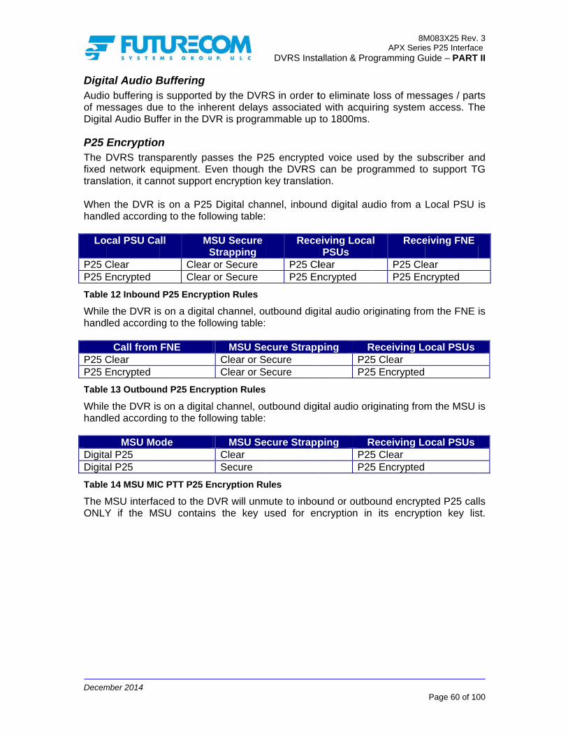
Decem
DigitAudioof meDigita
P25 The fixed trans Whenhand
Lo
P25 CP25 E
Table
Whilehand
P25 CP25 E
Table
Whilehand
DigitaDigita
Table
The MONLY
mber 2014
tal Audio Bo buffering isessages dueal Audio Buff
EncryptionDVRS transnetwork eq
lation, it can
n the DVR iled accordin
cal PSU Ca
Clear Encrypted
e 12 Inbound
e the DVR isled accordin
Call from Clear Encrypted
e 13 Outboun
e the DVR isled accordin
MSU Moal P25 al P25
e 14 MSU MIC
MSU interfacY if the MS
Buffering s supported e to the inheffer in the DV
n sparently paquipment. Evnnot support
s on a P25 ng to the follo
all MSS
Clear Clear
P25 Encryp
s on a digitang to the follo
FNE
nd P25 Encry
s on a digitalng to the follo
ode
C PTT P25 En
ced to the DSU contains
by the DVRerent delaysVR is progra
sses the P2ven though encryption k
Digital chanowing table:
SU Secure Strapping or Secure or Secure
ption Rules
l channel, ouowing table:
MSU SeClear or SClear or S
yption Rules
l channel, ouowing table:
MSU SeClear Secure
ncryption Ru
DVR will unms the key u
DVRS Insta
RS in order ts associatedmmable up
25 encryptedthe DVRS
key translati
nnel, inboun
Rece
P25 ClP25 En
utbound dig
ecure StrappSecure Secure
utbound digi
ecure Strapp
ules
mute to inbouused for en
allation & Pro
to eliminate d with acquito 1800ms.
d voice usecan be pro
ion.
nd digital au
eiving LocaPSUs
lear ncrypted
ital audio or
ping RP25P25
ital audio ori
ping RP25P25
und or outboncryption in
8MAPX Serie
ogramming Gu
loss of mesring system
ed by the sugrammed to
udio from a
l Rece
P25 CleP25 En
riginating fro
Receiving L5 Clear 5 Encrypted
iginating from
Receiving L5 Clear 5 Encrypted
ound encryp its encryp
M083X25 Rev.es P25 Interfacuide – PART
Page 60 of 10
ssages / part access. Th
ubscriber ano support TG
Local PSU
eiving FNE
ear ncrypted
om the FNE
ocal PSUs
m the MSU
ocal PSUs
pted P25 caltion key lis
3 ce
II
00
ts he
nd G
is
is
is
ls st.

Decem
RemA P2a spe
NOTERemothe aMode The DVRS NOTEAll DVremoassumsupp The Prima
mber 2014
mote DVR A5 PSU may
ecific DVRS
DVRS M DVR Sta Selected
E: ote change area since te change wit
DVRS is adS’ ID.
E: VRS should
ote control fme the ID oorted when
remote DVRary already p
Activation abe programand thereby
ode (from Otus (Second TG / Chann
of MSU Modthe TG Proxthin the sam
ddressed by
d have uniqufeature is tof the MSU cthe MSU ID
R status chapresent in th
and Steerinmmed to seny remotely ch
OFF or Localdary / Primarnel on MSU
de has no exing feature
me system, a
y sending a
ue IDs progro be used. currently inte= DVR ID.
ange will nohe area (see
DVRS Insta
ng by PSUd a call alerhange:
to System)ry)
effect on the e allows mund when TG
call alert (p
rammed in tIf no DVRS
erfaced to it.
ot be succe Table 15).
allation & Pro
U Call Alertrt (page) and
operation oltiple TG op
G Translation
page) with t
the digital mS ID is pro. Remote ac
essful if ther
8MAPX Serie
ogramming Gu
t (Page) d preprogram
of the rest ofperation. Thn is not enab
the specific
mode settingsogrammed, tctivation and
re is anothe
M083X25 Rev.es P25 Interfacuide – PART
Page 61 of 10
mmed NID t
f the PSUs ihis applies tbled
programme
s menu if ththe DVR w
d steering ar
er Permanen
3 ce
II
00
to
in to
ed
he will re
nt

Decem
The f
Lo
Call A
DPS
Call A
DPS
Call A
DPS
Call A
PS
Call A
PSU
Ca(P
PS
Table
mber 2014
following tab
cal PSU
Alert (Page) to:
DVRS A SU on TG 1
Alert (Page) to:
DVRS A SU on TG 1
Alert (Page) to:
DVRS A SU on TG 2
Alert (Page) to:
DVRS A SU on TG 2
Alert (Page) to:
DVRS A U on CONV1
all Alert Page) to:
DVRS A
SU on TG1
e 15 Typical R
ble illustrates
BEFOOFF ORLOCAL
SECONDA
DVR CH MSU TG
OFF ORLOCAL
SECONDA
DVR CH MSU TG
OFF ORLOCAL
SECONDA
DVR CH MSU TG
OFF ORLOCAL
SECONDA
DVR CH MSU TG
OFF ORLOCAL
SECONDA
DVR CH MSU TG
OFF ORLOCAL
SECONDA
DVR CH
MSU CON
Remote Stee
s some typic
DVRS A Steering
ORE AR
ARY
1 1
P
DM
R
ARY
1 1
SE
DM
R
ARY
1 1
P
DM
R
ARY
1 1
SE
DM
R
ARY
1 1
P
DM
R L
ARY
1 NV1
P
DM
ering Scenar
DVRS Insta
cal remote St
AFTER SYSTEM
PRIMARY
DVR CH 1 MSU TG 1
SYSTEM
ECONDARY
DVR CH 1 MSU TG 1
SYSTEM
PRIMARY
DVR CH 1 MSU TG 2
SYSTEM
ECONDARY
DVR CH 1 MSU TG 2
SYSTEM
PRIMARY
DVR CH 1 SU CONV1
SYSTEM
PRIMARY
DVR CH 1 MSU TG 1
ios
allation & Pro
teering scen
BEFOLOCAL OR S
PRIMAR
DVR CHMSU TG
LOCAL OR S
PERM. PRIM
DVR CHMSU TG
LOCAL OR S
PRIMAR
DVR CHMSU TG
LOCAL OSYSTE
PERM. PRIM
DVR CHMSU TG
LOCAL OSYSTE
PRIMAR
DVR CHMSU TG
LOCAL OSYSTE
PRIMAR
DVR CHMSU TG
8MAPX Serie
ogramming Gu
narios:
DVRS B Steering
ORE SYSTEM
RY
H 1 G 1
S
SYSTEM
MARY
H 1 G 1
PE
SYSTEM
RY
H 1 G 1
S
OR EM
MARY
H 1 G 1
PE
OR EM
RY
H 1 G 1
S
OR EM
RY
H 1 G 1
S
M083X25 Rev.es P25 Interfacuide – PART
Page 62 of 10
AFTER LOCAL OR
SYSTEM
SECONDARY
DVR CH 1 MSU TG 1 LOCAL OR
SYSTEM
RM. PRIMARY
DVR CH 1 MSU TG 1 LOCAL OR
SYSTEM
SECONDARY
DVR CH 1 MSU TG 1 LOCAL OR
SYSTEM
RM. PRIMARY
DVR CH 1 MSU TG 1 LOCAL OR
SYSTEM
SECONDARY
DVR CH 1 MSU TG 1 LOCAL OR
SYSTEM
SECONDARY
DVR CH 1 MSU TG 1
3 ce
II
00

Decem
The finvolv DVR RepeCH #
1
Table
NOTEF7E E The F(4, 5,Page5. ThrepeaTGs. same
EmeThe EmerBlockThe ‘Revewitho
EmerWhenproce
mber 2014
following tabved (DVR, P
Programminater Channe# RX
NID F7E
e 16 Program
E: Enables the
F7E setting , 6 in the ab
e to the DVRhe DVR willating the calAll of the ab
e DVR chann
ergency in ‘DVRS Ena
rgency featuked in Failso‘DVRS Enab
ert Talkgrouout an assign
rgency Alarn an affiliateess the Eme
If the ‘Pochecked, current PrThe PSUare prograDuring Emthe Emerare prograThe localconsole.
The DVRthe Emerg
ble illustratesPSUs):
ng – el Setup:
TX NID
10
mming Examp
DVR / PSU
ensures the bove examplR (using the l detect stel with TX NIbove settingnel. DVR ch
Digital Moabled’ P25 ure if the P2oft’ is enablebled’ P25 Pp’ while in ned dynamic
rm ed Local PSergency to th
ortable ID the local PS
rimary DVRS unit ID will ammed accomergency prgency Alarmammed acco PSU ID du
R sends bacgency either
s the progra
DVR PrograMobile RadTG /CH Name TG1 TG2
CONV1
ple - Remote
to receive o
DVR will rele). When a unique DVRer NID 5 aD 10, whichs refer to DVannel steeri
ode PSU can
25 trunking d).
PSU can be Emergency
c working gro
U issues anhe system as
Display’ boSU unit ID wS. also appea
ordingly. rocessing, t
m, may be dordingly. uring Emerg
k an Emergr right after t
DVRS Insta
amming requ
amming – dio Channel S
Steer NID
V
4 5 6
e Steering
on any NID a
eceive when PSU user s
R ID numbernd switch t
h is receivedVR CH1 i.e. ng is not rec
be programsystem is i
programmeand when
oup.
n Emergencys follows:
ox (in the will be displa
ar on the dis
he unit ID odisplayed on
gency may a
gency ACK tthe DVR de
allation & Pro
uirements p
Setup: VRch
1 1 1
and TG ID.
the PSU traselects TG2r), the PSU the MSU tod by the PSU
the PSU remcommended
mmed to bin Failsoft m
ed to use thon the dyn
y Alarm, the
DVR Emerayed on the
splay of the
of the local n the system
also be disp
to prevent tcodes the E
8MAPX Serie
ogramming Gu
ertaining to
PSU Template - D
RX NID
TN
10 10 10
ansmits diffe2 and sends
will transmit TG2. The
U on any of motely steer.
block the lamode (when
he programmnamic talkgr
e active Prim
rgency ModMSU contro
other local
PSU, whichm PSUs / M
played on th
he PSU froEmergency r
M083X25 Rev.es P25 Interfacuide – PART
Page 63 of 10
all template
ProgramminDVR CH 1: TX NID
TG CH
4 TG15 TG26 CONV
erent TX NIDa Call Alert
t with TX NIDVR will bthe steerablrs TGs on th
aunch of thn ‘Emergenc
med ‘Fallbacroup channe
mary DVR w
de Setup) ol head of th
PSUs if the
h has initiateMSUs if thos
he dispatche
m re-sendinrequest (if th
3 ce
II
00
es
ng
/ H 1 2 V1
Ds t / D
be le
he
he cy
ck el
will
is he
ey
ed se
er
ng he

Decem
The P‘Atte
EmerEmerbasisUponlocallPSUsDVRScancetranssuppEmerenabR12.0whichplaceDVRS
EmerThe Dsteeremerthe pPSU.back has n
mber 2014
‘System set to “VAcknowl‘Site AckAll Seconissued byCounter’ number othe SeconPrimary toIf a DVRSthe DVR affiliate thIf a DVRSPSU withthe DVRSSYSTEM
PSU Emergmpts Coun
rgency Callrgency Call os. The user’sn receipt of y as well pros EmergencS will clear ellation to thmission witorted only orgency Alarmled in Gene00.13), the h prevents ced in EmergS proxy list.
rgency ReveDVR can bering the MSUrgency reverpreprogramm. When the to the origin
not manually
AcknowledVR Ack”) edge Type’
k’ or ‘Consondary DVRSy local PSU
settings prof detected bndary DVRso pass the eS is in the Owill switch t
he PSU and S is on a ‘VR a valid steeS will steer mode, affilia
ency attempter’ plus 3.
l operation pr
s Emergencyan Emergenoxy the call cy Call condits emergen
he P25 FNEthout havingon ‘DVRS Em ACK befo
eric P25 PSUPSU will seconsistent eency Call, th
ert throughe configured U to a precort and the MSmed zone/chDVR receivenal zone / chy changed th
dge Type’ oor after FN’ on the Mole Ack’ ).
S in the areUs accordinrogrammed but not servs will go throemergency toOFF Mode w
o System mpass the Em
R Disabled’ Mering NAC tto the corre
ate the PSU
pts counter
rovides the uy Call has prncy Call froto the FNE.
dition. Uponncy display. E. Emergencg to press Enabled’ PSore requestUs (or ‘DVRnd emergenmergency phe DVR will
h DVR to revert loc
onfigured zonSU is not alr
hannel upon es emergenchannel, provhe MSU chan
DVRS Insta
n the MobilNE ACK haobile Radio
ea are monng to the ‘A
in the DVRviced Emergough Primaryo the Systemhen it receiv
mode after thmergency to Mode and it then after thesponding ‘ and pass th
must be pro
user with accriority over am a local PThe DVR al PSU CancThe DVRS
cy Hot MIC the PSU P
SUs. Only ting a voice
RS Enabled’ ncy alarm anprocessing. I proxy the c
cal PSUs thane/channel.ready in Emreceiving a
cy cancellatvided the MSnnel.
allation & Pro
e Radio Chas been re
o Channel S
nitoring the Attempts TRs Emergenency Attempy / Secondam. ves an Emerhe ‘Attemptthe Systemreceives an
he ‘Attempts‘VR Enabledhe Emergen
ogrammed t
cess to a voall other typePSU, the DVlso updates
cellation of twill also prenables autPTT. PSU the ‘DVRS channel. IfXTS PSUs
nd immediatIf the MSU call to all Lo
at have enteWhen the Dergency, thend Emergention from theSU is not in
8MAPX Serie
ogramming Gu
hannel Settieceived (if Settings me
number of Timeout’ anncy Mode Spts exceeds
ary voting to
rgency fromts Counter’ .
n Emergencys Counter’ d’ MSU modcy to the Sy
to be equal
oice resourcees of call trafVRS will pro
its display tothe Emergeroxy the PSUtomatic emeEmergencyEnabled’ P
f Emergencywith firmwa
tely enter thinterfaced to
ocal PSUs th
ered emergeDVRS is proe DVR steerncy Alarm / e PSU, it steemergency
M083X25 Rev.es P25 Interfacuide – PART
Page 64 of 10
ings menu the ‘Systemenu is set t
emergenciend ‘AttemptSetup. If ths the counte
select a new
a local PSUis exceeded
y from a locais exceededde, switch t
ystem.
to the DVR
e on a prioritffic. ocess the cao indicate thncy Call, thU emergencergency voicy Hot Mic SU waits foy Hot MIC
are older thahe call phaseo the DVR hat are in th
ency by modogrammed fors the MSU tCall from th
eers the MSand the use
3 ce
II
00
is m to
es ts he er, w
U, d,
al d, to
RS
ty
all he he cy ce is or is
an e, is
he
de or to
he U er

Decem
EmerThe Pwhenits morelatesupp
EmerEmer
FiregThe incideFiregDVRSto therepea NOTEOnly
mber 2014
rgency RevePSU can ben it enters Eode but rathed voice andorted on the
rgency operrgency opera
Inbound and repeawhich aretranslatedOutboun(TG Y) withat are sInbound the TG seOutbounrepeated If Emerge
a. If EmMenPS
b. If twine
If the MSprogrammwill also b
ground (FGFireground ent commanround (FG) S channel, te FG terminated locally,
E: ‘Generic P2
ert throughe configuredmergency. W
her stays on d signaling
e APX ‘DVRS
ration durination is affecEmergency
ated locally e currently d to the ID ofd Emergenill be translaelected on LEmergency
elected on thd Emergenby the DVR
ency Revert the revert T
mergency wSU. Emergnabled TG SUs. the revert TGll be proxied
ew emergenSU (interfac
med to revebe translated
G) Signalindeployment
nder positionsignaling is
the DVR repal. FG Emesent to the s
25’ PSUs sup
h PSU to revert toWith the Talthe current
by using theS’ Enabled P
ng TG Trancted by TG Ty Alarm recon all transaffiliated wf the TG sele
ncy Alarm rated and repLocal, affiliaty Call on TGhe MSU andncy call recS to the Locis programm
TG is on thewill be transla
ency AlarmIDs that are
G is not in thd and the incy revert TGced to the rt in Emerg
d and declare
ng t consists ofn using digits enabled in peats locally rgency signsystem or bo
pport Firegro
DVRS Insta
o a preprogrkgroup revely selected ce Revert TaPSUs.
nslation Translation aceived by thslated TG IDith the DVRected on thereceived by eated to theted with the G X will be will be repeceived on Tcal PSUs on med in the loe DVRS TGated to the
m will be re selected
he DVRS TGbound, outb
G. Primary D
ency then aed on the M
f a fleet of al signaling the local Pthe FG mesaling receiveoth (as prog
ound operat
allation & Pro
rammed talkert option, thchannel and
alkgroup ID.
as follows: he DVRS onDs that are sRS. The Eme MSU and f
the MSU oe local PSUsDVRS PSUstranslated b
eated locally TG Y select
TG Y. ocal PSU theG TranslatioID of the TG
repeated locon local (a
G Translationbound and lo
DVR) is plaa subsequenSU’s emerg
subscribersand either SUs and onssages receed from the rammed in t
tion.
8MAPX Serie
ogramming Gu
kgroup or zohe PSU doed performs a
Talkgroup
n TG X will selected on mergency Aforwarded toon the MSU s on all transs.
by the DVRS on the transted on the
en: n list, then G that is secally on alffiliated with
n list then thocal repeat w
ced in Emnt local PSU
gency revert
s communicaanalog or d
n the selecteived form th local PSU the DVR).
M083X25 Rev.es P25 Interfacuide – PART
Page 65 of 10
one / channes not chang
all emergencrevert is on
be translateLocal PSUs
Alarm is also the System
selected TGslated TG ID
S to the ID oslated TG. MSU will b
proxied PSlected on thl Translatioh the DVRS
he emergencwill be on th
ergency anU emergencTG.
ating with aigital voice.ed full duplehe local PSUcan be eithe
3 ce
II
00
el ge cy ly
ed s, so m. G
Ds
of
be
U he on S)
cy he
nd cy
an If
ex Us er

Decem
PSUPSU or P2Gene
PSUThe mon a
PSUThe PPSUs
PSUThe DP25 digitaoperapriori
PSUGPS TrunkDVRS
AutoThe outsidduplesimplTA soway, the D
mber 2014
U Call Alert call alert is
25 conventioeric.
U Message message feaP25 conven
U Status UpPSU Status s when the M
U IV&D DVRS suppo‘DVRS Ena
al or Forcedation and sity over data
U Location is supporte
ked mode. S. This featu
omatic PSUDVRS Enabde of the DVex operationlex DVRS cho that it can simplex PS
DVRS.
supported vonal mode
ature is suppntional mode
pdate and SUpdate & S
MSU is oper
orts IV&D fobled’ PSUs, Analog chaignaling (su operation.
Reporting ed on ‘DVRPSU Locatioure relies on
U Revert tobled PSU caVR radio con as soon ahannel, the transmit ev
U-to-PSU ca
via the DVRand when t
ported on ale only.
Status ReqStatus Requrating on a P
or only one P, a DVR in annel, and Mch as call a
GPS RS Enabled”
on reporting PSU IV&D
o Talk Arouan be progrverage rangas it re-entesimplex PSUen when thealls will be a
DVRS Insta
S when the the PSU is
l types of P2
quest uest featuresP25 conventi
PSU at any LOCAL or S
MSU operatalert etc.) in
” PSUs wheg (GPS) is functionality
und (TA) rammed to age. The PSUers the DVRU can be pre PSU is outllowed rega
allation & Pro
MSU is opeeither P25
25 PSUs wh
s are suppoional or P25
time. The usSYSTEM mting on a P2nitiated from
en the MSUsupported o
y described a
automaticallU automaticaR radio covrogrammed tside of the rdless of the
8MAPX Serie
ogramming Gu
erating on aDVRS Ena
hen the MSU
orted on all 5 trunked mo
se of PSU IVmode operati25 Trunked
m the MSU
U is operatinon a single above.
ly revert to ally reverts
verage rangto automaticrange of the
e presence o
M083X25 Rev.es P25 Interfacuide – PART
Page 66 of 10
a P25 trunkeabled or P2
U is operatin
types of P2ode.
V&D requireing on a P2mode. Voicor PSU tak
ng on a P2PSU via th
TA if it goeto normal fue. If using cally revert te DVRS. Thor absence o
3 ce
II
00
ed 25
ng
25
es 25 ce ke
25 he
es ull a to is of

Decem
ForcForceand t‘forcemodeanaloDVR P25 cthe smust ‘Repe IMPOGene IMPOThe DVRSprog
mber 2014
ced Analoed Analog Mthe ‘DVRS Eed’ to be anae is used onog conventio‘forces’ the
channel / taignaling betwbe on a D
eater Chann
ORTANT! eric P25 PS
ORTANT! PSU and DS Enabled ram PL on
og DVR MMode is a hyEnabled’ P2alog when thnly when thonal or 3600
‘DVRS Enaalkgroup, theween the DVDVR channnel Setup M
Us cannot o
DVR PL/DPLPSU must ba ‘DVRS En
Mode - Opeybrid mode in5 PSU are
he MSU is one Local PSBaud trunki
abled’ PSU te DVRS andVRS Enableel programm
Menu’ sectio
operate wit
Ls must bebe programnabled’ chan
DVRS Insta
eration ann which the P25 digital, n a non-P25Us are ‘DVing (analog to transmit ad PSU operad PSUs andmed for ‘F.
on.
h a DVRS in
e programmmmed for m
nnel.
allation & Pro
nd Progracommunicawhile the vo
5 channel / TRS Enabledor digital) or
analog voiceate in P25 dd the DVRS Analog’ mo
n Forced An
med to be ixed receiv
8MAPX Serie
ogramming Gu
amming Oations betweoice commuTalkgroup. Fd’. When ther P25 TDMAe. When the digital modeis digital P2
ode as desc
nalog Mode
properly mve in order t
M083X25 Rev.es P25 Interfacuide – PART
Page 67 of 10
verview en the DVR
unications arForced analoe MSU is o
A channel, thMSU is on
e. At all time5. The DVRcribed in th
e.
matched. Thto be able t
3 ce
II
00
RS re og on he
a es
RS he
he to

Decem
Ana
DVRTo enRepeThe Dmatc NOTEMixedtempmixedspeciDVR opera
GrouAn anan acand uover repea
PSUWhenPSUsEmerMDCrangehave
EmeThe Ein theMDCbe enEmerenab NOTEMDCOnly DVRS
EmerWhenproce
mber 2014
log DVR
R Channel Snable Analoeater ChanneDVR Tx / Rxh the corres
E: d DVR modeorary analod mode for ial user trainmode shou
ate on the sa
up Calls nalog local Pctive Primarusing matchthe currentlyated to the lo
U Affiliationn the MSU s are affiliargency Alarm
C ID is allowes are not tvalid unit ID
ergency in Emergency e Emergency
C1200. Note nabled in thergency Alarmled (valid) o
E: C PTT ID pas
MDC EmeS on Type 2
rgency Alarn an affiliateess the eme
Mode - O
Setup for Aog DVR opeel Setup Mex Frequencieponding PS
e allows anag modes asanalog DVR
ning due to uld only be ame DVR ch
PSU in DVRry DVRS if ahing PL / DPy selected Mocal analog
n is operatingted when Pm (MDC120ed on the Pthe same. P
Ds that can b
Analog Mooperation iny Mode Setuthat in addite local PSUm MDC ID wn the system
ss-through isrgency ID (
2 trunking MS
rm ed local PSUrgency to th
peration a
Analog Moration on a
enu) must bees as well asU settings.
alog DVR ops described RS communthe switchinused when
hannel.
RS mode canall units are PLs. Inboun
MSU TG / ChPSUs.
on a P25 TPTT ID (MD0) is sent b
P25 trunking Portable radbe recognize
ode n analog modup Menu. Thtion to the DV personality
will be passem side.
s not supporwith EmergSU modes.
U issues an e system as
DVRS Insta
and Progr
ode specific DV
e set to Anals the Tx / Rx
peration by sin the Mixe
nications is ng from digit both analo
n communicusing the s
nd PSU callshannel. Outb
Trunked sysDC1200) pay the Local system. Th
dio reprogramed by the P2
de is based he recommeVR program
y. If MDC 12ed through to
rted by DVRSency Alarm
Emergencys follows:
allation & Pro
ramming O
R channel tlog. x PL or DPL
switching beed DVRS M
not recommtal to analogog and digita
cate with othame radio cs will be repbound calls
stem (FDMAass-through
PSU. The ahe MDC Unimming may
25 trunking s
on the typeended analo
mming, MDC200 signalingo the system
S on Type 2m) pass-throu
y Alarm, the
8MAPX Serie
ogramming Gu
Overview
the Channel
L must be pr
etween defaMode sectionmended sincg mode dynal PSUs are
er analog lochannel (fullpeated on threceived by
A or TDMA),is enabled
above assumt ID and Tru
y be requiresystem.
e of signalingog mode sig
C1200 signalg is used, th
m provided th
2 trunking MSugh is supp
e active Prim
M083X25 Rev.es P25 Interfacuide – PART
Page 68 of 10
w
Type (in th
rogrammed t
ult digital ann. The use oce it requireamics. Mixee required t
ocal PSUs vi duplex onlyhe MSU sidthe MSU ar
local analoor when a
mes the PSunked unit Id in order t
g as selectenaling type ing must als
he Local PShe MDC ID
SU modes.ported by th
mary DVR w
3 ce
II
00
he
to
nd of es ed to
ia y)
de re
og an U D to
ed is
so U is
he
will

Decem
The P‘Atte
EmerEmerbasisreceiwell awill bupda
EmerThe DmodeprogrsteerAlarmpermoriginactivi
AnalAudioof meanalo
mber 2014
If the ‘Pochecked, current PrThe PSUare prograThe localconsole. The DVRthe Emerg‘System set to “VAcknowl‘Site AckAll Seconissued byCounter’ number oSecondarPrimary toIf a DVRSthe DVR waffiliate th
PSU Emergmpts Coun
rgency Callrgency Call os. The user’spt of an Emeas proxy thebe proxied wtes its displa
rgency ReveDVR can bee steering rammed for rs the MSU m / Call froanent or tim
nal channel aty.
log Audio o buffering isessages dueog buffer is p
ortable ID the Local Primary DVRS Unit ID willammed acco PSU ID du
R sends bacgency eitherAcknowledVR Ack”) edge Type’
k’ or ‘Consondary DVRSy local PSU
settings prof detected nry DVRs wilo pass the eS is in the Owill switch to
he PSU and
ency attempter’ plus 3.
l operation prs Emergencergency Cal
e call to the Fwith the MSay to indicate
ert throughe configuredthe MSU emergency to the prep
m the PSUmed. If configafter the em
Buffering s supported e to the inheprogrammab
Display’ boSU Unit ID wS. l also appeaordingly. uring Emerg
k an Emergr right after t
dge Type’ oor after FN’ on the Mole Ack’ ).
S in the areUs accordinrogrammed not servicedll go throug
emergency toOFF mode wo SYSTEM mpass the Em
pts counter
rovides the ucy Call has ll from a locaFNE. On TyU Emergene the PSUs
h DVR d to revert thto a precorevert and t
programmedU. The emegured as timergency ina
by the DVRerent delays
ble in the DV
DVRS Insta
ox (in the will be displa
ar on the dis
gency may a
gency ACK tthe DVR den the Mobil
NE ACK haobile Radio
ea are monng to the ‘A
in the DVRd Emergencygh Primary /o the systemhen it receivmode after thmergency to
must be pro
user with accpriority overal PSU, the pe II trunkinncy ID, NOTEmergency
he local PSUonfigured zthe MSU is
d zone/chanergency reveed then the ctivity timer
RS in order ts associated
VR (up to 130
allation & Pro
DVR Emerayed on the
splay of the
also be disp
to prevent tcodes the Ee Radio Chas been re
o Channel S
nitoring the Attempts TRs Emergeny Attempts e/ Secondary
m. ves an Emerhe ‘Attemptthe system.
ogrammed t
cess to a vor all other tyDVRS will pg systems, tT the PSU Call conditio
Us that haveone/channenot already
nnel upon reert conditionDVR will revexpires with
to eliminate d with acqui00ms).
8MAPX Serie
ogramming Gu
rgency ModMSU contro
other local
played on th
he PSU froEmergency rhannel Settieceived (if Settings me
number of Timeout’ anncy Mode Sexceeds they voting to s
rgency fromts Counter’ .
to be equal
oice resourceypes of call process the the PSU EmMDC ID. Ton.
e entered eel. When thy in Emergeneceiving andn can be cvert the MS
hout inbound
loss of mesring system
M083X25 Rev.es P25 Interfacuide – PART
Page 69 of 10
de Setup) ol head of th
PSUs if the
he dispatche
m re-sendinrequest (if things menu the ‘Systemenu is set t
emergenciend ‘AttemptSetup. If th
e counter, thselect a new
a local PSUis exceeded
to the DVR
e on a priorittraffic. Upo
call locally amergency Cahe DVR als
emergency bhe DVRS ncy, the DVd Emergencconfigured aU back to thd or outboun
ssages / part access. Th
3 ce
II
00
is he
ey
er
ng he is m to
es ts he he w
U, d,
RS
ty on as all so
by is R
cy as he nd
ts he

Decem
TactThe TID infDVR analo
FiregThe incideIf FireDVRSto therepea NOTEOnly
RemThe lOFF to AnfeatuThe rsameopera NOTEThe D
mber 2014
tical PublicTactical Pubformation onis on an a
og transmit (
ground (FGFireground ent commaneground (FGS channel, te FG terminated locally,
E: Generic P25
mote DVRS local PSU mor LOCAL to
nalog Setupre). remote active radio chanating on the
E: DVR cannot
c Safety (TPblic Safety (Tn an analog analog chanwithout any
G) Signalindeployment
nder positionG) signaling the DVR repal. FG Emesent to the s
5 PSUs sup
Activationmay be progo SYSTEM p screen in T
vation only wnel and thersame chann
be switched
TPS) TPS) featurechannel witnel in the Ssignaling) a
ng t consists ofn using digitais enabled i
peats locally rgency signsystem or bo
port Firegro
n via DTMFgrammed to mode by seTweaker for
works if the lore is no othenel.
d OFF remot
DVRS Insta
e allows anah analog vo
SYSTEM moand with mixe
f a fleet of al signaling an the local Pthe FG mesaling receiveoth (as prog
und operatio
F remotely acnding a pre-r DVRS prog
ocal PSU aner Primary /
tely via DTM
allation & Pro
alog subscrioice. TPS is ode and theed receive.
subscribersand either anPSUs and onssages receed from the rammed in t
on.
ctivate the D-programmegramming in
nd the DVR Permanent
MF.
8MAPX Serie
ogramming Gu
ibers to senonly suppore MSU is c
s communicanalog or digin the selecteived from th local PSU the DVR).
DVR by swited DTMF seqnstructions r
are set to oPrimary DV
M083X25 Rev.es P25 Interfacuide – PART
Page 70 of 10
nd digital PTrted when thconfigured fo
ating with aital voice. ed full duple
he local PSUcan be eithe
tching it fromquence (referelated to th
perate on thVR in the are
3 ce
II
00
TT he or
an
ex Us er
m er is
he ea
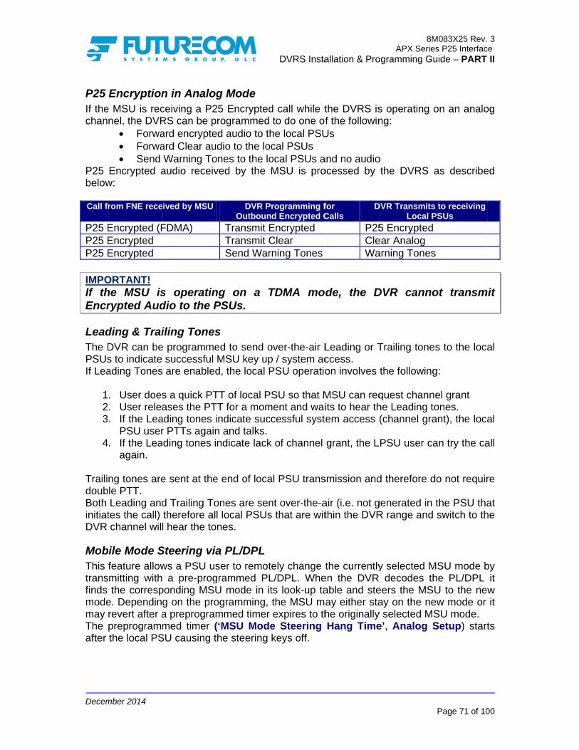
Decem
P25 If thechan
P25 below Call fr
P25 EP25 EP25 E
IMPOIf thEncr
LeadThe DPSUsIf Lea
123
4
TrailidoubBoth initiatDVR
MobThis transfinds modemay The after
mber 2014
Encryptione MSU is recnel, the DVR
Forwa Forwa Send
Encrypted aw:
rom FNE rece
Encrypted (FEncrypted Encrypted
ORTANT! he MSU isrypted Aud
ding & TraiDVR can bes to indicate ading Tones
. User does
. User relea
. If the LeaPSU user
. If the Leaagain.
ng tones arele PTT. Leading and
tes the call) channel will
bile Mode Sfeature allowmitting withthe corresp
e. Dependinrevert after apreprogrammthe local PS
n in Analogceiving a P2RS can be pard encrypteard Clear auWarning To
audio receiv
ived by MSU
FDMA)
s operatindio to the P
iling Tonese programme
successful are enabled
s a quick PTases the PT
ading tones ir PTTs againding tones i
e sent at the
d Trailing Totherefore alll hear the to
Steering viaws a PSU us a pre-prog
ponding MSUg on the proa preprogrammed timer (
SU causing t
g Mode 25 Encryptedrogrammed
ed audio to thdio to the lo
ones to the loved by the
DVR POutboun
Transmit ETransmit CSend War
ng on a TPSUs.
s ed to send oMSU key upd, the local P
TT of local PTT for a momindicate sucn and talks.ndicate lack
e end of loca
ones are senl local PSUsnes.
a PL/DPLser to remot
grammed PLU mode in itogramming, mmed timer (‘MSU Modehe steering
DVRS Insta
d call while tto do one of
he local PSUcal PSUs ocal PSUs aMSU is pro
rogramming fnd Encrypted C
Encrypted Clear rning Tones
TDMA mo
over-the-air Lp / system acPSU operatio
SU so that Mment and wai
cessful syst
k of channel
al PSU trans
nt over-the-as that are wit
tely change L/DPL. Whets look-up tathe MSU mexpires to th
e Steering keys off.
allation & Pro
the DVRS isf the followin
Us
and no audioocessed by
for Calls
D
P25CleWa
ode, the D
Leading or Tccess. on involves
MSU can reqits to hear thtem access
grant, the L
smission and
air (i.e. not gthin the DVR
the currentlyen the DVRable and steay either stahe originallyHang Time
8MAPX Serie
ogramming Gu
s operating ng:
o the DVRS
DVR TransmitsLocal P
5 Encryptedear Analog arning Tones
DVR canno
Trailing tone
the following
quest channhe Leading t(channel gra
PSU user ca
d therefore d
generated in R range and
y selected MR decodes theers the MSay on the ne
y selected Me’, Analog S
M083X25 Rev.es P25 Interfacuide – PART
Page 71 of 10
on an analo
as describe
s to receiving PSUs
s
ot transm
es to the loca
g:
nel grant tones. ant), the loca
an try the ca
do not requir
the PSU tha switch to th
MSU mode bhe PL/DPL U to the new
ew mode or SU mode. Setup) start
3 ce
II
00
og
ed
mit
al
al
all
re
at he
by it w it
ts
Decem
Steer
MSUWhenAnaloFor Fthis dWhenthe fo
Whento intranstrans
mber 2014
ring and Em
If steeringdeclared If steeringdeclared When MSenabled),EmergenEmergenchannel (If ‘SteerinMSU. In tto) channIf ‘Put Dprogrammwhile the and steerthe emerg
U Operatingn the MSU og or ForcedForced Analodocument. n the DVR iollowing feat
EmergencGroup voMDC PTTEmergencStatus Up
n operating nterrupt an missions to mission from
mergency
g is disableon the curreg is enabledon the new (SU is in em the local
ncy’ prograncy’ is Disabno steering ng in Emergthis case thel.
DVR in Emmed for Em
MSU is wair the MSU togency alarm
g on TDMAis switched
d Analog moog mode ope
s on an anatures are sup
cy Alarm anice, Inbound
T-ID cy ID pdate (MDC1
on TDMA songoing trathe system
m the MSU t
ed on the cently selectedd on the cur(steered) MSergency cal
PSU callsmming for
bled, the DVoccurs). gency’ is ee MSU will
mergency Cergency Alating for eme
o the corresp on the new
A (P25, Phato a TDMA
ode. eration, plea
alog channepported via t
d Call (MDCd and Outbo
1200)
ystem, any ansmission . The Local o the system
DVRS Insta
current DVRd MSU chanrrent DVR chSU mode. l state (‘Puts handling
the specifR repeats an
nabled, the re-declare E
Call State’arm only), aergency ACKponding MSU MSU chann
ase 2) A capable m
ase refer to t
el and the Mthe DVRS:
C1200) und
TDMA specwill also a
PSU will nom may have
allation & Pro
R channel, lnnel (no steehannel, the
t DVR in Emis defined
fic DVR chny local PSU
DVR will stEmergency
is Disabledan inbound K, should terU mode/chanel.
mode, the DV
the Forced
MSU is on a
cific feature affect the pot receive angotten inter
8MAPX Serie
ogramming Gu
ocal PSU eering). local PSU e
mergency Cd by the ‘hannel. If U calls on th
teer and thecall on the
d (local PSlocal PSU
rminate MSUannel withou
VR can ope
Analog Mo
TDMA capa
that can caproxying ofn indication rrupted.
M083X25 Rev.es P25 Interfacuide – PART
Page 72 of 10
emergency
emergency
Call State’ ‘Steering i‘Steering i
he emergenc
en key up thnew (steere
U and MScall initiate
U emergenct re-declarin
erate in eithe
ode section o
able channe
use the MSf Local PSthat its prox
3 ce
II
00
is
is
is in in cy
he ed
U ed cy ng
er
of
el,
U U xy

Decem
MixeWhencalls WhenModeenaba P25DVR DTMAnaloduratwhichthe Dthe DThe SyncDigit
mber 2014
ed DVR Mn a DVR chfrom both Pn Mixed Moe as describled by defau5 Frame synswitches to
F, MDC120og PSUs. Aftion of the ph are receiveDVR as AnaDVR returns DVRS opera
c Detection al System S
Mode annel is pro25 and anal
ode is selecbed below. ult. If a Call fnc within theo Analog M00 etc.). Thefter the Locareprogrammed by the Mlog Conventback to Digiation in MixTimer’ and
Setup menu
ogrammed toog local PSU
cted, the DVThe default from a Locae preprogramode and stae DVR enabal PSU keys
med ‘VR Ch MSU prior to
tional. Oncetal Mode an
xed Mode is d ‘VR Ch Mu screen.
DVRS Insta
o operate in Us. VR can be
DVRS modl PSU is detmmed ‘P25 arts decodinbles the reps off, the DVMixed Modthe above t
e the ‘VR Chnd any Outbo
determinedixed Mode
allation & Pro
Mixed mod
toggled betwde is Digitatected and thFrame Syn
ng Analog Mpeat of AnaVR stays in de Hold Timtimer’s expirh Mixed Moound calls ad by the setHold Time
8MAPX Serie
ogramming Gu
de, the DVRS
ween digital i.e. the P2he DVR doenc DetectionMode signalalog signals the Analog
mer’. Any Ouration will beode Hold Timre repeated ttings of ther’ as progra
M083X25 Rev.es P25 Interfacuide – PART
Page 73 of 10
S can handl
al and analo25 modem es not decodn Timer’, thling (such ato the LocaMode for thutbound cale repeated bmer’ expiresas digital. ‘P25 Fram
ammed in th
3 ce
II
00
le
og is
de he as al
he ls
by s,
me he

Decem
UsinThe Dthe vopera The Ron a
SettiThe signalocallRSSIwantscoverTo ex
1
2
3456
7
891
1
SettiThosfollow DVRSDVRSmove
mber 2014
ng the TwDVRS RSSIvoting algoration and run
RSSI setup per channel
RSSI ON Busy LocTX RSSI Rx RSSI
ing up the RSSI ON th
al level the Dy and to theI ON threshs to test therage area exxecute the te
. PSU userswitched
. Tweaker shown ab
. Select ‘Sy
. Switch ‘S
. Press the
. The PSU press and
. The DVRThresholdcompletio
. Enter des
. Repeat th0. Close the
described1. Review th
and save
ing up the e automated
ws:
S 1 – DVR wS 2 - DVR es any farthe
eaker’s RI Setup screrithm paramnning some
screen is us basis:
threshold ckout ThresThreshold Threshold
RSSI ON rhreshold deDVR receivee System. old is normae actual levxtreme then est, the follow
r is located to the correcis running
bove. ystem’ or ‘Loet Test Mod
e ‘RSSI ON LUser will he
d hold the PTRS measured field. The con. sired Margin he test for ale monitoringd below. he ‘RSSI ONto the DVRS
Voting Pad tests are
with Tweakeparked at th
er it should a
RSSI Setueen is provi
meters by cautomated D
sed to assis
shold
range efines the Der needs to
ally programvels receivedthe ‘RSSI Owing steps a
at the edgect channel (mon the Prim
ocal’ Mode ine’ to ON.
Level Test’ bear 3 short TT for 10 sees the rececheck box a
(min 6dB orl required chg screen o
N ThresholdS and in a d
rameters (used to cali
er running anhe desired ealso become
DVRS Insta
p Applicaded in orde
creating a tyDVRS tests
st with the se
DVRS incidedetect from
mmed to stand from a po
ON Level Tesare to be foll
e of the desimatching themary DVRS
n the ‘Opera
button. and 1 long conds.
eived signalagainst the p
r higher recohannels. r proceed w
’ levels on tpd file as re
(Primary / Sbrate the ra
nd RSSI Setuedge of DVRe a Primary.
allation & Pro
ation er to assist typical real as describe
etup the follo
ent range sim the Local P
ndard -114dortable radiost’ can be pelowed:
ired coverage channel se
and Monito
ating Mode’ F
beeps and h
level and parameter is
ommended).
with the Vo
the ‘Repeatequired.
Secondaryange betwee
up screen oRS 1 Prima
8MAPX Serie
ogramming Gu
the users wlife scenar
ed below.
owing DVRS
nce this is PSU in orde
Bm. Howevo located aerformed.
ge range anelected on thoring screen
Field.
he/she must
updates ths checked to
.
oting algorit
er Channel s
y Range) en two Prima
pen ary Range i.
M083X25 Rev.es P25 Interfacuide – PART
Page 74 of 10
ith optimizinio for DVR
S parameter
the minimumer to repeat
er, if the uset the desire
d the PSU he DVR). n is open a
t immediate
he RSSI Oo indicate tes
thm tests a
setup’ scree
ary DVRS a
e. if DVRS
3 ce
II
00
ng RS
rs
m it
er ed
is
as
ly
N st
as
en
as
2

Decem
123456
78
91
111
1
mber 2014
. Run Twea
. Deploy DV
. Select Sy
. Switch “S
. Type the
. Set Remo2000’ and
. Press the
. Note the two checkcompletio
. Press the0. Note the
checked t1. If any of t2. Enter req3. Close the
Setup scr4. Save the
aker and opeVRS 2 and e
ystem or LocSet Test Mod
ID of DVRS ote Test Mod DVR channe ‘Busy Locknew levels ik boxes aga
on. e ‘Primary Ra
new level to indicate she tests failsuired Margin
e RSSI Setureen. data to the D
en the RSSIensure both
cal Mode in tde” to ON.
2 in the Remode to ON.nel / mode o. Thresh. Ten the ‘Busy
ainst those p
ange Test’ bupdate in tuccessful tes, please repns and repeap screen an
DVRS and d
DVRS Insta
I Setup screunits are on
the Operatin
mote DVRS Note that b
on the top linest’ button anLock. Thres
parameters w
button and whe ‘Rx. RSS
est completiopeat the testat the tests fnd review th
dpd file as re
allation & Pro
en on DVRSn the same cng Mode Fiel
ID Box. both DVRS wne of the connd wait until sh.’ and ‘Tx Rwill become
wait until the SI Thresh.’
on. t. for all desire
he settings o
equired.
8MAPX Serie
ogramming Gu
S 1. channel. ld.
will alternatentrol head di
the test is cRSSI Thresh
e checked to
test is compfield. The
ed channels.on the Repe
M083X25 Rev.es P25 Interfacuide – PART
Page 75 of 10
e ‘WARNINGsplay.
complete. h.’ fields. Th
o indicate tes
plete. check box
eater Channe
3 ce
II
00
G
he st
is
el

Decem
UsinThe TDVRS The Powe IMPOIt muthe u
Tran
R
P25 R
mber 2014
ng the TwTweaker’s MS setup and
Monitoring er, PL detect
ORTANT! ust be noteduse of prope
Field smitter Mod
Tx O
PT
Repeater CA
RSS
RSP
SINARF Pow
Oper. Sta
Ant. SMobile RU
Mobile PTTemPA
Test Mod
Rx Modem TTest Mod
BEBER
eaker MoMonitoring S troubleshoo
screen provtion etc as d
d that the Merly calibrat
de Can beOn Does n
Tx Off (TT Offers t
PTT OprogramPTT OFCARRImodulaTo useset to Y
AS
SSISql
IndicateActive) Squelch
SSI DisplayPL Display
DVR. AD Display
wer Displayup.
ate IndicatePerman
w. IndicateUS Provide
signal (TT Activatemp DisplayA_t Displayde Must b
Test opTest (for tesde Set to YERRm
Display
onitoring Screen is pro
oting.
vides real tdescribed be
Monitoring sted test equ
e set to eitheot require us(unchecked)three setting
ON – DVRmmed settinFF – DVR TER – DVR
ation). Limitee PTT ON oYES and “Tes the Carr
of the DVRh thresholds
ys the RSSI ys presence
ys the calculays the DVR
es the currnent Primaryes the Antenes informatio(Active or Idled when theys the currenys the currene set to YE
ptions. st procedurYES in orderys instant (B
DVRS Insta
Screen
ovided in ord
time indicatelow.
screen appuipment in t
Deser “Tx Disablser input. Us) gs: keys up g (channel transmitted isTransmitter
ed to 10 minuor CARRIERTransmitter rier ActivateR with resps on the sele
of the DVR. of the prog
ated SINADTx Power w
rent DVR sy or OFF. nna switch pon on when le).
e MSU MIC int controller tnt PA tempeES in order t
re see “BERr to measureER) and ave
allation & Pro
der to assist
ion of the
plication is nthe field.
scription e” or “Tx Ensed to indica
on selectetype, PL/DPLs idle r is keyed uutes max keR, the “TestMode” mused Squelch pect to the pected DVR c
grammed P
of the DVRwhen the DV
state – Pri
position; Normthe Mobile r
s PTT-ed. temperaturerature. to use the P
R Test Setue BER eraged (BER
8MAPX Serie
ogramming Gu
t the field te
RRSI level,
not intende
nable”. ated Tx On (
ed channel L, NAC etc)
up with carrey up time. t Mode” fiest be set to
(CAS) staprogrammed
channel.
PL/DPL deco
R received sigVR transmit
imary, Non
mal or BL Rradio is rece
e.
PTT or P25
p”)
Rm) Bit Erro
M083X25 Rev.es P25 Interfacuide – PART
Page 76 of 10
echnician wit
, SINAD, R
ed to replac
(checked) or
and using
rier only (no
eld must beTx Enable.tus (Idle ord RSSI and
oded by the
gnal. tter is keyed
-Primary or
Reversed. eiving a valid
Rx Modem
r Rate
3 ce
II
00
th
RF
ce
r
g
o
e
r d
e
d
r
d
m

Decem
BERThe fScree
1
23
mber 2014
R Test Setufollowing is ren:
. Connect adescribed
Pr PA M NA AL M TG SI
. Set the Te
. Lower theMonitorin
up required in o
an IFR test d below: rogram TX frATTERN 10ODULATIONAC 293 LGID 80 FID 00 GID 1 D 000001 est Mode Ae IFR Transg screen.
order to be a
set or equiv
requency ma11 N P25
ND P25 Rx smit level un
DVRS Insta
able to meas
valent to the
atching the p
Modem Tesntil desired
allation & Pro
sure BER on
e DVR Anten
programmed
st – Test MoBER Thres
8MAPX Serie
ogramming Gu
n the Tweak
nna port and
d DVR Rx F
ode to ‘YESshold is obs
M083X25 Rev.es P25 Interfacuide – PART
Page 77 of 10
ker Monitorin
d set it up a
requency
S’ erved on th
3 ce
II
00
ng
as
he

Decem
Trou
SoftwMost portarequi The f
INCO
AlterRC E
INCO
WARWAR
RC E
RC E
LOWVR P
ID MI
SYNC
TRAN
mber 2014
ubleshoot
ware / Progof the DVR
able radio tere correspon
following err
CH DispOMP MSU H
rnating VR EERROR XXX
OMP MSU S
RNING 0400 RNING 0800
ERROR 1000
ERROR 4000
W BATTERY PROGRAMM
ISCONFIG
C ERROR
NSL TG WR
ing
gramming RS Programmmplates. Nonding chang
or message
play W
ERROR andXX
W
0
0
MING
RN
Related Pming proble
ote that any ges to be ma
s may be dis
Indicatesconnecteconnect an XTL c
d Turn thecorrect tcontact instructioPlease compatibDisplayedBackup Edata. TheEEPROMlatest TwMain / BaDisplayedBackup EoperationinstructioIndicatesprogrammneeds toTweaker EEPROMinstructioIndicatesIndicateson standbIndicatesRequiresIndicatesthe DVRexport anThis watalkgroupsystem. Tmust be used for T
DVRS Insta
Problems ms are cauupdates to
ade in the DV
splayed on t
Des incompatied to an Aa compatibl
compatible me DVRS off the conditioFuturecom
ons. contact Mo
ble firmware d upon powEEPROM me DVR will sM map. To fweaker to reackup EEPRd permanenEEPROM mnal. Pleaseons on how ts that the DVmed persono be updatprogrammin
M map as dons provideds Low Batterys the VR is by.
s a PSU ID ms PSU ID chas the MSU pR template nd import of rning is dis
p translationThe DVR (achanged so
Translation.
allation & Pro
sed by mismthe MSU orVR template
the MSU con
escription / Aible MSU APX compae APX MSU
model. and then
on, note theto obtain
otorola andupgrades fo
wer up only map of the still operate pfix the primaead the DV
ROM Map. ntly indicatesaps are corr
e contact to troubleshoVR firmware nality has noted by reang softwaredescribed in by Futurecoy Warning obeing progr
misconfiguraange. programming
has not bthe new MSsplayed whn table is and respecto that valid
8MAPX Serie
ogramming Gu
matched MSr the PSU tee.
ntrol head:
Action hardware
atible DVR)U or change
back on. Ife exact erroan RMA a
d Futurecomor the radiosindicates thDVR contaiproperly fromary map, ple
VR. This wil
s that both trupted and tFuturecom
oot the problhas been upot. The DVRading the ue in order ton the Firmwom.
or Alarm. rammed and
ation has be
g has been been updateSU .XML file hen a talkg
active on ively PSU) system TG
M083X25 Rev.es P25 Interfacuide – PART
Page 78 of 10
SU, DVR anemplates ma
(XTL MS). Ensure te the DVR t
f it does noor code anand shippin
m to obtas. at the Mainins corruptem the backuease use thll restore th
the Main anthe unit is no
for furthelem. pdated but itR personalitunit with th upgrade th
ware upgrad
d the MSU
een detected
changed bued. Requirein the DVR.
group in ththe trunkinprogrammin
G IDs are no
3 ce
II
00
nd ay
U to to
ot nd ng
in
/ ed up he he
nd ot er
ts ty
he he de
is
d.
ut es
he ng ng ot

Decem
In cafrequthe dEnsuDVR
FirmSomeEEPREEPR
mber 2014
ase of insuencies proguplexer andre the DVR Model.
mware Upgre DVRS unROM map uROM, please
ufficient DVrammed in t in-band filteis only enab
rade nits which wupgrade afte follow the
R Tx Powethe DVR areering labels. bled on MSU
were originaer re-flashininstructions
DVRS Insta
er or poor e within the f
U Modes usin
ally shippedng them witshipped with
allation & Pro
sensitivity, filtering spec
ng the frequ
d with oldeth newer firh the flash u
8MAPX Serie
ogramming Gu
please vecifications as
uency plan fo
er firmware rmware. To upgrade.
M083X25 Rev.es P25 Interfacuide – PART
Page 79 of 10
erify that ths indicated o
or the specif
may requirupgrade th
3 ce
II
00
he on
fic
re he

Decem
ApGene
DWe
DC C
Exter
Equip
Trans
F
Rece
Audi
mber 2014
pendixeral Specificaimensions: Height (DVR O
urrent Drain
OpProte
rnal Connect
pment Type A
smitter SpecF
Power Ou
FM Hum and
iver SpecificF
Sel
DevFM Hum an
io Output (Re
x 1 – DVations Height / WidtOnly, without
ChanneNumber of
CTPowe
Standby
perating Temction Agains
Antenna ImD
tors
ComputerAcceptance
Industr
ification requency Ba
utput @ AnteTC
Max SpuriouFrequency
Noise 12.5Audio R
Audio Dcation requency Ba
Receiver SFrequency
ectivity 12.5Interm
viation 12.5nd Noise 12.5epeater Dete
Audio R
Audio D
VR Spec
th / Depth 1t filtering) 1l Spacing 1Channels U
TCSS/DCS Per Supply 1
RPTR Offy/ReceiveTransmit
004
mperature -st Liquids Impedance 5uty Cycle C
Antennar Interface
MU
FCCry Canada
L
2
and [MHz]
enna Port 1CT Optionus Outputy Stability5 / 25 kHzResponse
Distortion
and [MHz]
Sensitivityy Stability5 / 25 kHzodulation5 / 25 kHz5 / 25 kHz
ect Audio)Response
Distortion
DVRS Insta
cificatio
185mm (7.2810.3kg (22.7l12.5 or 25 kHUp to 192 Programmab13.8V DC +/-
0.01 A Max 0.8 A Max 4.5 A Max -30ºC to +60ºIP54 50 Ohms Continuous
Mini UHF USB
VHF
LO6-DVRSVHF
2098B-DVRSVHF
VHF 136-174
10W (progra15
+1, -3 dchar
VHF 136-174
600 mV R+1, -3 d
char
allation & Pro
ons
8”) / 186mm (lb) Hz programm
ble per Chan20%
ºC
UHF
LO6-DVRSUHF 2098B-DVRSUHF
UHF 380-430 450-470 470-512
mmable per 5 sec to 15 m
-20d+/- 1.
37 dB dB of 6 dB / oracteristic ov
<2UHF
380-430 450-470 470-512
-115+/- 1.
60 dB 70
+/-2.5 kHz37 dB
RMS nominal,dB of 6 dB / oracteristic ov
<2
8MAPX Serie
ogramming Gu
(7.32”) / 315m
mable
nel
700
LO6-DVRS700 2098B-DVRS700
700 764-776
channel frommin or DisabldBm .5ppm / 43 dB
octave pre-emver 300 Hz – 2%
700 794-806
5 dBm .5ppm / 75 dB
0 dB z / +/-5 kHz / 43 dB , flat responsoctave de-emver 300 Hz – 2%
M083X25 Rev.es P25 Interfacuide – PART
Page 80 of 10
mm (12.41”)
800 LO6-DVRS800 2098B-DVRS800
800 851-870
m 1W to 10Wled
mphasis 3 kHz
800 806-825
se mphasis 3 kHz
3 ce
II
00
0
0
W)
5

Decem
ApMSIC
mber 2014
pendixSU CH DIS
CON / MESS
Steady
Steady
Steady
Steady
Flashing
Flashing
Steady
Flashing
Steady
Steady
Steady
VR SERVIC
VR ERRO
VR IN RES
VR DISABL
V
V
V
V
x 2 – DVPLAY
SAGE
D
P
P
P
D
S
D
Dia
P
P
P
CE Df
OR DE
SET D
LED D
R
R
R
R
VR Statu
DVR is in a
Primary DVR
Primary DVR
Primary DVR
DVR is in a
Secondary D
DVR is in a
DVR is in a s another P
area)
Permanent
Permanent
Permanent
DVR is in Sefirmware). DVR DetectERROR and
DVR is bein
DVR Disable
DVRS Insta
us DispDVRS ST
Primary Sta
R Receiving
R Transmitt
R Receiving
Secondary
DVR Receiv
Permanent
Permanent Permanent P
Primary DV
Primary DV
Primary DV
ervice Mode
ed Error. Dd the actual
ng reset
ed on Selec
allation & Pro
play
TATUS DESC
ate
g
ting
g and Trans
State
ving
t Primary St
t Primary ‘OPrimary alre
VR Receivin
VR Transmit
VR Receivin
e (during re
isplay toggerror code
cted MSU T
8MAPX Serie
ogramming Gu
CRIPTION
smitting
tate
On Standby’eady prese
ng
tting
ng and Tran
e-flashing o
les betwee / number.
G / Mode
M083X25 Rev.es P25 Interfacuide – PART
Page 81 of 10
’ State (thernt in the
smitting
of the
n VR
3 ce
II
00
re

Decem
ApWhendedicavailaThe t
PS
Talk
Syste
Tal
Leadi
ReRe
Table
Note 1PSU isNote 2Note 3Note 4Note 5Note 6
mber 2014
pendixn the PSU Ucated DVR cable to the Ptable below s
SU FEATUREDV
Registratiok Group Prox
AnnoPh
DynSelec
EmergEmergency
PSU E
em Status BrOut Of Ran
LocaAdapti
lk Permit Ton
ing / Trailing
Radio CheP2
emote DVR Aemote DVR A
E
e 17 DVRS Fe
1 When selects deregistered 2 Supported on3 Analog PSU i4 Requires firm5 The PSU mod6: Motorola Sol
x 3 – DVUser is out ochannel so tPSU User dspecifies wh
E SUPPORT BVRS on / Deregistrxying / Trans
GroupPrivate
ouncement Ghone Interco
namic Regroctor Lock / Ugency Call / Ay ID Pass thr
PSU HoEmergency R
P25 EncryCall Alert
roadcast (Fage, Site Trun
al Mode Indicive Power Cones (generat
g Tones (sentth
eck / Radio I25 Trunking O
PSUPSU S
Activation byActivation byEmergency A
eatures vs Ty
ing a DVR Moafter a preprog
nly with MDC12is registered on
mware R12.00.1dels that can butions XTS or
VRS Feaof System Rthat the PSUdepend on thhat features
BY DVRPS
rationlation Calls Calls
GroupnnectPatchupingnlockAlarmroughot Mic YeRevertyption Pageilsoft,
nking)cationontrolted by PSU)
t over he air)nhibitOTAR
U GPSSCANy PSU Yesy PSU Alarm
ype of PSU
ode on the Gegrammed timer200 capable pon the P25 syste13 or later in the programmedAPX series PS
DVRS Insta
atures vRadio CoverU can commhe PSU typeare supporte
RS Enabled SU [Note 5]
Yes Yes Yes Yes No Yes Yes Yes No Yes Yes
es [Note 4] Yes Yes Yes Yes
Yes Yes Yes
No
Yes Yes Yes No
s (Call Alert)Yes
neric P25 PSUr counting the portables. em with its MDe XTS ‘DVRS
d as DVRS EnaSUs in non DVR
allation & Pro
vs PSUrage, the PS
municate via e, programmed by the dif
Gene P25 P
Yes [NoYesYesNoNoNoNoNoNoYesYesNoYesYesYesNo
NoYes [No
No
No
YesNoNoNo
Yes (CallYes
U, it registers uperiod of inactiv
C1200 ID. Enabled’ PSU.abled are descRS Enabled mo
8MAPX Serie
ogramming Gu
U Type SU can be sthe DVRS.
ming and sefferent PSU
eric PSU
A
ote 1] Ys s o o o o o o s s Yo s s s o
o ote 6] o
o
s o o o l Alert) Ys
upon first Grouvity expires.
. cribed in Tableode.
M083X25 Rev.es P25 Interfacuide – PART
Page 82 of 10
switched to The feature
elected modetypes.
Analog PSU
Yes [Note 3]No Yes No No No No No No Yes
Yes [Note 2]No Yes No No No
No No No
Yes
No No No No
Yes (DTMF)Yes
(MDC1200)
up Call. Gener
e 2.
3 ce
II
00
a es e.
ric

Decem
ApP25The oP25 featu
DVRS
Talk
PSPSU E
PSPSU
F
DVR
P
mber 2014
pendix5 Trunkoperation deTalk Groupres require D
FEATU
S Status DisplP
Group ProxinOutbou
OutbounMSU Mi
InbouInboun
InboPSU Talk
SU EmergencEmergency ReSU Emerg. ID Remote DVR
Failsoft / Out oTrunking IndiPSU Local MPrimary / SecDVR Tones –
PSU Radio
PSU P25 T
PSU DynamPSU Selecto
PSU PhonPSU Adaptive
AP
PSU AnnounPSU Sta
x 4 DVRking Moescribed belop are selectDVRS Enab
RE
ay on MSU CHPSU Affiliationg / Translation
und Group Calnd Private Calicrophone PTTund Group Calnd Private Calound Call Alerk Permit Tonescy Alarm & Calevert via DVRSPass Through
RS Activation &Steering
of Range / Sitecation on PSUode Indication
condary Voting– MSU SpeakeCheck / Inhibi
PSU GPSTrunking OTAR
PSU Patchmic Regrouping
r Lock /Unlocke InterconnecPower Controudio Buffering
P25 EncryptionPSU Scan
cement Groupatus / Message
PSU PTT ID
RS Feaobile Moow assumested on the
bled PSUs as
DV OFF
H VR OFF <n Nn Nll Nll NT Keys up Mll Nll Nrt Ns Nll Yes (after S Nh Yes (after & g
Yes – C
e U
N
n Ng N
er Nit NS NR Nh Ng Nk N
ct Nol Ng Nn Nn Np Ne ND N
DVRS Insta
atures ode s a DVR DigDVR and
s described
VR Mode
<DVR CH> VNo No No No MSU only
No No No No
activation) No
activation)
Call Alert
No
No No No No No No No No No No No No No No No No No
allation & Pro
– P25
gital Mode cMSU respein Table 12
DVRSYSTEM M
VR SYS <DVRYes Yes Yes Yes
As programmYes Yes Yes Yes Yes Yes Yes
Yes – Call A
Yes
No Yes Yes Yes Yes Yes Yes Yes No
Yes (FDX onYes Yes Yes No No
Status onlYes
8MAPX Serie
ogramming Gu
DVR M
conventionalectively. Not.
Mode LOR CH> VR L
Pr
med AsYe
Alert Ye
nly) Ye
ly
M083X25 Rev.es P25 Interfacuide – PART
Page 83 of 10
Mode &
channel ante that som
DVR OCAL ModeLOC <DVR CH
Yes Yes
rogrammable Yes
s programmeds (Local Side)
Yes Yes Yes Yes Yes Yes
es – Call Alert
No
Yes Yes Yes Yes Yes Yes Yes Yes No
es (FDX only)Yes Yes Yes No No
Status only Yes
3 ce
II
00
&
nd me
e >

Decem
ApP25The oP25 C
DVRS
Talk
PSPSU E
PSPSU
F
DVR
P
mber 2014
pendix5 Convoperation deConventiona
FEATU
S Status DisplP
Group ProxinOutbou
OutbounMSU Mi
InbouInboun
InboPSU Talk
SU EmergencEmergency ReSU Emerg. ID Remote DVR
Failsoft / Out oTrunking IndiPSU Local MPrimary / SecDVR Tones –
PSU Radio
PSU P25 T
PSU DynamPSU Selecto
PSU PhonPSU Adaptive
A
PSU AnnounP
PSU Sta
x 5 DVRventiona
escribed beloal Mode are
RE
ay on MSU CHPSU Affiliationg / Translation
und Group Calnd Private Calicrophone PTTund Group Calnd Private Calound Call Alerk Permit Tonescy Alarm & Calevert via DVRSPass Through
RS Activation &Steering
of Range / Sitecation on PSUode Indication
condary Voting– MSU SpeakeCheck / Inhibi
PSU GPSTrunking OTAR
PSU Patchmic Regrouping
r Lock /Unlocke InterconnecPower Controudio Buffering
PSU Scancement Group
P25 Encryptionatus / Message
PSU PTT ID
RS Feaal Mobiow assumesselected on
DV OFF
H VR OFF <n Nn Nll Nll NT Keys up Mll Nll Nrt Ns Nll Yes (after S Nh Yes (after & g
Yes – C
e U
N
n Ng N
er Nit NS NR Nh Ng Nk N
ct Nol Ng Nn Np Nn Ne ND N
DVRS Insta
atures iile Mods a DVR Digthe DVR an
VR Mode
<DVR CH> VNo No No No MSU only
No No No No
activation) No
activation)
Call Alert
A
No No No No No
A A A A A
No No No No No No No
allation & Pro
in P25 de
gital Mode cnd MSU resp
DVRSYSTEM M
VR SYS <DVRYes Yes Yes No
As programmYes No Yes Yes Yes Yes Yes
Yes – Call A
NA
No Yes Yes Yes No NA NA NA NA NA Yes Yes No No Yes Yes Yes
8MAPX Serie
ogramming Gu
DVR M
conventionalpectively.
Mode LOR CH> VR L
Pr
med AsYe
Alert Ye
M083X25 Rev.es P25 Interfacuide – PART
Page 84 of 10
Mode &
channel an
DVR OCAL ModeLOC <DVR CH
Yes Yes
rogrammable No
s programmeds (Local Side)
No Yes Yes Yes Yes Yes
es – Call Alert
NA
Yes Yes Yes Yes No NA NA NA NA NA Yes Yes No No Yes Yes Yes
3 ce
II
00
&
nd
e >

Decem
ApMoThe f
DVR
PSU P
PSU
DVR
mber 2014
pendixode & C
features belo
FEATU
RS Status Disp
TalkOutbo
OutbouMSU M
InboInbou
InbPSU TalPSU Em
Emergency RPSU Emerg. IDU Remote DVR
Failsoft / OutTrunking IndPSU Local M
R Primary / SeDVR Tones
PSU Radio
PSU P25 T
PSU DynamPSU Selecto
PSU PhonPSU Adaptive
A
PSU Annou
PSU St
x 6 DVRConvent
ow are supp
URE
play on the MSC
PSU Affiliatiok Group Proxinound Group Caund Private Ca
Microphone PTound Group Caund Private Cabound Call Alelk Permit Tone
mergency AlarRevert via DVRD Pass ThrougRS Activation
Steerint of Range / Sidication on PSMode Indicatioecondary Votin
– MSU Speako Check / Inhib
PSU GPTrunking OTA
PSU Patcmic Regroupinor Lock / Unlocne Interconnee Power ContrAudio Bufferin
PSU Scancement GrouP25 Encryptiotatus / Messag
PSU PTT
RS Feattional Aported on ‘DV
D OFF
SU CH
VR OFF <
on Nng Nall Nall NTT Keys up all Nall Nert Nes Nrm Yes (afterRS Ngh N&
ng Yes – C
ite SU
N
on Nng N
ker Nbit NPS NAR Nch Nng Nck N
ect Nrol Nng Nan Nup Non Nge NID N
DVRS Insta
tures inAnalog VRS Enable
VR F Mode
<DVR CH>
No No No No MSU only
No No No No r activation) No No
Call Alert
NA
No No No No No NA NA NA NA NA No No No No No No No
allation & Pro
n ForceMobiled’ PSUs onl
DVR SYSTEM M
VR SYS <DVR
No No Yes No
As programmYes No No Yes Yes Yes Yes
Yes – Call A
NA
No Yes Yes No No NA NA NA NA NA No Yes No No
ProgrammaYes
Locally on
8MAPX Serie
ogramming Gu
ed Analoe Mode
y.
Mode LO
R CH> VR L
Pr
med AsYe
Ye
Alert Ye
able Pr
nly
M083X25 Rev.es P25 Interfacuide – PART
Page 85 of 10
og DVR
DVR OCAL Mode
LOC <DVR CH
No No
rogrammable No
s programmeds (Local Side)
No s (Local Side)
Yes Yes Yes Yes
es – Call Alert
NA
Yes Yes Yes No No NA NA NA NA NA No Yes No No
rogrammable Yes
Locally only
3 ce
II
00
R
e
>
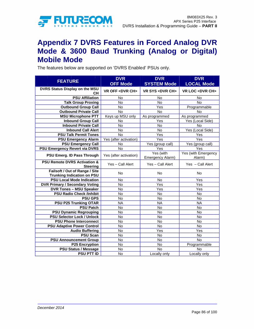
Decem
ApMoMoThe f
DVR
PSU
P
PSU
DVR
mber 2014
pendixode & 3obile Mo
features belo
FEATU
RS Status Disp
TalkOutbo
OutbouMSU M
InboInbou
InbPSU TalPSU Em
PSU EEmergency R
PSU Emerg. ID
U Remote DVR
Failsoft / OutTrunking IndPSU Local M
R Primary / SeDVR Tones
PSU Radio
PSU P25 T
PSU DynamPSU Selecto
PSU PhonPSU Adaptive
A
PSU Annou
PSU St
x 7 DVR3600 Bode ow are supp
URE
play on the MSC
PSU Affiliatiok Group Proxinound Group Caund Private Ca
Microphone PTound Group Caund Private Cabound Call Alelk Permit Tone
mergency AlarEmergency Ca
Revert via DVR
D Pass Throug
RS Activation Steerin
t of Range / Sidication on PSMode Indicatioecondary Votin
– MSU Speako Check /Inhib
PSU GPTrunking OTA
PSU Patcmic Regroupinor Lock / Unlocne Interconnee Power ContrAudio Bufferin
PSU Scancement GrouP25 Encryptiotatus / Messag
PSU PTT
RS FeatBaud Tr
ported on ‘DV
D OFF
SU CH
VR OFF <
on Nng Nall Nall NTT Keys up all Nall Nert Nes Nrm Yes (afterall NRS N
gh Yes (after
& ng
Yes – C
ite SU
N
on Nng N
ker Nbit NPS NAR Nch Nng Nck N
ect Nrol Nng Nan Nup Non Nge NID N
DVRS Insta
tures inrunking
VRS Enable
VR F Mode
<DVR CH>
No No No No MSU only A
No No No No r activation) NoNo
r activation)
Call Alert
No
No No No No No NA No No No No No No No No No No No
allation & Pro
n Forceg (Anal
d’ PSUs onl
DVR SYSTEM M
VR SYS <DVR
No No Yes No
As programmeYes No No Yes Yes
Yes (group cYes
Yes (withEmergency A
Yes – Call A
No
No Yes Yes No No NA No No No No No Yes No No No No
Locally on
8MAPX Serie
ogramming Gu
ed Analolog or
y.
Mode LO
R CH> VR L
Pr
ed As prYe
Ye
call) Ye
h Alarm)
Yes (
Alert Ye
Pr
nly L
M083X25 Rev.es P25 Interfacuide – PART
Page 86 of 10
og DVRDigital
DVR OCAL Mode
LOC <DVR CH
No No
rogrammable No
rogrammed s (Local Side)
No s (Local Side)
Yes Yes
es (group call)Yes
(with EmergencAlarm)
es – Call Alert
No
Yes Yes Yes No No NA No No No No No Yes No No
rogrammable No
Locally only
3 ce
II
00
R l)
e
>
cy

Decem
ApP25
DVRS
P
PSU E
PS
PS
F
DVR
P
mber 2014
pendix5 Trunk
FEATU
S Status DisplP
Talk GOutbou
OutbounMSU Mi
InbouInboun
InboPSU Leading/
PSU EmePSU E
Emergency Re
SU Emerg. ID
SU Remote DVMSU
Failsoft / Out oTrunking IndiPSU Local MPrimary / SecDVR Tones –
PSU Radio
PSU P25 T
PSU DynamPSU Selecto
PSU PhonPSU Adaptive
A
PSU AnnounP
PSU Sta
x 8 DVRking Mo
RE
ay on MSU CHPSU AffiliationGroup Proxingund Group Calnd Private Calicrophone PTTund Group Calnd Private Calound Call AlerTrailing Tonesergency Alarmmergency Cal
evert via DVRS
Pass Through
VRS ActivationMode Steeringof Range / Sitecation on PSUode Indication
condary Voting– MSU SpeakeCheck / Inhibi
PSU GPSTrunking OTAR
PSU Patchmic Regrouping
r Lock /Unlocke InterconnecPower Controudio Buffering
PSU Scancement Group
P25 Encryptionatus / Message
PSU PTT ID
RS Featuobile Mo
DV OFF
H VR OFF <n Ng Nll Nll NT Keys up Mll Nll Nrt Ns N
m Yes (after ll NS Yes (after
h Yes (after
n Yes –g Ne U
N
n Ng N
er Nit NS NR Nh Ng Nk N
ct Nol Ng Nn Np Nn Ne ND N
DVRS Insta
ures inode
VR Mode
<DVR CH> VNo No No No MSU only A
No No No No
activation) No
activation)
activation) Y
DTMF No
No
No No No No No No No No No No No No No No No No No
allation & Pro
Analog
DVRSYSTEM M
VR SYS <DVRNo No Yes No
As programmedYes No No
As programmYes
Yes (group cYes
Yes – MDC120Emerg. Ala
NA Yes (PL/DP
No
No Yes Yes No No No No No No No No Yes No No
ProgrammaYes Status o
Yes
8MAPX Serie
ogramming Gu
g DVR
Mode LOR CH> VR L
Pr
d As prYe
med As
call) Ye
00 with rm
Yes –EY
PL) Y
able Pronly Ye
M083X25 Rev.es P25 Interfacuide – PART
Page 87 of 10
Mode &
DVR OCAL ModeLOC <DVR CH
No No
rogrammable No
rogrammed s (Local Side)
No No
s programmedYes
es (group call)Yes
– MDC1200 witEmerg. Alarm Yes – DTMF Yes (PL/DPL)
No
No Yes Yes No No No No No No No No Yes No No
rogrammable es Status only
Yes
3 ce
II
00
&
e >
th

Decem
ApP25
DVRS
P
PSU E
PS
F
DVR
P
mber 2014
pendix5 Conv
FEATU
S Status Displ
PTalk G
OutbouOutbounMSU Mi
InbouInboun
InboSU Leading /
PSU EmeEmergency Re
SU Emerg. ID
MSU Failsoft / Out oTrunking IndiPSU Local MPrimary / SecDVR Tones –
PSU Radio
PSU P25 T
PSU DynamPSU Selecto
PSU PhonPSU Adaptive
A
PSU AnnounP
PSU Sta
x 9 DVRventiona
RE
ay on MSU CH
PSU AffiliationGroup Proxingund Group Calnd Private Calicrophone PTTund Group Calnd Private Calound Call AlerTrailing Tonesergency Alarmevert via DVRS
Pass Through
Mode Steeringof Range / Sitecation on PSUode Indication
condary Voting– MSU SpeakeCheck / Inhibi
PSU GPSTrunking OTAR
PSU Patchmic Regrouping
r Lock /Unlocke InterconnecPower Contro
udio BufferingPSU Scan
cement GroupP25 Encryptionatus / Message
PSU PTT ID
RS Featual Mobi
DV OFF
H VR OFF <
n Ng Nll Nll NT Keys up Mll Nll Nrt Ns N
m Yes (after S N
h Yes (after
g Ne U
N
n Ng N
er Nit NS NR Nh Ng Nk N
ct Nol N
g Nn Np Nn Ne ND N
DVRS Insta
ures inile Mod
VR Mode
<DVR CH> V
No No No No MSU only A
No No No No
activation) No
activation) Y
No
A
No No No No No
A A A A
No No
No No No No No No
allation & Pro
Analogde
DVRSYSTEM M
VR SYS <DVR
No No Yes No
As programmedYes No No ?
Yes Yes
Yes – MDC120Emerg. AlaYes (PL/DP
NA
No Yes Yes No No NA NA NA NA No No
Yes No No
ProgrammaYes Yes
8MAPX Serie
ogramming Gu
g DVR
Mode LO
R CH> VR L
Pr
d As prYe
00 with rm
Yes –E
PL) Y
able Pr
M083X25 Rev.es P25 Interfacuide – PART
Page 88 of 10
Mode &
DVR OCAL Mode
LOC <DVR CH
No No
rogrammable No
rogrammed s (Local Side)
No No ?
Yes Yes
– MDC1200 witEmerg. Alarm Yes (PL/DPL)
NA
No Yes Yes No No NA NA NA NA No No
Yes No No
rogrammable Yes Yes
3 ce
II
00
&
e
>
th

Decem
Ap& C
DVR
P
PSU
P
P
LDVR
mber 2014
pendixConven
FEATU
RS Status Disp
TalkOutbo
OutbouMSU M
InboInbou
InbPSU Leading /
PSU Em
Emergency R
PSU Emerg. ID
PSU Remote DMSU
Failsoft / OutTrunking Ind
ocal Mode IndR Primary / Se
DVR Tones PSU Radio
P25 T
PSU DynamPSU Selecto
PSU PhonPSU Adaptive
A
PSU Annou
PSU St
x 10 DVntional A
URE
play on MSU CPSU Affiliatio
k Group Proxinound Group Caund Private Ca
Microphone PTound Group Caund Private Cabound Call Ale/ Trailing Tone
mergency Alar
Revert via DVR
D Pass Throug
DVRS ActivatioU Mode Steerint of Range / Sidication on PSdication on PSecondary Votin
– MSU Speako Check / Inhib
PSU GPTrunking OTA
PSU Patcmic Regroupinor Lock / Unlocne Interconnee Power ContrAudio Bufferin
PSU Scancement GrouP25 Encryptiotatus / Messag
PSU PTT
VRS FeaAnalog
DV OFF
CH VR OFF <on Nng Nall Nall NTT Keys up all Nall Nert Nes N
rm Yes activ
RS N
gh Yes activ
on Yes –ng Nite SU
N
SU Nng Y
ker Nbit NPS NAR Nch Nng Nck N
ect Nrol Nng Nan Nup Non Nge NID N
DVRS Insta
atures i Mobile
VR Mode
<DVR CH> VNo No No No MSU only A
No NA No No (after
vation) No (after
vation) – DTMF No
NA
No Yes No No No NA NA NA NA NA NA No No No No No No
allation & Pro
in Anale Mode
DVRSYSTEM M
VR SYS <DVRNo No Yes No
As programmedYes NA No Yes
Yes
Yes
Yes
NA Yes (PL/DP
NA
No Yes Yes No No NA NA NA NA NA NA Yes No No No Yes Yes
8MAPX Serie
ogramming Gu
log DVRe
Mode LOR CH> VR L
Pr
d As prYe
YPL) Y
Pr
M083X25 Rev.es P25 Interfacuide – PART
Page 89 of 10
R Mode
DVR OCAL ModeLOC <DVR CH
No No
rogrammable No
rogrammed s (Local Side)
NA No Yes
Yes
Yes
Yes
Yes – DTMF Yes (PL/DPL)
NA
No Yes Yes No No NA NA NA NA NA NA Yes No No
rogrammable Yes Yes
3 ce
II
00
e
e >

Decem
Ap& 3Mo
DVRS
P
PS
PS
F
DVR
P
mber 2014
pendix3600 B
ode
FEATU
S Status DisplP
Talk GOutbou
OutbounMSU Mi
InbouInboun
InboSU Leading /
PSU Eme
PSU E
PSU Eme
SU Emerg. ID
SU Remote DVMSU
Failsoft / Out oTrunking IndiPSU Local MPrimary / SecDVR Tones –
PSU Radio
PSU P25 T
PSU DynamPSU Selecto
PSU PhonPSU Adaptive
A
PSU AnnounP
PSU Sta
x 11 DVaud (A
RE
ay on MSU CHPSU AffiliationGroup Proxingund Group Calnd Private Calicrophone PTTund Group Calnd Private Calound Call AlerTrailing Tonesergency Alarm
mergency Cal
ergency Rever
Pass Through
VRS ActivationMode Steeringof Range / Sitecation on PSUode Indication
condary Voting– MSU SpeakeCheck / Inhibi
PSU GPSTrunking OTAR
PSU Patchmic Regrouping
r Lock /Unlocke InterconnecPower Controudio Buffering
PSU Scancement Group
P25 Encryptionatus / Message
PSU PTT ID
RS FeaAnalog
DV OFF
H VR OFF <n Ng Nll Nll NT Keys up Mll Nll Nrt Ns N
m Yes (after
ll N
rt N
h Yes (after
n Yes –g Ne U
N
n Ng N
er Nit NS NR Nh Ng Nk N
ct Nol Ng Nn Np Nn Ne ND N
DVRS Insta
atures ior Digi
VR Mode
<DVR CH> VNo No No No MSU only A
No No No No
activation)
No YM
No
activation) Y
DTMF No
No
No No No No No
A No No No No No No No No No No No
allation & Pro
in Analital) Tru
DVRSYSTEM M
VR SYS <DVRNo No Yes No
As programmedYes No No
As ProgrammYes
Yes (group callMSU unit ID an
Yes Yes – MDC120
Emerg. AlaNA
Yes (PL/DP
No
No Yes Yes No No NA No No No No No Yes No No No No No
8MAPX Serie
ogramming Gu
log DVRunking
Mode LOR CH> VR L
Pr
d As prYe
med As
l; uses nd TG)
Yes (MSU
00 with rm
Yes –EY
PL) Y
Pr
M083X25 Rev.es P25 Interfacuide – PART
Page 90 of 10
R Mode Mobile
DVR OCAL ModeLOC <DVR CH
No No
rogrammable No
rogrammed s (Local Side)
No No
ProgrammedYes
(group call, use unit ID and TG
Yes – MDC1200 wit
Emerg. Alarm Yes – DTMF Yes (PL/DPL)
No
No Yes Yes No No NA No No No No No Yes No No
rogrammable No No
3 ce
II
00
e e
e >
es G)
th

Decem
Apand
DVRS
P
PS
PS
F
DVR
P
mber 2014
pendixd P25 P
FEATU
S Status DisplP
Talk GOutbou
OutbounMSU Mi
InbouInboun
InboSU Leading /
PSU EmePSU E
PSU Eme
SU Emerg. ID
SU Remote DVMSU
Failsoft / Out oTrunking IndiPSU Local MPrimary / SecDVR Tones –
PSU Radio
PSU P25 T
PSU DynamPSU Selecto
PSU PhonPSU Adaptive
A
PSU AnnounP
PSU Sta
x 12 DVPhase II
RE
ay on MSU CHPSU AffiliationGroup Proxingund Group Calnd Private Calicrophone PTTund Group Calnd Private Calound Call AlerTrailing Tonesergency Alarmmergency Cal
ergency Rever
Pass Through
VRS ActivationMode Steeringof Range / Sitecation on PSUode Indication
condary Voting– MSU SpeakeCheck / Inhibi
PSU GPSTrunking OTAR
PSU Patchmic Regrouping
r Lock /Unlocke InterconnecPower Controudio Buffering
PSU Scancement Group
P25 Encryptionatus / Message
PSU PTT ID
VRS FeaI TDMA
DV OFF
H VR OFF <n Ng Nll Nll NT Keys up Mll Nll Nrt Ns N
m Yes (after ll Nrt N
h Yes (after
n Yes –g Ne U
N
n Ng N
er Nit NS NR Nh Ng Nk N
ct Nol Ng Nn Np Nn Ne ND N
DVRS Insta
atures iA Trunk
VR Mode
<DVR CH> VNo No No No MSU only A
No No No No
activation) No No
activation) Y
DTMF No
No
No No No No No
A No No No No No No No No No No No
allation & Pro
in Analing Mo
DVRSYSTEM M
VR SYS <DVRNo No Yes No
As programmedYes No No Yes Yes
Yes (group cYes
Yes – MDC120Emerg. Ala
NA Yes (PL/DP
No
No Yes Yes No No NA No No No No No Yes No No No
Status onlYes (MDC12
8MAPX Serie
ogramming Gu
log DVRbile Mo
Mode LOR CH> VR L
Pr
d As prYe
call) Ye
00 with rm
Yes –EY
PL) Y
Prly 200) Ye
M083X25 Rev.es P25 Interfacuide – PART
Page 91 of 10
R Modeode
DVR OCAL ModeLOC <DVR CH
No No
rogrammable No
rogrammed s (Local Side)
No No Yes Yes
es (group call)Yes
– MDC1200 witEmerg. Alarm Yes – DTMF Yes (PL/DPL)
No
No Yes Yes No No NA No No No No No Yes No No
rogrammable Status only
es (MDC1200)
3 ce
II
00
e
e >
th

Decem
ApDVRadThe f
DVR
PSU
DV
*PSU
mber 2014
pendixVR Mode
dio Mofeatures belo
FEATU
RS Status Dis
TalOutb
OutboMSU
InbInbo
InPSU Ta
PSU E
PSUPSU Em
U Emergency I
PSU Remote MS
Failsoft / OuTrunking InPSU Local
VR Primary / SDVR Tones
PSU Radi
PSU P25
PSU DynaPSU Selec
PSU PhoPSU Adaptiv
PSU Annou
PSU S
PTT ID is displ
x 13 DVe and Pde ow are supp
URE
splay on MSU
PSU Affiliatk Group Proxound Group C
ound Private CMicrophone Pound Group C
ound Private Cnbound Call Alalk Permit Ton
mergency Ala
Emergency Cmergency Rev
ID Pass Throu
DVRS ActivatU Mode Steerut of Range / Sndication on P
Mode Indicatecondary Vots – MSU Speaio Check / Inh
PSU G5 Trunking OT
PSU Patamic Regrouptor Lock /Unloone Interconnve Power Cont
Audio BufferPSU Sc
uncement Gro
P25 Encrypt
Status / MessaPSU PTT
layed on the FN
VRS FP25 Pha
ported on ‘DV
D OFF
CH VR OF
Cion Ning N
Call NCall NPTT Keys upCall NCall Nlert Nnes N
arm Yesactiv
Call Nvert N
ugh Yesactiv
ion Yes (Cing N
Site PSU
N
ion Ning Nker Nibit N
GPS NTAR Ntch Ning Nock Nect Ntrol Ning Ncan Noup N
ion N
age NT ID NNE side (on sy
DVRS Insta
Featuresase II T
VRS Enable
DVR F Mode FF <DVR CH>
V
No No No No
p MSU only ANo No No No
s (after vation) No No
s (after vation)
Call Alert) No
No
No No No No No NA No No No No No No No No
No
I
P
No No
ystem radios) b
allation & Pro
s in FTDMA T
d’ PSUs onl
DVRSYSTEM M
VR SYS <DVR
Yes No Yes No
As programmedYes No Yes Yes
Yes
Yes (group cYes
Yes
NA Yes (Call Ale
Yes
Yes Yes Yes Yes No NA No No No No Yes Yes No No
Inbound – LocaOutbound
Programmable voice or ton
Status onlYes*
but not on other
8MAPX Serie
ogramming Gu
Forced Trunked
y.
Mode LO
R CH> VR L
Pr
d As prYe
call) Ye
Yeert) Ye
al only – (clear es)
InbouO
Progrvo
ly
r local PSUs.
M083X25 Rev.es P25 Interfacuide – PART
Page 92 of 10
Analogd Mobile
DVR OCAL Mode
LOC <DVR CH
Yes No
rogrammable No
rogrammed s (Local Side)
No Yes Yes
Yes
es (group call)Yes
Yes
es (Call Alert)es (Call Alert)
Yes
Yes Yes Yes Yes No NA No No No No Yes Yes No No
und – Local onOutbound – rammable (cleaoice or tones) Status only
Yes*
3 ce
II
00
g e
e
>
ly
ar

Decem
ApDVR
O
HHHHHHHH
CabOrdCod
DDN9
DDN9DDN9DDN9DDN9DDN9DDN9DDN9
mber 2014
pendixR Antenn
Order Code
HAD4006A HAD4007A HAD4008A HAD4009A HAE6012A HAE4003A HAE4004A HAF4016A
bles der de
P
9028 7W083
9029 1W0839030 1W0839031 7W0839034 7W0839032 7W0839033 7W0839025 USBA
x 14 – Aas – Veh
Fr
11
44
PN L
3X05-01 3f
3B09-01 3f3A01-01 - 3X06-01 2.3X17-01 3f3X09-01 1f3X16-01 3f
AB99 10
Accessoicular Moreq. Band
[MHz] 136-144 44-150.8 50.8-162 162-174 380-433 450-470 470-512 764-870
Length
ft DVCu
ft ReDV
5ft Opft MSft RFft DV0ft US
DVRS Insta
ories ount
Roof / Roof / Roof / Roof / Roof / Roof / Roof / Roof /
VR-to- MSU Custom lengthseplaces 1 if a VR Power Captions Cable. SU to In-BandF switch optioVR to In-BandSB DVR Prog
allation & Pro
Type
Trunk MounTrunk MounTrunk MounTrunk MounTrunk MounTrunk MounTrunk MounTrunk Moun
Not
Control Cable.s available – uSiren is to beble
d Filtering RFon cable d Filtering RF gramming / Re
8MAPX Serie
ogramming Gu
G
nt 0 (nt 0 (nt 0 (nt 0 (nt 0 (nt 0 (nt 0 (nt 0 (
tes
up to 25ft. e interfaced to
F Cable
Cable e-flashing Ca
M083X25 Rev.es P25 Interfacuide – PART
Page 93 of 10
Gain dBd (Unity) (Unity) (Unity) (Unity) (Unity) (Unity) (Unity) (Unity)
o the MSU.
ble
3 ce
II
00

Decem
Co Tech 905-6supp Orde Pleas Retu 1-800 Head 3277 ConcoCana905-6 www.
mber 2014
ntact In
hnical Supp
660-5548 ort@futurec
ers
se contact M
rn Authoriz
0-701-9180
d Office and
Langstaff Rdord, Ontario Lda
660-5548
futurecom.co
nformat
ort
om.com
Motorola / Dr
zations
d Manufactu
L4K 5P8
om
tion
rop Ship
uring
DVRS Instaallation & Pro
8MAPX Serie
ogramming Gu
M083X25 Rev.es P25 Interfacuide – PART
Page 94 of 10
3 ce
II
00

Decem
Ind
AdaptiAnalogAnalogAnalogAntennAutomAVRA
Band LBER T
CablesClonin
DigitalDigitalDigitalDigitalDownldpd fileDTMFDVR ADVR CDVR EDVR RDVR SDVR SDVR SDynam
EmergEmergEmergEmergepr fileExtern
F7E ...FiregroFixed MForcedFreque
mber 2014
dex
ve Power Controg Audio Buffering DVR Mode ....g Setup .............nas ...................
mated VR ActivatA ........................
Locking .............Test Setup ..........
s ........................ng ......................
l Audio Bufferinl DVR Mode .....l Mode ..............l System Setup Moading Data .....e .......................
F Remote ControActive Warning Common Setup .Electronic Label Remote ActivatioSpecifications ...Status Display ...System Topologimic Regrouping .
ency in Analog Mency in Digital Mency Mode .......ency operation de ........................al Master Light
.........................ound (FG) SignaMode ................
d Analog DVR Mency Band Setup
A
ol ......................ng ....................................................................................................tion (AVRA) ...............................
B ....................................................
C
..........................
..........................
D
ng ...........................................................................Menu .....................................................................
ol Code ..............Tone .....................................................................on IDs ...................................................................ies ...............................................
E Mode ................Mode ...........................................during TG Trans....................................................
F ..........................
aling .............................................
Mode ..................p .........................
...................... 59
...................... 69
...................... 68
...................... 30
...................... 93
...................... 45
...................... 26
...................... 46
...................... 77
...................... 93
........................ 8
...................... 60
................ 42, 52
...................... 83
...................... 39
........................ 8
........................ 7
...................... 30
...................... 34
...................... 33
........................ 7
...................... 28
...................... 80
...................... 81
...................... 44
...................... 59
...................... 68
...................... 63
...................... 36slation ............ 65........................ 7...................... 27
...................... 63
................ 65, 70
...................... 33
...................... 67
...................... 18
DVRS Insta
9 9 8 0 3 5 6
6 7
3 8
0 2 3 9 8 7 0 4 3 7 8 0 1 4 9
8 3 6 5 7 7
3 0 3 7 8
GlobaGloss
HardwHeartHeart
ImporIn CaInterf
LabelLeadiLocalLow B
MixedMobiMobiMorseMSUMSUMSU
NetwNo A
P25 EP25 EP25 TP25 TPatchPhonePowePrimaPrimaPrivatProgrPSU APSU CPSU IPSU I
allation & Pro
al DVRS Featursary ...................
ware Setup Ment Beat ................t Beats ...............
rting Motorola Xar Monitor (ICMface to Mobile S
ls .......................ing & Trailing Tl Mode IndicatioBattery Alarm ..
d DVR Mode ....ile Mode Steerinile Radio Channee Code ..............
U Operating on TU Proxy Request U RF Bypass Swi
work Status RepoActivity Timer ....
Encryption .........Encryption in AnTrunking OTARTrunking OTARh .........................e Interconnect ...
er Up Mode .......ary / Secondary .ary / Secondary
ate Calls .............ramming Steps ..Affiliation.........Call Alert..........ID Data .............IV&D ...............
8MAPX Serie
ogramming Gu
G
res ................................................
H
nu ...........................................................................
I XML File ..........
M) .......................Setup ..................
L ..........................
Tones .................on ................................................
M
..........................ng via PL/DPL ...el Setup ......................................
TDMA (P25, PhaPriorities ..........itch ....................
N
orting ...........................................
P ..........................nalog Mode .......
R .........................R via DVRS ........
..........................
..........................
..........................
..........................Setup ............................................................................................................................................................................
M083X25 Rev.es P25 Interfacuide – PART
Page 95 of 10
........................ 4
........................ 9
........................ 2
........................ 4
........................ 4
........................ 2
........................ 4
........................ 1
........................ 1
........................ 7
........................ 5
........................ 2
........................ 7
........................ 7
........................ 2
........................ 3ase 2) ............... 7........................ 5........................ 2
.................. 41, 5
........................ 3
........................ 6
........................ 7
........................ 5
........................ 1
........................ 5
........................ 5
........................ 3
........................ 4
.................. 42, 4
........................ 5
..........................
.................. 52, 6
........................ 6
........................ 2
........................ 6
3 ce
II
00
45 97
26 42 49
23 46 18
18 71 58 27
73 71 23 38 72 53 27
58 33
60 71 58 13 59 59 33 48 43 57 . 9 68 66 28 66

Decem
PSU LPSU MPSU PrPSU StPSU T
Radio CRemotRemotRepeatRepeatRSSI ..Rx NID
SquelcStatus
mber 2014
Location ReportiMessage .............
roxy Request Prtatus Update andalk Permit Tone
Check / Inhibit .e DVR Activatioe DVRS Activatter Active Tonester Channel Setu.........................D (h) ................
h ......................Broadcast .........
ing GPS ......................................riorities ..............d Status Requestes .......................
R
..........................on and Steering .tion via DTMF ..s .........................up Menu .................................................................
S ....................................................
...................... 66
...................... 66
...................... 53t ..................... 66...................... 58
...................... 58
...................... 61
...................... 70
...................... 33
...................... 19
...................... 26
...................... 20
...................... 26
...................... 58
DVRS Insta
6 6 3 6 8
8 1 0 3 9 6 0
6 8
Steer
Talk GTalk GTG MTG TTone TroubTweaTx N
UnsupUploaUser UsingUsing
allation & Pro
NID (h) ............
Group Proxy .....Group Translati
Mode ..................Translation Table
Setup ...............bleshooting .......aker Programmin
NID (h) ...............
pported PSU Feading Data ........Text ..................
g the Tweaker Mg the Tweaker’s
8MAPX Serie
ogramming Gu
..........................
T ..........................on ...............................................e ............................................................................ng Software .................................
U
eatures ...................................................................
Monitoring ScreeRSSI Setup App
M083X25 Rev.es P25 Interfacuide – PART
Page 96 of 10
........................ 2
........................ 5
........................ 5
........................ 2
........................ 2
........................ 3
........................ 7
..........................
........................ 2
........................ 5
..........................
........................ 1en ..................... 7plication .......... 7
3 ce
II
00
24
57 57 25 29 38 78 . 6 20
51 . 8 18 76 74

Decem
GloKeyACK
AVR
Ban
BL
Cha
Cod
Con
Disp
DPD
DPL
DVR
DVR
DVR
‘DVRPSU
mber 2014
ossary yword K
RA
nd Lock
annel
ded Squelch
nventional
patcher
D File
L Coded Sq
R
R Mode
RS
RS EnabledU
DesAckAutoautothe Reqhard
Whefreqby d
BusPrimalgo
A grfreq
h Tonconv
Refebas
An i
DVR
uelch A cocarr
Digi
DeteSysLOC
DigiMobmouThis
d’ P25APXope
scription knowledgemeomated VR /omated activMSU CH / D
quires externdware.
en enabled, quency banddefault when
sy Lockout –mary / Seconorithm.
roup of charquency pairs
ne Private-Liventional ch
ers to radio-e station rep
individual wh
R personality
ontinuous surier. See Cod
ital Vehicula
ermines the tem Users a
CAL or SYST
ital Vehiculabile radio witunt XTL2500s document
5 XTSTM1500XTM6000 or Aration.
DVRS Insta
ent of comm/ DVR Activavation of the DEK or a pinnal logic / sw
causes the as the DVR
n no in-band
dynamic vondary phase
racteristics, s, radio param
ne (PL) or Dhannels for s
-to-radio compeater or veh
ho has radio
y file saved
ub-audible dded Squelch
ar Repeater.
communicaand Local PoTEM.
ar Repeater ith or without0 / XTL5000 t only desc0, XTSTM250APXTM7000
allation & Pro
munications.ation. DVR ODVR by eith
n on the DVRwitch, not pro
MSU to blocR while the D
filter is pres
oting phase (e) of the DVR
such as tranmeters, encr
Digital Privatesignal validat
mmunicationhicular repea
o system ma
as file_nam
ata signal trh.
ation exchanortable User
interfaced tot Control He with O3/O5ribed the A
00, XTSTM50Portable Ra
8MAPX Serie
ogramming Gu
Option whichher using a VR Auxiliary covided with t
ck usage of DVR is activesent.
(follows the R simulcast p
nsmit / receivryption enco
e-Line (DPLtion.
ns, sometimeater.
anagement d
me.dpd.
ransmitted w
nge capabilitrs; Can be se
o a Remote Mad or to a re
5/M5 ControlAPX interfac000, APXTM4adio with ena
M083X25 Rev.es P25 Interfacuide – PART
Page 97 of 10
h permits VIP input onable. the DVRS
the same e. Enabled
static prevention
ve oding etc.
L). Used on
es through a
duties.
with the
ies betweenet to OFF,
Mount APXemote l head.
ced DVR. 4000, abled DVRS
3 ce
II
00
n
a
n

Decem
Key
EPR
FCC
FNE
ForcMod
Hea
HUB
ICM
Inbo
Loc
Loc
Loc
Mod
MPE
MSU
mber 2014
yword
R File
C
E
ced Analogde
art Beat
B
ound Call
al Mode
al PSU
al Tx Fallba
de
E
U
DesFile the xxxxFed
FixeInfra
Hybbetwdigitwhea P2in D
P25DVR
Hanor o
In Cuse
A C
DVRandcomto th
PSUcom
ack Wheacce
MSUparaDVRMax
Mob
scription containing Dspecific DVRxxxxx.epr wh
deral Commu
ed Network Eastructure
brid DVR Moween the DVtal while the
en a non-P2525 channel /
Digital mode.
5 Message pRs during Pr
ng Up Box –off hook.
Car Monitor –r to monitor
all transmitte
R Mode whic data range
mmunicationshe DVR.
U switched tommunication
en enabled, ess the syst
U / PSU - A ameters. R – OFF, SYximum Perm
bile Subscrib
DVRS Insta
DVR personR unit. Typichere xxxxxxxunications C
Equipment –
ode of operatVR and the P
voice comm5 channel / T/ TG is selec Applicable
periodically srimary/Secon
refers to the
– when enabvoice traffic
ed by Local
ch provides by repeating
s without key
o the DVR cwith the DV
the MSU reem.
programme
YSTEM or LOmissible Expo
ber Unit
allation & Pro
nality (dpd) acally saved ixx is the SN
Commission.
– Trunking o
tion where cP25 ‘DVRS emunications TG is selectcted on the Monly to ‘DVR
sent by a Prindary proce
e MSU Micro
bled in the M to and from
PSU and re
extended pog Local PSUying up the
channel and VR
everts to loca
ed combinati
OCAL (see Dosure.
8MAPX Serie
ogramming Gu
and calibration the followi
N of the spec
or Conventio
communicatienabled’ PSare forced toed on the MMSU the DVRS Enabled’
mary DVR tessing.
ophone bein
MSU, allows m the local PS
eceived by th
ortable-to-poU (optionally Mobile radio
used for
al call if the M
on of operat
DVR Mode)
M083X25 Rev.es P25 Interfacuide – PART
Page 98 of 10
on data of ing format cific DVR.
nal System
ions SUs are o be analog SU. When
VR operates ’ PSUs.
to other
ng on hook
the MSU SU
he DVR.
ortable voiceMSU)
o interfaced
MSU fails to
ting
)
3 ce
II
00
e

Decem
Key
NAC
NID
Out
PSU
PTT
RF
RSS
Sys
Talk
TalkTran
Trun
Twe
mber 2014
yword
C
bound Call
U
T
SI
tem Mode
k Group
k Group nslation
nking
eaker
DesNetwP25anaNetw
Sys
Port
Pusor M
Rad10k
Rec
DVRcomUse
A grusin
Feamat
Theuseconv
DVR
scription work Access
5 radio commlog mode. Awork ID - se
tem Call rec
table Subsc
sh to talk. ThMobile radio
dio FrequencHz - 10,000
ceived Signa
R mode whicmmunicationsers over the s
roup of radiong the same
ature where ttch the curre
e automatic srs based onversation.
RS Program
DVRS Insta
s Code – usemunications,Also used foree Network A
ceived by the
riber Unit.
he PTT engaand / or DVR
cy. Part of th,000 MHz.
al Strength In
ch provides s between Sselected DV
o users who communica
the PSU talkently selected
sharing of racommunica
ming Softwa
allation & Pro
ed in P25 m similar to thr DVRS SteeAccess Code
e MSU.
ages the tranR) when pre
he general fr
ndicator.
extended voSystem UserVR channel /
communicaation path.
kgroup is trad MSU talkg
adio frequenation path sh
are Applicati
8MAPX Serie
ogramming Gu
mode for validhe use of PLering. e (NAC)
nsmitter (of tessed.
requency sp
oice and signrs and Local/ Mobile Rad
ate with each
anslated by tgroup.
cies by largeharing for the
ion
M083X25 Rev.es P25 Interfacuide – PART
Page 99 of 10
dation of L/DPL in
the Portable
ectrum
naling Portable
dio Mode.
h other by
the DVR to
e number of e length of a
3 ce
II
00
fa

Futurecom S3277 LangsConcord, OnCanada 1-800-701-9
© Futureco
Systems Groutaff Rd ntario L4K 5P
9180
om Systems
up, ULC.
P8
Group, ULCC 2014


![PE&RS Deceremoet mber 2014[1]](https://img.pdfslide.net/doc/110x75/55cf9324550346f57b9c12e4/pers-deceremoet-mber-20141.jpg)