Embed Size (px)
Citation preview

8K083X01 Rev. 6
MOBEXCOM P25 DIGITAL VEHICULAR
REPEATER
Functional Description

8K083X01 Rev. 6 Functional Description
Digital Vehicular Repeater System Using Mobexcom P25 DVR Interfaced to XTLTM 5000 / O5 Control Head
Page 2 of 36
NOTES

8K083X01 Rev. 6 Functional Description
Digital Vehicular Repeater System Using Mobexcom P25 DVR Interfaced to XTLTM 5000 / O5 Control Head
Page 3 of 36
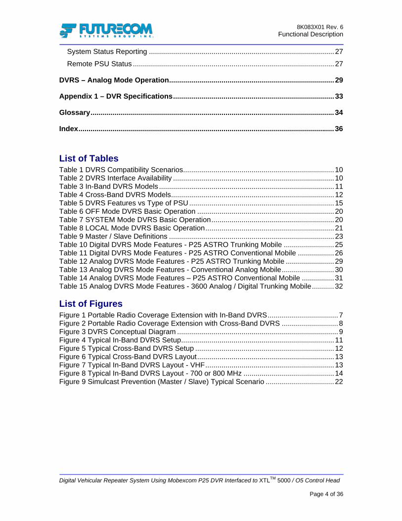
Contents Contents...........................................................................................................................3
List of Tables.................................................................................................................4 List of Figures................................................................................................................4 Manual Revisions..........................................................................................................5 Computer Software Copyrights .....................................................................................6 Document Copyrights....................................................................................................6 Disclaimer .....................................................................................................................6 Trademarks ...................................................................................................................6
Introduction .....................................................................................................................7
DVRS Principle of Operation..........................................................................................9 DVRS Compatibility.....................................................................................................10 DVRS Models..............................................................................................................11
Frequency Band of Operation............................................................................................... 11 DVRS Mounting Arrangement .............................................................................................. 13
DVRS Features vs PSU Type .....................................................................................15 DVRS Operation and Basic Features .........................................................................16
DVRS Status Display ............................................................................................................ 16 Activating the DVRS via the 05 Control Head ...................................................................... 16 Automatic DVRS Activation (AVRA) ..................................................................................... 17 Remote Activation of the DVRS............................................................................................ 17
‘DVRS Enabled’ Mobile Radio TGs / Channels ..........................................................18 ‘DVRS Disabled’ Mobile Radio TGs / Channels..........................................................18 DVRS Modes of Operation..........................................................................................19 OFF Mode Operation ..................................................................................................20 System Mode Operation .............................................................................................20 Local Mode Operation.................................................................................................21 Selecting DVRS Mode ................................................................................................21 Selecting DVRS Channel ............................................................................................22 Master / Slave DVR Basics .........................................................................................22
Multiple DVRS Operation on Different DVR Frequencies .................................................... 24 Siren............................................................................................................................24
DVRS – P25 Digital Mode Operation ...........................................................................25 Remote Steering – Phase I .........................................................................................27 Multiple Talk Group Operation – Phase II ...................................................................27
8K083X01 Rev. 6 Functional Description
Digital Vehicular Repeater System Using Mobexcom P25 DVR Interfaced to XTLTM 5000 / O5 Control Head
Page 4 of 36
System Status Reporting ............................................................................................27 Remote PSU Status ....................................................................................................27
DVRS – Analog Mode Operation..................................................................................29
Appendix 1 – DVR Specifications................................................................................33
Glossary.........................................................................................................................34
Index...............................................................................................................................36
List of Tables Table 1 DVRS Compatibility Scenarios...........................................................................10 Table 2 DVRS Interface Availability ................................................................................10 Table 3 In-Band DVRS Models .......................................................................................11 Table 4 Cross-Band DVRS Models.................................................................................12 Table 5 DVRS Features vs Type of PSU........................................................................15 Table 6 OFF Mode DVRS Basic Operation ....................................................................20 Table 7 SYSTEM Mode DVRS Basic Operation.............................................................20 Table 8 LOCAL Mode DVRS Basic Operation................................................................21 Table 9 Master / Slave Definitions ..................................................................................23 Table 10 Digital DVRS Mode Features - P25 ASTRO Trunking Mobile .........................25 Table 11 Digital DVRS Mode Features - P25 ASTRO Conventional Mobile ..................26 Table 12 Analog DVRS Mode Features - P25 ASTRO Trunking Mobile ........................29 Table 13 Analog DVRS Mode Features - Conventional Analog Mobile..........................30 Table 14 Analog DVRS Mode Features – P25 ASTRO Conventional Mobile ................31 Table 15 Analog DVRS Mode Features - 3600 Analog / Digital Trunking Mobile...........32
List of Figures Figure 1 Portable Radio Coverage Extension with In-Band DVRS...................................7 Figure 2 Portable Radio Coverage Extension with Cross-Band DVRS ............................8 Figure 3 DVRS Conceptual Diagram ................................................................................9 Figure 4 Typical In-Band DVRS Setup............................................................................11 Figure 5 Typical Cross-Band DVRS Setup .....................................................................12 Figure 6 Typical Cross-Band DVRS Layout....................................................................13 Figure 7 Typical In-Band DVRS Layout - VHF................................................................13 Figure 8 Typical In-Band DVRS Layout - 700 or 800 MHz .............................................14 Figure 9 Simulcast Prevention (Master / Slave) Typical Scenario ..................................22

8K083X01 Rev. 6 Functional Description
Digital Vehicular Repeater System Using Mobexcom P25 DVR Interfaced to XTLTM 5000 / O5 Control Head
Page 5 of 36
Manual Revisions Revision # Date ECN Notes & References
0 01/14/2006 na Original Release 1 01/25/2006 06037 Various format updates 2 02/14/2006 06046 Table 3 updated 3 03/03/2006 06068 380-403MHz model added 4 04/28/2006 06098 Merged 380-430MHz model 5 06/08/2006 06132 Full Duplex option availability reference added 6 07/07/2006 06157 Phase II features expanded - preliminary

8K083X01 Rev. 6 Functional Description
Digital Vehicular Repeater System Using Mobexcom P25 DVR Interfaced to XTLTM 5000 / O5 Control Head
Page 6 of 36
Computer Software Copyrights The products described in this manual include copyrighted Futurecom computer programs stored in semiconductor memories or other media. Laws in the United States, Canada and other countries preserve for Futurecom certain exclusive rights for copyrighted computer programs, including but not limited to, the exclusive right to copy or reproduce in any form the copyrighted computer programs. Any copyrighted computer program contained in the Futurecom products described in this manual may not be copied, reproduced, modified, reverse-engineered, or distributed in any manner without the express written permission of Futurecom. The purchase of Futurecom products shall not be deemed to grant either directly or by implication, estoppels, or otherwise, any license under the copyrights, patents or patent applications of Futurecom, except for the normal non-exclusive license to use that arises by operation of law in the sale of a product.
Document Copyrights No part of this manual may be reproduced, distributed or transmitted in any form or by any means, for any purpose without written permission of Futurecom.
Disclaimer The information in this document is carefully examined and is believed to be entirely reliable. However, no responsibility is assumed for inaccuracies. Futurecom Systems Group Inc. reserves the right to make changes to any products herein to improve readability, function or design. Futurecom does not assume any liability arising out of the application or use of any product or circuit described herein.
Trademarks MOTOROLA, ASTRO, XTLTM 5000, SmartZone are trademarks of Motorola Inc.
8K083X01 Rev. 6 Functional Description
Digital Vehicular Repeater System Using Mobexcom P25 DVR Interfaced to XTLTM 5000 / O5 Control Head
Page 7 of 36
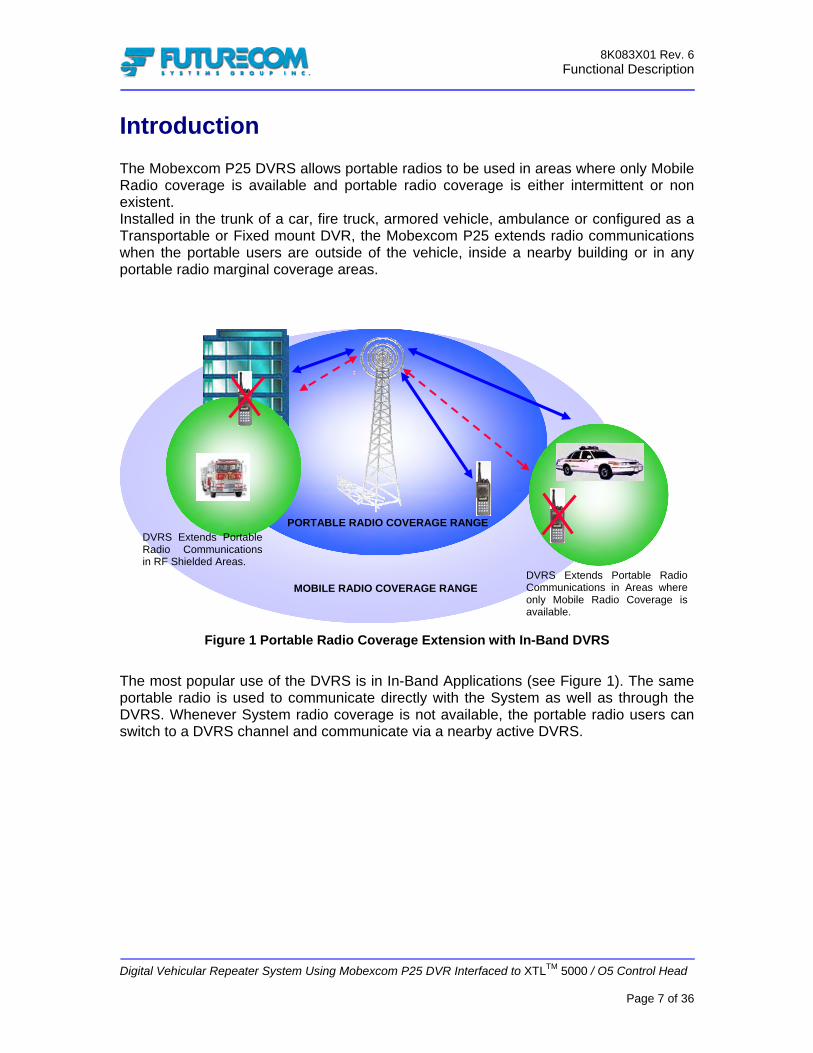
Introduction The Mobexcom P25 DVRS allows portable radios to be used in areas where only Mobile Radio coverage is available and portable radio coverage is either intermittent or non existent. Installed in the trunk of a car, fire truck, armored vehicle, ambulance or configured as a Transportable or Fixed mount DVR, the Mobexcom P25 extends radio communications when the portable users are outside of the vehicle, inside a nearby building or in any portable radio marginal coverage areas.
Figure 1 Portable Radio Coverage Extension with In-Band DVRS
The most popular use of the DVRS is in In-Band Applications (see Figure 1). The same portable radio is used to communicate directly with the System as well as through the DVRS. Whenever System radio coverage is not available, the portable radio users can switch to a DVRS channel and communicate via a nearby active DVRS.
PORTABLE RADIO COVERAGE RANGE
MOBILE RADIO COVERAGE RANGE
DVRS Extends Portable Radio Communications in RF Shielded Areas.
DVRS Extends Portable Radio Communications in Areas where only Mobile Radio Coverage is available.

8K083X01 Rev. 6 Functional Description
Digital Vehicular Repeater System Using Mobexcom P25 DVR Interfaced to XTLTM 5000 / O5 Control Head
Page 8 of 36
The P25 DVRS can also be used in Cross-Band Systems, where all Portable Radio Coverage is provided via the DVRS. Some Cross-Band applications may require the use of two portable radios – type 1 (operating on Frequency Band 1) for direct use on the System and type 2 (operating on Frequency Band 2) for use via the DVRS when the type 1 is out of system radio coverage. However, the most typical Cross-Band DVRS scenario is as shown on Figure 2 – when the entire portable radio coverage is provided via DVRS.
Figure 2 Portable Radio Coverage Extension with Cross-Band DVRS
The DVR not only extends voice (clear or encrypted) communications but it also supports key trunking system features and can be configured to provide various advanced options to the Users.
MOBILE RADIO COVERAGE RANGE – Band 1
Band 1 Band 1
Band 2 Portable Radio Coverage Through DVRS
Band 2 Portable Radio Coverage Through DVRS

8K083X01 Rev. 6 Functional Description
Digital Vehicular Repeater System Using Mobexcom P25 DVR Interfaced to XTLTM 5000 / O5 Control Head
Page 9 of 36
DVRS Principle of Operation
Figure 3 DVRS Conceptual Diagram
The P25 DVR is a versatile, full duplex digital repeater, designed to be seamlessly interfaced to a Remote Mount XTL5000 Digital Mobile Radio using O5 Control Head. W – Series control heads are NOT supported by the DVRS. The DVRS is controlled from (and its status is displayed on) the O5 Control Head. It is equipped with all necessary filtering for interference-free operation. When the DVRS is activated, any Outbound Calls (Mobile radio receiving on the selected TG 1) can be repeated to the Local Portable radios over the selected DVR conventional digital or conventional analog channel DVR1 – see Figure 3. Local Portables can communicate with each other over DVR1 as well as to the System Users on TG 1. In-car monitor will be supported in Phase II. NOTES: Phase I – DVRS and XTL5000 Firmware Released in Q1 2006. Phase II – Scheduled DVRS and XTL5000 Firmware Release in Q4 2006. Full Duplex Option Availability for a particular frequency band configuration needs to be confirmed at the time of order.
Remote Mount XTL5000
Mobexcom P25DVR Duplexer
O5
Tx
Rx
Tx/Rx
Speaker TG 1
DVR1
DVR1
TG 1

8K083X01 Rev. 6 Functional Description
Digital Vehicular Repeater System Using Mobexcom P25 DVR Interfaced to XTLTM 5000 / O5 Control Head
Page 10 of 36
DVRS Compatibility The following table summarizes the DVRS compatibility scenarios:
Table 1 DVRS Compatibility Scenarios
IMPORTANT! XTL5000 Interfaced DVRS requires the following: XTL5000 must be equipped with firmware release 7.00.00 or later. O5 Control Head must be equipped with firmware release 2.00.00 or later.
Mobile Radio Type Control Head Projected DVRS
Availability XTL5000 O5 Available XTL5000 O3 Phase II XTL2500 M5 Phase II
Table 2 DVRS Interface Availability
YesNoPhase IINoConventional DigitalP25 DVRS Enabled
YesPhase IIPhase IIYesConventional Analog
YesNoPhase IINoConventional DigitalP25
NoNoNoNo9600 Digital Trunking
NoNoNoNo3600 Analog Trunking3600 Digital Trunking
9600 Digital P25 Trunking
3600 Analog3600 DigitalTrunking
ConventionalDigital P25
ConventionalAnalogPSU MODE
MSU MODE

8K083X01 Rev. 6 Functional Description
Digital Vehicular Repeater System Using Mobexcom P25 DVR Interfaced to XTLTM 5000 / O5 Control Head
Page 11 of 36
DVRS Models
Frequency Band of Operation Depending on the frequency band of operation of the XTLTM 5000 and the interfaced DVR, the DVRS models are classified as follows:
• In-Band – when the XTLTM 5000 and DVR operate in the same frequency band. • Cross-Band – when the XTLTM 5000 and DVR operate in two different frequency
bands.
In-Band The following In-Band DVRS Model Groups are available:
DVR BAND OF OPERATION [MHz] 136-174 380-430 450-470 470-512 764-776
794-806 806-825 851-870
XTLTM 5000 BAND OF
OPERATION [MHz]
136-174
380-470
OR 450-520
380-470
OR 450-520
380-470
OR 450-520
762-776 794-806
OR 806-825 851-870
762-776 794-806
OR 806-825 851-870
Table 3 In-Band DVRS Models
Figure 4 Typical In-Band DVRS Setup
The In-Band DVRS is equipped with two sets of filters (Figure 4): An internal duplexer, providing the necessary isolation between the DVR Transmit
and Receive Frequencies, as well as rejecting the Mobile radio frequencies. An in-band filter installed at the output of the Mobile Radio, rejecting the DVR
transmit and Receive Frequencies. An RF Bypass switch bypasses the in-band filter when a ‘VR Disabled’ mode is selected on the O5. When a ‘VR Enabled’ mode is selected on the O5, the in-band filters are switched in to ensure interference free operation. Important: Minimum 30 dB antenna isolation must be provided in order to ensure interference-free operation of both the Mobile Radio and the DVR.
Remote Mount XTL5000800MHz
Mobexcom P25 DVR700MHz Duplexer
O5
Tx
Rx
Tx/Rx
Speaker
NotchFilters
RF SW
8K083X01 Rev. 6 Functional Description
Digital Vehicular Repeater System Using Mobexcom P25 DVR Interfaced to XTLTM 5000 / O5 Control Head
Page 12 of 36
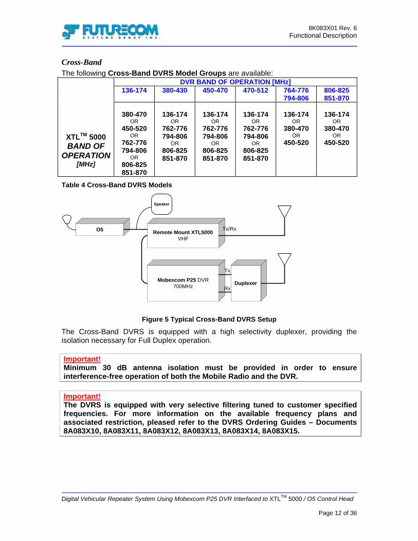
Cross-Band The following Cross-Band DVRS Model Groups are available:
DVR BAND OF OPERATION [MHz] 136-174 380-430 450-470 470-512 764-776
794-806 806-825 851-870
XTLTM 5000 BAND OF
OPERATION [MHz]
380-470
OR 450-520
OR 762-776 794-806
OR 806-825 851-870
136-174
OR 762-776 794-806
OR 806-825 851-870
136-174
OR 762-776 794-806
OR 806-825 851-870
136-174
OR 762-776 794-806
OR 806-825 851-870
136-174
OR 380-470
OR 450-520
136-174
OR 380-470
OR 450-520
Table 4 Cross-Band DVRS Models
Figure 5 Typical Cross-Band DVRS Setup
The Cross-Band DVRS is equipped with a high selectivity duplexer, providing the isolation necessary for Full Duplex operation. Important! Minimum 30 dB antenna isolation must be provided in order to ensure interference-free operation of both the Mobile Radio and the DVR. Important! The DVRS is equipped with very selective filtering tuned to customer specified frequencies. For more information on the available frequency plans and associated restriction, pleased refer to the DVRS Ordering Guides – Documents 8A083X10, 8A083X11, 8A083X12, 8A083X13, 8A083X14, 8A083X15.
Remote Mount XTL5000VHF
Mobexcom P25 DVR700MHz Duplexer
O5
Tx
Rx
Tx/Rx
Speaker

8K083X01 Rev. 6 Functional Description
Digital Vehicular Repeater System Using Mobexcom P25 DVR Interfaced to XTLTM 5000 / O5 Control Head
Page 13 of 36
DVRS Mounting Arrangement
Side-By-Side DVRS Side-By-Side mounting is the standard option for vehicular type installations. The Cross-Band DVRS package includes a DVR Repeater and Duplexer Enclosure, mounted on one side and a Remote Mount XTLTM 5000 Radio mounted next to the DVR.
Figure 6 Typical Cross-Band DVRS Layout
The In-Band models are comprised of a DVR Repeater and its associated filtering shelves mounted on one side, a model-specific in-band filtering shelf (shelves) mounted as close as possible to the DVR and a Remote Mount XTLTM 5000 Radio mounted next to the in-band filtering.
Figure 7 Typical In-Band DVRS Layout - VHF
NOTE The DVR and XTLTM 5000 always require two separate antennas.

8K083X01 Rev. 6 Functional Description
Digital Vehicular Repeater System Using Mobexcom P25 DVR Interfaced to XTLTM 5000 / O5 Control Head
Page 14 of 36
Figure 8 Typical In-Band DVRS Layout - 700 or 800 MHz
Transportable DVRS The Transportable DVRS is packaged in a durable suitcase and includes all necessary electronics and filtering. The Transportable unit can be easily deployed in the field and is powered up either by plugging into an AC outlet or by using an optional battery backup kit. The battery backup kit is also packaged in a suitcase for ease of transportation. The Transportable Model requires two antennas - one connected to the XTLTM 5000 and one to the DVR. The XTLTM 5000 antenna needs to be strategically deployed in order to ensure reliable link between the XTLTM 5000 and the P25 Radio System. The DVR antenna needs to be positioned to provide optimum radio coverage for the portable radio users. For further details, please refer to publication 8F083X02.
Fixed DVRS The Fixed DVRS model is housed in a wall-mount indoor enclosure and includes all necessary electronics and filtering. The Fixed DVRS is intended for permanent i.e. ‘Fixed’ type installations. For further details, please refer to publication 8F083X01.
Fixed DVRS Transportable DVRS (TDVRS) Battery Pack
for TDVRS

8K083X01 Rev. 6 Functional Description
Digital Vehicular Repeater System Using Mobexcom P25 DVR Interfaced to XTLTM 5000 / O5 Control Head
Page 15 of 36
DVRS Features vs PSU Type Depending on the type of portable radios used, the following DVRS features may be available if enabled by the programmed personalities of the DVR, Portable Subscriber Unit (PSU) and Mobile Subscriber Unit (MSU):
DVRS FEATURE XTS 5000
DVRS EnabledP25 PSU
Generic P25 PSU Analog PSU
REGISTRATION / DEREGISTRATION
Yes Yes* No
GROUP CALL Yes Yes Yes PRIVATE CALL Yes No No EMERGENCY CALL/ALARM Yes Yes Yes ENCRYPTION Yes Yes No CALL ALERT PAGING Yes Yes No FAILSOFT Yes No No OUT OF RANGE Yes No No SITE TRUNKING Yes No No TALK PERMIT TONES (GENERATED BY PSU)
Yes No No
TALK PERMIT TONES SENT BY DVR
No No Yes
RADIO INHIBIT Yes Yes No RADIO CHECK Yes Yes No
Table 5 DVRS Features vs Type of PSU
* Generic P25 PSU registers upon first Group Call after switching to DVR mode.

8K083X01 Rev. 6 Functional Description
Digital Vehicular Repeater System Using Mobexcom P25 DVR Interfaced to XTLTM 5000 / O5 Control Head
Page 16 of 36
DVRS Operation and Basic Features
DVRS Status Display The DVRS Status is displayed on the O5 as follows: The DVRS current mode and channel alias are displayed on the top line (for example VR SYS CHAN1). The DVR Icons change to indicate the DVRS status (Master / Slave / Permanent Master) as well as the RF activities involving the DVRS (DVR Receiving, DVR Transmitting, DVR Receiving and Transmitting).
Activating the DVRS via the 05 Control Head
The DVRS mode of operation and status can be changed from the ‘VRS’ soft key. The DVRS channel can be controlled by pressing the VRS Soft Key and subsequently turning the Rotary mode control knob.
VRS Soft Key
V RVR SYS CHAN 1 TALK GR1
DVR Status & Icon
8K083X01 Rev. 6 Functional Description
Digital Vehicular Repeater System Using Mobexcom P25 DVR Interfaced to XTLTM 5000 / O5 Control Head
Page 17 of 36
Automatic DVRS Activation (AVRA) The DVR can be activated automatically if one of the VIP inputs on the MSU control head is wired to the desired trigger source – portable charger switch or door switch or custom manual switch. When the DVR is in the OFF mode and the VIP input is asserted by the installed trigger, the DVR will automatically switch to the SYSTEM mode. For instance, removing the portable radio from the charger before leaving the vehicle may be set up to automatically activate the DVR (i.e. switch it to System Mode). If the DVR is in the SYSTEM or LOCAL mode, asserting the VIP output through the installed trigger switch will not cause any change of the DVR status. If the DVR is in the SYSTEM or LOCAL Mode and the AVRA VIP input is de-asserted, the DVR will switch to OFF Mode. If the DVR is in the OFF Mode, de-asserting the AVRA VIP will not result in any change. The method of de-asserting the AVRA VIP depends on the actual installed trigger. For example, if the selected AVRA trigger is the Portable Charger Switch, de-asserting the AVRA VIP input is equivalent to placing the PSU back in the charger.
Remote Activation of the DVRS
Via PSU Call Alert To remotely activate a DVR, the PSU user can send a Call Alert Page with the ID of the specific DVR. Upon receipt of a Call Alert Page from the PSU the DVR will:
• Switch from OFF or LOCAL mode to SYSTEM Mode (unless it is already in the SYSTEM Mode).
• Switch to Master Status and force any other Master DVR to become a Slave unless there is a Permanent Master (on the same DVR channel) already present in the same area.
• Force the MSU to revert to the TG selected on the PSU (if enabled by the DVR and PSU programming).
Via PSU Emergency Call / Alarm The DVR switches from OFF to SYSTEM Mode after a programmable number of Emergency Alarm or Emergency Call attempts sent by a PSU are successfully received by the DVR and are not serviced by another (Master) DVRS.
Inactivity Timer If programmed, the DVR can switch automatically to OFF Mode upon expiration of its Inactivity Timer (programmable from 0 to 180 minutes). The timer is restarted every time the DVR detects PSU activity.

8K083X01 Rev. 6 Functional Description
Digital Vehicular Repeater System Using Mobexcom P25 DVR Interfaced to XTLTM 5000 / O5 Control Head
Page 18 of 36
‘DVRS Enabled’ Mobile Radio TGs / Channels DVR Operation may be enabled (by the DVR and MSU programming) on selected Mobile Radio Talk Groups / Channels and disabled on others. When the User selects a DVRS Enabled TG / Channel on the O5 Control Head, the DVR Operation is enabled in the following manner:
• The DVR automatically enters the pre-programmed DVR Mode/Channel associated (‘slaved’) with the selected MSU TG / Channel if DVR Slaved Operation is programmed in the DVR.
OR • The User may change the DVR Mode / Channel (if ‘slaving’ is not enabled) by
pressing the assigned VRS Button and entering the DVR Control Mode. • The DVR can be activated and used to repeat messages between the System
Users of the TG/Channel Selected on the MSU O5 and the PSU users on the Selected DVR Channel.
• If enabled in the DVR personality, ‘DVR Enabled’ tones will be heard every few seconds (5-255 sec. programmable) in the MSU speaker, regardless of the Master / Slave status.
‘DVRS Disabled’ Mobile Radio TGs / Channels DVR Operation may be enabled on selected Mobile Radio Talk Groups / Channels and disabled on others. When the User selects a “DVRS Disabled” TG / Channel on the O5 Control Head:
• VR DISABLED message appears on the O5 display. • Pressing the VRS button results in a DVR Invalid Option Tone (single low-pitched
tone). • DVR Operation is prohibited i.e. all DVR functions are disabled.

8K083X01 Rev. 6 Functional Description
Digital Vehicular Repeater System Using Mobexcom P25 DVR Interfaced to XTLTM 5000 / O5 Control Head
Page 19 of 36
DVRS Modes of Operation When a “DVRS Enabled” TG / Channel is selected on the O5 Control Head, the DVR can be switched to one of the following Modes – OFF, LOCAL or SYSTEM.
OFF mode is used when the DVRS repeat is not required (for example while the portable user is in the vehicle driving). LOCAL mode is used in some tactical applications when only portable-to-portable communications are required. Inbound calls are not repeated to the System in the LOCAL mode i.e. the calls received by the DVRS are repeated locally but the Mobile Radio does not key up. As an option, the DVRS can be programmed to repeat System outbound calls to the local portable users. SYSTEM mode enables the full DVRS repeat – locally and to the System. Outbound calls received by the Mobile Radio are repeated by the DVRS to the local portables over the DVRS channel. Inbound calls received by the DVRS are repeated locally (portable-to-portable) as well as to the System users (by keying up the Mobile Radio).
OFF LOCAL SYSTEM

8K083X01 Rev. 6 Functional Description
Digital Vehicular Repeater System Using Mobexcom P25 DVR Interfaced to XTLTM 5000 / O5 Control Head
Page 20 of 36
OFF Mode Operation
ACTIVITY OFF MODE ACTION O5 Display VR OFF <DVR CH Name> VRS Button Press Short high-pitched tone.
DVR Control Mode is accessible. MSU Receiving from System on Selected MSU TG/Channel
DVR does not repeat audio received by MSU.Speaker Audio present.
MSU User PTTs the MSU Microphone
MSU Keys up. DVR does not key up.
PSU Activity on DVR channel DVRS Transmit Function Disabled i.e. No DVR repeat. No Speaker Audio.
Table 6 OFF Mode DVRS Basic Operation
System Mode Operation ACTIVITY SYSTEM MODE ACTION
O5 Display VR SYS <DVR CH Name>
DVRS Active Tones If programmed, a short high-pitched ‘DVR Enabled’ tone is repeated every 10 seconds (5-255 sec. programmable) in the MSU Speaker regardless of the Master / Slave Status of the DVR.
VRS Button Press Short high-pitched tone. DVR Control Mode is accessible.
MSU User PTTs the MSU Microphone
Phase I: DVR does not key up. MSU keys up.Phase II: Both DVR and MSU key up.
MSU Receiving from System on Selected MSU TG/Channel
DVR repeats audio received by MSU to PSU Users of the designated DVR Channel. Speaker Audio present.
PSU Activity on DVR channel PSU audio is repeated locally by DVRS as well as by the MSU to the System (on the selected TG). No Speaker Audio in Phase I. Programmable In-Car Monitor in Phase II.
Table 7 SYSTEM Mode DVRS Basic Operation
NOTE If the selected DVR TG / channel attribute is programmed as an Extender or in Simplex mode the local repeat DVR function is not available.

8K083X01 Rev. 6 Functional Description
Digital Vehicular Repeater System Using Mobexcom P25 DVR Interfaced to XTLTM 5000 / O5 Control Head
Page 21 of 36
Local Mode Operation ACTIVITY LOCAL MODE ACTION
O5 Display VR LOC <DVR CH Name> DVRS Active Tones If programmed, a short high-pitched ‘DVR
Enabled’ tone is repeated every 10 seconds (5-255 sec. programmable) in the MSU Speaker regardless of the Master / Slave Status of the DVR.
VRS Button Press Short high-pitched tone. DVR Control Mode is accessible.
MSU Receiving from System on Selected MSU TG/Channel
DVR may be programmed to repeat audio received by MSU to the PSU Users over the DVR Channel when the DVR is idle. Speaker Audio present.
MSU User PTTs the MSU Microphone
Phase I: DVR does not key up. MSU keys up. Phase II: DVR keys up. MSU does not key up.
PSU Activity on DVR channel PSU audio is repeated locally by DVRS. No Speaker Audio in Phase I. Programmable In-Car Monitor in Phase II.
Table 8 LOCAL Mode DVRS Basic Operation
Selecting DVRS Mode When a ‘DVRS Enabled’ TG / Channel is selected on the MSU, the User may change the DVRS Mode / Channel / Status by entering the ‘DVRS Control Mode’ (VRS soft key press). The DVRS Mode and Channel may be programmed to be ‘Slaved’ to the specific MSU TG/Channel. In this case, selecting a specific MSU TG / Channel on the O5 Control Head would automatically force the DVR to revert to a pre-programmed DVR Mode and/or Channel. For example, selecting a DVR Enabled TG named ‘DISPATCH’ on the O5 may automatically force the DVR to switch to DVR Channel 1, SYSTEM Mode. If enabled in the specific DVR personality programming, the DVRS User can still toggle the DVR Mode by pressing the VRS Button and entering the ‘DVR Control Mode’. If Mode change by the User is prohibited in the specific DVRS personality, the User can only select between the ‘Slaved’ (either LOCAL or SYSTEM) and OFF DVR Modes.

8K083X01 Rev. 6 Functional Description
Digital Vehicular Repeater System Using Mobexcom P25 DVR Interfaced to XTLTM 5000 / O5 Control Head
Page 22 of 36
Selecting DVRS Channel When a ‘DVRS Enabled’ TG / Channel is selected on the MSU, the User may change the DVRS Channel by entering the ‘DVRS Control Mode’ (VRS soft key press) and then turning the Rotary mode selector. The DVRS Mode and Channel may be programmed to be ‘Slaved’ to the specific MSU TG/Channel. In this case, selecting a specific MSU TG / Channel would automatically force the DVR to revert to a given DVR Channel and/or Mode. For example, selecting a DVR Enabled TG named ‘DISPATCH’ on the O5 may automatically force the DVR to switch to DVR Channel 1, SYSTEM Mode.
Master / Slave DVR Basics In order to prevent interference and loss of communications when more then one active DVRS are present at the same location and tuned to the same DVR Channel, a sophisticated simulcast prevention algorithm is employed to ensure only one DVRS repeats radio communications on the same DVR frequency at the same time.
Figure 9 Simulcast Prevention (Master / Slave) Typical Scenario
While the algorithm is transparent to the User, on some occasions he/she may need to be able to select (or simply be aware of) which DVRS is currently the ‘Master’ and which ones are ‘Slaves’. Furthermore, a DVRS may be assigned to be a Permanent Master if this selection is enabled in the programmed personality. A Permanent Master always wins the voting algorithm. If more then one Permanent Masters are activated simultaneously, they vote to ensure only one DVR remains as a Permanent Master and the other(s) revert to Slave status.
TG 1
DVR 1 Slave
No repeat
Slave
No repeat
Master
TG 1
DVR 1
TG 1
DVR 1
TG 1
DVR 1 Slave
No repeat
Slave
No repeat
Master
TG 1
DVR 1
TG 1
DVR 1
8K083X01 Rev. 6 Functional Description
Digital Vehicular Repeater System Using Mobexcom P25 DVR Interfaced to XTLTM 5000 / O5 Control Head
Page 23 of 36
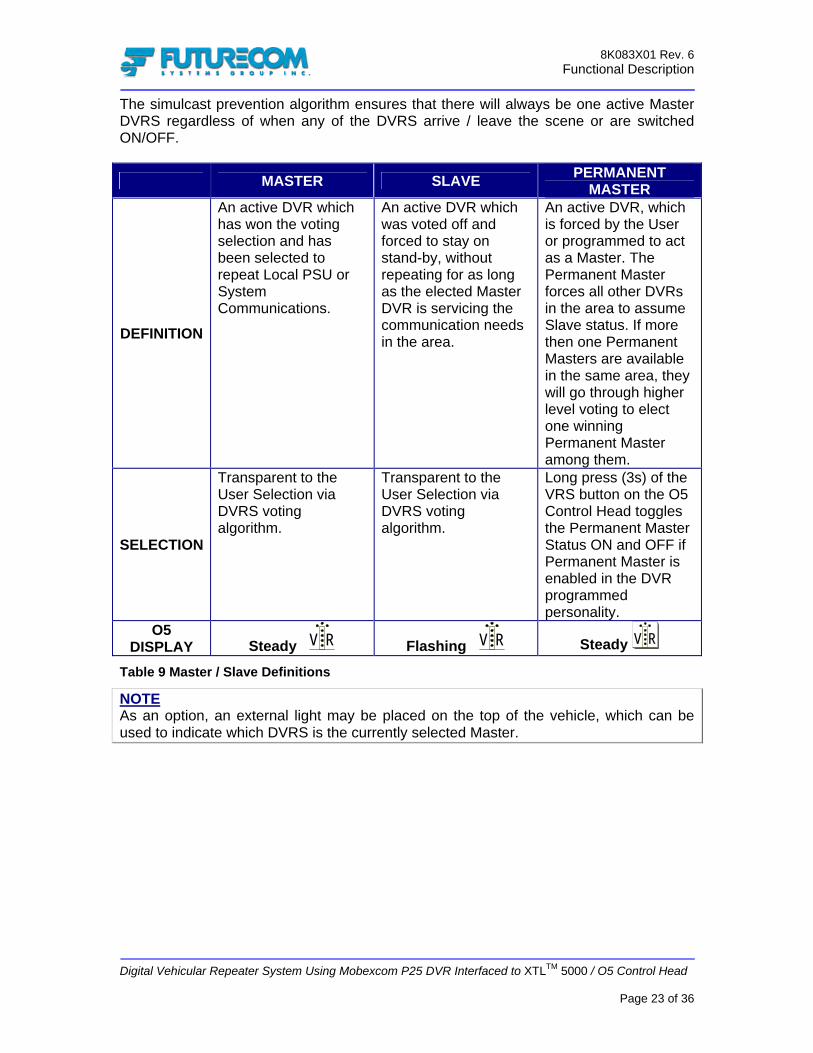
The simulcast prevention algorithm ensures that there will always be one active Master DVRS regardless of when any of the DVRS arrive / leave the scene or are switched ON/OFF.
MASTER SLAVE PERMANENT MASTER
DEFINITION
An active DVR which has won the voting selection and has been selected to repeat Local PSU or System Communications.
An active DVR which was voted off and forced to stay on stand-by, without repeating for as long as the elected Master DVR is servicing the communication needs in the area.
An active DVR, which is forced by the User or programmed to act as a Master. The Permanent Master forces all other DVRs in the area to assume Slave status. If more then one Permanent Masters are available in the same area, they will go through higher level voting to elect one winning Permanent Master among them.
SELECTION
Transparent to the User Selection via DVRS voting algorithm.
Transparent to the User Selection via DVRS voting algorithm.
Long press (3s) of the VRS button on the O5 Control Head toggles the Permanent Master Status ON and OFF if Permanent Master is enabled in the DVR programmed personality.
O5 DISPLAY Steady V R Flashing V R Steady V R
Table 9 Master / Slave Definitions
NOTE As an option, an external light may be placed on the top of the vehicle, which can be used to indicate which DVRS is the currently selected Master.

8K083X01 Rev. 6 Functional Description
Digital Vehicular Repeater System Using Mobexcom P25 DVR Interfaced to XTLTM 5000 / O5 Control Head
Page 24 of 36
Multiple DVRS Operation on Different DVR Frequencies If more then one DVRS are present at the same location at the same time and they are set to operate on different DVR channels, the DVRs will operate completely independently. For example, DVRS A may be set to operate on DVR CH 1 and TG X while DVRS B may be set to DVR CH 2 and TG Y. Local PSU User can select DVR CH 1 and talk to TG X Users through DVRS A. Local PSU User can select DVR CH 2 and talk to TG Y Users through DVRS B. Both DVRS A and DVRS B will be Masters i.e. each DVRS will be the Master of its selected DVR channel. NOTE The above described DVRS independent operation may be very useful for some multi-agency operation scenarios.
Siren To connect a Siren to a DVR equipped Mobile Radio, a special interface cable is required. Refer to the DVRS Ordering Guides for part number information - Documents 8A083X10, 8A083X11, 8A083X12, 8A083X13, 8A083X14, 8A083X15.

8K083X01 Rev. 6 Functional Description
Digital Vehicular Repeater System Using Mobexcom P25 DVR Interfaced to XTLTM 5000 / O5 Control Head
Page 25 of 36
DVRS – P25 Digital Mode Operation The operation described below assumes a DVR Digital Mode channel and a P25 Talk Group are selected on the DVR and XTL5000 respectively.
FEATURE DVR OFF Mode
DVR SYSTEM Mode
DVR LOCAL Mode
DVRS Status Display on the O5
VR OFF <DVR CH> VR SYS <DVR CH> VR LOC <DVR CH>
PSU Affiliation NO YES YES Outbound Group Call NO YES YES Outbound Private Call NO YES YES
Microphone PTT (MSU) YES
Phase I NO – on DVR side YES – System side
Phase II YES
Phase I NO – on DVR side YES – System side
Phase II YES – DVR Side
NO – System side Inbound Group Call NO YES YES Inbound Private Call NO YES YES Inbound Call Alert NO YES YES
Inbound Emergency Alarm / Call YES YES YES
Steering YES YES YES Multiple Talk Groups NO Phase II Phase II
Failsoft NO YES NO Out of Range NO YES NO Site Trunking NO YES NO
Master / Slave Voting NO YES YES DVRS Status Tones –
MSU Speaker NO YES YES
DVRS Status Tones - PSU NO YES YES
Radio Inhibit NO YES YES Radio Check NO YES YES
Scan YES Phase II NO Talk Permit Tones NO YES YES
OTAR NO Phase II Phase II Fire Ground NO Phase II Phase II
Patch NO Phase II Phase II Dynamic Regrouping NO Phase II Phase II
Phone NO Phase II Phase II Remote DVRS
Activation / Deactivation
Phase II Phase II Phase II
Adaptive Power Control NO Phase II Phase II
Emergency MDC1200 ID pass through NA NA NA
Encryption NO YES YES
Table 10 Digital DVRS Mode Features - P25 ASTRO Trunking Mobile
NOTE Phase II features listed are preliminary.

8K083X01 Rev. 6 Functional Description
Digital Vehicular Repeater System Using Mobexcom P25 DVR Interfaced to XTLTM 5000 / O5 Control Head
Page 26 of 36
The operation described below assumes a DVR Digital Mode channel and Conventional Digital Mode are selected on the DVR and the XTL5000 respectively. All Features listed below are planned for Phase II release and are subject to change.
FEATURE DVR OFF Mode
DVR SYSTEM Mode
DVR LOCAL Mode
DVRS Status Display on the O5
VR OFF <DVR CH> VR SYS <DVR CH> VR LOC <DVR CH>
PSU Affiliation NO Phase II Phase II Outbound Group Call NO Phase II Phase II Outbound Private Call NO Phase II Phase II
Microphone PTT (MSU) Phase II Phase II Phase II – DVR Side NO – System side
Inbound Group Call NO Phase II Phase II Inbound Private Call NO Phase II Phase II Inbound Call Alert NO Phase II Phase II
Inbound Emergency Alarm / Call Phase II Phase II Phase II
Steering Phase II Phase II Phase II Multiple Talk Groups NO Phase II Phase II
Failsoft NO NO NO Out of Range NO NO NO Site Trunking NO NO NO
Master / Slave Voting NO Phase II Phase II DVRS Status Tones –
MSU Speaker NO Phase II Phase II
DVRS Status Tones - PSU NO Phase II Phase II
Radio Inhibit NO Phase II Phase II Radio Check NO Phase II Phase II
Scan Phase II Phase II NO Talk Permit Tones NO Phase II Phase II
OTAR NO Phase II Phase II Fire Ground NO Phase II Phase II
Patch NO Phase II Phase II Dynamic Regrouping NO NO NO
Phone NO NO NO Remote DVRS
Activation / Deactivation
Phase II Phase II Phase II
Adaptive Power Control Phase II Phase II Phase II
Emergency MDC1200 ID pass through NO NO NO
Encryption NO Phase II Phase II
Table 11 Digital DVRS Mode Features - P25 ASTRO Conventional Mobile
8K083X01 Rev. 6 Functional Description
Digital Vehicular Repeater System Using Mobexcom P25 DVR Interfaced to XTLTM 5000 / O5 Control Head
Page 27 of 36
NOTE Both CLEAR and ENCRYPTED calls are supported by the DVRS. NOTE If the selected DVR TG / channel attribute is programmed as an Extender or Simplex mode, the local repeat DVR function is not available.
Remote Steering – Phase I In Phase I a Local PSU User can send a Call Alert Page to a specific DVRS and execute a remote change of the following:
• DVR Mode – from OFF or LOCAL to SYSTEM • DVR Status – from SLAVE to MASTER • DVRS TG – from the originally selected on the O5 TG to the TG selected by the
Local PSU.
Multiple Talk Group Operation – Phase II In Phase II, the PSUs will be capable of transparently accessing the System through the DVR on different Talk Groups without any need for changing the Talk Group selected on the XTL5000 (i.e. without any need for Call Alert Talk Group Steering).
System Status Reporting The following System Status Reporting Functions are passed to the PSUs through the DVRS when SYSTEM Mode is selected:
• Failsoft • Out of Range • Site Trunking
Remote PSU Status The following Functions are passed to the PSUs through the DVRS when SYSTEM or LOCAL Mode is selected:
• Radio Inhibit • Radio Check
Patch – Phase II When several talk groups are patched on the system side, the DVRS ensures the patching is matched on the local portables side.
Dynamic Regrouping – Phase II The system Dispatcher can temporarily assign selected individual radios operating on different talk groups to operate on a new talk group. The DVRS extends this functionality to the local portables.

8K083X01 Rev. 6 Functional Description
Digital Vehicular Repeater System Using Mobexcom P25 DVR Interfaced to XTLTM 5000 / O5 Control Head
Page 28 of 36
Phone Interconnect – Phase II The DVRS supports the transmission of a message initiated by a Local portable through the telephone system. This feature is only supported over P25 Trunking System infrastructure.
Fire Ground – Phase II The DVRS repeats locally Fireground signaling.
ASTRO OTAR – Phase II The DVRS facilitates ASTRO OTAR transmissions between the System and the local portables.
DVRS Remote Activation / Deactivation – Phase II The DVRS can be remotely activated / deactivated by the Dispatcher by changing the DVRS mode.
Adaptive Power Control – Phase II The DVRS sends messages to the local portables to adjust their transmit power depending on the received signal strength.
8K083X01 Rev. 6 Functional Description
Digital Vehicular Repeater System Using Mobexcom P25 DVR Interfaced to XTLTM 5000 / O5 Control Head
Page 29 of 36
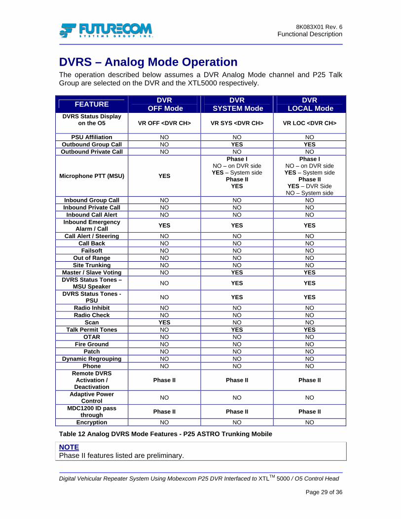
DVRS – Analog Mode Operation The operation described below assumes a DVR Analog Mode channel and P25 Talk Group are selected on the DVR and the XTL5000 respectively.
FEATURE DVR OFF Mode
DVR SYSTEM Mode
DVR LOCAL Mode
DVRS Status Display on the O5
VR OFF <DVR CH> VR SYS <DVR CH> VR LOC <DVR CH>
PSU Affiliation NO NO NO Outbound Group Call NO YES YES Outbound Private Call NO NO NO
Microphone PTT (MSU) YES
Phase I NO – on DVR side YES – System side
Phase II YES
Phase I NO – on DVR side YES – System side
Phase II YES – DVR Side
NO – System side Inbound Group Call NO NO NO Inbound Private Call NO NO NO Inbound Call Alert NO NO NO
Inbound Emergency Alarm / Call YES YES YES
Call Alert / Steering NO NO NO Call Back NO NO NO Failsoft NO NO NO
Out of Range NO NO NO Site Trunking NO NO NO
Master / Slave Voting NO YES YES DVRS Status Tones –
MSU Speaker NO YES YES
DVRS Status Tones - PSU NO YES YES
Radio Inhibit NO NO NO Radio Check NO NO NO
Scan YES NO NO Talk Permit Tones NO YES YES
OTAR NO NO NO Fire Ground NO NO NO
Patch NO NO NO Dynamic Regrouping NO NO NO
Phone NO NO NO Remote DVRS
Activation / Deactivation
Phase II Phase II Phase II
Adaptive Power Control NO NO NO
MDC1200 ID pass through Phase II Phase II Phase II
Encryption NO NO NO
Table 12 Analog DVRS Mode Features - P25 ASTRO Trunking Mobile
NOTE Phase II features listed are preliminary.

8K083X01 Rev. 6 Functional Description
Digital Vehicular Repeater System Using Mobexcom P25 DVR Interfaced to XTLTM 5000 / O5 Control Head
Page 30 of 36
The operation described below assumes a DVR Analog Mode channel and a Conventional Analog Channel are selected on the DVR and the XTL5000 respectively.
FEATURE DVR OFF Mode
DVR SYSTEM Mode
DVR LOCAL Mode
DVRS Status Display on the O5
VR OFF <DVR CH> VR SYS <DVR CH> VR LOC <DVR CH>
PSU Affiliation NO NO NO Outbound Group Call NO NO NO Outbound Private Call NO NO NO
Microphone PTT (MSU) YES
Phase I NO – on DVR side YES – System side
Phase II YES
Phase I NO – on DVR side YES – System side
Phase II YES – DVR Side
NO – System side Inbound Group Call NO NO NO Inbound Private Call NO NO NO Inbound Call Alert NO NO NO
Inbound Emergency Alarm / Call NO NO NO
Call Alert / Steering NO NO NO Call Back NO NO NO Failsoft NO NO NO
Out of Range NO NO NO Site Trunking NO NO NO
Master / Slave Voting NO YES YES DVRS Status Tones –
MSU Speaker NO YES YES
DVRS Status Tones - PSU NO YES YES
Radio Inhibit NO NO NO Radio Check NO NO NO
Scan YES NO NO Talk Permit Tones NO YES YES
OTAR NO NO NO Fire Ground NO NO NO
Patch NO NO NO Dynamic Regrouping NO NO NO
Phone NO NO NO Remote DVRS
Activation / Deactivation
NO NO NO
Adaptive Power Control NO NO NO
MDC1200 ID pass through NO NO NO
Encryption NO NO NO
Table 13 Analog DVRS Mode Features - Conventional Analog Mobile
NOTE Phase II features listed are preliminary.

8K083X01 Rev. 6 Functional Description
Digital Vehicular Repeater System Using Mobexcom P25 DVR Interfaced to XTLTM 5000 / O5 Control Head
Page 31 of 36
The operation described below assumes a DVR Analog Mode channel and a Conventional Digital Channel are selected on the DVR and the XTL5000 respectively – All Features listed below are planned for Phase II release and are subject to change.
FEATURE DVR OFF Mode
DVR SYSTEM Mode
DVR LOCAL Mode
DVRS Status Display on the O5
VR OFF <DVR CH> VR SYS <DVR CH> VR LOC <DVR CH>
PSU Affiliation NO NO NO Outbound Group Call NO Phase II Phase II Outbound Private Call NO NO NO
Microphone PTT (MSU) Phase II Phase II
Phase II – DVR Side NO – System side
Inbound Group Call NO Phase II Phase II Inbound Private Call NO NO NO Inbound Call Alert NO NO NO
Inbound Emergency Alarm / Call Phase II Phase II Phase II
Call Alert / Steering NO NO NO Multiple Talk Groups NO NO NO
Call Back NO NO NO Failsoft NO NO NO
Out of Range NO NO NO Site Trunking NO NO NO
Master / Slave Voting NO Phase II Phase II DVRS Status Tones –
MSU Speaker NO Phase II Phase II
DVRS Status Tones - PSU NO Phase II Phase II
Radio Inhibit NO NO NO Radio Check NO NO NO
Scan Phase II NO NO Talk Permit Tones NO Phase II Phase II
OTAR NO NO NO Fire Ground NO NO NO
Patch NO NO NO Dynamic Regrouping NO NO NO
Phone NO NO NO Remote DVRS
Activation / Deactivation
NO NO NO
Adaptive Power Control NO NO NO
Emergency MDC1200 ID pass through NO NO NO
Encryption NO NO NO
Table 14 Analog DVRS Mode Features – P25 ASTRO Conventional Mobile

8K083X01 Rev. 6 Functional Description
Digital Vehicular Repeater System Using Mobexcom P25 DVR Interfaced to XTLTM 5000 / O5 Control Head
Page 32 of 36
The operation described below assumes a DVR Analog Mode channel and a 3600 Analog or Digital Trunking mode are selected on the DVR and the XTL5000 respectively All Features listed below are planned for Phase II release and are subject to change.
FEATURE DVR OFF Mode
DVR SYSTEM Mode
DVR LOCAL Mode
DVRS Status Display on the O5
VR OFF <DVR CH> VR SYS <DVR CH> VR LOC <DVR CH>
PSU Affiliation NO NO NO Outbound Group Call NO Phase II Phase II Outbound Private Call NO NO NO
Microphone PTT (MSU) Phase II Phase II Phase II – DVR Side NO – System side
Inbound Group Call NO Phase II Phase II Inbound Private Call NO NO NO Inbound Call Alert NO NO NO
Inbound Emergency Alarm / Call Phase II Phase II Phase II
Call Alert / Steering NO NO NO Multiple Talk Groups NO NO NO
Call Back NO NO NO Failsoft NO NO NO
Out of Range NO NO NO Site Trunking NO NO NO
Master / Slave Voting NO Phase II Phase II DVRS Status Tones –
MSU Speaker NO Phase II Phase II
DVRS Status Tones - PSU NO Phase II Phase II
Radio Inhibit NO NO NO Radio Check NO NO NO
Scan Phase II NO NO Talk Permit Tones NO Phase II Phase II
OTAR NO NO NO Fire Ground NO NO NO
Patch NO NO NO Dynamic Regrouping NO NO NO
Phone NO NO NO Remote DVRS
Activation / Deactivation
NO NO NO
Adaptive Power Control NO NO NO
Emergency MDC1200 ID pass through Phase II Phase II Phase II
Encryption NO NO NO
Table 15 Analog DVRS Mode Features - 3600 Analog / Digital Trunking Mobile
8K083X01 Rev. 6 Functional Description
Digital Vehicular Repeater System Using Mobexcom P25 DVR Interfaced to XTLTM 5000 / O5 Control Head
Page 33 of 36
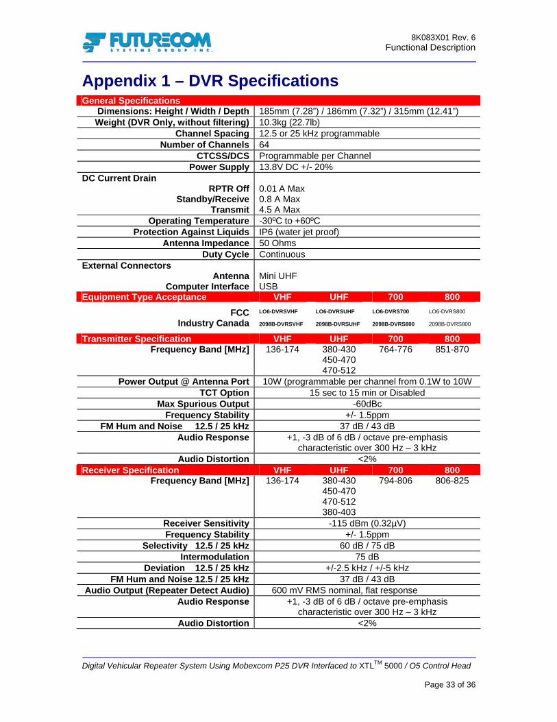
Appendix 1 – DVR Specifications General Specifications
Dimensions: Height / Width / Depth 185mm (7.28”) / 186mm (7.32”) / 315mm (12.41”) Weight (DVR Only, without filtering) 10.3kg (22.7lb)
Channel Spacing 12.5 or 25 kHz programmable Number of Channels 64
CTCSS/DCS Programmable per Channel Power Supply 13.8V DC +/- 20%
DC Current Drain RPTR Off
Standby/ReceiveTransmit
0.01 A Max 0.8 A Max 4.5 A Max
Operating Temperature -30ºC to +60ºC Protection Against Liquids IP6 (water jet proof)
Antenna Impedance 50 Ohms Duty Cycle Continuous
External Connectors Antenna
Computer Interface
Mini UHF USB
Equipment Type Acceptance VHF UHF 700 800 FCC
Industry Canada
LO6-DVRSVHF 2098B-DVRSVHF
LO6-DVRSUHF 2098B-DVRSUHF
LO6-DVRS700 2098B-DVRS800
LO6-DVRS800 2098B-DVRS800
Transmitter Specification VHF UHF 700 800 Frequency Band [MHz] 136-174 380-430
450-470 470-512
764-776 851-870
Power Output @ Antenna Port 10W (programmable per channel from 0.1W to 10W TCT Option 15 sec to 15 min or Disabled
Max Spurious Output -60dBc Frequency Stability +/- 1.5ppm
FM Hum and Noise 12.5 / 25 kHz 37 dB / 43 dB Audio Response +1, -3 dB of 6 dB / octave pre-emphasis
characteristic over 300 Hz – 3 kHz Audio Distortion <2%
Receiver Specification VHF UHF 700 800 Frequency Band [MHz] 136-174 380-430
450-470 470-512 380-403
794-806 806-825
Receiver Sensitivity -115 dBm (0.32µV) Frequency Stability +/- 1.5ppm
Selectivity 12.5 / 25 kHz 60 dB / 75 dB Intermodulation 75 dB
Deviation 12.5 / 25 kHz +/-2.5 kHz / +/-5 kHz FM Hum and Noise 12.5 / 25 kHz 37 dB / 43 dB
Audio Output (Repeater Detect Audio) 600 mV RMS nominal, flat response Audio Response +1, -3 dB of 6 dB / octave pre-emphasis
characteristic over 300 Hz – 3 kHz Audio Distortion <2%

8K083X01 Rev. 6 Functional Description
Digital Vehicular Repeater System Using Mobexcom P25 DVR Interfaced to XTLTM 5000 / O5 Control Head
Page 34 of 36
Glossary ACK Acknowledgement of communications.
AVRA Automated VR / DVR Activation. DVR Option which permits automated activation of the DVR, typically triggered by removing the portable from the charger (ON) and placing it back in (OFF).
Channel A group of characteristics, such as transmit / receive frequency pairs, radio parameters, encryption encoding etc.
Coded Squelch Tone Private-Line (PL) or Digital Private-Line (DPL). Used on conventional channels for signal validation.
Conventional Refers to radio-to-radio communications, sometimes through a base station repeater or vehicular repeater.
Dispatcher An individual who has radio system management duties.
DPL Coded Squelch A continuous sub-audible data signal transmitted with the carrier. See Coded Squelch.
DVR Digital Vehicular Repeater.
DVR Mode Determines the communication exchange capabilities between System Users and Local Portable Users; Can be set to OFF, LOCAL or SYSTEM.
DVRS Digital Vehicular Repeater interfaced to an XTLTM5000 Mobile radio with O5 Control Head.
DVR ID Programmable (in the DVR) ID, which is used for Mode / TG steering. To remotely change the Mode / TG on the DVRS, the PSU User sends a Call Alert Page to the specific DVR ID.
Extender
Variation of the SYSTEM DVR Mode, programmable per TG / DVR Channel. While in the Extender Mode the DVR repeats Local PSU-to-System and System-to-Local PSU communications but does not repeat locally i.e. no Local PSU-to-PSU communications are enabled.
FCC Federal Communications Commission.
Inbound Call PSU originated call received by the DVR.
Local Mode DVR Mode which provides extended portable-to-portable voice and data range by repeating Local PSU (optionally MSU) communications without keying up the Mobile radio interfaced to the DVR.

8K083X01 Rev. 6 Functional Description
Digital Vehicular Repeater System Using Mobexcom P25 DVR Interfaced to XTLTM 5000 / O5 Control Head
Page 35 of 36
Mobexcom II Analog Vehicular Repeater, NOT compatible with XTLTM5000 radios using CAN bus Control Heads such as the O5. Mobexcom II can be interfaced to XTLTM5000 using W-series Control Heads, Astro Spectra or MCS2000 Mobile Radios.
Mode MSU / PSU - A programmed combination of operating parameters. DVR – OFF, SYSTEM or LOCAL (see DVR Mode)
MPE Maximum Permissible Exposure. MSU Mobile Subscriber Unit. Outbound Call System Call received by the MSU. O5 Odyssey 5 Control Head using CAN bus.
Phase I First DVR & XTL5000 Firmware Release – Release Date - Q1 2006.
Phase II Second DVR & XTL5000 Firmware Release – Target Release Date – Q4 2006.
PSU Portable Subscriber Unit.
PTT Push to talk. The PTT engages the transmitter (of the Portable or Mobile radio and / or DVR) when pressed.
RF Radio Frequency. Part of the general frequency spectrum 10kHz - 10,000,000 MHz.
RSSI Received Signal Strength Indicator.
System Mode DVR mode which provides extended voice and signaling communications between System Users and Local Portable Users over the selected DVR channel / Mobile Radio Mode.
Talk Group A group of radio users who communicate with each other by using the same communication path.
Trunking The automatic sharing of radio frequencies by large number of users based on communication path sharing for the length of a conversation.

8K083X01 Rev. 6 Functional Description
Digital Vehicular Repeater System Using Mobexcom P25 DVR Interfaced to XTLTM 5000 / O5 Control Head
Page 36 of 36
Index A
Analog Mode ............................................................25 Automatic DVRS Activation (AVRA) .....................14
C Cross-Band ...............................................................10
D DVR Specifications ..................................................28 DVRS Control Mode ..........................................19, 20 DVRS Modes of Operation.......................................17 DVRS Status Display................................................14
E ENCRYPTED .........................................................24 Extender....................................................................18
F Failsoft ......................................................................24 Fixed DVRS..............................................................12
G Glossary ....................................................................30
I Inactivity Timer ........................................................15
In-Band ...................................................................... 9
M Master / Slave........................................................... 20
O Out of Range ............................................................ 24
P P25 Digital Mode ..................................................... 23
R Radio Check............................................................. 24 Radio Inhibit ............................................................ 24 Remote Activation of the DVRS.............................. 15
S Selecting DVRS Mode ............................................. 19 Side-By-Side DVRS................................................. 11 Siren ......................................................................... 14 Site Trunking............................................................ 24 System Mode...................................................... 23, 25 System Status Reporting .......................................... 24
T Transportable DVRS................................................ 12


![Order Identification Number: [######]Land Mobile Radio · Web viewActivation of vehicular repeater mode operation shall be provided by both front panel control and by remote activation](https://img.pdfslide.net/doc/110x75/5c396ce909d3f2fd328c314f/order-identification-number-land-mobile-radio-web-viewactivation-of-vehicular.jpg)