Embed Size (px)
Citation preview
2010 CA08103002Z-EN www.eaton.com
Electronic timing relay DILET45 mm contactor width +++ Numerous time relay functions +++ Ideal when combined with contactors
Electronic timing relay ETR217.5 mm width (one division unit = 18 mm) +++ With 45 mm cap dimensions, suitable for integration into distribution boards +++ Numerous time relay functions
Electronic timing relay ETR4Robust industrial construction, 22.5 mm width +++ Numerous time relay functions
EMR Electronic measuring and monitoring relaysMonitors levels of conductive fluids, current, phase sequence and position, insulation resistance, asymmetry, over- and undervoltage +++ All devices in 22.5 mm or 45 mm width +++ Phase monitor at 580 V AC in 45 mm width
The range of electronic time relays comprises three different construction types, adapted for the most widely varying applications. The time relays are mounted on a DIN top-hat rail.The measurement and monitoring relays monitor fluids, currents, phases, resistances or voltages.
DILET, ETR Timing Relays, measuring relays and EMR Monitoring relays
DILET, ETR timing relay
Ordering
DILET timing relays 11/2
ETR4 timing relays 11/4
ETR2 timing relays 11/6
Engineering
DILET, ETR timing relay
Contact sequence diagram 11/8
Load limit curves 11/10
Technical data
DILET, ETR4 timing relays 11/11
ETR2 timing relays 11/13
Dimensions
DILET, ETR timing relays 11/15
EMR Measuring and monitoring relays
Ordering
EMR measuring and monitoring relays 11/16
Engineering
EMR Measuring and monitoring relays
Load limit curves 11/19
Technical data
EMR Measuring and monitoring relays
EMR4-I... current monitoring relay 11/20
Phase sequence relay EMR5 (300 V) 11/24
Phase imbalance monitor 11/26
Liquid level monitoring relays 11/28
Insulation monitoring relays 11/30
Phase monitoring relays 11/32
Dimensions
EMR measuring and monitoring relays 11/36
17.5 5 58
80
45
43.4
I [A]
105
106
104
S
4321 5 6 7 8
109.5
102
5.5 1
100
22.5
78
Timing relay, measuring relay and monitoring relay
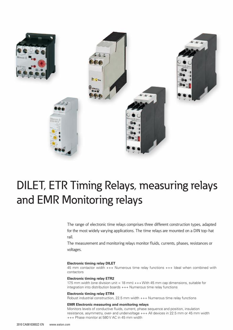
Our product range of measurement and monitoring relays has been partially updated.
Old device Old article no. New device New article no.EMR4-W500-2-C 221785 EMR5-W500-1-D 134221EMR4-W500-2-D 221786 EMR5-W500-1-D 134221EMR4-W580-2-D 221787 EMR5-AWM720-2 134236EMR4-A400-1 221788 EMR5-A400-1 134222EMR4-AW300-1-C 290243 EMR5-AW300-1-C 134223EMR4-AW500-1-D 290244 EMR5-AW500-1-D 134224EMR4-AWN170-1-E 290245 EMR5-AWN170-1-E 134225EMR4-AWN280-1-F 290246 EMR5-AWN280-1-F 134226EMR4-W300-1-C 290182 EMR5-W300-1-C 134227EMR4-W500-1-D 290183 EMR5-W500-1-D 134221EMR4-W380-1 290184 EMR5-W380-1 134228EMR4-W400-1 290185 EMR5-W400-1 134229EMR4-A300-1-C 290180 EMR5-A300-1-C 134230EMR4-A500-1-D 290181 EMR5-A400-1 134222
This table provides assistance in replacing EMR4 articles with current EMR5 products.
11/2 Electronic relaysTiming relays
DILET
2010 CA08103002Z-EN www.eaton.com 2010 CA08103002Z-EN www.eaton.com
Electronic relaysTiming relays
DILET
DILETTiming relays
Rated operational current AC-11
Conventional thermal current
Time Range Voltage range Part no.Article No.
PriceSee price list
Std. pack Notes Information relevant for export to North America
230 V 400 V Ith
Ie Ie A
A A
A A
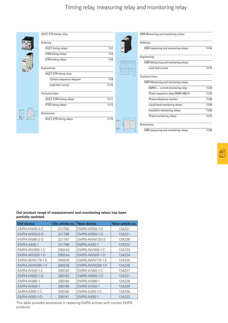
Timing relays DILET
On-delayedTiming functions → Page 11/8Component lifespan → Page 11/10
3 3 6 1.5 - 30 s 24 - 240 V AC, 50/60 Hz24 - 240 V DC
DILET11-30-A048878
1 off Fixed11, On-delayed
Product Standards IEC/EN 61812-1; IEC/EN 60947-5-1; UL 508; CSA-22.2 No. 14-05; CE marking
UL File No. E29184UL CCN NKCR, NKCR7CSA File No. 12528CSA Class No. 3211-03NA Certification UL Listed, CSA CertifiedDegree of Protection IEC: IP20, UL/CSA Type: -
3 3 6 1.5 - 30 s 400 V AC, 50/60 Hz DILET11-30-W048904
3 3 6 0.05 - 1 s0.15 - 3 s0.5 - 10 s3 - 60 s0.15 - 3 min0.5 - 10 min3 - 60 min0.15 - 3 h0.5 - 10 h3 - 60 h
24 - 240 V AC, 50/60 Hz24 - 240 V DC
DILET11-M-A048886
3 3 6 400 V AC, 50/60 Hz DILET11-M-W048891
Multi-functional with remote potentiometerTiming functions → Page 11/8 Component lifespan → Page 11/10
3 3 6 0.05 - 1s0.15 - 3 s0.2217925 - 10 s3 - 60 s0.15 - 3 min0.5 - 10 min3 - 60 min0.15 - 3 h0.5 - 10 h3 - 60 h
24 - 240 V AC, 50/60 Hz24 - 240 V DC
DILET70-A048893
1 off Adjustable11, On-delayed21, Fleeting contact on energization42, Flashing81, Pulse generatingON-OFF
Adjustable12, Off-delayed16, On- and off-delayed22, Fleeting contact on de-energization82, Pulse shapingON-OFF
Product Standards IEC/EN 61812-1; IEC/EN 60947-5-1; UL 508; CSA-22.2 No. 14-05; CE marking
UL File No. E29184UL CCN NKCR, NKCR7CSA File No. 12528CSA Class No. 3211-03NA Certification UL Listed, CSA CertifiedDegree of Protection IEC: IP20, UL/CSA Type: -
11 ON-DELAYED21 FLEETING CONTACT ON ENERGIZATION42 FLASHING81 PULSE GENERATING CONTACT
3 3 6 400 V AC, 50/60 Hz DILET70-W048899
A1
A2
15
16 18
A1
A2
15
16 18
Cable connection with Y1/Y2, Z1/Z2
Permissible cable length (cable unshielded, with cable cross-section 0.5-1.5 mm2):
Two-core cable 250 m
Two-core cable in the same cable duct with mains cable, 50/60 Hz
50 m
A1
A2
Z2Z1
15
16 18
A1
A2
Z2Z1
Y1
Y2
15
16 18
A2
A1
16 18
15
Z1 Z2
Resistance Rated power For use with Part no.Article no.
PriceSee price list
Std. pack Information relevant for export to North America
R P
kΩ W
Remote potentiometer, IP66
10 ≦ 0.5 DILET…ETR4-70
M22-R10K229491
1 off Product Standards IEC/EN 60947-5; UL 508; CSA-C22.2 No. 14-05; CSA-C22.2 No. 94-91; CE markingUL File No. E29184UL CCN NKCRCSA File No. 012528CSA Class No. 3211-03NA Certification UL Listed, CSA CertifiedDegree of Protection UL/CSA part no. 3R, 4X, 12, 13
10 – DILET…ETR4-70
M22S-R10K232233
1 off
Screw adapters
For screw fixing
– – EWDILETS4-VS3ETR4
CS-TE095853
10 off UL/CSA certification not required
11/3
HPL11002EN HPL11003EN
11/4 Electronic relaysTiming relays
ETR2
2010 CA08103002Z-EN www.eaton.com 2010 CA08103002Z-EN www.eaton.com
Electronic relaysTiming relays
ETR2
ETR2Timing relays
24 - 240 V AC, 50/60 Hz24 - 240 V DC
400 V AC, 50/60 Hz
Rated operational current AC-15
Conventional thermal current
Time Range Part no.Article no.
PriceSee price list
Std. pack Part no.Article no.
PriceSee price list
Std. pack
Notes
230 V 400 V Ith
Ie Ie A
A A
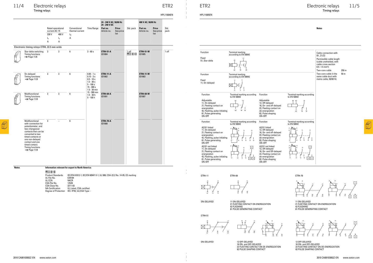
Electronic timing relays ETR4, 22.5 mm wide
Star-delta switchingTiming functions → Page 11/8
3 3 6 3 - 60 s ETR4-51-A031884
1 off ETR4-51-W031885
1 off
On-delayedTiming functions → Page 11/8
3 3 6 0.05 - 1 s0.15 - 3 s0.5 - 10 s1.5 - 30 s5 - 100 s15 - 300 s1.5 - 30 min15 - 300 min1.5 - 30 h5 - 100 h
ETR4-11-A031882
ETR4-11-W031883
MultifunctionalTiming functions → Page 11/8
3 3 6 ETR4-69-A031891
ETR4-69-W031887
Multifunctionalwith connection for potentiometer, and two changeover contacts that can be converted to two timed contacts or one non-delayed contact and one timed contact.Timing functions → Page 11/8
3 – 6 ETR4-70-A031888
Notes Information relevant for export to North America
Product Standards IEC/EN 61812-1; IEC/EN 60947-5-1; UL 508; CSA-22.2 No. 14-05; CE markingUL File No. E29184UL CCN NKCRCSA File No. 12528CSA Class No. 3211-03NA Certification UL Listed, CSA certifiedDegree of Protection IEC: IP20, UL/CSA Type: -
Function Terminal marking according to EN 50042
Fixed51, Star-delta A1
A2 18
17
28
Cable connection with B1, Z1/Z2
Permissible cable length (cable unshielded, with cable cross-section 0.5--1.5 mm2):
Two-core cable 250 m
Two-core cable in the same cable duct with mains cable, 50/60 Hz
50 mFunction Terminal marking according to EN 50042
Fixed11, On-delayed
A1
A2
15
16 18
Function Terminal marking according to EN 50042
Function Terminal marking according to EN 50042
Adjustable11, On-delayed21, Fleeting contact on energization42, Flashing, pulse initiating81, Pulse generatingON-OFF
Adjustable12, Off-delayed16, On- and off-delayed22, Fleeting contact on de-energization82, Pulse shapingON-OFF
A1
A2 16
15
18
A1
A2
B1 15
16 18
Function Terminal marking according to EN 50042
Function Terminal marking according to EN 50042
A2/X1 linked11, On-delayed21, Fleeting contact on energization42, Flashing, pulse initiating81, Pulse generatingON-OFF
A2/X1 linked12, Off-delayed16, On- and off-delayed22, Fleeting contact on de-energization82, Pulse shapingON-OFF
A2/X1 not linked11, On-delayed21, Fleeting contact on energization42, Flashing, pulse initiating81, Pulse generatingON-OFF
A2/X1 not linked12, Off-delayed16, On- and Off-delayed22, Fleeting contact on de-energization82, Pulse shapingON-OFF
A1
A2X1
Z2Z1
15
16 18
25
26 28
A1
A2X1
Z1 Z215
16 18
21
22 24
A1
A2X1
Z2Z1
15
16 18
25
26 28
B1
A1
A2X1
Z1 Z2
15
16 18
21
22 24
B1
ETR4-11 ETR4-69 ETR4-70
ON-DELAYED 11 ON-DELAYED21 FLEETING CONTACT ON ENERGIZATION42 FLASHING81 PULSE GENERATING CONTACT
11 ON-DELAYED21 FLEETING CONTACT ON ENERGIZATION42 FLASHING81 PULSE GENERATING CONTACT
A1
A2
15
16 18
15
16 18
A1
A2
Z1 Z2
A1 15
X1 A2 16 18
25
2826
Z1
A1
Z2
15 21
X1 A2 16 1822 24
ETR4-51
ON-DELAYED 12 OFF-DELAYED16 ON- and OFF-DELAYED22 FLEETING CONTACT ON DE-ENERGIZATION82 PULSE SHAPING CONTACT
12 OFF-DELAYED16 ON- and OFF-DELAYED22 FLEETING CONTACT ON DE-ENERGIZATION82 PULSE SHAPING CONTACT
17
2818
A1
A2
15
16 18A2
A1B1
15
16 18Y2 A2
Y1 A1
Z1 Z2 Z1 Z2
A1 15 25
28261816A2X1
B1
Z1 Z2
A1B1 15
1816A2X1
21
2422
11/5
HPL11004EN HPL11005EN
11/6 Electronic relaysTiming relays
DILET, ETR
2010 CA08103002Z-EN www.eaton.com 2010 CA08103002Z-EN www.eaton.com
Electronic relaysTiming relays
DILET, ETR
DILET, ETRTiming relays
Rated operation current Conventional thermal current
Time Range Voltage range Part no.Article no.
PriceSee price list
Std. pack Information relevant for export to North AmericaN/O
230 V230 V (N/C)
Ie Ie Ith
A A A
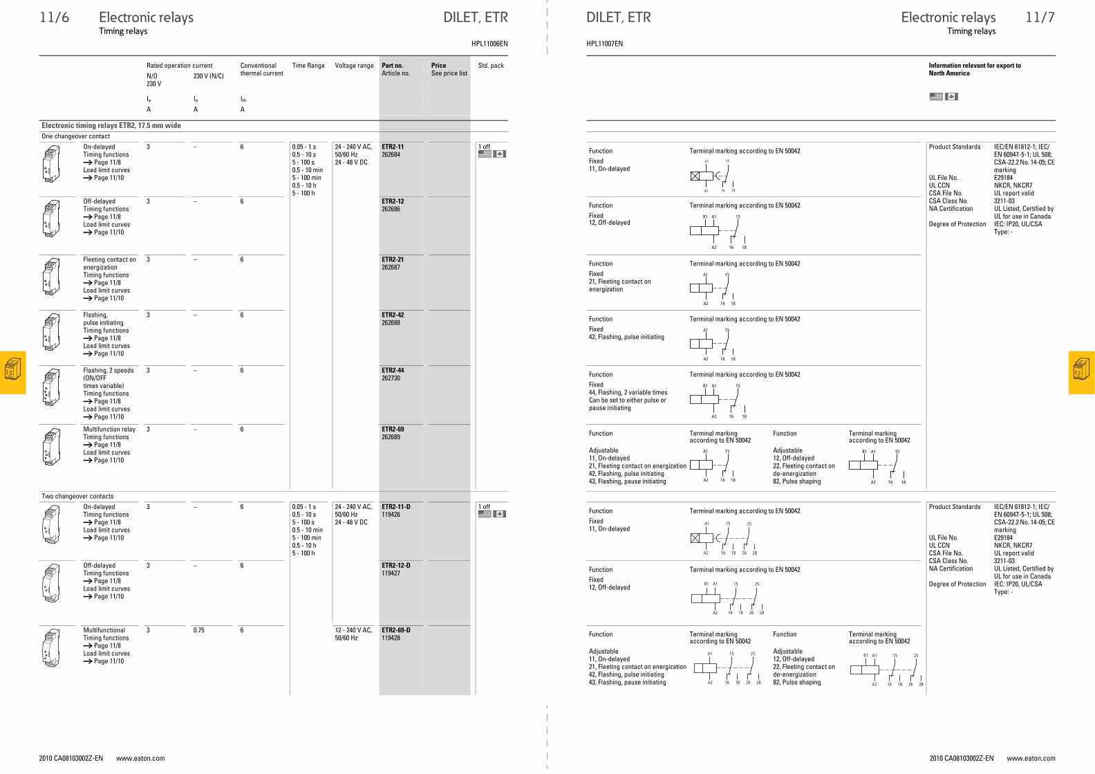
Electronic timing relays ETR2, 17.5 mm wide
One changeover contact
On-delayedTiming functions → Page 11/8 Load limit curves → Page 11/10
3 – 6 0.05 - 1 s0.5 - 10 s5 - 100 s0.5 - 10 min5 - 100 min0.5 - 10 h5 - 100 h
24 - 240 V AC, 50/60 Hz24 - 48 V DC
ETR2-11262684
1 off Product Standards IEC/EN 61812-1; IEC/EN 60947-5-1; UL 508; CSA-22.2 No. 14-05; CE marking
UL File No. E29184UL CCN NKCR, NKCR7CSA File No. UL report validCSA Class No. 3211-03NA Certification UL Listed, Certified by
UL for use in CanadaDegree of Protection IEC: IP20, UL/CSA
Type: -
Off-delayedTiming functions→ Page 11/8 Load limit curves → Page 11/10
3 – 6 ETR2-12262686
Fleeting contact on energizationTiming functions→ Page 11/8 Load limit curves → Page 11/10
3 – 6 ETR2-21262687
Flashing, pulse initiatingTiming functions→ Page 11/8 Load limit curves → Page 11/10
3 – 6 ETR2-42262688
Flashing, 2 speeds(ON/OFFtimes variable)Timing functions→ Page 11/8 Load limit curves → Page 11/10
3 – 6 ETR2-44262730
Multifunction relayTiming functions → Page 11/8Load limit curves → Page 11/10
3 – 6 ETR2-69262689
Two changeover contacts
On-delayedTiming functions→ Page 11/8 Load limit curves → Page 11/10
3 – 6 0.05 - 1 s0.5 - 10 s5 - 100 s0.5 - 10 min5 - 100 min0.5 - 10 h5 - 100 h
24 - 240 V AC, 50/60 Hz24 - 48 V DC
ETR2-11-D119426
1 off Product Standards IEC/EN 61812-1; IEC/EN 60947-5-1; UL 508; CSA-22.2 No. 14-05; CE marking
UL File No. E29184UL CCN NKCR, NKCR7CSA File No. UL report validCSA Class No. 3211-03NA Certification UL Listed, Certified by
UL for use in CanadaDegree of Protection IEC: IP20, UL/CSA
Type: -
Off-delayedTiming functions→ Page 11/8 Load limit curves → Page 11/10
3 – 6 ETR2-12-D119427
MultifunctionalTiming functions→ Page 11/8 Load limit curves → Page 11/10
3 0.75 6 12 - 240 V AC, 50/60 Hz
ETR2-69-D119428
Function Terminal marking according to EN 50042
Fixed11, On-delayed
A1
A2
15
16 18
Function Terminal marking according to EN 50042
Fixed12, Off-delayed
A1
A2
B1 15
16 18
Function Terminal marking according to EN 50042
Fixed21, Fleeting contact on energization
A1
A2 16
15
18
Function Terminal marking according to EN 50042
Fixed42, Flashing, pulse initiating
A1
A2 16
15
18
Function Terminal marking according to EN 50042
Fixed44, Flashing, 2 variable timesCan be set to either pulse or pause initiating
A1
A2
B1 15
16 18
Function Terminal marking according to EN 50042
Function Terminal marking according to EN 50042
Adjustable11, On-delayed21, Fleeting contact on energization42, Flashing, pulse initiating43, Flashing, pause initiating
Adjustable12, Off-delayed22, Fleeting contact on de-energization82, Pulse shaping
A1
A2 16
15
18
A1
A2
B1 15
16 18
Function Terminal marking according to EN 50042
Fixed11, On-delayed
A1
A2 16
15
18 26
25
28
Function Terminal marking according to EN 50042
Fixed12, Off-delayed
A1
A2
B1
16
15
18 26
25
28
Function Terminal marking according to EN 50042
Function Terminal marking according to EN 50042
Adjustable11, On-delayed21, Fleeting contact on energization42, Flashing, pulse initiating43, Flashing, pause initiating
Adjustable12, Off-delayed22, Fleeting contact on de-energization82, Pulse shaping
A1
A2 16
15
18 26
25
28
A1
A2
B1
16
15
18 26
25
28
11/7
HPL11006EN HPL11007EN
11/8 Electronic relaysTiming relays
DILET, ETR
2010 CA08103002Z-EN www.eaton.com 2010 CA08103002Z-EN www.eaton.com
Electronic relaysTiming relays
DILET, ETR
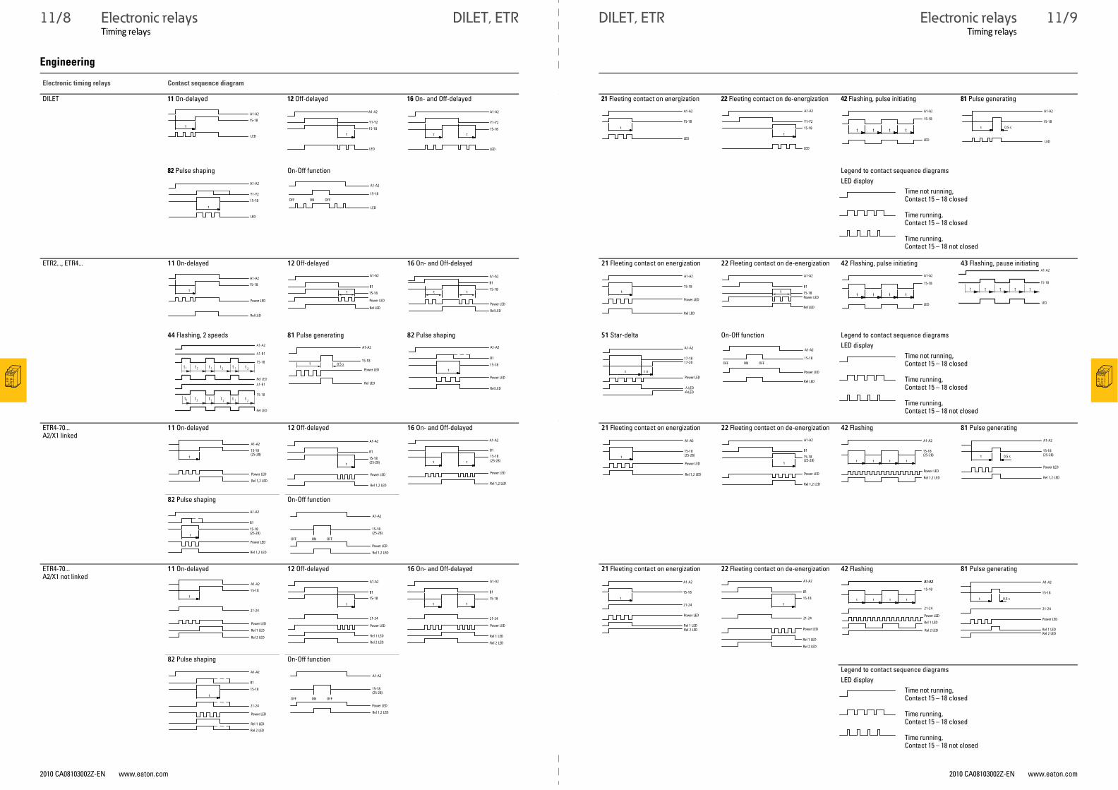
Engineering
Electronic timing relays Contact sequence diagram
DILET 11 On-delayed 12 Off-delayed 16 On- and Off-delayed 21 Fleeting contact on energization 22 Fleeting contact on de-energization 42 Flashing, pulse initiating 81 Pulse generating
82 Pulse shaping On-Off function Legend to contact sequence diagrams
LED display
Time not running,Contact 15 – 18 closed
Time running,Contact 15 – 18 closed
Time running,Contact 15 – 18 not closed
ETR2..., ETR4... 11 On-delayed 12 Off-delayed 16 On- and Off-delayed 21 Fleeting contact on energization 22 Fleeting contact on de-energization 42 Flashing, pulse initiating 43 Flashing, pause initiating
44 Flashing, 2 speeds 81 Pulse generating 82 Pulse shaping 51 Star-delta On-Off function Legend to contact sequence diagrams
LED display
Time not running,Contact 15 – 18 closed
Time running,Contact 15 – 18 closed
Time running,Contact 15 – 18 not closed
ETR4-70...A2/X1 linked
11 On-delayed 12 Off-delayed 16 On- and Off-delayed 21 Fleeting contact on energization 22 Fleeting contact on de-energization 42 Flashing 81 Pulse generating
82 Pulse shaping On-Off function
ETR4-70...A2/X1 not linked
11 On-delayed 12 Off-delayed 16 On- and Off-delayed 21 Fleeting contact on energization 22 Fleeting contact on de-energization 42 Flashing 81 Pulse generating
82 Pulse shaping On-Off function
Legend to contact sequence diagrams
LED display
Time not running,Contact 15 – 18 closed
Time running,Contact 15 – 18 closed
Time running,Contact 15 – 18 not closed
LED
A1-A2
15-18
t
A1-A2
Y1-Y2
15-18t
LED
A1-A2
Y1-Y2
15-18tt
LED
A1-A2
15-18
t
LED
A1-A2
Y1-Y2
15-18
t
LED
LED
ttt t
A1-A2
15-18
LED
A1-A2
15-18
0.5 st
A1-A2
Y1-Y2
15-18
t
LED
A1-A2
15-18
OFFONOFF
LED
A1-A2
15-18
t
Rel LED
Power LED
Rel LED
A1-A2
B1
15-18t
Power LED
A1-A2
B1
15-18tt
Power LED
Rel LED
A1-A2
15-18t
Rel LED
Power LED
A1-A2
B1
15-18t
Power LED
Rel LEDLED
ttt t
A1-A2
15-18
LED
ttt t
A1-A2
15-18
t
A1-B1
A1-A2
Rel LED
A1-B1
Rel LED
ttt t15-18
t t1 2 1 2 1 2
15-18ttt t t t1 2 1 2 1 2
t
A1-A2
15-180.5 s
Rel LED
Power LED
A1-A2
B1
15-18t
Power LED
Rel LED
17-18
t t u
A1-A2
17-28
Power LED
LED LED
15-18
A1-A2
OFFONOFF
Rel LED
Power LED
(25-28)
A1-A2
15-18
t
Power LED
Rel 1,2 LED
A1-A2
B1
15-18
t (25-28)
Power LED
Rel 1,2 LED
A1-A2
B1
tt (25-28)15-18
Power LED
Rel 1,2 LED
A1-A2
t (25-28)15-18
Rel 1,2 LED
Power LED
A1-A2
B1
t(25-28)15-18
Rel 1,2 LED
Power LED
A1-A2
15-18
t t t t
(25-28)
Rel 1,2 LED
Power LED
15-18
A1-A2
0,5 st (25-28)
Rel 1,2 LED
Power LED
15-18
A1-A2
B1
t (25-28)
Rel 1,2 LED
Power LED
15-18(25-28)
A1-A2
Rel 1,2 LED
OFFONOFF
Power LED
A1-A2
15-18
t
21-24
Power LED
Rel 1 LED
Rel 2 LED
A1-A2
B1
15-18
t
21-24
Power LED
Rel 1 LED
Rel 2 LED
A1-A2
B1
15-18tt
21-24
Power LED
Rel 1 LED
Rel 2 LED
15-18
t
21-24
A1-A2
Rel 1 LED
Power LED
Rel 2 LED
A1-A2
B1
15-18
t
21-24
Rel 1 LED
Power LED
Rel 2 LED
15-18
t t t t
21-24
A1-A2A1-A2
Rel 2 LED
Rel 1 LED
Power LED
A1-A2
15-18
0.5 st
21-24
Rel 1 LED
Power LED
Rel 2 LED
B1
A1-A2
15-18
t
21-24
Rel 1 LED
Power LED
Rel 2 LED
15-18(25-28)
A1-A2
Rel 1,2 LED
OFFONOFF
Power LED
11/9
11/10 Electronic relaysTiming relays
2010 CA08103002Z-EN www.eaton.com
DILET, ETR
Timing relaysDILET, ETR
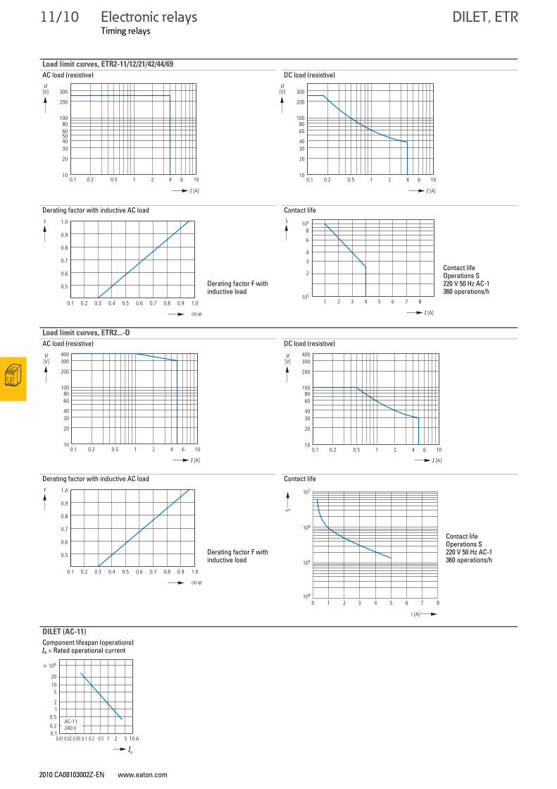
Load limit curves, ETR2-11/12/21/42/44/69
AC load (resistive) DC load (resistive)
Derating factor with inductive AC load Contact life
Derating factor F with inductive load
Contact lifeOperations S220 V 50 Hz AC-1360 operations/h
Load limit curves, ETR2...-D
AC load (resistive) DC load (resistive)
Derating factor with inductive AC load Contact life
Derating factor F with inductive load
Contact lifeOperations S220 V 50 Hz AC-1360 operations/h
DILET (AC-11)
Component lifespan (operations)Ie = Rated operational current
300
200
10
20
3040
6050
80100
0.1 0.2 0.5 1 2 4 6 10
[V]U
I [A]
300
200
10
20
3040
6080
100
0.1 0.2 0.5 1 2 4 6 10
I [A]
[V]U
0.5
0.6
0.7
0.8
0.9
1.0
0.1 0.2 0.3 0.4 0.5 0.6 0.7 0.8 0.9 1.0
cos v
F
I [A]
S
2
3
4
6
8
1 2 3 4 5 6 7 8105
106
400300
200
10
20
3040
6080
100
0.1 0.2 0.5 1 2 4 6 10
I [A]
[V]U 400
300
200
10
20
3040
6080
100
0.1 0.2 0.5 1 2 4 6 10
I [A]
[V]U
0.5
0.6
0.7
0.8
0.9
1.0
0.1 0.2 0.3 0.4 0.5 0.6 0.7 0.8 0.9 1.0
cos v
F
10 2 3 4 5 6 7 8
I [A]
S
107
106
105
104
240 V
0.01 0.050.02 20.1 0.5 10.2 5 10 A
20
105
21
0.5
0.20.1
x 106
Ie
AC-11
Electronic relaysTiming relays
2010 CA08103002Z-EN www.eaton.com
DILET, ETR4 11/11
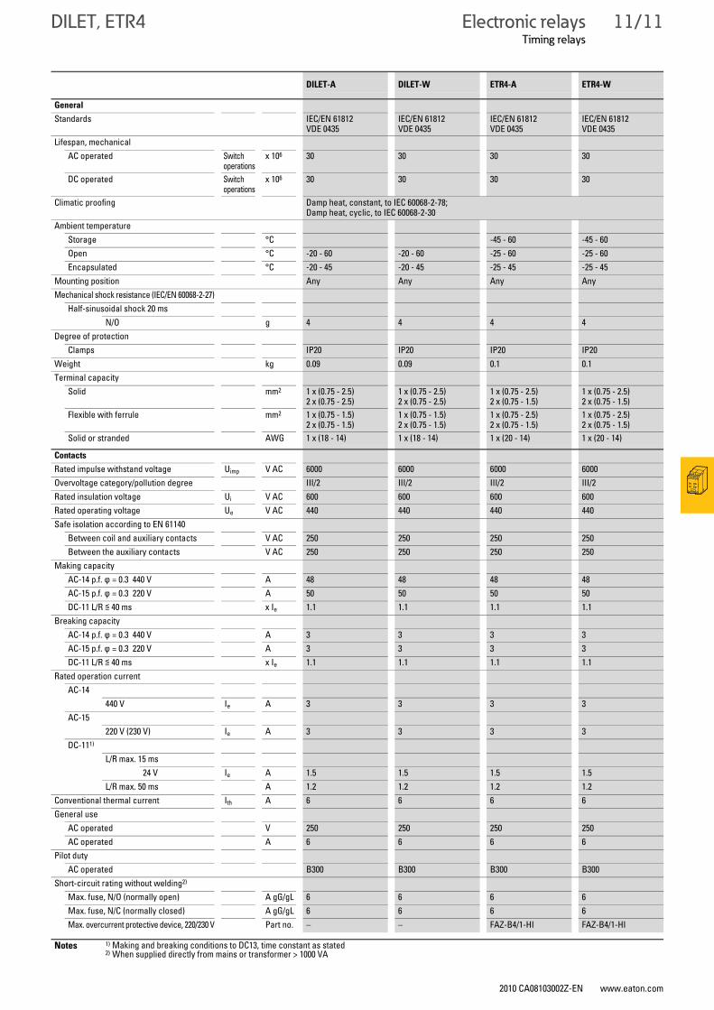
DILET, ETR4Timing relays
DILET-A DILET-W ETR4-A ETR4-W
General
Standards IEC/EN 61812VDE 0435
IEC/EN 61812VDE 0435
IEC/EN 61812VDE 0435
IEC/EN 61812VDE 0435
Lifespan, mechanicalAC operated Switch
operationsx 106 30 30 30 30
DC operated Switch operations
x 106 30 30 30 30
Climatic proofing Damp heat, constant, to IEC 60068-2-78;Damp heat, cyclic, to IEC 60068-2-30
Ambient temperatureStorage °C -45 - 60 -45 - 60Open °C -20 - 60 -20 - 60 -25 - 60 -25 - 60Encapsulated °C -20 - 45 -20 - 45 -25 - 45 -25 - 45
Mounting position Any Any Any AnyMechanical shock resistance (IEC/EN 60068-2-27)
Half-sinusoidal shock 20 msN/O g 4 4 4 4
Degree of protectionClamps IP20 IP20 IP20 IP20
Weight kg 0.09 0.09 0.1 0.1Terminal capacity
Solid mm2 1 x (0.75 - 2.5)2 x (0.75 - 2.5)
1 x (0.75 - 2.5)2 x (0.75 - 2.5)
1 x (0.75 - 2.5)2 x (0.75 - 1.5)
1 x (0.75 - 2.5)2 x (0.75 - 1.5)
Flexible with ferrule mm2 1 x (0.75 - 1.5)2 x (0.75 - 1.5)
1 x (0.75 - 1.5)2 x (0.75 - 1.5)
1 x (0.75 - 2.5)2 x (0.75 - 1.5)
1 x (0.75 - 2.5)2 x (0.75 - 1.5)
Solid or stranded AWG 1 x (18 - 14) 1 x (18 - 14) 1 x (20 - 14) 1 x (20 - 14)
Contacts
Rated impulse withstand voltage Uimp V AC 6000 6000 6000 6000Overvoltage category/pollution degree III/2 III/2 III/2 III/2Rated insulation voltage Ui V AC 600 600 600 600Rated operating voltage Ue V AC 440 440 440 440Safe isolation according to EN 61140
Between coil and auxiliary contacts V AC 250 250 250 250Between the auxiliary contacts V AC 250 250 250 250
Making capacityAC-14 p.f. ϕ = 0.3 440 V A 48 48 48 48AC-15 p.f. ϕ = 0.3 220 V A 50 50 50 50DC-11 L/R ≦ 40 ms x Ie 1.1 1.1 1.1 1.1
Breaking capacity AC-14 p.f. ϕ = 0.3 440 V A 3 3 3 3AC-15 p.f. ϕ = 0.3 220 V A 3 3 3 3DC-11 L/R ≦ 40 ms x Ie 1.1 1.1 1.1 1.1
Rated operation currentAC-14
440 V Ie A 3 3 3 3AC-15
220 V (230 V) Ie A 3 3 3 3DC-111)
L/R max. 15 ms24 V Ie A 1.5 1.5 1.5 1.5
L/R max. 50 ms A 1.2 1.2 1.2 1.2Conventional thermal current Ith A 6 6 6 6General use
AC operated V 250 250 250 250AC operated A 6 6 6 6
Pilot dutyAC operated B300 B300 B300 B300
Short-circuit rating without welding2)
Max. fuse, N/O (normally open) A gG/gL 6 6 6 6Max. fuse, N/C (normally closed) A gG/gL 6 6 6 6Max. overcurrent protective device, 220/230 V Part no. – – FAZ-B4/1-HI FAZ-B4/1-HI
Notes 1) Making and breaking conditions to DC13, time constant as stated2) When supplied directly from mains or transformer > 1000 VA
11/12 Electronic relaysTiming relays
2010 CA08103002Z-EN www.eaton.com
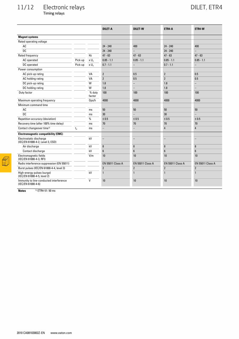
DILET, ETR4
DILET-A DILET-W ETR4-A ETR4-W
Magnet systems
Rated operating voltageAC 24 - 240 400 24 - 240 400DC 24 - 240 – 24 - 240 –
Rated frequency Hz 47 - 63 47 - 63 47 - 63 47 - 63AC operated Pick-up x Uc 0.85 - 1.1 0.85 - 1.1 0.85 - 1.1 0.85 - 1.1DC operated Pick-up x Uc 0.7 - 1.1 – 0.7 - 1.1 –
Power consumptionAC pick-up rating VA 2 0.5 2 0.5AC holding rating VA 2 0.5 2 0.5DC pick-up rating W 1.8 – 1.8 –DC holding rating W 1.8 – 1.8 –
Duty factor % duty factor
100 100 100 100
Maximum operating frequency Ops/h 4000 4000 4000 4000Minimum command time
AC ms 50 50 50 50DC ms 30 – 30 –
Repetition accuracy (deviation) % ≦ 0.5 ≦ 0.5 ≦ 0.5 ≦ 0.5Recovery time (after 100% time delay) ms 70 70 70 70Contact changeover time1) tu ms – – 4 4
Electromagnetic compatibility (EMC)
Electrostatic discharge (IEC/EN 61000-4-2, Level 3, ESD)
kV – – – –
Air discharge kV 8 8 8 8Contact discharge kV 6 6 6 6
Electromagnetic fields (IEC/EN 61000-4-3, RFI)
V/m 10 10 10 10
Radio interference suppression (EN 55011) EN 55011 Class A EN 55011 Class A EN 55011 Class A EN 55011 Class ABurst pulses (IEC/EN 61000-4-4, level 3) 2 2 2 2High-energy pulses (surge) (IEC/EN 61000-4-5, level 2)
kV 1 1 1 1
Immunity to line-conducted interference (IEC/EN 61000-4-6)
V 10 10 10 10
Notes 1) ETR4-51: 50 ms
Electronic relaysTiming relays
2010 CA08103002Z-EN www.eaton.com
ETR2 11/13
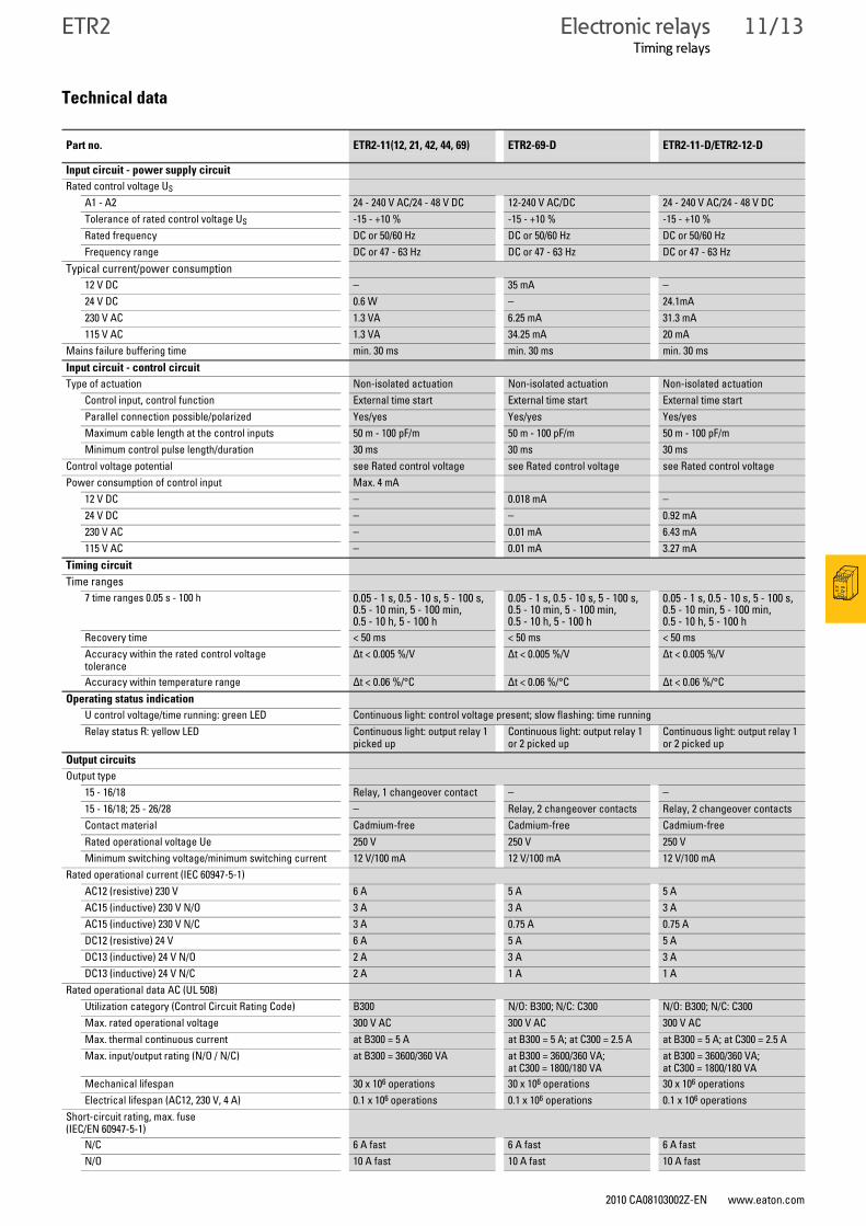
Timing relaysETR2
Technical data
Part no. ETR2-11(12, 21, 42, 44, 69) ETR2-69-D ETR2-11-D/ETR2-12-D
Input circuit - power supply circuit
Rated control voltage USA1 - A2 24 - 240 V AC/24 - 48 V DC 12-240 V AC/DC 24 - 240 V AC/24 - 48 V DCTolerance of rated control voltage US -15 - +10 % -15 - +10 % -15 - +10 %Rated frequency DC or 50/60 Hz DC or 50/60 Hz DC or 50/60 HzFrequency range DC or 47 - 63 Hz DC or 47 - 63 Hz DC or 47 - 63 Hz
Typical current/power consumption12 V DC – 35 mA –24 V DC 0.6 W – 24.1mA230 V AC 1.3 VA 6.25 mA 31.3 mA115 V AC 1.3 VA 34.25 mA 20 mA
Mains failure buffering time min. 30 ms min. 30 ms min. 30 msInput circuit - control circuit
Type of actuation Non-isolated actuation Non-isolated actuation Non-isolated actuationControl input, control function External time start External time start External time startParallel connection possible/polarized Yes/yes Yes/yes Yes/yesMaximum cable length at the control inputs 50 m - 100 pF/m 50 m - 100 pF/m 50 m - 100 pF/mMinimum control pulse length/duration 30 ms 30 ms 30 ms
Control voltage potential see Rated control voltage see Rated control voltage see Rated control voltagePower consumption of control input Max. 4 mA
12 V DC – 0.018 mA –24 V DC – – 0.92 mA230 V AC – 0.01 mA 6.43 mA115 V AC – 0.01 mA 3.27 mA
Timing circuit
Time ranges7 time ranges 0.05 s - 100 h 0.05 - 1 s, 0.5 - 10 s, 5 - 100 s,
0.5 - 10 min, 5 - 100 min, 0.5 - 10 h, 5 - 100 h
0.05 - 1 s, 0.5 - 10 s, 5 - 100 s, 0.5 - 10 min, 5 - 100 min, 0.5 - 10 h, 5 - 100 h
0.05 - 1 s, 0.5 - 10 s, 5 - 100 s, 0.5 - 10 min, 5 - 100 min, 0.5 - 10 h, 5 - 100 h
Recovery time < 50 ms < 50 ms < 50 msAccuracy within the rated control voltage tolerance
Δt < 0.005 %/V Δt < 0.005 %/V Δt < 0.005 %/V
Accuracy within temperature range Δt < 0.06 %/°C Δt < 0.06 %/°C Δt < 0.06 %/°COperating status indication
U control voltage/time running: green LED Continuous light: control voltage present; slow flashing: time runningRelay status R: yellow LED Continuous light: output relay 1
picked upContinuous light: output relay 1 or 2 picked up
Continuous light: output relay 1 or 2 picked up
Output circuits
Output type15 - 16/18 Relay, 1 changeover contact – –15 - 16/18; 25 - 26/28 – Relay, 2 changeover contacts Relay, 2 changeover contactsContact material Cadmium-free Cadmium-free Cadmium-freeRated operational voltage Ue 250 V 250 V 250 VMinimum switching voltage/minimum switching current 12 V/100 mA 12 V/100 mA 12 V/100 mA
Rated operational current (IEC 60947-5-1)AC12 (resistive) 230 V 6 A 5 A 5 AAC15 (inductive) 230 V N/O 3 A 3 A 3 AAC15 (inductive) 230 V N/C 3 A 0.75 A 0.75 ADC12 (resistive) 24 V 6 A 5 A 5 ADC13 (inductive) 24 V N/O 2 A 3 A 3 ADC13 (inductive) 24 V N/C 2 A 1 A 1 A
Rated operational data AC (UL 508)Utilization category (Control Circuit Rating Code) B300 N/O: B300; N/C: C300 N/O: B300; N/C: C300Max. rated operational voltage 300 V AC 300 V AC 300 V ACMax. thermal continuous current at B300 = 5 A at B300 = 5 A; at C300 = 2.5 A at B300 = 5 A; at C300 = 2.5 AMax. input/output rating (N/O / N/C) at B300 = 3600/360 VA at B300 = 3600/360 VA;
at C300 = 1800/180 VAat B300 = 3600/360 VA; at C300 = 1800/180 VA
Mechanical lifespan 30 x 106 operations 30 x 106 operations 30 x 106 operationsElectrical lifespan (AC12, 230 V, 4 A) 0.1 x 10⁶ operations 0.1 x 10⁶ operations 0.1 x 10⁶ operations
Short-circuit rating, max. fuse(IEC/EN 60947-5-1)
N/C 6 A fast 6 A fast 6 A fastN/O 10 A fast 10 A fast 10 A fast
11/14 Electronic relaysTiming relays
2010 CA08103002Z-EN www.eaton.com
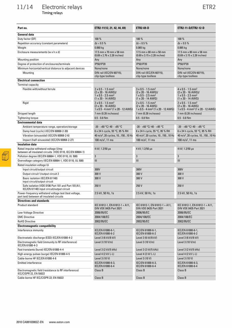
ETR2
General data
Duty factor (DF) 100 % 100 % 100 %Repetition accuracy (constant parameters) Δt < 0.5 % Δt < 0.5 % Δt < 0.5 %Weight 0.060 kg 0.065 kg 0.065 kgEnclosure measurements (w x h x d) 17.5 mm x 70 mm x 58 mm
(0.69 x 2.76 x 2.28 inches)17.5 mm x 80 mm x 58 mm (0.69 x 3.15 x 2.28 inches)
17.5 mm x 80 mm x 58 mm (0.69 x 3.15 x 2.28 inches)
Mounting position Any Any AnyDegree of protection of enclosures/terminals IP50/IP20 IP50/IP20 IP50/IP20Minimum horizontal/vertical distance to adjacent devices None/none None/none None/none
Mounting DIN rail (IEC/EN 60715), clip-type toolless
DIN rail (IEC/EN 60715), clip-type toolless
DIN rail (IEC/EN 60715), clip-type toolless
Electrical connection
Terminal capacityFlexible with/without ferrule 2 x 0.5 - 1.5 mm2
(2 x 20 - 16 AWG)/1 x 0.5 - 2.5 mm2 (1 x 20 - 14 AWG)
3 x 0.5 - 1.5 mm2
(2 x 20 - 16 AWG)/1 x 0.5 - 2.5 mm2 (1 x 20 - 14 AWG)
4 x 0.5 - 1.5 mm2 (2 x 20 - 16 AWG)/1 x 0.5 - 2.5 mm2 (1 x 20 - 14 AWG)
Rigid 2 x 0.5 - 1.5 mm2 (2 x 20 - 16 AWG)1 x 0.5 - 4 mm2 (1 x 20 - 12 AWG)
2 x 0.5 - 1.5 mm2 (2 x 20 - 16 AWG)1 x 0.5 - 4 mm2 (1 x 20 - 12 AWG)
2 x 0.5 - 1.5 mm2(2 x 20 - 16 AWG)1 x 0.5 - 4 mm2 (1 x 20 - 12 AWG)
Stripped length 7 mm (0.28 incheses) 7 mm (0.28 incheses) 7 mm (0.28 incheses)Tightening torque 0.5 - 0.8 Nm 0.5 - 0.8 Nm 0.5 - 0.8 NmEnvironmental data
Ambient temperature range, operation/storage -20 - +60 °C/-40 - +85 °C -20 - +60 °C/-40 - +85 °C -20 - +60 °C/-40 - +85 °CDamp heat (cyclic) (IEC/EN 60068-2-30) 6 x 24 h cycle, 55 °C, 95 % RH 6 x 24 h cycle, 55 °C, 95 % RH 6 x 24 h cycle, 55 °C, 95 % RHVibration (sinusoidal) (IEC/EN 60068-2-6) 40 m/s2, 20 cycles, 10...150...10 Hz 40 m/s2, 20 cycles, 10...150...10 Hz 40 m/s2, 20 cycles, 10...150...10 HzImpact (half-sinusoidal) (IEC/EN 60068-2-27) 100 m/s2, 11 ms 100 m/s2, 11 ms 100 m/s2, 11 ms
Insulation data
Rated impulse withstand voltage Uimpbetween all insulated circuits (VDE 0110, IEC/EN 60664-1)
4 kV; 1.2/50 μs 4 kV; 1.2/50 μs 4 kV; 1.2/50 μs
Pollution degree (IEC/EN 60664-1, VDE 0110, UL 508) 3 3 3Overvoltage category (IEC/EN 60664-1, VDE 0110, UL 508) III III IIIRated insulation voltage Ui
Input circuit/output circuit 300V 300V 300VOutput circuit 1/output circuit 2 300 V 300 V 300 V Basic isolation (IEC/EN 61140) input circuit/output circuit
300 V 300 V 300 V
Safe isolation (VDE 0106 Part 101 and Part 101/A1; IEC/EN 61140) input circuit/output circuit
250 V 250 V 250 V
Power-frequency withstand voltage test (test voltage, part test) between all insulated circuits
2.5 kV, 50 Hz, 1s 2.5 kV, 50 Hz, 1s 2.5 kV, 50 Hz, 1s
Directives and standards
Product standard IEC 61812-1, EN 61812-1 + A11, DIN VDE 0435 Part 2021
IEC 61812-1, EN 61812-1 + A11, DIN VDE 0435 Part 2021
IEC 61812-1, EN 61812-1 + A11, DIN VDE 0435 Part 2021
Low-Voltage Directive 2006/95/EC 2006/95/EC 2006/95/ECEMC Directive 2004/108/EC 2004/108/EC 2004/108/ECRoHS Directive 2002/95/EC 2002/95/EC 2002/95/ECElectromagnetic compatibility
Interference immunity IEC/EN 61000-6-1, IEC/EN 61000-6-2
IEC/EN 61000-6-1, IEC/EN 61000-6-2
IEC/EN 61000-6-1, IEC/EN 61000-6-2
Electrostatic discharge (ESD) IEC/EN 61000-4-2 Level 3 (6 kV/8 kV) Level 3 (6 kV/8 kV) Level 3 (6 kV/8 kV)Electromagnetic field (immunity to RF interference) IEC/EN 61000-4-3
Level 3 (10 V/m) Level 3 (10 V/m) Level 3 (10 V/m)
Fast transients (burst) IEC/EN 61000-4-4 Level 3 (2 kV/5 kHz) Level 3 (2 kV/5 kHz) Level 3 (2 kV/5 kHz)High-energy pulses (surge) IEC/EN 61000-4-5 Level 4 (2 kV L-L) Level 4 (2 kV L-L) Level 4 (2 kV L-L)Cable-borne HF IEC/EN 61000-4-6 Level 3 (10 V) Level 3 (10 V) Level 3 (10 V)Emitted interference IEC/EN 61000-6-3,
IEC/EN 61000-6-4IEC/EN 61000-6-3, IEC/EN 61000-6-4
IEC/EN 61000-6-3, IEC/EN 61000-6-4
Electromagnetic field (resistance to RF interference) IEC/CISPR 22, EN 55022
Class B Class B Class B
Cable-borne HF IEC/CISPR 22; EN 55022 Class B Class B Class B
Part no. ETR2-11(12, 21, 42, 44, 69) ETR2-69-D ETR2-11-D/ETR2-12-D
Electronic relaysTiming relays, potentiometers
2010 CA08103002Z-EN www.eaton.com
DILET, ETR 11/15
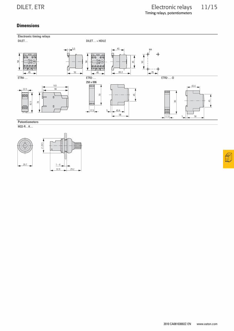
DILET, ETRTiming relays, potentiometers
Dimensions
Electronic timing relays
DILET… DILET… + HDILE
ETR4-… ETR2-… ETR2-…-D250 x 006
Potentiometers
M22-R…K…
45
58
52
5,5
65.3
43
45 50
35
M4
45
5810398
78
22.5
82.5
17.5 5 43.4
58
70 45
17.5 5 58
80
45
43.4
29.7
29.232.9
o 2
9.5
1 – 6
11/16 Electronic relaysMeasuring and monitoring relays
2010 CA08103002Z-EN www.eaton.com
EMR
EMRMeasuring and monitoring relays
Ordering
Current measurement range
Contact sequences Supply voltage connection
Part no.Article no.
PriceSee price list
Std. pack
I∼/I=A
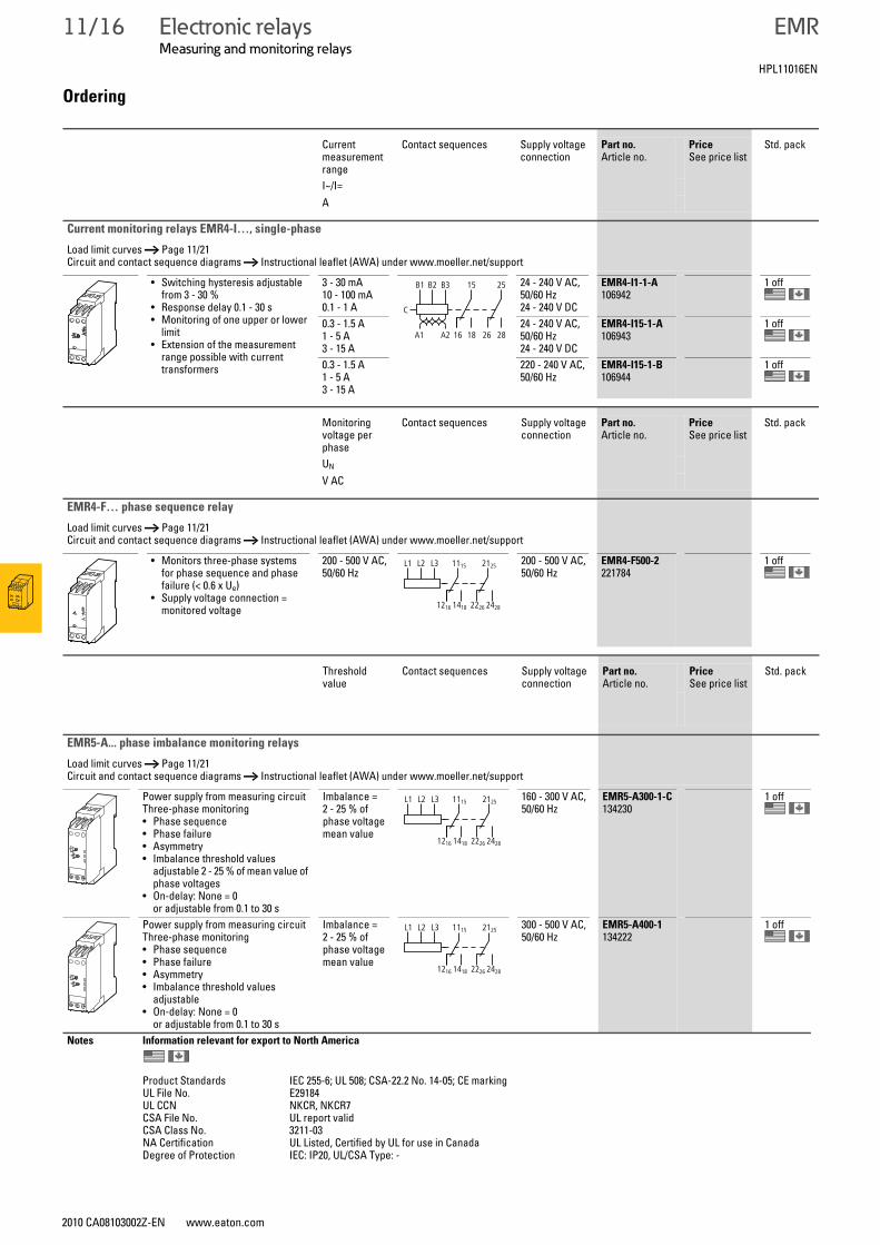
Current monitoring relays EMR4-I…, single-phase
Load limit curves → Page 11/21Circuit and contact sequence diagrams → Instructional leaflet (AWA) under www.moeller.net/support
• Switching hysteresis adjustable from 3 - 30 %
• Response delay 0.1 - 30 s• Monitoring of one upper or lower
limit• Extension of the measurement
range possible with current transformers
3 - 30 mA10 - 100 mA0.1 - 1 A
24 - 240 V AC, 50/60 Hz24 - 240 V DC
EMR4-I1-1-A106942
1 off
0.3 - 1.5 A1 - 5 A3 - 15 A
24 - 240 V AC, 50/60 Hz24 - 240 V DC
EMR4-I15-1-A106943
1 off
0.3 - 1.5 A1 - 5 A3 - 15 A
220 - 240 V AC, 50/60 Hz
EMR4-I15-1-B106944
1 off
Monitoring voltage per phase
Contact sequences Supply voltage connection
Part no.Article no.
PriceSee price list
Std. pack
UN
V AC
EMR4-F… phase sequence relay
Load limit curves → Page 11/21Circuit and contact sequence diagrams → Instructional leaflet (AWA) under www.moeller.net/support
• Monitors three-phase systems for phase sequence and phase failure (< 0.6 x Ue)
• Supply voltage connection = monitored voltage
200 - 500 V AC, 50/60 Hz
200 - 500 V AC, 50/60 Hz
EMR4-F500-2221784
1 off
Threshold value
Contact sequences Supply voltage connection
Part no.Article no.
PriceSee price list
Std. pack
EMR5-A... phase imbalance monitoring relays
Load limit curves → Page 11/21Circuit and contact sequence diagrams → Instructional leaflet (AWA) under www.moeller.net/support
Power supply from measuring circuitThree-phase monitoring• Phase sequence• Phase failure• Asymmetry• Imbalance threshold values
adjustable 2 - 25 % of mean value of phase voltages
• On-delay: None = 0 or adjustable from 0.1 to 30 s
Imbalance = 2 - 25 % of phase voltage mean value
160 - 300 V AC, 50/60 Hz
EMR5-A300-1-C134230
1 off
Power supply from measuring circuitThree-phase monitoring• Phase sequence• Phase failure• Asymmetry• Imbalance threshold values
adjustable• On-delay: None = 0
or adjustable from 0.1 to 30 s
Imbalance = 2 - 25 % of phase voltage mean value
300 - 500 V AC, 50/60 Hz
EMR5-A400-1134222
1 off
Notes Information relevant for export to North America
Product Standards IEC 255-6; UL 508; CSA-22.2 No. 14-05; CE markingUL File No. E29184UL CCN NKCR, NKCR7CSA File No. UL report validCSA Class No. 3211-03NA Certification UL Listed, Certified by UL for use in CanadaDegree of Protection IEC: IP20, UL/CSA Type: -
C
15 25B1 B2 B3
1816 26 28A1 A2
15L1 L2 L3 11
1612 1814 2622 2824
2521
15L1 L2 L3 11
1612 1814 2622 2824
2521
15L1 L2 L3 11
1612 1814 2622 2824
2521
HPL11016EN
Electronic relaysMeasuring and monitoring relays
2010 CA08103002Z-EN www.eaton.com
EMR 11/17
Response sen-sitivity
Contact sequences Supply voltage connection
Part no.Article no.
PriceSee price list
Std. pack
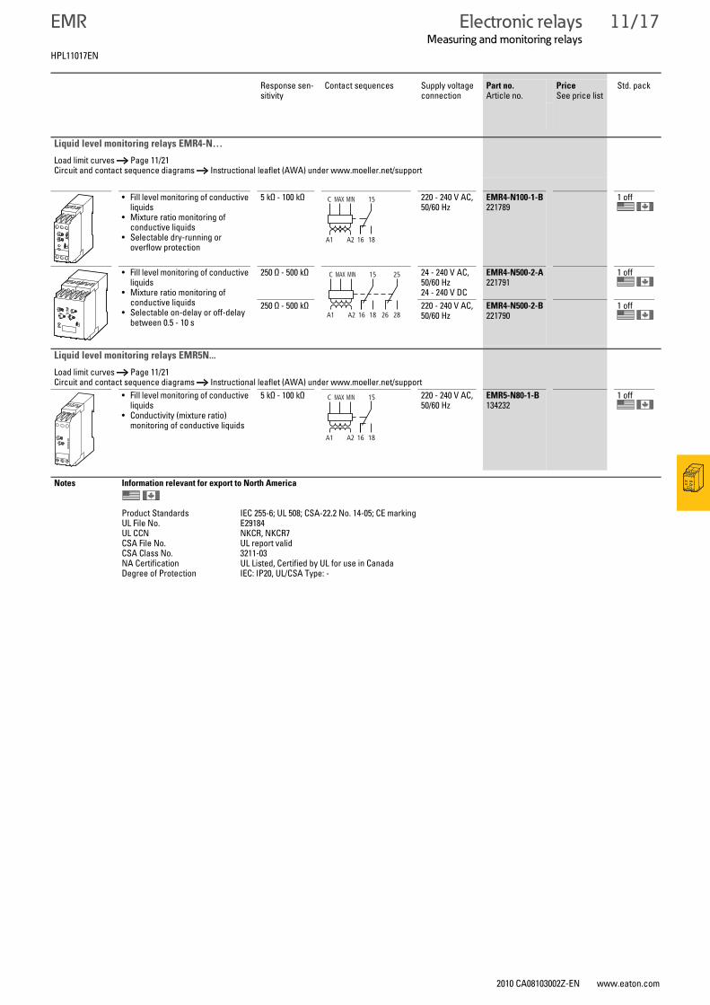
Liquid level monitoring relays EMR4-N…
Load limit curves → Page 11/21Circuit and contact sequence diagrams → Instructional leaflet (AWA) under www.moeller.net/support
• Fill level monitoring of conductive liquids
• Mixture ratio monitoring of conductive liquids
• Selectable dry-running or overflow protection
5 kΩ - 100 kΩ 220 - 240 V AC, 50/60 Hz
EMR4-N100-1-B221789
1 off
• Fill level monitoring of conductive liquids
• Mixture ratio monitoring of conductive liquids
• Selectable on-delay or off-delay between 0.5 - 10 s
250 Ω - 500 kΩ 24 - 240 V AC, 50/60 Hz24 - 240 V DC
EMR4-N500-2-A221791
1 off
250 Ω - 500 kΩ 220 - 240 V AC, 50/60 Hz
EMR4-N500-2-B221790
1 off
Liquid level monitoring relays EMR5N...
Load limit curves → Page 11/21Circuit and contact sequence diagrams → Instructional leaflet (AWA) under www.moeller.net/support
• Fill level monitoring of conductive liquids
• Conductivity (mixture ratio) monitoring of conductive liquids
5 kΩ - 100 kΩ 220 - 240 V AC, 50/60 Hz
EMR5-N80-1-B134232
1 off
Notes Information relevant for export to North America
Product Standards IEC 255-6; UL 508; CSA-22.2 No. 14-05; CE markingUL File No. E29184UL CCN NKCR, NKCR7CSA File No. UL report validCSA Class No. 3211-03NA Certification UL Listed, Certified by UL for use in CanadaDegree of Protection IEC: IP20, UL/CSA Type: -
15C MAX MIN
1816A1 A2
15 25C
1816 26 28A1 A2
MAX MIN
15C MAX MIN
1816A1 A2
HPL11017EN
11/18 Electronic relaysMeasuring and monitoring relays
2010 CA08103002Z-EN www.eaton.com
EMR
EMRMeasuring and monitoring relays
Monitoring voltage per phase
Threshold value1) Contact sequences
Supply voltage connection
Width Part no.Article no.
PriceSee price list
Std. pack
mm
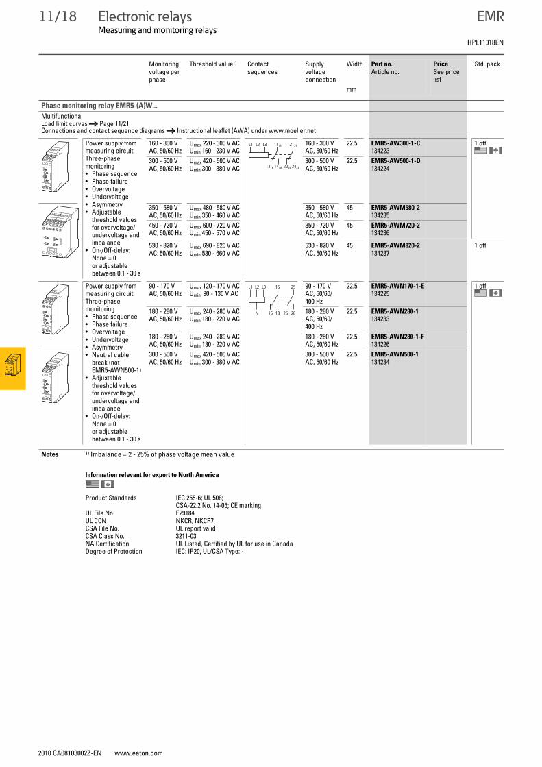
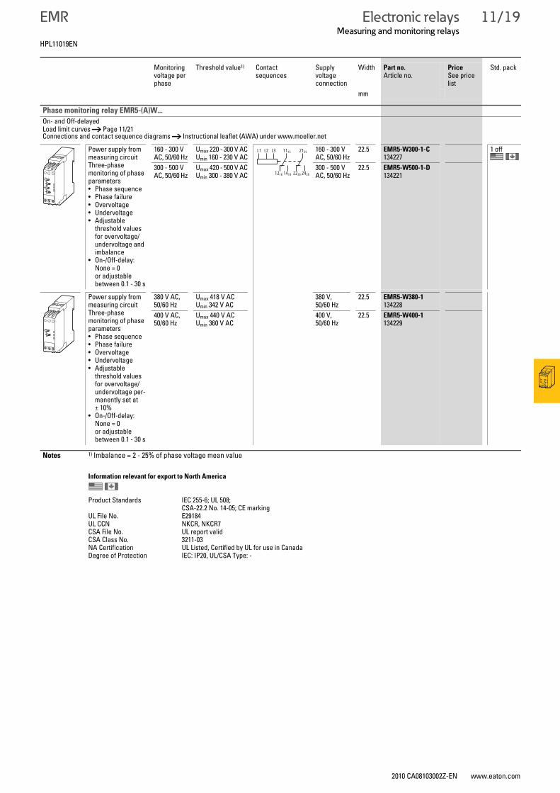
Phase monitoring relay EMR5-(A)W...
MultifunctionalLoad limit curves → Page 11/21 Connections and contact sequence diagrams → Instructional leaflet (AWA) under www.moeller.net
Power supply from measuring circuitThree-phase monitoring• Phase sequence• Phase failure• Overvoltage• Undervoltage• Asymmetry• Adjustable
threshold values for overvoltage/undervoltage and imbalance
• On-/Off-delay: None = 0 or adjustable between 0.1 - 30 s
160 - 300 V AC, 50/60 Hz
Umax 220 - 300 V ACUmin 160 - 230 V AC
160 - 300 V AC, 50/60 Hz
22.5 EMR5-AW300-1-C134223
1 off
300 - 500 V AC, 50/60 Hz
Umax 420 - 500 V ACUmin 300 - 380 V AC
300 - 500 V AC, 50/60 Hz
22.5 EMR5-AW500-1-D134224
350 - 580 V AC, 50/60 Hz
Umax 480 - 580 V ACUmin 350 - 460 V AC
350 - 580 V AC, 50/60 Hz
45 EMR5-AWM580-2134235
450 - 720 V AC; 50/60 Hz
Umax 600 - 720 V ACUmin 450 - 570 V AC
350 - 720 V AC, 50/60 Hz
45 EMR5-AWM720-2134236
530 - 820 V AC; 50/60 Hz
Umax 690 - 820 V ACUmin 530 - 660 V AC
530 - 820 V AC, 50/60 Hz
45 EMR5-AWM820-2134237
1 off
Power supply from measuring circuitThree-phase monitoring• Phase sequence• Phase failure• Overvoltage• Undervoltage• Asymmetry• Neutral cable
break (not EMR5-AWN500-1)
• Adjustable threshold values for overvoltage/undervoltage and imbalance
• On-/Off-delay: None = 0 or adjustable between 0.1 - 30 s
90 - 170 V AC, 50/60 Hz
Umax 120 - 170 V ACUmin. 90 - 130 V AC
90 - 170 V AC, 50/60/400 Hz
22.5 EMR5-AWN170-1-E134225
1 off
180 - 280 V AC, 50/60 Hz
Umax 240 - 280 V ACUmin 180 - 220 V AC
180 - 280 V AC, 50/60/400 Hz
22.5 EMR5-AWN280-1134233
180 - 280 V AC, 50/60 Hz
Umax 240 - 280 V ACUmin 180 - 220 V AC
180 - 280 V AC, 50/60 Hz
22.5 EMR5-AWN280-1-F134226
300 - 500 V AC, 50/60 Hz
Umax 420 - 500 V ACUmin 300 - 380 V AC
300 - 500 V AC, 50/60 Hz
22.5 EMR5-AWN500-1134234
Notes 1) Imbalance = 2 - 25% of phase voltage mean value
Information relevant for export to North America
Product Standards IEC 255-6; UL 508; CSA-22.2 No. 14-05; CE marking
UL File No. E29184UL CCN NKCR, NKCR7CSA File No. UL report validCSA Class No. 3211-03NA Certification UL Listed, Certified by UL for use in CanadaDegree of Protection IEC: IP20, UL/CSA Type: -
15L1 L2 L3 11
1612 1814 2622 2824
2521
15 25L1 L2 L3
1816N 26 28
HPL11018EN
Electronic relaysMeasuring and monitoring relays
2010 CA08103002Z-EN www.eaton.com
EMR 11/19
On- and Off-delayedLoad limit curves → Page 11/21 Connections and contact sequence diagrams → Instructional leaflet (AWA) under www.moeller.net
Power supply from measuring circuitThree-phase monitoring of phase parameters• Phase sequence• Phase failure• Overvoltage• Undervoltage• Adjustable
threshold values for overvoltage/undervoltage and imbalance
• On-/Off-delay: None = 0 or adjustable between 0.1 - 30 s
160 - 300 V AC, 50/60 Hz
Umax 220 - 300 V ACUmin 160 - 230 V AC
160 - 300 V AC, 50/60 Hz
22.5 EMR5-W300-1-C134227
1 off
300 - 500 V AC, 50/60 Hz
Umax 420 - 500 V ACUmin 300 - 380 V AC
300 - 500 V AC, 50/60 Hz
22.5 EMR5-W500-1-D134221
Power supply from measuring circuitThree-phase monitoring of phase parameters• Phase sequence• Phase failure• Overvoltage• Undervoltage• Adjustable
threshold values for overvoltage/undervoltage per-manently set at ± 10%
• On-/Off-delay: None = 0 or adjustable between 0.1 - 30 s
380 V AC, 50/60 Hz
Umax 418 V ACUmin 342 V AC
380 V, 50/60 Hz
22.5 EMR5-W380-1134228
400 V AC, 50/60 Hz
Umax 440 V ACUmin 360 V AC
400 V, 50/60 Hz
22.5 EMR5-W400-1134229
Notes 1) Imbalance = 2 - 25% of phase voltage mean value
Information relevant for export to North America
Product Standards IEC 255-6; UL 508; CSA-22.2 No. 14-05; CE marking
UL File No. E29184UL CCN NKCR, NKCR7CSA File No. UL report validCSA Class No. 3211-03NA Certification UL Listed, Certified by UL for use in CanadaDegree of Protection IEC: IP20, UL/CSA Type: -
Monitoring voltage per phase
Threshold value1) Contact sequences
Supply voltage connection
Width Part no.Article no.
PriceSee price list
Std. pack
mm
Phase monitoring relay EMR5-(A)W...
15L1 L2 L3 11
1612 1814 2622 2824
2521
HPL11019EN
11/20 Electronic relaysMeasuring and monitoring relays, accessories
2010 CA08103002Z-EN www.eaton.com
EMR
EMRMeasuring and monitoring relays, accessories
Description Insulation resistance range
Contact sequences
Supply voltage connection
Part no.Article no.
PriceSee price list
Std. pack
Ω V AC
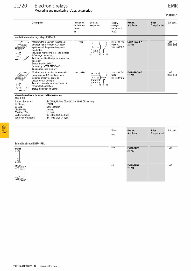
Insulation monitoring relays EMR4-R...
Monitors the insulation resistance between non-grounded AC supply systems and the protective ground conductorInsulation monitoring in 1- and 3-phase AC voltage networksTest via local test button or remote test operationStatus display via LED (according to VDE 0413/Part 2)Tripping function memory
1 - 110 kΩ 24 - 240 V AC, 50/60 Hz24 - 240 V DC
EMR4-RAC-1-A221793
1 off
Monitors the insulation resistance in non-grounded DC supply systemsSelector switch for open- or closed-circuit principleTest and reset via local test button or remote test operationStatus indication via LEDs
10 - 110 kΩ 24 - 240 V AC, 50/60 Hz24 - 240 V DC
EMR4-RDC-1-A221792
1 off
Information relevant for export to North America
Product Standards IEC 255-6; UL 508; CSA-22.2 No. 14-05; CE markingUL File No. E29184UL CCN NKCR, NKCR7CSA File No. 203843CSA Class No. 3211-03NA Certification UL Listed, CSA CertifiedDegree of Protection IEC: IP20, UL/CSA Type: -
Width Part no.Article no.
PriceSee price list
Std. packmm
Sealable shroud EMR4-PH...
22.5 EMR4-PH22221795
1 off
45 EMR4-PH45221794
1 off
15L
R <
1816A1 A2
15L+
R <
L–
1816A1 A2
HPL11020EN
Electronic relaysMeasuring and monitoring relays
2010 CA08103002Z-EN www.eaton.com
EMR 11/21
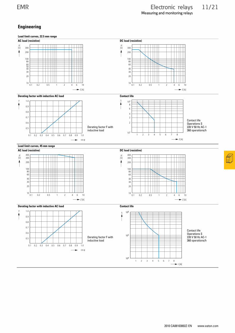
Engineering
Load limit curves, 22.5 mm range
AC load (resistive) DC load (resistive)
Derating factor with inductive AC load Contact life
Derating factor F with inductive load
Contact lifeOperations S220 V 50 Hz AC-1360 operations/h
Load limit curves, 45 mm range
AC load (resistive) DC load (resistive)
Derating factor with inductive AC load Contact life
Derating factor F with inductive load
Contact lifeOperations S220 V 50 Hz AC-1360 operations/h
300
200
10
20
3040
6050
80100
0.1 0.2 0.5 1 2 4 6 10
[V]U
I [A]
300
200
10
20
3040
6080
100
0.1 0.2 0.5 1 2 4 6 10
I [A]
[V]U
0.5
0.6
0.7
0.8
0.9
1.0
0.1 0.2 0.3 0.4 0.5 0.6 0.7 0.8 0.9 1.0
cos v
F
I [A]
S
2
3
4
6
8
1 2 3 4 5 6 7 8105
106
400300
200
10
20
3040
6080
100
0.1 0.2 0.5 1 2 4 6 10
I [A]
[V]U 400
300
200
10
20
3040
6080
100
0.1 0.2 0.5 1 2 4 6 10
I [A]
[V]U
0.5
0.6
0.7
0.8
0.9
1.0
0.1 0.2 0.3 0.4 0.5 0.6 0.7 0.8 0.9 1.0
cos v
F
I [A]
105
106
104
S
4321 5 6 7 8
11/22 Electronic relaysMeasuring and monitoring relays
2010 CA08103002Z-EN www.eaton.com
EMR
Measuring and monitoring relaysEMR
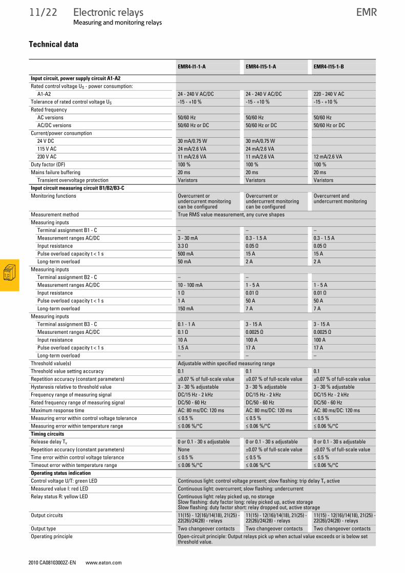
Technical data
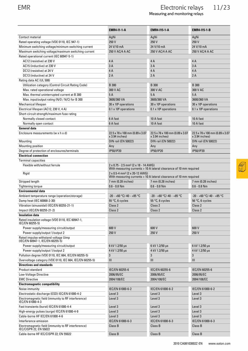
EMR4-I1-1-A EMR4-I15-1-A EMR4-I15-1-B
Input circuit, power supply circuit A1-A2
Rated control voltage US - power consumption:A1-A2 24 - 240 V AC/DC 24 - 240 V AC/DC 220 - 240 V AC
Tolerance of rated control voltage US -15 - +10 % -15 - +10 % -15 - +10 %Rated frequency
AC versions 50/60 Hz 50/60 Hz 50/60 HzAC/DC versions 50/60 Hz or DC 50/60 Hz or DC 50/60 Hz or DC
Current/power consumption24 V DC 30 mA/0.75 W 30 mA/0.75 W115 V AC 24 mA/2.6 VA 24 mA/2.6 VA230 V AC 11 mA/2.6 VA 11 mA/2.6 VA 12 mA/2.6 VA
Duty factor (DF) 100 % 100 % 100 %Mains failure buffering 20 ms 20 ms 20 ms
Transient overvoltage protection Varistors Varistors VaristorsInput circuit measuring circuit B1/B2/B3-C
Monitoring functions Overcurrent or undercurrent monitoring can be configured
Overcurrent or undercurrent monitoring can be configured
Overcurrent and undercurrent monitoring
Measurement method True RMS value measurement, any curve shapesMeasuring inputs
Terminal assignment B1 - C – – –Measurement ranges AC/DC 3 - 30 mA 0.3 - 1.5 A 0.3 - 1.5 AInput resistance 3.3 Ω 0.05 Ω 0.05 ΩPulse overload capacity t < 1 s 500 mA 15 A 15 ALong-term overload 50 mA 2 A 2 A
Measuring inputs Terminal assignment B2 - C – –Measurement ranges AC/DC 10 - 100 mA 1 - 5 A 1 - 5 AInput resistance 1 Ω 0.01 Ω 0.01 ΩPulse overload capacity t < 1 s 1 A 50 A 50 ALong-term overload 150 mA 7 A 7 A
Measuring inputs Terminal assignment B3 - C 0.1 - 1 A 3 - 15 A 3 - 15 AMeasurement ranges AC/DC 0.1 Ω 0.0025 Ω 0.0025 ΩInput resistance 10 A 100 A 100 APulse overload capacity t < 1 s 1.5 A 17 A 17 ALong-term overload – – –
Threshold value(s) Adjustable within specified measuring rangeThreshold value setting accuracy 0.1 0.1 0.1Repetition accuracy (constant parameters) ±0.07 % of full-scale value ±0.07 % of full-scale value ±0.07 % of full-scale valueHysteresis relative to threshold value 3 - 30 % adjustable 3 - 30 % adjustable 3 - 30 % adjustableFrequency range of measuring signal DC/15 Hz - 2 kHz DC/15 Hz - 2 kHz DC/15 Hz - 2 kHzRated frequency range of measuring signal DC/50 - 60 Hz DC/50 - 60 Hz DC/50 - 60 HzMaximum response time AC: 80 ms/DC: 120 ms AC: 80 ms/DC: 120 ms AC: 80 ms/DC: 120 msMeasuring error within control voltage tolerance ≤ 0.5 % ≤ 0.5 % ≤ 0.5 %Measuring error within temperature range ≤ 0.06 %/°C ≤ 0.06 %/°C ≤ 0.06 %/°CTiming circuits
Release delay Tv 0 or 0.1 - 30 s adjustable 0 or 0.1 - 30 s adjustable 0 or 0.1 - 30 s adjustableRepetition accuracy (constant parameters) None ±0.07 % of full-scale value ±0.07 % of full-scale valueTime error within control voltage tolerance ≤ 0.5 % ≤ 0.5 % ≤ 0.5 %Timeout error within temperature range ≤ 0.06 %/°C ≤ 0.06 %/°C ≤ 0.06 %/°COperating status indication
Control voltage U/T: green LED Continuous light: control voltage present; slow flashing: trip delay Tv activeMeasured value I: red LED Continuous light: overcurrent; slow flashing: undercurrentRelay status R: yellow LED Continuous light: relay picked up, no storage
Slow flashing: duty factor long: relay picked up, active storage Slow flashing: duty factor short: relay dropped out, active storage
Output circuits 11(15) - 12(16)/14(18), 21(25) -22(26)/24(28) - relays
11(15) - 12(16)/14(18), 21(25) - 22(26)/24(28) - relays
11(15) - 12(16)/14(18), 21(25) -22(26)/24(28) - relays
Output type Two changeover contacts Two changeover contacts Two changeover contactsOperating principle Open-circuit principle: Output relays pick up when actual value exceeds or is below set
threshold value.
Electronic relaysMeasuring and monitoring relays
2010 CA08103002Z-EN www.eaton.com
EMR 11/23
Contact material AgNi AgNi AgNiRated operating voltage (VDE 0110, IEC 947-1) 250 V 250 V 250 VMinimum switching voltage/minimum switching current 24 V/10 mA 24 V/10 mA 24 V/10 mAMaximum switching voltage/maximum switching current 250 V AC/4 A AC 250 V AC/4 A AC 250 V AC/4 A ACRated operational current (IEC 60947-5-1)
AC12 (resistive) at 230 V 4 A 4 A 4 AAC15 (inductive) at 230 V 3 A 3 A 3 ADC12 (resistive) at 24 V 4 A 4 A 4 ADC13 (inductive) at 24 V 2 A 2 A 2 A
Rating data AC (UL 508) Utilization category (Control Circuit Rating Code) B 300 B 300 B 300Max. rated operational voltage 300 V AC 300 V AC 300 V ACMax. thermal uninterrupted current at B 300 5 A 5 A 5 AMax. input/output rating (N/O / N/C) for B 300 3600/360 VA 3600/360 VA 3600/360 VA
Mechanical lifespan 30 x 106 operations 30 x 106 operations 30 x 106 operationsElectrical lifespan (AC12, 230 V, 4 A) 0.1 x 10⁶ operations 0.1 x 10⁶ operations 0.1 x 10⁶ operationsShort-circuit strength/maximum fuse rating
Normally closed contact 6 A fast 10 A fast 10 A fastNormally open contact 6 A fast 10 A fast 10 A fast
General data
Enclosure measurements (w x h x d) 22.5 x 78 x 100 mm (0.89 x 3.07 x 3.94 inches)
22.5 x 78 x 100 mm (0.89 x 3.07 x 3.94 inches)
22.5 x 78 x 100 mm (0.89 x 3.07 x 3.94 inches)
Mounting DIN rail (EN 50022) DIN rail (EN 50022) DIN rail (EN 50022)Mounting position Any Any AnyDegree of protection of enclosures/terminals IP50/IP20 IP50/IP20 IP50/IP20Electrical connection
Terminal capacities Flexible with/without ferrule 2 x 0.75 - 2.5 mm² (2 x 18 - 14 AWG)
With measuring currents > 10 A lateral clearance of 10 mm requiredRigid 2 x 0.5-4 mm² (2 x 20-12 AWG)
With measuring currents > 10 A lateral clearance of 10 mm requiredStripped length 7 mm (0.28 inches) 7 mm (0.28 inches) 7 mm (0.28 inches)Tightening torque 0.6 - 0.8 Nm 0.6 - 0.8 Nm 0.6 - 0.8 NmEnvironmental data
Ambient temperature range (operation/storage) -20 - +60 °C/-40 - +85 °C -20 - +60 °C/-40 - +85 °C -20 - +60 °C/-40 - +85 °CDamp heat (IEC 60068-2-30) 55 °C, 6 cycles 55 °C, 6 cycles 56 °C, 6 cyclesVibration (sinusoidal) (IEC/EN 60255-21-1) Class 2 Class 2 Class 2Impact (IEC/EN 60255-21-2) Class 2 Class 2 Class 2Insulation data
Rated insulation voltage (VDE 0110, IEC 60947-1, IEC/EN 60255-5)
Power supply/measuring circuit/output 600 V 600 V 600 V Power supply/output 1/output 2 250 V 250 V 250 V
Rated impulse withstand voltage Uimp (IEC/EN 60947-1, IEC/EN 60255-5)
Power supply/measuring circuit/output 6 kV 1.2/50 μs 6 kV 1.2/50 μs 6 kV 1.2/50 μsPower supply/output 1/output 2 4 kV 1.2/50 μs 4 kV 1.2/50 μs 4 kV 1.2/50 μs
Pollution degree (VDE 0110, IEC 664, IEC/EN 60255-5) 3 3 3Overvoltage category (VDE 0110, IEC 664, IEC/EN 60255-5) III III IIIDirectives and standards
Product standard IEC/EN 60255-6 IEC/EN 60255-6 IEC/EN 60255-6Low-Voltage Directive 2006/95/EC 2006/95/EC 2006/95/ECEMC Directive 2004/108/EC 2004/108/EC 2004/108/ECElectromagnetic compatibility
Noise immunity IEC/EN 61000-6-2 IEC/EN 61000-6-2 IEC/EN 61000-6-2Electrostatic discharge (ESD) IEC/EN 61000-4-2 Level 3 Level 3 Level 3Electromagnetic field (immunity to RF interference) IEC/EN 61000-4-3
Level 3 Level 3 Level 3
Fast transients (burst) IEC/EN 61000-4-4 Level 3 Level 3 Level 3High-energy pulses (surge) IEC/EN 61000-4-9 Level 3 Level 3 Level 3Cable-borne HF IEC/EN 61000-4-6 Level 3 Level 3 Level 3Interference emission IEC/EN 61000-6-3 IEC/EN 61000-6-3 IEC/EN 61000-6-3Electromagnetic field (immunity to RF interference) IEC/CISPR 22, EN 55022
Class B Class B Class B
Cable-borne HF IEC/CISPR 22; EN 55022 Class B Class B Class B
EMR4-I1-1-A EMR4-I15-1-A EMR4-I15-1-B
11/24 Electronic relaysMeasuring and monitoring relays
2010 CA08103002Z-EN www.eaton.com
EMR
Measuring and monitoring relaysEMR
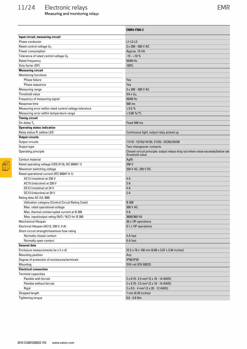
EMR4-F500-2
Input circuit, measuring circuit
Phase conductor L1-L2-L3Rated control voltage US 3 x 200 - 500 V ACPower consumption Approx. 15 VATolerance of rated control voltage US -15 - +10 %Rated frequency 50/60 HzDuty factor (DF) 100%Measuring circuit
Monitoring functionsPhase failure YesPhase sequence Yes
Measuring range 3 x 200 - 500 V ACThreshold value 0.6 x UN
Frequency of measuring signal 50/60 HzResponse time 500 msMeasuring error within rated control voltage tolerance ≤ 0.5 %Measuring error within temperature range ≤ 0.06 %/°CTiming circuit
On-delay Ts Fixed 500 msOperating status indication
Relay status R: yellow LED Continuous light: output relay picked upOutput circuits
Output circuits 11(15) -12(16)/14(18), 21(25) -22(26)/24(28)Output type Two changeover contactsOperating principle Closed-circuit principle: output relays drop out when value exceeds/below set
threshold valueContact material AgNiRated operating voltage (VDE 0110, IEC 60947-1) 250 VMaximum switching voltage 250 V AC, 250 V DCRated operational current (IEC 60947-5-1)
AC12 (resistive) at 230 V 4 AAC15 (inductive) at 230 V 3 ADC12 (resistive) at 24 V 4 ADC13 (inductive) at 24 V 2 A
Rating data AC (UL 508) Utilization category (Control Circuit Rating Code) B 300Max. rated operational voltage 300 V ACMax. thermal uninterrupted current at B 300 5 AMax. input/output rating (N/O / N/C) for B 300 3600/360 VA
Mechanical lifespan 30 x 106 operationsElectrical lifespan (AC12, 230 V, 4 A) 0.1 x 10⁶ operationsShort-circuit strength/maximum fuse rating
Normally closed contact 4 A fastNormally open contact 6 A fast
General data
Enclosure measurements (w x h x d) 22.5 x 78 x 100 mm (0.89 x 3.07 x 3.94 inches)Mounting position AnyDegree of protection of enclosures/terminals IP50/IP20Mounting DIN rail (EN 50022)Electrical connection
Terminal capacities Flexible with ferrule 2 x 0.75- 2.5 mm² (2 x 18 - 14 AWG)Flexible without ferrule 2 x 0.75- 2.5 mm² (2 x 18 - 14 AWG)Rigid 2 x 0.5 - 4 mm² (2 x 20 - 12 AWG)
Stripped length 7 mm (0.28 inches)Tightening torque 0.6 - 0.8 Nm
Electronic relaysMeasuring and monitoring relays
2010 CA08103002Z-EN www.eaton.com
EMR 11/25
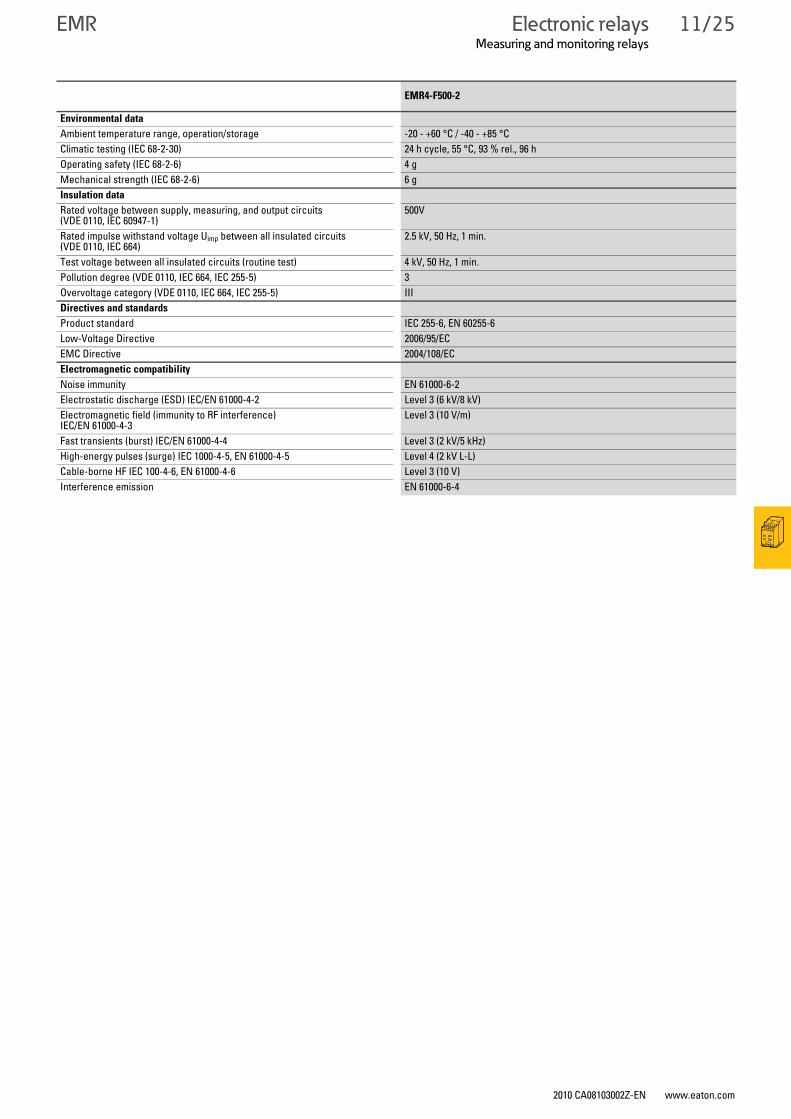
EMR4-F500-2
Environmental data
Ambient temperature range, operation/storage -20 - +60 °C / -40 - +85 °CClimatic testing (IEC 68-2-30) 24 h cycle, 55 °C, 93 % rel., 96 hOperating safety (IEC 68-2-6) 4 gMechanical strength (IEC 68-2-6) 6 gInsulation data
Rated voltage between supply, measuring, and output circuits (VDE 0110, IEC 60947-1)
500V
Rated impulse withstand voltage Uimp between all insulated circuits (VDE 0110, IEC 664)
2.5 kV, 50 Hz, 1 min.
Test voltage between all insulated circuits (routine test) 4 kV, 50 Hz, 1 min.Pollution degree (VDE 0110, IEC 664, IEC 255-5) 3Overvoltage category (VDE 0110, IEC 664, IEC 255-5) IIIDirectives and standards
Product standard IEC 255-6, EN 60255-6Low-Voltage Directive 2006/95/ECEMC Directive 2004/108/ECElectromagnetic compatibility
Noise immunity EN 61000-6-2Electrostatic discharge (ESD) IEC/EN 61000-4-2 Level 3 (6 kV/8 kV)Electromagnetic field (immunity to RF interference) IEC/EN 61000-4-3
Level 3 (10 V/m)
Fast transients (burst) IEC/EN 61000-4-4 Level 3 (2 kV/5 kHz)High-energy pulses (surge) IEC 1000-4-5, EN 61000-4-5 Level 4 (2 kV L-L)Cable-borne HF IEC 100-4-6, EN 61000-4-6 Level 3 (10 V)Interference emission EN 61000-6-4
11/26 Electronic relaysMeasuring and monitoring relays
2010 CA08103002Z-EN www.eaton.com
EMR
EMRMeasuring and monitoring relays
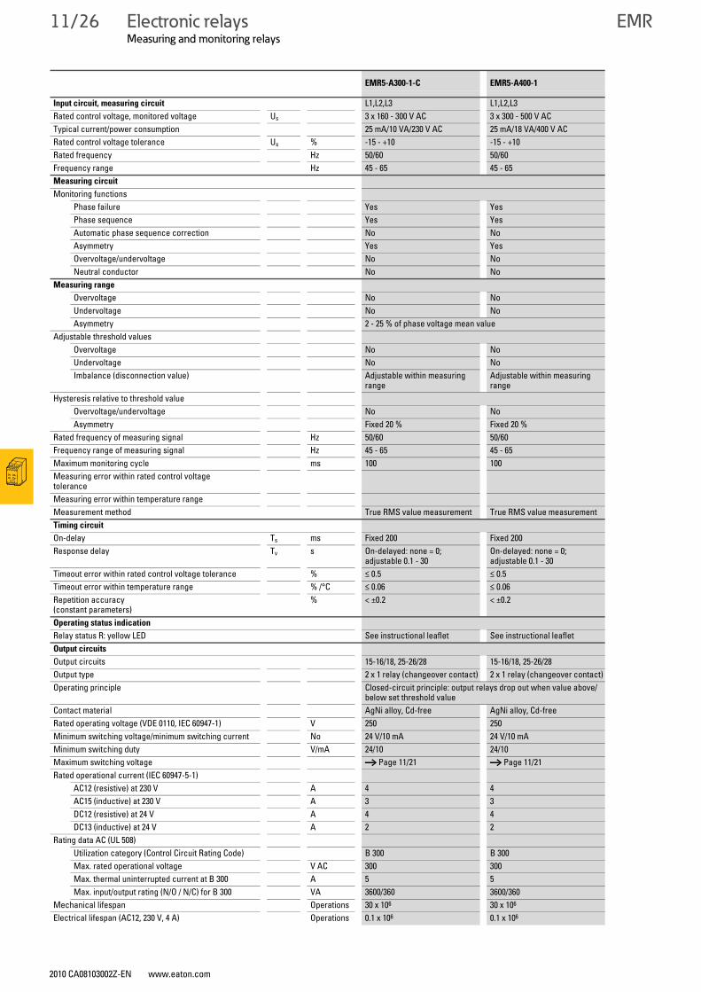
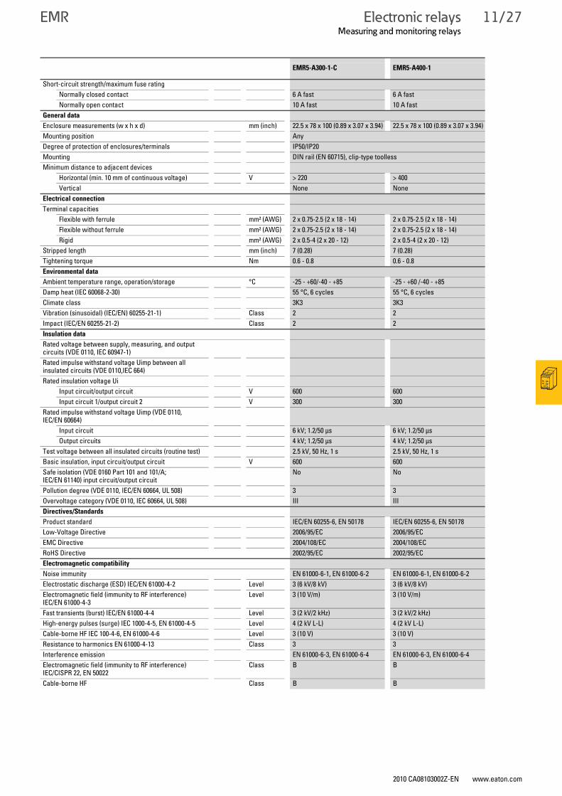
EMR5-A300-1-C EMR5-A400-1
Input circuit, measuring circuit L1,L2,L3 L1,L2,L3Rated control voltage, monitored voltage Us 3 x 160 - 300 V AC 3 x 300 - 500 V AC Typical current/power consumption 25 mA/10 VA/230 V AC 25 mA/18 VA/400 V ACRated control voltage tolerance Us % -15 - +10 -15 - +10Rated frequency Hz 50/60 50/60Frequency range Hz 45 - 65 45 - 65Measuring circuit
Monitoring functionsPhase failure Yes YesPhase sequence Yes YesAutomatic phase sequence correction No NoAsymmetry Yes YesOvervoltage/undervoltage No NoNeutral conductor No No
Measuring range
Overvoltage No NoUndervoltage No NoAsymmetry 2 - 25 % of phase voltage mean value
Adjustable threshold values Overvoltage No NoUndervoltage No NoImbalance (disconnection value) Adjustable within measuring
rangeAdjustable within measuring range
Hysteresis relative to threshold valueOvervoltage/undervoltage No NoAsymmetry Fixed 20 % Fixed 20 %
Rated frequency of measuring signal Hz 50/60 50/60Frequency range of measuring signal Hz 45 - 65 45 - 65Maximum monitoring cycle ms 100 100 Measuring error within rated control voltage toleranceMeasuring error within temperature rangeMeasurement method True RMS value measurement True RMS value measurementTiming circuit
On-delay Ts ms Fixed 200 Fixed 200Response delay Tv s On-delayed: none = 0;
adjustable 0.1 - 30On-delayed: none = 0; adjustable 0.1 - 30
Timeout error within rated control voltage tolerance % ≤ 0.5 ≤ 0.5Timeout error within temperature range % /°C ≤ 0.06 ≤ 0.06Repetition accuracy (constant parameters)
% < ±0.2 < ±0.2
Operating status indication
Relay status R: yellow LED See instructional leaflet See instructional leafletOutput circuits
Output circuits 15-16/18, 25-26/28 15-16/18, 25-26/28Output type 2 x 1 relay (changeover contact) 2 x 1 relay (changeover contact) Operating principle Closed-circuit principle: output relays drop out when value above/
below set threshold valueContact material AgNi alloy, Cd-free AgNi alloy, Cd-freeRated operating voltage (VDE 0110, IEC 60947-1) V 250 250 Minimum switching voltage/minimum switching current No 24 V/10 mA 24 V/10 mAMinimum switching duty V/mA 24/10 24/10Maximum switching voltage → Page 11/21 → Page 11/21Rated operational current (IEC 60947-5-1)
AC12 (resistive) at 230 V A 4 4AC15 (inductive) at 230 V A 3 3DC12 (resistive) at 24 V A 4 4DC13 (inductive) at 24 V A 2 2
Rating data AC (UL 508) Utilization category (Control Circuit Rating Code) B 300 B 300Max. rated operational voltage V AC 300 300Max. thermal uninterrupted current at B 300 A 5 5Max. input/output rating (N/O / N/C) for B 300 VA 3600/360 3600/360
Mechanical lifespan Operations 30 x 106 30 x 106
Electrical lifespan (AC12, 230 V, 4 A) Operations 0.1 x 10⁶ 0.1 x 10⁶
Electronic relaysMeasuring and monitoring relays
2010 CA08103002Z-EN www.eaton.com
EMR 11/27
Short-circuit strength/maximum fuse ratingNormally closed contact 6 A fast 6 A fastNormally open contact 10 A fast 10 A fast
General data
Enclosure measurements (w x h x d) mm (inch) 22.5 x 78 x 100 (0.89 x 3.07 x 3.94) 22.5 x 78 x 100 (0.89 x 3.07 x 3.94)Mounting position AnyDegree of protection of enclosures/terminals IP50/IP20Mounting DIN rail (EN 60715), clip-type toollessMinimum distance to adjacent devices
Horizontal (min. 10 mm of continuous voltage) V > 220 > 400Vertical None None
Electrical connection
Terminal capacities Flexible with ferrule mm² (AWG) 2 x 0.75-2.5 (2 x 18 - 14) 2 x 0.75-2.5 (2 x 18 - 14)Flexible without ferrule mm² (AWG) 2 x 0.75-2.5 (2 x 18 - 14) 2 x 0.75-2.5 (2 x 18 - 14)Rigid mm² (AWG) 2 x 0.5-4 (2 x 20 - 12) 2 x 0.5-4 (2 x 20 - 12)
Stripped length mm (inch) 7 (0.28) 7 (0.28)Tightening torque Nm 0.6 - 0.8 0.6 - 0.8Environmental data
Ambient temperature range, operation/storage °C -25 - +60/-40 - +85 -25 - +60 /-40 - +85Damp heat (IEC 60068-2-30) 55 °C, 6 cycles 55 °C, 6 cyclesClimate class 3K3 3K3Vibration (sinusoidal) (IEC/EN) 60255-21-1) Class 2 2Impact (IEC/EN 60255-21-2) Class 2 2Insulation data
Rated voltage between supply, measuring, and output circuits (VDE 0110, IEC 60947-1)Rated impulse withstand voltage Uimp between all insulated circuits (VDE 0110,IEC 664)Rated insulation voltage Ui
Input circuit/output circuit V 600 600Input circuit 1/output circuit 2 V 300 300
Rated impulse withstand voltage Uimp (VDE 0110, IEC/EN 60664)
Input circuit 6 kV; 1.2/50 μs 6 kV; 1.2/50 μsOutput circuits 4 kV; 1.2/50 μs 4 kV; 1.2/50 μs
Test voltage between all insulated circuits (routine test) 2.5 kV, 50 Hz, 1 s 2.5 kV, 50 Hz, 1 sBasic insulation, input circuit/output circuit V 600 600 Safe isolation (VDE 0160 Part 101 and 101/A; IEC/EN 61140) input circuit/output circuit
No No
Pollution degree (VDE 0110, IEC/EN 60664, UL 508) 3 3Overvoltage category (VDE 0110, IEC 60664, UL 508) III IIIDirectives/Standards
Product standard IEC/EN 60255-6, EN 50178 IEC/EN 60255-6, EN 50178Low-Voltage Directive 2006/95/EC 2006/95/ECEMC Directive 2004/108/EC 2004/108/ECRoHS Directive 2002/95/EC 2002/95/ECElectromagnetic compatibility
Noise immunity EN 61000-6-1, EN 61000-6-2 EN 61000-6-1, EN 61000-6-2Electrostatic discharge (ESD) IEC/EN 61000-4-2 Level 3 (6 kV/8 kV) 3 (6 kV/8 kV)Electromagnetic field (immunity to RF interference) IEC/EN 61000-4-3
Level 3 (10 V/m) 3 (10 V/m)
Fast transients (burst) IEC/EN 61000-4-4 Level 3 (2 kV/2 kHz) 3 (2 kV/2 kHz)High-energy pulses (surge) IEC 1000-4-5, EN 61000-4-5 Level 4 (2 kV L-L) 4 (2 kV L-L)Cable-borne HF IEC 100-4-6, EN 61000-4-6 Level 3 (10 V) 3 (10 V)Resistance to harmonics EN 61000-4-13 Class 3 3Interference emission EN 61000-6-3, EN 61000-6-4 EN 61000-6-3, EN 61000-6-4Electromagnetic field (immunity to RF interference) IEC/CISPR 22, EN 50022
Class B B
Cable-borne HF Class B B
EMR5-A300-1-C EMR5-A400-1
11/28 Electronic relaysMeasuring and monitoring relays
2010 CA08103002Z-EN www.eaton.com
EMR
Measuring and monitoring relaysEMR
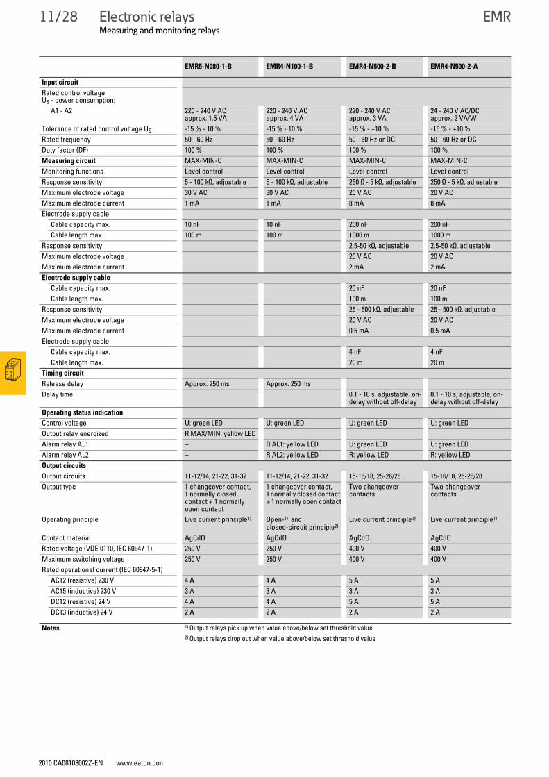
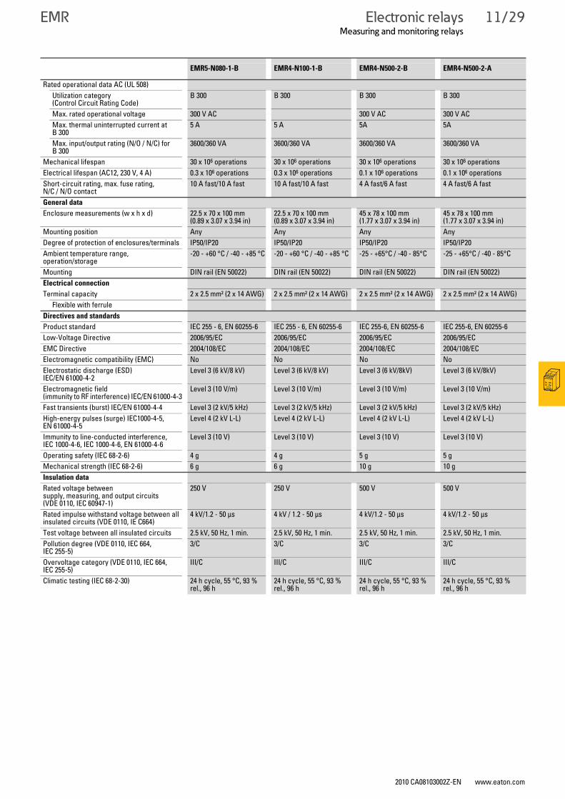
EMR5-N080-1-B EMR4-N100-1-B EMR4-N500-2-B EMR4-N500-2-A
Input circuit
Rated control voltage US - power consumption:
A1 - A2 220 - 240 V AC approx. 1.5 VA
220 - 240 V AC approx. 4 VA
220 - 240 V AC approx. 3 VA
24 - 240 V AC/DC approx. 2 VA/W
Tolerance of rated control voltage US -15 % - 10 % -15 % - 10 % -15 % - +10 % -15 % - +10 %Rated frequency 50 - 60 Hz 50 - 60 Hz 50 - 60 Hz or DC 50 - 60 Hz or DCDuty factor (DF) 100 % 100 % 100 % 100 %Measuring circuit MAX-MIN-C MAX-MIN-C MAX-MIN-C MAX-MIN-CMonitoring functions Level control Level control Level control Level controlResponse sensitivity 5 - 100 kΩ, adjustable 5 - 100 kΩ, adjustable 250 Ω - 5 kΩ, adjustable 250 Ω - 5 kΩ, adjustableMaximum electrode voltage 30 V AC 30 V AC 20 V AC 20 V ACMaximum electrode current 1 mA 1 mA 8 mA 8 mAElectrode supply cable
Cable capacity max. 10 nF 10 nF 200 nF 200 nFCable length max. 100 m 100 m 1000 m 1000 m
Response sensitivity 2.5-50 kΩ, adjustable 2.5-50 kΩ, adjustableMaximum electrode voltage 20 V AC 20 V ACMaximum electrode current 2 mA 2 mAElectrode supply cable
Cable capacity max. 20 nF 20 nFCable length max. 100 m 100 m
Response sensitivity 25 - 500 kΩ, adjustable 25 - 500 kΩ, adjustableMaximum electrode voltage 20 V AC 20 V ACMaximum electrode current 0.5 mA 0.5 mAElectrode supply cable
Cable capacity max. 4 nF 4 nFCable length max. 20 m 20 m
Timing circuit
Release delay Approx. 250 ms Approx. 250 msDelay time 0.1 - 10 s, adjustable, on-
delay without off-delay0.1 - 10 s, adjustable, on-delay without off-delay
Operating status indication
Control voltage U: green LED U: green LED U: green LED U: green LEDOutput relay energized R MAX/MIN: yellow LEDAlarm relay AL1 – R AL1: yellow LED U: green LED U: green LEDAlarm relay AL2 – R AL2: yellow LED R: yellow LED R: yellow LEDOutput circuits
Output circuits 11-12/14, 21-22, 31-32 11-12/14, 21-22, 31-32 15-16/18, 25-26/28 15-16/18, 25-26/28Output type 1 changeover contact,
1 normally closed contact + 1 normally open contact
1 changeover contact, 1 normally closed contact + 1 normally open contact
Two changeover contacts
Two changeover contacts
Operating principle Live current principle1) Open-1) andclosed-circuit principle2)
Live current principle1) Live current principle1)
Contact material AgCdO AgCdO AgCdO AgCdORated voltage (VDE 0110, IEC 60947-1) 250 V 250 V 400 V 400 VMaximum switching voltage 250 V 250 V 400 V 400 VRated operational current (IEC 60947-5-1)
AC12 (resistive) 230 V 4 A 4 A 5 A 5 AAC15 (inductive) 230 V 3 A 3 A 3 A 3 ADC12 (resistive) 24 V 4 A 4 A 5 A 5 ADC13 (inductive) 24 V 2 A 2 A 2 A 2 A
Notes 1) Output relays pick up when value above/below set threshold value2) Output relays drop out when value above/below set threshold value
Electronic relaysMeasuring and monitoring relays
2010 CA08103002Z-EN www.eaton.com
EMR 11/29
Rated operational data AC (UL 508)Utilization category (Control Circuit Rating Code)
B 300 B 300 B 300 B 300
Max. rated operational voltage 300 V AC 300 V AC 300 V ACMax. thermal uninterrupted current at B 300
5 A 5 A 5A 5A
Max. input/output rating (N/O / N/C) for B 300
3600/360 VA 3600/360 VA 3600/360 VA 3600/360 VA
Mechanical lifespan 30 x 106 operations 30 x 106 operations 30 x 106 operations 30 x 106 operationsElectrical lifespan (AC12, 230 V, 4 A) 0.3 x 10⁶ operations 0.3 x 10⁶ operations 0.1 x 10⁶ operations 0.1 x 10⁶ operationsShort-circuit rating, max. fuse rating, N/C / N/O contact
10 A fast/10 A fast 10 A fast/10 A fast 4 A fast/6 A fast 4 A fast/6 A fast
General data
Enclosure measurements (w x h x d) 22.5 x 70 x 100 mm (0.89 x 3.07 x 3.94 in)
22.5 x 70 x 100 mm (0.89 x 3.07 x 3.94 in)
45 x 78 x 100 mm (1.77 x 3.07 x 3.94 in)
45 x 78 x 100 mm (1.77 x 3.07 x 3.94 in)
Mounting position Any Any Any AnyDegree of protection of enclosures/terminals IP50/IP20 IP50/IP20 IP50/IP20 IP50/IP20Ambient temperature range, operation/storage
-20 - +60 °C / -40 - +85 °C -20 - +60 °C / -40 - +85 °C -25 - +65°C / -40 - 85°C -25 - +65°C / -40 - 85°C
Mounting DIN rail (EN 50022) DIN rail (EN 50022) DIN rail (EN 50022) DIN rail (EN 50022)Electrical connection
Terminal capacity 2 x 2.5 mm² (2 x 14 AWG) 2 x 2.5 mm² (2 x 14 AWG) 2 x 2.5 mm² (2 x 14 AWG) 2 x 2.5 mm² (2 x 14 AWG)Flexible with ferrule
Directives and standards
Product standard IEC 255 - 6, EN 60255-6 IEC 255 - 6, EN 60255-6 IEC 255-6, EN 60255-6 IEC 255-6, EN 60255-6Low-Voltage Directive 2006/95/EC 2006/95/EC 2006/95/EC 2006/95/ECEMC Directive 2004/108/EC 2004/108/EC 2004/108/EC 2004/108/ECElectromagnetic compatibility (EMC) No No No NoElectrostatic discharge (ESD) IEC/EN 61000-4-2
Level 3 (6 kV/8 kV) Level 3 (6 kV/8 kV) Level 3 (6 kV/8kV) Level 3 (6 kV/8kV)
Electromagnetic field (immunity to RF interference) IEC/EN 61000-4-3
Level 3 (10 V/m) Level 3 (10 V/m) Level 3 (10 V/m) Level 3 (10 V/m)
Fast transients (burst) IEC/EN 61000-4-4 Level 3 (2 kV/5 kHz) Level 3 (2 kV/5 kHz) Level 3 (2 kV/5 kHz) Level 3 (2 kV/5 kHz)High-energy pulses (surge) IEC1000-4-5, EN 61000-4-5
Level 4 (2 kV L-L) Level 4 (2 kV L-L) Level 4 (2 kV L-L) Level 4 (2 kV L-L)
Immunity to line-conducted interference, IEC 1000-4-6, IEC 1000-4-6, EN 61000-4-6
Level 3 (10 V) Level 3 (10 V) Level 3 (10 V) Level 3 (10 V)
Operating safety (IEC 68-2-6) 4 g 4 g 5 g 5 gMechanical strength (IEC 68-2-6) 6 g 6 g 10 g 10 gInsulation data
Rated voltage between supply, measuring, and output circuits(VDE 0110, IEC 60947-1)
250 V 250 V 500 V 500 V
Rated impulse withstand voltage between all insulated circuits (VDE 0110, IE C664)
4 kV/1.2 - 50 μs 4 kV / 1.2 - 50 μs 4 kV/1.2 - 50 μs 4 kV/1.2 - 50 μs
Test voltage between all insulated circuits 2.5 kV, 50 Hz, 1 min. 2.5 kV, 50 Hz, 1 min. 2.5 kV, 50 Hz, 1 min. 2.5 kV, 50 Hz, 1 min.Pollution degree (VDE 0110, IEC 664, IEC 255-5)
3/C 3/C 3/C 3/C
Overvoltage category (VDE 0110, IEC 664, IEC 255-5)
III/C III/C III/C III/C
Climatic testing (IEC 68-2-30) 24 h cycle, 55 °C, 93 % rel., 96 h
24 h cycle, 55 °C, 93 % rel., 96 h
24 h cycle, 55 °C, 93 % rel., 96 h
24 h cycle, 55 °C, 93 % rel., 96 h
EMR5-N080-1-B EMR4-N100-1-B EMR4-N500-2-B EMR4-N500-2-A
11/30 Electronic relaysMeasuring and monitoring relays
2010 CA08103002Z-EN www.eaton.com
EMR
Measuring and monitoring relaysEMR
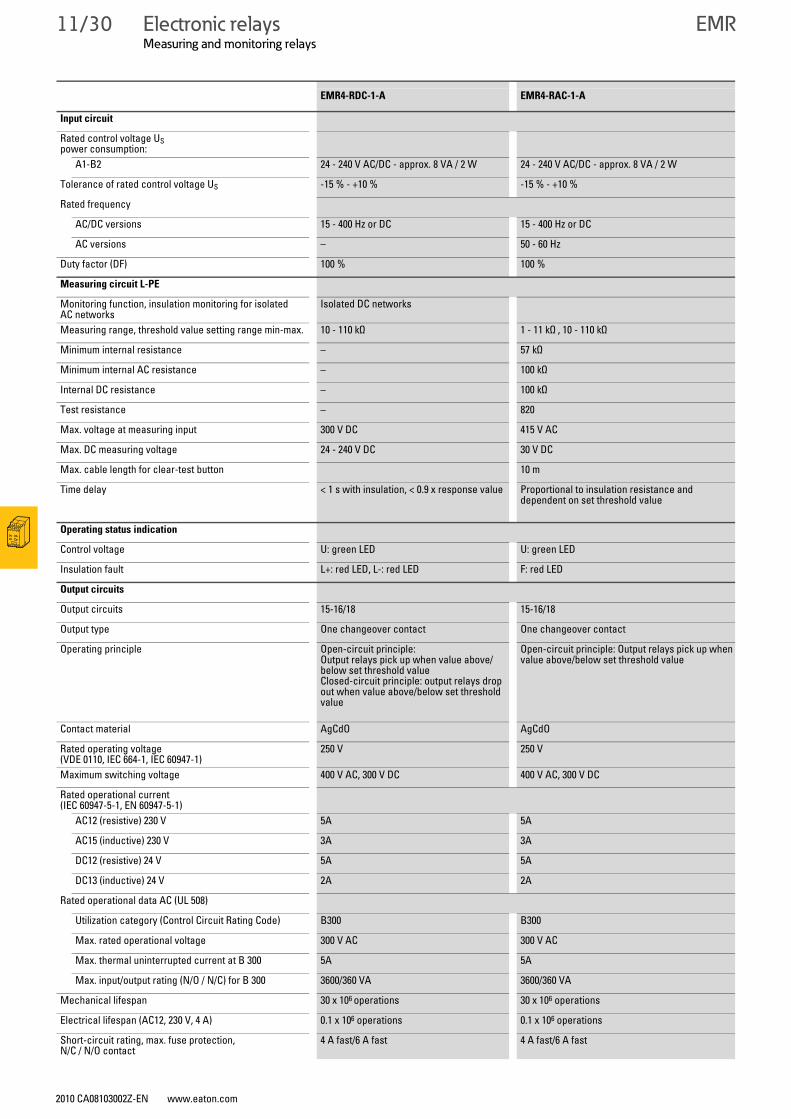
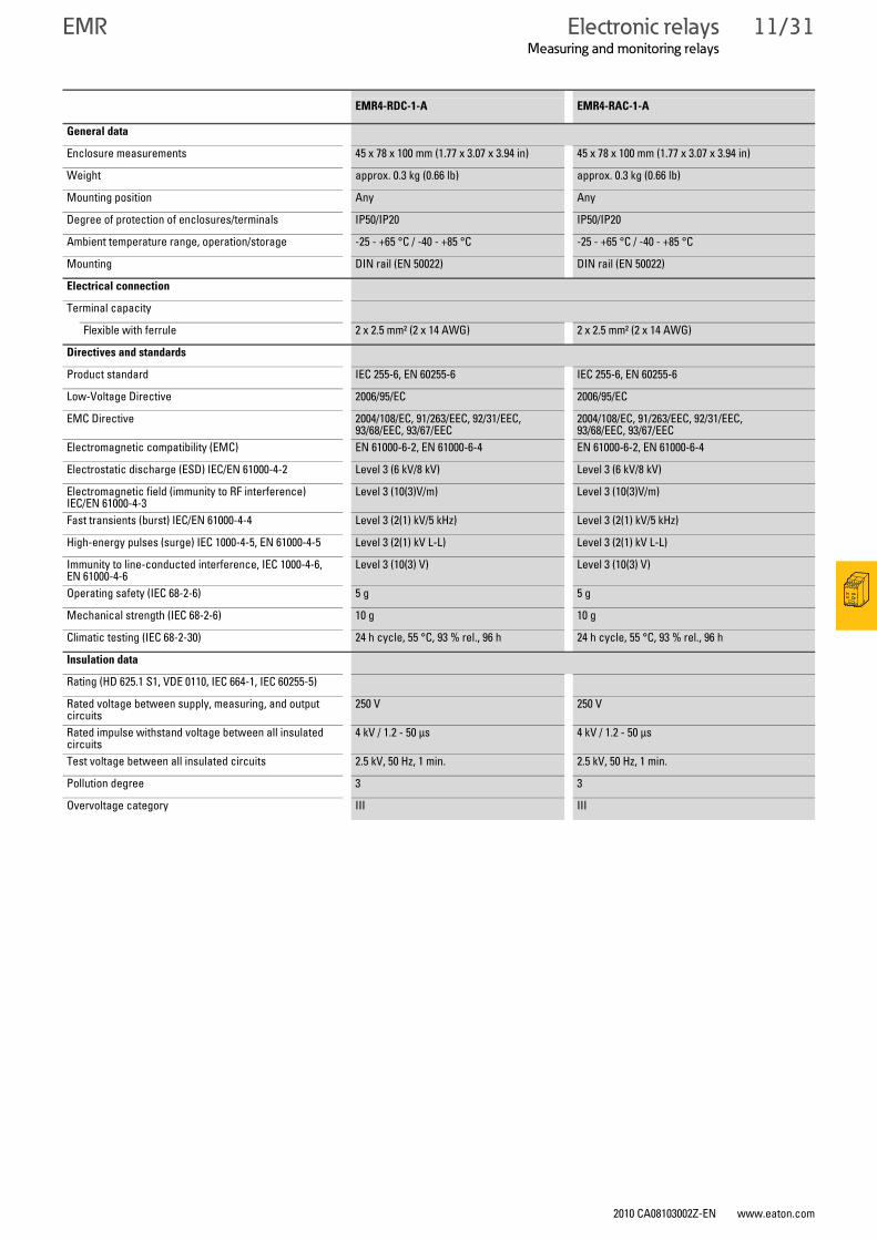
EMR4-RDC-1-A EMR4-RAC-1-A
Input circuit
Rated control voltage US power consumption:
A1-B2 24 - 240 V AC/DC - approx. 8 VA / 2 W 24 - 240 V AC/DC - approx. 8 VA / 2 W
Tolerance of rated control voltage US -15 % - +10 % -15 % - +10 %
Rated frequency
AC/DC versions 15 - 400 Hz or DC 15 - 400 Hz or DC
AC versions – 50 - 60 Hz
Duty factor (DF) 100 % 100 %
Measuring circuit L-PE
Monitoring function, insulation monitoring for isolated AC networks
Isolated DC networks
Measuring range, threshold value setting range min-max. 10 - 110 kΩ 1 - 11 kΩ , 10 - 110 kΩ
Minimum internal resistance – 57 kΩ
Minimum internal AC resistance – 100 kΩ
Internal DC resistance – 100 kΩ
Test resistance – 820
Max. voltage at measuring input 300 V DC 415 V AC
Max. DC measuring voltage 24 - 240 V DC 30 V DC
Max. cable length for clear-test button 10 m
Time delay < 1 s with insulation, < 0.9 x response value Proportional to insulation resistance and dependent on set threshold value
Operating status indication
Control voltage U: green LED U: green LED
Insulation fault L+: red LED, L-: red LED F: red LED
Output circuits
Output circuits 15-16/18 15-16/18
Output type One changeover contact One changeover contact
Operating principle Open-circuit principle: Output relays pick up when value above/below set threshold valueClosed-circuit principle: output relays drop out when value above/below set threshold value
Open-circuit principle: Output relays pick up when value above/below set threshold value
Contact material AgCdO AgCdO
Rated operating voltage (VDE 0110, IEC 664-1, IEC 60947-1)
250 V 250 V
Maximum switching voltage 400 V AC, 300 V DC 400 V AC, 300 V DC
Rated operational current(IEC 60947-5-1, EN 60947-5-1)
AC12 (resistive) 230 V 5A 5A
AC15 (inductive) 230 V 3A 3A
DC12 (resistive) 24 V 5A 5A
DC13 (inductive) 24 V 2A 2A
Rated operational data AC (UL 508)
Utilization category (Control Circuit Rating Code) B300 B300
Max. rated operational voltage 300 V AC 300 V AC
Max. thermal uninterrupted current at B 300 5A 5A
Max. input/output rating (N/O / N/C) for B 300 3600/360 VA 3600/360 VA
Mechanical lifespan 30 x 106 operations 30 x 106 operations
Electrical lifespan (AC12, 230 V, 4 A) 0.1 x 10⁶ operations 0.1 x 10⁶ operations
Short-circuit rating, max. fuse protection, N/C / N/O contact
4 A fast/6 A fast 4 A fast/6 A fast
Electronic relaysMeasuring and monitoring relays
2010 CA08103002Z-EN www.eaton.com
EMR 11/31
General data
Enclosure measurements 45 x 78 x 100 mm (1.77 x 3.07 x 3.94 in) 45 x 78 x 100 mm (1.77 x 3.07 x 3.94 in)
Weight approx. 0.3 kg (0.66 lb) approx. 0.3 kg (0.66 lb)
Mounting position Any Any
Degree of protection of enclosures/terminals IP50/IP20 IP50/IP20
Ambient temperature range, operation/storage -25 - +65 °C / -40 - +85 °C -25 - +65 °C / -40 - +85 °C
Mounting DIN rail (EN 50022) DIN rail (EN 50022)
Electrical connection
Terminal capacity
Flexible with ferrule 2 x 2.5 mm² (2 x 14 AWG) 2 x 2.5 mm² (2 x 14 AWG)
Directives and standards
Product standard IEC 255-6, EN 60255-6 IEC 255-6, EN 60255-6
Low-Voltage Directive 2006/95/EC 2006/95/EC
EMC Directive 2004/108/EC, 91/263/EEC, 92/31/EEC, 93/68/EEC, 93/67/EEC
2004/108/EC, 91/263/EEC, 92/31/EEC, 93/68/EEC, 93/67/EEC
Electromagnetic compatibility (EMC) EN 61000-6-2, EN 61000-6-4 EN 61000-6-2, EN 61000-6-4
Electrostatic discharge (ESD) IEC/EN 61000-4-2 Level 3 (6 kV/8 kV) Level 3 (6 kV/8 kV)
Electromagnetic field (immunity to RF interference)IEC/EN 61000-4-3
Level 3 (10(3)V/m) Level 3 (10(3)V/m)
Fast transients (burst) IEC/EN 61000-4-4 Level 3 (2(1) kV/5 kHz) Level 3 (2(1) kV/5 kHz)
High-energy pulses (surge) IEC 1000-4-5, EN 61000-4-5 Level 3 (2(1) kV L-L) Level 3 (2(1) kV L-L)
Immunity to line-conducted interference, IEC 1000-4-6, EN 61000-4-6
Level 3 (10(3) V) Level 3 (10(3) V)
Operating safety (IEC 68-2-6) 5 g 5 g
Mechanical strength (IEC 68-2-6) 10 g 10 g
Climatic testing (IEC 68-2-30) 24 h cycle, 55 °C, 93 % rel., 96 h 24 h cycle, 55 °C, 93 % rel., 96 h
Insulation data
Rating (HD 625.1 S1, VDE 0110, IEC 664-1, IEC 60255-5)
Rated voltage between supply, measuring, and output circuits
250 V 250 V
Rated impulse withstand voltage between all insulated circuits
4 kV / 1.2 - 50 μs 4 kV / 1.2 - 50 μs
Test voltage between all insulated circuits 2.5 kV, 50 Hz, 1 min. 2.5 kV, 50 Hz, 1 min.
Pollution degree 3 3
Overvoltage category III III
EMR4-RDC-1-A EMR4-RAC-1-A
11/32 Electronic relaysMeasuring and monitoring relays
EMR
2010 CA08103002Z-EN www.eaton.com 2010 CA08103002Z-EN www.eaton.com
Electronic relaysMeasuring and monitoring relays
EMR
Measuring and monitoring relaysEMR
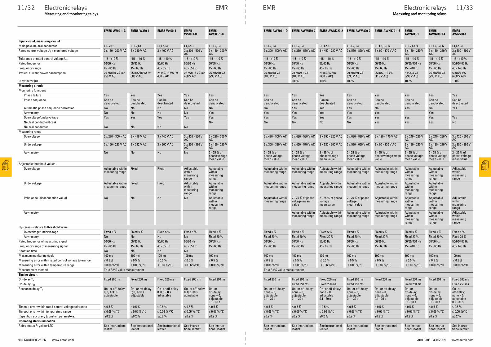
EMR5-W300-1-C EMR5-W380-1 EMR5-W400-1 EMR5-W500-1-D
EMR5-AW300-1-C
EMR5-AW500-1-D EMR5-AWM580-2 EMR5-AWM720-2 EMR5-AWM820-2 EMR5-AWN170-1-E EMR5-AWN280-1
EMR5-AWN280-1-F
EMR5-AWN500-1
Input circuit, measuring circuit
Main pole, neutral conductor L1,L2,L3 L1,L2,L3 L1,L2,L3 L1,L2,L3 L1, L2, L3 L1, L2, L3 L1, L2, L3 L1, L2, L3 L1, L2, L3 L1, L2, L3, N L1,L2,L3 N L1, L2, L3, N L1,L2,L3Rated control voltage US = monitored voltage 3 x 160 - 300 V AC 3 x 380 V AC 3 x 400 V AC 3 x 300 - 500 V
AC 3 x 160 - 300 V AC
3 x 300 - 500 V AC 3 x 350 - 580 V AC 3 x 450 - 720 V AC 3 x 530 - 820 V AC 3 x 90 - 170 V AC 3 x 180 - 280 V AC
3 x 180 - 280 V AC
3 x 300 - 500 V AC
Tolerance of rated control voltage US -15 - +10 % -15 - +10 % -15 - +10 % -15 - +10 % -15 - +10 % -15 - +10 % -15 - +10 % -15 - +10 % -15 - +10 % -15 - +10 % -15 - +10 % -15 - +10 % -15 - +10 %Rated frequency 50/60 Hz 50/60 Hz 50/60 Hz 50/60 Hz 50/60 Hz 50/60 Hz 50/60 Hz 50/60 Hz 50/60 Hz 50/60 Hz 50/60/400 Hz 50/60 Hz 50/60/400 HzFrequency range 45 - 65 Hz 45 - 65 Hz 45 - 65 Hz 45 - 65 Hz 45 - 65 Hz 45 - 65 Hz 45 - 65 Hz 45 - 65 Hz 45 - 65 Hz 45 - 65 Hz 45 - 440 Hz 45 - 65 Hz 45 - 440 HzTypical current/power consumption 25 mA/10 VA /at
250 V AC25 mA/18 VA /at 380 V AC
25 mA/18 VA /at 400 V AC
25 mA/18 VA /at 400 V AC
25 mA/10 VA (230 V AC)
25 mA/18 VA (400 V AC)
29 mA/41 VA (480 V AC)
29 mA/52 VA (600 V AC)
29 mA/59 VA (690 V AC)
25 mA / 10 VA (115 V AC)
5 mA/4 VA (230 V AC)
25 mA/18 VA (230 V AC)
5 mA/4 VA (400 V AC)
Duty factor (DF) 100% 100% 100% 100% 100%Measuring circuit Monitoring functions
Phase failure Yes Yes Yes Yes Yes Yes Yes Yes Yes Yes Yes Yes YesPhase sequence Can be
deactivated Can be deactivated
Can be deactivated
Can be deactivated
Can be deactivated
Can be deactivated
Can be deactivated
Can be deactivated
Can be deactivated
Can be deactivated
Can be deactivated
Can be deactivated
Can be deactivated
Automatic phase sequence correction No No No No No No Yes Yes Yes No Yes No YesAsymmetry No No No No Yes Yes Yes Yes Yes Yes YesOvervoltage/undervoltage Yes Yes Yes Yes Yes Yes Yes Yes Yes Yes Yes Yes YesNeutral conductor/break No No No No No Yes Yes Yes NoNeutral conductor No No No No
Measuring range Overvoltage 3 x 220 - 300 v AC 3 x 418 V AC 3 x 440 V AC 3 x 420 - 500 V
AC 3 x 220 - 300 V AC
3 x 420 - 500 V AC 3 x 480 - 580 V AC 3 x 690 - 820 V AC 3 x 690 - 820 V AC 3 x 120 - 170 V AC 3 x 240 - 280 V AC
3 x 240 - 280 V AC
3 x 420 - 500 V AC
Undervoltage 3 x 160 - 230 V AC 3 x 342 V AC 3 x 360 V AC 3 x 300 - 380 V AC
3 x 160 - 230 V AC
3 x 300 - 380 V AC 3 x 450 - 570 V AC 3 x 530 - 660 V AC 3 x 530 - 660 V AC 3 x 90 - 130 V AC 3 x 180 - 220 V AC
3 x 180 - 220 V AC
3 x 300 - 380 V AC
Asymmetry No No No No 2 - 25 % of phase voltage mean value
2 - 25 % of phase voltage mean value
2 - 25 % of phase voltage mean value
2 - 25 % of phase voltage mean value
2 - 25 % of phase voltage mean value
2 - 25 % of phase voltage mean value
2 - 25 % of phase voltage mean value
2 - 25 % of phase voltage mean value
2 - 25 % of phase voltage mean value
Adjustable threshold values Overvoltage Adjustable within
measuring rangeFixed Fixed Adjustable
within measuring range
Adjustable within measuring range
Adjustable within measuring range
Adjustable within measuring range
Adjustable within measuring range
Adjustable within measuring range
Adjustable within measuring range
Adjustable within measuring range
Adjustable within measuring range
Adjustable within measuring range
Undervoltage Adjustable within measuring range
Fixed Fixed Adjustable within measuring range
Adjustable within measuring range
Adjustable within measuring range
Adjustable within measuring range
Adjustable within measuring range
Adjustable within measuring range
Adjustable within measuring range
Adjustable within measuring range
Adjustable within measuring range
Imbalance (disconnection value) No No No No Adjustable within measuring range
Adjustable within measuring range
2 - 25 % of phase voltage mean value
2 - 25 % of phase voltage mean value
2 - 25 % of phase voltage mean value
Adjustable within measuring range
Adjustable within measuring range
Adjustable within measuring range
Adjustable within measuring range
Asymmetry Adjustable within measuring range
Adjustable within measuring range
Adjustable within measuring range
Adjustable within measuring range
Adjustable within measuring range
Adjustable within measuring range
Adjustable within measuring range
Hysteresis relative to threshold valueOvervoltage/undervoltage Fixed 5 % Fixed 5 % Fixed 5 % Fixed 5 % Fixed 5 % Fixed 5 % Fixed 5 % Fixed 5 % Fixed 5 % Fixed 5 % Fixed 5 % Fixed 5 % Fixed 5 %Asymmetry No No No No Fixed 20 % Fixed 20 % Fixed 20 % Fixed 20 % Fixed 20 % Fixed 20 % Fixed 20 % Fixed 20 % Fixed 20 %
Rated frequency of measuring signal 50/60 Hz 50/60 Hz 50/60 Hz 50/60 Hz 50/60 Hz 50/60 Hz 50/60 Hz 50/60 Hz 50/60 Hz 50/60 Hz 50/60/400 Hz 50/60 Hz 50/60/400 HzFrequency range of measuring signal 45 - 65 Hz 45 - 65 Hz 45 - 65 Hz 45 - 65 Hz 45 - 65 Hz 45 - 65 Hz 45 - 65 Hz 45 - 65 Hz 45 - 65 Hz 45 - 65 Hz 45 - 440 Hz 45 - 65 Hz 45 - 440 HzReaction time No No No NoMaximum monitoring cycle 100 ms 100 ms 100 ms 100 ms 100 ms 100 ms 100 ms 100 ms 100 ms 100 ms 100 ms 100 ms 100 msMeasuring error within rated control voltage tolerance ≤ 0.5 % ≤ 0.5 % ≤ 0.5 % ≤ 0.5 % ≤ 0.5 % ≤ 0.5 % ≤ 0.5 % ≤ 0.5 % ≤ 0.5 % ≤ 0.5 % ≤ 0.5 % ≤ 0.5 % ≤ 0.5 %Measuring error within temperature range ≤ 0.06 %/°C ≤ 0.06 %/°C ≤ 0.06 %/°C ≤ 0.06 %/°C ≤ 0.06 %/°C ≤ 0.06 %/°C ≤ 0.06 %/°C ≤ 0.06 %/°C ≤ 0.06 %/°C ≤ 0.06 %/°C ≤ 0.06 %/°C ≤ 0.06 %/°C ≤ 0.06 %/°C Measurement method True RMS value measurement True RMS value measurementTiming circuit
On-delay Ts Fixed 200 ms Fixed 200 ms Fixed 200 ms Fixed 200 ms Fixed 200 ms Fixed 200 ms Fixed 200 ms Fixed 200 ms Fixed 200 ms Fixed 200 ms Fixed 200 ms Fixed 200 ms Fixed 200 msOn-delay Ts1 Fixed 250 ms Fixed 250 ms Fixed 250 ms Fixed 250 ms Fixed 250 msResponse delay Tv On- or off-delay
0; 0, 1-30 s adjustable
On- or off-delay 0; 0, 1-30 s adjustable
On- or off-delay 0; 0, 1-30 s adjustable
On- or off-delay 0; 0, 1-30 s adjustable
On- or off-delay; none = 0, adjustable 0.1 - 30 s
On- or off-delay; none = 0, adjustable 0.1 - 30 s
On- or off-delay; none = 0, adjustable 0.1 - 30 s
On- or off-delay; none = 0, adjustable 0.1 - 30 s
On- or off-delay; none = 0, adjustable 0.1 - 30 s
On- or off-delay; none = 0, adjustable 0.1 - 30 s
On- or off-delay; none = 0, adjustable 0.1 - 30 s
On- or off-delay; none = 0, adjustable 0.1 - 30 s
On- or off-delay; none = 0, adjustable 0.1 - 30 s
Timeout error within rated control voltage tolerance ≤ 0.5 % ≤ 0.5 % ≤ 0.5 % ≤ 0.5 % ≤ 0.5 % ≤ 0.5 % ≤ 0.5 % ≤ 0.5 % ≤ 0.5 % ≤ 0.5 % ≤ 0.5 % ≤ 0.5 % ≤ 0.5 % Timeout error within temperature range ≤ 0.06 % /°C ≤ 0.06 % /°C ≤ 0.06 % /°C ≤ 0.06 % /°C ≤ 0.06 %/°C ≤ 0.06 %/°C ≤ 0.06 %/°C ≤ 0.06 %/°C ≤ 0.06 %/°C ≤ 0.06 %/°C ≤ 0.06 %/°C ≤ 0.06 %/°C ≤ 0.06 %/°CRepetition accuracy (constant parameters) ±0.2 % ±0.2 % ±0.2 % ±0.2 % ±0.2 % ±0.2 % ±0.2 % ±0.2 % ±0.2 % ±0.2 % ±0.2 % ±0.2 % ±0.2 %Operating status indication
Relay status R: yellow LED See instructional leaflet
See instructional leaflet
See instructional leaflet
See instruc-tional leaflet
See instruc-tional leaflet
See instructional leaflet
See instructional leaflet
See instructional leaflet
See instructional leaflet
See instructional leaflet
See instruc-tional leaflet
See instruc-tional leaflet
See instruc-tional leaflet
11/33
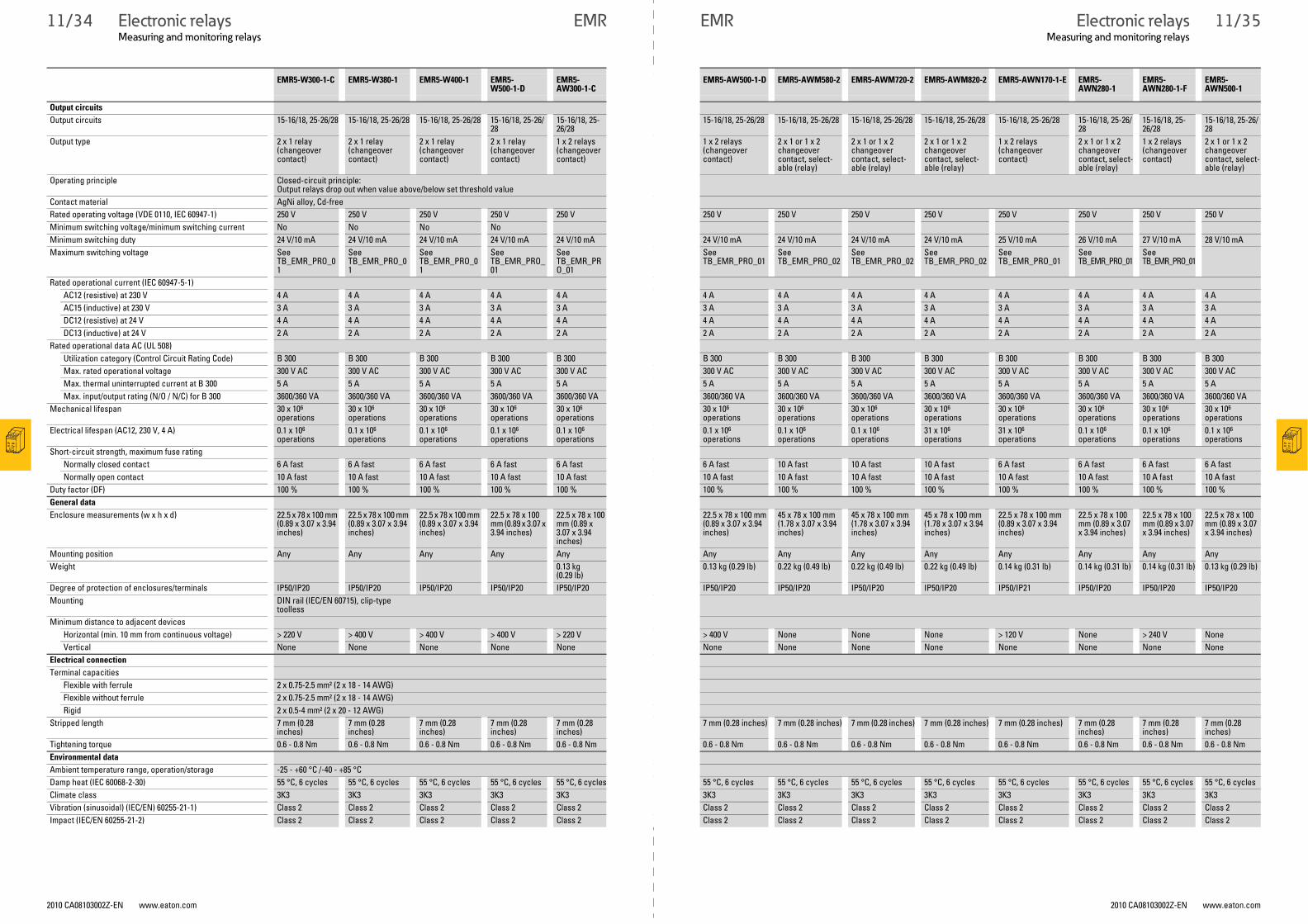
11/34 Electronic relaysMeasuring and monitoring relays
EMR
2010 CA08103002Z-EN www.eaton.com 2010 CA08103002Z-EN www.eaton.com
Electronic relaysMeasuring and monitoring relays
EMR
EMR5-W300-1-C EMR5-W380-1 EMR5-W400-1 EMR5-W500-1-D
EMR5-AW300-1-C
EMR5-AW500-1-D EMR5-AWM580-2 EMR5-AWM720-2 EMR5-AWM820-2 EMR5-AWN170-1-E EMR5-AWN280-1
EMR5-AWN280-1-F
EMR5-AWN500-1
Output circuits
Output circuits 15-16/18, 25-26/28 15-16/18, 25-26/28 15-16/18, 25-26/28 15-16/18, 25-26/28
15-16/18, 25-26/28
15-16/18, 25-26/28 15-16/18, 25-26/28 15-16/18, 25-26/28 15-16/18, 25-26/28 15-16/18, 25-26/28 15-16/18, 25-26/28
15-16/18, 25-26/28
15-16/18, 25-26/28
Output type 2 x 1 relay (changeover contact)
2 x 1 relay (changeover contact)
2 x 1 relay (changeover contact)
2 x 1 relay (changeover contact)
1 x 2 relays (changeover contact)
1 x 2 relays (changeover contact)
2 x 1 or 1 x 2 changeover contact, select-able (relay)
2 x 1 or 1 x 2 changeover contact, select-able (relay)
2 x 1 or 1 x 2 changeover contact, select-able (relay)
1 x 2 relays (changeover contact)
2 x 1 or 1 x 2 changeover contact, select-able (relay)
1 x 2 relays (changeover contact)
2 x 1 or 1 x 2 changeover contact, select-able (relay)
Operating principle Closed-circuit principle:Output relays drop out when value above/below set threshold value
Contact material AgNi alloy, Cd-freeRated operating voltage (VDE 0110, IEC 60947-1) 250 V 250 V 250 V 250 V 250 V 250 V 250 V 250 V 250 V 250 V 250 V 250 V 250 VMinimum switching voltage/minimum switching current No No No NoMinimum switching duty 24 V/10 mA 24 V/10 mA 24 V/10 mA 24 V/10 mA 24 V/10 mA 24 V/10 mA 24 V/10 mA 24 V/10 mA 24 V/10 mA 25 V/10 mA 26 V/10 mA 27 V/10 mA 28 V/10 mAMaximum switching voltage See
TB_EMR_PRO_01
See TB_EMR_PRO_01
See TB_EMR_PRO_01
See TB_EMR_PRO_01
See TB_EMR_PRO_01
See TB_EMR_PRO_01
See TB_EMR_PRO_02
See TB_EMR_PRO_02
See TB_EMR_PRO_02
See TB_EMR_PRO_01
See TB_EMR_PRO_01
See TB_EMR_PRO_01
Rated operational current (IEC 60947-5-1)AC12 (resistive) at 230 V 4 A 4 A 4 A 4 A 4 A 4 A 4 A 4 A 4 A 4 A 4 A 4 A 4 AAC15 (inductive) at 230 V 3 A 3 A 3 A 3 A 3 A 3 A 3 A 3 A 3 A 3 A 3 A 3 A 3 ADC12 (resistive) at 24 V 4 A 4 A 4 A 4 A 4 A 4 A 4 A 4 A 4 A 4 A 4 A 4 A 4 ADC13 (inductive) at 24 V 2 A 2 A 2 A 2 A 2 A 2 A 2 A 2 A 2 A 2 A 2 A 2 A 2 A
Rated operational data AC (UL 508)Utilization category (Control Circuit Rating Code) B 300 B 300 B 300 B 300 B 300 B 300 B 300 B 300 B 300 B 300 B 300 B 300 B 300Max. rated operational voltage 300 V AC 300 V AC 300 V AC 300 V AC 300 V AC 300 V AC 300 V AC 300 V AC 300 V AC 300 V AC 300 V AC 300 V AC 300 V ACMax. thermal uninterrupted current at B 300 5 A 5 A 5 A 5 A 5 A 5 A 5 A 5 A 5 A 5 A 5 A 5 A 5 AMax. input/output rating (N/O / N/C) for B 300 3600/360 VA 3600/360 VA 3600/360 VA 3600/360 VA 3600/360 VA 3600/360 VA 3600/360 VA 3600/360 VA 3600/360 VA 3600/360 VA 3600/360 VA 3600/360 VA 3600/360 VA
Mechanical lifespan 30 x 106 operations
30 x 106 operations
30 x 106 operations
30 x 106 operations
30 x 106 operations
30 x 106 operations
30 x 106 operations
30 x 106 operations
30 x 106 operations
30 x 106 operations
30 x 106 operations
30 x 106 operations
30 x 106 operations
Electrical lifespan (AC12, 230 V, 4 A) 0.1 x 10⁶ operations
0.1 x 10⁶ operations
0.1 x 10⁶ operations
0.1 x 10⁶ operations
0.1 x 10⁶ operations
0.1 x 10⁶ operations
0.1 x 10⁶ operations
0.1 x 10⁶ operations
31 x 106 operations
31 x 106 operations
0.1 x 10⁶ operations
0.1 x 10⁶ operations
0.1 x 10⁶ operations
Short-circuit strength, maximum fuse ratingNormally closed contact 6 A fast 6 A fast 6 A fast 6 A fast 6 A fast 6 A fast 10 A fast 10 A fast 10 A fast 6 A fast 6 A fast 6 A fast 6 A fastNormally open contact 10 A fast 10 A fast 10 A fast 10 A fast 10 A fast 10 A fast 10 A fast 10 A fast 10 A fast 10 A fast 10 A fast 10 A fast 10 A fast
Duty factor (DF) 100 % 100 % 100 % 100 % 100 % 100 % 100 % 100 % 100 % 100 % 100 % 100 % 100 %General data
Enclosure measurements (w x h x d) 22.5 x 78 x 100 mm (0.89 x 3.07 x 3.94 inches)
22.5 x 78 x 100 mm (0.89 x 3.07 x 3.94 inches)
22.5 x 78 x 100 mm (0.89 x 3.07 x 3.94 inches)
22.5 x 78 x 100 mm (0.89 x 3.07 x 3.94 inches)
22.5 x 78 x 100 mm (0.89 x 3.07 x 3.94 inches)
22.5 x 78 x 100 mm (0.89 x 3.07 x 3.94 inches)
45 x 78 x 100 mm (1.78 x 3.07 x 3.94 inches)
45 x 78 x 100 mm (1.78 x 3.07 x 3.94 inches)
45 x 78 x 100 mm (1.78 x 3.07 x 3.94 inches)
22.5 x 78 x 100 mm (0.89 x 3.07 x 3.94 inches)
22.5 x 78 x 100 mm (0.89 x 3.07 x 3.94 inches)
22.5 x 78 x 100 mm (0.89 x 3.07 x 3.94 inches)
22.5 x 78 x 100 mm (0.89 x 3.07 x 3.94 inches)
Mounting position Any Any Any Any Any Any Any Any Any Any Any Any AnyWeight 0.13 kg
(0.29 lb)0.13 kg (0.29 lb) 0.22 kg (0.49 lb) 0.22 kg (0.49 lb) 0.22 kg (0.49 lb) 0.14 kg (0.31 lb) 0.14 kg (0.31 lb) 0.14 kg (0.31 lb) 0.13 kg (0.29 lb)
Degree of protection of enclosures/terminals IP50/IP20 IP50/IP20 IP50/IP20 IP50/IP20 IP50/IP20 IP50/IP20 IP50/IP20 IP50/IP20 IP50/IP20 IP50/IP21 IP50/IP20 IP50/IP20 IP50/IP20Mounting DIN rail (IEC/EN 60715), clip-type
toollessMinimum distance to adjacent devices
Horizontal (min. 10 mm from continuous voltage) > 220 V > 400 V > 400 V > 400 V > 220 V > 400 V None None None > 120 V None > 240 V NoneVertical None None None None None None None None None None None None None
Electrical connection
Terminal capacities Flexible with ferrule 2 x 0.75-2.5 mm² (2 x 18 - 14 AWG)Flexible without ferrule 2 x 0.75-2.5 mm² (2 x 18 - 14 AWG)Rigid 2 x 0.5-4 mm² (2 x 20 - 12 AWG)
Stripped length 7 mm (0.28 inches)
7 mm (0.28 inches)
7 mm (0.28 inches)
7 mm (0.28 inches)
7 mm (0.28 inches)
7 mm (0.28 inches) 7 mm (0.28 inches) 7 mm (0.28 inches) 7 mm (0.28 inches) 7 mm (0.28 inches) 7 mm (0.28 inches)
7 mm (0.28 inches)
7 mm (0.28 inches)
Tightening torque 0.6 - 0.8 Nm 0.6 - 0.8 Nm 0.6 - 0.8 Nm 0.6 - 0.8 Nm 0.6 - 0.8 Nm 0.6 - 0.8 Nm 0.6 - 0.8 Nm 0.6 - 0.8 Nm 0.6 - 0.8 Nm 0.6 - 0.8 Nm 0.6 - 0.8 Nm 0.6 - 0.8 Nm 0.6 - 0.8 NmEnvironmental data
Ambient temperature range, operation/storage -25 - +60 °C /-40 - +85 °CDamp heat (IEC 60068-2-30) 55 °C, 6 cycles 55 °C, 6 cycles 55 °C, 6 cycles 55 °C, 6 cycles 55 °C, 6 cycles 55 °C, 6 cycles 55 °C, 6 cycles 55 °C, 6 cycles 55 °C, 6 cycles 55 °C, 6 cycles 55 °C, 6 cycles 55 °C, 6 cycles 55 °C, 6 cyclesClimate class 3K3 3K3 3K3 3K3 3K3 3K3 3K3 3K3 3K3 3K3 3K3 3K3 3K3Vibration (sinusoidal) (IEC/EN) 60255-21-1) Class 2 Class 2 Class 2 Class 2 Class 2 Class 2 Class 2 Class 2 Class 2 Class 2 Class 2 Class 2 Class 2Impact (IEC/EN 60255-21-2) Class 2 Class 2 Class 2 Class 2 Class 2 Class 2 Class 2 Class 2 Class 2 Class 2 Class 2 Class 2 Class 2
11/35
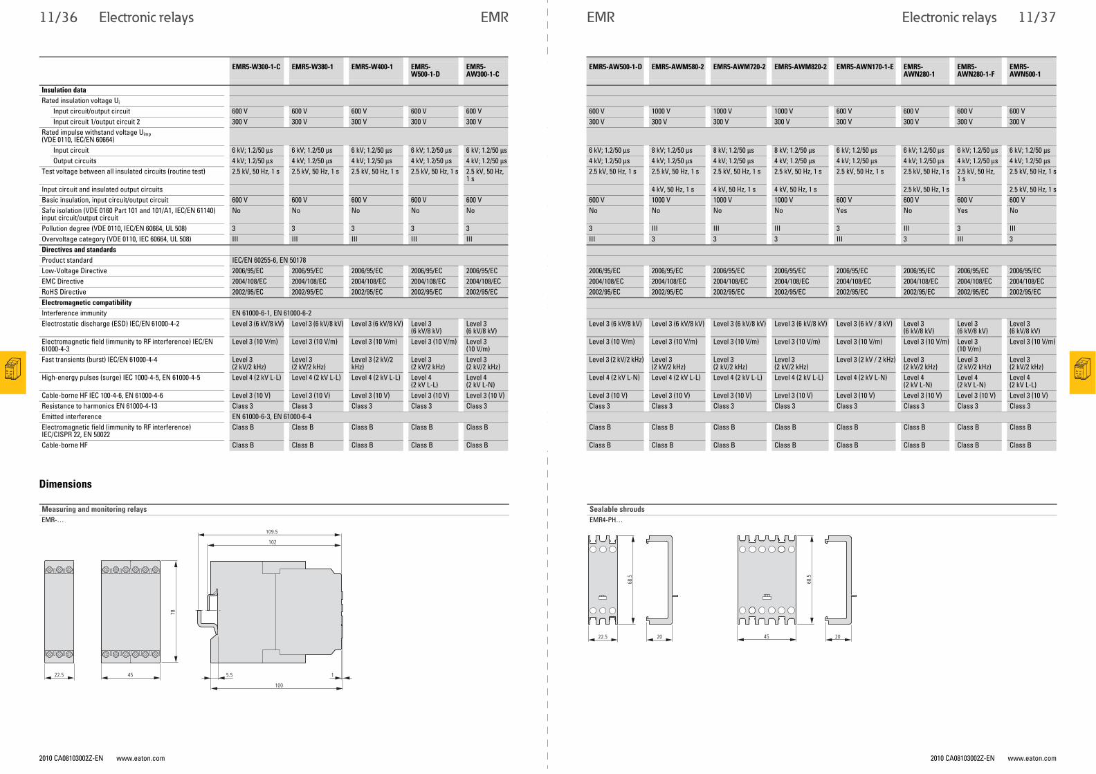
11/36 Electronic relays EMR
2010 CA08103002Z-EN www.eaton.com 2010 CA08103002Z-EN www.eaton.com
Electronic relaysEMR
Dimensions
EMR5-W300-1-C EMR5-W380-1 EMR5-W400-1 EMR5-W500-1-D
EMR5-AW300-1-C
EMR5-AW500-1-D EMR5-AWM580-2 EMR5-AWM720-2 EMR5-AWM820-2 EMR5-AWN170-1-E EMR5-AWN280-1
EMR5-AWN280-1-F
EMR5-AWN500-1
Insulation data
Rated insulation voltage Ui Input circuit/output circuit 600 V 600 V 600 V 600 V 600 V 600 V 1000 V 1000 V 1000 V 600 V 600 V 600 V 600 VInput circuit 1/output circuit 2 300 V 300 V 300 V 300 V 300 V 300 V 300 V 300 V 300 V 300 V 300 V 300 V 300 V
Rated impulse withstand voltage Uimp(VDE 0110, IEC/EN 60664)
Input circuit 6 kV; 1.2/50 μs 6 kV; 1.2/50 μs 6 kV; 1.2/50 μs 6 kV; 1.2/50 μs 6 kV; 1.2/50 μs 6 kV; 1.2/50 μs 8 kV; 1.2/50 μs 8 kV; 1.2/50 μs 8 kV; 1.2/50 μs 6 kV; 1.2/50 μs 6 kV; 1.2/50 μs 6 kV; 1.2/50 μs 6 kV; 1.2/50 μsOutput circuits 4 kV; 1.2/50 μs 4 kV; 1.2/50 μs 4 kV; 1.2/50 μs 4 kV; 1.2/50 μs 4 kV; 1.2/50 μs 4 kV; 1.2/50 μs 4 kV; 1.2/50 μs 4 kV; 1.2/50 μs 4 kV; 1.2/50 μs 4 kV; 1.2/50 μs 4 kV; 1.2/50 μs 4 kV; 1.2/50 μs 4 kV; 1.2/50 μs
Test voltage between all insulated circuits (routine test) 2.5 kV, 50 Hz, 1 s 2.5 kV, 50 Hz, 1 s 2.5 kV, 50 Hz, 1 s 2.5 kV, 50 Hz, 1 s 2.5 kV, 50 Hz, 1 s
2.5 kV, 50 Hz, 1 s 2.5 kV, 50 Hz, 1 s 2.5 kV, 50 Hz, 1 s 2.5 kV, 50 Hz, 1 s 2.5 kV, 50 Hz, 1 s 2.5 kV, 50 Hz, 1 s 2.5 kV, 50 Hz, 1 s
2.5 kV, 50 Hz, 1 s
Input circuit and insulated output circuits 4 kV, 50 Hz, 1 s 4 kV, 50 Hz, 1 s 4 kV, 50 Hz, 1 s 2.5 kV, 50 Hz, 1 s 2.5 kV, 50 Hz, 1 sBasic insulation, input circuit/output circuit 600 V 600 V 600 V 600 V 600 V 600 V 1000 V 1000 V 1000 V 600 V 600 V 600 V 600 VSafe isolation (VDE 0160 Part 101 and 101/A1, IEC/EN 61140) input circuit/output circuit
No No No No No No No No No Yes No Yes No
Pollution degree (VDE 0110, IEC/EN 60664, UL 508) 3 3 3 3 3 3 III III III 3 III 3 IIIOvervoltage category (VDE 0110, IEC 60664, UL 508) III III III III III III 3 3 3 III 3 III 3Directives and standards
Product standard IEC/EN 60255-6, EN 50178Low-Voltage Directive 2006/95/EC 2006/95/EC 2006/95/EC 2006/95/EC 2006/95/EC 2006/95/EC 2006/95/EC 2006/95/EC 2006/95/EC 2006/95/EC 2006/95/EC 2006/95/EC 2006/95/ECEMC Directive 2004/108/EC 2004/108/EC 2004/108/EC 2004/108/EC 2004/108/EC 2004/108/EC 2004/108/EC 2004/108/EC 2004/108/EC 2004/108/EC 2004/108/EC 2004/108/EC 2004/108/ECRoHS Directive 2002/95/EC 2002/95/EC 2002/95/EC 2002/95/EC 2002/95/EC 2002/95/EC 2002/95/EC 2002/95/EC 2002/95/EC 2002/95/EC 2002/95/EC 2002/95/EC 2002/95/ECElectromagnetic compatibility
Interference immunity EN 61000-6-1, EN 61000-6-2Electrostatic discharge (ESD) IEC/EN 61000-4-2 Level 3 (6 kV/8 kV) Level 3 (6 kV/8 kV) Level 3 (6 kV/8 kV) Level 3
(6 kV/8 kV)Level 3 (6 kV/8 kV)
Level 3 (6 kV/8 kV) Level 3 (6 kV/8 kV) Level 3 (6 kV/8 kV) Level 3 (6 kV/8 kV) Level 3 (6 kV / 8 kV) Level 3 (6 kV/8 kV)
Level 3 (6 kV/8 kV)
Level 3 (6 kV/8 kV)
Electromagnetic field (immunity to RF interference) IEC/EN 61000-4-3
Level 3 (10 V/m) Level 3 (10 V/m) Level 3 (10 V/m) Level 3 (10 V/m) Level 3 (10 V/m)
Level 3 (10 V/m) Level 3 (10 V/m) Level 3 (10 V/m) Level 3 (10 V/m) Level 3 (10 V/m) Level 3 (10 V/m) Level 3 (10 V/m)
Level 3 (10 V/m)
Fast transients (burst) IEC/EN 61000-4-4 Level 3 (2 kV/2 kHz)
Level 3 (2 kV/2 kHz)
Level 3 (2 kV/2 kHz)
Level 3 (2 kV/2 kHz)
Level 3 (2 kV/2 kHz)
Level 3 (2 kV/2 kHz) Level 3 (2 kV/2 kHz)
Level 3 (2 kV/2 kHz)
Level 3 (2 kV/2 kHz)
Level 3 (2 kV / 2 kHz) Level 3 (2 kV/2 kHz)
Level 3 (2 kV/2 kHz)
Level 3 (2 kV/2 kHz)
High-energy pulses (surge) IEC 1000-4-5, EN 61000-4-5 Level 4 (2 kV L-L) Level 4 (2 kV L-L) Level 4 (2 kV L-L) Level 4 (2 kV L-L)
Level 4 (2 kV L-N)
Level 4 (2 kV L-N) Level 4 (2 kV L-L) Level 4 (2 kV L-L) Level 4 (2 kV L-L) Level 4 (2 kV L-N) Level 4 (2 kV L-N)
Level 4 (2 kV L-N)
Level 4 (2 kV L-L)
Cable-borne HF IEC 100-4-6, EN 61000-4-6 Level 3 (10 V) Level 3 (10 V) Level 3 (10 V) Level 3 (10 V) Level 3 (10 V) Level 3 (10 V) Level 3 (10 V) Level 3 (10 V) Level 3 (10 V) Level 3 (10 V) Level 3 (10 V) Level 3 (10 V) Level 3 (10 V)Resistance to harmonics EN 61000-4-13 Class 3 Class 3 Class 3 Class 3 Class 3 Class 3 Class 3 Class 3 Class 3 Class 3 Class 3 Class 3 Class 3Emitted interference EN 61000-6-3, EN 61000-6-4Electromagnetic field (immunity to RF interference) IEC/CISPR 22, EN 50022
Class B Class B Class B Class B Class B Class B Class B Class B Class B Class B Class B Class B Class B
Cable-borne HF Class B Class B Class B Class B Class B Class B Class B Class B Class B Class B Class B Class B Class B
Measuring and monitoring relays
EMR-…109.5
102
78
5.5 1
100
45 22.5
Sealable shrouds
EMR4-PH…
22.5 20 68
.5
45
68.5
20
11/37