Embed Size (px)
Citation preview
Dr Alan WilsonEngineering Measurement
Industry and Innovation DivisionNational Physical Laboratory
Dimensional measurementsof waveguide apertures used
above 100 GHz
Presentation outline31st ANAMET meeting,2nd Apr 2009
Dimensional measurements of waveguideapertures used above 100 GHz
EM waveguide calibration standards – descriptionCoordinate Measuring Machines – The Zeiss F25Waveguide standard measurements on the F25Future measurementsQuestions
EM waveguide calibration standards
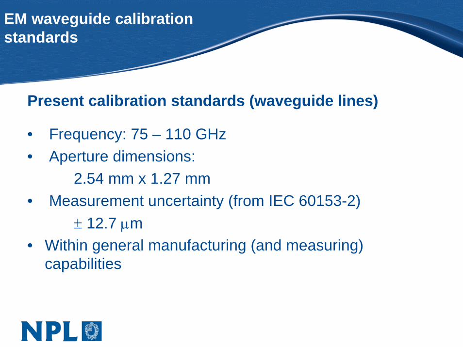
Present calibration standards (waveguide lines)
• Frequency: 75 – 110 GHz• Aperture dimensions:
2.54 mm x 1.27 mm• Measurement uncertainty (from IEC 60153-2)
± 12.7 μm• Within general manufacturing (and measuring)
capabilities
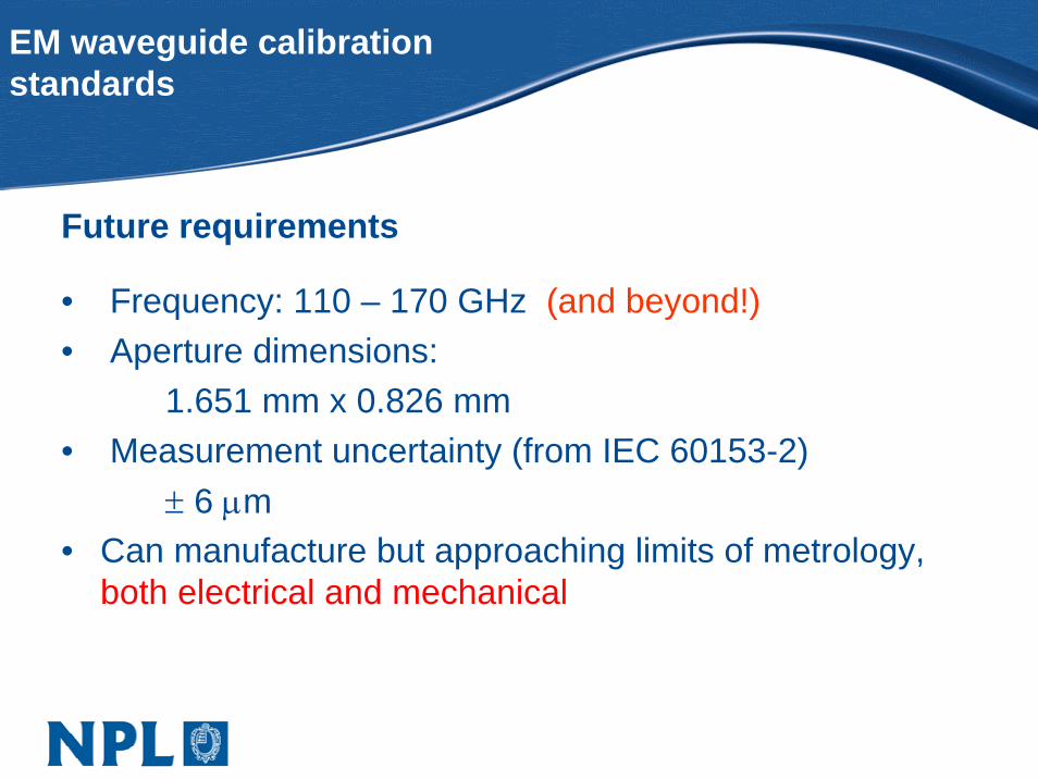
Future requirements
• Frequency: 110 – 170 GHz (and beyond!)• Aperture dimensions:
1.651 mm x 0.826 mm• Measurement uncertainty (from IEC 60153-2)
± 6 μm• Can manufacture but approaching limits of metrology,
both electrical and mechanical
EM waveguide calibration standards
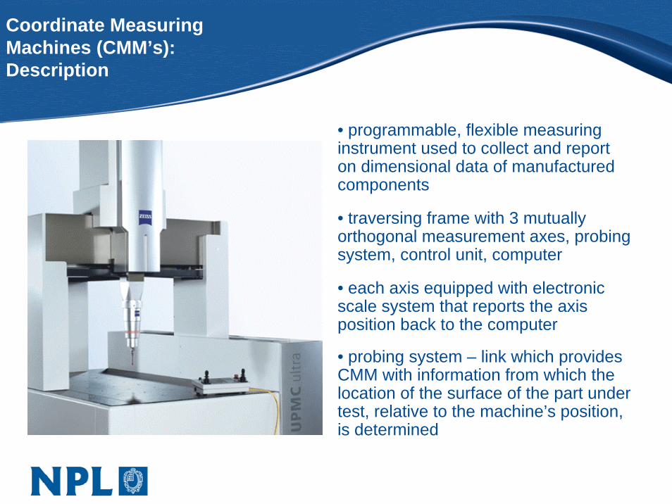
Coordinate MeasuringMachines (CMM’s):Description
• programmable, flexible measuring instrument used to collect and report on dimensional data of manufactured components
• traversing frame with 3 mutually orthogonal measurement axes, probing system, control unit, computer
• each axis equipped with electronic scale system that reports the axis position back to the computer
• probing system – link which provides CMM with information from which the location of the surface of the part under test, relative to the machine’s position, is determined
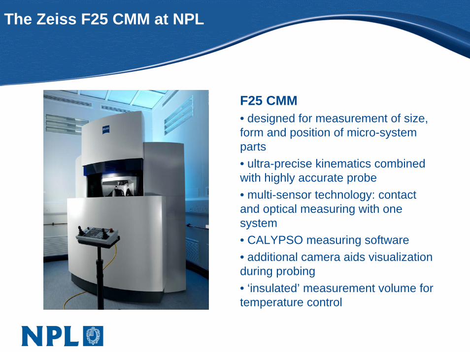
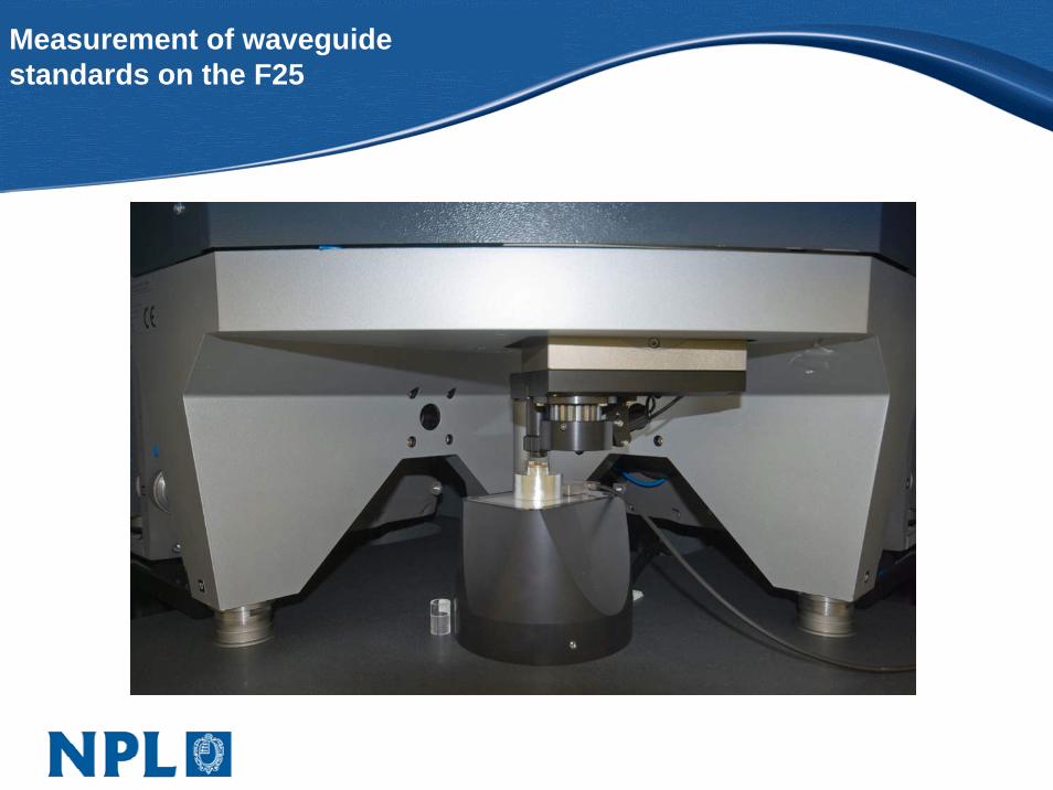
The Zeiss F25 CMM at NPL
F25 CMM• designed for measurement of size, form and position of micro-system parts• ultra-precise kinematics combined with highly accurate probe• multi-sensor technology: contact and optical measuring with one system• CALYPSO measuring software • additional camera aids visualization during probing• ‘insulated’ measurement volume for temperature control
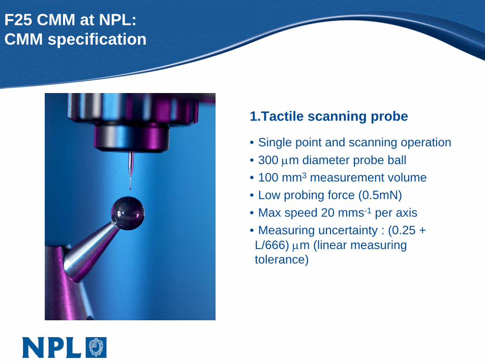
F25 CMM at NPL:CMM specification
1.Tactile scanning probe
• Single point and scanning operation• 300 μm diameter probe ball• 100 mm3 measurement volume• Low probing force (0.5mN)• Max speed 20 mms-1 per axis• Measuring uncertainty : (0.25 + L/666) μm (linear measuring tolerance)
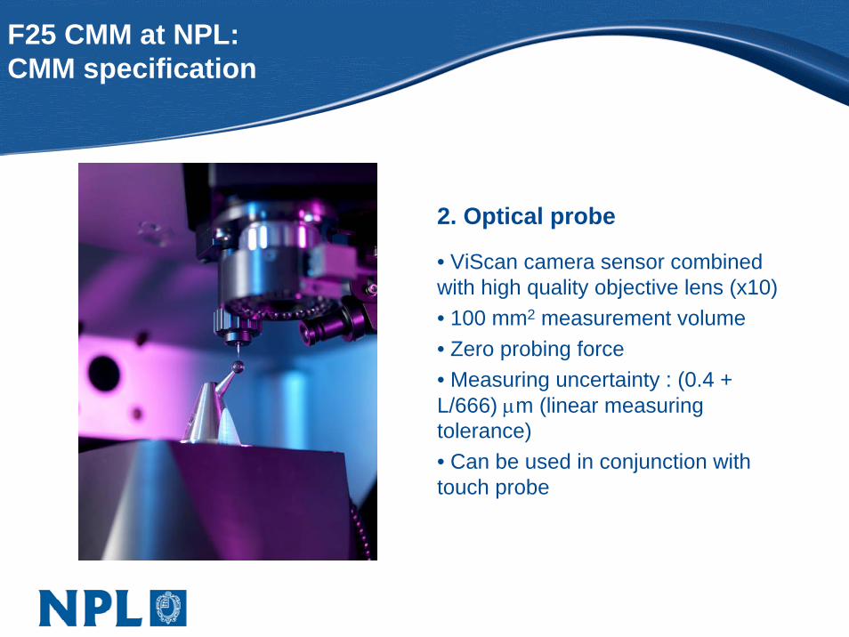
F25 CMM at NPL:CMM specification
2. Optical probe
• ViScan camera sensor combined with high quality objective lens (x10)• 100 mm2 measurement volume• Zero probing force• Measuring uncertainty : (0.4 + L/666) μm (linear measuring tolerance) • Can be used in conjunction with touch probe
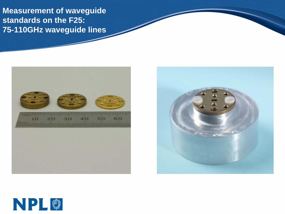
Measurement of waveguidestandards on the F25:75-110GHz waveguide lines
Measurement of waveguidestandards on the F25
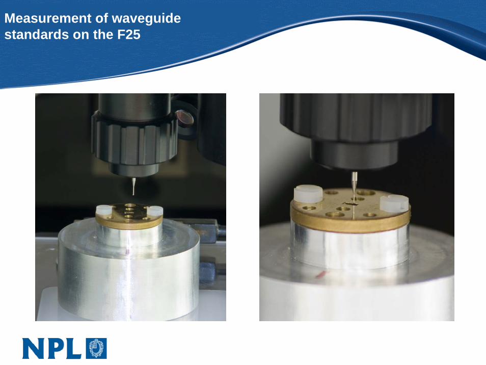
Measurement of waveguidestandards on the F25

Measurement of waveguidestandards on the F25:CAD model
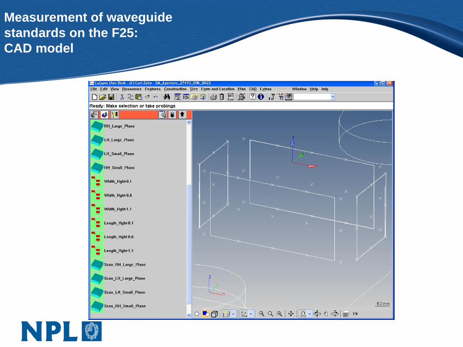
Measurement of waveguidestandards on the F25:CAD model
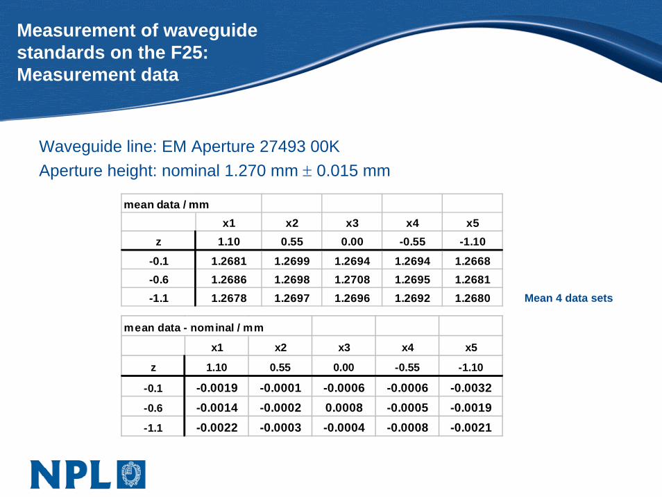
Measurement of waveguidestandards on the F25:Measurement data
Waveguide line: EM Aperture 27493 00KAperture height: nominal 1.270 mm ± 0.015 mm
mean data / mmx1 x2 x3 x4 x5
z 1.10 0.55 0.00 -0.55 -1.10
-0.1 1.2681 1.2699 1.2694 1.2694 1.2668-0.6 1.2686 1.2698 1.2708 1.2695 1.2681-1.1 1.2678 1.2697 1.2696 1.2692 1.2680
mean data - nominal / mm
x1 x2 x3 x4 x5
z 1.10 0.55 0.00 -0.55 -1.10
-0.1 -0.0019 -0.0001 -0.0006 -0.0006 -0.0032-0.6 -0.0014 -0.0002 0.0008 -0.0005 -0.0019-1.1 -0.0022 -0.0003 -0.0004 -0.0008 -0.0021
Mean 4 data sets
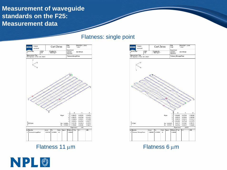
Measurement of waveguidestandards on the F25:Measurement data
Flatness: single point
Flatness 11 μm Flatness 6 μm
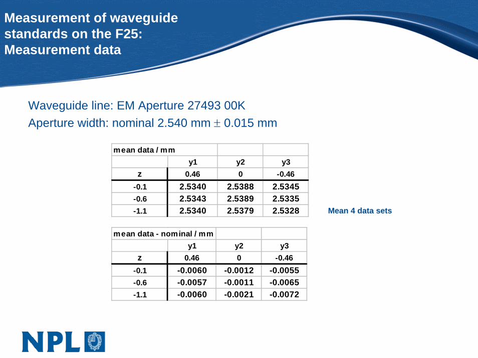
Measurement of waveguidestandards on the F25:Measurement data
Waveguide line: EM Aperture 27493 00KAperture width: nominal 2.540 mm ± 0.015 mm
mean data / mmy1 y2 y3
z 0.46 0 -0.46-0.1 2.5340 2.5388 2.5345-0.6 2.5343 2.5389 2.5335-1.1 2.5340 2.5379 2.5328
mean data - nominal / mmy1 y2 y3
z 0.46 0 -0.46-0.1 -0.0060 -0.0012 -0.0055-0.6 -0.0057 -0.0011 -0.0065-1.1 -0.0060 -0.0021 -0.0072
Mean 4 data sets

Measurement of waveguidestandards on the F25:Measurement data
Flatness: scan
Flatness 7 μm Flatness 4 μm
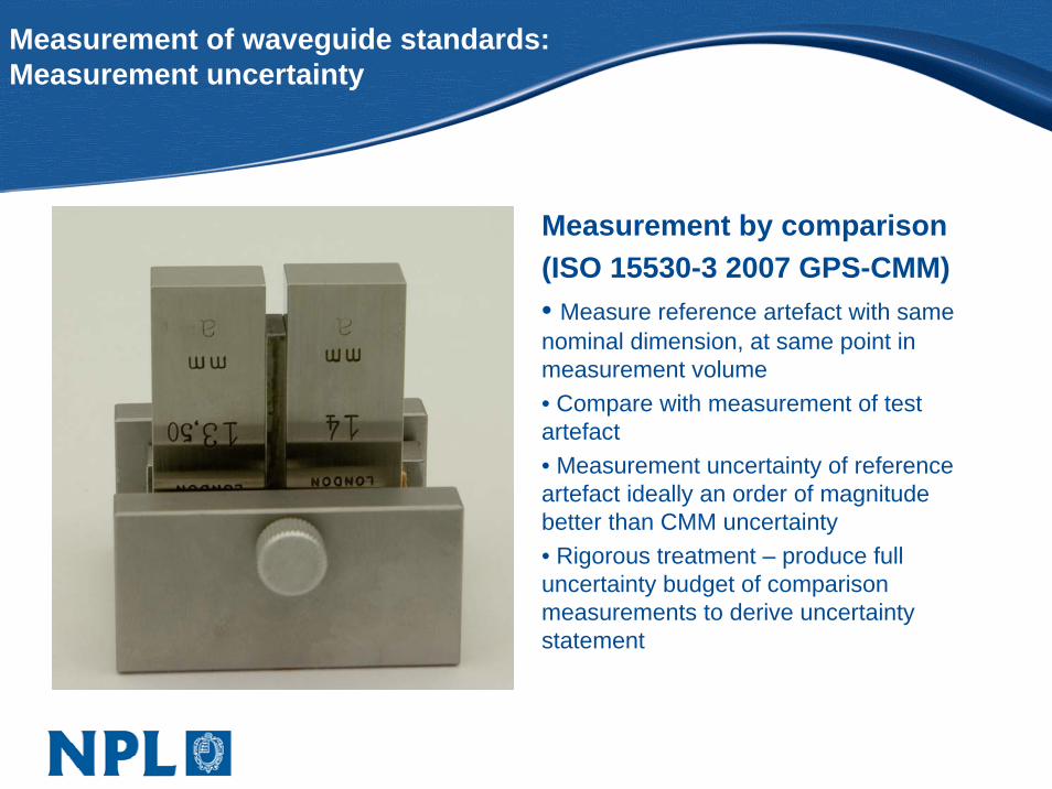
Measurement of waveguide standards: Measurement uncertainty
Measurement by comparison(ISO 15530-3 2007 GPS-CMM)• Measure reference artefact with same nominal dimension, at same point in measurement volume• Compare with measurement of test artefact• Measurement uncertainty of reference artefact ideally an order of magnitude better than CMM uncertainty• Rigorous treatment – produce full uncertainty budget of comparison measurements to derive uncertainty statement
10 mm
Measurement of waveguide standards: Measurement uncertainty
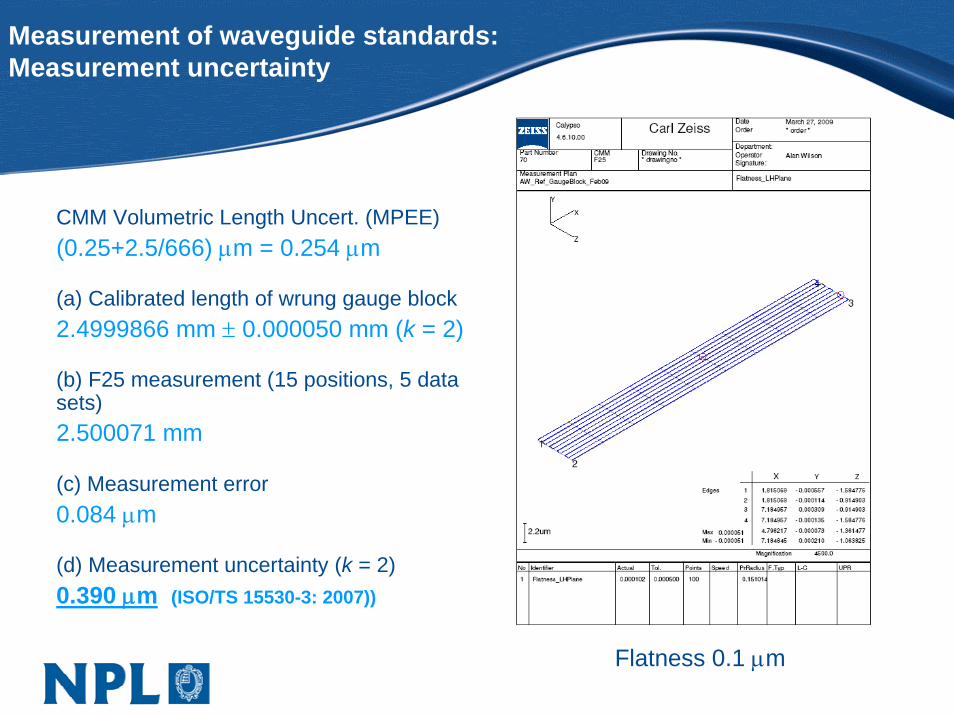
CMM Volumetric Length Uncert. (MPEE)(0.25+2.5/666) μm = 0.254 μm
(a) Calibrated length of wrung gauge block2.4999866 mm ± 0.000050 mm (k = 2)
(b) F25 measurement (15 positions, 5 data sets)2.500071 mm
(c) Measurement error0.084 μm
(d) Measurement uncertainty (k = 2)0.390 μm (ISO/TS 15530-3: 2007))
Flatness 0.1 μm
Measurement of waveguidestandards on the F25:110 - 170GHz standards
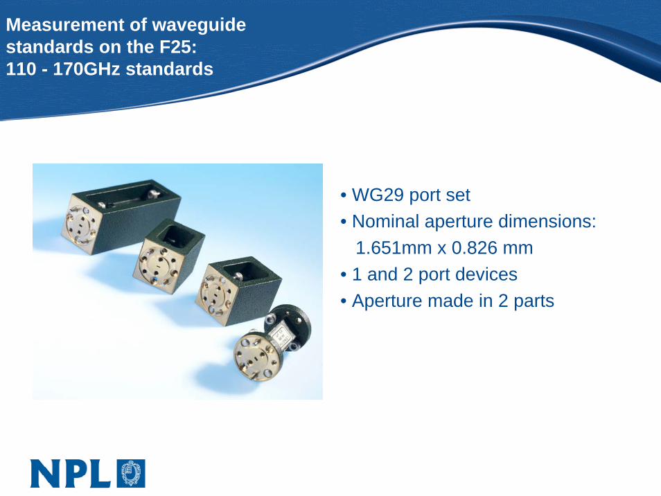
• WG29 port set• Nominal aperture dimensions:
1.651mm x 0.826 mm• 1 and 2 port devices• Aperture made in 2 parts
Measurement of 110 – 170GHzstandards on the F25:Measurement data
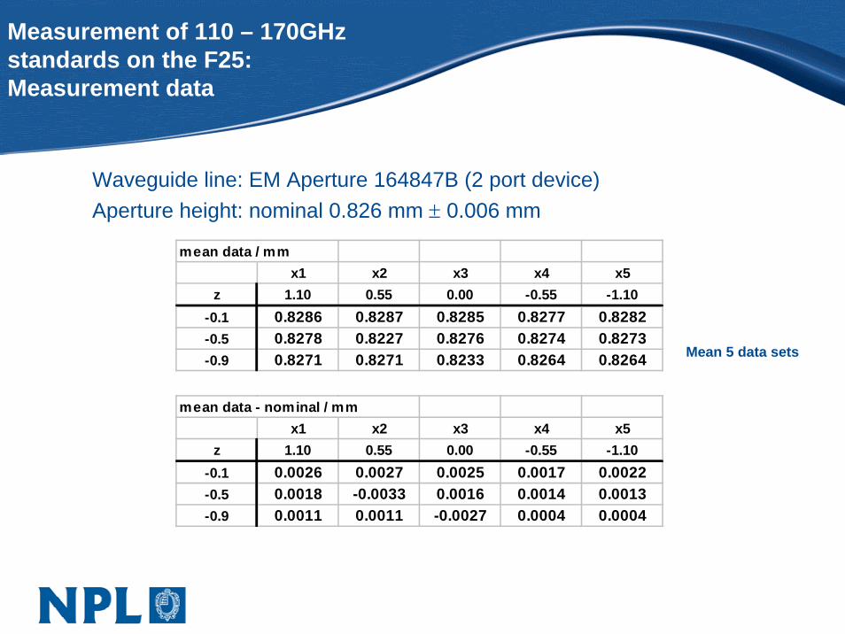
Waveguide line: EM Aperture 164847B (2 port device)Aperture height: nominal 0.826 mm ± 0.006 mm
mean data / mmx1 x2 x3 x4 x5
z 1.10 0.55 0.00 -0.55 -1.10-0.1 0.8286 0.8287 0.8285 0.8277 0.8282-0.5 0.8278 0.8227 0.8276 0.8274 0.8273-0.9 0.8271 0.8271 0.8233 0.8264 0.8264
mean data - nominal / mmx1 x2 x3 x4 x5
z 1.10 0.55 0.00 -0.55 -1.10-0.1 0.0026 0.0027 0.0025 0.0017 0.0022-0.5 0.0018 -0.0033 0.0016 0.0014 0.0013-0.9 0.0011 0.0011 -0.0027 0.0004 0.0004
Mean 5 data sets
Measurement of 110 – 170GHzstandards on the F25:Measurement data
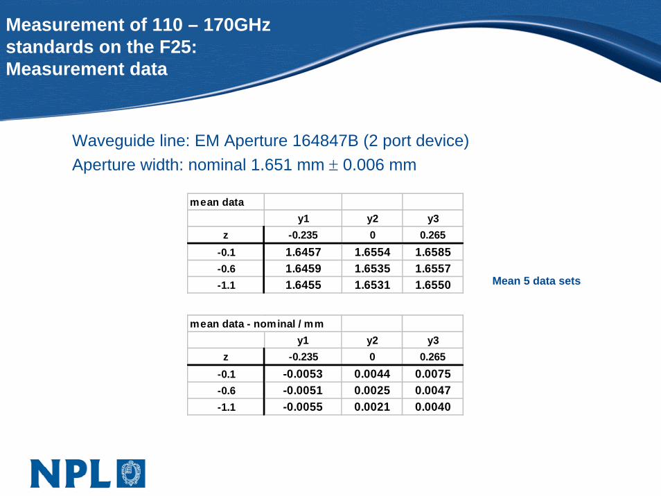
Waveguide line: EM Aperture 164847B (2 port device)Aperture width: nominal 1.651 mm ± 0.006 mm
mean datay1 y2 y3
z -0.235 0 0.265-0.1 1.6457 1.6554 1.6585-0.6 1.6459 1.6535 1.6557-1.1 1.6455 1.6531 1.6550
mean data - nominal / mmy1 y2 y3
z -0.235 0 0.265-0.1 -0.0053 0.0044 0.0075-0.6 -0.0051 0.0025 0.0047-1.1 -0.0055 0.0021 0.0040
Mean 5 data sets
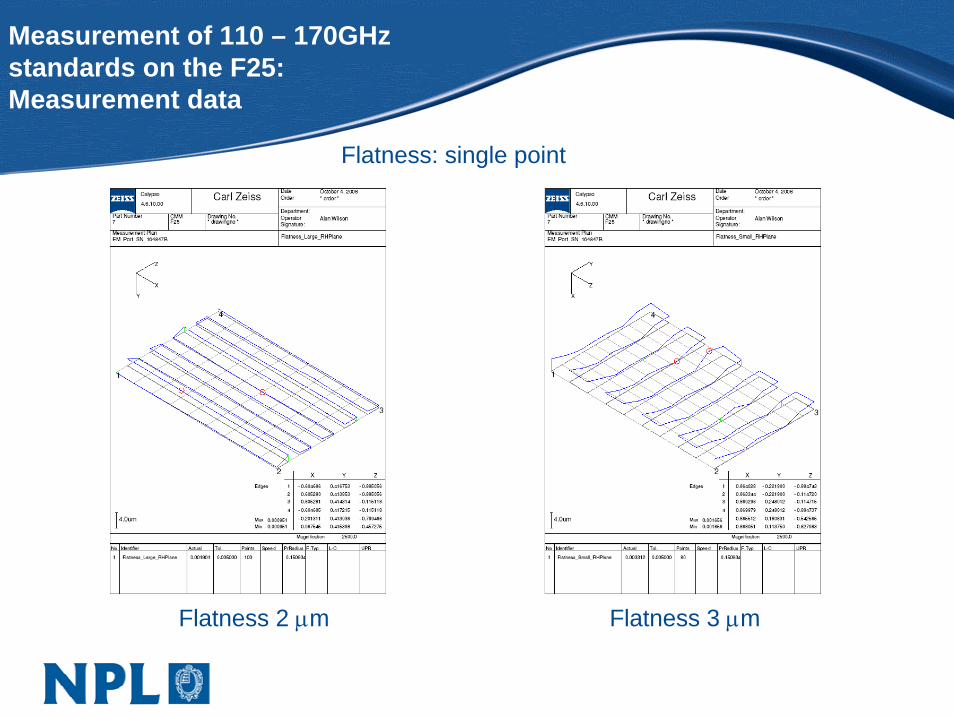
Measurement of 110 – 170GHzstandards on the F25:Measurement data
Flatness: single point
Flatness 2 μm Flatness 3 μm
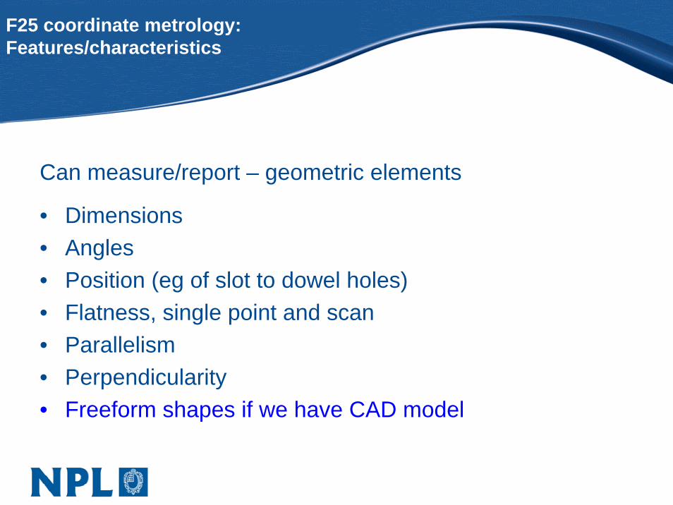
F25 coordinate metrology:Features/characteristics
Can measure/report – geometric elements
• Dimensions• Angles• Position (eg of slot to dowel holes)• Flatness, single point and scan• Parallelism• Perpendicularity• Freeform shapes if we have CAD model
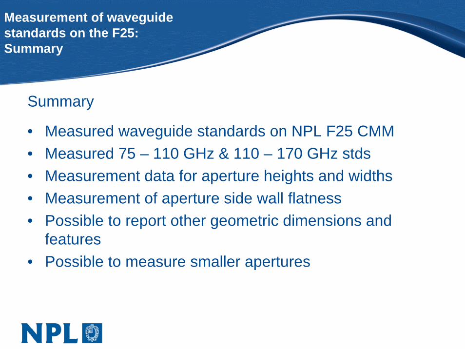
Measurement of waveguidestandards on the F25:Summary
Summary
• Measured waveguide standards on NPL F25 CMM• Measured 75 – 110 GHz & 110 – 170 GHz stds• Measurement data for aperture heights and widths• Measurement of aperture side wall flatness• Possible to report other geometric dimensions and
features• Possible to measure smaller apertures
Acknowledgements
Thanks to:N. Ridler, M. Salter (NPL)T. Gregory & N. Nazoa (LA Techniques Ltd.)Dr. A. Lewis (NPL)A. Hanson (NPL) for video

Thank you