Embed Size (px)
Citation preview

RT865BXL2
Dimensions
Turning Radius . . . . . . . . . . . .
22’ 6” (6858 mm)
Front Axle Load . . . . . . . . . . . 52,239 lbs. (23 695 kg)
Rear Axle Load. . . . . . . . . . . . 50,601 lbs. (22 953 kg)
Gross Vehicle Weight . . . . . . . 102,840 lbs. (46 648 kg)
24' (7315)
10' 10-1/2" (3315)
TRACK 8' 4-1/2" (2553)
TAILSWING 14'
(4280)
24' 11" (7595)
26' 6-1/2" (8090)
1' 3" (381)
1' 8" (508)1' 8"
(508)
2' 1" (635)
1' 2-3/8" (365)
14' 11" (4546)
13' 1/2" (3975)
3' 7" (1310)
7' 3" (2210)
13' 4" (4064)
12' 3" (3734)
12' 8" (3861)
28' 3" (8611)
CL
21°
Note: ( ) Reference dimensions in mm
RT865BXL3
0
0°10
20
30
40
50
60
70
80
90
100
110
120
130
140
150
160
170
180
190
200
210
220
230
74
61
55
35
87
99
112
125
138
31
56
45°
1.5°
10
10°
20
20°
30
30°
40
40°
50
50°
60
60°
70
70°
8090
100110
120130
140150
160170
180
360°35-138 ft. (10.6-42 m)
31-56 ft. (9.4-17 m)
9'-7"5'-6" 7'-0"
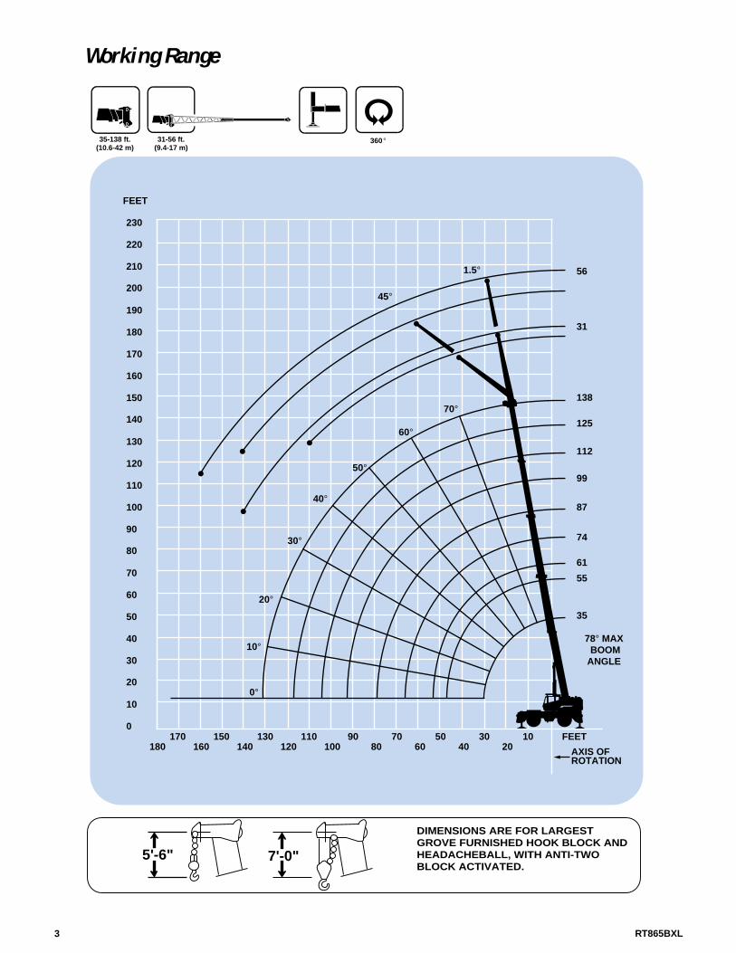
DIMENSIONS ARE FOR LARGEST GROVE FURNISHED HOOK BLOCK AND HEADACHEBALL, WITH ANTI-TWO BLOCK ACTIVATED.
FEET
AXIS OF ROTATION
78° MAX BOOM ANGLE
FEET
Working Range

RT865BXL
Superstructure specifications
4
Boom
35 ft. - 138 ft. (10.6 m - 42 m) five-section full powerboom.Maximum Tip Height: 148 ft. (45.1 m).
Folding Lattice Extension31 ft. - 56 ft. (9.4 m - 17 m) bi-fold lattice swingawayextension offsettable at 1.5° or 45°.Stows alongsidebase section.Maximum Tip Height: 204 ft. (62.1 m).
*Optional Lattice Extension31 ft. (9.4 m) lattice swingaway extension. Offsettable at1.5° or 45°. Stows alongside base boom section.Maximum Tip Height: 179 ft. (54.5 m).
Boom NoseFive Nylatron sheaves mounted on heavy duty taperedroller bearings with removable pin-type rope guards.Quick reeving type boom nose. A removable auxiliaryboom nose with removable pin type rope guard.
Boom Elevation One double acting hydraulic cylinder with integral holding valve provides elevation from -3° to 78°.
Load Moment & Anti-Two Block SystemStandard load moment and anti-two block system with audio-visual warning and control lever lockout. These systems provide electronic display of boom angle,length, radius, tip height, relative load moment,maximum permissible load and load indication andwarning of impending two-block condition.
CabFull vision, all galvanealed steel fabricated withacoustical lining and tinted safety glass throughout.Deluxe seat with armrest mounted hydraulic single axiscontrollers. Dash panel incorporates gauges for engine functions. Other standard features include: skylightscreen, hydraulic oil cab heater/defroster, telescopingtilt wheel, sliding side and rear windows, opening skylight, electric windshield wash-wipe, electric skylightwipers, fire extinguisher, seat belt, ashtray and levelindicator.
Swing Planetary swing with foot applied multi-disc wet brake.Spring applied, hydraulically released swing brake, 360°positive swing lock (N.Y.C. style) and 1 position,mechanical house lock, operated from cab.Maximum speed: 2.0 RPM.
Counterweight Removable: 8,500 lbs. (3855 kg).2,155 lbs. (977 kg) slab I.P.O. auxiliary hoist.
Hydraulic System Seven main pumps with a combined capacity 199.2GPM (754 LPM). Maximum operating pressure 3500 psi(241 bar). Three individual valve banks. Return linetype filter with full flow by-pass protection and service indicator. Replaceable cartridge with micron filtrationrating of 5/12/16. 200 gallons (757 L) reservoir. Remotemounted oil cooler with thermostatically controlledhydraulic motor driven fan/air to oil. System pressuretest panel with quick release type fittings for each circuit.
Hoist SpecificationsMain and Auxiliary Hoist Planetary reduction with automatic spring appliedmulti-disc brake. Electronic hoist drum rotation indicator, hoist drum cable followers and wire rope.
Maximum Single Line Pull: 16,969 lbs.(7697 kg)
Maximum Single Line Speed: 385 FPM(117 m/min)
Maximum Permissible 12,920 lbs.Line Pull: (5860 kg)
Rope Diameter: 3/4 in.(19 mm)
Rope Length: 620 ft.(190 m)
Maximum Rope Stowage: 1,163 ft.(354.5 m)
Carrier specifications
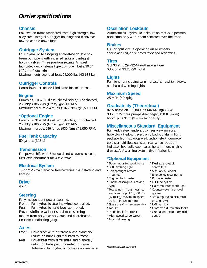
ChassisBox section frame fabricated from high-strength, lowalloy steel. Integral outrigger housings and front/reartowing and tie down lugs.
Outrigger SystemFour hydraulic telescoping single-stage double boxbeam outriggers with inverted jacks and integral holding valves. Three position setting. All steel fabricated quick release type outrigger floats, 30.5"(77.5 mm) diameter.Maximum outrigger pad load: 94,000 lbs. (42 638 kg).
Outrigger ControlsControls and crane level indicator located in cab.
EngineCummins 6CTA 8.3 diesel, six cylinders, turbocharged,250 bhp (186 kW) (Gross) @ 2,200 RPM.Maximum torque: 794 ft. lbs. (1077 Nm) @ 1,500 RPM.
*Optional EngineCaterpillar 3126TA diesel, six cylinders, turbocharged,250 bhp (186 kW) (Gross) @ 2,500 RPM.Maximum torque: 686 ft. lbs. (930 Nm) @ 1,650 RPM.
Fuel Tank Capacity80 gallons (303 L)
TransmissionFull powershift with 6 forward and 6 reverse speeds.Rear axle disconnect for 4 x 2 travel.
Electrical SystemTwo 12 V - maintenance free batteries. 24 V starting andlighting.
Drive4 x 4.
SteeringFully independent power steering:Front: Full hydraulic steering wheel controlled.Rear: Full hydraulic hand lever controlled.Provides infinite variations of 4 main steering modes: front only, rear only, crab and coordinated.Rear steer indicating gauge.
AxlesFront: Drive steer with differential and planetary
reduction hubs rigid mounted to frame.Rear: Drive/steer with differential and planetary
reduction hubs pivot mounted to frame.Automatic full hydraulic lockouts on rear axle.
Oscillation Lockouts Automatic full hydraulic lockouts on rear axle permitsoscillation only with boom centered over the front.
BrakesFull air split circuit operating on all wheels.Spring-applied, air released front and rear axles.
TiresStd. 33.25 x 29 - 32PR earthmover type.*Optional: 33.25R29 radial.
LightsFull lighting including turn indicators, head, tail, brake,and hazard warning lights.
Maximum Speed25 MPH (40 kph).
Gradeability (Theoretical)87% based on 102,840 lbs. (46 648 kg) GVW.33.25 x 29 tires, pumps disengaged, 138 ft. (42 m)boom, plus 31 ft. (9.4 m) swingaway.
Miscellaneous Standard EquipmentFull width steel fenders, dual rear view mirrors,hookblock tiedown, electronic back-up alarm, lightpackage, front stowage well, tachometer/hourmeter,cold start aid (less canister), rear wheel position indicator, hydraulic cab heater, hoist mirrors, engine distress A/V warning system, tire inflation kit.
*Optional Equipment
*Denotes optional equipment
5RT865BXL
* Boom mounted worklights* 360° flashing light* Cab spotlight remote
mounted* Engine block heater* Hookblocks (quick reeving
type)* Tow winch - front mounted
-- maximum pull 15,000 lbs.(6804 kg); maximum speed 92 ft./min. (28 m/min)
* Spare tire & wheel assembly* Tool kit* Pintle hook front/rear* High Speed Glide system* Air conditioning
* Dual axis joystickcontrollers
* Auxiliary oil cooler* Emergency steer pump* Propane heater* T/T lube system* Hoist mounted work light* Counterweight removal
system* 3rd wrap indicators (main
or auxiliary)* LMI light bar* Cross axle differential locks* Oscillation lockout override
control
RT865BXL6
THIS CHART IS ONLY A GUIDE AND SHOULD NOT BE USED TO OPERATE THE CRANE. The individual crane's load chart, operating instructions and other instructional plates must be read and understood prior to operating the crane.
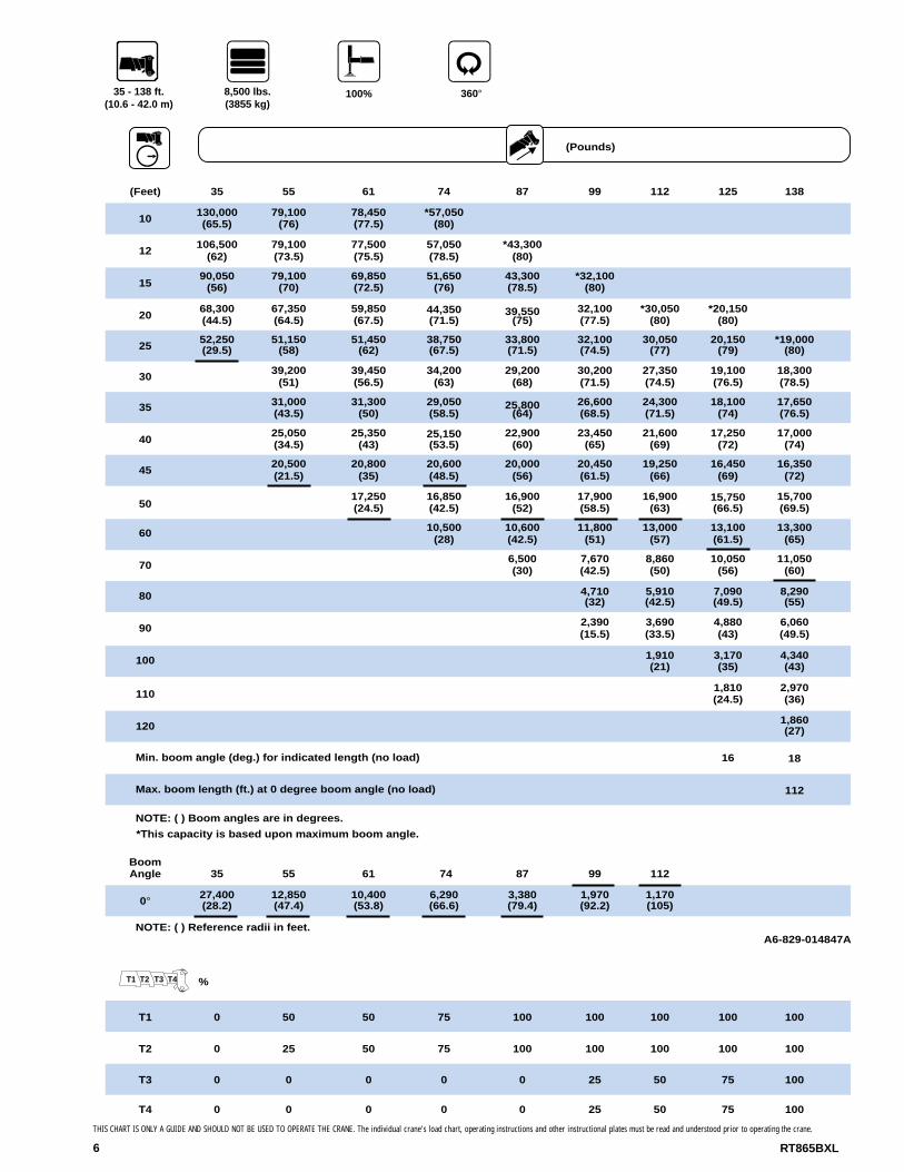
35 - 138 ft. (10.6 - 42.0 m)
360°
(Pounds)
100%
(Feet) 35 55 61 74 87 99 112 125 138
BoomAngle 35 55 61 74 87 99 112
0°
NOTE: ( ) Reference radii in feet.
50 50 75 100 100 100 100 100
25 50 75 100100 100 100 1000
0
0 0 0 25 50 75 1000 0
0 0 0 25 50 75 1000 0
Min. boom angle (deg.) for indicated length (no load)
Max. boom length (ft.) at 0 degree boom angle (no load)
NOTE: ( ) Boom angles are in degrees.
*This capacity is based upon maximum boom angle.
T1
T2
T3
T4
10130,000(65.5)
79,100(76)
78,450(77.5)
*57,050(80)
12106,500
(62)79,100(73.5)
77,500(75.5)
57,050(78.5)
*43,300(80)
1590,050
(56)79,100
(70)69,850(72.5)
51,650(76)
43,300(78.5)
*32,100(80)
2068,300(44.5)
67,350(64.5)
59,850(67.5)
44,350(71.5)
39,550(75)
32,100(77.5)
*30,050(80)
*20,150(80)
2552,250(29.5)
51,150(58)
51,450(62)
38,750(67.5)
33,800(71.5)
32,100(74.5)
30,050(77)
20,150(79)
*19,000(80)
3039,200
(51)39,450(56.5)
34,200(63)
29,200(68)
30,200(71.5)
27,350(74.5)
19,100(76.5)
18,300(78.5)
35 31,000(43.5)
31,300(50)
29,050(58.5)
25,800(64)
26,600(68.5)
24,300(71.5)
18,100(74)
17,650(76.5)
4025,050(34.5)
25,350(43)
25,150(53.5)
22,900(60)
23,450(65)
21,600(69)
17,250(72)
17,000(74)
4520,500(21.5)
20,800(35)
20,600(48.5)
20,000(56)
20,450(61.5)
19,250(66)
16,450(69)
16,350(72)
5017,250(24.5)
16,850(42.5)
16,900(52)
17,900(58.5)
16,900(63)
15,750(66.5)
15,700(69.5)
60 10,500(28)
10,600(42.5)
11,800(51)
13,000(57)
13,100(61.5)
13,300(65)
706,500(30)
7,670(42.5)
8,860(50)
10,050(56)
11,050(60)
80 4,710(32)
5,910(42.5)
7,090(49.5)
8,290(55)
90 2,390(15.5)
3,690(33.5)
4,880(43)
6,060(49.5)
100 1,910(21)
3,170(35)
4,340(43)
1101,810(24.5)
2,970(36)
1201,860(27)
16 18
112
27,400(28.2)
12,850(47.4)
10,400(53.8)
6,290(66.6)
3,380(79.4)
1,970(92.2)
1,170(105)
A6-829-014847A
8,500 lbs. (3855 kg)
T2T1 T3 T4 %
7RT865BXL
THIS CHART IS ONLY A GUIDE AND SHOULD NOT BE USED TO OPERATE THE CRANE. The individual crane's load chart, operating instructions and other instructional plates must be read and understood prior to operating the crane.
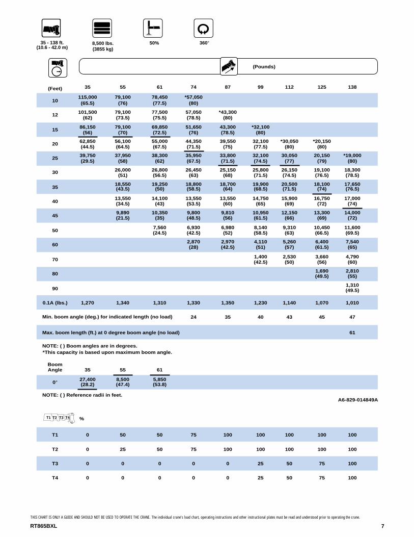
35 - 138 ft. (10.6 - 42.0 m)
360°8,500 lbs. (3855 kg)
50%
(Feet) 35 55 61 74 87 99 112 125 138
BoomAngle 35 55 61
0°
NOTE: ( ) Reference radii in feet.
50 50 75 100 100 100 100 100
25 50 75 100100 100 100 1000
0
0 0 0 25 50 75 1000 0
0 0 0 25 50 75 1000 0
Min. boom angle (deg.) for indicated length (no load)
Max. boom length (ft.) at 0 degree boom angle (no load)
NOTE: ( ) Boom angles are in degrees.*This capacity is based upon maximum boom angle.
T1
T2
T3
T4
27,400(28.2)
8,500(47.4)
5,850(53.8)
10115,000(65.5)
79,100(76)
78,450(77.5)
*57,050(80)
12 101,500(62)
79,100(73.5)
77,500(75.5)
57,050(78.5)
*43,300(80)
15 86,150(56)
79,100(70)
69,850(72.5)
51,650(76)
43,300(78.5)
*32,100(80)
20 62,850(44.5)
56,100(64.5)
55,000(67.5)
44,350(71.5)
39,550(75)
32,100(77.5)
*30,050(80)
*20,150(80)
25 39,750(29.5)
37,950(58)
38,300(62)
35,950(67.5)
33,800(71.5)
32,100(74.5)
30,050(77)
20,150(79)
*19,000(80)
30 26,000(51)
26,800(56.5)
26,450(63)
25,150(68)
25,800(71.5)
26,150(74.5)
19,100(76.5)
18,300(78.5)
3518,550(43.5)
19,250(50)
18,800(58.5)
18,700(64)
19,900(68.5)
20,500(71.5)
18,100(74)
17,650(76.5)
4013,550(34.5)
14,100(43)
13,550(53.5)
13,550(60)
14,750(65)
15,900(69)
16,750(72)
17,000(74)
459,890(21.5)
10,350(35)
9,800(48.5)
9,810(56)
10,950(61.5)
12,150(66)
13,300(69)
14,000(72)
507,560(24.5)
6,930(42.5)
6,980(52)
8,140(58.5)
9,310(63)
10,450(66.5)
11,600(69.5)
602,870(28)
2,970(42.5)
4,110(51)
5,260(57)
6,400(61.5)
7,540(65)
701,400(42.5)
2,530(50)
3,660(56)
4,790(60)
80 1,690(49.5)
2,810(55)
901,310(49.5)
0.1A (lbs.) 1,270 1,340 1,310 1,330 1,350 1,230 1,140 1,070 1,010
24 35 40 43 45 47
61
A6-829-014849A
(Pounds)
T2T1 T3 T4 %

8 RT865BXL
THIS CHART IS ONLY A GUIDE AND SHOULD NOT BE USED TO OPERATE THE CRANE. The individual crane's load chart, operating instructions and other instructional plates must be read and understood prior to operating the crane.
35 - 138 ft. (10.6 - 42.0 m)
360°
(Pounds)
8,500 lbs. (3855 kg)
0%
(Feet) 35 55 61 74 87 99 112 125 138
BoomAngle 35 55
0° 14,950(28.2)
NOTE: ( ) Reference radii in feet.
50 50 100 100 100 100 100
25 50 75 100100 100 100 1000
0
0 0 0 25 50 75 1000 0
0 0 0 25 50 75 1000 0
Min. boom angle (deg.) for indicated length (no load)
Max. boom length (ft.) at 0 degree boom angle (no load)
NOTE: ( ) Boom angles are in degrees.*This capacity is based upon maximum boom angle.
T2T1 T3 T4 %
T1
T2
T3
T4
1086,700(65.5)
71,750(76)
69,000(77.5)
*57,050(80)
1265,550
(62)55,400(73.5)
53,700(75.5)
49,100(78.5)
*43,300(80)
1546,750
(56)40,050
(70)39,200(72.5)
36,150(76)
33,550(78.5)
*32,100(80)
2029,400(44.5)
25,650(64.5)
25,350(67.5)
23,500(71.5)
21,950(75)
22,400(77.5)
*22,550(80)
*20,150(80)
2519,100(29.5)
17,450(58)
17,400(62)
16,050(67.5)
14,950(71.5)
15,750(74.5)
16,200(77)
16,450(79)
*16,550(80)
3011,450
(51)12,150(56.5)
11,150(63)
10,300(68)
11,250(71.5)
11,850(74.5)
12,250(76.5)
12,500(78.5)
357,350(43.5)
7,950(50)
7,540(58.5)
6,980(64)
8,020(68.5)
8,730(71.5)
9,230(74)
9,580(76.5)
404,420(34.5)
4,940(43)
4,460(53.5)
4,430(60)
5,570(65)
6,350(69)
6,910(72)
7,320(74)
452,240(21.5)
2,690(35)
2,150(48.5)
2,160(56)
3,290(61.5)
4,410(66)
5,080(69)
5,530(72)
501,500(58.5)
2,590(63)
3,600(66.5)
4,080(69.5)
60 1,880(65)
0.1A (lbs.) 1,270 1,340 1,310 1,330 1,350 1,230 1,140 1,070 1,010
25 44 53 56 59 62 62
55
1,390(47.4)
A6-829-014851A
75

9RT865BXL
THIS CHART IS ONLY A GUIDE AND SHOULD NOT BE USED TO OPERATE THE CRANE. The individual crane's load chart, operating instructions and other instructional plates must be read and understood prior to operating the crane.
100
35 - 138 ft. (10.6 - 42.0 m)
360°
(Pounds)
0 lbs. (0 kg)
100%
Max. boom length (ft.) at 0 degree boom angle (no load)
(Feet) 35 55 61 74 87 99 112 125 138
Min. boom angle (deg.) for indicated length (no load) 22 27
(35)
NOTE: ( ) Boom angles are in degrees.*This capacity is based upon maximum boom angle.
BoomAngle 35
0°27,400(28.2)
55
12,850(47.4)
61
10,400(53.8)
74
4,370(66.6)
NOTE: ( ) Reference radii in feet.A6-829-014848A
T1
T2
0 50 50 75 100 100 100 100
0 25 50 75
100
0 0 0 0 0 25 50 75 100T3
T4
T2T1 T3 T4 %
10122,000(65.5)
79,100(76)
78,450(77.5)
*57,050(80)
12 104,500(62)
79,100(73.5)
77,500(75.5)
57,050(78.5)
*43,300(80)
1585,800
(56)79,100
(70)69,850(72.5)
51,650(76)
43,300(78.5)
*32,100(80)
20 63,400(44.5)
62,150(64.5)
59,850(67.5)
44,350(71.5)
39,550(75)
32,100(77.5)
*30,050(80)
*20,150(80)
25 46,000(29.5)
44,900(58)
45,200(62)
38,750(67.5)
33,800(71.5)
32,100(74.5)
30,050(77)
20,150(79)
*19,000(80)
30 34,100(51)
34,400(56.5)
34,150(63)
29,200(68)
30,200(71.5)
27,350(74.5)
19,100(76.5)
18,300(78.5)
3526,750(43.5)
27,000(50)
26,800(58.5)
25,800(64)
26,600(68.5)
24,300(71.5)
18,100(74)
17,650(76.5)
4021,350(34.5)
21,650(43)
21,450(53.5)
21,300(60)
22,600(65)
21,600(69)
17,250(72)
17,000(74)
45 16,200(21.5)
16,750(35)
16,100(48.5)
16,150(56)
17,400(61.5)
18,700(66)
16,450(69)
16,350(72)
50 12,900(24.5)
12,200(42.5)
12,250(52)
13,500(58.5)
14,750(63)
15,750(66.5)
15,700(69.5)
606,830(28)
6,950(42.5)
8,140(51)
9,360(57)
10,550(61.5)
11,800(65)
703,450(30)
4,620(42.5)
5,810(50)
7,020(56)
8,230(60)
2,080(32)
3,310(42.5)
4,490(49.5)
5,690(55)
1,400(33.5)
2,610(43)
3,790(49.5)
1,160
343331
2,330(43)
1,170(36)
80
90
110
74
100 100 100 100 100
0 0 0 0 0 25 50 75 100

10 RT865BXL
THIS CHART IS ONLY A GUIDE AND SHOULD NOT BE USED TO OPERATE THE CRANE. The individual crane's load chart, operating instructions and other instructional plates must be read and understood prior to operating the crane.
35 - 138 ft. (10.6 - 42.0 m)
360°0 lbs. (0 kg)
50%
(Feet) 35 55 61 74 87 99 112 125 138
10112,500(65.5)
79,100(76)
78,450(77.5)
*57,050(80)
1299,350
(62)79,100(73.5)
77,500(75.5)
57,050(78.5)
*43,300(80)
1584,050
(56)73,500
(70)69,850(72.5)
51,650(76)
43,300(78.5)
*32,100
*30,050
26,750
(80)
20 50,150(44.5)
44,350(64.5)
43,550(67.5)
40,400(71.5)
37,800(75)
32,100(77.5) (80)
*20,150(80)
2530,950(29.5)
29,150(58)
29,650(62)
27,650(67.5)
26,000(71.5)
26,550(74.5) (77)
20,150(79)
*19,000(80)
3019,250
(51)20,050(56.5)
19,700(63)
18,650(68)
19,500 19,950(71.5) (74.5)
19,100(76.5)
18,300(78.5)
3513,100(43.5)
13,800(50)
13,300(58.5)
13,200(64)
14,450 15,250(68.5) (71.5)
15,700(74)
15,950(76.5)
408,950(34.5)
9,520(43)
8,990(53.5)
8,960(60)
10,150 11,300(65) (69)
12,300(72)
12,650(74)
455,930(21.5)
6,420(35)
5,840(48.5)
5,850(56)
7,030(61.5)
8,200(66)
9,380(69)
10,100(72)
504,070(24.5)
3,450(42.5)
3,490(52)
4,660(58.5)
5,820(63)
6,980(66.5)
8,130(69.5)
601,310(51)
2,450(57)
3,590(61.5)
4,730(65)
70 1,310(56)
2,440(60)
0.1A (lbs.) 1,270 1,340 1,310 1,330 1,350 1,230 1,140 1,070 1,010
30 43 48 51 54 56
61
BoomAngle 35 55 61
0°23,900(28.2)
4,780(47.4)
2,660(53.8)
NOTE: ( ) Reference radii in feet.A6-829-014850A
50 50 75 100 100 100 100 100
25 50 75 100100 100 100 1000
0
0 0 0 25 50 75 1000 0
0 0 0 25 50 75 1000 0
Min. boom angle (deg.) for indicated length (no load)
Max. boom length (ft.) at 0 degree boom angle
NOTE: ( ) Boom angles are in degrees.
*This capacity is based upon maximum boom angle.
T2T1 T3 T4 %
T1
T2
T3
T4
(Pounds)

11RT865BXL
THIS CHART IS ONLY A GUIDE AND SHOULD NOT BE USED TO OPERATE THE CRANE. The individual crane's load chart, operating instructions and other instructional plates must be read and understood prior to operating the crane.
35 - 138 ft. (10.6 - 42.0 m)
360°0 lbs. (0 kg)
0%
(Feet) 35 55 61 74 87 99 112 125 138
1066,900(65.5)
54,600(76)
52,500(77.5) (80)
12 49,950(62)
41,500(73.5)
40,300(75.5)
36,500(78.5)
*33,350
*47,100
(80)
1534,950
(56)29,300
(70)28,700(72.5)
26,200(76)
24,100(78.5)
*24,300(80)
2021,300(44.5)
17,800(64.5)
17,700(67.5)
16,100(71.5)
14,800(75)
15,550(77.5)
*15,900(80)
*16,050(80)
25 13,050(29.5)
11,250(58)
11,300(62)
10,150(67.5)
9,250(71.5)
10,200(74.5)
10,800(77)
11,200(79)
*11,400(80)
306,630(51)
7,190(56.5)
6,260(63)
5,540(68)
6,600(71.5)
7,330(74.5)
7,840(76.5)
8,190(78.5)
353,330(43.5)
3,930(50)
3,480(58.5)
2,880(64)
4,010(68.5)
4,810(71.5)
5,390(74)
5,810(76.5)
401,500(43)
1,020(53.5)
2,060(65)
2,890(69)
3,520(72)
3,980(74)
45 1,390(66)
2,040(69)
2,540(72)
501,380(69.5)
0.1A (lbs.) 1,270 1,340 1,310 1,330 1,350 1,230 1,140 1,070 1,010
Min. boom angle (deg.) for indicated length (no load) 36 41 52 61 62 64 67 67
Max. boom length (ft.) at 0 degree boom angle (no load)
35
NOTE: ( ) Boom angles are in degrees.*This capacity is based upon maximum boom angle.
BoomAngle 35
0°9,750(28.2)
NOTE: ( ) Reference radii in feet.A6-829-014896A
T1 0 50 50 75 100 100 100 100 100
T2 0 25 50 75 100 100 100 100 100
0 0 0 0 0 25 50 75 100
0 0 0 0 0 25 50 75 100
T3
T4
(Pounds)
T2T1 T3 T4 %
360°100%
(Pounds)
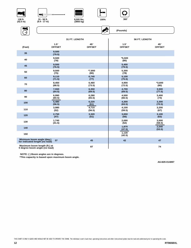
138 ft. (42.0 m)
8,500 lbs. (3855 kg)
31 - 56 ft. (9.4 - 17 m)
(Feet)
31 FT. LENGTH 56 FT. LENGTH
1.5°OFFSET
45°OFFSET
1.5°OFFSET
45°OFFSET
Minimum boom angle (deg.) for indicated length (no load)
Maximum boom length (ft.) at 0 degree boom angle (no load)
NOTE: ( ) Boom angles are in degrees.*This capacity is based upon maximum boom angle.
359,500(79.5)
409,500(78)
*5,500(80)
45 9,500(76.5)
5,400(79.5)
50 9,500(75)
*7,800(80)
5,300(78)
60 9,110(71.5)
6,740(77)
5,100(75.5)
708,450(68.5)
6,460(73.5)
4,900(72.5)
*3,600(80)
807,550(64.5)
6,350(69.5)
4,700(69.5)
3,500(77.5)
906,990(60.5)
6,280(65.5)
4,500(66.5)
3,400(74)
100 5,480(56.5)
6,220(61)
4,300(63.5)
3,300(70.5)
1103,980(52)
4,710(56.5)
4,100(59.5)
3,200(67)
120 2,750(47)
3,320(51)
3,650(56)
3,100(63)
130 1,740(41.5)
2,690(52)
3,000(58.5)
140 1,870(47.5)
2,540(53.5)
150 1,130(42.5)
37 45 42 47
87 74
A6-829-014897
12 RT865BXL
THIS CHART IS ONLY A GUIDE AND SHOULD NOT BE USED TO OPERATE THE CRANE. The individual crane's load chart, operating instructions and other instructional plates must be read and understood prior to operating the crane.
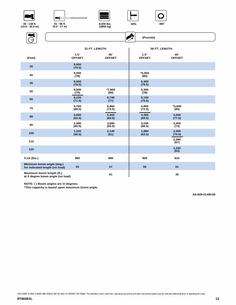
360°50%
(Pounds)
35 - 138 ft. (10.6 - 42.0 m)
8,500 lbs. (3855 kg)
31 - 56 ft. (9.4 - 17 m)
(Feet)
31 FT. LENGTH 56 FT. LENGTH
1.5°OFFSET
45°OFFSET
1.5°OFFSET
45°OFFSET
359,500(79.5)
409,500(78)
*5,500(80)
45 9,500(76.5)
5,400(79.5)
509,500(75)
*7,800(80)
5,300(78)
608,220(71.5)
6,740(77)
5,100(75.5)
705,760(68.5)
6,460(73.5)
4,900(72.5)
*3,600(80)
803,920(64.5)
5,450(69.5)
4,460(69.5)
3,500(77.5)
90 2,480(60.5)
3,690(65.5)
3,030(66.5)
3,400(74)
1001,220(56.5)
2,140(61)
1,890(63.5)
3,300(70.5)
1102,280(67)
120 1,230(63)
0.1A (lbs.) 960 880 900 810
Minimum boom angle (deg.) for indicated length (no load) 53 57 59 61
Maximum boom length (ft.) at 0 degree boom angle (no load)
61 35
NOTE: ( ) Boom angles are in degrees.
A6-829-014901B
*This capacity is based upon maximum boom angle.
13RT865BXL
THIS CHART IS ONLY A GUIDE AND SHOULD NOT BE USED TO OPERATE THE CRANE. The individual crane's load chart, operating instructions and other instructional plates must be read and understood prior to operating the crane.

14 RT865BXL
THIS CHART IS ONLY A GUIDE AND SHOULD NOT BE USED TO OPERATE THE CRANE. The individual crane's load chart, operating instructions and other instructional plates must be read and understood prior to operating the crane.
360°100%
(Pounds)
35 - 138 ft. (10.6 - 42.0 m)
0 lbs. (0 kg)
31 - 56 ft. (9.4 - 17 m)
(Feet)
31 FT. LENGTH 56 FT. LENGTH
1.5°OFFSET
45°OFFSET
1.5°OFFSET
45°OFFSET
359,500(79.5)
409,500(78)
*5,500(80)
45 9,500(76.5)
5,400(79.5)
50 9,500(75)
*7,800(80)
5,300(78)
609,110(71.5)
6,740(77)
5,100(75.5)
70 8,450(68.5)
6,460(73.5)
4,900(72.5)
*3,600(80)
80 7,210(64.5)
6,350(69.5)
4,700(69.5)
3,500(77.5)
905,100(60.5)
6,280(65.5)
4,500(66.5)
3,400(74)
100 3,470(56.5)
4,420(61)
4,300(63.5)
3,300(70.5)
110 2,170(52)
2,910(56.5)
3,210(59.5)
3,200(67)
120 1,120(47)
1,680(51)
2,170(56)
3,090(63)
130 1,260(52)
2,040(58.5)
140 1,160(53.5)
Minimum boom angle (deg.) for indicated length (no load) 46 49 50 52
74 61
NOTE: ( ) Boom angles are in degrees.
A6-829-014899A
Maximum boom length (ft.) at 0 degree boom angle (no load)
*This capacity is based upon maximum boom angle.

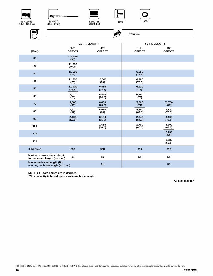
360°100%
(Pounds)
125 ft. (38.1 m)
8,500 lbs. (3855 kg)
31 - 56 ft. (9.4 - 17 m)
*This capacity is based upon maximum boom angle.
(Feet)
31 FT. LENGTH 56 FT. LENGTH
1.5°OFFSET
45°OFFSET
1.5°OFFSET
45°OFFSET
Minimum boom angle (deg.) for indicated length (no load)
Maximum boom length (ft.) at 0 degree boom angle (no load)
NOTE: ( ) Boom angles are in degrees.
30*11,500
(80)
35 11,500(78.5)
4011,500
(77)6,950(79.5)
4511,500
(75)*8,000
(80)6,780(78.5)
50 11,000(73.5)
6,810(78.5)
6,620(77)
6010,050
(70)6,490(74.5)
6,290(74)
709,220(66)
6,400(70.5)
5,960(71)
*3,700(80)
808,440(62)
6,350(66)
6,340(61.5)
5,860(56.5)
4,180(51)
5,640(67.5)
3,520(76.5)
906,900(57.5)
5,260(64.5)
3,400(72.5)
1005,090(53)
4,980(60.5)
3,290(68.5)
110 3,640(47.5)
4,630(56.5)
3,190(64)
120 2,450(41.5)
3,420(52)
3,110(59.5)
1301,450(34.5)
2,360(47.5)
3,040(54)
140 1,460(42.5)
33 45 39 49
87 74
A6-829-014898A
15RT865BXL
THIS CHART IS ONLY A GUIDE AND SHOULD NOT BE USED TO OPERATE THE CRANE. The individual crane's load chart, operating instructions and other instructional plates must be read and understood prior to operating the crane.
RT865BXL16
360°50%
(Pounds)
35 - 125 ft. (10.6 - 38.1 m)
8,500 lbs. (3855 kg)
31 - 56 ft. (9.4 - 17 m)
(Feet)
31 FT. LENGTH 56 FT. LENGTH
1.5°OFFSET
45°OFFSET
1.5°OFFSET
45°OFFSET
30*11,500
(80)
35 11,500(78.5)
4011,500
(77)6,950(79.5)
45 11,500(75)
*8,000(80)
6,780(78.5)
5011,000(73.5)
6,810(78.5)
6,620(77)
608,070(70)
6,490(74.5)
6,290(74)
70 5,580(66)
6,400(70.5)
5,960(71)
*3,700(80)
803,710(62)
5,080(66)
4,390(67.5)
3,520(76.5)
902,100(57.5)
3,130(61.5)
2,940(64.5)
3,400(72.5)
100 1,610(56.5)
1,790(60.5)
3,290(68.5)
110 2,430(64)
120 1,230(59.5)
0.1A (lbs.) 990 900 910 810
Minimum boom angle (deg.) for indicated length (no load) 53 55 57 58
Maximum boom length (ft.) at 0 degree boom angle (no load) 61 35
NOTE: ( ) Boom angles are in degrees.
A6-829-014902A
*This capacity is based upon maximum boom angle.
THIS CHART IS ONLY A GUIDE AND SHOULD NOT BE USED TO OPERATE THE CRANE. The individual crane's load chart, operating instructions and other instructional plates must be read and understood prior to operating the crane.

THIS CHART IS ONLY A GUIDE AND SHOULD NOT BE USED TO OPERATE THE CRANE. The individual crane's load chart, operating instructions and other instructional plates must be read and understood prior to operating the crane.
17RT865BXL
360°100%
(Pounds)
35 - 125 ft. (10.6 - 38.1 m)
0 lbs. (0 kg)
31 - 56 ft. (9.4 - 17 m)
(Feet)
31 FT. LENGTH 56 FT. LENGTH
1.5°OFFSET
45°OFFSET
1.5°OFFSET
45°OFFSET
30*11,500
(80)
3511,500(78.5)
4011,500
(77)6,950(79.5)
4511,500
(75)*8,000
(80)6,780(78.5)
5011,000(73.5)
6,810(78.5)
6,620(77)
6010,050
(70)6,490(74.5)
6,290(74)
709,220(66)
6,400(70.5)
5,960(71)
*3,700(80)
806,670(62)
6,350(66)
5,640(67.5)
3,520(76.5)
90 4,650(57.5)
5,710(61.5)
5,260(64.5)
3,400(72.5)
1003,080(53)
3,860(56.5)
4,270(60.5)
3,290(68.5)
1101,830(47.5)
2,380(51)
2,900(56.5)
3,190(64)
1201,790(52)
3,110(59.5)
1301,920(54)
Minimum boom angle (deg.) for indicated length (no load) 42 46 48 51
74 61
NOTE: ( ) Boom angles are in degrees.
Maximum boom length (ft.) at 0 degree boom angle (no load)
A6-829-014900*This capacity is based upon maximum boom angle.
THIS CHART IS ONLY A GUIDE AND SHOULD NOT BE USED TO OPERATE THE CRANE. The individual crane's load chart, operating instructions and other instructional plates must be read and understood prior to operating the crane.
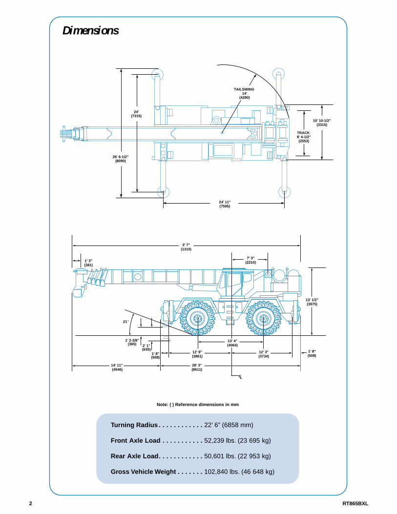
RT865BXL18
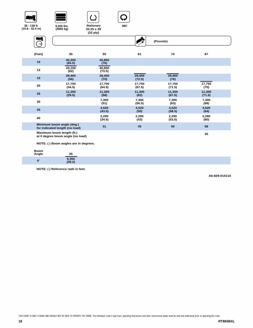
(Pounds)
35 - 138 ft. (10.6 - 42.0 m)
360°Stationary 33.25 x 29
(32 ply)
o
8,500 lbs. (3855 kg)
(Feet) 35 55 61 74 87
1045,200(65.5)
40,850(76)
1243,100
(62)40,850(73.5)
1529,400
(56)29,400
(70)29,400(72.5)
29,400(76)
2017,750(44.5)
17,750(64.5)
17,750(67.5)
17,750(71.5)
17,750(75)
2511,300(29.5)
11,300(58)
11,300(62)
11,300(67.5)
11,300(71.5)
307,300(51)
7,300(56.5)
7,300(63)
7,300(68)
354,520(43.5)
4,520(50)
4,520(58.5)
4,520(64)
402,290(34.5)
2,290(43)
2,290(53.5)
2,290(60)
Minimum boom angle (deg.) for indicated length (no load) 31 40 50 58
Maximum boom length (ft.) at 0 degree boom angle (no load)
35
NOTE: ( ) Boom angles are in degrees.
BoomAngle 35
0° 9,350(28.2)
NOTE: ( ) Reference radii in feet.
A6-829-015116

THIS CHART IS ONLY A GUIDE AND SHOULD NOT BE USED TO OPERATE THE CRANE. The individual crane's load chart, operating instructions and other instructional plates must be read and understood prior to operating the crane.
19RT865BXL
(Pounds)
35 - 138 ft. (10.6 - 42.0 m)
8,500 lbs. (3855 kg)
Defined Arc Over Front
(Feet) 35 55 61 74 87
10 45,200(65.5)
40,850(76)
1245,200
(62)40,850(73.5)
40,850(75.5)
1545,200
(56)40,850
(70)40,850(72.5)
34,400(76)
20 40,850(44.5)
40,850(64.5)
40,850(67.5)
34,400(71.5)
24,050(75)
25 27,000(29.5)
27,100(58)
27,100(62)
27,100(67.5)
24,050(71.5)
3019,200
(51)19,200(56.5)
19,200(63)
19,200(68)
3514,200(43.5)
14,200(50)
14,200(58.5)
14,200(64)
40 10,550(34.5)
10,550(43)
10,550(53.5)
10,550(60)
457,905(21.5)
7,905(35)
7,905(48.5)
7,905(56)
505,840(24.5)
5,840(42.5)
5,840(52)
602,880(28)
2,880(42.5)
Minimum boom angle (deg.) for indicated length (no load) 40
Maximum boom length (ft.) at 0 degree boom angle (no load) 74
NOTE: ( ) Boom angles are in degrees.
BoomAngle 35 55 61 74
0° 22,000(28.2)
6,860(47.4)
4,570(53.8)
1,480(66.6)
NOTE: ( ) Reference radii in feet.
A6-829-015117
Stationary 33.25 x 29
(32 ply)
RT865BXL20
THIS CHART IS ONLY A GUIDE AND SHOULD NOT BE USED TO OPERATE THE CRANE. The individual crane's load chart, operating instructions and other instructional plates must be read and understood prior to operating the crane.
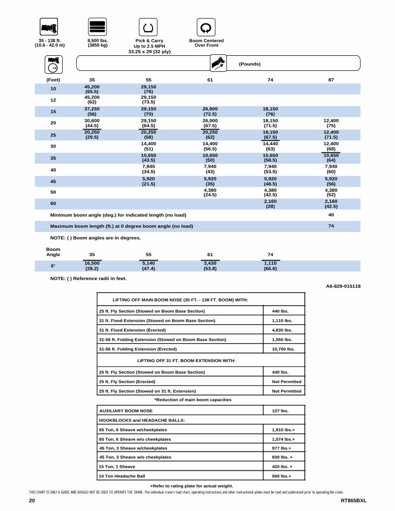
(Pounds)
35 - 138 ft. (10.6 - 42.0 m)
8,500 lbs. (3855 kg)
Boom Centered Over Front
Pick & Carry Up to 2.5 MPH
33.25 x 29 (32 ply)
(Feet) 35 55 61 74 87
10 45,200(65.5)
29,150(76)
1245,200
(62)29,150(73.5)
1537,250
(56)29,150
(70)26,900(72.5)
18,150(76)
20 30,600(44.5)
29,150(64.5)
26,900(67.5)
18,150(71.5)
12,400(75)
2520,250(29.5)
20,250(58)
20,250(62)
18,150(67.5)
12,400(71.5)
30 14,400(51)
14,400(56.5)
14,440(63)
12,400(68)
3510,650(43.5)
10,650(50)
10,650(58.5)
10,650(64)
407,940(34.5)
7,940(43)
7,940(53.5)
7,940(60)
455,920(21.5)
5,920(35)
5,920(48.5)
5,920(56)
50 4,380(24.5)
4,380(42.5)
4,380(52)
60 2,160(28)
2,160(42.5)
Minimum boom angle (deg.) for indicated length (no load) 40
Maximum boom length (ft.) at 0 degree boom angle (no load) 74
NOTE: ( ) Boom angles are in degrees.
BoomAngle
0°
35
16,500(28.2)
55
5,140(47.4)
61
3,430(53.8)
74
1,110(66.6)
NOTE: ( ) Reference radii in feet.
A6-829-015118
LIFTING OFF MAIN BOOM NOSE (35 FT. - 138 FT. BOOM) WITH:
25 ft. Fly Section (Stowed on Boom Base Section) 440 lbs.
31 ft. Fixed Extension (Stowed on Boom Base Section) 1,110 lbs.
31 ft. Fixed Extension (Erected) 4,830 lbs.
31-56 ft. Folding Extension (Stowed on Boom Base Section) 1,550 lbs.
31-56 ft. Folding Extension (Erected) 10,700 lbs.
LIFTING OFF 31 FT. BOOM EXTENSION WITH:
25 ft. Fly Section (Stowed on Boom Base Section) 440 lbs.
25 ft. Fly Section (Erected) Not Permitted
25 ft. Fly Section (Stowed on 31 ft. Extension) Not Permitted
*Reduction of main boom capacities
AUXILIARY BOOM NOSE 127 lbs.
HOOKBLOCKS and HEADACHE BALLS:
65 Ton, 6 Sheave w/cheekplates 1,910 lbs.+
65 Ton, 6 Sheave w/o cheekplates 1,574 lbs.+
45 Ton, 3 Sheave w/cheekplates 977 lbs.+
45 Ton, 3 Sheave w/o cheekplates 830 lbs. +
15 Ton, 1 Sheave 420 lbs. +
10 Ton Headache Ball 560 lbs.+
+Refer to rating plate for actual weight.
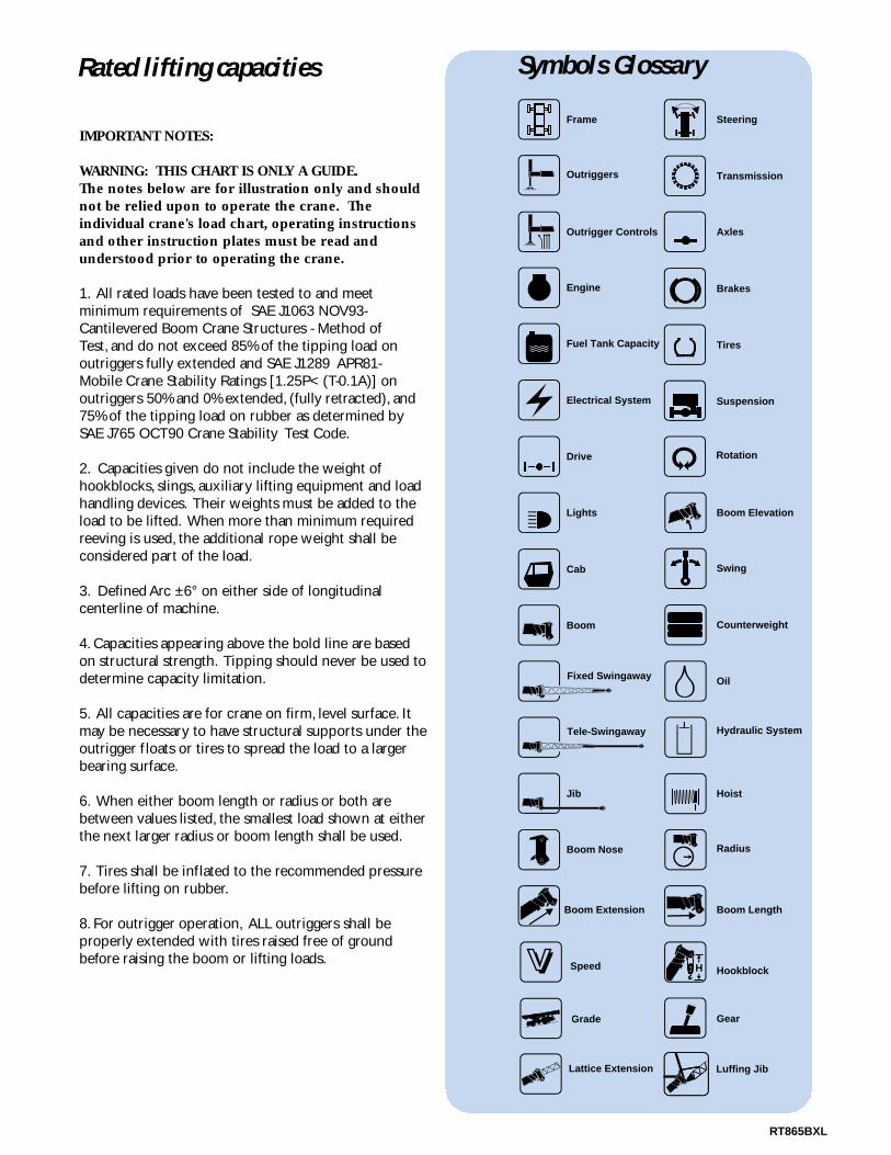
Rated lifting capacities Symbols Glossary
Drive Rotation
Electrical System Suspension
Fuel Tank Capacity Tires
Engine Brakes
Outrigger Controls Axles
Outriggers Transmission
Frame Steering
Lights Boom Elevation
Cab Swing
Tele-Swingaway Hydraulic System
Jib Hoist
Boom Nose Radius
Boom Extension Boom Length
Grade Gear
Boom Counterweight
HookblockHSpeed
OilFixed Swingaway
Lattice Extension Luffing Jib
RT865BXL
IMPORTANT NOTES:
WARNING: THIS CHART IS ONLY A GUIDE.The notes below are for illustration only and shouldnot be relied upon to operate the crane. Theindividual crane's load chart, operating instructionsand other instruction plates must be read andunderstood prior to operating the crane.
1. All rated loads have been tested to and meet minimum requirements of SAE J1063 NOV93-Cantilevered Boom Crane Structures - Method ofTest, and do not exceed 85% of the tipping load on outriggers fully extended and SAE J1289 APR81-Mobile Crane Stability Ratings [1.25P< (T-0.1A)] on outriggers 50% and 0% extended, (fully retracted), and75% of the tipping load on rubber as determined bySAE J765 OCT90 Crane Stability Test Code.
2. Capacities given do not include the weight of hookblocks, slings, auxiliary lifting equipment and loadhandling devices. Their weights must be added to theload to be lifted. When more than minimum requiredreeving is used, the additional rope weight shall be considered part of the load.
3. Defined Arc ±6° on either side of longitudinal centerline of machine.
4. Capacities appearing above the bold line are basedon structural strength. Tipping should never be used todetermine capacity limitation.
5. All capacities are for crane on firm, level surface. Itmay be necessary to have structural supports under theoutrigger floats or tires to spread the load to a largerbearing surface.
6. When either boom length or radius or both arebetween values listed, the smallest load shown at eitherthe next larger radius or boom length shall be used.
7. Tires shall be inflated to the recommended pressurebefore lifting on rubber.
8. For outrigger operation, ALL outriggers shall be properly extended with tires raised free of groundbefore raising the boom or lifting loads.

Distributed By:
Constant improvement and engineering progress make it necessary that we reserve the right to makespecification, equipment, and price changes without notice. Illustrations shown may include optional equipmentand accessories and may not include all standard equipment.
Form No.: RT865BXL Part No.: 3-968 597-8M Printed in U.S.A.
Grove Worldwide – World HeadquartersGrove North America1565 Buchanan Trail East P.O. Box 21 Shady Grove, Pennsylvania 17256, U.S.A.Tel: [Int + 1] (717) 597-8121Fax: [Int + 1] (717) 597-4062Western Hemisphere, Asia/Pacific
Grove Europe Limited* Sunderland SR4 6TT, England Tel: [Int + 44] 191 565-6281Fax: [Int + 44] 191 564-0442Europe, Africa, Middle East
Grove Europe Limited*P.O. Box No. 2684A Kimber RoadAbingdon, Oxfordshire, 0X141SGTel: [Int + 44] 1235 55-3184Fax: [Int + 44] 1235 55-3218
Deutsche Grove GmbHSales and Service Helmholtzstrasse 12, Postfach 5026D-40750 Langenfeld, GermanyTel: [Int + 49] (2173) 8909-0Fax: [Int + 49] (2173) 8909-30
Wilhelmshaven WorksIndustriegelande West, Postfach 1853D-26358 Wilhelmshaven, Germany Tel: [Int + 49] (4421) 294-0Fax: [Int + 49] (4421) 294-301
Grove France S.A. 16, chaussée Jules-César, 95520 OSNYB.P. 203, 95523 CERGY PONTOISE CEDEXFranceTel: [Int + 33] (1) 30313150Int: [Int + 33] (1) 30386085
*Grove Europe Limited, Registered in England,
Number 1845128, Registered office, Crown Works,
Pallion, Sunderland, Tyne & Wear, England SR4 6TT
Grove Asia/Pacific - Regional Office 171 Chin Swee Road#06-01 San Centre Singapore 0316Tel: [Int + 65] 536-6112 Fax: [Int + 65] 536-6119 Asia/Pacific, Near East
Grove China - Representative Office Beijing Hotel Room 6074No. 33 East Chang An Avenue Beijing, 100004, China Tel: [Int + 86] (10) 513-7766Fax: [Int + 86] (10) 513-7307
Grove Product Support Western Hemisphere, Asia/Pacific1086 Wayne AvenueChambersburg, Pennsylvania USATel: [Int + 1] (717) 263-5100Fax: [Int + 1] (717) 267-0404
Europe, Africa, Middle EastSunderland SR4 6TT, EnglandTel: [Int + 44] 191 565-6281Parts Fax: [Int + 44] 191 510-9242Service Fax: [Int + 44] 191 510-9560