Embed Size (px)
Citation preview

Dimmer actuators of the MIX2 series DMG 2 T
Updated: Dec-12 (Subject to change) Page 1 of 71
Dimmer actuators of the MIX 2 series DMG 2 T, Extension module DME 2 T
and Booster DMB 1 T
DMG 2 T 4930270 DME 2 T 4930275 DMB 1 T 4930279

Dimmer actuators of the MIX2 series DMG 2 T
Updated: Dec-12 (Subject to change) Page 2 of 71
Contents
1 FUNCTIONAL CHARACTERISTICS ......................................................................... 42 MIX AND MIX2 DEVICES ............................................................................................ 5
2.1 OPERATION ................................................................................................................. 6
3 TECHNICAL DATA ....................................................................................................... 73.1 IMPORTANT INFORMATION .......................................................................................... 8
4 THE APPLICATION PROGRAM "MIX2 SERIES V1.1 SWITCHING AND DIMMING" .............................................................................................................................. 9
4.1 SELECTION IN THE PRODUCT DATABASE ...................................................................... 94.2 COMMUNICATION OBJECTS ........................................................................................ 10
4.2.1 Channel-related objects ....................................................................................... 104.2.2 Common objects ................................................................................................... 144.2.3 Description of objects ........................................................................................... 15
4.3 PARAMETERS ............................................................................................................ 244.3.1 Parameter pages .................................................................................................. 244.3.2 General ................................................................................................................. 254.3.3 DMG 2 T Channel C1/C2: Function selection ..................................................... 274.3.4 Dimming response ................................................................................................ 304.3.5 Dimming value limits ........................................................................................... 344.3.6 Soft switching ....................................................................................................... 354.3.7 Locking function ................................................................................................... 364.3.8 Forced operation .................................................................................................. 374.3.9 Scenes ................................................................................................................... 394.3.10 Feedback .......................................................................................................... 424.3.11 Operating hours counter and service ............................................................... 434.3.12 Loss of power and restoration .......................................................................... 454.3.13 Diagnostic messages ........................................................................................ 45
5 TYPICAL APPLICATIONS ......................................................................................... 465.1 BEDROOM LIGHTING .................................................................................................. 46
5.1.1 Devices: ................................................................................................................ 465.1.2 Overview ............................................................................................................... 465.1.3 Objects and links .................................................................................................. 475.1.4 Important parameter settings ............................................................................... 48
6 APPENDIX ..................................................................................................................... 496.1 USE OF SOFT SWITCHING FUNCTION ........................................................................... 49
6.1.1 General ................................................................................................................. 496.1.2 Soft ON for staircase lighting ............................................................................... 496.1.3 Entrance lighting .................................................................................................. 506.1.4 Simulation of a daily routine ................................................................................ 516.1.5 Retriggering and premature switch-off ................................................................ 526.1.6 Soft Off telegram during a Soft On process ......................................................... 536.1.7 Soft On telegram during a Soft Off process ......................................................... 54
6.2 APPLICATION OF THE FORCED OPERATION FUNCTION ................................................ 55

Dimmer actuators of the MIX2 series DMG 2 T
Updated: Dec-12 (Subject to change) Page 3 of 71
6.3 DIMMING ENERGY-SAVING LAMPS (ESL) .................................................................. 566.3.1 General ................................................................................................................. 566.3.2 Selection of RC or L-response: ............................................................................ 566.3.3 Dimmable energy-saving lamps with RC response (reverse phase control) ....... 576.3.4 Dimmable energy-saving lamps with L-response (phase control) ....................... 58
6.4 DIM LED LAMPS ....................................................................................................... 596.4.1 General ................................................................................................................. 596.4.2 Selection of RC or L-response: ............................................................................ 59
6.5 4-BIT TELEGRAMS (BRIGHTER/DARKER) .................................................................... 606.5.1 Telegram format 4-bit EIS 2 relative dimming: ................................................... 606.5.2 Parameter: "Switching on/off with a 4-bit telegram" .......................................... 61
6.6 THE SCENES ............................................................................................................... 626.6.1 Principle ............................................................................................................... 626.6.2 Select and save settings: ....................................................................................... 636.6.3 Enter scenes without telegrams (MIX2 ONLY) .................................................... 65
6.7 STORE LIGHT SCENES IN ONE BUTTON ....................................................................... 656.7.1 Assignment of group addresses and setting for the object flag ............................ 656.7.2 Functional description ......................................................................................... 66
6.8 CONVERSION OF PERCENTAGES TO HEXADECIMAL AND DECIMAL VALUES ................ 666.9 FUNCTION DIAGRAM ................................................................................................. 67
7 OPERATING INSTRUCTIONS .................................................................................. 68

Dimmer actuators of the MIX2 series DMG 2 T
Updated: Dec-12 (Subject to change) Page 4 of 71
1 Functional characteristics
• Double universal dimming actuator MIX2 • MIX 2 basic module • For upgrading to maximum of 6 channels • Dimming range 0-100% • For dimming incandescent lamps, low voltage and high voltage halogen lamps,
dimmable LED retrofit lamps • Also suitable for dimming dimmable energy-saving lamps via different dimming curves • Also suitable for controlling fans • Up to 2 MIX or MIX2
upgrade modules can be connected to a basic module • Device and KNX bus module can be swapped independently of each other • Removable KNX bus module enables devices to be changed without reprogramming • Manual set-up and use of switch actuators is also
possible without KNX bus module • LED switching status indicator for each channel • Manual operation on device (even without bus connection) • Dimming output: 400 W/VA per channel or 1 x 800 W/VA in parallel operation • Use of the 1-channel DMB 1 T KNX dimming booster can increase dimming output
by 300 W/VA. • Output of up to 2000 W /VA possible via max. 4 boosters in parallel operation (C1//C2). • Automatic load detection (can be deactivated) • For R, L and C-load
Dimmer actuators of the MIX2 series DMG 2 T
Updated: Dec-12 (Subject to change) Page 5 of 71
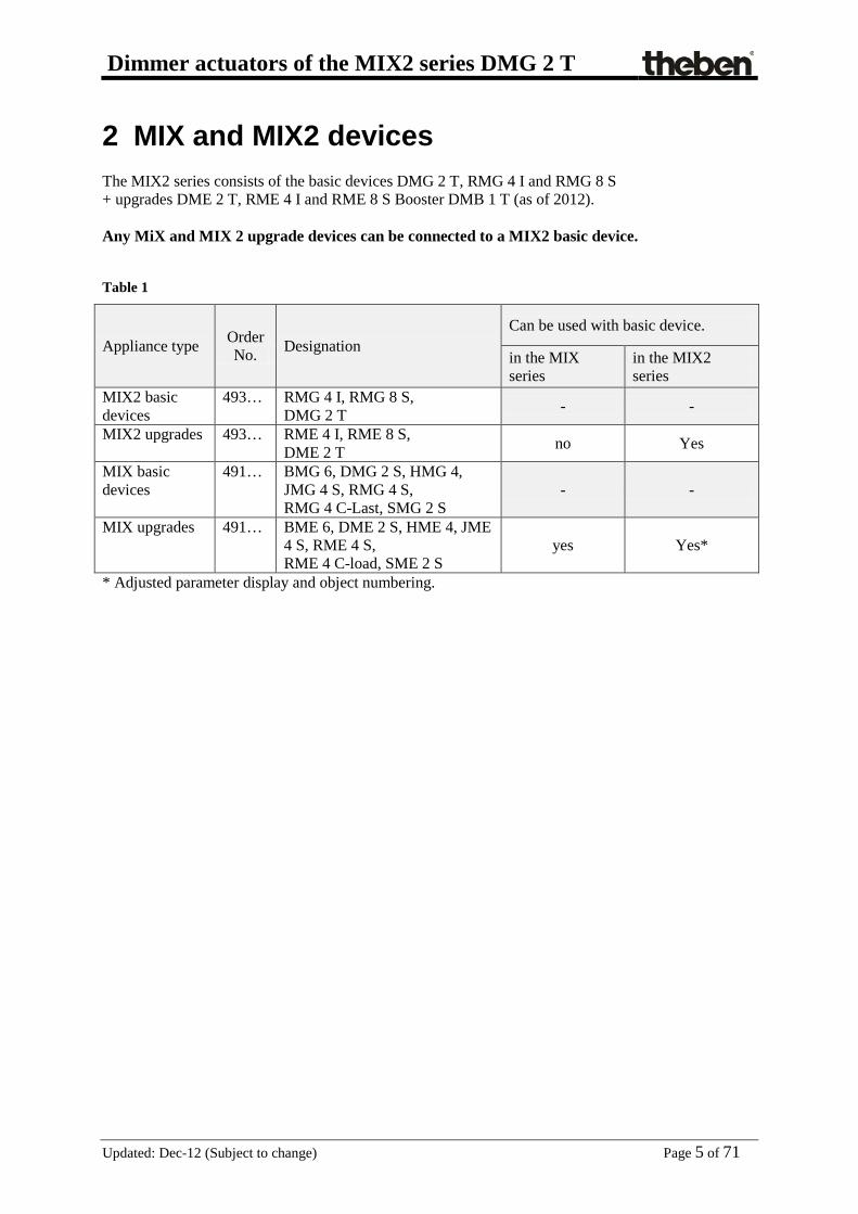
2 MIX and MIX2 devices The MIX2 series consists of the basic devices DMG 2 T, RMG 4 I and RMG 8 S + upgrades DME 2 T, RME 4 I and RME 8 S Booster DMB 1 T (as of 2012). Any MiX and MIX 2 upgrade devices can be connected to a MIX2 basic device.
Table 1
Appliance type Order No. Designation
Can be used with basic device.
in the MIX series
in the MIX2 series
MIX2 basic devices
493… RMG 4 I, RMG 8 S, DMG 2 T - -
MIX2 upgrades 493… RME 4 I, RME 8 S, DME 2 T no Yes
MIX basic devices
491… BMG 6, DMG 2 S, HMG 4, JMG 4 S, RMG 4 S, RMG 4 C-Last, SMG 2 S
- -
MIX upgrades 491… BME 6, DME 2 S, HME 4, JME 4 S, RME 4 S, RME 4 C-load, SME 2 S
yes Yes*
* Adjusted parameter display and object numbering.

Dimmer actuators of the MIX2 series DMG 2 T
Updated: Dec-12 (Subject to change) Page 6 of 71
2.1 Operation Every dimmer actuator has a manual button. When manual mode is activated the dimmer can only be operated with the buttons. Bus telegrams will not be implemented. 4 buttons and 4 LEDs are available for each channel. The LEDs shown the current state as a bar display: LED 1 LED 2 LED 3 LED 4 > 0 % > 25 % > 50% > 75 % The device dims down to 0% in the event of excess temperature or a short circuit in the load. The buttons call up the following dimming values:
Table 2:
Button 1 Button 2 Button 3 Button 4 25 %
or OFF 50 % 75 % 100 %
In standard operation: Pressing a button establishes the desired dimming value. A status established via the channel button can be overwritten via the bus at any time. In manual operation with the manual button or Manual object: If the "manual" function is selected, the associated LED lights up. Any time-based functions that are running (e.g. soft switching) will be terminated. The dimming status will be frozen and can only be changed via the channel buttons. Bus telegrams will not be implemented. The "Manual" state will be reset during a mains power failure. After cancelling manual operation already received bus events will not be obtained later.

Dimmer actuators of the MIX2 series DMG 2 T
Updated: Dec-12 (Subject to change) Page 7 of 71
3 Technical data
Operating voltage KNX Bus voltage, ≤10 mA Operating voltage 230 V AC +10 % -15 % Frequency 50 Hz Standby output 0.9 W Width 4 module Installation type DIN-rail Connection type Terminals screws
Max. cable cross-section Solid: 0.5 mm² (Ø 0.8) to 4 mm² | strand with wire end sleeve: 0.5 mm² to 2.5 mm²
Number of channels 2
Lamp types Incandescent lamps, low-voltage and
high-voltage halogen lamps, dimmable energy saving lamps and LEDs
Switching capacity per channel 400 W Switching capacity in parallel operation 800 W Dimmable switching capacity Energy saving lamps per channel 80 W
Switching capacity dimmable energy saving lamps in parallel operation 140 W
Dimmable switching capacity 230 V LED per channel 60 W
Dimmable switching capacity 230 V LED in parallel operation 120 W
Min. switching capacity 5 W Max. line length 100 m Ambient temperature -5 °C … +45 °C Protection rating IP 20 Protection class II in accordance with EN 60 669

Dimmer actuators of the MIX2 series DMG 2 T
Updated: Dec-12 (Subject to change) Page 8 of 71
3.1 Important information
1. The voltage supply (at the fuse box) must be switched off without fail when replacing lamps. 2. The EIB voltage must be switched off when plugging together or separating modules. 3. Connecting dimmers in series or in parallel is not permitted:
ONLY the Booster module is connected in parallel (up to 2 items per channel possible). 4. If C2 boosts the channel C1 (special parallel operation) a total of up to 4 booster modules can
be connected and an output of up to 2000 W can be dimmed. 5. Do not install adjustable transformers ahead of the dimmer. 6. Ripple control pulses from electric power plants may cause temporary flickering of the
lighting.

Dimmer actuators of the MIX2 series DMG 2 T
Updated: Dec-12 (Subject to change) Page 9 of 71
4 The application program "MIX2 Series V1.1 switching and dimming"
4.1 Selection in the product database Manufacturer Theben AG Product family Dimmers Product type DMG 2 T Program name MIX 2 V1.1 The ETS database can be found on our website: www.theben.de/downloads Table 3
Number of communication objects: 254 Number of group addresses: 254 Number of associations: 255

Dimmer actuators of the MIX2 series DMG 2 T
Updated: Dec-12 (Subject to change) Page 10 of 71
4.2 Communication objects The objects are divided into channel-related and common objects
4.2.1 Channel-related objects Table 4
No. Object name Function Length DPT
Flags C R W T
0 DMG 2 T channel C1 Switching ON/OFF 1 bit 1.001 C R W -
1 DMG 2 T channel C1 Brighter/darker 4 bit 3.007 C R W -
2 DMG 2 T channel C1 Dimming value 1 byte 5.001 C - W -
3 DMG 2 T channel C1 Soft switching 1 bit 1.001 C R W -
4 DMG 2 T channel C1 Lock 1 bit 1.001 C R W -
5 DMG 2 T channel C1 Call up/save scenes 1 byte 17.001 C R W -
6 DMG 2 T channel C1 Lock scenes = 1 1 bit 1.001 C R W -
Enable scenes = 1 1 bit 1.001 C R W -
7 DMG 2 T channel C1
Force = 1 1 bit 1.001 C R W -
Force = 0 1 bit 1.001 C R W -
Dimming value with forced op 1 byte 5.001 C R W -
Forced operation 2 bit 2.001 C R W -
8 DMG 2 T channel C1 Dimming value limit 1 byte 5.001 C R W -
9 DMG 2 T channel C1 Feedback On/Off 1 bit 1.001 C R - T
10 DMG 2 T channel C1 Feedback in % 1 byte 5.001 C R - T
11 DMG 2 T channel C1 Time to next service 2 byte 7.001 C R W T
Operating hours feedback 2 byte 7.001 C R W T
12 DMG 2 T channel C1 Service required 1 bit 1.001 C R - T

Dimmer actuators of the MIX2 series DMG 2 T
Updated: Dec-12 (Subject to change) Page 11 of 71
Continuation:
No. Object name Function Length Flags
C R W T
13 DMG 2 T channel C1 Reset service 1 bit 1.001 C R W -
Reset operating hours 1 bit 1.001 C R W -
14 DMG 2 T channel C1 General error message 1 bit 1.001 C R - T
15 DMG 2 T channel C1 Short circuit message 1 bit 1.001 C R - T
16 DMG 2 T channel C1 Excess temperature message 1 bit 1.001 C R - T
17 DMG 2 T channel C1 Mains power failure 1 bit 1.001 C R - T
18 DMG 2 T channel C1 Load type message (R, C/L) 1 bit 1.001 C R - T
19 DMG 2 T channel C1 Status message (bit set) 1 byte 5.010 C R - T
30 DMG 2 T channel C2 Switching ON/OFF 1 bit 1.001 C R W -
31 DMG 2 T channel C2 Brighter/darker 4 bit 3.007 C R W -
32 DMG 2 T channel C2 Dimming value 1 byte 5.001 C - W -
33 DMG 2 T channel C2 Soft switching 1 bit 1.001 C R W -
34 DMG 2 T channel C2 Lock 1 bit 1.001 C R W -
35 DMG 2 T channel C2 Call up/save scenes 1 byte 17.001 C R W -
36 DMG 2 T channel C2 Enable scenes = 1 1 bit 1.001 C R W -
Lock scenes = 1 1 bit 1.001 C R W -
37 DMG 2 T channel C2
Force = 0 1 bit 1.001 C R W -
Force = 1 1 bit 1.001 C R W -
Dimming value with forced op 1 byte 5.001 C R W -
Forced operation 2 bit 2.001 C R W -
38 DMG 2 T channel C2 Dimming value limit 1 byte 5.001 C R W -
39 DMG 2 T channel C2 Feedback On/Off 1 bit 1.001 C R - T
40 DMG 2 T channel C2 Feedback in % 1 byte 5.001 C R - T

Dimmer actuators of the MIX2 series DMG 2 T
Updated: Dec-12 (Subject to change) Page 12 of 71
Continuation:
No. Object name Function Length Flags
C R W T
41 DMG 2 T channel C2 Time to next service
2 byte 7.001 C R W T
DMG 2 T channel C2 Operating hours feedback 2 byte 7.001 C R W T
42 DMG 2 T channel C2 Service required 1 bit 1.001 C R - T
43 DMG 2 T channel C2 Reset service
1 bit 1.001 C R W -
DMG 2 T channel C2 Reset operating hours 1 bit 1.001 C R W -
44 DMG 2 T channel C2 General error message 1 bit 1.001 C R - T
45 DMG 2 T channel C2 Short circuit message 1 bit 1.001 C R - T
46 DMG 2 T channel C2 Excess temperature message 1 bit 1.001 C R - T
47 DMG 2 T channel C2 Mains power failure 1 bit 1.001 C R - T
48 DMG 2 T channel C2 Load type message (R, C/L) 1 bit 1.001 C R - T
49 DMG 2 T channel C2 Status message (bit set) 1 byte 5.010 C R - T

Dimmer actuators of the MIX2 series DMG 2 T
Updated: Dec-12 (Subject to change) Page 13 of 71
Table 5: Overview of channel-related objects
Basic module DMG 2 T
1st update DME 2 T
2nd upgrade DME 2 T
C1 C2 C1 C2 C1 C2 0 30 80 110 160 190 1 31 81 111 161 191 2 32 82 112 162 192 3 33 83 113 163 193 4 34 84 114 164 194 5 35 85 115 165 195 6 36 86 116 166 196 7 37 87 117 167 197 8 38 88 118 168 198 9 39 89 119 169 199
10 40 90 120 170 200 11 41 91 121 171 201 12 42 92 122 172 202 13 43 93 123 173 203 14 44 94 124 174 204 15 45 95 125 175 205 16 46 96 126 176 206 17 47 97 127 177 207 18 48 98 128 178 208 19 49 99 129 179 209

Dimmer actuators of the MIX2 series DMG 2 T
Updated: Dec-12 (Subject to change) Page 14 of 71
4.2.2 Common objects These objects are partly used by the basic device and the two upgrade devices. Table 6:
No. Object name Function Type DPT
Flags C R W T
78 C R W T 158 EM1 DME 2 T
238 EM2 DME 2 T
240 Central continuous ON For RMG 8S, DME 2 S, SME 2 S, DMG 2 T, DME 2 T
1 bit 1.001 C R W T
241 Central continuous OFF For RMG 8S, DME 2S, SME 2S, DMG 2 T, DME 2 T
1 bit 1.001 C R W T
242 Central switching For RMG8S, DME 2S, SME 2S, DMG 2 T, DME 2 T
1 bit 1.001 C R W T
243 Call up/save central scenes RMG8S, DME2S, JME4S, SME2S, DMG 2 T, DME 2 T
1 Byte 18.001 C R W T
244 Central safety 1 For JME 4 S 1 bit 1.001 C R W -
245 Central safety 2 For JME 4 S 1 bit 1.001 C R W -
246 Central safety 3 For JME 4 S 1 bit 1.001 C R W -
247 Central up/down For JME 4 S 1 bit 1.008 C R W -
248 Not used 249 Not used
250 Version of bus coupling unit transmit 14 byte 16.001 C R - T
251 Version of basic device transmit 14 byte 16.001 C R - T
252 Version of first upgrade device transmit 14 byte 16.001 C R - T
253 Version of second upgrade device transmit 14 byte
16.001 C R - T

Dimmer actuators of the MIX2 series DMG 2 T
Updated: Dec-12 (Subject to change) Page 15 of 71
4.2.3 Description of objects • Objects 0, 30, 80, 110, 160, 190 "Switching ON/OFF"
A 1 on this object dims up to 100%, and 0 dims to 0% • Objects 1, 31, 81, 111, 161, 191 "brighter/darker"
This object is actuated with 4-bit telegrams (DPT 3.007 Control Dimming). This function can be used to dim the light up or down in in increments. In the standard application, telegrams are sent with 64 increments. IMPORTANT: The response to 4-bit telegrams depends on the “Switching On/Off with a 4-bit telegram” parameter. See appendix: 4-bit telegrams (brighter/darker) • Objects 2, 32, 82, 112, 162, 192 "Dimming value"
This object can be used to select the desired dimmer setting directly. Format: 1 byte percentage value EIS 2 dimming, value. 0 = 0% 255 = 100% • Objects 3, 33, 83, 113, 163, 193 "Soft switching"
A “1” on this object starts a soft switching cycle, i.e.: The brightness is gradually increased, starting from the minimum brightness. The dimming value remains constant for the programmed time and is then gradually reduced after this time has elapsed. Once the programmed minimum brightness has been reached the dimming value is reset to 0%. The cycle can be extended or prematurely terminated via telegrams. This sequence can also be controlled using a time switch if the "Time between soft ON and soft OFF" parameter is set to "Until soft OFF telegram". The dimming cycle is then started with a “1” and finished with a “0”. See appendix: Use of the soft switch function • Object 4, 34, 84, 114, 164, 194 "Lock"
Responses to setting and cancelling the lock can be configured if the lock function has been activated. (parameter page Channel C1/C2 function selection). The lock only applies when the object is received, i.e. with Lock with OFF telegram the channel is not locked after bus restoration. If the parameter Behaviour when setting the lock = no reaction, a running soft-switch process will not be interrupted.

Dimmer actuators of the MIX2 series DMG 2 T
Updated: Dec-12 (Subject to change) Page 16 of 71
• Objects 5, 35, 85, 115, 165, 195 "Call up/save scenes"
Only available if the scene function has been activated (Function selection parameter page). This object can be used to save and subsequently call up scenes. Saving stores the dimming value of the channel. It does not matter how this dimming value is produced (whether via switching commands, central objects or the buttons on the device). The saved dimming value is re-established when it is called up. All scene numbers from 1 to 64 are supported. Each channel can participate in up to 8 scenes. See appendix: Scenes • Objects 6, 36, 86, 116, 166, 196 "Lock scenes = 1, Enable scenes = 1"
Locks the scene function with a 1 or a 0 depending on the configuration. As long as it is locked, scenes cannot be saved or called up. • Objects 7, 37, 87, 117, 167, 197 "Forced operation = 1" / "Forced operation = 0" /
"Dimming value during forced operation" The function of the forced operation object can be configured as a 1-bit, 2-bit or 1-byte object. Table 7
Format of forced object
Forced operation Response with forced operation Trigger with End with Start End
1 bit 1 or 0 (configurable)
0 or 1 (configurable)
configurable in the application program
2 bit Forced operation on = 3 Forced off = 2
Deactivate forced operation = 0 or 1
configurable in the application program.
The last dimming value before forced operation is restored
1 byte 1-100 % 0 The triggering telegram also acts simultaneously as a forced operation dimming value
The last dimming value before forced operation is restored
• Objects 8, 38, 88, 118, 168, 198 "Dimming value limit" The value received will be configured as the maximum configurable dimming value. Its range of applicability is defined on the Dimming value restrictions parameter page.

Dimmer actuators of the MIX2 series DMG 2 T
Updated: Dec-12 (Subject to change) Page 17 of 71
• Object 9, 39, 89, 119, 169, 199 "Feedback On/Off"
Sends the current dimming status: 1 = current dimming value is between 1% and 100% 0 = current dimming value is 0% • Object 10, 40, 90, 120, 170, 200 "Feedback in %"
Sends the new dimming value after a change as soon as a dimming procedure is completed, i.e. once the new set point value has been reached. Format: 1 Byte, 0 ... 255 i.e. 0 ... 100% • Objects 11, 41, 91, 121, 171, 201"Operating hours feedback", "Time to next service"
Only available if the operating hours counter function has been activated (Function selection parameter page). Reports, depending on selected Type of operating hours counter (Operating hours counter and service parameter page), either the remaining period to the next set service or the current status of the operating hours counter. • Objects 12, 42, 92, 122, 172, 202 "Service required"
Only available if the operating hours counter function has been activated (Function selection parameter page) and Type of operating hours counter = Counter for time to next service. Reports if the next service is due. 0 = not due 1 = service is due. • Objects 13, 43, 93, 123, 173, 203 "Reset operating hours", "Reset service"
Only available if the operating hours counter function has been activated (Function selection parameter page). • Object 14, 44, 94, 124, 174, 204 "General error message"
Used as a malfunction signal: 0 = No error 1 = an error has been detected This message can, for example, be displayed on a screen. For detailed error analysis refer to Object 19.

Dimmer actuators of the MIX2 series DMG 2 T
Updated: Dec-12 (Subject to change) Page 18 of 71
• Object 15, 45, 95, 125, 175, 205 "Short circuit message"
0 = OK 1 = Short circuit at dimmer output. When there is a short circuit, all 4 status LEDs on the device flash. • Object 16, 46, 96, 126, 176, 206 "Excess temperature message"
0 = OK 1= the dimmer is overloaded. If there is excess temperature, the status LEDs 2, 3, and 4 flash. • Object 17, 47, 97, 127, 177, 207 "Mains power failure"
0 = OK 1 = No mains voltage available. To be able to recognise the mains power failure on the load side, the dimmer must be supplied with power via the mains connection on the basic device. • Object 18, 48, 98, 128, 178, 208 "Load type message (R/C, L)"
Currently selected load type feedback. 0 = L-Load 1 = R/C-Load

Dimmer actuators of the MIX2 series DMG 2 T
Updated: Dec-12 (Subject to change) Page 19 of 71
• Objects 19, 49, 99, 129, 179, 209 "Bit set status message"
Diagnosis object for status and error display. Status information is encoded in one byte according to the following bit pattern. Table 8: Bitset
Bit 7 Bit 6 Bit 5 Bit 4 Bit 3 Bit 2 Bit 1 Bit 0
n.a.
Mai
ns p
ower
fa
ilure
Dim
min
g va
lue
>
0 %
Man
ual o
pera
tion
Load
type
Shor
t circ
uit
Exce
ss
tem
pera
ture
Gen
eral
err
or
Table 9
Bit Name Meaning 0 General error An error has occurred. 1 Excess temperature 1= the dimmer is overloaded:
• connected power is too high, • - ambient temperature is too high, • booster defective • incorrect installation position, i.e. device cannot dissipate the
heat, If there is excess temperature, the status LEDs 2, 3, and 4 flash.
2 Short circuit 1= check connected lines and load When there is a short circuit, all 4 status LEDs on the device flash.
3 Type of load 1= reverse phase control (R, C load connected), electronic transformers or incandescent lamps test 0= phase control (L load connected), conventional transformers
4 Manual/bus operation 1= manual switch on the device set to manual operation “0” or “1” 0= manual switch set to bus operation
5 Dimming value 1= Dimming value >0% 0 = Off
6 Mains power failure 1 = Mains power failure (loss of power or defective hardware) 0 = No error

Dimmer actuators of the MIX2 series DMG 2 T
Updated: Dec-12 (Subject to change) Page 20 of 71
• Objects 78, 158, 238 "Manual"
Only available for devices in the MIX 2 series (order number 493…) Puts the relevant module in manual mode or sends the status of the manual operation. Table 10
Telegram Meaning Explanation 0 Auto All channels can be operated via the bus as well as via the buttons.
1 Manual
The channels can only be operated via the buttons on the device. Bus telegrams will not work. Any time-based functions that are running (e.g. soft switching) will be terminated.
The duration of the manual mode, i.e. the function of the manual operation is set on the General parameter page. After cancelling manual operation already received bus events will not be obtained later. The "Manual" state will be reset during a mains power failure.
• Object 240 "Central permanent ON" Central switch-on function. Enables simultaneous switch-on of all channels (basic and extension modules) with a single telegram. 0 = No function 1 = Permanent ON Participation in this object can be set individually for each channel (see parameter page DMG 2 T channel C1/C2: Function selection). IMPORTANT: This object takes top priority. As long as it is set, the other switching commands will not work on the participating channels. Works on the following devices: RMG 4 I / RME 4 I, RMG 8 S / RME 8 S, RME 4 S / C-Load, DME 2 S, SME 2 S.
• Object 241 "Central permanent OFF" Central switch-off function. Enables simultaneous switch-off of all channels (basic and extension modules) with a single telegram. 0 = No function 1 = Permanent OFF Participation in this object can be set individually for each channel (see parameter page). IMPORTANT: This object has the second highest priority after Central permanent ON. As long as it is set, the other switching commands will not work on the participating channels. Works on the following devices: RMG 4 I / RME 4 I, RMG 8 S / RME 8 S, RME 4 S / C-Load, DME 2 S, SME 2 S, DMG 2 T, DME 2 T

Dimmer actuators of the MIX2 series DMG 2 T
Updated: Dec-12 (Subject to change) Page 21 of 71
• Object 242 "Central switching"
Central switching function. Enables simultaneous switch-on or off of all channels (basic and extension modules) with a single telegram. 0 = OFF 1 = ON Participation in this object can be set individually for each channel (see parameter page DMG 2 T channel C1/C2: Function selection). With this object, every participating channel responds exactly as if its first object (i.e. obj. 0, 30, etc.) were receiving a switching command. Works on the following devices: RMG 4 I / RME 4 I, RMG 8 S / RME 8 S, RME 4 S / C-Load, DME 2 S, SME 2 S, DMG 2 T, DME 2 T
• Object 243 "Call up/save central scenes" This object can be used to save and subsequently call up "scenes". The save process stores the current status of the dimming channel (or the switch state with other actuators), regardless of how the status was brought about (e.g. via dimming values, switching commands, central objects or the manual switches). The saved status is thus restored when called up. Each channel can participate in a maximum of 8 scenes. Works on the following devices: RMG 4 I / RME 4 I, RMG 8 S / RME 8 S, RME 4 S / C-Load, DME 2 S, SME 2 S, JME 4 S See appendix: The scenes
• Objects 244, 245, 246 Only for JMG 4 S blinds actuator.
• Object 247 "Central Up/Down" Only for JMG 4 S blinds actuator.
• Object 248 Not used.
• Object 249 Not used.

Dimmer actuators of the MIX2 series DMG 2 T
Updated: Dec-12 (Subject to change) Page 22 of 71
• Object 250 "Version of bus coupling unit"
For diagnostic purposes only. Sends the bus coupling unit software version after reset or download. Can also be read out via the ETS. Format: Axx Hyy Vzzz Code Meaning
xx 00 .. FF = Version of application without dividing point (10 = V1.0, 11 = V1.1, etc.). yy Hardware version 00..99 zzz Firmware version 000..999
EXAMPLE: A10 H03 V014 - ETS application version 1.0 - Hardware version $03 - Firmware version $14
• Object 251 "Version of basic device" For diagnostic purposes only. Only for basic devices in the MIX 2 series (order number 493…). Sends the software version (firmware) of the basic device after reset or download. Can also be read out via the ETS. The version is issued as an ASCII character string. Format: Mxx Hyy Vzzz Code Meaning
xx 01 .. FF = Module code (hexadecimal). yy Hardware version 00..99 zzz Firmware version 000..999
EXAMPLE: M11 H25 V025 - Module $11 = RMG 8 S - Hardware version V25 - Firmware version V25 Possible module codes (as at 2012) Module Code Module or mains voltage are unavailable. $00 RMG 8 S $11 RMG 4 I $12 DME 2 T $13

Dimmer actuators of the MIX2 series DMG 2 T
Updated: Dec-12 (Subject to change) Page 23 of 71
• Object 252 "Version of first upgrade device"
Telegram format: See above, object 251 Possible module codes (as at 2012) Module Code Module or mains voltage are unavailable. $00 RME 8 S $11 RME 4 I $12 DME 2 T $13 RME 4 S / RME 4 C-load: $01 DME 2 S / SME 2 S $02 BME 6 $81 JME 4 S $03 HME 4 $04
• Object 253 "Version of second upgrade device" See above, object 252

Dimmer actuators of the MIX2 series DMG 2 T
Updated: Dec-12 (Subject to change) Page 24 of 71
4.3 Parameters
4.3.1 Parameter pages Every device has 2 identical channels. A copy function in the 2nd channel makes programming easier.
Table 11
Function description General Selection of module and central parameters. BASIC DEVICE: RMG DMG 2 T (Empty page) DMG 2 T Channel C1 Function selection
Characteristics of channel and activation of additional functions (soft switching, forced operation, scenes, etc.).
Dimming response Load selection, dimming times, dimming switch-on value, etc. Dimming value limits Scope of the limit. Soft switching Brightness/dimming value and time settings for soft switching. Locking function Type of lock telegram and response to locking. Forced operation Behaviour in forced operation mode. Scenes Selection of scene numbers relevant to the channel. Feedback Format of the feedback objects and cyclical transmission time. Operating hours counter and service
Type of operating hours counter and, if required, service interval etc.
Loss of power and restoration Behaviour during failure and restoration of bus and mains power.
Diagnostic messages Activate transmission of the diagnostic and error messages.

Dimmer actuators of the MIX2 series DMG 2 T
Updated: Dec-12 (Subject to change) Page 25 of 71
4.3.2 General
Table 12
Designation Values description Type of basic module Select device.
RMG 8 S RMG 4 I
DMG 2 T
Selection of available basic device (MIX 2 series only)
Type of first extension module not available/inactive RME 8 S.. RME 4 I.. DME 2 T
RME 4 S or RME 4 C-load.. DME 2 or SME 2..
BME 6.. JME 4 S.. HME 4..
Selection of first upgrade device, if available. (MIX or MIX 2 series)
Type of second extension module not available/inactive RME 8 S.. RME 4 I.. DME 2 T
RME 4 S or RME 4 C-load.. DME 2 or SME 2..
BME 6.. JME 4 S.. HME 4..
Selection of second upgrade device, if available. (MIX or MIX 2 series)
Time for cyclical sending of feedback object (MIX series, order no. 491...)
2 minutes, 3 minutes, 5 minutes, 10 minutes,
15 minutes, 20 minutes 30 minutes, 45 minutes
60 minutes
This parameter is used exclusively for MIX series upgrade devices. (DME 2 S, SME 2, JME 4 S, BME 6 RME 4 S / C-Load, and HME 4)
Function of manual button (MIX 2 series, order no. 493...)
applies for 24 hours or until reset via object
disabled applies until reset via object
applies for 30 minutes or until reset via object
applies for 1 hour or until reset via object
applies for 2 hours or until reset via object
applies for 4 hours or until reset via object
applies for 8 hours or until reset via object
applies for 12 hours or until reset via object
Determines how long the device works manually and how this is ended. In manual mode, the channels can only be switched on and off via the buttons on the device. See also: Object_78 This parameter is used exclusively for MIX 2 series devices. (RMG 4 I, RMG 8 S, RME 4 I, RME 8 S, DMG 2 T, DME 2 T)

Dimmer actuators of the MIX2 series DMG 2 T
Updated: Dec-12 (Subject to change) Page 26 of 71
Continuation:
Designation Values description Manual operation of channels (MIX 2 series, order no. 493...)
enabled
The channels can be operated via the buttons on the device.
disabled No manual operation, the buttons on the device are locked.

Dimmer actuators of the MIX2 series DMG 2 T
Updated: Dec-12 (Subject to change) Page 27 of 71
4.3.3 DMG 2 T Channel C1/C2: Function selection Table 13
Designation Values description Copy main parameter of channel C1
This parameter is only available for C2.
no C1 and C2 can be configured completely separately from one another.
yes C2 is operated automatically with the same settings as C1. Only forced operation, scenes, operating hours counter and diagnostic messages remain individually configurable for C2.
yes, channel C2 boosts channel C1
Channel C2 is wired in parallel with C1 and serves only as an output amplifier. In this mode up to 4 booster modules can be connected in parallel and a dimming output of up to 2000 W achieved
Adjust dimming value limits no The standard values apply: Implement limit when executing the object = no Limit applies for: - Soft switching, - absolute dimming, - relative dimming, - switch command = no
yes.. The page Dimming value restrictions will be shown and all parameters can be adjusted individually.

Dimmer actuators of the MIX2 series DMG 2 T
Updated: Dec-12 (Subject to change) Page 28 of 71
Continuation: Designation Values description Adjust soft switching
no The standard values apply: - Time for Soft ON = 1 min - Dimming value after Soft On = 100% - Time between Soft On and Soft Off = 5 min - Time for Soft OFF = 1 min
yes.. The page Soft switching will be shown and all parameters can be adjusted individually.
Adjust lock function
no The standard values apply: - Lock with ON telegram - Behaviour when setting the lock = 10 % - Behaviour when cancelling the lock = update
yes.. The page Lock function will be shown and all parameters can be adjusted individually.
Activate forced operation function
no No forced operation function. yes.. The page Forced operation will
be shown. Activate scenes
no Do not use scenes. yes.. The Scenes will be shown
Participation in central objects
no Central objects are not taken into account.
Yes: in all central objects only in central continuous ON
only in central continuous OFF only in central switching
only in central switching and continuous ON
only in central switching and continuous OFF
only in central permanent On and permanent OFF
Which central objects are to be taken into account? Central objects enable the simultaneous switching on and off of several channels with one single object.

Dimmer actuators of the MIX2 series DMG 2 T
Updated: Dec-12 (Subject to change) Page 29 of 71
Continuation: Designation Values description Adjust feedback no
The standard values apply: - Format of 1-bit feedback = not inverted - Send 1-bit feedback cyclically = no - Send 8-Bit feedback: = only after ending dimming process - Send 8-bit feedback cyclically = no - Time for cyclical transmission of feedback = 60 min
yes.. The page Feedback will be shown and all parameters can be adjusted individually.
Activate operating hours counter
no
No operating hours counter.
yes.. The page operating hours counter will be shown.
Activate diagnostic messages
no
No diagnostic messages
yes.. The page Diagnostic messages will be shown.

Dimmer actuators of the MIX2 series DMG 2 T
Updated: Dec-12 (Subject to change) Page 30 of 71
4.3.4 Dimming response
Table 14
Designation Values description Load selection automatic
The dimmer detects what type of load is connected and automatically selects the appropriate dimming strategy (phase control or reverse phase control).
RC load (incandescent lamps, electronic transformers)
Phase control for resistive and capacitive loads (LED lamps, incandescent lamps, halogen high-voltage lamps etc.). For electronic transformers/power units designated for use with RC-mode dimmers (phase control/ trailing edge phase ctrl.). Notice: When selecting RC mode load recognition will always be performed in the interests of safety. This should prevent the dimmer being damaged (e.g. wound transformer) when an L-load is connected. The RC mode is actually only used when no
L-load is recognised.
L load (wound transformers)
Phase control (leading edge phase ctrl.) for inductive loads, e.g. wound transformers. Not suitable for electronic transformers, can lead to a dimmer overload.
dimmable energy-saving lamps with RC response
Generally recommended for ESL, especially for high loads (advantage: less heat generated in the dimmer).

Dimmer actuators of the MIX2 series DMG 2 T
Updated: Dec-12 (Subject to change) Page 31 of 71
Continuation: Designation Values description
Load selection (continuation)
dimmable energy-saving lamps with L response
With ESL, only use if a disruptive flickering is noted when dimming up or down. See appendix: Dimming energy-saving lamps (ESL)
Fan (soft switching deactivated) Special mode for fans, with configurable start-up time (see below).
reserve 1 …
reserve 32
Do not use.
Start-up time 2-60 s Only with Load selection = fan. Time for which the fan must be driven with full voltage, until it has reached a specific speed.
Minimum dimming value 1 %, 5 %, 10 %, 15 %, 20 %, 25 %, 30 % 35 %, 40 %, 45 %, 50 %
Minimum dimming value for all dimming processes (except 0%). Any values (switch-on dimming value, response to bus failure, etc.) which are below this threshold are increased to the minimum dimming value.
Dimming time 1 from 0% to 100%
1 s, 2 s, 4 s 6 s, 8 s, 12 s,
15 s, 24 s, 30 s, 60 s
This parameter defines the maximum dimming speed from 0 to 100% For greater flexibility 3 different values can be specified. (see below).
Dimming time 2 from 0% to 100%
1 s, 2 s, 4 s 6 s, 8 s, 12 s,
15 s, 24 s, 30 s, 60 s Dimming time 3 from 0% to 100%
1 s, 2 s, 4 s 6 s, 8 s, 12 s,
15 s, 24 s, 30 s, 60 s Behaviour when receiving a switch command (1-bit)
immediate on
The change from 0% to 100% or 100% to 0% takes place within max. 1 s.
soft on with dimming time 1 soft on with dimming time 2 soft on with dimming time 3
The change from 0% to 100% or 100% to 0% takes place within the preset dimming time.

Dimmer actuators of the MIX2 series DMG 2 T
Updated: Dec-12 (Subject to change) Page 32 of 71
Continuation: Designation Values description Behaviour when receiving a dimming command (4-bit)
immediate on
The change from 0% to 100% or 100% to 0% takes place within max. 1 s (in very quick increments), but can be interrupted by a stop command (release button).
soft on with dimming time 1 soft on with dimming time 2 soft on with dimming time 3
The change from 0% to 100% or 100% to 0% takes place within the preset dimming time in correspondingly lower increments.
Behaviour when receiving an absolute value (8-bit)
immediate on
The received dimming value is adopted immediately (max. delay 1 s).
soft on with dimming time 1 soft on with dimming time 2 soft on with dimming time 3
The change from the new dimming value takes place within the preset dimming time proportionately to the change in value. Example with dimming time 1 = 12 s: Change from: - 0 to 100% or 100 to 0% in 12 s (= 100 % of 12s) - 25 to 50% or 50 to 25% in 3 s (= 25% of 12s) etc.
Switch-on value Value before previous switch-off
The last dimming value before switching off is saved and restored
minimum value
The configured minimum brightness is applied.
100 % 10 %, 20 %, 30 % 40 %, 50 %, 60 % 70 %, 80 %, 90 %
The dimmer adopts the selected value after it is switched on. Here again the configured minimum dimmer value needs to be taken into account.

Dimmer actuators of the MIX2 series DMG 2 T
Updated: Dec-12 (Subject to change) Page 33 of 71
Continuation: Designation Values description Switching on/off with a 4-bit dim telegram
Defines the response if the channel is switched off and a 4-bit telegram (brighter/darker) is received. See appendix: 4-bit telegrams (brighter/darker).
no Channel status remains unchanged.
yes Channel is switched on and dimmed or switched off.

Dimmer actuators of the MIX2 series DMG 2 T
Updated: Dec-12 (Subject to change) Page 34 of 71
4.3.5 Dimming value limits The dimming value can be temporarily restricted via the Object 8 Brightness restriction. This is used, for example, to ensure that basic lighting is not exceeded at night, while during the evening the full range of lighting can be used. The function is implemented as follows: If the object value = 0, the dimming value is not restricted. If the object value is greater than 0, then this value indicates the limits for the dimming value. If the object value is smaller than the configured minimum dimming value, then the brightness is restricted to this minimum dimming value. If the restriction is removed, the dimming value continues to remain restricted until a new dimming command is received. During the restriction, the Soft On and Soft Off times are adjusted in such a way that the speed of the brightness change remains the same as when there are no restrictions.
Table 15
Designation Values description Perform limit in describing object
no Limit not applied till next dimming process.
yes Dimming value limit as soon as a value is received on the dimming value limit object (Obj. 8, 38..).
Limit applies to switching command (1-bit)
no No limit during switch commands.
yes Limit is effective. Limit applies to relative dimming (4-bit)
no No restriction during brighter/darker comments.
yes Limit is effective. Limit applies to absolute dimming (8-bit)
no No limit for percentage value telegrams.
yes Limit is effective. Limit applies to soft switching no No limit for soft switching
yes Limit is effective.

Dimmer actuators of the MIX2 series DMG 2 T
Updated: Dec-12 (Subject to change) Page 35 of 71
4.3.6 Soft switching
Table 16
Designation Values description Time for Soft ON
0 s, 1 s , 2 s, 4 s 6 s, , 8 s, 12 s, 15 s
24 s, 30 s, 45 s, 1 min 2 min, 3 min, 4 min, 5 min 6 min, 7 min, 8 min, 9 min
10 min, 12 min, 15 min, 20 min 30 min, 40 min, 50 min, 60 min
Duration of the dimming-up phase (t1) for Soft switching (see appendix). 0 sec. = switch on immediately. IMPORTANT: See appendix for further details: Retriggering and premature switch-off
Dimming value after Soft ON
10 %, 20 %, 30 % 40 %, 50 %, 60 %,
70 %, 80 %, 90 %, 100 %
Final value at the end of the Soft on phase (val) Remarks: Here again the configured minimum dimmer value needs to be taken into account.
Time between Soft ON and Soft OFF
Until Soft Off telegram
No time restriction; Soft Off phase is initiated by a telegram.
1 s, 2 s, 3 s, 4 s 5 s, 6 s, 7 s, 8 s, 9 s
10 s, 15 s, 20 s, 30 s 40 s, 50 s, 1 min, 2 min
3 min, 4 min, 5 min, 6 min 7 min, 8 min, 9 min, 10 min
12 min, 15 min, 20 min, 30 min 40 min, 50 min, 60 min
Delay (t2) to the start of the Soft Off phase
Time for Soft OFF 0 s, 1 s , 2 s, 4 s 6 s, , 8 s, 12 s, 15 s
24 s, 30 s, 45 s, 1 min 2 min, 3 min, 4 min, 5 min 6 min, 7 min, 8 min, 9 min
10 min, 12 min, 15 min, 20 min 30 min, 40 min, 50 min, 60 min
Duration of the Soft Off phase (t3) 0 sec. = switch off immediately IMPORTANT: See appendix for further details: Retriggering and premature switch-off

Dimmer actuators of the MIX2 series DMG 2 T
Updated: Dec-12 (Subject to change) Page 36 of 71
4.3.7 Locking function
Table 17
Designation Values description Lock telegram
lock with ON telegram
0 = Enable 1 = lock
lock with OFF telegram 0 = lock 1 = Enable Note: The lock is always deactivated after reset.
Behaviour when setting the lock
No change No response. 100 %
0 %, 10 %, 20 %, 30 % 40 %, 50 %, 60 %, 70 %, 80 %, 90 %
Dim to the set value
Behaviour when cancelling the lock
No change No response. Update If a telegram was received
during the lock: apply state. Otherwise: restore state before the lock.
100 %, 0 %,10 %, 20 %, 30 % 40 %, 50 %, 60 %, 70 %, 80 %, 90 %
Dim to the set value

Dimmer actuators of the MIX2 series DMG 2 T
Updated: Dec-12 (Subject to change) Page 37 of 71
4.3.8 Forced operation
Table 18
Designation Values description Format of forced object
Forced operation triggered by: 1 bit Switch telegram. 2 bit
Priority telegram.
1 byte (%) Dimming value. 1 bit
Activate forced function with 1 Recommended.
0
After reset/download forced operation is already activated and must be cancelled if necessary.
Behaviour at start of forced operation
No change Response to the receipt of a forced operation telegram. Here again the configured minimum dimmer value needs to be taken into account.
Minimum dimming value
100 % OFF
10 %, 20 %, 30 % 40 %, 50 %, 60 % 70 %, 80 %, 90 %
Behaviour at end of forced operation
update Response to cancellation of forced operation. Here again the configured minimum dimmer value needs to be taken into account.
Value before forced operation Minimum dimming value
100 % OFF
10 %, 20 %, 30 % 40 %, 50 %, 60 % 70 %, 80 %, 90 %
2 bit Response with forced operation ON
No change Response to the receipt of a forced operation telegram. Here again the configured minimum dimmer value needs to be taken into account.
Minimum dimming value 100 % OFF
10 %, 20 %, 30 % 40 %, 50 %, 60 % 70 %, 80 %, 90 %
Response with forced operation OFF
update Response to cancellation of forced operation Here again the configured minimum dimmer value needs to be taken into account.
Value before forced operation Minimum dimming value
100 % OFF
10 %, 20 %, 30 % 40 %, 50 %, 60 % 70 %, 80 %, 90 %
Dimmer actuators of the MIX2 series DMG 2 T
Updated: Dec-12 (Subject to change) Page 38 of 71
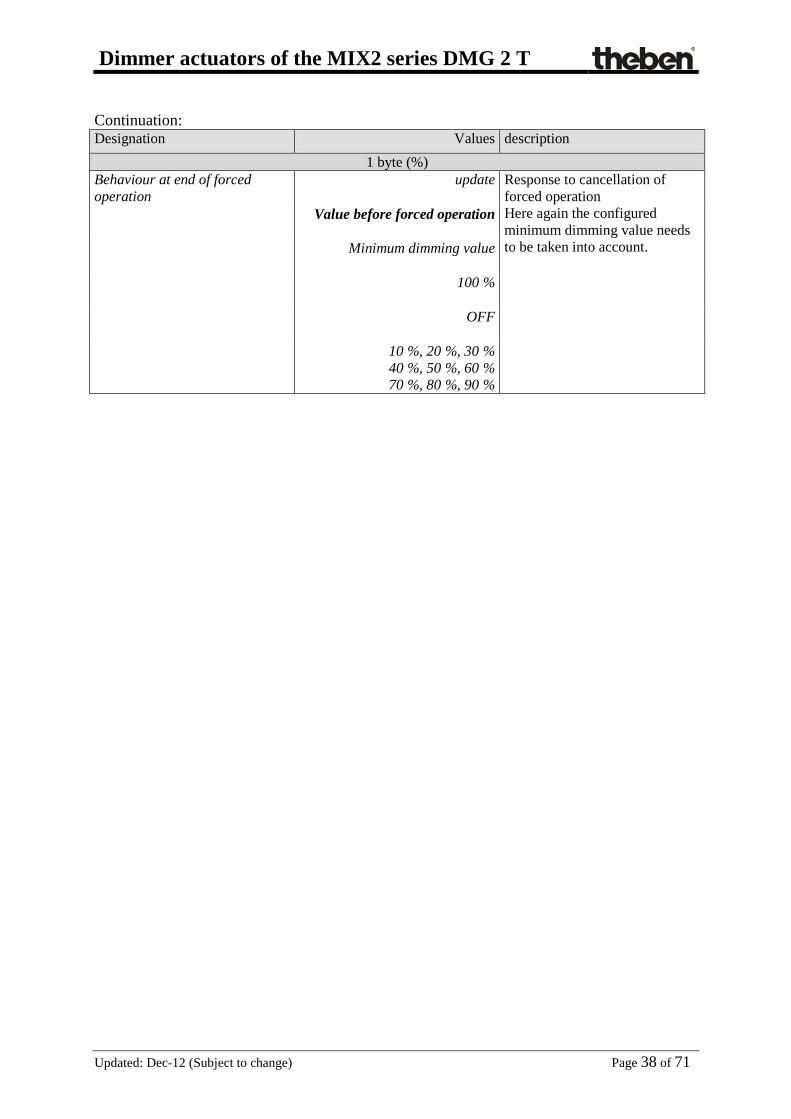
Continuation: Designation Values description
1 byte (%) Behaviour at end of forced operation
update
Response to cancellation of forced operation Here again the configured minimum dimming value needs to be taken into account.
Value before forced operation
Minimum dimming value
100 %
OFF
10 %, 20 %, 30 % 40 %, 50 %, 60 % 70 %, 80 %, 90 %

Dimmer actuators of the MIX2 series DMG 2 T
Updated: Dec-12 (Subject to change) Page 39 of 71
4.3.9 Scenes
This page appears when the Scenes are activated on the Function selection parameter page. Each channel can participate in up to 8 scenes. Table 19
Designation Values description Lock telegram for scenes lock with ON telegram
0 = Enable 1 = lock
lock with OFF telegram
0 = lock 1 = Enable Note: The lock is always deactivated after reset.
All channel scene statuses Overwrite on download
A download deletes all scene memories in a channel, i.e. all previously taught scenes. When a scene number is called, the channel assumes the configured Status after download (see below). See appendix: Enter scenes without telegrams (MIX 2 ONLY).
Unchanged after download All previously taught-in scenes are saved. However, the scene numbers the channel can react to can be changed (see below: Channel reacts to).
Participation in central scene object
No yes
Should the device react to the central scene object?
Channel reacts to No scene number
Scene number 1
Scene number 63
First of the 8 possible scene numbers the channel is to react to.
Allocated dimming value Off 10 %, 20 %, 30 % 40 %, 50 %, 60 %,
70 %, 80 %, 90 %, 100 %
New dimming value to be assigned to the selected scene number. Only possible if the scene statuses are to be overwritten after download.

Dimmer actuators of the MIX2 series DMG 2 T
Updated: Dec-12 (Subject to change) Page 40 of 71
Continuation: Designation Values description Permit teach-in No
Scenes can only be called up.
Yes The user can both call up and teach-in or amend scenes.
Channel reacts to No scene number
Scene number1 Scene number 2
… Scene number 63
Second of the 8 possible scene numbers
Allocated dimming value Off 10 %, 20 %, 30 % 40 %, 50 %, 60 %,
70 %, 80 %, 90 %, 100 %
See above.
Permit teach-in No Yes
See above.
Channel reacts to No scene number
Scene number1 …
Scene number 3 …
Scene number 63
Third of the 8 possible scene numbers
Allocated dimming value Off 10 %, 20 %, 30 % 40 %, 50 %, 60 %,
70 %, 80 %, 90 %, 100 %
See above.
Permit teach-in No Yes
See above.
Channel reacts to No scene number
Scene number1 …
Scene number 4 …
Scene number 63
Fourth of the 8 possible scene numbers
Allocated dimming value Off 10 %, 20 %, 30 % 40 %, 50 %, 60 %,
70 %, 80 %, 90 %, 100 %
See above.
Permit teach-in No Yes
See above.
Channel reacts to No scene number
Scene number1 …
Scene number 5 …
Scene number 63
Fifth of the 8 possible scene numbers

Dimmer actuators of the MIX2 series DMG 2 T
Updated: Dec-12 (Subject to change) Page 41 of 71
Continuation:
Designation Values description Allocated dimming value Off
10 %, 20 %, 30 % 40 %, 50 %, 60 %,
70 %, 80 %, 90 %, 100 %
See above.
Permit teach-in No Yes
See above.
Channel reacts to No scene number
Scene number1 …
Scene number 6 …
Scene number 63
Sixth of the 8 possible scene numbers
Allocated dimming value Off 10 %, 20 %, 30 %
40 %, 50 %, 60 %, 70 %, 80 %, 90 %, 100 %
See above.
Permit teach-in No Yes
See above.
Channel reacts to No scene number
Scene number1 …
Scene number 7 …
Scene number 63
Seventh of the 8 possible scene numbers
Allocated dimming value Off 10 %, 20 %, 30 % 40 %, 50 %, 60 %,
70 %, 80 %, 90 %, 100 %
See above.
Permit teach-in No Yes
See above.
Channel reacts to No scene number
Scene number1 …
Scene number 8 …
Scene number 63
Last of the 8 possible scene numbers
Allocated dimming value Off 10 %, 20 %, 30 % 40 %, 50 %, 60 %,
70 %, 80 %, 90 %, 100 %
See above.
Permit teach-in No Yes
See above.

Dimmer actuators of the MIX2 series DMG 2 T
Updated: Dec-12 (Subject to change) Page 42 of 71
4.3.10 Feedback Each channel has 2 feedback objects (e.g. Obj. 9 + 10, 39 + 40, etc.) Table 20
Designation Values description
Format of 1-bit feedback
Not inverted
Standard setting: 1-100 % = 1 0 % = 0
inverted 1-100 % = 0 0 % = 1
Send 1-bit feedback cyclically no yes
Send at regular intervals?
Send 8-bit feedback
only after ending dimming process
Only send current dimmer value when the new dimmer value has been reached.
every 10 % every 20 % every 30 %
Send even during the dimming process
Send 8-bit feedback cyclically
no yes
Send at regular intervals?
Time for cyclical transmission of feedback (if available)
2 min, 3 min , 5 min 10 min, 15 min, 20 min 30 min, 45 min, 60 min
At what interval? This setting applies for both feedback objects (1 and 8-bit)

Dimmer actuators of the MIX2 series DMG 2 T
Updated: Dec-12 (Subject to change) Page 43 of 71
4.3.11 Operating hours counter and service This page appears when Activate operating hours counter is selected on the Function selection parameter page.
Table 21
Designation Values description Type of operating hours counter Operating hours counter
Forward counter for channel power-on time.
counter for time period before next service
Backward counter for channel power-on time.
Operating hours counter Reporting of changes to operating hours (0..100 h, 0 = no report)
0..100 Default value = 10
At what interval is the current counter status to be sent? Example: 10 = Send each time the counter status increases by another 10 hours.
Report operating hours cyclically
No yes
Send at regular intervals?
Time for cyclical transmission 2 minutes, 3 minutes, 5 minutes, 10 minutes,
15 minutes, 20 minutes, 30 minutes, 45 minutes
60 minutes
At what interval?
counter for time period before next service Service interval (0..2000, x10 h) 0..2000
Default value = 100 Desired timescale between two services. Example: 10 = 10 x 10 h = 100 hours
Reporting of changes to time to service (0..100 h, 0 = no report)
0..100 Default value = 10
At what interval is the current counter status to be sent? Example: 10 = Send each time the counter status decreases by another 10 hours.
Report time to service cyclically no Yes
Send remaining time to next service at regular intervals? Object Time to next service.

Dimmer actuators of the MIX2 series DMG 2 T
Updated: Dec-12 (Subject to change) Page 44 of 71
Continuation:
Designation Values description Report service cyclically no
Yes Send expiry of time to next service at regular intervals? Object Service required.
Tine for cyclical transmission (time to service and service
2 minutes, 3 minutes, 5 minutes, 10 minutes,
15 minutes, 20 minutes, 30 minutes, 45 minutes
60 minutes
At what interval?

Dimmer actuators of the MIX2 series DMG 2 T
Updated: Dec-12 (Subject to change) Page 45 of 71
4.3.12 Loss of power and restoration
Table 22
Designation Values description Dimming value during download and bus failure
Same as before failure
Restore status before download or maintain status before bus failure.
100 %, 0 %, 10 %, 20 %, 30 % 40 %, 50 %, 60 % 70 %, 80 %, 90 %
Apply set value here. Here again the configured minimum dimmer value needs to be taken into account.
Dimming value during restoration of the mains supply or bus supply
Same as before failure
Restore status before failure
100 %, 0 %, 10 %, 20 %, 30 % 40 %, 50 %, 60 % 70 %, 80 %, 90 %
Apply set value here. Here again the configured minimum dimmer value needs to be taken into account.
4.3.13 Diagnostic messages The diagnostic messages are used during troubleshooting when there are faults. Table 23
Designation Values description
Send general error cyclically no Yes
Which messages should be sent cyclically?
Send short circuit cyclically
no Yes
Send excess temperature cyclically
no Yes
Send mains failure cyclically
no Yes
Send load type cyclically
no Yes
Send status cyclically (bit set)
no Yes
Cycle time for all diagnostic messages (if used)
2 minutes, 3 minutes, 5 minutes, 10 minutes,
15 minutes, 20 minutes, 30 minutes, 45 minutes
60 minutes
At what interval?

Dimmer actuators of the MIX2 series DMG 2 T
Updated: Dec-12 (Subject to change) Page 46 of 71
5 Typical applications
5.1 Bedroom lighting The light should not be blinding when switching on at night, otherwise it should light up immediately at 100%. All dimming values should, however, be configurable via the dimming function:
• At night the switch-on value should not exceed the 40% limit • Dimming up to 100% should be possible however (e.g. when reading) • No restrictions during the day • Dimming via 2 buttons
5.1.1 Devices:
• DMG 2 T (4930270) • TA2 (4969202) • TR 648 top2 (6489210) • 2 conventional buttons (NO contact)
5.1.2 Overview
Figure 1

Dimmer actuators of the MIX2 series DMG 2 T
Updated: Dec-12 (Subject to change) Page 47 of 71
5.1.3 Objects and links Table 24:
No. TA2 No. DMG 2 T Comment Object name Object name
0 Dim channel 1 / Switch on/off* 0 Switching On/Off Switch on light via button 1 (brief
button press)
1 Dim channel 1 / brighter** 1 Brighter / darker Button 1 (brighter)
3 Dim channel 2 / Switch on/off* 0 Switching On/Off Switch off light via button 2 (brief
button press)
4 Dim channel 1 / darker** 1 Brighter / darker Button 2 (darker)
* A common group address for both objects ** A common group address for both objects Table 25:
No. TR 648 top2 No. DMG 2 T Comment Object name Object name
7 C1.1 switching channel per cent 8 Dimming value limit 0.4 -100 % = limit
0 = No limit.

Dimmer actuators of the MIX2 series DMG 2 T
Updated: Dec-12 (Subject to change) Page 48 of 71
5.1.4 Important parameter settings Standard or customer-defined parameter settings apply for unlisted parameters. Table 26: DMG 2 T
Parameter page to select parameter Setting DMG 2 T channel C1: Function selection
Adjust dimming value limits yes
Dimming response Switch-on value 100 % Dimming value limits Perform limit in describing
object yes
Limit applies to switching command
yes
Limit applies to relative dimming
no
Limit applies to absolute dimming
no
Limit applies to soft switching yes Table 27: TA 2
Parameter page to select parameter Setting Channel 1 Channel function Dimming
Reaction to long / short Brighter / On Channel 2 Channel function Dimming
Reaction to long / short Darker / Off
Table 28: TR 648 top2
Parameter page to select parameter Setting General Activate time switch channel C1 yes Switching channel C1 Telegram type C1.1 percentage value
With clock ON send following telegram once Telegram (%) 40 With clock OFF send following telegram once Telegram (%) 0

Dimmer actuators of the MIX2 series DMG 2 T
Updated: Dec-12 (Subject to change) Page 49 of 71
6 APPENDIX
6.1 Use of soft switching function
6.1.1 General The Soft switch function is a cycle consisting of switch-on, dimming up, Maintain target brightness, dimming down and switch-off.
6.1.2 Soft ON for staircase lighting The following function is recommended for staircase lighting: When the light switch is operated: Full brightness. After required length of time: Lighting is slowly dimmed down and then switched off.
0 % t(h)
100 %
A/B
t1 = 0s
t3t2 / t2+
Min.
Val.
C D
P
A Switch sends Soft On telegram. t1 The Soft On time is equal to 0, i.e. the "Dim up slowly" function is deactivated B The brightness is immediately adjusted to the configured value after Soft On t2 Configured time between Soft on and Soft Off* elapses
t2+ It is possible for t2 to be extended with another Soft On telegram C t2 or t2+ has elapsed, or a Soft Off telegram was received:
Start of the Soft Off phase t3 The brightness is gradually reduced within the configured time for Soft Off D t3 has elapsed, the configured minimum brightness has been reached and the system dims to 0%
* Soft Off via configured time or via Soft Off telegram. The light can be turned off with a Soft Off telegram or retriggered with a Soft On telegram.

Dimmer actuators of the MIX2 series DMG 2 T
Updated: Dec-12 (Subject to change) Page 50 of 71
6.1.3 Entrance lighting A motion detector activates the dimmer via the soft switching object. The lighting is dimmed up within 5 seconds if a movement is detected. This delay gives the eyes enough time to adjust to the light without being dazzled The lighting is gradually dimmed down within a minute and then switched off after the configured time has elapsed or a Soft Off telegram is received via the button or via the motion detector (cyclic).
0 % t(h)
100 %
A
t1=5s t3 =1 Min. t2
Min.
Val.
B C D
P
Sequence:
A Soft On is sent by the motion detector: The brightness is immediately adjusted to the configured Minimum dimming value
t1 The brightness is gradually increased within the configured time for Soft On (5 s) B Configured value after Soft On is reached t2 Time between Soft On (1) and Soft Off C Soft Off telegram was received or configured time has elapsed:
Start of the Soft Off phase t3 The brightness is gradually reduced within the configured time for Soft Off D t3 has elapsed, the configured Minimum dimming value has been reached and the system dims
to 0%

Dimmer actuators of the MIX2 series DMG 2 T
Updated: Dec-12 (Subject to change) Page 51 of 71
6.1.4 Simulation of a daily routine Using a time switch, it is possible to simulate an entire daily routine with sunrise and sunset. To do this, the parameter "Time between Soft ON and Soft OFF" needs to be set to "Until Soft Off telegram" (See object 3, soft switching). The timer switch sends object 3 a Soft On telegram (=1) in the morning and a Soft Off telegram (=0) in the evening.
0 % t(h)
100 %
A
t1 t3t2
Min.
Val.
B C D
P
Key: Min. Configurable Minimum dimming value Val. Target dimming value, i.e. configured Dimming value after Soft On t(h) Time
Sequence:
A Soft ON will be sent by the timer: The brightness is immediately adjusted to the configured Minimum dimming value
t1 The brightness is gradually increased within the configured time for Soft On B Configured value after Soft On is reached t2 Time programmed in the time switch between Soft On (1) and Soft Off telegram (0) C Soft Off telegram has been received: start of the Soft Off phase t3 The brightness is gradually reduced within the configured time for Soft Off D t3 has elapsed, the configured minimum brightness has been reached and the system dims to 0%

Dimmer actuators of the MIX2 series DMG 2 T
Updated: Dec-12 (Subject to change) Page 52 of 71
6.1.5 Retriggering and premature switch-off It is also possible to influence the soft switching process while it is still active. Depending on which phase is currently being executed, the following responses can be triggered by Soft ON and Soft OFF telegrams.
Table 29
Telegram Response Soft ON during t1 none Soft ON during t2 t2 is restarted Soft ON during t3 A new Soft On process is started. See below.
Soft OFF during t1 The Soft ON process is stopped and the Soft OFF phase started immediately. See below.
Soft OFF during t2 The Soft Off phase starts immediately. Soft OFF during t3 none
0 % t(h)
100 %
A
t1 t3t2
Min.
Val.
B C D
P

Dimmer actuators of the MIX2 series DMG 2 T
Updated: Dec-12 (Subject to change) Page 53 of 71
6.1.6 Soft Off telegram during a Soft On process The duration of the Soft Off phase (t3’) is always equivalent to the configured time, independent of the current dimming value.
0 %
100 %
A
Min.
B C D
P
D’
Val.
t3’
t(min)
Example 1: Soft Off at the start of the Soft On phase.
0 % t(min)
100 %
A
Min.
B C D
P
t3’
D’
Val.
Example 2: Soft Off at the end of the Soft On phase. Sequence:
A A Soft On process is started. B A Soft Off telegram is received: The Soft On phase is interrupted and a Soft Off phase starts. t3’ Duration of the Soft Off phase = configured Soft Off time D’ End of the Soft Off phase

Dimmer actuators of the MIX2 series DMG 2 T
Updated: Dec-12 (Subject to change) Page 54 of 71
6.1.7 Soft On telegram during a Soft Off process The duration of the Soft On phase (t1’) is always equivalent to the configured time regardless of the current dimming value.
0 %
100 %
Min.
A
P
t1’
C
Val.
Bt(min)
D’ Example 3: Soft On at the start of the Soft Off phase.
0 %
Min.
A
P
t1’
C
Val.
B
100 %
t(min)D’
Example 4: Soft On at the end of the Soft Off phase. Sequence:
A A Soft Off process is started. B A Soft Off telegram is received: The Soft Off phase is interrupted and a Soft On phase starts. t1’ Duration of the Soft On phase = configured Soft On time D’ End of the Soft On phase

Dimmer actuators of the MIX2 series DMG 2 T
Updated: Dec-12 (Subject to change) Page 55 of 71
6.2 Application of the forced operation function Example: Lighting with brightness control during the daytime and minimum lighting during the night. The brightness controller continuously measures the brightness of the room and actuates the dimmer as required to keep the brightness constant. A dimming value of 20% is parameterized for forced mode. In the evening at the close of work, the time switch activates forced mode, as a result of which the brightness is dimmed down to 20%. During the night, the lighting is switched on for a certain period of time by the night-watchmen via the central continuous ON function. In the morning at the start of work, the time switch cancels the forced mode again and the dimmer is actuated via the brightness control.
0 % t(h)
100 %
A
n d
Min.
B C E
P nm e
D F
nc
G H Table 30
A Forced mode is cancelled by the timer. As the daylight is not yet bright enough the brightness control actuates the dimmer.
B The daylight is now bright enough to illuminate the room and the dimmer is switched off. C Heavy cloud cover, the dimmer compensates for the lack of bright daylight. D Clear sunshine, the dimmer is turned back down. S Late afternoon, the dimmer gradually replaces the receding daylight.
F Forced mode is activated by the timer. The dimmer reduces the light to 20%.
G Central continuous ON = 1 H Central continuous ON = 0 n During the night time, the parameterized value for forced mode applies. c Night round of security guards: the lighting is switched on via central continuous ON. m Morning: Daylight increases and the brightness control slowly reduces the dimming value. e Evening: Daylight decreases and the brightness control slowly increases the dimming value.
d During the daytime, the dimmer is actuated by the brightness control according to the brightness of the sunlight.

Dimmer actuators of the MIX2 series DMG 2 T
Updated: Dec-12 (Subject to change) Page 56 of 71
6.3 Dimming energy-saving lamps (ESL)
6.3.1 General Standard energy-saving lamps are not dimmable unless specifically denoted as dimmable. There are also manufacturer- and type-related differences. In particular, there are variations in switch-on brightness and performance with cold lamps. Although the ESL mode of the Theben dimmer takes account of the characteristic features of dimmable energy-saving lamps, attention should be paid to the following points.
• ESL can be connected in parallel but it is recommended to only use the same type of lighting on each channel.
• The maximum output per device is 2 x 80 W or 1x 140 W
• The minimum output per channel is 5 W
• When dimming down rapidly (e.g. Jumping configured, dimming value from 100% to 20%) there may be brief flickering even with "warm" lights.
• Brightness values that are too low (below 20%, even partially below 35%) can lead to flickering. Flickering can have a negative effect on the lifespan of the lamp similar to being switched on and off.
• When used with automatic switches (motion/presence detectors) the minimum switch-on time of an ESL must not be < 5 minutes indoors or <10 minutes outdoors. This prevents frequent switching on and off and extends the service life of the light.
To avoid dimmable ESLs flickering or not coming on at all, it is always switched on with a high dimming value and then reduced to the desired brightness within a minute. This has a compensating effect, as cold ESLs normally exhibit reduced brightness: It can take up to 5 mins to reach full brightness, depending on manufacturer, type and ambient temperature. To be able to dim dimmable ESL without problems the Theben dimmer DMG 2 T offers two special modes for dimmable energy saving lamps with RC or L-response. These modes also take account of the varying characteristic curve in comparison with the incandescent lamp, i.e. the relationship of the set percentage value to the emitted brightness in relation to maximum brightness.
6.3.2 Selection of RC or L-response: Alongside the recommendations of the ESL manufacturer, the following applies:
• RC-mode: Generally recommended for ESL, especially for high loads (advantage: less heat generated in the dimmer).
• L-mode:. With ESL, only use if a disruptive flickering is noted when dimming up or down.

Dimmer actuators of the MIX2 series DMG 2 T
Updated: Dec-12 (Subject to change) Page 57 of 71
6.3.3 Dimmable energy-saving lamps with RC response (reverse phase control)
This setting allows dimmable energy-saving lamps with RC response to be dimmed.
The energy-saving lamp always starts with 100% output and then, if applicable, automatically dims down to 95% after 3 seconds. After another 30 s the ESL is warm enough and can be dimmed down to the minimum brightness.
• Minimum configurable minimum brightness = 1%. With energy-saving lamps, depending on type, a minimum brightness of 20%...35% is sensible (below that the lamps flicker or go out completely).
• If the ESL is switched off in the warm state for less than 30 s, after being switched on again the heating phase will be shorter. In this case the duration of the warm-up phase corresponds to the previous switch-off time.
• This configuration is optimal, for example, for MEGAMAN lamps. This produces the following relation between the time elapsed since switch-on and the minimum possible dimming value:
No values are permitted in the hatched area independent of the requested dimming value.
Notice: As connecting an L-load in RC mode could lead to functional problems with the dimmer load recognition will always be performed in the interests of safety. The RC mode will only actually be used when no
L-load is recognised.

Dimmer actuators of the MIX2 series DMG 2 T
Updated: Dec-12 (Subject to change) Page 58 of 71
6.3.4 Dimmable energy-saving lamps with L-response (phase control) This setting allows dimmable energy-saving lamps with L response to be dimmed. No load recognition is performed; dimming is carried out with phase control instead.
• The energy-saving lamp always starts with at least 85% output and then, if applicable,
automatically dims down to the minimum brightness after 1 second. • Minimum configurable minimum brightness = 1%. With energy-saving lamps, depending on
type, a minimum brightness of 20%...35% is sensible (below that the lamps flicker or go out completely).
• This configuration is optimal, for example, for OSRAM lamps. This produces the following relation between the time elapsed since switch-on and the minimum possible dimming value:
No values are permitted in the hatched area independent of the requested dimming value.
Notes:
• Many types of lamp can cause an overload in L-mode, which automatically leads to the dimming down of the load.
• Because of impermissible radio interference some ESL may not be operated in L-mode. In both cases automatic load recognition must be selected (i.e. RC mode).

Dimmer actuators of the MIX2 series DMG 2 T
Updated: Dec-12 (Subject to change) Page 59 of 71
6.4 Dim LED lamps
6.4.1 General The dimmer may only operate LED lamps for 230V mains operation (so-called retrofit lamps), which are exclusively identified as dimmable. In dimming response, there are also manufacturer- and type-related differences. For that reason we recommend only operating lights of the same type in parallel on one channel.
• The maximum output per channel is 60 W, in parallel operation both channels maximum 120 W
• The minimum output per channel is 5 W.
It may be necessary to adjust the "minimum dimming value" for each parameter.
6.4.2 Selection of RC or L-response: Alongside the recommendations of the LED manufacturer, the following applies: LEDs are typically operated in RC mode in order to reduce the activation currents of the lamps, which can lead to disruptions in the power network. RC mode is therefore especially to be recommended at high outputs. Another advantage: less heat is generated in the dimmer. L-mode: Only use LED if a disruptive flickering is noted when dimming up or down. Notice: Many types of lamp can cause an overload in L-mode, which automatically leads to the dimming down of the load. Then in both cases automatic load recognition must be selected (i.e. RC mode).

Dimmer actuators of the MIX2 series DMG 2 T
Updated: Dec-12 (Subject to change) Page 60 of 71
6.5 4-bit telegrams (brighter/darker)
6.5.1 Telegram format 4-bit EIS 2 relative dimming: Table 31
Bit 3 Bit 2 Bit 1 Bit 0
Direction Dimming range divided into increments Code Increments
Dim up: dim down: 1 0
000 001 010 011 100 101 110 111
Stop 1 2 4 8
16 32
64* *typical application Examples: 1111 = to make 64 levels brighter 0111 = decrease brightness by 64 levels 1101 = make 16 levels brighter

Dimmer actuators of the MIX2 series DMG 2 T
Updated: Dec-12 (Subject to change) Page 61 of 71
6.5.2 Parameter: "Switching on/off with a 4-bit telegram"
In general, the setting "Yes" is required. The setting "No" is available for use with special customer requests, e.g. in conference rooms. The situation is described below. A whole group of dimmer channels is operated from a button (4-bit). A certain lighting situation has been adjusted by a scene or through other means – e.g. channel 1 OFF, channel 2 40%, channel 3 50%. The requirement is to now dim up and increase the brightness of the entire scene, but the channels which are switched off should remain off. The parameter "Switch on/off with a 4-bit telegram" blocks the usual switch on/off function of 4-bit telegram. Table 32
Parameter: "Switching on/off
with a 4-bit telegram"
4-bit Telegram
Dimmer output status Response
yes Brighter/darker Switched on (1%...100%)
Channel is dimmed in the normal fashion (to 0%* or 100% if applicable).
Brighter Off Channel is switched on and dimmed
no Brighter / darker Off Dimmer stays switched off
Brighter / darker Switched on (1%...100%)
Channel is dimmed in range from min. to 100%
* With the 4-bit telegram "Darker", the channel is switched off if the switch/button is kept depressed for longer than approximately 2s when the minimum brightness is reached.

Dimmer actuators of the MIX2 series DMG 2 T
Updated: Dec-12 (Subject to change) Page 62 of 71
6.6 The scenes
6.6.1 Principle The current status of a channel, or a complete MIX system can be stored and retrieved as required at a later point via the scene function. That applies to switching, blinds and dimming channels. Each channel can participate simultaneously in up to 8 scenes. This requires permission to access scenes for the relevant channel via parameter. See Activate scenes parameter and Scenes parameter page. The current status is allocated to the appropriate scene number when a scene is saved. The previously saved status is restored when a scene number is called up. This allows a MIX system to be easily associated with each chosen user scene. Table 33: Permitted scene numbers
Series Appliance Supported scene numbers
MIX (order no. 4910xxx) DME 2 S 1 .. 8 JME 4 S
MIX 2 (order no. 4930xxx) RMG / RME 8 S
1 .. 64 RMG / RME 4 I DMG 2 T / DME 2 T
The scenes are permanently stored and remain intact even after the application has been downloaded again. See parameter All channel scene statuses on the parameter page Scenes.

Dimmer actuators of the MIX2 series DMG 2 T
Updated: Dec-12 (Subject to change) Page 63 of 71
6.6.2 Select and save settings: To call up or store a scene the relevant code is sent to the scene object (obj. 243).
Table 34
scene Select Save Hex. Dec. Hex. Dec.
1 $00 0 $80 128 2 $01 1 $81 129 3 $02 2 $82 130 4 $03 3 $83 131 5 $04 4 $84 132 6 $05 5 $85 133 7 $06 6 $86 134 8 $07 7 $87 135 9 $08 8 $88 136
10 $09 9 $89 137 11 $0A 10 $8A 138 12 $0B 11 $8B 139 13 $0C 12 $8C 140 14 $0D 13 $8D 141 15 $0E 14 $8E 142 16 $0F 15 $8F 143 17 $10 16 $90 144 18 $11 17 $91 145 19 $12 18 $92 146 20 $13 19 $93 147 21 $14 20 $94 148 22 $15 21 $95 149 23 $16 22 $96 150 24 $17 23 $97 151 25 $18 24 $98 152 26 $19 25 $99 153 27 $1A 26 $9A 154 28 $1B 27 $9B 155 29 $1C 28 $9C 156 30 $1D 29 $9D 157 31 $1E 30 $9E 158 32 $1F 31 $9F 159

Dimmer actuators of the MIX2 series DMG 2 T
Updated: Dec-12 (Subject to change) Page 64 of 71
Continuation:
scene Select Save Hex Dec. Hex Dec.
33 $20 32 $A0 160 34 $21 33 $A1 161 35 $22 34 $A2 162 36 $23 35 $A3 163 37 $24 36 $A4 164 38 $25 37 $A5 165 39 $26 38 $A6 166 40 $27 39 $A7 167 41 $28 40 $A8 168 42 $29 41 $A9 169 43 $2A 42 $AA 170 44 $2B 43 $AB 171 45 $2C 44 $AC 172 46 $2D 45 $AD 173 47 $2E 46 $AE 174 48 $2F 47 $AF 175 49 $30 48 $B0 176 50 $31 49 $B1 177 51 $32 50 $B2 178 52 $33 51 $B3 179 53 $34 52 $B4 180 54 $35 53 $B5 181 55 $36 54 $B6 182 56 $37 55 $B7 183 57 $38 56 $B8 184 58 $39 57 $B9 185 59 $3A 58 $BA 186 60 $3B 59 $BB 187 61 $3C 60 $BC 188 62 $3D 61 $BD 189 63 $3E 62 $BE 190 64 $3F 63 $BF 191
Examples (central or channel-related): Select status of scene 5: → Send $04 to the relevant scene object. Save current status with scene 5: → Send $84 to the relevant scene object.

Dimmer actuators of the MIX2 series DMG 2 T
Updated: Dec-12 (Subject to change) Page 65 of 71
6.6.3 Enter scenes without telegrams (MIX2 ONLY) Instead of defining scenes individually by telegram, this can be done in advance in the ETS. This merely requires the setting of the All channel scene statuses parameter (Scenes) parameter page to overwrite at download. Accordingly, the required status can be selected for each of the 8 possible scene numbers in a channel (= Status after download parameter). The scenes are programmed into the device after the download has been completed. Later changes via teach-in telegrams are possible if required and they can be permitted or blocked via a parameter.
6.7 Store light scenes in one button Scenes are normally stored in the DMG 2 T. Object 5 (call up/save scenes) is used for this purpose. However, if the light scenes are to be stored externally, for example with a scene-capable switch, the following steps should be taken: The DMG 2 T has one dimming object (dimming value) and one feedback object (feedback in %) per channel. 2 group addresses are used here; hereafter referred to as “Gr.adr.1” and “Gr.adr.2”.
6.7.1 Assignment of group addresses and setting for the object flag
Object Connect with set to sending
Flags* K L W T
PUSH
B
UTT
ON
Brightness value telegrams Gr.adr.1 yes
- Gr.adr.2 no
DIM
MER
Dimming value Gr.adr.1 x - x
Feedback in % Gr.adr.1 no
- x Gr.adr.2 yes
* Object flag: Communication, read, write, transfer, update. x = user-defined Feedback to the dimmer should not be configured for cyclical sending.

Dimmer actuators of the MIX2 series DMG 2 T
Updated: Dec-12 (Subject to change) Page 66 of 71
6.7.2 Functional description Save scenes: The touch sensor sends a read request to Gr.adr.1 which is only answered by the "Feedback in %" object and with Gr.adr.2. Gr.adr.2 is not processed by the object "dimming value". In contrast, the touch sensor receives the value and saves it for the appropriate scene. Calling a scene: The touch sensor sends the value saved for the scene to the % object with the sending address Gr.adr.1. The value of the object “dimming value” is further processed to set the output brightness. Once the dimmer has set the requested value, it sends feedback to the object “Feedback in %” depending on the configuration.
6.8 Conversion of percentages to hexadecimal and decimal values Table 35
percentage value
0% 10% 20% 30% 40% 50% 60% 70% 80% 90% 100%
Hexadecimal 00 1A 33 4D 66 80 99 B3 CC E6 FF Decimal 00 26 51 77 102 128 153 179 204 230 255 All values from 00 to FF hex. (0 to 255 dec.) are valid.

Dimmer actuators of the MIX2 series DMG 2 T
Updated: Dez-12 (Subject to change) Page 67 of 71
6.9 Function diagram
Disable object
Set scenes
Call up/save scenes
Lock scenes
Man
ual
butto
n
Manual Obj.
Lock
Scen
es Fo
rced
ope
ratio
n
Report manual obj.
Forced operation
Perm
anen
t Off
Ope
ratin
g bu
tton
AU
S/25
%, 5
0%, 7
5%, 1
00%
Central continuous off
Perm
anen
t On
Central continuous on
230 V power supply
Short-circuit and temperature monitoring
Ope
ratin
g ho
urs
or se
rvic
e co
unte
r centrally
Report service
Reset Report hours / time to service
Stat
us fe
edba
ck
Feedback On/Off
Feedback in %
Status message (bit set)
General error message
Excess temperature message
Short circuit message
Load type message (R, C/L)
Mains power failure
Central switching
Switch ON/OFF
Brighter/darker (4 bit)
Dimming value (1 byte)
Soft switching
Brightness limit
Switc
h &
dim
min
g va
lue
Dimmer actuators of the MIX2 series DMG 2 T
Updated: Dez-12 (Subject to change) Page 68 of 71
7 Operating instructions

Dimmer actuators of the MIX2 series DMG 2 T
Updated: Dez-12 (Subject to change) Page 69 of 71

Dimmer actuators of the MIX2 series DMG 2 T
Updated: Dez-12 (Subject to change) Page 70 of 71

Dimmer actuators of the MIX2 series DMG 2 T
Updated: Dez-12 (Subject to change) Page 71 of 71