Embed Size (px)
Citation preview
ENERGY /// ANALOGUE METERS
Type of
instrument
Moving iron
for current
and voltage
Moving coil
for current
and voltage
Moving coil
with rectifiers
for current
and voltage
Moving coil
with built-in
transducer
for frequency
measurement
Maximum
demand
indicators
Combined MD with
moving
iron movement
Format
48 x 48 mm
72 x 72 mm
96 x 96 mm
144 x 144 mm
48 x 48 mm
72 x 72 mm
96 x 96 mm
144 x 144 mm
48 x 48 mm
72 x 72 mm
96 x 96 mm
144 x 144 mm
72 x 72 mm
96 x 96 mm
144 x 144 mm
72 x 72 mm
96 x 96 mm
96 x 96 mm
Movement
type
Sprung pivot
jewel with
silicon
oil damping
Sprung pivot
jewel with
eddy current
damping
Sprung pivot
jewel with
eddy current
damping
Sprung pivot
jewel with
eddy current
damping
Sprung pivot
jewel with
silicon oil
damping
Sprung pivot
jewel with
silicon oil damping
Burden
0.5 VA-15 A
then 0.8 VA
voltmeters
4.5 VA
See type specific
specifications
See type specific
specifications
See type specific
specifications2.5 VA 3 VA
Accuracy1.5% to
DIN43780
1.5% to
DIN43780
2.5% to
DIN43780
0.5% to
DIN437803%
3% on MDI
1.5% ammeter
Input typeAC current
or voltage
DC current
or voltage
AC current
or voltageAC voltage AC current AC current
Measuring
range
6-600 V
100 mA-100 A
48 mm only
up to 40 A
50 mV-600 V
100 µA-40 A,
48 mm
only 25 A
15-600 V
1m A-100 mA
and 1 A & 5 A
57.7 V @ 45 Hz
500 V @ 44 Hz
0-1/1.2 A or
0-5/6 A
8, 15 or 20
minute delays
1-6 A 8, 15 or 20
minute delays
0-5 A/6 A
instantaneous
Dielectric
voltage
withstand
test
3 kV AC 3 kV AC 3 kV AC 3 kV AC 3 kV AC 3 kV AC
6
DIN panel meters – short scale
Chapter 1: DIN panel meters Short scale
FEATURES
• A range of the most popular short-scale measuring instruments in 4 case sizes
• Shock resistant sprung pivot and jewel movement
• Terminal covers supplied as standard
• EMC hard frequency meters are fully EMC and LVD compliant
• 1/4” ‘fast on’ terminals available
APPROVALS
APPLICATIONS
• Switchgear• Distribution systems• Generator sets• Control panels• Energy management• Building management• Utility power monitoring• Process control• Motor control
BENEFITS
• Low cost• Local indication• Ease of installation• Minimal training• Low maintenance• Customised options and features
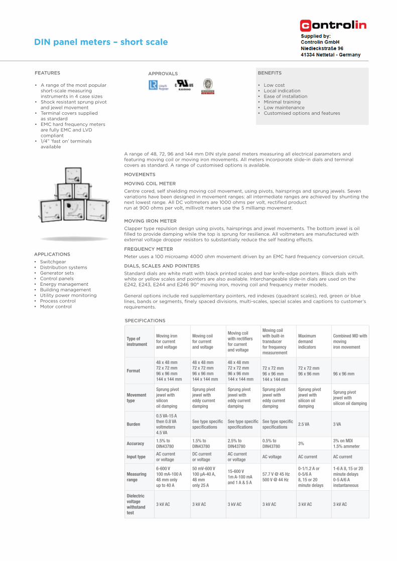
A range of 48, 72, 96 and 144 mm DIN style panel meters measuring all electrical parameters and featuring moving coil or moving iron movements. All meters incorporate slide-in dials and terminal covers as standard. A range of customised options is available.
MOVEMENTS
MOVING COIL METER
Centre cored, self shielding moving coil movement, using pivots, hairsprings and sprung jewels. Seven variations have been designed in movement ranges: all intermediate ranges are achieved by shunting the next lowest range. All DC voltmeters are 1000 ohms per volt, rectified productrun at 900 ohms per volt, millivolt meters use the 5 milliamp movement.
MOVING IRON METER
Clapper type repulsion design using pivots, hairsprings and jewel movements. The bottom jewel is oil filled to provide damping while the top is sprung for resilience. All voltmeters are manufactured with external voltage dropper resistors to substantially reduce the self heating effects.
FREQUENCY METER
Meter uses a 100 microamp 4000 ohm movement driven by an EMC hard frequency conversion circuit.
DIALS, SCALES AND POINTERS
Standard dials are white matt with black printed scales and bar knife-edge pointers. Black dials with white or yellow scales and pointers are also available. Interchangeable slide-in dials are used on the E242, E243, E244 and E246 90° moving iron, moving coil and frequency meter models.
General options include red supplementary pointers, red indexes (quadrant scales), red, green or blue lines, bands or segments, finely spaced divisions, multi-scales, special scales and captions to customer’s requirements.
SPECIFICATIONS
E203000
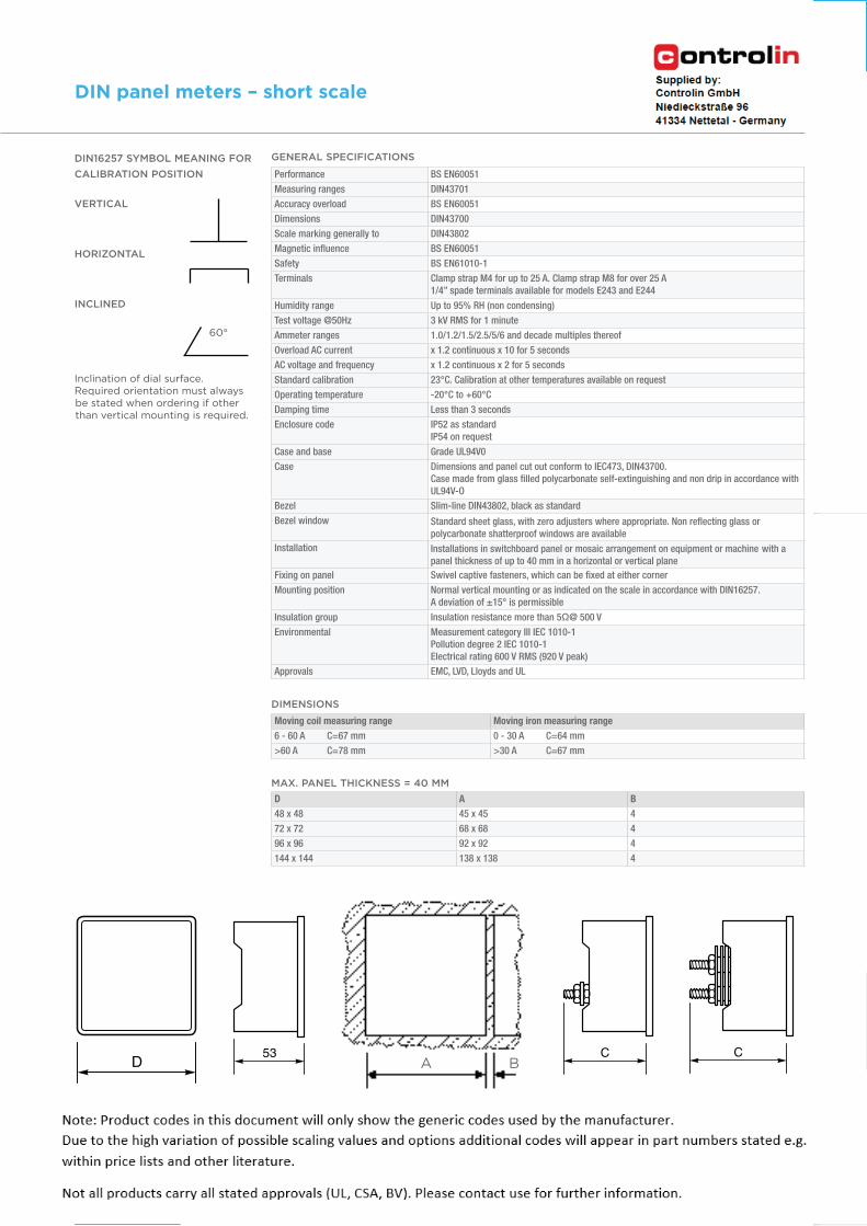
DIMENSIONS
MAX. PANEL THICKNESS = 40 MM
Moving coil measuring range Moving iron measuring range
6 - 60 A C=67 mm 0 - 30 A C=64 mm
>60 A C=78 mm >30 A C=67 mm
Performance BS EN60051
Measuring ranges DIN43701
Accuracy overload BS EN60051
Dimensions DIN43700
Scale marking generally to DIN43802
Magnetic influence BS EN60051
Safety BS EN61010-1
Terminals Clamp strap M4 for up to 25 A. Clamp strap M8 for over 25 A
1/4” spade terminals available for models E243 and E244
Humidity range Up to 95% RH (non condensing)
Test voltage @50Hz 3 kV RMS for 1 minute
Ammeter ranges 1.0/1.2/1.5/2.5/5/6 and decade multiples thereof
Overload AC current x 1.2 continuous x 10 for 5 seconds
AC voltage and frequency x 1.2 continuous x 2 for 5 seconds
Standard calibration 23°C. Calibration at other temperatures available on request
Operating temperature -20°C to +60°C
Damping time Less than 3 seconds
Enclosure code IP52 as standard
IP54 on request
Case and base Grade UL94V0
Case Dimensions and panel cut out conform to IEC473, DIN43700.
Case made from glass filled polycarbonate self-extinguishing and non drip in accordance with
UL94V-O
Bezel Slim-line DIN43802, black as standard
Bezel window Standard sheet glass, with zero adjusters where appropriate. Non reflecting glass or polycarbonate shatterproof windows are available
Installation Installations in switchboard panel or mosaic arrangement on equipment or machine with a
panel thickness of up to 40 mm in a horizontal or vertical plane
Fixing on panel Swivel captive fasteners, which can be fixed at either corner
Mounting position Normal vertical mounting or as indicated on the scale in accordance with DIN16257.
A deviation of ±15° is permissible
Insulation group Insulation resistance more than 5Ω@ 500 V
Environmental Measurement category III IEC 1010-1
Pollution degree 2 IEC 1010-1
Electrical rating 600 V RMS (920 V peak)
Approvals EMC, LVD, Lloyds and UL
GENERAL SPECIFICATIONSDIN16257 SYMBOL MEANING FOR
CALIBRATION POSITION
VERTICAL
HORIZONTAL
INCLINED
Inclination of dial surface.Required orientation must always be stated when ordering if other than vertical mounting is required.
D53 C C
A B
60°
DIN
pan
el m
ete
rs7
Chapter 1: DIN panel meters Short scale
DIN panel meters – short scale
D A B
48 x 48 45 x 45 4
72 x 72 68 x 68 4
96 x 96 92 x 92 4
144 x 144 138 x 138 4
ENERGY /// ANALOGUE METERS
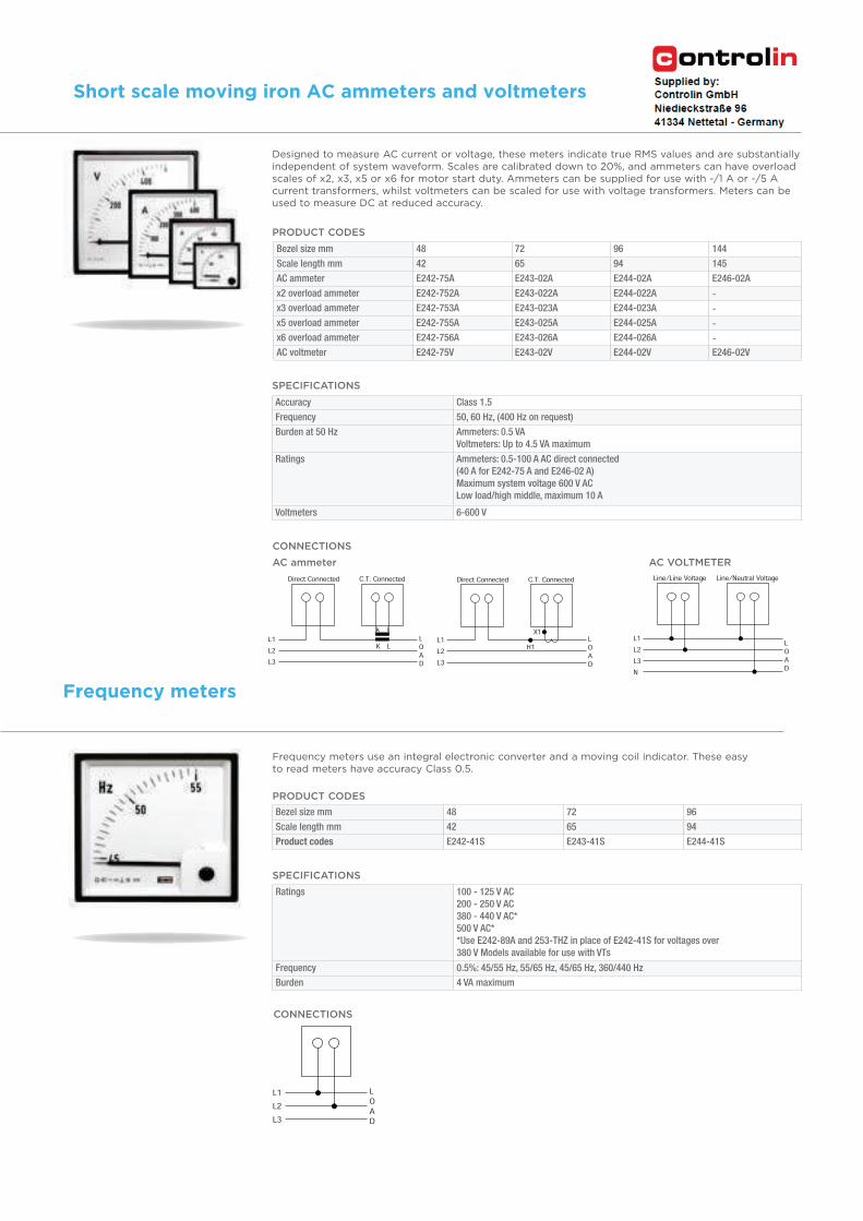
CONNECTIONS
AC VOLTMETER
Designed to measure AC current or voltage, these meters indicate true RMS values and are substantially independent of system waveform. Scales are calibrated down to 20%, and ammeters can have overload scales of x2, x3, x5 or x6 for motor start duty. Ammeters can be supplied for use with -/1 A or -/5 A current transformers, whilst voltmeters can be scaled for use with voltage transformers. Meters can be used to measure DC at reduced accuracy.
Frequency meters use an integral electronic converter and a moving coil indicator. These easy to read meters have accuracy Class 0.5.
SPECIFICATIONS
Accuracy Class 1.5
Frequency 50, 60 Hz, (400 Hz on request)
Burden at 50 Hz Ammeters: 0.5 VA
Voltmeters: Up to 4.5 VA maximum
Ratings Ammeters: 0.5-100 A AC direct connected
(40 A for E242-75 A and E246-02 A)
Maximum system voltage 600 V AC
Low load/high middle, maximum 10 A
Voltmeters 6-600 V
SPECIFICATIONS
Ratings 100 - 125 V AC
200 - 250 V AC
380 - 440 V AC*
500 V AC*
*Use E242-89A and 253-THZ in place of E242-41S for voltages over
380 V Models available for use with VTs
Frequency 0.5%: 45/55 Hz, 55/65 Hz, 45/65 Hz, 360/440 Hz
Burden 4 VA maximum
PRODUCT CODES
Bezel size mm 48 72 96 144
Scale length mm 42 65 94 145
AC ammeter E242-75A E243-02A E244-02A E246-02A
x2 overload ammeter E242-752A E243-022A E244-022A -
x3 overload ammeter E242-753A E243-023A E244-023A -
x5 overload ammeter E242-755A E243-025A E244-025A -
x6 overload ammeter E242-756A E243-026A E244-026A -
AC voltmeter E242-75V E243-02V E244-02V E246-02V
PRODUCT CODES
Bezel size mm 48 72 96
Scale length mm 42 65 94
Product codes E242-41S E243-41S E244-41S
CONNECTIONS
AC ammeter
8
Short scale moving iron AC ammeters and voltmeters
Chapter 1: DIN panel meters Short scale
Frequency meters
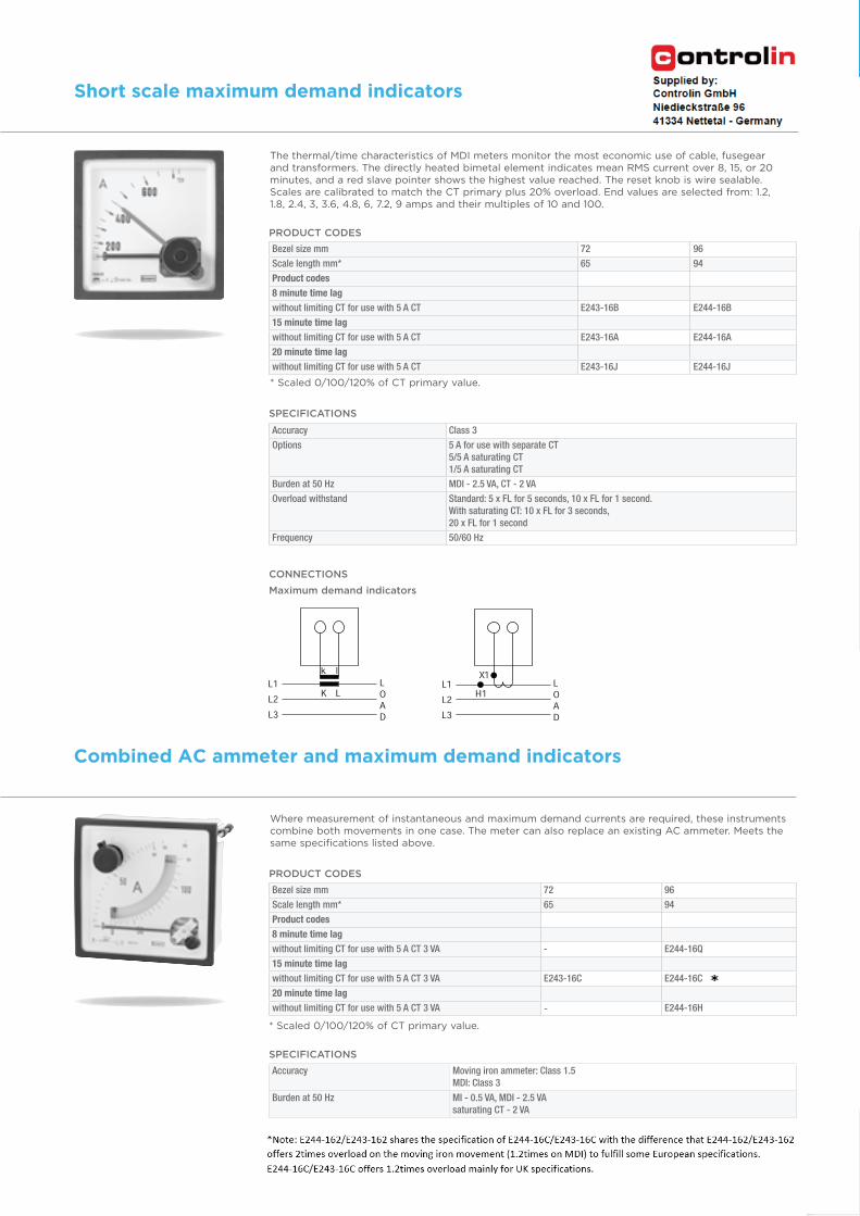
The thermal/time characteristics of MDI meters monitor the most economic use of cable, fusegear and transformers. The directly heated bimetal element indicates mean RMS current over 8, 15, or 20 minutes, and a red slave pointer shows the highest value reached. The reset knob is wire sealable. Scales are calibrated to match the CT primary plus 20% overload. End values are selected from: 1.2, 1.8, 2.4, 3, 3.6, 4.8, 6, 7.2, 9 amps and their multiples of 10 and 100.
Where measurement of instantaneous and maximum demand currents are required, these instruments combine both movements in one case. The meter can also replace an existing AC ammeter. Meets the same specifications listed above.
SPECIFICATIONS
Accuracy Class 3
Options 5 A for use with separate CT
5/5 A saturating CT
1/5 A saturating CT
Burden at 50 Hz MDI - 2.5 VA, CT - 2 VA
Overload withstand Standard: 5 x FL for 5 seconds, 10 x FL for 1 second.
With saturating CT: 10 x FL for 3 seconds,
20 x FL for 1 second
Frequency 50/60 Hz
SPECIFICATIONS
Accuracy Moving iron ammeter: Class 1.5
MDI: Class 3
Burden at 50 Hz MI - 0.5 VA, MDI - 2.5 VA
saturating CT - 2 VA
PRODUCT CODES
* Scaled 0/100/120% of CT primary value.
Bezel size mm 72 96
Scale length mm* 65 94
Product codes
8 minute time lag
without limiting CT for use with 5 A CT E243-16B E244-16B
15 minute time lag
without limiting CT for use with 5 A CT E243-16A E244-16A
20 minute time lag
without limiting CT for use with 5 A CT E243-16J E244-16J
PRODUCT CODES
* Scaled 0/100/120% of CT primary value.
Bezel size mm 72 96
Scale length mm* 65 94
Product codes
8 minute time lag
without limiting CT for use with 5 A CT 3 VA - E244-16Q
15 minute time lag
without limiting CT for use with 5 A CT 3 VA E243-16C E244-16C
20 minute time lag
without limiting CT for use with 5 A CT 3 VA - E244-16H
CONNECTIONS
Maximum demand indicators
DIN
pan
el m
ete
rs9
Chapter 1: DIN panel meters Short scale
Short scale maximum demand indicators
Combined AC ammeter and maximum demand indicators
ENERGY /// ANALOGUE METERS
CONNECTIONS
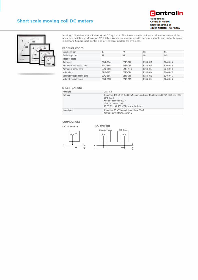
DC voltmeter DC ammeter
PRODUCT CODES
Moving coil meters are suitable for all DC systems. The linear scale is calibrated down to zero and the accuracy maintained down to 10%. High currents are measured with separate shunts and suitably scaled indicators. Suppressed, centre and offset zero models are available.
SPECIFICATIONS
Accuracy Class 1.5
Ratings Ammeters: 100 µA-25 A 4/20 mA suppressed zero 40 A for model E242, E243 and E244
up to 100 A
Voltmeters: 50 mV-600 V
1/5 V suppressed zero
50, 60, 75, 100, 150 mV for use with shunts
Impedance Ammeters: 75 mV internal shunt above 60mA
Voltmeters: 1000 Ω/V above 1 V
Bezel size mm 48 72 96 144
Scale length mm 42 65 94 145
Product codes
Ammeters E242-89A E243-01A E244-01A E246-01A
Ammeters suppressed zero E242-89R E243-01R E244-01R E246-01R
Ammeters centre zero E242-89C E243- 01C E244-01C E246-01C
Voltmeters E242-89V E243-01V E244-01V E246-01V
Voltmeters suppressed zero E242-89S E243-01S E244-01S E246-01S
Voltmeters centre zero E242-89N E243-01N E244-01N E246-01N
10
Short scale moving coil DC meters
Chapter 1: DIN panel meters Short scale
CONNECTIONS
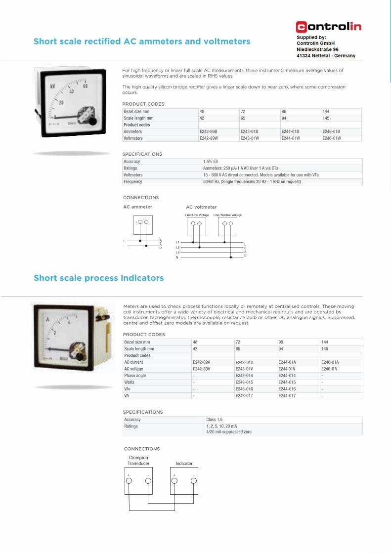
AC ammeter AC voltmeter
For high frequency or linear full scale AC measurements, these instruments measure average values of sinusoidal waveforms and are scaled in RMS values. The high quality silicon bridge rectifier gives a linear scale down to near zero, where some compression occurs.
SPECIFICATIONS
Accuracy 1.5% ES
Ratings Ammeters: 250 µA-1 A AC Over 1 A via CTs
Voltmeters 15 - 600 V AC direct connected. Models available for use with VTs
Frequency 50/60 Hz, (Single frequencies 25 Hz - 1 kHz on request)
PRODUCT CODES
Bezel size mm 48 72 96 144
Scale length mm 42 65 94 145
Product codes
Ammeters E242-89B E243-01B E244-01B E246-01B
Voltmeters E242-89W E243-01W E244-01W E246-01W
Bezel size mm 48 72 96 144
Scale length mm 42 65 94 145
Product codes
AC current E242-89A E243-01A E244-01A E246-01A
AC voltage E242-89V E243-01V E244 01V E246-0 V
Phase angle - E243-014 E244-014 -
Watts - E243-015 E244-015 -
VAr - E243-016 E244-016 -
VA - E243-017 E244-017 -
PRODUCT CODES
Meters are used to check process functions locally or remotely at centralised controls. These moving coil instruments offer a wide variety of electrical and mechanical readouts and are operated by transducer, tachogenerator, thermocouple, resistance bulb or other DC analogue signals. Suppressed, centre and offset zero models are available on request.
SPECIFICATIONS
Accuracy Class 1.5
Ratings 1, 2, 5, 10, 20 mA
4/20 mA suppressed zero
CONNECTIONS
DIN
pan
el m
ete
rs11
Chapter 1: DIN panel meters Short scale
Short scale rectified AC ammeters and voltmeters
Short scale process indicators
ENERGY /// ANALOGUE METERS
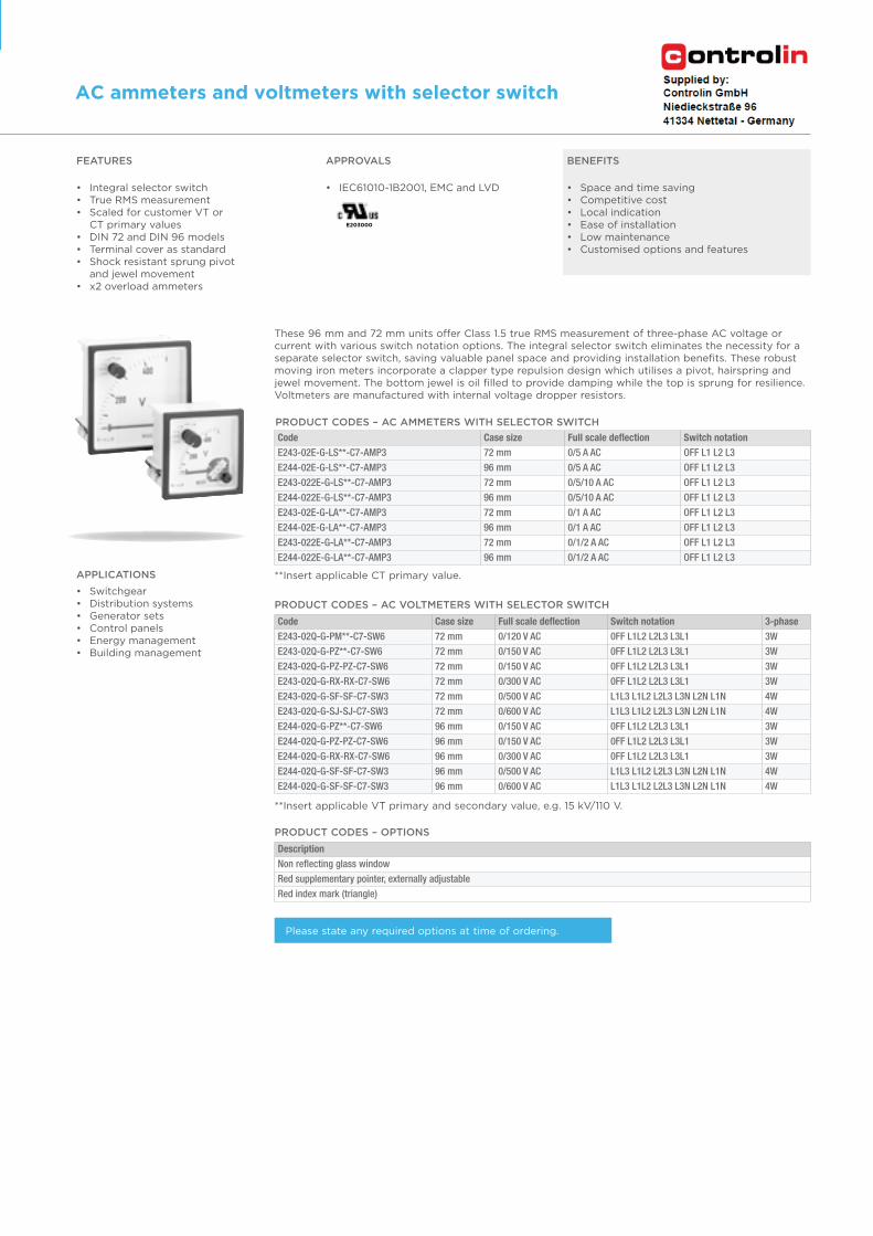
These 96 mm and 72 mm units offer Class 1.5 true RMS measurement of three-phase AC voltage or current with various switch notation options. The integral selector switch eliminates the necessity for a separate selector switch, saving valuable panel space and providing installation benefits. These robust moving iron meters incorporate a clapper type repulsion design which utilises a pivot, hairspring and jewel movement. The bottom jewel is oil filled to provide damping while the top is sprung for resilience. Voltmeters are manufactured with internal voltage dropper resistors.
PRODUCT CODES – AC VOLTMETERS WITH SELECTOR SWITCH
PRODUCT CODES – OPTIONS
Code Case size Full scale deflection Switch notation
E243-02E-G-LS**-C7-AMP3 72 mm 0/5 A AC OFF L1 L2 L3
E244-02E-G-LS**-C7-AMP3 96 mm 0/5 A AC OFF L1 L2 L3
E243-022E-G-LS**-C7-AMP3 72 mm 0/5/10 A AC OFF L1 L2 L3
E244-022E-G-LS**-C7-AMP3 96 mm 0/5/10 A AC OFF L1 L2 L3
E243-02E-G-LA**-C7-AMP3 72 mm 0/1 A AC OFF L1 L2 L3
E244-02E-G-LA**-C7-AMP3 96 mm 0/1 A AC OFF L1 L2 L3
E243-022E-G-LA**-C7-AMP3 72 mm 0/1/2 A AC OFF L1 L2 L3
E244-022E-G-LA**-C7-AMP3 96 mm 0/1/2 A AC OFF L1 L2 L3
Code Case size Full scale deflection Switch notation 3-phase
E243-02Q-G-PM**-C7-SW6 72 mm 0/120 V AC 0FF L1L2 L2L3 L3L1 3W
E243-02Q-G-PZ**-C7-SW6 72 mm 0/150 V AC 0FF L1L2 L2L3 L3L1 3W
E243-02Q-G-PZ-PZ-C7-SW6 72 mm 0/150 V AC 0FF L1L2 L2L3 L3L1 3W
E243-02Q-G-RX-RX-C7-SW6 72 mm 0/300 V AC 0FF L1L2 L2L3 L3L1 3W
E243-02Q-G-SF-SF-C7-SW3 72 mm 0/500 V AC L1L3 L1L2 L2L3 L3N L2N L1N 4W
E243-02Q-G-SJ-SJ-C7-SW3 72 mm 0/600 V AC L1L3 L1L2 L2L3 L3N L2N L1N 4W
E244-02Q-G-PZ**-C7-SW6 96 mm 0/150 V AC 0FF L1L2 L2L3 L3L1 3W
E244-02Q-G-PZ-PZ-C7-SW6 96 mm 0/150 V AC 0FF L1L2 L2L3 L3L1 3W
E244-02Q-G-RX-RX-C7-SW6 96 mm 0/300 V AC 0FF L1L2 L2L3 L3L1 3W
E244-02Q-G-SF-SF-C7-SW3 96 mm 0/500 V AC L1L3 L1L2 L2L3 L3N L2N L1N 4W
E244-02Q-G-SF-SF-C7-SW3 96 mm 0/600 V AC L1L3 L1L2 L2L3 L3N L2N L1N 4W
Description
Non reflecting glass window
Red supplementary pointer, externally adjustable
Red index mark (triangle)
**Insert applicable VT primary and secondary value, e.g. 15 kV/110 V.
**Insert applicable CT primary value.APPLICATIONS
• Switchgear• Distribution systems• Generator sets• Control panels• Energy management• Building management
12
AC ammeters and voltmeters with selector switch
Chapter 1: DIN panel meters Short scale
FEATURES
• Integral selector switch• True RMS measurement • Scaled for customer VT or
CT primary values• DIN 72 and DIN 96 models• Terminal cover as standard• Shock resistant sprung pivot
and jewel movement• x2 overload ammeters
APPROVALS
• IEC61010-1B2001, EMC and LVD
BENEFITS
• Space and time saving• Competitive cost• Local indication• Ease of installation• Low maintenance• Customised options and features
Please state any required options at time of ordering.
PRODUCT CODES – AC AMMETERS WITH SELECTOR SWITCH
E203000
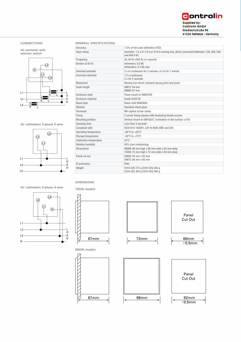
96DIN models
DIMENSIONS
72DIN models
Accuracy 1.5% of full scale deflection (FSD)
Input rating Ammeter: 1 A, 5 A 1/2 A or 5/10 A moving iron, direct connected Voltmeter: 120, 300, 500
and 600 V AC
Frequency 50, 60 Hz (400 Hz on request)
Burden at 50 Hz Ammeters: 0.5 VA
Voltmeters: 4-5 VA max
Overload ammeter 2 x In continuous for 2 minutes, 4 x In for 1 minute
Overload voltmeter 1.2 x continuous
2 x for 5 seconds
Movement Moving iron shock resistant sprung pivot and jewel
Scale length DIN72: 54 mm
DIN96: 97 mm
Enclosure style Panel mount to DIN42700
Enclosure material Grade UL94 VO
Bezel style Black matt DIN43802
Window Standard sheet glass
Terminals M4 captive screw clamp
Fixing 2 corner fixing clamps with tensioning thumb screws
Mounting position Vertical mount to DIN16257, inclination of dial surface ±15%
Damping time Less than 3 seconds
Compliant with IEC61010-1B2001, CAT III 600V, EMC and LVD
Operating temperature -20°C to +55°C
Storage temperature -40°C to +75°C
Calibration temperature 23°C
Relative humidity 95% (non condensing)
Dimensions 96DIN: 96 mm high x 96 mm wide x 63 mm deep
72DIN: 72 mm high x 72 mm wide x 63 mm deep
Panel cut out DIN96: 92 mm x 92 mm
DIN72: 68 mm x 68 mm
IP protection IP40
Weight E243-02E 275 g E243-02Q 300 g
E244-02E 360 g E244-02Q 390 g
GENERAL SPECIFICATIONSCONNECTIONS
AC ammeter with selector switch
AC voltmeters 3-phase 3-wire
AC voltmeters 3-phase 4-wire
DIN
pan
el m
ete
rs13
Chapter 1: DIN panel meters Short scale
LOAD
+-
L1 LOAD
L2L3
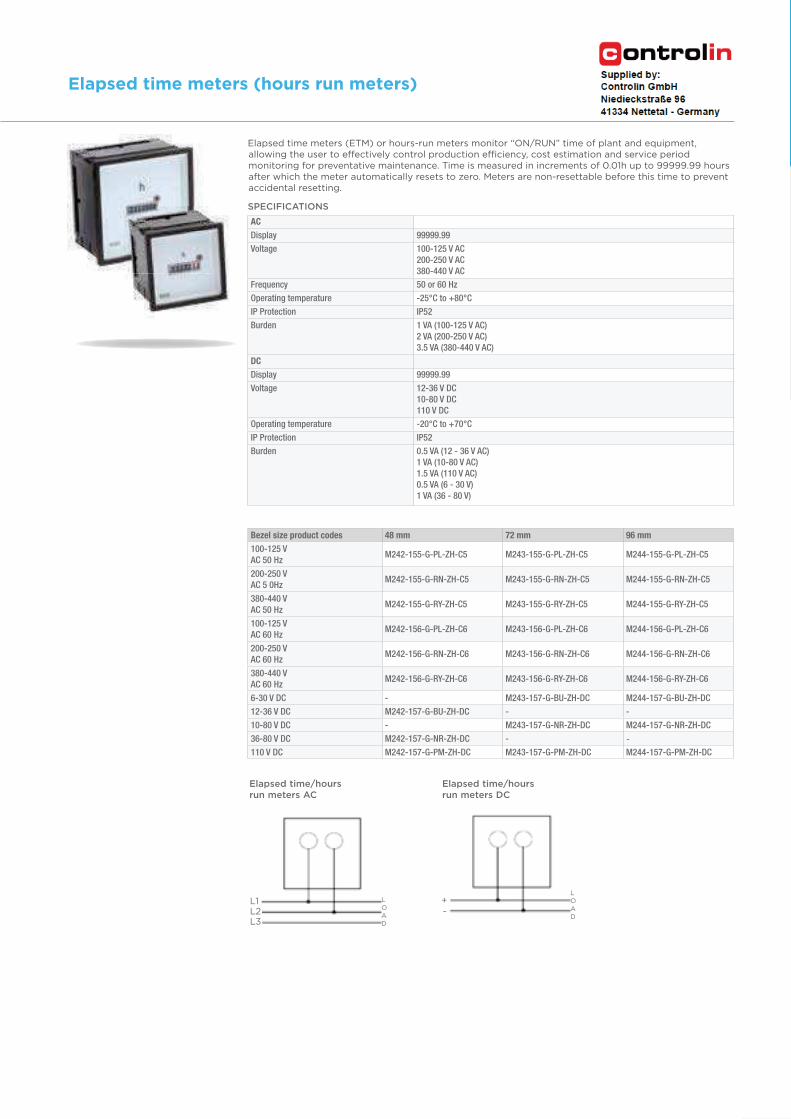
Elapsed time/hours run meters AC
Elapsed time/hours run meters DC
Elapsed time meters (ETM) or hours-run meters monitor “ON/RUN” time of plant and equipment, allowing the user to effectively control production efficiency, cost estimation and service period monitoring for preventative maintenance. Time is measured in increments of 0.01h up to 99999.99 hours after which the meter automatically resets to zero. Meters are non-resettable before this time to prevent accidental resetting.
SPECIFICATIONS
Bezel size product codes 48 mm 72 mm 96 mm
100-125 V AC 50 Hz
M242-155-G-PL-ZH-C5 M243-155-G-PL-ZH-C5 M244-155-G-PL-ZH-C5
200-250 V AC 5 0Hz
M242-155-G-RN-ZH-C5 M243-155-G-RN-ZH-C5 M244-155-G-RN-ZH-C5
380-440 V AC 50 Hz
M242-155-G-RY-ZH-C5 M243-155-G-RY-ZH-C5 M244-155-G-RY-ZH-C5
100-125 V AC 60 Hz
M242-156-G-PL-ZH-C6 M243-156-G-PL-ZH-C6 M244-156-G-PL-ZH-C6
200-250 V AC 60 Hz
M242-156-G-RN-ZH-C6 M243-156-G-RN-ZH-C6 M244-156-G-RN-ZH-C6
380-440 V AC 60 Hz
M242-156-G-RY-ZH-C6 M243-156-G-RY-ZH-C6 M244-156-G-RY-ZH-C6
6-30 V DC - M243-157-G-BU-ZH-DC M244-157-G-BU-ZH-DC
12-36 V DC M242-157-G-BU-ZH-DC - -
10-80 V DC - M243-157-G-NR-ZH-DC M244-157-G-NR-ZH-DC
36-80 V DC M242-157-G-NR-ZH-DC - -
110 V DC M242-157-G-PM-ZH-DC M243-157-G-PM-ZH-DC M244-157-G-PM-ZH-DC
DIN
pan
el m
ete
rs19
Chapter 1: DIN panel meters Long scale
Elapsed time meters (hours run meters)
AC
Display 99999.99
Voltage 100-125 V AC200-250 V AC380-440 V AC
Frequency 50 or 60 Hz
Operating temperature -25°C to +80°C
IP Protection IP52
Burden 1 VA (100-125 V AC)2 VA (200-250 V AC)3.5 VA (380-440 V AC)
DC
Display 99999.99
Voltage 12-36 V DC10-80 V DC110 V DC
Operating temperature -20°C to +70°C
IP Protection IP52
Burden 0.5 VA (12 - 36 V AC)1 VA (10-80 V AC)1.5 VA (110 V AC) 0.5 VA (6 - 30 V) 1 VA (36 - 80 V)
ENERGY /// ANALOGUE METERS
Bezel size (mm) 96 96 96 -
Scale length (mm) 41 41 - -
Voltmeter meter 2 x 90° M244-80L - - -
Frequency meter 2 x 90° - M244-41D - -
Frequency meter 2 x 21 reeds - - M244-41E -
Standard input ranges
Dual voltmeter (direct connected) 300 V, 500 V
Dual voltmeter (VT connected)120 V (for use with VT`s x/100 V), 132 V (for use with VT`s x/110 V), 144 V (for use with VT`s 120 V), 125 V, 137,5 V, 150 V (for use with some VT`s having primary voltage less then 1 kV)
Dual frequency meter - pointer type 57-110 V, 400 V +/- 20%, 500 V +/-20%
Dual frequency meter - reed type 100 V, 110 V, 230 V, 400 V +/- 20%, 500 V +/-20%
Scaling
Dual voltmeter Specify to suit application
Dual frequency meter - pointer type 45-50-55 Hz, 55-60-55 Hz, 45-55-65 Hz
Dual frequency meter - reed type 45-50-55 Hz, 55-60-65 Hz
20
Dual voltmeter and frequency meter
Chapter 1: DIN panel meters Dual voltmeter and frequency meter
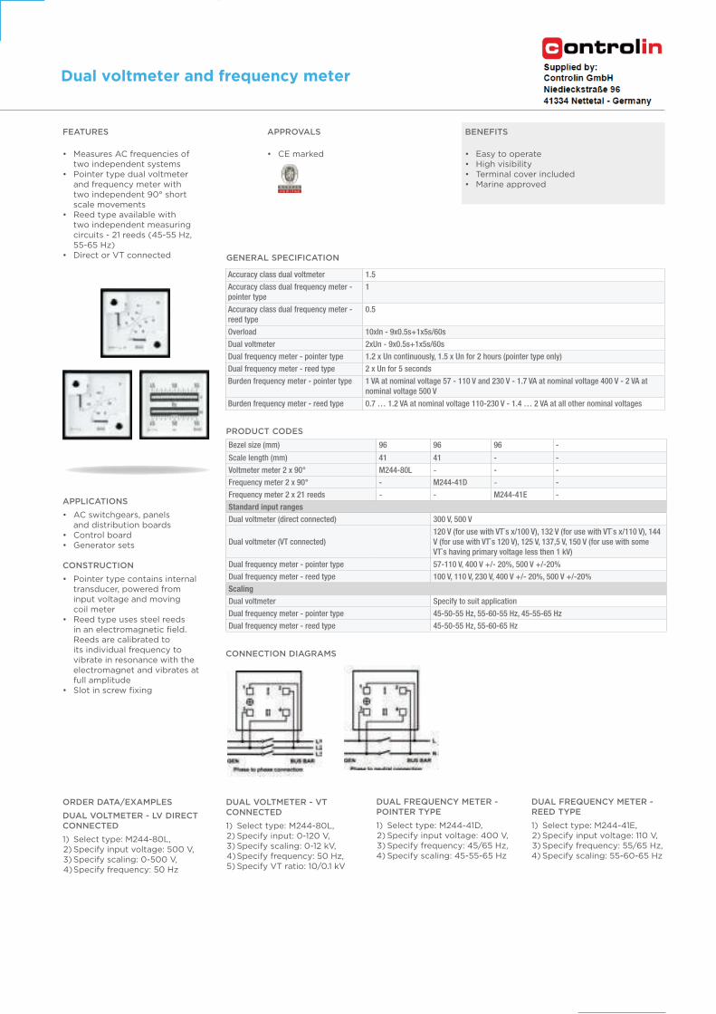
FEATURES
• Measures AC frequencies of two independent systems
• Pointer type dual voltmeter and frequency meter with two independent 90° short scale movements
• Reed type available with two independent measuring circuits - 21 reeds (45-55 Hz, 55-65 Hz)
• Direct or VT connected
APPROVALS
• CE marked
BENEFITS
• Easy to operate• High visibility• Terminal cover included• Marine approved
APPLICATIONS
• AC switchgears, panels and distribution boards
• Control board• Generator sets
CONSTRUCTION
• Pointer type contains internal transducer, powered from input voltage and moving coil meter
• Reed type uses steel reeds in an electromagnetic field. Reeds are calibrated to its individual frequency to vibrate in resonance with the electromagnet and vibrates at full amplitude
• Slot in screw fixing
PRODUCT CODES
CONNECTION DIAGRAMS
DUAL VOLTMETER - VT CONNECTED
1) Select type: M244-80L, 2) Specify input: 0-120 V, 3) Specify scaling: 0-12 kV, 4) Specify frequency: 50 Hz, 5) Specify VT ratio: 10/0.1 kV
ORDER DATA/EXAMPLES
DUAL VOLTMETER - LV DIRECT CONNECTED
1) Select type: M244-80L, 2) Specify input voltage: 500 V, 3) Specify scaling: 0-500 V, 4) Specify frequency: 50 Hz
DUAL FREQUENCY METER - POINTER TYPE
1) Select type: M244-41D, 2) Specify input voltage: 400 V, 3) Specify frequency: 45/65 Hz,4) Specify scaling: 45-55-65 Hz
DUAL FREQUENCY METER - REED TYPE
1) Select type: M244-41E, 2) Specify input voltage: 110 V, 3) Specify frequency: 55/65 Hz,4) Specify scaling: 55-60-65 Hz
GENERAL SPECIFICATION
Accuracy class dual voltmeter 1.5
Accuracy class dual frequency meter - pointer type
1
Accuracy class dual frequency meter - reed type
0.5
Overload 10xIn - 9x0.5s+1x5s/60s
Dual voltmeter 2xUn - 9x0.5s+1x5s/60s
Dual frequency meter - pointer type 1.2 x Un continuously, 1.5 x Un for 2 hours (pointer type only)
Dual frequency meter - reed type 2 x Un for 5 seconds
Burden frequency meter - pointer type 1 VA at nominal voltage 57 - 110 V and 230 V - 1.7 VA at nominal voltage 400 V - 2 VA at nominal voltage 500 V
Burden frequency meter - reed type 0.7 … 1.2 VA at nominal voltage 110-230 V - 1.4 … 2 VA at all other nominal voltages
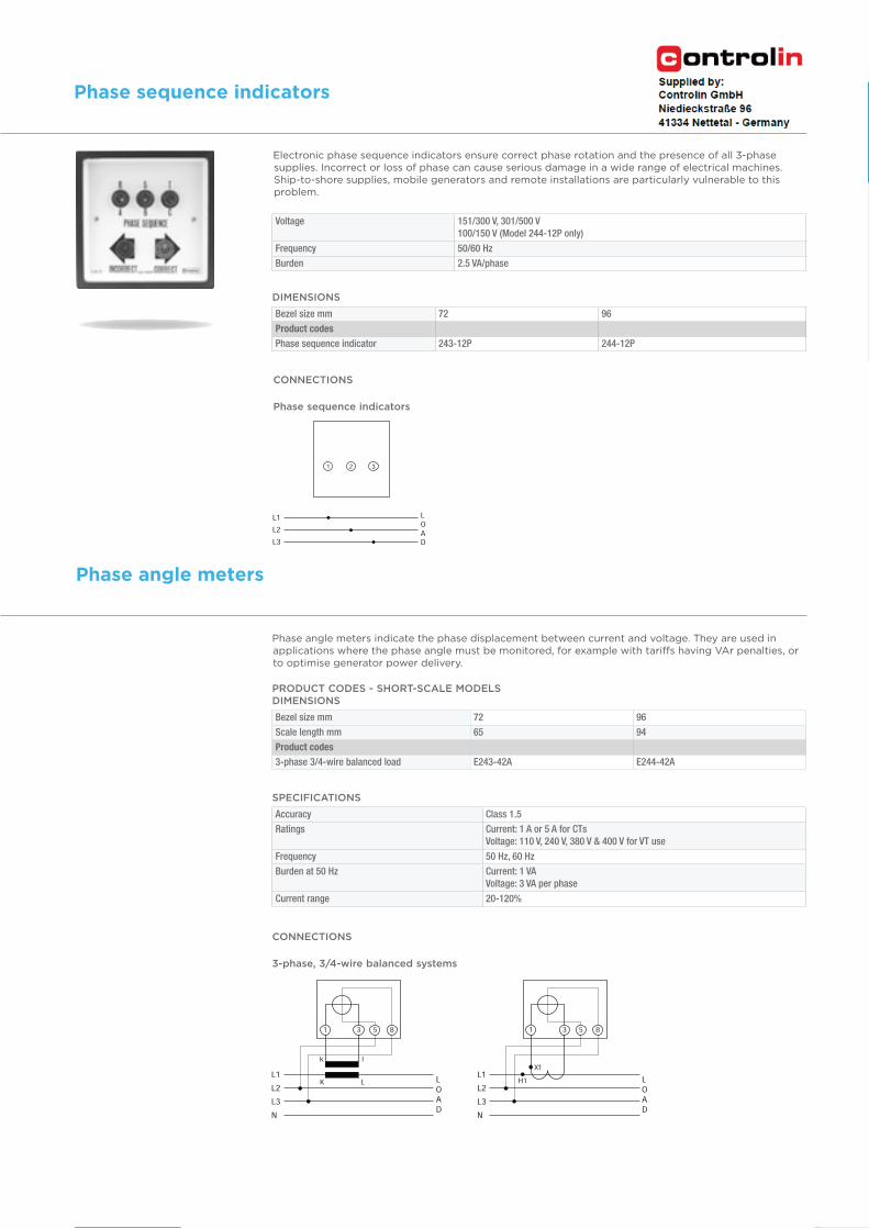
Voltage 151/300 V, 301/500 V100/150 V (Model 244-12P only)
Frequency 50/60 Hz
Burden 2.5 VA/phase
DIMENSIONS
Bezel size mm 72 96
Product codes
Phase sequence indicator 243-12P 244-12P
CONNECTIONS
Phase sequence indicators
CONNECTIONS
3-phase, 3/4-wire balanced systems
SPECIFICATIONS
Accuracy Class 1.5
Ratings Current: 1 A or 5 A for CTsVoltage: 110 V, 240 V, 380 V & 400 V for VT use
Frequency 50 Hz, 60 Hz
Burden at 50 Hz Current: 1 VAVoltage: 3 VA per phase
Current range 20-120%
PRODUCT CODES - SHORT-SCALE MODELS DIMENSIONS
Bezel size mm 72 96
Scale length mm 65 94
Product codes
3-phase 3/4-wire balanced load E243-42A E244-42A
Phase angle meters indicate the phase displacement between current and voltage. They are used in applications where the phase angle must be monitored, for example with tariffs having VAr penalties, or to optimise generator power delivery.
Phase angle meters
DIN
pan
el m
ete
rs21
Chapter 1: DIN panel meters Phase sequence indicators and phase angle meters
Phase sequence indicators
Electronic phase sequence indicators ensure correct phase rotation and the presence of all 3-phase supplies. Incorrect or loss of phase can cause serious damage in a wide range of electrical machines. Ship-to-shore supplies, mobile generators and remote installations are particularly vulnerable to this problem.
ENERGY /// ANALOGUE METERS
Bezel size (mm) 96 96 96 96 96
Scale length (mm) 95 95 95 95 95
Power factor meter 90°M244-420 single-phase
M244-421 3P/3W balanced
M244-42C 3P/4W balanced
M244-423 3P/3W unbalanced
M244-424 3P/4W unbalanced
Bezel size (mm) 96 96 96 96 96
Scale Length (mm) 135 135 135 135 135
Power factor meter 240°M244-135 single-phase
M244-136 3P/3W balanced
M244-13D 3P/4W balanced
M244-138 3P/3W unbalanced
M244-139 3P/4W unbalanced
Standard input ranges
Single-phase, 3P/4W balanced, 3P/4W unbalanced
57.7 V L-N/1 A, 57.7 V L-N/5 A, 63.5 V L-N/1 A, 63.5 V L-N/5 A, 69.3 V L-N/1 A, 9.3 V L-N/5 A, 230 V L-N/1 A, 230 V L-N/5 A, 240 V L-N/1 A, 240 V L-N/5 A, 254 V L-N/1 A, 254 V L-N/5 A
3P/3W balanced, 3P/3W unbalanced100 V L-L/1 A, 100 V L-L/5 A, 110 V L-L/1 A, 110 V L-L/5 A, 400 V L-L/1 A, 400 V L-L/5 A, 415 V L-L/1 A, 415 V L-L/5 A, 440 V L-L/1 A, 440 V L-L/5 A
Scaling 0.5/1/0.5 CAP/IND or 0.8/1/0.2 CAP/IND or 0.1/1/0/1/0.1 CAP/IND
22
Power factor meters
Chapter 1: DIN panel meters Power factor meters
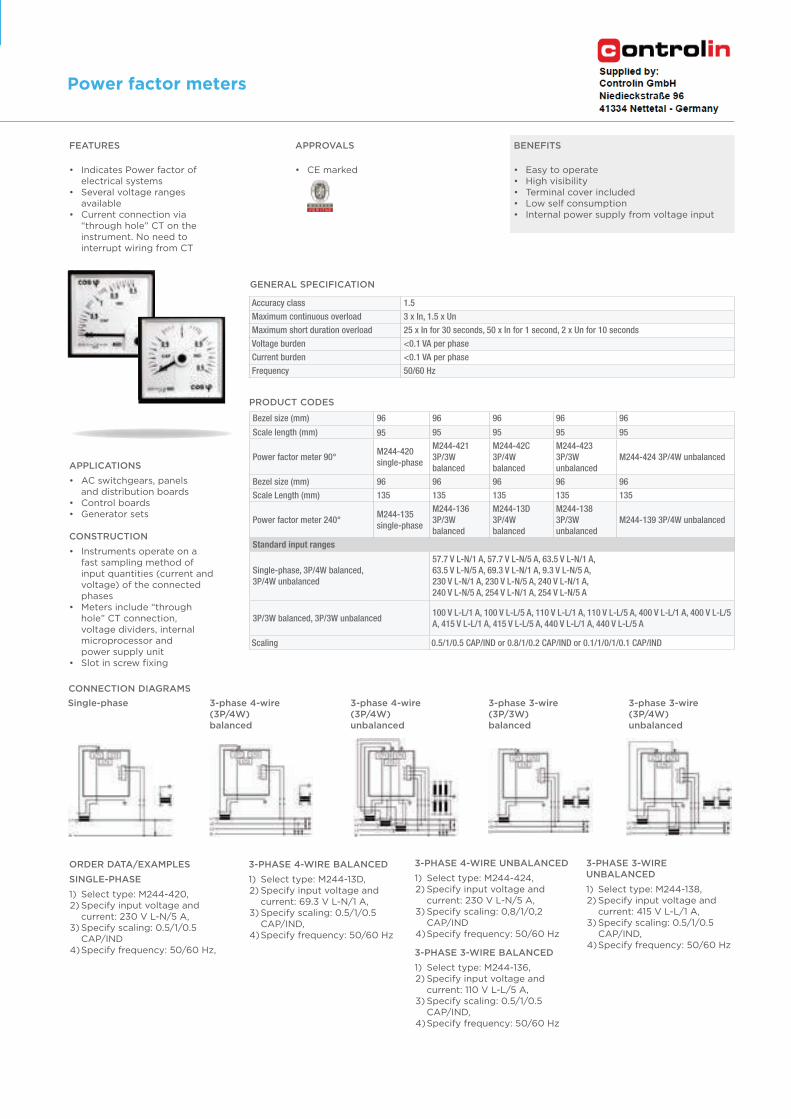
FEATURES
• Indicates Power factor of electrical systems
• Several voltage ranges available
• Current connection via “through hole” CT on the instrument. No need to interrupt wiring from CT
APPROVALS
• CE marked
BENEFITS
• Easy to operate• High visibility• Terminal cover included• Low self consumption• Internal power supply from voltage input
APPLICATIONS
• AC switchgears, panels and distribution boards
• Control boards• Generator sets
CONSTRUCTION
• Instruments operate on a fast sampling method of input quantities (current and voltage) of the connected phases
• Meters include “through hole” CT connection, voltage dividers, internal microprocessor and power supply unit
• Slot in screw fixing
PRODUCT CODES
CONNECTION DIAGRAMS
3-phase 3-wire (3P/3W)balanced
Single-phase 3-phase 4-wire (3P/4W) balanced
3-phase 4-wire (3P/4W) unbalanced
3-phase 3-wire (3P/4W) unbalanced
3-PHASE 4-WIRE BALANCED
1) Select type: M244-13D, 2) Specify input voltage and current: 69.3 V L-N/1 A, 3) Specify scaling: 0.5/1/0.5 CAP/IND, 4) Specify frequency: 50/60 Hz
ORDER DATA/EXAMPLES
SINGLE-PHASE
1) Select type: M244-420, 2) Specify input voltage and current: 230 V L-N/5 A, 3) Specify scaling: 0.5/1/0.5 CAP/IND 4) Specify frequency: 50/60 Hz,
3-PHASE 4-WIRE UNBALANCED
1) Select type: M244-424, 2) Specify input voltage and current: 230 V L-N/5 A, 3) Specify scaling: 0,8/1/0,2 CAP/IND 4) Specify frequency: 50/60 Hz
3-PHASE 3-WIRE BALANCED
1) Select type: M244-136, 2) Specify input voltage and current: 110 V L-L/5 A, 3) Specify scaling: 0.5/1/0.5 CAP/IND, 4) Specify frequency: 50/60 Hz
3-PHASE 3-WIRE UNBALANCED
1) Select type: M244-138, 2) Specify input voltage and current: 415 V L-L/1 A, 3) Specify scaling: 0.5/1/0.5 CAP/IND, 4) Specify frequency: 50/60 Hz
GENERAL SPECIFICATION
Accuracy class 1.5
Maximum continuous overload 3 x In, 1.5 x Un
Maximum short duration overload 25 x In for 30 seconds, 50 x In for 1 second, 2 x Un for 10 seconds
Voltage burden <0.1 VA per phase
Current burden <0.1 VA per phase
Frequency 50/60 Hz
CONNECTIONS
360° LED synchroscope 360° LED synchroscope and syncro check relay
Ratings voltage 63.5, 110, 120, 220, 230, 240, 380, 400, 415, 440, 480 V110/120 V (115 V nominal)220/240 V (230 V nominal)380/480 V (430 V nominal) Volts AC or via VT
Frequency 40/65 Hz
Burden at 50Hz / 60Hz 4 VA maximumSuitable for 1 or 3-phase systems
Safety IEC1010-1 (300 V AC RMS installation degree 2)
Dielectric 4 kV rms for 1 minute
Isolation BUS/GEN/RELAY
Vibration To Lloyds shipping specification
*Phase difference +0-20°, +2%
*Voltage difference +0-20%, +/-2%0-10% for models G and H
*Time delay 0-2.5 seconds +10%
*Accuracy Synchronisation at T.DC is +1˚
DIMENSIONS
Bezel size mm 96 96 96
Scale length mm 360° LED 360° LED 360° LED
3- or 4-wire40-65 Hz
Synchroscope Synchroscope and synchro check
Synchroscope and synchro checkrelay (dead bus)
Product codes
110/120 V - 244-14GG-POBX 244-14HG-POBX
220/240 V - 244-14GG-R5BX 244-14HG-R5BX
380/480 V - 244-14GG-RUBX 244-14HG-RUBX
63.5 V 244-14AG-NXYY 244-14LG-NXBX 244-14DG-NXBX
110 V 244-14AG-PMYY 244-14LG-PMBX 244-14DG-PMBX
220 V 244-14AG-R4YY 244-14LG-R4BX 244-14DG-R4BX
230 V 244-14AG-RQYY 244-14LG-RQBX 244-14DG-RQBX
240 V 244-14AG-RRYY 244-14LG-RRBX 244-14DG-RRBX
380 V 244-14AG-RUYY 244-14LG-RUBX 244-14DG-RUBX
400 V 244-14AG-SCYY 244-14LG-SCBX 244-14DG-SCBX
415 V 244-14AG-SBYY 244-14LG-SBBX 244-14DG-SBBX
440 V 244-14AG-SHYY 244-14LG-SHBX 244-14DG-SHBX
480 V 244-14AG-SEYY 244-14LG-SEBX 244-14DG-SEBX
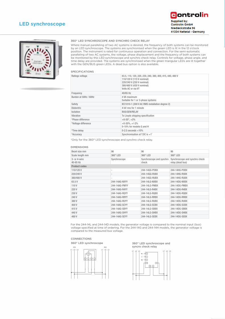
360° LED SYNCHROSCOPE AND SYNCHRO CHECK RELAY
Where manual paralleling of two AC systems is desired, the frequency of both systems can be monitored by an LED synchroscope. The systems are synchronised when the green LED is lit in the 12 o’clock position. The instrument is rated for continuous operation and connection. For the semi-automatic paralleling of two AC systems, the voltage, phase displacement and the frequency of both systems can be monitored by this LED synchroscope and synchro check relay. Controls for voltage, phase angle, and time delay are provided. The systems are synchronised when the green triangular LEDs are lit together with the GEN/BUS green LEDs. A dead bus option is also available.
SPECIFICATIONS
*Only for the 360° LED synchroscope and synchro check relay.
For the 244-14L and 244-14D models, the generator voltage is compared to the nominal input (bus) voltage specified at time of ordering. For the 244-14G and 244-14H models, the generator voltage is compared to the measured bus voltage.
3D
IN p
an
el m
ete
rs23
Chapter 1: DIN panel meters LED synchroscope
LED synchroscope
Bezel size (mm) 96 96 96 96 96
Scale length (mm) 95 95 95 95 95
Wattmeter 90°M244-210
single-phase
M244-211 3P/3W
balanced
M244-21C 3P/4W
balanced
M244-213 3P/3W
unbalanced
M244-214 3P/4W
unbalanced
Bezel size (mm) 96 96 96 96 96
Scale Length (mm) 135 135 135 135 135
Wattmeter 240°M244-215
single-phase
M244-216 3P/3W
balanced
M244-21D 3P/4W
balanced
M244-218 3P/3W
unbalanced
M244-219 3P/4W
unbalanced
Standard input ranges
Single-phase, 3P/4W balanced,
3P/4W unbalanced
57.7 V L-N/1A, 57.7 V L-N/5A, 63.5 V L-N/1A, 63.5 V L-N/5 A, 230 V L-N/1 A, 230 V L-N/5 A,
240 V -N/1 A, 240 V L-N/5 A, 254 V L-N/1 A, 254 V L-N/5 A,
3P/3W balanced, 3P/3W
unbalanced
100 V L-L/1 A, 100 V L-L/5 A, 110 V L-L/1 A, 110 V L-L/5 A, 400 V L-L/1 A, 400 V L-L/5 A, 415
V L-L/1 A, 415 V L-L/5 A, 440 V L-L/1 A, 440 V L-L/5 A
Electrical system Formula ExampleEnd scale value to choose
(considering 0,6 to 1.2 x S)
Single-phase, direct voltage
connection
P = U(L-N)
x Ip x cos
P = 230 V x 50A x 0.9
= 10350 W = 10.35 kW10 kW
3-phase 4-wire,
direct voltage connection
(balanced or unbalanced)
P = 3 x U(L-N)
x Ip x cos
P = 3 x 230 V x 400 A
x 0.95 = 262200 W
= 262,2 kW
250 kW
3-phase 3-wire,
direct voltage connection
(balanced or unbalanced)
P = 1.732 x U(L-L) x Ip x cos
P = 1.732 x 400 V
x 1000 A x 0,9 = 623520 W
= 623,52 kW
600 kW
3-phase 4-wire,
voltage connection via VT
(balanced or unbalanced)
P = 3 x Up(L-N)
x Ip x cos
P = 3 x 5770 V x 100 A x 0.95 = 1644450 W = 1,64445 MW
1.5 MW
3-phase 3-wire,
voltage connection via VT
(balanced or unbalanced)
P = 1.732 x p(L-L) x Ip x cos
P = 1.732 x 30000 V
x 50 A x 0,9 = 2338200 W
= 2,3382 MW
2.5 MW
PRODUCT CODES
CALCULATION OF END SCALE VALUE
End scale value is calculated using the formula below, where correct voltage must be selected (either L-N or L-L), depending on the electrical system and the type of meter used. Scale factor, e.g. the relation between end scale value and nominal apparent power (cos-phi = 1) must be between 0.6 to 1.2. It is recommended selecting the scale value from 1 - 1.2 - 1.25 - 1.5 - 2 - 2.5 - 3 - 4 - 5 - 6 - 7.5 – 8 (and their decades) closest to the calculated result.
DIN
pan
el m
ete
rs25
Chapter 1: DIN panel meters Power wattmeters
Power wattmeters
APPLICATIONS
• AC switchgears, panels and distribution boards
• Control boards• Generator sets
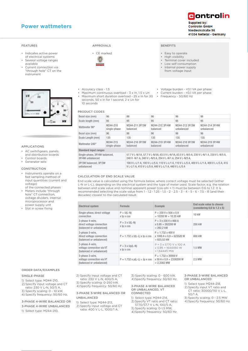
CONSTRUCTION
• Instruments operate on a fast sampling method of input quantities (current and voltage) of the connected phases
• Meters include “through hole” CT connection, voltage dividers, internal microprocessor and power supply unit
• Slot in screw fixing
FEATURES
• Indicates active power of electrical systems
• Several voltage ranges available
• Current connection via “through hole” CT on the instrument
APPROVALS
• CE marked
BENEFITS
• Easy to operate• High visibility• Terminal cover included• Low self consumption• Internal power supply
from voltage input
ORDER DATA/EXAMPLES
SINGLE-PHASE
1) Select type: M244-210, 2) Specify input voltage and CT
ratio: 230 V L-N, 50/5 A,3) Specify scaling: 0 - 10 kW, 4) Specify frequency: 50/60 Hz,
3-PHASE 4-WIRE BALANCED OR
3-PHASE 4-WIRE UNBALANCED
1) Select type: M244-21D,
2) Specify input voltage and CT ratio: 230 V L-N, 400/5 A,3) Specify scaling: 0-250 kW, 4) Specify frequency: 50/60 Hz
3-PHASE 3-WIRE BALANCED OR
UNBALANCED
1) Select type: M244-213, 2) Specify input voltage and CT
ratio: 400 V L-L, 1000/1 A,
3) Specify scaling: 0 - 600 kW, 4) Specify frequency: 50/60 Hz
3-PHASE 4-WIRE BALANCED OR UNBALANCED, VT CONNECTED
1) Select type: M244-214, 2) Specify VT ratio and CT ratio:
5770/57.7 V L-N, 100/5 A,3) Specify scaling: 0-1.5 MW, 4) Specify frequency: 50/60 Hz
3-PHASE 3-WIRE BALANCED OR UNBALANCED
1) Select type: M244-218, 2) Specify input VT ratio and
CT ratio: 30000/110 V L-L, 50/1 A,
3) Specify scaling: 0 - 2.5 MW 4) Specify frequency: 50/60 Hz
• Accuracy class - 1.5• Maximum continuous overload - 3 x In, 1.5 x Un• Maximum short duration overload - 25 x In for 30
seconds, 50 x In for 1 second, 2 x Un for 10 seconds
• Voltage burden - <0.1 VA per phase • Current burden - <0.1 VA per phase• Frequency - 50/60 Hz
ENERGY /// ANALOGUE METERS
Bezel size (mm) 96 96 96 96 96
Scale Length (mm) 95 95 95 95 95
Varmeter 90°M244-310
single-phase
M244-311 3P/3W
balanced
M244-31C 3P/4W
balanced
M244-313 3P/3W
unbalanced
M244-314 3P/4W
unbalanced
Bezel size (mm) 96 96 96 96 96
Scale length (mm) 135 135 135 135 135
Varmeter 240°M244-315
single-phase
M244-316
3P/3W balanced
M244-31D 3P/4W
balanced
M244-318 3P/3W
unbalanced
M244-319 3P/4W
unbalanced
Standard input ranges
Single-phase, 3P/4W balanced,
3P/4W unbalanced
57.7 V L-N/1 A, 57.7 V L-N/5 A, 63.5 V L-N/1 A, 63.5 V L-N/5 A, 230 V L-N/1 A, 230 V L-N/5
A, 240 V L-N/1 A, 240 V L-N/5 A, 254 V L-N/1 A, 254 V L-N/5 A
3P/3W balanced, 3P/3W
unbalanced
100 V L-L/1 A, 100 V L-L/5 A, 110 V L-L/1 A, 110 V L-L/5 A, 400 V L-L/1 A, 400 V L-L/5 A,
415 V L-L/1 A, 415 V L-L/5 A, 440 V L-L/1 A, 440 V L-L/5 A
Electrical system Formula ExampleEnd scale value to choose
(considering 0,6 to 1.2 x S)
Single-phase, direct voltage
connection
Q = U(L-N)
x Ip x sin Q = 230V x 50A x 0.44 = 5060 var = 5,06 kvar
6 kvar
3-phase 4-wire, direct voltage
connection (balanced or unbalanced)
Q = 3 x U(L-N)
x Ip x sin
P = 3 x 230V x 400A x 0.31
= 85560 var = 85,56 kvar200 kvar
3-phase 3-wire, direct voltage
connection (balanced or unbalanced)
Q = 1.732 x U(L-L)
x Ip x sin
P = 1.732 x 400V x 1000A x 0,44
= 304832 var = 304,8 kvar500 kvar
3-phase 4-wire, voltage connection via
VT (balanced or unbalanced)
Q = 3 x Up(L-N)
x Ip x sin
P = 3 x 5770V x 100A x 0.199
= 344469 var = 344,469 kvar1 Mvar
3-phase 3-wire, voltage connection via
VT (balanced or unbalanced)
Q = 1.732 x p(L-L)
x Ip x sin
P = 1.732 x 30000V x 50A x 0,44
= 1143120 var = 1,14312 Mvar2 Mvar
26
Power varmeters
Chapter 1: DIN panel meters Power
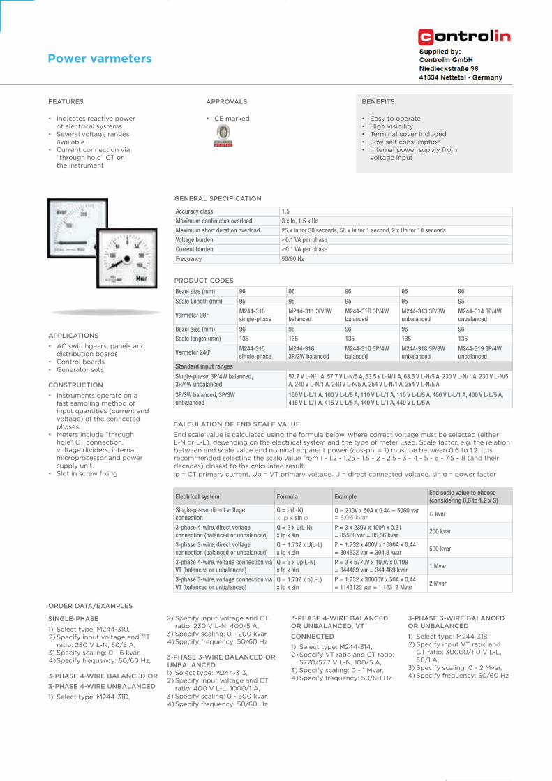
FEATURES
• Indicates reactive power of electrical systems
• Several voltage ranges available
• Current connection via “through hole” CT on the instrument
APPROVALS
• CE marked
BENEFITS
• Easy to operate• High visibility• Terminal cover included• Low self consumption• Internal power supply from
voltage input
APPLICATIONS
• AC switchgears, panels and distribution boards
• Control boards• Generator sets
CONSTRUCTION
• Instruments operate on a fast sampling method of input quantities (current and voltage) of the connected phases.
• Meters include “through hole” CT connection, voltage dividers, internal microprocessor and power supply unit.
• Slot in screw fixing
PRODUCT CODES
CALCULATION OF END SCALE VALUE
End scale value is calculated using the formula below, where correct voltage must be selected (either L-N or L-L), depending on the electrical system and the type of meter used. Scale factor, e.g. the relation between end scale value and nominal apparent power (cos-phi = 1) must be between 0.6 to 1.2. It is recommended selecting the scale value from 1 - 1.2 - 1.25 - 1.5 - 2 - 2.5 - 3 - 4 - 5 - 6 - 7.5 – 8 (and their decades) closest to the calculated result.
Ip = CT primary current, Up = VT primary voltage, U = direct connected voltage, sin = power factor
ORDER DATA/EXAMPLES
SINGLE-PHASE
1) Select type: M244-310, 2) Specify input voltage and CT
ratio: 230 V L-N, 50/5 A,3) Specify scaling: 0 - 6 kvar, 4) Specify frequency: 50/60 Hz,
3-PHASE 4-WIRE BALANCED OR
3-PHASE 4-WIRE UNBALANCED
1) Select type: M244-31D,
2) Specify input voltage and CT ratio: 230 V L-N, 400/5 A,
3) Specify scaling: 0 - 200 kvar, 4) Specify frequency: 50/60 Hz
3-PHASE 3-WIRE BALANCED OR UNBALANCED 1) Select type: M244-313, 2) Specify input voltage and CT
ratio: 400 V L-L, 1000/1 A,3) Specify scaling: 0 - 500 kvar, 4) Specify frequency: 50/60 Hz
3-PHASE 4-WIRE BALANCED OR UNBALANCED, VT
CONNECTED
1) Select type: M244-314, 2) Specify VT ratio and CT ratio:
5770/57.7 V L-N, 100/5 A,3) Specify scaling: 0 - 1 Mvar, 4) Specify frequency: 50/60 Hz
3-PHASE 3-WIRE BALANCED OR UNBALANCED
1) Select type: M244-318, 2) Specify input VT ratio and
CT ratio: 30000/110 V L-L, 50/1 A,
3) Specify scaling: 0 - 2 Mvar, 4) Specify frequency: 50/60 Hz
GENERAL SPECIFICATION
Accuracy class 1.5
Maximum continuous overload 3 x In, 1.5 x Un
Maximum short duration overload 25 x In for 30 seconds, 50 x In for 1 second, 2 x Un for 10 seconds
Voltage burden <0.1 VA per phase
Current burden <0.1 VA per phase
Frequency 50/60 Hz
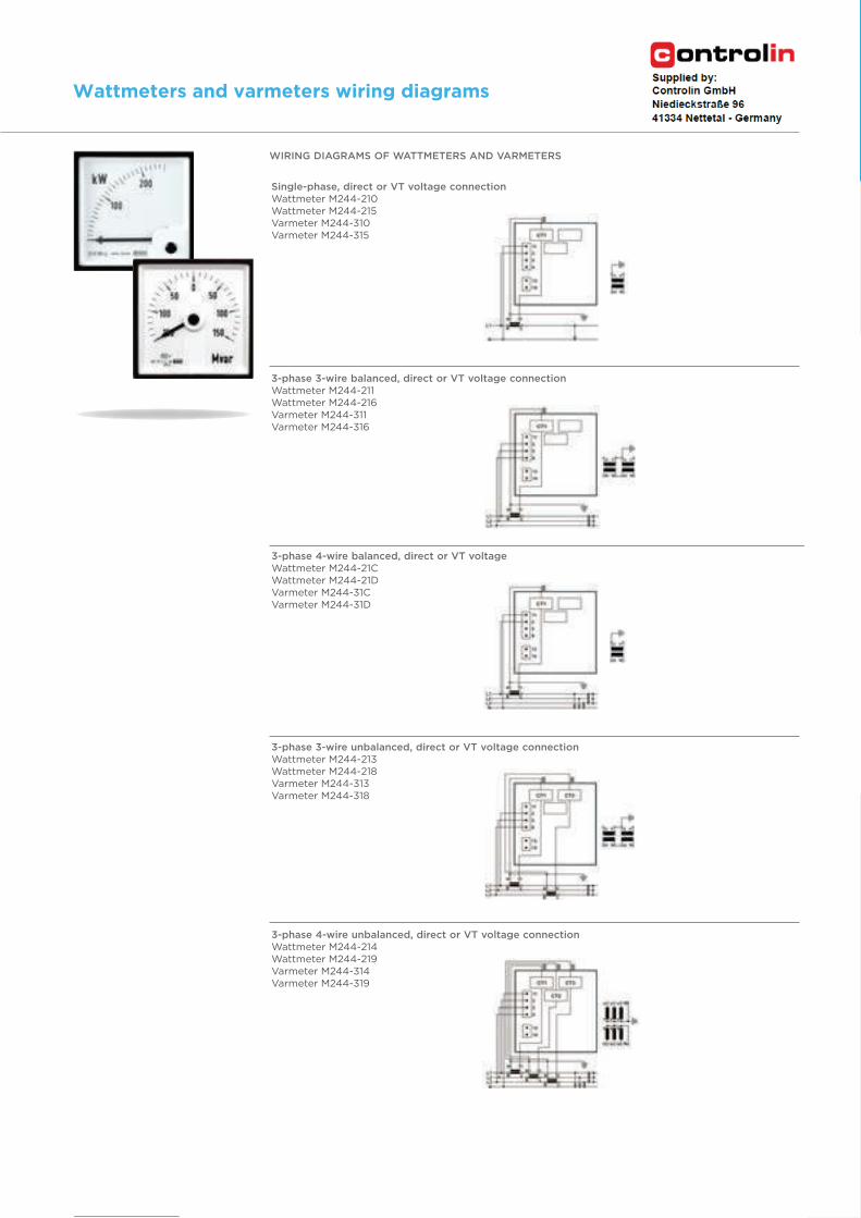
Single-phase, direct or VT voltage connectionWattmeter M244-210Wattmeter M244-215Varmeter M244-310Varmeter M244-315
3-phase 3-wire balanced, direct or VT voltage connectionWattmeter M244-211Wattmeter M244-216Varmeter M244-311Varmeter M244-316
3-phase 4-wire balanced, direct or VT voltageWattmeter M244-21CWattmeter M244-21DVarmeter M244-31CVarmeter M244-31D
3-phase 3-wire unbalanced, direct or VT voltage connectionWattmeter M244-213Wattmeter M244-218Varmeter M244-313Varmeter M244-318
3-phase 4-wire unbalanced, direct or VT voltage connectionWattmeter M244-214Wattmeter M244-219Varmeter M244-314Varmeter M244-319
WIRING DIAGRAMS OF WATTMETERS AND VARMETERS
DIN
pan
el m
ete
rs27
Chapter 1: DIN panel meters Power
Wattmeters and varmeters wiring diagrams