Embed Size (px)
Citation preview
GETTING STARTED
The COMMANDER 350 can be configured and made ready for operation in three easy steps. This'Getting Started' guide provides an overview of these steps and, where necessary, refers to therelevant section of the manual.
Step 1 – Decide on the Application Template and theOutput Configuration required
Step 2 – Connect the process inputs and outputs
Step 3 – Power up the instrument, set the template number and the outputconfiguration details
Your COMMANDER 350 is now ready for operation
Step 1 – Application Template and Output Configuration• Choose the Template which best suits your application from the list in Table A, located on the
rear fold-out.
• Choose the Control Output Type required from the list of options in Table B on the rear foldout.
Step 2 – Electrical ConnectionsUsing the labels on the back of the instrument as a guide, connect the process inputs, outputs andpower supplies. Refer to Section 5.2 of this manual (Electrical Installation) for more information.
Continued…
1/4 DIN Process Controller
C351
User GuideIM/C351_9
ABBThe Company
We are an established world force in the design and manufacture ofinstrumentation for industrial process control, flow measurement, gasand liquid analysis and environmental applications.
As a part of ABB, a world leader in process automation technology, weoffer customers application expertise, service and support worldwide.
We are committed to teamwork, high quality manufacturing, advancedtechnology and unrivalled service and support.
The quality, accuracy and performance of the Company’s productsresult from over 100 years experience, combined with a continuousprogram of innovative design and development to incorporate the latesttechnology.
The UKAS Calibration Laboratory (No. 0255) is just one of ten flowcalibration plants operated by the Company, and is indicative of ourdedication to quality and accuracy.
Health and Safety
To ensure that our products are safe and without risk to health, the following points must be noted:
1. The relevant sections of these instructions must be read carefully before proceeding.
2. Warning labels on containers and packages must be observed.
3. Installation, operation, maintenance and servicing must only be carried out by suitably trained personneland in accordance with the information given.
4. Normal safety precautions must be taken to avoid the possibility of an accident occurring when operatingin conditions of high pressure and/or temperature.
5. Chemicals must be stored away from heat, protected from temperature extremes and powders kept dry.Normal safe handling procedures must be used.
6. When disposing of chemicals ensure that no two chemicals are mixed.
Safety advice concerning the use of the equipment described in this manual or any relevant hazard datasheets (where applicable) may be obtained from the Company address on the back cover, together withservicing and spares information.
EN ISO 9001:2000
Cert. No. Q 05907
EN 29001 (ISO 9001)
Lenno, Italy – Cert. No. 9/90A
APPLLEV.6
INPtLEV.7
tUNELEV2
B
C D
+
A
01.SLt.APP
ANLGO.tYP
rEVC.ACt
50FrEJ
EF
350.0
351.5
70
350.0
351.5
70
350.0
351.5
70
GETTING STARTED
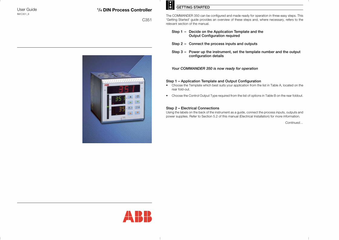
Step 3 – Setting the Parameters (Fig. GS.1)A Power-up the instrument. Press the and keys simultaneously and hold for 3 seconds
to advance directly to Level 6 – Basic Configuration.
B Set the appropriate application template, output type and control action. Use the key toadvance between frames and upper and keys to adjust the default values – seeSection 4.2 for further information.
Note. When the output type has been selected, the available inputs and outputs defaultto the settings shown in Table B on the rear fold-out.
C If you are not using 4 to 20mA inputs, then select Level 7 using the upper and keys andset up Analog Inputs I/P1 to I/P3 to suit your process – see Section 4.3.
D Controller templates only:
Select Level 2 using the upper and keys and set the tune parameters:• Analog or Motorized Valve Control – set the Proportional, Integral and
Derivative terms.• Time Proportioning Control – set the Cycle Time, Hysteresis and P, I & D Terms• Heat/Cool Outputs – set the points at which the Output 1 and Output 2
become active.
E Press to return to the Operating displays.
F Adjust the set point to the required value.
Your COMMANDER 350 is now in operation
Note. With the aboveconfiguration, no alarms orlimits have been set andadvanced functionality(gain scheduling, set pointsources etc.) has not beenenabled.
Fig. GS.1 Setting the Parameters
REGISTERE
D
Electrical Safety
This equipment complies with the requirements of CEI/IEC 61010-1:1993 "Safety requirements for electricalequipment for measurement, control, and laboratory use". If the equipment is used in a manner NOT specified by theCompany, the protection provided by the equipment may be impaired.
Symbols
One or more of the following symbols may appear on the equipment labelling:
Information in this manual is intended only to assist our customers in the efficient operation of our equipment. Useof this manual for any other purpose is specifically prohibited and its contents are not to be reproduced in full or partwithout prior approval of the Technical Publications Department.
Warning – Refer to the manual for instructions
Caution – Risk of electric shock
Protective earth (ground) terminal
Earth (ground) terminal
Direct current supply only
Alternating current supply only
Both direct and alternating current supply
The equipment is protectedthrough double insulation
1
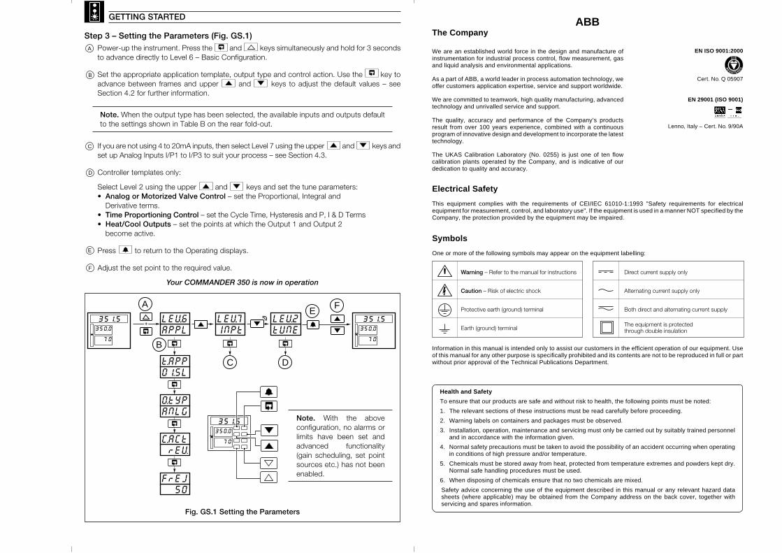
This manual is divided into 5 sections which contain all the information needed to install, configure,commission and operate the COMMANDER 351. Each section is identified clearly by a symbol asshown in Fig. 1.
OVERVIEW
!
" #$ %& '#%(
8
) *+ *, '*- %* * .* .* '' '/
GettingStarted
GettingStarted
Table A – Template ApplicationsB – Output Sources
Table C – Digital SourcesD – Analog Sources
Pull-up Resistors2 x 100kΩ
Shunt Resistors3 x 100Ω
Panel Clampsx2
CJ Sensorx2
Fig. 1 Overview of Contents
Fig. 2 Foldouts
Fig. 3 Accessories
2
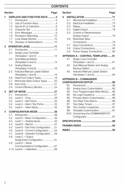
CONTENTS
Section Page
1 DISPLAYS AND FUNCTION KEYS .......... 31.1 Introduction ...................................... 31.2 Use of Function Keys ........................ 41.3 Secret-til-Lit Indicators ...................... 81.4 Character Set ................................... 81.5 Error Messages ................................ 91.6 Processor Watchdog ...................... 101.7 Loop Break Monitor ........................ 101.8 Glossary of Abbreviations ............... 10
2 OPERATOR LEVEL ................................. 112.1 Introduction .................................... 112.2 Single Loop Controller
(Templates 1 and 2) ........................ 122.3 Auto/Manual Station
(Templates 3 and 4) ........................ 142.4 Analog Backup
(Templates 5 and 6) ........................ 162.5 Indicator/Manual Loader Station
(Templates 7 and 8) ........................ 182.6 Heat/Cool Output Types .................. 192.7 Motorized Valve Output Types ......... 202.8 Auto-tune ........................................ 212.9 Control Efficiency Monitor ................ 24
3 SET UP MODE ....................................... 273.1 Introduction .................................... 273.2 Level 2 – Tune ................................. 283.3 Level 3 – Set Points ........................ 323.4 Level 4 – Alarm Trip Points .............. 343.5 Level 5 – Valve Setup ...................... 35
4 CONFIGURATION MODE ...................... 384.1 Introduction .................................... 384.2 Level 6 – Basic Configuration .......... 394.3 Level 7 – Analog Inputs ................... 434.4 Level 8 – Alarms ............................. 474.5 Level 9 – Set Point Configuration .... 514.6 Level A – Control Configuration ....... 544.7 Level B – Operator Configuration .... 594.8 Level C – Output
Assignment Configuration ............... 614.9 Level D – Serial
Communications Configuration ....... 674.10 Level E – Calibration ....................... 68
Section Page
5 INSTALLATION ....................................... 715.1 Mechanical Installation .................... 715.2 Electrical Installation ........................ 755.3 Relays ............................................. 785.4 Digital Output .................................. 785.5 Control or Retransmission
Analog Output ................................ 785.6 Motorized Valve
Connections ................................... 795.7 Input Connections .......................... 795.8 Output Connections ........................ 805.9 Power Supply Connections ............. 80
APPENDIX A – CONTROL TEMPLATES ...... 81A1 Single Loop Controller
(Templates 1 and 2) ........................ 81A2 Auto/Manual Station and Analog
Backup Station ............................... 82A3 Indicator/Manual Loader Station
(Templates 7 and 8) ........................ 85
APPENDIX B – COMMANDERCONFIGURATION EDITOR .......................... 86
B1 Introduction .................................... 86B2 Analog Input Customization ............ 86B3 Four Programmable Math Blocks .... 86B4 Six Logic Equations ........................ 86B5 Process Alarm Customization ......... 86B6 Two Real Time Alarms .................... 86B7 Two Delay Timers ........................... 87B8 Two Custom Linearizers .................. 87B9 Template Customization .................. 87B10 Connecting the COMMANDER PC
Configurator .................................... 87
SPECIFICATION ........................................... 88
FRAMES INDEX ........................................... 92
INDEX ........................................................... 95
3
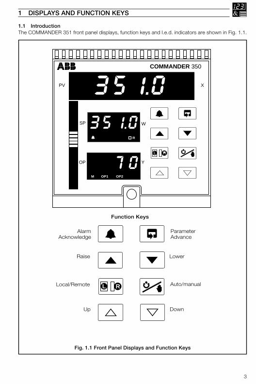
1.1 IntroductionThe COMMANDER 351 front panel displays, function keys and l.e.d. indicators are shown in Fig. 1.1.
1 DISPLAYS AND FUNCTION KEYS
Fig. 1.1 Front Panel Displays and Function Keys
COMMANDER 350
PV
SP
OP Y
X
351.0
351.0
70
R
M OP1 OP2
W
Function Keys
Auto/manual
Raise
Local/Remote L LR
ParameterAdvance
AlarmAcknowledge
Lower
Up Down
4
…1 DISPLAYS AND FUNCTION KEYS
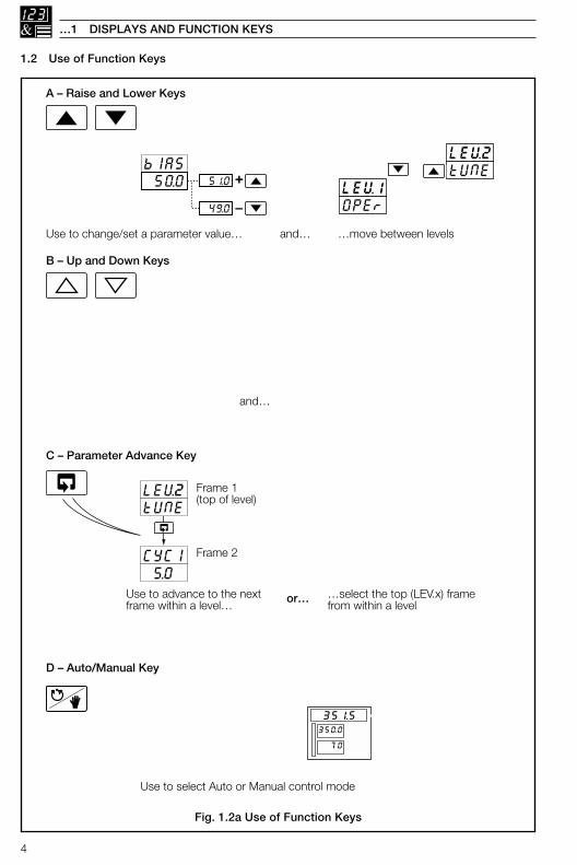
1.2 Use of Function Keys
Fig. 1.2a Use of Function Keys
350.0
351.5
70
D – Auto/Manual Key
Use to select Auto or Manual control mode
A – Raise and Lower Keys
Use to change/set a parameter value… …move between levelsand…
C – Parameter Advance Key
Use to advance to the nextframe within a level…
or… …select the top (LEV.x) framefrom within a level
LEV2tUNE
CYCl 5.0
Frame 2
Frame 1(top of level)
B – Up and Down Keys
and…
bIAS 50.0 51.0
49.0
+
–LEV1OPEr
LEV2tUNE
…move between frames within a Setupor Configuration level. Any changes madein the current frame are stored when thenext frame is selected.
LEV2tUNE
CYCl 5.0
Frame 2
Frame 1(top of level)
Press and hold
LEVx100110021003
Use to adjust the output value…
700 710
690
+
–
Auto Manual
Process VariableControl Set Point
Control Output (%)
M
2.00
2.01
350.0
351.5
70
Note. This key also stores any changes made in the previous frame
5
1 DISPLAYS AND FUNCTION KEYS…
…1.2 Use of Function Keys
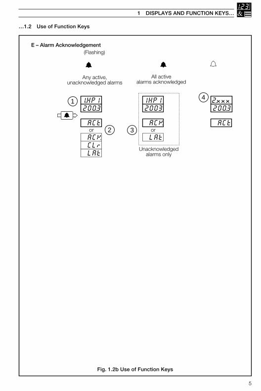
Fig. 1.2b Use of Function Keys
E – Alarm Acknowledgement
Any active,unacknowledged alarms
All activealarms acknowledged
(Flashing)
200.31.HP1
20031HP1
ACt
ACK
LAt
or
CLr
ACK
LAtor
200.32.xxx
ACt
1
2 3
4
Unacknowledgedalarms only
(On continuously) (Off)
No activealarms present
Pressing again acknowledges the displayed alarm.Lower display changes to reflect new status.
3
Next active and unacknowledged alarm is displayed. If no alarms areactive, the next enabled alarm is displayed.
4
High Process, PV High Output Low Process, PV Low Output High Latch, PV Power Failure Time Low Latch, PV Math Block 1 High High Deviation Math Block 1 Low Low Deviation Math Block 2 High High Process I/P1 Math Block 2 Low Low Process I/P1 Math Block 3 High High Process I/P2 Math Block 3 Low Low Process I/P2 Math Block 4 High High Process I/P3 Math Block 4 Low Low Process I/P3
The first active and unacknowledged alarm is displayed(or if no alarms are active, the first enabled alarm is displayed)
1
The lower display shows alarm status:ACt Alarm active and unacknowledgedACK Alarm active and acknowledgedCLr Cleared or Inactive alarmLAt Unacknowledged latched alarm
2
HPV H0LPV LOHLP PF.tLLP Hb1Hd Lb1Ld Hb2HP1 Lb2LP1 Hb3HP2 Lb3LP2 Hb4HP3 Lb4LP3
350.0
351.5
70
350.0
351.5
70
Note. If no alarms have been enabled in the Set Up level, pressing thekey has no effect.
Note. The time of the power failure,PF.t, is shown in the set point display.
– see Note below.
6
…1 DISPLAYS AND FUNCTION KEYS
…1.2 Use of Function Keys
Fig. 1.2c Use of Function Keys
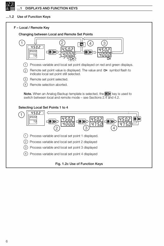
F – Local / Remote Key
Changing between Local and Remote Set Points
Selecting Local Set Points 1 to 4
400.0450.2
400.0450.2
2 4 3
L LR
R
L LR
1
4
Remote set point value is displayed. The value and symbol flash toindicate local set point still selected.
Process variable and local set point displayed on red and green displays.1
2
Remote set point selected.3
Remote selection aborted.
R
Note. When an Analog Backup template is selected, the key is used toswitch between local and remote mode – see Sections 2.4 and 4.2.
L LR
R
350.0
450.2
70
350.0
450.2
70
Process variable and local set point 2 displayed
400.0450.2
475.0450.2
2 43
L LR
Process variable and local set point 1 displayed.1
1
2
Process variable and local set point 3 displayed3
Process variable and local set point 4 displayed
L LR
475.0450.2
L LR
4
L LR
7
1 DISPLAYS AND FUNCTION KEYS…
…1.2 Use of Function Keys
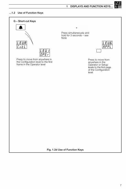
Fig. 1.2d Use of Function Keys
G – Short-cut Keys
Press to move from anywhere inthe Configuration level to the firstframe in the Operator level
Press to move fromanywhere in theOperator or Setuplevels to the first pageof the Configurationlevel
LEVACntL
LEV1OPEr
LEV6APPL
Press simultaneously andhold for 3 seconds – seeNote
+
Press to move from the Operator Level to theSecurity Code Frame and then to other levels:
Tune Level – See Section 2.13.3Set Up Level – See Fig. 3.1Configuration Level – See Fig. 4.1
COdE 0
350.0
351.5
70
350.0
351.5
70
Note. This Short-cut key combinationoperates only when the Configurationpassword is set to '0'.
8
…1 DISPLAYS AND FUNCTION KEYS
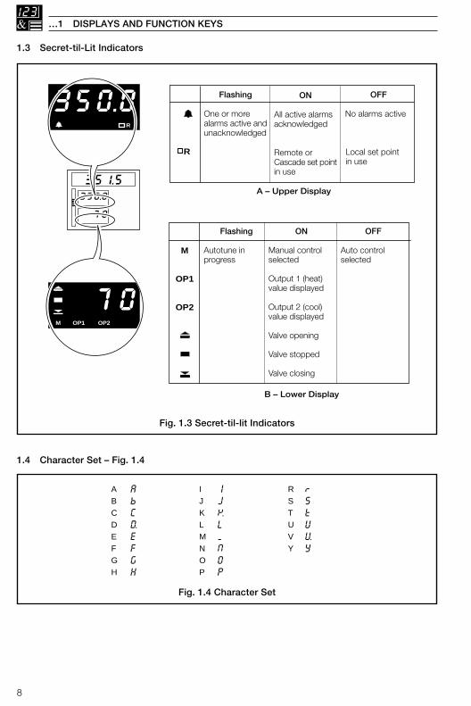
1.3 Secret-til-Lit Indicators
1.4 Character Set – Fig. 1.4
70M OP1 OP2
350.0R
350.0
351.5
70
M
OP1
OP2
OFF
Auto controlselected
ON
Manual controlselected
Output 1 (heat)value displayed
Output 2 (cool)value displayed
Valve opening
Valve stopped
Valve closing
Flashing
Autotune inprogress
OFF
No alarms active
Local set pointin use
ON
All active alarmsacknowledged
Remote orCascade set pointin use
Flashing
One or morealarms active andunacknowledged
A – Upper Display
B – Lower Display
R
ABCDEFGH
IJKLMNOP
RSTUVY
AbCDEFGH
IJKLMNOP
rStUVY
Fig. 1.3 Secret-til-lit Indicators
Fig. 1.4 Character Set
9
1 DISPLAYS AND FUNCTION KEYS…
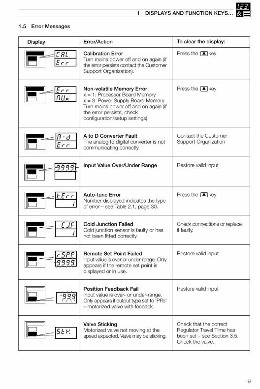
1.5 Error Messages
350.0
351.5
350.0
351.5
350.0
351.5
350.0
351.5
350.0
351.5
350.0
351.5
Error/Action
Calibration ErrorTurn mains power off and on again (ifthe error persists contact the CustomerSupport Organization).
Non-volatile Memory Errorx = 1: Processor Board Memoryx = 3: Power Supply Board MemoryTurn mains power off and on again (ifthe error persists, checkconfiguration/setup settings).
A to D Converter FaultThe analog to digital converter is notcommunicating correctly.
Input Value Over/Under Range
Auto-tune ErrorNumber displayed indicates the typeof error – see Table 2.1, page 30.
Cold Junction FailedCold junction sensor is faulty or hasnot been fitted correctly.
Remote Set Point FailedInput value is over or under-range. Onlyappears if the remote set point isdisplayed or in use.
Position Feedback FailInput value is over- or under-range.Only appears if output type set to 'PFb'– motorized valve with feeback.
Valve StickingMotorized valve not moving at thespeed expected. Valve may be sticking.
To clear the display:
Press the key
Press the key
Contact the CustomerSupport Organization
Restore valid input
Press the key
Check connections or replaceif faulty.
Restore valid input
Restore valid input
Check that the correctRegulator Travel Time hasbeen set – see Section 3.5.Check the valve.
Display
CALErr
9999
t.Err 1
StK
A-dErr
ErrNVx
CJ.F 1
350.0
351.5 rSP.F9999
999
10
…1 DISPLAYS AND FUNCTION KEYS
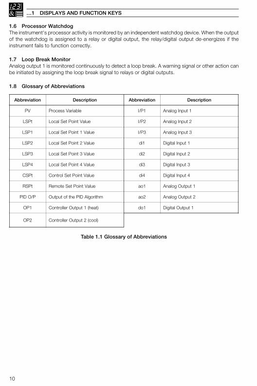
1.6 Processor WatchdogThe instrument's processor activity is monitored by an independent watchdog device. When the outputof the watchdog is assigned to a relay or digital output, the relay/digital output de-energizes if theinstrument fails to function correctly.
1.7 Loop Break MonitorAnalog output 1 is monitored continuously to detect a loop break. A warning signal or other action canbe initiated by assigning the loop break signal to relays or digital outputs.
1.8 Glossary of Abbreviations
Table 1.1 Glossary of Abbreviations
noitaiverbbA noitpircseD noitaiverbbA noitpircseD
VP elbairaVssecorP 1P/I 1tupnIgolanA
tPSL eulaVtnioPteSlacoL 2P/I 2tupnIgolanA
1PSL eulaV1tnioPteSlacoL 3P/I 3tupnIgolanA
2PSL eulaV2tnioPteSlacoL 1id 1tupnIlatigiD
3PSL eulaV3tnioPteSlacoL 2id 2tupnIlatigiD
4PSL eulaV4tnioPteSlacoL 3id 3tupnIlatigiD
tPSC eulaVtnioPteSlortnoC 4id 4tupnIlatigiD
tPSR eulaVtnioPteSetomeR 1oa 1tuptuOgolanA
P/ODIP mhtiroglADIPehtfotuptuO 2oa 2tuptuOgolanA
1PO )taeh(1tuptuOrellortnoC 1od 1tuptuOlatigiD
2PO )looc(2tuptuOrellortnoC
11
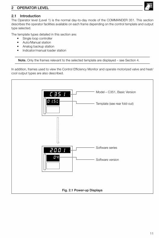
2.1 IntroductionThe Operator level (Level 1) is the normal day-to-day mode of the COMMANDER 351. This sectiondescribes the operator facilities available on each frame depending on the control template and outputtype selected.
The template types detailed in this section are:• Single loop controller• Auto/Manual station• Analog backup station• Indicator/manual loader station
Note. Only the frames relevant to the selected template are displayed – see Section 4.
In addition, frames used to view the Control Efficiency Monitor and operate motorized valve and heat/cool output types are also described.
2 OPERATOR LEVEL
Fig. 2.1 Power-up Displays
01.SL
C351Model – C351, Basic Version
Template (see rear fold-out)
Software series
Software version 04
2001
12
…2 OPERATOR LEVEL
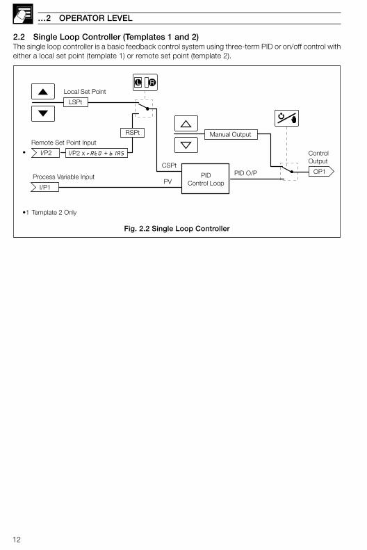
Fig. 2.2 Single Loop Controller
2.2 Single Loop Controller (Templates 1 and 2)The single loop controller is a basic feedback control system using three-term PID or on/off control witheither a local set point (template 1) or remote set point (template 2).
PIDControl Loop
PID O/PCSPt
I/P2
PVI/P1
Manual Output
OP1
Remote Set Point Input
Process Variable Input
•1 Template 2 Only
•
LSPt
I/P2 x rAtO + bIAS
RSPt
L LRLocal Set Point
ControlOutput
13
350.0
351.5
70
PV – CSPtDeviation
OP1
•1
1.000
rAtO
OP1
•2
5.000
bIAS
OP1
•3
2 OPERATOR LEVEL…
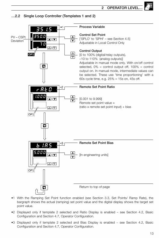
Process Variable
Control Set Point['SPLO' to 'SPHI' – see Section 4.5]Adjustable in Local Control Only
Control Output[0 to 100% (digital/relay outputs),–10 to 110% (analog outputs)]Adjustable in manual mode only. With on/off controlselected, 0% = control output off, 100% = controloutput on. In manual mode, intermediate values canbe selected. These use 'time proportioning' with a60s cycle time, e.g. 25% = 15s on, 45s off.
Remote Set Point Ratio
[0.001 to 9.999]Remote set point value =(ratio x remote set point input) + bias
Remote Set Point Bias
[In engineering units]
Return to top of page
•1 With the Ramping Set Point function enabled (see Section 3.3, Set Points/ Ramp Rate), thebargraph shows the actual (ramping) set point value and the digital display shows the target setpoint value.
•2 Displayed only if template 2 selected and Ratio Display is enabled – see Section 4.2, BasicConfiguration and Section 4.7, Operator Configuration.
•3 Displayed only if template 2 selected and Bias Display is enabled – see Section 4.2, BasicConfiguration and Section 4.7, Operator Configuration.
…2.2 Single Loop Controller (Templates 1 and 2)
14
…2 OPERATOR LEVEL
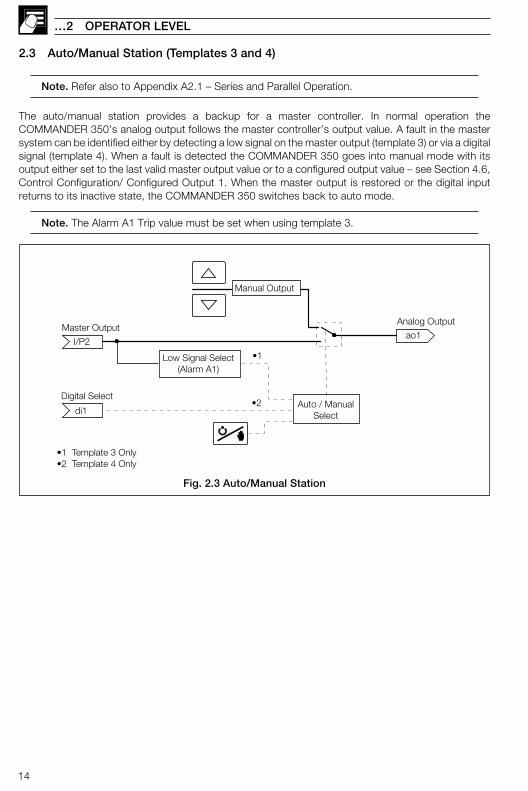
2.3 Auto/Manual Station (Templates 3 and 4)
Note. Refer also to Appendix A2.1 – Series and Parallel Operation.
The auto/manual station provides a backup for a master controller. In normal operation theCOMMANDER 350’s analog output follows the master controller’s output value. A fault in the mastersystem can be identified either by detecting a low signal on the master output (template 3) or via a digitalsignal (template 4). When a fault is detected the COMMANDER 350 goes into manual mode with itsoutput either set to the last valid master output value or to a configured output value – see Section 4.6,Control Configuration/ Configured Output 1. When the master output is restored or the digital inputreturns to its inactive state, the COMMANDER 350 switches back to auto mode.
Note. The Alarm A1 Trip value must be set when using template 3.
Fig. 2.3 Auto/Manual Station
di1
Master Outputao1
•1
•2
•1 Template 3 Only•2 Template 4 Only
Digital Select
I/P2
Manual Output
Low Signal Select(Alarm A1)
Auto / ManualSelect
Analog Output
15
orLow MasterOutput Value
Digital InputActive
or
•1
•2
•3
orRestoredMaster Output
Digital InputInactive
or
•1
•2
•3
50.0
55.0
70
50.0
55.5
50
M
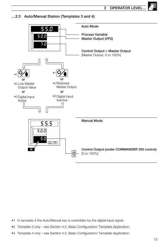
Auto Mode
Process VariableMaster Output (I/P2)
Control Output = Master Output[Master Output, 0 to 100%]
Manual Mode
Control Output (under COMMANDER 350 control)[0 to 100%]
2 OPERATOR LEVEL…
…2.3 Auto/Manual Station (Templates 3 and 4)
•1 In template 4 the Auto/Manual key is overridden by the digital input signal.
•2 Template 3 only – see Section 4.2, Basic Configuration/ Template Application.
•3 Template 4 only – see Section 4.2, Basic Configuration/ Template Application.
16
…2 OPERATOR LEVEL
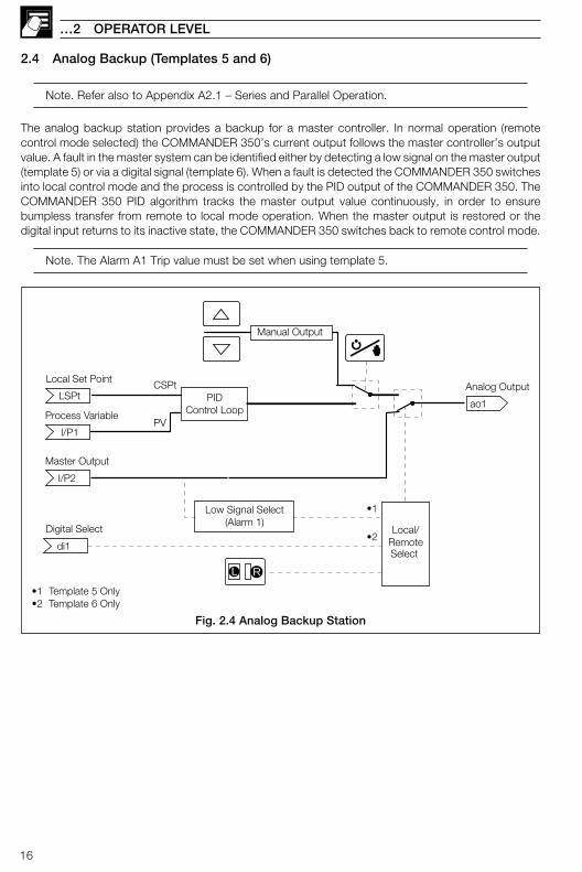
2.4 Analog Backup (Templates 5 and 6)
Note. Refer also to Appendix A2.1 – Series and Parallel Operation.
The analog backup station provides a backup for a master controller. In normal operation (remotecontrol mode selected) the COMMANDER 350’s current output follows the master controller’s outputvalue. A fault in the master system can be identified either by detecting a low signal on the master output(template 5) or via a digital signal (template 6). When a fault is detected the COMMANDER 350 switchesinto local control mode and the process is controlled by the PID output of the COMMANDER 350. TheCOMMANDER 350 PID algorithm tracks the master output value continuously, in order to ensurebumpless transfer from remote to local mode operation. When the master output is restored or thedigital input returns to its inactive state, the COMMANDER 350 switches back to remote control mode.
Note. The Alarm A1 Trip value must be set when using template 5.
Fig. 2.4 Analog Backup Station
LSPt
I/P1
di1
Local Set Point
PVProcess Variable
PIDControl Loop
Local/RemoteSelect
•1
•1 Template 5 Only•2 Template 6 Only
Master Output
Digital Select
ao1
Manual Output
Low Signal Select(Alarm 1)
L LR
Analog Output
I/P2
•2
CSPt
17
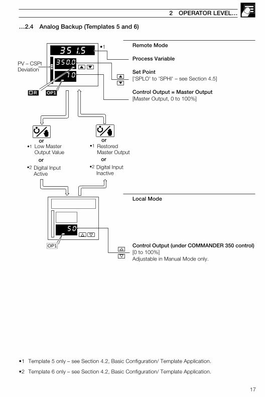
Remote Mode
Process Variable
Set Point['SPLO' to 'SPHI' – see Section 4.5]
Control Output = Master Output[Master Output, 0 to 100%]
Local Mode
Control Output (under COMMANDER 350 control)[0 to 100%]Adjustable in Manual Mode only.
2 OPERATOR LEVEL…
…2.4 Analog Backup (Templates 5 and 6)
•1 Template 5 only – see Section 4.2, Basic Configuration/ Template Application.
•2 Template 6 only – see Section 4.2, Basic Configuration/ Template Application.
orRestoredMaster Output
Digital InputInactive
or
•1
•2
orLow MasterOutput Value
Digital InputActive
or
•1
•2
350.0
351.5
70
PV – CSPtDeviation
OP1
•1
50
OP1
R
18
…2 OPERATOR LEVEL
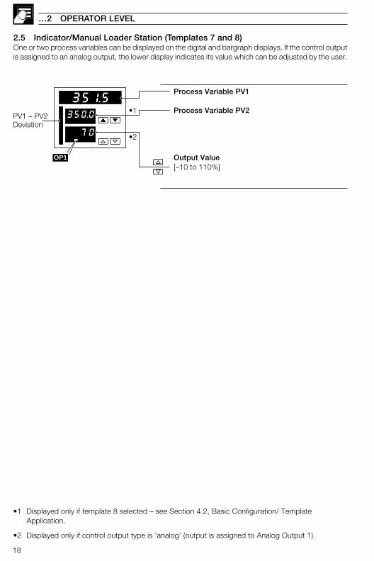
2.5 Indicator/Manual Loader Station (Templates 7 and 8)One or two process variables can be displayed on the digital and bargraph displays. If the control outputis assigned to an analog output, the lower display indicates its value which can be adjusted by the user.
•1 Displayed only if template 8 selected – see Section 4.2, Basic Configuration/ TemplateApplication.
•2 Displayed only if control output type is 'analog' (output is assigned to Analog Output 1).
Process Variable PV1
Process Variable PV2
Output Value[–10 to 110%]
350.0
351.5
70
OP1
•1
•2
PV1 – PV2Deviation
19
2 OPERATOR LEVEL…
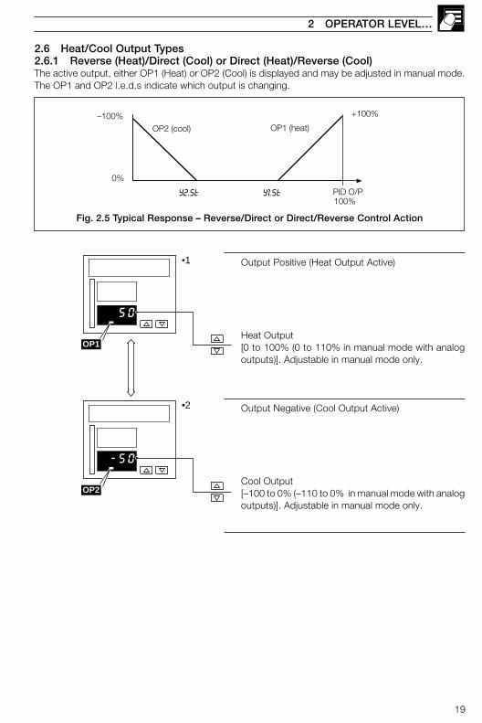
2.6 Heat/Cool Output Types2.6.1 Reverse (Heat)/Direct (Cool) or Direct (Heat)/Reverse (Cool)The active output, either OP1 (Heat) or OP2 (Cool) is displayed and may be adjusted in manual mode.The OP1 and OP2 l.e.d.s indicate which output is changing.
Output Positive (Heat Output Active)
Heat Output[0 to 100% (0 to 110% in manual mode with analogoutputs)]. Adjustable in manual mode only.
Output Negative (Cool Output Active)
Cool Output[–100 to 0% (–110 to 0% in manual mode with analogoutputs)]. Adjustable in manual mode only.
OP2 (cool) OP1 (heat)
Y2.St Y1.St PID O/P
0%
–100%
100%
+100%
50
OP1
-50
OP2
•1
•2
Fig. 2.5 Typical Response – Reverse/Direct or Direct/Reverse Control Action
20
…2 OPERATOR LEVEL
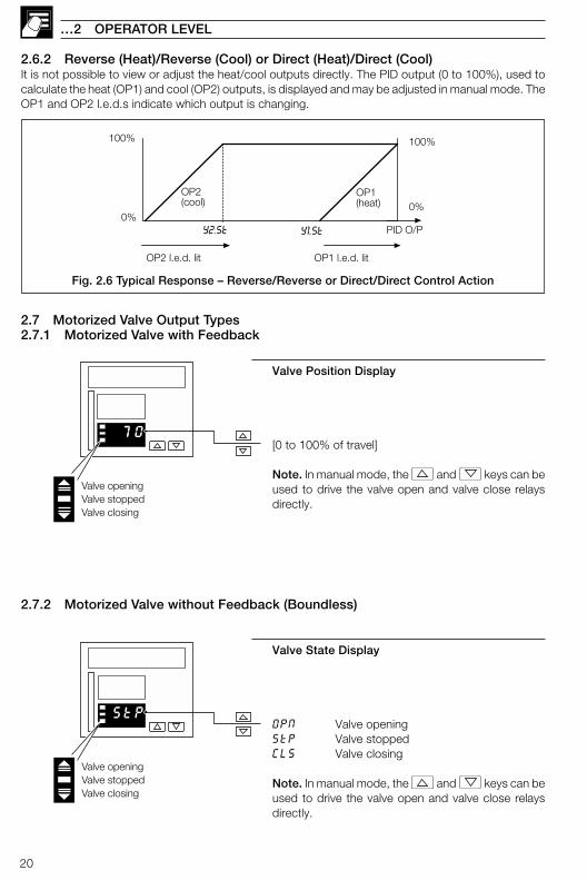
2.6.2 Reverse (Heat)/Reverse (Cool) or Direct (Heat)/Direct (Cool)It is not possible to view or adjust the heat/cool outputs directly. The PID output (0 to 100%), used tocalculate the heat (OP1) and cool (OP2) outputs, is displayed and may be adjusted in manual mode. TheOP1 and OP2 l.e.d.s indicate which output is changing.
2.7 Motorized Valve Output Types2.7.1 Motorized Valve with Feedback
Valve Position Display
[0 to 100% of travel]
Note. In manual mode, the and keys can beused to drive the valve open and valve close relaysdirectly.
2.7.2 Motorized Valve without Feedback (Boundless)
Valve State Display
OPN Valve openingStP Valve stoppedCLS Valve closing
Note. In manual mode, the and keys can beused to drive the valve open and valve close relaysdirectly.
OP2(cool)
OP1(heat)
Y2.St Y1.St PID O/P
OP2 l.e.d. lit OP1 l.e.d. lit
100%
0%0%
100%
70
Valve openingValve stoppedValve closing
StP
Valve openingValve stoppedValve closing
Fig. 2.6 Typical Response – Reverse/Reverse or Direct/Direct Control Action
21
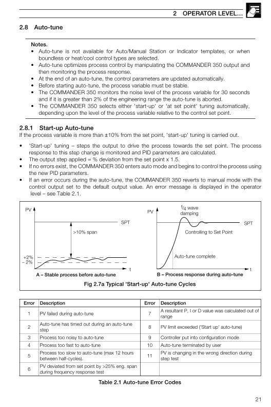
2.8 Auto-tune
Notes.• Auto-tune is not available for Auto/Manual Station or Indicator templates, or when
boundless or heat/cool control types are selected.• Auto-tune optimizes process control by manipulating the COMMANDER 350 output and
then monitoring the process response.• At the end of an auto-tune, the control parameters are updated automatically.• Before starting auto-tune, the process variable must be stable.• The COMMANDER 350 monitors the noise level of the process variable for 30 seconds
and if it is greater than 2% of the engineering range the auto-tune is aborted.• The COMMANDER 350 selects either 'start-up' or 'at set point' tuning automatically,
depending upon the level of the process variable relative to the control set point.
2.8.1 Start-up Auto-tuneIf the process variable is more than ±10% from the set point, 'start-up' tuning is carried out.
• 'Start-up' tuning – steps the output to drive the process towards the set point. The processresponse to this step change is monitored and PID parameters are calculated.
• The output step applied = % deviation from the set point x 1.5.• If no errors exist, the COMMANDER 350 enters auto mode and begins to control the process using
the new PID parameters.• If an error occurs during the auto-tune, the COMMANDER 350 reverts to manual mode with the
control output set to the default output value. An error message is displayed in the operator level – see Table 2.1.
2 OPERATOR LEVEL…
+2%– 2%
tA – Stable process before auto-tune
SPT
PV
B – Process response during auto-tunet
PV1/4 wavedamping
Controlling to Set Point
Auto-tune complete
SPT
>10% span
rorrE noitpircseD rorrE noitpircseD
1 enut-otuagniruddeliafVP 7fotuodetaluclacsaweulavDroI,PtnatluserA
egnar
2enut-otuanagnirudtuodemitsahenut-otuA
pets8 )enut-otua'putratS'(dedeecxetimilVP
3 enut-otuaotysionootssecorP 9 edomnoitarugifnocotnituprellortnoC
4 enut-otuaottsafootssecorP 01 resuybdetanimretenut-otuA
5sruoh21xam(enut-otuaotwolsootssecorP
.)selcyc-flahneewteb11
gnirudnoitceridgnorwehtnignignahcsiVPtsetpets
6naps.gne%52>ybtnioptesmorfdetaivedVP
tsetesnopserycneuqerfgnirud
Fig 2.7a Typical 'Start-up' Auto-tune Cycles
Table 2.1 Auto-tune Error Codes
22
…2 OPERATOR LEVEL
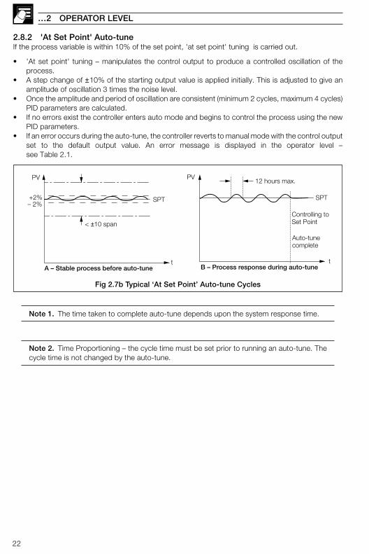
Note 1. The time taken to complete auto-tune depends upon the system response time.
Note 2. Time Proportioning – the cycle time must be set prior to running an auto-tune. Thecycle time is not changed by the auto-tune.
2.8.2 'At Set Point' Auto-tuneIf the process variable is within 10% of the set point, 'at set point' tuning is carried out.
• 'At set point' tuning – manipulates the control output to produce a controlled oscillation of theprocess.
• A step change of ±10% of the starting output value is applied initially. This is adjusted to give anamplitude of oscillation 3 times the noise level.
• Once the amplitude and period of oscillation are consistent (minimum 2 cycles, maximum 4 cycles)PID parameters are calculated.
• If no errors exist the controller enters auto mode and begins to control the process using the newPID parameters.
• If an error occurs during the auto-tune, the controller reverts to manual mode with the control outputset to the default output value. An error message is displayed in the operator level –see Table 2.1.
t
SPT
PV
Auto-tunecomplete
Controlling toSet Point
B – Process response during auto-tune
+2%– 2%
t
PV
A – Stable process before auto-tune
SPT
< ±10 span
12 hours max.
Fig 2.7b Typical ‘At Set Point’ Auto-tune Cycles
23
1.xx
1COdE
1.xx
OFFAtNE
1..xx
xxxxxxxx
xxxxxxxx
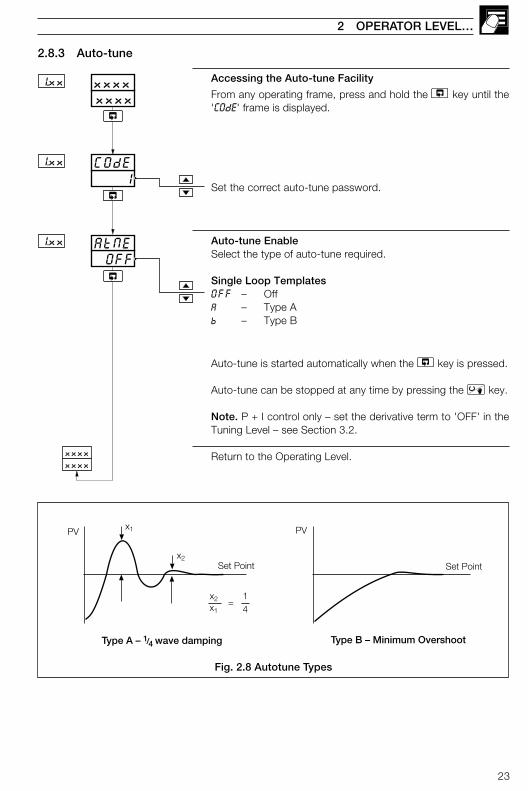
2.8.3 Auto-tune
Accessing the Auto-tune Facility
From any operating frame, press and hold the key until the'COdE' frame is displayed.
Set the correct auto-tune password.
Auto-tune EnableSelect the type of auto-tune required.
Single Loop TemplatesOFF – OffA – Type Ab – Type B
Auto-tune is started automatically when the key is pressed.
Auto-tune can be stopped at any time by pressing the key.
Note. P + I control only – set the derivative term to 'OFF' in theTuning Level – see Section 3.2.
Return to the Operating Level.
2 OPERATOR LEVEL…
Set Point
PV
14
=
Type A – 1/4 wave damping Type B – Minimum Overshoot
Set Point
PVx1
x2
x1
x2
Fig. 2.8 Autotune Types
24
…2 OPERATOR LEVEL
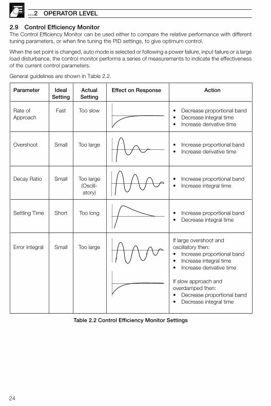
2.9 Control Efficiency MonitorThe Control Efficiency Monitor can be used either to compare the relative performance with differenttuning parameters, or when fine tuning the PID settings, to give optimum control.
When the set point is changed, auto mode is selected or following a power failure, input failure or a largeload disturbance, the control monitor performs a series of measurements to indicate the effectivenessof the current control parameters.
General guidelines are shown in Table 2.2.
Action
• Decrease proportional band• Decrease integral time• Increase derivative time
• Increase proportional band• Increase derivative time
• Increase proportional band• Increase integral time
• Increase proportional band• Decrease integral time
If large overshoot andoscillatory then:• Increase proportional band• Increase integral time• Increase derivative time
If slow approach andoverdamped then:• Decrease proportional band• Decrease integral time
IdealSetting
Fast
Small
Small
Short
Small
Parameter
Rate ofApproach
Overshoot
Decay Ratio
Settling Time
Error Integral
ActualSetting
Too slow
Too large
Too large(Oscill-atory)
Too long
Too large
Effect on Response
Table 2.2 Control Efficiency Monitor Settings

25
…2.9 Control Efficiency Monitor
2.9.1 Manual TuningThe Control Efficiency Monitor may be used for manually tuning the PID parameters. The followingmethod describes how to tune the controller for 1/4 wave damping:
a) Set the integral and derivative action times to OFF.
b) Set the proportional band (PB) to a low setting.
c) Apply a small set point change.
d) Use the Control Efficiency Monitor to note the decay ratio.
e) If the decay ratio > 0.25, increase the Proportional Band until decay ratio = 0.25If the decay ratio < 0.25, decrease the Proportional Band until decay ratio = 0.25
f) Leave the proportional band at the setting which gives 0.25 decay ratio and, using the ControlEfficiency Monitor, note the period between peaks.
g) Calculate and set the following parameters:Integral action time = Period/1.5Derivative action time = Period/6
Note. The manual tuning facility must not be used with boundless motorized valve control, asan Integral Action Time is required for these applications.
2 OPERATOR LEVEL…
Set Point
x1 x2
y1y2
95%
5%
tperiodPV
Start ofCalculation
t
+2%
–2%
tsettle
tapproach
Fig. 2.9 Control Efficiency Monitor Parameters
26
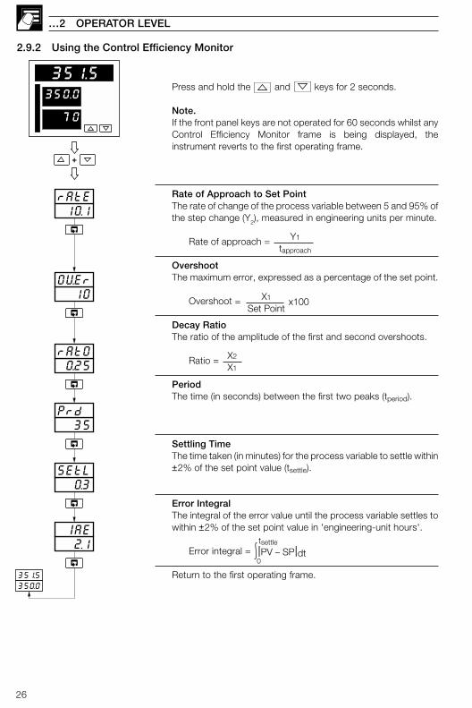
Press and hold the and keys for 2 seconds.
Note.If the front panel keys are not operated for 60 seconds whilst anyControl Efficiency Monitor frame is being displayed, theinstrument reverts to the first operating frame.
Rate of Approach to Set PointThe rate of change of the process variable between 5 and 95% ofthe step change (Y2), measured in engineering units per minute.
Rate of approach = Y1
tapproach
OvershootThe maximum error, expressed as a percentage of the set point.
Overshoot = X1
Set Pointx100
Decay RatioThe ratio of the amplitude of the first and second overshoots.
Ratio = X2
X1
PeriodThe time (in seconds) between the first two peaks (tperiod).
Settling TimeThe time taken (in minutes) for the process variable to settle within±2% of the set point value (tsettle).
Error IntegralThe integral of the error value until the process variable settles towithin ±2% of the set point value in 'engineering-unit hours'.
Error integral = |PV – SP|dt0
tsettle
Return to the first operating frame.
…2 OPERATOR LEVEL
2.9.2 Using the Control Efficiency Monitor
+
10.1rAtE
10OVEr
0.25rAtO
35Prd
0.3SEtL
2.1 IAE
351.5350.0
350.0
351.5
70

27
83 SET UP MODE
3.1 IntroductionTo access the Set Up mode (Levels 2 to 5) the correct password must be entered in the security code frame.
Fig. 3.1 Set Up Mode – Overview
350.0
351.5
70
350.0
351.5
70 50COdE
OFFAtNE LEV1
OPEr
LEV2LEV5
tUNEVLVE
LEV1OPEr
Valid Set Up orConfigurationpassword
LEV2 TuningCycle time, output 1 & 2On/off hysteresis valuesProportional bands 1 to 4Integral action times 1 to 4Derivative action times 1 & 2Manual reset valueControl deadbandHeat Cool Output 1 & 2 Start
LEV3 Set PointsLocal set point values 1 to 4Slave set point valueRemote set point ratio/biasRamp rate
LEV4 Alarm Trip PointsAlarm 1 to 8 trip points
LEV5 Motorized Valve Set UpWith feedback:
Feedback ratio/biasDeadbandRegulator travel time
Boundless:DeadbandRegulator travel time
Pressand hold
Invalidpassword
350.0
351.5
70
350.0
351.5
70
tUNELEV.2
1.0CYC.12.01
Frame number2.xx – Level 23.xx – Level 3 etc.
Parameter
Parameteradjustment
2.00
Defaultvalue
350.0
351.5
70
Fig. 3.2 – Scroll Display Overview
28
82.00...2.04
…3 SET UP MODE
3.2 Level 2 – Tune
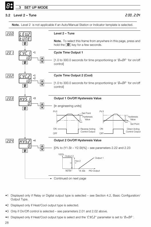
Note. Level 2 is not applicable if an Auto/Manual Station or Indicator template is selected.
•1 Displayed only if Relay or Digital output type is selected – see Section 4.2, Basic Configuration/Output Type.
•2 Displayed only if Heat/Cool output type is selected.
•3 Only if On/Off control is selected – see parameters 2.01 and 2.02 above.
•4 Displayed only if Heat/Cool output type is select and the 'CYC.2' parameter is set to 'OnOF'.
tUNELEV.22.00
0HYS12.03
1.0CYC.22.02
1.0CYC.12.01 •1
•1•2
0HYS22.04
100%
Output 1
Y1.StY2.St
Output 2
PID Output
Hys 2
•3
•4
Set Point
Reverse ActingControl Output
PV
OFF
ON
HysteresisValue
Set Point
Direct ActingControl Output
PV
OFF
ON
HysteresisValue
Level 2 – Tune
Note. To select this frame from anywhere in this page, press andhold the key for a few seconds.
Cycle Time Output 1
[1.0 to 300.0 seconds for time proportioning or 'OnOF' for on/offcontrol]
Cycle Time Output 2 (Cool)
[1.0 to 300.0 seconds for time proportioning or 'OnOF' for on/offcontrol]
Output 1 On/Off Hysteresis Value
[In engineering units]
Output 2 On/Off Hysteresis Value
[0% to (Y1.St – Y2.St)%] – see parameters 2.22 and 2.23
Continued on next page
29
8
OFFIAt.42..12
OFFIAt..22.10
OFFIAt.12.09
•2
•3
•1
100.0Pb-22.06
100.0Pb-12.05
Pb-42.08
100.0
•3
OFFdrV12.13
•1
•2
2.05...2.13
3 SET UP MODE…
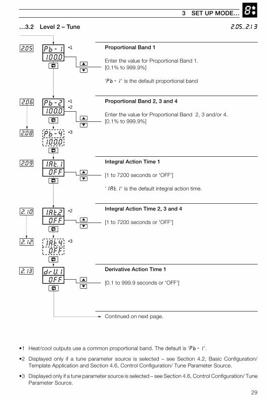
…3.2 Level 2 – Tune
•1 Heat/cool outputs use a common proportional band. The default is 'Pb-1'.
•2 Displayed only if a tune parameter source is selected – see Section 4.2, Basic Configuration/Template Application and Section 4.6, Control Configuration/ Tune Parameter Source.
•3 Displayed only if a tune parameter source is selected – see Section 4.6, Control Configuration/ TuneParameter Source.
Proportional Band 1
Enter the value for Proportional Band 1.[0.1% to 999.9%]
'Pb-1' is the default proportional band
Proportional Band 2, 3 and 4
Enter the value for Proportional Band 2, 3 and/or 4.[0.1% to 999.9%]
Integral Action Time 1
[1 to 7200 seconds or 'OFF']
'IAt.1' is the default integral action time.
Integral Action Time 2, 3 and 4
[1 to 7200 seconds or 'OFF']
Derivative Action Time 1
[0.1 to 999.9 seconds or 'OFF']
Continued on next page.
30
8
50.0rSt.1
2.15
1.0 Ab.1
2.17
•1
•2
OFFCbnd2..21
Deadband
Set Point
Process Variable
Control Output
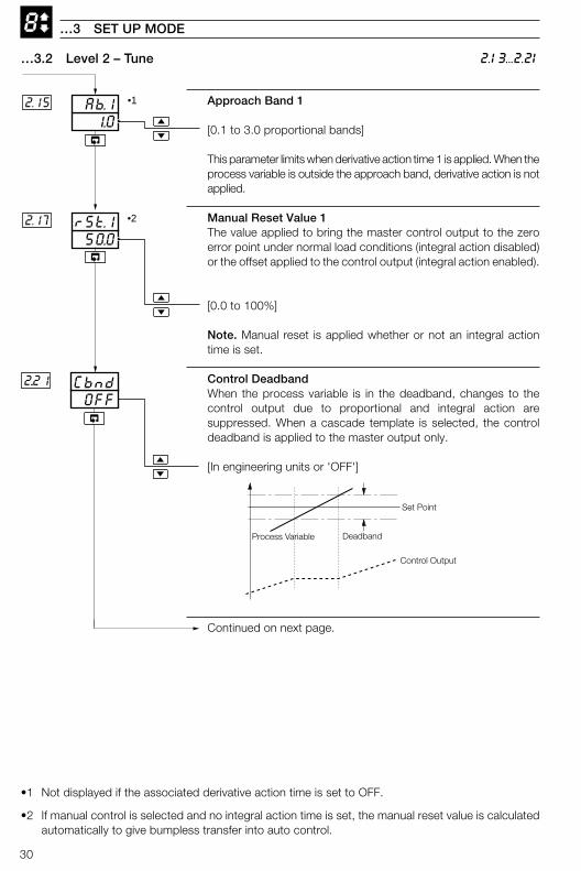
…3 SET UP MODE
Approach Band 1
[0.1 to 3.0 proportional bands]
This parameter limits when derivative action time 1 is applied. When theprocess variable is outside the approach band, derivative action is notapplied.
Manual Reset Value 1The value applied to bring the master control output to the zeroerror point under normal load conditions (integral action disabled)or the offset applied to the control output (integral action enabled).
[0.0 to 100%]
Note. Manual reset is applied whether or not an integral actiontime is set.
Control DeadbandWhen the process variable is in the deadband, changes to thecontrol output due to proportional and integral action aresuppressed. When a cascade template is selected, the controldeadband is applied to the master output only.
[In engineering units or 'OFF']
Continued on next page.
…3.2 Level 2 – Tune
•1 Not displayed if the associated derivative action time is set to OFF.
•2 If manual control is selected and no integral action time is set, the manual reset value is calculatedautomatically to give bumpless transfer into auto control.
2.13...2.21
31
8
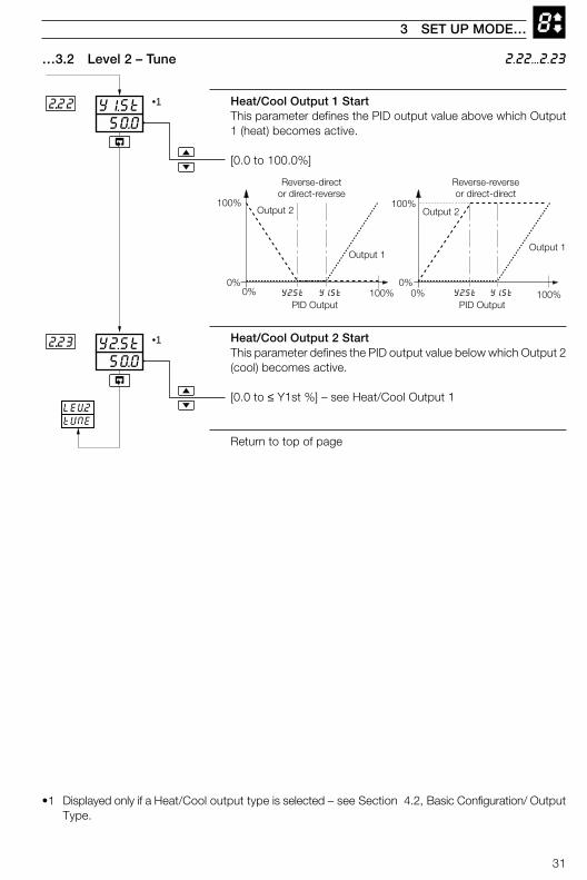
Heat/Cool Output 1 StartThis parameter defines the PID output value above which Output1 (heat) becomes active.
[0.0 to 100.0%]
Heat/Cool Output 2 StartThis parameter defines the PID output value below which Output 2(cool) becomes active.
[0.0 to ≤ Y1st %] – see Heat/Cool Output 1
Return to top of page
3 SET UP MODE…
2.22...2.23…3.2 Level 2 – Tune
•1 Displayed only if a Heat/Cool output type is selected – see Section 4.2, Basic Configuration/ OutputType.
50.0Y2.St2...23
50.0Y1.St2...22
LEV2tUNE
•1
•1
Output 2
PID Output
0%
100%
100%0% Y2.St Y1.St
Output 1
Output 2
PID Output
0%
100%
100%0% Y2.St Y1.St
Output 1
Reverse-director direct-reverse
Reverse-reverseor direct-direct
32
8
SEtPLEV.33.00
1.000rAtO
0BIAS
3.06
3.07
400LSP43.04
200LSP23.02
500LSP13.01
•1
•2
•2
•1
3.00...3.07
…3 SET UP MODE
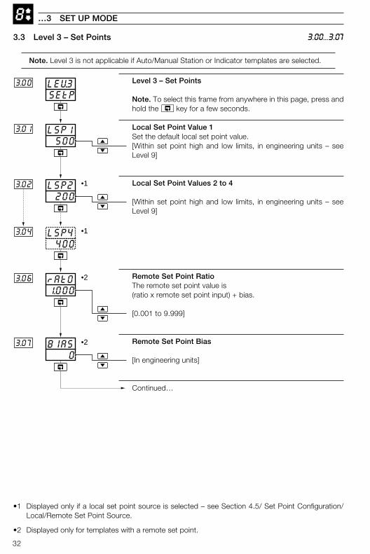
•1 Displayed only if a local set point source is selected – see Section 4.5/ Set Point Configuration/Local/Remote Set Point Source.
•2 Displayed only for templates with a remote set point.
3.3 Level 3 – Set Points
Note. Level 3 is not applicable if Auto/Manual Station or Indicator templates are selected.
Level 3 – Set Points
Note. To select this frame from anywhere in this page, press andhold the key for a few seconds.
Local Set Point Value 1Set the default local set point value.[Within set point high and low limits, in engineering units – seeLevel 9]
Local Set Point Values 2 to 4
[Within set point high and low limits, in engineering units – seeLevel 9]
Remote Set Point RatioThe remote set point value is(ratio x remote set point input) + bias.
[0.001 to 9.999]
Remote Set Point Bias
[In engineering units]
Continued…
33
8
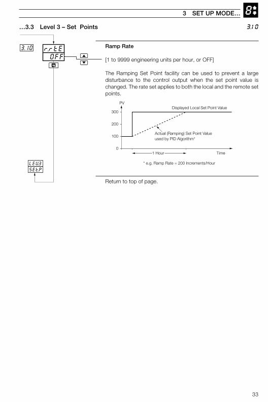
Ramp Rate
[1 to 9999 engineering units per hour, or OFF]
The Ramping Set Point facility can be used to prevent a largedisturbance to the control output when the set point value ischanged. The rate set applies to both the local and the remote setpoints.
Return to top of page.
…3.3 Level 3 – Set Points
3 SET UP MODE…
3.10
OFFr.rtE3.10
LEV3SEt.P
Actual (Ramping) Set Point Valueused by PID Algorithm*
0
100
200
300
1 Hour
Displayed Local Set Point Value
Time
PV
* e.g. Ramp Rate = 200 Increments/Hour
34
84.00...4.08
…3 SET UP MODE
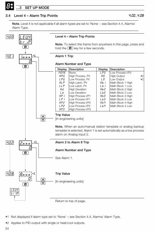
•1 Not displayed if alarm type set to 'None' – see Section 4.4, Alarms/ Alarm Type.
•2 Applies to PID output with single or heat/cool outputs.
3.4 Level 4 – Alarm Trip Points
Note. Level 4 is not applicable if all alarm types are set to 'None' – see Section 4.4, Alarms/Alarm Type.
triPLEV.44.00
4.08
02.xxx4.02
01.xxx4.01
08.xxx •1
•1
•1
LEV.4trIP
yalpsiD noitpircseD yalpsiD noitpircseDENON enoN 3PL 3P/IssecorPwoLVPH VP,ssecorPhgiH OH tuptuOhgiH 2•VPL VP,ssecorPwoL OL tuptuOwoL 2•PLH VP,hctaLhgiH 1bH hgiH1kcolBhtaMPLL VP,hctaLwoL 1bL woL1kcolBhtaMdH noitaiveDhgiH 2bH hgiH2kcolBhtaMdL noitaiveDwoL 2bL woL2kcolBhtaM1PH 1P/IssecorPhgiH 3bH hgiH3kcolBhtaM1PL 1P/IssecorPwoL 3bL woL3kcolBhtaM2PH 2P/IssecorPhgiH 4bH hgiH4kcolBhtaM2PL 2P/IssecorPwoL 4bL woL4kcolBhtaM3PH 3P/IssecorPhgiH
Level 4 – Alarm Trip Points
Note. To select this frame from anywhere in this page, press andhold the key for a few seconds.
Alarm 1 Trip
Alarm Number and Type
Trip Value[In engineering units]
Note. When an auto/manual station template or analog backuptemplate is selected, Alarm 1 is set automatically as a low processalarm on Analog Input 2.
Alarm 2 to Alarm 8 Trip
Alarm Number and Type
See Alarm 1.
Trip Value
[In engineering units]
Return to top of page.
35
85.00...5.04
3 SET UP MODE…
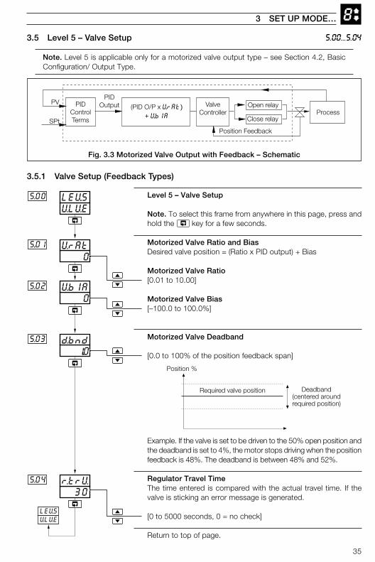
Level 5 – Valve Setup
Note. To select this frame from anywhere in this page, press andhold the key for a few seconds.
Motorized Valve Ratio and BiasDesired valve position = (Ratio x PID output) + Bias
Motorized Valve Ratio[0.01 to 10.00]
Motorized Valve Bias[–100.0 to 100.0%]
Motorized Valve Deadband
[0.0 to 100% of the position feedback span]
Example. If the valve is set to be driven to the 50% open position andthe deadband is set to 4%, the motor stops driving when the positionfeedback is 48%. The deadband is between 48% and 52%.
Regulator Travel TimeThe time entered is compared with the actual travel time. If thevalve is sticking an error message is generated.
[0 to 5000 seconds, 0 = no check]
Return to top of page.
U.LU.ELEV.55.00
1..0d.bnd5.03
0VbIA5.02
0VrAt5..01
30r.trU.5.04
Position %
Required valve position Deadband(centered aroundrequired position)
LEV.5VLVE
PIDControlTerms
PV
SPtProcess
Open relayValveController
Position Feedback
Close relay
PIDOutput (PID O/P x V.rAt)
+ V.bIA
3.5.1 Valve Setup (Feedback Types)
3.5 Level 5 – Valve Setup
Note. Level 5 is applicable only for a motorized valve output type – see Section 4.2, BasicConfiguration/ Output Type.
Fig. 3.3 Motorized Valve Output with Feedback – Schematic
36
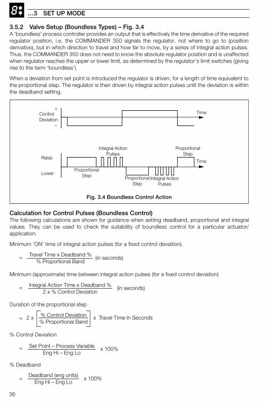
83.5.2 Valve Setup (Boundless Types) – Fig. 3.4A ‘boundless’ process controller provides an output that is effectively the time derivative of the requiredregulator position, i.e. the COMMANDER 350 signals the regulator, not where to go to (positionderivative), but in which direction to travel and how far to move, by a series of integral action pulses.Thus, the COMMANDER 350 does not need to know the absolute regulator position and is unaffectedwhen regulator reaches the upper or lower limit, as determined by the regulator’s limit switches (givingrise to the term ‘boundless’).
When a deviation from set point is introduced the regulator is driven, for a length of time equivalent tothe proportional step. The regulator is then driven by integral action pulses until the deviation is withinthe deadband setting.
…3 SET UP MODE
ProportionalStep
TimeControlDeviation
Raise
Lower
Time
Integral ActionPulses
ProportionalStep Proportional
StepIntegral Action
Pulses
+
–
Fig. 3.4 Boundless Control Action
Calculation for Control Pulses (Boundless Control)The following calculations are shown for guidance when setting deadband, proportional and integralvalues. They can be used to check the suitability of boundless control for a particular actuator/application.
Minimum 'ON' time of integral action pulses (for a fixed control deviation).
= Travel Time x Deadband %% Proportional Band
(in seconds)
Minimum (approximate) time between integral action pulses (for a fixed control deviation)
= Integral Action Time x Deadband %2 x % Control Deviation
(in seconds)
Duration of the proportional step
= % Control Deviation% Proportional Band
2 x x Travel Time in Seconds
% Control Deviation
= Set Point – Process VariableEng Hi – Eng Lo
x 100%
% Deadband
= Deadband (eng units)Eng Hi – Eng Lo
x 100%

37
85.00...5.04…3.5.2 Valve Setup – Boundless
Level 5 – Valve Setup
Note. To select this frame from anywhere in this page, pressand hold the key for a few seconds.
Boundless Deadband
[In engineering units]
Regulator Travel TimeThe time taken for the regulator to travel from the fully open to thefully closed position.
[1 to 5000 seconds]
Return to top of page.
U.LU.ELEV.55.00
0r.trU.
5.03
5..04
0d.bnd
Position %
Control Set Point Deadband(centered around
Set Point)
LEV.5VLVE
3 SET UP MODE

38
4 CONFIGURATION MODE
Fig. 4.1 Configuration Mode – Summary
LEV6 Basic ConfigurationTemplate applicationOutput typeControl actionMains rejection frequency
LEV7 Analog Inputs 1 to 3TypeElectrical rangeDecimal placesEngineering rangeBroken sensor driveInput filter time constant
LEV9 Set PointsTracking enableSet point limitsLocal set point sources 1 to 4Local/remote set point selection
LEV8 Alarms 1 to 8TypeTrip levelHysteresis band
LEVA Control ConfigurationPower fail recovery actionOutput high/low limitsSlew rate + disableConfigured outputs 1 to 3Manual output selection sourcesAuto mode selection sourceTune parameter sources 1 to 4
LEVb Operator ConfigurationAuto/manual key enablesLocal/remote key enablesAlarm acknowledge key enableOperator set point adjust enableOperator ratio/bias enablePassword settingsClock settings
LEVC Output AssignmentOutputs 1 and 2 typeDigital output
Assignment sourcePolarity
Analog outputAssignment sourceElectrical rangeEngineering range
Relay outputs 1 to 4Assignment sourcePolarity
LEVd Serial Communications2-/4-wire connection2400/9600/19200 baud rateParityModbus address
LEVE CalibrationOffset/span adjustmentMotorized valve feedback
APPL
INPt
SEt.P
ALr
CNtL
OPEr
ASSN
SErL
CAL
Valid Set Up orConfigurationpassword
ValidConfigurationpassword
Pressand hold
LEV1OPEr
LEV2tUNE
LEV5VLVE
LEV6APPL
50COdE
OFFAtNE
Pressand hold
LEVECAL
Valid Auto-tune,Set Up orConfigurationpassword
Invalidpassword
Autotunepassword
Enter the Auto-tune,Set Up orConfigurationpassword
Set Uppassword
350.0
351.5
70
4.1 IntroductionTo access the Configuration mode (Levels 6 to E) the correct password must be entered in the security code frame.
Note. When in the configuration mode,the green bargraph led illuminates. Allrelays and digital outputs are de-energized and all analog outputs revert tothe set minimum current output.
39
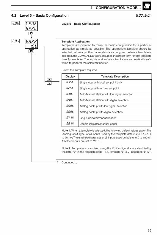
Level 6 – Basic Configuration
Template ApplicationTemplates are provided to make the basic configuration for a particularapplication as simple as possible. The appropriate template should beselected before any other parameters are configured. When a template isselected, the COMMANDER 350 assumes the preset form for that template(see Appendix A). The inputs and software blocks are automatically soft-wired to perform the selected function.
Select the Template required
Note 1. When a template is selected, the following default values apply: The'Analog Input Type' of all inputs used by the template defaults to '2', i.e. 4to 20mA; The engineering ranges of all inputs used default to '0.0 to 100.0'.All other inputs are set to 'OFF'.
Note 2. Templates customized using the PC Configurator are identified bythe letter 'U' in the template code – i.e. template '01.SL' becomes '01.U'.
Continued…
4.2 Level 6 – Basic Configuration 6.00...6.01
4 CONFIGURATION MODE…
APPLLEV.66.00
1.SLt.APP6..01
yalpsiD noitpircseDetalpmeT
LS.10 ylnotniopteslacolhtiwpoolelgniS
LS.20 tnioptesetomerhtiwpoolelgniS
MA.30 noitceleslangiswolhtiwnoitatslaunaM/otuA
MA.40 noitceleslatigidhtiwnoitatslaunaM/otuA
bA.50 noitceleslangiswolhtiwpukcabgolanA
bA.60 noitceleslatigidhtiwpukcabgolanA
NI.70 redaollaunam/rotacidnielgniS
NI.80 redaollaunam/rotacidnielbuoD
40
…4.2 Level 6 – Basic Configuration
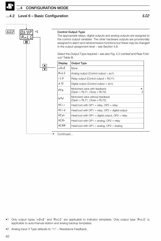
Control Output TypeThe appropriate relays, digital outputs and analog outputs are assigned tothe control output variables. The other hardware outputs are provisionallyassigned to alarm and retransmission functions but these may be changedin the output assignment level – see Section 4.8.
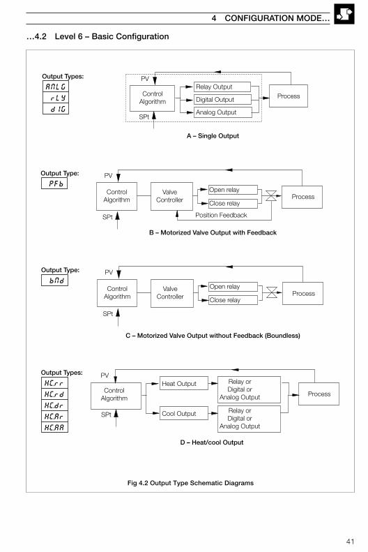
Select the Output Type required – see also Fig. 4.2 overleaf and Rear Fold-out/ Table B.
Continued…
AnLGO.tYP6.02 •1
6.02
…4 CONFIGURATION MODE
•1 Only output types 'nOnE' and 'AnLG' are applicable to indicator templates. Only output type 'AnLG' isapplicable to auto/manual station and analog backup templates.
•2 Analog Input 3 Type defaults to '11' – Resistance Feedback.
yalpsiD epyTtuptuO
EnOn enoN
GLnA )1oa=tuptuolortnoC(tuptuogolanA
YLr )1YLR=tuptuolortnoC(tuptuoyaleR
GId )1od=tuptuolortnoC(tuptuolatigiD
bFP kcabdeefhtiwevlavdezirotoM)2YLR=esolC,1YLR=nepO(
-•2
dNb kcabdeeftuohtiwevlavdezirotoM)2YLR=esolC,1YLR=nepO(
rr.CH yaler=2PO,yaler=1POhtiwlooc/taeH
dr.CH tuptuolatigid=2PO,yaler=1POhtiwlooc/taeH
rd.CH yaler=2PO,tuptuolatigid=1POhtiwlooc/taeH
rA.CH yaler=2PO,golana=1POhtiwlooc/taeH
AA.CH golana=2PO,golana=1POhtiwlooc/taeH
41
…4.2 Level 6 – Basic Configuration
4 CONFIGURATION MODE…
A – Single Output
ControlAlgorithm
PV
SPt
ProcessRelay Output
Digital Output
Analog Output
ANLG
rLY
dIG
Output Types:
ProcessOpen relay
Close relay
ValveController
Position Feedback
ControlAlgorithm
PV
SPt
B – Motorized Valve Output with Feedback
PFb
Output Type:
C – Motorized Valve Output without Feedback (Boundless)
ProcessOpen relay
Close relay
ValveController
ControlAlgorithm
PV
SPt
bNd
Output Type:
HC.rr
HC.rd
HC.dr
HC.Ar
HC.AA
Output Types:
D – Heat/cool Output
PVRelay orDigital or
Analog Output Process
Heat Output
Cool Output Relay orDigital or
Analog Output
ControlAlgorithm
SPt
Fig 4.2 Output Type Schematic Diagrams
42
…4.2 Level 6 – Basic Configuration 6.03...6.06
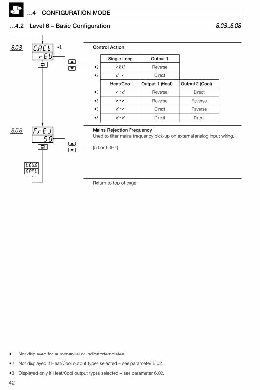
Control Action
Mains Rejection FrequencyUsed to filter mains frequency pick-up on external analog input wiring.
[50 or 60Hz]
Return to top of page.
•1 Not displayed for auto/manual or indicatortemplates.
•2 Not displayed if Heat/Cool output types selected – see parameter 6.02.
•3 Displayed only if Heat/Cool output types selected – see parameter 6.02.
6.06
rEUC.ACt6.03 •1
LEV.6APPL
50F.rEJ
…4 CONFIGURATION MODE
pooLelgniS 1tuptuO
2• VEr esreveR
2• rid tceriD
looC/taeH )taeH(1tuptuO )looC(2tuptuO
3• d-r esreveR tceriD
3• r-r esreveR esreveR
3• r-d tceriD esreveR
3• d-d tceriD tceriD

43
4.3 Level 7 – Analog Inputs 7.00...7.03
Level 7 – Analog Inputs
Note 1. Refer also to Rear Foldout/Table A, Template Applications.
Note 2. To select this frame from anywhere in this page, press the keyfor a few seconds.
Analog Input 1 (I/P1) Type & Electrical Range
Temperature Units (I/P1)
C – THC/PT100 readings displayed in °CF – THC/PT100 readings displayed in °F
Decimal Places (Engineering Range, I/P1)
0 – XXXX1 – XXX.X2 – XX.XX3 – X.XXX
Continued…
4 CONFIGURATION MODE…
InPtLEV.77.00
0dP.17.03
CUNt.17.02
2tYP.17.01
•1
•1 Displayed only if THC or RTD input types are selected
yalpsiD noitpircseD yalpsiD noitpircseD
FFO desUtoN P DTR001TP
b BepyTCHT 1 Am02ot0
E EepyTCHT 2 Am02ot4
J JepyTCHT 3 V5ot0
K KepyTCHT 4 V5ot1
L LepyTCHT 6 Vm05ot0
N NepyTCHT 7 reziraeniltoorerauqsAm02ot4
r RepyTCHT 8 2/3rewopAm02ot4
S SepyTCHT 9 2/5rewopAm02ot4
t TepyTCHT U motsuC
44
… 4.3 Level 7 – Analog Inputs 7.04...7.07
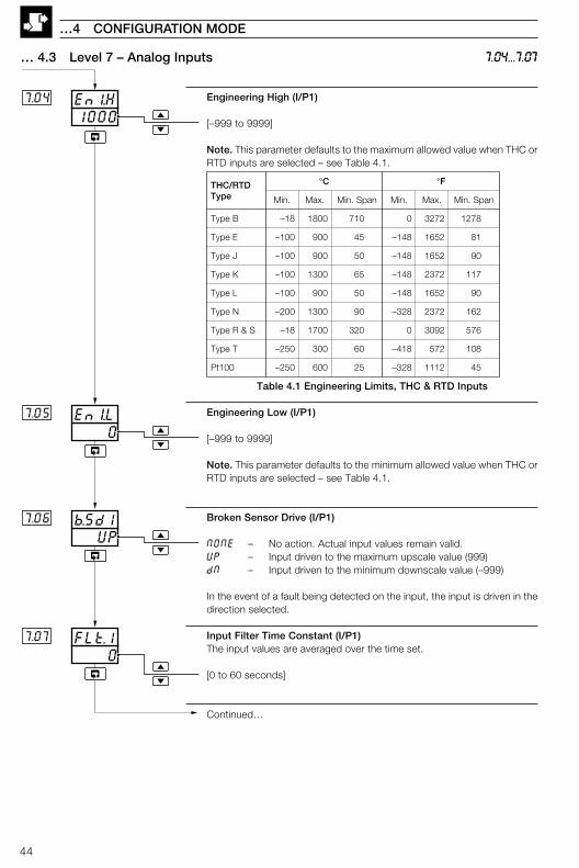
Engineering High (I/P1)
[–999 to 9999]
Note. This parameter defaults to the maximum allowed value when THC orRTD inputs are selected – see Table 4.1.
Table 4.1 Engineering Limits, THC & RTD Inputs
Engineering Low (I/P1)
[–999 to 9999]
Note. This parameter defaults to the minimum allowed value when THC orRTD inputs are selected – see Table 4.1.
Broken Sensor Drive (I/P1)
NONE – No action. Actual input values remain valid.UP – Input driven to the maximum upscale value (999)dN – Input driven to the minimum downscale value (–999)
In the event of a fault being detected on the input, the input is driven in thedirection selected.
Input Filter Time Constant (I/P1)The input values are averaged over the time set.
[0 to 60 seconds]
Continued…
…4 CONFIGURATION MODE
0FLt.17.07
1000En1.H7.04
0EnI.L
UPb.Sd1
7.05
7.06
DTR/CHTepyT
°C °F
.niM .xaM napS.niM .niM .xaM napS.niM
BepyT 81– 0081 017 0 2723 8721
EepyT 001– 009 54 841– 2561 18
JepyT 001– 009 05 841– 2561 09
KepyT 001– 0031 56 841– 2732 711
LepyT 001– 009 05 841– 2561 09
NepyT 002– 0031 09 823– 2732 261
S&RepyT 81– 0071 023 0 2903 675
TepyT 052– 003 06 814– 275 801
001tP 052– 006 52 823– 2111 54

45
… 4.3 Level 7 – Analog Inputs
1000En2.H7..11
0dP.27..10
CUNt27.09
2tYP27.08
0En2.L7.12
•1
•2
UPbsd.27.13
0FLt.27.14
•3
7.08...7.14
Analog Input Type & Electrical Range (I/P2)
Note. THC inputs can only be used on I/P2 if I/P1 is also set to THC.
Temperature Units (I/P2)
C – THC readings displayed in °CF – THC readings displayed in °F
Decimal Places (Engineering Range, I/P2)
0 – XXXX1 – XXX.X2 – XX.XX3 – X.XXX
Engineering High (I/P2)
[–999 to 9999]
Note. This parameter defaults to the maximum allowed value when THCinput type is selected – see Table 4.1.
Engineering Low (I/P2)
[–999 to 9999]
Note. This parameter defaults to the minimum allowed value when THCinput is selected – see Table 4.1.
Broken Sensor Drive (I/P2)
NONE – No action. Actual input values remain valid.UP – Input driven to the maximum upscale value (999)dN – Input driven to the minimum downscale value (–999)
Filter Time Constant (I/P2)The input values are averaged over the time set.
[0 to 60 seconds]
Continued…
4 CONFIGURATION MODE…
•1 Frames 7.09 to 7.14 are not displayed if Analog Input Type 2 is set to 'OFF'.•2 Displayed only if THC input type is selected.•3 When i/p 2 is assigned to a remote set point input, it is displayed with the same number of decimal places as the
associated process variable.
yalpsiD noitpircseD yalpsiD noitpircseDFFO desUtoN t 1epyTCHT
b BepyTCHT 1 Am02ot0E EepyTCHT 2 Am02ot4J JepyTCHT 6 Vm05ot0K KepyTCHT 7 reziraeniltoorerauqsAm02ot4L LepyTCHT 8 2/3rewopAm02ot4N NepyTCHT 9 2/5rewopAm02ot4r RepyTCHT U motsuCS SepyTCHT

46
… 4.3 Level 7 – Analog Inputs 7.15...7.21
Analog Input Type & Electrical Range (I/P3)
Temperature Units
C – THC readings displayed in °CF – THC readings displayed in °F
Decimal Places
0 – XXXX1 – XXX.X2 – XX.XX3 – X.XXX
Engineering High
[–999 to 9999]
Note. This parameter defaults to the maximum allowed value when THC orRTD inputs are selected – see Table 4.1.
Engineering Low
[–999 to 9999]
Note. This parameter defaults to the minimum allowed value when THC orRTD inputs are selected – see Table 4.1.
Broken Sensor Drive (I/P3)
NONE – No action. Actual input values remain valid.UP – Input driven to the maximum upscale value (999)dN – Input driven to the minimum downscale value (–999)
Filter Time Constant (I/P3)The input values are averaged over the time set.
[0 to 60 seconds]
Return to top of page.
…4 CONFIGURATION MODE
•1 Frames 7.16 to 7.21 are not displayed if Analog Input Type 3 is set to 'OFF'.•2 Displayed only if THC or RTD input types are selected.•3 When i/p 2 is assigned to a remote set point input, it is displayed with the same number of decimal places as the
associated process variable.
1000En3.H7...18
0dP.37...17
CUNt37..16
2tYP.37.15
0En3.L
7...19
•1
•2
UPbSd.37.20
0FLt.37.21
LEV7INPt
•3
yalpsiD noitpircseD yalpsiD noitpircseDFFO desUtoN 1 Am02ot0
b BepyTCHT 2 Am02ot4E EepyTCHT 3 V5ot0J JepyTCHT 4 V5ot1K KepyTCHT 6 Vm05ot0L LepyTCHT 7 reziraeniltoorerauqsAm02ot4N NepyTCHT 8 2/3rewopAm02ot4r RepyTCHT 9 2/5rewopAm02ot4S SepyTCHT 11 rofkcabdeefecnatsiseRt TepyTCHT evlavdezirotomP DTR001TP U motsuC
47
4 CONFIGURATION MODE…
4.4 Level 8 – Alarms
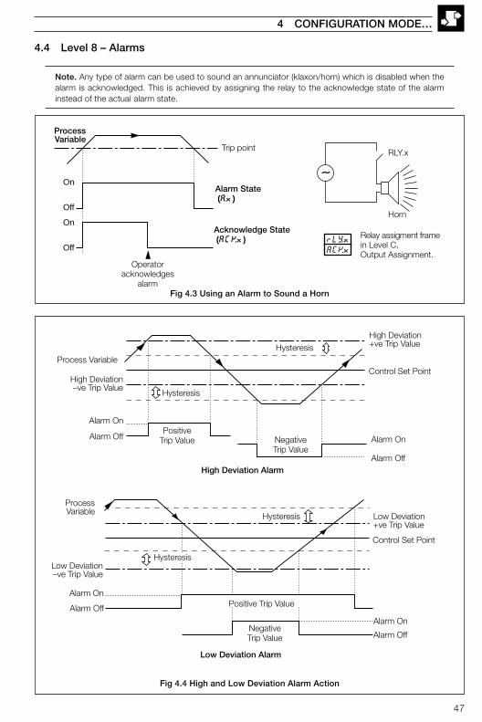
Note. Any type of alarm can be used to sound an annunciator (klaxon/horn) which is disabled when thealarm is acknowledged. This is achieved by assigning the relay to the acknowledge state of the alarminstead of the actual alarm state.
Trip point
Operatoracknowledges
alarm
Alarm State (A.x)
Acknowledge State (ACK.x)
ProcessVariable
On
Off
On
OffrLY.xACK.x
RLY.x
Horn
Relay assigment framein Level C,Output Assignment.
Alarm On
Alarm OffNegativeTrip Value
Positive Trip Value
Low Deviation Alarm
Control Set Point
Hysteresis Low Deviation+ve Trip Value
Alarm On
Alarm Off
HysteresisLow Deviation–ve Trip Value
ProcessVariable
High Deviation+ve Trip ValueHysteresis
Alarm On
Alarm Off
Control Set Point
Alarm On
Alarm Off
PositiveTrip Value Negative
Trip Value
High Deviation–ve Trip Value
High Deviation Alarm
Hysteresis
Process Variable
Fig 4.3 Using an Alarm to Sound a Horn
Fig 4.4 High and Low Deviation Alarm Action
48
…4 CONFIGURATION MODE
…4.4 Level 8 – Alarms
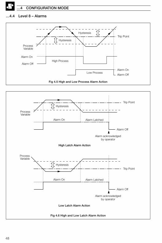
Trip Point
Alarm On
Alarm Off
Alarm Latched
Alarm acknowledgedby operator
Hysteresis
ProcessVariable
Trip Point
Alarm On
Alarm Off
Alarm Latched
Alarm acknowledgedby operator
Hysteresis
ProcessVariable
High Latch Alarm Action
Low Latch Alarm Action
Trip Point
Alarm On
Alarm Off
Alarm On
Alarm Off
High Process
Low Process
Hysteresis
Hysteresis
ProcessVariable
Fig 4.5 High and Low Process Alarm Action
Fig 4.6 High and Low Latch Alarm Action
49
ALMSLEV.88.00
HP1tYP.18.01
0HYS.18.03
0trP.18.02
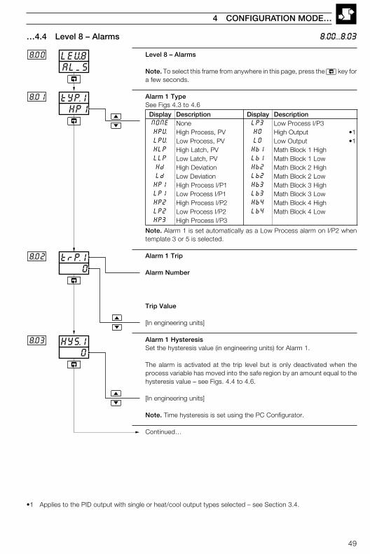
…4.4 Level 8 – Alarms
Level 8 – Alarms
Note. To select this frame from anywhere in this page, press the key fora few seconds.
Alarm 1 TypeSee Figs 4.3 to 4.6
Note. Alarm 1 is set automatically as a Low Process alarm on I/P2 whentemplate 3 or 5 is selected.
Alarm 1 Trip
Alarm Number
Trip Value
[In engineering units]
Alarm 1 HysteresisSet the hysteresis value (in engineering units) for Alarm 1.
The alarm is activated at the trip level but is only deactivated when theprocess variable has moved into the safe region by an amount equal to thehysteresis value – see Figs. 4.4 to 4.6.
[In engineering units]
Note. Time hysteresis is set using the PC Configurator.
Continued…
8.00...8.03
4 CONFIGURATION MODE…
•1 Applies to the PID output with single or heat/cool output types selected – see Section 3.4.
yalpsiD noitpircseD yalpsiD noitpircseDENON enoN 3PL 3P/IssecorPwoLVPH VP,ssecorPhgiH OH tuptuOhgiH 1•VPL VP,ssecorPwoL OL tuptuOwoL 1•PLH VP,hctaLhgiH 1bH hgiH1kcolBhtaMPLL VP,hctaLwoL 1bL woL1kcolBhtaMdH noitaiveDhgiH 2bH hgiH2kcolBhtaMdL noitaiveDwoL 2bL woL2kcolBhtaM1PH 1P/IssecorPhgiH 3bH hgiH3kcolBhtaM1PL 1P/IssecorPwoL 3bL woL3kcolBhtaM2PH 2P/IssecorPhgiH 4bH hgiH4kcolBhtaM2PL 2P/IssecorPwoL 4bL woL4kcolBhtaM3PH 3P/IssecorPhgiH
50
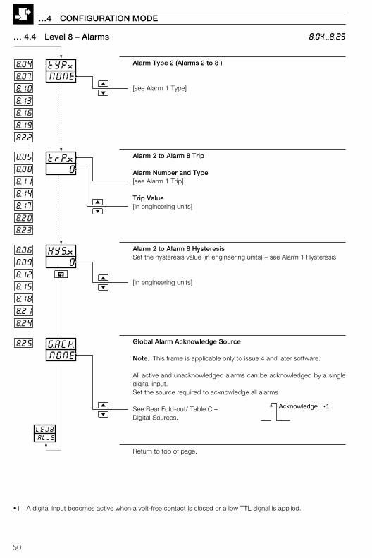
Alarm Type 2 (Alarms 2 to 8 )
[see Alarm 1 Type]
Alarm 2 to Alarm 8 Trip
Alarm Number and Type[see Alarm 1 Trip]
Trip Value[In engineering units]
Alarm 2 to Alarm 8 HysteresisSet the hysteresis value (in engineering units) – see Alarm 1 Hysteresis.
[In engineering units]
Global Alarm Acknowledge Source
Note. This frame is applicable only to issue 4 and later software.
All active and unacknowledged alarms can be acknowledged by a singledigital input.Set the source required to acknowledge all alarms
See Rear Fold-out/ Table C –Digital Sources.
Return to top of page.
… 4.4 Level 8 – Alarms
…4 CONFIGURATION MODE
8.04...8.25
0trP.x8.05
8.06
8.07 NONEtYPx8.04
8.10
8.13
8.16
8.19
8.22
8.08
8.11
8.14
8.17
8.20
8.23
0HYS.x
8.09
8.12
8.15
8.18
8.21
8.24
LEV8ALMS
8.25
NONEG.ACK
Acknowledge •1
•1 A digital input becomes active when a volt-free contact is closed or a low TTL signal is applied.
51
SEt.PLEV99.00
0SPt.L9.03
1000SPt.H9.02
9.01
OFFtrCK
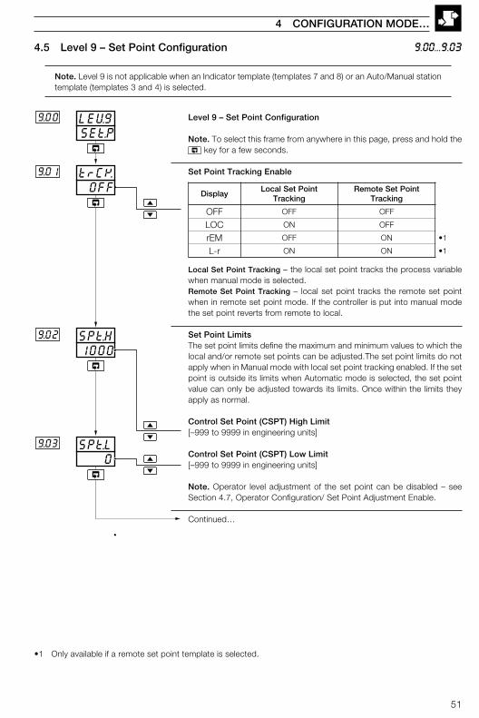
4.5 Level 9 – Set Point Configuration
Note. Level 9 is not applicable when an Indicator template (templates 7 and 8) or an Auto/Manual stationtemplate (templates 3 and 4) is selected.
9.00...9.03
4 CONFIGURATION MODE…
Level 9 – Set Point Configuration
Note. To select this frame from anywhere in this page, press and hold the key for a few seconds.
Set Point Tracking Enable
Local Set Point Tracking – the local set point tracks the process variablewhen manual mode is selected.Remote Set Point Tracking – local set point tracks the remote set pointwhen in remote set point mode. If the controller is put into manual modethe set point reverts from remote to local.
Set Point LimitsThe set point limits define the maximum and minimum values to which thelocal and/or remote set points can be adjusted.The set point limits do notapply when in Manual mode with local set point tracking enabled. If the setpoint is outside its limits when Automatic mode is selected, the set pointvalue can only be adjusted towards its limits. Once within the limits theyapply as normal.
Control Set Point (CSPT) High Limit[–999 to 9999 in engineering units]
Control Set Point (CSPT) Low Limit[–999 to 9999 in engineering units]
Note. Operator level adjustment of the set point can be disabled – seeSection 4.7, Operator Configuration/ Set Point Adjustment Enable.
Continued…
•1 Only available if a remote set point template is selected.
yalpsiDtnioPteSlacoL
gnikcarTtnioPteSetomeR
gnikcarT
FFO FFO FFO
COL NO FFO
MEr FFO NO 1•
r-L NO NO 1•

52
NONEL.Sr29..09
NONEL.Sr19..08
NONEL.Sr3
NONEL.Sr4
9.10
9.11
NONESP.FA9..06
0.0dF.SP9..07
LSP1
LSP2
LSP3
LSP4
•2
•2
•2
•2
•1
•1
…4.5 Level 9 – Set Point Configuration 9.06...9.11
…4 CONFIGURATION MODE
Remote Set Point Fault ActionThe action required when a fault occurs with the remote set point.
NONE – No actionLOC – Select local set point modedFLt – Select local set point mode and set to the default value
Local Set Point Default ValueSet the value required for the local set point under remote set point faultconditions.
[In engineering units]
Local Set Point Source 1The source required to select local set point 1 (LSP1) as the current local setpoint.
See Rear Fold-out/ Table C –Digital Sources.
Local Set Point Source 2The source required to select local set point 2 (LSP2) as the current local setpoint.
See Rear Fold-out/ Table C –Digital Sources.
Local Set Point Source 3The source required to select local set point 3 (LSP3) as the current local setpoint.
See Rear Fold-out/ Table C –Digital Sources.
Local Set Point Source 4The source required to select local set point 4 (LSP4) as the current local setpoint.
See Rear Fold-out/ Table C –Digital Sources.
Continued…
•1 Displayed only if a remote set point template is selected.
•2 A digital input becomes active when a volt-free contact is closed or a low TTL signal is applied.
53
NONELr.5r9.12
NONEr.SrC9.14
NONELC.5r9.13
Local
Remote
Local
Local Set Point Mode
Remote Set Point Mode
•1
•1
•1
•1
•1
•1
SEt.PLEV9
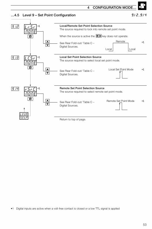
…4.5 Level 9 – Set Point Configuration 9.12...9.14
4 CONFIGURATION MODE…
Local/Remote Set Point Selection SourceThe source required to lock into remote set point mode.
When the source is active the L LR key does not operate.
See Rear Fold-out/ Table C –Digital Sources.
Local Set Point Selection SourceThe source required to select local set point mode.
See Rear Fold-out/ Table C –Digital Sources.
Remote Set Point Selection SourceThe source required to select remote set point mode.
See Rear Fold-out/ Table C –Digital Sources.
Return to top of page.
•1 Digital inputs are active when a volt-free contact is closed or a low TTL signal is applied
54
4.6 Level A – Control Configuration
Note. Level A is not displayed if an indicator template is selected.
…4 CONFIGURATION MODE
Level A – Control Configuration
Note. To select this frame from anywhere in this page, press and hold the key for a few seconds.
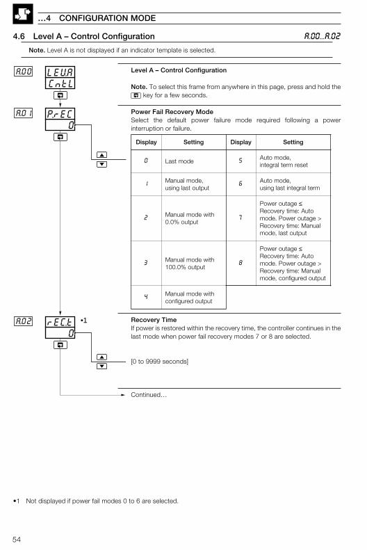
Power Fail Recovery ModeSelect the default power failure mode required following a powerinterruption or failure.
Recovery TimeIf power is restored within the recovery time, the controller continues in thelast mode when power fail recovery modes 7 or 8 are selected.
[0 to 9999 seconds]
Continued…
CntLLEVAA.00
0rEC.tA.02
0P.rECA.01
•1
A.00...A.02
yalpsiD gnitteS yalpsiD gnitteS
0 edomtsaL 5 ,edomotuAtesermretlargetni
1 ,edomlaunaMtuptuotsalgnisu
6 ,edomotuAmretlargetnitsalgnisu
2 htiwedomlaunaMtuptuo%0.0
7
egatuorewoP ≤otuA:emityrevoceR
>egatuorewoP.edomlaunaM:emityrevoceR
tuptuotsal,edom
3 htiwedomlaunaMtuptuo%0.001
8
egatuorewoP ≤otuA:emityrevoceR
>egatuorewoP.edomlaunaM:emityrevoceR
tuptuoderugifnoc,edom
4 htiwedomlaunaMtuptuoderugifnoc
•1 Not displayed if power fail modes 0 to 6 are selected.
55
4 CONFIGURATION MODE…
A.03...A.08
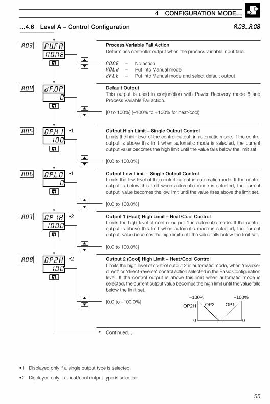
Process Variable Fail ActionDetermines controller output when the process variable input fails.
NONE – No actionHOLd – Put into Manual modedFLt – Put into Manual mode and select default output
Default OutputThis output is used in conjunction with Power Recovery mode 8 andProcess Variable Fail action.
[0 to 100%] (–100% to +100% for heat/cool)
Output High Limit – Single Output ControlLimits the high level of the control output in automatic mode. If the controloutput is above this limit when automatic mode is selected, the currentoutput value becomes the high limit until the value falls below the limit set.
[0.0 to 100.0%]
Output Low Limit – Single Output ControlLimits the low level of the control output in automatic mode. If the controloutput is below this limit when automatic mode is selected, the currentoutput value becomes the low limit until the value rises above the limit set.
[0.0 to 100.0%]
Output 1 (Heat) High Limit – Heat/Cool ControlLimits the high level of control output 1 in automatic mode. If the controloutput is above this limit when automatic mode is selected, the currentoutput value becomes the high limit until the value falls below the limit set.
[0.0 to 100.0%]
Output 2 (Cool) High Limit – Heat/Cool ControlLimits the high level of control output 2 in automatic mode, when 'reverse-direct' or 'direct-reverse' control action selected in the Basic Configurationlevel. If the control output is above this limit when automatic mode isselected, the current output value becomes the high limit until the value fallsbelow the limit set.
[0.0 to –100.0%]
Continued…
…4.6 Level A – Control Configuration
•1 Displayed only if a single output type is selected.
•2 Displayed only if a heat/cool output type is selected.
100OP.HIA.05
0dF.OPA.04
NONEPVFAA.03
•1
0OP.L0A.06 •1
100.0OP1HA.07 •2
100OP2HA.08 •2
OP1OP2OP2H
–100% +100%
0 0
56
OFFSrd5A..11
OFFM5r1A.12
Slew rate disabled
OFFOP.SrA.10
0OP2LA.09 •1
OP1OP2
OP2L
time
EnabledEnabled
Auto
Manual withoutput = C.OP1 •2
+100%+100%
00
…4.6 Level A – Control Configuration
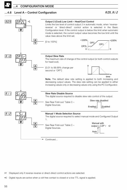
Output 2 (Cool) Low Limit – Heat/Cool ControlLimits the low level of control output 2 in automatic mode, when 'reverse-reverse' or 'direct-direct' control action is selected in the BasicConfiguration level. If the control output is below this limit when automaticmode is selected, the current output value becomes the low limit until thevalue rises above the limit set.
[0 to 100%]
Output Slew RateThe maximum rate of change of the control output (or both control outputsfor heat/cool).
[0.01 to 99.99% change persecond or 'OFF']
Note. The default slew rate setting is applied to both increasing anddecreasing output values. The slew rate setting can be applied to eitherincreasing values only or decreasing values only using the PC Configurator.
Slew Rate Disable SourceThe digital source required to disable slew rate control of the output.
See Rear Fold-out/ Table C –Digital Sources.
Manual 1 Mode Selection SourceThe digital source required to select manual mode and Configured Output1.
See Rear Fold-out/ Table C –Digital Sources.
Continued…
…4 CONFIGURATION MODE
A.09...A.12
•1 Displayed only if reverse-reverse or direct-direct control actions are selected.
•2 Digital inputs are active when a volt free contact is closed or a low TTL signal is applied.

57
4 CONFIGURATION MODE…
…4.6 Level A – Control Configuration
Configured Output 1The control output value required when manual is selected by manualmode source 1.
[0 to 100% or LAST (non-heat/cool)][–100 to 100% (heat/cool only)]
Manual Mode Selection Source 2The digital source required to select manual mode and Configured Output2.
See Rear Fold-out/ Table C –Digital Sources.
Configured Output 2The control output value required when manual is selected by manualmode source 2.
[0 to 100% or LAST (non-heat/cool)][–100 to 100% (heat/cool only)]
Auto/Manual Selection SourceUsed with auto/manual station.The source required to lock into manual mode with Configured Output 3.Switching from manual to auto is not possible via the front panel.
See Rear Fold-out/ Table C –Digital Sources.
Note. If template 3 is selected, the source is assigned to alarm 1. Iftemplate 4 is selected, the source is assigned to digital input 1.
Configured Output 3The control output value required when manual mode is selected by theauto/manual selection source.
[0 to 100% or LAST (non-heat/cool)][–100 to 100% (heat/cool only)]
Continued…
A.13...A.17
•1 Digital inputs are active when a volt free contact is closed or a low TTL signal is applied
OFFAM.5r
0.0COP.3
A.16
A.17
0.0C.OP2A..15
OFFM5r2A..14
0.0C.OP1A.13
Auto
Manual with output = C.OP2 •1
Auto
Manual with output = C.OP3 •1
Auto

58
…4.6 Level A – Control Configuration A.18...A.22
…4 CONFIGURATION MODE
Auto Mode Selection SourceSelect the digital source used to activate auto mode.
See Rear Fold-out/ Table C –Digital Sources.
Tune Parameter Source 1 (Gain Scheduling)Determine the digital source used to select the proportional 1 and integral1 terms as the tuning parameters.
See Rear Fold-out/ Table C –Digital Sources.
Tune Parameter Source 2 (Gain Scheduling)Determine the digital source used to select the proportional 2 and integral2 terms as the tuning parameters.
See Rear Fold-out/ Table C –Digital Sources.
Tune Parameter Source 3 (Gain Scheduling)Determine the digital source used to select the proportional 3 and integral3 terms as the tuning parameters..
See Rear Fold-out/ Table C –Digital Sources.
Tune Parameter Source 4 (Gain Scheduling)Determine the digital source used to select the proportional 4 and integral4 terms as the tuning parameters.
See Rear Fold-out/ Table C –Digital Sources.
Return to top of page.
OFFA.5rCA.18
OFFt4.SrA...22
OFFt3.5rA...21
OFFt2.SrA..20
OFFt1.SrA.19
•2
•2
•2
Select Pb-1 and IAt.1
•2
Manual
•1Auto
LEVACNtL
•1
Select Pb-2 and IAt.2 •1
Select Pb-3 and IAt.3 •1
Select Pb-4 and IAt4 •1
•1 Digital inputs are active when a volt free contact is closed or a low TTL signal is applied.
•2 PB–x and INt.x values are set in Level 2 – see Section 3.2, Tune/Proportional Band x and Integral Action Timex. This function is not applicable to Auto/Manual Station or Indicator templates.
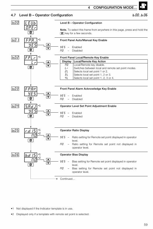
59
4.7 Level B – Operator Configuration
Level B – Operator Configuration
Note. To select this frame from anywhere in this page, press and hold the key for a few seconds.
Front Panel Auto/Manual Key Enable
YES – EnabledNO – Disabled
Front Panel Local/Remote Key Enable
Front Panel Alarm Acknowledge Key Enable
YES – EnabledNO – Disabled
Operator Level Set Point Adjustment Enable
YES – EnabledNO – Disabled
Operator Ratio Display
YES – Ratio setting for Remote set point displayed in operatorlevel.
NO – Ratio setting for Remote set point not displayed inoperator level.
Operator Bias Display
YES – Bias setting for Remote set point displayed in operatorlevel.
NO – Bias setting for Remote set point not displayed inoperator level.
Continued…
4 CONFIGURATION MODE…
•1 Not displayed if the Indicator template is in use.
•2 Displayed only if a template with remote set point is selected.
OPErLEVbb.00
NOr.d15
NOb.d15
b.05
b.06
YESS.AdJb.04
YESFPAKb.03
LrFPLrb.02
YESFP.AMb.01 •1
•1
•1
•1•2
•1•2
b.00...b.06
yalpsiD noitcAyeKetomeR/lacoLON .elbasidyeketomeR/lacoLrL .sedomtnioptesetomerdnalacolneewtebsehctiwSL2 .2ro1tniopteslacolstceleSL3 .3ro2,1tniopteslacolstceleSL4 .4ro3,2,1tniopteslacolstceleS
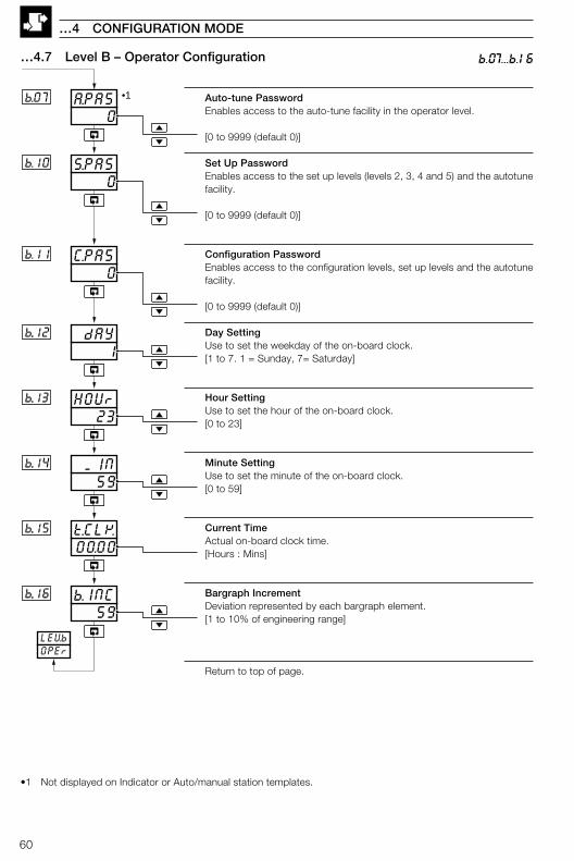
60
0A.PA5b.07
00.00t.CLKb..15
0C.PA5b.11
0S.PASb.10
1 dAYb..12
23HOUrb..13
59 MINb..14
•1
LEVbOPEr
59b.INCb..16
b.07...b.16
…4 CONFIGURATION MODE
…4.7 Level B – Operator Configuration
Auto-tune PasswordEnables access to the auto-tune facility in the operator level.
[0 to 9999 (default 0)]
Set Up PasswordEnables access to the set up levels (levels 2, 3, 4 and 5) and the autotunefacility.
[0 to 9999 (default 0)]
Configuration PasswordEnables access to the configuration levels, set up levels and the autotunefacility.
[0 to 9999 (default 0)]
Day SettingUse to set the weekday of the on-board clock.[1 to 7. 1 = Sunday, 7= Saturday]
Hour SettingUse to set the hour of the on-board clock.[0 to 23]
Minute SettingUse to set the minute of the on-board clock.[0 to 59]
Current TimeActual on-board clock time.[Hours : Mins]
Bargraph IncrementDeviation represented by each bargraph element.[1 to 10% of engineering range]
Return to top of page.
•1 Not displayed on Indicator or Auto/manual station templates.
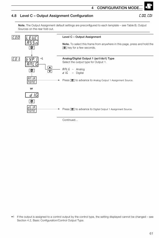
61
Level C – Output Assignment
Note. To select this frame from anywhere in this page, press and hold the key for a few seconds.
Analog/Digital Output 1 (ao1/do1) TypeSelect the output type for Output 1.
ANLG – AnalogdIG – Digital
Press to advance to Analog Output 1 Assignment Source.
Press to advance to Digital Output 1 Assignment Source.
Continued…
ASSnLEV.CC.00
ANLGtYP.1C.01
dIG
or
AN1.ANONE
dG1.ANONE
•1
4.8 Level C – Output Assignment Configuration
Note. The Output Assignment default settings are preconfigured to each template – see Table B, OutputSources on the rear fold-out.
C.00, C01
4 CONFIGURATION MODE…
•1 If the output is assigned to a control output by the control type, the setting displayed cannot be changed – seeSection 4.2, Basic Configuration/Control Output Type.
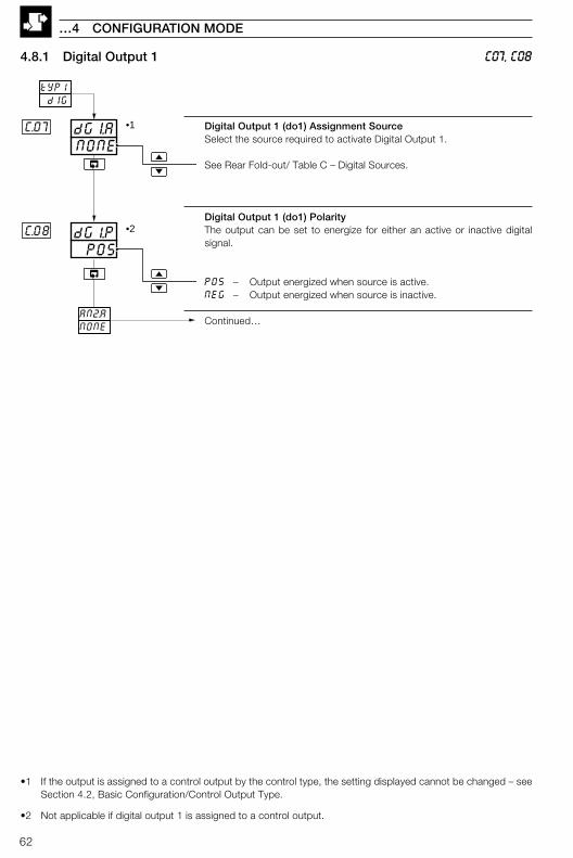
62
…4 CONFIGURATION MODE
4.8.1 Digital Output 1
Digital Output 1 (do1) Assignment SourceSelect the source required to activate Digital Output 1.
See Rear Fold-out/ Table C – Digital Sources.
Digital Output 1 (do1) PolarityThe output can be set to energize for either an active or inactive digitalsignal.
POS – Output energized when source is active.NEG – Output energized when source is inactive.
Continued…
•1 If the output is assigned to a control output by the control type, the setting displayed cannot be changed – seeSection 4.2, Basic Configuration/Control Output Type.
•2 Not applicable if digital output 1 is assigned to a control output.
tYP1 dIG
NONEdGI.AC.07
POSdG1.PC.08
AN2.ANONE
•1
•2
C07, C08
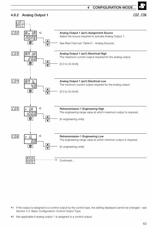
63
Analog Output 1 (ao1) Assignment SourceSelect the source required to activate Analog Output 1.
See Rear Fold-out/ Table D – Analog Sources.
Analog Output 1 (ao1) Electrical HighThe maximum current output required for the analog output.
[0.0 to 22.0mA]
Analog Output 1 (ao1) Electrical LowThe minimum current output required for the analog output.
[0.0 to 22.0mA]
Retransmission 1 Engineering HighThe engineering range value at which maximum output is required.
[In engineering units]
Retransmission 1 Engineering LowThe engineering range value at which minimum output is required.
[In engineering units]
Continued…
4 CONFIGURATION MODE…
C02...C064.8.2 Analog Output 1
•1 If the output is assigned to a control output by the control type, the setting displayed cannot be changed – seeSection 4.2, Basic Configuration/ Control Output Type.
•2 Not applicable if analog output 1 is assigned to a control output.
tYP1ANLG
NONEAnI.A
100.0r1.H
C.02
C.05
0.0r1.LC.06
20.0AN1.HC.03
4.0AN1.LC.04
AN2.ANONE
•1
•2
•2
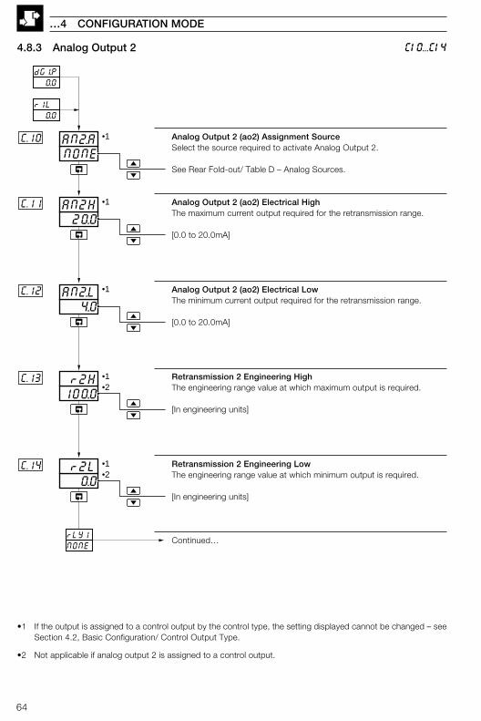
64
…4 CONFIGURATION MODE
C10...C14
0.0 r2LC.14
NONEAN2.AC.10
20.0AN2HC.11
4.0AN2.LC.12
100.0 r2HC.13
rLY1NONE
•1
•1
•1
•1
•1
•2
•2
dG1.P 0.0
r1L 0.0
4.8.3 Analog Output 2
Analog Output 2 (ao2) Assignment SourceSelect the source required to activate Analog Output 2.
See Rear Fold-out/ Table D – Analog Sources.
Analog Output 2 (ao2) Electrical HighThe maximum current output required for the retransmission range.
[0.0 to 20.0mA]
Analog Output 2 (ao2) Electrical LowThe minimum current output required for the retransmission range.
[0.0 to 20.0mA]
Retransmission 2 Engineering HighThe engineering range value at which maximum output is required.
[In engineering units]
Retransmission 2 Engineering LowThe engineering range value at which minimum output is required.
[In engineering units]
Continued…
•1 If the output is assigned to a control output by the control type, the setting displayed cannot be changed – seeSection 4.2, Basic Configuration/ Control Output Type.
•2 Not applicable if analog output 2 is assigned to a control output.
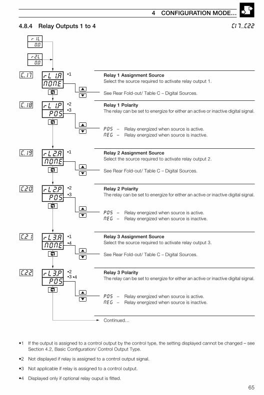
65
4 CONFIGURATION MODE…
C17...C22
POSrL2.PC.20
NONErL2.A
POSrL1.PC.18
NONErL1.AC..17
POSrL3..PC.22
NONErL3.AC.21
r1L 0.0
r2L 0.0
•1
•2•3
•2
•1
•1
•3
•2•3
•4
•4
C.19
4.8.4 Relay Outputs 1 to 4
Relay 1 Assignment SourceSelect the source required to activate relay output 1.
See Rear Fold-out/ Table C – Digital Sources.
Relay 1 PolarityThe relay can be set to energize for either an active or inactive digital signal.
POS – Relay energized when source is active.NEG – Relay energized when source is inactive.
Relay 2 Assignment SourceSelect the source required to activate relay output 2.
See Rear Fold-out/ Table C – Digital Sources.
Relay 2 PolarityThe relay can be set to energize for either an active or inactive digital signal.
POS – Relay energized when source is active.NEG – Relay energized when source is inactive.
Relay 3 Assignment SourceSelect the source required to activate relay output 3.
See Rear Fold-out/ Table C – Digital Sources.
Relay 3 PolarityThe relay can be set to energize for either an active or inactive digital signal.
POS – Relay energized when source is active.NEG – Relay energized when source is inactive.
Continued…
•1 If the output is assigned to a control output by the control type, the setting displayed cannot be changed – seeSection 4.2, Basic Configuration/ Control Output Type.
•2 Not displayed if relay is assigned to a control output signal.
•3 Not applicable if relay is assigned to a control output.
•4 Displayed only if optional relay ouput is fitted.
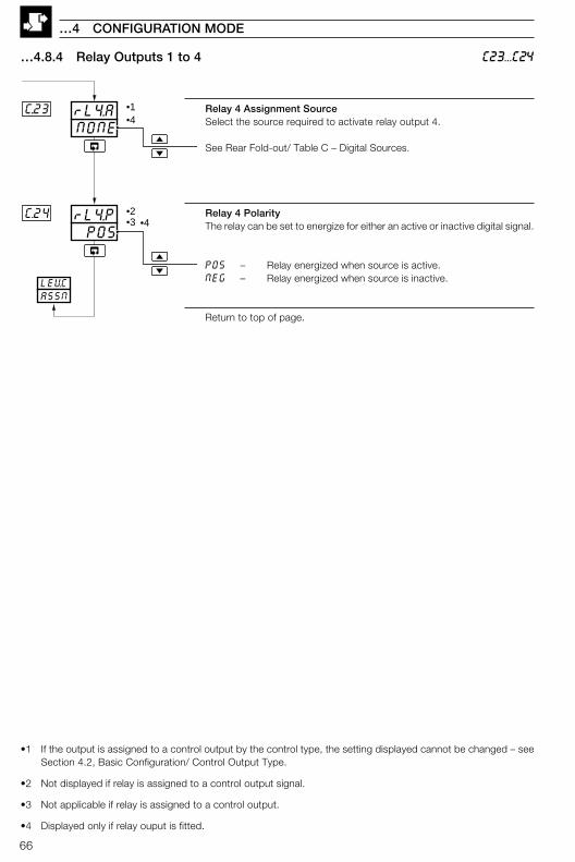
66
…4 CONFIGURATION MODE
C23...C24
NONErL4.AC..23
POSrL4.PC.24
•1
•2•3
LEVCASSN
•4
•4
…4.8.4 Relay Outputs 1 to 4
Relay 4 Assignment SourceSelect the source required to activate relay output 4.
See Rear Fold-out/ Table C – Digital Sources.
Relay 4 PolarityThe relay can be set to energize for either an active or inactive digital signal.
POS – Relay energized when source is active.NEG – Relay energized when source is inactive.
Return to top of page.
•1 If the output is assigned to a control output by the control type, the setting displayed cannot be changed – seeSection 4.2, Basic Configuration/ Control Output Type.
•2 Not displayed if relay is assigned to a control output signal.
•3 Not applicable if relay is assigned to a control output.
•4 Displayed only if relay ouput is fitted.

67
SErLLEVdd.00
1Addrd.03
NONEPrtYd.02
0S.CFGd.01
SErLLEVd
d.00...d.03
4 CONFIGURATION MODE…
4.9 Level D – Serial Communications Configuration
Note. Level D is only applicable if the serial communications option is fitted.
Level D – Serial Communications Configuration
Note. To select this frame from anywhere in this page, press and hold the key for a few seconds.
Serial Configuration
0 – Off1 – 2-wire connection, 2400 baud rate2 – 4-wire connection, 2400 baud rate3 – 2-wire connection, 9600 baud rate4 – 4-wire connection, 9600 baud rate5 – 2-wire connection, 19200 baud rate6 – 4-wire connection, 19200 baud rate
Parity
NONE – NoneOdd – OddEVEN – Even
ModbusTM AddressEach slave on a Modbus link must be assigned a unique address – see IM/C350–MOD.
[1 to 99]
Return to top of page.

68
E.00...E.04
…4 CONFIGURATION MODE
CALLEVEE.00
0.0OFF.2E.03
0.0SPn.1E.02
0.0OFF.1E.01
1.0SPn.2E.04
0.0100.3
0.0100.3
0.0100.3
0.0100.3
4.10 Level E – Calibration
Note. This page enables fine tuning of the inputs to eliminate system errors.
Level E – Calibration
Note. To select this frame from anywhere in this page, press the key fora few seconds.
Analog Input 1 Offset CalibrationAnalog Input 1 Value in Engineering Units
Offset [in engineering Units]
If the and keys are not operated for three seconds the displayreverts to the offset value only.
Analog Input 1 Span CalibrationAnalog Input 1 Value in Engineering Units
Span Adjustment[0.750 to 1.250]
If the and keys are not operated for three seconds the displayreverts to the span value only.
Analog Input 2 Offset CalibrationAnalog Input 2 Value in Engineering Units
Offset [In engineering Units]
If the and keys are not operated for three seconds the displayreverts to the offset value only.
Analog Input 2 Span CalibrationAnalog Input 2 Value in Engineering Units
Span Adjustment[0.750 to 1.250]
If the and keys are not operated for three seconds the displayreverts to the offset value only.
Continued…
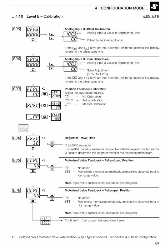
69
8888OFF.3E.05
8888SPN.3E.06
0.0100.3
0.0100.3
NOC.CAL
E.07
NOO.CAL
E.08
E.09
E.10
FCAL
30r.trV
rEF2700
F.CALAUtO
rEF2700
r.trV 30
Fb.LO 100
NO
AUtO
MAN
•1
•1
•1
•1
E.05...E.10
4 CONFIGURATION MODE…
…4.10 Level E – Calibration
Analog Input 3 Offset CalibrationAnalog Input 3 Value in Engineering Units
Offset [In engineering Units]
If the and keys are not operated for three seconds the displayreverts to the offset value only.
Analog Input 3 Span CalibrationAnalog Input 3 Value in Engineering Units
Span Adjustment[0.750 to 1.250]
If the and keys are not operated for three seconds the displayreverts to the offset value only.
Position Feedback CalibrationSelect the calibration required.NO – No CalibrationAUtO – Auto Calibration_AN – Manual Calibration
Regulator Travel Time
[0 to 5000 seconds]Ensure that the value entered is compatible with the regulator motor, as thisis used to determine the length of travel of the feedback mechanism.
Motorized Valve Feedback – Fully-closed Position
NO – No actionYES – Fully closes the valve automatically and sets the electrical input to
low range value.
Note. Input value flashes when calibration is in progress.
Motorized Valve Feedback – Fully-open Position
NO – No actionYES – Fully opens the valve automatically and sets the electrical input to
high range value.
Note. Input value flashes when calibration is in progress.
Continued in Cold Junction Reference Value frame.
•1 Displayed only if Motorized Valve with feedback output type is selected – see Section 4.2, Basic Configuration.
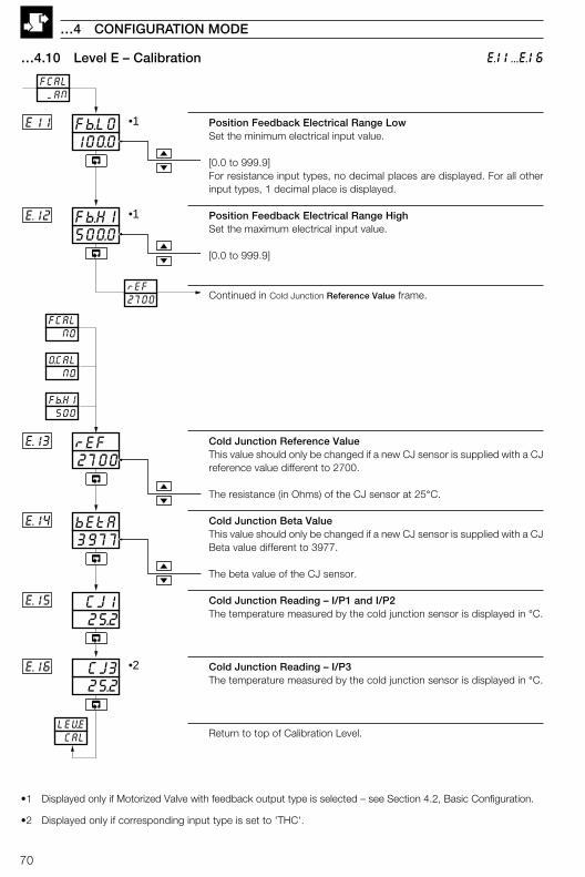
70
Position Feedback Electrical Range LowSet the minimum electrical input value.
[0.0 to 999.9]For resistance input types, no decimal places are displayed. For all otherinput types, 1 decimal place is displayed.
Position Feedback Electrical Range HighSet the maximum electrical input value.
[0.0 to 999.9]
Continued in Cold Junction Reference Value frame.
Cold Junction Reference ValueThis value should only be changed if a new CJ sensor is supplied with a CJreference value different to 2700.
The resistance (in Ohms) of the CJ sensor at 25°C.
Cold Junction Beta ValueThis value should only be changed if a new CJ sensor is supplied with a CJBeta value different to 3977.
The beta value of the CJ sensor.
Cold Junction Reading – I/P1 and I/P2The temperature measured by the cold junction sensor is displayed in °C.
Cold Junction Reading – I/P3The temperature measured by the cold junction sensor is displayed in °C.
Return to top of Calibration Level.
100.0Fb.LOE11
500.0Fb.HIE.12
FCAL MAN
rEF2700
Fb.HI 500
2700rEFE.13
3977bEtAE.14
25.2CJ3E.16
LEV.E CAL
O.CAL NO
FCAL NO
•1
•1
25.2 CJ1E.15
•2
…4 CONFIGURATION MODE
E.11...E.16…4.10 Level E – Calibration
•1 Displayed only if Motorized Valve with feedback output type is selected – see Section 4.2, Basic Configuration.
•2 Displayed only if corresponding input type is set to 'THC'.
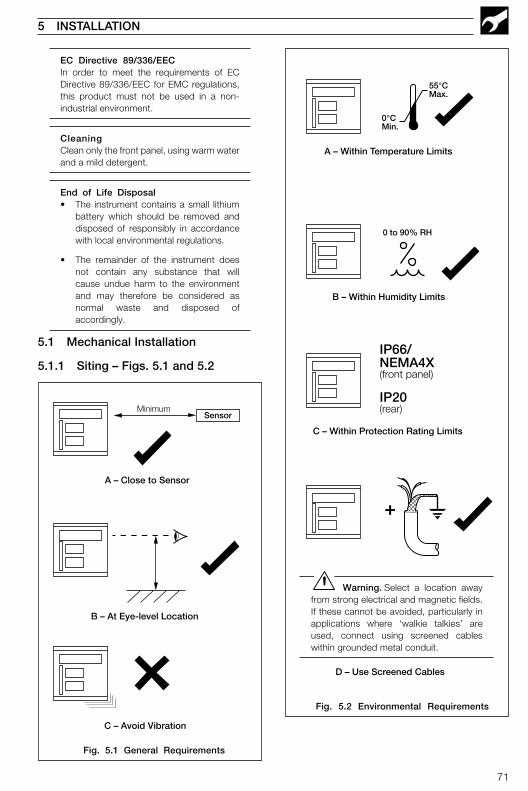
71
55°CMax.
0°CMin.
IP66/NEMA4X(front panel)
IP20(rear)
0 to 90% RH
+
A – Within Temperature Limits
B – Within Humidity Limits
C – Within Protection Rating Limits
D – Use Screened Cables
5 INSTALLATION
Fig. 5.2 Environmental Requirements
Warning. Select a location awayfrom strong electrical and magnetic fields.If these cannot be avoided, particularly inapplications where ‘walkie talkies’ areused, connect using screened cableswithin grounded metal conduit.
SensorMinimum
A – Close to Sensor
B – At Eye-level Location
C – Avoid Vibration
Fig. 5.1 General Requirements
EC Directive 89/336/EECIn order to meet the requirements of ECDirective 89/336/EEC for EMC regulations,this product must not be used in a non-industrial environment.
CleaningClean only the front panel, using warm waterand a mild detergent.
End of Life Disposal• The instrument contains a small lithium
battery which should be removed anddisposed of responsibly in accordancewith local environmental regulations.
• The remainder of the instrument doesnot contain any substance that willcause undue harm to the environmentand may therefore be considered asnormal waste and disposed ofaccordingly.
5.1 Mechanical Installation
5.1.1 Siting – Figs. 5.1 and 5.2
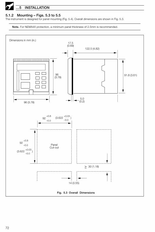
72
…5 INSTALLATION
5.1.2 Mounting – Figs. 5.3 to 5.5The instrument is designed for panel mounting (Fig. 5.4). Overall dimensions are shown in Fig. 5.3.
Note. For NEMA4X protection, a minimum panel thickness of 2.5mm is recommended.
96(3.78)
122.5 (4.82)
17.5(0.69)
Dimensions in mm (in.)
96 (3.78)
PanelCut-out
30 (1.18)
92+0.8
–0.0
(3.622 )–0.0
+0.03
14 (0.55)
91.8 (3.61)
5.0(0.2)
92+0.8
–0.0(3.622 )
–0.0
+0.03
Fig. 5.3 Overall Dimensions
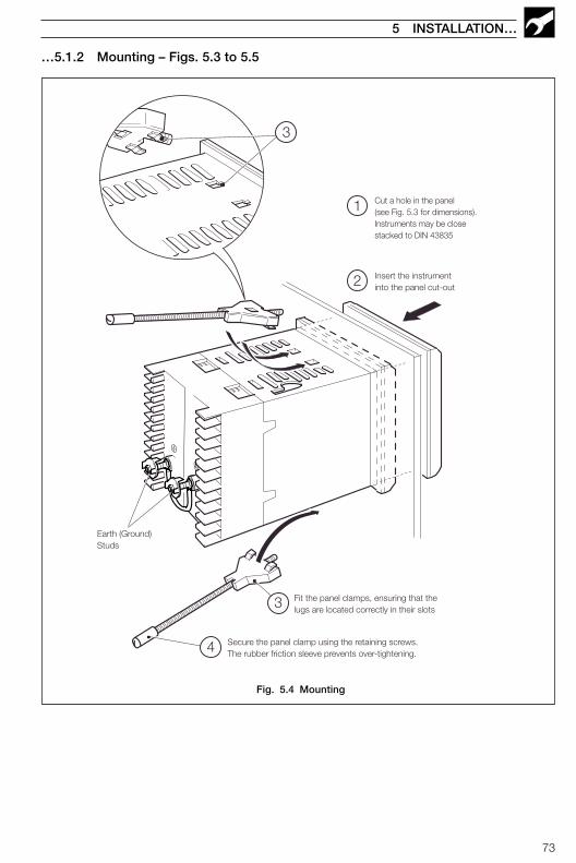
73
5 INSTALLATION…
…5.1.2 Mounting – Figs. 5.3 to 5.5
1
2
3
4
3
Cut a hole in the panel(see Fig. 5.3 for dimensions).Instruments may be closestacked to DIN 43835
Insert the instrumentinto the panel cut-out
Fit the panel clamps, ensuring that thelugs are located correctly in their slots
Secure the panel clamp using the retaining screws.The rubber friction sleeve prevents over-tightening.
Earth (Ground)Studs
Fig. 5.4 Mounting

74
…5 INSTALLATION
…5.1.2 Mounting – Figs. 5.3 to 5.5
Turn the jacking screw anticlockwise to pullthe instrument from the case2
Release the jacking screw cover1
Note. Refitting is the reversal of removal.
Fig. 5.5 Inserting/Removing the Instrument from the Case
75
5 INSTALLATION…
5.2 Electrical InstallationRefer to the Template Applications table and Output Sources table on the rear fold-out to determine the input andoutput connections to be made.
Warnings.• The instrument is not fitted with a switch therefore a disconnecting device such as a switch or circuit
breaker conforming to local safety standards must be fitted to the final installation. It must be fitted inclose proximity to the instrument within easy reach of the operator and must be marked clearly as thedisconnection device for the instrument.
• Remove all power from supply, relay and any powered control circuits and high common modevoltages before accessing or making any connections.
• Use cable appropriate for the load currents. The terminals accept cables up to 14AWG (2.5mm2).
• The instrument conforms to Mains Power Input Insulation Category II. All other inputs and outputsconform to Category II.
• All connections to secondary circuits must have basic insulation.
• After installation, there must be no access to live parts e.g. terminals.
• Terminals for external circuits are for use only with equipment with no accessible live parts.
• If the instrument is used in a manner not specified by the Company, the protection provided by theequipment may be impaired.
• All equipment connected to the instrument's terminals must comply with local safety standards(CEI/IEC 61010-1:2001-2).
Notes.• Always route signal leads and power cables separately, preferably in earthed (grounded) metal
conduit.
• It is strongly recommended that screened cable is used for signal inputs and relay connections.Connect the screen to the earth (ground stud) – see Fig. 5.4.
• The battery is a 3V non-replaceable lithium cell.
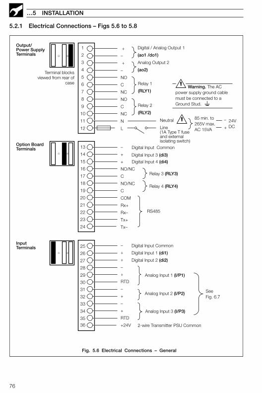
76
…5 INSTALLATION
+
–
+
–
NO
C
NC
NO
C
NC
N
L
Analog Output 2
(ao2)
Relay 1
(RLY1)
1
2
3
4
5
6
7
8
9
10
11
12
Neutral
Line(1A Type T fuseand externalisolating switch)
25
26
27
28
29
30
31
32
34
3536
33
15
16
17
18
19
20
21
22
23
24
13
14
Relay 2
(RLY2)
Digital Input 3 (di3)
Digital Input Common
Digital Input 4 (di4)
–
+
+
NO/NC
C
NO/NC
C
COM
Rx+
Rx–
Tx+
Tx–
Relay 3 (RLY3)
Relay 4 (RLY4)
RS485
–
+
+
–
+
RTD
–
+
–
+
RTD
+24V 2-wire Transmitter PSU Common
Analog Input 3 (I/P3)
Analog Input 1 (I/P1)
Analog Input 2 (I/P2) SeeFig. 6.7
Digital Input Common
Digital Input 1 (di1)
Digital Input 2 (di2)
Output/Power SupplyTerminals
Option BoardTerminals
InputTerminals
Terminal blocksviewed from rear of
case
Digital / Analog Output 1
(ao1 /do1)
Warning. The ACpower supply ground cablemust be connected to aGround Stud.
–
+
24VDC
85 min. to265V max.AC 15VA
5.2.1 Electrical Connections – Figs 5.6 to 5.8
Fig. 5.6 Electrical Connections – General

77
5 INSTALLATION…
…5.2.1 Electrical Connections – Figs 5.6 to 5.8
* Using internal transmitter power supply
** Use 100Ω shunt resistor provided with instrument
*** For correct broken sensor operation with voltage inputs, fit a 100KΩ pull-up resistor
# Fit the CJ sensor supplied if I/P1 or I/P2 are THC inputs
## I/P2 can only be used with THC inputs if I/P1 is also used as a THC input
### Fit the CJ sensor supplied if I/P3 is a THC input
–
+
THCmillivoltsand volts
RTD –
3rd lead
RTD +
3-leadRTD
–
+
milliamps
28
29
30
31
–
+
* milliamps
2-wireTransmitter
RTD –
RTD –
RTD +
2-lead RTDand Resistance
**100Ω**100Ω
Tx
Milliamps–
+
**100Ω
–
+
2-wireTransmitter**100Ω
–
+
Millivolts
Tx
32
36
CJ Sensor#
THC##
–
+
AnalogInput 1(I/P 1)
AnalogInput 2(I/P 2)
–
+
THCmilliVoltsand volts
RTD –
3rd lead
RTD +
3-leadRTD
–
+
milliAmps
33
34
35
–
+
* milliAmps
2-wireTransmitter
RTD –
RTD –
RTD +
2-lead RTDand Resistance
**100Ω**100Ω
Tx
CJ Sensor###
AnalogInput 3(I/P 3)
TransmitterPowerSupply
* milliAmps
***100KΩ
***100KΩ
voltage
Volt freeInactive Active
TTLInactive
Active
5V
0V
Fig. 5.7 Electrical Connections – Analog Inputs
Fig. 5.8 Electrical Connections – Digital Inputs

78
5.3 Relays
Note. Refer to the Rear Fold-out/Table B for default relay assignments.
Relay contacts are rated at:115/230 V AC at 5 A (non-inductive)250 V DC 25 W max.
A suitable fuse must be fitted.
5.3.1 Setting the Relay Links – Fig. 5.9Set the links on the option board (if fitted).
5.4 Digital Output15 V DC min. at 20 mAMin. load 750 Ω
5.5 Control or RetransmissionAnalog Output
Max. load 15 V (750 Ω at 20 mA).Isolated from analog input, dielectric strength500 V for 1 minute.
…5 INSTALLATION
LK3
LK4
LK3 = Relay 3LK4 = Relay 4
Normally Closed
Normally Open
Note. The default setting for the relay links is 'Normally Open' (N/O).
Fig. 5.9 Relay Links
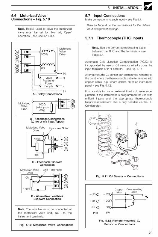
79
5.7 Input ConnectionsMake connections to each input – see Fig 5.7.
Refer to Table A on the rear fold-out for the defaultinput assignment settings.
5.7.1 Thermocouple (THC) Inputs
Note. Use the correct compensating cablebetween the THC and the terminals – seeTable 5.1.
Automatic Cold Junction Compensation (ACJC) isincorporated by use of CJ sensors wired across theinput terminals of I/P1 and I/P3 – see Fig. 5.11.
Alternatively, the CJ sensor can be mounted remotely atthe point where the thermocouple cable terminates intocopper cable, e.g. where cables enter an instrumentpanel – see Fig. 5.12.
It is possible to use an external fixed cold (reference)junction, if the instrument is programmed for use withmillivolt inputs and the appropriate thermocouplelinearizer is selected. This is only possible via the PCConfigurator.
5 INSTALLATION…
0%
100%
MotorizedValveDrive
(N)
N
L
(L)
MotorizedValveDrive
ValvePositioner
PowerSupply
0%
100%
Link – see Note.
0%
100%
34
33
35
8
9
5
6
–+
A – Relay Connections
Motorized ValveDrive
B – Feedback Connections(V, mA or mV Input Types)
C – Feedback SlidewireConnection
100Ω(mA inputs
only)
33
34
35
D – Alternative FeedbackSlidewire Connection
34
33
Motorized ValveDrive
Link – see Note.
7
–
+
28
29
30
Coppercable
I/P1
Compensatingcable
–
+
33
34
35
I/P3
5.6 Motorized ValveConnections – Fig. 5.10
Note. Relays used to drive the motorizedvalve must be set for 'Normally Open'operation – see Section 5.3.1.
Fig. 5.10 Motorized Valve Connections
Fig. 5.11 CJ Sensor – Connections
Fig. 5.12 Remote-mounted CJSensor – Connections
Note. The wire link must be connected atthe motorized valve end, NOT to theinstrument terminals.
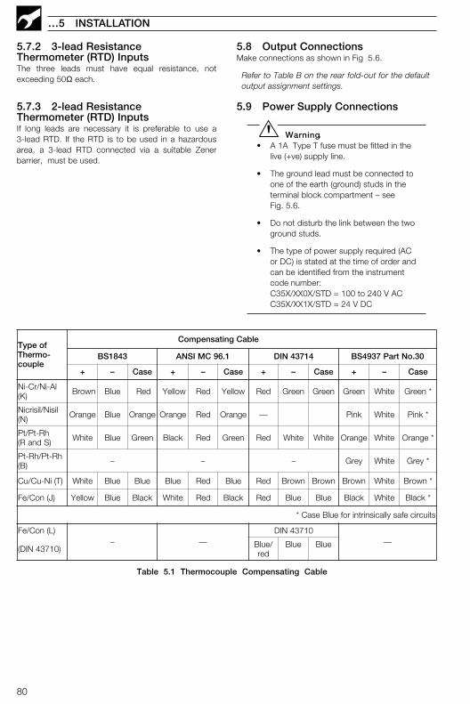
80
…5 INSTALLATION
foepyT-omrehT
elpuoc
elbaCgnitasnepmoC
3481SB 1.69CMISNA 41734NID 03.oNtraP7394SB
+ – esaC + – esaC + – esaC + – esaC
lA-iN/rC-iN)K( nworB eulB deR wolleY deR wolleY deR neerG neerG neerG etihW *neerG
lisiN/lisirciN)N( egnarO eulB egnarO egnarO deR egnarO — kniP etihW *kniP
hR-tP/tP)SdnaR( etihW eulB neerG kcalB deR neerG deR etihW etihW egnarO etihW *egnarO
hR-tP/hR-tP)B( – – – yerG etihW *yerG
)T(iN-uC/uC etihW eulB eulB eulB deR eulB deR nworB nworB nworB etihW *nworB
)J(noC/eF wolleY eulB kcalB etihW deR kcalB deR eulB eulB kcalB etihW *kcalB
stiucricefasyllacisnirtnirofeulBesaC*
)L(noC/eF– —
01734NID—
)01734NID( /eulBder
eulB eulB
5.7.2 3-lead ResistanceThermometer (RTD) InputsThe three leads must have equal resistance, notexceeding 50Ω each.
5.7.3 2-lead ResistanceThermometer (RTD) InputsIf long leads are necessary it is preferable to use a3-lead RTD. If the RTD is to be used in a hazardousarea, a 3-lead RTD connected via a suitable Zenerbarrier, must be used.
5.8 Output ConnectionsMake connections as shown in Fig 5.6.
Refer to Table B on the rear fold-out for the defaultoutput assignment settings.
5.9 Power Supply Connections
Warning.• A 1A Type T fuse must be fitted in the
live (+ve) supply line.
• The ground lead must be connected toone of the earth (ground) studs in theterminal block compartment – seeFig. 5.6.
• Do not disturb the link between the twoground studs.
• The type of power supply required (ACor DC) is stated at the time of order andcan be identified from the instrumentcode number:C35X/XX0X/STD = 100 to 240 V ACC35X/XX1X/STD = 24 V DC
Table 5.1 Thermocouple Compensating Cable
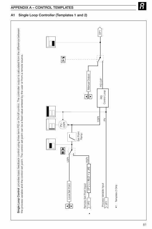
81
A1 Single Loop Controller (Templates 1 and 2)
APPENDIX A – CONTROL TEMPLATES
LSP
t
RS
Pt
PID
Con
trol
Loo
pP
ID O
/PC
SP
t
LLR
PV
Man
ual O
utpu
t
OP
1
Rem
ote
Set
Poi
nt In
put
Pro
cess
Var
iabl
e In
put
•1Te
mpl
ate
2 O
nly
Set
Poi
ntR
amp
•
Loca
l Set
Poi
nt
PV
–C
SP
t
I/P 2
x rAtO
+ biAS
I/P2
I/P1
Sin
gle
Lo
op
Co
ntr
ol
prov
ides
bas
ic fe
edba
ck c
ontr
ol u
sing
thre
e te
rm P
ID o
r On/
off c
ontr
ol. T
he c
ontr
olle
r out
put i
s ca
lcul
ated
from
the
diffe
renc
e be
twee
nth
e pr
oces
s va
riabl
e an
d th
e co
ntro
l set
poi
nt. T
he c
ontr
ol s
et p
oint
can
be
a fix
ed v
alue
ent
ered
by
the
user
or
from
a r
emot
e so
urce
.
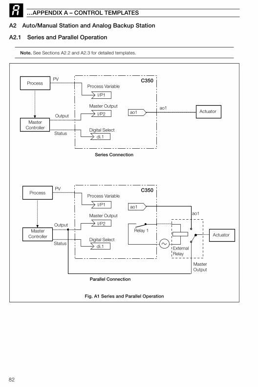
82
A2 Auto/Manual Station and Analog Backup Station
A2.1 Series and Parallel Operation
Note. See Sections A2.2 and A2.3 for detailed templates.
…APPENDIX A – CONTROL TEMPLATES
Process Variable
di.1
Master Output
ao1
Digital Select
I/P2
PV
Output
Status
Relay 1
ExternalRelay
I/P1
ao1
MasterOutput
Actuator
Process
MasterController
C350
Process Variable
di.1
Master Outputao1
Digital Select
I/P2
PV
Output
Status
I/P1
ao1Actuator
Process
MasterController
C350
Series Connection
Parallel Connection
Fig. A1 Series and Parallel Operation

83
APPENDIX A – CONTROL TEMPLATES…
Pro
cess
Var
iabl
e
di.1
Aut
o/M
anua
lS
elec
t
Mas
ter
Out
put
ao1
• •
•2
Tem
plat
e 4
only
•1Te
mpl
ate
3 on
ly. A
larm
A1
trip
val
ue c
an b
e se
t to
give
the
desi
red
low
sig
nal d
etec
tion
Dig
ital S
elec
t
Man
ual O
utpu
t
I/P2
Low
Sig
nal S
elec
t(A
larm
A1)
I/P1
OP
1
…A2.2 Auto/Manual Station (Templates 3 and 4)Th
e A
uto
/man
ual
Sta
tio
npr
ovid
es a
bac
kup
for
a M
aste
r co
ntro
ller.
In
norm
al o
pera
tion
the
CO
MM
AN
DE
R 3
50’s
cur
rent
out
put
follo
ws
the
mas
ter
cont
rolle
r’s
outp
ut v
alue
. A fa
ult i
n th
e m
aste
r sy
stem
can
be
iden
tifie
d ei
ther
by
dete
ctin
g a
low
sig
nal o
n th
e m
aste
r ou
tput
(tem
plat
e 3)
or
via
a di
gita
l sig
nal
(tem
plat
e 4)
. W
hen
a fa
ult
is d
etec
ted
the
CO
MM
AN
DE
R 3
50 s
elec
ts m
anua
l mod
e w
ith it
s ou
tput
eith
er s
et t
o th
e la
st v
alid
mas
ter
outp
ut v
alue
or
to a
conf
igur
ed o
utpu
t va
lue
– se
e S
ectio
n 4.
6/ C
ontr
ol C
onfig
urat
ion/
Con
figur
ed O
utpu
t 1.
Whe
n th
e m
aste
r si
gnal
is r
esto
red
or t
he d
igita
l inp
ut r
etur
ns t
o its
norm
al s
tate
the
CO
MM
AN
DE
R 3
50 s
witc
hes
back
to
auto
mod
e (i.
e. C
OM
MA
ND
ER
350
out
put
= m
aste
r ou
tput
).
The
auto
/man
ual s
tatio
n ca
n be
use
d in
ser
ies
or in
par
alle
l with
the
mas
ter
outp
ut s
igna
l – s
ee F
ig. A
1. P
aral
lel o
pera
tion
is a
chie
ved
by u
sing
rel
ay 1
in t
heC
OM
MA
ND
ER
350
to e
nerg
ize
an e
xter
nal r
elay
(with
sui
tabl
e ch
ange
over
con
tact
s fo
r sw
itchi
ng lo
w le
vel s
igna
ls) w
hich
sel
ects
the
outp
ut to
be
rout
ed to
the
actu
ator
.
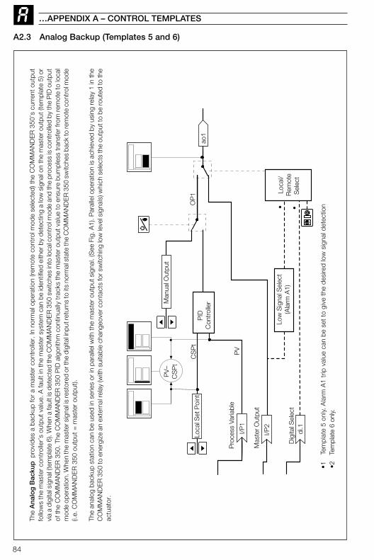
84
…APPENDIX A – CONTROL TEMPLATES
CS
Pt
I/P2
I/P1
di.1
PV
Pro
cess
Var
iabl
e
PID
Con
trol
ler
Low
Sig
nal S
elec
t(A
larm
A1)
Loca
l/R
emot
eS
elec
t
• •
•1
Tem
plat
e 5
only.
Ala
rm A
1 tr
ip v
alue
can
be
set
to g
ive
the
desi
red
low
sig
nal d
etec
tion
•2Te
mpl
ate
6 on
ly.
Mas
ter
Out
put
Dig
ital S
elec
t
Man
ual O
utpu
t
LLR
ao1
OP
1Lo
cal S
et P
oint
PV
–C
SP
t
A2.3 Analog Backup (Templates 5 and 6)Th
e A
nal
og
Bac
kup
prov
ides
a b
acku
p fo
r a
mas
ter
cont
rolle
r. In
nor
mal
ope
ratio
n (re
mot
e co
ntro
l mod
e se
lect
ed) t
he C
OM
MA
ND
ER
350
’s c
urre
nt o
utpu
tfo
llow
s th
e m
aste
r con
trol
ler’
s ou
tput
val
ue. A
faul
t in
the
mas
ter s
yste
m c
an b
e id
entif
ied
eith
er b
y de
tect
ing
a lo
w s
igna
l on
the
mas
ter o
utpu
t (te
mpl
ate
5) o
rvi
a a
digi
tal s
igna
l (te
mpl
ate
6). W
hen
a fa
ult i
s de
tect
ed th
e C
OM
MA
ND
ER
350
sw
itche
s in
to lo
cal c
ontr
ol m
ode
and
the
proc
ess
is c
ontr
olle
d by
the
PID
out
put
of th
e C
OM
MA
ND
ER
350
. The
CO
MM
AN
DE
R 3
50 P
ID a
lgor
ithm
con
tinua
lly tr
acks
the
mas
ter
outp
ut v
alue
to e
nsur
e bu
mpl
ess
tran
sfer
from
rem
ote
to lo
cal
mod
e op
erat
ion.
Whe
n th
e m
aste
r sig
nal i
s re
stor
ed o
r the
dig
ital i
nput
retu
rns
to it
s no
rmal
sta
te th
e C
OM
MA
ND
ER
350
sw
itche
s ba
ck to
rem
ote
cont
rol m
ode
(i.e.
CO
MM
AN
DE
R 3
50 o
utpu
t =
mas
ter
outp
ut).
The
anal
og b
acku
p st
atio
n ca
n be
use
d in
ser
ies
or in
par
alle
l with
the
mas
ter o
utpu
t sig
nal.
(See
Fig
. A1)
. Par
alle
l ope
ratio
n is
ach
ieve
d by
usi
ng re
lay
1 in
the
CO
MM
AN
DE
R 3
50 to
ene
rgiz
e an
ext
erna
l rel
ay (w
ith s
uita
ble
chan
geov
er c
onta
cts
for s
witc
hing
low
leve
l sig
nals
) whi
ch s
elec
ts th
e ou
tput
to b
e ro
uted
to th
eac
tuat
or.
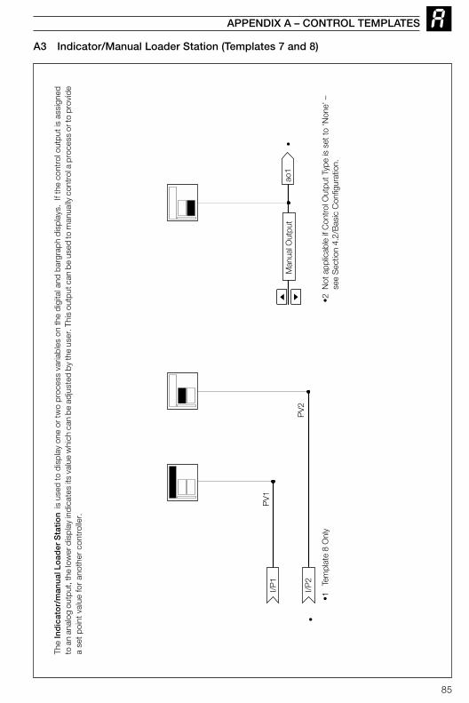
85
APPENDIX A – CONTROL TEMPLATES
PV
1
PV
2I/P
2
I/P1
Man
ual O
utpu
tao
1
•1
Tem
plat
e 8
Onl
y
•
•2 N
ot a
pplic
able
if C
ontr
ol O
utpu
t Typ
e is
set
to 'N
one'
–se
e S
ectio
n 4.
2/B
asic
Con
figur
atio
n.
•
A3 Indicator/Manual Loader Station (Templates 7 and 8)Th
e In
dic
ato
r/m
anu
al L
oad
er S
tati
on
is u
sed
to d
ispl
ay o
ne o
r tw
o pr
oces
s va
riabl
es o
n th
e di
gita
l and
bar
grap
h di
spla
ys.
If th
e co
ntro
l out
put i
s as
sign
edto
an
anal
og o
utpu
t, th
e lo
wer
dis
play
indi
cate
s its
val
ue w
hich
can
be
adju
sted
by
the
user
. Thi
s ou
tput
can
be
used
to m
anua
lly c
ontr
ol a
pro
cess
or t
o pr
ovid
ea
set
poin
t va
lue
for
anot
her
cont
rolle
r.
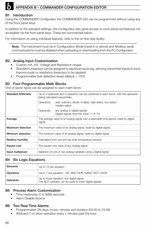
86
APPENDIX B – COMMANDER CONFIGURATION EDITOR
B1 IntroductionUsing the COMMANDER Configurator the COMMANDER 350 can be programmed without using anyof the front panel keys.
In addition to the standard settings, the Configurator also gives access to more advanced features notaccessible via the front panel keys. These are summarized below.
For information on using individual features, refer to the on-line help facility.
Note. The instrument must be in Configuration Mode (Level 6 or above) and Modbus serialcommunications must be disabled when uploading or downloading from the PC Configurator.
B2 Analog Input Customization• Custom mA, mV, Voltage and Resistance ranges• Standard Linearizers can be assigned to electrical inputs (eg. allowing transmitter inputs to have
thermocouple or resistance linearizers to be applied)• Programmable fault detection levels (default = 10%)
B3 Four Programmable Math BlocksOne of seven types can be assigned to each math block:
citemhtirAdradnatS sdnarepoehthtiw,kcolbhcaenidenibmocebnacsrotarepo3dnasdnarepo4otpU.yllaitneuqesdetaluclacgnieb
:srotarepO ,tceleswol,tceleshgih,ylpitlum,edivid,tcartbus,ddatcelesnaidem
:sdnarepO slangislatigidrogolanayna)'0'ro'1'eulavehtevahslangislatigid(
egarevA latigidybteser,doirepemitelbatcelesarevolangisgolananafoeulavegarevaehTlangis
noitcetedmumixaM langislatigidybteser,langisgolananafoeulavmumixamehT
noitcetedmuminiM langislatigidybteser,langisgolananafoeulavmuminimehT
ytidimuhevitaleR srosneserutarepmetblubyrddnatewmorfdetaluclaC
toorerauqS langisgolanaynafoeulavtoorerauqsehT
rexelpitlumtupnI langislatigidagnisuselbairavgolanaowtroenofonoitceleS
stnemelE noitauqerep51otpU
srotarepO ROXE,TON,DNAN,RON,DNA,RO:noitauqerep7otpU
sdnarepO.langislatigidyna:noitauqerep8otpU
.slangislatigidtrevniotdesuebnacrotarepoTONehT
B4 Six Logic Equations
B5 Process Alarm Customization• Time Hysteresis, 0 to 9999 seconds• Alarm Disable Source
B6 Two Real Time Alarms• Programmable ON days, hours, minutes and duration (00:00 to 23:59)• Wildcard (*) to allow operation every x minutes past the hour
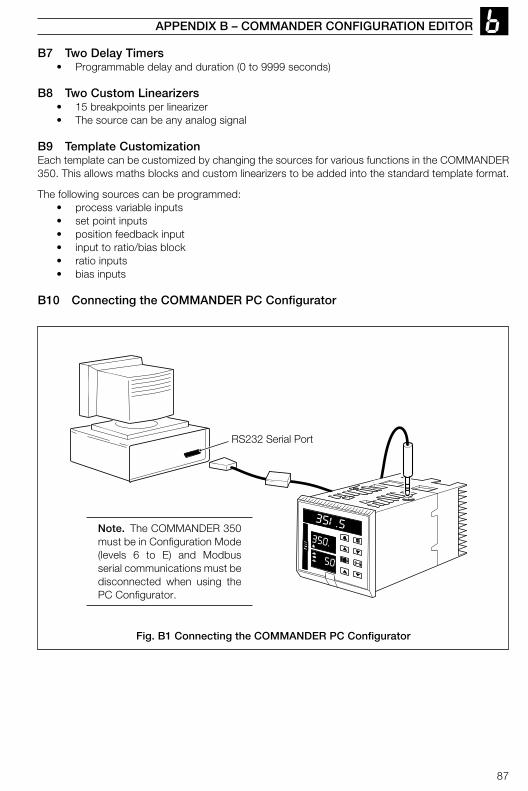
87
351.5350.
50
RS232 Serial Port
B7 Two Delay Timers• Programmable delay and duration (0 to 9999 seconds)
B8 Two Custom Linearizers• 15 breakpoints per linearizer• The source can be any analog signal
B9 Template CustomizationEach template can be customized by changing the sources for various functions in the COMMANDER350. This allows maths blocks and custom linearizers to be added into the standard template format.
The following sources can be programmed:• process variable inputs• set point inputs• position feedback input• input to ratio/bias block• ratio inputs• bias inputs
B10 Connecting the COMMANDER PC Configurator
APPENDIX B – COMMANDER CONFIGURATION EDITOR
Note. The COMMANDER 350must be in Configuration Mode(levels 6 to E) and Modbusserial communications must bedisconnected when using thePC Configurator.
Fig. B1 Connecting the COMMANDER PC Configurator
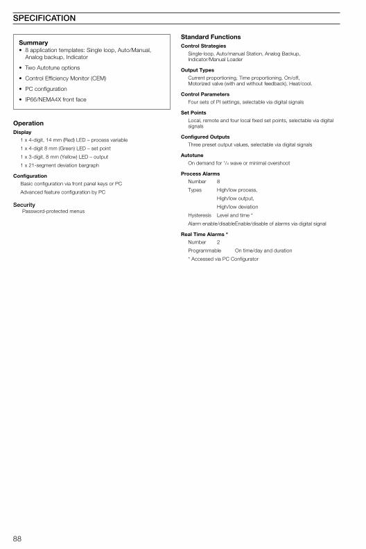
88
SPECIFICATION
Summary• 8 application templates: Single loop, Auto/Manual,
Analog backup, Indicator
• Two Autotune options
• Control Efficiency Monitor (CEM)
• PC configuration
• IP66/NEMA4X front face
OperationDisplay
1 x 4-digit, 14 mm (Red) LED – process variable
1 x 4-digit 8 mm (Green) LED – set point
1 x 3-digit, 8 mm (Yellow) LED – output
1 x 21-segment deviation bargraph
Configuration
Basic configuration via front panel keys or PC
Advanced feature configuration by PC
SecurityPassword-protected menus
Standard FunctionsControl Strategies
Single-loop, Auto/manual Station, Analog Backup,Indicator/Manual Loader
Output Types
Current proportioning, Time proportioning, On/off,Motorized valve (with and without feedback), Heat/cool.
Control Parameters
Four sets of PI settings, selectable via digital signals
Set Points
Local, remote and four local fixed set points, selectable via digitalsignals
Configured Outputs
Three preset output values, selectable via digital signals
Autotune
On demand for 1/4 wave or minimal overshoot
Process Alarms
Number 8
Types High/low process,
High/low output,
High/low deviation
Hysteresis Level and time *
Alarm enable/disableEnable/disable of alarms via digital signal
Real Time Alarms *
Number 2
Programmable On time/day and duration
* Accessed via PC Configurator
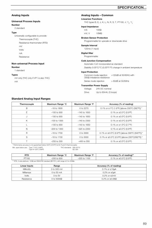
89
SPECIFICATION...
Analog Inputs
Universal Process InputsNumber
2 standard
Type
Universally configurable to provide:
Thermocouple (THC)
Resistance thermometer (RTD)
mV
Volts
mA
Resistance
Non-universal Process InputNumber
1 standard
Types
mV only (THC only if I/P1 is also THC)
mA
elpuocomrehT egnaRmumixaM °C egnaRmumixaM °F )gnidaerfo%(ycaruccA
B 0081ot81– 0723ot0 ro%1.0 ±1° 8.1(C ° 002evoba[)F ° 293(C ° *])F
E 009ot001– 0561ot041– ro%1.0 ± 5.0 ° 9.0(C ° )F
J 009ot001– 0561ot041– ro%1.0 ± 5.0 ° 9.0(C ° )F
K 0031ot001– 0532ot041– ro%1.0 ± 5.0 ° 9.0(C ° )F
L 009ot001– 0561ot041– ro%1.0 ± 5.1 ° 7.2(C ° )F
N 0031ot002– 0532ot523– ro%1.0 ± 5.0 ° 9.0(C ° )F
R 0071ot81– 0003ot0 ro%1.0 ± 5.0 ° 9.0(C ° 003evoba[)F ° 045(C ° *])F
S 0071ot81– 0003ot0 ro%1.0 ± 5.0 ° 9.0(C ° 002evoba[)F ° 293(C ° *])F
T 003ot052– 055ot004– ro%1.0 ± 5.0 ° 9.0(C ° )F
selpuocomrehtSdnaR,Brof)Fº275(Cº003wolebdeetnaraugtonsiycaruccaecnamrofreP*
orezwolebnaps.niM )Fº621(Cº07TepyT)Fº981(Cº501NepyT
sdradnatsCHT 01734NID485CEI
DTR egnaRmumixaM °C egnaRmumixaM °F **)gnidaerfo%(ycaruccA
001TP 006ot002– 0011ot523– ro%1.0 ± 5.0 ° 9.0(C ° )F001,munitalperiw-3,DTR** Ω 004ot0foegnarhtiw,)157CEI(dradnats06734NIDrep Ωs
stupnIraeniL egnaR )gnidaerfo%(ycaruccA
stlovilliM Vm005ot0 ro%1.0 ± 01 µA
spmailliM Am05ot0 ro%2.0 ±2µA
stloV V5ot0 ro%2.0 ± Vm2
ecnatsiseR 0005ot0 Ω ro%2.0 ± 80.0 Ω
Analog Inputs – CommonLinearizer Functions
THC types B, E, J, K, L, N, R, S, T, PT100, √, 3/2,5/2
Input Impedance
mA 100Ω
mV, V 10MΩ
Broken Sensor Protection
Programmable for upscale or downscale drive
Sample Interval
125ms (1 input)
Digital filter
Programmable
Cold Junction Compensation
Automatic CJC incorporated as standard
Stability 0.05°C/°C (0.05°F/°F) change in ambient temperature
Input Protection
Common mode rejection >120dB at 50/60Hz with300Ω imbalance resistance
Series mode rejection > 60dB at 50/60Hz
Transmitter Power Supply
Voltage: 24V DC nominal
Drive: Up to 60mA, (3 loops)
Standard Analog Input Ranges
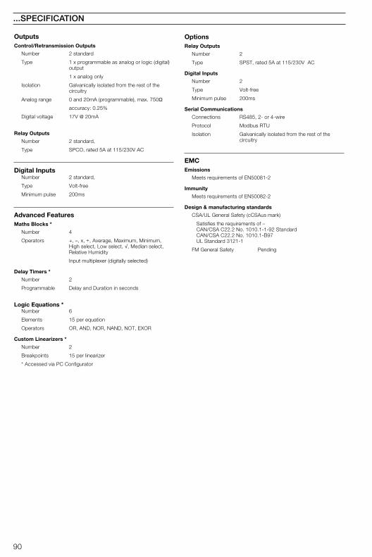
90
...SPECIFICATION
OutputsControl/Retransmission Outputs
Number 2 standard
Type 1 x programmable as analog or logic (digital)output
1 x analog only
Isolation Galvanically isolated from the rest of thecircuitry
Analog range 0 and 20mA (programmable), max. 750Ω
accuracy: 0.25%
Digital voltage 17V @ 20mA
Relay Outputs
Number 2 standard,
Type SPCO, rated 5A at 115/230V AC
Digital InputsNumber 2 standard,
Type Volt-free
Minimum pulse 200ms
Advanced FeaturesMaths Blocks *
Number 4
Operators +, –, x, ÷, Average, Maximum, Minimum,High select, Low select, √, Median select,Relative Humidity
Input multiplexer (digitally selected)
Delay Timers *
Number 2
Programmable Delay and Duration in seconds
Logic Equations *Number 6
Elements 15 per equation
Operators OR, AND, NOR, NAND, NOT, EXOR
Custom Linearizers *
Number 2
Breakpoints 15 per linearizer
* Accessed via PC Configurator
OptionsRelay Outputs
Number 2
Type SPST, rated 5A at 115/230V AC
Digital Inputs
Number 2
Type Volt-free
Minimum pulse 200ms
Serial Communications
Connections RS485, 2- or 4-wire
Protocol Modbus RTU
Isolation Galvanically isolated from the rest of thecircuitry
EMCEmissions
Meets requirements of EN50081-2
Immunity
Meets requirements of EN50082-2
Design & manufacturing standards
CSA/UL General Safety (cCSAus mark)
Satisfies the requirements of –CAN/CSA C22.2 No. 1010.1-1-92 StandardCAN/CSA C22.2 No. 1010.1-B97UL Standard 3121-1
FM General Safety Pending
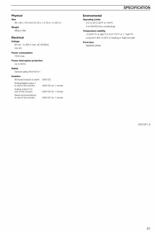
91
SPECIFICATION
PhysicalSize
96 x 96 x 122.5mm (3.78 in. x 3.78 in. x 4.82 in.)
Weight
680g (1.5lb)
ElectricalVoltage
85 min. to 265 V max. AC 50/60Hz
24V DC
Power consumption
15VA max.
Power interruption protection
Up to 60ms
Safety
General safety EN 61010-1
Isolation
All inputs/outputs to earth: 500V DC
Analog/digital output 1to rest of the circuitry: 500V DC for 1 minute
Analog output 2 torest of the circuitry: 500V DC for 1 minute
Serial communicationsto rest of the circuitry: 500V DC for 1 minute
EnvironmentalOperating Limits
0°C to 55°C (32°F to 130°F)
5 to 95%RH (non-condensing)
Temperature stability
<0.02%/°C or 2µV/°C (<0.011%/°F or 1.11µV/°F)
Long term drift <0.02% of reading or 20µV annually
Front face
NEMA4X (IP66)
SS/C351_6

92
FRAMES INDEX
Set Up FramesFrame TitleAAlarm 1 TripAlarm 2 TripAlarm 3 TripAlarm 4 TripAlarm 5 TripAlarm 6 TripAlarm 7 TripAlarm 8 Trip
Approach Band 1
CControl Zone DeadbandCycle Time 1Cycle Time 2
DDeadband (Feedback only)Derivative Action Time 1
HHeat/Cool Output 1 StartHeat/Cool Output 2 Start
IIntegral Action Time 1Integral Action Time 2Integral Action Time 3Integral Action Time 4
LLocal Set Point 1Local Set Point 2Local Set Point 3Local Set Point 4
MManual ResetMotorised Valve BiasMotorised Valve Ratio
OOutput 1 On/off Hysteresis ValueOutput 2 On/off Hysteresis Value
Frame TitlePProportional Band 1Proportional Band 2Proportional Band 3Proportional Band 4
RRamp RateRegulator Travel TimeRemote Set Point BiasRemote Set Point Ratio
SSet Points
TTune
VValve Set Up
Mnemonic Number
1.xxx 4.012.xxx 4.023.xxx 4.034.xxx 4.045.xxx 4.056.xxx 4.067.xxx 4.078.xxx 4.08
Ab 1 2.15
dbNd 2.21CYC1 2.01CYC2 2.02
d.bNd 5.03drV1 2.13
Y1St 2.22Y2St 2.23
IAt.1 2.09IAt.2 2.10IAt.3 2.11IAt.4 2.12
LSP.1 3.01LSP.2 3.02LSP.3 3.03LSP.4 3.04
rSt.1 2.17VbIA 5.02VrAt 5.01
HYS.1 2.03HYS.2 2.04
Mnemonic Number
Pb-1 2.05Pb-2 2.06Pb-3 2.07Pb-4 2.08
r.rtE 3.10r.trV 5.04bIAS 3.07rAtO 3.06
LEV3 3.00
LEV2 2.00
LEV5 5.00
Mnemonic
Frame Number
ParameterSetting/Value
Fig. I.1 Parameter Identification
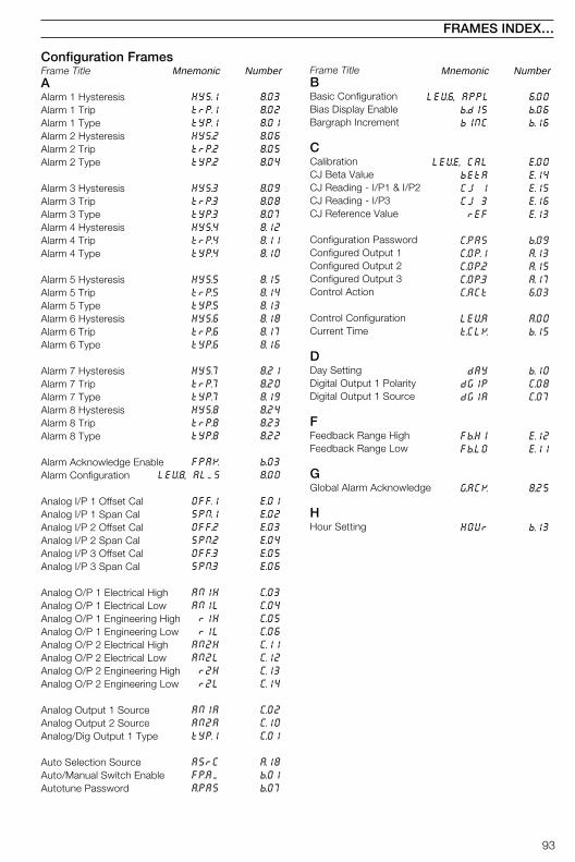
93
FRAMES INDEX…
Configuration FramesFrame TitleAAlarm 1 HysteresisAlarm 1 TripAlarm 1 TypeAlarm 2 HysteresisAlarm 2 TripAlarm 2 Type
Alarm 3 HysteresisAlarm 3 TripAlarm 3 TypeAlarm 4 HysteresisAlarm 4 TripAlarm 4 Type
Alarm 5 HysteresisAlarm 5 TripAlarm 5 TypeAlarm 6 HysteresisAlarm 6 TripAlarm 6 Type
Alarm 7 HysteresisAlarm 7 TripAlarm 7 TypeAlarm 8 HysteresisAlarm 8 TripAlarm 8 Type
Alarm Acknowledge EnableAlarm Configuration
Analog I/P 1 Offset CalAnalog I/P 1 Span CalAnalog I/P 2 Offset CalAnalog I/P 2 Span CalAnalog I/P 3 Offset CalAnalog I/P 3 Span Cal
Analog O/P 1 Electrical HighAnalog O/P 1 Electrical LowAnalog O/P 1 Engineering HighAnalog O/P 1 Engineering LowAnalog O/P 2 Electrical HighAnalog O/P 2 Electrical LowAnalog O/P 2 Engineering HighAnalog O/P 2 Engineering Low
Analog Output 1 SourceAnalog Output 2 SourceAnalog/Dig Output 1 Type
Auto Selection SourceAuto/Manual Switch EnableAutotune Password
Frame TitleBBasic ConfigurationBias Display EnableBargraph Increment
CCalibrationCJ Beta ValueCJ Reading - I/P1 & I/P2CJ Reading - I/P3CJ Reference Value
Configuration PasswordConfigured Output 1Configured Output 2Configured Output 3Control Action
Control ConfigurationCurrent Time
DDay SettingDigital Output 1 PolarityDigital Output 1 Source
FFeedback Range HighFeedback Range Low
GGlobal Alarm Acknowledge
HHour Setting
Mnemonic Number
HYS.1 8.03trP.1 8.02tYP.1 8.01HYS.2 8.06trP.2 8.05tYP.2 8.04
HYS.3 8.09trP.3 8.08tYP.3 8.07HYS.4 8.12trP.4 8.11tYP.4 8.10
HYS.5 8.15trP.5 8.14tYP.5 8.13HYS.6 8.18trP.6 8.17tYP.6 8.16
HYS.7 8.21trP.7 8.20tYP.7 8.19HYS.8 8.24trP.8 8.23tYP.8 8.22
FPAK b.03LEV8, ALMS 8.00
OFF.1 E.01SPN.1 E.02OFF.2 E.03SPN.2 E.04OFF.3 E.05SPN.3 E.06
AN1H C.03AN1L C.04r1H C.05r1L C.06
AN2H C.11AN2L C.12r2H C.13r2L C.14
AN1A C.02AN2A C.10tYP.1 C.01
ASrC A.18FP.AM b.01A.PAS b.07
Mnemonic Number
LEV6, APPL 6.00b.dIS b.06bINC b.16
LEVE, CAL E.00bEtA E.14CJ 1 E.15CJ 3 E.16rEF E.13
C.PAS b.09C.OP.1 A.13C.OP.2 A.15C.OP.3 A.17C.ACt 6.03
LEV.A A.00t.CLK b.15
dAY b.10dG1P C.08dG1A C.07
Fb.HI E.12Fb.LO E.11
G.ACK 8.25
HOUr b.13

94
Mnemonic Number
P.rEC A.01rEC.t A.02PVFA A.03dF.OP A.04
r.dIS b.05r.trV E.08rL1P C.18rL1A C.17rL2P C.20rL2A C.19
rL3P C.22rL3A C.21rL4P C.24rL4A C.23r.SrC 9.14SP.FA 9.06
LEVd d.00S.CFG d.01
LEV9, SEt.P 9.00L.Sr.1 9.08L.Sr.2 9.09L.Sr.3 9.10L.Sr.4 9.11
dF.SP 9.07SPt.H 9.02SPt.L 9.03trCK 9.01
S.PAS b.10SSP.H 9.04SSPL 9.05S.AdJ b.04
t.APP 6.01t.CLK b.13t1Sr A.19t2Sr A..20t3Sr A.21t4Sr A.22
…Configuration FramesFrame TitleIInput 1 Broken SensorInput 1 Decimal PointInput 1 Engineering HighInput 1 Engineering LowInput 1 Filter Time ConstantInput 1 Temp UnitsInput 1 Type
Input 2 Broken SensorInput 2 Decimal PointInput 2 Engineering HighInput 2 Engineering LowInput 2 Filter Time ConstantInput 2 Temp UnitsInput 2 Type
Input 3 Broken SensorInput 3 Decimal PointInput 3 Engineering HighInput 3 Engineering LowInput 3 Filter Time ConstantInput 3 Temp UnitsInput 3 Type
LLevel HeadingLocal Set Point SourceLocal/Remote EnableLocal/Remote Set Point Source
MMV Calibration selectionMV Feedback – closedMV Feedback – openMains RejectionMan/Auto Selection SourceManual 1 Selection SourceManual 2 Selection SourceMinute Setting
Modbus AddressModbus Parity
OO/P Low LimitO/P High LimitOP 1 High LimitOP 2 High LimitOP 2 Low LimitOperator Configuration
Output AssignmentOutput Slew RateOutput Slew Rate DisableOutput Type
Frame TitlePPower Fail Recovery ModePower Fail Recovery TimeProcess Variable Fail ActionPV Fail Default Output
RRatio Display EnableRegulator Travel TimeRelay 1 PolarityRelay 1 SourceRelay 2 PolarityRelay 2 Source
Relay 3 PolarityRelay 3 SourceRelay 4 PolarityRelay 4 SourceRemote Set Point SourceRSPT Fault Action
SSerial CommunicationsSerial ConfigurationSet Point ConfigurationSet Point 1 SourceSet Point 2 SourceSet Point 3 SourceSet Point 4 Source
Set Point Default ValueSet Point High LimitSet Point Low LimitSet Point Tracking
Set up PasswordSlave Set Point High LimitSlave Set Point Low LimitSet Point Adjust Disable
TTemplate ApplicationsTime DisplayTune Select Source 1Tune Select Source 2Tune Select Source 3Tune Select Source 4
…FRAMES INDEX
Mnemonic Number
bSd.1 7.06dP.1 7.03EN1H 7.04EN1L 7.05FLt.1 7.07UNt.1 7.02tYP.1 7.01
bSd.2 7.13dP.2 7.10EN2H 7.11EN2L 7.12FLt.2 7.14UNt.2 7.09tYP.2 7.08
bSd.3 7.20dP.3 7.17EN3H 7.18EN3L 7.19FLt.3 7.21UNt.3 7.16tYP.3 7.15
LEV7 7.00LC.Sr 9.13FPLr b.02Lr.Sr 9.12
FCAL E.07C.CAL E.09O.CAL E.10F.rEJ 6.06AM.Sr A.16M.Sr1 A.12M.Sr2 A.14MIN b.14
Addr d.03PrtY d.02
OP.LO A.06OP.HI A.05OP1H A.07OP2H A.08OP2L A.09
LEVb, OPEr b.00
LEVC, ASSn C.00OP.Sr A.10SrdS A.11O.tYP 6.02
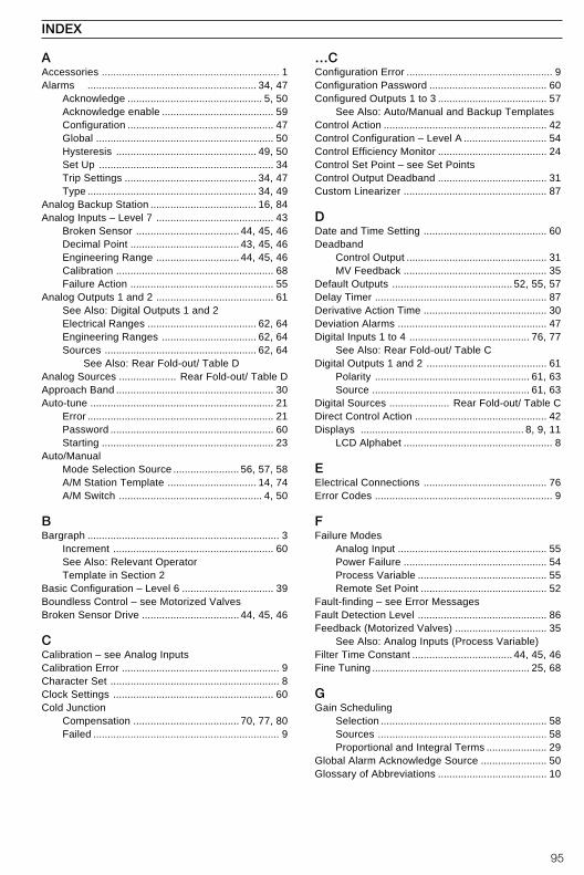
95
INDEX
AAccessories .............................................................. 1Alarms ........................................................... 34, 47
Acknowledge ............................................... 5, 50Acknowledge enable ....................................... 59Configuration ................................................... 47Global .............................................................. 50Hysteresis ................................................. 49, 50Set Up ............................................................. 34Trip Settings .............................................. 34, 47Type ........................................................... 34, 49
Analog Backup Station ..................................... 16, 84Analog Inputs – Level 7 ......................................... 43
Broken Sensor .................................... 44, 45, 46Decimal Point ...................................... 43, 45, 46Engineering Range ............................. 44, 45, 46Calibration ....................................................... 68Failure Action .................................................. 55
Analog Outputs 1 and 2 ......................................... 61See Also: Digital Outputs 1 and 2Electrical Ranges ...................................... 62, 64Engineering Ranges ................................. 62, 64Sources ..................................................... 62, 64
See Also: Rear Fold-out/ Table DAnalog Sources .................... Rear Fold-out/ Table DApproach Band ....................................................... 30Auto-tune ................................................................ 21
Error ................................................................. 21Password ......................................................... 60Starting ............................................................ 23
Auto/ManualMode Selection Source ....................... 56, 57, 58A/M Station Template ............................... 14, 74A/M Switch .................................................. 4, 50
BBargraph ................................................................... 3
Increment ........................................................ 60See Also: Relevant OperatorTemplate in Section 2
Basic Configuration – Level 6 ................................ 39Boundless Control – see Motorized ValvesBroken Sensor Drive .................................. 44, 45, 46
CCalibration – see Analog InputsCalibration Error ....................................................... 9Character Set ........................................................... 8Clock Settings ........................................................ 60Cold Junction
Compensation ..................................... 70, 77, 80Failed ................................................................. 9
…CConfiguration Error ................................................... 9Configuration Password ......................................... 60Configured Outputs 1 to 3 ...................................... 57
See Also: Auto/Manual and Backup TemplatesControl Action ......................................................... 42Control Configuration – Level A ............................. 54Control Efficiency Monitor ...................................... 24Control Set Point – see Set PointsControl Output Deadband ...................................... 31Custom Linearizer .................................................. 87
DDate and Time Setting ........................................... 60Deadband
Control Output ................................................. 31MV Feedback .................................................. 35
Default Outputs .......................................... 52, 55, 57Delay Timer ............................................................ 87Derivative Action Time ........................................... 30Deviation Alarms .................................................... 47Digital Inputs 1 to 4 .......................................... 76, 77
See Also: Rear Fold-out/ Table CDigital Outputs 1 and 2 .......................................... 61
Polarity ...................................................... 61, 63Source ....................................................... 61, 63
Digital Sources ..................... Rear Fold-out/ Table CDirect Control Action .............................................. 42Displays ......................................................... 8, 9, 11
LCD Alphabet .................................................... 8
EElectrical Connections ........................................... 76Error Codes .............................................................. 9
FFailure Modes
Analog Input .................................................... 55Power Failure .................................................. 54Process Variable ............................................. 55Remote Set Point ............................................ 52
Fault-finding – see Error MessagesFault Detection Level ............................................. 86Feedback (Motorized Valves) ................................ 35
See Also: Analog Inputs (Process Variable)Filter Time Constant ................................... 44, 45, 46Fine Tuning ....................................................... 25, 68
GGain Scheduling
Selection .......................................................... 58Sources ........................................................... 58Proportional and Integral Terms ..................... 29
Global Alarm Acknowledge Source ....................... 50Glossary of Abbreviations ...................................... 10
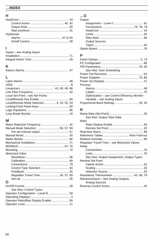
96
HHeat/Cool ................................................................ 19
Control Action ........................................... 40, 42Output limits .................................................... 55Start positions ................................................. 31
HysteresisAlarms .................................................... 47 to 50On/off Control .................................................. 28
IInputs – see Analog InputsInstallation .............................................................. 71Integral Action Time ............................................... 29
KKlaxon Alarms ........................................................ 47
LLatch Alarms .......................................................... 48LEDs ................................................................... 8Linearizers ........................................... 43, 45, 46, 86Line Filter Frequency ............................................. 42Local Set Point – see Set PointsLocal/Remote Key Enable ..................................... 59Local/Remote Mode Selection .............. 6, 16, 52, 53Locking Front Panel Keys ...................................... 59Logic Equations ...................................................... 86Loop Break Monitor ................................................ 10
MMains Rejection Frequency ................................... 42Manual Mode Selection ............................. 56, 57, 59
Pre-set manual output .................................... 57Manual Reset ......................................................... 30Maths Blocks .......................................................... 86Mechanical Installation ........................................... 71MODBUS .......................................................... 67, 76Mounting ................................................................. 72Motorized Valve
Boundless ........................................................ 36Calibration ....................................................... 69Connections .................................................... 79Control Type Selection ................................... 40Feedback ......................................................... 35Regulator Travel Time ........................ 35, 37, 69Set Up ............................................................. 35
OOn/Off Control ........................................................ 28
See Also: Control TypesOperator Configuration – Level B .......................... 59Operating Displays ................................................... 3Operator Ratio/Bias Display Enable ...................... 59Operator Level ........................................................ 11
…OOutput
Assignment – Level C ..................................... 61Connections ........................................ 76, 78, 79Heat/Cool ........................................................ 19Limits ............................................................... 55Slew Rate ........................................................ 56Output SourcesTypes ............................................................... 40
Option Board .......................................................... 76
PPanel Clamps ..................................................... 2, 73PC Configurator ...................................................... 86PID Parameters ................................................ 29, 30
See Also: Gain SchedulingPower Fail Recovery .............................................. 54Power Supplies ................................................ 76, 80Power Up Displays ................................................. 11Process
Alarms ............................................................. 48Labels .............................................................. 75Optimization – see Control Efficiency MonitorVariable – see Analog Inputs
Proportional Band Settings .............................. 29, 30
RRamp Rate (Set Point) ........................................... 33
See Also: Output Slew RateRatio
Ratio Display Enable ...................................... 59Remote Set Point ............................................ 32
Real-time Alarm ...................................................... 86Reference Tables ................................ Rear Fold-outRelative Humidity ................................................... 86Regulator Travel Time – see Motorized ValvesRelay
Connections .................................................... 76Links ................................................................ 78See Also: Output Assignment, Output Types
Remote Set PointFailure Action .................................................. 52Scaling ............................................................. 32Selection Source ............................................. 53
Resistance Thermometer ........................... 43, 46, 76Retransmission – See Analog Outputs,
Analog SourcesReverse Control Action .......................................... 42
…INDEX
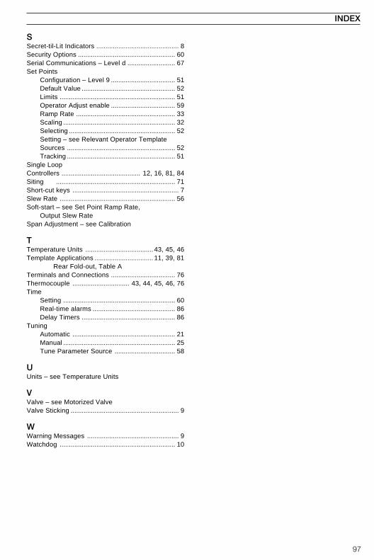
97
SSecret-til-Lit Indicators ............................................. 8Security Options ..................................................... 60Serial Communications – Level d .......................... 67Set Points
Configuration – Level 9 ................................... 51Default Value ................................................... 52Limits ............................................................... 51Operator Adjust enable ................................... 59Ramp Rate ...................................................... 33Scaling ............................................................. 32Selecting .......................................................... 52Setting – see Relevant Operator TemplateSources ........................................................... 52Tracking ........................................................... 51
Single LoopControllers ........................................... 12, 16, 81, 84Siting ................................................................. 71Short-cut keys .......................................................... 7Slew Rate ............................................................... 56Soft-start – see Set Point Ramp Rate,
Output Slew RateSpan Adjustment – see Calibration
TTemperature Units ..................................... 43, 45, 46Template Applications ................................ 11, 39, 81
Rear Fold-out, Table ATerminals and Connections ................................... 76Thermocouple ............................... 43, 44, 45, 46, 76Time
Setting ............................................................. 60Real-time alarms ............................................. 86Delay Timers ................................................... 86
TuningAutomatic ........................................................ 21Manual ............................................................. 25Tune Parameter Source ................................. 58
UUnits – see Temperature Units
VValve – see Motorized ValveValve Sticking ........................................................... 9
WWarning Messages .................................................. 9Watchdog ............................................................... 10
INDEX

98
NOTES

99
NOTES...

100
...NOTES
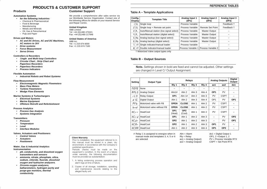
PRODUCTS & CUSTOMER SUPPORTProducts
Automation Systems• for the following industries:
– Chemical & Pharmaceutical– Food & Beverage– Manufacturing– Metals and Minerals– Oil, Gas & Petrochemical– Pulp and Paper
Drives and Motors• AC and DC Drives, AC and DC Machines,
AC motors to 1kV• Drive systems• Force Measurement• Servo Drives
Controllers & Recorders• Single and Multi-loop Controllers• Circular Chart , Strip Chart and
Paperless Recorders• Paperless Recorders• Process Indicators
Flexible Automation• Industrial Robots and Robot Systems
Flow Measurement• Electromagnetic Magnetic Flowmeters• Mass Flow Meters• Turbine Flowmeters• Wedge Flow Elements
Marine Systems & Turbochargers• Electrical Systems• Marine Equipment• Offshore Retrofit and Referbishment
Process Analytics• Process Gas Analysis• Systems Integration
Transmitters• Pressure• Temperature• Level• Interface Modules
Valves, Actuators and Positioners• Control Valves• Actuators• Positioners
Water, Gas & Industrial AnalyticsInstrumentation
• pH, conductivity, and dissolved oxygentransmitters and sensors
• ammonia, nitrate, phosphate, silica,sodium, chloride, fluoride, dissolvedoxygen and hydrazine analyzers.
• Zirconia oxygen analyzers,katharometers, hydrogen purity andpurge-gas monitors, thermalconductivity.
Customer Support
We provide a comprehensive after sales service viaour Worldwide Service Organization. Contact one ofthe following offices for details on your nearest Serviceand Repair Centre.
United KingdomABB LimitedTel: +44 (0)1480 475321Fax: +44 (0)1480 217948
United States of AmericaABB Inc.Tel: +1 215 674 6000Fax: +1 215 674 7183
.gifnoCyalpsiD
eltiTetalpmeT1tupnIgolanA
)1P/I(2tupnIgolanA
)2P/I(3tupnIgolanA
)3P/I(
.1 LS poolelgniS elbairaVssecorP †kcabdeeF
.2 LS tnioptesetomeR+poolelgniS elbairaVssecorP tnioPteSetomeR †kcabdeeF
.3 MA )tceleslangiswol(noitatslaunaM/otuA elbairaVssecorP tuptuOretsaM –
.4 MA )tceleslatigid(noitatslaunaM/otuA elbairaVssecorP tuptuOretsaM –
.5 bA )tceleslangiswol(pukcabgolanA elbairaVssecorP tuptuOretsaM –
.6 bA )tceleslatigid(pukcabgolanA elbairaVssecorP tuptuOretsaM –
.7 NI redaollaunam/rotacidnielgniS elbairaVssecorP – –
..8 NI redaollaunam/rotacidnielbuoD 1elbairaVssecorP 2elbairaVssecorP –
ylnosepyttuptuoevlaVdezirotoM†
gnitteS epyTtuptuOsyaleR stuptuOgolanA
latigiDtuptuO
1ylR 2ylR 3ylR 4ylR 1oa 2oa 1od
ENON enoN – – – – – – –
GLNA tuptuOgolanA #1mlA 2mlA 3mlA 4mlA 1PO VP –
YLr tuptuOyaleR 1PO #1mlA 2mlA 3mlA VP TPSC –
GId tuptuOlatigiD 1mlA 2mlA 3mlA 4mlA 1PO VP 1PO
bFP BFhtiwevlavdezirotoM NEPO ESOLC 1mlA 2mlA VP TPSC –
dnb BFtuohtiwevlavdezirotoM NEPO ESOLC 1mlA 2mlA VP TPSC –
rr.CH looC/taeH1PO
)taeH(2PO
)looC(1mlA 2mlA VP TPSC –
dr.CH looC/taeH 1PO 1mlA 2mlA 3mlA – VP 2PO
rd.CH looC/taeH 2PO 1mlA 2mlA 3mlA – VP 1PO
rA.CH looC/taeH 2PO 1mlA 2mlA 3mlA 1PO VP –
AA.CH looC/taeH 1mlA 2mlA 3mlA 4mlA 1PO 2PO –
# ninehwezigreneotdengissasi1yaleR6ro5,4,3setalpmetdnaedomlaunam
detcelesera
mralA=mlAyaleR=ylR
1tuptuOgolanA=1oa2tuptuOgolanA=2oa
1tuptuOlatigiD=1od2,1tuptuO=2,1PO
XTRelbairaVssecorP=VPXTRtnioPteS=TPSC
REFERENCE TABLES
Table A – Template Applications
Table B – Output Sources
Note. Settings shown in bold are fixed and cannot be adjusted. Other settingsare changed in Level C/ Output Assignment.
Client WarrantyPrior to installation, the equipment referred to inthis manual must be stored in a clean, dryenvironment, in accordance with the Company'spublished specification.Periodic checks must be made on theequipment's condition. In the event of a failureunder warranty, the following documentationmust be provided as substantiation:
1. A listing evidencing process operation andalarm logs at time of failure.
2. Copies of all storage, installation, operatingand maintenance records relating to thealleged faulty unit.
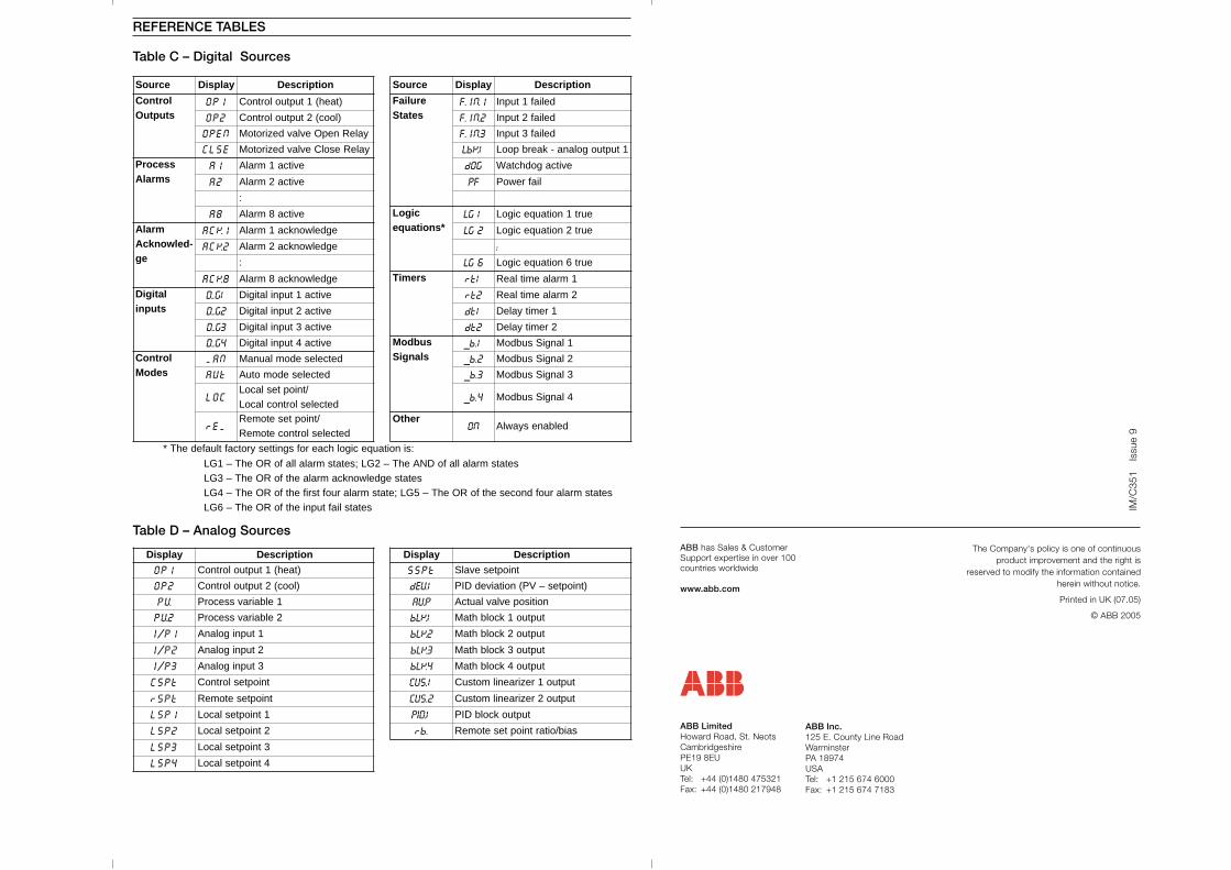
ecruoS yalpsiD noitpircseD ecruoS yalpsiD noitpircseD
lortnoCstuptuO
1PO )taeh(1tuptuolortnoC eruliaFsetatS
1.NI.F deliaf1tupnI
2PO )looc(2tuptuolortnoC 2.NI.F deliaf2tupnI
NEPO yaleRnepOevlavdezirotoM 3.NI.F deliaf3tupnI
ESLC yaleResolCevlavdezirotoM 1KbL 1tuptuogolana-kaerbpooL
ssecorPsmralA
1A evitca1mralA GOd evitcagodhctaW
2A evitca2mralA FP liafrewoP
:
8A evitca8mralA cigoL*snoitauqe
1GL eurt1noitauqecigoL
mralA-delwonkcA
eg
1KCA egdelwonkca1mralA 2GL eurt2noitauqecigoL
2KCA egdelwonkca2mralA :: 6GL eurt6noitauqecigoL
8KCA egdelwonkca8mralA sremiT 1tr 1mralaemitlaeR
latigiDstupni
1G.D evitca1tupnilatigiD 2tr 2mralaemitlaeR
2G.D evitca2tupnilatigiD 1td 1remityaleD
3G.D evitca3tupnilatigiD 2td 2remityaleD
4G.D evitca4tupnilatigiD subdoMslangiS
1.b_ 1langiSsubdoM
lortnoCsedoM
NAM detcelesedomlaunaM 2.b_ 2langiSsubdoM
tUA detcelesedomotuA 3.b_ 3langiSsubdoM
COL/tniopteslacoL
detceleslortnoclacoL4.b_ 4langiSsubdoM
MEr/tnioptesetomeR
detceleslortnocetomeRrehtO
NO delbanesyawlA
:sinoitauqecigolhcaerofsgnittesyrotcaftluafedehT*
setatsmralallafoDNAehT–2GL;setatsmralallafoROehT–1GLsetatsegdelwonkcamralaehtfoROehT–3GL
setatsmralaruofdnocesehtfoROehT–5GL;etatsmralaruoftsrifehtfoROehT–4GLsetatsliaftupniehtfoROehT–6GL
yalpsiD noitpircseD yalpsiD noitpircseD
1PO )taeh(1tuptuolortnoC tPSS tnioptesevalS
2PO )looc(2tuptuolortnoC 1VEd )tnioptes–VP(noitaivedDIP
VP 1elbairavssecorP PVA noitisopevlavlautcA
2VP 2elbairavssecorP 1KLb tuptuo1kcolbhtaM
1P/I 1tupnigolanA 2KLb tuptuo2kcolbhtaM
2P/I 2tupnigolanA 3KLb tuptuo3kcolbhtaM
3P/I 3tupnigolanA 4KLb tuptuo4kcolbhtaM
tPSC tniopteslortnoC 1.SUC tuptuo1reziraenilmotsuC
tPSr tnioptesetomeR 2.SUC tuptuo2reziraenilmotsuC
1PSL 1tniopteslacoL 1DIP tuptuokcolbDIP
2PSL 2tniopteslacoL .br saib/oitartnioptesetomeR
3PSL 3tniopteslacoL
4PSL 4tniopteslacoL
REFERENCE TABLES
Table C – Digital Sources
Table D – Analog SourcesThe Company's policy is one of continuous
product improvement and the right isreserved to modify the information contained
herein without notice.
Printed in UK (07.05)
© ABB 2005
ABB Inc.125 E. County Line RoadWarminsterPA 18974USATel: +1 215 674 6000Fax: +1 215 674 7183
ABB has Sales & CustomerSupport expertise in over 100countries worldwide
www.abb.com
ABB LimitedHoward Road, St. NeotsCambridgeshirePE19 8EUUKTel: +44 (0)1480 475321Fax: +44 (0)1480 217948
IM/C
351
Issu
e 9