Embed Size (px)
Citation preview
DIO3265
Digital I/O Card
Software Manual (V3.0)
健昇科技股份有限公司
JS AUTOMATION CORP.
新北市汐止區中興路 100號 6樓
6F., No.100, Zhongxing Rd., Xizhi Dist., New Taipei City, Taiwan
TEL:+886-2-2647-6936
FAX:+886-2-2647-6940
http://www.automation.com.tw
http://www.automation-js.com/ E-mail:[email protected]

1
Correction record
Manual
Version
Record
1.0 First publish
2.0 revised to new manual style
add new function DIO3265_set_default_password
3.0 disable the software key function with return value always true
2
Contents
1. How to install the software of DIO3265 .......................................................................................... 4
1.1 Install the PCI driver .............................................................................................................. 4
2. Where to find the file you need ....................................................................................................... 5
3. About the DIO3265 software ........................................................................................................... 6
3.1 What you need to get started .................................................................................................. 6
3.2 Software programming choices .............................................................................................. 6
4. DIO3265 Language support............................................................................................................. 7
4.1 Building applications with the DIO3265 software library ..................................................... 7
4.2 DIO3265 Windows libraries ................................................................................................... 7
5. Basic concepts of digital I/O control ............................................................................................... 8
6. Function format and language difference ...................................................................................... 11
6.1 Function format .................................................................................................................... 11
6.2 Variable data types ................................................................................................................ 12
6.3 Programming language considerations ................................................................................. 13
7. Flow chart of application implementation ..................................................................................... 15
7.1 DIO3265 Flow chart of application implementation ............................................................ 15
8. Software overview and dll function ............................................................................................... 17
8.1 Initialization and close .......................................................................................................... 17
DIO3265_initial ................................................................................................................. 17
DIO3265_close .................................................................................................................. 17
DIO3265_info .................................................................................................................... 17
8.2 Out port R/W ........................................................................................................................ 18
DIO3265_out_port_set ....................................................................................................... 19
DIO3265_out_port_read .................................................................................................... 19
DIO3265_out_point_set ..................................................................................................... 20
DIO3265_out_point_read .................................................................................................. 20
DIO3265_out_polarity_set ................................................................................................. 21
DIO3265_out_polarity_read .............................................................................................. 21
8.3 TTL I/O Port R/W ................................................................................................................ 22
DIO3265_TTL_IO_config_set .......................................................................................... 23
DIO3265_TTL_IO_config_read ........................................................................................ 23
DIO3265_TTL_IO_polarity_set ........................................................................................ 24
DIO3265_TTL_IO_polarity_read ...................................................................................... 24
DIO3265_TTL_IO_Enable ................................................................................................ 25
DIO3265_TTL_IO_Disable ............................................................................................... 25
DIO3265_TTL_IO_port_set .............................................................................................. 25
DIO3265_TTL_IO_port_read ............................................................................................ 26
DIO3265_TTL_IO_point_set ............................................................................................ 26
DIO3265_TTL_IO_point_read .......................................................................................... 27
3
DIO3265_TTL_IO_debounce_time_set ............................................................................ 27
DIO3265_TTL_IO_debounce_time_read .......................................................................... 28
8.4 Timer function ...................................................................................................................... 29
DIO3265_timer_set ............................................................................................................ 29
DIO3265_timer_read ......................................................................................................... 29
DIO3265_timer_start ......................................................................................................... 30
DIO3265_timer_stop.......................................................................................................... 30
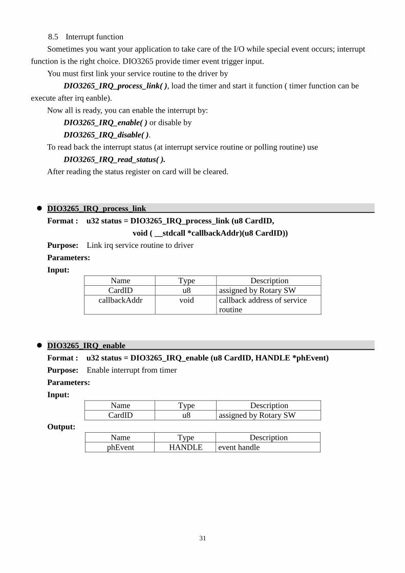
8.5 Interrupt function .................................................................................................................. 31
DIO3265_IRQ_process_link.............................................................................................. 31
DIO3265_IRQ_enable ....................................................................................................... 31
DIO3265_IRQ_disable ...................................................................................................... 32
DIO3265_IRQ_read_status ................................................................................................ 32
8.6 Software key function ........................................................................................................... 33
DIO3265_set_password ..................................................................................................... 34
DIO3265_change_password .............................................................................................. 34
DIO3265_clear_password .................................................................................................. 34
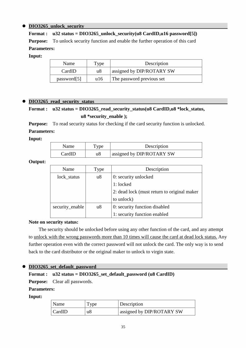
DIO3265_unlock_security ................................................................................................. 35
DIO3265_read_security_status .......................................................................................... 35
DIO3265_set_default_password ........................................................................................ 35
9. Dll list ............................................................................................................................................ 36
10. DIO3265 Error codes summary ..................................................................................................... 37
4
1. How to install the software of DIO3265
1.1 Install the PCI driver
The PCI card is a plug and play card, once you add on a new card, the window system will detect
while it is booting. Please follow the following steps to install your new card.
In WinXP/7 and up system you should: (take Win XP as example)
1. Make sure the power is off
2. Plug in the interface card
3. Power on
4. A hardware install wizard will appear and tell you it finds a new PCI card
5. Do not response to the wizard, just Install the file
(..\DIO3265\Software\WinXP_7\ or if you download from website please execute the file
DIO3265_Install.exe to get the file)
6. After installation, power off
7. Power on, it’s ready to use
For more detail of step by step installation guide, please refer the file “installation.pdf “ on the CD
come with the product or register as a member of our user’s club at:
http://automation.com.tw/
to download the complementary documents.

5
2. Where to find the file you need
WinXP/7 and up
The directory will be located at
.. \ JS Automation \DIO3265\API\ (header files and lib files for VB,VC,BCB,C#)
.. \ JS Automation \DIO3265\Driver\ (backup copy of DIO3265 drivers)
.. \ JS Automation \DIO3265\exe\ (demo program and source code)
The system driver is located at ..\system32\Drivers and the DLL is located at ..\system.
For your easy startup, the demo program with source code demonstrates the card functions and help
file.
6
3. About the DIO3265 software
DIO3265 software includes a set of dynamic link library (DLL) and system driver that you can
utilize to control the I/O card’s ports and points separately.
Your DIO3265 software package includes setup driver, tutorial example and test program that help
you how to setup and run appropriately, as well as an executable file which you can use to test each of
the DIO3265 functions within Windows’ operation system environment.
3.1 What you need to get started
To set up and use your DIO3265 software, you need the following:
DIO3265 software
DIO3265 hardware
Main board
Wiring board (Option)
3.2 Software programming choices
You have several options to choose from when you are programming DIO3265 software. You can
use Borland C/C++, Microsoft Visual C/C++, Microsoft Visual Basic, or any other Windows-based
compiler that can call into Windows dynamic link libraries (DLLs) for use with the DIO3265 software.
7
4. DIO3265 Language support
The DIO3265 software library is a DLL used with WinXP/7 and up. You can use these DLL with
any Windows integrating development environment that can call Windows DLLs.
4.1 Building applications with the DIO3265 software library
The DIO3265 function reference topic contains general information about building DIO3265
applications, describes the nature of the DIO3265 files used in building DIO3265 applications, and
explains the basics of making applications using the following tools:
Applications tools
Microsoft Visual C/C++
Borland C/C++
Microsoft Visual C#
Microsoft Visual Basic
Microsoft VB.net
If you are not using one of the tools listed, consult your development tool reference manual for
details on creating applications that call DLLs.
4.2 DIO3265 Windows libraries
The DIO3265 for Windows function library is a DLL called DIO3265.dll. Since a DLL is used,
DIO3265 functions are not linked into the executable files of applications. Only the information about
the DIO3265 functions in the DIO3265 import libraries is stored in the executable files.
Import libraries contain information about their DLL-exported functions. They indicate the presence and
location of the DLL routines. Depending on the development tools you are using, you can make your
compiler and linker aware of the DLL functions through import libraries or through function
declarations.
Refer to Table 1 to determine to which files you need to link and which to include in your
development to use the DIO3265 functions in DIO3265.dll.
Header Files and Import Libraries for Different Development Environments
Language Header File Import Library
Microsoft Visual C/C++ DIO3265.h DIO3265VC.lib
Borland C/C++ DIO3265.h DIO3265BC.lib
Microsoft Visual C# DIO3265.cs
Microsoft Visual Basic DIO3265.bas
Microsoft VB.net DIO3265.vb
Table 1
8
5. Basic concepts of digital I/O control
The digital I/O control is the most common type of PC based application. For example, on the main
board, printer port is the TTL level digital I/O.
Types of I/O classified by isolation
If the system and I/O are not electrically connected, we call it is isolated. There are many kinds of
isolation: by transformer, by photo-coupler, by magnetic coupler,… Any kind of device, they can brake
the electrical connection without braking the signal is suitable for the purpose.
Currently, photo-coupler isolation is the most popular selection; isolation voltage up to 2000V or
over is common. But the photo-coupler is limited by the response time, the high frequency type cost a lot.
The new selection is magnetic coupler; it is designed to focus on high speed application.
The merit of isolation is to avoid the noise from outside world to enter the PC system, if the noise
comes into PC system without elimination, the system maybe get “crazy” by the noise disturbance. Of
course the isolation also limits the versatile of programming as input or output at the same pin as the
TTL does. The inter-connection of add-on card and wiring board maybe extend to several meters without
any problem.
The non-isolated type is generally the TTL level input/output. The ground and power source of the
input/output port come from the system. Generally you can program as input or output at the same pin as
you wish. The connection of wiring board and the add-on board is limited to 50cm or shorter
(depends on the environmental noise condition).
Types of Output calssified by driver device
There are several devices used as output driver, the relay, transistor or MOS FET, SCR and SSR.
Relay is electric- mechanical device, its life time is about 1,000,000 times of switching. But on the
other hand it has many selections such as high voltage or high current. It can also be used to switch DC
load or AC load.
Transistor and MOS FET are basically semi-permanent devices. If you have selected the right
ratings, it can work without switching life limit. But the transistor or MOS FET can only work in DC
load condition.
The transistor or MOS FET also have another option is source or sink. For PMOS or PNP transistor
is source type device, the load is one terminal connects to output and another connects to common
ground, but NPN or NMOS is one terminal connects to output and the other connects to VCC+. If you
are concerned about hazard from high DC voltage while the load is floating, please choose the
source type driver device.
SCR (or triac) is seldom direct connect to digital output, but his relative SSR is the most often
selection. In fact, SSR is a compact package of trigger circuit and triac. You can choose zero cross
trigger (output command only turn on the output at power phase near zero to eliminate surge) or direct
turn on type. SSR is working in AC load condition.
9
Input debounce
Debounce is the function to filter the input jitters. From the microscope view of a switch input, you
will see the contact does not come to close or release to open clearly. In most cases, it will
contact-release-contact-release… for many times then go to steady state (ON or OFF). If you do not
have the debounce function, you will read the input at high state and then next read will get low state,
this maybe an error data for your decision of contact input.
Debounce can be implemented by hardware or software. Analog hardware debounce circuit will
have fixed time constant to filter out the significant input signal, if you want to change the response time,
the only way is to change the circuit device.
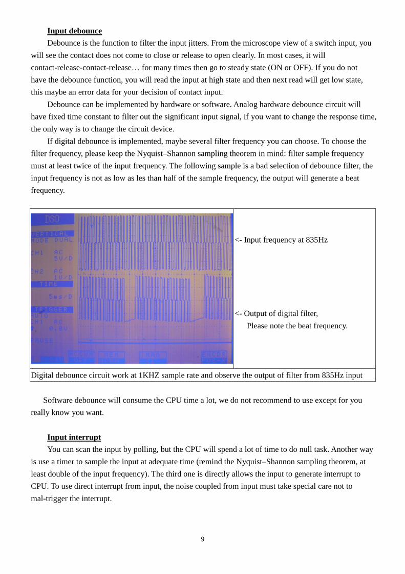
If digital debounce is implemented, maybe several filter frequency you can choose. To choose the
filter frequency, please keep the Nyquist–Shannon sampling theorem in mind: filter sample frequency
must at least twice of the input frequency. The following sample is a bad selection of debounce filter, the
input frequency is not as low as les than half of the sample frequency, the output will generate a beat
frequency.
<- Input frequency at 835Hz
<- Output of digital filter,
Please note the beat frequency.
Digital debounce circuit work at 1KHZ sample rate and observe the output of filter from 835Hz input
Software debounce will consume the CPU time a lot, we do not recommend to use except for you
really know you want.
Input interrupt
You can scan the input by polling, but the CPU will spend a lot of time to do null task. Another way
is use a timer to sample the input at adequate time (remind the Nyquist–Shannon sampling theorem, at
least double of the input frequency). The third one is directly allows the input to generate interrupt to
CPU. To use direct interrupt from input, the noise coupled from input must take special care not to
mal-trigger the interrupt.

10
Read back of Output status
Some applications need to read back the output status, if the card does not provide output status
read back, you can use a variable to store the status of output before you really command it output. Some
cards provide the read back function but please note that the read back status is come from the output
register, not from the real physical output.
11
6. Function format and language difference
6.1 Function format
Every DIO3265 function is consist of the following format:
Status = function_name (parameter 1, parameter 2, … parameter n);
Each function returns a value in the Status global variable that indicates the success or failure of
the function. A returned Status equal to zero that indicates the function executed successfully. A
non-zero status indicates failure that the function did not execute successfully because of an error, or
executed with an error.
Note: Status is a 32-bit unsigned integer.
The first parameter to almost every DIO3265 function is the parameter CardID which is located
the driver of DIO3265 board you want to use those given operation. The CardID is assigned by
DIP/ROTARY SW. You can utilize multiple devices with different card CardID within one application;
to do so, simply pass the appropriate CardID to each function.
Note: CardID is set by DIP/ROTARY SW (0x0-0xF)
12
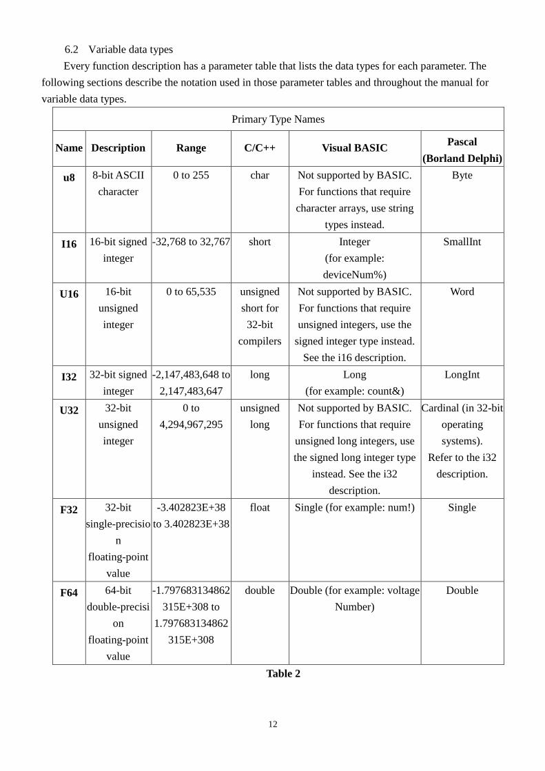
6.2 Variable data types
Every function description has a parameter table that lists the data types for each parameter. The
following sections describe the notation used in those parameter tables and throughout the manual for
variable data types.
Primary Type Names
Name Description Range C/C++ Visual BASIC Pascal
(Borland Delphi)
u8 8-bit ASCII
character
0 to 255 char Not supported by BASIC.
For functions that require
character arrays, use string
types instead.
Byte
I16 16-bit signed
integer
-32,768 to 32,767 short Integer
(for example:
deviceNum%)
SmallInt
U16 16-bit
unsigned
integer
0 to 65,535 unsigned
short for
32-bit
compilers
Not supported by BASIC.
For functions that require
unsigned integers, use the
signed integer type instead.
See the i16 description.
Word
I32 32-bit signed
integer
-2,147,483,648 to
2,147,483,647
long Long
(for example: count&)
LongInt
U32 32-bit
unsigned
integer
0 to
4,294,967,295
unsigned
long
Not supported by BASIC.
For functions that require
unsigned long integers, use
the signed long integer type
instead. See the i32
description.
Cardinal (in 32-bit
operating
systems).
Refer to the i32
description.
F32 32-bit
single-precisio
n
floating-point
value
-3.402823E+38
to 3.402823E+38
float Single (for example: num!) Single
F64 64-bit
double-precisi
on
floating-point
value
-1.797683134862
315E+308 to
1.797683134862
315E+308
double Double (for example: voltage
Number)
Double
Table 2
13
6.3 Programming language considerations
Apart from the data type differences, there are a few language-dependent considerations you need
to be aware of when you use the DIO3265 API. Read the following sections that apply to your
programming language.
Note: Be sure to include the declaration functions of DIO3265 prototypes by including the appropriate
DIO3265 header file in your source code. Refer to Building Applications with the DIO3265 Software
Library for the header file appropriate to your compiler.
6.3.1 C/C++
For C or C++ programmers, parameters listed as Input/Output parameters or Output parameters are
pass-by-reference parameters, which means a pointer points to the destination variable should be passed
into the function. For example, the Read Port function has the following format:
Status = DIO3265_out_port_read (u8 CardID, u8 port, u8*data);
where CardID and port are input parameters, and data is an output parameter. Consider the following
example:
u8 CardID, port;
u8 data,
u32 Status;
Status = DIO3265_out_port_read (CardID, port, &data);
6.3.2 Visual basic
The file DIO3265.bas contains definitions for constants required for obtaining DIO Card
information and declared functions and variable as global variables. You should use these constants
symbols in the DIO3265.bas, do not use the numerical values.
In Visual Basic, you can add the entire DIO3265.bas file into your project. Then you can use any
of the constants defined in this file and call these constants in any module of your program. To add the
DIO3265.bas file for your project in Visual Basic 4.0, go to the File menu and select the Add File...
option. Select DIO3265.bas, which is browsed in the DIO3265 \ API directory. Then, select Open to add
the file to the project.
To add the DIO3265.bas file to your project in Visual Basic 5.0 and 6.0, go to the Project menu and
select Add Module. Click on the Existing tab page. Select DIO3265.bas, which is in the DIO3265 \ API
directory. Then, select Open to add the file to the project.
14
6.3.3 Borland C++ builder
To use Borland C++ builder as development tool, you should generate a .lib file from the .dll file
by implib.exe.
implib DIO3265BC.lib DIO3265.dll
Then add the DIO3265BC.lib to your project and add
#include “DIO3265.h” to main program.
Now you may use the dll functions in your program. For example, the Read Port function has the
following format:
Status = DIO3265_out_port_read (u8 CardID, u8 port, u8*data);
where CardID and port are input parameters, and data is an output parameter. Consider the following
example:
u8 CardID, port;
u8 data;
u32 Status;
Status = DIO3265_out_port_read (CardID, port, &data);
15
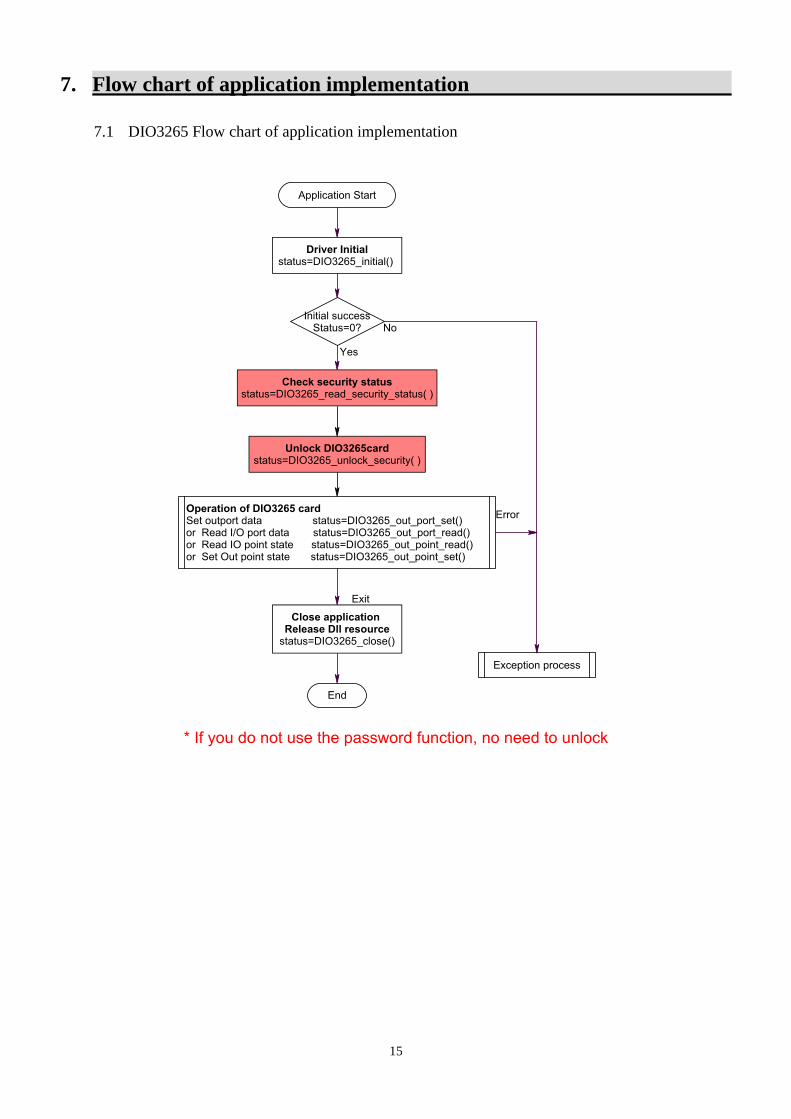
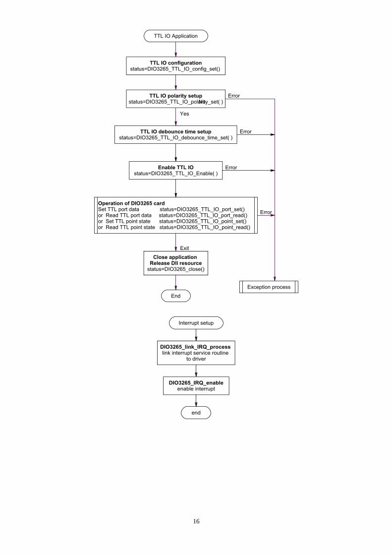
7. Flow chart of application implementation
7.1 DIO3265 Flow chart of application implementation
16
17
8. Software overview and dll function
8.1 Initialization and close
You need to initialize system resource each time you run your application.
DIO3265_initial( ) will do.
Once you want to close your application, call
DIO3265_close( ) to release all the resource.
If you want to know the physical address assigned by OS. Use
DIO3265_info( ) to get the address .
DIO3265_initial
Format : u32 status =DIO3265_initial (void)
Purpose: Initial the DIO3265 resource when start the Windows applications.
DIO3265_close
Format : u32 status = DIO3265_close (void);
Purpose: Release the DIO3265 resource when close the Windows applications.
DIO3265_info
Format : u32 status = DIO3265_info(u8 CardID, u16 * address);
Purpose: Read the physical I/O address assigned by O.S.
Parameters:
Input:
Name Type Description
CardID u8 assigned by DIP/ROTARY SW
Output:
Name Type Description
address u16 physical I/O address assigned to DIO block by
OS
18
8.2 Out port R/W
The DIO3265 card has only isolated output port and 2 byte programmable TTL I/O. We provide
different functions for the two type of I/O.
The isolated output port can be set by:
DIO3265_out_port_set( ) and the output register can be read back by:
DIO3265_out_port_read( ).
If you just want to set one point or read one point, the function
DIO3265_out_point_set( ) and
DIO3265_out_point_read( ) will do.
To match with your application and keep the application software at logic conformity, the output
polarity can be set and read back to verify by:
DIO3265_out_polarity_set( ) and read back by:
DIO3265_out_polarity_read( ).
19
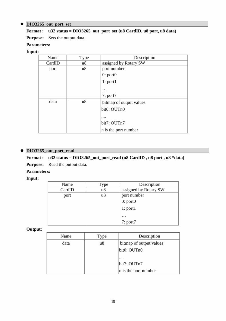
DIO3265_out_port_set
Format : u32 status = DIO3265_out_port_set (u8 CardID, u8 port, u8 data)
Purpose: Sets the output data.
Parameters:
Input:
Name Type Description
CardID u8 assigned by Rotary SW
port u8 port number
0: port0
1: port1
…
7: port7
data u8 bitmap of output values
bit0: OUTn0
....
bit7: OUTn7
n is the port number
DIO3265_out_port_read
Format : u32 status = DIO3265_out_port_read (u8 CardID , u8 port , u8 *data)
Purpose: Read the output data.
Parameters:
Input:
Name Type Description
CardID u8 assigned by Rotary SW
port u8 port number
0: port0
1: port1
…
7: port7
Output:
Name Type Description
data u8 bitmap of output values
bit0: OUTn0
....
bit7: OUTn7
n is the port number
20
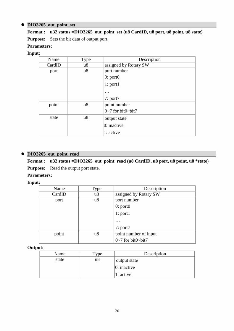
DIO3265_out_point_set
Format : u32 status =DIO3265_out_point_set (u8 CardID, u8 port, u8 point, u8 state)
Purpose: Sets the bit data of output port.
Parameters:
Input:
Name Type Description
CardID u8 assigned by Rotary SW
port u8 port number
0: port0
1: port1
…
7: port7
point u8 point number
0~7 for bit0~bit7
state u8 output state
0: inactive
1: active
DIO3265_out_point_read
Format : u32 status =DIO3265_out_point_read (u8 CardID, u8 port, u8 point, u8 *state)
Purpose: Read the output port state.
Parameters:
Input:
Name Type Description
CardID u8 assigned by Rotary SW
port u8 port number
0: port0
1: port1
…
7: port7
point u8 point number of input
0~7 for bit0~bit7
Output:
Name Type Description
state u8 output state
0: inactive
1: active
21
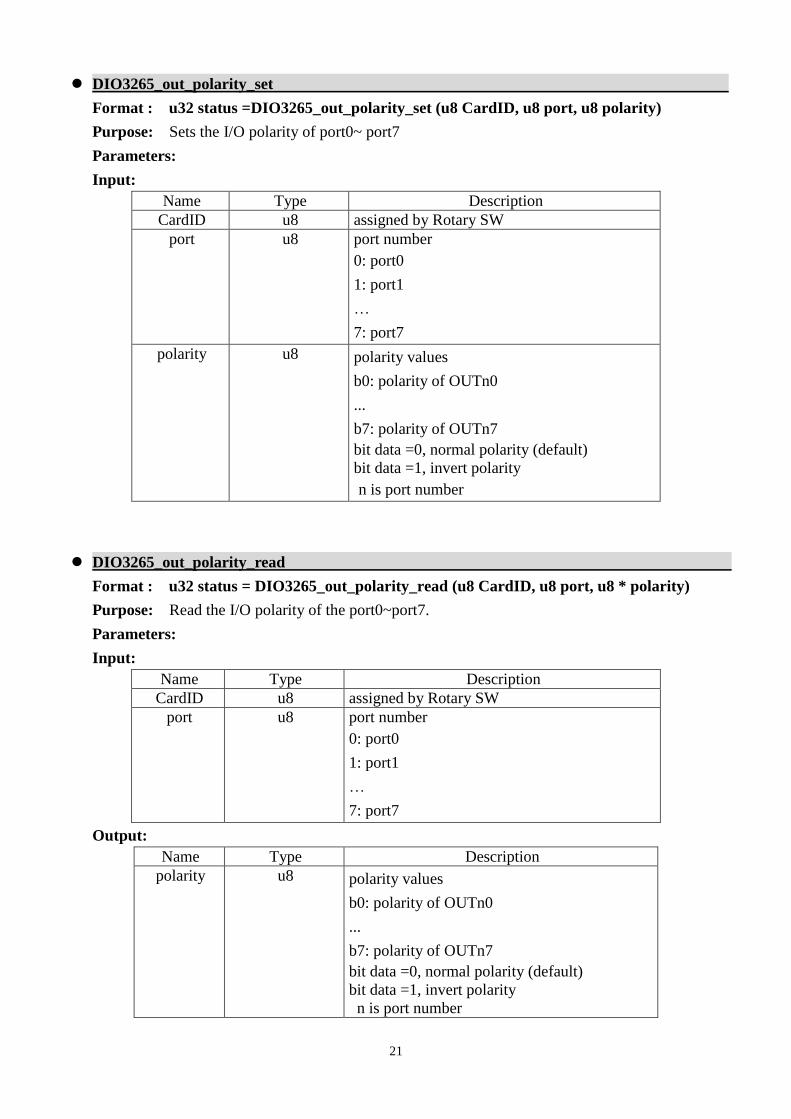
DIO3265_out_polarity_set
Format : u32 status =DIO3265_out_polarity_set (u8 CardID, u8 port, u8 polarity)
Purpose: Sets the I/O polarity of port0~ port7
Parameters:
Input:
Name Type Description
CardID u8 assigned by Rotary SW
port u8 port number
0: port0
1: port1
…
7: port7
polarity u8 polarity values
b0: polarity of OUTn0
...
b7: polarity of OUTn7
bit data =0, normal polarity (default)
bit data =1, invert polarity
n is port number
DIO3265_out_polarity_read
Format : u32 status = DIO3265_out_polarity_read (u8 CardID, u8 port, u8 * polarity)
Purpose: Read the I/O polarity of the port0~port7.
Parameters:
Input:
Name Type Description
CardID u8 assigned by Rotary SW
port u8 port number
0: port0
1: port1
…
7: port7
Output:
Name Type Description
polarity u8 polarity values
b0: polarity of OUTn0
...
b7: polarity of OUTn7
bit data =0, normal polarity (default)
bit data =1, invert polarity
n is port number
22
8.3 TTL I/O Port R/W
DIO3265 has only isolated output ports but it also provides 2 TTL I/O ports which are more
flexible for non-isolated application. The ports can be configured as input or output on port base. The
port can be set at normal high or normal low voltage during power on by the on card jumper JP1 and JP2.
(Refer Hardware manual, chapter 8 Hardware settings)
To configure the port as input or output by:
DIO3265_TTL_IO_config_set ( ) and read back the configuration by:
DIO3265_TTL_IO_config_read ( ).
To change the polarity as you need by:
DIO3265_TTL_IO_polarity_set( ) and read back to verify by:
DIO3265_TTL_IO_polarity_read( ).
After the configuration is complete, you can enable the port to function or disable it any time you
want, the output of the disabled port will remain at high or low depends on the jumper setting. Use:
DIO3265_TTL_IO_Enable( ) to enable the port and
DIO3265_TTL_IO_Disable( ) to disable the port.
The TTL I/O port can use:
DIO3265_TTL_IO_port_set ( ) to output data and input data by:
DIO3265_TTL_IO_port_read( ).
For the point output, use:
DIO3265_TTL_IO_point_set ( ) and point input by:
DIO3265_TTL_IO_point_read ( ).
The DIO3265 card provides digital input debounce function. There are 4 range: 100Hz, 200Hz,
1KHz and no debounce to select for your application. At noisy environment to debounce the signal or to
debounce the mechanical contact input, use:
DIO3265_TTL_IO_debounce_time_set ( ) to set the adequate time constant to drop out the noise and
read back to check the setting by:
DIO3265_TTL_IO_debounce_time_read( ).
23
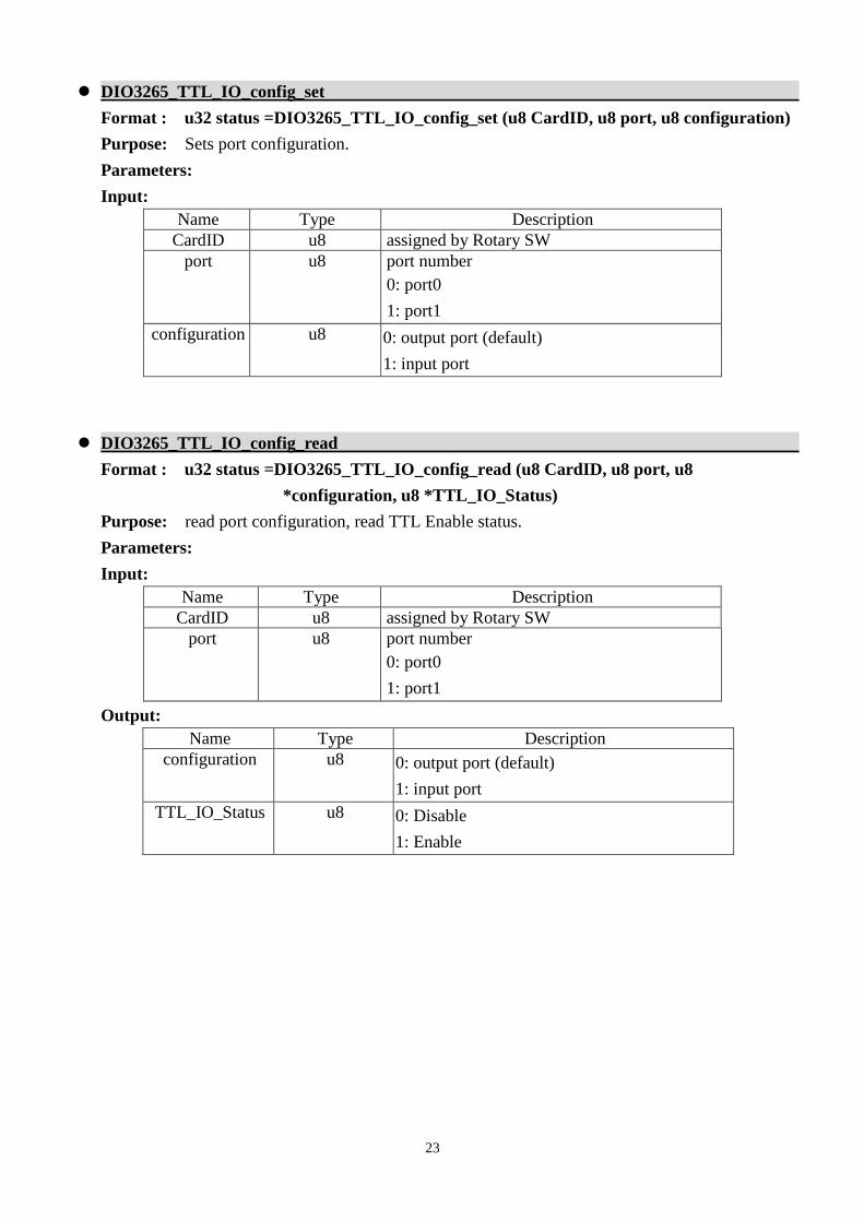
DIO3265_TTL_IO_config_set
Format : u32 status =DIO3265_TTL_IO_config_set (u8 CardID, u8 port, u8 configuration)
Purpose: Sets port configuration.
Parameters:
Input:
Name Type Description
CardID u8 assigned by Rotary SW
port u8 port number
0: port0
1: port1
configuration u8 0: output port (default)
1: input port
DIO3265_TTL_IO_config_read
Format : u32 status =DIO3265_TTL_IO_config_read (u8 CardID, u8 port, u8
*configuration, u8 *TTL_IO_Status)
Purpose: read port configuration, read TTL Enable status.
Parameters:
Input:
Name Type Description
CardID u8 assigned by Rotary SW
port u8 port number
0: port0
1: port1
Output:
Name Type Description
configuration u8 0: output port (default)
1: input port
TTL_IO_Status u8 0: Disable
1: Enable
24
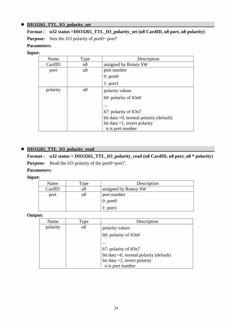
DIO3265_TTL_IO_polarity_set
Format : u32 status =DIO3265_TTL_IO_polarity_set (u8 CardID, u8 port, u8 polarity)
Purpose: Sets the I/O polarity of port0~ port7
Parameters:
Input:
Name Type Description
CardID u8 assigned by Rotary SW
port u8 port number
0: port0
1: port1
polarity u8 polarity values
b0: polarity of IOn0
...
b7: polarity of IOn7
bit data =0, normal polarity (default)
bit data =1, invert polarity
n is port number
DIO3265_TTL_IO_polarity_read
Format : u32 status = DIO3265_TTL_IO_polarity_read (u8 CardID, u8 port, u8 * polarity)
Purpose: Read the I/O polarity of the port0~port7.
Parameters:
Input:
Name Type Description
CardID u8 assigned by Rotary SW
port u8 port number
0: port0
1: port1
Output:
Name Type Description
polarity u8 polarity values
b0: polarity of IOn0
...
b7: polarity of IOn7
bit data =0, normal polarity (default)
bit data =1, invert polarity
n is port number
25
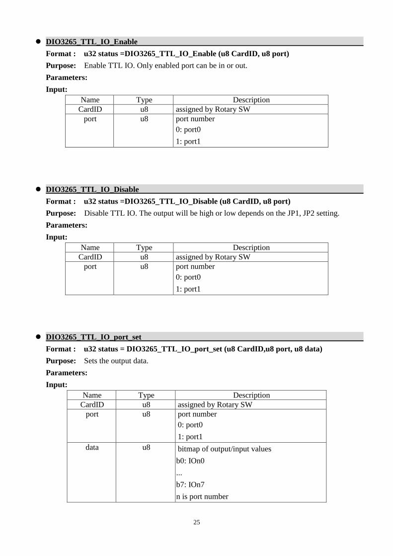
DIO3265_TTL_IO_Enable
Format : u32 status =DIO3265_TTL_IO_Enable (u8 CardID, u8 port)
Purpose: Enable TTL IO. Only enabled port can be in or out.
Parameters:
Input:
Name Type Description
CardID u8 assigned by Rotary SW
port u8 port number
0: port0
1: port1
DIO3265_TTL_IO_Disable
Format : u32 status =DIO3265_TTL_IO_Disable (u8 CardID, u8 port)
Purpose: Disable TTL IO. The output will be high or low depends on the JP1, JP2 setting.
Parameters:
Input:
Name Type Description
CardID u8 assigned by Rotary SW
port u8 port number
0: port0
1: port1
DIO3265_TTL_IO_port_set
Format : u32 status = DIO3265_TTL_IO_port_set (u8 CardID,u8 port, u8 data)
Purpose: Sets the output data.
Parameters:
Input:
Name Type Description
CardID u8 assigned by Rotary SW
port u8 port number
0: port0
1: port1
data u8 bitmap of output/input values
b0: IOn0
...
b7: IOn7
n is port number
26
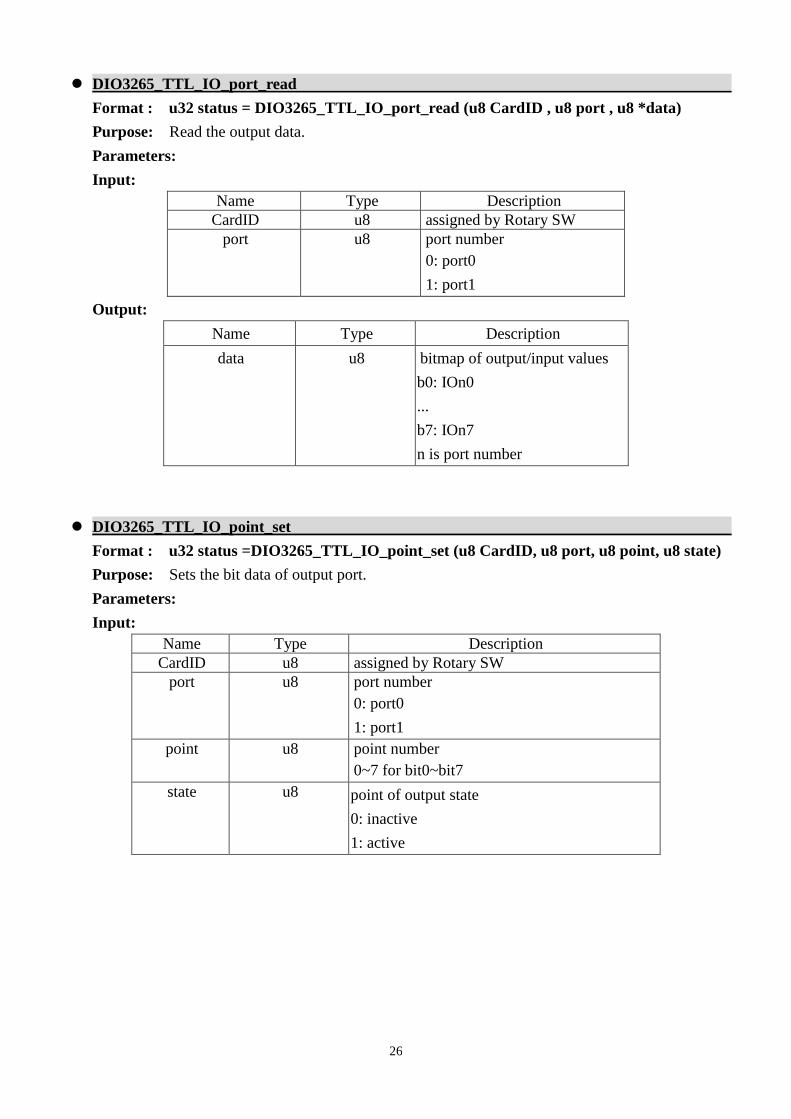
DIO3265_TTL_IO_port_read
Format : u32 status = DIO3265_TTL_IO_port_read (u8 CardID , u8 port , u8 *data)
Purpose: Read the output data.
Parameters:
Input:
Name Type Description
CardID u8 assigned by Rotary SW
port u8 port number
0: port0
1: port1
Output:
Name Type Description
data u8 bitmap of output/input values
b0: IOn0
...
b7: IOn7
n is port number
DIO3265_TTL_IO_point_set
Format : u32 status =DIO3265_TTL_IO_point_set (u8 CardID, u8 port, u8 point, u8 state)
Purpose: Sets the bit data of output port.
Parameters:
Input:
Name Type Description
CardID u8 assigned by Rotary SW
port u8 port number
0: port0
1: port1
point u8 point number
0~7 for bit0~bit7
state u8 point of output state
0: inactive
1: active
27
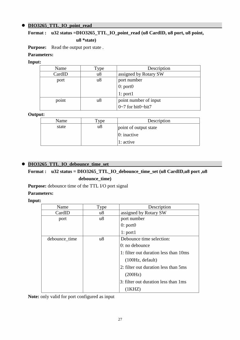
DIO3265_TTL_IO_point_read
Format : u32 status =DIO3265_TTL_IO_point_read (u8 CardID, u8 port, u8 point,
u8 *state)
Purpose: Read the output port state .
Parameters:
Input:
Name Type Description
CardID u8 assigned by Rotary SW
port u8 port number
0: port0
1: port1
point u8 point number of input
0~7 for bit0~bit7
Output:
Name Type Description
state u8 point of output state
0: inactive
1: active
DIO3265_TTL_IO_debounce_time_set
Format : u32 status = DIO3265_TTL_IO_debounce_time_set (u8 CardID,u8 port ,u8
debounce_time)
Purpose: debounce time of the TTL I/O port signal
Parameters:
Input:
Name Type Description
CardID u8 assigned by Rotary SW
port u8 port number
0: port0
1: port1
debounce_time
u8 Debounce time selection:
0: no debounce
1: filter out duration less than 10ms
(100Hz, default)
2: filter out duration less than 5ms
(200Hz)
3: filter out duration less than 1ms
(1KHZ)
Note: only valid for port configured as input
28
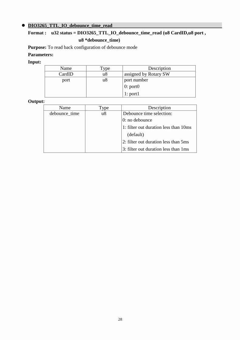
DIO3265_TTL_IO_debounce_time_read
Format : u32 status = DIO3265_TTL_IO_debounce_time_read (u8 CardID,u8 port ,
u8 *debounce_time)
Purpose: To read back configuration of debounce mode
Parameters:
Input:
Name Type Description
CardID u8 assigned by Rotary SW
port u8 port number
0: port0
1: port1
Output:
Name Type Description
debounce_time
u8 Debounce time selection:
0: no debounce
1: filter out duration less than 10ms
(default)
2: filter out duration less than 5ms
3: filter out duration less than 1ms
29
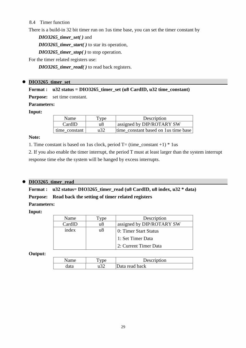
8.4 Timer function
There is a build-in 32 bit timer run on 1us time base, you can set the timer constant by
DIO3265_timer_set( ) and
DIO3265_timer_start( ) to star its operation,
DIO3265_timer_stop( ) to stop operation.
For the timer related registers use:
DIO3265_timer_read( ) to read back registers.
DIO3265_timer_set
Format : u32 status = DIO3265_timer_set (u8 CardID, u32 time_constant)
Purpose: set time constant.
Parameters:
Input:
Name Type Description
CardID u8 assigned by DIP/ROTARY SW
time_constant u32 time_constant based on 1us time base
Note:
1. Time constant is based on 1us clock, period T= (time_constant +1) * 1us
2. If you also enable the timer interrupt, the period T must at least larger than the system interrupt
response time else the system will be hanged by excess interrupts.
DIO3265_timer_read
Format : u32 status= DIO3265_timer_read (u8 CardID, u8 index, u32 * data)
Purpose: Read back the setting of timer related registers
Parameters:
Input:
Name Type Description
CardID u8 assigned by DIP/ROTARY SW
index u8 0: Timer Start Status
1: Set Timer Data
2: Current Timer Data
Output:
Name Type Description
data u32 Data read back
30
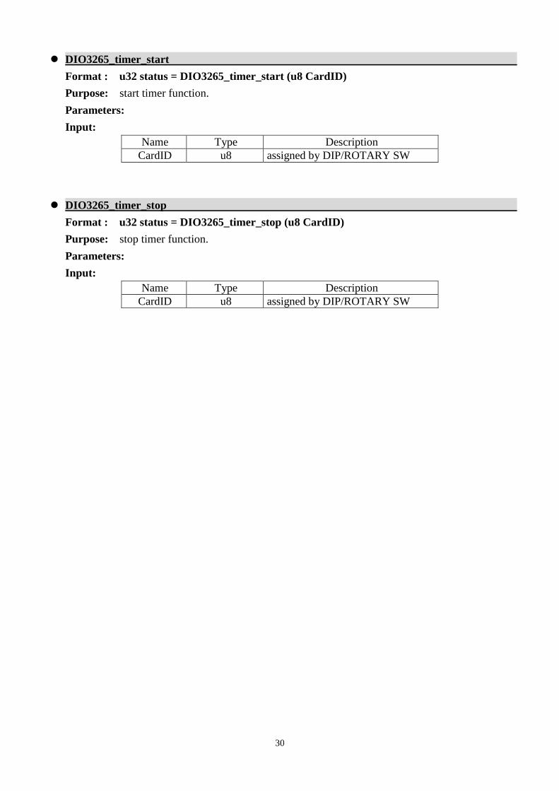
DIO3265_timer_start
Format : u32 status = DIO3265_timer_start (u8 CardID)
Purpose: start timer function.
Parameters:
Input:
Name Type Description
CardID u8 assigned by DIP/ROTARY SW
DIO3265_timer_stop
Format : u32 status = DIO3265_timer_stop (u8 CardID)
Purpose: stop timer function.
Parameters:
Input:
Name Type Description
CardID u8 assigned by DIP/ROTARY SW
31
8.5 Interrupt function
Sometimes you want your application to take care of the I/O while special event occurs; interrupt
function is the right choice. DIO3265 provide timer event trigger input.
You must first link your service routine to the driver by
DIO3265_IRQ_process_link( ), load the timer and start it function ( timer function can be
execute after irq eanble).
Now all is ready, you can enable the interrupt by:
DIO3265_IRQ_enable( ) or disable by
DIO3265_IRQ_disable( ).
To read back the interrupt status (at interrupt service routine or polling routine) use
DIO3265_IRQ_read_status( ).
After reading the status register on card will be cleared.
DIO3265_IRQ_process_link
Format : u32 status = DIO3265_IRQ_process_link (u8 CardID,
void ( __stdcall *callbackAddr)(u8 CardID))
Purpose: Link irq service routine to driver
Parameters:
Input:
Name Type Description
CardID u8 assigned by Rotary SW
callbackAddr void callback address of service
routine
DIO3265_IRQ_enable
Format : u32 status = DIO3265_IRQ_enable (u8 CardID, HANDLE *phEvent)
Purpose: Enable interrupt from timer
Parameters:
Input:
Name Type Description
CardID u8 assigned by Rotary SW
Output:
Name Type Description
phEvent HANDLE event handle
32
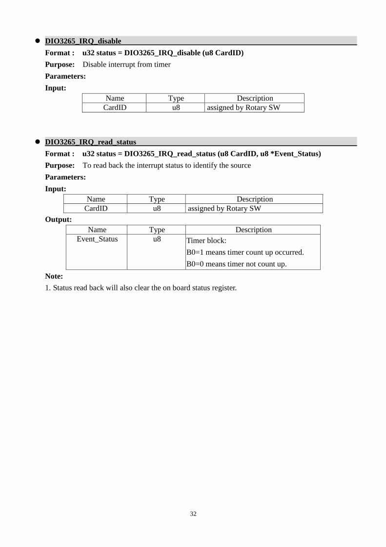
DIO3265_IRQ_disable
Format : u32 status = DIO3265_IRQ_disable (u8 CardID)
Purpose: Disable interrupt from timer
Parameters:
Input:
Name Type Description
CardID u8 assigned by Rotary SW
DIO3265_IRQ_read_status
Format : u32 status = DIO3265_IRQ_read_status (u8 CardID, u8 *Event_Status)
Purpose: To read back the interrupt status to identify the source
Parameters:
Input:
Name Type Description
CardID u8 assigned by Rotary SW
Output:
Name Type Description
Event_Status u8 Timer block:
B0=1 means timer count up occurred.
B0=0 means timer not count up.
Note:
1. Status read back will also clear the on board status register.
33
8.6 Software key function
From the dll version 3.0 and later, we remove the software key function owing to some
customers complained about the card locked on some unknown occasion. We only remain the
functions to comply with the existing programs but the returned value always true.
Since DIO3265 is a general purpose card, anyone who can buy from JS automation Corp. or her
distributors. Your program is the fruit of your intelligence, un-authorized copy maybe prevent by the
security function enabled.
You can use
DIO3265_set_password( ) to set password and start the security function.
DIO3265_change_password( ) to change it.
If you don’t want to use security function after the password being setup,
DIO3265_clear_password( ) will reset to the virgin state.
Once the password is set, any function call of the dll’s (except for the security functions) will be
blocked until the
DIO3265_unlock_security( ) unlock the security.
You can also use
DIO3265_read_security_status( ) to check the current status of security.
On some special occasion, you do not set any password but the card locked by unknown accident,
to unlock the unknown password to virgin state, use
DIO3265_set_default_password ( ) to clear all passwords.
34
DIO3265_set_password
Format : u32 status = DIO3265_set_password(u8 CardID,u16 password[5]);
Purpose: To set password and if the password is not all “0”, security function will be enabled.
Parameters:
Input:
Name Type Description
CardID u8 assigned by DIP/ROTARY SW
password[5] u16 Password, 5 words
Note on password:
If the password is all “0”, the security function is disabled.
DIO3265_change_password
Format : u32 status = DIO3265_change_password(u8 CardID, u16 Oldpassword[5],
u16 password[5]);
Purpose: To replace old password with new password.
Parameters:
Input:
Name Type Description
CardID u8 assigned by DIP/ROTARY SW
Oldpassword [5] u16 The previous password
password[5] u16 The new password to be set
DIO3265_clear_password
Format : u32 status = DIO3265_clear_password(u8 CardID,u16 password[5])
Purpose: To clear password, to set password to all “0”, i.e. disable security function.
Parameters:
Input:
Name Type Description
CardID u8 assigned by DIP/ROTARY SW
password[5] u16 The password previous set
35
DIO3265_unlock_security
Format : u32 status = DIO3265_unlock_security(u8 CardID,u16 password[5])
Purpose: To unlock security function and enable the further operation of this card
Parameters:
Input:
Name Type Description
CardID u8 assigned by DIP/ROTARY SW
password[5] u16 The password previous set
DIO3265_read_security_status
Format : u32 status = DIO3265_read_security_status(u8 CardID,u8 *lock_status,
u8 *security_enable );
Purpose: To read security status for checking if the card security function is unlocked.
Parameters:
Input:
Name Type Description
CardID u8 assigned by DIP/ROTARY SW
Output:
Name Type Description
lock_status u8 0: security unlocked
1: locked
2: dead lock (must return to original maker
to unlock)
security_enable u8 0: security function disabled
1: security function enabled
Note on security status:
The security should be unlocked before using any other function of the card, and any attempt
to unlock with the wrong passwords more than 10 times will cause the card at dead lock status. Any
further operation even with the correct password will not unlock the card. The only way is to send
back to the card distributor or the original maker to unlock to virgin state.
DIO3265_set_default_password
Format : u32 status = DIO3265_set_default_password (u8 CardID)
Purpose: Clear all passwords.
Parameters:
Input:
Name Type Description
CardID u8 assigned by DIP/ROTARY SW
36
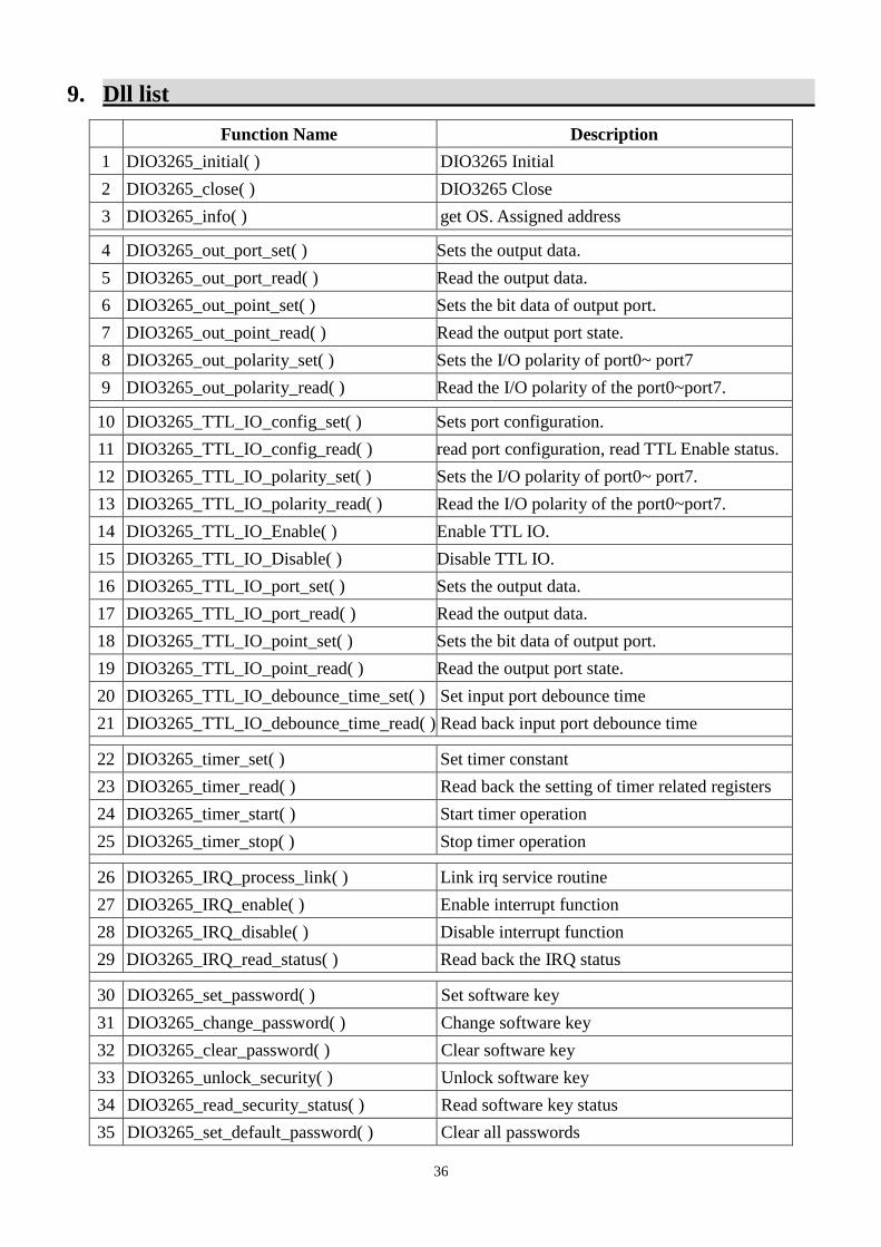
9. Dll list
Function Name Description
1 DIO3265_initial( ) DIO3265 Initial
2 DIO3265_close( ) DIO3265 Close
3 DIO3265_info( ) get OS. Assigned address
4 DIO3265_out_port_set( ) Sets the output data.
5 DIO3265_out_port_read( ) Read the output data.
6 DIO3265_out_point_set( ) Sets the bit data of output port.
7 DIO3265_out_point_read( ) Read the output port state.
8 DIO3265_out_polarity_set( ) Sets the I/O polarity of port0~ port7
9 DIO3265_out_polarity_read( ) Read the I/O polarity of the port0~port7.
10 DIO3265_TTL_IO_config_set( ) Sets port configuration.
11 DIO3265_TTL_IO_config_read( ) read port configuration, read TTL Enable status.
12 DIO3265_TTL_IO_polarity_set( ) Sets the I/O polarity of port0~ port7.
13 DIO3265_TTL_IO_polarity_read( ) Read the I/O polarity of the port0~port7.
14 DIO3265_TTL_IO_Enable( ) Enable TTL IO.
15 DIO3265_TTL_IO_Disable( ) Disable TTL IO.
16 DIO3265_TTL_IO_port_set( ) Sets the output data.
17 DIO3265_TTL_IO_port_read( ) Read the output data.
18 DIO3265_TTL_IO_point_set( ) Sets the bit data of output port.
19 DIO3265_TTL_IO_point_read( ) Read the output port state.
20 DIO3265_TTL_IO_debounce_time_set( ) Set input port debounce time
21 DIO3265_TTL_IO_debounce_time_read( ) Read back input port debounce time
22 DIO3265_timer_set( ) Set timer constant
23 DIO3265_timer_read( ) Read back the setting of timer related registers
24 DIO3265_timer_start( ) Start timer operation
25 DIO3265_timer_stop( ) Stop timer operation
26 DIO3265_IRQ_process_link( ) Link irq service routine
27 DIO3265_IRQ_enable( ) Enable interrupt function
28 DIO3265_IRQ_disable( ) Disable interrupt function
29 DIO3265_IRQ_read_status( ) Read back the IRQ status
30 DIO3265_set_password( ) Set software key
31 DIO3265_change_password( ) Change software key
32 DIO3265_clear_password( ) Clear software key
33 DIO3265_unlock_security( ) Unlock software key
34 DIO3265_read_security_status( ) Read software key status
35 DIO3265_set_default_password( ) Clear all passwords
37
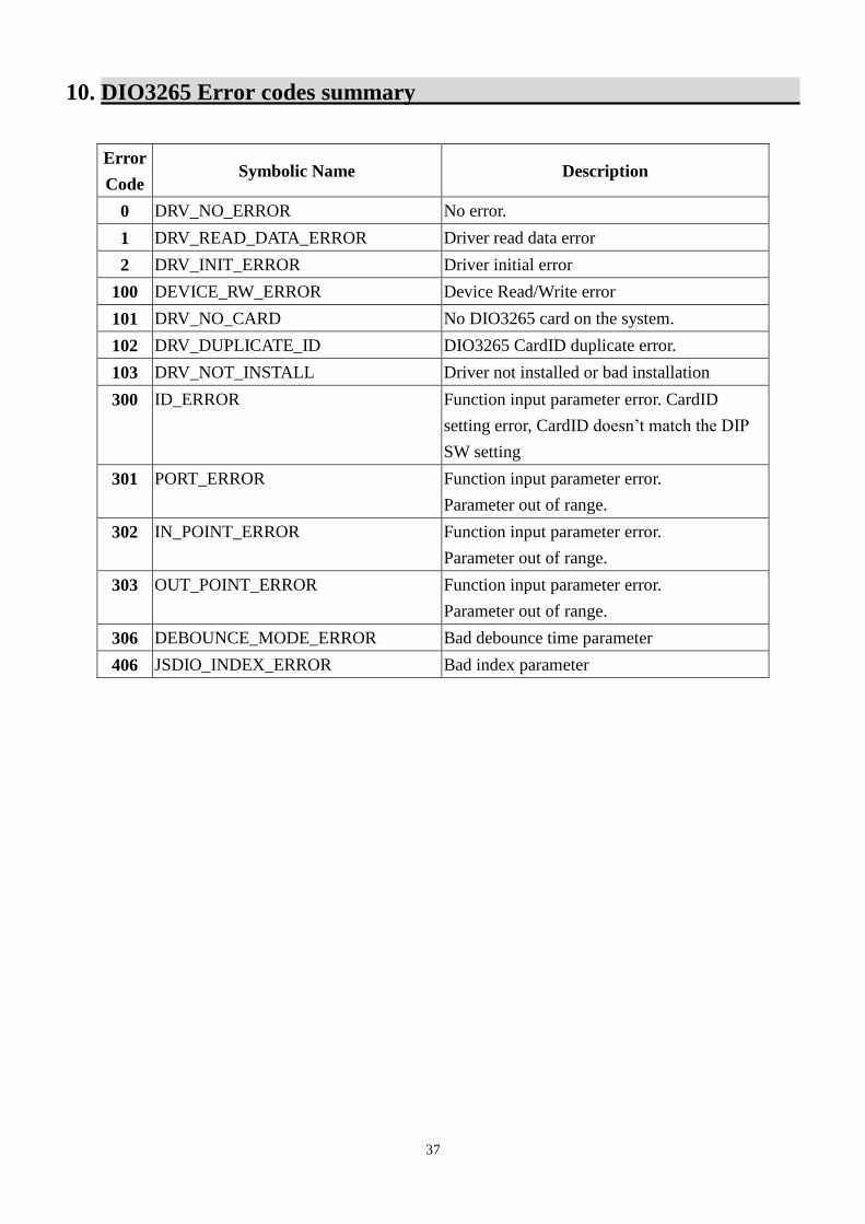
10. DIO3265 Error codes summary
Error
Code Symbolic Name Description
0 DRV_NO_ERROR No error.
1 DRV_READ_DATA_ERROR Driver read data error
2 DRV_INIT_ERROR Driver initial error
100 DEVICE_RW_ERROR Device Read/Write error
101 DRV_NO_CARD No DIO3265 card on the system.
102 DRV_DUPLICATE_ID DIO3265 CardID duplicate error.
103 DRV_NOT_INSTALL Driver not installed or bad installation
300 ID_ERROR Function input parameter error. CardID
setting error, CardID doesn’t match the DIP
SW setting
301 PORT_ERROR Function input parameter error.
Parameter out of range.
302 IN_POINT_ERROR Function input parameter error.
Parameter out of range.
303 OUT_POINT_ERROR Function input parameter error.
Parameter out of range.
306 DEBOUNCE_MODE_ERROR Bad debounce time parameter
406 JSDIO_INDEX_ERROR Bad index parameter