Embed Size (px)
Citation preview

Diploma project database for semester-3 Academic year 2017-18 Project title: ELECTRONIC CRICKET MATCH GAME USING 555 TIMER AND
CD 4017 Project Supervisor: Dr.Sugumaran Semester: 3 Level Diploma
ABSTRACT This electronic cricket is interesting game. This simple battery powered circuit can be used to play Cricket Match with
your friends. Each LED in the circuit indicates various status of the cricket match like Sixer, Run out, Catch etc. The
Circuit uses two ICs, one in the Astable mode and the second in the display driver mode. IC1 is wired as an Astable
Multivibrator with the timing elements R1, R2 and C1. With the shown values of these components very fast output
pulses are generated from the Astable. Output from IC1 passes into the input of IC2 which is the popular Johnson
Decade counter CD4017. It has 10 outputs. Of these 8 outputs are used. Output 9 (pin9) is tied to the reset pin 15 to
repeat the cycle. When the input pin 14 of IC2 gets low to high pluses, its output turns high one by one. Resistor R3
keeps the input of IC2 low in stand by state to avoid false indications
.Circuit Diagram/Block Diagram
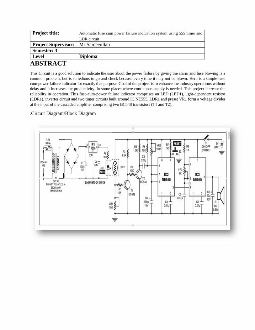
Project title: Automatic fuse cum power failure indication system using 555 timer and LDR circuit
Project Supervisor: Mr.Sameeullah Semester: 3 Level Diploma
ABSTRACT This Circuit is a good solution to indicate the user about the power failure by giving the alarm and fuse blowing is a common problem, but is so tedious to go and check because every time it may not be blown. Here is a simple fuse cum power failure indicator for exactly that purpose. Goal of the project is to enhance the industry operations without delay and it increases the productivity. In some places where continuous supply is needed. This project increase the reliability in operation. This fuse-cum-power failure indicator comprises an LED (LED1), light-dependent resistor (LDR1), inverter circuit and two timer circuits built around IC NE555. LDR1 and preset VR1 form a voltage divider at the input of the cascaded amplifier comprising two BC548 transistors (T1 and T2). .Circuit Diagram/Block Diagram

Project title: AUDIO RESPONSE LIGHT
Project Supervisor: Dr.Vimal Keerthy Semester: 3 Level Diploma
ABSTRACT his project aims to understand and implement an audio response light system using simple and cheaper electronics
components. IC CD4017 is the heart of the circuit. IC responds to the clock signal coming from microphone and
convert it into the sequence of light output using LEDs. The circuit is assembled and tested using bread board
connection. PCB fabrication is done by proteus software. Components are soldered at right positions and are tested
for its performance. This project can be used in parties, musical classes, and audio systems and even in hospitals for
alerting.
.Circuit Diagram/Block Diagram

ABSTRACT Design circuit can give a visual indication of the rate of air flow. It can be also used to check whether there is air flow in a given space Air flow detection is often necessary in many applications or systems we need air flow detection in engines. Amount of contamination.
we need air flow detection to ensure the devices from getting over heated. This circuit can give a visual indication of the rate of air flow.
Circuit Diagram/Block Diagram
Project title: Air flow detector circuit Project Supervisor: Mr.Muhammed Khurrum Semester: 3 Level Diploma

ABSTRACT The main objective of this project is to implement an auto-intensity control of LED-based on LDR which is interfaced to a 555 Timer. As the surrounding light decreases slowly from evening to night, the light intensity gradually increases and then gets gradually decreased from night to early dawn hence saves energy .Thus, the lights switch on at the sunset.
Circuit Diagram/Block Diagram
Project title: Smart Emergency Light
Project Supervisor: Mr.Muhammed Khurrum Semester: 3 Level Diploma

ABSTRACT In this project, the circuit Digital Dice Circuit using 555 Timer IC. The power supply unit which is convert 230V AC to 9V DC, the second section is control circuit and the last section is Display. In first section, convert 230V AC supply to 16V by step down transformer, then to 9V DC supply by rectifier unit. The first section is connected to 555 timer IC which it’s put in stable mode and produces accurate and highly stable time delays or oscillation and IC 4017 (CMOS decade counter chip). The final, connected to LED display.
Circuit Diagram/Block Diagram
Project title: Digital Dice Circuit Using 555 Timer IC
Project Supervisor: Dr.Sugumaran Semester: 3 Level Diploma

ABSTRACT
We present an approach to control the household electrical devices like room light or fan in a room environment using whistle and clap. There are many alternative techniques to remotely control electrical devices in room environment such as using a TV remote control or speech recognition techniques etc. But our approach is the most cost effective. Though this product is aimed at physically challenged user, it has universal appeal as a comfortable way to control the room environment. We have designed microcontroll er based circuits to detect clap and whistle against other sounds and are controlling the intensity of the load us ing a microcontroller based triac drive and a specific code.
Circuit Diagram/Block Diagram
Project title: Sound Controlled Lamp
Project Supervisor: Mr.Farooq Semester: 3 Level Diploma

ABSTRACT An audio signal can be used as a form of input to control any security system. For example, an automatic security camera can be configured to respond to a knock on the door. The circuit described here allows the security system to automatically switch on when a master switch is in on state. It uses a transducer to detect intruders and a 5V regulated DC power supply provides power to the circuit. A condenser microphone is connected to the input of small signal preamplifier built around transistor and the biasing resistor determines to a large extent the microphone sensitivity.
Circuit Diagram/Block Diagram
Project title: Security System Switcher
Project Supervisor: Mr.Srinivasan Semester: 3 Level Diploma

ABSTRACT
• tachometer is an instrument which is used to measure the revolution speed of any rotating object such as a shaft or motor
• When the switch is turned on the power supply will come to all the circuit, the signal goes to the 555 timer and then to the AND gate and inverters. After that, will go to the decade counter. Finally, display the value in 7 segment display.
• When the disc rotates, the infrared transmitter and receiver sensed and sends signals to the circuits and displaying the results. The result is the number of rotation that the disc has made in revolution per seconds.
• Circuit Diagram/Block Diagram
Project title: Tachometer
Project Supervisor: Mrs.Morena Semester: 3 Level Diploma

ABSTRACT Automatic water re-filler for air coolers that provide cool air in a room by adding moisture to the air which require frequent refilling of water. The Automatic water re-filler That helps save time and energy wasted by the consumer in filling the air cooler tank and the waste of water that comes when the user forget the water open . Air cooler provide cool air in a room. It relies on the two reed switches.
• Circuit Diagram/Block Diagram
•
Project title: Automatic Water Re-filler for Air-Coolers
Project Supervisor: Mr.Ragavendra Semester: 3 Level Diploma

ABSTRACT This project aims to maintain some private property in the house. Also to account the amount of some products in some plants . To find the number of people who are in a foundation, whether in school or college or companies. IC CD4040 is the heart of the circuit. IC responds to the clock signal coming from microphone and convert it into the sequence of light output using LEDs. The circuit is assembled and tested using bread board connection. PCB fabrication is done by proteus software. Components are soldered at right positions and are tested for its performance. This project can be used in detect whether somebody opened your cupboard or drawer in your absence, to count the prod-ucts in the factories, also in an Institutions to count the workers
• Circuit Diagram/Block Diagram
Project title: Light dependent counter
Project Supervisor: Mr.Ragavendra Semester: 3 Level Diploma

ABSTRACT Goal of the project is to protect refrigerator from getting damage and malfunctioning.
Circuit triggers the alarm if the door of Fridge is left open for the long time. When the door of the refrigerator is left open, the temperature inside the cabin will increase. This rise in temperature will be sensed by thermostat and try to cool down the cabin. It will always try to maintain constant temperature of the system. The compressor will be working continuously to remove the heat from cabin, this increases the power consumption. Also, continuous usage under this condition would reduce the life of compressor and probably do malfunction..
Circuit Diagram/Block Diagram
Project title: Refrigerator door alarm circuit using 555 Timer and LDR
Project Supervisor: Mr.Sameeullah Semester: 3 Level Diploma

ABSTRACT There are times when it is difficult to judge the distance while reversing the car or while parking. If you are a new driver then it is very difficult to judge the distance while parking the car. This project is designed in such a way it will guide the driver while doing his reverse parking. IC555 based IR sensor is used to find the obstacles, once the obstacles are located within the range it give signal LM 324 IC based receiver. The receiver trigger the warning system i.e, LED and buzzer. While comparing other sensors this IR is a low cost, hence overall cost of this project is under control.
Circuit Diagram/Block Diagram
Project title: Reverse Parking Sensor Circuit
Project Supervisor: Dr.Sivakumar Semester: 3 Level Diploma
Advance Diploma project database for semester-3 Academic year 2017-18
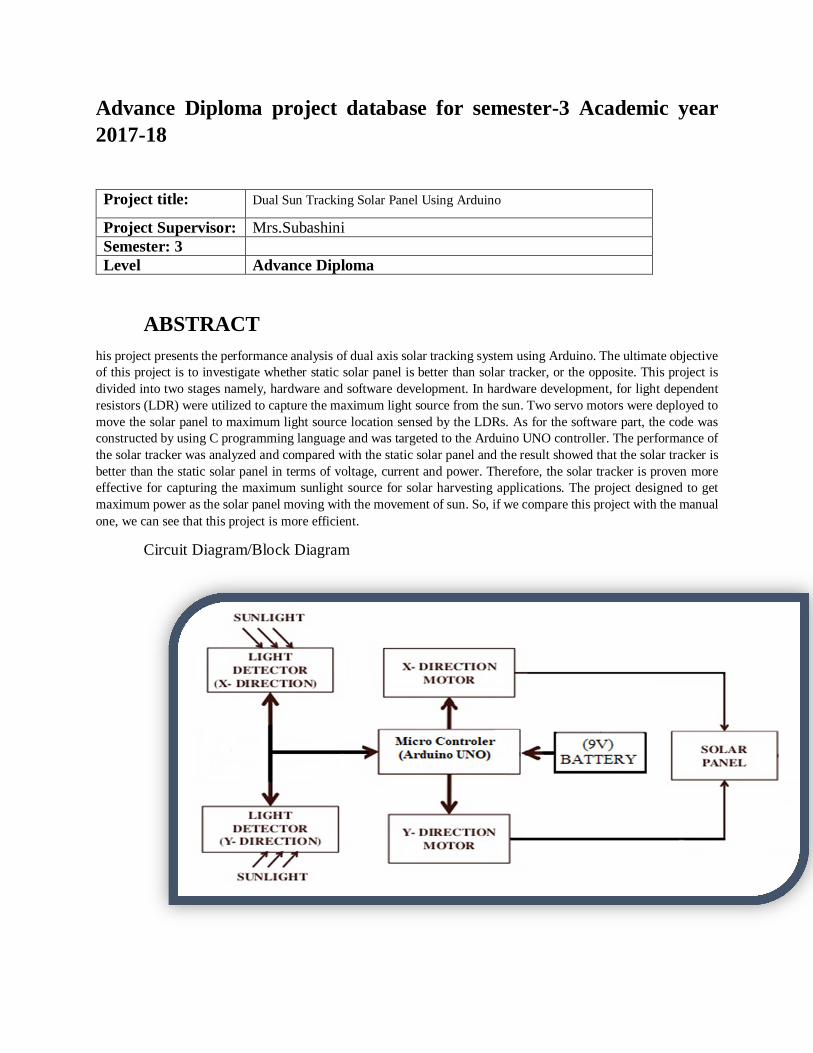
ABSTRACT his project presents the performance analysis of dual axis solar tracking system using Arduino. The ultimate objective of this project is to investigate whether static solar panel is better than solar tracker, or the opposite. This project is divided into two stages namely, hardware and software development. In hardware development, for light dependent resistors (LDR) were utilized to capture the maximum light source from the sun. Two servo motors were deployed to move the solar panel to maximum light source location sensed by the LDRs. As for the software part, the code was constructed by using C programming language and was targeted to the Arduino UNO controller. The performance of the solar tracker was analyzed and compared with the static solar panel and the result showed that the solar tracker is better than the static solar panel in terms of voltage, current and power. Therefore, the solar tracker is proven more effective for capturing the maximum sunlight source for solar harvesting applications. The project designed to get maximum power as the solar panel moving with the movement of sun. So, if we compare this project with the manual one, we can see that this project is more efficient.
Circuit Diagram/Block Diagram
Project title: Dual Sun Tracking Solar Panel Using Arduino
Project Supervisor: Mrs.Subashini Semester: 3 Level Advance Diploma
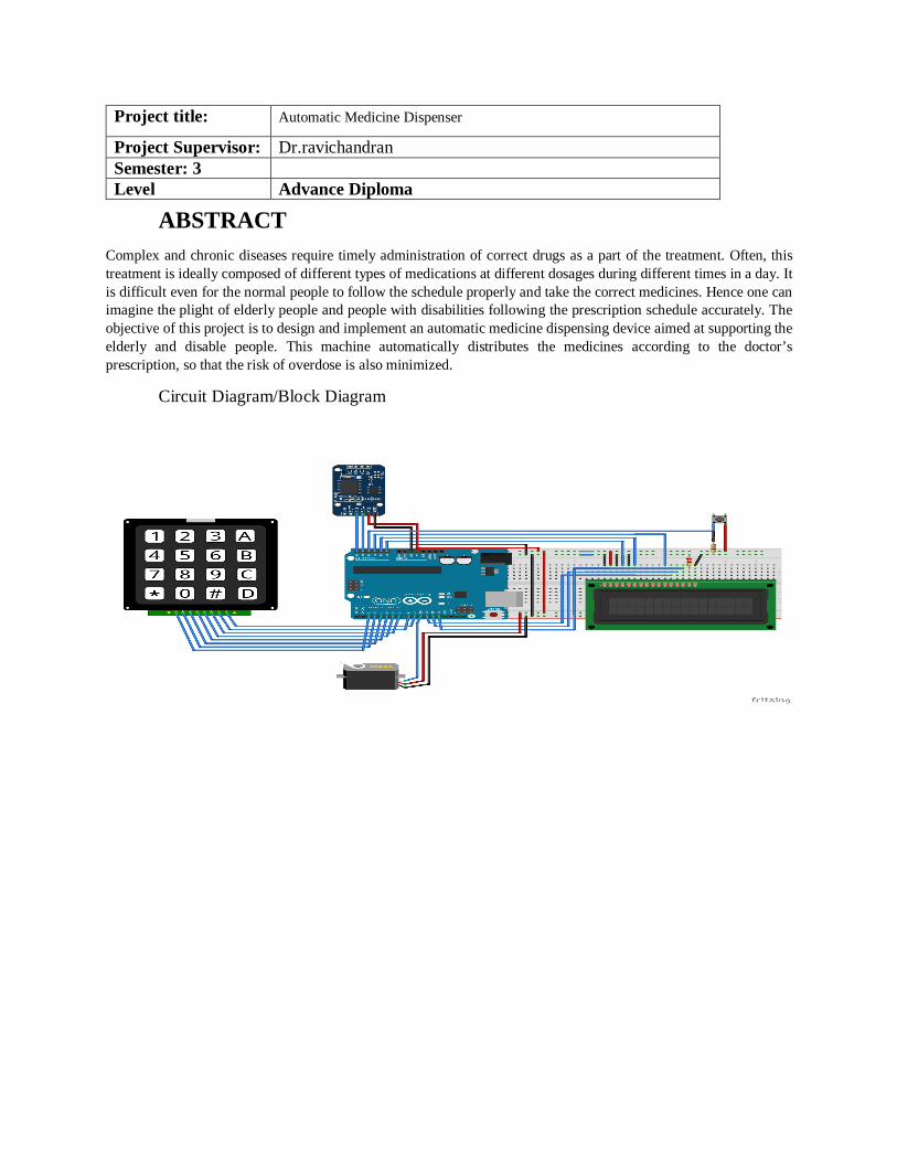
ABSTRACT Complex and chronic diseases require timely administration of correct drugs as a part of the treatment. Often, this treatment is ideally composed of different types of medications at different dosages during different times in a day. It is difficult even for the normal people to follow the schedule properly and take the correct medicines. Hence one can imagine the plight of elderly people and people with disabilities following the prescription schedule accurately. The objective of this project is to design and implement an automatic medicine dispensing device aimed at supporting the elderly and disable people. This machine automatically distributes the medicines according to the doctor’s prescription, so that the risk of overdose is also minimized.
Circuit Diagram/Block Diagram
Project title: Automatic Medicine Dispenser
Project Supervisor: Dr.ravichandran Semester: 3 Level Advance Diploma

ABSTRACT
Nowadays technology is our way to improve our life style. We can use technology in many ways and in many systems which can make our life easy and safety .We do our project to help farmers to save their time and also to manage the natural resource like water in a more effective way by using the latest technology like Arduino controlled pump considering many parameters. This project uses Arduino, sensors and indicators.
Circuit Diagram/Block Diagram
Project title: Arduino based Irrigation System
Project Supervisor: Mr.muthu Kumar Semester: 3 Level Advance Diploma
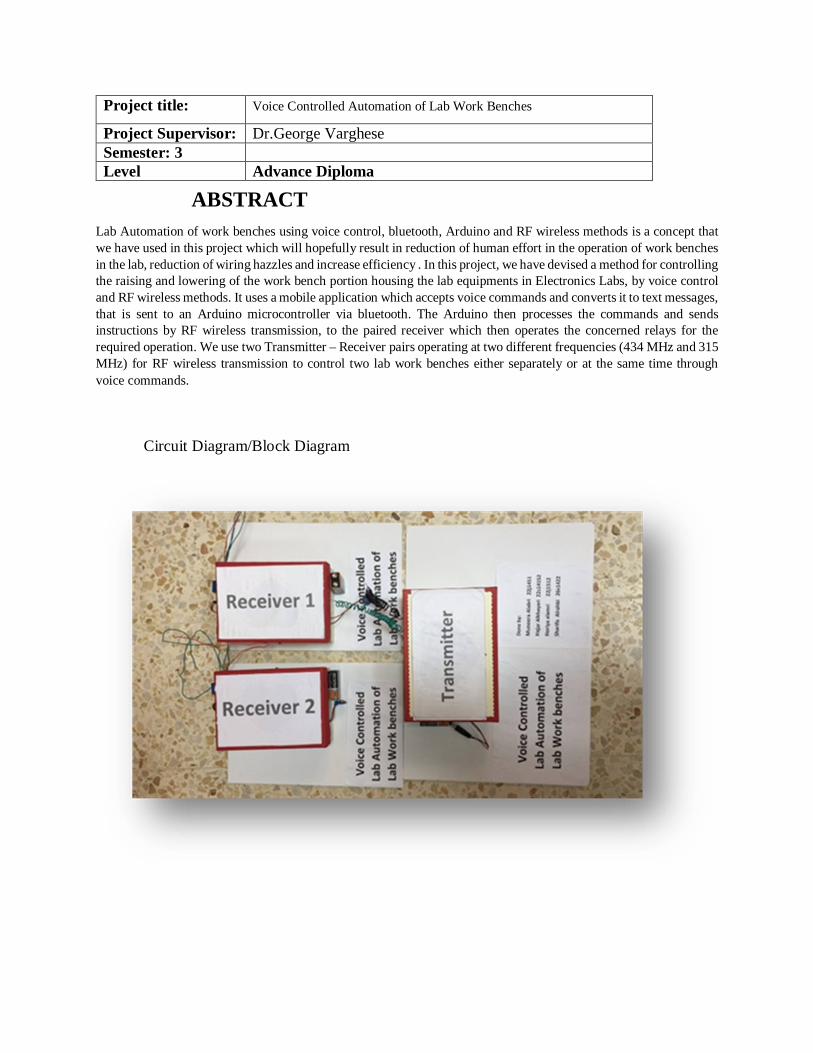
ABSTRACT Lab Automation of work benches using voice control, bluetooth, Arduino and RF wireless methods is a concept that we have used in this project which will hopefully result in reduction of human effort in the operation of work benches in the lab, reduction of wiring hazzles and increase efficiency . In this project, we have devised a method for controlling the raising and lowering of the work bench portion housing the lab equipments in Electronics Labs, by voice control and RF wireless methods. It uses a mobile application which accepts voice commands and converts it to text messages, that is sent to an Arduino microcontroller via bluetooth. The Arduino then processes the commands and sends instructions by RF wireless transmission, to the paired receiver which then operates the concerned relays for the required operation. We use two Transmitter – Receiver pairs operating at two different frequencies (434 MHz and 315 MHz) for RF wireless transmission to control two lab work benches either separately or at the same time through voice commands.
Circuit Diagram/Block Diagram
Project title: Voice Controlled Automation of Lab Work Benches
Project Supervisor: Dr.George Varghese Semester: 3 Level Advance Diploma

ABSTRACT
Here we focused in one of technology ,which can reduce risking of human lives. we know that to rescue people and to put out the fire we are forced to use Human Resources which are not safe ,but With the advancement of technology especially in Robotics it is very much possible to replace humans with robots for fighting the fire. As it would improve the efficiency of firefighters. By our project we decided to build a Fire Fighting Robot using Arduino, which will automatically sense the fire and start the water pump.
Circuit Diagram/Block Diagram
Project title: Auduino based firefighting robot
Project Supervisor: Mr.Aleem Semester: 3 Level Advance Diploma

ABSTRACT
A comprehensive solution has been designed by using a WLAN. In order to maintain security, we used a firewall through which we can control the unwanted traffic and customized the requirements according to the needs which make the network more secure & physible.
Circuit Diagram/Block Diagram
Project title: Secure WiFi solution for coffee shops
Project Supervisor: Mr.Zafar Semester: 3 Level Advance Diploma

B.Tech project database for semester-3 Academic year 2017-18
ABSTRACT Land mines pose a big threat to soldiers and battle tanks in a battle field. Yearly many soldiers lose their life or get disabled because of the land mines. The objective of this project lies in the detection of land mine with the help of a metal detector circuit attached to a rover. The scope of the project is to implement a metal detector circuit using a proximity switch and also to design a rover. The rover designed is an autonomous rover guided by user search coordinates (dimensions).
Circuit Diagram/Block Diagram
Project title: Autonomous Rover for Landmine Detection
Project Supervisor: Dr.Ravichandran Semester: 3 Level B.Tech Phase-2
Keypad Arduino Rover Motor
Proximity Switch
LED and Buzzer

ABSTRACT The purpose of this project is to detect and alert gas leakage incidents. The equipment detects a gas leakage using a sensor and alerts the registered user about the same through a SMS. Alternatively provision is made to implement the opening of a window (using a Servo Motor) to reduce the gas level, main power is made off using a relay and finally a sprinkler system is also been implemented to subside the gas level in the room.
Circuit Diagram/Block Diagram
Project title: A Security Alert System using GSM and a Remedy for Gas Leakage
Project Supervisor: Mr.abdul Nasar Semester: 3 Level B.Tech Phase-2

ABSTRACT In this project one IOT based temperature and blood pressure monitoring system has been proposed to measure and monitor human temperature and blood pressure rate from any location around the world. Infrared based pulse sensor has been applied to collect the human temperature and blood pressure, SPO2 and after processing data through Arduino, has been transferred to Thinkspeak IOT server through ESP8266 Wi-Fi module.
Circuit Diagram/Block Diagram
Project title: IOT Based Patient Health Monitoring System
Project Supervisor: Dr.Subra Debdas Semester: 3 Level B.Tech Phase-2

ABSTRACT This project deals with design and implementation of a smart traffic lights controller prototype. Smart traffic lights controller provides variable ON/OFF timing of lights according to vehicle density (length of vehicle queue per line). The other goal is to provide priority to pass special vehicles such as; ambulance, police, and VIP cars. Moreover, add of digital camera offer anytime record of red signal violation via snapshot (take photo) of the vehicle’s number. Microcontroller via Arduino Mega board is for processing and control tasks. While, IR sensors and RFID sensors are needed for; detection of traffic density, detection of red signal crossing, and detection of existence and leaving of special vehicles
Circuit Diagram/Block Diagram
Project title: Smart traffic light controller with Camera
Project Supervisor: Dr.Wisam Semester: 3 Level B.Tech Phase-2
Rel
ays
Light
Bulbs
Camera
MCU
(Arduino
MEGA) IR
Sensors
RFID
Sensors

ABSTRACT To measure weather parameters like temperature , humidity and pressure with the help of sensors and microcontroller interfacing and transfer the real-time data to cloud computing environment for analysis and monitoring.
Circuit Diagram/Block Diagram
Project title: Application of IOT Cloud Computing for Weather Monitoring and Recording
Project Supervisor: Dr.Subra debdas Semester: 3 Level B.Tech Phase-2