Embed Size (px)
Citation preview
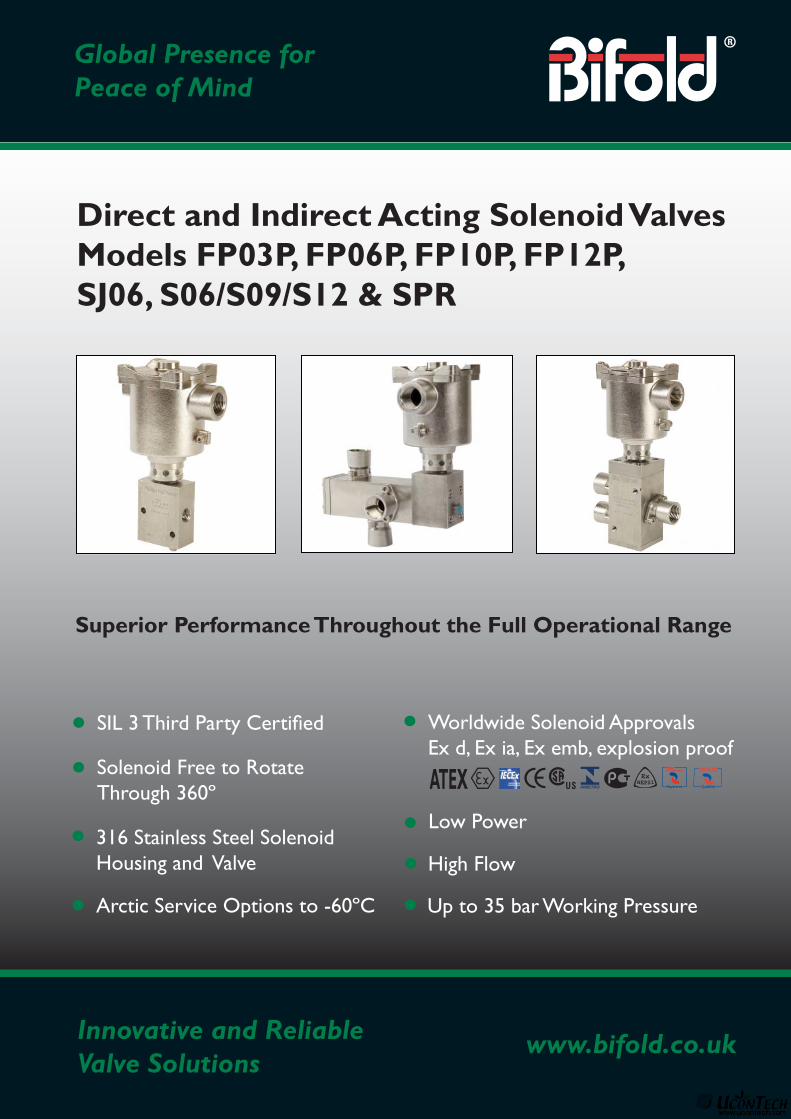
SIL 3 Third Party Certifi ed
Solenoid Free to RotateThrough 360º
316 Stainless Steel SolenoidHousing and Valve
Low Power
High Flow
Arctic Service Options to -60ºC Up to 35 bar Working Pressure
Worldwide Solenoid ApprovalsEx d, Ex ia, Ex emb, explosion proof
ATEX RegisteredRegistered
Innovative and ReliableValve Solutions
www.bifold.co.uk
Global Presence forPeace of Mind
Direct and Indirect Acting Solenoid ValvesModels FP03P, FP06P, FP10P, FP12P,SJ06, S06/S09/S12 & SPR
Superior Performance Throughout the Full Operational Range
is a member of the
of companies
www.bifold.co.uk
BFD15 Jan ‘11 © Bifold 2011
2
Features & Benefi ts
Solenoid Valve Range
Accuracy of informationWe take care to ensure that product information in thiscatalogue is reasonably accurate and up-to-date. However,our products are continually developed and updatedso to ensure accurate and up-to-date information pleaserefer to the product catalogue issue list on our web site orcontact a member of our sales team.
When selecting a product, the applicable operating systemdesign must be considered to ensure safe use. The productsfunction, material compatibility, adequate ratings, correctinstallation, operation and maintenance are theresponsibilities of the system designer and user.
Quality AssuranceAll Bifold products are manufactured to a most stringentQA programme to ensure that every product will give optimumperformance and reliability. We are third party certifi ed to EN ISO 9001:2008. Functional test certifi cate, letter ofconformity and copies of original mill certifi cates, providingtotal traceability are available on request, to BSEN 10204.3.1.Bwhere available. We reserve the right to make changesto the specifi cations and design etc., without prior notice.
Equipment Design & Build
Commissioning and Maintenance Benefi ts
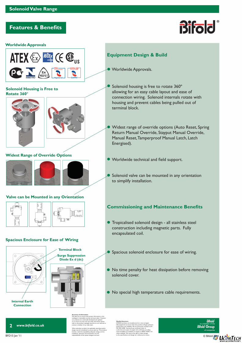
Worldwide Approvals
Spacious Enclosure for Ease of Wiring
Terminal Block
Surge SuppressionDiode Ex d (dc)
Internal Earth Connection
Widest Range of Override Options
Solenoid Housing is Free toRotate 360º
Valve can be Mounted in any Orientation
ATEX
Widest range of override options (Auto Reset, Spring Return Manual Override, Stayput Manual Override,Manual Reset, Tamperproof Manual Latch, LatchEnergised).
Solenoid housing is free to rotate 360ºallowing for an easy cable layout and ease ofconnection wiring. Solenoid internals rotate withhousing and prevent cables being pulled out ofterminal block.
Solenoid valve can be mounted in any orientation to simplify installation.
Spacious solenoid enclosure for ease of wiring.
Worldwide technical and fi eld support.
No time penalty for heat dissipation before removing solenoid cover.
No special high temperature cable requirements.
Tropicalised solenoid design - all stainless steelconstruction including magnetic parts. Fullyencapsulated coil.
Worldwide Approvals.
RegisteredRegistered
is a member of the
of companies
www.bifold.co.uk
BFD15 Jan ‘11 © Bifold 2011
3
Features & Benefi ts
Solenoid Valve Range
Accuracy of informationWe take care to ensure that product information in thiscatalogue is reasonably accurate and up-to-date. However,our products are continually developed and updatedso to ensure accurate and up-to-date information pleaserefer to the product catalogue issue list on our web site orcontact a member of our sales team.
When selecting a product, the applicable operating systemdesign must be considered to ensure safe use. The productsfunction, material compatibility, adequate ratings, correctinstallation, operation and maintenance are theresponsibilities of the system designer and user.
Quality AssuranceAll Bifold products are manufactured to a most stringentQA programme to ensure that every product will give optimumperformance and reliability. We are third party certifi ed to EN ISO 9001:2008. Functional test certifi cate, letter ofconformity and copies of original mill certifi cates, providingtotal traceability are available on request, to BSEN 10204.3.1.Bwhere available. We reserve the right to make changesto the specifi cations and design etc., without prior notice.
Safety and Environmental Benefi ts
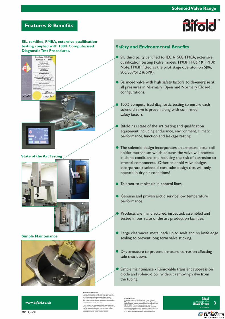
Simple Maintenance
State of the Art Testing
SIL certifi ed, FMEA, extensive qualifi cation testing coupled with 100% Computerised Diagnostic Test Procedures.
Simple maintenance - Removable transient suppression diode and solenoid coil without removing valve fromthe tubing.
SIL third party certifi ed to IEC 61508, FMEA, extensive qualifi cation testing (valve models FP03P, FP06P & FP10P. Note: FP03P fi tted as the pilot stage operator on SJ06, S06/S09/S12 & SPR).
Balanced valve with high safety factors to de-energise at all pressures in Normally Open and Normally Closedconfi gurations.
The solenoid design incorporates an armature plate coilholder mechanism which ensures the valve will operatein damp conditions and reducing the risk of corrosion tointernal components. Other solenoid valve designs incorporate a solenoid core tube design that will onlyoperate in dry air conditions!
Bifold has state of the art testing and qualifi cationequipment including endurance, environment, climatic, performance, function and leakage testing.
100% computerised diagnostic testing to ensure eachsolenoid valve is proven along with confi rmedsafety factors.
Tolerant to moist air in control lines.
Genuine and proven arctic service low temperatureperformance.
Large clearances, metal back up to seals and no knife edge sealing to prevent long term valve sticking.
Dry armature to prevent armature corrosion affecting safe shut down.
Products are manufactured, inspected, assembled and tested in our state of the art production facilities.

is a member of the
of companies
www.bifold.co.uk
BFD15 Jan ‘11 © Bifold 2011
4
Selection Table
Solenoid Valve Range
Accuracy of informationWe take care to ensure that product information in thiscatalogue is reasonably accurate and up-to-date. However,our products are continually developed and updatedso to ensure accurate and up-to-date information pleaserefer to the product catalogue issue list on our web site orcontact a member of our sales team.
When selecting a product, the applicable operating systemdesign must be considered to ensure safe use. The productsfunction, material compatibility, adequate ratings, correctinstallation, operation and maintenance are theresponsibilities of the system designer and user.
Quality AssuranceAll Bifold products are manufactured to a most stringentQA programme to ensure that every product will give optimumperformance and reliability. We are third party certifi ed to EN ISO 9001:2008. Functional test certifi cate, letter ofconformity and copies of original mill certifi cates, providingtotal traceability are available on request, to BSEN 10204.3.1.Bwhere available. We reserve the right to make changesto the specifi cations and design etc., without prior notice.
SCHEMATIC 3/2 NC
1
3
2
SCHEMATIC 3/2 NC
1
3
2
SCHEMATIC 3/2 NU
1
3
2
SCHEMATIC 3/2 NU
1
3
2
R
R
†
†
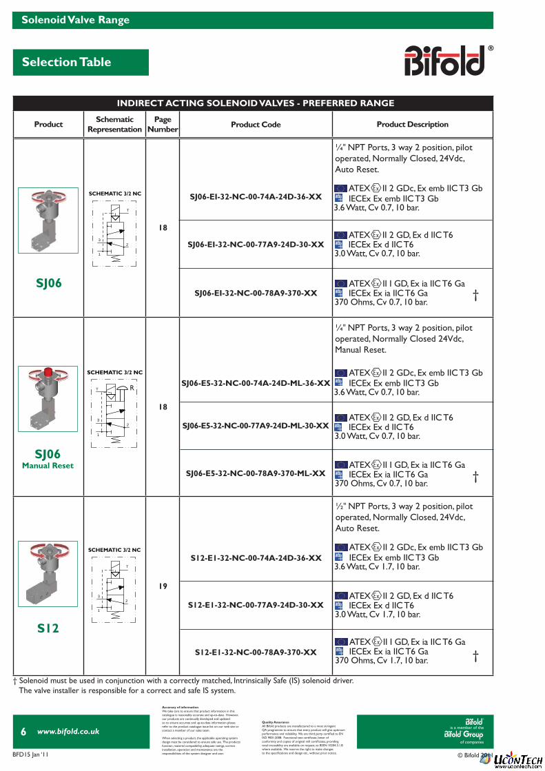
† Solenoid must be used in conjunction with a correctly matched, Intrinsically Safe (IS) solenoid driver. The valve installer is responsible for a correct and safe IS system.
Product SchematicRepresentation
PageNumber Product Code Product Description
14
14
15
15
FP03P-02-32-NC-V-74A-24D-36-XX
FP03P-02-32-NC-V-77A9-24D-30-XX
FP03P-02-32-NC-V-78A9-370-XX
ATEX II 2 GDc, Ex emb IIC T3 Gb
ATEX II 2 GDc, Ex emb IIC T3 Gb
ATEX II 2 GDc, Ex emb IIC T3 Gb
ATEX II 2 GDc, Ex emb IIC T3 Gb
ATEX II 2 GD, Ex d IIC T6
ATEX II 2 GD, Ex d IIC T6
ATEX II 2 GD, Ex d IIC T6
ATEX II 2 GD, Ex d IIC T6
ATEX II I GD, Ex ia IIC T6 Ga
ATEX II I GD, Ex ia IIC T6 Ga
IECEx Ex emb IIC T3 Gb
IECEx Ex emb IIC T3 Gb
IECEx Ex emb IIC T3 Gb
IECEx Ex emb IIC T3 Gb
IECEx Ex d IIC T6
IECEx Ex d IIC T6
IECEx Ex d IIC T6
IECEx Ex d IIC T6
IECEx Ex ia IIC T6 Ga
IECEx Ex ia IIC T6 Ga
3.6 Watt, Cv 0.1, 10 bar.
3.6 Watt, Cv 0.1, 10 bar.
4.4 Watt, Cv 0.5, 10 bar.6.8 Watt, Cv 0.75, 10 bar.
3.6 Watt, Cv 0.75, 10 bar.
3.0 Watts, Cv 0.1, 10 bar.
3.0 Watt, Cv 0.1, 10 bar.
3.5 Watt, Cv 0.5, 10 bar.5.7 Watt, Cv 0.75, 10 bar.
3.0 Watt, Cv 0.75, 10 bar.
370 Ohms, Cv 0.1, 10 bar.
370 Ohms, Cv 0.1, 10 bar.
FP03P-02-32-NC-V-74A-24D-ML-36-XX
FP03P-02-32-NC-V-77A9-24D-ML-30-XX
FP03P-02-32-NC-V-78A9-24D-ML-370-XX
FP06P-S1-04-32-NU-V-74A-24D-44-XXFP06P-S1-04-32-NU-V-74A-24D-68-XX
FP06P-S1-04-32-NU-V-77A9-24D-57-XXFP06P-S1-04-32-NU-V-77A9-24D-35-XX
FP06P-S1-04-32-NU-V-74A9-24D-ML-36-XX
FP06P-S1-04-32-NU-V-77A9-24D-ML-30-XX
1⁄8" NPT Ports, 3 way 2 position, direct acting, Normally Universal, 24Vdc, Auto Reset.
1⁄8" NPT Ports, 3 way 2 position, direct acting, Normally Universal, 24Vdc, Manual Reset.
FP03P
FP03PManual Reset
FP06PManual Reset
FP06P
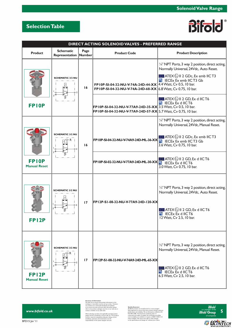
¼ " NPT Ports, 3 way 2 position, direct acting,Normally Universal, 24Vdc, Auto Reset.
¼ " NPT Ports, 3 way 2 position, direct acting,Normally Universal, 24Vdc, Manual Reset.
DIRECT ACTING SOLENOID VALVES - PREFERRED RANGE
is a member of the
of companies
www.bifold.co.uk
BFD15 Jan ‘11 © Bifold 2011
5
Selection Table
Solenoid Valve Range
Accuracy of informationWe take care to ensure that product information in thiscatalogue is reasonably accurate and up-to-date. However,our products are continually developed and updatedso to ensure accurate and up-to-date information pleaserefer to the product catalogue issue list on our web site orcontact a member of our sales team.
When selecting a product, the applicable operating systemdesign must be considered to ensure safe use. The productsfunction, material compatibility, adequate ratings, correctinstallation, operation and maintenance are theresponsibilities of the system designer and user.
Quality AssuranceAll Bifold products are manufactured to a most stringentQA programme to ensure that every product will give optimumperformance and reliability. We are third party certifi ed to EN ISO 9001:2008. Functional test certifi cate, letter ofconformity and copies of original mill certifi cates, providingtotal traceability are available on request, to BSEN 10204.3.1.Bwhere available. We reserve the right to make changesto the specifi cations and design etc., without prior notice.
SCHEMATIC 3/2 NU
1
3
2
SCHEMATIC 3/2 NU
1
3
2
SCHEMATIC 3/2 NU
1
3
2
SCHEMATIC 3/2 NU
1
3
2
R
R
Product SchematicRepresentation
PageNumber Product Code Product Description
16
16
17
17
FP10P-SI-04-32-NU-V-74A-24D-44-XXFP10P-SI-04-32-NU-V-74A-24D-68-XX
FP10P-SI-04-32-NU-V-77A9-24D-35-XXFP10P-SI-04-32-NU-V-77A9-24D-57-XX
ATEX II 2 GDc, Ex emb IIC T3
ATEX II 2 GDc, Ex emb IIC T3
ATEX II 2 GD, Ex d IIC T6
ATEX II 2 GD, Ex d IIC T6
ATEX II 2 GD, Ex d IIC T6
ATEX II 2 GD, Ex d IIC T6
IECEx Ex emb IIC T3 Gb
IECEx Ex emb IIC T3 Gb
IECEx Ex d IIC T6
IECEx Ex d IIC T6
IECEx Ex d IIC T6
IECEx Ex d IIC T6
4.4 Watt, Cv 0.5, 10 bar.6.8 Watt, Cv 0.75, 10 bar.
3.6 Watt, Cv 0.75, 10 bar.
3.5 Watt, Cv 0.5, 10 bar. 5.7 Watt, Cv 0.75, 10 bar.
3.0 Watt, Cv 0.75, 10 bar.
6.5 Watt, Cv 2.5, 10 bar.
12 Watt, Cv 2.5, 10 bar.
FP10P-SI-04-32-NU-V-74A9-24D-ML-36-XX
FP10P-SI-02-32-NU-V-77A9-24D-ML-30-XX
FP12P-S1-08-32-NU-V-74A9-24D-ML-65-XX
FP12P-S1-08-32-NU-V-77A9-24D-120-XX
¼" NPT Ports, 3 way 2 position, direct acting, Normally Universal, 24Vdc, Auto Reset.
¼" NPT Ports, 3 way 2 position, direct acting, Normally Universal, 24Vdc, Manual Reset.
FP10P
FP12P
FP10PManual Reset
FP12PManual Reset
½" NPT Ports, 3 way 2 position, direct acting, Normally Universal, 24Vdc, Auto Reset.
½" NPT Ports, 3 way 2 position, direct acting, Normally Universal, 24Vdc, Manual Reset.
DIRECT ACTING SOLENOID VALVES - PREFERRED RANGE
is a member of the
of companies
www.bifold.co.uk
BFD15 Jan ‘11 © Bifold 2011
6
Selection Table
Solenoid Valve Range
Accuracy of informationWe take care to ensure that product information in thiscatalogue is reasonably accurate and up-to-date. However,our products are continually developed and updatedso to ensure accurate and up-to-date information pleaserefer to the product catalogue issue list on our web site orcontact a member of our sales team.
When selecting a product, the applicable operating systemdesign must be considered to ensure safe use. The productsfunction, material compatibility, adequate ratings, correctinstallation, operation and maintenance are theresponsibilities of the system designer and user.
Quality AssuranceAll Bifold products are manufactured to a most stringentQA programme to ensure that every product will give optimumperformance and reliability. We are third party certifi ed to EN ISO 9001:2008. Functional test certifi cate, letter ofconformity and copies of original mill certifi cates, providingtotal traceability are available on request, to BSEN 10204.3.1.Bwhere available. We reserve the right to make changesto the specifi cations and design etc., without prior notice.
1
23
T
SCHEMATIC 3/2 NC
1
23
T
SCHEMATIC 3/2 NC
1
23
T
SCHEMATIC 3/2 NC
R
† Solenoid must be used in conjunction with a correctly matched, Intrinsically Safe (IS) solenoid driver. The valve installer is responsible for a correct and safe IS system.
†
†
†
Product SchematicRepresentation
PageNumber Product Code Product Description
18
18
19
SJ06-EI-32-NC-00-74A-24D-36-XX
SJ06-EI-32-NC-00-77A9-24D-30-XX
SJ06-EI-32-NC-00-78A9-370-XX
ATEX II 2 GDc, Ex emb IIC T3 Gb
ATEX II 2 GDc, Ex emb IIC T3 Gb
ATEX II 2 GDc, Ex emb IIC T3 Gb
ATEX II 2 GD, Ex d IIC T6
ATEX II 2 GD, Ex d IIC T6
ATEX II 2 GD, Ex d IIC T6
ATEX II I GD, Ex ia IIC T6 Ga
ATEX II I GD, Ex ia IIC T6 Ga
ATEX II I GD, Ex ia IIC T6 Ga
IECEx Ex emb IIC T3 Gb
IECEx Ex emb IIC T3 Gb
IECEx Ex emb IIC T3 Gb
IECEx Ex d IIC T6
IECEx Ex d IIC T6
IECEx Ex d IIC T6
IECEx Ex ia IIC T6 Ga
IECEx Ex ia IIC T6 Ga
IECEx Ex ia IIC T6 Ga
3.6 Watt, Cv 0.7, 10 bar.
3.6 Watt, Cv 0.7, 10 bar.
3.6 Watt, Cv 1.7, 10 bar.
3.0 Watt, Cv 0.7, 10 bar.
3.0 Watt, Cv 0.7, 10 bar.
3.0 Watt, Cv 1.7, 10 bar.
370 Ohms, Cv 0.7, 10 bar.
370 Ohms, Cv 0.7, 10 bar.
370 Ohms, Cv 1.7, 10 bar.
SJ06-E5-32-NC-00-74A-24D-ML-36-XX
SJ06-E5-32-NC-00-77A9-24D-ML-30-XX
SJ06-E5-32-NC-00-78A9-370-ML-XX
S12-E1-32-NC-00-74A-24D-36-XX
S12-E1-32-NC-00-77A9-24D-30-XX
S12-E1-32-NC-00-78A9-370-XX
¼" NPT Ports, 3 way 2 position, pilotoperated, Normally Closed, 24Vdc, Auto Reset.
¼" NPT Ports, 3 way 2 position, pilotoperated, Normally Closed 24Vdc,Manual Reset.
½" NPT Ports, 3 way 2 position, pilotoperated, Normally Closed, 24Vdc,Auto Reset.
SJ06Manual Reset
SJ06
S12
INDIRECT ACTING SOLENOID VALVES - PREFERRED RANGE

is a member of the
of companies
www.bifold.co.uk
BFD15 Jan ‘11 © Bifold 2011
7
Selection Table
Solenoid Valve Range
Accuracy of informationWe take care to ensure that product information in thiscatalogue is reasonably accurate and up-to-date. However,our products are continually developed and updatedso to ensure accurate and up-to-date information pleaserefer to the product catalogue issue list on our web site orcontact a member of our sales team.
When selecting a product, the applicable operating systemdesign must be considered to ensure safe use. The productsfunction, material compatibility, adequate ratings, correctinstallation, operation and maintenance are theresponsibilities of the system designer and user.
Quality AssuranceAll Bifold products are manufactured to a most stringentQA programme to ensure that every product will give optimumperformance and reliability. We are third party certifi ed to EN ISO 9001:2008. Functional test certifi cate, letter ofconformity and copies of original mill certifi cates, providingtotal traceability are available on request, to BSEN 10204.3.1.Bwhere available. We reserve the right to make changesto the specifi cations and design etc., without prior notice.
1
23
T
SCHEMATIC 3/2 NC
1
23
T
SCHEMATIC 3/2 NC
1
23
T
SCHEMATIC 3/2 NC
R
R
† Solenoid must be used in conjunction with a correctly matched, Intrinsically Safe (IS) solenoid driver. The valve installer is responsible for a correct and safe IS system.
†
†
†
Product SchematicRepresentation
PageNumber Product Code Product Description
19
20
20
ATEX II 2 GDc, Ex emb IIC T3 Gb
ATEX II 2 GDc, Ex emb IIC T3 Gb
ATEX II 2 GDc, Ex emb IIC T3 Gb
ATEX II 2 GD, Ex d IIC T6
ATEX II 2 GD, Ex d IIC T6
ATEX II 2 GD, Ex d IIC T6
ATEX II I GD, Ex ia IIC T6 Ga
ATEX II I GD, Ex ia IIC T6 Ga
ATEX II I GD, Ex ia IIC T6 Ga
IECEx Ex emb IIC T3 Gb
IECEx Ex emb IIC T3 Gb
IECEx Ex emb IIC T3 Gb
IECEx Ex d IIC T6
IECEx Ex d IIC T6
IECEx Ex d IIC T6
IECEx Ex ia IIC T6 Ga
IECEx Ex ia IIC T6 Ga
IECEx Ex ia IIC T6 Ga
3.6 Watt, Cv 1.7, 10 bar.
3.6 Watt, Cv 3.0, 10 bar.
3.6 Watt, Cv 3.0, 10 bar.
3.0 Watt, Cv 1.7, 10 bar.
3.0 Watt, Cv 3.0, 10 bar.
3.0 Watt, Cv 3.0, 10 bar.
370 Ohms, Cv 1.7, 10 bar.
370 Ohms, Cv 3.0, 10 bar.
370 Ohms, Cv 3.0, 10 bar.
SPR12-E1-32-NC-00-74A-24D-36-XX
SPR12-E5-32-NC-00-74A9-24D-ML-36-XX
SPR12-E1-32-NC-00-77A9-24D-30-XX
SPR12-E5-32-NC-00-77A9-24D-ML-30-XX
SPR12-E1-32-NC-00-78A9-370-XX
SPR12-E5-32-NC-00-78A9-370-ML-XX
S12-E5-32-NC-00-74A-24D-ML-36-XX
S12-E5-32-NC-00-77A9-24D-ML-30-XX
S12-E5-32-NC-00-78A9-370-ML-XX
½" NPT Ports, 3 way 2 position, pilotoperated, Normally Closed, 24Vdc, Manual Reset.
½" NPT Ports, 3 way 2 position, pilotoperated, Normally Closed 24Vdc,Auto Reset.
½" NPT Ports, 3 way 2 position, pilotoperated, Normally Closed, 24Vdc,Manual Reset.
S12Manual Reset
SPR12
SPR12Manual Reset
INDIRECT ACTING SOLENOID VALVES - PREFERRED RANGE
is a member of the
of companies
www.bifold.co.uk
BFD15 Jan ‘11 © Bifold 2011
8
Overview
Solenoid Valve Range
Accuracy of informationWe take care to ensure that product information in thiscatalogue is reasonably accurate and up-to-date. However,our products are continually developed and updatedso to ensure accurate and up-to-date information pleaserefer to the product catalogue issue list on our web site orcontact a member of our sales team.
When selecting a product, the applicable operating systemdesign must be considered to ensure safe use. The productsfunction, material compatibility, adequate ratings, correctinstallation, operation and maintenance are theresponsibilities of the system designer and user.
Quality AssuranceAll Bifold products are manufactured to a most stringentQA programme to ensure that every product will give optimumperformance and reliability. We are third party certifi ed to EN ISO 9001:2008. Functional test certifi cate, letter ofconformity and copies of original mill certifi cates, providingtotal traceability are available on request, to BSEN 10204.3.1.Bwhere available. We reserve the right to make changesto the specifi cations and design etc., without prior notice.
Materials of Construction
Technical Data
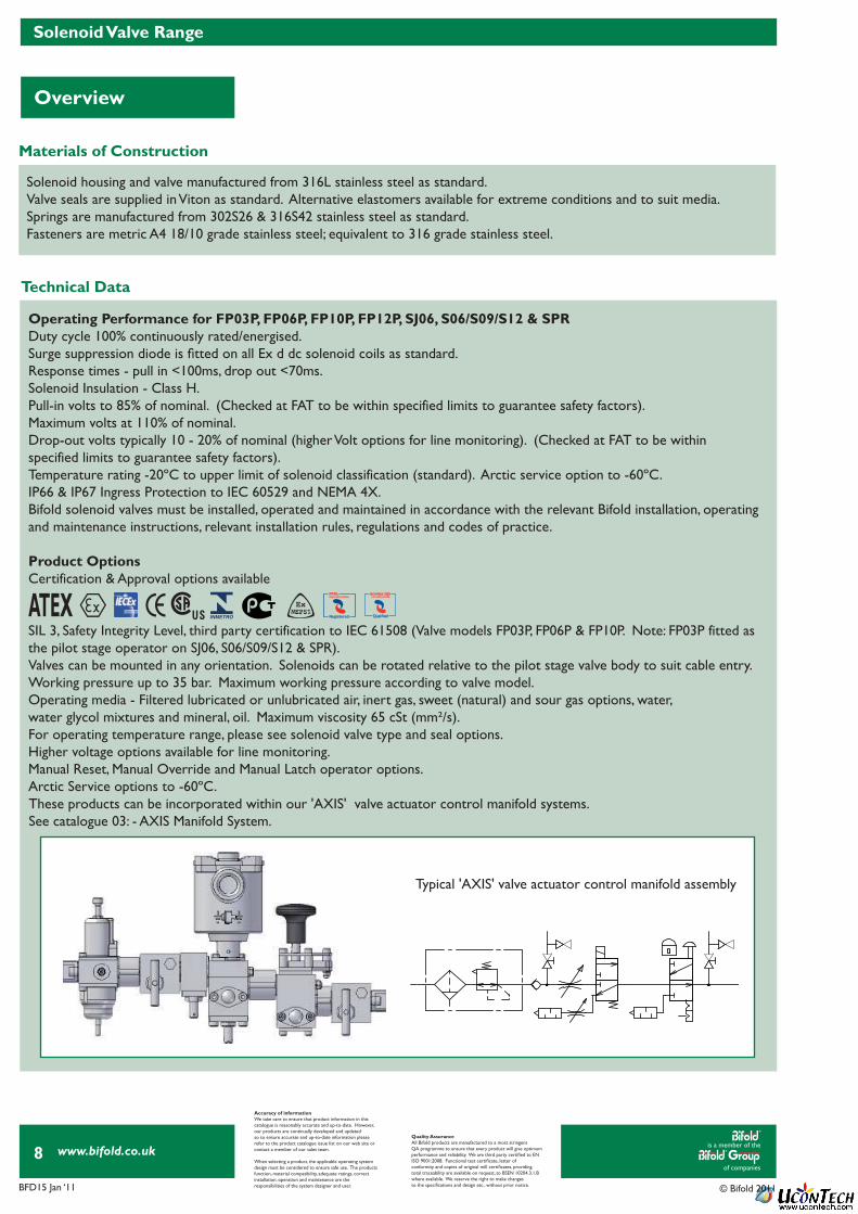
These products can be incorporated within our 'AXIS' valve actuator control manifold systems.See catalogue 03: - AXIS Manifold System.
Solenoid housing and valve manufactured from 316L stainless steel as standard.Valve seals are supplied in Viton as standard. Alternative elastomers available for extreme conditions and to suit media. Springs are manufactured from 302S26 & 316S42 stainless steel as standard.Fasteners are metric A4 18/10 grade stainless steel; equivalent to 316 grade stainless steel.
Operating Performance for FP03P, FP06P, FP10P, FP12P, SJ06, S06/S09/S12 & SPRDuty cycle 100% continuously rated/energised.Surge suppression diode is fi tted on all Ex d dc solenoid coils as standard.Response times - pull in <100ms, drop out <70ms.Solenoid Insulation - Class H. Pull-in volts to 85% of nominal. (Checked at FAT to be within specified limits to guarantee safety factors). Maximum volts at 110% of nominal.Drop-out volts typically 10 - 20% of nominal (higher Volt options for line monitoring). (Checked at FAT to be withinspecified limits to guarantee safety factors).Temperature rating -20ºC to upper limit of solenoid classification (standard). Arctic service option to -60ºC.IP66 & IP67 Ingress Protection to IEC 60529 and NEMA 4X.Bifold solenoid valves must be installed, operated and maintained in accordance with the relevant Bifold installation, operatingand maintenance instructions, relevant installation rules, regulations and codes of practice.
Product OptionsCertification & Approval options available
SIL 3, Safety Integrity Level, third party certification to IEC 61508 (Valve models FP03P, FP06P & FP10P. Note: FP03P fitted asthe pilot stage operator on SJ06, S06/S09/S12 & SPR).Valves can be mounted in any orientation. Solenoids can be rotated relative to the pilot stage valve body to suit cable entry.Working pressure up to 35 bar. Maximum working pressure according to valve model.Operating media - Filtered lubricated or unlubricated air, inert gas, sweet (natural) and sour gas options, water,water glycol mixtures and mineral, oil. Maximum viscosity 65 cSt (mm²/s).For operating temperature range, please see solenoid valve type and seal options.Higher voltage options available for line monitoring.Manual Reset, Manual Override and Manual Latch operator options. Arctic Service options to -60ºC.
Typical 'AXIS' valve actuator control manifold assembly
ATEX RegisteredRegistered

is a member of the
of companies
www.bifold.co.uk
BFD15 Jan ‘11 © Bifold 2011
9
Certifi cation Details
Solenoid Certifi cation & Approvals
Accuracy of informationWe take care to ensure that product information in thiscatalogue is reasonably accurate and up-to-date. However,our products are continually developed and updatedso to ensure accurate and up-to-date information pleaserefer to the product catalogue issue list on our web site orcontact a member of our sales team.
When selecting a product, the applicable operating systemdesign must be considered to ensure safe use. The productsfunction, material compatibility, adequate ratings, correctinstallation, operation and maintenance are theresponsibilities of the system designer and user.
Quality AssuranceAll Bifold products are manufactured to a most stringentQA programme to ensure that every product will give optimumperformance and reliability. We are third party certifi ed to EN ISO 9001:2008. Functional test certifi cate, letter ofconformity and copies of original mill certifi cates, providingtotal traceability are available on request, to BSEN 10204.3.1.Bwhere available. We reserve the right to make changesto the specifi cations and design etc., without prior notice.
Certifi cation & Approval Details
Type 77 Solenoid
Type 74 Solenoid
Type 78 Solenoid
Type 77 Solenoid
Type 78 Solenoid
Type 77 Solenoid
Type 87 Solenoid Type 77 & 78 Solenoid
Type 78 Solenoid
Type 77 Solenoid
Type 77 Solenoid
IECEx, Certificate Number IECEx Bas 10.0008. Ex d IIC T6 (Tamb -60ºC to +40ºC). Ex d IIC T5 (Tamb -60ºC to +55ºC). Ex d IIC T4 (Tamb -60ºC to +90ºC).
IECEx, Certificate Number IECEx Bas 09.0012X. Ex emb IIC T3 Gb Tamb -25ºC to +40ºC. Ex emb IIC T3 Gb Tamb -25ºC to +55ºC.
IECEx, Certificate Number IECEx Bas 09.0092X. Ex ia IIC T6 Ga (Tamb = -60ºC to +60ºC). Ex ia IIC T4 Ga (Tamb = -60ºC to +95ºC).
INMETRO, Certificate Number CEPEL-EX-097/2003X. BR-Ex d IIC T6 -60ºC to +40ºC ambient. BR-Ex d IIC T5 -60ºC to +55ºC ambient. BR-Ex d IIC T4 -60ºC to +90ºC ambient.
ATEX, Certificate Number Baseefa 10ATEX0026. II 2 GD Ex d IIC T6 (Tamb -60ºC to +40ºC). II 2 GD Ex d IIC T5 (Tamb -60ºC to +55ºC). II 2 GD Ex d IIC T4 (Tamb -60ºC to +90ºC).
ATEX, Certificate Number Baseefa 10ATEX0026. II 2GD Ex d IIC T6 (Tamb -60ºC to +40ºC). II 2GD Ex d IIC T5 (Tamb -60ºC to +55ºC). II 2GD Ex d IIC T4 (Tamb -60ºC to +90ºC).
ATEX, Certificate Number Baseefa 09ATEX0040X. II 2GD c Ex emb IIC T3 Gb Tamb -25ºC to +40ºC. II 2GD c Ex emb IIC T3 Gb Tamb -25ºC to +55ºC.
ATEX, Certificate Number Baseefa 02ATEX0124X. II I GD Ex ia IIC T6 Ga (Tamb = -60ºC to +60ºC). II I GD Ex ia IIC T4 Ga (Tamb = -60ºC to +95ºC).
INMETRO, Certificate Number CEPEL-EX-532/05. BR-Ex ia IIC T6 -60ºC to + 40ºC ambient. BR-Ex ia IIC T4 -60ºC to + 95ºC ambient.
GOST, Certificate Number B00763, RTN. Ex d IIC T6 -60ºC to +40ºC ambient. Ex d IIC T5 -60ºC to +55ºC ambient. Ex d IIC T4 -60ºC to +90ºC ambient.
GOST K, GGTN K Permit, Kazakhstan, BIF 7727 2.
NEPSI, Certificate Number GYJ081011. Ex d IIC T6 up to 40ºC ambient. Ex d IIC T5 up to 55ºC ambient. Ex d IIC T4 up to 95ºC ambient.
GOST, Certificate Number B00015, RTN. Permit Number PPC 00-28504. Ex ia IIC T6 -60ºC to +40ºC ambient. Ex ia IIC T5 -60ºC to +55ºC ambient. Ex ia IIC T4 -60ºC to +90ºC ambient.
CSA (US), Certificate Number 1398692 Class 1, Division 1, Groups B, C & D for both Canada & USA. Ex d IIC for Canada, AEx d IIC for USA. T85ºC -60ºC to +40ºC ambient. T100ºC -60ºC to +55ºC ambient. T135ºC -60ºC to +90ºC ambient.
Dual Labelled/Marked
Dual Labelled/Marked
Dual Labelled/Marked
Dual Labelled/Marked
Please note that operation ambients are dependant upon seal types.For solenoid type 87 please note that the solenoid housing is fi xed.For solenoid type 74 the maximum permissible ambient temperature is subject to the coil wattage. Please see page 11.
is a member of the
of companies
www.bifold.co.uk
BFD15 Jan ‘11 © Bifold 2011
10
Solenoid Valve Product Options
Port Connections
Seal Repair Kit
Solenoid Coil Spare
Product Weights
Accuracy of informationWe take care to ensure that product information in thiscatalogue is reasonably accurate and up-to-date. However,our products are continually developed and updatedso to ensure accurate and up-to-date information pleaserefer to the product catalogue issue list on our web site orcontact a member of our sales team.
When selecting a product, the applicable operating systemdesign must be considered to ensure safe use. The productsfunction, material compatibility, adequate ratings, correctinstallation, operation and maintenance are theresponsibilities of the system designer and user.
Quality AssuranceAll Bifold products are manufactured to a most stringentQA programme to ensure that every product will give optimumperformance and reliability. We are third party certifi ed to EN ISO 9001:2008. Functional test certifi cate, letter ofconformity and copies of original mill certifi cates, providingtotal traceability are available on request, to BSEN 10204.3.1.Bwhere available. We reserve the right to make changesto the specifi cations and design etc., without prior notice.
Port Connections for(FP06P, FP10P, FP12P, SJ06,S06/S09/S12 & SPR)
Port Connections (FP03P Only)
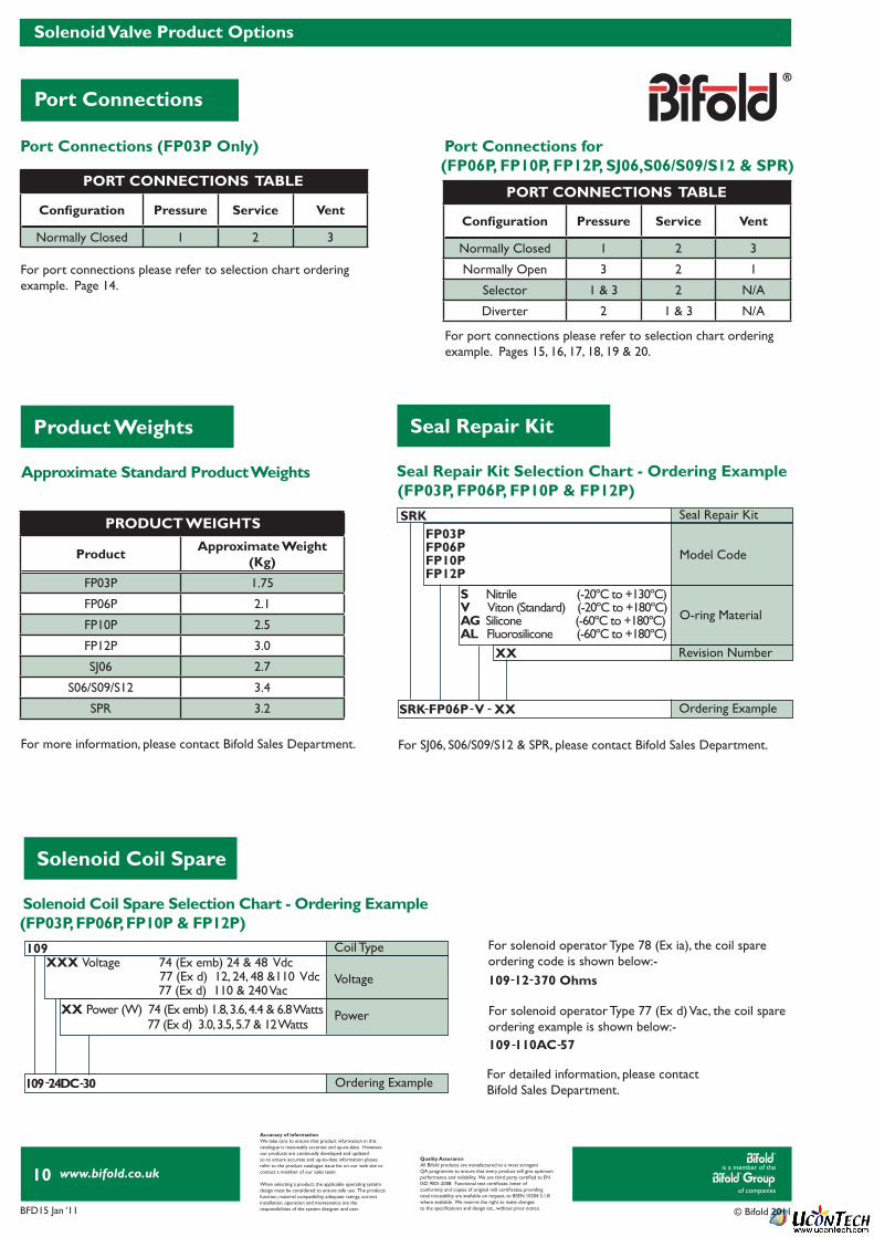
Seal Repair Kit Selection Chart - Ordering Example (FP03P, FP06P, FP10P & FP12P)
Solenoid Coil Spare Selection Chart - Ordering Example(FP03P, FP06P, FP10P & FP12P)
Approximate Standard Product Weights
For port connections please refer to selection chart ordering example. Pages 15, 16, 17, 18, 19 & 20.
For more information, please contact Bifold Sales Department. For SJ06, S06/S09/S12 & SPR, please contact Bifold Sales Department.
For detailed information, please contactBifold Sales Department.
For solenoid operator Type 78 (Ex ia), the coil spareordering code is shown below:-
For solenoid operator Type 77 (Ex d) Vac, the coil spareordering example is shown below:-
For port connections please refer to selection chart ordering example. Page 14.
109
109
12
110AC
370 Ohms
57
Confi guration Pressure Service Vent
Normally Closed 1 2 3
Normally Open 3 2 1
Selector 1 & 3 2 N/A
Diverter 2 1 & 3 N/A
Product Approximate Weight (Kg)
FP03P 1.75
FP06P 2.1
FP10P 2.5
FP12P 3.0
SJ06 2.7
S06/S09/S12 3.4
SPR 3.2
Confi guration Pressure Service Vent
Normally Closed 1 2 3
SRK
109
Model Code
Voltage
Seal Repair Kit
Coil Type
O-ring Material
Power
Revision Number
Ordering Example
Ordering Example
XX
SRK
109
V
30
FP06P
24DC
XX
S Nitrile (-20ºC to +130ºC)V Viton (Standard) (-20ºC to +180ºC)AG Silicone (-60ºC to +180ºC)AL Fluorosilicone (-60ºC to +180ºC)
FP03P FP06P FP10P FP12P
XXX Voltage 74 (Ex emb) 24 & 48 Vdc
XX Power (W) 74 (Ex emb) 1.8, 3.6, 4.4 & 6.8 Watts
77 (Ex d) 12, 24, 48 &110 Vdc77 (Ex d) 110 & 240 Vac
77 (Ex d) 3.0, 3.5, 5.7 & 12 Watts
PORT CONNECTIONS TABLE
PRODUCT WEIGHTS
PORT CONNECTIONS TABLE
is a member of the
of companies
www.bifold.co.uk
BFD15 Jan ‘11 © Bifold 2011
11
Solenoid Options
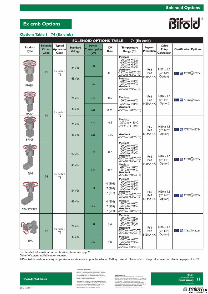
Ex emb Options
Accuracy of informationWe take care to ensure that product information in thiscatalogue is reasonably accurate and up-to-date. However,our products are continually developed and updatedso to ensure accurate and up-to-date information pleaserefer to the product catalogue issue list on our web site orcontact a member of our sales team.
When selecting a product, the applicable operating systemdesign must be considered to ensure safe use. The productsfunction, material compatibility, adequate ratings, correctinstallation, operation and maintenance are theresponsibilities of the system designer and user.
Quality AssuranceAll Bifold products are manufactured to a most stringentQA programme to ensure that every product will give optimumperformance and reliability. We are third party certifi ed to EN ISO 9001:2008. Functional test certifi cate, letter ofconformity and copies of original mill certifi cates, providingtotal traceability are available on request, to BSEN 10204.3.1.Bwhere available. We reserve the right to make changesto the specifi cations and design etc., without prior notice.
FP03P
Options Table 1 74 (Ex emb)
Other Wattages available upon request.# Permissible media operating temperatures are dependent upon the selected O-Ring material. Please refer to the product selection charts on pages 14 to 20.
For detailed information on certifi cation please see page 9.
#
#
#
#
#
#
#
#
#
#
ProductType
SolenoidOrderCode
TypicalApparatus
Code
IngressProtection
CableEntry
ConnectionCertifi cation Options
4.4
1.8
4.4
1.8
1.8
1.8
6.8
3.6
6.8
3.6
3.6
3.6
Ex emb II T3
Ex emb II T3
Ex emb II T3
Ex emb II T3
74
74
74
74
FP06P
FP10P
SJ06
S06/S09/S12
SPR
24 Vdc
24 Vdc
24 Vdc
24 Vdc
24 Vdc
24 Vdc
48 Vdc
48 Vdc
48 Vdc
48 Vdc
48 Vdc
48 Vdc
Standard Voltage
CVRate
PowerConsumption
(W)
-20ºC to +40ºC-25ºC to +40ºC
-20ºC to +40ºC-25ºC to +40ºC-20ºC to +55ºC-25ºC to +55ºC
-20ºC to +40ºC-25ºC to +40ºC-20ºC to +55ºC-25ºC to +55ºC
-20ºC to +40ºC-25ºC to +40ºC-20ºC to +55ºC-25ºC to +55ºC
-20ºC to +40ºC-25ºC to +40ºC-20ºC to +55ºC-25ºC to +55ºC
-20ºC to +40ºC-25ºC to +40ºC
-20ºC to +40ºC-25ºC to +40ºC
-20ºC to +40ºC-25ºC to +40ºC
-20ºC to +40ºC-25ºC to +40ºC
-20ºC to +130ºC-20ºC to +180ºC
-25ºC to +40ºC (T3)
-25ºC to +40ºC (T3) -25ºC to +55ºC (T3)
-25ºC to +40ºC (T3) -25ºC to +55ºC (T3)
-25ºC to +40ºC (T3) -25ºC to +55ºC (T3)
-25ºC to +40ºC (T3) -25ºC to +55ºC (T3)
-25ºC to +40ºC (T3)
-25ºC to +40ºC (T3)
-25ºC to +40ºC (T3)
-25ºC to +40ºC (T3)
-25ºC to +40ºC (T3)
0.75
0.75
0.5
0.1
0.5
1.0 (S06)
1.0 (S06)
1.7 (S09)
1.7 (S09)
1.7 (S12)
1.7 (S12)
0.7
0.7
3.0
3.0
TemperatureRange (ºC)
Media
Media
Media
Media
Media
Media
Media
Media
Media
Media
Ambient
Ambient
Ambient
Ambient
Ambient
Ambient
Ambient
Ambient
Ambient
Ambient
ATEX IECEx
ATEX IECEx
ATEX IECEx
ATEX IECEx
ATEX IECEx
ATEX IECEx
IP66IP67
NEMA 4X
IP66IP67
NEMA 4X
IP66IP67
NEMA 4X
IP66IP67
NEMA 4X
IP66IP67
NEMA 4X
IP66IP67
NEMA 4X
M20 x 1.5(½" NPT Option)
M20 x 1.5(½" NPT Option)
M20 x 1.5(½" NPT Option)
M20 x 1.5(½" NPT Option)
M20 x 1.5(½" NPT Option)
M20 x 1.5(½" NPT Option)
SOLENOID OPTIONS TABLE 1 74 (Ex emb)
is a member of the
of companies
www.bifold.co.uk
BFD15 Jan ‘11 © Bifold 2011
12
Solenoid Options
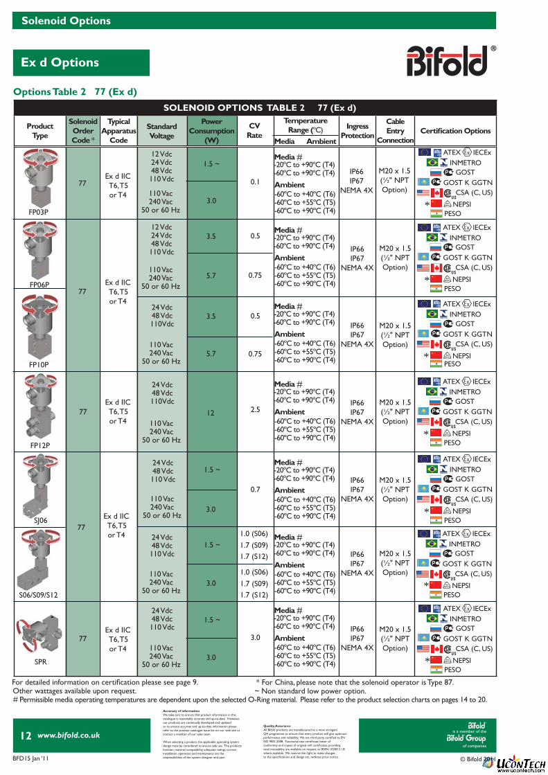
Ex d Options
Accuracy of informationWe take care to ensure that product information in thiscatalogue is reasonably accurate and up-to-date. However,our products are continually developed and updatedso to ensure accurate and up-to-date information pleaserefer to the product catalogue issue list on our web site orcontact a member of our sales team.
When selecting a product, the applicable operating systemdesign must be considered to ensure safe use. The productsfunction, material compatibility, adequate ratings, correctinstallation, operation and maintenance are theresponsibilities of the system designer and user.
Quality AssuranceAll Bifold products are manufactured to a most stringentQA programme to ensure that every product will give optimumperformance and reliability. We are third party certifi ed to EN ISO 9001:2008. Functional test certifi cate, letter ofconformity and copies of original mill certifi cates, providingtotal traceability are available on request, to BSEN 10204.3.1.Bwhere available. We reserve the right to make changesto the specifi cations and design etc., without prior notice.
Options Table 2 77 (Ex d)
*
* For China, please note that the solenoid operator is Type 87.~ Non standard low power option.Other wattages available upon request.
For detailed information on certifi cation please see page 9.
# Permissible media operating temperatures are dependent upon the selected O-Ring material. Please refer to the product selection charts on pages 14 to 20.
#
#
#
#
#
#
#
ProductType
SolenoidOrderCode *
TypicalApparatus
Code
IngressProtection
CableEntry
ConnectionCertifi cation Options
5.7
3.0
5.7
12
3.5
1.5 ~
1.5 ~
1.5 ~
1.5 ~
3.5
3.0
3.0
3.0
Ex d IIC T6, T5or T4
Ex d IIC T6, T5or T4
Ex d IIC T6, T5or T4
Ex d IIC T6, T5or T4
Ex d IIC T6, T5or T4
77
77
77
77
77
FP06P
FP10P
FP12P
SJ06
S06/S09/S12
SPR
12 Vdc24 Vdc48 Vdc110 Vdc
12 Vdc24 Vdc48 Vdc110 Vdc
24 Vdc48 Vdc110Vdc
24 Vdc48 Vdc110Vdc
24 Vdc48 Vdc110 Vdc
24 Vdc48 Vdc110 Vdc
24 Vdc48 Vdc110 Vdc
Standard Voltage
CVRate
PowerConsumption
(W)
IP66IP67
NEMA 4X
IP66IP67
NEMA 4X
IP66IP67
NEMA 4X
IP66IP67
NEMA 4X
IP66IP67
NEMA 4X
IP66IP67
NEMA 4X
IP66IP67
NEMA 4X
0.75
0.75
0.5
0.1
0.5
2.5
0.7
3.0
M20 x 1.5(½" NPTOption)
M20 x 1.5(½" NPTOption)
M20 x 1.5(½" NPTOption)
M20 x 1.5(½" NPTOption)
M20 x 1.5(½" NPTOption)
M20 x 1.5(½" NPTOption)
M20 x 1.5(½" NPTOption)
TemperatureRange (ºC)
Media Ambient
110 Vac240 Vac
50 or 60 Hz
110 Vac240 Vac
50 or 60 Hz
110 Vac240 Vac
50 or 60 Hz
110 Vac240 Vac
50 or 60 Hz
110 Vac240 Vac
50 or 60 Hz
110 Vac240 Vac
50 or 60 Hz
110 Vac240 Vac
50 or 60 Hz
ATEX IECEx
ATEX IECEx
ATEX IECEx
ATEX IECEx
ATEX IECEx
ATEX IECEx
ATEX IECEx
INMETRO
INMETRO
INMETRO
INMETRO
INMETRO
INMETRO
INMETRO
GOST
GOST
GOST
GOST
GOST
GOST
GOST
GOST K GGTN
GOST K GGTN
GOST K GGTN
GOST K GGTN
GOST K GGTN
GOST K GGTN
GOST K GGTN
CSA (C, US)
CSA (C, US)
CSA (C, US)
CSA (C, US)
CSA (C, US)
CSA (C, US)
CSA (C, US)
NEPSI
NEPSI
NEPSI
NEPSI
NEPSI
NEPSI
NEPSI
PESO
PESO
PESO
PESO
PESO
PESO
PESO
-60ºC to +40ºC (T6)-60ºC to +55ºC (T5)-60ºC to +90ºC (T4)
-60ºC to +40ºC (T6)-60ºC to +55ºC (T5)-60ºC to +90ºC (T4)
-60ºC to +40ºC (T6)-60ºC to +55ºC (T5)-60ºC to +90ºC (T4)
-60ºC to +40ºC (T6)-60ºC to +55ºC (T5)-60ºC to +90ºC (T4)
-60ºC to +40ºC (T6)-60ºC to +55ºC (T5)-60ºC to +90ºC (T4)
-60ºC to +40ºC (T6)-60ºC to +55ºC (T5)-60ºC to +90ºC (T4)
-60ºC to +40ºC (T6)-60ºC to +55ºC (T5)-60ºC to +90ºC (T4)
Media
Media
Media
Media
Media
Media
Media
Ambient
Ambient
Ambient
Ambient
Ambient
Ambient
Ambient
-20ºC to +90ºC (T4)-60ºC to +90ºC (T4)
-20ºC to +90ºC (T4)-60ºC to +90ºC (T4)
-20ºC to +90ºC (T4)-60ºC to +90ºC (T4)
-20ºC to +90ºC (T4)-60ºC to +90ºC (T4)
-20ºC to +90ºC (T4)-60ºC to +90ºC (T4)
-20ºC to +90ºC (T4)-60ºC to +90ºC (T4)
-20ºC to +90ºC (T4)-60ºC to +90ºC (T4)
FP03P*
*
*
*
*
*
1.0 (S06)
1.0 (S06)
1.7 (S09)
1.7 (S09)
1.7 (S12)
1.7 (S12)
SOLENOID OPTIONS TABLE 2 77 (Ex d)
is a member of the
of companies
www.bifold.co.uk
BFD15 Jan ‘11 © Bifold 2011
13
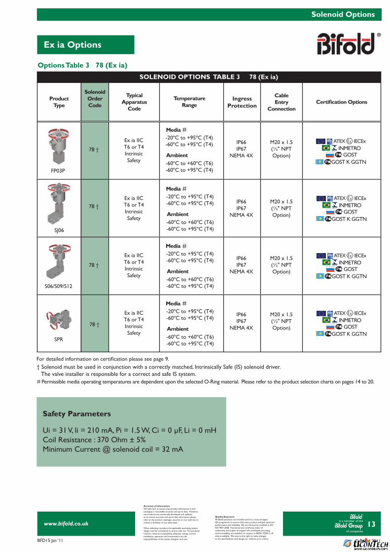
Ex ia Options
Solenoid Options
Accuracy of informationWe take care to ensure that product information in thiscatalogue is reasonably accurate and up-to-date. However,our products are continually developed and updatedso to ensure accurate and up-to-date information pleaserefer to the product catalogue issue list on our web site orcontact a member of our sales team.
When selecting a product, the applicable operating systemdesign must be considered to ensure safe use. The productsfunction, material compatibility, adequate ratings, correctinstallation, operation and maintenance are theresponsibilities of the system designer and user.
Quality AssuranceAll Bifold products are manufactured to a most stringentQA programme to ensure that every product will give optimumperformance and reliability. We are third party certifi ed to EN ISO 9001:2008. Functional test certifi cate, letter ofconformity and copies of original mill certifi cates, providingtotal traceability are available on request, to BSEN 10204.3.1.Bwhere available. We reserve the right to make changesto the specifi cations and design etc., without prior notice.
Options Table 3 78 (Ex ia)
For detailed information on certifi cation please see page 9.
# Permissible media operating temperatures are dependent upon the selected O-Ring material. Please refer to the product selection charts on pages 14 to 20.
#
#
#
#
† Solenoid must be used in conjunction with a correctly matched, Intrinsically Safe (IS) solenoid driver. The valve installer is responsible for a correct and safe IS system.
Safety Parameters
Ui = 31 V, Ii = 210 mA, Pi = 1.5 W, Ci = 0 μF, Li = 0 mHCoil Resistance : 370 Ohm ± 5%Minimum Current @ solenoid coil = 32 mA
ProductType
Solenoid OrderCode
TypicalApparatus
Code
IngressProtection
Cable Entry
ConnectionCertifi cation Options
Ex ia IIC T6 or T4IntrinsicSafety
Ex ia IIC T6 or T4IntrinsicSafety
Ex ia IIC T6 or T4IntrinsicSafety
Ex ia IIC T6 or T4IntrinsicSafety
78 †
78 †
78 †
78 †
FP03P-60ºC to +60ºC (T6)-60ºC to +95ºC (T4)
-60ºC to +60ºC (T6)-60ºC to +95ºC (T4)
-60ºC to +60ºC (T6)-60ºC to +95ºC (T4)
-60ºC to +60ºC (T6)-60ºC to +95ºC (T4)
INMETRO
INMETRO
INMETRO
INMETRO
GOST
GOST
GOST
GOST
GOST K GGTN
GOST K GGTN
GOST K GGTN
GOST K GGTN
IP66IP67
NEMA 4X
IP66IP67
NEMA 4X
IP66IP67
NEMA 4X
IP66IP67
NEMA 4X
M20 x 1.5(½" NPT Option)
M20 x 1.5(½" NPT Option)
M20 x 1.5(½" NPT Option)
M20 x 1.5(½" NPT Option)
TemperatureRange
Media
Media
Media
Media
Ambient
Ambient
Ambient
Ambient
ATEX IECEx
ATEX IECEx
ATEX IECEx
ATEX IECEx
-20ºC to +95ºC (T4)-60ºC to +95ºC (T4)
-20ºC to +95ºC (T4)-60ºC to +95ºC (T4)
-20ºC to +95ºC (T4)-60ºC to +95ºC (T4)
-20ºC to +95ºC (T4)-60ºC to +95ºC (T4)
SJ06
S06/S09/S12
SPR
SOLENOID OPTIONS TABLE 3 78 (Ex ia)

is a member of the
of companies
www.bifold.co.uk
BFD15 Jan ‘11 © Bifold 2011
14
FP03P Selection Chart
FP03P
Accuracy of informationWe take care to ensure that product information in thiscatalogue is reasonably accurate and up-to-date. However,our products are continually developed and updatedso to ensure accurate and up-to-date information pleaserefer to the product catalogue issue list on our web site orcontact a member of our sales team.
When selecting a product, the applicable operating systemdesign must be considered to ensure safe use. The productsfunction, material compatibility, adequate ratings, correctinstallation, operation and maintenance are theresponsibilities of the system designer and user.
Quality AssuranceAll Bifold products are manufactured to a most stringentQA programme to ensure that every product will give optimumperformance and reliability. We are third party certifi ed to EN ISO 9001:2008. Functional test certifi cate, letter ofconformity and copies of original mill certifi cates, providingtotal traceability are available on request, to BSEN 10204.3.1.Bwhere available. We reserve the right to make changesto the specifi cations and design etc., without prior notice.
AC VOLTAGE
SOLENOIDCASE
WINDING
77 SOLENOID(EExd)
RED + BLACK -
DC VOLTAGE
SOLENOIDCASE
WINDING
CONNECTIONS AREBI-POLAR
74 SOLENOID(EExemb)
BLACK -
RED +
WIN
DIN
G
78 SOLENOID(EExia)
BLACK -
RED +
Wiring DiagramsSCHEMATIC 3/2 NC
1
3
2
1
3
2
SCHEMATIC 2/2 NC
1
3
2
SCHEMATIC 2/2 NO
M20 x 1.5PCABLE ENTRY
EXTERNALEARTH STUD
TYPE ‘M’OVERRIDEOPTION
MOUNTING POSITIONS2 x Ø5.5 THRO' HOLES
1
32
155.
4
37.1
14
25
124.
6
68 86.5
50
26.2
13.8
28 538.1 q
= =
34
50.5
180.
1
Dimensional Drawings
FP03P Selection Chart - Ordering Example
For green block sections, please refer to the same colour section on pages 11, 12 or 13.* For China, please note that the solenoid operator is Type 87.** Special conditions for safe use - The supply circuit shall be fi tted with a fuse capable of meeting a 1500Amp short circuit current.
FP03P Model Code
Connections
Valve Confi guration
O-ring Material
Solenoid Approval
T-Rating & Gas Group
Voltage
Solenoid ***
OptionOption
Options
Revision Number
Resistance
Power
Ordering Example
XX Refer to Solenoid options tables.
XXX Voltage, refer to Solenoid option tables.
XX
XX Resistance (Ω)
M1 Manifold mount - For use with Axis Manifold System OnlyM7 Manifold mount stacker - For use with Axis Manifold System Only 02 1⁄8" NPT body ported - Shown above
A ATEX/IECEx Dual Certifi ed/LabelledG GOST I INMETRON NEPSI*U CSA (US) ATEX Dual Certified/Labelled
3 T4 IIC 77 (Ex d)6 T5 IIC 77 (Ex d) 9 T6 IIC 77 (Ex d)`
74(Ex emb) 77(Ex d) 78(Ex ia)
FP03P 02 32 NC V 9 24D 30ML XXK85K677 A
32 3-way, 2-positionNC Normally Closed
V Viton (Standard) (-20ºC to +180ºC)AL Flurosilicone (-60ºC to +180ºC)
XX Power (W)
x xx
x xx x
78 (Ex ia) - 370 Ohms Page 13 - Table 3
74 (Ex emb) Page 11 - Table 1
74 (Ex emb) Page 11 - Table 1
77 (Ex d) - 1.5 & 3.0 Watts Page 12 - Table 2
77 (Ex d) Page 12 - Table 2
77 (Ex d) Page 12 - Table 2
78 (Ex ia) Page 13 - Table 3
78 (Ex ia) Page 13 - Table 3
74 (Ex emb)- 1.8 & 3.6Watts Page 11 - Table 1
K85 ½ " NPT cable entry
See 'T' Rating Limitations for Ex emb,Ex d & Ex ia on pages 11, 12 & 13.
M Electrical to switch or temporary manual overrideML Electrical and manual required to latch or temporary manual override (3.0 Watts Ex d Only)MLT Electrical and manual required to latch - tamperproof
K6 BSPP Ports
For maximum operating temperaturessee 'T' Rating Limitations for Ex emb,Ex d & Ex ia on pages 11, 12 & 13.
is a member of the
of companies
www.bifold.co.uk
BFD15 Jan ‘11 © Bifold 2011
15
FP06P Selection Chart
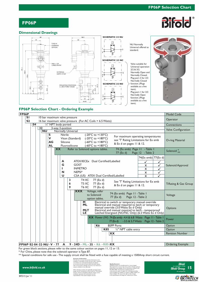
FP06P
Accuracy of informationWe take care to ensure that product information in thiscatalogue is reasonably accurate and up-to-date. However,our products are continually developed and updatedso to ensure accurate and up-to-date information pleaserefer to the product catalogue issue list on our web site orcontact a member of our sales team.
When selecting a product, the applicable operating systemdesign must be considered to ensure safe use. The productsfunction, material compatibility, adequate ratings, correctinstallation, operation and maintenance are theresponsibilities of the system designer and user.
Quality AssuranceAll Bifold products are manufactured to a most stringentQA programme to ensure that every product will give optimumperformance and reliability. We are third party certifi ed to EN ISO 9001:2008. Functional test certifi cate, letter ofconformity and copies of original mill certifi cates, providingtotal traceability are available on request, to BSEN 10204.3.1.Bwhere available. We reserve the right to make changesto the specifi cations and design etc., without prior notice.
NU Normally Universal offered as standard.
Valve suitable for Universal operation2/2 & 3/2.Normally Open and Normally Closed.Plug port 3 for 2/2Normally Closedfunction. (Plugsavailable as a lineitem).Plug port 1 for 2/2 Normally Openfunction. (Plugsavailable as a line item).
1
3
2
SCHEMATIC 2/2 NC
1
3
2
SCHEMATIC 2/2 NO
SCHEMATIC 3/2 NU
1
3
2
M20 x 1.5PCABLE ENTRY
1
32MOUNTING POSITIONS
2 x Ø5.5 THRO' HOLES
68
34
33.5
22
46.5
135.
6
166.
4191.
1
86.5
50
32
= =
6.2
44.45
25.4
17.5 33
.5
61.5
EXTERNALEARTH STUD
TYPE ‘M’OVERRIDEOPTION
Dimensional Drawings
FP06P Selection Chart - Ordering Example
For green block sections, please refer to the same colour section on pages 11, 12 or 13.* For China, please note that the solenoid operator is Type 87.** Special conditions for safe use - The supply circuit shall be fi tted with a fuse capable of meeting a 1500Amp short circuit current.
FP06P Model Code
Operator
Connections
Valve Confi guration
O-ring Material
Solenoid Approval
T-Rating & Gas Group
Voltage
OptionOption
Options
Revision Number
Power
Ordering Example
XX Refer to Solenoid options tables. 74 (Ex emb) Page 11 - Table 1 77 (Ex d) Page 12 - Table 2
XXX Voltage, refer to Solenoid option tables.
XX
S1 10 bar maximum valve pressureS2 16 bar maximum valve pressure (For AC Coils = 6.5 Watts)
A ATEX/IECEx Dual Certifi ed/LabelledG GOST I INMETRON NEPSI*U CSA (US) ATEX Dual Certified/Labelled
3 T4 IIC 77 (Ex d)6 T5 IIC 77 (Ex d) 9 T6 IIC 77 (Ex d)
74(Ex emb) 77(Ex d)
FP06P S2 04 32 NU V 9 24D ML 35 K85K6 XX77 A
04 ¼" NPT body ported32 3-way, 2-position
NU Normally UniversalS Nitrile (-20ºC to +130ºC)V Viton (Standard) (-20ºC to +180ºC)AG Silicone (-60ºC to +180ºC)AL Fluorosilicone (-60ºC to +180ºC)
XX Power (W)
xx
xx
77 (Ex d) Page 12 - Table 2
77 (Ex d) - 3.5 & 5.7 Watts Page 12 - Table 2
74 (Ex emb) Page 11 - Table 1
74 (Ex emb) - 4.4 & 6.8 Watts Page 11 - Table 1
K6 BSPP Ports
K85 ½ " NPT cable entry
M Electrical to switch or temporary manual overrideML Electrical and manual required to latch or temporary manual override (3.0 Watts Ex d Only)MLT Electrical and manual required to latch - tamperproofLE Latched Energised (NO/NC Only) (6.5 Watts Ex d Only)
For maximum operating temperaturessee 'T' Rating Limitations for Ex emb& Ex d on pages 11 & 12.
See 'T' Rating Limitations for Ex emb& Ex d on pages 11 & 12.
Solenoid ***
is a member of the
of companies
www.bifold.co.uk
BFD15 Jan ‘11 © Bifold 2011
16
FP10P Selection Chart
FP10P
Accuracy of informationWe take care to ensure that product information in thiscatalogue is reasonably accurate and up-to-date. However,our products are continually developed and updatedso to ensure accurate and up-to-date information pleaserefer to the product catalogue issue list on our web site orcontact a member of our sales team.
When selecting a product, the applicable operating systemdesign must be considered to ensure safe use. The productsfunction, material compatibility, adequate ratings, correctinstallation, operation and maintenance are theresponsibilities of the system designer and user.
Quality AssuranceAll Bifold products are manufactured to a most stringentQA programme to ensure that every product will give optimumperformance and reliability. We are third party certifi ed to EN ISO 9001:2008. Functional test certifi cate, letter ofconformity and copies of original mill certifi cates, providingtotal traceability are available on request, to BSEN 10204.3.1.Bwhere available. We reserve the right to make changesto the specifi cations and design etc., without prior notice.
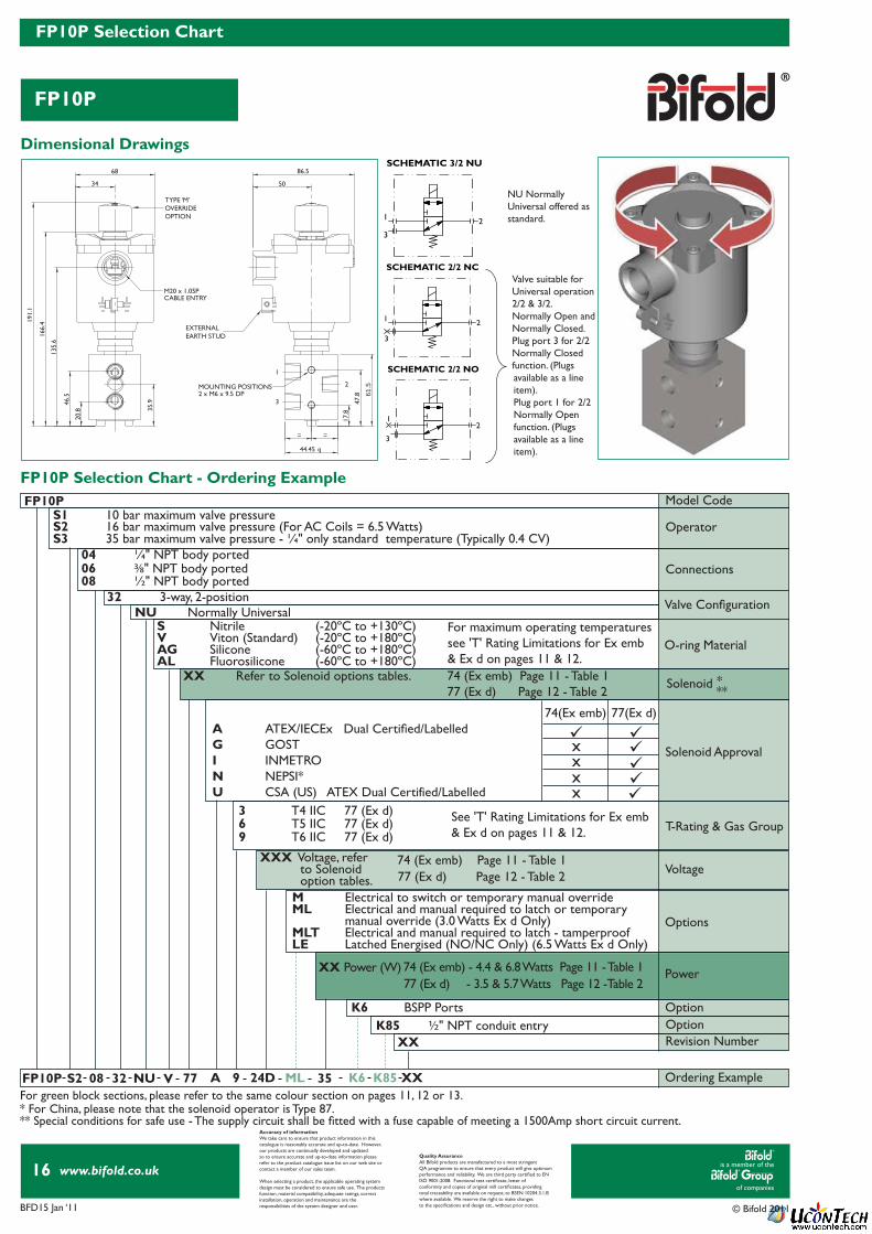
NU Normally Universal offered as standard.
Valve suitable for Universal operation2/2 & 3/2.Normally Open and Normally Closed.Plug port 3 for 2/2Normally Closedfunction. (Plugsavailable as a lineitem).Plug port 1 for 2/2 Normally Openfunction. (Plugsavailable as a line item).
1
3
2
SCHEMATIC 2/2 NC
1
3
2
SCHEMATIC 2/2 NO
SCHEMATIC 3/2 NU
1
3
2
M20 x 1.05PCABLE ENTRY
1
3
2MOUNTING POSITIONS2 x M6 x 9.5 DP
68
34
46.5
135.
6
166.
4191.
1
86.5
50
44.45 q
61.5
=
20.8 35
.9
=
17.8
47.8
EXTERNALEARTH STUD
TYPE ‘M’OVERRIDEOPTION
Dimensional Drawings
FP10P Selection Chart - Ordering Example
For green block sections, please refer to the same colour section on pages 11, 12 or 13.* For China, please note that the solenoid operator is Type 87.** Special conditions for safe use - The supply circuit shall be fi tted with a fuse capable of meeting a 1500Amp short circuit current.
FP10P Model Code
Operator
Connections
Valve Confi guration
O-ring Material
Solenoid Approval
T-Rating & Gas Group
Voltage
OptionOption
Options
Revision Number
Power
Ordering Example
XXX Voltage, refer to Solenoid option tables.
XX
S1 10 bar maximum valve pressure
04 ¼" NPT body ported
3 T4 IIC 77 (Ex d)6 T5 IIC 77 (Ex d) 9 T6 IIC 77 (Ex d)
FP10P S2 08 32 NU V 9 24D ML 35 K6 K85 XX77 A
32 3-way, 2-positionNU Normally Universal
S Nitrile (-20ºC to +130ºC)V Viton (Standard) (-20ºC to +180ºC)AG Silicone (-60ºC to +180ºC)AL Fluorosilicone (-60ºC to +180ºC)
K6 BSPP Ports
S2 16 bar maximum valve pressure (For AC Coils = 6.5 Watts) S3 35 bar maximum valve pressure - ¼" only standard temperature (Typically 0.4 CV)
06 3⁄8" NPT body ported08 ½" NPT body ported
XX Power (W)
K85 ½ " NPT conduit entry
A ATEX/IECEx Dual Certifi ed/LabelledG GOST I INMETRON NEPSI*U CSA (US) ATEX Dual Certified/Labelled
74(Ex emb) 77(Ex d)
xx
xx
77 (Ex d) Page 12 - Table 2 74 (Ex emb) Page 11 - Table 1
77 (Ex d) - 3.5 & 5.7 Watts Page 12 -Table 2 74 (Ex emb) - 4.4 & 6.8 Watts Page 11 - Table 1
M Electrical to switch or temporary manual overrideML Electrical and manual required to latch or temporary manual override (3.0 Watts Ex d Only)MLT Electrical and manual required to latch - tamperproofLE Latched Energised (NO/NC Only) (6.5 Watts Ex d Only)
XX Refer to Solenoid options tables. 74 (Ex emb) Page 11 - Table 1 77 (Ex d) Page 12 - Table 2
For maximum operating temperaturessee 'T' Rating Limitations for Ex emb& Ex d on pages 11 & 12.
See 'T' Rating Limitations for Ex emb& Ex d on pages 11 & 12.
Solenoid ***

is a member of the
of companies
www.bifold.co.uk
BFD15 Jan ‘11 © Bifold 2011
17
FP12P Selection Chart
FP12P
Accuracy of informationWe take care to ensure that product information in thiscatalogue is reasonably accurate and up-to-date. However,our products are continually developed and updatedso to ensure accurate and up-to-date information pleaserefer to the product catalogue issue list on our web site orcontact a member of our sales team.
When selecting a product, the applicable operating systemdesign must be considered to ensure safe use. The productsfunction, material compatibility, adequate ratings, correctinstallation, operation and maintenance are theresponsibilities of the system designer and user.
Quality AssuranceAll Bifold products are manufactured to a most stringentQA programme to ensure that every product will give optimumperformance and reliability. We are third party certifi ed to EN ISO 9001:2008. Functional test certifi cate, letter ofconformity and copies of original mill certifi cates, providingtotal traceability are available on request, to BSEN 10204.3.1.Bwhere available. We reserve the right to make changesto the specifi cations and design etc., without prior notice.
NU Normally Universal offered as standard.
Valve suitable for universal operation2/2 & 3/2.Normally Open and Normally Closed.Plug port 3 for 2/2Normally Closedfunction. (Plugsavailable as a lineitem).Plug port 1 for 2/2 Normally Openfunction. (Plugsavailable as a line item).
1
3
2
SCHEMATIC 2/2 NC
1
3
2
SCHEMATIC 2/2 NO
SCHEMATIC 3/2 NU
1
3
2
M20 x 1.5PCONDUIT ENTRY
1
3
2
MOUNTING POSITIONS2 x M6 x 10 DP
68
200.
8225.
5
86.5
96
44.45 q
102.8
26.5
61
170
34 50
43.8
8.527.8
19.5
67
EXTERNALEARTH STUD
TYPE ‘M’OVERRIDEOPTION
FP12P Selection Chart - Ordering Example
Dimensional Drawings
For green block sections, please refer to the same colour section on page 12.* For China, please note that the solenoid operator is Type 87.
FP12P Model Code OperatorConnections
Valve Confi guration
O-ring Material
Solenoid Approval
T-Rating & Gas Group
Options
Solenoid *
Power
Revision Number
OptionOption
Ordering Example
XX
S1 10 bar maximum valve pressure - standard08 ½ " NPT body ported
32 3-way, 2-position
K6 BSPP ports
120 12 Watts - auto reset65 6.5 Watts - manual reset only (ML)
NU Normally Universal
S Nitrile (-20ºC to +130ºC)V Viton (standard) (-20ºC to +180ºC)AG Silicone (-60ºC to +180ºC) AL Fluorosilicone (-60ºC to +180ºC)
FP12P S1 08 32 NU A 9 24D ML 65 K6 K85 XXV 77
VoltageXXX Voltage, refer to Solenoid option tables
3 T4 IIC 77 (Ex d)6 T5 IIC 77 (Ex d) 9 T6 IIC 77 (Ex d)
XX Refer to Solenoid options tables. 77 (Ex d) Page 12 - Table 2
K85 ½ " NPT conduit entry
A ATEX/IECEx Dual Certifi ed/LabelledG GOST I INMETRON NEPSI*U CSA (US) ATEX Dual Certified/Labelled
77(Ex d)
77 (Ex d) Page 12 - Table 2
For maximum operating temperaturessee 'T' Rating Limitations for Ex don page 12.
See 'T' Rating Limitations for Ex don page 12.
M Electrical to switch or temporary manual overrideML Electrical and manual required to latch or temporary manual override (3.0 Watts Ex d Only)MLT Electrical and manual required to latch - tamperproof
Page 12 - Table 2
is a member of the
of companies
www.bifold.co.uk
BFD15 Jan ‘11 © Bifold 2011
18
SJ06 Selection Chart
SJ06
Accuracy of informationWe take care to ensure that product information in thiscatalogue is reasonably accurate and up-to-date. However,our products are continually developed and updatedso to ensure accurate and up-to-date information pleaserefer to the product catalogue issue list on our web site orcontact a member of our sales team.
When selecting a product, the applicable operating systemdesign must be considered to ensure safe use. The productsfunction, material compatibility, adequate ratings, correctinstallation, operation and maintenance are theresponsibilities of the system designer and user.
Quality AssuranceAll Bifold products are manufactured to a most stringentQA programme to ensure that every product will give optimumperformance and reliability. We are third party certifi ed to EN ISO 9001:2008. Functional test certifi cate, letter ofconformity and copies of original mill certifi cates, providingtotal traceability are available on request, to BSEN 10204.3.1.Bwhere available. We reserve the right to make changesto the specifi cations and design etc., without prior notice.
2
1
3
T
SCHEMATIC 3/2 NO
1
23
T
SCHEMATIC 3/2 NC
MOUNTING POSITIONS2 x Ø5.5 THRO' HOLES
VIEW OF DETAIL 'A'
M20 x 1.5PCABLE ENTRY
1 32
1/8" NPTPILOT VENT
196.
6
165.
8
1531.4
48
34
68
19
31.4
28=
=
221.
3
86.5
50
38.1
59.5
93.5
DETAIL A
EXTERNALEARTH STUD
TYPE ‘M’OVERRIDEOPTION
Dimensional Drawings
SJ06 Selection Chart - Ordering Example
For green block sections, please refer to the same colour section on pages 11, 12 or 13.* For China, please note that the solenoid operator is Type 87.** Special conditions for safe use - The supply circuit shall be fi tted with a fuse capable of meeting a 1500Amp short circuit current.
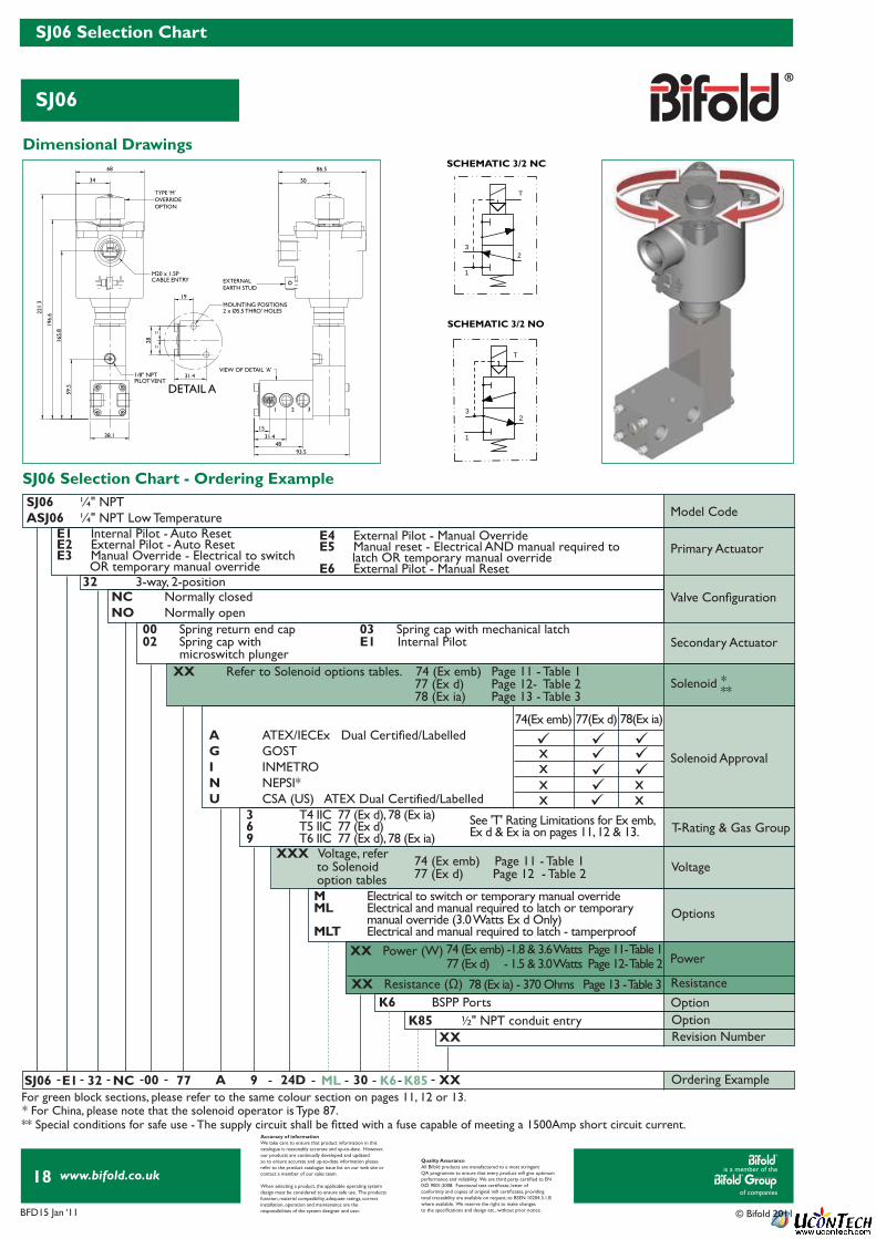
00 Spring return end cap02 Spring cap with microswitch plunger
03 Spring cap with mechanical latchE1 Internal Pilot
SJ06 ¼" NPTASJ06 ¼" NPT Low Temperature Model Code
Primary Actuator
Secondary Actuator
Valve Confi guration
Solenoid Approval
See 'T' Rating Limitations for Ex emb,Ex d & Ex ia on pages 11, 12 & 13.
T-Rating & Gas Group
Voltage
OptionOptionRevision Number
Options
Ordering Example
XX Refer to Solenoid options tables. 74 (Ex emb) Page 11 - Table 1 77 (Ex d) Page 12- Table 2 78 (Ex ia) Page 13 - Table 3
XX
XX Resistance (Ω)
3 T4 IIC 77 (Ex d), 78 (Ex ia)6 T5 IIC 77 (Ex d) 9 T6 IIC 77 (Ex d), 78 (Ex ia)
SJ06 E1 32 NC 00 9 24D 30ML K85K6 XX77 A
32 3-way, 2-positionNC Normally closedNO Normally open
XX Power (W)
78 (Ex ia) - 370 Ohms Page 13 - Table 3 K6 BSPP Ports
K85 ½ " NPT conduit entry
A ATEX/IECEx Dual Certifi ed/LabelledG GOST I INMETRON NEPSI*U CSA (US) ATEX Dual Certified/Labelled
74(Ex emb) 77(Ex d) 78(Ex ia)
xx
x xx x
77 (Ex d) - 1.5 & 3.0 Watts Page 12- Table 2 74 (Ex emb) -1.8 & 3.6 Watts Page 11- Table 1
XXX Voltage, refer to Solenoid option tables
77 (Ex d) Page 12 - Table 2 74 (Ex emb) Page 11 - Table 1
Resistance
Power
E1 Internal Pilot - Auto Reset E2 External Pilot - Auto Reset E3 Manual Override - Electrical to switch OR temporary manual override
E4 External Pilot - Manual Override E5 Manual reset - Electrical AND manual required to latch OR temporary manual overrideE6 External Pilot - Manual Reset
M Electrical to switch or temporary manual overrideML Electrical and manual required to latch or temporary manual override (3.0 Watts Ex d Only)MLT Electrical and manual required to latch - tamperproof
Solenoid ***
is a member of the
of companies
www.bifold.co.uk
BFD15 Jan ‘11 © Bifold 2011
19
S06/S09/S12 Selection Chart
S06/S09/S12
Accuracy of informationWe take care to ensure that product information in thiscatalogue is reasonably accurate and up-to-date. However,our products are continually developed and updatedso to ensure accurate and up-to-date information pleaserefer to the product catalogue issue list on our web site orcontact a member of our sales team.
When selecting a product, the applicable operating systemdesign must be considered to ensure safe use. The productsfunction, material compatibility, adequate ratings, correctinstallation, operation and maintenance are theresponsibilities of the system designer and user.
Quality AssuranceAll Bifold products are manufactured to a most stringentQA programme to ensure that every product will give optimumperformance and reliability. We are third party certifi ed to EN ISO 9001:2008. Functional test certifi cate, letter ofconformity and copies of original mill certifi cates, providingtotal traceability are available on request, to BSEN 10204.3.1.Bwhere available. We reserve the right to make changesto the specifi cations and design etc., without prior notice.
2
1
3
T
SCHEMATIC 3/2 NO
1
23
T
SCHEMATIC 3/2 NC
MOUNTING POSITIONS3 x Ø5.2 THRO' HOLES
VIEW OF DETAIL 'A'
M20 x 1.5PCABLE ENTRY
1 32
1/8" NPTPILOT VENT
187.
9
68
212.
5
86.5
50.8
38
==
34
36.4
20.7
52.2
36.352.2
67.4
50
157.
1
50.8
125.3
DETAIL A
EXTERNALEARTH STUD
TYPE ‘M’OVERRIDEOPTION
S06/S09/S12 Selection Chart - Ordering Example
Dimensional Drawings
For green block sections, please refer to the same colour section on pages 11, 12 or 13.* For China, please note that the solenoid operator is Type 87.** Special conditions for safe use - The supply circuit shall be fi tted with a fuse capable of meeting a 1500Amp short circuit current.
Model Code
Primary Actuator
Valve Confi guration
Valve Confi guration
Secondary Actuator
Solenoid Approval
T-Rating & Gas Group
Options
Resistance
Revision Number
Power
OptionOption
Ordering Example
XX
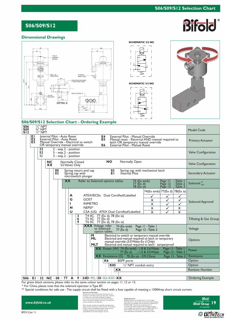
K6 BSPP ports
22 2 - way, 2 - position52 5 - way, 2 - position32 3 - way, 2 - position
S06 E1 32 NC A 9 24D ML 30 K6 K85 XX00 77
Voltage
3 T4 IIC 77 (Ex d), 78 (Ex ia)6 T5 IIC 77 (Ex d) 9 T6 IIC 77 (Ex d), 78 (Ex ia)
NC Normally ClosedXX 52 Valves Only
00 Spring return end cap02 Spring cap with microswitch plunger
03 Spring cap with mechanical latchE1 Internal Pilot
S06 ¼" NPT S09 3⁄8" NPT S12 ½" NPT
E1 Internal Pilot - Auto Reset E2 External Pilot - Auto Reset E3 Manual Override - Electrical to switch OR temporary manual override
XX Refer to Solenoid options tables. 74 (Ex emb) Page 11 - Table 1 77 (Ex d) Page 12 - Table 2 78 (Ex ia) Page 13 - Table 3
XX Resistance (Ω)
XX Power (W)
78 (Ex ia) - 370 Ohms Page 13 - Table 3
A ATEX/IECEx Dual Certifi ed/LabelledG GOST I INMETRON NEPSI* U CSA (US) ATEX Dual Certified/Labelled
74(Ex emb) 77(Ex d) 78(Ex ia)
xx
xx
K85 ½ " NPT conduit entry
XXX Voltage, refer to Solenoid option tables.
77 (Ex d) Page 12 - Table 2
77 (Ex d) - 1.5 & 3.0 Watts Page 12 - Table 2
74 (Ex emb) Page 11 - Table 1
74 (Ex emb) - 1.8 & 3.6 Watts Page 11 - Table 1
xx
E4 External Pilot - Manual Override E5 Manual reset - Electrical AND manual required to latch OR temporary manual overrideE6 External Pilot - Manual Reset
NO Normally Open
M Electrical to switch or temporary manual overrideML Electrical and manual required to latch or temporary manual override (3.0 Watts Ex d Only)MLT Electrical and manual required to latch - tamperproof
Solenoid ***
is a member of the
of companies
www.bifold.co.uk
BFD15 Jan ‘11 © Bifold 2011
20
SPR Selection Chart
SPR
Accuracy of informationWe take care to ensure that product information in thiscatalogue is reasonably accurate and up-to-date. However,our products are continually developed and updatedso to ensure accurate and up-to-date information pleaserefer to the product catalogue issue list on our web site orcontact a member of our sales team.
When selecting a product, the applicable operating systemdesign must be considered to ensure safe use. The productsfunction, material compatibility, adequate ratings, correctinstallation, operation and maintenance are theresponsibilities of the system designer and user.
Quality AssuranceAll Bifold products are manufactured to a most stringentQA programme to ensure that every product will give optimumperformance and reliability. We are third party certifi ed to EN ISO 9001:2008. Functional test certifi cate, letter ofconformity and copies of original mill certifi cates, providingtotal traceability are available on request, to BSEN 10204.3.1.Bwhere available. We reserve the right to make changesto the specifi cations and design etc., without prior notice.
1
3
2
M20 x 1.5PCABLE ENTRY
VIEW OF DETAIL 'A'
MOUNTING POSITIONS2 x M5 x 9 DP
162.
2
86.5
128.
2
180
38.1 96.5
50 155.4
44.7
77.7
24==
124.6
37.7
61.2
84.7
DETAIL A
EXTERNALEARTH STUD
TYPE ‘M’OVERRIDEOPTION
23
1
T
SCHEMATIC 3/2 NU
Dimensional Drawings
SPR Selection Chart - Ordering Example
For green block sections, please refer to the same colour section on pages 11, 12 or 13.* For China, please note that the solenoid operator is Type 87.** Special conditions for safe use - The supply circuit shall be fi tted with a fuse capable of meeting a 1500Amp short circuit current.
Model Code
Primary Actuator
Valve Confi guration
Valve Confi guration
Secondary Actuator
Solenoid Approval
T-Rating & Gas Group
Options
Resistance
Revision Number
Power
OptionOption
Ordering Example
XX
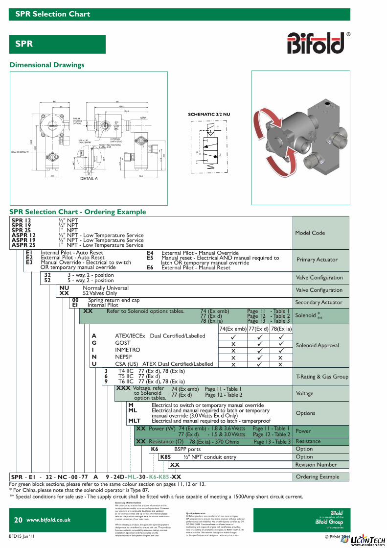
K6 BSPP ports
52 5 - way, 2 - position
SPR E1 32 NC A 9 24D ML 30 K6 K85 XX00 77
Voltage
3 T4 IIC 77 (Ex d), 78 (Ex ia)6 T5 IIC 77 (Ex d) 9 T6 IIC 77 (Ex d), 78 (Ex ia)
NU Normally UniversalXX 52 Valves Only
00 Spring return end capEI Internal Pilot
SPR 12 ½" NPT SPR 19 ¾" NPT SPR 25 1" NPTASPR 12 ½" NPT - Low Temperature ServiceASPR 19 ¾" NPT - Low Temperature ServiceASPR 25 1" NPT - Low Temperature Service E1 Internal Pilot - Auto Reset
E2 External Pilot - Auto Reset E3 Manual Override - Electrical to switch OR temporary manual override
XX Refer to Solenoid options tables. 74 (Ex emb) Page 11 - Table 1 77 (Ex d) Page 12 - Table 2 78 (Ex ia) Page 13 - Table 3
XX Resistance (Ω)
XX Power (W)
78 (Ex ia) - 370 Ohms Page 13 - Table 3
A ATEX/IECEx Dual Certifi ed/LabelledG GOST I INMETRON NEPSI*U CSA (US) ATEX Dual Certified/Labelled
74(Ex emb) 77(Ex d) 78(Ex ia)
xx
xx
K85 ½ " NPT conduit entry
XXX Voltage, refer to Solenoid option tables.
77 (Ex d) Page 12 - Table 2
77 (Ex d) - 1.5 & 3.0 Watts Page 12 - Table 2
74 (Ex emb) Page 11 - Table 1
74 (Ex emb) - 1.8 & 3.6 Watts Page 11 - Table 1
xx
E4 External Pilot - Manual Override E5 Manual reset - Electrical AND manual required to latch OR temporary manual overrideE6 External Pilot - Manual Reset
32 3 - way, 2 - position
M Electrical to switch or temporary manual overrideML Electrical and manual required to latch or temporary manual override (3.0 Watts Ex d Only)MLT Electrical and manual required to latch - tamperproof
Solenoid ***
is a member of the
of companies
www.bifold.co.uk
BFD15 Jan ‘11 © Bifold 2011
21
Accessory Information
Options
Accuracy of informationWe take care to ensure that product information in thiscatalogue is reasonably accurate and up-to-date. However,our products are continually developed and updatedso to ensure accurate and up-to-date information pleaserefer to the product catalogue issue list on our web site orcontact a member of our sales team.
When selecting a product, the applicable operating systemdesign must be considered to ensure safe use. The productsfunction, material compatibility, adequate ratings, correctinstallation, operation and maintenance are theresponsibilities of the system designer and user.
Quality AssuranceAll Bifold products are manufactured to a most stringentQA programme to ensure that every product will give optimumperformance and reliability. We are third party certifi ed to EN ISO 9001:2008. Functional test certifi cate, letter ofconformity and copies of original mill certifi cates, providingtotal traceability are available on request, to BSEN 10204.3.1.Bwhere available. We reserve the right to make changesto the specifi cations and design etc., without prior notice.
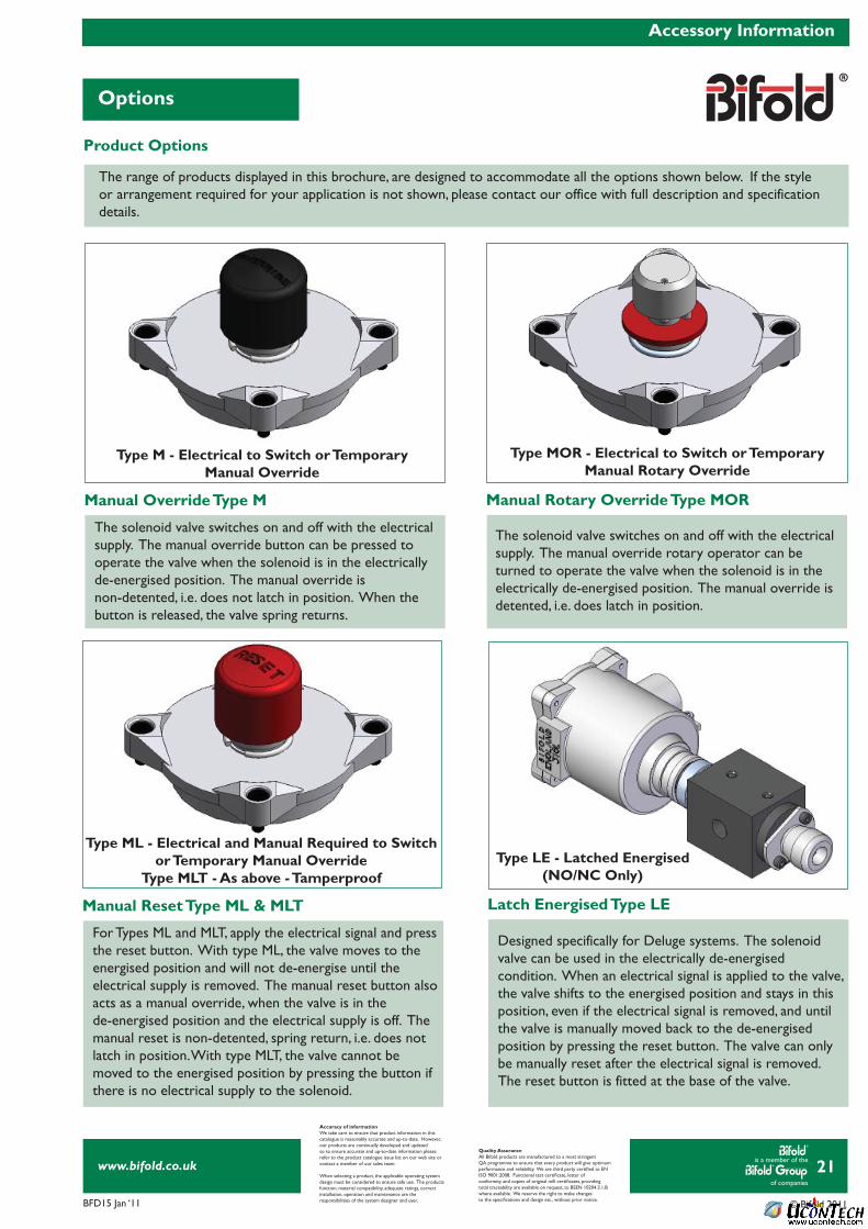
Product Options
Manual Override Type M Manual Rotary Override Type MOR
Latch Energised Type LEManual Reset Type ML & MLT
The range of products displayed in this brochure, are designed to accommodate all the options shown below. If the styleor arrangement required for your application is not shown, please contact our office with full description and specificationdetails.
The solenoid valve switches on and off with the electrical supply. The manual override button can be pressed tooperate the valve when the solenoid is in the electrically de-energised position. The manual override isnon-detented, i.e. does not latch in position. When the button is released, the valve spring returns.
The solenoid valve switches on and off with the electrical supply. The manual override rotary operator can beturned to operate the valve when the solenoid is in theelectrically de-energised position. The manual override isdetented, i.e. does latch in position.
Designed specifically for Deluge systems. The solenoid valve can be used in the electrically de-energisedcondition. When an electrical signal is applied to the valve, the valve shifts to the energised position and stays in this position, even if the electrical signal is removed, and until the valve is manually moved back to the de-energisedposition by pressing the reset button. The valve can only be manually reset after the electrical signal is removed. The reset button is fitted at the base of the valve.
For Types ML and MLT, apply the electrical signal and press the reset button. With type ML, the valve moves to the energised position and will not de-energise until theelectrical supply is removed. The manual reset button also acts as a manual override, when the valve is in thede-energised position and the electrical supply is off. The manual reset is non-detented, spring return, i.e. does not latch in position. With type MLT, the valve cannot bemoved to the energised position by pressing the button if there is no electrical supply to the solenoid.
Type M - Electrical to Switch or TemporaryManual Override
Type LE - Latched Energised(NO/NC Only)
Type MOR - Electrical to Switch or TemporaryManual Rotary Override
Type ML - Electrical and Manual Required to Switch or Temporary Manual Override
Type MLT - As above - Tamperproof