Embed Size (px)
Citation preview
18Direct-Current Circuits
Clicker Questions
Question N2.01
Description: Understanding circuits with parallel resistances.
Question
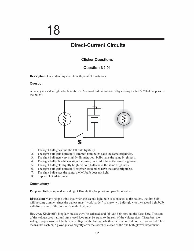
A battery is used to light a bulb as shown. A second bulb is connected by closing switch S. What happens to the bulbs?
1. The right bulb goes out; the left bulb lights up. 2. The right bulb gets noticeably dimmer; both bulbs have the same brightness. 3. The right bulb gets very slightly dimmer; both bulbs have the same brightness. 4. The right bulb’s brightness stays the same; both bulbs have the same brightness. 5. The right bulb gets slightly brighter; both bulbs have the same brightness. 6. The right bulb gets noticeably brighter; both bulbs have the same brightness. 7. The right bulb stays the same; the left bulb does not light. 8. Impossible to determine
Commentary
Purpose: To develop understanding of Kirchhoff’s loop law and parallel resistors.
Discussion: Many people think that when the second light bulb is connected to the battery, the fi rst bulb will become dimmer, since the battery must “work harder” to make two bulbs glow or the second light bulb will divert some of the current from the fi rst bulb.
However, Kirchhoff’s loop law must always be satisfi ed, and this can help sort out the ideas here. The sum of the voltage drops around any closed loop must be equal to the sum of the voltage rises. Therefore, the voltage drop across each bulb is the voltage of the battery, whether there is one bulb or two connected. This means that each bulb glows just as brightly after the switch is closed as the one bulb glowed beforehand.
110
56157_18_ch18_p110-170.indd 11056157_18_ch18_p110-170.indd 110 3/19/08 1:35:14 AM3/19/08 1:35:14 AM
Direct-Current Circuits 111
This does not mean that nothing changes in the circuit. With two bulbs glowing, twice as much current is fl owing through the battery as before, so it is also delivering twice as much power as before, and will run out of energy twice as quickly.
Note that ideal batteries are not sources of constant current. In other words, the same current does not fl ow through the battery at all times. Instead, an ideal battery maintains a certain voltage across its terminals, adjusting the current to make sure the voltage is constant.
If we include the effects of internal resistance in the battery, we expect the terminal voltage to be slightly smaller, which means the bulbs would glow a little less brightly after the switch is closed. However, unless the resistance of each bulb is very small, this effect is not observable.
Key Points:
• For any closed loop in a circuit, the sum of the voltage rises must equal the sum of the voltage drops.
• The current a battery must provide does not affect its voltage signifi cantly; if the battery’s internal resistance is ignored, the voltage is not affected at all.
• Batteries are not sources of constant current. They maintain a certain “terminal voltage” and the current changes to make sure this happens.
For Instructors Only
Many students will think that the glowing bulb will dim noticeably when the second bulb is connected.
Some students will use experience to answer the question. They might have noticed that sometimes the lights in their houses dim when something turns on, such as the compressor of an air conditioner. This experience is not particularly relevant, since internal resistance is a factor. In other words, when the com-pressor turns on, it draws a very large current, which causes the voltage to dip slightly, which in turn causes the lights in the house to dim. An appropriate experience is simply turning on a light when another light is already on. Houses are wired “in parallel” just as this circuit is wired. We do not generally experience noticeable changes in brightness when various appliances turn on and off in the home, so we should not expect any changes here either.
This question can be followed up with a live demonstration.
Question N2.02
Description: Understanding circuits with parallel resistances.
Question
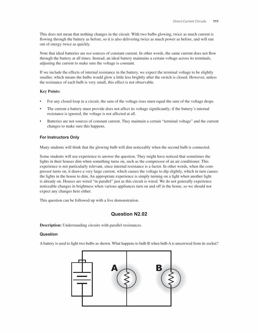
A battery is used to light two bulbs as shown. What happens to bulb B when bulb A is unscrewed from its socket?
56157_18_ch18_p110-170.indd 11156157_18_ch18_p110-170.indd 111 3/19/08 1:35:15 AM3/19/08 1:35:15 AM
112 Chapter 18
1. Bulb B goes out. 2. Bulb B gets noticeably dimmer, without going out. 3. Bulb B gets slightly dimmer. 4. Bulb B’s brightness stays the same. 5. Bulb B gets slightly brighter. 6. Bulb B gets noticeably brighter. 7. Impossible to determine
Commentary
Purpose: To develop understanding of Kirchhoff’s loop law and parallel resistors.
Discussion: When two circuit elements are arranged in parallel, they necessarily have the same voltage across them. When arranged in series, they have the same current through them. In this situation, the volt-ages must be the same. The currents will only be the same if the bulbs have the same resistance.
Also, when elements are arranged in parallel, disconnecting one does not disconnect the rest. When bulb A is removed, there is still a closed circuit with the battery and bulb B. No current fl ows through A, but this does not affect the fl ow of current through B. Further, the voltage across bulb B does not change when bulb A is removed; it is the voltage across the battery, according to Kirchhoff’s loop law. Therefore, the bright-ness of bulb B does not change.
Your house is wired “in parallel.” When you replace a bulb, the rest of the lights in the house do not go out, and they do not change in brightness. The voltage across each light and each appliance remains the same, no matter how many are on and how many are off.
Key Points:
• Circuit elements in parallel have the same voltage across them.
• Removing one path from a circuit does not break paths in parallel with it.
For Instructors Only
Some students will think that bulb B goes out when bulb A is removed, perhaps because they do not recog-nize that the fl ow of current is not broken.
They also might recognize that the current through the bulbs beforehand is the same, which suggests to them that they are in series, overgeneralizing a critical feature of the series arrangement. In other words, instructors often emphasize that the current through elements in series is the same. Students might misapply that “rule” here.
Other students might think that bulb B is brighter after A is removed, because then only one bulb is con-nected to the battery. They might even be surprised when there is no change. It is useful, therefore, to focus some attention on the battery, explaining that the current through it is half as much as before, so the power it delivers is also cut in half.
Internal resistance should not be a factor here. Including its effects would make bulb B glow slightly brighter after A is removed, since the terminal voltage across the battery would be slightly higher than before. If this is issue is raised, you must discuss it carefully, since they may take the message that “bulb B is brighter afterwards” and interpret it as a consequence of the circuit arrangement rather than the battery’s internal resistance.
This question can be followed up with a live demonstration.
56157_18_ch18_p110-170.indd 11256157_18_ch18_p110-170.indd 112 3/19/08 1:35:16 AM3/19/08 1:35:16 AM
Direct-Current Circuits 113
Question N2.03
Description: Developing problem solving skills with resistor circuits.
Question
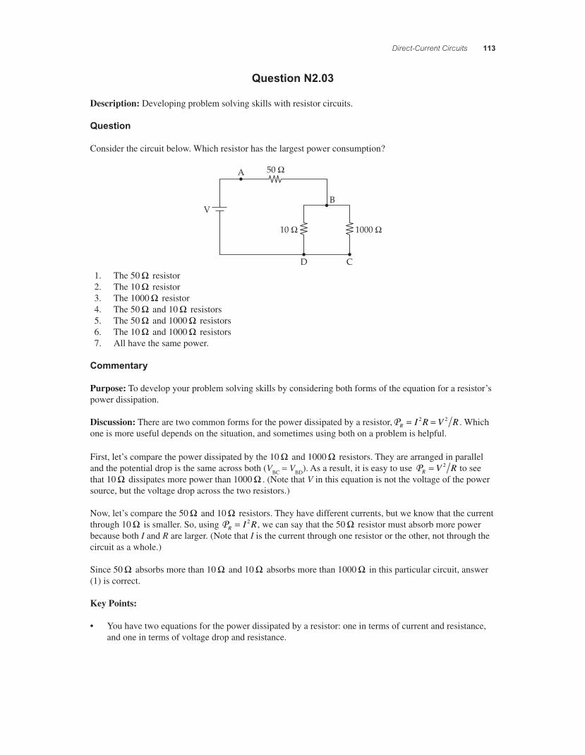
Consider the circuit below. Which resistor has the largest power consumption?
A
VB
50 !
10 ! 1000 !
D C 1. The 50 ! resistor 2. The 10 ! resistor 3. The 1000 ! resistor 4. The 50 ! and 10 ! resistors 5. The 50 ! and 1000 ! resistors 6. The 10 ! and 1000 ! resistors 7. All have the same power.
Commentary
Purpose: To develop your problem solving skills by considering both forms of the equation for a resistor’s power dissipation.
Discussion: There are two common forms for the power dissipated by a resistor,PR I R V R= =2 2 . Which one is more useful depends on the situation, and sometimes using both on a problem is helpful.
First, let’s compare the power dissipated by the 10 ! and 1000 ! resistors. They are arranged in parallel and the potential drop is the same across both (VBC = VBD). As a result, it is easy to use PR V R= 2 to see that 10 ! dissipates more power than 1000 ! . (Note that V in this equation is not the voltage of the power source, but the voltage drop across the two resistors.)
Now, let’s compare the 50 ! and 10 ! resistors. They have different currents, but we know that the current through 10 ! is smaller. So, using PR I R= 2 , we can say that the 50 ! resistor must absorb more power because both I and R are larger. (Note that I is the current through one resistor or the other, not through the circuit as a whole.)
Since 50 ! absorbs more than 10 ! and 10 ! absorbs more than 1000 ! in this particular circuit, answer (1) is correct.
Key Points:
• You have two equations for the power dissipated by a resistor: one in terms of current and resistance, and one in terms of voltage drop and resistance.
56157_18_ch18_p110-170.indd 11356157_18_ch18_p110-170.indd 113 3/19/08 1:35:16 AM3/19/08 1:35:16 AM
114 Chapter 18
• Both of these power dissipation equations are useful, sometimes on the same problem.
• Pay attention to what the variables R, V, and I mean in the context you are applying the equation — not all Vs or Is mean the same thing!
For Instructors Only
Students selecting answer (2) may be reasoning from P = V R2 that the lower the resistance, the higher the power dissipated. Students selecting answer (3) may be reasoning from P I R= 2 that the higher the resistance, the higher the power dissipated. Either way, they should be engaged in a discussion about what the variables in the equation mean.
Common mistakes include using the voltage of the power supply (“V ”) in P = V R2 and using one generic current value (“I ”) for all three resistors. Common sources of confusion include failing to appreciate that the 10 ! and 1000 ! resistors share the same voltage drop.
Question N2.04
Description: Developing reasoning ability with resistor circuits.
Question
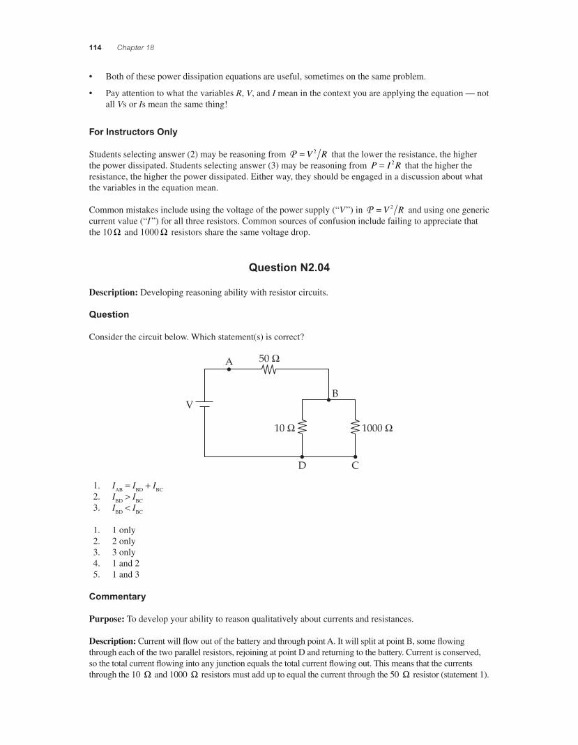
Consider the circuit below. Which statement(s) is correct?
A
VB
50 !
10 ! 1000 !
D C
1. IAB = IBD + IBC 2. IBD > IBC 3. IBD < IBC
1. 1 only 2. 2 only 3. 3 only 4. 1 and 2 5. 1 and 3
Commentary
Purpose: To develop your ability to reason qualitatively about currents and resistances.
Description: Current will fl ow out of the battery and through point A. It will split at point B, some fl owing through each of the two parallel resistors, rejoining at point D and returning to the battery. Current is conserved, so the total current fl owing into any junction equals the total current fl owing out. This means that the currents through the 10 ! and 1000 ! resistors must add up to equal the current through the 50 ! resistor (statement 1).
56157_18_ch18_p110-170.indd 11456157_18_ch18_p110-170.indd 114 3/19/08 1:35:17 AM3/19/08 1:35:17 AM
Direct-Current Circuits 115
The potential difference across the 10 ! and 1000 ! resistors is the same — ideal wires have the same potential everywhere on them — so according to Ohm’s law ("V IR= ), the smaller resistor must have the larger current through it (statement 2). Thus, the best answer is (4).
Key Points:
• At any wire junction, the total current entering equals the total current leaving.
• Two parallel circuit branches have the same potential difference across them.
• Ohm’s law ("V IR= ) relates the potential difference across a resistor to its resistance and the current fl owing through it.
For Instructors Only
This is a fairly straightforward question about currents, resistances, and potential differences, and serves well when students are fi rst beginning to analyze nontrivial complete circuits after having learned about the elements (current conservation, Ohm’s law, etc.).
Note that the question does not specify a numerical value for the battery voltage. If it did, students would be far more inclined to calculate the currents rather than reason about them.
Question N2.05
Description: Understanding Kirchhoff’s loop law (batteries in parallel).
Question
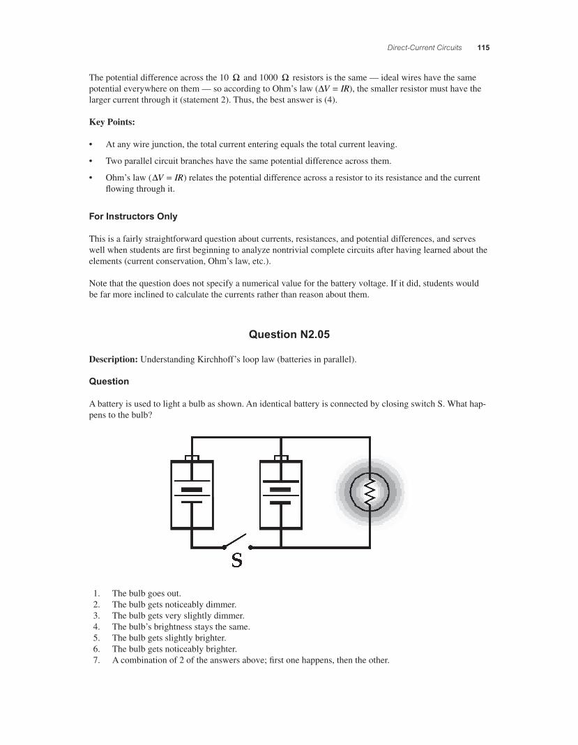
A battery is used to light a bulb as shown. An identical battery is connected by closing switch S. What hap-pens to the bulb?
1. The bulb goes out. 2. The bulb gets noticeably dimmer. 3. The bulb gets very slightly dimmer. 4. The bulb’s brightness stays the same. 5. The bulb gets slightly brighter. 6. The bulb gets noticeably brighter. 7. A combination of 2 of the answers above; fi rst one happens, then the other.
56157_18_ch18_p110-170.indd 11556157_18_ch18_p110-170.indd 115 3/19/08 1:35:18 AM3/19/08 1:35:18 AM
116 Chapter 18
Commentary
Purpose: To check your awareness and understanding of Kirchhoff’s loop law.
Discussion: It is tempting to think that the bulb will glow brighter with 2 batteries connected than with only 1 connected, but this would not satisfy Kirchhoff’s loop law.
The voltage rises in a closed loop must equal the voltage drops, and this is true even when there are multi-ple loops to consider.
Kirchhoff’s loop law is satisfi ed easily for the left loop, since the batteries are “identical.” Going around the right loop, the voltage drop across the bulb (a resistor) must be equal to the voltage rise across one battery. But that is exactly what was true before the switch was closed, so we should expect no change in the bright-ness of the bulb. The current through it is the same as before.
Even though there is no change in the brightness of the bulb, this does not mean there are no changes in the circuit. With 2 batteries connected “in parallel,” each battery has only half as much current going through it as the one battery originally, which means each battery provides half of the power dissipated by the bulb. This means that, for instance, the 2-battery arrangement would be able to keep the bulb glowing about twice as long as the 1-battery arrangement.
If we include the effects of internal resistance, then the terminal voltage would be slightly larger than before since each battery has less current fl owing through it, which means the bulb would glow slightly brighter than before. However, unless the resistance of the bulb is extremely small, we do not expect to be able to see any difference in brightness.
The orientation of the two batteries is critical. If one of them is reversed, then the result is very different.
Key Points:
• For any closed loop in a circuit, the sum of the voltage rises must equal the sum of the voltage drops.
• Two identical batteries in parallel provide the same voltage as one alone (though they will last longer).
For Instructors Only
Students are likely to say that the bulb will glow much more brightly with 2 batteries attached than with only 1 attached. They are not distinguishing between parallel and series arrangements, but relying on intuition.
This question can be followed up with a live demonstration. Students will be surprised by the result, since it appears that nothing changes. What they cannot see is that the current drawn from each battery is much reduced.
Question N2.06
Description: Understanding internal resistance of batteries and recognizing common but imperfect circuit assumptions.
Question
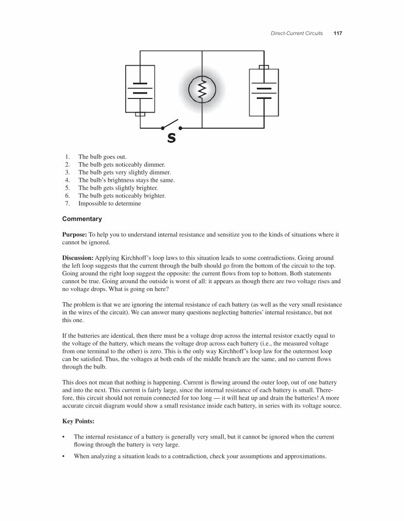
A battery is used to light a bulb as shown. An identical battery is connected by closing switch S. What hap-pens to the bulb?
56157_18_ch18_p110-170.indd 11656157_18_ch18_p110-170.indd 116 3/19/08 1:35:19 AM3/19/08 1:35:19 AM
Direct-Current Circuits 117
1. The bulb goes out. 2. The bulb gets noticeably dimmer. 3. The bulb gets very slightly dimmer. 4. The bulb’s brightness stays the same. 5. The bulb gets slightly brighter. 6. The bulb gets noticeably brighter. 7. Impossible to determine
Commentary
Purpose: To help you to understand internal resistance and sensitize you to the kinds of situations where it cannot be ignored.
Discussion: Applying Kirchhoff’s loop laws to this situation leads to some contradictions. Going around the left loop suggests that the current through the bulb should go from the bottom of the circuit to the top. Going around the right loop suggest the opposite: the current fl ows from top to bottom. Both statements cannot be true. Going around the outside is worst of all: it appears as though there are two voltage rises and no voltage drops. What is going on here?
The problem is that we are ignoring the internal resistance of each battery (as well as the very small resistance in the wires of the circuit). We can answer many questions neglecting batteries’ internal resistance, but not this one.
If the batteries are identical, then there must be a voltage drop across the internal resistor exactly equal to the voltage of the battery, which means the voltage drop across each battery (i.e., the measured voltage from one terminal to the other) is zero. This is the only way Kirchhoff’s loop law for the outermost loop can be satisfi ed. Thus, the voltages at both ends of the middle branch are the same, and no current fl ows through the bulb.
This does not mean that nothing is happening. Current is fl owing around the outer loop, out of one battery and into the next. This current is fairly large, since the internal resistance of each battery is small. There-fore, this circuit should not remain connected for too long — it will heat up and drain the batteries! A more accurate circuit diagram would show a small resistance inside each battery, in series with its voltage source.
Key Points:
• The internal resistance of a battery is generally very small, but it cannot be ignored when the current fl owing through the battery is very large.
• When analyzing a situation leads to a contradiction, check your assumptions and approximations.
56157_18_ch18_p110-170.indd 11756157_18_ch18_p110-170.indd 117 3/19/08 1:35:19 AM3/19/08 1:35:19 AM
118 Chapter 18
For Instructors Only
Students might not notice that the polarity of one of the batteries is reversed.
Most circuit problems can be solved ignoring internal resistance, but this situation is impossible to under-stand without it. When we occasionally discuss situations in which our “common” approximations fail, it helps students to understand the approximations better: their implications, when they are or are not war-ranted, etc.
It is useful to label the nodes above and below the bulb and use them to discuss this situation. It is also useful to redraw the circuit with small resistors inside the outlines of the batteries to represent internal resistance.
This question can be followed up with a live demonstration, which is quite dramatic when the bulb goes out. Note that you should not leave the switch closed for any length of time, since a very large current is fl owing elsewhere in the circuit!
Question N2.07
Description: Understanding internal resistance of batteries and recognizing common but imperfect circuit assumptions.
Question
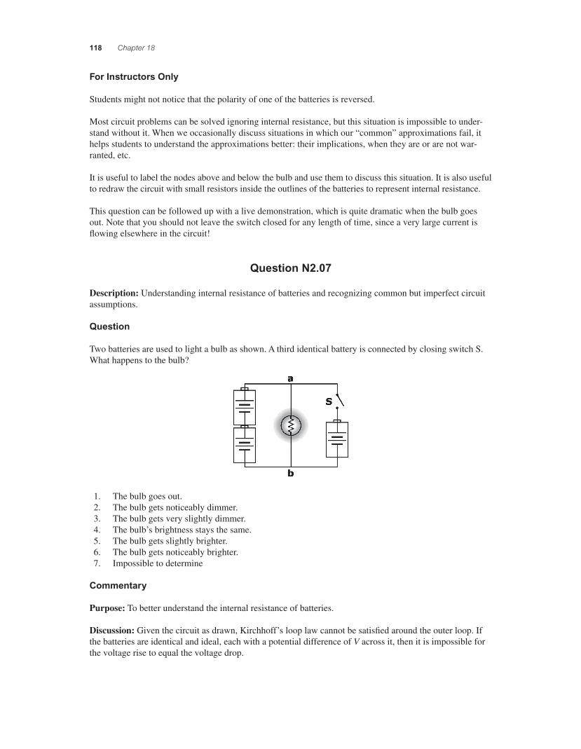
Two batteries are used to light a bulb as shown. A third identical battery is connected by closing switch S. What happens to the bulb?
1. The bulb goes out. 2. The bulb gets noticeably dimmer. 3. The bulb gets very slightly dimmer. 4. The bulb’s brightness stays the same. 5. The bulb gets slightly brighter. 6. The bulb gets noticeably brighter. 7. Impossible to determine
Commentary
Purpose: To better understand the internal resistance of batteries.
Discussion: Given the circuit as drawn, Kirchhoff’s loop law cannot be satisfi ed around the outer loop. If the batteries are identical and ideal, each with a potential difference of V across it, then it is impossible for the voltage rise to equal the voltage drop.
56157_18_ch18_p110-170.indd 11856157_18_ch18_p110-170.indd 118 3/19/08 1:35:20 AM3/19/08 1:35:20 AM
Direct-Current Circuits 119
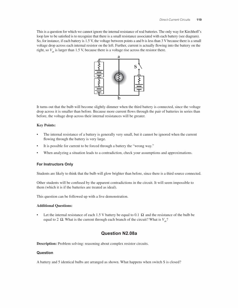
This is a question for which we cannot ignore the internal resistance of real batteries. The only way for Kirchhoff’s loop law to be satisfi ed is to recognize that there is a small resistance associated with each battery (see diagram). So, for instance, if each battery is 1.5 V, the voltage between points a and b is less than 3 V because there is a small voltage drop across each internal resistor on the left. Further, current is actually fl owing into the battery on the right, so Vab is larger than 1.5 V, because there is a voltage rise across the resistor there.
It turns out that the bulb will become slightly dimmer when the third battery is connected, since the voltage drop across it is smaller than before. Because more current fl ows through the pair of batteries in series than before, the voltage drop across their internal resistances will be greater.
Key Points:
• The internal resistance of a battery is generally very small, but it cannot be ignored when the current fl owing through the battery is very large.
• It is possible for current to be forced through a battery the “wrong way.”
• When analyzing a situation leads to a contradiction, check your assumptions and approximations.
For Instructors Only
Students are likely to think that the bulb will glow brighter than before, since there is a third source connected.
Other students will be confused by the apparent contradictions in the circuit. It will seem impossible to them (which it is if the batteries are treated as ideal).
This question can be followed up with a live demonstration.
Additional Questions:
• Let the internal resistance of each 1.5 V battery be equal to 0.1 ! and the resistance of the bulb be equal to 2 !. What is the current through each branch of the circuit? What is Vab?
Question N2.08a
Description: Problem solving: reasoning about complex resistor circuits.
Question
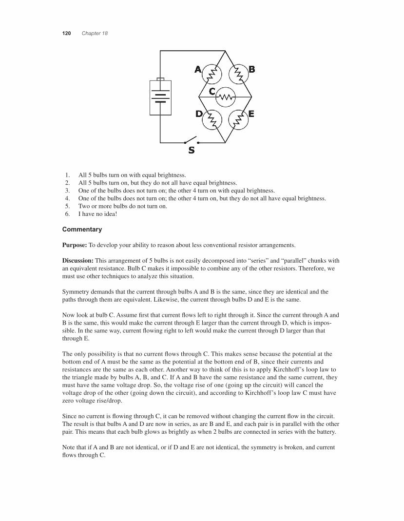
A battery and 5 identical bulbs are arranged as shown. What happens when switch S is closed?
56157_18_ch18_p110-170.indd 11956157_18_ch18_p110-170.indd 119 3/19/08 1:35:20 AM3/19/08 1:35:20 AM
120 Chapter 18
1. All 5 bulbs turn on with equal brightness. 2. All 5 bulbs turn on, but they do not all have equal brightness. 3. One of the bulbs does not turn on; the other 4 turn on with equal brightness. 4. One of the bulbs does not turn on; the other 4 turn on, but they do not all have equal brightness. 5. Two or more bulbs do not turn on. 6. I have no idea!
Commentary
Purpose: To develop your ability to reason about less conventional resistor arrangements.
Discussion: This arrangement of 5 bulbs is not easily decomposed into “series” and “parallel” chunks with an equivalent resistance. Bulb C makes it impossible to combine any of the other resistors. Therefore, we must use other techniques to analyze this situation.
Symmetry demands that the current through bulbs A and B is the same, since they are identical and the paths through them are equivalent. Likewise, the current through bulbs D and E is the same.
Now look at bulb C. Assume fi rst that current fl ows left to right through it. Since the current through A and B is the same, this would make the current through E larger than the current through D, which is impos-sible. In the same way, current fl owing right to left would make the current through D larger than that through E.
The only possibility is that no current fl ows through C. This makes sense because the potential at the bottom end of A must be the same as the potential at the bottom end of B, since their currents and resistances are the same as each other. Another way to think of this is to apply Kirchhoff’s loop law to the triangle made by bulbs A, B, and C. If A and B have the same resistance and the same current, they must have the same voltage drop. So, the voltage rise of one (going up the circuit) will cancel the voltage drop of the other (going down the circuit), and according to Kirchhoff’s loop law C must have zero voltage rise/drop.
Since no current is fl owing through C, it can be removed without changing the current fl ow in the circuit. The result is that bulbs A and D are now in series, as are B and E, and each pair is in parallel with the other pair. This means that each bulb glows as brightly as when 2 bulbs are connected in series with the battery.
Note that if A and B are not identical, or if D and E are not identical, the symmetry is broken, and current fl ows through C.
56157_18_ch18_p110-170.indd 12056157_18_ch18_p110-170.indd 120 3/19/08 1:35:21 AM3/19/08 1:35:21 AM
Direct-Current Circuits 121
Key Points:
• Sometimes clever reasoning can help you analyze a circuit and fi gure out how it behaves.
• Not all circuit arrangements can be thought of as sets of resistors in series and parallel.
• A branch of a circuit with zero current can be ignored, since its absence would not change the currents or voltages anywhere else in the circuit.
For Instructors Only
This is the fi rst of two questions using this situation.
Arrangements like this are often avoided at the introductory level because they cannot be simplifi ed using standard techniques of series and parallel combinations. But even though we cannot easily solve this prob-lem in general, we can still reason to an answer using other simple arguments, as above. Engaging in this reasoning process is valuable for students.
Note that Kirchhoff’s loop law and node law can be used to fi nd the currents through each resistor, though the resulting system has six equations in six unknowns. This approach should be discouraged by giving students a relatively short amount of time to answer the question.
It is useful to label the nodes and use these labels when discussing this situation. There are 4 relevant nodes.
This question can be followed up with a live demonstration.
One drawback to be guarded against when using this question is inappropriate generalization: students might incorrectly conclude that any time a resistor is connected between two branches like C is here, the current through it is zero. It happens here only because identical resistors are paired up, A and B, D and E. In other words, all 5 resistors do not need to be the same, but certain pairs do: A and B must be identical, and D and E must be identical, though A and B do not need to be the same as D and E, and C can be differ-ent from all of the others.
Additional Questions
• Using the same network of 5 identical bulbs, connect the battery across bulb C. Which bulbs will light and which will not? Which will glow more brightly than the others? Which will glow with the same brightness as when only one bulb is connected to the battery? Which will glow with the same brightness as when two are connected in series with the battery?
Question N2.08b
Description: Problem solving: reasoning about complex resistor circuits; distinguishing zero current from an open circuit.
Question
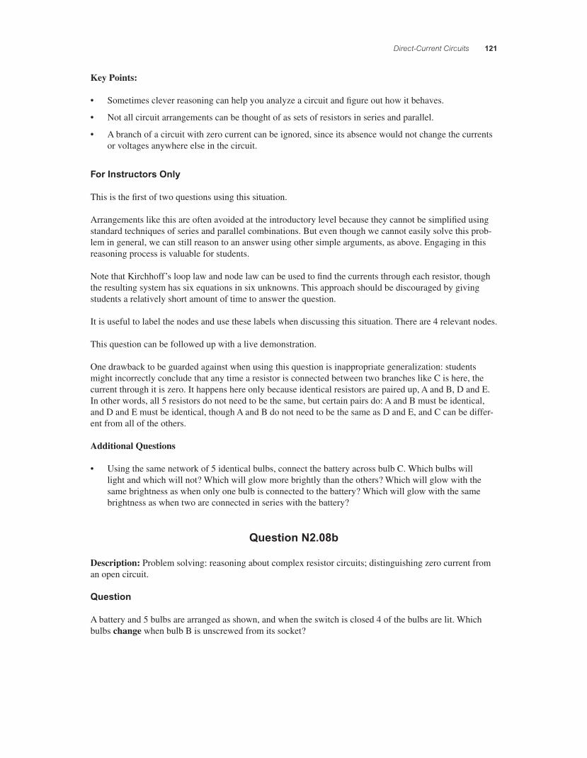
A battery and 5 bulbs are arranged as shown, and when the switch is closed 4 of the bulbs are lit. Which bulbs change when bulb B is unscrewed from its socket?
56157_18_ch18_p110-170.indd 12156157_18_ch18_p110-170.indd 121 3/19/08 1:35:22 AM3/19/08 1:35:22 AM
122 Chapter 18
1. Bulb E goes out. (Bulbs A and D stay on; bulb C stays off.) 2. Bulb E goes out; bulb C goes on. (Bulbs A and D stay on.) 3. Bulb A goes out; bulb C goes on. (Bulbs D and E stay on.) 4. Bulb C goes on. (Bulbs A, D, and E stay on.) 5. Bulb C goes on; bulb D goes out. (Bulbs A and E stay on.) 6. I have no idea!
Commentary
Purpose: To develop intuition for current fl ow in circuits, and help you distinguish between an open circuit and one that is closed but has zero current.
Discussion: As discussed in the previous question, no current fl ows through C in the initial arrangement (i.e., while B is still part of the circuit). However, C is still a viable path for current. It is not “open,” but merely does not have any current in that set of circumstances.
Once B is removed, the voltages in the circuit change. B is now “open,” and all the current will fl ow through A. When it reaches the node after A, the current has two paths it can follow to return to the battery: through D, or through C and then E. C and E are in series, and the C+E combination is in parallel with D. The current will therefore divide, some going through each path, and then join up again at the bottom.
So, A, D, and E will stay lit, and C will light up when B is removed. (If you work out what the currents must be, you’ll see that A will glow brightest, then D, and C and E will be the dimmest and equally dim. All will change in brightness when B is removed.)
Key Points:
• An open circuit is one in which current cannot fl ow because no complete conducting path exists. This is not the same as a closed circuit with zero current.
• When an element of a complex circuit is changed or removed, it can affect voltages and current fl ows elsewhere in the circuit.
For Instructors Only
Students are likely to have oversimplifi ed ideas of open circuits and closed paths. Some will think that bulb C must be an open circuit because it is not glowing. They might wonder why it is not glowing and ask if there is something wrong with the bulb.
56157_18_ch18_p110-170.indd 12256157_18_ch18_p110-170.indd 122 3/19/08 1:35:22 AM3/19/08 1:35:22 AM
Direct-Current Circuits 123
It is not necessary to discuss which bulb is brightest, dimmest, etc. The focus of this question should be to identify paths for which current can fl ow vs. paths for which no current fl ows.
It is useful to label the 4 nodes in the resistive network and use them to discuss this situation. It is useful also to redraw the situation with an open circuit at B.
This question can be followed up with a live demonstration.
Additional Questions:
• If each bulb has a constant resistance R, what is the equivalent resistance of the network after bulb B is removed, and what is the current through each bulb?
• What is the power dissipated by each resistor before and after B is removed? Which bulbs will become brighter and which will become dimmer after B is removed?
Question N2.09a
Description: Linking theory to real-world experience: bulbs and batteries.
Question
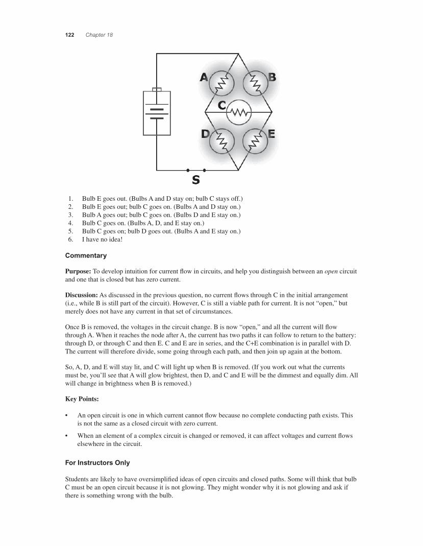
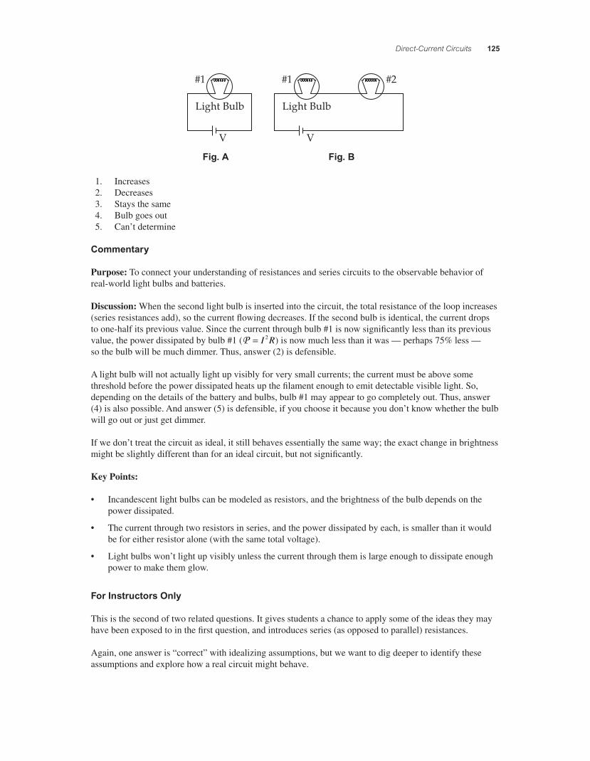
A light bulb is connected to a battery as shown in Figure A below. When a second bulb is connected as shown in Figure B, what happens to the brightness of the original bulb?
Fig. A Fig. B
Light Bulb
V V
#1
Light Bulb
#1
#2
1. Increases 2. Decreases 3. Stays the same 4. Bulb goes out 5. Can’t determine
Commentary
Purpose: To connect your understanding of resistances and parallel circuits to the observable behavior of real-world light bulbs and batteries.
Discussion: An incandescent light bulb can be thought of as a resistor. The brightness of the bulb depends on the amount of power dissipated by it:P = = =I R IV V R2 2 .
The potential difference across bulb #1 is equal to the potential difference of the battery, regardless of whether bulb #2 is placed in parallel with it. For an ideal circuit, the potential difference of the battery is always the same, so the power dissipated by bulb #1 won’t change when bulb #2 is connected. (Bulb #2 will light up, too.) So, answer (3) is correct for an ideal circuit.
56157_18_ch18_p110-170.indd 12356157_18_ch18_p110-170.indd 123 3/19/08 1:35:23 AM3/19/08 1:35:23 AM
124 Chapter 18
But what if the circuit isn’t ideal? Real batteries have a maximum current output as well as a rated potential difference (“voltage”). As more and more current is drawn from a battery, its output voltage drops: slightly at fi rst, but signifi cantly as the current approaches the battery’s maximum. When the second light bulb is attached, it draws additional current from the battery, so the fi rst bulb’s brightness will decrease. It will decrease very slightly — probably not enough to notice — unless the battery is already near its maximum current capacity, in which case bulb #1 may dim signifi cantly. So, answer (2) is possible for a circuit with a real battery.
Since real light bulbs don’t appear to light up at all for very low current fl ows and power dissipation (they get slightly warm, but not hot enough to glow visibly), bulb #1 may even appear to go out completely if attaching the second bulb and drawing more current causes the battery’s voltage to drop, which causes the current through bulb #1 to decrease below the bulb’s threshold for “lighting up.” So, answer (4) is possible for a circuit with a real battery and real bulbs.
An additional real-world complication is that no wire really has zero resistance, so that when current fl ows through the circuit, some power is dissipated by the wires. That means there is some nonzero potential dif-ference between the battery’s terminal and the light bulbs’ contacts, which means that the voltage across the bulbs won’t be exactly equal to the voltage across the battery; the more current that fl ows, the bigger this difference will be. This is unlikely to be a signifi cant effect for typical wires, batteries, and bulbs, however.
Key Points:
• Incandescent light bulbs can be modeled as resistors, and the brightness of the bulb depends on the power dissipated.
• Adding one light bulb in parallel with another doesn’t affect the brightness of the fi rst, if the potential difference across the fi rst remains the same.
• The voltage output by a real, non-ideal battery decreases as more current is drawn from it, though the change is small unless the current approaches the battery’s maximum current capacity.
• Light bulbs won’t light up visibly if too little power is dissipated.
For Instructors Only
This is the fi rst of two related questions.
Students often can’t, or don’t try to, associate what they learn about “ideal” circuits with their experience of real electrical devices like light bulbs, batteries, and the like. This inhibits both their understanding of the physics and their ability to use physics to understand their world.
One or more demonstrations can signifi cantly enhance the learning from this question. Optimally, you would have one set of components that approximates an ideal circuit well, and another with a marginal enough battery that non-ideal effects can be observed.
Question N2.09b
Description: Linking theory to real-world experience: bulbs and batteries.
Question
A light bulb is connected to a battery as shown in Figure A below. When a second bulb is connected as shown in Figure B, what happens to the brightness of the original bulb?
56157_18_ch18_p110-170.indd 12456157_18_ch18_p110-170.indd 124 3/19/08 1:35:23 AM3/19/08 1:35:23 AM
Direct-Current Circuits 125
Fig. A Fig. B
Light Bulb
V
#1
Light Bulb
V
#1 #2
1. Increases 2. Decreases 3. Stays the same 4. Bulb goes out 5. Can’t determine
Commentary
Purpose: To connect your understanding of resistances and series circuits to the observable behavior of real-world light bulbs and batteries.
Discussion: When the second light bulb is inserted into the circuit, the total resistance of the loop increases (series resistances add), so the current fl owing decreases. If the second bulb is identical, the current drops to one-half its previous value. Since the current through bulb #1 is now signifi cantly less than its previous value, the power dissipated by bulb #1 (P = I R2 ) is now much less than it was — perhaps 75% less — so the bulb will be much dimmer. Thus, answer (2) is defensible.
A light bulb will not actually light up visibly for very small currents; the current must be above some threshold before the power dissipated heats up the fi lament enough to emit detectable visible light. So, depending on the details of the battery and bulbs, bulb #1 may appear to go completely out. Thus, answer (4) is also possible. And answer (5) is defensible, if you choose it because you don’t know whether the bulb will go out or just get dimmer.
If we don’t treat the circuit as ideal, it still behaves essentially the same way; the exact change in brightness might be slightly different than for an ideal circuit, but not signifi cantly.
Key Points:
• Incandescent light bulbs can be modeled as resistors, and the brightness of the bulb depends on the power dissipated.
• The current through two resistors in series, and the power dissipated by each, is smaller than it would be for either resistor alone (with the same total voltage).
• Light bulbs won’t light up visibly unless the current through them is large enough to dissipate enough power to make them glow.
For Instructors Only
This is the second of two related questions. It gives students a chance to apply some of the ideas they may have been exposed to in the fi rst question, and introduces series (as opposed to parallel) resistances.
Again, one answer is “correct” with idealizing assumptions, but we want to dig deeper to identify these assumptions and explore how a real circuit might behave.
56157_18_ch18_p110-170.indd 12556157_18_ch18_p110-170.indd 125 3/19/08 1:35:23 AM3/19/08 1:35:23 AM
126 Chapter 18
Question N2.10
Description: Reasoning with power and understanding the “wattage” rating of light bulbs.
Question
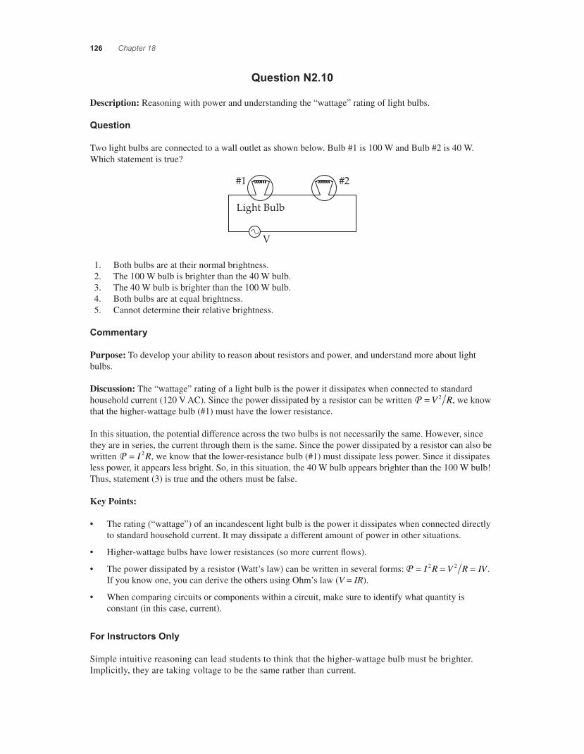
Two light bulbs are connected to a wall outlet as shown below. Bulb #1 is 100 W and Bulb #2 is 40 W. Which statement is true?
Light Bulb
V
#1 #2
1. Both bulbs are at their normal brightness. 2. The 100 W bulb is brighter than the 40 W bulb. 3. The 40 W bulb is brighter than the 100 W bulb. 4. Both bulbs are at equal brightness. 5. Cannot determine their relative brightness.
Commentary
Purpose: To develop your ability to reason about resistors and power, and understand more about light bulbs.
Discussion: The “wattage” rating of a light bulb is the power it dissipates when connected to standard household current (120 V AC). Since the power dissipated by a resistor can be written P = V R2 , we know that the higher-wattage bulb (#1) must have the lower resistance.
In this situation, the potential difference across the two bulbs is not necessarily the same. However, since they are in series, the current through them is the same. Since the power dissipated by a resistor can also be written P = I R2 , we know that the lower-resistance bulb (#1) must dissipate less power. Since it dissipates less power, it appears less bright. So, in this situation, the 40 W bulb appears brighter than the 100 W bulb! Thus, statement (3) is true and the others must be false.
Key Points:
• The rating (“wattage”) of an incandescent light bulb is the power it dissipates when connected directly to standard household current. It may dissipate a different amount of power in other situations.
• Higher-wattage bulbs have lower resistances (so more current fl ows).
• The power dissipated by a resistor (Watt’s law) can be written in several forms: P = = =I R V R IV2 2 . If you know one, you can derive the others using Ohm’s law (V = IR).
• When comparing circuits or components within a circuit, make sure to identify what quantity is constant (in this case, current).
For Instructors Only
Simple intuitive reasoning can lead students to think that the higher-wattage bulb must be brighter. Implicitly, they are taking voltage to be the same rather than current.
56157_18_ch18_p110-170.indd 12656157_18_ch18_p110-170.indd 126 3/19/08 1:35:24 AM3/19/08 1:35:24 AM
Direct-Current Circuits 127
This question can reveal confusion about what the “wattage” of an incandescent bulb really means, espe-cially for those choosing answer (1). It can also reveal confusion about what the “brightness” of a bulb corresponds to.
Errors of relational reasoning — using proportional rather than inverse relationships — are also likely.
Question N3.06a
Description: Introducing capacitor behavior in DC circuits: charge vs. voltage.
Question
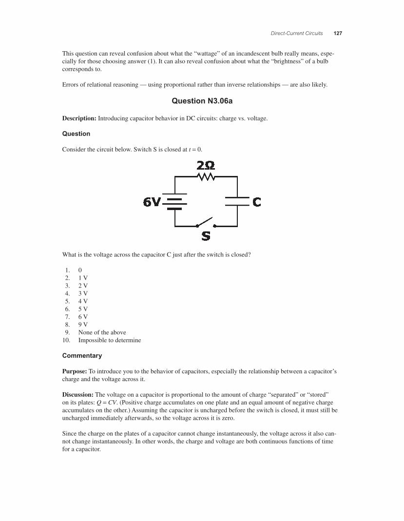
Consider the circuit below. Switch S is closed at t = 0.
What is the voltage across the capacitor C just after the switch is closed?
1. 0 2. 1 V 3. 2 V 4. 3 V 5. 4 V 6. 5 V 7. 6 V 8. 9 V 9. None of the above 10. Impossible to determine
Commentary
Purpose: To introduce you to the behavior of capacitors, especially the relationship between a capacitor’s charge and the voltage across it.
Discussion: The voltage on a capacitor is proportional to the amount of charge “separated” or “stored” on its plates: Q = CV. (Positive charge accumulates on one plate and an equal amount of negative charge accumulates on the other.) Assuming the capacitor is uncharged before the switch is closed, it must still be uncharged immediately afterwards, so the voltage across it is zero.
Since the charge on the plates of a capacitor cannot change instantaneously, the voltage across it also can-not change instantaneously. In other words, the charge and voltage are both continuous functions of time for a capacitor.
56157_18_ch18_p110-170.indd 12756157_18_ch18_p110-170.indd 127 3/19/08 1:35:24 AM3/19/08 1:35:24 AM
128 Chapter 18
Key Points:
• The voltage difference between the plates of a capacitor is proportional to the charge stored on them.
• Neither charge nor voltage can change instantaneously for a capacitor; when current starts to fl ow through an uncharged capacitor, charge starts to build up and the voltage starts to change from zero.
For Instructors Only
This is fi rst of three questions using this situation. It is a good question for developing a physical picture of capacitance and understanding why charge and voltage are intimately related.
In questions like this we typically assume that the capacitor is initially uncharged, but the question does not explicitly state that. Therefore, a valid (if not optimal) response is to say that the voltage is impossible to determine since the initial conditions are not given. If students pick up on this ambiguity, it can be used to motivate a discussion of how the initial conditions might affect the circuit’s behavior.
Question N3.06b
Description: Introducing capacitor behavior in DC circuits: voltage vs. current.
Question
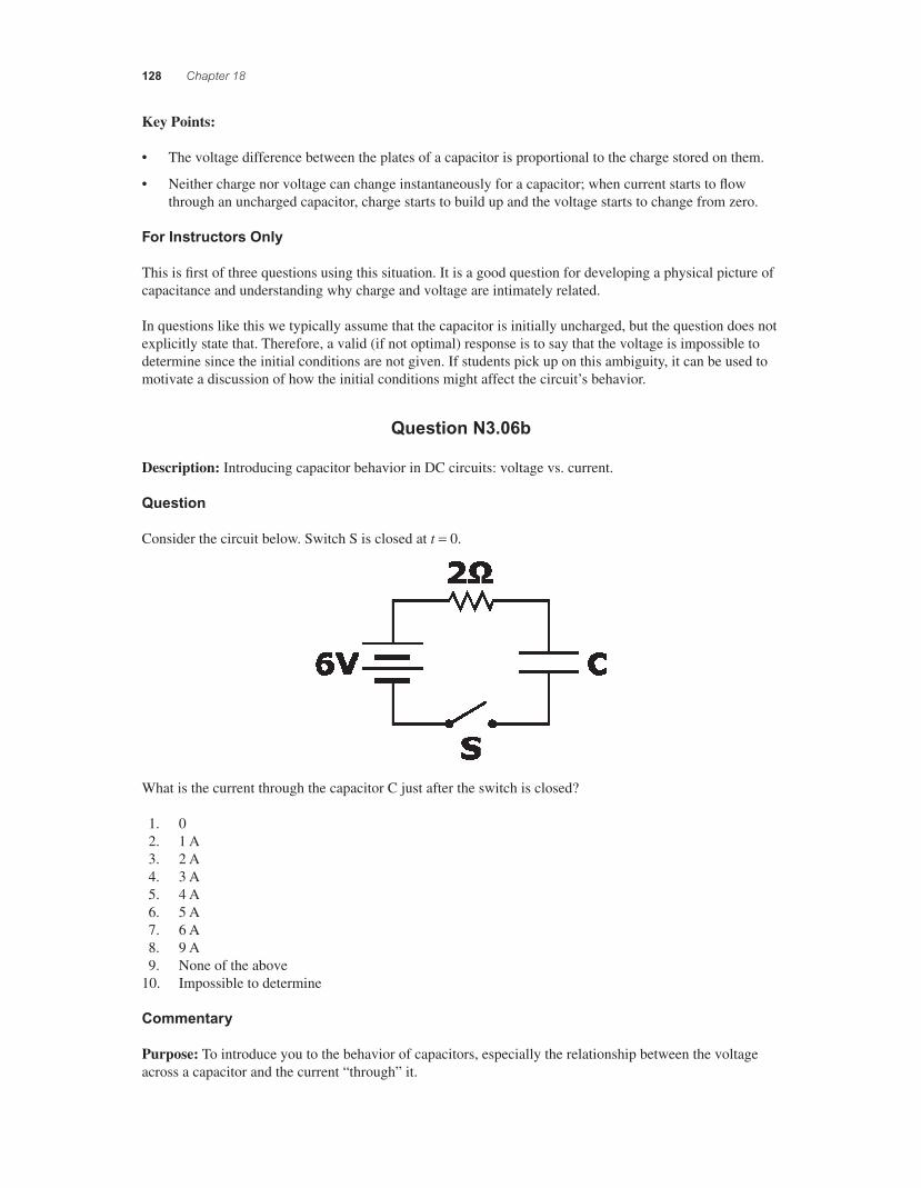
Consider the circuit below. Switch S is closed at t = 0.
What is the current through the capacitor C just after the switch is closed?
1. 0 2. 1 A 3. 2 A 4. 3 A 5. 4 A 6. 5 A 7. 6 A 8. 9 A 9. None of the above 10. Impossible to determine
Commentary
Purpose: To introduce you to the behavior of capacitors, especially the relationship between the voltage across a capacitor and the current “through” it.
56157_18_ch18_p110-170.indd 12856157_18_ch18_p110-170.indd 128 3/19/08 1:35:25 AM3/19/08 1:35:25 AM
Direct-Current Circuits 129
Discussion: Assuming there is no charge on the capacitor when the switch is closed, there is no voltage across it, and it behaves like a conductor. In other words, at the instant t = 0 we can imagine replacing the capacitor with a wire. With no voltage across C, Kirchhoff’s loop law requires that the voltage across the resistor be 6 V, so the current everywhere must be 3 A, including through the capacitor.
(Current fl ow “through” a capacitor does not mean that charge actually travels across the gap from one plate to the other. Rather, current fl ows into one terminal and accumulates as charge on the connected plate; meanwhile, current fl ows out of the other terminal as the opposite charge accumulates on that plate. As long as one does not look inside the capacitor itself, however, the capacitor behaves as if current is fl owing “through” it.)
The behavior of a capacitor is different from that of a resistor. If there is zero voltage across a resistor, there must be zero current; if there is a current through a resistor, there must a voltage across it. For capacitors, however, zero voltage means current can fl ow unimpeded, while a voltage difference (due to charge build-up) hinders current fl ow.
Note that the current through a capacitor can change instantaneously. The current was zero just before the switch is closed, and is 3 A just afterwards. This situation is analogous to dropping an object at t = 0. The velocity is zero but changing, so the net force on it is nonzero. Likewise, the voltage across the capacitor is zero but changing, so there is a current through it. (The current through a capacitor is proportional to the rate of change of its voltage, just as the net force on an object is proportional to the rate of change of its velocity.)
Key Points:
• A capacitor with zero voltage across it allows current to fl ow unimpeded, like a zero-resistance wire.
• The charge on or voltage across a capacitor cannot change instantaneously, but the current through it can.
• The relationship between voltage and current differs for capacitors and resistors.
For Instructors Only
This is second of three questions using this situation.
This discussion neglects the issue of charge building up and gradually decreasing the current. That will be visited in the fi nal question in this set.
Be on the lookout for signs of confusion between the voltage-current relationships for resistors and capaci-tors; it is common.
As with the previous question, this one does not identify the initial state of the capacitor. If the ambiguity and the signifi cance of different initial conditions was not discussed then, it may be now.
Question N3.06c
Description: Introducing capacitor behavior in DC circuits: saturation.
Question
Consider the circuit below. Switch S is closed at t = 0.
56157_18_ch18_p110-170.indd 12956157_18_ch18_p110-170.indd 129 3/19/08 1:35:25 AM3/19/08 1:35:25 AM
130 Chapter 18
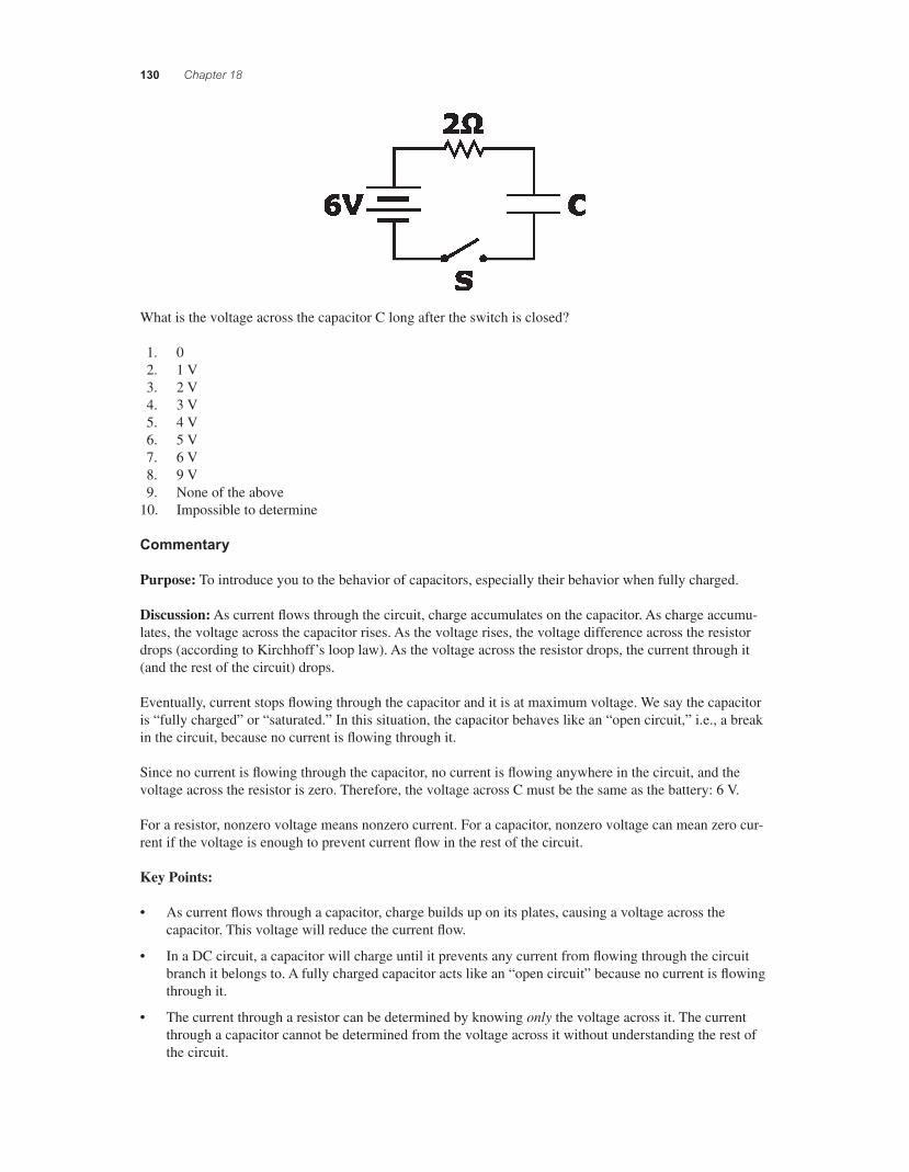
What is the voltage across the capacitor C long after the switch is closed?
1. 0 2. 1 V 3. 2 V 4. 3 V 5. 4 V 6. 5 V 7. 6 V 8. 9 V 9. None of the above 10. Impossible to determine
Commentary
Purpose: To introduce you to the behavior of capacitors, especially their behavior when fully charged.
Discussion: As current fl ows through the circuit, charge accumulates on the capacitor. As charge accumu-lates, the voltage across the capacitor rises. As the voltage rises, the voltage difference across the resistor drops (according to Kirchhoff’s loop law). As the voltage across the resistor drops, the current through it (and the rest of the circuit) drops.
Eventually, current stops fl owing through the capacitor and it is at maximum voltage. We say the capacitor is “fully charged” or “saturated.” In this situation, the capacitor behaves like an “open circuit,” i.e., a break in the circuit, because no current is fl owing through it.
Since no current is fl owing through the capacitor, no current is fl owing anywhere in the circuit, and the voltage across the resistor is zero. Therefore, the voltage across C must be the same as the battery: 6 V.
For a resistor, nonzero voltage means nonzero current. For a capacitor, nonzero voltage can mean zero cur-rent if the voltage is enough to prevent current fl ow in the rest of the circuit.
Key Points:
• As current fl ows through a capacitor, charge builds up on its plates, causing a voltage across the capacitor. This voltage will reduce the current fl ow.
• In a DC circuit, a capacitor will charge until it prevents any current from fl owing through the circuit branch it belongs to. A fully charged capacitor acts like an “open circuit” because no current is fl owing through it.
• The current through a resistor can be determined by knowing only the voltage across it. The current through a capacitor cannot be determined from the voltage across it without understanding the rest of the circuit.
56157_18_ch18_p110-170.indd 13056157_18_ch18_p110-170.indd 130 3/19/08 1:35:26 AM3/19/08 1:35:26 AM
Direct-Current Circuits 131
For Instructors Only
This is last of three questions using this situation. It provides an opportunity to discuss the charging behav-ior of capacitors and further make sense of the relationship between voltage, charge, and capacitance.
Some students will say that the voltage on the capacitor is 6 V without fully appreciating the reasoning needed to determine this. A slightly more complicated circuit can help tease this out.
Additional Questions:
• How would your answer change if (a) 2 ! was changed to 3 !, (b) C was changed to C/2, and (c) 6 V was changed to 8 V?
• What would happen if the switch is opened after a long time?
Question N3.07
Description: Developing an understanding of how an uncharged capacitor behaves in a circuit.
Question
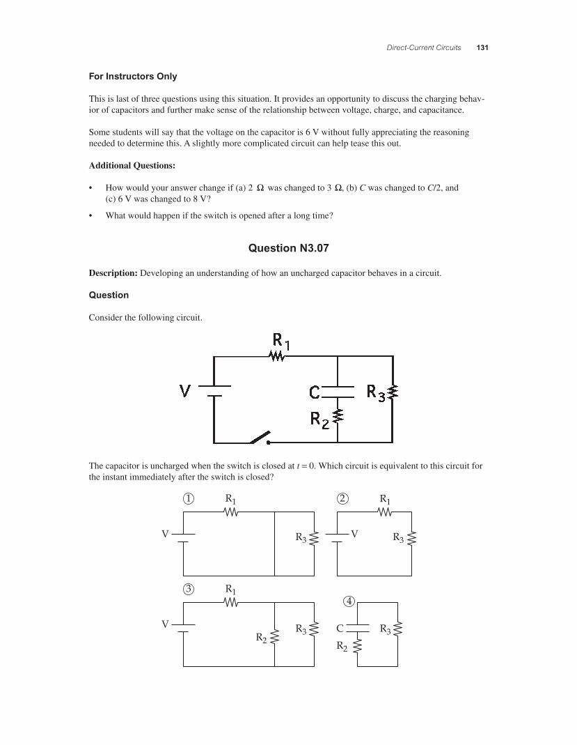
Consider the following circuit.
The capacitor is uncharged when the switch is closed at t = 0. Which circuit is equivalent to this circuit for the instant immediately after the switch is closed?
V
V V
R11 R1
R3 R3
R1
R2 R2
R3R3 C
3
2
4
56157_18_ch18_p110-170.indd 13156157_18_ch18_p110-170.indd 131 3/19/08 1:35:26 AM3/19/08 1:35:26 AM
132 Chapter 18
Commentary
Purpose: To develop your understanding of how an uncharged capacitor behaves in a circuit.
Discussion: When there is no charge on a capacitor, it behaves like a short circuit, which means it does not impede the free fl ow of current. We can imagine replacing it with a wire for that instant. However, R2 can not be replaced by a wire as well. Thus, answer (3) is best.
Answer (2) is a correct representation of the long-term or steady-state behavior of the circuit: when the capacitor is fully charged, the current through it and R2 are zero, and we can replace the entire branch with an open circuit.
Key Points:
• An uncharged capacitor acts like a short circuit (a resistanceless wire) until it accumulates some charge.
• Any resistors in series with the capacitor still impede current fl ow; they do not act like short circuits.
For Instructors Only
This is a good question to present just after a question set like Questions 39a–39c: it asks students to apply knowledge they’ve gained there in a slightly more complicated situation. This is an example of the “extend the context” tactic: present a concept, and then challenge students to apply it in a different context to push them to generalize the concept and dissociate it from the details of the original context in which they learned it.
Circuit (1) is never equivalent to the original. Circuit (2) is the equivalent circuit at steady state. Circuit (4) is the equivalent at the instant the switch is opened after being closed for a long time.
Additional Questions:
1. Just after the switch is closed, determine the current through each resistor. 2. Long after the switch is closed, (a) draw the equivalent circuit, then determine (b) the currents
through the resistors and (c) the voltage across the capacitor. 3. The switch is closed for a long time, then opened again. (a) Which diagram would be equivalent just
after the switch is open again? (b) Determine the current through each circuit element.
Question N3.08a
Description: Extending understanding of capacitor behavior in DC circuits.
Question
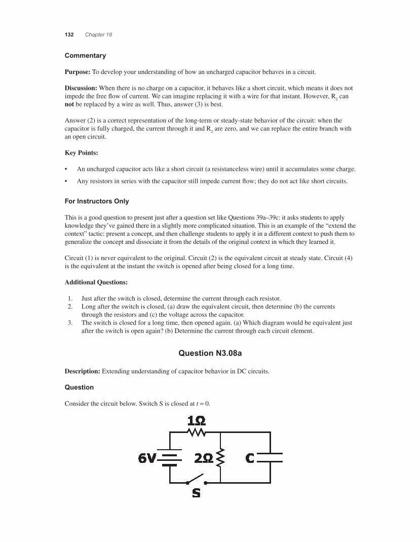
Consider the circuit below. Switch S is closed at t = 0.
56157_18_ch18_p110-170.indd 13256157_18_ch18_p110-170.indd 132 3/19/08 1:35:27 AM3/19/08 1:35:27 AM
Direct-Current Circuits 133
What is the voltage across the capacitor C just after the switch is closed?
1. 0 2. 1 V 3. 2 V 4. 3 V 5. 4 V 6. 5 V 7. 6 V 8. 9 V 9. None of the above 10. Impossible to determine
Commentary
Purpose: To develop your understanding of how capacitors behave in circuits with other elements.
Discussion: The voltage on a capacitor is proportional to the amount of charge “separated” or “stored” on its plates. Assuming the capacitor is uncharged before the switch is closed, it must still be uncharged imme-diately afterwards, so the voltage across it is zero.
Since the charge on the plates of a capacitor cannot change instantaneously, the voltage across it also can-not change instantaneously. In other words, the charge and voltage are both continuous functions of time for a capacitor. (For resistors, however, voltage is not a continuous function of time.)
The answer “impossible to determine” is not particularly defensible here, even though the initial charge on the capacitor at t = 0 is not given. While the switch is open, the capacitor discharges through the 2 ! resis-tor. Thus, for most typical capacitors, after just a few seconds of the switch being open, the charge on the capacitor is zero. We generally assume that these kinds of situations have no relevant history, that is, that the initial condition is steady-state and has existed for a long time.
Key Points:
• The voltage across a capacitor is proportional to the charge stored on its plates.
• Neither the charge on nor the voltage across a capacitor can change instantaneously.
• Sometimes we must make “reasonable” assumptions to answer a question, taking into account the question’s intent.
For Instructors Only
This is fi rst of three questions using this situation.
Students might think that the answer is impossible to determine, perhaps because they do not know how much charge is stored on the capacitor when the switch is closed. In this case, however, the capacitor discharges when the switch is open, so it is not really a defensible position.
Students might recognize that current is fl owing to the capacitor, but they might not realize that its voltage is zero. Having current fl owing to a circuit element with no voltage across it might be hard for them to reconcile.
This is the simplest of the three questions in this set. Instructors do not need to spend much time on it. The main idea (that charge and voltage are intimately related for a capacitor) should have been settled for most students before asking this question. However, it is worth checking this quickly before asking the other two questions in this set.
56157_18_ch18_p110-170.indd 13356157_18_ch18_p110-170.indd 133 3/19/08 1:35:28 AM3/19/08 1:35:28 AM
134 Chapter 18
Question N3.08b
Description: Extending understanding of capacitor behavior in DC circuits.
Source: Leonard
Question
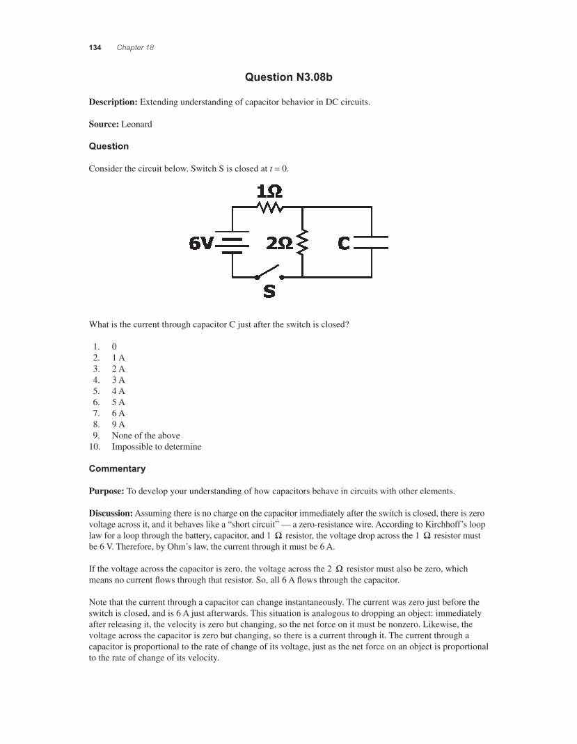
Consider the circuit below. Switch S is closed at t = 0.
What is the current through capacitor C just after the switch is closed?
1. 0 2. 1 A 3. 2 A 4. 3 A 5. 4 A 6. 5 A 7. 6 A 8. 9 A 9. None of the above 10. Impossible to determine
Commentary
Purpose: To develop your understanding of how capacitors behave in circuits with other elements.
Discussion: Assuming there is no charge on the capacitor immediately after the switch is closed, there is zero voltage across it, and it behaves like a “short circuit” — a zero-resistance wire. According to Kirchhoff’s loop law for a loop through the battery, capacitor, and 1 ! resistor, the voltage drop across the 1 ! resistor must be 6 V. Therefore, by Ohm’s law, the current through it must be 6 A.
If the voltage across the capacitor is zero, the voltage across the 2 ! resistor must also be zero, which means no current fl ows through that resistor. So, all 6 A fl ows through the capacitor.
Note that the current through a capacitor can change instantaneously. The current was zero just before the switch is closed, and is 6 A just afterwards. This situation is analogous to dropping an object: immediately after releasing it, the velocity is zero but changing, so the net force on it must be nonzero. Likewise, the voltage across the capacitor is zero but changing, so there is a current through it. The current through a capacitor is proportional to the rate of change of its voltage, just as the net force on an object is proportional to the rate of change of its velocity.
56157_18_ch18_p110-170.indd 13456157_18_ch18_p110-170.indd 134 3/19/08 1:35:28 AM3/19/08 1:35:28 AM
Direct-Current Circuits 135
Key Points:
• For a capacitor, zero voltage does not mean zero current. (For a resistor, it does.)
• A capacitor with zero voltage acts like a zero-resistance wire (until some charge builds up), and can “short out” other branches of a circuit in parallel with it.
• Kirchhoff’s loop law and node law remain useful analysis tools, even though we are now dealing with capacitors.
• To fi gure out the current through a capacitor, you need to know about the rest of the circuit.
For Instructors Only
This is second of three questions using this situation.
As with the previous question, we assume but are not told explicitly that at t = 0 the switch has been closed long enough so that the capacitor is fully discharged. The answer “impossible to determine,” because the initial charge is not given, is somewhat defensible but not preferred.
Some students will not realize that they need to use Kirchhoff’s laws to answer this question. In other words, once they recognize that the voltage across the capacitor is zero, they need Kirchhoff’s laws to deduce what the current through it will be at that instant.
A diagram showing the equivalent circuit (i.e., with the capacitor replaced by a wire) might help some students.
Additional Questions:
1. How would the answer change if (a) the 1 ! resistor is replaced by a 2 ! one, (b) the 2 ! resistor is replaced by a 1 ! one, (c) the 6 V battery is changed to a 12 V one, and (d) capacitor C is replaced by a capacitor 2C?
2. When the voltage across the capacitor is 3 V, what are the currents through (a) 1 ! , (b) 2 !, and (c) C?
Question N3.08c
Description: Extending understanding of capacitor behavior in DC circuits.
Question
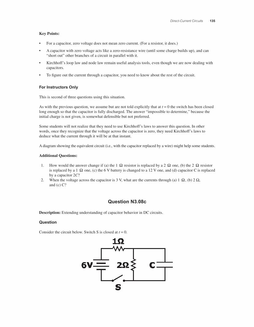
Consider the circuit below. Switch S is closed at t = 0.
56157_18_ch18_p110-170.indd 13556157_18_ch18_p110-170.indd 135 3/19/08 1:35:29 AM3/19/08 1:35:29 AM
136 Chapter 18
What is the voltage across the capacitor C long after the switch is closed?
1. 0 2. 1 V 3. 2 V 4. 3 V 5. 4 V 6. 5 V 7. 6 V 8. 9 V 9. None of the above 10. Impossible to determine
Commentary
Purpose: To develop your understanding of how capacitors behave in circuits with other elements.
Discussion: As discussed in the previous questions, current will start fl owing through the capacitor when the switch is closed. As it fl ows, charge accumulates on the capacitor’s plates, increasing the voltage across them. This voltage opposes current fl ow through the capacitor, causing some of the current to fl ow through the 2 ! resistor. Eventually, enough charge will have accumulated on the capacitor to prevent any more current fl ow there; that is the capacitor’s “steady-state” charge.
When all the current in the circuit fl ows through the 2 ! resistor and none through the capacitor, the capacitor’s branch of the circuit no longer impacts the rest of the circuit; the capacitor is effectively an “open circuit.” In the simple two-resistor series circuit that remains, we can determine that the voltage across the 2 ! resistor must be 4 V. (The current through the resistors is 2 A.) The voltage drop across the capacitor must be the same as that across the 2 ! resistor, since they are in parallel.
Key Points:
• In a steady-state situation (nothing changing, i.e., “after a long time”), the current through a capacitor will be zero, and the voltage across it will be whatever value is consistent with that. The actual value depends on the rest of the circuit.
• A fully-charged capacitor (i.e., steady-state) acts like an open circuit and has no effect on other circuit branches in parallel with it.
• Kirchhoff's laws are useful for analyzing all circuits.
For Instructors Only
This is last of three questions using this situation.
Students who choose 6 V (answer 7) may be thinking that the voltage across the capacitor limits to the battery voltage, because that’s what happens in simpler capacitor situations they have seen before (for example, if either of the resistors were removed). With this question, we are “extending the context” in which they consider capacitance. If students see only simpler cases, they may form inappropriate generalizations.
Some students will fi nd it counterintuitive to focus on the 2 ! resistor when the question asks specifi cally about the capacitor. Often, good problem solving is the ability to transform a question from an unanswer-able to an answerable one. In this case, recognizing that the voltages are the same across C and 2 ! is a key step. (Students must also recognize that no current fl ows through C.)
56157_18_ch18_p110-170.indd 13656157_18_ch18_p110-170.indd 136 3/19/08 1:35:30 AM3/19/08 1:35:30 AM
Direct-Current Circuits 137
Students can also fi nd the voltage across the 2 ! resistor using a “voltage divider,” since the two resistors are in series when the capacitor behaves like an open circuit.
A new diagram in which the capacitor is replaced by an open circuit might help some students sort out these ideas.
Students might not realize just how useful Kirchhoff’s laws remain for analyzing these other circuits.
Question N3.09
Description: Linking energy conservation ideas to capacitor circuits.
Question
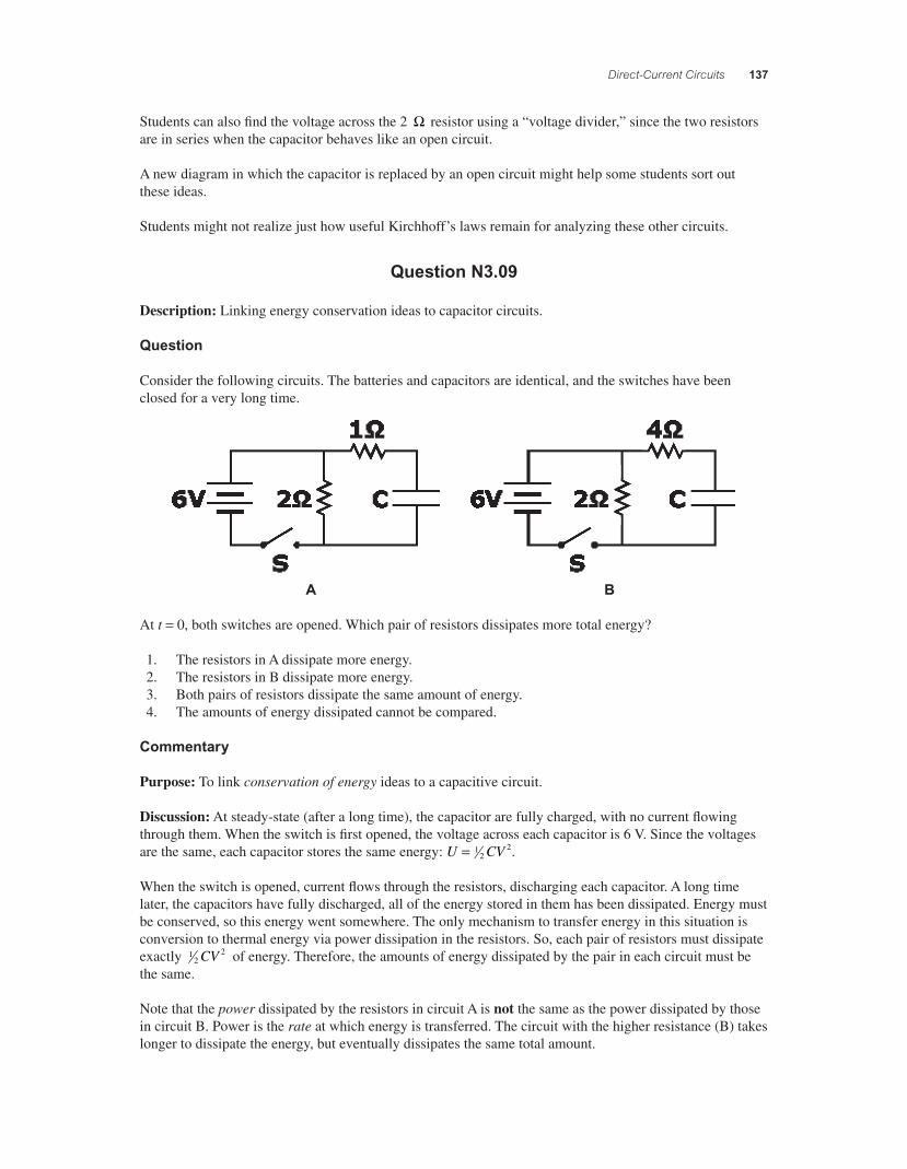
Consider the following circuits. The batteries and capacitors are identical, and the switches have been closed for a very long time.
A B
At t = 0, both switches are opened. Which pair of resistors dissipates more total energy?
1. The resistors in A dissipate more energy. 2. The resistors in B dissipate more energy. 3. Both pairs of resistors dissipate the same amount of energy. 4. The amounts of energy dissipated cannot be compared.
Commentary
Purpose: To link conservation of energy ideas to a capacitive circuit.
Discussion: At steady-state (after a long time), the capacitor are fully charged, with no current fl owing through them. When the switch is fi rst opened, the voltage across each capacitor is 6 V. Since the voltages are the same, each capacitor stores the same energy: U CV= 1
22.
When the switch is opened, current fl ows through the resistors, discharging each capacitor. A long time later, the capacitors have fully discharged, all of the energy stored in them has been dissipated. Energy must be conserved, so this energy went somewhere. The only mechanism to transfer energy in this situation is conversion to thermal energy via power dissipation in the resistors. So, each pair of resistors must dissipate exactly 1
22CV of energy. Therefore, the amounts of energy dissipated by the pair in each circuit must be
the same.
Note that the power dissipated by the resistors in circuit A is not the same as the power dissipated by those in circuit B. Power is the rate at which energy is transferred. The circuit with the higher resistance (B) takes longer to dissipate the energy, but eventually dissipates the same total amount.
56157_18_ch18_p110-170.indd 13756157_18_ch18_p110-170.indd 137 3/19/08 1:35:30 AM3/19/08 1:35:30 AM
138 Chapter 18
Key Points:
• The energy stored in a capacitor with capacitance C and voltage V across it is U CV= 12
2.
• Although you learned the principle of conservation of energy in mechanics, it applies to other areas of physics as well.
• Do not confuse energy with power. Power is the rate at which energy is transferred, and has units of energy per unit time.
For Instructors Only
Fruitful use of this question requires that students are comfortable enough with capacitance to know that both capacitors will have the same initial voltage.
Students choosing answer (1) may be reasoning that circuit A dissipates more energy because it has a lower resistance and thus higher initial current. Students choosing answer (2) may be reasoning that circuit B dissipates more energy because current fl ows in it for longer (i.e., has a large time constant RC).
If any students choose answer (4), you should ask them what information they need to be able to answer the question. (They are likely to say they need a value for C in order to calculate the energy stored. In this case, stress that the question is qualitative and comparative, and does not require calculations.)
QUICK QUIZZES
1. True. When a battery is delivering a current, there is a voltage drop within the battery due to internal resistance, making the terminal voltage less than the emf.
2. Because of internal resistance, power is dissipated into the battery material, raising its temperature.
3. (b). When the switch is opened, resistors R1 and R2 are in series, so that the total circuit resistance is larger than when the switch was closed. As a result, the current decreases.
4. (a). When the switch is opened, resistors R1 and R2 are in series, so the total circuit resistance is larger, and the current through R1 is less, with the switch open than when it is closed. Since the power delivered to R1 isP = I R2
1 , P Po c< .
5. (a). When the switch is closed, resistors R1 and R2 are in parallel, so that the total circuit resistance is smaller than when the switch was open. As a result, the current increases.
6. (b). Observe that the potential difference across R1 equals the terminal potential difference of the battery. If the battery has negligible internal resistance, the terminal potential difference is the same with the switch open or closed. Under these conditions, the power delivered to R1, equal toP = ( )"V R2
1, is unchanged when the switch is closed.
56157_18_ch18_p110-170.indd 13856157_18_ch18_p110-170.indd 138 3/19/08 1:35:31 AM3/19/08 1:35:31 AM
Direct-Current Circuits 139
7. The voltage drop across each bulb connected in parallel with each other and across the battery equals the terminal potential difference of the battery. As more bulbs are added, the current sup-plied by the battery increases. However, if the internal resistance is negligible, the terminal poten-tial difference is constant and the current through each bulb is the same regardless of the number of bulbs connected. Under these conditions: (a) The brightness of a bulb, determined by the current fl owing in the bulb, is unchanged as bulbs are added. (b) The individual currents in the bulbs, I V R= " , are constant as bulbs are added since "V does not change. (c) The total power delivered by the battery increases by an amount "V R( )2 each time a bulb is added. (d) With the total delivered power increasing, energy is drawn from the battery at an increasing rate and the battery’s lifetime decreases.
8. Adding bulbs in series with each other and the battery increases the total load resistance seen by the battery. This means that the current supplied by the battery decreases with each new bulb that is added. (a) The brightness of a bulb is determined by the power delivered to that bulb, Pbulb = I R2 , decreases as bulbs are added and the current decreases. (b) For a series connection, the individual currents in the bulbs are the same and equal to the total current supplied by the battery. This decreases as bulbs are added. (c) The total power delivered by the battery is given by Ptotal = ( )"V I , where "V is the terminal potential difference of the battery and I is the total current supplied by the battery. With negligible internal resistance, "V is constant. Thus, with I decreasing as bulbs are added, the total delivered power decreases. (d) With the delivered power decreasing, energy is drawn from the battery at a decreasing rate, which increases the lifetime of the battery.
9. (c). After the capacitor is fully charged, current fl ows only around the outer loop of the circuit. This path has a total resistance of 3 !, so the 6-V battery will supply a current of 2 amperes.
ANSWERS TO MULTIPLE CHOICE QUESTIONS
1. In a series connection, the same current exists in each element. The potential difference across a resistor in this series connection is directly proportional to the resistance of that resistor, "V IR= , and independent of its location within the series connection. The only true statement among the listed choices is (c).
2. The same potential difference exists across all elements connected in parallel with each other, while the current through each element is inversely proportional to the resistance of that element ( I V R= " ). Thus, both (b) and (c) are true statements while the other choices are false.
3. For these parallel resistors, 1 1
1 001
2 002 1
2 00Req = + = +
. . .! ! ! and Req
= =2 00
30 667
..
! !, and (c) is the correct answer.
4. The total power dissipated is P P Ptotal W W W= + = + =1 2 120 60 180 while the potential differ-ence across this series combination is "V = 120 V. The current drawn through the series combi-
nation is then IV
= = =Ptotal W120 V
A"
1801 5. , and (b) is the correct choice.
5. The potential difference across each element of this parallel combination is "V = 120 V and the total power dissipated is Ptotal W W W= + =1 200 600 1 800 . The total current through the parallel combination, and hence, the current drawn from the external source is then
IP
V= = =total W
120 V A
"1 800
15 . The correct choice is (e).
56157_18_ch18_p110-170.indd 13956157_18_ch18_p110-170.indd 139 3/19/08 1:35:32 AM3/19/08 1:35:32 AM
140 Chapter 18
6. The equivalent resistance of the parallel combination consisting of the 4 0. !, 6.0 !, and 10 ! resistors is Rp = 1 9. !. This resistance is in series with a 2 0. ! resistor, making the total resistance of the circuit Rtotal = 3 9. !. The total current supplied by the battery is I V Rtotal total V 3.9 A= = =" !12 3 1. . Thus, the potential difference across each resistor in the parallel combination is " !V R Ip p= = ( )( ) =total A V1 9 3 1 5 9. . . and the current through the 10 ! resistor is I Vp10 10 5 9 0 59= = =" ! ! V 10 A. . . Choice (a) is the correct answer.
7. The equation of choice (b) is the result of a correct application of Kirchhoff’s junction rule at either of the two junctions in the circuit. The equation of choice (c) results from a correct applica-tion of Kirchhoff’s loop rule to the lower loop in the circuit, while the equation of choice (d) is obtained by correctly applying the loop rule to the loop forming the outer perimeter of the circuit. The equation of choice (a) is the result of an incorrect application (involving two sign errors) of the loop rule to the upper loop in the circuit. The correct answer is choice (a).
8. When the two identical resistors are in series, the current supplied by the battery is I V R= " 2 , and the total power delivered is Ps V I V R= ( ) = ( )" " 2 2 . With the resistors connected in paral-lel, the potential difference across each resistor is "V and the power delivered to each resistor isP1
2= ( )"V R. Thus, the total power delivered in this case is
P Pp s
VR
VR
P= = ( ) = ( )#
$%%
&
'((
= = (2 2 42
4 4 8 01
2 2" ". W)) = 32 W
and (b) is the correct choice.
9. The equivalent resistance for the series combination of fi ve identical resistors is R Req = 5 , and the equivalent capacitance of fi ve identical capacitors in parallel is C Ceq = 5 . The time constant for the circuit is therefore ) = = ( )( ) =R C R C RCeq eq 5 5 25 , and (d) is the correct choice.
10. When the switch is closed, the current has a large initial value but decreases exponentially in time. The bulb will glow brightly at fi rst, but fade rapidly as the capacitor charges. After a time equal to many time constants of the circuit, the current is essentially zero and the bulb does not glow. The correct answer is choice (c).
11. The equivalent resistance of a group of resistors connected in parallel is the reciprocal of the inverses of the individual resistances and is always less than the smallest resistance in the group. Therefore, both (b) and (e) are true statements while all other choices are false.
12. The equivalent resistance of a series combination of resistors is the algebraic sum of the individ-ual resistances and is always greater than any individual resistance. Therefore, choices (a) and (d) are true statements and all others are false.
13. With the capacitor initially uncharged, the potential difference across the capacitor, "V q C= , starts at zero when the switch is fi rst closed and rises exponentially toward the equilibrium value of " "V V( ) = =max .battery V6 00 . The time constant of the circuit is the time required for the charge (and hence the potential difference) to increase from 0 to 63 2. % of the maximum equi-librium value. Thus, after one time constant, the potential difference across the capacitor will be "V = ( ) =0 632 6 00 3 79. . . V V. The correct answer is choice (d).
56157_18_ch18_p110-170.indd 14056157_18_ch18_p110-170.indd 140 3/19/08 1:35:33 AM3/19/08 1:35:33 AM
Direct-Current Circuits 141
ANSWERS TO EVEN NUMBERED CONCEPTUAL QUESTIONS
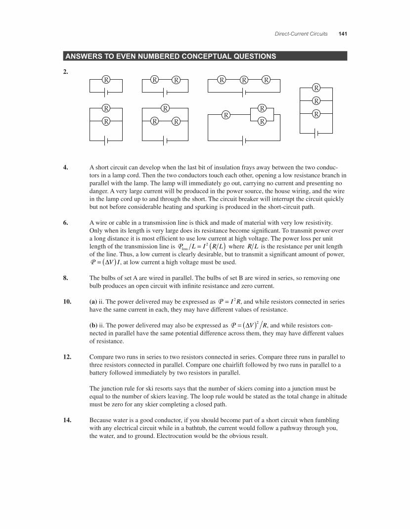
2.
4. A short circuit can develop when the last bit of insulation frays away between the two conduc-tors in a lamp cord. Then the two conductors touch each other, opening a low resistance branch in parallel with the lamp. The lamp will immediately go out, carrying no current and presenting no danger. A very large current will be produced in the power source, the house wiring, and the wire in the lamp cord up to and through the short. The circuit breaker will interrupt the circuit quickly but not before considerable heating and sparking is produced in the short-circuit path.
6. A wire or cable in a transmission line is thick and made of material with very low resistivity. Only when its length is very large does its resistance become signifi cant. To transmit power over a long distance it is most effi cient to use low current at high voltage. The power loss per unit length of the transmission line is Ploss L I R L= ( )2 where R L is the resistance per unit length of the line. Thus, a low current is clearly desirable, but to transmit a signifi cant amount of power, P = ( )"V I , at low current a high voltage must be used.
8. The bulbs of set A are wired in parallel. The bulbs of set B are wired in series, so removing one bulb produces an open circuit with infi nite resistance and zero current.
10. (a) ii. The power delivered may be expressed as P = I R2 , and while resistors connected in series have the same current in each, they may have different values of resistance.
(b) ii. The power delivered may also be expressed as P = ( )"V R2 , and while resistors con-nected in parallel have the same potential difference across them, they may have different values of resistance.
12. Compare two runs in series to two resistors connected in series. Compare three runs in parallel to three resistors connected in parallel. Compare one chairlift followed by two runs in parallel to a battery followed immediately by two resistors in parallel.
The junction rule for ski resorts says that the number of skiers coming into a junction must be equal to the number of skiers leaving. The loop rule would be stated as the total change in altitude must be zero for any skier completing a closed path.
14. Because water is a good conductor, if you should become part of a short circuit when fumbling with any electrical circuit while in a bathtub, the current would follow a pathway through you, the water, and to ground. Electrocution would be the obvious result.
56157_18_ch18_p110-170.indd 14156157_18_ch18_p110-170.indd 141 3/19/08 1:35:34 AM3/19/08 1:35:34 AM
142 Chapter 18
PROBLEM SOLUTIONS
18.1 From "V I R r= +( ) , the internal resistance is
rVI
R= * = * =" ! !9 0072 0 4 92
.. .
V0.117 A
18.2 (a) When the three resistors are in series, the equivalent resistance of the circuit is R R R Req = + + = ( ) =1 2 3 3 9 0 27. ! !
(b) The terminal potential difference of the battery is applied across the series combination of the three 9 0. ! resistors, so the current supplied by the battery and the current through each resistor in the series combination is
IV
R= = ="
!eq
V27
A12
0 44.
(c) If the three 9 0. ! are now connected in parallel with each other, the equivalent resistance is
1 19 0
19 0
19 0
39 0Req
= + + =. . . .! ! ! !
or
Req
= =9 0
33 0
..
! !
When this parallel combination is connected to the battery, the potential difference across each resistor in the combination is "V = 12 V, so the current through each of the resistors is
IVR
= = ="!
121 3
V9.0
A.
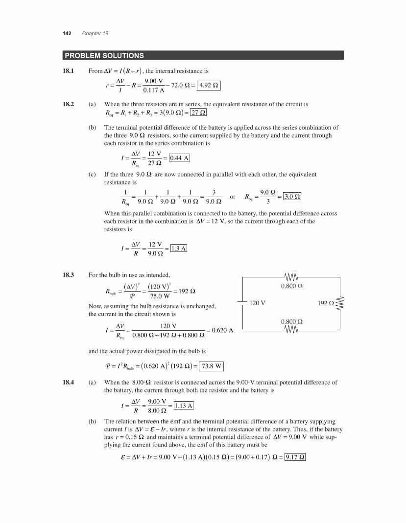
18.3 For the bulb in use as intended,
RV
bulb
V W
= ( ) = ( ) =" !2 2120
75 0192
P .
Now, assuming the bulb resistance is unchanged, the current in the circuit shown is
IV
R= =
+ +="
! ! !eq
V0.800
A120192 0 800
0 620.
.
and the actual power dissipated in the bulb is
P = = ( ) ( ) =I R2 20 620 192 73 8bulb A W. .!
18.4 (a) When the 8 00. -! resistor is connected across the 9.00-V terminal potential difference of the battery, the current through both the resistor and the battery is
IVR
= = ="!
9 001 13
..
V8.00
A
(b) The relation between the emf and the terminal potential difference of a battery supplying current I is "V Ir= *+ , where r is the internal resistance of the battery. Thus, if the battery has r = 0 15. ! and maintains a terminal potential difference of "V = 9 00. V while sup-plying the current found above, the emf of this battery must be
+ = + = + ( )( ) = +( )" !V Ir 9 00 1 13 0 15 9 00 0 17. . . . . V A ! != 9 17.
56157_18_ch18_p110-170.indd 14256157_18_ch18_p110-170.indd 142 3/19/08 1:35:35 AM3/19/08 1:35:35 AM
Direct-Current Circuits 143
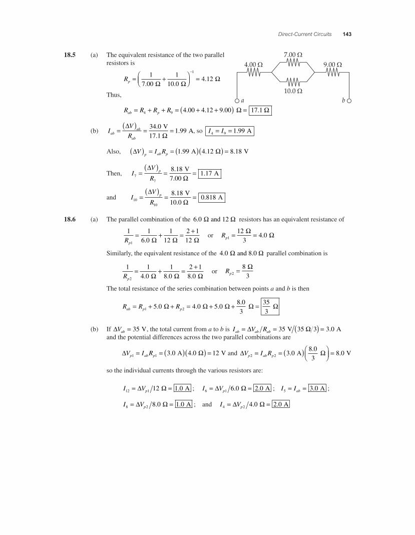
18.5 (a) The equivalent resistance of the two parallel resistors is
Rp = +,-.
/01 =
*17 00
110 0
4 121
. ..
! !!
Thus,
R R R Rab p= + + = + +( ) =4 9 4 00 4 12 9 00 17 1. . . . ! !
(b) IV
Rabab
ab
=( )
= ="
!34 017 1
1 99..
. V
A, so I I4 9 1 99= = . A
Also, " !V I Rp ab p( ) = = ( )( ) =1 99 4 12 8 18. . . A V
Then, IV
Rp
77
8 181 17=
( )= =
"!
..
V7.00
A
and IV
Rp
1010
8 180 818=
( )= =
"!
..
V10.0
A
18.6 (a) The parallel combination of the 6 0. and 12 ! ! resistors has an equivalent resistance of
1 16 0
112
2 1121Rp
= + = +. ! ! !
or Rp1
123
4 0= =
! !.
Similarly, the equivalent resistance of the 4 0. and 8.0 ! ! parallel combination is
1 1
4 01
8 02 1
8 02Rp
= + = +. . . ! ! !
or Rp2
83
= !
The total resistance of the series combination between points a and b is then
R R Rab p p= + + = + + =1 25 0 4 0 5 08 03
353
. . ..
! ! ! ! !
(b) If "Vab = 35 V, the total current from a to b is I V Rab ab ab= = ( ) =" !35 3 0 V 35 3 A.and the potential differences across the two parallel combinations are
" !V I Rp ab p1 1 3 0 4 0 12= = ( )( ) =. . A V and " !V I Rp ab p2 2 3 08 03
8 0= = ( ),-.
/01 =.
.. A V
so the individual currents through the various resistors are:
I Vp12 1 12 1 0= =" ! A. ; I Vp6 1 6 0 2 0= =" !. . A ; I Iab5 3 0= = . A ;
I Vp8 2 8 0 1 0= =" !. . A ; and I Vp4 2 4 0 2 0= =" !. . A
56157_18_ch18_p110-170.indd 14356157_18_ch18_p110-170.indd 143 3/19/08 1:35:36 AM3/19/08 1:35:36 AM
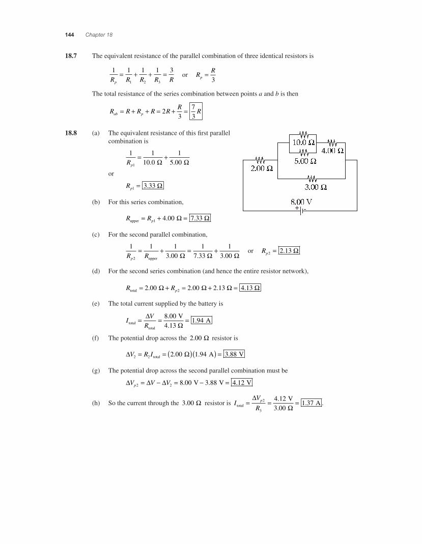
144 Chapter 18
18.7 The equivalent resistance of the parallel combination of three identical resistors is
1 1 1 1 3
1 2 3R R R R Rp
= + + = or RR
p =3
The total resistance of the series combination between points a and b is then
R R R R RR
Rab p= + + = + =23
73
18.8 (a) The equivalent resistance of this fi rst parallel combination is
1 1
10 01
5 001Rp
= +. . ! !
or
Rp1 3 33= . !
(b) For this series combination,
R Rpupper = + =1 4 00 7 33. .! !
(c) For the second parallel combination,
1 1 1
3 001
7 331
3 002R Rp
= + = +upper . . .! ! !
or Rp2 2 13= . !
(d) For the second series combination (and hence the entire resistor network),
R Rptotal = + = + =2 00 2 00 2 13 4 132. . . .! ! ! !
(e) The total current supplied by the battery is
IV
Rtotaltotal
V
A= = ="!
8 004 13
1 94..
.
(f) The potential drop across the 2 00. ! resistor is
" !V R I2 2 2 00 1 94 3 88= = ( )( ) =total A V. . .
(g) The potential drop across the second parallel combination must be
" " "V V Vp2 2 8 00 3 88 4 12= * = * =. . . V V V
(h) So the current through the 3 00. ! resistor is IV
Rp
total
V
A= = ="
!2
3
4 123 00
1 37..
. .
56157_18_ch18_p110-170.indd 14456157_18_ch18_p110-170.indd 144 3/19/08 1:35:37 AM3/19/08 1:35:37 AM
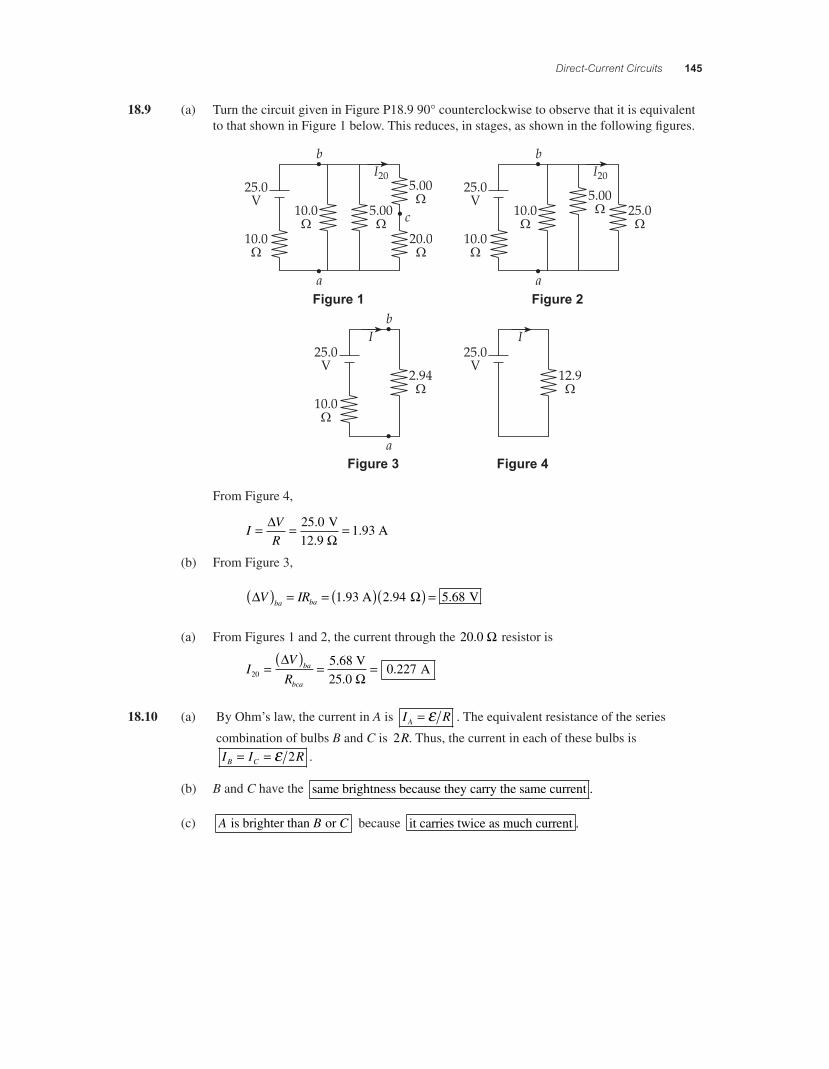
Direct-Current Circuits 145
18.9 (a) Turn the circuit given in Figure P18.9 90° counterclockwise to observe that it is equivalent to that shown in Figure 1 below. This reduces, in stages, as shown in the following fi gures.
Figure 1 Figure 2
Figure 3 Figure 4
From Figure 4,
IVR
= = ="!
25 01 93
..
V12.9
A
(b) From Figure 3,
" !V IRba ba( ) = = ( )( ) =1 93 2 94 5 68. . . A V
(a) From Figures 1 and 2, the current through the 20.0 ! resistor is
IV
Rba
bca20
50 227=
( )= =
"!
.68 V25.0
A.
18.10 (a) By Ohm’s law, the current in A is I RA = + . The equivalent resistance of the series
combination of bulbs B and C is 2R. Thus, the current in each of these bulbs isI I RB C= = + 2 .
(b) B and C have the same brightness because they carry the same current .
(c) A B C is brighter than or because it carries twice as much current .
56157_18_ch18_p110-170.indd 14556157_18_ch18_p110-170.indd 145 3/19/08 1:35:38 AM3/19/08 1:35:38 AM
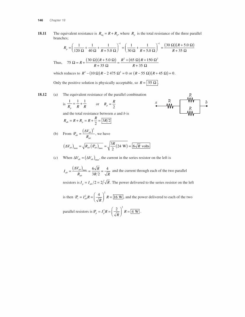
146 Chapter 18
18.11 The equivalent resistance is R R Rpeq = + , where Rp is the total resistance of the three parallel branches;
R
R Rp = + ++
,-.
/01 = +
+
*1120
14
15 0
13
15
1
0 0 ! ! ! !. ...
030 5 0
35
1
!! !
!,-.
/01 = ( ) +( )
+
* RR
Thus, 7530 5 0
3565 1502
! ! !
!!= + ( ) +( )
+= + ( ) +
RR
RR R.
!
!
2
35R +
which reduces to R R2 21 2 475 0* ( ) * =0 ! ! or R R*( ) +( ) =55 45 0 ! ! .
Only the positive solution is physically acceptable, so R = 55 ! .
18.12 (a) The equivalent resistance of the parallel combination
is 1 1 1R R Rp
= + or RR
p =2
and the total resistance between a and b is
R R R RR
Rab p= + = + =2
3 2
(b) From Pabab
ab
V
R= ( )" 2
, we have
"V R
RRab ab ab( ) = ( ) = ( ) =
max maxP 3
224 6 W volts
(c) When " "V Vab ab= ( )max, the current in the series resistor on the left is
IV
RR
R Rabab
ab
=( )
= ="
max 63 2
4 and the current through each of the two parallel
resistors is I I Rp ab= =2 2 . The power delivered to the series resistor on the left
is then Ps abI RR
R= = ,-.
/01
=22
416 W , and the power delivered to each of the two
parallel resistors isPp pI RR
R= = ,-.
/01
=22
24 W .
56157_18_ch18_p110-170.indd 14656157_18_ch18_p110-170.indd 146 3/19/08 1:35:38 AM3/19/08 1:35:38 AM
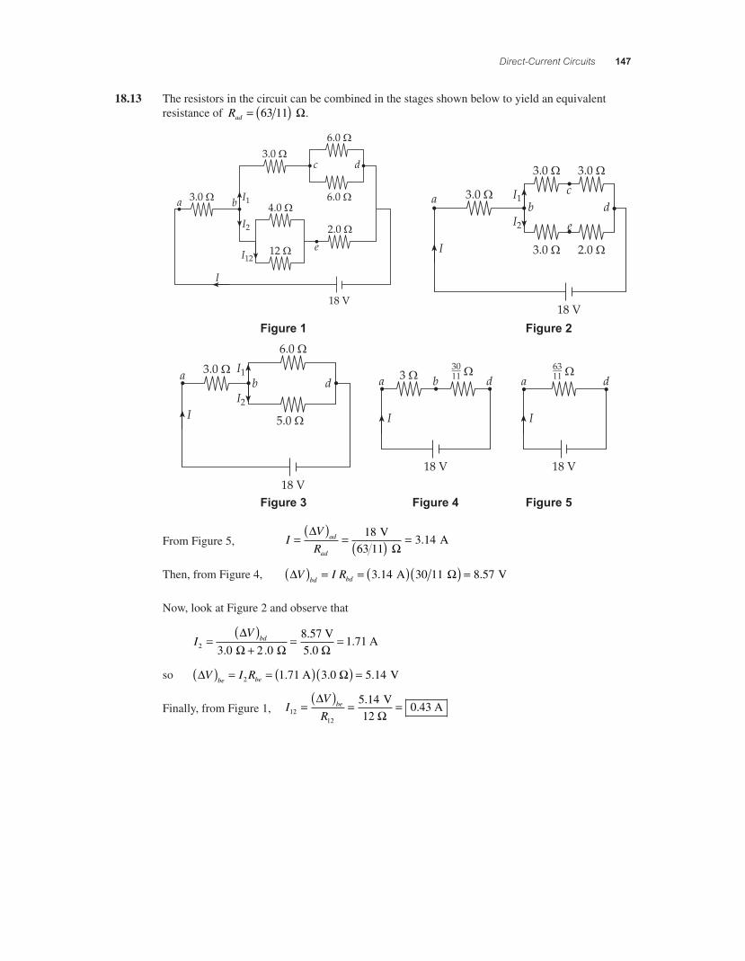
Direct-Current Circuits 147
18.13 The resistors in the circuit can be combined in the stages shown below to yield an equivalent resistance of Rad = ( )63 11 !.
Figure 1 Figure 2
Figure 3 Figure 5Figure 4
From Figure 5, IV
Rad
ad
=( )
= ( ) ="
!18
3 14 V
63 11 A.
Then, from Figure 4, " !V I Rbd bd( ) = = ( )( ) =3 14 30 11 8 57. . A V
Now, look at Figure 2 and observe that
IV bd
2 3 0 2 08
1 71=( )
+= =
"! ! !. .
.
.57 V5.0
A
so " !V I Rbe be( ) = = ( )( ) =2 1 71 5 14. . A 3.0 V
Finally, from Figure 1, IV
Rbe
1212
5 140 43=
( )= =
"!
..
V12
A
56157_18_ch18_p110-170.indd 14756157_18_ch18_p110-170.indd 147 3/19/08 1:35:39 AM3/19/08 1:35:39 AM
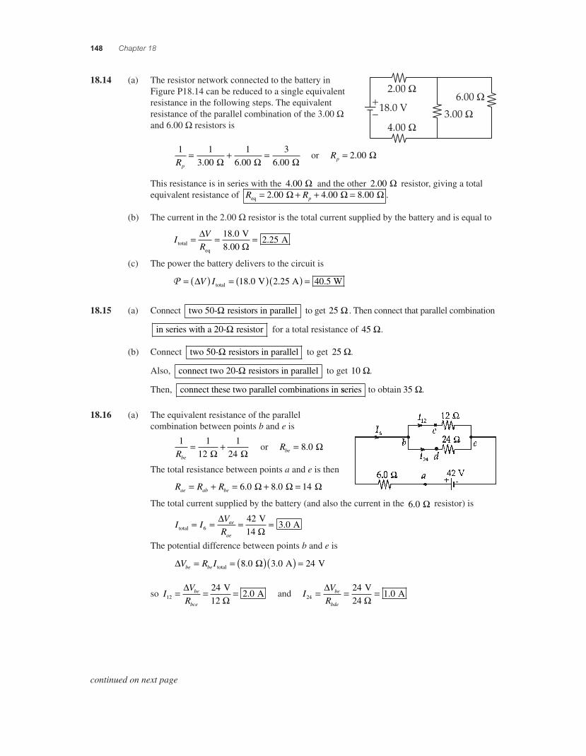
148 Chapter 18
18.14 (a) The resistor network connected to the battery in
4.00 !
+"
2.00 !6.00 !
3.00 !18.0 V
Figure P18.14 can be reduced to a single equivalent resistance in the following steps. The equivalent resistance of the parallel combination of the 3.00 ! and 6.00 ! resistors is
1 1
3 001
6 003
6 00Rp
= + =. . . ! ! !
or Rp = 2 00. !
This resistance is in series with the 4 00. ! and the other 2 00. ! resistor, giving a total equivalent resistance of R Rpeq = + + =2 00 4 00 8 00. . . .! ! !
(b) The current in the 2.00 ! resistor is the total current supplied by the battery and is equal to
IV
Rtotaleq
V8.00
A= = ="!
18 02 25
..
(c) The power the battery delivers to the circuit is
P = ( ) = ( )( ) ="V I total V A W18 0 2 25 40 5. . .
18.15 (a) Connect two 50- resistors in parallel! to get 25 ! . Then connect that parallel combination
in series with a 20- resistor! for a total resistance of 45 !.
(b) Connect two 50- resistors in parallel! to get 25 !.
Also, connect two 20- resistors in parallel! to get 10 !.
Then, connect these two parallel combinations in sseries to obtain 35 !.
18.16 (a) The equivalent resistance of the parallel combination between points b and e is
1 1
121
24Rbe
= + ! !
or Rbe = 8 0. !
The total resistance between points a and e is then
R R Rae ab be= + = + =6 0 8 0 14. . ! ! !
The total current supplied by the battery (and also the current in the 6 0. ! resistor) is
I IV
Rae
aetotal
V14
A= = = =6
423 0
"!
.
The potential difference between points b and e is
" !V R Ibe be= = ( )( ) =total A V8 0 3 0 24. .
so IV
Rbe
bce12
242 0= = ="
! V
12 A. and I
VR
be
bde24
241 0= = ="
! V
24 A.
continued on next page
56157_18_ch18_p110-170.indd 14856157_18_ch18_p110-170.indd 148 3/19/08 3:30:36 AM3/19/08 3:30:36 AM
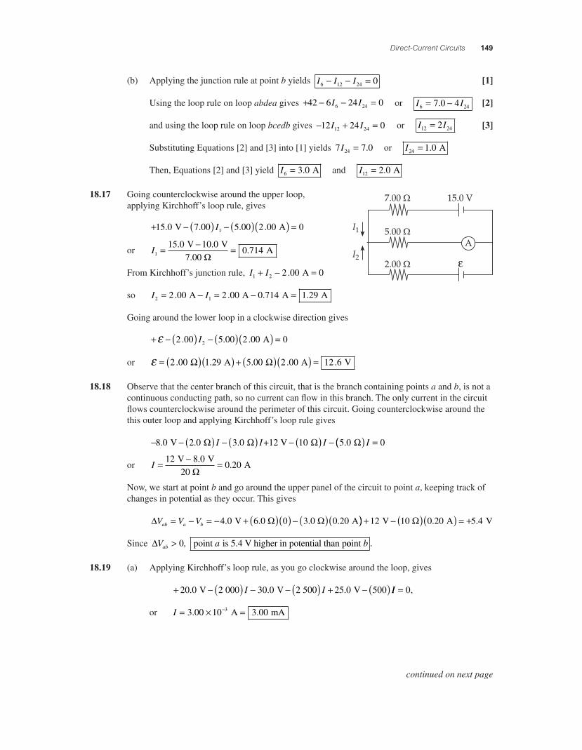
Direct-Current Circuits 149
(b) Applying the junction rule at point b yields I I I6 12 24 0! ! = [1]
Using the loop rule on loop abdea gives + ! ! =42 6 24 06 24I I or I I6 247 0 4= !. [2]
and using the loop rule on loop bcedb gives ! + =12 24 012 24I I or I I12 242= [3]
Substituting Equations [2] and [3] into [1] yields 7 7 024I = . or I24 1 0= . A
Then, Equations [2] and [3] yield I6 3 0= . A and I12 2 0= . A
18.17 Going counterclockwise around the upper loop,
!
applying Kirchhoff’s loop rule, gives
+ ! ( ) ! ( )( ) =15 0 7 00 5 00 2 00 01. . . . V AI
or I1
15 0 10 00 714= ! =. .
. V V7.00
A"
From Kirchhoff’s junction rule, I I1 2 2 00 0+ ! =. A
so I I2 12 00 2 00 0 714 1 29= ! = ! =. . . . A A A A
Going around the lower loop in a clockwise direction gives
+ ! ( ) ! ( )( ) =# 2 00 5 00 2 00 02. . .I A
or # = ( )( ) + ( )( ) =2 00 1 29 5 00 2 00 12 6. . . . . A A V" "
18.18 Observe that the center branch of this circuit, that is the branch containing points a and b, is not a continuous conducting path, so no current can fl ow in this branch. The only current in the circuit fl ows counterclockwise around the perimeter of this circuit. Going counterclockwise around the this outer loop and applying Kirchhoff’s loop rule gives
! ! ( ) ! ( ) ! ( ) !8 0 2 0 3 0 10 5 0. . . . V +12 V " " " "I I I (( ) =I 0
or I = ! =12 8 00 20
V V20
A.
."
Now, we start at point b and go around the upper panel of the circuit to point a, keeping track of changes in potential as they occur. This gives
$ " "V V Vab a b= ! = ! + ( )( ) ! ( )(4 0 0 0 20. . V 6.0 3.0 A)) + ! ( )( ) = +12 0 20 5 4 V 10 A V" . .
Since $Vab > 0, point is 5.4 V higher in potential than pa ooint b .
18.19 (a) Applying Kirchhoff’s loop rule, as you go clockwise around the loop, gives
+ ! ( ) ! ! ( ) + ! ( )20 0 2 000 30 0 2 500 25 0 500. . . V V VI I II = 0,
or I = % =!3 00 10 3 003. . A mA
continued on next page
56157_18_ch18_p110-170.indd 14956157_18_ch18_p110-170.indd 149 3/19/08 3:30:37 AM3/19/08 3:30:37 AM
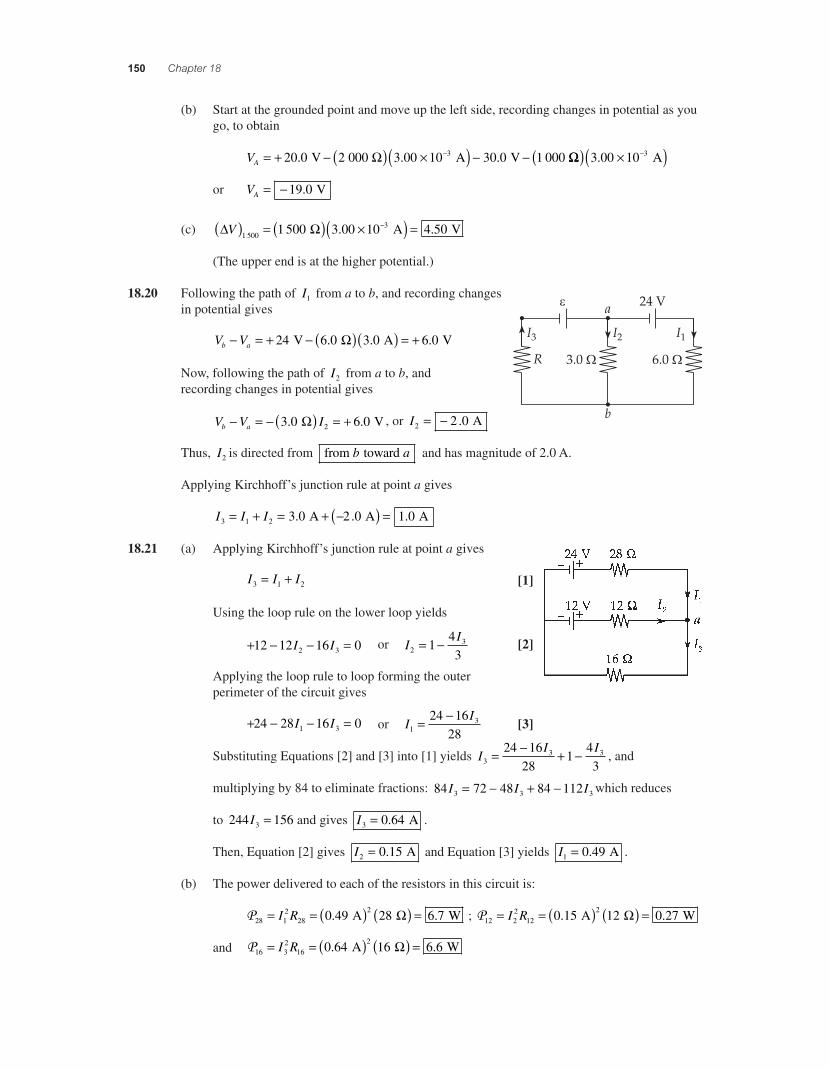
150 Chapter 18
(b) Start at the grounded point and move up the left side, recording changes in potential as you go, to obtain
VA = + * ( ) 2( ) * **20 0 2 000 3 00 10 30 0 1 0003. . . V A V! !!( ) 2( )*3 00 10 3. A
or VA = * 19 0. V
(c) " !V( ) = ( ) 2( ) =*1 500
31 500 3 00 10 4 50 A V. .
(The upper end is at the higher potential.)
18.20 Following the path of I1 from a to b, and recording changes in potential gives
V Vb a* = + * ( )( ) = +24 6 0 3 0 6 0 V A V. . .!
Now, following the path of I2 from a to b, and recording changes in potential gives
V V Ib a* = * ( ) = +3 0 6 02. . V! , or I2 2 0= * . A
Thus, I2 is directed from from toward b a and has magnitude of 2.0 A.
Applying Kirchhoff’s junction rule at point a gives
I I I3 1 2 3 0 2 0 1 0= + = + *( ) =. . . A A A
18.21 (a) Applying Kirchhoff’s junction rule at point a gives
I I I3 1 2= + [1]
Using the loop rule on the lower loop yields
+ * * =12 12 16 02 3I I or II
231
43
= * [2]
Applying the loop rule to loop forming the outer perimeter of the circuit gives
+ * * =24 28 16 01 3I I or II
1324 16
28= *
[3]
Substituting Equations [2] and [3] into [1] yields II I
33 324 16
281
43
= * + * , and
multiplying by 84 to eliminate fractions: 84 72 48 84 1123 3 3I I I= * + * which reduces
to 244 1563I = and gives I3 0 64= . A .
Then, Equation [2] gives I2 0 15= . A and Equation [3] yields I1 0 49= . A .
(b) The power delivered to each of the resistors in this circuit is:
P28 12
2820 49 28 6 7= = ( ) ( ) =I R . . A W! ; P12 2
212
20 15 12 0 27= = ( ) ( ) =I R . . A W!
and P16 32
1620 64 16 6 6= = ( ) ( ) =I R . . A W!
56157_18_ch18_p110-170.indd 15056157_18_ch18_p110-170.indd 150 3/19/08 1:35:42 AM3/19/08 1:35:42 AM
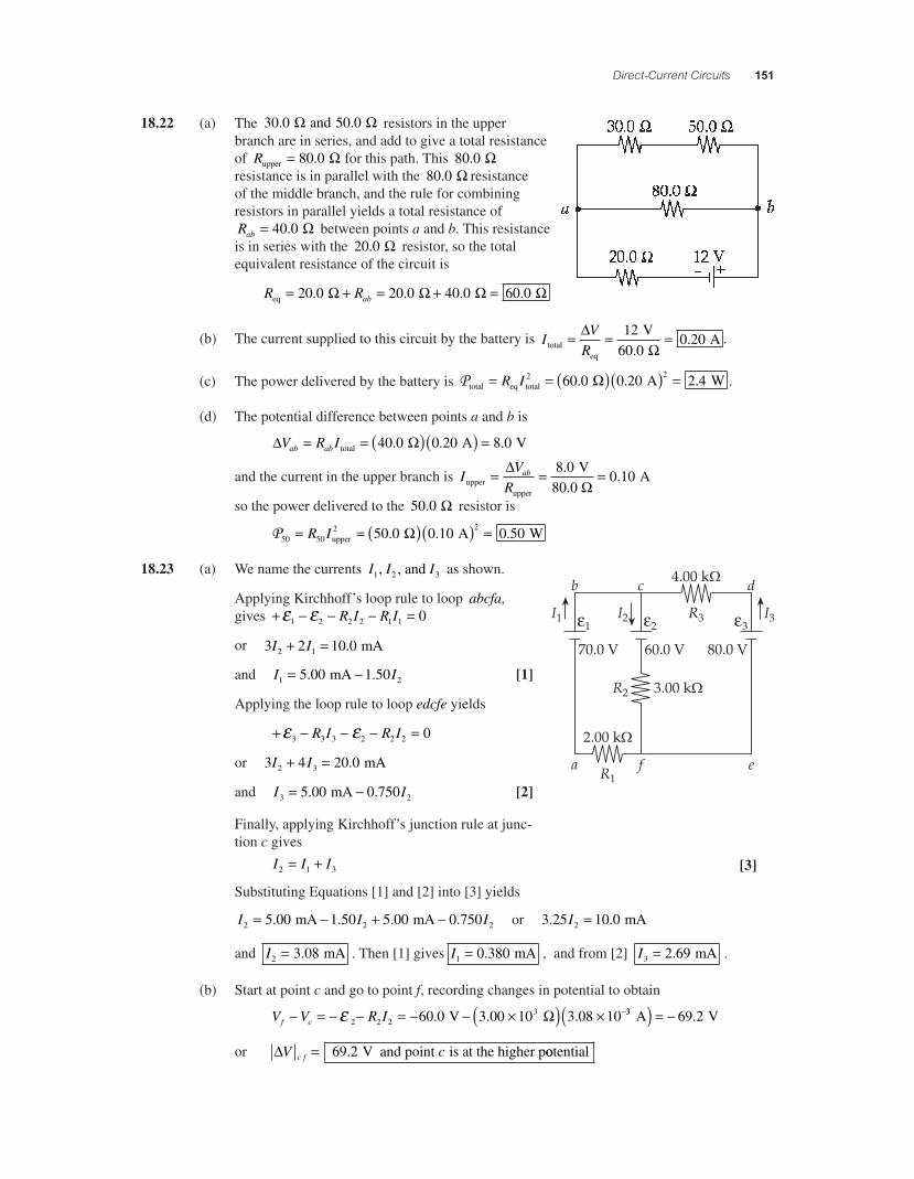
Direct-Current Circuits 151
18.22 (a) The 30 0 50 0. . and ! ! resistors in the upper branch are in series, and add to give a total resistance of Rupper = 80 0. ! for this path. This 80 0. ! resistance is in parallel with the 80 0. ! resistance of the middle branch, and the rule for combining resistors in parallel yields a total resistance of Rab = 40 0. ! between points a and b. This resistance is in series with the 20 0. ! resistor, so the total equivalent resistance of the circuit is
R Rabeq = + = + =20 0 20 0 40 0 60 0. . . .! ! ! !
(b) The current supplied to this circuit by the battery is IV
Rtotaleq
V
A= = ="!
1260 0
0 20.
. .
(c) The power delivered by the battery is Ptotal eq total A W= = ( )( ) =R I 2 260 0 0 20 2 4. . .! .
(d) The potential difference between points a and b is
" !V R Iab ab= = ( )( ) =total A V40 0 0 20 8 0. . .
and the current in the upper branch is IV
Rab
upperupper
V80.0
A= = ="!
8 00 10
..
so the power delivered to the 50 0. ! resistor is
P50 502 250 0 0 10 0 50= = ( )( ) =R Iupper A W. . .!
18.23 (a) We name the currents I I I1 2 3, , and as shown.
" " " Applying Kirchhoff’s loop rule to loop abcfa,
gives + * * * =+ +1 2 2 2 1 1 0R I R I
or 3 2 10 02 1I I+ = . mA
and I I1 25 00 1 50= *. . mA [1]
Applying the loop rule to loop edcfe yields
+ * * * =+ +3 3 3 2 2 2 0R I R I
or 3 4 20 02 3I I+ = . mA
and I I3 25 00 0 750= *. . mA [2]
Finally, applying Kirchhoff’s junction rule at junc-tion c gives
I I I2 1 3= + [3]
Substituting Equations [1] and [2] into [3] yields
I I I2 2 25 00 1 50 5 00 0 750= * + *. . . . mA mA or 3 25 10 02. .I = mA
and I2 3 08= . mA . Then [1] gives I1 0 380= . mA , and from [2] I3 2 69= . mA .
(b) Start at point c and go to point f, recording changes in potential to obtain
V V R If c* = * * = * * 2( ) 2 *+ 2 2 2360 0 3 00 10 3 08 10. . . V ! 33 69 2 A V( ) = * .
or "V cc f = 69 2. V and point is at the higher pootential
56157_18_ch18_p110-170.indd 15156157_18_ch18_p110-170.indd 151 3/19/08 1:35:43 AM3/19/08 1:35:43 AM
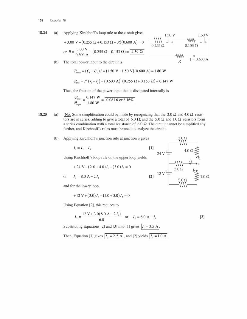
152 Chapter 18
18.24 (a) Applying Kirchhoff’s loop rule to the circuit gives
+ * + +( )( ) =3 00 0 255 0 153 0 600 0. . . . V A! ! R
or R = * +( ) =3 000 600
0 255 0 153 4 59.
.. . .
V A
! ! !
(b) The total power input to the circuit is
Pinput V V A= +( ) = +( )( ) =+ +1 2 1 50 1 50 0 600 1I . . . .880 W
Ploss A .255 .153 = +( ) = ( ) +( )I r r21 2
20 600 0 0. ! ! == 0 147. W
Thus, the fraction of the power input that is dissipated internally is
PP
loss
input
W W
or 8.16%= =0 1471 80
0 081 6..
.
18.25 (a) No. Some simplifi cation could be made by recognizing that the 2 0. and 4.0 ! ! resis-tors are in series, adding to give a total of 6 0. !; and the 5 0. and 1.0 ! ! resistors form a series combination with a total resistance of 6 0. !. The circuit cannot be simplifi ed any further, and Kirchhoff’s rules must be used to analyze the circuit.
(b) Applying Kirchhoff’s junction rule at junction a gives
I I I1 2 3= + [1]
Using Kirchhoff’s loop rule on the upper loop yields
+ * +( ) * ( ) =24 2 0 4 0 3 0 01 3 V . . .I I
or I I3 18 0 2= *. A [2]
and for the lower loop,
+ + ( ) * +( ) =1 3 0 1 0 5 0 03 22 V . . .I I
Using Equation [2], this reduces to
II
211 3 0 8 0 2
6 0=
+ *( )2 V A. ..
or I I2 16 0= *. A [3]
Substituting Equations [2] and [3] into [1] gives I1 3 5= . A .
Then, Equation [3] gives I2 2 5= . A , and [2] yields I3 1 0= . A .
56157_18_ch18_p110-170.indd 15256157_18_ch18_p110-170.indd 152 3/19/08 1:35:45 AM3/19/08 1:35:45 AM
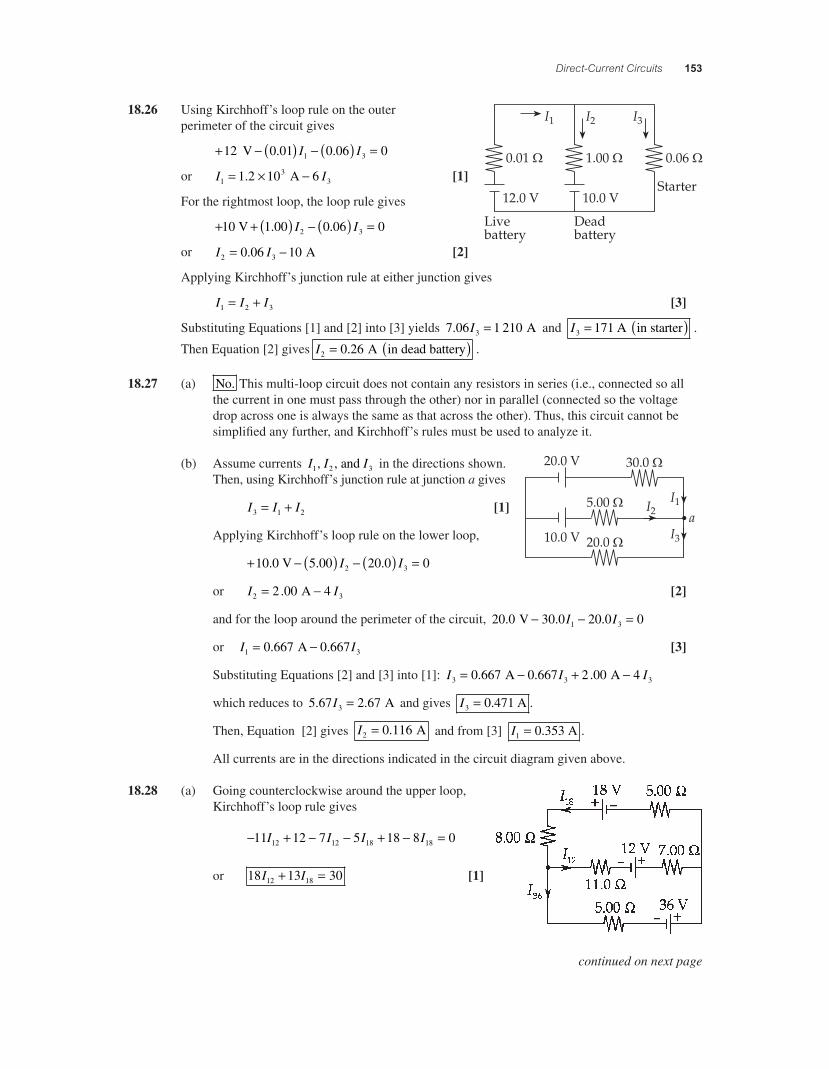
Direct-Current Circuits 153
18.26 Using Kirchhoff’s loop rule on the outer perimeter of the circuit gives
+ ! ( ) ! ( ) =1 0 01 0 06 01 32 V . .I I
or I I13
31 2 10 6= " !. A [1]
For the rightmost loop, the loop rule gives
+ + ( ) ! ( ) =1 1 00 0 06 02 30 V . .I I
or I I2 30 06 10= !. A [2]
Applying Kirchhoff’s junction rule at either junction gives
I I I1 2 3= + [3]
Substituting Equations [1] and [2] into [3] yields 7 06 1 2103. I = A and I3 171= ( ) A in starter .
Then Equation [2] gives I2 0 26= ( ). A in dead battery .
18.27 (a) No. This multi-loop circuit does not contain any resistors in series (i.e., connected so all the current in one must pass through the other) nor in parallel (connected so the voltage drop across one is always the same as that across the other). Thus, this circuit cannot be simplifi ed any further, and Kirchhoff’s rules must be used to analyze it.
(b) Assume currents I I I1 2 3, , and in the directions shown. Then, using Kirchhoff’s junction rule at junction a gives
I I I3 1 2= + [1]
Applying Kirchhoff’s loop rule on the lower loop,
+ ! ( ) ! ( ) =10 5 00 20 0 02 3.0 V . .I I
or I I2 32 00 4= !. A [2]
and for the loop around the perimeter of the circuit, 20 0 30 0 20 0 01 3. . . V ! ! =I I
or I I1 30 667 0 667= !. . A [3]
Substituting Equations [2] and [3] into [1]: I I I3 3 30 667 0 667 2 00 4= ! + !. . . A A
which reduces to 5 67 2 673. .I = A and gives I3 0 471= . A .
Then, Equation [2] gives I2 0 116= . A and from [3] I1 0 353= . A .
All currents are in the directions indicated in the circuit diagram given above.
18.28 (a) Going counterclockwise around the upper loop, Kirchhoff’s loop rule gives
! + ! ! + ! =11 12 7 5 18 8 012 12 18 18I I I I
or 18 13 3012 18I I+ = [1]
continued on next page
56157_18_ch18_p110-170.indd 15356157_18_ch18_p110-170.indd 153 3/19/08 3:30:38 AM3/19/08 3:30:38 AM
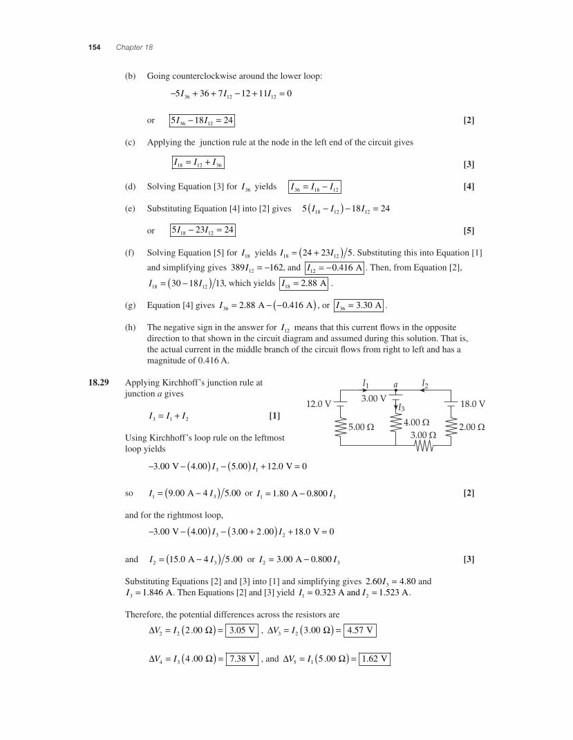
154 Chapter 18
(b) Going counterclockwise around the lower loop:
* + + * + =5 36 7 12 11 036 12 12I I I
or 5 18 2436 12I I* = [2]
(c) Applying the junction rule at the node in the left end of the circuit gives
I I I18 12 36= + [3]
(d) Solving Equation [3] for I36 yields I I I36 18 12= * [4]
(e) Substituting Equation [4] into [2] gives 5 18 2418 12 12I I I*( ) * =
or 5 23 2418 12I I* = [5]
(f) Solving Equation [5] for I18 yields I I18 1224 23 5= +( ) . Substituting this into Equation [1]
and simplifying gives 389 16212I = * , and I12 0 416= * . A . Then, from Equation [2],
I I18 1230 18 13= *( ) , which yields I18 2 88= . A .
(g) Equation [4] gives I36 2 88 0 416= * *( ). . A A , or I36 3 30= . A .
(h) The negative sign in the answer for I12 means that this current fl ows in the opposite direction to that shown in the circuit diagram and assumed during this solution. That is, the actual current in the middle branch of the circuit fl ows from right to left and has a magnitude of 0.416 A.
18.29 Applying Kirchhoff’s junction rule at junction a gives I I I3 1 2= + [1]
Using Kirchhoff’s loop rule on the leftmost loop yields
* * ( ) * ( ) + =3 00 4 00 5 00 12 0 03 1. . . . V VI I
so I I1 39 00 4 5 00= *( ). . A or I I1 31 80 0 800= *. . A [2]
and for the rightmost loop,
* * ( ) * +( ) + =3 00 4 00 3 00 2 00 18 0 03 2. . . . . V VI I
and I I2 315 0 4 5 00= *( ). . A or I I2 33 00 0 800= *. . A [3]
Substituting Equations [2] and [3] into [1] and simplifying gives 2 60 4 803. .I = and I3 1 846= . A. Then Equations [2] and [3] yield I I1 20 323 1 523= =. . A and A.
Therefore, the potential differences across the resistors are
" !V I2 2 2 00 3 05= ( ) =. . V ,
" !V I3 2 3 00 4 57= ( ) =. . V
" !V I4 3 4 00 7 38= ( ) =. . V , and " !V I5 1 5 00 1 62= ( ) =. . V
56157_18_ch18_p110-170.indd 15456157_18_ch18_p110-170.indd 154 3/19/08 1:35:47 AM3/19/08 1:35:47 AM
Direct-Current Circuits 155
18.30 The time constant is ) = R C. Considering units, we fi nd
R C 3 ( )( ) = ,-.
/01
Ohms FaradsVolts
AmperesCoulombss
VoltsCoulombsAmperes
Coulomb
,-.
/01 = ,
-./01
= ssCoulombs Second
Second,-.
/01
=
or ) = R C has units of time.
18.31 (a) The time constant is: ) = = 2( ) 2( ) =*RC 75 0 10 25 0 10 1 883 6. . . F s!
(b) At t = ) , q Q C= = ( ) = 2( )*0 632 0 632 0 632 25 0 10 126. . . . .max + F 00 1 90 10 4 V C( ) = 2 *.
18.32 (a) ) = = ( ) 2( ) = 2 =* *R C 1 20 0 10 2 00 10 2 006 300 F s ! . . . mms
(b) Q Cmax F .00 V C= = 2( )( ) = 2 =* *+ 20 0 10 9 1 80 10 16 4. . 880 Cµ
(c) Q Q e Q e Qe
t= *( ) = *( ) = *,-.
/01 =* *
max max max1 1 11) ) ) 1114 Cµ
18.33 Q Cmax = = 2( )( ) = 2* *+ 5.0 F 30 V 1.5 C10 106 4 , and
) = = 2( ) 2( ) =*R C 1 0 10 5 0 10 5 06 6. F s! . .
Thus, at t = =10 2 s )
Q Q e et= *( ) = 2( ) *( ) = 2* * * *max C1 1 5 10 1 1 3 104 2 4) . . C
18.34 The charge on the capacitor at time t is Q Q e t= *( )*max 1 ) , where
Q C V= ( )" and Q Cmax = + . Thus, "V e t= *( )*+ )1 or e Vt* = * ( )) +1 "
We are given that + = 12 V, and at t = 1 0. s, "V = 10 V
Therefore, e* = * = * =1 0 11012
12 1012
16 0
.
. s ) or e+ =1 0 6 0. . s )
Taking the natural logarithm of each side of the equation gives
1 0
6 0.
ln . s
)= ( ) or ) = ( ) =1 0
6 00 56
.ln .
. s
s
Since the time constant is ) = RC , we have
CR
= =2
= 2 =*) µ0 564 7 10 475..
s12 10
F F3 !
56157_18_ch18_p110-170.indd 15556157_18_ch18_p110-170.indd 155 3/19/08 1:35:48 AM3/19/08 1:35:48 AM
156 Chapter 18
18.35 (a) The charge remaining on the capacitor after time t is q Qe t= * ) .Thus, if q Q= 0 75. , then e t* =) 0 75. and * = ( )t ) ln .0 75 ,
or t = * ( ) = * ( ) ( ) =) ln . . ln . .0 75 1 5 0 75 0 43 s s
(b) ) = RC , so CR
= =2
= 2 =*) µ1 510
6 0 10 6 06.. .
s250
F F3 !
18.36 (a) IRmax = +
, so the resistance is
RI
= =2
= 2*+max
3
V0.500 10 A
48 0
9 60 104.. !
The time constant is ) = R C , so the capacitance is found to be C
R= =
2= 2 =*) µ0 960
9 60 101 00 10 10 04
5..
. . s
F F
!
(b) Q Cmax F V C= = ( )( ) =+ µ µ10 0 48 0 480. . , so the charge stored in the capacitor at t = 1 92. s is
Q Q e et= *( ) = ( ) *,-.
* *
max
s0.960 s C1 480 11 92
) µ. //
01= ( ) *( ) =*480 1 4152 C Cµ µe
18.37 The current drawn by a single 75-W bulb connected to a 120-V source is I V1 75 120= =P " W V. Thus, the number of such bulbs that can be connected in parallel with this source before the total current drawn will equal 30.0 A is
nI
= = ( ),-.
/01 =30 0
30 0120
481
..
A A
V75 W
18.38 (a) The equivalent resistance of the parallel combination is
RR R Req
1
5 = + +
,-.
/01
= + +,*
1 1 1 1150
12
1501 2 3 ! ! !--.
/01 =
*1
15 !
so the total current supplied to the circuit is
IVRtotal
V15
A= = ="!
1208 0.
(b) Since the appliances are connected in parallel,
the voltage across each one is "V = 120 V .
(c) IV
Rlamplamp
V150
A= = ="!
1200 80.
(d) Pheaterheater
V25
W= ( ) = ( ) = 2"!
VR
2 22120
5 8 10.
56157_18_ch18_p110-170.indd 15656157_18_ch18_p110-170.indd 156 3/19/08 1:35:49 AM3/19/08 1:35:49 AM
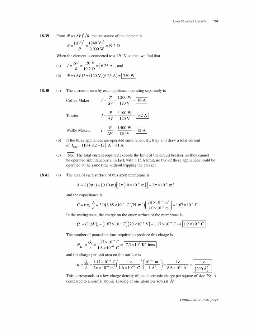
Direct-Current Circuits 157
18.39 From P = ( )!V R2 , the resistance of the element is
RV= ( ) = ( ) =! "
2 22403 000
19 2P
V W
.
When the element is connected to a 120-V source, we fi nd that
(a) IVR
= = =!"
1206 25
V19.2
A. , and
(b) P = ( ) = ( )( ) =!V I 120 6 25 750 V A W.
18.40 (a) The current drawn by each appliance operating separately is
Coffee Maker: IV
= = =P!
1 20010
W120 V
A
Toaster: IV
= = =P!
11009 2
W120 V
A.
Waffl e Maker: IV
= = =P!
1 40012
W120 V
A
(b) If the three appliances are operated simultaneously, they will draw a total current of I total A A= + +( ) =10 9 2 12 31. .
(c) No. The total current required exceeds the limit of the circuit breaker, so they cannot be operated simultaneously. In fact, with a 15 A limit, no two of these appliances could be operated at the same time without tripping the breaker.
18.41 (a) The area of each surface of this axon membrane is
A L r= ( ) = ( ) #( )$% &' = #( (2 0 10 2 10 10 2 106 6) ) ). m m mm2
and the capacitance is
CAd
= * = # +( ) ##
((
, )0
126
3 0 8 85 102 10
. . C N m m
1.02 2
2
110 m F8(
(-./
012
= #1 67 10 8.
In the resting state, the charge on the outer surface of the membrane is
Q C Vi i= ( ) = #( ) #( ) = #( ( (! 1 67 10 70 10 1 17 108 3. . F V 99 91 2 10 C C3 # (.
The number of potassium ions required to produce this charge is
NQe
iK 19
+ C1.6 10 C
K i+ = = ##
= #(
(1 17 10
7 3 109
9.. oons
and the charge per unit area on this surface is
4)
= = ## #
-.
(
( (QA
ei 1 17 10 19. C2 10 m
1.6 10 C6 2 19//
012
-./
012
=#
=(101
18
1
2
20 m Å
.6 10 Å
9
2
2 4 2
e e
00 Å2( )
This corresponds to a low charge density of one electronic charge per square of side 290 Å, compared to a normal atomic spacing of one atom per several Å2.
continued on next page
56157_18_ch18_p110-170.indd 15756157_18_ch18_p110-170.indd 157 3/19/08 3:30:39 AM3/19/08 3:30:39 AM
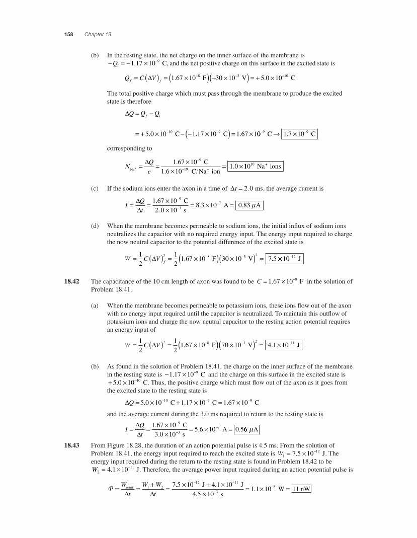
158 Chapter 18
(b) In the resting state, the net charge on the inner surface of the membrane is * = * 2 *Qi 1 17 10 9. C, and the net positive charge on this surface in the excited state is
Q C Vf f= ( ) = 2( ) + 2( ) = + 2* *" 1 67 10 30 10 5 0 108 3. . F V **10 C
The total positive charge which must pass through the membrane to produce the excited state is therefore
"Q Q Qf i= *
= + 2 * * 2( ) = 2* *5 0 10 1 17 10 1 67 110 9. . . C C 00 1 7 109 9* *3 2 C C.
corresponding to
N
QeNa 19 ++
C1.6 10 C Na ion
= = 22
= 2*
*" 1 67 10
1 09.
. 11010 Na ions+
(c) If the sodium ions enter the axon in a time of "t = 2 0. ms, the average current is
I
Qt
= = 22
= 2 =*
**"
"1 67 102 0 10
8 3 10 0 89
37.
.. .
C s
A 33 Aµ
(d) When the membrane becomes permeable to sodium ions, the initial infl ux of sodium ions neutralizes the capacitor with no required energy input. The energy input required to charge the now neutral capacitor to the potential difference of the excited state is
W C V f= ( ) = 2( ) 2( ) =* *1
212
1 67 10 30 10 7 52 8 3 2" . . F V 22 *10 12 J
18.42 The capacitance of the 10 cm length of axon was found to be C = 2 *1 67 10 8. F in the solution of Problem 18.41.
(a) When the membrane becomes permeable to potassium ions, these ions fl ow out of the axon with no energy input required until the capacitor is neutralized. To maintain this outfl ow of potassium ions and charge the now neutral capacitor to the resting action potential requires an energy input of
W C V= ( ) = 2( ) 2( ) = 2* *1
212
1 67 10 70 10 4 12 8 3 2" . . F V 110 11* J
(b) As found in the solution of Problem 18.41, the charge on the inner surface of the membrane in the resting state is * 2 *1 17 10 9. C and the charge on this surface in the excited state is + 2 *5 0 10 10. C. Thus, the positive charge which must fl ow out of the axon as it goes from the excited state to the resting state is
"Q = 2 + 2 = 2* * *5 0 10 1 17 10 1 67 1010 9 9. . . C C C
and the average current during the 3.0 ms required to return to the resting state is
IQt
= = 22
= 2 =*
**"
"1 67 10
105 6 10 0 5
97.
. . C
3.0 s A3 66 Aµ
18.43 From Figure 18.28, the duration of an action potential pulse is 4.5 ms. From the solution of Problem 18.41, the energy input required to reach the excited state is W1
127 5 10= 2 *. J. The energy input required during the return to the resting state is found in Problem 18.42 to be W2
114 1 10= 2 *. J. Therefore, the average power input required during an action potential pulse is
P = = + = 2 + 2* *Wt
W Wt
total
" "1 2
12 117 5 10 4 1 10. . J J4..5 s
W nW32= 2 =*
*
101 1 10 118.
56157_18_ch18_p110-170.indd 15856157_18_ch18_p110-170.indd 158 3/19/08 1:35:50 AM3/19/08 1:35:50 AM
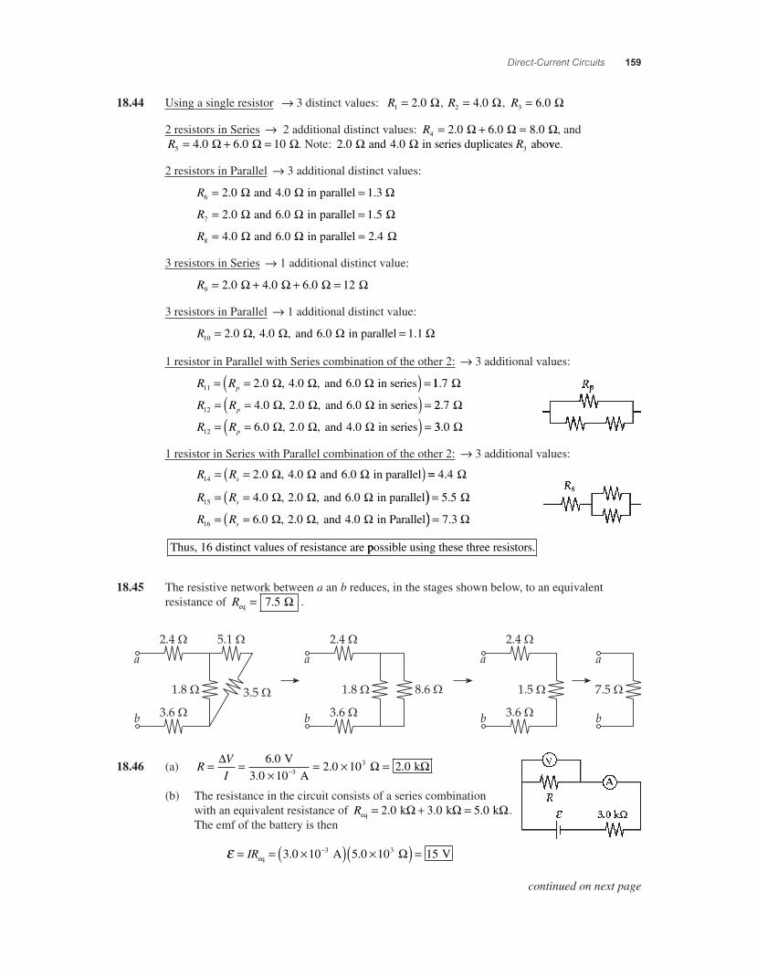
Direct-Current Circuits 159
18.44 Using a single resistor ! 3 distinct values: R1 2 0= . ", R2 4 0= . ", R3 6 0= . "
2 resistors in Series ! 2 additional distinct values: R4 2 0 6 0 8 0= + =. . . " " ", and R5 4 0 6 0 10= + =. . " " ". Note: 2 0 4 0 3. . and in series duplicates abo" " R vve.
2 resistors in Parallel ! 3 additional distinct values:
R6 2 0 4 0 1 3= =. . . and in parallel " " "
R7 2 0 6 0 1 5= =. . . and in parallel " " "
R8 4 0 6 0 2 4= =. . . and in parallel " " "
3 resistors in Series ! 1 additional distinct value:
R9 2 0 4 0 6 0 12= + + =. . . " " " "
3 resistors in Parallel ! 1 additional distinct value:
R10 2 0 4 0 6 0 1 1= =. . , . . , and in parallel" " " "
1 resistor in Parallel with Series combination of the other 2: ! 3 additional values:
R Rp11 2 0 4 0 6 0= =( ) =. . , . , and in series" " " 11 7. "
R Rp12 4 0 2 0 6 0= =( ) =. . , . , and in series" " " 22 7. "
R Rp12 6 0 2 0 4 0= =( ) =. . , . , and in series" " " 33 0. "
1 resistor in Series with Parallel combination of the other 2: ! 3 additional values:
R Rs14 2 0 4 0 6 0= =( ). . . , and in parallel" " " == 4 4. "
R Rs15 4 0 2 0 6 0= =( . . , . , and in parallel" " " )) = 5 5. "
R Rs16 6 0 2 0 4 0= =( . . , . , and in Parallel" " " )) = 7 3. "
Thus, 16 distinct values of resistance are ppossible using these three resistors.
18.45 The resistive network between a an b reduces, in the stages shown below, to an equivalent resistance of Req = 7 5. " .
18.46 (a) RVI
= =#
= # =$% " "6 0
102 0 10 2 03.
. . V
3.0 A k3
(b) The resistance in the circuit consists of a series combination with an equivalent resistance of Req k k k= + =2 0 3 0 5 0. . ." " ". The emf of the battery is then
& = = #( ) #( ) =$IReq A V3 0 10 5 0 10 153 3. . "
continued on next page
56157_18_ch18_p110-170.indd 15956157_18_ch18_p110-170.indd 159 3/19/08 3:30:39 AM3/19/08 3:30:39 AM
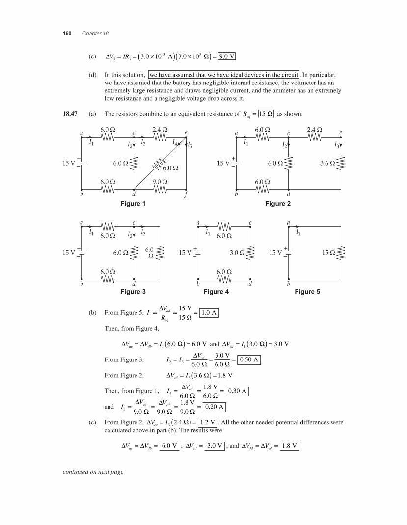
160 Chapter 18
(c) ! "V IR3 33 33 0 10 3 0 10 9 0= = #( ) #( ) =$. . . A V
(d) In this solution, we have assumed that we have ideal devices iin the circuit . In particular, we have assumed that the battery has negligible internal resistance, the voltmeter has an extremely large resistance and draws negligible current, and the ammeter has an extremely low resistance and a negligible voltage drop across it.
18.47 (a) The resistors combine to an equivalent resistance of Req = 15 " as shown.
Figure 1 Figure 2
Figure 3 Figure 5Figure 4
(b) From Figure 5, IV
Rab
eq1
151 0= = =!
" V
15 A.
Then, from Figure 4, ! ! "V V Iac db= = ( ) =1 6 0 6 0. . V and ! "V Icd = ( ) =1 3 0 3 0. . V
From Figure 3, I IVcd
2 3 6 03
0 50= = = =!" ".
.
.0 V6.0
A
From Figure 2, ! "V Ied = ( ) =3 3 1 8.6 V.
Then, from Figure 1, IVed
4 6 01
0 30= = =!" ".
.
.8 V6.0
A
and IV Vfd ed
5 9 0 9 01
0 20= = = =!
"!
" ". ..
.8 V
9.0 A
(c) From Figure 2, ! "V Ice = ( ) =3 2 1 2.4 V. . All the other needed potential differences were calculated above in part (b). The results were
! !V Vac db= = 6 0. V ; !Vcd = 3 0. V ; and ! !V Vfd ed= = 1 8. V
continued on next page
56157_18_ch18_p110-170.indd 16056157_18_ch18_p110-170.indd 160 3/19/08 3:30:40 AM3/19/08 3:30:40 AM
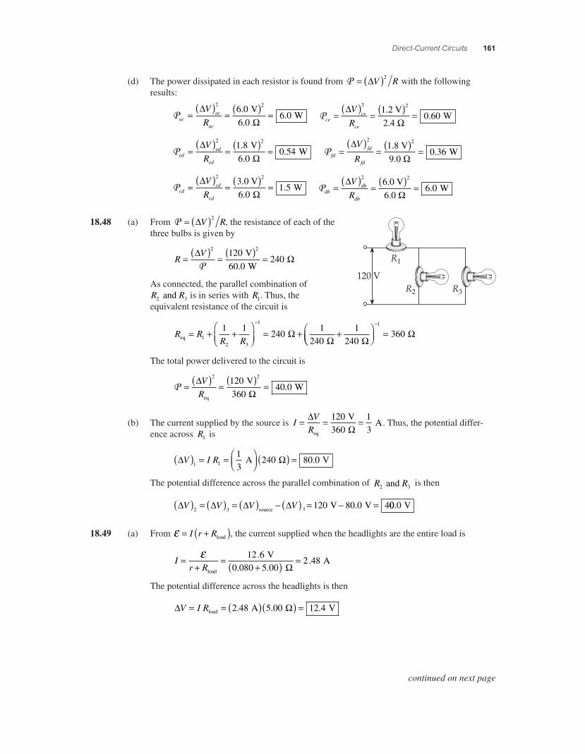
Direct-Current Circuits 161
(d) The power dissipated in each resistor is found from P = ( )!V R2 with the following results:
Pacac
ac
V
R=
( )= ( ) =
!"
2 26 06 0
6 0..
. V
W Pcece
ce
V
R=
( )= ( ) =
!"
2 212
0 60.2 V.4
W.
Peded
ed
V
R=
( )= ( ) =
!"
2 21 86 0
0 54..
. V
W P fdfd
fd
V
R=
( )= ( ) =
!"
2 219
0 36.8 V.0
W.
Pcdcd
cd
V
R=
( )= ( ) =
!"
2 236 0
1 5.0 V
W
.. Pdb
db
db
V
R=
( )= ( ) =
!"
2 266
6 0.0 V.0
W.
18.48 (a) From P = ( )!V R2 , the resistance of each of the three bulbs is given by
RV= ( ) = ( ) =! "
2 212060 0
240P
V W
.
As connected, the parallel combination of R R2 3 and is in series with R1. Thus, the equivalent resistance of the circuit is
R RR Req
= + +
#$%
&'(
= + +#)
12 3
11 1
2401
2401
240"
" "$$%&'( =
)1
360 "
The total power delivered to the circuit is
P = ( ) = ( ) =!"
VR
2 2120360
40 0eq
V
W.
(b) The current supplied by the source is IV
R= = =!
"eq
V
A120360
13
. Thus, the potential differ-ence across R1 is
! "V I R( ) = = #$%
&'( ( ) =1 1
13
240 80 0 A V.
The potential difference across the parallel combination of R R2 3 and is then
! ! ! !V V V V( ) = ( ) = ( ) ) ( ) = ) =2 3 1 120 80 0 4source V V. 00 0. V
18.49 (a) From * = +( )I r Rload , the current supplied when the headlights are the entire load is
Ir R
=+
=+( ) =*
load
V0.080 5.00
A12 6
2 48.
."
The potential difference across the headlights is then
! "V I R= = ( )( ) =load A V2 48 5 00 12 4. . .
continued on next page
56157_18_ch18_p110-170.indd 16156157_18_ch18_p110-170.indd 161 3/19/08 3:30:41 AM3/19/08 3:30:41 AM
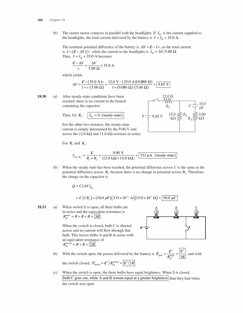
162 Chapter 18
(b) The starter motor connects in parallel with the headlights. If Ihl is the current supplied to the headlights, the total current delivered by the battery is I I= +hl A35 0. .
The terminal potential difference of the battery is "V I r= *+ , so the total current is I V r= *( )+ " while the current to the headlights is I Vhl = " !5 00. . Thus, I I= +hl A35 0. becomes
+ * = +" "
!V
rV
5 0035 0
..
A
which yields
"!
Vr
r= * ( )
+ ( ) = * ( )+ 35 01 5 00
12 6 35 0 0..
. . . A
V A 00800 080 5 00
9 65
1 V
!! !
( )+ ( ) ( ) =
. ..
18.50 (a) After steady-state conditions have been
"
reached, there is no current in the branch containing the capacitor.
Thus, for R3 : IR30= ( ) steady-state
For the other two resistors, the steady-state current is simply determined by the 9.00-V emf across the 12.0-k! and 15.0-k! resistors in series:
For R1 and R2 :
IR RR R1 2
1 2
9 0012 0 15 0
333+( ) =+
=+
=+ .( . . )
V k k! !
A steady-stateµ ( )
(b) When the steady state has been reached, the potential difference across C is the same as the potential difference across R2 because there is no change in potential across R3. Therefore, the charge on the capacitor is
Q C V
C I R
R= ( )
= ( ) = ( ) 2( ) 2*
"2
2610 0 333 10 15 0. . F Aµ 110 50 03 C!( ) = . µ
18.51 (a) When switch S is open, all three bulbs are in series and the equivalent resistance is R R R R Req
open = + + = 3 .
When the switch is closed, bulb C is shorted across and no current will fl ow through that bulb. This leaves bulbs A and B in series with an equivalent resistance of R R R Req
closed = + = 2 .
(b) With the switch open, the power delivered by the battery is Popeneqopen= =+ +2 2
3R R, and with
the switch closed, Pclosed eqclosed= =+ +2 2 2R R .
(c) When the switch is open, the three bulbs have equal brightness. When S is closed, bulb C goes out, while A and B remain equal at a greater brightness than they had when the switch was open.
56157_18_ch18_p110-170.indd 16256157_18_ch18_p110-170.indd 162 3/19/08 1:35:54 AM3/19/08 1:35:54 AM
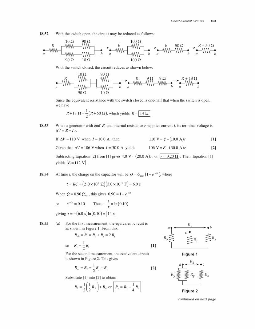
Direct-Current Circuits 163
18.52 With the switch open, the circuit may be reduced as follows:
With the switch closed, the circuit reduces as shown below:
Since the equivalent resistance with the switch closed is one-half that when the switch is open, we have
R R+ = +( )1812
50 ! ! , which yields R = 14 !
18.53 When a generator with emf " and internal resistance r supplies current I, its terminal voltage is #V I r= $" .
If #V = 110 V when I = 10 0. A , then 110 10 0 V A= $ ( )" . r [1]
Given that #V = 106 V when I = 30 0. A, yields 106 30 0 V A= $ ( )" . r [2]
Subtracting Equation [2] from [1] gives 4 0 20 0. . V A= ( ) r , or r = 0 20. ! . Then, Equation [1]
yields " = 112 V .
18.54 At time t, the charge on the capacitor will be Q Q e t= $( )$max 1 % , where
% = = &( ) &( ) =$RC 2 0 10 3 0 10 6 06 6. . . F s!
When Q Q= 0 90. max, this gives 0 90 1. = $ $e t %
or e t$ =% 0 10. Thus, $ = ( )t%
ln .0 10
giving t = $ ( ) ( ) =6 0 0 10 14. ln . s s
18.55 (a) For the fi rst measurement, the equivalent circuit is
Figure 1
Figure 2
as shown in Figure 1. From this,
R R R R Rab y y y= = + =1 2
so R Ry = 12 1 [1]
For the second measurement, the equivalent circuit is shown in Figure 2. This gives
R R R Rac y x= = +2
12
[2]
Substitute [1] into [2] to obtain
R R Rx2 1
12
12
= '()
*+, + , or R R Rx = $2 1
14
continued on next page
56157_18_ch18_p110-170.indd 16356157_18_ch18_p110-170.indd 163 3/19/08 3:30:42 AM3/19/08 3:30:42 AM
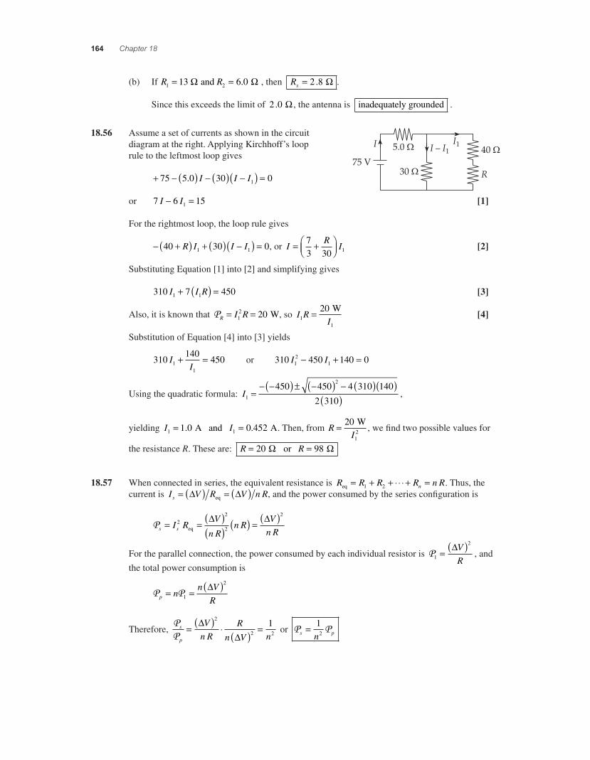
164 Chapter 18
(b) If R R1 213 6 0= = and ! !. , then Rx = 2 8. ! .
Since this exceeds the limit of 2 0. ! , the antenna is inadequately grounded .
18.56 Assume a set of currents as shown in the circuit diagram at the right. Applying Kirchhoff’s loop rule to the leftmost loop gives
+ * ( ) * ( ) *( ) =75 5 0 30 01. I I I
or 7 6 151I I* = [1]
For the rightmost loop, the loop rule gives
* +( ) + ( ) *( ) =40 30 01 1R I I I , or IR
I= +,-.
/01
73 30 1 [2]
Substituting Equation [1] into [2] and simplifying gives
310 7 4501 1I I R+ ( ) = [3]
Also, it is known that PR I R= =12 20 W, so I R
I11
20= W [4]
Substitution of Equation [4] into [3] yields
310140
45011
II
+ = or 310 450 140 012
1I I* + =
Using the quadratic formula: I1
2450 450 4 310 140
2 310=
* *( ) ± *( ) * ( )( )( ) ,
yielding I I1 11 0 0 452= =. . A and A. Then, from RI
= 20
12
W, we fi nd two possible values for
the resistance R. These are: R R= =20 98 or ! !
18.57 When connected in series, the equivalent resistance is R R R R n Rneq = + + 4 4 4 + =1 2 . Thus, the current is I V R V n Rs = ( ) = ( )" "eq , and the power consumed by the series confi guration is
Ps sI RV
n Rn R
Vn R
= = ( )( ) ( ) = ( )2
2
2
2
eq
" "
For the parallel connection, the power consumed by each individual resistor is P1
2
= ( )"VR
, and
the total power consumption is
P Pp nn V
R= = ( )
1
2"
Therefore, PP
s
p
Vn R
R
n V n= ( ) 4
( ) =""
2
2 2
1 or P Ps pn
= 12
56157_18_ch18_p110-170.indd 16456157_18_ch18_p110-170.indd 164 3/19/08 1:35:57 AM3/19/08 1:35:57 AM
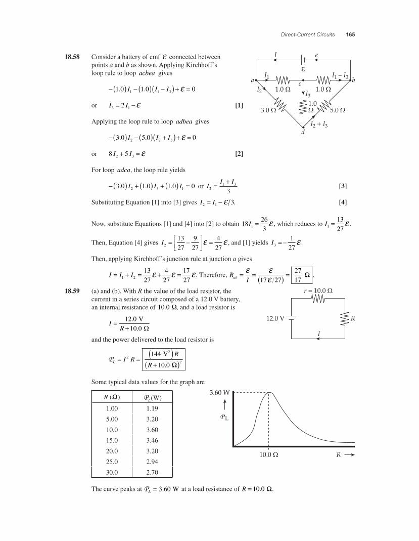
Direct-Current Circuits 165
18.58 Consider a battery of emf + connected between
"points a and b as shown. Applying Kirchhoff’s loop rule to loop acbea gives
* ( ) * ( ) *( ) + =1 0 1 0 01 1 3. .I I I +
or I I3 12= * + [1]
Applying the loop rule to loop adbea gives
* ( ) * ( ) +( ) + =3 0 5 0 02 2 3. .I I I +
or 8 52 3I I+ = + [2]
For loop adca, the loop rule yields
* ( ) + ( ) + ( ) =3 0 1 0 1 0 02 3 1. . .I I I or II I
21 3
3= +
[3]
Substituting Equation [1] into [3] gives I I2 1 3= * + . [4]
Now, substitute Equations [1] and [4] into [2] to obtain 182631I = + , which reduces to I1
1327
= + .
Then, Equation [4] gives I2
1327
927
427
= *#$%
&'(
=+ + , and [1] yields I3
127
= * + .
Then, applying Kirchhoff’s junction rule at junction a gives
I I I= + = + =1 2
1327
427
1727
+ + + . Therefore, RIab = = ( ) =+
++
17 272717
! .
18.59 (a) and (b). With R the value of the load resistor, the current in a series circuit composed of a 12.0 V battery, an internal resistance of 10 0. !, and a load resistor is
IR
=+12 0
10 0.
. V
!and the power delivered to the load resistor is
PL I RR
R= =
( )+( )
22
144
10 0
V
2
. !
Some typical data values for the graph are
P L
R (!) PL(W)
1.00 1.19
5.00 3.20
10.0 3.60
15.0 3.46
20.0 3.20
25.0 2.94
30.0 2.70
The curve peaks at PL = 3 60. W at a load resistance of R = 10 0. !.
56157_18_ch18_p110-170.indd 16556157_18_ch18_p110-170.indd 165 3/19/08 1:35:57 AM3/19/08 1:35:57 AM
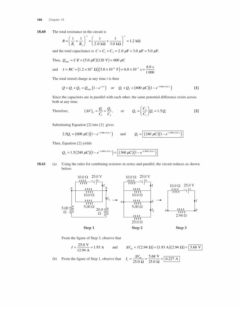
166 Chapter 18
18.60 The total resistance in the circuit is
RR R
= +,-.
/01
= +,-.
/01
=* *
1 1 12 0
13 0
11 2
1 1
. . k k! !..2 k!
and the total capacitance is C C C= + = + =1 2 2 0 3 0 5 0. . . F F Fµ µ µ .
Thus, Q Cmax F V C= = ( )( ) =+ µ µ5 0 120 600.
and ) = = 2( ) 2( ) = 2 =* *RC 1 2 10 5 0 10 6 0 106 03 6 3. . ..
F s! s1 000
The total stored charge at any time t is then
Q Q Q Q e t= + = *( )*1 2 1max
) or Q Q e t1 2
1 000 6 0600 1+ = ( ) *( )* C sµ . [1]
Since the capacitors are in parallel with each other, the same potential difference exists across both at any time.
Therefore, "VQC
QCC( ) = =1
1
2
2
, or QCC
Q Q22
11 11 5=
,-.
/01
= . [2]
Substituting Equation [2] into [1] gives
2 5 600 111 000 6 0. .Q e t= ( ) *( )* C sµ and Q e t
11 000 6 0240 1= ( ) *( )* C sµ .
Then, Equation [2] yields
Q e et2
1 000 6 01 5 240 1 3 1= ( ) *( ) = ( ) ** *. . C 60 C sµ µ 11 000 6 0t . s( )
18.61 (a) Using the rules for combining resistors in series and parallel, the circuit reduces as shown below:
From the fi gure of Step 3, observe that
I = =25 01 93
..
V12.94 A
A and " ! !V Iab = ( ) = ( )( ) =2 94 1 93 2 94 5 68. . . . A V
(b) From the fi gure of Step 1, observe that IVab
1 25 05 6825 0
0 227= = ="! !.
..
.
V
A
56157_18_ch18_p110-170.indd 16656157_18_ch18_p110-170.indd 166 3/19/08 1:35:59 AM3/19/08 1:35:59 AM
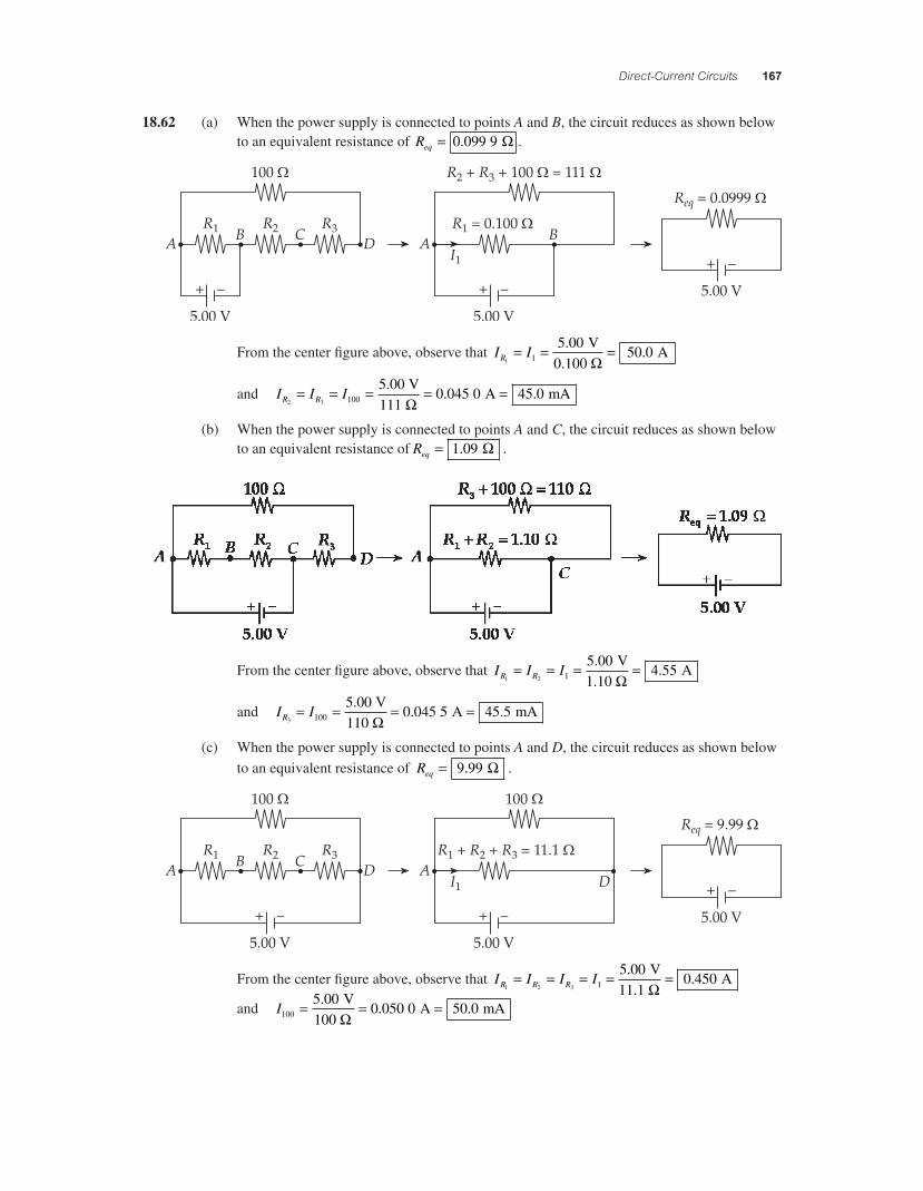
Direct-Current Circuits 167
18.62 (a) When the power supply is connected to points A and B, the circuit reduces as shown below to an equivalent resistance of Req = 0 099 9. ! .
From the center fi gure above, observe that I IR1 1
5 0050 0= = =.
. V
0.100 A
!
and I I IR R2 3 100
5 000 045 0 45 0= = = = =.. .
V111
A mA!
(b) When the power supply is connected to points A and C, the circuit reduces as shown below to an equivalent resistance of Req = 1 09. ! .
From the center fi gure above, observe that I I IR R1 2 1
5 004 55= = = =..
V1.10
A!
and I IR3 100
5 000 045 5 45 5= = = =.. .
V110
A mA!
(c) When the power supply is connected to points A and D, the circuit reduces as shown below to an equivalent resistance of Req = 9 99. ! .
From the center fi gure above, observe that I I I IR R R1 2 3 1
5 000 450= = = = =..
V11.1
A!
and I100
5 000 050 0 50 0= = =.. .
V100
A mA!
56157_18_ch18_p110-170.indd 16756157_18_ch18_p110-170.indd 167 3/19/08 1:35:59 AM3/19/08 1:35:59 AM
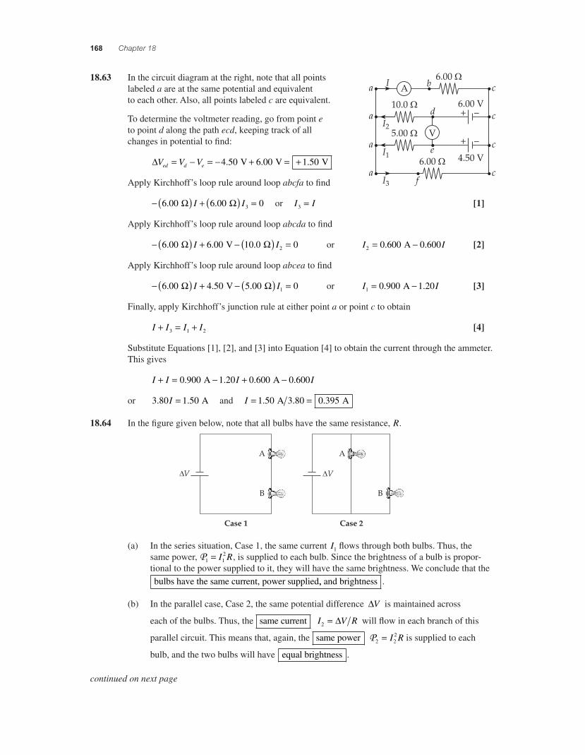
168 Chapter 18
18.63 In the circuit diagram at the right, note that all points labeled a are at the same potential and equivalent to each other. Also, all points labeled c are equivalent.
To determine the voltmeter reading, go from point e to point d along the path ecd, keeping track of all changes in potential to fi nd:
!V V Ved d e= " = " + = +4 50 6 00 1 50. . . V V V
Apply Kirchhoff’s loop rule around loop abcfa to fi nd
" ( ) + ( ) =6 00 6 00 03. . # #I I or I I3 = [1]
Apply Kirchhoff’s loop rule around loop abcda to fi nd
" ( ) + " ( ) =6 00 6 00 10 0 02. . . V # #I I or I I2 0 600 0 600= ". . A [2]
Apply Kirchhoff’s loop rule around loop abcea to fi nd
" ( ) + " ( ) =6 00 4 50 5 00 01. . . V # #I I or I I1 0 900 1 20= ". . A [3]
Finally, apply Kirchhoff’s junction rule at either point a or point c to obtain
I I I I+ = +3 1 2 [4]
Substitute Equations [1], [2], and [3] into Equation [4] to obtain the current through the ammeter. This gives
I I I I+ = " + "0 900 1 20 0 600 0 600. . . . A A
or 3 80 1 50. .I = A and I = =1 50 0 395. . A 3.80 A
18.64 In the fi gure given below, note that all bulbs have the same resistance, R.
(a) In the series situation, Case 1, the same current I1 fl ows through both bulbs. Thus, the same power, P1 1
2= I R, is supplied to each bulb. Since the brightness of a bulb is propor-tional to the power supplied to it, they will have the same brightness. We conclude that the bulbs have the same current, power supplied,, and brightness .
(b) In the parallel case, Case 2, the same potential difference !V is maintained across
each of the bulbs. Thus, the same current I V R2 = ! will fl ow in each branch of this
parallel circuit. This means that, again, the same power P2 22= I R is supplied to each
bulb, and the two bulbs will have equal brightness .
continued on next page
56157_18_ch18_p110-170.indd 16856157_18_ch18_p110-170.indd 168 3/19/08 3:30:42 AM3/19/08 3:30:42 AM
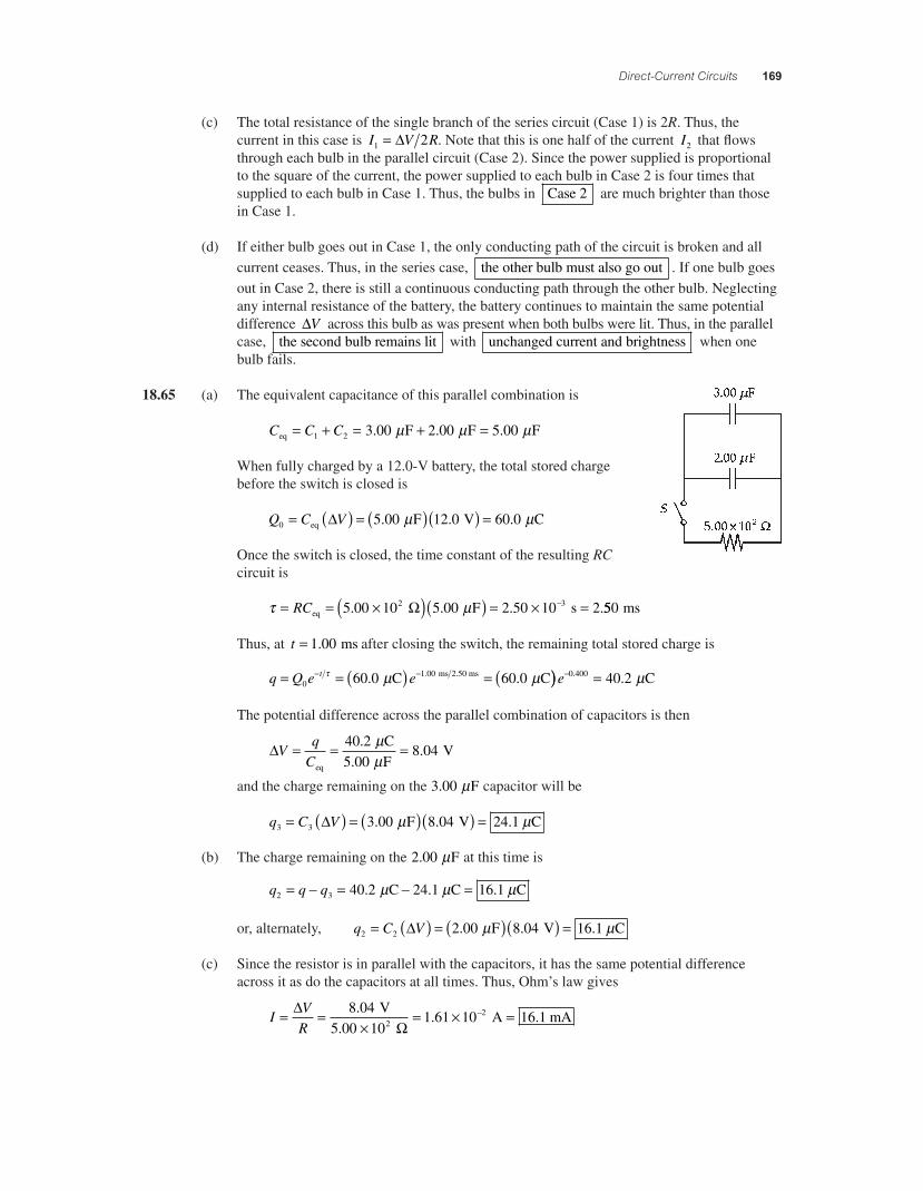
Direct-Current Circuits 169
(c) The total resistance of the single branch of the series circuit (Case 1) is 2R. Thus, the current in this case is I V R1 2= " . Note that this is one half of the current I2 that fl ows through each bulb in the parallel circuit (Case 2). Since the power supplied is proportional to the square of the current, the power supplied to each bulb in Case 2 is four times that supplied to each bulb in Case 1. Thus, the bulbs in Case 2 are much brighter than those in Case 1.
(d) If either bulb goes out in Case 1, the only conducting path of the circuit is broken and all current ceases. Thus, in the series case, the other bulb must also go out . If one bulb goes out in Case 2, there is still a continuous conducting path through the other bulb. Neglecting any internal resistance of the battery, the battery continues to maintain the same potential difference "V across this bulb as was present when both bulbs were lit. Thus, in the parallel case, the second bulb remains lit with unchanged current and brightness when one bulb fails.
18.65 (a) The equivalent capacitance of this parallel combination is
C C Ceq F F F= + = + =1 2 3 00 2 00 5 00. . .µ µ µ
When fully charged by a 12.0-V battery, the total stored charge before the switch is closed is
Q C V0 5 00 12 0 60 0= ( ) = ( )( ) =eq F V C" . . .µ µ
Once the switch is closed, the time constant of the resulting RC circuit is
) µ= = 2( )( ) = 2 =*RCeq F s5 00 10 5 00 2 50 10 22 3. . . .! 550 ms
Thus, at t = 1 00. ms after closing the switch, the remaining total stored charge is
q Q e et= = ( ) = (* *0
1 0060 0 60 0) µ µ. .. C C ms 2.50 ms )) =*e 0 400 40 2. . Cµ
The potential difference across the parallel combination of capacitors is then
"Vq
C= = =
eq
C F
V40 25 00
8 04.
..
µµ
and the charge remaining on the 3 00. F µ capacitor will be
q C V3 3 3 00 8 04 24 1= ( ) = ( )( ) =" . . . F V Cµ µ
(b) The charge remaining on the 2 00. F µ at this time is
q q q2 3 40 2 24 1 16 1= * = * =. . . C C Cµ µ µ
or, alternately, q C V2 2 2 00 8 04 16 1= ( ) = ( )( ) =" . . . F V Cµ µ
(c) Since the resistor is in parallel with the capacitors, it has the same potential difference across it as do the capacitors at all times. Thus, Ohm’s law gives
IVR
= =2
= 2 =*"!
8 0410
1 61 10 16 12.. .
V5.00
A mA2
56157_18_ch18_p110-170.indd 16956157_18_ch18_p110-170.indd 169 3/19/08 1:36:01 AM3/19/08 1:36:01 AM
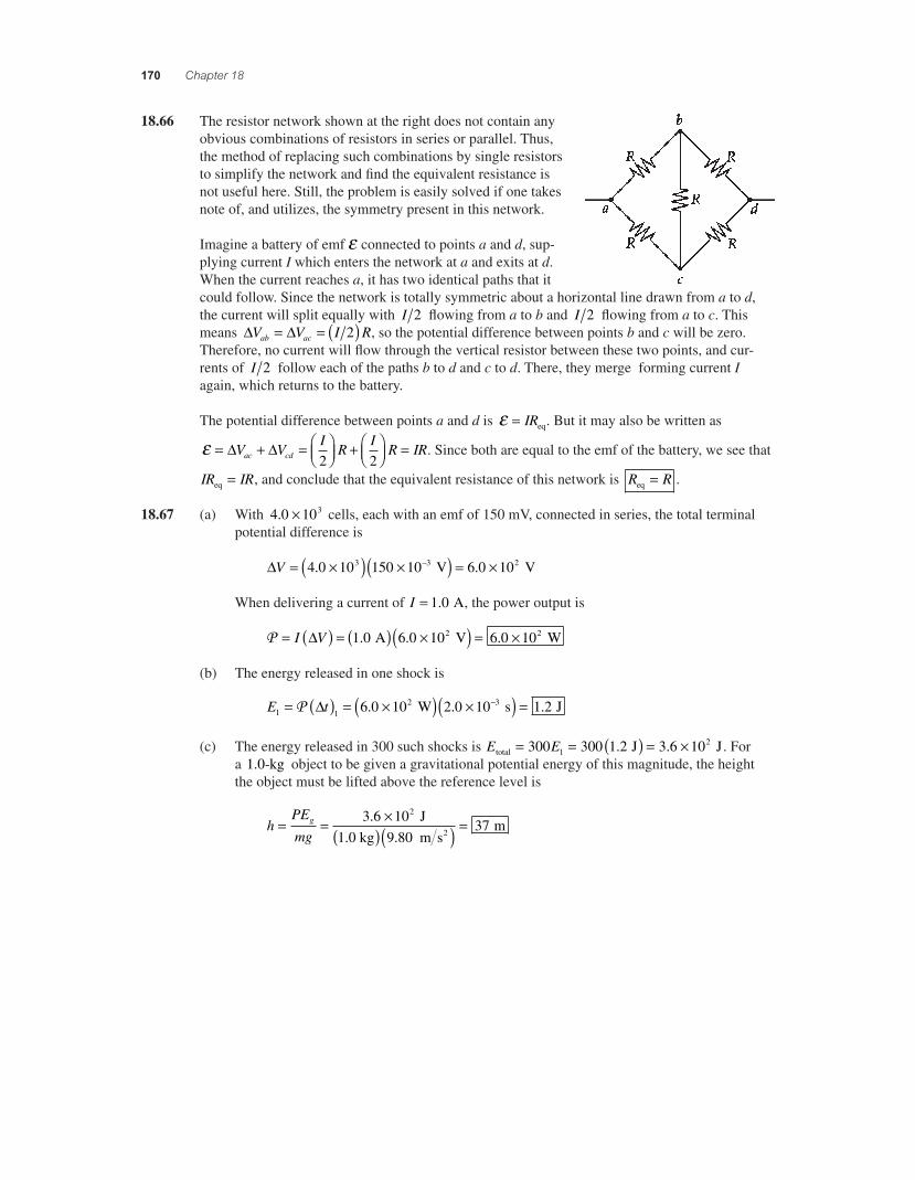
170 Chapter 18
18.66 The resistor network shown at the right does not contain any obvious combinations of resistors in series or parallel. Thus, the method of replacing such combinations by single resistors to simplify the network and fi nd the equivalent resistance is not useful here. Still, the problem is easily solved if one takes note of, and utilizes, the symmetry present in this network.
Imagine a battery of emf + connected to points a and d, sup-plying current I which enters the network at a and exits at d. When the current reaches a, it has two identical paths that it could follow. Since the network is totally symmetric about a horizontal line drawn from a to d, the current will split equally with I 2 fl owing from a to b and I 2 fl owing from a to c. This means " "V V I Rab ac= = ( )2 , so the potential difference between points b and c will be zero. Therefore, no current will fl ow through the vertical resistor between these two points, and cur-rents of I 2 follow each of the paths b to d and c to d. There, they merge forming current I again, which returns to the battery.
The potential difference between points a and d is + = IReq. But it may also be written as
+ = + = ,-.
/01 + ,
-./01 =" "V V
IR
IR IRac cd 2 2
. Since both are equal to the emf of the battery, we see that
IR IReq = , and conclude that the equivalent resistance of this network is R Req = .
18.67 (a) With 4 0 103. 2 cells, each with an emf of 150 mV, connected in series, the total terminal potential difference is
"V = 2( ) 2( ) = 2*4 0 10 150 10 6 0 103 3 2. . V V
When delivering a current of I = 1 0. A, the power output is
P = ( ) = ( ) 2( ) = 2I V" 1 0 6 0 10 6 0 102 2. . . A V W
(b) The energy released in one shock is
E t1 12 36 0 10 2 0 10 1 2= ( ) = 2( ) 2( ) =*P " . . . W s J
(c) The energy released in 300 such shocks is E Etotal J J= = ( ) = 2300 300 1 2 3 6 1012. . . For
a 1 0. -kg object to be given a gravitational potential energy of this magnitude, the height the object must be lifted above the reference level is
hPE
mgg= = 2
( )( ) =3 6 109 80
372.
. J
1.0 kg m s m
2
56157_18_ch18_p110-170.indd 17056157_18_ch18_p110-170.indd 170 3/19/08 1:36:02 AM3/19/08 1:36:02 AM