Embed Size (px)
Citation preview

Spring 2018 © CS 438 Staff, University of Illinois 1
Direct Link Networks -Encoding
Reading: Peterson and Davie, Chapter 2

Where are we?
Spring 2018 © CS 438 Staff, University of Illinois 2
WiFiDSL4GEthernet
IPNetwork
TCP UDP
Skype(VOIP)Application
Layers
Physical
Data Link
Transport
IPTV(streaming
media)
HTTP(Web)
BitTorrent(P2P)
Today
Spring 2018 © CS 438 Staff, University of Illinois 3
Direct Link Networks
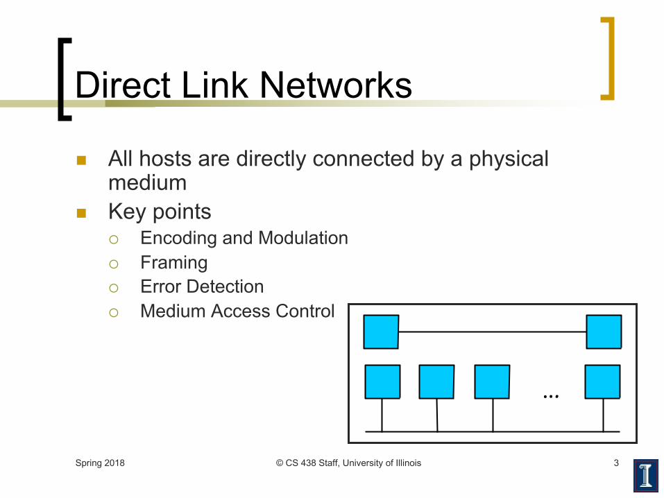
n All hosts are directly connected by a physical medium
n Key points¡ Encoding and Modulation¡ Framing¡ Error Detection¡ Medium Access Control
…

Spring 2018 © CS 438 Staff, University of Illinois 4
Internet Protocols
Physical
Data Link Hardware (network adapter)
Network
TransportKernel software (device driver)
Application
Presentation
Session
User-level software
Framing, error detection, medium access controlEncoding

Spring 2018 © CS 438 Staff, University of Illinois 5
Direct Link Networks - Outline
n Hardware building blocksn Encodingn Framingn Error detectionn Multiple access media (MAC examples)n Network adapters

Spring 2018 © CS 438 Staff, University of Illinois 6
Hardware Building Blocks
n Nodes¡ Hosts: general purpose computers¡ Switches: typically special purpose hardware¡ Routers: varied

Spring 2018 © CS 438 Staff, University of Illinois 7
Nodes: Workstation Architecture
n Finite memory¡ Scarce
resourcen Runs at
memory speeds, NOT processor speeds
Processor
Cache
Network AdaptorNETWORK
memory bus (MBUS) input/outputbus(I/O BUS)
Memory

Hardware Building Blocks
n Links¡ Physical medium
n Copper wire with electronic signalingn Glass fiber with optical signalingn Wireless with electromagnetic (radio,
infrared, microwave) signalingn Two cups and a string
Spring 2018 © CS 438 Staff, University of Illinois 8

Spring 2018 © CS 438 Staff, University of Illinois 9
Links - Copper
n Copper-based Media¡ Category 5/6 Twisted Pair 10-1Gbps 100m¡ ThinNet Coaxial Cable 10-100Mbps 200m¡ ThickNet Coaxial Cable 10-100Mbps 500m
twisted pair
copper coreinsulationbraided outer conductorouter insulation
coaxialcable(coax)
more twists, less crosstalk, better signal over longer distances
More expensive than twisted pair
High bandwidth and excellent noise
immunity

Spring 2018 © CS 438 Staff, University of Illinois 10
Links - Optical
n Optical Media¡ Multimode Fiber 100Gbps 2km¡ Single Mode Fiber 100-2400Mbps 40km
glass core (the fiber)glass claddingplastic jacket
opticalfiber

Spring 2018 © CS 438 Staff, University of Illinois 11
Links - Optical
O(100 microns) thick
core of multimode fiber (same frequency; colors for clarity)
~1 wavelength thick = ~1 micron
core of single mode fiber
n Single mode fiber¡ Expensive to drive (Lasers)¡ Lower attenuation (longer
distances) ≤ 0.5 dB/km ¡ Lower dispersion (higher
data rates)
n Multimode fiber¡ Cheap to drive (LED�s)¡ Higher attenuation¡ Easier to terminate

Spring 2018 © CS 438 Staff, University of Illinois 12
Links - Optical
n Advantages of optical communication¡ Higher bandwidths¡ Superior (lower) attenuation properties¡ Immune from electromagnetic
interference¡ No crosstalk between fibers
¡ Thin, lightweight, and cheap (the fiber, not the optical-electrical interfaces)

Links - Wireless
n Path loss¡ Signal attenuation as a function of distance¡ Signal-to-noise ratio (SNR—Signal Power/Noise Power)
decreases, make signal unrecoverable
n Multipath propagation¡ Signal reflects off surfaces, effectively causing self-interference
n Internal interference (from other users)¡ Hosts within range of each other collide with one another�s
transmission
n External interference¡ Microwave is turned on and blocks your signal
Spring 2018 © CS 438 Staff, University of Illinois 13

Wireless Path Loss
n Signal power attenuates by about ~r2 factor for omni-directional antennas in free space¡ r is the distance between the sender and the receiver
n The exponent in the factor is different depending on placement of antennas¡ Less than 2 for directional antennas¡ Faster attenuation
n Exponent > 2 when antennas are placed on the groundn Signal bounces off the ground and reduces the power of the
signal
Spring 2018 © CS 438 Staff, University of Illinois 14

Wireless Multipath Effects
n Signals bounce off surfaces and interfere with one another
n What if signals are out of phase?¡ Orthogonal signals cancel each other and
nothing is received!Spring 2018 © CS 438 Staff, University of Illinois 15
Ceiling
FloorS S
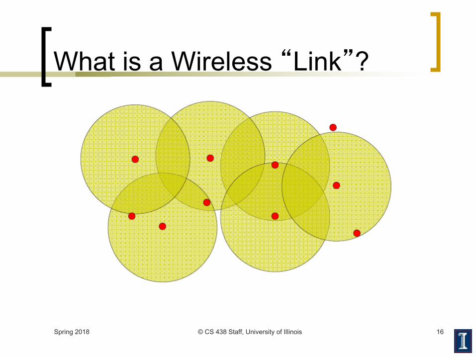
What is a Wireless �Link�?
Spring 2018 © CS 438 Staff, University of Illinois 16
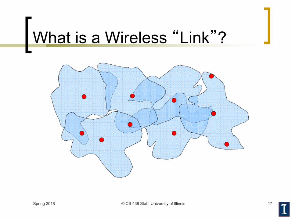
What is a Wireless �Link�?
Spring 2018 © CS 438 Staff, University of Illinois 17
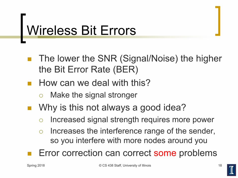
Wireless Bit Errors
n The lower the SNR (Signal/Noise) the higher the Bit Error Rate (BER)
n How can we deal with this?¡ Make the signal stronger
n Why is this not always a good idea?¡ Increased signal strength requires more power¡ Increases the interference range of the sender,
so you interfere with more nodes around youn Error correction can correct some problemsSpring 2018 © CS 438 Staff, University of Illinois 18

Spring 2018 © CS 438 Staff, University of Illinois 19
Encoding
n Problems with signal transmission¡ Attenuation: Signal power absorbed by medium¡ Dispersion: A discrete signal spreads in space¡ Noise: Random background �signals�
digital data(a string of symbols)
digital data(a string of symbols)
modulator demodulator
a stringof signals
modulator demodulator

How can two hosts communicate?
n Encode information on modulated �Carrier signal�¡ Phase, frequency, and/or amplitude modulation¡ Ethernet: self-clocking Manchester coding¡ Technologies: copper, optical, wireless
Spring 2018 © CS 438 Staff, University of Illinois 20
0.7 Volts
-0.7 Volts

Spring 2018 © CS 438 Staff, University of Illinois 21
Encoding
n Goal¡ Understand how to connect nodes in such a way
that bits can be transmitted from one node to another
n Idea¡ The physical medium is used to propagate
signalsn Modulate electromagnetic wavesn Vary voltage, frequency, wavelength
¡ Data is encoded in the signal

Spring 2018 © CS 438 Staff, University of Illinois 22
Bauds and Bits
n Baud rate¡ Number of physical symbols transmitted per
secondn Bit rate
¡ Actual number of data bits transmitted per second
n Relationship¡ Depends on the number of bits encoded in each
symbol
Analog vs. Digital Transmission
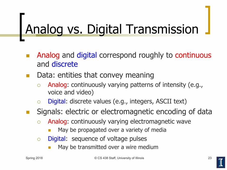
n Analog and digital correspond roughly to continuousand discrete
n Data: entities that convey meaning¡ Analog: continuously varying patterns of intensity (e.g.,
voice and video)¡ Digital: discrete values (e.g., integers, ASCII text)
n Signals: electric or electromagnetic encoding of data¡ Analog: continuously varying electromagnetic wave
n May be propagated over a variety of media¡ Digital: sequence of voltage pulses
n May be transmitted over a wire mediumSpring 2018 © CS 438 Staff, University of Illinois 23

Analog vs. Digital Transmission
n Advantages of digital transmission over analog¡ Cheaper¡ Simpler for multiplexing distinct data types (audio, video, e-mail,
etc.)¡ Easier to encrypt
n Two examples based on modulator-demodulators (modems)¡ Electronic Industries Association (EIA) standard: RS-232¡ International Telecommunications Union (ITU)
V.32 9600 bps modem standard
Spring 2018 © CS 438 Staff, University of Illinois 24

Spring 2018 © CS 438 Staff, University of Illinois 25
RS-232
n Communication between computer and modemn Uses two voltage levels (+15V, -15V),
a binary voltage encodingn Data rate limited to 19.2 kbps (RS-232-C); raised to
115,200 kbps in later standardsn Characteristics
¡ Serialn One signaling wire, one bit at a time
¡ Asynchronousn Line can be idle, clock generated from data
¡ Character-basedn Send data in 7- or 8-bit characters

Spring 2018 © CS 438 Staff, University of Illinois 26
RS-232 Timing Diagram
idle start 1 110 0 0 0 stop idle-15
+
+15
Time
Voltage
One bit per clock tick
Voltage never returns to 0V
0V is a dead/disconnected line
-15V is both �idle� and �1�
Spring 2018 © CS 438 Staff, University of Illinois 27
RS-232
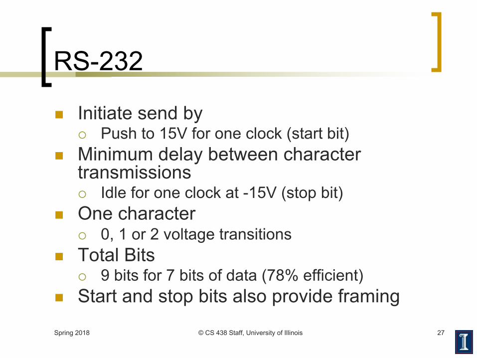
n Initiate send by ¡ Push to 15V for one clock (start bit)
n Minimum delay between character transmissions¡ Idle for one clock at -15V (stop bit)
n One character ¡ 0, 1 or 2 voltage transitions
n Total Bits¡ 9 bits for 7 bits of data (78% efficient)
n Start and stop bits also provide framing

Spring 2018 © CS 438 Staff, University of Illinois 28
RS-232 Timing Diagram
idle start 1 110 0 0 0 stop idle-15
+
+15
Time
Voltage

Spring 2018 © CS 438 Staff, University of Illinois 29
Voltage Encoding
n Binary voltage encoding¡ Done with RS-232 example¡ Generalize before continuing with V.32 (not a
binary voltage encoding)n Common binary voltage encodings
¡ Non-return to zero (NRZ)¡ NRZ inverted (NRZI)¡ Manchester (used by IEEE 802.3—10 Mbps
Ethernet)¡ 4B/5B

Spring 2018 © CS 438 Staff, University of Illinois 30
Non-Return to Zero (NRZ)
n Signal to Data¡ High ð 1¡ Low ð 0
n Comments¡ Transitions maintain clock synchronization¡ Long strings of 0s confused with no signal¡ Long strings of 1s causes baseline wander¡ Both inhibit clock recovery
Bits 0 0 1 0 1 1 1 1 0 1 0 0 0 0 1 0
NRZ
Spring 2018 © CS 438 Staff, University of Illinois 31
Non-Return to Zero Inverted (NRZI)
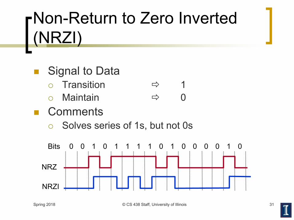
n Signal to Data¡ Transition ð 1¡ Maintain ð 0
n Comments¡ Solves series of 1s, but not 0s
Bits 0 0 1 0 1 1 1 1 0 1 0 0 0 0 1 0
NRZ
NRZI

Spring 2018 © CS 438 Staff, University of Illinois 32
Manchester Encoding
n Signal to Data
¡ XOR NRZ data with clock
¡ High to low transition ð 1
¡ Low to high transition ð 0
n Comments
¡ (used by IEEE 802.3—10 Mbps Ethernet)
¡ Solves clock recovery problem
¡ Only 50% efficient ( ½ bit per transition)
Bits 0 0 1 0 1 1 1 1 0 1 0 0 0 0 1 0
NRZ
Clock
Manchester

Spring 2018 © CS 438 Staff, University of Illinois 33
4B/5B
n Signal to Data¡ Encode every 4 consecutive bits as a 5 bit symbol
n Symbols¡ At most 1 leading 0¡ At most 2 trailing 0s¡ Never more than 3 consecutive 0s¡ Transmit with NRZI
n Comments¡ 16 of 32 possible codes used for data¡ At least two transitions for each code¡ 80% efficient

Spring 2018 © CS 438 Staff, University of Illinois 34
4B/5B – Data Symbols
n 0000 Þ 11110n 0001 Þ 01001n 0010 Þ 10100n 0011 Þ 10101n 0100 Þ 01010n 0101 Þ 01011n 0110 Þ 01110n 0111 Þ 01111
n 1000 Þ 10010 n 1001 Þ 10011n 1010 Þ 10110n 1011 Þ 10111n 1100 Þ 11010n 1101 Þ 11011n 1110 Þ 11100n 1111 Þ 11101
At most 1 leading 0 At most 2 trailing 0s
Spring 2018 © CS 438 Staff, University of Illinois 35
4B/5B – Control Symbols
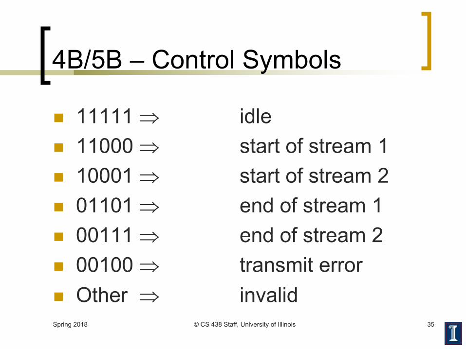
n 11111 Þ idlen 11000 Þ start of stream 1n 10001 Þ start of stream 2n 01101 Þ end of stream 1n 00111 Þ end of stream 2n 00100 Þ transmit errorn Other Þ invalid

Spring 2018 © CS 438 Staff, University of Illinois 36
Binary Voltage Encodings
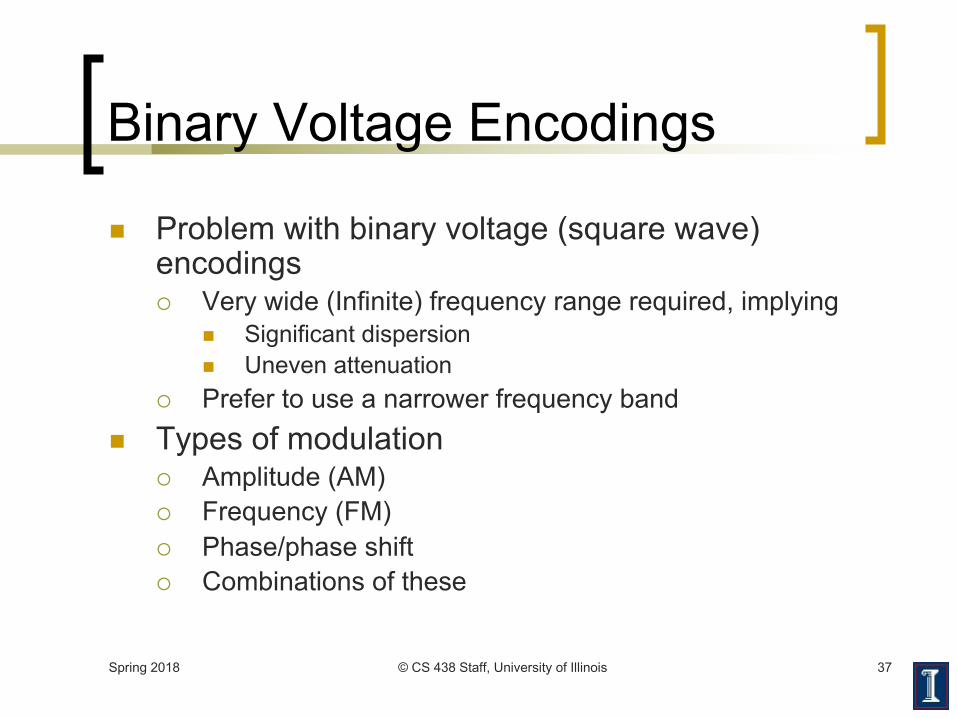
n Problem with binary voltage (square wave) encodings¡ Very wide (Infinite) frequency range required, implying
n Significant dispersionn Uneven attenuation
¡ Prefer to use a narrower frequency band
1 1 1 stop0 0 0 0start-30
-20
-10
0
10
20
Voltage
Spring 2018 © CS 438 Staff, University of Illinois 37
Binary Voltage Encodings
n Problem with binary voltage (square wave) encodings¡ Very wide (Infinite) frequency range required, implying
n Significant dispersionn Uneven attenuation
¡ Prefer to use a narrower frequency band n Types of modulation
¡ Amplitude (AM)¡ Frequency (FM)¡ Phase/phase shift ¡ Combinations of these
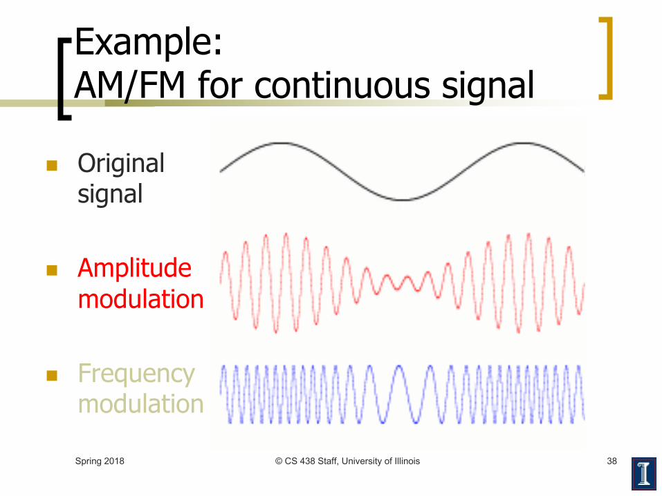
Example: AM/FM for continuous signal
n Original signal
n Amplitude modulation
n Frequency modulation
Spring 2018 © CS 438 Staff, University of Illinois 38

Spring 2018 © CS 438 Staff, University of Illinois 39
Amplitude Modulation
1 0idle

Spring 2018 © CS 438 Staff, University of Illinois 40
Frequency Modulation
1 0idle

Spring 2018 © CS 438 Staff, University of Illinois 41
Phase Modulation
1 0idle

Spring 2018 © CS 438 Staff, University of Illinois 42
Phase Modulation
108º difference in phase
collapse for 108º shift
phase shiftin carrierfrequency

Spring 2018 © CS 438 Staff, University of Illinois 43
Phase Modulation Algorithm
n Send carrier frequency for one period¡ Perform phase shift
¡ Shift value encodes symboln Value in range [0, 360º)
n Multiple values for multiple symbols
n Represent as circle
0º
45º
90º
315º
270º
135º
225º
180º
8-symbolexample

Spring 2018 © CS 438 Staff, University of Illinois 44
V.32 9600 bps
n Communication between modemsn Analog phone linen Uses a combination of amplitude and
phase modulation¡ Known as Quadrature Amplitude
Modulation (QAM)n Sends one of 16 signals each clock
cycle

Constellation Pattern for V.32 QAM
n Same algorithm as phase modulation
n Can also change signal amplitude
n 2-dimensional representation¡ Angle is phase shift¡ Radial distance is
new amplitudeSpring 2018 © CS 438 Staff, University of Illinois 45
45º
15º
16-symbol example

Example constellation
Spring 2018 © CS 438 Staff, University of Illinois 46

Spring 2018 © CS 438 Staff, University of Illinois 47
Comments on V.32
n V.32 transmits at 2400 baud¡ i.e., 2,400 symbols per second
n Each symbol contains ¡ log2 16 = 4 bits
n Data rate ¡ 4 x 2400 = 9600 bps
n Points in constellation diagram¡ Chosen to maximize error detection¡ Process called trellis coding

Modulation (Baud) Rate
Spring 2018 © CS 438 Staff, University of Illinois 48
5 bits = 5µsec
1 bit = 1µsec
1 bit = 1µsec
1 signal element =0.5µsec
NRZI
Manchester
1 1 1 1 1A stream of binary 1sat 1 Mbps
What is a bit?
What is a signal
element?
1 signal element =1µsec

Modulation (Baud) Rate
Spring 2018 © CS 438 Staff, University of Illinois 49
5 bits = 5µsec
1 bit = 1µsec
1 signal element =0.5µsec
NRZI
Manchester
1 1 1 1 1A stream of binary 1sat 1 Mbps
Modulation Rate = Baud Rate = Rate at which
signal elements are generated
= R (NRZI)= 2R (Manchester)
1 bit = 1µsec
1 signal element =1µsec
What is the modulation
rate?What is the data rate?
Data Rate (R)= bits/sec = 1 Mbps for both

Sampling
n Suppose you have the following 1Hz signal being received
n How fast to sample, to capture the signal?Spring 2018 © CS 438 Staff, University of Illinois 50

Sampling
n Sampling a 1 Hz signal at 2 Hz is enough¡ Captures every peak and trough
Spring 2018 © CS 438 Staff, University of Illinois 51

Sampling
n Sampling a 1 Hz signal at 3 Hz is also enough¡ In fact, more than enough samples to capture
variation in signalSpring 2018 © CS 438 Staff, University of Illinois 52

Sampling
n Sampling a 1 Hz signal at 1.5 Hz is not enough¡ Why?
Spring 2018 © CS 438 Staff, University of Illinois 53
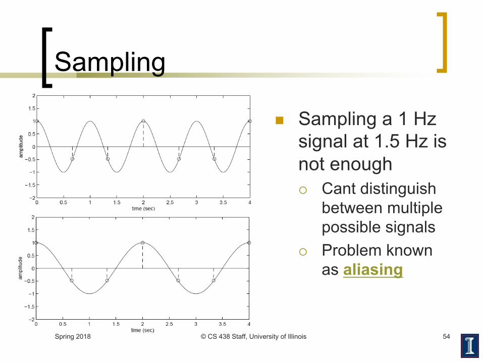
Sampling
n Sampling a 1 Hz signal at 1.5 Hz is not enough¡ Cant distinguish
between multiple possible signals
¡ Problem known as aliasing
Spring 2018 © CS 438 Staff, University of Illinois 54

What about more complex signals?
n Fourier�s theorem¡ Any continuous signal can be decomposed into a sum of sines
and cosines at different frequenciesn Example: Sum of 1 Hz, 2 Hz, and 3 Hz sines
¡ How fast to sample?Spring 2018 © CS 438 Staff, University of Illinois 55

What about more complex signals?
n Fourier�s theorem¡ Any continuous signal can be decomposed into a sum of sines
and cosines at different frequenciesn Example: Sum of 1 Hz, 2 Hz, and 3 Hz sines
¡ How fast to sample? --> answer: 6 HzSpring 2018 © CS 438 Staff, University of Illinois 56

Spring 2018 © CS 438 Staff, University of Illinois 57
Generalizing the Examples
n What limits baud rate?n What data rate can a channel sustain?n How is data rate related to bandwidth?n How does noise affect these bounds?n What else can limit maximum data
rate?

Spring 2018 © CS 438 Staff, University of Illinois 58
What Limits Baud Rate?
n Baud rate¡ Typically limited by electrical signaling properties
n Changing voltages takes time ¡ No matter how small the voltage or how short the wire
n Electronics¡ Slow compared to optics
n Baud rate ¡ Can be as high as twice the bandwidth of communication

Spring 2018 © CS 438 Staff, University of Illinois 59
What Data Rate can a Channel Sustain?
How is Data Rate Related to Bandwidth?
n Transmitting N distinct signals over a noiseless channel with bandwidth B, we can achieve at most a data rate of
2B log2 N
n Nyquist�s Sampling Theorem (H. Nyquist, 1920�s)
Number of signals
per second
Number of bits per
signal

Spring 2018 © CS 438 Staff, University of Illinois 60
What Data Rate can a Channel Sustain?How is Data Rate Related to Bandwidth?
n Transmitting N distinct signals over a noiseless channel with bandwidth B, we can achieve at most a data rate of
2B log2 N
n Nyquist�s Sampling Theorem (H. Nyquist, 1920�s)
Number of signals per second
Number of bits per signal
Baud rateNumber of physical symbolstransmitted per second
Bit rateActual number of data bitstransmitted per second
RelationshipDepends on the number of bitsencoded in each symbol

Noiseless Capacity
n Nyquist�s theorem: 2B log2 Nn Example 1: sampling rate of a phone line
¡ B = 4000 Hz¡ 2B = 8000 samples/sec.
n sample every 125 microseconds
Spring 2018 © CS 438 Staff, University of Illinois 61

Noiseless Capacity
n Nyquist�s theorem: 2B log2 N
n Example 2: noiseless capacity
¡ B = 1200 Hz
¡ N = each pulse encodes 16 symbols
¡ C =
Spring 2018 © CS 438 Staff, University of Illinois 62

Noiseless Capacity
n Nyquist�s theorem: 2B log2 Nn Example 2: noiseless capacity
¡ B = 1200 Hz ¡ N = each pulse encodes 16 symbols¡ C = 2B log2 (N) = D x log2 (N)
= 2400 x 4 = 9600 bps
Spring 2018 © CS 438 Staff, University of Illinois 63
Spring 2018 © CS 438 Staff, University of Illinois 64
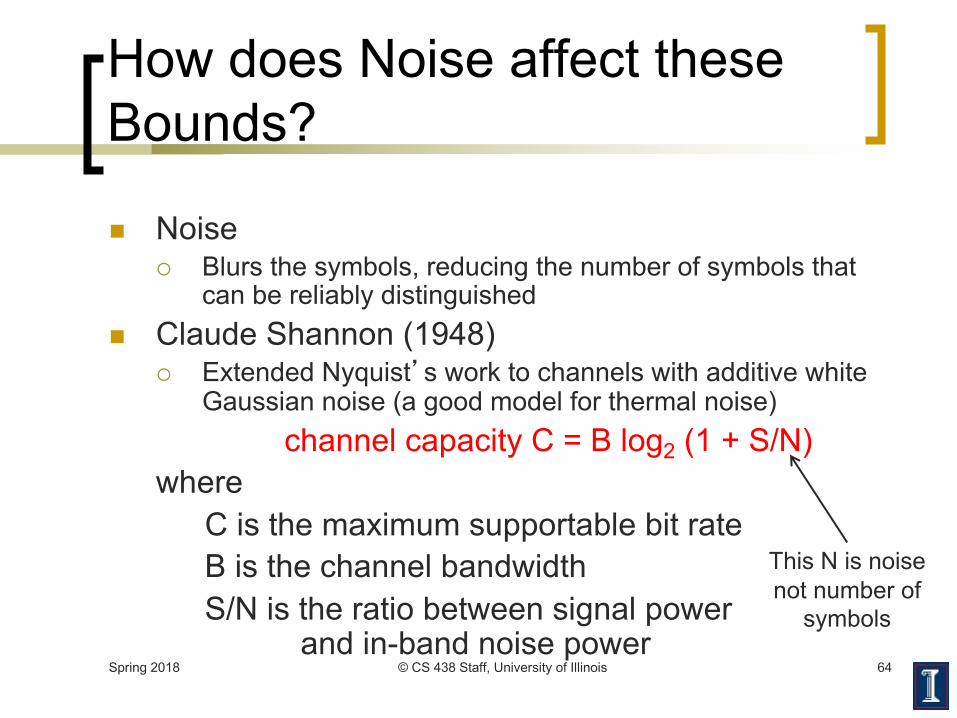
How does Noise affect these Bounds?
n Noise ¡ Blurs the symbols, reducing the number of symbols that
can be reliably distinguishedn Claude Shannon (1948)
¡ Extended Nyquist�s work to channels with additive white Gaussian noise (a good model for thermal noise)
channel capacity C = B log2 (1 + S/N)where
C is the maximum supportable bit rateB is the channel bandwidthS/N is the ratio between signal power
and in-band noise power
This N is noise not number of
symbols

Spring 2018 © CS 438 Staff, University of Illinois 65
How does Noise affect these Bounds?
n Noise ¡ Blurs the symbols, reducing the number of symbols that
can be reliably distinguishedn Claude Shannon (1948)
¡ Extended Nyquist�s work to channels with additive white Gaussian noise (a good model for thermal noise)
channel capacity C = B log2 (1 + S/N)¡ Represents error free capacity
n also used to calculate the noise that can be tolerated to achieve a certain rate through a channel
¡ Result is based on many assumptionsn Formula assumes white noise (thermal noise)n Impulse noise is not accounted forn Various types of distortion are also not accounted for

Noisy Capacity
n Telephone channel ¡ 3400 Hz at 40 dB SNR
Spring 2018 © CS 438 Staff, University of Illinois 66
decibels (dB) is a logarithmic unit of measurement that expresses the magnitude of a physical quantity
(usually power or intensity) relative to a specified or implied reference
level
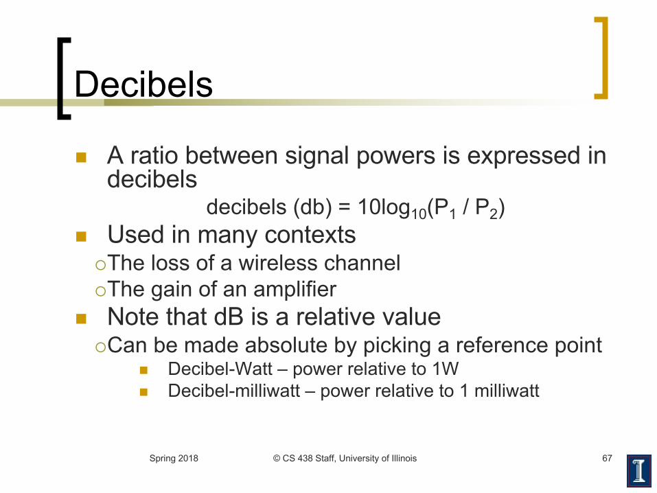
Decibels
n A ratio between signal powers is expressed in decibels
decibels (db) = 10log10(P1 / P2)
n Used in many contexts¡The loss of a wireless channel¡The gain of an amplifier
n Note that dB is a relative value¡Can be made absolute by picking a reference point
n Decibel-Watt – power relative to 1Wn Decibel-milliwatt – power relative to 1 milliwatt
Spring 2018 © CS 438 Staff, University of Illinois 67

Signal-to-Noise Ratio
Spring 2018 © CS 438 Staff, University of Illinois 68
n Signal-to-noise ratio (SNR, or S/N)¡ Ratio of
n the power in a signal to
n the power contained in the noise¡ Typically measured at a receiver
n A high SNR ¡ High-quality signal
n Low SNR ¡ May be hard to “extract” the signal from the noise
n SNR sets upper bound on achievable data rate
power noisepower signal
log10)( 10dB =SNR

Noisy Capacity
n Telephone channel ¡ 3400 Hz at 40 dB SNR¡ C = B log2 (1+S/N) bits/s¡ SNR = 40 dB
40 =10 log10 (S/N) S/N =10,000
¡ C = 3400 log2 (10001) = 44.8 kbps
Spring 2018 © CS 438 Staff, University of Illinois 69
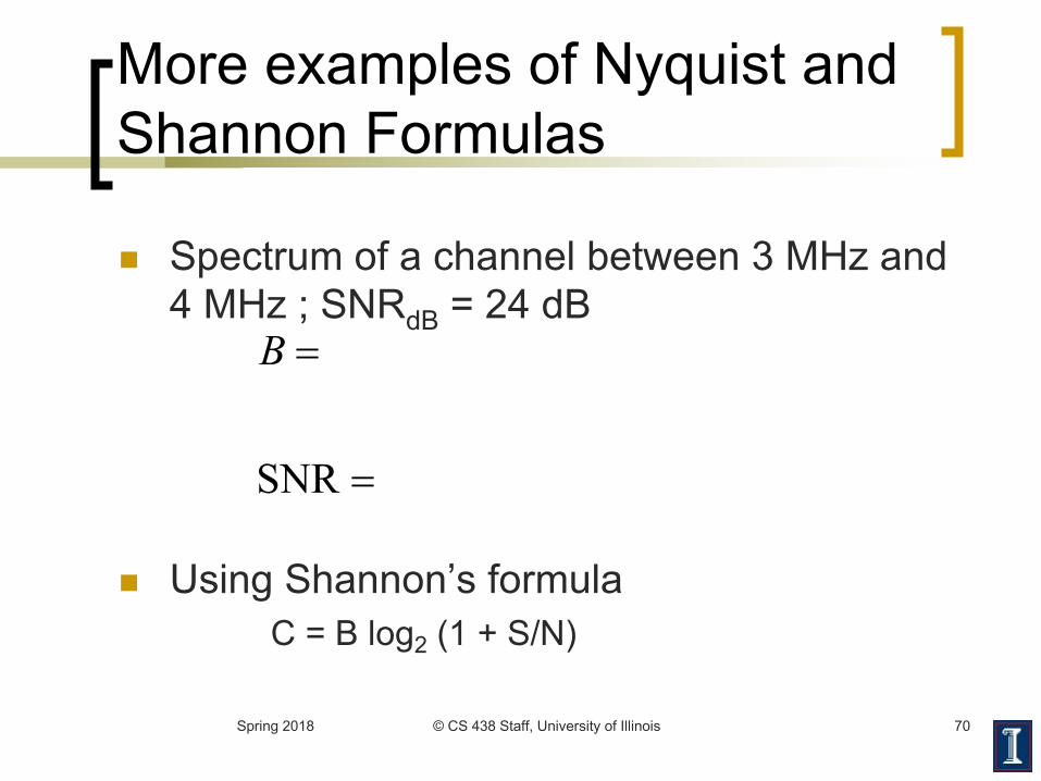
More examples of Nyquist and Shannon Formulas
n Spectrum of a channel between 3 MHz and 4 MHz ; SNRdB = 24 dB
n Using Shannon’s formulaC = B log2 (1 + S/N)
Spring 2018 © CS 438 Staff, University of Illinois 70
=
=
SNR
B
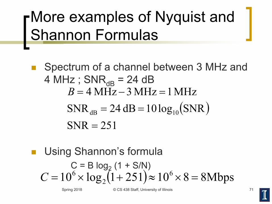
More examples of Nyquist and Shannon Formulas
n Spectrum of a channel between 3 MHz and 4 MHz ; SNRdB = 24 dB
n Using Shannon’s formulaC = B log2 (1 + S/N)
( )251SNR
SNRlog10dB 24SNRMHz 1MHz 3MHz 4
10dB
===
=-=B
( ) Mbps88102511log10 62
6 =´»+´=CSpring 2018 © CS 438 Staff, University of Illinois 71

More examples of Nyquist and Shannon Formulas
n How many signaling levels are required?
Spring 2018 © CS 438 Staff, University of Illinois 72
MBC 2log2=

More examples of Nyquist and Shannon Formulas
n How many signaling levels are required?
n Look out for: dB versus linear values, log2versus log10
( )
16log4
log102108
log2
2
266
2
==
´´=´
=
MM
MMBC
Spring 2018 © CS 438 Staff, University of Illinois 73

Spring 2018 © CS 438 Staff, University of Illinois 74
Summary of Encoding
n Problems: attenuation, dispersion, noisen Digital transmission allows periodic regenerationn Variety of binary voltage encodings
¡ High frequency components limit to short range¡ More voltage levels provide higher data rate
n Modulation schemes¡ Amplitude, frequency, phase, and combinations¡ Quadrature amplitude modulation: amplitude and phase,
many signalsn Nyquist (noiseless) and Shannon (noisy) limits on
data rates


![Serdar Ortaç Full Albümleri [320 Kbps + Full Cover]](https://img.pdfslide.net/doc/110x75/54f612ca4a7959d76e8b53e4/serdar-ortac-full-albuemleri-320-kbps-full-cover.jpg)