Embed Size (px)
Citation preview
Direct measurement of reflectance fromaluminum alloys during CO 2 laser welding
Bulent A. Mehmetli, Kunimitsu Takahashi, and Shunichi Sato
A simple method for measuring the reflected amount of a CO2 laser beam from the surface of a weldedaluminum alloy is described. This device can be used for cases in which an integrating sphere isimpractical to use. A pyroelectric detector measures the amount of reflected laser radiation atprespecified locations that define a semisphere on top of the weld spot. The spatial distribution of areflected laser beam is obtained. It is found that ,80% of the total incident power is reflected by thealloy until a welding keyhole is developed. However, once the keyhole is formed, the reflected amountis as low as 4–8%.Key words: Reflectance measurement, aluminum alloys, CO2 laser welding.
1. Introduction
The measurement of reflected laser power from awelded metal surface is an important part of investi-gation of laser-materials processing such as surfaceheat treatment, welding, and cladding. Especiallywith highly reflective materials of industrial use,e.g., aluminum or copper, reflectivity is a factor thatmust be carefully accounted for because it may bedecisive in the success of the process. It is commonpractice to use an integrating sphere to measuredirectly the reflectance of a weld metal surface.1–5Another commonly used, but indirect, method iscalorimetry, which measures the amount of heatabsorbed by theweld piece from temperature change;therefore the reflected amount can be deduced.6–9Direct measurement of the reflected specular beamis yet another method.10,11 Among the above-mentioned methods, the integrating sphere is themost commonly used and is likely to give moreaccurate results. But it is a practical impossibilityto use an integrating sphere for CO2 or CO laserwelding of aluminum alloys because of the excessivesplash of molten metal that damages the sphere’sinterior surface. With the pulsed Nd:YAG laser thesplash problem in the integrating sphere can beovercome by placing a quartz window on top of the
The authors are with the Laser Laboratory, Institute of Re-search and Innovation, 1201 Takada, Kashiwa-shi, Chiba, 277Japan.Received 15 September 1995; revised manuscript received 11
January 1996.0003-6935@96@183237-06$10.00@0r 1996 Optical Society of America
weld location.2 At the shorter wavelength of theNd:YAG laser, the high transmittance and the lowcost of the quartz make its use practicable.In this paper a simple and straightforward appara-
tus that can be used tomeasure reflection from a CO2laser-welded metal surface is described. The re-sults obtained with aluminum alloys, mainly A5083,are given. The advantage over an integrating sphereis its low cost and its ability to measure the spatialdistribution of a reflected beam. The idea is to placea pyroelectric detector or an array of detectorsaround the weld location and measure the radiationat certain prespecified points away from the weld.The damage to the detector1s2 by the splash metalcan be kept to a minimum by placing the detectorinto a casing that is away from flying droplets.Even if there is damage to the detector, the cost is notprohibitive. Such a simple apparatus can easily bebuilt to simulate some functions of an integratingsphere. Furthermore the device can be used as anin-line monitoring device to check possible weldinterruptions.
2. Apparatus Description
The pyroelectric IR detector, facing the weld spot, isinstalled on a rail that is bent into a semicircle 3Fig.11a24. The rail can pivot around its axis; thus it ispossible to place the detector anywhere on thesemispherical surface defined by the pivoting motionof the semicircle 3Fig. 11b24. The weld piece is locatedat the center of this semisphere at the bottom. Thereflected light from the weld is captured by thepyroelectric detector that is placed at a prespecifiedlocation on the rail, defining the semisphere. The
20 June 1996 @ Vol. 35, No. 18 @ APPLIED OPTICS 3237
material for which reflectivity is to be measured ismoved by a servomotor-controlled X table placedbeneath the main platform of the apparatus 3Fig.11b24. Shielding gas 1Ar, He, or N2 at a 40-L@min flowrate2 is supplied through a circular tube bent at 15°from the vertical to the workpiece.The IR pyroelectric detector is an Eltec 420-25
with a lithium tantalate sensing element. The win-dow material that is delivered in the detector packagehas an atmospheric window transmittance between 8and 14 µm. Separate spectroscopic investigationsshowed that there is no emission in the IR regionoriginating from the plasma. Therefore one can beassured that the radiation detected by the pyroelec-tric detector with its special window is only thereflected laser beam. One pyroelectric detector isused to measure the reflected signal from the metalsurface, and another identical one is used tomeasurethe laser pulse shape. They are located in a casingthat can be mounted on the rail where the reflectedsignal can be watched and near the beam path wherethe beam from the laser can be watched, respectively.The signals from both pyroelectric detectors aresimultaneously recorded with an HP52111D digitiz-ing oscilloscope. The response of the pyroelectricdetector to a certain power density is needed toconvert reflection signal into power. One does thiscalibration by irradiating the detector with a low-intensity laser beam obtained by expanding thebeam from the oscillator. The detector is placedbehind a mask of known area, and the detectorresponse and the power measured with a CoherentLM10 powermeter are compared. A HamamatsuPhotonics P2748 liquid-nitrogen-cooled HgCdTe de-tector with a 1-µs rise time is used to test the timeresponse of the pyroelectric detector with a biasing
Fig. 1. 1a2 Conceptual description and 1b2 side schematics of theapparatus. The front, back, left, and right sides of the weld pointthat are referred to in the text or in Fig. 4 are also indicated.
3238 APPLIED OPTICS @ Vol. 35, No. 18 @ 20 June 1996
circuit. Because both detector types produce thesame pulse shape in working conditions, it is con-cluded that the rise time of the pyroelectric detectoris fast enough to provide accurate data.The CO2 laser is a commercial, fast, axial-flow,
axial, dc discharge device 1Kawasaki Heavy Indus-triesAF5L-Mk22 that can be operated in cw or pulsedconditions. Pulsed operation is chosen for the follow-ing reasons: The pyroelectric detector needs apulsed signal for operation, and detector damagefrom long exposure can be prevented. Furthermorethere is no need for long pulses because the reflectiv-ity signal reaches a steady-state value ,1 ms afterthe start of the pulse. A pulse length of 3.2 ms witha 15.8-Hz repetition rate 13.2 ms on, 60 ms off, i.e.,5% duty2 is chosen as the standard operating condi-tion, because such a short duty permits the detectorto recover during off periods to keep the responsecharacteristics unaltered. Also, a reasonable num-ber of weld spots are produced on the length of thesamples to provide long sampling periods. Thewelding speed is always kept constant at 3 m@minthroughout the experiments. Although A50831AlMg4.5Mn0.72 is used as the primary alloy, A50521AlMg2.5Cr0.252, A5182 1AlMg4.5Mn0.352, A60611AlMg1.0Si0.6Cu0.3Cr0.22, A6N01 1AlMg0.7Si0.6Mn0.152, A7N01 1AlMg1.2Zn4.72, and SUS304 stain-less steel are also used for comparison experiments.Samples are stainless-steel wire-brushed and ac-etone-cleaned before laser irradiation except forSUS304, which is only acetone-cleaned.In standard operating conditions 15% duty, 3.2-ms
pulse length2 the energy delivered from the laser tothe sample per pulse is 7.2 J, which corresponds to a2.25-kW cw power level. The beam is focused on thematerial with a 250-mm, focal-length parabolic mir-ror, and the beam diameter at the focal point is 0.53mm, measured by a UFF100 Prometec beam profiler.The measured beam diameter is the representativediameter of an area treated as a circle and contains86% of the total beam power, and the mean intensitycorresponds to the average intensity in this represen-tative circle. The average fluence and average inten-sity are 2.8 kJ@cm2 and 0.88 3 106 W@cm2, respec-tively, at the focal point. The beam quality is 30mm mrad, a value obtained by multiplying theunfocused beam diameter of 15 mm and the actualbeam divergence of 2.1 mrad.
3. Signal Characteristics
To record the temporal pulse shape of the laser, awire is introduced into the beam path of the CO2laser and the diffusely reflected laser pulse is cap-tured by a pyroelectric detector. The reflected sig-nal detector is located at a 10° angle of incidence onthe rail. The laser signal and the signal from thedetector that watches the weld are introduced in tothe digitizing oscilloscope, and the pulse shapes areobserved with respect to one another. The maxi-mum intensity and the rise time 110–90%2 of eachsignal are recorded.
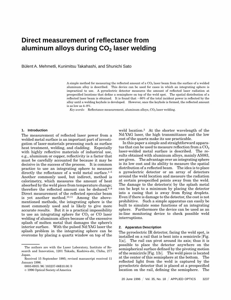
Although there are slight pulse-to-pulse instabili-ties, a typical real-time laser pulse shape is like theone shown in Fig. 21a2, and one can reduce this pulseto the geometrically simple shape shown in Fig. 21b2to make approximate calculations. Then the en-ergy delivered during the initial rise of the pulse is,15% of the total pulse energy. In the standardcase mentioned above this is ,1.1 J. There are nodelays between the starts of the laser and thereflection signals. Although they both start risingat the same time, the rise times 110–90%2 of thereflected and the laser signals are ,0.25 and 0.35ms, respectively. Because of the heating and melt-ing of the alloy on the weld spot, the reflection signaldrops because of higher beam absorption by themolten metal. The peak of the reflected signalsignifies the start of the liquid phase. The shorterrise time of the reflected signal indicates that beforethe laser pulse peak is over, the surface has meltedand a welding keyhole has formed.3,5,10 The re-flected real-time signal sometime exhibits smallpeaks even after the initial large peak 3Fig. 21a24.These peaks seem to have no direct relationship tolaser conditions, and they occur at random times.The presence of these peaks is probably related tothe random ejection of molten particles.
Fig. 2. 1a2 Typical shapes of the laser pulse 1continuous curve2 andthe real-time reflected signal 1dashed curve2. 1b2 Approximationof the laser pulse for calculations. The shaded area 11.1 J2corresponds to 15% of the total pulse energy of 7.2 J.
4. Results
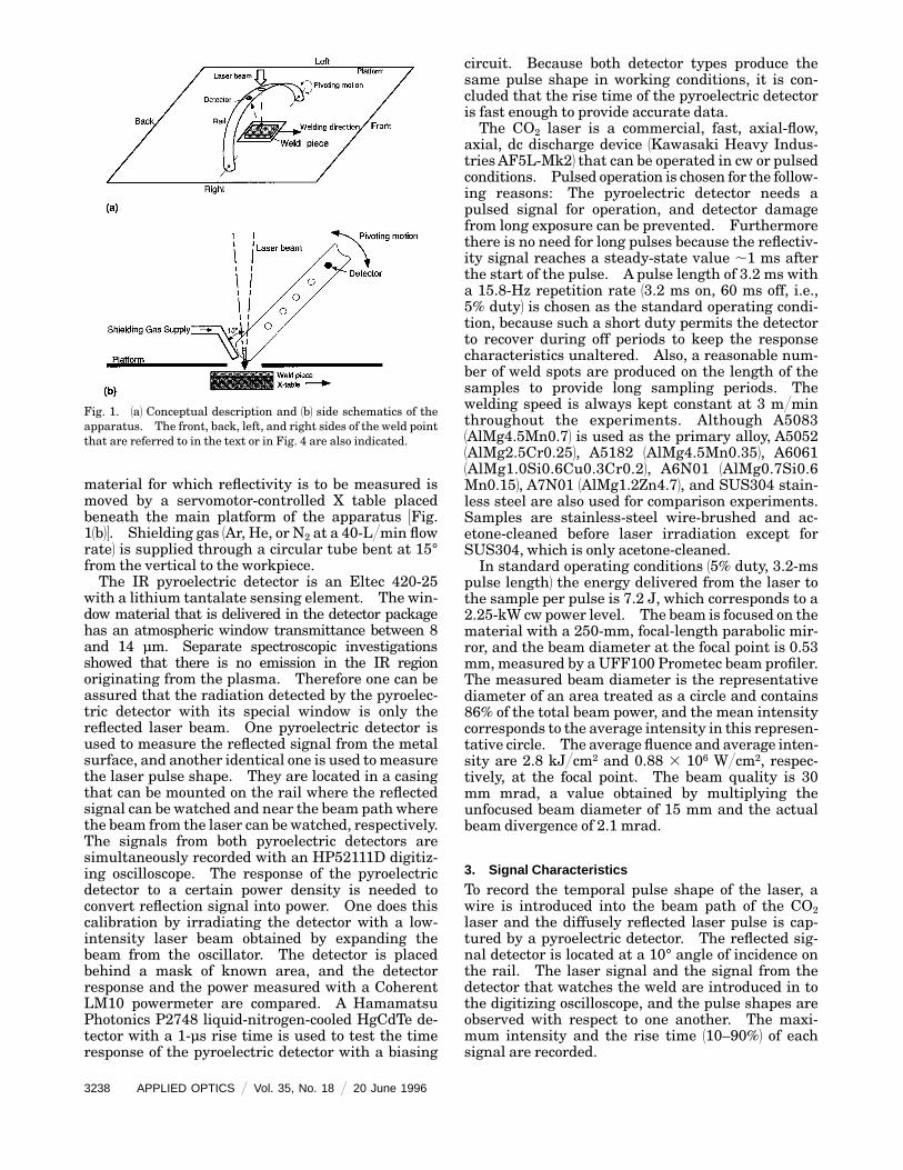
The reflected light from a metal surface has aspecular and a diffuse component. To measure thespatial distribution of the reflected laser beam, thelocation of the detector is changed at 10° intervalseach time a measurement is taken. This is re-peated for all four sides of the weld point. At eachdetector location the data from 100 laser pulses arecollected in order to have an adequately high averag-ing number to nullify the effect of pulse-to-pulseinstability. As mentioned above the pyroelectricdetector can be placed only on a semicircular rail,which, upon pivoting around its diameter, defines asemispherical surface on top of the weld location atthe center of the bottom circle. In this way thereflected beam intensity measured by the detector isalways the same distance from the weld location,and this permits an easy calculation of the totalreflection because the solid angle seen by the detec-tor is constant at all locations. The reflection atangles close to the incidence 1specular reflection2, i.e.,between 0° and 10°, is particularly difficult to obtainbecause of the incoming laser radiation and thephysical size of the detector. The readings in thisrange are taken by tilting the A5083 sample by suchan angle that the reflection hits a location close tothe detector placed at 10° from the incident laserbeam 1Fig. 32. This particular procedure for narrow
Fig. 3. Arrangement for reflectivitymeasurement at angles closeto the incident beam.
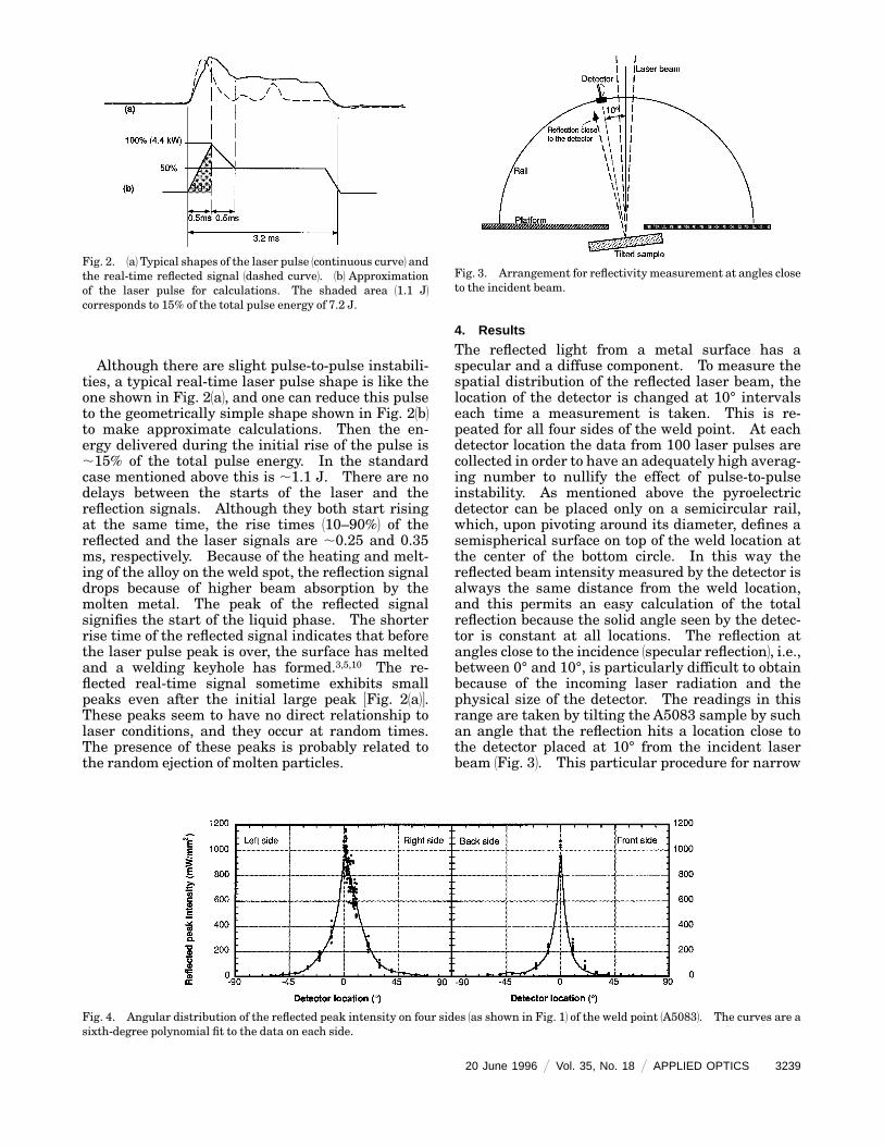
Fig. 4. Angular distribution of the reflected peak intensity on four sides 1as shown in Fig. 12 of the weld point 1A50832. The curves are asixth-degree polynomial fit to the data on each side.
20 June 1996 @ Vol. 35, No. 18 @ APPLIED OPTICS 3239
angles of incidence is done only on the right side ofthe welding direction. The results of spatial distri-bution experiments are in Fig. 4. At an angle ofincidence greater than 70°, the reflection was al-ready very weak and no clear data could be obtained.The reflection at the right side of the welding direc-tion is higher than the one for the other threedirections. We believe that this is due to the slightlyuneven beam profile.The total power reflected from the weld surface
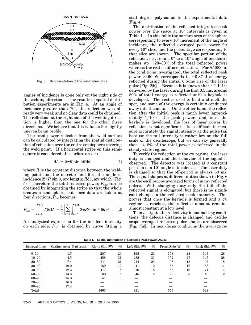
can be calculated by integrating the spatial distribu-tion of reflection over the entire semisphere coveringthe weld point. If a horizontal stripe on this semi-sphere is considered, the surface area is
dA 5 2pR sin uRdu, 112
where R is the constant distance between the weld-ing point and the detector and u is the angle ofincidence 12pR sin u, arc length; Rdu, arc width2 1Fig.52. Therefore the total reflected power, Ptot, can beobtained by integrating the stripe so that the wholecreates a semisphere, but since data are taken atfour directions, Ptot becomes
Ptot 5 eu50
p@2
I1u2dA 51
4 3oi51
4 eu50
p@2
2pR2 sin uduIi1u24 . 122
An analytical expression for the incident intensityon each side, Ii1u2, is obtained by curve fitting a
Fig. 5. Representation of the integration area.
sixth-degree polynomial to the experimental data1Fig. 42.The distribution of the reflected integrated peak
power over the space at 10° intervals is given inTable 1. In this table the surface area of the spherecorresponding to every 10° increment of the angle ofincidence, the reflected averaged peak power forevery 10° slice, and the percentage corresponding tothat slice are shown. The specular portion of thereflection, i.e., from a 0° to a 10° angle of incidence,makes up ,20–30% of the total reflected powerwhereas the rest is diffuse reflection. For A5083, inthe conditions investigated, the total reflected peakpower 13460 W2 corresponds to ,0.87 J of energyreflected during the initial 0.5-ms rise of the laserpulse 3Fig. 21b24. Because it is known that ,1.1 J isdelivered by the laser during the first 0.5 ms, around80% of total energy is reflected until a keyhole isdeveloped. The rest is used to heat and melt thespot, and some of the energy is certainly conductedaway into the metal. On the other hand, the reflec-tion after the initial peak is much lower 1approxi-mately 1@10 of the peak power2, and, once thekeyhole is developed, the loss of laser power byreflection is not significant. It is difficult to mea-sure accurately the signal intensity at the pulse tailbecause the tail intensity is rather low on the fullscale of the oscilloscope, but we can say generallythat ,4–8% of the total power is reflected in thesteady-state regime.To verify the reflection at the cw regime, the laser
duty is changed and the behavior of the signal isobserved. The detector was located at a constantposition of a 10° angle of incidence. The laser dutyis changed so that the off-period is always 60 ms.The signal shapes at different duties shown in Fig. 6are the oscilloscope averaged forms of many reflectedpulses. With changing duty only the tail of thereflected signal is elongated, but there is no signifi-cant change in the reflected peak intensity. Thisproves that once the keyhole is formed and a cwregime is reached, the reflected amount remainsalmost constant at a low level.To investigate the reflectivity in nonmelting condi-
tions, the defocus distance is changed and oscillo-scope-averaged reflected pulse shapes are observed3Fig. 71a24. In near-focus conditions the average re-
Table 1. Spatial Distribution of Reflected Peak Power 1A50832
Interval 1deg2 Surface Area 1% of total2 Right Side 1W2 1%2 Left Side 1W2 1%2 Front Side 1W2 1%2 Back Side 1W2 1%2
0–10 1.5 287 20 198 21 158 28 147 2810–20 4.5 458 31 282 31 152 27 145 2820–30 7.4 311 21 214 23 98 18 92 1830–40 10.0 169 12 111 12 65 12 58 1140–50 12.3 117 8 70 8 56 10 71 1450–60 14.3 80 5 45 5 26 5 10 260–70 15.8 41 3 — — —70–80 16.8 — — — —80–90 17.4 — — — —Total 1463 921 555 522
3240 APPLIED OPTICS @ Vol. 35, No. 18 @ 20 June 1996
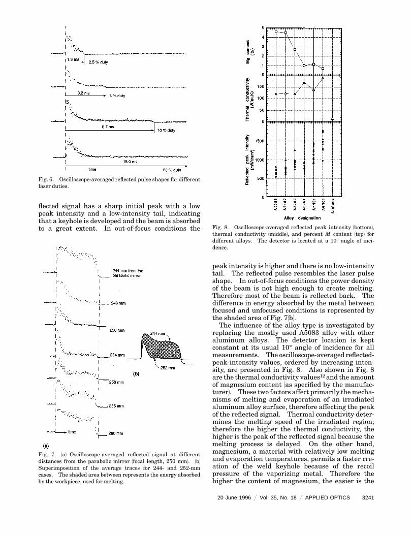
flected signal has a sharp initial peak with a lowpeak intensity and a low-intensity tail, indicatingthat a keyhole is developed and the beam is absorbedto a great extent. In out-of-focus conditions the
Fig. 6. Oscilloscope-averaged reflected pulse shapes for differentlaser duties.
Fig. 7. 1a2 Oscilloscope-averaged reflected signal at differentdistances from the parabolic mirror 1focal length, 250 mm2. 1b2Superimposition of the average traces for 244- and 252-mmcases. The shaded area between represents the energy absorbedby the workpiece, used for melting.
peak intensity is higher and there is no low-intensitytail. The reflected pulse resembles the laser pulseshape. In out-of-focus conditions the power densityof the beam is not high enough to create melting.Therefore most of the beam is reflected back. Thedifference in energy absorbed by the metal betweenfocused and unfocused conditions is represented bythe shaded area of Fig. 71b2.The influence of the alloy type is investigated by
replacing the mostly used A5083 alloy with otheraluminum alloys. The detector location is keptconstant at its usual 10° angle of incidence for allmeasurements. The oscilloscope-averaged reflected-peak-intensity values, ordered by increasing inten-sity, are presented in Fig. 8. Also shown in Fig. 8are the thermal conductivity values12 and the amountof magnesium content 1as specified by the manufac-turer2. These two factors affect primarily themecha-nisms of melting and evaporation of an irradiatedaluminum alloy surface, therefore affecting the peakof the reflected signal. Thermal conductivity deter-mines the melting speed of the irradiated region;therefore the higher the thermal conductivity, thehigher is the peak of the reflected signal because themelting process is delayed. On the other hand,magnesium, a material with relatively low meltingand evaporation temperatures, permits a faster cre-ation of the weld keyhole because of the recoilpressure of the vaporizing metal. Therefore thehigher the content of magnesium, the easier is the
Fig. 8. Oscilloscope-averaged reflected peak intensity 1bottom2,thermal conductivity 1middle2, and percent M content 1top2 fordifferent alloys. The detector is located at a 10° angle of inci-dence.
20 June 1996 @ Vol. 35, No. 18 @ APPLIED OPTICS 3241
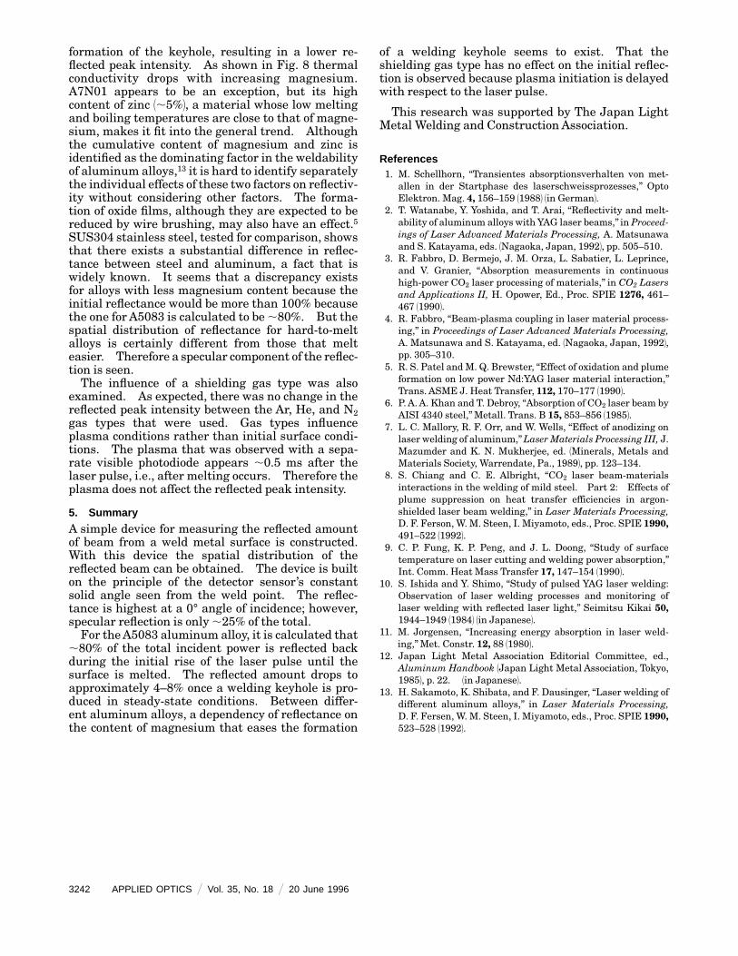
formation of the keyhole, resulting in a lower re-flected peak intensity. As shown in Fig. 8 thermalconductivity drops with increasing magnesium.A7N01 appears to be an exception, but its highcontent of zinc 1,5%2, a material whose low meltingand boiling temperatures are close to that of magne-sium, makes it fit into the general trend. Althoughthe cumulative content of magnesium and zinc isidentified as the dominating factor in the weldabilityof aluminum alloys,13 it is hard to identify separatelythe individual effects of these two factors on reflectiv-ity without considering other factors. The forma-tion of oxide films, although they are expected to bereduced by wire brushing, may also have an effect.5SUS304 stainless steel, tested for comparison, showsthat there exists a substantial difference in reflec-tance between steel and aluminum, a fact that iswidely known. It seems that a discrepancy existsfor alloys with less magnesium content because theinitial reflectance would be more than 100% becausethe one forA5083 is calculated to be ,80%. But thespatial distribution of reflectance for hard-to-meltalloys is certainly different from those that melteasier. Therefore a specular component of the reflec-tion is seen.The influence of a shielding gas type was also
examined. As expected, there was no change in thereflected peak intensity between the Ar, He, and N2gas types that were used. Gas types influenceplasma conditions rather than initial surface condi-tions. The plasma that was observed with a sepa-rate visible photodiode appears ,0.5 ms after thelaser pulse, i.e., after melting occurs. Therefore theplasma does not affect the reflected peak intensity.
5. Summary
A simple device for measuring the reflected amountof beam from a weld metal surface is constructed.With this device the spatial distribution of thereflected beam can be obtained. The device is builton the principle of the detector sensor’s constantsolid angle seen from the weld point. The reflec-tance is highest at a 0° angle of incidence; however,specular reflection is only ,25% of the total.For theA5083 aluminum alloy, it is calculated that
,80% of the total incident power is reflected backduring the initial rise of the laser pulse until thesurface is melted. The reflected amount drops toapproximately 4–8% once a welding keyhole is pro-duced in steady-state conditions. Between differ-ent aluminum alloys, a dependency of reflectance onthe content of magnesium that eases the formation
3242 APPLIED OPTICS @ Vol. 35, No. 18 @ 20 June 1996
of a welding keyhole seems to exist. That theshielding gas type has no effect on the initial reflec-tion is observed because plasma initiation is delayedwith respect to the laser pulse.
This research was supported by The Japan LightMetal Welding and ConstructionAssociation.
References1. M. Schellhorn, ‘‘Transientes absorptionsverhalten von met-
allen in der Startphase des laserschweissprozesses,’’ OptoElektron. Mag. 4, 156–159 119882 1in German2.
2. T. Watanabe, Y. Yoshida, and T. Arai, ‘‘Reflectivity and melt-ability of aluminum alloys withYAG laser beams,’’ in Proceed-ings of Laser Advanced Materials Processing, A. Matsunawaand S. Katayama, eds. 1Nagaoka, Japan, 19922, pp. 505–510.
3. R. Fabbro, D. Bermejo, J. M. Orza, L. Sabatier, L. Leprince,and V. Granier, ‘‘Absorption measurements in continuoushigh-power CO2 laser processing of materials,’’ in CO2 Lasersand Applications II, H. Opower, Ed., Proc. SPIE 1276, 461–467 119902.
4. R. Fabbro, ‘‘Beam-plasma coupling in laser material process-ing,’’ in Proceedings of Laser Advanced Materials Processing,A. Matsunawa and S. Katayama, ed. 1Nagaoka, Japan, 19922,pp. 305–310.
5. R. S. Patel andM. Q. Brewster, ‘‘Effect of oxidation and plumeformation on low power Nd:YAG laser material interaction,’’Trans. ASME J. Heat Transfer, 112, 170–177 119902.
6. P. A.A. Khan and T. Debroy, ‘‘Absorption of CO2 laser beam byAISI 4340 steel,’’ Metall. Trans. B 15, 853–856 119852.
7. L. C. Mallory, R. F. Orr, and W. Wells, ‘‘Effect of anodizing onlaser welding of aluminum,’’Laser Materials Processing III, J.Mazumder and K. N. Mukherjee, ed. 1Minerals, Metals andMaterials Society, Warrendate, Pa., 19892, pp. 123–134.
8. S. Chiang and C. E. Albright, ‘‘CO2 laser beam-materialsinteractions in the welding of mild steel. Part 2: Effects ofplume suppression on heat transfer efficiencies in argon-shielded laser beam welding,’’ in Laser Materials Processing,D. F. Ferson, W. M. Steen, I. Miyamoto, eds., Proc. SPIE 1990,491–522 119922.
9. C. P. Fung, K. P. Peng, and J. L. Doong, ‘‘Study of surfacetemperature on laser cutting and welding power absorption,’’Int. Comm. Heat Mass Transfer 17, 147–154 119902.
10. S. Ishida and Y. Shimo, ‘‘Study of pulsed YAG laser welding:Observation of laser welding processes and monitoring oflaser welding with reflected laser light,’’ Seimitsu Kikai 50,1944–1949 119842 1in Japanese2.
11. M. Jorgensen, ‘‘Increasing energy absorption in laser weld-ing,’’Met. Constr. 12, 88 119802.
12. Japan Light Metal Association Editorial Committee, ed.,Aluminum Handbook 1Japan Light Metal Association, Tokyo,19852, p. 22. 1in Japanese2.
13. H. Sakamoto, K. Shibata, and F. Dausinger, ‘‘Laser welding ofdifferent aluminum alloys,’’ in Laser Materials Processing,D. F. Fersen, W. M. Steen, I. Miyamoto, eds., Proc. SPIE 1990,523–528 119922.