Embed Size (px)
Citation preview

Title Direct Optical Switching Code Division MultipleAccess Systems for Fiber-Optic Radio Networks
Author(s) Park, Sang-Jo
Citation
Issue Date
Text Version ETD
URL https://doi.org/10.11501/3155405
DOI 10.11501/3155405
rights
Direct Optical Switching Code Division Multiple Access
Systems for Fiber-Optic Radio Networks
Sang-Jo Park
Osaka University
January 1999


Acknowledgments
The research described in this thesis has been carried out by the author during his Ph. D course
at the Department of Communications Engineering, Graduated School of Engineering, Osaka
University.
The author would like to express his sincere gratitude to his supervisor, Professor Shozo
Komaki, for giving the author an opportunity to study as a Ph.D student and for his academic
advice, encouragement, and various supports throughout this research.
The author gives his appreciation to Professor Norihiko Morinaga and Associate
Professor Masayuki Matsumoto for their readings and valuable criticisms on the whole contents
of this thesis.
The author gives his appreciation to Professor Hajime Maeda, Professor Hiromasa Ikeda,
Professor Hiroshi Motoda, Professor Yuji Kodama and Professor Toshiyuki Shiozawa of
Graduated School of Engineering, Osaka University for their valuable comments on this
research.
The author wants to appreciate Assistant Professor Minoru Okada and all members of
Komaki Laboratory, especially Mr. Yozo Shoji, Mr. Masahiro Nishi and Mr. Satoshi Kajiya of
Mitsubishi Co. Ltd. for their valuable comments on this study.
The author also thanks Associate Professor Katsutoshi Tsukamoto for his academic
guidance and detailed comments throughout this study.
Without the scholarship from Ministry of Education, Science Research and Culture, Japan
and the financial support from Electronics and Telecommunications Research Institute(ETRI),
Korea, this research could not have carried out. The author gives his appreciation to both for
their special helps as well as financial supports.
The author thanks Dr. Manseop Lee, Dr. Kanghee Y oo, Mr. Seongsoo Kang and Mr.
Chan goo Lee of ETRI, Korea for their encouragements and supports.

Finally, the author expresses his appreciation to his parents, brothers, wife Munsuk Lim,
daughter Solah and son Junwhan for their endless loves and encouragements.
11

Preface
Recently, the international mobile telecommunication for the 2000s(IMT -2000), wireless
asynchronous transfer mode(ATM) systems and future cable television(CATV) systems have
beeri extensively developed to satisfy the increasing demand for the multimedia
communications including voices, video-on-demands, high speed data and so on. In addition,
future mobile communications providing multimedia services should have two important
capabilities: one is the globally enhanced seamless connection capability among a huge number
of cells, and the other is the flexibility and universality for diversified and various radio signal
formats. However, broadband multimedia communications will need a lot of frequency
resources and the microcellular/picocellular technology has many problems including the signal
transfer among many microcells.
To solve these problems, fiber-optic radio networks have been studied. As an effective
multiple access method for various types of radio signals over an fiber-optic link, the optical
code division multiple access(CDMA) method will be a strong candidate. The optical CDMA
methods have been studied mainly for digital optical local area network(LAN)s.
This thesis proposes optical CDMA methods for fiber-optic radio highway networks that
can operate for such future mobile communications and is organized by the following six
chapters.
Chapter 1 describes the purposes of this thesis in conjunction with the backgrounds.
Chapter 2 describes optical code division multiple access methods for fiber-optic radio
networks. Multiple access methods for fiber-optic radio networks and conventional optical
CDMA methods are described. We discuss the necessity for a new type of the optical CDMA
method for fiber-optic radio highway networks.
Chapter 3 describes the concept of cable-to-the-air (CATA) system and the principle of
the direct optical switching(DOS) CDMA for fiber-optic radio networks including CAT A
iii

systems. We propose two types of bus connection methods, the optical coupler connection and
the optical switch connection where an optical switch is used not only to spread the spectrum of
optical signals but also to launch them into the fiber-optic bus link. Then, in two types of DOS
CDMA CATA systems, we theoretically analyze the carrier-to-interference-plus-noise power
ratio(CINR)s of regenerated radio signals. The results show that, in the optical switch
connection system, by introducing the additional optical gain at each radio base station, the
CINR's for all radio base stations and the connected number of radio base stations can be
improved compared with the optical coupler connection system.
Chapter 4 proposes the optical polarity reversing correlator(OPRC) for the DOS-CDMA
scheme in order to apply PN codes that are usually used in CDMA radio systems. The CINR of
the regenerated radio signal is theoretically analyzed. The results show that, for small average
transmitted optical powers, the OPRC using Gold codes can more improve the number of
maximum connected radio base stations than the unipolar type correlator using prime codes.
Chapter 5 proposes the reversing optical intensity(ROI) CDMA where the spectrum
spreading is performed for all intervals of a PN code in order to increase the received optical
power at the receiver and have the flexibility for conventional CDMA radio systems. We apply
the ROI-CDMA routing scheme to conventional CDMA radio systems in order to route code
division multiplexing( COM) signals to the control station. The CINR of the regenerated radio
signal is theoretically analyzed. As a result, the CINR can be more improved by increasing the
code sequence length at the ROI-CDMA transmitter than that in the radio highway using the
electrical COMA and intensity modulation(IM) method.
Chapter 6 summarizes the results obtained from this study.
The work summarized in this thesis has been carried out by the author during his Ph. D
course at the Department of Communications Engineering, Graduated School of Engineering,
Osaka University, during 1995-1999.
Osaka, Japan
January 1999
iv
Sang-Jo Park
Contents
1 Introduction 1
2 Optical Code Division Multiple Access Method for Fiber-Optic Radio Networks 7
2.1 Introduction . 0 ••••••••••••••••••••••••••••••••• e •••••••••••••••••••••••••••••••••••••••••••••••• 7
2.2 Multiple Access Method for Fiber-Optic Radio Networks ........•.•...•.....•...........•• 8
2.3 Optical Code Division Multiple Access Method ................••••.•...............•..•... 10
2.4 Concluding Remarks .......................................................................... 12
3 Fiber-Optic Radio Networks Using Direct Optical Switching(DOS) CDMA And Its
Performance Analysis 13
3.1 Introduction ................................................................................. . 13
3-.2 Direct Optical Switching(DOS) CDMA Cable-To-The Air(CATA) System
.................................................................................................. 16
3 .2.1 Principle of DOS-CDMA Method ......••••...•••••••..•......••.•••..•........•..... 16
3.2.2 System Configuration ............................................................... 22
3.3 Theoretical Analysis of Carrier-to-Interference-plus-Noise Ratio Performance ......•. 23
3.3 .1 Optical Coupler Connection ......................................................... 23
3.3.2 Optical Switch Connection ........................................................... 27
3.4 Numerical Results and Discussions ........................................................ 30
3.5 Concluding Remarks ....................................................................... 36
4 Optical Polarity Reversing Correlator(OPRC) for DOS-CDMA Using PN codes 37
4.1 Introduction ................................................................................... 37
4.2 Direct Optical Switching(DOS) CDMA Radio Networks Using OPRC ................. 38
v

4.2.1 Principle of OPRC ..................................•.................................... 38
4.2.2 System Configuration .....•.............•..................•...........••.............. 41
4.3 Theoretical Analysis of Carrier-to-Interference-plus-Noise Ratio Performance ....... .42
4.4 Numerical Results and Discussions .........................................••..•.......... 48
4.5 Concluding Remarks ........................................................................ 54
5 Reversing Optical lntensity(ROI) CDMA Routing Method for CDMA Radio Systems
55
5.1 Introduction ................................................................................. 55
5.2 ROI-CDMA Routing Method for CDMA Radio Systems .•..•...........••..••...•....... 55
5.3 Theoretical Analysis of Carrier-to-Interference-plus-Noise Ratio Performance ••..•.•. 57
5.3 .1 The Desired Destination Control Station .•.....•...............•..•......•.•..•..••• 59
5.3.2 Routing to Other Control Stations ...........•...............................•...•..•. 62
5.4 Numerical Results and Discussions ••••••...•.••••••••••••.•••.•.•.•......•.•••••.•........ 62
5.5 Concluding Remarks ..••....•...........•.............•.................•.....•......•...•.. 65
6 Conclusions 67
References 71
Appendix 77
Appendix A. Optical Signal Beat Noise for DOS-CDMA Radio Networks Using OPRC
...................................................................................... 77
Appendix B. Optical Signal Beat Noise for Fiber-Optic Radio Networks Using ROI-
CDMA Method .................................................................. 81
Related Publications 85
vi

List of Figures
2.1 Concept of fiber-optic radio networks ....................................................... 9
2.2 Configuration of the electrical CDMA and 1M method .................................... 11
2.3 Examples of conventional optical CDMA methods ........................................ 12
3.1 Concept of the CAT A system ............................................................... 14
3.2 Principle of the DOS-CDMA process .......•.........•..................................... 16
3.3 Normalized both-side PSD of signal component .......................................... 21
3.4 Relationship between CSIR and prime code number p ................................... 21
3.5 Configuration of the proposed DOS-CDMA CATA system .............................. 24
3.6 Collision between two IM/CDMA signals .................................................. 24
3.7 CIR of the k-th RBS from the HE for p=23 andM=20 .................................. 31
3.8 CIR of the farthest M-th RBS versus prime code number p for M~of 20, 40 and 80 .... 33
3.9 Relationship between PrM IPs and M for p=79 in the OSW connection system ....... 33
3.10 CNR versus prime code number p for Ps=OdBm and M of 20 and 40 ................... 35
3.11 CINR versus number of connected RBS's, M for p=79 (11Tc=11.2GHz) .............. 35
4.1 Configuration of the transmitter and the OPRC for optical CDMA using PN codes ..... 39
4.2 Configuration of the optical CDMA radio highway network using the OPRC ........... .41
4.3 Relationship between the code sequence length, L and the CIR......................... 49
4.4 Number of distinct code.sequences versus the code sequence length, L ................. 51
vii

4.5(a) Relationship between the code sequence length, Land the CINR for Ps=OdBm ....... 51
4.5(b) Relationship between the code sequence length Land the CINR for Ps=-lOdBm ..... 52
4.6 Relationship between the average transmitted optical power, P5 and the CINR ......... 52
4.7 Relationship the switching speed in the DOS-CDMA, 11 Tc and the number of
maximum connected RBS's, Mmax ••••••••••••••••••••••••••••••••••••••••••••••••••••••••• 53
5.1 Configuration of the radio highway using the ROI-CDMA routing method .............. 56
5.2 Configuration of the RCT and the OPRC ................................................. 58
5.3 Relationship between the CIR and the code sequence length, La ••••••••••••••••••••••• 63
5.4 Relationship between the CNR and the code sequence length, La ••••••••••••••••••••••• 64
5.5 Relationship between the CINR and the code sequence length, La •••••••••••••••••••••• 65
vm

Chapter 1
Introduction
Recently, the international mobile telecommunication for the 2000s(IMT-2000) [1], wireless
asynchronous transfer mode(ATM) systems [2] and future cable television(CATV) systems [3]
have been extensively developed to satisfy the increasing demands for the multimedia
communications including voices, video-on-demands, high speed data and so on. To satisfy
these demands, we need to realize broadband transmissions, and the fiber optic systems have
been introduced into trunk networks as one of the solutions. On the other hand, radio access
links for broadband communications have a variety of features such as the portability of set-top
box (STB )es and the flexible construction of access links [ 4]. The wired local loop system will
be used for the radio signal delivery to construct indoor wireless networks. However, mobile
wireless communications or mobile computings should be operated as anytime and anywhere as
possible, so we must provide the same communication environments both for insides such as
in-houses, offices, in-shops and so on, and for outsides such as streets, in-cars, stations and so
on. In addition, future mobile communications providing multimedia services should have two
important capabilities: one is the globally enhanced seamless connection capability among a
huge number of cells, and the other is the flexibility and universality for diversified and various
radio signal formats. Wide-band data transmissions need a lot of frequency resources, thus
microcellular systems have been proposed [5]. However, the microcellular technology has
many problems including the signal transfer and switching among many microcells and the
installation of new radio base station(RBS)s.
To solve these problems, fiber-optic microcellular systems have been proposed and
1

studied [6]-[7]. In this system, microcells in wide area are connected by optical fibers and radio
signals are transmitted over fiber-optic links among microcells and a control station(CS). This
system can simultaneously open radio free spaces among several users and CS's according to
user's demand. We have called this space as "Virtual radio free space" and have proposed
"Fiber-optic radio networks" [8]-[9]. This network can operate for any types of air interfaces,
and needs no restoration of RES's to start any new services for global area. Moreover, this
network can realize the universal capability and flexibility for various types of air interfaces
such as microcelluar radio systems, fiber-to-the-air (FTTA) systems, B-ISDN ATM based high
speed radio distributions and so on. ARBS is only equipped with an electric-to-optic(E/0) and
an optic-to-electric( OlE) converter, and all of complicated functions such as the RF modulation/
demodulation and the spectrum delivery switching are installed at the CS.
We investigate the configuration of fiber-optic radio highway networks. Conventionally,
a single star configuration has been mainly investigated because of its simplicity and high
reliability. However, a problem in this configuration is the enormous investment for the
construction of many fiber-optic links. Moreover, we should consider robust and flexible
architecture as well as cost-efficient configuration for fiber-optic radio highway networks.
Reference [10] has reported that the bus type optical link or the passive double star link provides
not only lower cost implementation, but also much more robust and flexible configuration than
the star type optical link. So we adopt the bus type optical link as a configuration of fiber-optic
radio highway networks [6][13]. Therefore, we should consider multiple access methods for
fiber-optic radio highway networks. As a multiple access method for fiber-optic radio highway
networks, subcarrier division multiple access(SCMA) methods [6][11] and time division
multiple access(TDMA) methods [12]-[13] have often been discussed. The SCMA method
excels in simplicity and flexibility, however, each cell needs a different radio frequency and
optical signal beat noises severely deteriorate the carrier-to-noise ratio(CNR) at the CS if there
are no strict controls of optical wavelengths of laser diodes connected to fiber-optic at each
RBS. Reference [14] investigates the reduction of optical signal beat noises in the SCM/
wavelength division multiplexing(WDM) network, however the spectrum spreading technique
has not been investigated. On the other hand, in the TDMA method no optical signal beat noise
2

arises and a radio frequency can be reused among several microcells, however, this method
needs the time synchronization of the whole system. In the downlink of fiber-optic radio
highway networks, for example, the radio or video distribution can be provided by the
conventional multiplexing method such as the SCMA method. On the other hand, the uplink
traffic is not so large in spite of many potential subscribers, but there exist various types of radio
signals which have different frequencies and different multiple access methods. Thus, the code
division multiple access(CDMA) method will be a strong candidate as a multiple access method
for the uplink of fiber-optic radio networks because of its asynchronous access property,
flexibility and transparency for various radio air interfaces. As CDMA methods that are applied
for fiber-optic radio highway networks, there are two methods : one is the electrical CDMA and
intensity modulated(IM) method [15] where radio signals are spectrum-spread and their
correlations are performed in the electrical domain. Another is the optical CDMA method where
radio signals are spectrum-spread and their correlations are performed in the optical domain.
Out of two CDMA methods for fiber-optic radio networks, the optical CDMA method is more
suitable than the conventional electrical CDMA and IM method because radio signals are
multiplexed in the optical domain and high processing gains can be gained with ease by using
the broad bandwidth of optical devices.
Up to this time, various optical CDMA methods have been studied mainly for digital
optical local area network(LAN)s. Optical CDMA methods suchas using fiber delay lines [16]
[20], optical phase masks [21]-[22] and coherent optical phase modulations [23]-[25] have been
proposed and studied. In the optical CDMA method using fiber delay lines, the encoding and the
decoding are performed by delaying optical pulses in the time domain. In the optical CDMA
method using optical phase masks, the spectral encoding and the decoding are performed by
phase-modulating optical pulses in the optical frequency domain. However, these methods can
not be applied for multiplexing radio signals for fiber-optic radio networks. Furthermore, these
methods have no flexibility in assigning code sequences. In the optical CDMA method using
coherent optical phase modulations, its correlators are very complicated and need very fine
narrowband optical filters that are very sensitive to temperature changes. On the other hand, the
optical CDMA using optical disk patterns [26] has been proposed, however in this method the
3

assigning code sequences is not flexible and the application to radio signals has not been taken.
Therefore, we investigate optical CDMA methods for fiber-optic radio highway networks
from the view points of the flexibility in assigning code sequences and the use of the optical
intensity modulation. In this thesis, we investigate the direct optical switching (DOS)-CDMA
scheme as a multiple access for fiber-optic radio networks [27]-[30], where a radio signal is
converted into an optical intensity-modulated (IM) signal and the multiplexing is performed
with randomizing positions of optical pulses by driving directly an OSW on-off switchings with
a code sequence. So any types of radio signal can be converted into optical intensity-modulating
(IM) I CDMA signals. We apply the concept of fiber-optic radio highway networks to the
CATV system and firstly call it cable-to-the-air (CAT A) system [27]. The configuration of the
DOS-CDMA CATA system is proposed by using the optical coupler(OC) connection and the
optical switch(OSW) connection and their performances using prime codes are theoretically
analyzed [29][30].
As an optical orthogonal code, the prime code that is applied to obtain a desired process
gain in optical CDMA methods [16]-[20], suffers a limit in the number of distinct code
sequences, which results in the limitation of the number of radio base stations connected to
fiber-optic radio networks. Besides in fiber-optic radio networks using DOS-CDMA with prime
codes, the optical power efficiency is low because the pulse duty of a prime code is quite low.
Therefore, we should consider a new type of correlator for DOS-CDMA method to which
pseudo noise(PN) codes such as Maximal length codes and Gold codes can be applied because
those codes are usually used in radio system and generally superior in the number of distinct
code sequences compared with prime codes. For digital networks using optical CDMA
methods, sequence inversion keyed(SIK) direct sequence(DS) CDMA methods that have been
proposed in Refs.[31]-[32], require specially balanced PN codes. In order to allow the use of any
unbalanced PN codes, the power splitting ratio of the power divider at the optical correlator has
been controlled [33], and the transmission of two channels using two wavelengths or two
orthogonal polarizations has been proposed [34]. In SIK-CDMA methods, however, binary
digital data are encoded and transmitted with the positive polarity and the negative polarity of
bipolar codes, thereby their correlators at the receiver can not be applied to DOS-CDMA signals
4

that are converted from radio signals by the on-off switching CDMA method.
In this thesis, we newly propose the optical polarity-reversing correlator(OPRC) for DOS
CDMA radio highway networks usihg PN codes [35]-[39]. In DOS-CDMA methods, as the
optical power is zero for the interval of zero parts in prime codes or negative polarity parts in
PN codes, the received optical power at the receiver is less than the laser power at the RBS.
Moreover, the optical CDMA using all intervals of PN codes for fiber-optic radio networks is
needed in order to have the flexibility for conventional CDMA radio systems. In this thesis, we
newly propose the reversing optical intensity(ROI) CDMA method where the spectrum
spreading is performed for all intervals of a PN code [40]-[41]. We apply the ROI-CDMA
routing scheme to conventional CDMA radio systems to route CDM signals to the routing
destination CS [41]. In the proposed networks, we theoretically analyze the carrier-to
interference-plus-noise power ratio(CINR)s of regenerated radio signals because the noise
power is the important factor in fiber-optic radio networks, however in conventional CDMA
radio systems the carrier-to-interference-power ratio(CIR) is analyzed.
In this thesis, we treat the following five chapters :
Chapter 2 describes optical code division multiple access methods for fiber-optic radio
networks. Multiple access methods for fiber-optic radio networks and the conventional optical
CDMA methods are described. The necessity for a new type of the optical CDMA method for
fiber-optic radio highway networks is discussed.
Chapter 3 describes the concept of cable-to-the-air (CATA) system and the principle of
the direct optical switching CDMA for fiber-optic radio networks including CAT A systems. We
propose two types of bus connection methods, the optical coupler connection and the optical
switch connection where an optical switch is used not only to spread the spectrum of optical
signals but also to launch them into the fiber-optic bus link. Then, in two types of DOS-CDMA
CAT A systems, we theoretically analyze the carrier-to-interference-plus-noise power
ratio(CINR)s of regenerated radio signals. The results show that by introducing the additional
optical gain at each radio base station, the CINR's for all radio base stations and the connected
number of radio base stations can be improved in the optical switch connection system
compared with the optical coupler connection system.
5

Chapter 4 proposes the optical polarity reversing correlator(OPRC) for the DOS-CDMA
scheme in order to apply PN codes that are usually used in CDMA radio systems. The CINR of
the regenerated radio signal is theoretically analyzed. The results show that, for small average
transmitted optical powers, the OPRC using Gold codes can more improve the number of
maximum connected radio base stations than the unipolar type correlator using prime codes.
Chapter 5 proposes the reversing optical intensity(ROI) CDMA where the spectrum
spreading is performed for all intervals of a PN code in order to increase the received optical
power at the receiver and have the flexibility for conventional CDMA radio systems. We apply
the ROI-CDMA routing scheme to conventional CDMA radio systems to route code division
multiplexing(CDM) signals to the routing destination control station. The CINR of the
regenerated radio signal is theoretically analyzed. As a result, the CINR can be more improved
by increasing the code sequence length at the ROI-CDMA transmitter than that in the radio
highway using the electrical.CDMA and intensity modulation(IM) method.
Chapter 6 summarizes the results obtained from this study.
6
Chapter 2
Optical Code Division Multiple Access
Method for Fiber-Optic Radio Networks
2.1 Introduction
A bus type optical link or a passive double star link is preferable for fiber-optic radio highway
networks because it provides more the reduction in conduits and optical fiber lengths as well as
more robust and flexible interconnection architectures than a star link [10]. Therefore, we
should consider effective multiple access methods for various types of radio signals over a
fiber-optic link. The uplink traffic in fiber-optic radio networks is not so large in spite of many
potential subscribers, but there exist various types of radio signals which have different
frequencies and different multiple access methods. Thus, the CDMA method will be a stronger
candidate as a multiple access method for the uplink of fiber-optic radio networks because of its
asynchronous access property, flexibility and transparency for various radio air interfaces than
SCMA methods [6][11] and TDMA methods [12]-[13].
In radio highway networks using the electrical CDMA method and intensity
modulation(IM) method [12], radio signals are spectrum-spread and their correlations are
performed in the electrical domain. As a CDMA method for fiber-optic radio highway
networks, the optical CDMA method is more suitable than the electrical CDMA method in
order to multiplex radio signals in the optical domain and to gain high processing gains.
Up to this time, various optical CDMA methods using such as optical pulse codings using
7

fiber delay lines [16]-[19] and optical phase masks [21]-[22], and coherent optical phase
modulations [23]-[25] have been studied mainly for digital signals in the LAN. The optical
CDMA method using optical pulse codings can not be applied to analog radio signals, because
their CDMA transmitters and correlators are based on optical pulses. In the optical CDMA
method using coherent optical phase modulations, its correlators have considerable
complexities. On the other hand, the optical CDMA using optical disk patterns [26] has been
proposed, however in this method the assigning code sequences is not flexible and the
application to radio signals has not been taken.
So we investigate optical CDMA methods for the uplink of fiber-optic radio highway
networks from the view points of the flexibility in assigning code sequences and the use of the
optical intensity modulation.
2.2 Multiple Access Method for Fiber-Optic Radio Networks
Recently, wide-band data transmissions need a lot of frequency resources and microcellular
systems have been proposed [5]. However, the microcellular technology has many problems
including the signal transfer and switching among many microcells and the installation of new
radio base station(RBS)s. To solve these problems, fiber-optic microcellular systems have been
proposed and studied [6]-[7]. In this system, microcells in wide area are connected by optical
fibers and radio signals are transmitted over fiber-optic links among microcells and a control
station(CS). This system can simultaneously open radio free spaces among several users and
CS's according to the user's demand. We have called this space as "Virtual radio free space" and
have proposed "Fiber-optic radio network" [8]-[9]. This network can operate for any types of air
interfaces, and needs no restoration of radio base station(RBS)s to start any new services for
global area. Figure 2.1 illustrates the concept of fiber-optic radio networks which can realize the
universal capability and flexibility for various types of air interfaces such as microcelluar radio
systems, fiber-to-the-air (FTTA) systems, B-ISDN ATM based high speed radio distribution
systems and so on. A RBS is only equipped with an electric-to-optic(E/0) and an optic-to
electric(O/E) converter, and all of complicated functions such as the RF modulation/
8

demodulation and the spectrum delivery switching are installed at the CS.
Fiber-Optic Picocell
.· Radio_S.ys.tem ______ ,
Fiber-Optic Micro
Radio System
cs (Control Station)
FTTA(Fiber-To-The-Air) system
Fig.2.1 Concept of fiber-optic radio networks.
We investigate the configuration of fiber-optic radio highway networks. Conventionally,
a single star configuration has been mainly studied because of its simplicity and high reliability.
However, a problem in this configuration is the enormous investment for the construction of
many fiber-optic links. Moreover, we should consider robust and flexible architecture as well as
cost-efficient configuration for fiber-optic radio highway networks. Reference [10] has reported
that the bus type optical link or the passive double star link provides not only lower cost
implementation, but also much more robust and flexible configuration than the star type optical
link. So we adopt the bus type optical link as a configuration of fiber-optic radio highway
networks [6][13]. Therefore, we should consider multiple access methods for fiber-optic radio
highway networks. As a multiple access method for fiber-optic radio highway networks, SCMA
methods [6][11] and TDMA methods [12]-[13] have often been discussed. The SCMA method
exceeds in simplicity and flexibility, however, each cell needs a different radio frequency and
optical signal beat noises severely deteriorate the carrier-to-noise ratio(CNR) at the CS if there
are no strict controls of optical wavelengths of laser diodes connected to the fiber-optic link at
each RBS. Reference [14] investigates the reduction of optical signal beat noises in the SCM/
wavelength division multiplexing(WDM) network, however the spectrum spreading technique
9

has not been investigated. On the other hand, in the TDMA method no optical beat noises arise
and a radio frequency can be reused among several microcells, however, this method needs the
time synchronization of the whole systems. In the downlink of fiber-optic radio highway
networks, for example, the radio or video distribution can be provided by the conventional
multiplexing method such as the SCMA method. On the other hand, the uplink traffic is not so
large in spite of many potential subscribers, but there exist various types of radio signals which
have different frequencies and different multiple access methods. Thus, the CDMA method will
be a stronger candidate as a multiple access method for the uplink of fiber-optic radio networks
because of its asynchronous access property, flexibility and transparency for various radio air
interfaces than SCMA methods [6][11] and TDMA methods [12]-[13]. Table 2.1 illustrates the
characteristics of multiple access methods for fiber-optic radio highway networks.
Table 2.1 Characteristics of multiple access methods for fiber-optic radio highway networks.
Multiple access method Configuration Characteristics
Subcarrier division use frequency o simple and flexible multiple access division multiplexed x each cell needs different (SCMA) RF signals radio frequency
Time division timewise sampled o radio frequency can be reused
multiple access among cells
(TDMA) using optical switch X need time synchronization of
whole system
Wavelength division use different optical X difficult to control optical multiple access
(WDMA) wavelengths wavelengths
2.3 Optical Code Division Multiple Access Method
As the CDMA methods that are applied for fiber-optic radio highway networks, there are two
methods: one is the electrical CDMA and IM method [15] where radio signals are spectrum
spread in the electrical domain and converted into 1M signals at the laser diode(LD), and their
correlations are performed in the electrical domain after the photodetection at the
photodetector(PD) as shown in Fig.2.2.
10
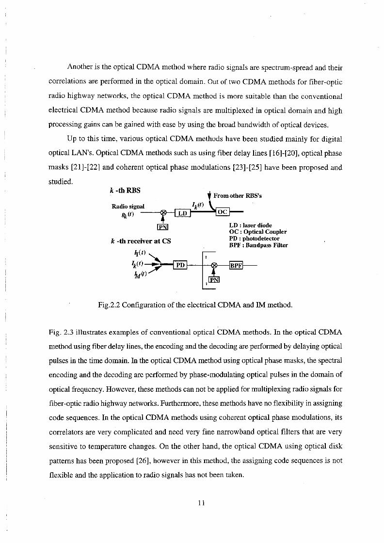
Another is the optical CDMA method where radio signals are spectrum-spread and their
correlations are performed in the optical domain. Out of two CDMA methods for fiber-optic
radio highway networks, the optical CDMA method is more suitable than the conventional
electrical CDMA method because radio signals are multiplexed in optical domain and high
processing gains can be gained with ease by using the broad bandwidth of optical devices.
Up to this time, various optical CDMA methods have been studied mainly for digital
optical LAN's. Optical CDMA methods such as using fiber delay lines [16]-[20], optical phase
masks [21]-[22] and coherent optical phase modulations [23]-[25] have been proposed and
studied. k -thRBS
k -th receiver at CS
l From other RBS's
LD : laser diode OC : Optical Coupler PD : photodetector BPF: Bandpass Filter
Fig.2.2 Configuration of the electrical CDMA and 1M method.
Fig. 2.3 illustrates examples of conventional optical CDMA methods. In the optical CDMA
method using fiber delay lines, the encoding and the decoding are performed by delaying optical
pulses in the time domain. In the optical CDMA method using optical phase masks, the spectral
encoding and the decoding are performed by phase-modulating optical pulses in the domain of
optical frequency. However, these methods can not be applied for multiplexing radio signals for
fiber-optic radio highway networks. Furthermore, these methods have no flexibility in assigning
code sequences. In the optical CDMA methods using coherent optical phase modulations, its
correlators are very complicated and need very fine narrowband optical filters that are very
sensitive to temperature changes. On the other hand, the optical CDMA using optical disk
patterns has been proposed [26], however in this method, the assigning code sequences is not
flexible and the application to radio signals has not been taken.
11

Therefore, we investigate optical CDMA methods for fiber-optic radio highway networks
from the view points of the flexibility in assigning code sequences and the optical CDMA using
the optical intensity modulation.
{a) Optical CDMA using tiber delay lines in the time domain
spread signal
n no o t
fiber delay line
(b) Optical CDMA using phase masks in the optical frequency domain
si\al
grnting~ $' >A > spread signal IC:I ~6..:::::-. .....
t ..... mz t t
(c) Optical CDMA using the coherent phase modulator
spectrum of signal (), ~ ••,..::::::~ pi m;dult:_A_ f ~ f .code code
Fig. 2.3 Examples of conventional optical CDMA methods.
2.4 Concluding Remarks
This chapter has described the various types of multiple access methods for fiber-optic radio
networks and performed the comparison of these methods. Among them, the CDMA method is
suitable for the uplink of fiber-optic radio networks. Also we have described the conventional
optical CDMA methods and discussed the necessity for a new type of the optical CDMA
method for the uplink of fiber-optic radio highway networks.
12
Chapter 3
Fiber-Optic Radio Networks Using Direct
Optical Switching(DOS) CDMA And Its
Performance Analysis
3.1 Introduction
A future CATV system [3] needs a broadband transmission link to offer interactive multimedia
services including voices, high quality videos, video-on-demands, high speed data and so on. In
addition, future mobile communications providing multimedia services should have two
important capabilities: 011e is the globally enhanced seamless connection capability among a
huge number of cell, and the other is the flexibility and universality for diversified and various
radio signal formats.
To solve above problems, we apply the concept of the m A system to the CATV system.
We first call such a system cable-to-the-air (CATA) system [27]. The CATA system is a
broadband wireless local loop, but by using progressive microwave/millimeter wave photonics
techniques, radio signals from subscribers are transmitted among radio base stations (RBS) and
a head end (HE) with radio signal formats kept over an optical fiber. Figure 3.1 illustrates the
concept of the CAT A system, where radio signals are encapsulated into the envelope of optical
signal through fiber-optic links. Since a RBS is only equipped with an E/0 converter and an
OlE converter, and all of complicated functions such as the RF modulation /demodulation and
13

the spectrum delivery switching are performed at the HE, the CAT A system can accommodate
various types of radio interfaces such as mobile communications, video broadcastings, in-house
radio networks and so on, and moreover it can provide the same wireless communication
environments for both indoor and outdoor. The CAT A system also has a great flexibility for any
changes or additions of radio services. For example, at first, this system provides a video-on
demand (VOD) service, and later it can immediately offer any new mobile communication
services or new video standards with no restoration of new set-top box(STB)es and only with
additional equipments at the HE.
Optical Fiber
Transmitter Demodulator Transceiver
Head End(HE)
Fig. 3.1 Concept of the CATA system.
In the downlink of CAT A system, for example, the radio or video distribution can be
provided by conventional multiplexing methods such as SCMA methods. On the other hand, the
uplink traffic is not so large in spite of many potential subscribers, but there exist various types
of radio signals which have different frequencies or different multiple access methods. Thus, the
optical CDMA method will be more suitable as a multiple access in the optical link because of
its asynchronous access property, greater flexibility and transparency for various radio air
14

interfaces than the SCMA method and the TDMA method.
In this chapter, we investigate the optical CDMA method for the uplink of fiber-optic
radio networks including CAT A systems from the view points of the flexibility in assigning
code sequences and the use of the optical intensity modulation. The direct optical switching
(DOS)-CDMA scheme is investigated as a multiple access for fiber-optic radio networks [27]
[30]. The proposed DOS-CDMA scheme can be performed only with an optical switch(OSW)
at the transmitter and also an OSW, a photodetector(PD), and an electrical bandpass filter(BPF)
at the receiver. So any types of radio signals can be converted into optical intensity-modulating
(IM) I CDMA signals. When applying DOS-CDMA scheme for a bus type optic-fiber link, an
OSW spreading the signal spectrum can be also used to launch them into the fiber link. In the
DOS-CDMA scheme, the multiplexing is performed by randomizing positions of optical pulses
by driving an OSW with a pseudo random code sequence. This is quite different from the
random access discrete address (RADA) scheme using the quantized pulse position modulation
(PPM) [42].
We propose the configuration of DOS-CDMA CAT A system by using the optical
coupler(OC) and the optical switch(OSW) connections and theoretically analyze their
performances. The remainders of this chapter are composed as followings: In Sect. 3.2, we
describe the principle ofDOS-CDMA scheme and the configuration of the DOS-CDMA CATA
system that is composed of two types of bus connection methods, the optical coupler(OC)
connection type and the OSW connection type. In the OSW connection type CATA system, an
OSW is used not only to spread the spectrum of optical signals but also to launch them into the
fiber-optic bus link. In Sect. 3.3, we theoretically analyze the carrier to interference-plus-noise
ratio (CINR)s of the radio signals regenerated at the HE for two types of bus connection
methods considering the chip pulse erasure at the OSW. In Sect. 3.4, some numerical results are
discussed and compared between two types of bus connection methods.
15

3.2 Direct Optical Switching(DOS) CDMA Cable-To-The
Air(CATA) System
3.2.1 Principle of DOS-CDMA Method
The DOS-CDMA scheme uses the on-off type switching spectral spreading. Each radio signal
received at each RBS is transmitted to a HE by analog type optical pulse amplitude
modulation(PAM) scheme, and the multiple access among many RBS's is performed by the
DOS-CDMA scheme. The regeneration of radio signal is based on the bandpass natural
sampling theory [13][43]. Figure 3.2 shows the system model of DOS-CDMA system to
illustrate the principle of the DOS-CDMA process at the RBS transmitter and the correlating
process at the HE receiver.
k-th RBS
t From other RBS's
k -th correlator OSW:Optical Switch OC : Optical Coupler
Desired radio Signal
Interference noise
Fig. 3.2 Principle of the DOS-CDMA process.
16

At aRBS, a received radio signal is converted into an optical intensity-modulated (IM)
signal by modulating LD directly and next sampled at an OSW, which is driven with a certain
code sequence, ck (t), and the output signal of OSW is transmitted to a receiver through optical
fiber. At the output of OSW in the transmitter, we can obtain optical PAMIIM signals whose
pulses are positioned according to the code pattern of ck(t). At the receiver, many PAMIIM
signals from many RBS's are correlated with the code sequence, ck(t), at an OSW, then directly
detected at a PD and interpolated at a BPF to regenerate the desired radio signal. It is assumed
that the code sequence, ck(t), matched with the one at the RBS is regenerated at the HE and the
synchronization between two code sequences is taken. The radio signal which is contaminated
by all other radio signals, is fed into a demodulator in order to obtain the information data.
The radio signal gk(t) at the k-th RBS is represented by
[ j21if. t] gk(t)=Re adt)e if , (3.1)
where frt is radio frequency and ak(t) is the complex envelope with its bandwidth, Brf. The
optical on-off switching CDMA is performed at the OSW driven by a code sequence, ck(t),
whose frame period and chip width are Tp(sec) and Tc respectively and its pulse amplitude is 1
or 0. The intensity of the optical P AMIIM signal at the output of the OSW is given by
Pk(t)=Ps{ l+gk(t) }ck (t), (3.2)
where Ps is the average transmitted optical power before optical switching.
The Pdt) is a bandpass natural sampled signal converted from a radio signal because an
optical switching is a window-type sampling. Therefore, a radio signal can be conveyed by
optical carrier with its signaling format kept and regenerated from the pulsed signals by the
interpolation at a BPF if we choose sampling period of less than or equal to half of the inverse of
radio signal bandwidth, S.li(2Brf) [43]. In the proposed DOS-CDMA system, since a pseudo
random sequence is chosen as a code sequence which drives the OSW at the transmitter, the
durations between optical pulses become various values according to the kind of code sequence,
but each pulse is surely repeated with its frame period of Tp. Therefore, in order to regenerate
the radio signal after interpolation, Tp of less than or equal to li(2Brf) should be chosen. From
the viewpoint of simplicity, using Tp of much less than l/(2Brf) is not effective, because a much
faster speed for OSW is required. Hence, in this paper, Tp is set to be the maximum value, that
17

is, 1 1(2Bif).
To improve the quality of the regenerated radio signal in DOS-CDMA system, a code
sequence with the highest possible autocorrelation and the lowest possible cross-correlation has
to be chosen. In the DOS-CDMA using optical 1M/direct detection (DD) scheme, a uniphase
code has to be used as a code sequence, while PN codes like maximum length or Gold code are
used in conventional radio CDMA system. References [16]-[20] have reported that a prime code
sequence is the best code as a uniphase orthogonal code which can provide the highest
autocorrelation and the lowest cross-correlation of various orthogonal codes. So in the proposed
DOS-CDMA system, the prime code sequence is employed as a spread spectrum (SS) code.
A set of prime codes has the preferable feature for IMIDD CDMA system that there are
very few coincidences of 1 's among code sequences. Prime codes with length, p 2 , are derived
from prime sequences obtained from a Galois field, GF(p), where p is a prime number [46].
Table 3.1 shows an example of prime sequences and prime code sequences for a prime number
p of 7. Each prime sequence element s mn is obtained by the product of the corresponding m and
n modulo p. Letting cm=(cm0,cm1, .• ,cmj•···cm(p-!)) denote the m-th prime code sequence, a j-th
code element, cmj, is given by
{1 ;j=smn+np
cmj= 0 ; otherwise· (3.3)
In the DOS-CDMA scheme using prime codes, TF( =p2 Tc) is set to 11(2Bif) in order to
gain the largest code length, p 2 , at the same switching speed of the OSW, thus the chip
width, Tc, is given by TF 1 p 2 • When an OSW correlator is driven with the k-th prime code
sequence, ck(t), at the receiver, the optical PAMIIM signal transmitted from the k-th RBS is
extracted out of all CDMA signals. Then the output current of the PD is composed of a desired
signal component, sk(t), interference components, I(t), and additive noise components, N(t).
Sk(t) and I(t) are respectively given by
(3.4)
M
I(t)=aP, I,gj(t)cj(t)ck(t), (3.5) j=l,j;ok
where a, P, and Mare the responsivity of the PD, the average received optical power at the
18

correlator, and the total number of connected RBS's, respectively. Here, we derive the carrier to
interference power ratio (CIR) in the DOS-CDMA system. We derive the power spectral
density (PSD) of signal component, Sk(t), by calculating the autocorrelation of sk(t) from
Eq.(3.4). The PSD of Sk(t), Sk(f), is given by
(3.6)
where Gk(f) is the power spectrum of gk(t) and sinc(x) is sin(x)/ x.
Table 3.1 Prime sequences and prime code sequences for prime number p=7.
Prime sequences for p=7
m SmO Sml Sm2 Sm3 Sm4 sms Sm6
0 0 0 0 0 0 0 0 1 0 1 2 3 4 5 6 2 0 2 4 6 1 3 5 3 0 3 6 2 5 1 4 4 0 4 1 5 2 6 3 5 0 5 3 1 6 4 2 6 0 6 5 4 3 2 1
Prime code sequences for p=7
m CmO Cmi cmz Cm3 Cm4 cm5 Cm6
0 1000000 1000000 1000000 1000000 1000000 1000000 1000000 1 1000000 0100000 0010000 0001000 0000100 0000010 0000001 2 1000000 0010000 0000100 0000001 0100000 0001000 0000010 3 1000000 0001000 0000001 0010000 0000010 0100000 0000100 4 1000000 0000100 0100000 0000010 0010000 0000001 0001000 5 1000000 0000010 0001000 0100000 0000001 0000100 0010000 6 1000000 0000001 0000010 0000100 0001000 0010000 0100000
Figure 3.3 shows the normalized both-sides PSD of the signal component. The first three terms
of sk (f) is the desired signal component around f rf and - f rf, and the other terms are the
frequency shifted components caused by bandpass sampling. Images of these shifted
components cause the distortion in the desired signal as the self-interference if they overlap over
19

the signal components as shown in Fig. 3.3 (a). We can perfectly remove the self-interference
components by setting the value of the radio frequency frt at (j+li2)Brf or j fTc (j is an integer)
as shown in Fig. 3.3 (b). Without such special values of frt, however, the self-interference
component may not deteriorate the signal quality because its power is much low compared with
that of the carrier signal component. We examine the carrier signal to self-interference power
ratio (CSIR) and Figure 3.4 shows the some numerical results for the frt of 1.93GHz and Brf of
900KHz. In the small value of p, the sine function causes the up and down in CSIR, but as p
increases, CSIR tends to be a saturated value of more than 30dB which is an enough value to
obtain the radio signal quality in DOS-CDMA. As p increases, the saturated value of CSIR is
determined by the relation between frt and Brf. Therefore, in the following analysis, we will
ignore the self-interference components.
From Eq. (3.6), the carrier power of the regenerated radio signal, C0 , is given by
Co=( aPr Y ~[1+~-~). p p p
(3.7)
Let (j'~ denote the average variance of the cross-correlation of the prime code. Then, the carrier
to interference power ratio, CIJ?o, is given by [16]-l20]
c p2 CI~ 0
lo G~(M-l). (3.8)
Table 3.2 shows 0'~ for different values of prime number p calculated by using computer
simulation. Table 3.2 shows that 0'~ is a little increased as p increases but has a saturated value
of 0.329 for p=97.
Table 3.2 Average variance of the cross-correlation of the prime code.
p ai 7 0.272 11 0.298 13 0.303 23 0.318 31 0.322 47 0.326 71 0.328 97 0.329
20

s f)
f
(a) Two components of desired signal and frequency shifted signal are overlapped.
f
(b) Two components of desired signal and frequency shifted signal are not overlapped.
Fig. 3.3 Normalized both-side PSD of signal component.
0 0 50
frt=1.93GHz
Brj=900KHz
100 150
Prime code number p
200
Fig. 3.4 Relationship between CSIR and prime code number p.
21

3.2.2 System Configuration
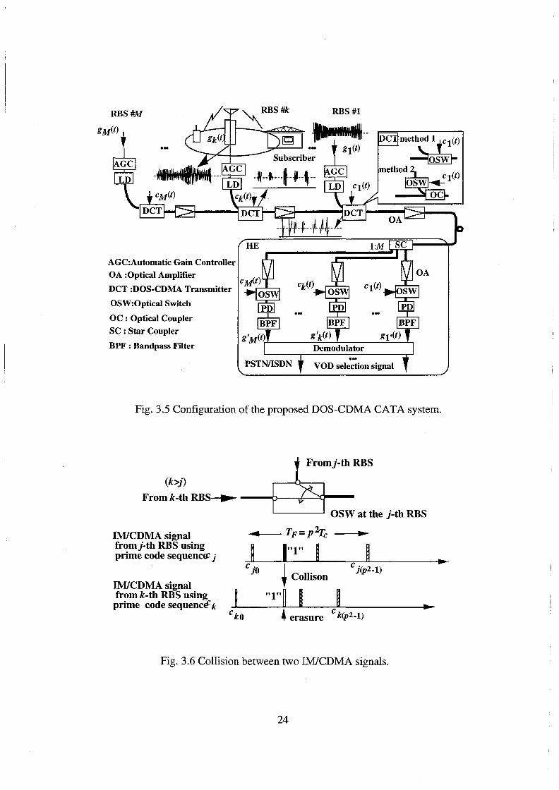
Figure 3.5 illustrates the configuration of the proposed DOS-CDMA CATA system. From the
viewpoint of a cost effective configuration, we adopt a bus type fiber-optic link for CAT A
system. M radio zones are connected to the bus link, where the radio signals from radio
terminals in each zone are multiplexed by the DOS-CDMA scheme and transmitted to the HE.
The RBS in each zone equips only a LD, an optical switch (OSW) and an automatic gain
controller (AGC).
As mentioned in sec. 3.2.1, after the direct-intensity-modulation ofLD, the optical on-off
switching spread spectrum (SS) is performed at the OSW, and in the bus type fiber link, many
DOS-CDMA signals are multiplexed by CDMA. At the receiver, received optical powers are
different among the received DOS-CDMA signals from M RBS's because the optical loss
between each RBS and HE is different. Also, intensity modulation indices are different among
the received CDMA signals because radio signal received by the RBS has various amplitudes
due to fading and the different distance between terminals and aRBS. These differences cause
the near-far problem in CDMA system. For this reason, a RBS is equipped with an automatic
gain controller(AGC) to control the amplitude of a received radio signal in order to keep the
optical modulation index constant at the LD, and also equipped with an OA to compensate
optical loss between two RBS's.
At the HE, optical CDMA signals from RBS's are at first power-split into each of M
receivers, then matched with one of different prime codes at each OSW correlator and detected
at PD. Finally, the desired radio signal of each RBS is regenerated by the interpolation in BPF
and then fed to a demodulator. In the conventional bus type fiber optic link, each node is usually
connected to a bus link with a passive optical coupler (OC). In this case, there are the insertion
loss and the coupling loss in a coupler. In the proposed DOS-CDMA CATA system where OC
connection is used, the optical signal beat noise is caused by the interference between two lights
arriving at the PD at the same time. On the other hand, an OSW is used not only to perform
switching-spread-spectrum of the optical 1M signal but also to launch them into the bus link. In
22

this chapter, a configuration of CATA system using the OC connection and the OSW
connection is proposed. These two connection methods at aRBS are shown in Fig. 3.5. In the
case of the OSW connection, when an IM/CDMA signal from RBS's that are further away from
the HE arrives at the OSW of the those which are closer and transmitting their signals, the signal
collision at the OSW of each RBS will cause the erasure of some chip pulses in DOS-CDMA
signal as shown in Fig. 3.6. The detail will be discussed in Sect. 3.3.
3.3 Theoretical Analysis of Carrier-to-Interference-plus
Noise Ratio Performance
In this section, we theoretically analyze the carrier-to-interference-plus-noise power
ratio(CINR)s of regenerated radio signals at the HE for both OC and OSW connections in the
DOS-CDMA CATA system.
3.3.1 Optical Coupler Connection
At the k-th correlator, the average received optical power, Prk, can be written as
Prk =lOlogiO Ps-k(Lt+L0 c)+kG-10logiO M+GM[dB], (3.9)
where L0 c[dB] , Lf [dB], G[dB] and GM[dB] are the coupling loss plus the insertion loss of an
OC, the fiber loss between RBS's, the gain of OA at the RBS and the gain of OA at the output of
l:M star coupler(SC), respectively [46]. It is assumed that an OA equipped at each RBS has the
gain G of Lt+Loc and GM is equal to 10log10 M. From Eq.(3.9), therefore, Prk is given by
Prk =Ps (k=1,2, .. ,M), (3.10)
At the HE, each correlator receives M optical signals with the same modulation index of 1 and
the same received power, Pr=Ps, thereby the carrier power and the CINR of the regenerated
radio signal are c0 and CIRo given by Eqs.(3.7) and (3.8) in the case of Pr=PS' respectively. At
the output of BPF, we consider additive noise currents composed of relative intensity noise, shot
noise, receiver thermal noise, beat noise among amplified spontaneous emissions (ASE) of an
optical amplifier and optical signal, beat noise among ASE's and optical signal beat noise.
23
RBS#M
AGC:Automatic Gain Controller
OA :Optical Amplifier
DCT :DOS-CDMA Transmitter
OSW:Optical Switch
OC : Optical Coupler
SC : Star Coupler
BPF : Bandpass Filter
RBS#l
Fig. 3.5 Configuration of the proposed DOS-CDMA CATA system.
Fromj-th RBS
(k>j)
From k-th RBS~ --ooo~
OSW at the j-th RBS
IM/CDMA signal fromj-th RBS using prime code sequenc~ j
IM/CDMA signal from k-th RBS using prime code sequence: k
ckO
• Tp=Plrc .,..
~ 1"1" I ~ c jO ~ Collison
c j(p2-1)
"1"~ I ~ • erasure c k(p2-1)
Fig. 3.6 Collision between two IM/CDMA signals.
24
......
~

Considering that the average number of coincidences of 1's between any prime code sequence
pair in the interval of the code frame period, TF, is one, that will be analyzed in Sect.3.3.2, the
total noise power, NC' is written by
and each power is given by
N - 4ksT B th-~ rf,
(3.11)
(3.12)
(3.13)
(3.14)
(3.15)
(3.16)
where e, ;; RIN, w, k8 , T and RL are the electric charge, the PSD of the relative intensity noise,
the bandwidth of optical filter at the HE, Boltzmann constant, the noise temperature and the load
resistance, respectively. The PSD's of the ASE, Nsp and NsPM, are given by
(3.17)
(3.18)
respectively, where 1Jsp, 1Ja and hv are the spontaneous emission factor, the quantum efficiency
of the OA and the photon energy, respectively [6].
The optical signal beat noise, ( Ns-s), is due to an interference between two optical
carriers. In this analysis, it is assumed that the k-th RBS uses a LD with its center frequency of
fk and its single mode gaussian shaped spectrum, and also assumed that fk is a random variable
with a uniform probability density [15]. The PSD of the optical signal-signal beat noise is given
25

by
where
Af}k= f}- fk
CJ=.1 v /(2log 2)
1 + e
2CJ.ffii } '
(3.19)
(3.20)
(3.21)
(3.22)
where .1vw is the full width half maximum(FWHM) of the LD, and ll.v is the FWHM after
spread spectrum by prime codes with the prime number p. The PSD of the optical signal beat
noise, S5 _ 5 (!), appears in the radio frequency band after the photodetection, but its frequency
location depends on the frequency difference among LD's of M RBS's. So we treat its power
Ns-s as a random variable and derive its average power (Ns-s). Assuming that optical carrier
frequencies at RBS's, !1 (j=1,2, ... , M) are mutually independent random variables with its mean
of fo and a uniform probability density function(PDF) in the range of lfr fol<~, then the
power of optical signal beat noise falling in bandwidth Bif, Ns-s, is given by
(3.23)
We can obtain the average power of optical signal beat noise falling in bandwidth Bif, ( Ns-s),
by ensemble averaging N5 _ 5 with the pdf of N1k(j,k=l,2, .. ,M,j-:t:.k).
Finally, the CINR of the regenerated radio signal in the OC connection system is given by
CINR=~ c Nc+lo.
26
(3.24)

3.3.2 Optical Switch Connection
In the case of the OSW connection, some optical chip pulses in CDMA signal from k-th RBS
may be lost at the OSW of other RBS's which are located between the k-th RBS and the HE,
therefore, the chip pulse erasure has to be taken into consideration for the CINR analysis. First,
we theoretically derive the average number of 1's in the prime code sequence successfully
reaching the HE and next analyze the CINR
At the OSW of each RBS, an optical 1M signal converted from a radio signal is spectrum
spread and simultaneously launched into the fiber-optic bus link. If an IM/CDMA signal from
the k-th RBS arrives at the OSW of the j-th (k>j) RBS which is transmitting its own signal, a
signal collision occurs and causes the erasure of some chip pulses from the k-th RBS. Figure
3.6 illustrates the collision between two IM/CDMA signals. When the collision between two
IM/CDMA signals occurs at the OSW of the j-th RBS, we lose IM/CDMA signal from the k-th
RBS located farther than the j-th RBS because the multiplexing of IM/CDMA signals is
performed by using OSW.
Here," we examine the number of coincidences of l's between any two prime code
sequences in the code word period, TF. For the 0-th prime code sequence, co, the number of
coincidences of 1's with any other sequences, cn(n:;eO), is always one in the code frame period
TF, and this property is kept for all shifted versions of cn(n:;eO). On the other hand, between any
other two code sequences, cm and cn (m:;eO,n:;eO,m:;en), the number of coincidences of 1's yields
none, one, or two. In other words, the peak of the cross-correlation function is 1 between co and
c n ( n:;eO) sequences, and 1 or 2 between c m and c n ( m:;eO,n:;eO,m:;en). Let N mni the number of the
shifted versions of cm sequences which has i coincidences of l's with cn sequences. For a prime
number p=2q-1, we can find that N mni is
{
0 ;i=0,2 No ·=
nl 2 2 • ' 4q -4q+l=p ;l=l for n=1,2, .. ,p-1 (3.25)
Nmni= {q2 -q ;i=0,2
2q2 -2q+l;i=l for m,n=1,2, .. ,p-l,m:;t:n· (3.26)
27

In the code frame period TF, therefore, the average number of coincidences of 1 'sis one
for any prime code sequence pair. In actual DOS-CDMA CAT A system, a code sequence comes
into collision with another sequence asynchronously, so we have to consider the partial collision
between two chip pulses. For the simplicity of analysis, however, we assume the full chip pulse
is lost even in this case.
From above results, when a DOS-CDMA signal from aRBS comes to another OSW, one
chip pulse is erased due to the collision on the average. Moreover a DOS-CDMA signal
transmitted from the k-th RBS may lost from 1 to (k-1) chip pulses because it passes through
(k-1) OSW's to the HE. Hence, letting Xk denote the average number of chips successfully
reaching the HE, Xk, is given by
Xk=p-(k-1). (3.27)
This is a worst case estimation because the same chip pulse comes into collision with different
chip pulses of more than two RBS's. The k-th average received optical power, Prk, at the output
of the SC is given by
P'k =10log10 Ps+kG'-kL1 -IOlog10 M+GM[dB](k=l,2, .. ,M). (3.28)
It is assumed that GM is equal to 10 log10 M as the same with the case of OC connection. For easy
discussion, we consider G'=Gc+Ga [dB]. G' is the gain of OA at each RBS to compensate the
optical loss caused by the chip pulse erasure. We set the value of Gc to keep the carrier power of
the radio signal from the farthest M-th RBS equal to that in OC connection at the correlator and
Ga [dB] is an additional gain. The gain Gc satisfies the following equation:
(3.29)
Consequently, the desired Gc is derived as
10 p Gc(dB]=-log10-X +Lf
M M (3.30)
and the average received optical power, Prk, at the k-th correlator is given by
(3.31)
28

The carrier power of the k-th radio signal regenerated at HE can be written as
(3.32)
On the other hand, IM/CDMA signals from RBS's located farther than the k-th RBS never
reach at the k-th correlator because they are erased at the OSW of the k-th RBS during the
interval of l's in ck(t) as shown in Fig.3.6. Thus, we consider only the IM signals from RBS's
nearer than the k-th RBS as the interference, then the interference power contaminating the k-th
radio signal regenerated at HE can be written as
(3.33)
Hence, the CIR of k-th radio signal in the OSW connection system is given by
c C/Rk =_!5_=ek CIRo ( k= 1,2, .. ,M)
Ik ' (3.34)
M-1
ek k-l( }2(j-kl/M(X. )2 L _l!_ _J ga 2(i-kl ' · j=l XM Xk
(3.35)
where CIRo is the CIR obtained in the OC connection system(Eq.(3.8)).
In the OSW connection system, since IM/CDMA signals from RBS's located farther than
the k-th RBS never reach the k-th correlator, relative intensity noise, shot noise, beat noise
among ASE of an OA and optical signal and beat noise among ASE's are different from those in
the OC connection system as in the followings:
(aP )2
NR_IN=I;RIN p~ (Xi+k-l)Bif(k=1,2, .. ,M), (3.36)
(3.37)
, { , k (g')i }aP'k _ Ns-sp=4a Nsp L - +MNsPM -2-(Xk+k-l)Bif(k-1,2, .. ,M),
j=l If P (3.38)
29
(3.39)
where G'=l0log10 g', L1 =l0Iogw t1 [dB] and N;P is given by Eq.(3.17) substituted G=G'. Note
that in OSW connection, no optical signal beat noise occurs that is different from the OC
connection. Therefore, the total noise power at the k-th correlator output, Nswk, is
(3.40)
and the CINR of the k-th regenerated radio signal, CINRk, is given by
(3.41)
3.4 Numerical Results and Discussions
In this section, some numerical results of CINR in the DOS-CDMA CATA system for both the
OC and the OSW connections are shown and discussed. Parameters used for calculation are
shown in Table 3.3.
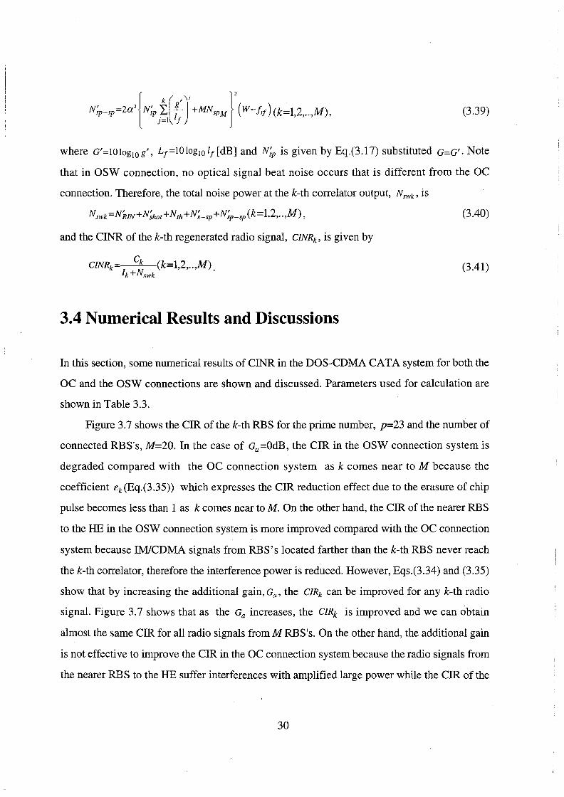
Figure 3.7 shows the CIR of the k-th RBS for the prime number, p=23 and the number of
connected RES's, M=20. In the case of Ga=OdB, the CIR in the OSW connection system is
degraded compared with the OC connection system as k comes near to M because the
coefficient t:k(Eq.(3.35)) which expresses the CIR reduction effect due to the erasure of chip
pulse becomes less than 1 as k comes near toM. On the other hand, the CIR of the nearer RBS
to the HE in the OSW connection system is more improved compared with the OC connection
system because IM/CDMA signals from RES's located farther than the k-th RBS never reach
the k-th correlator, therefore the interference power is reduced. However, Eqs.(3.34) and (3.35)
show that by increasing the additional gain, Ga, the C!Rk can be improved for any k-th radio
signal. Figure 3.7 shows that as the Ga increases, the CIRk is improved and we can obtain
almost the same CIR for all radio signals from M RBS's. On the other hand, the additional gain
is not effective to improve the CIR in the OC connection system because the radio signals from
the nearer RBS to the HE suffer interferences with amplified large power while the CIR of the
30
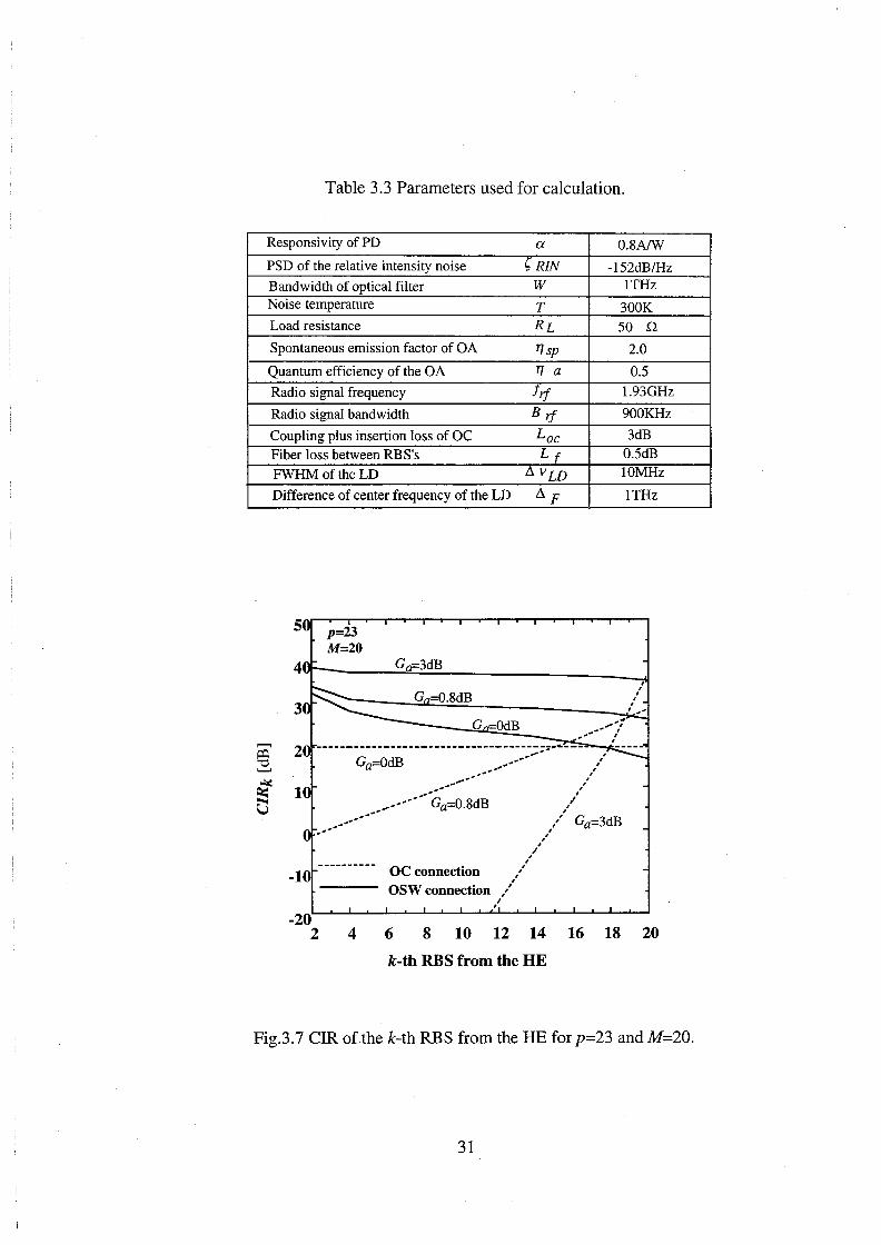
Table 3.3 Parameters used for calculation.
Responsivity of PD
PSD of the relative intensity noise
Bandwidth of optical filter Noise temperature
Load resistance
Spontaneous emission factor of OA
Quantum efficiency of the OA
Radio signal frequency
Radio signal bandwidth
Coupling plus insertion loss of OC Fiber loss between RES's
FWHM of the LD
Difference of center frequency of the LD
5
3
1
a
(, RIN w T RL
1J sp
1J a
lif
Bif
Lac Lr
~vLD
~F
, , , ,,,'' ,
,/
O.SA/W
-152dB/Hz lTHz
300K
50 Q
2.0
0.5
1.93GHz
900KHz
3dB 0.5dB lOMHz
lTHz
,/ Ga=3dB
-10
-20 2
---
4
, ,'
,/ , OC connection ,/ OSW connection /
/
6 8 10 12 14 16 18 20
k-th RBS from the HE
Fig.3.7 CIR ofthe k-th RBS from the HE for p=23 and M=20.
31

radio signal from the farther RES can be improved as shown in Fig.3.7.
Figure 3.8 shows the CIR of the farthest M-th RES as a function of prime code number, p
forM of 20,40 and 80. The upper abscissa is the switching speed of OSW. When Ga is OdB in
the OSW connection system, the coefficient t:M is less than 1 asp comes near toM, thus the
CIRM of the farthest M-th RES is degraded compared with the OC connection system. This is
due to the erasure of chip pulse of the M-th radio signal. However, this penalty can be reduced
and the CIRM comes to the same as that in the OC connection system asp increases more than
M. It is also found from Fig.3.8 that by introducing additional gain( Ga >OdB), the CIRM of the
farthest M-th RES is more improved than that in the OC connection system as Ga increases for
any p and M. This is because asp increases more than M, Eq.(3.35) shows that t:M comes near to
M-1
Mil ga 2(}-M) which is more than 1 and yields the same value regardless of M. j=l
Here, we have to consider the limitations in Ga and p to realize the OSW connection
system. Regarding p, the achievable switching speed of the OSW gives the limitations of the
prime code number, p. If we use the OSW with its speed of almost 10GHz for the case of
Bif=900KHz, we can increase the pup to about 80.
The possible additional gain, Ga, is limited by the optical power limitation in the optical
fiber. Figure 3.9 shows the relationship between the average received optical power from the
farthest M-th RES, PrM normalized by the average transmitted optical power, PrM IPs, and the
number of connected RES's, Min the case of p=79 (11Tc=ll.2GHz). For example, in the case
that the limitation of P;! is 20dB, the upper limits in numbers of connected RES's in OSW s
connection system are 63, 41, 30,23 and 19 for Ga= 0.2, 0.4, 0.6, 0.8 and 1dB's respectively. Ga
can be increased up to 0.8dB for P~M = 20dB and M=20. Thus it is seen from Fig.3.8 that for s
M=20, the CIR in the OSW connection system can be more improved by about 8dB than that in
the OC connection system by introducing the Ga of 0.8dB.
Figure 3.10 shows the CNR as a function of prime code number p for Ps of OdBm and M
32

Switching speed of OSW (liTe) [GHz]
0.72 2.88 6.48 11.52 18 25.92 35.28 6
5
2
10 20 40
OC connection
60 80 100 120 140
Prime code number p
Fig. 3.8 CIR of the farthest M-th RBS versus prime code number, p forM of 20, 40 and 80.
-
20 40 60 80
Number of connected RBS's, M
Fig.3.9 Relationship between PrM IPs and M for p=79 in the OSW connection system.
33

of 20 and 40. When G a is OdB, CNR' s for both OC and OSW connection systems are dominated
by the beat noise among ASE of an OA and the optical signal, Ns-sp and N;_sp, respectively for
small p but affected by the receiver thermal noise, Nrh , as p comes to large because the carrier
I power decreases in proportion to ---;-. As p comes near to M, the CNR in the OSW connection
p
system is degraded by the erasure of chip pulse compared with the OC connection system.
However, the CNR's of both OC and OSW connection systems are similar asp increases more
than M because the erasure of chip pulse can be neglected and Ns-sp and N;_sp are dominated by
the OA at the output of SC. On the other hand, when Ga is more than OdB, the CNR in the OSW
connection system is dominated by N;_sp caused by the OA at the RBS, thus, the CNR is more
improved than that in the OC connection system as Ga increases. For example, it is seen from
Fig.3.10 that for Ps =OdBm, M=20 and p=79, the CNR in the OSW connection system with Ga
of 0.8dB can be more improved by 11dB than that in the OC connection system.
It is seen from Figs.3.8 and 3.10 that the CINR is dominated by the CIR for any p. By
introducing additional gain, the CINR in the OSW connection system can be more improved
than that in the OC connection system. It is found that for M=20, the CINR in the OSW
connection system can be more improved by about 8dB than that in the OC connection system
by introducing the Ga of 0.8dB.
Figure 3.11 shows the CINR as a function of the number of connected RBS's, M, for p=79
( 1/ Tc= 11.2GHz) and Ps =OdBm. In the OSW connection system, when Ga =OdB and M comes
near top, the CIR is worse than the OC connection system. However, the CINR of the OSW
connection system is more improved than that in the OC connection system as Ga increases. In
the OC connection system, the number of connected RBS's is determined by the required CINR.
On the other hand, in the OSW connection system, the number of connected RBS's is
determined by both the required CINR and the optical power limitation. It is seen from Figs.3.9
p and 3.11 that when the required CINR is 30dB and the required ~M is 20dB, the numbers of
s
connected RBS's in the OSW connection system are 63, 41, 30 and 23 for Ga= 0.2, 0.4, 0.6 and
0.8dB's respectively, while the number of connected RBS's in the OC connection system is 18.
34

~ z u
30 20 40 60 80
OC connection OSW connection
100 120 140
Prime code number p
Fig. 3.10 CNR versus prime code number, p for Ps=OdBm and M of 20 and 40.
5
4
=: 3 z 1-4 u
10 0 20
Ga=OdB
OC connection
OSW connection
40 60
Number of connected RBS's, M
80
Fig. 3.11 CINR versus number of connected RBS's, M for p=79 (11Tc=ll.2GHz).
35

Thus itis found that in the OSW connection system with Ga=0.2dB, three times ofRBS's can be
connected to the CAT A system compared with the OC connection system.
3.5 Concluding Remarks
In this chapter, we have investigated the direct optical switching(DOS) CDMA method for
fiber-optic radio networks including CAT A systems where the concept of FTTA is applied to
CATV systems. The configuration of the DOS-CDMA CAT A system has been proposed by
using optical coupler and optical switch connections. We have theoretically analyzed the carrier
to interference-plus-noise ratios of regenerated radio signals at the head end for two types of bus
connection methods considering the chip pulse erasure at the optical switch. Following results
are obtained:
1. In the optical switch connection system, by introducing the additional optical gain at each
radio base station, the carrier to interference power ratios for all radio base stations can be
almost the same as those in the prime code number increases more than the number of
connected radio base stations.
2. In the optical switch connection system with the additional gain, the carrier to interference
plus-noise power ratio (CINR)s for all radio base stations and the number of connected radio
base stations can be improved compared with the optical coupler connection system. For
example, by using the optical switch connection system with additional gain, Ga=0.2dB,
three times of radio base stations can be connected to the CAT A system with the CINR of
30dB and the average received optical power from the farthest RBS normalized by the
average transmitted optical power of 20dB for prime number, p=79, compared with the
optical coupler connection system.
Thus the optical switch connection is an effective DOS-CDMA CAT A system where an
optical switch is used not only to spread the spectrum of optical signals but also to launch them
into the fiber-optic bus link.
36

Chapter 4
Optical Polarity Reversing Correlator
(OPRC) for DOS-CDMA Using PN codes
4.1 Introduction
In the direct optical switching (DOS)-CDMA method described in the Chapter 3, only optical
uniphase orthogonal codes such as prime codes [16]-[19] are applied to obtain a desired process
gain because an optical switch is used to correlate DOS-CDMA signals at each correlator.
However, the prime code suffers a limit in the number of distinct code sequences, which results
in the limitation of the number of radio base stations connected to fiber-optic radio networks.
Besides in fiber-optic radio networks using the DOS-CDMA scheme with prime codes, the
optical power efficiency is low because the pulse duty of a prime code is quite low. Therefore,
we should consider a new type of the correlator for the DOS-CDMA method to which PN codes
such as Maximal length codes and Gold codes can be applied because those codes are usually
used in radio systems and generally superior in the number of distinct code sequences compared
with prime codes. For digital networks using the optical CDMA method, the sequence inversion
keyed(SIK) direct sequence(DS) CDMA methods that have been proposed in Refs.[31]-[32],
require specially balanced PN codes. In order to allow the use of any unbalanced PN codes, the
power splitting ratio of the power divider at the optical correlator has been controlled [33], and
the transmission of two channels using two wavelengths or two orthogonal polarizations has
been proposed [34]. In SIK-CDMA methods, however, binary digital data are encoded and
transmitted with the positive polarity and the negative polarity of bipolar codes, thereby their
37

correlators at the receiver can not be applied to DOS-CDMA signals that are converted from
radio signals by the on-off switching CDMA method. In this thesis, we newly propose the
optical polarity reversing correlator(OPRC) for the DOS-CDMA radio highway network using
PN codes [35]-[39].
4.2 Direct Optical Switching(DOS) CDMA Radio Networks
UsingOPRC
4.2.1 Principle of OPRC
The optical polarity-reversing correlator(OPRC) can be realized with various optical devices
such as optical switch(OSW)es, matched filters and Mach-Zehnder Interferometer(MZI)s. We
realize the OPRC with a MZI or two OSW's. Figure 4.1 illustrates the configuration of the
transmitter and the OPRC for the optical CDMA using the PN code ck(t) having the value of 1
or -1. The ck(t) has the frame period, TF, and the chip width, Tc. In the interval of TF, ck(t) has
the code length L which is the number of chips and the number of 1 's of L;l. At the k-th RBS,
LD is directly modulated by the radio signal with the optical modulation index of 1. DOS
CDMA is performed at OSW driven with the biased PN code l+c;(t). Then, the intensity of
optical signal from the k-th RBS is written by
lk(t)=Ps{l+gk(t)}l+ck(t)' 2
(4.1)
where gk(t) is the radio signal with the bandwidth Brf and the carrier frequency frt and Psis the
average transmitted optical power before the optical switching.
At the k-th OPRC, many IM/CDMA signals are received and split into two signals at the
MZI or the optical coupler(OC).It is assumed that the biased PN code, l+ck(t), matched with the 2
one at the RBS is regenerated at the CS by using the retiming code generator such as the
retiming block [44] and the synchronization between two code sequences is taken. The OPRC is
38

k-th RBS
k-th OPRC at CS
l+ck(t) 2
l+ck(t) mua PN 2 T ___..
~~....- F Tc I
12 ----- L t
MZI:Mach-Zehnder Interferometer OPS:Optical Phase Shifter BMPD:Balanced Mixing Photodetector
OPRC
lk(t) ioi(t) [0 (!)
P, I:-.1..-J-):!;... j ' .~ ' N .~ '' ~. t I "" ' " " .. ......_ ~lllilrudillllua-~ L f ~!!~~~ ..... f lj(t) (J'*k) Desired signal
PJl!:~:.~:t,J .~. I ~. , ~ ... , lr f j" .. ,,..,
Fig.4.1 Configuration of the transmitter and the OPRC for optical CDMA using PN codes.
39

driven by the biased PN code, l+c;(t), matched with the one at the RBS. In the case of the OPRC
realized with a MZI, the phase of the OPS(optical phase shifter) is shifted according to the
biased PN code, l+ck(t). When l+ck(t) is 1, the phase difference between both arms of MZI is . 2 2
zero, thus IM/CDMA signals are outputted to the upper port of MZI through the second OC.
When 1 +c; (t) is 0, the phase difference between both arms of MZI is set to rc, thus the lower port
of MZI outputs IMICDMA signals through the second OC. In the case of OPRC realized with
l+ck(t) . two OSW's, when
2 IS 1 the upper OSW is set to on and the lower OSW is set to on when
Thus output currents of the BMPD(balanced mixing photodetector) are expressed as
(4.2)
(4.3)
where a is the responsivity of the PD, and in! (t) and in2 (t) are additive noise currents,
respectively. Eqs.(4.2) and (4.3) show that the positive polarity of the desired k-th code ck(t)
matches with the k-th one at the RBS at the upper port of MZI or the upper OSW, on the other
hand it is obstructed at the lower port of MZI or the lower OSW. The desired k-th signal at the
input to the BPF is a bandpass natural sampled signal converted from the k-th radio signal, gk(t),
because an optical switching is a window-type sampling. Therefore, a radio signal is conveyed
by the optical carrier with its signaling format kept and can be regenerated from the pulsed
signals by the interpolation at the BPF [29][43] whose principle will be discussed in Sect.4.3.
On the other hand, for the interference signal I1 (t) (j:t.k ), both ports of MZI or both
OSW's generate interferences only when the positive polarity of cj(t) coincides with the
positive or negative polarity of ck(t). Two interferences of BMPD are subtracted and the
interference is suppressed at the BPF. However, in the unipolar type correlator for optical
CDMA, PN codes can not be applied because the interference is not suppressed though the code
sequence length increases. The detail will be discussed in Sect.4.3.
40

4.2.2 System Configuration
Figure 4.2 illustrates the configuration of the optical CDMA radio highway network using the
OPRC.
RBS#M
OPRC :Optical Polarity Reversing Correlator
OA
Control Station(CS)
OA
Fig.4.2 Configuration of the optical CDMA radio highway network using the OPRC.
41

Each RBS is equipped with an automatic gain controller (AGC) to control the amplitude of a
received radio signal in order to keep the optical modulation index constant at the LD. After the
direct intensity-modulation(IM) at the LD, the direct optical switching(DOS) CDMA is per
formed by on-off switching at the OSW driven by a biased PN code. In the bus link, many 1M/
CDMA signals from M RBS's are multiplexed by the DOS-CDMA method and transmitted to
the CS. When any biased PN code sequence coincides with another biased PN code sequence,
the numbers of coincidences of chips is (L:22 out of chips of L. In the case of the fiber-optic
bus link using the OSW connection, the signal collision at the OSW of each RBS will cause the
erasure of enormous chip pulses in DOS-CDMA signals. As the enough additional gain can not
be inserted at each RBS owing to the optical power limitation, the far-near problem will happen
in the fiber-optic link. Thus we consider a system configuration using only the OC connection.
At the CS, optical CDMA signals are at first power-split to each of M receivers. IM/
CDMA signals are correlated at the OPRC driven by a biased PN code matched with the RBS.
To compensate the optical loss between RBS and the receiver, each RBS and CS are equipped
with OA's. At the k-th OPRC, the average received optical power, Prk, can be written as
Prk =l0log10 Ps-k(Lt+L0 c)+kG-10logiO M+GM-2L0 c[dB], (4.4)
where L0c[dB], Lt[dB], G[dB] and GM[dB] are the coupling loss plus the insertion loss of an
OC, the fiber loss between RBS's, the gain of OA at the RBS and the gain of OA at the output of
l:M SC, respectively. The last term 2 L0 c is the coupling loss caused by the two OC's at the MZI
in the Fig.4.1.
4.3 Theoretical Analysis of Carrier-to-Interference-plus
Noise Ratio Performance
The input current to the BPF is given by
i0 (t)=i0 1 (t)-i0 2 (t)
=isk (t)+i1(t)+iN(t), (4.5)
42

where isk (t), i1(t) and iN(t) are the desired signal, the interference and the additive noise,
respectively. In order to have the same optical received power at the OPRC, we assume that an
OA equipped at each RBS has the gain G of Lf+Loc and the gain of OA at the output of SC, GM,
is equal to 10log10 M+2Loc· Thus, the same received power Prk =Ps (k=l,2, .. ,M) is obtained from
Eq.(4.4). It is also assumed that each MZI receives M optical signals with the same modulation
index of 1. At the input of the BPF, isk (t) and i1(t) are expressed as
. l+ck(t) lsk(t)=aPsgk(t) 2 ' (4.6)
(4.7)
respectively.
We consider the carrier power of regenerated radio signal and the interference power at
the BPF from the power spectral density(PSD)s of the desired signal and the interference. The
autocorrelation of desired signal, isk (t), is expressed as
aP 2 Rs(r)=(-s )2 Rg(r){l+-+Rc(r)},
2 L (4.8)
where Rg ( r) and Rc ( r) are the autocorrelations of gk (t) and ck (t), respectively. Though we
assume that radio signals, gJ(t) (j=l,2, .. ,M), are unmodulated carriers, the calculated carrier
power of regenerated radio signals can be applied irrespective of the modulation method of
radio signals. Thus we assume that radio signals, gj(t) (j=l,2, .. ,M), are unmodulated carriers
which have the autocorrelation function, Rg(r),
1 Rg( r)=-cos(21ifrtr).
2
The autocorrelations of ck(t) is given by [48]
Thus, the PSD of isk (t), Ss<f), is given by
(4.9)
(4.10)
43
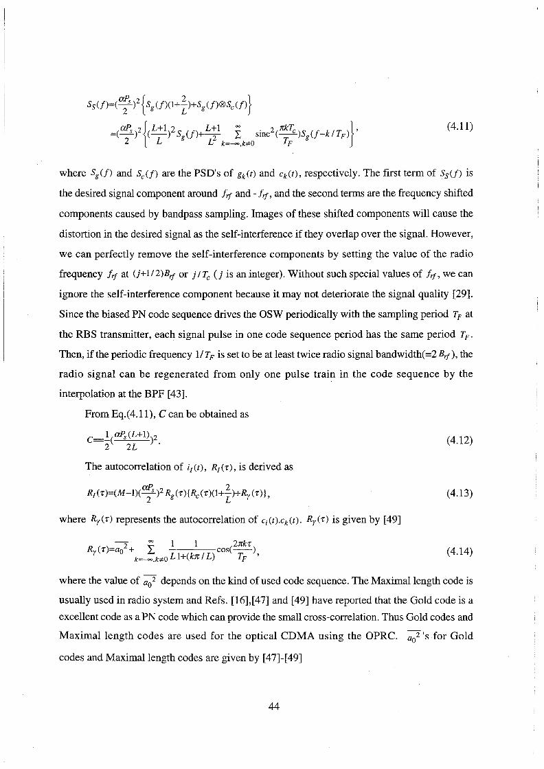
S5 (f)=( a;s )2 { Sg(f)(l+Z.)+Sg(f)®Sc(f)}
=(~ )2{(L+1)2 Sg(f)+ L:l I sinc2(nkYc )Sg(f-k ITF )} ' 2 L L k=-=,bO TF
(4.11)
where Sg(f) and Sc(f) are the PSD's of gk(t) and ck(t), respectively. The first term of S5 (f) is
the desired signal component around f rf and - f rf, and the second terms are the frequency shifted
components caused by bandpass sampling. Images of these shifted components will cause the
distortion in the desired signal as the self-interference if they overlap over the signal. However,
we can perfectly remove the self-interference components by setting the value of the radio
frequency frt at (j+lf2)Brf or j ITc (j is an integer). Without such special values of frt, we can
ignore the self-interference component because it may not deteriorate the signal quality [29].
Since the biased PN code sequence drives the OSW periodically with the sampling period TF at
the RBS transmitter, each signal pulse in one code sequence period has the same period TF.
Then, if the periodic frequency 11 TF is set to be at least twice radio signal bandwidth( =2 Brf ), the
radio signal can be regenerated from only one pulse train in the code sequence by the
interpolation at the BPF [43].
From Eq.(4.11), C can be obtained as
C=_!_(aPs(L+I))2 2 2L . (4.12)
The autocorrelation of i1(t), R1('r), is derived as
(4.13)
where Ry("r) represents the autocorrelation of c;(t).ck(t). Ry("r) is given by [49]
2 = 1 1 2nkr Ry(T)=a0 + I, cos(--)
k=-=,bO L l+(kn I L) TF ' (4.14)
where the value of a02 depends on the kind of used code sequence. The Maximal length code is
usually used in radio system and Refs. [16],[47] and [49] have reported that the Gold code is a
excellent code as a PN code which can provide the small cross-correlation. Thus Gold codes and
Maximal length codes are used for the optical CDMA using the OPRC. a02 's for Gold
codes and Maximal length codes are given by [47]-[49]
44

l-L2_+_L3~--1 for Gold codes
- 4L a 2_
0 -L2+L-l . ·
L3 for Maximal length codes
The PSD of i1(t), S1(f), is given by
SI<f)=(M-l)(a; )2 S8 (f)®{Sc<f)(l+~)+Sy(f)} =(M-1)(; )2[(L;2 +ao2)Sg(f)
~ {(L+1)(L+2) . 2 (nkTc) 1 1 }S (f k ' + L. smc -- + --)] k=-oo,ki'O £3 TF L 1+(kn I L) g TF
(4.15)
(4.16)
where Sy(f) is the PSD of ci(t).ck(t). The interference power at the output of the BPF, I, can be
obtained as
{
M-l(aPS )2 L2
+5L+7 .s:- G ld d -- -- 1.0r o co es 2 2 4L3
I= M-1 aP. L+1 2 . --(-s )2 (
3) for Maximal length codes
2 2 L
(4.17)
Hence, from Eqs.(4.12) and (4.17) the CIR(carrier-to-interference power ratio)s for Gold
codes and Maximal length codes are written by
{
4 L(L+1i 2 for Gold codes
CIR= M-1 L +5L+7 L .
-- for Maximal length codes M-1
(4.18)
For discussion, we consider the CIR in the case of unipolar type correlator for optical
CDMA as shown in Fig.3.2. When prime codes are applied, the CIR is given by [29][30]
1 2 C/Ruc P =--!!_ for prime codes
' (M-1) CJ 2 ' c
(4.19)
where CJ~ denote the average variance of the cross-correlation of the prime code, whose length,
L, is pz. On the other hand, when PN codes are applied to the unipolar type correlator as the
same with the proposed OPRC, from Eq.( 4.2), the interference current at the input of BPF is
45

given by
Autocorrelation function of i1,uc(t), R1,uc(r), is given by
aP 2 4 4 2 R1 uc(r)=(M-1)(-s) Rg(r){l+-+2 +2(1+-)Rc(r)+Ry(r)}
' 4 L L L .
The PSD of i1,ucCt), S1,ucCf), is given by
The interference power at the output of the BPF can be obtained as
{
2 M-1(~)2(l 17L +25L+18)-~" G ld d ---- + 3 10r o co es
I = 2 4 4L uc 2
M-1 aP 5L +7L+3 . · --(-s )2 (1+
3 ) for Maxtmallength codes
2 4 L
Hence, in the case of unipolar type correlator using PN codes, the CIR is written by
{
4 -----,.------4 L_('-;;L,--+-'l)_2-- for Gold codes
CIR = M-14L3+I7i?+25L+15 uc 2
4 3 L(~+l) for Maximal length codes
M-IL +5L +7L+3
(4.20)
(4.21)
(4.22)
(4.23)
(4.24)
We analyze the noise power at the output of BPF. We consider additive noise currents
composed of the relative intensity noise, the shot noise, the receiver thermal noise, the beat
noise between optical signal and amplified spontaneous emission(ASE), the beat noise between
ASE's and optical signal beat noise. The total noise power, N, is written by
(4.25)
When any biased PN code sequence coincides with the positive and the negative polarity of any
46

PN code sequence, the numbers of coincidences of 1 'sin the interval of TF are (L+ 1)2
and L2
-1
4L 4L
respectively. Each noise power is given by
) (4.26)
(4.27)
(4.28)
(4.29)
(4.30)
where e, ~RIN• w, k8 , T and RL are the electric charge, the PSD of the relative intensity noise,
the bandwidth of optical filter at the CS, Boltzmann constant, the noise temperature and the load
resistance, respectively. The PSD's of the ASE, Nsp and NsPM, are given by
T/ tOG/10_1 N =__!£_· hv
sp T/a tOG/10 ' (4.31)
(4.32)
respectively, where T/sp, T/a and hv are the spontaneous emission factor, the quantum efficiency
of the OA and the photon energy, respectively [6]. The optical signal beat noise, (Ns-s), is due to
an interference between two optical signals. (Ns-s) is composed of two interference
components: one is an interference between optical signals of a desired signal and an
interference, (Nss-si ), another is one between optical signals oftwo interferences, (Ns 1-s1 ) and
they will be derived in Appendix A.
Therefore, the CINR( carrier-to-interference-plus-noise ratio) of the regenerated radio
signal is given by
CINR=__s_. l+N
47
(4.33)

4.4 Numerical Results and Discussions
In this section, we show some numerical results and discussions. Table 4.1 shows parameters
used for calculation. Figure 4.3 shows the relationship between the code length L and the CIR
for the proposed OPRC and the unipolar type correlator shown in Fig.4.2 for the optical CDMA
radio highway in the case of using PN codes forM= 10. In the case of the unipolar type correlator
using Maximal length codes and Gold codes, there is no improvement in the CIR though L
increases. In this case, it is seen from Eq.(4.24) that the CIR almost equals to 4/(M-1) regardless
of L. However, it is seen from Eq.(4.18) that in the proposed OPRC, the CIR is improved as the
L increases. The results show that PN codes such as Maximal length codes and Gold codes can
be applied to the optical CDMA radio highway using the proposed OPRC. However, in the case
of the optical CDMA radio highway using the unipolar type correlator, it is seen that PN codes
can not be applied and only unipolar orthogonal codes can be applied. Refs.[13]-[15] have
reported that the prime code is the best code as a unipolar orthogonal code which can provide the
highest CIR. So in the next figure, we compare the number of distinct code sequences which
results in the limitation of the number of RES's connected to the radio highway for Maximal
length codes, Gold codes and prime codes.
Figure 4.4 shows the number of distinct code sequences versus the code sequence length
L. Gold code sequences are generated by combining a pair of preferred Maximal length
sequences using modulo-2 addition if the number of preferred maximal length sequences is at
least two [47][49]. On the other hand, in the case of prime codes the number of distinct code
sequences is equal to the prime number p for the code sequence length of p2 [13]. The numbers
of distinct code sequences for Maximal length codes and Gold codes are larger than that for
prime codes. For example, comparing Maximal length codes and Gold codes of L=32767 with
prime codes of p2=32041, the numbers of distinct code sequences for Maximal length codes
and Gold codes are 10 times and 183 times larger than that for prime codes, respectively.
Therefore, using the proposed OPRC can assign larger number of distinct code sequences to
RBS's in optical CDMA radio highway than using the unipolar type correlator using prime
48

50
40
= 30 "C ........
e: 20 u
10
Table 4.1 Parameters used in calculations
resoonsivity of PO a 0.8A/W PSD of the relative intensity noise t;RJN -152dB/Hz bandwidth of optical filter w lTHz
noise temoerature T 'lOOK
load resistance RL 50 Q spontaneous emission factor of OA 1Jsp 2.0 quantum efficiency of the OA 1Ja 0.5
radio signal frequency frr 1.9GHz radio signal bandwidth Brf 300KHz
couoling olus insertion loss of OC Lnr 3dB fiber loss between RBS's L£ 0.5dB FWHM of the LD Ll.vLD lOMHz
difference of center frequency Ll.F lTHz nfthP T n
M=10 c Gold codes A Maximal length codes
Unipolar type correlator
0 ···-li!il--li!il--li--li!il--li--li--li-----ii--li!il--li--0ii--li!il--li--
-10 L..-....o__._.. ........... L...-...r.~.........,Jt...........__._............;L...-...r._._._.........JL...-...r.__._._.........J
W 1 ro 2 W3 ro• W 5 W 6
Code sequence length L
Fig.4.3 Relationship between the code sequence length, Land the CIR.
49
codes.
Figure 4.5 (a) and (b) show the relationship between the code length Land the CINR in the
case of M=30 for Ps ofOdBm and -IOdBm, respectively. We calculate the CINR versus L where
Gold code sequence is defined. A little better CIR can be obtained by the proposed OPRC using
Gold codes than the unipolar type correlator using prime codes. In the case of Ps=OdBm, the
CNR in the proposed OPRC using Gold codes is dominated by the optical signal beat noise,
( Ns-s). On the other hand, in the case of the unipolar type correlator using prime codes, the CNR
is dominated by the beat noise among ASE of an OA and the optical signal, Ns-sp, and
deteriorated by the receiver thermal noise, Nth, as L comes to large because the carrier power
decreases in proportion to 1/L. Thus when radio signal bandwidth, Brf is increased to 900KHz,
the CNR is deteriorated bythe increase in Brf. When f1s is OdBm as shown in Fig.4.6 (a), the
CINR for the proposed OPRC using Gold codes is dominated by CIR. In the case of the unipolar
type correlator using prime codes, the CINR is dominated by CIR until L comes to 262143 from
which the CINR is dominated by the CNR of Nth. Thus, when Ps is OdBm, the CINR is a little
improved by the proposed OPRC using Gold codes compared with the unipolar type correlator
using prime codes because the CIR is determined by the kind of used code sequence.
In the case of fls=-10dBm as shown in Fig.4.5 (b), the CNR in the proposed OPRC using
Gold codes is dominated by the Ns-sp, while in the case of the unipolar type correlator using
prime codes, the CNR is dominated by the Nth and awfully deteriorated as L comes to large. In
the case of the conventional correlator using prime codes, as L increases the CINR is improved
by the CIR but deteriorated by the CNR of Nth as L increases more than 16383. Thus, in this
case, the maximal CINR is determined by the CIR and the CNR. In the case of the small average
transmitted optical power such as fls=-1 OdBm for the unipolar type correlator using prime
codes, it is seen from Fig.4.4 and Fig.4.5 (b) that L should be increased to assign larger number
of distinct code sequences to RBS's but the CINR is deteriorated as L comes to large. However,
in the case of the proposed OPRC using Gold codes, as the CNR is almost constant regardless of
L, the CINR is improved and not deteriorated as L increases.
Figure 4.6 shows the relationship between the average transmitted optical power, f1s and
the CINR in the case of M=40 for different switching speeds in the DOS-CDMA, 11 I;;= 2Brf.L.
50

106
c Gold codes <ll A Maximal length codes Cl.l
105 ~ 0 prime codes = Cl.l
= 0" Cl.l
104 <ll Q.l
"0 0 ~ ..... 103 ~
= .... ..... <ll ;a
102 <:o-o 0 a. Cl.l
,Q 101 s
= z 10°~~~~~~~~~~~~~~~~~
10 1 10 2 10 3 10 4 10 5 10 6
Code sequence length L
Fig. 4.4 Number of distinct code sequences versus the code sequence length, L.
60
50
40 ,......., ~ "C .......
30 ~ z """" u
20
10
0 10 2
Unipolar type correlator using prim ---o--·
Proposed OPRC using Gold codes --o--
Code sequence length L
OKHz
Fig.4.5(a) Relationship between the code sequence length, Land the CINR for P5 =0dBm.
51

,......., ~ "0 ....... ~ z ..... u
60 M=30
50
40
30
20
Ps=-lOdBm
Proposed OPRC using Gold codes --c--
o~~~~~~~~~~~~~~~~~
10 2 10 3 10 4 10 5 10 6
Code sequence length L
Fig.4.5((b) Relationship between the code sequence length, Land the CINR for -lOdBm.
10
Proposed OPRC using Gold codes
M=40 liT c=9.8GHz
(L=16383)
1/T c=2.5GHz (L=4095)
Unipolar type correlator using prime codes
o~~~~~~~~--~-L~--~~~
-20 -15 -10 -5 0 5 10
Transmitted optical peak power P s [dBm]
Fig.4.6 Relationship between the average transmitted optical power, f>s and the CINR.
52

In the unipolar type correlator using prime codes, when 1 I Tc is large, the CNR dominated by Nth
awfully deteriorates the CINR as P.s decreases because the signal power is in proportion to P.s 2
• L
However, in the proposed OPRC using Gold codes, the CINR is not so abruptly deteriorated
with the CNR as P5 decreases because the signal power is nearly in proportion to P.s2
from Eq. 4
(4.12). Thus, the CINR is more improved by the proposed OPRC using Gold codes compared
with the unipolar type correlator using prime codes as P.s decreases.
Figure 4.7 shows the relationship between the switching speed, 1/Tc, and the number of
maximum connected RBS's, Mmax, in the case that the CINR is 30dB.
,.-... 140 ;>< ec Required CINR=30dB
~= 120 '-' C'-l = ===
100 "CC ~ -~ ~ 80 = = 0 Proposed OPRC ~
e 60 using Gold codes
= s. ·- 40 ;>< ec s. ... 0 20 a. ~
,1:1 using s. = 5 10 15 20 z
Switching speed in DOS CDMA (1/T c) [GHz]
Fig. 4.7 Relationship the switching speed in the DOS-CDMA, 11 Tc and the number of
maximum connected RBS's, Mmax.
This figure shows that by the proposed OPRC using Gold codes, the number of maximum
connected RBS's can be much more improved for small P.s such as -lOdBm compared with the
conventional correlator using prime codes. For example, in the case of liTe= 9.8GHz, by the
53

proposed OPRC using Gold codes, 1.3 and 2.5 times of RBS's can be accessed to the radio
highway with the CINR of 30dB compared with the unipolar type correlator using prime codes
for Ps of OdBm and -10dBm respectively.
4.5 Concluding Remarks
In this chapter, we have newly proposed the optical polarity-reversing correlator(OPRC) for the
direct optical switching(DOS) CDMA radio highway network using PN codes such as Ma.{(imal
length codes and Gold codes which are usually used in radio systems. The carrier-to-interfer
ence-plus-noise power ratio(CINR) of the regenerated radio signal at the control station has
been theoretically analyzed. The following results are found:
1. We can more assign distinct code sequences to radio base stations connected to the DOS
CDMA radio highway network than the unipolar type correlator using prime codes by using
the OPRC with PN codes. For example, comparing Maximal length codes and Gold codes of
code length, L=32767 with prime codes of code length, p2=32041, the numbers of distinct
code sequences for Maximal length codes and Gold codes are 10 times and 183 times larger
than that for prime codes respectively.
2. For small average transmitted optical powers, the proposed optical polarity reversing
correlator using Gold codes can much more improve the number of maximum cormected
radio base stations than the unipolar type correlator using prime codes. For example, in the
case of the switching speed in DOS-CDMA of9.8GHz, by the proposed OPRC using Gold
codes, 1.3 and 2.5 times of radio base stations can be accessed to the DOS-CDMA radio
highway network with the CINR of 30dB compared with the unipolar type correlator using
prime codes for average transmitted optical powers of OdBm and -1 OdBm respectively.
54
Chapter 5
Reversing Optical Intensity(ROI) CDMA
Routing Method for CDMA Radio Systems
5.1 Introduction
In DOS-CDMA methods described in Chapters 3 and 4, as the optical power is zero during the
interval of zero parts in prime codes or negative polarity parts in PN codes, the received optical
power at the receiver is less than the laser power at the RBS. Also, in order to have the flexibility
for conventional CDMA radio systems using all intervals of PN codes, we newly propose the
reversing optical intensity(ROI) CDMA method where the spectrum spreading is performed in
the optical domain for all intervals of a PN code [40]-[41]. We apply the ROI-CDMA routing
scheme to conventional CDMA radio systems in order to route CDM signals to the control
station(CS)s, for example, according to services or operators [41]. In the proposed network, at
the desired CS the despreading for two-layered spectrum spreading is performed at the optical
polarity-reversing correlator (OPRC) by using the code sequence of two-layered spectrum
spreading at one time.
5.2 ROI-CDMA Routing Method for CDMA Radio Systems
Figure 5.1 illustrates the configuration of the radio highway using the ROI-CDMA routing
method. Radio base station(RBS)s are connected to the fiber-optic bus link, where CDM
55

Service #r or Operator #r ___.......,____
RBS#M
RCT : Reversing-optical-intensity COMA '&ansmitter
OPRC :Optical Polarity
RBS#k
Service #q or Operator #q ___.......,____
RBS#l RBS#l
~ (t)a1(t)
Reversing Correlator,--------------,;;;;;;;;;~------' RN: Routing Node
CS#q
Fig.5.1 Configuration of the radio highway using the ROI-CDMA routing method.
56

signals from radio terminals are multiplexed by the ROI-CDMA scheme. At the ROI-CDMA
transmitter(RCT), the spreading is performed with code sequences such as br(t) and bq(t) used
as the routing data of destination CS's according to services or operators. At the bus type fiber
link, many IM/CDMA signals are transmitted to the CS. Figure 5.2 illustrates the configurations
of the RCT and the optical polarity-reversing correlator (OPRC).
At the receiver of the CS, ROI-CDMA signals from RBS's are at first power-split into
OPRC's and the routing node(RN). To compensate the optical loss between RBS and the
receiver, each RBS and CS are equipped with OA's. At the k-th OPRC, the average received
optical power, Prk, can be written as Eq.(4.4). It is assumed that the code sequence used in
spreading at the RCT and the code sequence of two-layered spectrum spreading are regenerated
at the CS by using the retiming code generator such as the retiming block [44]. When the CS is
the desired destination CS, namely the code sequence, br(t) is regenerated at the CS#r, the
despreading for two-layered spectrum spreading is performed at the OPRC at one time and radio
signals are regenerated. On the other hand, in the case of routing to other CS's, for example
when bq(t) is regenerated at the CS#r, the despreading is performed at the OPRC by using the
code, hg(t) used in spreading at the RCT, thus CDM signals to the CS#q are regenerated.
Regenerated CDM signals are converted into IM signals at the LD and~ routed to the routing
destination CS#q.
5.3 Theoretical Analysis of Carrier-to-Interference-plus
Noise Ratio Performance
The spread spectrum signal received at the k-th RBS, 8ak (t), is written by
8ak (t)=gk(t)ak (t), (5.1)
where 8k(t) is the radio signal with its bandwidth Brf and carrier frequency frt and ak(t) is the
PN code with the frame period of TFa , the chip width of Tea and the code length of La which is
the number of chips. In order to simplify the discussion, each RBS receives CDM signals from
a radio terminal. 8ak (t) is split in two signals and one of them is phase-shifted by n. Next, two
57
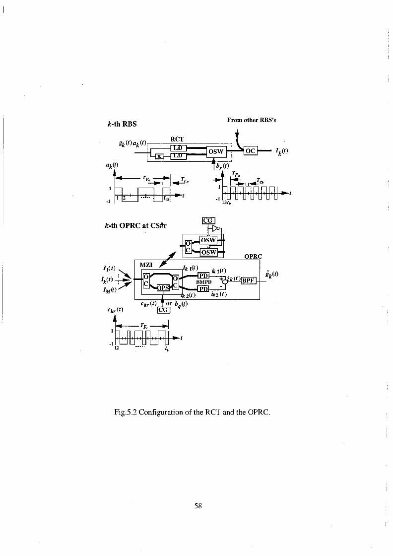
k-th RBS From other RBS's
k-th OPRC at CS#r
OPRC
Fig.5.2 Configuration of the RCT and the OPRC.
58

LD's are directly intensity modulated by them with the optical modulation index of 1. The
optical spectrum spreading is performed by switching outputs of two LD's at the OSW
according to the polarity of a PN code sequence, br(t), having the frame period of TFb, the chip
width of Tcb and the code length of Lb. Code sequences such as br(t) and bq(t) are used as the
routing data of destination CS's. It is assumed that the chip synchronization is taken between
ak(t) and br(t), Tea is the integer multiple of Tcb and Lb is less than La to simplify the discussion.
Thus, ak{t)br(t) can be expressed as ckr(t) having the frame period of TFa ,the chip width of Tcb
and the code length of LaLb. The ROI-CDMA can be expressed as
(5.2)
At the CS, an OPRC consists of a MZI or two OSW's, a balanced mixing
photodetector(BMPD) and a bandpass filter(BPF). Many IM/CDMA signals from many RBS's
are received at the MZI which is composed of two OC's and an optical phase shifter(OPS) or two
OSW's. It is assumed that an OA equipped at each RBS has the gain G of Lt+Lac and the gain
of OA at the output of SC, GM, is equal to 10 log10 M +2 Lac· Thus, each OPRC receives optical
signals with the same received power Prk =Ps (k=1,2, .. ,M) from Eq.(4.4).
5.3.1 The Desired Destination Control Station
When the CS is the desired destination CS, namely the code sequence, br(t) is regenerated at k
th receiver of the CS#r, the k-th OPRC is driven by the PN code, ckr(t). During the positive
polarity interval of ckr(t), the phase shift of OPS is set to zero or the upper OSW is set to on, thus
IM/CDMA signals are outputted to the upper port of BMPD. During the negative polarity
interval of ckr(t), the phase shift of OPS is set to n or the lower OSW is set to on , thus IM/
CDMA signals are outputted to the lower port of BMPD. Output currents of the BMPD are
expressed as
M l+ckr(t) . ) iki(t)=aj=t Psgj(t)cji(t).
2 +tn1(t
(5.3) i=q orr
59

M 1-ckr(t) . ik 2 (t)=a I. J>.sgj(t)cj1(t).
2 +tn2 (t)
j=l (5.4) i=q orr
where a is the responsivity of BMPD, and int (t) and in2 (t) are additive noise currents,
respectively. The input current to the BPF is given by
(5.5)
where isk (t), i1(t) and iN(t) are the desired signal, the interference and the additive noise,
respectively. isk (t) and i1(t) are expressed as
isk (t)=aPsgk(t),
M i1 (t)= I. af>.sg j(t)c ji (t)ckr(t)
j=1Jtc.k i=qor r
The power spectrum of isk (t) is given by
Ss(/)=(aPs)2 Sg(f),
(5.6)
(5.7)
(5.8)
where S8 (f) is the power spectrums of gk(t). We assume that radio signals, gj(t) (j=l,2, .. ,M), are
nonmodulated carriers which have S8 (f),
1 . S8(f)=-;;{d(f+ frt )+d(f-frt )} .
The carrier power at the output of the BPF, c, can be obtained as
c={Jfrf+Brt /2+J-frt+BrJ 12 }s (f)dlf=_!.(aP. )2 Jrj-Brf/2 -frJ-BrJ/2 S 2 s •
The autocorrelation of interference is expressed as
R1( r)=(M -l)(aPs )2 Rg ( r)Ry('r),
(5.9)
(5.10)
(5.11)
where Ry(r) represents the autocorrelation of a function Yjk(t) which is defined by
cji(t)ckr(t)(i=q orr). Ry(r) is given by
(5.12)
where the value of a02 depends on the kind of used code sequences [47]-[49]. The power
spectrum of i1(t) is given by
(5.13)
60

At the output of the BPF, I is obtained as
(5.14)
Hence, the carrier-to-interference power ratio(CIR) is written by
4(L L )3 a b , for Gold codes
(M-1){ (LaLb )2 +(LaLb )-1} CIR=
(L L )3 . · a ~ , for Maximal length codes
(M-1){(LaLb) +(LaLb)-1}
(5.15)
At the output ofBPF, we consider additive noise currents composed of relative intensity
noise, shot noise, receiver thermal noise, beat noise between optical signal and amplified
spontaneous emission(ASE), beat noise between ASE's and optical signal beat noise. The total
noise power, N, is written by
Each noise power is given by
NRIN='RIN(aPs)2 MBrf,
Ns-sp=4a2M2(Nsp+NSPM )~Brf,
Nsp-sp=2a2M2( Nsp+NSPM )z(w- frt)'
(5.16)
(5.17)
(5.18)
(5.19)
(5.20)
(5.21)
where e, 'RIN' w, k8 , T and RL aretheelectriccharge, thePSDoftherelativeintensitynoise,
the bandwidth of optical filter at the CS, Boltzmann constant, the noise temperature and the load
resistance, respectively [6]. The PSD's of the ASE, Nsp and NSPM' are given by Eq.(4.31) and
61

(4.32), respectively.
On the other hand, the optical signal beat noise is caused by an interference among M
optical carriers from M RBS's is derived in Appendix B.
5.3.2 Routing to Other Control Stations
In the case of routing to other CS's, for example when bq(t) is regenerated at the CS#r, at the RN
the despreading is performed at the OPRC by using the code, bq (t) used in spreading at the RCT.
During the positive polarity interval of bq(t), the phase shift of OPS is set to zero or the upper
OSW is set to on, thus IM/CDMA signals are outputted to the upper port ofBMPD. During the
negative polarity interval of bq(t), the phase shift of OPS is set to ,. or the lower OSW is set to
on, thus IM/CDMA signals are outputted to the lower port of BMPD. Output currents of the
BMPD are expressed as
M l+bq(t) . in (t)=a j=~ f>sgj (t)aj(t)bi(t).
2 +tn! (t)
(5.22) i=q orr
(5.23)
The input current to the BPF is given by
R M
=af>s L,gj(t)aj(t)+af>s L,gj(t)aj(t)b,(t)bq(t)+iN' (5.24) j=i j=R+i
where R is the RBS number routed to CS#q out of M RBS's.
5.4 Numerical Results and Discussions
Some numerical results are discussed below with parameters indicated in Table 4.1. Fig.5.3
shows the relationship between the CIR and the code sequence length La in the domain of
electrical signal for CDMA radios in the case of the RBS number of 30 and using Maximal
62

codes. In the proposed ROI-CDMA radio highway, the process gain can be more gained by
increasing the code sequence length Lb at the RCT compared with the radio highway using the
electrical CDMA and IM method. Thus, it is seen from this figure that in the proposed ROI
CDMA radio highway, the CIR is more improved by increasing the code sequence length Lb at
the RCT than the radio highway using the electrical CDMA and IM method.
50
40
20
10
Using Maximal length codes Proposed ROI-CDMA
radio highway
t Radio highway using the electrical CDMA and IM method
o~~~~~~--~~~~~--~~~~
10 2 10 3 10 4 10 5
Code sequence length, 4z
Fig.5.3 Relationship between the CIR and the code sequence length, La.
Fig.5.4 shows the relationship between the CNR and the code sequence length La in the
domain of electrical signal for CDMA radios in the case of the RBS number of 30. In the radio
highway using the electrical CDMA and IM method, the CNR is dominated by the optical signal
beat noise, (Ns-s) [15]. On the other hand, in the case of the ROI-CDMA radio highway, (Ns-s)
is reduced by the subtraction process and the BPF at the OPRC and the CNR is dominated by the
beat noise among ASE of an OA and the optical signal, Ns-sp. In the case of the CDMA radio
highway with the OC bus connection, the CNR is more deteriorated by (Ns-s) than Ns-sp [12].
63

Therefore, it is seen from this figure that the CNR in the ROI-CDMA radio highway is improved
compared with the radio highway using the electrical CDMA.
7 0
6 {I /"'\
L ~ =1,15,127
5 0 Proposed ROI-CDMA radio highway
0
0 t ~ 3 u
0 Radio highway using the electrical CDMA and IM 2
method 1 0
Code sequence length, La
Fig.5.4 Relationship between the CNR and the code sequence length, La.
Fig.5.5 shows the relationship between the CINR and the code sequence length La in the
domain of electrical signal for CDMA radios in the case of the RBS number of 30 and using
Maximal codes. In the radio highway using the electrical CDMA and IM method, the CINR is
dominated by the CIR for the small value of La and by the CNR as La increases. On the other
hand, in the proposed ROI- CDMA radio highway, the CINR is dominated by the CIR. Thus, it
is seen from this figure that in the proposed ROI CDMA radio highway, the CINR is more
improved by increasing the code sequence length Lb at the RCT than that in the radio highway
using the electrical CDMA and IM method.
64

60 Using Maximal Proposed ROI-CDMA length codes radio highway
50
40 ......, ~ "C ....... ~ z ~ u
Radio highway using the electrical CDMA and 1M method
0 10 2 10 3 10 4 10 5
Code sequence length, La
Fig.5.5 Relationship between the CINR and the code sequence length, La·
5.5 Concluding Remarks
In this chapter, we have newly proposed the reversing optical intensity(ROI) CDMA method
where spectrum spreading is performed during all intervals of a PN code in order to increase the
received optical power at the receiver and have the flexibility for conventional CDMA radio
systems. We have applied the ROI-CDMA routing scheme to conventional CDMA radio
systems in order to route CDM signals to the control station according to services or operators.
In the proposed network, at the desired control station the despreading for two-layered spectrum
spreadings is performed at the optical polarity-reversing correlator (OPRC) by using the code
sequence of two-layered spectrum spreadings at one time. It is found that the carrier-to
interference-plus-noise power ratio can be more improved by increasing the code sequence
65

length at the ROI-CDMA transmitter than that in the radio highway using the electrical CDMA
and intensity modulation(IM) method.
66

Chapter 6
Conclusions
In this thesis, optical code division multiple access(CDMA) methods have been proposed for
fiber-optic radio highway networks from the view points of the flexibility in assigning code
sequences and the optical CDMA using intensity modulation. The followings are the
conclusions obtained from Chapter 2- Chapter 5 in this study.
1. We have described the various types of multiple access methods for fiber-optic radio
networks and performed the comparison of these methods. Also we have described the
conventional optical CDMA methods and discussed the necessity for a new type of optical
CDMA method for fiber-optic radio highway networks.
2. We have investigated the direct optical switching(DOS) CDMA method for fiber-optic radio
networks including cable-to-the-air(CATA) systems where the concept of fiber-to-the-air
(FTTA) is applied to cable TV(CATV) systems. The configuration of the DOS-CDMA
CAT A system has been proposed by using the optical coupler and the optical switch
connections. We have theoretically analyzed the carrier-to-interference-plus-noise power
ratio(CINR)s of regenerated radio signals at the head end for two types of bus connection
methods considering the chip pulse erasure at the optical switch. It is found that in the optical
switch connection system, by introducing the additional optical gain at each radio base
station, the carrier-to-interference power ratios for all radio base stations can be almost the
same as those in the prime code number increases more than the number of connected radio
base stations. It is also found that in the optical switch connection system with the additional
gain, CINR's for all radio base station(RBS)s and the number of connected radio base
stations can be improved compared with the optical coupler connection system.
67

For example, by using the optical switch connection system with the additional optical gain,
Ga=0.2dB, three times of radio base stations can be connected to the CATA system with the
CINR of 30dB and the average received optical power from the farthest RBS normalized by
the average transmitted optical power of 20dB for the prime number of 79, compared with
the optical coupler connection system. Thus the optical switch connection is an effective
DOS-CDMA CATA system where an optical switch is used not only to spread the spectrum
of optical signals but also to launch them into the fiber-optic bus link.
3. We have newly proposed the optical polarity-reversing correlator(OPRC) for DOS-CDMA
radio highway networks using PN codes such as Maximal length codes and Gold codes
which are usually used in radio systems. It is found that we can more assign distinct code
sequences to radio base stations connected to DOS-CDMA radio highway networks than the
unipolar type correlator using prime codes by using the OPRC with PN codes. For example,
comparing Maximal length codes and Gold codes of code length, L=32767, with prime
codes of code length, p2=32041, the numbers of distinct code sequences for Maximal length
codes and Gold codes are 10 times and 183 times larger than that for prime codes
respectively. It is also found that for small average transmitted optical powers, the proposed
OPRC using Gold codes can much more improve the number of maximum connected radio
base stations than the unipolar type correlator using prime codes. For example, in the case of
the switching speed in DOS-CDMA of 9.8GHz by the proposed OPRC using Gold codes,
1.3 and 2.5 times of radio base stations can be accessed to DOS-CDMA radio highway
networks with the CINR of 30dB compared with the unipolar type correlator using prime
codes for average transmitted optical powers of OdBm and -1 OdBm respectively.
4. We have newly proposed the reversing optical intensity(ROI) CDMA method where the
spectrum spreading is performed for all intervals of a PN code in order to increase the
received optical power at the receiver and have the flexibility for conventional CDMA radio
systems. We have applied the ROI-CDMA routing scheme to conventional CDMA radio
systems to route CDM signals to the control station according to services or operators. In the
proposed network, at the desired control station the despreading for two-layered spectrum
spreadings is performed at the OPRC by using the code sequence of two-layered spectrum
68

spreadings at one time. It is found that the CINR can be more improved by increasing the
code sequence length at the ROI-CDMA transmitter than that in the radio highway network
using the electrical CDMA and intensity modulation(IM) method.
69

70

References
[1] A. Baier, U.C. Fiebig, W. Koch, P. Teder, and J. Thielecke, "Design study for a CDMA
based third generation mobile radio system", IEEE J. of Selected Area in Commun. vol.12,
no.4, pp.733-743, May 1994.
[2] K. Pahlavan, A. Zahedi, and P. Krishnamurthy, "Wideband local access: wireless LAN and
wireless ATM", IEEE Commun. Mag., pp.35-40, Nov. 1997.
[3] Y. H. Chang, D. Coggins, D. Pitt, D. Skellem, M. Thapar and C. Venkatraman, "An open
systems approach to video on demand", IEEE Commun. Mag., pp.69-80, May. 1994.
[4] T. Yoshida, "A high speed wireless access link-solution of last mile problems", Proc. of
Microwave workshops and exhibition(MWE), ppl95-200, Sept. ~993.
[5] D. C. Cox, "A radio system proposal for widespread low-power tetherless communications",
IEEE Trans. on Commun., vol.39, no.2, pp.324-335, Feb. 1991.
[6] T. Fujii, K. Tsukamoto, and N. Morinaga, "Transmission characteristics anlysis of optical
fiber bus link with optical amplifier for microcellular communication systems", IEICE
Tech. Report, RCS92-76, pp43-48, Oct. 1992.
[7] K.Tsukamoto, H. Harada, S. Kajiya, and S. Komaki, "TDM intercell connection fiber-optic
bus link for personal radio communication systems", Proc. of APMC'94, pp1039-1042,
Dec. 1994.
[8] S. Komaki, K. Tsukamoto, S. Hara, and N. Morinaga, "Proposal of fiber and radio extension
link for future personal communications", Microwave and optical technology letters, vol.6,
no.1, pp55-60, Jan. 1993.
[9] S. Komaki, K. Tsukamoto, M. Okada, and H. Harada, "Proposal of radio highway networks
for future multimedia-personal wireless communications", Proc. of ICPWC'94, pp.204-
208, Aug. 1994.
71

[10] H. Yanikomeroglu and E. S. Sousa, "Antenna interconnection strategies for personal com
munication systems", IEEE J. of Select. Areas Commun., vol.15, no.7, pp1327-1336, Sep.
1997.
[11] T. H. Wood and N. K. Shankaranarayanan, "Operation of a passive optical network with
subcarrier multiplexing in the presence of optical beat interference", IEEE J. of Lightwave
Tech., vol.LT-11, pp1632-1640, Oct. 1993.
[12] S. Kajiya,H. Harada, K.Tsukamoto, and S. Komaki, "TDM optical fiber bus link for
microcellular radio communication system", Proc. IEICE Spring Conf., B-325, p2-325,
Mar. 1994.
[13] H. Harada, S. Kajiya, K.Tsukamoto, and S. Komaki, "TDM intercell connection fiber-optic
bus link for personal radio communication systems", IEICE Trans. Commun., vol.E78-B,
no.9, pp1287-1294, Sep. 1995.
[14] M. M. Banat and M. Kavehrad, "Reduction of optical beat interference in SCMIWDM
networks using pseudorandom phase modulation", IEEE J. of Lightwave Tech., vol.LT-12,
No.lO, pp1863-1868, Oct. 1994.
[15] S. Kajiya, K. Tsukamoto, and S. Komaki, "Proposal of fiber-optic radio highway networks
using CDMA method", IEICE Trans. Electronics, vol.E79-C, no.1, pp111-117, Jan. 1996.
[16] P.R. Prucnal, M.A. Santoro, and T. R. Fan, "Spread spectrum fiber-optic local area net
work using optical processing", IEEE J. of Lightwave Tech., vol.LT-4, no.5, pp547-554,
May 1986.
[17] P.R. Prucnal, M.A. Santoro, and S. K Sehgal, "Ultrafast all optical synchronous multiple
access fiber networks", IEEE J. on Select. area in Commun., vol.SAC-4, no.9, pp1484-
1493, Dec. 1986.
[18] M. A. Santoro and P.R. Prucnal, "Asynchronous fiber optic local area network using
CDMA and optical correlation", Proc. IEEE, vol.79, No.9, pp1336-1338, Sept. 1987.
[19] W. C. Kwong, P. A. Perrier, and P.R. Prucnal, "Performance comparison of asynchronous
and synchronous CDMA techniques for fiber-optic local area networks", IEEE Trans.
Commun., vol.39, no.11, pp1625-1634, Nov. 1991.
[20] A. S. Holmes and R. R. A. Syms, "Al optical CDMA using Quasai-Prime codes", IEEE J.
72

of Lightwave Tech., vol.LT-10, no.2, pp279-286, Feb. 1992.
[21] J. A. Salehi, A.M. Weiner, and J.P. Heritage, "Coherent ultrashot light pulse code-division
multiple access communication systems", IEEE J. of Lightwave Tech., vol.7, no.3, pp478-
491, Mar. 1990.
[22] D. Zaccarin and M. Kavehrad, "All optical CDMA system based on spectral encoding of
LED", IEEE Photon. Tech. Lett., vol.4, no.4, pp479-482, Apr. 1993.
[23] S. Benedetto and G. Olmo, "Performance evaluation of coherent optical CDMA", Elec
tronics Letter, vol.27, no. 22, pp2000-2002, Oct. 1991.
[24] G.J. Foschini and G. Vannucci, "Using spread-spectrum in a high-capacity fiber-optical
network", IEEE J. of Lightwave Tech.; vol.LT-6, no.3, pp370-379, Mar. 1988.
[25] G. Vannucci and S. Yang, "Experimental spreading and despreading of the optical spec
trum", IEEE Trans. Commun., vol.37, no.1, pp63-65, Jan. 1994.
[26] J. A. Salehi, "Code division multiple access techniques in optical fiber networks-parts
!:fundamental principles", IEEE Trans. Commun., vol.E37, no.8, pp824-833, Aug. 1989.
[27] S.J. Park, K. Tsukamoto, and S. Komaki, "Proposal of CDMA cable-to-the air system",
Proc. IEICE Spring Conf., SB-5-8, pp.665-666, Mar. 1996.
[28] S.J. Park, K. Tsukamoto, and S. Komaki, "Multimedia mobile radio highway networks
using optical CDMA multiplexing method", Proc. MDMC(Multidimensional Mobile
Communications), Korea, pp.838-841, July 1996.
[29] S.J. Park, K. Tsukamoto, and S. Komaki, "Proposal of direct optical switching CDMA for
cable-to-the-air system and its performance analysis", IEICE Trans. on Commun. vol. E81-
B, no.6, pp1188-1196, June 1998.
[30] S.J. Park, K. Tsukamoto, and S. Komaki, "performance analysis of Direct Optical Switch
ing CDMA Cable-To-The-Air network", Proc. SPIE(International Society for Optical En
gineering) optical fiber communication, 3420-04, Taiwan, pp.20-29, Jul. 1998.
[31] T. O'Farrell and S. I. Lochmann, "Performance analysis of an optical correlator receiver for
SIK DS-CDMA communication systems", Electron. Letters, vol.30, no.1, pp.63-65, Jan.
1994.
[32] T. O'Farrell and S. I. Lochmann, "Switched correlator receiver architecture for optical
73

CDMA networks with bipolar capacity", Electron. Letters, vol.31, no.11, pp.905-906, May
1995.
[33] F. Khaleghi and M. Kavehrad, "A new correlator receiver architecture for noncoherent
optical CDMA networks with bipolar capacity", IEEE Trans. on Commun.,vol.44, no.10,
pp.1335-1339, Oct. 1996.
[34] L. Nguyen, B. Aazhang and J. F. Young, "All-optical CDMA with bipolar codes", Elec
tron. Letters, vol.31, no.6, pp.469-470, Mar. 1995.
[35] S.J. Park, K. Tsukamoto, and S. Komaki, "Proposal of radio highway network using a
novel Direct Optical Switched CDMA method", Proc. MWP(Microwave Photonics), TU4-
6, Japan, pp.77-80, Dec. 1996.
[36] S.J. Park, K. Tsukamoto, and S, Komaki, "Radio highway networks using optical CDMA
with optical polarity reversed correlator", Proc. MWP(Microwave Photonics), FR2-3, Ger
many, pp.227-230, Sep. 1997.
[37] S.J. Park, K. Tsukamoto, and S. Komaki, "Polarity-reversing type photonic receiving
scheme for optical CDMA signal in radio highway", IEICE Trans. on Electron. vol. E81-C,
no.3, pp462-467, March 1998.
[38] S.J. Park, K. Tsukamoto, and S. Komaki, "Proposal of radio highway networks using
optical DOS-CDMA method", IEICE Tech. Report, OMI96-8, pp.39-44, July 1996.
[39] S.J. Park, K. Tsukamoto, and S. Komaki, "Theoretical analysis on connectable RBS num
ber and CNR in direct optical switching CDMA radio highway", IEICE Tech. Report,
MWP97-23, pp.80-85, Jan. 1998.
[40] S. J. Park, K. Tsukamoto, and S. Komaki, "Proposal of reversing optical intensity type
DOS-CDMA radio highway", Proc. IEICE Autumn Conf., B-500, p.501, Sept. 1996.
[41] S.J. Park, K. Tsukamoto, and S. Komaki, "Proposal of reversing optical intensity CDMA
routing method in radio highway for CDMA radio", Proc. CIC(CDMA international con
ference), Korea, pp269-272, Oct. 1998.
[42] T. L. Duffield, "A comparison of modulation techniques for quantized voice communica
tions", IEEE Trans. Commun., vol.18, no.5, pp543-550, Oct. 1970.
[43] A. Kohlenberg, "Exat Interpolation of Band-Limited Functions", J. of applied physics,
74

vol.l2, no.12, pp1432-1436, Dec. 1953.
[44] T. Onoda and N. Miki, "Bidirectional multiplexing for optical subscriber systems using
code division multiplexing", IEICE Trans. on Commun. vol. 176-B, no.8, pp629-642, Aug.
1993.
[45] A. A. Shaar and P. A. Davies, "Prime sequences:Quasi-optimal sequences for or channel
code division multiplexing", Electronics Letter, vol.l9, no. 21, pp888-889, Oct. 1983.
[46] K.Tsukamoto, T. Fujii and N. Morinaga, "Multiaccess coherent optical communication
system using common optical carrier with star configuration", IEICE Trans. Commun.,
Vol.J77-B-I, No.5, pp267-274, May 1994.
[47] M. Yokoyama, "Spectrum spreading communication system", Science technology Inc.,
pp.401-409,1988.
[48] M. Yokoyama, "performance analysis of a SSRA communication system", IEICE Trans.
on Commun., vol.J64-B, no.1, pp.16-23, Jan. 1981.
[49] S. Tamura, S. Nakano, and K. Okazaki, "Optical code-multiplex transmission by Gold
sequence", J. of Lightwave Tech., vol.LT-3, no.1, pp.121-127, Feb. 1985.
75

76

Appendix
Appendix A. Optical Signal Beat Noise for DOS-CDMA Radio Networks
UsingOPRC
Optical carrier signals of a desired signal from the j-th RBS at the upper and the lower ports of
the k-th MZI, fl.j(t) and hj(t), can be written as
"·( )=[P ·() ·() 1+ck(t)J112 R [ j(27ifojt+I/Jj(t)J '=12 M J!J t sg1 t c1 t . 2
e e 1 , , .. , , (A.1)
f ·( )=[P ·() ·() 1-ck(t)Jl/2 R [ j{27ifojt+I/JjU)+n-)J '=12 M 21 t sg1 t c1 t . e e 1 , , .. , ,
2 (A.2)
where foj is the center frequency ofLD and lPj (t) is the phase component of optical carrier at the
j-th RBS. At first, we consider the beat noise caused by an interference between optical signals
of a desired signal and an interference signal, (Nss-si ). The current of beat noise between
desired signal and interference at the input of BPF, iss-s1 (t), is given by
(A.3)
The PSD of a(t), sa(f), can be written as
S (!) = (!)2[{1+±+__±_+ 2(L+2) +ao2}8(f) a · 4 L £2 £3
+ I {2(L+l);L+2)sinc2(mn)+ 1 1 }8(f-2Brfm)]' m=-oo,mi'O L L L 1+(mn I L)
(A.4)
77

It is assumed that the DOS-CDMA signal has a single mode gaussian shaped spectrum with the
full width half maximum(FWHM) after DOS-CDMA driven by the biased bipolar code, D.v,
given by
LlV=~ ilvw+( LBtf )2
, (A.5)
where ilvw is the FWHM of the LD [6][15]. The PSD of iss-s1 (t) , Sss-s1 (!),can be written as
where
ilv (j'=--
2log2
(A.6)
(A.7)
The Sss-s1 (!) appears in the radio frequency band after the photodetection, but its frequency
location depends on the frequency difference among LD's of M RBS's. So we treat its power
Nss-s1 as a random variable and derive its average power (Nss-sJ ). At the output of the BPF,
Nss-s1 is given by
(A.8)
78

Assuming that optical carrier frequencies at RBS's, foj (j=l,2, ... , M) are mutually independent
random variables with its mean of fo and a uniform probability density function(PDF) in the
range of lfoj-foi<M/2 [6], the PDF of !J.fkj• p(L1f!q), is given by
(A.9)
The ensemble average of Nss-s1 , (Nss-s1 ), is given by
(A.lO)
The beat noise caused by an interference between optical signals of two interferences,
(Ns1-s1 ) is examined. The current of beat noise between two interferences at the input ofBPF,
is1-s1 (t), is given by
(A.ll)
l+c·(t) l+c ·(t) . . where b(t)=--1
-.-1-. ck(t) and tJ.!ji=!orfoi· The autocorrelatiOn of b(t), Rb(r), 1s expressed
2 2
as
(A.l2)
where R13 (r) represents the autocorrelation of ci(t).cj(t).ck(t). As the ensemble of the square of
ci(t).c/t).ck(t) is approximately calculated as 1/L [48], its auto correlation, Rf3(r), can be given
by
1 "" 2nkr R13 (r)~-+ I. A(L)cos(--)
L k=-oo,k¢.0 TF ' (A.13)
where A(L) is a function of L.
The PSD of b(t),Sb(f), can be written as
79

(A.l4)
The PSD of is1-s1 (t) , Ss1-s1 (f), can be written as
(A.15)
At the output of the BPF, Ns1-s1 is given by
(A.16)
The PDF of A/ji, p(Afji), is given by
(A.17)
80

(A.18)
Appendix B. Optical Signal Beat Noise for Fiber-Optic Radio Networks
Using ROI-CDMA Method
We consider the optical beat noise caused by interferences between optical signals of a desired
signal and an interference signal and between optical signals of two interference signals. Optical
carrier signals of a desired signal from the j-th RBS at the upper and the lower ports of the k-th
MZI, IIj(t) and hj(t), can be written as
(B.l)
f ·( )=[P ·() ·() 1-ck(t)Jl/2 R [ j{27ifojt+I/Jj(t)H)] 0=12 M 21 t sg1 t c1 t o e e J , , .. , ,
2 (B.2)
where foj is the center frequency ofLD and ¢/t) is the phase component of optical carrier at the
j-th RBS. At first, we consider the beat noise between optical signals of a desired signal and an
interference signal, (Nss-s1 ).The current of beat noise between desired signal and interference
at the input ofBPF, iss-s1 U), is given by
is-sCt)=. ~ [~lfJk(t)fJj*(t)l- ~~fzk(t)/zj*(t)l] J=I,]'F·k
=. ~ aPs[gk(t)ck(t)gj(t)cj(t)f2
Re[ej{2
m'J.f.kjf+I/Jk(t)-I/Jj(t))].ck(t)' ]=I,)'F·k 2
where Nkj = fok- foj. The autocorrelations of ck(t), Rc(r), is given by [47]
1 L+ 1 oo 0 1CkT 21Ckr Rc ( r)= L
2 +-
2 L smc2 (--c) cos(--).
L k=-=,bO TF TF
. The PSD of ck(t), sc(J), is given by
( ) 1 L+ 1 ~ . 2 mn
Scf =----zb(f)+-2 ..t... smc (-)8(f-2Brfm). L L m=-=,m*O L
(B.3)
(B.4)
(B.5)
It is assumed that the ROI-CDMA signal has a single mode gaussian shaped spectrum with the
full width halfmaximum(FWHM) after ROI-CDMA driven by the biased bipolar, !l.v, given by
81

llv=~flvw+(LBif )2, (B.6)
where llvw is the FWHM of the LD [6][15]. The PSD of iss-s1 (t) , Sss-s1 (!),can be written as
where
!lv (J=--
2log2
(B.7)
(B.8)
The Sss-sJ (f) appears in the radio frequency band after the photodetection, but its frequency
location depends on the frequency difference among LD's of M RBS's. So we treat its power
Nss-s1 as a random variable and derive its average power (Nss-s1 ). At the output of the BPF,
Nss-s1 is given by
(B.9)
Assuming that optical carrier frequencies at RBS's, foj (}=1,2, ... , M) are mutually independent
random variables with its mean of fo and a uniform PDF in the range of lfoj- foi<M 12 [6], the
PDF of llfkj, p(LlfkJ), is given by
82

(B.IO)
The ensemble average of Nss-s1 , (Nss-s1 ), is given by
(B.ll)
The beat noise caused by an interference between optical signals of two interferences,
( Ns 1 -s 1 ) is examined. The current of beat noise between two interferences at the input of BPF,
is1-s1 (t), is given by
(B.12)
where Nji = foj- foi.
( ) ( aPs )2 1 M M 1 2o.2
{
(!-t.fji )2 Ss1-s1 f = - 2 L L r;:ce
4 L i=l,i"#kj=l,j"#i 2cr-v2n
+ e 2u + _s - L sinc2(-)
(!+t.tji )
2
} 2 1 2 ( aP ) L+ 1 = mn
2a-J2ii 4 L2 m=-=,m-#0 L
M M { 1 . I. I. e i=l,i"#kj=l,j"#i 2a..ffii
2CT (B.l3)
At the output of the BPF, Ns1-s1 is given by
83

(B.l4)
The PDF of Njt, p(Njt), is given by
(B.15)
The ensemble average of Ns1-s1 ,(Ns1-s1 ), is given by
(B.16)
84

Related Publications
[1] S.J. Park, K. Tsukamoto, and S. Komaki, "Proposal of direct optical switching CDMA for
cable-to-the-air system and its performance analysis", IEICE Trans. on Commun. vol. E81-
B, no.6, pp1188-1196, June 1998.
[2] S.J. Park, K. Tsukamoto, and S. Komaki, "Polarity-reversing type photonic receiving
scheme for optical CDMA signal in radio highway", IEICE Trans. on Electron. vol. E81-C,
no.3, pp462-467, March 1998.
[3] S.J. Park, K. Tsukamoto, and S. Komaki, "Multimedia mobile radio highway networks
using optical CDMA multiplexing method", Proc. MDMC(Multidimensional Mobile Com
munications), Korea, pp.838-841, July 1996.
[4] S.J. Park, K. Tsukamoto, and S. Komaki, "Proposal of radio highway network using a novel
Direct Optical Switched CDMA method", Proc. MWP(Microwave Photonics), TU4-6, Ja
pan, pp.77-80, Dec. 1996.
[5] S.J. Park, K. Tsukamoto, and S. Komaki, "Radio highway networks using optical CDMA
with optical polarity reversed correlator", Proc. MWP(Microwave Photonics), FR2-3, Ger
many, pp.227-230, Sep. 1997.
[6] S.J. Park, K. Tsukamoto, and S. Komaki, "Performance analysis of Direct Optical Switch
ing CDMA Cable-To-The-Air network", Proc. SPIE(Intemational Society for Optical En
gineering) optical fiber communication, 3420-04, Taiwan, pp.20-29, Jul. 1998.
[7] S.J. Park, K. Tsukamoto, and S. Komaki, "Proposal of reversing optical intensity CDMA
routing method in radio highway for CDMA radio", Proc. CIC(CDMA international con
ference), Korea, pp269-272, Oct. 1998.
[8] K. Tsukamoto, S. Fujii, S.J. Park, and S. Komaki, "Theoretical consideration on nonlinear
distortion suppression in direct optical FM microwave over fiber system", Proc.
MWP(Microwave Photonics), FR3-2, pp.251-255, Sep. 1997.
85

[9] K. Tsukamoto, S. Fujii, S.J. Park, and S. Komaki, "Fiber-optic rnicrocellular communica
tion system using frequency modulated LD and optical discriminator and its nonlinear dis
tortion supersession", Proc. PIMRC(Personal Indoor and Mobile Radio Communications),
pp.984-988, Sep. 1997.
[10] S. Fujii, S.J. Park, K. Tsukamoto and S. Komaki, "Proposal of compensation nonlinear
scheme in optical direct FM fiber-optic microcellular communication system", Proc.
OECC(Optoelectronics Communications), pp.312-313, Jul. 1998.
[11] K. Kumamoto, S.J. Park, K. Tsukamoto, and S. Komaki," Higher-order bandpass sam
pling spreading scheme for direct optical switching CDMA radio highway", Proc.
CPT(Contemporary Photonic Technologies), Jan. 1999.
[12] S.J. Park, K. Tsukamoto, and S. Komaki, "Proposal of radio highway networks using
optical DOS-CDMA method", IEICE Tech. Report, OMI96-8, pp.39-44, July 1996.
[13] S.J. Park, K. Tsukamoto, and S. Komaki, "Theoretical analysis on connectable RBS num
ber and CNR in direct optical switching CDMA radio highway", IEICE Tech. Report,
MWP97-23, pp.80-85, Jan. 1998.
[14] S. Kajiya, S.J. Park, K. Tsukamoto, and S. Komaki, "A consideration on fiber-optic radio
highway networks using CDMA method(II)", IEICE Tech. Report, RCS95-121, pp.63-68,
Jan. 1996.
[15] S. Fujii, S.J. Park, K. Tsukamoto, and S. Komaki, "Theoretical performance analysis on
direct optical FM radio highway and its nonlinear distortion suppression", IEICE Tech.
Report, MWP97-6, pp.50-55, Oct. 1997.
[16] K. Kumamoto, S.J. Park, K. Tsukamoto, and S. Komaki, "A consideration on higher order
bandpass sampling CDMA method for DOS-CDMA radio highway", IEICE Tech. Report,
MWP98-32, OPE98-24, pp.53-60, June 1998.
[17] S. J. Park, K. Tsukamoto, and S. Komaki, "Proposal of CDMA cable-to-the-air system
system", Proc. IEICE Spring Conf., SB-5-8, pp.665-666, Mar. 1996.
[18] S. J. Park, K. Tsukamoto, and S. Komaki, "Proposal of reversing optical intensity type
DOS-CDMA radio highway", Proc. IEICE Autumn Conf., B-500, p.501, Sept. 1996.
[19] S. J. Fujii, S. Park, K. Tsukamoto, and S. Komaki, "Signal transmission performance
86

analysis of radio highway using direct optical frequency modulation", Proc. IEICE Spring
Conf., B-5-260, p.647, Mar. 1997.
[20] K. Kumamoto, S.J. Park, K. Tsukamoto, and S. Komaki, "Proposal of aliasing canceller
for DOS-CDMA radio highway", Proc. IEICE Spring Conf., B-5-262, p626, Mar. 1998.
87