Embed Size (px)
Citation preview
Directed Energy Lasers: A Historic and Future Perspective
Gregory J. Quarles, PhDCEO Applied Energetics, Inc.Tucson, AZ USA
January 19, 2021
Outline
2
• Directed Energy Introduction• DE Threats and Solutions• DE Laser Timeline and History• DE Laser Performance• Evolution of DE Lasers 2001 – present• Fiber Laser Development• DE Lasers and Subsystems• High Energy Laser Roadmap• DE Funding Profile• Threat Defeats with Ultrashort Pulse Lasers
• Self-focusing via atmospheric nonlinear effects• USP Laser capability complimenting CW laser platforms• Industrial Applications for USP lasers• DE Industrial base challenges• Acknowledgements and References• Questions
3
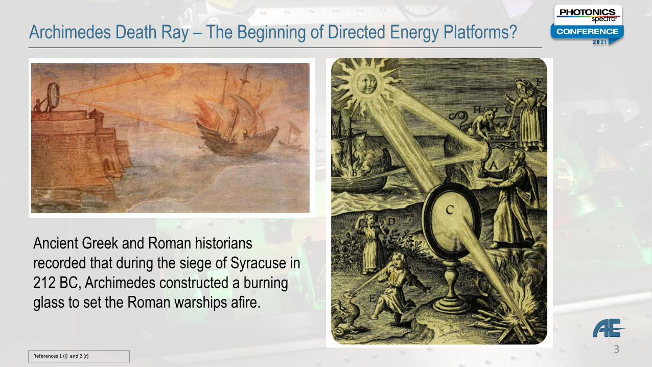
Archimedes Death Ray – The Beginning of Directed Energy Platforms?
Ancient Greek and Roman historians recorded that during the siege of Syracuse in 212 BC, Archimedes constructed a burning glass to set the Roman warships afire.
References 1 (l) and 2 (r)
4
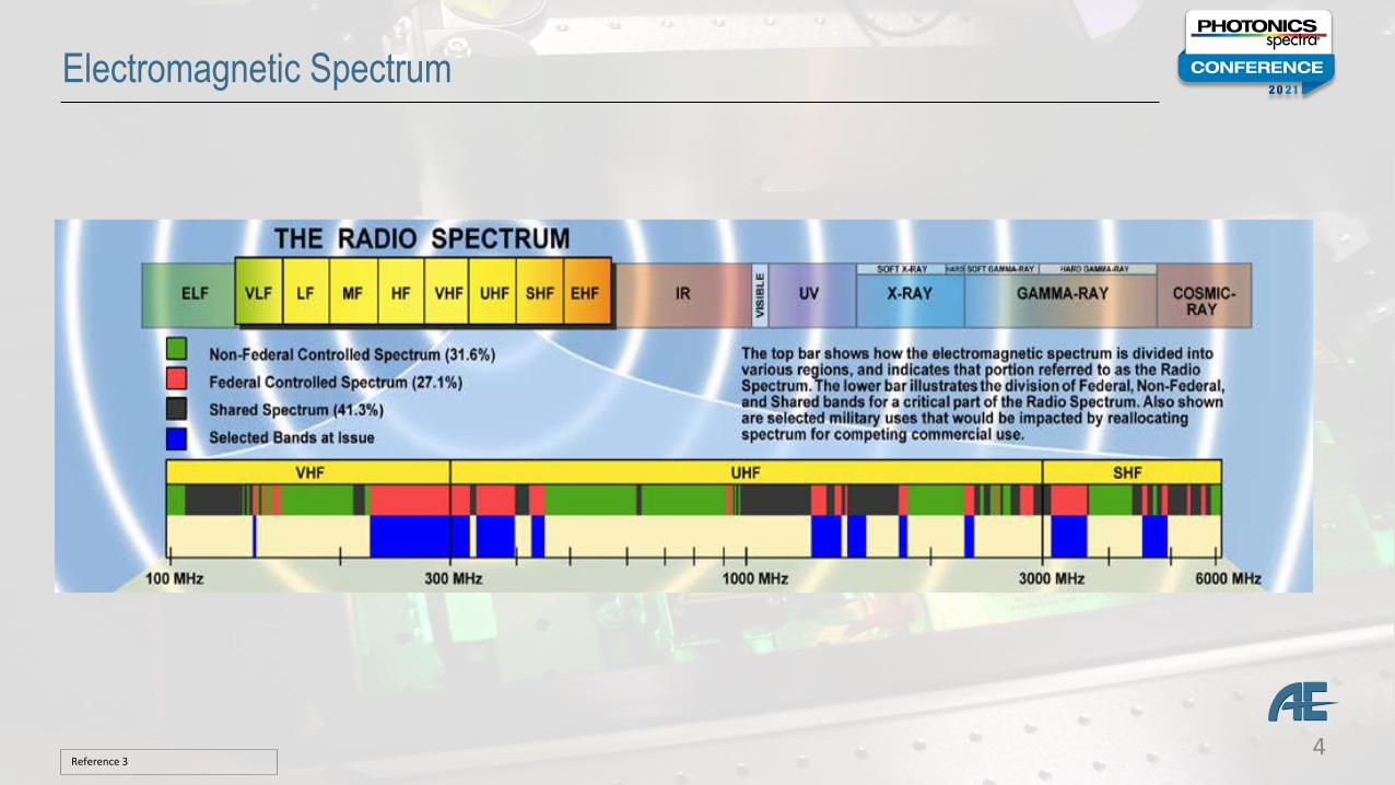
Electromagnetic Spectrum
Reference 3
5
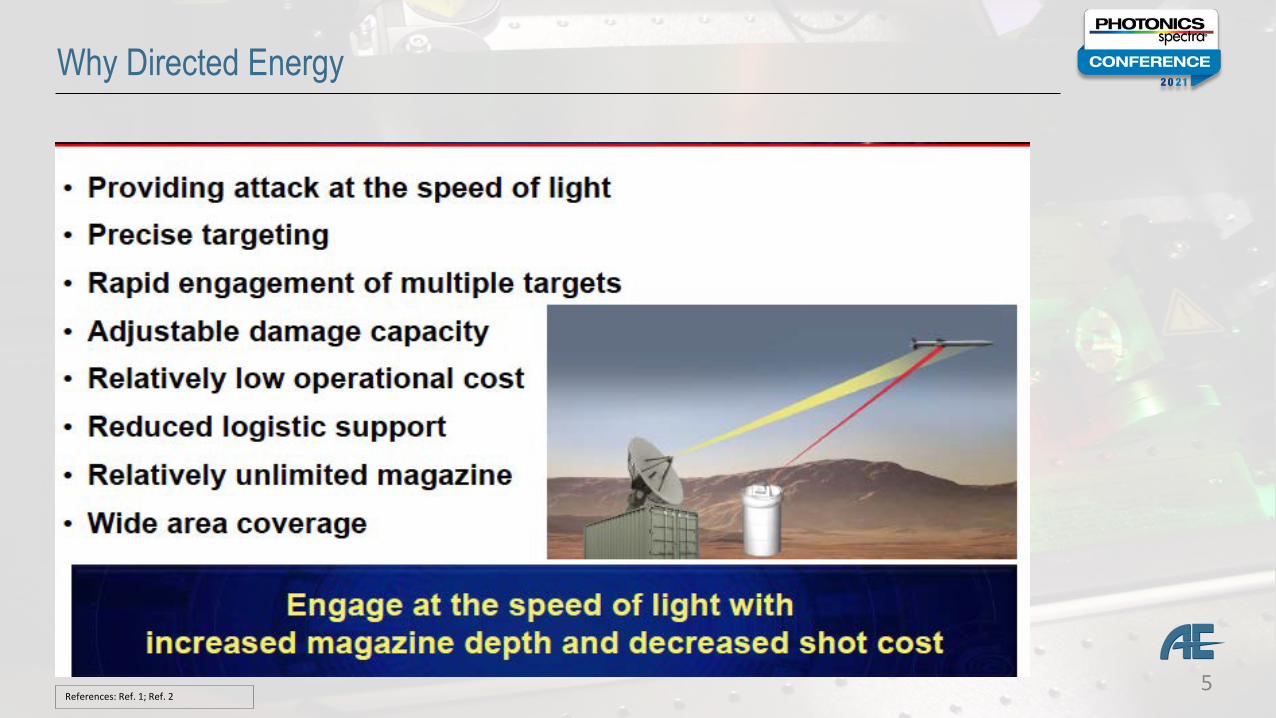
Why Directed Energy
References: Ref. 1; Ref. 2
6
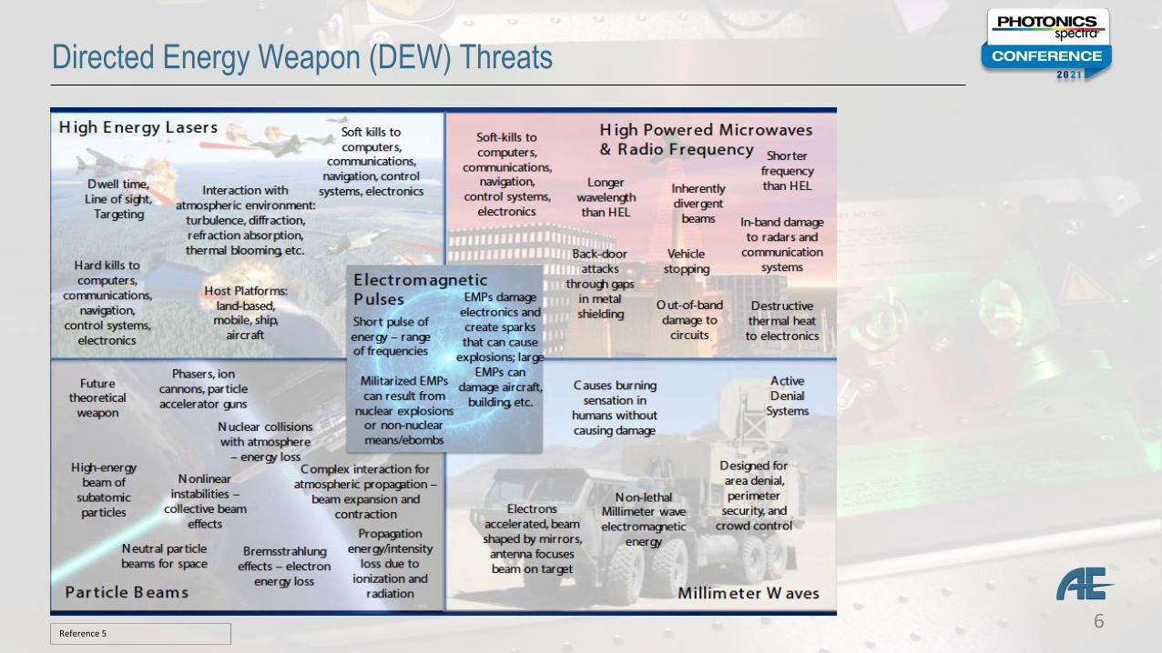
Directed Energy Weapon (DEW) Threats
Reference 5
7
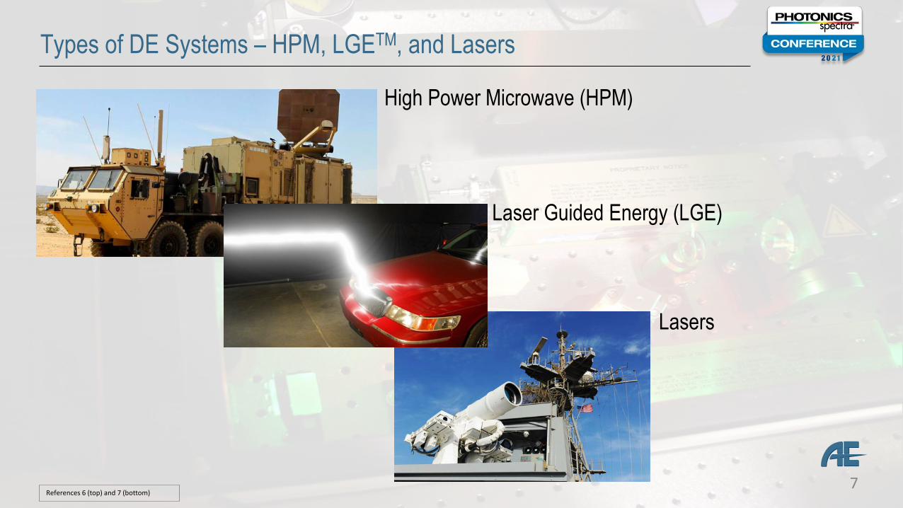
Types of DE Systems – HPM, LGETM, and Lasers
High Power Microwave (HPM)
Laser Guided Energy (LGE)
Lasers
References 6 (top) and 7 (bottom)
8
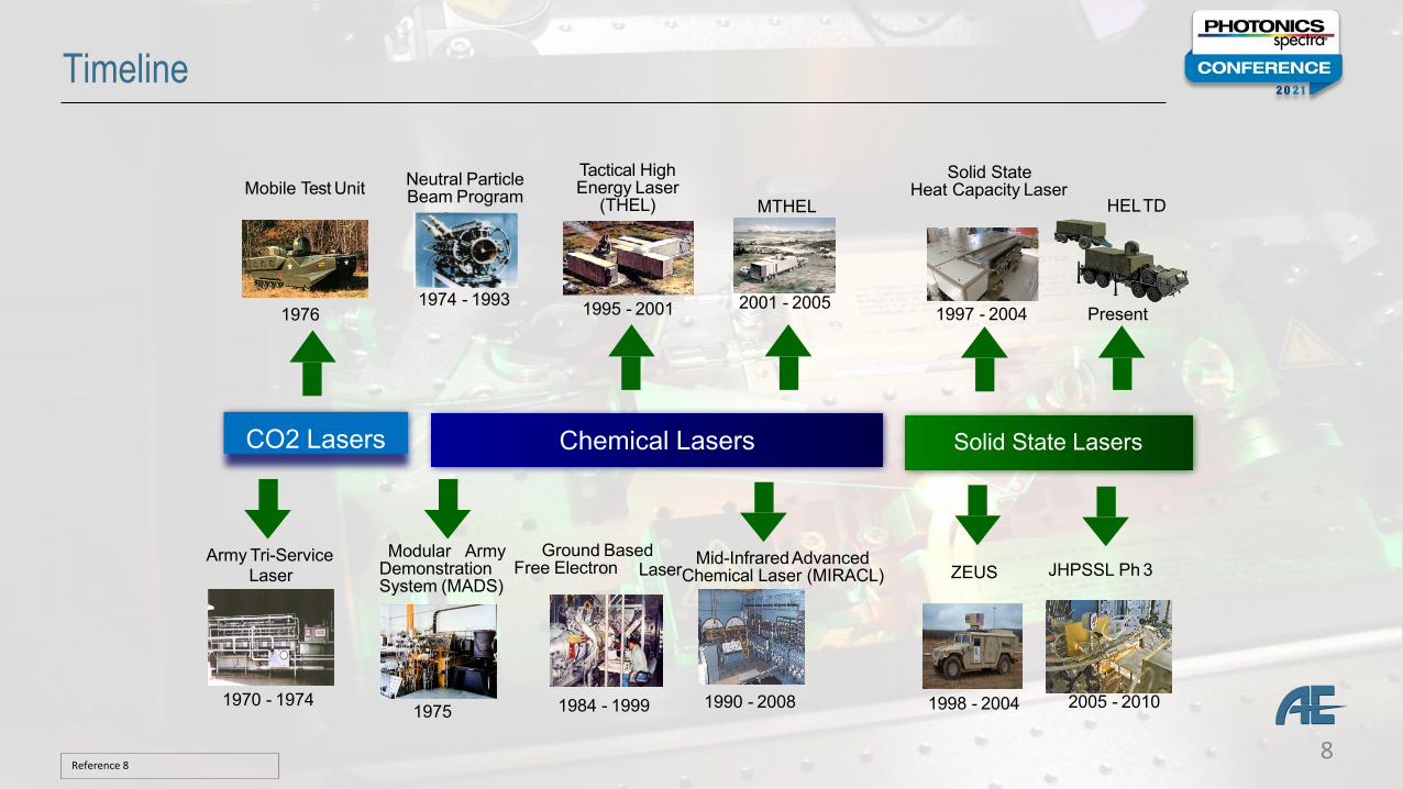
Timeline
1984 - 1999
Neutral Particle Beam Program
1974 - 1993
Ground BasedFree Electron Mid-InfraredAdvancedLaserChemical Laser (MIRACL)
Tactical High Energy Laser
(THEL)
Solid State Heat Capacity Laser
1995 - 2001
1990 - 2008
1997 - 20042001 - 2005
MTHEL
JHPSSL Ph 3
2005 - 2010
Mobile Test Unit
1976
1970 - 1974
Army Tri-Service Laser ZEUS
1998 - 2004
Modular ArmyDemonstrationSystem (MADS)
1975
HELTD
Chemical Lasers Solid State Lasers
Present
CO2 Lasers
Reference 8
9
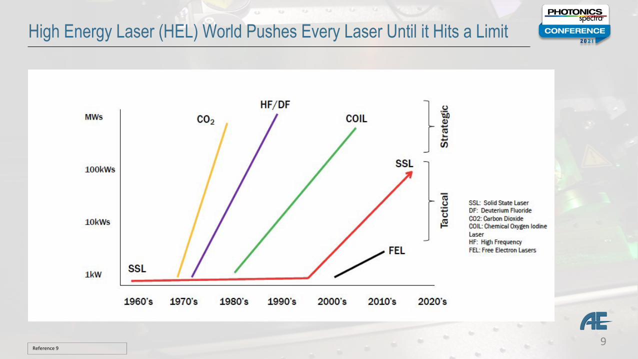
High Energy Laser (HEL) World Pushes Every Laser Until it Hits a Limit
Reference 9

10
JTO Early Years 2001 – 2009: Joint High Power Solid State Laser Program (JHPSSL)
Reference 10
11
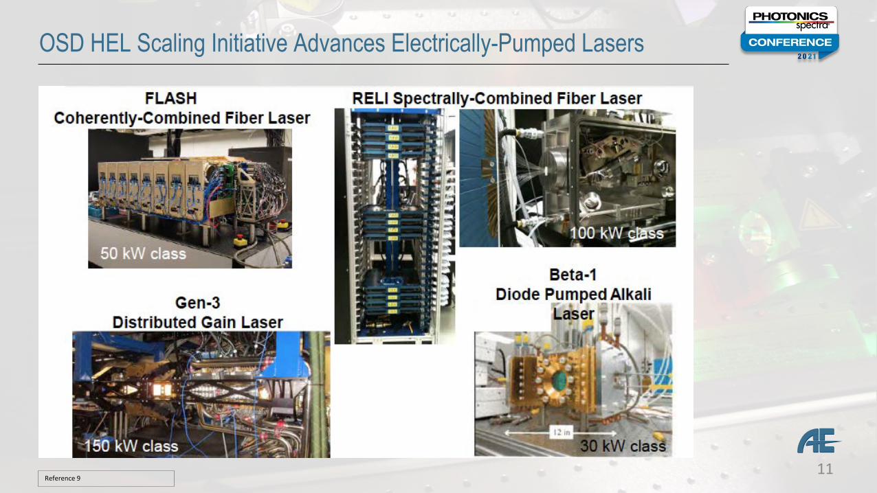
OSD HEL Scaling Initiative Advances Electrically-Pumped Lasers
Reference 9
12
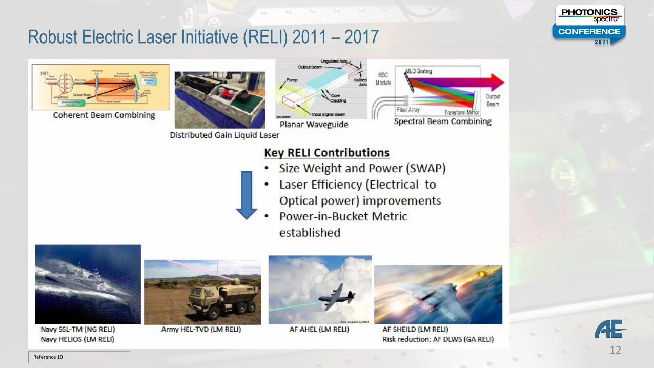
Robust Electric Laser Initiative (RELI) 2011 – 2017
Reference 10
13
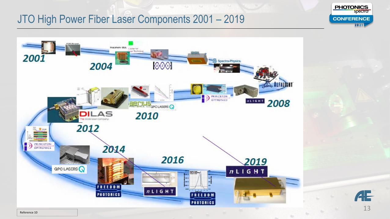
JTO High Power Fiber Laser Components 2001 – 2019
Reference 10
14
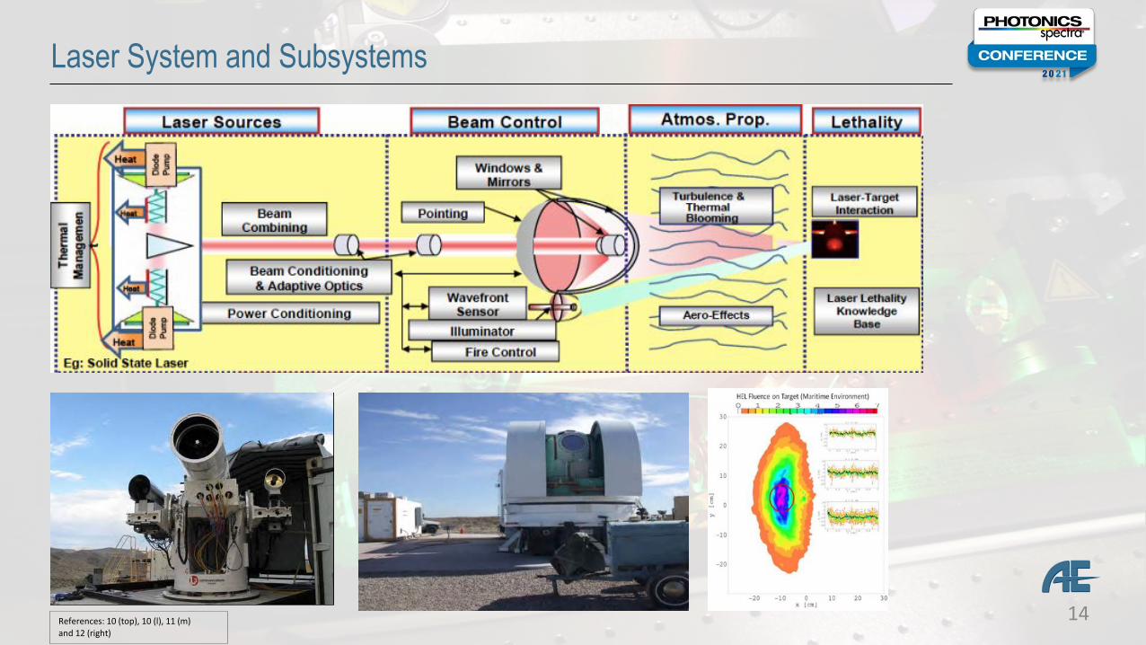
Laser System and Subsystems
References: 10 (top), 10 (l), 11 (m) and 12 (right)
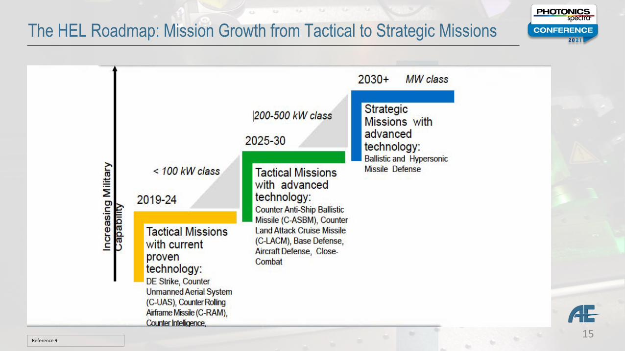
The HEL Roadmap: Mission Growth from Tactical to Strategic Missions
Reference 915
16
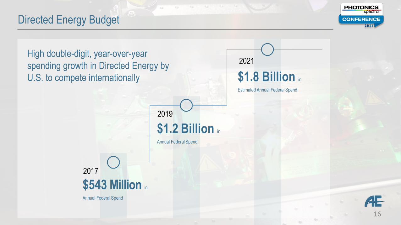
Directed Energy Budget
High double-digit, year-over-year spending growth in Directed Energy by U.S. to compete internationally
$1.2 Billion in
Annual Federal Spend
2021
$1.8 Billion in
Estimated Annual Federal Spend
$543 Million in
Annual Federal Spend
2017
2019
17
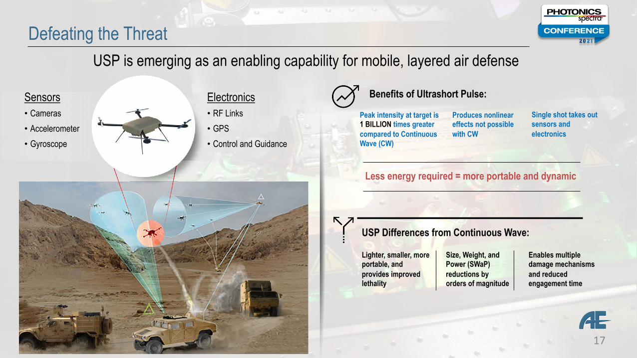
Defeating the Threat
Sensors• Cameras• Accelerometer• Gyroscope
Electronics• RF Links• GPS• Control and Guidance
Benefits of Ultrashort Pulse:
Peak intensity at target is 1 BILLION times greater compared to Continuous Wave (CW)
Produces nonlinear effects not possible with CW
Less energy required = more portable and dynamic
Single shot takes out sensors and electronics
USP Differences from Continuous Wave:
Lighter, smaller, more portable, and provides improved lethality
Size, Weight, and Power (SWaP) reductions by orders of magnitude
Enables multiple damage mechanisms and reduced engagement time
USP is emerging as an enabling capability for mobile, layered air defense
18
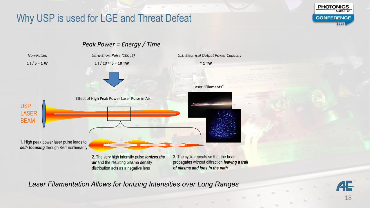
Why USP is used for LGE and Threat Defeat
1. High peak power laser pulse leads to self- focusing through Kerr nonlinearity
2. The very high intensity pulse ionizes the air and the resulting plasma density distribution acts as a negative lens
3. The cycle repeats so that the beam propagates without diffraction leaving a trail of plasma and Ions in the path
Laser Filamentation Allows for Ionizing Intensities over Long Ranges
USP LASERBEAM
Peak Power = Energy / Time
1 J / S = 1 W 1 J / 10-13 S = 10 TW
Ultra-Short Pulse (100 fS)Non-Pulsed U.S. Electrical Output Power Capacity
Effect of High Peak Power Laser Pulse in Air
Laser “Filaments”
~ 1 TW
19
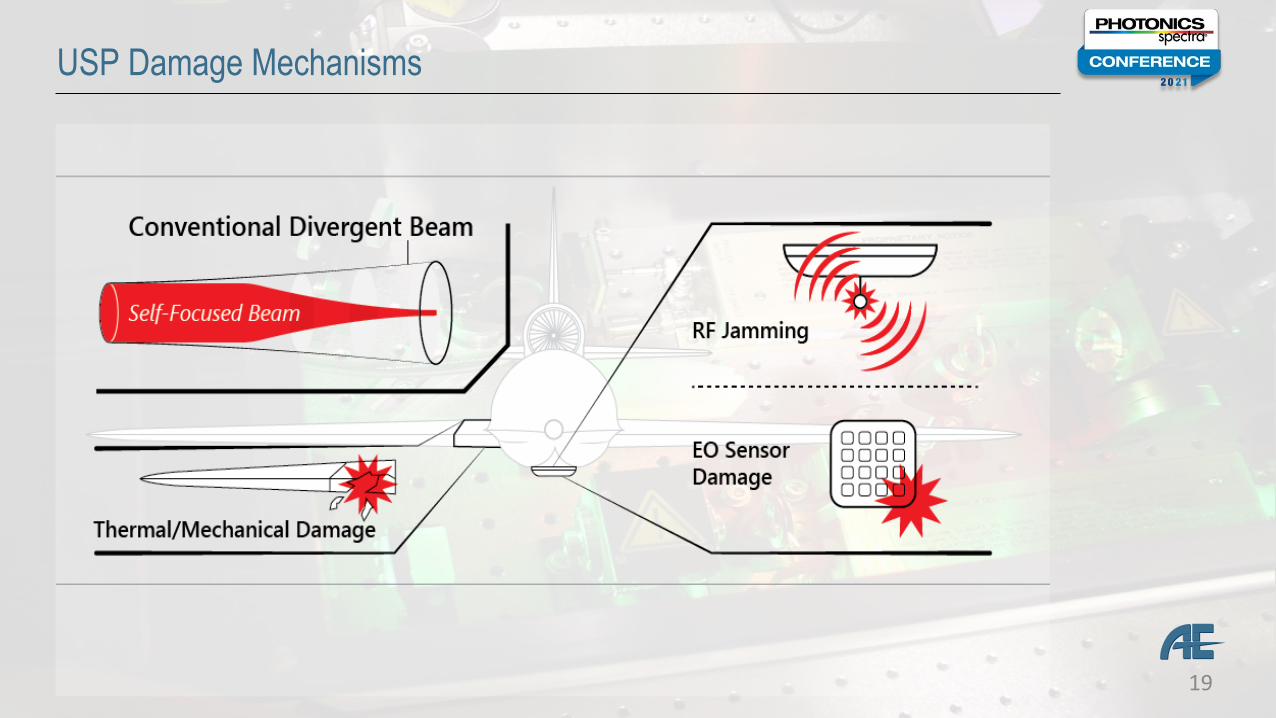
USP Damage Mechanisms
20
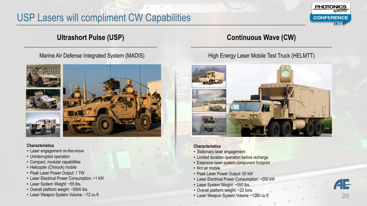
USP Lasers will compliment CW Capabilities
High Energy Laser Mobile Test Truck (HELMTT)Marine Air Defense Integrated System (MADIS)
Characteristics• Laser engagement on-the-move• Uninterrupted operation• Compact, modular capabilities• Helicopter (Chinook) mobile• Peak Laser Power Output: 1 TW• Laser Electrical Power Consumption: ~1 kW• Laser System Weight: ~55 lbs.• Overall platform weight: ~5500 lbs.• Laser Weapon System Volume: ~72 cu ft
Ultrashort Pulse (USP) Continuous Wave (CW)
Characteristics• Stationary laser engagement • Limited duration operation before recharge• Extensive laser system component footprint• Not air mobile• Peak Laser Power Output: 50 kW• Laser Electrical Power Consumption: ~200 kW• Laser System Weight: ~550 lbs.• Overall platform weight: ~22 tons• Laser Weapon System Volume ~1280 cu ft
21
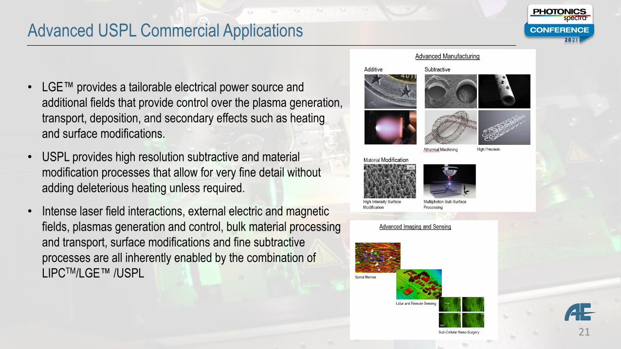
Advanced USPL Commercial Applications
• LGE™ provides a tailorable electrical power source and additional fields that provide control over the plasma generation, transport, deposition, and secondary effects such as heating and surface modifications.
• USPL provides high resolution subtractive and material modification processes that allow for very fine detail without adding deleterious heating unless required.
• Intense laser field interactions, external electric and magnetic fields, plasmas generation and control, bulk material processing and transport, surface modifications and fine subtractive processes are all inherently enabled by the combination of LIPCTM/LGE™ /USPL
22
Directed Energy Industrial Base Challenges
Development and supply chain maturation for laser system components
• High Damage Threshold Optics (> 1 µm)• Adaptive Optics and Advanced Jitter Control• Power and Thermal Management• High Volume Manufacturing of Diodes and Laser Gain media• Track and Beam Illuminator sources (> 1 µm)• Fire Control Modules• Laser Beam Propagation and Laser-Material Interaction (l and Dt)• Platform Traceable Laser Metrics• Standardization and Quality Control• Ruggedization• Utilization in public spaces
23
ACKNOWLEDGEMENTS• Patrick Williams and Stephen McCahon, PhD – Applied Energetics, Inc.• The Directed Energy Professional Society (www.DEPS.org)
REFERENCES
1. Artistic interpretation of Archimedes' mirror used to burn Roman ships. Painting by Giulio Parigi, c. 1599.2. Théodore Galle. Engravings for Duodecim Specula Deum Aliquando Videre Desideranti Concinnata, by Jan David. 1610.3. DOD Joint Spectrum Center, http://www.jsc.mil4. R. White, "MDA Update", Proceedings of the 2020 Directed Energy Systems Symposium (2020).5. B. Johnson, “Counter Directed Energy Weapons and the Defense of Naval Unmanned Aerial Vehicles“, Proceedings of the Annual
Directed Energy Science & Technology Symposium (2020).6. J. Tatum, "High-Power Microwave Directed Energy Weapons: A Model and Simulation Toolbox", DSAIC Journal, Vol. 1 (2014).7. https://www.navsea.navy.mil/Media/News/Article/611402/historic-leap-nswc-dahlgren-division-developed-navy-shipboard-
laser-operates-in/ )photo by J.F. Williams).8. https://www.slideshare.net/tseitlin/us-army-research-lab-2010, slide 4.9. T. J. Karr, “The OSD HEL Laser Scaling Initiative”, Proceedings of the Annual Directed Energy Science & Technology Symposium (2020).10. L. Grimes, “DE JTO Transitions: (HEL JTO - 20 years later) “, Proceedings of the Annual Directed Energy Science & Technology
Symposium (2020).11. K. Sparks, “Directed Energy S&T Portfolio Overview to Annual Directed Energy Science and Technology Symposium”, Proceedings of the
Annual Directed Energy Science & Technology Symposium (2020).12. https://www.nrl.navy.mil/ppd/atmo-prop
Acknowledgements and References

24
Questions?