Embed Size (px)
Citation preview

1
Direction Finding Antennas and Accuracy : Part 2
By Johan Fuhri, Product Owner

2
From its roots in 1990, Alaris Antennas has grown
to become a substantial supplier of advanced
Electronic Warfare (EW) antennas.
Alaris Antenna’s mission is to deliver high quality
antenna solutions on time through technical and
service excellence.
Furthermore, it is our mission to deliver
innovative, customised, high quality antenna and
related RF product solutions to global RF system
integrators speedily through technical and service
excellence.
For the global defence, security and
telecommunications markets, Alaris Antennas
delivers on time high quality antenna solutions,
offering customisation supported by technical and
service excellence, as Alaris Antennas is the
trusted and innovative partner to its clients for
over a decade.
About Alaris Antennas

1
IntroductionIn the previous blog post we
considered some of the ways in
which we can express the
performance of an DF antenna,
and we noted that simply stating
the ‘accuracy’ of a DF antenna is
not quite that simple.
We also noted that there are
various algorithms that can be
used along with a typical DF
antenna, and that the accuracy
and sensitivity of DF system is
dependent on both the quality
of the antenna and the
direction-finding algorithm.
In this blog post we will discuss
the process of ‘characterizing’ a
DF antenna array to generate a
table of values which can be
used in correlative algorithms.
We will also look at a few real-
life problems that cause
inaccuracies in DF systems,
specifically when using basic
correlative algorithms.

2
Correlation is a mathematical and statistical tool that can be used to
quantitively express how similar two or more sets of data are to each
other. It is basically a fancy way of playing ‘pick the closest match’.
To illustrate the process, we are going to use colour swatches (the type
that adorns the walls of the paint department at your favorite
hardware chain store) and create a simple direction-finding system.
Consider the image below, which is a circle divided into six sectors and
a colour assigned to each sector. Let’s suppose we have a DF antenna
right in the center of this circle, and the lines/sectors represent the
various directions from which a signal can arrive. This, however, is a
very special antenna, in the sense that it will tell you the colour of an
incoming signal.
What is a correlative algorithm?

3
If we are clever, we can make sure that we install the antenna in such a
way that a colour of our choosing, yellow in this case, is always pointing
due north. If we then receive a signal from our antenna (which will be
a color, remember), we can compare the color that we received from
the antenna with the image above to determine which direction the
signal came from! That’s not too hard now, is it?
On a very basic level, this is what correlative DF algorithms do. The DF
antenna is spun through 360⁰ and the incoming signal from each
direction, on each of the elements on the antenna, is sampled and stored
in a table. This table is called the ‘characterization table’ (although
different people might name it something else), and it effectively allows a
DF system to calculate the exact direction from which a signal arrives by
comparing the signal with those stored in the characterization table, just
like we did with the colours. The circle indicating which colour is in which
direction is effectively our own ‘characterization table’.
4
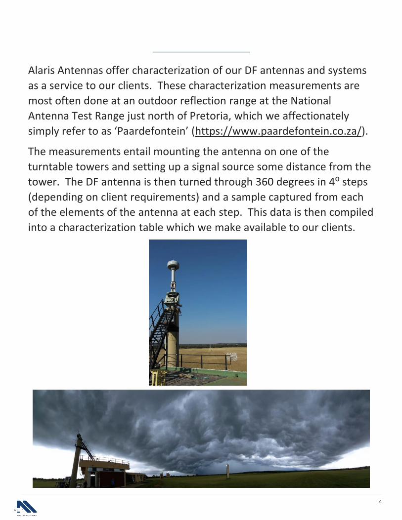
Alaris Antennas offer characterization of our DF antennas and systems
as a service to our clients. These characterization measurements are
most often done at an outdoor reflection range at the National
Antenna Test Range just north of Pretoria, which we affectionately
simply refer to as ‘Paardefontein’ (https://www.paardefontein.co.za/).
The measurements entail mounting the antenna on one of the
turntable towers and setting up a signal source some distance from the
tower. The DF antenna is then turned through 360 degrees in 4⁰ steps
(depending on client requirements) and a sample captured from each
of the elements of the antenna at each step. This data is then compiled
into a characterization table which we make available to our clients.
5
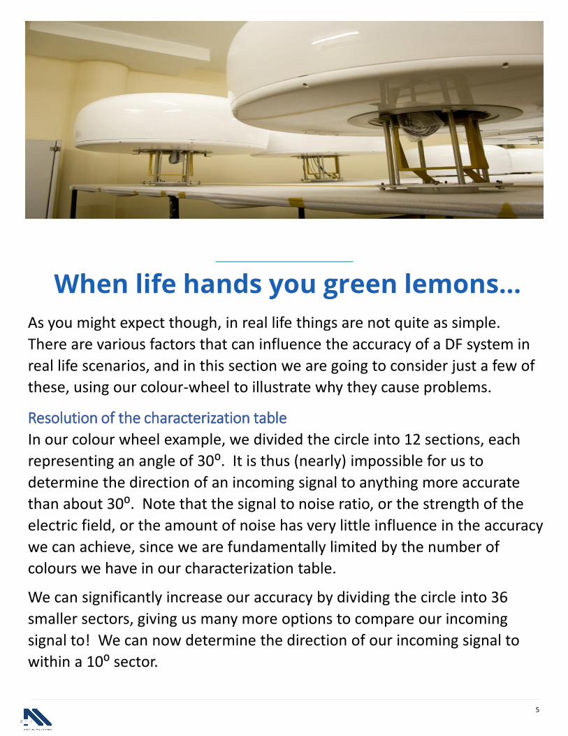
When life hands you green lemons…
As you might expect though, in real life things are not quite as simple.
There are various factors that can influence the accuracy of a DF system in
real life scenarios, and in this section we are going to consider just a few of
these, using our colour-wheel to illustrate why they cause problems.
Resolution of the characterization table
In our colour wheel example, we divided the circle into 12 sections, each
representing an angle of 30⁰. It is thus (nearly) impossible for us to
determine the direction of an incoming signal to anything more accurate
than about 30⁰. Note that the signal to noise ratio, or the strength of the
electric field, or the amount of noise has very little influence in the accuracy
we can achieve, since we are fundamentally limited by the number of
colours we have in our characterization table.
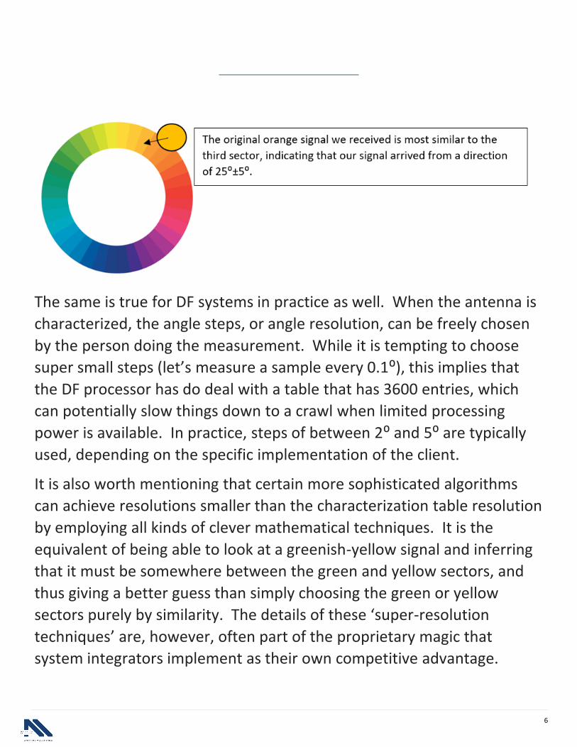
We can significantly increase our accuracy by dividing the circle into 36
smaller sectors, giving us many more options to compare our incoming
signal to! We can now determine the direction of our incoming signal to
within a 10⁰ sector.
6
The same is true for DF systems in practice as well. When the antenna is
characterized, the angle steps, or angle resolution, can be freely chosen
by the person doing the measurement. While it is tempting to choose
super small steps (let’s measure a sample every 0.1⁰), this implies that
the DF processor has do deal with a table that has 3600 entries, which
can potentially slow things down to a crawl when limited processing
power is available. In practice, steps of between 2⁰ and 5⁰ are typically
used, depending on the specific implementation of the client.
It is also worth mentioning that certain more sophisticated algorithms
can achieve resolutions smaller than the characterization table resolution
by employing all kinds of clever mathematical techniques. It is the
equivalent of being able to look at a greenish-yellow signal and inferring
that it must be somewhere between the green and yellow sectors, and
thus giving a better guess than simply choosing the green or yellow
sectors purely by similarity. The details of these ‘super-resolution
techniques’ are, however, often part of the proprietary magic that
system integrators implement as their own competitive advantage.

7
The effects of noise
Up to now we assumed that the incoming signal that we are evaluating is
perfectly clear, and that our accuracy is only limited by the resolution of
the table against which we can compare our incoming signal. In antenna
terms this is called the ‘large signal accuracy’ of the antenna, as it
assumes that no noise is present in the measurements.
Real life signals, however, rarely qualify as large signals and often has
noise superimposed on the signal of interest. Let’s look at an example in
our colour wheel example.

8
Adding noise to the signal makes it harder and harder to find the colour
that best matches the characterization table. If there is noise present on
the signal, invariably the DF processor will look at the ‘colours’ it can
choose from and make mistakes. At best it can tell you that the signal
belongs to one of these four sectors, and this reduces the RMS accuracy
of the overall system.
Adding even more noise, at some point it becomes practically impossible
for the DF processor to make any sense of the incoming signal, and it
may start taking ‘random’ guesses. These wild guesses can be in any
direction whatsoever, and are called appropriately called ‘wild bearings’.
The main source of noise in a DF system is the internal electronic
components of the system. Every amplifier, transistor and resistor
contribute a bit of noise, and all this noise is added to the incoming signal
before the DF processor has the opportunity to compare this signal to
the characterization table. We can thus see that it is important to ensure
that the received signal is as strong as possible while keeping the noise as
small as possible to get a good signal-to-noise ratio.
The design of the DF antenna, specifically the gain of the antenna
elements, directly contributes to keeping the SNR as high as possible by
ensuring that the incoming signal is converted to a large as possible
voltage for the receiver to work with. For a more detailed discussion on
this topic, refer to the previous blog post in this series.
9
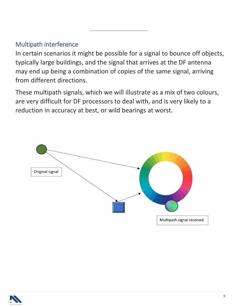
Multipath interference
In certain scenarios it might be possible for a signal to bounce off objects,
typically large buildings, and the signal that arrives at the DF antenna
may end up being a combination of copies of the same signal, arriving
from different directions.
These multipath signals, which we will illustrate as a mix of two colours,
are very difficult for DF processors to deal with, and is very likely to a
reduction in accuracy at best, or wild bearings at worst.

10
Using our colour wheel example, we can see that a pure green signal
leaves the source that we are trying to find, but along the way a signal
bouncing off a building also makes its way into the DF antenna. The
‘colour’ making its way into the DF processor is mostly green, with a dash
of blue mixed in. This mixed signal will certainly cause problems for most
simple correlative algorithms, as the received signal does not match any
of the signals in the correlation table, causing inaccuracies and wild
bearings.
Having said that, there are a few clever algorithms, like MUSIC, which can
actually use these strange signals to its advantage and can figure out that
there are multiple paths in play. How these clever algorithms work is
beyond the scope of this blog post (and the authors current intellectual
grasp…).
11
This blog post attempted to explain the principle behind most correlative
algorithms while trying to stay away from the complicated math that
make it work. We also looked at a few real-world effects that influence
the accuracy of DF systems in general, and specifically the mechanism
that causes problems in correlative algorithms. Most of these
inaccuracies are caused by external factors, ie. they are not so much
caused by the design of the DF antenna, but by the environments in
which they are employed.
In the last post of the series, we will discuss a few of the intricacies of DF
antenna design and how they can cause inherent inaccuracies (ie. non-
environmental causes) in poor designs. This will be a rare glimpse into
the everyday challenges that antenna engineers at Alaris Antennas deal
with on a daily basis!
Conclusion

9
Alaris Antennas offers SWaP optimized, high performance 3- and 4-channel DF antennas.Suitable for On-The-Move / On-The-Halt military reconnaissance missions during front lineoperations.Alaris Antennas SWaP optimized products are widely accepted as tactical drone detectionsolutions.Patented technology provides improved performance.
www.alarisantennas.com
CTA GOES HERE
If you enjoyed this Ebook, sign up for more at www.alarisantennas.com
12