Embed Size (px)
Citation preview
AP1201-0061
1
Abstract—In-body localization implies identifying 3D positions
of thermometer pills, smart pills, and other autonomous small
objects within the human body. The use of far-field scanning
arrays operating at frequencies above 900 MHz is generally
prohibitive due to severe multipath caused by different electric
properties of body organs. On the other hand, the magnetic
properties of the body are constant. Therefore, the standard
method is that of (quasi) magnetostatics. An intermediate region
between the two extremes is the Fresnel region, which
approximately corresponds to the center frequency of 400MHz
and the wavelength of ~10cm within the body. In this study, we
describe the new concept of a directional receiving antenna array
intended for localization purposes within a human body in the
Fresnel region. The individual array element is composed of two
small orthogonal coils (magnetic dipoles). The coils are to be
acquired/driven in quadrature, for both CW and pulse signals.
The individual array element possesses a highly-directional
single-lobe beam into the body directed at 45 degrees from the
broadside. An array of such radiators makes it possible to
develop a simple yet effective localization algorithm within a
realistic body using direct RSS estimates for every individual
receiver.
Index Terms— Antenna arrays, Beam steering, Biomedical
communication, Biomedical electromagnetic imaging
I. INTRODUCTION
N-BODY localization implies identifying 3D positions of
thermometer pills, smart pills, and other autonomous small
objects within the human body. The use of far-field scanning
arrays operating at frequencies above 900 MHz is generally
prohibitive due to severe multipath caused by different
permittivities and electric conductivities of body organs, skin,
Manuscript received January 20, 2012.
S. N. Makarov is with the Department of Electrical and Computer
Engineering at Worcester Polytechnic Institute, Worcester, MA 01609 USA (phone: 508-831-5017; fax: 508-831-5491; e-mail: [email protected]).
G. M. Noetscher is with the Department of Electrical and Computer
Engineering at Worcester Polytechnic Institute, Worcester, MA 01609 USA. He is also with the Natick Soldier Research, Development and Engineering
Center, Natick, MA 01760 USA (e-mail: [email protected]).
L. C. Kempel is with the College of Engineering, Michigan State University, East Lansing, MI 48824 USA (e-mail: [email protected]).
muscles, and fat. On the other hand, the permeability and the
magnetic loss tangent of the body are constant. Therefore, the
standard method is that of (quasi) magnetostatics where the
direction of the imposed 3D magnetic field is acquired by a
sensor, which results in encoding the sensor location.
Commercial magnetic surgical navigation systems include the
Medtronic Axiem, Northern Digital's Aurora, Ascension
Technology (Flock of birds, microBird), Biosense Webster,
Calypso, Polhemus, Praxim's Surgetics, GE Medical, etc. The
magnetostatic systems are bulky and hardly wearable; the
sensor must be cable- or battery-powered.
An intermediate region between the two extremes is the
Fresnel region, or the radiating near field, which
approximately corresponds to the center frequency of 400MHz
and the wavelength of ~10cm within the body. In this study,
we will describe the new concept of a directional receiving
antenna array intended for localization purposes of a small
radiating source within a human body in the Fresnel region.
A. Magnetic (electric) dipoles on the air-dielectric interface
in the quasi-static limit
In the quasi-static limit, an extensive study of magnetic
dipoles (electrically small loop/coil antennas) radiating into or
immersed within a lossy dielectric has been performed by J.
Wait and co-workers [1]-[4] and A. Baños [5]. The quasistatic
limit implies that the conduction current in a lossy medium
dominates the displacement current, i.e.
(1)
where is the medium conductivity, is the dielectric
constant, and is the angular frequency. No significant
directive properties of magnetic (and electric) dipoles
radiating close to an air-dielectric interface have been
established [5]. Average human body properties might be
characterized by 050,S/m5.0 . Eq. (1) is then satisfied
(assuming 10 ) only at frequencies below approximately
20MHz.
B. Magnetic (electric) dipoles on the air-dielectric interface
in the far field
Using a 2D spatial Fourier transform to solve Maxwell’s
Directional In-Quadrature Orthogonal-Coil
Antenna and an Array Thereof for Localization
Purposes within a Human Body in the Fresnel
Region. Numerical Simulations
Sergey N. Makarov, Senior Member, IEEE, Gregory M. Noetscher, Student Member, IEEE and Leo C.
Kempel, Fellow, IEEE
I
AP1201-0061
2
equations, G. Smith [6] established radiation patterns for
horizontal magnetic(electric) dipoles at the air-dielectric
interface. He found that the horizontal dipoles may create
highly-directive patterns into a dielectric, with off-broadside
main lobes. This effect occurs when the dipole is close to the
interface and when the dielectric contrast of two media is
reasonably large ( 4/12 ). This effect is weakly influenced
by conductivity of the medium. Using a similar approach, W.
Lukosz and R. E. Kunz [7], [8] have derived analytical
radiation patterns for vertical magnetic(electric) dipoles, and
arrived at a similar conclusion. Electric dipole patterns were
investigated in [9] and [10] (including finite wire dipoles).
Results for finite (resonant) loops are given in [11] and [12].
Near-field electric-dipole radiation dynamics through Finite
Difference Time Domain (FDTD) modeling have been
quantified in [13].
C. Frequency band under study
We will consider wideband pulse propagation with a center
frequency of around 400 MHz, which is within the UHF band.
Thus, the pulse spectrum will include a band newly
established by the FCC Medical Device Radiocommunication
Service used for diagnostic and therapeutic purposes in
humans at 401-406 MHz. If average human body properties of
050,S/m5.0 are used, the fields within the human
body medium at 400 MHz do not exactly correspond to the far
field. Instead, the bulk of the body volume in any direction
belongs to the Fresnel region of operation (the radiating near
field). Nevertheless, some general facts established with the
help of the far-field models [6], [8], [12] will be quite helpful
in providing theoretical background of our model.
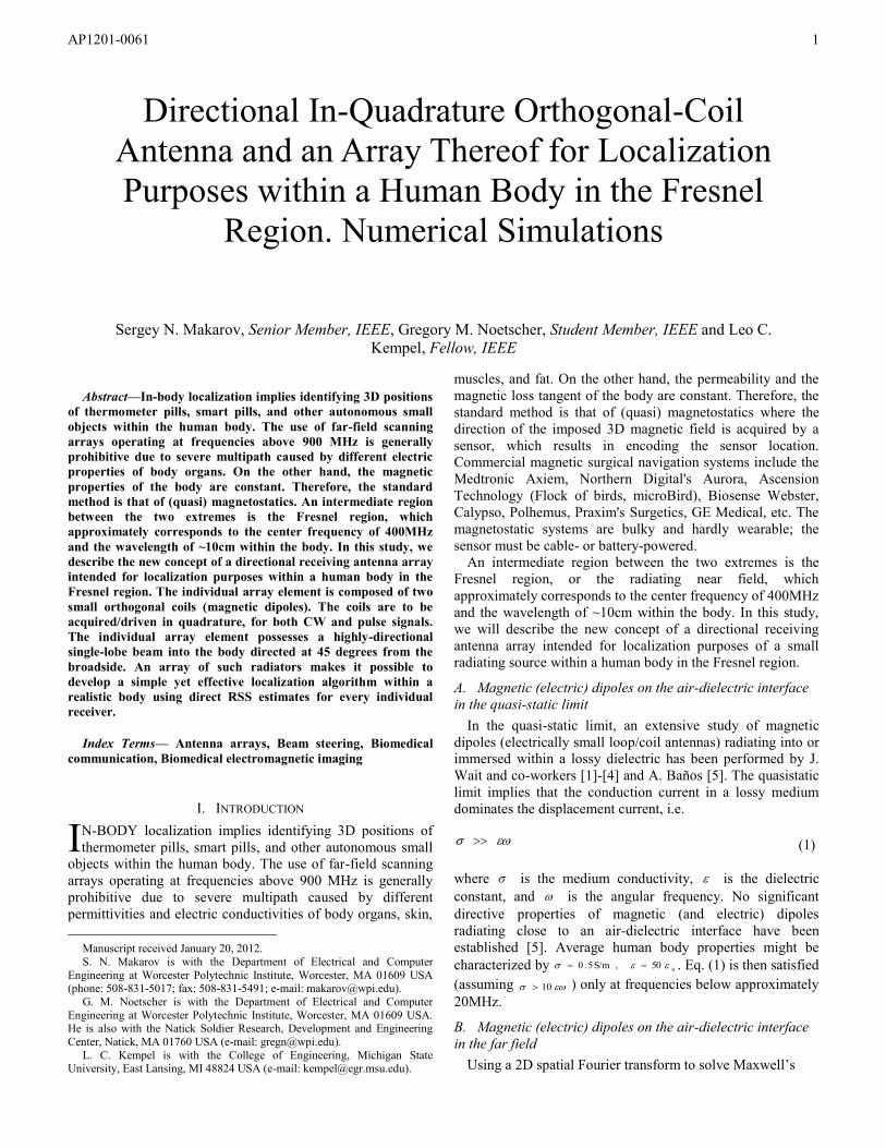
D. Model of orthogonal magnetic dipoles
In order to create a highly-directive one-lobe beam into the
body medium in the Fresnel region, we suggest using two
orthogonal magnetic dipoles (small coil antennas) with
coincident phase centers. The problem geometry is shown in
Fig. 1. The upper half-space is free space while the lower half-
space is a dielectric. Both dipoles have the same magnetic
moment, m; they are oriented as shown in Fig. 1.
II. PATTERN COMBINATION OF TWO ORTHOGONAL DIPOLES IN
THE FAR FIELD
A. CW radiation patterns in a lossless medium 2
With reference to Fig. 1, the radiated far-field electric-field
component 2E of the horizontal magnetic dipole in a lossless
medium has the form
r
nrjk
nhjk
nn
nnmkE
4
exp
sin1exp
sin1cos
sin1cossin2,
2
22
122
22
102
(2a)
Here, 12/ n is the relative refractive index, 2,12,1
/ ck , and
m is the magnetic dipole moment. Equation (2a) follows from
Eq. (24b) and Eq. (47d) of Ref. [6]. When 1n , it is reduced to
the isolated magnetic-dipole pattern in the lower half-space ( coscos ).
Similarly, the radiated far-field electric-field component
2E of the vertical magnetic dipole (the original Sommerfeld
asymptotic) has the form
r
nrjk
nhjk
nn
nnmkE
4
exp
sin1exp
sin1cos
cossin2,
2
22
122
102
(2b)
in a lossless medium. Equation (2b) follows from Eqs. (16a, d,
e) of Ref. [12]. When 1n , it is reduced to the isolated
vertical magnetic-dipole pattern in the lower halfspace ( coscos ).
B. Case 0,1 hn
In this particular and most interesting case, we restrict
ourselves to H-plane patterns ( 2/3,2/ ). In the H-plane,
which is the yz-plane in Fig. 1, we use the Cartesian field
component EysignE
x)( . Equations (2), which represent the
horizontal and vertical dipole moments of m, respectively, are
asymptotically reduced to
r
nrjk
jnmkjE
x
4
exp
sincos
2sin2
102
(3a)
r
nrjk
j
ysignnmkE
x
4
exp
sincos
2sin)(2
102
(3b)
The present asymptotic predicts that either dipole generates
two equal main lobes into the dielectric. Both lobes originate
from the function 2sin in Eqs. (3); they are centered at
90,45 and 270,45 , respectively. This result is
clearly expected for the vertical magnetic dipole, but is less
obvious for the horizontal magnetic dipole. It is explained by
the contribution of the evanescent spectrum of the isolated
antenna [6], [14]. The present asymptotic ignores a cusp
confined by critical angles, )/1arcsin( nc , for the horizontal
Fig. 1. Problem geometry and definition of the H-plane for two orthogonal
magnetic dipoles where the radiation patterns will be computed and
combined. ]2,0[],,0[ .
AP1201-0061
3
magnetic dipole [6]. Such cusps will become visible in the
further study.
C. CW radiation patterns in a lossless medium 2
The key observation is that Eqs. (3a) and (3b) become
identical to within: (i) a phase factor of )2/exp( j
corresponding to a quadrature phase delay between two
dipoles of the quarter wave period, 1
T , in free space 1 and (ii)
a space factor, )( ysign . This space factor obviously indicates
that the two main lobes of the vertical dipole are out of phase.
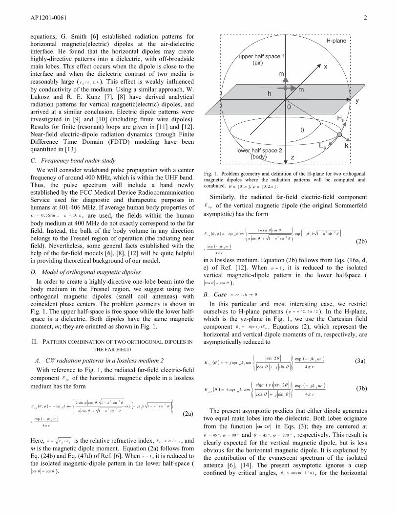
Therefore, two orthogonal magnetic dipoles in quadrature
should produce a highly directional beam with only one main
lobe: either along 45 and 90 ( 0y ) or along 45
and 270 ( 0y ), while exactly cancelling out the other
lobe. This concept is shown in Fig. 2 where the radiation
pattern into lower half space is depicted. The dashed curve is
the normalized linear pattern, xEE
22
, of either (horizontal
or vertical) dipole from Eqs. (3). The solid curve is the pattern
combination from Eqs. (3) when the horizontal dipole has a
time delay, 4/Ttt . Equations (3) predict a perfect
cancellation of one lobe and a creation of a highly-directive
beam into the dielectric at 45 degrees from broadside. In order
to re-direct the main beam into the third quadrant, either the
horizontal dipole should be subject to a negative time delay
4/Ttt or the vertical dipole should obey a positive time
delay, 4/Ttt .
III. PATTERN COMBINATION OF TWO ORTHOGONAL DIPOLES IN
THE FRESNEL REGION
A. Wideband pulse signal
We intend to show that the theoretical prediction of the
previous sections also holds in a Fresnel zone within a (highly
lossy) human body for wideband pulses with the center
frequency of 400 MHz. In this and following sections, a
bipolar Gaussian (Rayleigh) excitation current pulse is used
for a TX antenna in the form
A1,5,)2(
)(exp
)()(
002
2
00
0
It
ttttIti
(4a)
Its center frequency and a 3dB-power bandwidth are given by
16.0
cf (4b)
cf15.1BW (4c)
We employ 460MHzBWMHz,400ns4.0 c
f in
all examples given in the following text. Other pulse forms
have been checked with similar results. The in-quadrature CW
condition may be transformed to the pulse delay of 2 to
achieve the proper phase synchronization for two pulses. This
pulse delay is within 10% of the expected time delay of one
quarter wave period for a CW signal with frequency, c
f .
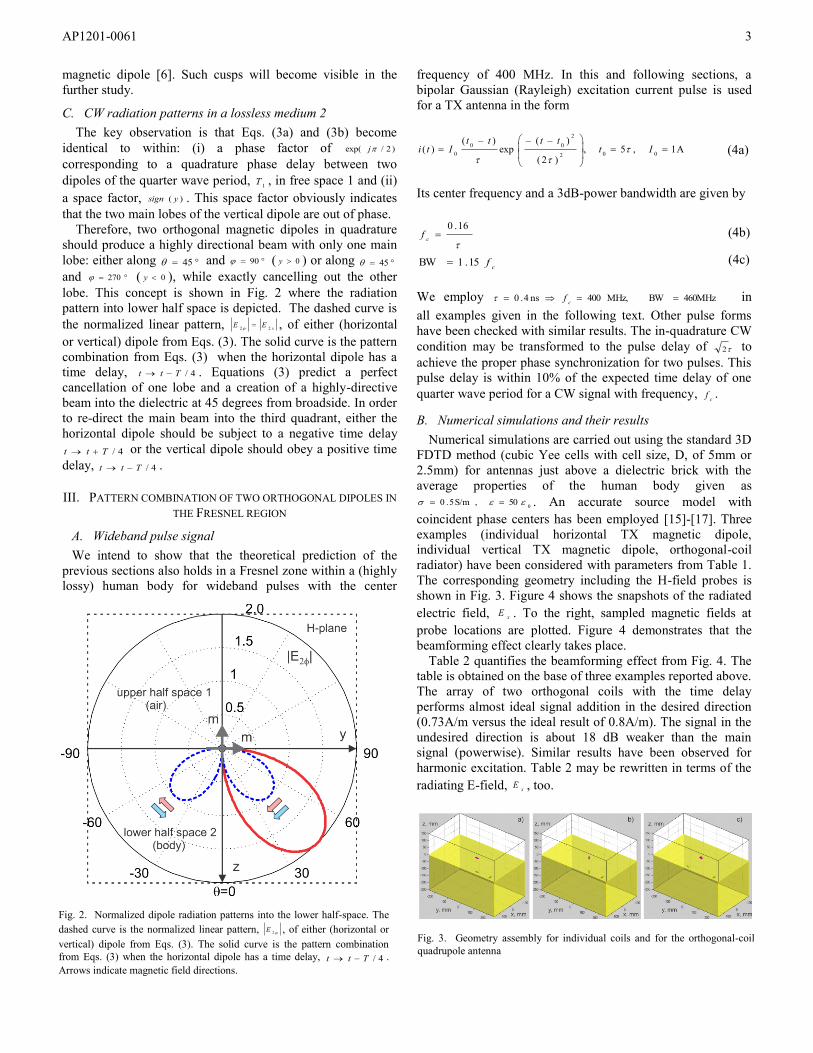
B. Numerical simulations and their results
Numerical simulations are carried out using the standard 3D
FDTD method (cubic Yee cells with cell size, D, of 5mm or
2.5mm) for antennas just above a dielectric brick with the
average properties of the human body given as
050,S/m5.0 . An accurate source model with
coincident phase centers has been employed [15]-[17]. Three
examples (individual horizontal TX magnetic dipole,
individual vertical TX magnetic dipole, orthogonal-coil
radiator) have been considered with parameters from Table 1.
The corresponding geometry including the H-field probes is
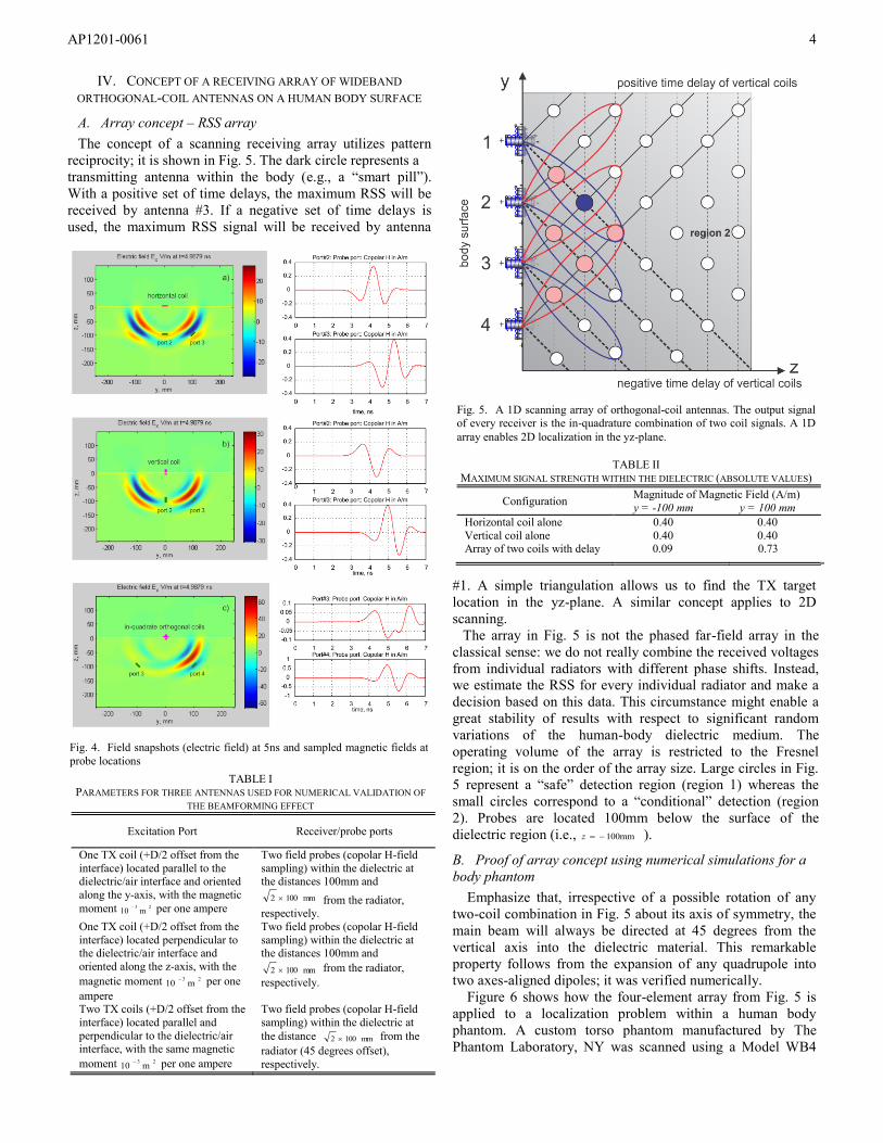
shown in Fig. 3. Figure 4 shows the snapshots of the radiated
electric field, xE . To the right, sampled magnetic fields at
probe locations are plotted. Figure 4 demonstrates that the
beamforming effect clearly takes place.
Table 2 quantifies the beamforming effect from Fig. 4. The
table is obtained on the base of three examples reported above.
The array of two orthogonal coils with the time delay
performs almost ideal signal addition in the desired direction
(0.73A/m versus the ideal result of 0.8A/m). The signal in the
undesired direction is about 18 dB weaker than the main
signal (powerwise). Similar results have been observed for
harmonic excitation. Table 2 may be rewritten in terms of the
radiating E-field, xE , too.
Fig. 2. Normalized dipole radiation patterns into the lower half-space. The
dashed curve is the normalized linear pattern, 2E , of either (horizontal or
vertical) dipole from Eqs. (3). The solid curve is the pattern combination
from Eqs. (3) when the horizontal dipole has a time delay, 4/Ttt .
Arrows indicate magnetic field directions.
Fig. 3. Geometry assembly for individual coils and for the orthogonal-coil
quadrupole antenna
AP1201-0061
4
IV. CONCEPT OF A RECEIVING ARRAY OF WIDEBAND
ORTHOGONAL-COIL ANTENNAS ON A HUMAN BODY SURFACE
A. Array concept – RSS array
The concept of a scanning receiving array utilizes pattern
reciprocity; it is shown in Fig. 5. The dark circle represents a
transmitting antenna within the body (e.g., a “smart pill”).
With a positive set of time delays, the maximum RSS will be
received by antenna #3. If a negative set of time delays is
used, the maximum RSS signal will be received by antenna
#1. A simple triangulation allows us to find the TX target
location in the yz-plane. A similar concept applies to 2D
scanning.
The array in Fig. 5 is not the phased far-field array in the
classical sense: we do not really combine the received voltages
from individual radiators with different phase shifts. Instead,
we estimate the RSS for every individual radiator and make a
decision based on this data. This circumstance might enable a
great stability of results with respect to significant random
variations of the human-body dielectric medium. The
operating volume of the array is restricted to the Fresnel
region; it is on the order of the array size. Large circles in Fig.
5 represent a “safe” detection region (region 1) whereas the
small circles correspond to a “conditional” detection (region
2). Probes are located 100mm below the surface of the
dielectric region (i.e.,
100mmz ).
B. Proof of array concept using numerical simulations for a
body phantom
Emphasize that, irrespective of a possible rotation of any
two-coil combination in Fig. 5 about its axis of symmetry, the
main beam will always be directed at 45 degrees from the
vertical axis into the dielectric material. This remarkable
property follows from the expansion of any quadrupole into
two axes-aligned dipoles; it was verified numerically.
Figure 6 shows how the four-element array from Fig. 5 is
applied to a localization problem within a human body
phantom. A custom torso phantom manufactured by The
Phantom Laboratory, NY was scanned using a Model WB4
TABLE I PARAMETERS FOR THREE ANTENNAS USED FOR NUMERICAL VALIDATION OF
THE BEAMFORMING EFFECT
Excitation Port Receiver/probe ports
One TX coil (+D/2 offset from the
interface) located parallel to the dielectric/air interface and oriented
along the y-axis, with the magnetic
moment 23m10
per one ampere
Two field probes (copolar H-field
sampling) within the dielectric at the distances 100mm and
mm1002 from the radiator, respectively.
One TX coil (+D/2 offset from the
interface) located perpendicular to the dielectric/air interface and
oriented along the z-axis, with the
magnetic moment 23m10
per one
ampere
Two field probes (copolar H-field
sampling) within the dielectric at the distances 100mm and
mm1002 from the radiator,
respectively.
Two TX coils (+D/2 offset from the
interface) located parallel and
perpendicular to the dielectric/air interface, with the same magnetic
moment 23m10
per one ampere
Two field probes (copolar H-field
sampling) within the dielectric at
the distance mm1002 from the
radiator (45 degrees offset),
respectively.
Fig. 4. Field snapshots (electric field) at 5ns and sampled magnetic fields at
probe locations
TABLE II
MAXIMUM SIGNAL STRENGTH WITHIN THE DIELECTRIC (ABSOLUTE VALUES)
Configuration Magnitude of Magnetic Field (A/m)
y = -100 mm y = 100 mm
Horizontal coil alone 0.40 0.40
Vertical coil alone 0.40 0.40 Array of two coils with delay 0.09 0.73 0.73
Fig. 5. A 1D scanning array of orthogonal-coil antennas. The output signal
of every receiver is the in-quadrature combination of two coil signals. A 1D
array enables 2D localization in the yz-plane.
AP1201-0061
5
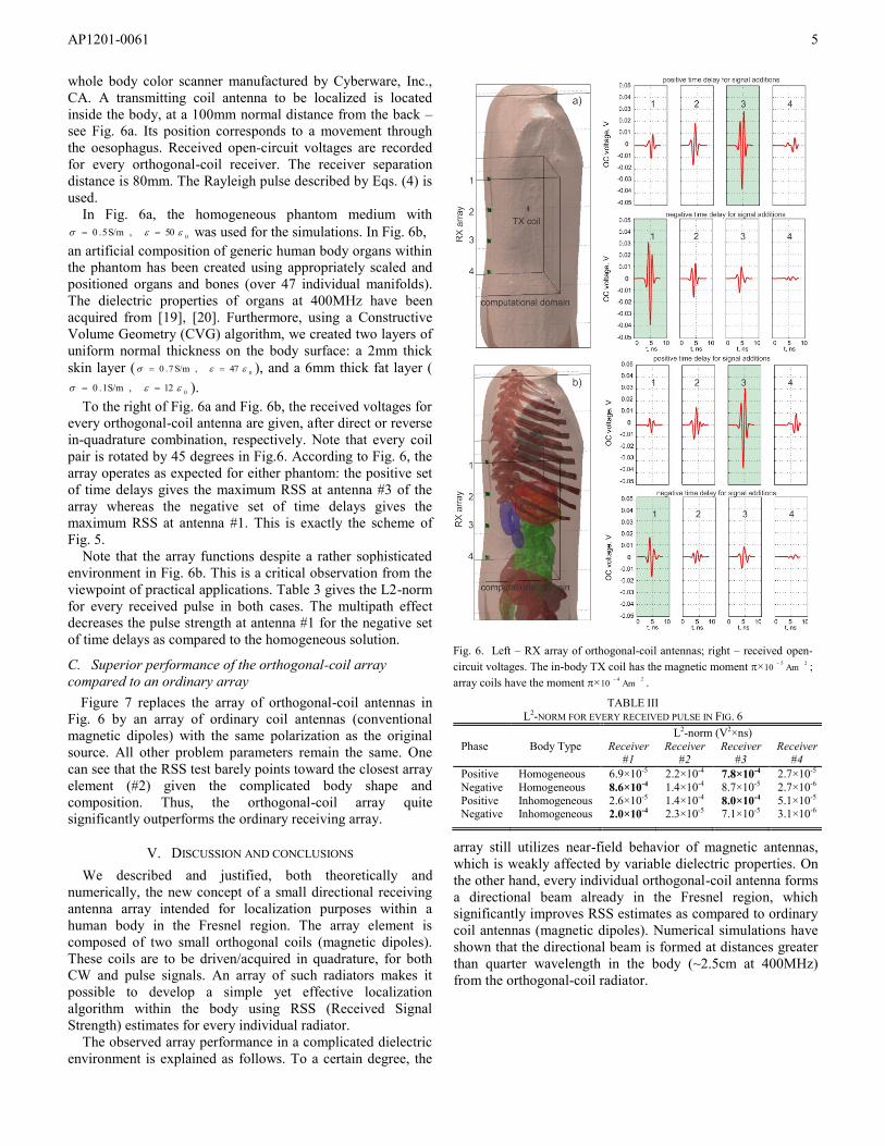
whole body color scanner manufactured by Cyberware, Inc.,
CA. A transmitting coil antenna to be localized is located
inside the body, at a 100mm normal distance from the back –
see Fig. 6a. Its position corresponds to a movement through
the oesophagus. Received open-circuit voltages are recorded
for every orthogonal-coil receiver. The receiver separation
distance is 80mm. The Rayleigh pulse described by Eqs. (4) is
used.
In Fig. 6a, the homogeneous phantom medium with
050,S/m5.0 was used for the simulations. In Fig. 6b,
an artificial composition of generic human body organs within
the phantom has been created using appropriately scaled and
positioned organs and bones (over 47 individual manifolds).
The dielectric properties of organs at 400MHz have been
acquired from [19], [20]. Furthermore, using a Constructive
Volume Geometry (CVG) algorithm, we created two layers of
uniform normal thickness on the body surface: a 2mm thick
skin layer ( 047,S/m7.0 ), and a 6mm thick fat layer (
012,S/m1.0 ).
To the right of Fig. 6a and Fig. 6b, the received voltages for
every orthogonal-coil antenna are given, after direct or reverse
in-quadrature combination, respectively. Note that every coil
pair is rotated by 45 degrees in Fig.6. According to Fig. 6, the
array operates as expected for either phantom: the positive set
of time delays gives the maximum RSS at antenna #3 of the
array whereas the negative set of time delays gives the
maximum RSS at antenna #1. This is exactly the scheme of
Fig. 5.
Note that the array functions despite a rather sophisticated
environment in Fig. 6b. This is a critical observation from the
viewpoint of practical applications. Table 3 gives the L2-norm
for every received pulse in both cases. The multipath effect
decreases the pulse strength at antenna #1 for the negative set
of time delays as compared to the homogeneous solution.
C. Superior performance of the orthogonal-coil array
compared to an ordinary array
Figure 7 replaces the array of orthogonal-coil antennas in
Fig. 6 by an array of ordinary coil antennas (conventional
magnetic dipoles) with the same polarization as the original
source. All other problem parameters remain the same. One
can see that the RSS test barely points toward the closest array
element (#2) given the complicated body shape and
composition. Thus, the orthogonal-coil array quite
significantly outperforms the ordinary receiving array.
V. DISCUSSION AND CONCLUSIONS
We described and justified, both theoretically and
numerically, the new concept of a small directional receiving
antenna array intended for localization purposes within a
human body in the Fresnel region. The array element is
composed of two small orthogonal coils (magnetic dipoles).
These coils are to be driven/acquired in quadrature, for both
CW and pulse signals. An array of such radiators makes it
possible to develop a simple yet effective localization
algorithm within the body using RSS (Received Signal
Strength) estimates for every individual radiator.
The observed array performance in a complicated dielectric
environment is explained as follows. To a certain degree, the
array still utilizes near-field behavior of magnetic antennas,
which is weakly affected by variable dielectric properties. On
the other hand, every individual orthogonal-coil antenna forms
a directional beam already in the Fresnel region, which
significantly improves RSS estimates as compared to ordinary
coil antennas (magnetic dipoles). Numerical simulations have
shown that the directional beam is formed at distances greater
than quarter wavelength in the body (~2.5cm at 400MHz)
from the orthogonal-coil radiator.
Fig. 6. Left – RX array of orthogonal-coil antennas; right – received open-
circuit voltages. The in-body TX coil has the magnetic moment ×25
Am10
;
array coils have the moment ×24
Am10
.
TABLE III
L2-NORM FOR EVERY RECEIVED PULSE IN FIG. 6
Phase Body Type
L2-norm (V2×ns)
Receiver #1
Receiver #2
Receiver #3
Receiver #4
Positive Homogeneous 6.9×10⁻⁵ 2.2×10⁻⁴ 7.8×10⁻⁴ 2.7×10⁻⁵
Negative Homogeneous 8.6×10⁻⁴ 1.4×10⁻⁴ 8.7×10⁻⁵ 2.7×10⁻⁶
Positive Inhomogeneous 2.6×10⁻⁵ 1.4×10⁻⁴ 8.0×10⁻⁴ 5.1×10⁻⁵ Negative Inhomogeneous 2.0×10⁻⁴ 2.3×10⁻⁵ 7.1×10⁻⁵ 3.1×10⁻⁶ 0.73
AP1201-0061
6
ACKNOWLEDGMENT
The authors would like to thank Dr. Bryan McLaughlin of
Draper Laboratory, MA for useful discussion and opinions on
this subject.
REFERENCES
[1] J. R. Wait, “The magnetic dipole antenna immersed in conducting
medium,” Proceedings of the I.R.E., vol. 40, no. 10, 1952, pp. 1244 – 1245.
[2] J. R. Wait, “Mutual electromagnetic coupling of loops over a
homogeneous ground,” Geophysics, vol. 20, 1955, pp. 630-637. [3] J. R. Wait and D. A. Hill, “Transient signals from a buried magnetic
dipole, J. Appl. Phys., vol. 42, no 10, 1971, pp. 3866-3869.
[4] D. A. Hill and J. R. Wait, “Electromagnetic transient response of a small wire loop buried in a homogeneous conducting Earth,” Pageoph, vol.
105, no. IV, 1973, pp. 869-878.
[5] A. Baños, Jr., Dipole Radiation on the Presence of a Conducting Half-Space, Pergamon Press, Oxford, UK, 1966.
[6] G. S. Smith, “Directive properties of antennas for transmission into a
material half-space,” IEEE Trans. Antennas Prop., vol. AP-32, no. 3, pp. 232-246, March 1984.
[7] W. Lukosz and R. E. Kunz, “Light emission by magnetic and electric
dipoles close to a plane dielectric interface. I. Total radiated power,” J. Optical Soc. Am., vol. 67, no. 12, pp. 1607-1615, Dec. 1977.
[8] W. Lukosz and R. E. Kunz, “Light emission by magnetic and electric
dipoles close to a plane dielectric interface. II. Radiation patterns of perpendicular oriented dipoles,” J. Optical Soc. Am., vol. 67, no. 12, pp.
1615-1619, Dec. 1977.
[9] N. Engheta, C. H. Papas, and C. Elachi, “Radiation patterns of interfacial dipole antennas,” Radio Sci., vol. 17, pp. 1557-1566, Nov.-Dec. 1982.
[10] E. C. Slob and J. T. Fokkema, “Interfacial dipoles and radiated energy,”
Subsurface Sensing Technologies and Applications, vol. 3, No. 4, October 2002, pp. 347-367.
[11] L. N. An and G. S. Smith, "The horizontal circular-loop antenna near a
planar interface," Radio Sci., vol. 17. pp. 483-502, May-June 1982. [12] G. S. Smith and L. N. An, "Loop antennas for directive transmission into
a material half space," Radio Sci., vol. 18, pp. 664-674, Sept.-Oct. 1983.
[13] S. J. Radzevicius, Chi-Chih Chen, L. Peters Jr., and J. J. Daniels, “Near-field dipole radiation dynamics through FDTD modeling,” Journal of
Applied Geophysics, vol.52, 2003, pp. 75– 91.
[14] Arthur D. Yaghjian, Private Communication. Jan. 5th 2011.
[15] G. Noetscher, S. Makarov, and N. Clow, “Modeling accuracy and
features of body-area networks with out-of-body Antennas at 402 MHz,” IEEE Antennas and Propagation Magazine, vol. 53, no. 4, pp. 118-143.
[16] G. Noetscher, Xu Yang, and S. Makarov, “Accuracy of point source
models with coincident phase centers in a cubic FDTD grid for arbitrary source orientation,” USNC-URSI National Radio Science Meeting,
Boulder, Co, Jan. 2012.
[17] G. Noetscher, Y. Xu, and S. N. Makarov, “Body area antenna link modeling using MATLAB® engine,” 35th Antenna Applications
Symposium, Monticello, IL, Sep. 19-22, 2011.
[18] S. N. Makarov, “Directional in-quadrature orthogonal-coil antenna and an array thereof for localization purposes within a human body,” Prov.
Patent Appl. 61582812, filed Jan. 3rd 2012.
[19] J. Kim and Y. Rahmat-Samii, “Implanted antennas inside a human body: simulations, designs, and characterizations,” IEEE Trans. Microwave
Theory Techniques, vol. 52, no. 8, Aug. 2004, pp. 1934-1943.
[20] Dielectric Properties of Body Tissues. Italian National Research Council. Online: http://niremf.ifac.cnr.it/tissprop/
Fig. 7. Left – RX array of orthogonal-coil antennas; right – received open-
circuit voltages. The in-body TX coil has the magnetic moment ×25
Am10
;
array coils have the moment ×24
Am10
.
![The DPC-Hysteresis Model in Two-Dimensional Magnetostatic ...PC-M2-3]_132.pdfThe DPC-Hysteresis Model in Two-Dimensional Magnetostatic Finite Element Analysis Stephan Willerich1, Christian](https://img.pdfslide.net/doc/110x75/5e4771de58ae235e311bac99/the-dpc-hysteresis-model-in-two-dimensional-magnetostatic-pc-m2-3132pdf-the.jpg)