Embed Size (px)
Citation preview
RE 24751 edition 2018-12 Bosch Rexroth AG
Directional spool valves pilot-operated with hydraulic or electro-hydraulic actuation
Features
43- 42- or 32-way version Types of actuation (internal or external pilot control)
ndash Electro-hydraulic (type WEH) ndash Hydraulic (type WH)
For subplate mounting Porting pattern according to ISO 4401 and
NFPA T351 R2 Spring or pressure centering spring end position or
hydraulic end position Wet-pin DC or AC solenoids optional Electrical connection as individual or central connection Optional versions
ndash Manual override ndash Switching time adjustment ndash Preload valve in channel P of the main valve ndash Stroke setting andor spool position monitoring
Contents
Features 1Ordering code 2 hellip 4Symbols 5 9Function section 10 12Pilot oil supply 13 14Technical data 15 18Characteristic curves performance limits 19 hellip 28Dimensions 29 hellip 35Stroke setting mounting options 36 37Switching time adjustment 38Pressure reducing valve D3 38Preload valve 39Project planning information 40Further information 40
Size 10 hellip 32 Component series 4X 6X 7X Maximum operating pressure 350bar [5076psi] Maximum flow 1100 lmin [290 US gpm]
RE 24751thinspEdition 2018-12Replaces 2016-06
H8051+8052
WEH and WH
Inhalt
Features 1Contents 1Ordering code 2Ordering code 3Ordering code 4Symbols 2 spool positions 5Symbols 3 spool positions 6Symbols for valves with 2 spool positions 7Symbols for valves with 2 spool positions 8Symbols for valves with 3 spool positions 8Symbols for valves with 3 spool positions 9Function section Type WEH 10Function section Type WH 11Function section Type WEHhellipH 12Pilot oil supply (schematic illustration) 13Pilot oil supply 14Technical data (For application outside these values please consult us) 15Technical data (For applications outside these parameters please consult us) 16Technical data (For application outside these values please consult us) 17Switching times 18Characteristic curves NG10 (measured with HLP46 ϑOil = 40 plusmn5degC [104 plusmn9degF]) 19Performance limits NG10 (measured with HLP46 ϑOil = 40 plusmn5degC [104 plusmn9degF]) 19Characteristic curves NG16 (measured with HLP46 ϑOil = 40 plusmn5 degC [104 plusmn9 degF]) 20Performance limits NG16 (measured with HLP46 ϑOil = 40 plusmn5 degC [104 plusmn9 degF]) 21Characteristic curves NG25 (WH 22) (measured with HLP46 ϑOil = 40 plusmn5 degC [104 plusmn9 degF]) 22Performance limits NG25 (WH 22) (measured with HLP46 ϑOil = 40 plusmn5 degC [104 plusmn9 degF]) 23Characteristic curves NG25 (WH 25) (measured with HLP46 ϑOil = 40 plusmn5 degC [104 plusmn9 degF]) 24Performance limits NG25 (WH 25) (measured with HLP46 ϑOil = 40 plusmn5 degC [104 plusmn9 degF]) 25Characteristic curves NG32 (measured with HLP46 ϑOil = 40 plusmn5 degC [104 plusmn9 degF]) 26Performance limits NG32 (measured with HLP46 ϑOil = 40 plusmn5 degC [104 plusmn9 degF]) 27Performance limits important information 28Dimensions NG10 (dimensions in mm [inch]) 29Dimensions NG16 (dimensions in mm [inch]) 30Dimensions NG25 (WH 22) (dimensions in mm [inch]) 31Dimensions NG25 (WH 25) (dimensions in mm [inch]) 32Dimensions NG32 (dimensions in mm [inch]) 33Dimensions 34Dimensions 35Stroke setting mounting options (dimensions in mm [inch]) 36Stroke setting mounting options (dimensions in mm [inch]) 37Switching time adjustment 38Pressure reducing valve D3 38Preload valve (not for NG10) 39Project planning information 40Further information 40
240 WEH WH | Directional spool valve
Bosch Rexroth AG RE 24751 edition 2018-12
Ordering code
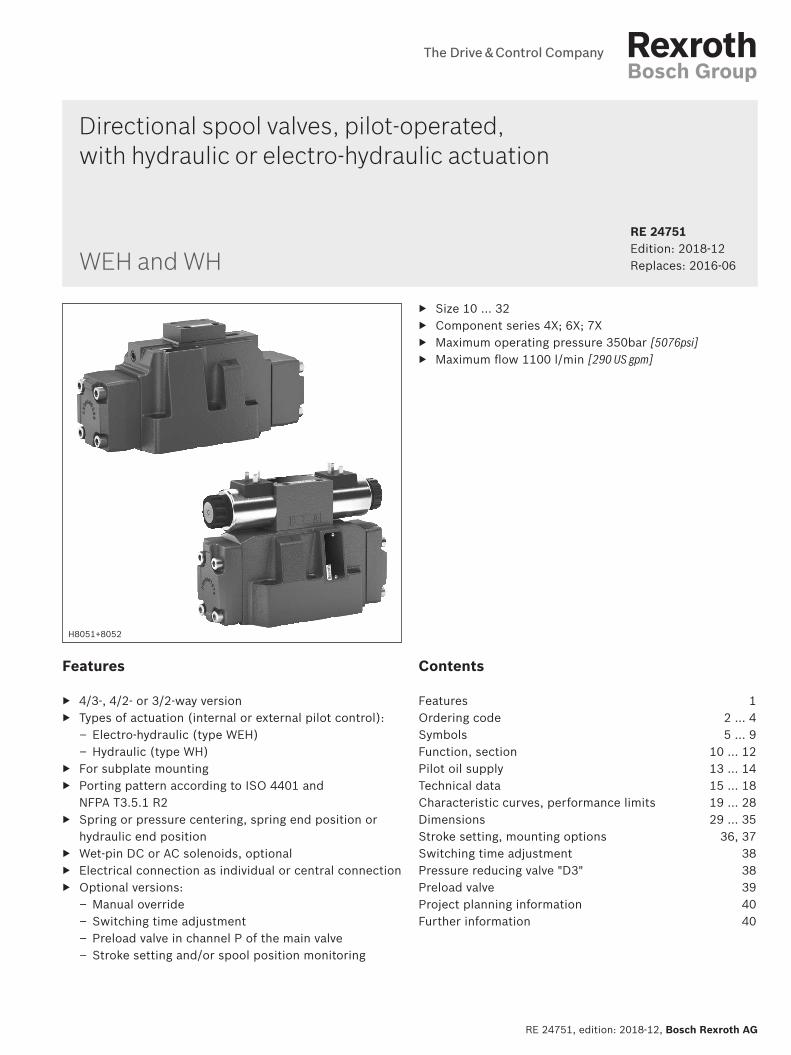
01 Up to 280 bar no codeUp to 350 bar H ndash
02 3-way version 34-way version 4
Types of actuation03 Electro-hydraulic WEH
Hydraulic WH
Size04 NG10 10
NG16 16NG25 (version WH 22) 22NG25 (version WH 25) 25NG32 32
Spool return in the main valve05 By means of springs no code
Hydraulic 1) H
06 For symbols see page 5 and 6
07 Component series 40 hellip 49 (40 hellip 49 unchanged installation and connection dimension) ndash NG10 4XComponent series 60 hellip 69 (60 hellip 69 unchanged installation and connection dimension) ndash NG25 (WH 25) and NG32 6XComponent series 70 hellip 79 (70 hellip 79 unchanged installation and connection dimension) ndash NG16 (from series 72) and NG25 (WH 22)
7X
Control spool return in the pilot control valve with 2 spool positions and 2 solenoids (only possible with symbols C D K Z and hydraulic control spool return in the main valve)
08 With spring return no codeWithout spring return OWithout spring return with detent 2) OF
Pilot control valve (2)
09 High-power valve (data sheet 23178) 6E
10 Direct voltage 24 V 2) G24Alternating voltage 230 V 5060 Hz 2) W230For other voltages frequencies and electric data see data sheet 23178
11 Without manual override no codeWith manual override NWith concealed manual override N9
Pilot oil flow12 External pilot oil supply external pilot oil return 3) no code
Internal pilot oil supply external pilot oil return 3 4) EInternal pilot oil supply internal pilot oil return 4) ETExternal pilot oil supply internal pilot oil return 3) T(For type WH only no code version ET and T with 3-spool position valve pressure-centered only possible if ppilot ge 2 x ptank + ppilot min)
01 02 03 04 05 06 07 08 09 10 11 12 13 14 15 16 17 18 19 20 21 22
Directional spool valve | WEH WH 340
RE 24751 edition 2018-12 Bosch Rexroth AG
Ordering code
01 02 03 04 05 06 07 08 09 10 11 12 13 14 15 16 17 18 19 20 21 22
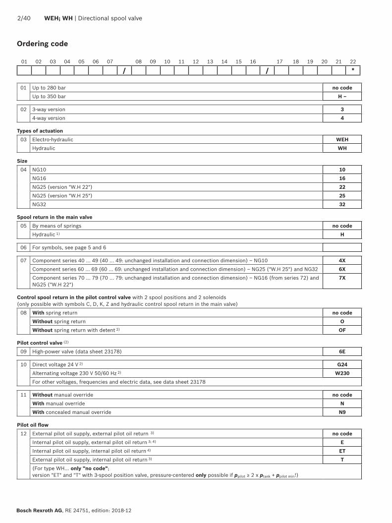
Switching time adjustment13 Without switching time adjustment no code
Switching time adjustment as supply control SSwitching time adjustment as discharge control S2
Corrosion resistance (outside)
14 None (valve housing primed) no codeImproved corrosion protection (240 h salt spray test according to EN ISO 9227) J3
Electrical connection 2)
15 Individual connectionWithout mating connector connector DIN EN 175301-803 K4 6)
For further electrical connections see data sheet 23178 and 08010
Spool position monitoring16 Without position switch no code
Monitored spool position a QMAG24Monitored spool position b QMBG24Monitored spool position a and b QMABG24Monitored rest position QM0G24For more information see data sheet 24830
Stroke setting17 For ordering code see page 36 and 37
Throttle insert 2)
18 Without throttle insert no codeThrottle Oslash 08 mm [00315 inch] B08Throttle Oslash 10 mm [00394 inch] B10Throttle Oslash 12 mm [00472 inch] B12Throttle Oslash 15 mm [00591 inch] B15Throttle Oslash 20 mm [00787 inch] B20Throttle Oslash 25 mm [00984 inch] B25
Preload valve (not for NG10) 2)
19 Without preload valve no codeWith preload valve (pc = 45 bar [65 psi]) P45
20 Without pressure reducing valve no codeWith pressure reducing valve D3 5)
Seal material (Observe compatibility of seals with hydraulic fluid used see page xx)
21 NBR seals no codeFKM seals VObserve compatibility of seals with hydraulic fluid used (other seals on request)
22 For further information see the plain text
ppilot = pilot pressureppilot min = minimum pilot pressureptank = tank pressurepc = cracking pressure
Explanation of the footnotes see page 4
440 WEH WH | Directional spool valve
Bosch Rexroth AG RE 24751 edition 2018-12
1) 2 spool positions (hydraulic end position) only symbols C D K Z Y
3 switching positions (hydraulically centered) only NG16 NG25 (4WH 25) and NG32
2) Only with electro-hydraulic actuation (type WEH)3) Pilot oil supply X or return Y external
The maximum admissible operating parameters of the pilot control valve must be observed (see data sheet 23178)
Minimum pilot pressure please observe page 16 Maximum pilot pressure please observe page 16
4) Pilot oil supply internal (version ET and E) Minimum pilot pressure please observe page 16 Maximum pilot pressure please observe page 16
With a higher pilot pressure use of a pressure reducing valve D3 is required (if it is not used pilot pressure = operating pressure at the port)
In order to prevent inadmissibly high pressure peaks a B10 throttle insert has to be provided in port P of the pilot control valve (see page 14)
In connection with version H the pressure reducing valve D3 is also required
5) Only in connection with the B10 throttle insert6) Mating connectors separate order see data sheet 23178
Ordering code
C
D
K
Z
A1)
Y
B1)
A B
P
a b
T
A B
P
a b
T
Directional spool valve | WEH WH 540
RE 24751 edition 2018-12 Bosch Rexroth AG
Symbols 2 spool positions
1) Only for NG10 and 25 (4WH 22) with 32-way version if operating pressure gt tank pressure port T is to be used as a leakage port
2) Example Symbol E with actuating side a rarr ordering code EA
3) Symbol S only for NG16
Ordering code Type of actuation
Symbol Spool return Type WH (hydraulic) Type WEH (electro-hydraulic)
A 1) C D K Z
a b
A B
P Ta X b Y
a b
A
a b
B
P T
H a b
A B
P Ta X b Y a b
A
a b
B
P T
HO a b
A
a b
B
P T
HOF a b
A
a b
B
P T
B 1) Y
a ba X b Y
A B
P T
a b
A
a b
B
P T
H a b
A
a b
B
P T
L
M
E2)
F
G
H
J
P
R
S3)
U
V
W
Q
T
640 WEH WH | Directional spool valve
Bosch Rexroth AG RE 24751 edition 2018-12
Symbols 3 spool positions
Ordering code Type of actuation
Symbol Actuating side Spool return Type WH (hydraulic) Type WEH (electro-hydraulic)
E F G H J L M P Q R S T
U V W
a b
A B
P Ta X b Y0 a b
A
a b
B
P T
0
A a
A B
P Ta 0
B b
A B
P Tb0
H a b
A B
P Ta Y b X0 a b
A
a b
B
P T
0
HA a
A B
P Ta 0
HB b
A B
P Tb0
Explanation of the footnotes see page 5
Directional spool valve | WEH WH 740
RE 24751 edition 2018-12 Bosch Rexroth AG
Valve with spring end position Valve with hydraulic end position
X =
ext
erna
l Y
= ex
tern
al
Type WEHhellip Type WEH H Type WEH HO Type WEH HOF
A B
a ba b
PX YT
A B
P T
a ba
a b
X b Y
P TYXA B
a ba b
PX YT
A B
P T
a ba
a b
X b Y
P TYXA B
a ba b
P T
A B
P T
a ba X b Y
P TYX
X Y
a b
A B
a ba b
P T
A B
P T
a ba X b Y
P TYX
X Y
a b
X =
inte
rnal
Y =
ext
erna
l
Type WEHhelliphellipEhellip Type WEH HhellipEhellip Type WEH HOhellipEhellip Type WEH HOFhellipEhellip
A B
A B
P T
a ba X b Y
P TYX
a ba b
P T Y
a b
A B
A B
P T
a ba X b Y
P TYX
a ba b
P T Y
a b
A B
A B
P T
a ba X b Y
P TYX
a ba b
P T Y
a b
A B
A B
P T
a ba X b Y
P TYX
a ba b
P T Y
a b
X =
inte
rnal
Y =
inte
rnal
Type WEHhelliphellipEThellip Type WEH HhellipEThellip Type WEH HOhellipEThellip Type WEH HOFhellipEThellip
A B
A B
P T
a ba X b Y
P TYX
a ba b
P T
a b
A B
A B
P T
a ba X b Y
P TYX
a ba b
P T
a b
A B
A B
P T
a ba X b Y
P TYX
a ba b
P T
a b
A B
A B
P T
a ba X b Y
P TYX
a ba b
P T
a b
Symbols for valves with 2 spool positions
840 WEH WH | Directional spool valve
Bosch Rexroth AG RE 24751 edition 2018-12
Valve with spring end position Valve with hydraulic end position
X =
ext
erna
l Y
= in
tern
al
Type WEHhelliphellipThellip Type WEH HhellipThellip Type WEH HOhellipThellip Type WEH HOFhellipThellip
A B
P T
a ba X b Y
P TYX
A B
a ba b
P TX
a b
A B
P T
a ba X b Y
P TYX
A B
a ba b
P TX
a b
A B
P T
a ba X b Y
P TYX
A
a ba b
PX
B
T
a b
A B
P T
a ba X b Y
P TYX
A B
a ba b
P TX
a b
Symbols for valves with 2 spool positions
Symbols for valves with 3 spool positions
Valve with spring-centered zero position Valve with pressure-centered zero position only NG16 25 (WH 25) and 32
X =
ext
erna
l Y
= ex
tern
al
Type WEHhelliphellip Type WEH HhellipA B
a 0a
a
a b
b
X b Yb
A B
a 0 b
PX YT
P TX Y
A B
a 0a X b Y
b
P TX YLA B
a 0 b
P TL
a
a b
b
X Y
X =
inte
rnal
Y =
ext
erna
l
Type WEHhelliphellipEhellip Type WEH HhellipEhellipA B
a 0a X b Y
b
A B
a 0 b
P T Y
P TX Y
a
a b
b
A B
a 0a X b Y
b
P TX YLA B
a 0 b
P T YL
a
a b
b
Directional spool valve | WEH WH 940
RE 24751 edition 2018-12 Bosch Rexroth AG
Valve with spring-centered zero position Valve with pressure-centered zero position only NG16 25 (WH 25) and 32
X =
inte
rnal
Y =
inte
rnal
Type WEHhelliphellipEThellip Type WEH HhellipEThellipA B
a 0a X b Y
b
A B
a 0 b
P T
P TX Y
a
a b
b
A B
a 0a X b Y
b
P TX YLA B
a 0 b
P TL
a
a b
b
X Y
X =
ext
erna
l Y
= in
tern
al
Type WEHhelliphellipThellip Type WEH HhellipThellipA B
a 0a X b Y
b
A B
a 0 b
P TX
P TX Y
a
a b
b
A B
a 0a X b Y
b
P TX YLA B
a 0 b
P T YL
a
a b
b
Symbols for valves with 3 spool positions
Notice3-spool position valves pressure-centered preferably with external pilot oil supply andor return (no code E)For preconditions for internal pilot oil supply andor return (ET T) see page 4 and 15
B A4 10
7
6
31
9
51
1
2
32
9
52
8
ldquobrdquo ldquoardquo
T A P B X Y
1040 WEH WH | Directional spool valve
Bosch Rexroth AG RE 24751 edition 2018-12
Function section Type WEH
Directional valves type WEHhellipThe valve type WEH is a directional spool valve with electro-hydraulic actuation It controls the start stop and direction of a flowThe directional valve basically consists of the main valve with housing (1) the main control spool (2) one or two return springs (31) and (32) as well as the pilot control valve (4) with one or two solenoids a (51) andor b (52)The main control spool (2) in the main valve is held in the zero or initial position by the springs or by means of pressurization In the initial position the two spring chambers (6) and (8) are connected with the tank in a depressurized form via the pilot control valve (4) Via the control line (7) the pilot control valve is supplied with pilot oil Supply can be implemented internally or externally (externally via port X) Upon actuation of the pilot control valve eg solenoid a the pilot control spool (10) is moved to the left and thus the spring chamber (8) is pressurized with pilot pressure The spring chamber (6) remains depressurizedThe pilot pressure acts on the left side of the main control spool (2) and moves it against the spring (31) This connects port P with B and A with T in the main valve
On switching off of solenoid the pilot control spool (10) returns to its initial position (except impulse spool) The spring chamber (8) is unloaded to the tankThe pilot oil return is implemented internally (via channel T) or externally (via channel Y)An optional manual override (9) allows for moving of the pilot control spool (10) without solenoid energization
NoticesThe return springs (31) and (32) in the spring chambers (6) and (8) hold the main control spool (2) in central position without pilot pressure even with for example vertical valve positioningDue to the design principle internal leakage is inherent to the valves which may increase over the life cycle
For pilot oil supply see page 13 and 14
7
6
31
1
2
32
8
T A P B X Y
11
Directional spool valve | WEH WH 1140
RE 24751 edition 2018-12 Bosch Rexroth AG
For pilot oil supply see page 13 and 14
Directional valves type WHhellipValve type WH is a directional spool valve with hydraulic actuation It controls the start stop and direction of a flowThe directional valve basically consists of the valve housing (1) the main control spool (2) one or two return springs (31) and (32) at valves with spring return or spring centering as well as the diversion plate (11)The main control spool (2) is actuated directly by pressurizationThe main control spool (2) is held in zero or initial position by springs or pressurization Pilot oil supply and return are external (see page 13)
43 directional valve with spring centering of the control spoolWith this version the main control spool (2) is held in zero position by two return springs (31) and (32) The two spring chambers (6) and (8) are connected to ports X and Y via the diversion plate (11)With pilot pressure loading of one of the two front sides of the main control spool (2) the spool is moved to the switching position In the valve the required ports are connected in this way The spring on the opposite side returns the spool to the zero or initial position at pressure relief of the pressurized control spool area
Function section Type WH
B A4 10
7
6
31
9
51
1
2
32
9
52
8
ldquobrdquo ldquoardquo
T A P B X Y12
L
1240 WEH WH | Directional spool valve
Bosch Rexroth AG RE 24751 edition 2018-12
43 directional valve with pressure centering of the main control spool type WEHhellipHThe main control spool (2) in the main valve is kept in the zero position by pressurization of the two front faces One centering bush (12) rests on the housing and fixes the control spool positionBy pressure relief of one front face the main control spool (2) is moved to the switching positionThe unloaded control spool face displaces the returning pilot oil into channel Y (external) via the pilot control valve
NoticesThe springs (31) and (32) do not have a return function in this version They hold the main control spool (2) in central position in the depressurized condition and with horizontal installation
Function section Type WEHhellipH
P
P
T
T 1
2P
P
T
T 1
2
P
P
T
T
1
2
P
P
T
T
3
1
P
P
T
T
1 2
Directional spool valve | WEH WH 1340
RE 24751 edition 2018-12 Bosch Rexroth AG
Pilot oil supply (schematic illustration)
Further explanations on page 14
NG10 NG16
Pilot oil supplyexternal 2 3 closedinternal 2 3 open
Pilot oil returnexternal 1 closedinternal 1 open
NG25 (WH 22) NG25 (WH 25)
NG32
1 Plug screw M6 according to DIN 906 wrench size 3 ndash pilot oil return
2 Plug screw M6 according to DIN 906 wrench size 3 ndash pilot oil supply
3 Plug screw M12 x 15 according DIN 906 wrench size 6 ndash pilot oil supply
P
3
4
5
1440 WEH WH | Directional spool valve
Bosch Rexroth AG RE 24751 edition 2018-12
Type WHhellipThe pilot oil supply and return is implemented externally via channel X and Y
Type WEHThe pilot oil supply is implemented externally - via channel X - from a separate pressure supplyThe pilot oil return is implemented externally - via channel Y - into the tank
Type WEHhellipEhellipThe pilot oil supply is implemented internally from channel P of the main valve (see page 15 footnotes 5) and 6))The pilot oil return is implemented externally - via channel Y - into the tank In the subplate port X is closed
Type WEHhellipEThellipThe pilot oil supply is implemented internally from channel P of the main valveThe pilot oil return is implemented internally - via channel T - into the tank In the subplate ports X and Y are closed
Type WEHhellipThellipThe pilot oil supply is implemented externally - via channel X - from a separate pressure supplyThe pilot oil return is implemented internally - via channel T - into the tank In the subplate port Y is closed
Throttle insertUse of the throttle insert (5) is necessary if the pilot oil supply in channel P of the pilot control valve is to be limited (see below)The throttle insert (5) is inserted in channel P of the pilot control valve
Pilot oil supply
NoticesThe modification of the pilot oil supply may only be performed by authorized specialists or at the factory
Pilot oil supply X or return Y external ndash The maximum admissible operating parameters of the pilot control valve must be observed (see data sheet 23178)
ndash Maximum pilot pressure please observe page 16 Pilot oil supply internal (version ET and E)
ndash Minimum pilot pressure please observe page 15 ndash In order to prevent inadmissibly high pressure peaks a B10 throttle insert has to be provided in port P of the pilot control valve (see above)
ndash In connection with version H the pressure reducing valve D3 (see page 38) is also required
3 Pilot control valve4 Main valve5 Throttle insert
Directional spool valve | WEH WH 1540
RE 24751 edition 2018-12 Bosch Rexroth AG
Technical data (For application outside these values please consult us)
generalSizes NG 10 16 25
WH 2225
WH 2532
Weight approx Valve with one solenoid kg [lbs] 64 [141] 85 [187] 115 [253] 176 [388] 176 [388]
Valve with two solenoids spring-centered kg [lbs] 68 [150] 89 [196] 119 [262] 190 [419] 410 [904]
Valve with two solenoids pressure-centered kg [lbs] 68 [150] 89 [196] 119 [262] 190 [419] 410 [904]
Valve witch hydraulic actuation (type WH) kg [lbs] 55 [121] 73 [161] 105 [231] 165 [364] 395 [871]
Switching time adjustment S and S2 kg [lbs] 08 [18] 08 [18] 08 [18] 08 [18] 08 [18]
Pressure reducing valve D3 kg [lbs] 04 [09] 04 [09] 04 [09] 04 [09] 04 [09]
Installation position Any horizontal with valves with hydraulic control spool return H and symbol A B C D K Z Y With suspended installation higher sensitivity to contamination ndash horizontal is recommended
Ambient temperature range
Standard version degC [degF] ndash20 hellip +50 [ndash4 hellip +122] (NBR seals)ndash15 hellip +70 [+5 hellip +122] (FKM seals)
Version for HFC hydraulic fluid degC [degF] ndash20 hellip +50 [ndash4 hellip +122]
Storage temperature range degC [degF] +5 hellip +40 [+41 hellip +104]
Surface protection (valve body) Coating layer thickness max 100 microm
MTTFd values according to EN ISO 13849 Years 100 (type WEH) 150 (type WH) (for further details see data sheet 08012)
hydraulicMaximum operating pressure
Port P A B Type WH bar [psi] 280 [4061] 280 [4061] 280 [4061] 280 [4061] 280 [4061]
Type H-WH bar [psi] 350 [5076]
350 [5076]
350 [5076]
350 [5076]
350 [5076]
Port T External pilot oil return Y
Type WH bar [psi] 280 [4061]
250 [3626] 250 [3626] 250 [3626] 250 [3626]
Type H-WH 315 [4568] 250 [3626] 250 [3626] 250 [3626] 250 [3626]
Internal pilot oil return Y
1)Type H-WEH WEH bar [psi] 210 [3046] with direct voltage
160 [2320] with alternating voltage
Port Y External pilot oil return Type H-WEH WEH bar [psi] 210 [3046] with direct voltage 160 [2320] with alternating voltage
Type WH H-WH bar [psi] 250 [3626] 250 [3626] 210 [3046] 250 [3626] 250 [3626]
Hydraulic fluid see table on page 15
Hydraulic fluid temperature range (at the valve working ports) 3)
degC [degF] ndash20 hellip +80 [ndash4 hellip +176] (NBR seals)ndash15 hellip +80 [+5 hellip +176] (FKM seals)ndash20 hellip +50 [ndash4 hellip +122] (HFC hydraulic fluid)
Viscosity range mm2s [SUS] 28 hellip 500 [35 hellip 2320]
Maximum admissible degree of contamination of the hydraulic fluid Cleanliness class according to ISO 4406 (c)
Class 201815 2)
1) As a 3-spool position valve pressure-centered only possible if ppilot ge 2 x ptank + ppilot min
2) The cleanliness classes specified for the components must be adhered to in hydraulic systems Effective filtration prevents faults and simultaneously increases the life cycle of the components
For selecting the filters see wwwboschrexrothcomfilter3) If type WH is used in potentially explosion-proof areas see
data sheet 07011
1640 WEH WH | Directional spool valve
Bosch Rexroth AG RE 24751 edition 2018-12
Technical data (For applications outside these parameters please consult us)
hydraulicSize NG 10 16 25
WH 2225
WH 2532
Maximum pilot pressure 4) bar [psi] 250 [3626]
250 [3626]
210 [3046]
250 [3626]
250 [3626]
Minimum pilot pressure
External pilot oil supply X (all symbols) internal pilot oil supply (only symbols D K E J L M Q R U W)
3-spool position valve spring-centered Type H-WHhellip bar [psi] 12 [174] 14 [203] 125 [181] 13 [188] 85 [123]
Type WH bar [psi] 12 [174] 14 [203] 105 [152] 13 [188] 85 [123]
3-spool position valve pressure-centered bar [psi] ndash 14 [203] ndash 18 [261] 85 [123]
2-spool position valve with spring end position
Type H-WH bar [psi] 10 [145] 14 [203] 14 [203] 13 [188] 10 [145]
Type WH bar [psi] 10 [145] 14 [203] 11 [159] 13 [188] 10 [145]
2-spool position valve with hydraulic end position bar [psi] 7 [101] 14 [203] 8 [116] 8 [116] 5 [72]
Internal pilot oil supply X (only type WEH) (with symbols C F G H P T V Z S 5))
bar [psi] 75 [109]
6)45 [65] 7) 45 [65] 7) 45 [65] 7) 45 [65] 7)
Free flow cross-sections in zero position with symbols Q V and W
Symbol Q A ndash T B ndash T mm2 [inch2] 13 [002] 32 [005] 78 [0121] 83 [0129] 78 [0121]
Symbol V P ndash A P ndash B mm2 [inch2] 13 [002] 32 [005] 73 [0113] 83 [0129] 73 [0113]
A ndash T B ndash T mm2 [inch2] 13 [002] 32 [005] 84 [013] 83 [0129] 84 [013]
Symbol W A ndash T B ndash T mm2 [inch2] 24 [0004] 6 [0009] 10 [0015] 14 [0022] 20 [0031]
Pilot volume for switching process
3-spool position valve spring-centered cm3 [inch3] 204 [0124]
572 [0349]
764 [0466]
142 [0866]
294 [1794]
2-spool position valve cm3 [inch3] 408 [0249]
1145 [0699]
1528 [0932]
284 [1733]
588 [3588]
3-spool position valve pressure-centered
from zero position in switching position a
Type WH cm3 [inch3] ndash 283 [0173]
ndash 715 [0436]
144 [0879]
Type WEH cm3 [inch3] ndash 283 [0173]
ndash 715 [0436]
144 [0879]
from switching position a in zero position
Type WH cm3 [inch3] ndash 572 [0349]
ndash 1418 [0865]
294 [1794]
Type WEH cm3 [inch3] ndash 29 [0177] ndash 70 [0427] 151 [0921]
from zero position in switching position b
Type WH cm3 [inch3] ndash 572 [0349]
ndash 1418 [0865]
294 [1794]
Type WEH cm3 [inch3] ndash 572 [0349]
ndash 1415 [0863]
294 [1794]
from switching position b in zero position
Type WH cm3 [inch3] ndash 855 [0522]
ndash 1988 [1213]
438 [2673]
Type WEH cm3 [inch3] ndash 283 [0173]
ndash 573 [0349]
144 [0879]
Pilot flow for shortest switching time approx lmin [US gpm] 35 [92] 35 [92] 35 [92] 35 [92] 45 [119]
Directional spool valve | WEH WH 1740
RE 24751 edition 2018-12 Bosch Rexroth AG
4) Internal pilot oil supply ndash With a higher pilot pressure use of a pressure reducing
valve D3 is required (if it is not used pilot pressure = operating pressure at the port)
ndash In connection with version H the pressure reducing valve D3 is also required
External pilot oil supply ndash Compliance with the maximum pilot pressure must be
ensured by appropriate measures (e g protection of the separate pilot oil circuit by means of a pressure relief valve)
5) Symbol S only for NG166) For symbols C F G H P T V Z an internal pilot oil supply is
only possible if the flow from P to T in the central position (for 3-spool position valve) or while crossing the central position (for 2-spool position valve) is so large that the pressure differential of P to T reaches a value of at least 75 bar [109 psi] and the pilot oil return Y is implemented externally
7) For symbols C F G J H P T V Z S 5) ndash by means of preload valve (not NG10) or correspondingly high flow (Determination of the required flow see Preload valve characteristic curves on page 39) For NG10 a check valve with a cracking pressure of 75 bar [109 psi] is to be provided in the return line to the tank The pilot oil return Y must be implemented externally
Technical data (For application outside these values please consult us)
Druckfluumlssigkeit Klassifizierung Geeignete Dichtungsmaterialien
Normen Datenblatt
Mineraloumlle HL HLP HLPD HVLP HVLPD NBR FKM DIN 51524 90220
Biologisch abbaubar wasserunloumlslich HETG FKMISO 15380
90221HEES FKM
wasserloumlslich HEPG FKM ISO 15380
Schwerentflammbar wasserfrei HFDU (Glykolbasis) FKM
ISO 12922 90222HFDU (Esterbasis) FKM
HFDR FKM
wasserhaltig HFC (Fuchs Hydrotherm 46M Renosafe 500 Petrofer Ultra Safe 620 Houghton Safe 620 Union Carbide HP5046)
NBR
ISO 12922 90223
Important information on hydraulic fluids For further information and data on the use of other hydraulic fluids please refer to the data sheets above or contact us
There may be limitations regarding the technical valve data (temperature pressure range life cycle maintenance intervals etc)
The ignition temperature of the hydraulic fluid used must be 50 K higher than the maximum surface temperature
Bio-degradable and flame-resistant ndash containing water If this hydraulic fluid is used small amounts of dissolved zinc may get into the hydraulic system
Flame-resistant ndash containing water ndash Due to increased cavitation tendency with HFC hydraulic fluids the life cycle of the component may be reduced by up to 30 as compared to the use with mineral oil HLP In order to reduce the cavitation effect it is recommended - if possible specific to the installation - to back up the return flow pressure in ports T to approx 20 of the pressure differential at the component
ndash Depending on the hydraulic fluid used the maximum ambient and hydraulic fluid temperature must not exceed 50 degC To reduce the heat input in the component a maximum duty cycle of 50 must be set for onoff valves in continuous operation (measuring time 300 s) If this is not possible due to the function an energy-reducing control of these components is recommended eg via a PWM plug-in amplifier
1840 WEH WH | Directional spool valve
Bosch Rexroth AG RE 24751 edition 2018-12
Switching times
Pilot pressure bar [psi] 70 [1015] 210 [3046] 250 [3626] Spring
ON OFF
NG10 Without throttle insert ms 40 hellip 60 ndash 40 hellip 60 20 hellip 30
With throttle insert ms 60 hellip 90 ndash 50 hellip 70 20 hellip 30
NG16 Without throttle insert ms 50 hellip 80 ndash 40 hellip 60 50 hellip 80
With throttle insert ms 110 hellip 130 ndash 80 hellip 100 50 hellip 80
NG25 (4WH 22) Without throttle insert ms 40 hellip 70 40 hellip 60 ndash 50 hellip 70
With throttle insert ms 140 hellip 160 80 hellip 110 ndash 50 hellip 70
NG25 (4WH 25) Without throttle insert ms 70 hellip 100 ndash 50 hellip 70 100 hellip 130
With throttle insert ms 200 hellip 250 ndash 120 hellip 150 100 hellip 130
NG32 Without throttle insert ms 80 hellip 130 ndash 70 hellip 100 140 hellip 160
With throttle insert ms 420 hellip 560 ndash 230 hellip 350 140 hellip 160
Notices Switching times = Contacting at the pilot control valve until start of opening of the control edge in the main valve and change in the control spool stroke by 95)
The switching times are measured according to ISO 6403 with HLP46 ϑoil = 40 degC plusmn 5 degC [104 degF plusmn9 degF] With different oil temperatures variations are possible
The switching times were determined using DC solenoids They decrease by approx 20 ms if AC solenoids are used
The shut-off of the solenoids creates voltage peaks which can be reduced by the use of suitable diodes
The switching times increase by approx 30 ms if the pressure reducing valve D3 is used
The switching times have been determined under ideal conditions and may differ in the system depending on the application conditions
6
1
10
8
6
4
2
20 40 60 80 100 120 140 1600
0
12
14
22
16
18
20
2
7
8
43
5
Directional spool valve | WEH WH 1940
RE 24751 edition 2018-12 Bosch Rexroth AG
Characteristic curves NG10 (measured with HLP46 ϑOil = 40 plusmn5degC [104 plusmn9degF])
Performance limits NG10 (measured with HLP46 ϑOil = 40 plusmn5degC [104 plusmn9degF])
Flow in lmin [US gpm] rarr
Pres
sure
diff
eren
tial i
n ba
r [p
si] rarr
∆p-qV characteristic curves
Symbol Spool position Zero positionP ndash A P ndash B A ndash T 1) B ndash T 1) A ndash T B ndash T P ndash T
E Y D Q V W Z 1 1 3 5
F 1 3 1 4 3 ndash 6
G T 4 2 4 7 ndash ndash 8
H C 3 3 1 7 1 5 5
J K 1 2 1 6
L 2 2 1 4 2 ndash ndash
M 3 3 2 5
P 3 1 2 7 ndash 5 7
R 1 2 3 ndash
U 2 2 3 6 ndash 6 ndash
A B 1 1 ndash ndash
1) The pressure differential refers to the use of port T If port T1 is additionally used the pressure differential may be lower If only port T1 is used the relations A ndash T and B ndash T may be reversed
Important notices see page 28
2-spool position valves ndash qV max in lmin [US gpm]
SymbolOperating pressure pmax in bar [psi]
70 [1015]
140 [2030]
210 [3046]
280 [4061]
350 [5076]
X external ndash spring end position in the main valve 1) (with ppilot min = 12 bar [174 psi])
C D K Y Z 160 [42] 160 [42] 160 [42] 160 [42] 160 [42]
X external ndash hydraulic end position in the main valveHC HD HK HZ HY
160 [42] 160 [42] 160 [42] 160 [42] 160 [42]
3-spool position valves ndash qV max in lmin [US gpm]
SymbolOperating pressure pmax in bar [psi]
70 [1015]
140 [2030]
210 [3046]
280 [4061]
350 [5076]
X external ndash spring-centeredE J L M Q U V W R
160 [42] 160 [42] 160 [42] 160 [42] 160 [42]
F P 160 [42] 120 [32] 100 [26] 90 [20] 90 [20]
G T 160 [42] 160 [42] 160 [42] 130 [34] 120 [32]
H 160 [42] 160 [42] 120 [32] 110 [29] 100 [26]1) If the pilot pressure fails the function of the return spring is no
longer guaranteed with the specified flow values
4
8
12
16
20
24
28
50 100 150 200 250 300
10
7
9 8
654321
0
[5][0] [10] [792]
0[0]
[50]
[75][15] [20] [25] [30] [35] [40] [45] [50] [55] [60] [65] [70]
[406]
[100]
[150]
[200]
[250]
[300]
[250]
2040 WEH WH | Directional spool valve
Bosch Rexroth AG RE 24751 edition 2018-12
Characteristic curves NG16 (measured with HLP46 ϑOil = 40 plusmn5 degC [104 plusmn9 degF])
∆p-qV characteristic curves
Flow in lmin [US gpm] rarr
Pres
sure
diff
eren
tial i
n ba
r [p
si] rarr
Symbol Spool position Zero positionP ndash A P ndash B A ndash T B ndash T P ndash T A ndash T B ndash T
D E Y 1 1 3 3
F 1 2 5 5 4 3 ndash
G 4 1 5 5 7 ndash ndash
C H 1 1 5 6 2 4 4
K J 2 2 6 6 ndash 3 ndash
L 2 2 5 4 ndash 3 ndash
M 1 1 3 4
P 2 1 3 6 5 ndash ndash
Symbol Spool position Zero positionP ndash A P ndash B A ndash T B ndash T P ndash T A ndash T B ndash T
Q 1 1 6 6
R 2 4 7 ndash
S 3 3 3 ndash 9 ndash ndash
T 4 1 5 5 7 ndash ndash
U 2 2 3 4 6
V Z 1 1 6 6 10 8 8
W 1 1 3 4
Directional spool valve | WEH WH 2140
RE 24751 edition 2018-12 Bosch Rexroth AG
Performance limits NG16 (measured with HLP46 ϑOil = 40 plusmn5 degC [104 plusmn9 degF])
2-spool position valves ndash qV max in lmin [US gpm]
SymbolOperating pressure pmax in bar [psi]
70 [1015]
140 [2030]
210 [3046]
280 [4061]
350 [5076]
X external ndash spring end position in the main valve (with ppilot min = 12 bar [174 psi])
C D K Y Z
300 [79] 300 [79] 300 [79] 300 [79] 300 [79]
X external ndash spring end position in the main valve 1)
C 300 [79] 300 [79] 300 [79] 300 [79] 300 [79]
D Y 300 [79] 270 [71] 260 [68] 250 [66] 230 [60]
K 300 [79] 250 [66] 240 [63] 230 [60] 210 [55]
Z 300 [79] 260 [68] 190 [50] 180 [47] 160 [42]
X external ndash hydraulic end position in the main valveHC HD HK HZ HY
300 [79] 300 [79] 300 [79] 300 [79] 300 [79]
3-spool position valves ndash qV max in lmin [US gpm]
SymbolOperating pressure pmax in bar [psi]
70 [1015]
140 [2030]
210 [3046]
280 [4061]
350 [5076]
X external ndash spring-centeredE H J L M Q U W R
300 [79] 300 [79] 300 [79] 300 [79] 300 [79]
F P 300 [79] 250 [66] 180 [47] 170 [45] 150 [39]
G T 300 [79] 300 [79] 240 [63] 210 [55] 190 [50]
S 300 [79] 300 [79] 300 [79] 250 [66] 220 [58]
V 300 [79] 250 [66] 210 [55] 200 [53] 180 [47]
X external ndash pressure-centered (at minimum pilot pressure of 16 bar [232 psi])
all sym-bols 2)
300 [79] 300 [79] 300 [79] 300 [79] 300 [79]
1) If the specified flow values are exceeded the function of the return spring is no longer guaranteed if the pilot pressure fails
2) With symbol V the pilot control valve is not required for flows gt160 lmin [42 US gpm]
Important notices see page 28
123
45
67
8
9
10
8
6
4
2
50 100 150 200 250 300 350 400
12
14
16
18
20
4500
[10][0] [20] [30] [40] [50] [60] [119]
0
[290]
[0]
[25]
[50]
[75]
[100]
[110][70] [80] [90] [100]
[125]
[150]
[175]
[200]
[225]
[250]
[275]
2240 WEH WH | Directional spool valve
Bosch Rexroth AG RE 24751 edition 2018-12
Characteristic curves NG25 (WH 22) (measured with HLP46 ϑOil = 40 plusmn5 degC [104 plusmn9 degF])
∆p-qV characteristic curves
Flow in lmin [US gpm] rarr
Pres
sure
diff
eren
tial i
n ba
r [p
si] rarr
Symbol Spool positionP ndash A P ndash B A ndash T B ndash T B ndash A
E D 2 2 3 5 ndash
J Q K 2 2 4 6 ndash
M W 1 1 3 5 ndash
H V C Z 1 1 4 6 ndash
F 1 2 4 5 ndash
G 3 4 5 6 ndash
R 1 2 2 ndash ndash
L 2 2 4 5 ndash
U 2 2 2 6 ndash
P 2 2 2 7 ndash
T 4 4 5 6 ndash
Symbol Zero positionA ndash T B ndash T P ndash T
F 2 ndash 4
G T ndash ndash 9
H ndash ndash 3
L 7 ndash ndash
U ndash 6 ndash
J 8 8 ndash
P ndash 4 6
V Z ndash ndash 8
Directional spool valve | WEH WH 2340
RE 24751 edition 2018-12 Bosch Rexroth AG
Performance limits NG25 (WH 22) (measured with HLP46 ϑOil = 40 plusmn5 degC [104 plusmn9 degF])
1) If the specified flow values are exceeded the function of the return spring is no longer guaranteed if the pilot pressure fails Important notices see page 28
2-spool position valves ndash qV max in lmin [US gpm]
SymbolOperating pressure pmax in bar [psi]
70 [1015]
140 [2030]
210 [3046]
280 [4061]
350 [5076]
X external ndash spring end position in the main valve (with ppilot min = 11 bar 14 bar [159 203 psi])
C D K Y Z 450 [119]
450 [119]
450 [119]
450 [119]
450 [119]
X external ndash spring end position in the main valve 1)
C 450 [119]
450 [119]
320 [84]
250 [66]
200 [53]
D Y 450 [119]
450 [119]
450 [119]
400 [105]
320 [84]
K 450 [119]
215 [57]
150 [39]
120 [32]
100 [26]
Z 350 [92]
300 [79]
290 [76]
260 [68]
160 [42]
X external ndash hydraulic end position in the main valveHC HD HK HZ HY
450 [119]
450 [119]
450 [119]
450 [119]
450 [119]
HCOhellip HDOhellip HKOhellip HZOhellip
450 [119]
450 [119]
450 [119]
450 [119]
450 [119]
HCOFhellip HDOFhellip HKOFhellip HZOFhellip
450 [119]
450 [119]
450 [119]
450 [119]
450 [119]
3-spool position valves ndash qV max in lmin [US gpm]
SymbolOperating pressure pmax in bar [psi]
70 [1015]
140 [2030]
210 [3046]
280 [4061]
350 [5076]
X external ndash spring-centered
E J L M Q U W R
450 [119]
450 [119]
450 [119]
450 [119]
450 [119]
H 450 [119]
450 [119]
300 [79]
260 [68]
230 [61]
G 400 [105]
350 [92]
250 [66]
200 [53]
180 [47]
F 450 [119]
270 [71]
175 [46]
130 [34]
110 [29]
V 450 [119]
300 [79]
240 [63]
220 [58]
160 [42]
T 400 [105]
300 [79]
240 [63]
200 [53]
160 [42]
P 450 [119]
270 [71]
180 [47]
170 [45]
110 [29]
1
2
3
4
5
6
0 100 200 300 400 500
78
600 650
10
8
6
4
2
12
14
16
18
20
22
2440 WEH WH | Directional spool valve
Bosch Rexroth AG RE 24751 edition 2018-12
Characteristic curves NG25 (WH 25) (measured with HLP46 ϑOil = 40 plusmn5 degC [104 plusmn9 degF])
∆p-qV characteristic curves
Flow in lmin [US gpm] rarr
Pres
sure
diff
eren
tial i
n ba
r [p
si] rarr
8 Symbol R spool position B ndash A
Symbol Spool position Zero positionP ndash A P ndash B A ndash T 1) B ndash T 1) A ndash T B ndash T P ndash T
E Y D 1 1 3 4
F 1 1 2 4 2 ndash 5
G T 1 1 2 5 ndash ndash 7
H 1 1 2 5 2 2 4
C 1 1 2 5
J 1 1 2 5 6 5 ndash
K 1 1 2 5
L 1 1 2 4 5 ndash ndash
M 1 1 3 4
P 1 1 3 5 ndash 3 5
Q 1 1 2 3
R 1 1 3 ndash
U 1 1 2 5 ndash 5 ndash
V 1 1 2 5 8 7 ndash
Z 1 1 2 5
W 1 1 3 4
Directional spool valve | WEH WH 2540
RE 24751 edition 2018-12 Bosch Rexroth AG
Performance limits NG25 (WH 25) (measured with HLP46 ϑOil = 40 plusmn5 degC [104 plusmn9 degF])
1) If the specified flow values are exceeded the function of the return spring is no longer guaranteed if the pilot pressure fails
Important notices see page 28
2-spool position valves ndash qV max in lmin [US gpm]
SymbolOperating pressure pmax in bar [psi]
70 [1015]
140 [2030]
210 [3046]
280 [4061]
350 [5076]
X external ndash spring end position in the main valve (with ppilot min = 13 bar [188 psi])
C D K Y Z 700 [185 ]
700 [185 ]
700 [185 ]
700 [185 ]
650 [172 ]
X external ndash spring end position in the main valve 1)
C 700 [185 ]
700 [185 ]
700 [185 ]
700 [185 ]
650 [172 ]
D Y 700 [185 ]
650 [172 ]
400 [105 ]
350 [92]
300 [79]
K 700 [185 ]
650 [172 ]
420 [111]
370 [98]
320 [84]
Z 700 [185 ]
700 [185 ]
650 [172 ]
480 [127 ]
400 [105 ]
X external ndash hydraulic end position in the main valveHC HD HK HZ HY
700 [185 ]
700 [185 ]
700 [185 ]
700 [185 ]
700 [185 ]
HCOhellip HDOhellip HKOhellip HZOhellip
700 [185 ]
700 [185 ]
700 [185 ]
700 [185 ]
700 [185 ]
HCOFhellip HDOFhellip HKOFhellip HZOFhellip
700 [185 ]
700 [185 ]
700 [185 ]
700 [185 ]
700 [185 ]
3-spool position valves ndash qV max in lmin [US gpm]
SymbolOperating pressure pmax in bar [psi]
70 [1015]
140 [2030]
210 [3046]
280 [4061]
350 [5076]
X external ndash spring-centeredE L M Q U W 700
[185 ]700
[185 ]700
[185 ]700
[185 ]650
[172 ]
G T 400 [105 ]
400 [105 ]
400 [105 ]
400 [105 ]
400 [105 ]
F 650 [172 ]
550 [145]
430 [113]
330 [87]
300 [79]
H 700 [185 ]
650 [172 ]
550 [145]
400 [105 ]
360 [95]
J 700 [185 ]
700 [185 ]
650 [172 ]
600 [158 ]
520 [137 ]
P 650 [172 ]
550 [145]
430 [113]
330 [87]
300 [79]
V 650 [172 ]
550 [145]
400 [105 ]
350 [92]
310 [82]
R 700 [185 ]
700 [185 ]
700 [185 ]
650 [172 ]
580 [153 ]
X external ndash pressure-centered (at minimum pilot pressure of 18 bar [261 psi])
E F H J L M P Q R U V W
700 [185 ]
700 [185 ]
700 [185 ]
700 [185 ]
650 [172 ]
G T 400 [105 ]
400 [105 ]
400 [105 ]
400 [105 ]
400 [105 ]
X external ndash pressure-centered (with pilot pressure gt 30 bar [435 psi])
G T 700 [185 ]
700 [185 ]
700 [185 ]
700 [185 ]
650 [172 ]
12
10
14
8
6
4
2
100 300
16
18
10800
[40][0] [285]
0500 700 900
[80] [120] [160] [200] [240]
1
2
3
4
[0]
[50]
[100]
[150]
[200]
[261]
12
10
14
8
6
4
2
100 300
16
18
10800
[40][0] [285]
0500 700 900
[80] [120] [160] [200] [240]
5
6
7
8
[0]
[50]
[100]
[150]
[200]
[261]
2640 WEH WH | Directional spool valve
Bosch Rexroth AG RE 24751 edition 2018-12
Characteristic curves NG32 (measured with HLP46 ϑOil = 40 plusmn5 degC [104 plusmn9 degF])
Flow in lmin [US gpm] rarr
Flow in lmin [US gpm] rarr
Pres
sure
diff
eren
tial
in b
ar [p
si] rarr
Pres
sure
diff
eren
tial
in b
ar [p
si] rarr
∆p-qV-characteristic curves ndash Symbol E R and W
∆p-qV characteristic curves ndash Symbol G and T
Symbol Spool positionP ndash A P ndash B A ndash T B ndash T B ndash A
E 4 4 3 2 ndash
R 4 4 3 ndash 1
W 4 4 3 2 ndash
Symbol Spool positionP ndash A P ndash B A ndash T B ndash T P ndash T
G 7 8 7 5 6
T 7 8 7 5 6
Directional spool valve | WEH WH 2740
RE 24751 edition 2018-12 Bosch Rexroth AG
Performance limits NG32 (measured with HLP46 ϑOil = 40 plusmn5 degC [104 plusmn9 degF])
1) If the specified flow values are exceeded the function of the return spring is no longer guaranteed if the pilot pressure fails Important notices see page 28
2-spool position valves ndash qV max in lmin [US gpm]
SymbolOperating pressure pmax in bar [psi]
70 [1015]
140 [2030]
210 [3046]
280 [4061]
350 [5076]
X external ndash spring end position in the main valve (with ppilot min = 10 bar [145 psi])
C D K Y Z 1100 [290]
1040 [275]
860 [227]
750 [198]
680 [179]
X external ndash spring end position in the main valve 1)
C 1100 [290]
1040 [275]
860 [227]
800 [211]
700 [185]
D Y 1100 [290]
1040 [275]
540 [142]
480 [127]
420 [111]
K 1100 [290]
1040 [275]
860 [227]
500 [132]
450 [119]
Z 1100 [290]
1040 [275]
860 [227]
700 [185]
650 [172]
X external ndash hydraulic end position in the main valveHC HD HK HZ HY
1100 [290]
1040 [275]
860 [227]
750 [198]
680 [179]
3-spool position valves ndash qV max in lmin [US gpm]
SymbolOperating pressure pmax in bar [psi]
70[1015]
140 [2030]
210 [3046]
280 [4061]
350 [5076]
X external ndash spring-centeredE J L M Q R U W
1100 [290]
1040 [275]
860 [227]
750 [198]
680 [179]
G T H F P 900 [238]
900 [238]
800 [211]
650 [172]
450 [119]
V 1100 [290]
1000 [264]
680 [179]
500 [132]
450 [119]
X external ndash pressure-centered (at minimum pilot pressure of 85 bar [123 psi])all symbols 1100
[290]1040 [275]
860 [227]
750 [198]
680 [179]
2840 WEH WH | Directional spool valve
Bosch Rexroth AG RE 24751 edition 2018-12
Performance limits important information
NG16 With pilot oil supply X internal a preload valve has to be used for flows lt 160 lmin [42 US gpm] due to the negative overlap of the symbols C Z and HC HZ
43 directional valves with pressure centering of the control spool in the main valve can be used above the indicated performance limit In this case a higher pilot pressure is required (values see performance limits of the corresponding size)
With pilot oil supply X internal sufficient flow needs to be ensured due to the negative overlap of symbols F G H P S and T (for determination of the required flow see Preload valve characteristic curves (page 39) If the required flow is not reached a preload valve has to be used (see page 16)
NG25(WH 22)
With pilot oil supply X internal a preload valve has to be used for flows lt 180 lmin [475 US gpm] due to the negative overlap of symbols Z HZ and V
With pilot oil supply X internal sufficient flow needs to be ensured due to the negative overlap of symbols C HC F G H P and T (for determination of the required flow see Preload valve characteristic curves (page 39) If the required flow is not reached a preload valve has to be used (see page 16)
NG25(WH 25)
With pilot oil supply X internal a preload valve has to be used for flows lt 180 lmin [475 US gpm] due to the negative overlap of symbols Z HZ and V
43 directional valves with pressure centering of the control spool in the main valve can be used above the indicated performance limit In this case a higher pilot pressure is required (values see performance limits of the corresponding size)
With pilot oil supply X internal sufficient flow needs to be ensured due to the negative overlap of symbols C HC F G H P and T (for determination of the required flow see Preload valve characteristic curves (page 39) If the required flow is not reached a preload valve has to be used (see page 16)
NG32 With pilot oil supply X internal a preload valve has to be used for flows lt 180 lmin [475 US gpm] due to the negative overlap of symbols Z HZ and V
43 directional valves with pressure centering of the control spool in the main valve can be used above the indicated performance limit In this case a higher pilot pressure is required (values see performance limits of the corresponding size)
With pilot oil supply X internal sufficient flow needs to be ensured due to the negative overlap of symbols C HC F G H P and T (for determination of the required flow see Preload valve characteristic curves (page 39) If the required flow is not reached a preload valve has to be used (see page 16)
Notice (applies to all sizes)The specified switching power limits apply to the use with two directions of flow (e g from P to A and simultaneous return flow from B to T at a ratio of 11)Due to the flow forces acting within the valves the admissible switching power limit may be considerably lower with only one direction of flow (e g from P to A
while port B is blocked with flow in the same or in different directions)In such cases of application please consult usThe switching power limit was established while the solenoids were at operating temperature at 10 undervoltage and without tank preloading
TT
19
44 1592
40
20
87
73
146
206
168 305
35
11
66
71
27
108
PA B
T
X Y
AT B TP
X Y
T1
AT P B T
A B AT P B T
4
6
72122 11
14
12
32 31
23
1
8
9
13
3514
5
255
135
101
F1 F2
F3F4
19
7
B AT
P
B A
B A
P
001100[0000440]
Rzmax 4
Directional spool valve | WEH WH 2940
RE 24751 edition 2018-12 Bosch Rexroth AG
Dimensions NG10 (dimensions in mm [inch])
For item explanations and subplates see page 34 Valve mounting screws see page 35
Required surface quality of the valve contact surface
NoticeThe dimensions are nominal dimensions which are subject to tolerances
27
9719
1166
206
82
64 164
15656
9240
20
43
93
11 18
3514
12
21
142
94BA
TP
X
LY
102
1
9
5
68
4
31
15
17
13
12
32
21 22
7
3
3 19
A B Y
T P X
B A
15
18 16
F1 F2
F3F4
G1F5
G2 F6
11 23 14
B AT
P
001100[0000440]
Rzmax 4
3040 WEH WH | Directional spool valve
Bosch Rexroth AG RE 24751 edition 2018-12
Dimensions NG16 (dimensions in mm [inch])
For item explanations and subplates see page 34 Valve mounting screws see page 35
Required surface quality of the valve contact surface
NoticeThe dimensions are nominal dimen-sions which are subject to toler-ances
001100[0000440]
Rzmax 4
15
117
14
20
14 193241
110
19
414
6
A BX
PT Y92
4020
4
7
11 1432
1
8
912
19
13
21 22
103
3123
6
5
3514
14
175
180
120
BAX
T PY
[07
5][4
33]
[055] [760]
[949]
[46
1]
[Oslash079]
[Oslash055][709]
[069]
[47
2]
[05
5]
[Oslash024]
[015
7][1
61]
[014]
[055]
[05
9]
[15
7]
[07
8][3
62]
F1 F2
F3F4
F5
F6
G1
G2
206 [811]
L 1)
T
PB A
B A
Directional spool valve | WEH WH 3140
RE 24751 edition 2018-12 Bosch Rexroth AG
For item explanations and subplates see page 34 Valve mounting screws see page 35 Required surface quality of the
valve contact surface
Dimensions NG25 (WH 22) (dimensions in mm [inch])
1) Port L only for valves with pressure-centered zero position
NoticeThe dimensions are nominal dimensions which are subject to tolerances
19 225
2973245
275
332
3245
126
19
414
6
1592
20
7
11
32
18
9
12
19
13
15
1617
18
21 22
6
5
23 31 144
40
3514
206
279
L1)
BAX
T P Y
AXB
T P Y 14
21
195
117
20
14
103
F1 F2
F3F4
F5
F6
G1
G2
B A
T
PB A
120
001100[0000440]
Rzmax 4
3240 WEH WH | Directional spool valve
Bosch Rexroth AG RE 24751 edition 2018-12
Dimensions NG25 (WH 25) (dimensions in mm [inch])
1) Port L only for valves with pressure-centered zero position
For item explanations and subplates see page 34 Valve mounting screws see page 35 Required surface quality of the
valve contact surface
NoticeThe dimensions are nominal dimensions which are subject to tolerances
001100[0000440]
Rzmax 4
T
X
1933 22
P Y
X A B
197
205
23
257
A B
T PY
49
40
2+0
3
2865
6362
391
406
215
152
19
1592
4020
7
11 14
32
12
19
13
1516
17
18
21 22
23 31 4
3514
6
5
8
91
104
[59
8][0
75]
[014]
[055]
[05
9]
[15
7]
[07
8][3
62]
[19
3]
[Oslash024] [01
57]
[00
079+0
011
8 ]
[085] [1425]
[1539]
[1598]
[77
6]
[Oslash130] [Oslash087]
[1012]
[091]
[08
1]
391 [1539]
[78
7]
F1 F2
F3F4
F5
F6
G1
G2
206 [811]
LT
PB A
B A
200
Directional spool valve | WEH WH 3340
RE 24751 edition 2018-12 Bosch Rexroth AG
For item explanations and subplates see page 34 Valve mounting screws see page 35 Required surface quality of the
valve contact surface
Dimensions NG32 (dimensions in mm [inch])
NoticeThe dimensions are nominal dimensions which are subject to tolerances
3440 WEH WH | Directional spool valve
Bosch Rexroth AG RE 24751 edition 2018-12
1 Main valve2 Pilot control valve type 4WE 6 (data sheet 23178)
21 Pilot control valve type 4WE 6 Dhellip (1 solenoid) for main valves with symbols C D K Z symbols HC HD HK HZ
Pilot control valve type 4WE 6 JA (1 solenoid a) for main valves with symbols EA FA etc spring return
Pilot control valve type 4WE 6 MA (1 solenoid a) for main valves with symbols HEA HFA etc hydraulic spool return
22 Pilot control valve type 4WE 6 Y (1 solenoid) for main valves with symbol Y symbol HY
Pilot control valve type 4WE 6 JB (1 solenoid b) for main valves with symbols EB FB etc spring return
Pilot control valve type 4WE 6 MB (1 solenoid b) for main valves with symbols HEB HFB etc hydraulic spool return
23 Pilot control valve type 4WE 6Jhellip (2 solenoids) for main valves with 3 spool positions spring-centered
Pilot control valve type 4WE 6 Mhellip (2 solenoids) for main valves with 3 spool positions pressure-centered
31 Solenoid a32 Solenoid b
4 Manual override N optional Actuation of the manual override is only possible up to a tank pressure of approx 50 bar Avoid damage to the bore of the manual override (Special tool for the operation separate order material no R900024943) When the manual override is blocked the operation of the solenoid must be prevented
Simultaneous actuation of the solenoids must be prevented
5 Solenoid without manual override6 Solenoid with manual override7 Height of the diversion plate with hydraulic actuation
(type WH)8 Switching time adjustment (wrench size 6) optional9 Pressure reducing valve optional
101 Machined valve contact surface porting pattern according to ISO 4401-05-05-0-05 and NFPAT351 R2-D05
102 Machined valve contact surface porting pattern according to ISO 4401-07-07-0-05 and NFPAT351 R2-D07
103 Machined valve contact surface porting pattern according to ISO 4401-08-08-0-05 and NFPAT351 R2-D08
104 Machined valve contact surface porting pattern according to ISO 4401-10-09-0-05 and NFPAT351 R2-D10
11 Name plate pilot control valve12 Name plate complete valve13 Seal rings14 Space required for removing the mating connector15 2-spool position valves with spring end position in the main
valve (symbols A C D K Z)16 2-spool position valves with spring end position in the main
valve (symbols B Y)
17 3-spool position valves spring-centered 2-spool position valves with hydraulic end position in the main valve
18 3-spool position valves pressure-centered19 Locking pin
Subplates (separate order) with porting pattern according to ISO 4401 see data sheet 45100
Valve mounting screws see page 35
Dimensions
Directional spool valve | WEH WH 3540
RE 24751 edition 2018-12 Bosch Rexroth AG
Dimensions
Valve mounting screws (separate order) Nominal size Quantity Hexagon socket head cap screws Material number10 4 ISO 4762 - M6 x 45 - 109-CM-Fe-ZnNi-5-Cn-T0-H-B
Friction coefficient micrototal = 009 hellip 014 tightening torque MA = 125 Nm [92 ft-lbs] plusmn10 R913043777
or
4 14-20 UNC x 1 34rdquo ASTM-A574 Not included in the Rexroth delivery range
16 4 ISO 4762 - M10 x 60 - 109-flZnnc480hCFriction coefficient micrototal = 009 hellip 014 tightening torque MA = 58 Nm [428 ft-lbs] plusmn10
R913014770
2 ISO 4762 - M6 x 60 - 109-CM-Fe-ZnNi-5-Cn-T0-H-B Friction coefficient micrototal = 009 hellip 014 tightening torque MA = 125 Nm [92 ft-lbs] plusmn10
R913043410
or
4 Zylinderschrauben UNC 38-16 UNC x 2 14rdquo ASTM-A574 Not included in the Rexroth delivery range2 Zylinderschrauben UNC 14-20 UNC x 2 14rdquo ASTM-A574
25 6 ISO 4762 - M12 x 60 - 109-flZnnc480hC Friction coefficient micrototal = 009 hellip 014 tightening torque MA = 100 Nm [74 ft-lbs] plusmn20
R913015613
or
6 UNC 12-13 UNC x 2 12rdquo ASTM-A574 Not included in the Rexroth delivery range
32 6 ISO 4762 - M20 x 80 - 109-flZnnc480hC Friction coefficient micrototal = 009 hellip 014 tightening torque MA = 340 Nm [251 ft-lbs] plusmn10
R913008472
or
6 UNC 34-10 UNC x 3 14rdquo ASTM-A574 Not included in the Rexroth delivery range
L4
L3
5
4 2
3
1
3640 WEH WH | Directional spool valve
Bosch Rexroth AG RE 24751 edition 2018-12
Stroke setting mounting options (dimensions in mm [inch])
NG L410 65 [026]
16 10 [039]
25 (WH 22) 95 [037]
25 (WH 25) 125 [049]
32 15 [059]
The stroke of the control spool is limited by the stroke setting (1) The control spool stroke is shortened by loosening the lock nut (2) and clockwise rotation of the adjustment spindle (3) The control chamber (4) must be depressurized for this
5 Adjustment range NG10 1 rotation = 1 mm [00394 inch] adjustment travel
NG16 and 32 1 rotation = 15 mm [00591 inch] adjustment travel
3-spool position valve 1)
spring-centered pressure-centered
L1 L2 L3 L1 L2 L3
Stroke setting on valve side A and B 10
10 90 [354] 144 [567] 234 [921]
16 100 [394] 200 [787] 300 [1181]
25 2) 96 [377] 241 [949] 337 [1327]
25 3) 123 [484] 276 [1087] 399 [1571]
32 133 [524] 344 [1354] 477 [1878]
Stroke setting on valve side A
11
10 90 [354] 106 [417] 196 [772]
16 100 [394] 156 [614] 256 [1008]
25 2) 96 [377] 193 [760] 289 [1138]
25 3) 123 [484] 225 [886] 348 [1370]
32 133 [524] 287 [1130] 420 [1654]
Stroke setting on valve side B 12
10 52 [205] 144 [567] 196 [772] ndash ndash ndash
16 56 [220] 200 [787] 256 [1008] 81 [319] 200 [787] 281 [1106]
25 2) 48 [189] 241 [949] 289 [1138] ndash ndash ndash
25 3) 72 [283] 276 [1087] 348 [1370] 107 [421] 276 [1087] 283 [1114]
32 76 [299] 344 [1354] 420 [1654] 120 [472] 344 [1354] 464 [1827]
More dimensions see below and page 37
Stroke limitation on side A Stroke limitation on side B
a
BA
L3
L1 L2
L3L2
X A B
a
B
b
A A B
L3
L3L2L1
L1
b a
X A B
1) With symbol A only version 11 with symbol B only version 12 possible
Directional spool valve | WEH WH 3740
RE 24751 edition 2018-12 Bosch Rexroth AG
Stroke setting mounting options (dimensions in mm [inch])
2) Version WH 223) Version WH 25
2-spool position valve Spring end position Hydraulic end position
A C D K Z B Y HC HD HK HZ HY
L1 L2 L3 L1 L2 L3 L1 L2 L3
Stroke setting on valve side A and B 10
10 90 [354]
144 [567]
234 [921]
90 [354]
144 [567]
234 [921]
90 [354]
144 [567]
234 [921]
16 ndash ndash ndash ndash ndash ndash 100 [394]
200 [787]
300 [1181]
25 2) 96 [378]
241 [949]
337 [1327]
96 [378]
241 [949]
337 [1327]
96 [378]
241 [949]
337 [1327]
25 3) ndash ndash ndash ndash ndash ndash 123 [484]
276 [1087]
399 [1571]
32 ndash ndash ndash ndash ndash ndash 133 [524]
344 [1354]
477 [1878]
Stroke setting on valve side A
11
10 90 [354]
106 [417]
196 [772]
90 [354]
106 [417]
196 [772]
90 [354]
106 [417]
196 [772]
16 100 [394]
180 [709]
280 [1102] ndash ndash ndash 100
[394]156
[614]256
[1008]
25 2) 96 [378]
193 [760]
289 [1138]
96 [378]
193 [760]
289 [1138]
96 [378]
193 [760]
289 [1138]
25 3) 123 [484]
253 [996]
376 [148] ndash ndash ndash 123
[484]225
[886]348
[1370]
32 133 [524]
316 [1244]
449 [1768] ndash ndash ndash 133
[524]287
[1130]420
[1653]
Stroke setting on valve side B 12
10 52 [205]
144 [567]
196 [772]
52 [205]
144 [567]
196 [772]
52 [205]
144 [567]
196 [772]
16 ndash ndash ndash 80 [315]
200 [787]
280 [1102]
56 [221]
200 [787]
256 [1008]
25 2) 48 [189]
241 [949]
289 [1138]
48 [189]
241 [949]
289 [1138]
48 [189]
241 [949]
289 [1138]
25 3) ndash ndash ndash 100 [394]
276 [1087]
376 [1480]
72 [284]
276 [1087]
348 [1370]
32 ndash ndash ndash 105 [413]
344 [1354]
449 [1768]
76 [299]
344 [1354]
420 [1653]
NoticeThe dimensions are nominal dimensions which are subject to tolerances
34
7 5
62
1
7
8
3840 WEH WH | Directional spool valve
Bosch Rexroth AG RE 24751 edition 2018-12
Switching time adjustment
Pressure reducing valve D3
The switching time of the main valve (1) is influenced by using a twin throttle check valve (2) (type Z2FS 6 data sheet 27506)
Modification of supply (3) to discharge control (4)Remove the pilot control valve (5) ndash The plate (6) to accept the seal rings stays in place ndash Turn the switching time adjustment (2) around its longitudinal axis and put it back install the pilot control valve (5)
NoticeThe modification may only be performed by authorized specialists or at the factory
Type WEH 10 4XhellipS Type WEH 10 4XhellipS2
The pressure reducing valve (8) has to be used at a pilot pressure above 250 bar [3626 psi] (with WEH 22 hellip 210 bar [3046 psi]) and with version HThe secondary pressure is kept at a constant level of 45 bar [652 psi]
Notice If a pressure reducing valve D3 (8) is used a B10
throttle insert has to be installed in channel P of the pilot control valve
The modification may only be performed by authorized specialists or at the factory Type WEH 10 4XhellipD3
92
10
11
141210
8
6
4
2
100 200 300 400 500 600 700
1 2
3
4
0
[20][0] [185]
0[0]
[50]
[100]
[150]
[203]
[40] [60] [80] [100] [120] [140] [160]
91
10
11
Directional spool valve | WEH WH 3940
RE 24751 edition 2018-12 Bosch Rexroth AG
Pres
sure
diff
eren
tial
in b
ar [p
si] rarr
Flow in lmin [US gpm] rarr
∆pndashqV characteristic curve (measured with HLP46 ϑOil = 40 degC plusmn 5 degC [104 degF plusmn9 degF])
1 NG16
2 NG25 (WH 25)
3 NG25 (WH 22)
4 NG32
In case of valves with depressurized circulation and internal pilot oil supply the installation of the preload valve (9) in channel P of the main valve is required in order to build up the minimum pilot pressure
SizeItem 91 Item 92
16 R961009415 (from component series 72) R961009417 (up to component series 71)
25 (WH 22) ndash R961009609 (up to component series 76)
25 (WH 25) R961009166 (from component series 68) R961009416 (up to component series 67)
32 ndash R961009610 (up to component series 63)
Preload valve (not for NG10)
91 Preload valve
92 Preload valve
10 Main valve
11 Subplate
The pressure differential of the preload valve is to be added to the pressure differential of the main valve (see characteristic curves) to result in one total valueThe cracking pressure amounts to approx 45 bar [65 psi]
NoticeSeries-production status see ordering key on the name plate
Bosch Rexroth AG RE 24751 edition 2018-12
4040 WEH WH | Directional spool valve
Bosch Rexroth AG Industrial HydraulicsZum Eisengieszliger 197816 Lohr am Main Germany Phone +49 (0) 93 52thinspthinsp40 30 20 mysupportboschrexrothde wwwboschrexrothde
copy All rights reserved to Bosch Rexroth AG also regarding any disposal exploitation reproduction editing distribution as well as in the event of applications for industrial property rightsThe data specified above only serve to describe the product No statements concerning a certain condition or suitability for a certain application can be derived from our information The information given does not release the user from the obligation of own judgment and verificationPlease note that our products are subject to a natural process of wear and aging
Project planning information
The stipulations of the Machinery Directive 200642EC are to be adhered toPlease also note data sheet 08012 with information on MTTFd values and shock and vibration loads
Further information
Directional spool valve Data sheet 23178 Subplates Data sheet 45100 Inductive position switch and proximity sensors (contactless) Data sheet 24830 Hydraulic fluids on mineral oil basis Data sheet 90220 Environmentally compatible hydraulic fluids Data sheet 90221 Flame-resistant water-free hydraulic fluids Data sheet 90222 Flame-resistant hydraulic fluids - containing water (HFAE HFAS HFB HFC) Data sheet 90223 Reliability characteristics according to EN ISO 13849 Data sheet 08012 Hexagon socket head cap screw metricUNC Data sheet 08936 Hydraulic valves for industrial applications Operating instructions 07600-B General product information on hydraulic products Data sheet 07008 Assembly commissioning and maintenance of industrial valves Data sheet 07300 Mating connectors and cable sets for valves and sensors in hydraulics Data sheet 08006 Directional spool valves and directional seat valves with electrical actuation and
M12x1 plug-in connectionData sheet 08010
Use of non-electrical hydraulic components in an explosive environment (ATEX) Data sheet 07011 Selection of filters wwwboschrexrothcomfilter Information on available spare parts wwwboschrexrothcomspc
240 WEH WH | Directional spool valve
Bosch Rexroth AG RE 24751 edition 2018-12
Ordering code
01 Up to 280 bar no codeUp to 350 bar H ndash
02 3-way version 34-way version 4
Types of actuation03 Electro-hydraulic WEH
Hydraulic WH
Size04 NG10 10
NG16 16NG25 (version WH 22) 22NG25 (version WH 25) 25NG32 32
Spool return in the main valve05 By means of springs no code
Hydraulic 1) H
06 For symbols see page 5 and 6
07 Component series 40 hellip 49 (40 hellip 49 unchanged installation and connection dimension) ndash NG10 4XComponent series 60 hellip 69 (60 hellip 69 unchanged installation and connection dimension) ndash NG25 (WH 25) and NG32 6XComponent series 70 hellip 79 (70 hellip 79 unchanged installation and connection dimension) ndash NG16 (from series 72) and NG25 (WH 22)
7X
Control spool return in the pilot control valve with 2 spool positions and 2 solenoids (only possible with symbols C D K Z and hydraulic control spool return in the main valve)
08 With spring return no codeWithout spring return OWithout spring return with detent 2) OF
Pilot control valve (2)
09 High-power valve (data sheet 23178) 6E
10 Direct voltage 24 V 2) G24Alternating voltage 230 V 5060 Hz 2) W230For other voltages frequencies and electric data see data sheet 23178
11 Without manual override no codeWith manual override NWith concealed manual override N9
Pilot oil flow12 External pilot oil supply external pilot oil return 3) no code
Internal pilot oil supply external pilot oil return 3 4) EInternal pilot oil supply internal pilot oil return 4) ETExternal pilot oil supply internal pilot oil return 3) T(For type WH only no code version ET and T with 3-spool position valve pressure-centered only possible if ppilot ge 2 x ptank + ppilot min)
01 02 03 04 05 06 07 08 09 10 11 12 13 14 15 16 17 18 19 20 21 22
Directional spool valve | WEH WH 340
RE 24751 edition 2018-12 Bosch Rexroth AG
Ordering code
01 02 03 04 05 06 07 08 09 10 11 12 13 14 15 16 17 18 19 20 21 22
Switching time adjustment13 Without switching time adjustment no code
Switching time adjustment as supply control SSwitching time adjustment as discharge control S2
Corrosion resistance (outside)
14 None (valve housing primed) no codeImproved corrosion protection (240 h salt spray test according to EN ISO 9227) J3
Electrical connection 2)
15 Individual connectionWithout mating connector connector DIN EN 175301-803 K4 6)
For further electrical connections see data sheet 23178 and 08010
Spool position monitoring16 Without position switch no code
Monitored spool position a QMAG24Monitored spool position b QMBG24Monitored spool position a and b QMABG24Monitored rest position QM0G24For more information see data sheet 24830
Stroke setting17 For ordering code see page 36 and 37
Throttle insert 2)
18 Without throttle insert no codeThrottle Oslash 08 mm [00315 inch] B08Throttle Oslash 10 mm [00394 inch] B10Throttle Oslash 12 mm [00472 inch] B12Throttle Oslash 15 mm [00591 inch] B15Throttle Oslash 20 mm [00787 inch] B20Throttle Oslash 25 mm [00984 inch] B25
Preload valve (not for NG10) 2)
19 Without preload valve no codeWith preload valve (pc = 45 bar [65 psi]) P45
20 Without pressure reducing valve no codeWith pressure reducing valve D3 5)
Seal material (Observe compatibility of seals with hydraulic fluid used see page xx)
21 NBR seals no codeFKM seals VObserve compatibility of seals with hydraulic fluid used (other seals on request)
22 For further information see the plain text
ppilot = pilot pressureppilot min = minimum pilot pressureptank = tank pressurepc = cracking pressure
Explanation of the footnotes see page 4
440 WEH WH | Directional spool valve
Bosch Rexroth AG RE 24751 edition 2018-12
1) 2 spool positions (hydraulic end position) only symbols C D K Z Y
3 switching positions (hydraulically centered) only NG16 NG25 (4WH 25) and NG32
2) Only with electro-hydraulic actuation (type WEH)3) Pilot oil supply X or return Y external
The maximum admissible operating parameters of the pilot control valve must be observed (see data sheet 23178)
Minimum pilot pressure please observe page 16 Maximum pilot pressure please observe page 16
4) Pilot oil supply internal (version ET and E) Minimum pilot pressure please observe page 16 Maximum pilot pressure please observe page 16
With a higher pilot pressure use of a pressure reducing valve D3 is required (if it is not used pilot pressure = operating pressure at the port)
In order to prevent inadmissibly high pressure peaks a B10 throttle insert has to be provided in port P of the pilot control valve (see page 14)
In connection with version H the pressure reducing valve D3 is also required
5) Only in connection with the B10 throttle insert6) Mating connectors separate order see data sheet 23178
Ordering code
C
D
K
Z
A1)
Y
B1)
A B
P
a b
T
A B
P
a b
T
Directional spool valve | WEH WH 540
RE 24751 edition 2018-12 Bosch Rexroth AG
Symbols 2 spool positions
1) Only for NG10 and 25 (4WH 22) with 32-way version if operating pressure gt tank pressure port T is to be used as a leakage port
2) Example Symbol E with actuating side a rarr ordering code EA
3) Symbol S only for NG16
Ordering code Type of actuation
Symbol Spool return Type WH (hydraulic) Type WEH (electro-hydraulic)
A 1) C D K Z
a b
A B
P Ta X b Y
a b
A
a b
B
P T
H a b
A B
P Ta X b Y a b
A
a b
B
P T
HO a b
A
a b
B
P T
HOF a b
A
a b
B
P T
B 1) Y
a ba X b Y
A B
P T
a b
A
a b
B
P T
H a b
A
a b
B
P T
L
M
E2)
F
G
H
J
P
R
S3)
U
V
W
Q
T
640 WEH WH | Directional spool valve
Bosch Rexroth AG RE 24751 edition 2018-12
Symbols 3 spool positions
Ordering code Type of actuation
Symbol Actuating side Spool return Type WH (hydraulic) Type WEH (electro-hydraulic)
E F G H J L M P Q R S T
U V W
a b
A B
P Ta X b Y0 a b
A
a b
B
P T
0
A a
A B
P Ta 0
B b
A B
P Tb0
H a b
A B
P Ta Y b X0 a b
A
a b
B
P T
0
HA a
A B
P Ta 0
HB b
A B
P Tb0
Explanation of the footnotes see page 5
Directional spool valve | WEH WH 740
RE 24751 edition 2018-12 Bosch Rexroth AG
Valve with spring end position Valve with hydraulic end position
X =
ext
erna
l Y
= ex
tern
al
Type WEHhellip Type WEH H Type WEH HO Type WEH HOF
A B
a ba b
PX YT
A B
P T
a ba
a b
X b Y
P TYXA B
a ba b
PX YT
A B
P T
a ba
a b
X b Y
P TYXA B
a ba b
P T
A B
P T
a ba X b Y
P TYX
X Y
a b
A B
a ba b
P T
A B
P T
a ba X b Y
P TYX
X Y
a b
X =
inte
rnal
Y =
ext
erna
l
Type WEHhelliphellipEhellip Type WEH HhellipEhellip Type WEH HOhellipEhellip Type WEH HOFhellipEhellip
A B
A B
P T
a ba X b Y
P TYX
a ba b
P T Y
a b
A B
A B
P T
a ba X b Y
P TYX
a ba b
P T Y
a b
A B
A B
P T
a ba X b Y
P TYX
a ba b
P T Y
a b
A B
A B
P T
a ba X b Y
P TYX
a ba b
P T Y
a b
X =
inte
rnal
Y =
inte
rnal
Type WEHhelliphellipEThellip Type WEH HhellipEThellip Type WEH HOhellipEThellip Type WEH HOFhellipEThellip
A B
A B
P T
a ba X b Y
P TYX
a ba b
P T
a b
A B
A B
P T
a ba X b Y
P TYX
a ba b
P T
a b
A B
A B
P T
a ba X b Y
P TYX
a ba b
P T
a b
A B
A B
P T
a ba X b Y
P TYX
a ba b
P T
a b
Symbols for valves with 2 spool positions
840 WEH WH | Directional spool valve
Bosch Rexroth AG RE 24751 edition 2018-12
Valve with spring end position Valve with hydraulic end position
X =
ext
erna
l Y
= in
tern
al
Type WEHhelliphellipThellip Type WEH HhellipThellip Type WEH HOhellipThellip Type WEH HOFhellipThellip
A B
P T
a ba X b Y
P TYX
A B
a ba b
P TX
a b
A B
P T
a ba X b Y
P TYX
A B
a ba b
P TX
a b
A B
P T
a ba X b Y
P TYX
A
a ba b
PX
B
T
a b
A B
P T
a ba X b Y
P TYX
A B
a ba b
P TX
a b
Symbols for valves with 2 spool positions
Symbols for valves with 3 spool positions
Valve with spring-centered zero position Valve with pressure-centered zero position only NG16 25 (WH 25) and 32
X =
ext
erna
l Y
= ex
tern
al
Type WEHhelliphellip Type WEH HhellipA B
a 0a
a
a b
b
X b Yb
A B
a 0 b
PX YT
P TX Y
A B
a 0a X b Y
b
P TX YLA B
a 0 b
P TL
a
a b
b
X Y
X =
inte
rnal
Y =
ext
erna
l
Type WEHhelliphellipEhellip Type WEH HhellipEhellipA B
a 0a X b Y
b
A B
a 0 b
P T Y
P TX Y
a
a b
b
A B
a 0a X b Y
b
P TX YLA B
a 0 b
P T YL
a
a b
b
Directional spool valve | WEH WH 940
RE 24751 edition 2018-12 Bosch Rexroth AG
Valve with spring-centered zero position Valve with pressure-centered zero position only NG16 25 (WH 25) and 32
X =
inte
rnal
Y =
inte
rnal
Type WEHhelliphellipEThellip Type WEH HhellipEThellipA B
a 0a X b Y
b
A B
a 0 b
P T
P TX Y
a
a b
b
A B
a 0a X b Y
b
P TX YLA B
a 0 b
P TL
a
a b
b
X Y
X =
ext
erna
l Y
= in
tern
al
Type WEHhelliphellipThellip Type WEH HhellipThellipA B
a 0a X b Y
b
A B
a 0 b
P TX
P TX Y
a
a b
b
A B
a 0a X b Y
b
P TX YLA B
a 0 b
P T YL
a
a b
b
Symbols for valves with 3 spool positions
Notice3-spool position valves pressure-centered preferably with external pilot oil supply andor return (no code E)For preconditions for internal pilot oil supply andor return (ET T) see page 4 and 15
B A4 10
7
6
31
9
51
1
2
32
9
52
8
ldquobrdquo ldquoardquo
T A P B X Y
1040 WEH WH | Directional spool valve
Bosch Rexroth AG RE 24751 edition 2018-12
Function section Type WEH
Directional valves type WEHhellipThe valve type WEH is a directional spool valve with electro-hydraulic actuation It controls the start stop and direction of a flowThe directional valve basically consists of the main valve with housing (1) the main control spool (2) one or two return springs (31) and (32) as well as the pilot control valve (4) with one or two solenoids a (51) andor b (52)The main control spool (2) in the main valve is held in the zero or initial position by the springs or by means of pressurization In the initial position the two spring chambers (6) and (8) are connected with the tank in a depressurized form via the pilot control valve (4) Via the control line (7) the pilot control valve is supplied with pilot oil Supply can be implemented internally or externally (externally via port X) Upon actuation of the pilot control valve eg solenoid a the pilot control spool (10) is moved to the left and thus the spring chamber (8) is pressurized with pilot pressure The spring chamber (6) remains depressurizedThe pilot pressure acts on the left side of the main control spool (2) and moves it against the spring (31) This connects port P with B and A with T in the main valve
On switching off of solenoid the pilot control spool (10) returns to its initial position (except impulse spool) The spring chamber (8) is unloaded to the tankThe pilot oil return is implemented internally (via channel T) or externally (via channel Y)An optional manual override (9) allows for moving of the pilot control spool (10) without solenoid energization
NoticesThe return springs (31) and (32) in the spring chambers (6) and (8) hold the main control spool (2) in central position without pilot pressure even with for example vertical valve positioningDue to the design principle internal leakage is inherent to the valves which may increase over the life cycle
For pilot oil supply see page 13 and 14
7
6
31
1
2
32
8
T A P B X Y
11
Directional spool valve | WEH WH 1140
RE 24751 edition 2018-12 Bosch Rexroth AG
For pilot oil supply see page 13 and 14
Directional valves type WHhellipValve type WH is a directional spool valve with hydraulic actuation It controls the start stop and direction of a flowThe directional valve basically consists of the valve housing (1) the main control spool (2) one or two return springs (31) and (32) at valves with spring return or spring centering as well as the diversion plate (11)The main control spool (2) is actuated directly by pressurizationThe main control spool (2) is held in zero or initial position by springs or pressurization Pilot oil supply and return are external (see page 13)
43 directional valve with spring centering of the control spoolWith this version the main control spool (2) is held in zero position by two return springs (31) and (32) The two spring chambers (6) and (8) are connected to ports X and Y via the diversion plate (11)With pilot pressure loading of one of the two front sides of the main control spool (2) the spool is moved to the switching position In the valve the required ports are connected in this way The spring on the opposite side returns the spool to the zero or initial position at pressure relief of the pressurized control spool area
Function section Type WH
B A4 10
7
6
31
9
51
1
2
32
9
52
8
ldquobrdquo ldquoardquo
T A P B X Y12
L
1240 WEH WH | Directional spool valve
Bosch Rexroth AG RE 24751 edition 2018-12
43 directional valve with pressure centering of the main control spool type WEHhellipHThe main control spool (2) in the main valve is kept in the zero position by pressurization of the two front faces One centering bush (12) rests on the housing and fixes the control spool positionBy pressure relief of one front face the main control spool (2) is moved to the switching positionThe unloaded control spool face displaces the returning pilot oil into channel Y (external) via the pilot control valve
NoticesThe springs (31) and (32) do not have a return function in this version They hold the main control spool (2) in central position in the depressurized condition and with horizontal installation
Function section Type WEHhellipH
P
P
T
T 1
2P
P
T
T 1
2
P
P
T
T
1
2
P
P
T
T
3
1
P
P
T
T
1 2
Directional spool valve | WEH WH 1340
RE 24751 edition 2018-12 Bosch Rexroth AG
Pilot oil supply (schematic illustration)
Further explanations on page 14
NG10 NG16
Pilot oil supplyexternal 2 3 closedinternal 2 3 open
Pilot oil returnexternal 1 closedinternal 1 open
NG25 (WH 22) NG25 (WH 25)
NG32
1 Plug screw M6 according to DIN 906 wrench size 3 ndash pilot oil return
2 Plug screw M6 according to DIN 906 wrench size 3 ndash pilot oil supply
3 Plug screw M12 x 15 according DIN 906 wrench size 6 ndash pilot oil supply
P
3
4
5
1440 WEH WH | Directional spool valve
Bosch Rexroth AG RE 24751 edition 2018-12
Type WHhellipThe pilot oil supply and return is implemented externally via channel X and Y
Type WEHThe pilot oil supply is implemented externally - via channel X - from a separate pressure supplyThe pilot oil return is implemented externally - via channel Y - into the tank
Type WEHhellipEhellipThe pilot oil supply is implemented internally from channel P of the main valve (see page 15 footnotes 5) and 6))The pilot oil return is implemented externally - via channel Y - into the tank In the subplate port X is closed
Type WEHhellipEThellipThe pilot oil supply is implemented internally from channel P of the main valveThe pilot oil return is implemented internally - via channel T - into the tank In the subplate ports X and Y are closed
Type WEHhellipThellipThe pilot oil supply is implemented externally - via channel X - from a separate pressure supplyThe pilot oil return is implemented internally - via channel T - into the tank In the subplate port Y is closed
Throttle insertUse of the throttle insert (5) is necessary if the pilot oil supply in channel P of the pilot control valve is to be limited (see below)The throttle insert (5) is inserted in channel P of the pilot control valve
Pilot oil supply
NoticesThe modification of the pilot oil supply may only be performed by authorized specialists or at the factory
Pilot oil supply X or return Y external ndash The maximum admissible operating parameters of the pilot control valve must be observed (see data sheet 23178)
ndash Maximum pilot pressure please observe page 16 Pilot oil supply internal (version ET and E)
ndash Minimum pilot pressure please observe page 15 ndash In order to prevent inadmissibly high pressure peaks a B10 throttle insert has to be provided in port P of the pilot control valve (see above)
ndash In connection with version H the pressure reducing valve D3 (see page 38) is also required
3 Pilot control valve4 Main valve5 Throttle insert
Directional spool valve | WEH WH 1540
RE 24751 edition 2018-12 Bosch Rexroth AG
Technical data (For application outside these values please consult us)
generalSizes NG 10 16 25
WH 2225
WH 2532
Weight approx Valve with one solenoid kg [lbs] 64 [141] 85 [187] 115 [253] 176 [388] 176 [388]
Valve with two solenoids spring-centered kg [lbs] 68 [150] 89 [196] 119 [262] 190 [419] 410 [904]
Valve with two solenoids pressure-centered kg [lbs] 68 [150] 89 [196] 119 [262] 190 [419] 410 [904]
Valve witch hydraulic actuation (type WH) kg [lbs] 55 [121] 73 [161] 105 [231] 165 [364] 395 [871]
Switching time adjustment S and S2 kg [lbs] 08 [18] 08 [18] 08 [18] 08 [18] 08 [18]
Pressure reducing valve D3 kg [lbs] 04 [09] 04 [09] 04 [09] 04 [09] 04 [09]
Installation position Any horizontal with valves with hydraulic control spool return H and symbol A B C D K Z Y With suspended installation higher sensitivity to contamination ndash horizontal is recommended
Ambient temperature range
Standard version degC [degF] ndash20 hellip +50 [ndash4 hellip +122] (NBR seals)ndash15 hellip +70 [+5 hellip +122] (FKM seals)
Version for HFC hydraulic fluid degC [degF] ndash20 hellip +50 [ndash4 hellip +122]
Storage temperature range degC [degF] +5 hellip +40 [+41 hellip +104]
Surface protection (valve body) Coating layer thickness max 100 microm
MTTFd values according to EN ISO 13849 Years 100 (type WEH) 150 (type WH) (for further details see data sheet 08012)
hydraulicMaximum operating pressure
Port P A B Type WH bar [psi] 280 [4061] 280 [4061] 280 [4061] 280 [4061] 280 [4061]
Type H-WH bar [psi] 350 [5076]
350 [5076]
350 [5076]
350 [5076]
350 [5076]
Port T External pilot oil return Y
Type WH bar [psi] 280 [4061]
250 [3626] 250 [3626] 250 [3626] 250 [3626]
Type H-WH 315 [4568] 250 [3626] 250 [3626] 250 [3626] 250 [3626]
Internal pilot oil return Y
1)Type H-WEH WEH bar [psi] 210 [3046] with direct voltage
160 [2320] with alternating voltage
Port Y External pilot oil return Type H-WEH WEH bar [psi] 210 [3046] with direct voltage 160 [2320] with alternating voltage
Type WH H-WH bar [psi] 250 [3626] 250 [3626] 210 [3046] 250 [3626] 250 [3626]
Hydraulic fluid see table on page 15
Hydraulic fluid temperature range (at the valve working ports) 3)
degC [degF] ndash20 hellip +80 [ndash4 hellip +176] (NBR seals)ndash15 hellip +80 [+5 hellip +176] (FKM seals)ndash20 hellip +50 [ndash4 hellip +122] (HFC hydraulic fluid)
Viscosity range mm2s [SUS] 28 hellip 500 [35 hellip 2320]
Maximum admissible degree of contamination of the hydraulic fluid Cleanliness class according to ISO 4406 (c)
Class 201815 2)
1) As a 3-spool position valve pressure-centered only possible if ppilot ge 2 x ptank + ppilot min
2) The cleanliness classes specified for the components must be adhered to in hydraulic systems Effective filtration prevents faults and simultaneously increases the life cycle of the components
For selecting the filters see wwwboschrexrothcomfilter3) If type WH is used in potentially explosion-proof areas see
data sheet 07011
1640 WEH WH | Directional spool valve
Bosch Rexroth AG RE 24751 edition 2018-12
Technical data (For applications outside these parameters please consult us)
hydraulicSize NG 10 16 25
WH 2225
WH 2532
Maximum pilot pressure 4) bar [psi] 250 [3626]
250 [3626]
210 [3046]
250 [3626]
250 [3626]
Minimum pilot pressure
External pilot oil supply X (all symbols) internal pilot oil supply (only symbols D K E J L M Q R U W)
3-spool position valve spring-centered Type H-WHhellip bar [psi] 12 [174] 14 [203] 125 [181] 13 [188] 85 [123]
Type WH bar [psi] 12 [174] 14 [203] 105 [152] 13 [188] 85 [123]
3-spool position valve pressure-centered bar [psi] ndash 14 [203] ndash 18 [261] 85 [123]
2-spool position valve with spring end position
Type H-WH bar [psi] 10 [145] 14 [203] 14 [203] 13 [188] 10 [145]
Type WH bar [psi] 10 [145] 14 [203] 11 [159] 13 [188] 10 [145]
2-spool position valve with hydraulic end position bar [psi] 7 [101] 14 [203] 8 [116] 8 [116] 5 [72]
Internal pilot oil supply X (only type WEH) (with symbols C F G H P T V Z S 5))
bar [psi] 75 [109]
6)45 [65] 7) 45 [65] 7) 45 [65] 7) 45 [65] 7)
Free flow cross-sections in zero position with symbols Q V and W
Symbol Q A ndash T B ndash T mm2 [inch2] 13 [002] 32 [005] 78 [0121] 83 [0129] 78 [0121]
Symbol V P ndash A P ndash B mm2 [inch2] 13 [002] 32 [005] 73 [0113] 83 [0129] 73 [0113]
A ndash T B ndash T mm2 [inch2] 13 [002] 32 [005] 84 [013] 83 [0129] 84 [013]
Symbol W A ndash T B ndash T mm2 [inch2] 24 [0004] 6 [0009] 10 [0015] 14 [0022] 20 [0031]
Pilot volume for switching process
3-spool position valve spring-centered cm3 [inch3] 204 [0124]
572 [0349]
764 [0466]
142 [0866]
294 [1794]
2-spool position valve cm3 [inch3] 408 [0249]
1145 [0699]
1528 [0932]
284 [1733]
588 [3588]
3-spool position valve pressure-centered
from zero position in switching position a
Type WH cm3 [inch3] ndash 283 [0173]
ndash 715 [0436]
144 [0879]
Type WEH cm3 [inch3] ndash 283 [0173]
ndash 715 [0436]
144 [0879]
from switching position a in zero position
Type WH cm3 [inch3] ndash 572 [0349]
ndash 1418 [0865]
294 [1794]
Type WEH cm3 [inch3] ndash 29 [0177] ndash 70 [0427] 151 [0921]
from zero position in switching position b
Type WH cm3 [inch3] ndash 572 [0349]
ndash 1418 [0865]
294 [1794]
Type WEH cm3 [inch3] ndash 572 [0349]
ndash 1415 [0863]
294 [1794]
from switching position b in zero position
Type WH cm3 [inch3] ndash 855 [0522]
ndash 1988 [1213]
438 [2673]
Type WEH cm3 [inch3] ndash 283 [0173]
ndash 573 [0349]
144 [0879]
Pilot flow for shortest switching time approx lmin [US gpm] 35 [92] 35 [92] 35 [92] 35 [92] 45 [119]
Directional spool valve | WEH WH 1740
RE 24751 edition 2018-12 Bosch Rexroth AG
4) Internal pilot oil supply ndash With a higher pilot pressure use of a pressure reducing
valve D3 is required (if it is not used pilot pressure = operating pressure at the port)
ndash In connection with version H the pressure reducing valve D3 is also required
External pilot oil supply ndash Compliance with the maximum pilot pressure must be
ensured by appropriate measures (e g protection of the separate pilot oil circuit by means of a pressure relief valve)
5) Symbol S only for NG166) For symbols C F G H P T V Z an internal pilot oil supply is
only possible if the flow from P to T in the central position (for 3-spool position valve) or while crossing the central position (for 2-spool position valve) is so large that the pressure differential of P to T reaches a value of at least 75 bar [109 psi] and the pilot oil return Y is implemented externally
7) For symbols C F G J H P T V Z S 5) ndash by means of preload valve (not NG10) or correspondingly high flow (Determination of the required flow see Preload valve characteristic curves on page 39) For NG10 a check valve with a cracking pressure of 75 bar [109 psi] is to be provided in the return line to the tank The pilot oil return Y must be implemented externally
Technical data (For application outside these values please consult us)
Druckfluumlssigkeit Klassifizierung Geeignete Dichtungsmaterialien
Normen Datenblatt
Mineraloumlle HL HLP HLPD HVLP HVLPD NBR FKM DIN 51524 90220
Biologisch abbaubar wasserunloumlslich HETG FKMISO 15380
90221HEES FKM
wasserloumlslich HEPG FKM ISO 15380
Schwerentflammbar wasserfrei HFDU (Glykolbasis) FKM
ISO 12922 90222HFDU (Esterbasis) FKM
HFDR FKM
wasserhaltig HFC (Fuchs Hydrotherm 46M Renosafe 500 Petrofer Ultra Safe 620 Houghton Safe 620 Union Carbide HP5046)
NBR
ISO 12922 90223
Important information on hydraulic fluids For further information and data on the use of other hydraulic fluids please refer to the data sheets above or contact us
There may be limitations regarding the technical valve data (temperature pressure range life cycle maintenance intervals etc)
The ignition temperature of the hydraulic fluid used must be 50 K higher than the maximum surface temperature
Bio-degradable and flame-resistant ndash containing water If this hydraulic fluid is used small amounts of dissolved zinc may get into the hydraulic system
Flame-resistant ndash containing water ndash Due to increased cavitation tendency with HFC hydraulic fluids the life cycle of the component may be reduced by up to 30 as compared to the use with mineral oil HLP In order to reduce the cavitation effect it is recommended - if possible specific to the installation - to back up the return flow pressure in ports T to approx 20 of the pressure differential at the component
ndash Depending on the hydraulic fluid used the maximum ambient and hydraulic fluid temperature must not exceed 50 degC To reduce the heat input in the component a maximum duty cycle of 50 must be set for onoff valves in continuous operation (measuring time 300 s) If this is not possible due to the function an energy-reducing control of these components is recommended eg via a PWM plug-in amplifier
1840 WEH WH | Directional spool valve
Bosch Rexroth AG RE 24751 edition 2018-12
Switching times
Pilot pressure bar [psi] 70 [1015] 210 [3046] 250 [3626] Spring
ON OFF
NG10 Without throttle insert ms 40 hellip 60 ndash 40 hellip 60 20 hellip 30
With throttle insert ms 60 hellip 90 ndash 50 hellip 70 20 hellip 30
NG16 Without throttle insert ms 50 hellip 80 ndash 40 hellip 60 50 hellip 80
With throttle insert ms 110 hellip 130 ndash 80 hellip 100 50 hellip 80
NG25 (4WH 22) Without throttle insert ms 40 hellip 70 40 hellip 60 ndash 50 hellip 70
With throttle insert ms 140 hellip 160 80 hellip 110 ndash 50 hellip 70
NG25 (4WH 25) Without throttle insert ms 70 hellip 100 ndash 50 hellip 70 100 hellip 130
With throttle insert ms 200 hellip 250 ndash 120 hellip 150 100 hellip 130
NG32 Without throttle insert ms 80 hellip 130 ndash 70 hellip 100 140 hellip 160
With throttle insert ms 420 hellip 560 ndash 230 hellip 350 140 hellip 160
Notices Switching times = Contacting at the pilot control valve until start of opening of the control edge in the main valve and change in the control spool stroke by 95)
The switching times are measured according to ISO 6403 with HLP46 ϑoil = 40 degC plusmn 5 degC [104 degF plusmn9 degF] With different oil temperatures variations are possible
The switching times were determined using DC solenoids They decrease by approx 20 ms if AC solenoids are used
The shut-off of the solenoids creates voltage peaks which can be reduced by the use of suitable diodes
The switching times increase by approx 30 ms if the pressure reducing valve D3 is used
The switching times have been determined under ideal conditions and may differ in the system depending on the application conditions
6
1
10
8
6
4
2
20 40 60 80 100 120 140 1600
0
12
14
22
16
18
20
2
7
8
43
5
Directional spool valve | WEH WH 1940
RE 24751 edition 2018-12 Bosch Rexroth AG
Characteristic curves NG10 (measured with HLP46 ϑOil = 40 plusmn5degC [104 plusmn9degF])
Performance limits NG10 (measured with HLP46 ϑOil = 40 plusmn5degC [104 plusmn9degF])
Flow in lmin [US gpm] rarr
Pres
sure
diff
eren
tial i
n ba
r [p
si] rarr
∆p-qV characteristic curves
Symbol Spool position Zero positionP ndash A P ndash B A ndash T 1) B ndash T 1) A ndash T B ndash T P ndash T
E Y D Q V W Z 1 1 3 5
F 1 3 1 4 3 ndash 6
G T 4 2 4 7 ndash ndash 8
H C 3 3 1 7 1 5 5
J K 1 2 1 6
L 2 2 1 4 2 ndash ndash
M 3 3 2 5
P 3 1 2 7 ndash 5 7
R 1 2 3 ndash
U 2 2 3 6 ndash 6 ndash
A B 1 1 ndash ndash
1) The pressure differential refers to the use of port T If port T1 is additionally used the pressure differential may be lower If only port T1 is used the relations A ndash T and B ndash T may be reversed
Important notices see page 28
2-spool position valves ndash qV max in lmin [US gpm]
SymbolOperating pressure pmax in bar [psi]
70 [1015]
140 [2030]
210 [3046]
280 [4061]
350 [5076]
X external ndash spring end position in the main valve 1) (with ppilot min = 12 bar [174 psi])
C D K Y Z 160 [42] 160 [42] 160 [42] 160 [42] 160 [42]
X external ndash hydraulic end position in the main valveHC HD HK HZ HY
160 [42] 160 [42] 160 [42] 160 [42] 160 [42]
3-spool position valves ndash qV max in lmin [US gpm]
SymbolOperating pressure pmax in bar [psi]
70 [1015]
140 [2030]
210 [3046]
280 [4061]
350 [5076]
X external ndash spring-centeredE J L M Q U V W R
160 [42] 160 [42] 160 [42] 160 [42] 160 [42]
F P 160 [42] 120 [32] 100 [26] 90 [20] 90 [20]
G T 160 [42] 160 [42] 160 [42] 130 [34] 120 [32]
H 160 [42] 160 [42] 120 [32] 110 [29] 100 [26]1) If the pilot pressure fails the function of the return spring is no
longer guaranteed with the specified flow values
4
8
12
16
20
24
28
50 100 150 200 250 300
10
7
9 8
654321
0
[5][0] [10] [792]
0[0]
[50]
[75][15] [20] [25] [30] [35] [40] [45] [50] [55] [60] [65] [70]
[406]
[100]
[150]
[200]
[250]
[300]
[250]
2040 WEH WH | Directional spool valve
Bosch Rexroth AG RE 24751 edition 2018-12
Characteristic curves NG16 (measured with HLP46 ϑOil = 40 plusmn5 degC [104 plusmn9 degF])
∆p-qV characteristic curves
Flow in lmin [US gpm] rarr
Pres
sure
diff
eren
tial i
n ba
r [p
si] rarr
Symbol Spool position Zero positionP ndash A P ndash B A ndash T B ndash T P ndash T A ndash T B ndash T
D E Y 1 1 3 3
F 1 2 5 5 4 3 ndash
G 4 1 5 5 7 ndash ndash
C H 1 1 5 6 2 4 4
K J 2 2 6 6 ndash 3 ndash
L 2 2 5 4 ndash 3 ndash
M 1 1 3 4
P 2 1 3 6 5 ndash ndash
Symbol Spool position Zero positionP ndash A P ndash B A ndash T B ndash T P ndash T A ndash T B ndash T
Q 1 1 6 6
R 2 4 7 ndash
S 3 3 3 ndash 9 ndash ndash
T 4 1 5 5 7 ndash ndash
U 2 2 3 4 6
V Z 1 1 6 6 10 8 8
W 1 1 3 4
Directional spool valve | WEH WH 2140
RE 24751 edition 2018-12 Bosch Rexroth AG
Performance limits NG16 (measured with HLP46 ϑOil = 40 plusmn5 degC [104 plusmn9 degF])
2-spool position valves ndash qV max in lmin [US gpm]
SymbolOperating pressure pmax in bar [psi]
70 [1015]
140 [2030]
210 [3046]
280 [4061]
350 [5076]
X external ndash spring end position in the main valve (with ppilot min = 12 bar [174 psi])
C D K Y Z
300 [79] 300 [79] 300 [79] 300 [79] 300 [79]
X external ndash spring end position in the main valve 1)
C 300 [79] 300 [79] 300 [79] 300 [79] 300 [79]
D Y 300 [79] 270 [71] 260 [68] 250 [66] 230 [60]
K 300 [79] 250 [66] 240 [63] 230 [60] 210 [55]
Z 300 [79] 260 [68] 190 [50] 180 [47] 160 [42]
X external ndash hydraulic end position in the main valveHC HD HK HZ HY
300 [79] 300 [79] 300 [79] 300 [79] 300 [79]
3-spool position valves ndash qV max in lmin [US gpm]
SymbolOperating pressure pmax in bar [psi]
70 [1015]
140 [2030]
210 [3046]
280 [4061]
350 [5076]
X external ndash spring-centeredE H J L M Q U W R
300 [79] 300 [79] 300 [79] 300 [79] 300 [79]
F P 300 [79] 250 [66] 180 [47] 170 [45] 150 [39]
G T 300 [79] 300 [79] 240 [63] 210 [55] 190 [50]
S 300 [79] 300 [79] 300 [79] 250 [66] 220 [58]
V 300 [79] 250 [66] 210 [55] 200 [53] 180 [47]
X external ndash pressure-centered (at minimum pilot pressure of 16 bar [232 psi])
all sym-bols 2)
300 [79] 300 [79] 300 [79] 300 [79] 300 [79]
1) If the specified flow values are exceeded the function of the return spring is no longer guaranteed if the pilot pressure fails
2) With symbol V the pilot control valve is not required for flows gt160 lmin [42 US gpm]
Important notices see page 28
123
45
67
8
9
10
8
6
4
2
50 100 150 200 250 300 350 400
12
14
16
18
20
4500
[10][0] [20] [30] [40] [50] [60] [119]
0
[290]
[0]
[25]
[50]
[75]
[100]
[110][70] [80] [90] [100]
[125]
[150]
[175]
[200]
[225]
[250]
[275]
2240 WEH WH | Directional spool valve
Bosch Rexroth AG RE 24751 edition 2018-12
Characteristic curves NG25 (WH 22) (measured with HLP46 ϑOil = 40 plusmn5 degC [104 plusmn9 degF])
∆p-qV characteristic curves
Flow in lmin [US gpm] rarr
Pres
sure
diff
eren
tial i
n ba
r [p
si] rarr
Symbol Spool positionP ndash A P ndash B A ndash T B ndash T B ndash A
E D 2 2 3 5 ndash
J Q K 2 2 4 6 ndash
M W 1 1 3 5 ndash
H V C Z 1 1 4 6 ndash
F 1 2 4 5 ndash
G 3 4 5 6 ndash
R 1 2 2 ndash ndash
L 2 2 4 5 ndash
U 2 2 2 6 ndash
P 2 2 2 7 ndash
T 4 4 5 6 ndash
Symbol Zero positionA ndash T B ndash T P ndash T
F 2 ndash 4
G T ndash ndash 9
H ndash ndash 3
L 7 ndash ndash
U ndash 6 ndash
J 8 8 ndash
P ndash 4 6
V Z ndash ndash 8
Directional spool valve | WEH WH 2340
RE 24751 edition 2018-12 Bosch Rexroth AG
Performance limits NG25 (WH 22) (measured with HLP46 ϑOil = 40 plusmn5 degC [104 plusmn9 degF])
1) If the specified flow values are exceeded the function of the return spring is no longer guaranteed if the pilot pressure fails Important notices see page 28
2-spool position valves ndash qV max in lmin [US gpm]
SymbolOperating pressure pmax in bar [psi]
70 [1015]
140 [2030]
210 [3046]
280 [4061]
350 [5076]
X external ndash spring end position in the main valve (with ppilot min = 11 bar 14 bar [159 203 psi])
C D K Y Z 450 [119]
450 [119]
450 [119]
450 [119]
450 [119]
X external ndash spring end position in the main valve 1)
C 450 [119]
450 [119]
320 [84]
250 [66]
200 [53]
D Y 450 [119]
450 [119]
450 [119]
400 [105]
320 [84]
K 450 [119]
215 [57]
150 [39]
120 [32]
100 [26]
Z 350 [92]
300 [79]
290 [76]
260 [68]
160 [42]
X external ndash hydraulic end position in the main valveHC HD HK HZ HY
450 [119]
450 [119]
450 [119]
450 [119]
450 [119]
HCOhellip HDOhellip HKOhellip HZOhellip
450 [119]
450 [119]
450 [119]
450 [119]
450 [119]
HCOFhellip HDOFhellip HKOFhellip HZOFhellip
450 [119]
450 [119]
450 [119]
450 [119]
450 [119]
3-spool position valves ndash qV max in lmin [US gpm]
SymbolOperating pressure pmax in bar [psi]
70 [1015]
140 [2030]
210 [3046]
280 [4061]
350 [5076]
X external ndash spring-centered
E J L M Q U W R
450 [119]
450 [119]
450 [119]
450 [119]
450 [119]
H 450 [119]
450 [119]
300 [79]
260 [68]
230 [61]
G 400 [105]
350 [92]
250 [66]
200 [53]
180 [47]
F 450 [119]
270 [71]
175 [46]
130 [34]
110 [29]
V 450 [119]
300 [79]
240 [63]
220 [58]
160 [42]
T 400 [105]
300 [79]
240 [63]
200 [53]
160 [42]
P 450 [119]
270 [71]
180 [47]
170 [45]
110 [29]
1
2
3
4
5
6
0 100 200 300 400 500
78
600 650
10
8
6
4
2
12
14
16
18
20
22
2440 WEH WH | Directional spool valve
Bosch Rexroth AG RE 24751 edition 2018-12
Characteristic curves NG25 (WH 25) (measured with HLP46 ϑOil = 40 plusmn5 degC [104 plusmn9 degF])
∆p-qV characteristic curves
Flow in lmin [US gpm] rarr
Pres
sure
diff
eren
tial i
n ba
r [p
si] rarr
8 Symbol R spool position B ndash A
Symbol Spool position Zero positionP ndash A P ndash B A ndash T 1) B ndash T 1) A ndash T B ndash T P ndash T
E Y D 1 1 3 4
F 1 1 2 4 2 ndash 5
G T 1 1 2 5 ndash ndash 7
H 1 1 2 5 2 2 4
C 1 1 2 5
J 1 1 2 5 6 5 ndash
K 1 1 2 5
L 1 1 2 4 5 ndash ndash
M 1 1 3 4
P 1 1 3 5 ndash 3 5
Q 1 1 2 3
R 1 1 3 ndash
U 1 1 2 5 ndash 5 ndash
V 1 1 2 5 8 7 ndash
Z 1 1 2 5
W 1 1 3 4
Directional spool valve | WEH WH 2540
RE 24751 edition 2018-12 Bosch Rexroth AG
Performance limits NG25 (WH 25) (measured with HLP46 ϑOil = 40 plusmn5 degC [104 plusmn9 degF])
1) If the specified flow values are exceeded the function of the return spring is no longer guaranteed if the pilot pressure fails
Important notices see page 28
2-spool position valves ndash qV max in lmin [US gpm]
SymbolOperating pressure pmax in bar [psi]
70 [1015]
140 [2030]
210 [3046]
280 [4061]
350 [5076]
X external ndash spring end position in the main valve (with ppilot min = 13 bar [188 psi])
C D K Y Z 700 [185 ]
700 [185 ]
700 [185 ]
700 [185 ]
650 [172 ]
X external ndash spring end position in the main valve 1)
C 700 [185 ]
700 [185 ]
700 [185 ]
700 [185 ]
650 [172 ]
D Y 700 [185 ]
650 [172 ]
400 [105 ]
350 [92]
300 [79]
K 700 [185 ]
650 [172 ]
420 [111]
370 [98]
320 [84]
Z 700 [185 ]
700 [185 ]
650 [172 ]
480 [127 ]
400 [105 ]
X external ndash hydraulic end position in the main valveHC HD HK HZ HY
700 [185 ]
700 [185 ]
700 [185 ]
700 [185 ]
700 [185 ]
HCOhellip HDOhellip HKOhellip HZOhellip
700 [185 ]
700 [185 ]
700 [185 ]
700 [185 ]
700 [185 ]
HCOFhellip HDOFhellip HKOFhellip HZOFhellip
700 [185 ]
700 [185 ]
700 [185 ]
700 [185 ]
700 [185 ]
3-spool position valves ndash qV max in lmin [US gpm]
SymbolOperating pressure pmax in bar [psi]
70 [1015]
140 [2030]
210 [3046]
280 [4061]
350 [5076]
X external ndash spring-centeredE L M Q U W 700
[185 ]700
[185 ]700
[185 ]700
[185 ]650
[172 ]
G T 400 [105 ]
400 [105 ]
400 [105 ]
400 [105 ]
400 [105 ]
F 650 [172 ]
550 [145]
430 [113]
330 [87]
300 [79]
H 700 [185 ]
650 [172 ]
550 [145]
400 [105 ]
360 [95]
J 700 [185 ]
700 [185 ]
650 [172 ]
600 [158 ]
520 [137 ]
P 650 [172 ]
550 [145]
430 [113]
330 [87]
300 [79]
V 650 [172 ]
550 [145]
400 [105 ]
350 [92]
310 [82]
R 700 [185 ]
700 [185 ]
700 [185 ]
650 [172 ]
580 [153 ]
X external ndash pressure-centered (at minimum pilot pressure of 18 bar [261 psi])
E F H J L M P Q R U V W
700 [185 ]
700 [185 ]
700 [185 ]
700 [185 ]
650 [172 ]
G T 400 [105 ]
400 [105 ]
400 [105 ]
400 [105 ]
400 [105 ]
X external ndash pressure-centered (with pilot pressure gt 30 bar [435 psi])
G T 700 [185 ]
700 [185 ]
700 [185 ]
700 [185 ]
650 [172 ]
12
10
14
8
6
4
2
100 300
16
18
10800
[40][0] [285]
0500 700 900
[80] [120] [160] [200] [240]
1
2
3
4
[0]
[50]
[100]
[150]
[200]
[261]
12
10
14
8
6
4
2
100 300
16
18
10800
[40][0] [285]
0500 700 900
[80] [120] [160] [200] [240]
5
6
7
8
[0]
[50]
[100]
[150]
[200]
[261]
2640 WEH WH | Directional spool valve
Bosch Rexroth AG RE 24751 edition 2018-12
Characteristic curves NG32 (measured with HLP46 ϑOil = 40 plusmn5 degC [104 plusmn9 degF])
Flow in lmin [US gpm] rarr
Flow in lmin [US gpm] rarr
Pres
sure
diff
eren
tial
in b
ar [p
si] rarr
Pres
sure
diff
eren
tial
in b
ar [p
si] rarr
∆p-qV-characteristic curves ndash Symbol E R and W
∆p-qV characteristic curves ndash Symbol G and T
Symbol Spool positionP ndash A P ndash B A ndash T B ndash T B ndash A
E 4 4 3 2 ndash
R 4 4 3 ndash 1
W 4 4 3 2 ndash
Symbol Spool positionP ndash A P ndash B A ndash T B ndash T P ndash T
G 7 8 7 5 6
T 7 8 7 5 6
Directional spool valve | WEH WH 2740
RE 24751 edition 2018-12 Bosch Rexroth AG
Performance limits NG32 (measured with HLP46 ϑOil = 40 plusmn5 degC [104 plusmn9 degF])
1) If the specified flow values are exceeded the function of the return spring is no longer guaranteed if the pilot pressure fails Important notices see page 28
2-spool position valves ndash qV max in lmin [US gpm]
SymbolOperating pressure pmax in bar [psi]
70 [1015]
140 [2030]
210 [3046]
280 [4061]
350 [5076]
X external ndash spring end position in the main valve (with ppilot min = 10 bar [145 psi])
C D K Y Z 1100 [290]
1040 [275]
860 [227]
750 [198]
680 [179]
X external ndash spring end position in the main valve 1)
C 1100 [290]
1040 [275]
860 [227]
800 [211]
700 [185]
D Y 1100 [290]
1040 [275]
540 [142]
480 [127]
420 [111]
K 1100 [290]
1040 [275]
860 [227]
500 [132]
450 [119]
Z 1100 [290]
1040 [275]
860 [227]
700 [185]
650 [172]
X external ndash hydraulic end position in the main valveHC HD HK HZ HY
1100 [290]
1040 [275]
860 [227]
750 [198]
680 [179]
3-spool position valves ndash qV max in lmin [US gpm]
SymbolOperating pressure pmax in bar [psi]
70[1015]
140 [2030]
210 [3046]
280 [4061]
350 [5076]
X external ndash spring-centeredE J L M Q R U W
1100 [290]
1040 [275]
860 [227]
750 [198]
680 [179]
G T H F P 900 [238]
900 [238]
800 [211]
650 [172]
450 [119]
V 1100 [290]
1000 [264]
680 [179]
500 [132]
450 [119]
X external ndash pressure-centered (at minimum pilot pressure of 85 bar [123 psi])all symbols 1100
[290]1040 [275]
860 [227]
750 [198]
680 [179]
2840 WEH WH | Directional spool valve
Bosch Rexroth AG RE 24751 edition 2018-12
Performance limits important information
NG16 With pilot oil supply X internal a preload valve has to be used for flows lt 160 lmin [42 US gpm] due to the negative overlap of the symbols C Z and HC HZ
43 directional valves with pressure centering of the control spool in the main valve can be used above the indicated performance limit In this case a higher pilot pressure is required (values see performance limits of the corresponding size)
With pilot oil supply X internal sufficient flow needs to be ensured due to the negative overlap of symbols F G H P S and T (for determination of the required flow see Preload valve characteristic curves (page 39) If the required flow is not reached a preload valve has to be used (see page 16)
NG25(WH 22)
With pilot oil supply X internal a preload valve has to be used for flows lt 180 lmin [475 US gpm] due to the negative overlap of symbols Z HZ and V
With pilot oil supply X internal sufficient flow needs to be ensured due to the negative overlap of symbols C HC F G H P and T (for determination of the required flow see Preload valve characteristic curves (page 39) If the required flow is not reached a preload valve has to be used (see page 16)
NG25(WH 25)
With pilot oil supply X internal a preload valve has to be used for flows lt 180 lmin [475 US gpm] due to the negative overlap of symbols Z HZ and V
43 directional valves with pressure centering of the control spool in the main valve can be used above the indicated performance limit In this case a higher pilot pressure is required (values see performance limits of the corresponding size)
With pilot oil supply X internal sufficient flow needs to be ensured due to the negative overlap of symbols C HC F G H P and T (for determination of the required flow see Preload valve characteristic curves (page 39) If the required flow is not reached a preload valve has to be used (see page 16)
NG32 With pilot oil supply X internal a preload valve has to be used for flows lt 180 lmin [475 US gpm] due to the negative overlap of symbols Z HZ and V
43 directional valves with pressure centering of the control spool in the main valve can be used above the indicated performance limit In this case a higher pilot pressure is required (values see performance limits of the corresponding size)
With pilot oil supply X internal sufficient flow needs to be ensured due to the negative overlap of symbols C HC F G H P and T (for determination of the required flow see Preload valve characteristic curves (page 39) If the required flow is not reached a preload valve has to be used (see page 16)
Notice (applies to all sizes)The specified switching power limits apply to the use with two directions of flow (e g from P to A and simultaneous return flow from B to T at a ratio of 11)Due to the flow forces acting within the valves the admissible switching power limit may be considerably lower with only one direction of flow (e g from P to A
while port B is blocked with flow in the same or in different directions)In such cases of application please consult usThe switching power limit was established while the solenoids were at operating temperature at 10 undervoltage and without tank preloading
TT
19
44 1592
40
20
87
73
146
206
168 305
35
11
66
71
27
108
PA B
T
X Y
AT B TP
X Y
T1
AT P B T
A B AT P B T
4
6
72122 11
14
12
32 31
23
1
8
9
13
3514
5
255
135
101
F1 F2
F3F4
19
7
B AT
P
B A
B A
P
001100[0000440]
Rzmax 4
Directional spool valve | WEH WH 2940
RE 24751 edition 2018-12 Bosch Rexroth AG
Dimensions NG10 (dimensions in mm [inch])
For item explanations and subplates see page 34 Valve mounting screws see page 35
Required surface quality of the valve contact surface
NoticeThe dimensions are nominal dimensions which are subject to tolerances
27
9719
1166
206
82
64 164
15656
9240
20
43
93
11 18
3514
12
21
142
94BA
TP
X
LY
102
1
9
5
68
4
31
15
17
13
12
32
21 22
7
3
3 19
A B Y
T P X
B A
15
18 16
F1 F2
F3F4
G1F5
G2 F6
11 23 14
B AT
P
001100[0000440]
Rzmax 4
3040 WEH WH | Directional spool valve
Bosch Rexroth AG RE 24751 edition 2018-12
Dimensions NG16 (dimensions in mm [inch])
For item explanations and subplates see page 34 Valve mounting screws see page 35
Required surface quality of the valve contact surface
NoticeThe dimensions are nominal dimen-sions which are subject to toler-ances
001100[0000440]
Rzmax 4
15
117
14
20
14 193241
110
19
414
6
A BX
PT Y92
4020
4
7
11 1432
1
8
912
19
13
21 22
103
3123
6
5
3514
14
175
180
120
BAX
T PY
[07
5][4
33]
[055] [760]
[949]
[46
1]
[Oslash079]
[Oslash055][709]
[069]
[47
2]
[05
5]
[Oslash024]
[015
7][1
61]
[014]
[055]
[05
9]
[15
7]
[07
8][3
62]
F1 F2
F3F4
F5
F6
G1
G2
206 [811]
L 1)
T
PB A
B A
Directional spool valve | WEH WH 3140
RE 24751 edition 2018-12 Bosch Rexroth AG
For item explanations and subplates see page 34 Valve mounting screws see page 35 Required surface quality of the
valve contact surface
Dimensions NG25 (WH 22) (dimensions in mm [inch])
1) Port L only for valves with pressure-centered zero position
NoticeThe dimensions are nominal dimensions which are subject to tolerances
19 225
2973245
275
332
3245
126
19
414
6
1592
20
7
11
32
18
9
12
19
13
15
1617
18
21 22
6
5
23 31 144
40
3514
206
279
L1)
BAX
T P Y
AXB
T P Y 14
21
195
117
20
14
103
F1 F2
F3F4
F5
F6
G1
G2
B A
T
PB A
120
001100[0000440]
Rzmax 4
3240 WEH WH | Directional spool valve
Bosch Rexroth AG RE 24751 edition 2018-12
Dimensions NG25 (WH 25) (dimensions in mm [inch])
1) Port L only for valves with pressure-centered zero position
For item explanations and subplates see page 34 Valve mounting screws see page 35 Required surface quality of the
valve contact surface
NoticeThe dimensions are nominal dimensions which are subject to tolerances
001100[0000440]
Rzmax 4
T
X
1933 22
P Y
X A B
197
205
23
257
A B
T PY
49
40
2+0
3
2865
6362
391
406
215
152
19
1592
4020
7
11 14
32
12
19
13
1516
17
18
21 22
23 31 4
3514
6
5
8
91
104
[59
8][0
75]
[014]
[055]
[05
9]
[15
7]
[07
8][3
62]
[19
3]
[Oslash024] [01
57]
[00
079+0
011
8 ]
[085] [1425]
[1539]
[1598]
[77
6]
[Oslash130] [Oslash087]
[1012]
[091]
[08
1]
391 [1539]
[78
7]
F1 F2
F3F4
F5
F6
G1
G2
206 [811]
LT
PB A
B A
200
Directional spool valve | WEH WH 3340
RE 24751 edition 2018-12 Bosch Rexroth AG
For item explanations and subplates see page 34 Valve mounting screws see page 35 Required surface quality of the
valve contact surface
Dimensions NG32 (dimensions in mm [inch])
NoticeThe dimensions are nominal dimensions which are subject to tolerances
3440 WEH WH | Directional spool valve
Bosch Rexroth AG RE 24751 edition 2018-12
1 Main valve2 Pilot control valve type 4WE 6 (data sheet 23178)
21 Pilot control valve type 4WE 6 Dhellip (1 solenoid) for main valves with symbols C D K Z symbols HC HD HK HZ
Pilot control valve type 4WE 6 JA (1 solenoid a) for main valves with symbols EA FA etc spring return
Pilot control valve type 4WE 6 MA (1 solenoid a) for main valves with symbols HEA HFA etc hydraulic spool return
22 Pilot control valve type 4WE 6 Y (1 solenoid) for main valves with symbol Y symbol HY
Pilot control valve type 4WE 6 JB (1 solenoid b) for main valves with symbols EB FB etc spring return
Pilot control valve type 4WE 6 MB (1 solenoid b) for main valves with symbols HEB HFB etc hydraulic spool return
23 Pilot control valve type 4WE 6Jhellip (2 solenoids) for main valves with 3 spool positions spring-centered
Pilot control valve type 4WE 6 Mhellip (2 solenoids) for main valves with 3 spool positions pressure-centered
31 Solenoid a32 Solenoid b
4 Manual override N optional Actuation of the manual override is only possible up to a tank pressure of approx 50 bar Avoid damage to the bore of the manual override (Special tool for the operation separate order material no R900024943) When the manual override is blocked the operation of the solenoid must be prevented
Simultaneous actuation of the solenoids must be prevented
5 Solenoid without manual override6 Solenoid with manual override7 Height of the diversion plate with hydraulic actuation
(type WH)8 Switching time adjustment (wrench size 6) optional9 Pressure reducing valve optional
101 Machined valve contact surface porting pattern according to ISO 4401-05-05-0-05 and NFPAT351 R2-D05
102 Machined valve contact surface porting pattern according to ISO 4401-07-07-0-05 and NFPAT351 R2-D07
103 Machined valve contact surface porting pattern according to ISO 4401-08-08-0-05 and NFPAT351 R2-D08
104 Machined valve contact surface porting pattern according to ISO 4401-10-09-0-05 and NFPAT351 R2-D10
11 Name plate pilot control valve12 Name plate complete valve13 Seal rings14 Space required for removing the mating connector15 2-spool position valves with spring end position in the main
valve (symbols A C D K Z)16 2-spool position valves with spring end position in the main
valve (symbols B Y)
17 3-spool position valves spring-centered 2-spool position valves with hydraulic end position in the main valve
18 3-spool position valves pressure-centered19 Locking pin
Subplates (separate order) with porting pattern according to ISO 4401 see data sheet 45100
Valve mounting screws see page 35
Dimensions
Directional spool valve | WEH WH 3540
RE 24751 edition 2018-12 Bosch Rexroth AG
Dimensions
Valve mounting screws (separate order) Nominal size Quantity Hexagon socket head cap screws Material number10 4 ISO 4762 - M6 x 45 - 109-CM-Fe-ZnNi-5-Cn-T0-H-B
Friction coefficient micrototal = 009 hellip 014 tightening torque MA = 125 Nm [92 ft-lbs] plusmn10 R913043777
or
4 14-20 UNC x 1 34rdquo ASTM-A574 Not included in the Rexroth delivery range
16 4 ISO 4762 - M10 x 60 - 109-flZnnc480hCFriction coefficient micrototal = 009 hellip 014 tightening torque MA = 58 Nm [428 ft-lbs] plusmn10
R913014770
2 ISO 4762 - M6 x 60 - 109-CM-Fe-ZnNi-5-Cn-T0-H-B Friction coefficient micrototal = 009 hellip 014 tightening torque MA = 125 Nm [92 ft-lbs] plusmn10
R913043410
or
4 Zylinderschrauben UNC 38-16 UNC x 2 14rdquo ASTM-A574 Not included in the Rexroth delivery range2 Zylinderschrauben UNC 14-20 UNC x 2 14rdquo ASTM-A574
25 6 ISO 4762 - M12 x 60 - 109-flZnnc480hC Friction coefficient micrototal = 009 hellip 014 tightening torque MA = 100 Nm [74 ft-lbs] plusmn20
R913015613
or
6 UNC 12-13 UNC x 2 12rdquo ASTM-A574 Not included in the Rexroth delivery range
32 6 ISO 4762 - M20 x 80 - 109-flZnnc480hC Friction coefficient micrototal = 009 hellip 014 tightening torque MA = 340 Nm [251 ft-lbs] plusmn10
R913008472
or
6 UNC 34-10 UNC x 3 14rdquo ASTM-A574 Not included in the Rexroth delivery range
L4
L3
5
4 2
3
1
3640 WEH WH | Directional spool valve
Bosch Rexroth AG RE 24751 edition 2018-12
Stroke setting mounting options (dimensions in mm [inch])
NG L410 65 [026]
16 10 [039]
25 (WH 22) 95 [037]
25 (WH 25) 125 [049]
32 15 [059]
The stroke of the control spool is limited by the stroke setting (1) The control spool stroke is shortened by loosening the lock nut (2) and clockwise rotation of the adjustment spindle (3) The control chamber (4) must be depressurized for this
5 Adjustment range NG10 1 rotation = 1 mm [00394 inch] adjustment travel
NG16 and 32 1 rotation = 15 mm [00591 inch] adjustment travel
3-spool position valve 1)
spring-centered pressure-centered
L1 L2 L3 L1 L2 L3
Stroke setting on valve side A and B 10
10 90 [354] 144 [567] 234 [921]
16 100 [394] 200 [787] 300 [1181]
25 2) 96 [377] 241 [949] 337 [1327]
25 3) 123 [484] 276 [1087] 399 [1571]
32 133 [524] 344 [1354] 477 [1878]
Stroke setting on valve side A
11
10 90 [354] 106 [417] 196 [772]
16 100 [394] 156 [614] 256 [1008]
25 2) 96 [377] 193 [760] 289 [1138]
25 3) 123 [484] 225 [886] 348 [1370]
32 133 [524] 287 [1130] 420 [1654]
Stroke setting on valve side B 12
10 52 [205] 144 [567] 196 [772] ndash ndash ndash
16 56 [220] 200 [787] 256 [1008] 81 [319] 200 [787] 281 [1106]
25 2) 48 [189] 241 [949] 289 [1138] ndash ndash ndash
25 3) 72 [283] 276 [1087] 348 [1370] 107 [421] 276 [1087] 283 [1114]
32 76 [299] 344 [1354] 420 [1654] 120 [472] 344 [1354] 464 [1827]
More dimensions see below and page 37
Stroke limitation on side A Stroke limitation on side B
a
BA
L3
L1 L2
L3L2
X A B
a
B
b
A A B
L3
L3L2L1
L1
b a
X A B
1) With symbol A only version 11 with symbol B only version 12 possible
Directional spool valve | WEH WH 3740
RE 24751 edition 2018-12 Bosch Rexroth AG
Stroke setting mounting options (dimensions in mm [inch])
2) Version WH 223) Version WH 25
2-spool position valve Spring end position Hydraulic end position
A C D K Z B Y HC HD HK HZ HY
L1 L2 L3 L1 L2 L3 L1 L2 L3
Stroke setting on valve side A and B 10
10 90 [354]
144 [567]
234 [921]
90 [354]
144 [567]
234 [921]
90 [354]
144 [567]
234 [921]
16 ndash ndash ndash ndash ndash ndash 100 [394]
200 [787]
300 [1181]
25 2) 96 [378]
241 [949]
337 [1327]
96 [378]
241 [949]
337 [1327]
96 [378]
241 [949]
337 [1327]
25 3) ndash ndash ndash ndash ndash ndash 123 [484]
276 [1087]
399 [1571]
32 ndash ndash ndash ndash ndash ndash 133 [524]
344 [1354]
477 [1878]
Stroke setting on valve side A
11
10 90 [354]
106 [417]
196 [772]
90 [354]
106 [417]
196 [772]
90 [354]
106 [417]
196 [772]
16 100 [394]
180 [709]
280 [1102] ndash ndash ndash 100
[394]156
[614]256
[1008]
25 2) 96 [378]
193 [760]
289 [1138]
96 [378]
193 [760]
289 [1138]
96 [378]
193 [760]
289 [1138]
25 3) 123 [484]
253 [996]
376 [148] ndash ndash ndash 123
[484]225
[886]348
[1370]
32 133 [524]
316 [1244]
449 [1768] ndash ndash ndash 133
[524]287
[1130]420
[1653]
Stroke setting on valve side B 12
10 52 [205]
144 [567]
196 [772]
52 [205]
144 [567]
196 [772]
52 [205]
144 [567]
196 [772]
16 ndash ndash ndash 80 [315]
200 [787]
280 [1102]
56 [221]
200 [787]
256 [1008]
25 2) 48 [189]
241 [949]
289 [1138]
48 [189]
241 [949]
289 [1138]
48 [189]
241 [949]
289 [1138]
25 3) ndash ndash ndash 100 [394]
276 [1087]
376 [1480]
72 [284]
276 [1087]
348 [1370]
32 ndash ndash ndash 105 [413]
344 [1354]
449 [1768]
76 [299]
344 [1354]
420 [1653]
NoticeThe dimensions are nominal dimensions which are subject to tolerances
34
7 5
62
1
7
8
3840 WEH WH | Directional spool valve
Bosch Rexroth AG RE 24751 edition 2018-12
Switching time adjustment
Pressure reducing valve D3
The switching time of the main valve (1) is influenced by using a twin throttle check valve (2) (type Z2FS 6 data sheet 27506)
Modification of supply (3) to discharge control (4)Remove the pilot control valve (5) ndash The plate (6) to accept the seal rings stays in place ndash Turn the switching time adjustment (2) around its longitudinal axis and put it back install the pilot control valve (5)
NoticeThe modification may only be performed by authorized specialists or at the factory
Type WEH 10 4XhellipS Type WEH 10 4XhellipS2
The pressure reducing valve (8) has to be used at a pilot pressure above 250 bar [3626 psi] (with WEH 22 hellip 210 bar [3046 psi]) and with version HThe secondary pressure is kept at a constant level of 45 bar [652 psi]
Notice If a pressure reducing valve D3 (8) is used a B10
throttle insert has to be installed in channel P of the pilot control valve
The modification may only be performed by authorized specialists or at the factory Type WEH 10 4XhellipD3
92
10
11
141210
8
6
4
2
100 200 300 400 500 600 700
1 2
3
4
0
[20][0] [185]
0[0]
[50]
[100]
[150]
[203]
[40] [60] [80] [100] [120] [140] [160]
91
10
11
Directional spool valve | WEH WH 3940
RE 24751 edition 2018-12 Bosch Rexroth AG
Pres
sure
diff
eren
tial
in b
ar [p
si] rarr
Flow in lmin [US gpm] rarr
∆pndashqV characteristic curve (measured with HLP46 ϑOil = 40 degC plusmn 5 degC [104 degF plusmn9 degF])
1 NG16
2 NG25 (WH 25)
3 NG25 (WH 22)
4 NG32
In case of valves with depressurized circulation and internal pilot oil supply the installation of the preload valve (9) in channel P of the main valve is required in order to build up the minimum pilot pressure
SizeItem 91 Item 92
16 R961009415 (from component series 72) R961009417 (up to component series 71)
25 (WH 22) ndash R961009609 (up to component series 76)
25 (WH 25) R961009166 (from component series 68) R961009416 (up to component series 67)
32 ndash R961009610 (up to component series 63)
Preload valve (not for NG10)
91 Preload valve
92 Preload valve
10 Main valve
11 Subplate
The pressure differential of the preload valve is to be added to the pressure differential of the main valve (see characteristic curves) to result in one total valueThe cracking pressure amounts to approx 45 bar [65 psi]
NoticeSeries-production status see ordering key on the name plate
Bosch Rexroth AG RE 24751 edition 2018-12
4040 WEH WH | Directional spool valve
Bosch Rexroth AG Industrial HydraulicsZum Eisengieszliger 197816 Lohr am Main Germany Phone +49 (0) 93 52thinspthinsp40 30 20 mysupportboschrexrothde wwwboschrexrothde
copy All rights reserved to Bosch Rexroth AG also regarding any disposal exploitation reproduction editing distribution as well as in the event of applications for industrial property rightsThe data specified above only serve to describe the product No statements concerning a certain condition or suitability for a certain application can be derived from our information The information given does not release the user from the obligation of own judgment and verificationPlease note that our products are subject to a natural process of wear and aging
Project planning information
The stipulations of the Machinery Directive 200642EC are to be adhered toPlease also note data sheet 08012 with information on MTTFd values and shock and vibration loads
Further information
Directional spool valve Data sheet 23178 Subplates Data sheet 45100 Inductive position switch and proximity sensors (contactless) Data sheet 24830 Hydraulic fluids on mineral oil basis Data sheet 90220 Environmentally compatible hydraulic fluids Data sheet 90221 Flame-resistant water-free hydraulic fluids Data sheet 90222 Flame-resistant hydraulic fluids - containing water (HFAE HFAS HFB HFC) Data sheet 90223 Reliability characteristics according to EN ISO 13849 Data sheet 08012 Hexagon socket head cap screw metricUNC Data sheet 08936 Hydraulic valves for industrial applications Operating instructions 07600-B General product information on hydraulic products Data sheet 07008 Assembly commissioning and maintenance of industrial valves Data sheet 07300 Mating connectors and cable sets for valves and sensors in hydraulics Data sheet 08006 Directional spool valves and directional seat valves with electrical actuation and
M12x1 plug-in connectionData sheet 08010
Use of non-electrical hydraulic components in an explosive environment (ATEX) Data sheet 07011 Selection of filters wwwboschrexrothcomfilter Information on available spare parts wwwboschrexrothcomspc
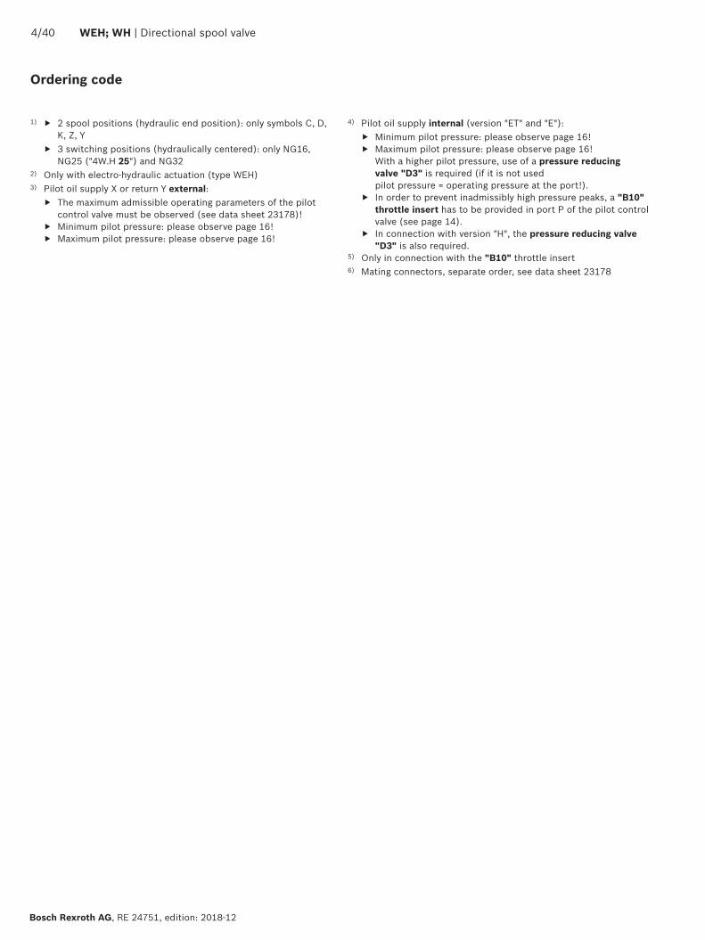
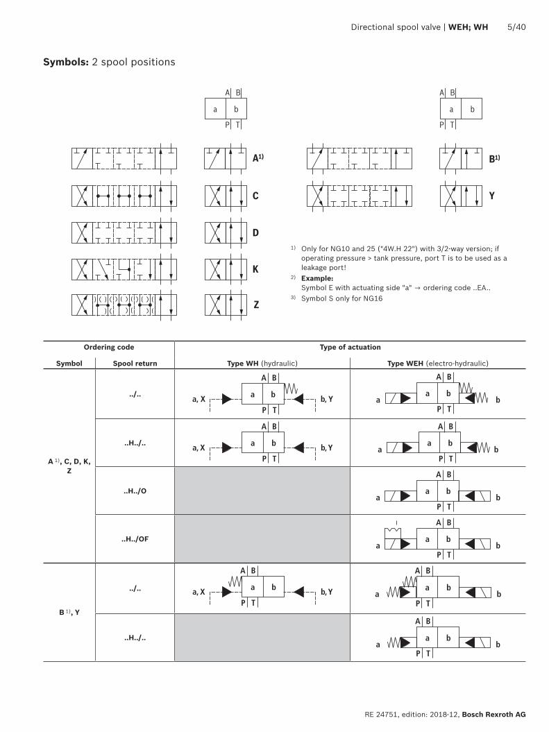
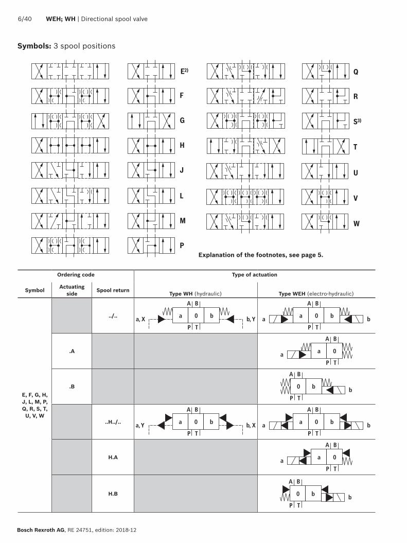
L
M
E2)
F
G
H
J
P
R
S3)
U
V
W
Q
T
640 WEH WH | Directional spool valve
Bosch Rexroth AG RE 24751 edition 2018-12
Symbols 3 spool positions
Ordering code Type of actuation
Symbol Actuating side Spool return Type WH (hydraulic) Type WEH (electro-hydraulic)
E F G H J L M P Q R S T
U V W
a b
A B
P Ta X b Y0 a b
A
a b
B
P T
0
A a
A B
P Ta 0
B b
A B
P Tb0
H a b
A B
P Ta Y b X0 a b
A
a b
B
P T
0
HA a
A B
P Ta 0
HB b
A B
P Tb0
Explanation of the footnotes see page 5
Directional spool valve | WEH WH 740
RE 24751 edition 2018-12 Bosch Rexroth AG
Valve with spring end position Valve with hydraulic end position
X =
ext
erna
l Y
= ex
tern
al
Type WEHhellip Type WEH H Type WEH HO Type WEH HOF
A B
a ba b
PX YT
A B
P T
a ba
a b
X b Y
P TYXA B
a ba b
PX YT
A B
P T
a ba
a b
X b Y
P TYXA B
a ba b
P T
A B
P T
a ba X b Y
P TYX
X Y
a b
A B
a ba b
P T
A B
P T
a ba X b Y
P TYX
X Y
a b
X =
inte
rnal
Y =
ext
erna
l
Type WEHhelliphellipEhellip Type WEH HhellipEhellip Type WEH HOhellipEhellip Type WEH HOFhellipEhellip
A B
A B
P T
a ba X b Y
P TYX
a ba b
P T Y
a b
A B
A B
P T
a ba X b Y
P TYX
a ba b
P T Y
a b
A B
A B
P T
a ba X b Y
P TYX
a ba b
P T Y
a b
A B
A B
P T
a ba X b Y
P TYX
a ba b
P T Y
a b
X =
inte
rnal
Y =
inte
rnal
Type WEHhelliphellipEThellip Type WEH HhellipEThellip Type WEH HOhellipEThellip Type WEH HOFhellipEThellip
A B
A B
P T
a ba X b Y
P TYX
a ba b
P T
a b
A B
A B
P T
a ba X b Y
P TYX
a ba b
P T
a b
A B
A B
P T
a ba X b Y
P TYX
a ba b
P T
a b
A B
A B
P T
a ba X b Y
P TYX
a ba b
P T
a b
Symbols for valves with 2 spool positions
840 WEH WH | Directional spool valve
Bosch Rexroth AG RE 24751 edition 2018-12
Valve with spring end position Valve with hydraulic end position
X =
ext
erna
l Y
= in
tern
al
Type WEHhelliphellipThellip Type WEH HhellipThellip Type WEH HOhellipThellip Type WEH HOFhellipThellip
A B
P T
a ba X b Y
P TYX
A B
a ba b
P TX
a b
A B
P T
a ba X b Y
P TYX
A B
a ba b
P TX
a b
A B
P T
a ba X b Y
P TYX
A
a ba b
PX
B
T
a b
A B
P T
a ba X b Y
P TYX
A B
a ba b
P TX
a b
Symbols for valves with 2 spool positions
Symbols for valves with 3 spool positions
Valve with spring-centered zero position Valve with pressure-centered zero position only NG16 25 (WH 25) and 32
X =
ext
erna
l Y
= ex
tern
al
Type WEHhelliphellip Type WEH HhellipA B
a 0a
a
a b
b
X b Yb
A B
a 0 b
PX YT
P TX Y
A B
a 0a X b Y
b
P TX YLA B
a 0 b
P TL
a
a b
b
X Y
X =
inte
rnal
Y =
ext
erna
l
Type WEHhelliphellipEhellip Type WEH HhellipEhellipA B
a 0a X b Y
b
A B
a 0 b
P T Y
P TX Y
a
a b
b
A B
a 0a X b Y
b
P TX YLA B
a 0 b
P T YL
a
a b
b
Directional spool valve | WEH WH 940
RE 24751 edition 2018-12 Bosch Rexroth AG
Valve with spring-centered zero position Valve with pressure-centered zero position only NG16 25 (WH 25) and 32
X =
inte
rnal
Y =
inte
rnal
Type WEHhelliphellipEThellip Type WEH HhellipEThellipA B
a 0a X b Y
b
A B
a 0 b
P T
P TX Y
a
a b
b
A B
a 0a X b Y
b
P TX YLA B
a 0 b
P TL
a
a b
b
X Y
X =
ext
erna
l Y
= in
tern
al
Type WEHhelliphellipThellip Type WEH HhellipThellipA B
a 0a X b Y
b
A B
a 0 b
P TX
P TX Y
a
a b
b
A B
a 0a X b Y
b
P TX YLA B
a 0 b
P T YL
a
a b
b
Symbols for valves with 3 spool positions
Notice3-spool position valves pressure-centered preferably with external pilot oil supply andor return (no code E)For preconditions for internal pilot oil supply andor return (ET T) see page 4 and 15
B A4 10
7
6
31
9
51
1
2
32
9
52
8
ldquobrdquo ldquoardquo
T A P B X Y
1040 WEH WH | Directional spool valve
Bosch Rexroth AG RE 24751 edition 2018-12
Function section Type WEH
Directional valves type WEHhellipThe valve type WEH is a directional spool valve with electro-hydraulic actuation It controls the start stop and direction of a flowThe directional valve basically consists of the main valve with housing (1) the main control spool (2) one or two return springs (31) and (32) as well as the pilot control valve (4) with one or two solenoids a (51) andor b (52)The main control spool (2) in the main valve is held in the zero or initial position by the springs or by means of pressurization In the initial position the two spring chambers (6) and (8) are connected with the tank in a depressurized form via the pilot control valve (4) Via the control line (7) the pilot control valve is supplied with pilot oil Supply can be implemented internally or externally (externally via port X) Upon actuation of the pilot control valve eg solenoid a the pilot control spool (10) is moved to the left and thus the spring chamber (8) is pressurized with pilot pressure The spring chamber (6) remains depressurizedThe pilot pressure acts on the left side of the main control spool (2) and moves it against the spring (31) This connects port P with B and A with T in the main valve
On switching off of solenoid the pilot control spool (10) returns to its initial position (except impulse spool) The spring chamber (8) is unloaded to the tankThe pilot oil return is implemented internally (via channel T) or externally (via channel Y)An optional manual override (9) allows for moving of the pilot control spool (10) without solenoid energization
NoticesThe return springs (31) and (32) in the spring chambers (6) and (8) hold the main control spool (2) in central position without pilot pressure even with for example vertical valve positioningDue to the design principle internal leakage is inherent to the valves which may increase over the life cycle
For pilot oil supply see page 13 and 14
7
6
31
1
2
32
8
T A P B X Y
11
Directional spool valve | WEH WH 1140
RE 24751 edition 2018-12 Bosch Rexroth AG
For pilot oil supply see page 13 and 14
Directional valves type WHhellipValve type WH is a directional spool valve with hydraulic actuation It controls the start stop and direction of a flowThe directional valve basically consists of the valve housing (1) the main control spool (2) one or two return springs (31) and (32) at valves with spring return or spring centering as well as the diversion plate (11)The main control spool (2) is actuated directly by pressurizationThe main control spool (2) is held in zero or initial position by springs or pressurization Pilot oil supply and return are external (see page 13)
43 directional valve with spring centering of the control spoolWith this version the main control spool (2) is held in zero position by two return springs (31) and (32) The two spring chambers (6) and (8) are connected to ports X and Y via the diversion plate (11)With pilot pressure loading of one of the two front sides of the main control spool (2) the spool is moved to the switching position In the valve the required ports are connected in this way The spring on the opposite side returns the spool to the zero or initial position at pressure relief of the pressurized control spool area
Function section Type WH
B A4 10
7
6
31
9
51
1
2
32
9
52
8
ldquobrdquo ldquoardquo
T A P B X Y12
L
1240 WEH WH | Directional spool valve
Bosch Rexroth AG RE 24751 edition 2018-12
43 directional valve with pressure centering of the main control spool type WEHhellipHThe main control spool (2) in the main valve is kept in the zero position by pressurization of the two front faces One centering bush (12) rests on the housing and fixes the control spool positionBy pressure relief of one front face the main control spool (2) is moved to the switching positionThe unloaded control spool face displaces the returning pilot oil into channel Y (external) via the pilot control valve
NoticesThe springs (31) and (32) do not have a return function in this version They hold the main control spool (2) in central position in the depressurized condition and with horizontal installation
Function section Type WEHhellipH
P
P
T
T 1
2P
P
T
T 1
2
P
P
T
T
1
2
P
P
T
T
3
1
P
P
T
T
1 2
Directional spool valve | WEH WH 1340
RE 24751 edition 2018-12 Bosch Rexroth AG
Pilot oil supply (schematic illustration)
Further explanations on page 14
NG10 NG16
Pilot oil supplyexternal 2 3 closedinternal 2 3 open
Pilot oil returnexternal 1 closedinternal 1 open
NG25 (WH 22) NG25 (WH 25)
NG32
1 Plug screw M6 according to DIN 906 wrench size 3 ndash pilot oil return
2 Plug screw M6 according to DIN 906 wrench size 3 ndash pilot oil supply
3 Plug screw M12 x 15 according DIN 906 wrench size 6 ndash pilot oil supply
P
3
4
5
1440 WEH WH | Directional spool valve
Bosch Rexroth AG RE 24751 edition 2018-12
Type WHhellipThe pilot oil supply and return is implemented externally via channel X and Y
Type WEHThe pilot oil supply is implemented externally - via channel X - from a separate pressure supplyThe pilot oil return is implemented externally - via channel Y - into the tank
Type WEHhellipEhellipThe pilot oil supply is implemented internally from channel P of the main valve (see page 15 footnotes 5) and 6))The pilot oil return is implemented externally - via channel Y - into the tank In the subplate port X is closed
Type WEHhellipEThellipThe pilot oil supply is implemented internally from channel P of the main valveThe pilot oil return is implemented internally - via channel T - into the tank In the subplate ports X and Y are closed
Type WEHhellipThellipThe pilot oil supply is implemented externally - via channel X - from a separate pressure supplyThe pilot oil return is implemented internally - via channel T - into the tank In the subplate port Y is closed
Throttle insertUse of the throttle insert (5) is necessary if the pilot oil supply in channel P of the pilot control valve is to be limited (see below)The throttle insert (5) is inserted in channel P of the pilot control valve
Pilot oil supply
NoticesThe modification of the pilot oil supply may only be performed by authorized specialists or at the factory
Pilot oil supply X or return Y external ndash The maximum admissible operating parameters of the pilot control valve must be observed (see data sheet 23178)
ndash Maximum pilot pressure please observe page 16 Pilot oil supply internal (version ET and E)
ndash Minimum pilot pressure please observe page 15 ndash In order to prevent inadmissibly high pressure peaks a B10 throttle insert has to be provided in port P of the pilot control valve (see above)
ndash In connection with version H the pressure reducing valve D3 (see page 38) is also required
3 Pilot control valve4 Main valve5 Throttle insert
Directional spool valve | WEH WH 1540
RE 24751 edition 2018-12 Bosch Rexroth AG
Technical data (For application outside these values please consult us)
generalSizes NG 10 16 25
WH 2225
WH 2532
Weight approx Valve with one solenoid kg [lbs] 64 [141] 85 [187] 115 [253] 176 [388] 176 [388]
Valve with two solenoids spring-centered kg [lbs] 68 [150] 89 [196] 119 [262] 190 [419] 410 [904]
Valve with two solenoids pressure-centered kg [lbs] 68 [150] 89 [196] 119 [262] 190 [419] 410 [904]
Valve witch hydraulic actuation (type WH) kg [lbs] 55 [121] 73 [161] 105 [231] 165 [364] 395 [871]
Switching time adjustment S and S2 kg [lbs] 08 [18] 08 [18] 08 [18] 08 [18] 08 [18]
Pressure reducing valve D3 kg [lbs] 04 [09] 04 [09] 04 [09] 04 [09] 04 [09]
Installation position Any horizontal with valves with hydraulic control spool return H and symbol A B C D K Z Y With suspended installation higher sensitivity to contamination ndash horizontal is recommended
Ambient temperature range
Standard version degC [degF] ndash20 hellip +50 [ndash4 hellip +122] (NBR seals)ndash15 hellip +70 [+5 hellip +122] (FKM seals)
Version for HFC hydraulic fluid degC [degF] ndash20 hellip +50 [ndash4 hellip +122]
Storage temperature range degC [degF] +5 hellip +40 [+41 hellip +104]
Surface protection (valve body) Coating layer thickness max 100 microm
MTTFd values according to EN ISO 13849 Years 100 (type WEH) 150 (type WH) (for further details see data sheet 08012)
hydraulicMaximum operating pressure
Port P A B Type WH bar [psi] 280 [4061] 280 [4061] 280 [4061] 280 [4061] 280 [4061]
Type H-WH bar [psi] 350 [5076]
350 [5076]
350 [5076]
350 [5076]
350 [5076]
Port T External pilot oil return Y
Type WH bar [psi] 280 [4061]
250 [3626] 250 [3626] 250 [3626] 250 [3626]
Type H-WH 315 [4568] 250 [3626] 250 [3626] 250 [3626] 250 [3626]
Internal pilot oil return Y
1)Type H-WEH WEH bar [psi] 210 [3046] with direct voltage
160 [2320] with alternating voltage
Port Y External pilot oil return Type H-WEH WEH bar [psi] 210 [3046] with direct voltage 160 [2320] with alternating voltage
Type WH H-WH bar [psi] 250 [3626] 250 [3626] 210 [3046] 250 [3626] 250 [3626]
Hydraulic fluid see table on page 15
Hydraulic fluid temperature range (at the valve working ports) 3)
degC [degF] ndash20 hellip +80 [ndash4 hellip +176] (NBR seals)ndash15 hellip +80 [+5 hellip +176] (FKM seals)ndash20 hellip +50 [ndash4 hellip +122] (HFC hydraulic fluid)
Viscosity range mm2s [SUS] 28 hellip 500 [35 hellip 2320]
Maximum admissible degree of contamination of the hydraulic fluid Cleanliness class according to ISO 4406 (c)
Class 201815 2)
1) As a 3-spool position valve pressure-centered only possible if ppilot ge 2 x ptank + ppilot min
2) The cleanliness classes specified for the components must be adhered to in hydraulic systems Effective filtration prevents faults and simultaneously increases the life cycle of the components
For selecting the filters see wwwboschrexrothcomfilter3) If type WH is used in potentially explosion-proof areas see
data sheet 07011
1640 WEH WH | Directional spool valve
Bosch Rexroth AG RE 24751 edition 2018-12
Technical data (For applications outside these parameters please consult us)
hydraulicSize NG 10 16 25
WH 2225
WH 2532
Maximum pilot pressure 4) bar [psi] 250 [3626]
250 [3626]
210 [3046]
250 [3626]
250 [3626]
Minimum pilot pressure
External pilot oil supply X (all symbols) internal pilot oil supply (only symbols D K E J L M Q R U W)
3-spool position valve spring-centered Type H-WHhellip bar [psi] 12 [174] 14 [203] 125 [181] 13 [188] 85 [123]
Type WH bar [psi] 12 [174] 14 [203] 105 [152] 13 [188] 85 [123]
3-spool position valve pressure-centered bar [psi] ndash 14 [203] ndash 18 [261] 85 [123]
2-spool position valve with spring end position
Type H-WH bar [psi] 10 [145] 14 [203] 14 [203] 13 [188] 10 [145]
Type WH bar [psi] 10 [145] 14 [203] 11 [159] 13 [188] 10 [145]
2-spool position valve with hydraulic end position bar [psi] 7 [101] 14 [203] 8 [116] 8 [116] 5 [72]
Internal pilot oil supply X (only type WEH) (with symbols C F G H P T V Z S 5))
bar [psi] 75 [109]
6)45 [65] 7) 45 [65] 7) 45 [65] 7) 45 [65] 7)
Free flow cross-sections in zero position with symbols Q V and W
Symbol Q A ndash T B ndash T mm2 [inch2] 13 [002] 32 [005] 78 [0121] 83 [0129] 78 [0121]
Symbol V P ndash A P ndash B mm2 [inch2] 13 [002] 32 [005] 73 [0113] 83 [0129] 73 [0113]
A ndash T B ndash T mm2 [inch2] 13 [002] 32 [005] 84 [013] 83 [0129] 84 [013]
Symbol W A ndash T B ndash T mm2 [inch2] 24 [0004] 6 [0009] 10 [0015] 14 [0022] 20 [0031]
Pilot volume for switching process
3-spool position valve spring-centered cm3 [inch3] 204 [0124]
572 [0349]
764 [0466]
142 [0866]
294 [1794]
2-spool position valve cm3 [inch3] 408 [0249]
1145 [0699]
1528 [0932]
284 [1733]
588 [3588]
3-spool position valve pressure-centered
from zero position in switching position a
Type WH cm3 [inch3] ndash 283 [0173]
ndash 715 [0436]
144 [0879]
Type WEH cm3 [inch3] ndash 283 [0173]
ndash 715 [0436]
144 [0879]
from switching position a in zero position
Type WH cm3 [inch3] ndash 572 [0349]
ndash 1418 [0865]
294 [1794]
Type WEH cm3 [inch3] ndash 29 [0177] ndash 70 [0427] 151 [0921]
from zero position in switching position b
Type WH cm3 [inch3] ndash 572 [0349]
ndash 1418 [0865]
294 [1794]
Type WEH cm3 [inch3] ndash 572 [0349]
ndash 1415 [0863]
294 [1794]
from switching position b in zero position
Type WH cm3 [inch3] ndash 855 [0522]
ndash 1988 [1213]
438 [2673]
Type WEH cm3 [inch3] ndash 283 [0173]
ndash 573 [0349]
144 [0879]
Pilot flow for shortest switching time approx lmin [US gpm] 35 [92] 35 [92] 35 [92] 35 [92] 45 [119]
Directional spool valve | WEH WH 1740
RE 24751 edition 2018-12 Bosch Rexroth AG
4) Internal pilot oil supply ndash With a higher pilot pressure use of a pressure reducing
valve D3 is required (if it is not used pilot pressure = operating pressure at the port)
ndash In connection with version H the pressure reducing valve D3 is also required
External pilot oil supply ndash Compliance with the maximum pilot pressure must be
ensured by appropriate measures (e g protection of the separate pilot oil circuit by means of a pressure relief valve)
5) Symbol S only for NG166) For symbols C F G H P T V Z an internal pilot oil supply is
only possible if the flow from P to T in the central position (for 3-spool position valve) or while crossing the central position (for 2-spool position valve) is so large that the pressure differential of P to T reaches a value of at least 75 bar [109 psi] and the pilot oil return Y is implemented externally
7) For symbols C F G J H P T V Z S 5) ndash by means of preload valve (not NG10) or correspondingly high flow (Determination of the required flow see Preload valve characteristic curves on page 39) For NG10 a check valve with a cracking pressure of 75 bar [109 psi] is to be provided in the return line to the tank The pilot oil return Y must be implemented externally
Technical data (For application outside these values please consult us)
Druckfluumlssigkeit Klassifizierung Geeignete Dichtungsmaterialien
Normen Datenblatt
Mineraloumlle HL HLP HLPD HVLP HVLPD NBR FKM DIN 51524 90220
Biologisch abbaubar wasserunloumlslich HETG FKMISO 15380
90221HEES FKM
wasserloumlslich HEPG FKM ISO 15380
Schwerentflammbar wasserfrei HFDU (Glykolbasis) FKM
ISO 12922 90222HFDU (Esterbasis) FKM
HFDR FKM
wasserhaltig HFC (Fuchs Hydrotherm 46M Renosafe 500 Petrofer Ultra Safe 620 Houghton Safe 620 Union Carbide HP5046)
NBR
ISO 12922 90223
Important information on hydraulic fluids For further information and data on the use of other hydraulic fluids please refer to the data sheets above or contact us
There may be limitations regarding the technical valve data (temperature pressure range life cycle maintenance intervals etc)
The ignition temperature of the hydraulic fluid used must be 50 K higher than the maximum surface temperature
Bio-degradable and flame-resistant ndash containing water If this hydraulic fluid is used small amounts of dissolved zinc may get into the hydraulic system
Flame-resistant ndash containing water ndash Due to increased cavitation tendency with HFC hydraulic fluids the life cycle of the component may be reduced by up to 30 as compared to the use with mineral oil HLP In order to reduce the cavitation effect it is recommended - if possible specific to the installation - to back up the return flow pressure in ports T to approx 20 of the pressure differential at the component
ndash Depending on the hydraulic fluid used the maximum ambient and hydraulic fluid temperature must not exceed 50 degC To reduce the heat input in the component a maximum duty cycle of 50 must be set for onoff valves in continuous operation (measuring time 300 s) If this is not possible due to the function an energy-reducing control of these components is recommended eg via a PWM plug-in amplifier
1840 WEH WH | Directional spool valve
Bosch Rexroth AG RE 24751 edition 2018-12
Switching times
Pilot pressure bar [psi] 70 [1015] 210 [3046] 250 [3626] Spring
ON OFF
NG10 Without throttle insert ms 40 hellip 60 ndash 40 hellip 60 20 hellip 30
With throttle insert ms 60 hellip 90 ndash 50 hellip 70 20 hellip 30
NG16 Without throttle insert ms 50 hellip 80 ndash 40 hellip 60 50 hellip 80
With throttle insert ms 110 hellip 130 ndash 80 hellip 100 50 hellip 80
NG25 (4WH 22) Without throttle insert ms 40 hellip 70 40 hellip 60 ndash 50 hellip 70
With throttle insert ms 140 hellip 160 80 hellip 110 ndash 50 hellip 70
NG25 (4WH 25) Without throttle insert ms 70 hellip 100 ndash 50 hellip 70 100 hellip 130
With throttle insert ms 200 hellip 250 ndash 120 hellip 150 100 hellip 130
NG32 Without throttle insert ms 80 hellip 130 ndash 70 hellip 100 140 hellip 160
With throttle insert ms 420 hellip 560 ndash 230 hellip 350 140 hellip 160
Notices Switching times = Contacting at the pilot control valve until start of opening of the control edge in the main valve and change in the control spool stroke by 95)
The switching times are measured according to ISO 6403 with HLP46 ϑoil = 40 degC plusmn 5 degC [104 degF plusmn9 degF] With different oil temperatures variations are possible
The switching times were determined using DC solenoids They decrease by approx 20 ms if AC solenoids are used
The shut-off of the solenoids creates voltage peaks which can be reduced by the use of suitable diodes
The switching times increase by approx 30 ms if the pressure reducing valve D3 is used
The switching times have been determined under ideal conditions and may differ in the system depending on the application conditions
6
1
10
8
6
4
2
20 40 60 80 100 120 140 1600
0
12
14
22
16
18
20
2
7
8
43
5
Directional spool valve | WEH WH 1940
RE 24751 edition 2018-12 Bosch Rexroth AG
Characteristic curves NG10 (measured with HLP46 ϑOil = 40 plusmn5degC [104 plusmn9degF])
Performance limits NG10 (measured with HLP46 ϑOil = 40 plusmn5degC [104 plusmn9degF])
Flow in lmin [US gpm] rarr
Pres
sure
diff
eren
tial i
n ba
r [p
si] rarr
∆p-qV characteristic curves
Symbol Spool position Zero positionP ndash A P ndash B A ndash T 1) B ndash T 1) A ndash T B ndash T P ndash T
E Y D Q V W Z 1 1 3 5
F 1 3 1 4 3 ndash 6
G T 4 2 4 7 ndash ndash 8
H C 3 3 1 7 1 5 5
J K 1 2 1 6
L 2 2 1 4 2 ndash ndash
M 3 3 2 5
P 3 1 2 7 ndash 5 7
R 1 2 3 ndash
U 2 2 3 6 ndash 6 ndash
A B 1 1 ndash ndash
1) The pressure differential refers to the use of port T If port T1 is additionally used the pressure differential may be lower If only port T1 is used the relations A ndash T and B ndash T may be reversed
Important notices see page 28
2-spool position valves ndash qV max in lmin [US gpm]
SymbolOperating pressure pmax in bar [psi]
70 [1015]
140 [2030]
210 [3046]
280 [4061]
350 [5076]
X external ndash spring end position in the main valve 1) (with ppilot min = 12 bar [174 psi])
C D K Y Z 160 [42] 160 [42] 160 [42] 160 [42] 160 [42]
X external ndash hydraulic end position in the main valveHC HD HK HZ HY
160 [42] 160 [42] 160 [42] 160 [42] 160 [42]
3-spool position valves ndash qV max in lmin [US gpm]
SymbolOperating pressure pmax in bar [psi]
70 [1015]
140 [2030]
210 [3046]
280 [4061]
350 [5076]
X external ndash spring-centeredE J L M Q U V W R
160 [42] 160 [42] 160 [42] 160 [42] 160 [42]
F P 160 [42] 120 [32] 100 [26] 90 [20] 90 [20]
G T 160 [42] 160 [42] 160 [42] 130 [34] 120 [32]
H 160 [42] 160 [42] 120 [32] 110 [29] 100 [26]1) If the pilot pressure fails the function of the return spring is no
longer guaranteed with the specified flow values
4
8
12
16
20
24
28
50 100 150 200 250 300
10
7
9 8
654321
0
[5][0] [10] [792]
0[0]
[50]
[75][15] [20] [25] [30] [35] [40] [45] [50] [55] [60] [65] [70]
[406]
[100]
[150]
[200]
[250]
[300]
[250]
2040 WEH WH | Directional spool valve
Bosch Rexroth AG RE 24751 edition 2018-12
Characteristic curves NG16 (measured with HLP46 ϑOil = 40 plusmn5 degC [104 plusmn9 degF])
∆p-qV characteristic curves
Flow in lmin [US gpm] rarr
Pres
sure
diff
eren
tial i
n ba
r [p
si] rarr
Symbol Spool position Zero positionP ndash A P ndash B A ndash T B ndash T P ndash T A ndash T B ndash T
D E Y 1 1 3 3
F 1 2 5 5 4 3 ndash
G 4 1 5 5 7 ndash ndash
C H 1 1 5 6 2 4 4
K J 2 2 6 6 ndash 3 ndash
L 2 2 5 4 ndash 3 ndash
M 1 1 3 4
P 2 1 3 6 5 ndash ndash
Symbol Spool position Zero positionP ndash A P ndash B A ndash T B ndash T P ndash T A ndash T B ndash T
Q 1 1 6 6
R 2 4 7 ndash
S 3 3 3 ndash 9 ndash ndash
T 4 1 5 5 7 ndash ndash
U 2 2 3 4 6
V Z 1 1 6 6 10 8 8
W 1 1 3 4
Directional spool valve | WEH WH 2140
RE 24751 edition 2018-12 Bosch Rexroth AG
Performance limits NG16 (measured with HLP46 ϑOil = 40 plusmn5 degC [104 plusmn9 degF])
2-spool position valves ndash qV max in lmin [US gpm]
SymbolOperating pressure pmax in bar [psi]
70 [1015]
140 [2030]
210 [3046]
280 [4061]
350 [5076]
X external ndash spring end position in the main valve (with ppilot min = 12 bar [174 psi])
C D K Y Z
300 [79] 300 [79] 300 [79] 300 [79] 300 [79]
X external ndash spring end position in the main valve 1)
C 300 [79] 300 [79] 300 [79] 300 [79] 300 [79]
D Y 300 [79] 270 [71] 260 [68] 250 [66] 230 [60]
K 300 [79] 250 [66] 240 [63] 230 [60] 210 [55]
Z 300 [79] 260 [68] 190 [50] 180 [47] 160 [42]
X external ndash hydraulic end position in the main valveHC HD HK HZ HY
300 [79] 300 [79] 300 [79] 300 [79] 300 [79]
3-spool position valves ndash qV max in lmin [US gpm]
SymbolOperating pressure pmax in bar [psi]
70 [1015]
140 [2030]
210 [3046]
280 [4061]
350 [5076]
X external ndash spring-centeredE H J L M Q U W R
300 [79] 300 [79] 300 [79] 300 [79] 300 [79]
F P 300 [79] 250 [66] 180 [47] 170 [45] 150 [39]
G T 300 [79] 300 [79] 240 [63] 210 [55] 190 [50]
S 300 [79] 300 [79] 300 [79] 250 [66] 220 [58]
V 300 [79] 250 [66] 210 [55] 200 [53] 180 [47]
X external ndash pressure-centered (at minimum pilot pressure of 16 bar [232 psi])
all sym-bols 2)
300 [79] 300 [79] 300 [79] 300 [79] 300 [79]
1) If the specified flow values are exceeded the function of the return spring is no longer guaranteed if the pilot pressure fails
2) With symbol V the pilot control valve is not required for flows gt160 lmin [42 US gpm]
Important notices see page 28
123
45
67
8
9
10
8
6
4
2
50 100 150 200 250 300 350 400
12
14
16
18
20
4500
[10][0] [20] [30] [40] [50] [60] [119]
0
[290]
[0]
[25]
[50]
[75]
[100]
[110][70] [80] [90] [100]
[125]
[150]
[175]
[200]
[225]
[250]
[275]
2240 WEH WH | Directional spool valve
Bosch Rexroth AG RE 24751 edition 2018-12
Characteristic curves NG25 (WH 22) (measured with HLP46 ϑOil = 40 plusmn5 degC [104 plusmn9 degF])
∆p-qV characteristic curves
Flow in lmin [US gpm] rarr
Pres
sure
diff
eren
tial i
n ba
r [p
si] rarr
Symbol Spool positionP ndash A P ndash B A ndash T B ndash T B ndash A
E D 2 2 3 5 ndash
J Q K 2 2 4 6 ndash
M W 1 1 3 5 ndash
H V C Z 1 1 4 6 ndash
F 1 2 4 5 ndash
G 3 4 5 6 ndash
R 1 2 2 ndash ndash
L 2 2 4 5 ndash
U 2 2 2 6 ndash
P 2 2 2 7 ndash
T 4 4 5 6 ndash
Symbol Zero positionA ndash T B ndash T P ndash T
F 2 ndash 4
G T ndash ndash 9
H ndash ndash 3
L 7 ndash ndash
U ndash 6 ndash
J 8 8 ndash
P ndash 4 6
V Z ndash ndash 8
Directional spool valve | WEH WH 2340
RE 24751 edition 2018-12 Bosch Rexroth AG
Performance limits NG25 (WH 22) (measured with HLP46 ϑOil = 40 plusmn5 degC [104 plusmn9 degF])
1) If the specified flow values are exceeded the function of the return spring is no longer guaranteed if the pilot pressure fails Important notices see page 28
2-spool position valves ndash qV max in lmin [US gpm]
SymbolOperating pressure pmax in bar [psi]
70 [1015]
140 [2030]
210 [3046]
280 [4061]
350 [5076]
X external ndash spring end position in the main valve (with ppilot min = 11 bar 14 bar [159 203 psi])
C D K Y Z 450 [119]
450 [119]
450 [119]
450 [119]
450 [119]
X external ndash spring end position in the main valve 1)
C 450 [119]
450 [119]
320 [84]
250 [66]
200 [53]
D Y 450 [119]
450 [119]
450 [119]
400 [105]
320 [84]
K 450 [119]
215 [57]
150 [39]
120 [32]
100 [26]
Z 350 [92]
300 [79]
290 [76]
260 [68]
160 [42]
X external ndash hydraulic end position in the main valveHC HD HK HZ HY
450 [119]
450 [119]
450 [119]
450 [119]
450 [119]
HCOhellip HDOhellip HKOhellip HZOhellip
450 [119]
450 [119]
450 [119]
450 [119]
450 [119]
HCOFhellip HDOFhellip HKOFhellip HZOFhellip
450 [119]
450 [119]
450 [119]
450 [119]
450 [119]
3-spool position valves ndash qV max in lmin [US gpm]
SymbolOperating pressure pmax in bar [psi]
70 [1015]
140 [2030]
210 [3046]
280 [4061]
350 [5076]
X external ndash spring-centered
E J L M Q U W R
450 [119]
450 [119]
450 [119]
450 [119]
450 [119]
H 450 [119]
450 [119]
300 [79]
260 [68]
230 [61]
G 400 [105]
350 [92]
250 [66]
200 [53]
180 [47]
F 450 [119]
270 [71]
175 [46]
130 [34]
110 [29]
V 450 [119]
300 [79]
240 [63]
220 [58]
160 [42]
T 400 [105]
300 [79]
240 [63]
200 [53]
160 [42]
P 450 [119]
270 [71]
180 [47]
170 [45]
110 [29]
1
2
3
4
5
6
0 100 200 300 400 500
78
600 650
10
8
6
4
2
12
14
16
18
20
22
2440 WEH WH | Directional spool valve
Bosch Rexroth AG RE 24751 edition 2018-12
Characteristic curves NG25 (WH 25) (measured with HLP46 ϑOil = 40 plusmn5 degC [104 plusmn9 degF])
∆p-qV characteristic curves
Flow in lmin [US gpm] rarr
Pres
sure
diff
eren
tial i
n ba
r [p
si] rarr
8 Symbol R spool position B ndash A
Symbol Spool position Zero positionP ndash A P ndash B A ndash T 1) B ndash T 1) A ndash T B ndash T P ndash T
E Y D 1 1 3 4
F 1 1 2 4 2 ndash 5
G T 1 1 2 5 ndash ndash 7
H 1 1 2 5 2 2 4
C 1 1 2 5
J 1 1 2 5 6 5 ndash
K 1 1 2 5
L 1 1 2 4 5 ndash ndash
M 1 1 3 4
P 1 1 3 5 ndash 3 5
Q 1 1 2 3
R 1 1 3 ndash
U 1 1 2 5 ndash 5 ndash
V 1 1 2 5 8 7 ndash
Z 1 1 2 5
W 1 1 3 4
Directional spool valve | WEH WH 2540
RE 24751 edition 2018-12 Bosch Rexroth AG
Performance limits NG25 (WH 25) (measured with HLP46 ϑOil = 40 plusmn5 degC [104 plusmn9 degF])
1) If the specified flow values are exceeded the function of the return spring is no longer guaranteed if the pilot pressure fails
Important notices see page 28
2-spool position valves ndash qV max in lmin [US gpm]
SymbolOperating pressure pmax in bar [psi]
70 [1015]
140 [2030]
210 [3046]
280 [4061]
350 [5076]
X external ndash spring end position in the main valve (with ppilot min = 13 bar [188 psi])
C D K Y Z 700 [185 ]
700 [185 ]
700 [185 ]
700 [185 ]
650 [172 ]
X external ndash spring end position in the main valve 1)
C 700 [185 ]
700 [185 ]
700 [185 ]
700 [185 ]
650 [172 ]
D Y 700 [185 ]
650 [172 ]
400 [105 ]
350 [92]
300 [79]
K 700 [185 ]
650 [172 ]
420 [111]
370 [98]
320 [84]
Z 700 [185 ]
700 [185 ]
650 [172 ]
480 [127 ]
400 [105 ]
X external ndash hydraulic end position in the main valveHC HD HK HZ HY
700 [185 ]
700 [185 ]
700 [185 ]
700 [185 ]
700 [185 ]
HCOhellip HDOhellip HKOhellip HZOhellip
700 [185 ]
700 [185 ]
700 [185 ]
700 [185 ]
700 [185 ]
HCOFhellip HDOFhellip HKOFhellip HZOFhellip
700 [185 ]
700 [185 ]
700 [185 ]
700 [185 ]
700 [185 ]
3-spool position valves ndash qV max in lmin [US gpm]
SymbolOperating pressure pmax in bar [psi]
70 [1015]
140 [2030]
210 [3046]
280 [4061]
350 [5076]
X external ndash spring-centeredE L M Q U W 700
[185 ]700
[185 ]700
[185 ]700
[185 ]650
[172 ]
G T 400 [105 ]
400 [105 ]
400 [105 ]
400 [105 ]
400 [105 ]
F 650 [172 ]
550 [145]
430 [113]
330 [87]
300 [79]
H 700 [185 ]
650 [172 ]
550 [145]
400 [105 ]
360 [95]
J 700 [185 ]
700 [185 ]
650 [172 ]
600 [158 ]
520 [137 ]
P 650 [172 ]
550 [145]
430 [113]
330 [87]
300 [79]
V 650 [172 ]
550 [145]
400 [105 ]
350 [92]
310 [82]
R 700 [185 ]
700 [185 ]
700 [185 ]
650 [172 ]
580 [153 ]
X external ndash pressure-centered (at minimum pilot pressure of 18 bar [261 psi])
E F H J L M P Q R U V W
700 [185 ]
700 [185 ]
700 [185 ]
700 [185 ]
650 [172 ]
G T 400 [105 ]
400 [105 ]
400 [105 ]
400 [105 ]
400 [105 ]
X external ndash pressure-centered (with pilot pressure gt 30 bar [435 psi])
G T 700 [185 ]
700 [185 ]
700 [185 ]
700 [185 ]
650 [172 ]
12
10
14
8
6
4
2
100 300
16
18
10800
[40][0] [285]
0500 700 900
[80] [120] [160] [200] [240]
1
2
3
4
[0]
[50]
[100]
[150]
[200]
[261]
12
10
14
8
6
4
2
100 300
16
18
10800
[40][0] [285]
0500 700 900
[80] [120] [160] [200] [240]
5
6
7
8
[0]
[50]
[100]
[150]
[200]
[261]
2640 WEH WH | Directional spool valve
Bosch Rexroth AG RE 24751 edition 2018-12
Characteristic curves NG32 (measured with HLP46 ϑOil = 40 plusmn5 degC [104 plusmn9 degF])
Flow in lmin [US gpm] rarr
Flow in lmin [US gpm] rarr
Pres
sure
diff
eren
tial
in b
ar [p
si] rarr
Pres
sure
diff
eren
tial
in b
ar [p
si] rarr
∆p-qV-characteristic curves ndash Symbol E R and W
∆p-qV characteristic curves ndash Symbol G and T
Symbol Spool positionP ndash A P ndash B A ndash T B ndash T B ndash A
E 4 4 3 2 ndash
R 4 4 3 ndash 1
W 4 4 3 2 ndash
Symbol Spool positionP ndash A P ndash B A ndash T B ndash T P ndash T
G 7 8 7 5 6
T 7 8 7 5 6
Directional spool valve | WEH WH 2740
RE 24751 edition 2018-12 Bosch Rexroth AG
Performance limits NG32 (measured with HLP46 ϑOil = 40 plusmn5 degC [104 plusmn9 degF])
1) If the specified flow values are exceeded the function of the return spring is no longer guaranteed if the pilot pressure fails Important notices see page 28
2-spool position valves ndash qV max in lmin [US gpm]
SymbolOperating pressure pmax in bar [psi]
70 [1015]
140 [2030]
210 [3046]
280 [4061]
350 [5076]
X external ndash spring end position in the main valve (with ppilot min = 10 bar [145 psi])
C D K Y Z 1100 [290]
1040 [275]
860 [227]
750 [198]
680 [179]
X external ndash spring end position in the main valve 1)
C 1100 [290]
1040 [275]
860 [227]
800 [211]
700 [185]
D Y 1100 [290]
1040 [275]
540 [142]
480 [127]
420 [111]
K 1100 [290]
1040 [275]
860 [227]
500 [132]
450 [119]
Z 1100 [290]
1040 [275]
860 [227]
700 [185]
650 [172]
X external ndash hydraulic end position in the main valveHC HD HK HZ HY
1100 [290]
1040 [275]
860 [227]
750 [198]
680 [179]
3-spool position valves ndash qV max in lmin [US gpm]
SymbolOperating pressure pmax in bar [psi]
70[1015]
140 [2030]
210 [3046]
280 [4061]
350 [5076]
X external ndash spring-centeredE J L M Q R U W
1100 [290]
1040 [275]
860 [227]
750 [198]
680 [179]
G T H F P 900 [238]
900 [238]
800 [211]
650 [172]
450 [119]
V 1100 [290]
1000 [264]
680 [179]
500 [132]
450 [119]
X external ndash pressure-centered (at minimum pilot pressure of 85 bar [123 psi])all symbols 1100
[290]1040 [275]
860 [227]
750 [198]
680 [179]
2840 WEH WH | Directional spool valve
Bosch Rexroth AG RE 24751 edition 2018-12
Performance limits important information
NG16 With pilot oil supply X internal a preload valve has to be used for flows lt 160 lmin [42 US gpm] due to the negative overlap of the symbols C Z and HC HZ
43 directional valves with pressure centering of the control spool in the main valve can be used above the indicated performance limit In this case a higher pilot pressure is required (values see performance limits of the corresponding size)
With pilot oil supply X internal sufficient flow needs to be ensured due to the negative overlap of symbols F G H P S and T (for determination of the required flow see Preload valve characteristic curves (page 39) If the required flow is not reached a preload valve has to be used (see page 16)
NG25(WH 22)
With pilot oil supply X internal a preload valve has to be used for flows lt 180 lmin [475 US gpm] due to the negative overlap of symbols Z HZ and V
With pilot oil supply X internal sufficient flow needs to be ensured due to the negative overlap of symbols C HC F G H P and T (for determination of the required flow see Preload valve characteristic curves (page 39) If the required flow is not reached a preload valve has to be used (see page 16)
NG25(WH 25)
With pilot oil supply X internal a preload valve has to be used for flows lt 180 lmin [475 US gpm] due to the negative overlap of symbols Z HZ and V
43 directional valves with pressure centering of the control spool in the main valve can be used above the indicated performance limit In this case a higher pilot pressure is required (values see performance limits of the corresponding size)
With pilot oil supply X internal sufficient flow needs to be ensured due to the negative overlap of symbols C HC F G H P and T (for determination of the required flow see Preload valve characteristic curves (page 39) If the required flow is not reached a preload valve has to be used (see page 16)
NG32 With pilot oil supply X internal a preload valve has to be used for flows lt 180 lmin [475 US gpm] due to the negative overlap of symbols Z HZ and V
43 directional valves with pressure centering of the control spool in the main valve can be used above the indicated performance limit In this case a higher pilot pressure is required (values see performance limits of the corresponding size)
With pilot oil supply X internal sufficient flow needs to be ensured due to the negative overlap of symbols C HC F G H P and T (for determination of the required flow see Preload valve characteristic curves (page 39) If the required flow is not reached a preload valve has to be used (see page 16)
Notice (applies to all sizes)The specified switching power limits apply to the use with two directions of flow (e g from P to A and simultaneous return flow from B to T at a ratio of 11)Due to the flow forces acting within the valves the admissible switching power limit may be considerably lower with only one direction of flow (e g from P to A
while port B is blocked with flow in the same or in different directions)In such cases of application please consult usThe switching power limit was established while the solenoids were at operating temperature at 10 undervoltage and without tank preloading
TT
19
44 1592
40
20
87
73
146
206
168 305
35
11
66
71
27
108
PA B
T
X Y
AT B TP
X Y
T1
AT P B T
A B AT P B T
4
6
72122 11
14
12
32 31
23
1
8
9
13
3514
5
255
135
101
F1 F2
F3F4
19
7
B AT
P
B A
B A
P
001100[0000440]
Rzmax 4
Directional spool valve | WEH WH 2940
RE 24751 edition 2018-12 Bosch Rexroth AG
Dimensions NG10 (dimensions in mm [inch])
For item explanations and subplates see page 34 Valve mounting screws see page 35
Required surface quality of the valve contact surface
NoticeThe dimensions are nominal dimensions which are subject to tolerances
27
9719
1166
206
82
64 164
15656
9240
20
43
93
11 18
3514
12
21
142
94BA
TP
X
LY
102
1
9
5
68
4
31
15
17
13
12
32
21 22
7
3
3 19
A B Y
T P X
B A
15
18 16
F1 F2
F3F4
G1F5
G2 F6
11 23 14
B AT
P
001100[0000440]
Rzmax 4
3040 WEH WH | Directional spool valve
Bosch Rexroth AG RE 24751 edition 2018-12
Dimensions NG16 (dimensions in mm [inch])
For item explanations and subplates see page 34 Valve mounting screws see page 35
Required surface quality of the valve contact surface
NoticeThe dimensions are nominal dimen-sions which are subject to toler-ances
001100[0000440]
Rzmax 4
15
117
14
20
14 193241
110
19
414
6
A BX
PT Y92
4020
4
7
11 1432
1
8
912
19
13
21 22
103
3123
6
5
3514
14
175
180
120
BAX
T PY
[07
5][4
33]
[055] [760]
[949]
[46
1]
[Oslash079]
[Oslash055][709]
[069]
[47
2]
[05
5]
[Oslash024]
[015
7][1
61]
[014]
[055]
[05
9]
[15
7]
[07
8][3
62]
F1 F2
F3F4
F5
F6
G1
G2
206 [811]
L 1)
T
PB A
B A
Directional spool valve | WEH WH 3140
RE 24751 edition 2018-12 Bosch Rexroth AG
For item explanations and subplates see page 34 Valve mounting screws see page 35 Required surface quality of the
valve contact surface
Dimensions NG25 (WH 22) (dimensions in mm [inch])
1) Port L only for valves with pressure-centered zero position
NoticeThe dimensions are nominal dimensions which are subject to tolerances
19 225
2973245
275
332
3245
126
19
414
6
1592
20
7
11
32
18
9
12
19
13
15
1617
18
21 22
6
5
23 31 144
40
3514
206
279
L1)
BAX
T P Y
AXB
T P Y 14
21
195
117
20
14
103
F1 F2
F3F4
F5
F6
G1
G2
B A
T
PB A
120
001100[0000440]
Rzmax 4
3240 WEH WH | Directional spool valve
Bosch Rexroth AG RE 24751 edition 2018-12
Dimensions NG25 (WH 25) (dimensions in mm [inch])
1) Port L only for valves with pressure-centered zero position
For item explanations and subplates see page 34 Valve mounting screws see page 35 Required surface quality of the
valve contact surface
NoticeThe dimensions are nominal dimensions which are subject to tolerances
001100[0000440]
Rzmax 4
T
X
1933 22
P Y
X A B
197
205
23
257
A B
T PY
49
40
2+0
3
2865
6362
391
406
215
152
19
1592
4020
7
11 14
32
12
19
13
1516
17
18
21 22
23 31 4
3514
6
5
8
91
104
[59
8][0
75]
[014]
[055]
[05
9]
[15
7]
[07
8][3
62]
[19
3]
[Oslash024] [01
57]
[00
079+0
011
8 ]
[085] [1425]
[1539]
[1598]
[77
6]
[Oslash130] [Oslash087]
[1012]
[091]
[08
1]
391 [1539]
[78
7]
F1 F2
F3F4
F5
F6
G1
G2
206 [811]
LT
PB A
B A
200
Directional spool valve | WEH WH 3340
RE 24751 edition 2018-12 Bosch Rexroth AG
For item explanations and subplates see page 34 Valve mounting screws see page 35 Required surface quality of the
valve contact surface
Dimensions NG32 (dimensions in mm [inch])
NoticeThe dimensions are nominal dimensions which are subject to tolerances
3440 WEH WH | Directional spool valve
Bosch Rexroth AG RE 24751 edition 2018-12
1 Main valve2 Pilot control valve type 4WE 6 (data sheet 23178)
21 Pilot control valve type 4WE 6 Dhellip (1 solenoid) for main valves with symbols C D K Z symbols HC HD HK HZ
Pilot control valve type 4WE 6 JA (1 solenoid a) for main valves with symbols EA FA etc spring return
Pilot control valve type 4WE 6 MA (1 solenoid a) for main valves with symbols HEA HFA etc hydraulic spool return
22 Pilot control valve type 4WE 6 Y (1 solenoid) for main valves with symbol Y symbol HY
Pilot control valve type 4WE 6 JB (1 solenoid b) for main valves with symbols EB FB etc spring return
Pilot control valve type 4WE 6 MB (1 solenoid b) for main valves with symbols HEB HFB etc hydraulic spool return
23 Pilot control valve type 4WE 6Jhellip (2 solenoids) for main valves with 3 spool positions spring-centered
Pilot control valve type 4WE 6 Mhellip (2 solenoids) for main valves with 3 spool positions pressure-centered
31 Solenoid a32 Solenoid b
4 Manual override N optional Actuation of the manual override is only possible up to a tank pressure of approx 50 bar Avoid damage to the bore of the manual override (Special tool for the operation separate order material no R900024943) When the manual override is blocked the operation of the solenoid must be prevented
Simultaneous actuation of the solenoids must be prevented
5 Solenoid without manual override6 Solenoid with manual override7 Height of the diversion plate with hydraulic actuation
(type WH)8 Switching time adjustment (wrench size 6) optional9 Pressure reducing valve optional
101 Machined valve contact surface porting pattern according to ISO 4401-05-05-0-05 and NFPAT351 R2-D05
102 Machined valve contact surface porting pattern according to ISO 4401-07-07-0-05 and NFPAT351 R2-D07
103 Machined valve contact surface porting pattern according to ISO 4401-08-08-0-05 and NFPAT351 R2-D08
104 Machined valve contact surface porting pattern according to ISO 4401-10-09-0-05 and NFPAT351 R2-D10
11 Name plate pilot control valve12 Name plate complete valve13 Seal rings14 Space required for removing the mating connector15 2-spool position valves with spring end position in the main
valve (symbols A C D K Z)16 2-spool position valves with spring end position in the main
valve (symbols B Y)
17 3-spool position valves spring-centered 2-spool position valves with hydraulic end position in the main valve
18 3-spool position valves pressure-centered19 Locking pin
Subplates (separate order) with porting pattern according to ISO 4401 see data sheet 45100
Valve mounting screws see page 35
Dimensions
Directional spool valve | WEH WH 3540
RE 24751 edition 2018-12 Bosch Rexroth AG
Dimensions
Valve mounting screws (separate order) Nominal size Quantity Hexagon socket head cap screws Material number10 4 ISO 4762 - M6 x 45 - 109-CM-Fe-ZnNi-5-Cn-T0-H-B
Friction coefficient micrototal = 009 hellip 014 tightening torque MA = 125 Nm [92 ft-lbs] plusmn10 R913043777
or
4 14-20 UNC x 1 34rdquo ASTM-A574 Not included in the Rexroth delivery range
16 4 ISO 4762 - M10 x 60 - 109-flZnnc480hCFriction coefficient micrototal = 009 hellip 014 tightening torque MA = 58 Nm [428 ft-lbs] plusmn10
R913014770
2 ISO 4762 - M6 x 60 - 109-CM-Fe-ZnNi-5-Cn-T0-H-B Friction coefficient micrototal = 009 hellip 014 tightening torque MA = 125 Nm [92 ft-lbs] plusmn10
R913043410
or
4 Zylinderschrauben UNC 38-16 UNC x 2 14rdquo ASTM-A574 Not included in the Rexroth delivery range2 Zylinderschrauben UNC 14-20 UNC x 2 14rdquo ASTM-A574
25 6 ISO 4762 - M12 x 60 - 109-flZnnc480hC Friction coefficient micrototal = 009 hellip 014 tightening torque MA = 100 Nm [74 ft-lbs] plusmn20
R913015613
or
6 UNC 12-13 UNC x 2 12rdquo ASTM-A574 Not included in the Rexroth delivery range
32 6 ISO 4762 - M20 x 80 - 109-flZnnc480hC Friction coefficient micrototal = 009 hellip 014 tightening torque MA = 340 Nm [251 ft-lbs] plusmn10
R913008472
or
6 UNC 34-10 UNC x 3 14rdquo ASTM-A574 Not included in the Rexroth delivery range
L4
L3
5
4 2
3
1
3640 WEH WH | Directional spool valve
Bosch Rexroth AG RE 24751 edition 2018-12
Stroke setting mounting options (dimensions in mm [inch])
NG L410 65 [026]
16 10 [039]
25 (WH 22) 95 [037]
25 (WH 25) 125 [049]
32 15 [059]
The stroke of the control spool is limited by the stroke setting (1) The control spool stroke is shortened by loosening the lock nut (2) and clockwise rotation of the adjustment spindle (3) The control chamber (4) must be depressurized for this
5 Adjustment range NG10 1 rotation = 1 mm [00394 inch] adjustment travel
NG16 and 32 1 rotation = 15 mm [00591 inch] adjustment travel
3-spool position valve 1)
spring-centered pressure-centered
L1 L2 L3 L1 L2 L3
Stroke setting on valve side A and B 10
10 90 [354] 144 [567] 234 [921]
16 100 [394] 200 [787] 300 [1181]
25 2) 96 [377] 241 [949] 337 [1327]
25 3) 123 [484] 276 [1087] 399 [1571]
32 133 [524] 344 [1354] 477 [1878]
Stroke setting on valve side A
11
10 90 [354] 106 [417] 196 [772]
16 100 [394] 156 [614] 256 [1008]
25 2) 96 [377] 193 [760] 289 [1138]
25 3) 123 [484] 225 [886] 348 [1370]
32 133 [524] 287 [1130] 420 [1654]
Stroke setting on valve side B 12
10 52 [205] 144 [567] 196 [772] ndash ndash ndash
16 56 [220] 200 [787] 256 [1008] 81 [319] 200 [787] 281 [1106]
25 2) 48 [189] 241 [949] 289 [1138] ndash ndash ndash
25 3) 72 [283] 276 [1087] 348 [1370] 107 [421] 276 [1087] 283 [1114]
32 76 [299] 344 [1354] 420 [1654] 120 [472] 344 [1354] 464 [1827]
More dimensions see below and page 37
Stroke limitation on side A Stroke limitation on side B
a
BA
L3
L1 L2
L3L2
X A B
a
B
b
A A B
L3
L3L2L1
L1
b a
X A B
1) With symbol A only version 11 with symbol B only version 12 possible
Directional spool valve | WEH WH 3740
RE 24751 edition 2018-12 Bosch Rexroth AG
Stroke setting mounting options (dimensions in mm [inch])
2) Version WH 223) Version WH 25
2-spool position valve Spring end position Hydraulic end position
A C D K Z B Y HC HD HK HZ HY
L1 L2 L3 L1 L2 L3 L1 L2 L3
Stroke setting on valve side A and B 10
10 90 [354]
144 [567]
234 [921]
90 [354]
144 [567]
234 [921]
90 [354]
144 [567]
234 [921]
16 ndash ndash ndash ndash ndash ndash 100 [394]
200 [787]
300 [1181]
25 2) 96 [378]
241 [949]
337 [1327]
96 [378]
241 [949]
337 [1327]
96 [378]
241 [949]
337 [1327]
25 3) ndash ndash ndash ndash ndash ndash 123 [484]
276 [1087]
399 [1571]
32 ndash ndash ndash ndash ndash ndash 133 [524]
344 [1354]
477 [1878]
Stroke setting on valve side A
11
10 90 [354]
106 [417]
196 [772]
90 [354]
106 [417]
196 [772]
90 [354]
106 [417]
196 [772]
16 100 [394]
180 [709]
280 [1102] ndash ndash ndash 100
[394]156
[614]256
[1008]
25 2) 96 [378]
193 [760]
289 [1138]
96 [378]
193 [760]
289 [1138]
96 [378]
193 [760]
289 [1138]
25 3) 123 [484]
253 [996]
376 [148] ndash ndash ndash 123
[484]225
[886]348
[1370]
32 133 [524]
316 [1244]
449 [1768] ndash ndash ndash 133
[524]287
[1130]420
[1653]
Stroke setting on valve side B 12
10 52 [205]
144 [567]
196 [772]
52 [205]
144 [567]
196 [772]
52 [205]
144 [567]
196 [772]
16 ndash ndash ndash 80 [315]
200 [787]
280 [1102]
56 [221]
200 [787]
256 [1008]
25 2) 48 [189]
241 [949]
289 [1138]
48 [189]
241 [949]
289 [1138]
48 [189]
241 [949]
289 [1138]
25 3) ndash ndash ndash 100 [394]
276 [1087]
376 [1480]
72 [284]
276 [1087]
348 [1370]
32 ndash ndash ndash 105 [413]
344 [1354]
449 [1768]
76 [299]
344 [1354]
420 [1653]
NoticeThe dimensions are nominal dimensions which are subject to tolerances
34
7 5
62
1
7
8
3840 WEH WH | Directional spool valve
Bosch Rexroth AG RE 24751 edition 2018-12
Switching time adjustment
Pressure reducing valve D3
The switching time of the main valve (1) is influenced by using a twin throttle check valve (2) (type Z2FS 6 data sheet 27506)
Modification of supply (3) to discharge control (4)Remove the pilot control valve (5) ndash The plate (6) to accept the seal rings stays in place ndash Turn the switching time adjustment (2) around its longitudinal axis and put it back install the pilot control valve (5)
NoticeThe modification may only be performed by authorized specialists or at the factory
Type WEH 10 4XhellipS Type WEH 10 4XhellipS2
The pressure reducing valve (8) has to be used at a pilot pressure above 250 bar [3626 psi] (with WEH 22 hellip 210 bar [3046 psi]) and with version HThe secondary pressure is kept at a constant level of 45 bar [652 psi]
Notice If a pressure reducing valve D3 (8) is used a B10
throttle insert has to be installed in channel P of the pilot control valve
The modification may only be performed by authorized specialists or at the factory Type WEH 10 4XhellipD3
92
10
11
141210
8
6
4
2
100 200 300 400 500 600 700
1 2
3
4
0
[20][0] [185]
0[0]
[50]
[100]
[150]
[203]
[40] [60] [80] [100] [120] [140] [160]
91
10
11
Directional spool valve | WEH WH 3940
RE 24751 edition 2018-12 Bosch Rexroth AG
Pres
sure
diff
eren
tial
in b
ar [p
si] rarr
Flow in lmin [US gpm] rarr
∆pndashqV characteristic curve (measured with HLP46 ϑOil = 40 degC plusmn 5 degC [104 degF plusmn9 degF])
1 NG16
2 NG25 (WH 25)
3 NG25 (WH 22)
4 NG32
In case of valves with depressurized circulation and internal pilot oil supply the installation of the preload valve (9) in channel P of the main valve is required in order to build up the minimum pilot pressure
SizeItem 91 Item 92
16 R961009415 (from component series 72) R961009417 (up to component series 71)
25 (WH 22) ndash R961009609 (up to component series 76)
25 (WH 25) R961009166 (from component series 68) R961009416 (up to component series 67)
32 ndash R961009610 (up to component series 63)
Preload valve (not for NG10)
91 Preload valve
92 Preload valve
10 Main valve
11 Subplate
The pressure differential of the preload valve is to be added to the pressure differential of the main valve (see characteristic curves) to result in one total valueThe cracking pressure amounts to approx 45 bar [65 psi]
NoticeSeries-production status see ordering key on the name plate
Bosch Rexroth AG RE 24751 edition 2018-12
4040 WEH WH | Directional spool valve
Bosch Rexroth AG Industrial HydraulicsZum Eisengieszliger 197816 Lohr am Main Germany Phone +49 (0) 93 52thinspthinsp40 30 20 mysupportboschrexrothde wwwboschrexrothde
copy All rights reserved to Bosch Rexroth AG also regarding any disposal exploitation reproduction editing distribution as well as in the event of applications for industrial property rightsThe data specified above only serve to describe the product No statements concerning a certain condition or suitability for a certain application can be derived from our information The information given does not release the user from the obligation of own judgment and verificationPlease note that our products are subject to a natural process of wear and aging
Project planning information
The stipulations of the Machinery Directive 200642EC are to be adhered toPlease also note data sheet 08012 with information on MTTFd values and shock and vibration loads
Further information
Directional spool valve Data sheet 23178 Subplates Data sheet 45100 Inductive position switch and proximity sensors (contactless) Data sheet 24830 Hydraulic fluids on mineral oil basis Data sheet 90220 Environmentally compatible hydraulic fluids Data sheet 90221 Flame-resistant water-free hydraulic fluids Data sheet 90222 Flame-resistant hydraulic fluids - containing water (HFAE HFAS HFB HFC) Data sheet 90223 Reliability characteristics according to EN ISO 13849 Data sheet 08012 Hexagon socket head cap screw metricUNC Data sheet 08936 Hydraulic valves for industrial applications Operating instructions 07600-B General product information on hydraulic products Data sheet 07008 Assembly commissioning and maintenance of industrial valves Data sheet 07300 Mating connectors and cable sets for valves and sensors in hydraulics Data sheet 08006 Directional spool valves and directional seat valves with electrical actuation and
M12x1 plug-in connectionData sheet 08010
Use of non-electrical hydraulic components in an explosive environment (ATEX) Data sheet 07011 Selection of filters wwwboschrexrothcomfilter Information on available spare parts wwwboschrexrothcomspc
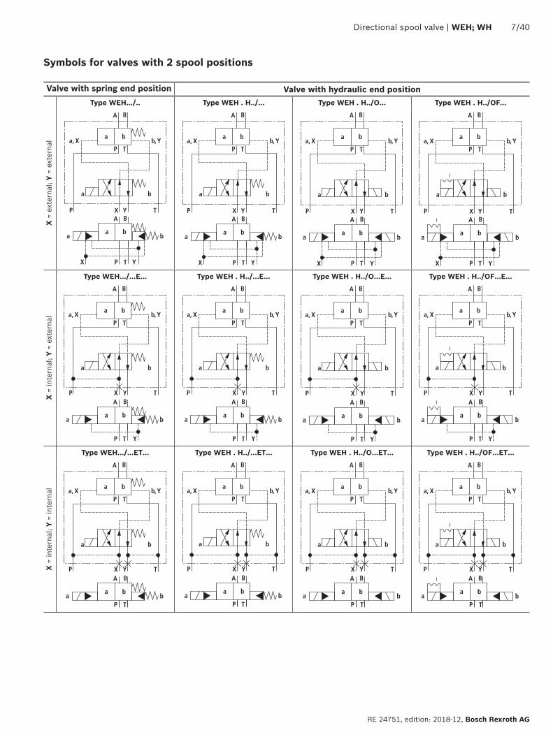
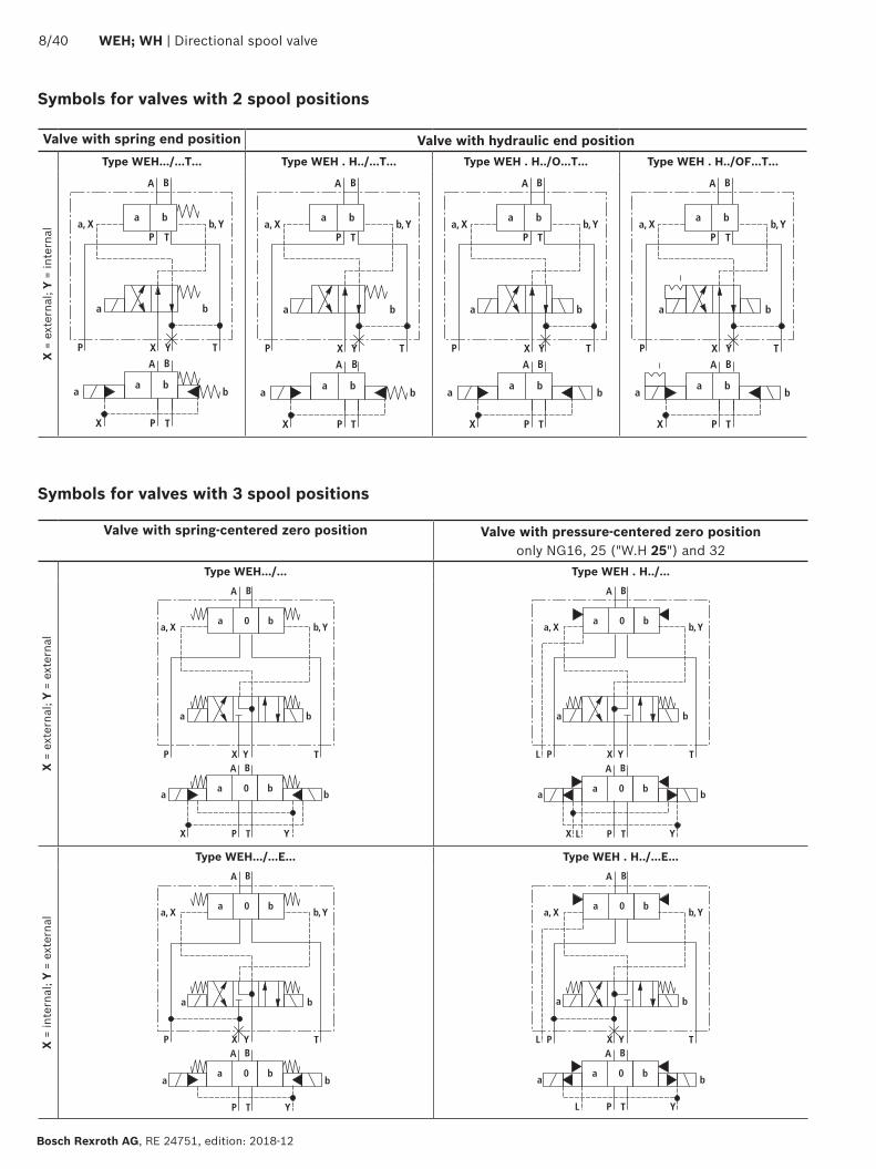
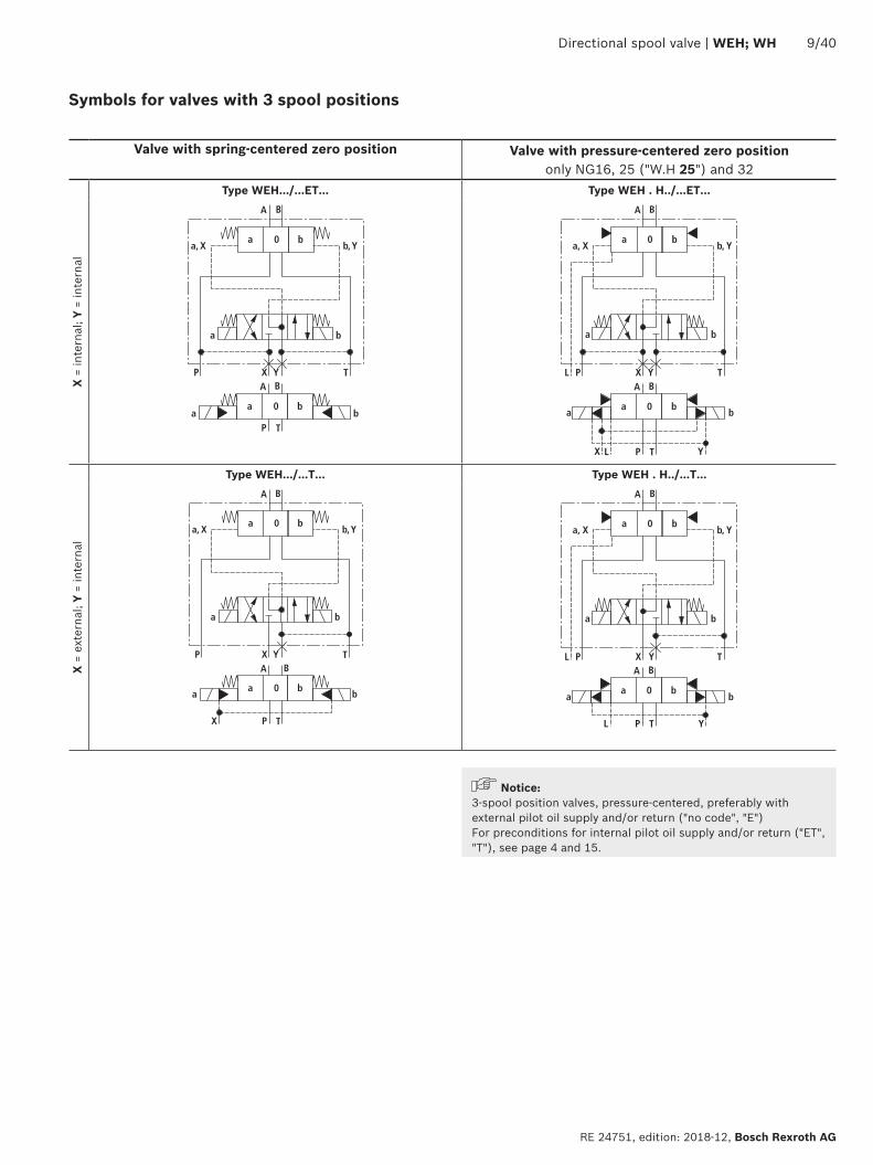
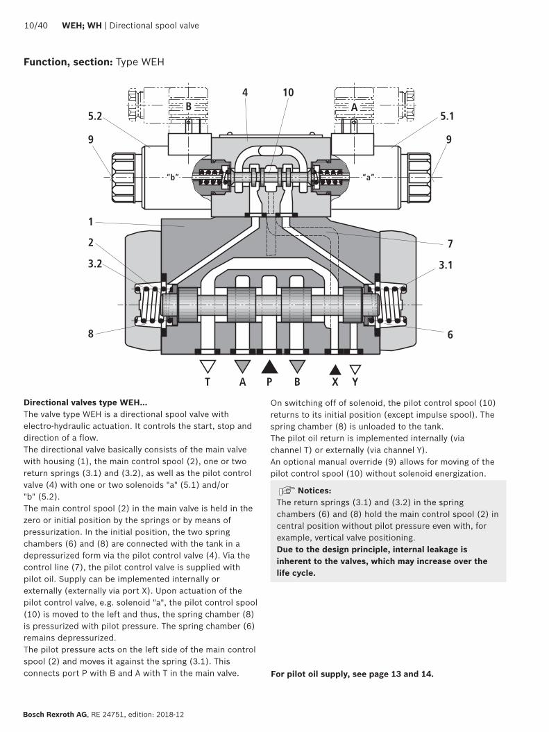
B A4 10
7
6
31
9
51
1
2
32
9
52
8
ldquobrdquo ldquoardquo
T A P B X Y
1040 WEH WH | Directional spool valve
Bosch Rexroth AG RE 24751 edition 2018-12
Function section Type WEH
Directional valves type WEHhellipThe valve type WEH is a directional spool valve with electro-hydraulic actuation It controls the start stop and direction of a flowThe directional valve basically consists of the main valve with housing (1) the main control spool (2) one or two return springs (31) and (32) as well as the pilot control valve (4) with one or two solenoids a (51) andor b (52)The main control spool (2) in the main valve is held in the zero or initial position by the springs or by means of pressurization In the initial position the two spring chambers (6) and (8) are connected with the tank in a depressurized form via the pilot control valve (4) Via the control line (7) the pilot control valve is supplied with pilot oil Supply can be implemented internally or externally (externally via port X) Upon actuation of the pilot control valve eg solenoid a the pilot control spool (10) is moved to the left and thus the spring chamber (8) is pressurized with pilot pressure The spring chamber (6) remains depressurizedThe pilot pressure acts on the left side of the main control spool (2) and moves it against the spring (31) This connects port P with B and A with T in the main valve
On switching off of solenoid the pilot control spool (10) returns to its initial position (except impulse spool) The spring chamber (8) is unloaded to the tankThe pilot oil return is implemented internally (via channel T) or externally (via channel Y)An optional manual override (9) allows for moving of the pilot control spool (10) without solenoid energization
NoticesThe return springs (31) and (32) in the spring chambers (6) and (8) hold the main control spool (2) in central position without pilot pressure even with for example vertical valve positioningDue to the design principle internal leakage is inherent to the valves which may increase over the life cycle
For pilot oil supply see page 13 and 14
7
6
31
1
2
32
8
T A P B X Y
11
Directional spool valve | WEH WH 1140
RE 24751 edition 2018-12 Bosch Rexroth AG
For pilot oil supply see page 13 and 14
Directional valves type WHhellipValve type WH is a directional spool valve with hydraulic actuation It controls the start stop and direction of a flowThe directional valve basically consists of the valve housing (1) the main control spool (2) one or two return springs (31) and (32) at valves with spring return or spring centering as well as the diversion plate (11)The main control spool (2) is actuated directly by pressurizationThe main control spool (2) is held in zero or initial position by springs or pressurization Pilot oil supply and return are external (see page 13)
43 directional valve with spring centering of the control spoolWith this version the main control spool (2) is held in zero position by two return springs (31) and (32) The two spring chambers (6) and (8) are connected to ports X and Y via the diversion plate (11)With pilot pressure loading of one of the two front sides of the main control spool (2) the spool is moved to the switching position In the valve the required ports are connected in this way The spring on the opposite side returns the spool to the zero or initial position at pressure relief of the pressurized control spool area
Function section Type WH
B A4 10
7
6
31
9
51
1
2
32
9
52
8
ldquobrdquo ldquoardquo
T A P B X Y12
L
1240 WEH WH | Directional spool valve
Bosch Rexroth AG RE 24751 edition 2018-12
43 directional valve with pressure centering of the main control spool type WEHhellipHThe main control spool (2) in the main valve is kept in the zero position by pressurization of the two front faces One centering bush (12) rests on the housing and fixes the control spool positionBy pressure relief of one front face the main control spool (2) is moved to the switching positionThe unloaded control spool face displaces the returning pilot oil into channel Y (external) via the pilot control valve
NoticesThe springs (31) and (32) do not have a return function in this version They hold the main control spool (2) in central position in the depressurized condition and with horizontal installation
Function section Type WEHhellipH
P
P
T
T 1
2P
P
T
T 1
2
P
P
T
T
1
2
P
P
T
T
3
1
P
P
T
T
1 2
Directional spool valve | WEH WH 1340
RE 24751 edition 2018-12 Bosch Rexroth AG
Pilot oil supply (schematic illustration)
Further explanations on page 14
NG10 NG16
Pilot oil supplyexternal 2 3 closedinternal 2 3 open
Pilot oil returnexternal 1 closedinternal 1 open
NG25 (WH 22) NG25 (WH 25)
NG32
1 Plug screw M6 according to DIN 906 wrench size 3 ndash pilot oil return
2 Plug screw M6 according to DIN 906 wrench size 3 ndash pilot oil supply
3 Plug screw M12 x 15 according DIN 906 wrench size 6 ndash pilot oil supply
P
3
4
5
1440 WEH WH | Directional spool valve
Bosch Rexroth AG RE 24751 edition 2018-12
Type WHhellipThe pilot oil supply and return is implemented externally via channel X and Y
Type WEHThe pilot oil supply is implemented externally - via channel X - from a separate pressure supplyThe pilot oil return is implemented externally - via channel Y - into the tank
Type WEHhellipEhellipThe pilot oil supply is implemented internally from channel P of the main valve (see page 15 footnotes 5) and 6))The pilot oil return is implemented externally - via channel Y - into the tank In the subplate port X is closed
Type WEHhellipEThellipThe pilot oil supply is implemented internally from channel P of the main valveThe pilot oil return is implemented internally - via channel T - into the tank In the subplate ports X and Y are closed
Type WEHhellipThellipThe pilot oil supply is implemented externally - via channel X - from a separate pressure supplyThe pilot oil return is implemented internally - via channel T - into the tank In the subplate port Y is closed
Throttle insertUse of the throttle insert (5) is necessary if the pilot oil supply in channel P of the pilot control valve is to be limited (see below)The throttle insert (5) is inserted in channel P of the pilot control valve
Pilot oil supply
NoticesThe modification of the pilot oil supply may only be performed by authorized specialists or at the factory
Pilot oil supply X or return Y external ndash The maximum admissible operating parameters of the pilot control valve must be observed (see data sheet 23178)
ndash Maximum pilot pressure please observe page 16 Pilot oil supply internal (version ET and E)
ndash Minimum pilot pressure please observe page 15 ndash In order to prevent inadmissibly high pressure peaks a B10 throttle insert has to be provided in port P of the pilot control valve (see above)
ndash In connection with version H the pressure reducing valve D3 (see page 38) is also required
3 Pilot control valve4 Main valve5 Throttle insert
Directional spool valve | WEH WH 1540
RE 24751 edition 2018-12 Bosch Rexroth AG
Technical data (For application outside these values please consult us)
generalSizes NG 10 16 25
WH 2225
WH 2532
Weight approx Valve with one solenoid kg [lbs] 64 [141] 85 [187] 115 [253] 176 [388] 176 [388]
Valve with two solenoids spring-centered kg [lbs] 68 [150] 89 [196] 119 [262] 190 [419] 410 [904]
Valve with two solenoids pressure-centered kg [lbs] 68 [150] 89 [196] 119 [262] 190 [419] 410 [904]
Valve witch hydraulic actuation (type WH) kg [lbs] 55 [121] 73 [161] 105 [231] 165 [364] 395 [871]
Switching time adjustment S and S2 kg [lbs] 08 [18] 08 [18] 08 [18] 08 [18] 08 [18]
Pressure reducing valve D3 kg [lbs] 04 [09] 04 [09] 04 [09] 04 [09] 04 [09]
Installation position Any horizontal with valves with hydraulic control spool return H and symbol A B C D K Z Y With suspended installation higher sensitivity to contamination ndash horizontal is recommended
Ambient temperature range
Standard version degC [degF] ndash20 hellip +50 [ndash4 hellip +122] (NBR seals)ndash15 hellip +70 [+5 hellip +122] (FKM seals)
Version for HFC hydraulic fluid degC [degF] ndash20 hellip +50 [ndash4 hellip +122]
Storage temperature range degC [degF] +5 hellip +40 [+41 hellip +104]
Surface protection (valve body) Coating layer thickness max 100 microm
MTTFd values according to EN ISO 13849 Years 100 (type WEH) 150 (type WH) (for further details see data sheet 08012)
hydraulicMaximum operating pressure
Port P A B Type WH bar [psi] 280 [4061] 280 [4061] 280 [4061] 280 [4061] 280 [4061]
Type H-WH bar [psi] 350 [5076]
350 [5076]
350 [5076]
350 [5076]
350 [5076]
Port T External pilot oil return Y
Type WH bar [psi] 280 [4061]
250 [3626] 250 [3626] 250 [3626] 250 [3626]
Type H-WH 315 [4568] 250 [3626] 250 [3626] 250 [3626] 250 [3626]
Internal pilot oil return Y
1)Type H-WEH WEH bar [psi] 210 [3046] with direct voltage
160 [2320] with alternating voltage
Port Y External pilot oil return Type H-WEH WEH bar [psi] 210 [3046] with direct voltage 160 [2320] with alternating voltage
Type WH H-WH bar [psi] 250 [3626] 250 [3626] 210 [3046] 250 [3626] 250 [3626]
Hydraulic fluid see table on page 15
Hydraulic fluid temperature range (at the valve working ports) 3)
degC [degF] ndash20 hellip +80 [ndash4 hellip +176] (NBR seals)ndash15 hellip +80 [+5 hellip +176] (FKM seals)ndash20 hellip +50 [ndash4 hellip +122] (HFC hydraulic fluid)
Viscosity range mm2s [SUS] 28 hellip 500 [35 hellip 2320]
Maximum admissible degree of contamination of the hydraulic fluid Cleanliness class according to ISO 4406 (c)
Class 201815 2)
1) As a 3-spool position valve pressure-centered only possible if ppilot ge 2 x ptank + ppilot min
2) The cleanliness classes specified for the components must be adhered to in hydraulic systems Effective filtration prevents faults and simultaneously increases the life cycle of the components
For selecting the filters see wwwboschrexrothcomfilter3) If type WH is used in potentially explosion-proof areas see
data sheet 07011
1640 WEH WH | Directional spool valve
Bosch Rexroth AG RE 24751 edition 2018-12
Technical data (For applications outside these parameters please consult us)
hydraulicSize NG 10 16 25
WH 2225
WH 2532
Maximum pilot pressure 4) bar [psi] 250 [3626]
250 [3626]
210 [3046]
250 [3626]
250 [3626]
Minimum pilot pressure
External pilot oil supply X (all symbols) internal pilot oil supply (only symbols D K E J L M Q R U W)
3-spool position valve spring-centered Type H-WHhellip bar [psi] 12 [174] 14 [203] 125 [181] 13 [188] 85 [123]
Type WH bar [psi] 12 [174] 14 [203] 105 [152] 13 [188] 85 [123]
3-spool position valve pressure-centered bar [psi] ndash 14 [203] ndash 18 [261] 85 [123]
2-spool position valve with spring end position
Type H-WH bar [psi] 10 [145] 14 [203] 14 [203] 13 [188] 10 [145]
Type WH bar [psi] 10 [145] 14 [203] 11 [159] 13 [188] 10 [145]
2-spool position valve with hydraulic end position bar [psi] 7 [101] 14 [203] 8 [116] 8 [116] 5 [72]
Internal pilot oil supply X (only type WEH) (with symbols C F G H P T V Z S 5))
bar [psi] 75 [109]
6)45 [65] 7) 45 [65] 7) 45 [65] 7) 45 [65] 7)
Free flow cross-sections in zero position with symbols Q V and W
Symbol Q A ndash T B ndash T mm2 [inch2] 13 [002] 32 [005] 78 [0121] 83 [0129] 78 [0121]
Symbol V P ndash A P ndash B mm2 [inch2] 13 [002] 32 [005] 73 [0113] 83 [0129] 73 [0113]
A ndash T B ndash T mm2 [inch2] 13 [002] 32 [005] 84 [013] 83 [0129] 84 [013]
Symbol W A ndash T B ndash T mm2 [inch2] 24 [0004] 6 [0009] 10 [0015] 14 [0022] 20 [0031]
Pilot volume for switching process
3-spool position valve spring-centered cm3 [inch3] 204 [0124]
572 [0349]
764 [0466]
142 [0866]
294 [1794]
2-spool position valve cm3 [inch3] 408 [0249]
1145 [0699]
1528 [0932]
284 [1733]
588 [3588]
3-spool position valve pressure-centered
from zero position in switching position a
Type WH cm3 [inch3] ndash 283 [0173]
ndash 715 [0436]
144 [0879]
Type WEH cm3 [inch3] ndash 283 [0173]
ndash 715 [0436]
144 [0879]
from switching position a in zero position
Type WH cm3 [inch3] ndash 572 [0349]
ndash 1418 [0865]
294 [1794]
Type WEH cm3 [inch3] ndash 29 [0177] ndash 70 [0427] 151 [0921]
from zero position in switching position b
Type WH cm3 [inch3] ndash 572 [0349]
ndash 1418 [0865]
294 [1794]
Type WEH cm3 [inch3] ndash 572 [0349]
ndash 1415 [0863]
294 [1794]
from switching position b in zero position
Type WH cm3 [inch3] ndash 855 [0522]
ndash 1988 [1213]
438 [2673]
Type WEH cm3 [inch3] ndash 283 [0173]
ndash 573 [0349]
144 [0879]
Pilot flow for shortest switching time approx lmin [US gpm] 35 [92] 35 [92] 35 [92] 35 [92] 45 [119]
Directional spool valve | WEH WH 1740
RE 24751 edition 2018-12 Bosch Rexroth AG
4) Internal pilot oil supply ndash With a higher pilot pressure use of a pressure reducing
valve D3 is required (if it is not used pilot pressure = operating pressure at the port)
ndash In connection with version H the pressure reducing valve D3 is also required
External pilot oil supply ndash Compliance with the maximum pilot pressure must be
ensured by appropriate measures (e g protection of the separate pilot oil circuit by means of a pressure relief valve)
5) Symbol S only for NG166) For symbols C F G H P T V Z an internal pilot oil supply is
only possible if the flow from P to T in the central position (for 3-spool position valve) or while crossing the central position (for 2-spool position valve) is so large that the pressure differential of P to T reaches a value of at least 75 bar [109 psi] and the pilot oil return Y is implemented externally
7) For symbols C F G J H P T V Z S 5) ndash by means of preload valve (not NG10) or correspondingly high flow (Determination of the required flow see Preload valve characteristic curves on page 39) For NG10 a check valve with a cracking pressure of 75 bar [109 psi] is to be provided in the return line to the tank The pilot oil return Y must be implemented externally
Technical data (For application outside these values please consult us)
Druckfluumlssigkeit Klassifizierung Geeignete Dichtungsmaterialien
Normen Datenblatt
Mineraloumlle HL HLP HLPD HVLP HVLPD NBR FKM DIN 51524 90220
Biologisch abbaubar wasserunloumlslich HETG FKMISO 15380
90221HEES FKM
wasserloumlslich HEPG FKM ISO 15380
Schwerentflammbar wasserfrei HFDU (Glykolbasis) FKM
ISO 12922 90222HFDU (Esterbasis) FKM
HFDR FKM
wasserhaltig HFC (Fuchs Hydrotherm 46M Renosafe 500 Petrofer Ultra Safe 620 Houghton Safe 620 Union Carbide HP5046)
NBR
ISO 12922 90223
Important information on hydraulic fluids For further information and data on the use of other hydraulic fluids please refer to the data sheets above or contact us
There may be limitations regarding the technical valve data (temperature pressure range life cycle maintenance intervals etc)
The ignition temperature of the hydraulic fluid used must be 50 K higher than the maximum surface temperature
Bio-degradable and flame-resistant ndash containing water If this hydraulic fluid is used small amounts of dissolved zinc may get into the hydraulic system
Flame-resistant ndash containing water ndash Due to increased cavitation tendency with HFC hydraulic fluids the life cycle of the component may be reduced by up to 30 as compared to the use with mineral oil HLP In order to reduce the cavitation effect it is recommended - if possible specific to the installation - to back up the return flow pressure in ports T to approx 20 of the pressure differential at the component
ndash Depending on the hydraulic fluid used the maximum ambient and hydraulic fluid temperature must not exceed 50 degC To reduce the heat input in the component a maximum duty cycle of 50 must be set for onoff valves in continuous operation (measuring time 300 s) If this is not possible due to the function an energy-reducing control of these components is recommended eg via a PWM plug-in amplifier
1840 WEH WH | Directional spool valve
Bosch Rexroth AG RE 24751 edition 2018-12
Switching times
Pilot pressure bar [psi] 70 [1015] 210 [3046] 250 [3626] Spring
ON OFF
NG10 Without throttle insert ms 40 hellip 60 ndash 40 hellip 60 20 hellip 30
With throttle insert ms 60 hellip 90 ndash 50 hellip 70 20 hellip 30
NG16 Without throttle insert ms 50 hellip 80 ndash 40 hellip 60 50 hellip 80
With throttle insert ms 110 hellip 130 ndash 80 hellip 100 50 hellip 80
NG25 (4WH 22) Without throttle insert ms 40 hellip 70 40 hellip 60 ndash 50 hellip 70
With throttle insert ms 140 hellip 160 80 hellip 110 ndash 50 hellip 70
NG25 (4WH 25) Without throttle insert ms 70 hellip 100 ndash 50 hellip 70 100 hellip 130
With throttle insert ms 200 hellip 250 ndash 120 hellip 150 100 hellip 130
NG32 Without throttle insert ms 80 hellip 130 ndash 70 hellip 100 140 hellip 160
With throttle insert ms 420 hellip 560 ndash 230 hellip 350 140 hellip 160
Notices Switching times = Contacting at the pilot control valve until start of opening of the control edge in the main valve and change in the control spool stroke by 95)
The switching times are measured according to ISO 6403 with HLP46 ϑoil = 40 degC plusmn 5 degC [104 degF plusmn9 degF] With different oil temperatures variations are possible
The switching times were determined using DC solenoids They decrease by approx 20 ms if AC solenoids are used
The shut-off of the solenoids creates voltage peaks which can be reduced by the use of suitable diodes
The switching times increase by approx 30 ms if the pressure reducing valve D3 is used
The switching times have been determined under ideal conditions and may differ in the system depending on the application conditions
6
1
10
8
6
4
2
20 40 60 80 100 120 140 1600
0
12
14
22
16
18
20
2
7
8
43
5
Directional spool valve | WEH WH 1940
RE 24751 edition 2018-12 Bosch Rexroth AG
Characteristic curves NG10 (measured with HLP46 ϑOil = 40 plusmn5degC [104 plusmn9degF])
Performance limits NG10 (measured with HLP46 ϑOil = 40 plusmn5degC [104 plusmn9degF])
Flow in lmin [US gpm] rarr
Pres
sure
diff
eren
tial i
n ba
r [p
si] rarr
∆p-qV characteristic curves
Symbol Spool position Zero positionP ndash A P ndash B A ndash T 1) B ndash T 1) A ndash T B ndash T P ndash T
E Y D Q V W Z 1 1 3 5
F 1 3 1 4 3 ndash 6
G T 4 2 4 7 ndash ndash 8
H C 3 3 1 7 1 5 5
J K 1 2 1 6
L 2 2 1 4 2 ndash ndash
M 3 3 2 5
P 3 1 2 7 ndash 5 7
R 1 2 3 ndash
U 2 2 3 6 ndash 6 ndash
A B 1 1 ndash ndash
1) The pressure differential refers to the use of port T If port T1 is additionally used the pressure differential may be lower If only port T1 is used the relations A ndash T and B ndash T may be reversed
Important notices see page 28
2-spool position valves ndash qV max in lmin [US gpm]
SymbolOperating pressure pmax in bar [psi]
70 [1015]
140 [2030]
210 [3046]
280 [4061]
350 [5076]
X external ndash spring end position in the main valve 1) (with ppilot min = 12 bar [174 psi])
C D K Y Z 160 [42] 160 [42] 160 [42] 160 [42] 160 [42]
X external ndash hydraulic end position in the main valveHC HD HK HZ HY
160 [42] 160 [42] 160 [42] 160 [42] 160 [42]
3-spool position valves ndash qV max in lmin [US gpm]
SymbolOperating pressure pmax in bar [psi]
70 [1015]
140 [2030]
210 [3046]
280 [4061]
350 [5076]
X external ndash spring-centeredE J L M Q U V W R
160 [42] 160 [42] 160 [42] 160 [42] 160 [42]
F P 160 [42] 120 [32] 100 [26] 90 [20] 90 [20]
G T 160 [42] 160 [42] 160 [42] 130 [34] 120 [32]
H 160 [42] 160 [42] 120 [32] 110 [29] 100 [26]1) If the pilot pressure fails the function of the return spring is no
longer guaranteed with the specified flow values
4
8
12
16
20
24
28
50 100 150 200 250 300
10
7
9 8
654321
0
[5][0] [10] [792]
0[0]
[50]
[75][15] [20] [25] [30] [35] [40] [45] [50] [55] [60] [65] [70]
[406]
[100]
[150]
[200]
[250]
[300]
[250]
2040 WEH WH | Directional spool valve
Bosch Rexroth AG RE 24751 edition 2018-12
Characteristic curves NG16 (measured with HLP46 ϑOil = 40 plusmn5 degC [104 plusmn9 degF])
∆p-qV characteristic curves
Flow in lmin [US gpm] rarr
Pres
sure
diff
eren
tial i
n ba
r [p
si] rarr
Symbol Spool position Zero positionP ndash A P ndash B A ndash T B ndash T P ndash T A ndash T B ndash T
D E Y 1 1 3 3
F 1 2 5 5 4 3 ndash
G 4 1 5 5 7 ndash ndash
C H 1 1 5 6 2 4 4
K J 2 2 6 6 ndash 3 ndash
L 2 2 5 4 ndash 3 ndash
M 1 1 3 4
P 2 1 3 6 5 ndash ndash
Symbol Spool position Zero positionP ndash A P ndash B A ndash T B ndash T P ndash T A ndash T B ndash T
Q 1 1 6 6
R 2 4 7 ndash
S 3 3 3 ndash 9 ndash ndash
T 4 1 5 5 7 ndash ndash
U 2 2 3 4 6
V Z 1 1 6 6 10 8 8
W 1 1 3 4
Directional spool valve | WEH WH 2140
RE 24751 edition 2018-12 Bosch Rexroth AG
Performance limits NG16 (measured with HLP46 ϑOil = 40 plusmn5 degC [104 plusmn9 degF])
2-spool position valves ndash qV max in lmin [US gpm]
SymbolOperating pressure pmax in bar [psi]
70 [1015]
140 [2030]
210 [3046]
280 [4061]
350 [5076]
X external ndash spring end position in the main valve (with ppilot min = 12 bar [174 psi])
C D K Y Z
300 [79] 300 [79] 300 [79] 300 [79] 300 [79]
X external ndash spring end position in the main valve 1)
C 300 [79] 300 [79] 300 [79] 300 [79] 300 [79]
D Y 300 [79] 270 [71] 260 [68] 250 [66] 230 [60]
K 300 [79] 250 [66] 240 [63] 230 [60] 210 [55]
Z 300 [79] 260 [68] 190 [50] 180 [47] 160 [42]
X external ndash hydraulic end position in the main valveHC HD HK HZ HY
300 [79] 300 [79] 300 [79] 300 [79] 300 [79]
3-spool position valves ndash qV max in lmin [US gpm]
SymbolOperating pressure pmax in bar [psi]
70 [1015]
140 [2030]
210 [3046]
280 [4061]
350 [5076]
X external ndash spring-centeredE H J L M Q U W R
300 [79] 300 [79] 300 [79] 300 [79] 300 [79]
F P 300 [79] 250 [66] 180 [47] 170 [45] 150 [39]
G T 300 [79] 300 [79] 240 [63] 210 [55] 190 [50]
S 300 [79] 300 [79] 300 [79] 250 [66] 220 [58]
V 300 [79] 250 [66] 210 [55] 200 [53] 180 [47]
X external ndash pressure-centered (at minimum pilot pressure of 16 bar [232 psi])
all sym-bols 2)
300 [79] 300 [79] 300 [79] 300 [79] 300 [79]
1) If the specified flow values are exceeded the function of the return spring is no longer guaranteed if the pilot pressure fails
2) With symbol V the pilot control valve is not required for flows gt160 lmin [42 US gpm]
Important notices see page 28
123
45
67
8
9
10
8
6
4
2
50 100 150 200 250 300 350 400
12
14
16
18
20
4500
[10][0] [20] [30] [40] [50] [60] [119]
0
[290]
[0]
[25]
[50]
[75]
[100]
[110][70] [80] [90] [100]
[125]
[150]
[175]
[200]
[225]
[250]
[275]
2240 WEH WH | Directional spool valve
Bosch Rexroth AG RE 24751 edition 2018-12
Characteristic curves NG25 (WH 22) (measured with HLP46 ϑOil = 40 plusmn5 degC [104 plusmn9 degF])
∆p-qV characteristic curves
Flow in lmin [US gpm] rarr
Pres
sure
diff
eren
tial i
n ba
r [p
si] rarr
Symbol Spool positionP ndash A P ndash B A ndash T B ndash T B ndash A
E D 2 2 3 5 ndash
J Q K 2 2 4 6 ndash
M W 1 1 3 5 ndash
H V C Z 1 1 4 6 ndash
F 1 2 4 5 ndash
G 3 4 5 6 ndash
R 1 2 2 ndash ndash
L 2 2 4 5 ndash
U 2 2 2 6 ndash
P 2 2 2 7 ndash
T 4 4 5 6 ndash
Symbol Zero positionA ndash T B ndash T P ndash T
F 2 ndash 4
G T ndash ndash 9
H ndash ndash 3
L 7 ndash ndash
U ndash 6 ndash
J 8 8 ndash
P ndash 4 6
V Z ndash ndash 8
Directional spool valve | WEH WH 2340
RE 24751 edition 2018-12 Bosch Rexroth AG
Performance limits NG25 (WH 22) (measured with HLP46 ϑOil = 40 plusmn5 degC [104 plusmn9 degF])
1) If the specified flow values are exceeded the function of the return spring is no longer guaranteed if the pilot pressure fails Important notices see page 28
2-spool position valves ndash qV max in lmin [US gpm]
SymbolOperating pressure pmax in bar [psi]
70 [1015]
140 [2030]
210 [3046]
280 [4061]
350 [5076]
X external ndash spring end position in the main valve (with ppilot min = 11 bar 14 bar [159 203 psi])
C D K Y Z 450 [119]
450 [119]
450 [119]
450 [119]
450 [119]
X external ndash spring end position in the main valve 1)
C 450 [119]
450 [119]
320 [84]
250 [66]
200 [53]
D Y 450 [119]
450 [119]
450 [119]
400 [105]
320 [84]
K 450 [119]
215 [57]
150 [39]
120 [32]
100 [26]
Z 350 [92]
300 [79]
290 [76]
260 [68]
160 [42]
X external ndash hydraulic end position in the main valveHC HD HK HZ HY
450 [119]
450 [119]
450 [119]
450 [119]
450 [119]
HCOhellip HDOhellip HKOhellip HZOhellip
450 [119]
450 [119]
450 [119]
450 [119]
450 [119]
HCOFhellip HDOFhellip HKOFhellip HZOFhellip
450 [119]
450 [119]
450 [119]
450 [119]
450 [119]
3-spool position valves ndash qV max in lmin [US gpm]
SymbolOperating pressure pmax in bar [psi]
70 [1015]
140 [2030]
210 [3046]
280 [4061]
350 [5076]
X external ndash spring-centered
E J L M Q U W R
450 [119]
450 [119]
450 [119]
450 [119]
450 [119]
H 450 [119]
450 [119]
300 [79]
260 [68]
230 [61]
G 400 [105]
350 [92]
250 [66]
200 [53]
180 [47]
F 450 [119]
270 [71]
175 [46]
130 [34]
110 [29]
V 450 [119]
300 [79]
240 [63]
220 [58]
160 [42]
T 400 [105]
300 [79]
240 [63]
200 [53]
160 [42]
P 450 [119]
270 [71]
180 [47]
170 [45]
110 [29]
1
2
3
4
5
6
0 100 200 300 400 500
78
600 650
10
8
6
4
2
12
14
16
18
20
22
2440 WEH WH | Directional spool valve
Bosch Rexroth AG RE 24751 edition 2018-12
Characteristic curves NG25 (WH 25) (measured with HLP46 ϑOil = 40 plusmn5 degC [104 plusmn9 degF])
∆p-qV characteristic curves
Flow in lmin [US gpm] rarr
Pres
sure
diff
eren
tial i
n ba
r [p
si] rarr
8 Symbol R spool position B ndash A
Symbol Spool position Zero positionP ndash A P ndash B A ndash T 1) B ndash T 1) A ndash T B ndash T P ndash T
E Y D 1 1 3 4
F 1 1 2 4 2 ndash 5
G T 1 1 2 5 ndash ndash 7
H 1 1 2 5 2 2 4
C 1 1 2 5
J 1 1 2 5 6 5 ndash
K 1 1 2 5
L 1 1 2 4 5 ndash ndash
M 1 1 3 4
P 1 1 3 5 ndash 3 5
Q 1 1 2 3
R 1 1 3 ndash
U 1 1 2 5 ndash 5 ndash
V 1 1 2 5 8 7 ndash
Z 1 1 2 5
W 1 1 3 4
Directional spool valve | WEH WH 2540
RE 24751 edition 2018-12 Bosch Rexroth AG
Performance limits NG25 (WH 25) (measured with HLP46 ϑOil = 40 plusmn5 degC [104 plusmn9 degF])
1) If the specified flow values are exceeded the function of the return spring is no longer guaranteed if the pilot pressure fails
Important notices see page 28
2-spool position valves ndash qV max in lmin [US gpm]
SymbolOperating pressure pmax in bar [psi]
70 [1015]
140 [2030]
210 [3046]
280 [4061]
350 [5076]
X external ndash spring end position in the main valve (with ppilot min = 13 bar [188 psi])
C D K Y Z 700 [185 ]
700 [185 ]
700 [185 ]
700 [185 ]
650 [172 ]
X external ndash spring end position in the main valve 1)
C 700 [185 ]
700 [185 ]
700 [185 ]
700 [185 ]
650 [172 ]
D Y 700 [185 ]
650 [172 ]
400 [105 ]
350 [92]
300 [79]
K 700 [185 ]
650 [172 ]
420 [111]
370 [98]
320 [84]
Z 700 [185 ]
700 [185 ]
650 [172 ]
480 [127 ]
400 [105 ]
X external ndash hydraulic end position in the main valveHC HD HK HZ HY
700 [185 ]
700 [185 ]
700 [185 ]
700 [185 ]
700 [185 ]
HCOhellip HDOhellip HKOhellip HZOhellip
700 [185 ]
700 [185 ]
700 [185 ]
700 [185 ]
700 [185 ]
HCOFhellip HDOFhellip HKOFhellip HZOFhellip
700 [185 ]
700 [185 ]
700 [185 ]
700 [185 ]
700 [185 ]
3-spool position valves ndash qV max in lmin [US gpm]
SymbolOperating pressure pmax in bar [psi]
70 [1015]
140 [2030]
210 [3046]
280 [4061]
350 [5076]
X external ndash spring-centeredE L M Q U W 700
[185 ]700
[185 ]700
[185 ]700
[185 ]650
[172 ]
G T 400 [105 ]
400 [105 ]
400 [105 ]
400 [105 ]
400 [105 ]
F 650 [172 ]
550 [145]
430 [113]
330 [87]
300 [79]
H 700 [185 ]
650 [172 ]
550 [145]
400 [105 ]
360 [95]
J 700 [185 ]
700 [185 ]
650 [172 ]
600 [158 ]
520 [137 ]
P 650 [172 ]
550 [145]
430 [113]
330 [87]
300 [79]
V 650 [172 ]
550 [145]
400 [105 ]
350 [92]
310 [82]
R 700 [185 ]
700 [185 ]
700 [185 ]
650 [172 ]
580 [153 ]
X external ndash pressure-centered (at minimum pilot pressure of 18 bar [261 psi])
E F H J L M P Q R U V W
700 [185 ]
700 [185 ]
700 [185 ]
700 [185 ]
650 [172 ]
G T 400 [105 ]
400 [105 ]
400 [105 ]
400 [105 ]
400 [105 ]
X external ndash pressure-centered (with pilot pressure gt 30 bar [435 psi])
G T 700 [185 ]
700 [185 ]
700 [185 ]
700 [185 ]
650 [172 ]
12
10
14
8
6
4
2
100 300
16
18
10800
[40][0] [285]
0500 700 900
[80] [120] [160] [200] [240]
1
2
3
4
[0]
[50]
[100]
[150]
[200]
[261]
12
10
14
8
6
4
2
100 300
16
18
10800
[40][0] [285]
0500 700 900
[80] [120] [160] [200] [240]
5
6
7
8
[0]
[50]
[100]
[150]
[200]
[261]
2640 WEH WH | Directional spool valve
Bosch Rexroth AG RE 24751 edition 2018-12
Characteristic curves NG32 (measured with HLP46 ϑOil = 40 plusmn5 degC [104 plusmn9 degF])
Flow in lmin [US gpm] rarr
Flow in lmin [US gpm] rarr
Pres
sure
diff
eren
tial
in b
ar [p
si] rarr
Pres
sure
diff
eren
tial
in b
ar [p
si] rarr
∆p-qV-characteristic curves ndash Symbol E R and W
∆p-qV characteristic curves ndash Symbol G and T
Symbol Spool positionP ndash A P ndash B A ndash T B ndash T B ndash A
E 4 4 3 2 ndash
R 4 4 3 ndash 1
W 4 4 3 2 ndash
Symbol Spool positionP ndash A P ndash B A ndash T B ndash T P ndash T
G 7 8 7 5 6
T 7 8 7 5 6
Directional spool valve | WEH WH 2740
RE 24751 edition 2018-12 Bosch Rexroth AG
Performance limits NG32 (measured with HLP46 ϑOil = 40 plusmn5 degC [104 plusmn9 degF])
1) If the specified flow values are exceeded the function of the return spring is no longer guaranteed if the pilot pressure fails Important notices see page 28
2-spool position valves ndash qV max in lmin [US gpm]
SymbolOperating pressure pmax in bar [psi]
70 [1015]
140 [2030]
210 [3046]
280 [4061]
350 [5076]
X external ndash spring end position in the main valve (with ppilot min = 10 bar [145 psi])
C D K Y Z 1100 [290]
1040 [275]
860 [227]
750 [198]
680 [179]
X external ndash spring end position in the main valve 1)
C 1100 [290]
1040 [275]
860 [227]
800 [211]
700 [185]
D Y 1100 [290]
1040 [275]
540 [142]
480 [127]
420 [111]
K 1100 [290]
1040 [275]
860 [227]
500 [132]
450 [119]
Z 1100 [290]
1040 [275]
860 [227]
700 [185]
650 [172]
X external ndash hydraulic end position in the main valveHC HD HK HZ HY
1100 [290]
1040 [275]
860 [227]
750 [198]
680 [179]
3-spool position valves ndash qV max in lmin [US gpm]
SymbolOperating pressure pmax in bar [psi]
70[1015]
140 [2030]
210 [3046]
280 [4061]
350 [5076]
X external ndash spring-centeredE J L M Q R U W
1100 [290]
1040 [275]
860 [227]
750 [198]
680 [179]
G T H F P 900 [238]
900 [238]
800 [211]
650 [172]
450 [119]
V 1100 [290]
1000 [264]
680 [179]
500 [132]
450 [119]
X external ndash pressure-centered (at minimum pilot pressure of 85 bar [123 psi])all symbols 1100
[290]1040 [275]
860 [227]
750 [198]
680 [179]
2840 WEH WH | Directional spool valve
Bosch Rexroth AG RE 24751 edition 2018-12
Performance limits important information
NG16 With pilot oil supply X internal a preload valve has to be used for flows lt 160 lmin [42 US gpm] due to the negative overlap of the symbols C Z and HC HZ
43 directional valves with pressure centering of the control spool in the main valve can be used above the indicated performance limit In this case a higher pilot pressure is required (values see performance limits of the corresponding size)
With pilot oil supply X internal sufficient flow needs to be ensured due to the negative overlap of symbols F G H P S and T (for determination of the required flow see Preload valve characteristic curves (page 39) If the required flow is not reached a preload valve has to be used (see page 16)
NG25(WH 22)
With pilot oil supply X internal a preload valve has to be used for flows lt 180 lmin [475 US gpm] due to the negative overlap of symbols Z HZ and V
With pilot oil supply X internal sufficient flow needs to be ensured due to the negative overlap of symbols C HC F G H P and T (for determination of the required flow see Preload valve characteristic curves (page 39) If the required flow is not reached a preload valve has to be used (see page 16)
NG25(WH 25)
With pilot oil supply X internal a preload valve has to be used for flows lt 180 lmin [475 US gpm] due to the negative overlap of symbols Z HZ and V
43 directional valves with pressure centering of the control spool in the main valve can be used above the indicated performance limit In this case a higher pilot pressure is required (values see performance limits of the corresponding size)
With pilot oil supply X internal sufficient flow needs to be ensured due to the negative overlap of symbols C HC F G H P and T (for determination of the required flow see Preload valve characteristic curves (page 39) If the required flow is not reached a preload valve has to be used (see page 16)
NG32 With pilot oil supply X internal a preload valve has to be used for flows lt 180 lmin [475 US gpm] due to the negative overlap of symbols Z HZ and V
43 directional valves with pressure centering of the control spool in the main valve can be used above the indicated performance limit In this case a higher pilot pressure is required (values see performance limits of the corresponding size)
With pilot oil supply X internal sufficient flow needs to be ensured due to the negative overlap of symbols C HC F G H P and T (for determination of the required flow see Preload valve characteristic curves (page 39) If the required flow is not reached a preload valve has to be used (see page 16)
Notice (applies to all sizes)The specified switching power limits apply to the use with two directions of flow (e g from P to A and simultaneous return flow from B to T at a ratio of 11)Due to the flow forces acting within the valves the admissible switching power limit may be considerably lower with only one direction of flow (e g from P to A
while port B is blocked with flow in the same or in different directions)In such cases of application please consult usThe switching power limit was established while the solenoids were at operating temperature at 10 undervoltage and without tank preloading
TT
19
44 1592
40
20
87
73
146
206
168 305
35
11
66
71
27
108
PA B
T
X Y
AT B TP
X Y
T1
AT P B T
A B AT P B T
4
6
72122 11
14
12
32 31
23
1
8
9
13
3514
5
255
135
101
F1 F2
F3F4
19
7
B AT
P
B A
B A
P
001100[0000440]
Rzmax 4
Directional spool valve | WEH WH 2940
RE 24751 edition 2018-12 Bosch Rexroth AG
Dimensions NG10 (dimensions in mm [inch])
For item explanations and subplates see page 34 Valve mounting screws see page 35
Required surface quality of the valve contact surface
NoticeThe dimensions are nominal dimensions which are subject to tolerances
27
9719
1166
206
82
64 164
15656
9240
20
43
93
11 18
3514
12
21
142
94BA
TP
X
LY
102
1
9
5
68
4
31
15
17
13
12
32
21 22
7
3
3 19
A B Y
T P X
B A
15
18 16
F1 F2
F3F4
G1F5
G2 F6
11 23 14
B AT
P
001100[0000440]
Rzmax 4
3040 WEH WH | Directional spool valve
Bosch Rexroth AG RE 24751 edition 2018-12
Dimensions NG16 (dimensions in mm [inch])
For item explanations and subplates see page 34 Valve mounting screws see page 35
Required surface quality of the valve contact surface
NoticeThe dimensions are nominal dimen-sions which are subject to toler-ances
001100[0000440]
Rzmax 4
15
117
14
20
14 193241
110
19
414
6
A BX
PT Y92
4020
4
7
11 1432
1
8
912
19
13
21 22
103
3123
6
5
3514
14
175
180
120
BAX
T PY
[07
5][4
33]
[055] [760]
[949]
[46
1]
[Oslash079]
[Oslash055][709]
[069]
[47
2]
[05
5]
[Oslash024]
[015
7][1
61]
[014]
[055]
[05
9]
[15
7]
[07
8][3
62]
F1 F2
F3F4
F5
F6
G1
G2
206 [811]
L 1)
T
PB A
B A
Directional spool valve | WEH WH 3140
RE 24751 edition 2018-12 Bosch Rexroth AG
For item explanations and subplates see page 34 Valve mounting screws see page 35 Required surface quality of the
valve contact surface
Dimensions NG25 (WH 22) (dimensions in mm [inch])
1) Port L only for valves with pressure-centered zero position
NoticeThe dimensions are nominal dimensions which are subject to tolerances
19 225
2973245
275
332
3245
126
19
414
6
1592
20
7
11
32
18
9
12
19
13
15
1617
18
21 22
6
5
23 31 144
40
3514
206
279
L1)
BAX
T P Y
AXB
T P Y 14
21
195
117
20
14
103
F1 F2
F3F4
F5
F6
G1
G2
B A
T
PB A
120
001100[0000440]
Rzmax 4
3240 WEH WH | Directional spool valve
Bosch Rexroth AG RE 24751 edition 2018-12
Dimensions NG25 (WH 25) (dimensions in mm [inch])
1) Port L only for valves with pressure-centered zero position
For item explanations and subplates see page 34 Valve mounting screws see page 35 Required surface quality of the
valve contact surface
NoticeThe dimensions are nominal dimensions which are subject to tolerances
001100[0000440]
Rzmax 4
T
X
1933 22
P Y
X A B
197
205
23
257
A B
T PY
49
40
2+0
3
2865
6362
391
406
215
152
19
1592
4020
7
11 14
32
12
19
13
1516
17
18
21 22
23 31 4
3514
6
5
8
91
104
[59
8][0
75]
[014]
[055]
[05
9]
[15
7]
[07
8][3
62]
[19
3]
[Oslash024] [01
57]
[00
079+0
011
8 ]
[085] [1425]
[1539]
[1598]
[77
6]
[Oslash130] [Oslash087]
[1012]
[091]
[08
1]
391 [1539]
[78
7]
F1 F2
F3F4
F5
F6
G1
G2
206 [811]
LT
PB A
B A
200
Directional spool valve | WEH WH 3340
RE 24751 edition 2018-12 Bosch Rexroth AG
For item explanations and subplates see page 34 Valve mounting screws see page 35 Required surface quality of the
valve contact surface
Dimensions NG32 (dimensions in mm [inch])
NoticeThe dimensions are nominal dimensions which are subject to tolerances
3440 WEH WH | Directional spool valve
Bosch Rexroth AG RE 24751 edition 2018-12
1 Main valve2 Pilot control valve type 4WE 6 (data sheet 23178)
21 Pilot control valve type 4WE 6 Dhellip (1 solenoid) for main valves with symbols C D K Z symbols HC HD HK HZ
Pilot control valve type 4WE 6 JA (1 solenoid a) for main valves with symbols EA FA etc spring return
Pilot control valve type 4WE 6 MA (1 solenoid a) for main valves with symbols HEA HFA etc hydraulic spool return
22 Pilot control valve type 4WE 6 Y (1 solenoid) for main valves with symbol Y symbol HY
Pilot control valve type 4WE 6 JB (1 solenoid b) for main valves with symbols EB FB etc spring return
Pilot control valve type 4WE 6 MB (1 solenoid b) for main valves with symbols HEB HFB etc hydraulic spool return
23 Pilot control valve type 4WE 6Jhellip (2 solenoids) for main valves with 3 spool positions spring-centered
Pilot control valve type 4WE 6 Mhellip (2 solenoids) for main valves with 3 spool positions pressure-centered
31 Solenoid a32 Solenoid b
4 Manual override N optional Actuation of the manual override is only possible up to a tank pressure of approx 50 bar Avoid damage to the bore of the manual override (Special tool for the operation separate order material no R900024943) When the manual override is blocked the operation of the solenoid must be prevented
Simultaneous actuation of the solenoids must be prevented
5 Solenoid without manual override6 Solenoid with manual override7 Height of the diversion plate with hydraulic actuation
(type WH)8 Switching time adjustment (wrench size 6) optional9 Pressure reducing valve optional
101 Machined valve contact surface porting pattern according to ISO 4401-05-05-0-05 and NFPAT351 R2-D05
102 Machined valve contact surface porting pattern according to ISO 4401-07-07-0-05 and NFPAT351 R2-D07
103 Machined valve contact surface porting pattern according to ISO 4401-08-08-0-05 and NFPAT351 R2-D08
104 Machined valve contact surface porting pattern according to ISO 4401-10-09-0-05 and NFPAT351 R2-D10
11 Name plate pilot control valve12 Name plate complete valve13 Seal rings14 Space required for removing the mating connector15 2-spool position valves with spring end position in the main
valve (symbols A C D K Z)16 2-spool position valves with spring end position in the main
valve (symbols B Y)
17 3-spool position valves spring-centered 2-spool position valves with hydraulic end position in the main valve
18 3-spool position valves pressure-centered19 Locking pin
Subplates (separate order) with porting pattern according to ISO 4401 see data sheet 45100
Valve mounting screws see page 35
Dimensions
Directional spool valve | WEH WH 3540
RE 24751 edition 2018-12 Bosch Rexroth AG
Dimensions
Valve mounting screws (separate order) Nominal size Quantity Hexagon socket head cap screws Material number10 4 ISO 4762 - M6 x 45 - 109-CM-Fe-ZnNi-5-Cn-T0-H-B
Friction coefficient micrototal = 009 hellip 014 tightening torque MA = 125 Nm [92 ft-lbs] plusmn10 R913043777
or
4 14-20 UNC x 1 34rdquo ASTM-A574 Not included in the Rexroth delivery range
16 4 ISO 4762 - M10 x 60 - 109-flZnnc480hCFriction coefficient micrototal = 009 hellip 014 tightening torque MA = 58 Nm [428 ft-lbs] plusmn10
R913014770
2 ISO 4762 - M6 x 60 - 109-CM-Fe-ZnNi-5-Cn-T0-H-B Friction coefficient micrototal = 009 hellip 014 tightening torque MA = 125 Nm [92 ft-lbs] plusmn10
R913043410
or
4 Zylinderschrauben UNC 38-16 UNC x 2 14rdquo ASTM-A574 Not included in the Rexroth delivery range2 Zylinderschrauben UNC 14-20 UNC x 2 14rdquo ASTM-A574
25 6 ISO 4762 - M12 x 60 - 109-flZnnc480hC Friction coefficient micrototal = 009 hellip 014 tightening torque MA = 100 Nm [74 ft-lbs] plusmn20
R913015613
or
6 UNC 12-13 UNC x 2 12rdquo ASTM-A574 Not included in the Rexroth delivery range
32 6 ISO 4762 - M20 x 80 - 109-flZnnc480hC Friction coefficient micrototal = 009 hellip 014 tightening torque MA = 340 Nm [251 ft-lbs] plusmn10
R913008472
or
6 UNC 34-10 UNC x 3 14rdquo ASTM-A574 Not included in the Rexroth delivery range
L4
L3
5
4 2
3
1
3640 WEH WH | Directional spool valve
Bosch Rexroth AG RE 24751 edition 2018-12
Stroke setting mounting options (dimensions in mm [inch])
NG L410 65 [026]
16 10 [039]
25 (WH 22) 95 [037]
25 (WH 25) 125 [049]
32 15 [059]
The stroke of the control spool is limited by the stroke setting (1) The control spool stroke is shortened by loosening the lock nut (2) and clockwise rotation of the adjustment spindle (3) The control chamber (4) must be depressurized for this
5 Adjustment range NG10 1 rotation = 1 mm [00394 inch] adjustment travel
NG16 and 32 1 rotation = 15 mm [00591 inch] adjustment travel
3-spool position valve 1)
spring-centered pressure-centered
L1 L2 L3 L1 L2 L3
Stroke setting on valve side A and B 10
10 90 [354] 144 [567] 234 [921]
16 100 [394] 200 [787] 300 [1181]
25 2) 96 [377] 241 [949] 337 [1327]
25 3) 123 [484] 276 [1087] 399 [1571]
32 133 [524] 344 [1354] 477 [1878]
Stroke setting on valve side A
11
10 90 [354] 106 [417] 196 [772]
16 100 [394] 156 [614] 256 [1008]
25 2) 96 [377] 193 [760] 289 [1138]
25 3) 123 [484] 225 [886] 348 [1370]
32 133 [524] 287 [1130] 420 [1654]
Stroke setting on valve side B 12
10 52 [205] 144 [567] 196 [772] ndash ndash ndash
16 56 [220] 200 [787] 256 [1008] 81 [319] 200 [787] 281 [1106]
25 2) 48 [189] 241 [949] 289 [1138] ndash ndash ndash
25 3) 72 [283] 276 [1087] 348 [1370] 107 [421] 276 [1087] 283 [1114]
32 76 [299] 344 [1354] 420 [1654] 120 [472] 344 [1354] 464 [1827]
More dimensions see below and page 37
Stroke limitation on side A Stroke limitation on side B
a
BA
L3
L1 L2
L3L2
X A B
a
B
b
A A B
L3
L3L2L1
L1
b a
X A B
1) With symbol A only version 11 with symbol B only version 12 possible
Directional spool valve | WEH WH 3740
RE 24751 edition 2018-12 Bosch Rexroth AG
Stroke setting mounting options (dimensions in mm [inch])
2) Version WH 223) Version WH 25
2-spool position valve Spring end position Hydraulic end position
A C D K Z B Y HC HD HK HZ HY
L1 L2 L3 L1 L2 L3 L1 L2 L3
Stroke setting on valve side A and B 10
10 90 [354]
144 [567]
234 [921]
90 [354]
144 [567]
234 [921]
90 [354]
144 [567]
234 [921]
16 ndash ndash ndash ndash ndash ndash 100 [394]
200 [787]
300 [1181]
25 2) 96 [378]
241 [949]
337 [1327]
96 [378]
241 [949]
337 [1327]
96 [378]
241 [949]
337 [1327]
25 3) ndash ndash ndash ndash ndash ndash 123 [484]
276 [1087]
399 [1571]
32 ndash ndash ndash ndash ndash ndash 133 [524]
344 [1354]
477 [1878]
Stroke setting on valve side A
11
10 90 [354]
106 [417]
196 [772]
90 [354]
106 [417]
196 [772]
90 [354]
106 [417]
196 [772]
16 100 [394]
180 [709]
280 [1102] ndash ndash ndash 100
[394]156
[614]256
[1008]
25 2) 96 [378]
193 [760]
289 [1138]
96 [378]
193 [760]
289 [1138]
96 [378]
193 [760]
289 [1138]
25 3) 123 [484]
253 [996]
376 [148] ndash ndash ndash 123
[484]225
[886]348
[1370]
32 133 [524]
316 [1244]
449 [1768] ndash ndash ndash 133
[524]287
[1130]420
[1653]
Stroke setting on valve side B 12
10 52 [205]
144 [567]
196 [772]
52 [205]
144 [567]
196 [772]
52 [205]
144 [567]
196 [772]
16 ndash ndash ndash 80 [315]
200 [787]
280 [1102]
56 [221]
200 [787]
256 [1008]
25 2) 48 [189]
241 [949]
289 [1138]
48 [189]
241 [949]
289 [1138]
48 [189]
241 [949]
289 [1138]
25 3) ndash ndash ndash 100 [394]
276 [1087]
376 [1480]
72 [284]
276 [1087]
348 [1370]
32 ndash ndash ndash 105 [413]
344 [1354]
449 [1768]
76 [299]
344 [1354]
420 [1653]
NoticeThe dimensions are nominal dimensions which are subject to tolerances
34
7 5
62
1
7
8
3840 WEH WH | Directional spool valve
Bosch Rexroth AG RE 24751 edition 2018-12
Switching time adjustment
Pressure reducing valve D3
The switching time of the main valve (1) is influenced by using a twin throttle check valve (2) (type Z2FS 6 data sheet 27506)
Modification of supply (3) to discharge control (4)Remove the pilot control valve (5) ndash The plate (6) to accept the seal rings stays in place ndash Turn the switching time adjustment (2) around its longitudinal axis and put it back install the pilot control valve (5)
NoticeThe modification may only be performed by authorized specialists or at the factory
Type WEH 10 4XhellipS Type WEH 10 4XhellipS2
The pressure reducing valve (8) has to be used at a pilot pressure above 250 bar [3626 psi] (with WEH 22 hellip 210 bar [3046 psi]) and with version HThe secondary pressure is kept at a constant level of 45 bar [652 psi]
Notice If a pressure reducing valve D3 (8) is used a B10
throttle insert has to be installed in channel P of the pilot control valve
The modification may only be performed by authorized specialists or at the factory Type WEH 10 4XhellipD3
92
10
11
141210
8
6
4
2
100 200 300 400 500 600 700
1 2
3
4
0
[20][0] [185]
0[0]
[50]
[100]
[150]
[203]
[40] [60] [80] [100] [120] [140] [160]
91
10
11
Directional spool valve | WEH WH 3940
RE 24751 edition 2018-12 Bosch Rexroth AG
Pres
sure
diff
eren
tial
in b
ar [p
si] rarr
Flow in lmin [US gpm] rarr
∆pndashqV characteristic curve (measured with HLP46 ϑOil = 40 degC plusmn 5 degC [104 degF plusmn9 degF])
1 NG16
2 NG25 (WH 25)
3 NG25 (WH 22)
4 NG32
In case of valves with depressurized circulation and internal pilot oil supply the installation of the preload valve (9) in channel P of the main valve is required in order to build up the minimum pilot pressure
SizeItem 91 Item 92
16 R961009415 (from component series 72) R961009417 (up to component series 71)
25 (WH 22) ndash R961009609 (up to component series 76)
25 (WH 25) R961009166 (from component series 68) R961009416 (up to component series 67)
32 ndash R961009610 (up to component series 63)
Preload valve (not for NG10)
91 Preload valve
92 Preload valve
10 Main valve
11 Subplate
The pressure differential of the preload valve is to be added to the pressure differential of the main valve (see characteristic curves) to result in one total valueThe cracking pressure amounts to approx 45 bar [65 psi]
NoticeSeries-production status see ordering key on the name plate
Bosch Rexroth AG RE 24751 edition 2018-12
4040 WEH WH | Directional spool valve
Bosch Rexroth AG Industrial HydraulicsZum Eisengieszliger 197816 Lohr am Main Germany Phone +49 (0) 93 52thinspthinsp40 30 20 mysupportboschrexrothde wwwboschrexrothde
copy All rights reserved to Bosch Rexroth AG also regarding any disposal exploitation reproduction editing distribution as well as in the event of applications for industrial property rightsThe data specified above only serve to describe the product No statements concerning a certain condition or suitability for a certain application can be derived from our information The information given does not release the user from the obligation of own judgment and verificationPlease note that our products are subject to a natural process of wear and aging
Project planning information
The stipulations of the Machinery Directive 200642EC are to be adhered toPlease also note data sheet 08012 with information on MTTFd values and shock and vibration loads
Further information
Directional spool valve Data sheet 23178 Subplates Data sheet 45100 Inductive position switch and proximity sensors (contactless) Data sheet 24830 Hydraulic fluids on mineral oil basis Data sheet 90220 Environmentally compatible hydraulic fluids Data sheet 90221 Flame-resistant water-free hydraulic fluids Data sheet 90222 Flame-resistant hydraulic fluids - containing water (HFAE HFAS HFB HFC) Data sheet 90223 Reliability characteristics according to EN ISO 13849 Data sheet 08012 Hexagon socket head cap screw metricUNC Data sheet 08936 Hydraulic valves for industrial applications Operating instructions 07600-B General product information on hydraulic products Data sheet 07008 Assembly commissioning and maintenance of industrial valves Data sheet 07300 Mating connectors and cable sets for valves and sensors in hydraulics Data sheet 08006 Directional spool valves and directional seat valves with electrical actuation and
M12x1 plug-in connectionData sheet 08010
Use of non-electrical hydraulic components in an explosive environment (ATEX) Data sheet 07011 Selection of filters wwwboschrexrothcomfilter Information on available spare parts wwwboschrexrothcomspc
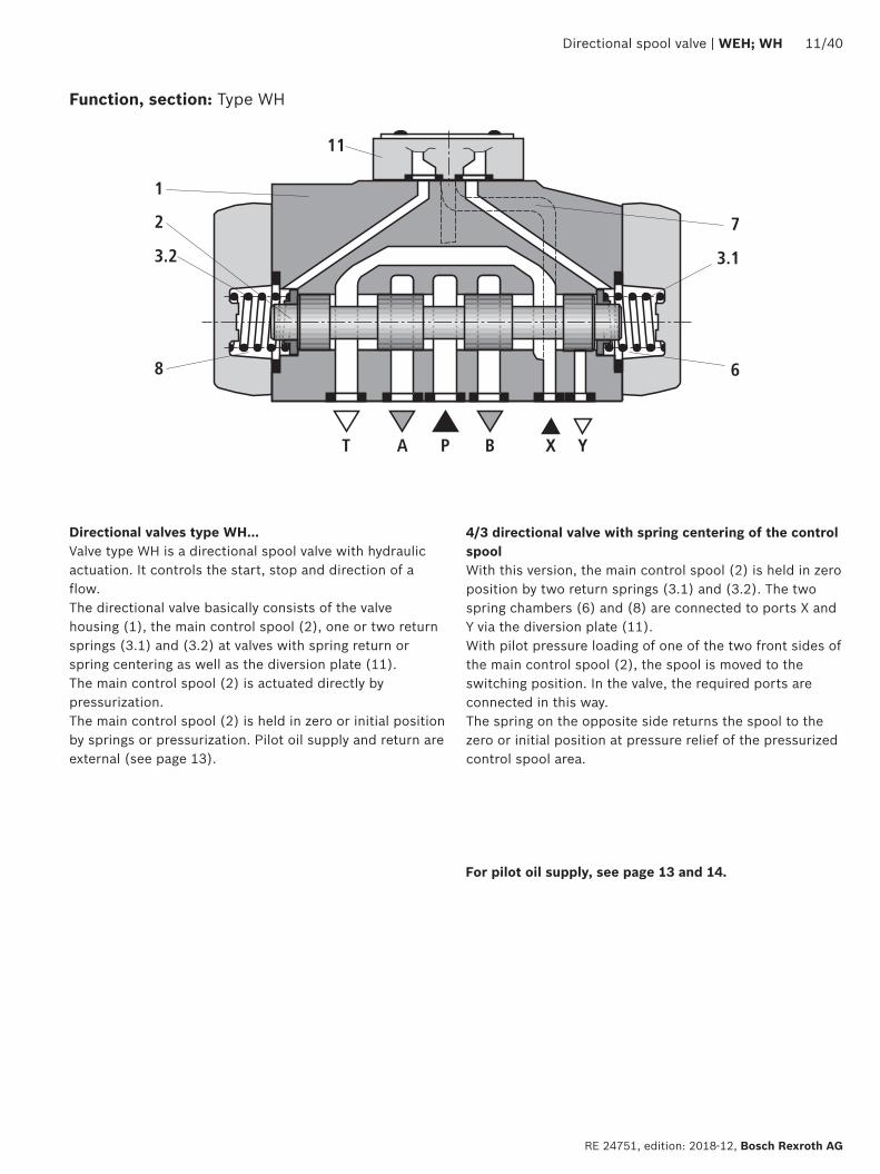
7
6
31
1
2
32
8
T A P B X Y
11
Directional spool valve | WEH WH 1140
RE 24751 edition 2018-12 Bosch Rexroth AG
For pilot oil supply see page 13 and 14
Directional valves type WHhellipValve type WH is a directional spool valve with hydraulic actuation It controls the start stop and direction of a flowThe directional valve basically consists of the valve housing (1) the main control spool (2) one or two return springs (31) and (32) at valves with spring return or spring centering as well as the diversion plate (11)The main control spool (2) is actuated directly by pressurizationThe main control spool (2) is held in zero or initial position by springs or pressurization Pilot oil supply and return are external (see page 13)
43 directional valve with spring centering of the control spoolWith this version the main control spool (2) is held in zero position by two return springs (31) and (32) The two spring chambers (6) and (8) are connected to ports X and Y via the diversion plate (11)With pilot pressure loading of one of the two front sides of the main control spool (2) the spool is moved to the switching position In the valve the required ports are connected in this way The spring on the opposite side returns the spool to the zero or initial position at pressure relief of the pressurized control spool area
Function section Type WH
B A4 10
7
6
31
9
51
1
2
32
9
52
8
ldquobrdquo ldquoardquo
T A P B X Y12
L
1240 WEH WH | Directional spool valve
Bosch Rexroth AG RE 24751 edition 2018-12
43 directional valve with pressure centering of the main control spool type WEHhellipHThe main control spool (2) in the main valve is kept in the zero position by pressurization of the two front faces One centering bush (12) rests on the housing and fixes the control spool positionBy pressure relief of one front face the main control spool (2) is moved to the switching positionThe unloaded control spool face displaces the returning pilot oil into channel Y (external) via the pilot control valve
NoticesThe springs (31) and (32) do not have a return function in this version They hold the main control spool (2) in central position in the depressurized condition and with horizontal installation
Function section Type WEHhellipH
P
P
T
T 1
2P
P
T
T 1
2
P
P
T
T
1
2
P
P
T
T
3
1
P
P
T
T
1 2
Directional spool valve | WEH WH 1340
RE 24751 edition 2018-12 Bosch Rexroth AG
Pilot oil supply (schematic illustration)
Further explanations on page 14
NG10 NG16
Pilot oil supplyexternal 2 3 closedinternal 2 3 open
Pilot oil returnexternal 1 closedinternal 1 open
NG25 (WH 22) NG25 (WH 25)
NG32
1 Plug screw M6 according to DIN 906 wrench size 3 ndash pilot oil return
2 Plug screw M6 according to DIN 906 wrench size 3 ndash pilot oil supply
3 Plug screw M12 x 15 according DIN 906 wrench size 6 ndash pilot oil supply
P
3
4
5
1440 WEH WH | Directional spool valve
Bosch Rexroth AG RE 24751 edition 2018-12
Type WHhellipThe pilot oil supply and return is implemented externally via channel X and Y
Type WEHThe pilot oil supply is implemented externally - via channel X - from a separate pressure supplyThe pilot oil return is implemented externally - via channel Y - into the tank
Type WEHhellipEhellipThe pilot oil supply is implemented internally from channel P of the main valve (see page 15 footnotes 5) and 6))The pilot oil return is implemented externally - via channel Y - into the tank In the subplate port X is closed
Type WEHhellipEThellipThe pilot oil supply is implemented internally from channel P of the main valveThe pilot oil return is implemented internally - via channel T - into the tank In the subplate ports X and Y are closed
Type WEHhellipThellipThe pilot oil supply is implemented externally - via channel X - from a separate pressure supplyThe pilot oil return is implemented internally - via channel T - into the tank In the subplate port Y is closed
Throttle insertUse of the throttle insert (5) is necessary if the pilot oil supply in channel P of the pilot control valve is to be limited (see below)The throttle insert (5) is inserted in channel P of the pilot control valve
Pilot oil supply
NoticesThe modification of the pilot oil supply may only be performed by authorized specialists or at the factory
Pilot oil supply X or return Y external ndash The maximum admissible operating parameters of the pilot control valve must be observed (see data sheet 23178)
ndash Maximum pilot pressure please observe page 16 Pilot oil supply internal (version ET and E)
ndash Minimum pilot pressure please observe page 15 ndash In order to prevent inadmissibly high pressure peaks a B10 throttle insert has to be provided in port P of the pilot control valve (see above)
ndash In connection with version H the pressure reducing valve D3 (see page 38) is also required
3 Pilot control valve4 Main valve5 Throttle insert
Directional spool valve | WEH WH 1540
RE 24751 edition 2018-12 Bosch Rexroth AG
Technical data (For application outside these values please consult us)
generalSizes NG 10 16 25
WH 2225
WH 2532
Weight approx Valve with one solenoid kg [lbs] 64 [141] 85 [187] 115 [253] 176 [388] 176 [388]
Valve with two solenoids spring-centered kg [lbs] 68 [150] 89 [196] 119 [262] 190 [419] 410 [904]
Valve with two solenoids pressure-centered kg [lbs] 68 [150] 89 [196] 119 [262] 190 [419] 410 [904]
Valve witch hydraulic actuation (type WH) kg [lbs] 55 [121] 73 [161] 105 [231] 165 [364] 395 [871]
Switching time adjustment S and S2 kg [lbs] 08 [18] 08 [18] 08 [18] 08 [18] 08 [18]
Pressure reducing valve D3 kg [lbs] 04 [09] 04 [09] 04 [09] 04 [09] 04 [09]
Installation position Any horizontal with valves with hydraulic control spool return H and symbol A B C D K Z Y With suspended installation higher sensitivity to contamination ndash horizontal is recommended
Ambient temperature range
Standard version degC [degF] ndash20 hellip +50 [ndash4 hellip +122] (NBR seals)ndash15 hellip +70 [+5 hellip +122] (FKM seals)
Version for HFC hydraulic fluid degC [degF] ndash20 hellip +50 [ndash4 hellip +122]
Storage temperature range degC [degF] +5 hellip +40 [+41 hellip +104]
Surface protection (valve body) Coating layer thickness max 100 microm
MTTFd values according to EN ISO 13849 Years 100 (type WEH) 150 (type WH) (for further details see data sheet 08012)
hydraulicMaximum operating pressure
Port P A B Type WH bar [psi] 280 [4061] 280 [4061] 280 [4061] 280 [4061] 280 [4061]
Type H-WH bar [psi] 350 [5076]
350 [5076]
350 [5076]
350 [5076]
350 [5076]
Port T External pilot oil return Y
Type WH bar [psi] 280 [4061]
250 [3626] 250 [3626] 250 [3626] 250 [3626]
Type H-WH 315 [4568] 250 [3626] 250 [3626] 250 [3626] 250 [3626]
Internal pilot oil return Y
1)Type H-WEH WEH bar [psi] 210 [3046] with direct voltage
160 [2320] with alternating voltage
Port Y External pilot oil return Type H-WEH WEH bar [psi] 210 [3046] with direct voltage 160 [2320] with alternating voltage
Type WH H-WH bar [psi] 250 [3626] 250 [3626] 210 [3046] 250 [3626] 250 [3626]
Hydraulic fluid see table on page 15
Hydraulic fluid temperature range (at the valve working ports) 3)
degC [degF] ndash20 hellip +80 [ndash4 hellip +176] (NBR seals)ndash15 hellip +80 [+5 hellip +176] (FKM seals)ndash20 hellip +50 [ndash4 hellip +122] (HFC hydraulic fluid)
Viscosity range mm2s [SUS] 28 hellip 500 [35 hellip 2320]
Maximum admissible degree of contamination of the hydraulic fluid Cleanliness class according to ISO 4406 (c)
Class 201815 2)
1) As a 3-spool position valve pressure-centered only possible if ppilot ge 2 x ptank + ppilot min
2) The cleanliness classes specified for the components must be adhered to in hydraulic systems Effective filtration prevents faults and simultaneously increases the life cycle of the components
For selecting the filters see wwwboschrexrothcomfilter3) If type WH is used in potentially explosion-proof areas see
data sheet 07011
1640 WEH WH | Directional spool valve
Bosch Rexroth AG RE 24751 edition 2018-12
Technical data (For applications outside these parameters please consult us)
hydraulicSize NG 10 16 25
WH 2225
WH 2532
Maximum pilot pressure 4) bar [psi] 250 [3626]
250 [3626]
210 [3046]
250 [3626]
250 [3626]
Minimum pilot pressure
External pilot oil supply X (all symbols) internal pilot oil supply (only symbols D K E J L M Q R U W)
3-spool position valve spring-centered Type H-WHhellip bar [psi] 12 [174] 14 [203] 125 [181] 13 [188] 85 [123]
Type WH bar [psi] 12 [174] 14 [203] 105 [152] 13 [188] 85 [123]
3-spool position valve pressure-centered bar [psi] ndash 14 [203] ndash 18 [261] 85 [123]
2-spool position valve with spring end position
Type H-WH bar [psi] 10 [145] 14 [203] 14 [203] 13 [188] 10 [145]
Type WH bar [psi] 10 [145] 14 [203] 11 [159] 13 [188] 10 [145]
2-spool position valve with hydraulic end position bar [psi] 7 [101] 14 [203] 8 [116] 8 [116] 5 [72]
Internal pilot oil supply X (only type WEH) (with symbols C F G H P T V Z S 5))
bar [psi] 75 [109]
6)45 [65] 7) 45 [65] 7) 45 [65] 7) 45 [65] 7)
Free flow cross-sections in zero position with symbols Q V and W
Symbol Q A ndash T B ndash T mm2 [inch2] 13 [002] 32 [005] 78 [0121] 83 [0129] 78 [0121]
Symbol V P ndash A P ndash B mm2 [inch2] 13 [002] 32 [005] 73 [0113] 83 [0129] 73 [0113]
A ndash T B ndash T mm2 [inch2] 13 [002] 32 [005] 84 [013] 83 [0129] 84 [013]
Symbol W A ndash T B ndash T mm2 [inch2] 24 [0004] 6 [0009] 10 [0015] 14 [0022] 20 [0031]
Pilot volume for switching process
3-spool position valve spring-centered cm3 [inch3] 204 [0124]
572 [0349]
764 [0466]
142 [0866]
294 [1794]
2-spool position valve cm3 [inch3] 408 [0249]
1145 [0699]
1528 [0932]
284 [1733]
588 [3588]
3-spool position valve pressure-centered
from zero position in switching position a
Type WH cm3 [inch3] ndash 283 [0173]
ndash 715 [0436]
144 [0879]
Type WEH cm3 [inch3] ndash 283 [0173]
ndash 715 [0436]
144 [0879]
from switching position a in zero position
Type WH cm3 [inch3] ndash 572 [0349]
ndash 1418 [0865]
294 [1794]
Type WEH cm3 [inch3] ndash 29 [0177] ndash 70 [0427] 151 [0921]
from zero position in switching position b
Type WH cm3 [inch3] ndash 572 [0349]
ndash 1418 [0865]
294 [1794]
Type WEH cm3 [inch3] ndash 572 [0349]
ndash 1415 [0863]
294 [1794]
from switching position b in zero position
Type WH cm3 [inch3] ndash 855 [0522]
ndash 1988 [1213]
438 [2673]
Type WEH cm3 [inch3] ndash 283 [0173]
ndash 573 [0349]
144 [0879]
Pilot flow for shortest switching time approx lmin [US gpm] 35 [92] 35 [92] 35 [92] 35 [92] 45 [119]
Directional spool valve | WEH WH 1740
RE 24751 edition 2018-12 Bosch Rexroth AG
4) Internal pilot oil supply ndash With a higher pilot pressure use of a pressure reducing
valve D3 is required (if it is not used pilot pressure = operating pressure at the port)
ndash In connection with version H the pressure reducing valve D3 is also required
External pilot oil supply ndash Compliance with the maximum pilot pressure must be
ensured by appropriate measures (e g protection of the separate pilot oil circuit by means of a pressure relief valve)
5) Symbol S only for NG166) For symbols C F G H P T V Z an internal pilot oil supply is
only possible if the flow from P to T in the central position (for 3-spool position valve) or while crossing the central position (for 2-spool position valve) is so large that the pressure differential of P to T reaches a value of at least 75 bar [109 psi] and the pilot oil return Y is implemented externally
7) For symbols C F G J H P T V Z S 5) ndash by means of preload valve (not NG10) or correspondingly high flow (Determination of the required flow see Preload valve characteristic curves on page 39) For NG10 a check valve with a cracking pressure of 75 bar [109 psi] is to be provided in the return line to the tank The pilot oil return Y must be implemented externally
Technical data (For application outside these values please consult us)
Druckfluumlssigkeit Klassifizierung Geeignete Dichtungsmaterialien
Normen Datenblatt
Mineraloumlle HL HLP HLPD HVLP HVLPD NBR FKM DIN 51524 90220
Biologisch abbaubar wasserunloumlslich HETG FKMISO 15380
90221HEES FKM
wasserloumlslich HEPG FKM ISO 15380
Schwerentflammbar wasserfrei HFDU (Glykolbasis) FKM
ISO 12922 90222HFDU (Esterbasis) FKM
HFDR FKM
wasserhaltig HFC (Fuchs Hydrotherm 46M Renosafe 500 Petrofer Ultra Safe 620 Houghton Safe 620 Union Carbide HP5046)
NBR
ISO 12922 90223
Important information on hydraulic fluids For further information and data on the use of other hydraulic fluids please refer to the data sheets above or contact us
There may be limitations regarding the technical valve data (temperature pressure range life cycle maintenance intervals etc)
The ignition temperature of the hydraulic fluid used must be 50 K higher than the maximum surface temperature
Bio-degradable and flame-resistant ndash containing water If this hydraulic fluid is used small amounts of dissolved zinc may get into the hydraulic system
Flame-resistant ndash containing water ndash Due to increased cavitation tendency with HFC hydraulic fluids the life cycle of the component may be reduced by up to 30 as compared to the use with mineral oil HLP In order to reduce the cavitation effect it is recommended - if possible specific to the installation - to back up the return flow pressure in ports T to approx 20 of the pressure differential at the component
ndash Depending on the hydraulic fluid used the maximum ambient and hydraulic fluid temperature must not exceed 50 degC To reduce the heat input in the component a maximum duty cycle of 50 must be set for onoff valves in continuous operation (measuring time 300 s) If this is not possible due to the function an energy-reducing control of these components is recommended eg via a PWM plug-in amplifier
1840 WEH WH | Directional spool valve
Bosch Rexroth AG RE 24751 edition 2018-12
Switching times
Pilot pressure bar [psi] 70 [1015] 210 [3046] 250 [3626] Spring
ON OFF
NG10 Without throttle insert ms 40 hellip 60 ndash 40 hellip 60 20 hellip 30
With throttle insert ms 60 hellip 90 ndash 50 hellip 70 20 hellip 30
NG16 Without throttle insert ms 50 hellip 80 ndash 40 hellip 60 50 hellip 80
With throttle insert ms 110 hellip 130 ndash 80 hellip 100 50 hellip 80
NG25 (4WH 22) Without throttle insert ms 40 hellip 70 40 hellip 60 ndash 50 hellip 70
With throttle insert ms 140 hellip 160 80 hellip 110 ndash 50 hellip 70
NG25 (4WH 25) Without throttle insert ms 70 hellip 100 ndash 50 hellip 70 100 hellip 130
With throttle insert ms 200 hellip 250 ndash 120 hellip 150 100 hellip 130
NG32 Without throttle insert ms 80 hellip 130 ndash 70 hellip 100 140 hellip 160
With throttle insert ms 420 hellip 560 ndash 230 hellip 350 140 hellip 160
Notices Switching times = Contacting at the pilot control valve until start of opening of the control edge in the main valve and change in the control spool stroke by 95)
The switching times are measured according to ISO 6403 with HLP46 ϑoil = 40 degC plusmn 5 degC [104 degF plusmn9 degF] With different oil temperatures variations are possible
The switching times were determined using DC solenoids They decrease by approx 20 ms if AC solenoids are used
The shut-off of the solenoids creates voltage peaks which can be reduced by the use of suitable diodes
The switching times increase by approx 30 ms if the pressure reducing valve D3 is used
The switching times have been determined under ideal conditions and may differ in the system depending on the application conditions
6
1
10
8
6
4
2
20 40 60 80 100 120 140 1600
0
12
14
22
16
18
20
2
7
8
43
5
Directional spool valve | WEH WH 1940
RE 24751 edition 2018-12 Bosch Rexroth AG
Characteristic curves NG10 (measured with HLP46 ϑOil = 40 plusmn5degC [104 plusmn9degF])
Performance limits NG10 (measured with HLP46 ϑOil = 40 plusmn5degC [104 plusmn9degF])
Flow in lmin [US gpm] rarr
Pres
sure
diff
eren
tial i
n ba
r [p
si] rarr
∆p-qV characteristic curves
Symbol Spool position Zero positionP ndash A P ndash B A ndash T 1) B ndash T 1) A ndash T B ndash T P ndash T
E Y D Q V W Z 1 1 3 5
F 1 3 1 4 3 ndash 6
G T 4 2 4 7 ndash ndash 8
H C 3 3 1 7 1 5 5
J K 1 2 1 6
L 2 2 1 4 2 ndash ndash
M 3 3 2 5
P 3 1 2 7 ndash 5 7
R 1 2 3 ndash
U 2 2 3 6 ndash 6 ndash
A B 1 1 ndash ndash
1) The pressure differential refers to the use of port T If port T1 is additionally used the pressure differential may be lower If only port T1 is used the relations A ndash T and B ndash T may be reversed
Important notices see page 28
2-spool position valves ndash qV max in lmin [US gpm]
SymbolOperating pressure pmax in bar [psi]
70 [1015]
140 [2030]
210 [3046]
280 [4061]
350 [5076]
X external ndash spring end position in the main valve 1) (with ppilot min = 12 bar [174 psi])
C D K Y Z 160 [42] 160 [42] 160 [42] 160 [42] 160 [42]
X external ndash hydraulic end position in the main valveHC HD HK HZ HY
160 [42] 160 [42] 160 [42] 160 [42] 160 [42]
3-spool position valves ndash qV max in lmin [US gpm]
SymbolOperating pressure pmax in bar [psi]
70 [1015]
140 [2030]
210 [3046]
280 [4061]
350 [5076]
X external ndash spring-centeredE J L M Q U V W R
160 [42] 160 [42] 160 [42] 160 [42] 160 [42]
F P 160 [42] 120 [32] 100 [26] 90 [20] 90 [20]
G T 160 [42] 160 [42] 160 [42] 130 [34] 120 [32]
H 160 [42] 160 [42] 120 [32] 110 [29] 100 [26]1) If the pilot pressure fails the function of the return spring is no
longer guaranteed with the specified flow values
4
8
12
16
20
24
28
50 100 150 200 250 300
10
7
9 8
654321
0
[5][0] [10] [792]
0[0]
[50]
[75][15] [20] [25] [30] [35] [40] [45] [50] [55] [60] [65] [70]
[406]
[100]
[150]
[200]
[250]
[300]
[250]
2040 WEH WH | Directional spool valve
Bosch Rexroth AG RE 24751 edition 2018-12
Characteristic curves NG16 (measured with HLP46 ϑOil = 40 plusmn5 degC [104 plusmn9 degF])
∆p-qV characteristic curves
Flow in lmin [US gpm] rarr
Pres
sure
diff
eren
tial i
n ba
r [p
si] rarr
Symbol Spool position Zero positionP ndash A P ndash B A ndash T B ndash T P ndash T A ndash T B ndash T
D E Y 1 1 3 3
F 1 2 5 5 4 3 ndash
G 4 1 5 5 7 ndash ndash
C H 1 1 5 6 2 4 4
K J 2 2 6 6 ndash 3 ndash
L 2 2 5 4 ndash 3 ndash
M 1 1 3 4
P 2 1 3 6 5 ndash ndash
Symbol Spool position Zero positionP ndash A P ndash B A ndash T B ndash T P ndash T A ndash T B ndash T
Q 1 1 6 6
R 2 4 7 ndash
S 3 3 3 ndash 9 ndash ndash
T 4 1 5 5 7 ndash ndash
U 2 2 3 4 6
V Z 1 1 6 6 10 8 8
W 1 1 3 4
Directional spool valve | WEH WH 2140
RE 24751 edition 2018-12 Bosch Rexroth AG
Performance limits NG16 (measured with HLP46 ϑOil = 40 plusmn5 degC [104 plusmn9 degF])
2-spool position valves ndash qV max in lmin [US gpm]
SymbolOperating pressure pmax in bar [psi]
70 [1015]
140 [2030]
210 [3046]
280 [4061]
350 [5076]
X external ndash spring end position in the main valve (with ppilot min = 12 bar [174 psi])
C D K Y Z
300 [79] 300 [79] 300 [79] 300 [79] 300 [79]
X external ndash spring end position in the main valve 1)
C 300 [79] 300 [79] 300 [79] 300 [79] 300 [79]
D Y 300 [79] 270 [71] 260 [68] 250 [66] 230 [60]
K 300 [79] 250 [66] 240 [63] 230 [60] 210 [55]
Z 300 [79] 260 [68] 190 [50] 180 [47] 160 [42]
X external ndash hydraulic end position in the main valveHC HD HK HZ HY
300 [79] 300 [79] 300 [79] 300 [79] 300 [79]
3-spool position valves ndash qV max in lmin [US gpm]
SymbolOperating pressure pmax in bar [psi]
70 [1015]
140 [2030]
210 [3046]
280 [4061]
350 [5076]
X external ndash spring-centeredE H J L M Q U W R
300 [79] 300 [79] 300 [79] 300 [79] 300 [79]
F P 300 [79] 250 [66] 180 [47] 170 [45] 150 [39]
G T 300 [79] 300 [79] 240 [63] 210 [55] 190 [50]
S 300 [79] 300 [79] 300 [79] 250 [66] 220 [58]
V 300 [79] 250 [66] 210 [55] 200 [53] 180 [47]
X external ndash pressure-centered (at minimum pilot pressure of 16 bar [232 psi])
all sym-bols 2)
300 [79] 300 [79] 300 [79] 300 [79] 300 [79]
1) If the specified flow values are exceeded the function of the return spring is no longer guaranteed if the pilot pressure fails
2) With symbol V the pilot control valve is not required for flows gt160 lmin [42 US gpm]
Important notices see page 28
123
45
67
8
9
10
8
6
4
2
50 100 150 200 250 300 350 400
12
14
16
18
20
4500
[10][0] [20] [30] [40] [50] [60] [119]
0
[290]
[0]
[25]
[50]
[75]
[100]
[110][70] [80] [90] [100]
[125]
[150]
[175]
[200]
[225]
[250]
[275]
2240 WEH WH | Directional spool valve
Bosch Rexroth AG RE 24751 edition 2018-12
Characteristic curves NG25 (WH 22) (measured with HLP46 ϑOil = 40 plusmn5 degC [104 plusmn9 degF])
∆p-qV characteristic curves
Flow in lmin [US gpm] rarr
Pres
sure
diff
eren
tial i
n ba
r [p
si] rarr
Symbol Spool positionP ndash A P ndash B A ndash T B ndash T B ndash A
E D 2 2 3 5 ndash
J Q K 2 2 4 6 ndash
M W 1 1 3 5 ndash
H V C Z 1 1 4 6 ndash
F 1 2 4 5 ndash
G 3 4 5 6 ndash
R 1 2 2 ndash ndash
L 2 2 4 5 ndash
U 2 2 2 6 ndash
P 2 2 2 7 ndash
T 4 4 5 6 ndash
Symbol Zero positionA ndash T B ndash T P ndash T
F 2 ndash 4
G T ndash ndash 9
H ndash ndash 3
L 7 ndash ndash
U ndash 6 ndash
J 8 8 ndash
P ndash 4 6
V Z ndash ndash 8
Directional spool valve | WEH WH 2340
RE 24751 edition 2018-12 Bosch Rexroth AG
Performance limits NG25 (WH 22) (measured with HLP46 ϑOil = 40 plusmn5 degC [104 plusmn9 degF])
1) If the specified flow values are exceeded the function of the return spring is no longer guaranteed if the pilot pressure fails Important notices see page 28
2-spool position valves ndash qV max in lmin [US gpm]
SymbolOperating pressure pmax in bar [psi]
70 [1015]
140 [2030]
210 [3046]
280 [4061]
350 [5076]
X external ndash spring end position in the main valve (with ppilot min = 11 bar 14 bar [159 203 psi])
C D K Y Z 450 [119]
450 [119]
450 [119]
450 [119]
450 [119]
X external ndash spring end position in the main valve 1)
C 450 [119]
450 [119]
320 [84]
250 [66]
200 [53]
D Y 450 [119]
450 [119]
450 [119]
400 [105]
320 [84]
K 450 [119]
215 [57]
150 [39]
120 [32]
100 [26]
Z 350 [92]
300 [79]
290 [76]
260 [68]
160 [42]
X external ndash hydraulic end position in the main valveHC HD HK HZ HY
450 [119]
450 [119]
450 [119]
450 [119]
450 [119]
HCOhellip HDOhellip HKOhellip HZOhellip
450 [119]
450 [119]
450 [119]
450 [119]
450 [119]
HCOFhellip HDOFhellip HKOFhellip HZOFhellip
450 [119]
450 [119]
450 [119]
450 [119]
450 [119]
3-spool position valves ndash qV max in lmin [US gpm]
SymbolOperating pressure pmax in bar [psi]
70 [1015]
140 [2030]
210 [3046]
280 [4061]
350 [5076]
X external ndash spring-centered
E J L M Q U W R
450 [119]
450 [119]
450 [119]
450 [119]
450 [119]
H 450 [119]
450 [119]
300 [79]
260 [68]
230 [61]
G 400 [105]
350 [92]
250 [66]
200 [53]
180 [47]
F 450 [119]
270 [71]
175 [46]
130 [34]
110 [29]
V 450 [119]
300 [79]
240 [63]
220 [58]
160 [42]
T 400 [105]
300 [79]
240 [63]
200 [53]
160 [42]
P 450 [119]
270 [71]
180 [47]
170 [45]
110 [29]
1
2
3
4
5
6
0 100 200 300 400 500
78
600 650
10
8
6
4
2
12
14
16
18
20
22
2440 WEH WH | Directional spool valve
Bosch Rexroth AG RE 24751 edition 2018-12
Characteristic curves NG25 (WH 25) (measured with HLP46 ϑOil = 40 plusmn5 degC [104 plusmn9 degF])
∆p-qV characteristic curves
Flow in lmin [US gpm] rarr
Pres
sure
diff
eren
tial i
n ba
r [p
si] rarr
8 Symbol R spool position B ndash A
Symbol Spool position Zero positionP ndash A P ndash B A ndash T 1) B ndash T 1) A ndash T B ndash T P ndash T
E Y D 1 1 3 4
F 1 1 2 4 2 ndash 5
G T 1 1 2 5 ndash ndash 7
H 1 1 2 5 2 2 4
C 1 1 2 5
J 1 1 2 5 6 5 ndash
K 1 1 2 5
L 1 1 2 4 5 ndash ndash
M 1 1 3 4
P 1 1 3 5 ndash 3 5
Q 1 1 2 3
R 1 1 3 ndash
U 1 1 2 5 ndash 5 ndash
V 1 1 2 5 8 7 ndash
Z 1 1 2 5
W 1 1 3 4
Directional spool valve | WEH WH 2540
RE 24751 edition 2018-12 Bosch Rexroth AG
Performance limits NG25 (WH 25) (measured with HLP46 ϑOil = 40 plusmn5 degC [104 plusmn9 degF])
1) If the specified flow values are exceeded the function of the return spring is no longer guaranteed if the pilot pressure fails
Important notices see page 28
2-spool position valves ndash qV max in lmin [US gpm]
SymbolOperating pressure pmax in bar [psi]
70 [1015]
140 [2030]
210 [3046]
280 [4061]
350 [5076]
X external ndash spring end position in the main valve (with ppilot min = 13 bar [188 psi])
C D K Y Z 700 [185 ]
700 [185 ]
700 [185 ]
700 [185 ]
650 [172 ]
X external ndash spring end position in the main valve 1)
C 700 [185 ]
700 [185 ]
700 [185 ]
700 [185 ]
650 [172 ]
D Y 700 [185 ]
650 [172 ]
400 [105 ]
350 [92]
300 [79]
K 700 [185 ]
650 [172 ]
420 [111]
370 [98]
320 [84]
Z 700 [185 ]
700 [185 ]
650 [172 ]
480 [127 ]
400 [105 ]
X external ndash hydraulic end position in the main valveHC HD HK HZ HY
700 [185 ]
700 [185 ]
700 [185 ]
700 [185 ]
700 [185 ]
HCOhellip HDOhellip HKOhellip HZOhellip
700 [185 ]
700 [185 ]
700 [185 ]
700 [185 ]
700 [185 ]
HCOFhellip HDOFhellip HKOFhellip HZOFhellip
700 [185 ]
700 [185 ]
700 [185 ]
700 [185 ]
700 [185 ]
3-spool position valves ndash qV max in lmin [US gpm]
SymbolOperating pressure pmax in bar [psi]
70 [1015]
140 [2030]
210 [3046]
280 [4061]
350 [5076]
X external ndash spring-centeredE L M Q U W 700
[185 ]700
[185 ]700
[185 ]700
[185 ]650
[172 ]
G T 400 [105 ]
400 [105 ]
400 [105 ]
400 [105 ]
400 [105 ]
F 650 [172 ]
550 [145]
430 [113]
330 [87]
300 [79]
H 700 [185 ]
650 [172 ]
550 [145]
400 [105 ]
360 [95]
J 700 [185 ]
700 [185 ]
650 [172 ]
600 [158 ]
520 [137 ]
P 650 [172 ]
550 [145]
430 [113]
330 [87]
300 [79]
V 650 [172 ]
550 [145]
400 [105 ]
350 [92]
310 [82]
R 700 [185 ]
700 [185 ]
700 [185 ]
650 [172 ]
580 [153 ]
X external ndash pressure-centered (at minimum pilot pressure of 18 bar [261 psi])
E F H J L M P Q R U V W
700 [185 ]
700 [185 ]
700 [185 ]
700 [185 ]
650 [172 ]
G T 400 [105 ]
400 [105 ]
400 [105 ]
400 [105 ]
400 [105 ]
X external ndash pressure-centered (with pilot pressure gt 30 bar [435 psi])
G T 700 [185 ]
700 [185 ]
700 [185 ]
700 [185 ]
650 [172 ]
12
10
14
8
6
4
2
100 300
16
18
10800
[40][0] [285]
0500 700 900
[80] [120] [160] [200] [240]
1
2
3
4
[0]
[50]
[100]
[150]
[200]
[261]
12
10
14
8
6
4
2
100 300
16
18
10800
[40][0] [285]
0500 700 900
[80] [120] [160] [200] [240]
5
6
7
8
[0]
[50]
[100]
[150]
[200]
[261]
2640 WEH WH | Directional spool valve
Bosch Rexroth AG RE 24751 edition 2018-12
Characteristic curves NG32 (measured with HLP46 ϑOil = 40 plusmn5 degC [104 plusmn9 degF])
Flow in lmin [US gpm] rarr
Flow in lmin [US gpm] rarr
Pres
sure
diff
eren
tial
in b
ar [p
si] rarr
Pres
sure
diff
eren
tial
in b
ar [p
si] rarr
∆p-qV-characteristic curves ndash Symbol E R and W
∆p-qV characteristic curves ndash Symbol G and T
Symbol Spool positionP ndash A P ndash B A ndash T B ndash T B ndash A
E 4 4 3 2 ndash
R 4 4 3 ndash 1
W 4 4 3 2 ndash
Symbol Spool positionP ndash A P ndash B A ndash T B ndash T P ndash T
G 7 8 7 5 6
T 7 8 7 5 6
Directional spool valve | WEH WH 2740
RE 24751 edition 2018-12 Bosch Rexroth AG
Performance limits NG32 (measured with HLP46 ϑOil = 40 plusmn5 degC [104 plusmn9 degF])
1) If the specified flow values are exceeded the function of the return spring is no longer guaranteed if the pilot pressure fails Important notices see page 28
2-spool position valves ndash qV max in lmin [US gpm]
SymbolOperating pressure pmax in bar [psi]
70 [1015]
140 [2030]
210 [3046]
280 [4061]
350 [5076]
X external ndash spring end position in the main valve (with ppilot min = 10 bar [145 psi])
C D K Y Z 1100 [290]
1040 [275]
860 [227]
750 [198]
680 [179]
X external ndash spring end position in the main valve 1)
C 1100 [290]
1040 [275]
860 [227]
800 [211]
700 [185]
D Y 1100 [290]
1040 [275]
540 [142]
480 [127]
420 [111]
K 1100 [290]
1040 [275]
860 [227]
500 [132]
450 [119]
Z 1100 [290]
1040 [275]
860 [227]
700 [185]
650 [172]
X external ndash hydraulic end position in the main valveHC HD HK HZ HY
1100 [290]
1040 [275]
860 [227]
750 [198]
680 [179]
3-spool position valves ndash qV max in lmin [US gpm]
SymbolOperating pressure pmax in bar [psi]
70[1015]
140 [2030]
210 [3046]
280 [4061]
350 [5076]
X external ndash spring-centeredE J L M Q R U W
1100 [290]
1040 [275]
860 [227]
750 [198]
680 [179]
G T H F P 900 [238]
900 [238]
800 [211]
650 [172]
450 [119]
V 1100 [290]
1000 [264]
680 [179]
500 [132]
450 [119]
X external ndash pressure-centered (at minimum pilot pressure of 85 bar [123 psi])all symbols 1100
[290]1040 [275]
860 [227]
750 [198]
680 [179]
2840 WEH WH | Directional spool valve
Bosch Rexroth AG RE 24751 edition 2018-12
Performance limits important information
NG16 With pilot oil supply X internal a preload valve has to be used for flows lt 160 lmin [42 US gpm] due to the negative overlap of the symbols C Z and HC HZ
43 directional valves with pressure centering of the control spool in the main valve can be used above the indicated performance limit In this case a higher pilot pressure is required (values see performance limits of the corresponding size)
With pilot oil supply X internal sufficient flow needs to be ensured due to the negative overlap of symbols F G H P S and T (for determination of the required flow see Preload valve characteristic curves (page 39) If the required flow is not reached a preload valve has to be used (see page 16)
NG25(WH 22)
With pilot oil supply X internal a preload valve has to be used for flows lt 180 lmin [475 US gpm] due to the negative overlap of symbols Z HZ and V
With pilot oil supply X internal sufficient flow needs to be ensured due to the negative overlap of symbols C HC F G H P and T (for determination of the required flow see Preload valve characteristic curves (page 39) If the required flow is not reached a preload valve has to be used (see page 16)
NG25(WH 25)
With pilot oil supply X internal a preload valve has to be used for flows lt 180 lmin [475 US gpm] due to the negative overlap of symbols Z HZ and V
43 directional valves with pressure centering of the control spool in the main valve can be used above the indicated performance limit In this case a higher pilot pressure is required (values see performance limits of the corresponding size)
With pilot oil supply X internal sufficient flow needs to be ensured due to the negative overlap of symbols C HC F G H P and T (for determination of the required flow see Preload valve characteristic curves (page 39) If the required flow is not reached a preload valve has to be used (see page 16)
NG32 With pilot oil supply X internal a preload valve has to be used for flows lt 180 lmin [475 US gpm] due to the negative overlap of symbols Z HZ and V
43 directional valves with pressure centering of the control spool in the main valve can be used above the indicated performance limit In this case a higher pilot pressure is required (values see performance limits of the corresponding size)
With pilot oil supply X internal sufficient flow needs to be ensured due to the negative overlap of symbols C HC F G H P and T (for determination of the required flow see Preload valve characteristic curves (page 39) If the required flow is not reached a preload valve has to be used (see page 16)
Notice (applies to all sizes)The specified switching power limits apply to the use with two directions of flow (e g from P to A and simultaneous return flow from B to T at a ratio of 11)Due to the flow forces acting within the valves the admissible switching power limit may be considerably lower with only one direction of flow (e g from P to A
while port B is blocked with flow in the same or in different directions)In such cases of application please consult usThe switching power limit was established while the solenoids were at operating temperature at 10 undervoltage and without tank preloading
TT
19
44 1592
40
20
87
73
146
206
168 305
35
11
66
71
27
108
PA B
T
X Y
AT B TP
X Y
T1
AT P B T
A B AT P B T
4
6
72122 11
14
12
32 31
23
1
8
9
13
3514
5
255
135
101
F1 F2
F3F4
19
7
B AT
P
B A
B A
P
001100[0000440]
Rzmax 4
Directional spool valve | WEH WH 2940
RE 24751 edition 2018-12 Bosch Rexroth AG
Dimensions NG10 (dimensions in mm [inch])
For item explanations and subplates see page 34 Valve mounting screws see page 35
Required surface quality of the valve contact surface
NoticeThe dimensions are nominal dimensions which are subject to tolerances
27
9719
1166
206
82
64 164
15656
9240
20
43
93
11 18
3514
12
21
142
94BA
TP
X
LY
102
1
9
5
68
4
31
15
17
13
12
32
21 22
7
3
3 19
A B Y
T P X
B A
15
18 16
F1 F2
F3F4
G1F5
G2 F6
11 23 14
B AT
P
001100[0000440]
Rzmax 4
3040 WEH WH | Directional spool valve
Bosch Rexroth AG RE 24751 edition 2018-12
Dimensions NG16 (dimensions in mm [inch])
For item explanations and subplates see page 34 Valve mounting screws see page 35
Required surface quality of the valve contact surface
NoticeThe dimensions are nominal dimen-sions which are subject to toler-ances
001100[0000440]
Rzmax 4
15
117
14
20
14 193241
110
19
414
6
A BX
PT Y92
4020
4
7
11 1432
1
8
912
19
13
21 22
103
3123
6
5
3514
14
175
180
120
BAX
T PY
[07
5][4
33]
[055] [760]
[949]
[46
1]
[Oslash079]
[Oslash055][709]
[069]
[47
2]
[05
5]
[Oslash024]
[015
7][1
61]
[014]
[055]
[05
9]
[15
7]
[07
8][3
62]
F1 F2
F3F4
F5
F6
G1
G2
206 [811]
L 1)
T
PB A
B A
Directional spool valve | WEH WH 3140
RE 24751 edition 2018-12 Bosch Rexroth AG
For item explanations and subplates see page 34 Valve mounting screws see page 35 Required surface quality of the
valve contact surface
Dimensions NG25 (WH 22) (dimensions in mm [inch])
1) Port L only for valves with pressure-centered zero position
NoticeThe dimensions are nominal dimensions which are subject to tolerances
19 225
2973245
275
332
3245
126
19
414
6
1592
20
7
11
32
18
9
12
19
13
15
1617
18
21 22
6
5
23 31 144
40
3514
206
279
L1)
BAX
T P Y
AXB
T P Y 14
21
195
117
20
14
103
F1 F2
F3F4
F5
F6
G1
G2
B A
T
PB A
120
001100[0000440]
Rzmax 4
3240 WEH WH | Directional spool valve
Bosch Rexroth AG RE 24751 edition 2018-12
Dimensions NG25 (WH 25) (dimensions in mm [inch])
1) Port L only for valves with pressure-centered zero position
For item explanations and subplates see page 34 Valve mounting screws see page 35 Required surface quality of the
valve contact surface
NoticeThe dimensions are nominal dimensions which are subject to tolerances
001100[0000440]
Rzmax 4
T
X
1933 22
P Y
X A B
197
205
23
257
A B
T PY
49
40
2+0
3
2865
6362
391
406
215
152
19
1592
4020
7
11 14
32
12
19
13
1516
17
18
21 22
23 31 4
3514
6
5
8
91
104
[59
8][0
75]
[014]
[055]
[05
9]
[15
7]
[07
8][3
62]
[19
3]
[Oslash024] [01
57]
[00
079+0
011
8 ]
[085] [1425]
[1539]
[1598]
[77
6]
[Oslash130] [Oslash087]
[1012]
[091]
[08
1]
391 [1539]
[78
7]
F1 F2
F3F4
F5
F6
G1
G2
206 [811]
LT
PB A
B A
200
Directional spool valve | WEH WH 3340
RE 24751 edition 2018-12 Bosch Rexroth AG
For item explanations and subplates see page 34 Valve mounting screws see page 35 Required surface quality of the
valve contact surface
Dimensions NG32 (dimensions in mm [inch])
NoticeThe dimensions are nominal dimensions which are subject to tolerances
3440 WEH WH | Directional spool valve
Bosch Rexroth AG RE 24751 edition 2018-12
1 Main valve2 Pilot control valve type 4WE 6 (data sheet 23178)
21 Pilot control valve type 4WE 6 Dhellip (1 solenoid) for main valves with symbols C D K Z symbols HC HD HK HZ
Pilot control valve type 4WE 6 JA (1 solenoid a) for main valves with symbols EA FA etc spring return
Pilot control valve type 4WE 6 MA (1 solenoid a) for main valves with symbols HEA HFA etc hydraulic spool return
22 Pilot control valve type 4WE 6 Y (1 solenoid) for main valves with symbol Y symbol HY
Pilot control valve type 4WE 6 JB (1 solenoid b) for main valves with symbols EB FB etc spring return
Pilot control valve type 4WE 6 MB (1 solenoid b) for main valves with symbols HEB HFB etc hydraulic spool return
23 Pilot control valve type 4WE 6Jhellip (2 solenoids) for main valves with 3 spool positions spring-centered
Pilot control valve type 4WE 6 Mhellip (2 solenoids) for main valves with 3 spool positions pressure-centered
31 Solenoid a32 Solenoid b
4 Manual override N optional Actuation of the manual override is only possible up to a tank pressure of approx 50 bar Avoid damage to the bore of the manual override (Special tool for the operation separate order material no R900024943) When the manual override is blocked the operation of the solenoid must be prevented
Simultaneous actuation of the solenoids must be prevented
5 Solenoid without manual override6 Solenoid with manual override7 Height of the diversion plate with hydraulic actuation
(type WH)8 Switching time adjustment (wrench size 6) optional9 Pressure reducing valve optional
101 Machined valve contact surface porting pattern according to ISO 4401-05-05-0-05 and NFPAT351 R2-D05
102 Machined valve contact surface porting pattern according to ISO 4401-07-07-0-05 and NFPAT351 R2-D07
103 Machined valve contact surface porting pattern according to ISO 4401-08-08-0-05 and NFPAT351 R2-D08
104 Machined valve contact surface porting pattern according to ISO 4401-10-09-0-05 and NFPAT351 R2-D10
11 Name plate pilot control valve12 Name plate complete valve13 Seal rings14 Space required for removing the mating connector15 2-spool position valves with spring end position in the main
valve (symbols A C D K Z)16 2-spool position valves with spring end position in the main
valve (symbols B Y)
17 3-spool position valves spring-centered 2-spool position valves with hydraulic end position in the main valve
18 3-spool position valves pressure-centered19 Locking pin
Subplates (separate order) with porting pattern according to ISO 4401 see data sheet 45100
Valve mounting screws see page 35
Dimensions
Directional spool valve | WEH WH 3540
RE 24751 edition 2018-12 Bosch Rexroth AG
Dimensions
Valve mounting screws (separate order) Nominal size Quantity Hexagon socket head cap screws Material number10 4 ISO 4762 - M6 x 45 - 109-CM-Fe-ZnNi-5-Cn-T0-H-B
Friction coefficient micrototal = 009 hellip 014 tightening torque MA = 125 Nm [92 ft-lbs] plusmn10 R913043777
or
4 14-20 UNC x 1 34rdquo ASTM-A574 Not included in the Rexroth delivery range
16 4 ISO 4762 - M10 x 60 - 109-flZnnc480hCFriction coefficient micrototal = 009 hellip 014 tightening torque MA = 58 Nm [428 ft-lbs] plusmn10
R913014770
2 ISO 4762 - M6 x 60 - 109-CM-Fe-ZnNi-5-Cn-T0-H-B Friction coefficient micrototal = 009 hellip 014 tightening torque MA = 125 Nm [92 ft-lbs] plusmn10
R913043410
or
4 Zylinderschrauben UNC 38-16 UNC x 2 14rdquo ASTM-A574 Not included in the Rexroth delivery range2 Zylinderschrauben UNC 14-20 UNC x 2 14rdquo ASTM-A574
25 6 ISO 4762 - M12 x 60 - 109-flZnnc480hC Friction coefficient micrototal = 009 hellip 014 tightening torque MA = 100 Nm [74 ft-lbs] plusmn20
R913015613
or
6 UNC 12-13 UNC x 2 12rdquo ASTM-A574 Not included in the Rexroth delivery range
32 6 ISO 4762 - M20 x 80 - 109-flZnnc480hC Friction coefficient micrototal = 009 hellip 014 tightening torque MA = 340 Nm [251 ft-lbs] plusmn10
R913008472
or
6 UNC 34-10 UNC x 3 14rdquo ASTM-A574 Not included in the Rexroth delivery range
L4
L3
5
4 2
3
1
3640 WEH WH | Directional spool valve
Bosch Rexroth AG RE 24751 edition 2018-12
Stroke setting mounting options (dimensions in mm [inch])
NG L410 65 [026]
16 10 [039]
25 (WH 22) 95 [037]
25 (WH 25) 125 [049]
32 15 [059]
The stroke of the control spool is limited by the stroke setting (1) The control spool stroke is shortened by loosening the lock nut (2) and clockwise rotation of the adjustment spindle (3) The control chamber (4) must be depressurized for this
5 Adjustment range NG10 1 rotation = 1 mm [00394 inch] adjustment travel
NG16 and 32 1 rotation = 15 mm [00591 inch] adjustment travel
3-spool position valve 1)
spring-centered pressure-centered
L1 L2 L3 L1 L2 L3
Stroke setting on valve side A and B 10
10 90 [354] 144 [567] 234 [921]
16 100 [394] 200 [787] 300 [1181]
25 2) 96 [377] 241 [949] 337 [1327]
25 3) 123 [484] 276 [1087] 399 [1571]
32 133 [524] 344 [1354] 477 [1878]
Stroke setting on valve side A
11
10 90 [354] 106 [417] 196 [772]
16 100 [394] 156 [614] 256 [1008]
25 2) 96 [377] 193 [760] 289 [1138]
25 3) 123 [484] 225 [886] 348 [1370]
32 133 [524] 287 [1130] 420 [1654]
Stroke setting on valve side B 12
10 52 [205] 144 [567] 196 [772] ndash ndash ndash
16 56 [220] 200 [787] 256 [1008] 81 [319] 200 [787] 281 [1106]
25 2) 48 [189] 241 [949] 289 [1138] ndash ndash ndash
25 3) 72 [283] 276 [1087] 348 [1370] 107 [421] 276 [1087] 283 [1114]
32 76 [299] 344 [1354] 420 [1654] 120 [472] 344 [1354] 464 [1827]
More dimensions see below and page 37
Stroke limitation on side A Stroke limitation on side B
a
BA
L3
L1 L2
L3L2
X A B
a
B
b
A A B
L3
L3L2L1
L1
b a
X A B
1) With symbol A only version 11 with symbol B only version 12 possible
Directional spool valve | WEH WH 3740
RE 24751 edition 2018-12 Bosch Rexroth AG
Stroke setting mounting options (dimensions in mm [inch])
2) Version WH 223) Version WH 25
2-spool position valve Spring end position Hydraulic end position
A C D K Z B Y HC HD HK HZ HY
L1 L2 L3 L1 L2 L3 L1 L2 L3
Stroke setting on valve side A and B 10
10 90 [354]
144 [567]
234 [921]
90 [354]
144 [567]
234 [921]
90 [354]
144 [567]
234 [921]
16 ndash ndash ndash ndash ndash ndash 100 [394]
200 [787]
300 [1181]
25 2) 96 [378]
241 [949]
337 [1327]
96 [378]
241 [949]
337 [1327]
96 [378]
241 [949]
337 [1327]
25 3) ndash ndash ndash ndash ndash ndash 123 [484]
276 [1087]
399 [1571]
32 ndash ndash ndash ndash ndash ndash 133 [524]
344 [1354]
477 [1878]
Stroke setting on valve side A
11
10 90 [354]
106 [417]
196 [772]
90 [354]
106 [417]
196 [772]
90 [354]
106 [417]
196 [772]
16 100 [394]
180 [709]
280 [1102] ndash ndash ndash 100
[394]156
[614]256
[1008]
25 2) 96 [378]
193 [760]
289 [1138]
96 [378]
193 [760]
289 [1138]
96 [378]
193 [760]
289 [1138]
25 3) 123 [484]
253 [996]
376 [148] ndash ndash ndash 123
[484]225
[886]348
[1370]
32 133 [524]
316 [1244]
449 [1768] ndash ndash ndash 133
[524]287
[1130]420
[1653]
Stroke setting on valve side B 12
10 52 [205]
144 [567]
196 [772]
52 [205]
144 [567]
196 [772]
52 [205]
144 [567]
196 [772]
16 ndash ndash ndash 80 [315]
200 [787]
280 [1102]
56 [221]
200 [787]
256 [1008]
25 2) 48 [189]
241 [949]
289 [1138]
48 [189]
241 [949]
289 [1138]
48 [189]
241 [949]
289 [1138]
25 3) ndash ndash ndash 100 [394]
276 [1087]
376 [1480]
72 [284]
276 [1087]
348 [1370]
32 ndash ndash ndash 105 [413]
344 [1354]
449 [1768]
76 [299]
344 [1354]
420 [1653]
NoticeThe dimensions are nominal dimensions which are subject to tolerances
34
7 5
62
1
7
8
3840 WEH WH | Directional spool valve
Bosch Rexroth AG RE 24751 edition 2018-12
Switching time adjustment
Pressure reducing valve D3
The switching time of the main valve (1) is influenced by using a twin throttle check valve (2) (type Z2FS 6 data sheet 27506)
Modification of supply (3) to discharge control (4)Remove the pilot control valve (5) ndash The plate (6) to accept the seal rings stays in place ndash Turn the switching time adjustment (2) around its longitudinal axis and put it back install the pilot control valve (5)
NoticeThe modification may only be performed by authorized specialists or at the factory
Type WEH 10 4XhellipS Type WEH 10 4XhellipS2
The pressure reducing valve (8) has to be used at a pilot pressure above 250 bar [3626 psi] (with WEH 22 hellip 210 bar [3046 psi]) and with version HThe secondary pressure is kept at a constant level of 45 bar [652 psi]
Notice If a pressure reducing valve D3 (8) is used a B10
throttle insert has to be installed in channel P of the pilot control valve
The modification may only be performed by authorized specialists or at the factory Type WEH 10 4XhellipD3
92
10
11
141210
8
6
4
2
100 200 300 400 500 600 700
1 2
3
4
0
[20][0] [185]
0[0]
[50]
[100]
[150]
[203]
[40] [60] [80] [100] [120] [140] [160]
91
10
11
Directional spool valve | WEH WH 3940
RE 24751 edition 2018-12 Bosch Rexroth AG
Pres
sure
diff
eren
tial
in b
ar [p
si] rarr
Flow in lmin [US gpm] rarr
∆pndashqV characteristic curve (measured with HLP46 ϑOil = 40 degC plusmn 5 degC [104 degF plusmn9 degF])
1 NG16
2 NG25 (WH 25)
3 NG25 (WH 22)
4 NG32
In case of valves with depressurized circulation and internal pilot oil supply the installation of the preload valve (9) in channel P of the main valve is required in order to build up the minimum pilot pressure
SizeItem 91 Item 92
16 R961009415 (from component series 72) R961009417 (up to component series 71)
25 (WH 22) ndash R961009609 (up to component series 76)
25 (WH 25) R961009166 (from component series 68) R961009416 (up to component series 67)
32 ndash R961009610 (up to component series 63)
Preload valve (not for NG10)
91 Preload valve
92 Preload valve
10 Main valve
11 Subplate
The pressure differential of the preload valve is to be added to the pressure differential of the main valve (see characteristic curves) to result in one total valueThe cracking pressure amounts to approx 45 bar [65 psi]
NoticeSeries-production status see ordering key on the name plate
Bosch Rexroth AG RE 24751 edition 2018-12
4040 WEH WH | Directional spool valve
Bosch Rexroth AG Industrial HydraulicsZum Eisengieszliger 197816 Lohr am Main Germany Phone +49 (0) 93 52thinspthinsp40 30 20 mysupportboschrexrothde wwwboschrexrothde
copy All rights reserved to Bosch Rexroth AG also regarding any disposal exploitation reproduction editing distribution as well as in the event of applications for industrial property rightsThe data specified above only serve to describe the product No statements concerning a certain condition or suitability for a certain application can be derived from our information The information given does not release the user from the obligation of own judgment and verificationPlease note that our products are subject to a natural process of wear and aging
Project planning information
The stipulations of the Machinery Directive 200642EC are to be adhered toPlease also note data sheet 08012 with information on MTTFd values and shock and vibration loads
Further information
Directional spool valve Data sheet 23178 Subplates Data sheet 45100 Inductive position switch and proximity sensors (contactless) Data sheet 24830 Hydraulic fluids on mineral oil basis Data sheet 90220 Environmentally compatible hydraulic fluids Data sheet 90221 Flame-resistant water-free hydraulic fluids Data sheet 90222 Flame-resistant hydraulic fluids - containing water (HFAE HFAS HFB HFC) Data sheet 90223 Reliability characteristics according to EN ISO 13849 Data sheet 08012 Hexagon socket head cap screw metricUNC Data sheet 08936 Hydraulic valves for industrial applications Operating instructions 07600-B General product information on hydraulic products Data sheet 07008 Assembly commissioning and maintenance of industrial valves Data sheet 07300 Mating connectors and cable sets for valves and sensors in hydraulics Data sheet 08006 Directional spool valves and directional seat valves with electrical actuation and
M12x1 plug-in connectionData sheet 08010
Use of non-electrical hydraulic components in an explosive environment (ATEX) Data sheet 07011 Selection of filters wwwboschrexrothcomfilter Information on available spare parts wwwboschrexrothcomspc
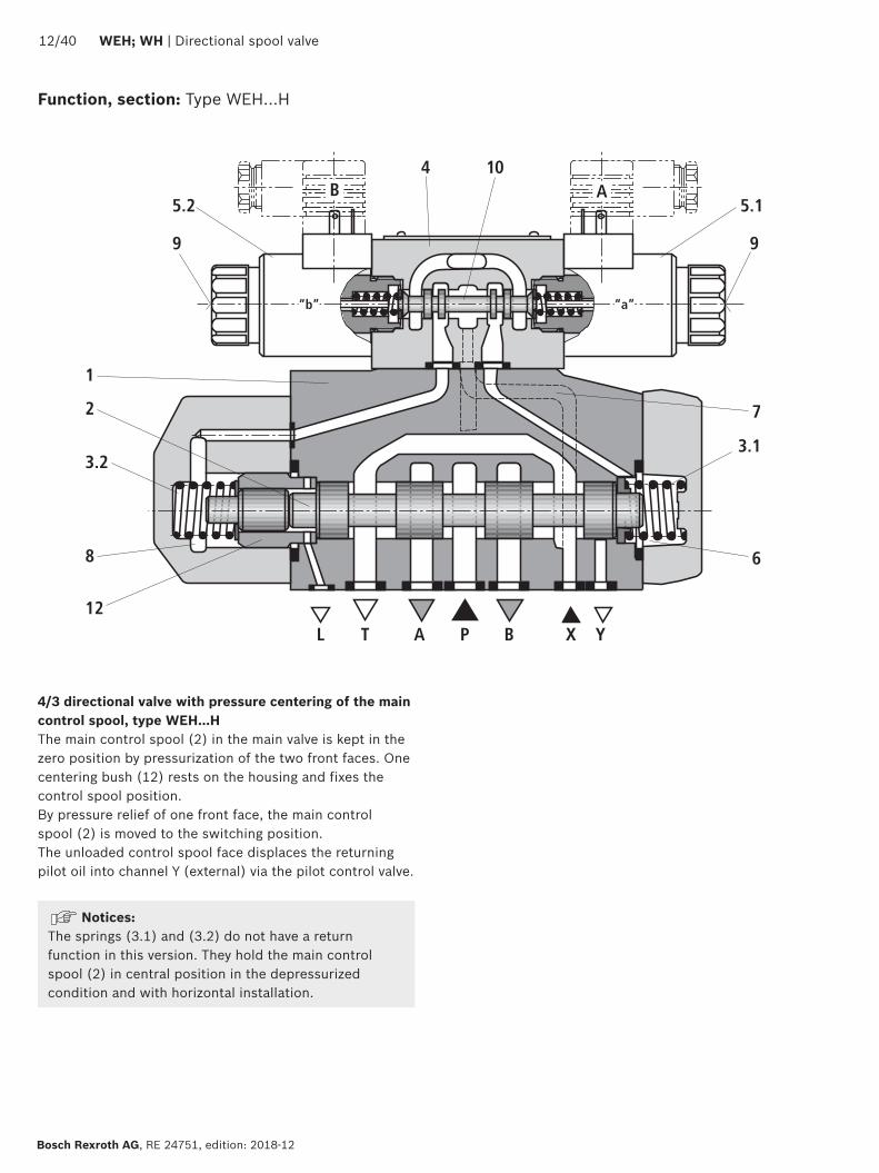
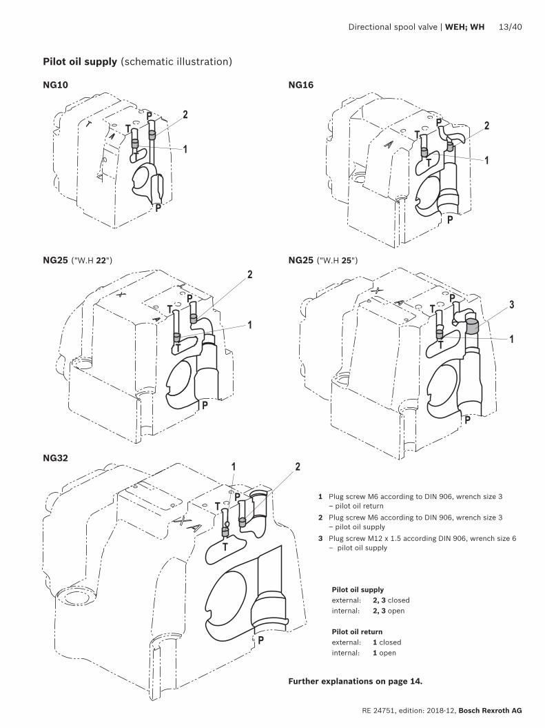
P
P
T
T 1
2P
P
T
T 1
2
P
P
T
T
1
2
P
P
T
T
3
1
P
P
T
T
1 2
Directional spool valve | WEH WH 1340
RE 24751 edition 2018-12 Bosch Rexroth AG
Pilot oil supply (schematic illustration)
Further explanations on page 14
NG10 NG16
Pilot oil supplyexternal 2 3 closedinternal 2 3 open
Pilot oil returnexternal 1 closedinternal 1 open
NG25 (WH 22) NG25 (WH 25)
NG32
1 Plug screw M6 according to DIN 906 wrench size 3 ndash pilot oil return
2 Plug screw M6 according to DIN 906 wrench size 3 ndash pilot oil supply
3 Plug screw M12 x 15 according DIN 906 wrench size 6 ndash pilot oil supply
P
3
4
5
1440 WEH WH | Directional spool valve
Bosch Rexroth AG RE 24751 edition 2018-12
Type WHhellipThe pilot oil supply and return is implemented externally via channel X and Y
Type WEHThe pilot oil supply is implemented externally - via channel X - from a separate pressure supplyThe pilot oil return is implemented externally - via channel Y - into the tank
Type WEHhellipEhellipThe pilot oil supply is implemented internally from channel P of the main valve (see page 15 footnotes 5) and 6))The pilot oil return is implemented externally - via channel Y - into the tank In the subplate port X is closed
Type WEHhellipEThellipThe pilot oil supply is implemented internally from channel P of the main valveThe pilot oil return is implemented internally - via channel T - into the tank In the subplate ports X and Y are closed
Type WEHhellipThellipThe pilot oil supply is implemented externally - via channel X - from a separate pressure supplyThe pilot oil return is implemented internally - via channel T - into the tank In the subplate port Y is closed
Throttle insertUse of the throttle insert (5) is necessary if the pilot oil supply in channel P of the pilot control valve is to be limited (see below)The throttle insert (5) is inserted in channel P of the pilot control valve
Pilot oil supply
NoticesThe modification of the pilot oil supply may only be performed by authorized specialists or at the factory
Pilot oil supply X or return Y external ndash The maximum admissible operating parameters of the pilot control valve must be observed (see data sheet 23178)
ndash Maximum pilot pressure please observe page 16 Pilot oil supply internal (version ET and E)
ndash Minimum pilot pressure please observe page 15 ndash In order to prevent inadmissibly high pressure peaks a B10 throttle insert has to be provided in port P of the pilot control valve (see above)
ndash In connection with version H the pressure reducing valve D3 (see page 38) is also required
3 Pilot control valve4 Main valve5 Throttle insert
Directional spool valve | WEH WH 1540
RE 24751 edition 2018-12 Bosch Rexroth AG
Technical data (For application outside these values please consult us)
generalSizes NG 10 16 25
WH 2225
WH 2532
Weight approx Valve with one solenoid kg [lbs] 64 [141] 85 [187] 115 [253] 176 [388] 176 [388]
Valve with two solenoids spring-centered kg [lbs] 68 [150] 89 [196] 119 [262] 190 [419] 410 [904]
Valve with two solenoids pressure-centered kg [lbs] 68 [150] 89 [196] 119 [262] 190 [419] 410 [904]
Valve witch hydraulic actuation (type WH) kg [lbs] 55 [121] 73 [161] 105 [231] 165 [364] 395 [871]
Switching time adjustment S and S2 kg [lbs] 08 [18] 08 [18] 08 [18] 08 [18] 08 [18]
Pressure reducing valve D3 kg [lbs] 04 [09] 04 [09] 04 [09] 04 [09] 04 [09]
Installation position Any horizontal with valves with hydraulic control spool return H and symbol A B C D K Z Y With suspended installation higher sensitivity to contamination ndash horizontal is recommended
Ambient temperature range
Standard version degC [degF] ndash20 hellip +50 [ndash4 hellip +122] (NBR seals)ndash15 hellip +70 [+5 hellip +122] (FKM seals)
Version for HFC hydraulic fluid degC [degF] ndash20 hellip +50 [ndash4 hellip +122]
Storage temperature range degC [degF] +5 hellip +40 [+41 hellip +104]
Surface protection (valve body) Coating layer thickness max 100 microm
MTTFd values according to EN ISO 13849 Years 100 (type WEH) 150 (type WH) (for further details see data sheet 08012)
hydraulicMaximum operating pressure
Port P A B Type WH bar [psi] 280 [4061] 280 [4061] 280 [4061] 280 [4061] 280 [4061]
Type H-WH bar [psi] 350 [5076]
350 [5076]
350 [5076]
350 [5076]
350 [5076]
Port T External pilot oil return Y
Type WH bar [psi] 280 [4061]
250 [3626] 250 [3626] 250 [3626] 250 [3626]
Type H-WH 315 [4568] 250 [3626] 250 [3626] 250 [3626] 250 [3626]
Internal pilot oil return Y
1)Type H-WEH WEH bar [psi] 210 [3046] with direct voltage
160 [2320] with alternating voltage
Port Y External pilot oil return Type H-WEH WEH bar [psi] 210 [3046] with direct voltage 160 [2320] with alternating voltage
Type WH H-WH bar [psi] 250 [3626] 250 [3626] 210 [3046] 250 [3626] 250 [3626]
Hydraulic fluid see table on page 15
Hydraulic fluid temperature range (at the valve working ports) 3)
degC [degF] ndash20 hellip +80 [ndash4 hellip +176] (NBR seals)ndash15 hellip +80 [+5 hellip +176] (FKM seals)ndash20 hellip +50 [ndash4 hellip +122] (HFC hydraulic fluid)
Viscosity range mm2s [SUS] 28 hellip 500 [35 hellip 2320]
Maximum admissible degree of contamination of the hydraulic fluid Cleanliness class according to ISO 4406 (c)
Class 201815 2)
1) As a 3-spool position valve pressure-centered only possible if ppilot ge 2 x ptank + ppilot min
2) The cleanliness classes specified for the components must be adhered to in hydraulic systems Effective filtration prevents faults and simultaneously increases the life cycle of the components
For selecting the filters see wwwboschrexrothcomfilter3) If type WH is used in potentially explosion-proof areas see
data sheet 07011
1640 WEH WH | Directional spool valve
Bosch Rexroth AG RE 24751 edition 2018-12
Technical data (For applications outside these parameters please consult us)
hydraulicSize NG 10 16 25
WH 2225
WH 2532
Maximum pilot pressure 4) bar [psi] 250 [3626]
250 [3626]
210 [3046]
250 [3626]
250 [3626]
Minimum pilot pressure
External pilot oil supply X (all symbols) internal pilot oil supply (only symbols D K E J L M Q R U W)
3-spool position valve spring-centered Type H-WHhellip bar [psi] 12 [174] 14 [203] 125 [181] 13 [188] 85 [123]
Type WH bar [psi] 12 [174] 14 [203] 105 [152] 13 [188] 85 [123]
3-spool position valve pressure-centered bar [psi] ndash 14 [203] ndash 18 [261] 85 [123]
2-spool position valve with spring end position
Type H-WH bar [psi] 10 [145] 14 [203] 14 [203] 13 [188] 10 [145]
Type WH bar [psi] 10 [145] 14 [203] 11 [159] 13 [188] 10 [145]
2-spool position valve with hydraulic end position bar [psi] 7 [101] 14 [203] 8 [116] 8 [116] 5 [72]
Internal pilot oil supply X (only type WEH) (with symbols C F G H P T V Z S 5))
bar [psi] 75 [109]
6)45 [65] 7) 45 [65] 7) 45 [65] 7) 45 [65] 7)
Free flow cross-sections in zero position with symbols Q V and W
Symbol Q A ndash T B ndash T mm2 [inch2] 13 [002] 32 [005] 78 [0121] 83 [0129] 78 [0121]
Symbol V P ndash A P ndash B mm2 [inch2] 13 [002] 32 [005] 73 [0113] 83 [0129] 73 [0113]
A ndash T B ndash T mm2 [inch2] 13 [002] 32 [005] 84 [013] 83 [0129] 84 [013]
Symbol W A ndash T B ndash T mm2 [inch2] 24 [0004] 6 [0009] 10 [0015] 14 [0022] 20 [0031]
Pilot volume for switching process
3-spool position valve spring-centered cm3 [inch3] 204 [0124]
572 [0349]
764 [0466]
142 [0866]
294 [1794]
2-spool position valve cm3 [inch3] 408 [0249]
1145 [0699]
1528 [0932]
284 [1733]
588 [3588]
3-spool position valve pressure-centered
from zero position in switching position a
Type WH cm3 [inch3] ndash 283 [0173]
ndash 715 [0436]
144 [0879]
Type WEH cm3 [inch3] ndash 283 [0173]
ndash 715 [0436]
144 [0879]
from switching position a in zero position
Type WH cm3 [inch3] ndash 572 [0349]
ndash 1418 [0865]
294 [1794]
Type WEH cm3 [inch3] ndash 29 [0177] ndash 70 [0427] 151 [0921]
from zero position in switching position b
Type WH cm3 [inch3] ndash 572 [0349]
ndash 1418 [0865]
294 [1794]
Type WEH cm3 [inch3] ndash 572 [0349]
ndash 1415 [0863]
294 [1794]
from switching position b in zero position
Type WH cm3 [inch3] ndash 855 [0522]
ndash 1988 [1213]
438 [2673]
Type WEH cm3 [inch3] ndash 283 [0173]
ndash 573 [0349]
144 [0879]
Pilot flow for shortest switching time approx lmin [US gpm] 35 [92] 35 [92] 35 [92] 35 [92] 45 [119]
Directional spool valve | WEH WH 1740
RE 24751 edition 2018-12 Bosch Rexroth AG
4) Internal pilot oil supply ndash With a higher pilot pressure use of a pressure reducing
valve D3 is required (if it is not used pilot pressure = operating pressure at the port)
ndash In connection with version H the pressure reducing valve D3 is also required
External pilot oil supply ndash Compliance with the maximum pilot pressure must be
ensured by appropriate measures (e g protection of the separate pilot oil circuit by means of a pressure relief valve)
5) Symbol S only for NG166) For symbols C F G H P T V Z an internal pilot oil supply is
only possible if the flow from P to T in the central position (for 3-spool position valve) or while crossing the central position (for 2-spool position valve) is so large that the pressure differential of P to T reaches a value of at least 75 bar [109 psi] and the pilot oil return Y is implemented externally
7) For symbols C F G J H P T V Z S 5) ndash by means of preload valve (not NG10) or correspondingly high flow (Determination of the required flow see Preload valve characteristic curves on page 39) For NG10 a check valve with a cracking pressure of 75 bar [109 psi] is to be provided in the return line to the tank The pilot oil return Y must be implemented externally
Technical data (For application outside these values please consult us)
Druckfluumlssigkeit Klassifizierung Geeignete Dichtungsmaterialien
Normen Datenblatt
Mineraloumlle HL HLP HLPD HVLP HVLPD NBR FKM DIN 51524 90220
Biologisch abbaubar wasserunloumlslich HETG FKMISO 15380
90221HEES FKM
wasserloumlslich HEPG FKM ISO 15380
Schwerentflammbar wasserfrei HFDU (Glykolbasis) FKM
ISO 12922 90222HFDU (Esterbasis) FKM
HFDR FKM
wasserhaltig HFC (Fuchs Hydrotherm 46M Renosafe 500 Petrofer Ultra Safe 620 Houghton Safe 620 Union Carbide HP5046)
NBR
ISO 12922 90223
Important information on hydraulic fluids For further information and data on the use of other hydraulic fluids please refer to the data sheets above or contact us
There may be limitations regarding the technical valve data (temperature pressure range life cycle maintenance intervals etc)
The ignition temperature of the hydraulic fluid used must be 50 K higher than the maximum surface temperature
Bio-degradable and flame-resistant ndash containing water If this hydraulic fluid is used small amounts of dissolved zinc may get into the hydraulic system
Flame-resistant ndash containing water ndash Due to increased cavitation tendency with HFC hydraulic fluids the life cycle of the component may be reduced by up to 30 as compared to the use with mineral oil HLP In order to reduce the cavitation effect it is recommended - if possible specific to the installation - to back up the return flow pressure in ports T to approx 20 of the pressure differential at the component
ndash Depending on the hydraulic fluid used the maximum ambient and hydraulic fluid temperature must not exceed 50 degC To reduce the heat input in the component a maximum duty cycle of 50 must be set for onoff valves in continuous operation (measuring time 300 s) If this is not possible due to the function an energy-reducing control of these components is recommended eg via a PWM plug-in amplifier
1840 WEH WH | Directional spool valve
Bosch Rexroth AG RE 24751 edition 2018-12
Switching times
Pilot pressure bar [psi] 70 [1015] 210 [3046] 250 [3626] Spring
ON OFF
NG10 Without throttle insert ms 40 hellip 60 ndash 40 hellip 60 20 hellip 30
With throttle insert ms 60 hellip 90 ndash 50 hellip 70 20 hellip 30
NG16 Without throttle insert ms 50 hellip 80 ndash 40 hellip 60 50 hellip 80
With throttle insert ms 110 hellip 130 ndash 80 hellip 100 50 hellip 80
NG25 (4WH 22) Without throttle insert ms 40 hellip 70 40 hellip 60 ndash 50 hellip 70
With throttle insert ms 140 hellip 160 80 hellip 110 ndash 50 hellip 70
NG25 (4WH 25) Without throttle insert ms 70 hellip 100 ndash 50 hellip 70 100 hellip 130
With throttle insert ms 200 hellip 250 ndash 120 hellip 150 100 hellip 130
NG32 Without throttle insert ms 80 hellip 130 ndash 70 hellip 100 140 hellip 160
With throttle insert ms 420 hellip 560 ndash 230 hellip 350 140 hellip 160
Notices Switching times = Contacting at the pilot control valve until start of opening of the control edge in the main valve and change in the control spool stroke by 95)
The switching times are measured according to ISO 6403 with HLP46 ϑoil = 40 degC plusmn 5 degC [104 degF plusmn9 degF] With different oil temperatures variations are possible
The switching times were determined using DC solenoids They decrease by approx 20 ms if AC solenoids are used
The shut-off of the solenoids creates voltage peaks which can be reduced by the use of suitable diodes
The switching times increase by approx 30 ms if the pressure reducing valve D3 is used
The switching times have been determined under ideal conditions and may differ in the system depending on the application conditions
6
1
10
8
6
4
2
20 40 60 80 100 120 140 1600
0
12
14
22
16
18
20
2
7
8
43
5
Directional spool valve | WEH WH 1940
RE 24751 edition 2018-12 Bosch Rexroth AG
Characteristic curves NG10 (measured with HLP46 ϑOil = 40 plusmn5degC [104 plusmn9degF])
Performance limits NG10 (measured with HLP46 ϑOil = 40 plusmn5degC [104 plusmn9degF])
Flow in lmin [US gpm] rarr
Pres
sure
diff
eren
tial i
n ba
r [p
si] rarr
∆p-qV characteristic curves
Symbol Spool position Zero positionP ndash A P ndash B A ndash T 1) B ndash T 1) A ndash T B ndash T P ndash T
E Y D Q V W Z 1 1 3 5
F 1 3 1 4 3 ndash 6
G T 4 2 4 7 ndash ndash 8
H C 3 3 1 7 1 5 5
J K 1 2 1 6
L 2 2 1 4 2 ndash ndash
M 3 3 2 5
P 3 1 2 7 ndash 5 7
R 1 2 3 ndash
U 2 2 3 6 ndash 6 ndash
A B 1 1 ndash ndash
1) The pressure differential refers to the use of port T If port T1 is additionally used the pressure differential may be lower If only port T1 is used the relations A ndash T and B ndash T may be reversed
Important notices see page 28
2-spool position valves ndash qV max in lmin [US gpm]
SymbolOperating pressure pmax in bar [psi]
70 [1015]
140 [2030]
210 [3046]
280 [4061]
350 [5076]
X external ndash spring end position in the main valve 1) (with ppilot min = 12 bar [174 psi])
C D K Y Z 160 [42] 160 [42] 160 [42] 160 [42] 160 [42]
X external ndash hydraulic end position in the main valveHC HD HK HZ HY
160 [42] 160 [42] 160 [42] 160 [42] 160 [42]
3-spool position valves ndash qV max in lmin [US gpm]
SymbolOperating pressure pmax in bar [psi]
70 [1015]
140 [2030]
210 [3046]
280 [4061]
350 [5076]
X external ndash spring-centeredE J L M Q U V W R
160 [42] 160 [42] 160 [42] 160 [42] 160 [42]
F P 160 [42] 120 [32] 100 [26] 90 [20] 90 [20]
G T 160 [42] 160 [42] 160 [42] 130 [34] 120 [32]
H 160 [42] 160 [42] 120 [32] 110 [29] 100 [26]1) If the pilot pressure fails the function of the return spring is no
longer guaranteed with the specified flow values
4
8
12
16
20
24
28
50 100 150 200 250 300
10
7
9 8
654321
0
[5][0] [10] [792]
0[0]
[50]
[75][15] [20] [25] [30] [35] [40] [45] [50] [55] [60] [65] [70]
[406]
[100]
[150]
[200]
[250]
[300]
[250]
2040 WEH WH | Directional spool valve
Bosch Rexroth AG RE 24751 edition 2018-12
Characteristic curves NG16 (measured with HLP46 ϑOil = 40 plusmn5 degC [104 plusmn9 degF])
∆p-qV characteristic curves
Flow in lmin [US gpm] rarr
Pres
sure
diff
eren
tial i
n ba
r [p
si] rarr
Symbol Spool position Zero positionP ndash A P ndash B A ndash T B ndash T P ndash T A ndash T B ndash T
D E Y 1 1 3 3
F 1 2 5 5 4 3 ndash
G 4 1 5 5 7 ndash ndash
C H 1 1 5 6 2 4 4
K J 2 2 6 6 ndash 3 ndash
L 2 2 5 4 ndash 3 ndash
M 1 1 3 4
P 2 1 3 6 5 ndash ndash
Symbol Spool position Zero positionP ndash A P ndash B A ndash T B ndash T P ndash T A ndash T B ndash T
Q 1 1 6 6
R 2 4 7 ndash
S 3 3 3 ndash 9 ndash ndash
T 4 1 5 5 7 ndash ndash
U 2 2 3 4 6
V Z 1 1 6 6 10 8 8
W 1 1 3 4
Directional spool valve | WEH WH 2140
RE 24751 edition 2018-12 Bosch Rexroth AG
Performance limits NG16 (measured with HLP46 ϑOil = 40 plusmn5 degC [104 plusmn9 degF])
2-spool position valves ndash qV max in lmin [US gpm]
SymbolOperating pressure pmax in bar [psi]
70 [1015]
140 [2030]
210 [3046]
280 [4061]
350 [5076]
X external ndash spring end position in the main valve (with ppilot min = 12 bar [174 psi])
C D K Y Z
300 [79] 300 [79] 300 [79] 300 [79] 300 [79]
X external ndash spring end position in the main valve 1)
C 300 [79] 300 [79] 300 [79] 300 [79] 300 [79]
D Y 300 [79] 270 [71] 260 [68] 250 [66] 230 [60]
K 300 [79] 250 [66] 240 [63] 230 [60] 210 [55]
Z 300 [79] 260 [68] 190 [50] 180 [47] 160 [42]
X external ndash hydraulic end position in the main valveHC HD HK HZ HY
300 [79] 300 [79] 300 [79] 300 [79] 300 [79]
3-spool position valves ndash qV max in lmin [US gpm]
SymbolOperating pressure pmax in bar [psi]
70 [1015]
140 [2030]
210 [3046]
280 [4061]
350 [5076]
X external ndash spring-centeredE H J L M Q U W R
300 [79] 300 [79] 300 [79] 300 [79] 300 [79]
F P 300 [79] 250 [66] 180 [47] 170 [45] 150 [39]
G T 300 [79] 300 [79] 240 [63] 210 [55] 190 [50]
S 300 [79] 300 [79] 300 [79] 250 [66] 220 [58]
V 300 [79] 250 [66] 210 [55] 200 [53] 180 [47]
X external ndash pressure-centered (at minimum pilot pressure of 16 bar [232 psi])
all sym-bols 2)
300 [79] 300 [79] 300 [79] 300 [79] 300 [79]
1) If the specified flow values are exceeded the function of the return spring is no longer guaranteed if the pilot pressure fails
2) With symbol V the pilot control valve is not required for flows gt160 lmin [42 US gpm]
Important notices see page 28
123
45
67
8
9
10
8
6
4
2
50 100 150 200 250 300 350 400
12
14
16
18
20
4500
[10][0] [20] [30] [40] [50] [60] [119]
0
[290]
[0]
[25]
[50]
[75]
[100]
[110][70] [80] [90] [100]
[125]
[150]
[175]
[200]
[225]
[250]
[275]
2240 WEH WH | Directional spool valve
Bosch Rexroth AG RE 24751 edition 2018-12
Characteristic curves NG25 (WH 22) (measured with HLP46 ϑOil = 40 plusmn5 degC [104 plusmn9 degF])
∆p-qV characteristic curves
Flow in lmin [US gpm] rarr
Pres
sure
diff
eren
tial i
n ba
r [p
si] rarr
Symbol Spool positionP ndash A P ndash B A ndash T B ndash T B ndash A
E D 2 2 3 5 ndash
J Q K 2 2 4 6 ndash
M W 1 1 3 5 ndash
H V C Z 1 1 4 6 ndash
F 1 2 4 5 ndash
G 3 4 5 6 ndash
R 1 2 2 ndash ndash
L 2 2 4 5 ndash
U 2 2 2 6 ndash
P 2 2 2 7 ndash
T 4 4 5 6 ndash
Symbol Zero positionA ndash T B ndash T P ndash T
F 2 ndash 4
G T ndash ndash 9
H ndash ndash 3
L 7 ndash ndash
U ndash 6 ndash
J 8 8 ndash
P ndash 4 6
V Z ndash ndash 8
Directional spool valve | WEH WH 2340
RE 24751 edition 2018-12 Bosch Rexroth AG
Performance limits NG25 (WH 22) (measured with HLP46 ϑOil = 40 plusmn5 degC [104 plusmn9 degF])
1) If the specified flow values are exceeded the function of the return spring is no longer guaranteed if the pilot pressure fails Important notices see page 28
2-spool position valves ndash qV max in lmin [US gpm]
SymbolOperating pressure pmax in bar [psi]
70 [1015]
140 [2030]
210 [3046]
280 [4061]
350 [5076]
X external ndash spring end position in the main valve (with ppilot min = 11 bar 14 bar [159 203 psi])
C D K Y Z 450 [119]
450 [119]
450 [119]
450 [119]
450 [119]
X external ndash spring end position in the main valve 1)
C 450 [119]
450 [119]
320 [84]
250 [66]
200 [53]
D Y 450 [119]
450 [119]
450 [119]
400 [105]
320 [84]
K 450 [119]
215 [57]
150 [39]
120 [32]
100 [26]
Z 350 [92]
300 [79]
290 [76]
260 [68]
160 [42]
X external ndash hydraulic end position in the main valveHC HD HK HZ HY
450 [119]
450 [119]
450 [119]
450 [119]
450 [119]
HCOhellip HDOhellip HKOhellip HZOhellip
450 [119]
450 [119]
450 [119]
450 [119]
450 [119]
HCOFhellip HDOFhellip HKOFhellip HZOFhellip
450 [119]
450 [119]
450 [119]
450 [119]
450 [119]
3-spool position valves ndash qV max in lmin [US gpm]
SymbolOperating pressure pmax in bar [psi]
70 [1015]
140 [2030]
210 [3046]
280 [4061]
350 [5076]
X external ndash spring-centered
E J L M Q U W R
450 [119]
450 [119]
450 [119]
450 [119]
450 [119]
H 450 [119]
450 [119]
300 [79]
260 [68]
230 [61]
G 400 [105]
350 [92]
250 [66]
200 [53]
180 [47]
F 450 [119]
270 [71]
175 [46]
130 [34]
110 [29]
V 450 [119]
300 [79]
240 [63]
220 [58]
160 [42]
T 400 [105]
300 [79]
240 [63]
200 [53]
160 [42]
P 450 [119]
270 [71]
180 [47]
170 [45]
110 [29]
1
2
3
4
5
6
0 100 200 300 400 500
78
600 650
10
8
6
4
2
12
14
16
18
20
22
2440 WEH WH | Directional spool valve
Bosch Rexroth AG RE 24751 edition 2018-12
Characteristic curves NG25 (WH 25) (measured with HLP46 ϑOil = 40 plusmn5 degC [104 plusmn9 degF])
∆p-qV characteristic curves
Flow in lmin [US gpm] rarr
Pres
sure
diff
eren
tial i
n ba
r [p
si] rarr
8 Symbol R spool position B ndash A
Symbol Spool position Zero positionP ndash A P ndash B A ndash T 1) B ndash T 1) A ndash T B ndash T P ndash T
E Y D 1 1 3 4
F 1 1 2 4 2 ndash 5
G T 1 1 2 5 ndash ndash 7
H 1 1 2 5 2 2 4
C 1 1 2 5
J 1 1 2 5 6 5 ndash
K 1 1 2 5
L 1 1 2 4 5 ndash ndash
M 1 1 3 4
P 1 1 3 5 ndash 3 5
Q 1 1 2 3
R 1 1 3 ndash
U 1 1 2 5 ndash 5 ndash
V 1 1 2 5 8 7 ndash
Z 1 1 2 5
W 1 1 3 4
Directional spool valve | WEH WH 2540
RE 24751 edition 2018-12 Bosch Rexroth AG
Performance limits NG25 (WH 25) (measured with HLP46 ϑOil = 40 plusmn5 degC [104 plusmn9 degF])
1) If the specified flow values are exceeded the function of the return spring is no longer guaranteed if the pilot pressure fails
Important notices see page 28
2-spool position valves ndash qV max in lmin [US gpm]
SymbolOperating pressure pmax in bar [psi]
70 [1015]
140 [2030]
210 [3046]
280 [4061]
350 [5076]
X external ndash spring end position in the main valve (with ppilot min = 13 bar [188 psi])
C D K Y Z 700 [185 ]
700 [185 ]
700 [185 ]
700 [185 ]
650 [172 ]
X external ndash spring end position in the main valve 1)
C 700 [185 ]
700 [185 ]
700 [185 ]
700 [185 ]
650 [172 ]
D Y 700 [185 ]
650 [172 ]
400 [105 ]
350 [92]
300 [79]
K 700 [185 ]
650 [172 ]
420 [111]
370 [98]
320 [84]
Z 700 [185 ]
700 [185 ]
650 [172 ]
480 [127 ]
400 [105 ]
X external ndash hydraulic end position in the main valveHC HD HK HZ HY
700 [185 ]
700 [185 ]
700 [185 ]
700 [185 ]
700 [185 ]
HCOhellip HDOhellip HKOhellip HZOhellip
700 [185 ]
700 [185 ]
700 [185 ]
700 [185 ]
700 [185 ]
HCOFhellip HDOFhellip HKOFhellip HZOFhellip
700 [185 ]
700 [185 ]
700 [185 ]
700 [185 ]
700 [185 ]
3-spool position valves ndash qV max in lmin [US gpm]
SymbolOperating pressure pmax in bar [psi]
70 [1015]
140 [2030]
210 [3046]
280 [4061]
350 [5076]
X external ndash spring-centeredE L M Q U W 700
[185 ]700
[185 ]700
[185 ]700
[185 ]650
[172 ]
G T 400 [105 ]
400 [105 ]
400 [105 ]
400 [105 ]
400 [105 ]
F 650 [172 ]
550 [145]
430 [113]
330 [87]
300 [79]
H 700 [185 ]
650 [172 ]
550 [145]
400 [105 ]
360 [95]
J 700 [185 ]
700 [185 ]
650 [172 ]
600 [158 ]
520 [137 ]
P 650 [172 ]
550 [145]
430 [113]
330 [87]
300 [79]
V 650 [172 ]
550 [145]
400 [105 ]
350 [92]
310 [82]
R 700 [185 ]
700 [185 ]
700 [185 ]
650 [172 ]
580 [153 ]
X external ndash pressure-centered (at minimum pilot pressure of 18 bar [261 psi])
E F H J L M P Q R U V W
700 [185 ]
700 [185 ]
700 [185 ]
700 [185 ]
650 [172 ]
G T 400 [105 ]
400 [105 ]
400 [105 ]
400 [105 ]
400 [105 ]
X external ndash pressure-centered (with pilot pressure gt 30 bar [435 psi])
G T 700 [185 ]
700 [185 ]
700 [185 ]
700 [185 ]
650 [172 ]
12
10
14
8
6
4
2
100 300
16
18
10800
[40][0] [285]
0500 700 900
[80] [120] [160] [200] [240]
1
2
3
4
[0]
[50]
[100]
[150]
[200]
[261]
12
10
14
8
6
4
2
100 300
16
18
10800
[40][0] [285]
0500 700 900
[80] [120] [160] [200] [240]
5
6
7
8
[0]
[50]
[100]
[150]
[200]
[261]
2640 WEH WH | Directional spool valve
Bosch Rexroth AG RE 24751 edition 2018-12
Characteristic curves NG32 (measured with HLP46 ϑOil = 40 plusmn5 degC [104 plusmn9 degF])
Flow in lmin [US gpm] rarr
Flow in lmin [US gpm] rarr
Pres
sure
diff
eren
tial
in b
ar [p
si] rarr
Pres
sure
diff
eren
tial
in b
ar [p
si] rarr
∆p-qV-characteristic curves ndash Symbol E R and W
∆p-qV characteristic curves ndash Symbol G and T
Symbol Spool positionP ndash A P ndash B A ndash T B ndash T B ndash A
E 4 4 3 2 ndash
R 4 4 3 ndash 1
W 4 4 3 2 ndash
Symbol Spool positionP ndash A P ndash B A ndash T B ndash T P ndash T
G 7 8 7 5 6
T 7 8 7 5 6
Directional spool valve | WEH WH 2740
RE 24751 edition 2018-12 Bosch Rexroth AG
Performance limits NG32 (measured with HLP46 ϑOil = 40 plusmn5 degC [104 plusmn9 degF])
1) If the specified flow values are exceeded the function of the return spring is no longer guaranteed if the pilot pressure fails Important notices see page 28
2-spool position valves ndash qV max in lmin [US gpm]
SymbolOperating pressure pmax in bar [psi]
70 [1015]
140 [2030]
210 [3046]
280 [4061]
350 [5076]
X external ndash spring end position in the main valve (with ppilot min = 10 bar [145 psi])
C D K Y Z 1100 [290]
1040 [275]
860 [227]
750 [198]
680 [179]
X external ndash spring end position in the main valve 1)
C 1100 [290]
1040 [275]
860 [227]
800 [211]
700 [185]
D Y 1100 [290]
1040 [275]
540 [142]
480 [127]
420 [111]
K 1100 [290]
1040 [275]
860 [227]
500 [132]
450 [119]
Z 1100 [290]
1040 [275]
860 [227]
700 [185]
650 [172]
X external ndash hydraulic end position in the main valveHC HD HK HZ HY
1100 [290]
1040 [275]
860 [227]
750 [198]
680 [179]
3-spool position valves ndash qV max in lmin [US gpm]
SymbolOperating pressure pmax in bar [psi]
70[1015]
140 [2030]
210 [3046]
280 [4061]
350 [5076]
X external ndash spring-centeredE J L M Q R U W
1100 [290]
1040 [275]
860 [227]
750 [198]
680 [179]
G T H F P 900 [238]
900 [238]
800 [211]
650 [172]
450 [119]
V 1100 [290]
1000 [264]
680 [179]
500 [132]
450 [119]
X external ndash pressure-centered (at minimum pilot pressure of 85 bar [123 psi])all symbols 1100
[290]1040 [275]
860 [227]
750 [198]
680 [179]
2840 WEH WH | Directional spool valve
Bosch Rexroth AG RE 24751 edition 2018-12
Performance limits important information
NG16 With pilot oil supply X internal a preload valve has to be used for flows lt 160 lmin [42 US gpm] due to the negative overlap of the symbols C Z and HC HZ
43 directional valves with pressure centering of the control spool in the main valve can be used above the indicated performance limit In this case a higher pilot pressure is required (values see performance limits of the corresponding size)
With pilot oil supply X internal sufficient flow needs to be ensured due to the negative overlap of symbols F G H P S and T (for determination of the required flow see Preload valve characteristic curves (page 39) If the required flow is not reached a preload valve has to be used (see page 16)
NG25(WH 22)
With pilot oil supply X internal a preload valve has to be used for flows lt 180 lmin [475 US gpm] due to the negative overlap of symbols Z HZ and V
With pilot oil supply X internal sufficient flow needs to be ensured due to the negative overlap of symbols C HC F G H P and T (for determination of the required flow see Preload valve characteristic curves (page 39) If the required flow is not reached a preload valve has to be used (see page 16)
NG25(WH 25)
With pilot oil supply X internal a preload valve has to be used for flows lt 180 lmin [475 US gpm] due to the negative overlap of symbols Z HZ and V
43 directional valves with pressure centering of the control spool in the main valve can be used above the indicated performance limit In this case a higher pilot pressure is required (values see performance limits of the corresponding size)
With pilot oil supply X internal sufficient flow needs to be ensured due to the negative overlap of symbols C HC F G H P and T (for determination of the required flow see Preload valve characteristic curves (page 39) If the required flow is not reached a preload valve has to be used (see page 16)
NG32 With pilot oil supply X internal a preload valve has to be used for flows lt 180 lmin [475 US gpm] due to the negative overlap of symbols Z HZ and V
43 directional valves with pressure centering of the control spool in the main valve can be used above the indicated performance limit In this case a higher pilot pressure is required (values see performance limits of the corresponding size)
With pilot oil supply X internal sufficient flow needs to be ensured due to the negative overlap of symbols C HC F G H P and T (for determination of the required flow see Preload valve characteristic curves (page 39) If the required flow is not reached a preload valve has to be used (see page 16)
Notice (applies to all sizes)The specified switching power limits apply to the use with two directions of flow (e g from P to A and simultaneous return flow from B to T at a ratio of 11)Due to the flow forces acting within the valves the admissible switching power limit may be considerably lower with only one direction of flow (e g from P to A
while port B is blocked with flow in the same or in different directions)In such cases of application please consult usThe switching power limit was established while the solenoids were at operating temperature at 10 undervoltage and without tank preloading
TT
19
44 1592
40
20
87
73
146
206
168 305
35
11
66
71
27
108
PA B
T
X Y
AT B TP
X Y
T1
AT P B T
A B AT P B T
4
6
72122 11
14
12
32 31
23
1
8
9
13
3514
5
255
135
101
F1 F2
F3F4
19
7
B AT
P
B A
B A
P
001100[0000440]
Rzmax 4
Directional spool valve | WEH WH 2940
RE 24751 edition 2018-12 Bosch Rexroth AG
Dimensions NG10 (dimensions in mm [inch])
For item explanations and subplates see page 34 Valve mounting screws see page 35
Required surface quality of the valve contact surface
NoticeThe dimensions are nominal dimensions which are subject to tolerances
27
9719
1166
206
82
64 164
15656
9240
20
43
93
11 18
3514
12
21
142
94BA
TP
X
LY
102
1
9
5
68
4
31
15
17
13
12
32
21 22
7
3
3 19
A B Y
T P X
B A
15
18 16
F1 F2
F3F4
G1F5
G2 F6
11 23 14
B AT
P
001100[0000440]
Rzmax 4
3040 WEH WH | Directional spool valve
Bosch Rexroth AG RE 24751 edition 2018-12
Dimensions NG16 (dimensions in mm [inch])
For item explanations and subplates see page 34 Valve mounting screws see page 35
Required surface quality of the valve contact surface
NoticeThe dimensions are nominal dimen-sions which are subject to toler-ances
001100[0000440]
Rzmax 4
15
117
14
20
14 193241
110
19
414
6
A BX
PT Y92
4020
4
7
11 1432
1
8
912
19
13
21 22
103
3123
6
5
3514
14
175
180
120
BAX
T PY
[07
5][4
33]
[055] [760]
[949]
[46
1]
[Oslash079]
[Oslash055][709]
[069]
[47
2]
[05
5]
[Oslash024]
[015
7][1
61]
[014]
[055]
[05
9]
[15
7]
[07
8][3
62]
F1 F2
F3F4
F5
F6
G1
G2
206 [811]
L 1)
T
PB A
B A
Directional spool valve | WEH WH 3140
RE 24751 edition 2018-12 Bosch Rexroth AG
For item explanations and subplates see page 34 Valve mounting screws see page 35 Required surface quality of the
valve contact surface
Dimensions NG25 (WH 22) (dimensions in mm [inch])
1) Port L only for valves with pressure-centered zero position
NoticeThe dimensions are nominal dimensions which are subject to tolerances
19 225
2973245
275
332
3245
126
19
414
6
1592
20
7
11
32
18
9
12
19
13
15
1617
18
21 22
6
5
23 31 144
40
3514
206
279
L1)
BAX
T P Y
AXB
T P Y 14
21
195
117
20
14
103
F1 F2
F3F4
F5
F6
G1
G2
B A
T
PB A
120
001100[0000440]
Rzmax 4
3240 WEH WH | Directional spool valve
Bosch Rexroth AG RE 24751 edition 2018-12
Dimensions NG25 (WH 25) (dimensions in mm [inch])
1) Port L only for valves with pressure-centered zero position
For item explanations and subplates see page 34 Valve mounting screws see page 35 Required surface quality of the
valve contact surface
NoticeThe dimensions are nominal dimensions which are subject to tolerances
001100[0000440]
Rzmax 4
T
X
1933 22
P Y
X A B
197
205
23
257
A B
T PY
49
40
2+0
3
2865
6362
391
406
215
152
19
1592
4020
7
11 14
32
12
19
13
1516
17
18
21 22
23 31 4
3514
6
5
8
91
104
[59
8][0
75]
[014]
[055]
[05
9]
[15
7]
[07
8][3
62]
[19
3]
[Oslash024] [01
57]
[00
079+0
011
8 ]
[085] [1425]
[1539]
[1598]
[77
6]
[Oslash130] [Oslash087]
[1012]
[091]
[08
1]
391 [1539]
[78
7]
F1 F2
F3F4
F5
F6
G1
G2
206 [811]
LT
PB A
B A
200
Directional spool valve | WEH WH 3340
RE 24751 edition 2018-12 Bosch Rexroth AG
For item explanations and subplates see page 34 Valve mounting screws see page 35 Required surface quality of the
valve contact surface
Dimensions NG32 (dimensions in mm [inch])
NoticeThe dimensions are nominal dimensions which are subject to tolerances
3440 WEH WH | Directional spool valve
Bosch Rexroth AG RE 24751 edition 2018-12
1 Main valve2 Pilot control valve type 4WE 6 (data sheet 23178)
21 Pilot control valve type 4WE 6 Dhellip (1 solenoid) for main valves with symbols C D K Z symbols HC HD HK HZ
Pilot control valve type 4WE 6 JA (1 solenoid a) for main valves with symbols EA FA etc spring return
Pilot control valve type 4WE 6 MA (1 solenoid a) for main valves with symbols HEA HFA etc hydraulic spool return
22 Pilot control valve type 4WE 6 Y (1 solenoid) for main valves with symbol Y symbol HY
Pilot control valve type 4WE 6 JB (1 solenoid b) for main valves with symbols EB FB etc spring return
Pilot control valve type 4WE 6 MB (1 solenoid b) for main valves with symbols HEB HFB etc hydraulic spool return
23 Pilot control valve type 4WE 6Jhellip (2 solenoids) for main valves with 3 spool positions spring-centered
Pilot control valve type 4WE 6 Mhellip (2 solenoids) for main valves with 3 spool positions pressure-centered
31 Solenoid a32 Solenoid b
4 Manual override N optional Actuation of the manual override is only possible up to a tank pressure of approx 50 bar Avoid damage to the bore of the manual override (Special tool for the operation separate order material no R900024943) When the manual override is blocked the operation of the solenoid must be prevented
Simultaneous actuation of the solenoids must be prevented
5 Solenoid without manual override6 Solenoid with manual override7 Height of the diversion plate with hydraulic actuation
(type WH)8 Switching time adjustment (wrench size 6) optional9 Pressure reducing valve optional
101 Machined valve contact surface porting pattern according to ISO 4401-05-05-0-05 and NFPAT351 R2-D05
102 Machined valve contact surface porting pattern according to ISO 4401-07-07-0-05 and NFPAT351 R2-D07
103 Machined valve contact surface porting pattern according to ISO 4401-08-08-0-05 and NFPAT351 R2-D08
104 Machined valve contact surface porting pattern according to ISO 4401-10-09-0-05 and NFPAT351 R2-D10
11 Name plate pilot control valve12 Name plate complete valve13 Seal rings14 Space required for removing the mating connector15 2-spool position valves with spring end position in the main
valve (symbols A C D K Z)16 2-spool position valves with spring end position in the main
valve (symbols B Y)
17 3-spool position valves spring-centered 2-spool position valves with hydraulic end position in the main valve
18 3-spool position valves pressure-centered19 Locking pin
Subplates (separate order) with porting pattern according to ISO 4401 see data sheet 45100
Valve mounting screws see page 35
Dimensions
Directional spool valve | WEH WH 3540
RE 24751 edition 2018-12 Bosch Rexroth AG
Dimensions
Valve mounting screws (separate order) Nominal size Quantity Hexagon socket head cap screws Material number10 4 ISO 4762 - M6 x 45 - 109-CM-Fe-ZnNi-5-Cn-T0-H-B
Friction coefficient micrototal = 009 hellip 014 tightening torque MA = 125 Nm [92 ft-lbs] plusmn10 R913043777
or
4 14-20 UNC x 1 34rdquo ASTM-A574 Not included in the Rexroth delivery range
16 4 ISO 4762 - M10 x 60 - 109-flZnnc480hCFriction coefficient micrototal = 009 hellip 014 tightening torque MA = 58 Nm [428 ft-lbs] plusmn10
R913014770
2 ISO 4762 - M6 x 60 - 109-CM-Fe-ZnNi-5-Cn-T0-H-B Friction coefficient micrototal = 009 hellip 014 tightening torque MA = 125 Nm [92 ft-lbs] plusmn10
R913043410
or
4 Zylinderschrauben UNC 38-16 UNC x 2 14rdquo ASTM-A574 Not included in the Rexroth delivery range2 Zylinderschrauben UNC 14-20 UNC x 2 14rdquo ASTM-A574
25 6 ISO 4762 - M12 x 60 - 109-flZnnc480hC Friction coefficient micrototal = 009 hellip 014 tightening torque MA = 100 Nm [74 ft-lbs] plusmn20
R913015613
or
6 UNC 12-13 UNC x 2 12rdquo ASTM-A574 Not included in the Rexroth delivery range
32 6 ISO 4762 - M20 x 80 - 109-flZnnc480hC Friction coefficient micrototal = 009 hellip 014 tightening torque MA = 340 Nm [251 ft-lbs] plusmn10
R913008472
or
6 UNC 34-10 UNC x 3 14rdquo ASTM-A574 Not included in the Rexroth delivery range
L4
L3
5
4 2
3
1
3640 WEH WH | Directional spool valve
Bosch Rexroth AG RE 24751 edition 2018-12
Stroke setting mounting options (dimensions in mm [inch])
NG L410 65 [026]
16 10 [039]
25 (WH 22) 95 [037]
25 (WH 25) 125 [049]
32 15 [059]
The stroke of the control spool is limited by the stroke setting (1) The control spool stroke is shortened by loosening the lock nut (2) and clockwise rotation of the adjustment spindle (3) The control chamber (4) must be depressurized for this
5 Adjustment range NG10 1 rotation = 1 mm [00394 inch] adjustment travel
NG16 and 32 1 rotation = 15 mm [00591 inch] adjustment travel
3-spool position valve 1)
spring-centered pressure-centered
L1 L2 L3 L1 L2 L3
Stroke setting on valve side A and B 10
10 90 [354] 144 [567] 234 [921]
16 100 [394] 200 [787] 300 [1181]
25 2) 96 [377] 241 [949] 337 [1327]
25 3) 123 [484] 276 [1087] 399 [1571]
32 133 [524] 344 [1354] 477 [1878]
Stroke setting on valve side A
11
10 90 [354] 106 [417] 196 [772]
16 100 [394] 156 [614] 256 [1008]
25 2) 96 [377] 193 [760] 289 [1138]
25 3) 123 [484] 225 [886] 348 [1370]
32 133 [524] 287 [1130] 420 [1654]
Stroke setting on valve side B 12
10 52 [205] 144 [567] 196 [772] ndash ndash ndash
16 56 [220] 200 [787] 256 [1008] 81 [319] 200 [787] 281 [1106]
25 2) 48 [189] 241 [949] 289 [1138] ndash ndash ndash
25 3) 72 [283] 276 [1087] 348 [1370] 107 [421] 276 [1087] 283 [1114]
32 76 [299] 344 [1354] 420 [1654] 120 [472] 344 [1354] 464 [1827]
More dimensions see below and page 37
Stroke limitation on side A Stroke limitation on side B
a
BA
L3
L1 L2
L3L2
X A B
a
B
b
A A B
L3
L3L2L1
L1
b a
X A B
1) With symbol A only version 11 with symbol B only version 12 possible
Directional spool valve | WEH WH 3740
RE 24751 edition 2018-12 Bosch Rexroth AG
Stroke setting mounting options (dimensions in mm [inch])
2) Version WH 223) Version WH 25
2-spool position valve Spring end position Hydraulic end position
A C D K Z B Y HC HD HK HZ HY
L1 L2 L3 L1 L2 L3 L1 L2 L3
Stroke setting on valve side A and B 10
10 90 [354]
144 [567]
234 [921]
90 [354]
144 [567]
234 [921]
90 [354]
144 [567]
234 [921]
16 ndash ndash ndash ndash ndash ndash 100 [394]
200 [787]
300 [1181]
25 2) 96 [378]
241 [949]
337 [1327]
96 [378]
241 [949]
337 [1327]
96 [378]
241 [949]
337 [1327]
25 3) ndash ndash ndash ndash ndash ndash 123 [484]
276 [1087]
399 [1571]
32 ndash ndash ndash ndash ndash ndash 133 [524]
344 [1354]
477 [1878]
Stroke setting on valve side A
11
10 90 [354]
106 [417]
196 [772]
90 [354]
106 [417]
196 [772]
90 [354]
106 [417]
196 [772]
16 100 [394]
180 [709]
280 [1102] ndash ndash ndash 100
[394]156
[614]256
[1008]
25 2) 96 [378]
193 [760]
289 [1138]
96 [378]
193 [760]
289 [1138]
96 [378]
193 [760]
289 [1138]
25 3) 123 [484]
253 [996]
376 [148] ndash ndash ndash 123
[484]225
[886]348
[1370]
32 133 [524]
316 [1244]
449 [1768] ndash ndash ndash 133
[524]287
[1130]420
[1653]
Stroke setting on valve side B 12
10 52 [205]
144 [567]
196 [772]
52 [205]
144 [567]
196 [772]
52 [205]
144 [567]
196 [772]
16 ndash ndash ndash 80 [315]
200 [787]
280 [1102]
56 [221]
200 [787]
256 [1008]
25 2) 48 [189]
241 [949]
289 [1138]
48 [189]
241 [949]
289 [1138]
48 [189]
241 [949]
289 [1138]
25 3) ndash ndash ndash 100 [394]
276 [1087]
376 [1480]
72 [284]
276 [1087]
348 [1370]
32 ndash ndash ndash 105 [413]
344 [1354]
449 [1768]
76 [299]
344 [1354]
420 [1653]
NoticeThe dimensions are nominal dimensions which are subject to tolerances
34
7 5
62
1
7
8
3840 WEH WH | Directional spool valve
Bosch Rexroth AG RE 24751 edition 2018-12
Switching time adjustment
Pressure reducing valve D3
The switching time of the main valve (1) is influenced by using a twin throttle check valve (2) (type Z2FS 6 data sheet 27506)
Modification of supply (3) to discharge control (4)Remove the pilot control valve (5) ndash The plate (6) to accept the seal rings stays in place ndash Turn the switching time adjustment (2) around its longitudinal axis and put it back install the pilot control valve (5)
NoticeThe modification may only be performed by authorized specialists or at the factory
Type WEH 10 4XhellipS Type WEH 10 4XhellipS2
The pressure reducing valve (8) has to be used at a pilot pressure above 250 bar [3626 psi] (with WEH 22 hellip 210 bar [3046 psi]) and with version HThe secondary pressure is kept at a constant level of 45 bar [652 psi]
Notice If a pressure reducing valve D3 (8) is used a B10
throttle insert has to be installed in channel P of the pilot control valve
The modification may only be performed by authorized specialists or at the factory Type WEH 10 4XhellipD3
92
10
11
141210
8
6
4
2
100 200 300 400 500 600 700
1 2
3
4
0
[20][0] [185]
0[0]
[50]
[100]
[150]
[203]
[40] [60] [80] [100] [120] [140] [160]
91
10
11
Directional spool valve | WEH WH 3940
RE 24751 edition 2018-12 Bosch Rexroth AG
Pres
sure
diff
eren
tial
in b
ar [p
si] rarr
Flow in lmin [US gpm] rarr
∆pndashqV characteristic curve (measured with HLP46 ϑOil = 40 degC plusmn 5 degC [104 degF plusmn9 degF])
1 NG16
2 NG25 (WH 25)
3 NG25 (WH 22)
4 NG32
In case of valves with depressurized circulation and internal pilot oil supply the installation of the preload valve (9) in channel P of the main valve is required in order to build up the minimum pilot pressure
SizeItem 91 Item 92
16 R961009415 (from component series 72) R961009417 (up to component series 71)
25 (WH 22) ndash R961009609 (up to component series 76)
25 (WH 25) R961009166 (from component series 68) R961009416 (up to component series 67)
32 ndash R961009610 (up to component series 63)
Preload valve (not for NG10)
91 Preload valve
92 Preload valve
10 Main valve
11 Subplate
The pressure differential of the preload valve is to be added to the pressure differential of the main valve (see characteristic curves) to result in one total valueThe cracking pressure amounts to approx 45 bar [65 psi]
NoticeSeries-production status see ordering key on the name plate
Bosch Rexroth AG RE 24751 edition 2018-12
4040 WEH WH | Directional spool valve
Bosch Rexroth AG Industrial HydraulicsZum Eisengieszliger 197816 Lohr am Main Germany Phone +49 (0) 93 52thinspthinsp40 30 20 mysupportboschrexrothde wwwboschrexrothde
copy All rights reserved to Bosch Rexroth AG also regarding any disposal exploitation reproduction editing distribution as well as in the event of applications for industrial property rightsThe data specified above only serve to describe the product No statements concerning a certain condition or suitability for a certain application can be derived from our information The information given does not release the user from the obligation of own judgment and verificationPlease note that our products are subject to a natural process of wear and aging
Project planning information
The stipulations of the Machinery Directive 200642EC are to be adhered toPlease also note data sheet 08012 with information on MTTFd values and shock and vibration loads
Further information
Directional spool valve Data sheet 23178 Subplates Data sheet 45100 Inductive position switch and proximity sensors (contactless) Data sheet 24830 Hydraulic fluids on mineral oil basis Data sheet 90220 Environmentally compatible hydraulic fluids Data sheet 90221 Flame-resistant water-free hydraulic fluids Data sheet 90222 Flame-resistant hydraulic fluids - containing water (HFAE HFAS HFB HFC) Data sheet 90223 Reliability characteristics according to EN ISO 13849 Data sheet 08012 Hexagon socket head cap screw metricUNC Data sheet 08936 Hydraulic valves for industrial applications Operating instructions 07600-B General product information on hydraulic products Data sheet 07008 Assembly commissioning and maintenance of industrial valves Data sheet 07300 Mating connectors and cable sets for valves and sensors in hydraulics Data sheet 08006 Directional spool valves and directional seat valves with electrical actuation and
M12x1 plug-in connectionData sheet 08010
Use of non-electrical hydraulic components in an explosive environment (ATEX) Data sheet 07011 Selection of filters wwwboschrexrothcomfilter Information on available spare parts wwwboschrexrothcomspc
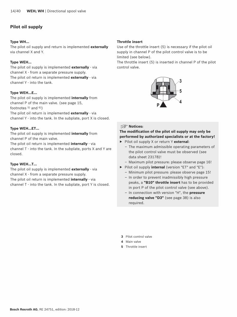
P
3
4
5
1440 WEH WH | Directional spool valve
Bosch Rexroth AG RE 24751 edition 2018-12
Type WHhellipThe pilot oil supply and return is implemented externally via channel X and Y
Type WEHThe pilot oil supply is implemented externally - via channel X - from a separate pressure supplyThe pilot oil return is implemented externally - via channel Y - into the tank
Type WEHhellipEhellipThe pilot oil supply is implemented internally from channel P of the main valve (see page 15 footnotes 5) and 6))The pilot oil return is implemented externally - via channel Y - into the tank In the subplate port X is closed
Type WEHhellipEThellipThe pilot oil supply is implemented internally from channel P of the main valveThe pilot oil return is implemented internally - via channel T - into the tank In the subplate ports X and Y are closed
Type WEHhellipThellipThe pilot oil supply is implemented externally - via channel X - from a separate pressure supplyThe pilot oil return is implemented internally - via channel T - into the tank In the subplate port Y is closed
Throttle insertUse of the throttle insert (5) is necessary if the pilot oil supply in channel P of the pilot control valve is to be limited (see below)The throttle insert (5) is inserted in channel P of the pilot control valve
Pilot oil supply
NoticesThe modification of the pilot oil supply may only be performed by authorized specialists or at the factory
Pilot oil supply X or return Y external ndash The maximum admissible operating parameters of the pilot control valve must be observed (see data sheet 23178)
ndash Maximum pilot pressure please observe page 16 Pilot oil supply internal (version ET and E)
ndash Minimum pilot pressure please observe page 15 ndash In order to prevent inadmissibly high pressure peaks a B10 throttle insert has to be provided in port P of the pilot control valve (see above)
ndash In connection with version H the pressure reducing valve D3 (see page 38) is also required
3 Pilot control valve4 Main valve5 Throttle insert
Directional spool valve | WEH WH 1540
RE 24751 edition 2018-12 Bosch Rexroth AG
Technical data (For application outside these values please consult us)
generalSizes NG 10 16 25
WH 2225
WH 2532
Weight approx Valve with one solenoid kg [lbs] 64 [141] 85 [187] 115 [253] 176 [388] 176 [388]
Valve with two solenoids spring-centered kg [lbs] 68 [150] 89 [196] 119 [262] 190 [419] 410 [904]
Valve with two solenoids pressure-centered kg [lbs] 68 [150] 89 [196] 119 [262] 190 [419] 410 [904]
Valve witch hydraulic actuation (type WH) kg [lbs] 55 [121] 73 [161] 105 [231] 165 [364] 395 [871]
Switching time adjustment S and S2 kg [lbs] 08 [18] 08 [18] 08 [18] 08 [18] 08 [18]
Pressure reducing valve D3 kg [lbs] 04 [09] 04 [09] 04 [09] 04 [09] 04 [09]
Installation position Any horizontal with valves with hydraulic control spool return H and symbol A B C D K Z Y With suspended installation higher sensitivity to contamination ndash horizontal is recommended
Ambient temperature range
Standard version degC [degF] ndash20 hellip +50 [ndash4 hellip +122] (NBR seals)ndash15 hellip +70 [+5 hellip +122] (FKM seals)
Version for HFC hydraulic fluid degC [degF] ndash20 hellip +50 [ndash4 hellip +122]
Storage temperature range degC [degF] +5 hellip +40 [+41 hellip +104]
Surface protection (valve body) Coating layer thickness max 100 microm
MTTFd values according to EN ISO 13849 Years 100 (type WEH) 150 (type WH) (for further details see data sheet 08012)
hydraulicMaximum operating pressure
Port P A B Type WH bar [psi] 280 [4061] 280 [4061] 280 [4061] 280 [4061] 280 [4061]
Type H-WH bar [psi] 350 [5076]
350 [5076]
350 [5076]
350 [5076]
350 [5076]
Port T External pilot oil return Y
Type WH bar [psi] 280 [4061]
250 [3626] 250 [3626] 250 [3626] 250 [3626]
Type H-WH 315 [4568] 250 [3626] 250 [3626] 250 [3626] 250 [3626]
Internal pilot oil return Y
1)Type H-WEH WEH bar [psi] 210 [3046] with direct voltage
160 [2320] with alternating voltage
Port Y External pilot oil return Type H-WEH WEH bar [psi] 210 [3046] with direct voltage 160 [2320] with alternating voltage
Type WH H-WH bar [psi] 250 [3626] 250 [3626] 210 [3046] 250 [3626] 250 [3626]
Hydraulic fluid see table on page 15
Hydraulic fluid temperature range (at the valve working ports) 3)
degC [degF] ndash20 hellip +80 [ndash4 hellip +176] (NBR seals)ndash15 hellip +80 [+5 hellip +176] (FKM seals)ndash20 hellip +50 [ndash4 hellip +122] (HFC hydraulic fluid)
Viscosity range mm2s [SUS] 28 hellip 500 [35 hellip 2320]
Maximum admissible degree of contamination of the hydraulic fluid Cleanliness class according to ISO 4406 (c)
Class 201815 2)
1) As a 3-spool position valve pressure-centered only possible if ppilot ge 2 x ptank + ppilot min
2) The cleanliness classes specified for the components must be adhered to in hydraulic systems Effective filtration prevents faults and simultaneously increases the life cycle of the components
For selecting the filters see wwwboschrexrothcomfilter3) If type WH is used in potentially explosion-proof areas see
data sheet 07011
1640 WEH WH | Directional spool valve
Bosch Rexroth AG RE 24751 edition 2018-12
Technical data (For applications outside these parameters please consult us)
hydraulicSize NG 10 16 25
WH 2225
WH 2532
Maximum pilot pressure 4) bar [psi] 250 [3626]
250 [3626]
210 [3046]
250 [3626]
250 [3626]
Minimum pilot pressure
External pilot oil supply X (all symbols) internal pilot oil supply (only symbols D K E J L M Q R U W)
3-spool position valve spring-centered Type H-WHhellip bar [psi] 12 [174] 14 [203] 125 [181] 13 [188] 85 [123]
Type WH bar [psi] 12 [174] 14 [203] 105 [152] 13 [188] 85 [123]
3-spool position valve pressure-centered bar [psi] ndash 14 [203] ndash 18 [261] 85 [123]
2-spool position valve with spring end position
Type H-WH bar [psi] 10 [145] 14 [203] 14 [203] 13 [188] 10 [145]
Type WH bar [psi] 10 [145] 14 [203] 11 [159] 13 [188] 10 [145]
2-spool position valve with hydraulic end position bar [psi] 7 [101] 14 [203] 8 [116] 8 [116] 5 [72]
Internal pilot oil supply X (only type WEH) (with symbols C F G H P T V Z S 5))
bar [psi] 75 [109]
6)45 [65] 7) 45 [65] 7) 45 [65] 7) 45 [65] 7)
Free flow cross-sections in zero position with symbols Q V and W
Symbol Q A ndash T B ndash T mm2 [inch2] 13 [002] 32 [005] 78 [0121] 83 [0129] 78 [0121]
Symbol V P ndash A P ndash B mm2 [inch2] 13 [002] 32 [005] 73 [0113] 83 [0129] 73 [0113]
A ndash T B ndash T mm2 [inch2] 13 [002] 32 [005] 84 [013] 83 [0129] 84 [013]
Symbol W A ndash T B ndash T mm2 [inch2] 24 [0004] 6 [0009] 10 [0015] 14 [0022] 20 [0031]
Pilot volume for switching process
3-spool position valve spring-centered cm3 [inch3] 204 [0124]
572 [0349]
764 [0466]
142 [0866]
294 [1794]
2-spool position valve cm3 [inch3] 408 [0249]
1145 [0699]
1528 [0932]
284 [1733]
588 [3588]
3-spool position valve pressure-centered
from zero position in switching position a
Type WH cm3 [inch3] ndash 283 [0173]
ndash 715 [0436]
144 [0879]
Type WEH cm3 [inch3] ndash 283 [0173]
ndash 715 [0436]
144 [0879]
from switching position a in zero position
Type WH cm3 [inch3] ndash 572 [0349]
ndash 1418 [0865]
294 [1794]
Type WEH cm3 [inch3] ndash 29 [0177] ndash 70 [0427] 151 [0921]
from zero position in switching position b
Type WH cm3 [inch3] ndash 572 [0349]
ndash 1418 [0865]
294 [1794]
Type WEH cm3 [inch3] ndash 572 [0349]
ndash 1415 [0863]
294 [1794]
from switching position b in zero position
Type WH cm3 [inch3] ndash 855 [0522]
ndash 1988 [1213]
438 [2673]
Type WEH cm3 [inch3] ndash 283 [0173]
ndash 573 [0349]
144 [0879]
Pilot flow for shortest switching time approx lmin [US gpm] 35 [92] 35 [92] 35 [92] 35 [92] 45 [119]
Directional spool valve | WEH WH 1740
RE 24751 edition 2018-12 Bosch Rexroth AG
4) Internal pilot oil supply ndash With a higher pilot pressure use of a pressure reducing
valve D3 is required (if it is not used pilot pressure = operating pressure at the port)
ndash In connection with version H the pressure reducing valve D3 is also required
External pilot oil supply ndash Compliance with the maximum pilot pressure must be
ensured by appropriate measures (e g protection of the separate pilot oil circuit by means of a pressure relief valve)
5) Symbol S only for NG166) For symbols C F G H P T V Z an internal pilot oil supply is
only possible if the flow from P to T in the central position (for 3-spool position valve) or while crossing the central position (for 2-spool position valve) is so large that the pressure differential of P to T reaches a value of at least 75 bar [109 psi] and the pilot oil return Y is implemented externally
7) For symbols C F G J H P T V Z S 5) ndash by means of preload valve (not NG10) or correspondingly high flow (Determination of the required flow see Preload valve characteristic curves on page 39) For NG10 a check valve with a cracking pressure of 75 bar [109 psi] is to be provided in the return line to the tank The pilot oil return Y must be implemented externally
Technical data (For application outside these values please consult us)
Druckfluumlssigkeit Klassifizierung Geeignete Dichtungsmaterialien
Normen Datenblatt
Mineraloumlle HL HLP HLPD HVLP HVLPD NBR FKM DIN 51524 90220
Biologisch abbaubar wasserunloumlslich HETG FKMISO 15380
90221HEES FKM
wasserloumlslich HEPG FKM ISO 15380
Schwerentflammbar wasserfrei HFDU (Glykolbasis) FKM
ISO 12922 90222HFDU (Esterbasis) FKM
HFDR FKM
wasserhaltig HFC (Fuchs Hydrotherm 46M Renosafe 500 Petrofer Ultra Safe 620 Houghton Safe 620 Union Carbide HP5046)
NBR
ISO 12922 90223
Important information on hydraulic fluids For further information and data on the use of other hydraulic fluids please refer to the data sheets above or contact us
There may be limitations regarding the technical valve data (temperature pressure range life cycle maintenance intervals etc)
The ignition temperature of the hydraulic fluid used must be 50 K higher than the maximum surface temperature
Bio-degradable and flame-resistant ndash containing water If this hydraulic fluid is used small amounts of dissolved zinc may get into the hydraulic system
Flame-resistant ndash containing water ndash Due to increased cavitation tendency with HFC hydraulic fluids the life cycle of the component may be reduced by up to 30 as compared to the use with mineral oil HLP In order to reduce the cavitation effect it is recommended - if possible specific to the installation - to back up the return flow pressure in ports T to approx 20 of the pressure differential at the component
ndash Depending on the hydraulic fluid used the maximum ambient and hydraulic fluid temperature must not exceed 50 degC To reduce the heat input in the component a maximum duty cycle of 50 must be set for onoff valves in continuous operation (measuring time 300 s) If this is not possible due to the function an energy-reducing control of these components is recommended eg via a PWM plug-in amplifier
1840 WEH WH | Directional spool valve
Bosch Rexroth AG RE 24751 edition 2018-12
Switching times
Pilot pressure bar [psi] 70 [1015] 210 [3046] 250 [3626] Spring
ON OFF
NG10 Without throttle insert ms 40 hellip 60 ndash 40 hellip 60 20 hellip 30
With throttle insert ms 60 hellip 90 ndash 50 hellip 70 20 hellip 30
NG16 Without throttle insert ms 50 hellip 80 ndash 40 hellip 60 50 hellip 80
With throttle insert ms 110 hellip 130 ndash 80 hellip 100 50 hellip 80
NG25 (4WH 22) Without throttle insert ms 40 hellip 70 40 hellip 60 ndash 50 hellip 70
With throttle insert ms 140 hellip 160 80 hellip 110 ndash 50 hellip 70
NG25 (4WH 25) Without throttle insert ms 70 hellip 100 ndash 50 hellip 70 100 hellip 130
With throttle insert ms 200 hellip 250 ndash 120 hellip 150 100 hellip 130
NG32 Without throttle insert ms 80 hellip 130 ndash 70 hellip 100 140 hellip 160
With throttle insert ms 420 hellip 560 ndash 230 hellip 350 140 hellip 160
Notices Switching times = Contacting at the pilot control valve until start of opening of the control edge in the main valve and change in the control spool stroke by 95)
The switching times are measured according to ISO 6403 with HLP46 ϑoil = 40 degC plusmn 5 degC [104 degF plusmn9 degF] With different oil temperatures variations are possible
The switching times were determined using DC solenoids They decrease by approx 20 ms if AC solenoids are used
The shut-off of the solenoids creates voltage peaks which can be reduced by the use of suitable diodes
The switching times increase by approx 30 ms if the pressure reducing valve D3 is used
The switching times have been determined under ideal conditions and may differ in the system depending on the application conditions
6
1
10
8
6
4
2
20 40 60 80 100 120 140 1600
0
12
14
22
16
18
20
2
7
8
43
5
Directional spool valve | WEH WH 1940
RE 24751 edition 2018-12 Bosch Rexroth AG
Characteristic curves NG10 (measured with HLP46 ϑOil = 40 plusmn5degC [104 plusmn9degF])
Performance limits NG10 (measured with HLP46 ϑOil = 40 plusmn5degC [104 plusmn9degF])
Flow in lmin [US gpm] rarr
Pres
sure
diff
eren
tial i
n ba
r [p
si] rarr
∆p-qV characteristic curves
Symbol Spool position Zero positionP ndash A P ndash B A ndash T 1) B ndash T 1) A ndash T B ndash T P ndash T
E Y D Q V W Z 1 1 3 5
F 1 3 1 4 3 ndash 6
G T 4 2 4 7 ndash ndash 8
H C 3 3 1 7 1 5 5
J K 1 2 1 6
L 2 2 1 4 2 ndash ndash
M 3 3 2 5
P 3 1 2 7 ndash 5 7
R 1 2 3 ndash
U 2 2 3 6 ndash 6 ndash
A B 1 1 ndash ndash
1) The pressure differential refers to the use of port T If port T1 is additionally used the pressure differential may be lower If only port T1 is used the relations A ndash T and B ndash T may be reversed
Important notices see page 28
2-spool position valves ndash qV max in lmin [US gpm]
SymbolOperating pressure pmax in bar [psi]
70 [1015]
140 [2030]
210 [3046]
280 [4061]
350 [5076]
X external ndash spring end position in the main valve 1) (with ppilot min = 12 bar [174 psi])
C D K Y Z 160 [42] 160 [42] 160 [42] 160 [42] 160 [42]
X external ndash hydraulic end position in the main valveHC HD HK HZ HY
160 [42] 160 [42] 160 [42] 160 [42] 160 [42]
3-spool position valves ndash qV max in lmin [US gpm]
SymbolOperating pressure pmax in bar [psi]
70 [1015]
140 [2030]
210 [3046]
280 [4061]
350 [5076]
X external ndash spring-centeredE J L M Q U V W R
160 [42] 160 [42] 160 [42] 160 [42] 160 [42]
F P 160 [42] 120 [32] 100 [26] 90 [20] 90 [20]
G T 160 [42] 160 [42] 160 [42] 130 [34] 120 [32]
H 160 [42] 160 [42] 120 [32] 110 [29] 100 [26]1) If the pilot pressure fails the function of the return spring is no
longer guaranteed with the specified flow values
4
8
12
16
20
24
28
50 100 150 200 250 300
10
7
9 8
654321
0
[5][0] [10] [792]
0[0]
[50]
[75][15] [20] [25] [30] [35] [40] [45] [50] [55] [60] [65] [70]
[406]
[100]
[150]
[200]
[250]
[300]
[250]
2040 WEH WH | Directional spool valve
Bosch Rexroth AG RE 24751 edition 2018-12
Characteristic curves NG16 (measured with HLP46 ϑOil = 40 plusmn5 degC [104 plusmn9 degF])
∆p-qV characteristic curves
Flow in lmin [US gpm] rarr
Pres
sure
diff
eren
tial i
n ba
r [p
si] rarr
Symbol Spool position Zero positionP ndash A P ndash B A ndash T B ndash T P ndash T A ndash T B ndash T
D E Y 1 1 3 3
F 1 2 5 5 4 3 ndash
G 4 1 5 5 7 ndash ndash
C H 1 1 5 6 2 4 4
K J 2 2 6 6 ndash 3 ndash
L 2 2 5 4 ndash 3 ndash
M 1 1 3 4
P 2 1 3 6 5 ndash ndash
Symbol Spool position Zero positionP ndash A P ndash B A ndash T B ndash T P ndash T A ndash T B ndash T
Q 1 1 6 6
R 2 4 7 ndash
S 3 3 3 ndash 9 ndash ndash
T 4 1 5 5 7 ndash ndash
U 2 2 3 4 6
V Z 1 1 6 6 10 8 8
W 1 1 3 4
Directional spool valve | WEH WH 2140
RE 24751 edition 2018-12 Bosch Rexroth AG
Performance limits NG16 (measured with HLP46 ϑOil = 40 plusmn5 degC [104 plusmn9 degF])
2-spool position valves ndash qV max in lmin [US gpm]
SymbolOperating pressure pmax in bar [psi]
70 [1015]
140 [2030]
210 [3046]
280 [4061]
350 [5076]
X external ndash spring end position in the main valve (with ppilot min = 12 bar [174 psi])
C D K Y Z
300 [79] 300 [79] 300 [79] 300 [79] 300 [79]
X external ndash spring end position in the main valve 1)
C 300 [79] 300 [79] 300 [79] 300 [79] 300 [79]
D Y 300 [79] 270 [71] 260 [68] 250 [66] 230 [60]
K 300 [79] 250 [66] 240 [63] 230 [60] 210 [55]
Z 300 [79] 260 [68] 190 [50] 180 [47] 160 [42]
X external ndash hydraulic end position in the main valveHC HD HK HZ HY
300 [79] 300 [79] 300 [79] 300 [79] 300 [79]
3-spool position valves ndash qV max in lmin [US gpm]
SymbolOperating pressure pmax in bar [psi]
70 [1015]
140 [2030]
210 [3046]
280 [4061]
350 [5076]
X external ndash spring-centeredE H J L M Q U W R
300 [79] 300 [79] 300 [79] 300 [79] 300 [79]
F P 300 [79] 250 [66] 180 [47] 170 [45] 150 [39]
G T 300 [79] 300 [79] 240 [63] 210 [55] 190 [50]
S 300 [79] 300 [79] 300 [79] 250 [66] 220 [58]
V 300 [79] 250 [66] 210 [55] 200 [53] 180 [47]
X external ndash pressure-centered (at minimum pilot pressure of 16 bar [232 psi])
all sym-bols 2)
300 [79] 300 [79] 300 [79] 300 [79] 300 [79]
1) If the specified flow values are exceeded the function of the return spring is no longer guaranteed if the pilot pressure fails
2) With symbol V the pilot control valve is not required for flows gt160 lmin [42 US gpm]
Important notices see page 28
123
45
67
8
9
10
8
6
4
2
50 100 150 200 250 300 350 400
12
14
16
18
20
4500
[10][0] [20] [30] [40] [50] [60] [119]
0
[290]
[0]
[25]
[50]
[75]
[100]
[110][70] [80] [90] [100]
[125]
[150]
[175]
[200]
[225]
[250]
[275]
2240 WEH WH | Directional spool valve
Bosch Rexroth AG RE 24751 edition 2018-12
Characteristic curves NG25 (WH 22) (measured with HLP46 ϑOil = 40 plusmn5 degC [104 plusmn9 degF])
∆p-qV characteristic curves
Flow in lmin [US gpm] rarr
Pres
sure
diff
eren
tial i
n ba
r [p
si] rarr
Symbol Spool positionP ndash A P ndash B A ndash T B ndash T B ndash A
E D 2 2 3 5 ndash
J Q K 2 2 4 6 ndash
M W 1 1 3 5 ndash
H V C Z 1 1 4 6 ndash
F 1 2 4 5 ndash
G 3 4 5 6 ndash
R 1 2 2 ndash ndash
L 2 2 4 5 ndash
U 2 2 2 6 ndash
P 2 2 2 7 ndash
T 4 4 5 6 ndash
Symbol Zero positionA ndash T B ndash T P ndash T
F 2 ndash 4
G T ndash ndash 9
H ndash ndash 3
L 7 ndash ndash
U ndash 6 ndash
J 8 8 ndash
P ndash 4 6
V Z ndash ndash 8
Directional spool valve | WEH WH 2340
RE 24751 edition 2018-12 Bosch Rexroth AG
Performance limits NG25 (WH 22) (measured with HLP46 ϑOil = 40 plusmn5 degC [104 plusmn9 degF])
1) If the specified flow values are exceeded the function of the return spring is no longer guaranteed if the pilot pressure fails Important notices see page 28
2-spool position valves ndash qV max in lmin [US gpm]
SymbolOperating pressure pmax in bar [psi]
70 [1015]
140 [2030]
210 [3046]
280 [4061]
350 [5076]
X external ndash spring end position in the main valve (with ppilot min = 11 bar 14 bar [159 203 psi])
C D K Y Z 450 [119]
450 [119]
450 [119]
450 [119]
450 [119]
X external ndash spring end position in the main valve 1)
C 450 [119]
450 [119]
320 [84]
250 [66]
200 [53]
D Y 450 [119]
450 [119]
450 [119]
400 [105]
320 [84]
K 450 [119]
215 [57]
150 [39]
120 [32]
100 [26]
Z 350 [92]
300 [79]
290 [76]
260 [68]
160 [42]
X external ndash hydraulic end position in the main valveHC HD HK HZ HY
450 [119]
450 [119]
450 [119]
450 [119]
450 [119]
HCOhellip HDOhellip HKOhellip HZOhellip
450 [119]
450 [119]
450 [119]
450 [119]
450 [119]
HCOFhellip HDOFhellip HKOFhellip HZOFhellip
450 [119]
450 [119]
450 [119]
450 [119]
450 [119]
3-spool position valves ndash qV max in lmin [US gpm]
SymbolOperating pressure pmax in bar [psi]
70 [1015]
140 [2030]
210 [3046]
280 [4061]
350 [5076]
X external ndash spring-centered
E J L M Q U W R
450 [119]
450 [119]
450 [119]
450 [119]
450 [119]
H 450 [119]
450 [119]
300 [79]
260 [68]
230 [61]
G 400 [105]
350 [92]
250 [66]
200 [53]
180 [47]
F 450 [119]
270 [71]
175 [46]
130 [34]
110 [29]
V 450 [119]
300 [79]
240 [63]
220 [58]
160 [42]
T 400 [105]
300 [79]
240 [63]
200 [53]
160 [42]
P 450 [119]
270 [71]
180 [47]
170 [45]
110 [29]
1
2
3
4
5
6
0 100 200 300 400 500
78
600 650
10
8
6
4
2
12
14
16
18
20
22
2440 WEH WH | Directional spool valve
Bosch Rexroth AG RE 24751 edition 2018-12
Characteristic curves NG25 (WH 25) (measured with HLP46 ϑOil = 40 plusmn5 degC [104 plusmn9 degF])
∆p-qV characteristic curves
Flow in lmin [US gpm] rarr
Pres
sure
diff
eren
tial i
n ba
r [p
si] rarr
8 Symbol R spool position B ndash A
Symbol Spool position Zero positionP ndash A P ndash B A ndash T 1) B ndash T 1) A ndash T B ndash T P ndash T
E Y D 1 1 3 4
F 1 1 2 4 2 ndash 5
G T 1 1 2 5 ndash ndash 7
H 1 1 2 5 2 2 4
C 1 1 2 5
J 1 1 2 5 6 5 ndash
K 1 1 2 5
L 1 1 2 4 5 ndash ndash
M 1 1 3 4
P 1 1 3 5 ndash 3 5
Q 1 1 2 3
R 1 1 3 ndash
U 1 1 2 5 ndash 5 ndash
V 1 1 2 5 8 7 ndash
Z 1 1 2 5
W 1 1 3 4
Directional spool valve | WEH WH 2540
RE 24751 edition 2018-12 Bosch Rexroth AG
Performance limits NG25 (WH 25) (measured with HLP46 ϑOil = 40 plusmn5 degC [104 plusmn9 degF])
1) If the specified flow values are exceeded the function of the return spring is no longer guaranteed if the pilot pressure fails
Important notices see page 28
2-spool position valves ndash qV max in lmin [US gpm]
SymbolOperating pressure pmax in bar [psi]
70 [1015]
140 [2030]
210 [3046]
280 [4061]
350 [5076]
X external ndash spring end position in the main valve (with ppilot min = 13 bar [188 psi])
C D K Y Z 700 [185 ]
700 [185 ]
700 [185 ]
700 [185 ]
650 [172 ]
X external ndash spring end position in the main valve 1)
C 700 [185 ]
700 [185 ]
700 [185 ]
700 [185 ]
650 [172 ]
D Y 700 [185 ]
650 [172 ]
400 [105 ]
350 [92]
300 [79]
K 700 [185 ]
650 [172 ]
420 [111]
370 [98]
320 [84]
Z 700 [185 ]
700 [185 ]
650 [172 ]
480 [127 ]
400 [105 ]
X external ndash hydraulic end position in the main valveHC HD HK HZ HY
700 [185 ]
700 [185 ]
700 [185 ]
700 [185 ]
700 [185 ]
HCOhellip HDOhellip HKOhellip HZOhellip
700 [185 ]
700 [185 ]
700 [185 ]
700 [185 ]
700 [185 ]
HCOFhellip HDOFhellip HKOFhellip HZOFhellip
700 [185 ]
700 [185 ]
700 [185 ]
700 [185 ]
700 [185 ]
3-spool position valves ndash qV max in lmin [US gpm]
SymbolOperating pressure pmax in bar [psi]
70 [1015]
140 [2030]
210 [3046]
280 [4061]
350 [5076]
X external ndash spring-centeredE L M Q U W 700
[185 ]700
[185 ]700
[185 ]700
[185 ]650
[172 ]
G T 400 [105 ]
400 [105 ]
400 [105 ]
400 [105 ]
400 [105 ]
F 650 [172 ]
550 [145]
430 [113]
330 [87]
300 [79]
H 700 [185 ]
650 [172 ]
550 [145]
400 [105 ]
360 [95]
J 700 [185 ]
700 [185 ]
650 [172 ]
600 [158 ]
520 [137 ]
P 650 [172 ]
550 [145]
430 [113]
330 [87]
300 [79]
V 650 [172 ]
550 [145]
400 [105 ]
350 [92]
310 [82]
R 700 [185 ]
700 [185 ]
700 [185 ]
650 [172 ]
580 [153 ]
X external ndash pressure-centered (at minimum pilot pressure of 18 bar [261 psi])
E F H J L M P Q R U V W
700 [185 ]
700 [185 ]
700 [185 ]
700 [185 ]
650 [172 ]
G T 400 [105 ]
400 [105 ]
400 [105 ]
400 [105 ]
400 [105 ]
X external ndash pressure-centered (with pilot pressure gt 30 bar [435 psi])
G T 700 [185 ]
700 [185 ]
700 [185 ]
700 [185 ]
650 [172 ]
12
10
14
8
6
4
2
100 300
16
18
10800
[40][0] [285]
0500 700 900
[80] [120] [160] [200] [240]
1
2
3
4
[0]
[50]
[100]
[150]
[200]
[261]
12
10
14
8
6
4
2
100 300
16
18
10800
[40][0] [285]
0500 700 900
[80] [120] [160] [200] [240]
5
6
7
8
[0]
[50]
[100]
[150]
[200]
[261]
2640 WEH WH | Directional spool valve
Bosch Rexroth AG RE 24751 edition 2018-12
Characteristic curves NG32 (measured with HLP46 ϑOil = 40 plusmn5 degC [104 plusmn9 degF])
Flow in lmin [US gpm] rarr
Flow in lmin [US gpm] rarr
Pres
sure
diff
eren
tial
in b
ar [p
si] rarr
Pres
sure
diff
eren
tial
in b
ar [p
si] rarr
∆p-qV-characteristic curves ndash Symbol E R and W
∆p-qV characteristic curves ndash Symbol G and T
Symbol Spool positionP ndash A P ndash B A ndash T B ndash T B ndash A
E 4 4 3 2 ndash
R 4 4 3 ndash 1
W 4 4 3 2 ndash
Symbol Spool positionP ndash A P ndash B A ndash T B ndash T P ndash T
G 7 8 7 5 6
T 7 8 7 5 6
Directional spool valve | WEH WH 2740
RE 24751 edition 2018-12 Bosch Rexroth AG
Performance limits NG32 (measured with HLP46 ϑOil = 40 plusmn5 degC [104 plusmn9 degF])
1) If the specified flow values are exceeded the function of the return spring is no longer guaranteed if the pilot pressure fails Important notices see page 28
2-spool position valves ndash qV max in lmin [US gpm]
SymbolOperating pressure pmax in bar [psi]
70 [1015]
140 [2030]
210 [3046]
280 [4061]
350 [5076]
X external ndash spring end position in the main valve (with ppilot min = 10 bar [145 psi])
C D K Y Z 1100 [290]
1040 [275]
860 [227]
750 [198]
680 [179]
X external ndash spring end position in the main valve 1)
C 1100 [290]
1040 [275]
860 [227]
800 [211]
700 [185]
D Y 1100 [290]
1040 [275]
540 [142]
480 [127]
420 [111]
K 1100 [290]
1040 [275]
860 [227]
500 [132]
450 [119]
Z 1100 [290]
1040 [275]
860 [227]
700 [185]
650 [172]
X external ndash hydraulic end position in the main valveHC HD HK HZ HY
1100 [290]
1040 [275]
860 [227]
750 [198]
680 [179]
3-spool position valves ndash qV max in lmin [US gpm]
SymbolOperating pressure pmax in bar [psi]
70[1015]
140 [2030]
210 [3046]
280 [4061]
350 [5076]
X external ndash spring-centeredE J L M Q R U W
1100 [290]
1040 [275]
860 [227]
750 [198]
680 [179]
G T H F P 900 [238]
900 [238]
800 [211]
650 [172]
450 [119]
V 1100 [290]
1000 [264]
680 [179]
500 [132]
450 [119]
X external ndash pressure-centered (at minimum pilot pressure of 85 bar [123 psi])all symbols 1100
[290]1040 [275]
860 [227]
750 [198]
680 [179]
2840 WEH WH | Directional spool valve
Bosch Rexroth AG RE 24751 edition 2018-12
Performance limits important information
NG16 With pilot oil supply X internal a preload valve has to be used for flows lt 160 lmin [42 US gpm] due to the negative overlap of the symbols C Z and HC HZ
43 directional valves with pressure centering of the control spool in the main valve can be used above the indicated performance limit In this case a higher pilot pressure is required (values see performance limits of the corresponding size)
With pilot oil supply X internal sufficient flow needs to be ensured due to the negative overlap of symbols F G H P S and T (for determination of the required flow see Preload valve characteristic curves (page 39) If the required flow is not reached a preload valve has to be used (see page 16)
NG25(WH 22)
With pilot oil supply X internal a preload valve has to be used for flows lt 180 lmin [475 US gpm] due to the negative overlap of symbols Z HZ and V
With pilot oil supply X internal sufficient flow needs to be ensured due to the negative overlap of symbols C HC F G H P and T (for determination of the required flow see Preload valve characteristic curves (page 39) If the required flow is not reached a preload valve has to be used (see page 16)
NG25(WH 25)
With pilot oil supply X internal a preload valve has to be used for flows lt 180 lmin [475 US gpm] due to the negative overlap of symbols Z HZ and V
43 directional valves with pressure centering of the control spool in the main valve can be used above the indicated performance limit In this case a higher pilot pressure is required (values see performance limits of the corresponding size)
With pilot oil supply X internal sufficient flow needs to be ensured due to the negative overlap of symbols C HC F G H P and T (for determination of the required flow see Preload valve characteristic curves (page 39) If the required flow is not reached a preload valve has to be used (see page 16)
NG32 With pilot oil supply X internal a preload valve has to be used for flows lt 180 lmin [475 US gpm] due to the negative overlap of symbols Z HZ and V
43 directional valves with pressure centering of the control spool in the main valve can be used above the indicated performance limit In this case a higher pilot pressure is required (values see performance limits of the corresponding size)
With pilot oil supply X internal sufficient flow needs to be ensured due to the negative overlap of symbols C HC F G H P and T (for determination of the required flow see Preload valve characteristic curves (page 39) If the required flow is not reached a preload valve has to be used (see page 16)
Notice (applies to all sizes)The specified switching power limits apply to the use with two directions of flow (e g from P to A and simultaneous return flow from B to T at a ratio of 11)Due to the flow forces acting within the valves the admissible switching power limit may be considerably lower with only one direction of flow (e g from P to A
while port B is blocked with flow in the same or in different directions)In such cases of application please consult usThe switching power limit was established while the solenoids were at operating temperature at 10 undervoltage and without tank preloading
TT
19
44 1592
40
20
87
73
146
206
168 305
35
11
66
71
27
108
PA B
T
X Y
AT B TP
X Y
T1
AT P B T
A B AT P B T
4
6
72122 11
14
12
32 31
23
1
8
9
13
3514
5
255
135
101
F1 F2
F3F4
19
7
B AT
P
B A
B A
P
001100[0000440]
Rzmax 4
Directional spool valve | WEH WH 2940
RE 24751 edition 2018-12 Bosch Rexroth AG
Dimensions NG10 (dimensions in mm [inch])
For item explanations and subplates see page 34 Valve mounting screws see page 35
Required surface quality of the valve contact surface
NoticeThe dimensions are nominal dimensions which are subject to tolerances
27
9719
1166
206
82
64 164
15656
9240
20
43
93
11 18
3514
12
21
142
94BA
TP
X
LY
102
1
9
5
68
4
31
15
17
13
12
32
21 22
7
3
3 19
A B Y
T P X
B A
15
18 16
F1 F2
F3F4
G1F5
G2 F6
11 23 14
B AT
P
001100[0000440]
Rzmax 4
3040 WEH WH | Directional spool valve
Bosch Rexroth AG RE 24751 edition 2018-12
Dimensions NG16 (dimensions in mm [inch])
For item explanations and subplates see page 34 Valve mounting screws see page 35
Required surface quality of the valve contact surface
NoticeThe dimensions are nominal dimen-sions which are subject to toler-ances
001100[0000440]
Rzmax 4
15
117
14
20
14 193241
110
19
414
6
A BX
PT Y92
4020
4
7
11 1432
1
8
912
19
13
21 22
103
3123
6
5
3514
14
175
180
120
BAX
T PY
[07
5][4
33]
[055] [760]
[949]
[46
1]
[Oslash079]
[Oslash055][709]
[069]
[47
2]
[05
5]
[Oslash024]
[015
7][1
61]
[014]
[055]
[05
9]
[15
7]
[07
8][3
62]
F1 F2
F3F4
F5
F6
G1
G2
206 [811]
L 1)
T
PB A
B A
Directional spool valve | WEH WH 3140
RE 24751 edition 2018-12 Bosch Rexroth AG
For item explanations and subplates see page 34 Valve mounting screws see page 35 Required surface quality of the
valve contact surface
Dimensions NG25 (WH 22) (dimensions in mm [inch])
1) Port L only for valves with pressure-centered zero position
NoticeThe dimensions are nominal dimensions which are subject to tolerances
19 225
2973245
275
332
3245
126
19
414
6
1592
20
7
11
32
18
9
12
19
13
15
1617
18
21 22
6
5
23 31 144
40
3514
206
279
L1)
BAX
T P Y
AXB
T P Y 14
21
195
117
20
14
103
F1 F2
F3F4
F5
F6
G1
G2
B A
T
PB A
120
001100[0000440]
Rzmax 4
3240 WEH WH | Directional spool valve
Bosch Rexroth AG RE 24751 edition 2018-12
Dimensions NG25 (WH 25) (dimensions in mm [inch])
1) Port L only for valves with pressure-centered zero position
For item explanations and subplates see page 34 Valve mounting screws see page 35 Required surface quality of the
valve contact surface
NoticeThe dimensions are nominal dimensions which are subject to tolerances
001100[0000440]
Rzmax 4
T
X
1933 22
P Y
X A B
197
205
23
257
A B
T PY
49
40
2+0
3
2865
6362
391
406
215
152
19
1592
4020
7
11 14
32
12
19
13
1516
17
18
21 22
23 31 4
3514
6
5
8
91
104
[59
8][0
75]
[014]
[055]
[05
9]
[15
7]
[07
8][3
62]
[19
3]
[Oslash024] [01
57]
[00
079+0
011
8 ]
[085] [1425]
[1539]
[1598]
[77
6]
[Oslash130] [Oslash087]
[1012]
[091]
[08
1]
391 [1539]
[78
7]
F1 F2
F3F4
F5
F6
G1
G2
206 [811]
LT
PB A
B A
200
Directional spool valve | WEH WH 3340
RE 24751 edition 2018-12 Bosch Rexroth AG
For item explanations and subplates see page 34 Valve mounting screws see page 35 Required surface quality of the
valve contact surface
Dimensions NG32 (dimensions in mm [inch])
NoticeThe dimensions are nominal dimensions which are subject to tolerances
3440 WEH WH | Directional spool valve
Bosch Rexroth AG RE 24751 edition 2018-12
1 Main valve2 Pilot control valve type 4WE 6 (data sheet 23178)
21 Pilot control valve type 4WE 6 Dhellip (1 solenoid) for main valves with symbols C D K Z symbols HC HD HK HZ
Pilot control valve type 4WE 6 JA (1 solenoid a) for main valves with symbols EA FA etc spring return
Pilot control valve type 4WE 6 MA (1 solenoid a) for main valves with symbols HEA HFA etc hydraulic spool return
22 Pilot control valve type 4WE 6 Y (1 solenoid) for main valves with symbol Y symbol HY
Pilot control valve type 4WE 6 JB (1 solenoid b) for main valves with symbols EB FB etc spring return
Pilot control valve type 4WE 6 MB (1 solenoid b) for main valves with symbols HEB HFB etc hydraulic spool return
23 Pilot control valve type 4WE 6Jhellip (2 solenoids) for main valves with 3 spool positions spring-centered
Pilot control valve type 4WE 6 Mhellip (2 solenoids) for main valves with 3 spool positions pressure-centered
31 Solenoid a32 Solenoid b
4 Manual override N optional Actuation of the manual override is only possible up to a tank pressure of approx 50 bar Avoid damage to the bore of the manual override (Special tool for the operation separate order material no R900024943) When the manual override is blocked the operation of the solenoid must be prevented
Simultaneous actuation of the solenoids must be prevented
5 Solenoid without manual override6 Solenoid with manual override7 Height of the diversion plate with hydraulic actuation
(type WH)8 Switching time adjustment (wrench size 6) optional9 Pressure reducing valve optional
101 Machined valve contact surface porting pattern according to ISO 4401-05-05-0-05 and NFPAT351 R2-D05
102 Machined valve contact surface porting pattern according to ISO 4401-07-07-0-05 and NFPAT351 R2-D07
103 Machined valve contact surface porting pattern according to ISO 4401-08-08-0-05 and NFPAT351 R2-D08
104 Machined valve contact surface porting pattern according to ISO 4401-10-09-0-05 and NFPAT351 R2-D10
11 Name plate pilot control valve12 Name plate complete valve13 Seal rings14 Space required for removing the mating connector15 2-spool position valves with spring end position in the main
valve (symbols A C D K Z)16 2-spool position valves with spring end position in the main
valve (symbols B Y)
17 3-spool position valves spring-centered 2-spool position valves with hydraulic end position in the main valve
18 3-spool position valves pressure-centered19 Locking pin
Subplates (separate order) with porting pattern according to ISO 4401 see data sheet 45100
Valve mounting screws see page 35
Dimensions
Directional spool valve | WEH WH 3540
RE 24751 edition 2018-12 Bosch Rexroth AG
Dimensions
Valve mounting screws (separate order) Nominal size Quantity Hexagon socket head cap screws Material number10 4 ISO 4762 - M6 x 45 - 109-CM-Fe-ZnNi-5-Cn-T0-H-B
Friction coefficient micrototal = 009 hellip 014 tightening torque MA = 125 Nm [92 ft-lbs] plusmn10 R913043777
or
4 14-20 UNC x 1 34rdquo ASTM-A574 Not included in the Rexroth delivery range
16 4 ISO 4762 - M10 x 60 - 109-flZnnc480hCFriction coefficient micrototal = 009 hellip 014 tightening torque MA = 58 Nm [428 ft-lbs] plusmn10
R913014770
2 ISO 4762 - M6 x 60 - 109-CM-Fe-ZnNi-5-Cn-T0-H-B Friction coefficient micrototal = 009 hellip 014 tightening torque MA = 125 Nm [92 ft-lbs] plusmn10
R913043410
or
4 Zylinderschrauben UNC 38-16 UNC x 2 14rdquo ASTM-A574 Not included in the Rexroth delivery range2 Zylinderschrauben UNC 14-20 UNC x 2 14rdquo ASTM-A574
25 6 ISO 4762 - M12 x 60 - 109-flZnnc480hC Friction coefficient micrototal = 009 hellip 014 tightening torque MA = 100 Nm [74 ft-lbs] plusmn20
R913015613
or
6 UNC 12-13 UNC x 2 12rdquo ASTM-A574 Not included in the Rexroth delivery range
32 6 ISO 4762 - M20 x 80 - 109-flZnnc480hC Friction coefficient micrototal = 009 hellip 014 tightening torque MA = 340 Nm [251 ft-lbs] plusmn10
R913008472
or
6 UNC 34-10 UNC x 3 14rdquo ASTM-A574 Not included in the Rexroth delivery range
L4
L3
5
4 2
3
1
3640 WEH WH | Directional spool valve
Bosch Rexroth AG RE 24751 edition 2018-12
Stroke setting mounting options (dimensions in mm [inch])
NG L410 65 [026]
16 10 [039]
25 (WH 22) 95 [037]
25 (WH 25) 125 [049]
32 15 [059]
The stroke of the control spool is limited by the stroke setting (1) The control spool stroke is shortened by loosening the lock nut (2) and clockwise rotation of the adjustment spindle (3) The control chamber (4) must be depressurized for this
5 Adjustment range NG10 1 rotation = 1 mm [00394 inch] adjustment travel
NG16 and 32 1 rotation = 15 mm [00591 inch] adjustment travel
3-spool position valve 1)
spring-centered pressure-centered
L1 L2 L3 L1 L2 L3
Stroke setting on valve side A and B 10
10 90 [354] 144 [567] 234 [921]
16 100 [394] 200 [787] 300 [1181]
25 2) 96 [377] 241 [949] 337 [1327]
25 3) 123 [484] 276 [1087] 399 [1571]
32 133 [524] 344 [1354] 477 [1878]
Stroke setting on valve side A
11
10 90 [354] 106 [417] 196 [772]
16 100 [394] 156 [614] 256 [1008]
25 2) 96 [377] 193 [760] 289 [1138]
25 3) 123 [484] 225 [886] 348 [1370]
32 133 [524] 287 [1130] 420 [1654]
Stroke setting on valve side B 12
10 52 [205] 144 [567] 196 [772] ndash ndash ndash
16 56 [220] 200 [787] 256 [1008] 81 [319] 200 [787] 281 [1106]
25 2) 48 [189] 241 [949] 289 [1138] ndash ndash ndash
25 3) 72 [283] 276 [1087] 348 [1370] 107 [421] 276 [1087] 283 [1114]
32 76 [299] 344 [1354] 420 [1654] 120 [472] 344 [1354] 464 [1827]
More dimensions see below and page 37
Stroke limitation on side A Stroke limitation on side B
a
BA
L3
L1 L2
L3L2
X A B
a
B
b
A A B
L3
L3L2L1
L1
b a
X A B
1) With symbol A only version 11 with symbol B only version 12 possible
Directional spool valve | WEH WH 3740
RE 24751 edition 2018-12 Bosch Rexroth AG
Stroke setting mounting options (dimensions in mm [inch])
2) Version WH 223) Version WH 25
2-spool position valve Spring end position Hydraulic end position
A C D K Z B Y HC HD HK HZ HY
L1 L2 L3 L1 L2 L3 L1 L2 L3
Stroke setting on valve side A and B 10
10 90 [354]
144 [567]
234 [921]
90 [354]
144 [567]
234 [921]
90 [354]
144 [567]
234 [921]
16 ndash ndash ndash ndash ndash ndash 100 [394]
200 [787]
300 [1181]
25 2) 96 [378]
241 [949]
337 [1327]
96 [378]
241 [949]
337 [1327]
96 [378]
241 [949]
337 [1327]
25 3) ndash ndash ndash ndash ndash ndash 123 [484]
276 [1087]
399 [1571]
32 ndash ndash ndash ndash ndash ndash 133 [524]
344 [1354]
477 [1878]
Stroke setting on valve side A
11
10 90 [354]
106 [417]
196 [772]
90 [354]
106 [417]
196 [772]
90 [354]
106 [417]
196 [772]
16 100 [394]
180 [709]
280 [1102] ndash ndash ndash 100
[394]156
[614]256
[1008]
25 2) 96 [378]
193 [760]
289 [1138]
96 [378]
193 [760]
289 [1138]
96 [378]
193 [760]
289 [1138]
25 3) 123 [484]
253 [996]
376 [148] ndash ndash ndash 123
[484]225
[886]348
[1370]
32 133 [524]
316 [1244]
449 [1768] ndash ndash ndash 133
[524]287
[1130]420
[1653]
Stroke setting on valve side B 12
10 52 [205]
144 [567]
196 [772]
52 [205]
144 [567]
196 [772]
52 [205]
144 [567]
196 [772]
16 ndash ndash ndash 80 [315]
200 [787]
280 [1102]
56 [221]
200 [787]
256 [1008]
25 2) 48 [189]
241 [949]
289 [1138]
48 [189]
241 [949]
289 [1138]
48 [189]
241 [949]
289 [1138]
25 3) ndash ndash ndash 100 [394]
276 [1087]
376 [1480]
72 [284]
276 [1087]
348 [1370]
32 ndash ndash ndash 105 [413]
344 [1354]
449 [1768]
76 [299]
344 [1354]
420 [1653]
NoticeThe dimensions are nominal dimensions which are subject to tolerances
34
7 5
62
1
7
8
3840 WEH WH | Directional spool valve
Bosch Rexroth AG RE 24751 edition 2018-12
Switching time adjustment
Pressure reducing valve D3
The switching time of the main valve (1) is influenced by using a twin throttle check valve (2) (type Z2FS 6 data sheet 27506)
Modification of supply (3) to discharge control (4)Remove the pilot control valve (5) ndash The plate (6) to accept the seal rings stays in place ndash Turn the switching time adjustment (2) around its longitudinal axis and put it back install the pilot control valve (5)
NoticeThe modification may only be performed by authorized specialists or at the factory
Type WEH 10 4XhellipS Type WEH 10 4XhellipS2
The pressure reducing valve (8) has to be used at a pilot pressure above 250 bar [3626 psi] (with WEH 22 hellip 210 bar [3046 psi]) and with version HThe secondary pressure is kept at a constant level of 45 bar [652 psi]
Notice If a pressure reducing valve D3 (8) is used a B10
throttle insert has to be installed in channel P of the pilot control valve
The modification may only be performed by authorized specialists or at the factory Type WEH 10 4XhellipD3
92
10
11
141210
8
6
4
2
100 200 300 400 500 600 700
1 2
3
4
0
[20][0] [185]
0[0]
[50]
[100]
[150]
[203]
[40] [60] [80] [100] [120] [140] [160]
91
10
11
Directional spool valve | WEH WH 3940
RE 24751 edition 2018-12 Bosch Rexroth AG
Pres
sure
diff
eren
tial
in b
ar [p
si] rarr
Flow in lmin [US gpm] rarr
∆pndashqV characteristic curve (measured with HLP46 ϑOil = 40 degC plusmn 5 degC [104 degF plusmn9 degF])
1 NG16
2 NG25 (WH 25)
3 NG25 (WH 22)
4 NG32
In case of valves with depressurized circulation and internal pilot oil supply the installation of the preload valve (9) in channel P of the main valve is required in order to build up the minimum pilot pressure
SizeItem 91 Item 92
16 R961009415 (from component series 72) R961009417 (up to component series 71)
25 (WH 22) ndash R961009609 (up to component series 76)
25 (WH 25) R961009166 (from component series 68) R961009416 (up to component series 67)
32 ndash R961009610 (up to component series 63)
Preload valve (not for NG10)
91 Preload valve
92 Preload valve
10 Main valve
11 Subplate
The pressure differential of the preload valve is to be added to the pressure differential of the main valve (see characteristic curves) to result in one total valueThe cracking pressure amounts to approx 45 bar [65 psi]
NoticeSeries-production status see ordering key on the name plate
Bosch Rexroth AG RE 24751 edition 2018-12
4040 WEH WH | Directional spool valve
Bosch Rexroth AG Industrial HydraulicsZum Eisengieszliger 197816 Lohr am Main Germany Phone +49 (0) 93 52thinspthinsp40 30 20 mysupportboschrexrothde wwwboschrexrothde
copy All rights reserved to Bosch Rexroth AG also regarding any disposal exploitation reproduction editing distribution as well as in the event of applications for industrial property rightsThe data specified above only serve to describe the product No statements concerning a certain condition or suitability for a certain application can be derived from our information The information given does not release the user from the obligation of own judgment and verificationPlease note that our products are subject to a natural process of wear and aging
Project planning information
The stipulations of the Machinery Directive 200642EC are to be adhered toPlease also note data sheet 08012 with information on MTTFd values and shock and vibration loads
Further information
Directional spool valve Data sheet 23178 Subplates Data sheet 45100 Inductive position switch and proximity sensors (contactless) Data sheet 24830 Hydraulic fluids on mineral oil basis Data sheet 90220 Environmentally compatible hydraulic fluids Data sheet 90221 Flame-resistant water-free hydraulic fluids Data sheet 90222 Flame-resistant hydraulic fluids - containing water (HFAE HFAS HFB HFC) Data sheet 90223 Reliability characteristics according to EN ISO 13849 Data sheet 08012 Hexagon socket head cap screw metricUNC Data sheet 08936 Hydraulic valves for industrial applications Operating instructions 07600-B General product information on hydraulic products Data sheet 07008 Assembly commissioning and maintenance of industrial valves Data sheet 07300 Mating connectors and cable sets for valves and sensors in hydraulics Data sheet 08006 Directional spool valves and directional seat valves with electrical actuation and
M12x1 plug-in connectionData sheet 08010
Use of non-electrical hydraulic components in an explosive environment (ATEX) Data sheet 07011 Selection of filters wwwboschrexrothcomfilter Information on available spare parts wwwboschrexrothcomspc
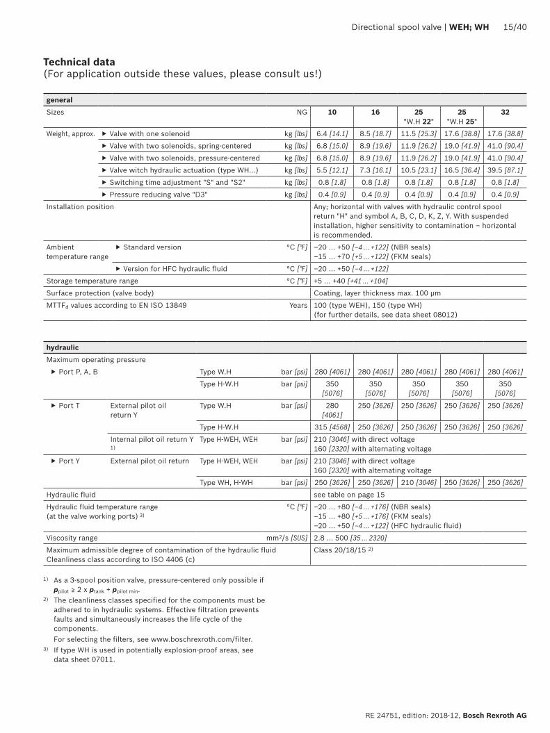
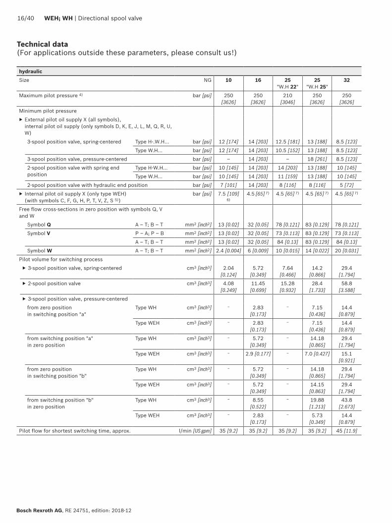
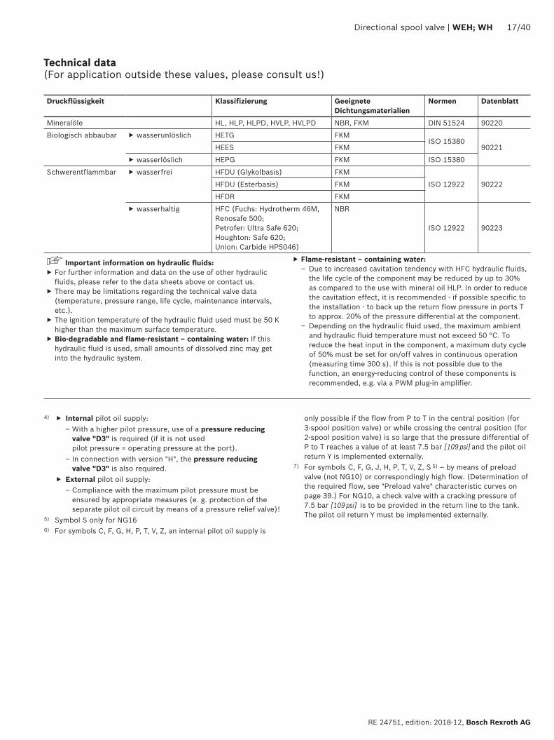
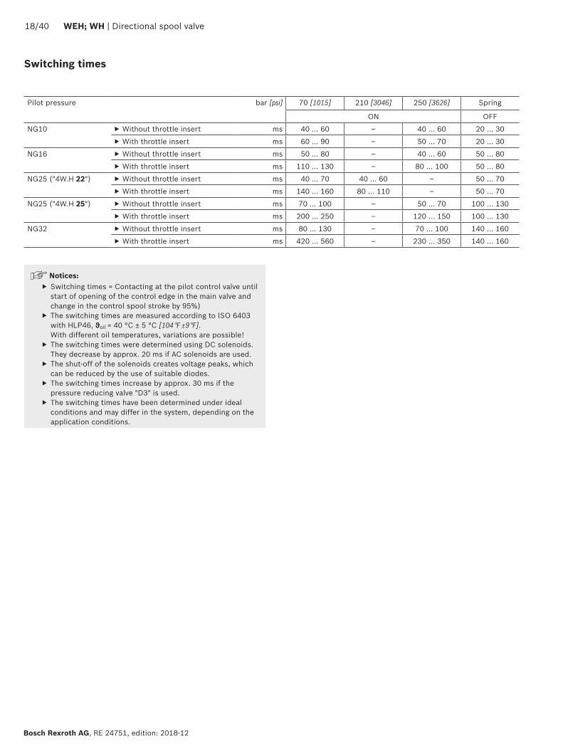
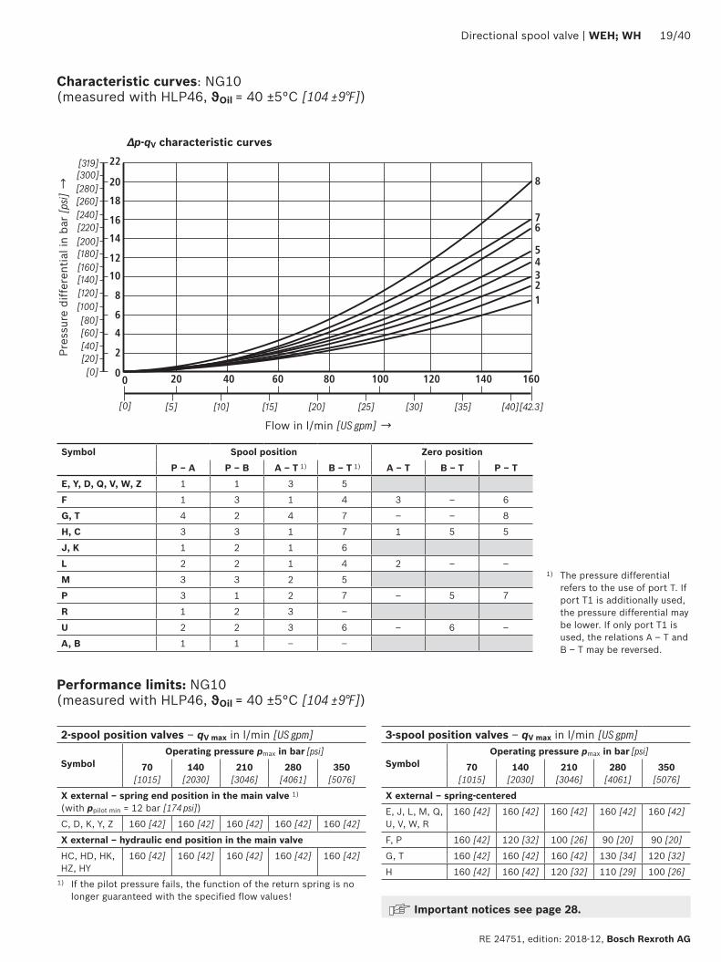
6
1
10
8
6
4
2
20 40 60 80 100 120 140 1600
0
12
14
22
16
18
20
2
7
8
43
5
Directional spool valve | WEH WH 1940
RE 24751 edition 2018-12 Bosch Rexroth AG
Characteristic curves NG10 (measured with HLP46 ϑOil = 40 plusmn5degC [104 plusmn9degF])
Performance limits NG10 (measured with HLP46 ϑOil = 40 plusmn5degC [104 plusmn9degF])
Flow in lmin [US gpm] rarr
Pres
sure
diff
eren
tial i
n ba
r [p
si] rarr
∆p-qV characteristic curves
Symbol Spool position Zero positionP ndash A P ndash B A ndash T 1) B ndash T 1) A ndash T B ndash T P ndash T
E Y D Q V W Z 1 1 3 5
F 1 3 1 4 3 ndash 6
G T 4 2 4 7 ndash ndash 8
H C 3 3 1 7 1 5 5
J K 1 2 1 6
L 2 2 1 4 2 ndash ndash
M 3 3 2 5
P 3 1 2 7 ndash 5 7
R 1 2 3 ndash
U 2 2 3 6 ndash 6 ndash
A B 1 1 ndash ndash
1) The pressure differential refers to the use of port T If port T1 is additionally used the pressure differential may be lower If only port T1 is used the relations A ndash T and B ndash T may be reversed
Important notices see page 28
2-spool position valves ndash qV max in lmin [US gpm]
SymbolOperating pressure pmax in bar [psi]
70 [1015]
140 [2030]
210 [3046]
280 [4061]
350 [5076]
X external ndash spring end position in the main valve 1) (with ppilot min = 12 bar [174 psi])
C D K Y Z 160 [42] 160 [42] 160 [42] 160 [42] 160 [42]
X external ndash hydraulic end position in the main valveHC HD HK HZ HY
160 [42] 160 [42] 160 [42] 160 [42] 160 [42]
3-spool position valves ndash qV max in lmin [US gpm]
SymbolOperating pressure pmax in bar [psi]
70 [1015]
140 [2030]
210 [3046]
280 [4061]
350 [5076]
X external ndash spring-centeredE J L M Q U V W R
160 [42] 160 [42] 160 [42] 160 [42] 160 [42]
F P 160 [42] 120 [32] 100 [26] 90 [20] 90 [20]
G T 160 [42] 160 [42] 160 [42] 130 [34] 120 [32]
H 160 [42] 160 [42] 120 [32] 110 [29] 100 [26]1) If the pilot pressure fails the function of the return spring is no
longer guaranteed with the specified flow values
4
8
12
16
20
24
28
50 100 150 200 250 300
10
7
9 8
654321
0
[5][0] [10] [792]
0[0]
[50]
[75][15] [20] [25] [30] [35] [40] [45] [50] [55] [60] [65] [70]
[406]
[100]
[150]
[200]
[250]
[300]
[250]
2040 WEH WH | Directional spool valve
Bosch Rexroth AG RE 24751 edition 2018-12
Characteristic curves NG16 (measured with HLP46 ϑOil = 40 plusmn5 degC [104 plusmn9 degF])
∆p-qV characteristic curves
Flow in lmin [US gpm] rarr
Pres
sure
diff
eren
tial i
n ba
r [p
si] rarr
Symbol Spool position Zero positionP ndash A P ndash B A ndash T B ndash T P ndash T A ndash T B ndash T
D E Y 1 1 3 3
F 1 2 5 5 4 3 ndash
G 4 1 5 5 7 ndash ndash
C H 1 1 5 6 2 4 4
K J 2 2 6 6 ndash 3 ndash
L 2 2 5 4 ndash 3 ndash
M 1 1 3 4
P 2 1 3 6 5 ndash ndash
Symbol Spool position Zero positionP ndash A P ndash B A ndash T B ndash T P ndash T A ndash T B ndash T
Q 1 1 6 6
R 2 4 7 ndash
S 3 3 3 ndash 9 ndash ndash
T 4 1 5 5 7 ndash ndash
U 2 2 3 4 6
V Z 1 1 6 6 10 8 8
W 1 1 3 4
Directional spool valve | WEH WH 2140
RE 24751 edition 2018-12 Bosch Rexroth AG
Performance limits NG16 (measured with HLP46 ϑOil = 40 plusmn5 degC [104 plusmn9 degF])
2-spool position valves ndash qV max in lmin [US gpm]
SymbolOperating pressure pmax in bar [psi]
70 [1015]
140 [2030]
210 [3046]
280 [4061]
350 [5076]
X external ndash spring end position in the main valve (with ppilot min = 12 bar [174 psi])
C D K Y Z
300 [79] 300 [79] 300 [79] 300 [79] 300 [79]
X external ndash spring end position in the main valve 1)
C 300 [79] 300 [79] 300 [79] 300 [79] 300 [79]
D Y 300 [79] 270 [71] 260 [68] 250 [66] 230 [60]
K 300 [79] 250 [66] 240 [63] 230 [60] 210 [55]
Z 300 [79] 260 [68] 190 [50] 180 [47] 160 [42]
X external ndash hydraulic end position in the main valveHC HD HK HZ HY
300 [79] 300 [79] 300 [79] 300 [79] 300 [79]
3-spool position valves ndash qV max in lmin [US gpm]
SymbolOperating pressure pmax in bar [psi]
70 [1015]
140 [2030]
210 [3046]
280 [4061]
350 [5076]
X external ndash spring-centeredE H J L M Q U W R
300 [79] 300 [79] 300 [79] 300 [79] 300 [79]
F P 300 [79] 250 [66] 180 [47] 170 [45] 150 [39]
G T 300 [79] 300 [79] 240 [63] 210 [55] 190 [50]
S 300 [79] 300 [79] 300 [79] 250 [66] 220 [58]
V 300 [79] 250 [66] 210 [55] 200 [53] 180 [47]
X external ndash pressure-centered (at minimum pilot pressure of 16 bar [232 psi])
all sym-bols 2)
300 [79] 300 [79] 300 [79] 300 [79] 300 [79]
1) If the specified flow values are exceeded the function of the return spring is no longer guaranteed if the pilot pressure fails
2) With symbol V the pilot control valve is not required for flows gt160 lmin [42 US gpm]
Important notices see page 28
123
45
67
8
9
10
8
6
4
2
50 100 150 200 250 300 350 400
12
14
16
18
20
4500
[10][0] [20] [30] [40] [50] [60] [119]
0
[290]
[0]
[25]
[50]
[75]
[100]
[110][70] [80] [90] [100]
[125]
[150]
[175]
[200]
[225]
[250]
[275]
2240 WEH WH | Directional spool valve
Bosch Rexroth AG RE 24751 edition 2018-12
Characteristic curves NG25 (WH 22) (measured with HLP46 ϑOil = 40 plusmn5 degC [104 plusmn9 degF])
∆p-qV characteristic curves
Flow in lmin [US gpm] rarr
Pres
sure
diff
eren
tial i
n ba
r [p
si] rarr
Symbol Spool positionP ndash A P ndash B A ndash T B ndash T B ndash A
E D 2 2 3 5 ndash
J Q K 2 2 4 6 ndash
M W 1 1 3 5 ndash
H V C Z 1 1 4 6 ndash
F 1 2 4 5 ndash
G 3 4 5 6 ndash
R 1 2 2 ndash ndash
L 2 2 4 5 ndash
U 2 2 2 6 ndash
P 2 2 2 7 ndash
T 4 4 5 6 ndash
Symbol Zero positionA ndash T B ndash T P ndash T
F 2 ndash 4
G T ndash ndash 9
H ndash ndash 3
L 7 ndash ndash
U ndash 6 ndash
J 8 8 ndash
P ndash 4 6
V Z ndash ndash 8
Directional spool valve | WEH WH 2340
RE 24751 edition 2018-12 Bosch Rexroth AG
Performance limits NG25 (WH 22) (measured with HLP46 ϑOil = 40 plusmn5 degC [104 plusmn9 degF])
1) If the specified flow values are exceeded the function of the return spring is no longer guaranteed if the pilot pressure fails Important notices see page 28
2-spool position valves ndash qV max in lmin [US gpm]
SymbolOperating pressure pmax in bar [psi]
70 [1015]
140 [2030]
210 [3046]
280 [4061]
350 [5076]
X external ndash spring end position in the main valve (with ppilot min = 11 bar 14 bar [159 203 psi])
C D K Y Z 450 [119]
450 [119]
450 [119]
450 [119]
450 [119]
X external ndash spring end position in the main valve 1)
C 450 [119]
450 [119]
320 [84]
250 [66]
200 [53]
D Y 450 [119]
450 [119]
450 [119]
400 [105]
320 [84]
K 450 [119]
215 [57]
150 [39]
120 [32]
100 [26]
Z 350 [92]
300 [79]
290 [76]
260 [68]
160 [42]
X external ndash hydraulic end position in the main valveHC HD HK HZ HY
450 [119]
450 [119]
450 [119]
450 [119]
450 [119]
HCOhellip HDOhellip HKOhellip HZOhellip
450 [119]
450 [119]
450 [119]
450 [119]
450 [119]
HCOFhellip HDOFhellip HKOFhellip HZOFhellip
450 [119]
450 [119]
450 [119]
450 [119]
450 [119]
3-spool position valves ndash qV max in lmin [US gpm]
SymbolOperating pressure pmax in bar [psi]
70 [1015]
140 [2030]
210 [3046]
280 [4061]
350 [5076]
X external ndash spring-centered
E J L M Q U W R
450 [119]
450 [119]
450 [119]
450 [119]
450 [119]
H 450 [119]
450 [119]
300 [79]
260 [68]
230 [61]
G 400 [105]
350 [92]
250 [66]
200 [53]
180 [47]
F 450 [119]
270 [71]
175 [46]
130 [34]
110 [29]
V 450 [119]
300 [79]
240 [63]
220 [58]
160 [42]
T 400 [105]
300 [79]
240 [63]
200 [53]
160 [42]
P 450 [119]
270 [71]
180 [47]
170 [45]
110 [29]
1
2
3
4
5
6
0 100 200 300 400 500
78
600 650
10
8
6
4
2
12
14
16
18
20
22
2440 WEH WH | Directional spool valve
Bosch Rexroth AG RE 24751 edition 2018-12
Characteristic curves NG25 (WH 25) (measured with HLP46 ϑOil = 40 plusmn5 degC [104 plusmn9 degF])
∆p-qV characteristic curves
Flow in lmin [US gpm] rarr
Pres
sure
diff
eren
tial i
n ba
r [p
si] rarr
8 Symbol R spool position B ndash A
Symbol Spool position Zero positionP ndash A P ndash B A ndash T 1) B ndash T 1) A ndash T B ndash T P ndash T
E Y D 1 1 3 4
F 1 1 2 4 2 ndash 5
G T 1 1 2 5 ndash ndash 7
H 1 1 2 5 2 2 4
C 1 1 2 5
J 1 1 2 5 6 5 ndash
K 1 1 2 5
L 1 1 2 4 5 ndash ndash
M 1 1 3 4
P 1 1 3 5 ndash 3 5
Q 1 1 2 3
R 1 1 3 ndash
U 1 1 2 5 ndash 5 ndash
V 1 1 2 5 8 7 ndash
Z 1 1 2 5
W 1 1 3 4
Directional spool valve | WEH WH 2540
RE 24751 edition 2018-12 Bosch Rexroth AG
Performance limits NG25 (WH 25) (measured with HLP46 ϑOil = 40 plusmn5 degC [104 plusmn9 degF])
1) If the specified flow values are exceeded the function of the return spring is no longer guaranteed if the pilot pressure fails
Important notices see page 28
2-spool position valves ndash qV max in lmin [US gpm]
SymbolOperating pressure pmax in bar [psi]
70 [1015]
140 [2030]
210 [3046]
280 [4061]
350 [5076]
X external ndash spring end position in the main valve (with ppilot min = 13 bar [188 psi])
C D K Y Z 700 [185 ]
700 [185 ]
700 [185 ]
700 [185 ]
650 [172 ]
X external ndash spring end position in the main valve 1)
C 700 [185 ]
700 [185 ]
700 [185 ]
700 [185 ]
650 [172 ]
D Y 700 [185 ]
650 [172 ]
400 [105 ]
350 [92]
300 [79]
K 700 [185 ]
650 [172 ]
420 [111]
370 [98]
320 [84]
Z 700 [185 ]
700 [185 ]
650 [172 ]
480 [127 ]
400 [105 ]
X external ndash hydraulic end position in the main valveHC HD HK HZ HY
700 [185 ]
700 [185 ]
700 [185 ]
700 [185 ]
700 [185 ]
HCOhellip HDOhellip HKOhellip HZOhellip
700 [185 ]
700 [185 ]
700 [185 ]
700 [185 ]
700 [185 ]
HCOFhellip HDOFhellip HKOFhellip HZOFhellip
700 [185 ]
700 [185 ]
700 [185 ]
700 [185 ]
700 [185 ]
3-spool position valves ndash qV max in lmin [US gpm]
SymbolOperating pressure pmax in bar [psi]
70 [1015]
140 [2030]
210 [3046]
280 [4061]
350 [5076]
X external ndash spring-centeredE L M Q U W 700
[185 ]700
[185 ]700
[185 ]700
[185 ]650
[172 ]
G T 400 [105 ]
400 [105 ]
400 [105 ]
400 [105 ]
400 [105 ]
F 650 [172 ]
550 [145]
430 [113]
330 [87]
300 [79]
H 700 [185 ]
650 [172 ]
550 [145]
400 [105 ]
360 [95]
J 700 [185 ]
700 [185 ]
650 [172 ]
600 [158 ]
520 [137 ]
P 650 [172 ]
550 [145]
430 [113]
330 [87]
300 [79]
V 650 [172 ]
550 [145]
400 [105 ]
350 [92]
310 [82]
R 700 [185 ]
700 [185 ]
700 [185 ]
650 [172 ]
580 [153 ]
X external ndash pressure-centered (at minimum pilot pressure of 18 bar [261 psi])
E F H J L M P Q R U V W
700 [185 ]
700 [185 ]
700 [185 ]
700 [185 ]
650 [172 ]
G T 400 [105 ]
400 [105 ]
400 [105 ]
400 [105 ]
400 [105 ]
X external ndash pressure-centered (with pilot pressure gt 30 bar [435 psi])
G T 700 [185 ]
700 [185 ]
700 [185 ]
700 [185 ]
650 [172 ]
12
10
14
8
6
4
2
100 300
16
18
10800
[40][0] [285]
0500 700 900
[80] [120] [160] [200] [240]
1
2
3
4
[0]
[50]
[100]
[150]
[200]
[261]
12
10
14
8
6
4
2
100 300
16
18
10800
[40][0] [285]
0500 700 900
[80] [120] [160] [200] [240]
5
6
7
8
[0]
[50]
[100]
[150]
[200]
[261]
2640 WEH WH | Directional spool valve
Bosch Rexroth AG RE 24751 edition 2018-12
Characteristic curves NG32 (measured with HLP46 ϑOil = 40 plusmn5 degC [104 plusmn9 degF])
Flow in lmin [US gpm] rarr
Flow in lmin [US gpm] rarr
Pres
sure
diff
eren
tial
in b
ar [p
si] rarr
Pres
sure
diff
eren
tial
in b
ar [p
si] rarr
∆p-qV-characteristic curves ndash Symbol E R and W
∆p-qV characteristic curves ndash Symbol G and T
Symbol Spool positionP ndash A P ndash B A ndash T B ndash T B ndash A
E 4 4 3 2 ndash
R 4 4 3 ndash 1
W 4 4 3 2 ndash
Symbol Spool positionP ndash A P ndash B A ndash T B ndash T P ndash T
G 7 8 7 5 6
T 7 8 7 5 6
Directional spool valve | WEH WH 2740
RE 24751 edition 2018-12 Bosch Rexroth AG
Performance limits NG32 (measured with HLP46 ϑOil = 40 plusmn5 degC [104 plusmn9 degF])
1) If the specified flow values are exceeded the function of the return spring is no longer guaranteed if the pilot pressure fails Important notices see page 28
2-spool position valves ndash qV max in lmin [US gpm]
SymbolOperating pressure pmax in bar [psi]
70 [1015]
140 [2030]
210 [3046]
280 [4061]
350 [5076]
X external ndash spring end position in the main valve (with ppilot min = 10 bar [145 psi])
C D K Y Z 1100 [290]
1040 [275]
860 [227]
750 [198]
680 [179]
X external ndash spring end position in the main valve 1)
C 1100 [290]
1040 [275]
860 [227]
800 [211]
700 [185]
D Y 1100 [290]
1040 [275]
540 [142]
480 [127]
420 [111]
K 1100 [290]
1040 [275]
860 [227]
500 [132]
450 [119]
Z 1100 [290]
1040 [275]
860 [227]
700 [185]
650 [172]
X external ndash hydraulic end position in the main valveHC HD HK HZ HY
1100 [290]
1040 [275]
860 [227]
750 [198]
680 [179]
3-spool position valves ndash qV max in lmin [US gpm]
SymbolOperating pressure pmax in bar [psi]
70[1015]
140 [2030]
210 [3046]
280 [4061]
350 [5076]
X external ndash spring-centeredE J L M Q R U W
1100 [290]
1040 [275]
860 [227]
750 [198]
680 [179]
G T H F P 900 [238]
900 [238]
800 [211]
650 [172]
450 [119]
V 1100 [290]
1000 [264]
680 [179]
500 [132]
450 [119]
X external ndash pressure-centered (at minimum pilot pressure of 85 bar [123 psi])all symbols 1100
[290]1040 [275]
860 [227]
750 [198]
680 [179]
2840 WEH WH | Directional spool valve
Bosch Rexroth AG RE 24751 edition 2018-12
Performance limits important information
NG16 With pilot oil supply X internal a preload valve has to be used for flows lt 160 lmin [42 US gpm] due to the negative overlap of the symbols C Z and HC HZ
43 directional valves with pressure centering of the control spool in the main valve can be used above the indicated performance limit In this case a higher pilot pressure is required (values see performance limits of the corresponding size)
With pilot oil supply X internal sufficient flow needs to be ensured due to the negative overlap of symbols F G H P S and T (for determination of the required flow see Preload valve characteristic curves (page 39) If the required flow is not reached a preload valve has to be used (see page 16)
NG25(WH 22)
With pilot oil supply X internal a preload valve has to be used for flows lt 180 lmin [475 US gpm] due to the negative overlap of symbols Z HZ and V
With pilot oil supply X internal sufficient flow needs to be ensured due to the negative overlap of symbols C HC F G H P and T (for determination of the required flow see Preload valve characteristic curves (page 39) If the required flow is not reached a preload valve has to be used (see page 16)
NG25(WH 25)
With pilot oil supply X internal a preload valve has to be used for flows lt 180 lmin [475 US gpm] due to the negative overlap of symbols Z HZ and V
43 directional valves with pressure centering of the control spool in the main valve can be used above the indicated performance limit In this case a higher pilot pressure is required (values see performance limits of the corresponding size)
With pilot oil supply X internal sufficient flow needs to be ensured due to the negative overlap of symbols C HC F G H P and T (for determination of the required flow see Preload valve characteristic curves (page 39) If the required flow is not reached a preload valve has to be used (see page 16)
NG32 With pilot oil supply X internal a preload valve has to be used for flows lt 180 lmin [475 US gpm] due to the negative overlap of symbols Z HZ and V
43 directional valves with pressure centering of the control spool in the main valve can be used above the indicated performance limit In this case a higher pilot pressure is required (values see performance limits of the corresponding size)
With pilot oil supply X internal sufficient flow needs to be ensured due to the negative overlap of symbols C HC F G H P and T (for determination of the required flow see Preload valve characteristic curves (page 39) If the required flow is not reached a preload valve has to be used (see page 16)
Notice (applies to all sizes)The specified switching power limits apply to the use with two directions of flow (e g from P to A and simultaneous return flow from B to T at a ratio of 11)Due to the flow forces acting within the valves the admissible switching power limit may be considerably lower with only one direction of flow (e g from P to A
while port B is blocked with flow in the same or in different directions)In such cases of application please consult usThe switching power limit was established while the solenoids were at operating temperature at 10 undervoltage and without tank preloading
TT
19
44 1592
40
20
87
73
146
206
168 305
35
11
66
71
27
108
PA B
T
X Y
AT B TP
X Y
T1
AT P B T
A B AT P B T
4
6
72122 11
14
12
32 31
23
1
8
9
13
3514
5
255
135
101
F1 F2
F3F4
19
7
B AT
P
B A
B A
P
001100[0000440]
Rzmax 4
Directional spool valve | WEH WH 2940
RE 24751 edition 2018-12 Bosch Rexroth AG
Dimensions NG10 (dimensions in mm [inch])
For item explanations and subplates see page 34 Valve mounting screws see page 35
Required surface quality of the valve contact surface
NoticeThe dimensions are nominal dimensions which are subject to tolerances
27
9719
1166
206
82
64 164
15656
9240
20
43
93
11 18
3514
12
21
142
94BA
TP
X
LY
102
1
9
5
68
4
31
15
17
13
12
32
21 22
7
3
3 19
A B Y
T P X
B A
15
18 16
F1 F2
F3F4
G1F5
G2 F6
11 23 14
B AT
P
001100[0000440]
Rzmax 4
3040 WEH WH | Directional spool valve
Bosch Rexroth AG RE 24751 edition 2018-12
Dimensions NG16 (dimensions in mm [inch])
For item explanations and subplates see page 34 Valve mounting screws see page 35
Required surface quality of the valve contact surface
NoticeThe dimensions are nominal dimen-sions which are subject to toler-ances
001100[0000440]
Rzmax 4
15
117
14
20
14 193241
110
19
414
6
A BX
PT Y92
4020
4
7
11 1432
1
8
912
19
13
21 22
103
3123
6
5
3514
14
175
180
120
BAX
T PY
[07
5][4
33]
[055] [760]
[949]
[46
1]
[Oslash079]
[Oslash055][709]
[069]
[47
2]
[05
5]
[Oslash024]
[015
7][1
61]
[014]
[055]
[05
9]
[15
7]
[07
8][3
62]
F1 F2
F3F4
F5
F6
G1
G2
206 [811]
L 1)
T
PB A
B A
Directional spool valve | WEH WH 3140
RE 24751 edition 2018-12 Bosch Rexroth AG
For item explanations and subplates see page 34 Valve mounting screws see page 35 Required surface quality of the
valve contact surface
Dimensions NG25 (WH 22) (dimensions in mm [inch])
1) Port L only for valves with pressure-centered zero position
NoticeThe dimensions are nominal dimensions which are subject to tolerances
19 225
2973245
275
332
3245
126
19
414
6
1592
20
7
11
32
18
9
12
19
13
15
1617
18
21 22
6
5
23 31 144
40
3514
206
279
L1)
BAX
T P Y
AXB
T P Y 14
21
195
117
20
14
103
F1 F2
F3F4
F5
F6
G1
G2
B A
T
PB A
120
001100[0000440]
Rzmax 4
3240 WEH WH | Directional spool valve
Bosch Rexroth AG RE 24751 edition 2018-12
Dimensions NG25 (WH 25) (dimensions in mm [inch])
1) Port L only for valves with pressure-centered zero position
For item explanations and subplates see page 34 Valve mounting screws see page 35 Required surface quality of the
valve contact surface
NoticeThe dimensions are nominal dimensions which are subject to tolerances
001100[0000440]
Rzmax 4
T
X
1933 22
P Y
X A B
197
205
23
257
A B
T PY
49
40
2+0
3
2865
6362
391
406
215
152
19
1592
4020
7
11 14
32
12
19
13
1516
17
18
21 22
23 31 4
3514
6
5
8
91
104
[59
8][0
75]
[014]
[055]
[05
9]
[15
7]
[07
8][3
62]
[19
3]
[Oslash024] [01
57]
[00
079+0
011
8 ]
[085] [1425]
[1539]
[1598]
[77
6]
[Oslash130] [Oslash087]
[1012]
[091]
[08
1]
391 [1539]
[78
7]
F1 F2
F3F4
F5
F6
G1
G2
206 [811]
LT
PB A
B A
200
Directional spool valve | WEH WH 3340
RE 24751 edition 2018-12 Bosch Rexroth AG
For item explanations and subplates see page 34 Valve mounting screws see page 35 Required surface quality of the
valve contact surface
Dimensions NG32 (dimensions in mm [inch])
NoticeThe dimensions are nominal dimensions which are subject to tolerances
3440 WEH WH | Directional spool valve
Bosch Rexroth AG RE 24751 edition 2018-12
1 Main valve2 Pilot control valve type 4WE 6 (data sheet 23178)
21 Pilot control valve type 4WE 6 Dhellip (1 solenoid) for main valves with symbols C D K Z symbols HC HD HK HZ
Pilot control valve type 4WE 6 JA (1 solenoid a) for main valves with symbols EA FA etc spring return
Pilot control valve type 4WE 6 MA (1 solenoid a) for main valves with symbols HEA HFA etc hydraulic spool return
22 Pilot control valve type 4WE 6 Y (1 solenoid) for main valves with symbol Y symbol HY
Pilot control valve type 4WE 6 JB (1 solenoid b) for main valves with symbols EB FB etc spring return
Pilot control valve type 4WE 6 MB (1 solenoid b) for main valves with symbols HEB HFB etc hydraulic spool return
23 Pilot control valve type 4WE 6Jhellip (2 solenoids) for main valves with 3 spool positions spring-centered
Pilot control valve type 4WE 6 Mhellip (2 solenoids) for main valves with 3 spool positions pressure-centered
31 Solenoid a32 Solenoid b
4 Manual override N optional Actuation of the manual override is only possible up to a tank pressure of approx 50 bar Avoid damage to the bore of the manual override (Special tool for the operation separate order material no R900024943) When the manual override is blocked the operation of the solenoid must be prevented
Simultaneous actuation of the solenoids must be prevented
5 Solenoid without manual override6 Solenoid with manual override7 Height of the diversion plate with hydraulic actuation
(type WH)8 Switching time adjustment (wrench size 6) optional9 Pressure reducing valve optional
101 Machined valve contact surface porting pattern according to ISO 4401-05-05-0-05 and NFPAT351 R2-D05
102 Machined valve contact surface porting pattern according to ISO 4401-07-07-0-05 and NFPAT351 R2-D07
103 Machined valve contact surface porting pattern according to ISO 4401-08-08-0-05 and NFPAT351 R2-D08
104 Machined valve contact surface porting pattern according to ISO 4401-10-09-0-05 and NFPAT351 R2-D10
11 Name plate pilot control valve12 Name plate complete valve13 Seal rings14 Space required for removing the mating connector15 2-spool position valves with spring end position in the main
valve (symbols A C D K Z)16 2-spool position valves with spring end position in the main
valve (symbols B Y)
17 3-spool position valves spring-centered 2-spool position valves with hydraulic end position in the main valve
18 3-spool position valves pressure-centered19 Locking pin
Subplates (separate order) with porting pattern according to ISO 4401 see data sheet 45100
Valve mounting screws see page 35
Dimensions
Directional spool valve | WEH WH 3540
RE 24751 edition 2018-12 Bosch Rexroth AG
Dimensions
Valve mounting screws (separate order) Nominal size Quantity Hexagon socket head cap screws Material number10 4 ISO 4762 - M6 x 45 - 109-CM-Fe-ZnNi-5-Cn-T0-H-B
Friction coefficient micrototal = 009 hellip 014 tightening torque MA = 125 Nm [92 ft-lbs] plusmn10 R913043777
or
4 14-20 UNC x 1 34rdquo ASTM-A574 Not included in the Rexroth delivery range
16 4 ISO 4762 - M10 x 60 - 109-flZnnc480hCFriction coefficient micrototal = 009 hellip 014 tightening torque MA = 58 Nm [428 ft-lbs] plusmn10
R913014770
2 ISO 4762 - M6 x 60 - 109-CM-Fe-ZnNi-5-Cn-T0-H-B Friction coefficient micrototal = 009 hellip 014 tightening torque MA = 125 Nm [92 ft-lbs] plusmn10
R913043410
or
4 Zylinderschrauben UNC 38-16 UNC x 2 14rdquo ASTM-A574 Not included in the Rexroth delivery range2 Zylinderschrauben UNC 14-20 UNC x 2 14rdquo ASTM-A574
25 6 ISO 4762 - M12 x 60 - 109-flZnnc480hC Friction coefficient micrototal = 009 hellip 014 tightening torque MA = 100 Nm [74 ft-lbs] plusmn20
R913015613
or
6 UNC 12-13 UNC x 2 12rdquo ASTM-A574 Not included in the Rexroth delivery range
32 6 ISO 4762 - M20 x 80 - 109-flZnnc480hC Friction coefficient micrototal = 009 hellip 014 tightening torque MA = 340 Nm [251 ft-lbs] plusmn10
R913008472
or
6 UNC 34-10 UNC x 3 14rdquo ASTM-A574 Not included in the Rexroth delivery range
L4
L3
5
4 2
3
1
3640 WEH WH | Directional spool valve
Bosch Rexroth AG RE 24751 edition 2018-12
Stroke setting mounting options (dimensions in mm [inch])
NG L410 65 [026]
16 10 [039]
25 (WH 22) 95 [037]
25 (WH 25) 125 [049]
32 15 [059]
The stroke of the control spool is limited by the stroke setting (1) The control spool stroke is shortened by loosening the lock nut (2) and clockwise rotation of the adjustment spindle (3) The control chamber (4) must be depressurized for this
5 Adjustment range NG10 1 rotation = 1 mm [00394 inch] adjustment travel
NG16 and 32 1 rotation = 15 mm [00591 inch] adjustment travel
3-spool position valve 1)
spring-centered pressure-centered
L1 L2 L3 L1 L2 L3
Stroke setting on valve side A and B 10
10 90 [354] 144 [567] 234 [921]
16 100 [394] 200 [787] 300 [1181]
25 2) 96 [377] 241 [949] 337 [1327]
25 3) 123 [484] 276 [1087] 399 [1571]
32 133 [524] 344 [1354] 477 [1878]
Stroke setting on valve side A
11
10 90 [354] 106 [417] 196 [772]
16 100 [394] 156 [614] 256 [1008]
25 2) 96 [377] 193 [760] 289 [1138]
25 3) 123 [484] 225 [886] 348 [1370]
32 133 [524] 287 [1130] 420 [1654]
Stroke setting on valve side B 12
10 52 [205] 144 [567] 196 [772] ndash ndash ndash
16 56 [220] 200 [787] 256 [1008] 81 [319] 200 [787] 281 [1106]
25 2) 48 [189] 241 [949] 289 [1138] ndash ndash ndash
25 3) 72 [283] 276 [1087] 348 [1370] 107 [421] 276 [1087] 283 [1114]
32 76 [299] 344 [1354] 420 [1654] 120 [472] 344 [1354] 464 [1827]
More dimensions see below and page 37
Stroke limitation on side A Stroke limitation on side B
a
BA
L3
L1 L2
L3L2
X A B
a
B
b
A A B
L3
L3L2L1
L1
b a
X A B
1) With symbol A only version 11 with symbol B only version 12 possible
Directional spool valve | WEH WH 3740
RE 24751 edition 2018-12 Bosch Rexroth AG
Stroke setting mounting options (dimensions in mm [inch])
2) Version WH 223) Version WH 25
2-spool position valve Spring end position Hydraulic end position
A C D K Z B Y HC HD HK HZ HY
L1 L2 L3 L1 L2 L3 L1 L2 L3
Stroke setting on valve side A and B 10
10 90 [354]
144 [567]
234 [921]
90 [354]
144 [567]
234 [921]
90 [354]
144 [567]
234 [921]
16 ndash ndash ndash ndash ndash ndash 100 [394]
200 [787]
300 [1181]
25 2) 96 [378]
241 [949]
337 [1327]
96 [378]
241 [949]
337 [1327]
96 [378]
241 [949]
337 [1327]
25 3) ndash ndash ndash ndash ndash ndash 123 [484]
276 [1087]
399 [1571]
32 ndash ndash ndash ndash ndash ndash 133 [524]
344 [1354]
477 [1878]
Stroke setting on valve side A
11
10 90 [354]
106 [417]
196 [772]
90 [354]
106 [417]
196 [772]
90 [354]
106 [417]
196 [772]
16 100 [394]
180 [709]
280 [1102] ndash ndash ndash 100
[394]156
[614]256
[1008]
25 2) 96 [378]
193 [760]
289 [1138]
96 [378]
193 [760]
289 [1138]
96 [378]
193 [760]
289 [1138]
25 3) 123 [484]
253 [996]
376 [148] ndash ndash ndash 123
[484]225
[886]348
[1370]
32 133 [524]
316 [1244]
449 [1768] ndash ndash ndash 133
[524]287
[1130]420
[1653]
Stroke setting on valve side B 12
10 52 [205]
144 [567]
196 [772]
52 [205]
144 [567]
196 [772]
52 [205]
144 [567]
196 [772]
16 ndash ndash ndash 80 [315]
200 [787]
280 [1102]
56 [221]
200 [787]
256 [1008]
25 2) 48 [189]
241 [949]
289 [1138]
48 [189]
241 [949]
289 [1138]
48 [189]
241 [949]
289 [1138]
25 3) ndash ndash ndash 100 [394]
276 [1087]
376 [1480]
72 [284]
276 [1087]
348 [1370]
32 ndash ndash ndash 105 [413]
344 [1354]
449 [1768]
76 [299]
344 [1354]
420 [1653]
NoticeThe dimensions are nominal dimensions which are subject to tolerances
34
7 5
62
1
7
8
3840 WEH WH | Directional spool valve
Bosch Rexroth AG RE 24751 edition 2018-12
Switching time adjustment
Pressure reducing valve D3
The switching time of the main valve (1) is influenced by using a twin throttle check valve (2) (type Z2FS 6 data sheet 27506)
Modification of supply (3) to discharge control (4)Remove the pilot control valve (5) ndash The plate (6) to accept the seal rings stays in place ndash Turn the switching time adjustment (2) around its longitudinal axis and put it back install the pilot control valve (5)
NoticeThe modification may only be performed by authorized specialists or at the factory
Type WEH 10 4XhellipS Type WEH 10 4XhellipS2
The pressure reducing valve (8) has to be used at a pilot pressure above 250 bar [3626 psi] (with WEH 22 hellip 210 bar [3046 psi]) and with version HThe secondary pressure is kept at a constant level of 45 bar [652 psi]
Notice If a pressure reducing valve D3 (8) is used a B10
throttle insert has to be installed in channel P of the pilot control valve
The modification may only be performed by authorized specialists or at the factory Type WEH 10 4XhellipD3
92
10
11
141210
8
6
4
2
100 200 300 400 500 600 700
1 2
3
4
0
[20][0] [185]
0[0]
[50]
[100]
[150]
[203]
[40] [60] [80] [100] [120] [140] [160]
91
10
11
Directional spool valve | WEH WH 3940
RE 24751 edition 2018-12 Bosch Rexroth AG
Pres
sure
diff
eren
tial
in b
ar [p
si] rarr
Flow in lmin [US gpm] rarr
∆pndashqV characteristic curve (measured with HLP46 ϑOil = 40 degC plusmn 5 degC [104 degF plusmn9 degF])
1 NG16
2 NG25 (WH 25)
3 NG25 (WH 22)
4 NG32
In case of valves with depressurized circulation and internal pilot oil supply the installation of the preload valve (9) in channel P of the main valve is required in order to build up the minimum pilot pressure
SizeItem 91 Item 92
16 R961009415 (from component series 72) R961009417 (up to component series 71)
25 (WH 22) ndash R961009609 (up to component series 76)
25 (WH 25) R961009166 (from component series 68) R961009416 (up to component series 67)
32 ndash R961009610 (up to component series 63)
Preload valve (not for NG10)
91 Preload valve
92 Preload valve
10 Main valve
11 Subplate
The pressure differential of the preload valve is to be added to the pressure differential of the main valve (see characteristic curves) to result in one total valueThe cracking pressure amounts to approx 45 bar [65 psi]
NoticeSeries-production status see ordering key on the name plate
Bosch Rexroth AG RE 24751 edition 2018-12
4040 WEH WH | Directional spool valve
Bosch Rexroth AG Industrial HydraulicsZum Eisengieszliger 197816 Lohr am Main Germany Phone +49 (0) 93 52thinspthinsp40 30 20 mysupportboschrexrothde wwwboschrexrothde
copy All rights reserved to Bosch Rexroth AG also regarding any disposal exploitation reproduction editing distribution as well as in the event of applications for industrial property rightsThe data specified above only serve to describe the product No statements concerning a certain condition or suitability for a certain application can be derived from our information The information given does not release the user from the obligation of own judgment and verificationPlease note that our products are subject to a natural process of wear and aging
Project planning information
The stipulations of the Machinery Directive 200642EC are to be adhered toPlease also note data sheet 08012 with information on MTTFd values and shock and vibration loads
Further information
Directional spool valve Data sheet 23178 Subplates Data sheet 45100 Inductive position switch and proximity sensors (contactless) Data sheet 24830 Hydraulic fluids on mineral oil basis Data sheet 90220 Environmentally compatible hydraulic fluids Data sheet 90221 Flame-resistant water-free hydraulic fluids Data sheet 90222 Flame-resistant hydraulic fluids - containing water (HFAE HFAS HFB HFC) Data sheet 90223 Reliability characteristics according to EN ISO 13849 Data sheet 08012 Hexagon socket head cap screw metricUNC Data sheet 08936 Hydraulic valves for industrial applications Operating instructions 07600-B General product information on hydraulic products Data sheet 07008 Assembly commissioning and maintenance of industrial valves Data sheet 07300 Mating connectors and cable sets for valves and sensors in hydraulics Data sheet 08006 Directional spool valves and directional seat valves with electrical actuation and
M12x1 plug-in connectionData sheet 08010
Use of non-electrical hydraulic components in an explosive environment (ATEX) Data sheet 07011 Selection of filters wwwboschrexrothcomfilter Information on available spare parts wwwboschrexrothcomspc
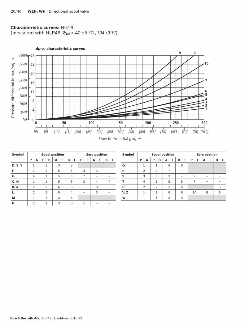
4
8
12
16
20
24
28
50 100 150 200 250 300
10
7
9 8
654321
0
[5][0] [10] [792]
0[0]
[50]
[75][15] [20] [25] [30] [35] [40] [45] [50] [55] [60] [65] [70]
[406]
[100]
[150]
[200]
[250]
[300]
[250]
2040 WEH WH | Directional spool valve
Bosch Rexroth AG RE 24751 edition 2018-12
Characteristic curves NG16 (measured with HLP46 ϑOil = 40 plusmn5 degC [104 plusmn9 degF])
∆p-qV characteristic curves
Flow in lmin [US gpm] rarr
Pres
sure
diff
eren
tial i
n ba
r [p
si] rarr
Symbol Spool position Zero positionP ndash A P ndash B A ndash T B ndash T P ndash T A ndash T B ndash T
D E Y 1 1 3 3
F 1 2 5 5 4 3 ndash
G 4 1 5 5 7 ndash ndash
C H 1 1 5 6 2 4 4
K J 2 2 6 6 ndash 3 ndash
L 2 2 5 4 ndash 3 ndash
M 1 1 3 4
P 2 1 3 6 5 ndash ndash
Symbol Spool position Zero positionP ndash A P ndash B A ndash T B ndash T P ndash T A ndash T B ndash T
Q 1 1 6 6
R 2 4 7 ndash
S 3 3 3 ndash 9 ndash ndash
T 4 1 5 5 7 ndash ndash
U 2 2 3 4 6
V Z 1 1 6 6 10 8 8
W 1 1 3 4
Directional spool valve | WEH WH 2140
RE 24751 edition 2018-12 Bosch Rexroth AG
Performance limits NG16 (measured with HLP46 ϑOil = 40 plusmn5 degC [104 plusmn9 degF])
2-spool position valves ndash qV max in lmin [US gpm]
SymbolOperating pressure pmax in bar [psi]
70 [1015]
140 [2030]
210 [3046]
280 [4061]
350 [5076]
X external ndash spring end position in the main valve (with ppilot min = 12 bar [174 psi])
C D K Y Z
300 [79] 300 [79] 300 [79] 300 [79] 300 [79]
X external ndash spring end position in the main valve 1)
C 300 [79] 300 [79] 300 [79] 300 [79] 300 [79]
D Y 300 [79] 270 [71] 260 [68] 250 [66] 230 [60]
K 300 [79] 250 [66] 240 [63] 230 [60] 210 [55]
Z 300 [79] 260 [68] 190 [50] 180 [47] 160 [42]
X external ndash hydraulic end position in the main valveHC HD HK HZ HY
300 [79] 300 [79] 300 [79] 300 [79] 300 [79]
3-spool position valves ndash qV max in lmin [US gpm]
SymbolOperating pressure pmax in bar [psi]
70 [1015]
140 [2030]
210 [3046]
280 [4061]
350 [5076]
X external ndash spring-centeredE H J L M Q U W R
300 [79] 300 [79] 300 [79] 300 [79] 300 [79]
F P 300 [79] 250 [66] 180 [47] 170 [45] 150 [39]
G T 300 [79] 300 [79] 240 [63] 210 [55] 190 [50]
S 300 [79] 300 [79] 300 [79] 250 [66] 220 [58]
V 300 [79] 250 [66] 210 [55] 200 [53] 180 [47]
X external ndash pressure-centered (at minimum pilot pressure of 16 bar [232 psi])
all sym-bols 2)
300 [79] 300 [79] 300 [79] 300 [79] 300 [79]
1) If the specified flow values are exceeded the function of the return spring is no longer guaranteed if the pilot pressure fails
2) With symbol V the pilot control valve is not required for flows gt160 lmin [42 US gpm]
Important notices see page 28
123
45
67
8
9
10
8
6
4
2
50 100 150 200 250 300 350 400
12
14
16
18
20
4500
[10][0] [20] [30] [40] [50] [60] [119]
0
[290]
[0]
[25]
[50]
[75]
[100]
[110][70] [80] [90] [100]
[125]
[150]
[175]
[200]
[225]
[250]
[275]
2240 WEH WH | Directional spool valve
Bosch Rexroth AG RE 24751 edition 2018-12
Characteristic curves NG25 (WH 22) (measured with HLP46 ϑOil = 40 plusmn5 degC [104 plusmn9 degF])
∆p-qV characteristic curves
Flow in lmin [US gpm] rarr
Pres
sure
diff
eren
tial i
n ba
r [p
si] rarr
Symbol Spool positionP ndash A P ndash B A ndash T B ndash T B ndash A
E D 2 2 3 5 ndash
J Q K 2 2 4 6 ndash
M W 1 1 3 5 ndash
H V C Z 1 1 4 6 ndash
F 1 2 4 5 ndash
G 3 4 5 6 ndash
R 1 2 2 ndash ndash
L 2 2 4 5 ndash
U 2 2 2 6 ndash
P 2 2 2 7 ndash
T 4 4 5 6 ndash
Symbol Zero positionA ndash T B ndash T P ndash T
F 2 ndash 4
G T ndash ndash 9
H ndash ndash 3
L 7 ndash ndash
U ndash 6 ndash
J 8 8 ndash
P ndash 4 6
V Z ndash ndash 8
Directional spool valve | WEH WH 2340
RE 24751 edition 2018-12 Bosch Rexroth AG
Performance limits NG25 (WH 22) (measured with HLP46 ϑOil = 40 plusmn5 degC [104 plusmn9 degF])
1) If the specified flow values are exceeded the function of the return spring is no longer guaranteed if the pilot pressure fails Important notices see page 28
2-spool position valves ndash qV max in lmin [US gpm]
SymbolOperating pressure pmax in bar [psi]
70 [1015]
140 [2030]
210 [3046]
280 [4061]
350 [5076]
X external ndash spring end position in the main valve (with ppilot min = 11 bar 14 bar [159 203 psi])
C D K Y Z 450 [119]
450 [119]
450 [119]
450 [119]
450 [119]
X external ndash spring end position in the main valve 1)
C 450 [119]
450 [119]
320 [84]
250 [66]
200 [53]
D Y 450 [119]
450 [119]
450 [119]
400 [105]
320 [84]
K 450 [119]
215 [57]
150 [39]
120 [32]
100 [26]
Z 350 [92]
300 [79]
290 [76]
260 [68]
160 [42]
X external ndash hydraulic end position in the main valveHC HD HK HZ HY
450 [119]
450 [119]
450 [119]
450 [119]
450 [119]
HCOhellip HDOhellip HKOhellip HZOhellip
450 [119]
450 [119]
450 [119]
450 [119]
450 [119]
HCOFhellip HDOFhellip HKOFhellip HZOFhellip
450 [119]
450 [119]
450 [119]
450 [119]
450 [119]
3-spool position valves ndash qV max in lmin [US gpm]
SymbolOperating pressure pmax in bar [psi]
70 [1015]
140 [2030]
210 [3046]
280 [4061]
350 [5076]
X external ndash spring-centered
E J L M Q U W R
450 [119]
450 [119]
450 [119]
450 [119]
450 [119]
H 450 [119]
450 [119]
300 [79]
260 [68]
230 [61]
G 400 [105]
350 [92]
250 [66]
200 [53]
180 [47]
F 450 [119]
270 [71]
175 [46]
130 [34]
110 [29]
V 450 [119]
300 [79]
240 [63]
220 [58]
160 [42]
T 400 [105]
300 [79]
240 [63]
200 [53]
160 [42]
P 450 [119]
270 [71]
180 [47]
170 [45]
110 [29]
1
2
3
4
5
6
0 100 200 300 400 500
78
600 650
10
8
6
4
2
12
14
16
18
20
22
2440 WEH WH | Directional spool valve
Bosch Rexroth AG RE 24751 edition 2018-12
Characteristic curves NG25 (WH 25) (measured with HLP46 ϑOil = 40 plusmn5 degC [104 plusmn9 degF])
∆p-qV characteristic curves
Flow in lmin [US gpm] rarr
Pres
sure
diff
eren
tial i
n ba
r [p
si] rarr
8 Symbol R spool position B ndash A
Symbol Spool position Zero positionP ndash A P ndash B A ndash T 1) B ndash T 1) A ndash T B ndash T P ndash T
E Y D 1 1 3 4
F 1 1 2 4 2 ndash 5
G T 1 1 2 5 ndash ndash 7
H 1 1 2 5 2 2 4
C 1 1 2 5
J 1 1 2 5 6 5 ndash
K 1 1 2 5
L 1 1 2 4 5 ndash ndash
M 1 1 3 4
P 1 1 3 5 ndash 3 5
Q 1 1 2 3
R 1 1 3 ndash
U 1 1 2 5 ndash 5 ndash
V 1 1 2 5 8 7 ndash
Z 1 1 2 5
W 1 1 3 4
Directional spool valve | WEH WH 2540
RE 24751 edition 2018-12 Bosch Rexroth AG
Performance limits NG25 (WH 25) (measured with HLP46 ϑOil = 40 plusmn5 degC [104 plusmn9 degF])
1) If the specified flow values are exceeded the function of the return spring is no longer guaranteed if the pilot pressure fails
Important notices see page 28
2-spool position valves ndash qV max in lmin [US gpm]
SymbolOperating pressure pmax in bar [psi]
70 [1015]
140 [2030]
210 [3046]
280 [4061]
350 [5076]
X external ndash spring end position in the main valve (with ppilot min = 13 bar [188 psi])
C D K Y Z 700 [185 ]
700 [185 ]
700 [185 ]
700 [185 ]
650 [172 ]
X external ndash spring end position in the main valve 1)
C 700 [185 ]
700 [185 ]
700 [185 ]
700 [185 ]
650 [172 ]
D Y 700 [185 ]
650 [172 ]
400 [105 ]
350 [92]
300 [79]
K 700 [185 ]
650 [172 ]
420 [111]
370 [98]
320 [84]
Z 700 [185 ]
700 [185 ]
650 [172 ]
480 [127 ]
400 [105 ]
X external ndash hydraulic end position in the main valveHC HD HK HZ HY
700 [185 ]
700 [185 ]
700 [185 ]
700 [185 ]
700 [185 ]
HCOhellip HDOhellip HKOhellip HZOhellip
700 [185 ]
700 [185 ]
700 [185 ]
700 [185 ]
700 [185 ]
HCOFhellip HDOFhellip HKOFhellip HZOFhellip
700 [185 ]
700 [185 ]
700 [185 ]
700 [185 ]
700 [185 ]
3-spool position valves ndash qV max in lmin [US gpm]
SymbolOperating pressure pmax in bar [psi]
70 [1015]
140 [2030]
210 [3046]
280 [4061]
350 [5076]
X external ndash spring-centeredE L M Q U W 700
[185 ]700
[185 ]700
[185 ]700
[185 ]650
[172 ]
G T 400 [105 ]
400 [105 ]
400 [105 ]
400 [105 ]
400 [105 ]
F 650 [172 ]
550 [145]
430 [113]
330 [87]
300 [79]
H 700 [185 ]
650 [172 ]
550 [145]
400 [105 ]
360 [95]
J 700 [185 ]
700 [185 ]
650 [172 ]
600 [158 ]
520 [137 ]
P 650 [172 ]
550 [145]
430 [113]
330 [87]
300 [79]
V 650 [172 ]
550 [145]
400 [105 ]
350 [92]
310 [82]
R 700 [185 ]
700 [185 ]
700 [185 ]
650 [172 ]
580 [153 ]
X external ndash pressure-centered (at minimum pilot pressure of 18 bar [261 psi])
E F H J L M P Q R U V W
700 [185 ]
700 [185 ]
700 [185 ]
700 [185 ]
650 [172 ]
G T 400 [105 ]
400 [105 ]
400 [105 ]
400 [105 ]
400 [105 ]
X external ndash pressure-centered (with pilot pressure gt 30 bar [435 psi])
G T 700 [185 ]
700 [185 ]
700 [185 ]
700 [185 ]
650 [172 ]
12
10
14
8
6
4
2
100 300
16
18
10800
[40][0] [285]
0500 700 900
[80] [120] [160] [200] [240]
1
2
3
4
[0]
[50]
[100]
[150]
[200]
[261]
12
10
14
8
6
4
2
100 300
16
18
10800
[40][0] [285]
0500 700 900
[80] [120] [160] [200] [240]
5
6
7
8
[0]
[50]
[100]
[150]
[200]
[261]
2640 WEH WH | Directional spool valve
Bosch Rexroth AG RE 24751 edition 2018-12
Characteristic curves NG32 (measured with HLP46 ϑOil = 40 plusmn5 degC [104 plusmn9 degF])
Flow in lmin [US gpm] rarr
Flow in lmin [US gpm] rarr
Pres
sure
diff
eren
tial
in b
ar [p
si] rarr
Pres
sure
diff
eren
tial
in b
ar [p
si] rarr
∆p-qV-characteristic curves ndash Symbol E R and W
∆p-qV characteristic curves ndash Symbol G and T
Symbol Spool positionP ndash A P ndash B A ndash T B ndash T B ndash A
E 4 4 3 2 ndash
R 4 4 3 ndash 1
W 4 4 3 2 ndash
Symbol Spool positionP ndash A P ndash B A ndash T B ndash T P ndash T
G 7 8 7 5 6
T 7 8 7 5 6
Directional spool valve | WEH WH 2740
RE 24751 edition 2018-12 Bosch Rexroth AG
Performance limits NG32 (measured with HLP46 ϑOil = 40 plusmn5 degC [104 plusmn9 degF])
1) If the specified flow values are exceeded the function of the return spring is no longer guaranteed if the pilot pressure fails Important notices see page 28
2-spool position valves ndash qV max in lmin [US gpm]
SymbolOperating pressure pmax in bar [psi]
70 [1015]
140 [2030]
210 [3046]
280 [4061]
350 [5076]
X external ndash spring end position in the main valve (with ppilot min = 10 bar [145 psi])
C D K Y Z 1100 [290]
1040 [275]
860 [227]
750 [198]
680 [179]
X external ndash spring end position in the main valve 1)
C 1100 [290]
1040 [275]
860 [227]
800 [211]
700 [185]
D Y 1100 [290]
1040 [275]
540 [142]
480 [127]
420 [111]
K 1100 [290]
1040 [275]
860 [227]
500 [132]
450 [119]
Z 1100 [290]
1040 [275]
860 [227]
700 [185]
650 [172]
X external ndash hydraulic end position in the main valveHC HD HK HZ HY
1100 [290]
1040 [275]
860 [227]
750 [198]
680 [179]
3-spool position valves ndash qV max in lmin [US gpm]
SymbolOperating pressure pmax in bar [psi]
70[1015]
140 [2030]
210 [3046]
280 [4061]
350 [5076]
X external ndash spring-centeredE J L M Q R U W
1100 [290]
1040 [275]
860 [227]
750 [198]
680 [179]
G T H F P 900 [238]
900 [238]
800 [211]
650 [172]
450 [119]
V 1100 [290]
1000 [264]
680 [179]
500 [132]
450 [119]
X external ndash pressure-centered (at minimum pilot pressure of 85 bar [123 psi])all symbols 1100
[290]1040 [275]
860 [227]
750 [198]
680 [179]
2840 WEH WH | Directional spool valve
Bosch Rexroth AG RE 24751 edition 2018-12
Performance limits important information
NG16 With pilot oil supply X internal a preload valve has to be used for flows lt 160 lmin [42 US gpm] due to the negative overlap of the symbols C Z and HC HZ
43 directional valves with pressure centering of the control spool in the main valve can be used above the indicated performance limit In this case a higher pilot pressure is required (values see performance limits of the corresponding size)
With pilot oil supply X internal sufficient flow needs to be ensured due to the negative overlap of symbols F G H P S and T (for determination of the required flow see Preload valve characteristic curves (page 39) If the required flow is not reached a preload valve has to be used (see page 16)
NG25(WH 22)
With pilot oil supply X internal a preload valve has to be used for flows lt 180 lmin [475 US gpm] due to the negative overlap of symbols Z HZ and V
With pilot oil supply X internal sufficient flow needs to be ensured due to the negative overlap of symbols C HC F G H P and T (for determination of the required flow see Preload valve characteristic curves (page 39) If the required flow is not reached a preload valve has to be used (see page 16)
NG25(WH 25)
With pilot oil supply X internal a preload valve has to be used for flows lt 180 lmin [475 US gpm] due to the negative overlap of symbols Z HZ and V
43 directional valves with pressure centering of the control spool in the main valve can be used above the indicated performance limit In this case a higher pilot pressure is required (values see performance limits of the corresponding size)
With pilot oil supply X internal sufficient flow needs to be ensured due to the negative overlap of symbols C HC F G H P and T (for determination of the required flow see Preload valve characteristic curves (page 39) If the required flow is not reached a preload valve has to be used (see page 16)
NG32 With pilot oil supply X internal a preload valve has to be used for flows lt 180 lmin [475 US gpm] due to the negative overlap of symbols Z HZ and V
43 directional valves with pressure centering of the control spool in the main valve can be used above the indicated performance limit In this case a higher pilot pressure is required (values see performance limits of the corresponding size)
With pilot oil supply X internal sufficient flow needs to be ensured due to the negative overlap of symbols C HC F G H P and T (for determination of the required flow see Preload valve characteristic curves (page 39) If the required flow is not reached a preload valve has to be used (see page 16)
Notice (applies to all sizes)The specified switching power limits apply to the use with two directions of flow (e g from P to A and simultaneous return flow from B to T at a ratio of 11)Due to the flow forces acting within the valves the admissible switching power limit may be considerably lower with only one direction of flow (e g from P to A
while port B is blocked with flow in the same or in different directions)In such cases of application please consult usThe switching power limit was established while the solenoids were at operating temperature at 10 undervoltage and without tank preloading
TT
19
44 1592
40
20
87
73
146
206
168 305
35
11
66
71
27
108
PA B
T
X Y
AT B TP
X Y
T1
AT P B T
A B AT P B T
4
6
72122 11
14
12
32 31
23
1
8
9
13
3514
5
255
135
101
F1 F2
F3F4
19
7
B AT
P
B A
B A
P
001100[0000440]
Rzmax 4
Directional spool valve | WEH WH 2940
RE 24751 edition 2018-12 Bosch Rexroth AG
Dimensions NG10 (dimensions in mm [inch])
For item explanations and subplates see page 34 Valve mounting screws see page 35
Required surface quality of the valve contact surface
NoticeThe dimensions are nominal dimensions which are subject to tolerances
27
9719
1166
206
82
64 164
15656
9240
20
43
93
11 18
3514
12
21
142
94BA
TP
X
LY
102
1
9
5
68
4
31
15
17
13
12
32
21 22
7
3
3 19
A B Y
T P X
B A
15
18 16
F1 F2
F3F4
G1F5
G2 F6
11 23 14
B AT
P
001100[0000440]
Rzmax 4
3040 WEH WH | Directional spool valve
Bosch Rexroth AG RE 24751 edition 2018-12
Dimensions NG16 (dimensions in mm [inch])
For item explanations and subplates see page 34 Valve mounting screws see page 35
Required surface quality of the valve contact surface
NoticeThe dimensions are nominal dimen-sions which are subject to toler-ances
001100[0000440]
Rzmax 4
15
117
14
20
14 193241
110
19
414
6
A BX
PT Y92
4020
4
7
11 1432
1
8
912
19
13
21 22
103
3123
6
5
3514
14
175
180
120
BAX
T PY
[07
5][4
33]
[055] [760]
[949]
[46
1]
[Oslash079]
[Oslash055][709]
[069]
[47
2]
[05
5]
[Oslash024]
[015
7][1
61]
[014]
[055]
[05
9]
[15
7]
[07
8][3
62]
F1 F2
F3F4
F5
F6
G1
G2
206 [811]
L 1)
T
PB A
B A
Directional spool valve | WEH WH 3140
RE 24751 edition 2018-12 Bosch Rexroth AG
For item explanations and subplates see page 34 Valve mounting screws see page 35 Required surface quality of the
valve contact surface
Dimensions NG25 (WH 22) (dimensions in mm [inch])
1) Port L only for valves with pressure-centered zero position
NoticeThe dimensions are nominal dimensions which are subject to tolerances
19 225
2973245
275
332
3245
126
19
414
6
1592
20
7
11
32
18
9
12
19
13
15
1617
18
21 22
6
5
23 31 144
40
3514
206
279
L1)
BAX
T P Y
AXB
T P Y 14
21
195
117
20
14
103
F1 F2
F3F4
F5
F6
G1
G2
B A
T
PB A
120
001100[0000440]
Rzmax 4
3240 WEH WH | Directional spool valve
Bosch Rexroth AG RE 24751 edition 2018-12
Dimensions NG25 (WH 25) (dimensions in mm [inch])
1) Port L only for valves with pressure-centered zero position
For item explanations and subplates see page 34 Valve mounting screws see page 35 Required surface quality of the
valve contact surface
NoticeThe dimensions are nominal dimensions which are subject to tolerances
001100[0000440]
Rzmax 4
T
X
1933 22
P Y
X A B
197
205
23
257
A B
T PY
49
40
2+0
3
2865
6362
391
406
215
152
19
1592
4020
7
11 14
32
12
19
13
1516
17
18
21 22
23 31 4
3514
6
5
8
91
104
[59
8][0
75]
[014]
[055]
[05
9]
[15
7]
[07
8][3
62]
[19
3]
[Oslash024] [01
57]
[00
079+0
011
8 ]
[085] [1425]
[1539]
[1598]
[77
6]
[Oslash130] [Oslash087]
[1012]
[091]
[08
1]
391 [1539]
[78
7]
F1 F2
F3F4
F5
F6
G1
G2
206 [811]
LT
PB A
B A
200
Directional spool valve | WEH WH 3340
RE 24751 edition 2018-12 Bosch Rexroth AG
For item explanations and subplates see page 34 Valve mounting screws see page 35 Required surface quality of the
valve contact surface
Dimensions NG32 (dimensions in mm [inch])
NoticeThe dimensions are nominal dimensions which are subject to tolerances
3440 WEH WH | Directional spool valve
Bosch Rexroth AG RE 24751 edition 2018-12
1 Main valve2 Pilot control valve type 4WE 6 (data sheet 23178)
21 Pilot control valve type 4WE 6 Dhellip (1 solenoid) for main valves with symbols C D K Z symbols HC HD HK HZ
Pilot control valve type 4WE 6 JA (1 solenoid a) for main valves with symbols EA FA etc spring return
Pilot control valve type 4WE 6 MA (1 solenoid a) for main valves with symbols HEA HFA etc hydraulic spool return
22 Pilot control valve type 4WE 6 Y (1 solenoid) for main valves with symbol Y symbol HY
Pilot control valve type 4WE 6 JB (1 solenoid b) for main valves with symbols EB FB etc spring return
Pilot control valve type 4WE 6 MB (1 solenoid b) for main valves with symbols HEB HFB etc hydraulic spool return
23 Pilot control valve type 4WE 6Jhellip (2 solenoids) for main valves with 3 spool positions spring-centered
Pilot control valve type 4WE 6 Mhellip (2 solenoids) for main valves with 3 spool positions pressure-centered
31 Solenoid a32 Solenoid b
4 Manual override N optional Actuation of the manual override is only possible up to a tank pressure of approx 50 bar Avoid damage to the bore of the manual override (Special tool for the operation separate order material no R900024943) When the manual override is blocked the operation of the solenoid must be prevented
Simultaneous actuation of the solenoids must be prevented
5 Solenoid without manual override6 Solenoid with manual override7 Height of the diversion plate with hydraulic actuation
(type WH)8 Switching time adjustment (wrench size 6) optional9 Pressure reducing valve optional
101 Machined valve contact surface porting pattern according to ISO 4401-05-05-0-05 and NFPAT351 R2-D05
102 Machined valve contact surface porting pattern according to ISO 4401-07-07-0-05 and NFPAT351 R2-D07
103 Machined valve contact surface porting pattern according to ISO 4401-08-08-0-05 and NFPAT351 R2-D08
104 Machined valve contact surface porting pattern according to ISO 4401-10-09-0-05 and NFPAT351 R2-D10
11 Name plate pilot control valve12 Name plate complete valve13 Seal rings14 Space required for removing the mating connector15 2-spool position valves with spring end position in the main
valve (symbols A C D K Z)16 2-spool position valves with spring end position in the main
valve (symbols B Y)
17 3-spool position valves spring-centered 2-spool position valves with hydraulic end position in the main valve
18 3-spool position valves pressure-centered19 Locking pin
Subplates (separate order) with porting pattern according to ISO 4401 see data sheet 45100
Valve mounting screws see page 35
Dimensions
Directional spool valve | WEH WH 3540
RE 24751 edition 2018-12 Bosch Rexroth AG
Dimensions
Valve mounting screws (separate order) Nominal size Quantity Hexagon socket head cap screws Material number10 4 ISO 4762 - M6 x 45 - 109-CM-Fe-ZnNi-5-Cn-T0-H-B
Friction coefficient micrototal = 009 hellip 014 tightening torque MA = 125 Nm [92 ft-lbs] plusmn10 R913043777
or
4 14-20 UNC x 1 34rdquo ASTM-A574 Not included in the Rexroth delivery range
16 4 ISO 4762 - M10 x 60 - 109-flZnnc480hCFriction coefficient micrototal = 009 hellip 014 tightening torque MA = 58 Nm [428 ft-lbs] plusmn10
R913014770
2 ISO 4762 - M6 x 60 - 109-CM-Fe-ZnNi-5-Cn-T0-H-B Friction coefficient micrototal = 009 hellip 014 tightening torque MA = 125 Nm [92 ft-lbs] plusmn10
R913043410
or
4 Zylinderschrauben UNC 38-16 UNC x 2 14rdquo ASTM-A574 Not included in the Rexroth delivery range2 Zylinderschrauben UNC 14-20 UNC x 2 14rdquo ASTM-A574
25 6 ISO 4762 - M12 x 60 - 109-flZnnc480hC Friction coefficient micrototal = 009 hellip 014 tightening torque MA = 100 Nm [74 ft-lbs] plusmn20
R913015613
or
6 UNC 12-13 UNC x 2 12rdquo ASTM-A574 Not included in the Rexroth delivery range
32 6 ISO 4762 - M20 x 80 - 109-flZnnc480hC Friction coefficient micrototal = 009 hellip 014 tightening torque MA = 340 Nm [251 ft-lbs] plusmn10
R913008472
or
6 UNC 34-10 UNC x 3 14rdquo ASTM-A574 Not included in the Rexroth delivery range
L4
L3
5
4 2
3
1
3640 WEH WH | Directional spool valve
Bosch Rexroth AG RE 24751 edition 2018-12
Stroke setting mounting options (dimensions in mm [inch])
NG L410 65 [026]
16 10 [039]
25 (WH 22) 95 [037]
25 (WH 25) 125 [049]
32 15 [059]
The stroke of the control spool is limited by the stroke setting (1) The control spool stroke is shortened by loosening the lock nut (2) and clockwise rotation of the adjustment spindle (3) The control chamber (4) must be depressurized for this
5 Adjustment range NG10 1 rotation = 1 mm [00394 inch] adjustment travel
NG16 and 32 1 rotation = 15 mm [00591 inch] adjustment travel
3-spool position valve 1)
spring-centered pressure-centered
L1 L2 L3 L1 L2 L3
Stroke setting on valve side A and B 10
10 90 [354] 144 [567] 234 [921]
16 100 [394] 200 [787] 300 [1181]
25 2) 96 [377] 241 [949] 337 [1327]
25 3) 123 [484] 276 [1087] 399 [1571]
32 133 [524] 344 [1354] 477 [1878]
Stroke setting on valve side A
11
10 90 [354] 106 [417] 196 [772]
16 100 [394] 156 [614] 256 [1008]
25 2) 96 [377] 193 [760] 289 [1138]
25 3) 123 [484] 225 [886] 348 [1370]
32 133 [524] 287 [1130] 420 [1654]
Stroke setting on valve side B 12
10 52 [205] 144 [567] 196 [772] ndash ndash ndash
16 56 [220] 200 [787] 256 [1008] 81 [319] 200 [787] 281 [1106]
25 2) 48 [189] 241 [949] 289 [1138] ndash ndash ndash
25 3) 72 [283] 276 [1087] 348 [1370] 107 [421] 276 [1087] 283 [1114]
32 76 [299] 344 [1354] 420 [1654] 120 [472] 344 [1354] 464 [1827]
More dimensions see below and page 37
Stroke limitation on side A Stroke limitation on side B
a
BA
L3
L1 L2
L3L2
X A B
a
B
b
A A B
L3
L3L2L1
L1
b a
X A B
1) With symbol A only version 11 with symbol B only version 12 possible
Directional spool valve | WEH WH 3740
RE 24751 edition 2018-12 Bosch Rexroth AG
Stroke setting mounting options (dimensions in mm [inch])
2) Version WH 223) Version WH 25
2-spool position valve Spring end position Hydraulic end position
A C D K Z B Y HC HD HK HZ HY
L1 L2 L3 L1 L2 L3 L1 L2 L3
Stroke setting on valve side A and B 10
10 90 [354]
144 [567]
234 [921]
90 [354]
144 [567]
234 [921]
90 [354]
144 [567]
234 [921]
16 ndash ndash ndash ndash ndash ndash 100 [394]
200 [787]
300 [1181]
25 2) 96 [378]
241 [949]
337 [1327]
96 [378]
241 [949]
337 [1327]
96 [378]
241 [949]
337 [1327]
25 3) ndash ndash ndash ndash ndash ndash 123 [484]
276 [1087]
399 [1571]
32 ndash ndash ndash ndash ndash ndash 133 [524]
344 [1354]
477 [1878]
Stroke setting on valve side A
11
10 90 [354]
106 [417]
196 [772]
90 [354]
106 [417]
196 [772]
90 [354]
106 [417]
196 [772]
16 100 [394]
180 [709]
280 [1102] ndash ndash ndash 100
[394]156
[614]256
[1008]
25 2) 96 [378]
193 [760]
289 [1138]
96 [378]
193 [760]
289 [1138]
96 [378]
193 [760]
289 [1138]
25 3) 123 [484]
253 [996]
376 [148] ndash ndash ndash 123
[484]225
[886]348
[1370]
32 133 [524]
316 [1244]
449 [1768] ndash ndash ndash 133
[524]287
[1130]420
[1653]
Stroke setting on valve side B 12
10 52 [205]
144 [567]
196 [772]
52 [205]
144 [567]
196 [772]
52 [205]
144 [567]
196 [772]
16 ndash ndash ndash 80 [315]
200 [787]
280 [1102]
56 [221]
200 [787]
256 [1008]
25 2) 48 [189]
241 [949]
289 [1138]
48 [189]
241 [949]
289 [1138]
48 [189]
241 [949]
289 [1138]
25 3) ndash ndash ndash 100 [394]
276 [1087]
376 [1480]
72 [284]
276 [1087]
348 [1370]
32 ndash ndash ndash 105 [413]
344 [1354]
449 [1768]
76 [299]
344 [1354]
420 [1653]
NoticeThe dimensions are nominal dimensions which are subject to tolerances
34
7 5
62
1
7
8
3840 WEH WH | Directional spool valve
Bosch Rexroth AG RE 24751 edition 2018-12
Switching time adjustment
Pressure reducing valve D3
The switching time of the main valve (1) is influenced by using a twin throttle check valve (2) (type Z2FS 6 data sheet 27506)
Modification of supply (3) to discharge control (4)Remove the pilot control valve (5) ndash The plate (6) to accept the seal rings stays in place ndash Turn the switching time adjustment (2) around its longitudinal axis and put it back install the pilot control valve (5)
NoticeThe modification may only be performed by authorized specialists or at the factory
Type WEH 10 4XhellipS Type WEH 10 4XhellipS2
The pressure reducing valve (8) has to be used at a pilot pressure above 250 bar [3626 psi] (with WEH 22 hellip 210 bar [3046 psi]) and with version HThe secondary pressure is kept at a constant level of 45 bar [652 psi]
Notice If a pressure reducing valve D3 (8) is used a B10
throttle insert has to be installed in channel P of the pilot control valve
The modification may only be performed by authorized specialists or at the factory Type WEH 10 4XhellipD3
92
10
11
141210
8
6
4
2
100 200 300 400 500 600 700
1 2
3
4
0
[20][0] [185]
0[0]
[50]
[100]
[150]
[203]
[40] [60] [80] [100] [120] [140] [160]
91
10
11
Directional spool valve | WEH WH 3940
RE 24751 edition 2018-12 Bosch Rexroth AG
Pres
sure
diff
eren
tial
in b
ar [p
si] rarr
Flow in lmin [US gpm] rarr
∆pndashqV characteristic curve (measured with HLP46 ϑOil = 40 degC plusmn 5 degC [104 degF plusmn9 degF])
1 NG16
2 NG25 (WH 25)
3 NG25 (WH 22)
4 NG32
In case of valves with depressurized circulation and internal pilot oil supply the installation of the preload valve (9) in channel P of the main valve is required in order to build up the minimum pilot pressure
SizeItem 91 Item 92
16 R961009415 (from component series 72) R961009417 (up to component series 71)
25 (WH 22) ndash R961009609 (up to component series 76)
25 (WH 25) R961009166 (from component series 68) R961009416 (up to component series 67)
32 ndash R961009610 (up to component series 63)
Preload valve (not for NG10)
91 Preload valve
92 Preload valve
10 Main valve
11 Subplate
The pressure differential of the preload valve is to be added to the pressure differential of the main valve (see characteristic curves) to result in one total valueThe cracking pressure amounts to approx 45 bar [65 psi]
NoticeSeries-production status see ordering key on the name plate
Bosch Rexroth AG RE 24751 edition 2018-12
4040 WEH WH | Directional spool valve
Bosch Rexroth AG Industrial HydraulicsZum Eisengieszliger 197816 Lohr am Main Germany Phone +49 (0) 93 52thinspthinsp40 30 20 mysupportboschrexrothde wwwboschrexrothde
copy All rights reserved to Bosch Rexroth AG also regarding any disposal exploitation reproduction editing distribution as well as in the event of applications for industrial property rightsThe data specified above only serve to describe the product No statements concerning a certain condition or suitability for a certain application can be derived from our information The information given does not release the user from the obligation of own judgment and verificationPlease note that our products are subject to a natural process of wear and aging
Project planning information
The stipulations of the Machinery Directive 200642EC are to be adhered toPlease also note data sheet 08012 with information on MTTFd values and shock and vibration loads
Further information
Directional spool valve Data sheet 23178 Subplates Data sheet 45100 Inductive position switch and proximity sensors (contactless) Data sheet 24830 Hydraulic fluids on mineral oil basis Data sheet 90220 Environmentally compatible hydraulic fluids Data sheet 90221 Flame-resistant water-free hydraulic fluids Data sheet 90222 Flame-resistant hydraulic fluids - containing water (HFAE HFAS HFB HFC) Data sheet 90223 Reliability characteristics according to EN ISO 13849 Data sheet 08012 Hexagon socket head cap screw metricUNC Data sheet 08936 Hydraulic valves for industrial applications Operating instructions 07600-B General product information on hydraulic products Data sheet 07008 Assembly commissioning and maintenance of industrial valves Data sheet 07300 Mating connectors and cable sets for valves and sensors in hydraulics Data sheet 08006 Directional spool valves and directional seat valves with electrical actuation and
M12x1 plug-in connectionData sheet 08010
Use of non-electrical hydraulic components in an explosive environment (ATEX) Data sheet 07011 Selection of filters wwwboschrexrothcomfilter Information on available spare parts wwwboschrexrothcomspc
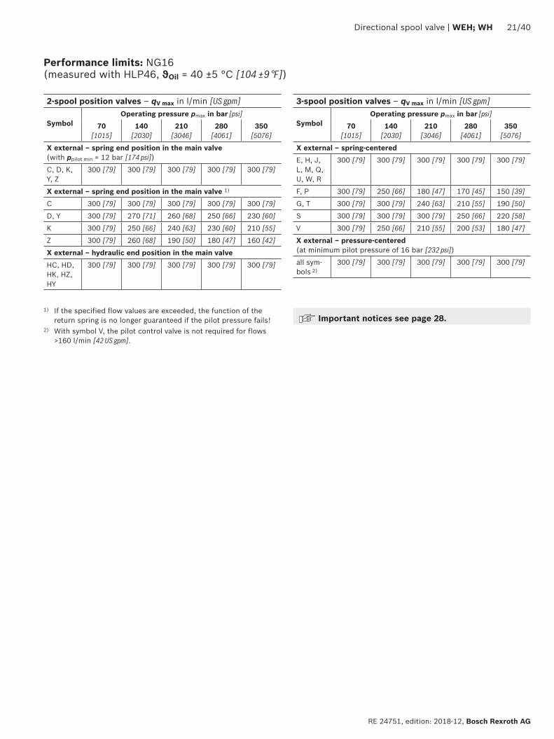
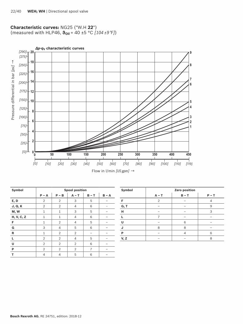
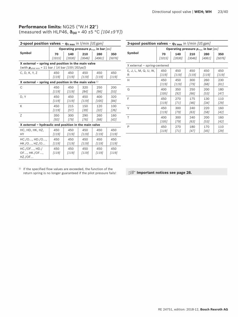
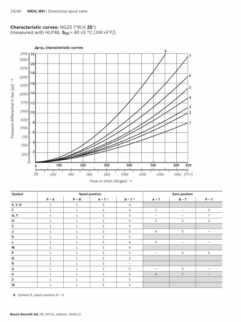
1
2
3
4
5
6
0 100 200 300 400 500
78
600 650
10
8
6
4
2
12
14
16
18
20
22
2440 WEH WH | Directional spool valve
Bosch Rexroth AG RE 24751 edition 2018-12
Characteristic curves NG25 (WH 25) (measured with HLP46 ϑOil = 40 plusmn5 degC [104 plusmn9 degF])
∆p-qV characteristic curves
Flow in lmin [US gpm] rarr
Pres
sure
diff
eren
tial i
n ba
r [p
si] rarr
8 Symbol R spool position B ndash A
Symbol Spool position Zero positionP ndash A P ndash B A ndash T 1) B ndash T 1) A ndash T B ndash T P ndash T
E Y D 1 1 3 4
F 1 1 2 4 2 ndash 5
G T 1 1 2 5 ndash ndash 7
H 1 1 2 5 2 2 4
C 1 1 2 5
J 1 1 2 5 6 5 ndash
K 1 1 2 5
L 1 1 2 4 5 ndash ndash
M 1 1 3 4
P 1 1 3 5 ndash 3 5
Q 1 1 2 3
R 1 1 3 ndash
U 1 1 2 5 ndash 5 ndash
V 1 1 2 5 8 7 ndash
Z 1 1 2 5
W 1 1 3 4
Directional spool valve | WEH WH 2540
RE 24751 edition 2018-12 Bosch Rexroth AG
Performance limits NG25 (WH 25) (measured with HLP46 ϑOil = 40 plusmn5 degC [104 plusmn9 degF])
1) If the specified flow values are exceeded the function of the return spring is no longer guaranteed if the pilot pressure fails
Important notices see page 28
2-spool position valves ndash qV max in lmin [US gpm]
SymbolOperating pressure pmax in bar [psi]
70 [1015]
140 [2030]
210 [3046]
280 [4061]
350 [5076]
X external ndash spring end position in the main valve (with ppilot min = 13 bar [188 psi])
C D K Y Z 700 [185 ]
700 [185 ]
700 [185 ]
700 [185 ]
650 [172 ]
X external ndash spring end position in the main valve 1)
C 700 [185 ]
700 [185 ]
700 [185 ]
700 [185 ]
650 [172 ]
D Y 700 [185 ]
650 [172 ]
400 [105 ]
350 [92]
300 [79]
K 700 [185 ]
650 [172 ]
420 [111]
370 [98]
320 [84]
Z 700 [185 ]
700 [185 ]
650 [172 ]
480 [127 ]
400 [105 ]
X external ndash hydraulic end position in the main valveHC HD HK HZ HY
700 [185 ]
700 [185 ]
700 [185 ]
700 [185 ]
700 [185 ]
HCOhellip HDOhellip HKOhellip HZOhellip
700 [185 ]
700 [185 ]
700 [185 ]
700 [185 ]
700 [185 ]
HCOFhellip HDOFhellip HKOFhellip HZOFhellip
700 [185 ]
700 [185 ]
700 [185 ]
700 [185 ]
700 [185 ]
3-spool position valves ndash qV max in lmin [US gpm]
SymbolOperating pressure pmax in bar [psi]
70 [1015]
140 [2030]
210 [3046]
280 [4061]
350 [5076]
X external ndash spring-centeredE L M Q U W 700
[185 ]700
[185 ]700
[185 ]700
[185 ]650
[172 ]
G T 400 [105 ]
400 [105 ]
400 [105 ]
400 [105 ]
400 [105 ]
F 650 [172 ]
550 [145]
430 [113]
330 [87]
300 [79]
H 700 [185 ]
650 [172 ]
550 [145]
400 [105 ]
360 [95]
J 700 [185 ]
700 [185 ]
650 [172 ]
600 [158 ]
520 [137 ]
P 650 [172 ]
550 [145]
430 [113]
330 [87]
300 [79]
V 650 [172 ]
550 [145]
400 [105 ]
350 [92]
310 [82]
R 700 [185 ]
700 [185 ]
700 [185 ]
650 [172 ]
580 [153 ]
X external ndash pressure-centered (at minimum pilot pressure of 18 bar [261 psi])
E F H J L M P Q R U V W
700 [185 ]
700 [185 ]
700 [185 ]
700 [185 ]
650 [172 ]
G T 400 [105 ]
400 [105 ]
400 [105 ]
400 [105 ]
400 [105 ]
X external ndash pressure-centered (with pilot pressure gt 30 bar [435 psi])
G T 700 [185 ]
700 [185 ]
700 [185 ]
700 [185 ]
650 [172 ]
12
10
14
8
6
4
2
100 300
16
18
10800
[40][0] [285]
0500 700 900
[80] [120] [160] [200] [240]
1
2
3
4
[0]
[50]
[100]
[150]
[200]
[261]
12
10
14
8
6
4
2
100 300
16
18
10800
[40][0] [285]
0500 700 900
[80] [120] [160] [200] [240]
5
6
7
8
[0]
[50]
[100]
[150]
[200]
[261]
2640 WEH WH | Directional spool valve
Bosch Rexroth AG RE 24751 edition 2018-12
Characteristic curves NG32 (measured with HLP46 ϑOil = 40 plusmn5 degC [104 plusmn9 degF])
Flow in lmin [US gpm] rarr
Flow in lmin [US gpm] rarr
Pres
sure
diff
eren
tial
in b
ar [p
si] rarr
Pres
sure
diff
eren
tial
in b
ar [p
si] rarr
∆p-qV-characteristic curves ndash Symbol E R and W
∆p-qV characteristic curves ndash Symbol G and T
Symbol Spool positionP ndash A P ndash B A ndash T B ndash T B ndash A
E 4 4 3 2 ndash
R 4 4 3 ndash 1
W 4 4 3 2 ndash
Symbol Spool positionP ndash A P ndash B A ndash T B ndash T P ndash T
G 7 8 7 5 6
T 7 8 7 5 6
Directional spool valve | WEH WH 2740
RE 24751 edition 2018-12 Bosch Rexroth AG
Performance limits NG32 (measured with HLP46 ϑOil = 40 plusmn5 degC [104 plusmn9 degF])
1) If the specified flow values are exceeded the function of the return spring is no longer guaranteed if the pilot pressure fails Important notices see page 28
2-spool position valves ndash qV max in lmin [US gpm]
SymbolOperating pressure pmax in bar [psi]
70 [1015]
140 [2030]
210 [3046]
280 [4061]
350 [5076]
X external ndash spring end position in the main valve (with ppilot min = 10 bar [145 psi])
C D K Y Z 1100 [290]
1040 [275]
860 [227]
750 [198]
680 [179]
X external ndash spring end position in the main valve 1)
C 1100 [290]
1040 [275]
860 [227]
800 [211]
700 [185]
D Y 1100 [290]
1040 [275]
540 [142]
480 [127]
420 [111]
K 1100 [290]
1040 [275]
860 [227]
500 [132]
450 [119]
Z 1100 [290]
1040 [275]
860 [227]
700 [185]
650 [172]
X external ndash hydraulic end position in the main valveHC HD HK HZ HY
1100 [290]
1040 [275]
860 [227]
750 [198]
680 [179]
3-spool position valves ndash qV max in lmin [US gpm]
SymbolOperating pressure pmax in bar [psi]
70[1015]
140 [2030]
210 [3046]
280 [4061]
350 [5076]
X external ndash spring-centeredE J L M Q R U W
1100 [290]
1040 [275]
860 [227]
750 [198]
680 [179]
G T H F P 900 [238]
900 [238]
800 [211]
650 [172]
450 [119]
V 1100 [290]
1000 [264]
680 [179]
500 [132]
450 [119]
X external ndash pressure-centered (at minimum pilot pressure of 85 bar [123 psi])all symbols 1100
[290]1040 [275]
860 [227]
750 [198]
680 [179]
2840 WEH WH | Directional spool valve
Bosch Rexroth AG RE 24751 edition 2018-12
Performance limits important information
NG16 With pilot oil supply X internal a preload valve has to be used for flows lt 160 lmin [42 US gpm] due to the negative overlap of the symbols C Z and HC HZ
43 directional valves with pressure centering of the control spool in the main valve can be used above the indicated performance limit In this case a higher pilot pressure is required (values see performance limits of the corresponding size)
With pilot oil supply X internal sufficient flow needs to be ensured due to the negative overlap of symbols F G H P S and T (for determination of the required flow see Preload valve characteristic curves (page 39) If the required flow is not reached a preload valve has to be used (see page 16)
NG25(WH 22)
With pilot oil supply X internal a preload valve has to be used for flows lt 180 lmin [475 US gpm] due to the negative overlap of symbols Z HZ and V
With pilot oil supply X internal sufficient flow needs to be ensured due to the negative overlap of symbols C HC F G H P and T (for determination of the required flow see Preload valve characteristic curves (page 39) If the required flow is not reached a preload valve has to be used (see page 16)
NG25(WH 25)
With pilot oil supply X internal a preload valve has to be used for flows lt 180 lmin [475 US gpm] due to the negative overlap of symbols Z HZ and V
43 directional valves with pressure centering of the control spool in the main valve can be used above the indicated performance limit In this case a higher pilot pressure is required (values see performance limits of the corresponding size)
With pilot oil supply X internal sufficient flow needs to be ensured due to the negative overlap of symbols C HC F G H P and T (for determination of the required flow see Preload valve characteristic curves (page 39) If the required flow is not reached a preload valve has to be used (see page 16)
NG32 With pilot oil supply X internal a preload valve has to be used for flows lt 180 lmin [475 US gpm] due to the negative overlap of symbols Z HZ and V
43 directional valves with pressure centering of the control spool in the main valve can be used above the indicated performance limit In this case a higher pilot pressure is required (values see performance limits of the corresponding size)
With pilot oil supply X internal sufficient flow needs to be ensured due to the negative overlap of symbols C HC F G H P and T (for determination of the required flow see Preload valve characteristic curves (page 39) If the required flow is not reached a preload valve has to be used (see page 16)
Notice (applies to all sizes)The specified switching power limits apply to the use with two directions of flow (e g from P to A and simultaneous return flow from B to T at a ratio of 11)Due to the flow forces acting within the valves the admissible switching power limit may be considerably lower with only one direction of flow (e g from P to A
while port B is blocked with flow in the same or in different directions)In such cases of application please consult usThe switching power limit was established while the solenoids were at operating temperature at 10 undervoltage and without tank preloading
TT
19
44 1592
40
20
87
73
146
206
168 305
35
11
66
71
27
108
PA B
T
X Y
AT B TP
X Y
T1
AT P B T
A B AT P B T
4
6
72122 11
14
12
32 31
23
1
8
9
13
3514
5
255
135
101
F1 F2
F3F4
19
7
B AT
P
B A
B A
P
001100[0000440]
Rzmax 4
Directional spool valve | WEH WH 2940
RE 24751 edition 2018-12 Bosch Rexroth AG
Dimensions NG10 (dimensions in mm [inch])
For item explanations and subplates see page 34 Valve mounting screws see page 35
Required surface quality of the valve contact surface
NoticeThe dimensions are nominal dimensions which are subject to tolerances
27
9719
1166
206
82
64 164
15656
9240
20
43
93
11 18
3514
12
21
142
94BA
TP
X
LY
102
1
9
5
68
4
31
15
17
13
12
32
21 22
7
3
3 19
A B Y
T P X
B A
15
18 16
F1 F2
F3F4
G1F5
G2 F6
11 23 14
B AT
P
001100[0000440]
Rzmax 4
3040 WEH WH | Directional spool valve
Bosch Rexroth AG RE 24751 edition 2018-12
Dimensions NG16 (dimensions in mm [inch])
For item explanations and subplates see page 34 Valve mounting screws see page 35
Required surface quality of the valve contact surface
NoticeThe dimensions are nominal dimen-sions which are subject to toler-ances
001100[0000440]
Rzmax 4
15
117
14
20
14 193241
110
19
414
6
A BX
PT Y92
4020
4
7
11 1432
1
8
912
19
13
21 22
103
3123
6
5
3514
14
175
180
120
BAX
T PY
[07
5][4
33]
[055] [760]
[949]
[46
1]
[Oslash079]
[Oslash055][709]
[069]
[47
2]
[05
5]
[Oslash024]
[015
7][1
61]
[014]
[055]
[05
9]
[15
7]
[07
8][3
62]
F1 F2
F3F4
F5
F6
G1
G2
206 [811]
L 1)
T
PB A
B A
Directional spool valve | WEH WH 3140
RE 24751 edition 2018-12 Bosch Rexroth AG
For item explanations and subplates see page 34 Valve mounting screws see page 35 Required surface quality of the
valve contact surface
Dimensions NG25 (WH 22) (dimensions in mm [inch])
1) Port L only for valves with pressure-centered zero position
NoticeThe dimensions are nominal dimensions which are subject to tolerances
19 225
2973245
275
332
3245
126
19
414
6
1592
20
7
11
32
18
9
12
19
13
15
1617
18
21 22
6
5
23 31 144
40
3514
206
279
L1)
BAX
T P Y
AXB
T P Y 14
21
195
117
20
14
103
F1 F2
F3F4
F5
F6
G1
G2
B A
T
PB A
120
001100[0000440]
Rzmax 4
3240 WEH WH | Directional spool valve
Bosch Rexroth AG RE 24751 edition 2018-12
Dimensions NG25 (WH 25) (dimensions in mm [inch])
1) Port L only for valves with pressure-centered zero position
For item explanations and subplates see page 34 Valve mounting screws see page 35 Required surface quality of the
valve contact surface
NoticeThe dimensions are nominal dimensions which are subject to tolerances
001100[0000440]
Rzmax 4
T
X
1933 22
P Y
X A B
197
205
23
257
A B
T PY
49
40
2+0
3
2865
6362
391
406
215
152
19
1592
4020
7
11 14
32
12
19
13
1516
17
18
21 22
23 31 4
3514
6
5
8
91
104
[59
8][0
75]
[014]
[055]
[05
9]
[15
7]
[07
8][3
62]
[19
3]
[Oslash024] [01
57]
[00
079+0
011
8 ]
[085] [1425]
[1539]
[1598]
[77
6]
[Oslash130] [Oslash087]
[1012]
[091]
[08
1]
391 [1539]
[78
7]
F1 F2
F3F4
F5
F6
G1
G2
206 [811]
LT
PB A
B A
200
Directional spool valve | WEH WH 3340
RE 24751 edition 2018-12 Bosch Rexroth AG
For item explanations and subplates see page 34 Valve mounting screws see page 35 Required surface quality of the
valve contact surface
Dimensions NG32 (dimensions in mm [inch])
NoticeThe dimensions are nominal dimensions which are subject to tolerances
3440 WEH WH | Directional spool valve
Bosch Rexroth AG RE 24751 edition 2018-12
1 Main valve2 Pilot control valve type 4WE 6 (data sheet 23178)
21 Pilot control valve type 4WE 6 Dhellip (1 solenoid) for main valves with symbols C D K Z symbols HC HD HK HZ
Pilot control valve type 4WE 6 JA (1 solenoid a) for main valves with symbols EA FA etc spring return
Pilot control valve type 4WE 6 MA (1 solenoid a) for main valves with symbols HEA HFA etc hydraulic spool return
22 Pilot control valve type 4WE 6 Y (1 solenoid) for main valves with symbol Y symbol HY
Pilot control valve type 4WE 6 JB (1 solenoid b) for main valves with symbols EB FB etc spring return
Pilot control valve type 4WE 6 MB (1 solenoid b) for main valves with symbols HEB HFB etc hydraulic spool return
23 Pilot control valve type 4WE 6Jhellip (2 solenoids) for main valves with 3 spool positions spring-centered
Pilot control valve type 4WE 6 Mhellip (2 solenoids) for main valves with 3 spool positions pressure-centered
31 Solenoid a32 Solenoid b
4 Manual override N optional Actuation of the manual override is only possible up to a tank pressure of approx 50 bar Avoid damage to the bore of the manual override (Special tool for the operation separate order material no R900024943) When the manual override is blocked the operation of the solenoid must be prevented
Simultaneous actuation of the solenoids must be prevented
5 Solenoid without manual override6 Solenoid with manual override7 Height of the diversion plate with hydraulic actuation
(type WH)8 Switching time adjustment (wrench size 6) optional9 Pressure reducing valve optional
101 Machined valve contact surface porting pattern according to ISO 4401-05-05-0-05 and NFPAT351 R2-D05
102 Machined valve contact surface porting pattern according to ISO 4401-07-07-0-05 and NFPAT351 R2-D07
103 Machined valve contact surface porting pattern according to ISO 4401-08-08-0-05 and NFPAT351 R2-D08
104 Machined valve contact surface porting pattern according to ISO 4401-10-09-0-05 and NFPAT351 R2-D10
11 Name plate pilot control valve12 Name plate complete valve13 Seal rings14 Space required for removing the mating connector15 2-spool position valves with spring end position in the main
valve (symbols A C D K Z)16 2-spool position valves with spring end position in the main
valve (symbols B Y)
17 3-spool position valves spring-centered 2-spool position valves with hydraulic end position in the main valve
18 3-spool position valves pressure-centered19 Locking pin
Subplates (separate order) with porting pattern according to ISO 4401 see data sheet 45100
Valve mounting screws see page 35
Dimensions
Directional spool valve | WEH WH 3540
RE 24751 edition 2018-12 Bosch Rexroth AG
Dimensions
Valve mounting screws (separate order) Nominal size Quantity Hexagon socket head cap screws Material number10 4 ISO 4762 - M6 x 45 - 109-CM-Fe-ZnNi-5-Cn-T0-H-B
Friction coefficient micrototal = 009 hellip 014 tightening torque MA = 125 Nm [92 ft-lbs] plusmn10 R913043777
or
4 14-20 UNC x 1 34rdquo ASTM-A574 Not included in the Rexroth delivery range
16 4 ISO 4762 - M10 x 60 - 109-flZnnc480hCFriction coefficient micrototal = 009 hellip 014 tightening torque MA = 58 Nm [428 ft-lbs] plusmn10
R913014770
2 ISO 4762 - M6 x 60 - 109-CM-Fe-ZnNi-5-Cn-T0-H-B Friction coefficient micrototal = 009 hellip 014 tightening torque MA = 125 Nm [92 ft-lbs] plusmn10
R913043410
or
4 Zylinderschrauben UNC 38-16 UNC x 2 14rdquo ASTM-A574 Not included in the Rexroth delivery range2 Zylinderschrauben UNC 14-20 UNC x 2 14rdquo ASTM-A574
25 6 ISO 4762 - M12 x 60 - 109-flZnnc480hC Friction coefficient micrototal = 009 hellip 014 tightening torque MA = 100 Nm [74 ft-lbs] plusmn20
R913015613
or
6 UNC 12-13 UNC x 2 12rdquo ASTM-A574 Not included in the Rexroth delivery range
32 6 ISO 4762 - M20 x 80 - 109-flZnnc480hC Friction coefficient micrototal = 009 hellip 014 tightening torque MA = 340 Nm [251 ft-lbs] plusmn10
R913008472
or
6 UNC 34-10 UNC x 3 14rdquo ASTM-A574 Not included in the Rexroth delivery range
L4
L3
5
4 2
3
1
3640 WEH WH | Directional spool valve
Bosch Rexroth AG RE 24751 edition 2018-12
Stroke setting mounting options (dimensions in mm [inch])
NG L410 65 [026]
16 10 [039]
25 (WH 22) 95 [037]
25 (WH 25) 125 [049]
32 15 [059]
The stroke of the control spool is limited by the stroke setting (1) The control spool stroke is shortened by loosening the lock nut (2) and clockwise rotation of the adjustment spindle (3) The control chamber (4) must be depressurized for this
5 Adjustment range NG10 1 rotation = 1 mm [00394 inch] adjustment travel
NG16 and 32 1 rotation = 15 mm [00591 inch] adjustment travel
3-spool position valve 1)
spring-centered pressure-centered
L1 L2 L3 L1 L2 L3
Stroke setting on valve side A and B 10
10 90 [354] 144 [567] 234 [921]
16 100 [394] 200 [787] 300 [1181]
25 2) 96 [377] 241 [949] 337 [1327]
25 3) 123 [484] 276 [1087] 399 [1571]
32 133 [524] 344 [1354] 477 [1878]
Stroke setting on valve side A
11
10 90 [354] 106 [417] 196 [772]
16 100 [394] 156 [614] 256 [1008]
25 2) 96 [377] 193 [760] 289 [1138]
25 3) 123 [484] 225 [886] 348 [1370]
32 133 [524] 287 [1130] 420 [1654]
Stroke setting on valve side B 12
10 52 [205] 144 [567] 196 [772] ndash ndash ndash
16 56 [220] 200 [787] 256 [1008] 81 [319] 200 [787] 281 [1106]
25 2) 48 [189] 241 [949] 289 [1138] ndash ndash ndash
25 3) 72 [283] 276 [1087] 348 [1370] 107 [421] 276 [1087] 283 [1114]
32 76 [299] 344 [1354] 420 [1654] 120 [472] 344 [1354] 464 [1827]
More dimensions see below and page 37
Stroke limitation on side A Stroke limitation on side B
a
BA
L3
L1 L2
L3L2
X A B
a
B
b
A A B
L3
L3L2L1
L1
b a
X A B
1) With symbol A only version 11 with symbol B only version 12 possible
Directional spool valve | WEH WH 3740
RE 24751 edition 2018-12 Bosch Rexroth AG
Stroke setting mounting options (dimensions in mm [inch])
2) Version WH 223) Version WH 25
2-spool position valve Spring end position Hydraulic end position
A C D K Z B Y HC HD HK HZ HY
L1 L2 L3 L1 L2 L3 L1 L2 L3
Stroke setting on valve side A and B 10
10 90 [354]
144 [567]
234 [921]
90 [354]
144 [567]
234 [921]
90 [354]
144 [567]
234 [921]
16 ndash ndash ndash ndash ndash ndash 100 [394]
200 [787]
300 [1181]
25 2) 96 [378]
241 [949]
337 [1327]
96 [378]
241 [949]
337 [1327]
96 [378]
241 [949]
337 [1327]
25 3) ndash ndash ndash ndash ndash ndash 123 [484]
276 [1087]
399 [1571]
32 ndash ndash ndash ndash ndash ndash 133 [524]
344 [1354]
477 [1878]
Stroke setting on valve side A
11
10 90 [354]
106 [417]
196 [772]
90 [354]
106 [417]
196 [772]
90 [354]
106 [417]
196 [772]
16 100 [394]
180 [709]
280 [1102] ndash ndash ndash 100
[394]156
[614]256
[1008]
25 2) 96 [378]
193 [760]
289 [1138]
96 [378]
193 [760]
289 [1138]
96 [378]
193 [760]
289 [1138]
25 3) 123 [484]
253 [996]
376 [148] ndash ndash ndash 123
[484]225
[886]348
[1370]
32 133 [524]
316 [1244]
449 [1768] ndash ndash ndash 133
[524]287
[1130]420
[1653]
Stroke setting on valve side B 12
10 52 [205]
144 [567]
196 [772]
52 [205]
144 [567]
196 [772]
52 [205]
144 [567]
196 [772]
16 ndash ndash ndash 80 [315]
200 [787]
280 [1102]
56 [221]
200 [787]
256 [1008]
25 2) 48 [189]
241 [949]
289 [1138]
48 [189]
241 [949]
289 [1138]
48 [189]
241 [949]
289 [1138]
25 3) ndash ndash ndash 100 [394]
276 [1087]
376 [1480]
72 [284]
276 [1087]
348 [1370]
32 ndash ndash ndash 105 [413]
344 [1354]
449 [1768]
76 [299]
344 [1354]
420 [1653]
NoticeThe dimensions are nominal dimensions which are subject to tolerances
34
7 5
62
1
7
8
3840 WEH WH | Directional spool valve
Bosch Rexroth AG RE 24751 edition 2018-12
Switching time adjustment
Pressure reducing valve D3
The switching time of the main valve (1) is influenced by using a twin throttle check valve (2) (type Z2FS 6 data sheet 27506)
Modification of supply (3) to discharge control (4)Remove the pilot control valve (5) ndash The plate (6) to accept the seal rings stays in place ndash Turn the switching time adjustment (2) around its longitudinal axis and put it back install the pilot control valve (5)
NoticeThe modification may only be performed by authorized specialists or at the factory
Type WEH 10 4XhellipS Type WEH 10 4XhellipS2
The pressure reducing valve (8) has to be used at a pilot pressure above 250 bar [3626 psi] (with WEH 22 hellip 210 bar [3046 psi]) and with version HThe secondary pressure is kept at a constant level of 45 bar [652 psi]
Notice If a pressure reducing valve D3 (8) is used a B10
throttle insert has to be installed in channel P of the pilot control valve
The modification may only be performed by authorized specialists or at the factory Type WEH 10 4XhellipD3
92
10
11
141210
8
6
4
2
100 200 300 400 500 600 700
1 2
3
4
0
[20][0] [185]
0[0]
[50]
[100]
[150]
[203]
[40] [60] [80] [100] [120] [140] [160]
91
10
11
Directional spool valve | WEH WH 3940
RE 24751 edition 2018-12 Bosch Rexroth AG
Pres
sure
diff
eren
tial
in b
ar [p
si] rarr
Flow in lmin [US gpm] rarr
∆pndashqV characteristic curve (measured with HLP46 ϑOil = 40 degC plusmn 5 degC [104 degF plusmn9 degF])
1 NG16
2 NG25 (WH 25)
3 NG25 (WH 22)
4 NG32
In case of valves with depressurized circulation and internal pilot oil supply the installation of the preload valve (9) in channel P of the main valve is required in order to build up the minimum pilot pressure
SizeItem 91 Item 92
16 R961009415 (from component series 72) R961009417 (up to component series 71)
25 (WH 22) ndash R961009609 (up to component series 76)
25 (WH 25) R961009166 (from component series 68) R961009416 (up to component series 67)
32 ndash R961009610 (up to component series 63)
Preload valve (not for NG10)
91 Preload valve
92 Preload valve
10 Main valve
11 Subplate
The pressure differential of the preload valve is to be added to the pressure differential of the main valve (see characteristic curves) to result in one total valueThe cracking pressure amounts to approx 45 bar [65 psi]
NoticeSeries-production status see ordering key on the name plate
Bosch Rexroth AG RE 24751 edition 2018-12
4040 WEH WH | Directional spool valve
Bosch Rexroth AG Industrial HydraulicsZum Eisengieszliger 197816 Lohr am Main Germany Phone +49 (0) 93 52thinspthinsp40 30 20 mysupportboschrexrothde wwwboschrexrothde
copy All rights reserved to Bosch Rexroth AG also regarding any disposal exploitation reproduction editing distribution as well as in the event of applications for industrial property rightsThe data specified above only serve to describe the product No statements concerning a certain condition or suitability for a certain application can be derived from our information The information given does not release the user from the obligation of own judgment and verificationPlease note that our products are subject to a natural process of wear and aging
Project planning information
The stipulations of the Machinery Directive 200642EC are to be adhered toPlease also note data sheet 08012 with information on MTTFd values and shock and vibration loads
Further information
Directional spool valve Data sheet 23178 Subplates Data sheet 45100 Inductive position switch and proximity sensors (contactless) Data sheet 24830 Hydraulic fluids on mineral oil basis Data sheet 90220 Environmentally compatible hydraulic fluids Data sheet 90221 Flame-resistant water-free hydraulic fluids Data sheet 90222 Flame-resistant hydraulic fluids - containing water (HFAE HFAS HFB HFC) Data sheet 90223 Reliability characteristics according to EN ISO 13849 Data sheet 08012 Hexagon socket head cap screw metricUNC Data sheet 08936 Hydraulic valves for industrial applications Operating instructions 07600-B General product information on hydraulic products Data sheet 07008 Assembly commissioning and maintenance of industrial valves Data sheet 07300 Mating connectors and cable sets for valves and sensors in hydraulics Data sheet 08006 Directional spool valves and directional seat valves with electrical actuation and
M12x1 plug-in connectionData sheet 08010
Use of non-electrical hydraulic components in an explosive environment (ATEX) Data sheet 07011 Selection of filters wwwboschrexrothcomfilter Information on available spare parts wwwboschrexrothcomspc
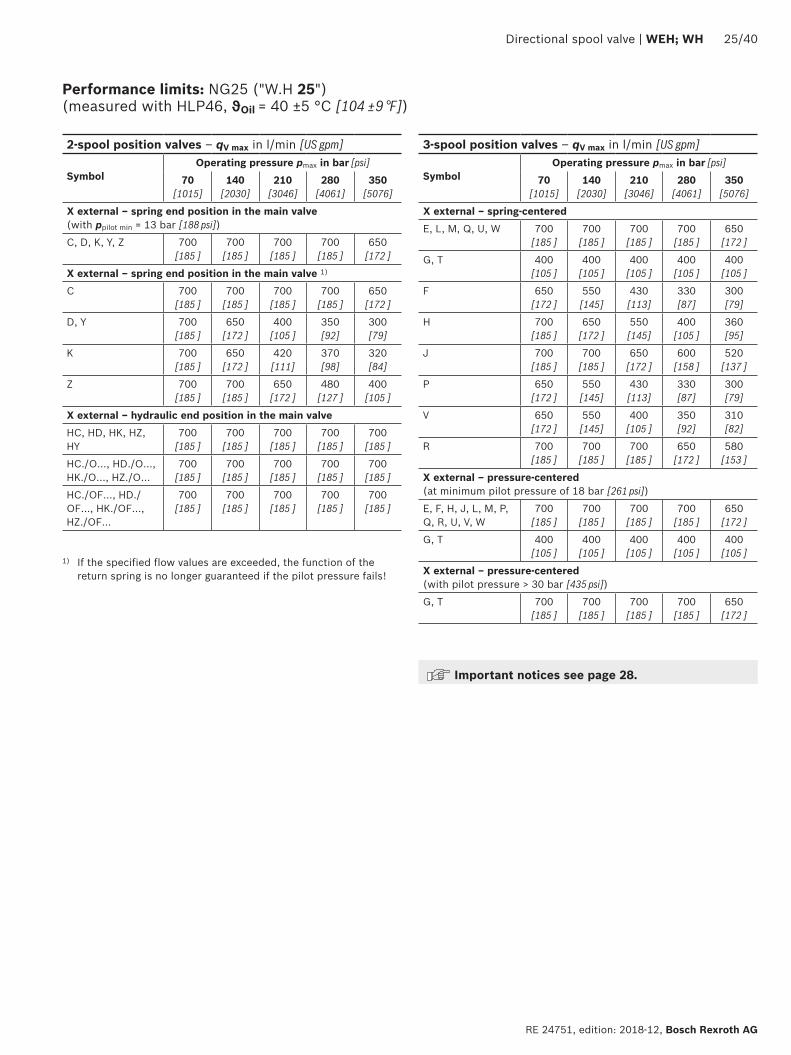
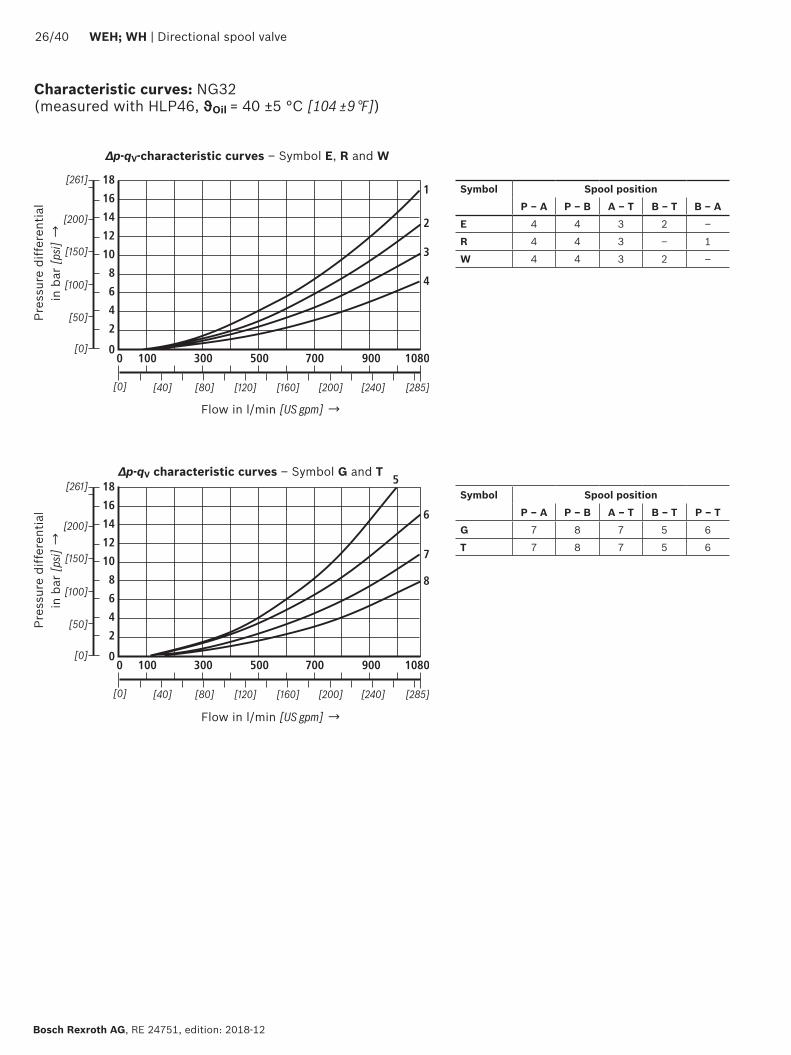
12
10
14
8
6
4
2
100 300
16
18
10800
[40][0] [285]
0500 700 900
[80] [120] [160] [200] [240]
1
2
3
4
[0]
[50]
[100]
[150]
[200]
[261]
12
10
14
8
6
4
2
100 300
16
18
10800
[40][0] [285]
0500 700 900
[80] [120] [160] [200] [240]
5
6
7
8
[0]
[50]
[100]
[150]
[200]
[261]
2640 WEH WH | Directional spool valve
Bosch Rexroth AG RE 24751 edition 2018-12
Characteristic curves NG32 (measured with HLP46 ϑOil = 40 plusmn5 degC [104 plusmn9 degF])
Flow in lmin [US gpm] rarr
Flow in lmin [US gpm] rarr
Pres
sure
diff
eren
tial
in b
ar [p
si] rarr
Pres
sure
diff
eren
tial
in b
ar [p
si] rarr
∆p-qV-characteristic curves ndash Symbol E R and W
∆p-qV characteristic curves ndash Symbol G and T
Symbol Spool positionP ndash A P ndash B A ndash T B ndash T B ndash A
E 4 4 3 2 ndash
R 4 4 3 ndash 1
W 4 4 3 2 ndash
Symbol Spool positionP ndash A P ndash B A ndash T B ndash T P ndash T
G 7 8 7 5 6
T 7 8 7 5 6
Directional spool valve | WEH WH 2740
RE 24751 edition 2018-12 Bosch Rexroth AG
Performance limits NG32 (measured with HLP46 ϑOil = 40 plusmn5 degC [104 plusmn9 degF])
1) If the specified flow values are exceeded the function of the return spring is no longer guaranteed if the pilot pressure fails Important notices see page 28
2-spool position valves ndash qV max in lmin [US gpm]
SymbolOperating pressure pmax in bar [psi]
70 [1015]
140 [2030]
210 [3046]
280 [4061]
350 [5076]
X external ndash spring end position in the main valve (with ppilot min = 10 bar [145 psi])
C D K Y Z 1100 [290]
1040 [275]
860 [227]
750 [198]
680 [179]
X external ndash spring end position in the main valve 1)
C 1100 [290]
1040 [275]
860 [227]
800 [211]
700 [185]
D Y 1100 [290]
1040 [275]
540 [142]
480 [127]
420 [111]
K 1100 [290]
1040 [275]
860 [227]
500 [132]
450 [119]
Z 1100 [290]
1040 [275]
860 [227]
700 [185]
650 [172]
X external ndash hydraulic end position in the main valveHC HD HK HZ HY
1100 [290]
1040 [275]
860 [227]
750 [198]
680 [179]
3-spool position valves ndash qV max in lmin [US gpm]
SymbolOperating pressure pmax in bar [psi]
70[1015]
140 [2030]
210 [3046]
280 [4061]
350 [5076]
X external ndash spring-centeredE J L M Q R U W
1100 [290]
1040 [275]
860 [227]
750 [198]
680 [179]
G T H F P 900 [238]
900 [238]
800 [211]
650 [172]
450 [119]
V 1100 [290]
1000 [264]
680 [179]
500 [132]
450 [119]
X external ndash pressure-centered (at minimum pilot pressure of 85 bar [123 psi])all symbols 1100
[290]1040 [275]
860 [227]
750 [198]
680 [179]
2840 WEH WH | Directional spool valve
Bosch Rexroth AG RE 24751 edition 2018-12
Performance limits important information
NG16 With pilot oil supply X internal a preload valve has to be used for flows lt 160 lmin [42 US gpm] due to the negative overlap of the symbols C Z and HC HZ
43 directional valves with pressure centering of the control spool in the main valve can be used above the indicated performance limit In this case a higher pilot pressure is required (values see performance limits of the corresponding size)
With pilot oil supply X internal sufficient flow needs to be ensured due to the negative overlap of symbols F G H P S and T (for determination of the required flow see Preload valve characteristic curves (page 39) If the required flow is not reached a preload valve has to be used (see page 16)
NG25(WH 22)
With pilot oil supply X internal a preload valve has to be used for flows lt 180 lmin [475 US gpm] due to the negative overlap of symbols Z HZ and V
With pilot oil supply X internal sufficient flow needs to be ensured due to the negative overlap of symbols C HC F G H P and T (for determination of the required flow see Preload valve characteristic curves (page 39) If the required flow is not reached a preload valve has to be used (see page 16)
NG25(WH 25)
With pilot oil supply X internal a preload valve has to be used for flows lt 180 lmin [475 US gpm] due to the negative overlap of symbols Z HZ and V
43 directional valves with pressure centering of the control spool in the main valve can be used above the indicated performance limit In this case a higher pilot pressure is required (values see performance limits of the corresponding size)
With pilot oil supply X internal sufficient flow needs to be ensured due to the negative overlap of symbols C HC F G H P and T (for determination of the required flow see Preload valve characteristic curves (page 39) If the required flow is not reached a preload valve has to be used (see page 16)
NG32 With pilot oil supply X internal a preload valve has to be used for flows lt 180 lmin [475 US gpm] due to the negative overlap of symbols Z HZ and V
43 directional valves with pressure centering of the control spool in the main valve can be used above the indicated performance limit In this case a higher pilot pressure is required (values see performance limits of the corresponding size)
With pilot oil supply X internal sufficient flow needs to be ensured due to the negative overlap of symbols C HC F G H P and T (for determination of the required flow see Preload valve characteristic curves (page 39) If the required flow is not reached a preload valve has to be used (see page 16)
Notice (applies to all sizes)The specified switching power limits apply to the use with two directions of flow (e g from P to A and simultaneous return flow from B to T at a ratio of 11)Due to the flow forces acting within the valves the admissible switching power limit may be considerably lower with only one direction of flow (e g from P to A
while port B is blocked with flow in the same or in different directions)In such cases of application please consult usThe switching power limit was established while the solenoids were at operating temperature at 10 undervoltage and without tank preloading
TT
19
44 1592
40
20
87
73
146
206
168 305
35
11
66
71
27
108
PA B
T
X Y
AT B TP
X Y
T1
AT P B T
A B AT P B T
4
6
72122 11
14
12
32 31
23
1
8
9
13
3514
5
255
135
101
F1 F2
F3F4
19
7
B AT
P
B A
B A
P
001100[0000440]
Rzmax 4
Directional spool valve | WEH WH 2940
RE 24751 edition 2018-12 Bosch Rexroth AG
Dimensions NG10 (dimensions in mm [inch])
For item explanations and subplates see page 34 Valve mounting screws see page 35
Required surface quality of the valve contact surface
NoticeThe dimensions are nominal dimensions which are subject to tolerances
27
9719
1166
206
82
64 164
15656
9240
20
43
93
11 18
3514
12
21
142
94BA
TP
X
LY
102
1
9
5
68
4
31
15
17
13
12
32
21 22
7
3
3 19
A B Y
T P X
B A
15
18 16
F1 F2
F3F4
G1F5
G2 F6
11 23 14
B AT
P
001100[0000440]
Rzmax 4
3040 WEH WH | Directional spool valve
Bosch Rexroth AG RE 24751 edition 2018-12
Dimensions NG16 (dimensions in mm [inch])
For item explanations and subplates see page 34 Valve mounting screws see page 35
Required surface quality of the valve contact surface
NoticeThe dimensions are nominal dimen-sions which are subject to toler-ances
001100[0000440]
Rzmax 4
15
117
14
20
14 193241
110
19
414
6
A BX
PT Y92
4020
4
7
11 1432
1
8
912
19
13
21 22
103
3123
6
5
3514
14
175
180
120
BAX
T PY
[07
5][4
33]
[055] [760]
[949]
[46
1]
[Oslash079]
[Oslash055][709]
[069]
[47
2]
[05
5]
[Oslash024]
[015
7][1
61]
[014]
[055]
[05
9]
[15
7]
[07
8][3
62]
F1 F2
F3F4
F5
F6
G1
G2
206 [811]
L 1)
T
PB A
B A
Directional spool valve | WEH WH 3140
RE 24751 edition 2018-12 Bosch Rexroth AG
For item explanations and subplates see page 34 Valve mounting screws see page 35 Required surface quality of the
valve contact surface
Dimensions NG25 (WH 22) (dimensions in mm [inch])
1) Port L only for valves with pressure-centered zero position
NoticeThe dimensions are nominal dimensions which are subject to tolerances
19 225
2973245
275
332
3245
126
19
414
6
1592
20
7
11
32
18
9
12
19
13
15
1617
18
21 22
6
5
23 31 144
40
3514
206
279
L1)
BAX
T P Y
AXB
T P Y 14
21
195
117
20
14
103
F1 F2
F3F4
F5
F6
G1
G2
B A
T
PB A
120
001100[0000440]
Rzmax 4
3240 WEH WH | Directional spool valve
Bosch Rexroth AG RE 24751 edition 2018-12
Dimensions NG25 (WH 25) (dimensions in mm [inch])
1) Port L only for valves with pressure-centered zero position
For item explanations and subplates see page 34 Valve mounting screws see page 35 Required surface quality of the
valve contact surface
NoticeThe dimensions are nominal dimensions which are subject to tolerances
001100[0000440]
Rzmax 4
T
X
1933 22
P Y
X A B
197
205
23
257
A B
T PY
49
40
2+0
3
2865
6362
391
406
215
152
19
1592
4020
7
11 14
32
12
19
13
1516
17
18
21 22
23 31 4
3514
6
5
8
91
104
[59
8][0
75]
[014]
[055]
[05
9]
[15
7]
[07
8][3
62]
[19
3]
[Oslash024] [01
57]
[00
079+0
011
8 ]
[085] [1425]
[1539]
[1598]
[77
6]
[Oslash130] [Oslash087]
[1012]
[091]
[08
1]
391 [1539]
[78
7]
F1 F2
F3F4
F5
F6
G1
G2
206 [811]
LT
PB A
B A
200
Directional spool valve | WEH WH 3340
RE 24751 edition 2018-12 Bosch Rexroth AG
For item explanations and subplates see page 34 Valve mounting screws see page 35 Required surface quality of the
valve contact surface
Dimensions NG32 (dimensions in mm [inch])
NoticeThe dimensions are nominal dimensions which are subject to tolerances
3440 WEH WH | Directional spool valve
Bosch Rexroth AG RE 24751 edition 2018-12
1 Main valve2 Pilot control valve type 4WE 6 (data sheet 23178)
21 Pilot control valve type 4WE 6 Dhellip (1 solenoid) for main valves with symbols C D K Z symbols HC HD HK HZ
Pilot control valve type 4WE 6 JA (1 solenoid a) for main valves with symbols EA FA etc spring return
Pilot control valve type 4WE 6 MA (1 solenoid a) for main valves with symbols HEA HFA etc hydraulic spool return
22 Pilot control valve type 4WE 6 Y (1 solenoid) for main valves with symbol Y symbol HY
Pilot control valve type 4WE 6 JB (1 solenoid b) for main valves with symbols EB FB etc spring return
Pilot control valve type 4WE 6 MB (1 solenoid b) for main valves with symbols HEB HFB etc hydraulic spool return
23 Pilot control valve type 4WE 6Jhellip (2 solenoids) for main valves with 3 spool positions spring-centered
Pilot control valve type 4WE 6 Mhellip (2 solenoids) for main valves with 3 spool positions pressure-centered
31 Solenoid a32 Solenoid b
4 Manual override N optional Actuation of the manual override is only possible up to a tank pressure of approx 50 bar Avoid damage to the bore of the manual override (Special tool for the operation separate order material no R900024943) When the manual override is blocked the operation of the solenoid must be prevented
Simultaneous actuation of the solenoids must be prevented
5 Solenoid without manual override6 Solenoid with manual override7 Height of the diversion plate with hydraulic actuation
(type WH)8 Switching time adjustment (wrench size 6) optional9 Pressure reducing valve optional
101 Machined valve contact surface porting pattern according to ISO 4401-05-05-0-05 and NFPAT351 R2-D05
102 Machined valve contact surface porting pattern according to ISO 4401-07-07-0-05 and NFPAT351 R2-D07
103 Machined valve contact surface porting pattern according to ISO 4401-08-08-0-05 and NFPAT351 R2-D08
104 Machined valve contact surface porting pattern according to ISO 4401-10-09-0-05 and NFPAT351 R2-D10
11 Name plate pilot control valve12 Name plate complete valve13 Seal rings14 Space required for removing the mating connector15 2-spool position valves with spring end position in the main
valve (symbols A C D K Z)16 2-spool position valves with spring end position in the main
valve (symbols B Y)
17 3-spool position valves spring-centered 2-spool position valves with hydraulic end position in the main valve
18 3-spool position valves pressure-centered19 Locking pin
Subplates (separate order) with porting pattern according to ISO 4401 see data sheet 45100
Valve mounting screws see page 35
Dimensions
Directional spool valve | WEH WH 3540
RE 24751 edition 2018-12 Bosch Rexroth AG
Dimensions
Valve mounting screws (separate order) Nominal size Quantity Hexagon socket head cap screws Material number10 4 ISO 4762 - M6 x 45 - 109-CM-Fe-ZnNi-5-Cn-T0-H-B
Friction coefficient micrototal = 009 hellip 014 tightening torque MA = 125 Nm [92 ft-lbs] plusmn10 R913043777
or
4 14-20 UNC x 1 34rdquo ASTM-A574 Not included in the Rexroth delivery range
16 4 ISO 4762 - M10 x 60 - 109-flZnnc480hCFriction coefficient micrototal = 009 hellip 014 tightening torque MA = 58 Nm [428 ft-lbs] plusmn10
R913014770
2 ISO 4762 - M6 x 60 - 109-CM-Fe-ZnNi-5-Cn-T0-H-B Friction coefficient micrototal = 009 hellip 014 tightening torque MA = 125 Nm [92 ft-lbs] plusmn10
R913043410
or
4 Zylinderschrauben UNC 38-16 UNC x 2 14rdquo ASTM-A574 Not included in the Rexroth delivery range2 Zylinderschrauben UNC 14-20 UNC x 2 14rdquo ASTM-A574
25 6 ISO 4762 - M12 x 60 - 109-flZnnc480hC Friction coefficient micrototal = 009 hellip 014 tightening torque MA = 100 Nm [74 ft-lbs] plusmn20
R913015613
or
6 UNC 12-13 UNC x 2 12rdquo ASTM-A574 Not included in the Rexroth delivery range
32 6 ISO 4762 - M20 x 80 - 109-flZnnc480hC Friction coefficient micrototal = 009 hellip 014 tightening torque MA = 340 Nm [251 ft-lbs] plusmn10
R913008472
or
6 UNC 34-10 UNC x 3 14rdquo ASTM-A574 Not included in the Rexroth delivery range
L4
L3
5
4 2
3
1
3640 WEH WH | Directional spool valve
Bosch Rexroth AG RE 24751 edition 2018-12
Stroke setting mounting options (dimensions in mm [inch])
NG L410 65 [026]
16 10 [039]
25 (WH 22) 95 [037]
25 (WH 25) 125 [049]
32 15 [059]
The stroke of the control spool is limited by the stroke setting (1) The control spool stroke is shortened by loosening the lock nut (2) and clockwise rotation of the adjustment spindle (3) The control chamber (4) must be depressurized for this
5 Adjustment range NG10 1 rotation = 1 mm [00394 inch] adjustment travel
NG16 and 32 1 rotation = 15 mm [00591 inch] adjustment travel
3-spool position valve 1)
spring-centered pressure-centered
L1 L2 L3 L1 L2 L3
Stroke setting on valve side A and B 10
10 90 [354] 144 [567] 234 [921]
16 100 [394] 200 [787] 300 [1181]
25 2) 96 [377] 241 [949] 337 [1327]
25 3) 123 [484] 276 [1087] 399 [1571]
32 133 [524] 344 [1354] 477 [1878]
Stroke setting on valve side A
11
10 90 [354] 106 [417] 196 [772]
16 100 [394] 156 [614] 256 [1008]
25 2) 96 [377] 193 [760] 289 [1138]
25 3) 123 [484] 225 [886] 348 [1370]
32 133 [524] 287 [1130] 420 [1654]
Stroke setting on valve side B 12
10 52 [205] 144 [567] 196 [772] ndash ndash ndash
16 56 [220] 200 [787] 256 [1008] 81 [319] 200 [787] 281 [1106]
25 2) 48 [189] 241 [949] 289 [1138] ndash ndash ndash
25 3) 72 [283] 276 [1087] 348 [1370] 107 [421] 276 [1087] 283 [1114]
32 76 [299] 344 [1354] 420 [1654] 120 [472] 344 [1354] 464 [1827]
More dimensions see below and page 37
Stroke limitation on side A Stroke limitation on side B
a
BA
L3
L1 L2
L3L2
X A B
a
B
b
A A B
L3
L3L2L1
L1
b a
X A B
1) With symbol A only version 11 with symbol B only version 12 possible
Directional spool valve | WEH WH 3740
RE 24751 edition 2018-12 Bosch Rexroth AG
Stroke setting mounting options (dimensions in mm [inch])
2) Version WH 223) Version WH 25
2-spool position valve Spring end position Hydraulic end position
A C D K Z B Y HC HD HK HZ HY
L1 L2 L3 L1 L2 L3 L1 L2 L3
Stroke setting on valve side A and B 10
10 90 [354]
144 [567]
234 [921]
90 [354]
144 [567]
234 [921]
90 [354]
144 [567]
234 [921]
16 ndash ndash ndash ndash ndash ndash 100 [394]
200 [787]
300 [1181]
25 2) 96 [378]
241 [949]
337 [1327]
96 [378]
241 [949]
337 [1327]
96 [378]
241 [949]
337 [1327]
25 3) ndash ndash ndash ndash ndash ndash 123 [484]
276 [1087]
399 [1571]
32 ndash ndash ndash ndash ndash ndash 133 [524]
344 [1354]
477 [1878]
Stroke setting on valve side A
11
10 90 [354]
106 [417]
196 [772]
90 [354]
106 [417]
196 [772]
90 [354]
106 [417]
196 [772]
16 100 [394]
180 [709]
280 [1102] ndash ndash ndash 100
[394]156
[614]256
[1008]
25 2) 96 [378]
193 [760]
289 [1138]
96 [378]
193 [760]
289 [1138]
96 [378]
193 [760]
289 [1138]
25 3) 123 [484]
253 [996]
376 [148] ndash ndash ndash 123
[484]225
[886]348
[1370]
32 133 [524]
316 [1244]
449 [1768] ndash ndash ndash 133
[524]287
[1130]420
[1653]
Stroke setting on valve side B 12
10 52 [205]
144 [567]
196 [772]
52 [205]
144 [567]
196 [772]
52 [205]
144 [567]
196 [772]
16 ndash ndash ndash 80 [315]
200 [787]
280 [1102]
56 [221]
200 [787]
256 [1008]
25 2) 48 [189]
241 [949]
289 [1138]
48 [189]
241 [949]
289 [1138]
48 [189]
241 [949]
289 [1138]
25 3) ndash ndash ndash 100 [394]
276 [1087]
376 [1480]
72 [284]
276 [1087]
348 [1370]
32 ndash ndash ndash 105 [413]
344 [1354]
449 [1768]
76 [299]
344 [1354]
420 [1653]
NoticeThe dimensions are nominal dimensions which are subject to tolerances
34
7 5
62
1
7
8
3840 WEH WH | Directional spool valve
Bosch Rexroth AG RE 24751 edition 2018-12
Switching time adjustment
Pressure reducing valve D3
The switching time of the main valve (1) is influenced by using a twin throttle check valve (2) (type Z2FS 6 data sheet 27506)
Modification of supply (3) to discharge control (4)Remove the pilot control valve (5) ndash The plate (6) to accept the seal rings stays in place ndash Turn the switching time adjustment (2) around its longitudinal axis and put it back install the pilot control valve (5)
NoticeThe modification may only be performed by authorized specialists or at the factory
Type WEH 10 4XhellipS Type WEH 10 4XhellipS2
The pressure reducing valve (8) has to be used at a pilot pressure above 250 bar [3626 psi] (with WEH 22 hellip 210 bar [3046 psi]) and with version HThe secondary pressure is kept at a constant level of 45 bar [652 psi]
Notice If a pressure reducing valve D3 (8) is used a B10
throttle insert has to be installed in channel P of the pilot control valve
The modification may only be performed by authorized specialists or at the factory Type WEH 10 4XhellipD3
92
10
11
141210
8
6
4
2
100 200 300 400 500 600 700
1 2
3
4
0
[20][0] [185]
0[0]
[50]
[100]
[150]
[203]
[40] [60] [80] [100] [120] [140] [160]
91
10
11
Directional spool valve | WEH WH 3940
RE 24751 edition 2018-12 Bosch Rexroth AG
Pres
sure
diff
eren
tial
in b
ar [p
si] rarr
Flow in lmin [US gpm] rarr
∆pndashqV characteristic curve (measured with HLP46 ϑOil = 40 degC plusmn 5 degC [104 degF plusmn9 degF])
1 NG16
2 NG25 (WH 25)
3 NG25 (WH 22)
4 NG32
In case of valves with depressurized circulation and internal pilot oil supply the installation of the preload valve (9) in channel P of the main valve is required in order to build up the minimum pilot pressure
SizeItem 91 Item 92
16 R961009415 (from component series 72) R961009417 (up to component series 71)
25 (WH 22) ndash R961009609 (up to component series 76)
25 (WH 25) R961009166 (from component series 68) R961009416 (up to component series 67)
32 ndash R961009610 (up to component series 63)
Preload valve (not for NG10)
91 Preload valve
92 Preload valve
10 Main valve
11 Subplate
The pressure differential of the preload valve is to be added to the pressure differential of the main valve (see characteristic curves) to result in one total valueThe cracking pressure amounts to approx 45 bar [65 psi]
NoticeSeries-production status see ordering key on the name plate
Bosch Rexroth AG RE 24751 edition 2018-12
4040 WEH WH | Directional spool valve
Bosch Rexroth AG Industrial HydraulicsZum Eisengieszliger 197816 Lohr am Main Germany Phone +49 (0) 93 52thinspthinsp40 30 20 mysupportboschrexrothde wwwboschrexrothde
copy All rights reserved to Bosch Rexroth AG also regarding any disposal exploitation reproduction editing distribution as well as in the event of applications for industrial property rightsThe data specified above only serve to describe the product No statements concerning a certain condition or suitability for a certain application can be derived from our information The information given does not release the user from the obligation of own judgment and verificationPlease note that our products are subject to a natural process of wear and aging
Project planning information
The stipulations of the Machinery Directive 200642EC are to be adhered toPlease also note data sheet 08012 with information on MTTFd values and shock and vibration loads
Further information
Directional spool valve Data sheet 23178 Subplates Data sheet 45100 Inductive position switch and proximity sensors (contactless) Data sheet 24830 Hydraulic fluids on mineral oil basis Data sheet 90220 Environmentally compatible hydraulic fluids Data sheet 90221 Flame-resistant water-free hydraulic fluids Data sheet 90222 Flame-resistant hydraulic fluids - containing water (HFAE HFAS HFB HFC) Data sheet 90223 Reliability characteristics according to EN ISO 13849 Data sheet 08012 Hexagon socket head cap screw metricUNC Data sheet 08936 Hydraulic valves for industrial applications Operating instructions 07600-B General product information on hydraulic products Data sheet 07008 Assembly commissioning and maintenance of industrial valves Data sheet 07300 Mating connectors and cable sets for valves and sensors in hydraulics Data sheet 08006 Directional spool valves and directional seat valves with electrical actuation and
M12x1 plug-in connectionData sheet 08010
Use of non-electrical hydraulic components in an explosive environment (ATEX) Data sheet 07011 Selection of filters wwwboschrexrothcomfilter Information on available spare parts wwwboschrexrothcomspc
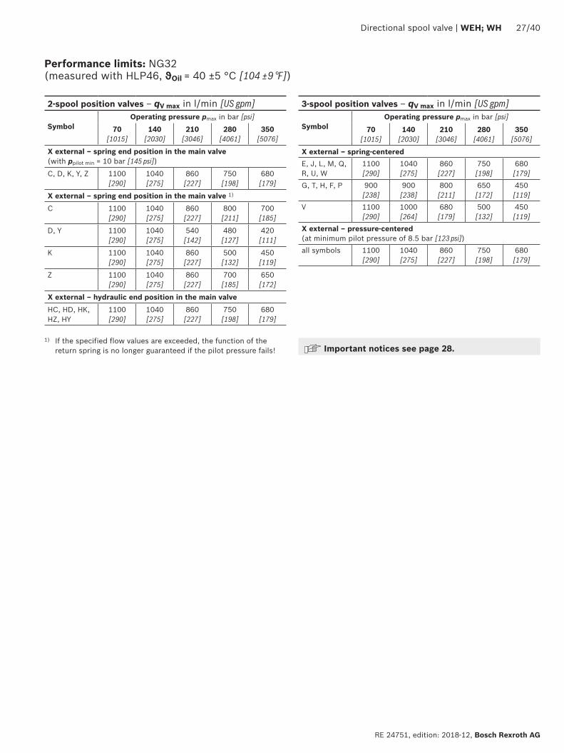
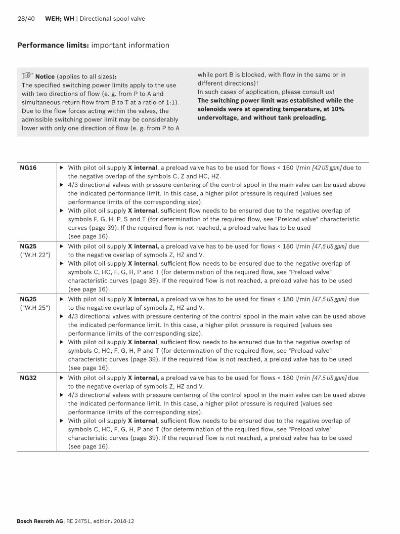
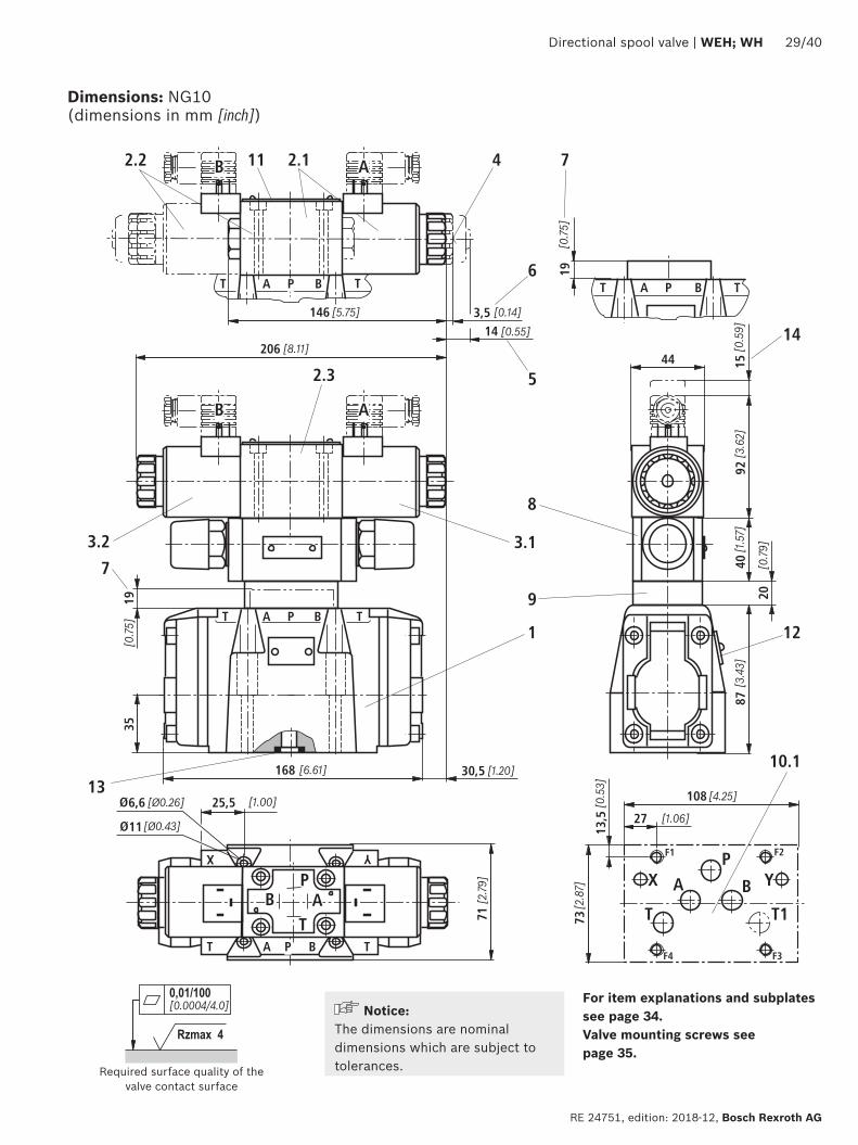
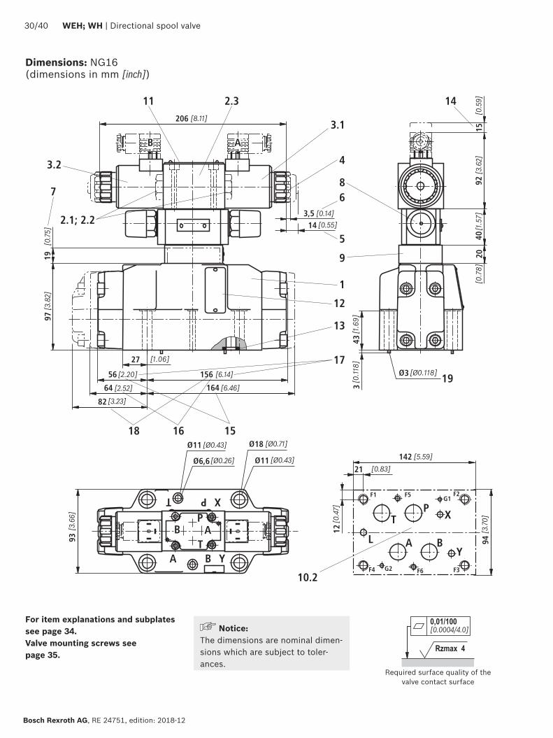
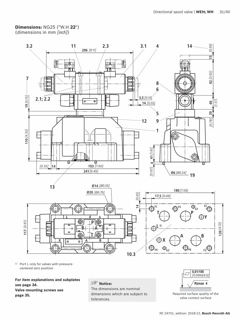
001100[0000440]
Rzmax 4
15
117
14
20
14 193241
110
19
414
6
A BX
PT Y92
4020
4
7
11 1432
1
8
912
19
13
21 22
103
3123
6
5
3514
14
175
180
120
BAX
T PY
[07
5][4
33]
[055] [760]
[949]
[46
1]
[Oslash079]
[Oslash055][709]
[069]
[47
2]
[05
5]
[Oslash024]
[015
7][1
61]
[014]
[055]
[05
9]
[15
7]
[07
8][3
62]
F1 F2
F3F4
F5
F6
G1
G2
206 [811]
L 1)
T
PB A
B A
Directional spool valve | WEH WH 3140
RE 24751 edition 2018-12 Bosch Rexroth AG
For item explanations and subplates see page 34 Valve mounting screws see page 35 Required surface quality of the
valve contact surface
Dimensions NG25 (WH 22) (dimensions in mm [inch])
1) Port L only for valves with pressure-centered zero position
NoticeThe dimensions are nominal dimensions which are subject to tolerances
19 225
2973245
275
332
3245
126
19
414
6
1592
20
7
11
32
18
9
12
19
13
15
1617
18
21 22
6
5
23 31 144
40
3514
206
279
L1)
BAX
T P Y
AXB
T P Y 14
21
195
117
20
14
103
F1 F2
F3F4
F5
F6
G1
G2
B A
T
PB A
120
001100[0000440]
Rzmax 4
3240 WEH WH | Directional spool valve
Bosch Rexroth AG RE 24751 edition 2018-12
Dimensions NG25 (WH 25) (dimensions in mm [inch])
1) Port L only for valves with pressure-centered zero position
For item explanations and subplates see page 34 Valve mounting screws see page 35 Required surface quality of the
valve contact surface
NoticeThe dimensions are nominal dimensions which are subject to tolerances
001100[0000440]
Rzmax 4
T
X
1933 22
P Y
X A B
197
205
23
257
A B
T PY
49
40
2+0
3
2865
6362
391
406
215
152
19
1592
4020
7
11 14
32
12
19
13
1516
17
18
21 22
23 31 4
3514
6
5
8
91
104
[59
8][0
75]
[014]
[055]
[05
9]
[15
7]
[07
8][3
62]
[19
3]
[Oslash024] [01
57]
[00
079+0
011
8 ]
[085] [1425]
[1539]
[1598]
[77
6]
[Oslash130] [Oslash087]
[1012]
[091]
[08
1]
391 [1539]
[78
7]
F1 F2
F3F4
F5
F6
G1
G2
206 [811]
LT
PB A
B A
200
Directional spool valve | WEH WH 3340
RE 24751 edition 2018-12 Bosch Rexroth AG
For item explanations and subplates see page 34 Valve mounting screws see page 35 Required surface quality of the
valve contact surface
Dimensions NG32 (dimensions in mm [inch])
NoticeThe dimensions are nominal dimensions which are subject to tolerances
3440 WEH WH | Directional spool valve
Bosch Rexroth AG RE 24751 edition 2018-12
1 Main valve2 Pilot control valve type 4WE 6 (data sheet 23178)
21 Pilot control valve type 4WE 6 Dhellip (1 solenoid) for main valves with symbols C D K Z symbols HC HD HK HZ
Pilot control valve type 4WE 6 JA (1 solenoid a) for main valves with symbols EA FA etc spring return
Pilot control valve type 4WE 6 MA (1 solenoid a) for main valves with symbols HEA HFA etc hydraulic spool return
22 Pilot control valve type 4WE 6 Y (1 solenoid) for main valves with symbol Y symbol HY
Pilot control valve type 4WE 6 JB (1 solenoid b) for main valves with symbols EB FB etc spring return
Pilot control valve type 4WE 6 MB (1 solenoid b) for main valves with symbols HEB HFB etc hydraulic spool return
23 Pilot control valve type 4WE 6Jhellip (2 solenoids) for main valves with 3 spool positions spring-centered
Pilot control valve type 4WE 6 Mhellip (2 solenoids) for main valves with 3 spool positions pressure-centered
31 Solenoid a32 Solenoid b
4 Manual override N optional Actuation of the manual override is only possible up to a tank pressure of approx 50 bar Avoid damage to the bore of the manual override (Special tool for the operation separate order material no R900024943) When the manual override is blocked the operation of the solenoid must be prevented
Simultaneous actuation of the solenoids must be prevented
5 Solenoid without manual override6 Solenoid with manual override7 Height of the diversion plate with hydraulic actuation
(type WH)8 Switching time adjustment (wrench size 6) optional9 Pressure reducing valve optional
101 Machined valve contact surface porting pattern according to ISO 4401-05-05-0-05 and NFPAT351 R2-D05
102 Machined valve contact surface porting pattern according to ISO 4401-07-07-0-05 and NFPAT351 R2-D07
103 Machined valve contact surface porting pattern according to ISO 4401-08-08-0-05 and NFPAT351 R2-D08
104 Machined valve contact surface porting pattern according to ISO 4401-10-09-0-05 and NFPAT351 R2-D10
11 Name plate pilot control valve12 Name plate complete valve13 Seal rings14 Space required for removing the mating connector15 2-spool position valves with spring end position in the main
valve (symbols A C D K Z)16 2-spool position valves with spring end position in the main
valve (symbols B Y)
17 3-spool position valves spring-centered 2-spool position valves with hydraulic end position in the main valve
18 3-spool position valves pressure-centered19 Locking pin
Subplates (separate order) with porting pattern according to ISO 4401 see data sheet 45100
Valve mounting screws see page 35
Dimensions
Directional spool valve | WEH WH 3540
RE 24751 edition 2018-12 Bosch Rexroth AG
Dimensions
Valve mounting screws (separate order) Nominal size Quantity Hexagon socket head cap screws Material number10 4 ISO 4762 - M6 x 45 - 109-CM-Fe-ZnNi-5-Cn-T0-H-B
Friction coefficient micrototal = 009 hellip 014 tightening torque MA = 125 Nm [92 ft-lbs] plusmn10 R913043777
or
4 14-20 UNC x 1 34rdquo ASTM-A574 Not included in the Rexroth delivery range
16 4 ISO 4762 - M10 x 60 - 109-flZnnc480hCFriction coefficient micrototal = 009 hellip 014 tightening torque MA = 58 Nm [428 ft-lbs] plusmn10
R913014770
2 ISO 4762 - M6 x 60 - 109-CM-Fe-ZnNi-5-Cn-T0-H-B Friction coefficient micrototal = 009 hellip 014 tightening torque MA = 125 Nm [92 ft-lbs] plusmn10
R913043410
or
4 Zylinderschrauben UNC 38-16 UNC x 2 14rdquo ASTM-A574 Not included in the Rexroth delivery range2 Zylinderschrauben UNC 14-20 UNC x 2 14rdquo ASTM-A574
25 6 ISO 4762 - M12 x 60 - 109-flZnnc480hC Friction coefficient micrototal = 009 hellip 014 tightening torque MA = 100 Nm [74 ft-lbs] plusmn20
R913015613
or
6 UNC 12-13 UNC x 2 12rdquo ASTM-A574 Not included in the Rexroth delivery range
32 6 ISO 4762 - M20 x 80 - 109-flZnnc480hC Friction coefficient micrototal = 009 hellip 014 tightening torque MA = 340 Nm [251 ft-lbs] plusmn10
R913008472
or
6 UNC 34-10 UNC x 3 14rdquo ASTM-A574 Not included in the Rexroth delivery range
L4
L3
5
4 2
3
1
3640 WEH WH | Directional spool valve
Bosch Rexroth AG RE 24751 edition 2018-12
Stroke setting mounting options (dimensions in mm [inch])
NG L410 65 [026]
16 10 [039]
25 (WH 22) 95 [037]
25 (WH 25) 125 [049]
32 15 [059]
The stroke of the control spool is limited by the stroke setting (1) The control spool stroke is shortened by loosening the lock nut (2) and clockwise rotation of the adjustment spindle (3) The control chamber (4) must be depressurized for this
5 Adjustment range NG10 1 rotation = 1 mm [00394 inch] adjustment travel
NG16 and 32 1 rotation = 15 mm [00591 inch] adjustment travel
3-spool position valve 1)
spring-centered pressure-centered
L1 L2 L3 L1 L2 L3
Stroke setting on valve side A and B 10
10 90 [354] 144 [567] 234 [921]
16 100 [394] 200 [787] 300 [1181]
25 2) 96 [377] 241 [949] 337 [1327]
25 3) 123 [484] 276 [1087] 399 [1571]
32 133 [524] 344 [1354] 477 [1878]
Stroke setting on valve side A
11
10 90 [354] 106 [417] 196 [772]
16 100 [394] 156 [614] 256 [1008]
25 2) 96 [377] 193 [760] 289 [1138]
25 3) 123 [484] 225 [886] 348 [1370]
32 133 [524] 287 [1130] 420 [1654]
Stroke setting on valve side B 12
10 52 [205] 144 [567] 196 [772] ndash ndash ndash
16 56 [220] 200 [787] 256 [1008] 81 [319] 200 [787] 281 [1106]
25 2) 48 [189] 241 [949] 289 [1138] ndash ndash ndash
25 3) 72 [283] 276 [1087] 348 [1370] 107 [421] 276 [1087] 283 [1114]
32 76 [299] 344 [1354] 420 [1654] 120 [472] 344 [1354] 464 [1827]
More dimensions see below and page 37
Stroke limitation on side A Stroke limitation on side B
a
BA
L3
L1 L2
L3L2
X A B
a
B
b
A A B
L3
L3L2L1
L1
b a
X A B
1) With symbol A only version 11 with symbol B only version 12 possible
Directional spool valve | WEH WH 3740
RE 24751 edition 2018-12 Bosch Rexroth AG
Stroke setting mounting options (dimensions in mm [inch])
2) Version WH 223) Version WH 25
2-spool position valve Spring end position Hydraulic end position
A C D K Z B Y HC HD HK HZ HY
L1 L2 L3 L1 L2 L3 L1 L2 L3
Stroke setting on valve side A and B 10
10 90 [354]
144 [567]
234 [921]
90 [354]
144 [567]
234 [921]
90 [354]
144 [567]
234 [921]
16 ndash ndash ndash ndash ndash ndash 100 [394]
200 [787]
300 [1181]
25 2) 96 [378]
241 [949]
337 [1327]
96 [378]
241 [949]
337 [1327]
96 [378]
241 [949]
337 [1327]
25 3) ndash ndash ndash ndash ndash ndash 123 [484]
276 [1087]
399 [1571]
32 ndash ndash ndash ndash ndash ndash 133 [524]
344 [1354]
477 [1878]
Stroke setting on valve side A
11
10 90 [354]
106 [417]
196 [772]
90 [354]
106 [417]
196 [772]
90 [354]
106 [417]
196 [772]
16 100 [394]
180 [709]
280 [1102] ndash ndash ndash 100
[394]156
[614]256
[1008]
25 2) 96 [378]
193 [760]
289 [1138]
96 [378]
193 [760]
289 [1138]
96 [378]
193 [760]
289 [1138]
25 3) 123 [484]
253 [996]
376 [148] ndash ndash ndash 123
[484]225
[886]348
[1370]
32 133 [524]
316 [1244]
449 [1768] ndash ndash ndash 133
[524]287
[1130]420
[1653]
Stroke setting on valve side B 12
10 52 [205]
144 [567]
196 [772]
52 [205]
144 [567]
196 [772]
52 [205]
144 [567]
196 [772]
16 ndash ndash ndash 80 [315]
200 [787]
280 [1102]
56 [221]
200 [787]
256 [1008]
25 2) 48 [189]
241 [949]
289 [1138]
48 [189]
241 [949]
289 [1138]
48 [189]
241 [949]
289 [1138]
25 3) ndash ndash ndash 100 [394]
276 [1087]
376 [1480]
72 [284]
276 [1087]
348 [1370]
32 ndash ndash ndash 105 [413]
344 [1354]
449 [1768]
76 [299]
344 [1354]
420 [1653]
NoticeThe dimensions are nominal dimensions which are subject to tolerances
34
7 5
62
1
7
8
3840 WEH WH | Directional spool valve
Bosch Rexroth AG RE 24751 edition 2018-12
Switching time adjustment
Pressure reducing valve D3
The switching time of the main valve (1) is influenced by using a twin throttle check valve (2) (type Z2FS 6 data sheet 27506)
Modification of supply (3) to discharge control (4)Remove the pilot control valve (5) ndash The plate (6) to accept the seal rings stays in place ndash Turn the switching time adjustment (2) around its longitudinal axis and put it back install the pilot control valve (5)
NoticeThe modification may only be performed by authorized specialists or at the factory
Type WEH 10 4XhellipS Type WEH 10 4XhellipS2
The pressure reducing valve (8) has to be used at a pilot pressure above 250 bar [3626 psi] (with WEH 22 hellip 210 bar [3046 psi]) and with version HThe secondary pressure is kept at a constant level of 45 bar [652 psi]
Notice If a pressure reducing valve D3 (8) is used a B10
throttle insert has to be installed in channel P of the pilot control valve
The modification may only be performed by authorized specialists or at the factory Type WEH 10 4XhellipD3
92
10
11
141210
8
6
4
2
100 200 300 400 500 600 700
1 2
3
4
0
[20][0] [185]
0[0]
[50]
[100]
[150]
[203]
[40] [60] [80] [100] [120] [140] [160]
91
10
11
Directional spool valve | WEH WH 3940
RE 24751 edition 2018-12 Bosch Rexroth AG
Pres
sure
diff
eren
tial
in b
ar [p
si] rarr
Flow in lmin [US gpm] rarr
∆pndashqV characteristic curve (measured with HLP46 ϑOil = 40 degC plusmn 5 degC [104 degF plusmn9 degF])
1 NG16
2 NG25 (WH 25)
3 NG25 (WH 22)
4 NG32
In case of valves with depressurized circulation and internal pilot oil supply the installation of the preload valve (9) in channel P of the main valve is required in order to build up the minimum pilot pressure
SizeItem 91 Item 92
16 R961009415 (from component series 72) R961009417 (up to component series 71)
25 (WH 22) ndash R961009609 (up to component series 76)
25 (WH 25) R961009166 (from component series 68) R961009416 (up to component series 67)
32 ndash R961009610 (up to component series 63)
Preload valve (not for NG10)
91 Preload valve
92 Preload valve
10 Main valve
11 Subplate
The pressure differential of the preload valve is to be added to the pressure differential of the main valve (see characteristic curves) to result in one total valueThe cracking pressure amounts to approx 45 bar [65 psi]
NoticeSeries-production status see ordering key on the name plate
Bosch Rexroth AG RE 24751 edition 2018-12
4040 WEH WH | Directional spool valve
Bosch Rexroth AG Industrial HydraulicsZum Eisengieszliger 197816 Lohr am Main Germany Phone +49 (0) 93 52thinspthinsp40 30 20 mysupportboschrexrothde wwwboschrexrothde
copy All rights reserved to Bosch Rexroth AG also regarding any disposal exploitation reproduction editing distribution as well as in the event of applications for industrial property rightsThe data specified above only serve to describe the product No statements concerning a certain condition or suitability for a certain application can be derived from our information The information given does not release the user from the obligation of own judgment and verificationPlease note that our products are subject to a natural process of wear and aging
Project planning information
The stipulations of the Machinery Directive 200642EC are to be adhered toPlease also note data sheet 08012 with information on MTTFd values and shock and vibration loads
Further information
Directional spool valve Data sheet 23178 Subplates Data sheet 45100 Inductive position switch and proximity sensors (contactless) Data sheet 24830 Hydraulic fluids on mineral oil basis Data sheet 90220 Environmentally compatible hydraulic fluids Data sheet 90221 Flame-resistant water-free hydraulic fluids Data sheet 90222 Flame-resistant hydraulic fluids - containing water (HFAE HFAS HFB HFC) Data sheet 90223 Reliability characteristics according to EN ISO 13849 Data sheet 08012 Hexagon socket head cap screw metricUNC Data sheet 08936 Hydraulic valves for industrial applications Operating instructions 07600-B General product information on hydraulic products Data sheet 07008 Assembly commissioning and maintenance of industrial valves Data sheet 07300 Mating connectors and cable sets for valves and sensors in hydraulics Data sheet 08006 Directional spool valves and directional seat valves with electrical actuation and
M12x1 plug-in connectionData sheet 08010
Use of non-electrical hydraulic components in an explosive environment (ATEX) Data sheet 07011 Selection of filters wwwboschrexrothcomfilter Information on available spare parts wwwboschrexrothcomspc
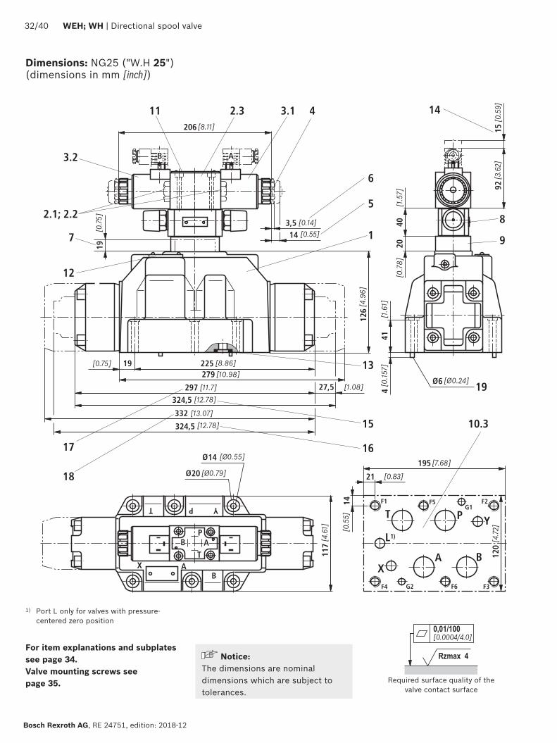
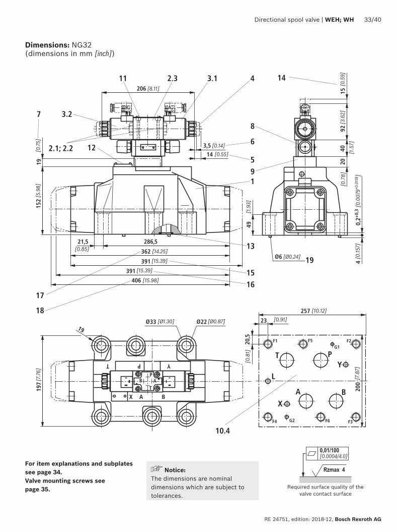
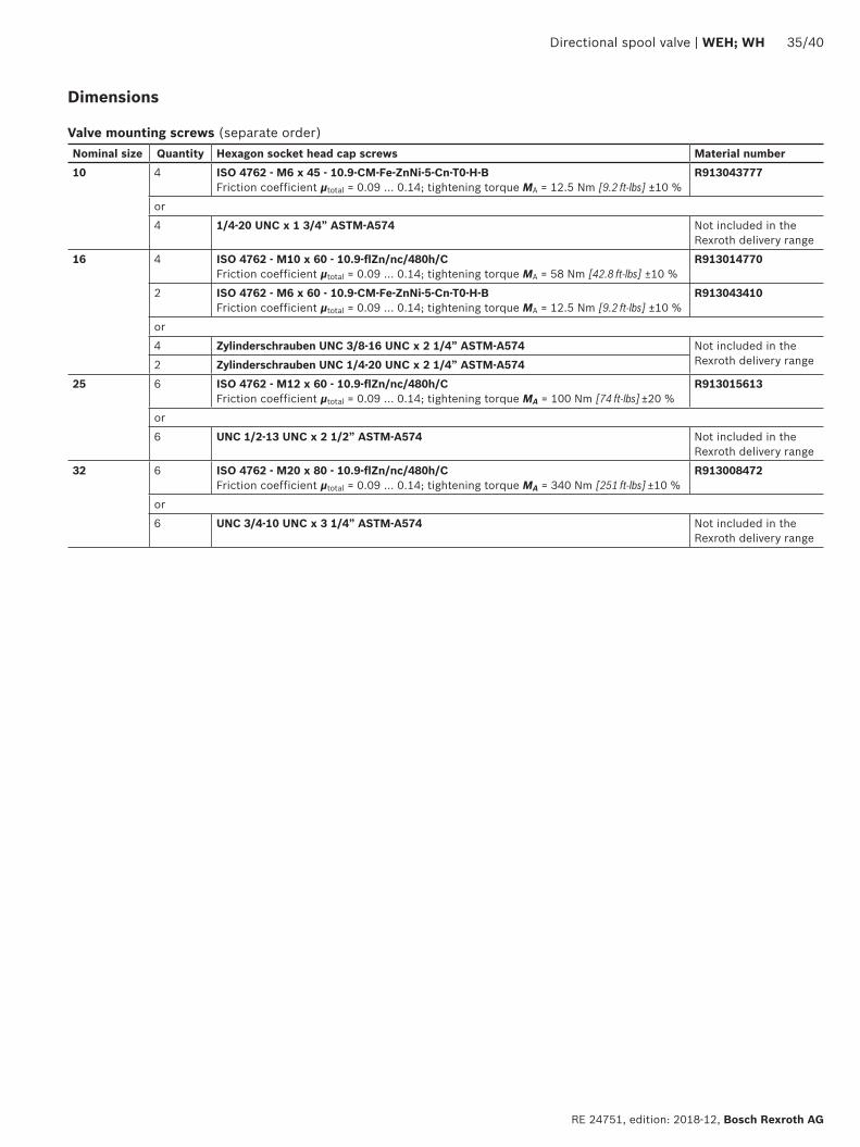
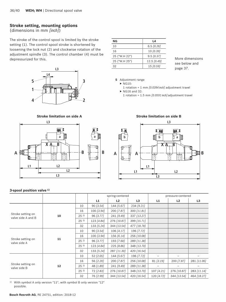
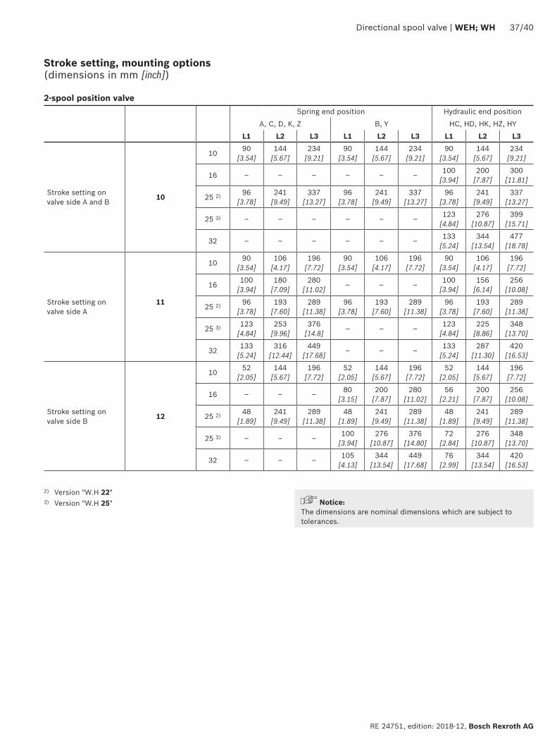
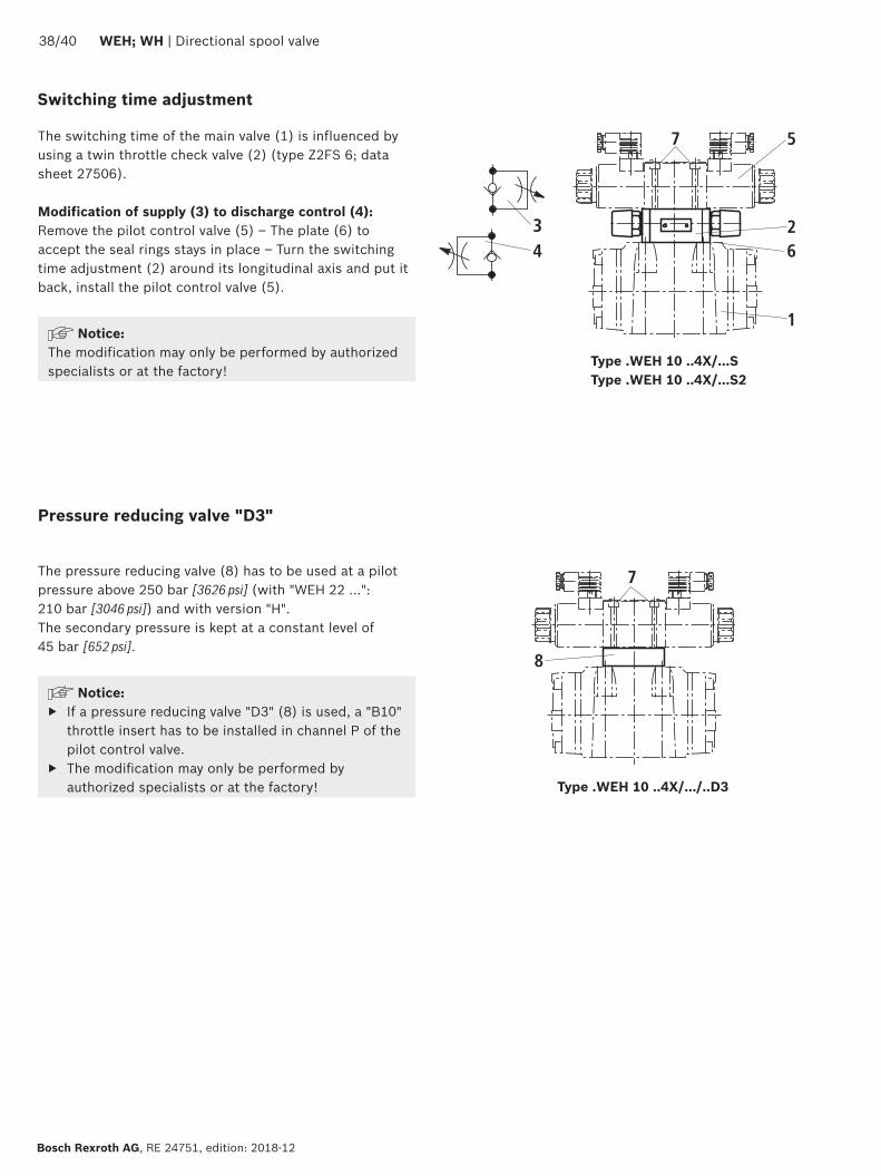
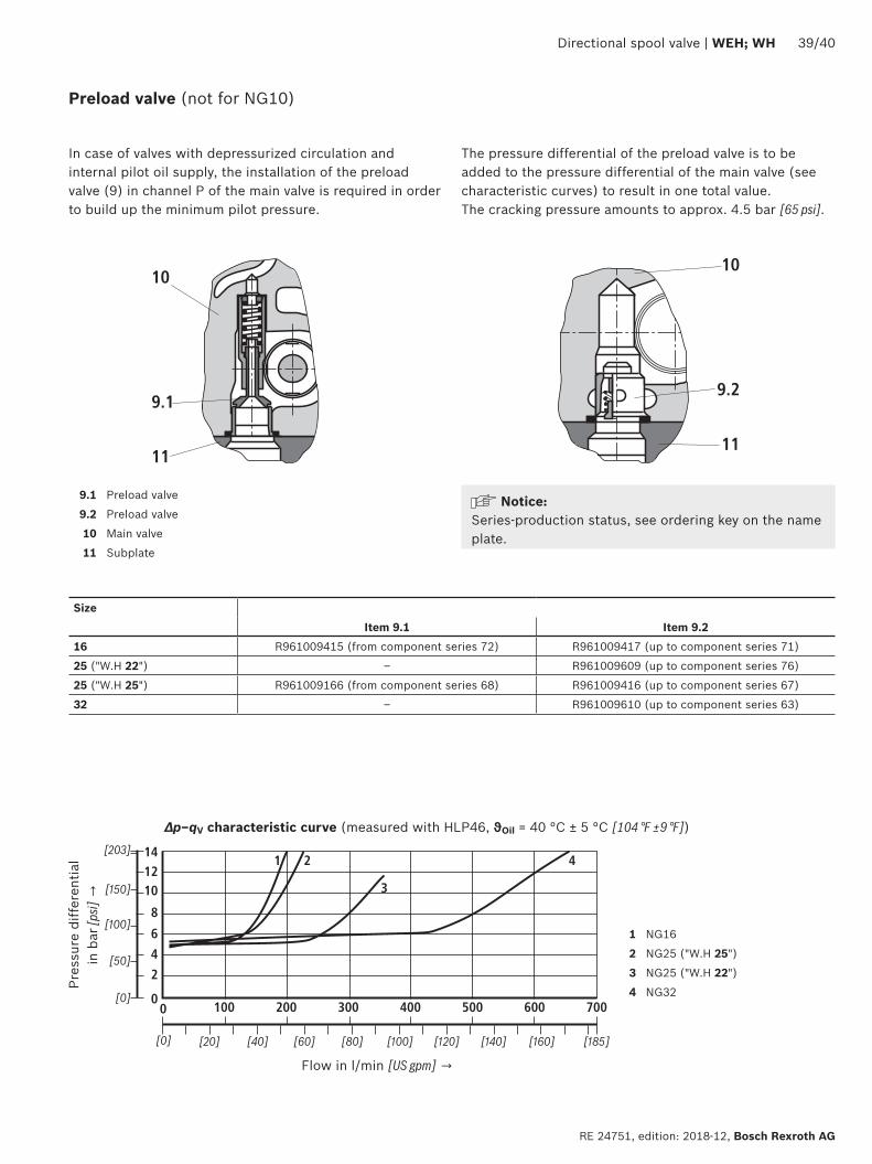