Embed Size (px)
Citation preview
Hired-Hand, Inc. • 1733 Co Rd 68 • Bremen, AL 35033 • Phone 256-287-1000 • Fax 256-287-2000 Sheet Part No. 4801-5308 (Rev 3-02) Page 1 of 8
STEP 1
Ventilation Kits
Power Ventilation Cut-Out
Natural Ventilation Cut-Out
Cut out the label around the switch opening and the bolt holes with a small knife.
Description These instructions are for installing Ventilation Kits in the Evolution 3000 Controller. Three kits are discussed: The Power Ventilation Kit (Part No. 6450-5101), the Natural Ventilation Kit (Part No. 6450-5102) and the Ventilation Expansion Kit (Part No. 6450-5104). The installer will also need the Evolution Owners Manual (Part No. 4801-5307) for wiring diagrams external to the Ventilation Kits. Contents of Ventilation Kits Those items included in each kit are indicated in the right hand columns with an “X”.
ITEM - DESCRIPTION HHI Part Number Quan.
Power Vent Kit (6450-5101)
Natural Vent Kit (6450-5102)
Vent Expan. Kit (6450-5104)
PCB167 EV Curtain Relay Board 6407-1516 1 X X X
Conn TBLK 3 pos Magnum 3006-5082 2 X X
Conn TBLK 3 pos EBY 3006-5077 2 X
Conn TBLK 4 pos EBY 3006-5078 2 X
Inlet Machine SWX Assy. 6407-6017 1 X X X
NUT Machine 6-32 hx z 1001-1461 4 X X X
EV I/O Curtain Card Harness 1903-4010 1 X
EV I/O Curtain Nat. Card Harness 1903-4023 1 X Module Static Pressure 3591-2252 1 X
SCRW 10-32X1/2 PAN SL M/S Z 1004-3056 2 X
HRNS EV Setra 1903-4011 1 X
Owners Manual Vent Add-On 4801-5308 1 X X X
CTRL tubing 1/8” pvc clr 25’ 6407-0156 1 X
KIT Static Pressure Control 6450-0125 1 X
Vent Expansion Harness 1903-4029 1 X
Tools Required Screw Driver Small Knife Wrench Set Nut Driver Kit
Drill with Bits Meas. Tape Socket Set 5/16” and ¼” Nut Driver
Directions First, remove all electrical power from the Evolution 3000 cabinet and
interconnected equipment containing voltages that may be fed back into the Evolution 3000. (Unless otherwise noted, the following steps are for any of the Ventilation kits.)
Directions for Installing Evolution 3000 Add-On Ventilation Kits
Hired-Hand, Inc. • 1733 Co Rd 68 • Bremen, AL 35033 • Phone 256-287-1000 • Fax 256-287-2000 Sheet Part No. 4801-5308 (Rev. 3-02) Page 2 of 8
STEP 3
STEP 2
STEP 4
STEP 5
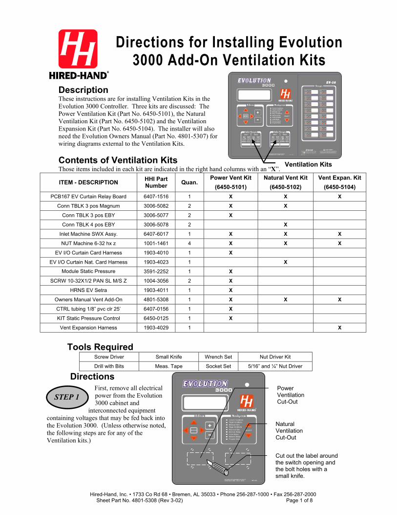
Connector to Switch panels
Ventilation Board PCB 167
Holes for Standoff
Top of enclosure
Harness to I/O Board
Switch Panels - Natural Ventilation Harness Assembly and the Power Ventilation Harness Assembly (6407-6017)
Natural Ventilation Board (PCB 167)
Input/Output Board (PCB 169)
Power Ventilation Board (PCB 167) (or)
Open the Evolution front panel and locate the outlined location for the Power or
Natural Ventilation switches as illustrated on the previous page. Using a small knife, cut the Evolution label around the opening and around the four bolt holes.
Locate the Inlet stage switch panels and harness assemblies shown at the
right and install in the Evolution cut-outs from the step above. Attach with four 6x32 hx z nuts (1001-1461) supplied.
Locate the Printed Circuit Board (PCB 167) in the Add-On
Kit. They are the same for either the Natural or Power Ventilation. See Figure 1 on page 4 of this document for the location of these boards in the lower right corner of the Evolution Cabinet. Press the boards over the nylon standoffs until a “click is heard” indicating the boards are fastened into the standoffs. Insure that the board is placed so that the connector to the Ventilator switch panel is at the TOP. Next, connect the cable from the Ventilation Switches to the Ventilation Board.
(For the Natural or Power Vent Kits) Locate the harness that connects between the Ventilation Board (PCB 167) and the Input/Output Control Board (PCB 169). See Figure 1 on page 4 of this document for the location of the boards. Connect the harnesses from the Ventilation boards (PCB
167) to the Relay Control on the Input/Output Control Board (PCB 169) as shown below.
White Black
Yellow Red
Orange
Harness between PCB 167 and PCB 169
Hired-Hand, Inc. • 1733 Co Rd 68 • Bremen, AL 35033 • Phone 256-287-1000 • Fax 256-287-2000 Sheet Part No. 4801-5308 (Rev. 3-02) Page 3 of 8
STEP 6
HIG
HLO
W
Red Black
White -
+
CO
M O
UT
EXE
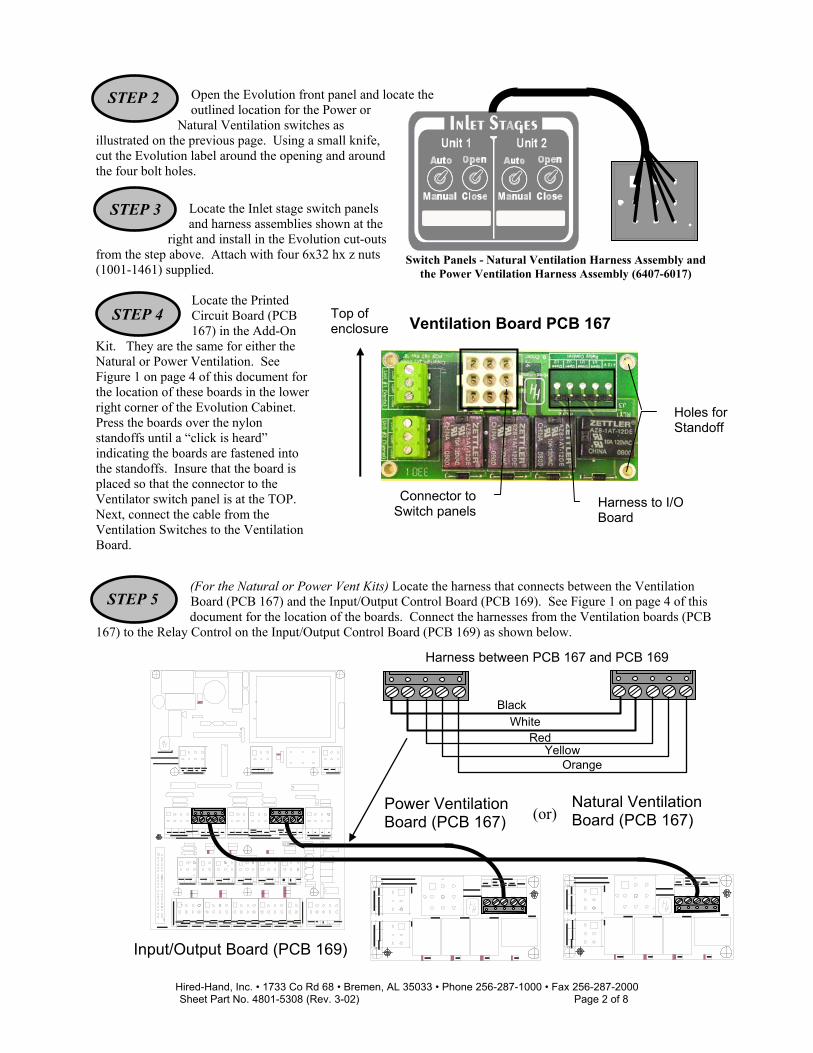
(For the Vent Expansion Kit) Locate the harness that connects between the Ventilation Board (PCB 167) and the Input/Output Control Board (PCB 169). See Figure 1 on page 4 of this document for the location of the boards. Connect the harnesses from the Ventilation boards
(PCB 167) to the Relay Control on the Input/Output Control Board (PCB 169) as shown below.
(Power Vent Only) Mount the Static Pressure Transmitter (3591-2252) at the top left of the Evolution cabinet with two 10x32x1/2 pan screws (1004-3056) provided in kit.
STEP 7
Natural Ventilation Board (PCB 167)
Input/Output Board (PCB 169)
Power Ventilation Board (PCB 167) (or)
White
Red Black
12V SIG GND
STEP 8 (Power Vent Only) Cut two pieces of clear
PVC tubing 5.5” long from the 25 foot roll (6407-0156) provided with the kit. Install the two pieces of tubing from the pressure gauge to the fittings in the cabinet side. NOTE: The HIGH fitting is toward the front.
STEP 9 (Power Vent Only) Install the three-wire
harness (1903-4011) from the EV Input/Output board (PCB 169) to the Pressure Transducer as shown.
EV Input/Output Board (PCB 169)
White Black
Yellow Red
Orange
Harness between PCB 167 and PCB 169
Hired-Hand, Inc. • 1733 Co Rd 68 • Bremen, AL 35033 • Phone 256-287-1000 • Fax 256-287-2000 Sheet Part No. 4801-5308 (Rev. 3-02) Page 4 of 8
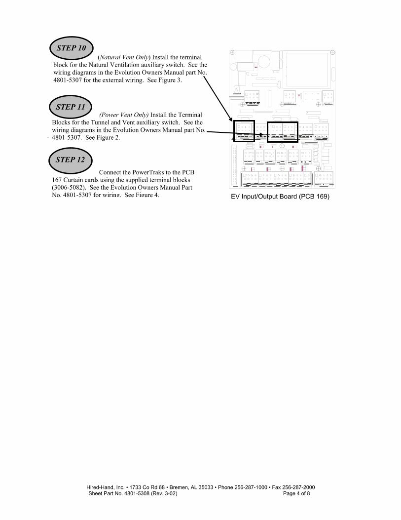
STEP 11
STEP 10
STEP 12
.
EV Input/Output Board (PCB 169)
(Natural Vent Only) Install the terminal block for the Natural Ventilation auxiliary switch. See the wiring diagrams in the Evolution Owners Manual part No. 4801-5307 for the external wiring. See Figure 3.
(Power Vent Only) Install the Terminal Blocks for the Tunnel and Vent auxiliary switch. See the wiring diagrams in the Evolution Owners Manual part No. 4801-5307. See Figure 2.
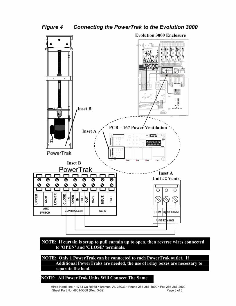
Connect the PowerTraks to the PCB 167 Curtain cards using the supplied terminal blocks (3006-5082). See the Evolution Owners Manual Part No. 4801-5307 for wiring. See Figure 4.
Hired-Hand, Inc. • 1733 Co Rd 68 • Bremen, AL 35033 • Phone 256-287-1000 • Fax 256-287-2000 Sheet Part No. 4801-5308 (Rev. 3-02) Page 5 of 8
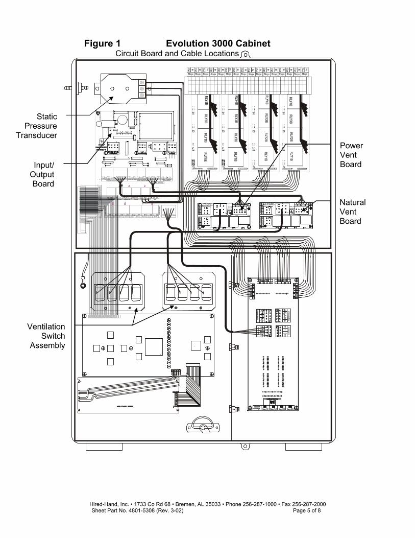
Figure 1 Evolution 3000 Cabinet Circuit Board and Cable Locations
Input/ Output Board
Power Vent Board
Ventilation Switch
Assembly
Natural Vent Board
Aux Inputs
Sig. Sig. Sig. Sig. Sig.
Relay Control Tunnel Aux Inputs Tunnel Aux Inputs Relay Control VAR #1 VAR #2Power V entila tion Module Varia ble Module
HHnet TerminationNat ural Ventilation M odule
Close.Aux
Close.Aux
OpenU1
OpenU1
OpenAux
OpenAux
CloseAux
CloseAux
OpenU2
OpenU2
CloseU2
CloseU2
CloseU1
CloseU1Com Com Com Com+12V +12V
+12V +12V +12V
+12V
+12V ncDigital Input #1
Sensor 1Black Black Black Black Black Black Black Black BlackWhite
ShieldWhiteShield
WhiteShield
WhiteShield
WhiteShield
WhiteShield
WhiteShield
WhiteShield
WhiteShield
Sensor 2 Sensor 3 Sensor 4 Sensor 5 Sensor 6 Sensor 7 Sensor 8 Outside Local Network
Temp
eratu
re Se
nsor
s
Temperature Sensors
Wind Speed
B.Crider
Analog Input #2 Humidity Pressure HHnet
Shield
+12 VRelay Control
RLY 1RLY 2RLY 3RLY 4
J1J2
OpenU1
OpenU2
CloseU2Copyright (c) 2000
PCB 167 Rev ‘0’
Hired-HandB. CriderCOMUnit #1 (Vents)
Unit #2 (Vents)COM
Open
OpenClose
Close
D1D2D3D4
+12 VRelay Control
RLY 1RLY 2RLY 3RLY 4
J1J2
OpenU1
OpenU2
CloseU2Copyright (c) 2000
PCB 167 Rev ‘0’
Hired-HandB. CriderCOMUnit #1 (Vents)
Unit #2 (Vents)COM
OpenOpen
CloseClose
D1D2D3D4
Static Pressure
Transducer
Hired-Hand, Inc. • 1733 Co Rd 68 • Bremen, AL 35033 • Phone 256-287-1000 • Fax 256-287-2000 Sheet Part No. 4801-5308 (Rev. 3-02) Page 6 of 8
CloseAux. +12V +12VCom.
Auxilliary Inputs Relay Control Tunnel Aux. Input Vent Aux. Input Relay ControlVariable Module
HHNet TerminationPower Ventilation ModuleNatural Ventilation Module
Var #1 Var #2
OpenU1
OpenU1
OpenU2
OpenU2
OpenAUX
CloseAUX
OpenAUX Com
CloseAUXComCom.
CloseAux.
CloseU1
CloseU1
CloseU2
CloseU2
+ +- -
+12V GND ShieldLocal Network-
Sensor #1
Tem
pera
ture
Sens
ors Temperature SensorsBlack Black Black BlackBlack Black Black Black BlackWhite
ShieldWhiteShield
WhiteShield
WhiteShield
WhiteShield
WhiteShield
WhiteShield
WhiteShield
WhiteShield
Sensor #2 Sensor #3 Sensor #4 Sensor #5 Sensor #6 Sensor #7 Sensor #8 Outside
N.C.IN
N.C.OUT
N.O.IN
N.O.OUT
Auxilliary Alarm DC Power Supply+12V +5V
115 V
230 V
AC SupplyL1 L2
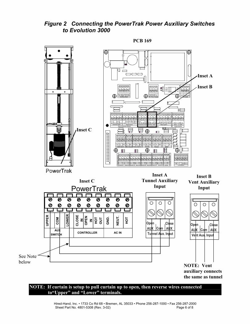
Figure 2 Connecting the PowerTrak Power Auxiliary Switches to Evolution 3000
PowerTrak
AUX SWITCH CONTROLLER AC IN
HO
T
NEU
T.
LOW
ER
GN
D.
HO
T
OU
T
CLO
SE
IN
OPE
N
IN
CO
M
UPP
ER
NOTE: If curtain is setup to pull curtain up to open, then reverse wires connected
to“Upper” and “Lower” terminals.
Inset A
PCB 169
Tunnel Aux. Input
Open AUX
Close AUX Com
Inset A Tunnel Auxiliary
Input
See Note below
Inset C
Inset C
Vent Aux. Input
Open AUX
Close AUX Com
Inset B Vent Auxiliary
Input
NOTE: Vent auxiliary connects the same as tunnel
Inset B
Hired-Hand, Inc. • 1733 Co Rd 68 • Bremen, AL 35033 • Phone 256-287-1000 • Fax 256-287-2000 Sheet Part No. 4801-5308 (Rev. 3-02) Page 7 of 8
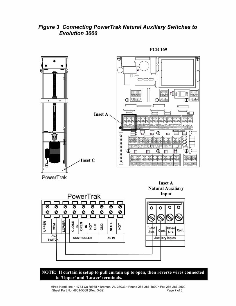
Figure 3 Connecting PowerTrak Natural Auxiliary Switches to Evolution 3000
PowerTrak
AUX SWITCH CONTROLLER AC IN
HO
T
NEU
T.
LOW
ER
GN
D.
HO
T
OU
T
CLO
SE
IN
OPE
N
IN
CO
M
UPP
ER
NOTE: If curtain is setup to pull curtain up to open, then reverse wires connected
to 'Upper' and 'Lower' terminals.
CloseAux. +12V +12VCom.
Auxilliary Inputs Relay Control Tunnel Aux. Input Vent Aux. Input Relay ControlVariable Module
HHNet TerminationPower Ventilation ModuleNatural Ventilation Module
Var #1 Var #2
OpenU1
OpenU1
OpenU2
OpenU2
OpenAUX
CloseAUX
OpenAUX Com
CloseAUXComCom.
CloseAux.
CloseU1
CloseU1
CloseU2
CloseU2
+ +- -
+12V GND ShieldLocal Network-
Sensor #1
Tem
pera
ture
Sens
ors Tem
perature SensorsBlack Black Black BlackBlack Black Black Black BlackWhiteShield
WhiteShield
WhiteShield
WhiteShield
WhiteShield
WhiteShield
WhiteShield
WhiteShield
WhiteShield
Sensor #2 Sensor #3 Sensor #4 Sensor #5 Sensor #6 Sensor #7 Sensor #8 Outside
N.C.IN
N.C.OUT
N.O.IN
N.O.OUT
Auxilliary Alarm DC Power Supply+12V +5V
115 V
230 V
AC SupplyL1 L2
PCB 169
Inset A
Inset C
Inset A Natural Auxiliary
Input
CloseAux.
CloseAux.Com. Com.
Auxiliary Inputs
Hired-Hand, Inc. • 1733 Co Rd 68 • Bremen, AL 35033 • Phone 256-287-1000 • Fax 256-287-2000 Sheet Part No. 4801-5308 (Rev. 3-02) Page 8 of 8
PowerTrak
AUX SWITCH CONTROLLER AC IN
HO
T
NEU
T.
LOW
ER
GND
.
HO
T O
UT
CLO
SE
IN
OPE
N
IN
CO
M
UPP
ER
Figure 4 Connecting the PowerTrak to the Evolution 3000
NOTE: If curtain is setup to pull curtain up to open, then reverse wires connected
to 'OPEN' and 'CLOSE' terminals. NOTE: Only 1 PowerTrak can be connected to each PowerTrak outlet. If
Additional PowerTraks are needed, the use of relay boxes are necessary to separate the load.
Inset A
Evolution 3000 Enclosure
Hired-Hand
Auxilliary A larm
Aux Inputs
Sig. Sig. Sig. Sig. Sig.
Relay Contro l Tunnel Aux Inputs Tunnel Aux Inputs Relay Contro l VAR #1 VAR #2Power Ventilation Module Variable Module
HHnet TerminationNatural Ventilation Module
DC Power Supply AC Supply+12V +5V L1 L2
Copyright (c) 2000PCB 169 Rev ‘0’
R
N.C.IN
Close.Aux
Close.Aux
OpenU1
OpenU1
OpenAux
OpenAux
CloseAux
CloseAux
OpenU2
OpenU2
CloseU2
CloseU2
CloseU1
CloseU1Com Com Com Com+12V +12V
+12V +12V +12V
+12V
+12V
N.C.OUT
nc
Digital Input #1
Sensor 1Black Black Black Black Black Black Black Black BlackWhite
ShieldWhiteShield
WhiteShield
WhiteShield
WhiteShield
WhiteShield
WhiteShield
WhiteShield
WhiteShield
Sensor 2 Sensor 3 Sensor 4 Sensor 5 Sensor 6 Sensor 7 Sensor 8 Outside Local Network
Tem
pera
ture
Sen
sors
Temperature Sensors
Wind Speed
B.Crider
Analog Input #2 Humidity Pressure HHnet
Shield
N.O.IN
N.O.OUT
+12 VRelay Control
RLY 1RLY 2RLY 3RLY 4
J1J2
OpenU1
OpenU2
CloseU2Copyright (c) 2000
PCB 167 Rev ‘0’
Hired-HandB. CriderCOMUnit #1 (Vents)
Unit #2 (Vents)COM
Open
Open
CloseClose
D1D2D3D4
+12 VRelay Control
RLY 1RLY 2RLY 3RLY 4
J1J2
OpenU1
OpenU2
CloseU2Copyright (c) 2000
PCB 167 Rev ‘0’
Hired-HandB. CriderCOMUnit #1 (Vents)
Unit #2 (Vents)COM
Open
OpenClose
Close
D1D2D3D4
Inset A Unit #2 Vents
Unit #2 Vents
COM Close Open
PCB – 167 Power Ventilation
Inset B
Inset B
NOTE: All PowerTrak Units Will Connect The Same.