Embed Size (px)
Citation preview
Directive 010
Directive 010: Minimum Casing Design Requirements December 22, 2009 Effective June 17, 2013, the Energy Resources Conservation Board (ERCB) has been succeeded by the Alberta Energy Regulator (AER). As part of this succession, the title pages of all existing ERCB directives now carry the new AER logo. However, no other changes have been made to the directives, and they continue to have references to the ERCB. As new editions of the directives are issued, these references will be changed. Some phone numbers in the directives may no longer be valid. Contact AER Inquiries at 1-855-297-8311 or [email protected].
ERCB Directive 010: Minimum Casing Design Requirements (December 2009) • 1
Directive 010 Revised edition: December 22, 2009
Minimum Casing Design Requirements The Energy Resources Conservation Board (ERCB/Board) has approved this directive on December 22, 2009.
<original signed by>
Dan McFadyen Chairman
_____________________________________________________________________________________
Contents 1 Overview ………………………………………………………………………………………2
1.1 What’s New in Directive 010 ............................................................................................. 2 1.2 Compliance and Enforcement ............................................................................................. 4 1.3 Material Selection ............................................................................................................... 4
1.3.1 Materials Not Meeting Requirements of Appendix B ........................................... 5 1.3.2 Representative Testing Program ............................................................................ 5
1.4 Well Category Table for Sweet, Sour, Critical Sour, and Reentry Wells ........................... 5 1.5 Casing Performance Properties ........................................................................................... 6 1.6 Burst Design Factor Adjustments ....................................................................................... 6 1.7 Casing Wear Considerations ............................................................................................... 7 1.8 Other Design Considerations .............................................................................................. 7
2 Simplified Method ..................................................................................................................... 8 2.1 Surface Casing—Design Factors and Assumptions ............................................................ 8
2.1.1 Burst ....................................................................................................................... 8 2.1.2 Collapse ................................................................................................................. 8 2.1.3 Tension .................................................................................................................. 8
2.2 Production Casing—Design Factors and Assumptions ...................................................... 8 2.2.1 Burst ....................................................................................................................... 9 2.2.2 Collapse ................................................................................................................. 9 2.2.3 Tension .................................................................................................................. 9
2.3 Intermediate Casing—Design Factors and Assumptions .................................................. 10 2.4 Liners—Design Factors and Assumptions ........................................................................ 10
3 Alternative Design Method ..................................................................................................... 10 3.1 Introduction ....................................................................................................................... 10 3.2 Alternative Design Method Tables ................................................................................... 11
3.2.1 Surface Casing ..................................................................................................... 11 3.2.2 Protective Intermediate Casing / Protective Liner ............................................... 12 3.2.3 Productive Intermediate Casing / Production Casing / Production Liner ............ 13
2 • ERCB Directive 010: Minimum Casing Design Requirements (December 2009)
Appendix A References and Suggested Reading ........................................................................ 14 Appendix B Material Requirements for Sour Wells —
Additional Constraints to API 5CT/ISO 11960 ...................................................... 15 Appendix C NACE Sulphide Stress Cracking (SSC) Testing Parameters .................................. 17 Appendix D Definitions ............................................................................................................... 18 Appendix E Effects of Tensile Loading on Casing Collapse ..................................................... 20 Appendix F Alternative Design Method Example ...................................................................... 21
1 Overview 1.1 What’s New in Directive 010
The June 2008 revised edition of ERCB Directive 010 (formerly Guide 10) was developed with input from a technical subcommittee of the Drilling and Completions Committee (DACC) and the ERCB, which reviewed various technical documents containing information on casing design for sweet, sour, and critical sour wells in the Western Canadian Sedimentary Basin (WCSB). In the future, as industry casing design specifications and standards change, the ERCB will consider approving the new standards for use in conjunction with Directive 010 and will incorporate such changes in subsequent revisions to this directive
The June 2008 edition of Directive 010 included a grace period up to June 20, 2009, for the use of the existing inventory of materials which do not meet the requirements of Appendix B. Due to the unexpected reduction in drilling activity, changes to the June 20, 2009, grace period for the use of this inventory have become necessary. Technical concerns brought forward by licensees and casing manufacturers regarding a specific requirement in Appendix B have also been addressed. Changes in the December 2009 edition of Directive 010 include
• amending the grandfathering criteria and extending the grandfathering period beyond June 20, 2009, to address noncompliant materials in regard to Appendix B (Section 1.3.1);
• simplifying the Representative Testing Program (Section 1.3.2); and
• clarifying the use in sour service wells of Industry Recommended Practices (IRP) casing (Section 1.4), the use of casings not defined by American Petroleum Institute (API) 5CT/ISO 11960 specifications (Section 1.5), and revised Appendix B: Materials Requirements for Sour Wells.
This new edition of the directive includes the option to use an Alternative Design Method to allow a licensee to determine the design loads and capabilities of the casing strings and still meet the minimum design factors, which was introduced in the previous edition.
The technical review committee noted that conventional API materials made to API Specification 5CT specifications cannot consistently pass National Association of Corrosion Engineers (NACE) TM0177 sulphide stress cracking (SSC) testing due to manufacturing differences. To address this issue, upgraded design factors and material specifications have been implemented that incorporate the criteria from NACE MR0175/ International Association for Standardization (ISO) 15156 (see Appendix A for all references).
ERCB Directive 010: Minimum Casing Design Requirements (December 2009) • 3
Directive 010 includes
• discussion on compliance and enforcement (Section 1.2);
• revisions to the sections on Material Selection (Section 1.3) and Casing Performance Properties (Section 1.5);
• new detailed design and metallurgy criteria for sweet, sour, and critical sour wells, including - the Well Category Table (Section 1.4), - Appendix B: Material Requirement, which specifies additional sour service (partial
pressure [pp] H2S ≥ 0.3 kPa.) requirements for materials manufactured according to API 5CT Specification, and
- when existing casing inventories do not meet the requirements of Appendix B, representative testing is required to ensure satisfactory product performance in sour service environments, as discussed in (Section 1.3.2);
• casing requirements for re-entry wells (Section 1.4), IRP Volume 1 (Section 4), and IRP Volume 6 (Section 5);
• casing wear considerations (Section 1.7);
• other design considerations (e.g., tri-axial, bending, compression, and non-API pipe and connections) (Section 1.8);
• design criteria for - using the lesser of connection burst strength or pipe body burst strength (Section
2.2.1), - using the lesser of the pipe body yield strength or the joint strength (connection
parting strength) (Section 2.2.3), and - revised design factors on tension based on connection type (API vs. premium with
internal metal-to-metal seal [Section 3.2]);
• a new Alternative Design Method approach (Section 3);
• burst design loads using an assumed or calculated gas gradient (Section 3.2); and
• the following appendices: - References, including related ERCB and other applicable publications (Appendix A), - Material Requirements (Appendix B), - NACE SSC Testing Summary (Appendix C), - Definitions as they pertain to this directive (Appendix D), - Effects of Tensile Loading on Casing Collapse (Appendix E) (Directive 015 will be
rescinded once this new edition of Directive 010 is issued), and - Alternative Design Method Example (Appendix F).
Licensees must consider all post drilling casing loading, such as fracture stimulation down casing, tubing packer leaks, compressive loading, tri-axial loading, and temperature (see IRP Volume 3: Heavy Oil and Oil Sands Operations, Section 3.1.6, and Appendix E) effects for the life of the well in their casing design.
4 • ERCB Directive 010: Minimum Casing Design Requirements (December 2009)
1.2 Compliance and Enforcement
ERCB requirements are those rules that a licensee has a legal obligation to meet and against which the ERCB may take enforcement action in case of noncompliance. The ERCB’s enforcement process is specified in Directive 019: ERCB Compliance Assurance—Enforcement.
The requirements in this edition of Directive 010 are effective on December 22, 2009. All casing ordered prior to the issuance of this directive may be used if it conforms to the design factor requirements in Section 1.3.1. All casing ordered or manufactured after September 22, 2008, must conform to the material requirements in Appendix B.
Licensees must retain records of all supporting data and information used to meet the ERCB minimum casing design requirements for the Simplified and Alternative Design Methods. The licensee must submit information requested by the ERCB within 20 working days.
Directive 010 noncompliance events can be found on the ERCB Web site at www.ercb.ca under Industry Zone: Compliance and Enforcement : ERCB Risk Assessed Noncompliance.
Licensees are reminded that in the event of a well licence transfer or an amalgamation, the new licensee assumes responsibility for meeting all ERCB minimum requirements specified in this directive.
1.3 Material Selection
Licensees must ensure the suitability of casing and pressure-rated casing accessories (e.g., stage tools, external casing packers, in-line centralizers, and float collars) for each specific application for the life of the well. External centralizers, scratchers, and turbolizers are exempt. Unless otherwise specified, any reference to casing includes the casing pipe body and the couplings. Anticipated current and future environments must be considered when selecting casing for use in wells that may encounter hydrogen sulphide (H2S), or carbon dioxide (CO2) with H2S.
Licensees must follow Appendix B to select the proper material specifications for all wells, using partial pressures (pp) of H2S and CO2, as well as design factors, to determine the appropriate material specifications. An alternative materials selection process may be used as long as the material meets all the minimum requirements in Directive 010. Fit-for-purpose SSC (all casing grades) and hydrogen-induced cracking (HIC; nonquenched and tempered material only) testing may be performed if well conditions result in a situation where Directive 010-compliant materials cannot be supplied. Fit-for-purpose testing using actual worst-case environmental wellbore conditions may also be used to qualify materials to higher stress levels, as discussed in Section 1.6.
The partial pressure of each component in the wellbore is equal to the pressure multiplied by its mole fraction in the mixture. For example, a pressure of 30 000 kilopascals (kPa) and a 3 mole % (0.03 mole fraction) H2S content would have 30 000 kPa x 0.03 = 900 kPa H2S partial pressure.
Surface casing must be designed for sour service (see Section 1.5) if the licensee intends to drill into a sour zone before setting the next sour service casing string. The casing bowl weld must also be suitable for sour service.
Licensees must maintain casing integrity for the life of the well, including post-abandonment (see Directive 020: Well Abandonment Guide, Casing pressure testing requirements).
ERCB Directive 010: Minimum Casing Design Requirements (December 2009) • 5
Corrosion-resistant alloys (CRAs) are specialty materials designed for use in corrosive environments. It is the responsibility of the end user to ensure that the material will perform acceptably in the well environment (see NACE International MR0175/ISO 15156, Part 3: Cracking-resistant CRAs and other alloys).
For IRP materials, licensees must follow the SSC and HIC test procedures, specimen types, loading conditions, and all other acceptance criteria specified in IRP Volume 1, Section 4, for the grade of casing being used. This testing must involve a laboratory experienced with the testing of materials for sour service at elevated pressures.
1.3.1 Materials Not Meeting Requirements of Appendix B
Existing API 5CT/ISO 11960 compliant materials purchased or manufactured prior to September 22, 2008, that do not meet the requirements of Appendix B may be used in drilling of noncritical sour wells providing the following conditions are met:
• if the H2S concentration is less than 1.00%, the burst design safety factor is 1.30 or greater (increased from the 1.25 minimum for Directive 010 Appendix B compliant materials), or
• if the H2S concentration is higher than 1% but less than 5.00%, the burst design safety factor is 1.35 or greater, or
• if the H2S concentration is greater than or equal to 5.00%, the burst design safety factor is 1.40 or greater, and
• A burst design safety factor of 1.25 shall be used for non-compliant API H40, J55, K55, L80, C90 or T95, if the materials are tested as described in Section 1.3.2.
• Materials not listed in Appendix B must be tested as described in Section 1.3.2 for use in sour wells.
These requirements pertain to both casing and coupling stock.
1.3.2 Representative Testing Program
Materials that do not comply with the requirements of Appendix B can be tested to verify performance in sour service conditions.
API 5CT/ISO 11960 casing and coupling materials must each be tested to the following parameters per heat lot:
• SSC testing—Method A or Method C is sufficient for testing; in accordance with NACE TM0177, the SSC test condition must be either
- 80% specific minimum yield strength (SMYS) with Solution A Environment, or
- in accordance with fit-for-purpose testing, as stated in Appendix C.
• HIC testing—for all materials that are not quenched and tempered in accordance with NACE TM0284 and with pass criteria outlined in IRP Volume 1.
1.4 Well Category Table
A well’s sour classification is defined by the partial pressure of H2S, as shown in the table below. Licensees must determine which column their well is under and then select the appropriate recommended casing load conditions, minimum design factors, and material specifications. For reentry wells, an evaluation of the remaining casing wall thickness must
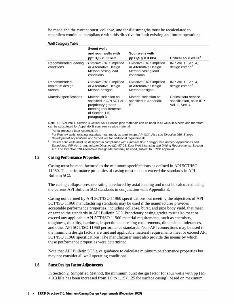
6 • ERCB Directive 010: Minimum Casing Design Requirements (December 2009)
be made and the current burst, collapse, and tensile strengths must be recalculated to reconfirm continued compliance with this directive for both existing and future operations.
Well Category Table Sweet wells,
and sour wells with pp1 H2S < 0.3 kPa
Sour wells with pp H2S > 0.3 kPa
Critical sour wells3
Recommended loading conditions
Directive 010 Simplified or Alternative Design Method casing load conditions
Directive 010 Simplified or Alternative Design Method casing load conditions
IRP Vol. 1, Sec. 4, design criteria3
Recommended minimum design factors
Directive 010 Simplified or Alternative Design Method designs
Directive 010 Simplified or Alternative Design Method designs
IRP Vol. 1, Sec. 4, design criteria3
Material specifications Material selection as specified in API 5CT or proprietary grades meeting requirements of Section 1.5, paragraph 3
Material selection as specified in Appendix B2
Critical sour service specification, as in IRP Vol. 1, Sec. 4
Note: IRP Volume 1, Section 4 Critical Sour Service pipe materials can be used in all wells in Alberta and therefore can be substituted for Appendix B sour service pipe material. 1 Partial pressure (see Appendix D). 2 For Reentry wells, existing materials must meet, as a minimum, API 5CT. Also see Directive 056: Energy
Development Applications and Schedules for additional requirements. 3 Critical sour wells must be designed in compliance with Directive 056: Energy Development Applications and
Schedules, IRP Vol. 1, and Interim Directive (ID) 97-06: Sour Well Licensing and Drilling Requirements, Section 4.2. The Directive 010 Alternative Design Method may be used, subject to ERCB approval.
1.5 Casing Performance Properties
Casing must be manufactured to the minimum specifications as defined in API 5CT/ISO 11960. The performance properties of casing must meet or exceed the standards in API Bulletin 5C2.
The casing collapse pressure rating is reduced by axial loading and must be calculated using the current API Bulletin 5C3 standards in conjunction with Appendix E.
Casing not defined by API 5CT/ISO 11960 specifications but meeting the objectives of API 5CT/ISO 11960 manufacturing standards may be used if the manufacturer provides acceptable performance properties, including collapse, burst, and pipe body yield, that meet or exceed the standards in API Bulletin 5C3. Proprietary casing grades must also meet or exceed any applicable API 5CT/ISO 11960 material requirements, such as chemistry, toughness, ductility, hardness, inspection and testing requirements, dimensional tolerances, and other API 5CT/ISO 11960 performance standards. Non-API connections may be used if the minimum design factors are met and applicable material requirements meet or exceed API 5CT/ISO 11960 specifications. The manufacturer must also provide the means by which these performance properties were determined.
Note that API Bulletin 5C3 give guidance to calculate minimum performance properties but may not consider all well operating conditions.
1.6 Burst Design Factor Adjustments
In Section 2: Simplified Method, the minimum burst design factor for sour wells with pp H2S > 0.3 kPa has been increased from 1.0 to 1.15 (1.25 for surface casing), based on maximum
ERCB Directive 010: Minimum Casing Design Requirements (December 2009) • 7
potential formation pressure. The restricted hoop stress load reduces the susceptibility to SSC.
In Section 3: Alternative Design Method, for sour wells with pp H2S < 0.3 kPa, SSC is not an issue. Therefore, for practical purposes these wells may be considered sweet wells. For sweet wells, a lower minimum burst design factor of 1.10 may be used, based on maximum potential formation pressure less gas gradient to surface. Wells with pp H2S of 0.3 kPa or greater are considered sour wells. For sour wells with 0.3 < pp H2S < 10 kPa (a pp of H2S of 0.3 kPa or greater and less than 10 kPa), the minimum burst design factor is 1.20. For sour wells with pp H2S > 10 kPa, the minimum burst design factor is 1.25. This ensures that the casing hoop stress level in mild sour wells will be less than 83.3 (1/design factor) of its specified minimum yield strength, and in wells with pp H2S above 10 kPa, the hoop stress level will be less than 80% of SMYS.
Burst design factors for materials used in sour wells may be reduced from the value of 1.25 outlined in the design loading constraints by conducting Fit-for-purpose SSC testing in accordance with NACE TM0177 Method A, Solution A, to a representative load condition. A licensee requesting a reduction in the burst design factor is required to test to an additional 5% stress level or a stress level of 105% (1.05) of the maximum potential material stress.
The load test stress is inversely proportional to the proposed burst design factor: test stress level = (1.05 / minimum burst design factor) x SMYS.
For example, for noncritical sour wells with pp H2S > 0.3 kPa, if the burst safety factor is limited to 1.18 due to product availability, the product must be tested to 1.05/1.18 = 0.89, or 89% of the SMYS of the material, instead of the more common 80 to 85% of SMYS.
1.7 Casing Wear Considerations
Casing wear considerations in Subsection 8.141(3) of the Oil and Gas Conservation Regulations (OGCR) must be taken into account. Casing safety factors must be increased as necessary to maintain the required minimum design factors after consideration of anticipated casing wear. Casing wear can be affected by casing grade, rotating hours, rpm, type of drilling fluid, dogleg severity, inclination, deviated wellbore, tripping frequency, and the types of downhole tools run. Efforts to minimize wear include use of drill pipe conveyed casing wear protectors, use of downhole motors, and drilling fluid additives designed to reduce torque and drag.
Section 12.141 of the OGCR requires the licensee to notify the ERCB immediately on detection of a casing leak or failure. Also, if requested by the ERCB, the licensee must provide a report assessing the leak or failure, including a discussion of the cause, duration, damages, proposed remedial program, and measures to prevent future failures (see Interim Directive [ID] 2003-01).
1.8 Other Design Considerations
Determination of axial loads must include consideration for additional tension loading (e.g., casing overpull when setting slips, casing pressure testing) or compressive loading (e.g. due to subsequent well operations, such as the installation of a blowout preventer (BOP) stack and subsequent casing and tubing strings), as well as well servicing conditions.
For all directional wells, the licensee must address additional stresses (or loads) caused by bending, regardless of the design method chosen.
8 • ERCB Directive 010: Minimum Casing Design Requirements (December 2009)
Surface casing setting depth must be in accordance with Directive 008: Surface Casing Depth Minimum Requirements.
According to Section 6.081 of the OGCR, the licensee must not drill beyond a depth of 3600 metres [m] without first setting intermediate casing to ensure well control.
Collapse design must consider uphole formations that contain higher pressures or gradients than those used for the drilling fluid gradient. An example is high pressure/low permeability zones where the drilling fluid gradient is not increased to a fully balanced condition, which eliminates entry of background gas.
The licensee must consider corrosion for the portion of casing subject to long-term exposure to highly corrosive conditions (see API Recommended Practice 5C1: Recommended Practice for Care and Use of Casing and Tubing, Sections 4.8.16 and 5.5.15). Corrosion control may be addressed through appropriate material selection, coatings, environmentally safe corrosion inhibition, cathodic protection, cementing of casing (see Directive 009: Casing Cementing Minimum Requirements, DACC’s Primary and Remedial Cementing Guidelines, and IRP Volume 3: Heavy Oil and Oil Sands Operations, Section 3.1.5), use of tubing and packers, or other engineered options. For external corrosion, see NACE RP0186 Standard (latest edition; see Appendix A for all references).
2 Simplified Method
The Simplified Method is a modification of the design criteria previously specified in Directive 010 (Guide 10), September 1990.
2.1 Surface Casing—Design Factors and Assumptions
Appendix B must be used to select the proper material specifications if the licensee intends to drill into a sour zone before setting the next casing string.
2.1.1 Burst
Design factor = 1.0 for sweet wells or sour wells with pp H2S < 0.3 kPa.
Design factor = 1.25 for sour wells where the surface casing is potentially exposed to an pp H2S ≥ 0.3 kPa.
As a minimum, the casing burst pressure load (kPa) must be no less than 5 times the setting depth (metres true vertical depth [m TVD]) of the next casing string.
2.1.2 Collapse
The collapse design factors and assumptions must be the same as for production casing (Section 2.2.2).
2.1.3 Tension
The tension design factors and assumptions must be the same as for production casing (Section 2.2.3).
2.2 Production Casing—Design Factors and Assumptions
Appendix B must be used to select the proper material specifications for sour wells.
ERCB Directive 010: Minimum Casing Design Requirements (December 2009) • 9
Reentry wells must meet the specifications in the Well Category Table in Section 1.4.
2.2.1 Burst
Design factor = 1.0 for sweet or sour wells with pp H2S < 0.3 kPa.
Design factor = 1.15 for sour wells with pp H2S ≥ 0.3 kPa.
No allowance is made for external pressure.
The minimum burst pressure design load that the casing is exposed to must equal the maximum potential formation pressure taken from valid representative offset well data. The casing burst rating must equal or exceed the burst pressure design load times the design factor. In this directive, the design factor is defined as equal to the rating of the tubular divided by the design load on the tubular.
If the maximum potential formation pressure is unknown and not expected to be abnormally overpressured, the minimum burst pressure design load must be equal to an internal pressure gradient of 11 kPa/m times the total depth (m TVD) of the well.
The lesser of the pipe body burst strength or the connection burst strength must be used in the casing minimum burst strength.
If the Simplified Method does not meet the minimum design burst factors, the Alternative Design Method must be applied for burst design.
2.2.2 Collapse
Design factor = 1.0. The casing collapse pressure rating (API Bulletin 5C2) must exceed the external pressure acting on the casing at any given point. No allowance is made for internal pressure, as total evacuation of the casing is assumed.
Axial loading reduces casing collapse pressure rating. The method used to calculate the collapse pressure reduction is outlined in the latest edition of API Bulletin 5C3. The ERCB will continue to accept casing designs where Appendix E has been used to calculate the reduced collapse pressure.
The external pressure acting on the casing is calculated using an external fluid gradient of 12 kPa/m. If the actual drilling fluid gradient is higher than 12 kPa/m, that higher gradient must be used. An acceptable design may be based on a lesser external fluid gradient, but not less than 11 kPa/m, provided that the actual drilling fluid gradient at the time of running casing does not exceed the design gradient.
If the Simplified Method does not meet the minimum design collapse factors, the Alternative Design Method must be applied for collapse design.
2.2.3 Tension
Design factor = 1.6. No allowance is made for buoyancy.
The casing minimum tensile strength must exceed 1.6 times the design tensile load acting on the casing at any given point. The lesser of the pipe body yield strength or the joint strength (connection parting strength) must be considered in the casing minimum tensile strength.
10 • ERCB Directive 010: Minimum Casing Design Requirements (December 2009)
If the Simplified Method does not meet the minimum design tension factors, the Alternative Design Method must be applied for tension design.
2.3 Intermediate Casing—Design Factors and Assumptions
For intermediate casing, the burst, collapse, and tension design factors and assumptions are the same as for production casing (Section 2.2).
2.4 Liners—Design Factors and Assumptions
For liners, the burst, collapse, and tension design factors and assumptions are the same as for production casing (Section 2.2).
The burst and collapse ratings of the preceding casing strings must also meet the requirements for production casing, adjusted for any casing wall thickness reduction.
3 Alternative Design Method 3.1 Introduction
The Alternative Design Method requirements allow the licensee to use a detailed engineering approach to determine the design loads and capabilities of the casing strings. When choosing the Alternative Design Method, the licensee must ensure that the individuals preparing such designs are technically capable and experienced in casing design.
In the event of an ERCB assessment of a casing design, licensees choosing to use the Alternative Design Method must submit supporting data and information, including
1) a detailed wellbore schematic (similar to the STICK drawing example described in Section 11.14 of Directive 036: Drilling Blowout Prevention Requirements and Procedures),
2) calculations for each casing string by load type, and
3) any available graphical illustrations of these calculations.
Appendix B must be used to select appropriate materials for sour wells, as discussed in Section 1.3.
Applicants may use an independent engineered design option that determines the loads and capabilities of casing strings in more detail than either the Simplified Method or Alternative Design Method. When an independent engineered option is used, the minimum design factors as listed in Directive 010 must be met for compliance.
Reentry wells must meet the testing requirements in the Well Category Table in Section 1.4 of Directive 010. The casing for reentry wells must also be tested in accordance with Directive 056: Energy Development Applications and Schedules, Section 7.10.4. Critical sour reentry wells must also comply with the appropriate sections of the IRP Volume 1: Critical Sour Drilling, Section 4, and IRP Volume 6: Critical Sour Underbalanced Drilling, Section 5.
ERCB Directive 010: Minimum Casing Design Requirements (December 2009) • 11
3.2 Alternative Design Method Tables
3.2.1 Surface Casing
Minimum design factor Load condition Internal pressures/fluid
External pressures/fluid
1.0
Collapse Surface: 0 kPa Fluids: evacuated1
Surface: 0 kPa Fluids: mud density at casing point
1.1 1.203 1.253
1.254 (IRP Vol. 1, Sec. 4 material)
Burst if pp H2S < 0.3 kPa Burst if 0.3 ≤ pp H2S ≤ 10 kPa and pp CO2 < 2000 kPa Burst if pp H2S > 10 kPa Burst if pp H2S > 3500 kPa Note: pp H2S based on maximum internal casing pressure at surface2
Surface: the lesser of a) fracture gradient pressure at
surface casing shoe: assume minimum 22 kPa/m (unless an actual value is supported by representative offset leak-off test [LOT] data),2 or
b) maximum formation pressure (MFP) in the next hole section less a gas gradient (default is 0.85 x MFP)2
Surface: 0 kPa Fluids: 10 kPa/m
1.75 – API connections 1.60 - Premium connections with internal metal to metal seals 1.60 – Pipe body yield strength
Buoyed load tension using the pressure x pipe body area method (see Appendix F)
Surface: 0 kPa Fluids: Mud density at casing point
Surface: 0 kPa Fluids: Mud density at casing point
1 Evacuated casing in the collapse case may occur in the event of severe lost circulation. 2 The intent is to have the surface casing burst rating greater than the maximum surface pressure (the lesser of
fracture gradient breakdown pressure or formation pressure). This maximum surface pressure is used to calculate the partial pressure of H2S for selecting the casing minimum burst design factor.
3 Materials with specifications meeting or exceeding the requirements in Appendix B. 4 Materials with specifications meeting or exceeding the requirements in IRP Volume 1, Section 4.
12 • ERCB Directive 010: Minimum Casing Design Requirements (December 2009)
3.2.2 Protective Intermediate Casing / Protective Liner
Minimum design factor Load condition Internal pressures/fluid
External pressures/fluid
1.0 Collapse Surface: 0 kPa Fluids: evacuated to at least ½ TVD of next full length casing setting depth, with the lightest mud density after drill-out1
Surface: 0 kPa Fluids: mud density at casing/liner setting depth2
1.1 1.203 1.253
1.254 (IRP Vol. 1, Sec. 4 material)
Burst if pp H2S < 0.3 kPa Burst if 0.3 ≤ pp H2S ≤ 10 kPa and pp CO2 < 2000 kPa Burst if pp H2S > 10 kPa Burst if pp H2S ≥ 3500 kPa
Lesser of a) maximum formation pressure
less gas gradient to any depth,5 or
b) fracture gradient pressure at the casing/liner shoe: assume minimum 22 kPa/m less gas gradient to surface, or
c) maximum formation pressure x 0.85 for wells with total depth > 1800 m TVD, or
d) maximum formation pressure x 0.90 for wells with total depth < 1800 m TVD
Fluids: Assumed gas gradient
Surface: 0 kPa Fluids: 10 kPa/m gradient
1.75 – API connections 1.60 – Premium connections with internal metal to metal seals 1.60 – Pipe body yield strength
Buoyed load tension using the pressure x pipe body area method (see Appendix F)
Surface: 0 kPa Fluids: Mud density at casing/liner setting depth
Surface: 0 kPa Fluids: mud density at casing/liner setting depth
1 Potential consequences of fully evacuated intermediate casing must be considered. 2 High-pressure low-permeability zones, if known, must be considered when assessing external pressures. 3 Materials with specifications meeting or exceeding the requirements outlined in Appendix B. 4 Materials with specifications meeting or exceeding the requirements outlined in IRP Volume 1, Section 4. 5 The Cullender and Smith method is offered as the standard for the calculation of static bottomhole pressure for this
directive. It is applicable to shallow and deep wells, it can be used for sour gases, and with slight modifications it is easily adapted to computer programming. Applicants may use an independent method for the calculation of bottomhole pressures, provided that the method used follows sound engineering principles. (See Directive 034: Gas Well Testing: Theory and Practice (3rd edition, 1975), Appendix B.)
As in IRP Volume 1, Section 4 (Fig 1.4.4: Wellhead vs. bottomhole pressure), shut-in tubing pressure is estimated at 85% of bottomhole pressure. Gas gradient is normally calculated by taking 15% (100% - 85%) of formation pressure and dividing by TVD. However, if an actual gas gradient is known (e.g., gas composition, PVT data), that value may be used to determine surface pressure and internal pressure at any depth in the casing string.
ERCB Directive 010: Minimum Casing Design Requirements (December 2009) • 13
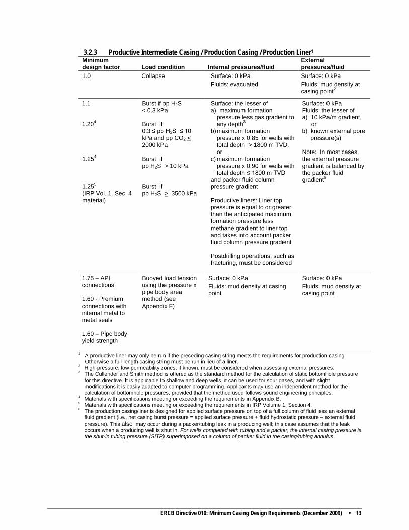
3.2.3 Productive Intermediate Casing / Production Casing / Production Liner1 Minimum design factor Load condition Internal pressures/fluid
External pressures/fluid
1.0
Collapse Surface: 0 kPa Fluids: evacuated
Surface: 0 kPa Fluids: mud density at casing point2
1.1 1.204 1.254
1.255 (IRP Vol. 1. Sec. 4 material)
Burst if pp H2S < 0.3 kPa Burst if 0.3 ≤ pp H2S ≤ 10 kPa and pp CO2 < 2000 kPa Burst if pp H2S > 10 kPa Burst if pp H2S > 3500 kPa
Surface: the lesser of a) maximum formation
pressure less gas gradient to any depth3
b) maximum formation pressure x 0.85 for wells with total depth > 1800 m TVD, or
c) maximum formation pressure x 0.90 for wells with total depth ≤ 1800 m TVD
and packer fluid column pressure gradient
Productive liners: Liner top pressure is equal to or greater than the anticipated maximum formation pressure less methane gradient to liner top and takes into account packer fluid column pressure gradient Postdrilling operations, such as fracturing, must be considered
Surface: 0 kPa Fluids: the lesser of a) 10 kPa/m gradient, or b) known external pore pressure(s) Note: In most cases, the external pressure gradient is balanced by the packer fluid gradient6
1.75 – API connections 1.60 - Premium connections with internal metal to metal seals 1.60 – Pipe body yield strength
Buoyed load tension using the pressure x pipe body area method (see Appendix F)
Surface: 0 kPa Fluids: mud density at casing point
Surface: 0 kPa Fluids: mud density at casing point
1 A productive liner may only be run if the preceding casing string meets the requirements for production casing. Otherwise a full-length casing string must be run in lieu of a liner.
2 High-pressure, low-permeability zones, if known, must be considered when assessing external pressures. 3 The Cullender and Smith method is offered as the standard method for the calculation of static bottomhole pressure
for this directive. It is applicable to shallow and deep wells, it can be used for sour gases, and with slight modifications it is easily adapted to computer programming. Applicants may use an independent method for the calculation of bottomhole pressures, provided that the method used follows sound engineering principles.
4 Materials with specifications meeting or exceeding the requirements in Appendix B. 5 Materials with specifications meeting or exceeding the requirements in IRP Volume 1, Section 4. 6 The production casing/liner is designed for applied surface pressure on top of a full column of fluid less an external
fluid gradient (i.e., net casing burst pressure = applied surface pressure + fluid hydrostatic pressure – external fluid pressure). This also may occur during a packer/tubing leak in a producing well; this case assumes that the leak occurs when a producing well is shut in. For wells completed with tubing and a packer, the internal casing pressure is the shut-in tubing pressure (SITP) superimposed on a column of packer fluid in the casing/tubing annulus.

14 • ERCB Directive 010: Minimum Casing Design Requirements (December 2009)
Appendix A References and Suggested Reading ERCB Publications
Oil and Gas Conservation Act, Oil and Gas Conservation Regulations Directive 008: Surface Casing Depth Minimum Requirements Directive 009: Casing Cementing Minimum Requirements Directive 020: Well Abandonment Guide Directive 034: Gas Well Testing—Theory and Practice (3rd edition, 1975) Directive 036: Drilling Blowout Prevention Requirements and Procedures Directive 056: Energy Development Applications and Schedules Interim Directive (ID) 97-06: Sour Well Licensing and Drilling Requirements ID 2003-01: 1) Isolation Packer Testing, Reporting, and Repair Requirements,
2) Surface Casing Vent Flow/Gas Migration Testing, Reporting, and Repair Requirements, 3) Casing Failure Reporting and Repair Requirements
Other Applicable Publications (latest editions)
Industry Recommended Practices (IRP) Volume 1: Critical Sour Drilling IRP Volume 3: Heavy Oil and Oil Sands Operations IRP Volume 6: Critical Sour Underbalanced Drilling
Alberta Recommended Practices (ARP) Volume 2: Completing and Servicing
Drilling and Completion Committee Alberta, Primary and Remedial Cementing Guidelines (April 1995)
National Association of Corrosion Engineers (NACE) MR0175/ISO 15156: Petroleum and natural gas industries—Materials for use in H2S-containing environments in oil and gas production
NACE RP0186 Standard: Recommended Practice for the Application of Cathodic Protection for Well Casings
NACE Standard TM0177: Laboratory Testing of Metals for Resistance to Specific Forms of Environmental Cracking in H2S Environments
NACE Standard TM0284: Evaluation of Pipeline and Pressure Vessel Steels for Resistance to Hydrogen-Induced Cracking
American Petroleum Institute (API) Recommended Practice 5C1: Recommended Practice for Care and Use of Casing and Tubing
API Bulletin 5C3: Formulas and Calculations for Casing, Tubing, Drill Pipe and Line Pipe Properties
API Specification 5CT/ISO 11960: Specification for Casing and Tubing
Suggested Reading
NACE Paper # 03105: Development of Recommended Practices for Completing and Producing Critical Sour Gas Wells – Materials Requirements, by Malcolm Hay and Dan Belczewski (NACE Corrosion Conference 2003)
How to Design Casing Strings for Horizontal Wells, by John F. Greenip Jr., Hydril, Houston, Texas, Petroleum Engineer International (December 1989)
The Development of a New High Strength Casing Steel with Improved Hydrogen Sulfide Cracking Resistance for Sour Oil and Gas Well Applications, by George M. Waid and Robert T. Ault, Republic Steel Corporation, Corrosion/79, Paper No. 180 March 1979
ERCB Directive 010: Minimum Casing Design Requirements (December 2009) • 15
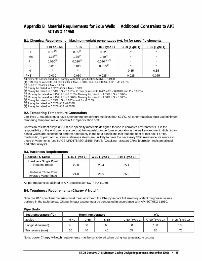
Appendix B Material Requirements for Sour Wells — Additional Constraints to API 5CT/ISO 11960
B1. Chemical Requirement—Maximum weight percentages (wt. %) for specific elements
H-40 or J-55 K-55 L-80 (Type 1) C-90 (Type 1) T-95 (Type 1) C 0.35(4) 0.35(4) 0.32(7) * * Mn 1.35(5) 1.35(5) 1.40(6) * * P 0.020(8) 0.020(8) 0.020(9), (3) * * S 0.015 0.015 0.010(2) * * Ni * * * 0.35 0.35
P+S 0.030 0.030 0.025(1) 0.025 0.025 All elements not specified must comply with API Specification 5CT/ISO 11960. (1) P+S can be raised to < 0.030% if Cr + Mo > 0.30%, and to < 0.035% if Cr + Mo >0.6%. (2) S < 0.015% if Cr + Mo > 0.60%. (3) P may be raised to 0.025% if Cr + Mo > 0.30% (4) C may be raised to 0.38% if S < 0.010%; C may be raised to 0.40% if S < 0.010% and P < 0.015%. (5) Mn may be raised to 1.45% if S < 0.010%; Mn may be raised to 1.55% if S < 0.007%. (6) Mn may be raised to 1.45% if S < 0.007%, Mn may be raised to 1.50% if S < 0.005% (7) C may be raised to 0.35% if S < 0.005% and P < 0.015%. (8) P may be raised to 0.025% if S <0.010% (9) P may be raised to 0.025% if S <0.005% B2. Tempering Temperature Constraints L80 Type 1 materials must have a tempering temperature not less than 621oC. All other materials must use minimum tempering temperatures outlined in API Specification 5CT. Corrosion-resistant alloys (CRAs) are specialty materials designed for use in corrosive environments. It is the responsibility of the end user to ensure that the material can perform acceptably in the well environment. High nickel-based CRAs are expected to perform adequately in the sour conditions that lead the user to this box. Ferritic, martensitic, duplex, and austenitic stainless steels are unlikely to have the necessary SSC resistance for service in these environments (see NACE MR0175/ISO 15156, Part 3: “Cracking-resistant CRAs [corrosion-resistant alloys] and other alloys”). B3. Hardness Requirements Rockwell C Scale L-80 (Type 1) C-90 (Type 1) T-95 (Type 1)
Hardness Single Point Reading (max)
22.0 25.4 25.4
Hardness Three Point Average Value (max) 21.0 25.0 25.0
As per frequencies outlined in API Specification 5CT/ISO 11960. B4. Toughness Requirements (Charpy V-Notch) Directive 010 compliant materials must meet or exceed the Charpy impact full sized equivalent toughness values outlined in the table below. Charpy impact testing must be conducted in accordance with API 5CT/ISO 11960. Pipe Body Test temperature (0C) Room temperature 00C Joules H-40 J-55 K-55 L-80 (Type 1) C-90 (Type 1) T-95 (Type 1)
Longitudinal (min) 45 60 60 80 100 100
Transverse (min) 30 40 40 55 70 70 . Note: Lower Charpy V-Notch requirements may be considered when using low temperature testing.
16 • ERCB Directive 010: Minimum Casing Design Requirements (December 2009)
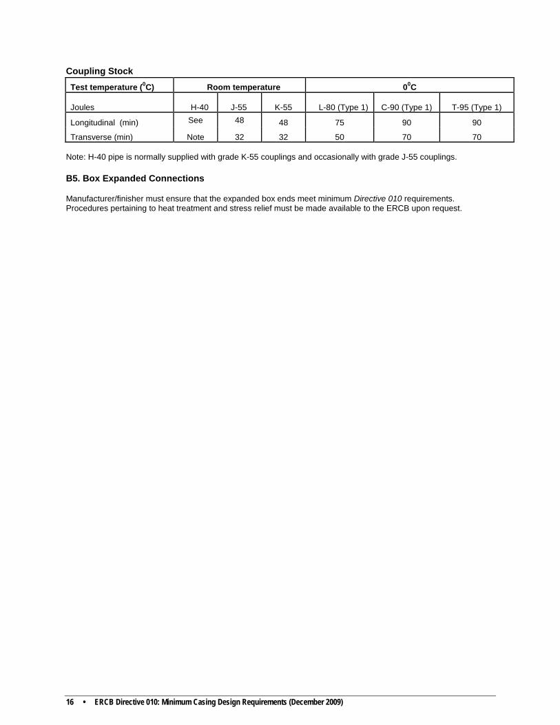
Coupling Stock Test temperature (0C) Room temperature 00C
Joules
H-40 J-55 K-55 L-80 (Type 1) C-90 (Type 1) T-95 (Type 1)
Longitudinal (min) See 48 48 75 90 90
Transverse (min) Note 32 32 50 70 70 Note: H-40 pipe is normally supplied with grade K-55 couplings and occasionally with grade J-55 couplings. B5. Box Expanded Connections Manufacturer/finisher must ensure that the expanded box ends meet minimum Directive 010 requirements. Procedures pertaining to heat treatment and stress relief must be made available to the ERCB upon request.
ERCB Directive 010: Minimum Casing Design Requirements (December 2009) • 17
Appendix C NACE Sulphide Stress Cracking (SSC) Testing Parameters In the event that fit-for-purpose SSC testing is required, refer to the following sources for recommendations on testing parameters: • NACE TM0177 • IRP Volume 1 • Certified NACE testing laboratory Use of Material Requirements (Appendix B) will assist with the selection of appropriate materials based on partial pressures of H2S and CO2.
18 • ERCB Directive 010: Minimum Casing Design Requirements (December 2009)
Appendix D Definitions Casing: The casing string forms a major structural component of the wellbore and serves several important functions: preventing the formation wall from caving into the wellbore, isolating the different formations to prevent the flow or cross flow of formation fluids, and providing a means of maintaining control of formation fluids and pressure as the well is drilled. The casing string provides a means of securing surface pressure control equipment, such as the drilling blowout preventer (BOP) and downhole production equipment (e.g., production packer). Casing is available in a range of sizes, weights, grades, and materials.
Casing grade: A system of identifying and categorizing the strength of casing materials. The appropriate casing grade for any application typically is based on design loads and the corrosion environment.
Casing point: The depth at which casing is run and cemented. The casing point may be a predetermined depth selected according to geological observations or dictated by problems in the open-hole section.
Design factors: The design factor, as specified in this directive, is the minimum acceptable value. Safety factors must be equal to or greater than the minimum design factors.
Directional wells: Wells where the bending stresses exceed 10% of the SMYS.
Formation (or pore) pressure: The pressure of the fluids within the pores of a reservoir.
Formation (or pore) pressure gradient: The pressure gradient is expressed as kPa/m. This corresponds to the formation (or pore) pressure divided by the true vertical depth of the formation top. The pressure gradient can be expressed as an equivalent mud density, the fluid density required in the wellbore to balance the formation (or pore) pressure.
Fracture gradient: The pressure required to induce fractures in rock divided by depth. In the absence of other data, the default value for casing design is 22 kPa/m.
Fracture pressure: The pressure required to induce fractures at a given depth.
Hydrogen induced cracking (HIC): The development of cracks along the rolling direction of the steel due to the absorption of hydrogen atoms and formation of internal hydrogen gas. The hydrogen is generated by the corrosion of steel in a wet hydrogen sulphide (H2S) environment.
Intermediate casing: Intermediate casing strings are used to ensure wellbore integrity down to total depth or the next full-length casing point. Intermediate casing strings are set after the surface and before the production casing. For example, the intermediate casing strings may provide protection against caving of weak or abnormally pressured formations and enable the use of drilling fluids of different density necessary for the control of deeper formations to the next casing point.
Joint strength: The joint strength is the connection parting strength (or ultimate strength). The joint strengths of API connections are published in API Bulletin 5C2. For non-API connections, the connection yield and/or ultimate strength may be supplied by the manufacturer. The ultimate strength of non-API connections may be used to meet the minimum tension design factor.
Joule: One joule is the work done, or energy expended, by a force of one newton moving an object one metre along the direction of the force.
ERCB Directive 010: Minimum Casing Design Requirements (December 2009) • 19
Liner: Any string of casing in which the top does not extend to the surface but instead is suspended from inside the previous casing string. The liner can be either protective or productive and must be designed accordingly.
Partial pressure (pp): The partial pressure of each component in a gas mixture is equal to the pressure multiplied by its mole fraction in the mixture. For example: A pressure of 30 000 kPa and a 3 mole % (0.03 mole fraction) H2S content would have (30 000 kPa x 0.03) = 900 kPa pp H2S.
Pipe Body Yield Strength (PBYS): The pipe body yield strength is the minimal axial yield strength of the casing tube body. The PBYS is calculated by multiplying the nominal pipe body cross-sectional area by the specified minimum yield strength (SMYS) of the material.
Premium Connections: Non-API connections are sometimes referred to as “premium” connections and are generally used in place of API connections when additional connection performance is required. Premium connections may have one or more enhanced features, such as a modified thread profile and/or a metal to metal seal. Premium connection manufacturers may publish the connection ultimate strength and/or connection yield strength.
Production casing: The last casing string set within a wellbore, which contains the primary completion components. No subsequent drilling operations are conducted after setting production casing; otherwise the string must be designed as productive intermediate casing.
Productive intermediate casing: Productive intermediate casing functions as part of the production string and may be exposed to production fluids. It must meet production casing design criteria suitable for the life of the well.
Protective intermediate casing: Protective intermediate casing cannot be exposed to production fluids after completion; it can only be exposed to drilling or formation fluids while drilling the next hole section(s).
Reservoir: A subsurface body of rock having sufficient porosity and permeability to store and transmit fluids.
Safety factor: The safety factor in this directive is defined as equal to the load rating of the tubular divided by the actual load on the tubular. The calculated safety factors must be equal to or greater than the minimum design factors.
Shut-in tubing pressure (SITP): Shut-in tubing pressure is the producing formation pressure less the gas gradient to surface.
Sour service: Sour service, as specified in Directive 010, refers to a partial pressure of H2S > 0.3 kPa. This value is consistent with NACE MR0175/ISO 15156.
Sulphide stress cracking (SSC): Brittle failure by cracking under the combined tensile stress and corrosion in the presence of water and H2S.
Surface casing: The first casing string pressure cemented back to surface, which permits installation of blowout preventers for the primary function of well control during the subsequent deepening of the well. It may also provide protection of freshwater aquifers and structural strength, so that the remaining casing strings and surface equipment may be installed.
20 • ERCB Directive 010: Minimum Casing Design Requirements (December 2009)
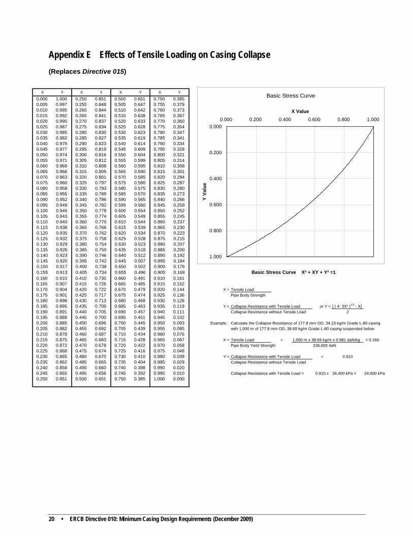
Appendix E Effects of Tensile Loading on Casing Collapse (Replaces Directive 015)
X Y X Y X Y X Y0.000 1.000 0.250 0.851 0.500 0.651 0.750 0.3850.005 0.997 0.255 0.848 0.505 0.647 0.755 0.3790.010 0.995 0.260 0.844 0.510 0.642 0.760 0.3730.015 0.992 0.265 0.841 0.515 0.638 0.765 0.3670.020 0.990 0.270 0.837 0.520 0.633 0.770 0.3600.025 0.987 0.275 0.834 0.525 0.628 0.775 0.3540.030 0.985 0.280 0.830 0.530 0.623 0.780 0.3470.035 0.982 0.285 0.827 0.535 0.619 0.785 0.3410.040 0.979 0.290 0.823 0.540 0.614 0.790 0.3340.045 0.977 0.295 0.819 0.545 0.609 0.795 0.3280.050 0.974 0.300 0.816 0.550 0.604 0.800 0.3210.055 0.971 0.305 0.812 0.555 0.599 0.805 0.3140.060 0.969 0.310 0.808 0.560 0.595 0.810 0.3080.065 0.966 0.315 0.805 0.565 0.590 0.815 0.3010.070 0.963 0.320 0.801 0.570 0.585 0.820 0.2940.075 0.960 0.325 0.797 0.575 0.580 0.825 0.2870.080 0.958 0.330 0.793 0.580 0.575 0.830 0.2800.085 0.955 0.335 0.789 0.585 0.570 0.835 0.2730.090 0.952 0.340 0.786 0.590 0.565 0.840 0.2660.095 0.949 0.345 0.782 0.595 0.560 0.845 0.2590.100 0.946 0.350 0.778 0.600 0.554 0.850 0.2520.105 0.943 0.355 0.774 0.605 0.549 0.855 0.2450.110 0.940 0.360 0.770 0.610 0.544 0.860 0.2370.115 0.938 0.365 0.766 0.615 0.539 0.865 0.2300.120 0.935 0.370 0.762 0.620 0.534 0.870 0.2230.125 0.932 0.375 0.758 0.625 0.528 0.875 0.2150.130 0.929 0.380 0.754 0.630 0.523 0.880 0.2070.135 0.926 0.385 0.750 0.635 0.518 0.885 0.2000.140 0.923 0.390 0.746 0.640 0.512 0.890 0.1920.145 0.920 0.395 0.742 0.645 0.507 0.895 0.1840.150 0.917 0.400 0.738 0.650 0.502 0.900 0.1760.155 0.913 0.405 0.734 0.655 0.496 0.905 0.169 Basic Stress Curve X² + XY + Y² =10.160 0.910 0.410 0.730 0.660 0.491 0.910 0.1610.165 0.907 0.415 0.726 0.665 0.485 0.915 0.1520.170 0.904 0.420 0.722 0.670 0.479 0.920 0.144 X = Tensile Load0.175 0.901 0.425 0.717 0.675 0.474 0.925 0.136 Pipe Body Strength0.180 0.898 0.430 0.713 0.680 0.468 0.930 0.1280.185 0.895 0.435 0.709 0.685 0.463 0.935 0.119 Y = Collapse Resistance with Tensile Load or Y = [ ( 4- 3X² )1/2 - X]0.190 0.891 0.440 0.705 0.690 0.457 0.940 0.111 Collapse Resistance without Tensile Load 20.195 0.888 0.445 0.700 0.695 0.451 0.945 0.1020.200 0.885 0.450 0.696 0.700 0.445 0.950 0.093 Example: Calculate the Collapse Resistance of 177.8 mm OD, 34.23 kg/m Grade L-80 casing 0.205 0.882 0.455 0.692 0.705 0.439 0.955 0.085 with 1,000 m of 177.8 mm OD, 38.69 kg/m Grade L-80 casing suspended below0.210 0.878 0.460 0.687 0.710 0.434 0.960 0.0760.215 0.875 0.465 0.683 0.715 0.428 0.965 0.067 X = Tensile Load = 1,000 m x 38.69 kg/m x 0.981 daN/kg = 0.1600.220 0.872 0.470 0.678 0.720 0.422 0.970 0.058 Pipe Body Yield Strength 236,600 daN0.225 0.868 0.475 0.674 0.725 0.416 0.975 0.0480.230 0.865 0.480 0.670 0.730 0.410 0.980 0.039 Y = Collapse Resistance with Tensile Load = 0.9100.235 0.862 0.485 0.665 0.735 0.404 0.985 0.029 Collapse Resistance without Tensile Load0.240 0.858 0.490 0.660 0.740 0.398 0.990 0.0200.245 0.855 0.495 0.656 0.745 0.392 0.995 0.010 Collapse Resistance with Tensile Load = 0.910 x 26,400 kPa = 24,000 kPa0.250 0.851 0.500 0.651 0.750 0.385 1.000 0.000
Basic Stress Curve
0.000
0.200
0.400
0.600
0.800
1.000
0.000 0.200 0.400 0.600 0.800 1.000
X Value
Y Va
lue
ERCB Directive 010: Minimum Casing Design Requirements (December 2009) • 21
Appendix F Alternative Design Method Example
Noncritical Sour Well Example
Surface Section
444 mm surface hole TrueVertical Surface CasingDepth
(metres) Size: 339.7 mm OD,Weight: 81.10 kg/mGrade: K55,
Connection: ST&C
Setting depth: 500 m Casing top: 0 m
500
Intermediate Section
311 mm holeProtective Intermediate Casing
Size: 244.5 mm ODWeight: 69.94 kg/m
Grade: L80Connection: LT&C
Setting depth: 2,500 m
H2S 0.0% Casing top: 0 m CO2 0.0%
28,000 kPa
2,500
Production Casing Section Production Casing
216 mm holeSize: 177.8 mm OD,
Weight: 43.15 kg/mGrade: L80
Connection: LT&C
H2S 1.5% Setting depth: 3,600 m CO2 2.0% Casing top: 0 m
44,000 kPa 3,500
Total depth 3,600
Estimated maximum form- ation pressure:
Estimated maximum form- ation pressure:
22 • ERCB Directive 010: Minimum Casing Design Requirements (December 2009)
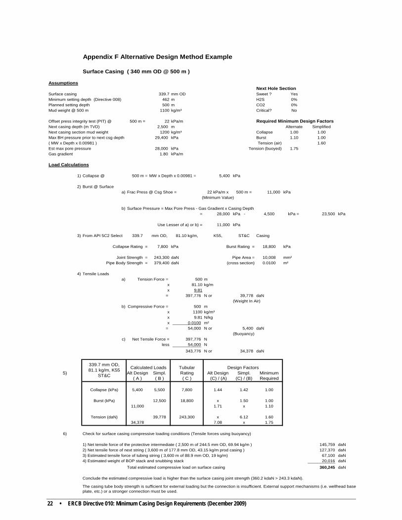
Appendix F Alternative Design Method Example
Surface Casing ( 340 mm OD @ 500 m )
AssumptionsNext Hole Section
Surface casing 339.7 mm OD Sweet ? YesMinimum setting depth (Directive 008) 462 m H2S 0%Planned setting depth 500 m CO2 0%Mud weight @ 500 m 1100 kg/m³ Critical? No
Offset press integrity test (PIT) @ 500 m = 22 kPa/m Required Minimum Design FactorsNext casing depth (m TVD) 2,500 m Alternate SimplifiedNext casing section mud weight 1200 kg/m³ Collapse 1.00 1.00Max BH pressure prior to next csg depth 29,400 kPa Burst 1.10 1.00( MW x Depth x 0.00981 ) Tension (air) 1.60Est max pore pressure 28,000 kPa Tension (buoyed) 1.75Gas gradient 1.80 kPa/m
Load Calculations
1) Collapse @ 500 m = MW x Depth x 0.00981 = 5,400 kPa
2) Burst @ Surfacea) Frac Press @ Csg Shoe = 22 kPa/m x 500 m = 11,000 kPa
(Minimum Value)
b) Surface Pressure = Max Pore Press - Gas Gradient x Casing Depth= 28,000 kPa - 4,500 kPa = 23,500 kPa
Use Lesser of a) or b) = 11,000 kPa
3) From API 5C2 Select 339.7 mm OD, 81.10 kg/m, K55, ST&C Casing
Collapse Rating = 7,800 kPa Burst Rating = 18,800 kPa
Joint Strength = 243,300 daN Pipe Area = 10,008 mm²Pipe Body Strength = 379,400 daN (cross section) 0.0100 m²
4) Tensile Loadsa) Tension Force = 500 m
x 81.10 kg/mx 9.81
= 397,776 N or 39,778 daN(Weight In Air)
b) Compressive Force = 500 mx 1100 kg/m³x 9.81 N/kgx 0.0100 m²
= 54,000 N or 5,400 daN(Buoyancy)
c) Net Tensile Force = 397,776 Nless 54,000 N
343,776 N or 34,378 daN
Tubular5) Alt Design Simpl. Rating Alt Design Simpl. Minimum
( A ) ( B ) ( C ) (C) / (A) (C) / (B) Required
Collapse (kPa) 5,400 5,500 7,800 1.44 1.42 1.00
Burst (kPa) 12,500 18,800 x 1.50 1.0011,000 1.71 x 1.10
Tension (daN) 39,778 243,300 x 6.12 1.6034,378 7.08 x 1.75
6) Check for surface casing compressive loading conditions (Tensile forces using buoyancy)
1) Net tensile force of the protective intermediate ( 2,500 m of 244.5 mm OD, 69.94 kg/m ) 145,759 daN2) Net tensile force of next string ( 3,600 m of 177.8 mm OD, 43.15 kg/m prod casing ) 127,370 daN3) Estimated tensile force of tubing string ( 3,600 m of 88.9 mm OD, 19 kg/m) 67,100 daN4) Estimated weight of BOP stack and snubbing stack 20,016 daN
Total estimated compressive load on surface casing 360,245 daN
Conclude the estimated compressive load is higher than the surface casing joint strength (360.2 kdaN > 243.3 kdaN).
Calculated Loads
The casing tube body strength is sufficient for external loading but the connection is insufficient. External support mechanisms (i.e. wellhead base plate, etc.) or a stronger connection must be used.
339.7 mm OD, 81.1 kg/m, K55
ST&C
Design Factors
ERCB Directive 010: Minimum Casing Design Requirements (December 2009) • 23
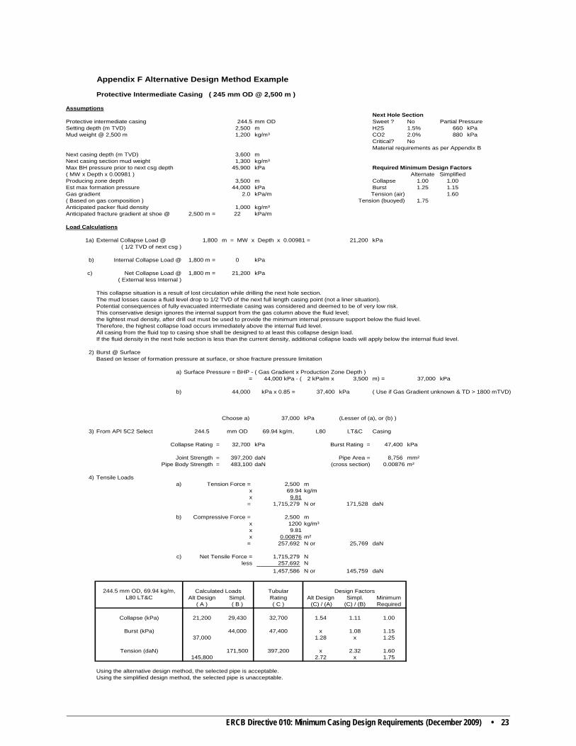
Appendix F Alternative Design Method Example
Protective Intermediate Casing ( 245 mm OD @ 2,500 m )
AssumptionsNext Hole Section
Protective intermediate casing 244.5 mm OD Sweet ? No Partial PressureSetting depth (m TVD) 2,500 m H2S 1.5% 660 kPaMud weight @ 2,500 m 1,200 kg/m³ CO2 2.0% 880 kPa
Critical? NoMaterial requirements as per Appendix B
Next casing depth (m TVD) 3,600 m Next casing section mud weight 1,300 kg/m³Max BH pressure prior to next csg depth 45,900 kPa Required Minimum Design Factors( MW x Depth x 0.00981 ) Alternate SimplifiedProducing zone depth 3,500 m Collapse 1.00 1.00Est max formation pressure 44,000 kPa Burst 1.25 1.15Gas gradient 2.0 kPa/m Tension (air) 1.60( Based on gas composition ) Tension (buoyed) 1.75 Anticipated packer fluid density 1,000 kg/m³Anticipated fracture gradient at shoe @ 2,500 m = 22 kPa/m
Load Calculations
1a) External Collapse Load @ 1,800 m = MW x Depth x 0.00981 = 21,200 kPa( 1/2 TVD of next csg )
b) Internal Collapse Load @ 1,800 m = 0 kPa
c) Net Collapse Load @ 1,800 m = 21,200 kPa( External less Internal )
This collapse situation is a result of lost circulation while drilling the next hole section.The mud losses cause a fluid level drop to 1/2 TVD of the next full length casing point (not a liner situation).Potential consequences of fully evacuated intermediate casing was considered and deemed to be of very low risk.This conservative design ignores the internal support from the gas column above the fluid level; the lightest mud density, after drill out must be used to provide the minimum internal pressure support below the fluid level.Therefore, the highest collapse load occurs immediately above the internal fluid level.All casing from the fluid top to casing shoe shall be designed to at least this collapse design load. If the fluid density in the next hole section is less than the current density, additional collapse loads will apply below the internal fluid level.
2) Burst @ Surface Based on lesser of formation pressure at surface, or shoe fracture pressure limitation
a) Surface Pressure = BHP - ( Gas Gradient x Production Zone Depth )= 44,000 kPa - ( 2 kPa/m x 3,500 m) = 37,000 kPa
b) 44,000 kPa x 0.85 = 37,400 kPa ( Use if Gas Gradient unknown & TD > 1800 mTVD)
Choose a) 37,000 kPa (Lesser of (a), or (b) )
3) From API 5C2 Select 244.5 mm OD 69.94 kg/m, L80 LT&C Casing
Collapse Rating = 32,700 kPa Burst Rating = 47,400 kPa
Joint Strength = 397,200 daN Pipe Area = 8,756 mm²Pipe Body Strength = 483,100 daN (cross section) 0.00876 m²
4) Tensile Loadsa) Tension Force = 2,500 m
x 69.94 kg/mx 9.81
= 1,715,279 N or 171,528 daN
b) Compressive Force = 2,500 mx 1200 kg/m³x 9.81x 0.00876 m²
= 257,692 N or 25,769 daN
c) Net Tensile Force = 1,715,279 Nless 257,692 N
1,457,586 N or 145,759 daN
TubularAlt Design Simpl. Rating Alt Design Simpl. Minimum
( A ) ( B ) ( C ) (C) / (A) (C) / (B) Required
Collapse (kPa) 21,200 29,430 32,700 1.54 1.11 1.00
Burst (kPa) 44,000 47,400 x 1.08 1.1537,000 1.28 x 1.25
Tension (daN) 171,500 397,200 x 2.32 1.60145,800 2.72 x 1.75
Using the alternative design method, the selected pipe is acceptable.Using the simplified design method, the selected pipe is unacceptable.
Calculated Loads Design Factors244.5 mm OD, 69.94 kg/m, L80 LT&C
24 • ERCB Directive 010: Minimum Casing Design Requirements (December 2009)
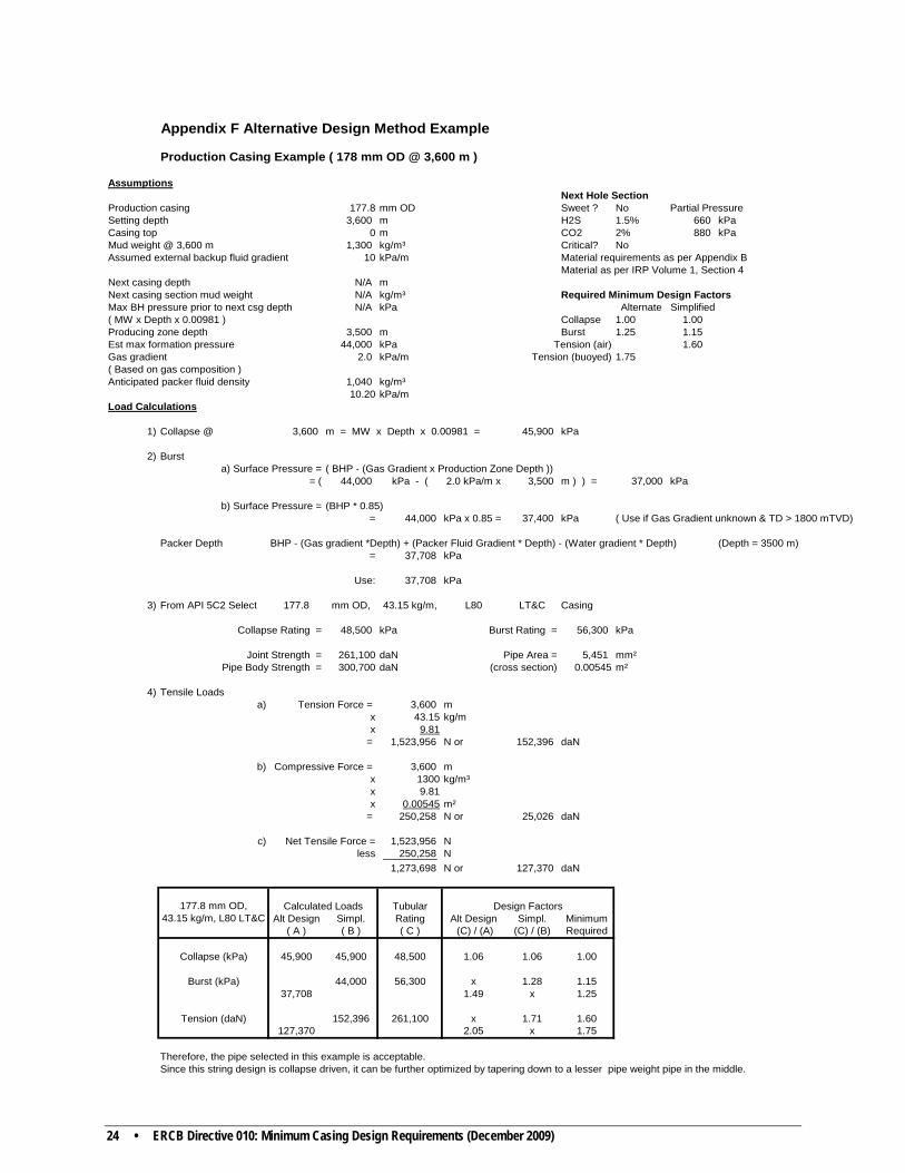
Appendix F Alternative Design Method Example
Production Casing Example ( 178 mm OD @ 3,600 m )
AssumptionsNext Hole Section
Production casing 177.8 mm OD Sweet ? No Partial PressureSetting depth 3,600 m H2S 1.5% 660 kPaCasing top 0 m CO2 2% 880 kPaMud weight @ 3,600 m 1,300 kg/m³ Critical? NoAssumed external backup fluid gradient 10 kPa/m Material requirements as per Appendix B
Material as per IRP Volume 1, Section 4 Next casing depth N/A m Next casing section mud weight N/A kg/m³ Required Minimum Design FactorsMax BH pressure prior to next csg depth N/A kPa Alternate Simplified( MW x Depth x 0.00981 ) Collapse 1.00 1.00Producing zone depth 3,500 m Burst 1.25 1.15Est max formation pressure 44,000 kPa Tension (air) 1.60Gas gradient 2.0 kPa/m Tension (buoyed) 1.75( Based on gas composition )Anticipated packer fluid density 1,040 kg/m³
10.20 kPa/mLoad Calculations
1) Collapse @ 3,600 m = MW x Depth x 0.00981 = 45,900 kPa
2) Burst a) Surface Pressure = ( BHP - (Gas Gradient x Production Zone Depth ))
= ( 44,000 kPa - ( 2.0 kPa/m x 3,500 m ) ) = 37,000 kPa
b) Surface Pressure = (BHP * 0.85)= 44,000 kPa x 0.85 = 37,400 kPa ( Use if Gas Gradient unknown & TD > 1800 mTVD)
Packer Depth BHP - (Gas gradient *Depth) + (Packer Fluid Gradient * Depth) - (Water gradient * Depth) (Depth = 3500 m)= 37,708 kPa
Use: 37,708 kPa
3) From API 5C2 Select 177.8 mm OD, 43.15 kg/m, L80 LT&C Casing
Collapse Rating = 48,500 kPa Burst Rating = 56,300 kPa
Joint Strength = 261,100 daN Pipe Area = 5,451 mm²Pipe Body Strength = 300,700 daN (cross section) 0.00545 m²
4) Tensile Loadsa) Tension Force = 3,600 m
x 43.15 kg/mx 9.81
= 1,523,956 N or 152,396 daN
b) Compressive Force = 3,600 mx 1300 kg/m³x 9.81x 0.00545 m²
= 250,258 N or 25,026 daN
c) Net Tensile Force = 1,523,956 Nless 250,258 N
1,273,698 N or 127,370 daN
TubularAlt Design Simpl. Rating Alt Design Simpl. Minimum
( A ) ( B ) ( C ) (C) / (A) (C) / (B) Required
Collapse (kPa) 45,900 45,900 48,500 1.06 1.06 1.00
Burst (kPa) 44,000 56,300 x 1.28 1.1537,708 1.49 x 1.25
Tension (daN) 152,396 261,100 x 1.71 1.60127,370 2.05 x 1.75
Therefore, the pipe selected in this example is acceptable.Since this string design is collapse driven, it can be further optimized by tapering down to a lesser pipe weight pipe in the middle.
Calculated Loads Design Factors177.8 mm OD, 43.15 kg/m, L80 LT&C