Embed Size (px)
Citation preview

Directive 037
Directive 037: Service Rig Inspection Manual February 2006 Effective June 17, 2013, the Energy Resources Conservation Board (ERCB) has been succeeded by the Alberta Energy Regulator (AER). As part of this succession, the title pages of all existing ERCB directives now carry the new AER logo. However, no other changes have been made to the directives, and they continue to have references to the ERCB. As new editions of the directives are issued, these references will be changed. Some phone numbers in the directives may no longer be valid. Contact AER Inquiries at 1-855-297-8311 or [email protected].

GUIDE RENAMED AS A DIRECTIVE As announced in Bulletin 2004-02: Streamlining EUB Documents on Regulatory Requirements, the Alberta Energy and Utilities Board (EUB) will issue only “directives,” discontinuing interim directives, informational letters, and guides. Directives set out new or amended EUB requirements or processes to be implemented and followed by licensees, permittees, and other approval holders under the jurisdiction of the EUB. As part of this initiative, this document has been renamed as a directive. Changes in Accord with Directive 019: Compliance Assurance—Enforcement As well, changes have been incorporated reflecting the compliance assurance process introduced with Directive 019: Compliance Assurance—Enforcement. However, no other changes have been made. Therefore, The document text continues to have references to “guides.” These references should be read as referring to the directive of the same number. When this directive is further amended, these references will be changed to reflect their renaming as directives.
The Alberta Energy and Utilities Board (EUB/Board) has approved this directive on February 16, 2006.
<original signed by>
B. T. McManus, Q.C.
ALBERTA ENERGY AND UTILITIES BOARD Directive 037: Service Rig Inspection Manual February 2006 Replaces Guides 37: Service Rig Inspection Manual (June 1995) Published by Alberta Energy and Utilities Board 640 – 5 Avenue SW Calgary, Alberta T2P 3G4 Telephone: (403) 297-8311 Fax: (403) 297-7040 Web site: www.eub.gov.ab.ca

EUB Directive 037: Service Rig Inspection Manual (February 2006) • i
Contents Guide to Manual ........................................................................................................................................... 1
015: About This Manual ............................................................................................................. 1 015-2: Electrical Inspections of Service Rigs ................................................................................ 1 020: Using the Manual ................................................................................................................ 3
100: Policies ............................................................................................................................................. 3 105: EUB Responsibilities .......................................................................................................... 3 110: Conduct ............................................................................................................................... 6 115: Safety .................................................................................................................................. 6 120: Industry/Government Involvement ..................................................................................... 6
200: Conducting the Inspection ............................................................................................................... 7 205: Arrival at the Well Site ....................................................................................................... 7 210: BOP System Requirements and Specifications .................................................................. 7 215: BOP Controls .................................................................................................................... 14 220: Crew Training and Certification ....................................................................................... 15 225: BOP Mechanical Test ....................................................................................................... 17 230: Air Shut-offs/Diesel and Gasoline Engine Spacing .......................................................... 22 235: Accumulator Sizing and Operating Policies ..................................................................... 24 240: Back-up Nitrogen Supply ................................................................................................. 31 245: Winterizing BOP Equipment ............................................................................................ 37 250: Spacing Regulations ......................................................................................................... 38 255: Handling Sour Effluent ..................................................................................................... 39 260: BOP Pressure Test ............................................................................................................ 40 265: Well-Site Conditions ......................................................................................................... 42 270: Operator and Contractor Inspections ................................................................................ 44 280: Smoking ............................................................................................................................ 47
300: Completing the Inspection Report ................................................................................................. 48 305: General Information .......................................................................................................... 48 310: Mechanical Tests .............................................................................................................. 49 315: Inspection Results ............................................................................................................. 50 320: Remedial Action ............................................................................................................... 52 325: Signatures and On-Site Discussions ................................................................................. 56 330: Special Wells .................................................................................................................... 57
1000: Appendices ..................................................................................................................................... 57 1005: Sample Inspection Reports ............................................................................................... 57 1010: Well Servicing Equipment Code ...................................................................................... 61 1025: Accumulator Sizing Calculations – Alternate Method ..................................................... 66 1030: Back-Up Nitrogen Calculations – Alternate Method ........................................................ 67 1035: EUB Crew Training Assessment Form ............................................................................. 70 1040: EUB Crew Procedures Form ............................................................................................ 71 1045: Operational Deficiencies ................................................................................................... 75 1055: BOP Fluid Volumes .......................................................................................................... 83 1060: Alberta Occupational Health & Safety Legislation .......................................................... 96 1070: Drilling with a Service Rig ............................................................................................. 111 1080: Coiled Tubing Requirements .......................................................................................... 111 1090: BOP Modification Submission ....................................................................................... 112 1100: Oilfield Waste Management Inspection Guidelines – Drilling Operations .................... 112


EUB Directive 037: Service Rig Inspection Manual (February 2006) • 1
Guide to Manual 015: About This Manual
Purpose of Manual
This manual is designed to assist EUB employees and others who inspect service rigs. Inspectors should use this manual as a reference during inspections. It anticipates questions that may arise in interpreting regulations. The manual is divided into three main sections:
1. EUB policy related to inspections.
2. Detailed instructions and criteria for conducting the inspection.
3. Detailed instructions explaining each item on the inspection report.
AOH&S Legislation The manual includes AOH&S legislation with respect to drilling rig
safety (Appendix 1060). Its inclusion is intended to inform users of this manual of the regulations that should be considered in the overall safety performance at drilling sites. EUB inspectors should become familiar with AOH&S legislation and be prepared to
- alert operators and/or contractors regarding unsafe operating practices.
- advise AOH&S and EPB of unsafe operating practices noted during rig inspections.
EUB inspectors may periodically note differences between EUB and AOH&S equipment spacing requirements. During such occasions, the EUB requirements take precedence.
015-2: Electrical Inspections of Service Rigs
Electrical Protection Branch Legislation
This document is intended to describe and formalize the roles and expectations of the EUB and Alberta Labour with regards to electrical conditions at rigs. It is important to note that all jurisdiction of electrical systems at rigs remains with Alberta Labour. Included in this document is a discussion of the background and goals which have to be met to achieve a satisfactory agreement.
Roles and Expectations EUB inspectors conduct inspections of rigs to ensure compliance with EUB requirements. They are not inspecting the electrical systems on those rigs. However, if during the EUB inspection an

2 • EUB Directive 037: Service Rig Inspection Manual (February 2006)
*obvious problem with the electrical system is noted, the inspector will write the following reminder on the EUB rig inspection form. A copy of that form will be forwarded to Alberta Labour at the address listed at the end of this agreement. * obvious problem: because of the lack of formal electrical
training of EUB staff, obvious problems are considered to be electrical systems with signs of poor maintenance such as tattered and frayed cords, numerous light protectors missing, and evidence of shorting or sparking.
It is the responsibility of the contractor to ensure electrical
compliance and there will be no follow-up on these reminders by EUB staff. However, repeat electrical problems would be followed up by Alberta Labour as they will have copies of all such reminders forwarded to them by EUB inspectors.
Background Alberta Labour staff do not normally inspect electrical systems on rigs after the rigs are in service. They are concerned that rigs, with their constant moving, are prone to electrical system deterioration. EUB staff, though they have no formal training in electrical systems, inspect rigs at regular, if infrequent, intervals. It is felt that EUB staff could help Alberta Labour by reminding personnel, at rigs with questionable electrical systems, of their responsibilities and informing Alberta Labour. EUB has no jurisdiction to enforce any requests for remedial work on electrical systems.
Goals of This Agreement 1. To help ensure that electrical systems on rigs are maintained according to the Safety Codes Act.
2. To coordinate “government inspections”, efficiently reduce
duplication, and facilitate government agencies' aid to each other.
3. To emphasize the fact that EUB staff, while willing to help, are
not trained specialists in the area of electrical inspections, and that in no way should their inspection be construed as a complete and thorough inspection of the electrical system.
4. To ensure that it is understood that, by this willingness to help,
the EUB is in no way assuming jurisdiction of electrical systems.
5. To ensure that the EUB and its staff are protected from the potential of court actions as a result of trying to help out a member of our government family.
Ken McLennan, Sr. Technical Advisor Bill Remmer, Field Operations Alberta Labour Alberta Energy and Utilities Board 8th Floor, 10808 - 99 Avenue 640 - 5 Avenue SW Edmonton, AB T5K 0G5 Calgary, AB T2P 3G4

EUB Directive 037: Service Rig Inspection Manual (February 2006) • 3
020: Using the Manual Preliminaries
1. Review the Table of Contents to become familiar with the
organization of the manual. 2. Read and study the manual to become familiar with its contents.
References 3. An inspector should be totally familiar with the manual's inspection procedures, policies, and technical data before embarking on any service rig inspections.
Non-EUB Users 4. While every effort has been made to ensure the accuracy and
reliability of the technical data presented in this manual, the EUB does not guarantee the data and hereby disclaims responsibility for loss or damage resulting from its use. It is the responsibility of the user to verify the data provided.
Waivers 5. Operators who wish to be exempt from any requirement of this
manual, must submit a request for waiver of the section involved to the Drilling and Production Department, EUB, Calgary. Waivers that result in major modifications to BOP components or procedures will not be granted by the Area Office.
100: Policies 105: EUB Responsibilities
The Alberta Energy and Utilities Board's responsibilities with respect to well servicing are 1. according to the Energy Resources Conservation Act (section
2(d)(e)),
“to control pollution and ensure environment conservation in the exploration for, processing, development and transportation of the energy resources and energy,” “to secure the observance of safe and efficient practices in the exploration for, processing, development and transportation of the energy resources of Alberta,”
2. according to the Oil and Gas Conservation Act (Part 1, section
4(b)(d)(f)),
“to secure the observance of safe and efficient practices in the locating, spacing, drilling, equipping, completing, reworking, testing, operating and abandonment of wells and in the operations for the production of oil, gas and crude bitumen,”

4 • EUB Directive 037: Service Rig Inspection Manual (February 2006)
“to afford each owner the opportunity of obtaining their share of the production of oil or gas from any pool or of crude bitumen from any oil sands deposit,” “to control pollution above, at or below the surface in the drilling of wells and in operations for the production of oil, gas and crude bitumen and in other operations over which the Board has jurisdiction.”
3. according to the Oil and Gas Conservation Regulations (section
8.149), “to require a licensee or operator of the well to
(a) test the operation and effectiveness of the equipment required by sections 8.100, 8.130, 8.133, 8.135, 8.144 and 8.145,
(b) conduct a pressure test of the blowout prevention equipment,
using where necessary a hanger plug or casing packer, and (c) perform a “blowout prevention drill.”
Purpose of Rig Inspections The Inspectors Role
The EUB inspectors role is to encourage cooperation with the Contractor and Licensee representatives, with the aim of improving their understanding and commitment towards meeting the inspection requirements and regulations.
Where it becomes obvious that such commitment is lacking and an open disregard for the Board's requirements is displayed, a system of escalating consequences will be imposed by the EUB. This will be in keeping with our “firm but fair” approach to all our customers. In an effort to be efficient in the use of the Board's resources, the following criteria may be used in determining which rigs will be inspected.
In an effort to be efficient in the use of the Board's resources, the following criteria may be used in determining which rigs will be inspected.
1. Inspection History of the Rig Contractor and Operator.
- Previously noted unsatisfactory items or requests for remedial action should be followed up.
2. On-Site Assessment of Drilling Occurrence Information.
- Are there any instances of kicks, blows, blowouts,
documented for the area the rig is working in and are the on-site personnel aware of them.

EUB Directive 037: Service Rig Inspection Manual (February 2006) • 5
3. Approvals, Directives.
- Are there any new policies or requirements which may need to be addressed during the inspection.
4. Focus.
- The inspector should thoroughly evaluate equipment,
procedures and operating policies on-site including:
• crew training, - kick prevention, detection, control • well control information • servicing program • offset well data
- The inspector should also be receptive to:
• concerns and questions regarding regulations or requirements
• providing additional clarification or information as requested.
An inspector should be prepared to initiate additional discussion or
request additional crew training if during the inspection there is evidence it is required.
Industry’s Role The licensee and their contractors should understand, respect, meet or exceed the servicing regulations, recommended practices and standards. This is achieved by the implementation of:
1. Internal inspection, compliance programs, and being aware of their company EUB inspection record, and taking appropriate action where necessary.
2. Ongoing training of wellsite personnel. For safety, well control
and equipment. 3. Informing on-site personnel of potential hole problems,
sensitive environmental and public issues, in order to ensure appropriate responses are implemented.
4. Cooperation with the EUB, government and public by the open
exchange of dialogue to address areas of mutual concern.

6 • EUB Directive 037: Service Rig Inspection Manual (February 2006)
110: Conduct
Each inspector is an official representative of the Board. When at a well site and when performing any function under the Board's responsibility, the inspector shall conduct himself/herself in a business-like and professional manner. Each inspector must display a positive attitude, job knowledge, tact, fairness, and discretion to earn industry's respect for the Board and its inspectors. Historically, Board staff have achieved compliance with the regulations through co-operation with industry rather than through confrontation. Each inspector should continue to foster this working relationship.
115: Safety
Each inspector shall - wear a hard hat and steel-toed boots when inspecting rigs. - be familiar with all safety procedures and requirements in the
ERCB Safety Manual (IG-8). Refer specifically to Section VI - Field Operations/Inspections.
- be aware of an operator's or contractor's specific safety policies
regarding well servicing.
120: Industry/Government Involvement
Most of the regulations currently in effect for well servicing were endorsed by the Independent Petroleum Association of Canada and the Canadian Petroleum Association before being proclaimed. The EUB service rig inspection policies and procedures contained in this manual were endorsed by the Canadian Association of Petroleum Producers, Canadian Association of Oilwell Drilling Contractors, and Alberta Occupational Health and Safety.

EUB Directive 037: Service Rig Inspection Manual (February 2006) • 7
200: Conducting the Inspection 205: Arrival at the Well Site Contact with Operator’s and Contractor’s Representative
1. Whenever possible, the inspection should be conducted without
prior notice given to the operator or contractor.
2. Upon arrival at the site, contact the Rig Manager (toolpusher) and the company representative.
- If unavailable, locate the Driller.
3. Take time to get acquainted.
4. Explain the purpose of the visit. 5. Determine if hole conditions are safe to conduct a complete
inspection.
Request by Operator or Contractor that BOPs NOT BE CHECKED
6. If the Rig Manager and/or the company representative request that the blowout preventers (BOPs) not be checked because of an operational problem, use discretion in deciding whether or not to proceed with the inspection
- It is advisable to respect the wishes of the rig supervisors. An
abbreviated inspection may, however, still be conducted. - Consult with your supervisor if there is concern about
conducting a full inspection.
210: BOP System Requirements and Specifications BOP Requirements (8.144*)
1. Refer to Appendix 1010 - Schedule 10 - Servicing Blowout
Prevention Systems to determine the required type and pressure rating of the BOPs.
Tripping Small Diameter Tubing and Electrical Cables
2. An annular preventer must be installed whenever electrical cables, small diameter tubing control, or circulating strings are being tripped.
- Notched rams are not a suitable replacement for an annular
preventer. - See Section 235(13) for accumulator requirements.
* The numbers in brackets refer to the applicable regulation in the Oil and Gas Conservation Regulations.

8 • EUB Directive 037: Service Rig Inspection Manual (February 2006)
Rod Jobs 3. When a rod string is being tripped a rod preventer must be installed on the tubing string.
- The rod preventer permanently installed on the wellhead
must not be used as the servicing preventer. A separate unit must be furnished.
Tripping Small Diameter Tubing Inside Tubing
4. The appropriate BOP requirements must be applied whenever small diameter tubing is being tripped inside tubing.
Mechanical Ram Conversions 5. Mechanically operated rams, that have been converted to
hydraulically operated units, are acceptable provided they meet the operating requirements specified in this manual (see Section 235(12) and Section 240(5)).
Annular Specifications – Class I Gas Wells
6. A stripper type annular preventer may be used in lieu of a conventional annular preventer when servicing Class I Gas Wells.
- A stripper-type annular must have a pressure rating at least
equal to the formation pressure. - A stripper-type annular is subject to the same accumulator
requirements as imposed on a conventional annular.
Breakdowns – Class I Gas Wells
7. Class I Gas Wells must be fully blown down or killed prior to installing the BOP prevention equipment, unless a snubbing unit is in service.
Tubing Strippers – Class 1 Gas Wells
8. A tubing stripper must be installed either above or below the BOPs in a Class I Gas Well Blowout Prevention System.
- The stripper may be located below the preventer(s) provided
it is an integral part of the wellhead. - The stripper may be either a manufactured or “poorboy”
model. - No leakage should occur around the stripper during tripping
operations. However, minimal leakage may occur when the collars enter the stripper.
Tubing Plugs – Class I Gas Wells
9. If a well is flowing, a tubing plug or other suitable shut-off device must be installed in the bottom joint of the tubing string to prevent flow from the tubing during tripping operations.
- Operations are to be suspended whenever a shut off device is
not found in service.
Lubricators 10. After a well is perforated, a full lubricator must be installed when any form of wireline work is being performed.

EUB Directive 037: Service Rig Inspection Manual (February 2006) • 9
BOP Quick Connectors 11. Quick connectors may be used to connect various flanged BOP equipment.
- “Clamp Connections” (manufactured by Cameron) and
Grayloc clamp connections (manufactured by Gray Tool Company) are acceptable.
- Clamp-type connections can save many man hours when
connections must be repeatedly made up and broken.
Double Drilling BOP Equipment 12. The double drilling of BOP equipment (BOP body, BOP flanges, adapter flanges, or spools) is acceptable; however, the following policies are recognized by industry:
- Double studding the body of a BOP, to accept two sizes of
API flanges (equipment which may have a lower pressure rating), does not result in a derating of the preventer.
- Double drilling flanged BOP equipment, to accommodate
connections to other API equipment (equipment which may have a lower pressure rating), results in a derating of the flange to the lower working pressure.
- In many cases, derated flanges will be acceptable for the
particular class of well being serviced. However, if a double drilled flange is to be used in an application requiring a higher pressure rating, the operator must provide evidence from either the manufacturer or a professional engineer (P.Eng.) that the flange is certified for the higher pressure (equipment identification must be established with the certification document).
- If certification cannot be provided during the inspection, the
operator must furnish the necessary evidence within a reasonable time-frame. If this cannot be done, a High Risk deficiency must be recorded on the rig inspection report.
The equipment must not be used for another servicing job until the matter is resolved.
Re-entries or Drilling Operations 13. Service rigs conducting re-entries or drilling below production
or intermediate casing may be required to conform to a combination of drilling and servicing regulations.
14. Operators are required to apply to the Drilling Section of the
Drilling and Production Department in Calgary before commencing operations, as the basic requirements may be altered for site specific wells. Generally the applicable requirements are:

10 • EUB Directive 037: Service Rig Inspection Manual (February 2006)
Regulation General Regulation 8.144 Class III Servicing BOP stack 8.145 Class III Servicing accumulator system and nitrogen back up system 8.146 Servicing kill and bleed-off lines, servicing manifold with adjustable choke, gauge, and stabbing valve 8.135 Remote drill pipe gauge only 8.136 Mud tank degasser
8.137 Trip tank and pit level monitor 8.138 Proper heating for winter operations 8.140 Rotating head for air drilling 8.142 Second Line Supervisor must be readily available 8.147 Servicing pressure test requirements 8.143 DST equipment (circulating sub and remote controlled testing head) 8.148 Driller requires Well Service Blowout Prevention Certificate
Bleed-off and Kill Lines (8.146)
15. Class I Gas Well BOP Systems require either one (75 mm) or two (50 mm) vent or flare lines through which gas can be discharged during servicing operations.
- The line(s) must have a working pressure at least equal to or greater than the maximum reservoir pressure to be encountered.
- The line(s) must be connected to a valved spool below the
preventer(s). - The line(s) must be securely tied down. Devices such as
stakes (set at 10-m intervals), rubber tires filled with cement, pipeline weights, clamp and interconnecting cable mechanisms, or other properly designed devices, are acceptable.
- Steel swivel joint connections may be used provided gas is
not venting at the elbows or connections. If leakage is detected operations must be suspended until the problem is corrected.

EUB Directive 037: Service Rig Inspection Manual (February 2006) • 11
16.* Class IIA Heavy Oil BOP Systems require one 50 mm kill line connected to the wellhead, spool or BOP port and extending a minimum of 15 m from the well during the servicing of a secondary recovery well.
- A bleed-off and kill line is not required during the servicing
of a primary recovery well.
17. Class II and III BOP Systems require an additional spool and valve, or flanged BOP port and valve, for connecting bleed-off or kill lines.
- The spool or BOP port must be located below the lowest set
of rams. - The spool and valve (including BOP port valve) must match
the existing wellhead design. If flanged equipment is used on the wellhead, then the additional spool and valve must be flanged (flanges mated to back-welded threaded connections are only acceptable if the connection has been stress relieved. This generally requires shop fabrication).
- Wellhead casing valves may be used for the bleed-off or kill
line connection whenever a tubing hanger (dognut) is in place. However, once the BOP stack is installed, the spool or BOP port must be used for making the connection. The casing valves must be reserved for emergency purposes only.
- A threaded BOP port is not acceptable for this connection
because of potential thread damage which may occur through continuous make up and dismantling.
18. Class II and III BOP Systems require both a bleed-off and kill
line. The lines
- must be at least 50 mm nominal diameter. - must have a working pressure equal to or greater than the
production casing flange, or the formation pressure, whichever is the lesser.
* A Primary Recovery Heavy Oil/Oil Sands Well, for the purpose of this manual, is defined as a well having a
sandface reservoir pressure equal to or less than the hydrostatic pressure that would be exerted at the sandface if the well were filled with formation fluids. A Secondary Recovery Heavy Oil/Oil Sands Well (EOR), for the purpose of this manual, is defined as a well having a sandface reservoir pressure greater than that described above, by virtue of injection into the formation of fluid(s) other than water at ambient temperatures. This includes all wells that are a part of an active EOR project approved by the EUB and any offset wells within 1 km of an EOR well within the project.

12 • EUB Directive 037: Service Rig Inspection Manual (February 2006)
- must be installed such that one line is connected to a spool or BOP port (see item 17) and the second line is connected to the tubing (or equipment is readily available to make this connection).
- must be either connected to the rig pump or rig tank.
Snubbing units and rigs completing rod jobs do not
require bleed-off and kill lines or a pump and tank.
- may contain steel swivel joint connections. - must be securely tied down. Devices such as stakes (set at
10 m intervals), rubber tires filled with cement, pipeline weights, clamp and interconnecting cable mechanisms, or other properly designed devices, are acceptable.
Flexible Hose in Bleed-off and Kill Lines (8.146)
19. A flexible hose, without fire resistant sheathing, may be installed in the bleed-off and kill lines provided the hose has
- a working pressure equal to or greater than the production
casing flange, or the formation pressure, whichever is the lesser.
- a nominal diameter of 50 mm (75 mm if single line used in
Class I Gas Well BOP System).
Circulation Manifold 20. Class IIA BOP Systems do not require a circulation manifold during servicing operations. Return fluids must be contained. If a rig tank is used it must be located a minimum of 15 m from the well.
21. Class II and III BOP Systems require a manifold for the purpose
of directing fluids to and from the well. The manifold must
- conform to the minimum design requirements set out in Schedule 10.
- have a working pressure equal to or greater than the production casing flange, or the formation pressure, whichever is the lesser.
- be valved to allow flow to be directed to the tubing, annulus,
or rig tank. - include a check valve to prevent back-flow to the rig pump.

EUB Directive 037: Service Rig Inspection Manual (February 2006) • 13
- be equipped with a gauge and suitable fittings to accurately measure pump pressures.
- if equipped with an adjustable choke, have provisions made
(upstream of the choke) for the installation of a gauge in order to maintain proper circulation pressures.
- be equipped with a pressure relief device, on the pump
discharge, to prevent overpressuring of the circulation system (AOH&S regulation 202 requires the discharge line be secured).
Manifold Gauge 22. The manifold gauge must
- be installed or be readily accessible. - have an operating range at least equal to the formation
pressure. - have readable increments not exceeding 500 kPa
Casing Gauge 23. A gauge and suitable fittings must be available to obtain the casing pressure during a well shut-in.
- The installation and operating conditions set out in item 22
above are also applicable to this gauge.
Degasser Requirements 24. A degasser is not required at the present time because of design and dispersion uncertainties. However, this matter is currently being studied and a degasser requirement is anticipated in the future.
Stabbing Valve (8.146) 25. The rig must be equipped with a full opening stabbing valve, a
closing wrench and the necessary cross-over subs to enable the make-up of the valve with tubing or any other pipe in the well.
26. The stabbing valve shall be
- kept readily accessible and operable. - kept in the open position.
27. The stabbing valve does not have to be sized such that it can be
stripped into the well. 28. The stabbing valve must be equipped with carrying handles or
hanger caps if more than one person is required to handle it.
Drilling with a Service Rig Drilling with a service rig must comply with Section 4 Part 2 of the ERCB Guide G-33 “Application for a Well Licence” document. See Appendix 1070.

14 • EUB Directive 037: Service Rig Inspection Manual (February 2006)
BOP Modifications All modifications to BOP configurations must comply with Section 3 of ERCB Guide G-33 “Application for a Well Licence” document. See Appendix 1090.
215: BOP Controls Floor and Remote Control Requirements (8.145)
1. There must be both floor and remote controls for each BOP
installed. The controls must be properly installed, correctly identified and show function operations (e.g. open-close, as well as accumulator system pressure).
2. The floor controls must be located near the Driller's position
and be easily accessible. It is satisfactory for the controls to be located on the sub base, down a few stairs, or a few steps away. Use discretion.
3. The remote controls must be
- located at least 7 m from the well for Classes I, II and IIA (at
front of rig acceptable). - located at least 25 m from the well for Class III and be
shielded or housed. - readily accessible.
Master Control Location 4. It is preferable, but not mandatory, that the main hydraulic
controls (capable of closing and opening BOP's) be located at the remote panel and the auxiliary controls be located on the rig floor or near the Driller's station.
Check Valve Installation 5. A check valve must be installed between the accumulator
recharge pump and the accumulator itself.
- If the rig hydraulic system is used to recharge the accumulator, as in Classes I, II and IIA BOP Systems, the check valve must be located next to the accumulator and it must be visible.
Fire-proofing Hydraulic Lines (8.145) 6. All non-steel hydraulic BOP control lines located within 7 m of
the well, or located under the rig substructure, must be completely sheathed with fire resistant sleeving.
Manual Closing/Locking Handwheels (8.144)
7. Check whether or not ram type preventers have automatic locking features. If they don't, then a closing/locking device must be installed or be readily accessible.

EUB Directive 037: Service Rig Inspection Manual (February 2006) • 15
- Manual locking rams are easily identified as the manual locking shafts extend through the cylinder head permitting the installation of locking handwheels. Self-locking rams have enclosed ram shafts.
- A single handwheel is acceptable as the ram closing device. - A ratchet and socket set is considered a suitable replacement
for a handwheel. - “Readily accessible” means the crew should be able to find
the closing device without any searching whatsoever.
220: Crew Training and Certification Conducting Crew BOP Drills (8.148)
1. A crew BOP drill must be conducted during the inspection
provided it is operationally prudent to do so.
Rig Supervisors’ Involvement 2. The Rig Manager and/or the operator's representative should be requested to co-ordinate the blowout drill, following the procedures outlined in Appendix 1040.
- The alert should be initiated by the Rig Manager or the
operator's representative. - A horn is the required method of alerting the crew. A Low
Risk deficiency exists if the rig does not have a horn, but the crew responds to an alternate alert. A High Risk deficiency exists if the horn is not operable and the crew does not respond to any form of alternate alert.
Drill Requirements 3. The drill conducted should determine the crew's ability to detect
a well kick and perform a shut-in for the operation in progress at the time of the inspection.
4. The crew should be capable of applying well control procedures
for four situations: when drilling or working with a kelly or power swivel, while tripping, when pipe or tubing is out of the hole, while tripping sucker rods.
Inspector’s Role 5. The inspector's role throughout the drill should be that of an
observer unless it is apparent that the servicing supervisors need some assistance in establishing the format of the drill. The inspector may also question the crew about specific well control procedures.

16 • EUB Directive 037: Service Rig Inspection Manual (February 2006)
Crew Assessment and Procedures Forms
6. Use the Crew Training Assessment Form and the Crew Procedures Form(s) when observing drills.
- The Crew Training Assessment Form (Appendix 1035) only
serves as a guide and is not to be left at the rig. It may be appropriate to retain the form in the office files if crew training is found deficient.
- The Crew Procedures Charts (Appendix 1040) only serve as
guides during the inspection.
Hands-on Drill Not Possible 7. If adverse hole conditions will not permit a “hands-on” drill, have the Rig Manager and/or operator's representative conduct a verbal drill on the lease.
8. If the crew is not properly trained operations must be suspended
until additional training is provided. The necessary training should be provided by the on site supervisors; however, the inspector may wish to offer some assistance.
Recording Blowout Drills (8.148) 9. Check the tour sheets to ensure that a blowout drill is conducted
by each crew a minimum of once every 7 calendar days.
P.I.T.S. Blowout Prevention Certificate (8.148)
10. The Driller must possess a valid Well Service Blowout Prevention Certificate, issued by P.I.T.S.
- The inspector should request to see the Driller's certificate to ensure that he does in fact have one and secondly, to ensure that it hasn't expired.
- If the Driller claims to have a valid certificate, but is unable
to produce it during the inspection, the inspector must take the necessary follow-up action to substantiate the Driller's claim (this may be done either during or immediately after the inspection).
- It is a High Risk deficiency if the Driller has never held a
certificate and the rig must be shut down until such time as a qualified Driller takes over operations.
- A High Risk deficiency exists if the Driller's certificate has
expired. In such cases, a recommendation should be made that his/her certificate be renewed.(comment on inspection report if Driller has registered to acquire certification).

EUB Directive 037: Service Rig Inspection Manual (February 2006) • 17
225: BOP Mechanical Test
BOP, Accumulator, and Recharge Pump Check
1. Have crew remove slips and wiper rubber, if in use.
Class I BOP System – Gas Wells* 2. If no tubing is in the well, have crew run in joint of tubing in
order to check the annular and tubing stripper.
3. Have crew shut down accumulator recharge pump.
- This may be the rig's hydraulic pump (if so, use emergency motor kill).
4. Observe and record accumulator operating pressure.
5. If rig hydraulic pump is used to charge accumulator and pump is a single-stage unit, have crew operate power tongs to determine if accumulator pressure decreases.
- If pressure remains the same, the check valve on the
accumulator recharge pump is holding pressure on the accumulator.
- If pressure bleeds off, the rig should be shut down until
pressure can be maintained (check valve may need replacing, etc.).
6. Have crew close annular (periodically use remote controls).
- Closing time for annular is 60 seconds. - Visual check of annular element may not be possible if
tubing stripper is positioned above annular (element may be viewed if stripper is integral part of wellhead - see Section 210, item 8).
7. Observe and record accumulator pressure.
- If an annular is being checked this pressure is only an indication that the accumulator is functioning and sizing calculations must be performed. A High Risk deficiency automatically exists whenever 8400 kPa or less remains on the system after completing a mechanical test.
- Calculations are necessary because the annular
preventer is checked with pipe in the well. Calculations will indicate if the accumulator has additional usable fluid available (at a minimum pressure of 8400 kPa) to close the annular on open hole. If it doesn't, a High Risk deficiency exists.
* The following procedure is based on the assumption that an annular preventer is in service on a Class I Gas Well.
However, if ram preventers are employed, the procedures outlined for a Class II BOP System should be followed.

18 • EUB Directive 037: Service Rig Inspection Manual (February 2006)
8. Have crew start up accumulator pump.
- Accumulator must recharge to its original operating pressure within 5 minutes at idle speed (see either item 9 or 10 in Section 235 if this is not achieved).
9. Have crew open annular.
10. Operate the BOP again from the opposite set of controls to ensure proper function from both sets of controls (floor and remote).
BOP, Accumulator and Recharge Pump Check
1. Have crew remove slips and wiper rubber, if in use.
Class II BOP System* 2. Have crew shut down accumulator recharge pump.
- This may be the rig's hydraulic pump (if so, use emergency motor kill).
3. Observe and record accumulator operating pressure.
4. If rig hydraulic pump is used to charge accumulator and pump
is a single stage unit, have crew operate power tongs to determine if accumulator pressure decreases.
- If pressure remains the same, the check valve on the
accumulator recharge pump is holding pressure on the accumulator.
- If pressure bleeds off, the rig should be shut down until
pressure can be maintained (check valve may need replacing, etc.)
5.** Have crew close pipe rams.
- Closing time for rams is 30 seconds. - Visually check condition of ram rubbers and size of rams.
6.** Have crew open pipe rams.
* The following procedure is based on the assumption that tubing is in the hole; therefore, the blind rams cannot be
included in the accumulator sizing check. The pipe rams are closed and opened, in steps 5 and 6, in order to compensate for the inability to close the blind rams (fluid volumes required to close and open pipe and blind ram preventers are approximately the same).
** If tubing is not in the hole, the blind rams should be used. The pipe rams should then be checked after step 8 (have rig crew run in joint of tubing before closing pipe rams).
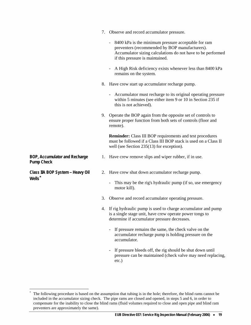
EUB Directive 037: Service Rig Inspection Manual (February 2006) • 19
7. Observe and record accumulator pressure.
- 8400 kPa is the minimum pressure acceptable for ram preventers (recommended by BOP manufacturers). Accumulator sizing calculations do not have to be performed if this pressure is maintained.
- A High Risk deficiency exists whenever less than 8400 kPa
remains on the system.
8. Have crew start up accumulator recharge pump.
- Accumulator must recharge to its original operating pressure within 5 minutes (see either item 9 or 10 in Section 235 if this is not achieved).
9. Operate the BOP again from the opposite set of controls to
ensure proper function from both sets of controls (floor and remote).
Reminder: Class III BOP requirements and test procedures must be followed if a Class III BOP stack is used on a Class II well (see Section 235(13) for exception).
BOP, Accumulator and Recharge Pump Check
1. Have crew remove slips and wiper rubber, if in use.
Class IIA BOP System – Heavy Oil Wells*
2. Have crew shut down accumulator recharge pump.
- This may be the rig's hydraulic pump (if so, use emergency motor kill).
3. Observe and record accumulator operating pressure.
4. If rig hydraulic pump is used to charge accumulator and pump is a single stage unit, have crew operate power tongs to determine if accumulator pressure decreases.
- If pressure remains the same, the check valve on the
accumulator recharge pump is holding pressure on the accumulator.
- If pressure bleeds off, the rig should be shut down until
pressure can be maintained (check valve may need replacing, etc.)
* The following procedure is based on the assumption that tubing is in the hole; therefore, the blind rams cannot be
included in the accumulator sizing check. The pipe rams are closed and opened, in steps 5 and 6, in order to compensate for the inability to close the blind rams (fluid volumes required to close and open pipe and blind ram preventers are approximately the same).

20 • EUB Directive 037: Service Rig Inspection Manual (February 2006)
5.** Have crew close pipe rams.
- Closing time for rams is 30 seconds. - Visually check condition of ram rubbers and size of rams.
6.**Have crew open pipe rams.
7. Observe and record accumulator pressure.
- 8400 kPa is the minimum pressure acceptable for ram preventers (recommended by BOP manufacturers). Accumulator sizing calculations do not have to be performed if this pressure is maintained.
- A High Risk deficiency exists whenever less than 8400 kPa
remains on the system.
8. Have crew start up accumulator recharge pump.
- Accumulator must recharge to its original operating pressure within 5 minutes (see either item 9 or 10 in Section 235 if this is not achieved).
9. Operate the BOP again from the opposite set of controls to
ensure proper function from both sets of controls (floor and remote).
Redundant Servicing Equipment 1. Whenever redundant servicing equipment is in place it must
remain functional at all times unless equipment is locked out.
- Deficiencies noted with redundant equipment are to be recorded as outlined in section 1050 on the inspection report.
2. All redundant equipment which is not in service must be
“locked out” in an appropriate fashion (e.g. unplug, remove handles, disconnect lines, use locks and the like).
- Inspectors must ensure that locked-out equipment is
completely inoperable.
3. Should the equipment be connected, it must be fully functional, operate correctly, be identified and included in all accumulator and back-up nitrogen system volume calculations. If found deficient, the items are to be corrected as with any other deficiency on the minimum equipment.
** If tubing is not in the hole, the blind rams should be used. The pipe rams should then be checked after step 8
(have rig crew run in joint of tubing before closing pipe rams).

EUB Directive 037: Service Rig Inspection Manual (February 2006) • 21
BOP, Accumulator and Recharge Pump Check
1. Have crew remove slips and wiper rubber, if in use.
Class III BOP System* 2. Have crew shut off accumulator recharge pump.
- Recharge pump must be independent from rig's hydraulic system.
3. Observe and record accumulator operating pressure.
4. Have crew close pipe rams.
- Closing time for rams is 30 seconds.
- Visually check condition of ram rubbers and size of rams.
5. Have crew open pipe rams.
6. Have crew close annular preventer (periodically use remote controls).
- Closing time for annular is 60 seconds.
- Visually check condition of annular element.
7. Observe and record accumulator pressure.
- This pressure is only an indication that the accumulator is
functioning and sizing calculations must be performed. A High Risk deficiency automatically exists whenever 8400 kPa or less remains on the system after completing a mechanical test.
Calculations are necessary because the annular preventer is
checked with pipe in the well. Calculations will indicate if the accumulator has additional usable fluid available (at a minimum pressure of 8400 kPa) to close the annular on open hole. If it doesn't, a High Risk deficiency exists.
8. Have crew start up accumulator recharge pump.
- Accumulator must recharge within 5 minutes (see either item
9 or 10 in Section 235 if this is not achieved).
9. Have crew open annular preventer.
* The following procedure is based on the assumption that tubing is in the hole; therefore, the blind rams cannot be
included in the accumulator sizing check. The pipe rams are closed and opened, in steps 4 and 5, in order to compensate for the inability to close the blind rams (fluid volumes required to close and open pipe and blind ram preventers are approximately the same).
This procedure should be followed even if tubing is not in the hole. Always ensure that a joint of tubing is run in
the well before conducting any tests on the annular and pipe rams.
22 • EUB Directive 037: Service Rig Inspection Manual (February 2006)
10. Have crew remove joint of tubing, if one has been run in order to perform tests.
11. Have crew close blind rams (only if no pipe in well).
- Periodically use remote controls.
- Visually check condition of ram rubbers.
12. Have crew open blind rams (if step 11 performed).
13. Operate the BOP again from the opposite set of controls to ensure proper function from both sets of controls (floor and remote).
230: Air Shut-offs/Diesel and Gasoline Engine Spacing Reason for Shut-offs
The purpose of air shut-offs is to prevent diesel motors from running uncontrolled in the event of a natural gas blow from the well. Since diesels are compression ignition engines, fuel shut offs will be ineffective in stopping the engine if it is drawing a combustible air gas mixture into its air intake.
Shut-off Requirements (8.100) 1. Ensure that any diesel engine within 25 m (75 feet) of a well is equipped with
- an adequate air intake shut-off valve equipped with a remote
control readily accessible from the Driller's position, or - a system for injecting an inert gas into the engine's cylinders,
equipped with a remote control, or - a suitable duct so that air for the engine is obtained at least
25 m (75 feet) from the well. Confirming Shut-off Test with Well-site Supervisors
2. Before conducting a mechanical test of the air intake shut-offs, consult with the Rig Manager and/or operator's representative as to possible problems (hole problems, inability to restart motor, etc.).
Disengaging Clutches 3. When conducting the test, ensure that the engines are idling and
the clutches are disengaged so that all engines will have to stop independently.
4. Request that the test be conducted by having the air shut-off
control activated.

EUB Directive 037: Service Rig Inspection Manual (February 2006) • 23
Individual Motor Tests 5. The motors may be tested individually by holding the air shut-offs open.
- This may alleviate possible problems of engines failing to
restart. - It is a good check to ensure that fuel shut-offs are not being
operated in place of the air shut-offs.
Shut-off Test Results 6. The motors will power down and stop rapidly. The motors must stop for the test to be successful - engine lugging is not acceptable.
Spacing for Vehicles Without Air Shut-offs
7. Vehicles (diesel or gasoline) are not allowed within 25 m (75 feet) of a well during well servicing. However, vehicles essential to operations may operate within this distance provided the well-site supervisors first assess the on-site safety.
- This policy applies in instances where a vehicle may be
unloading supplies such as tubular goods. - It does not apply where a vehicle may be performing an
operation on the well (e.g. pressure truck).
Rig Pump (Engine) Spacing and Requirements (8.148)
8. A rig pump (diesel engine) must be located not closer than 7 m (25 feet) to a rig tank (see Schedule 11) and should be spotted according to the direction of the prevailing wind. The engine must also be equipped with
- an adequate air intake shut-off valve, or - a system for injecting an inert gas into the engine's cylinders.
Bailing Tank (Heavy Oil Only) Spacing Exception
9. Bailing operations may be conducted to an open tank. The tank may be adjacent to the well but must be removed as soon as bailing operations are complete.
Tank Truck Spacing and Requirements
10. Diesel tank trucks transferring fluids either to or from the rig tank must also adhere to the same requirements outlined in item 8 above.
Spacing (Engines) near Rig Tank 11. Diesel or gasoline engines not associated with the transfer of
rig tank fluids must be located not closer than 25 m (75 feet) to the rig tank, whenever the wellbore is open to the tank.
Handling Spacing Problems 12. Spacing problems related to items 7, 9, and 10 above do not
constitute an unsatisfactory rig inspection. A comment that a problem existed and that it was corrected should only be made on the inspection report.

24 • EUB Directive 037: Service Rig Inspection Manual (February 2006)
Engine Exhausts (8.090)
13. An exhaust pipe from an internal combustion engine located within 25 m (75 feet) of any well must
- be constructed to prevent any emergence of flame along its
length or at its end, - end not closer than 6 m (20 feet) to the vertical centreline of
the well, and must be directed away from the well.
Spacing exemptions may be granted by Area office staff provided the operator discusses its spacing needs with the appropriate Area Office before commencing operations.
235: Accumulator Sizing and Operating Policies Accumulator Requirements (8.145) 1. The accumulator must have sufficient usable fluid available, at
a minimum pressure of 8400 kPa, to close all BOPs.
When to Complete Sizing Calculations 2. Accumulator sizing calculations must be completed during the initial inspection of a rig when an annular preventer is in service.
The above policy applies even if an actual mechanical test of the BOP equipment cannot be completed according to the procedures outlined in Section 225. - See item 5 of this section or Appendix 1025 for sizing
methods.
Recording Accumulator Specifications 3. Determine and record the accumulator system's make, number of bottles, capacity, design pressure, and operating pressure (upstream of any regulators).
- Accumulator Specifications should be available at each rig
and this includes Specifications for “homemade” models. Operators and/or contractors should be encouraged to complete a BOP Data sheet similar to Drawing No. 1 on page 5.
- Operators of “homemade” models must affix a tag to their
units indicating the manufacturer, working pressure, and capacity.
Reminder: Subtract one US gal from nominal size of each
accumulator bottle to account for displacement of bladder or float assembly (see Table No. 1 on page 6 for accumulator specifications).
Reminder: Accumulators are sized in US gals. Use the following for conversions: US gals x 3.7854 = litres

EUB Directive 037: Service Rig Inspection Manual (February 2006) • 25
Determining Precharge Pressure 4. If well conditions allow, and it is safe to do so, have the Manager check the precharge pressure on each accumulator bottle. Record pressures.
- A gauge and the necessary fittings must be readily available
to determine the pressures. - Another method of determining precharge is available if the
well-site supervisors are concerned about the “down time” necessary for determining individual pressures or if a proper gauge and fittings are not available. However, this method will only indicate the lowest precharge in service and it also has a number of other shortcomings which could create problems for less experienced inspectors. It should only be used as a last resort for calculation purposes.
METHOD: A. Shut down recharge pump. B. Depressure accumulator. C. Restart pump. D. Observe first pressure* obtained on accumulator
gauge—this is the lowest precharge pressure available.
* It should only take a few seconds to obtain this pressure. Sizing Methods 5. Two methods for calculating accumulator sizes are provided in
the manual. - Method 1, shown in item 6, is the preferable method to use
during inspections because of its simplicity. - The “Alternate Method”, shown in Appendix 1025, requires
more detailed calculations. - Drawing No. 2 (page 7), in Method 1, is derived from the
equations shown in Appendix 1025. Sizing Calculations (Method 1) 6. Complete usable fluid volume calculations, using Drawing No.
2, and the following procedures: - Using pressures obtained in items 3 and 4 and Drawing No.
2, follow accumulator operating pressure slope on drawing (go beyond apex for precharge less than 8400 kPa) until it intersects with the appropriate vertical precharge pressure line.
- Read drawing's left vertical axis to determine the percentage
of total accumulator capacity which is considered usable at the current operating pressures.
- Calculate usable fluid using percentage determined. Usable Fluid = Per cent x Acc Cap

26 • EUB Directive 037: Service Rig Inspection Manual (February 2006)
- Determine and total the required closing volume for each
BOP component (see Appendix 1055) and compare it with volume of usable fluid calculated earlier.
- The accumulator is adequately sized if the usable fluid
volume is equal to or greater than the fluid volume required to close all BOP components.
7. Remember to include “redundant equipment” in usable fluid
volume requirement calculations. (See section 225(3)).
EXAMPLE SIZING CALCULATION Rig has 76-litre accumulator, operating at 14-MPa and 7-MPa precharge pressure Per cent usable fluid available at current operating pressures - 33.5% CALCULATED USABLE FLUID 33.5 x 76 litres = 25.5 litres 100 Rig Has 21-MPa BOP Stack Consisting of: 152.4-mm Shaffer Spherical BOP - closing vol req'd 17.3 litres 152.4-mm Shaffer LWP Tubing Rams - closing vol req'd 2.1 litres 152.4-mm Shaffer LWP Blind Rams - closing vol req'd 2.1 litres TOTAL CLOSING VOLUME REQUIRED 21.5 litres • The accumulator is adequately sized since the usable fluid volume available exceeds the closing volume required.

EUB Directive 037: Service Rig Inspection Manual (February 2006) • 27

28 • EUB Directive 037: Service Rig Inspection Manual (February 2006)
TABLE 1 ACCUMULATOR SPECIFICATIONS VOLUME PER NO. OF ACCUMULATOR BOTTLES CYLINDRICAL SPHERICAL 5* gal (4)** 10 gal (9) 11 gal (10) 15 gal (14) 80 gal (79) Bottles Litres Bottles Litres Bottles Litres Bottles Litres Bottles Litres 1 15.1 1 34.1 1 37.9 1 53.0 1 299.0 2 30.2 2 68.2 2 75.8 2 106.0 2 598.1 3 45.3 3 102.3 3 113.7 3 159.0 3 897.1 4 60.4 4 136.4 4 151.6 4 212.0 4 1 196.2 5 170.5 5 189.5 5 265.0 6 204.6 6 227.4 6 318.0 7 238.7 7 265.3 7 371.0 8 272.8 8 303.2 8 424.0 9 306.9 9 341.1 9 477.0 10 341.0 10 379.0 10 530.0 11 583.0 __________________ * nominal volume ** actual volume COMMON ACCUMULATOR SUPPLIERS AND SIZES Koomey: Bottle availability 5 gal workover (4) Greer (manufacturer)
10 gal (9) 11 gal (10)
15 gal (14) 80 gal Spherical (79)
e.g. Model #TA112-15BF3 T series, 112 gal - 15 gal, Buoyant Float, 3000 psi
Wagner: Same bottles as Koomey
e.g. Model #10-060-3BB 10 hp - 60 gal - 3000 psi, Buoyant Bladder Valvcon: Bottle availability 15 gal standard (14) Valvcon (manufacturer)
80 gal spherical (79) 5 gal & 10 gal non-standard
e.g. Model #90-E10GD-1B60 90 gal electric, 10 hp pump style, 1 pump, ratio 60:1
NL Shaffer: Bottle availability 11 gal (10) Greer (manufacturer)
Cameron: Bottle availability 20 gal standard (19) Payne (manufacturer)
27, 35, 50, 80 gal (available)

EUB Directive 037: Service Rig Inspection Manual (February 2006) • 29
30 • EUB Directive 037: Service Rig Inspection Manual (February 2006)
Sizing Rechecks 7. Once an initial accumulator sizing check has been completed for Class I and Class III BOP systems (where annular is in service) it is not necessary to complete sizing calculations during each subsequent rig inspection—provided the accumulator's operating parameters and BOP stack remain the same.
Precharge Requirements (8.145) 8. Full precharge is not required for an accumulator to meet the
requirements for Class I, II, IIA or III BOP systems. - For Classes I, II & IIA, where only ram preventers are
installed, the accumulator is considered adequate, regardless of its precharge pressure, if after closing and opening the preventer the pressure remaining on the system is at least 8400 kPa.
- For Classes I and III, where an annular preventer is installed,
the accumulator is considered adequate, regardless of its precharge pressure, if sufficient usable fluid is available to close all the preventers (annular on open hole) and retain a minimum accumulator pressure of 8400 kPa. Sizing calculations must be performed.
Manufacturers' recommended precharge:
5250 kPa (± 10%) for 10 500 kPa system 7000 kPa (± 10%) for 14 000 kPa system 7000 kPa (± 10%) for 21 000 kPa system
Recharge Pump Problems 9. If the accumulator recharge pump fails to recharge the
accumulator to its original operating pressure when an annular preventer is in service, a complete function test of the BOP components and sizing calculations must be completed to reconfirm that adequate usable fluid is available while operating at the lower accumulator pressure.
10. If the accumulator pump fails to recharge the accumulator to its
original operating pressure when only ram preventers are in service, a complete function test of the BOP components must be completed to reconfirm that 8400 kPa will remain on the system while operating at the lower accumulator pressure.
Low-pressure Alarm System 11. Board inspectors should recommend that a low pressure alarm
system be installed in instances where decreasing accumulator pressures have gone undetected by a particular operator and/or contractor.
- This option should be considered the second time a problem
is noted.

EUB Directive 037: Service Rig Inspection Manual (February 2006) • 31
- Electronic alarms, using either a warning light or horn, can be installed without difficulty.
- The alarm setting should be integrated with the
accumulator's operating pressure. Mechanical Ram Conversions 12. Manual ram preventers, converted to hydraulic motor drives,
require a minimum of 7.6 litres (2 US gal) usable fluid to close each set of 152.4 mm rams. The inspector must ensure that the accumulator is sized accordingly.
Accumulator Requirements when Annular Installed for Tripping Small Diameter Tubing and Electric Cables
13. Even though the annular preventer would normally be the only BOP component activated during the tripping of small diameter tubing and electrical cables, the rig's accumulator system must still have sufficient usable fluid available, at a minimum pressure of 8400 kPa, to close all connected preventers.
- Wells requiring a Class I BOP stack will only require an
annular preventer. - When a Class II well requires an annular preventer, it is
acceptable for contractors to temporarily disconnect the pipe rams (if installed) from the rig's accumulator system and utilize the rams' controls to function the annular.
- No variations are permitted for wells requiring a Class III
BOP stack. - A remote accumulator system will only be necessary when a
Class III BOP stack is required. Accumulator Reservoir Venting 14. It is recommended that an accumulator reservoir which is
enclosed in a building must have its vent installed in such a manner that venting takes place outside the building. (Do not mark this item unsatisfactory on the rig inspection form.)
240: Back-up Nitrogen Supply Nitrogen Requirements (8.145)
1. Sufficient usable* nitrogen must be available, at a minimum pressure of 8400 kPa, to fully close all BOPs (including “redundant equipment” see section 225).
The nitrogen supply must be tied into the system at a point
which will allow the N2 to function the BOPs and not be lost by venting or displacement into the accumulator bottles. (see CAODC technical bulletin T92-2) and Appendix 1030, to determine if the rig system is properly configured.
* Usable is defined as the equivalent litres of stored nitrogen at a minimum pressure of 8400 kPa.

32 • EUB Directive 037: Service Rig Inspection Manual (February 2006)
Recording Nitrogen Particulars 2. Determine and record the number of nitrogen bottles in service. Determine if the bottles are in cross flow (on a common line tied into the system). If they can be equalized when both bottles are open, then the pressure must be averaged and the usable fluid volume calculated using an average of all bottles. If the bottles are independent of each other by means of a check valve installed on each bottle (if open pressure on both bottles cannot be equalized) then the pressure in each bottle can be used individually to calculate the usable fluid equivalent. To calculate, see examples Section 240 or Appendix 1030.
Nitrogen Calculation (Method 1) 3. After completing usable volume calculations, use the following
procedures: Plot the pressure from the bottles in service either combined
average or independently as determined from item 2 above, on a vertical axis and draw a horizontal line across the appropriate bottle size, then plot perpendicular line down to horizontal axis. Read equivalent litres of usable nitrogen. Total the fluid volume determined.
Multiply the usable nitrogen volume by the number of bottles in
service to determine the total usable volume available. Determine and total the fluid volume required to close all
preventers (see Appendix 1055) and compare this volume with the volume of usable nitrogen calculated earlier.
The back-up nitrogen supply is adequate if its calculated
volume is equal to or greater than the fluid volume required to activate the BOP components.
Manual Ram Conversions 5. Manual ram preventers converted to hydraulic motor drives also
require a back up nitrogen supply (field tests indicate nitrogen will operate hydraulic motors).
Hydraulic motor drives require a minimum of 7.6 litres
(2 US gal) usable fluid to close each set of 152.4 mm rams. Therefore, an equivalent volume of nitrogen must be available.

EUB Directive 037: Service Rig Inspection Manual (February 2006) • 33
EXAMPLE NITROGEN CALCULATION – For “Averaged” bottles system. Rig has two 42-litre nitrogen bottles available: Bottle 1 @ 17.5 MPa - Bottle 2 @ 14.0 MPa Average bottle pressure 17.5 MPa + 14.0 MPa = 15.75 MPa * - use average or 2 bottles independent pressures
see Section 240(2). Usable fluid (per bottle) from drawing 37.0 litres TOTAL USABLE FLUID 2 X 37.0 LITRES 74.0 litres Rig has 21-MPa BOP stack consisting of: 152.4-mm Shaffer Spherical BOP - closing vol req'd 17.3 litres 152.4-mm Shaffer LWP Pipe Rams - closing vol req'd 2.1 litres 152.4-mm Shaffer LWP Blind Rams - closing vol req'd 2.1 litres TOTAL CLOSING VOLUME REQUIRED 21.5 litres • Nitrogen volume is acceptable since 74.0 litres are available when only 21.5 litres are required to close
BOPs.

34 • EUB Directive 037: Service Rig Inspection Manual (February 2006)
Example Nitrogen calculation for “individual bottle” pressure - see drawing No. 2. Rig has two 42-litre nitrogen bottles available: Tied in but independent isolation by check valve. Bottle 1 @ 16.5 mpa useable fluid from drawing 41.0 litres Bottle 2 @ 14.7 mpa useable fluid from drawing 31.5 litres TOTAL USEABLE FLUID 72.5 litres Rig has 21 mpa BOP stack - components to be considered:* 254 mm Hydril GK-900 annual BOP - closing vol. req'd 28.1 litres 254 mm Hydril MPL Pipe ram - closing vol. req'd 12.5 litres 101.6 mm Cameron HCR Hydraulic valve - opening vol. req'd 2.3 litres TOTAL CLOSING/OPENING VOLUME REQUIRED 42.9 litres Nitrogen volume is acceptable since 72.5 litres are available when only 42.9 litres are required to activate BOP components. * If two sets of runs are required or redundant equipment is in service (not locked out) the closing volume for each component must be included in the calculations.
Drawing No. 1
N2 Bottle Configuration
Common Line “crossflow” equalized system
- Use average pressure from all bottles.
Drawing No. 2
N2 Bottle Configuration
Independent bottles isolated by check valve
- Use individual pressure from each bottle.

EUB Directive 037: Service Rig Inspection Manual (February 2006) • 35

36 • EUB Directive 037: Service Rig Inspection Manual (February 2006)

EUB Directive 037: Service Rig Inspection Manual (February 2006) • 37
245: Winterizing BOP Equipment BOP Stack and Accumulator Heating (8.148)
1. The policies outlined in the following tables must be applied during cold weather operations.
The ambient temperatures in the tables are a guide for initiating
a heating requirement check. The BOP body temperature is the determining factor for enforcement action.
ANNULAR ELEMENT HEATING REQUIREMENTS AMBIENT TEMP (°C)
BOP CONDITION
ELEMENT REQUIRED
SUPPLEMENTARY HEAT
ABOVE -10°C
ICE FREE
ANY ELEMENT
NONE
BELOW -10°C
ICE FREE
ANY ELEMENT
SUFFICIENT HEAT REQUIRED TO MAINTAIN BOP BODY TEMP ABOVE -10°C
RAM ELEMENT HEATING REQUIREMENTS AMBIENT TEMP (°C)
BOP CONDITION
ELEMENT REQUIRED
SUPPLEMENTARY HEAT
ABOVE -10°C
ICE FREE
ANY ELEMENT
NONE
BELOW -10°C TO -25°C
ICE FREE
IDENTIFIABLE LOW TEMP ELEMENT
* NONE
BELOW -25°C
ICE FREE
IDENTIFIABLE LOW TEMP ELEMENT
* SUFFICIENT HEAT
REQUIRED TO MAINTAIN BOP BODY TEMP ABOVE -25°C
* A standard element may be used at any ambient temp provided sufficient heat is applied to maintain the BOP
body temp above -10°C.
ACCUMULATOR REQUIREMENTS DURING COLD WEATHER OPERATIONS THE ACCUMULATOR MAY NOT REQUIRE HEAT; HOWEVER, IT MUST REMAIN FUNCTIONAL AT ANY AMBIENT TEMPERATURE

38 • EUB Directive 037: Service Rig Inspection Manual (February 2006)
Determining BOP Body Temperature (Surface Thermometer)
2. A surface thermometer, which may be affixed to the BOP stack, should be used for determining BOP body temperatures.
Winterizing Bleed off 3. The bleed-off line, kill line, and manifold require winterizing - These components may be drained, filled with a freezing
depressant fluid (e.g. glycol), or be blown out with air. - Ask the rig supervisors what method was used to winterize
these systems. Use of Diesel Fuel 4. The use of diesel fuel in the bleed-off and kill system should be
discouraged because diesel - does not serve as an absorbent as does glycol. - simply displaces water from the system (total displacement
may not always be successful). - is flammable (flash point approximately 48-59 degrees C). - may not be compatible with valve gaskets and/or packing. - when cooled, may become cloudy, “gel”, as fine wax
crystals precipitate. Also, dissolved water may form very fine ice crystals (summer fuel -9/-15, winter fuel -41/-42 degrees C). Therefore, wax (and ice) could hamper operation of the system.
Use of Glycol 5. Operators and contractors should be reminded to follow the
manufacturer's mixing requirements when using glycol to winterize the bleed-off and kill system. An improper mixture, even from the standpoint of adding too much glycol, can create a problem during cold temperatures.
250: Spacing Regulations Well to Flame-type Equipment (8.090)
1. No flame-type equipment shall be placed or operated within 25 m (75 feet) of a well, oil storage tank, or other source of ignitable vapour (except water injection wells).
- Flame-type equipment is any fired heating equipment using
an open flame. It includes a space heater, torch, heated process vessel, boiler, electric arc or open flame welder.
- Grinders, appliances must not be used within 25 m without
shutting in the wellbore first. Welding 2. Special circumstances may necessitate welding within 25 m (75
feet) of a well. Strict safety procedures must be adhered to, which include closing the applicable BOPs.

EUB Directive 037: Service Rig Inspection Manual (February 2006) • 39
Well to End of Flare Line (8.080)
3. The flare pit and the termination of all flare lines shall be at least 50 m (150 feet) from a well (see Section 320(2) for method of handling deficiency).
4. The flare pit shall - be excavated to a depth of not less than 2 m. - have side and back walls rising not less than 2 m above
ground level. - be constructed to resist the erosion of a high pressure flow of
gas or liquid. - be shaped to contain all liquids. Wellsite Waste Management (8.090)
5. Waste materials must be disposed of in accordance with Appendix 1100.
Well to Crude Oil Storage Tank (8.090)
6. No oil storage tank shall be located within 50 m (150 feet) of a well, unless approved by an EUB representative (see Section 320(2) for method of handling deficiency).
Spacing exemptions may be granted by Area Office staff
provided the operator discusses its spacing needs with the appropriate Area Office before commencing operations.
255: Handling Sour Effluent Operations Not Permitted (7.060)
1. Circulating, swabbing, or flowing sour effluent (regardless of H2S concentration) to an open rig tank or flare pit is discouraged. If a potential hazard exists for on site personnel, or if an odour problem could be created for local residents, then proper containment equipment must be installed before operations begin.
- Operators are encouraged to consult with area office staff if
they have concerns regarding equipment needs for specific wells or areas.
Proper Handling Methods 2. Sour effluent must be handled by one of the following methods: - By installing proper separation equipment, whereby the sour
liquids are directed to a storage tank equipped with a vapour gathering system (VGS). Gas discharged from the separator and VGS must not be vented to atmosphere.
- Producing the effluent to an existing separation facility
which is properly equipped to handle sour products (flow line already in place).

40 • EUB Directive 037: Service Rig Inspection Manual (February 2006)
260: BOP Pressure Test Inspector’s Involvement 1. Although field staff are not usually required to witness the
pressure testing of BOP components, they should ensure that a proper pressure test was conducted by the operator.
- The on-site supervisors should be questioned as to the exact
method (and tools) used to conduct the pressure test. - If it is determined that an improper test was conducted (e.g.
failure to test BOP to wellhead connection) operations must be suspended until a proper test is carried out. In some cases this may mean setting a packer in the production casing.
Test Requirements (8.147)
2. With the exception of wells in Class I, each BOP, the connection between the stack and the wellhead, the safety (stabbing) valve, the bleed-off manifold, and the bleed-off and kill lines must be pressure tested.
- A low-pressure test of 1400 kPa must be conducted on each
ram preventer. This test is to be conducted first. - A high pressure test must be conducted on each ram
preventer, the full opening safety valve and the connection between the stack and the wellhead. The pressure required shall be the wellhead pressure rating or the formation pressure whichever is the lesser.
- The annular preventer shall be pressure tested to 7000 kPa or
the formation pressure whichever is the lesser. - The BOP to wellhead connection does not require testing
when an electrical submersible pump is in the well (see item 14).
3. All valves in the bleed-off manifold must be tested individually
(at the same pressure as the manifold) to confirm their isolation. - Adjustable chokes do not require testing. 4. For a satisfactory pressure test, all components must maintain a
stabilized pressure of at least 90 per cent of the test pressure over a 10-minute interval or over a 2-minute interval for each well in a Heavy Oil/Oil Sands *secondary recovery well servicing program subsequent to weekly 10-minute pressure tests: (see item 13).
* A Primary Recovery Heavy Oil/Oil Sands Well, for the purpose of this manual, is defined as a well having a
sandface reservoir pressure equal to or less than the hydrostatic pressure that would be exerted at the sandface if the well were filled with formation fluids. A Secondary Recovery Heavy Oil/Oil Sands Well (EOR), for the purpose of this manual, is defined as a well having a sandface reservoir pressure greater than that described above, by virtue of injection into the formation of fluids(s) other than water at ambient temperatures. This includes all
EUB Directive 037: Service Rig Inspection Manual (February 2006) • 41
Handling Test Deficiencies 5. See Section 320(3) if deficiencies occur during the witnessing of a pressure test.
Testing Using Test Stump or Test Flange
6. A test stump or test flange may be used for pressure testing all BOP components
7. Stump or flange testing is recommended over wellhead testing
as it allows for the detection of problems before the wellhead is removed.
8. Although there are many ways BOPs may be stump or flange
tested, the following points may serve as a guide to the procedures commonly used by industry.
- The test stump or flange must be equipped in such a fashion
that test fluid can be introduced below the lowest preventer in order to test each BOP component.
- A pup joint is generally run into the BOPs and secured to the
test stump or flange to permit the testing of the pipe rams and the annular preventer (a tubing collar is usually welded to the stump or flange).
- The stabbing valve may be mounted on top of the pup joint
to allow for the testing of the stabbing valve (pup joint must be perforated to permit the simultaneous testing of the valve with either the pipe rams or the annular preventer).
- In some cases, contractors will only use the stump or flange
to pressure test the blind rams. The remaining preventers will be tested on the wellhead against the dognut (pup joint screwed into dognut to carry out tests).
Testing BOP to Wellhead Connection (8.147)
9. The BOP to wellhead connection also requires pressure testing when stump or flange testing has been performed.
10. If no tubing is in the well, and a formation is open to the
wellbore - a packer may have to be run in the casing to permit pressure
testing. - the dognut may be run on the bottom of a joint of tubing and
landed in the tubing spool (set screws secured). Testing can then take place by pressuring up below a closed preventer.
wells that are a part of an active EOR project approved by the EUB and any offset wells within 1 km of an EOR well within the project.

42 • EUB Directive 037: Service Rig Inspection Manual (February 2006)
11. If tubing is in the well, and a formation is open to the wellbore - a pup joint can be screwed into the dognut and testing take
place by pressuring up below a closed preventer (the pup joint will have to be blanked on bottom and perforated above the blank if the stabbing valve is to be pressure tested along with BOPs).
Testing with Slip-type Wellheads 12. In the case of slip-type wellheads a proper tubing hanger
(dognut) can be landed in the tubing spool after the slips, seals, and tubing head adapter have been removed. A pressure test can be carried out by following step 11 above.
Dognut Fails Pressure Test 13. If the dognut fails to hold pressure, it is acceptable to maintain
the required pressure on the wellhead while the pipe rams (or annular), as well as the wellhead connection, are monitored for leaks. If it can be positively determined that no leaks exist, the test may be considered satisfactory.
Wellhead Connection Test/Electrical Submersible Pump
14. A pressure test of the wellhead connection cannot be conducted when a well contains an electric submersible pump (cable protrudes from tubing hanger). This is acceptable.
265: Well-Site Conditions Condensate Requirements (8.110)
These rules must be followed when condensate or other low flashpoint hydrocarbons are being used at the well (see Section 320(2) for method of handling deficiency).
1. No open tanks may be used for storing or gauging or measuring
the pumping rate. 2. A minimum distance of 50 m must be maintained between the
wellhead and storage tank. 3. Positive shut-off valves must be installed between the pump and
wellhead. 4. A check valve must be installed between the pump and the well
to prevent backflow from the well. 5. All surface lines downstream from the pump must be pressure
tested to 10 000 kPa (1500 psig) above anticipated maximum pressure.
6. No significant wastage may occur. 7. The operator must obtain approval from the Drilling and
Production Department in Calgary to use condensate for the purpose of hydraulic fracturing.

EUB Directive 037: Service Rig Inspection Manual (February 2006) • 43
DST Equipment (8.143)
8. When a drill-stem test is either in progress or being rigged up, ensure that there is a means of circulating fluid through the drill string (reverse circulating sub).
9. A remote-controlled master valve must be installed on the
testing head. - If a DST unit is on the lease, but not rigged up, check if this
equipment is available. - Notify the on-site supervisor of any problems noted. Engine Exhausts (8.090)
10. An exhaust pipe from an internal combustion engine located within 25 m (75 feet) of a well must
- be constructed to prevent any emergence of flame along its
length or at its end. - end not closer than 6 m (20 feet) to the vertical centreline of
the well, and must be directed away from the well. For directional wells where the casing and BOP's are set on an
angle, the measurement is from the top of the flow tee position. Containment of Drilling Fluids (8.150)
11. All drilling fluids, whether they be contained in a sump, lined pits, trenches or buried tanks, must be properly contained.
- Disposal of waste lubricants, oil, glycol, etc. into a sump or
other site is NOT permitted. These materials must be disposed of in accordance with Appendix 1100.
Sump Construction 12. CPA issued “Environmental Operating Guidelines” for the
petroleum industry in September, 1988. Along with many other recommendations, this document suggested that the following guidelines be recognized during sump construction and operation.
- The sump should be excavated from an impervious,
undisturbed subsoil and should be shaped to allow maximum reuse of clear water for mud make-up.
- The sump must be adequately sized to allow for the
anticipated volume of drilling fluid. Although certain drilling variables may be expected, 1 m of freeboard should be considered.
- The sump should be located on the high side of the lease and
as far away as possible from any bodies of water. - Rain and snow run-off diversion ditches may be necessary if
the site topography poses a problem or if the area is considered sensitive.

44 • EUB Directive 037: Service Rig Inspection Manual (February 2006)
- Sumps constructed in permeable soil must be sealed with clay or a synthetic liner, or any other approved technique which will prevent fluid leakage.
- Well workover and completion wastes must be isolated from
the main sump upon completion of well drilling operations. - See ERCB Guide G-50 for sump guidelines. Handling Containment and Spillage Problems
13. Initiate appropriate corrective action if it appears that sump fluids, workover or wellbore fluids, mud additives, chemicals, fuel, or any other materials have been spilled on or off lease.
- Consult with Area Supervisor if assistance in determining the best clean-up method is required.
- See Section 320(2) for method of handling deficiency. 270: Operator and Contractor Inspections Daily Inspections 1. The operator's (if available) and contractor's on-site supervisor
must conduct a Daily “walk around” Inspection of the rig in an effort to spot deficient well control and safety related items.
2. Ideally, this inspection should be carried out in conjunction
with the daily mechanical testing of the BOP equipment. Recording Daily Inspections 3. The on-site supervisors are to record Daily Inspections on the
tour reports. - A comment such as “Daily Inspection Completed” would be
appropriate. - It is not necessary for the supervisors to sign or initial the
above statement. The daily signing of the tour reports is all the verification necessary.
4. The inspector should check the tour reports to ensure that these
inspections are being conducted. - If deficiency noted, mark inspection item 108 with an “X” in
the “NO” box, and make an appropriate comment on the inspection report.
Do not mark rig or non-rig related summary boxes 50 and
100 unsatisfactory if this is the only deficiency noted during the inspection.
Detailed Inspections 5. The operator's (if available) and contractor's on-site supervisor
must individually or jointly conduct a Detailed Inspection of the rig.

EUB Directive 037: Service Rig Inspection Manual (February 2006) • 45
6. Ideally this inspection should be completed during the initial rig up and weekly thereafter. A weekly crew BOP drill would be an appropriate time to conduct the weekly Detailed Inspection.
7. For critical wells, inspections must be completed within the 24-
hour period prior to initiating operations in the H2S or abnormally pressured formation.
8. A comprehensive check sheet, including EUB inspection items
listed as High Risk and Low Risk in Appendix 1045, should be used for this inspection.
Recording Detailed Inspections 9. The on-site supervisors are to record Detailed Inspections on
the tour reports. - A comment such as “Detailed Inspection Completed” would
be appropriate. - It is not necessary for the supervisors to sign or initial the
above statements. The daily signing of the tour reports is all the verification necessary.
10. The inspector should check the tour reports to ensure that these
inspections are being conducted. - If deficiency noted, mark inspection item 108 with an “X” in
the “NO” box, and make an appropriate comment on the inspection report.
Do not mark rig related or non-rig related inspection
summary boxes 50 and 100 unsatisfactory if this is the only deficiency noted.
Reviewing Detailed Inspection Form 11. It may be necessary to review the Detailed Inspection Form
used by the operator and contractor if a number of deficiencies surface during an EUB inspection. This may indicate an incomplete inspection is being conducted by the operator and/or contractor.
275: Well-Site Records and Signs Warning Signs in H2S Area (6.020)
1. If there is reasonable expectation of encountering H2S gas during servicing operations, the operator must post a poisonous gas warning sign on or near the rig.
- If a warning sign is posted at a well site where no H2S is anticipated the inspector should require that the sign be removed. The indiscriminate posting of signs may tend to decrease the importance of a sign at a well site where H2S may truly be encountered.

46 • EUB Directive 037: Service Rig Inspection Manual (February 2006)
Recording Pressure Test (8.147)
2. Check the tour sheets to determine if the tests were conducted.
- Ensure that the following were noted on the tour sheets: - BOP tested (all components).
- Test duration. - Low- and high-pressure test details
Recording Daily Mechanical Test (8.147)
3. Check the tour sheets to determine if the BOPs have been mechanically tested daily.
- Ensure actual components checked by crews are recorded (e.g. “Rig Service and BOP Check” is not adequate).
- The blind rams do not have to be tested if a special trip from
the hole is required. Shop Servicing Records for BOPs and Flexible Bleed-off and Kill-line Hoses (8.147)
4. All BOPs and bleed-off and kill-line hoses require shop servicing and pressure testing every 3 years.
5. The acceptable servicing and testing requirements are specified in Informational Letter IL 88-11 entitled Shop Servicing and Testing of Blowout Preventers and Flexible Bleed-off and Kill-line Hoses. This document is available through our Drilling and Production Department in Calgary.
6. During service rig inspections, the contractor should be
requested to supply evidence that proper servicing and testing have been completed.
Recording Weekly Diesel Engine Tests (8.100)
7. Check the tour sheets to ensure that the rig has tested its air shut-offs
- before conducting any servicing operations on a completed
well. - at least once in every 7-day period during the servicing of
the well. Recording Operator and Contractor Inspections
8. Check the tour sheets to ensure that the Rig Manager and operator's representative are conducting “Daily” and “Detailed” inspections (see Section 270).

EUB Directive 037: Service Rig Inspection Manual (February 2006) • 47
280: Smoking
Smoking Regulations (8.120) 1. No person shall smoke within 25 m of a well, separator, oil storage tank, or other unprotected source of ignitable vapour, or on a rig or derrick at a well site.
Handling Smoking Violations 2. If someone is found smoking in contravention of the
regulations, follow one of three options:
- Verbal warning
Explain the reason for the regulation and the possibility of prosecution.
- Inform Contractor and Operator
By telephone or letter, notify senior personnel of the servicing contractor and the operator about the infraction. Request that they investigate the problem and report the actions taken. Alternatively, hold a meeting to discuss the problem.
- Prosecute
If it is evident that the first two options are not effective, prosecution may be used as a last resort. The regulations allow the Board to prosecute the contractor, who is the employer of the person, and the licensee of the well, whether or not they had any knowledge of the smoking, or whether or not they had taken any steps to prevent smoking from occurring. It is not the Board's intention to prosecute the employee only. When a recommendation is being made to prosecute, include evidence of the attempt to utilize the first two options.
If prosecution is believed to be necessary, gather the following
evidence:
- date and time of the occurrence,
- full name (no initials), address, driver's licence number, birth date, any other details of the person in violation, and all witnesses' names,
- measure distance from the well to the location of the offence (have person witness measurement).
Even if prosecution is not necessary, gathering evidence may be
a good deterrent to convince the person of the seriousness of the violation.
Penalties for Smoking 3. The Oil and Gas Conservation Act provides for the following
penalties:
(a) if a corporation, a fine of not less than $300.00 nor more than $1000.00, and
(b) if a person, a fine of not less than $50.00 nor more than $500.00, and in default of payment, a term of imprisonment not exceeding 6 months.

48 • EUB Directive 037: Service Rig Inspection Manual (February 2006)
300: Completing the Inspection Report 305: General Information Report Completion An inspection report should be completed even if only one rig or
non-rig related item is examined. See Appendix 1005 for examples of completed reports.
Contractor Name Enter the name in sufficient detail to enable the coding staff in
Calgary to positively identify the contractor. Number Leave blank. Rig Number Enter the unique 4-character number identifying the rig. Fill in all
spaces, using zeros when necessary. Examples: For rig #1, enter 0001.
For rig 7E, enter 0007, and print “RIG 7E” above the line. For rig #C-2, enter 0002, and print “Rig C-2” above the line. For
rigs Mr. Jim, Mr. Nick, Mr. Digger, enter OJIM, NICK, DIGG.
Rig Type S-service rig. Well I.D. Enter the 13-character “unique identifier” taken directly from the
well licence (if available). Note: Fill in all spaces. Check the UID in the tour reports and on
the well name sign or plate. The UID obtained on the lease must be checked at the office through the Basic Well Data System. For directionally drilled wells, be sure to enter the unique ID location for the licence and not the surface location
- The LE section will change when a specific LSD has more than
one well. Ensure the correct LE is used and check it back at the field office through the BWD System.
- The final space refers to the event sequence and depends upon
the number of zones completed, re entry, deepening of the well, etc. It must be checked back in the office through the BWD system.
Operator Name Enter the name of the company shown as “licensee” on the well
licence (may be unit operator in some cases). Operator Number Leave blank. Inspection Type Partial - Circle when any inspection results are noted, except
P when a pressure test of the blowout preventers has been witnessed.

EUB Directive 037: Service Rig Inspection Manual (February 2006) • 49
Complete - Circle when a pressure test of the blowout preventers C has been witnessed, in whole or in part.
Area Office Enter the 2-digit code indicating the Board office that conducted the
inspection. 03 - Wainwright
04 - Calgary (S) 05 - Bonnyville 06 - Drayton Valley 07 - Edmonton 08 - Medicine Hat 09 - Red Deer 10 - Grande Prairie
Inspection Date Enter the date the inspection was completed. Well Class Enter the class of well being inspected. - Be sure to record the required servicing class and not the class
of BOP stack in service. Rig Manager Enter the name of the Rig Manager present at the rig during
the inspection. - if the Rig Manager present is relieving the regular Rig Manager,
enter the regular's name also. Rig Status Enter the status of the rig during the inspection. - Check the tour sheet since the status may not be obvious. If in
doubt, ask the Rig Manager or Driller. 310: Mechanical Tests Description and Location of Equipment and Controls
Record
1. Accumulator make, number of bottles, capacity, design pressure, precharge, and pressures before and after mechanical check.
2. The time required to recharge the accumulator system. 3. The number of nitrogen bottles, their capacity, and their
combined average pressure (record each bottle's capacity and pressure if bottles not the same size or bottles are isolated independently).
4. Number and type of BOP controls, and the number, type, and
distance of remote controls. 5. Whether locking handles for ram type preventers are available,
or whether the rams have automatic locking devices.

50 • EUB Directive 037: Service Rig Inspection Manual (February 2006)
315: Inspection Results General - For inspection procedures and test requirements, see Section
200 - Conducting the Inspection. The corresponding section number is shown beside each item below.
- Satisfactory inspection results in this section are marked
with an “X” in the appropriate box. - If any one aspect of a test or condition is unsatisfactory, code
the “NO” box either (1) Low Risk, (2) High Risk, or (3) Both.
- Mark inspection results based on the initial check, not after
repair or adjustment. - If an unsatisfactory item is corrected during the inspection,
make note of it in the Remedial Action Section. - If an item is not checked, leave both boxes blank. - The following numbers refer to the items on the rig
inspection form. YES/NO 50 - Mark an “X” in the “YES” box only if all of the following
inspection results in boxes 52-91 are either marked satisfactory or left blank. If any deficiencies are noted in boxes 52-91, mark an “X” in the “NO” box.
- If pressure test being conducted on BOP stack, do not mark
rig inspection or any rig related items unsatisfactory. - Non-rig related items may still be marked as unsatisfactory. BOP System 52 - Section 210, 1 to 14; Section 275, 4 to 6 53 - Section 210, 15 to 22 54 - Section 215, 6 55 - Section 210, 24 to 26 56 - Section 245, 1 to 5 57 - Section 215, 1 to 5 and 7; Section 225, 1 to 9, 1 to 8, 1 to 12;
Section 235, 1 to 14; Section 240, 1 to 5 60 - Section 210, 23 Training and Procedures 71 - Section 220, 1 to 9 72 - Section 210, 18 74 - Section 220, 10

EUB Directive 037: Service Rig Inspection Manual (February 2006) • 51
Rig Other 80 - Section 230, 7, 10 and 11; Section 250, 1 and 2 81 - Section 280, 1 to 3 82 - Section 265, 8 and 9 83 - Section 275, 1 84 - Section 260, 1 to 14; Section 275, 2 85 - Section 275, 3 86 - Section 275, 7 Engines 90 - Section 230, 1 to 6, 8 and 9 91 - Section 265, 10 Non-rig Related 100 - Mark “YES” only if items 101 to 107 are either satisfactory
or left blank Miscellaneous 101 - Section 250, 3 and 4 102 - Section 250, 5 103 - Section 250, 6 104 - Section 265, 1 to 7 105 - Section 255, 1 and 2; Section 265, 11 to 15 106 - Record the licence number beside this line, if well re-entry
taking place (operator not original licensee) 108 - Section 270, 1 to 11; Section 275, 8 Special Well 114 - Section 330 Letter Sent - Check “YES” if a letter is to be sent by the Area Office. - Check “NO” if the area office is not sending a letter. BOP Stack Diagram - This stack diagram is generalized to fit all possible
situations. - In cases where all the parts of the diagram are not needed,
the diagram of the stack should start at the top and work down using each box as one component of the stack.
- The smaller squares that appear between the individual
components represent spools. Indicate whether or not these spools are present.
- At whatever point the stack diagram is complete, draw a
horizontal line across and vertical lines down to indicate the wellhead.

52 • EUB Directive 037: Service Rig Inspection Manual (February 2006)
- Note all brand names, size, and pressures on the left hand side of the BOP stack diagram.
- Show the relative position of all flexible hoses, valves,
chokes, gauges, flare lines, degasser; and if a manifold is required, indicate its components and its position within the circulation system.
- In all cases use the symbols shown in Appendix 1010. 320: Remedial Action General 1. Each item marked “NO” under Inspection Results requires a
description of - the deficiency noted. - the type of remedial action required. 2. Do not mark the rig inspection unsatisfactory (item 50) if
inspection items 101, 102, 103, 104, 105, 106, 107, and 108 are found deficient. These items are considered secondary with respect to well control, and not related to the rig.
- Excluding item 108, these items are still to be handled as
high or low risk deficiencies (see Section 320(15)). - With the exception of item 108, mark item 100
unsatisfactory if the above deficiencies occur. 3. Deficiencies noted during the witnessing of a pressure test must
only be recorded in the remarks section of the report (e.g. air shut-off must be repaired within 4 hours and the Red Deer office advised accordingly).
4. If more than one inspection form is needed to provide
descriptions, ensure that - the top right-hand corner is marked page 2. - the top two lines of boxes are completed. - the remainder of the form, other than the Remedial Action
Section, is left blank. Handling High Risk Deficiencies Definition*
5. A High Risk deficiency is any violation of regulations which occurs when a formation is open to the wellbore and which occurs prior to, during, or after the installation of appropriate BOP equipment and which could
* From the Service Rig Inspection and Enforcement Committee, 1986.

EUB Directive 037: Service Rig Inspection Manual (February 2006) • 53
- restrict the crew's ability to safely detect and circulate out a kick or shut in the well.
- contribute to an operational failure of any BOP equipment. - impair the crew's ability to maintain control of the well. Recording High Risk Deficiencies 6. Indicate High Risk deficiencies on the inspection report by
writing the words High Risk after the appropriate inspection item number (e.g. #53 High Risk Pressure gauge in manifold inaccurate).
7. It is important to designate which items are High Risk since
there may be several deficiencies which relate to a specific inspection item, some of which are not High Risk.
- See Appendix 1045 for list of High Risk deficiencies. Action Required for High Risk Deficiencies
8. Servicing operations should be suspended immediately whenever a High Risk deficiency is detected. Do not overlook a rig shut-down because servicing operations are nearly completed. A shut-down must take place provided it is safe to do so.
- If the service rig is conducting drilling operations allow the
rig to continue circulating until repairs are made. As long as the rig can circulate, hole conditions should not be jeopardized.
9. Generally, drill-stem testing and logging operations should be
permitted to continue, provided the deficiency does not specifically relate to these operations.
- It may be necessary to restrict the pulling of a test until the
deficiency is corrected (allow circulation through reverse circulating sub).
- It may also be necessary to allow the pulling of a small
segment of the test string to prevent the sticking of the tail pipe during a conventional test (relocate tail pipe to consolidated portion of wellbore).
10. Inform the operator and contractor of the shut-down. Do not
allow operations to resume until the deficiency is corrected. - Remain at rig if repairs can be completed in a short time. - If lengthy repairs are necessary have operator or contractor
confirm, by telephone, that deficiencies have been corrected (provide area office, home, or other telephone number).
- If practical, conduct reinspection.

54 • EUB Directive 037: Service Rig Inspection Manual (February 2006)
- Use discretion when allowing rig to resume operations before, or without, being reinspected.
11. Advise Area Supervisor of rig shut-down. - Area office may wish to inform Calgary. Follow-up to High Risk Deficiencies 12. A letter describing the deficiency should be sent to the operator
with photocopies directed to the contractor and the Field Operations Department.
- Attach photocopy of rig inspection report to operator and
contractor letters. 13. If deficiencies repeatedly recur for a particular operator and/or
contractor, a meeting should be held to discuss their respective inspection records (consider shut-down until meeting with operator's and contractor's senior personnel takes place on site).
- Area office should initiate this action. - Co-ordinate meetings through the Field Operations
Department and Drilling/Servicing Coordinator. - Involvement of more than one area office may be needed. Operator and/or Contractor Indicated Shut Down (High Risk Deficiencies)
14. If the rig has been shut down by the operator and/or contractor to remedy a High Risk deficiency, the inspector should not mark the rig unsatisfactory, provided a list of the deficiencies to be corrected has been prepared by the rig supervisors.
- The deficiencies do not have to be recorded in the tour
reports—any form of documentation is satisfactory provided the list can be produced the moment an inspector arrives at the rig.
- A comment should only be made on the inspection report
that a High Risk deficiency existed upon arrival at the rig and that the deficiency was being corrected by the rig supervisors.
- The inspector should ensure that operations are not resumed
until the deficiency is corrected. Handling Low Risk Deficiencies Definition
15. Deficiencies rated as Low Risk are those contraventions of the regulations which should not affect the operation of the BOP system or restrict the crew's ability to control the well.
16. These deficiencies are nevertheless contraventions of the
regulations and therefore should not be considered unimportant. - See Appendix 1045 for list of Low Risk deficiencies.

EUB Directive 037: Service Rig Inspection Manual (February 2006) • 55
Recording Low Risk Deficiencies 17. These deficiencies should be designated as Low Risk on the Inspection Report.
- Simply record the inspection item and specify the deficiency
(e.g. #90 Diesel engine shut-off on rig motor failed to operate).
Action Required for Low Risk Deficiencies
18. Operations are not normally suspended, although suspension may be necessary in some instances if
- the rig has a history of similar deficiencies. - numerous deficiencies are identified. 19. A depth or time limitation is usually assigned for the correction
of deficiencies. - Time limitations may range from immediate to next hole. - Determine, through consultation with the rig supervisors,
what reasonable time-frame should be imposed. Consider the time needed to make repairs or to acquire and install replacement parts.
- Do not overlook imposing reasonable deadlines even if
servicing operations are nearly completed. 20. If a reinspection is not possible, have rig supervisors confirm,
by telephone, that deficiencies have been corrected. - Provide area office, home, or other telephone number. Follow-up to Low Risk Deficiencies 21. A letter describing the deficiencies is usually not required,
however, if the Driller's BOP certificate has expired a letter may be required (see Section 220 pg 2).
- A letter may be appropriate under other circumstances as
well. 22. A letter or meeting may be necessary if deficiencies keep
recurring for a particular operator and/or contractor. - Area office should initiate this action. - Co-ordinate efforts through the Field Operations
Department. - Photocopy of rig inspection report must accompany all
letters to operators and contractors.

56 • EUB Directive 037: Service Rig Inspection Manual (February 2006)
Operator and/or Contractor Initiated Remedial Action (Low Risk Deficiencies)
23. If the operator and/or contractor have detected a Low Risk deficiency and have undertaken appropriate corrective action, the inspector should not mark the rig unsatisfactory, provided a list of the deficiencies to be corrected has been prepared by the rig supervisors.
- The deficiencies do not have to be recorded in the tour
reports—any form of documentation is satisfactory provided the list can be produced the moment an inspector arrives at the rig.
- A comment should only be made on the inspection report
that a Low Risk deficiency existed upon arrival at the rig and that the deficiency was being corrected by the rig supervisors.
- The inspector should ensure that an appropriate deadline for
correcting the problem has been established by the rig supervisors.
- The inspector should ensure that he is advised by the rig
supervisors once the deficiency has been corrected. 325: Signatures and On-Site Discussions Area Office - Enter the name of the area office. Inspector’s Signature - Sign your name (print it above also if your signature is illegible). Report Review with On-site Supervisors
- Review the form with the Rig Manager and operator's representative.
- Discuss any remedial action required. On-site Supervisors’ Signatures - Ask the representatives to sign the form. If either representative
refuses to sign the form or if either representative is not at the lease, make appropriate comments in the remarks section of the report.
- Call Area Supervisor when a representative refuses to sign
report. Discuss inspection details. - Area Supervisor should consider calling operator and contractor
to resolve contentious issues. Recording Rig Down-time - Record the total time (to the nearest quarter hour) that
operations were interrupted to carry out the rig inspection or subsequent remedial action.
EUB Directive 037: Service Rig Inspection Manual (February 2006) • 57
330: Special Wells Unsatisfactory Inspection – Critical Sour Well
- If a High Risk deficiency or several Low Risk deficiencies are noted during an inspection of a service rig working on a critical sour well, a follow-up inspection must be conducted before operations are completed.
1000: Appendices 1005: Sample Inspection Reports The next three pages provide examples of completed inspection
reports (Figures 1005-A, 1005-B, and 1005-C).

58 • EUB Directive 037: Service Rig Inspection Manual (February 2006)

EUB Directive 037: Service Rig Inspection Manual (February 2006) • 59

60 • EUB Directive 037: Service Rig Inspection Manual (February 2006)

EUB Directive 037: Service Rig Inspection Manual (February 2006) • 61
1010: Well Servicing Equipment Code

62 • EUB Directive 037: Service Rig Inspection Manual (February 2006)

EUB Directive 037: Service Rig Inspection Manual (February 2006) • 63

64 • EUB Directive 037: Service Rig Inspection Manual (February 2006)

EUB Directive 037: Service Rig Inspection Manual (February 2006) • 65
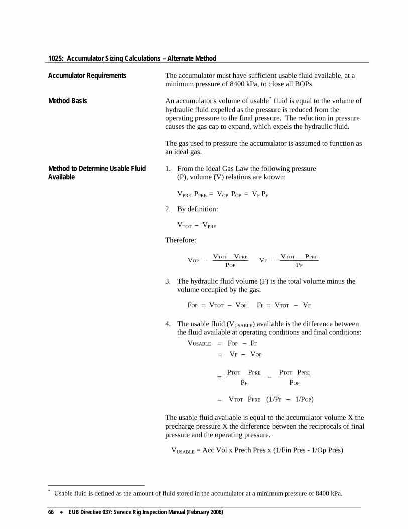
66 • EUB Directive 037: Service Rig Inspection Manual (February 2006)
1025: Accumulator Sizing Calculations – Alternate Method Accumulator Requirements The accumulator must have sufficient usable fluid available, at a
minimum pressure of 8400 kPa, to close all BOPs. Method Basis An accumulator's volume of usable* fluid is equal to the volume of
hydraulic fluid expelled as the pressure is reduced from the operating pressure to the final pressure. The reduction in pressure causes the gas cap to expand, which expels the hydraulic fluid.
The gas used to pressure the accumulator is assumed to function as
an ideal gas. Method to Determine Usable Fluid Available
1. From the Ideal Gas Law the following pressure (P), volume (V) relations are known:
VPRE PPRE = VOP POP = VF PF 2. By definition: VTOT = VPRE Therefore:
F
PRE TOTF
OP
PRETOTOP
PP VV
PV VV ==
3. The hydraulic fluid volume (F) is the total volume minus the volume occupied by the gas:
FTOTF OPTOT OP VVFVVF −=−= 4. The usable fluid (VUSABLE) available is the difference between
the fluid available at operating conditions and final conditions:
OPF
FOPUSABLE
VVFFV
−=−=
OP
PRETOT
F
PRETOT
PPP
PPP
−=
)1/P(1/PPV OPFPRETOT −=
The usable fluid available is equal to the accumulator volume X the
precharge pressure X the difference between the reciprocals of final pressure and the operating pressure.
VUSABLE = Acc Vol x Prech Pres x (1/Fin Pres - 1/Op Pres)
* Usable fluid is defined as the amount of fluid stored in the accumulator at a minimum pressure of 8400 kPa.

EUB Directive 037: Service Rig Inspection Manual (February 2006) • 67
Calculation Formula VUSABLE = Acc Vol x Prech Pres x (1/Fin Pres - 1/0 Pres) Since the Minimum Final* Pressure required is 8400 kPa, VUSABLE = Acc Vol x Prech Pres x (1.84 MPa - 1/Op Pres) Sample Calculation Rig has: 76.0 litre Accumulator w/
14.0 MPa Operating Pressure 7.0 MPa Precharge Pressure 152.4 mm 21 MPa Shaffer Annular 152.4 mm 21 MPa Shaffer LWP Pipe Rams 152.4 mm 21 MPa Shaffer LWP Blind Rams
Step 1 VUSABLE = 76 litres x 7.0 MPa x (1/8.4 MPa - 1/14.0 MPa) = 76 litres x 7.0 x 0.048 = 25.5 litres Step 2 Determine fluid volume needed to close preventers
(Appendix 1055). Vol to close annular 17.3 litres
Vol to close pipe rams 2.1 litres Vol to close blind rams 2.1 litres
TOTAL VOLUME 21.5 litres Conclusion The accumulator is adequate because 25.5 litres of usable fluid is
available when only 21.5 litres of fluid is needed to close all BOP components.
1030: Back-Up Nitrogen Calculations – Alternate Method Nitrogen Requirements The back-up nitrogen supply must have sufficient usable* volume
available, at a minimum pressure of 8400 kPa, to fully close the annular preventer and one set of ram preventers, and open the hydraulic valve.
- If two sets of pipe rams are required, there must be additional
usable nitrogen available to close the extra set of rams. Method Basis A nitrogen bottle's volume of usable fluid is equal to the volume of
gas expelled as the pressure is reduced from the operating pressure to the final pressure. The reduction in pressure causes the gas to expand into the BOP closing system.
Nitrogen is assumed to function as an Ideal Gas. * If precharge is greater than 8.4 MPa, final pressure must equal precharge pressure. * Usable is defined as the equivalent litres of stored nitrogen at a minimum pressure of 8400 kPa.
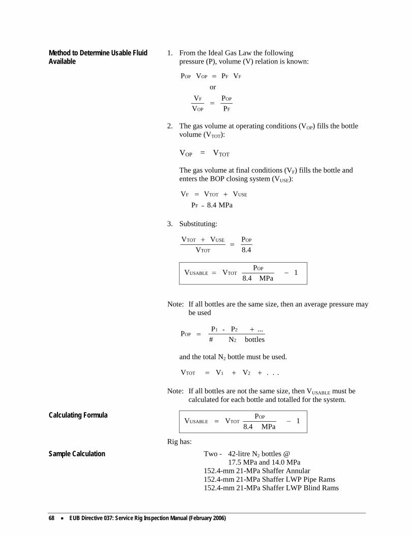
68 • EUB Directive 037: Service Rig Inspection Manual (February 2006)
Method to Determine Usable Fluid Available
1. From the Ideal Gas Law the following pressure (P), volume (V) relation is known:
F
OP
OP
F
FFOPOP
PP
VV
orVPVP
=
=
2. The gas volume at operating conditions (VOP) fills the bottle
volume (VTOT): VOP = VTOT The gas volume at final conditions (VF) fills the bottle and
enters the BOP closing system (VUSE):
MPa8.4PVVV
F
USETOTF
=
+=
3. Substituting:
8.4P
VVV OP
TOT
USETOT=
+
1MPa8.4
PVV OPTOTUSABLE −=
Note: If all bottles are the same size, then an average pressure may
be used
bottlesN#...PPP
2
21OP
+=
+
and the total N2 bottle must be used. ...VV V 21TOT ++= Note: If all bottles are not the same size, then VUSABLE must be
calculated for each bottle and totalled for the system. Calculating Formula
1MPa8.4
PVV OPTOTUSABLE −=
Rig has:
Sample Calculation Two - 42-litre N2 bottles @ 17.5 MPa and 14.0 MPa 152.4-mm 21-MPa Shaffer Annular 152.4-mm 21-MPa Shaffer LWP Pipe Rams
152.4-mm 21-MPa Shaffer LWP Blind Rams
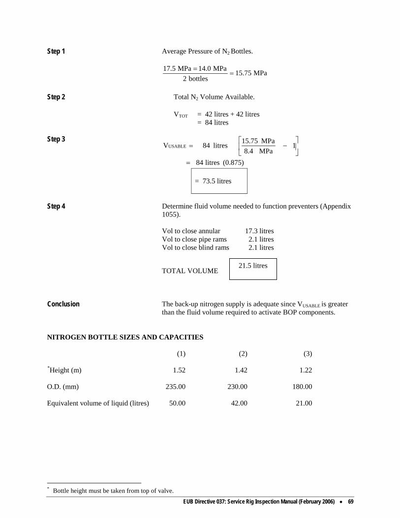
EUB Directive 037: Service Rig Inspection Manual (February 2006) • 69
Step 1 Average Pressure of N2 Bottles.
MPa15.75bottles2
MPa14.0MPa17.5=
=
Step 2 Total N2 Volume Available. VTOT = 42 litres + 42 litres
= 84 litres
Step 3
(0.875)litres84
1MPa8.4MPa15.75litres84VUSABLE
=
−=
= 73.5 litres
Step 4 Determine fluid volume needed to function preventers (Appendix
1055). Vol to close annular 17.3 litres Vol to close pipe rams 2.1 litres Vol to close blind rams 2.1 litres
TOTAL VOLUME
Conclusion The back-up nitrogen supply is adequate since VUSABLE is greater
than the fluid volume required to activate BOP components.
NITROGEN BOTTLE SIZES AND CAPACITIES (1) (2) (3) *Height (m) 1.52 1.42 1.22 O.D. (mm) 235.00 230.00 180.00 Equivalent volume of liquid (litres) 50.00 42.00 21.00
* Bottle height must be taken from top of valve.
21.5 litres

70 • EUB Directive 037: Service Rig Inspection Manual (February 2006)
1035: EUB Crew Training Assessment Form Well Name Unique Well Identifier
LE
LS
SC
TWP
RG
W
M
EV
Contractor
Rig No.
Date
TIMES_______________ ALERT CALLED ELAPSED / WELL SHUT-IN ELAPSED
MARK APPROPRIATE BOX FOR PROCEDURES APPLICABLE TO SHUT-IN
YES
NO
1. WAS HORN USED TO SOUND ALERT?
1.
2. DID ALL CREW MEMBERS RESPOND TO ALERT?
2.
3. WAS CREW ANTICIPATING A DRILL?
3.
4. DID ON-SITE SUPERVISORS CO-ORDINATE DRILL?
4.
5. DID ON-SITE SUPERVISORS QUESTION CREW ABOUT KICK DETECTION
AND SHUT-IN PROCEDURES?
5.
6. WAS WELL SHUT-IN COMPLETED PROPERTLY?
6.
7. DID ALL CREW MEMBERS KNOW THEIR POSITIONS AND
RESPONSIBILITIES?
7.
8. WAS STABBING VALVE USED?
8.
9. WAS STABBING VALVE ACCESSIBLE AND OPERATIONAL?
9.
10. WAS ROD BOP CLOSING DEVICE ACCESSIBLE AND OPERATIONAL?
10.
11. DID CREW KNOW HOW TO OBTAIN STIP, SICP AND TANK GAIN?
11.
13. WERE PROPER GAUGES AND FITTINGS AVAILABLE TO OBTAIN SITP AND
SICP?
12.
COMMENTS: _________________________________________________________________________________ _____________________________________________________________________________________________ INSPECTOR _________________________________ CREWS MUST KNOW KICK DETECTION SIGNS AND SHUT-IN PROCEDURES WHEN:
A. DRILLING/CLEANING TO BOTTOM/CIRCULATION B. TRIPPING/TUBING/DRILL PIPE C. TUBING DRILL PIPE IS OUT OF WELL D. TRIPPING SUCKER RODS.

EUB Directive 037: Service Rig Inspection Manual (February 2006) • 71
1040: EUB Crew Procedures Form * Crew Positions and Duties While Shutting in a Well
Operation: Drilling/Cleaning to Bottom/Circulating
Step No.
Driller
Derrickman
Floorhand
Floorhand
1.
Calls alert.
To pump control.
To rig floor.
To rig floor.
2.
Stops rotating. Raises kelly or power swivel clear of BOPs
Stops pump. Proceeds to BOP controls
Assists Driller as directed.
3.
Directs Derrickman to, or closes appropriate BOP.
Stands by at BOP control to assist Driller.
Closes annular valve. Installs casing gauge.
4.
Stays on rig floor and directs crew activities.
Reads and records SITP and SICP until stabilized. Reads and records tank gain (if possible).
Notifies Op. Rep. and Rig Mgr. Returns to rig floor
ALL CREW MEMBERS - - - - - PREPARE TO KILL WELL
* The following procedures serve as guidelines only and may vary according to operator preference and the number of rig personnel.
The above procedures are in draft format and are subject to approval by The Well Service Blowout Prevention Examination and Certification Committee.

72 • EUB Directive 037: Service Rig Inspection Manual (February 2006)
* Crew Positions and Duties While Shutting in a Well Operation: Tripping (Tubing/Drill Pipe)
Step No.
Driller
Derrickman
Floorhand
Floorhand
1.
Calls alert. Calls down Derrickman.
Comes down derrick.
Rig floor.
Rig floor.
2.
Positions collar just above floor. Sets slips.
Proceeds to BOP controls.
Unlatches elevators. Install stabbing valve and close when directed by Driller
Assists Floorhand.
3.
Directs Derrickman to, or closes appropriate BOP.
Stands by at BOP control to assist Driller.
Closes annular valve. Installs casing gauge.
4.
Picks up circulating equipment.
Fill circulating lines and stops pump.
Picks up and connects circulating equipment. Opens stabbing valve.
Returns to rig floor. Assists in make up of circulating equipment.
6.
Stays on rig floor and directs crew activities.
Reads and records SITP and SICP until stabilized. Reads and records tank gain (if possible).
Notifies Op. Rep. and Rig. Mgr. Returns to rig floor.
Stands by on rig floor.
ALL CREW MEMBERS - - - - - PREPARE TO KILL WELL
* The following procedures serve as guidelines only and may vary according to operator preference and the number of rig personnel.
The above procedures are in draft format and are subject to approval by The Well Service Blowout Prevention Examination and Certification Committee.

EUB Directive 037: Service Rig Inspection Manual (February 2006) • 73
* Crew Positions and Duties While Shutting in a Well Operation: Tubing/Drill Pipe Out of Hole
Step No.
Driller
Derrickman
Floorhand
Floorhand
1.
Calls alert.
Proceeds to BOP controls.
To rig floor
To rig floor
2.
Directs Derrickman to, or closes blind rams.
Stands by at BOP control to assist Driller.
Closes annular valve. Installs casing gauge. Returns to rig floor.
Assists Driller as directed.
3.
Stays on rig floor and directs crew activities.
Reads and records SICP until stabilized. Reads and records tank gain (if possible).
Notifies Op. Rep. and Rig Mgr. Returns to rig floor.
ALL CREW MEMBERS - - - - - PREPARE TO KILL WELL
* The following procedures serve as guidelines only and may vary according to operator preference and the number of rig personnel.
The above procedures are in draft format and are subject to approval by The Well Service Blowout Prevention Examination and Certification Committee.

74 • EUB Directive 037: Service Rig Inspection Manual (February 2006)
CREW PROCEDURES FORM * Crew Positions and Duties While Shutting in a Well
Operation: Tripping (Sucker Rods)
Step No.
Driller
Derrickman
Floorhand
Floorhand
1.
Calls alert. Calls down Derrickman.
Comes down from derrick.
Rig floor.
Rig floor
2.
Positions rod elevator.
Stands by to assist Driller.
Unlatches rod hook, if required.
3.
Stays on rig floor and directs crew activities.
Closes rod BOP.
Closes flow line valve to rig tank.
4.
Installs pressure gauge on flow tee.
Returns to rig floor.
5.
Reads and records SITP and SICP until stabilized. Reads and records tank gain (if possible).
Notifies Op. Rep. and Rig Mgr. Returns to rig floor.
ALL CREW MEMBERS - - - - - PREPARE TO KILL WELL
* The following procedures serve as guidelines only and may vary according to operator preference and the number of rig personnel.
The above procedures are in draft format and are subject to approval by The Well Service Blowout Prevention Examination and Certification Committee.

EUB Directive 037: Service Rig Inspection Manual (February 2006) • 75
1045: Operational Deficiencies
The level of each deficiency is based on the criteria set out in Directive 019: EUB Compliance Assurance—Enforcement. Definitions of Unsatisfactory Inspections • Low Risk unsatisfactory event/inspection (L) — a contravention of regulation(s) or
requirement(s) that represents an acceptable level of risk that requires mitigative measures within an acceptable time frame.
• High Risk unsatisfactory event/inspection (H) — a contravention of regulation(s)
or requirements(s) that represents an unacceptable level of risk requiring the inclusion of mitigative measures, provided the benefits outweigh the risks.
The EUB may escalate noncompliance issues(s) to any level should conditions warrant. Compliance and Noncompliance Results Inspection results are rated “X” – satisfactory, “L” – low risk unsatisfactory, and “H” – high risk unsatisfactory. Inspection No. Inspection Item and Deficiency
52 BOP Type, Ram Size, & Pressure Rating
H 1. Using inadequate preventer H 2. Improper pipe ram sizing H 3. BOP pressure rating low
H 4. BOP stack arrangement does not conform to requirements (annular not provided)
H 5. Spool improper pressure rating
H 6. Tubing stripper not installed or not operating properly (Class I gas wells only)
H 7. Tubing plug or other suitable shut-off device not installed
in tubing string during tripping operations (Class I gas wells only)
H 8. Wireline annular preventer not in use (conventional
annular preventer not in service) L 9. Three-year shop servicing not conducted L 10. BOP stack arrangement does not conform to requirements
(however, all components are present)

76 • EUB Directive 037: Service Rig Inspection Manual (February 2006)
L 11. BOP pressure rating not detectable
53 Bleed Off & Kill Lines H 1. Pressure gauge at manifold inaccurate (e.g. out of
calibration or range too large and no suitable back-up) H 2. Check valve in kill line in backwards H 3. Kill line or bleed-off line or manifold improper pressure
rating H 4. Shock hose in kill line or bleed-off line improper pressure
rating H 5. Kill line and/or bleed-off line not properly secured H 6. Casing gauge inaccurate (e.g. out of calibration or range
too large and no suitable back-up) L 7. Manifold valves difficult to operate, need
lubrication/repair, or washed out L 8. Valve handles missing on kill line or bleed-off line or
manifold (no alternate handle provided) L 9. Manifold design improper - check valve or valves location
incorrect L 10. Kill line or bleed-off line improperly positioned within
BOP stack L 11. Kill line or bleed-off line or manifold improper size L 12. Bolts missing from bleed-off or kill line flanges L 13. End of flare line does not terminate in flare pit (class I) L 14. Bleed-off line disconnected from wellhead L 15. Kill line and/or bleed-off line not connected to rig tank or
manifold L 16. Spool or flanged BOP port not used for bleed-off or kill-
line connection (Classes II, IIA and III) L 17. Improper spool used for bleed-off or kill-line connection
on Class II or III well (spool has threaded outlets whereas wellhead has flanged equipment)

EUB Directive 037: Service Rig Inspection Manual (February 2006) • 77
54 Non-Steel Hydraulic Lines Fire Sheathed H 1. Hydraulic hoses inadequately fire sheathed or fire
sheathing damaged
55 Drill-String Valves Readily Accessible
H 1. Stabbing valve not accessible or not operable H 2. Stabbing valve closing handle not on location or
inaccessible H 3. Work string cross-over sub not available or accessible H 4. Stabbing valve in closed position H 5. Stabbing valve not full opening L 6. Poor maintenance of valve threads on stabbing valve or
work string cross-over sub L 7. Hanger cap on stabbing valve not full opening L 8. Carrying handles/hanger cap not provided
56 Equipment Adequately Heated H 1. BOPs inadequately heated H 2. Bleed-off and/or kill-line valves iced up H 3. Ice plug in bleed-off and/or kill line L 4. Stabbing valve not kept in ice-free environment during
cold weather conditions 57 BOP Equipment & Controls Workable & Properly Connected
H 1. Accumulator has insufficient usable fluid available, at a
minimum pressure of 8400 kPa, to close all BOP components (sizing calculations performed)
H 2. Accumulator not connected to hydraulic system H 3. Accumulator gauge inaccurate or unavailable H 4. Full BOP controls not provided at or near Driller's station H 5. Remote BOP controls inadequate or controls not provided H 6. Nitrogen bottles not provided H 7. Nitrogen bottles not connected or improperly connected

78 • EUB Directive 037: Service Rig Inspection Manual (February 2006)
L 8. Gauge and/or fittings not available for taking pressure of nitrogen bottles
L 9. Nitrogen bottle gauge inaccurate H 10. Nitrogen bottle volume low (insufficient usable fluid
available—sizing calculations performed) H 11. Accumulator pump failed to recharge accumulator H 12. Annular or ram preventer seals leaking H 13. Hydraulic hoses improper pressure rating H 14. BOP control functions not clearly marked H 15. Fluid leak in hydraulic system (BOPs will not function) H 16. Fluid by-passing through BOP controls (BOPs will not
function) or pressure dropped below 8400 kPa after function test with pump off. Bypass allows loss of pressure.
H 17. Closing devices (cranks) not available for rod preventer H 18. BOPs failed to operate from remote position H 19. BOPs failed to operate from Driller's position H 20. BOPs not installed on well L 21. Manual BOP closing device not available or incorrectly
sized L 22. Accumulator pump failed to recharge accumulator within
5 minutes L 23. Fittings not available to obtain accumulator precharge L 24. Accumulator improperly connected (check valve location
does not allow for accumulator recharge pump change) L 25. Hydraulic hoses not protected from damage (outer
protective coating either damaged or missing) L 26. Remote controls located within 7 m of wellbore (Classes I,
II and IIA) or within 25 m (Class III) L 27. Fluid leak in hydraulic system (BOPs still function) L 28. Fluid by-passing through BOP controls (BOPs still
function) and no pressure loss occurring on system

EUB Directive 037: Service Rig Inspection Manual (February 2006) • 79
L 29. Annular or ram preventers failed to close within regulation times
L 30. Bolts missing from BOP or wellhead to the wellhead
flange during operations
L 31. Accumulator bottles cannot be isolated to prevent back-up nitrogen loss into system
71 Crew BOP Training
H 1. Crew training inadequate H 2. Crew drills not being performed H 3. Rig horn inoperable or not in place for sounding crew alert
(crew did not respond to alternative alert) L 4. Crew BOP drills not recorded in tour reports (prior to
commencement of operations or after BOPs installed) L 5. Rig horn inoperable or not in place for sounding crew alert
(crew responded to alternative alert)
72 Fluid Measurements & Hole-Filling Procedures H 1. Rig pump and/or tank not on location
74 Driller Has P.I.T.S. Well Servicing Certificate H 1. Driller has never held valid certificate (regulation
requiring Driller's certification is forthcoming) H 2. Driller's certificate has expired
80 Well to Flame-Type Equipment L 1. Flame-type equipment operating within 25 m of wellbore
(welder, steamer)
81 Smoking Rules Being Observed L 1. Member of rig crew or other individual observed smoking
within 25 m of wellbore L 2. Evidence of smoking within 25 m of wellbore
82 DST Equipment H 1. Remote controlled master valve on testing head not
provided

80 • EUB Directive 037: Service Rig Inspection Manual (February 2006)
H 2. Remote controlled master valve on testing head not operating
H 3. Reverse circulating sub not installed in test string
83 Warning Signs Posted in H2S Areas L 1. Warning sign not posted L 2. Warning sign illegible L 3. Warning sign posted on known sweet well
84 BOP Pressure Tests Recorded & Test Procedures Satisfactory H 1. BOP components not pressure tested H 2. Stabbing valve would not pressure test (after operations in
progress) L 3. Pressure test not recorded in tour reports L 4. Incomplete pressure test data recorded in tour reports L 5. Low-pressure test not conducted L 6. Low-pressure test not conducted prior to high-pressure test L 7. Improper test pressure used L 8. Pressure testing medium not low viscosity fluid L 9. Well control equipment testing times less than 10 minutes
85 Daily Mechanical Tests Recorded L 1. Daily BOP mechanical tests not completed L 2. Daily mechanical tests not recorded L 3. Description of mechanical tests conducted incomplete
86 Weekly Diesel Engine Tests Recorded L 1. Diesel engine shut-off test not conducted prior to
commencing operations L 2. Diesel engine shut-off test, conducted prior to
commencing operations, not recorded L 3. Weekly diesel engine shut-off test not conducted L 4. Weekly diesel engine shut-off test not recorded

EUB Directive 037: Service Rig Inspection Manual (February 2006) • 81
90 Diesel Engine Shut-Offs L 1. Diesel engine shut-off did not operate L 2. Air supply not connected to diesel engine shut-off L 3. Diesel engine not equipped with shut-off
91 Engine Exhausts L 1. Engine exhausts in need of repair L 2. Engine exhausts not directed away from wellbore
101 End of Flare Line L 1. Flare line not 50 m from wellbore L 2. Flare pit improperly constructed
102 Rubbish Burn Pile L 1. Camp and rig combustible debris not being disposed of
properly as required in Appendix 1100 L 2. Information not readily available to show proper
characterization of wastes generated on site (Dangerous/Non-dangerous)(e.g. CAODC wall chart)
L 3. Wastes generated on site not properly stored (i.e.
secondary containment) L 4. Waste material generated on site disposed of at a facility
not approved to handle that specific waste L 5. Records not available showing source, volume and final
disposition of waste
103 Crude Oil Storage Tank L 1. Crude oil storage tank located within 50 m of wellbore L 2. Service rig tank located within 7 m of rig pump
104 Condensate Rules Being Observed H 1. Open tank used for storing or gauging or measuring the
pumping rate H 2. Minimum distance of 50 m not maintained between the
wellhead and storage tank H 3. Positive shut-off valve not installed between pump and
wellhead

82 • EUB Directive 037: Service Rig Inspection Manual (February 2006)
H 4. Check valve not installed between pump and wellhead H 5. Surface lines not pressure tested or test pressure
inadequate L 6. Approval to use condensate for fracturing not obtained
from Calgary office
105 Fluids Properly Contained N/A 1. Sump leaking N/A 2. Fluids around rig substructure not directed to sump N/A 3. Transfer of drilling fluids to remote sump unsatisfactory
H 4. Workover or wellbore fluids spilled on or off lease H 5. Chemicals, mud additives, fuel, or other materials spilled
on or off lease
106 Licence Posted L 1. Well licence not at lease (well re-entry/not original
licensee) L 2. Well licence not posted (well re-entry/not original
licensee)
108 L 1. Contractor and operator inspections not recorded L 2. Contractor and operator detailed inspections NOT
conducted L 3. Contractor and operator daily inspections NOT conducted

EUB Directive 037: Service Rig Inspection Manual (February 2006) • 83
1055: BOP Fluid Volumes Acknowledgement The following tables were prepared from data supplied by the
various BOP manufacturers listed in this section. The co operation of these companies is greatly appreciated.
Ram-type Blowout Preventer MODEL OR TYPE
BOP SIZE mm
WORKING PRESSURE MAXIMUM kPa
VERTICAL BORE Mm
HYDRAULIC OPERATOR kPa
LITRES TO CLOSE
LITRES TO OPEN
CLOSE RATIO
OPEN RATIO
Bowen Tools
51922 51923 51924 60701 50460 51926 51927 51928 51929 61040 61044 61048 61050 47034 60467 61053 61055 61057 61060 51938 63642
63.5S 63.5S 63.5T 63.5T 65.1S 76.2S 76.2S 76.2T 76.2T
101.6S 101.6S 101.6T 101.6T 103.2S 103.2S 114.3S 114.3S 114.3T 114.3T 139.7S 179.4S
42 000 70 000 34 000 69 000 104 000 34 000 69 000 34 000 69 000 34 000 69 000 34 000 69 000 69 000 104 000 21 000 69 000 34 000 69 000 21 000 69 000
63.5 63.5 63.5 63.5 65.1 76.2 76.2 76.2 76.2
101.6 101.6 101.6 101.6 103.2 103.2 114.3 114.3 114.3 114.3 139.7 179.4
5 378 8 963 4 771 6 902 6 895 2 544 5 088 2 544 5 088 3 827 7 653 3 827 7 653 6 895
20 684 2 551 7 653 3 827 7 653 1 655 6 205
0.6 0.7 1.4 1.6 1.1 1.1 1.1 2.0 2.0 3.4 3.4 4.5 4.5 1.6 1.6 3.4 3.4 6.9 6.9 5.7 2.8
0.6 0.7 1.1 1.3 1.1 0.8 0.8 1.9 1.9 3.1 3.1 6.1 6.1 1.3 1.3 3.1 3.1 6.2 6.2 5.2 2.8
7.9 7.9 7.9 7.9
8.18 13.2 13.2 13.2 13.2 15.3 15.3 15.3 15.3 13.6 13.6 15.3 15.3 15.3 15.3 20.8 10.9

84 • EUB Directive 037: Service Rig Inspection Manual (February 2006)
Ram-type Blowout Preventer
MODEL OR TYPE
BOP SIZE mm
WORKING PRESSURE MAXIMUM kPa
VERTICAL BORE mm
HYDRAULIC OPERATOR kPa
LITRES TO CLOSE
LITRES TO OPEN
CLOSE RATIO
OPEN RATIO
Cameron Iron Works
U U U U U U U U
152.4 152.4 179.4 179.4 254.0 254.0 279.4 279.4
21 000 34 000 69 000
104 000 21 000 34 000 69 000
104 000
179.4 179.4 179.4 179.4 279.4 279.4 279.4 279.4
10 500/21 000 10 500/21 000 10 500/21 000 10 500/21 000 10 500/21 000 10 500/21 000 10 500/21 000 10 500/21 000
5.0 5.0 5.0 5.0
12.7 12.7 12.7 12.7
4.8 4.8 4.8 4.8
12.1 12.1 12.1 12.1
7:1 7:1 7:1 7:1 7:1 7:1 7:1 7:1
2.30:1 2.30:1 2.30:1 2.30:1 2.30:1 2.30:1 2.30:1 2.30:1
QRC QRC QRC QRC QRC QRC QRC
152.4 152.4 203.2 203.2 254.0 254.0 304.8
21 000 34 000 21 000 34 000 21 000 34 000 21 000
179.4 179.4 228.6 228.6 279.4 279.4 346.1
10 500/34 000 10 500/34 000 10 500/34 000 10 500/34 000 10 500/34 000 10 500/34 000 10 500/34 000
3.1 3.1 8.9 8.9
10.5 10.5 16.7
3.6 3.6
10.2 10.2 12.0 12.0 19.3
7.75:1 7.75:1 9.05:1 9.05:1 9.05:1 9.05:1 8.64:1
1.50:1 1.50:1 1.83:1 1.83:1 1.21:1 1.21:1 1.07:1
Type F With Type L Oper
152.4 152.4 177.8 177.8 203.2
21 000 34 000 69 000
104 000 21 000
179.4 179.4 179.4 179.4 228.6
1 725/10 500 1 725/10 500 1 725/10 500 1 725/10 500 1 725/10 500
15.0 15.0 15.0 15.0 25.9
13.0 13.0 13.0 13.0 23.4
V A R I A B L E
4.90:1 4.90:1 4.90:1
4.90:13.44:1

EUB Directive 037: Service Rig Inspection Manual (February 2006) • 85
Ram-type Blowout Preventer
MODEL OR TYPE
BOP SIZE
mm
WORKING PRESSURE MAXIMUM kPa
VERTICAL BORE mm
HYDRAULIC OPERATOR kPa
LITRES TO CLOSE
LITRES TO OPEN
CLOSE RATIO
OPEN RATIO
Cameron Iron Works Type F With Type L Oper
203.2 254.0 254.0 279.4 304.8
34 000 21 000 34 000 69 000 21 000
228.6 279.4 279.4 279.4 346.1
1 725/10 500 1 725/10 500 1 725/10 500 1 725/10 500 1 725/10 500
25.9 25.9 25.9 25.9 39.0
23.4 23.4 23.4 23.4 35.5
V A R I A B L E
3.44:1 3.44:1 3.44:1 3.44:1 2.30:1
Type F With Type H Oper
152.4 152.4 177.8 177.8 203.2 203.2 254.0 254.0 279.4 304.8
21 000 34 000 69 000
104 000 21 000 34 000 21 000 34 000 69 000 21 000
179.4 179.4 179.4 179.4 228.6 228.6 279.4 279.4 279.4 346.1
6 900/34 000 6 900/34 000 6 900/34 000 6 900/34 000 6 900/34 000 6 900/34 000 6 900/34 000 6 900/34 000 6 900/34 000 6 900/34 000
2.0 2.0 2.0 2.0 3.4 3.4 3.4 3.4 3.4 5.6
4.0 4.0 4.0 4.0 6.8 6.8 6.8 6.8 6.8
10.2
V A R I A B L E
1.50:1 1.50:1 1.50:1 1.50:1
10:1 10:1 10:1 10:1 10:1
2.13:1

86 • EUB Directive 037: Service Rig Inspection Manual (February 2006)
Ram-type Blowout Preventer
MODEL OR TYPE
BOP SIZE
mm
WORKING PRESSURE MAXIMUM kPa
VERTICAL BORE mm
HYDRAULIC OPERATOR kPa
LITRES TO CLOSE
LITRES TO OPEN
CLOSE RATIO
OPEN RATIO
Cameron Iron Works
SS SS SS SS SS SS SS
152.4 152.4 203.2 203.2 254.0 254.0 304.8
21 000 34 000 21 000 34 000 21 000 34 000 21 000
179.4 179.4 228.6 228.6 279.4 279.4 346.1
10 500/34 000 10 500/34 000 10 500/34 000 10 500/34 000 10 500/34 000 10 500/34 000 10 500/34 000
3.0 3.0 5.7 5.7 5.7 5.7
11.0
2.6 2.6 4.9 4.9 4.9 4.9 9.5
3.8:1 3.8:1 3.8:1 3.9:1 3.9:1 3.9:1 3.7:1
10:1 10:1 10:1 10:1 10:1 10:1 10:1
Type F With Type W2 Oper
152.4 152.4 177.8 177.8 203.2 203.2 254.0 254.0
21 000 34 000 69 000
104 000 21 000 34 000 21 000 34 000
179.4 179.4 179.4 179.4 228.6 228.6 279.4 279.4
3 500/10 500 3 500/10 500 3 500/10 500 3 500/10 500 3 500/10 500 3 500/10 500 3 500/10 500 3 500/10 500
5.7 5.7 5.7 5.7
10.6 10.6 10.6 10.6
8.7 8.7 8.7 8.7
14.0 14.0 14.0 14.0
V A R I A B L E
4.50:1 4.50:1 4.50:1 4.50:1 2.50:1 2.50:1 2.50:1 2.50:1
Ram-type Blowout Preventer
MODEL OR TYPE
BOP SIZE
mm
WORKING PRESSURE MAXIMUM kPa
VERTICAL BORE mm
HYDRAULIC OPERATOR kPa
LITRES TO CLOSE
LITRES TO OPEN
CLOSE RATIO
OPEN RATIO
Cameron Iron Works
Type F With Type W Oper
152.4 152.4 177.8 177.8 203.2 203.2 254.0 254.0 279.4 304.8
21 000 34 000 69 000
104 000 21 000 34 000 21 000 34 000 69 000 21 000
179.4 179.4 179.4 179.4 228.6 228.6 279.4 279.4 279.4 346.1
3 500/10 500 3 500/10 500 3 500/10 500 3 500/10 500 3 500/10 500 3 500/10 500 3 500/10 500 3 500/10 500 3 500/10 500 3 500/10 500
8.7 8.7 8.7 8.7
14.0 14.0 14.0 14.0 14.0 25.7
11.5 11.5 11.5 11.5 17.4 17.4 17.4 17.4 17.4 30.7
V A R I A B L E

EUB Directive 037: Service Rig Inspection Manual (February 2006) • 87
Ram-type Blowout Preventer
MODEL OR TYPE
BOP SIZE
mm
WORKING PRESSURE MAXIMUM kPa
VERTICAL BORE mm
HYDRAULIC OPERATOR kPa
LITRES TO CLOSE
LITRES TO OPEN
CLOSE RATIO
OPEN RATIO
Dresser Ome (Guiberson)
Type H Hyd Cyl
152.4 203.2
21 000 14 000
187.3 230.2
14 000 14 000
4.2 4.2
3.6 3.6
6.50:1 6.50:1
1:1 1:1
1531 1101
179.4 179.4
21 000 34 500
Dreco and Griffith Oil Tool
177.8 6 825 177.8 9 100
2.0 2.6
1.5 1.9
V V V V X V
152.4 152.4 254.0 254.0 279.4 304.8
21 000 34 000 21 000 34 000 69 000 21 000
Hydril Company
179.4 5 171 179.4 8 101 279.4 3 792 279.4 5 861 279.4 7 239 346.1 4 826
5.7 5.7
12.5 12.5 48.8 22.3
4.9 4.9
12.1 12.1 44.7 18.5
5.32:1 5.32:1 6.00:1 6.00:1
10.56:1 5.20:1

88 • EUB Directive 037: Service Rig Inspection Manual (February 2006)
Ram-type Blowout Preventer
MODEL OR TYPE
BOP SIZE mm
WORKING PRESSURE MAXIMUM kPa
VERTICAL BORE mm
HYDRAULIC OPERATOR kPa
LITRES TO CLOSE
LITRES TO OPEN
CLOSE RATIO
OPEN RATIO
Rucker Shaffer
Types B&E
152.4 152.4 203.2
203.2254.0
254.0 304.8
21 000 34 000 21 000 34 000 21 000 34 000 21 000
179.4 179.4 228.6 228.6 279.4 279.4 346.1
10 500/21 000 10 500/21 000 10 500/21 000 10 500/21 000 10 500/21 000 10 500/21 000 10 500/21 000
10.4 10.4 10.4 10.4 12.3 12.3 13.4
8.7 8.7 8.7 8.7
10.2 10.2 11.0
6.00:1 6.00:1 6.00:1 6.00:1 6.00:1 6.00:1 6.00:1
2.57:1 2.57:1 1.89:1 1.89:1 1.51:1 1.35:1 1.14:1
LWS With Locking Manual Screw
103.2 152.4 152.4 179.4 179.4 203.2 203.2 228.6 254.0 254.0 279.4 304.8
69 000 21 000 34 000 69 000
104 000 21 000 34 000 69 000 21 000 34 000 69 000 21 000
103.2 179.4 179.4 179.4 179.4 228.6 228.6 228.1 279.4 279.4 279.4 346.1
10 500/21 000 10 500/21 000 10 500/21 000 10 500/21 000 10 500/21 000 10 500/21 000 10 500/21 000 10 500/21 000 10 500/21 000 10 500/21 000 10 500/21 000 10 500/21 000
2.2 4.7 4.7
24.0 24.0 9.8 9.8 9.2 6.6
11.3 13.7 12.7
1.8 3.8 3.8
22.3 22.3 8.6 8.6 8.1 5.5 9.9
12.5 11.2
8.45:1 4.44:1 4.45:1
10.63:1 10.63:1 5.58:1 5.58:1 5.58:1 4.45:1 5.58:1 7.83:1 5.58:1
4.74:1 1.82:1 1.82:1
19.40:1 19.40:1 3.00:1 3.00:1 1.69:1 1.16:1 2.10:1 2.20:1 1.75:1

EUB Directive 037: Service Rig Inspection Manual (February 2006) • 89
Ram-type Blowout Preventer
MODEL OR TYPE
BOP SIZE mm
WORKING PRESSURE MAXIMUM kPa
VERTICAL BORE mm
HYDRAULIC OPERATOR kPa
LITRES TO CLOSE
LITRES TO OPEN
CLOSE RATIO
OPEN RATIO
Rucker Shaffer
LWS Posi- Lock
179.4 254.0 254.0 279.4 279.4 304.8 304.8
104 000
34 000 34 000 69 000 69 000 21 000 21 000
179.4 279.4 279.4 279.4 279.4 346.1 346.1
10 500/21 000 10 500/21 000 10 500/21 000 10 500/21 000 10 500/21 000 10 500/21 000 10 500/21 000
27.4 18.0 35.2 15.9 31.2 20.2 40.0
25.0 15.8 32.1 14.0 28.4 17.8 36.4
10.85:1 8.16:1
10.85:1 8.16:1
10.85:1 8.16:1
10.85:1
19.44:1 3.07:1 7.82:1 2.21:1 6.24:1 2.56:1 6.25:1
LWP
152.4 203.2
21 000 21 000
179.4 228.6
10 500/21 000 10 500/21 000
2.1 2.9
1.9 2.6
4.00:1 4.00:1
1.81:1 2.50:1
Sen- tinel
179.4
21 000
179.4
10 500
2.6
2.1
4.00:1
2.50:1
Well Site Specialists
Incorporated WSI
Duke
179.4
21 000
179.4
10 500
2.7
2.2
4.20:1

90 • EUB Directive 037: Service Rig Inspection Manual (February 2006)
Bag-type (or Annular) Preventers, Diverters, Strippers
MODEL OR TYPE
BOP SIZE
mm
WORKING PRESSURE MAXIMUM kPa
VERTICAL BORE mm
HYDRAULIC OPERATOR kPa
LITRES TO CLOSE
LITRES TO OPEN
PACK OFF OPEN HOLE MINIMUM kPa
Cameron Iron Works
A A A A
152.4 152.4 279.4 279.4
34 000 69 000 34 000 69 000
179.4 179.4 279.4 279.4
10 500 10 500 10 500 10 500
8.3
15.1 29.5 45.8
7.2
11.7 24.6 39.7
NA NA NA NA
D D D D D D D
179.4 179.4 179.4 179.4 279.4 279.4 279.4
34 000 69 000
104 000 138 000
21 000 34 000 69 000
179.4 179.4 179.4 179.4 279.4 279.4 279.4
10 500/21 000 10 500/21 000 10 500/21 000 10 500/21 000 10 500/21 000 10 500/21 000 10 500/21 000
6.4
11.1 26.3 31.7 21.4 21.4 38.4
5.3 9.7
23.2 28.6 17.8 17.8 34.3
NA NA NA NA NA NA NA
Griffith Oil Tool
1100 1100
179.4 179.4
21 000 34 500
179.4 179.4
10 500/21 000 10 500/21 000
14.8 14.8
12.7 12.7
NOTE: 21 000 kPa closing pressure may be applied safely to the Cameron “D” and Griffith annular preventers to effect a faster closing
time; however, this is not a requirement.

EUB Directive 037: Service Rig Inspection Manual (February 2006) • 91
Bag-type (or Annular) Preventers, Diverters, Strippers
MODEL OR TYPE
BOP SIZE mm
WORKING PRESSURE MAXIMUM kPa
VERTICAL BORE mm
HYDRAULIC OPERATOR kPa
LITRES TO CLOSE
LITRES TO OPEN
PACK OFF OPEN HOLE MINIMUM kPa
Hydril Company
GK GK GK GK GK GK GK
152.4 152.4 203.2 203.2 254.0 254.0 304.8
21 000 34 000 21 000 34 000 21 000 34 000 21 000
179.4 179.4 227.0 227.0 279.4 279.4 346.1
10 500 10 500 10 500 10 500 10 500 10 500 10 500
10.8 14.6 16.4 25.9 28.1 37.1 43.0
8.5
12.5 12.9 22.0 21.0 30.2 33.8
6 895 6 895 7 240 7 930 7 930 7 930 7 930
MSP MSP MSP
152.4 203.2 254.0
14 000 14 000 14 000
179.4
227 279.4
10 500 10 500 10 500
10.8 17.3 28.1
7.5
11.2 19.8
6 895 7 240 7 930

92 • EUB Directive 037: Service Rig Inspection Manual (February 2006)
Bag-type (or Annular) Preventers, Diverters, Strippers
MODEL OR TYPE
BOP SIZE mm
WORKING PRESSURE MAXIMUM kPa
VERTICAL BORE mm
HYDRAULIC OPERATOR kPa
LITRES TO CLOSE
LITRES TO OPEN
PACK OFF OPEN HOLE MINIMUM kPa
Hydril Company
K K K K K K K K
76.2
101.6 177.8 219.1 244.5 273.1 298.5 298.5
21 000 21 000 21 000 21 000 21 000 21 000 21 000 21 000
76.2
101.6 179.4 200.0 225.4 254.0 276.2 282.6
21 000 21 000 21 000 21 000 21 000 21 000 21 000 21 000
0.76 3.0 6.1
12.9 21.6 28.8 30.7 39.0
NA NA NA NA NA NA NA NA
V A R I A B L E
Torus Torus Torus Torus
152.4 152.4 203.2 203.2
21 000 21 000 21 000 42 000
179.4 179.4 228.6 228.6
21 000 21 000 21 000 21 000
16.3 16.3 30.7 30.7
NA NA NA NA
V A R I B L E
Bag-type (or Annular) Preventers, Diverters, Strippers
MODEL OR TYPE
BOP SIZE mm
WORKING PRESSURE MAXIMUM kPa
VERTICAL BORE mm
HYDRAULIC OPERATOR kPa
LITRES TO CLOSE
LITRES TO OPEN
PACK OFF OPEN HOLE MINIMUM kPa
Hydril Company
Spher BOP Spher BOP Spher BOP Spher BOP Spher BOP Spher BOP Spher BOP Spher BOP
103.1 152.4 152.4 203.2 203.2 254.0 254.0 304.8
69 000 21 000 34 000 21 000 34 000 21 000 34 000 21 000
103.1 179.4 179.4 228.6 228.6 279.4 279.4 346.1
10 500 10 500 10 500 10 500 10 500 10 500 10 500 10 500
7.8
17.3 17.3 27.4 41.8 41.6 70.7 89.0
6.3
12.2 12.2 19.0 33.0 25.7 55.2 55.5
V A R I A B L E

EUB Directive 037: Service Rig Inspection Manual (February 2006) • 93
Cameron Iron Works
MODEL OR TYPE
LINE SIZE mm
MAXIMUM WORKING PRESSURE kPa
BORE SIZE mm
HYDRAULIC OPERATION MAXIMUM kPa
LITRES TO CLOSE
LITRES TO OPEN
HCR HCR HCR HCR
101.6 101.6 152.4 152.4
21 000 34 000 21 000 34 000
101.6 101.6 177.8 177.8
10 500 10 500 10 500 10 500
2.3 2.3 8.5 8.5
2.0 2.0 7.4 7.4
F F F F F F F F F F F F F
50.8 50.8 50.8 50.8 63.5 63.5 76.2 76.2 76.2 76.2
101.6 101.6 152.4
6 600/21 000
34 000/104 000 6 600/21 000
34 000/104 000 6 600/69 000
104 000 6 600/14 000
21 000/34 000 69 000
104 000 14 000/34 000
69 000 14 000/34 000
46.1 46.1 52.4 52.4 65.1 65.1 79.4 79.4 79.4 79.4
104.8 104.8 155.6
10 500/34 000 10 500/34 000 10 500/34 000 10 500/34 000 10 500/34 000 10 500/34 000 10 500/34 000 10 500/34 000 10 500/34 000 10 500/34 000 10 500/34 000 10 500/34 000 10 500/34 000
0.4 0.6 0.4 0.6 0.8 1.5 0.6 0.9 1.0 1.9 1.1 2.2 3.2
0.4 0.6 0.4 0.6 0.8 1.5 0.6 0.9 1.0 1.9 1.1 2.2 3.2
Cameron Iron Works
MODEL OR TYPE
LINE SIZE mm
MAXIMUM WORKING PRESSURE kPa
BORE SIZE mm
HYDRAULIC OPERATION MAXIMUM kPa
LITRES TO CLOSE
LITRES TO OPEN
DV DV DV DV DV DV DV
101.6 101.6 152.4 203.2 254.0 254.0 304.8
21 000 34 000 21 000 21 000 21 000 34 000 21 000
101.6 101.6 177.8 228.6 279.4 279.4 346.1
10 500 10 500 10 500 10 500 10 500 10 500 10 500
3.0 3.0 7.9 9.1
21.6 21.6 44.7
4.2 4.2
13.6 21.2 43.2 43.2 85.9
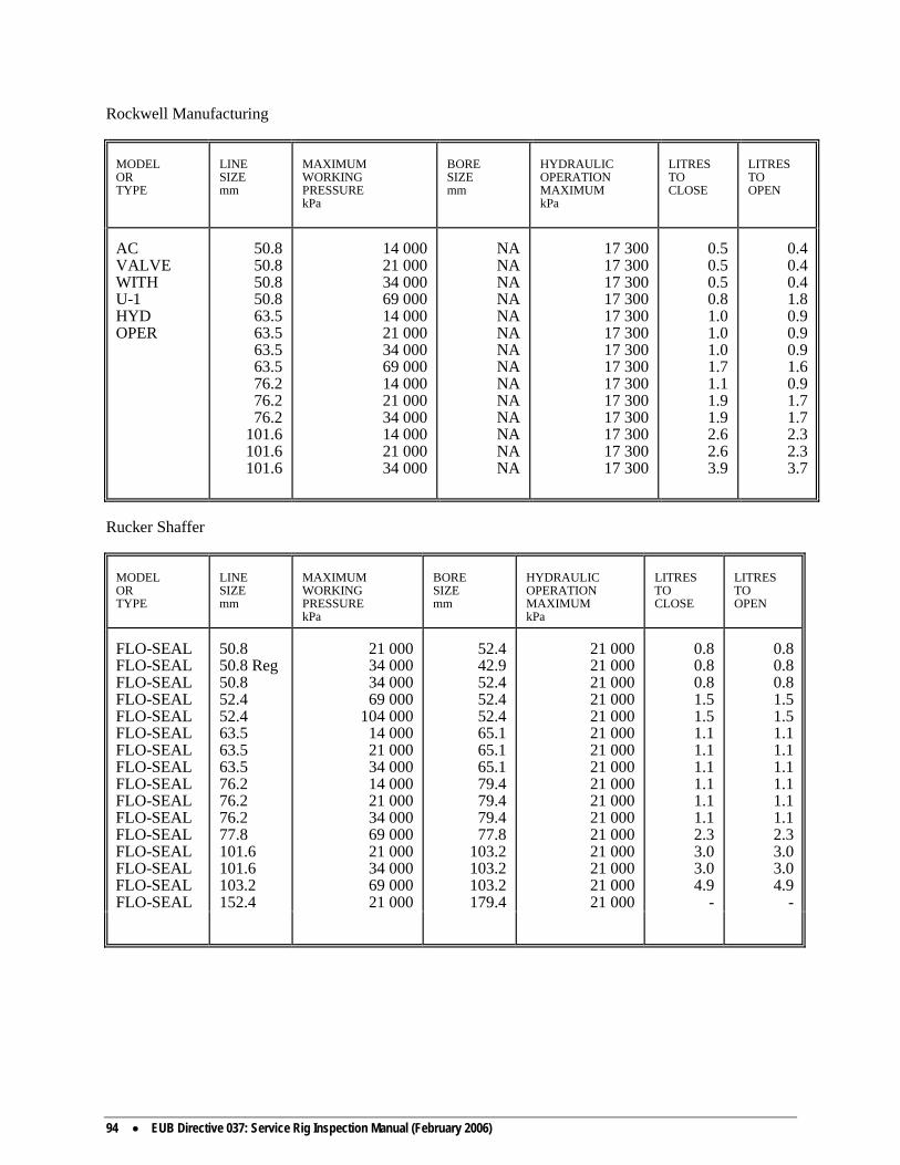
94 • EUB Directive 037: Service Rig Inspection Manual (February 2006)
Rockwell Manufacturing
MODEL OR TYPE
LINE SIZE mm
MAXIMUM WORKING PRESSURE kPa
BORE SIZE mm
HYDRAULIC OPERATION MAXIMUM kPa
LITRES TO CLOSE
LITRES TO OPEN
AC VALVE WITH U-1 HYD OPER
50.8 50.8 50.8 50.8 63.5 63.5 63.5 63.5 76.2 76.2 76.2
101.6 101.6 101.6
14 000 21 000 34 000 69 000 14 000 21 000 34 000 69 000 14 000 21 000 34 000 14 000 21 000 34 000
NA NA NA NA NA NA NA NA NA NA NA NA NA NA
17 300 17 300 17 300 17 300 17 300 17 300 17 300 17 300 17 300 17 300 17 300 17 300 17 300 17 300
0.5 0.5 0.5 0.8 1.0 1.0 1.0 1.7 1.1 1.9 1.9 2.6 2.6 3.9
0.4 0.4 0.4 1.8 0.9 0.9 0.9 1.6 0.9 1.7 1.7 2.3 2.3 3.7
Rucker Shaffer
MODEL OR TYPE
LINE SIZE mm
MAXIMUM WORKING PRESSURE kPa
BORE SIZE mm
HYDRAULIC OPERATION MAXIMUM kPa
LITRES TO CLOSE
LITRES TO OPEN
FLO-SEAL FLO-SEAL FLO-SEAL FLO-SEAL FLO-SEAL FLO-SEAL FLO-SEAL FLO-SEAL FLO-SEAL FLO-SEAL FLO-SEAL FLO-SEAL FLO-SEAL FLO-SEAL FLO-SEAL FLO-SEAL
50.8 50.8 Reg 50.8 52.4 52.4 63.5 63.5 63.5 76.2 76.2 76.2 77.8 101.6 101.6 103.2 152.4
21 000 34 000 34 000 69 000
104 000 14 000 21 000 34 000 14 000 21 000 34 000 69 000 21 000 34 000 69 000 21 000
52.4 42.9 52.4 52.4 52.4 65.1 65.1 65.1 79.4 79.4 79.4 77.8
103.2 103.2 103.2 179.4
21 000 21 000 21 000 21 000 21 000 21 000 21 000 21 000 21 000 21 000 21 000 21 000 21 000 21 000 21 000 21 000
0.8 0.8 0.8 1.5 1.5 1.1 1.1 1.1 1.1 1.1 1.1 2.3 3.0 3.0 4.9
-
0.8 0.8 0.8 1.5 1.5 1.1 1.1 1.1 1.1 1.1 1.1 2.3 3.0 3.0 4.9
-

EUB Directive 037: Service Rig Inspection Manual (February 2006) • 95
Rucker Shaffer
MODEL OR TYPE
LINE SIZE mm
MAXIMUM WORKING PRESSURE kPa
BORE SIZE mm
HYDRAULIC OPERATION MAXIMUM kPa
LITRES TO CLOSE
LITRES TO OPEN
FLO-SEAL WITH RAM LOCK
50.8 Reg
50.8 50.8 Reg
50.8 50.8 Reg
50.8 52.4 52.4 63.5 63.5 63.5 76.2 76.2 76.2 77.8
101.6 101.6 103.2 152.4
14 000 14 000 21 000 21 000 34 000 34 000 69 000
104 000 14 000 21 000 34 000 14 000 21 000 34 000 69 000 21 000 34 000 69 000 21 000
42.9 52.4 42.9 52.4 42.9 52.4 52.4 52.4 65.1 65.1 65.1 79.4 79.4 79.4 77.8
103.2 103.2 103.2 179.4
21 000 21 000 21 000 21 000 21 000 21 000 21 000 21 000 21 000 21 000 21 000 21 000 21 000 21 000 21 000 21 000 21 000 21 000 21 000
1.1 1.1 1.1 1.1 1.1 1.1 1.5 1.5 1.1 1.1 1.1 1.5 1.5 1.5 2.3 3.0 3.0 3.0
-
1.1 1.1 1.1 1.1 1.1 1.1 1.5 1.5 1.1 1.1 1.1 1.5 1.5 1.5 2.3 3.0 3.0 3.0
-
Rucker Shaffer
MODEL OR TYPE
LINE SIZE
mm
MAXIMUM WORKING PRESSURE kPa
BORE SIZE mm
HYDRAULIC OPERATION MAXIMUM kPa
LITRES TO CLOSE
LITRES TO OPEN
DB DB DB DB DB DB DB
76.2 76.2 77.8
101.6 101.6 103.2 152.4
21 000 34 000 69 000 21 000 34 000 69 000 21 000
79.4 79.4 77.8
103.2 103.2 103.2 179.4
21 000 21 000 21 000 21 000 21 000 21 000 21 000
1.1 1.1 2.3 3.0 3.0 4.9 7.6
1.1 1.1 2.3 3.0 3.0 4.9 7.6

96 • EUB Directive 037: Service Rig Inspection Manual (February 2006)
1060: Alberta Occupational Health & Safety Legislation Foreword This appendix is a compendium of the Occupational Health & Safety legislation that complements EUB policies and regulations with respect to service rig safety. Its inclusion in the EUB Drilling Rig Inspection Manual is intended to inform users of the manual of the regulations that should be considered in the overall safety performance at drilling and servicing sites, and may be applied by Occupational Health & Safety Officers in the course of their rig inspections. All persons using this appendix are reminded that it is limited in scope and that the original regulations should be consulted for additional information and interpretation. AOH&S equipment spacing requirements may differ from the requirements prescribed by the EUB. The EUB requirements will take precedence when such differences arise in the field.

EUB Directive 037: Service Rig Inspection Manual (February 2006) • 97

98 • EUB Directive 037: Service Rig Inspection Manual (February 2006)

EUB Directive 037: Service Rig Inspection Manual (February 2006) • 99

100 • EUB Directive 037: Service Rig Inspection Manual (February 2006)

EUB Directive 037: Service Rig Inspection Manual (February 2006) • 101

102 • EUB Directive 037: Service Rig Inspection Manual (February 2006)

EUB Directive 037: Service Rig Inspection Manual (February 2006) • 103

104 • EUB Directive 037: Service Rig Inspection Manual (February 2006)

EUB Directive 037: Service Rig Inspection Manual (February 2006) • 105

106 • EUB Directive 037: Service Rig Inspection Manual (February 2006)

EUB Directive 037: Service Rig Inspection Manual (February 2006) • 107

108 • EUB Directive 037: Service Rig Inspection Manual (February 2006)

EUB Directive 037: Service Rig Inspection Manual (February 2006) • 109

110 • EUB Directive 037: Service Rig Inspection Manual (February 2006)

EUB Directive 037: Service Rig Inspection Manual (February 2006) • 111
1070: Drilling with a Service Rig Requirements Where drilling operations are conducted with a service rig, an
application to modify the drilling regulations is not required provided casing has been set to a sufficient depth allowing shut-in of the well and:
• As a minimum, the blowout prevention system must conform to
the Class III Servicing Blowout Prevention Requirements • A full-opening drill string safety valve in the open position and
a device capable of stopping back flow, both of which can be stripped into the well, shall be maintained on the rig in a readily accessible location
• The driller must be in possession of a valid First Line
Supervisors Blowout Prevention or Well Service Blowout Prevention Certificate. At least one additional person who has a valid PITS Second Line or Well Service Blowout Prevention Certificate shall be readily available to assist the crew with well control operations
• A device shall be installed and maintained to provide warning
at the driller's position of a change of the level of fluid in the mud tank or of an imbalance in the volume of fluids entering and returning from the well. Alternatively, the circulating tank and pump shall be continuously manned
• Adequate precaution shall be taken during drilling operations
for wells which may contain hydrogen sulphide. In addition, the surface handling of any sour gas shall be in accordance with Informational Letter IL 91-2.
• All provisions of the well licence will be adhered to, including
sample requirements • The appropriate Board area office must be notified at least 24
hours prior to commencing operations 1080: Coiled Tubing Requirements Note: From EUB Calgary, Drilling and Production Department Contact department for requirements or document status.

112 • EUB Directive 037: Service Rig Inspection Manual (February 2006)
1090: BOP Modification Submission Requirements Drilling operations that deviate from the requirements of Schedule 8
of the Oil and Gas Conservation Regulation, or do not meet the requirements of section 4, Part II of this guide (service rigs), require EUB approval. Applications shall include the following information:
• The proposed BOP stack configuration including manifold
diagram • A detailed discussion is to be included where any loss of
functionality or redundancy from the Schedule 8 requirements is proposed. This discussion must include details of any proposed compensating features
Where additional drilling requirements of the Oil and Gas
Conservation Regulations will be modified, supporting information must be included justifying these changes.
1100: Oilfield Waste Management Inspection Guidelines – Drilling Operations 1.0 Definitions “Container” means any portable device which has a capacity that
does not exceed 454 litres and is used to store oilfield waste. “On-Site Facility” means a facility that is used solely to deal with
waste generated on that property or related properties owned by the owner of the facility.
“Oilfield Waste” means an unwanted substance or mixture of
substances that results from the construction, operation or reclamation of a well site, oil and gas battery, gas plant, compressor station, crude oil terminal, pipeline, gas gathering system, heavy oil site, oil sands site or related facility.
“Oilfield Waste Management Facility” means a facility consisting
of any or all of the following: a waste processing facility, a waste storage facility, a land treatment facility, a landfill, an incinerator, or any other oilfield waste management technology or facility.
“Oilfield Waste Processing Facility” means a system or
arrangement of tanks or other surface equipment collecting, storing, treating or disposing of oilfield waste material from any gas, oil, oilfield or oil sands operation especially for the purpose of hydrocarbon recovery.
“Recover” means extracting materials or energy from a waste for
other uses. “Recycle” means converting waste back into usable material. “Reduce” means generating less waste through more efficient
practices.

EUB Directive 037: Service Rig Inspection Manual (February 2006) • 113
“Reuse” means reusing materials in their original form. “Secondary Containment System” means a system to prevent
contaminant migration which can consist of either a liner system or in the case of containers, an overpack system.
“Storage” means the holding of oilfield waste for a temporary
period of time until the oilfield waste is transported, treated, or disposed.
“Tank” means a stationary device, designed to contain an
accumulation of oilfield waste, which is constructed primarily of non-earthen, impervious materials that provide structural support and may include such materials as concrete, steel, plastic, or fibreglass. Tanks may be above ground, semi-buried or underground.
2.0 Waste Characterization 2.1 It is the responsibility of the waste generator (licensee of the
well) to properly identify and characterize all oilfield wastes on site.
(a) The three major categories under which oilfield wastes may
be characterized are as follows: • Dangerous Oilfield Wastes • Non-dangerous Oilfield Wastes • Testing required to determine characteristics. 2.2 As a minimum the company representative should have all
of the following information readily available to show proper waste characterization.
(a) The type of wastes generated on site. (b) The characteristics of these wastes. • Dangerous • Non-dangerous (c) The volume of those wastes currently generated and
stored on site. 2.3 Refer to Table 1 of this appendices for listed Drilling Waste
treatment and disposal information. Note: For further and more detailed information see Section 5.0 of
the “Recommended Oilfield Waste Management Requirements”. 3.0 Waste Storage 3.1 Storage of oilfield wastes on site may include: (a) Above Ground tanks
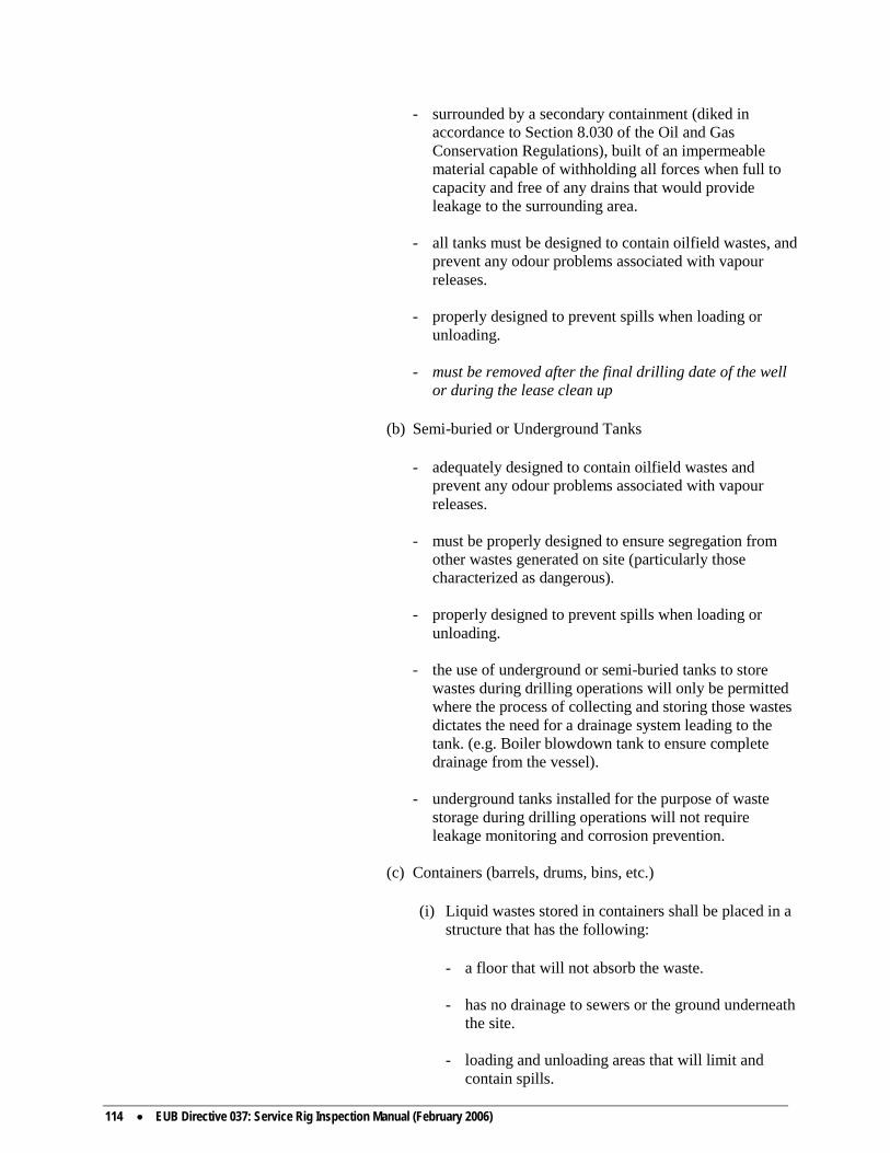
114 • EUB Directive 037: Service Rig Inspection Manual (February 2006)
- surrounded by a secondary containment (diked in accordance to Section 8.030 of the Oil and Gas Conservation Regulations), built of an impermeable material capable of withholding all forces when full to capacity and free of any drains that would provide leakage to the surrounding area.
- all tanks must be designed to contain oilfield wastes, and
prevent any odour problems associated with vapour releases.
- properly designed to prevent spills when loading or
unloading. - must be removed after the final drilling date of the well
or during the lease clean up (b) Semi-buried or Underground Tanks - adequately designed to contain oilfield wastes and
prevent any odour problems associated with vapour releases.
- must be properly designed to ensure segregation from
other wastes generated on site (particularly those characterized as dangerous).
- properly designed to prevent spills when loading or
unloading. - the use of underground or semi-buried tanks to store
wastes during drilling operations will only be permitted where the process of collecting and storing those wastes dictates the need for a drainage system leading to the tank. (e.g. Boiler blowdown tank to ensure complete drainage from the vessel).
- underground tanks installed for the purpose of waste
storage during drilling operations will not require leakage monitoring and corrosion prevention.
(c) Containers (barrels, drums, bins, etc.) (i) Liquid wastes stored in containers shall be placed in a
structure that has the following: - a floor that will not absorb the waste. - has no drainage to sewers or the ground underneath
the site. - loading and unloading areas that will limit and
contain spills.

EUB Directive 037: Service Rig Inspection Manual (February 2006) • 115
- a secondary containment system. (ii) Solid wastes stored in containers shall be placed in a
structure that has the following: - side walls and a cover to protect the containers
from the weather, or - a secondary containment system. 3.2 As a minimum the company representative should have all
of the following information readily available to show proper storage of oilfield wastes.
(a) The location of storage facilities, on site. (b) The volume of wastes stored. (c) Information and specifications on each storage facility
to ensure that they meet the requirements outlined above.
Note: For further and more detailed information see Section 7.0 of
the “Recommended Oilfield Waste Management Requirements”. 4.0 Waste Disposal 4.1 The EUB emphasizes waste minimization through the 4 R's
(reduce, reuse, recycle, recover). Prior to disposal of oilfield wastes the licensee of the well should be minimizing wastes generated by using these principles.
For routine inspection purposes we should encourage waste
minimization and ensure proper disposal. 4.2 The disposal options may vary greatly from one well to another,
generally there will be 4 categories of disposal under which the waste generators options could be categorized.
(a) On Site Facilities - this would include disposal wells
licensed by the EUB or land treatment facilities, landfills, septic fields, etc. that were licensed by AEP on the facility's clean water licence, and owned by the waste generator.
(b) EUB Approved Facilities - this will include the Oilfield
Waste Management Facilities listed in GB 93-15. (c) AEP or Alberta Health Approval Facilities - these facilities
must be authorized to handle specific wastes.

116 • EUB Directive 037: Service Rig Inspection Manual (February 2006)
(d) One time Disposal Approvals - One time disposal options approved through the Area Offices or the Environment Protection Department. (e.g. Sump disposal in accordance with ID 93-1 and Guide G-50).
It is the responsibility of the generator to characterize their waste material and to ensure that the facility receiving their waste is approved to handle it. On the other hand, it is the responsibility of the facility operator to know the facility's capabilities and limitations and to disclose this information to the waste generators asking to use their facility.
Generators found sending their waste material to an unapproved
facility or to an approved facility that is not authorized to accept that specific waste will be required to retrieve their wastes plus any other material contaminated by the waste.
4.3 As a minimum the company representative should have all
of the following information readily available to demonstrate proper disposal of oilfield wastes.
(a) A list of all wastes generated and currently stored on
site and the disposal plans in place for these wastes. 4.4 Refer to attachment Table 1 Drilling Wastes Treatment and
Disposal Information. 4.5 An excellent reference to proper disposal options for specific
wastes in Section 7.0 “Waste Specific Information” of the CPA Production Waste Management Handbook.
5.0 Accounting and Documentation 5.1 Waste generators are responsible to account for wastes from
their source to their final disposition. (a) Records showing the source, volume, and final disposition
of wastes generated onsite and disposed of since 1 September 1993.
Note: For further more detailed information see Section 6.0 of the
Recommended Oilfield Waste Management Requirements”. 6.0 Summary 1. Waste Characterization ─ Types of wastes generated and their
properties and characteristics. (Non-dangerous or dangerous). 2. Waste Storage ─In accordance to Section 7.0 of the
“Recommended Oilfield Waste Management Requirements”. 3. Waste Disposal ─ Proper disposal with an emphasis on
minimization. 4. Accounting ─ From the source of generation to the final
disposition.

EUB Directive 037: Service Rig Inspection Manual (February 2006) • 117
Table 1 Drilling Wastes Treatment and Disposal Information The following waste streams have been characterized and classified based on historical knowledge, testing and in some cases the origin of the waste streams. In applying these characterizations, it is essential that generators examine their own wastes to determine if standard industry practices have resulted in the production of the waste and that their wastes fit the listed type. Any unusual operations, new process feedstock used or site specific conditions may result in a change in a waste's properties. If unusual properties are suspected to exist, then the general characterization method outlined in Section 5.1 of the ERCB's publication “Recommended Oilfield Waste Management Requirements” must be used. This table contains treatment and disposal information. Other issues such as worker safety, material handling procedures, storage and transportation requirements should also be considered. References for these areas include the Canadian Association of Petroleum Producers' Production Waste Management Handbook, the Workplace Hazardous Materials Information System (WHIMS) and the Transportation of Dangerous Goods Regulations (TDGR). The following headings are used within the table: Waste Name - the generic name for a given waste stream Class - the usual classification of the waste. Wastes are classified as Dangerous Oilfield
Waste, Non-Dangerous Oilfield Waste, or Testing Required. This class is to be used when considering disposal options.
Dangerous Oilfield Waste: Some waste facilities may be prohibited from accepting
Dangerous Oilfield Wastes. As well, if an oilfield waste is designated as Dangerous Oilfield Waste it is considered dangerous for the purposes of the Transportation of Dangerous Goods Act.
A generator whose waste is listed as Dangerous Oilfield Waste may choose to test the
waste properties listed in the Criteria column and any other suspected dangerous properties based on the generator's knowledge of the waste. If the tests show the waste is Non-Dangerous Oilfield Waste, it may be classified as such.
Testing Required: Where Testing Required is indicated, either the waste is too
variable in nature to confidently describe its typical properties or the historical information available at the present time is insufficient to definitively classify the waste. In these cases, the wastes should be tested for, as a minimum, the properties noted in the Criteria column, and evaluated against the dangerous properties defined in Section 5.2 of the ERCB's publication “Recommended Oilfield Waste Management Requirements” to determine the waste's proper classification.
See Comments: The Comments column gives direction on classification of the
waste and properties of the waste to consider. These wastes are usually Non-Dangerous Oilfield Wastes.
Non-Dangerous Oilfield Wastes: These wastes usually are non-dangerous in
nature. Criteria - these are the properties that generally are of concern in Dangerous Oilfield Wastes or
wastes classified as Testing Required. Generators may identify other properties of concern based on a site specific evaluation of their wastes.

118 • EUB Directive 037: Service Rig Inspection Manual (February 2006)
Acceptable - these are practices accepted by industry, the EUB and AEP as a means by which Industry the environmental and safety consequences of the waste may be appropriately Practices managed. In the case of Dangerous Oilfield Wastes or wastes where Testing is
Required, the use of these practices do not result in the reclassification of the waste to Non-Dangerous Oilfield Waste. Dangerous Oilfield Wastes remain classified as Dangerous regardless of whether the Acceptable Practices are used or not, and all requirements for handling, manifesting, storage, etc. remain in effect. The practices are seen as processes as a whole by which the dangerous properties are managed. Reclassification of the waste can only occur through waste treatment and testing or the use of an Approved Treatment Standard contained in Attachment C of the ERCB's publication “Recommended Oilfield Waste Management Requirements”.
The practices described generally will be conducted at a facility approved by either the EUB or Alberta Environmental Protection. Other sections of the ERCB Guide to Oilfield Waste Management should be referenced to clarify the expectations, both operationally and for approval requirements, for a given disposal practice.
Comments - these are provided to give clarification to the previous columns, to give additional
guidance as to waste properties of concern and other considerations. This table will be reviewed and amended periodically. The next scheduled review is September 1995 or earlier as required. References: ERCB “Recommended Oilfield Waste Management Requirements” CAODC “Oilfield Waste Management Procedures” CAPP “Production Waste Management Handbook” Section 7

EUB Directive 037: Service Rig Inspection Manual (February 2006) • 119
Table 1 Drilling Waste Treatment and Disposal Information
WASTE NAME
CLASS
CRITERIA
ACCEPTABLE INDUSTRY
PRACTICES
COMMENTS
Absorbent - used to control spills
See comments
• Store in a separate container • Thermal treatment • dispose of in an approved landfill
- normally not a Dangerous Oilfield waste - This material may constitute a Dangerous
Oilfield Waste depending on its leachate characteristics (esp. BTEX); if the BTEX level in this material > 1000 mg/kg, it is non-landfillable
Acid (non-neutralized), used for operations such as water treatment, cooling water inhibition, descaling operations and well servicing. Includes left over and spent acids.
Dangerous Oilfield Waste
corrosivity, heavy metals content, flash point (if hydrocarbons present)
adjust pH to between 4.5 and 12.5, then inject down an EUB approved Class Ia well or adjust pH to between 6.0 and 9.0 then inject down an EUB approved Class Ib disposal well, depending on the heavy metal content - hydrocarbons should be recovered
- ERCB Guide G-51 gives details on disposal
well requirements - heavy metals normally are not concern for
well servicing fluids
Batteries including lead acid and nickel cadmium types from vehicles, electric and lighting systems and instrumentation
Dangerous Oilfield Waste
pH < 2, corrosivity, leachate characteristics (heavy metals (esp. Pb, Cd))
- recycle via battery recyclers - remove free liquid from wet batteries and
neutralize, landfill containers in an approved landfill
- for alkaline batteries see Camp - Domestic
Waste
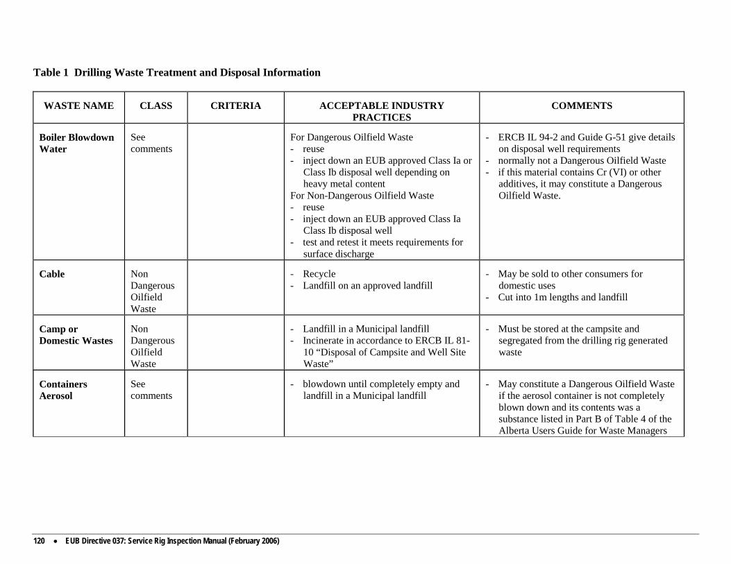
120 • EUB Directive 037: Service Rig Inspection Manual (February 2006)
Table 1 Drilling Waste Treatment and Disposal Information
WASTE NAME
CLASS
CRITERIA
ACCEPTABLE INDUSTRY
PRACTICES
COMMENTS
Boiler Blowdown Water
See comments
For Dangerous Oilfield Waste - reuse - inject down an EUB approved Class Ia or
Class Ib disposal well depending on heavy metal content
For Non-Dangerous Oilfield Waste - reuse - inject down an EUB approved Class Ia
Class Ib disposal well - test and retest it meets requirements for
surface discharge
- ERCB IL 94-2 and Guide G-51 give details
on disposal well requirements - normally not a Dangerous Oilfield Waste - if this material contains Cr (VI) or other
additives, it may constitute a Dangerous Oilfield Waste.
Cable
Non Dangerous Oilfield Waste
- Recycle - Landfill on an approved landfill
- May be sold to other consumers for
domestic uses - Cut into 1m lengths and landfill
Camp or Domestic Wastes
Non Dangerous Oilfield Waste
- Landfill in a Municipal landfill - Incinerate in accordance to ERCB IL 81-
10 “Disposal of Campsite and Well Site Waste”
- Must be stored at the campsite and
segregated from the drilling rig generated waste
Containers Aerosol
See comments
- blowdown until completely empty and
landfill in a Municipal landfill
- May constitute a Dangerous Oilfield Waste
if the aerosol container is not completely blown down and its contents was a substance listed in Part B of Table 4 of the Alberta Users Guide for Waste Managers

EUB Directive 037: Service Rig Inspection Manual (February 2006) • 121
Table 1 Drilling Waste Treatment and Disposal Information
WASTE NAME
CLASS
CRITERIA
ACCEPTABLE INDUSTRY
PRACTICES
COMMENTS
Containers (Empty) - Drums/Barrels, Crude Oil Sample Bottles
See comments
For Dangerous or Non-Dangerous Oilfield Waste - reuse (return to supplier) - recycle - rinse (see definition Section 5.2(2)(c),
crush and landfill in an approved landfill (industrial, municipal)
- normally not a Dangerous Oilfield Waste - drums/barrels must be completely empty;
those drums/barrels that are not empty may be a Dangerous Oilfield Waste depending on their last contents
Containers - Paint and Brushes
See comments
- triple rinse, reuse and recycle where
possible - Use completely, then leave can open in a
ventilated area for residue to dry and harden. Once dry, deposit in garbage bin, lid off
- Clean and reuse brushes. Once unusable, leave to harden and deposit in garbage bin
May constitute a Dangerous Oilfield Waste depending on its flash point, ignitability and leachate characteristics if not rinsed, dried, and ventilated correctly
Containers - Pipe Dope and Brushes
See comments
- triple rinse and reuse or recycle where
possible - once unusable, triple rinse and dispose of
in an approved landfill
May constitute a Dangerous Oilfield Waste based on leachate characteristics if not rinsed properly
Contaminated Soil - Hydrocarbons, Diesel, Hydraulic Fluids, Glycol
See comments
For Dangerous or Non-Dangerous Waste: - if land treatment on-site is not possible,
excavate and send to licensed oilfield waste processing facility for hydrocarbon recovery
- thermal treatment
- normally not a Dangerous Oilfield Waste - this material may constitute a Dangerous
Oilfield Waste depending on its flash point and BTEX content
- treat on-site if possible, in consultation with EUB
- all off-site spills or spills in excess of 2 m3 must be reported to the EUB

122 • EUB Directive 037: Service Rig Inspection Manual (February 2006)
Table 1 Drilling Waste Treatment and Disposal Information
WASTE NAME
CLASS
CRITERIA
ACCEPTABLE INDUSTRY
PRACTICES
COMMENTS
Corrosion Inhibited Water
Dangerous Oilfield Waste
heavy metals content
- inject down an EUB approved Class Ib
disposal well if meets heavy metals limits; Class Ia well if exceeds limits
- ERCB Guide G-51 gives detail on disposal
well requirements.
Drilling Sump Materials - Gel chem
Not a Dangerous Oilfield Waste
- treatment on-site, land treatment in
accordance with ERCB ID 93-1
Drilling Sump Materials - KCI
Not a Dangerous Oilfield Waste
- inject liquids down an EUB approved
Class Ia or Class Ib disposal well, bury solids on-site in accordance with ERCB ID 93-1
- EUB approval for disposal of KCL sump
materials must be obtained prior to spudding the well (see ERCB IL 93-6)
- in some cases liquids may be land treated in accordance with ERCB ID 93-1
Drilling Sump Materials - Oil Base
See comments
For Dangerous or Non-Dangerous Oilfield Waste: - recycle liquids, land treat solids in
accordance with ERCB ID 93-1 - thermal treatment
- normally not a Dangerous Oilfield Waste - this material may constitute a Dangerous
Oilfield Waste depending on its flash point and BTEX content
- EUB approval for disposal of invert sump materials must be obtained prior to spudding the well (see ERCB IL 93-6)
- additives may render fluid unacceptable for re-refining.
Drill Stem Test Fluids - Hydrocarbon, Salt Water
Dangerous Oilfield Waste
flash point ignitability
- Contain and recover - Send for hydrocarbon recovery at an
approved oilfield waste processing facility

EUB Directive 037: Service Rig Inspection Manual (February 2006) • 123
Table 1 Drilling Waste Treatment and Disposal Information
WASTE NAME
CLASS
CRITERIA
ACCEPTABLE INDUSTRY
PRACTICES
COMMENTS
Filters
Dangerous Oilfield Waste
ignitability, flash point, spontaneous combustibility, leachate if in a friable form
- recycle (metal recovery) - thermal treatment - remove entrained liquids to standard as
outlined in Attachment 5C, place in suitable container to prevent contact with air and landfill in an approved landfill
- CAPP has developed sampling and testing
protocol - recovered entrained liquid is a Dangerous
Oilfield Waste and should be recycled, injected down an EUB approved Class Ia disposal well if organic fraction less than 10 per cent or incinerated
Frac Sand - Radioactive
See comments
For Dangerous Oilfield Waste (Non-radioactive): - recycle (return to supplier) - place in suitable container and landfill in
an EUB approved Class I or II oilfield landfill or equivalent
For Non-Dangerous Oilfield Waste (non-radioactive): - recycle (return to supplier) - bury on-site in accordance with AECB
guidelines
- radioactive materials must NOT be taken to
a waste processing facility or road disposed - radioactive materials are regulated by the
Atomic Energy Control Board. Approval from the AECB is required for off site transportation.
- this material may constitute a Dangerous Oilfield Waste after radioactive decay due to leachate characteristics (heavy metals from radioactive tracers)
Glycol solutions (aqueous)
See comments
For Dangerous or Non-Dangerous Oilfield Waste: - recycle - inject in EUB approved Class Ia or Class
Ib disposal well if glycol content less than 40% by mass.
- normally not a Dangerous Oilfield Waste - this material may constitute Dangerous
Oilfield Waste depending on its leachate characteristics, flash point and toxicity
- ERCB Guide G-51 give details on disposal well requirements
Grease Cartridges (Empty)
Not a Dangerous Oilfield Waste
- dispose of in an approved landfill
- completely empty cartridge - Clean with a rag or sorbent material

124 • EUB Directive 037: Service Rig Inspection Manual (February 2006)
Table 1 Drilling Waste Treatment and Disposal Information
WASTE NAME
CLASS
CRITERIA
ACCEPTABLE INDUSTRY
PRACTICES
COMMENTS
Hydrotest Fluids (Methanol)
Dangerous Oilfield Waste
ignitability, flash point, toxicity
- reuse - recycle - inject down an EUB approved Class Ia or
Class Ib disposal well - thermal treatment
- ERCB Guide G-51 gives details on disposal
well requirements
Hydraulic Oil
Dangerous Oilfield Waste
- heavy metals - ignitability and
flash point
- recycle - reuse - thermal treatment
- supplier may take back used product - Deliver to an used oil recycler
Lubricating Oil - Hydrocarbon
Dangerous Oilfield Waste
heavy metal content (esp. Ba), ignitability, flash point
- collect and direct to a licensed lube oil
recycling firm - thermal treatment
- supplier may take back used product
Lubricating Oil - Synthetic
Dangerous Oilfield Waste
heavy metal content, ignitability, flash point
- collect and direct to a licensed lube oil
recycling firm - thermal treatment
- supplier may take back used product
Mud sacks
Not a Dangerous Oilfield Waste
- recycle - dispose of to an approved landfill
- collect in a segregated storage area and
return them to the supplier

EUB Directive 037: Service Rig Inspection Manual (February 2006) • 125
Table 1 Drilling Waste Treatment and Disposal Information
WASTE NAME
CLASS
CRITERIA
ACCEPTABLE INDUSTRY
PRACTICES
COMMENTS
Rags - Oily
See comments
For Dangerous Oilfield Waste: - reuse via laundering/dry-cleaning - remove entrained liquids and landfill in
an approved landfill - thermal treatment For Non-Dangerous Oilfield Waste: - reuse via laundering/dry cleaning - remove entrained liquids and landfill in
an approved landfill (EUB, industrial or municipal)
- normally not a Dangerous Oilfield Waste - this material may constitute a Dangerous
Oilfield Waste depending on its flash point or ignitability if it is not hydrocarbon free or due to its leachate characteristics (esp. BTEX); if the BTEX level in this material >1000 mg/kg, it is non-landfillable
- section 8.2 has information on oilfield landfill design requirements
Refuse - Planks, scrap metal, papers, plastics
ignitability, flash point, halogenated organic content
- recycle
(regenerate, alternate uses)
- thermal treatment
- recylce - reuse - landfill
Solvents
Dangerous Oilfield Waste
ignitability, flash point, halogenated organic content
- recycle (regenerate, alternate uses) - thermal treatment
Thread Protectors
See comments
- recycle - thermal treatment - clean and landfill in an approved landfill
- normally not a Dangerous Oilfield Waste - may constitute a Dangerous Oilfield Waste
based on the lead content of the pipe dope - store in a separate bin or container and
return to supplier or recycler

126 • EUB Directive 037: Service Rig Inspection Manual (February 2006)
Table 1 Drilling Waste Treatment and Disposal Information
WASTE NAME
CLASS
CRITERIA
ACCEPTABLE INDUSTRY
PRACTICES
COMMENTS
Water - Rig Wash
Not a Dangerous Oilfield Waste
- Reuse - inject down an EUB Class Ia or Class Ib
disposal well - test and release if water meets surface
discharge criteria
Surface Discharge Criteria a) Chlorides - < 500 mg/l b) pH - 6 to 9 c) no visible hydrocarbon sheen d) landowner consent e) water must not be allowed to flow directly
into rivers, creeks, or any other permanent body of water
f) document and record discharge criteria and volumes
1. It is the generator's responsibility to ensure wastes are treated and disposed of correctly. This table is based on wastes produced through the use of
standard industry practices. If unusual properties are suspected to exist or the characteristics are uncertain, the general characterization method outlined in Section 5.1 of the “Recommended Oilfield Waste Management Requirements”.
2. This table contains treatment and disposal information. Other issues such as worker safety, material handling procedures, storage and transportation requirements should also be considered. References for these areas include the Canadian Association of Petroleum Producers' Production Waste Management Handbook, the Workplace Hazardous Materials Information System (WHMIS) and the Transportation of Dangerous Goods Regulations (TDGR). All requirements of the Transportation of Dangerous Goods Act must still be met.
3. The use of Acceptable Industry Practices does not result in the reclassification of a Dangerous Oilfield Waste or a waste indicated as Testing Required to a Non-Dangerous Oilfield Waste. See notes which precede table.