Embed Size (px)
Citation preview
Schedule A
Directive PNG008: Disposal and Injection Well Requirements
Directive PNG008
March 29, 2018
Revision 1.1
Governing Legislation:
Act: The Oil and Gas Conservation Act
Regulation: The Oil and Gas Conservation Regulations, 2012
Minister’s Order: 101/18
Directive PNG008: Disposal and Injection Well Requirements
March 29, 2018 Page 2 of 24
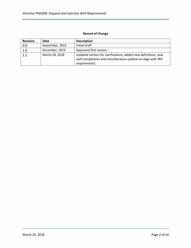
Record of Change
Revision Date Description 0.0 September, 2015 Initial draft 1.0 December, 2015 Approved first version 1.1 March 29, 2018 Updated version for clarifications, added new definitions, new
well completions and miscellaneous updates to align with IRIS requirements.
Directive PNG008: Disposal and Injection Well Requirements
March 29, 2018 Page 3 of 24
Contents 1. Introduction .......................................................................................................................................... 4
2. Definitions ............................................................................................................................................. 4
3. Governing Legislation............................................................................................................................ 6
4. Well Completion Types of Disposal/Injection Wells ............................................................................. 6
4.1 Well Completion Types without Authorizations before Licensing ............................................... 6
4.2 Well Completion Types Requiring Authorization before Licensing .............................................. 7
5. Application, Consents and Notification Requirements ......................................................................... 8
5.1 IRIS Application ............................................................................................................................. 8
5.2 Drainage Unit/Area for Disposal/Injection Wells ......................................................................... 8
5.3 Written Consent for Disposal Wells .............................................................................................. 8
5.4 Written Consent for Injection Wells ............................................................................................. 9
5.5 Written Consent Format ............................................................................................................... 9
5.6 Public Notification for Offsetting Owners ..................................................................................... 9
6. Casing and Cementing Requirements ................................................................................................... 9
7. Completion, Operation and Monitoring Requirements ..................................................................... 10
8. Logging Requirements ........................................................................................................................ 12
9. Logging Amendment ........................................................................................................................... 13
10. Annulus Test Requirements ................................................................................................................ 14
11. Injectivity Test Requirements ............................................................................................................. 14
12. Surface Facilities.................................................................................................................................. 14
13. Measurement and Reporting Requirements ...................................................................................... 15
14. Well Data Submission Requirements .................................................................................................. 15
Appendix 1: Common Disposal Pools ......................................................................................................... 16
Appendix 2: Flow Chart Related to Applying for a Licence for a Disposal Well .......................................... 18
Appendix 3: Calculation of Maximum Wellhead Injection Pressure .......................................................... 19
Appendix 4: Potash Waste Disposal Well ................................................................................................... 20
Appendix 5: Logging Guidelines .................................................................................................................. 21
Appendix 6: Recommended Procedures for Step-Rate Injectivity Test ...................................................... 24
Directive PNG008: Disposal and Injection Well Requirements
March 29, 2018 Page 4 of 24
1. Introduction Directive PNG008: Disposal and Injection Well Requirements (Directive PNG008) sets out the requirements of the Saskatchewan Ministry of Energy and Resources (ER) for the licensing and operation of disposal and injection wells. The purpose of this Directive is to detail the wellbore design, wellbore integrity logging, operational monitoring, and reporting requirements for disposal and injection wells. Injection refers to injection of fluids into subsurface pools for the purpose of enhanced recovery and storage. Disposal refers to disposing of fluids into subsurface pools for purposes other than enhanced recovery or storage. The requirements in this Directive are designed to ensure hydraulic isolation of stored, injected or disposed fluids, and to protect groundwater and energy resources. Disposal and injection wells that were approved before the release of this Directive (Revision 1.1) dated March 29, 2018 must meet the current completion, operation, monitoring and logging requirements within five years of the effective date of this revised Directive, unless otherwise approved by ER. ER refers to the latest edition of Canadian Standards Association Standard (CSA) Z341: Storage of Hydrocarbons in Underground Formations and Salt Cavern Waste Disposal, for additional requirements for the design, construction, testing, operation, maintenance and repair of underground hydrocarbon storage and cavern waste disposal projects in Saskatchewan. CSA Z341 can be accessed at CSA website at http://www.csagroup.org/. Questions on Directive PNG008 can be directed to Petroleum and Natural Gas (PNG) Support at 1-855-219-9373 or [email protected].
2. Definitions
Acid gas means a gas that is separated during the treating of solution, or non-associated gas that contains hydrogen sulfide (H2S), totally reduced sulfur compounds, and/or carbon dioxide (CO2). Casing inspection log means a log that determines the depth of anomalies into the well casing; distinguishes between external and internal corrosion; and detects holes, pits, perforations, metal loss and metal thickness in the casing. Cement bond log means a log used to determine the quality of cement bonding between casing and rock formations. Commingled disposal means the disposal of fluids into two or more pools through a common wellbore without separate measurement of the disposal into each pool. Common disposal pool means a pool that is non-hydrocarbon bearing and for the purpose of disposal, as shown in Map 1 and Map 2 in Appendix 1. Disposal well means a well that has a primary purpose of fluid disposal.
Directive PNG008: Disposal and Injection Well Requirements
March 29, 2018 Page 5 of 24
Fracture gradient means the pressure gradient that, when applied to subsurface formations, causes the formations to fracture physically. Hydraulic isolation log means a log that detects the flow of injected fluids behind the casing string. Injection well means a well that is linked to a project as part of a project for incremental recovery or for underground storage. Integrated Resource Information System (IRIS) means an online business system that supports the development and regulation of Saskatchewan's energy and resources industry. Through IRIS, the oil and gas industry completes regularly performed business activities and regulatory tasks with the province online. Non-routine application means an application that is not a routine application. Packer isolation test means a pressure test of the tubing-casing annulus designed to evaluate the integrity of the casing, tubing and packer. Produced salt water means water produced in association with the recovery of hydrocarbons and other gases. Project means a development that groups one or more wells for approval of a specialized scheme, e.g., waterflood, EOR, storage, etc. Routine application means an application submitted to ER where a licensee self-declares that all the necessary regulatory requirements are met. Routine applications are authorized without additional review and they may be reviewed after authorization through the auditing process. Step-rate injectivity test means an injectivity test that plots stabilized injection pressures against stabilized flow rates, at increasing flow rate steps sufficient to indicate either formation fracture, or the absence of fracture. Thermal Enhanced Oil Recovery (EOR) means any process that utilizes heat to aid in the recovery of hydrocarbons, including but not limited to, steam injection, heated water injection, heated oil injection and in-situ combustion. Waste processing facility means any facility that is constructed and operated for the purpose of containing, storing, handling, treating, processing, recovering, reusing, recycling, destroying or disposing of oil-and-gas waste.
Directive PNG008: Disposal and Injection Well Requirements
March 29, 2018 Page 6 of 24
3. Governing Legislation The requirements in this Directive are authorized under and supplemented by: • The Oil and Gas Conservation Act (OGCA) • The Oil and Gas Conservation Regulations, 2012 (OGCR) • Associated Directives and Guidelines
• Directive PNG001: Facility Licence Requirements • Directive PNG005: Casing and Cementing Requirements • Directive PNG006: Horizontal Oil Well Requirements • Directive PNG009: Public Notice Requirements • Directive PNG010: Well Logging Requirements • Directive PNG013: Well Data Submission Requirements • Directive PNG017: Measurement Requirements for Oil and Gas Operations • Guideline PNG021: Determining Drainage Units and Target Areas • Guideline PNG024: Reclassification and Recompletion • Guideline PNG029: Annulus Test Reporting Requirements
4. Well Completion Types of Disposal/Injection Wells
4.1 Well Completion Types without Authorizations before Licensing
The following well completion types do not require additional authorization in IRIS before licensing, as long as they are not used for commingled disposal: (a) Disposal Well
Disposal wells are used for the disposal of produced salt water or brine equivalent fluids and when the well is not part of an active project approved by ER (i.e., waterflood project, EOR project, storage project, etc.). Examples of the disposal fluids include the following:
• produced salt water associated with the recovery of hydrocarbons and other gases; • water-based pigging fluids from cleaning of a collection or injection line, provided it
does not contain additional chemicals; • brine reject or backwash from water softeners associated with enhanced recovery
schemes; • water from enhanced recovery schemes (can contain polymers or chemicals); and • brine, excluding potash waste brine as described in Appendix 4 and brine as a by-
product from the prescribed industries in subclause 4.1(c)(ii). (b) Potash Waste Disposal Well
Potash waste disposal wells are used for the disposal of potash waste brines recovered from potash operations. Please refer to Appendix 4 for the description of potash waste brines.
(c) Waste Disposal Well Most waste disposal wells are associated with an approved waste-processing facility regulated by ER and/or an industrial facility regulated by the Saskatchewan Ministry of Environment. Waste disposal wells are used for disposal of the following:
Directive PNG008: Disposal and Injection Well Requirements
March 29, 2018 Page 7 of 24
(i) oil-and-gas field non-hazardous waste fluids including produced salt water and specific common oil-and-gas field waste streams. Examples of non-hazardous oil-and-gas field wastes that may be disposed include boiler blowdown water, tank wash water, rig wash, spent glycol and drilling waste leachate; and/or
(ii) non-oil-and-gas or industrial waste fluids generated from the following prescribed industries: the chemical and petro-chemical refining industry, the mining and minerals processing industry, the electrical energy generating industry, the manufacturing industry, the forestry and forestry products industry, the construction industry, the transportation industry, the service industry, the waste management industry, and the geothermal industry.
4.2 Well Completion Types Requiring Authorization before Licensing
A well licence cannot be issued for certain well completion types prior to obtaining additional authorization in IRIS. Most of the well completion types are associated with a project, e.g., waterflood, EOR, or storage. Upon authorization, a licensee must specify the authorization number at the time of licensing for every well approved by that authorization. The following are well completion types requiring additional authorization in IRIS before licensing: • Pressure Maintenance – Water Injection Well • Pressure Maintenance – Gas Injection Well • Air Injector (Combustion) Well • Alternating Pressure Maintenance – Water Injection/Air Injection • Alternating Pressure Maintenance – Water Injection/CO2 Injection • Alternating Pressure Maintenance – Water Injection/Gas Injection • CO2 Injector Well (these are wells used for the injection of CO2 into a reservoir matrix for an
enhanced recovery operation) • Disposal wells listed in subsection 4.1 and used for commingled disposal • Cyclic Oil/Steam Injector Well • Gas Storage (Cavern) Well • Gas Storage Well (these are wells used for the storage of gas in underground reservoir
formations) • Liquid Gas/NGLS Storage Well • Nitrogen Injector Well • Oxygen Injector Well • Permanent Oil/Steam Injector Well • Polymer Injector Well • Solvent Injector Well • Steam Injector Well (Permanent) (these are wells used for the injection of steam from
potable water or recycled water into a reservoir matrix to stimulate reservoir production) • Acid Gas Disposal Well (these are wells used for the disposal/injection of acid gas into a
deep saline aquifer or depleted hydrocarbon pool in non-EOR operations) • CO2 Storage Well (these are wells used for the injection of anthropogenic CO2 into a deep
saline aquifer or depleted hydrocarbon pool in non-EOR operations) • Waste Disposal (Cavern) Well (these are wells associated with waste disposal cavern
systems, which can receive hydrocarbon based drilling wastes and other types of authorized wastes)
Directive PNG008: Disposal and Injection Well Requirements
March 29, 2018 Page 8 of 24
• Permanent Oil and Oil Injector Well • Oil Producer and Water Injector Well • Cyclic Oil/Solvent Injector • Gas Producer and Gas Injector • Oil Producer/Alternating Pressure Maintenance – Water Injection/Gas Injection • Permanent Oil/CO2 Injection • Waste Disposal Well, used for the disposal of cooling formation water after a heat
extraction process and is part of geothermal project
5. Application, Consents and Notification Requirements
5.1 IRIS Application
Licences for disposal wells with a well completion type listed in subsection 4.1 can be applied for through the licensing process in IRIS, without requiring additional authorization from ER. An application for a disposal well licence is either a routine or non-routine application in IRIS depending on the licensee’s response to disclosure questions. An application for a potash waste disposal well licence or a waste disposal well licence is a non-routine application. Appendix 2 shows the flow chart for decisions when licensing a disposal well. Licences for disposal/injection wells with a well completion type listed in subsection 4.2 must be applied for through the licensing process in IRIS, after receiving additional authorization from ER. Reclassification and/or recompletion to disposal/injection wells after the initial completion of the well must be applied for in IRIS, using the appropriate application process. Refer to Guideline PNG024.
5.2 Drainage Unit/Area for Disposal/Injection Wells
The drainage unit/area assigned to a disposal/injection well is that which would be assigned to an oil producing well. Please refer to Directive PNG006 and Guideline PNG021 on how to determine the drainage unit/area. Please note that target area is not applied to disposal/injection wells. A request for modification of drainage unit/area for a disposal/injection well that is subject to a lease of spaces agreement issued under The Oil and Gas Tenure Registry Regulations must be emailed to [email protected].
5.3 Written Consent for Disposal Wells
Before submitting an application in IRIS, applicants must obtain the right to dispose within the proposed disposal pool. Proof of the right to dispose includes the following: • Freehold land: written consent from all freehold mineral owners, other than the applicant,
within the drainage unit/area of the proposed disposal well. • Disposed Crown land: written consent from the holders of the Crown disposition, other than
the applicant, within the drainage unit/area of the proposed disposal well. Dispositions include oil and gas leases, licences or permits issued pursuant to The Crown Minerals Act.
Directive PNG008: Disposal and Injection Well Requirements
March 29, 2018 Page 9 of 24
• Undisposed Crown land: consent or non-objection letter from the Crown, within the drainage unit/area of the proposed disposal well. The licensee must email the request to [email protected].
5.4 Written Consent for Injection Wells
Written consent is required from all freehold mineral owners within the drainage unit/area of the proposed injection well, before submitting an application for the injection well.
5.5 Written Consent Format
Please refer to Directive PNG009 for the consent format.
5.6 Public Notification for Offsetting Owners
The applicant must notify offsetting or impacted mineral owners or operators whose lands are offsetting the proposed well. The notification can be conducted through the public notice process. Please refer to Directive PNG009 for the public notice process related to disposal/injection wells. Notification is not required if disposing of produced salt water into a common disposal pool. The applicant may choose to obtain consents from all parties within the notification area as identified in Directive PNG009. If all consents are obtained, then the public notice requirement is considered to be satisfied. Note: It is the responsibility of the applicant to identify any potentially or directly affected parties outside of the minimum notification area and provide notification to these parties.
6. Casing and Cementing Requirements The well casing and cement must provide hydraulic isolation of the disposal/injection contact intervals as well as protection of useable groundwater from aquifer cross-flow of the injected fluid, regardless of the fluid being disposed. In addition to the casing and cementing requirements outlined in Directive PNG005, special cements are required in the following: (a) Acid gas disposal well
Acid-resistant cement must be used from total depth to above the disposal zone.
(b) Wells in thermal project areas Any new injection and disposal wells within an approved thermal EOR project area, as defined in a Minister’s Order for that specific project, will be required to have thermal cement and casing from total depth to surface. It is recommended that all new injection and disposal wells, currently outside of an approved thermal EOR project area but may be included as part of the future thermal development, be completed with thermal casing and cement.
Directive PNG008: Disposal and Injection Well Requirements
March 29, 2018 Page 10 of 24
7. Completion, Operation and Monitoring Requirements
A licensee must ensure that all disposal/injection wells maintain wellbore integrity and hydraulic isolation of the disposal/injection fluids from other porous stratigraphic units. Any well that does not meet the requirements of this Directive may have its application denied or be subject to additional requirements. Please refer to CSA Z341 for additional completion, testing, operation and monitoring requirements for wells used for hydrocarbon storage and cavern waste disposal. A licensee must meet the following requirements: (a) Maximum Wellhead Injection Pressure (MWHIP)
Disposal/Injection pressure in the disposal/injection formation must not exceed the formation fracture pressure. All disposal/injection wells will be subject to a MWHIP. The recommended practice for the determination of the MWHIP is based on the formation fracture pressure with a safety factor applied (refer to Appendix 3). The formation fracture pressure may be determined by step-rate injectivity tests (see Appendix 6 for recommended procedures), in-situ stress tests, or reliable offset data. A safety factor of 90 per cent must be used, unless otherwise approved by ER on an application through IRIS, or an email request to PNG Support at [email protected] after an IRIS authorization. An IRIS obligation is generated for a Well Completion when a disposal or injection well licence is issued or a disposal/injection reclassification or recompletion application is authorized. To fulfill the obligation, a MWHIP report and MWHIP value must be submitted on all disposal and injection wells through IRIS, within 30 days of completion. The subsequent MWHIP report and MWHIP value must be submitted through IRIS if there are any changes from the initial reported MWHIP. The report must include the following: (i) the calculation of the MWHIP in accordance with Appendix 3; (ii) the complete test data, plots and all analyses, if testing is conducted to determine the
formation fracture pressure outlined in section 11 of this Directive; (iii) technical justification of the proposed MWHIP, locations and testing conducted in the
offset wells, discussion of the stratigraphic, structural and lithological analogies and in-situ stress conditions, etc., if the offset data is used to determine the MWHIP; and
(iv) reasons for the change of MWHIP if the formerly reported MWHIP is changed. Once the MWHIP report is submitted and the MWHIP value is entered in IRIS, ER deems it acceptable given the MWHIP determination is in accordance with this Directive. ER may audit, re-evaluate and enforce compliance where the MWHIP does not meet the requirement in accordance with this Directive. ER also has authority to assess and override MWHIP values at ER’s discretion.
Directive PNG008: Disposal and Injection Well Requirements
March 29, 2018 Page 11 of 24
(b) Injection packer With the exception of previously approved disposal/injection wells, an injection packer is required for all disposal/injection wells. Unless otherwise approved on an application through IRIS, the injection packer must be set within the disposal/injection pool or below the next porous interval above the disposal/injection pool, at a location no more than five (5) metres true vertical depth (TVD) to: • the top of the perforations; • the casing seat in an open hole completion; or • the top of the liner hanger in a liner completion. A request to deviate from the above injection packer requirement after an IRIS authorization must be email to PNG Support at [email protected].
(c) The tubing-production casing annulus must be filled with corrosion-inhibiting fluid and maintained at a positive pressure.
(d) The portion of the casing exposed to disposal/injection fluids below the perforations must not exceed 25 m within the disposal/injection pool or within a shale formation directly below the disposal/injection pool. The portion of the wellbore below the disposal/injection interval must be plugged back in accordance with Guideline PNG024.
(e) An initial packer isolation test is required in accordance with Guideline PNG029. (f) The tubing-production casing- annulus and tubing pressures must be monitored and
recorded on a: • daily basis for waste disposal wells, potash waste disposal wells, acid gas disposal wells
and CO2 storage wells; or • monthly basis for other wells not included in (a) above.
ER can set a different frequency for monitoring annulus and tubing pressures based on well-specific conditions. Pressure records must be retained by the licensee for a period of not less than five (5) years. The pressure data must be made available upon request by ER within two (2) business days for compliance audit purposes.
(g) The hydraulic stimulation of any formation in the disposal well is not allowed. ER will require licensees to apply through IRIS for any proposed hydraulic stimulation, approval may be granted provided the proper supporting technical information is provided.
(h) For potash waste disposal wells, unless otherwise previously exempted by ER or on an application and authorization in IRIS, annual pressure fall-off tests must be conducted. The test report must be submitted in IRIS in accordance with Directive PNG013. Refer to Appendix 4: Potash Waste Disposal Well for details.
Directive PNG008: Disposal and Injection Well Requirements
March 29, 2018 Page 12 of 24
(i) All surface casing vent issues (presence of gas or fluid at surface) must be reported to the appropriate field office or ER’s Petroleum and Natural Gas Emergency Support Line at 1-844-764-3637. Management of the issue after consultation and assessment review will be dealt with in manner that ensures worker, public, environmental and subsurface reservoir protection.
8. Logging Requirements
All required logs outlined in this section must be submitted to ER through IRIS, accompanied by a detailed interpretation of the log against its specific objective performed by qualified personnel. Disposal or injection must not commence if log interpretation deems a lack of hydraulic isolation. In order to proceed, an application to repair a well must be submitted through IRIS and all work required must be completed to the satisfaction of ER area field office. For existing wells, all porous stratigraphic units, in addition to the disposal/injection pool, must be isolated by cement. In addition to the well logging requirements outlined in Directive PNG010, the following logging requirements must be met to evaluate hydraulic isolation of the disposal or injection contact intervals , unless otherwise approved by ER on an application through IRIS. Please refer to CSA Z341 for additional logging requirements for wells used for hydrocarbon storage and cavern waste disposal. (a) Cement Bond Log
The cement bond log must demonstrate that hydraulic isolation exists between all porous stratigraphic units and provide a radial view of cement quality and identify lightweight cement quality. The cement bond log requirements include: • An initial full-length cement bond log must be run for non-horizontal disposal/injection
wells; or • An initial cement bond log must be run from the top of the disposal/injection pool to
the surface for horizontal wells.
(b) Hydraulic Isolation Logs • An initial hydraulic isolation log must be run on waste disposal or potash waste disposal
wells; and • A subsequent hydraulic isolation log must be run every five (5) years on waste disposal
wells. ER can set a different frequency for running a subsequent hydraulic isolation log based on well-specific conditions.
(c) Casing Inspection Log A full interpretation of the log must be submitted on a joint-by-joint basis that identifies anomalies, holes, pits, perforations, metal loss, wall thickness, and internal and external corrosion. The casing age, grade and collapse pressure of wells within the area of pressure influence must also be considered at the time of the application, which may be a potential
Directive PNG008: Disposal and Injection Well Requirements
March 29, 2018 Page 13 of 24
limiting factor to the MWHIP. As casing integrity may degrade with age, an appropriate safety factor must be applied. The casing inspection log requirements include: • An initial full-length casing inspection log must be run on:
• new and existing wells being converted for waste disposal or potash waste disposal; • existing wells being converted for injection of CO2, solvent, or thermal fluids used in
an EOR process; or • existing wells being converted for disposal/injection of hydrocarbon or other gases;
and • A subsequent casing inspection log must be run every ten (10) years on waste disposal
wells and potash waste disposal wells.
ER can set a different frequency for running a subsequent casing inspection log based on well-specific conditions.
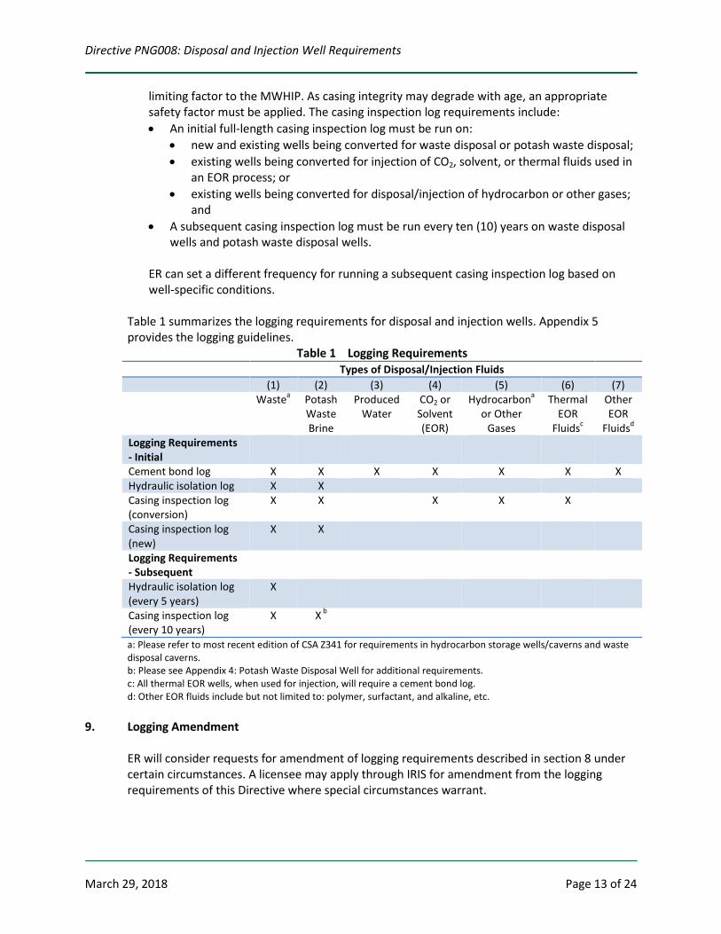
Table 1 summarizes the logging requirements for disposal and injection wells. Appendix 5 provides the logging guidelines.
Table 1 Logging Requirements Types of Disposal/Injection Fluids (1) (2) (3) (4) (5) (6) (7) Wastea Potash
Waste Brine
Produced Water
CO2 or Solvent (EOR)
Hydrocarbona or Other
Gases
Thermal EOR
Fluidsc
Other EOR
Fluidsd Logging Requirements - Initial
Cement bond log X X X X X X X Hydraulic isolation log X X Casing inspection log (conversion)
X X X X X
Casing inspection log (new)
X X
Logging Requirements - Subsequent
Hydraulic isolation log (every 5 years)
X
Casing inspection log (every 10 years)
X X b
a: Please refer to most recent edition of CSA Z341 for requirements in hydrocarbon storage wells/caverns and waste disposal caverns. b: Please see Appendix 4: Potash Waste Disposal Well for additional requirements. c: All thermal EOR wells, when used for injection, will require a cement bond log. d: Other EOR fluids include but not limited to: polymer, surfactant, and alkaline, etc.
9. Logging Amendment ER will consider requests for amendment of logging requirements described in section 8 under certain circumstances. A licensee may apply through IRIS for amendment from the logging requirements of this Directive where special circumstances warrant.
Directive PNG008: Disposal and Injection Well Requirements
March 29, 2018 Page 14 of 24
10. Annulus Test Requirements All disposal and injection wells must be tested and inspected at least once every year. All tests must be conducted in accordance with section 53 of the OGCR. Please refer to Guideline PNG029 for more information.
11. Injectivity Test Requirements Subject to conditions in clause 11 (b) being met, a maximum cumulative water injection of 500 m3 in order to acquire the information to determine the MWHIP or injectivity may be undertaken without prior authorization from ER. A step-rate injectivity test can be used to determine the MWHIP or to confirm injectivity without fracturing the formation. Please note that step-rate test data from tests conducted after a hydraulic fracture stimulation may be inconclusive, and may not be acceptable for determining fracture pressure. (a) Procedure
The recommended standard procedure for carrying out a step-rate injectivity test is described in Appendix 6. Other types of testing methods, such as in-situ stress tests, mini-micro frac tests, or Diagnostic Fracture Injection Tests (DFIT), can also be used to determine the MWHIP.
(b) Conditions
The following conditions must be met when conducting a step-rate injectivity test or an analogous test to determine the MWHIP or injectivity of a well: (i) The licensee must have the Right to Dispose/Inject; (ii) The test period must not exceed seven (7) days; (iii) The water injection volume must not exceed 500 m3; (iv) The injection packer must be set in accordance with requirements in clause 7(2); (v) If a new completion is required for the injection, an approval to recomplete must first
be obtained from ER prior to completing in a new pool (Refer to the Guideline PNG024); and
(vi) The step-rate injectivity test report must be submitted through IRIS, meeting the same requirements set for MWHIP reporting in clause 7(1).
If the proposed testing method does not meet the conditions above, an application to reclassify the well must be submitted through IRIS for approval prior to commencement of injection.
12. Surface Facilities A separate facility licence application must be submitted to ER through IRIS if an upstream facility is required for the disposal or injection well. For information on how to obtain a licence to construct and operate an upstream facility refer to Directive PNG001.
Directive PNG008: Disposal and Injection Well Requirements
March 29, 2018 Page 15 of 24
13. Measurement and Reporting Requirements Refer to Directive PNG017 for measurement and reporting requirements that are applicable to disposal or injection wells/facilities.
14. Well Data Submission Requirements Refer to Directive PNG013 for requirements for the submission of well data associated with drilling, completion, workover and abandonment activities.
Directive PNG008: Disposal and Injection Well Requirements
March 29, 2018 Page 16 of 24
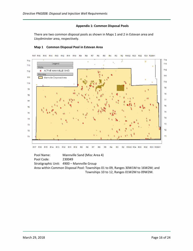
Appendix 1: Common Disposal Pools
There are two common disposal pools as shown in Maps 1 and 2 in Estevan area and Lloydminster area, respectively. Map 1 Common Disposal Pool in Estevan Area
Pool Name: Mannville Sand (Misc Area 4) Pool Code: 230049 Stratigraphic Unit: 4900 – Mannville Group Area within Common Disposal Pool: Townships 01 to 09, Ranges 30W1M to 16W2M; and Townships 10 to 12, Ranges 01W2M to 09W2M.
Directive PNG008: Disposal and Injection Well Requirements
March 29, 2018 Page 17 of 24
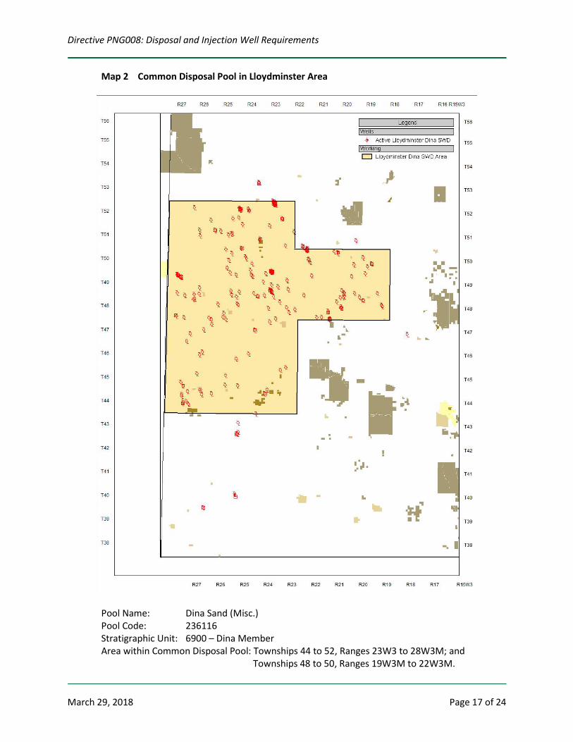
Map 2 Common Disposal Pool in Lloydminster Area
Pool Name: Dina Sand (Misc.) Pool Code: 236116 Stratigraphic Unit: 6900 – Dina Member Area within Common Disposal Pool: Townships 44 to 52, Ranges 23W3 to 28W3M; and Townships 48 to 50, Ranges 19W3M to 22W3M.
Directive PNG008: Disposal and Injection Well Requirements
March 29, 2018 Page 18 of 24
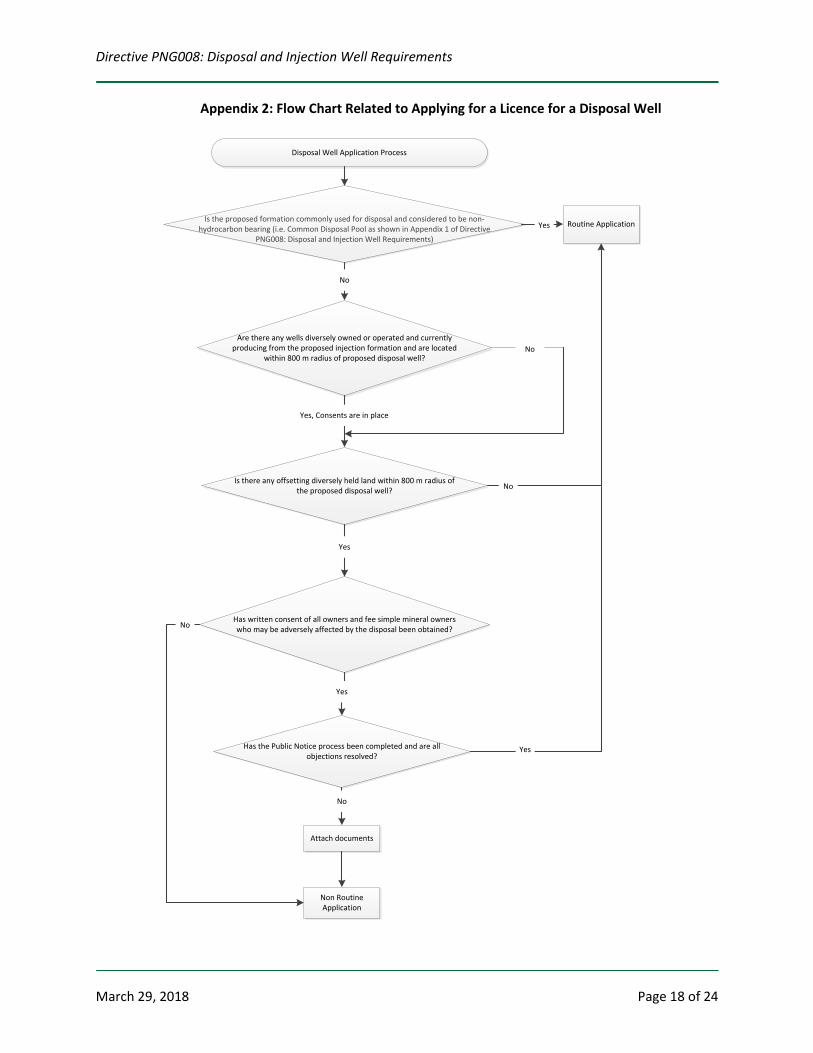
Appendix 2: Flow Chart Related to Applying for a Licence for a Disposal Well
Disposal Well Application Process
Is the proposed formation commonly used for disposal and considered to be non-hydrocarbon bearing (i.e. Common Disposal Pool as shown in Appendix 1 of Directive
PNG008: Disposal and Injection Well Requirements)
Routine ApplicationYes
Are there any wells diversely owned or operated and currently producing from the proposed injection formation and are located
within 800 m radius of proposed disposal well?
Is there any offsetting diversely held land within 800 m radius of the proposed disposal well?
Has written consent of all owners and fee simple mineral owners who may be adversely affected by the disposal been obtained?
Has the Public Notice process been completed and are all objections resolved?
Attach documents
Non Routine Application
No
Yes, Consents are in place
No
Yes
Yes
No
Yes
No
No
Directive PNG008: Disposal and Injection Well Requirements
March 29, 2018 Page 19 of 24
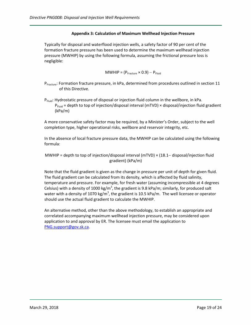
Appendix 3: Calculation of Maximum Wellhead Injection Pressure
Typically for disposal and waterflood injection wells, a safety factor of 90 per cent of the formation fracture pressure has been used to determine the maximum wellhead injection pressure (MWHIP) by using the following formula, assuming the frictional pressure loss is negligible:
MWHIP = (PFracture × 0.9) − PFluid
PFracture: Formation fracture pressure, in kPa, determined from procedures outlined in section 11
of this Directive. PFluid: Hydrostatic pressure of disposal or injection fluid column in the wellbore, in kPa.
PFluid = depth to top of injection/disposal interval (mTVD) × disposal/injection fluid gradient (kPa/m)
A more conservative safety factor may be required, by a Minister’s Order, subject to the well completion type, higher operational risks, wellbore and reservoir integrity, etc. In the absence of local fracture pressure data, the MWHIP can be calculated using the following formula:
MWHIP = depth to top of injection/disposal interval (mTVD) × (18.1− disposal/injection fluid gradient) (kPa/m)
Note that the fluid gradient is given as the change in pressure per unit of depth for given fluid. The fluid gradient can be calculated from its density, which is affected by fluid salinity, temperature and pressure. For example, for fresh water (assuming incompressible at 4 degrees Celsius) with a density of 1000 kg/m3, the gradient is 9.8 kPa/m; similarly, for produced salt water with a density of 1070 kg/m3, the gradient is 10.5 kPa/m. The well licensee or operator should use the actual fluid gradient to calculate the MWHIP. An alternative method, other than the above methodology, to establish an appropriate and correlated accompanying maximum wellhead injection pressure, may be considered upon application to and approval by ER. The licensee must email the application to [email protected].
Directive PNG008: Disposal and Injection Well Requirements
March 29, 2018 Page 20 of 24
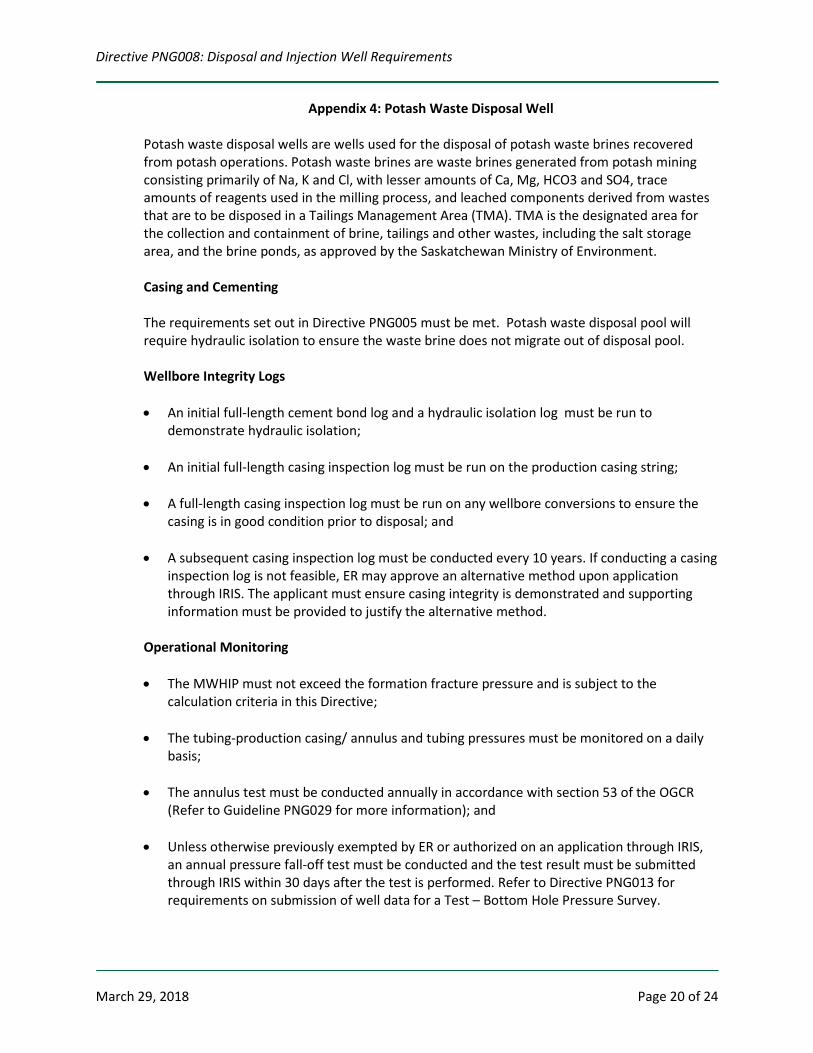
Appendix 4: Potash Waste Disposal Well
Potash waste disposal wells are wells used for the disposal of potash waste brines recovered from potash operations. Potash waste brines are waste brines generated from potash mining consisting primarily of Na, K and Cl, with lesser amounts of Ca, Mg, HCO3 and SO4, trace amounts of reagents used in the milling process, and leached components derived from wastes that are to be disposed in a Tailings Management Area (TMA). TMA is the designated area for the collection and containment of brine, tailings and other wastes, including the salt storage area, and the brine ponds, as approved by the Saskatchewan Ministry of Environment. Casing and Cementing The requirements set out in Directive PNG005 must be met. Potash waste disposal pool will require hydraulic isolation to ensure the waste brine does not migrate out of disposal pool. Wellbore Integrity Logs • An initial full-length cement bond log and a hydraulic isolation log must be run to
demonstrate hydraulic isolation;
• An initial full-length casing inspection log must be run on the production casing string;
• A full-length casing inspection log must be run on any wellbore conversions to ensure the casing is in good condition prior to disposal; and
• A subsequent casing inspection log must be conducted every 10 years. If conducting a casing inspection log is not feasible, ER may approve an alternative method upon application through IRIS. The applicant must ensure casing integrity is demonstrated and supporting information must be provided to justify the alternative method.
Operational Monitoring • The MWHIP must not exceed the formation fracture pressure and is subject to the
calculation criteria in this Directive;
• The tubing-production casing/ annulus and tubing pressures must be monitored on a daily basis;
• The annulus test must be conducted annually in accordance with section 53 of the OGCR (Refer to Guideline PNG029 for more information); and
• Unless otherwise previously exempted by ER or authorized on an application through IRIS, an annual pressure fall-off test must be conducted and the test result must be submitted through IRIS within 30 days after the test is performed. Refer to Directive PNG013 for requirements on submission of well data for a Test – Bottom Hole Pressure Survey.
Directive PNG008: Disposal and Injection Well Requirements
March 29, 2018 Page 21 of 24
Appendix 5: Logging Guidelines
The following are general guidelines that should be considered when running a hydraulic isolation, casing or cement integrity log. Certain aspects of these guidelines may not be appropriate in all situations. Regardless, logging company representatives should always be made aware of why logging is being conducted, to ensure that the configuration of programs and tools is appropriate for the specific well situation. Hydraulic Isolation Logs For all logs requiring injection (i.e., temperature and radioactive tracer), the following general design considerations apply: • The well should be capable of accepting a stable injection rate, with sufficient fluid made
available to conduct the entire logging program; • Logging should be conducted with the well under normal injection conditions, preferably at
or near the approved or requested MWHIP; • Wireline pressure control equipment that is capable of maintaining a casing pressure at
least equal to the maximum injection pressure without significant pressure bleed-off while logging should be installed; and
• The hydraulic isolation log must be run from the top of the injection interval to at least 200 m above the top of the zone of interest.
(a) Temperature Logs
The temperature of the injected fluid should be adjusted to provide for a differential of at least 5°C at the injection zone. All temperature logs should be obtained logging down at a limit of 10 m per minute with the speed displayed on the log. If conducting a temperature log on a horizontal well, an extended reach system may be needed.
Wells with or without prior injection (e.g., new, existing, extended shut-in, and converted wells)
The following procedures should be followed if no significant injection has occurred or the well has been shut in for an extended period where wellbore temperatures would be expected to be near geothermal: • with the well shut in, run a baseline temperature log (logged down) and a baseline
gamma ray log (logged up) from approximately 200 m above the top of the zone of interest to plug back total depth (PBTD);
• inject a volume of fluid at or near the maximum operating pressure under normal injection conditions; and
• with the well shut in, conduct four temperature runs (logged down) at intervals of at least a half hour to help identify storage areas. Be aware of boundary effects when analyzing for reservoir inflow.
Directive PNG008: Disposal and Injection Well Requirements
March 29, 2018 Page 22 of 24
The shut-in logs obtained should be presented as a composite overlay on the same axis for comparative purposes. Displays should enhance visual identification of anomalies by compressing the depth scale and expanding the temperature scale. If running a temperature log on a steam injection well, it should be run a minimum of 200 m above the injection zone, full length if total depth (TD) is less than 200 m, or to the top of the horizontal section. Temperature logs should be run at a target downhole temperature in the range of 140°C to 160°C.
(b) Radioactive Tracer Logs Radioactive tracer log means a log that injects soluble radioactive material with a downhole injector at or near the maximum allowable injection pressure. Radioactive tracer logs can be effective for detecting near-wellbore flow behind casing. The tracer material should be compatible with the injection fluid to avoid density segregation or dropout of the tracer material. Logging tools should be centralized to avoid tracer ejection against the casing wall. The wellbore should be clear of tubing and packers over the zone of interest wherever practical, to avoid any radioactive tracer traps and to enhance interpretation. The logging program should include the following basic components: • the radioactive tracer material should be miscible with the fluid/gas being injected; • with the well shut in, a baseline gamma ray (logged up) should be run from the TD or
the PBTD to at least 200 m above the top of the zone of interest; • with the well under a stable injection rate at or near the maximum injection pressure, a
series of stationary tracer injections should be performed commencing above and continuing through the perforated interval until the bottom detector no longer detects the ejected slug. In cases of low injection rates, log-through procedures may be used in which the tracer ejections are not stationary;
• injection of a slug of tracer above the perforations should be followed by four consecutive logging runs (i.e., storage passes) from the TD or the PBTD to 200 m above the zone of interest until the slug disappears or becomes stationary; and
• it is recommended that stationary checks be performed above the packer to verify that the packer is holding (if applicable).
The results of the storage passes should be presented as a composite overlay.
Cement Bond Logs All cement bond logs should be run after cement has cured; the timing of the logs is subject to the cement blend and downhole wellbore conditions.
(a) General Design Considerations
• The well history should be researched to determine the cement type and anticipated placement, casing sizes and grades, and maximum fluid pressure exerted on the casing since the annular cement has cured.
• The logging tool should be selected and calibrated for the type of cement used. • The logging tool should be properly centralized in the casing and be appropriately sized
for the diameter casing used.
Directive PNG008: Disposal and Injection Well Requirements
March 29, 2018 Page 23 of 24
(b) Well Preparation • The casing should be cleared of any internal cement sheathing prior to logging. • The wellbore fluid should be displaced with a consistent fluid of fresh water, drilling
mud, or dead crude. Mud weights should be kept below 1200 kilograms per cubic metre to avoid attenuation problems.
(c) Logging Procedures
• The main logging pass should, where possible, be run with the maximum historical fluid pressure on the casing to avoid micro-annulus effects.
• If possible, a section of free pipe should be logged as a baseline reference and for transit time/amplitude calibration.
Casing Inspection Logs (a) General Design Considerations
The history of the well should be researched to determine all casing sizes, weights, and any activities that would influence the magnetic characteristics of the wellbore.
(b) Well Preparation
All tubing and mechanical items should be removed from the well.
Directive PNG008: Disposal and Injection Well Requirements
March 29, 2018 Page 24 of 24
Appendix 6: Recommended Procedures for Step-Rate Injectivity Test
The following procedure should be used as a guideline for performing a step-rate injectivity test1: (a) Shut in the well or inject at a low rate until the bottom hole pressure has stabilized. This
step will represent the first point of the pressure vs. rate plot.
(b) Commence injection at a low rate until wellbore storage has been overcome and radial flow conditions are achieved. A stabilized pressure will indicate that radial flow conditions have been achieved. The time interval required to achieve a stabilized pressure must be applied to all subsequent injection periods.
(c) Increase injection rate and continue to inject for the same time interval as the first injection period. Record the injection rate used and pressure at the end of this time interval.
(d) Repeat step (c) at increasing injection rates until a minimum of five injection periods have been recorded. If formation fracture is achieved, two or more injection periods should be above the fracture pressure to clearly identify the inflection point in the pressure vs. rate plot.
(e) Plot the stabilized pressures and injection rates. Draw a straight line through the data points. The point of inflection will indicate the formation fracture pressure, if achieved.
1 Singh, P.K., Agarwal, R.G. and Jrase, L.D. (1987): Systematic design and analysis of step-rate tests to determine formation parting pressure; SPE paper 16798, presented at the 62nd Annual Technical Conference and Exhibition of the Society of Petroleum Engineers, Dallas, Texas, September 27 to 30, 1987.