Embed Size (px)
Citation preview
1
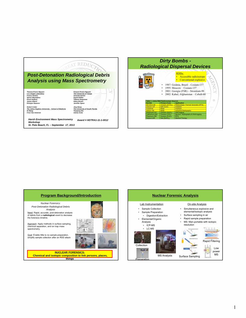
Post-Detonation Radiological Debris Analysis using Mass Spectrometry
Theresa Evans-NguyenC.S. Draper LaboratoryFrancy SinatraSpiros ManolakosKevin HuffordJames AlbertiErkinjon Nazarov
Robert CotterThe Johns Hopkins University – School of MedicineDi WangFriso Van Amerom
Harsh Environment Mass Spectrometry WorkshopSt. Pete Beach, FL – September 17, 2013
Kenyon Evans-NguyenThe University of TampaAmanda QuintoDavid GlatterTiffanie HargravesHilary BrownJennifer Speer
Jing WangThe University of South FloridaTianpeng WuAdrian Avila
Award # HDTRA1-11-1-0012
Dirty Bombs -Radiological Dispersal Devices
• 1987: Goiânia, Brazil – Cesium-137• 1995: Moscow – Cesium-137• 2001: Georgia (FSR) – Strontium-90• 2002: Kabul, Afghanistan – Cobalt-60
Table 1. Likely RDD Radioisotope SourcesNuclide Primary Form Application Strontium-90 Ceramic (SrTiO3) Radioisotopic Thermal Generator (RTG) Cesium-137 Salt (CsCl) IrradiatorCobalt-60 Metal Irradiator Iridium-192 Metal Industrial Radiography Americium-241 Ceramic (AmO2) Well-logging Californium-252 Ceramic (CfO2) Neutron Radiography & Well-logging Plutonium-238 Ceramic (PuO2) RTGRadium-226 Salt (RaSO4) Medical Therapy
RDDs:• Accessible radioisotope• Conventional explosive
Nuclear Forensics:
Post-Detonation Radiological Debris Analysis
Need: Rapid, accurate, post-detonation analysis of debris from a radiological event to decrease the forensics timeline.
Approach: Apply methods in surface sampling, chemical separation, and ion trap mass spectrometry.
Goal: Enable little to no sample preparation, simplify sample collection after an RDD attack
Program Background/Introduction
NUCLEAR FORENSICS: Chemical and isotopic composition to link persons, places,
things
• Simultaneous explosive and elemental/isotopic analysis
• Surface sampling in air
• Rapid sample preparation
• MS: Man-portable with isotopic resolution
Nuclear Forensic Analysis
• Sample Collection
• Sample Preparation
• Digestion/Extraction
• Elemental/Organic Analysis
• ICP-MS
• LC-MS
Lab Instrumentation On-site Analysis
Collection
Preparation
MS Analysis Surface Sampling
Rapid Filtering
Low power
MS
2
5
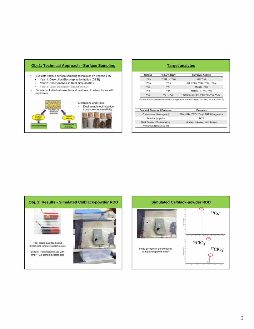
Obj.1: Technical Approach - Surface Sampling
• Evaluate various surface sampling techniques on Thermo LTQ• Year 1: Desorption Electrospray Ionization (DESI) • Year 2: Direct Analysis in Real Time (DART)• Year 3: Laser Desorption Ionization (LDI)
• Simulants: Individual samples and mixtures of radioisotopes with explosives
• Limitations and Risks• Dual sample optimization
compromises sensitivity
Target analytes
Isotope Primary decay Surrogate Analyte
137Cs 137mBa → 137Ba Salt 133Cs
226Ra 222Rn Salt (134Ba, 135Ba, 137Ba, 138Ba)
60Co 60Ni Metallic 59Co
192Ir 192Pt Metallic Ir (191Ir, 193Ir)
90Sr 90Y → 90Zr Ceramic SrTiO3* (84Sr, 86Sr, 87Sr, 88Sr)
*Also an effective mimic for ceramics of significant Actinide oxides: 241AmO2, 252CfO2, 238PuO2)
Potential Dispersant Explosive Examples
Conventional Nitro(organic) RDX, HMX, PETN, Tetryl, TNT, Nitroglycerine
Peroxide (organic) TATP
Black Powder IEDs (inorganic) nitrates, chlorates, perchlorates
Ammonium Nitrate/Fuel Oil
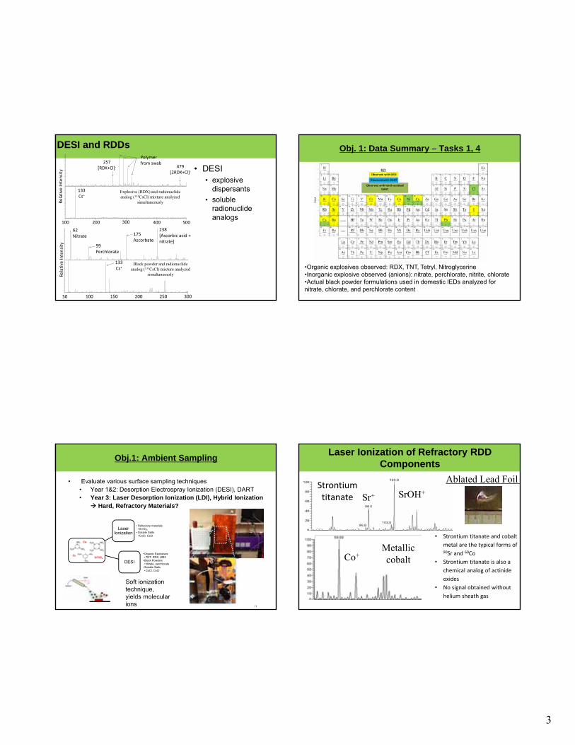
Top: Black powder-based firecracker (primarily perchlorate)
Bottom: Firecracker laced with 5mg 133Cs using electrical tape
Obj. 1: Results - Simulated Cs/black-powder RDD Simulated Cs/black-powder RDD
Swab portions of the container with polypropylene mesh
35ClO4-
37ClO4-
133Cs+
3
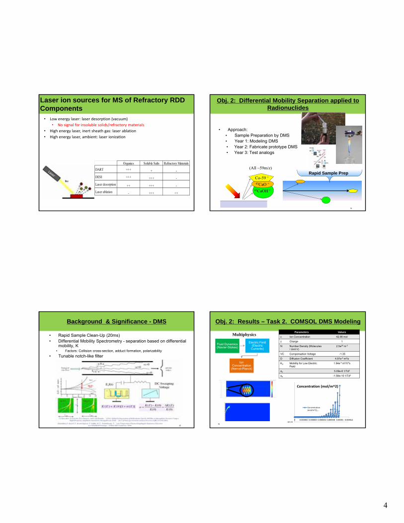
DESI and RDDs
• DESI • explosive
dispersants
• soluble radionuclide analogs
100 200 300 400
Relative Intensity
133Cs+
257[RDX+Cl]‐
500
479[2RDX+Cl]‐
Polymer from swab
50 100 150 250
Relative Intensity
133Cs+
62Nitrate
300200
99Perchlorate
175Ascorbate
238[Ascorbic acid + nitrate]‐
Explosive (RDX) and radionuclide analog (133CsCl) mixture analyzed
simultaneously
Black powder and radionuclide analog (133CsCl) mixture analyzed
simultaneously
Obj. 1: Data Summary – Tasks 1, 4
•Organic explosives observed: RDX, TNT, Tetryl, Nitroglycerine•Inorganic explosive observed (anions): nitrate, perchlorate, nitrite, chlorate•Actual black powder formulations used in domestic IEDs analyzed for nitrate, chlorate, and perchlorate content
11
Obj.1: Ambient Sampling
• Evaluate various surface sampling techniques• Year 1&2: Desorption Electrospray Ionization (DESI), DART • Year 3: Laser Desorption Ionization (LDI), Hybrid Ionization
Hard, Refractory Materials?
Laser Ionization
• Refractory materials• SrTiO3
• Soluble Salts• CoCl, CsCl
DESI
• Organic Explosives• TNT, RDX, HMX
• Black Powders• Nitrate, perchlorate
• Soluble Salts• CoCl, CsCl
Soft ionization technique, yields molecular ions
Laser Ionization of Refractory RDD Components
SrOH+Sr+
Co+
Strontium titanate
Metallic cobalt
Ablated Lead Foil
• Strontium titanate and cobalt
metal are the typical forms of 90Sr and 60Co
• Strontium titanate is also a
chemical analog of actinide
oxides
• No signal obtained without
helium sheath gas
4
Laser ion sources for MS of Refractory RDD Components
• Low energy laser: laser desorption (vacuum)
• No signal for insoluble solids/refractory materials
• High energy laser, inert sheath gas: laser ablation
• High energy laser, ambient: laser ionization
Organics Soluble Salts Refractory Materials
DART +++ + -
DESI +++ +++ -
Laser desorption ++ +++ -
Laser ablation - +++ ++
14
Obj. 2: Differential Mobility Separation applied to Radionuclides
• Approach:• Sample Preparation by DMS• Year 1: Modeling DMS • Year 2: Fabricate prototype DMS• Year 3: Test analogs
(All ~59m/z)
Co-59 +
43CaO +
42CaOH +
Rapid Sample Prep
Background & Significance - DMS
• Rapid Sample Clean-Up (20ms)• Differential Mobility Spectrometry - separation based on differential
mobility, K • Factors: Collision cross-section, adduct formation, polarizability
• Tunable notch-like filter
15
Fluid Dynamics (Navier-Stokes)
Electric Field (Electric Currents)
Ion Concentration
(Nernst-Planck)
Obj. 2: Results – Task 2. COMSOL DMS Modeling
16
MultiphysicsParameters Values
c Ion Concentration 42.86 mol
z Charge 1
N Number Density (Molecules / Unit V)
2.5e25 m-3
VC Compensation Voltage -1.35
D Diffusion Coefficient 4.97e-6 m2/s
K0 Mobility for Low Electric Field
1.94e-4 m2/V*s
α2 5.09e-6 1/Td2
α4 -1.58e-10 1/Td4
‐1E‐150 0.000002 0.000004 0.000006 0.000008 0.00001 0.000012
Concentration (mol/m^2)
Concentration(mol/m^2),…
5
Radioisotope mobility parameters
17
• Prior DMS experiments focus mostly on organic species• Historical atomic data for ion mobilities in N2
• Cesium• Potassium
50 100 150 200 250 300 350 400
0.00
0.05
0.10
0.15
0.20
0.25
Alp
ha M
obi
lity
(Effe
ctiv
e)
E/N (Td)
Cs K
SIMION DMS Modeling
• SIMION modeled electro-optical forces with parabolic flow profile from COMSOL
18
-5
0
5
10
15
20
25
-8 -6 -4 -2 0
600V
K+ Cs+
K+ and Cs+
TNT-
-2
0
2
4
6
8
10
12
-20 -15 -10 -5 0
1000V
Cs+
K+
Cs+
K+ TNT-
TNT -
Fluid Dynamics (Navier-Stokes)
Electric Field (Electric Currents)
Particle Tracking
(Newtonian)
COMSOL DMS Modeling: Particle Tracing Module
19
Multiphysics Parameters Values
Ion # Number of ions Released at Inlet (Uniformly distributed over 0.05mm gap at center of channel)
10
z Charge 1
N Number Density (Molecules / Unit V)
1.5511e25 m-3
VC Compensation Voltage -7.35V
Vac AC Voltage 750 V
K0 Mobility for Low Electric Field
2.00934 [cm2/V*s]
α2 Alpha 2 Parameter 9.016e-6 [Td-2]
α4 Alpha 4 Parameter -1.321e-10 [Td-4]
Multiphysics: Semi-computing intensive• Particle tracing module
• Collision frequency E dependence
• Includes Electric and Elastic Collision Forces
COMSOL: Forces Applied to Ions Particle Tracing Module
Electric Field Force Ion Collision Force
ViD = 1000 VVC = -5V
ω= 1.2 MHz*(2π)
+ VC
e = Ion charge [C]V = Electric potential [V]
mp = Ion mass [kg]v = Ion collision frequency [Hz]v = Neutral gas velocity [m/s]
u = Ion velocity [m/s]K = Ion mobility [m2/V*s]
µ = Reduced mass [kg]N = Neutral gas number density [m-3]
K(0) = 2.00934 [cm2/V*s]α2 = 9.016e-6 [Td-2]α4 = -1.321e-10 [Td-4]
6
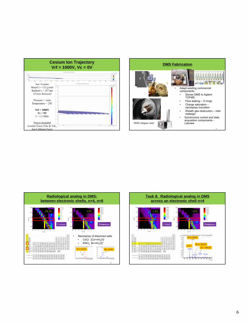
Cesium Ion TrajectoryVrf = 1000V, Vc = 0V
Ion: CesiumMassCs = 132 g/molRadiusCs = 167 pm
10 Ions Released
Pressure = 1atmTemperature = 25C
Vrf = 1000VVc = 0V
f = 1.2 MHz
Forces IncludedLorentz Force (Vac & Vdc)
Ion Collision Force
DMS Fabrication
22
• Adapt existing commercial components • Sionex DMS to Agilent
TOFMS• Flow leaking – O-rings• Charge saturation –
nanospray ionization• Sheath gas obstruction – inlet
redesign• Synchronize control and data
acquisition components -LabviewDMS Adaptor inlet
-30 -25 -20 -15 -10 -5 0 5
600
800
1000
1200
1400
Rf (
V)
Vc (V)
0.000
1581
3163
4744
6325
7906
9488
1.107E+04
1.265E+04
Radiological analog in DMS: between electronic shells, n=4, n=6
23
• Nanospray of dissolved salts• CsCl: [Cs+nH2O]+
• KNO3: [K+nH2O]+
Cesium Potassium
-10.5Vc -12Vc
[Cs + H2O]+ [K + H2O]+
Task 8. Radiological analog in DMSacross an electronic shell n=4
24
Cobalt Potassium
-7.5Vc -12Vc
[Co + H2O]+
[Co + 2H2O]+
[Co]+
[Co + 4H2O]+
7
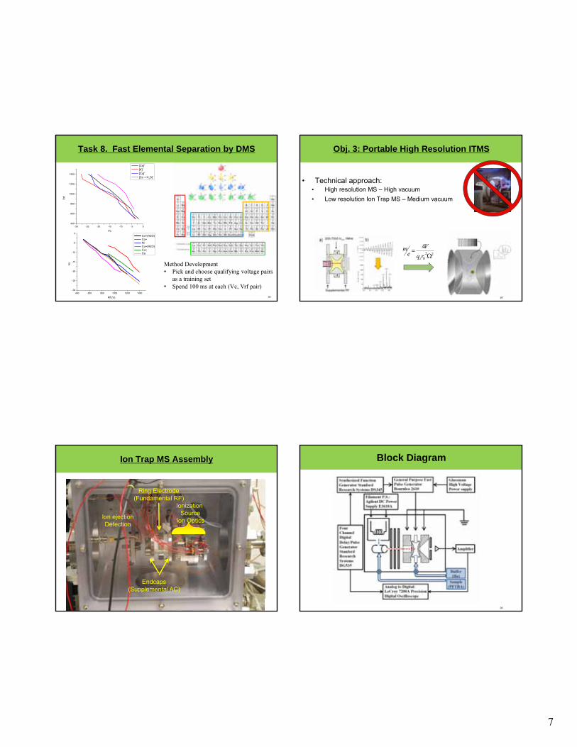
Task 8. Fast Elemental Separation by DMS
25
-30 -25 -20 -15 -10 -5 0400
600
800
1000
1200
1400
Vrf
Vc
[Cs]+
[K]+
[Co]+
[Co + H2O]+
Method Development• Pick and choose qualifying voltage pairs
as a training set• Spend 100 ms at each (Vc, Vrf pair)
400 600 800 1000 1200 1400-30
-25
-20
-15
-10
-5
0
Vc
Rf (V)
Co+(H2O) Co+ Ni Cu+(H2O) Cu+ Ca
26
Obj. 3: Portable High Resolution ITMS
• Technical approach: • High resolution MS – High vacuum
• Low resolution Ion Trap MS – Medium vacuum
220
4
rq
Ve
mz
Ion Trap MS Assembly
27
Ring Electrode(Fundamental RF)
Endcaps(Supplemental AC)
Ionization Source
Ion OpticsIon ejectionDetection
Block Diagram
28
8
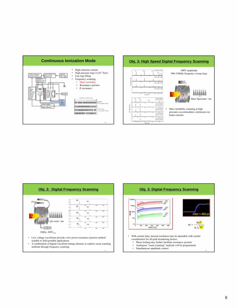
Continuous Ionization Mode
29
• High emission current• High pressure trap (1x10⁻³ Torr)• Fast trap filling• Frequency scanning
• Mass instability• Resonance ejection• resonance
Obj. 3: High Speed Digital Frequency Scanning
+
1 Mass Spectrum / ms
++++++
• Mass instability scanning at high pressures accommodates continuous ion beam currents
400V amplitude900-350kHz frequency sweep (log)
31
Obj. 3: Digital Frequency Scanning
+
1 pre-scan / ms
++++++
5Vpp
1MHz, 200V0-p
• Low voltage waveforms provide a low power resonance ejection method suitable to field portable applications
• A combination of digital waveform timing schemes to explore zoom scanning methods through frequency scanning.
32
Obj. 3: Digital Frequency Scanning
• With current jitter, desired resolution may be attainable with careful consideration for all peak broadening factors.• Phase locking may further facilitate resonance ejection• Analogous “zoom scanning” methods will be programmed • Simultaneous amplitude control
220
4
rq
eVm
z
9
33
Conclusions & Future Directions
• IONIZATION:• DESI, DART, LDI
• Multi-mode source configuration, hybridize desorption/ionization processes
• SEPARATION:• Computational models inform DMS design
• DMS separation of isobars and elemental species promising
• Explore homologous series
• MASS ANALYSIS:• Continuous ionization (with semi-continuous injection)
• Frequency scanning digital waveforms can enable fast MS scanning up to 1000Hz
• Resonance ejection mode uses higher scan speeds and pressures so better for low power field portable MS?
• Optimize waveform sync, phase locking, to increase resolution
34
Acknowledgements/Coordination&Collaboration
Theresa Evans-NguyenC.S. Draper LaboratoryFrancy SinatraSpiros ManolakosKevin HuffordJames AlbertiErkinjon Nazarov
Kenyon Evans-NguyenThe University of TampaAmanda QuintoDavid GlatterTiffanie Hargraves
Robert CotterThe Johns Hopkins University – School of MedicineDi WangFriso Van Amerom
Jing WangThe University of South FloridaTianpeng WuAdrian Avila