Embed Size (px)
Citation preview

ibm.com/redbooks
Disaster Recovery and Backup Solutions for IBM FileNet P8 Version 4.5.1 Systems
Wei-Dong ZhuGary AllenbachRoss Battaglia
Julie BoudreauxDavid Harnick-Shapiro
Heajin KimBob KreuchTim MorganSandip Patel
Martin Willingham
Discusses disaster recovery and backup strategies and options
Explains core components data relationship and dependencies
Provides detail procedures including system testing and validation
Front cover


Disaster Recovery and Backup Solutions for IBM FileNet P8 Version 4.5.1 Systems
June 2010
International Technical Support Organization
SG24-7744-00

© Copyright International Business Machines Corporation 2010. All rights reserved.Note to U.S. Government Users Restricted Rights -- Use, duplication or disclosure restricted by GSA ADPSchedule Contract with IBM Corp.
First Edition (June 2010)
This edition applies to Version 4, Release 5, Modification 1 of IBM FileNet Content Manager (program number 5724-R81) and Version 4, Release 5, Modification 1 of IBM FileNet Business Process Manager (program number 5724-R76), Version 4, Release 1, Modification 2 of IBM FileNet Image Manager Active Edition v4.5.1 (program number 5724-R95)
Note: Before using this information and the product it supports, read the information in “Notices” on page ix.

Contents
Notices . . . . . . . . . . . . . . . . . . . . . . . . . . . . . . . . . . . . . . . . . . . . . . . . . . . . . . . ixTrademarks . . . . . . . . . . . . . . . . . . . . . . . . . . . . . . . . . . . . . . . . . . . . . . . . . . . . x
Preface . . . . . . . . . . . . . . . . . . . . . . . . . . . . . . . . . . . . . . . . . . . . . . . . . . . . . . . xiThe team who wrote this book . . . . . . . . . . . . . . . . . . . . . . . . . . . . . . . . . . . . . xiiNow you can become a published author, too! . . . . . . . . . . . . . . . . . . . . . . . . xviComments welcome. . . . . . . . . . . . . . . . . . . . . . . . . . . . . . . . . . . . . . . . . . . . . xviStay connected to IBM Redbooks . . . . . . . . . . . . . . . . . . . . . . . . . . . . . . . . . xvii
Part 1. Concept and overview . . . . . . . . . . . . . . . . . . . . . . . . . . . . . . . . . . . . . . . . . . . . . . . . . 1
Chapter 1. Introducing disaster recovery . . . . . . . . . . . . . . . . . . . . . . . . . . . 31.1 Business continuity . . . . . . . . . . . . . . . . . . . . . . . . . . . . . . . . . . . . . . . . . . . 41.2 Defining disaster recovery and basic terminology. . . . . . . . . . . . . . . . . . . . 4
1.2.1 Disaster recovery contrasted with high availability . . . . . . . . . . . . . . . 51.2.2 Disaster recovery terminology. . . . . . . . . . . . . . . . . . . . . . . . . . . . . . . 61.2.3 Common disaster scenarios and their implications. . . . . . . . . . . . . . . 7
1.3 Data replication for disaster recovery . . . . . . . . . . . . . . . . . . . . . . . . . . . . . 71.3.1 Synchronous and asynchronous replication . . . . . . . . . . . . . . . . . . . . 91.3.2 Write order fidelity . . . . . . . . . . . . . . . . . . . . . . . . . . . . . . . . . . . . . . . 101.3.3 Initializing replication . . . . . . . . . . . . . . . . . . . . . . . . . . . . . . . . . . . . . 121.3.4 IBM products for data replication . . . . . . . . . . . . . . . . . . . . . . . . . . . 131.3.5 Disaster recovery site location best practices . . . . . . . . . . . . . . . . . . 151.3.6 Using a bunker (three-way replication) site . . . . . . . . . . . . . . . . . . . . 18
1.4 Backups as part of a disaster recovery plan . . . . . . . . . . . . . . . . . . . . . . . 191.5 Choosing a disaster recovery strategy . . . . . . . . . . . . . . . . . . . . . . . . . . . 211.6 Disaster recovery testing. . . . . . . . . . . . . . . . . . . . . . . . . . . . . . . . . . . . . . 221.7 Disaster recovery site sizing . . . . . . . . . . . . . . . . . . . . . . . . . . . . . . . . . . . 231.8 Declaring a disaster. . . . . . . . . . . . . . . . . . . . . . . . . . . . . . . . . . . . . . . . . . 24
1.8.1 Disaster recovery process: failing over . . . . . . . . . . . . . . . . . . . . . . . 251.8.2 Basic failover steps . . . . . . . . . . . . . . . . . . . . . . . . . . . . . . . . . . . . . . 261.8.3 Disaster recovery process: failing back. . . . . . . . . . . . . . . . . . . . . . . 27
Chapter 2. Introducing backup and restore . . . . . . . . . . . . . . . . . . . . . . . . 292.1 The importance of backup. . . . . . . . . . . . . . . . . . . . . . . . . . . . . . . . . . . . . 302.2 Backup components and storage location . . . . . . . . . . . . . . . . . . . . . . . . 31
2.2.1 Backup components . . . . . . . . . . . . . . . . . . . . . . . . . . . . . . . . . . . . . 312.2.2 Backup storage location . . . . . . . . . . . . . . . . . . . . . . . . . . . . . . . . . . 31
2.3 Backup modes. . . . . . . . . . . . . . . . . . . . . . . . . . . . . . . . . . . . . . . . . . . . . . 32
© Copyright IBM Corp. 2010. All rights reserved. iii
2.3.1 Offline backup . . . . . . . . . . . . . . . . . . . . . . . . . . . . . . . . . . . . . . . . . . 322.3.2 Warm online backup . . . . . . . . . . . . . . . . . . . . . . . . . . . . . . . . . . . . . 332.3.3 Hot online backup . . . . . . . . . . . . . . . . . . . . . . . . . . . . . . . . . . . . . . . 34
2.4 Backup types. . . . . . . . . . . . . . . . . . . . . . . . . . . . . . . . . . . . . . . . . . . . . . . 342.4.1 Full backup . . . . . . . . . . . . . . . . . . . . . . . . . . . . . . . . . . . . . . . . . . . . 342.4.2 Incremental backup. . . . . . . . . . . . . . . . . . . . . . . . . . . . . . . . . . . . . . 342.4.3 Differential . . . . . . . . . . . . . . . . . . . . . . . . . . . . . . . . . . . . . . . . . . . . . 352.4.4 Synthetic . . . . . . . . . . . . . . . . . . . . . . . . . . . . . . . . . . . . . . . . . . . . . . 352.4.5 Progressive . . . . . . . . . . . . . . . . . . . . . . . . . . . . . . . . . . . . . . . . . . . . 352.4.6 Multilevel incremental . . . . . . . . . . . . . . . . . . . . . . . . . . . . . . . . . . . . 36
2.5 Backup and restore window and scheduling . . . . . . . . . . . . . . . . . . . . . . . 362.5.1 Backup and restore window . . . . . . . . . . . . . . . . . . . . . . . . . . . . . . . 362.5.2 FlashCopy . . . . . . . . . . . . . . . . . . . . . . . . . . . . . . . . . . . . . . . . . . . . . 372.5.3 Backup scheduling . . . . . . . . . . . . . . . . . . . . . . . . . . . . . . . . . . . . . . 37
2.6 Restoring a FileNet P8 system . . . . . . . . . . . . . . . . . . . . . . . . . . . . . . . . . 382.6.1 Partial restore . . . . . . . . . . . . . . . . . . . . . . . . . . . . . . . . . . . . . . . . . . 382.6.2 Point-in-time restore . . . . . . . . . . . . . . . . . . . . . . . . . . . . . . . . . . . . . 382.6.3 Checking system consistency after a restore . . . . . . . . . . . . . . . . . . 39
2.7 Tivoli Storage Manager overview . . . . . . . . . . . . . . . . . . . . . . . . . . . . . . . 392.7.1 Introducing Tivoli Storage Manager . . . . . . . . . . . . . . . . . . . . . . . . . 392.7.2 IBM Tivoli Storage Manager clients . . . . . . . . . . . . . . . . . . . . . . . . . 402.7.3 IBM Tivoli Storage Manager server. . . . . . . . . . . . . . . . . . . . . . . . . . 40
Chapter 3. FileNet P8 system architecture overview . . . . . . . . . . . . . . . . . 433.1 Architectural overview . . . . . . . . . . . . . . . . . . . . . . . . . . . . . . . . . . . . . . . . 443.2 Content Engine . . . . . . . . . . . . . . . . . . . . . . . . . . . . . . . . . . . . . . . . . . . . . 45
3.2.1 Database. . . . . . . . . . . . . . . . . . . . . . . . . . . . . . . . . . . . . . . . . . . . . . 493.2.2 Communication protocols . . . . . . . . . . . . . . . . . . . . . . . . . . . . . . . . . 50
3.3 Process Engine . . . . . . . . . . . . . . . . . . . . . . . . . . . . . . . . . . . . . . . . . . . . . 513.3.1 Component Integrator . . . . . . . . . . . . . . . . . . . . . . . . . . . . . . . . . . . . 523.3.2 Communication protocols . . . . . . . . . . . . . . . . . . . . . . . . . . . . . . . . . 53
3.4 Application Engine. . . . . . . . . . . . . . . . . . . . . . . . . . . . . . . . . . . . . . . . . . . 533.4.1 Communication protocols . . . . . . . . . . . . . . . . . . . . . . . . . . . . . . . . . 56
3.5 Image Services and CFS-IS . . . . . . . . . . . . . . . . . . . . . . . . . . . . . . . . . . . 563.5.1 Communication protocols . . . . . . . . . . . . . . . . . . . . . . . . . . . . . . . . . 583.5.2 CFS-IS architecture. . . . . . . . . . . . . . . . . . . . . . . . . . . . . . . . . . . . . . 58
3.6 Content Search Engine . . . . . . . . . . . . . . . . . . . . . . . . . . . . . . . . . . . . . . . 603.6.1 Content Search Engine architecture . . . . . . . . . . . . . . . . . . . . . . . . . 613.6.2 K2 Master Administration Server . . . . . . . . . . . . . . . . . . . . . . . . . . . 633.6.3 K2 Administration Server . . . . . . . . . . . . . . . . . . . . . . . . . . . . . . . . . 633.6.4 K2 Ticket Server . . . . . . . . . . . . . . . . . . . . . . . . . . . . . . . . . . . . . . . . 643.6.5 K2 Index Server . . . . . . . . . . . . . . . . . . . . . . . . . . . . . . . . . . . . . . . . 643.6.6 K2 Broker and Search Servers . . . . . . . . . . . . . . . . . . . . . . . . . . . . . 65
iv Disaster Recovery and Backup Solutions for IBM FileNet P8 Version 4.5.1 Systems

3.6.7 Communication protocols . . . . . . . . . . . . . . . . . . . . . . . . . . . . . . . . . 66
Chapter 4. FileNet P8 data relationships and dependencies . . . . . . . . . . 674.1 Content Engine data relationships, dependencies . . . . . . . . . . . . . . . . . . 68
4.1.1 FileNet P8 domain overview . . . . . . . . . . . . . . . . . . . . . . . . . . . . . . . 684.1.2 GCD database relationship . . . . . . . . . . . . . . . . . . . . . . . . . . . . . . . . 704.1.3 Object store relationship between metadata and content . . . . . . . . . 714.1.4 Content Engine document model . . . . . . . . . . . . . . . . . . . . . . . . . . . 734.1.5 Database storage . . . . . . . . . . . . . . . . . . . . . . . . . . . . . . . . . . . . . . . 784.1.6 File storage . . . . . . . . . . . . . . . . . . . . . . . . . . . . . . . . . . . . . . . . . . . . 814.1.7 Fixed storage . . . . . . . . . . . . . . . . . . . . . . . . . . . . . . . . . . . . . . . . . . 874.1.8 Federated content . . . . . . . . . . . . . . . . . . . . . . . . . . . . . . . . . . . . . . . 904.1.9 Autonomy K2 relationship to the Content Engine . . . . . . . . . . . . . . . 93
4.2 Process Engine relationship to Content Engine . . . . . . . . . . . . . . . . . . . . 964.3 Image Services relationship to the Content Engine . . . . . . . . . . . . . . . . . 99
4.3.1 CFS-IS architecture. . . . . . . . . . . . . . . . . . . . . . . . . . . . . . . . . . . . . 1004.3.2 Federation process . . . . . . . . . . . . . . . . . . . . . . . . . . . . . . . . . . . . . 1034.3.3 Federated document operations . . . . . . . . . . . . . . . . . . . . . . . . . . . 104
Chapter 5. FileNet P8 data components to backup and replicate. . . . . . 1075.1 Content Engine data requiring backup . . . . . . . . . . . . . . . . . . . . . . . . . . 108
5.1.1 GCD database . . . . . . . . . . . . . . . . . . . . . . . . . . . . . . . . . . . . . . . . 1085.1.2 Object store databases . . . . . . . . . . . . . . . . . . . . . . . . . . . . . . . . . . 1115.1.3 File and fixed storage areas . . . . . . . . . . . . . . . . . . . . . . . . . . . . . . 1135.1.4 Fixed and external repositories . . . . . . . . . . . . . . . . . . . . . . . . . . . . 1155.1.5 Autonomy K2 collections. . . . . . . . . . . . . . . . . . . . . . . . . . . . . . . . . 117
5.2 Process Engine data requiring backup . . . . . . . . . . . . . . . . . . . . . . . . . . 1195.3 Image Services data requiring backup . . . . . . . . . . . . . . . . . . . . . . . . . . 120
5.3.1 Index database . . . . . . . . . . . . . . . . . . . . . . . . . . . . . . . . . . . . . . . . 1215.3.2 MKF databases . . . . . . . . . . . . . . . . . . . . . . . . . . . . . . . . . . . . . . . . 1225.3.3 Content storage. . . . . . . . . . . . . . . . . . . . . . . . . . . . . . . . . . . . . . . . 1265.3.4 Configuration files . . . . . . . . . . . . . . . . . . . . . . . . . . . . . . . . . . . . . . 128
Chapter 6. Alternative strategies for backup . . . . . . . . . . . . . . . . . . . . . . 1316.1 Use of database storage area consideration. . . . . . . . . . . . . . . . . . . . . . 1326.2 Suspending database writes . . . . . . . . . . . . . . . . . . . . . . . . . . . . . . . . . . 1336.3 Stopping the Application Engine . . . . . . . . . . . . . . . . . . . . . . . . . . . . . . . 1336.4 Rolling storage policies . . . . . . . . . . . . . . . . . . . . . . . . . . . . . . . . . . . . . . 1346.5 Spraying storage policies . . . . . . . . . . . . . . . . . . . . . . . . . . . . . . . . . . . . 1356.6 Journaling . . . . . . . . . . . . . . . . . . . . . . . . . . . . . . . . . . . . . . . . . . . . . . . . 1376.7 Disk-to-disk versus disk-to-tape . . . . . . . . . . . . . . . . . . . . . . . . . . . . . . . 1386.8 FlashCopy . . . . . . . . . . . . . . . . . . . . . . . . . . . . . . . . . . . . . . . . . . . . . . . . 1396.9 Summary . . . . . . . . . . . . . . . . . . . . . . . . . . . . . . . . . . . . . . . . . . . . . . . . . 140
Contents v
Part 2. Implementation details . . . . . . . . . . . . . . . . . . . . . . . . . . . . . . . . . . . . . . . . . . . . . . . 143
Chapter 7. Case study description and system setup . . . . . . . . . . . . . . . 1457.1 Description of the case studies . . . . . . . . . . . . . . . . . . . . . . . . . . . . . . . . 146
7.1.1 Case study I: Backup and restore setup and configuration. . . . . . . 1467.1.2 Case study II: Recovery using standby disaster recovery site . . . . 146
7.2 Overview of FileNet P8 lab environment . . . . . . . . . . . . . . . . . . . . . . . . . 1477.2.1 Production lab environment hardware . . . . . . . . . . . . . . . . . . . . . . 1477.2.2 Storage configuration . . . . . . . . . . . . . . . . . . . . . . . . . . . . . . . . . . . 1497.2.3 DNS and host table entries . . . . . . . . . . . . . . . . . . . . . . . . . . . . . . . 150
7.3 Software configuration. . . . . . . . . . . . . . . . . . . . . . . . . . . . . . . . . . . . . . . 1527.3.1 DB2 configuration . . . . . . . . . . . . . . . . . . . . . . . . . . . . . . . . . . . . . . 1527.3.2 WebSphere configuration . . . . . . . . . . . . . . . . . . . . . . . . . . . . . . . . 1557.3.3 User and group configuration . . . . . . . . . . . . . . . . . . . . . . . . . . . . . 1597.3.4 FileNet P8 component configuration . . . . . . . . . . . . . . . . . . . . . . . . 160
Chapter 8. Backup and restore setup and configuration . . . . . . . . . . . . 1758.1 Backup and recovery overview . . . . . . . . . . . . . . . . . . . . . . . . . . . . . . . . 1768.2 Install and configure Tivoli Storage Manager . . . . . . . . . . . . . . . . . . . . . 179
8.2.1 Installing Tivoli Storage Manager client software . . . . . . . . . . . . . . 1798.2.2 Configuring the Tivoli Storage Manager client software . . . . . . . . . 180
8.3 Manual backup procedure using Tivoli Storage Manager . . . . . . . . . . . . 1878.4 Creating startup and shutdown scripts for FileNet P8 . . . . . . . . . . . . . . . 191
8.4.1 Starting and stopping the FileNet P8 J2EE-based applications . . . 1918.4.2 Starting and stopping the FileNet P8 Component Manager . . . . . . 1948.4.3 Starting and stopping the Content Search Engine . . . . . . . . . . . . . 2008.4.4 Starting and stopping the Process Engine . . . . . . . . . . . . . . . . . . . 2018.4.5 Starting and stopping Image Services . . . . . . . . . . . . . . . . . . . . . . 201
8.5 Performing offline backups for FileNet P8. . . . . . . . . . . . . . . . . . . . . . . . 2068.5.1 Determining shutdown sequence . . . . . . . . . . . . . . . . . . . . . . . . . . 2068.5.2 Determining shutdown timing . . . . . . . . . . . . . . . . . . . . . . . . . . . . . 2078.5.3 Additional backup considerations . . . . . . . . . . . . . . . . . . . . . . . . . . 210
8.6 Restore procedure for FileNet P8 . . . . . . . . . . . . . . . . . . . . . . . . . . . . . . 2168.6.1 Re-creating volumes and file system configuration. . . . . . . . . . . . . 2178.6.2 Restoring data files using Tivoli Storage Manager . . . . . . . . . . . . . 2188.6.3 Restoring Image Services raw data . . . . . . . . . . . . . . . . . . . . . . . . 2208.6.4 Testing and validating the system. . . . . . . . . . . . . . . . . . . . . . . . . . 226
Chapter 9. Disaster recovery setup and configuration . . . . . . . . . . . . . . 2279.1 Planning considerations for a DR site . . . . . . . . . . . . . . . . . . . . . . . . . . . 2289.2 Overview of FileNet P8 lab environment for DR . . . . . . . . . . . . . . . . . . . 229
9.2.1 Disaster recovery lab environment hardware . . . . . . . . . . . . . . . . . 2299.2.2 Storage configuration for DR. . . . . . . . . . . . . . . . . . . . . . . . . . . . . . 2319.2.3 DNS and host table setup . . . . . . . . . . . . . . . . . . . . . . . . . . . . . . . . 232
vi Disaster Recovery and Backup Solutions for IBM FileNet P8 Version 4.5.1 Systems
9.2.4 User and group configuration for DR . . . . . . . . . . . . . . . . . . . . . . . 2339.3 Software configuration. . . . . . . . . . . . . . . . . . . . . . . . . . . . . . . . . . . . . . . 233
9.3.1 DB2 configuration for DR . . . . . . . . . . . . . . . . . . . . . . . . . . . . . . . . 2349.3.2 DB2 client configuration for DR. . . . . . . . . . . . . . . . . . . . . . . . . . . . 2379.3.3 WebSphere configuration for DR . . . . . . . . . . . . . . . . . . . . . . . . . . 2409.3.4 Software configuration for DR . . . . . . . . . . . . . . . . . . . . . . . . . . . . . 244
9.4 Verifying the DR installation . . . . . . . . . . . . . . . . . . . . . . . . . . . . . . . . . . 2619.5 Enabling PROD to DR replication . . . . . . . . . . . . . . . . . . . . . . . . . . . . . . 2619.6 Activating the DR site . . . . . . . . . . . . . . . . . . . . . . . . . . . . . . . . . . . . . . . 2629.7 Maintaining the DR site . . . . . . . . . . . . . . . . . . . . . . . . . . . . . . . . . . . . . . 262
Chapter 10. System testing and validation . . . . . . . . . . . . . . . . . . . . . . . . 26310.1 Starting the FileNet P8 software . . . . . . . . . . . . . . . . . . . . . . . . . . . . . . 264
10.1.1 Starting the P8 databases. . . . . . . . . . . . . . . . . . . . . . . . . . . . . . . 26410.1.2 Starting Image Services and HPII . . . . . . . . . . . . . . . . . . . . . . . . . 26510.1.3 Starting the Content Engine . . . . . . . . . . . . . . . . . . . . . . . . . . . . . 26610.1.4 Starting the Process Engine . . . . . . . . . . . . . . . . . . . . . . . . . . . . . 26910.1.5 Starting the Workplace XT . . . . . . . . . . . . . . . . . . . . . . . . . . . . . . 27110.1.6 Starting the Component Manager . . . . . . . . . . . . . . . . . . . . . . . . . 27210.1.7 Starting the Content Search Engine (CSE). . . . . . . . . . . . . . . . . . 273
10.2 Testing for internal consistency. . . . . . . . . . . . . . . . . . . . . . . . . . . . . . . 27510.2.1 Importance of internal consistency . . . . . . . . . . . . . . . . . . . . . . . . 27610.2.2 Content Engine internal consistency. . . . . . . . . . . . . . . . . . . . . . . 27710.2.3 Process Engine internal consistency . . . . . . . . . . . . . . . . . . . . . . 28610.2.4 Image Services consistency . . . . . . . . . . . . . . . . . . . . . . . . . . . . . 288
10.3 Testing for consistency between applications . . . . . . . . . . . . . . . . . . . . 29310.3.1 Content Engine and Process Engine . . . . . . . . . . . . . . . . . . . . . . 29410.3.2 Content Engine and Content Search Engine . . . . . . . . . . . . . . . . 30010.3.3 Content Engine and Image Services. . . . . . . . . . . . . . . . . . . . . . . 307
Chapter 11. Working with IBM Information Archive . . . . . . . . . . . . . . . . . 31511.1 Setting up an IBM Information Archive appliance . . . . . . . . . . . . . . . . . 31611.2 IBM Information Archive failover scenarios . . . . . . . . . . . . . . . . . . . . . . 318
11.2.1 Information Archive in a full site failover . . . . . . . . . . . . . . . . . . . . 31811.2.2 Component-level failover of Information Archive . . . . . . . . . . . . . 319
Related publications . . . . . . . . . . . . . . . . . . . . . . . . . . . . . . . . . . . . . . . . . . 323IBM Redbooks . . . . . . . . . . . . . . . . . . . . . . . . . . . . . . . . . . . . . . . . . . . . . . . . 323Online resources . . . . . . . . . . . . . . . . . . . . . . . . . . . . . . . . . . . . . . . . . . . . . . 324How to get Redbooks . . . . . . . . . . . . . . . . . . . . . . . . . . . . . . . . . . . . . . . . . . . 324Help from IBM . . . . . . . . . . . . . . . . . . . . . . . . . . . . . . . . . . . . . . . . . . . . . . . . 325
Index . . . . . . . . . . . . . . . . . . . . . . . . . . . . . . . . . . . . . . . . . . . . . . . . . . . . . . . 327
Contents vii

viii Disaster Recovery and Backup Solutions for IBM FileNet P8 Version 4.5.1 Systems

Notices
This information was developed for products and services offered in the U.S.A.
IBM may not offer the products, services, or features discussed in this document in other countries. Consult your local IBM representative for information on the products and services currently available in your area. Any reference to an IBM product, program, or service is not intended to state or imply that only that IBM product, program, or service may be used. Any functionally equivalent product, program, or service that does not infringe any IBM intellectual property right may be used instead. However, it is the user's responsibility to evaluate and verify the operation of any non-IBM product, program, or service.
IBM may have patents or pending patent applications covering subject matter described in this document. The furnishing of this document does not give you any license to these patents. You can send license inquiries, in writing, to: IBM Director of Licensing, IBM Corporation, North Castle Drive, Armonk, NY 10504-1785 U.S.A.
The following paragraph does not apply to the United Kingdom or any other country where such provisions are inconsistent with local law: INTERNATIONAL BUSINESS MACHINES CORPORATION PROVIDES THIS PUBLICATION "AS IS" WITHOUT WARRANTY OF ANY KIND, EITHER EXPRESS OR IMPLIED, INCLUDING, BUT NOT LIMITED TO, THE IMPLIED WARRANTIES OF NON-INFRINGEMENT, MERCHANTABILITY OR FITNESS FOR A PARTICULAR PURPOSE. Some states do not allow disclaimer of express or implied warranties in certain transactions, therefore, this statement may not apply to you.
This information could include technical inaccuracies or typographical errors. Changes are periodically made to the information herein; these changes will be incorporated in new editions of the publication. IBM may make improvements and/or changes in the product(s) and/or the program(s) described in this publication at any time without notice.
Any references in this information to non-IBM Web sites are provided for convenience only and do not in any manner serve as an endorsement of those Web sites. The materials at those Web sites are not part of the materials for this IBM product and use of those Web sites is at your own risk.
IBM may use or distribute any of the information you supply in any way it believes appropriate without incurring any obligation to you.
Information concerning non-IBM products was obtained from the suppliers of those products, their published announcements or other publicly available sources. IBM has not tested those products and cannot confirm the accuracy of performance, compatibility or any other claims related to non-IBM products. Questions on the capabilities of non-IBM products should be addressed to the suppliers of those products.
This information contains examples of data and reports used in daily business operations. To illustrate them as completely as possible, the examples include the names of individuals, companies, brands, and products. All of these names are fictitious and any similarity to the names and addresses used by an actual business enterprise is entirely coincidental.
Autonomy materials reprinted with permission from Autonomy Corp.
COPYRIGHT LICENSE:
This information contains sample application programs in source language, which illustrate programming techniques on various operating platforms. You may copy, modify, and distribute these sample programs in any form without payment to IBM, for the purposes of developing, using, marketing or distributing application programs conforming to the application programming interface for the operating platform for which the sample programs are written. These examples have not been thoroughly tested under all conditions. IBM, therefore, cannot guarantee or imply reliability, serviceability, or function of these programs.
© Copyright IBM Corp. 2010. All rights reserved. ix

Trademarks
IBM, the IBM logo, and ibm.com are trademarks or registered trademarks of International Business Machines Corporation in the United States, other countries, or both. These and other IBM trademarked terms are marked on their first occurrence in this information with the appropriate symbol (® or ™), indicating US registered or common law trademarks owned by IBM at the time this information was published. Such trademarks may also be registered or common law trademarks in other countries. A current list of IBM trademarks is available on the Web at http://www.ibm.com/legal/copytrade.shtml
The following terms are trademarks of the International Business Machines Corporation in the United States, other countries, or both:
AIX®DB2®FileNet®FlashCopy®IBM®
POWER5™POWER6®Redbooks®Redbooks (logo) ®System Storage®
Tivoli®TotalStorage®WebSphere®
The following terms are trademarks of other companies:
SnapMirror, FlexVol, FlexClone, NetApp, and the NetApp logo are trademarks or registered trademarks of NetApp, Inc. in the U.S. and other countries.
FileNet, and the FileNet logo are registered trademarks of FileNet Corporation in the United States, other countries or both.
Oracle, JD Edwards, PeopleSoft, Siebel, and TopLink are registered trademarks of Oracle Corporation and/or its affiliates.
JBoss, and the Shadowman logo are trademarks or registered trademarks of Red Hat, Inc. in the U.S. and other countries.
Java, and all Java-based trademarks are trademarks of Sun Microsystems, Inc. in the United States, other countries, or both.
Microsoft, Windows, and the Windows logo are trademarks of Microsoft Corporation in the United States, other countries, or both.
UNIX is a registered trademark of The Open Group in the United States and other countries.
Linux is a trademark of Linus Torvalds in the United States, other countries, or both.
Other company, product, or service names may be trademarks or service marks of others.
x Disaster Recovery and Backup Solutions for IBM FileNet P8 Version 4.5.1 Systems

Preface
Many organizations require continuous operation of their mission-critical, IBM® FileNet® P8 systems after a failure has occurred. A failure can be caused by relatively small equipment problems, or a large-scale disaster such as a flood, earthquake, hazardous attacks, or other unexpected events. Loss of system resources and services as a result of any failure can translate directly into lost customers and lost revenue. The goal, therefore, is to design and implement a FileNet P8 system that ensures continuous operation even after a failure happens. A combination of techniques and practices that are available to design and implement such a system fall into two main categories:
� High availability: The ability to maintain operations by eliminating single points of failure in hardware or software, generally with zero data loss
� Disaster recovery: The ability to resume operations after a larger-scale failure and minimize business data loss
This IBM Redbooks® publication focuses on FileNet P8 Version 4.5.1 systems disaster recovery. The book covers strategies, preparation levels, site sizing, data replication, testing, and what to do during a disaster. Backup and restore planning is a critical aspect of a disaster recovery strategy. We discuss backup types and strategies. We also discuss alternative strategies such as rolling storage policies and IBM FlashCopy® capability.
In addition, with the help of use cases and our lab testing environment, the book has the following information:
� Guidelines for setting up a FileNet P8 production environment, and steps for setting up, configuring, and activating a standby FileNet P8 disaster recovery system.
� Detail steps for configuring and executing the backup and recovery of a FileNet P8 environment, using IBM Tivoli® Storage Manager.
The core FileNet P8 data components we discuss for backup and data replication include:
� Content Engine
� Process Engine
� Application Engine (Workplace XT)
� Content Search Engine
� Image Services
© Copyright IBM Corp. 2010. All rights reserved. xi

We explain data relationship and dependencies of these core components and the specific data that require backing up and replication. We also provide detailed steps involved in validating the FileNet P8 system, including how to test the internal health and consistency of each core component and the consistency between the components, after a disaster recovery.
Finally, we introduce IBM Information Archive, and give procedures for using it to provide a FileNet P8 fixed storage area.
This book is intended for IT architects, IT specialists, project managers, and decision makers, who must identify the best disaster recovery strategies and integrate them into the FileNet P8 system design process.
For more about high availability strategies, options, and implementations for FileNet P8 systems, see IBM High Availability Solution for IBM FileNet P8 Systems, SG24-7700. It can help you gain comprehensive understanding of how to best protect your business operation.
The team who wrote this book
This book was produced by a team of specialists from around the world working at the International Technical Support Organization (ITSO), Rochester Center.
Wei-Dong Zhu (Jackie) is an Enterprise Content Management Project Leader with ITSO. She has more than 10 years of software development experience in accounting, image workflow processing, and digital media distribution. Jackie holds a Master of Science degree in Computer Science from the University of Southern California. Jackie joined IBM in 1996. She is a Certified Solution Designer for IBM Content Manager and has managed and lead the production of many Enterprise Content Management Redbooks publications.
Gary Allenbach is an Enterprise Content Management Architect focusing on the IBM FileNet P8 Platform. He joined IBM in October, 2006 as IBM completed its acquisition of FileNet Corporation. He has over 12 years of computer technology experience in the areas of imaging, document management, business process management, team collaboration, Web site management, and electronic survey and testing. Prior to joining FileNet in 2001, Gary worked at companies such as Scantron, Kofax Image Products, and iManage. Gary is a FileNet Certified Professional and holds a Bachelor's degree from California State University, Long Beach.
Ross Battaglia is the co-founder of Tivoli Associates. He is an IBM subject matter expert in IBM Storage, IBM Tivoli Storage Manager, and disaster recovery. He is also a Certified IBM Instructor and has an extensive background
xii Disaster Recovery and Backup Solutions for IBM FileNet P8 Version 4.5.1 Systems

developing storage and performance software. Ross was one of the original developers for storage and backup software for IBM, and is under an open contract to IBM to provide development, support and Tivoli Services. Ross has written eight IBM Redbooks publications about Tivoli Storage Manager and is a member of the IBM Certification Exams Team for IBM Storage, Tivoli Storage Manager, IBM TotalStorage® Software and IBM Storage hardware. Ross holds 28 certifications.
Julie Boudreaux is a FileNet Software Accelerated Value Specialist for Enterprise Content Management with IBM in the U.S. She holds a Bachelor of Science degree in Computer Science from Louisiana State University and Certification in Mathematics and Computer Education from Nicholls State University. She joined FileNet in 1996 as a Technical Consultant and came to IBM in 2006. As a Software Specialist, Julie has over 10 years of field experience implementing FileNet Business Process Manager, Content Manager, Image Services, and Compliance software at IBM client sites. Currently, she leads the IBM FileNet P8 Platform Support Readiness program for the ECM Install/Upgrade Services and Support organization. Julie is a FileNet Certified Professional Technician.
David Harnick-Shapiro is a Software Engineer in the P8 Server Test team, with an emphasis on testing high availability configurations with IBM in the U.S. His 20 years of experience in systems and network administration have been in environments ranging from research universities to managed-service provider start-ups. David joined FileNet just shortly before FileNet was acquired by IBM in 2006. David earned Bachelor's degrees in Linguistics and in Computer Science at California State University, Fullerton. He has maintained collections of user documentation, has written administration and user guides, and regularly evaluates paper proposals for technical conferences.
Heajin Kim is a Software Engineer in the P8 Server Test team. She has more than 15 years of experience in software development and testing in the office management, network logistics, and content management fields. She holds a Master of Science degree in Computer Science from the University of Southern California. Heajin joined FileNet before FileNet was acquired by IBM in 2006. Her areas of expertise in IBM FileNet is Business Process Manager and recently the high availability environment.
Bob Kreuch is a Software Engineer for the IBM FileNet P8 Platform, specializing in content storage and content federation services. He has 30 years experience in software design and development, focused on developing consumer software for a wide range of very small to very large companies. In 1997, Bob joined the FileNet Enterprise Content Management group, and has been a Lead Developer of the content storage and content federation services components for the 3.5.x and 4.x IBM FileNet Content Manager products. Bob received a hands-on
Preface xiii

education in computer programming at the Albuquerque Technical Vocational Institute. He co-authored a patent application that is related to content federation services Extended System for Accessing Electronic Documents with Revision History in Non-Compatible Repositories.
Tim Morgan is a Software Architect for the IBM FileNet P8 Platform, specializing in high performance, enterprise deployments, high availability, and disaster recovery. He has 25 years of experience in the computer field, ranging from UNIX® system management to designing and implementing enterprise-class call processing software for the telephony industry. Tim joined FileNet in 2004 in the Performance Analysis group. He earned a Bachelor of Science degree in Physics and Computer Science from Vanderbilt University, and a Ph.D. degree in Information and Computer Science from the University of California, Irvine, on the topic of analysis of concurrent software. Tim has written published articles on a range of topics, authored several IBM FileNet white papers, and co-authored the IBM Redbooks publication, IBM High Availability Solution for IBM FileNet P8 Systems, SG24-7700.
Sandip Patel is a Senior Enterprise Content Management Field Delivery Consultant for IBM in the U.S. He has delivered many customer installations and upgrades for IBM FileNet Business Process Management and Content Management products. Sandip joined IBM FileNet in 2005 and has more than 15 years of industry experience in software technical support and development. Before joining IBM, Sandip was a Technical Support Team Lead at multiple start-up companies, supporting complex client server applications. Sandip holds a Master of Science degree in Computer Science from the California State University, Chico and is a FileNet Certified Professional.
Martin Willingham is a Senior Managing Consultant with Enterprise Content Management Lab Services for IBM in the U.S. He has over 20 years of IT experience as an Administrator, Manager, and Delivery Consultant. Martin holds a Master of Business Administration degree from Mercer University and a Bachelor of Business Administration degree from the University of the Georgia. Martin joined IBM, then FileNet in 2001. His areas of expertise, developed over the last 13 years, include FileNet Image Services and P8, data migrations, protected storage, federation, and enterprise systems management. Prior to joining FileNet, he worked with midrange infrastructure, accounting and ERP software, and warehouse management control. He is a FileNet Certified Professional and certified in Six Sigma process improvement methodology. He is a co-author of the IBM Redbooks publication, Federated Content Management: Accessing Content from Disparate Repositories with IBM Content Federation Services and IBM Content Integrator, SG24-7742.
xiv Disaster Recovery and Backup Solutions for IBM FileNet P8 Version 4.5.1 Systems

Very special thanks to the following people who have contributed countless hours, many of which were weekend and evening hours, in setting up the testing environment and systems, performing configuration, system testing, and educating us:
David BenninRichard M ConwayEdward Lee HolcombeAlex Osuna
We want to thank the following people who were the primary driving force behind the production of this book:
Patrick ChesnotChuck FayScott Braman
We want to thank the following people who have contributed to the production of this book, through patiently answering our questions, helping us to resolve the technical issues, helping us to get the necessary human and machine resources, and assisting us in various activities required during the residency:
Kenytt AveryKevin BatesNicholas BuchananJesse F ChenDao-Quynh (Quynh) DangThuy DoEvangeline FinkMike GrieseHemanth KalluriDharmesh KamdarSathees B KodiJeffry LarsonDiane McPheeSophia MullerDaniel RiedelDarik SiegfriedJohn SingGrace SmithAndrei SocoliucRoy G. SpencerSteve TimmDanny TrinhMarc Valesco
Preface xv

We also want to thank the following IBM Redbooks publication staff who helped make this book happen:
Emma JacobsMary LovelaceAnn LundDiane ShermanErica Wazewski
Now you can become a published author, too!
Here's an opportunity to spotlight your skills, grow your career, and become a published author - all at the same time! Join an ITSO residency project and help write a book in your area of expertise, while honing your experience using leading-edge technologies. Your efforts will help to increase product acceptance and customer satisfaction, as you expand your network of technical contacts and relationships. Residencies run from two to six weeks in length, and you can participate either in person or as a remote resident working from your home base.
Find out more about the residency program, browse the residency index, and apply online at:
ibm.com/redbooks/residencies.html
Comments welcome
Your comments are important to us!
We want our books to be as helpful as possible. Send us your comments about this book or other IBM Redbooks publications in one of the following ways:
� Use the online Contact us review Redbooks form found at:
ibm.com/redbooks
� Send your comments in an e-mail to:
� Mail your comments to:
IBM Corporation, International Technical Support OrganizationDept. HYTD Mail Station P0992455 South RoadPoughkeepsie, NY 12601-5400
xvi Disaster Recovery and Backup Solutions for IBM FileNet P8 Version 4.5.1 Systems
Stay connected to IBM Redbooks
� Find us on Facebook:
http://www.facebook.com/IBMRedbooks
� Follow us on twitter:
http://twitter.com/ibmredbooks
� Look for us on LinkedIn:
http://www.linkedin.com/groups?home=&gid=2130806
� Explore new Redbooks publications, residencies, and workshops with the IBM Redbooks weekly newsletter:
https://www.redbooks.ibm.com/Redbooks.nsf/subscribe?OpenForm
� Stay current on recent Redbooks publications with RSS Feeds:
http://www.redbooks.ibm.com/rss.html
Preface xvii

xviii Disaster Recovery and Backup Solutions for IBM FileNet P8 Version 4.5.1 Systems

Part 1 Concept and overview
This part contains the following chapters:
� Chapter 1, “Introducing disaster recovery” on page 3
� Chapter 2, “Introducing backup and restore” on page 29
� Chapter 3, “FileNet P8 system architecture overview” on page 43
� Chapter 4, “FileNet P8 data relationships and dependencies” on page 67
� Chapter 5, “FileNet P8 data components to backup and replicate” on page 107
� Chapter 6, “Alternative strategies for backup” on page 131
Part 1
© Copyright IBM Corp. 2010. All rights reserved. 1

2 Disaster Recovery and Backup Solutions for IBM FileNet P8 Version 4.5.1 Systems

Chapter 1. Introducing disaster recovery
This chapter provides an overview of disaster recovery (DR), and contrasts disaster recovery with high availability (HA). We show that various levels of disaster recovery preparation can be implemented. These different levels are described and guidelines are provided for choosing the level appropriate for each business situation.
This chapter contains the following topics:
� Business continuity
� Defining disaster recovery and basic terminology
� Data replication for disaster recovery
� Backups as part of a disaster recovery plan
� Choosing a disaster recovery strategy
� Disaster recovery testing
� Disaster recovery site sizing
� Declaring a disaster
1
© Copyright IBM Corp. 2010. All rights reserved. 3

1.1 Business continuity
Business continuity is a set of practices and procedures that are intended to enable a business to continue its data processing operations after a failure has occurred. A business data processing failure can be caused by relatively small equipment failures, such as an Ethernet card outage, or by large-scale disasters such as a flood, earthquake, hazardous attacks, or other unexpected events. Because of the wide range of possible failures, a single solution covering all of these possibilities is usually not optimal. Instead, a range of techniques is used. Generally, these practices are two main categories:
� High availability: The ability to maintain operations by eliminating single points of failure in hardware or software, generally with zero data loss
� Disaster recovery: The ability to resume operations after a larger-scale failure while minimizing business data loss
1.2 Defining disaster recovery and basic terminology
Disaster recovery is the set of equipment and practices that allows a business to recover its operations after a disaster strikes. We define a disaster in this context as an unexpected event which disrupts normal data processing operations for an entire data center, or at least for a set of servers that collectively provides a data processing service.
Recovery of the service or data center can be performed at the original site. You employ this strategy if the nature of the disaster is not permanently destructive to the site and its equipment. For example, loss of all network connectivity, or of electrical power, for a prolonged time period can be considered a disaster, and can warrant switching to an alternate site if one is available. Another option can be simply to wait until the problem has been resolved. In the end, the original data center’s operations can be resumed, perhaps with no loss of data. Loss of data, for example caused by an extensive equipment failure, can be remediated on-site by recovering from backup tapes. The time to recover in such a situation is the time to acquire and install replacement hardware, plus the time to retrieve the backup media and perform a full restore from it. Businesses that cannot tolerate such prolonged service outages must consider a more extensive disaster recovery strategy as discussed in this chapter.
4 Disaster Recovery and Backup Solutions for IBM FileNet P8 Version 4.5.1 Systems

1.2.1 Disaster recovery contrasted with high availability
High availability means having redundant hardware and software so that normal operations can continue after a single failure has occurred. Ideally, single failures do not interrupt operations at all, meaning that multiple instances of each component must be operational at all times so that the remaining component (or components) can take over the full load when any one component fails. In hardware devices, redundancy can be achieved by having redundant components within a single unit, or by having more than one unit installed and operational. If software redundancy is achieved by running the software simultaneously on more than one hardware device, the configuration is called active/active, because both components, or both units, are active at the same time. For this approach to be effective, the remaining components must be able handle the entire workload if a single component fails. The alternative approach for high availability is an active/passive configuration, in which the redundant component is not in use during normal operations but can be brought online if the component it is backing up fails.
For an entire operation to be considered highly available, every possible single point of failure must be addressed, either by an active/active or active/passive solution. Data storage is usually on a device that has internal high availability features, such as redundant disk drives, power supplies, and network connections. The drives are usually deployed in a Redundant Array of Independent Disks (RAID) configuration, as a RAID configuration gives the best combination of availability and performance. Effectively, there is one copy of the data at the primary site.
A disaster is any failure, or combination of failures, that goes beyond the single points of failure that high availability techniques would address. A disaster can result from as little as simultaneous failures of all the redundant components, all the way up to a large scale outage caused by an earthquake. In contrast with high availability, a disaster prevents operation of an entire data processing service, or of the entire data center, rather than crippling the operation of a single component. Disasters, in contrast with high availability concerns, threaten either data access or permanent loss of data, and recovery from a disaster often involves restoration of the data at a future time, often at a data center that is remote from the original one.
In a high availability solution, recovering from a single component failure is usually low cost and relatively quick, or instantaneous in the case of active/active redundancy. However, disasters can result in the total loss of the data center. Therefore, disaster recovery is a much more time-consuming operation and can result in data loss. As a result, most data centers are reluctant to put their disaster recovery plans into action if it can be avoided. An example of such a situation is the loss of network connectivity to the primary data center. For high
Chapter 1. Introducing disaster recovery 5

availability purposes, perhaps two separate service providers and cables are used, but an outage of both connections simultaneously is not impossible. In this case, the data center manager would want to confirm that the outages are expected to last for some time before making the decision to attempt a disaster recovery. Alternatively, other types of disasters can physically destroy the equipment at the data center. In this case, declare a disaster immediately so you can begin the recovery process and restore service as quickly as possible.
1.2.2 Disaster recovery terminology
The following terms are used throughout this book in discussing disaster recovery processes and procedures:
� Recovery point objective (RPO): The RPO is the maximum amount of data that the business can tolerate losing if a disaster occurs. The RPO is measured in terms of time. As an example, a data center with a one-hour RPO experiences a disaster at 3:00 p.m. which causes permanent loss of all equipment in the data center. In this case, all data changes through at least 2:00 p.m. the same afternoon will be available after the recovery has been accomplished so that no more than one hour’s worth of new data or data updates is lost.
� Recovery time objective (RTO): The RTO is the amount of time that passes from the time a disaster strikes until data center operations have resumed and recovery is complete.
� Primary (or production) data center or site: The primary data center is the location that houses the equipment used during normal operations.
� Recovery (or backup or disaster) data center or site: The recovery data center is another data center, separate and remote from the primary center, at which operations can be resumed in the event of the loss of the primary center. The recovery center can be owned directly, or it can be a time-shared lease of equipment from a third party.
� Fail over or failover: When a failure at the primary data center forces a transfer of operations to a recovery site, operations are said to fail over, and the process of failing over is known as a failover.
� Fail back or failback: Some time after a fail over, operations at the primary data center can be restored, or the primary center can be rebuilt. Then, you might want to transfer operations from the recover center back to the primary center. Similar to a failover, this operation is called failback, and the act of executing it is known as failing back.
6 Disaster Recovery and Backup Solutions for IBM FileNet P8 Version 4.5.1 Systems

� (Data) replication: This technique provides current, or nearly current, data at a recovery site by copying data from the primary site to the recovery site on a continuous basis. Several variations of data replication are described in 1.3, “Data replication for disaster recovery” on page 7.
� Service level agreement (SLA): Part of a service contract that specifies a level of service that is to be provided. Data center SLAs typically specify items such as average or maximum response time, uptime (or maximum unexpected downtime), and RPO and RTO values.
1.2.3 Common disaster scenarios and their implications
The goal of a successful disaster recovery initiative is to eliminate a corporation’s exposure to risk, regardless of circumstance. Although natural disasters can be a contributing factor, human error presents a far greater risk to data center availability. Many natural disasters are capable of temporarily or permanently preventing data center operations, including:
� Floods� Earthquakes� Wildfires� Hurricanes� Tornados
In addition, many possible man-made disasters exist as in the following examples:
� Construction accidents, including digging up network or power cables� War� Fire� Engineering or equipment failures� Human error, such as accidental deletion of important files� Sabotage
1.3 Data replication for disaster recovery
Generally, four mechanisms are available for performing data replication. The difference between them is the level at which the replication is performed within the hardware and software stack:
� Application level: generally not available in FileNet P8 products, but available in most database products, including IBM DB2® product.
� Host level: Replication implemented by a software layer running on the host operating system.
Chapter 1. Introducing disaster recovery 7

� Storage level: Data replication done by the storage device itself, typically to another device of the same model. The ability to perform replication can be a feature or an option for the storage device.
� Network level: Similar to storage-level replication. A device on the storage area network (SAN) intercepts device writes and replicates them to a corresponding SAN device at a remote site.
In addition to this general hierarchy, other differences exist between these replication mechanisms, which we describe next.
Database level replication is generally implemented to work between one instance of the database product and another, remote instance. The replication is done in a transactional fashion, meaning that at any instant, the state of the remote database is consistent. That database can therefore be started very quickly if a failover must be performed. In contrast with other replication mechanisms, it can be necessary to perform roll forward operations on the database to bring it up to the most recently replicated transaction before it can be brought online. This feature of database-to-database replication can be important for businesses whose recovery time objective is very stringent. Because the database replication is performed independently of content data replication, the two might not necessarily be in sync at the recovery site at the moment of a disaster. See 1.3.2, “Write order fidelity” on page 10, for further discussion of this topic.
Host-level replication can work at the file or at the block level. At the file level, the software typically copies newly created or modified files to the remote host when the file is closed. With block-level replication, when a block is written to the local disk, it is also written to the remote site’s disk. When file-level replication is implemented, the local and remote file systems do not have to be identical at the device-block level, if they contain the same files at the file-system level. In contrast, with block-level replication, the local and remote file systems must be the same block-for-block so that updates to a given block can be replicated to the identical block on the remote site’s disk.
The remaining two replication mechanisms, storage level and network level, have similar characteristics. Replication is done at the block level, because the devices are unaware of the file system that is built by the operating system on the volume being replicated.
With most block level replication mechanisms, if a disaster strikes the primary site and a failover is performed, check the consistency of the file system on the remote volumes before they can be mounted and brought online is necessary. The condition of the remote volume when replication is cut off by the disaster is exactly analogous to the condition of a local disk if a power failure or operating system crash occurs. Because blocks are cached in RAM by the operating
8 Disaster Recovery and Backup Solutions for IBM FileNet P8 Version 4.5.1 Systems

system for performance reasons, and only later written to the physical device, the state of the file system on disk can contain inconsistencies. Trying to use such a volume can lead to further data corruption and operating system crashes. We refer to recovering from such a state as a crash recovery, even if it results from a disaster, communication failure, or some other reason besides an actual operating system crash. The time needed to check the file system for consistency must be accounted for when considering how to meet a stated recovery time objective.
One exception to the rule (that storage level replication requires a file system check at the remote site before recovery can proceed) is when a network-attached storage (NAS) device performs replication through snapshots. In this case, the NAS gateway is responsible for the file system on the underlying device and is aware of data blocks that have not yet been written to disk when performing replication. In this approach, the NAS gateway takes a periodic snapshot of the contents of the volume and replicate that snapshot to the remote site, while simultaneously continuing to accept changes to the primary volume from the client machines. This approach has the advantage that recovery does not require a file system consistency check, but the disadvantage is that the snapshots and replication activities can only be done on a periodic basis; block-level replication can be done on a continual basis. So, although recovery time is reduced, the RPO might have to be increased. For instance, if the snapshots are taken every 15 minutes, the RPO cannot be smaller than this length of time.
1.3.1 Synchronous and asynchronous replication
Block-level replication can be performed synchronously or asynchronously. Using storage level replication as an example, synchronous replication means that before the device returns a result to the operating system in response to a block write, it also writes the block to the corresponding remote device, and the remote device commits the block to the physical media. Synchronous replication provides the smallest recovery point, potentially zero data loss, because every write to the local device involves a write to the remote device as well. Data loss can still occur during file system and application level consistency checking, however, if the state of the disk at the crash recovery point contained only a portion of a transaction that was being committed.
Latency is the length of time for an individual packet to traverse the network from sender to receiver. It includes processing time within the hardware devices and the operating systems, and it also includes the time that the packets are traveling between the sites. Even the fastest network connection, typically a fiber optic network, cannot send data faster than the speed of light. However, do not confuse latency with bandwidth. Bandwidth is the overall rate at which data can
Chapter 1. Introducing disaster recovery 9

be transmitted over the network. Networks can offer high bandwidth and still have a relatively high latency; the two network characteristics are only loosely related to each other.
The time required to do a single block write with synchronous replication enabled is most likely longer than the time required simply to do the local write. The local write and the remote write can be launched in parallel with each other, but the remote write is likely to take much longer than the local one because of latency of communications between the local site and the recovery site. Most likely the write itself takes about the same time on the recovery storage device as on the local one. The latency involved is doubled because the request first has to be sent from the local site to the remote one, then the remote write is executed, and then a response is sent from the recovery site back to the primary site. If the average write time is 10 ms, and the latency between the sites in one direction is also 10 ms, a write that would take only 10 ms to execute locally requires 30 ms if synchronous replication is in use.
In contrast to synchronous replication, asynchronous replication means that every time a block of data is written to the local device, a request to write the same data to the corresponding block at the recovery site is queued up. However, a response is returned to the requesting local operating system immediately after the local write has been accomplished, letting the software proceed in its processing without having to wait through the additional latency introduced by a synchronous write to a distant storage device.
In general, manufacturers of replication technology recommend that synchronous replication be used between sites that are no more than about 100 km (60 miles) apart. However, products such as the IBM Metro Mirror synchronous replication product allow the distance between the sites to be as great as 300 km (180 miles). Distances greater than this limit can introduce too much latency, and write performance can be seriously compromised. In such situations, use asynchronous replication.
1.3.2 Write order fidelity
A FileNet P8 deployment contains many storage areas that must be synchronized with each other. For example, if a Process Engine workflow is creating, modifying, or deleting Content Engine content or metadata, backing up and restoring the underlying databases and file storage areas together so that they stay in sync with one another is necessary.
Similarly, when doing replication, the data that is written to local disks must be written to the remote disks in the same order. With synchronous replication, the correct ordering of the writes is necessarily the case; with asynchronous replication, a possibility is that the disk writes at the remote site cannot be made
10 Disaster Recovery and Backup Solutions for IBM FileNet P8 Version 4.5.1 Systems

in the same order as the local writes. Out-of-order write operations are particularly likely if more than one storage device is in use, and the storage devices are performing storage level replication. Replication of the blocks in the same chronological order in which they were written is called write order fidelity.
Most databases allow the tables, indexes, and other on-disk files to be spread across multiple logical unit numbers (LUNs) for better I/O performance. When the database files do not all reside within the same LUN, they must be backed up together to ensure consistency, and they must be replicated with write order fidelity to ensure that the database at the recovery site is able to start in a consistent state.
In an active/active high availability configuration, more than one Content Engine is in use. In this case, the storage areas must be made available to all the Content Engines in the farm (application server cluster), typically accomplished with the use of an NAS gateway device. In this situation, host-level or software replication cannot be used because the software running on each host knows only about the files that have been created or modified by that host. It does not know about files modified by other hosts in the farm. Although each system can still do file-level replication, no mechanism exists for providing write order fidelity.
Certain storage devices provide the ability to preserve write order fidelity even across separate storage devices. When writes to separate LUNs are combined in time order, that group of LUNs is referred to as a consistency group. In the case of LUNs spread across multiple frames, the storage devices communicate with each other to ensure that the queue of asynchronous replication data is maintained in chronological order. Another approach to achieving write order fidelity is to use network-level replication because the device at the SAN level is aware of all writes to all devices within the SAN fabric. Thus, it can ensure that the blocks are replicated in the correct order to the storage devices at the recovery site.
When using more than one replication system it is not possible to preserve write order fidelity across all the replicas. For example, certain sites use database-level replication for the database, and use storage-level replication for the file storage areas and other data that resides outside the database. Although this approach means that the database can be recovered quickly if a disaster failover is necessary, it also means that there can be synchronization problems between the file storage areas and the metadata of the Content Engine, between the Content Engine and the Process Engine’s database, between the Content Engine and the Content Search Engine’s collections (index files). If, for example, a metadata row exists in an object store’s database, but the corresponding content file is not in the file storage area, users attempting to retrieve that document receive an error. This situation is known as a widow. In the opposite case, the content file can exist in the file storage area, but without the
Chapter 1. Introducing disaster recovery 11

corresponding metadata row in the database, that content is essentially inaccessible to users. This case is called an orphan. Such inconsistencies between the metadata and the content data are in general referred to as a broken document. This subject is covered in more detail in Chapter 4, “FileNet P8 data relationships and dependencies” on page 67.
The Content Engine provides a Consistency Checker that can find all widows, but it cannot identify orphans, and there is no easy way to find content within a file storage area that does not have corresponding metadata in the database.
In summary, the most common causes of lack of write order fidelity are as follows:
� Using database replication for the database but storage or network replication for the file storage area
� Using a mix of different devices
� Using storage-level replication with devices that cannot preserve write order fidelity across LUNs
1.3.3 Initializing replication
When first configuring data replication for disaster recovery, a very large amount of data must be copied from the primary storage system to the storage system at the recovery site. If the primary site has been in operation for some time, the volume of data can potentially be more than a terabyte.
The simplest way to establish the initial mirroring of the storage is to configure each site, establish data communications between the sites, and initiate replication. If the communications channel between the sites is appropriately sized for the rate at which data normally changes on the primary site, the bandwidth is grossly undersized for the purposes of establishing the initial mirror. An undersized communications channel can cause the initialization time to be on the order of months. Alternatively, sizing the communications channel, based on the speed that is required for the initial synchronization, leaves it with a great amount of excess capacity after the initial mirror is established.
Several methods of establishing the initial mirror exist. The preferred method is to bring the recovery storage devices into the primary data center, so that the initial mirror can be established over a LAN connection. Then, mirroring can be suspended while the device is transported to the actual recovery site, after which replication can be resumed.
If temporarily moving the recovery storage device to the primary site is not possible, an alternative (if it is supported by the replication software) is to take an image backup of the primary storage volumes, deliver the tapes to the recovery
12 Disaster Recovery and Backup Solutions for IBM FileNet P8 Version 4.5.1 Systems

site, and perform a full restoration of the volumes there. If the volumes are identical in size and the restore operation has been done on a block-level basis, the restoration replication can be enabled with the initialization step. Not all replication software supports this approach or requires this feature. Consult your documentation to determine the exact steps to use.
1.3.4 IBM products for data replication
IBM provides several products that are related to data replication for disaster recovery.
IBM System Storage DSx000For the IBM System Storage® DSx000 SAN, both synchronous and asynchronous replication are supported with the following solutions:
� Metro Mirror is a synchronous replication solution. It is intended for use within a metropolitan area, over a distance of up to 300 KM (180 miles).
� Global Mirror is an asynchronous replication solution. It can be used over any distance, because network latency is not an issue with its use. To be able to transport the amount of data that is being created or modified at the primary site over time, sufficient network bandwidth is required.
For more information about IBM system storages, see the following publications:
� IBM Midrange System Storage Hardware Guide, SG24-7676
� IBM System Storage DS8000: Architecture and Implementation, SG24-6786
� IBM System Storage DS8000: Copy Services in Open Environments, SG24-6788
� IBM System Storage DS8700: Architecture and Implementation, SG24-8786
IBM System Storage N SeriesIBM System Storage N-Series supports the SnapMirror® feature, which allows a volume to be replicated between N series storage system over a network. It uses FlexVol® and FlexClone®, the ability to make near-instantaneous snapshots of data volumes. SnapMirror works by taking snapshots and replicating the snapshots to the recovery site, using data compression of up to 70%. The failover and failback procedures can be automated. SnapMirror supports three mode of operation: asynchronous, synchronous, and semi-synchronous mode.
For more information about IBM System Storage N Series, see IBM System Storage N Series, SG24-7129.
Chapter 1. Introducing disaster recovery 13

IBM SAN Volume Controller (SVC)The SVC provides network-level replication. SVC is a device that combines storage capacity from multiple disk systems into a reservoir of capacity that can be managed more efficiently. It can cache writes from hosts and acknowledge them before the data has actually been stored on the destination device, accelerating writes to the SAN volumes. SVC can use Metro Mirror or Global Mirror capabilities to replicate SAN volumes to a recovery site, and because it has global visibility of the SAN volumes and updates to them, it can create consistency groups that span separate hardware frames, even if the frames are from separate storage vendors.
For more information about IBM SAN Volume Controller, see Implementing the IBM System Storage SAN Volume Controller V5.1, SG24-6423.
IBM softwareIBM provides the following software that can automate disaster recovery failover,:
� High-Availability Cluster Multi-Processing/Extended Distance (HACMP/XD)
� Geographically Dispersed Open Clusters (GDOC)
IBM Information ArchiveIBM Information Archive is an integrated information-retention appliance. It includes preinstalled servers, disk storage, and the Information Archive software.
The Information Archive appliance offers secure, cost-effective storage that can implement a variety of policies for document access, retention, deletion, and provides a single point from which to manage the whole system.
Optional features include Enhanced Remote Mirroring for disaster recovery, high-availability server configurations, and migration from disk to tape storage.
Information Archive featuresIBM Information Archive has the following features and functionalities:
� Provides information through multiple access methods such as file (for example, NFS) and System Storage Archive Manager (for example, the Tivoli Storage Manager API).
� Supports security by encryption options and a special Enhanced Tamper Protection feature which prevents system super user accounts from inappropriately modifying data.
� Offers universal storage repository for all types of content, structured and unstructured, compliant and non-compliant.
14 Disaster Recovery and Backup Solutions for IBM FileNet P8 Version 4.5.1 Systems

� Can accommodate several hundred terabytes of raw storage, and can store and manage multiple billions of documents over its deployment lifetime.
� Maintains data integrity until deletion is permitted by retention policy.
� Helps optimize storage consumption with data deduplication and compression features.
� Offers low total cost of ownership (TCO) by allowing use of mixed media (disk and tape).
� Has time-based and event-based information retention policies.
Information Archive as a FileNet P8 fixed content deviceFileNet P8 stores document content in a file storage area. File storage areas can be implemented in several ways, including by writing to an archiving storage system. Such file storage areas are called fixed storage areas.
Information Archive supports access to its storage through the Tivoli Storage Manager System Storage Archive Manager (SSAM) interface. Content Engine supports Tivoli Storage Manager as a fixed storage area. To use an Information Archive appliance as a FileNet P8 fixed storage area, configure both Information Archive and Content Engine to use Tivoli Storage Manager. For specific details about how to do this, see Chapter 11, “Working with IBM Information Archive” on page 315.
For additional information, go to the following Web address:
http://www.ibm.com/systems/storage/disk/archive/index.html
Support for Tivoli Storage Manager as a fixed content provider is available from Content Engine Version 4.5.1. Details of the versions required are available from the FileNet P8 Hardware and Software requirements guides at:
http://www.ibm.com/support/docview.wss?rs=3278&uid=swg27013654
1.3.5 Disaster recovery site location best practices
The basic choices regarding location of a disaster recovery site, in order of cost, are as follows:
� Choice 1: Buy new hardware, as needed, replace your data center, and restore your data from backup tapes.
� Choice 2: Rent availability services.
� Choice 3: Own a second data center in the same metropolitan area as the primary data center.
� Choice 4: Own a second data center located far from the primary data center.
Chapter 1. Introducing disaster recovery 15

In choice 1 that relies on your backup tape, your on-going costs are simply to create timely backups and ensure that your backup tapes are kept off-site. The recovery time can range from weeks to months before you can resume operations. Many companies cannot endure more than few days of IT system downtime. Some companies have declared bankruptcy after they experience IT system outage for less than a week. For these reasons, most companies choose one of the higher-cost solutions, because the companies realize that they cannot afford a prolonged data-processing outage.
In choice 2 that relies on renting availability service, you sign a contract with one of various availability service providers. In your contract, you agree on the specification of the equipment that is to be provided to you in the case of a disaster, and the conditions under which you are entitled to use that equipment (how frequently you can perform failover testing, the circumstances under which you can declare a disaster, how long you can use the equipment in the case of a disaster). This solution costs less than choices 3 and 4, and still gives you the ability to recover much more quickly than choice 1 because replacement hardware does not have to be procured and configured.
IBM offers Infrastructure Recovery Services, which uses 154 IBM business resilience centers in 55 countries to help recover client environments. For more information, go to the following Web address:
http://www.ibm.com/services/us/index.wss/offerfamily/bcrs/a1026935
The savings realized from renting available services comes with compromises:
� You lose control of your recovery equipment and data center, because you are renting equipment in a shared environment.
� Recovery time is considerably longer compared with a failover to a recovery center that you control, and to which you have been replicating data on a continuos basis. You are likely to have to recover from backup tapes, which is a lengthy process in itself. Furthermore, you must notify the service provider that you are declaring a disaster and transport your tapes and personnel to their data center, before you can begin the recovery process. Recovery time in this case ranges from days to possibly several weeks.
� You do not have an absolute guarantee of equipment availability. Because the equipment is shared, if more than one customer, sharing a piece of equipment, declares a disaster, the first customer to declare disaster usually gets the use of the equipment.
� There can be a time limit on how long you can use the equipment after it is allocated to you. You have only that length of time to restore or rebuild your primary data center and prepare to move operations back to it.
16 Disaster Recovery and Backup Solutions for IBM FileNet P8 Version 4.5.1 Systems

Choices 3 and 4 both involve owning and operating your own disaster recovery data center. These options are more expensive on an on-going basis than either backups alone or a time-shared recovery data center, but they also have the most significant advantages:
� Recovery time is minimal if continual data replication has been in place.
� After operating from the disaster site, you can continue to do so for as long as you want. You do not have to give up the equipment after any predetermined amount of time, giving you the maximum flexibility in planning the restoration of your primary data center.
Many companies already operate more than one data center within the same metropolitan area for a variety of business purposes. These companies might be tempted to use the existing data centers as recovery data centers for the following reasons:
� Costs are low because the other data center is already in operation.
� The proximity of the data centers makes it convenient for personnel to work at both sites.
� Replication can be synchronous, leading to very little or zero data loss in the event of a disaster.
Using a nearby data center for a disaster recovery center might not be considered the best practice. As listed in 1.2.3, “Common disaster scenarios and their implications” on page 7, many types of disasters can affect both data centers within a single metropolitan area. Furthermore, IT staff who service nearby data centers also represent a single point of failure themselves for those sites, because the same staff services both sites. If the staff members are unable to reach either site after a local disaster, both sites are in jeopardy of being unavailable. For these reasons, consider locating a recovery site several hundred miles (or more) from the primary site to be outside the impact zone of any possible disaster.
Another common mistake made by businesses planning for business continuity is to try to use a disaster recovery strategy as their high availability strategy. The time and cost required to do a failover, especially when the recovery site is far from the primary site, is considerable, and data loss can occur. High availability solutions, aimed at being able to recover quickly, or instantaneously, from a single component failure, generally involve having redundant hardware and software components at the primary site. Because best practice is to locate a recovery site at a significant distance, typically 650 km (400 miles) or more, from the primary site, network latency prevents using hardware at the disaster recovery site as redundant components for the primary site, or running this equipment in an active/active mode.
Chapter 1. Introducing disaster recovery 17

Having a second data center has a potential advantage of operational maintenance. When one site is down for maintenance, the other site can continue to offer services. However, their configuration might compromises high availability because of the additional complexity of two sites instead of one, and compromises disaster recovery by close enough to each other to both be lost in the same disaster.
1.3.6 Using a bunker (three-way replication) site
As discussed earlier, a best practice is to locate a recovery center far from the primary data center. Doing so means that replication necessarily is asynchronous, and that introduces the possibility of data loss in the event of the loss of the primary data center. The alternative of locating the recovery center close to the primary center eliminates or minimizes the possibility of data loss because it enables the use of synchronous replication. However, it greatly increases the chances that a single disaster disables or destroys both the primary and the recovery center.
Businesses with stringent RTO and RPO values of less than a day must consider data replication to a dedicated remote disaster recovery site. Recovering from backups without data replication can take days to weeks, depending on the amount of data, the number of backup media needing to be restored, and other characteristics of the backup technology. For this type of business, the possibility of any data loss must be eliminated if at all possible. The solution is to use three-way replication with a bunker site. A bunker site is a small data center located within the same metropolitan area as the primary data center. Data is replicated synchronously from the primary site to the bunker site. The equipment at the bunker site is configured to replicate asynchronously to the disaster recovery site that is located a great distance away. After a particular block of data has been replicated from the bunker site to the recovery site, it is no longer needed at the bunker site. Therefore, the storage requirements at the bunker site are much smaller than the requirements at the full recovery site.
Two possible outcomes exist when using a three -way replication configuration:
� If a disaster strikes the primary site, but not the bunker site, eventually all changes made at the primary site will be replicated to the recovery site. At that point, the recovery site can be brought up and resume operations with no data loss. In this case, the bunker site has eliminated the data loss that would have occurred had only a distant recovery site, with asynchronous replication, been in use.
� If the disaster affects both the primary and the bunker sites, the recovery site is in the same state as though a bunker site had not been used; certain data is lost, but operations can resume relatively quickly. Therefore in this case, the results are no worse than if the bunker site had not been in use.
18 Disaster Recovery and Backup Solutions for IBM FileNet P8 Version 4.5.1 Systems

Thus, the use of a bunker site gives the optimum possible results in the event of any possible disaster. Fortunately, the cost of establishing the bunker site is much less than that of establishing and maintaining the full recovery site, because the bunker site only requires communication equipment and sufficient storage to buffer data between the synchronous and asynchronous replications. It does not require all the other host computers that would be required to be able to bring up operations, so the size and equipment costs for establishing the bunker site are minimized.
Figure 1-1 illustrates a three-way replication configuration, with Site 1 being the primary site, Site 2 being the bunker site (both within the same metropolitan area) and Site 3 being the remote recovery site.
Figure 1-1 Bunker site configuration
1.4 Backups as part of a disaster recovery plan
Backups are the foundation of any disaster recovery plan. Replication of data to storage devices at a remote site is a form of backup, but it does not take the place of performing traditional backups, for a number of reasons:
� Consistency: Because of its nature, data replication at the disk-block level cannot guarantee from instant to instant that the data at the recovery site is in a consistent state. Similarly, by their nature, backups cannot be performed very frequently, because doing so requires halting, at least for a short time window, the operation of the application software. The inconsistencies that are possible with data replication can be at the file system level, at the application level, or both. The benefit that we receive in tolerating these possible inconsistencies is that we gain the ability to recover data that is more recent than the most recent backup. If a disaster is declared, but the system cannot be brought up by using the data on the recovery site’s storage devices, recovery must then be performed by using backup tapes.
Chapter 1. Introducing disaster recovery 19

� Recover to multiple points in time: With data replication, the recovery storage devices contain a recent (or possibly identical, in the case of synchronous replication) copy of the data from the primary site. From the perspective of recovering from a disaster with the least data loss, this solution is ideal. However, backup tapes are often used for other purposes, such as recovering files that users have deleted accidentally. More important, any accidents or sabotage that happen at the primary site quickly replicate to the recovery site. Examples of this type of event include an accidental deletion of files in a file storage area by an administrator, the introduction of a virus that infects files in the primary site, and so on. After these changes are replicated to the recovery site, recovery from the event is impossible by using only the recovery site’s data storage; recovery from backup tapes is required.
� Cost: Being able to perform backups typically involves cheaper hardware than data replication, and the cost of the media is such that multiple backups can be retained to allow for multiple point-in-time restorations.
For these reasons, a best practice is to perform regular backups that are guaranteed to be consistent. Another best practice is for the backups to cover multiple points in time. Do not simply keep the most recent backup tapes and overwrite all previous ones. The exact retention schedule must be determined based on the needs of each business.
The backup media does not have to be tapes, but it must be transportable so that the backups can be taken off-site. If the backups are kept on-site they are subject to the same disasters that might affect the site itself (such as flood, fire, and earthquake). As with data replication for disaster recovery, testing recovery from backups is necessary. Without testing, you might miss backing up key pieces of data; when a disaster occurs, the backup might be useless and business might not recover from the disaster.
For more information about backup and restore, see Chapter 2, “Introducing backup and restore” on page 29.
20 Disaster Recovery and Backup Solutions for IBM FileNet P8 Version 4.5.1 Systems

1.5 Choosing a disaster recovery strategy
Choosing an appropriate disaster recovery strategy for a business requires striking a balance between cost and service. This relationship is illustrated in Figure 1-2.
Figure 1-2 Cost of implementation of various forms of business continuity
The first step in planning a business availability and continuity strategy is to establish RPO and RTO values. These values are determined by the needs of the business. After values are established, they determine which strategies a business follows in its disaster preparations.
In general, the first line of defense is a regular program of backups, as discussed in the previous section. Beyond backups, most businesses choose to implement a high availability strategy before considering a data replication system for disaster recovery. The probability of the occurrence of a single hardware or software failure is much greater than the probability of the total loss of a data center, and with regular backups, the latter is also covered, but with the possibility of losing the data that was entered between the most recent backup and the time of the disaster. Only businesses with very stringent RPO values must consider data replication to a dedicated remote disaster recovery site.
Co
sts
Levels of Availability
BasicNo Redundancy
RAID xDisk Redundancy
Level 1
Level 2
Level 3
FailoverComponent Redundancy
ReplicationData
Redundancy
Disaster Recovery
Site Redundancy
Level 4
--------
-------
High Availabilit
y Levels -------
--------
Level 5
Chapter 1. Introducing disaster recovery 21

1.6 Disaster recovery testing
After you have set up a disaster recovery site and replicated your production data to the recovery site, you must test that you can actually bring up the software at the recovery site. Doing so verifies that you are replicating all the necessary files. A good practice is to perform periodic tests (every six months) of the recovery site in this manner.
As mentioned previously, a good practice is to perform a full restore operation from backup tapes, and to verify that you can bring up the software with the restored data. Fully testing the restoration process verifies that all necessary files are backed up, and that the backup and restore procedures are correct. If a disaster occurs, you can be confident that a full restore can be done from tape if necessary. Although you can use the hardware at the recovery site to do this testing, a consequence is that, unless you have sufficient free disk space, you must break the replication process and start it over again. This approach creates a window of time during which you cannot fail over to the disaster recovery site, except by doing a tape restore.
Certain businesses test their recovery site and failover capabilities by actually performing a clean failover, as described in 1.8.2, “Basic failover steps” on page 26, running their business for some time at the recovery site, then failing back to the primary site. This approach has the advantage that it also tests the failover and failback procedures. It has the downside that the business must have a downtime window during the failover. To ensure that no data is lost, the software at the primary site must be shut down, just as when doing a backup, and the replication process must be allowed to drain all the queued up data blocks at the primary site. Quiescing the disk storage is done to guarantee that the two sites are completely in sync with each other before performing the failover. After the failover has been accomplished and the software is brought up and verified at the recovery site, operations can resume against the recovery servers. This entire process means that the service is down for a considerable time, typically on the order of an hour or more.
Another consideration to take into account is whether the recovery site has the same complement of hardware as the primary site, as discussed in 1.7, “Disaster recovery site sizing” on page 23. If it does not, or you want to avoid the downtime required for a failover and later failback, you must use a different method of testing the recovery site that does not interrupt operations and does not run production operations at the recovery site at a time when the primary site is actually available.
22 Disaster Recovery and Backup Solutions for IBM FileNet P8 Version 4.5.1 Systems

The procedure for doing a test that does not interrupt production operations or disrupt the mirror volumes at the replication site is as follows:
1. Create a space-efficient, flash copy of the volumes at the recovery site to which data is being replicated. The flash copy simulates the state that the recovery volumes would be in had a disaster happened at the instant that the flash copy is made. Be sure to copy all of the volumes required by the software as a single consistency group.
2. Mount the flash copy volumes on the mount points where the data normally would be mounted.
3. Bring up the software and perform validation tests, described in Chapter 10, “System testing and validation” on page 263.
4. After you are satisfied that the recovery site is functioning correctly, shut down the software, unmount the flash copy volumes, and discard them.
1.7 Disaster recovery site sizing
The primary and disaster recovery data centers can be either symmetric or asymmetric site. In the most common case, symmetric sites, the equipment at the disaster recovery site is identical to that at the primary site. Using symmetric sites is the best practice approach because it ensures that even if operations have to be run from the recovery site for a prolonged period of time, the equipment is able to meet the demand just as the primary equipment did. Furthermore, assuming that the primary site was configured for high availability, the recovery site is similarly highly available.
Companies willing to risk these issues in exchange for the cost savings of not having to duplicate all equipment from the primary site at the recovery site choose to have an asymmetric recovery site. For example, if the primary site has two hosts for the Content Engine providing high availability of that service, the recovery site might have only one host. The analysis of the minimum required complement of equipment must be done very carefully before making the decision to have a smaller deployment at the recovery site than at the primary site. To use the example of a redundant Content Engine server, suppose the original purpose of the second Content Engine was only to provide high availability. It can be that, over time, utilization has increased to the point where the second host is required. It is easy not to notice that the desired utilization levels have been exceeded because the workload increases slowly, perhaps over several years. To have good response time characteristics, each server must be operating at no more than 60% of its CPU capacity, meaning that, roughly speaking, a redundant pair of servers for high availability must be operating at no
Chapter 1. Introducing disaster recovery 23

more than 30% of capacity, if they are backed up by a single replacement host at the recovery site.
Another frequent case is that companies use their recovery site hardware for other purposes during normal operations, usually for development or application testing. Using a disaster recovery site for an application different from the application at the production site is also possible. This application can either run in parallel with the production site's application, after a disaster at the production site, or might be a lower priority and therefore can be shut down to allow the production application to start in the event of a disaster at the production site. These are fine uses of hardware that otherwise would be idle most of the time. Be prepared to give up these activities for the duration of a failover to the recovery site, no matter how long operations must run at the alternate site. If your organization is not prepared to give up such activities for extended periods of time, additional capacity for the development and test activities or the other applications must be purchased rather than utilizing the hardware intended for disaster recovery. The cost savings of utilizing the recovery hardware for these other purposes during normal operations can allow the business to configure a symmetric recovery site. What is sacrificed during a disaster is not production capacity, as in the asymmetric case, but these other activities.
1.8 Declaring a disaster
The actual process of declaring a disaster, if it happens, is not as simple as it might first seem. A number of conflicting factors must be considered when making the decision to proceed with a failover, depending on the nature of the disaster; in other cases, the decision is completely clear.
Suppose, for instance, that you are the manager of a data center that has just lost power. Your SLA calls for unexpected downtime of no more than four hours. You telephone the power company, which estimates that power will be restored in three or more hours. You know from your prior testing that it takes two hours to bring up the software at the recovery site from the moment that you begin doing so, meaning that if you wait for power to be restored prior to your four-hour commitment, you will have insufficient time to bring up the recovery site and still meet your SLA. Alternatively, you also know from testing that you are likely to lose about 15 minutes of transactions if you do a failover, and you want to avoid that if possible. Under these circumstances, should you declare a disaster and commence the failover process, or should you wait for power to be restored, preserving all the transactions that have already been committed at the primary site?
24 Disaster Recovery and Backup Solutions for IBM FileNet P8 Version 4.5.1 Systems

1.8.1 Disaster recovery process: failing over
To the extent possible, your failover and failback processes must be automated, where possible by automating the procedures in programs or scripts that can be simply executed. Where steps cannot be automated, they must be part of a checklist that is kept available at the recovery site so that it can be followed by personnel at the time a disaster is declared. The checklist might consist of a single instruction, how to execute the automated failover procedure, or there may be no checklist at all, if the failover procedure is completely automatic. The extent to which failover is automated is determined by management.
The purpose of automating all of the procedures, particularly for failover, is that you do not want to be experimenting with your systems during a time of crisis. You want to be able to follow, exactly, a procedure that you have tested and know works correctly. This approach reduces recovery time and, more importantly, avoids the possibility of human errors that are more likely to happen in a panic situation. Airline pilots always follow a checklist before takeoffs, even though they have performed the same procedures hundreds of times. In contrast, your personnel have performed a failover very few times, and most likely only as part of a drill rather than in response to a real crisis.
Software, such as IBM HACMP/XD, is available that can automate the failover process. Because every disaster situation is likely to be different, most businesses choose not to have the failover process be completely automated. An automated system cannot take into account outside information, such as an estimate from the power company of when power can be restored, and can never make fully informed decisions. Furthermore, if the disaster site perceives that the primary site has gone down because the network link between the sites is disrupted, it can mistakenly initiate a failover while the primary site is still operational, leading to a split brain situation where both sites believe that they are the primary site. Obviously, a split brain condition is problematic because both sites can be processing transactions, leading to a situation where certain transactions are lost. For example, if communications are restored you might want to resume replication from the primary site to the recovery site, but what happens to the transactions that were committed to disk on the recovery site? Resuming replication overwrites those changes.
Chapter 1. Introducing disaster recovery 25

1.8.2 Basic failover steps
After a disaster is declared, there are several basic steps to execute to effect a failover.
If possible, you can perform a clean failover, which is a failover that guarantees no loss of data even when asynchronous replication is in use. To effect this type of failover, you must shut down the software at the primary site so that the storage is quiesced, just as when preparing to make a backup. Next, let the replication queue drain so that the recovery storage is synchronized with the primary storage. At this point, the contents of the storage at the primary site is identical to that at the recovery site, and the data is in a consistent state at the application level. Now follow the remaining steps, skipping any steps involving consistency checking because the storage is known to be consistent.
In the more common case, you fail over after replication has been cut off halfway through. Depending on the type of replication that you employ, you can first check the consistency of the file system.
At this time, you must remap your DNS entries to point to the equipment at the recovery site rather than to the hosts at the primary site, redirecting users to the Web tier, and also redirecting connections between the hosts forming the various tiers within the recovery data center. For example, the Content Engine normally attaches to databases, file storage areas, and fixed content devices running at the primary site. After you have failed over, all of these connections must be made to the equivalent hosts at the recovery data center. Remember that these hosts have IP addresses that differ from the original servers at the primary site. If possible, split the updates into internal updates and external updates so that you can do only the internal updates at this point.
To effect the DNS entry re-mapping, businesses typically use one of a several approaches:
� Update the existing DNS server (which cannot be located at the primary site and which is presumed to be down or inaccessible in the event of a failover).
� Use a geographic load balancer. In this approach, all references are normally set to go 100% of the time to the primary site and 0% of the time to the recovery site. When a disaster is declared, these values are reversed, so that all references are resolved to the IP addresses of the hosts at the recovery site.
� Update entries in the hosts file on each computer to override the DNS entries for internal hosts; use one of the other two techniques only for redirecting users to the recovery site. This approach is very useful in doing failover testing in which you want the primary site to continue operating and therefore you do not want to update all of the DNS entries.
26 Disaster Recovery and Backup Solutions for IBM FileNet P8 Version 4.5.1 Systems

After the DNS entries have been changed, the volumes can be mounted on the appropriate hosts and the software brought up for testing. Databases must be rolled forward to account for transactions logged but not yet committed, just as you would bring up the database after a system crash.
After the databases are operational, you can bring up the application software and perform validation steps as discussed in Chapter 10, “System testing and validation” on page 263. At this time, the software is ready for users to begin using it. External DNS updates must now be performed if they were not performed earlier.
1.8.3 Disaster recovery process: failing back
After you have declared a disaster and failed over to your recovery data center, you can run your operations from that site for an extended period of time. How you run your operations from your disaster recovery site depends on the nature of the disaster that struck the primary site. If the primary site was lost completely, you have to operate from the recovery site for many months while a new primary site is built, or you can permanently promote the recovery site to be your new primary site and build a new recovery site.
Assuming that you have reached the point where operations are to be shifted back to the primary site, perhaps after new equipment has been purchased, you are ready to execute a failback procedure. The exact steps that you must follow depend on how long you were operating from the recovery site and what the state of the primary site’s storage is.
When the time spent executing at the recovery site is relatively short, the differences between the storage at the recovery site and that at the primary site are small. In this case, it is feasible to reverse the replication process and replicate from the recovery site back to the primary site. Suppose, for example, that a hurricane is approaching. You perform a controlled failover and operate from the recovery site. However, the hurricane does not strike your area, and the primary data center was spared any major damage. In such a case, you might be ready to resume operations there after only a day or two; performing failback by reversing the direction of the data replication process is appropriate.
In most cases, however, the storage at the primary site is either hopelessly out of sync with the recovery site, the exact synchronization not known (as when communications were cut off unexpectedly by loss of power or communications), or the storage at the primary site is new. In all of these cases, you must first synchronize the primary storage with the state of the recovery site’s storage, using the same techniques, but in reverse, as discussed in 1.3.3, “Initializing replication” on page 12.
Chapter 1. Introducing disaster recovery 27

After the storage is synchronized completely, you can perform a controlled failback procedure:
1. Shut down the software.
2. Let the queue of blocks to be replicated drain so that the storage subsystems are completely synchronized.
3. Reverse the steps that were taken in performing the failover:
a. Restore the DNS settings to point to the primary site.
b. Mount the volumes at the primary site.
c. Bring up the software.
d. Resume replication from the primary site to the recovery site
28 Disaster Recovery and Backup Solutions for IBM FileNet P8 Version 4.5.1 Systems
Chapter 2. Introducing backup and restore
In this chapter, we introduce backup and describe different backup modes and strategies available for backing up and restoring an IBM FileNet P8 Version 4.5.1 system.
This chapter contains the following topics:
� The importance of backup
� Backup components and storage location
� Backup modes
� Backup types
� Backup and restore window and scheduling
� Restoring a FileNet P8 system
� Tivoli Storage Manager overview
2
© Copyright IBM Corp. 2010. All rights reserved. 29

2.1 The importance of backup
Administrators might discover that they must restore their FileNet P8 systems to a previously known good state. Reasons for restoring might be, but are not limited to, the following factors:
� Inadvertent human error� Hardware malfunction� Malicious virus
For each reason and others, the resulting data loss might be a small percentage of the overall data being managed. However, the loss of data might result in additional costs to the business of loss in productivity and customer satisfaction, as well as company profit. In a disaster situation, an entire facility with all of the data therein, can be lost. Companies can potentially go out of business if they do not have a proper disaster recovery plan. Any disaster recovery plan must have at its foundation a good backup and restore strategy.
For these reasons, performing the following steps is necessary:
1. Create regular backups of FileNet P8 data.
2. Test that the backups can be used to restore a working FileNet P8 system.
3. Keep the backup data off-site, away from the data center so that a localized disaster such as a fire does not destroy both the storage devices and the backups of those devices.
Data replication techniques for disaster recovery, described in 1.3, “Data replication for disaster recovery” on page 7, can be used to minimize the amount of data that could be lost in a disaster and the time required to restore operations. Businesses that employ data replication should also perform traditional backups. If operations cannot be restored from replicated data, the backup data offers the last possibility of restoring the company’s operations. Furthermore, corruption can possibly be introduced into the production system and replicated to the disaster recovery site long before it is detected. Then, the only hope of recovering the system to a safe, stable state is to perform a full recovery from prior backups. This is the reason why several generations of backups must be retained, representing data over several generations, such as days, weeks, and even months and years old.
Because backup media might be the last line of defense in the ability to restore a working FileNet P8 system, backups must represent a consistent state of the data. This technique generally requires that the FileNet P8 software is shut down so that the data being backed up is completely self-consistent.
30 Disaster Recovery and Backup Solutions for IBM FileNet P8 Version 4.5.1 Systems

Techniques for minimizing the required downtime to achieve a completely consistent backup image are explained in Chapter 6, “Alternative strategies for backup” on page 131.
2.2 Backup components and storage location
When planning for backup, you decide what components to backup and where to store the backup data. Given the complexity of a FileNet P8 installation, a possibility exists that a critical area of data is omitted from the backup plan, which renders the backups useless for performing a complete restoration of the system. Therefore, backups must be tested periodically to ensure that the media can be read and that the system that is restored from the backups can be brought up, is fully functional, and is not missing any data.
2.2.1 Backup components
Although the Process Engine stores all of its working data in a relational database, the Content Engine’s data may be spread across a number of areas: one or more databases, ordinary file storage, and specialized devices called fixed content devices (FCDs). In addition, most FileNet P8 components also rely on configuration files that are stored in various places. A comprehensive FileNet P8 backup strategy must back up the following components:
� Metadata in the relational databases
� Files in all file storage areas
� Files in all fixed content devices
� Full text index collections
� Configuration files
As a best practice, create a restorable image of the base operating system, applied patches, and binaries of the database, J2EE application server, and core FileNet P8 components. This image, or images, can be used to restore a FileNet P8 system to a previously known good state if the operating system or other core platform components become corrupted for any reason.
2.2.2 Backup storage location
If a disaster were to strike a production facility that housed its backup media on-site, both the production data and the backup data would be at risk of loss. Therefore, you must carefully consider where to store backup media off-site, particularly if a disaster recovery system is not in place. Although it is not as
Chapter 2. Introducing backup and restore 31
robust as the disaster recovery strategies, the storing of backup media off-site can be seen as a minimal disaster recovery system, and as explained previously, the off-site backup media might be your last opportunity for restoring your system. Businesses that do not employ real-time data replication to a disaster recovery site often choose to store some backup media on-site; other media is rotated off-site. This is seen as a reasonable compromise between ready accessibility of on-site media, and the safety of keeping backup media off-site. At a minimum, media containing one complete full backup must be kept off-site, even if data replication is also being used.
Off-site storage for backup media can be obtained from a variety of service providers. These services typically store the media in hardened locations1 that should be safe from most natural disasters. An alterative method used by certain businesses to these media storage services is for the business to maintain another site in the same metropolitan area, then media from each location can be exchanged with that of the remote location. Although cheaper than the storage services, this alternative is less desirable unless hardened storage is used for the media to protect it from fire, flood, earthquake, or other physical disasters.
2.3 Backup modes
The three backup modes are: cold, warm, and hot. As of this writing, use only cold, or offline, backups for FileNet P8 systems.
The time when a service must be down to perform a backup is known as the backup window. Further discussion of backup windows is in 2.5, “Backup and restore window and scheduling” on page 36. The goal for administrators is to reduce, or shrink, the backup window as much as possible, with the ideal situation being that no downtime is required.
2.3.1 Offline backup
An offline or cold backup is done when all system components are stopped. Files, metadata, and configuration data are then considered stable and can be backed up without concern for changes being made by users or external applications at that time.
1 A hardened location is a specially structured or reinforced building, storage, or location, that can withstand certain degree of physical destruction.
32 Disaster Recovery and Backup Solutions for IBM FileNet P8 Version 4.5.1 Systems

The optimal conditions for an offline backup when the following situations occur:
� All users are disconnected from the system.
� All Web-tier processes are stopped (Application Engine and Component Manager).
� All back-end processes are stopped (Content Engine and Process Engine).
� All database processes are stopped.
After all components are stopped, the backup can proceed. Backing up the databases, file storage areas, content search indices, and configuration data is necessary. A detailed list of items to be backed up is in Chapter 5, “FileNet P8 data components to backup and replicate” on page 107.
After completion of all backup operations, all FileNet P8 and database components must be restarted, and normal system operations can then resume.
Techniques for shrinking the backup window are described in Chapter 6, “Alternative strategies for backup” on page 131. Several of these techniques are general approaches for minimizing downtime during backups; others are specific to the FileNet P8 Platform.
2.3.2 Warm online backup
A warm online backup is done when users still have access to the system, but some level of system functionality is restricted to make the backup less complicated and to ensure consistency between the files and metadata being backed up.
For example, a FileNet P8 system administrator has suspended write privileges in the database. After the database write privilege has been suspended, a backup of metadata, files, and configuration data can commence. Users and other applications continue to have read access to the system. For the duration of the backup, the database caches all write operations. After the backup has completed, database-write privilege is restored, and the cached writes can be permanently written to the database.
As of this writing, this type of backup has not been qualified for the FileNet P8 software, so do not use this type of backup and do not provide a procedure for it.
Note: Any applications, such as XML Web Services-based applications, attempting to access the system at this time must not be able to do so. System administrators must consider how and when they will notify both internal and external users of any upcoming planned system downtime.
Chapter 2. Introducing backup and restore 33

2.3.3 Hot online backup
A hot online backup is done when the system is backed up and no user activities are restricted. Core content, process, full-text indexing, and publishing activities all continue during this type of backup. Because of the difficulties of synchronizing in-flight data on a system in this state, do not use this type of backup and do not provide a procedure for it.
2.4 Backup types
Each backup that is performed does not necessarily have to be a full backup of metadata, files, configuration data, and full-text indexes. In addition to using various backup approaches (described in 2.3, “Backup modes” on page 32) and the alternative backup strategies (described in Chapter 6, “Alternative strategies for backup” on page 131), there is another common method that is used to minimize downtimes for backups and the amount of backup storage consumed: backing up only files that were not contained within a previous backup, and combining the two sets of backup files if a restoration is required.
In this section, we discuss the range of backup types available for a FileNet P8 system.
2.4.1 Full backup
A full backup is backing up all files in a given storage area, regardless of their state (such as an archive bit setting), last change date, or creation date.
2.4.2 Incremental backup
An incremental backup means backing up only the files that have been modified since the last backup, whether the last backup was a full or incremental backup.
One advantage of incremental backups is that they store the least amount of data, because only the newly-modified files are backed up. The disadvantage is that if a restore is necessary, files must be restored first from the most recent full backup, then sequentially from each subsequent incremental backups. In this type of restore operation, files that had been deleted since the full backup are restored also, because the deletion information is not written to the backup media.
34 Disaster Recovery and Backup Solutions for IBM FileNet P8 Version 4.5.1 Systems

2.4.3 Differential
A differential backup (or delta backup), means backing up only the files that have been modified since the last full backup.
A differential backup is very similar to an incremental backup, but there are differences. Incremental backups are used to save tape or disk space, but may or may not reduce the time to do a restore. When recovery is needed, the full backup and all incremental backups are required to fully recover the data.
Differential backups do not save tape or disk space. Differential backups that are made subsequent to the first differential backup are bigger than incremental backups that are made at the same time. The restoration time is usually faster when using differential backups as compared to incremental backups. If restoration is necessary, only the full backup and the most recent differential backup would have to be restored.
Differential backups share with incremental backups the same problem with restoration of deleted files.
2.4.4 Synthetic
A synthetic backup means combining a full backup with subsequent incremental backups or with a subsequent differential backup offline.
A full backup, combined with subsequent incremental or differential backups, can be indistinguishable from a separate full backup that is done at the time of the most recent incremental or differential backup. For this to be the case, the subsequent partial backups must include information noting which files have been deleted since the full backup. This typically requires the use of a backup server with a database of information about the files that have been backed up. It can then combine the information from a full backup with that from the incremental or differential backup, adding new and changed files and removing any deleted files, in presenting the contents of the synthetic backup.
2.4.5 Progressive
A progressive incremental backup (a Tivoli Storage Manager feature) combines the advantages of incremental and differential backups, and eliminates the need to do more than one full backup.
In this approach, an initial full backup is performed, and thereafter only incremental backups are performed. This approach minimizes the amount of data that is sent to the Tivoli Storage Manager backup server. The backup server
Chapter 2. Introducing backup and restore 35

also determines whether a file that it previously considered to be active has been deleted. With this information, the backup server can reproduce the set of files that were on the backup system as of the most recent or previous backups. Deleted, or inactive, files are retained for a specified length of time before being permanently removed from the backup server.
2.4.6 Multilevel incremental
A multilevel incremental backup is the same as an incremental backup, except it is backing up all files that have been modified since the last n-1 level backup.
With multilevel incremental backup, a full backup is considered a level 0 backup. Multilevel incremental backups take advantage of both incremental and differential backups.
2.5 Backup and restore window and scheduling
When planning for backup, consider the backup and restore window and when to schedule the backups.
2.5.1 Backup and restore window
A backup and restore window is the amount of time a system administrator has been allocated to back up a system.
Best practices for system backup dictate that all components be stopped so that a static environment for the backup can be maintained. During this time, applications are unavailable to users. Likewise, if the system must be restored to a previous good state, the system must again be stopped and become unavailable to users.
Important: As system size grows, backup and restore windows might also grow. Therefore, system administrators must manage expectations among both users and management. System administrators must find a balance between speed of backup and restore, and the cost of the hardware and software that are required to meet stated goals.
36 Disaster Recovery and Backup Solutions for IBM FileNet P8 Version 4.5.1 Systems

2.5.2 FlashCopy
Modern storage systems such as IBM DS4800 provide a feature such as FlashCopy for creating a point-in-time copy of production data for transfer from disk to tape. FlashCopy (newer versions) can also support consistency groups. These consistency groups can be used to create consistent, point-in-time copies across multiple storage subsystems.
Because FlashCopy can perform these actions in a very short period of time, the backup can be performed in a very narrow window. The entire process can potentially be no longer than the time necessary for bringing down the system, executing the nearly instantaneous FlashCopy, and then restarting the system. The actual full, incremental, or differential backup is made after restarting the system, effectively masking most of the backup time. The FlashCopy approach eliminates most of the backup time from the backup window.
2.5.3 Backup scheduling
The tools being used to perform a FileNet P8 system backup dictate, to some degree, the frequency and type of backup to be done.
For example, if a system administrator chooses to use operating system tools to back up a FileNet P8 file storage area, a full backup might have to be performed weekly. However, if a more robust tool set, such as IBM Tivoli Storage Manager, is being used, regular full backups might not be necessary. Tivoli Storage Manager has the ability to track which files have been added or changed since the last backup. So, a system administrator may perform an initial full system backup, then choose to use Tivoli Storage Manager’s ability to do differential or incremental backups on a day-forward basis.
If you do not have these types of tools available, perform a full backup of the system at least once per week. Be sure to verify your backup! You do not want to discover later that the system has failed to backup for several months because storage space issues.
If you have tools such as Tivoli Storage Manager, perform an initial full backup of the system, followed by daily differential or incremental backups.
Chapter 2. Introducing backup and restore 37

2.6 Restoring a FileNet P8 system
This section discusses point-in-time and partial system restoration, and the problem of inconsistency that can occur after a system restoration.
2.6.1 Partial restore
If a user accidentally deletes a piece of content, do you need to do a full restore to recover that content? This is one question to consider when planning your backup and restore strategy.
Currently, FileNet P8 does not provide any facility for restoring a specific piece of content to a production system. Be sure to consider your options in case this situation occurs; determine what is acceptable and what is not acceptable for your business.
2.6.2 Point-in-time restore
If a FileNet P8 system becomes corrupted by human error, hardware malfunction, or a malicious virus, an administrator determines whether the system must be restored to a previously known good state. The conditions for performing a system restore are the same as those for the backup:
� All users are disconnected from the system.
� All Web-tier processes are stopped (Component Manager).
� All back-end processes are stopped (Content Engine and Process Engine).
� All database processes are stopped.
With the system quiesced, the administrator can begin the process of restoring the system. The types of tools being used, the nature or the backups previously done, and the reason for performing the restoration must all be considered.
If standard operating system file-copy functionality has been used to back up FileNet P8 file storage areas, the administrator might need to restore a previously-done full backup, thus losing all newly created content added since the last backup. However, if a tool such as Tivoli Storage Manager is used to perform both full and incremental backups, the administrator might have more flexibility in choosing what to restore. For example, if a full system backup was done on Sunday and a virus hits the network later in the week, the administrator has the flexibility to restore the system back to last Sunday, or perhaps Monday or Tuesday if that content is believed to be in a good state.
38 Disaster Recovery and Backup Solutions for IBM FileNet P8 Version 4.5.1 Systems

2.6.3 Checking system consistency after a restore
In theory, if the entire FileNet P8 system has been shut down correctly with no transactions happening during a backup, checking the system for inconsistencies after the restoration is unnecessary. In practice, however, you might find that your FileNet P8 system has database entries pointing to content that does not exist, or content on your file storage area that has no corresponding entry in the database, for a variety of reasons. Because of this possibility, use the FileNet Consistency Checker tool and others tools to inspect the system for such anomalies after a system restore.
For more information about Consistency Checker and post-restore procedures, see Chapter 10, “System testing and validation” on page 263.
2.7 Tivoli Storage Manager overview
In this book, we detail procedures for backing up and restoring a FileNet P8 system using Tivoli Storage Manager. In this section, we provide a high-level overview of the features and functions of Tivoli Storage Manager.
2.7.1 Introducing Tivoli Storage Manager
The Tivoli Storage Manager family of products offers a range of features supporting centralized, automated data protection that can help reduce the risk that is associated with data loss, and help to manage costs, reduce complexity and address compliance with regulatory data retention requirements.
Tivoli Storage Manager provides a data protection solution for backup, archiving, disaster recovery planning, space management, database and application protection, and bare machine recovery, all done through a consistent graphical user interface (GUI).
Using Tivoli Storage Manager provides the following benefits:
� Centralized administration for data and storage management
� Fully automated data protection and re-organization
� Efficient management of information growth
� Built-in data deduplication
� High-speed automated server recovery
Chapter 2. Introducing backup and restore 39

� Near real-time monitoring and operational reporting
� Full compatibility with hundreds of storage devices, local area network (LAN), wide area network (WAN), and storage area network (SAN) infrastructures.
2.7.2 IBM Tivoli Storage Manager clients
Tivoli Storage Manager client software is installed on the workstations, file servers, mobile computers, and other machines that must have their data protected. These machines with the client software installed become IBM Tivoli Storage Manager clients.
Tivoli Storage Manager is based on a DB2 database. The database tracks what is backed up, where it is stored, how long it will be stored, how many versions of the data are kept, and the number and length of time a copy of the file is kept after it is deleted from the original file system.
The relational database allows Tivoli Storage Manager to perform tasks that are not possible when using a flat file master catalog to track metadata. Tivoli Storage Manager also enables a two-phase commit, thus protecting the integrity of the database and allowing interrupted backups and restores to be restarted. For example, the underlying DB2 relational database can perform the following tasks:
� Move data from one type of storage pool to another.
� Retroactively update backed-up data when a policy changes.
� Track individual files.
� Schedule any type of client or administrative process.
� Reclaim expired dead space on tapes.
2.7.3 IBM Tivoli Storage Manager server
The principal architectural component of the Tivoli Storage Manager server is its DB2 database. The IBM Tivoli Storage Manager database is used to manage data and designed for zero-touch administration implementation.
All policy information, logging, authentication and security, media management, and object inventory are managed through the Tivoli Storage Manager database.
Most of the fields are externalized through IBM Tivoli Storage Manager high-level administration commands, SQL SELECT statements, or, for reporting purposes, by using an ODBC driver. This database is fully protected with software mirroring, roll-forward capability, and its own management, online backup, and restore functions.
40 Disaster Recovery and Backup Solutions for IBM FileNet P8 Version 4.5.1 Systems
For storing the managed data, the Tivoli Storage Manager server manages a storage repository. The storage repository can be implemented in a hierarchy using any combination of magnetic or optical disk, tape, and robotic storage devices. These devices are locally connected to the server system or are accessible through a SAN. To take advantage of SAN technology, the Tivoli Storage Manager server dynamically shares SAN-connected automated tape library systems among multiple Tivoli Storage Manager servers, and provides (as an option) LAN, or LAN-free and server-free backup.
For a complete description of the hardware and software configuration used for this book, see Chapter 7, “Case study description and system setup” on page 145.
Chapter 2. Introducing backup and restore 41

42 Disaster Recovery and Backup Solutions for IBM FileNet P8 Version 4.5.1 Systems

Chapter 3. FileNet P8 system architecture overview
In this chapter, we provide an overview of the overall IBM FileNet P8 Platform Version 4.5.1 system architecture and its three core components: Content Engine, Process Engine, and Application Engine. In addition, we describe two other important server components: Image Services and the Content Search Engine. We discuss the services that these engines provide and the communication protocols that are employed for communication between the various components.
This chapter contains the following topics:
� Architectural overview
� Content Engine
� Process Engine
� Application Engine
� Image Services and CFS-IS
� Content Search Engine
3
© Copyright IBM Corp. 2010. All rights reserved. 43

3.1 Architectural overview
The FileNet P8 suite of products provides a business-centric Enterprise Content Management (ECM) system. The core components of the FileNet P8 suite of products are Content Engine (CE), Process Engine (PE), and Application Engine (AE). Content Engine stores documents, workflow objects, and custom objects. Process Engine manages business processes, also known as workflows or workflow processes. Application Engine is the ready to use, predefined user interface for the FileNet P8 Platform, which through its layered applications, Workplace or Workplace XT, provides a general folder-based view of an FileNet P8 content repository. The user interface also provides various Process Engine components for representing objects, such as inboxes, public queues, and step processors.
Together, these core engines provide the FileNet P8 Platform on which many applications are built, including:
� IBM FileNet Content Manager
� IBM FileNet Business Process Manager (BPM)
� Process Analyzer (a tool that is provided with IBM FileNet Business Process Manager)
� Process Simulator (a tool that is provided with IBM FileNet Business Process Manager)
� IBM FileNet Capture
� IBM Content Collector for Email (replacing IBM FileNet Email Management
� IBM Content Collector for File Systems (replacing IBM FileNet Records Crawler)
� IBM Enterprise Records (formerly IBM FileNet Records Manager)
� IBM FileNet Business Activity Monitoring (BAM)
� IBM FileNet eForms
� IBM FileNet Business Process Framework (BPF)
� Rendition Engine
� Custom-developed applications
Content Engine and Process Engine are servers. They can be accessed by client programs, including the Application Engine user interface, but also by stand-alone programs that can be developed by customers or third parties. Both Content Engine and Process Engine provide Application Programming Interfaces (APIs) for accessing all of their features and capabilities. Client programs of these servers are often Java™ programs, so they both offer Java APIs. The Java
44 Disaster Recovery and Backup Solutions for IBM FileNet P8 Version 4.5.1 Systems

APIs allow stand-alone or Java 2 Platform, Enterprise Edition (J2EE)-based applications written in Java to access all the features of Content Engine and Process Engine. Most of the products that are listed access Content Engine or Process Engine using their Java APIs, which is usually the most efficient method to access the engines.
3.2 Content Engine
In an enterprise content management environment, the content of each document is stored and managed by content management software. In the case of the FileNet P8 suite of products, this function is performed by the Content Engine (CE) server. It is implemented as a J2EE application, and so it runs within a J2EE application server. Content Engine supports WebSphere®, WebLogic, and JBoss application servers.
The properties associated with each document comprise the document’s metadata. Typical metadata properties include: creator of the document, creation time of the document, and the type of the document. The metadata is stored in a database that is known as the document catalog. Content Engine supports DB2, Oracle, and SQL Server databases. Searching for a particular document consists of querying the Content Engine database, and then retrieving the content corresponding to the matching documents. More than one piece of content, which is called a content element, can be associated with a single document. The content elements can be stored in any of the following locations:
� Database� Conventional file system� Fixed content device
Although content can be stored in the Content Engine database, companies typically do not use this configuration, because the database can become too large and therefore difficult to manage if it holds all the content. Most companies therefore use one of the other two choices to store content: the file system or a fixed content device. If a file system is used, it is most often stored on a network-attached storage (NAS) or storage-attached network (SAN) device. For highly available configurations, consisting of more than one Content Engine node, a form of shared storage must be used for file system storage of content. Implementing a Redundant Array of Independent Disks (RAID) system provides both higher performance and high availability of the data.
Fixed content devices typically include specialized storage subsystems that meet certain compliance requirements, such as the ability to guarantee that content is never modified and that it cannot be deleted until a specified date in the future.
Chapter 3. FileNet P8 system architecture overview 45

These devices are often used to store legal and other documents in the financial, insurance, and related industries.
The architecture of Content Engine allows for a variety of devices to be used as fixed content devices. Content Engine can also be connected to other content storage systems, using these systems to store the content as conventional fixed content devices do. Content Federated Services (CFS) allows Content Engine to import document metadata and populate its object store, leaving the actual content in the remote content management system. This process, called federation, provides a number of unique benefits:
� New applications, taking advantage of the rich metadata object model provided by Content Engine, can be developed and used with both new content that is stored natively inside Content Engine and with older content that resides in an existing content management system.
� Because the content remains inside the existing system, applications that use interfaces that are provided by that system can continue to be used.
� The time and space required to federate the metadata of existing documents is much less than the time and space required for a full migration of content from the old system to the new one. No downtime is required of either system. Users can continue to use and add new documents to the existing system during the federation process.
� Clients can continue to use the existing systems and related hardware for as long as desired. Conversely, a migration over time can be effected, first by quickly federating the metadata, and then slowly moving content from the existing system into Content Engine as time and storage space permit. When the content of the last documents in the existing system have been moved, then the existing system can be retired.
A single Content Engine domain can manage one or more content repositories, which are called object stores. Each object store consists of a metadata database and one or more content storage locations. Information about object stores and domain configuration information are kept in a database called Global Configuration Database (GCD). By sharing access to the GCD, multiple Content Engines can participate in a single Content Engine domain, allowing these Content Engines to access the same object stores. This feature is the key for both Content Engine’s scalability (more servers can be added as demand grows) and its high availability (if one node fails, the other nodes can still be used to continue processing requests until the failed node can be restored).
Content Engine supports user-extensible document classes, allowing users to define new types of documents that can be stored and what additional metadata these classes of documents maintain. It also supports event processing, that is, the ability to perform a user-defined action when a chosen event happens, such as creating, deleting, checking in, and checking out documents. Security can be
46 Disaster Recovery and Backup Solutions for IBM FileNet P8 Version 4.5.1 Systems

configured on document classes or on an individual document using an Access Control List (ACL), allowing the owner of a document to define precisely who can access or modify the document. Content can be versioned, that is, revisions to the content of the document can be checked into the Content Engine, and the Content Engine maintains a list of all these versions over time. Documents within Content Engine can be arranged hierarchically by filing them into one or more folders.
Content Engine uses any one of a number of supported Lightweight Directory Access Protocol (LDAP) servers to perform user authentication. Using an LDAP server simplifies the installation and administration of Content Engine, because most corporations use an LDAP system for maintaining their user IDs, passwords, and groups. Content Engine caches the responses from the LDAP server (keeps a copy for a period of time), which reduces the number of LDAP queries and reduces future response times. In addition, Process Engine uses Content Engine for user authentication, again simplifying its installation and administration.
Figure 3-1 depicts the Content Engine system architecture.
Figure 3-1 Content Engine system architecture1
As Figure 3-1 shows, the Content Engine system architecture can be divided into three general areas: client connectivity, persistence, and background processing
1 Autonomy materials reprinted with permission from Autonomy Corp.
RDBMSRDBMS
ContentEngine
ContentEngine
Background ThreadsBackground Threads
Directory Server
Customer Code
Modules
IIOP / T3 IIOP / T3
HTTPHTTP
DB / File Stores / Fixed Content Devices
Autonomy
Liquent
ImageServices
WSI ListenerWSI Listener
EJB ListenerEJB Listener
Persistence Layer
Persisters Caches Retrievers
AuthorizationStorage
Persistence Layer
Persisters Caches Retrievers
AuthorizationStorage
Sync Events
StorageStorage
ClassificationClassification
PublishingPublishing
Text IndexingText Indexing
IS Pull DaemonIS Pull Daemon
Async EventsAsync Events
Chapter 3. FileNet P8 system architecture overview 47

threads. Client connectivity is based on the Enterprise JavaBeans (EJB) Listener, which receives client requests, executes them, and returns the results to the client. To accommodate standard Web Services clients, a Web Services Interface (WSI) Listener converts external Content Engine Web Services (CEWS) calls into the corresponding EJB calls and then passes them to the EJB layer for processing.
The Persistence Layer is responsible for many of the Content Engine’s basic functions. It handles communications with the supported databases and storage and retrieval of content from storage areas, including the database, file storage areas, and fixed content devices (FCDs). The Persistence Layer also performs authorization for the Content Engine by communicating with the supported LDAP server, and this layer also manages Content Cache Areas and their use. Finally, the Persistence Layer initiates event processing in response to changes to content and metadata, such as document creation, deletion, or updates.
For Synchronous Events, the corresponding event code is executed directly by the Persistence Layer as part of the initiating transaction. With Asynchronous Events, the Persistence Layer signals a background thread about an action of interest, and the Content Engine performs further processing within a separate transaction. In this case, the server does not wait until the operation has completed before returning control to the client. Such processing includes explicit Asynchronous Events, which can be used for workflow launches to request processing by the Process Engine, and also includes activities, such as:
� Classification: Content Engine provides a framework for automatically assigning incoming documents to a designated document class. With automatic document classification, you can automatically change a document’s class and set its property values. Content Engine provides ready to use, predefined support for the auto-classification of documents.
� Publishing: Content Engine’s publishing framework provides a rich set of tools and capabilities for re-purposing the content that is contained in document objects into HTML and PDF formats. Publishing is useful when you want to make a document available to customers, but you do not want them to be able to modify the document. When you publish a document, you maintain control over the source document and can continue to update and make changes to the source that are not visible to users of the publication document. When you are ready to make the new version of the document available to your users, you republish the source document, thereby creating a new version of the publication copy. Document Publishing is performed by the Rendition Engine.
� Indexing: Indexing a document consists of breaking the document into individual words and storing those words into a separate database, which is called a Collection, so that users can search for documents based on their content. This process is called Content Based Retrieval (CBR) or full text indexing.
48 Disaster Recovery and Backup Solutions for IBM FileNet P8 Version 4.5.1 Systems

Other background threads within the Content Engine include the Image Services Pull Daemon, which is responsible for communicating with an Image Services server to perform Content Federated Services for Image Services (CFS-IS), and storage management, which handles copying content into file storage areas and finalizing the file’s location, or deleting it if its originating transaction fails.
In addition to the Content Engine server, Content Engine also includes IBM FileNet Enterprise Manager (Enterprise Manager), a Microsoft® Management Console (MMC) snap-in application through which you can manage Content Engine services and object stores.
3.2.1 Database
Figure 3-2 shows the internal database structures for Content Engine. A Content Engine can have one to many object stores. This diagram shows the databases of two object stores, OS1 and OS2. These databases store information about the content and may also store the content itself. The Global Configuration Database (GCD) stores information about the object stores and information about the system configuration.
Figure 3-2 Content Engine internal database structure
RDBMSRDBMS
OS1 Database
GCD Database
Marking sets
Object stores
System config
DocVersion
Generic
ListOf…
Events…
OS2 Database
DocVersion
Generic
ListOf…
Events…
Chapter 3. FileNet P8 system architecture overview 49

3.2.2 Communication protocols
Content Engine supports a single API, with two transport protocols available for clients to use: Enterprise JavaBeans (EJB) and the Web Services Interface (WSI), also known as Content Engine Web Services (CEWS). Both transports support the same API, and each transport can access the full capabilities of Content Engine. These transports are sometimes referred to as the EJB API and the Web Services API of Content Engine. In reality, both transports offer the same set of services and thus represent the same API in separate ways.
The EJB transport resolves to a protocol that is specific to each application server. Therefore, clients of the Java API running within a J2EE application server and using the EJB transport must be running on the same application server as Content Engine (for instance, IBM WebSphere Application Server) so that the client and server portions of the EJB transport are compatible. Stand-alone Java applications that are to be Content Engine clients must similarly be linked with client libraries supplied with the application server on which Content Engine is running.
The Content Java API allows either transport to be used by Java clients. The EJB transport generally provides better performance than the Web Services transport, because internally within Content Engine, the CEWS layer is built on top of the EJB layer. For this reason, most FileNet P8 products that are written in Java and work with Content Engine, such as the Application Engine, use the Java API with the EJB transport. However, the WSI transport offers several advantages:
� Client applications can be written in any language, not just Java, because the Web Services Interface and transport are standards.
� No application-server-specific libraries are required by the clients, and access through firewalls can be simpler, easing deployment.
� The availability of the Web Services interface allows Content Engine to participate fully in standard service-oriented architecture (SOA).
Content Engine also provides a .NET API. This API uses the WSI transport to communicate with the server. Similarly, there is a COM API provided for backward compatibility with earlier versions of Content Engine. This API also uses the WSI transport for server communications.
50 Disaster Recovery and Backup Solutions for IBM FileNet P8 Version 4.5.1 Systems

3.3 Process Engine
Process Engine is a 32-bit C++ application that follows a single-threaded multi-process model. Process Engine currently runs on IBM AIX® operating system, Hewlett-Packard UNIX (HP-UX) operating system, Sun Microsystems Solaris operating environment, and Microsoft Windows® operating system. Process Engine provides enterprise-level software services for managing all aspects of business processes, including process modeling, routing, execution, process simulation, and analysis. Process Engine allows you to create, modify, and manage processes implemented by applications, enterprise users, or external users (such as partners and customers).
Figure 3-3 illustrates the Process Engine system architecture.
Figure 3-3 Process Engine system architecture
As shown in Figure 3-3, the Process Engine system architecture is divided into four areas:
� VWBroker processes receive incoming Internet Inter-ORB Protocol (IIOP) requests from clients and route them to a VWK process.
� Execution subsystem is the heart of the Process Engine, and it is mostly embedded in VWKs. It executes the steps of the defined workflow and in response moves workflow items from one queue to another queue. Interprocess communication occurs between all the processes that
RPCs
Execution
ProcessEngine
ProcessEngine
Broker (vwbroker)
Broker (vwbroker)
Content EngineContent Engine
Incoming IIOP
requests
Event Handler 1(VWKs)
Event Handler 1(VWKs)
Event Handler 2(VWKs)
Event Handler 2(VWKs)
Event Handler n(VWKs)
Event Handler n(VWKs)
…
Cache
Log ManagerLog Manager
Workspace Cache
Workspace Cache
Participant Cache
Participant Cache
Timer Manager (vwtime)
Timer Manager (vwtime)
Map InterpreterMap Interpreter
Expression Evaluator
Expression Evaluator
Event Manager
Event Manager
External InterfacesDatabaseDatabase
EmailEmail
RulesRules
User/Group Lookups
User/Group Lookups
Mail ServerMail Server
XPath, XSLT, Schema
XPath, XSLT, Schema
RDBMSRDBMS
ILog
Chapter 3. FileNet P8 system architecture overview 51

implement the Execution subsystem. The Execution module includes these pieces:
– Timer Manager: Controls workflow timers, deadlines, delays, and similar time-related activities. It is implemented by vwtime.
– Map Interpreter: Interprets workflow maps. A workflow map is a graphical representation of the workflow that shows the sequences of steps needed to complete the business processes.
– Expression Evaluator: Evaluates expressions. Expressions are formulas that are used to obtain results for route properties, data field definitions, and other field-related expressions.
– Log Manager: Manages logs. Event logs contain a record of specific system-related or workflow-related events for each isolated region. This type of logging is useful for tracking and analyzing workflow activity.
– Event Manager: Workflows within Process Engine can involve waiting for an event to occur, after which the workflow can proceed. This processing is handled by the Event Manager.
– XPath/Extensible Stylesheet Language Transformation (XSLT) processing: Processes XPath and XSLT. It includes functions for manipulating XML formatted strings.
� Cache: For performance reasons, Process Engine caches commonly used information. In particular, the users and groups that are returned by the directory service are cached in the Participant Cache. Another cache is Workspace Cache (a workspace is the configuration components of a type of workflow instance).
� External Interfaces of Process Engine include its database connections, the ability to originate Simple Mail Transfer Protocol (SMTP) e-mail, the authentication of users and groups through the Content Engine, and its interface for rules processing.
As with Content Engine, each Process Engine instance can operate independently of any others, storing all shared data in the database. By load balancing requests across a group of Process Engine servers, clients can achieve both scalability and high availability with Process Engine.
3.3.1 Component Integrator
Component Integrator provides a framework that enables Process Engine to connect to external applications or services. With Component Integrator, you can make custom Java code or existing Java Message Service (JMS) components available in a workflow. A component, in this context, can be a Java object or a JMS messaging system. Component Integrator handles the import of Java
52 Disaster Recovery and Backup Solutions for IBM FileNet P8 Version 4.5.1 Systems

classes and manages the communication between Process Engine and the external interfaces. Component Integrator provides the Web Services invocation framework for process orchestration, which uses SOAP/HTTP as its transport protocol. Component Integrator includes adaptors that communicate events from Process Engine to external system, services, or entities. Adaptors interact with various types of components from a workflow process step. Each of these interfaces is managed in Application Engine by an instance of Component Manager.
Component Integrator provides a default set of Content Engine operations in Process Engine. It can also include any custom components that are created by you or other people. Instances of Component Manager manage connections to external components. In a consistent way, Content Engine operations allow a workflow step to perform operations on Content Engine, such as filing a document in a folder or setting the properties of a document.
3.3.2 Communication protocols
Similar to Content Engine, Process Engine offers its services through two transports: Web Services and CORBA/IIOP. The Process Java API uses the IIOP transport, so clients, such as Application Engine, use this transport to connect to Process Engine. The Web Services interface can be used by clients in many languages, including FileNet P8 applications, such as the Microsoft SharePoint Connector.
Process Engine acts as a client of Content Engine. In response to Content Engine requests, Process Engine executes workflow operations. It also uses Content Engine to authenticate FileNet P8 domain users. These connections are made using Content Engine’s Web Services transport.
Process Engine can be either a provider or a consumer of Web services by using the process orchestration framework. Process orchestration uses standard Web Services definitions for business process management systems, such as Business Process Execution Language (BPEL), that were created to allow an IBM FileNet Business Process Manager system to participate in an SOA. Process orchestration also uses the Web Services transport.
3.4 Application Engine
Application Engine forms the Web tier front end, or presentation layer, to Content Engine and Process Engine. Application Engine is the FileNet P8 Platform component that hosts the Workplace or Workplace XT Web application, Workplace Java applets, application development tools, and other FileNet P8
Chapter 3. FileNet P8 system architecture overview 53

Web applications. Because Workplace and Workplace XT provide similar functionality, but with various user interfaces, we refer to the features of either simply by the term Workplace.
Workplace forms the presentation layer (a Web-based user interface) for both Content Engine and Process Engine. When a user logs in, the credentials that are supplied are maintained and protected by Application Engine. If Secure Sockets Layer (SSL) security is in use, Application Engine also provides this function. Workplace runs in a Web container in a J2EE application server, such as IBM WebSphere Application Server, as used in the configuration for this book. Component Manager, another Java application residing in Application Engine, manages interaction with external entities (in this context, components). Workplace can provide custom actions by integrating external custom code. Workplace also has the ability to configure custom viewers based on document Multipurpose Internet Mail Extensions (MIME) types.
In addition to the Workplace or Workplace XT application, Application Engine can host other features and applications:
� IBM Enterprise Records (formerly IBM FileNet Records Manager) is an addition to the features of Workplace that provides records management-related functions. These functions include declaring records, setting retention periods, and performing record-holds on documents that must not be deleted because of pending litigation or other reasons.
� IBM eForms is an electronic forms management package.
� Integration with Microsoft Office enables you to manage Office documents and Microsoft Outlook e-mail messages within the FileNet P8 content repository. Users can store, search, and retrieve documents, e-mail, and attachments directly from Microsoft Office menus. In addition to securing and versioning Microsoft Office documents, users can browse object stores and insert properties into Microsoft Word and Microsoft Excel documents. Users can also use entry templates to add documents to an object store and launch an approval workflow.
� WebDAV Servlet allows you to create and edit documents and manage content from WebDAV-compliant applications, such as Microsoft Word.
� Component Integrator provides a framework that allows you to create connectors to external applications, services, or entities. See 3.3.1, “Component Integrator” on page 52 for details.
In addition to the these features, Application Engine includes the Java APIs for Content Engine and Process Engine, the .NET API for Content Engine, and the Web Application Toolkit (WAT). The Web Application Toolkit is the basis of Application Engine and IBM Enterprise Records. It provides an extensible framework and reusable modules for building Web applications. The Toolkit
54 Disaster Recovery and Backup Solutions for IBM FileNet P8 Version 4.5.1 Systems
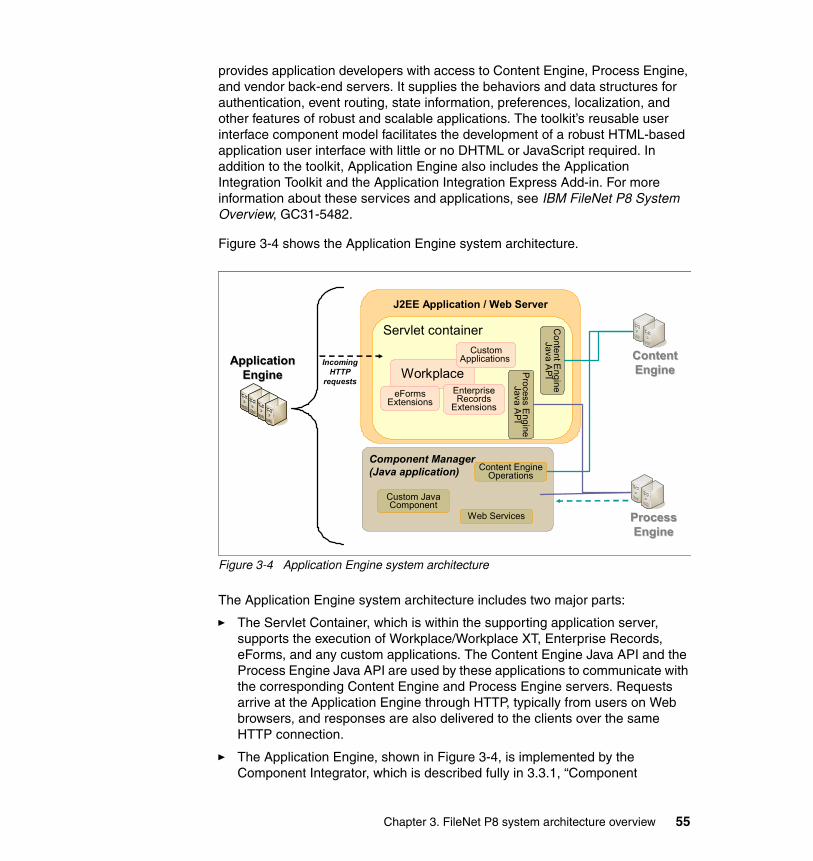
provides application developers with access to Content Engine, Process Engine, and vendor back-end servers. It supplies the behaviors and data structures for authentication, event routing, state information, preferences, localization, and other features of robust and scalable applications. The toolkit’s reusable user interface component model facilitates the development of a robust HTML-based application user interface with little or no DHTML or JavaScript required. In addition to the toolkit, Application Engine also includes the Application Integration Toolkit and the Application Integration Express Add-in. For more information about these services and applications, see IBM FileNet P8 System Overview, GC31-5482.
Figure 3-4 shows the Application Engine system architecture.
Figure 3-4 Application Engine system architecture
The Application Engine system architecture includes two major parts:
� The Servlet Container, which is within the supporting application server, supports the execution of Workplace/Workplace XT, Enterprise Records, eForms, and any custom applications. The Content Engine Java API and the Process Engine Java API are used by these applications to communicate with the corresponding Content Engine and Process Engine servers. Requests arrive at the Application Engine through HTTP, typically from users on Web browsers, and responses are also delivered to the clients over the same HTTP connection.
� The Application Engine, shown in Figure 3-4, is implemented by the Component Integrator, which is described fully in 3.3.1, “Component
ApplicationEngine
ApplicationEngine
J2EE Application / Web Server
Servlet container
Component Manager (Java application)
Workplace
CustomApplications
ProcessEngine
ProcessEngine
Process E
ngineJava A
PI
Content EngineOperations
Custom Java Component
Web Services
ContentEngineContentEngine
Conte
nt Engine
Java AP
I
eFormsExtensions
Enterprise Records
Extensions
Incoming HTTP
requests
Chapter 3. FileNet P8 system architecture overview 55

Integrator” on page 52. One or more Component Managers (Java applications) can run simultaneously. Content Engine operations allow workflows to access the Content Engine, and Web Services provides an invocation framework that is used for process orchestration.
Because each Application Engine works independently of any others and does not store any user data on disk, customers can easily provision a set of Application Engine servers. This configuration results in both scalability and high availability.
3.4.1 Communication protocols
Clients of Application Engine are Web browsers. They use the HTTP or HTTPS protocols in connecting to Application Engine. As a client of Content Engine and Process Engine, Application Engine uses their client protocols to connect to them. For Content Engine, the communication protocol used is the EJB transport. For Process Engine, the protocol is IIOP. Both protocols are carried over TCP/IP connections.
3.5 Image Services and CFS-IS
IBM FileNet Image Services is a powerful image and document management system. It integrates with a number of storage devices, including optical disk systems, Magnetic Storage and Retrieval (MSAR), and specialty storage units for compliance, such as IBM Information Archive and IBM System Storage N series storage.
Many companies with Image Services implementations want to take advantage of the functionality and features in the FileNet P8 suite, including Content Engine’s document class data model and Process Engine’s process workflow capabilities. Without having to give up existing applications and procedures that work with Image Services, FileNet P8 offers Content Federation Services for Image Services (CFS-IS) for these companies.
Content Federation Services (CFS) allows Content Engine to function as the master metadata catalog for documents that are stored in FileNet P8, Image Services, and other disparate content sources. Documents can be searched and retrieved directly by any FileNet P8 application, no matter where the actual content is stored.
For Image Services, CFS-IS federates the Image Services documents to the FileNet P8 catalog, meaning that the Image Services document metadata is
56 Disaster Recovery and Backup Solutions for IBM FileNet P8 Version 4.5.1 Systems

stored in the FileNet P8 catalog; the content remains where it was stored originally, until a user retrieves the document.
CFS-IS allows the Image Services users to deploy new FileNet P8 applications, which can use the documents that are stored in Image Services; the existing Image Services applications can continue to function for as long as they are required, until the decision is made to replace them with FileNet P8 applications.
CFS-IS also enables Content Engine to use Image Services as a content storage device. Users of FileNet P8 applications can have full access to content that is stored in existing Image Services repositories. Anything that is created in Workplace or created programmatically using Content Engine APIs can be stored in the Image Services permanent storage infrastructure if necessary, allowing companies to continue using their Image Services systems.
With CFS-IS, existing Image Services content is preserved and usable by Image Services clients, and it is also reusable by FileNet P8 applications, such as Workplace XT and Enterprise Records, without duplication and without change to existing applications. The location of document content is transparent to all Content Engine applications. Applications that store documents in Image Services systems can continue to be used.
For companies that are migrating from Image Services to FileNet P8 Platform, CFS-IS provides an initial bridge that allows Content Engine to be implemented quickly, without first requiring a full migration of all data. In this case, Content Engine can be configured to store new documents in its native storage areas, and content stored on the Image Services system can be migrated slowly while production operations continue. New applications can be developed in the FileNet P8 Platform. When all content is migrated from the Image Services system, and the Image Services system is no longer required for any applications, it can then be decommissioned.
If Image Services applications must run in parallel with the FileNet P8 application for at least a certain period of time, dual cataloging of documents is an option. Image Services documents can be cataloged in the Content Engine catalog, and they can also be cataloged in the Image Services catalog, resulting in all content being accessible by both Image Services clients and any application built on the FileNet P8 Platform, such as Workplace XT. Both the Image Services and Content Engine catalogs are masters and are automatically synchronized by CFS-IS. If properties change in Image Services, they are automatically propagated to the Content Engine catalog (metadata). Note that synchronization is not bidirectional. Updates in the Content Engine metadata do not propagate back to the Image Services catalog, so they are available only to FileNet P8 clients. Therefore, as long as Image Services clients are still in use, any updates must be made through the Image Services clients so that they are reflected in both catalogs (metadata).
Chapter 3. FileNet P8 system architecture overview 57

During the transition period from the Image Services catalog to the Content Engine catalog, both FileNet P8 Platform applications and Image Services clients can run concurrently, accessing the documents that are stored in Image Services. When a transition to the Content Engine catalog is complete, you may remove entries from the Image Services catalog, and replace the existing Image Services clients with native FileNet P8 applications.
You may catalog existing documents, images, and other content that are already cataloged on the Image Services system on an FileNet P8 system. The Image Services Catalog Export tool exports existing index data (document properties) from an Image Services catalog to a Content Engine catalog. The tool includes an option to delete the index entries from the Image Services index database after the index data has been exported to the Content Engine catalog. In preparation for implementing CFS-IS, the administrator must define a mapping between the document classes and properties within the Image Services system’s catalog and the document classes and properties in Content Engine. Properties that do not have a defined mapping are not exported. After CFS-IS is fully configured, CFS-IS automatically propagates the catalog entries of new documents added to Image Services document classes, which are mapped to Content Engine document classes, to the Content Engine catalog.
Architecturally, Image Services implements various components as separate processes. All of these processes can execute on the same host, in a combined server configuration, or you can spread the root, index, and library services across multiple hosts in a dual server configuration. Although Image Services does not support an active/active configuration, separation of these processes can allow an Image Services system to be scaled, within limitations, to accommodate increased demand. For high availability, only a combined server configuration is supported, with all the services resident in the same host. Remote Cache servers can also be used to improve performance in a geographically distributed environment by caching local copies of document content at remote work sites.
3.5.1 Communication protocols
The CFS-IS Pull Daemon threads reside in Content Engine. CFS-IS connects Image Services with Content Engine using a proprietary protocol over TCP/IP.
3.5.2 CFS-IS architecture
In FileNet P8 4.0, the implementation of CFS-IS resides within Content Engine as a number of Java classes and threads. This implementation is an important feature, because it means that the CFS-IS functionality is spread across all Content Engines in a Content Engine farm. This design increases performance
58 Disaster Recovery and Backup Solutions for IBM FileNet P8 Version 4.5.1 Systems

and scalability automatically as the number of active Content Engines in the farm increases. From a high availability standpoint, the CFS-IS functionality is inherently highly available when Content Engine is configured in this way. Figure 3-5 depicts the integration of Content Engine and an Image Services system.
When you add new documents to an Image Services system that is federated using CFS-IS, you can configure CFS to operate in one of the following ways:
� Index new documents to the Content Engine catalog only.
� Index new documents to the Content Engine catalog and the Image Services catalog.
In the latter option, updates to Image Services catalog entries are automatically propagated to the Content Engine catalog.
Figure 3-5 Integration of Content Engine and Image Services with CFS-IS
More than one Image Services system can be federated to the same Content Engine system, because each Image Services system appears to Content Engine as an individual fixed content device.
Content Manager
11
IBM FileNetP8 Platform Applications
Content Engine
Content Engine Catalog
Image Services
Image Services
Image Services Catalog
IndexServices
Database Storage
AreaFile Storage
Area
InformationArchive
SnapLock
b) Index to Image Services and Content Engine catalogs
a) Index to Content Engine catalog only
Image Services catalog updates propagated to Content Engine catalog
Content Engine catalog directly references
content stored in Image Services
CFS-IS
IDM Applications
Fixed Storage Area
Magnetic disk
Information Archive
SnapLock
Opticaldisk
Single Document Storage
MSAR OSAR
Magnetic disk
Chapter 3. FileNet P8 system architecture overview 59

3.6 Content Search Engine
Content Search Engine provides the ability to search for documents within Content Engine based on the content of the documents. It performs two basic functions:
� Full-text indexing: New documents that are added to the Content Engine repository can be full-text indexed. That is, the documents are scanned by the system to determine individual words that are found throughout the documents. The administrator can define a list of common words that do not require indexing (also known as the Excluded Word List); the use of this list greatly reduces both the size of the indexes and the time that it takes to index each document.
� Search, also known as Content Based Retrieval (CBR): This function identifies the documents whose content and properties match a given search query.
In defining a search template, a user can specify a search for one or more keywords, possibly also with conditional or alternative requirements, such as “high NEAR availability OR HA.” Search capabilities also include the ability to account for misspelled words, typographical errors, phonetic searching, word stem searching, synonym expansion, and wildcard searching, based on the search language that has been configured. Other important aspects of the search function include the following items:
� A single search can span multiple object stores across databases. This type of search is known as a Cross Repository Search (CRS). A Cross Repository Search is specified in Workplace simply by including more than one object store in the list of search targets.
� Workplace users can search for documents, folders, and custom objects. Searches can be designed to specify multiple folders, including a common folder name used in multiple object stores. Search templates can be constructed using a Query Builder, or more complex searches can be specified using the Verity Query Language (VQL).
� Content searches return matches not only on content but also on properties enabled for full-text indexing.
� Search results can be ranked automatically by relevancy.
� Searches can use language-specific processing and indexing.
� Bulk operations can be performed on search results in Enterprise Manager, where the operations can be scripted, or selected from a set of predefined operations, such as delete, cancel checkout, file, unfile, and change security.
60 Disaster Recovery and Backup Solutions for IBM FileNet P8 Version 4.5.1 Systems

� Searches can be created and stored for easy execution of common queries. Search templates provide a simple user interface for entering search criteria. Shortcuts to searches can be saved so it is easy to find them later.
� Searches can be expanded to retrieve documents, folders, and custom objects in the same search specification.
3.6.1 Content Search Engine architecture
Content Search Engine consists of components that can be deployed across one or more computers. Figure 3-6 shows Content Search Engine deployment, illustrating how the major components of Content Search Engine are interrelated.
Figure 3-6 Example Content Search Engine configuration
When a document is indexed by Content Search Engine, relevant information is stored in a proprietary database format in a file called a collection. Collections are stored within an index area, which is a Content Engine object created within Enterprise Manager. When a collection becomes full, a new collection is automatically created, up to the maximum number of collections that have been specified for the Index Area. Indexing can also be partitioned across a number of collections based on the value of a date-time property of the documents, primarily to increase search performance, if the date-time value is specified in the query, as it can significantly reduce the number of collections that must be searched to satisfy the query.
Ticket ServerMaster
AdministrationServer
Index Server
Local storage
Ticket ServerAdministration
Server
Index Server
Local storage
Broker ServerAdministration
Server
Search Server
Broker ServerAdministration
Server
Search Server
Local or remote access Local or remote access
Chapter 3. FileNet P8 system architecture overview 61

To initiate a request for Content Search Engine to index a document, Content Engine copies the document’s content to a temporary area, and then it submits a request to a Content Search Engine Index Server to index that document. In IBM FileNet Content Manager versions prior to 4.5, if multiple Content Engines are in a farm environment, you must manually set one Content Engine to initiate the index request. This unique Content Engine is designated by setting its EnableDispatcher configuration parameter to true. Starting from Version 4.5, the system automatically assign a Content Engine to perform the task. So, if this Content Engine fails, another Content Engine from the farm takes over automatically.
If the Content Search Engine Indexing Servers are down or unavailable, Content Engine queues requests to index documents, up to a maximum of 100,000 documents. Under normal circumstances, therefore, the unavailability of the Content Search Engine Indexing Servers does not prevent ingestion of new documents into Content Engine. Monitoring to ensure that the Content Search Engine Indexing Servers are up and running is therefore an important administrative task.
Not all new documents are required to be indexed. You can configure specific document classes and properties within the document classes to be full-text indexed, and documents of other classes are not indexed. In addition to automatic indexing of new documents, the administrator can manually submit a reindexing job from Enterprise Manager for a given document class, for all documents that have been marked for indexing, or for an individual document, folder, or subclass of any base document class. For example, the administrator can manually submit a reindexing job from Enterprise Manager to restore a particular collection that was lost because of a hardware failure. During the time that documents are being reindexed, search queries can still be performed against the existing collections. When the newly created collections are ready, the old ones are deleted and the new ones become active. Because reindexing jobs are typically time-consuming, perform this task during non-peak business hours.
The following sections describe each component of the Content Search Engine software. Although the term server is used for these components, each one is really a service, and within limits, each one can be deployed separately, helping to achieve scalability and availability requirements. In a minimal configuration, all of these services can be deployed on a single host computer, as in the configuration employed for this book. However, for scalability purposes, many clients spread these services across multiple host computers (or equivalents, such as logical partitions) as is done in the configuration used for this book. The services that require the most compute resources are the Index Servers and the Search Servers.
62 Disaster Recovery and Backup Solutions for IBM FileNet P8 Version 4.5.1 Systems
3.6.2 K2 Master Administration Server
For every Content Search Engine installation, there must be exactly one K2 Master Administration Server running. This server maintains information for all the other Content Search Engine server components. When Content Search Engine configuration changes (for instance, a new Search Server is added), the Master Administration Server updates itself and all of the other K2 Administration Servers so that they have the latest configuration settings. The Administration Servers also synchronize periodically with the Master Administration Server, upon startup and every 15 minutes thereafter.
An installation of a Master Administration Server and all the related services (which can be on the same or on remote hosts) is referred to as an Autonomy K2 domain2.
3.6.3 K2 Administration Server
Only one host computer within a K2 domain runs the Master Administration Server at a given time. Every other host computer in the K2 domain instead runs the K2 Administration Server.
The K2 Administration Server monitors the health of the Content Search Engine components installed on its host machine. In addition, Administration Servers can transfer configuration files that are used by the Content Search Engine system from one Content Search Engine host to another Content Search Engine host to propagate configuration changes.
Administration Server software is automatically installed when any other Content Search Engine server software is installed on a host machine. Remote Administration Servers are maintained by the Master Administration Server, including information, such as the configuration and status of a Content Search Engine installation. The information maintained by the local Administration Server is used by the other services running on the same host.
2 Autonomy materials reprinted with permission from Autonomy Corp.
Chapter 3. FileNet P8 system architecture overview 63

3.6.4 K2 Ticket Server
K2 Ticket Server is used for the security of the Content Search Engine system and its collection data. One or more Ticket Servers can exist in a K2 domain. The Ticket Servers store authentication information for users and grant access to the full text index collections accordingly. When a user authenticates to an LDAP server, the user receives a ticket. The Ticket Server gives the user access only to the part of the Content Search Engine system for which the user has the correct ticket. In the case of Content Engine, the credentials and other information that is necessary for Content Engine to connect to the Content Search Engine servers are stored in the K2 domain Configuration tab of the FileNet P8 domain root properties page within Enterprise Manager.
3.6.5 K2 Index Server
K2 Index Server is the software application that performs full-text indexing of documents. Specifically, Index Server reads a document, breaks it down into its component words, eliminates words that are in the Excluded Word List, and then creates entries in the collection, mapping those words to the particular document. Breaking apart the document to identify its relevant keywords for indexing is called information abstraction. Index Server is capable of performing this process on a wide range of document types.
Only Index Server writes to the collection files. To do so, Index Server requires local file access to the collection files. Physically, the files do not have to reside within the computer hosting Index Server. Most commonly, especially for highly available configurations, the collection files are stored on a SAN and accessed through a Fibre Channel network. Such access creates the appearance that the files are stored on a local Small Computer System Interface (SCSI) device, which Index Server can then access. Index Server cannot access collection files through network file share, such as Common Internet File System (CIFS) or Network File System (NFS).
The properties of each Index Area specify one or more Index Servers that Content Engine can use for that Index Area. By using this list, Content Engine can pick an Index Server for each document to be indexed.
64 Disaster Recovery and Backup Solutions for IBM FileNet P8 Version 4.5.1 Systems

Figure 3-7 shows how Content Engine distributes indexing requests among several Index Servers.
Figure 3-7 Content Engine sending index requests to Index Servers
3.6.6 K2 Broker and Search Servers
The content search process is the heart of a Content Search Engine system. Content Search Engine divides this process across two types of servers: K2 Broker Server and Search Server. When there is a search request, Content Engine sends the request to one of the Broker Servers. That Broker Server, in turn, divides the request into smaller pieces and spreads these pieces across a number of Search Servers. The configuration of each Broker Server determines to which Search Servers that broker distributes the request. When the Search Servers return their results to the Broker Server, it collates and merges the data into a single response and returns that response to the requesting Content Engine. Because the search process is one of the most critical functions of the Content Search Engine system, Search Servers are sometimes referred to simply as K2 Servers.
As with the farming capabilities of Application Engine, Content Engine, and Process Engine, this architecture allows automatic load balancing and scalability: as more Search Servers are added, individual searches can be spread over more servers, allowing faster response times. This process is called parallel querying. It also provides for automatic high availability: if a particular Search
ContentSearchEngine
ContentSearchEngine
Content EngineObject Store
Content Search Engine 2
Content Search Engine 1
Index Server 1Index Server 1
Index Server 2Index Server 2
Index Server 3Index Server 3
Object Store 1Object Store 1
Object Store 2Object Store 2
Index request
Index request
Index request
Collection 2
Collection 3
Collection 1
Indexing
Indexing
Indexing
Index Area 3Index Area 3
Index Area 1Index Area 1
Index Area 2Index Area 2
Chapter 3. FileNet P8 system architecture overview 65

Server fails, as long as at least one Search Server is available, the search process can still function.
Search Servers can access the collection files either as a local disk or through a network share, such as CIFS or NFS. Content Engines are automatically made aware of the Broker and Search Servers in the K2 domain by querying the Master Administration Server. When new Brokers or Search Servers are added, the Content Engines are automatically kept up-to-date.
3.6.7 Communication protocols
As a client of Content Search Engine, Content Engine connects to the Content Search Engine as a K2 Java client over TCP/IP. Installing the Content Search Engine client software on each of the Content Engine servers in the farm and then redeploying the FileNetEngine.ear file installs the necessary K2 Java client files.
66 Disaster Recovery and Backup Solutions for IBM FileNet P8 Version 4.5.1 Systems

Chapter 4. FileNet P8 data relationships and dependencies
This chapter describes the data relationships and dependences for IBM FileNet P8 Version 4.5.1 system components. The primary goal is to describe them in detail to support the design of a backup and disaster recovery strategy based on the backup and replication techniques described in this book.
This chapter contains the following topics:
� Content Engine data relationships, dependencies
� Process Engine relationship to Content Engine
� Image Services relationship to the Content Engine
4
© Copyright IBM Corp. 2010. All rights reserved. 67

4.1 Content Engine data relationships, dependencies
Content Engine provides the document and content management engine for FileNet P8. The three core data components of the Content Engine are the Global Configuration Database (GCD), the object stores, and content storage. These data components are grouped together to form a FileNet P8 domain.
4.1.1 FileNet P8 domain overview
The GCD database consists of a set of tables that define the FileNet P8 domain. The data components of a FileNet P8 domain are directly contained, or indirectly referenced, in the GCD. Figure 4-1 shows a high-level overview of the data components that encompass a FileNet P8 domain.
Figure 4-1 FileNet P8 Domain overview
GCDDatabase
Directory Server Configuration
Data
Domain Wide Configuration
DataObject Store
Database
Fixed Content Device Objects
K2 Full Text Indexes
Fixed Repository(Example : Tivoli Storage
Manager,Image Services)File & Fixed
Storage Areas
External Repository(Example: OnDemand,
Image Services)
CFS Database
Process Engine
68 Disaster Recovery and Backup Solutions for IBM FileNet P8 Version 4.5.1 Systems

A FileNet P8 domain consists of the following components:
� GCD
A set of database tables that directly contain or indirectly reference the data components of a FileNet P8 domain
� Directory Server configuration data
Configuration data for the authorization and authentication servers of the FileNet P8 domain
� Domain wide configuration data
Global configuration data for the FileNet P8 domain and sites within the domain
� Object store database
A set of database tables that define an object store, including the built in database storage area
� Process Engine
Process Engine configuration information for accessing isolated regions from FileNet P8 applications
� File storage area
A set of directories and files that define a file system based storage area
� Fixed storage area
A set of directories and files that define the staging area of a fixed content device-based storage area
� Fixed content device objects
Configuration information that defines a reference to a fixed content repository or an external repository
� Fixed repository
An Image Services, Tivoli Storage Manager, Snaplock, or Centera fixed content repository
� External repository
A Content Manager OnDemand (OnDemand), Image Services, or other external repository
� CFS database
A set of database tables used for document federation
� K2 full text index collections
The index collections that support of full text indexing of content and metadata
Chapter 4. FileNet P8 data relationships and dependencies 69

4.1.2 GCD database relationship
The GCD database contains a set of references to other databases in the FileNet P8 domain. The GCD database and all databases referenced by the GCD must be maintained in a synchronized state (all databases must be included in the backup or replication scheme).
The core GCD information is stored in a single active row in the FNGCD table as XML data. The FNGCD table always contains more than one row, but only the row with the highest sequence number (epoch) is the active row. All other rows are previous, inactive rows. Rows in the FNGCD table are never altered or deleted, they are always superseded by a new row with a higher epoch value. Figure 4-2 shows the relationship between the GCD database and other FileNet P8 databases referenced by the GCD.
Figure 4-2 GCD Relationship to other FileNet P8 databases
Important: Take all components of a FileNet P8 domain into account when implementing a backup or disaster recovery solution. To avoid data lost or inconsistent relationships between data, all data components of a FileNet P8 domain must be included in the set of data that is backed up or replicated. The backup or replication set must also be synchronized across the data of the FileNet P8 domain, meaning that all components must be backed up and replicated at the same point in time.
GCD
FNGCDGCD
configuration data XML
Object Storedatabases
CFSdatabases
Process Enginedatabases
GCD and all other databases must be included in backup or replication set
70 Disaster Recovery and Backup Solutions for IBM FileNet P8 Version 4.5.1 Systems

Cross object store object referencesAn object store can contain metadata objects that have references to objects in a separate object store in the FileNet P8 domain. To maintain the proper relationship between objects that cross object store boundaries, all object store databases of a FileNet P8 domain must be included in a synchronized backup or replication set.
4.1.3 Object store relationship between metadata and content
The object store data relationship that we discuss is the relationship between the metadata that is stored in the database, and the content that is stored external to the database. The key issues are the synchronization of the metadata and content, and the risk that metadata and content can become out of sync, resulting in a broken document. A broken document is an orphan document if there is metadata but no content, or a widow document if there is content but no metadata that is pointing to the content.
Out-of-sync and broken documentData stored in multiple tables in a database that have dependencies among them are always in sync. The transactional nature of the database is that either all updates to all tables are applied or all updates are rolled back. Content that is stored in a database storage area is always synchronized with the associated metadata, but content stored outside the database is not governed by the transactional nature of the database and, therefore, can be out of sync with the document metadata. How can the metadata and content be out of sync? How can a document be broken? Consider the two diagrams in Figure 4-3 on page 72
Note: If a FileNet P8 domain contains an object store with references to objects in an object store in a separate FileNet P8 domain, then both FileNet P8 domains must be included in the synchronized backup or replication set.
Chapter 4. FileNet P8 data relationships and dependencies 71
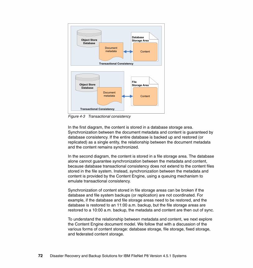
Figure 4-3 Transactional consistency
In the first diagram, the content is stored in a database storage area. Synchronization between the document metadata and content is guaranteed by database consistency. If the entire database is backed up and restored (or replicated) as a single entity, the relationship between the document metadata and the content remains synchronized.
In the second diagram, the content is stored in a file storage area. The database alone cannot guarantee synchronization between the metadata and content, because database transactional consistency does not extend to the content files stored in the file system. Instead, synchronization between the metadata and content is provided by the Content Engine, using a queuing mechanism to emulate transactional consistency.
Synchronization of content stored in file storage areas can be broken if the database and file system backups (or replication) are not coordinated. For example, if the database and file storage areas need to be restored, and the database is restored to an 11:00 a.m. backup, but the file storage areas are restored to a 10:00 a.m. backup, the metadata and content are then out of sync.
To understand the relationship between metadata and content, we next explore the Content Engine document model. We follow that with a discussion of the various forms of content storage: database storage, file storage, fixed storage, and federated content storage.
Database Storage Area
Content
Object Store Database
Documentmetadata
Transactional Consistency
Object Store Database
Documentmetadata
Transactional Consistency
File Storage Area
Content
72 Disaster Recovery and Backup Solutions for IBM FileNet P8 Version 4.5.1 Systems
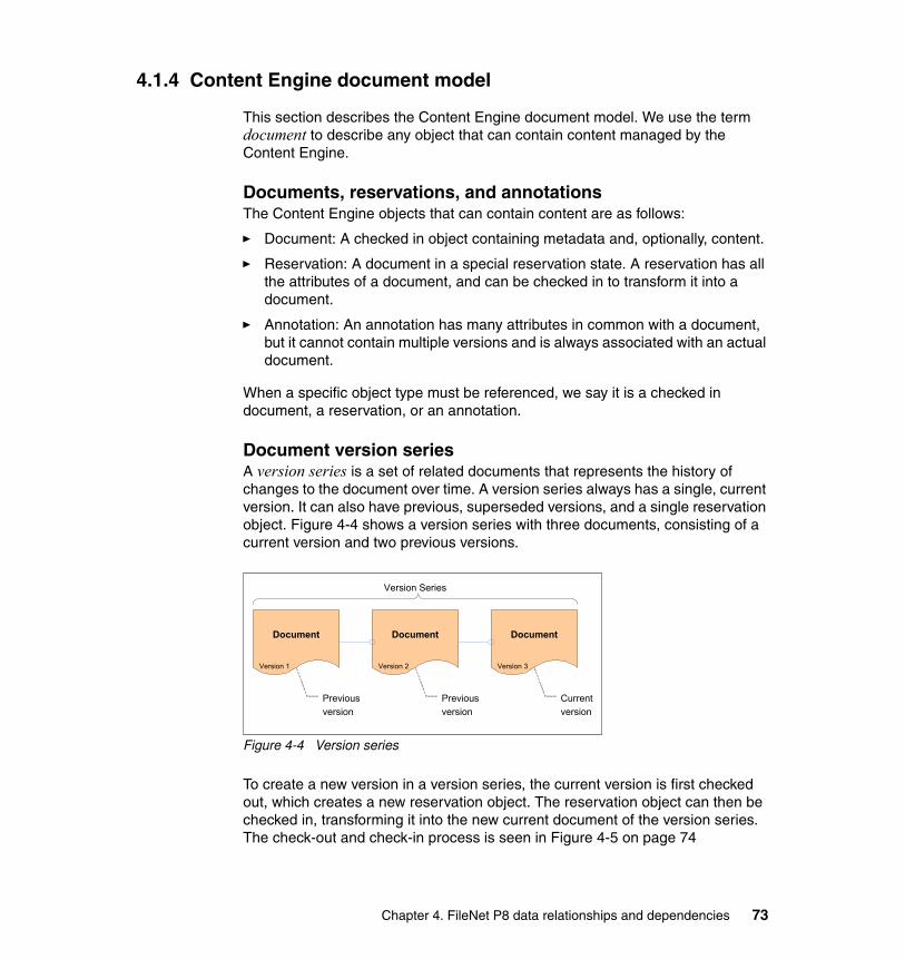
4.1.4 Content Engine document model
This section describes the Content Engine document model. We use the term document to describe any object that can contain content managed by the Content Engine.
Documents, reservations, and annotationsThe Content Engine objects that can contain content are as follows:
� Document: A checked in object containing metadata and, optionally, content.
� Reservation: A document in a special reservation state. A reservation has all the attributes of a document, and can be checked in to transform it into a document.
� Annotation: An annotation has many attributes in common with a document, but it cannot contain multiple versions and is always associated with an actual document.
When a specific object type must be referenced, we say it is a checked in document, a reservation, or an annotation.
Document version seriesA version series is a set of related documents that represents the history of changes to the document over time. A version series always has a single, current version. It can also have previous, superseded versions, and a single reservation object. Figure 4-4 shows a version series with three documents, consisting of a current version and two previous versions.
Figure 4-4 Version series
To create a new version in a version series, the current version is first checked out, which creates a new reservation object. The reservation object can then be checked in, transforming it into the new current document of the version series. The check-out and check-in process is seen in Figure 4-5 on page 74
Document
Version 1
Document
Version 2
Document
Version 3
Version Series
Previous
version
Previous
version
Current
version
Chapter 4. FileNet P8 data relationships and dependencies 73

Figure 4-5 Reservation check-out and check-in process
Content Engine document, metadata plus contentA Content Engine document consists of metadata and content. The metadata is stored in the object store database, and the content is stored in a storage area, as seen in Figure 4-6.
Figure 4-6 Content Engine document
Content elements, transfer versus referenceA Content Engine document has a set of zero or more content elements. Each content element is either a content transfer element or content reference element, as seen in Figure 4-7 on page 75.
Document
Version 3
Reservation
Reserved
Document
Version 4
Version Series
Checkout Check in
Reservation transformed into new current version
Only the current version can be checked out
PropertiesObject Store
databaseStorage Area
Document, Reservation, or
Annotation contains
metadata (property values) and content
Metadata is stored in
the Object Store database
Content is stored in a storage area
Content
74 Disaster Recovery and Backup Solutions for IBM FileNet P8 Version 4.5.1 Systems

Figure 4-7 Content elements
A content reference element contains a link to some form of external content. For example, a content reference element might contain a Web page address. The content that the link is pointing to (in this case the content of the Web page) is not maintained by the Content Engine; it is strictly an application feature.
A content transfer element always points to content managed by the Content Engine. The content may be stored in database, file, or fixed storage. The term content element is used as shorthand for a content transfer element in this book, because we are discussing content that is managed only by the Content Engine. The term content element blob is used to refer to the content bytes of the content element.
Immutable content elementsThe Content Engine implements an immutable content model. After a content element is committed to the system, the content element blob is never altered by the Content Engine. The resulting content model for the Content Engine is write once, read often, and optionally delete once. The immutable content model applies to all document objects, including checked in documents, reservations, and annotations. Immutable content, meaning immutable content blobs, is not to be confused with a mutable set of content elements, our next topic.
Content Transfer
objects contain content that is managed by the
Content Engine
Document, Reservation, or
AnnotationContentElements
(set of obejcts)
ContentTransfer
Content Reference objects contain
a reference to content that is not managed by the Content Engine
Each document contains a set of
zero or more Content Elements
ContentReference
Chapter 4. FileNet P8 data relationships and dependencies 75
Mutable content element setA document has a set of zero or more content elements. For a checked-in document, the content element set is immutable, but for a reservation or annotation the set is mutable.
When the set is mutable, new content elements can be added and existing elements can be deleted, but the content bytes of a given element cannot be altered. As an example, a reservation contains a single content element with a content element sequence number of zero. An application allows the user to check in the reservation, supplying a modified version of the content bytes. The application must delete the existing content element and add the new content element. To the user it appears that the content is replaced on check in, but the new content is assigned content element sequence one and the old content (sequence zero) is deleted. Most applications make this type of delete and add behavior transparent to the user.
Unique Content Element blob namingEach content blob stored by the Content Engine has a unique name, regardless of what type of storage area is used. For example, the file name of a content element blob in a file storage area is unique within a FileNet P8 domain. Having a unique name for each content blob simplifies restoration of an individual piece of content. Later in this chapter, we explore how the unique name is implemented for each type of storage area.
Content deduplicationContent deduplication is a process used by the Content Engine to prevent the storage of redundant content element blobs. Deduplication applies to a complete content blob, and is always relative to a storage area, it never crosses a storage area boundary. The Content Engine supports deduplication of content stored in database and file system storage areas.
Content deduplication is an optional feature that can be enabled for a given area, but by default it is disabled for an area. Figure 4-8 on page 77 shows an overview of the content deduplication process flow. The implementation details are different for database and file storage, and are described within the database and file storage topics.
76 Disaster Recovery and Backup Solutions for IBM FileNet P8 Version 4.5.1 Systems

Figure 4-8 Content deduplication process flow
The figure shows the following steps:
1. During content upload a signature is computed based on the bytes of the content element blob.
2. After upload, the system determines whether the content element blob already exists in the target storage area, using a deduplication table in the object store database. Database storage deduplication is implemented in the Content table and file storage deduplication is implemented in the ContentRef# table.
3. If the content is new, it is saved to the system and a deduplication row is established.
4. If the content already exists, the reference count for the deduplication row is incremented and the content is not saved to the system (because it already exists in the system).
Object Store
Content
Source Document, Reservation, or
Annotation
Content Content Engineupload
Compute content
signature
(1)
Exists?
(2)
Add content and deduplication row
No
Increment reference count
Yes
ContentRef
(4)
(3) Database storage
File storage
Chapter 4. FileNet P8 data relationships and dependencies 77

The remainder of this section explains database, file, and fixed storage, and federated content, K2 full text indexing, and the Process Engine. For each storage area type we explore the following topics:
� Brief architectural overview
� Unique blob naming
� Relationship to properties of a document
� Content deduplication (database and file storage)
� Content finalization
� How a document and content can be out of sync (file and fixed storage)
4.1.5 Database storage
A database storage area is implemented as a single table (named Content) within the object store database. Each content element blob is stored as a row in the Content table, as depicted in Figure 4-9.
Figure 4-9 Content element blob in database storage
Unique blob namingThe ELEMENT_ID column of the Content table is used to make the row unique, providing the unique blob name for database storage. The column is a concatenation of the document object ID and the content element sequence number. For example, the element ID value for content element zero of a document with an object ID of {C2D75341-1975-454f-AEE9-0666948E2E8C} appears as follows:
{C2D75341-1975-454f-AEE9-0666948E2E8C}0
Example: {C2D75341-1975-454f-AEE9-0666948E2E8C}0
Optional file extension of the source file (for example, ‘pdf’ for
a file named ‘mydocument.pdf’)
Size of the content data in
number of bytes
Content table
Object StoreDatabase
ELEMENT_ID EXTENSION CONTENT CONTENT_SIZE CREATE_DATE REFCOUNT
78 Disaster Recovery and Backup Solutions for IBM FileNet P8 Version 4.5.1 Systems

Relationship to properties of a documentA row in the Content table is related to the document object by two properties, the documents object ID and the content element sequence number (of the content element), as seen in Figure 4-10.
Figure 4-10 Content row relationship to a document
Database content deduplicationDatabase storage deduplication is implemented in the Content table, and makes use of the REFCOUNT column, introduced in Content Engine version 4.5.1. Redundant content elements are not added to the Content table when the optional deduplication feature is enabled. Two significant differences exist in how the Content table is used when deduplication is enabled, shown in Figure 4-11.
Figure 4-11 Database storage deduplication
For deduplicated content, the ELEMENT_ID column (1) contains a string version of content signature instead of a concatenation of the object ID and content element sequence number. The content signature is also stored as part of the document metadata, but is not exposed through the API.
Document
Object id
Element sequence number
Content table
Object StoreDatabase
ELEMENT_ID EXTENSION CONTENT CONTENT_SIZE CREATE_DATE REFCOUNT
Unique id of the
content element blob
(computed signature)
Content table
Object StoreDatabase
ELEMENT_ID EXTENSION CONTENT CONTENT_SIZE CREATE_DATE REFCOUNT
Reference count for the content element blob
1 2
Example: ]rh*ft4.-\0_h:a1k:*;<9:v^9dlap{r^0qn9{c>~c4m
Chapter 4. FileNet P8 data relationships and dependencies 79

For deduplicated content, the REFCOUNT column (2) is used to keep track of how many content elements are currently referencing the content blob row.
Finalizing a document to a database storage areaWe use the term finalized to describe the process of making content a persistent member of a storage area. The process of finalizing content varies by storage area type, and is described for each type in this chapter. Content for a document in the database storage area is finalized to the system in three steps, as seen in Figure 4-12.
Figure 4-12 Database content finalization
The figure shows the following steps, which are used to finalize database content:
1. Content element blobs are uploaded to files in temporary file system storage. The temporary files are normally located in a non-shared directory under the application server installation files.
2. The content is read from the temporary files and inserted into rows in the Content table. Each Content table row represents a single content element blob. The rows are inserted in a non-finalized form, which means that the ELEMENT_ID column is set to a special value that indicates that the content is not yet finalized.
3. A transaction is started, a row for the document metadata is inserted into the DocVersion table, and the associated Content rows are updated to the finalized state (the ELEMENT_ID column is changed from the temporary value to the finalized value).
(3)Content Enginecontent blob (1)
Object Store database
App-Server Temporary
Files
(1)
(3)
DocVersion table
(3)
(2)
Source Document
metadata
Content table
80 Disaster Recovery and Backup Solutions for IBM FileNet P8 Version 4.5.1 Systems

4.1.6 File storage
A file storage area consists of a set of directories and files, contained under a single root directory. Content element blobs are stored in files known as content element files. Figure 4-13 depicts the file storage area structure, including the location of a single content element file.
Figure 4-13 File storage area structure
Unique blob namingEach content element blob is stored in a separate content element file. The file name of the content element file is formatted in a way that makes it unique throughout a FileNet P8 domain, as seen in Figure 4-14 on page 82.
Note: The content upload process is more complex when large content blobs and multiple Content Engine servers are involved. For the purpose of this book, only simple content upload processing is described.
Storage Area Root Folder
Inbound Content
Stakefilefn_stakefile.xml
FN0 FN1 FN22
FN0 FN1 FN22
FN0 FN1 FN22
ContentFile
The root directory is created by a system
administrator
The stakefile
provides verification
that a storage area is really the correct area
The inbound directory provides
temporary storage
for content while it is uploaded to the
area
Content that has
been ‘finalized’ is stored under the content directory
hierarchy
An area has either two (small) or
three (large) levels of subdirectories
(used to distribute the content across
the file system namespace)
Content is stored in a
file, under the lowest level of the subdirectory hierarchy (each content
element blob is stored in a separate file)
Content is not stored in the upper levels of the subdirectory hierarchy
I0 I1 I63
V 4.5.1 areas
contain a set of 64
subdirectories for content upload
Chapter 4. FileNet P8 data relationships and dependencies 81
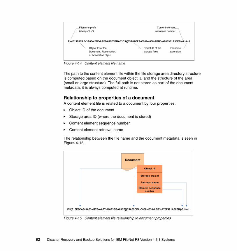
Figure 4-14 Content element file name
The path to the content element file within the file storage area directory structure is computed based on the document object ID and the structure of the area (small or large structure). The full path is not stored as part of the document metadata, it is always computed at runtime.
Relationship to properties of a documentA content element file is related to a document by four properties:
� Object ID of the document
� Storage area ID (where the document is stored)
� Content element sequence number
� Content element retrieval name
The relationship between the file name and the document metadata is seen in Figure 4-15.
Figure 4-15 Content element file relationship to document properties
FN{E15E8CAB-3A03-427E-AAF7-610F3BBA63C5}{35A02CFA-C069-4038-ABB3-A70F981A56EB}-0.html
Filename prefix(always ‘FN’)
Object ID of the Document, Reservation,
or Annotation object
Object ID of the storage Area
Content element sequence number
Filenameextension
FN{E15E8CAB-3A03-427E-AAF7-610F3BBA63C5}{35A02CFA-C069-4038-ABB3-A70F981A56EB}-0.html
Document
Object id
Storage area id
Retrieval name
Element sequence number
82 Disaster Recovery and Backup Solutions for IBM FileNet P8 Version 4.5.1 Systems

File storage content deduplicationFile storage content deduplication is implemented using the ContentRef# table, introduced in Content Engine version 4.5.1. Redundant content elements are not added to the file storage area when the optional deduplication feature is enabled.
Each file storage area that is enabled for deduplication has its own ContentRef# table. A sequence number is appended to the table name, starting with the number one (1). The first area that is enabled for deduplication is assigned ContentRef1, the second area is assigned ContentRef2, and so on.
The primary key to the ContentRef# table is the content signature value that is computed during content upload. The signature uniquely identifies the content blob within a file storage area. The ContentRef# table also contains a count of how many content elements are referencing the row.
The file name for a deduplicated content element file is based on the signature value, and not the document object ID. The hash value is binary and cannot be used directly as the file name, so instead it is converted to a valid file name string (hex encoded string), shown in Figure 4-16.
Figure 4-16 File storage deduplication
Object StoreDatabase
CONTENT_SIG
ContentRef# table
Unique ID of the de-duplicated element
(computed content signature)
REFCOUNT
Reference count forthe content element
02a3436d9edb701454aac687f9505ecf9698dcbff728b10bf2c5a025c8ba3db5Content element filename
Chapter 4. FileNet P8 data relationships and dependencies 83
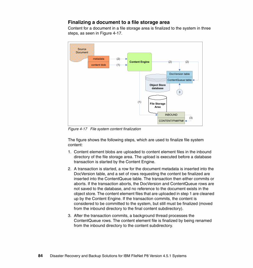
Finalizing a document to a file storage areaContent for a document in a file storage area is finalized to the system in three steps, as seen in Figure 4-17.
Figure 4-17 File system content finalization
The figure shows the following steps, which are used to finalize file system content:
1. Content element blobs are uploaded to content element files in the inbound directory of the file storage area. The upload is executed before a database transaction is started by the Content Engine.
2. A transaction is started, a row for the document metadata is inserted into the DocVersion table, and a set of rows requesting the content be finalized are inserted into the ContentQueue table. The transaction then either commits or aborts. If the transaction aborts, the DocVersion and ContentQueue rows are not saved to the database, and no reference to the document exists in the object store. The content element files that are uploaded in step 1 are cleaned up by the Content Engine. If the transaction commits, the content is considered to be committed to the system, but still must be finalized (moved from the inbound directory to the final content subdirectory).
3. After the transaction commits, a background thread processes the ContentQueue rows. The content element file is finalized by being renamed from the inbound directory to the content subdirectory.
content
SourceDocument
(2)Content Enginecontent blob (1)
Object Store database
File Storage Area
(1)
INBOUND
CONTENT/FN#/FN#
(2)
DocVersion table
ContentQueue table
(2)
(3)
3
metadata
84 Disaster Recovery and Backup Solutions for IBM FileNet P8 Version 4.5.1 Systems
Reasons for broken documentsThere are two significant cases related to backup and disaster recovery that can cause broken documents in a file storage area:
� Non-synchronized backup and restore of the object store database and file storage areas
� Disaster recovery failover to a replicated site
There are of course other things that can cause broken documents, such as media failure and malicious tampering. But in this chapter we only discuss the causes that are related to backup and disaster recovery implementations.
Non-synchronized backup and restoreIf the object store database and file system that contains the file storage areas are restored to different points in time, the result can be broken documents. For example, if the database is restored to 11:00 a.m. and the file system is restored to 10:00 a.m., all content element files created from 10:00 a.m. to 11:00 a.m. are missing, and all associated documents are broken.
Disaster recovery failover to a replicated siteThere are two types of replication that can be used to maintain a disaster recovery site: fully synchronized replication, and replication as needed. The first type of replication is equivalent to a synchronized backup and restore. All FileNet P8 components are shut down and then all data is replicated to the secondary site. This type of replication prevents broken documents, but has obvious operational limitations. The second type of replication is the more common case, the data is replicated continuously as needed. But this type of replication can result in broken documents if deployed incorrectly.
If the database and file storage areas are replicated as part of a consistency group, broken documents after the disaster failover are unlikely to occur. This is the result of the order in which the Content Engine processes content ingestion. Because the content is uploaded to the inbound directory prior to a reference to the document being created, there are not any documents that reference non-existent content. This type of replication configuration is shown in Figure 4-18 on page 86.
Chapter 4. FileNet P8 data relationships and dependencies 85

Figure 4-18 Replication using a single consistency group
If the database and file storage areas are not replicated as part of a consistency group, broken documents are a good possibility, because the database and content files are not synchronized. An example of this type of disjointed replication is shown in Figure 4-19.
Figure 4-19 Disjointed replication using multiple consistency groups
Content EngineServer #2
Content EngineServer #1
DS4000SAN Switch
Database Server
Database files(LUN 2)
File Storage Area files(LUN 1)
N-Series(NFS Server)
DS4000
Database files
File Storage Area files
Glo
bal M
irror
cons
iste
ncy
gro
up
Replica
The database server has
exclusive access to the DB files on the SAN (the
DB files are not shared).
The N-Series server hosts the
file storage areas, the actual directories and files reside on
the SAN.
Databaseaccess
Contentaccess
N-Series(NFS Server)
Content EngineServer #1
DS4000SAN Switch
Database Server
Database files(LUN 2)
DS4000 Database files
Glo
bal M
irro
rco
nsis
tenc
y g
roup
A
Replica
DS4000File Storage
Area files(LUN 1)
SAN Switch
DS4000 File Storage Area files
Glo
bal M
irro
rco
nsis
tenc
y g
roup
B
Replica
Content EngineServer #1
86 Disaster Recovery and Backup Solutions for IBM FileNet P8 Version 4.5.1 Systems

4.1.7 Fixed storage
A fixed storage area has two parts, a file storage area known as the staging area, and a reference to a fixed content repository. The staging area is used to upload content, hold content for reservations and annotation, and temporarily hold content for documents that are pending migration to the fixed repository. The fixed repository (of the fixed storage area) is used to store the content of checked-in documents.
When a document is in the staging area, it is treated like a document in a file storage area. The relationship between metadata and content is the same as with a file storage area. After a document is migrated to a fixed repository, the document metadata is updated to include a reference to the content in the fixed repository. The content element files are then removed from the staging area.
The metadata to fixed content relationship is shown in Figure 4-20.
Figure 4-20 Document metadata to fixed content relationship
Content referral blobThe metadata reference to content stored in a fixed repository is known as the content referral blob (or just referral blob). The referral blob is a column of the DocVersion table, and contains information needed to access the fixed content associated with a document.
Note: A staging area has the same physical structure as a file storage area (a staging area is implemented as a file storage area with a small directory structure). The content in a staging area is not temporary data, it is content that is used by documents in the system. The staging area directories and files must be backed up or replicated as part of the disaster recovery scheme.
Document
Content referral blob
FixedContent
RepositoryFixed content objects
Chapter 4. FileNet P8 data relationships and dependencies 87

A referral blob consists of two parts, the first part is housekeeping information, and is the same for all fixed repository types. The second part is the device specific address of the content stored in the fixed repository. The content address is used by the Content Engine to access the fixed content.
Unique content blob namingFor some fixed repositories the content address is computed by the Content Engine, and for others it is computed by the repository (the repository computes an address based on the content bytes). However, in all cases, the content address provides a unique content blob name for a content element blob. An example of a referral blob with a Content Engine computed address is shown in Figure 4-21. The example depicts an address for content stored in a Tivoli Storage Manager repository.
Figure 4-21 Tivoli Storage Manager referral blob
Relationship to properties of a documentAs Figure 4-21 shows, a document is related to fixed content through the content referral blob. The referral blob is document metadata that is not exposed through the Content Engine API.
Filespace name /FilenetP8
High level name /8A20A4C2-F917-4919-AE27-49B1839FF7B8
Low level name /B2846243-A4BB-4B9C-8436-2E27D4CE4B81/5FE277FB-E3D0-4BBA-B4F6-F7A677F90DD2-0
Object type 1
Delimiter /
Document
TivoliStorage Manager
Housekeeping Data
Content Referral Blob
content
Fixed Storage Area IDFixed Content Device property
Migration IDDocument
object ID
Tivoli Storage Manager Object Name
88 Disaster Recovery and Backup Solutions for IBM FileNet P8 Version 4.5.1 Systems

Migrating a document to a fixed storage areaContent for a document that is bound for a fixed repository is written to the repository in two phases. The first phase finalizes the content to the staging area, in exactly the same manner as a content is finalized to a file storage area (see Figure 4-17 on page 84). The second phase migrates the content from the fixed storage area to the fixed repository.
Migration processing is driven from the content queue table. When a document is checked in, a request is added to the content queue table to migrate the content to a fixed repository, and to delete the source content from the staging area.
The migration process is shown in Figure 4-22.
Figure 4-22 Content migration to a fixed repository
The figure shows the steps that are used to migrate content to a fixed repository:
1. A background thread processes the content queue request, writing the content to the fixed repository. When the content is migrated, the repository relative content address is computed. The content address is then used to create the content referral blob for the document.
2. The background task updates the document object, setting the content referral blob. After the content referral blob is set, future requests to retrieve or delete the content access the fixed repository, not the staging area.
3. The background task deletes the source content from the staging area, and deletes the request row from the content queue table.
(3)
Content Engine
Object Store database
Fixed Storage
Area
INBOUND
CONTENT/FN#/FN#
DocVersion table
ContentQueue table
Fixed Content Repository
(2)
(1)
(3)
Chapter 4. FileNet P8 data relationships and dependencies 89

Reason for broken documentsEach fixed content repository has its own scheme for preventing data loss, implementing replication, and participating in a disaster recovery scheme. A broken document can only exist if the content referral blob points to content that has been lost on the fixed repository, shown in Figure 4-23.
Figure 4-23 Content missing from a fixed repository
The system architect must consult with the fixed content repository vendor to determine the best approach to implementing disaster recovery for the specific repository to minimize the possibility of content being lost from the device.
4.1.8 Federated content
The Content Engine supports two types of federated content: � Federated content with Content Federation Services for IBM Content
Manager OnDemand (CFS-CMOD) and Content Federation Services using IBM Content Integrator. This type is described in this section.
� Federated content with Content Federation Services for Image Services (CFS-IS). This type is described in 4.3, “Image Services relationship to the Content Engine” on page 99.
Note: A document is migrated to a fixed repository only when it is checked in. Most applications combine document creation with check-in, which appears to the user as a single action. The content of documents in the reservation state, and the content of annotations, is not migrated to the fixed repository.
Document
Content referral blob
FixedContent
RepositoryMissing fixed content
objectsX
90 Disaster Recovery and Backup Solutions for IBM FileNet P8 Version 4.5.1 Systems

Federated content is very much like fixed content, in that it is stored in an external repository and accessed from the Content Engine using a content referral blob. The key difference between federated and fixed content is how it is ingested into the Content Engine. Fixed content is considered to be native content, because it is ingested directly into the Content Engine. Federated content is considered to be external content, because it is originally ingested into an external repository, then federated into the Content Engine. Figure 4-24 shows the difference between federated and fixed content ingestion.
Figure 4-24 Ingestion of federated versus fixed content
Ingestion of a federated document has the following steps:
1. The document is ingested into the external repository, using an application of the repository.
2. The document is federated into the Content Engine, creating a Content Engine document.
Note: When we talk about an IBM Content Integrator repository, we are talking about an external repository that is supported by Content Integrator. Content Integrator is not a content repository; instead it supports easy and uniformed access to various external repositories.
External RepositorySource
Document (1)
Content Engine
(2)
metadata
content
1
1
Document
metadata
(3)(4)
Ingestion of a Federated Document
Fixed Content Repository
SourceDocument (1)
Content Engine
content
Document
metadata
(3)
(4)
Ingestion of a Fixed Document
Referral blob
Referral blob
(2)
Chapter 4. FileNet P8 data relationships and dependencies 91

3. The Content Engine document receives a copy of the metadata of the external document.
4. The Content Engine document has a referral blob that points to the content in the external repository.
Ingestion of a document with fixed content has the following steps:
1. The document is ingested into Content Engine, using a Content Engine application.
2. The Content Engine creates a document and migrates the content to the fixed content repository (after storing it temporarily in the staging area).
3. The Content Engine document has a referral blob that points to the content stored in the fixed repository.
CFS databaseA separate database is used to support CFS-CMOD and CFS implementation (using IBM Content Integrator) federation. The database is known as the CFS database (sometimes referred to as the federation database). The CFS database is used to store the following data:
� Configuration data used by the CFS implementation (using IBM Content Integrator) administration tool, the OnDemand administration tool, and the CFS Import Agent
� Import request data, the CFS exporter inserts import requests into the CFS database, which are then processed by the CFS Import Agent to create Content Engine documents
� Mapping between objects in the external repository and the corresponding objects within the Content Engine
The CFS database is used only during the federation process; it is not used to access the metadata or content after the Content Engine document has been created. The CFS database is needed to support re-import from the external repository to the Content Engine. If the CFS database is inconsistent with the object store database, re-importing can fail. Therefore, the following tasks are important:
� Always include all CFS databases in any backup and disaster recovery scheme.
� Keep the CFS databases in sync with the GCD and object store databases of the FileNet P8 domain.
92 Disaster Recovery and Backup Solutions for IBM FileNet P8 Version 4.5.1 Systems
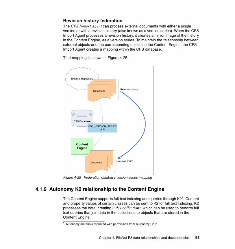
Revision history federationThe CFS Import Agent can process external documents with either a single version or with a revision history (also known as a version series). When the CFS Import Agent processes a revision history, it creates a mirror image of the history in the Content Engine, as a version series. To maintain the relationship between external objects and the corresponding objects in the Content Engine, the CFS Import Agent creates a mapping within the CFS database.
That mapping is shown in Figure 4-25.
Figure 4-25 Federation database version series mapping
4.1.9 Autonomy K2 relationship to the Content Engine
The Content Engine supports full-text indexing and queries through K21. Content and property values of certain classes can be sent to K2 for full text indexing. K2 processes the data, creating index collections, which can be used to perform full text queries that join data in the collections to objects that are stored in the Content Engine.
External Repository
DocumentDocument
Document
Content Engine
Revision history
CFS Database
FDB_VERSION_SERIEStable
DocumentDocument
DocumentVersion series
1 Autonomy materials reprinted with permission from Autonomy Corp.
Chapter 4. FileNet P8 data relationships and dependencies 93

An overview of full text indexing is shown in Figure 4-26.
Figure 4-26 Full text indexing overview
Full text indexing consists of the following major components:
� Label A: The IndexArea table stores configuration data that relates Content Engine objects to K2 indexes.
� Label B: The DocVersion, Generic, Container, and Annotation tables can be index enabled, allowing property values of the tables to be indexed.
� Label C: Content from all storage area types can be full text indexed. For database and fixed storage areas the content must be retrieved and written to a temporary file for indexing.
� Label D: K2 maintains a set of full text index collections. The Content Engine does not access the indexes directly.
� Label E: The Content Engine uses K2 to perform full text queries on property values and content.
Object Store
IndexArea
DocVersion
K2 Services
Full text index
collections
Generic
Container
Annotation
File Storage Areas
Indexing
Content Engine Full Text Queries
Fixed and federated content
Content
A
B
C
C
C
D
E
Tables
94 Disaster Recovery and Backup Solutions for IBM FileNet P8 Version 4.5.1 Systems

Relationship between Content Engine and K2 collectionsA Content Engine object that is full text indexed has a pointer to the K2 collection where the index data is stored. The pointer is the INDEXATION_ID property, which is defined on each class that supports full text indexing.
Each item in a K2 collection contains the object ID of the related Content Engine object. When a full text query is executed, K2 builds a result set and returns it to the Content Engine. The object IDs of the matching Content Engine objects are embedded in the result set. The object IDs can be used to join the K2 result set to objects in the Content Engine. The relationship between Content Engine metadata and K2 full text index collection items are shown in Figure 4-27.
Figure 4-27 Relationship between K2 items and Content Engine objects
Backup and disaster recovery considerationsThe K2 full text index collections must be included in the backup and replication data set for a FileNet P8 Domain. Although the indexes can be rebuilt from the source data, rebuilding the indexes can be very resource-intensive and time-consuming. The best practice is to back up (or replicate the index collections), and to synchronize the backups (or replication) with the complete FileNet P8 Domain data set.
Non-synchronized index collection backupIf the collection backups (or replicas) are not synchronized with the object store backup, the results of full text queries can be invalid. For example, if a collection is restored to a point in time before the object store database restoration time, the collection can be missing references to Content Engine objects. The out-of-sync collections can also include references to Content Engine objects that are no longer valid. For example, an out of date collection may include a reference to an object based on property values that have been altered on the object because the time the object was originally indexed.
Object Store
Index enabled object
INDEXATION_ID
K2 full text index
collection
Index Key
Object id
Indexed Data
Chapter 4. FileNet P8 data relationships and dependencies 95

Re-indexing collections to fix synchronization issuesAn administrator can re-index Content Engine objects to fix synchronization issues between index collections and an object store database. The types of re-index operations that a system administrator can choose from are re-index all classes, re-index a collection, and re-index of selected classes.
Re-index all classesThe re-index all classes operation can be used to re-index all content and property values of an object store. The Content Engine performs a complete re-index of all index enabled objects, creating a new set of index collections. When the operation is finished, the new collections replace the previous collections.
Re-index a collectionAll objects that are indexed into a given collection can be re-indexed using the collection re-index option. Objects are selected for re-indexing based on the indexation ID of the object. A new collection is created and replaces the previous collection when the re-index operation completes. This option is useful for restoring a single collection, but remember that only objects that are already indexed into the collection are re-indexed, no new objects are added to the collection.
Re-index of selected classesAll objects belonging to a class can be re-index. The re-index operation can span multiple collections (if objects from multiple collections are included in the class to being re-indexed). Re-indexing selected classes does not cause the index collections to be rebuilt and replaced; rather, individual objects are deleted and re-indexed into the collections.
4.2 Process Engine relationship to Content Engine
Process Engine manages workflow among people and systems for content and human-intensive processes.
The Process Engine stores data in a database (the Process Engine database) and in the Content Engine, as standard Content Engine objects. The Process Engine database is logically subdivided into isolated regions.
96 Disaster Recovery and Backup Solutions for IBM FileNet P8 Version 4.5.1 Systems

Each isolated region can contain references to objects in multiple Content Engine Object stores, as shown in Figure 4-28.
Figure 4-28 Isolated region to object store mapping
As labeled in Figure 4-28, the Process Engine and Content Engine have the following cross system dependencies:
� Label 1: The Content Engine maintains IsolatedRegion objects in the GCD. An IsolatedRegion object contains connection information used by the Content Engine to access the Process Engine.
� Label 2: The Process Engine Isolated Regions contain objects that have references to objects in the Content Engine.
� Label 3: Isolated region 1 contains objects that reference Content Engine objects in object stores A and B.
� Label 4: Isolated region 2 contains objects that reference Content Engine objects in object stores A and C.
Process Engine Database
GCD
Process EngineContent Engine
IsolatedRegion Object 1
IsolatedRegion Object 2
Object Store (A)
Object Store (B)
Isolated Region #2
Isolated Region #1
Object Store (C)
(3)
(3)
(4)
(4)
1
2
Chapter 4. FileNet P8 data relationships and dependencies 97

A more detailed view of the relationship between an isolated region and an object store is shown in Figure 4-29.
Figure 4-29 Process Engine data relationship to Content Engine
The process designer is a feature in Workplace or Workplace XT that is used to create workflow definition documents in the Content Engine. To use the workflow, the workflow definition documents must be transferred to Process Engine, which creates object level dependencies between the Process Engine and the Content Engine, as shown in Figure 4-29:
� Label A: A workflow definition document is created by the process designer application. The document is an instance of a special Content Engine document class, called the Workflow Definition class. Creation of a workflow definition document alone does not create corresponding objects in the Process Engine. The corresponding objects are created in Process Engine when the workflow is transferred to the Process Engine.
� Label B: Content Engine objects can be attached to a workflow definition document. The attachment objects can be any type of Content Engine object, for example, a document, a folder, or a custom object.
Process Engine Database
Object Store Database
GCD
Process EngineContent Engine
Workflow DefinitionDocument
IsolatedRegion Object
Process Engine Objects
ProcessDefinition
(work class)
Document, Folder, Custom Object
Attachment Data
Isolated Region
A
B
C
D
98 Disaster Recovery and Backup Solutions for IBM FileNet P8 Version 4.5.1 Systems

� Labels C and D: When the workflow is transferred to the Process Engine, a corresponding process definition object (C) with a set of corresponding attachment fields (D) is created within the isolated region. The transfer of the workflow results in a set of related objects in the Process Engine and the Content Engine, which must be synchronized across backup and replication sets.
4.3 Image Services relationship to the Content Engine
In a FileNet P8 environment, Image Services can be a repository for either federated or fixed FileNet P8 content, depending on whether a document originates from Image Services (federated) or from FileNet P8 (fixed). In both cases, the process that enables the technical relationship is Content Federation Services for Image Services (CFS-IS). In this section, we explain the relationship at a high level. For more details, see the following references:
� Product Documentation for IBM FileNet Content Federation Services
http://www.ibm.com/support/docview.wss?rs=3318&uid=swg27010328
� Product Documentation for IBM FileNet Image Services
http://www.ibm.com/support/docview.wss?rs=3283&uid=swg27010558
� IBM FileNet Content Federation Services for Image Services Guidelines
ftp://ftp.software.ibm.com/software/data/cm/filenet/docs/cfsdoc/is/45x/cfs_guide.pdf
� Federated Content Management Accessing Content From Anywhere with IBM Solutions, SG24-7742
http://www.redbooks.ibm.com/redpieces/abstracts/sg247742.html?Open
To maintain the proper relationship between objects in the Process Engine and corresponding objects in the Content Engine, the Process Engine databases must be included with the object store databases in the synchronized backup or replication set.
Chapter 4. FileNet P8 data relationships and dependencies 99

4.3.1 CFS-IS architecture
CFS-IS is used to federate content from Image Services repositories. Image Services, also referred to as Image Manager, is a high-performance and highly scalable imaging solution that uses advanced caching and a distributed architecture to manage large volumes of critical business information.
Thousands of Image Services implementations exist worldwide, making CFS-IS a very important and popular offering. CFS-IS allows for the preservation of the investment made in Image Services, capitalizing on the breadth of functionality available in FileNet P8. Because of the prevalence of CFS-IS customers, we include it in this book as a key component in our architecture, testing, and discussion.
With CFS-IS, businesses can use high-speed ingestion methods such as High Performance Image Import (HPII), IBM FileNet Capture, or other Image Services ingestion tools. Content that is captured and stored in Image Services is cataloged in FileNet P8 using CFS-IS.
With CFS-IS, content stored in Image Services can be used by IBM FileNet Business Process Manager, IBM Enterprise Records, and made accessible through federated search.
Whether the content is federated (content ingested in Image Services, content stored in Image Services, metadata cataloged in Content Engine and, optionally, Image Services) or fixed (content ingested in FileNet P8, content stored in Image Services, metadata cataloged in Content Engine only), the Content Engine database contains the document metadata and a reference to the content.
100 Disaster Recovery and Backup Solutions for IBM FileNet P8 Version 4.5.1 Systems

Figure 4-30 illustrates the CFS-IS conceptual model.
Figure 4-30 CFS-IS conceptual model
The figure shows the following CFS-IS components:
� Schema mapping editor� Schema map� Scheduler� Source repository� Exporter� Image Services Import Agent� Schema mapper� Federation database� Destination repository
Schema mapping editorTo prepare Image Services documents for federation, you create a schema map to map Image Services document classes and properties to FileNet P8 document classes and properties. This mapping occurs in FileNet P8 Content Engine (CE) using the Enterprise Manager.
Source Repository• IS index db: doctaba• IS perm db: annotation
DestinationRepository
P8 Object Store
Schema Map• P8 object store• IS index db
Federation DatabaseIS index db: export_logIS perm db: annot_log
Exporter• IS Index Service• IS Remote Admin
Console
ImporterP8 CFS-IS Import Agent
Schema MapperP8 CFS-IS ImportAgent
CFS -IS
Schema MappingEditorP8 FileNet EnterpriseManager
Chapter 4. FileNet P8 data relationships and dependencies 101
Schema mapThe results of the schema mapping process are persisted in both the FileNet P8 object store and the Image Services server database.
SchedulerUnlike with other implementations of CFS, no scheduling is involved with CFS-IS federation. Federation happens automatically as new documents are created by Image Services native applications. Image Services document classes can be assigned a default FileNet P8 object store to allow this automatic federation to occur.
Source repositoryThe source repository for Image Services is the Image Services database. In particular, the following Image Services database tables contain the content for the federated documents:
� The doctaba database table (in Image Services index database) is the document source repository.
� The annotation database table (in Image Services Perm database) is the annotation source repository.
ExportersThe exporters for CFS-IS are the Image Services Index Service and the Image Services Remote Administration Console (RAC). The Image Services Index Service provides the real-time exporting function as documents are created, updated, or deleted in Image Services. RAC provides a batch mechanism to manually export or re-export documents to a FileNet P8 object store.
Image Services Import AgentThe importer for CFS-IS is the Image Services Import Agent that runs as part of FileNet P8 Content Engine.
Schema mapperThe schema mapper for CFS-IS is also the Image Services Import Agent that runs as part of FileNet P8 Content Engine.
102 Disaster Recovery and Backup Solutions for IBM FileNet P8 Version 4.5.1 Systems

Federation databaseThe federation database for Image Services are the following database tables on the Image Services server:
� The export_log table (in Image Services index database) is the document export queue.
� The annot_log table (in Image Services Perm database) is the annotation export queue.
Destination repositoryAs with all CFS implementations, the destination repository is the FileNet P8 object store.
4.3.2 Federation process
The CFS-IS federation process involves two distinct phases that are performed on the Image Services server and the FileNet P8 Content Engine server: exporting and importing.
ExportingThe exporting phase of CFS-IS occurs on the Image Services server. The Image Services export_log and annot_log database tables serve as an import queue for CFS-IS. The exporting phase of CFS-IS involves adding entries to these two tables that correspond to the Image Services documents and annotations that are being federated.
As Image Services documents are created, updated, or deleted, the Image Services Index Service uses the document class to determine if this document event must be federated. If so, it adds an entry to the export_log table containing the metadata identified by the schema map associated with the document class.
Annotations that are added, updated, or deleted from any Image Services document that has been federated are federated as well. These annotation events are added to the annot_log table.
You can use the Image Services Catalog Export Tool on the Image Services RAC to manually initiate the export of existing Image Services documents using INX_export. INX_export processes requests by retrieving all rows in the doctaba table that satisfy the selection criteria and puts them in the export_log table. Annotations associated with these documents are likewise entered in the annot_log table.
Chapter 4. FileNet P8 data relationships and dependencies 103

ImportingThe importing phase of CFS-IS occurs within FileNet P8. The Image Services Import Agent, if enabled, runs continuously in the Content Engine server. The Image Services Import Agent periodically queries the Image Services server, which examines the export_log and annot_log tables for new entries. The import agent processes batches of rows at a time from these tables. After each batch has processed, it is removed from these tables.
The Image Services Import Agent performs the schema mapping function to map the Image Services document classes and properties to the FileNet P8 object model. Thus, it processes document create, update, and delete requests from the import queue and performs the corresponding action on the associated FileNet P8 document. For newly federated documents, it also creates the reference that is used by the FileNet P8 Content Engine server to access the content for the document back on the Image Services server.
4.3.3 Federated document operations
To manage federated Image Services documents, you may perform several operations on these documents including create, retrieve, lockdown, and delete.
CreateThe create operation is performed by the Image Services Import Agent. The following list describes the details of this operation:
� Image Services documents federated to FileNet P8 cause a corresponding FileNet P8 document to be created with the mapped properties of the Image Services document.
� The FileNet P8 document contains a reference to the content of the Image Services document located on the Image Services server.
� Image Services document pages correspond to the associated FileNet P8 document’s content elements.
� Annotations of the Image Services document cause corresponding FileNet P8 annotations to be created.
� These FileNet P8 annotations are associated to the FileNet P8 document that corresponds to the federated Image Services document.
� Unlike federated document content, the content of the Image Services annotation is copied into the corresponding FileNet P8 annotation. There is no reference back to the annotation content on the Image Services server.
� The FileNet P8 annotation content is stored in the storage area selected by the storage policy property of the FileNet P8 ISAnnotation document class. By default, this storage area is the FileNet P8 object store database.
104 Disaster Recovery and Backup Solutions for IBM FileNet P8 Version 4.5.1 Systems

RetrieveYou can retrieve the content of any federated Image Services document using FileNet P8 Workplace, Workplace XT, Enterprise Manager, or any custom application written to the FileNet P8 API.
When FileNet P8 retrieves federated content, it goes back to the Image Services server to get the native bytes. When FileNet P8 retrieves metadata, it returns (from the FileNet P8 object store) the mapped properties created or updated during federation.
UpdateThe content of federated documents cannot change. FileNet P8 and Image Services do not allow the content of a document version to change after it is checked in. Only the mapped properties can be updated. When property updates are made on the Image Services server for federated documents, the following conditions apply:
� Property updates of Image Services federated documents are propagated to FileNet P8 resulting in corresponding updates to the federated document’s properties.
� If the Image Services document is re-exported, it overwrites all the corresponding FileNet P8 document’s properties, including those that might have been updated by a FileNet P8 application.
� Updates to Image Services annotations federated to FileNet P8 cause the previous FileNet P8 annotation to be deleted and a new FileNet P8 annotation with the updated content to be created.
When property updates are made by FileNet P8 applications for federated documents, the following conditions apply:
� If the FileNet P8 properties of the federated document are updated by a FileNet P8 application, it causes future updates of those properties from Image Services to fail. To prevent FileNet P8 applications from updating FileNet P8 document properties of a federated Image Services document, we advise you to adopt procedures which avoid updates on the FileNet P8 side, or to use FileNet P8 security features to prevent such updates.
� The FileNet P8 property updates are only visible to FileNet P8 applications. These updates are not propagated back to Image Services.
� Because federated annotation content is copied into FileNet P8, updates to these annotations by FileNet P8 applications is the same as updates to regular FileNet P8 annotations. These updates are only visible to FileNet P8 applications and are not propagated back to Image Services.
Chapter 4. FileNet P8 data relationships and dependencies 105

LockdownTo prevent updates by Image Services native applications to Image Services documents that have been federated, FileNet P8 applications such as IBM Enterprise Records can initiate a lockdown of the document on the Image Services server. The following list describes the details of this operation:
� Lockdown changes the security of the document on the Image Services server to prevent updates or deletes to that document by native Image Services applications for non-administrators.
� Lockdown requires additional configuration changes to be made to the Image Services server. These changes involve creating a security group for lockdown, adding the CFS user as a member of that group, and specifying the security behavior when the lockdown operation is invoked by FileNet P8 using this CFS user.
DeleteThe delete operation of CFS-IS is bidirectional. The following list describes the details of this operation:
� Delete operations of Image Services documents by Image Services native applications are propagated to FileNet P8 where the corresponding FileNet P8 document is deleted.
� Delete operations of Image Services annotations by Image Services native applications are propagated to FileNet P8 where the corresponding FileNet P8 annotation is deleted.
� Delete operations from FileNet P8 applications of federated Image Services documents are propagated to Image Services where the corresponding Image Services document is deleted.
� Delete operations from FileNet P8 applications of federated Image Services annotations are propagated to Image Services where the corresponding Image Services annotation is deleted.
106 Disaster Recovery and Backup Solutions for IBM FileNet P8 Version 4.5.1 Systems

Chapter 5. FileNet P8 data components to backup and replicate
This chapter describes the specific IBM FileNet P8 Version 4.5.1 data components that must be backed up or replicated. You should understand this information so that you can implement a backup and disaster recovery scheme.
Chapter 4, “FileNet P8 data relationships and dependencies” on page 67 described the FileNet P8 data dependencies and relationships, and why creating a synchronized backup or replication set across all the data components is important.
In this chapter, we define those data components, discuss how each component is referenced within the FileNet P8 domain, and how to locate the underlying data for each component.
This chapter contains the following topics:
� Content Engine data requiring backup
� Process Engine data requiring backup
� Image Services data requiring backup
5
© Copyright IBM Corp. 2010. All rights reserved. 107

5.1 Content Engine data requiring backup
The following Content Engine components must be included in a synchronized backup or replication set:
� GCD database
� Object store databases
� File and fixed storage areas
� K2 full text index collections
� Process Engine database
� CFS databases
� External content
� Miscellaneous configuration files
5.1.1 GCD database
In this section, we revisit the FileNet P8 domain overview diagram from the previous chapter, and discuss each major component individually. For each component, a revised version of the diagram is shown, highlighting the component under discussion. We start with the GCD database, shown in Figure 5-1 on page 109.
Note: You must back up the Content Engine EAR file at least once after you install and configure the Content Engine software. The FileNet Configuration Manager compiles important system information, including the GCD data source names, into the Content Engine EAR file. The EAR file name and location differs for each application server:
� WebSphere: <CE_install_dir>\ContentEngine\lib\Engine-ws.ear
� WebLogic: <WebLogic_domain_dir>\Engine-wl.ear
� JBoss (non-clustered): <jboss_root_path>\server\<server_instance_name>\deploy\Engine-jb.ear
This chapter does not address software binaries beyond the Content Engine EAR file. For software binaries, see Chapter 7, “Case study description and system setup” on page 145.
108 Disaster Recovery and Backup Solutions for IBM FileNet P8 Version 4.5.1 Systems

Figure 5-1 GCD database
Internal reference to the GCD databaseThe GCD database is referenced by a pair of JDBC data sources defined within the application server that hosts the Content Engine. The Content Engine obtains the GCD JDBC data source names from the Content Engine EAR file, which is deployed under the application server, shown in Figure 5-2.
Figure 5-2 GCD database reference
Finding the GCD databaseTo determine the name and location of the GCD database, use the IBM FileNet Configuration Manager, and navigate to the Configure GCD JDBC Data Sources task for the proper Installation Profile. See Figure 5-3 on page 110.
GCDDatabase
Directory Server Configuration
Data
Dom ain W ide Configuration
DataObject Store
Database
Fixed Content Device Objects
K2 Full Text Indexes
Fixed Repository(Exam ple : T ivoli Storage
M anager,Im age Services)File & Fixed
Storage Areas
External Repository(Exam ple: OnDem and,
Im age Services)
CFS Database
Process Engine
Application Server Database System
Content EngineEAR
(Engine-ws.ear)
JDBC Datasources
(XA and non-XA) GCD Database
Chapter 5. FileNet P8 data components to backup and replicate 109

Figure 5-3 Configuration Manager GCD JDBC data source example
After you determine the GCD JDBC data source names, use the application server console to view the data source information. See Figure 5-4.
Figure 5-4 Application server console GCD JDBC data source example
Note: A limited set of optional Content Engine configuration files must be backed up. This set includes the FileNet.properties file and the rollfwd.properties file. When an optional configuration file is created and enabled for use by the Content Engine, it must be added to the set of files that are always backed up or replicated.
110 Disaster Recovery and Backup Solutions for IBM FileNet P8 Version 4.5.1 Systems

5.1.2 Object store databases
The next data component is the set of object store databases for the FileNet P8 domain. See Figure 5-5.
Figure 5-5 Object store databases
Internal reference to the object store databaseEach object store database is referenced by a pair of JDBC data source names that are part of the GCD definition of the object store, as shown in Figure 5-6. The data source names are exposed in the Content Engine API as properties of the ObjectStore object.
Figure 5-6 Object store database reference
GCDDatabase
Directory Server Configuration
Data
Domain Wide Configuration
DataObject Store
Database
Fixed Content Device Objects
K2 Full Text Indexes
Fixed Repository(Example : Tivoli Storage
Manager,Image Services)File & Fixed
Storage Areas
External Repository(Example: OnDemand,
Image Services)
CFS Database
Process Engine
Application Server Database System
JDBC Data Sources
(XA and non-XA) Object Store Database
GCDFNGCD
Object Store definitioncontains JDBC data
source names
GCDXML
Chapter 5. FileNet P8 data components to backup and replicate 111
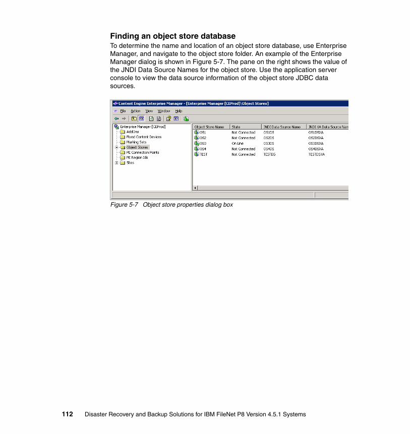
Finding an object store databaseTo determine the name and location of an object store database, use Enterprise Manager, and navigate to the object store folder. An example of the Enterprise Manager dialog is shown in Figure 5-7. The pane on the right shows the value of the JNDI Data Source Names for the object store. Use the application server console to view the data source information of the object store JDBC data sources.
Figure 5-7 Object store properties dialog box
112 Disaster Recovery and Backup Solutions for IBM FileNet P8 Version 4.5.1 Systems

5.1.3 File and fixed storage areas
File storage areas and the staging area for fixed storage areas are shown in Figure 5-8.
Figure 5-8 File and fixed storage areas
Internal reference to file and fixed storage areasThe root directory of file and fixed storage areas is referenced by data in the StorageClass table of the object store database, shown in Figure 5-9 on page 114. The root directory is exposed in the Content Engine API as a property of the FileStorageArea or FixedStorageArea object.
Note: The key piece of information needed when backing up a file or fixed storage area is the root directory of the area. All directories and folders under the root must be backed up or replicated. Backing up the directories of a fixed storage area only backs up content for annotations, documents in the reservation state, and documents that have yet to be migrated to the fixed repository. Content that has been migrated to the fixed repository must be backed up as part of the repository backup, which is explained in 5.1.4, “Fixed and external repositories” on page 115.
GCDDatabase
Directory Server Configuration
Data
Domain Wide Configuration
DataObject Store
Database
Fixed Content Device Objects
K2 Full Text Indexes
Fixed Repository(Example : Tivoli Storage
Manager,Image Services)File & Fixed
Storage Areas
External Repository(Example: OnDemand,
Image Services)
CFS Database
Process Engine
Chapter 5. FileNet P8 data components to backup and replicate 113

Figure 5-9 File or fixed storage area reference
Finding a file or fixed storage area root directoryTo determine the location of the root directory of a file or fixed storage area, navigate to the storage areas node in Enterprise Manager. Right-click the storage area of interest, select Properties, and then select the General tab. The path to the root directory is shown as the Location property (Figure 5-10).
Figure 5-10 File storage area location example
Database System
Object Store Database
StorageClasstable
File System
Storage Area
Root directory
114 Disaster Recovery and Backup Solutions for IBM FileNet P8 Version 4.5.1 Systems
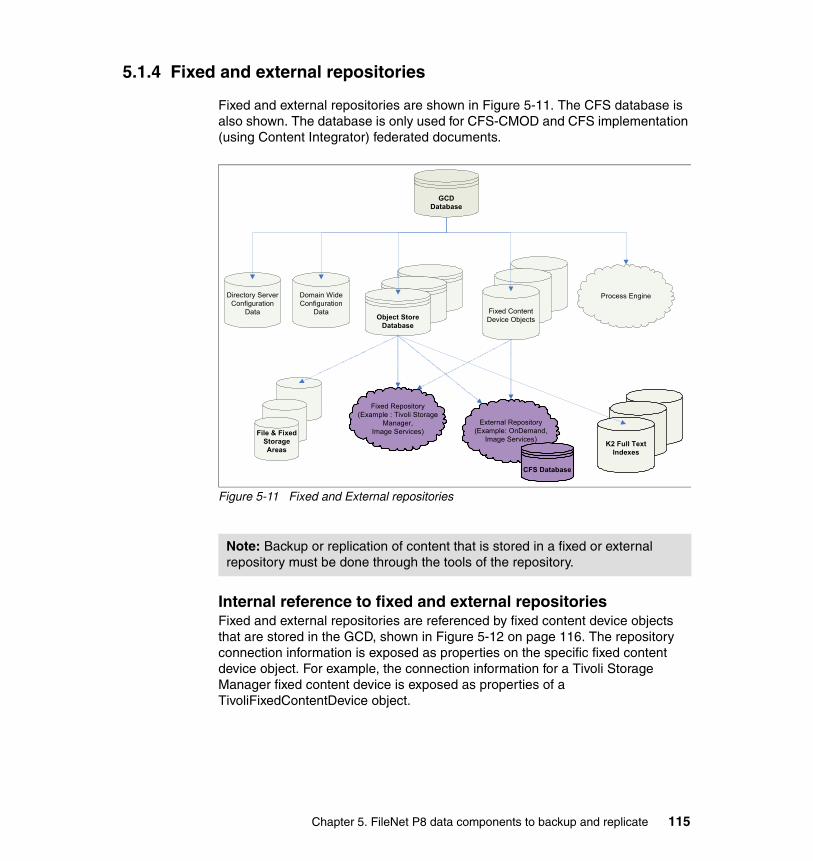
5.1.4 Fixed and external repositories
Fixed and external repositories are shown in Figure 5-11. The CFS database is also shown. The database is only used for CFS-CMOD and CFS implementation (using Content Integrator) federated documents.
Figure 5-11 Fixed and External repositories
Internal reference to fixed and external repositoriesFixed and external repositories are referenced by fixed content device objects that are stored in the GCD, shown in Figure 5-12 on page 116. The repository connection information is exposed as properties on the specific fixed content device object. For example, the connection information for a Tivoli Storage Manager fixed content device is exposed as properties of a TivoliFixedContentDevice object.
Note: Backup or replication of content that is stored in a fixed or external repository must be done through the tools of the repository.
GCDDatabase
Directory Server Configuration
Data
Domain Wide Configuration
DataObject Store
Database
Fixed Content Device Objects
K2 Full Text Indexes
Fixed Repository(Example : Tivoli Storage
Manager,Image Services)File & Fixed
Storage Areas
External Repository(Example: OnDemand,
Image Services)
CFS Database
Process Engine
Chapter 5. FileNet P8 data components to backup and replicate 115
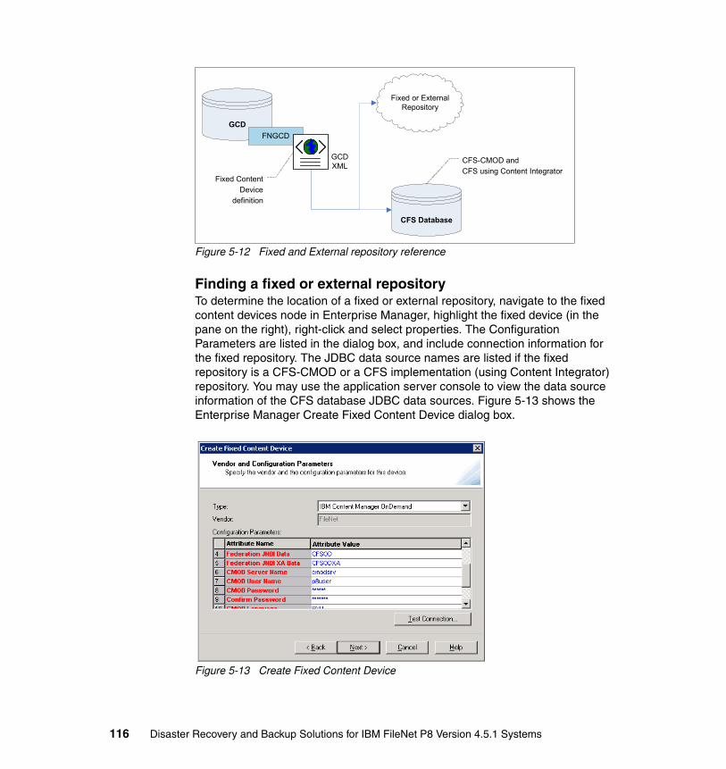
Figure 5-12 Fixed and External repository reference
Finding a fixed or external repositoryTo determine the location of a fixed or external repository, navigate to the fixed content devices node in Enterprise Manager, highlight the fixed device (in the pane on the right), right-click and select properties. The Configuration Parameters are listed in the dialog box, and include connection information for the fixed repository. The JDBC data source names are listed if the fixed repository is a CFS-CMOD or a CFS implementation (using Content Integrator) repository. You may use the application server console to view the data source information of the CFS database JDBC data sources. Figure 5-13 shows the Enterprise Manager Create Fixed Content Device dialog box.
Figure 5-13 Create Fixed Content Device
Fixed or External Repository
CFS Database
GCD
FNGCD
Fixed Content Device
definition
CFS-CMOD and CFS using Content Integrator
GCDXML
116 Disaster Recovery and Backup Solutions for IBM FileNet P8 Version 4.5.1 Systems

5.1.5 Autonomy K2 collections
Figure 5-14 shows K21 full text index collections.
Figure 5-14 K2 full text index collections
Internal reference to K2 index collectionThe root directory of a K2 index collection is referenced by the IndexArea table, as shown in Figure 5-15 on page 118. The root directory is exposed as a property of the IndexArea object.
Note: Some fixed repositories have associated configuration data that must be backed up or replicated. For example, a Tivoli Storage Manager fixed repository has one or more options files, which are maintained by the Content Engine. The options files are stored in the file system in a shared directory, referenced by the fixed content device configuration parameters.
1 Autonomy materials reprinted with permission from Autonomy Corp.
Note: The key piece of information needed when backing up a K2 collection is the root directory of the collection. All directories and folders under the root must be backed up or replicated.
GCDDatabase
Directory Server Configuration
Data
Domain Wide Configuration
DataObject Store
Database
Fixed Content Device Objects
K2 Full Text Indexes
Fixed Repository(Example : Tivoli Storage
Manager,Image Services)File & Fixed
Storage Areas
External Repository(Example: OnDemand,
Image Services)
CFS Database
Process Engine
Chapter 5. FileNet P8 data components to backup and replicate 117

Figure 5-15 K2 index collection reference
Finding the root path of a K2 collectionTo determine the location of an index collection, navigate to the Site folder in Enterprise Manager. For each site, navigate to the Index Areas folder. Right-click each index area and select Properties to determine the root directory of the index area. Figure 5-16 shows an index area Properties dialog box.
Figure 5-16 Index area properties dialog box
Database System
Object Store Database
IndexAreatable
File System
K2 index collection
Root directory
118 Disaster Recovery and Backup Solutions for IBM FileNet P8 Version 4.5.1 Systems

5.2 Process Engine data requiring backup
Figure 5-17 shows the Process Engine database.
Figure 5-17 Process Engine
Note: The K2 installation includes a set of configuration files that must be included in the backup or replication set. The files are in the K2 installation directory, as follows:
� \data\host\admin� \data\stylesets� \data\services\*.psm� \k2\common\style� \k2\common\styles� \k2\common\stop*� \k2\common\<verity_locale>
GCDDatabase
Directory Server Configuration
Data
Domain Wide Configuration
DataObject Store
Database
Fixed Content Device Objects
K2 Full Text Indexes
Fixed Repository(Example : Tivoli Storage
Manager,Image Services)File & Fixed
Storage Areas
External Repository(Example: OnDemand,
Image Services)
CFS Database
Process Engine
Chapter 5. FileNet P8 data components to backup and replicate 119

Internal reference to Process Engine databaseThe location of the Process Engine database is established during installation of the Process Engine software. The connection information is maintained within the directories of the partial Image Services installation that is required by the Process Engine, as shown in Figure 5-18.
Figure 5-18 Reference to Process Engine
Finding the Process Engine databaseTo determine the location of the Process Engine database, use the Process Engine Process Task Manager utility. Navigate to the Databases tab, and then examine the Database Settings.
5.3 Image Services data requiring backup
This section describes the data elements of Image Services that must be backed up. These elements include databases, content media files and devices, and configuration files. Although you back up the binary files as needed (before and after patching), this section describes only the data.
Image Services stores its data in multiple databases, formats, file types, and locations. Be sure to know the location of the data so that the data is backed up fully and consistently. If you are not experienced with Image Services and its data model, you might miss the important files.
Note: In addition to backing up the Process Engine database, the directories and files that contain the database connection information must be backed up. Those files are located in the /fnsw/local/sd directory.
Image Services Installation Files
Process Engine
Process Engine
ConfigurationData
Process Engine Database
Database connection data
<image-services-home>
/fnsw/local/sd
120 Disaster Recovery and Backup Solutions for IBM FileNet P8 Version 4.5.1 Systems

5.3.1 Index database
Similar to Content Engine, Image Services stores document metadata in an external RDBMS database. The supported databases include IBM DB2, Oracle, and Microsoft SQL Server. The database includes tables, most notably doctaba, which typically includes a reference for every document in the system with the corresponding metadata for each (for example, account number, and last name).
The index database also includes other tables containing related information, such as document class, and CFS-IS work queue. The tables that are in every Image Services system are listed in Table 5-1.
Table 5-1 Index database tables
Note: Configuring Image Services so that document references are not stored in doctaba is possible. This possibility is the case if cataloging is disabled for the document class or if the CFS-IS export tool was run with the Delete after export check box is selected.
Table name Description
ce_id_map Mapping from f_ce_os_id to the object store GUID, the Content Engine domain GUID, the object store name, and the Content Engine domain name.
doctaba Index values associated with committed documents
document_class Document classes attributes
doc_class_index User defined index attributes
ce_os_dcl_map Mapping from the Content Engine domain / object store to Image Services document class
export_log FileNet P8 federation work queue
folder Folder attributes
folder_contents Mapping from folder ID to document ID
folder_tabs (Not used)
GUIDS GUID attributes
index_cluster Information about documents in any document class that uses clustering
menu Menu attributes
menu_items Menu item attributes
Chapter 5. FileNet P8 data components to backup and replicate 121
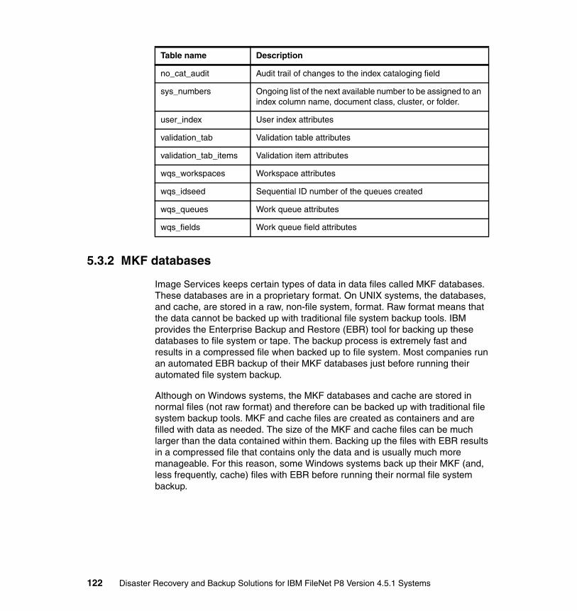
5.3.2 MKF databases
Image Services keeps certain types of data in data files called MKF databases. These databases are in a proprietary format. On UNIX systems, the databases, and cache, are stored in a raw, non-file system, format. Raw format means that the data cannot be backed up with traditional file system backup tools. IBM provides the Enterprise Backup and Restore (EBR) tool for backing up these databases to file system or tape. The backup process is extremely fast and results in a compressed file when backed up to file system. Most companies run an automated EBR backup of their MKF databases just before running their automated file system backup.
Although on Windows systems, the MKF databases and cache are stored in normal files (not raw format) and therefore can be backed up with traditional file system backup tools. MKF and cache files are created as containers and are filled with data as needed. The size of the MKF and cache files can be much larger than the data contained within them. Backing up the files with EBR results in a compressed file that contains only the data and is usually much more manageable. For this reason, some Windows systems back up their MKF (and, less frequently, cache) files with EBR before running their normal file system backup.
no_cat_audit Audit trail of changes to the index cataloging field
sys_numbers Ongoing list of the next available number to be assigned to an index column name, document class, cluster, or folder.
user_index User index attributes
validation_tab Validation table attributes
validation_tab_items Validation item attributes
wqs_workspaces Workspace attributes
wqs_idseed Sequential ID number of the queues created
wqs_queues Work queue attributes
wqs_fields Work queue field attributes
Table name Description
122 Disaster Recovery and Backup Solutions for IBM FileNet P8 Version 4.5.1 Systems

The three MKF databases are Security, Permanent, and Transient.
Security databaseThe Security database contains users, groups, and other security information. The tables in the database are listed in Table 5-2.
Table 5-2 Security database tables
Additional EBR usage: For more information about using EBR, review the IBM Enterprise Backup and Restore User's Guide, SC19-2670 in the Product Documentation for FileNet Image Services Web site:
http://www.ibm.com/support/docview.wss?rs=3283&uid=swg27010558
Table Description
sec_object Record of each security object
sec_system Record of the security service
sec_deleted not used
sec_groups Record of each security group
sec_functions Record of each security function
sec_funcmbr Record of each function member
sec_namemap Record of association of FileNet users to native database logons
sec_dbinfo Record of each db login added by the administrator
sec_rm_config Single record that defines system level Records Manager configuration
sec_map_prin_to_dn Record of association of Image Services objects to their LDAP distinguished names
sec_ce_dom_to_id Record of all unique Content Engine GUIDs
Chapter 5. FileNet P8 data components to backup and replicate 123

Permanent databaseThe Permanent database contains multiple tables, most notably a large table named docs, which contains the storage location of every document. Table 5-3 lists the tables in the Permanent database.
Table 5-3 Permanent database tables
Table Description
annotations Record of each annotation and its associated document and page
cluster_map Record of each cluster ID and the disk surface ID associated with it
docs Record of each document ID number and its associated disk surface
family_disk Record of each disk family on the system
family_locator Record of the association of disk family to storage server
od_stats Record of disk write errors
remote_family Record of remote disk family information for each local family configured for remote committal
scalar_numbers Record of next available document ID, disk surface number, and more
surf_dyn_info Record of available space, active documents, and more for each disk surface
surf_locator Record of the association of disk surface numbers to storage servers
surf_stat_info Record of each disk surface and its attributes
surface_activity Record of activity for each disk surface, if enabled
lib_surfaces Record of file system location and more for each disk surface
124 Disaster Recovery and Backup Solutions for IBM FileNet P8 Version 4.5.1 Systems

Transient databaseThis database contains information about documents that are in transition during document entry, retrieval cache, and print cache. Table 5-4 lists the tables in the Transient database.
Table 5-4 Transient database tables
Table Description
batch_ctl Record of next available batch_id
batch_doc Record of documents scanned under a single batch_id
batch_dyn_hdr Record of dynamic information for each batch
batch_image Record of each image ID associated with a batch
batch_ixdir Record of each indexing field associated with a batch
batch_ixval Record of the indexing information for each batch
batch_stat_hdr Record of static information for each batch
batch_data Record of data information for each batch
batch_folder Record of folder information for each batch
csm_caches Record of each logical cache ID number
csm_free_space Record of the empty sectors in the cache partitions
csm_temp_id Record of the temporary ID numbers
csm_used_space Record of each image, document, or object in the cache partitions
print_docs Record of each document to be printed
print_options Record of options chosen for each entry in the print_requests table
print_svcs Record of the association of Doc and Cache services to a 2 byte ID
print_requests Record of outstanding print request
bkg_request Record of each background job request, such as disk imports and copies
write_request Record of documents in page cache that need to be written to disk
Chapter 5. FileNet P8 data components to backup and replicate 125

CacheCache is the designated magnetic disk space that is used to store documents during their transition to and from storage media. The Transient database keeps track of where documents are in cache. Cache is divided into physical disk containers (such as cache0, cache1, and cache2) and logically into cache types.
Objects in cache are temporary in nature and can be aged out if they are not locked. Examples of locked objects are batches that have not yet been committed and documents that are committed but have not been written to permanent storage. You can use EBR to back up locked cache objects. When backing up cache, you must back up the Transient database at the same time.
The types of caches are as follows:
� Batch cache: This cache contains batches of documents as they are entered into Image Services, where they remain until they are ready to be committed. Capture, MRII, and other entry tools use batch cache (such as HPII); others do not. When a batch is ready to be committed, it is moved into page cache.
� Page cache: Also known as retrieval cache, page cache contains documents being committed to or retrieved from storage media. Page cache can also be pre-filed with documents that are expected to be retrieved in the short term.
� Print cache: This cache stores documents waiting to be printed.
� Folder notes cache: For systems using FolderView, this cache can store folder notes.
5.3.3 Content storage
Image Services can store the content of its documents in a variety of systems, including optical, temporary magnetic, and permanent magnetic.
For many years, the primary storage media for Image Services data was optical platters (surfaces). Although many customers still use optical storage today, most have moved to magnetic storage, either using FileNet’s Magnetic Storage and Retrieval (MSAR) or protected storage such as IBM Information Archive and SnapLock-enabled NepApp/N Series devices.
Optical storageOptical Storage and Retrieval (OSAR) is the name of the storage model for which Image Services stores documents on optical platters in a SCSI-attached optical storage library. With optical storage, the backup and DR process is to configure Image Services to copy newly committed documents to a primary and a secondary surface, then send the secondary surfaces, when full, to an offsite storage location.
126 Disaster Recovery and Backup Solutions for IBM FileNet P8 Version 4.5.1 Systems

Document Archive and Retrieval Transport (DART) provides a method of backing up documents located on optical disks, thereby facilitating a complete disaster recovery opportunity. To achieve this, DART stores documents from Image Services on a magnetic disk directory. After written to magnetic disk, documents can be backed up using a variety of options including tape or network backup facilities. These documents are then available to recover the system in the event of the physical loss of an optical disk and its documents. DART captures the document index values at the time of backup; however, it does not back up annotations or highlights, nor does it backup post-DART index changes. These are backed up during normal database backup procedures, independently of DART.
Magnetic storageMagnetic storage can be one of several storage models:
� Magnetic Storage and Retrieval (MSAR)
With MSAR storage, the surface model remains the same as with optical storage. MSAR surfaces are virtual platters that are really files stored on local disk or SAN attached storage. Many individual documents are stored within a single surface file. The surface files can be configured to contain 1 - 32 GB each.
To back up or prepare for a DR scenario, back up these magnetic files to tape, store them on a secondary data storage system, or both, preferably offsite.
� Protected storage
Documents can be protected (set to read-only for the active life of the document) by writing them to IBM Information Archive, NetApp/N Series, or one of the other supported systems. With each of these systems, you may set them to automatically mirror their contents to a separate unit, including one in a DR facility, using device-specific replication mechanisms.
� Cache only
As mentioned in “Cache” on page 126, documents are locked in cache until they are written to permanent storage. If there was a temporary problem with the permanent storage system that prevented documents from being migrated to it, the only copy of the document may be in cache. Therefore, some companies back up locked cache objects and the Transient database, along with the other data components. However, most companies do not back up the cache or the Transient database.
Chapter 5. FileNet P8 data components to backup and replicate 127

5.3.4 Configuration files
Backing up configuration files is important because they contain vital information that is also important when rebuilding a system after a disaster. The main Image Services configuration file is the Configuration Database (CDB) file, which contains the following information:
� Cache sizes and locations� Service configurations and locations� Data set sizes and locations� RDBMS type and version information� Tablespace names and locations� Network configuration information� Storage library configuration information� Peer system information� Performance tuning parameters
The CDB file is located in the following directory, depending on the platform:
� For UNIX: fnsw/local/sd/conf_db/IMS_nnn.cdb� For Windows: <drive>:\FNSW_LOC\sd\conf\IMS_nnn.cbd
The current file has the highest number for nnn.
The CDB file is modified with fn_edit tool and is activated with the fn_build command, which updates the following files (UNIX examples):
/fnsw/local/ssn/fnsw/local/setup_config/fnsw/local/sd//fnsw/local/sd/nch_dbinit/fnsw/local/sd/nch_domain/fnsw/local/sd/inx_conf/fnsw/local/sd/print_config/fnsw/local/sd/snmp.conf/fnsw/local/sd/as_conf.g/fnsw/local/sd/serverGroup/fnsw/local/sd/db.init/fnsw/local/sd/rdb.init/fnsw/local/sd/1/as_conf.s/fnsw/local/sd/1/tapeconfig/fnsw/local/sd/1/nch.ddl/fnsw/local/sd/1/permanent.ddl/fnsw/local/sd/1/transient.ddl/fnsw/local/sd/1/sec.ddl/fnsw/local/oracle/init.ora/fnsw/local/mssql/config.sql
128 Disaster Recovery and Backup Solutions for IBM FileNet P8 Version 4.5.1 Systems

All files are located in the local subdirectory structure. Simply back up the entire local subdirectory structure, as follows:
� For UNIX: /fnsw/local
� For Windows: <drive>:\FNSW_LOC
In addition to these files, two configuration files are not located in the local subdirectory but must be backed up if they exist:
/fnsw/etc/serverConfig/fnsw/etc/local_permission_table
Chapter 5. FileNet P8 data components to backup and replicate 129

130 Disaster Recovery and Backup Solutions for IBM FileNet P8 Version 4.5.1 Systems

Chapter 6. Alternative strategies for backup
In this chapter, we address alternative strategies that might be employed to speed backup and restore times of an IBM FileNet P8 Version 4.5.1 systems. We describe advantages and disadvantages of these alternative strategies.
This chapter contains the following topics:
� Use of database storage area consideration
� Suspending database writes
� Stopping the Application Engine
� Rolling storage policies
� Spraying storage policies
� Journaling
� Disk-to-disk versus disk-to-tape
� FlashCopy
6
© Copyright IBM Corp. 2010. All rights reserved. 131

6.1 Use of database storage area consideration
Since the inception of FileNet P8, administrators have had the option of creating object stores as database storage areas (storing both metadata and content in the database) or file storage areas (storing metadata in the database but content on a file system). In the past, we recommended the database storage area option if the content being stored is small in size (less than 1 MB per file). We recommended the file storage area option for files with consistently larger sizes. These recommendations were based on performance studies, which showed increased performance with smaller file sizes in a database storage area on a FileNet P8 3.x system. With the re-architecture of the Content Engine in FileNet P8 4.x, this database storage area advantage is eliminated. We currently do not see any performance enhancement on a FileNet P8 4.x system when using a database storage area instead of a file storage area.
Although many FileNet P8 clients do store both the metadata and content in the database, most customers opt to create their object stores as file storage areas. Because metadata and content are separated, backup becomes more difficult, and consistency between metadata and content can become an issue as well. Make sure you back up both metadata and content at the same time so that no row in the database references content that does not exist, and vice versa.
There are a number of factors to be weighed when considering the database storage area option:
� Consistency between metadata and content.
� BLOB size limit of the relational database.
� By replicating the database, recovery time can be close to zero.
� As database sizes grows, backup time may increase.
� Online backup may be an option.
� Database administrators frequently prefer not to store content in the database, to avoid database scalability issues such as excessive backup time for very large databases.
In general, use the database only to create, retrieve, update, and delete content, not to store files. In addition, modern fixed-storage devices such as IBM Information Archive offers deduplication (sometimes referred to as dedupe) capabilities. FileNet P8 4.5.1 provides a dedupe feature called Single Instance Storage which can be turned on for a specific file storage area or database storage area. These dedupe features can monitor the storage environment to ensure that a specific piece of content is stored only once, thus decreasing the total amount of content under management. Relational database systems do not offer these types of features.
132 Disaster Recovery and Backup Solutions for IBM FileNet P8 Version 4.5.1 Systems

Although modern relational databases do offer incremental backup capabilities, the FileNet P8 content stored within them is stored in a separate BLOB table. This BLOB table does not fall under the umbrella of an incremental backup. Over time, the amount of unstructured content in the BLOB table will grow and would need to go through a separate backup process.
When managing static content, there is less of a compelling reason to store it in the database. Because of this, and the other issues cited in this section, do not use FileNet P8 database storage areas as a general practice. FileNet P8 file storage areas simply offer more flexibility with the online and offline capabilities they offer.
6.2 Suspending database writes
An alternative strategy to speed up the backup process (instead of completely shutting down the system before backing up the system) is to suspend database write privileges (often referred to as quiescing) the system. The administrator can potentially send an e-mail or other message to users telling them the system is going down for maintenance and will be unavailable for some period of time. A notification such as this would then give users time to wrap up work in progress and gracefully log off the system.
Although such a scenario might have some merit, and the IBM DB2 database does in fact have quiesce and unquiesce commands. This is not currently a supported approach to backing up a FileNet P8 system.
6.3 Stopping the Application Engine
Another alternative strategy and possibly an acceptable approach to speed up the backup process, is stopping the Application Engine, leaving the Content Engine and Process Engine running. Any Web-tier applications that access the underlying Content Engine and Process Engine would be unable to perform any tasks if the Web applications are done. Bear in mind that there may be other applications using Content Engine or Process Engine Web Services APIs to communicate with these engines. If you can be sure that there are no other applications using Web Services to access the underlying FileNet P8 engines when the Application Engine is stopped, then you can assume that the metadata, content, and configuration data are in a fairly static state where they can be backed up cleanly.
Even with the Application Engine stopped and no users accessing the system, there could potentially still be Rendition Engine or Content Search Engine
Chapter 6. Alternative strategies for backup 133
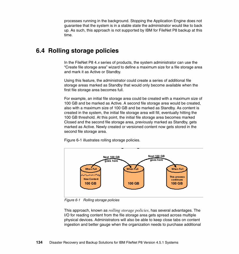
processes running in the background. Stopping the Application Engine does not guarantee that the system is in a stable state the administrator would like to back up. As such, this approach is not supported by IBM for FileNet P8 backup at this time.
6.4 Rolling storage policies
In the FileNet P8 4.x series of products, the system administrator can use the “Create file storage area” wizard to define a maximum size for a file storage area and mark it as Active or Standby.
Using this feature, the administrator could create a series of additional file storage areas marked as Standby that would only become available when the first file storage area becomes full.
For example, an initial file storage area could be created with a maximum size of 100 GB and be marked as Active. A second file storage area would be created, also with a maximum size of 100 GB and be marked as Standby. As content is created in the system, the initial file storage area will fill, eventually hitting the 100 GB threshold. At this point, the initial file storage area becomes marked Closed and the second file storage area, previously marked as Standby, gets marked as Active. Newly created or versioned content now gets stored in the second file storage area.
Figure 6-1 illustrates rolling storage policies.
Figure 6-1 Rolling storage policies
This approach, known as rolling storage policies, has several advantages. The I/O for reading content from the file storage area gets spread across multiple physical devices. Administrators will also be able to keep close tabs on content ingestion and better gauge when the organization needs to purchase additional
100 GB
g g
100 GB 100 GB
Next 100 GBgoes here
Next 100 GBgoes here
When Full
New Content
When Full When Full
This processcontinues
134 Disaster Recovery and Backup Solutions for IBM FileNet P8 Version 4.5.1 Systems

storage. The biggest advantage to this approach may be that when a file storage area is full and becomes marked as Closed, that file storage area will no longer need to be backed up. Because FileNet P8 content is immutable, it is constantly moving forward. If a user creates a new version of an existing document, FileNet P8 does not touch the previous version--it is maintained in the system as the new version is written.
With this strategy, normally only one file storage area is being written to at a given time. There may be many file storage areas that have become full and are effectively read-only, which is the goal from a backup perspective. Most systems have many more reads (document retrievals) compared to the number of new documents or versions of documents being created. In other words, a high read-to-write ratio. This is a perfect fit for a rolling file storage area scenario, because over time the ratio of read-only to writable file storage areas grows.
6.5 Spraying storage policies
Similar to the rolling storage policies described in 6.4, “Rolling storage policies” on page 134, is another alternative strategy called spraying storage policies. This is a strategy whereby multiple file storage areas are created and all marked as Active. When new content is added or versioned in the system, Content Engine places the content in a file storage area using a round-robin algorithm. The benefits of this approach are increased I/O capacity because the I/O load is spread across more file systems and devices.
For example, a system administrator creates three online file storage area across which all content gets sprayed. A fourth file storage area is created and marked Standby. Each file storage area has a maximum size of 100 GB. When the first Active storage area becomes full, spraying continues across the remaining two Active storage area. When the second Active storage area eventually becomes full, the system is left with only the third storage area to accept new content. When the third storage area becomes full, the fourth area, initially marked as Standby, automatically becomes Active. At this point, content is no longer being sprayed across multiple storage area, but being added to the only Active area.
Do not mix spraying storage policies with rolling storage policies: It is important to note that spraying storage policies cannot be combined with the rolling storage policies described previously.
Chapter 6. Alternative strategies for backup 135

Figure 6-2 illustrates spraying storage policies.
Figure 6-2 Spraying storage policies
System administrators who see a high read to write ratio (a high volume of reads, but not of writes) may favor rolling storage policies because this approach spreads the read operations across multiple physical devices, and reducing the amount of data that must be saved during a full backup.
A rolling scheme is not good if you have lots of writes and little or no reads. An example of this would be an e-mail archiving system, which also requires high performance because the incoming e-mail volume at most companies is very high. It does a lot of writes. For this application, spraying the writes across multiple LUNs is advantageous in such situations. It is equally advantageous if you have a lot of reads, because again the reads are spread across all the LUNs. So spraying is appropriate for all high volume applications; rolling is more applicable when the read-to-write ratio is high, which is the case for most customer situations. Obviously, rolling has the added advantage of making backups faster, therefore, use rolling storage policy if it is applicable to your situation.
136 Disaster Recovery and Backup Solutions for IBM FileNet P8 Version 4.5.1 Systems

6.6 Journaling
When performing an incremental or differential backup, the backup software normally searches throughout the file systems being backed up to identify the files that are new or have changed since the previous backup. Content management systems might have millions or even billions of separate files under management, so this process alone can be very time consuming.
To avoid this traversal of the file system, some backup software, including IBM Tivoli Storage Manager on AIX and Windows, offers the ability to create a journal when files are created or modified in the file system. The Tivoli Storage Manager Journal Based Backup (JBB) utilizes a journal daemon process, called the Tivoli Storage Manager Journal Service, to create the change journal.
When performing a traditional backup, the list of files, called the local list, is obtained by scanning the entire local file system, and the server list is obtained by querying the entire server inventory for all active objects. The two lists are then compared, and candidates are selected for backup according to the following criteria:
� An object is selected as a backup candidate if it exists in the local list but does not exist in the server list, or if the object exists in both lists but differs according to Tivoli Storage Manager incremental criteria (such as attribute changes, date and size changes).
� An object is selected as an expiration candidate if it exists in the server list but does not exist in the local list.
Journal based backup obtains the candidates list of objects to backup or expire by querying the Tivoli Storage Manager Journal Service for the contents of the change journal of the file system being backed up. Change journal entries are cleared (marked as free) after they have been processed by the backup client and committed on the Tivoli Storage Manager server. Journal Based Backup is activated by configuring the journal daemon to monitor specified file systems for change activity and is enabled by successfully completing a full incremental backup.
Journal Based Backup is considered a viable solution for environments in which the amount of file system activity is light to moderate, and that the activity is somewhat well distributed. This is commonly the case for a content management system, where files are added and occasionally are deleted, but the files are usually not modified after they are written.
Journal based backup is appropriate for backing up files systems with small or moderate amounts of change activity between backup cycles. Very large amount of file changes between backup cycles might result in very large change journals.
Chapter 6. Alternative strategies for backup 137

Very large change journals pose memory and performance problems which may negate the benefits of journal backup. So, if a very large number of documents have been created or deleted, then this may negate the benefit of using journal backup instead of normal incremental backup.
Journal backup is not intended to be a complete replacement for traditional incremental backup. The goal of journal backup is to track all file system changes in the change journal and to make every attempt to keep the journal synchronized with what has been backed up. Limitations on journal based backup include:
� Because individual server attributes are not available during a journal backup, certain policy settings such as copy frequency and copy mode may not be enforced.
� Other platform specific idiosyncrasies may prevent objects from being processed properly. Other software which changes the default behavior of the file system may prevent file system changes from being detected.
� It is possible for a small number of file system deletions to be missed when the file system is very active while a journal backup is in progress, which prevents the missed files from being expired during the journal backup.
Because of this and the stated limitation of journal backup, perform the periodic full incremental backups, along with more frequent journal backups. Traditional incremental backup compares the entire server inventory of files against the entire local file system and will therefore always be the most comprehensive backup method.
6.7 Disk-to-disk versus disk-to-tape
In the 1990s, disk-to-disk backups began to gain in popularity. This was the result of the falling cost of disk storage, the increasing sizes of disk volumes without a corresponding increase in tape speeds, and the fact that disk-to-disk I/O is faster than disk-to-tape I/O and therefore provides for a smaller backup window. In this scenario, a FileNet P8 system could be stopped and a backup to local disk storage could be initiated. Upon completion of this initial backup, the FileNet P8 system can be brought back online.
The fast random access nature of disk I/O allows for some additional capabilities. Some operating systems provide tools that are capable of checking time stamps and purging files from the copy that are no longer on the source, thus making the resulting backup smaller in size. These tools can usually also avoid copying a file if the same version exists already in the target file system, as determined by its
138 Disaster Recovery and Backup Solutions for IBM FileNet P8 Version 4.5.1 Systems

size and time stamp. By combining these techniques, a full of your disk storage can be performed effectively in relatively little time.
Backups are used for several different purposes. They can be used after a disaster (loss of an entire data center), after loss of the primary storage subsystem, after a corruption such as infection by a software virus, or to restore individual files that have been deleted or corrupted accidentally. A single disk backup of the primary volume therefore has a couple of potentially major disadvantages:
� The backup data is not stored off site. It is normal with tape backups to rotate tapes to and from an off-site storage facility, so that in the event of the loss of the data center, such as a fire, that a copy of the data will still exist for restoration.
� At any given time, only one point in time copy of the primary data exists on the backup disk volume. This copy can be used for full or partial restoration, but there are many circumstances under which this will not be satisfactory. For example, suppose that it is discovered that a software virus has infected the files, but the discovery is not made until after the most recent backup was made. In this case, the virus will have been copied to the backup volume, and no clean copy of the data exists. Most tape-based backup schemes involve rotation through multiple sets of tapes, some used for incremental or differential backups and others for full s, so that many points in time are represented by the complete set of tapes.
To gain the advantages of disk-to-disk backup, and mitigate the disadvantages that are listed, many data centers combine disk-to-disk copying with tape backups. With this approach, the production software is shut down for a short time while the disk-based backup is performed. After, the production software is brought up again, and then a tape backup is made from the backup disk volume, allowing for longer term storage of the data, and off-site storage.
6.8 FlashCopy
An alternative strategy to reduce the backup window is using FlashCopy or a similar function that is provided by the storage hardware or the file system. The idea is to make a nearly instantaneous copy of the entire file system, then bring up the FileNet P8 software again, while making a backup of the copy of the data. After the backup is completed, you may discard the copy.
FlashCopy and similar technologies seem to copy many gigabytes of data almost instantly because they do not really copy it; they create a new file system that points at the same underlying data. Similarly, the new file system can be
Chapter 6. Alternative strategies for backup 139

discarded in very little time, because it involves for the most part simply deleting these same pointers.
The FlashCopy technique is similar to the disk-to-disk copying, described in 6.7, “Disk-to-disk versus disk-to-tape” on page 138, combined with tape backup of the disk copy, but it is much faster and requires much less free disk space.
During the time that the copied file system exists (while the backup of it is running), if a data block in the original file system is modified, it is actually written to a separate block on the disk, so that the FlashCopy that was made previously is unchanged. Because the vast majority of the data is never actually copied, the storage requirements for making a FlashCopy are very small compared to the storage that is apparently being copied.
Because these file system copy technologies require approximately a few seconds to create a new file system, the production software must be shut down for only this length of time. After the FlashCopy has been made, the software can be restarted and production resumed. By using this technique, the backup window can thus be reduced to a very small amount of time.
6.9 Summary
The preferred location for storing unstructured content is the file storage area, not the database storage area. The reason is because the relational database is best at managing structured (relational) data and not the unstructured content found in the average FileNet P8 system.
Use an offline backup strategy for FileNet P8. Warm- or hot-backup strategies such as stopping the FileNet P8 Application Engine or quiescing the database are not supported for FileNet P8 at this time. By stopping all FileNet P8 components and the associated relational databases, the FileNet P8 administrator can ensure that both metadata and content are in the static state required for an offline backup.
Rolling or spraying storage policies can also be used to add flexibility to a FileNet P8 system. Because FileNet P8 content is immutable, rolling storage policies can be used to ensure that the amount of metadata and files being backed up is as small as possible, thus speeding backup time. This strategy also spreads read operations out among (potentially) many storage devices, improving disk I/O. A spraying storage policy approach might be considered for the opposite use case, when there is a high volume of write operations. In this scenario, incoming content is written to more than one storage device, thus increasing disk I/O.
140 Disaster Recovery and Backup Solutions for IBM FileNet P8 Version 4.5.1 Systems

The FileNet P8 administrator must also consider a disk-to-disk or disk-to-tape backup strategy. Because of the faster disk I/O in comparison to tape, a disk-to-disk backup may be initiated, the FileNet P8 system brought back online, and a tape backup initiated upon starting the FileNet P8 system again. Storage technology such as FlashCopy can be a big advantage in speeding backup times and keeping the backup window as small as possible.
Chapter 6. Alternative strategies for backup 141

142 Disaster Recovery and Backup Solutions for IBM FileNet P8 Version 4.5.1 Systems

Part 2 Implementation details
This part contains the following chapters:
� Chapter 7, “Case study description and system setup” on page 145
� Chapter 8, “Backup and restore setup and configuration” on page 175
� Chapter 9, “Disaster recovery setup and configuration” on page 227
� Chapter 10, “System testing and validation” on page 263
� Chapter 11, “Working with IBM Information Archive” on page 315
Part 2
© Copyright IBM Corp. 2010. All rights reserved. 143

144 Disaster Recovery and Backup Solutions for IBM FileNet P8 Version 4.5.1 Systems

Chapter 7. Case study description and system setup
This chapter defines the backup and disaster recovery case studies we set up and present in this book. The chapter also has installation guidelines for setting up an IBM FileNet P8 Version 4.5.1 production environment. For details about setting up a disaster recovery environment, see Chapter 9, “Disaster recovery setup and configuration” on page 227.
This chapter contains the following topics:
� Description of the case studies
– Case study I: Backup and restore setup and configuration– Case study II: Recovery using standby disaster recovery site
� Overview of FileNet P8 lab environment
– Production lab environment hardware– Storage configuration– DNS and host table entries
� Software configuration
– DB2 configuration– WebSphere configuration– User and group configuration– FileNet P8 component configuration
7
© Copyright IBM Corp. 2010. All rights reserved. 145

7.1 Description of the case studies
For the purpose of this book, our FileNet P8 lab systems are configured to test the following scenarios:
� Case study I: Backup and restore setup and configuration� Case study II: Recovery using standby disaster recovery site
7.1.1 Case study I: Backup and restore setup and configuration
In this case study, we perform a backup and restore of a FileNet P8 environment with the following components:
� Content Engine� Process Engine� Worplace XT� Image Services� Content Federation Service for Image Services� Content Search Engine
Our backup solution consists of an IBM Tivoli Storage Manager server with an attached tape library, integrated with Tivoli Storage Manager client software on each FileNet P8 server. The configuration of the Tivoli Storage Manager software and procedures for executing the backup and recovery are covered in Chapter 8, “Backup and restore setup and configuration” on page 175.
7.1.2 Case study II: Recovery using standby disaster recovery site
In this case study, we use a standby FileNet P8 system as a disaster recovery site. The standby site is installed on hardware similar to that used by the primary site. Both systems are configured with identical versions of FileNet P8 and other vendor application software. Pertinent data and configuration files are replicated from the primary site to the disaster recovery site using storage level replication.
Note: The information presented in these case studies does not include procedures for installing and configuring FileNet P8 software. Only concepts and considerations that are important to configuration of backup and recovery are included. For complete installation procedures, see the FileNet P8 information center:
http://publib.boulder.ibm.com/infocenter/p8docs/v4r5m1/index.jsp
146 Disaster Recovery and Backup Solutions for IBM FileNet P8 Version 4.5.1 Systems

We describe the hardware configuration of our lab environments for the primary and standby sites. We discuss tips and general guidelines for configuring the primary system in such a manner that failover to the standby disaster recovery system is quick and efficient.
The configuration of the standby system and procedures to activate the disaster recovery site are covered in Chapter 9, “Disaster recovery setup and configuration” on page 227.
7.2 Overview of FileNet P8 lab environment
The lab environment used for this book consists of two FileNet P8 systems:
� A primary production site, referred to as PROD� A standby disaster recovery site, referred to as DR
The hardware configuration for the PROD system is described in the following section. See Chapter 9, “Disaster recovery setup and configuration” on page 227 for a description of the DR environment.
7.2.1 Production lab environment hardware
The PROD FileNet P8 system resides on an IBM Model 9117-570 POWER5™ server, configured with nine logical partitions (LPARs). The LPARs are defined as shown in Figure 7-1 on page 148, with a separate LPAR for each of the following components:
� Virtual I/O (VIO) server� Tivoli Directory Service server� DB2 Database (DB2) server� Image Services (IS) server� Workplace XT (XT) server� Process Engine (PE) server� Content Search Engine (CSE) server� Content Engine (CE) server� Tivoli Storage Manager server
Chapter 7. Case study description and system setup 147

Figure 7-1 System architecture for PROD environment
LPAR1Virtual I/O Server
FNLVIOPROD
LPAR3Database Server FNLDB2PROD
LPAR2Tivoli Directory Server
FNLTDSPROD
LPAR8Content Engine Server
FNLCEPROD
LPAR9Tivoli Storage Manager
FNLTSMPROD
LPAR6Process Engine Server
FNLPEPROD
LPAR5Workplace XT Server
FNLXTPROD
LPAR7Content Search Engine
FNLCSEPROD
LPAR4Image Services Server
FNLISPROD
SAN LUN FNLDB2PROD
(Databases)
SAN LUN FNLISPROD
(Config files, MSAR)
SAN LUN FNLXTPROD(Config files)
SAN LUN FNLCSEPROD
(K2 app, K2Collections)
NAS LUN FNLCEPROD(FileStores)
NAS LUN FNLCSEPROD
(K2 temp)
IBM 9117-570 POWER5 Server
IBMSystem Storage
DS4800
SAN Switch
NAS Gateway
Tape Library
Production Environment
NFS Mounts
NFS Mounts
148 Disaster Recovery and Backup Solutions for IBM FileNet P8 Version 4.5.1 Systems

Storage for the PROD system is provided by an IBM System Storage DS4800 device. For our system, LUNs for SAN storage on the DS4800 are assigned to the LPARs as listed in Table 7-1.
Table 7-1 SAN LUN assignments for the DS4800
The DS4800 also provides LUNs designated as network attached storage (NAS). In general, data that must be accessible by more than one LPAR must reside on NAS. For our PROD environment, the NAS LUNs are located on the DS4800, and are managed by an IBM System Storage N-Series N5200 Gateway. File systems on NAS are presented to the LPARs through NFS mounts. The NAS LUN assignments for the PROD system are shown in Table 7-2.
Table 7-2 NAS LUN assignments for the DS4800
7.2.2 Storage configuration
For our disaster recovery solution, identical versions of the FileNet P8 applications reside on the PROD and DR systems. Each LPAR is configured with a root volume group (rootvg), consisting of local disks that contain the operating system and application binary files.
Files that are updated frequently, such as databases and configuration files, are located on the data volume group (datavg), consisting of SAN LUNs on the DS4800 system storage. Data shared by two or more servers, such as file storage areas and index temporary files, is also written to the system storage device utilizing NAS LUNs and NFS mounts.
LPAR assignment Type of data on SAN storage
FNLDB2PROD DB2 database instance files
FNLISPROD Image Services configuration files; MSAR files
FNLXTPROD Workplace XT configuration files
FNLPEPROD Process Engine configuration files
FNLCSEPROD Autonomy K2a application files; K2 collections (indexes)
a. Autonomy materials reprinted with permission from Autonomy Corp.
LPAR assignments (through NFS mounts)
Type of data on NAS
FNLCSEPROD K2 temporary files
FNLCEPROD file storage area files
Chapter 7. Case study description and system setup 149

Using block-level replication, the PROD data that is stored on the DS4800 is replicated onto the DS4500 in DR as shown in Figure 7-2.
Figure 7-2 PROD to DR data replication
7.2.3 DNS and host table entries
As noted in the diagrams for our PROD (Figure 7-1 on page 148) and DR (Figure 9-1 on page 230) systems, we use a naming convention for host names on each environment that end in either PROD or DR. We also use a virtual host name ending in the letter V that is shared by the two environments (see Table 7-3 on page 151).
SAN LUN FNLDB2DR(Databases)
SAN LUN FNLISDR
(Config files, MSAR)
SAN LUN FNLXTDR
(Config files)
SAN LUN FNLCSEDR
(K2 app, K2Collections)
NAS LUN FNLCEDR(FileStores)
NAS LUN FNLCSEDR(K2 temp)
DRIBM System Storage
DS4500
SAN LUN FNLDB2PROD
(Databases)
SAN LUN FNLISPROD
(Config files, MSAR)
SAN LUN FNLXTPROD(Config files)
SAN LUN FNLCSEPROD
(K2 app, K2Collections)
NAS LUN FNLCEPROD(FileStores)
NAS LUN FNLCSEPROD
(K2 temp)
PRODIBM System Storage
DS4800
Global MirroringAsynchronous
150 Disaster Recovery and Backup Solutions for IBM FileNet P8 Version 4.5.1 Systems

Table 7-3 List of virtual host names
The alias for the virtual host name is managed through local host files or DNS entries. Under normal production mode operations, the virtual host name is mapped to the PROD servers as shown in Figure 7-3.
Figure 7-3 Virtual host names for PROD mode
In disaster recovery mode, the virtual host names are mapped to the DR servers.
PROD host name DR host name Virtual host name
FNLCEPROD FNLCEDR FNLCEV
FNLPEPROD FNLPEDR FNLPEV
FNLXTPROD FNLXTDR FNLXTV
FNLISPROD FNLISDR FNLISV
FNLCSEPROD FNLCSEDR FNLCSEV
FNLDB2PROD FNLDB2DR FNLDB2V
FNLTDSPROD FNLTDSDR FNLTDSV
192.168.100.216 fnldb2prod fnldb2v192.168.100.217 fnltdsprod fnltdev192.168.100.218 fnlceprod fnlcev192.168.100.219 fnlisprod fnlisv fnlisv-filenet-nch-server192.168.100.220 fnlcseprod fnlcsev192.168.100.221 fnlxtprod fnlxtv192.168.100.222 fnlpeprod fnlpev192.168.100.223 fnltsmprod fnltsmv10.0.200.216 fnldb2dr10.0.200.217 fnltdsdr10.0.200.218 fnlcedr10.0.200.219 fnlisdr10.0.200.220 fnlcsedr10.0.200.221 fnlxtdr10.0.200.222 fnlpedr10.0.200.223 fnltsmdr
Chapter 7. Case study description and system setup 151
7.3 Software configuration
The versions of software for both the PROD and DR systems are as follows:
� IBM AIX v6.1 TL2 64-bit
� IBM Tivoli Directory Services v6.1
� IBM Tivoli Storage Manager Server v6.1 64-bit
� IBM Tivoli Storage Manager Client v6.1 64-bit
� IBM DB2 Server v9.7 64-bit
� IBM WebSphere Application Server v7.0.0.5 64-bit Network Deployment
� IBM FileNet Content Engine v4.5.1
� IBM FileNet Process Engine v4.5.1
� IBM FileNet Workplace XT v1.1.4.1
� IBM FileNet Content Search Engine v4.5.1
� IBM FileNet Image Services v4.1.2.4
� IBM FileNet High Performance Image Import v4.1.2
In this section, we present high-level information and guidelines for configuring FileNet P8 software on primary systems that use data replication for the standby disaster recovery site.
7.3.1 DB2 configuration
For FileNet P8 systems that use replication from PROD to DR for DB2 database data, consider the following tasks:
� Install the DB2 binary files in a directory that belongs to the root volume group file system, for example, /opt/IBM/db2/V9.7.
� Create a file system, such as /db2data, in the data volume group on the SAN device to store database instance files. For example, if your instance user name is db2inst1, create a home directory for this user under the /db2data file system, such as /db2data/home/db2inst1.
By default, DB2 uses the actual server host name as the system name when a new database instance is created. This becomes an issue when activating DB2 on the DR system because the host name stored in the database (in our case fnldb2prod) does not match the DR servername (fnldb2dr). This issue can be avoided by modifying the DB2 system name on the primary system to use the virtual host name (fnldb2v) prior to replication to the DR site.
152 Disaster Recovery and Backup Solutions for IBM FileNet P8 Version 4.5.1 Systems
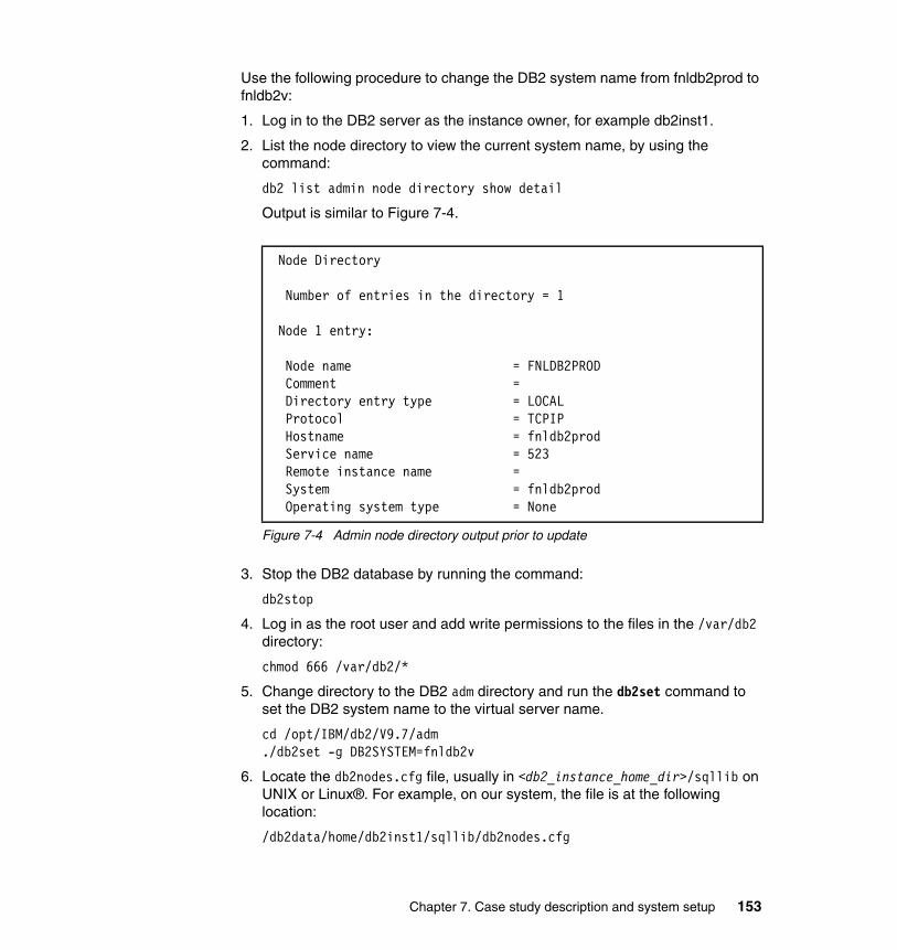
Use the following procedure to change the DB2 system name from fnldb2prod to fnldb2v:
1. Log in to the DB2 server as the instance owner, for example db2inst1.
2. List the node directory to view the current system name, by using the command:
db2 list admin node directory show detail
Output is similar to Figure 7-4.
Figure 7-4 Admin node directory output prior to update
3. Stop the DB2 database by running the command:
db2stop
4. Log in as the root user and add write permissions to the files in the /var/db2 directory:
chmod 666 /var/db2/*
5. Change directory to the DB2 adm directory and run the db2set command to set the DB2 system name to the virtual server name.
cd /opt/IBM/db2/V9.7/adm./db2set -g DB2SYSTEM=fnldb2v
6. Locate the db2nodes.cfg file, usually in <db2_instance_home_dir>/sqllib on UNIX or Linux®. For example, on our system, the file is at the following location:
/db2data/home/db2inst1/sqllib/db2nodes.cfg
Node Directory
Number of entries in the directory = 1
Node 1 entry:
Node name = FNLDB2PROD Comment = Directory entry type = LOCAL Protocol = TCPIP Hostname = fnldb2prod Service name = 523 Remote instance name = System = fnldb2prod Operating system type = None
Chapter 7. Case study description and system setup 153

Edit the db2nodes.cfg file and change the server name from fnldb2prod to fnldb2v.
7. Log off as the root user and log back in as the instance owner, for example db2inst1. Catalog the admin node using the virtual host name. The syntax for the catalog command is as follows:
db2 catalog admin tcpip node <new hostname> remote <new hostname> system <new hostname>
For example:
db2 catalog admin tcpip node fnldb2v remote fnldb2v system fnldb2v
8. Update the DB2SYSTEM and SMTP_SERVER values using the following commands:
db2 update admin cfg using DB2SYSTEM fnldb2vdb2 update admin cfg using SMTP_SERVER fnldb2v
9. Restart the DB2 instance using the following command:
db2start
10.List the node directory again to verify your changes.
db2 list admin node directory show detail
Output is similar to Figure 7-5.
Figure 7-5 Admin node directory output after update
Node Directory
Number of entries in the directory = 1
Node 1 entry:
Node name = FNLDB2V Comment = Directory entry type = LOCAL Protocol = TCPIP Hostname = fnldb2v Service name = 523 Remote instance name = System = fnldb2v Operating system type = None
154 Disaster Recovery and Backup Solutions for IBM FileNet P8 Version 4.5.1 Systems

7.3.2 WebSphere configuration
The test case systems for this book use a WebSphere Network Deployment configuration, with separate cells for the PROD and DR environments. (PROD is described in this section. DR is described in 9.3.3, “WebSphere configuration for DR” on page 240.)
WebSphere cell configuration for PRODThe cell topology for the PROD configuration is shown in Figure 7-6. The deployment manager (dmgr) for the cell is located on the Content Engine server (FNLCEPROD). A managed node (fnlceprodNode01) and application server (CEserver01) for the Content Engine are also located on the FNLCEPROD server. A second managed node (fnlxtprodNode01) and application server (XTserver01) for the Workplace XT application is located on the FNLXTPROD server.
Figure 7-6 Cell topology for PROD WebSphere configuration
We installed the WebSphere Application Server software on the Content Engine and Workplace XT servers. During the installation process, we deselected the option to create the default profiles, choosing instead to create these objects manually after the installation.
Chapter 7. Case study description and system setup 155

To create the WebSphere topology on the PROD system, shown in Figure 7-6 on page 155, perform the following steps:
1. Log in to the FNLCEPROD server as the user that installed the WebSphere application, in our case, the root user. Create the deployment manager on the FNLCEPROD server using the manageprofile.sh command with parameters similar to those in Figure 7-7.
Figure 7-7 Create cell and deployment manager node for PROD environment
2. Create the managed node for the Content Engine application on the FNLCEPROD server using the manageprofile.sh command with parameters similar to those in Figure 7-8.
Figure 7-8 Create the managed node for Content Engine on PROD environment
/opt/IBM/WebSphere/AppServer/bin/manageprofiles.sh -create \-templatePath /opt/IBM/WebSphere/AppServer/profileTemplates/cell/dmgr \-nodeProfilePath /opt/IBM/WebSphere/AppServer/profiles/p8AppSrv01 \-profileName p8dmgr01 \-profilePath /opt/IBM/WebSphere/AppServer/profiles/p8dmgr01 \-hostName fnlceprod.fn.ibm.com \-nodeName p8CellManager01 \-cellName p8Cell01 \-appServerNodeName fnlceprodNode01 \-enableAdminSecurity true \-adminUserName wasadmin \-adminPassword WASpassword
/opt/IBM/WebSphere/AppServer/bin/manageprofiles.sh -create \-templatePath /opt/IBM/WebSphere/AppServer/profileTemplates/cell/default \-dmgrProfilePath /opt/IBM/WebSphere/AppServer/profiles/p8dmgr01 \-portsFile \/opt/IBM/WebSphere/AppServer/profiles/p8dmgr01/properties/portdef.props \-nodePortsFile \/opt/IBM/WebSphere/AppServer/profiles/p8dmgr01/properties/nodeportdef.props\-profileName p8AppSrv01 \-profilePath /opt/IBM/WebSphere/AppServer/profiles/p8AppSrv01 \-hostName fnlceprod.fn.ibm.com \-nodeName p8CellManager01 \-cellName p8Cell01 \-appServerNodeName fnlceprodNode01 \-enableAdminSecurity true \-adminUserName wasadmin \-adminPassword WASpassword
156 Disaster Recovery and Backup Solutions for IBM FileNet P8 Version 4.5.1 Systems

3. Run the command shown in Figure 7-9 on the FNLXTPROD server to create the managed node for the Workplace XT application.
Figure 7-9 Create the managed node for Workplace XT on the PROD environment
4. Start the deployment manager and node agent on the FNLCEPROD server:
/opt/IBM/WebSphere/AppServer/profiles/p8dmgr01/bin/startManager.sh/opt/IBM/WebSphere/AppServer/profiles/p8AppSrv01/bin/startNode.sh
5. Start the node agent on the FNLXTPROD server:
/opt/IBM/WebSphere/AppServer/profiles/p8AppSrv01/bin/startNode.sh
6. From your browser, log in to the WebSphere Integrated Solutions Console using the adminUserName and adminPassword values specified in the manageprofiles.sh command (see Figure 7-7 on page 156). The URL for the WebSphere console is similar to http://<hostname>:9060/ibm/console.
7. Browse to Servers → New server and add a new server for the Content Engine application with values as listed in Table 7-4.
Table 7-4 Properties for CEserver01 application server
/opt/IBM/WebSphere/AppServer/bin/manageprofiles.sh -create \-templatePath /opt/IBM/WebSphere/AppServer/profileTemplates/managed \-profileName p8AppSrv01 \-profilePath /opt/IBM/WebSphere/AppServer/profiles/p8AppSrv01 \-hostName fnlxtprod.fn.ibm.com \-nodeName fnlxtprodNode01 \-cellName fnlxtprodNode01Cell01 \-dmgrHost fnlceprod.fn.ibm.com \-dmgrPort 8879 \-dmgrAdminUserName wasadmin \-dmgrAdminPassword WASpassword
Property Value
Server type WebSphere application server
Node fnlceprodNode01 (ND 7.0.0.5)
Server name CEserver01
Server template default
Server specific properties Generate Unique Ports (checked)
Chapter 7. Case study description and system setup 157

8. Add a server for the Workplace XT application with values as listed in Table 7-5.
Table 7-5 Properties for XTserver01 application server
9. Start the CEserver01 application server on the FNLCEPROD server using the following command (all on one line):
/opt/IBM/WebSphere/AppServer/profiles/p8AppSrv01/bin/startServer.sh CEserver01
10.Start the XTserver01 application server on the FNLXTPROD server using the following command (all on one line):
/opt/IBM/WebSphere/AppServer/profiles/p8AppSrv01/bin/startServer.sh XTserver01
After completing the WebSphere configurationAfter you have completed the WebSphere configuration, you must grant the operating system user who starts and stops the FileNet P8 applications the permissions to the profile directories. In our case, we use the following user, which is a member of the UNIX group p8OSgrp, for this purpose:
UNIX user account p8OSusr
To enable the p8OSusr account to start and stop the applications, perform the following steps:
1. Stop the XTserver01 and node agent on the FNLXTPROD server.
2. Stop the CEserver01 node agent and deployment manager on the FNLCEPROD server.
3. Change ownership of the profile directories to allow the operating system user p8OSusr access. For example, on FNLCEPROD, execute the following commands:
cd /opt/IBM/WebSphere/AppServer/profileschown -Rf p8OSusr:p8OSgrp p8dmgr01chown -Rf p8OSusr:p8OSgrp p8AppSrv01
Property Value
Server type WebSphere application server
Node fnlxtprodNode01 (ND 7.0.0.5)
Server name XTserver01
Server template default
Server specific properties Generate Unique Ports (checked)
158 Disaster Recovery and Backup Solutions for IBM FileNet P8 Version 4.5.1 Systems

On FNLXTPROD, execute the following commands:
cd /opt/IBM/WebSphere/AppServer/profileschown -Rf p8OSusr:p8OSgrp p8AppSrv01
4. Log in to the FNLCEPROD server as p8OSusr and start the deployment manager, node agent and CEserver01.
Log in to the FNLXTPROD server as p8OSusr and start the node agent and XTserver01.
7.3.3 User and group configuration
FileNet P8 uses the following types of user and group accounts:
� Operating system users and groups (such as AIX users/groups)
� LDAP users and groups (managed by a directory services application such as Tivoli Directory Server
Operating system users and groupsOperating system accounts are required to install and configure the FileNet P8 software. These accounts are also used as login accounts to start and stop the FileNet P8 software services. To maintain consistent file ownership between PROD and DR in a UNIX environment, you must ensure that IDs for individual user and group accounts are the same on both systems.
Figure 7-10 shows the ID values for the UNIX user p8OSusr on both the PROD and DR Content Engine servers. Notice that although p8OSusr was created separately on both the servers, the user ID (2001) and group ID (2000) is the same on both the Content Engine servers.
Figure 7-10 Sample ID values for UNIX users
p8OSusr@fnlceprod /home/p8OSusr > id p8OSusruid=2001(p8OSusr) gid=2000(p8OSgrp) groups=1(staff)
p8OSusr@fnlcedr /home/p8OSusr > id p8OSusruid=2001(p8OSusr) gid=2000(p8OSgrp) groups=1(staff)
Chapter 7. Case study description and system setup 159

LDAP users and groupsFor this case study, the same Tivoli Directory Server provides LDAP accounts for both the PROD and DR environments. If your configuration uses separate directory servers for PROD and DR, you must ensure that the GUIDs for these users and groups are identical on both systems. Access to objects stored in FileNet P8 is controlled by comparing the user and group GUIDs, not account names.
If you use a similar configuration with a single LDAP directory, the LDAP service and the underlying data must also be configured for disaster recovery. We do not cover how to do this because it is outside of the scope of this book.
7.3.4 FileNet P8 component configuration
Figure 7-11 on page 161 shows the software components installed on each server in our PROD configuration. The software configuration for the DR environment is identical to that used for PROD.
160 Disaster Recovery and Backup Solutions for IBM FileNet P8 Version 4.5.1 Systems

Figure 7-11 Software configuration for PROD environment
During the installation of the FileNet P8 software for the PROD environment, use the virtual server names where appropriate. The sections that follow list guidelines to consider when installing a production environment which you intend to replicate to a disaster recovery site.
Content EngineIBM P570 LPAR
Server Name: FNLCEPRODVirtual Name: FNLCEV
IP Address : 192.168.100.218
AIX 6.1 TL2, 64 bitWebSphere 7.0.0.5 ND
Tivoli Storage Mgr Client 6.1
Content Engine 4.5.1CFS-IS 4.5.1
Process Engine Client 4.5.1CSE Client 4.5.1
Workplace XTIBM P570 LPAR
Server Name: FNLXTPRODVirtual Name: FNLXTV
IP Address : 192.168.100.221
AIX 6.1 TL2, 64 bitWebSphere 7.0.0.5 ND
Tivoli Storage Mgr Client 6.1
Workplace XT 1.1.4FileNet P8 Help Files 4.5
Process Engine Client 4.5.1Content Engine Client 4.5.1
Content Search EngineIBM P570 LPAR
Server Name: FNLCSEPRODVirtual Name: FNLCSEV
IP Address : 192.168.100.220
AIX 6.1 TL2, 64 bitTivoli Storage Mgr Client 6.1
Content Search Engine 4.5.1
Process EngineIBM P570 LPAR
Server Name: FNLPEPRODVirtual Name: FNLPEV
IP Address : 192.168.100.222
AIX 6.1 TL2, 64 bitTivoli Storage Mgr Client 6.1
Process Engine 4.5.1DB2 Client 9.7
Image ServicesIBM P570 LPAR
Server Name: FNLISPRODVirtual Name: FNLISV
IP Address : 192.168.100.219
AIX 6.1 TL2, 64 bitTivoli Storage Mgr Client 6.1
Image Services 4.1.2.4ISTK 4.1.2.4HPII 3.3.8
DB2 Client 9.7
Client Workstation
Server Name: FNLCLIENTVirtual Name: n/a
IP Address : 192.168.100.121
Windows 2003 Server
Enterprise Manager 4.5.1Remote Admin Console (RAC)
(for CFS-IS)
DB2 ServerIBM P570 LPAR
Server Name: FNLDB2PRODVirtual Name: FNLDB2V
IP Address : 192.168.100.216
AIX 6.1 TL2, 64 bitTivoli Storage Mgr Client 6.1
DB2 Server 9.7 (Content Engine,
Process Engine, andImage Services databases)
Tivoli Directory Services
IBM P570 LPAR
Server Name: FNLTDSPRODVirtual Name: FNLTDSV
IP Address : 192.168.100.217
AIX 6.1 TL2, 64 bitTivoli Storage Mgr Client 6.1
Tivoli Directory Server 6.1 (LDAP Services for P8)
Tivoli Storage ManagerIBM P570 LPAR
Server Name: FNLTSMPRODVirtual Name: FNLTSMV
IP Address : 192.168.100.223
AIX 6.1 TL2, 64 bit
Tivoli Storage ManagerServer 6.1
Chapter 7. Case study description and system setup 161

Content Engine installationWhen installing and configuring Content Engine software for the production environment, consider the following guidelines:
� Replicating the PROD Content Engine binary files to the DR site is not necessary. Therefore, you may install the Content Engine application on a local file system.
� Configure the storage areas for PROD file storage areas on NAS and replicate to the DR site.
� During the PROD Content Engine installation, specify the virtual host name for the following items:
– FileNet P8 documentation URL, for example:
http://fnlxtv.fn.ibm.com:9081/ecm_help
– .NET API COM Compatibility Layer (CCL) server URL, for example:
http://fnlcev.fn.ibm.com:9080/wsi/FNCEWS40MTOM
� To configure the PROD Content Engine using the Configuration Manager tool, use the virtual host name as follows:
– For a new Content Engine configuration profile, use the Content Engine server’s virtual name, such as fnlcev.fn.ibm.com, for the application server host field on the Application Server Properties page.
– On the LDAP tab, use the virtual name for the directory service server host name, for example, fnltdsv.fn.ibm.com.
– On the JDBC tab for the GCD and objectstores data sources, use the virtual name of the DB2 server, for example, fnldb2v.fn.ibm.com.
� Use the virtual name for the directory service server host name when creating a directory service configuration in Enterprise Manager. For example, use fnltdsv.fn.ibm.com for the Tivoli Directory Service server name.
Content Search Engine installationConsider the following guidelines when you install and configure the Content Search Engine in the PROD environment:
� The Content Search Engine installer puts both the application binary files and configuration files under the <cse_install_dir>/verity directory. For the PROD installation, install the Content Search Engine application into a file system located on SAN storage and replicate to the DR site.
The default installation directory for Content Search Engine is /opt/IBM/FileNet/verity.
162 Disaster Recovery and Backup Solutions for IBM FileNet P8 Version 4.5.1 Systems

The following procedure is for installing the Content Search Engine onto a SAN file system, such as /k2verity, using a soft link to the default directory:
a. Log in as the root user and create a new file system on the SAN volume group with a mount point of /k2verity. Set ownership of the /k2verity file system to the FileNet P8 operating system account. For example:
cd /chown p8OSusr:p8OSgrp k2verity
b. Create the default Content Search Engine install directory, for example, /opt/IBM/FileNet, and set ownership to the FileNet P8 operating system account. For example:
cd /opt/IBMmkdir FileNetchown p8OSusr:p8OSgrp FileNet
c. Log in as the user p8OSusr and create a soft link using the SAN file system, /k2verity, as the source, and the default install directory, /opt/IBM/FileNET/verity, as the target. For example:
cd /opt/IBM/FileNetln -s /k2verity verity
d. Verify the link was created:
cd /opt/IBM/FileNetls -al
The results are similar to the following example:
lrwxrwxrwx 1 p8OSusr p8OSgrp 9 Oct 22 17:47 verity@ -> /k2verity/
e. Install the Content Search Engine software and accept the default install location. The Content Search Engine files will be written to the SAN file system but will still be accessible using the default install path. The SAN file system, /k2verity, can then be replicated to the DR site.
� Use the virtual name of the Content Search Engine server when specifying the Master Administration Server, the Administration Server host name, or both, for example, fnlcsev.fn.ibm.com.
� The Content Search Engine installer automatically inserts the default host name (FNLCSEPROD in our case), into several K2 configuration files during the installation process. After the installation is complete, you must manually edit these files to change all instances of the default host name, FNLCSEPROD, to the virtual name, FNLCSEV.
Chapter 7. Case study description and system setup 163

The list of files that you must edit include:
/opt/IBM/FileNet/verity/_cseuninst/installvariables.properties/opt/IBM/FileNet/verity/config.vcnf/opt/IBM/FileNet/verity/k2/common/base.xml/opt/IBM/FileNet/verity/k2/common/verity.cfg/opt/IBM/FileNet/verity/data/host/admin/adminN.xml
� Use the virtual host name for the K2 Verify Dashboard URL, for example:
http://fnlcsev.fn.ibm.com:9990/verity_dashboard/main.jsp
� When creating objects in the K2 Dashboard application, a best practice is to use the virtual host name in the object name. For example:
fnlcsev_broker_serverfnlcsev_index_serverfnlcsev_search_serverfnlcsev_ticket_server
Note: The following directory has multiple instances of the adminN.xml file (where N represents a number):
/opt/IBM/FileNet/verity/data/host/admin
You must edit the host name in all instances of the adminN.xml file.
164 Disaster Recovery and Backup Solutions for IBM FileNet P8 Version 4.5.1 Systems

� In Enterprise Manager, on the Verity Domain Configuration tab, use the virtual host name for the Content Search Engine server as shown in Figure 7-12.
Figure 7-12 Verity Domain Configuration tab for PROD environment
Chapter 7. Case study description and system setup 165
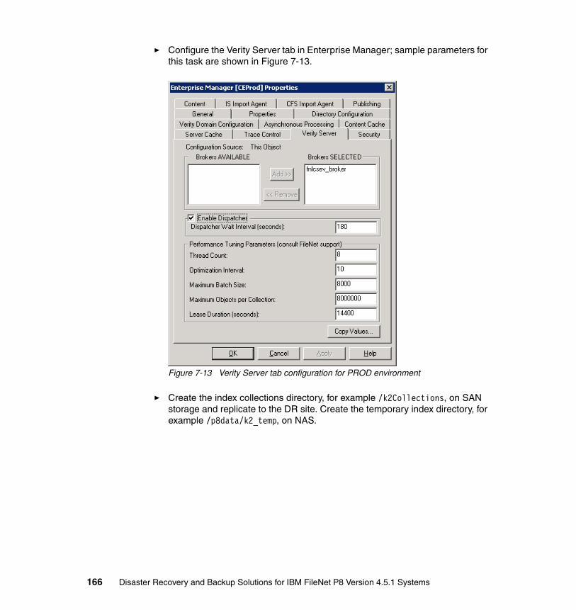
� Configure the Verity Server tab in Enterprise Manager; sample parameters for this task are shown in Figure 7-13.
Figure 7-13 Verity Server tab configuration for PROD environment
� Create the index collections directory, for example /k2Collections, on SAN storage and replicate to the DR site. Create the temporary index directory, for example /p8data/k2_temp, on NAS.
166 Disaster Recovery and Backup Solutions for IBM FileNet P8 Version 4.5.1 Systems

Figure 7-14 shows sample configuration parameters for an index area, named OS3INX, assigned to the object store OS3.
Figure 7-14 Index area collections configuration for PROD environment
Process Engine installationFor disaster recovery, be sure that the Process Engine servers for PROD and DR are set up in a single farm configuration, with the virtual host name (in our case fnlpev) serving as the load balancer name. See the IBM FileNet P8 High Availability Technical Notice publication for more information about configuring a Process Engine farm.
Chapter 7. Case study description and system setup 167

Consider the following guidelines when you install and configure Process Engine for the PROD environment:
� Modify the /etc/hosts file on the Process Engine PROD server to include both the PROD and DR servers as shown in Example 7-1. Format the virtual host name to resolve to the PROD server.
Example 7-1 Sample /etc/hosts entries for the Process Engine PROD server
192.168.100.222 fnlpeprod fnlpeprod.fn.ibm.com fnlpev fnlpev.fn.ibm.com10.0.200.222 fnlpedr fnlpedr.fn.ibm.com
� When installing the Content Engine client on the Process Engine, use the Content Engine server’s virtual host name in the WSI URL, for example:
cemp:http://fnlcev.fn.ibm.com:9080/wsi/FNCEWS40MTOM/
� Process Engine clients (in our case Workplace XT) send http requests to the Process Engine to get Interoperable Object Reference (IOR) information. By default, the Process Engine includes the IP address of the Process Engine host in the IOR response to Process Engine client. This works for a single Process Engine host, but in the case of Process Engine farm, using an IP address of a single Process Engine host in the IOR response breaks the purpose of a Process Engine farm. To resolve this issue, define the vworbbroker.endPoint using a load balancer name, or in our case, the virtual host name FNLPEV. Now, with proper local /etc/hosts table entries, each Process Engine host in a farm resolves the load balancer name to its own Process Engine host IP address. For example, using ipv4, define the vworbbroker.endPoint with the following value:
iiop://fnlpev.fn.ibm.com:32777/hostname_in_ior=fnlpev.fn.ibm.com
168 Disaster Recovery and Backup Solutions for IBM FileNet P8 Version 4.5.1 Systems

Figure 7-15 shows a sample configuration for the vworbbroker.endPoint value using Process Task Manager.
Figure 7-15 vworbbroker.endPoint configuration using Process Task Manager
Chapter 7. Case study description and system setup 169

� With the Enterprise Manager application, use the virtual host name when defining the Process Engine region, for example fnlpev.fn.ibm.com, as shown in Figure 7-16.
Figure 7-16 Process Engine region definition for PROD environment
170 Disaster Recovery and Backup Solutions for IBM FileNet P8 Version 4.5.1 Systems

� Use the Process Engine server’s virtual host name when defining the corresponding connection point as shown in Figure 7-17.
Figure 7-17 Process Engine connection point definition for PROD environment
Workplace XT installationConsider the following guidelines when installing and configuring Workplace XT for the PROD environment:
� For the path to use for the Workplace XT configuration files, use a file system that resides on SAN storage, and replicate to the DR environment.
� Workplace XT (and Application Engine) use EJB transport to connect to the Content Engine. Therefore, you must use the actual Content Engine host name, not the virtual host name, when specifying values for the following information:
– Content Engine client URL
– Content Engine upload URL
– Content Engine download URL
Chapter 7. Case study description and system setup 171

For example, use the following URL when installing the PROD Workplace XT application:
cemp:iiop://fnlceprod.fn.ibm.com:2809/FileNet/Engine
� To configure the Component Manager on the PROD environment, see the values in Table 7-6.
Table 7-6 Component Manager Configuration Parameters
Use the Content Engine server’s virtual host name for the Content Engine URI field on the General tab as shown in Figure 7-18.
Figure 7-18 Component Manager General tab configuration for PROD environment
To configure the entries on the Web Services tab in the Component Manager, use the Workplace XT server’s virtual host name for the listener URL field.
Parameter Value
Content Engine URI http://fnlcev.fn.ibm.com:9080/wsi/FNCEWS40MTOM/
Connection Point CPFNLPEV
Web Services Listener URL
http://fnlxtv.fn.ibm.com:9081/WorkplaceXT
Web Services Listener Local Host
fnlxtprod.fn.ibm.com:9081
172 Disaster Recovery and Backup Solutions for IBM FileNet P8 Version 4.5.1 Systems

However, you must use the actual server host name when specifying the Web services listener local host parameter. See Figure 7-19 for sample Web services configuration parameters.
Figure 7-19 Component Manager Web Services configuration settings for the PROD environment
Image Services installationConsider the following guidelines when you install and configure Image Services in the PROD environment:
� Create a file system with a mount point of /fnsw on the local volume group for the Image Services binary files. This file system does not have to be replicated to the DR environment.
� Create a file system with a mount point of /fnsw/local on the SAN storage volume group for the Image Services configuration files. This file system must be replicated to the DR environment.
� Create another file system for MSAR data with a mount point similar to /msar on the SAN storage volume group for storing Image Services documents. This file system must be replicated to the DR environment.
Chapter 7. Case study description and system setup 173

� Note that for Image Services, both the PROD and DR systems use the same values for the domain:organization (for example fnlisv:FileNet) and system serial number.
� Using the fn_edit tool, select the Network Addresses tab and set the network name to the Image Services server’s virtual host name. Also, make sure the IP addresses for both the PROD and DR servers are included, as shown in Figure 7-20.
Figure 7-20 Network Addresses configuration for PROD Image Services environment
174 Disaster Recovery and Backup Solutions for IBM FileNet P8 Version 4.5.1 Systems

Chapter 8. Backup and restore setup and configuration
This chapter provides procedures for backup and recovery of an IBM FileNet P8 Version 4.5.1 system using IBM Tivoli Storage Manager.
This chapter contains the following topics:
� Backup and recovery overview
� Install and configure Tivoli Storage Manager
� Manual backup procedure using Tivoli Storage Manager
� Creating startup and shutdown scripts for FileNet P8
� Performing offline backups for FileNet P8
� Restore procedure for FileNet P8
8
© Copyright IBM Corp. 2010. All rights reserved. 175
8.1 Backup and recovery overview
In planning the backup and recovery strategy for your FileNet P8 environment, ensure that data and configuration files are backed up on a regular and consistent basis. Consider the following guidelines when implementing your backup and recovery solution:
� You must back up all data within a FileNet P8 domain at the same time to maintain data integrity.
� FileNet P8 Platform does not support online backups. Therefore, you must shut down all FileNet P8 components before you start your backups. Sample scripts for shutdown and startup are included in this chapter.
� To back up file systems, use a backup utility that preserves security settings on files and folders. For our case study, we use IBM Tivoli Storage Manager. Procedures to configure the Tivoli Storage Manager client on each FileNet P8 component are outlined in this chapter.
� Backing up the entire server is not a requirement, because you can reinstall the operating system and FileNet P8 component software at any time. However, having a complete server backup can significantly reduce the recovery time.
A common configuration on AIX systems is to create a default volume group for the system software, such as rootvg, and a second volume group for application data, for example datavg. The application software, or binaries, can reside on either volume group.
A bootable backup of the root volume group (rootvg) can be captured using the AIX mksysb command. A mksysb backup written to tape includes a boot record at the beginning of the tape, which allows the server to boot from tape during a restore operation. For mksysb backups written to a file on disk, a Network Installation Management (NIM) server can be used to restore a file-based backup.
The FileNet P8 system that we use to test the scenario outlined in this chapter stores information in the following locations:
� Root volume group (rootvg) located on internal disk drives
� Data volume group (datavg) located on SAN storage
� Network attached storage (NAS) volumes, mounted locally through NFS
Table 8-1 on page 177 through Table 8-6 on page 179 show the data organization for this system.
176 Disaster Recovery and Backup Solutions for IBM FileNet P8 Version 4.5.1 Systems
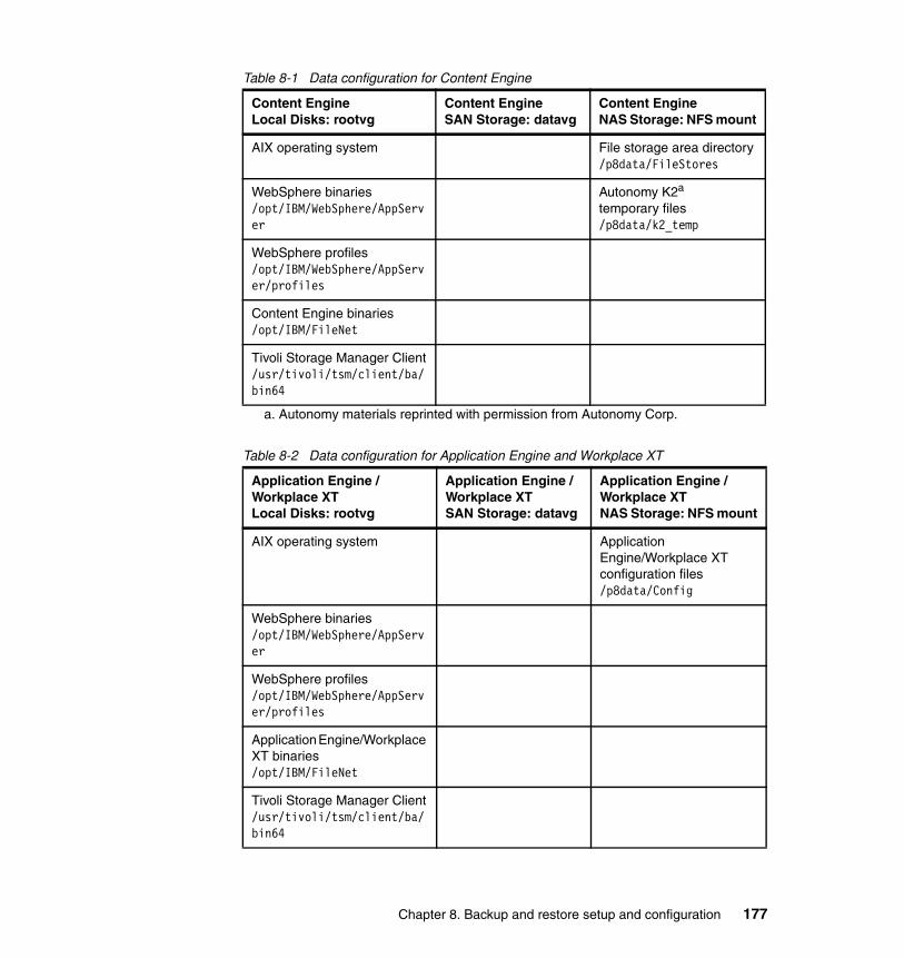
Table 8-1 Data configuration for Content Engine
Table 8-2 Data configuration for Application Engine and Workplace XT
Content EngineLocal Disks: rootvg
Content EngineSAN Storage: datavg
Content EngineNAS Storage: NFS mount
AIX operating system File storage area directory/p8data/FileStores
WebSphere binaries/opt/IBM/WebSphere/AppServer
Autonomy K2a temporary files/p8data/k2_temp
a. Autonomy materials reprinted with permission from Autonomy Corp.
WebSphere profiles/opt/IBM/WebSphere/AppServer/profiles
Content Engine binaries/opt/IBM/FileNet
Tivoli Storage Manager Client/usr/tivoli/tsm/client/ba/bin64
Application Engine / Workplace XTLocal Disks: rootvg
Application Engine / Workplace XTSAN Storage: datavg
Application Engine / Workplace XTNAS Storage: NFS mount
AIX operating system Application Engine/Workplace XT configuration files/p8data/Config
WebSphere binaries/opt/IBM/WebSphere/AppServer
WebSphere profiles/opt/IBM/WebSphere/AppServer/profiles
Application Engine/Workplace XT binaries/opt/IBM/FileNet
Tivoli Storage Manager Client/usr/tivoli/tsm/client/ba/bin64
Chapter 8. Backup and restore setup and configuration 177

Table 8-3 Data configuration for Content Search Engine
Table 8-4 Data configuration for Process Engine
Table 8-5 Data configuration for Image Services
Content Search EngineLocal Disk: rootvg
Content Search EngineSAN Storage: datavg
Content Search EngineNAS Storage: NFS mount
AIX operating system K2 binaries/k2verity
K2 temporary files/p8data/k2_temp
Tivoli Storage Manager Client/usr/tivoli/tsm/client/ba/bin64
K2 collections (Indexes)/k2Collections
File storage area directory/p8data/FileStores
Process EngineLocal Disk: rootvg
Process EngineSAN Storage: datavg
Process EngineNAS Storage: NFS mount
AIX operating system
Process Engine binaries and configuration files/fnsw /fnsw/local
Tivoli Storage Manager Client/usr/tivoli/tsm/client/ba/bin64
Image ServicesLocal Disk: rootvg
Image ServicesSAN Storage: datavg
Image ServicesNAS Storage: NFS mount
AIX operating system Image Services configuration files/fnsw/local
Image Services binaries /fnsw
MSAR files/msar
Tivoli Storage Manager Client/usr/tivoli/tsm/client/ba/bin64
Raw data partitions/dev/rfn_cache0/dev/rfn_perm_db0/dev/rfn_perm_rl0/dev/rfn_sec_db0/dev/rfn_sec_rl0/dev/rfn_trans_db0/dev/rfn_trans_rl0
178 Disaster Recovery and Backup Solutions for IBM FileNet P8 Version 4.5.1 Systems
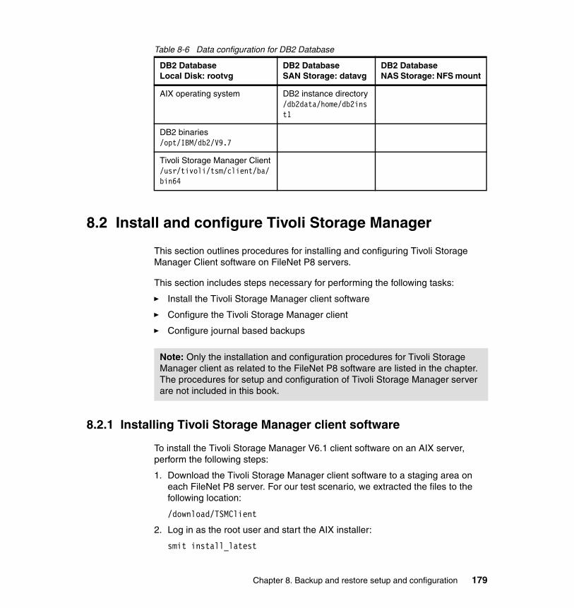
Table 8-6 Data configuration for DB2 Database
8.2 Install and configure Tivoli Storage Manager
This section outlines procedures for installing and configuring Tivoli Storage Manager Client software on FileNet P8 servers.
This section includes steps necessary for performing the following tasks:
� Install the Tivoli Storage Manager client software
� Configure the Tivoli Storage Manager client
� Configure journal based backups
8.2.1 Installing Tivoli Storage Manager client software
To install the Tivoli Storage Manager V6.1 client software on an AIX server, perform the following steps:
1. Download the Tivoli Storage Manager client software to a staging area on each FileNet P8 server. For our test scenario, we extracted the files to the following location:
/download/TSMClient
2. Log in as the root user and start the AIX installer:
smit install_latest
DB2 DatabaseLocal Disk: rootvg
DB2 DatabaseSAN Storage: datavg
DB2 DatabaseNAS Storage: NFS mount
AIX operating system DB2 instance directory/db2data/home/db2inst1
DB2 binaries/opt/IBM/db2/V9.7
Tivoli Storage Manager Client/usr/tivoli/tsm/client/ba/bin64
Note: Only the installation and configuration procedures for Tivoli Storage Manager client as related to the FileNet P8 software are listed in the chapter. The procedures for setup and configuration of Tivoli Storage Manager server are not included in this book.
Chapter 8. Backup and restore setup and configuration 179
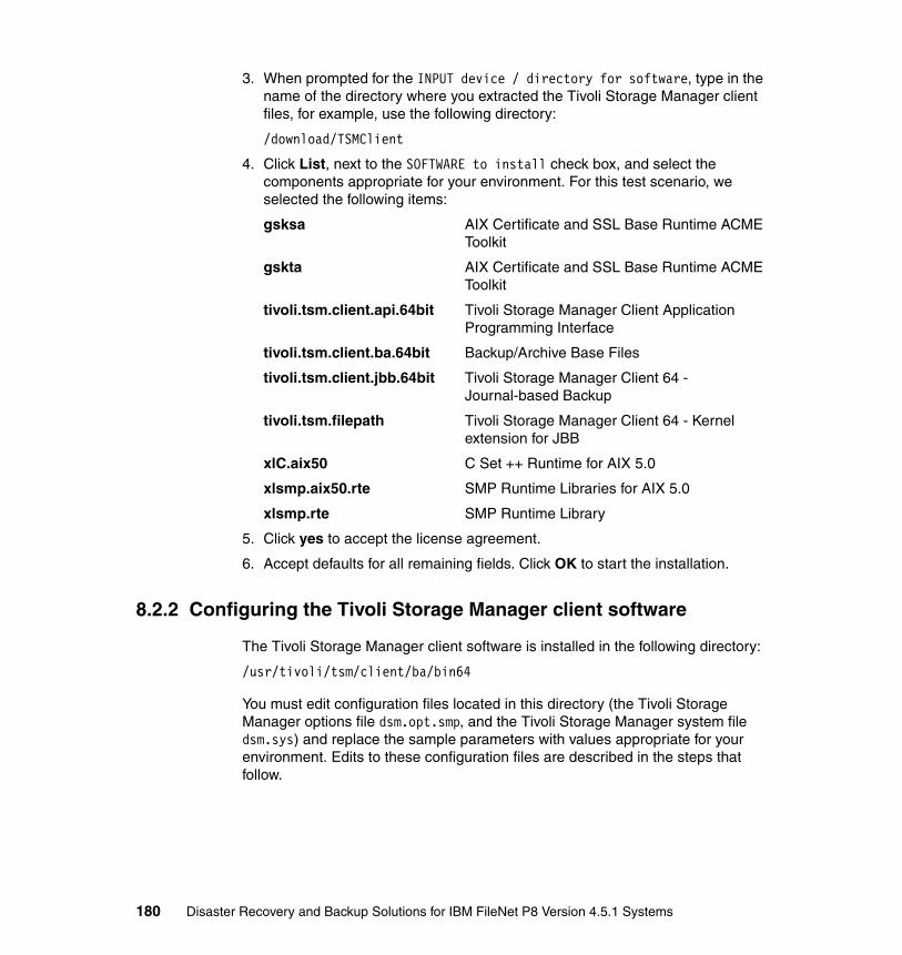
3. When prompted for the INPUT device / directory for software, type in the name of the directory where you extracted the Tivoli Storage Manager client files, for example, use the following directory:
/download/TSMClient
4. Click List, next to the SOFTWARE to install check box, and select the components appropriate for your environment. For this test scenario, we selected the following items:
gsksa AIX Certificate and SSL Base Runtime ACME Toolkit
gskta AIX Certificate and SSL Base Runtime ACME Toolkit
tivoli.tsm.client.api.64bit Tivoli Storage Manager Client Application Programming Interface
tivoli.tsm.client.ba.64bit Backup/Archive Base Files
tivoli.tsm.client.jbb.64bit Tivoli Storage Manager Client 64 - Journal-based Backup
tivoli.tsm.filepath Tivoli Storage Manager Client 64 - Kernel extension for JBB
xlC.aix50 C Set ++ Runtime for AIX 5.0
xlsmp.aix50.rte SMP Runtime Libraries for AIX 5.0
xlsmp.rte SMP Runtime Library
5. Click yes to accept the license agreement.
6. Accept defaults for all remaining fields. Click OK to start the installation.
8.2.2 Configuring the Tivoli Storage Manager client software
The Tivoli Storage Manager client software is installed in the following directory:
/usr/tivoli/tsm/client/ba/bin64
You must edit configuration files located in this directory (the Tivoli Storage Manager options file dsm.opt.smp, and the Tivoli Storage Manager system file dsm.sys) and replace the sample parameters with values appropriate for your environment. Edits to these configuration files are described in the steps that follow.
180 Disaster Recovery and Backup Solutions for IBM FileNet P8 Version 4.5.1 Systems

Editing the Tivoli Storage Manager options fileSpecify the name of the Tivoli Storage Manager server to be contacted by the client in the dsm.opt file. To edit this file, perform the following steps:
1. Log in as the root user and change directory to the location of the Tivoli Storage Manager binary files:
cd /usr/tivoli/tsm/client/ba/bin64
2. Make a copy of the sample Tivoli Storage Manager options file (dsm.opt.smp):
cp dsm.opt.smp dsm.opt
3. Edit the dsm.opt file and change the SErvername parameter to match that of your Tivoli Storage Manager server. In Example 8-1, the Tivoli Storage Manager servername is set to fnltsmprod.
Example 8-1 Tivoli Storage Manager options file - dsm.opt
****************************************************************** Tivoli Storage Manager ** Client User Options file for AIX (dsm.opt) ****************************************************************** This file contains an option you can use to specify the TSM* server to contact if more than one is defined in your client* system options file (dsm.sys). Copy dsm.opt.smp to dsm.opt.* If you enter a server name for the option below, remove the* leading asterisk (*).*****************************************************************SErvername fnltsmprod*****************************************************************
Editing the Tivoli Storage Manager system fileThe Tivoli Storage Manager system file (dsm.sys) is used to specify connection parameters that are used by the client to communicate with the Tivoli Storage Manager server. To edit this file, perform the following steps:
1. Log in as the root user and change directory to the location of the Tivoli Storage Manager binary files:
cd /usr/tivoli/tsm/client/ba/bin64
2. Make a copy of the sample Tivoli Storage Manager system file (dsm.sys.smp):
cp dsm.sys.smp dsm.sys
3. Edit the dsm.sys file and change the TCPServeraddress parameter to match that of your Tivoli Storage Manager server. You must also specify the communications method (COMMMethod) and TCP port number (TCPPort)
Chapter 8. Backup and restore setup and configuration 181

that is used to establish communications between the Tivoli Storage Manager server and client as shown in Example 8-2.
Note that we have added two optional parameters (PasswordAccess and ManagedServices) to be able to run the Tivoli Storage Manager scheduler service in client-acceptor mode. These parameters are discussed later in this chapter.
Example 8-2 Tivoli Storage Manager system file - dsm.sys
****************************************************************** Tivoli Storage Manager ** Client System Options file for AIX (dsm.sys) ****************************************************************** This file contains the minimum options required to get started* using TSM. Copy dsm.sys.smp to dsm.sys. In the dsm.sys file,* enter the appropriate values for each option listed below and* remove the leading asterisk (*) for each one.
* If your client node communicates with multiple TSM servers, be* sure to add a stanza, beginning with the SERVERNAME option, * for each additional server.*****************************************************************SErvername fnltsmprod COMMMethod TCPip TCPPort 1500 TCPServeraddress fnltsmprod.fn.ibm.com PasswordAccess generate ManagedServices schedule webclient
Starting the client-acceptor scheduler serviceConfigure the Tivoli Storage Manager client by using one of the following methods to manage the scheduler process:
� The traditional method keeps the Tivoli Storage Manager scheduler process running continuously.
� The client-acceptor mode starts the scheduler service only when needed.
Generally, using the client-acceptor daemon to manage the scheduler is the preferred method. The client-acceptor daemon (dsmcad) provides services on the Tivoli Storage Manager client server to automatically start and stop the scheduler process as needed for each scheduled action.
182 Disaster Recovery and Backup Solutions for IBM FileNet P8 Version 4.5.1 Systems

To start the daemon manually, perform the following steps on your client server:
1. Log in to the Tivoli Storage Manager client server as the root user.
2. Change directory to the Tivoli Storage Manager binaries location:
cd /usr/tivoli/tsm/client/ba/bin64
3. Start the client-acceptor daemon:
./dsmcad &
4. Check the log files dsmerror.log and dsmsched.log to verify that the client-acceptor daemon started successfully.
When you are satisfied that the client-acceptor daemon is configured correctly, you may configure the Tivoli Storage Manager client scheduler to run as a background system task, which starts automatically when your system is booted.
To enable this feature, you must set the ManagedServices option in the dsm.sys file to schedule, or schedule webclient. See Example 8-2 on page 182.
So that the scheduler can start unattended, you must enable the client to store its password by setting the PasswordAccess option to generate. See Example 8-2 on page 182.
To enable autostart, perform the following steps:
1. Log in as the root user and add the following entries (highlighted in bold) to your dsm.sys file as shown in Example 8-3.
Example 8-3 Parameters in dsm.sys used to automate the dsmcad daemon
SErvername fnltsmprod COMMMethod TCPip TCPPort 1500 TCPServeraddress fnltsmprod.fn.ibm.com PasswordAccess generate ManagedServices schedule webclient
2. To generate and store the password, run a simple Tivoli Storage Manager client command, such as:
./dsmc query session
3. Using an editor, create a startup script for the client-acceptor daemon:
vi /usr/tivoli/tsm/client/ba/bin64/rc.dsmcad
4. Include the commands shown in Example 8-4 on page 184 in your rc.dsmcad script file.
Chapter 8. Backup and restore setup and configuration 183

Example 8-4 An rc.dsmcad script file
#!/bin/ksh###################################################################### /usr/tivoli/tsm/client/ba/bin64/rc.dsmcad## Start up TSM client acceptor daemon when the system is rebooted...#####################################################################
DSM_DIR=/usr/tivoli/tsm/client/ba/bin64DSM_CONFIG=/usr/tivoli/tsm/client/ba/bin64/dsm.optDSM_LOG=/usr/tivoli/tsm/client/ba/bin64export DSM_DIR DSM_CONFIG DSM_LOG
## Start the daemon#print "$(date '+%D %T') Starting Tivoli Client Acceptor Daemon"/usr/tivoli/tsm/client/ba/bin64/dsmcad
5. The script in the Tivoli binaries directory is the rc.dsmcad file. Grant execute permissions to the file:
chmod 755 /usr/tivoli/tsm/client/ba/bin64/rc.dsmcad
6. Add the following entry to /etc/inittab so that the client-acceptor daemon can begin running when you restart your system. Type the entry on one continuous line:
tsm::once:/usr/tivoli/tsm/client/ba/bin64/rc.dsmcad > /dev/console 2>&1 # TSM Client Acceptor Daemon
Configuring the Tivoli Storage Manager journal based backup service When a traditional Tivoli Storage Manager incremental backup is initiated, the following actions occur:
1. A list of objects on the Tivoli Storage Manager client is generated by scanning the entire local file system.
2. The Tivoli Storage Manager server inventory is queried to generate a list of all active objects for the file system.
3. The two lists are compared to generate a final list of objects that are either new, changed, or deleted and therefore must be included in the incremental backup.
184 Disaster Recovery and Backup Solutions for IBM FileNet P8 Version 4.5.1 Systems

This process can be time-consuming on large file systems. Tivoli Storage Manager Journal Based Backup (JBB) provides an alternative method for generating the incremental backup list. With this method, a journal daemon runs on the local system that monitors change activity on designated file systems and records the information to a change log. This change log is then referenced to determine which files to backup or expire when an incremental backup is initiated.
You can configure journaling on selected file systems. Using journaling on all file systems on a particular server is not necessary.
To enable journal based backups, perform the following steps:
1. Make a copy of the sample Tivoli Storage Manager journal service configuration file (tsmjbbd.ini.smp):
cp tsmjbbd.ini.smp tsmjbbd.ini
Note that the sample tsmjbbd.ini file contains a number of commented lines, which are the lines that start with a semi-colon (;) character. The commented lines describe each of the journal service parameters configurable in Tivoli Storage Manager. Scroll to the bottom of the file to make changes appropriate for your environment.
2. Edit the tsmjbbd.ini file. Example 8-5 shows the parameters we specified to configure journaling for the /db2data directory on the database server.
Example 8-5 The tsmjbbd.ini file
;****************************************************************; Tivoli Storage Manager - Version 6, Release 1, Level 0; Journal Service Configuration File; (C) Copyright IBM Corporation, 1990, 2008, All Rights Reserved;**************************************************************** [JournalSettings]Errorlog=/tsmjournal/jbberror.log
Note: Tivoli Storage Manager Journal Based Backup can be configured only on local file systems. Therefore, journaling on NFS-mounted file systems is not supported.
In most FileNet P8 configurations, the file storage areas directory resides in an NFS-mounted directory. To take advantage of journaling in these configurations, install and configure the Tivoli Storage Manager client with journaling enabled on the system that serves as the host for the file storage areas file system.
Chapter 8. Backup and restore setup and configuration 185

Journaldir=/tsmjournal
[JournalExcludeList]; Note that this list contains the journal database files. *.jdb.jbbdb*.jdbInc.jbbdb
[JournaledFileSystemSettings]JournaledFileSystems=/db2data
; Override stanza for /db2data file system[JournaledFileSystemSettings./db2data]JournalDir=/tsmjournal/db2dataPreserveDBOnExit=1DeferFsMonStart=1DeferRetryInterval=2logFsErrors=0
3. Start the Tivoli Storage Manager journal daemon:
/usr/tivoli/tsm/client/ba/bin64/rc.tsmjbb
4. Journal startup information is recorded in the file specified in the Errorlog parameter in the tsmjbb.ini file. Successful initialization records information that is similar to the log file shown in Example 8-6.
Example 8-6 Journal daemon startup log file
10/24/09 12:31:49 Version 6, Release 1, Level 0.0 Last Update: Mar 6 2009 tsmjbbd, /usr/tivoli/tsm/client/ba/bin64,Prefs file: /usr/tivoli/tsm/client/ba/bin64/tsmjbbd.ini, Journal dir: /tsmjournalJournaled filespaces: /db2data10/24/09 12:31:52 Bringing Journaled File System '/db2data' online: Journal Database : '/tsmjournal/db2data/tsm_db2data.jdb' Notification Buffer Size : 0X020000 Preserve Journal On Exit : Yes Allow Deferred Start : Yes Defer Retry Interval : 2 Seconds Log File System Errors : No
5. When you are satisfied that the journaling is working correctly, run the following script to create an entry in the /etc/inittab directory so the daemon can start automatically when your system is restarted:
/usr/tivoli/tsm/client/ba/bin64/jbbinittab
186 Disaster Recovery and Backup Solutions for IBM FileNet P8 Version 4.5.1 Systems

The entry in the inittab script is similar to the following line:
tsmjbb:2:wait:/usr/tivoli/tsm/client/ba/bin64/rc.tsmjbb > /dev/console 2>&1 # tsmjbbd startup
8.3 Manual backup procedure using Tivoli Storage Manager
To validate your Tivoli Storage Manager client configuration, run a manual backup on each of the FileNet P8 servers by using the local Tivoli Storage Manager client. To run a manual backup on the Content Engine server, perform the following steps:
1. Log in to the Content Engine server as the root user. Be sure your DISPLAY variable has been exported to your workstation. Change directory to the location of the Tivoli Storage Manager binaries and launch the Tivoli Storage Manager client application (dsmj):
cd /usr/tivoli/tsm/client/ba/bin64./dsmj
2. The Tivoli Storage Manager interface is displayed, as shown in Figure 8-1 on page 188. Click the Backup link.
Chapter 8. Backup and restore setup and configuration 187

Figure 8-1 IBM Tivoli Storage Manager client interface
3. Select the files to back up. Figure 8-2 on page 189 shows the selections for the Content Engine, which include all the local file systems and the NFS-mounted /p8data directory.
188 Disaster Recovery and Backup Solutions for IBM FileNet P8 Version 4.5.1 Systems

Figure 8-2 Selecting objects for backup
4. From the drop-down menu, set the backup type to Incremental (complete). Click Backup to start the backup.
While the backup is running, status messages are displayed, similar to Figure 8-3.
Figure 8-3 Sample backup status message
5. A message similar to that shown in Figure 8-4 on page 190 is displayed when the backup is complete. Click OK to continue.
Chapter 8. Backup and restore setup and configuration 189

Figure 8-4 Sample backup completion message
A Detailed Status Report window similar to Figure 8-5 is displayed, showing statistical information relating to the backup.
Figure 8-5 Status report for successful backup
6. Close the status report window, and exit the Tivoli Storage Manager client application.
7. Repeat these steps on each server in your FileNet P8 configuration.
190 Disaster Recovery and Backup Solutions for IBM FileNet P8 Version 4.5.1 Systems

8.4 Creating startup and shutdown scripts for FileNet P8
Because FileNet P8 software does not support hot backups, you must develop automated procedures to shut down and restart the FileNet P8 component software before and after backups. These procedures must be executed in the correct sequence, and be scheduled to accommodate your backup and maintenance window.
For the systems in our test scenario, we created shell scripts and cron jobs to automatically start up and shut down FileNet P8 components. This section provides examples of our shell scripts for your reference.
8.4.1 Starting and stopping the FileNet P8 J2EE-based applications
Several FileNet P8 components are J2EE-based applications that run on an application server:
� Content Manager
– Content Engine (CE)– Application Engine (AE)– Workplace XT
� Business Process Manager
– Business Activity Monitor (BAM)– Business Process Framework (BPF)
� FileNet P8 expansion products
– eForms (eF)– Records Manager (RM)
These applications must be stopped and started using commands provided by your J2EE application server software. In our test scenario, we use IBM WebSphere Application Server version 7.0.0.5 for the applications installed on the Content Engine server (fnlceprod), and the Workplace XT server (fnlxtprod). Note the following information about our WebSphere configuration:
� WebSphere is running as a network deployment, with the deployment manager node residing on the Content Engine server (fnlceprod).
� WebSphere node agents are running on both the Content Engine server (fnlceprod), and the Workplace XT server (fnlxtprod).
� FileNet Content Engine application is deployed on the CEserver01 target on fnlceprod.
� Workplace XT application is deployed on the XTserver01 target on fnlxtprod.
Chapter 8. Backup and restore setup and configuration 191
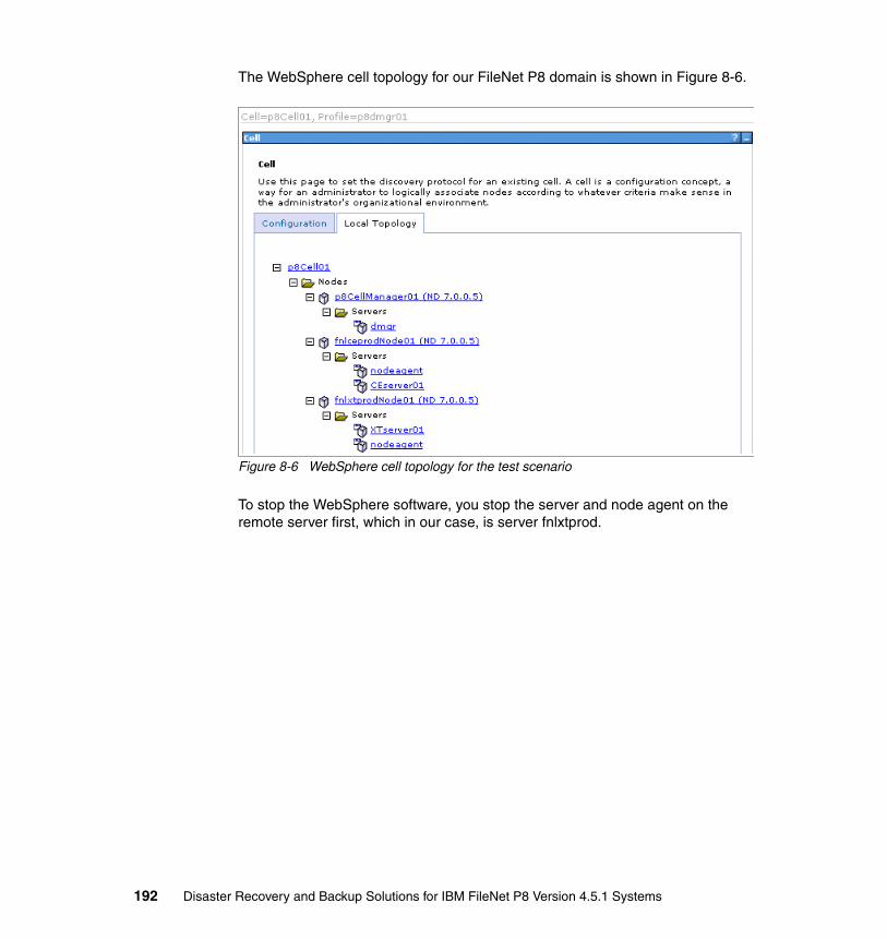
The WebSphere cell topology for our FileNet P8 domain is shown in Figure 8-6.
Figure 8-6 WebSphere cell topology for the test scenario
To stop the WebSphere software, you stop the server and node agent on the remote server first, which in our case, is server fnlxtprod.
192 Disaster Recovery and Backup Solutions for IBM FileNet P8 Version 4.5.1 Systems

Example 8-7 shows a copy of the script we used to stop all the WebSphere components (node agent and XTserver01) on fnlxtprod.
Example 8-7 Script to stop WebSphere services on the Workplace XT server
#!/bin/ksh## Script to stop WebSphere services on fnlxtprod## Script name: stopXTall.sh
echo "Stopping server XTserver01 . . ."/opt/IBM/WebSphere/AppServer/profiles/p8AppSrv01/bin/stopServer.sh XTserver01 \-username p8AdminUser \-password p8password
echo "Stopping node agent for fnlxtprodNode01 . . . "/opt/IBM/WebSphere/AppServer/profiles/p8AppSrv01/bin/stopNode.sh \-username p8AdminUser \-password p8password
The WebSphere components running on the Content Engine server (fnlceprod) include the deployment manager (dmgr), the node agent, and CEserver01. Example 8-8 shows commands for stopping the WebSphere components on fnlceprod.
Example 8-8 Script to stop WebSphere services on the Content Engine server
#!/bin/ksh## Script to stop WebSphere services on fnlceprod## Script name: stopCEall.sh
echo "Stopping server CEserver01 . . ."/opt/IBM/WebSphere/AppServer/profiles/p8AppSrv01/bin/stopServer.sh CEserver01 \-username p8AdminUser \-password p8password
echo "Stopping node agent for fnlceprodNode01 . . . "/opt/IBM/WebSphere/AppServer/profiles/p8AppSrv01/bin/stopNode.sh \-username p8AdminUser \-password p8password
echo "Stopping deployment manager (p8dmgr01) . . . "/opt/IBM/WebSphere/AppServer/profiles/p8dmgr01/bin/stopManager.sh \-username p8AdminUser \-password p8password
Chapter 8. Backup and restore setup and configuration 193

After backups are complete, you use a script similar to the one in Example 8-9 to restart WebSphere components on the Content Engine server (fnlceprod).
Example 8-9 Script to restart WebSphere services on the Content Engine server
#!/bin/ksh## Script to start WebSphere services on fnlceprod## Script name: startCEall.sh
echo "Starting deployment manager (p8dmgr01) . . . "
/opt/IBM/WebSphere/AppServer/profiles/p8dmgr01/bin/startManager.sh \-username p8AdminUser \-password p8password
echo "Starting node agent for fnlceprodNode01 . . . "/opt/IBM/WebSphere/AppServer/profiles/p8AppSrv01/bin/startNode.sh
echo "Starting server CEserver01 . . ."/opt/IBM/WebSphere/AppServer/profiles/p8AppSrv01/bin/startServer.sh CEserver01
To restart WebSphere components on the Workplace XT server (fnlxtprod), see Example 8-10.
Example 8-10 Script to restart WebSphere services on the Workplace XT server
#!/bin/ksh## Script to start WebSphere services on fnlxtprod## Script name: startXTall.sh
echo "Starting node agent for fnlxtprodNode01 . . . "/opt/IBM/WebSphere/AppServer/profiles/p8AppSrv01/bin/startNode.sh
echo "Starting server XTserver01 . . ."/opt/IBM/WebSphere/AppServer/profiles/p8AppSrv01/bin/startServer.sh XTserver01
8.4.2 Starting and stopping the FileNet P8 Component Manager
The Component Manager is a Process Engine component that runs on either the Application Engine (AE) server or the Workplace XT server. Because the command line to start the Component Manager can be long and complex, you use the Process Task Manager applet to generate the startup command for you. To use this feature, enable the Show Command button in the Process Task
194 Disaster Recovery and Backup Solutions for IBM FileNet P8 Version 4.5.1 Systems

Manager. To enable this feature and use it to generate the Component Manager startup command on Workplace XT, perform the following steps (The procedure for generating the command on the Application Engine is similar):
1. Log in to the Workplace XT server as the FileNet P8 operating system user. In our case, we logged in as user p8OSusr.
2. Open the taskman.properties file in an editor. The taskman.properties file is in the <install_dir>/Router directory on your WPXT server, for example:
/opt/IBM/FileNet/WebClient/Router/taskman.properties
3. Add the line filenet.ae.taskman.cm.advanced=true to the taskman.properties file. See text highlighted in bold in Example 8-11.
Example 8-11 The taskman.profiperties file
java.security.auth.login.config=/opt/IBM/FileNet/WebClient/Router/taskman.login.configjava.security.policy=/opt/IBM/FileNet/WebClient/Router/taskman.policywasp.location=/opt/IBM/FileNet/WebClient/CE_API/wsijava.protocol.handler.pkgs=com.ibm.net.ssl.www2.protocolfilenet.ae.taskman.cm.advanced=true
WF_HELP=http://fnlxtv.fn.ibm.com:9081/ecm_help/pe_help
TaskManager.ConsolidatedView=trueTaskManager.P8TASKMAN_HOME=/opt/IBM/FileNet/WebClient/CommonFilesTaskManager.ServiceMode=falseTaskManager.ServiceName=VWServicesWPXTTaskManager.ServiceDisplayName=Process WP XT Services ManagerTaskManager.ProductID=TaskManager.WPXT
4. Save your edits and launch the Process Task Manager applet as follows:
cd /opt/IBM/FileNet/WebClient/Router./routercmd.sh
5. In the left pane of the Process Task Manager, select the name of your connection point.
Chapter 8. Backup and restore setup and configuration 195

In our case, we selected CPFNLPEV.ALL, as shown in Figure 8-7.
Figure 8-7 Select connection point in Process Task Manager view
6. In the panel on the right side of the Process Task Manager, select the Java Security tab. The Show command button is then displayed (Figure 8-8). If you do not see the button, be sure you made the correct edits to the taskman.properties file as noted in Step 3.
Figure 8-8 Process Task Manager Java Security view
196 Disaster Recovery and Backup Solutions for IBM FileNet P8 Version 4.5.1 Systems

7. Click Show command. A Message window opens. It lists the Component Manager startup command similar to the one in Figure 8-9. Copy the text that is displayed in the window to your Component Manager startup script, and then click Close.
Figure 8-9 Sample Component Manager startup command
Chapter 8. Backup and restore setup and configuration 197

Example 8-12 shows a sample Component Manager startup script.
Example 8-12 Component Manager startup script
#!/bin/ksh## Script to start the Component Manager on fnlxtprod## Script name: startCM.sh
cd /home/p8OSusrdate >>nohup.outecho "Starting component manager..." >>nohup.outnohup /opt/IBM/FileNet/WebClient/Router/java/jre/bin/java -Dfilenet.pe.bootstrap.ceuri=http://fnlcev.fn.ibm.com:9080/wsi/FNCEWS40MTOM/ -Dwasp.location=/opt/IBM/FileNet/WebClient/CE_API/wsi -Djava.protocol.handler.pkgs=com.ibm.net.ssl.www2.protocol -Djava.security.auth.login.config=/opt/IBM/FileNet/WebClient/Router/taskman.login.config -Djava.security.policy=/opt/IBM/FileNet/WebClient/Router/taskman.policy -Dorg.apache.axis.components.net.SecureSocketFactory=filenet.ws.utils.jsse.FnJSSESocketFactory -cp /opt/IBM/FileNet/WebClient/Router/lib/pe.jar:/opt/IBM/FileNet/WebClient/Router/lib/peResources.jar:/opt/IBM/FileNet/WebClient/Router/lib/ContentExtendedOps.jar:/opt/IBM/FileNet/WebClient/Router/lib/xml-apis.jar:/opt/IBM/FileNet/WebClient/Router/lib/xercesImpl.jar:/opt/IBM/FileNet/WebClient/Router/lib/saaj.jar:/opt/IBM/FileNet/WebClient/CE_API/lib/Jace.jar:/opt/IBM/FileNet/WebClient/Router/lib/mailapi.jar:/opt/IBM/FileNet/WebClient/Router/lib/smtp.jar:/opt/IBM/FileNet/WebClient/Router/lib/axis.jar:/opt/IBM/FileNet/WebClient/Router/lib/axis-schema.jar:/opt/IBM/FileNet/WebClient/Router/lib/wsdl4j.jar:/opt/IBM/FileNet/WebClient/Router/lib/commons-logging.jar:/opt/IBM/FileNet/WebClient/Router/lib/commons-discovery.jar:/opt/IBM/FileNet/WebClient/Router/lib/jaxrpc.jar:/opt/IBM/FileNet/WebClient/Router/lib/juddi.jar:/opt/IBM/FileNet/WebClient/WorkplaceXT/download/activation.jar:/opt/IBM/FileNet/WebClient/Router/lib/addressing.jar:/opt/IBM/FileNet/WebClient/Router/lib/Sandesha.jar:/opt/IBM/FileNet/WebClient/WorkplaceXT/download/ciops.jar:/opt/IBM/FileNet/WebClient/WorkplaceXT/download/javaapi.jar:/opt/IBM/FileNet/WebClient/WorkplaceXT/download/applets.jar:/opt/IBM/FileNet/WebClient/WorkplaceXT/download/xalan.jar:/opt/IBM/FileNet/WebClient/Router/lib:/opt/IBM/FileNet/WebClient/WorkplaceXT/WEB-INF:/opt/IBM/FileNet/WebClient/WorkplaceXT/download/pe3pt.jar filenet.vw.integrator.base.VWComponentManager /named /routerURL CPFNLPEV /userName=-1 /password mhuFol9OnlbNpPiLpxbDqQPEn44Sq2GLa34QbK00 /registryPort 32771 /eventPort 32773 /registryName FileNet.VW.VWComponentManager.CPFNLPEV.ALL /queues=* &
8. To create the Component Manager shutdown script, add the following option to the same command line that is used to start the Component Manager:
/unbind
198 Disaster Recovery and Backup Solutions for IBM FileNet P8 Version 4.5.1 Systems

Be sure to put this option before the ampersand (&) character at the end of the command line. A sample shutdown script is shown in Example 8-13.
Example 8-13 Component Manager shutdown script
#!/bin/ksh## Script to shut down the Component Manager on fnlxtprod## Script name: stopCM.sh
cd /home/p8OSusrdate >>nohup.outecho "Stopping component manager..." >>nohup.outnohup /opt/IBM/FileNet/WebClient/Router/java/jre/bin/java -Dfilenet.pe.bootstrap.ceuri=http://fnlcev.fn.ibm.com:9080/wsi/FNCEWS40MTOM/ -Dwasp.location=/opt/IBM/FileNet/WebClient/CE_API/wsi -Djava.protocol.handler.pkgs=com.ibm.net.ssl.www2.protocol -Djava.security.auth.login.config=/opt/IBM/FileNet/WebClient/Router/taskman.login.config -Djava.security.policy=/opt/IBM/FileNet/WebClient/Router/taskman.policy -Dorg.apache.axis.components.net.SecureSocketFactory=filenet.ws.utils.jsse.FnJSSESocketFactory -cp /opt/IBM/FileNet/WebClient/Router/lib/pe.jar:/opt/IBM/FileNet/WebClient/Router/lib/peResources.jar:/opt/IBM/FileNet/WebClient/Router/lib/ContentExtendedOps.jar:/opt/IBM/FileNet/WebClient/Router/lib/xml-apis.jar:/opt/IBM/FileNet/WebClient/Router/lib/xercesImpl.jar:/opt/IBM/FileNet/WebClient/Router/lib/saaj.jar:/opt/IBM/FileNet/WebClient/CE_API/lib/Jace.jar:/opt/IBM/FileNet/WebClient/Router/lib/mailapi.jar:/opt/IBM/FileNet/WebClient/Router/lib/smtp.jar:/opt/IBM/FileNet/WebClient/Router/lib/axis.jar:/opt/IBM/FileNet/WebClient/Router/lib/axis-schema.jar:/opt/IBM/FileNet/WebClient/Router/lib/wsdl4j.jar:/opt/IBM/FileNet/WebClient/Router/lib/commons-logging.jar:/opt/IBM/FileNet/WebClient/Router/lib/commons-discovery.jar:/opt/IBM/FileNet/WebClient/Router/lib/jaxrpc.jar:/opt/IBM/FileNet/WebClient/Router/lib/juddi.jar:/opt/IBM/FileNet/WebClient/WorkplaceXT/download/activation.jar:/opt/IBM/FileNet/WebClient/Router/lib/addressing.jar:/opt/IBM/FileNet/WebClient/Router/lib/Sandesha.jar:/opt/IBM/FileNet/WebClient/WorkplaceXT/download/ciops.jar:/opt/IBM/FileNet/WebClient/WorkplaceXT/download/javaapi.jar:/opt/IBM/FileNet/WebClient/WorkplaceXT/download/applets.jar:/opt/IBM/FileNet/WebClient/WorkplaceXT/download/xalan.jar:/opt/IBM/FileNet/WebClient/Router/lib:/opt/IBM/FileNet/WebClient/WorkplaceXT/WEB-INF:/opt/IBM/FileNet/WebClient/WorkplaceXT/download/pe3pt.jar filenet.vw.integrator.base.VWComponentManager /named /routerURL CPFNLPEV /userName=-1 /password mhuFol9OnlbNpPiLpxbDqQPEn44Sq2GLa34QbK00 /registryPort 32771 /eventPort 32773 /registryName FileNet.VW.VWComponentManager.CPFNLPEV.ALL /queues=* /undbind &
Chapter 8. Backup and restore setup and configuration 199

8.4.3 Starting and stopping the Content Search Engine
To start and stop the Content Search Engine (CSE), use the k2adminstart and k2adminstop commands, which are located in the following directory on your Content Search Engine server:
<cse_install_dir>/k2/<platform_dir>/bin
We used the following commands for our system:
/k2verity/k2/_rs6k43/bin/k2adminstart/k2verity/k2/_rs6k43/bin/k2adminstop
To run the k2adminstart and k2adminstop commands, log in as the K2 operating system user, which in our case is p8OSusr.
These commands can be added to your startup and shutdown scripts to be run before and after backups. A sample Content Search Engine startup script is shown in Example 8-14.
Example 8-14 Content Search Engine startup script
#!/bin/ksh## Script to start the Content Search Engine on fnlcseprod## Script name: startK2.sh
cd /k2veritydate >>nohup.outecho "Starting k2 . . ." >>nohup.outnohup /k2verity/k2/_rs6k43/bin/k2adminstart &
Similarly, a sample Content Search Engine shutdown script is shown in Example 8-15.
Example 8-15 Content Search Engine shutdown script
#!/bin/ksh## Script to stop the Content Search Engine on fnlcseprod## Script name: stopK2.sh
cd /k2veritydate >>nohup.outecho "Stopping k2 . . ." >>nohup.outnohup /k2verity/k2/_rs6k43/bin/k2adminstop
200 Disaster Recovery and Backup Solutions for IBM FileNet P8 Version 4.5.1 Systems

8.4.4 Starting and stopping the Process Engine
The Process Engine (PE) has a built in command for starting and stopping the software.
To start the Process Engine, run the following command:
/fnsw/bin/initfnsw start
To stop the Process Engine, use the following command:
/fnsw/bin/initfnsw -y stop
The Process Engine logs information generated by the initfnsw command in the following location:
/fnsw/local/logs/elogs
8.4.5 Starting and stopping Image Services
In its simplest form, the process to start and stop Image Services is the same as that used to start and stop the Process Engine.
To start Image Services, run the following command:
/fnsw/bin/initfnsw start
To stop Image Services, use the following command:
/fnsw/bin/initfnsw -y stop
However, the following add-on components to Image Services must also be stopped and restarted when you recycle Image Services:
� High-Performance Image Import (HPII)
� Medium-Range Image Import (MRII)
� Document Archive Retrieval Transport (DART)
� Computer Output Laser Disk (COLD)
Starting and stopping Image Services add-on componentsMany Image Services configurations include add-on applications that must be launched when you start Image Services through the initfnsw start command. Place the required startup commands in an ims_start script file in the /fnsw/local/sd directory. When you execute the initfnsw start command, it will first start the Image Services software, then search the /fnsw/local/sd directory for the existence of an ims_start script file. If an ims_start script file is found, the commands in this script are executed immediately after the Image
Chapter 8. Backup and restore setup and configuration 201

Services software startup is complete. Example 8-16 shows a sample ims_start script file for starting HPII.
Example 8-16 The /fnsw/local/sd/ims_start script
#!/bin/ksh## Script to start up HPII software on fnlisprod# using the command "initfnsw start"## Script name: /fnsw/local/sd/ims_start
/fnsw/bin/sys_log "Starting HPII software on fnlisprod..."ORG_PATH=${PATH}PATH=/fnsw/client/bin:${PATH}cd /fnsw/local/bin/fnsw/local/bin/HPII_start -h /fnsw/local/bin/fnsw/bin/sys_log "HPII software started..."PATH=${ORG_PATH}
Similarly, the initfnsw stop command looks in the /fnsw/local/sd directory for an ims_stop script file, for a list of commands to be run before stopping the Image Services software. Example 8-17 shows an ims_stop script file for shutting down HPII.
Example 8-17 The /fnsw/local/sd/ims_stop script
#!/bin/ksh## Script to start up HPII software on fnlisprod# using the command "initfnsw start"## Script name: /fnsw/local/sd/ims_start/fnsw/bin/sys_log "Stopping HPII software on fnlisprod..."ORG_PATH=${PATH}PATH=/fnsw/client/bin:${PATH}cd /fnsw/local/bin/fnsw/local/bin/HPII_stop/fnsw/bin/sys_log "HPII software stopped..."PATH=${ORG_PATH}
202 Disaster Recovery and Backup Solutions for IBM FileNet P8 Version 4.5.1 Systems

Backing up Image Services raw dataOn UNIX platforms, Image Services stores certain data, such as that used for the MKF Permanent, Transient and Security databases, in raw partitions. This data cannot be backed up directly by a file level backup utility. Because of this limitation, Image Services software includes an Enterprise Backup and Restore (EBR) utility for backing up raw data to a standard file. A best practice in Image Services is to precede your file-level backups by using tools such as Tivoli Storage Manager with an EBR backup. This way, the data that is stored in the raw partitions is converted to a flat file format, which in turn can then be backed up by using a standard backup utility such as Tivoli Storage Manager.
Example 8-18 shows a sample script that places the Image Services software in backup mode, runs the EBR backup utility for the raw data partitions, and then stops the software for regular backups.
Example 8-18 Script for running EBR backups on Image Services
#! /bin/sh## Script to run EBR backup of PERM and SEC databases # and shut down IS software for full offline backup## Script name: /EBRdata/scripts/perm_sec_off.sh
## Remove previous backup files#rm /EBRdata/Backups/perm1-ebr.datrm /EBRdata/Backups/perm2-ebr.datrm /EBRdata/Backups/sec-ebr.dat
## Label EBR disk files for current backup#EBR_label disk=/EBRdata/Backups/perm1-ebr.dat vg=VG1 ser=R1EBR_label disk=/EBRdata/Backups/perm2-ebr.dat vg=VG1 ser=R2EBR_label disk=/EBRdata/Backups/sec-ebr.dat vg=VG1 ser=R3
# # Place the FileNet Image Services software in backup mode
Note: The ims_start and ims_stop files require execute permissions. Also, the location and names of these files are fixed; you cannot use alternative names or capitalization.
Chapter 8. Backup and restore setup and configuration 203

#/fnsw/bin/initfnsw -y stopsleep 30/fnsw/bin/initfnsw -y backupsleep 30
## Run the EBR script to create an offline backup of the# PERM and SEC databases#/fnsw/bin/EBR @/EBRdata/scripts/perm_sec_off.ebr
# # Shut down the FileNet Image Services software#/fnsw/bin/initfnsw -y stop
In the script, the following command is used to call the EBR utility:
/fnsw/bin/EBR @/EBRdata/scripts/perm_sec_off.ebr
Example 8-19 shows a sample EBR script that creates an offline backup of the Permanent and Security databases. For instructions of creating and running EBR scripts, see the IBM FileNet Image Services Enterprise Backup and Restore User’s Guide, which is available from the following location:
http://www.ibm.com/support/docview.wss?rs=3283&uid=swg27010558
Example 8-19 Sample EBR script for offline backup of Permanent and Security databases (/EBRdata/scripts/perm_sec_off.ebr)
EBR_script (format_level = 2;);
BACKUP_GLOBAL_PARAMETERS volume_group = VG1; -- tape volume group name expiration = 1 day;END_BACKUP_GLOBAL_PARAMETERS
DATASETS sec: MKF location = "fnlisv:FileNet"; -- hostname of Security database base_data_file = "/fnsw/dev/1/sec_db0"; end_MKF
perm: MKF location = "fnlisv:FileNet"; -- hostname of permanent database base_data_file = "/fnsw/dev/1/permanent_db0"; end_MKF
204 Disaster Recovery and Backup Solutions for IBM FileNet P8 Version 4.5.1 Systems

END_DATASETS
DEVICE_SPECIFICATIONS
perm1 : disk_file location = "fnlisv:FileNet"; filename = "/EBRdata/Backups/perm1-ebr.dat"; end_disk_file perm2 : disk_file location = "fnlisv:FileNet"; filename = "/EBRdata/Backups/perm2-ebr.dat"; end_disk_file
sec : disk_file location = "fnlisv:FileNet"; filename = "/EBRdata/Backups/sec-ebr.dat"; end_disk_file
END_DEVICE_SPECIFICATIONS
BACKUP_OPTIONS sec: backup_options full_backup; offline_backup; end_backup_options
perm: backup_options full_backup; offline_backup; end_backup_options
END_BACKUP_OPTIONS
THREADS
num_threads = 3;
thread 1 device = perm1; volume_serial = R1; -- tape serial number datasets perm (part 1 of 2); end_thread
thread 2 device = perm2;
Chapter 8. Backup and restore setup and configuration 205

volume_serial = R2; -- tape serial number datasets perm (part 2 of 2); end_thread
thread 3 device = sec; volume_serial = R3; datasets sec; end_thread
END_THREADS
8.5 Performing offline backups for FileNet P8
Because FileNet P8 software does not support backups while the software is active, scripts similar to those outlined in the previous section are required to shut down the software prior to running backups.
8.5.1 Determining shutdown sequence
Consider the relationship of the various FileNet P8 components when you are determining the proper sequence to shut down the software. A suggested sequence for preparing a FileNet P8 system for an offline backup is as follows:
1. Shut down any applications and components that input data into FileNet P8:
– Application Engine– Workplace XT– Image Services (CFS-IS)
2. Shut down any applications and components that depend on the Process Engine:
– Component Manager– Process Analyzer– Process Simulator
3. Shut down the Process Engine.
4. Shut down the Content Engine.
5. Shut down the Content Search Engine.
6. Shut down the database.
206 Disaster Recovery and Backup Solutions for IBM FileNet P8 Version 4.5.1 Systems
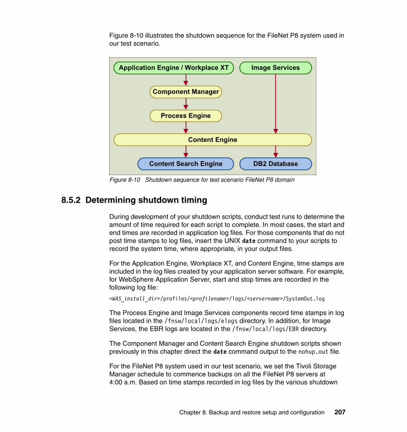
Figure 8-10 illustrates the shutdown sequence for the FileNet P8 system used in our test scenario.
Figure 8-10 Shutdown sequence for test scenario FileNet P8 domain
8.5.2 Determining shutdown timing
During development of your shutdown scripts, conduct test runs to determine the amount of time required for each script to complete. In most cases, the start and end times are recorded in application log files. For those components that do not post time stamps to log files, insert the UNIX date command to your scripts to record the system time, where appropriate, in your output files.
For the Application Engine, Workplace XT, and Content Engine, time stamps are included in the log files created by your application server software. For example, for WebSphere Application Server, start and stop times are recorded in the following log file:
<WAS_install_dir>/profiles/<profilename>/logs/<servername>/SystemOut.log
The Process Engine and Image Services components record time stamps in log files located in the /fnsw/local/logs/elogs directory. In addition, for Image Services, the EBR logs are located in the /fnsw/local/logs/EBR directory.
The Component Manager and Content Search Engine shutdown scripts shown previously in this chapter direct the date command output to the nohup.out file.
For the FileNet P8 system used in our test scenario, we set the Tivoli Storage Manager schedule to commence backups on all the FileNet P8 servers at 4:00 a.m. Based on time stamps recorded in log files by the various shutdown
Application Engine / Workplace XT
Process Engine
Component Manager
Content Engine
Content Search Engine DB2 Database
Image Services
Chapter 8. Backup and restore setup and configuration 207

scripts, the sequence and timings for stopping the FileNet P8 software for a 4:00 a.m. backup is as noted in Table 8-7.
Table 8-7 Shutdown sequence
This schedule is implemented through the following crontab entries. Notice that the su command is used to run each cron job as the appropriate UNIX user.
� Workplace XT server (fnlxtprod):
30 03 * * * su - p8OSusr "-c /opt/scripts/stopXTall.sh" 1>/dev/null 2>&135 03 * * * su - p8OSusr "-c /opt/scripts/stopCM.sh" 1>/dev/null 2>&1
� Image Services server (fnlisprod):
30 03 * * * su - fnsw "-c /EBRdata/scripts/perm_sec_off.sh" 1>/dev/null 2>&1
� Process Engine server (fnlpeprod):
40 03 * * * su - fnsw "-c /fnsw/bin/initfnsw -y stop" 1>/dev/null 2>&1
� Content Engine server (fnlceprod):
45 03 * * * su - p8OSusr "-c /opt/scripts/stopCEall.sh" 1>/dev/null 2>&1
� Content Search Engine server (fnlcseprod):
50 03 * * * su - p8OSusr "-c /opt/scripts/stopk2.sh" 1>/dev/null 2>&1
� DB2 database server (fnldb2prod):
50 03 * * * su - db2inst1 "-c db2 quiesce instance db2inst1 immediate force connections" 2>&1
Note that no crontab entry is used to initiate backups. In the case of Tivoli Storage Manager, backups are managed through the dsmcad daemon as discussed earlier in this chapter. You must, however, review the Tivoli Storage Manager backup logs to determine the length of time required to complete the backups. The Tivoli Storage Manager backup log file is named dsmsched.log,
FileNet P8 Component Stop Time
Workplace XT 3:30 a.m.
Image Services 3:30 a.m.
Component Manager 3:35 a.m.
Process Engine 3:40 a.m.
Content Engine 3:45 a.m.
Content Search Engine 3:50 a.m.
DB2 Database 3:50 a.m.
208 Disaster Recovery and Backup Solutions for IBM FileNet P8 Version 4.5.1 Systems
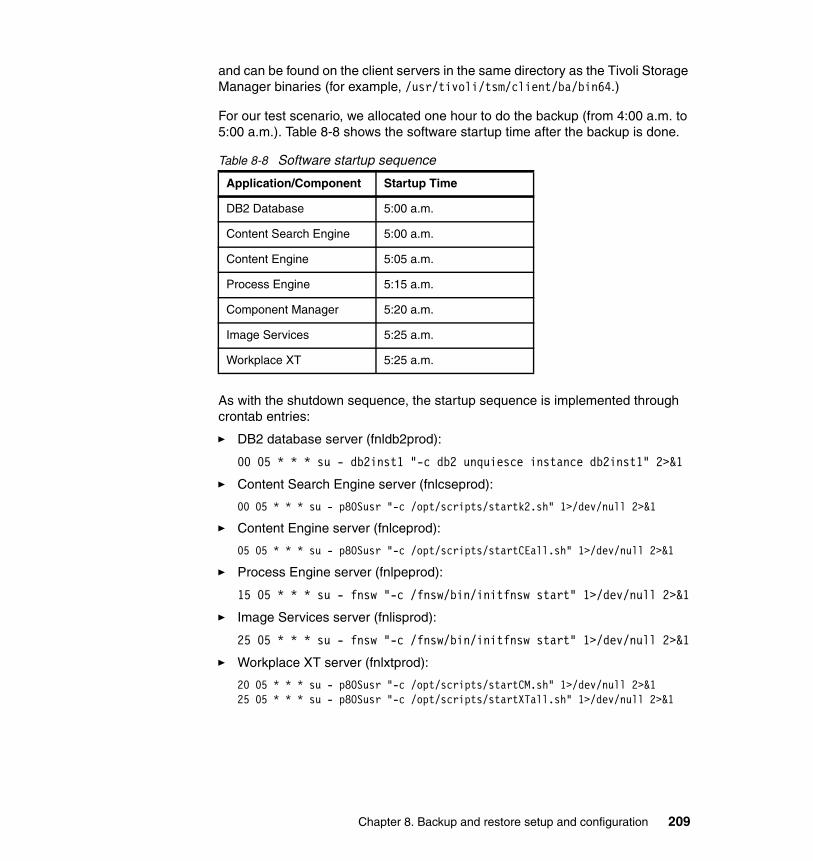
and can be found on the client servers in the same directory as the Tivoli Storage Manager binaries (for example, /usr/tivoli/tsm/client/ba/bin64.)
For our test scenario, we allocated one hour to do the backup (from 4:00 a.m. to 5:00 a.m.). Table 8-8 shows the software startup time after the backup is done.
Table 8-8 Software startup sequence
As with the shutdown sequence, the startup sequence is implemented through crontab entries:
� DB2 database server (fnldb2prod):
00 05 * * * su - db2inst1 "-c db2 unquiesce instance db2inst1" 2>&1
� Content Search Engine server (fnlcseprod):
00 05 * * * su - p8OSusr "-c /opt/scripts/startk2.sh" 1>/dev/null 2>&1
� Content Engine server (fnlceprod):
05 05 * * * su - p8OSusr "-c /opt/scripts/startCEall.sh" 1>/dev/null 2>&1
� Process Engine server (fnlpeprod):
15 05 * * * su - fnsw "-c /fnsw/bin/initfnsw start" 1>/dev/null 2>&1
� Image Services server (fnlisprod):
25 05 * * * su - fnsw "-c /fnsw/bin/initfnsw start" 1>/dev/null 2>&1
� Workplace XT server (fnlxtprod):
20 05 * * * su - p8OSusr "-c /opt/scripts/startCM.sh" 1>/dev/null 2>&125 05 * * * su - p8OSusr "-c /opt/scripts/startXTall.sh" 1>/dev/null 2>&1
Application/Component Startup Time
DB2 Database 5:00 a.m.
Content Search Engine 5:00 a.m.
Content Engine 5:05 a.m.
Process Engine 5:15 a.m.
Component Manager 5:20 a.m.
Image Services 5:25 a.m.
Workplace XT 5:25 a.m.
Chapter 8. Backup and restore setup and configuration 209

8.5.3 Additional backup considerations
As mentioned previously in this chapter, back up your system software using a tool similar to the AIX mksysb command. However, be aware that mksysb backs up only the root volume group (rootvg). Information residing on other volume groups such as datavg or NAS devices, is not included in the mksysb backup. Usually this data is backed up using the vendor file-based backup utility such as Tivoli Storage Manager.
If you have a hardware failure such as the loss of a disk drive, you might be required to re-create the data volume group and its associated logical volumes and file systems prior to restoring your data to this location. Therefore, be sure you maintain system documentation that includes the information you might need to re-create these objects. To accomplish this task, run system documentation scripts on a routine basis to collect the information required.
System documentationThe script in Example 8-20 shows commands that can be used to gather information about your file systems and volume groups and output the results to a text file.
Example 8-20 Sample system documentation script
#!/bin/ksh## Script to collect configuration information on fnlcseprod## Script name: system_doc.sh## This script should be run as the root user#SYSTEM_DOC="/backups/system/fnlcseprod_system.doc"date > $SYSTEM_DOCecho " " >> $SYSTEM_DOC
### List Software Versionecho "***** uname -a *****" >> $SYSTEM_DOCuname -a >> $SYSTEM_DOCecho " " >> $SYSTEM_DOCecho "***** oslevel -sq *****" >> $SYSTEM_DOCoslevel -sq >> $SYSTEM_DOCecho " " >> $SYSTEM_DOC
### Check File System Utilizationecho "***** File System Utilization *****" >> $SYSTEM_DOCdf -m >> $SYSTEM_DOCecho " " >> $SYSTEM_DOC
210 Disaster Recovery and Backup Solutions for IBM FileNet P8 Version 4.5.1 Systems

### List Physical Volumesecho "***** Physical Volume Information *****" >> $SYSTEM_DOCecho " " >> $SYSTEM_DOClspv | while read HDISKdo echo "******" >> $SYSTEM_DOC echo ${HDISK} >> $SYSTEM_DOC echo "******" >> $SYSTEM_DOC lspv ${HDISK} >> $SYSTEM_DOC lspv -l ${HDISK} >> $SYSTEM_DOC echo " " >>$SYSTEM_DOCdone
### List Volume Groupsecho "***** Volume Group Information *****" >> $SYSTEM_DOCecho " " >> $SYSTEM_DOClsvg | while read VGNAMEdo echo "******" >> $SYSTEM_DOC echo ${VGNAME} >> $SYSTEM_DOC echo "******" >> $SYSTEM_DOC lsvg ${VGNAME} >> $SYSTEM_DOC lsvg -l ${VGNAME} >> $SYSTEM_DOC echo " " >> $SYSTEM_DOCdone
Execute your system documentation script daily. Direct the output from your system documentation script to a file system located on the root volume group. If you are faced with a full system recovery, you would be able to restore the rootvg through a mksysb backup, then access the information contained in this output file to rebuild your data volume group. Example 8-21 shows sample output from the system documentation script.
Example 8-21 Sample system documentation
Mon Nov 16 23:00:00 EST 2009 ***** uname -a *****AIX fnlcseprod 1 6 00C7CD9E4C00 ***** oslevel -sq *****6100-02-01-08476100-01-03-08466100-01-02-08346100-01-01-08236100-01-00-00006100-00-07-0846
Chapter 8. Backup and restore setup and configuration 211

6100-00-06-08346100-00-05-08226100-00-04-08156100-00-03-08086100-00-02-07506100-00-01-0748 ***** File System Utilization *****Filesystem MB blocks Free %Used Iused %Iused Mounted on/dev/hd4 512.00 310.68 40% 12392 15% //dev/hd2 1856.00 50.73 98% 34733 70% /usr/dev/hd9var 128.00 53.65 59% 4557 27% /var/dev/hd3 2048.00 2036.86 1% 77 1% /tmp/dev/hd1 64.00 63.58 1% 25 1% /home/dev/hd11admin 128.00 127.64 1% 5 1% /admin/proc - - - - - /proc/dev/hd10opt 2048.00 1889.09 8% 2791 1% /opt/dev/livedump 256.00 255.64 1% 4 1% /var/adm/ras/livedump/dev/download_lv 4096.00 824.34 80% 64 1% /download/dev/tsmjrnlv 1024.00 1017.31 1% 14 1% /tsmjournal/dev/k2datalv 10112.00 10022.93 1% 146 1% /k2Collections/dev/k2veritylv 2048.00 1047.28 49% 17485 7% /k2verity192.168.100.114:/p8data 161792.00 145465.86 11% 2539287 42% /p8data ***** Physical Volume Information ***** ******hdisk0 00c7cd9e81b6528a rootvg active******PHYSICAL VOLUME: hdisk0 VOLUME GROUP: rootvgPV IDENTIFIER: 00c7cd9e81b6528a VG IDENTIFIER 00c7cd9e00004c000000012381b65458PV STATE: active STALE PARTITIONS: 0 ALLOCATABLE: yesPP SIZE: 64 megabyte(s) LOGICAL VOLUMES: 14TOTAL PPs: 559 (35776 megabytes) VG DESCRIPTORS: 2FREE PPs: 257 (16448 megabytes) HOT SPARE: noUSED PPs: 302 (19328 megabytes) MAX REQUEST: 256 kilobytesFREE DISTRIBUTION: 79..00..00..66..112 USED DISTRIBUTION: 33..112..111..46..00 MIRROR POOL: None hdisk0:LV NAME LPs PPs DISTRIBUTION MOUNT POINThd4 8 8 00..00..03..05..00 /hd2 29 29 00..00..27..02..00 /usrhd6 94 94 00..44..50..00..00 N/Ahd8 1 1 00..00..01..00..00 N/Ahd1 1 1 00..00..01..00..00 /homehd10opt 32 32 00..00..03..29..00 /opt
212 Disaster Recovery and Backup Solutions for IBM FileNet P8 Version 4.5.1 Systems

hd9var 2 2 00..00..02..00..00 /varhd3 32 32 00..00..22..10..00 /tmphd5 1 1 01..00..00..00..00 N/Ahd11admin 2 2 00..00..02..00..00 /adminlivedump 4 4 00..04..00..00..00 /var/adm/ras/livedumplg_dumplv 16 16 00..16..00..00..00 N/Atsmjrnlv 16 16 16..00..00..00..00 /tsmjournaldownload_lv 64 64 16..48..00..00..00 /download ******hdisk1 00c7cd9e84300dcb datavg active******PHYSICAL VOLUME: hdisk1 VOLUME GROUP: datavgPV IDENTIFIER: 00c7cd9e84300dcb VG IDENTIFIER 00c7cd9e00004c00000001248796b51fPV STATE: active STALE PARTITIONS: 0 ALLOCATABLE: yesPP SIZE: 64 megabyte(s) LOGICAL VOLUMES: 3TOTAL PPs: 191 (12224 megabytes) VG DESCRIPTORS: 2FREE PPs: 0 (0 megabytes) HOT SPARE: noUSED PPs: 191 (12224 megabytes) MAX REQUEST: 256 kilobytesFREE DISTRIBUTION: 00..00..00..00..00 USED DISTRIBUTION: 39..38..38..38..38 MIRROR POOL: None hdisk1:LV NAME LPs PPs DISTRIBUTION MOUNT POINTloglv00 1 1 00..00..00..00..01 N/Ak2veritylv 32 32 00..00..00..00..32 /k2verityk2datalv 158 158 39..38..38..38..05 /k2Collections ***** Volume Group Information ***** ******rootvg******VOLUME GROUP: rootvg VG IDENTIFIER: 00c7cd9e00004c000000012381b65458VG STATE: active PP SIZE: 64 megabyte(s)VG PERMISSION: read/write TOTAL PPs: 559 (35776 megabytes)MAX LVs: 256 FREE PPs: 257 (16448 megabytes)LVs: 14 USED PPs: 302 (19328 megabytes)OPEN LVs: 13 QUORUM: 2 (Enabled)TOTAL PVs: 1 VG DESCRIPTORS: 2STALE PVs: 0 STALE PPs: 0ACTIVE PVs: 1 AUTO ON: yes
Chapter 8. Backup and restore setup and configuration 213

MAX PPs per VG: 32512 MAX PPs per PV: 1016 MAX PVs: 32LTG size (Dynamic): 256 kilobyte(s) AUTO SYNC: noHOT SPARE: no BB POLICY: relocatable rootvg:LV NAME TYPE LPs PPs PVs LV STATE MOUNT POINThd5 boot 1 1 1 closed/syncd N/Ahd6 paging 94 94 1 open/syncd N/Ahd8 jfs2log 1 1 1 open/syncd N/Ahd4 jfs2 8 8 1 open/syncd /hd2 jfs2 29 29 1 open/syncd /usrhd9var jfs2 2 2 1 open/syncd /varhd3 jfs2 32 32 1 open/syncd /tmphd1 jfs2 1 1 1 open/syncd /homehd10opt jfs2 32 32 1 open/syncd /opthd11admin jfs2 2 2 1 open/syncd /adminlg_dumplv sysdump 16 16 1 open/syncd N/Alivedump jfs2 4 4 1 open/syncd /var/adm/ras/livedumpdownload_lv jfs2 64 64 1 open/syncd /downloadtsmjrnlv jfs2 16 16 1 open/syncd /tsmjournal ******datavg******VOLUME GROUP: datavg VG IDENTIFIER: 00c7cd9e00004c00000001248796b51fVG STATE: active PP SIZE: 64 megabyte(s)VG PERMISSION: read/write TOTAL PPs: 191 (12224 megabytes)MAX LVs: 256 FREE PPs: 0 (0 megabytes)LVs: 3 USED PPs: 191 (12224 megabytes)OPEN LVs: 3 QUORUM: 2 (Enabled)TOTAL PVs: 1 VG DESCRIPTORS: 2STALE PVs: 0 STALE PPs: 0ACTIVE PVs: 1 AUTO ON: yesMAX PPs per VG: 32512 MAX PPs per PV: 1016 MAX PVs: 32LTG size (Dynamic): 256 kilobyte(s) AUTO SYNC: noHOT SPARE: no BB POLICY: relocatable datavg:LV NAME TYPE LPs PPs PVs LV STATE MOUNT POINTk2datalv jfs2 158 158 1 open/syncd /k2Collectionsk2veritylv jfs2 32 32 1 open/syncd /k2verityloglv00 jfs2log 1 1 1 open/syncd N/A
214 Disaster Recovery and Backup Solutions for IBM FileNet P8 Version 4.5.1 Systems

Backup WebSphere profilesAn optional step you may want to consider including in your backup strategy, is to back up your application server profiles used in your FileNet P8 configuration. For IBM WebSphere, this task is accomplished by using the manageprofiles.sh command. A sample script for backing up the deployment manager profile for our test configuration is shown in Example 8-22.
Example 8-22 Deployment manager profile backup script
#!/bin/ksh## Script to backup the WebSphere profile p8dmgr01 on fnlceprod## Script name: backup_p8dmgr01.sh## This script should be run as the WAS owner (root).# Stop WebSphere using the stopCEall.sh script prior to backing up the profile.#
rm /backups/profiles/fnlceprod_p8dmgr01.zip
echo "Backing up profile p8dmgr01 . . ."/opt/IBM/WebSphere/AppServer/bin/manageprofiles.sh \-backupProfile \-profileName p8dmgr01 \-backupFile /backups/profiles/fnlceprod_p8dmgr01.zip \-username p8AdminUser \-password itso13sj
Chapter 8. Backup and restore setup and configuration 215

Example 8-23 shows a script for backing up the Content Engine application server profile.
Example 8-23 Application server profile backup script
#!/bin/ksh## Script to backup the WebSphere profile p8AppSrv01 on fnlceprod## Script name: backup_p8AppSrv01.sh## This script should be run as the WAS owner (root).# Stop WebSphere using the stopCEall.sh script prior to backing up the profile.#
rm /backups/profiles/fnlceprod_p8AppSrv01.zip
echo "Backing up profile p8AppSrv01 . . ."/opt/IBM/WebSphere/AppServer/bin/manageprofiles.sh \-backupProfile \-profileName p8AppSrv01 \-backupFile /backups/profiles/fnlceprod_p8AppSrv01.zip \-username p8AdminUser \-password itso13sj
8.6 Restore procedure for FileNet P8
It is important to remember that you must restore data for all FileNet P8 components from a particular point in time to maintain data consistency. For example, if you restore the database files on your DB2 server, you must also restore your file storage area files from the same backup. Even if there was no loss of file storage area data, you must still perform the restore operation to ensure the object store metadata in the DB2 databases is consistent with the object store files in the file storage areas.
In the restore scenario that follows, assume the root volume group (rootvg) on each server has been restored from a mksysb backup. This section will focus on the steps required to restore the data volume group from a Tivoli Storage Manager file level backup.
216 Disaster Recovery and Backup Solutions for IBM FileNet P8 Version 4.5.1 Systems

8.6.1 Re-creating volumes and file system configuration
If necessary, use your operating system administrative tools (such as smit on AIX) to re-create any volume manager objects that are missing. To assist in this task, see the output from your system documentation script described in the previous section. Example 8-24 shows the portion of the system documentation output that pertains to the data volume group (datavg) on the fnlcseprod server.
Example 8-24 System documentation for datavg on fnlcseprod
******datavg******VOLUME GROUP: datavg VG IDENTIFIER: 00c7cd9e00004c00000001248796b51fVG STATE: active PP SIZE: 64 megabyte(s)VG PERMISSION: read/write TOTAL PPs: 191 (12224 megabytes)MAX LVs: 256 FREE PPs: 0 (0 megabytes)LVs: 3 USED PPs: 191 (12224 megabytes)OPEN LVs: 3 QUORUM: 2 (Enabled)TOTAL PVs: 1 VG DESCRIPTORS: 2STALE PVs: 0 STALE PPs: 0ACTIVE PVs: 1 AUTO ON: yesMAX PPs per VG: 32512 MAX PPs per PV: 1016 MAX PVs: 32LTG size (Dynamic): 256 kilobyte(s) AUTO SYNC: noHOT SPARE: no BB POLICY: relocatable datavg:LV NAME TYPE LPs PPs PVs LV STATE MOUNT POINTk2datalv jfs2 158 158 1 open/syncd /k2Collectionsk2veritylv jfs2 32 32 1 open/syncd /k2verityloglv00 jfs2log 1 1 1 open/syncd N/A
Using this information from the Content Search Engine as an example, use the following steps to re-create the data volume group and file systems:
1. Create a volume group named datavg, using a physical partition size (PP SIZE) of 64 MB.
2. Create a logical volume named k2datalv. Set the logical volume type to jfs2, and assign 158 physical partitions to the volume.
3. Create a logical volume named k2veritylv. Set the logical volume type to jfs2, and assign 32 physical partitions.
4. Create an enhanced journaled file system (jfs2) with mount point /k2Collections on the previously defined logical volume k2datalv.
5. Create an enhanced journaled file system (jfs2) with mount point /k2verity on the previously defined logical volume k2veritylv.
6. Mount the /k2Collections and /k2verity file systems.
Chapter 8. Backup and restore setup and configuration 217

8.6.2 Restoring data files using Tivoli Storage Manager
After re-creating your file systems, you are ready to restore your data files using Tivoli Storage Manager client. To restore the DB2 database instance on the DB2 server, fnldb2prod, perform the following steps:
1. Log in to the DB2 database server as the root user. Verify that the Tivoli Storage Manager daemons (dsmcad and tsmjbbd) are running. Make sure that your DISPLAY variable has been exported to your workstation. Change directory to the location of the Tivoli Storage Manager binaries and launch the Tivoli Storage Manager client application (dsmj):
cd /usr/tivoli/tsm/client/ba/bin64./dsmj
The Tivoli Storage Manager interface is as shown Figure 8-11.
2. Click the link for Restore (Restores saved files from server storage).
Figure 8-11 Tivoli Storage Manager client interface
218 Disaster Recovery and Backup Solutions for IBM FileNet P8 Version 4.5.1 Systems

3. Browse to the File Level node and select the files you want to restore. See Figure 8-12.
Figure 8-12 Select files for restore
4. After you select the files to restore, click Restore.
5. Monitor the progress in the Task List window, shown in Figure 8-13 on page 220.
Chapter 8. Backup and restore setup and configuration 219

Figure 8-13 Restore task list
When restoration is complete, Tivoli Storage Manager displays a status report. See Figure 8-14.
Figure 8-14 Restore status report
6. Close the status report window and exit the Tivoli Storage Manager client application.
7. Repeat the restore process on all FileNet P8 servers as required to maintain data consistency.
8.6.3 Restoring Image Services raw data
Image Services stores data for the MKF databases and cache in raw data partitions. As noted in “Backing up Image Services raw data” on page 203, the
220 Disaster Recovery and Backup Solutions for IBM FileNet P8 Version 4.5.1 Systems
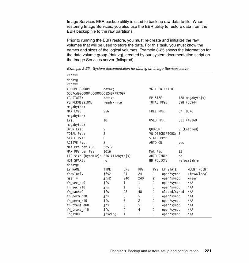
Image Services EBR backup utility is used to back up raw data to file. When restoring Image Services, you also use the EBR utility to restore data from the EBR backup file to the raw partitions.
Prior to running the EBR restore, you must re-create and initialize the raw volumes that will be used to store the data. For this task, you must know the names and sizes of the logical volumes. Example 8-25 shows the information for the data volume group (datavg), created by our system documentation script on the Image Services server (fnlisprod).
Example 8-25 System documentation for datavg on Image Services server
******datavg******VOLUME GROUP: datavg VG IDENTIFIER: 00c7cd9e00004c000000012487797097VG STATE: active PP SIZE: 128 megabyte(s)VG PERMISSION: read/write TOTAL PPs: 398 (50944 megabytes)MAX LVs: 256 FREE PPs: 67 (8576 megabytes)LVs: 10 USED PPs: 331 (42368 megabytes)OPEN LVs: 9 QUORUM: 2 (Enabled)TOTAL PVs: 2 VG DESCRIPTORS: 3STALE PVs: 0 STALE PPs: 0ACTIVE PVs: 2 AUTO ON: yesMAX PPs per VG: 32512 MAX PPs per PV: 1016 MAX PVs: 32LTG size (Dynamic): 256 kilobyte(s) AUTO SYNC: noHOT SPARE: no BB POLICY: relocatable datavg:LV NAME TYPE LPs PPs PVs LV STATE MOUNT POINTfnswloclv jfs2 24 24 1 open/syncd /fnsw/localmsarlv jfs2 240 240 2 open/syncd /msarfn_sec_db0 jfs 1 1 1 open/syncd N/Afn_sec_rl0 jfs 1 1 1 open/syncd N/Afn_cache0 jfs 48 48 1 closed/syncd N/Afn_perm_db0 jfs 5 5 1 open/syncd N/Afn_perm_rl0 jfs 2 2 1 open/syncd N/Afn_trans_db0 jfs 5 5 1 open/syncd N/Afn_trans_rl0 jfs 4 4 1 open/syncd N/Aloglv00 jfs2log 1 1 1 open/syncd N/A
Chapter 8. Backup and restore setup and configuration 221

The following procedure restores the Permanent and Security databases from the EBR backup file. The Transient database and cache are only re-initialized, not restored.
1. If necessary, create the datavg volume group, using a physical partition size (PP SIZE) of 128 MB.
2. Create the logical volumes based on the information from the system documentation shown in Example 8-25 on page 221. For this scenario, Table 8-9 lists the logical volumes you create in datavg.
Table 8-9 Logical volume parameters for raw data partitions
3. Change ownership on the logical volumes to the FileNet system user and group, for example:
cd /devchown fnsw:fnusr fn_*chown fnsw:fnusr rfn_*
Your file permissions are similar to those in Example 8-26.
Example 8-26 File permissions for raw data logical volumes
fnlisprod(root)/dev> ls -al *fn_*brw-rw---- 1 fnsw fnusr 36, 5 Oct 24 13:06 fn_cache0brw-rw---- 1 fnsw fnusr 36, 6 Oct 24 13:06 fn_perm_db0brw-rw---- 1 fnsw fnusr 36, 7 Oct 24 13:07 fn_perm_rl0brw-rw---- 1 fnsw fnusr 36, 3 Oct 24 13:05 fn_sec_db0brw-rw---- 1 fnsw fnusr 36, 4 Oct 24 13:05 fn_sec_rl0brw-rw---- 1 fnsw fnusr 36, 8 Oct 24 13:08 fn_trans_db0brw-rw---- 1 fnsw fnusr 36, 9 Oct 24 13:08 fn_trans_rl0crw-rw---- 1 fnsw fnusr 36, 5 Oct 24 13:06 rfn_cache0crw-rw---- 1 fnsw fnusr 36, 6 Oct 24 13:06 rfn_perm_db0crw-rw---- 1 fnsw fnusr 36, 7 Oct 24 13:07 rfn_perm_rl0crw-rw---- 1 fnsw fnusr 36, 3 Oct 24 13:05 rfn_sec_db0
LV NAME TYPE PPs
fn_sec_db0 jfs 1
fn_sec_rl0 jfs 1
fn_cache0 jfs 48
fn_perm_db0 jfs 5
fn_perm_rl0 jfs 2
fn_trans_db0 jfs 5
fn_trans_rl0 jfs 4
222 Disaster Recovery and Backup Solutions for IBM FileNet P8 Version 4.5.1 Systems

crw-rw---- 1 fnsw fnusr 36, 4 Oct 24 13:05 rfn_sec_rl0crw-rw---- 1 fnsw fnusr 36, 8 Oct 24 13:08 rfn_trans_db0crw-rw---- 1 fnsw fnusr 36, 9 Oct 24 13:08 rfn_trans_rl0fnlisprod(root)/dev>
4. Create the links to the raw data partitions. Log in as the FileNet software user, for example user fnsw. Change to the /fnsw/dev/1 directory:
cd /fnsw/dev/1
5. Run the following link commands. (Note, these link commands can be entered into a script.)
ln -s /dev/rfn_cache0 cache0ln -s /dev/rfn_perm_db0 permanent_db0ln -s /dev/rfn_perm_rl0 permanent_rl0ln -s /dev/rfn_trans_db0 transient_db0ln -s /dev/rfn_trans_rl0 transient_rl0ln -s /dev/rfn_sec_db0 sec_db0ln -s /dev/rfn_sec_rl0 sec_rl0
File permissions for the links in the /fnsw/dev/1 directory are similar to those in Example 8-27.
Example 8-27 File permissions for /fnsw/dev/1 links
lrwxrwxrwx 1 fnsw fnusr 15 Oct 03 17:10 cache0@ -> /dev/rfn_cache0lrwxrwxrwx 1 fnsw fnusr 17 Oct 03 17:10 permanent_db0@ -> /dev/rfn_perm_db0lrwxrwxrwx 1 fnsw fnusr 17 Oct 03 17:10 permanent_rl0@ -> /dev/rfn_perm_rl0lrwxrwxrwx 1 fnsw fnusr 16 Oct 03 17:10 sec_db0@ -> /dev/rfn_sec_db0lrwxrwxrwx 1 fnsw fnusr 16 Oct 03 17:10 sec_rl0@ -> /dev/rfn_sec_rl0lrwxrwxrwx 1 fnsw fnusr 18 Oct 03 17:10 transient_db0@ -> /dev/rfn_trans_db0lrwxrwxrwx 1 fnsw fnusr 18 Oct 03 17:10 transient_rl0@ -> /dev/rfn_trans_rl0
6. Verify that you are logged in as user fnsw and initialize the MKF databases:
MKF_ddl /fnsw/local/sd/1/transient.ddl -initializeMKF_ddl /fnsw/local/sd/1/permanent.ddl -initializeMKF_ddl /fnsw/local/sd/1/sec.ddl -initialize
7. Initialize cache by using the following command:
fn_util inittrans
8. Restore the Permanent and Security databases from the EBR backup files. To run the restore operation, first put the FileNet software in backup mode by using the following command:
initfnsw -y backup
Chapter 8. Backup and restore setup and configuration 223

Next, issue the EBR command, referencing the name of your restore script, for example:
EBR @/EBRdata/scripts/perm_sec_res.ebr
A copy of the EBR restore script is shown in Example 8-28.
Example 8-28 EBR restore script for Permanent and Security databases
EBR_script (format_level = 2;);
RESTORE_GLOBAL_PARAMETERS volume_group = VG1; -- tape volume group nameEND_RESTORE_GLOBAL_PARAMETERS
DATASETS sec: MKF location = "fnlisv:FileNet"; -- hostname of Security database base_data_file = "/fnsw/dev/1/sec_db0"; end_MKF
perm: MKF location = "fnlisv:FileNet"; -- hostname of Permanent database base_data_file = "/fnsw/dev/1/permanent_db0"; end_MKF
END_DATASETS
DEVICE_SPECIFICATIONS
perm1 : disk_file location = "fnlisv:FileNet"; filename = "/EBRdata/Backups/perm1-ebr.dat"; end_disk_file perm2 : disk_file location = "fnlisv:FileNet"; filename = "/EBRdata/Backups/perm2-ebr.dat"; end_disk_file
sec : disk_file location = "fnlisv:FileNet"; filename = "/EBRdata/Backups/sec-ebr.dat"; end_disk_file
END_DEVICE_SPECIFICATIONS
RESTORE_OPTIONS sec: restore_options
224 Disaster Recovery and Backup Solutions for IBM FileNet P8 Version 4.5.1 Systems

full_restore; interval_restore_follows = false; end_restore_options
perm: restore_options full_restore; interval_restore_follows = false; end_restore_options
END_RESTORE_OPTIONS
THREADS
num_threads = 3;
thread 1 device = perm1; volume_serial = R1; -- tape serial number datasets perm (part 1 of 2); end_thread
thread 2 device = perm2; volume_serial = R2; -- tape serial number datasets perm (part 2 of 2); end_thread
thread 3 device = sec; volume_serial = R3; datasets sec; end_thread
END_THREADS
9. If your restore operation included restoring the Permanent database, you may have to update the scalar numbers table (SNT) in the Permanent database so that it is synchronized with the checkpoint file, snt.chkpt, located in the /fnsw/local/sd directory. To update this table, run the following command:
/fnsw/bin/SNT_update
For full details about how to run the SNT_update tool, see the Image Services System Tools Reference Manual, CG31-5612.
Chapter 8. Backup and restore setup and configuration 225

8.6.4 Testing and validating the system
After restoring the data, start the FileNet P8 application in the correct sequence. Review log files for each component carefully to make sure the system is running in a stable state.
Perform consistency checks of your data to verify that the system is in a stable and consistent state. See the guidelines documented in Chapter 10, “System testing and validation” on page 263 for information about running consistency checks on your restored data.
226 Disaster Recovery and Backup Solutions for IBM FileNet P8 Version 4.5.1 Systems

Chapter 9. Disaster recovery setup and configuration
This chapter describes the setup and configuration of a standby IBM FileNet P8 Version 4.5.1 system for disaster recovery. The procedures provided in this chapter outline the steps to configure the lab environment for the disaster recovery (DR) case study described in 7.1.2, “Case study II: Recovery using standby disaster recovery site” on page 146.
This chapter contains the following topics:
� Planning considerations for a DR site
� Overview of FileNet P8 lab environment for DR
� Software configuration
� Verifying the DR installation
� Enabling PROD to DR replication
� Activating the DR site
� Maintaining the DR site
9
© Copyright IBM Corp. 2010. All rights reserved. 227

9.1 Planning considerations for a DR site
Review the following considerations when you prepare to build a DR environment:
� Hardware configuration
The hardware used for the DR site does not have to match the exact make and model of that used for PROD, but must support the same versions of the operating system software. In addition, you must ensure that the storage devices used for SAN/NAS replication is compatible. The hardware configuration for the PROD site used in our case study is described in Figure 7-1 on page 148. The hardware configuration for the DR site is shown in Figure 9-1 on page 230.
� Software configuration
The DR system must be configured with identical versions of software as that used in the PROD environment. If patches or hotfixes are applied to the PROD site, they must be applied to the DR system also. A good practice is to run the installers for each of the FileNet P8 component on the DR servers. Steps for installing and configuring the software for the DR site is covered in 9.3.4, “Software configuration for DR” on page 244.
� Network configuration
During the initial installation and configuration of the Content Engine and the Process Engine for the DR site, you need access to the PROD databases. Therefore, the network must be configured to allow the DR servers to connect to the PROD database server. This configuration is only required during the initial setup of the DR servers so that GCD and Process Engine databases are properly updated with DR servers information.
� Name resolution
The PROD environment uses virtual host names where possible. Use the same virtual host names when installing and configuring the DR site. See 7.2.3, “DNS and host table entries” on page 150 for more information about managing DNS or /etc/hosts entries in the PROD and DR environments. By using virtual host names in the configuration, minimal intervention is required to bring up the DR site.
� Storage replication
The storage configuration for the PROD and DR sites is described in 7.2.2, “Storage configuration” on page 149. For our case study, we use block-level replication of the LUNs, configured on the PROD storage device to the matching LUNs on the DR storage device. Be sure that the LUNs on the DR storage device are the same size as the corresponding LUNs in the PROD environment. A good practice is to keep the LUN sizes in the range of
228 Disaster Recovery and Backup Solutions for IBM FileNet P8 Version 4.5.1 Systems

20 - 50 GBs. For example, if you want to replicate a 100 GB file system, it is more efficient to create five 20 GB LUNs and replicate them, rather than a single 100 GB LUN.
� File systems and mount points
Build your DR file systems using the same logical mount points as used in PROD. For example, if the file storage area location on PROD is /p8data/FileStores, be sure that the same directory path is available on the DR site.
� Users and groups
To avoid permission issues, make sure the UNIX users and groups in DR have the same user ID (uid) and group ID (gid) as those found in PROD. Also, if you replicate LDAP users and groups from the PROD directory services to DR, make sure that the GUID for those accounts are properly replicated on the DR site.
9.2 Overview of FileNet P8 lab environment for DR
The hardware configuration for PROD is described in Chapter 7, “Case study description and system setup” on page 145.
The hardware configuration for the DR system is described in the remaining sections of this chapter.
9.2.1 Disaster recovery lab environment hardware
The hardware environment for the FileNet P8 DR environment is similar to that used in the PROD environment (see Figure 7-1 on page 148.) The DR system, however, uses two IBM Model 9117-MMA POWER6® servers, as shown in Figure 9-1 on page 230.
The LPARs for the DR system are distributed as follows:
� Server #1: IBM Model 9117-MMA POWER6
– Virtual I/O (VIO) server
– Tivoli Directory Service server
– DB2 Database (DB2) server
– Process Engine (PE) server
– Content Engine (CE) server
Chapter 9. Disaster recovery setup and configuration 229

� Server #2: IBM Model 9117-MMA POWER6
– Virtual I/O (VIO) server
– Image Services (IS) server
– Workplace XT (XT) server
– Content Search Engine server
– Tivoli Storage Manager server
Figure 9-1 System architecture for DR environment
LPAR1Virtual I/O Server
FNLVIO2DR
LPAR3Database Server
FNLDB2DR
LPAR2Tivoli Directory Server
FNLTDSDR
LPAR5Content Engine Server
FNLCEDR
LPAR4Process Engine Server
FNLPEDR
LPAR3Workplace XT Server
FNLXTDR
LPAR4Content Search Engine
FNLCSEDR
LPAR2Image Services Server
FNLISDR
SAN LUN FNLDB2DR(Databases)
SAN LUN FNLISDR
(Config files, MSAR)
SAN LUN FNLXTDR
(Config files)
SAN LUN FNLCSEDR
(K2 app, K2Collections)
NAS LUN FNLCEDR(FileStores)
NAS LUN FNLCSEDR(K2 temp)
IBM 9117-MMA POWER6 Server
IBM System Storage
DS4500
SAN Switch
NAS Gateway
Disaster Recovery Environment
LPAR5Tivoli Storage Manager
FNLTSMDR
LPAR1Virtual I/O Server
FNLVIO3DR
IBM 9117-MMA POWER6 Server
Tape Library
NF
S M
ounts
NFS Mounts
230 Disaster Recovery and Backup Solutions for IBM FileNet P8 Version 4.5.1 Systems

Configure the LPARs for the DR system with host names that use the suffix “DR”, such as FNLCEDR.
Although the PROD system uses an IBM System Storage DS4800 device for storage, the DR site uses an IBM System Storage DS4500. The LUN assignments for the DR site are the same type (SAN or NAS) and size as those defined for the PROD environment.
Storage for the DR system is provided by an IBM System Storage DS4500 device. For our system, LUNs for SAN storage on the DS4500 are assigned to the LPARs as show in Table 9-1.
Table 9-1 DR SAN LUN assignments for the DS4500
For our DR environment, the NAS LUNs are located on the DS4500, and are managed by an IBM System Storage N-Series N5200 Gateway. Similar to PROD, file systems on NAS are presented to the LPARs though NFS mounts. The NAS LUN assignments for the DR system are shown in Table 9-2.
Table 9-2 DR NAS LUN assignments for the DS4800
9.2.2 Storage configuration for DR
For the purpose of the installation you must create the volume groups, logical volumes, and file system mount points on the DR servers to match those on the PROD environment. For the disaster recovery case study covered in this book, we use identical names for the volume groups, logical volumes and mount points on the DR and PROD systems.
LPAR assignment Type of data on SAN storage
FNLDB2DR DB2 database instance files
FNLISDR Image Services configuration files; MSAR files
FNLXTDR Workplace XT configuration files
FNLCSEDR Autonomy K2a application files; K2 collections (indexes)
a. Autonomy materials reprinted with permission from Autonomy Corp.
LPAR assignments (through NFS mounts) Type of data on NAS
FNLCSEDR K2 temporary files
FNLCEDR File storage area files
Chapter 9. Disaster recovery setup and configuration 231

Each DR LPAR must have a root volume group (rootvg) consisting of local disks for the operating system and application binary files. Make the DR root volume groups similar in size to those configured for PROD.
Create the data volume group (datavg) on the DR LPARs, using the LUNs defined for SAN on the DS4500 system storage. Because the data stored on the DS4500 in the DR environment is a replica of the PROD data (see Figure 7-2 on page 150,) the LUNs defined on the DS4500 in DR must be the same size as those defined on the DS4800 in PROD.
Create the NFS mounts for the NAS file systems residing on the DR storage (DS4500), using the same options and security configured in the PROD environment. Make sure the DR NFS mounts point to the replicas of the PROD data, not to the actual data on PROD.
9.2.3 DNS and host table setup
Edit the /etc/hosts file on the DR servers to resolve the virtual host names to the DR server host names as shown in Figure 9-2.
Figure 9-2 Sample /etc/hosts file for the DR environment
Note: Do not turn on global mirroring/replication from the PROD system to the DR system until after the DR installation is complete. For the purpose of the installation, the mount points must be available on the DR servers, but contain no data.
192.168.100.216 fnldb2prod192.168.100.217 fnltdsprod192.168.100.218 fnlceprod192.168.100.219 fnlisprod192.168.100.220 fnlcseprod192.168.100.221 fnlxtprod192.168.100.222 fnlpeprod192.168.100.223 fnltsmprod10.0.200.216 fnldb2dr fnldb2v10.0.200.217 fnltdsdr fnltdsv10.0.200.218 fnlcedr fnlcev10.0.200.219 fnlisdr fnlisv fnlisv-filenet-nch-server10.0.200.220 fnlcsedr fnlcsev10.0.200.221 fnlxtdr fnlxtv10.0.200.222 fnlpedr fnlpev10.0.200.223 fnltsmdr fnltsmv
232 Disaster Recovery and Backup Solutions for IBM FileNet P8 Version 4.5.1 Systems

9.2.4 User and group configuration for DR
For UNIX environments, create the operating system users and groups on the DR server similar to the existing users and groups on the PROD environment. Be careful to match user IDs and group IDs on the two systems. Figure 9-3 compares the ID values for the UNIX user p8OSusr on the PROD Content Engine with that on the DR Content Engine. Note that the user ID (2001) and group ID (2000) is the same on both Content Engine servers.
Figure 9-3 User and group ID values for user p8OSusr
9.3 Software configuration
The versions of software for both the PROD and DR systems are as follows:
� IBM AIX v6.1 TL2 64-bit
� IBM Tivoli Directory Services v6.1
� IBM Tivoli Storage Manager Server v6.1 64-bit
� IBM Tivoli Storage Manager Client v6.1 64-bit
� IBM DB2 Server v9.7 64-bit
� IBM WebSphere Application Server v7.0.0.5 64-bit Network Deployment
� IBM FileNet Content Engine v4.5.1
� IBM FileNet Process Engine v4.5.1
� IBM FileNet Workplace XT v1.1.4.1
� IBM FileNet Content Search Engine v4.5.1
� IBM FileNet Image Services v4.1.2.4
� IBM FileNet High Performance Image Import v4.1.2
In this section, we present high-level information and guidelines for configuring FileNet P8 software on DR systems that use data replication from a primary PROD site.
p8OSusr@fnlceprod /home/p8OSusr > id p8OSusruid=2001(p8OSusr) gid=2000(p8OSgrp) groups=1(staff)
p8OSusr@fnlcedr /home/p8OSusr > id p8OSusruid=2001(p8OSusr) gid=2000(p8OSgrp) groups=1(staff)
Chapter 9. Disaster recovery setup and configuration 233

9.3.1 DB2 configuration for DR
Install and configure DB2 in a manner similar to the PROD environment. Place the binary files in a directory that belongs to the root volume group file system, for example:
/opt/IBM/db2/V9.7
Create a file system in the data volume group on the SAN device to store the DR database instance files. Use the same name for the mount point, for example/db2data, as that used for the PROD environment. Create the DR DB2 database instance, using the same instance name, instance user/owner and instance directory structure as the existing PROD instance.
Configure the DR database server to use the same port numbers for the FileNet P8 instance as that used in the PROD environment. To determine the DB2 service names used by the PROD instance, check the /etc/services file on the PROD DB2 server. For example, to see the ports defined for the instance db2inst1 on PROD, run the following command:
cat /etc/services | grep db2inst1
Output is similar to that shown Figure 9-4.
Figure 9-4 DB2 service names
Run the same command on the DR DB2 server and verify that the service names and port numbers for the database instance are the same on both environments. If not, edit the /etc/services file on DR so that the service names and port numbers match the values on PROD.
As was the case in the PROD environment, DB2 uses the actual server host name (fnldb2dr) as the system name when the database instance is first created.
db2c_db2inst1 50000/tcpDB2_db2inst1 60000/tcpDB2_db2inst1_1 60001/tcpDB2_db2inst1_2 60002/tcpDB2_db2inst1_END 60003/tcp
234 Disaster Recovery and Backup Solutions for IBM FileNet P8 Version 4.5.1 Systems

To change the DB2 system name from fnldb2dr to fnldb2v, perform the following steps:
1. Log in to the DB2 server as the instance owner, for example db2inst1.
2. List the node directory to view the current system name:
db2 list admin node directory show detail
Output is similar to the output in Figure 9-5.
Figure 9-5 Admin node directory output prior to update
3. Stop the DB2 database by running the following command:
db2stop
4. Log in as the root user and add write permissions to the files in the /var/db2 directory:
chmod 666 /var/db2/*
5. Change directory to the DB2 adm directory and run the db2set command to set the DB2 system name to the virtual server name:
cd /opt/IBM/db2/V9.7/adm./db2set -g DB2SYSTEM=fnldb2v
6. Locate the db2nodes.cfg file, usually in <db2_instance_home_dir>/sqllib on UNIX and Linux. For example, on our system, the file is located at:
/db2data/home/db2inst1/sqllib/db2nodes.cfg
Edit the db2nodes.cfg file and change the servername from fnldb2dr to fnldb2v.
Node Directory
Number of entries in the directory = 1
Node 1 entry:
Node name = FNLDB2DR Comment = Directory entry type = LOCAL Protocol = TCPIP Hostname = fnldb2dr Service name = 523 Remote instance name = System = fnldb2dr Operating system type = None
Chapter 9. Disaster recovery setup and configuration 235

7. Log off as the root user and log back in as the instance owner, for example db2inst1. Catalog the admin node using the virtual host name. The syntax for the catalog command is as follows:
db2 catalog admin tcpip node <new hostname> remote <new hostname> system <new hostname>
An example of the command is as follows:
db2 catalog admin tcpip node fnldb2v remote fnldb2v system fnldb2v
8. Update the DB2SYSTEM and SMTP_SERVER values using the following commands:
db2 update admin cfg using DB2SYSTEM fnldb2vdb2 update admin cfg using SMTP_SERVER fnldb2v
9. Restart the DB2 instance as follows:
db2start
10.List the node directory again to verify your changes.
db2 list admin node directory show detail
The output is similar to Figure 9-6.
Figure 9-6 Admin node directory output after update
Node Directory
Number of entries in the directory = 1
Node 1 entry:
Node name = FNLDB2V Comment = Directory entry type = LOCAL Protocol = TCPIP Hostname = fnldb2v Service name = 523 Remote instance name = System = fnldb2v Operating system type = None
236 Disaster Recovery and Backup Solutions for IBM FileNet P8 Version 4.5.1 Systems

9.3.2 DB2 client configuration for DR
Configure the DB2 client software on the Process Engine and Image Services servers to access the database server using the virtual host name (FNLDB2V).
To set up the DB2 client on the Process Engine server, perform the following steps:
1. Log in to the DR Process Engine server as the root user. Copy the DB2 service names entries from the /etc/services file on the DB2 server to the /etc/services file on the local DB2 client server. Entries look similar to Figure 9-7.
Figure 9-7 /etc/services DB2 entries for Process Engine client server
2. Reboot the DR Process Engine server and log in as the instance owner user (db2inst1). Change directory to the instance owner's sqllib directory (/home/db2inst1/sqllib) and source the db2profile as follows:
cd /home/db2inst1/sqllib. ./db2profile
3. Use the db2 catalog command to create an entry in the node directory. The syntax for this command is as follows:
db2 catalog tcpip node node_name remote hostname server service_name
The node_name is the name you want to assign the node, hostname is the name of the remote DB2 server, and service_name is the value of the /etc/services entry on the remote DB2 server for the instance. In our case, we use the virtual host name for the DB2 server. The commands are as follows:
db2=> catalog tcpip node fnldb2v remote fnldb2v server db2c_db2inst1=> terminate
4. Verify the results by issuing the following commands on the DR Process Engine server:
db2=> LIST NODE DIRECTORY show detail
db2c_db2inst1 50000/tcpDB2_db2inst1 60000/tcpDB2_db2inst1_1 60001/tcpDB2_db2inst1_2 60002/tcpDB2_db2inst1_END 60003/tcp
Chapter 9. Disaster recovery setup and configuration 237

The output is similar to Figure 9-8.
Figure 9-8 Node directory listing on DR Process Engine server
5. Create the Process Engine DB2 database alias. The syntax for this command is as follows:
db2 catalog database database_name as database_alias at node node_name
The database_name is the name of database on the remote DB2 server, database_alias is the name you want to reference the database as on the client, and node_name is the name of the node you created in the previous step.
For our case study, where the name of the Process Engine database is PEDB, the command is:
db2 => catalog database PEDB as PEDB at node FNLDB2V
6. Verify the results by issuing the following commands on the DR Process Engine server:
db2=> LIST DATABASE DIRECTORY show detail
Node Directory
Number of entries in the directory = 1
Node 1 entry:
Node name = FNLDB2V Comment = Directory entry type = LOCAL Protocol = TCPIP Hostname = fnldb2v Service name = db2c_db2inst1 Remote instance name = System = Operating system type = None
238 Disaster Recovery and Backup Solutions for IBM FileNet P8 Version 4.5.1 Systems
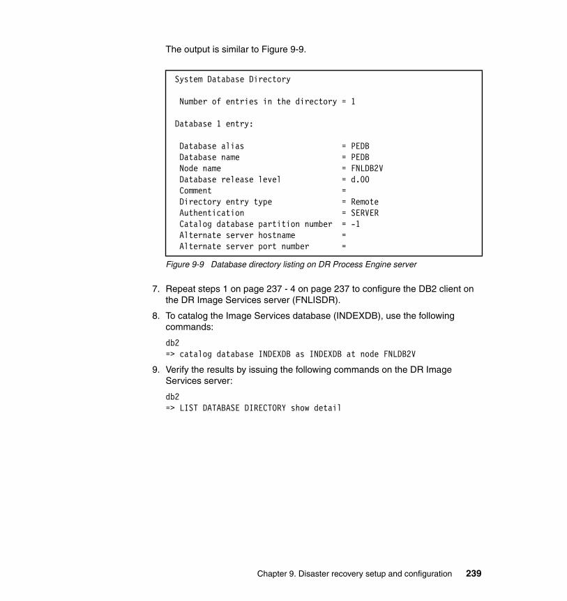
The output is similar to Figure 9-9.
Figure 9-9 Database directory listing on DR Process Engine server
7. Repeat steps 1 on page 237 - 4 on page 237 to configure the DB2 client on the DR Image Services server (FNLISDR).
8. To catalog the Image Services database (INDEXDB), use the following commands:
db2 => catalog database INDEXDB as INDEXDB at node FNLDB2V
9. Verify the results by issuing the following commands on the DR Image Services server:
db2=> LIST DATABASE DIRECTORY show detail
System Database Directory
Number of entries in the directory = 1
Database 1 entry:
Database alias = PEDB Database name = PEDB Node name = FNLDB2V Database release level = d.00 Comment = Directory entry type = Remote Authentication = SERVER Catalog database partition number = -1 Alternate server hostname = Alternate server port number =
Chapter 9. Disaster recovery setup and configuration 239

The output is similar to Figure 9-10.
Figure 9-10 Database directory listing on DR Image Services server
9.3.3 WebSphere configuration for DR
The PROD and DR application servers reside in separate WebSphere cells. The steps to create the cell for the PROD environment are listed in 7.3.2, “WebSphere configuration” on page 155.
The cell topology for the DR configuration, shown in Figure 9-11 on page 241, is similar to that used for the PROD environment. The deployment manager (dmgr) for the cell is located on the Content Engine server (FNLCEDR), with a managed node (fnlcedrNode01) and application server (CEserver01) for the Content Engine application. A second managed node (fnlxtdrNode01) and application server (XTserver01) for the Workplace XT application is located on FNLXTDR.
System Database Directory
Number of entries in the directory = 1
Database 1 entry:
Database alias = INDEXDB Database name = INDEXDB Node name = FNLDB2V Database release level = d.00 Comment = Directory entry type = Remote Authentication = SERVER Catalog database partition number = -1 Alternate server hostname = Alternate server port number =
240 Disaster Recovery and Backup Solutions for IBM FileNet P8 Version 4.5.1 Systems

Figure 9-11 WebSphere cell topology for DR system
As a best practice, configure the PROD and DR WebSphere environments to use identical port numbers. This practice simplifies the failover process if the port numbers in the two environments match.
Creating the WebSphere topology for the DR systemTo create the WebSphere topology for the DR system, perform the following steps:
1. Log in to the FNLCEDR server as the user that installed the WebSphere application, in our case, the root user. Create the deployment manager on the FNLCEDR server using the manageprofile.sh command shown in Figure 9-12.
Figure 9-12 Create cell and deployment manager node for the DR environment
2. Create the managed node for the Content Engine application on the FNLCEDR server using the manageprofile.sh command shown in Figure 9-13 on page 242.
/opt/IBM/WebSphere/AppServer/bin/manageprofiles.sh -create \-templatePath /opt/IBM/WebSphere/AppServer/profileTemplates/cell/dmgr \-nodeProfilePath /opt/IBM/WebSphere/AppServer/profiles/p8AppSrv01 \-profileName p8dmgr01 \-profilePath /opt/IBM/WebSphere/AppServer/profiles/p8dmgr01 \-hostName fnlcedr.fn.ibm.com \-nodeName p8CellManager01 \-cellName p8Cell01 \-appServerNodeName fnlcedrNode01 \-enableAdminSecurity true \-adminUserName wasadmin \-adminPassword WASpassword
Chapter 9. Disaster recovery setup and configuration 241

Figure 9-13 Create the managed node for Content Engine on the DR environment
3. Run the command shown in Figure 9-14 on the FNLXTDR server to create the managed node for the Workplace XT application.
Figure 9-14 Create the managed node for Workplace XT on the DR environment
4. Start the deployment manager and node agent on FNLCEDR.
/opt/IBM/WebSphere/AppServer/profiles/p8dmgr01/bin/startManager.sh/opt/IBM/WebSphere/AppServer/profiles/p8AppSrv01/bin/startNode.sh
5. Start the node agent on FNLXTDR.
/opt/IBM/WebSphere/AppServer/profiles/p8AppSrv01/bin/startNode.sh
/opt/IBM/WebSphere/AppServer/bin/manageprofiles.sh -create \-templatePath /opt/IBM/WebSphere/AppServer/profileTemplates/cell/default \-dmgrProfilePath /opt/IBM/WebSphere/AppServer/profiles/p8dmgr01 \-portsFile \/opt/IBM/WebSphere/AppServer/profiles/p8dmgr01/properties/portdef.props \-nodePortsFile \/opt/IBM/WebSphere/AppServer/profiles/p8dmgr01/properties/nodeportdef.props \-profileName p8AppSrv01 \-profilePath /opt/IBM/WebSphere/AppServer/profiles/p8AppSrv01 \-hostName fnlcedr.fn.ibm.com \-nodeName p8CellManager01 \-cellName p8Cell01 \-appServerNodeName fnlcedrNode01 \-enableAdminSecurity true \-adminUserName wasadmin \-adminPassword WASpassword
/opt/IBM/WebSphere/AppServer/bin/manageprofiles.sh -create \-templatePath /opt/IBM/WebSphere/AppServer/profileTemplates/managed \-profileName p8AppSrv01 \-profilePath /opt/IBM/WebSphere/AppServer/profiles/p8AppSrv01 \-hostName fnlxtdr.fn.ibm.com \-nodeName fnlxtdrNode01 \-cellName fnlxtdrNode01Cell01 \-dmgrHost fnlcedr.fn.ibm.com \-dmgrPort 8879 \-dmgrAdminUserName wasadmin \-dmgrAdminPassword WASpassword
242 Disaster Recovery and Backup Solutions for IBM FileNet P8 Version 4.5.1 Systems

6. From your browser, log in to the WebSphere Integrated Solutions Console using the adminUserName and adminPassword values specified in the manageprofiles.sh command (see Figure 9-12 on page 241.) The URL for the WebSphere console is similar to http://<hostname>:9060/ibm/console.
7. Browse to Servers → New server and add a new server for the Content Engine application with values that are listed in Table 9-3.
Table 9-3 Properties for the CEserver01 application server
8. Add a server for the Workplace XT application with values that are listed in Table 9-4.
Table 9-4 Properties for the XTserver01 application server
9. Start the CEserver01 application server on FNLCEDR using the following command (note, all on one line):
/opt/IBM/WebSphere/AppServer/profiles/p8AppSrv01/bin/startServer.sh CEserver01
10.Start the XTserver01 application server on FNLXTDR using the following command (note, all on one line):
/opt/IBM/WebSphere/AppServer/profiles/p8AppSrv01/bin/startServer.sh XTserver01
Property Value
Server type WebSphere application server
Node fnlcedrNode01 (ND 7.0.0.5)
Server name CEserver01
Server template default
Server specific properties Generate Unique Ports (checked)
Property Value
Server type WebSphere application server
Node fnlxtdrNode01 (ND 7.0.0.5)
Server name XTserver01
Server template default
Server specific properties Generate Unique Ports (checked)
Chapter 9. Disaster recovery setup and configuration 243

Granting permissionsAfter you have completed the WebSphere configuration, you must grant the operating system user who starts and stops the FileNet P8 applications the permissions to the profile directories. In our case, we use the UNIX user account p8OSusr, a member of the UNIX group p8OSgrp, for this purpose.
To enable the p8OSusr account to start and stop the applications, perform the following steps:
1. Stop the XTserver01 and node agent on FNLXTDR.
2. Stop the CEserver01, node agent and deployment manager on FNLCEDR.
3. Change ownership of the profile directories to allow the operating system user p8OSusr access. For example, on FNLCEDR, execute the following commands:
cd /opt/IBM/WebSphere/AppServer/profileschown -Rf p8OSusr:p8OSgrp p8dmgr01chown -Rf p8OSusr:p8OSgrp p8AppSrv01
On FNLXTDR, execute the following commands:
cd /opt/IBM/WebSphere/AppServer/profileschown -Rf p8OSusr:p8OSgrp p8AppSrv01
4. Log in to the FNLCEDR server as p8OSusr and start the deployment manager, node agent and CEserver01.
5. Log in to the FNLXTDR server as p8OSusr and start the node agent and XTserver01.
9.3.4 Software configuration for DR
Figure 9-15 on page 245 shows the software components installed on each server in our DR configuration. This software configuration is identical to that used for PROD.
During the installation of the FileNet P8 software for the DR environment, use the virtual server names where appropriate. The sections that follow list guidelines to consider when installing a disaster recovery environment that uses data replicated from the PROD environment.
244 Disaster Recovery and Backup Solutions for IBM FileNet P8 Version 4.5.1 Systems

Figure 9-15 Software configuration for the DR environment
Content Engine installationWhen configuring a standby Content Engine for disaster recovery, the DR Content Engine must belong to the same FileNet P8 domain as the PROD Content Engine. To accomplish this task, you must access the PROD global configuration database (GCD) and add the DR Content Engine server to the PROD FileNet P8 domain. Therefore, for the purpose of the initial installation and setup of the DR environment, you must configure the DR Content Engine server (FNLCEDR) to resolve the virtual DB2 database server name (FNLDB2V) to the PROD DB2 server (FNLDB2PROD).
Content EngineIBM P570 LPAR
Server Name: FNLCEDRVirtual Name: FNLCEV
IP Address : 10.0.200.218
AIX 6.1 TL2, 64 bitWebSphere 7.0.0.5 ND
Tivoli Storage Mgr Client 6.1
Content Engine 4.5.1CFS-IS 4.5.1
Process Engine Client 4.5.1CSE Client 4.5.1
Workplace XTIBM P570 LPAR
Server Name: FNLXTDRVirtual Name: FNLXTV
IP Address : 10.0.200.221
AIX 6.1 TL2, 64 bitWebSphere 7.0.0.5 ND
Tivoli Storage Mgr Client 6.1
Workplace XT 1.1.4FileNet P8 Help Files 4.5
Process Engine Client 4.5.1Content Engine Client 4.5.1
Content Search EngineIBM P570 LPAR
Server Name: FNLCSEDRVirtual Name: FNLCSEV
IP Address : 10.0.200.220
AIX 6.1 TL2, 64 bitTivoli Storage Mgr Client 6.1
Content Search Engine 4.5.1
Process EngineIBM P570 LPAR
Server Name: FNLPEDRVirtual Name: FNLPEV
IP Address : 10.0.200.222
AIX 6.1 TL2, 64 bitTivoli Storage Mgr Client 6.1
Process Engine 4.5.1DB2 Client 9.7
Image ServicesIBM P570 LPAR
Server Name: FNLISDRVirtual Name: FNLISV
IP Address : 10.0.200.219
AIX 6.1 TL2, 64 bitTivoli Storage Mgr Client 6.1
Image Services 4.1.2.4ISTK 4.1.2.4HPII 3.3.8
DB2 Client 9.7
Client Workstation
Server Name: FNLCLIENTVirtual Name: n/a
IP Address : 192.168.100.121
Windows 2003 Server
Enterprise Manager 4.5.1Remote Admin Console (RAC)
(for CFS-IS)
DB2 ServerIBM P570 LPAR
Server Name: FNLDB2DRVirtual Name: FNLDB2V
IP Address : 10.0.200.216
AIX 6.1 TL2, 64 bitTivoli Storage Mgr Client 6.1
DB2 Server 9.7 (Content Engine,
Process Engine, and Image Services databases)
Tivoli Directory Services
IBM P570 LPAR
Server Name: FNLTDSDRVirtual Name: FNLTDSV
IP Address : 10.0.200.217
AIX 6.1 TL2, 64 bitTivoli Storage Mgr Client 6.1
Tivoli Directory Server 6.1 (LDAP Services for P8)
Tivoli Storage ManagerIBM P570 LPAR
Server Name: FNLTSMDRVirtual Name: FNLTSMVIP Address : 10.0.200.223
AIX 6.1 TL2, 64 bit
Tivoli Storage ManagerServer 6.1
Chapter 9. Disaster recovery setup and configuration 245

After the DR Content Engine installation and configuration is complete, you can point the DR Content Engine server back to DR DB2 server.
To install and configure the Content Engine for the DR environment, perform the following steps:
1. Install Content Engine following the standard Content Engine installation procedure. During the DR Content Engine installation, specify the virtual host name for the following items:
– FileNet P8 documentation address, for example:
http://fnlxtv.fn.ibm.com:9081/ecm_help
– .NET API COM Compatibility Layer (CCL) server address, for example:
http://fnlcev.fn.ibm.com:9080/wsi/FNCEWS40TOM
2. Install the Process Engine client and Content Search Engine client software on the DR Content Engine server (FNLCEDR).
3. Edit either the local /etc/hosts file on the Content Engine server or the DNS tables so that the virtual host name of the database server (FNLDB2V) resolves to the PROD database server (FNLDB2PROD).
4. Create a new Configuration Manager Tool profile directory, such as DR1, on the DR Content Engine server:
cd /opt/IBM/FileNet/ContentEngine/tools/configure/profilesmkdir DR1chown p8OSusr:p8OSgrp DR1
5. Copy all the files and subfolders from the PROD Content Engine profile PROD1, which is in the following directory:
/opt/IBM/FileNet/ContentEngine/tools/configure/profiles/PROD1
Paste them to the new profile directory on the DR Content Engine server (DR1).
Make sure you copy the bootstrapped EAR file from PROD to DR. By default, the bootstrapped EAR file is stored in the EAR directory under the profile directory, for example:
<CE_install_dir>/tools/configure/profiles/PROD1/ear/Engine-ws.ear
Note: Use the nslookup command to verify that the DR Content Engine server (FNLCEDR) resolves the DB2 virtual host name to the PROD DB2 server (FNLDB2PROD). Do not proceed with the DR Content Engine configuration if the nslookup command fails to return the proper value.
246 Disaster Recovery and Backup Solutions for IBM FileNet P8 Version 4.5.1 Systems

6. Using the Content Engine Configuration Manager Tool on the DR server, open the DR profile (DR1). Edit the Application Server Properties page and make any changes necessary to point the application to the DR WebSphere environment. Use the Content Engine server’s virtual host name (fnlcev) for the application server host name. If necessary, change the application server cell name to match the name of the cell used in the DR environment. Note, in our lab environment, the cell name (p8Cell01) is the same in both the PROD and DR environments.
7. Using the Content Engine Configuration Manager Tool on the DR server, create the JDBC data sources for the GCD and any object store databases that currently existing in the PROD environment. The names of the JDBC XA and non-XA data sources on DR must be identical those used in PROD. For the database server name, use the virtual name for the DB2 server, for example FNLDB2V. Execute the Run Task command to create the DR JDBC data sources for the GCD and each objectstore. Log in to the DR WebSphere Administration Console and verify the JDBC connections to the database. Remember, at this stage in the procedure, the JDBC data sources must connect to the PROD database, not the DR.
8. Execute the Configure Login Modules task. There are no parameters to configure for this step. Running this task creates the WebSphere JAAS login modules in the DR environment required to run the Content Engine application.
9. Do not run the Configure Bootstrap Properties task. Because the DR environment is currently pointing to the PROD GCD, we use a copy of the bootstrapped EAR file from PROD for deployment.
10.Configure security on the DR WebSphere application server to match the existing configuration of the PROD environment. This can be accomplished manually, by using the WebSphere Integrated Console, or by executing the Configure LDAP task in the Content Engine Configuration Manager tool on the DR Content Engine. Use the same parameters that were used for the PROD environment. Make sure the Directory service server host name parameter references the virtual host name of the directory services server, for example FNLTDSV.
Note: Starting with version 4.5.1, Content Engine automatically generates the Master Key for the GCD that is used to encrypt all persisted passwords. In previous releases, users would provide a phrase during Content Engine installation that would be used to generate the Master Key.
Chapter 9. Disaster recovery setup and configuration 247

11.Using the Content Engine Configuration Manager Tool on the DR server, edit the Deploy Application task parameters. For the bootstrapped EAR file parameter, specify the path to the copy of the EAR file you transferred from the PROD server earlier in this procedure.
Table 9-5 shows the configuration parameters for the Deploy Application task for the DR lab environment.
Table 9-5 Configuration Manager Deploy Application module
Save your parameters and execute the Deploy Application task. When the deployment task is complete, log in to the WebSphere Integrated Solutions Console and start the FileNetEngine application. Review the SystemOut.log file to verify that the application startup was successful.
12.From your Enterprise Manager client workstation, configure a new connection to the DR Content Engine instance. For the Nickname field, use a name that references the DR environment, for example P8DR. For the server name, use the actual DR server name, not the virtual name.
Property Property value
Deployment type Network Deployment
Bootstrapped EAR file /opt/IBM/FileNet/ContentEngine/tools/configure/profiles/DR1/ear/Engine-ws.ear
Content Engine application name
FileNetEngine
Application server node fnlcedrNode01
Application server name CEserver01
248 Disaster Recovery and Backup Solutions for IBM FileNet P8 Version 4.5.1 Systems

Figure 9-16 shows the configuration parameters for our DR lab environment.
Figure 9-16 Configuration parameters for DR Enterprise Manager
You now see both the P8PROD and P8DR connections available on your client workstation, as shown in Figure 9-17 on page 250.
Chapter 9. Disaster recovery setup and configuration 249

Figure 9-17 Enterprise Manager connections for PROD and DR
13.Log in to Enterprise Manager using the DR connection configured in the previous step. Browse to the Virtual Servers node as shown in Figure 9-18. An entry for a virtual server with the same name as the application server node (fnlcedrNode01) is displayed.
Figure 9-18 Virtual server for DR environment
250 Disaster Recovery and Backup Solutions for IBM FileNet P8 Version 4.5.1 Systems

14.Because we are still pointing to the PROD copy of the GCD, the existing object stores are listed as shown in Figure 9-19.
Figure 9-19 View of object stores from DR environment
Note: The virtual server fnlcedrNode01 and its associated application server instance CEserver01, are created in the GCD when you deploy the EAR file in the DR environment. Be aware, however, that they are not removed from the GCD when the Content Engine is undeployed from the application server. You must delete the virtual servers manually from Enterprise Manager to remove the entries from the GCD.
Important: Do not attempt to add or retrieve any documents that reside on file storage areas. At this time, the file systems for the file storage areas have not been replicated to the DR environment and will result in an error. You can, however, retrieve documents that are stored in database storage areas, because the DR site is still connected to the PROD database server.
Chapter 9. Disaster recovery setup and configuration 251

The PROD and DR Content Engine servers are part of the same FileNet P8 domain, and thus share a common GCD. Because directory service configurations for the FileNet P8 domain are stored in the GCD, you cannot specify separate LDAP configurations for the PROD and DR environments. Therefore, if you are replicating your directory services data, make sure you specify the virtual host name for the directory services server (such as FNLTDSV) when configuring the PROD environment. This allows the DR environment to resolve the virtual name to the appropriate host.
15.Reconfigure the Content Engine to point to the DR database and file storage areas using the following steps:
a. Shut down the WebSphere services for both the PROD and DR Content Engine applications.
b. Shut down the PROD Content Engine databases (GCD, Object Stores).
c. Replicate, copy or restore the PROD Content Engine databases (GCD and object stores) to the DR database server.
d. Replicate, copy or restore the PROD file storage area directory to the DR system.
e. After the copies or restorations of the databases and file storage areas for the DR site is complete, restart the PROD database server and the PROD Content Engine application.
Note: To complete the Content Engine DR configuration and testing, only a copy of the databases is required at this time. This copy must include the GCD virtual server entries completed in the previous steps.
If preferred, you can delay activating full data replication/mirroring from PROD to DR until after all the DR FileNet P8 components have been configured and tested.
Note: For our case study, the PROD file storage area directory is located at the NFS mount point /p8data. For the DR system, you must create an identical NFS mount point. For the purpose of testing the DR environment, copy the files from the /p8data/filestores directory on PROD to the /p8data/filestores directory on DR. Full data replication/mirroring from PROD to DR can be enabled after all the DR FileNet P8 components have been configured and tested.
252 Disaster Recovery and Backup Solutions for IBM FileNet P8 Version 4.5.1 Systems

f. Modify your local /etc/hosts file on the DR Content Engine server, (or the DNS tables if appropriate,) so that the virtual host name of the database server (FNLDB2V) resolves to the DR database server (FNLDB2DR). Verify using the nslookup command.
g. Restart the DR databases for the GCD and object stores.
h. Restart the WebSphere services for the Content Engine application on the DR Content Engine server.
i. Using Content Engine Enterprise Manager, verify that you can add and retrieve documents from file storage areas on the DR Content Engine.
Content Search Engine installationThe Content Search Engine on DR is an exact replica of the Content Search Engine in the PROD environment. Although all binary files, configuration files, and index data on the newly installed DR Content Search Engine server are eventually replaced by a replica from the PROD environment, running the installer on both the PROD and DR servers is a good practice. This practice assures that the software is properly registered on each server and enables future upgrades or uninstallations to function properly.
Consider the following elements when you install Content Search Engine on DR:
� The default Content Search Engine installation directory is:
/opt/IBM/FileNet/verity.
This directory contains the Content Search Engine binaries and configuration files. This directory must be the same on both the PROD and DR sites, and must reference the virtual host name for all configuration parameters.
� Index data is stored in a collections directory, such as /k2Collections. This directory must be replicated from the PROD site to the DR site to avoid time consuming re-indexing of content whenever the DR site is activated.
� The Content Search Engine also uses a temporary file system, such as /p8data/k2_temp, to communicate between the Content Engine and the Content Search Engine. This directory is not required to be replicated from PROD to DR. In our lab environment, however, this directory is replicated because it is located on the same NFS mounted file system as our file storage areas (/p8data).
Chapter 9. Disaster recovery setup and configuration 253

The high-level installation and configuration steps for setting up the DR Content Search Engine environment are as follows:
1. Create the file systems and mount points on the DR Content Search Engine server to match those on the current PROD Content Search Engine server. Be sure to create the soft link from the /k2verity directory to the default install directory /opt/IBM/FileNet/verity. The procedure for creating the soft link is shown in Chapter 7, “Case study description and system setup” in “Content Search Engine installation” on page 162.
2. Install the Content Search Engine software on DR using the same parameters specified during the PROD install. Using the same installation location as in the PROD environment is important. The values you use for other parameters during the installation does not matter because the install directory, /opt/IBM/FileNet/verity, will be replicated from PROD to the DR site.
3. After the installation is complete, stop the Content Search Engine software if it is running.
4. Replicate, copy, or restore the Content Search Engine installation directory, /opt/IBM/FileNet/verity (soft linked to /k2verity), from the PROD Content Search Engine server to the DR site. This process includes all the configuration files from the PROD environment that were modified to use the virtual host name for the Content Search Engine server.
5. Replicate, copy, or restore the Content Search Engine collections directory, /k2Collections, from the PROD Content Search Engine server to the DR site.
6. Start the Content Search Engine software on the DR server. You are now able to log in to the K2 Dashboard using virtual host name:
http://fnlcsev.fn.ibm.com:9990/verity_dashboard/main.jsp
The following K2 objects already exist and require no changes because the PROD environment was configured using the virtual host name:
fnlcsev_broker_serverfnlcsev_index_serverfnlcsev_search_serverfnlcsev_ticket_server
7. Log in to Enterprise Manager in DR and verify the K2 domain configuration. Because the DR Content Engine is using a replicated copy of the PROD GCD, making changes is unnecessary because all configuration parameters reference the virtual host name.
Process Engine installationTo set up a standby Process Engine for disaster recovery, configure the DR Process Engine server as a member of a Process Engine farm that also includes
254 Disaster Recovery and Backup Solutions for IBM FileNet P8 Version 4.5.1 Systems

the PROD Process Engine server. To accomplish this task, you have access the Process Engine database on the PROD database server during the initial installation and configuration of the DR Process Engine server. As is the case with the DR Content Engine installation, after the configuration is complete, you can then point the DR Process Engine server to the DR database server.
The high-level installation and configuration steps are as follows:
1. Edit either the local /etc/hosts file on the Content Engine server or the DNS tables so that the virtual host name of the database server (FNLDB2V) resolves to the PROD database server (FNLDB2PROD). Verify using the nslookup command.
2. To configure a Process Engine farm, you must modify the /etc/hosts file on the DR Process Engine server to include entries for both the PROD and DR Process Engine servers. Also, append the alias for the virtual Process Engine server host name (FNLPEV) to the DR Process Engine entry. Entries are similar to those in Figure 9-20.
Figure 9-20 /etc/hosts entries on FNLPEDR
3. Install the Process Engine by using values listed in Table 9-6.
Table 9-6 Process Engine installation parameters for DR environment
192.168.100.222 fnlpeprod fnlpeprod.fn.ibm.com10.0.200.222 fnlpedr fnlpedr.fn.ibm.com fnlpev fnlpev.fn.ibm.com
Property Property value
Documentation URL http://fnlxtv.fn.ibm.com:9081/ecm_help
Common Files Directory /opt/IBM/FileNet/CommonFiles
Nework Name fnlpedr
Database Type DB2
Database Alias Name PEDB
DB2 Instance Owner Name db2inst1
Data Tablespace PEDATA_TS
Blob Tablespace PEBLOB_TS
Alias for group FNADMIN fnadmin
Alias for group FNOP fnop
Alias for group FNUSR fnusr
Chapter 9. Disaster recovery setup and configuration 255

4. Install Content Engine client using the virtual Content Engine server host name (fnlcev) for the Content Engine Client Software address (WSI):
cemp:http://fnlcev.fn.ibm.com:9080/wsi/FNCEWS40MTOM/
Note that on the DR Process Engine server, fnlcev.fn.ibm.com resolves to fnlcedr.fn.ibm.com.
5. Start Process Engine on the DR Process Engine server (FNLPEDR) and launch the Process Task Manager. Because the DR server is pointing to the PROD Process Engine database, the definition for the vworbbroker.endPoint already exists and can be found on the Advanced tab in the Process Task Manager as shown in Figure 9-21. Also note that because GCD database stores the information about Process Engine region and connection point, defining those on the DR server is not necessary.
Figure 9-21 Process Task Manager on DR
6. Reconfigure the DR Process Engine to point to the DR database using the following steps:
a. Shut down the Process Engine on both the PROD and DR servers.
b. Shut down the PROD Process Engine database (PEDB).
c. Replicate, copy or restore the PROD Process Engine databases (PEDB) to the DR database server.
Alias for user FNSW fnsw
Alias for user F_SW pe_sw
Alias for user F_MAINT pe_maint
Password for f_sw (or alias) ******
Password for f_maint (or alias) ******
Property Property value
256 Disaster Recovery and Backup Solutions for IBM FileNet P8 Version 4.5.1 Systems

d. After the copy or restore of the database for the DR site is complete, restart the PROD database server and the PROD Process Engine application.
e. Modify your local /etc/hosts file on the DR Process Engine server, (or the DNS tables if appropriate,) so that the virtual host name of the database server (FNLDB2V) resolves to the DR database server (FNLDB2DR). Verify using the nslookup command.
f. Restart the DR databases PEDB.
g. Restart the Process Engine application on the DR Process Engine server.
h. Check the elogs to make sure that no errors occur starting the Process Engine.
i. Verify the connection to Process Engine database by running vwcemp as show in Figure 9-22.
Figure 9-22 The vwcemp command to verify connection to the database
Workplace XT installationWorkplace XT in the DR environment is installed as a regular installation. The guidelines for installing and configuring Workplace XT on the DR server are as follows:
� Workplace XT and Application Engine use EJB transport to connect to the Content Engine. Therefore, you must use the actual DR Content Engine host name, not the virtual host name, when specifying values for the following URLs:
– Content Engine client URL– Content Engine upload URL– Content Engine download URL
For example, use the following URL when installing the DR Workplace XT application:
cemp:iiop://fnlcedr.fn.ibm.com:2809/FileNet/Engine
fnlpedr(fnsw)/home/fnsw> vwcemp -l Host = <localhost> IOR Port = <32776> Broker Port = <32777> ServiceUser = <peServiceUser> URL = <http://fnlcev.fn.ibm.com:9080/wsi/FNCEWS40MTOM/> SysAdminG = <peAdminGroup> SysConfigG = <peConfigGroup>
Chapter 9. Disaster recovery setup and configuration 257

� The default location for the Workplace XT configuration folder is /opt/IBM/FileNet/Config. Configuration files in this folder include bootstrap information such as the object store name for the site preferences and the site preference name for Workplace XT. During the installation of the DR Workplace XT, allow the installer to create the default configuration folder. After the installation is completed, replace the Config directory with a soft link to the /p8data/Config directory. The /p8data/Config directory in DR contains a copy or replica of the /p8data/Config folder from PROD.
� During the DR installation, use default locations for the Upload and Download directories on local disk, for example:
/opt/IBM/FileNet/WebClient/Upload /opt/IBM/FileNet/WebClient/Download
� During the DR Content Engine client installation on the Workplace XT server, specify the virtual host name for the Content Engine server when prompted for the Content Engine URL (WSI), for example:
cemp:http://fnlcev.fn.ibm.com:9080/wsi/FNCEWS40MTOM/
� Deploy Workplace XT as instructed in the installation guide.
� Start the Workplace XT application using the WebSphere Integrated Solutions console in the DR environment. Replicate the Config folder (/opt/IBM/FileNet/Config/WebClient) from PROD to DR, overwriting the current default content. Because this configuration is already set on the PROD site, you are not prompted to set the bootstrap preferences when you log in to Workplace XT for the first time.
� Log in to Workplace by using the virtual name for Workplace XT URL, for example
http://fnlxtv.fn.ibm.com:9081/WorkplaceXT
Note that in the DR environment, fnlxtv.fn.ibm.com resolves to fnlxtdr.fn.ibm.com.
� Because site preferences are stored in the GCD, all previous settings including Connection Points for Workplace XT is already defined.
� Because the Process Engine database has been replicated to DR, it is not necessary to initialize the isolated region.
� The Component Manager configuration is stored in a directory that is not replicated from the PROD environment. Therefore, you must create a new Component Manager for the DR environment. Use the properties defined in Table 9-7 on page 259. Note that most parameters reference the virtual host name, with the exception of the Web Services Listener Local Host field, which requires the actual DR host name.
258 Disaster Recovery and Backup Solutions for IBM FileNet P8 Version 4.5.1 Systems

Table 9-7 Component Manager Configuration Parameters
Image Services installationIn general, you install the DR Image Services software by using the same procedure and parameters that are used to set up the PROD environment. The guidelines for installing and configuring Image Services in the DR environment are as follows:
� Create the logical volumes, file systems, and mount points to match the existing PROD environment:
– Create the logical volume for the Image Services binaries with a mount point of /fnsw on local disk (rootvg).
– Create the logical volumes for the Image Services configuration files with a mount point of /fnsw/local on SAN storage (datavg).
– Create the MSAR file systems on SAN storage (datavg), using the same mount point name as PROD.
– Create the logical volumes for the MKF databases and cache on SAN storage (datavg). Links to these raw volumes will be created in the /fnsw/dev/1 directory during the installation procedure.
� For the initial DR installation, the /fnsw, /fnsw/local and MSAR file systems exist, but do not contain data. Likewise, the MKF/cache logical volumes also exist, but contain no data. Do not copy, restore or replicate any file systems from the PROD environment until after the initial configuration is complete.
� For the purpose of the install, point the DR Image Services server to the DR database server. Although the Content Engine and Process Engine installations require access to the PROD databases for the initial install, this is not the case for Image Services. Create the Image Services database, for example INDEXDB, on the DR database server and allow the installer to initialize the database. Do not copy, restore or replicate these file systems from the PROD environment until after the initial configuration is complete.
� Make sure the UNIX user fnsw and groups (fnadmin, fnusr and fnop) have the same user ID (uid) and group ID (gid) on both PROD and DR.
Parameter Value
Content Engine URI http://fnlcev.fn.ibm.com:9080/wsi/FNCEWS40MTOM/
Connection Point CPFNLPEV
Web Services Listener URL
http://fnlxtv.fn.ibm.com:9081/WorkplaceXT
Web Services Listener Local Host
fnlxtdr.fn.ibm.com:9081
Chapter 9. Disaster recovery setup and configuration 259

Complete the Image Services install on the DR server using the standard installation procedure. Follow the steps to initialize the DR INDEXDB database, MKF databases, and cache. Verify that the DR Image Services software starts and stops correctly using default data. A
After you confirm the startup and shutdown of the DR software, copy the PROD data and configuration files to DR as follows:
1. Shut down Image Services on both the PROD and DR servers.
2. Shut down the PROD and DR relational databases (INDEXDB).
3. Replicate, copy or restore the PROD Image Services database (INDEXDB) to the DR database server. When the copy is complete, restart the Image Services databases for both PROD and DR on the DB2 servers.
4. Replicate, copy or restore the MKF and cache files from PROD to the DR site.
5. Replicate, copy or restore the PROD MSAR directory to the DR Image Services server.
6. Copy the /fnsw/etc/serverConfig file from PROD to DR.
7. Replicate, copy or restore the PROD configuration directory (/fnsw/local) to the DR Image Services server.
8. Run the fn_build -a command on the DR server.
9. Restart the Image Services software on both PROD and DR. Check log files (elogs) to verify the software started correctly.
10.Test the DR Image Services system, using the procedures outlined in Chapter 10, “System testing and validation” on page 263.
Note: On UNIX environments, the MKF databases (PERM, TRANS, and SEC), and the cache objects, are stored in raw data partitions. These objects cannot be copied as you would a normal file system. To transfer this type of data from PROD to DR, use one of the following procedures:
� Replicate or mirror the LUN using block level replication.
� Restore the data using the IBM FileNet Enterprise Backup and Restore (EBR) utility.
� Copy the logical volume using the UNIX dd command.
Replicating the Transient database and cache files is optional, because you can reinitialize these partitions on the DR site. Be aware, however, that if you choose to reinitialize cache, the capture repository that is required by the IBM FileNet Capture software must be restored manually.
260 Disaster Recovery and Backup Solutions for IBM FileNet P8 Version 4.5.1 Systems
Content Federation Services for Image Services installationConfiguration for Content Federation Services for Image Services (CFS-IS) is stored in the Content Engine database. Because the Content Engine databases are replicated on the DR site, there are no configuration changes required for CFS-IS on DR. Any fixed storage locations used by CFS-IS must be replicated to the DR site.
9.4 Verifying the DR installation
After all software has been installed and configured on the DR servers, and initial data copied from PROD to DR, validate the system by using guidelines outlined in Chapter 10, “System testing and validation” on page 263. A best practice is to test the DR site while the PROD system is down. This practice ensures that the DR site has no dependencies on components in PROD.
9.5 Enabling PROD to DR replication
After the initial DR installation has been validated, you must enable replication on an on-going basis so that the DR system data can be synchronized with the PROD data.
To enable replication in our lab environment, perform the following steps:
1. Shut down all FileNet P8 components on the DR servers.
2. Shut down the DR WebSphere application servers for Workplace XT and Content Engine.
3. Shut down the DB2 databases on the DR database server.
4. Unmount all volumes in DR that reside on LUNs that are to be replicated from the PROD LUNs.
5. Turn on mirroring for on-going replication of PROD data to DR.
Note: While mirroring from PROD to DR is on, you cannot access the FileNet P8 components on the DR site. To use the DR site, you must first disable, or break the mirroring.
If you want to use the DR site for testing purposes, consider using a second copy, or FlashCopy image, of the data for testing purposes.
Chapter 9. Disaster recovery setup and configuration 261

9.6 Activating the DR site
The configuration guidelines for the PROD environment outlined in Chapter 7, “Case study description and system setup” on page 145, coupled with DR configuration guidelines presented in this chapter, allow for activation of the DR environment with no changes to the FileNet P8 configuration.
To activate the DR environment, perform the following steps:
1. Verify that mirroring has been disabled.
2. Mount all the necessary volumes on the DR servers.
3. Start up the DR databases.
4. Start up the DR WebSphere application servers.
5. Start up the DR FileNet P8 components.
6. Validate the DR applications by using steps outlined in Chapter 9, “Disaster recovery setup and configuration” on page 227.
.
9.7 Maintaining the DR site
After the DR system has been configured, you must maintain the software and configuration so that it remains synchronized with the PROD environment. The conditions that might require manual updates to the DR site are as follows:
� Creating a new object store
When a new object store is created on the PROD site, you must create new JDBC datasources to access the object store database. Make sure that you also add the new JDBC datasources to the DR site.
� Applying fix packs and patches
Whenever the PROD software is updated or patched, you must apply the updates to the DR system as well.
Note: During the test phase, restrict user access until validation is complete. This can be accomplished by modifying the local host tables on the test user’s workstation only so that the virtual host names resolve to the DR server host names. After the validation is complete, update the DNS entries for the entire site so that the virtual host names resolve to the DR server names for all users.
262 Disaster Recovery and Backup Solutions for IBM FileNet P8 Version 4.5.1 Systems

Chapter 10. System testing and validation
This chapter describes the detailed steps involved in validating the backup and disaster recovery procedures that we have identified in previous chapters for a FileNet P8 Version 4.5.1 system. We describe how to test the internal health and consistency of each core component and the consistency between the components after a restore or failover. The steps that are included here are for our test environment. For your environment, you must make adjustments such as changing server names, user IDs, passwords, and paths.
This chapter contains the following topics:
� Starting the FileNet P8 software
� Testing for internal consistency
– Importance of internal consistency– Content Engine internal consistency– Process Engine internal consistency– Image Services consistency
� Testing for consistency between applications
– Content Engine and Process Engine– Content Engine and Content Search Engine– Content Engine and Image Services
10
© Copyright IBM Corp. 2010. All rights reserved. 263

10.1 Starting the FileNet P8 software
The first steps to test the system after restoring data from a backup or failing over to a Disaster Recovery (DR) system are as follows:
1. Start the software.2. Verify that it started cleanly.3. Review the associated log files.
For DR failover, this chapter assumes that you have already made the necessary configuration changes to reflect the new environment. See Chapter 9, “Disaster recovery setup and configuration” on page 227 for these procedures. P8 runs in a distributed environment, and although several components can be started independently from other components, we start the components in the following order:
1. Databases (DB2)
We use databases in the following components:
– Content Engine (CE)– Process Engine (PE)– Image Services (IS)
2. Image Services and High Performance Image Import (HPII)
3. Content Engine
4. Process Engine
5. Workplace XT
6. Component Manager
7. Content Search Engine
10.1.1 Starting the P8 databases
Start the databases for Image Services, Content Engine, and Process Engine. In our case, all three databases are managed from the same DB2 server and instance and are all started automatically when DB2 is started.
To start the P8 databases, perform the following steps:
1. Log in to the database server as the database administrator (db2inst1).
2. Start the DB2 software and databases:
$ db2start
264 Disaster Recovery and Backup Solutions for IBM FileNet P8 Version 4.5.1 Systems

3. Review the DB2 diagnostic logs. To determine the location of the DB2 logs, type the following command:
$ db2 get dbm cfg |grep -i diag
We used the following log in our system:
/db2data/home/db2inst1/sqllib/db2dump/db2diag.log
10.1.2 Starting Image Services and HPII
To start the Image Services and HPII software, perform the following steps:
1. Log in to the Image Services server as Image Services administrator (fnsw).
2. Start Image Services:
$ initfnsw start
3. Verify that the software is started:
$ whatsup
4. Review the Image Services event log using either of the following commands:
– $ vl
– $ less /fnsw/local/logs/elogs/elogyyyymmdd
Replace yyyymmdd with the current year, month, and day.
5. Log in as to the Image Services server as the HPII user (hpiiusr).
6. Start HPII:
$ cd /fnsw/local/bin$ HPII_start
Note: To find database log files, use one of the following commands, depending on your system:
� DB2:
db2 get dbm cfg |grep -i diag
� Oracle:
show parameter BACKGROUND_DUMP_DEST
� MS SQL Server:
SELECT name, physical_name FROM sys.master_files
Chapter 10. System testing and validation 265

7. Verify that the software is started:
$ ps -ef |grep HPII_import$ ps -ef |grep HPII_val
8. Review the HPII import and validation logs:
$ less /fnsw/local/bin/journals/impyyyymmdd$ less /fnsw/local/bin/journals/valyyyymmdd
10.1.3 Starting the Content Engine
To start the Content Engine software, perform the following steps:
1. Log in to the Content Engine server as the Content Engine OS user (p8OSusr).
2. Start the application server deployment manager (if applicable), node agent, and Content Engine server, as appropriate in your environment. In our case, we start all three components with a single script:
$ /opt/scripts/startWASall.sh
This script contains the following lines:
WAS_HOME=/opt/IBM/WebSphere/AppServer$WAS_HOME/profiles/p8dmgr01/bin/startManager.sh \-username wasadmin \-password itso13sj$WAS_HOME/profiles/p8AppSrv01/bin/startNode.sh$WAS_HOME/profiles/p8AppSrv01/bin/startServer.sh CEserver01
3. Review the application server logs. In our case the logs are from WebSphere and are in the following locations:
– $WAS_HOME/profiles/p8AppSrv01/logs/CEserver01/startServer.log– $WAS_HOME/profiles/p8AppSrv01/logs/CEserver01/SystemErr.log– $WAS_HOME/profiles/p8AppSrv01/logs/CEserver01/SystemOut.log
4. Review the P8 server error log:
$WAS_HOME/profiles/p8AppSrv01/FileNet/CEserver01/p8_server_error.log
5. With an HTTP browser, check the Content Engine ping page (see Figure 10-1 on page 267). This page is displayed only if the Content Engine is started. This is a quick test; it does not check full Content Engine functionality:
http://fnlcev.fn.ibm.com:9080/FileNet/Engine
To determine the URL, replace /wsi/FNCEWS40MTOM in the Enterprise Manager connection string with /FileNet/Engine.
266 Disaster Recovery and Backup Solutions for IBM FileNet P8 Version 4.5.1 Systems

Figure 10-1 Content Engine ping page
6. Log in to Enterprise Manager.
This action verifies that the Content Engine software, Content Engine database, and directory services are all started.
7. In Enterprise Manager, select Sites → Initial Site → Virtual Servers.
Verify that Content Engine is running on the expected server. This verification is especially important if failing over to a DR Content Engine server. In our example as shown in Figure 10-2 on page 268, we can see that the Content Engine application is active on the Content Engine server at the production site. The Content Engine server at the DR site is down.
Chapter 10. System testing and validation 267

Figure 10-2 Active Content Engine server
8. Start the CFS-IS Import Agent if it is not started, as follows:
a. In Enterprise Manager, right-click the top level P8 domain and click Properties.
b. Select the IS Import Agent tab. See Figure 5-20 for the default values of the Image Services import agent.
c. Select the Enable Dispatcher check box.
d. Click OK.
268 Disaster Recovery and Backup Solutions for IBM FileNet P8 Version 4.5.1 Systems

See Figure 10-3 for an example.
Figure 10-3 CFS-IS import agent
9. Review the Content Engine P8 server error log again to verify that the CFS-IS agents started successfully:
$WAS_HOME/profiles/p8AppSrv01/FileNet/CEserver01/p8_server_error.log
10.1.4 Starting the Process Engine
To start the Process Engine software, perform the following steps:
1. Log in to the Process Engine server as the Process Engine administrative user (fnsw).
2. Verify Process Engine database connectivity with vwcemp command (see Example 10-1 on page 270):
$ vwcemp -l
Chapter 10. System testing and validation 269

Example 10-1 Verifying the connectivity with vwcemp -l
fnlpeprod(fnsw)/home/fnsw> vwcemp -l Host = <localhost> IOR Port = <32776> Broker Port = <32777> ServiceUser = <peServiceUser> URL = <http://fnlcev.fn.ibm.com:9080/wsi/FNCEWS40MTOM/> SysAdminG = <peAdminGroup> SysConfigG = <peConfigGroup>
3. Start the Process Engine software:
$ initfnsw start
Successfully starting the Process Engine software verifies a successful connection to the Content Engine.
4. Review the Process Engine event log by using either of the following commands:
– $ vl– $ less /fnsw/local/logs/elogs/elogyyyymmdd
Replace yyyymmdd with the current year, month, and day.
5. With an HTTP browser, check the Process Engine ping page. This page is displayed only if the Process Engine is started:
http://fnlpev.fn.ibm.com:32776/IOR/ping
See Figure 10-4 for our example.
Figure 10-4 Process Engine ping page
6. Run the vwtool command. The command checks full connectivity to the Process Engine software, Content Engine software, the Process Engine database, and directory services.
270 Disaster Recovery and Backup Solutions for IBM FileNet P8 Version 4.5.1 Systems

See Example 10-2.
Example 10-2 vwtool
fnlpeprod(fnsw)/home/fnsw> vwtoolUser name: p8AdminUserPassword: vwtool : fnlpeprod [Aix Server Production (3 silos) (DB2 Blob 512 MB) -- {dap451.100 pe451.062x pui451.075} Jul 24 2009 13:52:44 en ]Type '?' for help<vwtool:1>quit
10.1.5 Starting the Workplace XT
To start the Workplace XT software, perform the following steps:
1. Log in to the Workplace XT server as the Workplace XT OS user (p8OSusr).
2. Start the application server deployment manager (if applicable), node agent, and XTserver, as appropriate for your environment. In our case, we start the node agent and Workplace XT server only because the deployment manager is run from the Content Engine server. In our case, both the node agent and Workplace XT server are started with a single script:
$ /opt/scripts/startWASall.sh which contains:WAS_HOME=/opt/IBM/WebSphere/AppServer$WAS_HOME/profiles/p8AppSrv01/bin/startNode.sh$WAS_HOME/profiles/p8AppSrv01/bin/startServer.sh XTserver01
3. Review the application server logs. In our case, the logs are from WebSphere and are in the following locations:
– $WAS_HOME/profiles/p8AppSrv01/logs/XTserver01/startServer.log– $WAS_HOME/profiles/p8AppSrv01/logs/XTserver01/SystemErr.log– $WAS_HOME/profiles/p8AppSrv01/logs/XTserver01/SystemOut.log
4. With an HTTP browser, log in to the Workplace XT Web page:
http://fnlxtv.fn.ibm.com:9081/WorkplaceXT
Successful login verifies that Workplace XT software is started and the connectivity to the Content Engine server is successful.
5. To verify Process Engine connectivity, from within the Workplace XT Web page, click the Tasks check box icon, shown in Figure 10-5 on page 272.
Chapter 10. System testing and validation 271

Figure 10-5 Workplace XT Process Engine tasks
10.1.6 Starting the Component Manager
To start the Component Manager software, perform the following steps:
1. Log in to the Workplace XT server as the Workplace XT OS user (p8OSusr).
2. Start the Process Task Manager:
$ /opt/IBM/FileNet/WebClient/Router/routercmd.sh
3. Start the Component Manager.
4. Verify that the queues are started. See Figure 10-6 on page 273 for our example.
Note: Process Task Manager is an X-Windows application so you will need to set your DISPLAY variable and start an X Server on your desktop.
272 Disaster Recovery and Backup Solutions for IBM FileNet P8 Version 4.5.1 Systems

Figure 10-6 Process Task Manager - Component Manager
10.1.7 Starting the Content Search Engine (CSE)
Content Search Engine is also referred to as Autonomy K21.
To start the Content Search Engine software, perform the following steps:
1. Log in to the Content Search Engine server as the K2 operating system user (p8OSusr).
2. Start the K2 software:
$ nohup k2adminstart &
Note: You may also start the Component Manager from a script.
1 Autonomy materials reprinted with permission from Autonomy Corp.
Chapter 10. System testing and validation 273
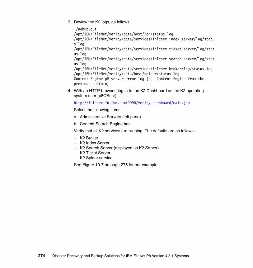
3. Review the K2 logs, as follows:
./nohup.out /opt/IBM/FileNet/verity/data/host/log/status.log/opt/IBM/FileNet/verity/data/services/fnlcsev_index_server/log/status.log/opt/IBM/FileNet/verity/data/services/fnlcsev_ticket_server/log/status.log/opt/IBM/FileNet/verity/data/services/fnlcsev_search_server/log/status.log/opt/IBM/FileNet/verity/data/services/fnlcsev_broker/log/status.log/opt/IBM/FileNet/verity/data/host/spider/status.logContent Engine p8_server_error.log (see Content Engine from the previous sectoin)
4. With an HTTP browser, log in to the K2 Dashboard as the K2 operating system user (p8OSusr):
http://fnlcsev.fn.ibm.com:9990/verity_dashboard/main.jsp
Select the following items:
a. Administrative Servers (left pane).
b. Content Search Engine host.
Verify that all K2 services are running. The defaults are as follows:
– K2 Broker– K2 Index Server– K2 Search Server (displayed as K2 Server)– K2 Ticket Server– K2 Spider service
See Figure 10-7 on page 275 for our example.
274 Disaster Recovery and Backup Solutions for IBM FileNet P8 Version 4.5.1 Systems

Figure 10-7 K2 Dashboard
10.2 Testing for internal consistency
After starting the software on all of the components and verifying that everything has started cleanly, the next step is to test for consistency within each component.
In 10.3, “Testing for consistency between applications” on page 293, we test for consistency between components, such as Content Engine to Image Services.
Chapter 10. System testing and validation 275
However, in this section, we focus on consistency only within the applications that can have consistency issues:
� Content Engine
– Content Engine database– Storage areas
� Process Engine
The Process Engine cannot become internally inconsistent in the same way as Content Engine and Image Services because all of its data is stored in a single database, but we have tools to test that the data within the database is internally consistent across the various tables.
� Image Services
– Media (storage locations)– Locator database– Index database
10.2.1 Importance of internal consistency
Although backing up and replicating various types of data at different times is possible, recovering this data can result in inconsistency. For example, the Content Engine typically stores a document’s content in a file storage area and a document’s metadata in a database. The file storage area and database are often stored with separate mechanisms, in separate locations, and can be backed up independently at separate times. If you recover a file storage area and database that were backed up at separate times, then for an individual document you might have the content from the file storage area with no corresponding reference in the database, or you might have the document reference in the database with no corresponding content. In the first case, the document content might exist but a user has no way to know of its existence; in the second case, the user sees a reference for the document, but is unable to view the content. This result is similar to a library that contains books but no card catalog (case 1) and a library with a card catalog but no books (case 2).
Because of the possibility of inconsistency, stop all applications before doing a backup, and store all data in a storage subsystem that can maintain write-order consistency when replicated to a remote site.
However, we realize that performing offline backups or storing all types of data in the same consistency group is not always possible. Therefore, when this type of data is restored or recovered, you must test the resulting data to find any inconsistencies and determine what action to take to resolve them.
276 Disaster Recovery and Backup Solutions for IBM FileNet P8 Version 4.5.1 Systems

10.2.2 Content Engine internal consistency
Content Engine stores the content of a document in a storage area. The storage area can be a database storage area, a file storage area, or a fixed storage area. When content is stored in a database storage area, the document content and metadata are very likely to always be consistent. However, if the content is stored in a file or fixed storage area, there is a possibility that the content and metadata can be restored or recovered to separate times. Therefore, after a restore or recovery operation, test the consistency between the metadata and the content. Check for the following possibilities:
� Document references exist but the corresponding content does not.
� Document content exists but the corresponding document references do not.
We address each possibility in this section.
Checking for document references that have no contentThe Content Engine includes a tool called Consistency Checker, which reads the document references in the Content Engine database and attempts to verify that the corresponding content exists. Running the check against all documents in a file storage area can be time-consuming. With P8 4.5, the tool enables you to specify a date range so that you can check only the documents that were added after a known consistent date.
To run the Consistency Checker, perform the following steps:
1. Log in to a Windows system where Consistency Checker is installed, typically the same location as Enterprise Manager. Then, select Start → Programs → IBM FileNet P8 Platform → FileNet Consistency Checker.
2. Click Select Domain and select an existing P8 domain or add a new one.
3. In the Domain window, shown in Figure 10-8 on page 278, enter the login and password information and click Test Connection, and then click OK.
Note: For database and file storage areas, in addition to verifying the existence of the content, the Consistency Checker also compares the file size to the size that was recorded when the document was added to the system.
Chapter 10. System testing and validation 277

Figure 10-8 Consistency Checker domain login
A list of the storage areas in the P8 domain is displayed.
4. Select a storage area and click File → Validate Storage Areas, or click the green arrow at the top left of the window, and then click Start.
If you have previously checked the selected storage area, you are prompted to run it again. Click Yes.
See Figure 10-9 and Figure 10-10 on page 279.
Figure 10-9 Consistency Checker storage area selection
278 Disaster Recovery and Backup Solutions for IBM FileNet P8 Version 4.5.1 Systems

Figure 10-10 Consistency Checker results
If the Consistency Checker finds a document that does not exist in a file storage area, it lists the file name in the resulting output. See Figure 10-11 on page 280.
Chapter 10. System testing and validation 279

Figure 10-11 Consistency Checker with errors
5. If errors exist, click Total Errors to see a list. See Figure 10-12.
Figure 10-12 Consistency Checker error detail
280 Disaster Recovery and Backup Solutions for IBM FileNet P8 Version 4.5.1 Systems

The window shows each document that has missing content. Select the document to view the details in the pane on the right, including the missing file name and directory where it was located. A possibility is to simply restore the missing files from backup media. If no backup exists, you might have to resubmit the missing content.
If the Consistency Checker returns more than a few errors, a more efficient to way to identify the results of the Consistency Checker is to view the p8_server_error.log file, where the Consistency Checker also reports the errors. Example 10-3 for shows the results from our system.
Example 10-3 Consistency Checker error in p8_server_error.log
com.filenet.api.exception.EngineRuntimeException: CONTENT_CA_VALIDATION_FAILED_NOT_FOUND: Content validation failed because it does not exist or is inaccessible in the storage area: objId={80EEE764-044D-4831-877A-5310A072AE6C}; seqNo=0; retrievalName=ibm.tif Missing filename=/p8data/FileStores/OS2FS/content/FN8/FN3/FN{80EEE764-044D-4831-877A-5310A072AE6C}{92A6AFF9-C2CA-4186-BE8B-D78B044D817E}-0.tif.
Use a tool such as grep to list all errors of this type and output the results to a file. Example 10-4 shows the listMissingFiles.sh file.
Example 10-4 listMissingFiles.sh
#!/usr/bin/shdir=/opt/scriptsgrep CONTENT_CA_VALIDATION_FAILED_NOT_FOUND /opt/IBM/WebSphere/AppServer/profiles/p8AppSrv01/FileNet/CEserver01/p8_server_error.log |awk -F"Missing filename=" '{print $2}'|sed s/.$// |sort -u >$dir/missing_files.txtecho "Result is stored in $dir/missing_files.txt"
Example 10-5 shows running the listMissingFiles.sh file and listing the missing files.
Example 10-5 Running the listMissingFiles.sh
fnlceprod(p8OSusr)/opt/scripts> ./listMissingFiles.shResult is stored in /opt/scripts/missing_files.txtfnlceprod(p8OSusr)/opt/scripts> cat missing_files.txt/p8data/FileStores/OS2FS/content/FN8/FN3/FN{80EEE764-044D-4831-877A-5310A072AE6C}{92A6AFF9-C2CA-4186-BE8B-D78B044D817E}-0.tif/p8data/FileStores/OS2FS/content/FN9/FN10/FN{9FC47E59-B6B8-4127-BA4F-A4C01669736A}{92A6AFF9-C2CA-4186-BE8B-D78B044D817E}-0.tif/p8data/FileStores/OS4Large/content/FN14/FN22/FN16/FN{83F803E3-7684-4152-906C-003930DB7402}{82766F71-5863-4211-A36D-5985A19D5B05}-0.bmp
Chapter 10. System testing and validation 281

6. After restoring or resubmitting the data, re-run the Consistency Checker and verify that the storage area has consistent data.
Checking for document content that has no referenceAlthough P8 does not offer a tool to check for document content that has no reference, you can check this manually. The idea is to identify the content high water mark, which is the latest content file in each storage area, and query the Content Engine database to see whether the resulting reference exists. If it does, you then know that the file storage area is not newer than the database.
Summary of the stepsA summary of the steps is as follows (repeat for each storage area):
1. Identify the file storage area location.
2. Determine the time that you want to search from.
3. Find the latest content file in the location and date range.
4. From the resulting file name, determine the reference ID that identifies the document in the Content Engine database.
5. Query the reference ID using Enterprise Manager.
Detail of the stepsDetails of each step are as follows:
1. Identify the file storage area location:
a. Start Enterprise Manager.
b. Select the object store that contains the storage area.
c. Click Storage Areas.
d. Right-click on a storage area and select Properties.
e. In the General tab, make a note of the Location. See Figure 10-13 on page 283.
282 Disaster Recovery and Backup Solutions for IBM FileNet P8 Version 4.5.1 Systems
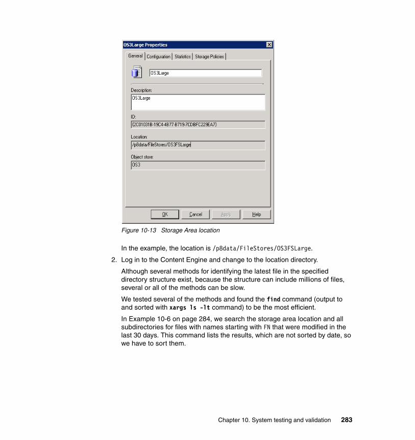
Figure 10-13 Storage Area location
In the example, the location is /p8data/FileStores/OS3FSLarge.
2. Log in to the Content Engine and change to the location directory.
Although several methods for identifying the latest file in the specified directory structure exist, because the structure can include millions of files, several or all of the methods can be slow.
We tested several of the methods and found the find command (output to and sorted with xargs ls -lt command) to be the most efficient.
In Example 10-6 on page 284, we search the storage area location and all subdirectories for files with names starting with FN that were modified in the last 30 days. This command lists the results, which are not sorted by date, so we have to sort them.
Chapter 10. System testing and validation 283

Example 10-6 find, xargs, and ls commands
$ find /p8data/FileStores/OS3FSLarge -name 'FN*' -type f -mtime -30 >/tmp/find_latest_doc.out$ xargs ls -lt < /tmp/find_latest_doc.out |head -1-rw-r--r-- 1 p8OSusr p8OSgrp 1024 Oct 29 21:18 /p8data/FileStores/OS3FSLarge/content/FN0/FN7/FN8/FN{05A4335A-DA16-49A4-96A7-30B10234F5EA}{2C01031B-19C4-4B77-B719-7CDBFC229EA7}-0.txt
Notice the following information in the example:
– Directory:
/p8data/FileStores/OS3FSLarge/content/FN0/FN7/FN8
– File name:
FN{05A4335A-DA16-49A4-96A7-30B10234F5EA}{2C01031B-19C4-4B77-B719-7CDBFC229EA7}-0.txt
As described in Chapter 4, “FileNet P8 data relationships and dependencies” on page 67, the document reference can be determined by the file name of the content file. The reference is called the object_id in the database and ID in Enterprise Manager and is the GUID located immediately after the FN in the file name (bold in the example).
3. Query the object store for the ID:
a. Start Enterprise Manager.
b. Right-click the object store that contains the Storage Area.
c. Click Search.
d. Click Document from the Select From Table drop-down menu.
e. In row A of the Criteria section (Figure 10-14 on page 285), select or enter the following values:
i. Column: ID
ii. Condition: Equal To
iii. Value: {05A4335A-DA16-49A4-96A7-30B10234F5EA}
f. Click OK.
284 Disaster Recovery and Backup Solutions for IBM FileNet P8 Version 4.5.1 Systems

Figure 10-14 Query for ID
Alternately, in Enterprise Manager, you can use the SQL View and perform the same search:
a. Start Enterprise Manager.
b. Right-click the object store that contains the Storage Area.
c. Click Search.
d. Click View → SQL View.
e. In the SQL Text box, enter the following text:
SELECT [This], [id] FROM [Document] where [id]={05A4335A-DA16-49A4-96A7-30B10234F5EA}
Chapter 10. System testing and validation 285

f. Click OK.
See Figure 10-15
Figure 10-15 Query results
g. Right-click and select Properties. Verify that the document is as expected.
If the query returns a result, you can be confident that the document reference exists in the Content Engine database. If not, you can output a larger set of files from the previous commands and determine at what time the file storage area files are newer than the Content Engine database. As a business, you can then decide the best resolution, including options such as verifying that you restored the latest database backup and redo logs, and identifying and resubmitting the missing data.
10.2.3 Process Engine internal consistency
The Process Engine stores all of its internal data in a database, so it is unlikely to be inconsistent the same way that Image Services and Content Engine can be. However, the objects in the various tables within the database can become inconsistent.
To test for internal consistency, run the vwverify Process Engine tool. See Example 10-7 on page 287.
286 Disaster Recovery and Backup Solutions for IBM FileNet P8 Version 4.5.1 Systems

Example 10-7 Running the vwverify tool
ffnlpeprod(fnsw)/home/fnsw> vwverify -r 601 -Y p8AdminUser+itso13sjConnecting to VWService0:ProcessEngine:FileNetIsolated Region = 601
Queues:-------Delay(0)39600 queue work objects: 39626, total: 39626Tracker(0)20750 queue work objects: 20754, total: 60380Conductor queue work objects: 0, total: 60380CompleteWF queue work objects: 0, total: 60380CE_Operations queue work objects: 0, total: 60380WorkQueue queue work objects: 0, total: 60380InstructionSheetInterpreter(0) queue work objects: 0, total: 60380Inbox(0)22200 queue work objects: 22201, total: 82581WSRequest(0) queue work objects: 0, total: 82581
Rosters:--------LoadTest400 roster work objects: 423, total: 423DefaultRoster82150 roster work objects: 82158, total: 82581Summary:-------- Total work objects counted: 82581sort < vwvfytmp.txt > vwvfyrec.txt/bin/rm vwvfytmp.txt
No fixup required
To specify the fixup option, run the command with the -f option:
$ vwverify -f -r 601 -Y p8AdminUser+itso13sj
Note: See IBM FileNet P8 documentation → System Administration → Process Administration → Administrative tools for more information about vwverify.
Chapter 10. System testing and validation 287

10.2.4 Image Services consistency
Image Services stores document content in one or more storage locations and references to the document’s location in an internal MKF database, named Permanent database in a table named docs. This database and other MKF databases in Image Services are not stored in an RDBMS and can be accessed only with Image Services tools. In addition, when Image Services is run on a UNIX system, the databases are stored in raw volumes, so they are more difficult to back up. Image Services includes a backup tool named Enterprise Backup and Restore (EBR), which can back up the raw data to files in a file system. Include this in your Image Services backup strategy. The user-defined properties (for example, last name and account number), the document class, creation date, security, and other system properties are stored in an RDBMS database named Index database and a table named Doctaba. Therefore, for every document in Image Services, the following items exist:
� One record in the Permanent database� One record in the Index database� The actual content is stored on media.
The media can include optical surfaces (OSAR), virtual surfaces stored on magnetic disk (MSAR), and protected storage devices such as the IBM DR550, IBM Information Archive. and NetApp® Snaplock.
The databases and storage media must be consistent. If the records in the Permanent database are missing, the document content would not be able to be located. If records are missing from the Index database, the user is unable to search for the document or is unaware of the existence of the documents. If the storage media is missing, users are not able to view the documents. It is therefore important for the two databases and the storage to be backed up in synchronization.
The dbverify toolTo test for consistency between these databases and media storage, Image Services provides a tool called dbverify, which reports documents that are missing from either database and, optionally, verifies that the documents can be retrieved from the storage location.
You can limit dbverify to a range of document IDs. Running dbverify without specifying a doc_id range can result in a very long operation, so we suggest running it periodically using a starting doc_id that is the ending doc_id in the previous instance. By using this approach, you will have a known point in time when the system was consistent and start dbverify at that point. Optionally, you can start dbverify from a doc_id that was created the day before the disaster.
288 Disaster Recovery and Backup Solutions for IBM FileNet P8 Version 4.5.1 Systems

To run dbverify, perform the following steps:
1. Log in to the Image Services server as Image Services administrator (fnsw).
2. Run dbverify with the appropriate syntax (Example 10-8):
$ dbverify -s 0 -e 0xFFFFFFFF -o -R0
The syntax has the following flags:
-s: Starting doc_id
-e: Ending doc_id
-o: Identify documents that are not on media
-R: Number of retries
The syntax provided in the example runs dbverify command against all the documents.
Example 10-8 The dbverify command
fnlisprod(fnsw)/home/fnsw> dbverify -s 0 -e 0xFFFFFFFF -o -R0....................................................................Number of documents missing in the index database : 0 (/fnsw/local/logs/inx_logs/Midx20091106_143831)Number of documents missing in the locator database : 0 (/fnsw/local/logs/inx_logs/Mloc20091106_143831)Number of documents missing in the media : 0 (/fnsw/local/logs/inx_logs/Modk20091106_143831)Number of documents fetched from the index database : 1002998 (last doc id is 1406006)Number of documents fetched from the locator database : 1002998 (last doc id is 1406006)
oddumpThe dbverify tool is excellent for checking cross-consistency between the two document databases and for checking whether those documents exist on media. However, it does not look at the media and verify that the documents that are contained in it are in the databases. In certain situations, you might not be sure whether documents on media are referenced in the databases. To test for that
Note: When using CFS-IS, there are several use cases where the document is not stored in the Index database, which would cause dbverify to report documents missing from the index database. See the System Tools Reference Manual in the Product Documentation for FileNet Image Services Web site for more information about dbverify and oddump:
http://www.ibm.com/support/docview.wss?rs=3283&uid=swg27010558
Chapter 10. System testing and validation 289

situation, use the oddump tool; it finds the highest doc_id in the current media surfaces. We can then search for the doc_id in the databases. Image Services uses families that are similar to P8 storage areas. Because more than one family might exist, be sure to check the active (current) surface for each active family.
The process is as follows:
1. Find the active media surface for the primary media families using MKF_tool, which has the following information (Example 10-9):
MKF_tool: MKF database query toolfamily_disk: Table containing family and surface informationis_primary: 1=primary, 2=tranlog (backup copy)family_name: Name of the media familycurrent_surfs: Active surface for the family
Example 10-9 Using MKF_tool to find the active surfaces
<MKF_tool>select family_disk * where is_primary=1 showing family_name current_surfscurrent_surfs........3016family_name.........."msar_1gb_family"-----------------------------------------------------------------------current_surfs........3014family_name.........."msar_4gb_family"<MKF_tool>quit
In our example, we want to look at the two surfaces 3014 and 3016 for the highest doc_id contained in each.
2. Use the oddump tool to find the highest doc_id on the selected surfaces (Example 10-10):
Example 10-10 Using oddump to find highest doc_id
fnlisprod(fnsw)/home/fnsw> oddump
ODDUMP -- Optical disk dump.
Logical drive number? (0, 1, ..., 9, a, b, c or CR=none) : 1
Drive successfully opened. Checking label . . . Disk is labeled; Surface id is 3014.
Note: This method works only for documents stored on surface based media (MSAR and OSAR).
290 Disaster Recovery and Backup Solutions for IBM FileNet P8 Version 4.5.1 Systems

Type '?' for help
<oddump:lib a:drive 1>loadSurface id (CR to specify slot) 3014Disk is labeled; Surface id is 3014.Disk swap succeeded<oddump:lib a:drive 1>docidrangeGet doc id ranges for all files? (y/n): : y
SSN: 1100555555 Min doc_id: 263501 Max doc_id: 1406006<oddump:lib a:drive 1>loadSurface id (CR to specify slot) 3016Disk is labeled; Surface id is 3016.Disk swap succeeded<oddump:lib a:drive 1>docidrangeGet doc id ranges for all files? (y/n): : y
SSN: 1100555555 Min doc_id: 1406011 Max doc_id: 1406011<oddump:lib a:drive 1>quit
Table 10-1 lists the highest doc_id for each active primary surface in our example.
Table 10-1 Highest doc_id for each active surface
3. Now that you have the doc_ids, use one of the following ways to determine whether the doc_ids are in the databases. (IDM Find is an excellent tool to verify the document in the database. If you prefer a command-line approach, you may use database queries.)
– IDM Find for Index database
Finding a document with IDM Find (doc_id in the results section) verifies that the document is in the Index database.
Figure 10-16 on page 292 shows a search for doc_id 1406006.
Family Surface Highest doc_id
msar_4gb_family 3014 1406006
msar_1gb_family 3016 1406011
Chapter 10. System testing and validation 291

Figure 10-16 IDM Find for doc_id 1406006
– IDM Find for the Permanent database
Successfully opening the document with IDM Find verifies that the document is in the Permanent database and is on the media.
– Database query for the doc_id in the Index database
The tool to use for querying the Index database varies depending on the type of database. Our example uses DB2, therefore, we use the appropriate DB2 commands. See Example 10-11.
Example 10-11 DB2 query for f_docnumber 1406006
fnlisprod(fnsw)/fnsw> db2db2 => connect to INDEXDB user f_maint using itso13sj
Database Connection Information
Database server = DB2/AIX64 9.7.0 SQL authorization ID = F_MAINT Local database alias = INDEXDB
db2 => select f_docnumber from f_sw.doctaba where f_docnumber=1406006
F_DOCNUMBER ------------
292 Disaster Recovery and Backup Solutions for IBM FileNet P8 Version 4.5.1 Systems

1406006.
1 record(s) selected.
db2 => quitDB20000I The QUIT command completed successfully.
– Database query for the doc_id in the Permanent database
Because the Permanent database is an MKF database, we use MKF_tool for the query. See Example 10-12.
Example 10-12 MKF_tool query for doc_id 1406006
<MKF_tool>select docs doc_id=1406006doc_id............1406006 pages...................1 surface_id_1.........3014 offset_1..........1400566 surface_id_2............0 offset_2................0back_contig.............2 ce_os_id.............1001<MKF_tool>quitfnlisprod(fnsw)/fnsw>
10.3 Testing for consistency between applications
In 10.2, “Testing for internal consistency” on page 275, we tested for consistency within each P8 application. Now, we test for consistency between applications. We test the following relationships for inconsistency:
� Content Engine and Process Engine
� Content Engine and Content Search Engine
� Content Engine and Image Services
Remember that in these exercises, we are not testing the integrity of all data between these applications. Rather, we are looking to validate that the data was restored or recovered to the same point in time. So, we look for the latest activity or object in one application that refers to another application, then verify that it exists in the other application. For example, for documents in Content Engine that refer to document content in Image Services, we determine the newest one of these and check whether it exists in Image Services. Similarly, for document content in Image Services that is referenced from Content Engine, we determine the newest one and verify that it exists in Content Engine.
Chapter 10. System testing and validation 293
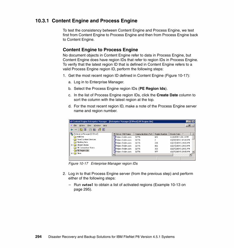
10.3.1 Content Engine and Process Engine
To test the consistency between Content Engine and Process Engine, we test first from Content Engine to Process Engine and then from Process Engine back to Content Engine.
Content Engine to Process EngineNo document objects in Content Engine refer to data in Process Engine, but Content Engine does have region IDs that refer to region IDs in Process Engine. To verify that the latest region ID that is defined in Content Engine refers to a valid Process Engine region ID, perform the following steps:
1. Get the most recent region ID defined in Content Engine (Figure 10-17):
a. Log in to Enterprise Manager.
b. Select the Process Engine region IDs (PE Region Ids).
c. In the list of Process Engine region IDs, click the Create Date column to sort the column with the latest region at the top.
d. For the most recent region ID, make a note of the Process Engine server name and region number.
Figure 10-17 Enterprise Manager region IDs
2. Log in to that Process Engine server (from the previous step) and perform either of the following steps:
– Run vwtool to obtain a list of activated regions (Example 10-13 on page 295).
294 Disaster Recovery and Backup Solutions for IBM FileNet P8 Version 4.5.1 Systems

Example 10-13 vwtool regions
fnlpeprod(fnsw)/fnsw/bin> vwtool
User name: p8AdminUserPassword: vwtool : fnlpeprod [Aix Server Production (3 silos) (DB2 Blob 512 MB) -- {dap451.100 pe451.062x pui451.075} Jul 24 2009 13:52:44 en ]
Type '?' for help
<vwtool:1>regionsDisplay isolated regions in memory or on disk (CR=m or d): dRegions are: 1, 2, 601<vwtool:601>quit
– Alternately, you can start Process Task Manager, which displays activated and unactivated regions. See Figure 10-18.
Figure 10-18 Process Task Manager region IDs
Process Engine to Content EngineThe Process Engine can have references to document objects in Content Engine. To check for consistency, we identify the most recent work object in Process Engine that has a referenced Content Engine document. The Process Engine is divided into multiple regions and the objects are divided into multiple
Chapter 10. System testing and validation 295

rosters and queues. Depending on your use of Process Engine, you might have to search multiple regions, rosters, and queues. However, you might be able to identify the region and roster or queue that is likely to have the most recent activity, and if those are consistent with Content Engine, you can be confident that all other Process Engine data is also.
This example checks one Process Engine region and one roster (DefaultRoster) for the latest work object that has a referenced Content Engine document. Then, the example queries the Content Engine for that document. You will have to repeat the process for all Process Engine regions and rosters as necessary. Perform the following steps:
1. Decide how far in the past you want to start the search for work objects. For our example, we use 26 October 2009 (the syntax mm/dd/yyyy is 10/26/2009 in Example 10-14). Our search includes all data between 10/26/2009 and the current date.
2. Convert the starting date to the date and time format that the vwtool uses (by using vwtool’s convert command). See Example 10-14.
Example 10-14 vwtool date time conversion
<vwtool:1>convertConvert: t - Time number to string s - String to time number e - Error tuple to three part p - Three part error to error tuple l - Log event type number to string i - User id to user name n - User name to user id w - wob number decode b - wob number encode (internal representation to wob)Choice? ('t', 's', 'e', 'p', 'l', 'w' or 'b'): sCurrent System Mask: 'mm/dd/yy HH:tt:ss'Time Mask (CR=system mask): Enter local time string (CR=''): 10/26/2009 00:00:00DTI Local Struct ...[0sec 0min 0hr 26mday 9mon 2009year 2wday 313yday 0dst]DTI Local String ...[10/26/09 00:00:00]DTI GMT Struct ...[0sec 0min 4hr 26mday 9mon 2009year 1wday 298yday 0dst]DTI GMT String ...[10/26/09 04:00:00]DTI Local String from UTC...[10/26/09 00:00:00]PE Local Time...[0x0000000000000000]........1256529600 => '10/26/2009 00:00:00' PE GMT Time...[0x0000000000000000]...1256529600 => GMT Time 10/26/09 04:00:00
The conversion resulted in the value 1256529600.
296 Disaster Recovery and Backup Solutions for IBM FileNet P8 Version 4.5.1 Systems

3. Enable the output to a file and search for work objects later than this value in the DefaultRoster roster using the vwtool’s wobquery command. See Example 10-15.
Example 10-15 wobquery
<vwtool:1>region 601Current region is: 1New region is: 601<vwtool:601>hardcopyOutput file: /tmp/Region601DefaultRoster.txt---------------------------Wed, 11 Nov 2009 12:28:37---------------------------vwtool : fnlpeprod [Aix Server Production (3 silos) (DB2 Blob 512 MB) -- {dap451.100 pe451.062x pui451.075} Jul 24 2009 13:52:44 en ]Outputting to file '/tmp/Region601DefaultRoster.txt' and the terminal<vwtool:601>wobqueryQueue or roster name: DefaultRosterSelective query? (y/CR=n): yIndex name (? for help, CR = 'F_WobTag'): Minimum value of field 'F_Tag', type=String, (CR=none): Maximum value of field 'F_Tag', type=String, (CR=none): Filter condition (SQL expression): F_StartTime>1256529600Display work objects, invocations, or roster records (CR=w, i, or r): Display size? (y/CR=n): nVerbose output? (CR=y/n): n---------------------------Wed, 11 Nov 2009 12:30:03---------------------------F_WobNum............8F6AE8C6CE4D11DE8D440000C0A864DE F_WFDeadline.......................................0 F_WFReminder.......................................0 F_Trackers*.......................................{}F_Comment*........................................'' F_Responses*......................................{} F_ResponseCount*...................................0F_Subject........................'AutoCase Workflow' F_SourceDoc......................'AutoCase Workflow' ID................................................''Customer..........................................'' * => field modified after work object created---------------------------Wed, 11 Nov 2009 12:30:03---------------------------F_WobNum............1C1D3D2ACE5611DE8D440000C0A864DE
Chapter 10. System testing and validation 297
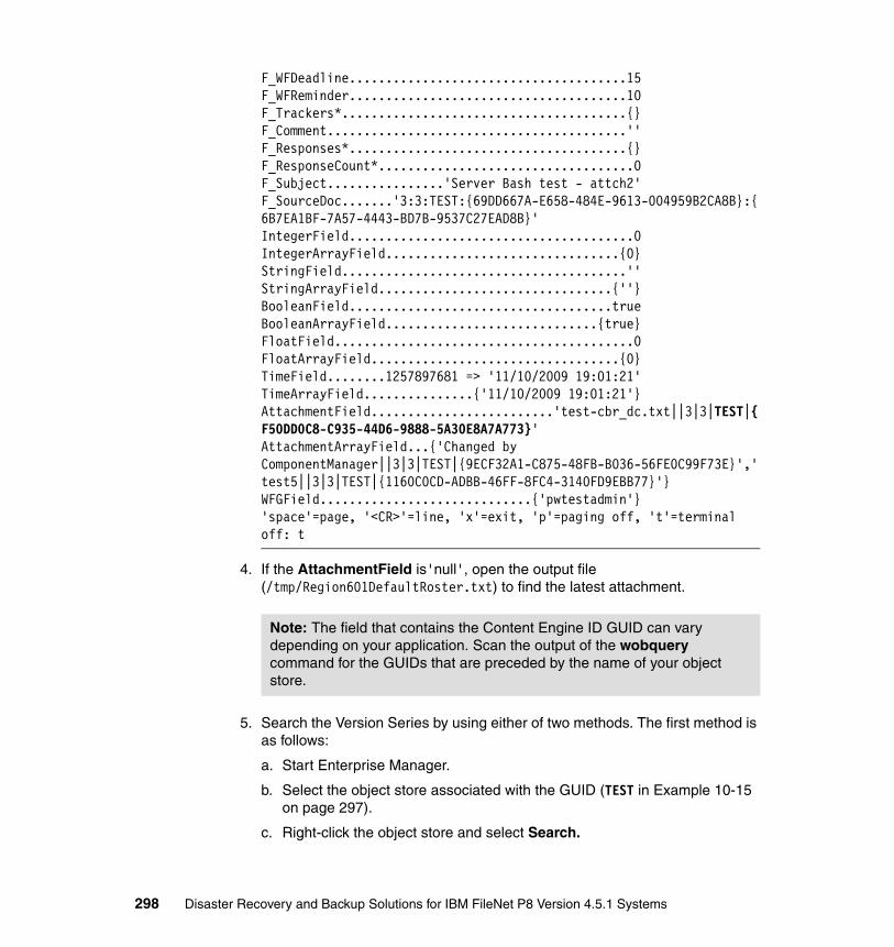
F_WFDeadline......................................15 F_WFReminder......................................10 F_Trackers*.......................................{}F_Comment.........................................'' F_Responses*......................................{} F_ResponseCount*...................................0F_Subject................'Server Bash test - attch2' F_SourceDoc.......'3:3:TEST:{69DD667A-E658-484E-9613-004959B2CA8B}:{6B7EA1BF-7A57-4443-BD7B-9537C27EAD8B}'IntegerField.......................................0 IntegerArrayField................................{0} StringField.......................................''StringArrayField................................{''} BooleanField....................................true BooleanArrayField.............................{true}FloatField.........................................0 FloatArrayField..................................{0} TimeField........1257897681 => '11/10/2009 19:01:21'TimeArrayField...............{'11/10/2009 19:01:21'} AttachmentField.........................'test-cbr_dc.txt||3|3|TEST|{F50DD0C8-C935-44D6-9888-5A30E8A7A773}'AttachmentArrayField...{'Changed by ComponentManager||3|3|TEST|{9ECF32A1-C875-48FB-B036-56FE0C99F73E}','test5||3|3|TEST|{1160C0CD-ADBB-46FF-8FC4-3140FD9EBB77}'}WFGField.............................{'pwtestadmin'}'space'=page, '<CR>'=line, 'x'=exit, 'p'=paging off, 't'=terminal off: t
4. If the AttachmentField is'null', open the output file (/tmp/Region601DefaultRoster.txt) to find the latest attachment.
5. Search the Version Series by using either of two methods. The first method is as follows:
a. Start Enterprise Manager.
b. Select the object store associated with the GUID (TEST in Example 10-15 on page 297).
c. Right-click the object store and select Search.
Note: The field that contains the Content Engine ID GUID can vary depending on your application. Scan the output of the wobquery command for the GUIDs that are preceded by the name of your object store.
298 Disaster Recovery and Backup Solutions for IBM FileNet P8 Version 4.5.1 Systems

d. Select Document from the Select From Table drop-down list.
e. In row A of the Criteria section (see Figure 10-19), select or enter the following values:
• Column: Version Series
• Condition: Equal To
• Value: {F50DD0C8-C935-44D6-9888-5A30E8A7A773}
f. Click OK.
Figure 10-19 Enterprise Manager query for Version Series
A second method for searching the Version Series is as follows:
a. Start Enterprise Manager.
b. Select the object store associated with the GUID (TEST in Example 10-15 on page 297).
c. Right-click the object store and click Search.
d. Select View → SQL View.
Version Series: In the AttachmentField, the Process Engine stores the Version Series GUID that represents all versions of a document instead of the ID of a specific version of a document.
Chapter 10. System testing and validation 299

e. For the SQL Text, enter the following string (see Figure 10-20):
SELECT [This], [DateCreated], [DateLastModified], [DocumentTitle], [Name], [VersionStatus] FROM [Document] WHERE ([VersionSeries] = Object('{F50DD0C8-C935-44D6-9888-5A30E8A7A773}'))
f. Click OK.
Figure 10-20 Enterprise Manager query for Version Series with SQL View
10.3.2 Content Engine and Content Search Engine
To test the consistency between Content Engine and Content Search Engine, we test first from Content Search Engine to Content Engine and then from Content Engine back to Content Search Engine.
Content Search Engine to Content EngineIf the Content Search Engine has a record of Content Engine document that is not in the Content Engine, then the Content Search Engine data might have been restored to a newer point in time than the Content Engine database.
300 Disaster Recovery and Backup Solutions for IBM FileNet P8 Version 4.5.1 Systems

To check if Content Search Engine has a record of Content Engine document that is not in Content Engine, perform the following steps:
1. With an HTTP browser, log in to the K2 Dashboard as a K2 operating system user (p8OSusr):
http://fnlcsev.fn.ibm.com:9990/verity_dashboard/main.jsp
2. Click Collections (from the left-side pane) and verify the following information:
– Each collection is online. Figure 10-21 shows the collection status.
Figure 10-21 K2 Dashboard collections status
– The “Date Last Modified” is as expected. You might have to scroll the window to the right to see this information. Figure 10-22 shows that the K2 Dashboard collection data is modified.
Figure 10-22 K2 Dashboard collections data modified
Chapter 10. System testing and validation 301

3. Search for the most recently indexed documents in the collection:
a. In the left pane, select K2 Servers. See Figure 10-23.
b. Click your search server in the main window.
c. Click Test Search.
d. In the Scope section, clear all check boxes except one object store collection.
e. Click Search.
Figure 10-23 K2 Dashboard test search of object store OS3
4. In the Results section at the bottom of the window, the search lists the most recently indexed documents in the specified collection. In our example, the document reference is IZDA8DFAFF51864F788ED3956FE077E932X0. Repeat this process for each collection and note the resulting document reference ID for each.
5. To query the Content Engine for the document referenced in Content Search Engine, first modify the format of the ID to a format that is expected by Enterprise Manager. The original format of the ID is as follows:
IZDA8DFAFF51864F788ED3956FE077E932X0
a. Replace the letters IZ, at the start of the ID, and the letters X0, at the end of the ID, with curly braces.
b. Add a dash after the character in positions 8, 12, 16, and 22.
302 Disaster Recovery and Backup Solutions for IBM FileNet P8 Version 4.5.1 Systems

The result of these changes is as follows:
{DA8DFAFF-5186-4F78-8ED3-956FE077E932}
Use the resulting ID to query the Content Engine from Enterprise Manager. See Figure 10-24.
Figure 10-24 Enterprise Manager Query for ID from K2 Dashboard
Content Engine to Content Search EngineFirst, determine the newest document in Content Engine that should be indexed in Content Search Engine. Then, determine whether it has been indexed.
Find the newest document that has been indexed for each object store, which can be accomplished in several ways:
� The easiest method is to query the object store for documents in a CBR-enabled document class and specify a date range. Because this query can be slow, using it might not be the best approach.
� The preferred method is to query the document database table for the highest rowid (therefore the newest document) that has been marked as indexed, and then query the same table for the Content Engine ID for that rowid.
Chapter 10. System testing and validation 303

Use the second (preferred) method as follows:
1. Query the document table for the highest rowid that has a value in the f_ce_row_id. Note the following information:
rowid Special database column that uniquely represents a row in a table
docversion Content Engine object store table that contains one row per document
indexation_id Column in docversion that contains the Content Search Engine Collection ID. If null, the document has not been indexed
object_id ID that uniquely identifies a specific version of a document
2. Query the document table for the object_id of the document from the previous step. See Example 10-16.
Example 10-16 Identify the highest indexed document
db2 => select max(rowid) from docversion where indexation_id is not null
1 -----------------------------------x'000000000208000B000000000274041A'
1 record(s) selected.
db2 => select object_id from docversion where rowid=x'000000000208000B000000000274041A'
OBJECT_ID -----------------------------------x'D65F242BA8CDF44A8155191CC57D8606'
1 record(s) selected.
3. Convert the format, as stored in the database, to the format that is used by Enterprise Manager (curly braces format, described in step 5 on page 302).
304 Disaster Recovery and Backup Solutions for IBM FileNet P8 Version 4.5.1 Systems

See Example 10-17.
Example 10-17 GUID conversion DB to curly bracket form
$ echo x'D65F242BA8CDF44A8155191CC57D8606' |sed s/x// |sed s/\'//g |awk '{printf ("{%s%s%s%s-%s%s-%s%s-%s-%s}\n",substr($1,7,2),substr($1,5,2),substr($1,3,2),substr($1,1,2),substr($1,11,2),substr($1,9,2),substr($1,15,2),substr($1,13,2),substr($1,17,4),substr($1,21,12))}'
{2B245FD6-CDA8-4AF4-8155-191CC57D8606}
The DB format is:
x'D65F242BA8CDF44A8155191CC57D8606'
The Enterprise Manager format is:
{2B245FD6-CDA8-4AF4-8155-191CC57D8606}
Notes:
� The previous command to convert the GUID is written on a single line. It can be run on any system with a UNIX shell. If the line is too long for your shell, create a file with the GUID and use the cat command for the file instead of echoing the GUID.
bash$ echo x'D65F242BA8CDF44A8155191CC57D8606' > c:/temp/GUID
bash$ cat c:/temp/GUID | sed s/x// |sed s/\'//g |awk '{printf ("{%s%s%s%s-%s%s-%s%s-%s-%s}\n",substr($1,7,2),substr($1,5,2),substr($1,3,2),substr($1,1,2),substr($1,11,2),substr($1,9,2),substr($1,15,2),substr($1,13,2),substr($1,17,4),substr($1,21,12))}'
{2B245FD6-CDA8-4AF4-8155-191CC57D8606}
� To convert a curly braces format to a DB format, use the following command:
$ echo {2B245FD6-CDA8-4AF4-8155-191CC57D8606} |sed s/{// |sed s/}// |sed s/\-//g |awk '{printf ("xQ%s%s%s%s%s%s%s%s%s%sQ\n",substr($1,7,2),substr($1,5,2),substr($1,3,2),substr($1,1,2),substr($1,11,2),substr($1,9,2),substr($1,15,2),substr($1,13,2),substr($1,17,4),substr($1,21,12))}' |sed s/Q/\'/g
x'D65F242BA8CDF44A8155191CC57D8606'
Chapter 10. System testing and validation 305

4. Convert the GUID from the Enterprise Manager format to the format expected by the K2 Dashboard. We simply reverse the process that is described in “Content Search Engine to Content Engine” on page 300. We replace curly braces and remove dashes, as shown:
– Enterprise Manager format:
{2B245FD6-CDA8-4AF4-8155-191CC57D8606}
– K2 format:
IZ2B245FD6CDA84AF48155191CC57D8606X0
5. Search the document in the K2 Dashboard (using the K2 format) to determine whether it is in the Content Search Engine collection:
a. With an HTTP browser, log in to the K2 Dashboard as a K2 operating system user (p8OSusr):
http://fnlcsev.fn.ibm.com:9990/verity_dashboard/main.jsp
b. Click K2 Servers in the left-side pane. See Figure 10-25.
Figure 10-25 K2 Dashboard search by GUID
c. Select your search server in the main window.
d. Click Test Search.
306 Disaster Recovery and Backup Solutions for IBM FileNet P8 Version 4.5.1 Systems

e. In the Scope section, select the collection that is associated with the object store you used in the database query, or select all collections.
f. In the Query section and the Search for field, enter the GUID in the K2 format that you determined in step 4 on page 306.
g. Click Search.
6. If the document does not exist, re-index the collection.
10.3.3 Content Engine and Image Services
The three use cases for CFS-IS are as follows:
� Use case 1: Documents are added through Image Services, federated to Content Engine, and the Image Services catalog entries remain in the Index database.
� Use case 2: Documents are added through Image Services, federated to Content Engine, and the Image Services catalog entry is deleted from the Image Services catalog when federated.
� Use case 3: Documents are added through Content Engine and the content is stored in Image Services.
We have found the first use case to be the most common among customers. In the systems we use for this book, we configured the first use case and in this section, we describe how to test for consistency, assuming the first use case. The second and third use cases have no catalog entries in Image Services; in the third use case, the Content Engine document ID GUID is not fabricated from the Image Services doc_id. These facts affect the testing process. For use case 2 and 3, we do not include testing for consistency.
Image Services to Content EngineDetermine whether the newest documents in Image Services (that have been federated) have corresponding records in Content Engine. First, identify the highest doc_id that has been federated, then check Content Engine for the doc_id.
Note: We use DB2 tools for several of these steps. Use the appropriate commands and syntax for your system.
Chapter 10. System testing and validation 307

Identifying the highest federated doc_id in the Image Services Index database
Identify the highest federated doc_id in the Image Services Index database:
1. Query the document table for the highest rowid that has a value in the f_ce_row_id:
rowid Special database column that uniquely represents a row in a table.
doctaba Image Services table that contains one row per doc_id.
f_ce_os_id Column in doctaba that contains the Content Engine object store ID. If null, the document has not been federated.
f_docnumber ID in the document table that uniquely identifies a single document.
2. Query the document table for the doc_id for the document (from the previous step). See Example 10-18.
Example 10-18 Identify the highest federated doc_id
db2 => select max(rowid) from f_sw.doctaba where f_ce_os_id is not null
1 -----------------------------------x'00000000114200B500000000033A5A02'
1 record(s) selected.
db2 => select f_docnumber from f_sw.doctaba where rowid=x'00000000114200B500000000033A5A02'
F_DOCNUMBER ------------ 1406012.
Querying the Content Engine database for the doc_id foundThere are several ways to query the Content Engine database for the doc_id (described in “Identifying the highest federated doc_id in the Image Services Index database” on page 308):
� Query the Content Engine database using a mapped property. This method is the easiest, if you have mapped the Image Services doc_id (f_docnumber) with CFS-IS. If so, use Enterprise Manager to search the object store and
308 Disaster Recovery and Backup Solutions for IBM FileNet P8 Version 4.5.1 Systems

document class for the mapped Image Services doc_id property. See Figure 10-26.
Figure 10-26 Enterprise Manager search for mapped doc_id
If the Image Services doc_id is not mapped, select an appropriate Image Services user index that is mapped and that uniquely identifies the document. Then, use Enterprise Manager to search for it. For example, if in Image Services you have an index named AccountNumber and it is mapped with CFS-IS, use IDM Find to list the AccountNumber for the doc_id that is identified. Use Enterprise Manager to search for the mapped Content Engine AccountNumber property.
� Query the Content Engine database for the doc_id using the Document Title.
By default, the Document Title of a federated document in Content Engine contains the name of the fixed content device and the Image Services doc_id. Therefore, we can search for Content Engine documents with the identified doc_id in the title. See Figure 10-27 on page 310.
Note: Searching with Like this way can be very slow and is not recommended unless your database is small. The Enterprise Manager Search warns you of the performance impact when you attempt this.
Chapter 10. System testing and validation 309

Figure 10-27 Enterprise Manager query by Document Title
� Query the Content Engine database for the doc_id using the Object_id field.
Although Content Engine stores the Image Services doc_id in its document table, it is stored in a GUID format. Therefore, we must convert the Image Services native doc_id to the GUID format before searching for it in Enterprise Manager. The Content Engine Object_id GUID for a CFS-IS federated document is made from the GUID of the fixed content device and hexidecimal value of the Image Services doc_id. Query the database:
a. Identify the name of the fixed content device in Enterprise Manager:
i. Start Enterprise Manager.
ii. Select Fixed Content Devices.
iii. Right-click the desired Fixed content Device.
iv. Click Properties.
v. Note the GUID in the ID field. See Figure 10-28 on page 311.
Note: Converting the Image Services doc_id to a Content Engine GUID is somewhat complicated. Partly for this reason, be sure to use mapping Image Services doc_id as part of your CFS-IS strategy.
310 Disaster Recovery and Backup Solutions for IBM FileNet P8 Version 4.5.1 Systems

Figure 10-28 Fixed content device GUID
In our example, the GUID is {13F89811-0B19-4BB0-AEAE-A22B3A0E396D}
b. In the third segment of the GUID, replace the number 4 with a 5:
Before: {13F89811-0B19-4BB0-AEAE-A22B3A0E396D}
After: {13F89811-0B19-5BB0-AEAE-A22B3A0E396D}
� Convert the Image Services doc_id to hexidecimal value with Windows Calculator or other tool:
Decimal: 1406012
Hexidecimal: 15743C
� Add zeros to the beginning of the hex value so that you have eight digits:
Before: 15743C
After: 0015743C
� Replace the first segment of the FCD GUID with the result of the doc_id in hex:
Before: {13F89811-0B19-5BB0-AEAE-A22B3A0E396D}
After: {0015743C-0B19-5BB0-AEAE-A22B3A0E396D}
The resulting GUID is how the Content Engine stores the federated Image Services document.
Chapter 10. System testing and validation 311

� Use Enterprise Manager to search for this GUID in the ID field. See Figure 10-29.
Figure 10-29 Enterprise Manager query by ID
If you determine that documents in Image Services are not in Content Engine, you can re-export the documents using the Image Services Remote Admin Console.
Content Engine to Image ServicesDetermine whether the most recent federated CFS-IS documents are in Content Engine, use the Content Engine Consistent Checker:
1. Log in to a Windows system where Consistency Checker is installed, typically the same location as Enterprise Manager. Select Start → Programs → IBM FileNet P8 Platform → FileNet Consistency Checker.
2. Click Select Domain.
3. Select an existing P8 domain or add a new one.
4. In the domain window, enter the login and password information and click Test Connection, and then click OK.
312 Disaster Recovery and Backup Solutions for IBM FileNet P8 Version 4.5.1 Systems

5. The storage areas in the P8 domain are listed. Select the storage area that is configured for CFS-IS. In our example, the storage area is named ISProd_OS2_sa.
6. Limit the documents that are checked to the last two days:
a. Click File → Options.
b. Select either the Validate by Date Created or Validate by Date Modified button. See Figure 10-30.
c. Specify a Starting Date / Time of two days ago.
d. Specify the current date and time for Ending Date / Time.
Figure 10-30 Consistency Checker date range
7. Click OK.
8. Click File → Validate Storage Areas, or click the green arrow at the top left of the window, and then click Start. If you have previously checked the selected storage area, you are prompted to run it again. Click Yes.
Chapter 10. System testing and validation 313
314 Disaster Recovery and Backup Solutions for IBM FileNet P8 Version 4.5.1 Systems

Chapter 11. Working with IBM Information Archive
So far in this book, we describe implementation details for setting up a disaster recovery solution for IBM FileNet P8 Version 4.5.1 systems. We also address system testing and validation for disaster recovery. If your system has a compliance requirement for some of the content, you can use IBM Information Archive as a fixed storage area for this type of content. In this chapter, we briefly describe how to set up the Information Archive appliance for a FileNet P8 system, in association with the disaster recovery topic.
This chapter contains the following topics:
� Setting up an IBM Information Archive appliance
� IBM Information Archive failover scenarios
11
© Copyright IBM Corp. 2010. All rights reserved. 315

11.1 Setting up an IBM Information Archive appliance
The IBM Information Archive appliance includes features that enable it to play a role in a disaster recovery plan. An important feature is that one Information Archive system can be set up to replicate stored data to another Information Archive system. This replication is specific to the Information Archive systems, and it runs along with the more general replication of shared storage, which was set up in 9.5, “Enabling PROD to DR replication” on page 261.
We do not address all issues of installing an Information Archive system, because that is outside the scope of this book. However, we do focus attention to certain configuration features that are important when using Information Archive systems in a disaster recovery solution.
The Information Archive Introduction and Planning Guide, SC27-2324, includes an Initial configuration worksheet. This worksheet collects all the configuration information that is needed by the person installing the Information Archive systems. Table 11-1 on page 317 shows the completed worksheet that we used to build our test environment.
Note the following configuration options:
� Enhanced Tamper Protection: This feature prevents the system super user from going around the protections that are applied to stored documents. Therefore, this feature is normally enabled in a production environment. However, after the feature is enabled, it cannot be turned off again. We therefore choose to delay enabling it until we are confident that our systems are set up properly.
� IP Settings: To perform replication, each Information Archive system must be able to access the Information Archive system in the other environment. Be sure to assign addresses that are usable across environments.
Where private IP addressing is being used, a temptation is to use the same address in each environment, to keep things similar; however, doing so can prevent the connections that are necessary for replication.
� SSAM collection: The Information Archive systems are configured to present an SSAM interface. This is how Information Archive provides the Tivoli Storage Manager API, which FileNet P8 uses to archive and retrieve documents on a fixed content device.
316 Disaster Recovery and Backup Solutions for IBM FileNet P8 Version 4.5.1 Systems

Table 11-1 Initial configuration work sheet
PROD environment DR environment
General
Appliance name fnliaprod fnliadr
Description (optional) PROD Information Archive
DR Information Archive
Time (NTP) server (default: internal)
internal internal
File archive document collections No No
SSAM document collections Yes Yes
Domain name fn.ibm.com fn.ibm.com
Subnet mask /24 /24
Default gateway 192.168.100.60 10.0.200.60
Primary DNS server 192.168.100.61 10.0.200.61
Enhanced Tamper Protection
Do not enable Do not enable
Security - System Passwords
iaadmin (your password) (your password)
iscadmin (your password) (your password)
IP Settings
IP addresses required for both
Management Console server 192.168.100.141 10.0.200.141
Remote Support Manager for Storage server
192.168.100.142 10.0.200.142
ianode 1 192.168.100.143 10.0.200.143
ianode 2 192.168.100.144 10.0.200.144
ianode 3 192.168.100.145 10.0.200.145
Additional IP addresses required only for file archive collections
N/A N/A
Additional IP addresses required only for SSAM collections
Chapter 11. Working with IBM Information Archive 317
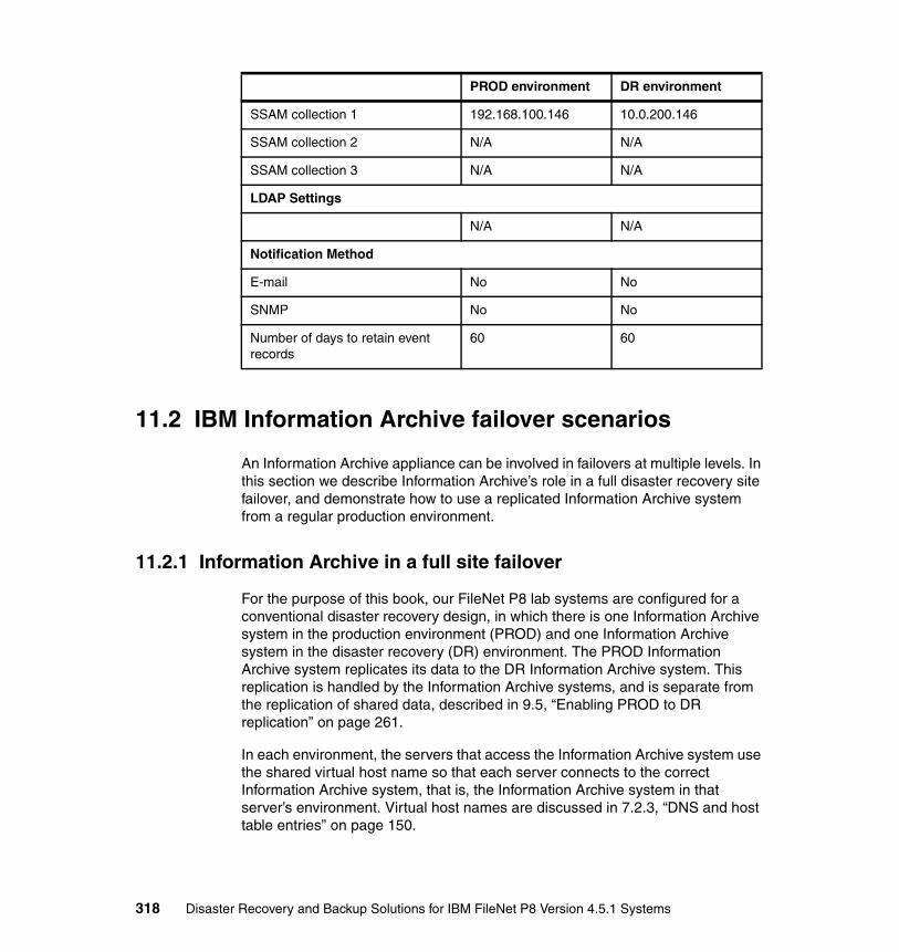
11.2 IBM Information Archive failover scenarios
An Information Archive appliance can be involved in failovers at multiple levels. In this section we describe Information Archive’s role in a full disaster recovery site failover, and demonstrate how to use a replicated Information Archive system from a regular production environment.
11.2.1 Information Archive in a full site failover
For the purpose of this book, our FileNet P8 lab systems are configured for a conventional disaster recovery design, in which there is one Information Archive system in the production environment (PROD) and one Information Archive system in the disaster recovery (DR) environment. The PROD Information Archive system replicates its data to the DR Information Archive system. This replication is handled by the Information Archive systems, and is separate from the replication of shared data, described in 9.5, “Enabling PROD to DR replication” on page 261.
In each environment, the servers that access the Information Archive system use the shared virtual host name so that each server connects to the correct Information Archive system, that is, the Information Archive system in that server’s environment. Virtual host names are discussed in 7.2.3, “DNS and host table entries” on page 150.
SSAM collection 1 192.168.100.146 10.0.200.146
SSAM collection 2 N/A N/A
SSAM collection 3 N/A N/A
LDAP Settings
N/A N/A
Notification Method
E-mail No No
SNMP No No
Number of days to retain event records
60 60
PROD environment DR environment
318 Disaster Recovery and Backup Solutions for IBM FileNet P8 Version 4.5.1 Systems

When a disaster is declared and a full site failover is performed, the Information Archive system in the DR environment must be brought into active service along with the other servers in the DR environment. If global DNS is being used for host name resolution, the virtual host name must be pointed to the DR system, as is done for the other hosts in the environment. After Content Engine starts running, you verify access to the documents stored on the fixed content device (for example, using Enterprise Manager).
11.2.2 Component-level failover of Information Archive
Full site-level failover, as described in 11.2.1, “Information Archive in a full site failover” on page 318, is the most common use for a replicated Information Archive system. Less common is to use the disaster recovery Information Archive system from the production environment, but it is possible, and might be done if, for example, the production Information Archive system suffered a hardware failure. In this section, we demonstrate how to configure FileNet P8 to use another Information Archive server to show the operations involved.
Prior to failover, we assume that an object store is created with a fixed content storage area that is provided by the Information Archive system in the production environment. Some documents have been created in the object store.
When the Information Archive system in the production environment fails, the Information Archive system in the DR environment is brought up and made accessible. The steps in this process are beyond the scope of this book. See the Information Archive documentation for details.
When the Information Archive system in the DR environment is available, open Enterprise Manager, in the production environment, and view the object store. At first, the object store might seem to be working correctly (see Figure 11-1 on page 320). However, remember that there are two parts to a fixed storage area: the staging area (where content is uploaded prior to migration) and the fixed device (Information Archive and Tivoli Storage Manager in this case), as described in 4.1.7, “Fixed storage” on page 87.
Chapter 11. Working with IBM Information Archive 319

The “OnLine” state being reported here is the status of the staging area (which has a zero file count after they are migrated).
Figure 11-1 FCD status in FEM
If you attempt to alter the fixed content device, or retrieve content of a document stored on the fixed content device, it will fail.
For example, when we browse into the object store and double-click a document, an error occurs, as shown in Figure 11-2 on page 321.
320 Disaster Recovery and Backup Solutions for IBM FileNet P8 Version 4.5.1 Systems

Figure 11-2 Enterprise Manager error accessing content from old FCD
To configure the production Content Engine to use the DR Information Archive system, perform the following steps (Figure 11-3 on page 322):
1. In Enterprise Manager, click Fixed Content Devices in the left panel.
2. From the right panel, right-click the fixed device, and select Properties.
3. In the Properties window, change the value for the IP Address attribute. In the example, we have changed it to the 10.0.200.146 address that is used by our DR Information Archive system.
4. Click OK to accept the change.
Chapter 11. Working with IBM Information Archive 321

Figure 11-3 Enterprise Manager configuring new fixed content provider
To verify that access to the fixed content has been restored, browse back to the document we tried to open earlier. This time, double-clicking it retrieves the content and displays it in the appropriate application.
322 Disaster Recovery and Backup Solutions for IBM FileNet P8 Version 4.5.1 Systems

Related publications
The publications listed in this section are considered particularly suitable for a more detailed discussion of the topics covered in this book.
IBM Redbooks
For information about ordering these publications, see “How to get Redbooks” on page 324. Note that some of the documents referenced here may be available in softcopy only.
� Federated Content Management: Accessing Content from Disparate Repositories with IBM Content Federation Services and IBM Content Integrator, SG24-7742
� IBM FileNet Content Manager Implementation Best Practices and Recommendations, SG24-7547
� IBM FileNet P8 Platform and Architecture, SG24-7667
� IBM High Availability Solution for IBM FileNet P8 Systems, SG24-7700
� IBM Midrange System Storage Copy Services Guide, SG24-7822
� IBM Midrange System Storage Hardware Guide, SG24-7676
� IBM Midrange System Storage Implementation and Best Practices Guide, SG24-6363
� IBM System Storage Business Continuity: Part 1 Planning Guide, SG24-6547
� IBM System Storage DS4000 and Storage Manager V10.30, SG24-7010
� Introducing IBM FileNet Business Process Manager, SG24-7509
� WebSphere Application Server V6 System Management & Configuration Handbook, SG24-6451
© Copyright IBM Corp. 2010. All rights reserved. 323
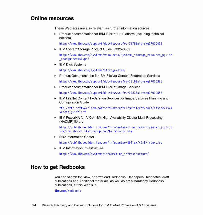
Online resources
These Web sites are also relevant as further information sources:
� Product documentation for IBM FileNet P8 Platform (including technical notices)
http://www.ibm.com/support/docview.wss?rs=3278&uid=swg27010422
� IBM System Storage Product Guide, G325-3369
http://www.ibm.com/systems/resources/systems_storage_resource_pguide_prodguidedisk.pdf
� IBM Disk Systems
http://www.ibm.com/systems/storage/disk/
� Product Documentation for IBM FileNet Content Federation Services
http://www.ibm.com/support/docview.wss?rs=3318&uid=swg27010328
� Product documentation for IBM FileNet Image Services
http://www.ibm.com/support/docview.wss?rs=3283&uid=swg27010558
� IBM FileNet Content Federation Services for Image Services Planning and Configuration Guide
ftp://ftp.software.ibm.com/software/data/cm/filenet/docs/cfsdoc/is/45x/cfs_guide.pdf
� IBM PowerHA for AIX or IBM High Availability Cluster Multi-Processing (HACMP) library
http://publib.boulder.ibm.com/infocenter/clresctr/vxrx/index.jsp?topic=/com.ibm.cluster.hacmp.doc/hacmpbooks.html
� DB2 Information Center
http://publib.boulder.ibm.com/infocenter/db2luw/v9r5/index.jsp
� IBM Information Infrastructure
http://www.ibm.com/systems/information_infrastructure/
How to get Redbooks
You can search for, view, or download Redbooks, Redpapers, Technotes, draft publications and Additional materials, as well as order hardcopy Redbooks publications, at this Web site:
ibm.com/redbooks
324 Disaster Recovery and Backup Solutions for IBM FileNet P8 Version 4.5.1 Systems

Help from IBM
IBM support and downloads
ibm.com/support
IBM Global Services
ibm.com/services
Related publications 325

326 Disaster Recovery and Backup Solutions for IBM FileNet P8 Version 4.5.1 Systems

Index
Symbols.Net API 50
Aaccess control list (ACL) 47activate
CDB file 128DR environment 262DR site 253Journal Based Backup 137obtain list of regions 294
active/active configuration 5active/passive configuration 5add-on components
Image Services 201start and stop 201
alternative backup strategy 131, 133, 135annotation 73applets 53Application Engine (AE) 33
architecture overview 43Content Manager 191data configuration 177EJB transport 171, 257farming capabilities 65manage interfaces 53stopping 133, 140
application server 45asynchronous replication 10asynchronous replication solution 13authentication information 64availability 21
Bbackup
alternative strategy 131, 133, 135backup tool, Image Services 288CE, manual backup 187cold backup 32component 31Content Engine application server, sample script 216
© Copyright IBM Corp. 2010. All rights reserved.
differential (delta) backup 35disk-to-disk 138–139disk-to-tape 138DR plan 19file-level backup utility 203full 37hot online backup 34incremental 34, 36journal based 137–138media off-site 32mode 32multilevel incremental 36of deployment manager profile, sample script 215of files in another directory 129of raw data 203of root volume group (rootvg) 210of WebSphere profiles 215offline (cold) backup 32offline backup, FileNet P8 system, preparing 206off-site storage 32progressive incremental 35restore data 264storage 34synchronized 107synthetic 35tape 19Tivoli Storage Manager journal 185Tivoli Storage Manager journal, configure 184validating 263warm online backup 33window 32
backup and restore window 36backup data center 6bandwidth 9block level replication 8–9bootable backup, root volume group (rootvg) 176broken document 12, 71, 85–86bulk operation 60bunker site 18Business Activity Monitor (BAM) 44, 191business availability 21business continuity 4
327

business process 51Business Process Execution Language 53Business Process Framework 44, 191Business Process Manager 44, 191
Ccache 260
object 127response 47
Capture 44, 126, 260case study 145–146, 160, 176, 227–228CE 31, 33, 43, 53, 132–133, 146–147, 187, 228–229, 264, 266, 296, 300, 319, 321
.NET API 54application server profile, backup sample script 216background threads 49capabilities 50communication protocol 50components to backup 108data configuration 177database 45document 74document objects 294EJB API 50high availability 46Image Services 58installing and configuring guidelines 162Java APIs 54managed node 156query for document 296sample script to stop WebSphere services 193scalability 46server 159server, running manual backup 187standby for DR 245start 264, 266test consistency, CSE 300transport protocol 50Web Services API 50WebSphere Application Server software 155
CE documentidentify doc_id 309
CFS 46database 69, 108
CFS-IS 49, 56, 261architecture 58work queue 121
clean failover 26client-acceptor daemon (dsmcad) 182client-acceptor mode 182
Tivoli Storage Manager scheduler 182cold backup 32collection 48, 61
restore 62COM API 50Common Internet File System (CIFS) 64communication protocol 43, 50, 56compliance requirement 45Component Integrator 52–53Component Manager 33, 38, 53, 172, 194, 197, 258, 264, 272
configuration 258configuration parameter 259shutdown script 198start 272starting and stopping 194Web Services configuration 172
componentsconsistency 263consistency test 275internal consistency 263start order 264
Computer Output Laser Disk (COLD) 201configuration
CSE 178data 117database 128, 179file 31, 63, 108, 146, 149, 176, 185, 231, 253PE 178Tivoli Storage Manager client, scheduler 182
configuration and data files, copy PROD to DR 260Configuration Manager Tool 247–248consistency
check 39, 295components 263test 275, 307test between CE and CSE 300test databases and media 288
Consistency Checker 12, 39, 277, 279, 312results 279
consistency group 11, 23, 37, 85content
file 282immutable 75migration process 89queue request 89
328 Disaster Recovery and Backup Solutions for IBM FileNet P8 Version 4.5.1 Systems

reference element 75referral blob 87, 89source 89storage 68transfer element 75upload process 81
Content Based Retrieval (CBR) 48, 60, 303Content Cache Areas 48content element 45, 74, 76
blob 75, 77, 81file 81–82sequence number 79
Content EngineSee CE
Content Engine Web Services (CEWS) 50Content Federation Service
See CFSContent Federation Service for Image Services
See CFS-ISContent Search Engine
See CSEContent table 78ContentQueue table 84continuity 4continuity strategy 21copy, file system 139crash recovery 9cron job 208crontab 208cross repository search 60CSE 43, 60–61, 146–147, 162, 178, 200, 230, 233, 264, 273, 300–301, 303
configuration 178exact replica 253installation guidelines 162installer 163installing and configuring guidelines 162major components 61start 273start and stop 200test consistency with CE 300
Ddata and configuration files
copy PROD to DR 260data center 6, 17data elements of Image Services 120data loss 4
data raw, backup 203data replication 7, 30, 32, 147, 149, 152, 233, 252
application level 7host level 7network level 8storage level 8
data restore 264data site 6data storage 20data volume group (datavg)
create 232re-create 217
databaseCFS 69, 108configuration 179finalize content 80GCD database 108Index database 121MKF database 122name 239–240replication 8storage area 69, 71, 78, 80, 132, 277structure 49suspend write privilege 133
database-to-database replication 8DB2
client, set up on Process Engine 237create database alias 238system name change 235
db2nodes.cfg file 153, 235db2set command 153, 235dbverify 288–289dedupe 132deduplication 76, 79, 83deployment manager 155–157, 191, 193, 240–241, 266, 271
profile, backup sample script 215device-specific address 88differential (delta) backup 35directory service configuration 252disaster 4–5
man-made 7natural 7nature of 4
disaster data center 6disaster recovery
See DRdisk-to-disk backup 138–139disk-to-tape backup 138
Index 329
DNS table 246, 253doc_id 288–289
highest 290identify 309
document 73broken document 71, 85–86catalog 45content that has no reference 282entry 125finalized 84object ID 78query, CE 296retrieval 135versioned 47
Document Archive Retrieval Transport (DART) 127, 201domain configuration 46DR 30–31, 145–146, 227, 263–264
center 17database server 234definition of 4Enhanced Remote Mirroring 14host name 258Information Archive failovers 318Information Archive role 316lab environment 227standby IBM FileNet P8 system 227standby Process Engine 254standby site 152strategy 17testing recovery from backups 20
DR Content Engine 252client installation 258configuration 246host name 257installation 246instance 248server 233, 245
DR environment 228–229activation 262Component Manager 258configuration work sheet 317Content Engine 246Content Engine server 267copy data and configuration from PROD 260CSE setup 254deployment manager node 241EAR file 251FileNet P8 software 244
guidelines 244Image Services 173, 259Image Services install 259Information Archive 319Information Archive system 319initial installation 259object stores 251servers 319software configuration 160virtual server 244WebSphere JAAS login modules 247Workplace XT 171, 257, 261
DR server 151, 168, 228, 232, 247CSE software 254FileNet P8 components 261initial setup 228necessary volumes 262Workplace XT 257
DR site 22, 152, 162–163, 228–229, 261, 267FileNet P8 components 261hardware configuration 228location 15
DR system 152, 174, 228–229, 319FileNet P8 software 233NAS LUN assignments 231WebSphere topology 241
dsm.opt.smp 180dsm.sys 180dsmcad 182dsmsched.log 208
EEBR 122, 203, 260, 288EBR utility 204eForms 44, 54EJB API Content Engine 50EJB transport 50, 56, 171, 257
advantages 50Java API 50server portions 50
electronic 54ELEMENT_ID 78email management 44Enhanced Remote Mirroring 14Enhanced Tamper Protection 316Enterprise Backup and Restore
See EBREnterprise Content Management 44
330 Disaster Recovery and Backup Solutions for IBM FileNet P8 Version 4.5.1 Systems

Enterprise JavaBeansSee EJB
Enterprise Manager 49, 60, 62, 162, 165–166, 170, 248–249, 266–267, 305–306, 309, 319
connection 250Content Engine 303directory service configuration 162fixed content device 310query 299, 303region IDs 294reindexing job 62search 309
epoch 70error 38Errorlog parameter tsmjbb.ini 186Event Manager 52event processing 46Expression Evaluator 52Extensible Stylesheet Language Transformation (XSLT) 52external content 108external repository 69
Ffailback 6, 22, 25
procedure 27–28failover 6, 25, 263
clean failover 26process 241restore data 264
federation 46benefit 46
file master catalog 40file storage area 37, 39, 69, 72, 76, 81, 85, 87, 89, 108, 113, 132, 134, 251
maximum size 134root directory 113root directory location 114structure 81
file system 45, 64, 132, 137–138, 149, 152, 162, 176, 184–186, 229, 234, 288
active objects 184finalize content 84journal 137nearly instantaneous copy 139re-create 217
file-copy functionality 38file-level backup utility 203
FileNet P8 29–30, 43–44, 175–176, 206, 216input data 206shutdown scripts 191
FileNet P8 J2EE-based applications 191FileNet P8 shutdown scripts 207FileNet P8 system 30–31, 39
offline backup, preparing 206shutdown sequence 206–207, 209
finalizedatabase content 80definition of 80document 84file system content 84
fixed and external repositories 115fixed content device (FCD) 26, 31, 45, 48, 59Fixed Content Device dialog box 116fixed repository 69, 87, 89fixed storage area 69, 108, 113
root directory 113root directory location 114
FlashCopy 37, 139–140FNGCD table 70full backup 34, 37full text index collection 108, 117full-text indexing 34, 48, 60fully synchronized replication 85
GGlobal Configuration Database (GCD) 49, 68, 70, 108, 162, 245, 258
location 109object stores 46
Global Mirror replication 13–14global mirroring 232
Hhardened locations 32hardware configuration 228hardware malfunction 38high availability 4–5, 23, 60high availability solution 5High-Performance Image Import (HPII)
See HPII softwarehost-level replication 8hot online backup 34HPII software 201–202
start 265human error 38
Index 331

II/O performance 11IBM FileNet
Business Process Manager 44, 53Content Manager 44, 62Image Services 56P8 system overview 55Records Crawler 44Records Manager 44, 54
IBM System Storage DS4500 231IBM System Storage N Series 231Image Manager 100Image Services 43, 100, 146–147, 201, 206, 230–231, 264–265
add-on components 201add-on components, start and stop 201backup tool 288catalog entries 307configuration 178configuration file 173configuration files 259Content Federation Services 49, 56data configuration 178data elements 120document content 293document, class 58document, metadata 56EBR backup utility 203–204, 221installing and configuring guidelines 173MKF databases 288properties change 57server 174start 264–265start and stop 201
immutable content model 75ims_start script file 201ims_stop script file 202incremental backup 34index
areas 61documents 59
Index database 121, 276, 288–289Index Server 62, 64
indexing requests 65index, full-text indexing 34INDEXDB database 260indexed document 302indexing 48in-flight data 34
information abstraction 64Information Archive 14, 318
appliance 315–316initfnsw 201inittab script file 187install and configure Tivoli Storage Manager client software 179installer 253instance owner 153–154, 235–236internal consistency 276internal consistency of core components 263Interoperable Object Reference (IOR) 168IP address 168, 317IP setting 316
JJava Message Service (JMS) 52journal based backup 137–138
enable 185Journal Based Backup (JBB) 180, 185journaling 137
KK2
Administration Server 63Master Administration Server 63start 200stop 200
K2 Broker Server 65K2 Index Server 64K2 Master Administration Server 63K2 Search Server 65K2 Ticket Server 64k2adminstart 200k2adminstop 200
Llatency 9levels of replication 7Lightweight Directory Access Protocol (LDAP) 47local area network (LAN) 40–41local file access 64local host parameter 173localization 55location
fixed or external repository 116GCD database 109
332 Disaster Recovery and Backup Solutions for IBM FileNet P8 Version 4.5.1 Systems

object store database 112Process Engine database 120root directory of a file storage area 114root directory of a fixed storage area 114
log file 226Log Manager 52loss of data 4LPAR 147, 149
assignment 149, 231LUN 228, 231
Mmagnetic disk space 126magnetic storage 56Magnetic Storage and Retrieval (MSAR) 56, 127managed node, creating 156manageprofiles.sh 215man-made disaster 7Map Interpreter 52master administration server 63Medium-Range Image Import (MRII) 201metadata 46Metro Mirror 13–14
synchronous replication 10Microsoft SharePoint Connector 53migration process 89MKF database 122, 220, 260, 288mksysb command 176, 210multilevel incremental backup 36Multipurpose Internet Mail Extensions (MIME) 54mutable 76
Nname resolution 228NAS LUNs 149, 231natural disaster 7, 32nature of the disaster 4Network File System (NFS) 176–177Network Installation Management (NIM) 176network latency 17network-attached storage (NAS) 9, 45, 149node agent 191, 266, 271node name 153–154, 235–236nslookup 255
Oobject reference, cross object stores 71
object store 282, 285, 319add documents 54browsing into an 320creating as database storage 132definition of 46in the domain 68listed in the window 251populate 46query 284shutdown 252stores information 49
object store database 108, 111location 112
object store, object reference 71oddump 289–290offline backup 32, 203, 206
FileNet P8 system, preparing 206off-site backup 32off-site storage backup 32operating system software 228optical disk 41Optical Storage and Retrieval (OSAR) 126orphan 12, 71out of sync 71
Pp8_server_error.log 281p8OSusr 158–159parallel querying 65PE 31, 33, 44, 133, 146–147, 178, 194, 201, 228–229, 264, 269, 295
configuration 178connection point 256Content Engine client installation 168Content Engine operations 53database location 120DB2 client software 237DB2 client, set up 237DB2,create database alias 238External Interfaces 52farm configuration 255high availability 52installation and configuration 255installation guidelines 167start 264, 269starting and stopping the software 201test internal consistency 286
PE database 108, 120
Index 333

verify connectivity 269PE region 170, 256performance, CE transport 50perm_sec_off.ebr 204Permanent database 124, 204, 224–225, 288, 292
restore from the EBR backup file 222permission 244permission issue 229physical partition 212–213point-in-time restore 38presentation layer 54primary data center (site) 6primary site 12, 28print cache 125private IP addressing 316process analyzer 44Process Engine
See PEprocess simulator 44Process Task Manager applet, launching 195PROD environment
configuration 160copy data and configuration files to DR 260software configuration 161
production data 22production data center (site) 6progressive incremental backup 35protected storage 127protocol, communication 43, 50, 56
QQuery Builder 60query CE document 296quiesce 133
RRAID system 45raw data partition 220raw volume 221Records Manager 191recovery 4, 9recovery center 18recovery data center 6, 17recovery point objective (RPO) 6–7recovery site 22, 24, 28
asymmetric recovery site 23recovery storage device 12recovery time objective (RTO) 6–7
Redbooks Web site 324Contact us xvi
redundancy 5Redundant Array of Independent Disks (RAID) 5, 45redundant hardware 5redundant software 5REFCOUNT column 79reference document content that has no reference 282remote content management system 46remote volume 8Rendition Engine 44, 48, 133replication 7–9, 108, 232
asynchronous replication 10, 13data 7–8database and file storage areas 85fully synchronized 85levels 7synchronous 9–10synchronous replication solution 13three-way replication configuration 18
replication set 119repository
fixed 69, 87, 89search 60
repository connection 115reservation 73reservation object 73, 76reservation state 73response caches 47restore 263
data 264data files using Tivoli Storage Manager client 218Permanent database 222point-in-time 38rootvg 211Security database 222
restore a collection 62retention period 54retrieval cache 125rolling scheme 136rolling storage policy 134, 140root directory
file storage area 113fixed storage area 113
root user 153, 156, 179, 181, 235, 237root volume group
334 Disaster Recovery and Backup Solutions for IBM FileNet P8 Version 4.5.1 Systems

backup 210bootable backup 176restore 211
Ssample script
back up the Content Engine application server profile 216back up the deployment manager profile 215restart WebSphere components on Content En-gine 194restart WebSphere components on Workplace XT 194stop WebSphere services on Content Engine 193stop WebSphere services on Workplace XT server 193
SAN storage 149, 162, 176–178, 231, 259SAN Volume Controller (SVC) 14scalar numbers table (SNT) 225scheduler
configuration 182enable autostart 183start unattended 183
SCSI attached optical storage library 126search cross repository 60search function 60search template 60Security database 123
restore from the EBR backup file 222server name 153, 157, 235, 243service level agreement (SLA) 7service-oriented architecture (SOA) 50, 53shutdown scripts, FileNet P8 191, 207shutdown sequence, FileNet P8 system 206–207, 209shutdown timing determination 207Simple Mail Transfer Protocol (SMTP) 52single instance storage 132single point of failure 5Small Computer System Interface (SCSI) 64SnapMirror 13SNT_update tool 225software configuration 41, 160–161, 228, 244
PROD environment 161source content 89split brain situation 25spraying storage policy 135–136, 140
SSAM collection 316SSL security 54staging area 87, 89standby DR site 152storage area 48, 76, 162, 277–278
content file 282storage area network (SAN) 8, 40, 45storage location 31, 276, 288storage policy 135
rolling 134rolling, spraying 140spraying 135–136, 140
storage replication 228storage, data 20StorageClass table 113suspend database write privilege 133symmetric recovery site 24symmetric site 23synchronize metadata and content 71synchronized backup 107synchronized state 70synchronous replication 9–10, 13synthetic backup 35system administrator 33, 36system crash 9system restoration 38system testing 226, 264
Ttape backup 19tape library system 41taskman.properties 195test
consistency 307consistency between CE and CSE 300consistency between components 275consistency between databases and media stor-age 288internal consistency, Process Engine 286system 264
Timer Manager 52time-shared recovery data center 17Tivoli Directory Service 147, 162, 229Tivoli Storage Manager 146–147, 175–176
administration 40backup log file 208benefits 39data volume group 216
Index 335

database 40family 39feature 35fixed repository 117point-in-time restore 38
Tivoli Storage Manager client 40, 233install 179install and configure 179restore data files 218scheduler configuration 182software 40validate configuration 187
Tivoli Storage Manager interface 218Tivoli Storage Manager Journal 137Tivoli Storage Manager journal based backup 185
configure 184Tivoli Storage Manager journal daemon, start 186Tivoli Storage Manager journal service, configura-tion file tsmjbbd.ini.smp 185Tivoli Storage Manager options file
dsm.opt.smp 180edit 181
Tivoli Storage Manager schedulerclient-acceptor mode 182traditional method 182
Tivoli Storage Manager server 40–41, 230, 233Tivoli Storage Manager system file
dsm.sys 180edit 181
Transient database 127transport protocol 53
Content Engine 50tsmjbb.ini Errorlog parameter 186tsmjbbd.ini 185tsmjbbd.ini.smp 185two-phase commit 40
Uunactivated region 295unexpected event 4unquiesce 133upload 257user authentication 47user-defined action 46
Vvalidating backup 263version series 73
versioned document 47virtual host name 151, 165, 170, 228, 232, 258, 318–319virtual name 162–163, 247–248virus 38volume manager object, re-create 217VWBroker 51vwcemp 269vworbbroker.endPoint 256vwtool 297vwverify 286
Wwarm online backup 33Web Application Toolkit (WAT) 54Web Services API, CE 50Web Services interface 50WebSphere 177, 191
cell configuration 155configuration 158create topology 156service 193, 252–253stop software 192
WebSphere componentsrestart on Content Engine 194restart on Workplace XT 194
WebSphere profilesbackup 215
WebSphere servicessample script to stop 193stop on Workplace XT server, sample script 193
wide area network (WAN) 40widow 11, 71window time for backup 32wobquery 297work queue, CFS-IS 121Workplace XT 44, 53, 149, 230–231, 264
Component Manager startup command 195configuration folder 258connection points 258connections points 258Content Manager 191data configuration 177DR WebSphere application servers 261installing and configuring 171managed node 157server 147
336 Disaster Recovery and Backup Solutions for IBM FileNet P8 Version 4.5.1 Systems

site preference name 258start 271URL 258
write order fidelity 11write to repository, two phases 89WSI 50
advantages of transport 50
XXML data 70
Index 337

338 Disaster Recovery and Backup Solutions for IBM FileNet P8 Version 4.5.1 Systems

(0.5” spine)0.475”<
->0.875”
250 <->
459 pages
Disaster Recovery and Backup Solutions for IBM FileNet P8 Version 4.5.1 System
s


®
SG24-7744-00 ISBN 073843437X
INTERNATIONAL TECHNICALSUPPORTORGANIZATION
BUILDING TECHNICALINFORMATION BASED ONPRACTICAL EXPERIENCE
IBM Redbooks are developed by the IBM International Technical Support Organization. Experts from IBM, Customers and Partners from around the world create timely technical information based on realistic scenarios. Specific recommendations are provided to help you implement IT solutions more effectively in your environment.
For more information:ibm.com/redbooks
®
Disaster Recovery and Backup Solutionsfor IBM FileNet P8 Version 4.5.1 Systems
Discusses disaster recovery and backup strategies and options
Explains core components data relationship and dependencies
Provides detail procedures including system testing and validation
Many organizations require continuous operation of their mission-critical, IBM FileNet P8 systems after a failure has occurred. Loss of system resources and services as a result of any failure can translate directly into lost customers and lost revenue. The goal, therefore, is to design and implement a FileNet P8 system that ensures continuous operation even after a failure happens.
This IBM Redbooks publication focuses on FileNet P8 Version 4.5.1 systems disaster recovery. The book covers strategies, preparation levels, site sizing, data replication, testing, and what to do during a disaster. Backup and restore planning is a critical aspect of a disaster recovery strategy. We discuss backup types and strategies. We also discuss alternative strategies such as rolling storage policies and IBM FlashCopy capability.
With the help of use cases and our lab testing environment, the book provides guidelines for setting up a FileNet P8 production environment and a standby FileNet P8 disaster recovery system.
This book is intended for IT architects, IT specialists, project managers, and decision makers, who must identify the best disaster recovery strategies and integrate them into the FileNet P8 system design process.
Back cover