Embed Size (px)
Citation preview

Discrete I/ODiscrete I/O
6000-016Revision B
Diagraph - an ITW Company Platinum Series Discrete I/O Manual
Diagraph, an ITW company, continually improves its products, and reserves the right to change or discon-tinue specifications and designs shown in this manual without notice and without incurring obligation. Diagraph has made every effort to verify the informa-tion contained in this manual, but reserves the right to correct any error at the time of the manual’s next revision.© 2009 Illinois Tool Works Inc. All rights reserved.Printed in the United States of America
Page 1
Diagraph - an ITW Company Platinum Series Discrete I/O ManualIntroduction
1.0 Introduction
1.1 Introduction to the Discrete I/O Module
The Discrete I/O Module contains 6 solid state AC/DC outputs and 4 optically isolated inputs. It can be installed in any of the Diagraph Platinum Series models using the PC104 connector interface. The Discrete I/O Module allows a PLC or similar device to monitor operations of the machine and control label application. The module can turn on and off other devices, such as a conveyor, when the output event has occurred.
1.2 Features
• Six (6) Solid-State Outputs capable of switch AC or DC loads up to 24 volts at 170 mA• Four (4) Optically Isolated Inputs that handle 5 to 24 VDC (DC signal only)• Fused 24 VDC Source for signalling• DB25 connection port for direct cabling or Phoenix screw terminal break-out port
1.3 Product Safety
Safety awareness is critical when working with equipment that contains moving parts and extending actuators. Please read all warnings and cautions thoroughly before operating this device.
WARNINGS
• WARNING - Moving parts of this machine can present hazards. Compo-nents that cannot be guarded because of loss of functionality are marked with a warning symbol.
• Be aware of the tamp cylinder extension distance, and avoid accidental trig-gering of the photosensor.
• When servicing the unit’s electronic assemblies, always remove the power cord from the unit to prevent accidental shock.
• When running for extended periods of time, use caution when accessing the drive module circuitry. The motor drive power transistors, motor case, and motor heatsink can become hot under constant use.
• Always close the air inlet valve shutoff when removing or servicing pneu-matic module or tamp cylinder.
• Wear personal protective equipment, as instructed by your supervisor, when operating or working near this device.
• See additional safety precautions in the product’s main manual.
Introduction Page 2
Diagraph - an ITW Company Platinum Series Discrete I/O ManualIntroduction
1.4 Document Conventions
Formatting conventions are used throughout this manual as a method of providing consistency for notes and warnings.
Notes:
1.5 Warranty Information
The Discrete I/O Module, including all components unless otherwise specified, carries a limited warranty.
For all warranty terms and conditions, contact Diagraph, an ITW Company, for a complete copy of the Limited Warranty Statement.
NoteThis symbol appears throughout the manual to provide additional information on a topic, including technical details, exceptions to the instructions and other pertinent information. Notes are identified with a note pad and pen symbol and italics text.
Introduction Page 3

Diagraph - an ITW Company Platinum Series Discrete I/O ManualIntroduction
1.6 Specifications
General Specifications
Category Parameter
Outputs - Power Rating 0 to 24 VAC or VDC @ 170 mA Maximum
Inputs - Power Source 5 to 24 VDC, minimum current 25 mA
Module Power Supply Output 24 VDC @ 0.5 Amp Thermal Fused
Port Pin Connections:
Introduction Page 4
Diagraph - an ITW Company Platinum Series Discrete I/O ManualIntroduction
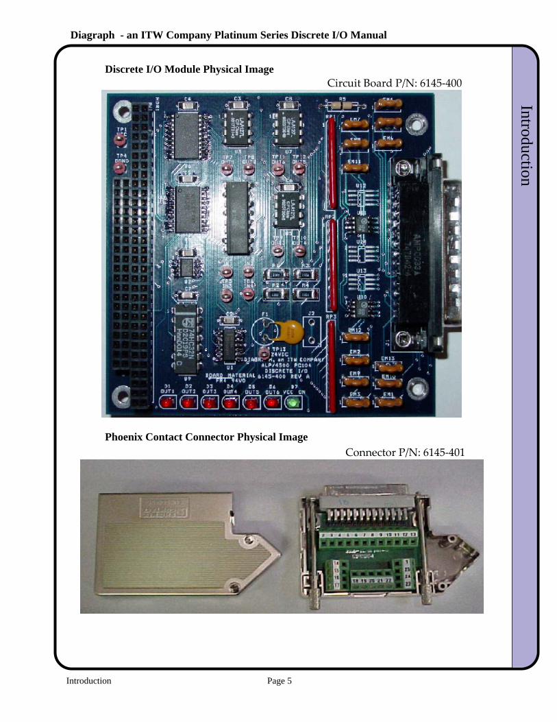
Discrete I/O Module Physical ImageCircuit Board P/N: 6145-400
Phoenix Contact Connector Physical ImageConnector P/N: 6145-401
Introduction Page 5
Diagraph - an ITW Company Platinum Series Discrete I/O ManualIntroduction
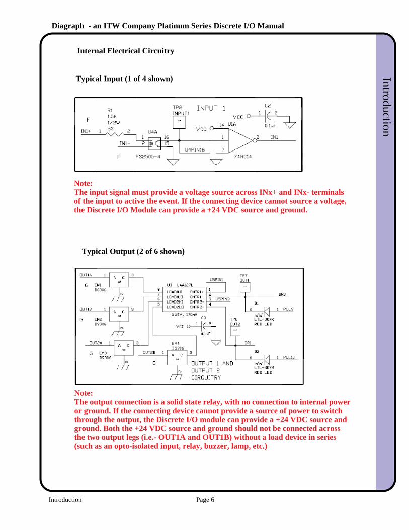
Internal Electrical Circuitry
Typical Input (1 of 4 shown)
Typical Output (2 of 6 shown)
Note:The output connection is a solid state relay, with no connection to internal power
Note:The input signal must provide a voltage source across INx+ and INx- terminalsof the input to active the event. If the connecting device cannot source a voltage,the Discrete I/O Module can provide a +24 VDC source and ground.
or ground. If the connecting device cannot provide a source of power to switchthrough the output, the Discrete I/O module can provide a +24 VDC source andground. Both the +24 VDC source and ground should not be connected acrossthe two output legs (i.e.- OUT1A and OUT1B) without a load device in series(such as an opto-isolated input, relay, buzzer, lamp, etc.)
Introduction Page 6
Diagraph - an ITW Company Platinum Series Discrete I/O ManualSetup
2.0 Setup
Step 1 - Electrical Connections - OUTPUTS
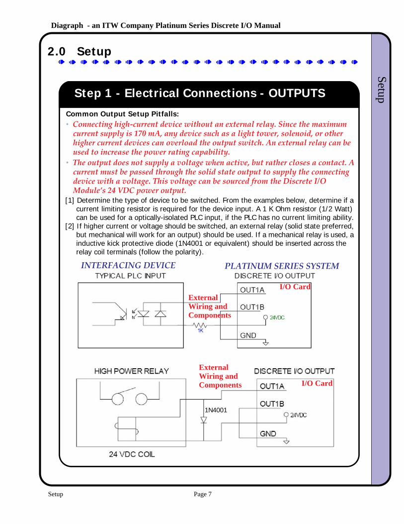
[1] Determine the type of device to be switched. From the examples below, determine if a current limiting resistor is required for the device input. A 1 K Ohm resistor (1/2 Watt) can be used for a optically-isolated PLC input, if the PLC has no current limiting ability.
[2] If higher current or voltage should be switched, an external relay (solid state preferred, but mechanical will work for an output) should be used. If a mechanical relay is used, a inductive kick protective diode (1N4001 or equivalent) should be inserted across the relay coil terminals (follow the polarity).
Common Output Setup Pitfalls:• Connecting high-current device without an external relay. Since the maximum
current supply is 170 mA, any device such as a light tower, solenoid, or other higher current devices can overload the output switch. An external relay can be used to increase the power rating capability.
• The output does not supply a voltage when active, but rather closes a contact. A current must be passed through the solid state output to supply the connecting device with a voltage. This voltage can be sourced from the Discrete I/O Module’s 24 VDC power output.
1N4001
PLATINUM SERIES SYSTEMINTERFACING DEVICE
I/O CardExternalWiring andComponents
ExternalWiring andComponents I/O Card
Setup Page 7
Diagraph - an ITW Company Platinum Series Discrete I/O ManualInstallation
Step 2 - Electrical Connections - INPUTS
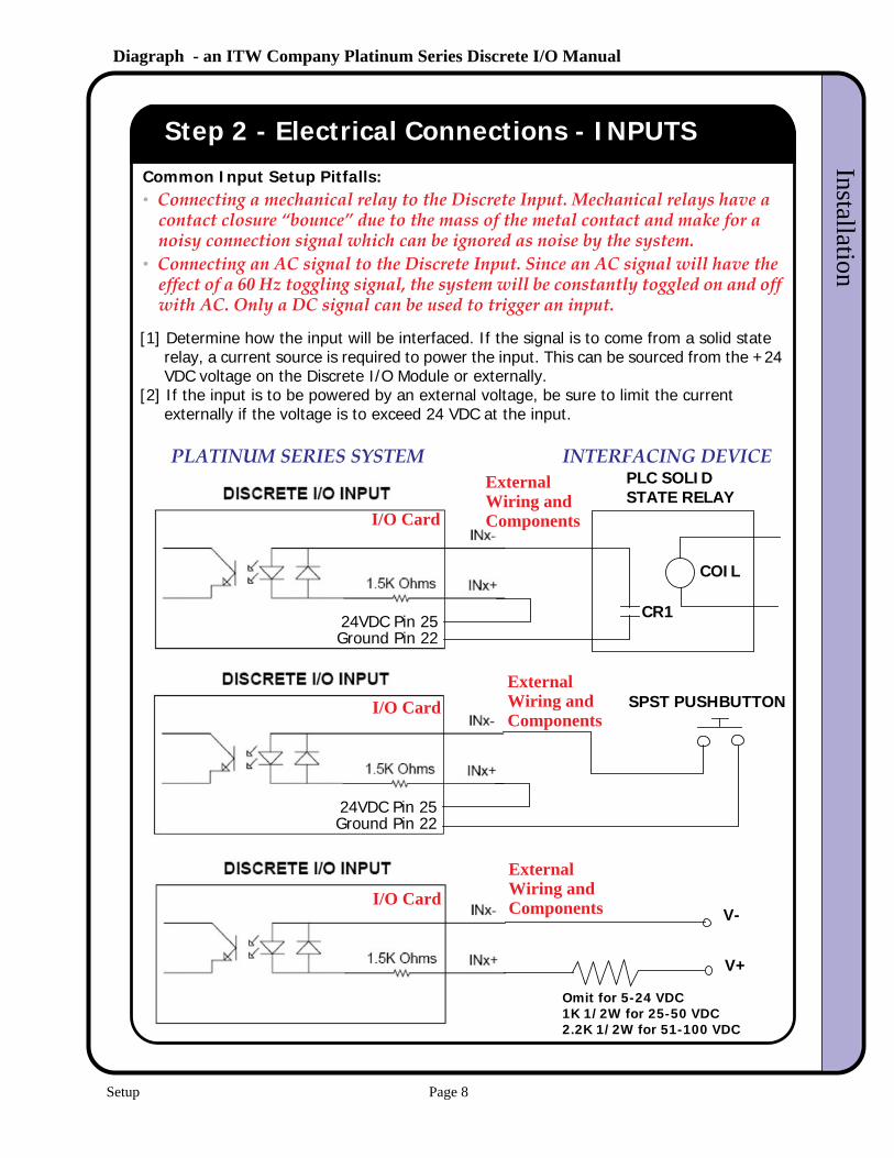
[1] Determine how the input will be interfaced. If the signal is to come from a solid state relay, a current source is required to power the input. This can be sourced from the +24 VDC voltage on the Discrete I/O Module or externally.
[2] If the input is to be powered by an external voltage, be sure to limit the current externally if the voltage is to exceed 24 VDC at the input.
Common Input Setup Pitfalls:• Connecting a mechanical relay to the Discrete Input. Mechanical relays have a
contact closure “bounce” due to the mass of the metal contact and make for a noisy connection signal which can be ignored as noise by the system.
• Connecting an AC signal to the Discrete Input. Since an AC signal will have the effect of a 60 Hz toggling signal, the system will be constantly toggled on and off with AC. Only a DC signal can be used to trigger an input.
24VDC Pin 25Ground Pin 22
PLC SOLIDSTATE RELAY
CR1
COIL
24VDC Pin 25Ground Pin 22
SPST PUSHBUTTON
V+
V-
Omit for 5-24 VDC1K 1/2W for 25-50 VDC2.2K 1/2W for 51-100 VDC
PLATINUM SERIES SYSTEM INTERFACING DEVICE
I/O Card
I/O Card
I/O Card
ExternalWiring andComponents
ExternalWiring andComponents
ExternalWiring andComponents
Setup Page 8
Diagraph - an ITW Company Platinum Series Discrete I/O ManualInstallation
Step 3 - Check Signals
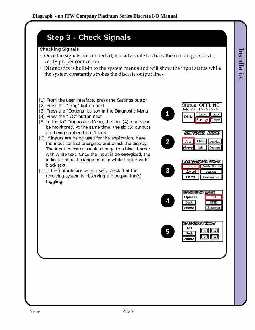
[1] From the user interface, press the Settings button[2] Press the “Diag” button next[3] Press the “Options” button in the Diagnostic Menu[4] Press the “I/O” button next[5] In the I/O Diagnostics Menu, the four (4) inputs can
be monitored. At the same time, the six (6) outputs are being strobed from 1 to 6.
[6] If inputs are being used for the application, have the input contact energized and check the display. The input indicator should change to a black border with white text. Once the input is de-energized, the indicator should change back to white border with black text.
[7] If the outputs are being used, check that the receiving system is observing the output line(s) toggling.
Checking Signals• Once the signals are connected, it is advisable to check them in diagnostics to
verify proper connection• Diagnostics is built-in to the system menus and will show the input status while
the system constantly strobes the discrete output lines
1
2
3
4
5
Setup Page 9

Diagraph - an ITW Company Platinum Series Discrete I/O ManualInstallation
Step 4 - Setting the Output Events
[1] From the Offline screen, press the Settings button[2] Press the Options button to enter the Options screen[3] Press the Discrete Out button from the Options Menu[4] To select the event that will trigger an output on the
selected channel, press the Change Mode button to toggle through the list:
Output Event Description Output
• None No output event selected None
• Media Out
Label and/or Ribbon supply is exhausted
Steady
• Media Low
Label and/or Ribbon supply is low Steady
• Online Unit is online (ready to print and apply) Steady
• No Format
There is no format in the printer to print Steady
• ErrorUnit is offline, due to error. This includes: Media Out, Air Pressure Out, Printer Errors, Repeat Print or Tamp Threshold Exceeded, etc.
Steady
• WarningUnit has experienced a condition that requires attention, but it is still able to run online.
Steady or intermittent, depending on event
• Cycle Complete
The apply cycle is finished Momentary, 20 mS
• Cycle Start
The apply cycle is beginning Dependent on extension stroke time
• Label Present
The label is on the tamp Dependent on the time label is on the pad
• Label Reject
The system is requesting the label on the pad to be rejected
Dependent on system reject time
• RFID/Scan Good
The system has determined the barcode scan or RFID tag encode was successful
Momentary, 20 mS
• RFID/Scan Bad
The system has determined the barcode scan or RFID tag encode was unsuccessful
Momentary, 20 mS
Input Events:• Can be done through the User Interface Menu Screens on the unit• Can be performed using the software program MTool2
1
2
3
4
Setup Page 10
Diagraph - an ITW Company Platinum Series Discrete I/O ManualInstallation
Step 5 - Setting the Input Events
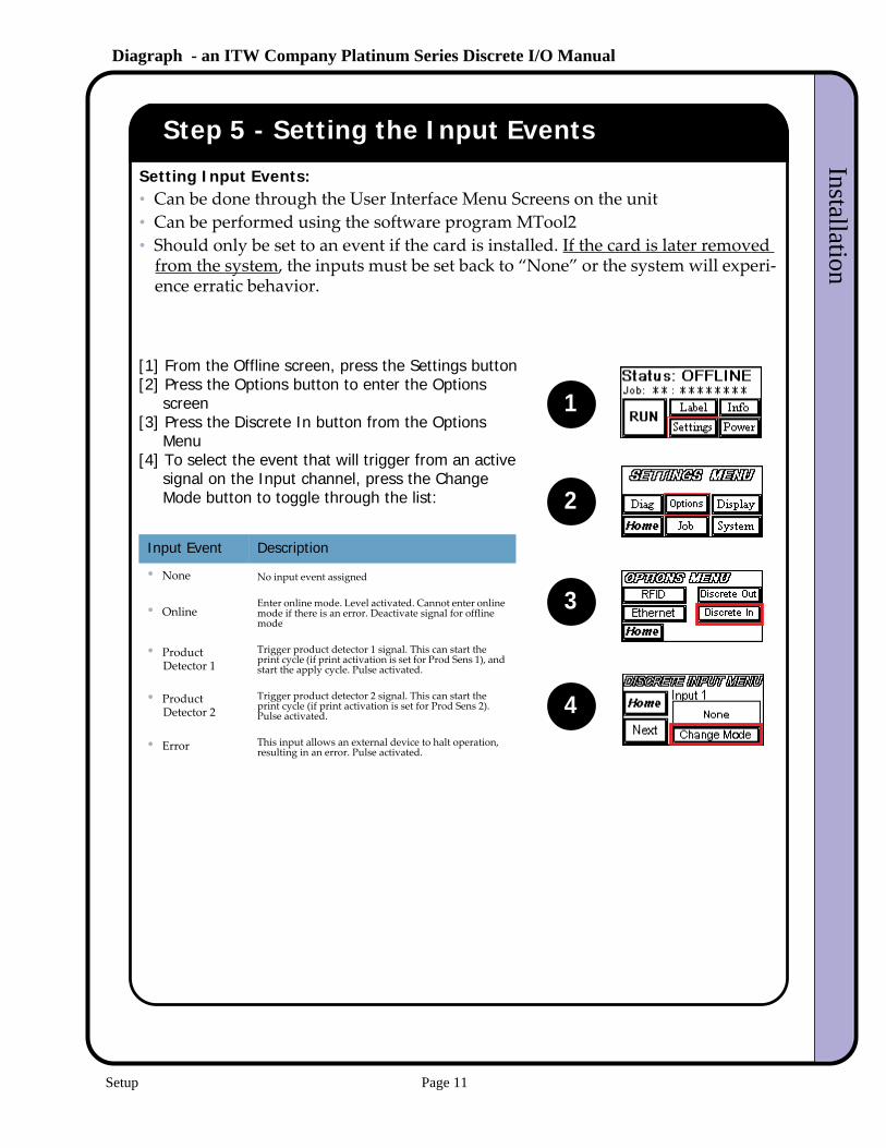
[1] From the Offline screen, press the Settings button[2] Press the Options button to enter the Options
screen[3] Press the Discrete In button from the Options
Menu[4] To select the event that will trigger from an active
signal on the Input channel, press the Change Mode button to toggle through the list:
Input Event Description
• None No input event assigned
• OnlineEnter online mode. Level activated. Cannot enter online mode if there is an error. Deactivate signal for offline mode
• Product Detector 1
Trigger product detector 1 signal. This can start the print cycle (if print activation is set for Prod Sens 1), and start the apply cycle. Pulse activated.
• Product Detector 2
Trigger product detector 2 signal. This can start the print cycle (if print activation is set for Prod Sens 2). Pulse activated.
• Error This input allows an external device to halt operation, resulting in an error. Pulse activated.
Setting Input Events:• Can be done through the User Interface Menu Screens on the unit• Can be performed using the software program MTool2• Should only be set to an event if the card is installed. If the card is later removed
from the system, the inputs must be set back to “None” or the system will experi-ence erratic behavior.
1
2
3
4
Setup Page 11


![3. Continuous and discrete time Fourier series - UPT · Continuous and discrete time Fourier series ... The discrete time signal x[n] ... following signals: Solution. a) 9. 10](https://img.pdfslide.net/doc/110x75/5b89429c7f8b9a655f8bce4f/3-continuous-and-discrete-time-fourier-series-continuous-and-discrete-time.jpg)