Embed Size (px)
Citation preview
II International Conference on Particle-based Methods - Fundamentals and ApplicationsPARTICLES 2011
E. Onate and D.R.J. Owen (Eds)
DISCRETE MODELLING OF A ROCKFALL PROTECTIVESYSTEM
K. Thoeni∗, C. Lambert†, A. Giacomini∗ and S.W. Sloan∗
∗Centre for Geotechnical and Materials ModellingThe University of Newcastle
Callaghan, NSW 2308, Australiahttp://www.newcastle.edu.au
†Department of Civil and Natural Resources EngineeringUniversity of Canterbury
Christchurch 8140, New Zealandhttp://www.civil.canterbury.ac.nz
Key words: DEM, YADE, Rockfall Protective System, Double-Twisted Hexagonal Mesh
Abstract. Metallic wire meshes are used worldwide for rockfall protective systems, suchas rockfall net barriers and drapery meshes. Within different types of meshes, the double-twisted hexagonal mesh is commonly used. This paper focuses on the implementationand validation of a computational tool for the simulation of the behaviour of such meshesas a single part and as a component of a rockfall protective system. The discrete elementmethod (DEM) is used to model the rockfall mesh and the impacting blocks. The open-source framework YADE has been extended in this context. Tensile tests of a planenet sheet subjected to a constant strain rate are used to calibrate the numerical model.Finally, the simulation of an impacting block on a horizontally spanned net is investigatedwhere numerical results are compared to experimental results.
1 INTRODUCTION
Rockfalls pose a significant safety hazard for people and infrastructure which needsto be rigorously managed, not only when dealing with mountainous regions, but alsoin quarries and mines. It is almost impossible to prevent these phenomena. However,the installation of rockfall protective systems, such as rockfall net barriers and draperymeshes, is a common and effective way to reduce the hazard. The design of such structuresis mostly based on empirical assumptions and, therefore, there is still a need to developefficient numerical models in order to efficiently control the rockfall hazard. A principalcomponent of these protection systems is the metallic wire mesh. The mesh can beinstalled in a more complex system as a rockfall barrier or directly installed on the slope,
1
K. Thoeni, C. Lambert, A. Giacomini and S.W. Sloan
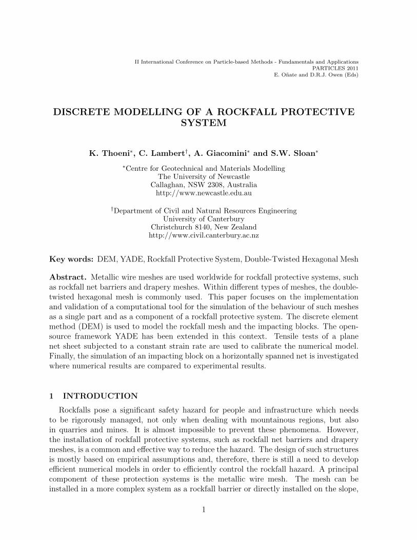
as in the case of drapery mesh systems. Different types of meshes are currently availablefrom rockfall barrier producers, with the double-twisted hexagonal mesh being the mostcommonly used (see Figure 1). This wire mesh is made by continuously twisting two wiresto form hexagonal-shaped openings as shown in Figure 2(a).
Figure 1: Application of double-twisted hexagonal rockfall mesh in a mine in New South Wales, Australia.
Several approaches for modelling steel wire meshes in numerical simulations have beenproposed in the literature, with the most common being the finite element method (FEM).The FEM has been used to simulate the impact of falling rocks against rockfall protectionsystems where the wire meshes have been modelled by using truss elements (see e.g. [4]),beam elements (see e.g. [3]), shell finite elements (see e.g. [10]) and special purpose finiteelements (see e.g. [11]). The FEM is well established for dynamic modelling of non-lineargeometries with complex mechanical and contact behaviour for continuum problems but,when dealing with discontinuous problems, computing time becomes a big issue especiallyif the failure of the wire mesh needs to be considered. Therefore, the discrete elementmethod (DEM) is a good alternative since the method is particularly suitable for dynamicimpact problems involving failure. In this work the open-source framework YADE [8, 12]has been extended to model the double twisted hexagonal wire mesh. For this purpose,a new material and the related contact laws for the double-twisted wire mesh have beenimplemented.
2 DISCRETE MODELLING OF THE WIRE MESH
Following an initial idea by [9], and later extended by [1, 2], the mesh is discretisedby a set of spherical particles which are located at the physical nodes of the mesh. Thepositions of the particles and remote interactions (i.e. interactions between the particlesexist without direct contact) are defined by the initial geometry of the mesh. Two dif-
2
K. Thoeni, C. Lambert, A. Giacomini and S.W. Sloan
ferent remote interactions have been introduced to represent single and double-twistedwires. The constitutive relations proposed by [1] are used at the contact level to take theelastoplastic behaviour of the metallic wire mesh into account.
2.1 Remote interaction model and particle interaction
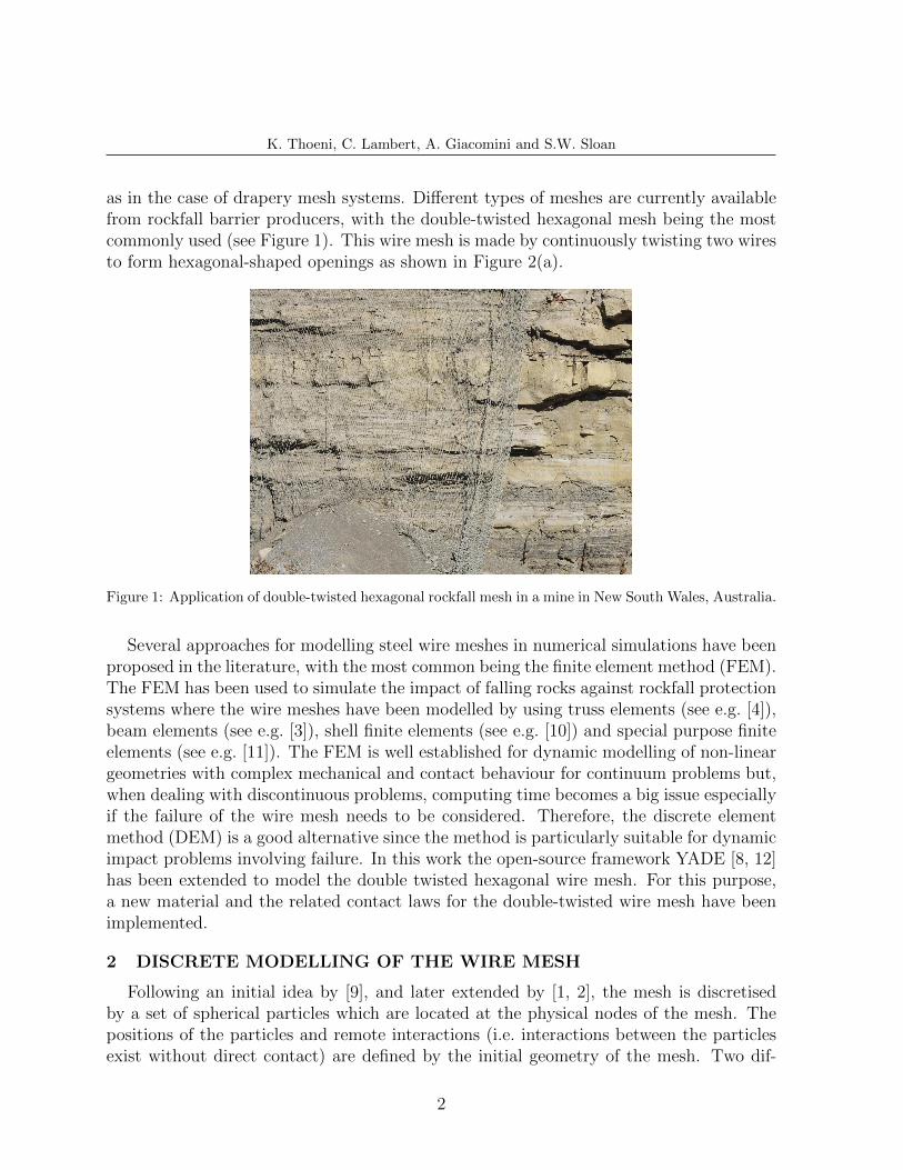
A nodal description of the wire mesh with remote interaction is used. As shown inFigure 2(b) particles are generated at the physical nodes of the mesh only. The wire itselfis not discretised because interactions between particles exist without contact. In YADEthe interactions are created by defining a interaction radius. Firstly, the particles aregenerated depending on the initial geometry of the mesh. Figure 2(a) shows a hexagon ofthe double twisted mesh with the requested dimensions to generate the mesh in YADE.Secondly, a simulation step is executed by defining a specific interaction radius. Thissimulation step initialises the interactions and creates the physical net. The generationof the mesh particles is done in a specific way in which double-twisted interactions areautomatically identified. The algorithm always starts at the left lower corner of the meshand generates a pair of particles which corresponds to a double-twist. Therefore, thenumber of the particles is used to identify if the interaction is a double-twisted or a singlewire. For double-twisted interactions the following relation holds
|ni − nj| = 1 (1)
where ni and nj are the number of particle i and j respectively. However, not all interac-tions might be created by the initialisation step since only interactions between the samewire material are identified automatically. The interactions for the selvedge wire, whichis used to edge the wire, has to be defined manually. The same applies if additional wires(or wire ropes) are used to strengthen the wire mesh.
a
b
b
mos
(a) Basic hexagonal shape ofthe double-twisted wire mesh[5] with dimensions used inYADE.
ni
nj
(b) Particles and remoteinteraction model.
Figure 2: Shape and remote interaction model of the double-twisted hexagonal mesh.
3
K. Thoeni, C. Lambert, A. Giacomini and S.W. Sloan
2.2 Constitutive law
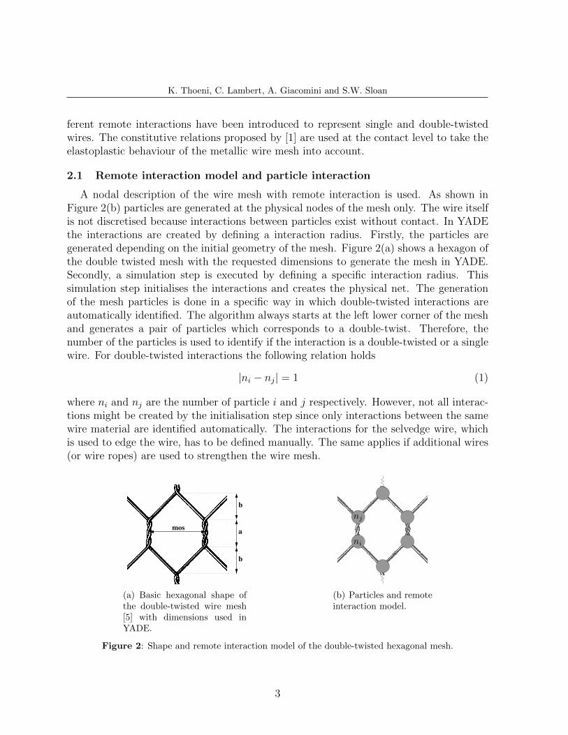
The constitutive relations proposed by [1] have been adapted in this work. However,the implementation in YADE does not follow the incremental formulation presented in[1]. The contact law is directly defined by a piece-wise linear force-displacement curve(e.g. Figure 4) which is derived from the stress-strain curve of a single wire. Figure 3shows the stress-strain curve used for the simulation. The relation corresponds to thestress-strain curve used by [1].
0
100
200
300
400
500
600
0 5 10 15 20 25 30 35 40
Axia
l T
en
sile
Str
ess
[M
Pa]
Axial Strain [%]
Figure 3: Piece-wise linear stress-strain curve used for the modelling of the steel wire.
It should be mentioned that the current implementation for the constitutive behaviourwas kept very general in YADE. In fact, there is no limitation on how many points areused to define the piece-wise linear stress-strain curve. Any piece-wise function can beused to represent the tensile behaviour of a wire and, therefore, additional wire or evenwire ropes can easily be considered in the model.
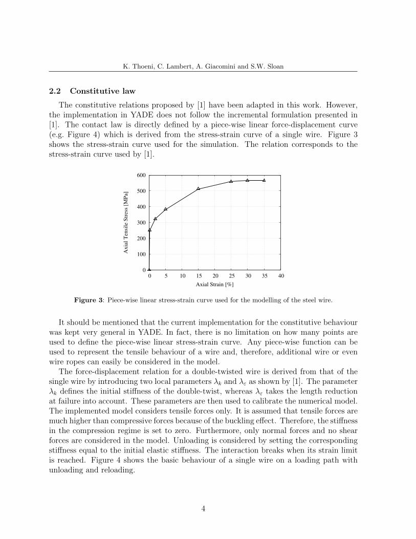
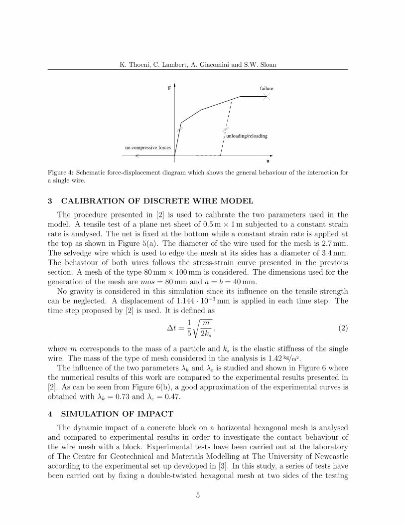
The force-displacement relation for a double-twisted wire is derived from that of thesingle wire by introducing two local parameters λk and λε as shown by [1]. The parameterλk defines the initial stiffness of the double-twist, whereas λε takes the length reductionat failure into account. These parameters are then used to calibrate the numerical model.The implemented model considers tensile forces only. It is assumed that tensile forces aremuch higher than compressive forces because of the buckling effect. Therefore, the stiffnessin the compression regime is set to zero. Furthermore, only normal forces and no shearforces are considered in the model. Unloading is considered by setting the correspondingstiffness equal to the initial elastic stiffness. The interaction breaks when its strain limitis reached. Figure 4 shows the basic behaviour of a single wire on a loading path withunloading and reloading.
4
K. Thoeni, C. Lambert, A. Giacomini and S.W. Sloan
F
u
no compressive forces
failure
unloading/reloading
Figure 4: Schematic force-displacement diagram which shows the general behaviour of the interaction fora single wire.
3 CALIBRATION OF DISCRETE WIRE MODEL
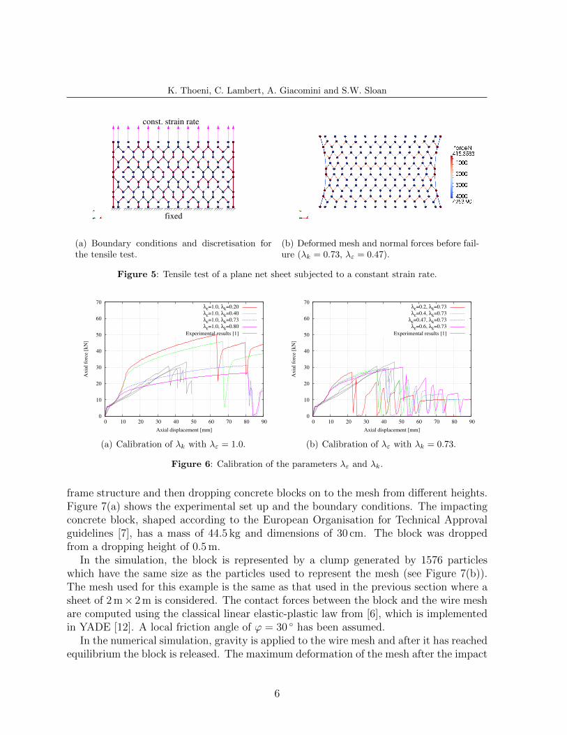
The procedure presented in [2] is used to calibrate the two parameters used in themodel. A tensile test of a plane net sheet of 0.5 m × 1 m subjected to a constant strainrate is analysed. The net is fixed at the bottom while a constant strain rate is applied atthe top as shown in Figure 5(a). The diameter of the wire used for the mesh is 2.7 mm.The selvedge wire which is used to edge the mesh at its sides has a diameter of 3.4 mm.The behaviour of both wires follows the stress-strain curve presented in the previoussection. A mesh of the type 80 mm× 100 mm is considered. The dimensions used for thegeneration of the mesh are mos = 80 mm and a = b = 40 mm.
No gravity is considered in this simulation since its influence on the tensile strengthcan be neglected. A displacement of 1.144 · 10−3 mm is applied in each time step. Thetime step proposed by [2] is used. It is defined as
∆t =1
5
√m
2ks, (2)
where m corresponds to the mass of a particle and ks is the elastic stiffness of the singlewire. The mass of the type of mesh considered in the analysis is 1.42 kg/m2.
The influence of the two parameters λk and λε is studied and shown in Figure 6 wherethe numerical results of this work are compared to the experimental results presented in[2]. As can be seen from Figure 6(b), a good approximation of the experimental curves isobtained with λk = 0.73 and λε = 0.47.
4 SIMULATION OF IMPACT
The dynamic impact of a concrete block on a horizontal hexagonal mesh is analysedand compared to experimental results in order to investigate the contact behaviour ofthe wire mesh with a block. Experimental tests have been carried out at the laboratoryof The Centre for Geotechnical and Materials Modelling at The University of Newcastleaccording to the experimental set up developed in [3]. In this study, a series of tests havebeen carried out by fixing a double-twisted hexagonal mesh at two sides of the testing
5
K. Thoeni, C. Lambert, A. Giacomini and S.W. Sloan
fixed
const. strain rate
(a) Boundary conditions and discretisation forthe tensile test.
(b) Deformed mesh and normal forces before fail-ure (λk = 0.73, λε = 0.47).
Figure 5: Tensile test of a plane net sheet subjected to a constant strain rate.
0
10
20
30
40
50
60
70
0 10 20 30 40 50 60 70 80 90
Ax
ial
forc
e [k
N]
Axial displacement [mm]
λε=1.0, λk=0.20
λε=1.0, λk=0.40
λε=1.0, λk=0.73
λε=1.0, λk=0.80
Experimental results [1]
(a) Calibration of λk with λε = 1.0.
0
10
20
30
40
50
60
70
0 10 20 30 40 50 60 70 80 90
Ax
ial
forc
e [k
N]
Axial displacement [mm]
λε=0.2, λk=0.73
λε=0.4, λk=0.73
λε=0.47, λk=0.73
λε=0.6, λk=0.73
Experimental results [1]
(b) Calibration of λε with λk = 0.73.
Figure 6: Calibration of the parameters λε and λk.
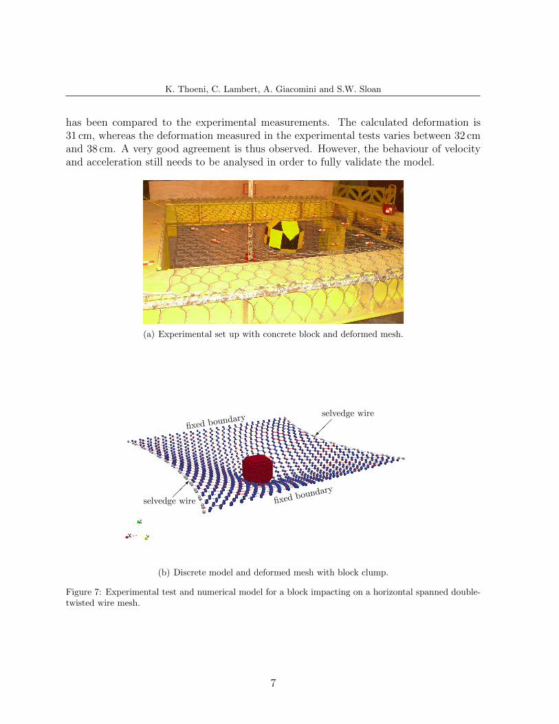
frame structure and then dropping concrete blocks on to the mesh from different heights.Figure 7(a) shows the experimental set up and the boundary conditions. The impactingconcrete block, shaped according to the European Organisation for Technical Approvalguidelines [7], has a mass of 44.5 kg and dimensions of 30 cm. The block was droppedfrom a dropping height of 0.5 m.
In the simulation, the block is represented by a clump generated by 1576 particleswhich have the same size as the particles used to represent the mesh (see Figure 7(b)).The mesh used for this example is the same as that used in the previous section where asheet of 2 m× 2 m is considered. The contact forces between the block and the wire meshare computed using the classical linear elastic-plastic law from [6], which is implementedin YADE [12]. A local friction angle of ϕ = 30 ◦ has been assumed.
In the numerical simulation, gravity is applied to the wire mesh and after it has reachedequilibrium the block is released. The maximum deformation of the mesh after the impact
6
K. Thoeni, C. Lambert, A. Giacomini and S.W. Sloan
has been compared to the experimental measurements. The calculated deformation is31 cm, whereas the deformation measured in the experimental tests varies between 32 cmand 38 cm. A very good agreement is thus observed. However, the behaviour of velocityand acceleration still needs to be analysed in order to fully validate the model.
(a) Experimental set up with concrete block and deformed mesh.
���
selvedge wire
��
selvedge wire
fixed boundary
fixed boundary
(b) Discrete model and deformed mesh with block clump.
Figure 7: Experimental test and numerical model for a block impacting on a horizontal spanned double-twisted wire mesh.
7
K. Thoeni, C. Lambert, A. Giacomini and S.W. Sloan
5 CONCLUSIONS
This paper presents a discrete wire mesh model currently implemented in the open-source framework YADE, which has the capability to model hexagonal double-twisted wiremeshes. The application to rockfall protective systems has been investigated. However,only a very simple example is presented and further research is under way.
The current work is part of an ongoing research project with the objective to assess therockfall hazard in open pit coal mines. The discrete model will be used to study rockfalltrajectories and velocities at highwalls which are protected by double-twisted hexagonalmeshes.
REFERENCES
[1] D. Bertrand, F. Nicot, P. Gotteland, and S. Lambert. Modelling a geo-compositecell using discrete analysis. Computers and Geotechnics, 32(8):564–577, 2005.
[2] D. Bertrand, F. Nicot, P. Gotteland, and S. Lambert. Discrete element method(DEM) numerical modeling of double-twisted hexagonal mesh. Canadian Geotech-nical Journal, 45(8):1104–1117, 2008.
[3] O. Buzzi, A. Giacomini, M. Spadari, and S. Fityus. Numerical modeling of a rockfall mesh perforation upon impact. In N. Khalili and M. Oeser, editors, ComputerMethods for Geomechanics: Frontiers and New Application, volume 2 of 13th Interna-tional Conference of the IACMAG 2011, pages 1141–1146. Centre for InfrastructureEngineering and Safety, 2011.
[4] A. Cazzani, L. Mongiovı, and T. Frenez. Dynamic finite element analysis of intercep-tive devices for falling rocks. International Journal of Rock Mechanics and MiningSciences, 39(3):303–321, 2002.
[5] D. Chaychuk. Case history: Valley lake rock face management works, Niddrie Quarry,Melbourne, Australia. Technical report, Maccaferri Australia Pty Ltd, 2008.
[6] P.A. Cundall and O.D.L. Strack. A discrete numerical model for granular assemblies.Geotechnique, 29(1):47–65, 1979.
[7] EOTA. ETAG 27, Guideline for European Technical approval of falling rock protec-tion kits. European Organisation for Technical Approvals.
[8] J. Kozicki and F.V. Donze. YADE-OPEN DEM: An opensource software using adiscrete element method to simulate granular material. Engineering Computations,26(7):786–805, 2009.
[9] F. Nicot, B. Cambou, and G. Mazzoleni. Design of rockfall restraining nets from adiscrete element modelling. Rock Mechanics and Rock Engineering, 34:99–118, 2001.
8
K. Thoeni, C. Lambert, A. Giacomini and S.W. Sloan
[10] N. Sasiharan, B. Muhunthan, T. C. Badger, S. Shu, and D. M. Carradine. Numericalanalysis of the performance of wire mesh and cable net rockfall protection systems.Engineering Geology, 88(1-2):121–132, 2006.
[11] A. Volkwein. Numerical simulation of flexible rockfall protection systems. In ASCE,editor, Proceedings of the International Conference on Computing in Civil Engineer-ing, 2005.
[12] V. Smilauer, E. Catalano, B. Chareyre, S. Dorofenko, J. Duriez, A. Gladky, J. Koz-icki, C. Modenese, L. Scholtes, L. Sibille, J. Stransky, and K. Thoeni. Yade ReferenceDocumentation. In V. Smilauer, editor, Yade Documentation. The Yade Project, 1stedition, 2010. http://yade-dem.org/doc/.
9