Embed Size (px)
Citation preview
Journal of Mechanical Science and Technology 27 (8) (2013) 2231~2236
www.springerlink.com/content/1738-494x
DOI 10.1007/s12206-013-0605-x
Discrete optimization of rigid rotor balancing†
Tanguy Messager1,* and Mariusz Pyrz2 1Laboratoire de Mécanique de Lille (UMR CNRS 8107), Université Lille 1, Cité Scientifique, 59655 Villeneuve d’Ascq cedex, France
2Faculty of Automotive and Construction Machinery Engineering, Warsaw University of Technology, Narbutta Str. 84, 02-524 Warsaw, Poland
(Manuscript Received April 10, 2012; Revised February 28, 2013; Accepted March 21, 2013)
----------------------------------------------------------------------------------------------------------------------------------------------------------------------------------------------------------------------------------------------------------------------------------------------
Abstract
This work deals with the discrete optimization problem of rotor two-plane balancing. The best balancing configuration is searched for
two discrete parameters: allowed standard masses and predefined angular positions on the balancing planes. The objective is to minimize
the residual unbalancing effects (such as reactions in supports) thanks to an optimal location of several accurately selected masses on
each balancing plane. The corresponding optimization problem is solved using genetic algorithm. A simple model of a rigid rotor
mounted on rigid supports is investigated in numerical examples. The optimization efficiency and the influence of the number of applied
balancing masses are discussed. The experimental tests have validated the developed balancing approach.
Keywords: Balancing; Discrete optimization; Genetic algorithm; Rigid rotor
----------------------------------------------------------------------------------------------------------------------------------------------------------------------------------------------------------------------------------------------------------------------------------------------
1. Introduction
The balancing of rotating machinery has become an impor-
tant technical problem for engineers and designers. Many
procedures have been developed to minimize the harmful
vibration effects. The classical off-line balancing vector
method and static couple method [1] are applied to rigid rotor
models. The extension of this approach to flexible rotors bal-
ance is proposed by the modal balancing method [2] and the
influence coefficient experimental technique [3, 4]. Recent
research works concern the problem of active (on line) balanc-
ing of rotors. The classification and the survey of various
methods from this domain are presented in Ref. [5].
Besides theoretical and experimental works studying differ-
ent techniques of rotor balancing, a number of papers has been
devoted in a straight line to the enhancing and the optimiza-
tion of balancing procedures. Everett [6] searched the estimate
of the rigid rotors unbalance for several vibration magnitudes
measured experimentally using the influence coefficient me-
thod. Xu et al. [7] investigated the optimal balancing of flexi-
ble rotors, based on the modal balancing method without test
runs and using genetic algorithm to evaluate the correction
masses.
The optimization techniques are also proposed to the active
balancing procedures, applied during the operation of the rotor,
and contributing to the active vibration control. Zhou and Shi
[8] presented the optimal one-plane balancing of rigid rotor.
Dyer et al. [9] has developed an optimal strategy for multi-
plane active balancing control, verified experimentally on a
flexible rotor. Kang et al. [10] extended the influence coeffi-
cient method for asymmetrical rotors and minimized the re-
sidual imbalance through an iterative process of multi-plane
technique for balancing crankshafts. Lui and Qu, [11] pre-
sented a new balancing method for flexible rotor systems,
based on the hoolospectrum technique and the use of several
sensors. Rodrigues et al. [12] proposed a two-plane automatic
self-compensating balancing device for rigid rotors and pro-
vided bifurcation analysis and numerical simulations for the
dynamic imbalance. Lee et al. [13] applied dual axes dynamic
imbalance correction method to moderate vibrations of high
speed rotors.
The analytical or experimental off-line techniques of rotor
balancing are based in general on continuous optimization
formulation and procedures. As a result, optimal continuous
solutions are determined and the balance correction weights
and the corresponding angular position may take any real
value. Furthermore, one mass per balancing plane is typically
considered. Numerous practical applications however imply
the discrete formulation of the balancing optimization prob-
lem: only a limited set of standardized mass values is available.
Moreover, each balancing plane often allows restricted, possi-
ble angular positions, defined for example by the locations of
drilling holes. In such a case, the “nearest” discrete solution
with respect to the continuous optimal balancing configuration
is commonly applied. Such “rounded off” design induces usu-
ally residual unbalancing and dynamic effects. This residual
*Corresponding author. Tel.: +33 328767376, Fax.: +33 328767361
E-mail address: [email protected] † Recommended by Associate Editor Ohseop Song
© KSME & Springer 2013
2232 T. Messager and M. Pyrz / Journal of Mechanical Science and Technology 27 (8) (2013) 2231~2236
unbalancing can then be minimized by recalculating and ap-
plying additional correcting mass on each balancing plane.
Such iterative procedure increases balancing time and cost [7].
The original contribution of this paper resides in the inves-
tigation of the practical situation of rigid rotor balancing, for-
mulated directly as a discrete optimization problem where
normalized (or available) mass values and predefined angular
positions are considered. The objective is to determine the best
balancing by searching directly several (a user’s fixed num-
ber) balancing masses and the corresponding angular positions
on each plane. The minimization of the forces acting on the
bearings is the optimization criteria. A stochastic search
method based on genetic algorithm is used to solve the result-
ing discrete optimization problem.
2. Formulation of the discrete optimization problem
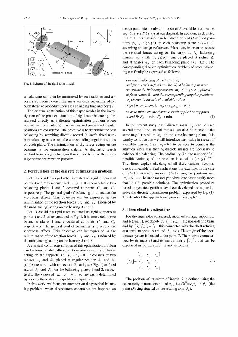
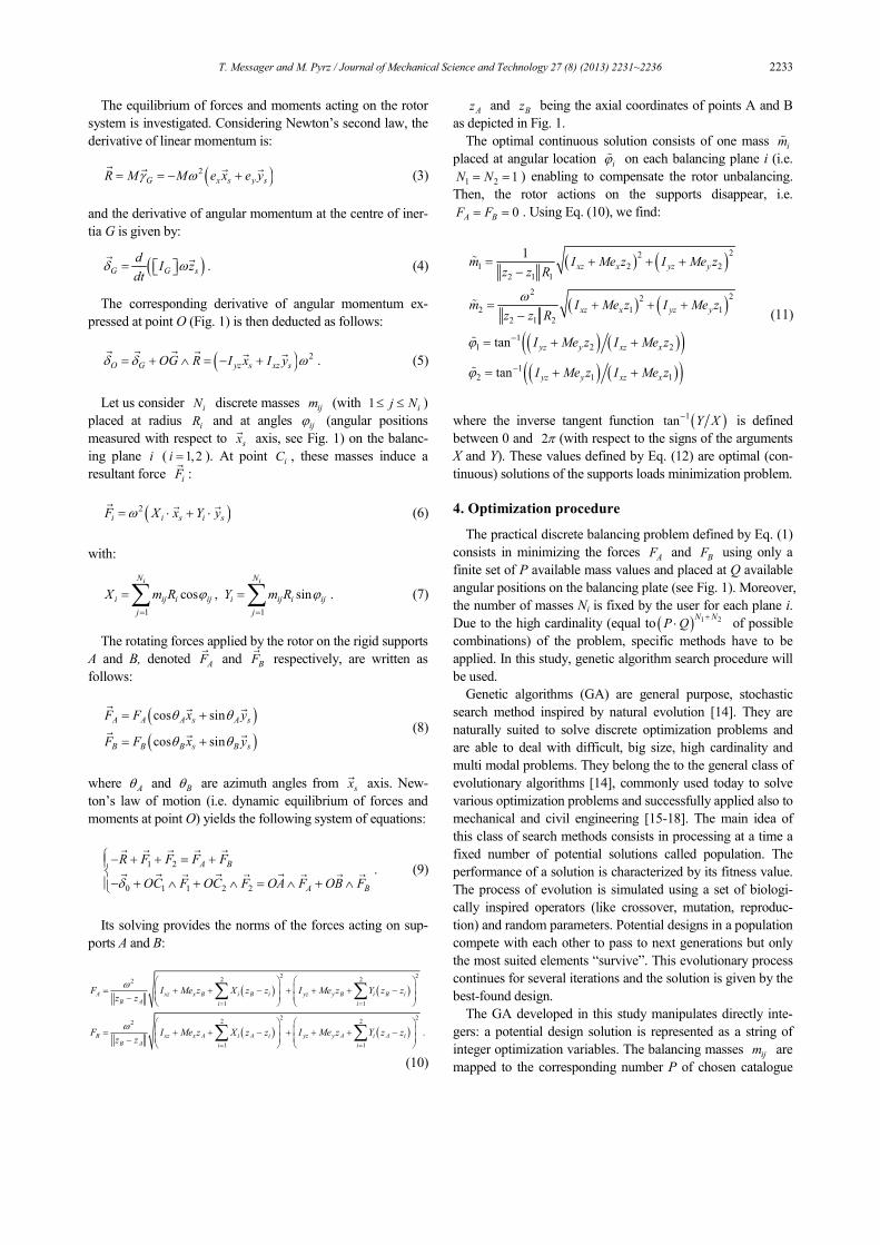
Let us consider a rigid rotor mounted on rigid supports at
points A and B as schematized in Fig. 1. It is connected to two
balancing planes 1 and 2 centered at points 1C and 2C
respectively. The general goal of balancing is to reduce the
vibrations effects. This objective can be expressed as the
minimization of the reaction forces AF and BF (induced by
the unbalancing) acting on the bearing A and B.
A classical continuous solution of this optimization problem
can be found analytically so as to ensure vanishing of forces
acting on the supports, i.e. 0A BF F= = . It consists of two
masses 1mɶ and 2mɶ placed at angular position 1ϕɶ and 2ϕɶ
(angle measured with respect to sx�
axis, see Fig. 1) at fixed
radius 1R and 2R on the balancing planes 1 and 2, respec-
tively. The values of 1mɶ , 1ϕɶ , 2mɶ , 2ϕɶ are easily determined
by solving the system of equilibrium equations.
In this work, we focus our attention on the practical balanc-
ing problem, when discreteness constraints are imposed on
design parameters: only a finite set of P available mass values
pm (1 p P≤ ≤ ) stays at our disposal. In addition, as depicted
in Fig. 1, these masses can be placed only at Q defined posi-
tions iqϕ (1 q Q≤ ≤ ) on each balancing plane i ( 1,2i = ),
according to design references. Moreover, in order to reduce
the residual forces acting on the supports, iN balancing
masses ijm (with 1 ij N≤ ≤ ) can be placed at radius iR
and at angles ijϕ on each balancing plane i ( 1,2i = ). The
corresponding discrete optimization problem of rotor balanc-
ing can finally be expressed as follows:
For each balancing plane i ( 1,2i = )
and for a user’s defined number Ni of balancing masses
determine the balancing masses ijm (1 ij N≤ ≤ ) placed
at fixed radius iR and the corresponding angular positions
ijϕ chosen in the sets of available values
{ } { }1 2 1 2; ;...; , ; ;...;ij P ij i i iQm m m m ϕ ϕ ϕ ϕ∈ ∈
so as to minimize the dynamic loads applied on supports
A and B: FA Æ min ; FB Æ min. (1)
In the present study, each discrete mass ijm can be used
several times, and several masses can also be placed at the
same angular position ijϕ on the same balancing plane. It is
worthy to notice that we will introduce zero value in the set of
available masses ( i.e. 1 0m = ) to be able to consider the
situation when less than Ni discrete masses are necessary to
enhance the balancing. The cardinality (i.e. the number of all
possible variants) of the problem is equal to ( ) 1 2N NP Q
+⋅ .
The direct explicit checking of all these variants becomes
quickly infeasible in real applications: for example, in the case
of 10P = available masses, 12Q = angular positions and
1 2 2N N= = balance masses per plane, one has to verify more
than 82 10⋅ possible solutions. The optimization procedure
based on genetic algorithm have been developed and applied to
solve the discrete optimization problem expressed by Eq. (1).
The details of the approach are given in paragraph §3.
3. Theoretical investigations
For the rigid rotor considered, mounted on rigid supports A
and B (Fig. 1), we denote by ( )0 0 0; ;x y z� � �
the non-rotating basis
and by ( )0; ;s s sx y z z=� � � �
this connected with the shaft rotating
at a constant speed ω around sz�
axis. The origin of the coor-
dinates system is located at the point O. The rotor is character-
ized by its mass M and its inertia matrix GI , that can be
expressed in the ( ); ;s s sx y z� � �
frame as follows:
.
xx xy xz
G xy yy yz
xz yz zz
I I I
I I I I
I I I
=
(2)
The position of its centre of inertia G is defined using the
eccentricity parameters xe and ye , i.e. x s y sOG e x e y= +� � �
(the
point O being situated on the rotating axis sz�
).
A
B•
•
•O
C1
C2
ω t
R1
R2
O
G ex
ey
ω t
=
=
=
=
022
011
0
0
zzOC
zzOC
zzOB
zzOA
B
A
r
r
r
r
sxr
sxr
syr
syr
11ϕ
12ϕ
0xr
0xr
0yr
sxr
szzrr
=0balancing planes
rotor
Fig. 1. Scheme of the rigid rotor model.
T. Messager and M. Pyrz / Journal of Mechanical Science and Technology 27 (8) (2013) 2231~2236 2233
The equilibrium of forces and moments acting on the rotor
system is investigated. Considering Newton’s second law, the
derivative of linear momentum is:
( )2G x s y sR M M e x e yγ ω= = − +
� � � � (3)
and the derivative of angular momentum at the centre of iner-
tia G is given by:
( ) .G G s
dI z
dtδ ω= � �
(4)
The corresponding derivative of angular momentum ex-
pressed at point O (Fig. 1) is then deducted as follows:
( ) 2 .O G yz s xz sOG R I x I yδ δ ω= + ∧ = − +� � � � � �
(5)
Let us consider iN discrete masses ijm (with 1 ij N≤ ≤ )
placed at radius iR and at angles ijϕ (angular positions
measured with respect to sx�
axis, see Fig. 1) on the balanc-
ing plane i ( 1,2i = ). At point iC , these masses induce a
resultant force iF�:
( )2i i s i sF X x Y yω= ⋅ + ⋅� � �
(6)
with:
1 1
cos , sin .
i iN N
i ij i ij i ij i ij
j j
X m R Y m Rϕ ϕ= =
= =∑ ∑ (7)
The rotating forces applied by the rotor on the rigid supports
A and B, denoted AF�
and BF�
respectively, are written as
follows:
( )( )cos sin
cos sin
A A A s A s
B B B s B s
F F x y
F F x y
θ θ
θ θ
= +
= +
� � �
� � � (8)
where Aθ and Bθ are azimuth angles from sx�
axis. New-
ton’s law of motion (i.e. dynamic equilibrium of forces and
moments at point O) yields the following system of equations:
1 2
0 1 1 2 2
.A B
A B
R F F F F
OC F OC F OA F OB Fδ
− + + = +− + ∧ + ∧ = ∧ + ∧
� � � � �
� � � �� � � � � (9)
Its solving provides the norms of the forces acting on sup-
ports A and B:
( ) ( )
( ) ( )
2 22 22
1 1
2 22 22
1 1
.
A xz x B i B i yz y B i B i
B A i i
B xz x A i A i yz y A i A i
B A i i
F I Me z X z z I Me z Y z zz z
F I Me z X z z I Me z Y z zz z
ω
ω
= =
= =
= + + − + + + − −
= + + − + + + − −
∑ ∑
∑ ∑
(10)
Az and Bz being the axial coordinates of points A and B
as depicted in Fig. 1.
The optimal continuous solution consists of one mass imɶ
placed at angular location iϕɶ on each balancing plane i (i.e.
1 2 1N N= = ) enabling to compensate the rotor unbalancing.
Then, the rotor actions on the supports disappear, i.e.
0A BF F= = . Using Eq. (10), we find:
( ) ( )
( ) ( )
( ) ( )( )( ) ( )( )
22
1 2 2
2 1 1
222
2 1 1
2 1 2
11 2 2
12 1 1
1
tan
tan
xz x yz y
xz x yz y
yz y xz x
yz y xz x
m I Me z I Me zz z R
m I Me z I Me zz z R
I Me z I Me z
I Me z I Me z
ω
ϕ
ϕ
−
−
= + + +−
= + + +−
= + +
= + +
ɶ
ɶ
ɶ
ɶ
(11)
where the inverse tangent function ( )1tan Y X− is defined
between 0 and 2π (with respect to the signs of the arguments
X and Y). These values defined by Eq. (12) are optimal (con-
tinuous) solutions of the supports loads minimization problem.
4. Optimization procedure
The practical discrete balancing problem defined by Eq. (1)
consists in minimizing the forces AF and BF using only a
finite set of P available mass values and placed at Q available
angular positions on the balancing plate (see Fig. 1). Moreover,
the number of masses Ni is fixed by the user for each plane i.
Due to the high cardinality (equal to ( ) 1 2N NP Q
+⋅ of possible
combinations) of the problem, specific methods have to be
applied. In this study, genetic algorithm search procedure will
be used.
Genetic algorithms (GA) are general purpose, stochastic
search method inspired by natural evolution [14]. They are
naturally suited to solve discrete optimization problems and
are able to deal with difficult, big size, high cardinality and
multi modal problems. They belong the to the general class of
evolutionary algorithms [14], commonly used today to solve
various optimization problems and successfully applied also to
mechanical and civil engineering [15-18]. The main idea of
this class of search methods consists in processing at a time a
fixed number of potential solutions called population. The
performance of a solution is characterized by its fitness value.
The process of evolution is simulated using a set of biologi-
cally inspired operators (like crossover, mutation, reproduc-
tion) and random parameters. Potential designs in a population
compete with each other to pass to next generations but only
the most suited elements “survive”. This evolutionary process
continues for several iterations and the solution is given by the
best-found design.
The GA developed in this study manipulates directly inte-
gers: a potential design solution is represented as a string of
integer optimization variables. The balancing masses ijm are
mapped to the corresponding number P of chosen catalogue
2234 T. Messager and M. Pyrz / Journal of Mechanical Science and Technology 27 (8) (2013) 2231~2236
values pm . Similar procedure is applied to encode their posi-
tions ijϕ chosen among the Q available values iqϕ . In that
way, the chromosome corresponding to a mass balancing sys-
tem contains ( )1 22 N N+ integers. In the obtained string,
each couple represents the mass number and the correspond-
ing angular position number.
In this analytical first approach, the reduction of the unbal-
ancing residual forces AF and BF acting on the supports (cf.
Eq. (10)) has been considered revealing of the balancing solu-
tion quality. The following fitness formulation has been con-
sidered:
1
0 0
1 .A B
A B
F Ff
F F
−
= + +
(12)
0AF and 0BF being the norms of the forces acting on the
supports for the unbalanced rotor, see Eq. (11). Better balanc-
ing solutions lead to bigger fitness values, the best solution
corresponding to a fitness equals to unity.
In the numerical applications, typical genetic operators and
recommended parameters have been used [14]. The initial
population of potential solution has been generated randomly.
The selection for mating is based on the tournament ranking
using random pairs. New propositions are generated by re-
combining the individuals of the current population using the
"single" arithmetical crossover (applied with the probability
75%) and the random mutation (with the probability of 5%).
Moreover, in the selection of survivors, the elitist approach
replaces the worst individual in the new generation by the best
individual found in the previous generation.
5. Numerical examples
The numerical examples concern the rigid rotor which ge-
ometry is determined by the following dimensions (in m):
0.2;Az = − 0.3;Bz = 1 0.25;z = − 2 0.35;z = 1 2 0.15R R= = .
The total mass 60M = kg and the constant rotating speed
1500ω = rpm are considered. The balancing masses should be
taken from the following set of 7P = values (in grams):
{ } 0 ; 10 ; 20 ; 50 ; 100 ; 200 ; 300 .ijm ∈ Moreover, each
balancing plane comprised 12Q = following available posi-
tions (angles in degrees): { } 30 ; 60 ; 90 ;...; 360 .ijϕ ∈ Three
different numerical examples are presented: static, dynamic
and general unbalancing. The unbalancing numerical charac-
teristics have been arbitrary chosen, but nevertheless in realis-
tic ranges with respect to the rotor dimensions and mass. The
corresponding eccentricities and the inertia components are
detailed in the next paragraph. Each case has been analyzed
for several combinations of mass numbers N1 and N2 placed
on the balancing planes 1 and 2. Table 1 details the cardinality
of the corresponding combinatorial problem. The number of
individuals and the numbers of generations used by the opti-
mization procedure, chosen with respect to the recommenda-
tions of the literature [14] and authors’ experience [16-18], are
given as well. It could be noticed that the case of 1 2 1N N= =
has been analyzed only to verify that the GA leads to the near-
est solution of the continuous optimal balancing. For all
treated numerical examples, the observed CPU time (numeri-
cal processing on a standard workstation) has not exceeded 20
seconds.
The first case concerns a statically unbalanced rotor, and we
consider the following eccentricity (values in mm): 1;xe =
0.25,ye = the products of inertia xzI and yzI being 0.
Using Eq. (10), the norms of the forces (expressed in N) act-
ing on the supports for this unbalanced configuration are:
0 915.6;AF = 0 610.4BF = . Using Eqs. (11) and (12), the
corresponding optimal balancing is done by (masses in grams,
angles in degrees): 1 240.5;m =ɶ 2 171.8;m =ɶ 1 2 194.0ϕ ϕ= =ɶ ɶ .
In Table 2, the optimized balancing discrete solutions (de-
ducted from 20 successive independent runs of the GA proce-
dure) are presented.
The second case is a dynamically unbalanced rotor, illus-
trated by the following the values of the products of inertia
have been taken (expressed in kg.m2): 0.004xzI = − ;
0.01yzI = − , the point G being situated on the rotating axis, i.e.
0x ye e= = . The initial forces acting on the supports are then
Table 1. Parameters of GA applied to the numerical tests.
Numbers of masses Cardinality Population size Number of
generations
N1 = N2 = 1 7056 50 400
N1 = N2 = 2 49.8⋅106 150 1600
N1 = N2 = 3 0.351⋅1012 300 4000
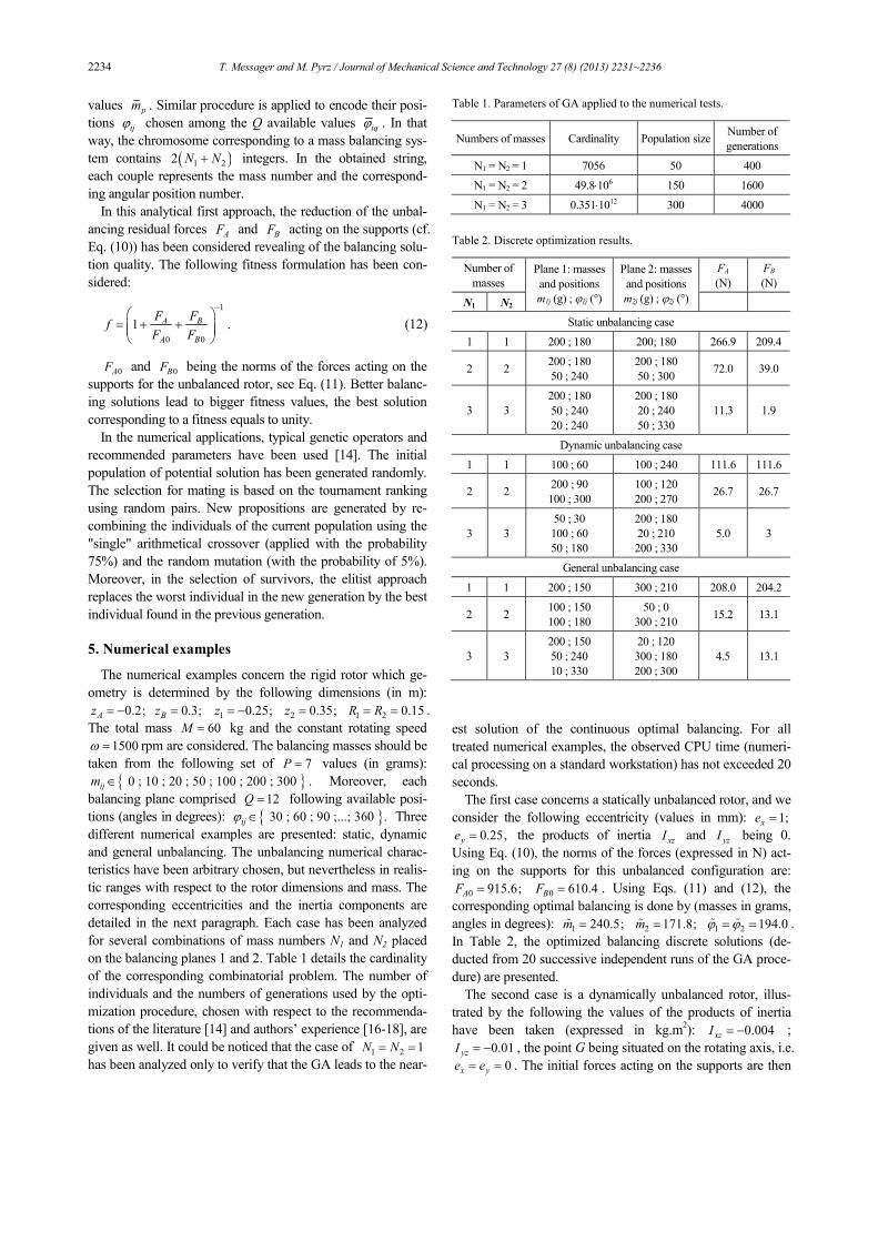
Table 2. Discrete optimization results.
Number of
masses
FA
(N)
FB
(N)
N1 N2
Plane 1: masses
and positions
m1j (g) ; ϕ1j (°)
Plane 2: masses
and positions
m2j (g) ; ϕ2j (°)
Static unbalancing case
1 1 200 ; 180 200; 180 266.9 209.4
2 2 200 ; 180
50 ; 240
200 ; 180
50 ; 300 72.0 39.0
3 3
200 ; 180
50 ; 240
20 ; 240
200 ; 180
20 ; 240
50 ; 330
11.3 1.9
Dynamic unbalancing case
1 1 100 ; 60 100 ; 240 111.6 111.6
2 2 200 ; 90
100 ; 300
100 ; 120
200 ; 270 26.7 26.7
3 3
50 ; 30
100 ; 60
50 ; 180
200 ; 180
20 ; 210
200 ; 330
5.0 3
General unbalancing case
1 1 200 ; 150 300 ; 210 208.0 204.2
2 2 100 ; 150
100 ; 180
50 ; 0
300 ; 210 15.2 13.1
3 3
200 ; 150
50 ; 240
10 ; 330
20 ; 120
300 ; 180
200 ; 300
4.5 13.1
T. Messager and M. Pyrz / Journal of Mechanical Science and Technology 27 (8) (2013) 2231~2236 2235
(in N): 0 0 531.5A BF F= = . The theoretical optimal balancing
correspond to the following configuration (masses in grams,
angular positions in degrees): 1 2 119.7;m m= =ɶ ɶ 1 68.2;ϕ =ɶ
2 248.2ϕ =ɶ . The obtained balancing solutions are presented in
Table 2.
At last, we consider a general unbalancing case with the fol-
lowing eccentricity (in mm): 1,xe = 0.25,ye = and the val-
ues of products of inertia (in kg.m2): 0.004,xzI = −
0.01yzI = − . The initial forces acting on A and B are then (in
N): 0 742.3;AF = 0 1017.3BF = . The theoretical optimal bal-
ancing configuration is reached for (masses in grams, angular
positions in degrees): 1 196.1;m =ɶ 2 260.6;m =ɶ 1 164.4;ϕ =ɶ
2 215.9ϕ =ɶ . The obtained optimized results are detailed in
Table 2.
The investigated numerical tests confirm the efficiency of
the developed approach. As depicted by Table 2, the use of
several standard masses on each balancing plane enables us to
reduce significantly the residual force. The obtained solution
is obviously function of number of masses, and better results
can be obtained for more balancing masses. The applied GA
procedure makes possible the direct choice of efficient balanc-
ing configurations using several masses per plane.
In order to verify the efficiency of the GA optimization
method, 30 independent runs of the balancing procedure have
been carried out for each numerical example, showing very
good convergence and regularity of the results. The CPU time
of the optimal balancing is very really small even for large
discrete design space.
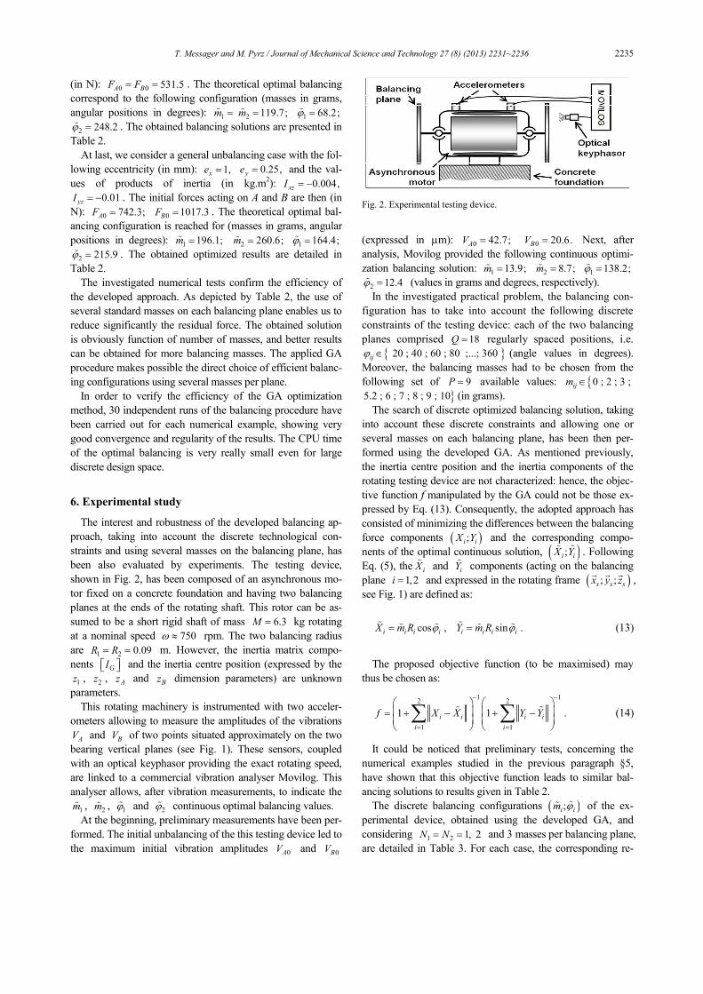
6. Experimental study
The interest and robustness of the developed balancing ap-
proach, taking into account the discrete technological con-
straints and using several masses on the balancing plane, has
been also evaluated by experiments. The testing device,
shown in Fig. 2, has been composed of an asynchronous mo-
tor fixed on a concrete foundation and having two balancing
planes at the ends of the rotating shaft. This rotor can be as-
sumed to be a short rigid shaft of mass 6.3M = kg rotating
at a nominal speed 750ω ≈ rpm. The two balancing radius
are 1 2 0.09R R= = m. However, the inertia matrix compo-
nents GI and the inertia centre position (expressed by the
1z , 2z , Az and Bz dimension parameters) are unknown
parameters.
This rotating machinery is instrumented with two acceler-
ometers allowing to measure the amplitudes of the vibrations
AV and BV of two points situated approximately on the two
bearing vertical planes (see Fig. 1). These sensors, coupled
with an optical keyphasor providing the exact rotating speed,
are linked to a commercial vibration analyser Movilog. This
analyser allows, after vibration measurements, to indicate the
1mɶ , 2mɶ , 1ϕɶ and 2ϕɶ continuous optimal balancing values.
At the beginning, preliminary measurements have been per-
formed. The initial unbalancing of the this testing device led to
the maximum initial vibration amplitudes 0AV and 0BV
(expressed in µm): 0 42.7;AV = 0 20.6.BV = Next, after
analysis, Movilog provided the following continuous optimi-
zation balancing solution: 1 13.9;m =ɶ 2 8.7;m =ɶ 1 138.2;ϕ =ɶ
2 12.4ϕ =ɶ (values in grams and degrees, respectively).
In the investigated practical problem, the balancing con-
figuration has to take into account the following discrete
constraints of the testing device: each of the two balancing
planes comprised 18Q = regularly spaced positions, i.e.
{ } 20 ; 40 ; 60 ; 80 ;...; 360 ijϕ ∈ (angle values in degrees).
Moreover, the balancing masses had to be chosen from the
following set of 9P = available values: {0 ; 2 ; 3 ;ijm ∈
}5.2 ; 6 ; 7 ; 8 ; 9 ; 10 (in grams).
The search of discrete optimized balancing solution, taking
into account these discrete constraints and allowing one or
several masses on each balancing plane, has been then per-
formed using the developed GA. As mentioned previously,
the inertia centre position and the inertia components of the
rotating testing device are not characterized: hence, the objec-
tive function f manipulated by the GA could not be those ex-
pressed by Eq. (13). Consequently, the adopted approach has
consisted of minimizing the differences between the balancing
force components ( );i iX Y and the corresponding compo-
nents of the optimal continuous solution, ( );i iX Yɶ ɶ . Following
Eq. (5), the iXɶ and iYɶ components (acting on the balancing
plane 1,2i = and expressed in the rotating frame ( ); ;s s sx y z� � �
,
see Fig. 1) are defined as:
cos , sin .i i i i i i i iX m R Y m Rϕ ϕ= =ɶ ɶɶ ɶɶ ɶ (13)
The proposed objective function (to be maximised) may
thus be chosen as:
1 12 2
1 1
1 1 .i i i i
i i
f X X Y Y
− −
= =
= + − + −
∑ ∑ɶ ɶ (14)
It could be noticed that preliminary tests, concerning the
numerical examples studied in the previous paragraph §5,
have shown that this objective function leads to similar bal-
ancing solutions to results given in Table 2.
The discrete balancing configurations ( );i im ϕɶɶ of the ex-
perimental device, obtained using the developed GA, and
considering 1 2 1, 2N N= = and 3 masses per balancing plane,
are detailed in Table 3. For each case, the corresponding re-
Fig. 2. Experimental testing device.
2236 T. Messager and M. Pyrz / Journal of Mechanical Science and Technology 27 (8) (2013) 2231~2236
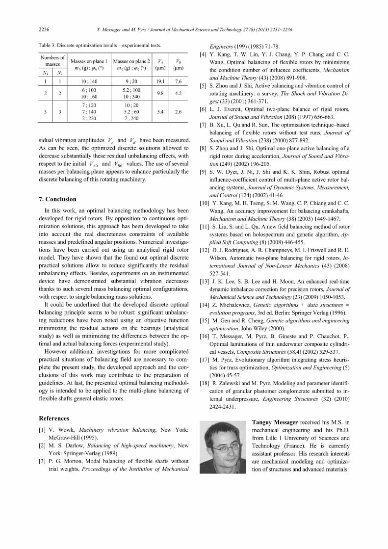
sidual vibration amplitudes AV and BV have been measured.
As can be seen, the optimized discrete solutions allowed to
decrease substantially these residual unbalancing effects, with
respect to the initial 0AV and 0BV values. The use of several
masses per balancing plane appears to enhance particularly the
discrete balancing of this rotating machinery.
7. Conclusion
In this work, an optimal balancing methodology has been
developed for rigid rotors. By opposition to continuous opti-
mization solutions, this approach has been developed to take
into account the real discreteness constraints of available
masses and predefined angular positions. Numerical investiga-
tions have been carried out using an analytical rigid rotor
model. They have shown that the found out optimal discrete
practical solutions allow to reduce significantly the residual
unbalancing effects. Besides, experiments on an instrumented
device have demonstrated substantial vibration decreases
thanks to such several mass balancing optimal configurations,
with respect to single balancing mass solutions.
It could be underlined that the developed discrete optimal
balancing principle seems to be robust: significant unbalanc-
ing reductions have been noted using an objective function
minimizing the residual actions on the bearings (analytical
study) as well as minimizing the differences between the op-
timal and actual balancing forces (experimental study).
However additional investigations for more complicated
practical situations of balancing field are necessary to com-
plete the present study, the developed approach and the con-
clusions of this work may contribute to the preparation of
guidelines. At last, the presented optimal balancing methodol-
ogy is intended to be applied to the multi-plane balancing of
flexible shafts general elastic rotors.
References
[1] V. Wowk, Machinery vibration balancing, New York:
McGraw-Hill (1995).
[2] M. S. Darlow, Balancing of high-speed machinery, New
York: Springer-Verlag (1989).
[3] P. G. Morton, Modal balancing of flexible shafts without
trial weights, Proceedings of the Institution of Mechanical
Engineers (199) (1985) 71-78.
[4] Y. Kang, T. W. Lin, Y. J. Chang, Y. P. Chang and C. C.
Wang, Optimal balancing of flexible rotors by minimizing
the condition number of influence coefficients, Mechanism
and Machine Theory (43) (2008) 891-908.
[5] S. Zhou and J. Shi, Active balancing and vibration control of
rotating machinery: a survey, The Shock and Vibration Di-
gest (33) (2001) 361-371.
[6] L. J. Everett, Optimal two-plane balance of rigid rotors,
Journal of Sound and Vibration (208) (1997) 656-663.
[7] B. Xu, L. Qu and R. Sun, The optimisation technique–based
balancing of flexible rotors without test runs, Journal of
Sound and Vibration (238) (2000) 877-892.
[8] S. Zhou and J. Shi, Optimal one-plane active balancing of a
rigid rotor during acceleration, Journal of Sound and Vibra-
tion (249) (2002) 196-205.
[9] S. W. Dyer, J. Ni, J. Shi and K. K. Shin, Robust optimal
influence-coefficient control of multi-plane active rotor bal-
ancing systems, Journal of Dynamic Systems, Measurement,
and Control (124) (2002) 41-46.
[10] Y. Kang, M. H. Tseng, S. M. Wang, C. P. Chiang and C. C.
Wang, An accuracy improvement for balancing crankshafts,
Mechanism and Machine Theory (38) (2003) 1449-1467.
[11] S. Liu, S. and L. Qu, A new field balancing method of rotor
systems based on holospectrum and genetic algorithm, Ap-
plied Soft Computing (8) (2008) 446-455.
[12] D. J. Rodrigues, A. R. Champneys, M. I. Friswell and R. E.
Wilson, Automatic two-plane balancing for rigid rotors, In-
ternational Journal of Non-Linear Mechanics (43) (2008)
527-541.
[13] J. K. Lee, S. B. Lee and H. Moon, An enhanced real-time
dynamic imbalance correction for precision rotors, Journal of
Mechanical Science and Technology (23) (2009) 1050-1053.
[14] Z. Michalewicz, Genetic algorithms + data structures =
evolution programs, 3rd ed. Berlin: Springer Verlag (1996).
[15] M. Gen and R. Cheng, Genetic algorithms and engineering
optimization, John Wiley (2000).
[16] T. Messager, M. Pyrz, B. Gineste and P. Chauchot, P.,
Optimal laminations of thin underwater composite cylindri-
cal vessels, Composite Structures (58,4) (2002) 529-537.
[17] M. Pyrz, Evolutionary algorithm integrating stress heuris-
tics for truss optimization, Optimization and Engineering (5)
(2004) 45-57.
[18] R. Zalewski and M. Pyrz, Modeling and parameter identifi-
cation of granular plastomer conglomerate submitted to in-
ternal underpressure, Engineering Structures (32) (2010)
2424-2431.
Tanguy Messager received his M.S. in
mechanical engineering and his Ph.D.
from Lille 1 University of Sciences and
Technology (France). He is currently
assistant professor. His research interests
are mechanical modeling and optimiza-
tion of structures and advanced materials.
Table 3. Discrete optimization results – experimental tests.
Numbers of
masses
N1 N2
Masses on plane 1
m1j (g) ; ϕ1j (°)
Masses on plane 2
m2j (g) ; ϕ2j (°)
VA
(µm)
VB
(µm)
1 1 10 ; 140 9 ; 20 19.1 7.6
2 2 6 ; 100
10 ; 160
5.2 ; 100
10 ; 340 9.8 4.2
3 3
7 ; 120
7 ; 140
2 ; 220
10 ; 20
5.2 ; 60
7 ; 240
5.4 2.6