Embed Size (px)
Citation preview

199NUCLEAR ENGINEERING AND TECHNOLOGY, VOL.41 NO.2 MARCH 2009 - SPECIAL ISSUE ON THE WATER REACTOR FUEL PERFORMANCE MEETING 2008
DISCUSSION ABOUT HBS TRANSFORMATION IN HIGHBURN-UP FUELS
DANIEL BARON*, MOTOYASU KINOSHITA1,2, PHILIPPE THEVENIN and RODRIGUE LARGENTONEDF R&D Les Renardières Route de Sens, 77818 MORET sur LOING Cedex France1 CRIEPI /JAEA/U-Tokyo, Project leader of NXO 2 Central Research of Electric Power Industry, 2-11-1 Iwadokita Komaeshi, Tokyo 201 Japan*Corresponding author. E-mail : [email protected]
Received December 10, 2008 Accepted for Publication January 20, 2009
1. INTRODUCTION
When EDF started to operate PWRs in 1977, a largesurvey program was launched, including TIHANGE,FESSENHEIM and BUGEY fuel rod examinations. Itwas conducted within a French collaboration programbetween EDF, FRAMATOME and CEA. This collaborativeprogram was then extended to WESTINGHOUSEparticipation. Standard discharge burn-up was around 34and 35 GWd/MtU. In order to investigate higher dischargeburn-up, four fuel assemblies were reloaded in theFESSENHEIM 2 core and four assemblies in the ZIONcore. The fuel rod average burn-up was increased up to 55GWd/MtU after a fourth and fifth cycle. Four Fessenheimfuel rods were examined in 1984 after the fourth cycle(around 45 GWd/MtU fuel rod average) and four in 1985after the fifth cycle. The same scheme was performedafter 4 and 5 cycles on the ZION rods in America.
After five cycles an abnormal porosity was observedin the outer “rim” region of the most irradiated pellets(D.Baron [2], P.Guedeney [49]). Going back on fuelirradiated for four cycles, the same observation was madebut at a much lower level. In addition, EPMA was showing
in the same cross section a loss of xenon in the pellet outerradius. Average porosity was evaluated around 8 to 10 %.Concomitant to these observations, the overall fuel rodfission gas release was exhibiting acceleration with burn-up. It was then suggested that the xenon excess was comingfrom this area. Later, after careful investigation it wasdemonstrated that this conclusion was wrong and that mostof the gases were stored in the newly formed porosities.The detection loss was mainly due to the EPMA depthlimitation, around 1 µm for the usual beam acceleration.It was demonstrated later on by increasing the electronsbeam energy, that gas could be detected in unopenedbubbles under the sample surface.
In conclusion, a new phenomenon was identified inthe coldest part of the fuel pellet, where thermal activationis usually considered too low to allow atoms mobility(below 900K). Because of the location of these observationsat the pellet edge, it was called “the RIM effect”.
Further SEM images have shown that this pore build-up is then accompanied by a grain subdivision. In 1962Bleiberg [1] had already mentioned such a remarkablemicro structural change on high burn-up LWR UO2 fuels.They found from replica electron microscopy, that at around
High burn-up transformation process in low temperature nuclear fuel oxides material was observed in the early sixties inLWR UO2 fuels, but not studied in depth. Increasing progressively the fuel discharge burn-up in PWR power plants, thismaterial transformation was again observed in 1985 and identified as an important process to be accounted for in the fuelsimulations due to its expected consequence on fuel heat transfer and therefore on the fission gas release. Fission gas releasewas one of the major concerns in PWR fuels, mainly during transient or accidents events. The behaviour of such a materialin case of rod failure was also an important aspect to analyse. Therefore several national and international programs werelaunched during the last 25 years to understand the mechanisms leading to the high burn-up structure formation and to evaluatethe physical properties of the final material. A large observations database has been acquired, using the more sophisticatedtechniques available in hot cells. This large database is discussed in this paper, providing basis to build an engineering-model,which is based on phenomenological description data and information accumulated. In addition this paper has the ambitionto construct the best logical model to understand restructuring.
KEYWORDS : Nuclear Fuel, LWR, High Burn-up, HBS, Mechanisms, Polygonisation, Porosity, Restructuration, Rim Effect
BARON et al., Discussion about HBS Transformation in High Burn-up Fuels
75 GWd/MtU the original grain subdivided into fine subgrains, less than 1 µm. However no further work waslaunched at that time to investigate this phenomenon.
In the framework of the PWR studies, consequenceson the fuel thermo-mechanical behaviour were expected,mainly on the fuel operating temperatures and thereforeon the level of fission gas release. Therefore, these 1985observations of the High Burn-up Structure (HBS)Transformation in the fuel pellet rim, led the designers toinvest time and money into national and internationalprograms to understand the mechanisms involved. Thefirst step was to suggest a reorientation of the High Burn-up Effect Program (HBEP) objectives in 1986 (D.Baron[2] and J.O.Barner [3]). EDF in 1990 launched a programon high burn-up fuel chemistry with CEA, developing afirst generation model for the engineering codes, focusedon simulating the porosity evolution (D.Baron [4]). Themajor concern was to study the consequence of thisadditional porosity on the evolution of the physical andmechanical properties of the material. A part of the surveyprograms was focused on the understanding of thetransformation threshold and later on, on its mechanism.
However, the engineering survey programs were notable to support such an investigation program, which needa pragmatic scientific approach. This was the reason forEDF R&D to join in 1994 the High Burn-up Rim Project(HBRP, 1992–2001) and then the HBRP_NT (2002–2005)proposed by the Japanese CRIEPI (M.Kinoshita [5],M.Kinoshita [6]). A well-defined parametric study wasengaged within this project on fuel discs irradiated inquasi-isothermal conditions, up to 100 GWj/MtU. Afterirradiation in the HALDEN reactor, burn-up and temperaturethreshold were identified and sample properties werecharacterized. SEM and TEM examinations in TUI haveprovided very useful information in particular on thedislocation piling and the nano-bubbles stabilization andgrowth. It should also be mentioned that a very efficientcomplement was also provided within the NFIR workinggroup. NFIR5 project is expected to bring again in the nextyears a new stage of understanding with the irradiation ofa set of parametric fuel wafers.
SIMS methodology development in CEA hot labs onnuclear fuel applications (Desgranges [7], Lamontagne[8]) is also a valuable tool to localize and quantify thefission gases, and to evaluate the gas pressure in themicrometric bubbles of the HBS. More widely, evolutionsin the investigation tools and methods are necessary to gofurther in the mechanisms understanding.
Since 2003, more theoretical works have been conductedto study in depth the effect of cascades produced by high-energy ions in fuel materials (indeed each material atomis displaced every two or three days). These are multi-scaleapproaches, starting from first principle calculations [19]in order to evaluate the atoms incorporation energies orthe defect formation energies of the fission products, andinvolving molecular dynamics and Monte Carlo calculations.
These works are performed within the Japanese inter-Universities NXO project and within the new EuropeanF-BRIDGE project.
In 2007, we had collected a large amount of data fromUO2, UO2+ additives, MOX fuels, in a large variety ofoperating conditions. What conclusions can be drawn?What are the questions still pending? This paper isdiscussing the main interrogations and available answers,pointing the existing controversies, in order to providethe best state of the art.
2. STATE OF THE ART
Evidence showed (Spino [9], Rest [10], Spino [11])that the gas precipitation and the propagation of the grainsubdivision don’t occur at the same burn-up. Gas starts to
200 NUCLEAR ENGINEERING AND TECHNOLOGY, VOL.41 NO.2 MARCH 2009 - SPECIAL ISSUE ON THE WATER REACTOR FUEL PERFORMANCE MEETING 2008
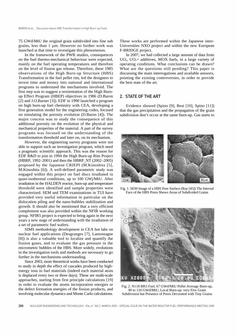
Fig. 1. SEM Image of a HBS Pore Surface (Ray [45]) The InternalFace of the HBS Pores Shows Areas of Subdivided Grains
Fig. 2. N118 BR3 Fuel, 67 GWd/MtU Pellet Average Burn-up,90 to 110 GWd/MtU, Local Burn-up: very Few Grain
Subdivision but Presence of Pores Decorated with Tiny Grains

precipitate in tiny bubbles then; bubbles grow sometimesquite quickly to achieve a micrometric size. During thisphase, the micrometric bubbles observed are systematicallydecorated with tiny grains on their surface (50 to 100 nm)(figure 1). The last stage of the process is the formationof areas of sub-divided grains filling the space betweenmicrometric bubbles. However, this step in the HBSprocess can be heavily delayed in some cases, as observedin the N118 BR3 fuel rod (Spino [9]) and other similar rods(figure 2). Spino [11] et al have recently shown that latticecontraction accompanies grain subdivision propagation.
Many parameters may influence the HBS transformation:the local temperature and burn-up, the instantaneousfission density, the local density of fission products, theinitial grain size, the local fuel constraint, some initialadditives, and the local oxygen potential. The evolutionof the oxygen potential is related to the global affinity ofthe fission products (their valence), and to the buffers ableto trap the oxygen, such as Molybdenum, or Zirconium.(J.H.Matzke [43,44]). It was also shown that the oxygenpotential of an irradiated fuel is increasing slowly withburn-up (Spino [28]), therefore the saturation of themolybdenum oxidation is likely an element to be takeninto account.
All investigation means available on irradiated fuel inhot cells have been used. The lower investigation scaleavailable is TEM, allowing observations of one to severalhundred of nanometres artefacts. However, the preparationof thin layers on irradiated samples is not possible at thistime. TEM observations are then performed on selected“chips” obtained by crunching samples. This does not allowlocating properly the observations performed. The followingdiscussion is then based on the overall information collectedon high burn-up fuels, combined with extrapolationssuggested by deduction.
2.1 Burn-up and Temperature Threshold (LocalValues)Non-constrained samples were irradiated for the HBRP
project, in the Halden reactor (IFA 601) in quasi-isothermalconditions at four temperatures: 450, 650, 900 and 1150°C.In order to achieve high burn-up in a short time, the fuelinitial 235U enrichment was 26.5 %. The instantaneousfission density was therefore 2 to 6 times higher than in astandard PWR fuel operating around 178 to 220 W/cmand the instantaneous fission density was different dependingupon the final discharge burn-up of the Samples, as shownin table 1.
This means that the instantaneous energy depositwas, except for the samples with the lowest burn-up (35GWd/MtU), higher in these fuels than in standard PWRfuels, even in the self-shielding area of an UO2 pellet, orin the rich Plutonium agglomerates of the MOX fuels.Having all this in mind, the burn-up threshold for HBSinitiation was found between 55 and 65 GWd/MtU andthe temperature threshold below 1100°C (M.Kinoshita[13]). The accuracy on these thresholds is obviouslylimited. HBS initiation could be detected very locally inthe 55 GWd/MtU and all samples above 65 GWd/MtUwere totally restructured. The burn-up threshold is thenin between these two values. It gives low information onthe real kinetic of the mechanism.
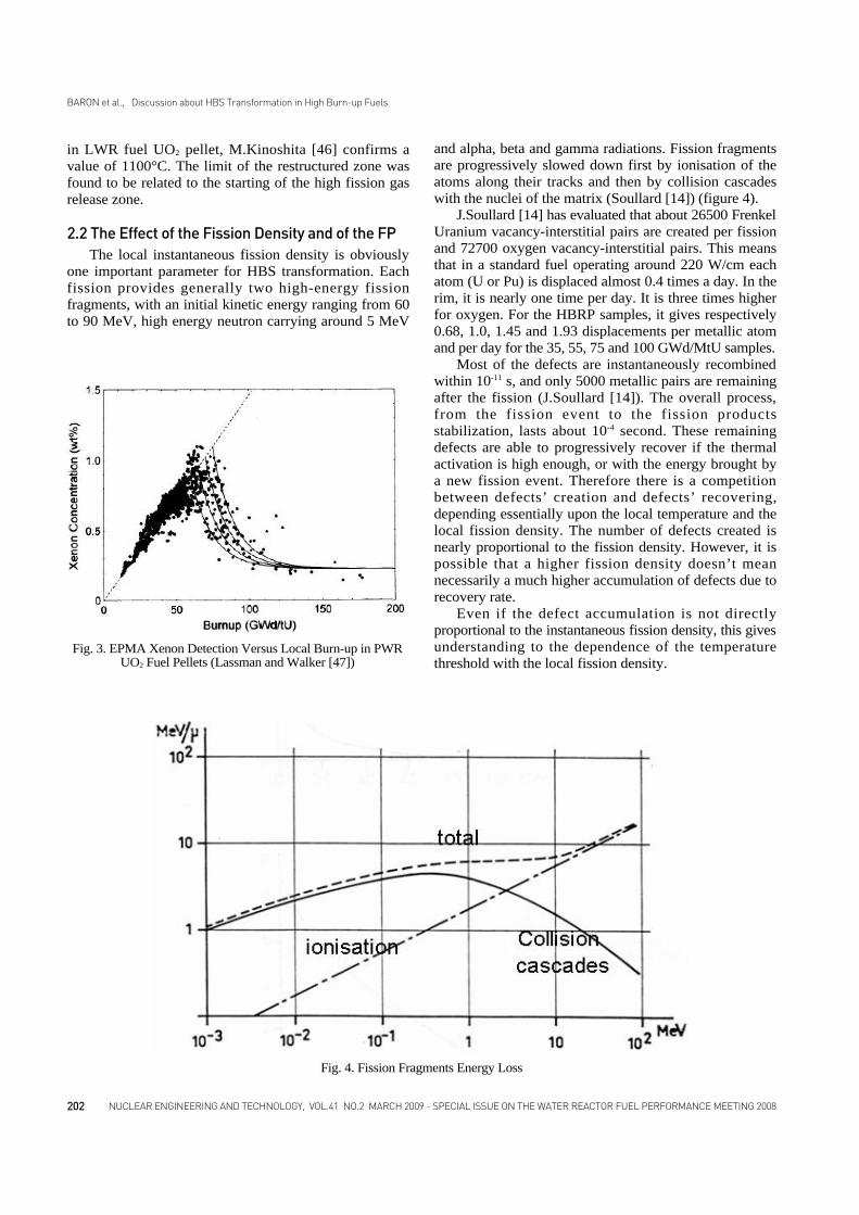
Related to the particular power density and constraintof the HBRP samples, 55-65 GWd/MtU is probably aconservative value with regard to HBS transformationkinetic in the industrial LWR fuels. From the overallPWR data (figure 3), the initiation threshold determinedfrom EPMA measurements by Lassmann and Walker[42] was ranging from 60 to 75 GWd/MtU. However, thedetermination of the local burn-up in this case is not soaccurate as in the HBRP samples. We have also to accountfor two other difficulties: a radial instantaneous fissiondensity profile very steep and therefore inaccurate in therim zone, and an unknown local constraint. Lately from avery fine analysis of a high burn-up fuel performed at TUI,M.Kinoshita [46] gives a probably more accurate thresholdaround 7 % FIMA (about 70 GWd/MtU).
Concerning the temperature threshold for rim formation
BARON et al., Discussion about HBS Transformation in High Burn-up Fuels
201NUCLEAR ENGINEERING AND TECHNOLOGY, VOL.41 NO.2 MARCH 2009 - SPECIAL ISSUE ON THE WATER REACTOR FUEL PERFORMANCE MEETING 2008
100 GWd/MtU 2020 6.32 1013
75 GWd/MtU 1520 4.74 1013
55 GWd/MtU 1110 3.48 1013
35 GWd/MtU 710 2.21 1013
PWR fuel220 W/cm 420 1.31 1013
PWR fuel178 W/cm 340 1.06 1013
MOX Pu clusters178 W/cm 730 to 1100 2.3 to 3.4 1013
Samples final BU Power density W/cm3 Fission density fissions/cm3/s
Table 1. Comparative Presentation of the Instantaneous Fission Density of the HBRP Samples with the Industrial Fuels
in LWR fuel UO2 pellet, M.Kinoshita [46] confirms avalue of 1100°C. The limit of the restructured zone wasfound to be related to the starting of the high fission gasrelease zone.
2.2 The Effect of the Fission Density and of the FPThe local instantaneous fission density is obviously
one important parameter for HBS transformation. Eachfission provides generally two high-energy fissionfragments, with an initial kinetic energy ranging from 60to 90 MeV, high energy neutron carrying around 5 MeV
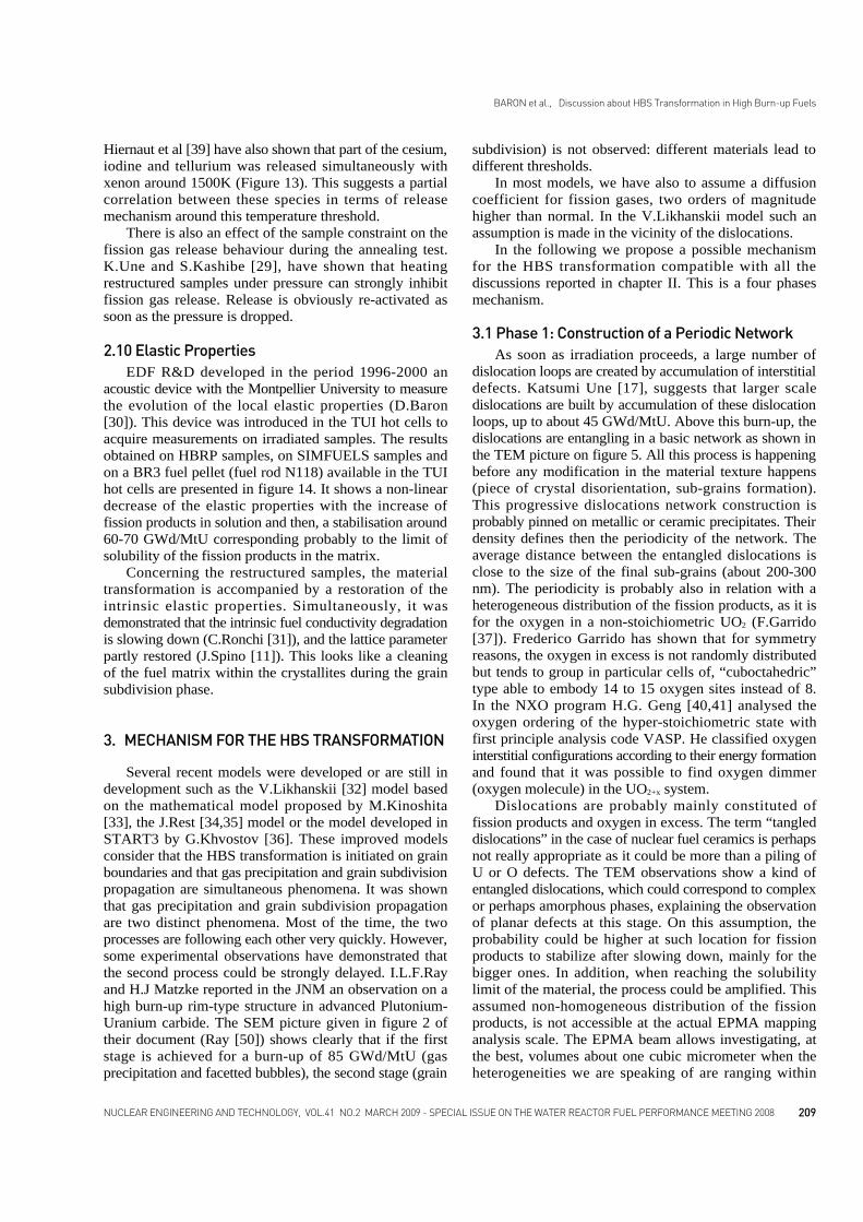
and alpha, beta and gamma radiations. Fission fragmentsare progressively slowed down first by ionisation of theatoms along their tracks and then by collision cascadeswith the nuclei of the matrix (Soullard [14]) (figure 4).
J.Soullard [14] has evaluated that about 26500 FrenkelUranium vacancy-interstitial pairs are created per fissionand 72700 oxygen vacancy-interstitial pairs. This meansthat in a standard fuel operating around 220 W/cm eachatom (U or Pu) is displaced almost 0.4 times a day. In therim, it is nearly one time per day. It is three times higherfor oxygen. For the HBRP samples, it gives respectively0.68, 1.0, 1.45 and 1.93 displacements per metallic atomand per day for the 35, 55, 75 and 100 GWd/MtU samples.
Most of the defects are instantaneously recombinedwithin 10-11 s, and only 5000 metallic pairs are remainingafter the fission (J.Soullard [14]). The overall process,from the fission event to the fission productsstabilization, lasts about 10-4 second. These remainingdefects are able to progressively recover if the thermalactivation is high enough, or with the energy brought bya new fission event. Therefore there is a competitionbetween defects’ creation and defects’ recovering,depending essentially upon the local temperature and thelocal fission density. The number of defects created isnearly proportional to the fission density. However, it ispossible that a higher fission density doesn’t meannecessarily a much higher accumulation of defects due torecovery rate.
Even if the defect accumulation is not directlyproportional to the instantaneous fission density, this givesunderstanding to the dependence of the temperaturethreshold with the local fission density.
202
BARON et al., Discussion about HBS Transformation in High Burn-up Fuels
NUCLEAR ENGINEERING AND TECHNOLOGY, VOL.41 NO.2 MARCH 2009 - SPECIAL ISSUE ON THE WATER REACTOR FUEL PERFORMANCE MEETING 2008
Fig. 3. EPMA Xenon Detection Versus Local Burn-up in PWRUO2 Fuel Pellets (Lassman and Walker [47])
Fig. 4. Fission Fragments Energy Loss

Another aspect is the role of the fission productsstabilized in the fuel matrix, inducing local lattice distortions.These fission products are potential crystal defects, evenif they are in solution. Trying to demonstrate the Plutoniumeffect on HBS transformation, Noirot [15] points out in aMOX fuel the UO2 matrix next to agglomerate, havingnearly the same fission product concentration than thecluster totally restructured. This UO2 matrix has nodiscernable initiation of the HBS structure. He concludedon the evidence of an effect of the Plutonium concentrationto accelerate the HBS process. The presence of Plutoniummodifies probably the oxygen distribution in the clusterand therefore the local material chemistry.
However, the interpretation given is not straightforward.The high fission product concentration in the UO2 matrix,next to the Plutonium cluster is mainly due to the fissionfragment implantation in the matrix. In other words, theflux of fission products generated in the Plutonium clusteris implanted in the UO2 matrix surrounding the Plutoniumcluster. Assuming an average free path of 7 µm, the kineticenergy deposit of the fission fragments during its interactionwith the overall material is shared between the clusterand the surrounding matrix. When the fission fragmentreaches the cluster limit, it has already lost most of itsenergy. This means that for the same amount of fissionproduct accumulation, the total energy deposit in thesurrounding UO2 matrix is lower than in the Plutoniumcluster. Therefore, this could be also an explanation forthe delay observed in the HBS formation in the UO2 matrix.
2.3 About Dislocations Fission energy is therefore the main energy provided
in the nuclei and particles mobility process. Howeverthese fission spikes are happening randomly and have noreason to induce a specifically ordered reorganization ofthe material. In order to induce the mobility and theredistribution of nuclei in a particular way, the materialneeds strain and stress gradients at the restructuring scale.From TEM observations, this scale is ranging around 100to 500 nm (figure 5).
The TEM pictures performed by T.Wiss in TUI orK.Nogita in Japan on high burn-up fuels above 45GWd/MtU, show dislocations progressively tangling-up(see example on figure 5). For burn-up lower than 45GWd/MtU, K.Nogita [17] gives the following correlationto evaluate the dislocations density evolution:
Where disloc is the dislocation density expressed in m/m3
and BU is the local burn-up in GWd/MtU. Saturation isobserved around 5.8 1014 m/m3. This doesn’t mean thatno more dislocations are created but that they are pilingup, creating a kind of entangled network. This limitation
in the density of dislocations clusters could be probablyrelated to the established density of precipitates on whichthe dislocations are fixed. This also means that theprobability for a fission product to stabilize is likely higherat the location where dislocations are.
The permanent increase of the material entropy, therelatively low evolution of the lattice parameter with burn-up and the recovery of the lattice parameters observed assoon as the material is restructuring, suggest that most ofthe fission products are not uniformly distributed. Inaddition the relative stabilization of both the materialthermal conductivity degradation even after annealing andof the elastic properties degradation when rim structureinitiates tends to demonstrate that the limit of solubility isreached. Where are these fission products located? Arethey really homogeneously distributed? Probably notbecause the presence of other fission products must changethe local incorporation energy in its surrounding. Onecan expect that a large part of fission products couldagglomerate. Dislocation tangles are probably mainlyconstituted of fission products. Nearly 30 % of thesefission products are gaseous fission products (xenon andkrypton). Moreover, because of decay chains, thesegaseous species must be associated to other elements. Forexample, xenon is always accompanied by tellurium,cesium, barium and iodine. The dislocations’ tanglesshould be therefore constituted of complex compounds.At the present time, such a proposed assumption cannotbe experimentally evidenced, having no way to characterizethe fission products distribution at such a scale (0.2 to 1µm).Very high energy XRD could perhaps allow detectionand identification of these compounds. Figure 5 shows adistance between dislocations around 0.2 to 0.4 µm (200to 400 nm).
These dislocation tangles induce local energyconcentrations, proportional to the local number ofdislocations. J.Jonet [18] studied in his PhD work the
BARON et al., Discussion about HBS Transformation in High Burn-up Fuels
203NUCLEAR ENGINEERING AND TECHNOLOGY, VOL.41 NO.2 MARCH 2009 - SPECIAL ISSUE ON THE WATER REACTOR FUEL PERFORMANCE MEETING 2008
Fig. 5. TEM on a HBRP Sample 35 GWd/MtUDislocations’ Spacing is about 100 to 200 nm. (HBRP [16])
(1)

effect of different dislocations configurations on the storedenergy, and their effect on the microstructure. A consequenceis that the entangled dislocations are creating a stress fieldin their direct neighbourhood, which locally increases thestress/strain gradient.
Mobility of vacancies should therefore be enhancedtowards dislocation clusters in order to release the localstress induced by local gas accumulation. This favoursbubble growth at dislocation location (figure 6). Bubblesare stabilized by their internal gas pressure.
This means that vacancies are moving towards gasaccumulation spots and not the opposite. As the vacanciesmobility is much higher than gas atoms, the apparent gasdiffusion rate used in modelling has to be be enhanced oftwo decades at short distance. But the reality is that the
gas atoms are not moving. Dynamic molecular calculationscould probably, confirm the high stability of gas atomsclose to dislocations.
2.4 A Transformation at Quasi-constant VolumeConcerning the grain subdivision mechanisms, Masaki
Amaya and Jinichi Nakamura [48] are providing usefulinformation, using fine XRD analysis on a representativeHBS transformation sampling, ranging between 40 and66 GWd/MtU. The shift of the diffraction angles is givingthe crystal lattice expansion, and the widening of thediffraction’s spikes the status of the grain subdivision andthe grain-to-grain constraint (William and Hall [20,21]method). The lower is the fuel local temperature; thelarger is the spikes width. Even after a heat treatment at1600 °C, the spikes width remains still enlarged. J.Nakamurashows that the crystallites size saturates around 200nmfor local burn-up higher than 67 GWd/MtU (pellet averageburn-up is 57 GWd/MtU). This is consistent with the valueof 300 nm reported by M.Kinoshita [46].
The non-uniform strain evaluation increases from 0.1to 0.2% with increasing grain subdivision (figure 7). Duringfuel restructuring, J.Spino [11] shows that the latticeparameter is decreasing in the same time of 0.1 %. Thismeans that the transformation could be considered ashappening at nearly constant volume.
It is confirmed in figure 8 where J.Nakamura givesthe evolution of the local stored energy as measured inhis own experimentations. These results also suggest thatthe stored-energy saturates when the grain subdivisionphase starts. The increase of the stored energy between55 and 65 GWd/MtU could be related to the attainmentof the solubility limit we have already mentioned, or a
BARON et al., Discussion about HBS Transformation in High Burn-up Fuels
204 NUCLEAR ENGINEERING AND TECHNOLOGY, VOL.41 NO.2 MARCH 2009 - SPECIAL ISSUE ON THE WATER REACTOR FUEL PERFORMANCE MEETING 2008
Fig. 7. Evolution of the Non-uniform Strain and the AverageCrystallite Size with Local Burn-up (Amaya and Nakamura [48])
Fig. 8. Evolution of the Average Stored Energy Density (Amayaand Nakamura [48])
Fig. 6. TEM on a HBRP Sample 35 GWd/MtUGrowing Bubbles Aligned along Dislocations Tangles

threshold in the oxygen buffering.The decrease of the non-uniform strain around 55
GWd/MtU is, up to now, not explained, but could probablybe in relation with the increase of the lattice parameterreported by J.Spino [11] in the “sub-rim” region.
2.5 Effect of the Local Constraint Because the material trend is swelling, there are two
kinds of constraints to be considered: a macroscopichydrostatic external constraint and the material internalconstraint.
Concerning the macroscopic constrain, it is due to thestructure interaction i.e. axial pellet-to-pellet interaction,pellet-cladding interaction and the global fuel swelling.Due to the cylindrical shape of the pellet, the thermalexpansion leads to a pellet edge hoop strain in tension anda pellet centre in compression. However as burn-up andassociated swelling proceed, the pellet edge is progressivelyin compression due to an accelerated swelling, as thepellet edge burn-up increases faster (self-shielding effectof 238U). Moreover, the axial and radial pellet clad interactionsamplify these phenomena. In case of high stress, creepdeformation could relax the material. Unfortunately, nodata are available at present time on the fuel creep propertiesat low temperature and high constraint; however we cannotignore that an axial flow was evidenced in the rim regionof commercial fuels (Guedeney [49]).
In fact, nuclear fuel material is a poly-crystalline,meaning that it must be regarded as constituted of twomaterials: the crystals (intrinsic properties) and the grainboundaries. As burn-up proceeds, many fission products,solid and gaseous, accumulate in the grain boundariespreventing the gas from diffusing by itself towards the freevolumes (P.Van Uffelen [22]) of the rod. Fission gasbubbles are formed at the grain boundary. Grain swellingaccommodation depends then upon the evolution of thegrain boundaries properties. In this condition the innergrains constraint is depending upon the capability of thegrain boundaries to accommodate the swelling. Decreasingthe average grain size increases the number of grainboundaries therefore the capacity of the fuel to accommodatethe swelling.
Increasing matrix hydrostatic compressive stressprobably reduces the fission products free path, andtherefore the fission products mobility. It was shown thatin case of a delayed HBS transformation like presented inthe N118 BR3 fuel rod (J.Spino [9-11]), it was associatedto a higher density of micrometric bubbles with a smallersize (presentation D.Baron [24] at the TUI HBS workshopin June 2004): 25-30.1016 bubbles/m3 instead of 5.1016
bubbles/m3 usually measured. The formation of a higherdensity of small bubbles suggests a smaller mobility ofatoms. However an addition of Chromium oxide cancounterbalance this matrix stress effect by increasing theinitial number of point defects and therefore the atomsself-diffusion, as presented in the following sub-chapter.
2.6 The Effect of the Initial Grain Size The contradictory results obtained about the grain
size effect on HBS formation can be explained by themanufacturing technique used to enlarge the grains. Thereare indeed several techniques: a) Increasing the sintering time enlarge the maximum
grains size in UO2 by 30 µm.b) Using additives like aluminum-silicates, inducing liquid
phases at grain boundaries at sintering temperaturesenlarge the average grain size from 30 to 65 µm.
c) Using trivalent additives promoting atomic self-diffusionin the grains during the sintering phase increase thegrain size from 30 to 100 µm (figure 9).The use of chromium oxides combines b) and c), with
the formation of a liquid CrO phase at the grain boundariesif the proper thermodynamic sintering conditions are met.The grain growth is then a combination of an auto-diffusionenhancement and acceleration due to the CrO liquid phase.Depending upon the Cr2O3 initial content, the solubilitylimit is overtaken or not initiated at all, then eventuallyprecipitates. This can then favour fission products ordislocations trapping.
A main conclusion reported by NFD is that a largegrain size delays the HBS transformation (K.Une [23]). Theexplanation proposed is that the HBS transformation isinitiated at grain boundaries essentially because vacanciesare provided from grain boundaries, therefore a reductionof the grain boundaries surface delays the HBS process.In this case large grains were obtained using techniquesa) and b).
These conclusions are consistent with observationswe have performed on a BR3 fuel rod in TUI (J.Spino [9-11]) with an average pellet burn-up of 68 GWd/MtU andan initial grains size of 17 µm obtained by technique a).The grain subdivision was greatly delayed despite a localburn-up in the pellet rim ranging from 80 to 100 GWd/MtU.
On the contrary, large grain fuel pellets manufactured
205NUCLEAR ENGINEERING AND TECHNOLOGY, VOL.41 NO.2 MARCH 2009 - SPECIAL ISSUE ON THE WATER REACTOR FUEL PERFORMANCE MEETING 2008
BARON et al., Discussion about HBS Transformation in High Burn-up Fuels
Fig. 9. Evolution of the Average Grain Size Versus AdditivesContent – Sintering Temperature 1700 °C - L.Bourgeois [26]

with Chromium additive exhibits an accelerated HBStransformation process, likely explained by a consequenceof the trivalent additive on the gaseous fission productsfree path as soon as the irradiation starts. The oxygen sub-lattice perturbation and cation charges have an importantinfluence on the atomic self-diffusion. The formation ofchromium nano-precipitates during the first irradiationperiod, could also favour an early precipitation of fissionproducts.
On the other hand, the large grains obtained withchromium additive in EDF industrial power plants showsthat HBS transformation is not always departing fromgrain boundaries (figure 10). It seems to depart randomly,depending upon very local conditions. This has also beenconfirmed on standard fuel where average grain size isabout 10 µm (J.Noirot [15]).
We can definitely conclude that enlarging grain sizetends to delay HBS transformation. On the basis of ourdiscussion in the previous sub-chapter it is shown thatgrain boundaries play the role of mechanical absorber. Itcan be expected that the constraint is globally higher inlarge grains, as enlarging grains reduces the number ofgrain boundaries.
2.7 The Effect of an Initial Micrometric PorosityIntroducing chapter II it was mentioned that micrometric
bubbles appear before the polygonisation process. It isconsidered that the round sub-grains (50 to 150 nm)observed on the bubble inner surface is related to a surfacerelaxation mechanism as suggested by N.Lozanno [12].Polygonisation is a bulk mechanism leading to polyhedral
grains 200 to 600 nm. The micrometric gas bubble densityachieved in the first stage could have an effect on themicrometric stress fields (energies) between the micro-pores, and then on the dislocations sources activity. Thepresence of this bubble feature reduces the global thermalconductivity but also decreases the global toughness ofthe material.
The Studsvik laboratory within the HBRP_NT projectproposed an interesting experiment (M.Kinoshita [25]).A fuel slice 1 mm thick was cut from a 61.4 GWd/MtUindustrial fuel pellet and re-irradiated in quasi isothermalconditions (400 to 450°C) in the R2 reactor up to 80.9GWd/MtU (figure 11), in a specific device (SRIP). Thedisk was sandwiched between two Molybdenum pelletsin order to limit the radial temperature gradient.
The post irradiation examinations gave the followinginformation:a) As expected, the restructured zone, already existing in
the initial pellet, is enlarged at the disk rim. b) HBS process is underway at mid radius of the disks. On
the original pellet, this “densification zone” does notexhibit any initiation of the HBS structure.
c) Near the disk centre, the material is totally restructured.On the pellet before re-irradiation, because of the baseirradiation, thermally activated gas precipitation is
206 NUCLEAR ENGINEERING AND TECHNOLOGY, VOL.41 NO.2 MARCH 2009 - SPECIAL ISSUE ON THE WATER REACTOR FUEL PERFORMANCE MEETING 2008
BARON et al., Discussion about HBS Transformation in High Burn-up Fuels
Fig. 11. Fuel Disk Cut in a 61.4 GWd/MtU Industrial Fuel Pelletand Re-irradiated in Quasi Isothermal Conditions (400 to 450°C)
in the R2 Reactor Up to 80.9 GWd/MtUFig. 10. HBS Transformation is Initiated Randomly in the Grain
and not Systematically from Grain Boundaries

observable. The gas bubbles are very similar in densityand size to what is observed in the cold area of the pelletduring the HBS transformation process. Comparing the centreline behaviour with the mid-
radius observations, it can be concluded that the pre-existence of a large density of micrometric pores enhancethe grain subdivision at low temperature; whatever is theorigin of the pores.
2.8 HBS Localization in the Fuel PelletIn UO2 fuel, the HBS restructuring initiates at the pellet
rim. The HBS transformation threshold is reached at thislocation because of the Uranium 238 self shielding effectleading to a higher local fission rate and a quicker burn-up accumulation, but also because the local temperatureis low enough to avoid any consequent thermal restorationof irradiation defects. When the pellet average burn-up isincreasing, the HBS structure tends to propagate towardthe centre.
The radial power generation distribution is almost flatin the major part of the pellet, apart in the neutronic self-shielding region at the pellet edge. It is similar for the burn-up radial profile, almost flat along the radius and increasingsharply in the self-shielding region. Then, in abscence oflocal burn-up gradient, the secondary local parameterssuch as constraint and temperature will determine HBSinitiation moment and location. There is therefore no reasonto propagate systematically the HBS structure from therim zone toward the pellet centre. It can be expected thatHBS formation conditions could be met at mid radius
before it is in the “sub-rim” region.Even if the HBS structure is considered almost as a
non-thermal mechanism, a minimum thermal activationcould favour short distance restructuring. For example, atmid radius (between 0.4 and 0.6R) where the temperatureis usually in the range 700-800°C, the thermal restorationis low enough to promote defects accumulation, accountingfor a standard fission rate of 1013 fiss/cm3/s. In additionbetween 0.4 and 0.6R , the macroscopic constraint is verylow during the whole irradiation.
Standard UO2 fuel rods were irradiated in the EDFGRAVELINES 5 reactor, for 6 and 7 cycles. A loss inxenon detection was found on EPMA analysis in the rimregion, but also between 0.65 and 0.8R. Examinations ofthis location combining SIMS analysis and EPMA haveshown an important intra and inter granular precipitationof fission gas in micrometric bubbles. The precipitationzone at mid radius can also be observed on the large-scale ceramography shown in figure 12. It doesn’tcorrespond to a thermal fission gas release zone. Thisobservation is very similar to the observation made in thesub-rim region with the difference that the loss ofdetection is higher. It suggests that the process is moreadvanced. The HBS process is probably initiated, beingstill in the plane defect state.
Similar observations were made in UO2 fuel withchromium additives, but at lower burn-up (60 GWd/MtU),confirming an accelerated process in this kind of fuel.
2.9 Thermal Annealing TestsThe HBS transformation leads to the precipitation in
the micrometric bubbles of nearly 80 % of the fissiongases produced. Indeed, a SIMS analysis is able to recovermost of gases generated in the restructured zones. Thefission gas release during standard base irradiation inPWR power plants is expected less than 8 to 10 %(J.Noirot [27]).
Annealing tests are usually performed on irradiatedfuel samples to measure the fission gas release accordingto temperature. Data collected within the HBRP (Kinoshita[5]) and the HPRP_NT (Kinoshita [25]) have shown anon-typical behaviour of the restructured samples. On anon-restructured material, the fission gas release isincreasing progressively with temperature. In the case ofthe HBS structure, a first release is observed as soon asthe temperature is beyond the irradiation temperaturethreshold. The material is meta-stable and tends to releasepart of its energy by a limited cracking of the sample,accompanied by a limited gas release, 5 to 10 % maximum.Then, increasing the temperature no further release ishappening up to a temperature threshold evaluated around1230°C for UO2. At this threshold temperature, the overallgas precipitated in the bubbles is quickly released. As thisthreshold is very reproducible from one fuel to the other,the interpretation is that this temperature corresponds to aphase transformation.
207NUCLEAR ENGINEERING AND TECHNOLOGY, VOL.41 NO.2 MARCH 2009 - SPECIAL ISSUE ON THE WATER REACTOR FUEL PERFORMANCE MEETING 2008
BARON et al., Discussion about HBS Transformation in High Burn-up Fuels
Fig. 12. UO2 Irradiated up to 80 GWd/MtU Pellet Average after7 Cycles in the GRAVELINE 5 EDF Reactor

Similar experiments were performed in CEA on MOXfuels samples. For the MOX fuels, the threshold temperaturewas lower than in UO2 and evaluated around 1140°C. Thisis likely due to a different distribution of the fissionproducts yield between Plutonium and Uranium 235. Itcan be expected that the chemical species, and mainly thephases formed are different in UO2 fuel and in MOX fuelmostly in the Plutonium agglomerates.
There are two possible explanations on the non inter-
linkage of the pores below the threshold temperature: - The presence of a viscous phase in the sub-grain boundaries,
stable up to the threshold temperature or, - A change in the overall oxygen distribution at the threshold
temperature, which leads to a modification of the overalloxygen potential.
It was pointed out by J.Spino [28] that the evolutionof the oxygen potential of the fuel could be one of thekey points of the HBS transformation. In their work J.P
208 NUCLEAR ENGINEERING AND TECHNOLOGY, VOL.41 NO.2 MARCH 2009 - SPECIAL ISSUE ON THE WATER REACTOR FUEL PERFORMANCE MEETING 2008
BARON et al., Discussion about HBS Transformation in High Burn-up Fuels
Fig. 14. Evolution of the intrinsic elastic modulus with burn-up (D.Baron [30])
Fig. 13. Fission Product Release During Laboratory Annealing of a very High Burn-up Fuel Specimen (Hiernaut [39])
Hiernaut et al [39] have also shown that part of the cesium,iodine and tellurium was released simultaneously withxenon around 1500K (Figure 13). This suggests a partialcorrelation between these species in terms of releasemechanism around this temperature threshold.
There is also an effect of the sample constraint on thefission gas release behaviour during the annealing test.K.Une and S.Kashibe [29], have shown that heatingrestructured samples under pressure can strongly inhibitfission gas release. Release is obviously re-activated assoon as the pressure is dropped.
2.10 Elastic Properties EDF R&D developed in the period 1996-2000 an
acoustic device with the Montpellier University to measurethe evolution of the local elastic properties (D.Baron[30]). This device was introduced in the TUI hot cells toacquire measurements on irradiated samples. The resultsobtained on HBRP samples, on SIMFUELS samples andon a BR3 fuel pellet (fuel rod N118) available in the TUIhot cells are presented in figure 14. It shows a non-lineardecrease of the elastic properties with the increase offission products in solution and then, a stabilisation around60-70 GWd/MtU corresponding probably to the limit ofsolubility of the fission products in the matrix.
Concerning the restructured samples, the materialtransformation is accompanied by a restoration of theintrinsic elastic properties. Simultaneously, it wasdemonstrated that the intrinsic fuel conductivity degradationis slowing down (C.Ronchi [31]), and the lattice parameterpartly restored (J.Spino [11]). This looks like a cleaningof the fuel matrix within the crystallites during the grainsubdivision phase.
3. MECHANISM FOR THE HBS TRANSFORMATION
Several recent models were developed or are still indevelopment such as the V.Likhanskii [32] model basedon the mathematical model proposed by M.Kinoshita[33], the J.Rest [34,35] model or the model developed inSTART3 by G.Khvostov [36]. These improved modelsconsider that the HBS transformation is initiated on grainboundaries and that gas precipitation and grain subdivisionpropagation are simultaneous phenomena. It was shownthat gas precipitation and grain subdivision propagationare two distinct phenomena. Most of the time, the twoprocesses are following each other very quickly. However,some experimental observations have demonstrated thatthe second process could be strongly delayed. I.L.F.Rayand H.J Matzke reported in the JNM an observation on ahigh burn-up rim-type structure in advanced Plutonium-Uranium carbide. The SEM picture given in figure 2 oftheir document (Ray [50]) shows clearly that if the firststage is achieved for a burn-up of 85 GWd/MtU (gasprecipitation and facetted bubbles), the second stage (grain
subdivision) is not observed: different materials lead todifferent thresholds.
In most models, we have also to assume a diffusioncoefficient for fission gases, two orders of magnitudehigher than normal. In the V.Likhanskii model such anassumption is made in the vicinity of the dislocations.
In the following we propose a possible mechanismfor the HBS transformation compatible with all thediscussions reported in chapter II. This is a four phasesmechanism.
3.1 Phase 1: Construction of a Periodic Network As soon as irradiation proceeds, a large number of
dislocation loops are created by accumulation of interstitialdefects. Katsumi Une [17], suggests that larger scaledislocations are built by accumulation of these dislocationloops, up to about 45 GWd/MtU. Above this burn-up, thedislocations are entangling in a basic network as shown inthe TEM picture on figure 5. All this process is happeningbefore any modification in the material texture happens(piece of crystal disorientation, sub-grains formation).This progressive dislocations network construction isprobably pinned on metallic or ceramic precipitates. Theirdensity defines then the periodicity of the network. Theaverage distance between the entangled dislocations isclose to the size of the final sub-grains (about 200-300nm). The periodicity is probably also in relation with aheterogeneous distribution of the fission products, as it isfor the oxygen in a non-stoichiometric UO2 (F.Garrido[37]). Frederico Garrido has shown that for symmetryreasons, the oxygen in excess is not randomly distributedbut tends to group in particular cells of, “cuboctahedric”type able to embody 14 to 15 oxygen sites instead of 8.In the NXO program H.G. Geng [40,41] analysed theoxygen ordering of the hyper-stoichiometric state withfirst principle analysis code VASP. He classified oxygeninterstitial configurations according to their energy formationand found that it was possible to find oxygen dimmer(oxygen molecule) in the UO2+x system.
Dislocations are probably mainly constituted offission products and oxygen in excess. The term “tangleddislocations” in the case of nuclear fuel ceramics is perhapsnot really appropriate as it could be more than a piling ofU or O defects. The TEM observations show a kind ofentangled dislocations, which could correspond to complexor perhaps amorphous phases, explaining the observationof planar defects at this stage. On this assumption, theprobability could be higher at such location for fissionproducts to stabilize after slowing down, mainly for thebigger ones. In addition, when reaching the solubilitylimit of the material, the process could be amplified. Thisassumed non-homogeneous distribution of the fissionproducts, is not accessible at the actual EPMA mappinganalysis scale. The EPMA beam allows investigating, atthe best, volumes about one cubic micrometer when theheterogeneities we are speaking of are ranging within
209NUCLEAR ENGINEERING AND TECHNOLOGY, VOL.41 NO.2 MARCH 2009 - SPECIAL ISSUE ON THE WATER REACTOR FUEL PERFORMANCE MEETING 2008
BARON et al., Discussion about HBS Transformation in High Burn-up Fuels

200 to 500 nm. It should be also noted that for the differentdecay chains, fission products associations are to beexpected such as iodine, xenon, cesium, tellurium andBarium. It means that the formation of complex fissionproducts compounds is favoured where fission productsaccumulate. The properties of such compounds in termsof elasticity, viscosity or thermal expansion is differentfrom UO2 as studied by J-P.Berton [38] at TUI. As anexample, he showed that Cs2UO4 is easily formed underconstraint above 400°C and stable up to 800-900°C. Thiscompound is becoming viscous above 400°C with athermal expansion coefficient 30% higher than the UO2
one. The compounds formed are certainly more complexthan Cs2UO4, however if these assumptions were confirmed,it should have a consequence on the sub-grain boundariesproperties and could then explain the particular fissiongas behaviour in HBS material. This behaviour would bethen compatible with a phase transformation around 1220°C.It would also explain that this temperature threshold looksdifferent for MOX fuels (1140°C).
3.2 Phase 2: Loss in EPMA Gas Detection The lattice distortion induced by tangled dislocations
leads to nano-scaled energy gradients, favouring vacanciesmigration towards dislocations in order to relax theselocal energies accumulations. The TEM images performedon HBRP samples [16], with a homogeneous burn-up
(figures 6 and 15) exhibits nano-bubbles in permanentcreation and decay. These bubbles are however able tostabilize and grow as soon as they are pinned on dislocations.Stabilization is due to their high pressurization due to thepresence of gas atoms in the disturbed zones, making theirdestruction difficult. They generate strain fields in theirsurrounding. The vacancies migration towards krypton/xenonrich zones should then explain the amplification of theapparent gas diffusion coefficients indispensable in theHBS formation models, to properly simulate the intra-granular bubbles formation and filling. Their circulationis made locally easy along the dislocation tangles. Modelsused are expecting a short distance diffusion coefficienttwo decades as fast as normal diffusion coefficient.
3.3 Phase 3: Intragranular Nano-bubblesCoalescence and Growth These stabilized nano-bubbles, still intragranular, are
then growing by a coalescence process along dislocationsclusters (figure 15, step 1), leading progressively to anopening of free flat surfaces (figure 15, step B). Thegeneration of free surfaces allows partial relaxation ofthe local energy through a surface undulation induced bysurface diffusion of point defects. This surface diffusionleads to the formation on the pore surface of 50 to 100nm “round grains” as reported by N.Lozanno [12] et al.Looking closer a minimum of three subdivision levelscan be observed, as shown on figure 1. Bubbles tend thento become quasi-spherical due to the internal gaspressurization (figure 15, step C), achieving at the endmicrometric sizes.
3.4 Grain Subdivision Propagation The grain subdivision propagation happens mostly
after the micrometric porosity formation, as suggested byseveral observations. Now most specialists agree on thefact that the mechanism involved is a polygonization
210 NUCLEAR ENGINEERING AND TECHNOLOGY, VOL.41 NO.2 MARCH 2009 - SPECIAL ISSUE ON THE WATER REACTOR FUEL PERFORMANCE MEETING 2008
BARON et al., Discussion about HBS Transformation in High Burn-up Fuels
Fig. 16. Dislocation Walls Formation
Fig. 15. Bubbles Coalescence Process along DislocationsClusters Followed by Free Surface Opening Process
Accompanied by Grain Surface Subdivision

process, as it can be seen on figure 16. The final grainsare large angle grains (figure 17) with low disorientation.
Subdivision kinetic seems to be influenced by thedensity of micro-pores formed. Delay in grain subdivisionwas indeed observed in the fuel pellets of the N118 BR3fuel rod (Spino [9]). In this fuel, the as fabricated porosityhas a density around 25 1016 bubbles/m3 when in standardfuels the usual porosity density is 5 to 10 1016 bubbles/m3.
If pores are stabilized on entangled dislocations anddislocation clusters are fastened on precipitates, it can beconcluded that there is a relation between the final poredensity and the initial precipitates density, formed earlyin the life. In addition the precipitates density is probablycorrelated to the local fuel intra-granular stress, or to thepre-existing precipitates in case of fuel manufacturedwith additives. TEM pictures should be performed on theN118 fuel where few grains subdivision was observed. Itwould be indeed interesting to check the dislocationsfeature prior to the HBS formation in such a fuel.
The inter-bubbles strain fields could induce dislocationssources, as suggested in figure 18. The pictures also suggestthe piling up of these dislocations, able to progressivelyisolate matrix portions by construction of dislocationswalls (figure 16). The final sub-grain is the achievement of
these processes. The isolated matrix tends to slightly rotateand relax part of the internal energy. XRD measurementconfirms a slight miss-orientation of the new sub-grains.Figure 17 shows the final HBS structure as seen on TEMobservations. Figure 19 represents very schematically thedislocations piling and sub grain apparition, between themicrometric pores surrounded by tiny round grains.
Unfortunately TEM pictures cannot be properlylocalized within the inter-pores material because they areperformed on fuel chips obtained by sample’s crushing.A chip 100 to 200 nm thick of irradiated fuel would benecessary to perform this measurement, which is technicallyimpossible up to now. The remaining question is now:where from the grain subdivision propagates? They aretwo possibilities: from the pores surface sub-grains orfrom the inter-pores mid region. Some authors havesuggested a kind of punching phenomenon related to porespressurization. Another possibility is that inter-poreszones are highly stressed and that pores tend to decreasethe stiffness in their surrounding. The observation of theinfluence of the micro-pores density reported here aboveis in favour of the second assumption.
4. CONCLUSIONS
High burn-up transformation process in low temperaturenuclear fuel oxides material was observed very early inthe sixties in LWR fuels (Shipping port) but not studiedin depth. Increasing progressively the fuel discharge burn-up in PWR power plants, this material transformationwas again observed in 1985 and identified as an importantprocess to be accounted for in the fuel simulations, due toits expected consequence on fuel heat transfer and thereforeon the fission gas release. Fission gas release is one ofthe major concerns in PWR fuels, mainly during transient
211NUCLEAR ENGINEERING AND TECHNOLOGY, VOL.41 NO.2 MARCH 2009 - SPECIAL ISSUE ON THE WATER REACTOR FUEL PERFORMANCE MEETING 2008
BARON et al., Discussion about HBS Transformation in High Burn-up Fuels
Fig. 17. Low Sub-grain Miss-orientationFig. 19. Grains Subdivision Process in the Inter-pores Areas
Fig. 18. Increase in Dislocation Generation and DislocationsPiling Process

accidental events. The behaviour of such a material in caseof rod failure is also an important aspect to be analysed.
Therefore several national and international programmeswere launched to understand the mechanisms leading tothe high burn-up structure formation and to evaluate thephysical properties of the final material. A large observationsdatabase has been gathered for more than twenty years,using the most sophisticated observation and measurementtechniques available in hot cells on irradiated materials.
We have used in this paper most of this database, tryingto extract the state of the art on the HBS transformation.Unfortunately, several of the base mechanisms are operatingat scales not accessible with the usual investigationsmethods. Therefore we have extrapolated assumptionsconsistent and compatible with the overall observations, inorder to propose a likely mechanism of the HBS formation.In order to go further in modelling, basic parameters mustbe evaluated by first principle calculation or very targetedexperiments. Multi-scale approaches become necessaryas proposed in the NXO Japanese project, to define whatis possible and what is not. For example, is the oxygenredistribution able to form planar oxygen clusters? Thebehaviour of a highly irradiated ionic material remainsstill complex as far as the fission products interact notonly with the irradiation defects, but also between them.
Nevertheless, this paper shows that, even if there is alarge number of pending questions, we have alreadyenough materials to develop a new generation model forengineering simulation codes. Our next work will proposesimplified parametric studies, based on RepresentativeElementary Volume calculations suggested by thedescribed mechanisms. The aim of this paper was totrigger discussions and also provide tracks for furtherinvestigations.
ACKNOWLEDGMENTSIt is difficult to thank all the researchers who brought
useful information in this paper as it is based on resultscollected during the past 25 years at CEA, TUI and NFDlabs and in the past UKAEA lab. The initial meetingpoint of all these researchers was probably around theBK365 fuel samples (83 GWd/MtU pellet average burn-up) provided by Framatome for the HBEP project. Asample from this fuel was sent inadvertently to Dr K.Une’slaboratory who used it with talent. This was a good overalloperation and the beginning of a large cooperation andfruitful discussions. We would like to thank the HBEPteam, the HBRP team, the EPRI FPAG group and obviouslyall the authors cited in the selected references. Finally wewould like to thank Pierre Chantoin who participatesindirectly to this publication.
NOMENCLATUREANS American Nuclear SocietyBU Burn-upCEA Commissariat à l’Energie Atomique
EDF Electricité De FranceENS European Nuclear SocietyFGR Fission Gas ReleaseFP Fission ProductsHBEP High Burn-up Effect Program HBS High Burn-up structureHBRP High Burn-up Rim ProjectIAEA International Atomic Energy AgencyJNES Japanese Nuclear Energy SocietyJNM Journal of Nuclear MaterialsMOX Mixed Oxides FuelNFIR Nuclear Fuel Industry Research groupNXO New cross Over ProjectPWR Pressurized Water ReactorSEM Scattering Electron MicroscopySRIP Slice Re-Irradiation ProjectTEM Transmission Electron MicroscopyTUI Trans Uranium InstituteXRD X Ray Diffraction
REFERENCES_______________________________[ 1 ] M.L.Bleiberg, R.M.Berman and B.Listman, proceedings
Symposium on Radiation Damage in solids and ReactorMaterials, IAEA, Vienna 1963, pp319
[ 2 ] D.Baron, “Abnormal Porosity Buildup in the Fuel Peripheryat High Burn-up”, 9th HBEP Review, Wengen (Switzerland),june 9th, 1986.
[ 3 ] J.O.Barner, M.E.Cuningham, M.D.Freshley, D.D Lanning,“High Burn-up Effect Program – Final Report”, HBEP-61,1990, Battelle Pacific Northwest Laboratories.
[ 4 ] D.Baron, B.Bordin-Lhermitte, J-P Piron , “an Attempt tosimulate the Porosity Build-up in the Rim at High Burn-up”,IAEA Technical Commitee Meeting on Advances in PelletTechnology for improved Performance and High Burn-up -Toranomon Pastral, TOKYO, JAPAN, October 26th –November 1st, 1996.
[ 5 ] M.Kinoshita et al, “Final Report of High Burn-up RimProject (HBRP), CRIEPI (2001).
[ 6 ] M.Kinoshita et al, “High Burn-up Rim Project II, Irradiationand examination to investigate rim-structured fuel” ANSMeeting, april 9-13 2000, Park City, USA (ANS CD-Rom).
[ 7 ] L.Desgranges, B.Pasquet, “Measurements of Xenon inUranium dioxide (UO2) with SIMS”, Journal of Nucl. Mat.215 (2004) pp 245-551
[ 8 ] J.Lamontagne, J.Noirot, L.Desgranges, T.Blay, B.Pasquet,I.Roure, “Detection of Gas Bubbles by SIMS in irradiatedMaterials”, Microchemica Acta 145 (2004) pp91-94.
[ 9 ] J.Spino, D.Baron, M.Coquerelle, A.D.Stalios, “High Burn-up Rim Structure: Evidence that Xenon Depletion, PoreFormation, and Grain Subdivision start at Different LocalBurn-ups”, Journal of Nucl. Mat. 256 (1998) 189-196.
[ 10 ] Jeff Rest, G.L. Hofman, “An alternative explanation forevidence that Xenon depletion, pore formation andsubdivision begin at different burn-ups”, Journal of Nucl.Mat. 277(2000), pp 231-238.
[ 11 ] J.Spino, D.Papaioannou, “Lattice contraction in the rimzone as controlled by recrystallization : additional evidence”,letter to the editor, Journal of Nucl. Mat. 372 (2008) pp416-420.
212 NUCLEAR ENGINEERING AND TECHNOLOGY, VOL.41 NO.2 MARCH 2009 - SPECIAL ISSUE ON THE WATER REACTOR FUEL PERFORMANCE MEETING 2008
BARON et al., Discussion about HBS Transformation in High Burn-up Fuels
[ 12 ] N.Lozanno, L.Desgranges, “High Magnification SEMObservations for two types of Granularity in a High Burn-up PWR Fuel Rim”, Journal of Nucl. Mat. 257 (1998) p78.
[ 13 ] M. Kinoshita, T. Sonoda, S. Kitajima, A. Sasahara, E.Kolstad, Hj. Matzke, V.V. Rondinella, A.D. Stalios, C.T.Walker, I.L.F. Ray, M. Sheindlin, D. Halton, C. Ronchi,“High Burnup Rim Project (II) Irradiation and Examinationto Investigate Rim-Structured Fuel”, Proc. Int. Conf. onLWR Fuel Performance, ANS, Park City, Utah, April 9-14,2000, p. 590-603.
[ 14 ] J.Soullard, “Contribution à l’étude des défauts de structuredans le bioxyde d’Uranium”, PHD work presented onOctober 8th, 1976, faculté des Sciences de Poitiers, reportCEA-R-4882 CEN Fontenay-aux-roses.
[ 15 ] J.Noirot, L.Desgranges, J.Lamontagne, “DetailedCharacterisations of High Burn-up Structures”, Journal ofNucl. Mat. 372 (2007) pp318-339.
[ 16 ] T. Sonoda, M. Kinoshita, I.L.F. Ray, T. Wiss, H. Thiele,D. Pellottiero, V.V. Rondinella, Hj. Matzke, “TEMobservation on irradiation-induced microstructural evolutionin high burn-up UO2 disk fuel”, Nucl. Instr. Meth. Phys.Res. B191 (2002) 622-628.
[ 17 ] Kazuhiro Nogita and Katsumi Une, “Radiation-inducedMicrostructural Change in High Burnup UO2 Fuel Pellets”,Nuclear Instruments and Methods in Physics Research B 91(1994) 301-306.
[ 18 ] J.Jonnet, “A Contribution to the Understanding of the HighBurn-up Structure Formation in Nuclear Fuel”, Thèsesoutenue à L’Institut National Polytechnique de Lorraine,Mécanique et Energétique, 9 Janvier 2007.
[ 19 ] M. Iwasawa, Y. Chen, Y. Kaneta Yasunori, T. Ohnuma, H-Y. Geng, M. Kinoshita, “First-principles calculation ofpoint defects in uranium dioxide”, Materials transactionsISSN 1345-9678, vol. 47, no11, pp. 2651-2657, 2006
[ 20 ] W.H. Hall, G.K.Williamson, Proc. Phys. Soc. A62, 631, 1959.[ 21 ] G.K.Williamson, W.H. Hall, “XRAY line broadening
from filed Aluminium and Wolfran”, acta Mettall. 1, pp22-31, 1953.
[ 22 ] Paul Van Uffelen, “Contribution to the Modelling of FissionGas Release in Light Water Reactor Fuel”, PhD reportJanuary 8th 2002, University of Liège, Faculty of AppliedSciences, Nuclear Engineering Department
[ 23 ] K.Une, M.Hirai, K.Nogita, et al, “Rim Structure Formationand High Burn-up Fuel Behaviour of large-grained UO2
Fuels”, Journal of Nucl. Mat. 278 (2000) n°1 pp54-63.[ 24 ] D.Baron presentation, Proceedings on CD-ROM (2004) P1-
1 ORA/PRO. RNK: V/458/04 Van Uffelen et al, InternationalWorkshop on the High Burn-Up Structures in Nuclear Fuels.
[ 25 ] M.Kinoshita, Takanori Kameyama et al, “HBRP_NT –Final report n°2”, July 2005 (restricted access).
[ 26 ] Laurent Bourgeois, PhD “Contribution à l’Etude du rôle desdopants dans la densification et la croissance cristalline dudioxyde d’Uranium”, INPG PhD presentation June 17th,1992, CEA Report CEA-R-5621, 1993.
[ 27 ] J.Noirot, L.Desgranges, P.Marimbeau, “Fission GasBehavior in Water reactor Fuels”, Seminar ProceedingsCadarache, France September 26-29 2000, NEA/OECD,NEA #03053, 2002 p 223 (ISBN 92-64-16715-X).
[ 28 ] J.Spino, P.Peerani, “Oxygen Stochiometry Shift ofIrradiated LWR-fuels : a Review. Implications for gasrelease”, Journal of Nucl. Mat. 375 (2008) pp 8-25.
[ 29 ] K.Une, S.Kashibe, K.Hayashi, “Fission Gas ReleaseBehavior in High Burn-up UO2 Fuels with develloped RimStructure”, Actinides 2001, Hayama, Japan, Nov 4-9, 2001.
[ 30 ] D.Baron, R.Masson, J-M.Gatt, J.Spino, D.Laux, “Evolutionof the Fuel Mechanical Properties with Burn-up, anExtensive European Experimental Program”, 2005 WaterReactor Fuel Performance JNS-ENS-ANS meeting, October2-6, 2005, Kyoto, Japan.
[ 31 ] C.Ronchi, M. Sheindlin, D Staicu, M. Kinoshita, “Effect ofburn-up on the thermal conductivity of Uranium dioxyde upto 100.000 MWd t-1.”, J. Nucl Mater. 327 (2004), p. 58.
[ 32 ] V.V.Likhanskii, O.V. Khoruzhii, A.A Sorokin, “PhysicalModel of Rim-layer formation in UO2 Fuels”, InternationalWorkshop on the High Burn-up Structure in Nuclear Fuels,TUI Karlsruhe, June 28th-30th, 2004.
[ 33 ] M.Kinoshita, “Towards the mathematical Model of RimStructure Formation”, Journal of Nucl. Mat. 248 (1997)185-190.
[ 34 ] J.Rest, “A model for the influence of microstructure,precipitate pinning and fission gas behavior on irradiation-induced recrystallisation of nuclear fuels” Journal of Nucl.Mat. 326(2004) pp 175-184.
[ 35 ] J.Rest, “A model for the effect of the progression ofirradiated-induced recrystallisation from initiation tocompletion on swelling of UO2 and U-10Mo nuclear fuels”,Journal of Nucl. Mat. 346 (2005) pp 226-232.
[ 36 ] G.Khvostov, Vladimir Novikov, Anatoli Medvedev, SergueyBogatyr, “Approaches to Modeling of High Burn-upStructure and Analysis of its Effects on the Behaviour ofLight Water Reactor Fuels in the START-3 Fuel PerformanceCode”, paper 1104, 2005 Water Reactor Fuel PerformanceJNS-ENS-ANS meeting, October 2-6, 2005, Kyoto, Japan.
[ 37 ] Frédérico Garrido, “Crystallochemistry of Anion-excessFluorite-type Uranium Oxides”, 4th NXO meeting, Acceleratorand Computer Science to Study Fission Irradiation on FuelMaterials, Tokyo University, November 13-14, 2007.
[ 38 ] J-P.Berton, D.Baron, M.Coquerelle, “Chemical Stabilityand Physical Properties of Cesium Uranates”, IAEA TCM,TOKYO, Japan, 29 October to 1 November 1996.
[ 39 ] J-P.Hiernaut, T.Wiss, J-Y.Colle, H.Thiele, C.T.Walker,W.Goll, R.J.M.Konings, “Fission product release andmicrostructure changes during laboratory annealing of avery high burn-up fuel specimen”, Journal of Nucl. Mat.377(2008) pp313-324.
[ 40 ] H.J.Geng, Y.Chen, Y.Kaneta, M.Kinoshita, Phys.Rev. B77, 180101, 2008.
[ 41 ] H.J.Geng, Y.Chen, Y.Kaneta, M.Iwasawa, T.Ohnuma,M.Kinoshita, Phys.Rev. B 77, 104120, 2008.
[ 42 ] C.Walker, V.Rondinella, D.Papaioannou, S.Van Vinckel,W.Goll, R.Manzel, Journal of Nucl. Mat. 345 (2005) 192.
[ 43 ] H.J.Matzke, “Oxygen potential in the rim region of highburn-up UO2 fuel”, Journal of Nucl. Mat. 208 (1994) 18-24.
[ 44 ] H.J.Matzke, “Oxygen potential measurements in high burn-up LWR UO2 fuel ”, Journal of Nucl. Mat. 223 (1995) 1-5.
[ 45 ] I.L.F.Ray, H.J.Matzke, H.A.Thiele, M.Kinoshita, “Anelectron microscopy study of the RIM structure of a UO2fuel with a high burn-up of 7.9 % FIMA”, Journal of Nucl.Mat. 245 (1997) 115-123.
[ 46 ] M.Kinoshita, T.Kameyama, S.Kitajima, H.J.Matzke,“Temperature and fission rate effects on the rim structureformation in a UO2 fuel with a burn-up of 7.9 % FIMA”,
213NUCLEAR ENGINEERING AND TECHNOLOGY, VOL.41 NO.2 MARCH 2009 - SPECIAL ISSUE ON THE WATER REACTOR FUEL PERFORMANCE MEETING 2008
BARON et al., Discussion about HBS Transformation in High Burn-up Fuels

Journal of Nucl. Mat. 252 (1998) 71-78 [ 47 ] K.Lassmann, C.T.Walker, J.Van de Laar, F.Lindström,
“Modelling the high burn-up UO2 Structure in LWR Fuel”,Journal of Nucl. Mat. 226 (1995) pp 1-8.
[ 48 ] J.Nakamura (JAERI), “Strain of Crystal Lattice in IrradiatedFuel”, Fuel Safety Research Meeting, May 16-17 2007.
[ 49 ] P.Guedeney, M.Trotabas, M.Boschiero, C.Forat, “FRAGEMA
Fuel Behaviour Characterization at High Burn-up”, ANS/ENSInternational Topical Meeting on LWR Fuel Performance,Avignon (France), April 21-24, 1991, P 627, Vol 2.
[ 50 ] I.L.F.Ray, H.J.Matzke, “Observation of a high burn-uprim-type structure in an advanced Plutonium-Uraniumcarbide”, Letter to the Editors, Journal of Nucl. Mat. 250(1997) 242-243.
214 NUCLEAR ENGINEERING AND TECHNOLOGY, VOL.41 NO.2 MARCH 2009 - SPECIAL ISSUE ON THE WATER REACTOR FUEL PERFORMANCE MEETING 2008
BARON et al., Discussion about HBS Transformation in High Burn-up Fuels