Embed Size (px)
Citation preview

Dishwasher Service Manual
69Troubleshooting and Repair
Dishwasher Service Manual
70Troubleshooting and Repair
Lower Component Access
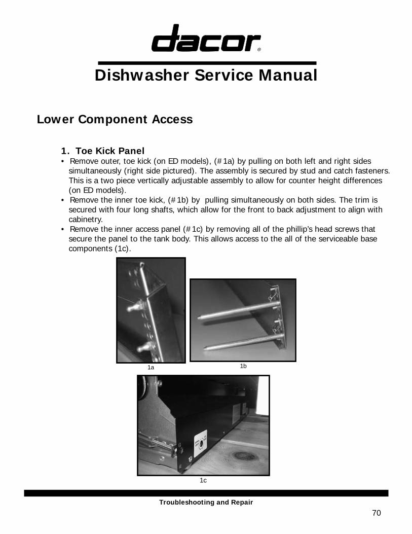
1. Toe Kick Panel• Remove outer, toe kick (on ED models), (#1a) by pulling on both left and right sides simultaneously (right side pictured). The assembly is secured by stud and catch fasteners. This is a two piece vertically adjustable assembly to allow for counter height differences (on ED models).• Remove the inner toe kick, (#1b) by pulling simultaneously on both sides. The trim is secured with four long shafts, which allow for the front to back adjustment to align with cabinetry. • Remove the inner access panel (#1c) by removing all of the phillip’s head screws that secure the panel to the tank body. This allows access to the all of the serviceable base components (1c).
1c
1a 1b
Dishwasher Service Manual
71Troubleshooting and Repair
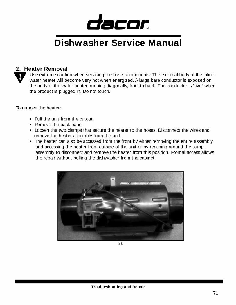
2. Heater RemovalUse extreme caution when servicing the base components. The external body of the inline water heater will become very hot when energized. A large bare conductor is exposed on the body of the water heater, running diagonally, front to back. The conductor is “live” when the product is plugged in. Do not touch.
To remove the heater: • Pull the unit from the cutout.
• Remove the back panel.• Loosen the two clamps that secure the heater to the hoses. Disconnect the wires and remove the heater assembly from the unit.• The heater can also be accessed from the front by either removing the entire assembly and accessing the heater from outside of the unit or by reaching around the sump assembly to disconnect and remove the heater from this position. Frontal access allows the repair without pulling the dishwasher from the cabinet.
2a
!
Dishwasher Service ManualTroubleshooting and Repair
72
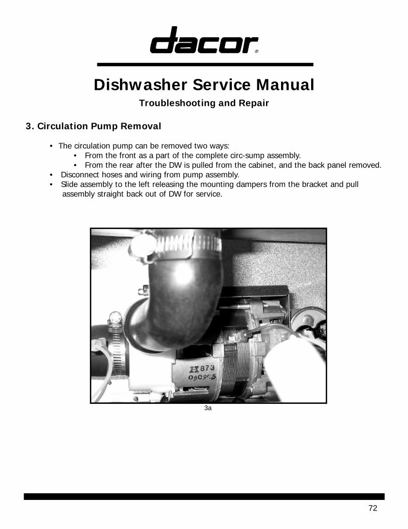
3. Circulation Pump Removal • The circulation pump can be removed two ways: • From the front as a part of the complete circ-sump assembly. • From the rear after the DW is pulled from the cabinet, and the back panel removed. • Disconnect hoses and wiring from pump assembly. • Slide assembly to the left releasing the mounting dampers from the bracket and pull assembly straight back out of DW for service.
3a
Dishwasher Service ManualTroubleshooting and Repair
73
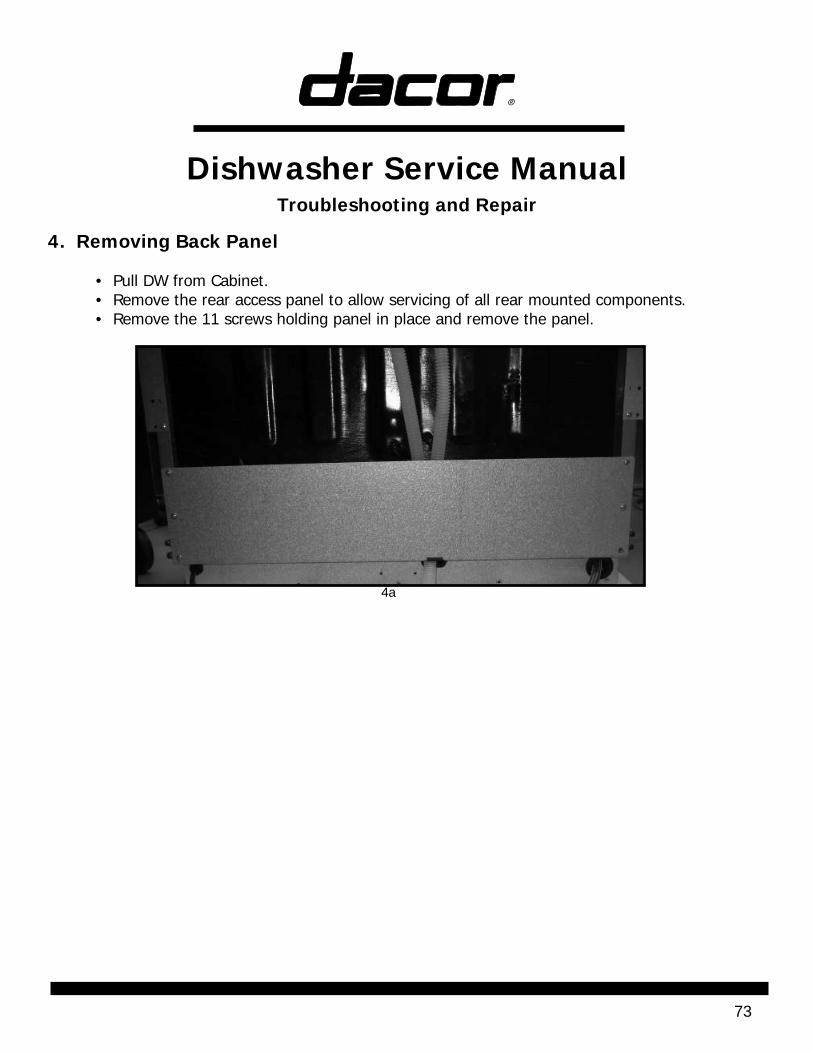
4. Removing Back Panel
• Pull DW from Cabinet. • Remove the rear access panel to allow servicing of all rear mounted components. • Remove the 11 screws holding panel in place and remove the panel.
4a
Dishwasher Service ManualTroubleshooting and Repair
74
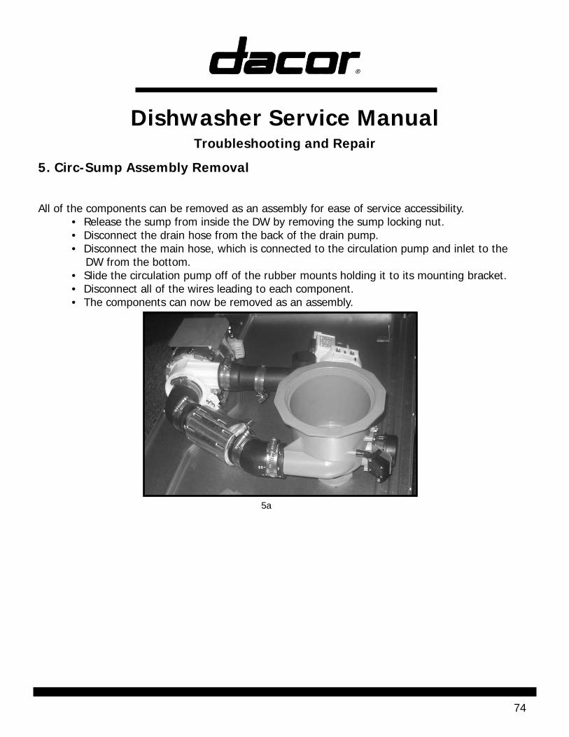
5. Circ-Sump Assembly Removal
All of the components can be removed as an assembly for ease of service accessibility. • Release the sump from inside the DW by removing the sump locking nut. • Disconnect the drain hose from the back of the drain pump. • Disconnect the main hose, which is connected to the circulation pump and inlet to the DW from the bottom. • Slide the circulation pump off of the rubber mounts holding it to its mounting bracket. • Disconnect all of the wires leading to each component. • The components can now be removed as an assembly.
5a
Dishwasher Service ManualTroubleshooting and Repair
75
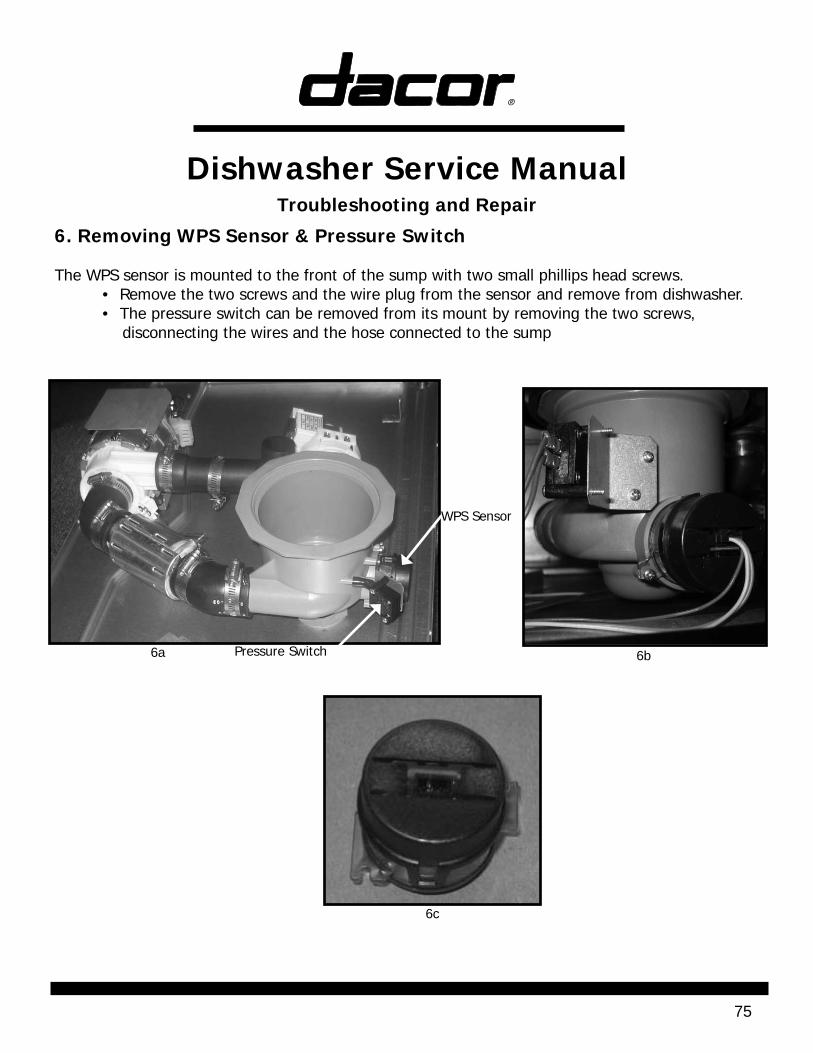
6. Removing WPS Sensor & Pressure Switch
The WPS sensor is mounted to the front of the sump with two small phillips head screws. • Remove the two screws and the wire plug from the sensor and remove from dishwasher. • The pressure switch can be removed from its mount by removing the two screws, disconnecting the wires and the hose connected to the sump
Pressure Switch
WPS Sensor
6a
6c
6b
Dishwasher Service ManualTroubleshooting and Repair
76
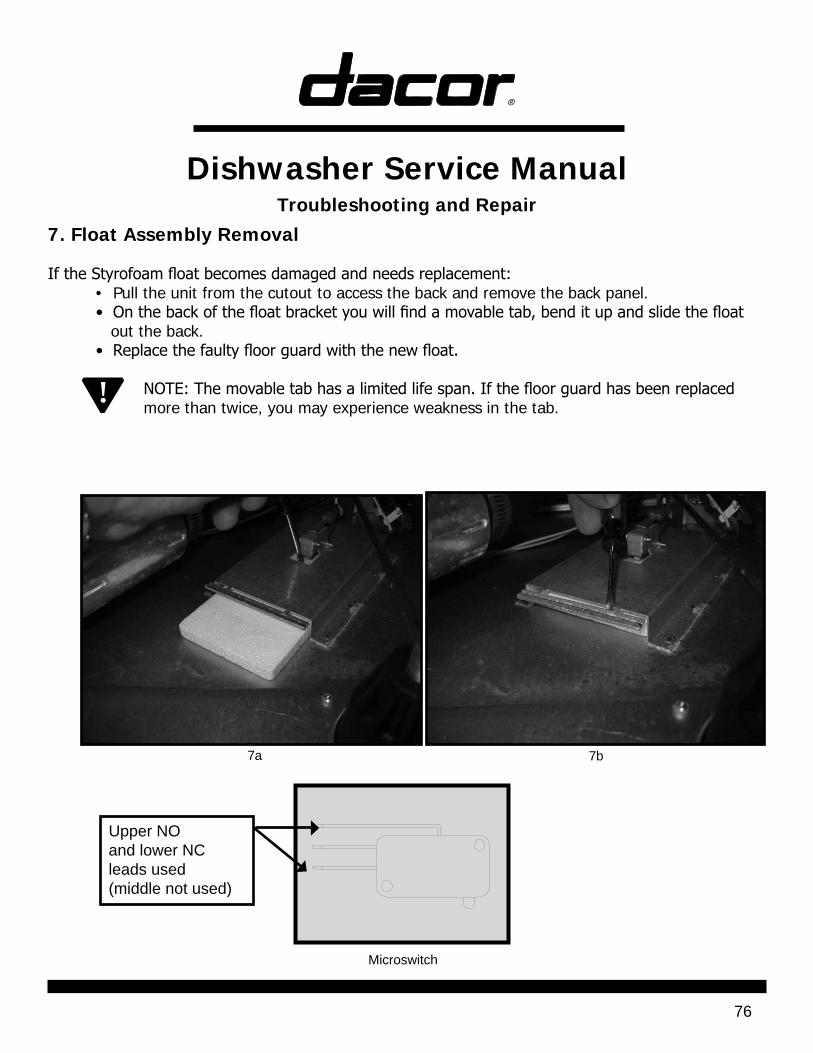
7. Float Assembly Removal
If the Styrofoam float becomes damaged and needs replacement: • Pull the unit from the cutout to access the back and remove the back panel. • On the back of the float bracket you will find a movable tab, bend it up and slide the float out the back. • Replace the faulty floor guard with the new float.
NOTE: The movable tab has a limited life span. If the floor guard has been replaced more than twice, you may experience weakness in the tab.
7a 7b
Microswitch
Upper NOand lower NC leads used(middle not used)
!
Dishwasher Service ManualTroubleshooting and Repair
77
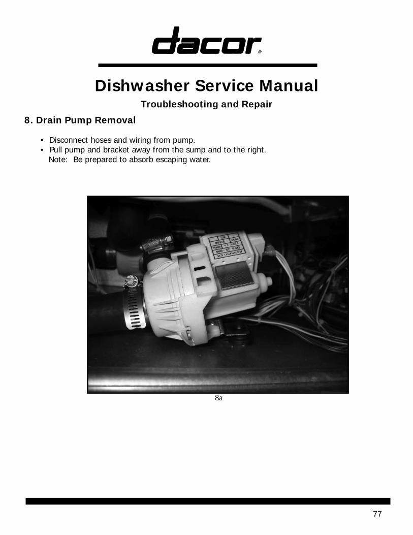
8. Drain Pump Removal • Disconnect hoses and wiring from pump. • Pull pump and bracket away from the sump and to the right. Note: Be prepared to absorb escaping water.
8a
Dishwasher Service ManualTroubleshooting and Repair
78
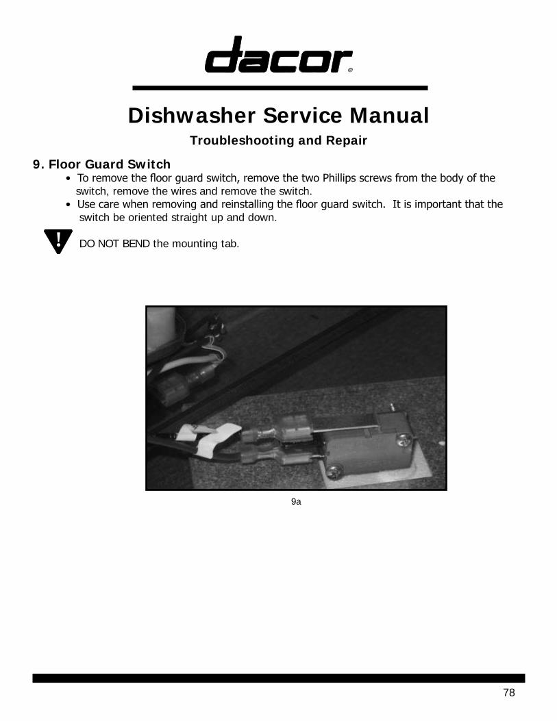
9. Floor Guard Switch• To remove the floor guard switch, remove the two Phillips screws from the body of the switch, remove the wires and remove the switch.• Use care when removing and reinstalling the floor guard switch. It is important that the switch be oriented straight up and down. DO NOT BEND the mounting tab.
9a
!
Dishwasher Service ManualTroubleshooting and Repair
79
10. Sump Removal
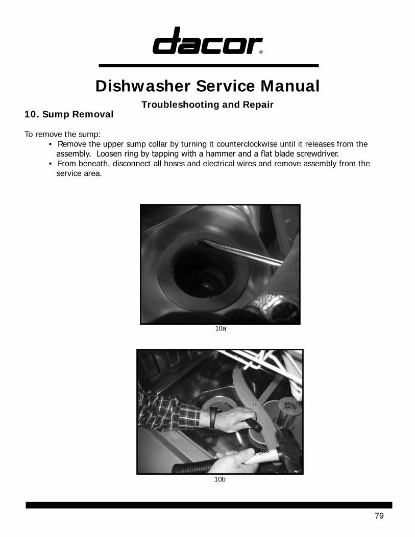
To remove the sump: • Remove the upper sump collar by turning it counterclockwise until it releases from the assembly. Loosen ring by tapping with a hammer and a flat blade screwdriver. • From beneath, disconnect all hoses and electrical wires and remove assembly from the service area.
10a
10b
Dishwasher Service ManualTroubleshooting and Repair
80
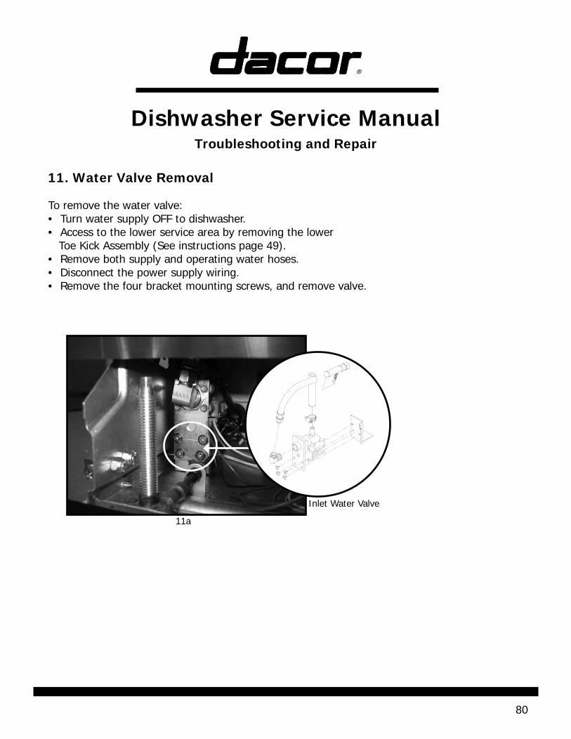
11. Water Valve Removal
To remove the water valve:• Turn water supply OFF to dishwasher.• Access to the lower service area by removing the lower Toe Kick Assembly (See instructions page 49). • Remove both supply and operating water hoses. • Disconnect the power supply wiring.• Remove the four bracket mounting screws, and remove valve.
11a
Inlet Water Valve
Dishwasher Service ManualTroubleshooting and Repair
81
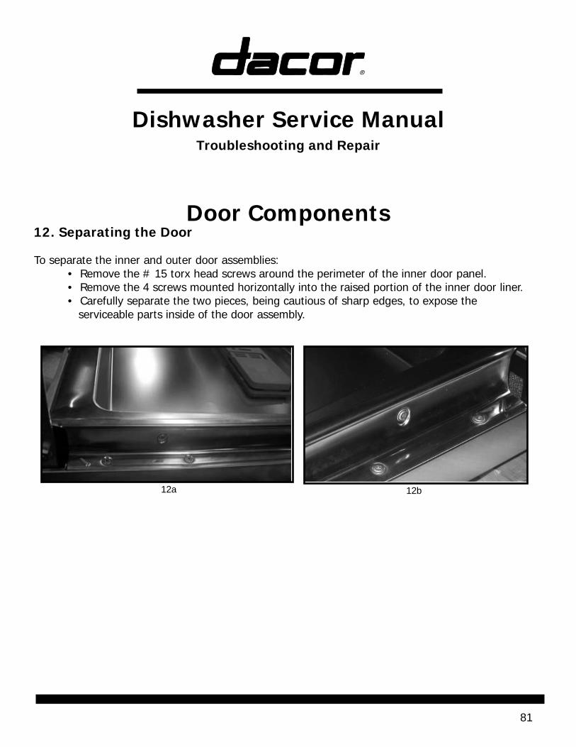
Door Components12. Separating the Door To separate the inner and outer door assemblies: • Remove the # 15 torx head screws around the perimeter of the inner door panel. • Remove the 4 screws mounted horizontally into the raised portion of the inner door liner. • Carefully separate the two pieces, being cautious of sharp edges, to expose the serviceable parts inside of the door assembly.
12a 12b
Dishwasher Service ManualTroubleshooting and Repair
82
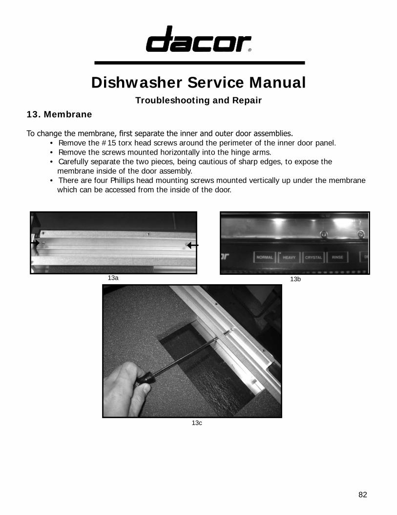
13. Membrane
To change the membrane, first separate the inner and outer door assemblies. • Remove the #15 torx head screws around the perimeter of the inner door panel. • Remove the screws mounted horizontally into the hinge arms. • Carefully separate the two pieces, being cautious of sharp edges, to expose the membrane inside of the door assembly. • There are four Phillips head mounting screws mounted vertically up under the membrane which can be accessed from the inside of the door.
13a 13b
13c
Dishwasher Service ManualTroubleshooting and Repair
83
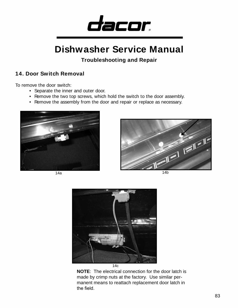
14. Door Switch Removal
To remove the door switch: • Separate the inner and outer door. • Remove the two top screws, which hold the switch to the door assembly. • Remove the assembly from the door and repair or replace as necessary.
14a 14b
14cNOTE: The electrical connection for the door latch is made by crimp nuts at the factory. Use similar per-manent means to reattach replacement door latch in the field.
Dishwasher Service ManualTroubleshooting and Repair
84
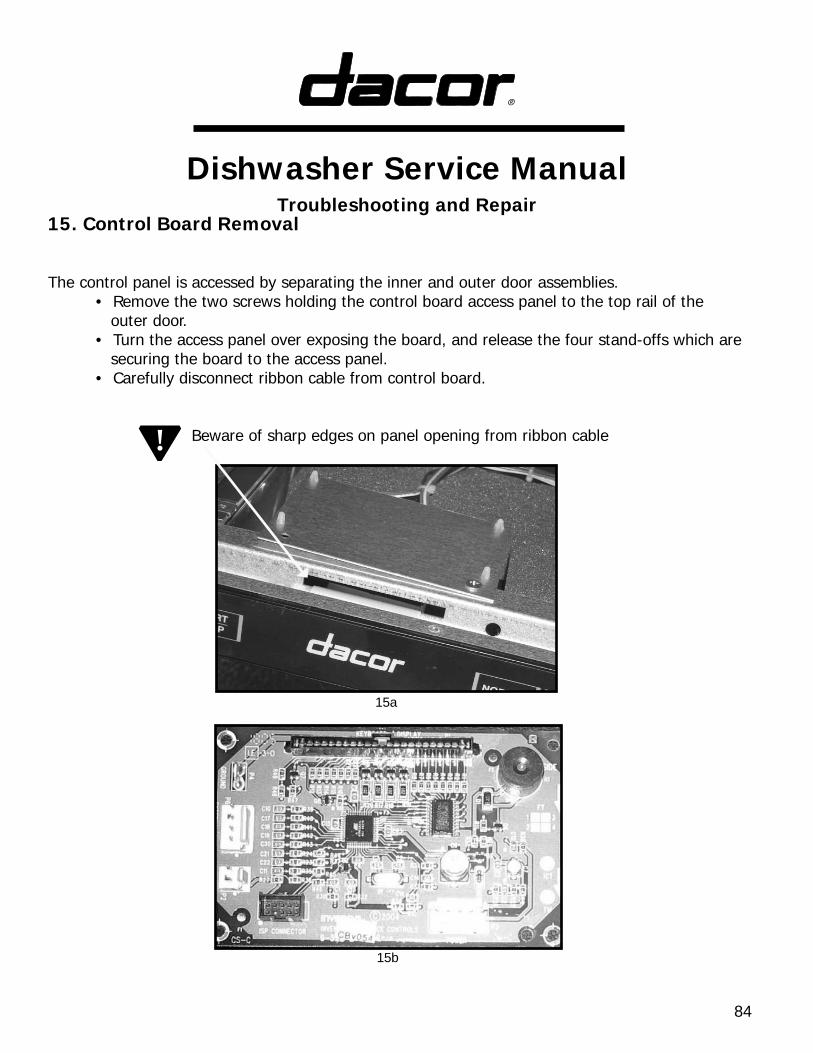
15. Control Board Removal
The control panel is accessed by separating the inner and outer door assemblies. • Remove the two screws holding the control board access panel to the top rail of the outer door. • Turn the access panel over exposing the board, and release the four stand-offs which are securing the board to the access panel. • Carefully disconnect ribbon cable from control board.
Beware of sharp edges on panel opening from ribbon cable
15a
15b
!
Dishwasher Service ManualTroubleshooting and Repair
85
Inner Tank Components
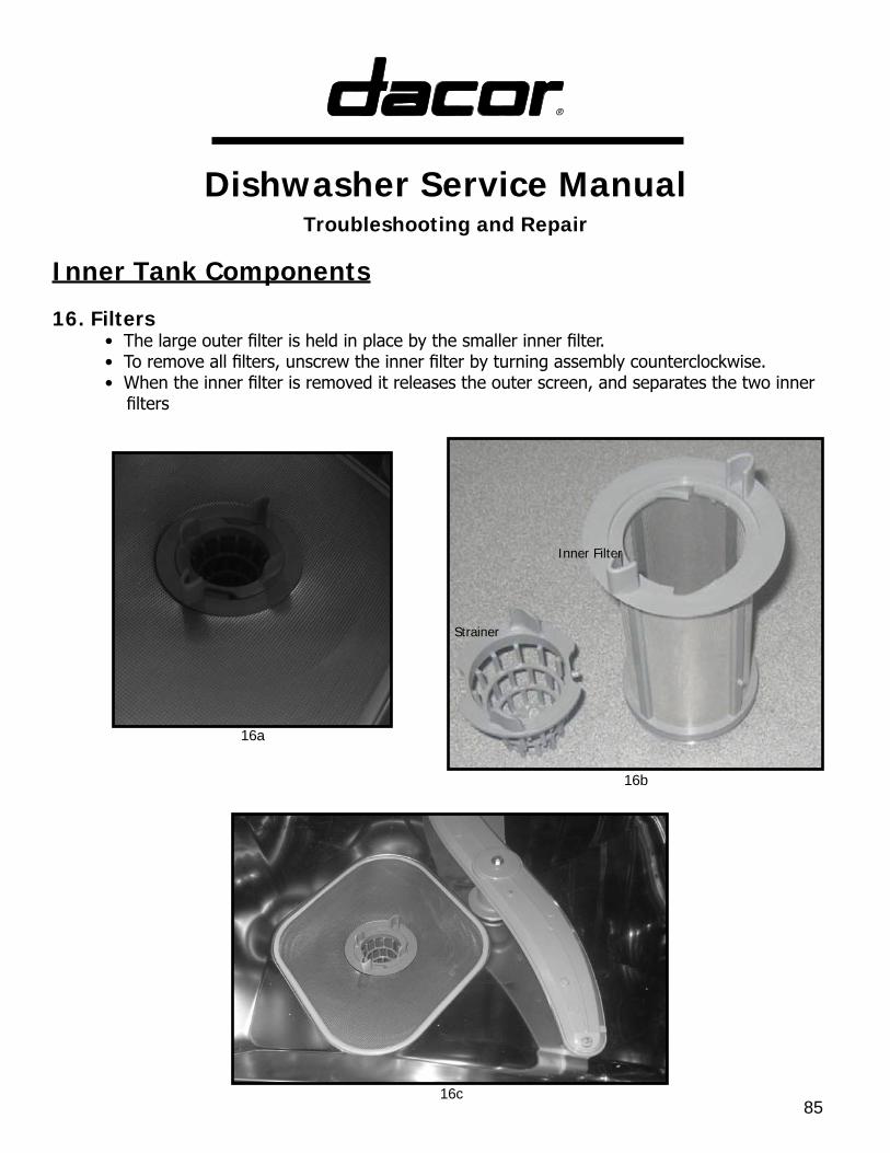
16. Filters • The large outer filter is held in place by the smaller inner filter. • To remove all filters, unscrew the inner filter by turning assembly counterclockwise. • When the inner filter is removed it releases the outer screen, and separates the two inner filters
16a
16b
16c
Strainer
Inner Filter
Dishwasher Service ManualTroubleshooting and Repair
86
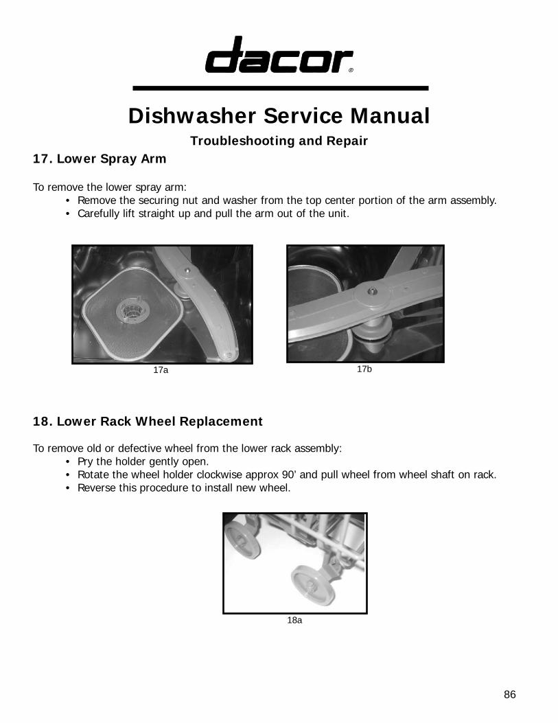
To remove the lower spray arm: • Remove the securing nut and washer from the top center portion of the arm assembly. • Carefully lift straight up and pull the arm out of the unit.
17. Lower Spray Arm
18. Lower Rack Wheel Replacement
To remove old or defective wheel from the lower rack assembly: • Pry the holder gently open. • Rotate the wheel holder clockwise approx 90’ and pull wheel from wheel shaft on rack. • Reverse this procedure to install new wheel.
17a
18a
17b
Dishwasher Service ManualTroubleshooting and Repair
87
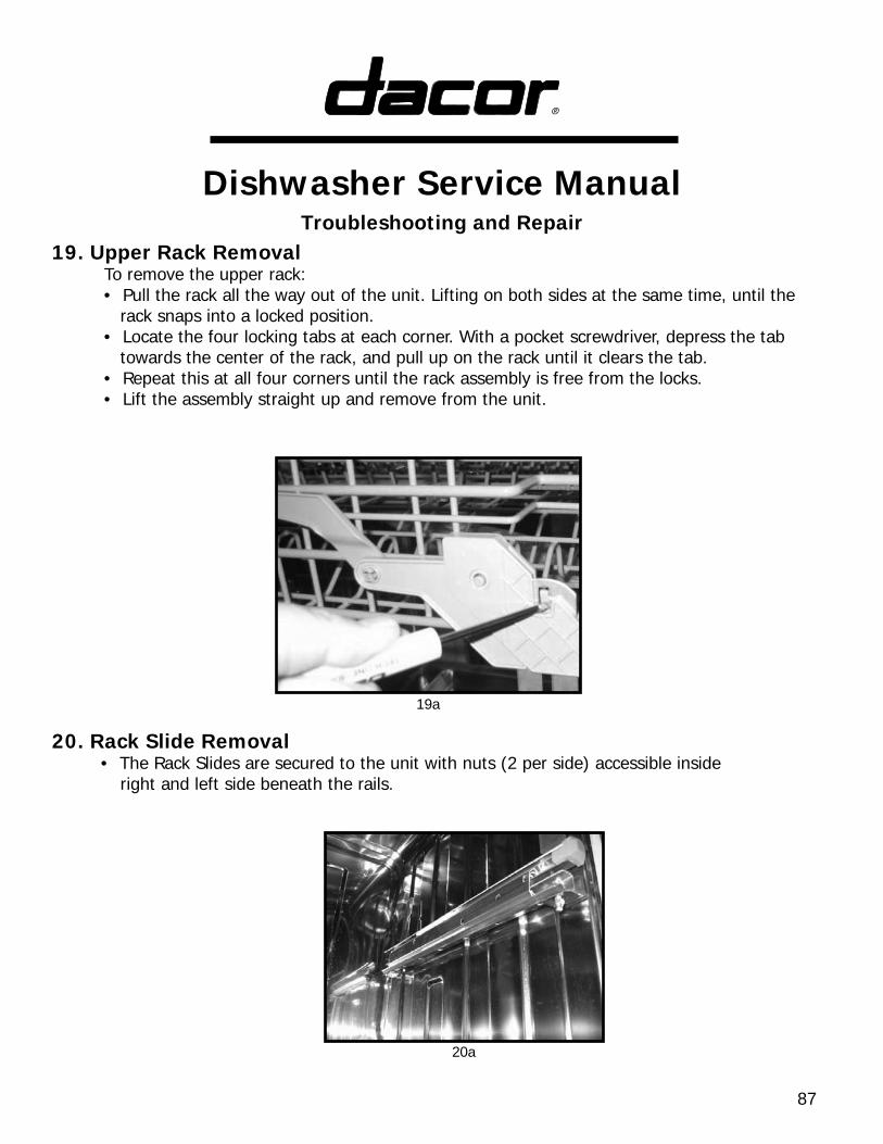
19. Upper Rack Removal To remove the upper rack: • Pull the rack all the way out of the unit. Lifting on both sides at the same time, until the rack snaps into a locked position. • Locate the four locking tabs at each corner. With a pocket screwdriver, depress the tab towards the center of the rack, and pull up on the rack until it clears the tab. • Repeat this at all four corners until the rack assembly is free from the locks. • Lift the assembly straight up and remove from the unit.
20. Rack Slide Removal • The Rack Slides are secured to the unit with nuts (2 per side) accessible inside right and left side beneath the rails.
19a
20a
Dishwasher Service ManualTroubleshooting and Repair
88
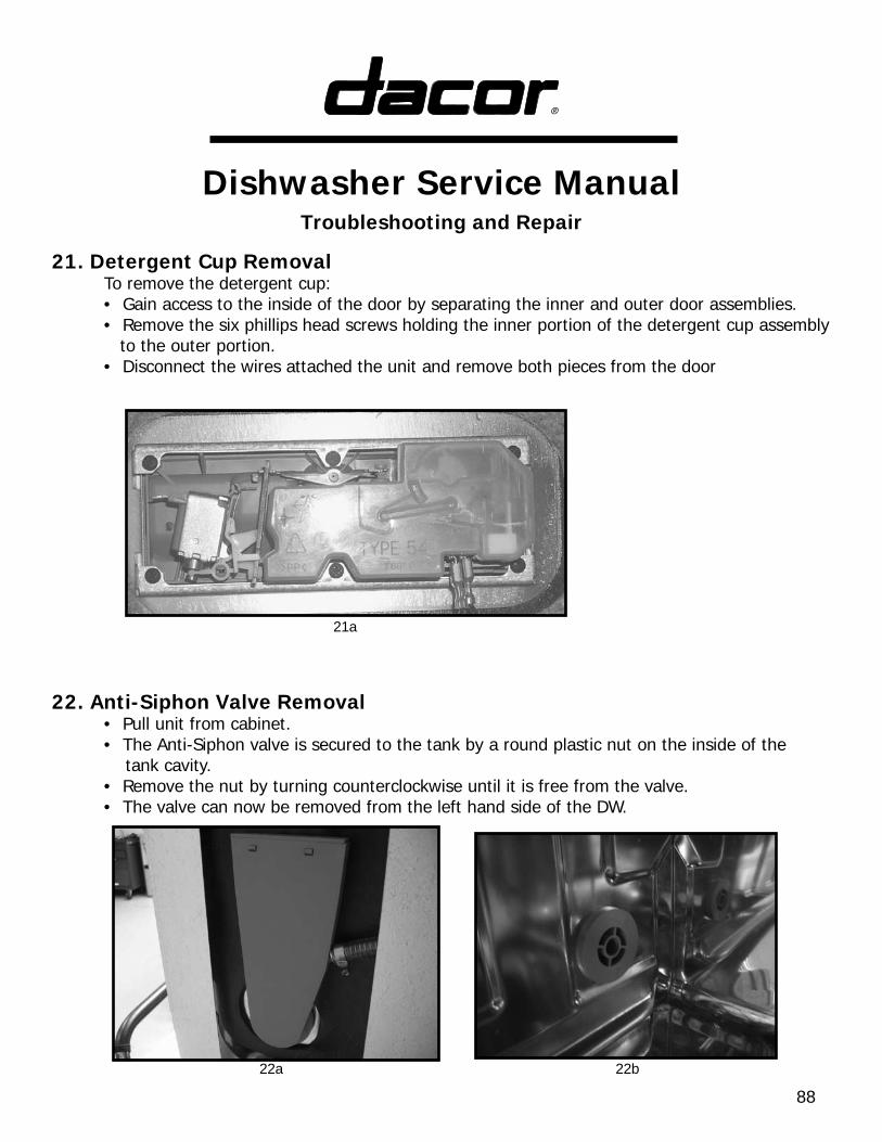
21. Detergent Cup Removal To remove the detergent cup: • Gain access to the inside of the door by separating the inner and outer door assemblies. • Remove the six phillips head screws holding the inner portion of the detergent cup assembly to the outer portion. • Disconnect the wires attached the unit and remove both pieces from the door
22. Anti-Siphon Valve Removal • Pull unit from cabinet. • The Anti-Siphon valve is secured to the tank by a round plastic nut on the inside of the tank cavity. • Remove the nut by turning counterclockwise until it is free from the valve. • The valve can now be removed from the left hand side of the DW.
21a
22a 22b

Dishwasher Service Manual
89Troubleshooting and Repair
Dishwasher Service Manual
90Troubleshooting and Repair
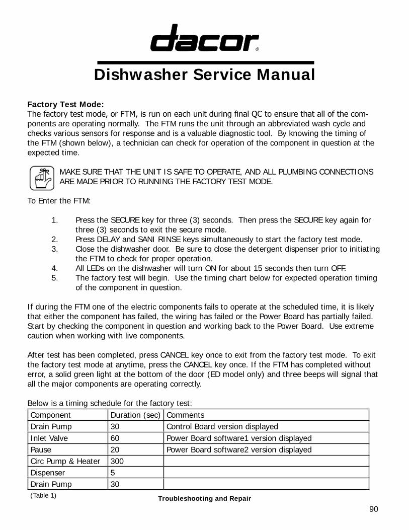
Factory Test Mode:The factory test mode, or FTM, is run on each unit during final QC to ensure that all of the com-ponents are operating normally. The FTM runs the unit through an abbreviated wash cycle and checks various sensors for response and is a valuable diagnostic tool. By knowing the timing of the FTM (shown below), a technician can check for operation of the component in question at the expected time.
MAKE SURE THAT THE UNIT IS SAFE TO OPERATE, AND ALL PLUMBING CONNECTIONS ARE MADE PRIOR TO RUNNING THE FACTORY TEST MODE.
To Enter the FTM:
1. Press the SECURE key for three (3) seconds. Then press the SECURE key again for three (3) seconds to exit the secure mode. 2. Press DELAY and SANI RINSE keys simultaneously to start the factory test mode. 3. Close the dishwasher door. Be sure to close the detergent dispenser prior to initiating the FTM to check for proper operation. 4. All LEDs on the dishwasher will turn ON for about 15 seconds then turn OFF. 5. The factory test will begin. Use the timing chart below for expected operation timing of the component in question.
If during the FTM one of the electric components fails to operate at the scheduled time, it is likely that either the component has failed, the wiring has failed or the Power Board has partially failed. Start by checking the component in question and working back to the Power Board. Use extreme caution when working with live components.
After test has been completed, press CANCEL key once to exit from the factory test mode. To exit the factory test mode at anytime, press the CANCEL key once. If the FTM has completed without error, a solid green light at the bottom of the door (ED model only) and three beeps will signal that all the major components are operating correctly.
Below is a timing schedule for the factory test:Component Duration (sec) CommentsDrain Pump 30 Control Board version displayedInlet Valve 60 Power Board software1 version displayedPause 20 Power Board software2 version displayedCirc Pump & Heater 300Dispenser 5Drain Pump 30(Table 1)
Dishwasher Service Manual
91Troubleshooting and Repair
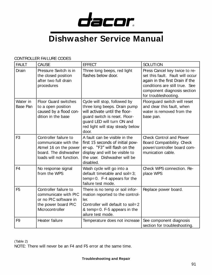
CONTROLLER FAILURE CODESFAULT CAUSE EFFECT SOLUTIONDrain Pressure Switch is in
the closed position after two full drain procedures
Three long beeps, red light flashes below door.
Press Cancel key twice to re-set this fault. Fault will occur again in the first Drain if the conditions are still true. See component diagnosis section for troubleshooting.
Water in Base Pan
Floor Guard switches to a open position caused by a flood con-dition in the base
Cycle will stop, followed by three long beeps. Drain pump will activate until the floor-guard switch is reset. Floor-guard LED will turn ON and red light will stay steady below door.
Floorguard switch will reset and clear this fault, when water is removed from the base pan.
F3 Controller failure to communicate with the Atmel 16 on the power board. The dishwasher loads will not function.
A fault can be visible in the first 15 seconds of initial pow-er-up. “F3” will flash on the display and will be visible to the user. Dishwasher will be disabled.
Check Control and Power Board Compatibility. Check power/controller board com-munication cable.
F4 No response signal from the WPS
Wash cycle will go into a default timetable and soil=3; temp=0. F-4 appears for the failure test mode.
Check WPS connection. Re-place WPS
F5 Controller failure to communicate with PIC or no PIC software in the power board PIC Microcontroller
There is no temp or soil infor-mation reported to the control-ler.Controller will default to soil=2 & temp=0. F-5 appears in the ailure test mode.
Replace power board.
F9 Heater failure Temperature does not increase See component diagnosis section for troubleshooting.
(Table 2)NOTE: There will never be an F4 and F5 error at the same time.
92
COMPONENT OVERVIEW AND TROUBLESHOOTING BEFORE SERVICING, UNPLUG UNIT.
USE EXTREME CAUTION WHEN SERVICING THE BASE COMPONENTS. THE EXTERNAL BODY OF THE INLINE WATER HEATER WILL BECOME VERY HOT WHEN ENERGIZED. A LARGE BARE CONDUCTOR IS EXPOSED ON THE BODY OF THE WATER HEATER, RUNNING DIAGO-NALLY, FRONT TO BACK. THE CONDUCTOR IS “LIVE” WHEN THE PRODUCT IS PLUGGED IN. DO NOT TOUCH.
Refer to Wiring Diagram for connector location and general information on component functionality.
Circulation PumpThe circulation pump is located in the base area. It is responsible for circulating large volumes of water to turn the wash arms and feed the high powered spray jets that distribute water through the tank. The circulation pump is controlled by power from the control board and power board. When energized, power is sent through terminal P3 of the power board (120VAC measured between P3 and Neutral). If the pump fails to operate and power is present at P3, check the resistance of the motor windings as follows: Main winding (Top/Mid; yellow and red leads) 0.7 ohms +/- 10% @ 70 deg F. Secondary winding (Top/Bottom; brown and red leads) 32.1 ohms +/- 10% @ 70 deg F. If resistance does not fall within this range replace pump. Capacitor failure. If the above listed tests do not locate fault, and the pump still fails to operate, then the capacitor may have failed. If this condition is present you may hear a light humming noise created when the pump is attempting to start. Check capacitor and verify correct wiring. Replace capacitor as needed.
Capacitor failure - If P3 energizes per the timing schedule yet the pump fails to operate and the resistance values are met, the capacitor may have failed. A light humming noise will be audible. The pump is attempting to start but the secondary windings are either not receiving energy or not receiving enough energy. Check capacitor wiring. Retest. Replace capacitor if necessary.
Detergent Dispenser The detergent dispenser is located in the door and is basically 3 components in one. The first func-tion is to dispense detergent to the wash cycle. The second function is to dispense rinse aid to the cycle. The final function this device serves is to sense the presence of rinse aid. This function is accomplished by a float mechanism. The door has to be closed to get an accurate reading. The detergent dispenser and the rinse aid dispenser are activated by the same circuit. The first time the circuit is energized the detergent door swings open and streams of water from the upper spray arm will rinse the detergent into the wash water. When de-energized the mechanism cycles so that the next time the circuit is energized, the rinse aid will be dispensed.
The detergent dispenser is energized by the control board and the power board as necessary (120VAC) through terminal P7 pin 4. This circuit operates a solenoid that creates the dispensing ac-tion of both devices. In order for the mechanism to reset the dishwasher door must be fully opened between washes. This allows a linkage bar to drop into position and resets the mechanism. If the detergent door fails to open during the wash cycle, a solenoid failure may have occurred. Check the resistance values of the solenoid at the connector. It should measure between 280 & 320 ohms. If these readings are present and the detergent door still fails to open, test by manually engaging the solenoid and watching the soap dispenser door catch. It should rotate CCW roughly
!
93
25 deg. Close the soap door and retest. Replace the dispenser if faulty.
If the user complains of water spotting and drying difficulties, the unit may not be dispensing the rinse aid. Check the rinse aid level to ensure an adequate supply. If rinse aid is present, the link-age bar may not be cycling into the proper position. Separate the door and inspect the solenoid and linkage for proper operation.
Door LatchThe door latch is located in the door and houses a switch that tells the controller if the door is open or closed. When the door is closed, the switch closes. When the door opens the switch opens, which is sensed by the controller. If operating, the unit will halt when the door is opened (switch open) until the door is closed again.
If the door latch is defective the unit may turn on but a wash cycle will not begin since the control-ler checks to see if the door latch circuit closes prior to starting. In this case, the door may close and physically latch but the dishwasher will not begin washing. The digital timer will not count-down but the green LED will blink as if running.
A small microswitch in the door latch assembly closes when the door closes. This closes pins 1 and 4 at P2 on the Power Board.
To test the latch without removal: 1. Disconnect the wire connector from P2 on the Power Board. 2. Touch a DMM set in continuity mode to pins 1 and 4 on the connector. 3. Open and close the dishwasher door. The continuity alarm should sound when the door is closed, (closing the switch and circuit.) If it does not, trace the wiring back to the door latch looking for the fault.
Check the striker, located on the tank, for proper position. If the striker does not extend out far enough, adjust to allow the latch assembly in the door to fully rotate into the closed position. Test by forcefully pushing on the door and listening for the continuity alarm.
Drain PumpThe drain pump is a small 120VAC pump located in the front of the base area. This pump is used to drain the tank of the wash and rinse water. The drain pump is powered by the control board and power board as necessary. See Wash Cycle Data Chart , for proper timing of drain pump usage.When energized 120VAC is supplied to pin 2 on terminal P7 on the power board, the drain pump will operate and deliver waste water to the appropriate drain location. Depending on the particular installation it could be routed through the garbage disposal, or directly to a waste pipe. The “high loop” in the supplied drain line must be utilized for proper drain operation. If the unit is drained into the garbage disposer then a sink air gap should be utilized. The rate at which the tank empties de-pends upon various installation conditions. See graph for flow rates. See chart for solutions to pump problems.
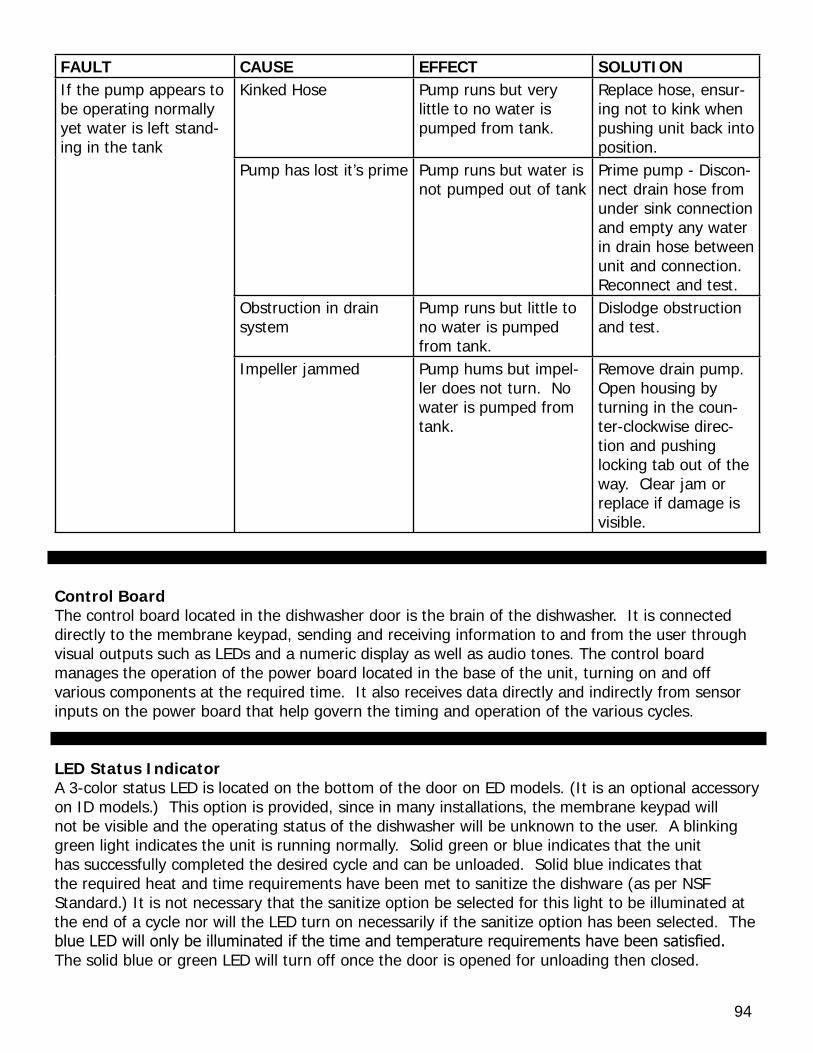
94
FAULT CAUSE EFFECT SOLUTIONIf the pump appears to be operating normally yet water is left stand-ing in the tank
Kinked Hose Pump runs but very little to no water is pumped from tank.
Replace hose, ensur-ing not to kink when pushing unit back into position.
Pump has lost it’s prime Pump runs but water is not pumped out of tank
Prime pump - Discon-nect drain hose from under sink connection and empty any water in drain hose between unit and connection. Reconnect and test.
Obstruction in drain system
Pump runs but little to no water is pumped from tank.
Dislodge obstruction and test.
Impeller jammed Pump hums but impel-ler does not turn. No water is pumped from tank.
Remove drain pump. Open housing by turning in the coun-ter-clockwise direc-tion and pushing locking tab out of the way. Clear jam or replace if damage is visible.
Control BoardThe control board located in the dishwasher door is the brain of the dishwasher. It is connected directly to the membrane keypad, sending and receiving information to and from the user through visual outputs such as LEDs and a numeric display as well as audio tones. The control board manages the operation of the power board located in the base of the unit, turning on and off various components at the required time. It also receives data directly and indirectly from sensor inputs on the power board that help govern the timing and operation of the various cycles.
LED Status IndicatorA 3-color status LED is located on the bottom of the door on ED models. (It is an optional accessory on ID models.) This option is provided, since in many installations, the membrane keypad will not be visible and the operating status of the dishwasher will be unknown to the user. A blinking green light indicates the unit is running normally. Solid green or blue indicates that the unit has successfully completed the desired cycle and can be unloaded. Solid blue indicates that the required heat and time requirements have been met to sanitize the dishware (as per NSF Standard.) It is not necessary that the sanitize option be selected for this light to be illuminated at the end of a cycle nor will the LED turn on necessarily if the sanitize option has been selected. The blue LED will only be illuminated if the time and temperature requirements have been satisfied. The solid blue or green LED will turn off once the door is opened for unloading then closed.
95
The red LED will be illuminated if a “Drain” or “Water in Base Pan” failure is detected. See page 69 for description of failure codes.
Floor Guard F9The floor guard assembly is welded to the base and consists of three components: a microswitch, a styrofoam float, and a metal housing spot welded to the base. If water is present in the base area, the float will rise and at predetermined height, trigger the microswitch and open the circuit, at this time the unit halts, and the drain pump operates.
The floor guard detects water in the base area. As water accumulates in the base area the float rises, activating the NO float switch, and closing the circuit between pins 1 & 2 on terminal P8 on the power board.
If water is present, repair or replace the faulty component and dry the base area. Check for water damage. Insure that all components are dry and retest.
If there is no water, there may be a problem with the circuit. 1. Ensure that the styrofoam float moves freely in the housing. Slide a credit card or similarly sized object under the styrofoam float and lift. An audible clicking should be heard when lifted and when released 2. Remove the Power Board and check the two leads at P8 for continuity. If open, with float clearly in the untriggered position, the problem has been isolated to the circuit between the lead and up to the microswitch. Check the wiring and the switch. Replace the faulty component. The float should be replaced if it has been damaged in any way. Replace it by lifting the retaining tab on the back of the housing.
Inlet ValveThe inlet valve is located on the left side of the base area, looking in from the front. The inlet side of the valve is connected to the house water supply, usually the hot side. When the inlet valve is energized with 120VAC at pin 1 on terminal P7 of the power board, the valve retracts a small, spring-loaded internal plunger with a rubberized tip, and allows water to flow through. The inlet valve is powered by the control board and power board as necessary. See Wash Cycle Data Chart on page 44, to confirm appropriate cycle times.
If tank fails to fill, or inadequate water flow is detected when valve is energized, check the follow-ing:
1) Check the water supply valve, usually located under the sink for proper flow and operation.2) Check the resistance between pin1 on terminal P7 & Neutral. It should read between 850 & 940 ohms.If the circuit is “open” then check the wiring before replacing the valve.3) Check the flow rate of the valve by disconnecting the outlet hose (Clear plastic) and put into a 2 gallon container. With the valve energized you should see between 1 to 1.5 gallons accumulate in the container in 60 seconds, with a house supply pressure of 20-120 PSI.
96
Inline Water HeaterUSE EXTREME CAUTION WHEN SERVICING THE INLINE WATER HEATER. THE EXTERNAL BODY OF THE HEATER WILL BECOME VERY HOT WHEN ENERGIZED. A LARGE BARE CON-DUCTOR IS EXPOSED ON THE BODY OF THE WATER HEATER, RUNNING DIAGONALLY FROM FRONT TO BACK. THIS CONDUCTOR IS “LIVE” WHEN THE PRODUCT IS PLUGGED IN, DO NOT TOUCH.
The inline water heater is located in the base area. Water flows from the sump to the circulation pump while passing through the heater. It has a flow-thru design and is a round cylinder, similar to a pipe. When supplied with 120VAC at terminal P5 on the power board, the heater begins to heat. “USE EXTREME CARE WHEN SERVICING” If water does not flow through the heater when ener-gized, it will overheat very quickly. The unit is equipped with internal overload protection and will automatically shut down at pre-determined temperatures. The “Automatic reset temp” is 208 deg. F +/- 10 deg, and the “Permanent disabling temp” is 402 deg F +/- 18 deg.
The resistance of the heating element should measure between 11 & 13 ohms. Change the hoses if the inline heater was operated without water. If this condition was suspected, change the hoses.
Membrane KeypadThe membrane keypad is used to enter the desired wash cycles, wash options and user commands. During a wash cycle the membrane keypad displays the selected cycle, the estimated completion time and any options that have been selected. Upon completion of a cycle the keypad membrane will indicate ompletion of the selected cycle and selected options.
Refer to the Wiring Diagram (page 45) for schematic of Membrane Keypad located on the bottom left of the diagram.
Power Board The power board, located in the base area of the dishwasher, takes commands sent from the control board and regulates power to the various components of the dishwasher by turning on and off corresponding relays according to the program selected by the user. It receives information from various sensors and converts the information into data the control board can understand before transfer to the control board.
The power board also houses the power supply transformer. This component transforms 120V AC power and distributes it to a variety of electronic components, including the control board.
If during the FTM the scheduled component’s connector fails to energize, the respective relay on the Power Board could have failed. In this case, it will be necessary to replace the Power Board.
For example: A problem is suspected with the detergent dispenser. Initiate the FTM and follow the timing chart on page xxxx. The Controller issues a command to the Power Board to energize P7 pin 4 and open the dispenser door for 5 seconds just after the circulation pump turns off. If dur-ing that window of time, 120V cannot be detected at P7 pin 4 then the Power Board is defective and needs replacement.
!
97
Pressure SwitchThe pressure switch is mounted to front of the sump, located in the lower base area. A small hose connects the pressure switch to the sump, allowing the switch to sense water levels inside the sump assembly. This NO switch will close and complete the circuit when the water level in the sump reaches 2.5” This is a non adjustable level, do not attempt to change. If a “Drain” fault occurs, the Control board has detected a closed circuit on pins 1 & 3 of terminal P12, when it should be open, indicating that water is still present in the sump, after the unit has attempted two drain events with no success.
If water is present see drain pump section for diagnosis.
If the tank is empty, a fault could exist with the pressure switch. It could be stuck in the closed position, or clogged under pressure. Check the connecting hose, sump port and switch body for ob-structions. If no obstruction is found; examine the switch for proper operation. If found to be faulty - replace.
Wash Process SensorThe wash process sensor, WPS, is mounted to the front of the sump mounted in the base area. The WPS consists of a transparent plastic cover in which an optical transmitter and receiver are housed. A beam of light passes through the soiled water and is picked up by the receiver. The difference between the light transmitted and the light received estimates the amount of soil in the water. In normal mode, wash times are modified based on the soil levels determined by the WPS.
In addition to water soil level, the WPS detects the wash water temperature, and is used by the control board, to regulate the inline heater on time.
If the WPS sensor is suspect, enter the Factory Test Mode. If an F4 or an F9 failure is detected then either the WPS or the wiring has failed. Remove the wire connector from P10 on the power board, and check for resistance as follows: Between red & yellow points on the connector it should read 14.0 – 16.0 ohms. Between the Red and Orange points on the connector it should read 10.0 – 13.0 ohms. If the measured values are outside of these tolerances, then replace the WPS sensor, and perform the Factory Test (page 68) again.
If no values are detected, remove the small, 3 pin connector from the WPS and check resistance from the left pin to the right pin and you should read 14.0 –16.0 ohms. Then check between the left pin to the middle pin and you should read 10.0 – 13.0 ohms. If both values are found to be in tolerance, check the wiring for faults. If one or both of the readings are out of tolerance then re-place the WPS and perform the Factory Test (page 68) again.