Embed Size (px)
Citation preview
7/31/2019 Dispelling Myths Associated With Power Factor Correction Capacitors
http://slidepdf.com/reader/full/dispelling-myths-associated-with-power-factor-correction-capacitors 1/3
e n e r g i z e - June 2011 - Page 39
TRAN SM ISSIO N AN D DISTRIBUTIO N
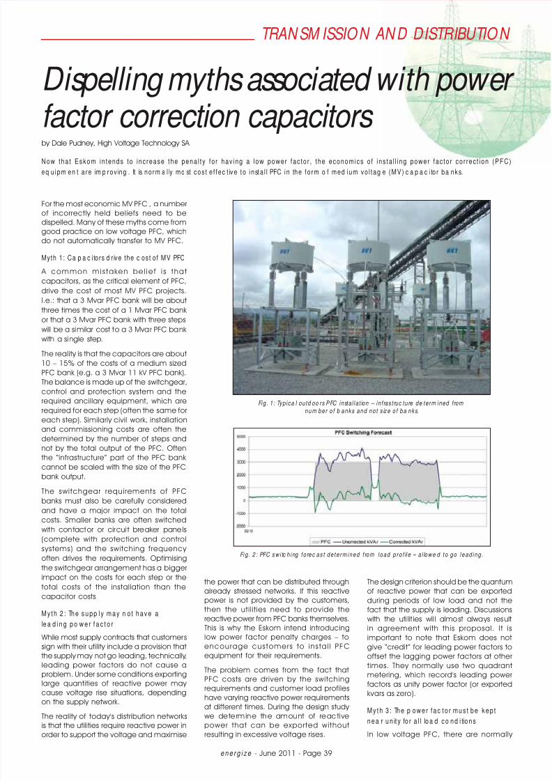
For the most economic MV PFC , a number
of incorrectly held beliefs need to be
dispelled. Many of these myths come from
good practice on low voltage PFC, which
do not automatically transfer to MV PFC.
Myth 1: Ca p a c i tors d r ive the c ost of MV PFC
A common mis taken bel ie f i s thatcapacitors, as the critical element of PFC,
drive the cost of most MV PFC projects.
I.e.: that a 3 Mvar PFC bank will be about
three times the cost of a 1 Mvar PFC bank
or that a 3 Mvar PFC bank with three steps
will be a similar cost to a 3 Mvar PFC bank
with a single step.
The reality is that the capacitors are about
10 – 15% of the costs of a medium sized
PFC bank (e.g. a 3 Mvar 11 kV PFC bank).
The balance is made up of the switchgear,
control and protection system and the
required ancillary equipment, which are
required for each step (often the same foreach step). Similarly civil work, installation
and commissioning costs are often the
determined by the number of steps and
not by the total output of the PFC. Often
the “infrastructure” part of the PFC bank
cannot be scaled with the size of the PFC
bank output.
The switchgear requirements of PFC
banks must also be carefully considered
and have a major impact on the total
costs. Smaller banks are often switched
with contactor or circui t breaker panels
(complete with protection and control
systems) and the switching frequency often drives the requirements. Optimising
the switchgear arrangement has a bigger
impact on the costs for each step or the
total costs of the installation than the
capacitor costs.
M y t h 2 : The s upp l y m ay n o t hav e a
le a d i n g p o w e r f a c t o r
While most supply contracts that customers
sign with their utility include a provision that
the supply may not go leading, technically,
leading power factors do not cause a
problem. Under some conditions exporting
large quantities of reactive power may cause voltage rise situations, depending
on the supply network.
The reality of today's distribution networks
is that the utilities require reactive power in
order to support the voltage and maximise
the power that can be distributed through
already stressed networks. If this reactive
power is not provided by the customers,
then the util it ies need to provide the
reactive power from PFC banks themselves.
This is why the Eskom intend introducing
low power factor penalty charges – to
encourage customers to insta l l PFC
equipment for their requirements.
The problem comes from the fact that
PFC costs are driven by the switching
requirements and customer load profiles
have varying reactive power requirements
at different times. During the design study
we determine the amount of reactive
power that can be exported without
resulting in excessive voltage rises.
The design criterion should be the quantum
of reactive power that can be exported
during periods of low load and not the
fact that the supply is leading. Discussions
with the uti lit ies wil l almost always result
in agreement with this proposal. It is
important to note that Eskom does not
give “credit” for leading power factors to
offset the lagging power factors at other
times. They normally use two quadrant
metering, which record's leading power
factors as unity power factor (or exportedkvars as zero).
M y t h 3 : The p ow er f ac t o r m us t be k ep t
nea r un it y fo r a l l loa d c o nd i tions
In low voltage PFC, there are normally
Dispelling myths associated with power factor correction capacitors by Dale Pudney, High Voltage Technology SA
Now that Eskom in tends to inc rease the penal t y for hav ing a low power fac tor , t he economics o f ins ta l l i ng power fac tor cor rec t ion (PFC)
eq uipm en t are im p rov ing . It is norm a l ly mo st cos t e f fec t ive to insta l l PFC in the form o f med ium vo l tag e (MV) c a p a c i tor ba nks.
Fig . 1 : Typ ica l ou td oo rs PFC insta l la t ion – in f rast ruc tu re de te rm ined f rom
n u m b e r o f b a n ks a n d n o t s ize o f b a n ks.
Fig . 2 : PFC sw i tc h ing f o re c a s t d e t e rm in e d f ro m lo a d p ro f il e – a l lo w e d t o g o l e a d in g .

7/31/2019 Dispelling Myths Associated With Power Factor Correction Capacitors
http://slidepdf.com/reader/full/dispelling-myths-associated-with-power-factor-correction-capacitors 2/3
e n e r g i z e - June 2011 - Page 40
TRAN SM ISSIO N AN D D ISTRIBUTIO N
many capacitor units that are switched
frequent ly wi th smal l and relat ively
inexpensive contactors. This allows low
vo lt age PFC to us e mu lt ip le step s to
accurately t rack the reactive power
demand profile and therefore maintain
a power factor near unity for all load
conditions. The costs to achieve this atmedium voltages would be exorbitant.
The need to maintain the power factor near
unity therefore needs to be examined. The
objective to maintain the power factor
near unity is probably because:
The kW maximum demand could be at
a different time to the uncorrected kVA
maximum demand due to the nature
of the loads (different power factors) in
service at the different times. Therefore
on maximum demand based tariffs,
the power factor corrected maximum
demand would now be at a different
time and a power factor near unity willensure optimised maximum demand
at all times.
On time of use tariffs like Eskom's
Megaflex and Miniflex, the reactive
power charges are based on the
reactive energy across the whole load
profile.
The need to maintain a high power
factor at all load conditions becomes
an economic trade-off between the
additional costs of a many PFC steps and
the additional savings that may not be
achieved with the coarser control that
could result in some low power factors atperiods of low load (when the PFC banks
are switched out to avoid high levels of
exported reactive power).
Al l of the above bas icall y dic tates the
need to change the control system for
MV PFC from “power factor” based control
(best suited to low voltage PFC) to “reactive
power” based control where the PFC banks
are switched based on the reactive power
demand from the utility. (Switch the PFC
banks based on their direct benefit to the
system than (providing a fixed amount of
reactive power) rather than a constructed
measure such as “power factor”).
In our opinion, the objective should not
be to maintain the power factor near
unity at all times, but rather to reduce
the react ive power demand on the
system that is stressing the generation
and distribution system and limiting the
power flow capacity of the generation and
distribution infrastructure.
The Megaflex tariff targets 0,96 power
factor, at which the reactive power is about
30 % of the real power. Therefore when a
single step capacitor bank is installed to
achieve 0.96 power factor at maximum
demand, the load can reduce by about
30% before unity power factor is reached.
The load can reduce further and the
supply go leading, which is limited by the
quantum of exported vars (and not leading
power factor).
Therefore a single step capacitor bank can
normally compensate for most loading
conditions in a typical industrial or mining
load.
Myth 4: Frequ ent sw i tc h ing o f m ul ti -step
c a p a c i to r b a n k s is te c h n ic a lly a c c e p ta b leSwitching capacitor banks is associated
with switching disturbances that can have
a detrimental effect on sensitive electronic
loads. In today's world, the proliferation
of sensitive electronic loads is increasing
all the time. When a capacitor bank is
switched in, the supply system effectively
sees a short circuit while the capacitor
bank is charged up. This is because the
impedance of a capacitor is inversely
proportional to the frequency – therefore a
step change (effectively infinite frequency)of the voltage across the capacitor sees
an effective zero impedance at the point
of switch-on.
Fig. 3 shows how the voltage dips at switch
on, followed by high frequency recovery
Fig . 3 : Typ ica l t rans ien ts assoc ia ted w i th ca pa c i to r b ank sw i tch ing (sing le p o le sw i tch ing) .
Fig . 4 : Im p e d a n ce vs f re q u e n c y p lo t w i th a ca p a c i t o r b a n k i n st a l le d .

7/31/2019 Dispelling Myths Associated With Power Factor Correction Capacitors
http://slidepdf.com/reader/full/dispelling-myths-associated-with-power-factor-correction-capacitors 3/3
e n e r g i z e - June 2011 - Page 41
TRAN SM ISSIO N AN D D ISTRIBUTIO N
oscillations (and overshoot). The larger the
capacitor bank is, the higher the inrush
will be, and therefore the larger the dip
impact will be.
Frequent switching of many capacitor
bank steps will have many such switching
transients, which are known to cause
problems on industrial and domestic
equipment. The inrush current (making
current of the circuit breaker) also has
a derating effect on the supply circuit
breakers or contactors, reducing their
useful life in terms of number of operations.
Whil st we are not aware of formal studies
that have been done to determine the
actual reduction in life, one circuit breaker
manufacturer we work with believes
that this reduction can be up to half
of the rated number of operations. In
order to reduce the amount of switching
disturbances that are associated with PFC
capacitor banks, one can either:
Reduce the number of switching
operations; or
Reduce the depth of the dip (smaller
capac i to r s teps o r i nc lude anadditional impedance in the circuit).
However, we have already determined
that smaller capacitor bank steps will result
in exorbitant costs for the total installation
cost that cannot typically be justified in
terms of the available saving.
IEC80671 requires MV capacitor to be able
to withstand certain switching transients
and bases the capacitor life on 1000
switching operations per annum (say
thgree times per day). Therefore, more
f requent swi tching can also have a
detrimental effect on the l i fe of the
capacitor.
Myth 5 : Inrush c ur rent l im i ting reac tors
e l im inate sw i t ch ing d is turbances
We know that to reduce the dip that is
associated with capacitor bank switching,
we need to inc lude an add i t iona l
impedance in the circuit. This is normally
done with a series reactor, which creates a
voltage divider effect on the MV busbars,
between the mostly inductive supply
impedance and the impedance of the
series reactor. Current limiting reactors
however are normally not sufficient to
reduce the switching transient; only the
inrush current to within the inrush current
rating of the capacitors (100 times the
rated continuous current).
To calculate the depth of the dip causedby the capacitors at swi tch on, we
calculate the voltage divider ratio. Let's
assume that we have an 11 kV system with
a 15 kA fault level – the supply impedance
will be about 0,4 Ω. If we install a 3 Mvar
capacitor bank with a current limiting
reactor (say 50 μH), the reactor will have
an impedance of about 0,016 Ω. In this
case, the voltage dip at each switch on
will be about 96%! If, however, we install
the PFC as a 5th harmonic filter, the series
reactor (5,7 mH) will have an impedance
of about 1,8 Ω. Therefore with the PFC as
a 5th harmonic filter, the voltage dip atswitch on will be reduced to about 19%
and the impact on the nearby equipment
is dramatically reduced. (A 3rd harmonic
filter will have a dip of only about 7%,
but the additional costs are normally not
just ified by this reduction of the dip from
19 to 7%.)
Therefore, current limiting reactors have
almost no impact on the voltage dip and
transients associated with capacitor bank
switching.
Myth 6: Ha rmon ic f i lt e rs a re on ly req u i red
w here t he re a re h i gh ha rm on i c l ev e l s We often hear “we don' t need harmonic
filters because there are no big harmonic
loads”. Or the existing harmonic levels are
not high. The reality is that most harmonic
filter banks are installed, not to reduce
existing high harmonic levels, but rather
to avoid PFC capacitor banks introducing
unacceptable high harmonic levels
due to harmonic resonance between
the capacitor banks and the supply
impedance.
Harmonic currents normally follow the path
of least resistance – normally back to the
source. By installing a capacitor bank, the
system impedance introduces a peak
at the “resonance point”. The harmonic
voltages at each frequency are therefore
the product of the harmonic current
and the impedance at that frequency.
Therefore the installation of a capacitor
bank can result in unacceptably high
harmonic voltages near the resonance
point because of the amplification of the
impedance at that point.
To avoid the harmonic resonance effects
of installing a capacitor bank, we normally
include a series reactor with the capacitor
bank, which effectively detunes the
capacitor bank into a harmonic filter.
Tuning the filter to near the 5th harmonic
normally has the lowest risk of amplifying
other harmonics while maintaining the
costs at an acceptable level.
A detuned fi lter normal ly in troduces a
low impedance at the tuning frequency
(to filter off the harmonic currents) and a
peak below the tuning frequency. Where
the fault level is low (supply impedance
high), there is a risk of amplifying the 3rd
harmonic. In these cases, a 5th harmonicfi l ter would not produce acceptable
harmonic per fo rmance and a 3 rd
harmonic or damped 5th harmonic filter
wi ll be required. (A damping resisto r is
included in a filter circuit to reduce the
magnitude of the peak and trough.)
Conc lus ion
The installation of MV PFC equipment will
provide economic benefits to customers
as the utilities, driven by Eskom, implement
addit ional low power factor penalty
charges. The law of diminishing returns
however applied to MV PFC, in that
there is a finite saving available, but the
costs to achieve those savings increase
significantly for each additional R1 saving
near the margin.
Single step PFC installed as 5th harmonic
f i l ters wi l l normal ly provide the best
technical performance with the lowest
risk of introducing unacceptable transients
and harmonics, while generating sufficient
savings to provide payback periods of the
capital costs of the order of 18 months
to 2 years. A detailed design study is
however recommended to ensure that the
proposed design and equipment to beinstalled will provide the expected results
in each customer's particular network.
Contact Dale Pudney,
High Voltage Technology SA,
Tel 012 666-9358, [email protected]
Fig . 5 : Typ ica l im pe da nc e vs f req uenc y p lo t o f a 5 th harm on ic f i l te r .