Embed Size (px)
Citation preview

Dispersants:subsea applicationGood practice guidelines for incident management and emergency response personnel

The global oil and gas industry association for environmental and social issues
14th Floor, City Tower, 40 Basinghall Street, London EC2V 5DE, United KingdomTelephone: +44 (0)20 7633 2388 Facsimile: +44 (0)20 7633 2389E-mail: [email protected] Website: www.ipieca.org
IOGP Report 533
Date of publication: 2015
© IPIECA-IOGP 2015 All rights reserved.
No part of this publication may be reproduced, stored in a retrieval system, or transmitted in any form or by any
means, electronic, mechanical, photocopying, recording or otherwise, without the prior consent of IPIECA.
International Association of Oil & Gas Producers
Disclaimer
While every effort has been made to ensure the accuracy of the information contained in thispublication, neither IPIECA, IOGP nor any of their members past, present or future warrants itsaccuracy or will, regardless of its or their negligence, assume liability for any foreseeable orunforeseeable use made of this publication. Consequently, such use is at the recipient’s own risk onthe basis that any use by the recipient constitutes agreement to the terms of this disclaimer. Theinformation contained in this publication does not purport to constitute professional advice fromthe various content contributors and neither IPIECA, IOGP nor their members accept anyresponsibility whatsoever for the consequences of the use or misuse of such documentation. Thisdocument may provide guidance supplemental to the requirements of local legislation. However,nothing herein is intended to replace, amend, supersede or otherwise depart from suchrequirements. In the event of any conflict or contradiction between the provisions of this documentand local legislation, applicable laws shall prevail.
Registered office 14th Floor, City Tower, 40 Basinghall Street, London EC2V 5DE, United KingdomTelephone: +44 (0)20 3763 9700 Facsimile: +44 (0)20 3763 9701E-mail: [email protected] Website: www.iogp.org
Brussels officeBoulevard du Souverain 165, 4th Floor, B-1160 Brussels, BelgiumTelephone: +32 (0)2 566 9150 Facsimile: +32 (0)2 566 9159E-mail: [email protected]
Houston office10777 Westheimer Road, Suite 1100, Houston, Texas 77042, United StatesTelephone: +1 (713) 470 0315 E-mail: [email protected]

Dispersants:subsea applicationGood practice guidelines for incident management and emergency response personnel

This publication is part of the IPIECA-IOGP Good Practice Guide Series which summarizes current
views on good practice for a range of oil spill preparedness and response topics. The series aims to
help align industry practices and activities, inform stakeholders, and serve as a communication
tool to promote awareness and education.
The series updates and replaces the well-established IPIECA ‘Oil Spill Report Series’ published
between 1990 and 2008. It covers topics that are broadly applicable both to exploration and
production, as well as shipping and transportation activities.
The revisions are being undertaken by the IOGP-IPIECA Oil Spill Response Joint Industry Project
(JIP). The JIP was established in 2011 to implement learning opportunities in respect of oil spill
preparedness and response following the April 2010 well control incident in the Gulf of Mexico.
Note on good practice
‘Good practice’ in this context is a statement of internationally-recognized guidelines, practices
and procedures that will enable the oil and gas industry to deliver acceptable health, safety and
environmental performance.
Good practice for a particular subject will change over time in the light of advances in technology,
practical experience and scientific understanding, as well as changes in the political and social
environment.
IPIECA • IOGP
2
Preface

3
DISPERSANTS: SUBSEA APPLICATION
Contents
Preface 2
Executive summary 4
The role of dispersant use in oil spill response 6
Behaviour of oil released subsea 7
Other subsea releases 10
Potential consequences of oil released subsea 11
Potential for effects in the water column 11
Potential for effects on the sea surface 12
Response to subsea oil releases 14
Subsea response 14
Dispersants and how they work 16
Composition of modern dispersants 16
Mechanism of dispersant action subsea 17
Benefits and potential risks of subsea dispersant use 19
Capabilities and limitations 21
Capabilities of subsea dispersant use 21
Limitations of subsea dispersant use 22
Toxicity and biodegradability of oil 23
Chemical compounds in crude oils 23
Potentially toxic chemical compounds in oil 23
Toxicity testing of dispersants and dispersed oil 23
Exposure to oil, dispersed oil and water-soluble 26compounds from the oil
Effect of subsea dispersant use 26
Exposure of marine organisms by ingestion 27of dispersed oil droplets
Biodegradation of oil 27
Net environmental benefit analysis 29
Step 1: Evaluate data 30
Step 2: Predict outcomes 30
Step 3: Balance trade-offs 31
Step 4: Select best options 34
Dispersant regulation principles 35
Dispersant product approval regulations 35for subsea use
Dispersant use authorization regulations 35for subsea use
Experience: the Macondo incident 36
Subsea oil and gas release at Macondo well 36
Dispersant use at the Macondo well 38
Water column monitoring requirements 43
Natural resource damage assessment (NRDA) 48
Operational aspects—an overview 49
Equipment needs 49
Dispersant stockpiles 50
Deployment of SSDI equipment 50
Subsea dispersant treatment rate 51
Purposes of subsea monitoring and sampling 52
Conclusion 55
Annex: Outline of NEBA for four 57
subsea release planning scenarios
References 65
Acknowledgements 70

The reason for using dispersants, either on floating oil or by subsea application, is the same: to
minimize the overall ecological and socio-economic damage, by preventing the released oil from
drifting into nearshore or coastal habitats and onto the shore. Dispersant use on floating oil breaks
the surface slick into many small oil droplets that are dispersed, rapidly diluted and subsequently
biodegraded in the upper layer of the water column. Subsea dispersant use aims to prevent the oil
released subsea from reaching the sea surface by dispersing the oil into the water close to the
release. This provides a major health and safety benefit by greatly reducing the exposure of
personnel responding near the release site to volatile organic compounds (VOCs). Adding
dispersant to the released oil and gas subsea causes a greater proportion of the released oil to
break into small oil droplets that will be dispersed, diluted and biodegraded in the water column,
unlike the larger oil droplets that will float up to the sea surface. The surfactants in the dispersant
greatly reduce the oil/water interfacial tension that exists between oil and water and this permits
the turbulence associated with a subsea oil and gas release to convert a greater proportion of the
released oil into small oil droplets.
The experience gained during the response to the release from the Macondo well associated with
the Deepwater Horizon incident off the Gulf of Mexico in 2010 has shown that subsea dispersant
injection (SSDI) can be an effective response method for subsea oil and gas blowouts. More oil
would have come ashore if subsea dispersant use had not been undertaken. The challenges of
conducting a response to oil released 5,100 feet (1,550 m) below the sea surface with a method
that had never been used before were great. Considerable ingenuity and expertise were required
to develop SSDI into a viable response during the largest oil spill response ever conducted.
As a subsea response to a subsea oil release, SSDI has many advantages over the strategy of
responding to the released oil only when it reaches the sea surface. For example, SSDI: l treats oil released at the point of release;l requires less dispersant compared to surface oil treatment;l reduces the exposure of responders to the health and safety hazards of VOCs and oil; andl can be conducted continuously, day and night and in practically any weather conditions, unlike
response methods used on the sea surface.
Dispersing released oil into the water column has capabilities and limitations plus potential
benefits and risks that, like the consideration of any response method, need to be addressed by
conducting net environmental benefit analysis (NEBA). The addition of dispersant will cause more
of the released oil to be produced as smaller oil droplets that will be dispersed within the water
column. SSDI has the following benefits:l Dispersing the released oil into the water column prevents, or reduces the amount of, oil
reaching the sea surface where it could drift inshore, potentially causing serious damage to oil-
sensitive coastal habitats, wildlife and socio-economic resources.l Dispersing the oil into the water as small oil droplets permits rapid colonization by petroleum-
degrading microorganisms that naturally occur in ocean environments. These microorganisms
will substantially biodegrade the majority of the oil within days and weeks. The dispersant will
also be biodegraded.
IPIECA • IOGP
4
Executive summary

SSDI use also has some potential risks. Increasing the amount and concentrations of dispersed oil
in the water may temporarily increase the risk to marine organisms resulting from the exposure to
dispersed oil. However, high levels of dispersed oil in the water column will occur in a high-
velocity, high-flow rate oil and gas blowout, even if subsea dispersants are not used. The trade-offs
involved in using SSDI need to be understood by all concerned and, ideally, should be addressed
during oil spill contingency planning.
The logistics of conducting SSDI require considerable specialist equipment, trained personnel and
support. Multiple remotely operated underwater vehicles (ROVs) will be required with dedicated
offshore supply vessels and a logistical supply chain for dispersant stocks.
Subsea dispersant use requires subsea monitoring to assess whether it is being effective and
where the subsea plumes of oil would be transported by the prevailing deep water currents. To
address concerns about the possibility of toxic effects on marine organisms caused by the
dispersed oil, it may be necessary to conduct additional water monitoring and water-sampling
surveys with subsequent chemical analysis to ensure that oil concentrations and oil extent do not
exceed the NEBA assumptions for the event. This was done during the Macondo incident.
Although research is still under way, available data indicate that concerns about substantial
toxicity to marine organisms, oxygen depletion in the water due to biodegradation and the
persistence of dispersant in the water column were demonstrated to be unfounded, and subsea
dispersant use proved to be a very effective spill response tool.
5
DISPERSANTS: SUBSEA APPLICATION

Surface dispersant application is one of several possible at-sea response methods. Dispersant
application can be a useful way of minimizing safety risks at a release site and reducing an
incident’s overall damage by removing oil from the sea surface by transferring it into the water
column, preventing it from reaching sensitive coastal habitats and shorelines. Dispersion of oil
enhances the natural biodegradation processes that break down oil. Dispersant use does not
cause the oil to sink to the seabed.
Like all methods in the response toolkit, dispersant use has some limitations, but also has
capabilities that make it particularly useful in responding to larger oil spills at sea. This IPIECA-IOGP
Good Practice Guide (GPG) is concerned with the use of dispersant to address subsea oil releases; a
companion GPG entitled Dispersants: surface application (IPIECA-IOGP, 2015) describes the use of
dispersant in responding to floating oil.
During the release of oil and gas from the Macondo well associated with the Macondo incident in
2010, subsea dispersant injection (SSDI) was used for the first time to treat the oil with dispersant
directly at the source of a large-scale blowout event. This was a novel way to apply dispersants
and is described in this GPG.
The reason for using SSDI at a subsea oil release is the same as for any dispersant use: to prevent,
or minimize the amount of, the oil from subsequently drifting into shallow coastal waters or onto
the shore, where it could cause serious damage to habitats and species present and disrupt socio-
economic activities. Any successful dispersant use involves transferring more oil into the water
column than would otherwise be the case, i.e.:l dispersant use on floating oil disperses oil from the sea surface into the upper layer of the water
column where it can be more quickly diluted and biodegraded; andl SSDI increases the proportion of oil that is dispersed, diluted and biodegraded in the water
column, compared to that which reaches the sea surface and could drift ashore.
Subsea dispersant use is a response to a subsea oil release. It is therefore convenient to first
consider how oil released subsea can behave.
IPIECA • IOGP
6
The role of dispersant use in oil spill response

Oil can be released subsea in a number of ways, including:l subsea blowouts, for example the Macondo incident in 2010 and the Ixtoc 1 incident in 1979
(Farringdon, 1980);l seabed fissure, for example the Frade Field seep in Brazil's Campos Basin in 2012 (Chevron, 2012)
and other widespread natural seeps throughout the world’s oceans;l subsea flowline (the pipes connecting subsea wells to the offshore installation) leaks or ruptures;l subsea oil export pipeline leaks or ruptures; andl releases from fuel or cargo tanks of sunken vessels.
The behaviour of the oil released will be determined by the:l characteristics of the release, i.e. the oil and gas pressures and flow rates, gas-to-oil ratio (GOR),
and the size and geometry of the release.l water conditions into which the oil is released, i.e the water depth (therefore hydrostatic
pressure), temperature, currents and oceanographic conditions at the release site; and l the properties of the released oil; in most cases, the oil released at a subsea blowout will be at
high temperature, but will be rapidly chilled when it comes into contact with the cold seawater
in deep water. The density, viscosity and pour point of the oil—and how these oil properties
change with time—will influence the behaviour of the released oil.
The principle characteristic of oil released subsea that affects its subsequent behaviour is the size,
or size distribution, of the oil droplets that are produced: l High-pressure, high-velocity oil releases, particularly with a gas phase present, will produce
small oil droplets and gas bubbles in the water. The subsequent behaviour of the oil and gas
will depend on the water depth. l Low-pressure, slow releases without gas present will allow the oil to enter the water as large
globules.
The speed that an oil droplet will rise through static seawater (salinity of 32 parts per thousand, i.e.
density of 1.024 g/ml) is dependent on the oil density and droplet size.
7
DISPERSANTS: SUBSEA APPLICATION
Behaviour of oil released subsea
Below: natural low-
pressure seep off the
Californian coast
Time to rise 1 metreOil droplet diameter (oil density = 0.85) Time to rise 1,500 metres
4 mm (4,000 μm)
3 mm (3,000 μm)
2 mm (2,000 μm)
1 mm (1,000 μm)
0.4 mm (400 μm)
0.2 mm (200 μm)
0.1 mm (100 μm)
0.05 mm (50 μm)
0.02 mm (20 μm)
0.01mm (10 μm)
3 to 5 sec
5 to 10 sec
About 15 sec
About 20 sec
85 sec
5 min
19 min
1.3 hours
8 hours
31 hours
1 to 2 hours
2 to 4 hours
About 6 hours
About 8 hours
35 hours
5 days
Biodegraded before rising this distance
Biodegraded before rising this distance
Biodegraded before rising this distance
Biodegraded before rising this distance
Table 1 Oil droplet diameter and rise times through static seawater
Note: oil droplets
larger than 0.4 mm in
diameter deform from
a spherical shape
during a rapid ascent
through water, and
time estimates
become less accurate.
USGS

Almost all crude oils are less dense than seawater so will tend to float, but large oil droplets float
towards the sea surface much more rapidly than smaller oil droplets (see Table 1 on page 7).
Smaller oil droplets from an oil release in deep water will be biodegraded before they could reach
the sea surface, as indicated. Biodegradation will also result in all droplets slowing their rise velocity
as they reduce in size through this process; this factor is not included in these estimated times.
Subsea blowout
Theoretical studies of what could happen to oil released at subsea blowouts in deep water have
been made, but only one large-scale field experiment had been conducted to either confirm or
modify the theoretical considerations. This was the DeepSpill experiment conducted in the
Norwegian Sea in 2000 in 844 m (2,770 feet) of water roughly 125 km off the coast of central Norway
(Johansen et al., 2001 and Johansen et al., 2003). Four controlled discharges of oil and gas were
made, amounting to a total of 120 m3 (755 bbl) of oil and 10,000 standard m3 of natural gas. This
experiment only studied untreated oil and no dispersant was used. Extensive observations were
made of wind, currents, water density, surface and subsurface oil concentrations, and chemical and
biological samples in the water column. The oil started reaching the surface about an hour after
the release began and within a few hundred metres of the release site. Oil continued to surface for
several hours after the release stopped. No gas hydrates were formed. No gas bubbles reached the
sea surface, indicating that the gas had dissolved into the water. The echo sounders onboard the
research vessels were able to track the oil/gas plume as it rose through the water column.
The conclusions of the DeepSpill field experiment, two other follow-up laboratory studies and
three model comparisons were summarized in a 2005 report entitled Review of Deep Oil Spill
Modeling Activity Supported by the DeepSpill JIP and Offshore Operators Committee (Adams and
Socolofsky, 2005). This report indicated that:l High-velocity jets of oil and methane gas released subsea in deep water will be broken up by the
intense turbulence of the release conditions into small oil droplets and gas bubbles. This is often
referred to as ‘mechanically’ dispersed oil to distinguish it from oil dispersed by dispersant use. l The plume of small oil droplets, gas bubbles and entrained water will initially rise rapidly in the
form of a buoyant plume, with the gas providing the dominant source of lift and buoyancy. Close
to the point of release, this plume will behave like a single-phase plume. l As the plume of oil droplets and gas bubbles rise through the deep water (more than 500 m in
depth), the methane gas will dissolve into the sea (due to its solubility at high pressure); this
reduces the buoyancy of the plume, thereby slowing its ascent through the water. l Stratification in the water column and currents will then separate the oil droplets and gas
bubbles (if not already dissolved) from the plume of entrained water.l The larger oil droplets will then continue to rise slowly to the sea surface under their own
buoyancy which is a function of size, while the smaller oil droplets will be carried horizontally
and remain suspended in the water column as they dilute and biodegrade.
These processes are represented schematically in Figure 1 on page 9.
Not all of the oil that is released from the subsea blowout in deep water will reach the sea surface.
The turbulence caused by the high-velocity, high-flow rate jet of oil and gas release will convert a
IPIECA • IOGP
8

���
���������
������ ����
������
��������������
�� ������
�������������
proportion of the oil into droplets that are small enough to be dispersed into the water column by
the prevailing currents in the stratified water column. The proportion of oil that is dispersed by the
turbulence of the release will depend on the precise circumstances of the release.
At oil and gas releases from subsea blowouts in water of less than 500 metres depth (see Figure 2),
the gas is not likely to totally dissolve into the water. At oil and gas blowouts in more shallow
water, the buoyant plume of gas bubbles is likely to rapidly arrive at the sea surface where the gas
9
DISPERSANTS: SUBSEA APPLICATION
Figure 1 is
representative of the
processes that occurred
at the DeepSpill
experiments and at the
Macondo incident in
2010 (not to scale). The
plume of larger oil
droplets that rise to the
sea surface and the
plume of smaller
dispersed oil droplets
that are stratified
horizontally and
remain in the water
column are visualized
in colour in the
diagram purely as an
aid to the explanation.
Dispersed oil plumes in
the water column are
not visible; sensitive
instrumentation is
required to detect them
as the dispersed oil is
diluted into the water
column.
Figure 1 Schematic representation of a subsea release (not to scale)
������
� ������� ����� �� ����
����������
�������������������
�� ������� ����
�����������
��� �� � ����������
����
�������������
��������������������
������� ����� ��� �� �����
��������
���
��������������
������
Figure 2 Schematic representation of a shallow water oil and gas blowout with the majority of the released gas
reaching the surface (not to scale)

will escape into the air (with the possibility of a fire/explosion hazard), and the oil will initially
spread out radially over the sea surface. The surfaced oil will then be subjected to typical
weathering processes including wind-driven and surface current-driven movement, evaporation,
fragmentation and possible emulsification.
Other subsea releases
The circumstances of each subsea oil release need to be considered when assessing the probable
outcome. Several computer models are available to forecast the likely oil behaviour.
l A pinhole leak in a subsea flowline carrying oil and gas will result in a fine jet of small oil droplets
entering the water, but the volume of the released oil will be low. A rupture of such a flowline
will result in an initially rapid discharge of oil and gas, but this will cease as the flowline is
isolated and the line depressurizes. l The rupture of a subsea oil export pipeline after the gas has been removed by processing
offshore will cause an initially rapid displacement of the oil into the water, followed by a much
slower release of oil as the ruptured pipeline fills with water. The oil is more likely to rise as
large globules.l Releases from sunken vessels would depend on the circumstances but are likely to be slow and
result in large globules of fuel or cargo oil.
The use of SSDI for the above release scenarios is unlikely to be either feasible or appropriate.
IPIECA • IOGP
10
The Ixtoc I blowout
in Mexico, 1979, in
water less than
100 m deep
NO
AA

As described in the previous section, oil released from a subsea blowout is likely to enter the water
column in the form of oil droplets of a variety of sizes. Relatively large oil droplets will rise
relatively rapidly through the water column, but smaller oil droplets will rise much more slowly
and some will not reach the water surface, being dispersed, rapidly diluted and subsequently
biodegraded in the water column.
Potential for effects in the water column
There is a potential risk to marine organisms in the water column that are exposed to dispersed oil
droplets and any compounds that may be dissolved and released from the oil droplets. Whether
these exposures cause harm to the organisms depends on multiple factors, including the chemical
composition of the oil, the concentration of droplets and dissolved compounds to which the
organism may be exposed, the duration of exposure and the sensitivity of the species. Adult fish
can detect oil compounds in the water and have the ability to move away from areas with higher
oil concentrations in the vicinity of a release, while plankton drift with the currents and cannot
avoid exposure to the compounds from the oil.
11
DISPERSANTS: SUBSEA APPLICATION
Potential consequences of oil released subsea
Adult fish (far left) can
detect oil compounds
in the water and are
likely to move away
to avoid the
contaminated area;
while plankton (near
left) drift with the
currents and are
unable to avoid
exposure to the oil.
Shut
ters
tock
.com
Wel
lcom
e Im
ages
IPIECA • IOGP
12
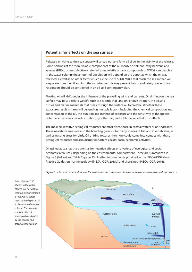
Note: dispersed oil
plumes in the water
column are not visible;
sensitive instrumentation
is required to detect
them as the dispersed oil
is diluted into the water
column. The potential
emulsification of
floating oil is indicated
by the change to a
brown/orange colour.
Figure 3 Schematic representation of the environmental compartments in relation to a subsea release in deeper waters
���
���������
������ ����
������
����
�� ������
�������� ��
�� ������ �����
������
��������������
���������� ��
�������� ��
������� ������ ��� �� �����
�����������
������
Potential for effects on the sea surface
Released oil rising to the sea surface will spread out and form oil slicks in the vicinity of the release.
Some portions of the more volatile components of the oil (benzene, toluene, ethylbenzene and
xylenes (BTEX), often collectively referred to as volatile organic compounds or VOCs), can dissolve
in the water column; the amount of dissolution will depend on the depth at which the oil was
released, as well as on other factors (such as the use of SSDI). VOCs that reach the sea surface will
evaporate from the oil and into the air. Whether this may present health and safety concerns for
responders should be considered in an oil spill contingency plan.
Floating oil will drift under the influence of the prevailing wind and currents. Oil drifting on the sea
surface may pose a risk to wildlife such as seabirds that land on, or dive through, the oil, and
turtles and marine mammals that break through the surface oil to breathe. Whether these
exposures result in harm will depend on multiple factors, including the chemical composition and
concentration of the oil, the duration and method of exposure and the sensitivity of the species.
Potential effects may include irritation, hypothermia, and sublethal or lethal toxic effects.
The most oil-sensitive ecological resources are most often those in coastal waters or on shorelines.
These nearshore areas are also the breeding grounds for many species of fish and invertebrates, as
well as nesting areas for birds. Oil drifting towards the shore could come into contact with these
ecological resources and also disrupt important coastal socio-economic activities.
Oil spilled at sea has the potential for negative effects on a variety of ecological and socio-
economic resources, depending on the environmental compartment. These are summarized in
Figure 3 (below) and Table 2 (page 13). Further information is provided in the IPIECA-IOGP Good
Practice Guides on marine ecology (IPIECA-IOGP, 2015a) and shorelines (IPIECA-IOGP, 2016).

13
DISPERSANTS: SUBSEA APPLICATION
Table 2 Potential effects of oil on environmental compartments
Environmental compartment
Seabed benthic zone
Watercolumn
Sea surface
Nearshore sediments
Shoreline
Socio-economic
Subsea discharges of oil will either float to the surface or form part of underwater plumesthat dilute and biodegrade as they move from the source of the release. The majority ofthe oil present as small oil droplets in the water will be biodegraded within days or weeks.The oil compounds that are slower to biodegrade are similar to those in bitumen orasphalt, and are largely biologically inert and of low toxicity. The proportion of a crude oilthat is present as these compounds is typically small and this residue will be present atvery low concentrations of a few ppb (parts per billion) in water as the remnants of thebiodegraded dispersed oil droplets. Some of these compounds may eventually bedeposited on the seabed at extremely low concentrations over a large area, posing no riskto marine life.
Deep ocean waters contain a relatively low density of biological life compared to the watercloser to the surface. However, animals living in deep open waters may be exposed todispersed oil plumes, and exposure may increase with dispersant usage. Potentiallyharmful concentrations would likely be limited to the area within a few kilometres of therelease site. Free swimming fish would be likely to detect and avoid areas of relatively highoil concentration.
Shallow nearshore habitats such as coral reefs may be susceptible to damage by exposureto naturally or chemically enhanced dispersed oil. Reefs more than 10 metres deep are atlow risk of harmful concentration of oil due to dilution potential.
Spilled oil floating on the sea surface poses risks to ecological resources such as seabirds,marine mammals and fish eggs/larvae present in the uppermost water column. Theplumage of seabirds that land in, or dive through, the oil will be contaminated with oil.This will reduce the insulation properties of the plumage and can lead to death byhypothermia. Floating oil may persist until it is removed by oil spill responders orweathering processes.
Naturally dispersed oil droplets that become incorporated into nearshore sediments willcontinue to be subject to weathering processes such as biodegradation. However, this oilmay result in longer-term exposure to the organisms that inhabit the mud and sediment.
Spilled oil on the sea surface can drift into shallow water and may contaminate coastalhabitats including particularly oil-sensitive mudflats and wetlands. Photos or video ofdistressed and dying seabirds covered in oil that washed ashore are stark images of the effectsof past oil spills. Spilled oil may smother shoreline organisms. Oil in shoreline substrateswill continue to be subject to weathering and biodegradation processes, but at a muchslower rate than occurs with dispersed oil, and may be a source of longer-term exposurefor shoreline organisms. Whether these exposures will have toxic effects is dependent on avariety of factors, including the chemical composition and concentration of the oil.
Oil on the sea surface can foul fishing vessels and their equipment; governments may prohibitfishing in oiled waters, potentially affecting the companies and people who fish in that area.Water recreation activities can be either prevented or disrupted by oil on the sea surface.
Spilled oil drifting onto a tourist beach could also result in beach closures and have animpact on the income of those whose livelihoods depend on tourism. Shoreline economicfeatures such as seawater intakes or ports and harbours can also be disrupted by oildrifting ashore.
Nearseabeddemersalzone
Deepwaterpelagic
Nearshore
Potential effects of oil

Deployment of any method in the oil spill response toolkit should aim to minimize the damage
that could be caused by spilled oil if no response were undertaken. The primary ecological threat
from floating oil is considered to be when oil enters the nearshore or comes ashore. Shoreline
environments typically have higher biological abundance and are often more sensitive to oil than
open water environments. Keeping oil from drifting inshore is often key to minimizing the
environmental impacts of an offshore oil spill.
The response to subsea oil releases could be undertaken:l at the source: source control aims to stop the release or prevent the released oil from reaching
the sea surface, either by subsea containment (with transfer to a surface recovery vessel) or by
enhancing dispersion of the oil; and/or l on the sea surface: after the oil released subsea has risen to the sea surface, where the primary
aim of the response is to prevent the oil from drifting ashore.
An advantage of conducting a subsea response is that operations can be undertaken at a known
and fixed location, as compared to the oil floating on the sea surface which in some cases may
appear as fragmented patches scattered over a large area of the sea surface and drifting under the
influence of the prevailing wind and currents.
Subsea response
Source control
Stopping the oil from being released subsea will always be the primary focus for response at
such incidents. In the case of leaks or ruptures of subsea flowlines or oil export pipelines,
engineering controls may be in place that can rapidly shut down the pipeline or isolate the
section that has been damaged. Stopping the flow from a subsea blowout where the blowout
preventer (BOP) has failed is a much greater challenge. Drilling relief wells to intercept and divert
the oil flow far below the seabed well head will eventually be effective, but can take weeks to
complete. Rapidly-deployable capping stacks to seal off an oil well in the unlikely event of the
failure of all safety barriers, including the BOP, have been developed in recent years. The Marine
Well Containment Company (MWCC), the Subsea Well Intervention Service (SWIS) and other
providers now have capping stacks that can be rapidly deployed to all oil exploration,
development and production regions.
Subsea containment and recovery
Recovery of some or all of the oil from the subsea release may be possible by the deployment of
various subsea oil collection and recovery devices. After the Macondo well release and other
incidents, the oil industry’s Subsea Well Response Project (SWRP), MWCC and Helix Well
Containment Group have developed toolkits of containment equipment and subsea well
containment guidelines. International subsea containment and recovery equipment and services
are now available through SWIS and other providers. The containment concept relies on existing
drilling rigs and commercially-available well-testing equipment to capture fluids from an incident
well and flow them to the surface for processing and disposal. If well shut-in is not possible, the
IPIECA • IOGP
14
Response to subsea oil releases
subsea well containment toolkit can be deployed to enable the flow of well hydrocarbons from
the capping stack to an offloading tanker.
Subsea dispersant injection
Subsea dispersant injection (SSDI) can prevent, or reduce the amount of, oil reaching the sea
surface and subsequently drifting ashore. Further information is provided in subsequent sections.
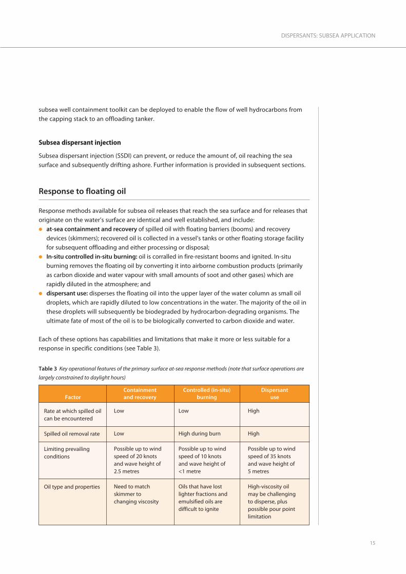
Response to floating oil
Response methods available for subsea oil releases that reach the sea surface and for releases that
originate on the water’s surface are identical and well established, and include:l at-sea containment and recovery of spilled oil with floating barriers (booms) and recovery
devices (skimmers); recovered oil is collected in a vessel’s tanks or other floating storage facility
for subsequent offloading and either processing or disposal;l In-situ controlled in-situ burning: oil is corralled in fire-resistant booms and ignited. In-situ
burning removes the floating oil by converting it into airborne combustion products (primarily
as carbon dioxide and water vapour with small amounts of soot and other gases) which are
rapidly diluted in the atmosphere; andl dispersant use: disperses the floating oil into the upper layer of the water column as small oil
droplets, which are rapidly diluted to low concentrations in the water. The majority of the oil in
these droplets will subsequently be biodegraded by hydrocarbon-degrading organisms. The
ultimate fate of most of the oil is to be biologically converted to carbon dioxide and water.
Each of these options has capabilities and limitations that make it more or less suitable for a
response in specific conditions (see Table 3).
15
DISPERSANTS: SUBSEA APPLICATION
Table 3 Key operational features of the primary surface at-sea response methods (note that surface operations are
largely constrained to daylight hours)
FactorContainment and recovery
Controlled (in-situ)burning
Dispersant use
Rate at which spilled oilcan be encountered
Spilled oil removal rate
Limiting prevailingconditions
Oil type and properties
Low
Low
Possible up to wind speed of 20 knots and wave height of 2.5 metres
Need to match skimmer to changing viscosity
Low
High during burn
Possible up to wind speed of 10 knots and wave height of <1 metre
Oils that have lost lighter fractions andemulsified oils aredifficult to ignite
High
High
Possible up to wind speed of 35 knots and wave height of 5 metres
High-viscosity oil may be challenging to disperse, plus possible pour pointlimitation
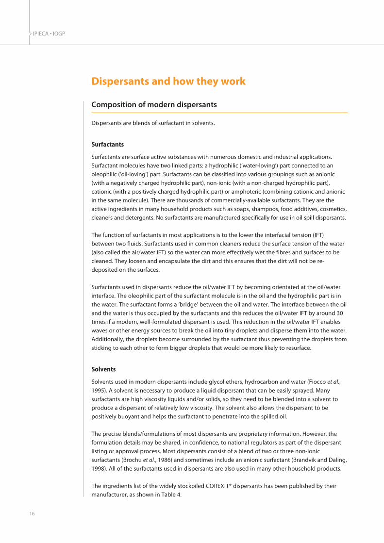
Composition of modern dispersants
Dispersants are blends of surfactant in solvents.
Surfactants
Surfactants are surface active substances with numerous domestic and industrial applications.
Surfactant molecules have two linked parts: a hydrophilic (‘water-loving’) part connected to an
oleophilic (‘oil-loving’) part. Surfactants can be classified into various groupings such as anionic
(with a negatively charged hydrophilic part), non-ionic (with a non-charged hydrophilic part),
cationic (with a positively charged hydrophilic part) or amphoteric (combining cationic and anionic
in the same molecule). There are thousands of commercially-available surfactants. They are the
active ingredients in many household products such as soaps, shampoos, food additives, cosmetics,
cleaners and detergents. No surfactants are manufactured specifically for use in oil spill dispersants.
The function of surfactants in most applications is to the lower the interfacial tension (IFT)
between two fluids. Surfactants used in common cleaners reduce the surface tension of the water
(also called the air/water IFT) so the water can more effectively wet the fibres and surfaces to be
cleaned. They loosen and encapsulate the dirt and this ensures that the dirt will not be re-
deposited on the surfaces.
Surfactants used in dispersants reduce the oil/water IFT by becoming orientated at the oil/water
interface. The oleophilic part of the surfactant molecule is in the oil and the hydrophilic part is in
the water. The surfactant forms a ‘bridge’ between the oil and water. The interface between the oil
and the water is thus occupied by the surfactants and this reduces the oil/water IFT by around 30
times if a modern, well-formulated dispersant is used. This reduction in the oil/water IFT enables
waves or other energy sources to break the oil into tiny droplets and disperse them into the water.
Additionally, the droplets become surrounded by the surfactant thus preventing the droplets from
sticking to each other to form bigger droplets that would be more likely to resurface.
Solvents
Solvents used in modern dispersants include glycol ethers, hydrocarbon and water (Fiocco et al.,
1995). A solvent is necessary to produce a liquid dispersant that can be easily sprayed. Many
surfactants are high viscosity liquids and/or solids, so they need to be blended into a solvent to
produce a dispersant of relatively low viscosity. The solvent also allows the dispersant to be
positively buoyant and helps the surfactant to penetrate into the spilled oil.
The precise blends/formulations of most dispersants are proprietary information. However, the
formulation details may be shared, in confidence, to national regulators as part of the dispersant
listing or approval process. Most dispersants consist of a blend of two or three non-ionic
surfactants (Brochu et al., 1986) and sometimes include an anionic surfactant (Brandvik and Daling,
1998). All of the surfactants used in dispersants are also used in many other household products.
The ingredients list of the widely stockpiled COREXIT® dispersants has been published by their
manufacturer, as shown in Table 4.
IPIECA • IOGP
16
Dispersants and how they work

Some of the most widely used non-ionic surfactants have a hydrophilic part based on sorbitan
(derived from sorbitol—a sugar) and an oleophilic part based on a fatty acid (a vegetable oil)
(Al-Sabagh et al., 2007). These non-ionic surfactants have the generic trade name of ‘Spans’. Other
non-ionic surfactants used are ethoxylated sorbitan esters, and these are generically known as
‘Tweens’. Spans and Tweens have applications in the pharmaceutical, cosmetic, food and
agrochemical industries. The anionic surfactant used in many modern dispersants is sodium diiso-
octyl sulphosuccinate (sometimes referred to as DOSS). This surfactant is also used in many
household products, such as cleaners of various types. Its water retention properties can be useful
and it is included in treatments for certain human health conditions.
Mechanism of dispersant action subsea
Dispersants greatly reduce the IFT that exists between oil and water when they are added to the
oil. The surfactants in dispersants ‘bridge’ the differences between the inherent properties of oil
and water. This allows the prevailing mixing energy to produce a much higher proportion of
smaller oil droplets when dispersant is added, than when it is not. When dispersant is used on
floating oil the prevailing mixing energy is from wave action (IPIECA-IOGP, 2015).
17
DISPERSANTS: SUBSEA APPLICATION
Table 4 Ingredients list of the widely stockpiled COREXIT® dispersants, as published by the manufacturer
Chemical abstracts service number
Name Generic name Examples of common, day-to-day use
1338-43-8
9005-65-6
9005-70-3
577-11-7
29911-28-2
64742-47-8
111-76-2
Sorbitan, mono-(9Z)-9-octadecenoate
Sorbitan, mono-(9Z)-9-octadecenoate, poly(oxy-1,2-ethanediyl) derivs.
Sorbitan, tri-(9Z)-9-octadecenoate, poly(oxy-1,2-ethanediyl) derivs
Butanedioic acid, 2-sulpho-,1,4-bis(2-ethylhexyl) ester,sodium salt (1:1) [contains2-Propanediol]
Propanol, 1-(2-butoxy-1-methylethoxy)
Distillates (petroleum),hydrotreated light
Ethanol, 2-butoxy [NOT included in thecomposition ofCOREXIT® 9500]
Span
Tween
Tween
DOSS
Glycol ether solvent
Hydrocarbon solvent
Glycol ether solvent
Skin cream, body shampoo,emulsifier in juice
Baby bath, mouth wash,face lotion, emulsifier infood
Body/face lotion, tanninglotions
Wetting agent in cosmeticproducts, gelatin,beverages
Household cleaningproducts
Air freshener, cleaner
Cleaners

When dispersant is used subsea on a blowout, the prevailing mixing energy is the turbulence
produced at the point of the oil and gas release. If the oil release is a high-pressure, high-velocity
event, particularly with a gas phase present, it will produce a plume of oil droplets and gas
bubbles in the water. Even without dispersant application, a proportion of the released oil will be
in the form of oil droplets that are too small to float to the sea surface and, in some circumstances,
this portion may already be substantial.
IPIECA • IOGP
18
Note: dispersed oil
plumes in the water
column are not
visible; sensitive
instrumentation is
required to detect
them as the dispersed
oil is diluted into the
water column.
Figure 4 Schematic representation of subsea release with, and without, the addition of dispersant (not to scale)
������
� ������� ����� �� ����
����������
�������������������
�� ������� ����
�����������
��� �� � ����������
����
�������������
��������������������
������� ����� ��� �� �����
������ ����
���
��������������
�������������������
�� ������� ����
�����������
��� �� � ����������
����
�������������
������ ����
���
��������������������
������������ ��� �
�!�"��� �������������
�!�"��������������
������
������

Dispersant that is added subsea to the oil release will cause a large reduction in the IFT, and the
turbulence of the release conditions will convert a greater proportion of the oil into droplets that
are small enough to be dispersed in the water column by the prevailing oceanographic conditions.
Benefits and potential risks of subsea dispersant use
The reason for using SSDI at a subsea blowout is the same as for any dispersant use: to prevent, or
minimize, the amount of oil that may subsequently drift into shallow coastal waters or onto the
shore, where it could cause damage to inshore habitats with relatively high biodiversity and
abundance, as well as disruption to socio-economic activities. SSDI also provides a major health
and safety benefit by greatly reducing the exposure of personnel responding near the release site
to VOCs.
Benefits of dispersant use
The benefits of dispersant use include the following: l It minimizes potential damages and disruption to sensitive wildlife, coastal habitats and socio-
economic features that could occur if dispersant were not used and the oil either remained on
the surface or reached coastal waters and shorelines.l It increases the availability of oil for biodegradation and thereby speeds up its natural break-
down and assimilation into the environment.l It can reduce potentially harmful vapours in the vicinity of a spill and provide a safety benefit to
responders undertaking vessel-based activities in the immediate area, as well as minimizing the
exposure of responders and local communities to oil in the wider context. The VOCs present in
dispersed oil will dissolve into the sea instead of evaporating into the air.l The use of SSDI reduces the amount of dispersant required compared to surface application and
can be operated day and night.l It reduces the amount of oil that reaches the shore, which may reduce the extent and duration of
shoreline clean-up operations.l It avoids the creation of large volumes of waste material often associated with shoreline clean-up
operations; such waste can present serious environmental challenges during its handling,
storage and disposal.
In summary, an efficient subsea dispersant delivery system could potentially treat the vast majority
of oil escaping from a single release point before it reaches the surface and forms a widely spread
floating slick. Oil dispersed at depth as small droplets will not rise to the upper water column
where there is generally a greater abundance of marine life.
Once deployed, SSDI is able to treat the oil released from a point-source with a high encounter
rate, can continue day and night and is generally not limited by weather. However, when SSDI is
applied from a ship on the surface, the ship may need to stop application and return to harbour if
extreme weather conditions arise, such as a hurricane or typhoon. Unmanned or remotely
operated SSDI systems may be able to continue operating in such conditions.
19
DISPERSANTS: SUBSEA APPLICATION
IPIECA • IOGP
20
Potential risks of subsea dispersant use
Any successful dispersant use (on the sea surface or subsea) involves transferring more of the oil
into the water column than would otherwise be the case. The potential risk of dispersant use is the
increased exposure of marine organisms in the deep sea water column to dispersed oil droplets
and water-soluble oil compounds released from these oil droplets.
At many subsea oil and gas blowouts, a substantial proportion of the released oil volume may
already have been produced in the form of a plume of very small oil droplets in the water by the
turbulence created by the high-velocity flow of oil and gas into the water. Adding dispersant to
the oil being released will increase the proportion of oil dispersed as very small oil droplets, but
from an already high value, not from zero.
Community perceptions of damage concerning the use of SSDI has a potential to impact fisheries
market confidence.
A process for evaluating subsea dispersant use is further discussed in the context of net
environmental benefit analysis (NEBA) on pages 29–34.

The capabilities and limitations of dispersant use on floating oil are described in the IPIECA-IOGP
Good Practice Guide on the surface application of dispersants (IPIECA-IOGP, 2015).
Capabilities of subsea dispersant use
Subsea response methods have the potential capability, once deployed, to deal with all the oil
being released from the point source. This is in contrast to a response to floating oil, where the
large area of fragmented and scattered oil on the sea surface is often a limiting factor. The rate at
which any response method can come into contact with oil is commonly called the encounter rate.
The encounter rate of surface response methods, particularly those involving containment of oil,
can be low. However the encounter rate of all subsea response methods is potentially very high;
all of the released oil can be ‘encountered’ in a very small area, albeit that this limited area may be
at some distance below the sea surface.
The potential capability of subsea dispersant use should therefore be initially compared with those
of other subsea response methods such as subsea capping and subsea containment and recovery.
A limiting factor common to all these methods is the speed with which the required equipment
and personnel can be deployed to the site of the oil release and the capability to conduct the
response in the water depth at which the release is occurring.
The logistics involved with transporting bulky, heavy equipment associated with subsea capping
and containment (a capping stack can weigh 300 tonnes) from where it is stored to where it is
required can be formidable.
21
DISPERSANTS: SUBSEA APPLICATION
Capabilities and limitations
Table 5 Comparison of the characteristics and limitations of subsea capping, containment and dispersant injection
Factor Subsea capping Subsea containment Subsea dispersant injection
Rate at which oilcan be encountered
Oil treatment rate
Deployment factors
Limitations
Prevents flow ofwell fluid
Initial removal ofdebris may be
required
Current systemstypically limited to a
maximum waterdepth of 3,000 m
and 15,000 psipressure
Captures well fluid
Applicable in rarescenarios where cappingis either not sufficient or
not possible
Current systems typically limited to a
maximum water depth of 3,000 m
Very high
Applicable while cappingand containment systems
are being deployed
Current systems typically limited to a
maximum water depth of 3,000 m
Very high

Limitations of subsea dispersant use
The prevailing sea state and oil properties, principally oil viscosity, and the way that the viscosity
increases as spilled oil ‘weathers’, determine the effectiveness of dispersant use on floating oil.
Subsea dispersant use will not be affected by the prevailing mixing energy provided by wave
action at the sea surface or by the change in oil properties as it ‘weathers’.
At a subsea blowout, there is a continuous ‘supply’ of crude oil and gas from the reservoir.
Dispersant would be added to the oil as it flows into the water. Although the oil properties will
change rapidly due to dissolution into the water of some of the water-soluble compounds in the
oil, and the sudden drop in temperature as the oil enters the sea, it is unlikely that this will reduce
the effectiveness of the dispersant in the case of most crude oils. Crude oil being released from a
subsea well will often be at high temperature, although it will be rapidly chilled when it comes
into contact with the cold water at deep releases. If a crude oil has a very high pour point due to a
very high wax content, it is possible that it would become solid on entering the water, and take
the form of a plume of solidified wax droplets.
A potential limitation of subsea dispersant use could be the effectiveness of its application at the
release location. Dispersant needs to be added to the oil as the oil and gas enters the water.
Studies (Brandvik et al., 2014a and 2013 and Johansen et al., 2013) have shown that the time
available for the surfactants in the dispersant to influence droplet formation after the oil is
released is very limited:l If injecting dispersant into the oil and gas before the release, for example if injecting dispersant
into a broken riser pipe, the dispersant should be injected no more than about six release
diameters before the release.l If the dispersant is to be added to the turbulent outflow from an oil and gas release, the
dispersant should be added only slightly above the oil and gas release at a maximum of 10
diameters of the release.
SSDI systems have been developed to take the above requirements into account to allow effective
operations. Injecting dispersant into the oil before it is released at the discharge point may be
better than spraying into the released oil jet near the discharge point. The injection point needs to
be within the energetic jet before it begins to break into individual droplets. The distance outside
the release point where this occurs will depend on the release conditions.
If the dispersant can’t be injected into the oil and gas flow before it is released, the next best
option is to get as close to the release point as possible. Dispersants have been shown to be
effective under test conditions as long as they are injected into the energetic solid jet of oil before
it breaks into droplets. A key requirement for injecting outside the release point will be to ensure
that the dispersant is distributed around the jet and not just into one side. The most effective way
to do this may be to use injection rings.
IPIECA • IOGP
22
Below: photograph
from a test tank
showing the injection
of dispersant into a
release; the
dispersant is visible as
a white line being
sucked into the rising
plume of oil.
SINTEF

Chemical compounds in crude oils
Crude oils are composed of a large number of individual chemical compounds. Almost all of these
are hydrocarbons, composed of only hydrogen and carbon. Hydrocarbons can be classified by
molecular weight, or carbon chain length, and the majority of hydrocarbons in crude oil contain
from 5 to 35 carbon atoms. Hydrocarbons can also be classified according to chemical type;
alkanes (paraffins), cycloalkanes (naphthenes) and aromatic compounds (containing one or more
benzene rings). The relative proportions of these chemical compounds differ between crude oils
and are responsible for the range of physical properties that crude oils exhibit. The majority of
hydrocarbons in most crude oils are alkanes and cycloalkanes and they can range from volatile
liquids to non-volatile liquids or solids (waxes) depending on their size (number of carbon atoms)
and the prevailing temperature.
Potentially toxic chemical compounds in oil
Most alkanes and cycloalkanes have a limited potential for toxic effects on marine organisms due
to their low water solubility. Aromatic hydrocarbons are partly water-soluble and are generally
considered to be the more potentially toxic component of crude and fuel oils with respect to
aquatic organisms (Anderson et al., 1974; Di Toro et al., 2007).
23
DISPERSANTS: SUBSEA APPLICATION
Toxicity and biodegradability of oil
l One-ring aromatic compounds: these are benzene, toluene, ethylbenzene and xylenes and are oftenreferred to as BTEX compounds. Crude oils contain from about 0.5% up to 5% BTEX. Gasoline cancontain up to 40% BTEX. BTEX compounds are relatively soluble in water, but they also comprise themajority of VOCs and, if they reach the surface, will rapidly evaporate into the air from the floating oil.
l Two-ring aromatic compounds: naphthalene and alkyl-substituted derivatives. Different crude oilscontain from 0% to 0.4% of naphthalene and from 0% up to 1% or more of substituted naphthalenes.These compounds are less water-soluble than BTEX and of moderate volatility.
l 3-, 4- and 5-ring polycyclic aromatic hydrocarbons (PAHs): crude oils contain from 0 ppm to severalhundred ppm of the 3-ring aromatic compounds, but much less, typically 1 to 10 ppm, of theindividual 4-ring and 5-ring compounds. These PAH compounds are not volatile and the 3- and 4-ringcompounds are slightly water-soluble.
Box 1 Aromatic chemical compounds in oils
Toxicity testing of dispersants and dispersed oil
Toxicity testing of dispersants and dispersant/oil mixtures (to produce dispersed oil) is carried out
for different purposes and using a variety of toxicity test methods. The intention of toxicity testing
of dispersants was to ensure that the use of toxic industrial detergents, such as those used in
massive quantities at the Torrey Canyon oil spill in the UK in 1967 (Smith, 1968), would not be
repeated. Currently, in order to be approved, most countries require dispersants to exhibit a
toxicity less than a level deemed acceptable.
#$����%�� �����
�&'
($����%�����������
($����%�($�����������������
'$����%����������
)$����%����� *�!���������
�$����%����� *�!������
�&'
Above: examples of
aromatic compounds
�� ������������
&
&
& &
&
& &
&&&
&&
�� ������
& � � � � &
& & & &
& & & &
������

A 96-hour or 48-hour LC50 (lethal concentration to 50% of the test population) toxicity test with a
variety of test species was used to determine the toxicity of the dispersants. The purpose of the 48-
or 96-hour LC50 toxicity test is to determine the concentration of dispersant in water that is lethal to
50% of the creatures exposed for the specified number of hours. The test can therefore be used to
rank the comparative toxicity of different dispersants. The exposure regime (concentration of
dispersant in the water and exposure duration) in an LC50 test does not simulate the exposure to
dispersant that a marine organism would experience if the dispersant was used on spilled oil at sea.
In the USA, the toxicity tests required by the US Environmental Protection agency (EPA) for
dispersants to be included on the NCP (National Oil and Hazardous Substances Pollution
Contingency Plan) Product Schedule involves testing with two US EPA standard species: inland
silverside fish (Menidia beryllina) and mysid shrimp (Americamysis bahia). The exposure regime of
the LC50 toxicity testing procedure does not simulate dispersant use on spilled oil at sea because
the concentrations used in the test are much higher, and the duration of exposure is much longer,
than would occur at sea. However, LC50 toxicity testing provides a way of assessing the relative
magnitude of toxic effects that could be caused by dispersants or dispersed oil under the test’s
exposure conditions.
At the time of the Macondo incident, eight dispersants on the NCP Product Schedule were tested
for toxicity (Hemmer et al., 2010).
The measured levels of toxicity in the LC50 tests were ranked on a five-level scale from ‘very highly
toxic’ to ‘practically non-toxic’ as used by the US EPA for interpreting the results of LC50 tests
(US EPA, 2012). This toxicity ranking scale is also used internationally (GESAMP, 2014).
IPIECA • IOGP
24
Table 6 Results of US EPA testing of eight dispersants on the NCP schedule
����������� ���������
+,-�� � .��������� ����*����/���������������� �!
�������������������������
������������� .�%���0#����
&������� .�%��0#1#����
2 ���������� .�%�3#1#�����
4��������� .�%�3#�1#������
,���������� �$� .�%�3#������
5���������4,��#���6 � ����'$--
��7+89:;�<���-6 � ����'$=)
>9$)��
5���������4,��#���
6 � ����'$=)6 � ����'$--
>9$)��4�$7 ��? ��4���@����A)
4�$7 ��? ��B5$(���
��7+89:;�<���-B5$(���
US
EPA
, 201
2

The majority of the dispersant used at the Macondo incident was COREXIT® 9500A, and was
ranked as ‘slightly toxic’ to mysid shrimp and ‘practically non-toxic’ to silverside fish in the LC50
toxicity tests.
The same toxicity testing methodology used for listing on the NCP Product Schedule was used by
the US EPA (US EPA, 2010) to determine the relative magnitude of the toxic effects that could be
caused by:l mechanically dispersed Louisiana Sweet Crude (LSC) oil;l the dispersant used during the response to the Macondo incident—COREXIT® EC9500A; and l LSC crude oil dispersed by using a mixture of 1:10 of COREXIT® EC9500A and LSC.
The results summarized in Table 7 show that the dispersant alone has a less toxic effect than the
crude oil alone. The dispersant alone is considered to be ‘practically non-toxic’ to the fish species
and only ‘slightly toxic’ to the shrimp, while the mechanically dispersed crude oil is rated as being
‘moderately toxic’ to both. The crude oil dispersed with the dispersant has the same rating as the
mechanically dispersed crude oil of ‘moderately toxic’ to both species. In this case the measured
toxic effects are caused by the oil, not the dispersant. Consequently, it is not appropriate to
evaluate dispersant toxicity by conducting toxicity tests on dispersed oil.
25
DISPERSANTS: SUBSEA APPLICATION
Table 7 US EPA’s LC50 aquatic toxicity testing summary results for the spilled oil, dispersant and dispersed oil from
the response to the Macondo incident
�������������������� ���!����
+,-�� � .��������� ����*����/���������������� �!
"�������� �#$%&'()�%�����*!
"����������� ����+��#$%&'()�%�����*!
������������� .�%���0#����
&������� .�%��0#1#����
2 ���������� .�%�3#1#�����
4��������� .�%�3#�1#������
,���������� �$� .�%�3#������
2����������
4������������
2����������
4������������
2����������
4������������
(0C���� '0����� �0)���� C0D����
)(����
#'�����
The LC50 toxicity testing used a 1:10 mixture of dispersant to oil. This is more dispersant than
would be used in subsea application, where ratios of 1:100 or 1:50 would be typical.
In actual dispersant use, on spilled floating oil or by subsea dispersant injection, the duration of
exposure of marine organisms to dispersed oil, and the concentration of dispersed oil, will be
dependent on a variety of factors, including environmental conditions and the circumstances of
the oil release.
US
EPA
, 201
0

Exposure to oil, dispersed oil and water-soluble compounds from the oil
A fundamental basis of toxicology is that the magnitude of the effect of a chemical compound on
an organism is dependent on the exposure of the organism to the chemical compound. Exposure
is a function of exposure route, the concentration of the chemical to which the organism is
exposed and the duration of exposure.
If a subsea oil release has occurred, some marine organisms may be exposed to elevated
concentrations of dispersed oil droplets and water-soluble compounds from the oil in the water.
At a subsea blowout of oil and gas at high pressure, all of the oil will likely be released into the
water as oil droplets. A significant proportion of the released oil may be converted to very small oil
droplets by the turbulence produced by the oil and gas release. In these circumstances, many of
the lower molecular weight aromatic compounds (the BTEX and the 2- and 3-ring PAHs) will be
rapidly transferred from the oil and into the water, where they will be subject to rapid dilution and
biodegradation.
These compounds have the potential to harm marine organisms that are in the vicinity of the
subsea blowout and are exposed to these dissolved compounds as well as to concentrations of
dispersed oil in the water. The larger oil droplets, gas bubbles and the water-soluble oil
compounds from the oil will rise rapidly through the water column, creating a potential risk to
pelagic organisms (those in the water column), rather than to benthic organisms (those that live
either in or on the seabed) or the demersal organisms that live near the seabed.
The concentrations of oil droplets and water-soluble compounds from the oil will rapidly decrease
as the buoyant plume entrains water and is diluted as it rises through the water column. However,
while the blowout continues, there will be a relatively high concentration of oil droplets and
water-soluble compounds from the oil in the close vicinity of the release.
Effect of subsea dispersant use
If subsea dispersant use is effective, the oil droplets entering the water as a plume will be smaller
in size. This will enhance the rate of transfer of the water-soluble compounds from the oil into the
water because the oil/water surface area is increased with smaller oil droplets. This will result in
higher concentrations of dispersed oil (very small oil droplets) and water-soluble compounds in
the water in close proximity to the release. Although SSDI will increase these concentrations, they
may already be relatively high close to the source without dispersant use. Hence, the potential for
toxic effects on marine organisms present in the vicinity of the subsea oil and gas release is
increased by subsea dispersant use, but from an already high ‘baseline’ condition. Oil that is
dispersed by SSDI will generally become neutrally buoyant and create subsea plumes of dispersed
oil at low concentration. These plumes will drift, dilute and biodegrade.
IPIECA • IOGP
26

Exposure of marine organisms by ingestion of dispersed oil droplets
The ingestion of food provides marine organisms with a potential route of exposure to higher
molecular weight PAHs. Filter feeding organisms that prey on plankton can ingest naturally- or
chemically-dispersed oil droplets when they are of a similar size to some plankton. Relatively
simple organisms, such as bivalves, cannot biochemically process the higher molecular weight
PAHs in the oil, and these PAHs can build up (‘bioaccumulate’) in some organs (Neff and Burns,
1996). Predators that consume oil-contaminated bivalves can therefore be exposed to elevated
concentrations of the higher molecular PAHs by this ingestion route. Organisms that possess
livers, such as fish, can quickly metabolize PAH although some of these metabolites may be
harmful. However, it is unlikely that bivalves will be exposed to subsea dispersed oil, as they are
benthic organisms and are therefore more likely to be exposed to naturally dispersed surface slicks
in shallow waters. Plankton and copepods may be found in the mid or deeper water column and
are therefore at increased risk of exposure. The low concentration of dispersed oil, coupled with the
abundance and rapid recovery of their populations, is likely to limit impacts on these organisms.
Biodegradation of oil
Oil droplets in the water column are rapidly colonized by petroleum degrading microorganisms
that occur naturally in ocean environments (King et al., 2014). All of the world’s oceans have
natural hydrocarbon seeps (Kvenvolden, 2003), and oil degrading microbes are found in all marine
environments—even cold, dark environments—having evolved to degrade petroleum from these
seeps. Most of the chemical components of crude oil in these
droplets has only limited water solubility and the microorganisms
must inhabit the interface between the oil and the water to
biodegrade the oil. Oil dispersed as small droplets has a much
greater oil/water interfacial area than an oil slick floating on the sea
surface. This increase in interfacial area results in greater microbial
attachment and faster biodegradation. A community of
microorganisms (bacteria and fungi) consumes and degrades the oil
as they grow and reproduce, and then larger protozoans and
nematodes consume the bacteria. The oil is thereby assimilated into
the environment (American Academy of Microbiology, 2011) and no
longer poses any risks. Dispersed oil also dilutes rapidly. By the time
an individual droplet is fully colonized by microorganisms and
biodegradation becomes significant, concentrations of dispersed oil
in the water are likely to be very low. At these low concentrations,
most marine environments have sufficient oxygen, phosphorous,
nitrogen and other nutrients to allow efficient aerobic
biodegradation to proceed.
Figure 5 shows a photomicrograph of an oil droplet with marine oil-
degrading bacteria attached. It can be seen that the microorganisms
(i.e. a few microns in length) that degrade oil can be much smaller
than the oil droplets themselves (i.e. a few tens of microns in diameter).
27
DISPERSANTS: SUBSEA APPLICATION
Haz
en e
t al.,
201
0
Figure 5 Biodegrading microbes begin ‘eating’
the dispersed oil droplet

Biodegradation proceeds principally by biochemical oxidation (Atlas and Bartha, 1992; Atlas and
Cerniglia, 1995; Prince, 1997; Prince et al., 2013). The different chemical compounds in crude oils
will be biodegraded at different rates and to different extents (Singer and Finnerty, 1984;
Lindstrom and Braddock, 2002; Campo et al., 2013). Linear chain alkanes will be most rapidly
biodegraded, followed by the single-ring aromatic compounds and then by branched chain
alkanes and cycloalkanes. Many complex branched, cyclic and aromatic hydrocarbons, which
otherwise would not be biodegraded individually, can be oxidized through co-metabolism in an
oil mixture due to the abundance of other substrates that can be metabolized easily within the oil
(Heitkamp and Cerniglia, 1987).
The ultimate fate of the majority of oil that is biodegraded is to be eventually converted into
carbon dioxide and water (MacNaughton et al., 2003). Some very heavy oil compounds, such as
asphalt or bitumen, are slower to biodegrade. These are biologically inert and are non-toxic or
practically non-toxic.
The concentration of dispersed oil in the water will progressively decrease to undetectable levels
as the small oil droplets are further diluted into the water column. The surfactants and solvent in
dispersants are biodegradable and the dispersant will therefore also be biodegraded, usually more
rapidly than the oil. The oil compounds that cannot be readily biodegraded will initially be present
at very low concentrations of a few ppb (parts per billion) in water as remnants of the dispersed oil
droplets. This oil residue will eventually be deposited at these low concentrations over a wide area
of the seabed.
To summarize, dispersing the oil by adding dispersants allows significant enhancement of the
natural biodegradation process. Oil that is dispersed effectively will persist in the environment for
days to weeks, while undispersed floating oil that weathers, emulsifies and ultimately strands on
shorelines could persist in the environment for several years.
IPIECA • IOGP
28
Net environmental benefit analysis (NEBA) is a process used by the response community for
making the best choices to minimize the impacts of oil spills on people and the environment—see
the IPIECA-IOGP Good Practice Guide on NEBA (IPIECA-IOGP, 2015b).
NEBA works at different stages in a spill:l NEBA is an integral part of the contingency planning process, used to ensure that the response
strategy for planning scenarios is well informed.l During a response, the NEBA process is used to ensure that evolving conditions are properly
understood and evaluated so that the response strategy can be adapted and adjusted as
necessary.l The NEBA process can also be used to ensure that longer-term response end points are defined
and achieved.
NEBA involves consideration and judgment to compare the likely outcomes of using different oil
spill response methods and recommendations as to the preferred tactics, based on the
considerations of experienced responders and consultations with stakeholders. NEBA typically
involves the following steps for identified release scenarios, and should be carried out prior to an
oil spill as an integral part of the oil spill contingency planning process.
29
DISPERSANTS: SUBSEA APPLICATION
Net environmental benefit analysis
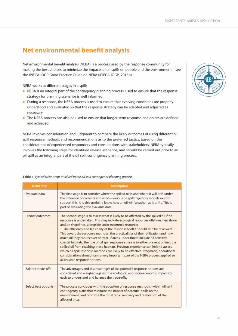
Table 8 Typical NEBA steps involved in the oil spill contingency planning process
NEBA step Description
Evaluate data
Predict outcomes
Balance trade-offs
Select best option(s)
The first stage is to consider where the spilled oil is and where it will drift underthe influence of currents and wind—various oil spill trajectory models exist tosupport this. It is also useful to know how an oil will ‘weather’ as it drifts. This ispart of evaluating the available data.
The second stage is to assess what is likely to be affected by the spilled oil if noresponse is undertaken. This may include ecological resources offshore, nearshoreand on shorelines, alongside socio-economic resources.
The efficiency and feasibility of the response toolkit should also be reviewed.This covers the response methods, the practicalities of their utilization and howmuch oil they can recover or treat. If areas under threat include oil-sensitivecoastal habitats, the role of oil spill response at sea is to either prevent or limit thespilled oil from reaching these habitats. Previous experience can help to assesswhich oil spill response methods are likely to be effective. Pragmatic, operationalconsiderations should form a very important part of the NEBA process applied toall feasible response options.
The advantages and disadvantages of the potential response options areconsidered and weighed against the ecological and socio-economic impacts ofeach to understand and balance the trade-offs.
The process concludes with the adoption of response method(s) within oil spillcontingency plans that minimize the impact of potential spills on theenvironment, and promote the most rapid recovery and restoration of theaffected area.

Step 1: Evaluate data
An important aspect of oil spill contingency planning is using realistic oil release scenarios (see theIPIECA-IOGP Good Practice Guide on contingency planning (IPIECA-IOGP, 2015c). Various subseaoil release scenarios, up to and including a worst credible case discharge, should be developed.The predicted prevailing conditions must be taken into account.
Modelling should then be conducted to help predict how the released oil will behave. Severalcomputer models are available for modelling subsea oil and gas blowouts. A model needs to takeinto account the relevant factors such as the well’s and metocean characteristics includingcurrents, temperatures, etc. throughout the relevant depths.
Work is still under way to develop models that accurately predict the oil droplet size distributionsproduced under a wide range of release conditions.
Step 2: Predict outcomes
Combining sensitivity mapping (IPIECA/IMO/IOGP, 2012) with modelling can indicate whichecological resources and socio-economic resources (offshore, nearshore and on shorelines) arepotentially at risk from oil if no response is undertaken. The ways in which oil can impact variousecological and socio-economic resources, and the factors that can influence these impacts, aredescribed in the IPIECA-IOGP Good Practice Guides on marine ecology (IPIECA-IOGP, 2015a) andshorelines (IPIECA-IOGP, 2016).
Feasibility of using a response method
The likely effectiveness and feasibility of conducting the different response methods under therange of likely prevailing conditions should be reviewed. This covers the response methods, thepracticalities of their utilization and how much oil they can recover or treat in the time that is likelyto be available for their use. Pragmatic, operational considerations should form an important partof the NEBA process applied to all feasible response options.
In considering a response to a subsea oil release, the decision must be made as to whether theresponse should be conducted subsea (with subsea capping, at-sea containment and recovery orsubsea dispersant use) or to wait until the released oil has risen to the sea surface where theresponse could be at-sea containment and recovery, controlled in-situ burning or surfacedispersant use. The particular characteristics of the subsea oil release scenario and released oil andgas behaviour will inform this decision.l At a subsea oil and gas blowout in deep water, where the gas will be dissolved in the water and not
reach the sea surface, the use of surface vessels to deploy subsea capping stacks, subsea containmentand recovery systems and subsea dispersant injection equipment may be a feasible response.
l However, at a subsea oil and gas blowout (with similar hydrocarbon flows and pressures) inshallower water, where the gas will not be totally dissolved in the water and will reach the seasurface, an offset subsea equipment system, deployed at a horizontal distance of up to 500 mfrom the well, should be considered as the fire and explosion risk will likely preclude the use ofsurface vessels above the well location.
IPIECA • IOGP
30

The time taken to deploy any response equipment may also be a key factor in assessing the
feasibility of conducting the response. Any oil spill response is often a race against time. Once a
subsea oil release has occurred, the potential risks will be determined by the proximity of resources
that could be damaged and by the prevailing conditions, such as wind direction and speed.
At-sea containment and recovery is generally the first oil spill response method considered for use.
This will continue to be the case in the future because the vast majority of oil spills are small and
located near stockpiles of equipment. As spills grow in size and move further away from stockpiles
of equipment, containment and recovery becomes less efficient due to the large surface area of
the oil, lower oil encounter rates, and logistical issues of transporting recovered oil to shore for
processing or disposal. This is why dispersants are needed that can be applied rapidly by air or applied
subsea. Dispersants can treat remote oil spills quickly because they can be deployed by fast-moving
aircraft. Aircraft deployment means that dispersants can treat large areas much more rapidly than in a
boat-based response. Subsea dispersants treat the oil at a known location even more efficiently.
Step 3: Balance trade-offs
A decision to use or not use dispersants is not a black and white decision, despite being typically
misconstrued as a ‘birds versus fish’ debate. Untreated oil slicks moving across the water surface
may impact fish eggs and larvae in or immediately under the slick. Furthermore, nearshore and
stranding oil may impact the juvenile life stages of many fish. If the oil is not dispersed, slicks may
drift across the water surface and strand on shorelines to impact fisheries—possibly more so than
dispersing the oil if the spill occurs during critical spawning periods or the oil moves into critical
nearshore habitat for juvenile fish. As the potential harm to fish stocks from dispersed oil is low,
there can be strong NEBA arguments that dispersant use can protect fisheries.
The trade-offs, or balance, of potential benefits and risks of subsea dispersant use at a subsea
blowout are similar, but not identical, to those of dispersant use on spilled floating oil because the
circumstances are different. The potential risks posed to marine organisms by dispersed oil are
different in terms of scale, location and possible consequence.
The risk of toxic effects on marine organisms is related to their exposure to dispersed oil and the
partially water-soluble components released from the oil. Exposure is a function of concentration
and duration.
Exposure to dispersed oil caused by dispersant use on floating oil
Breaking waves passing through a localized area of an oil slick will cause the oil to be broken up
into oil droplets with a range of sizes. The larger oil droplets will rapidly resurface, but the smaller
oil droplets will be dispersed into the water column. The proportion of oil dispersed by natural
dispersion is often low and decreases as the oil ‘weathers’.
Dispersant use greatly increases the proportion of the oil that is converted into small droplets by
the prevailing wave action. Localized plumes of dispersed oil droplets are produced as breaking
waves pass through dispersant-treated floating oil. The concentration of oil (as droplets) in the
31
DISPERSANTS: SUBSEA APPLICATION

upper water column rises rapidly, but then rapidly decreases as the oil is diluted into the
surrounding water. As the oil slick drifts under the influence of the wind, further breaking waves
will cause localized clouds of dispersed oil to be produced in the water column at locations some
distance from where the previous clouds were produced and subsequently diluted. The peak
concentrations of dispersed oil in water are low and of short duration, occurring at scattered
locations over a period of time under the dispersant-treated oil.
Marine organisms inhabiting the upper layer of the water column (to a maximum depth of around
5–10 m) can be briefly exposed to increased concentrations of dispersed oil droplets and water-
soluble oil compounds in the water column, compared to the situation if dispersants were not
used. Some exposure will occur if dispersants are not used, due to natural dispersion—see the
IPIECA-IOGP Good Practice Guide on the surface application of dispersants (IPIECA-IOGP, 2015).
Exposure to dispersed oil caused by SSDI at a subsea oil release
The continuous release of large amounts of oil and gas from a point source will produce high
concentrations of dispersed oil, and of the water-soluble components from the oil, in the water
close to the release. The concentration of dispersed oil in the water will be diluted and decrease as
the plume rises and drifts away. The use of SSDI will cause a further increase in these already high
concentrations of dispersed oil in water close to the release. These high concentrations of
dispersed oil in water close to the source will be maintained for as long as the oil and gas release
continues (as illustrated in Figure 4 on page 18).
The exposure regime for marine organisms exposed to dispersed oil and water-soluble oil
compounds in the water column will be dependent on their proximity to the release, the drift
direction of the plumes, and the ability of the marine organisms to detect oil and move away to
avoid the oil. Sessile organisms on the seabed that cannot move away may experience higher
exposure to dispersed oil than those organisms that can swim away. Sessile organisms close to the
release can be exposed to high concentrations of dispersed oil for prolonged periods.
The actual effects of the dispersed oil exposure regime produced by SSDI will depend on the
marine organisms that are present in the vicinity of the subsea oil and gas release or near the
subsea plumes of dispersed oil that are drifting, diluting and biodegrading. In general, the
population density in deep water is less than that present nearer to the sea surface.
The essential element of NEBA when considering subsea dispersant use and comparing its
probable effectiveness to that of other response methods will be the need to consider the
probable outcomes of:l no response, i.e. not using subsea dispersants or another response; compared with l the use of subsea dispersants.
Any ‘trade-off’ consideration of subsea dispersant use should consider the amount of severe and
long-lasting damage to oil-sensitive coastal habitats, and potentially to socio-economic resources,
that can likely be prevented by dispersant use and compare that with the potential localized
effects of dispersant use on the marine environment. Box 2 on page 33 provides an example
scenario illustrating how the use of SSDI can achieve a net benefit compared to no response.
IPIECA • IOGP
32

33
DISPERSANTS: SUBSEA APPLICATION
Box 2 Example scenario to illustrate how the use of SSDI can achieve a net benefit compared to no response
* Relative consequence categories take into the account a variety of factors, including the sensitivity of habitats, species or populations, thegeographic extent of an area that may be affected, the anticipated recovery time and socio-economic value of a resource, if applicable.
** Fisheries authorities are likely to impose a precautionary fishing ban or exclusion to protect perceived risks to human health and marketconfidence. A ban typically remains until there is evidence that fish are safe for consumption. Such bans can increase the consequence tofisheries through enforced loss of earnings, rather than through impacts on fish populations or stocks.
Environmental compartment
Representative population/resources
Potential relative consequence*with no response
Potential relativeconsequence with SSDI
Seabed benthic zone Burrowing organisms
Flatfish
Round body fish
Round body fish
Plankton
Coral reef
Seabirds/sea mammals
Seagrass
Burrowing organisms
Insignificant
Insignificant
Small
Small
Moderate
Moderate
Very large
Moderate
Very large
Moderate
Moderate
Very large
Large
Small
Insignificant
Very large
Very large
Insignificant
Insignificant
Moderate
Small
Insignificant
Insignificant
Small
Insignificant
Insignificant
Insignificant
Insignificant
Small
Small
Moderate
Large
Small
Small
Near seabed demersal zone
Deep water pelagic (>400 m)
Mid-water pelagic (<400 m)
Upper water layer (<20 m)
Nearshore water (<10 m)
Sea surface
Nearshore sediments
Wetlands
Rocky shores
Sandy shores
Coastal tourism
Inshore fisheries and aquaculture**
Mid-water fisheries**
Deep water fisheries**
Seawater intakes
Maritime recreation
������ �����������
������������������
������� �����
���������������
����������������
�������� ��
��������������� ������� ������ �����������
���������������� �
����������������������
�����������������
���������� ��
������ �����������
������������������
������� �����
���������������
����������������
�������� ��
��������������� ������� ������ �����������
���������������� �
����������������������
�����������������
���������� ��
6 $���� ���������� 4����� �������������4459
This representative scenario indicates how the successful use of SSDI can reduce the overall consequences of a release and therebyachieve a net environmental benefit.
Note that this example is illustrative, and that individual oil spill contingency planning cases need to consider the specifics of anoperation, including the local environmental resources, their ecological, commercial and cultural value and their seasonality.
Soci
o-ec
onom
icre
sour
ces
Shor
elin
eW
ater
col
umn

IPIECA • IOGP
34
Step 4: Select best options
In Step 4 of NEBA, data, viewpoints and trade-offs are taken into account to select the optimum
response strategy for the planning scenario or the prevailing incident conditions. This stage of
NEBA relies on planners and stakeholders reaching consensus on the priorities for protection and
the acceptable balance of trade-offs.
The key objective of planning for, and executing, a response is to implement those methods that,
at any moment in time, have the greatest net benefit. For example, in an offshore marine incident,
treating or recovering as much oil as close to the source as possible, will have the greatest benefit,
before it has had a chance to weather and spread out making other response methods less
effective and increasing the chances of more oil reaching sensitive areas, international boundaries
or the shoreline.
Example release scenarios and the NEBA considerations associated with response planning are
given in the Annex on pages 57–64.

A report entitled, Regulatory approval of dispersant products and authorization for their use has been
produced by the IPIECA-IOGP Oil Spill Response Joint Industry Project (JIP) (IPIECA-IOGP, 2014) to
provide an overview of the principles of regulations concerning dispersants.
Dispersant regulations have been divided into the following two categories:
1. Dispersant product approval regulation that describes which dispersants would be approved for
use in national waters.
2. Dispersant use authorization regulation that defines where and when approved dispersant
products may be authorized for use on spilled oil in national waters.
Dispersant product approval regulations for subsea use
The same considerations for dispersant product approval apply to dispersants used subsea and on
floating oil, namely that:l A dispersant should meet or exceed a threshold for effectiveness (or ‘efficacy’). l A dispersant should not exceed a maximum toxicity threshold to marine life. Care needs to be
taken when considering dispersant toxicity versus the toxicity of the dispersed oil (dispersant
plus oil). When approving a dispersant for use, the maximum toxicity threshold of a candidate
dispersant is usually set at either:l a level where the oil and dispersant mixture is no more toxic than the oil alone at the same
exposure levels; orl if the dispersant is tested alone, at a level which is significantly less toxic than a reference
toxicant.
Note: concerns over the toxicity of dispersed oil should be considered during dispersant use
authorization (i.e. when and where dispersant use may be allowed).l A dispersant should be readily biodegradable and not contain persistent harmful constituents.
This may require additional information to be provided as part of the product approval process.
Subsea dispersant use at the Macondo incident employed the same dispersants that have been
widely used around the world on floating oil.
Dispersant use authorization regulations for subsea use
To date, the USA is the only country that has had experience with regulating subsea dispersant
injection as a response method. Following the Macondo incident, the US National Response
Team published guidance on environmental monitoring for atypical dispersant operations (NRT,
2013) and began the process of revising the National Contingency Plan. The American
Petroleum Institute (API, 2013) has developed a similar monitoring guidance document that is
focused more towards collecting information needed to make operational decisions regarding
continued use of SSDI.
35
DISPERSANTS: SUBSEA APPLICATION
Regulations regarding dispersant use
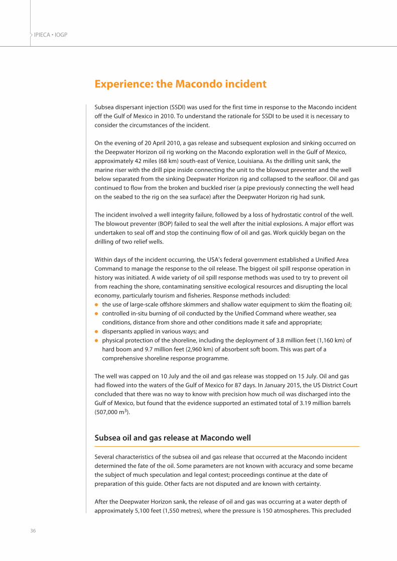
Subsea dispersant injection (SSDI) was used for the first time in response to the Macondo incident
off the Gulf of Mexico in 2010. To understand the rationale for SSDI to be used it is necessary to
consider the circumstances of the incident.
On the evening of 20 April 2010, a gas release and subsequent explosion and sinking occurred on
the Deepwater Horizon oil rig working on the Macondo exploration well in the Gulf of Mexico,
approximately 42 miles (68 km) south-east of Venice, Louisiana. As the drilling unit sank, the
marine riser with the drill pipe inside connecting the unit to the blowout preventer and the well
below separated from the sinking Deepwater Horizon rig and collapsed to the seafloor. Oil and gas
continued to flow from the broken and buckled riser (a pipe previously connecting the well head
on the seabed to the rig on the sea surface) after the Deepwater Horizon rig had sunk.
The incident involved a well integrity failure, followed by a loss of hydrostatic control of the well.
The blowout preventer (BOP) failed to seal the well after the initial explosions. A major effort was
undertaken to seal off and stop the continuing flow of oil and gas. Work quickly began on the
drilling of two relief wells.
Within days of the incident occurring, the USA’s federal government established a Unified Area
Command to manage the response to the oil release. The biggest oil spill response operation in
history was initiated. A wide variety of oil spill response methods was used to try to prevent oil
from reaching the shore, contaminating sensitive ecological resources and disrupting the local
economy, particularly tourism and fisheries. Response methods included:l the use of large-scale offshore skimmers and shallow water equipment to skim the floating oil; l controlled in-situ burning of oil conducted by the Unified Command where weather, sea
conditions, distance from shore and other conditions made it safe and appropriate;l dispersants applied in various ways; andl physical protection of the shoreline, including the deployment of 3.8 million feet (1,160 km) of
hard boom and 9.7 million feet (2,960 km) of absorbent soft boom. This was part of a
comprehensive shoreline response programme.
The well was capped on 10 July and the oil and gas release was stopped on 15 July. Oil and gas
had flowed into the waters of the Gulf of Mexico for 87 days. In January 2015, the US District Court
concluded that there was no way to know with precision how much oil was discharged into the
Gulf of Mexico, but found that the evidence supported an estimated total of 3.19 million barrels
(507,000 m3).
Subsea oil and gas release at Macondo well
Several characteristics of the subsea oil and gas release that occurred at the Macondo incident
determined the fate of the oil. Some parameters are not known with accuracy and some became
the subject of much speculation and legal contest; proceedings continue at the date of
preparation of this guide. Other facts are not disputed and are known with certainty.
After the Deepwater Horizon sank, the release of oil and gas was occurring at a water depth of
approximately 5,100 feet (1,550 metres), where the pressure is 150 atmospheres. This precluded
IPIECA • IOGP
36
Experience: the Macondo incident
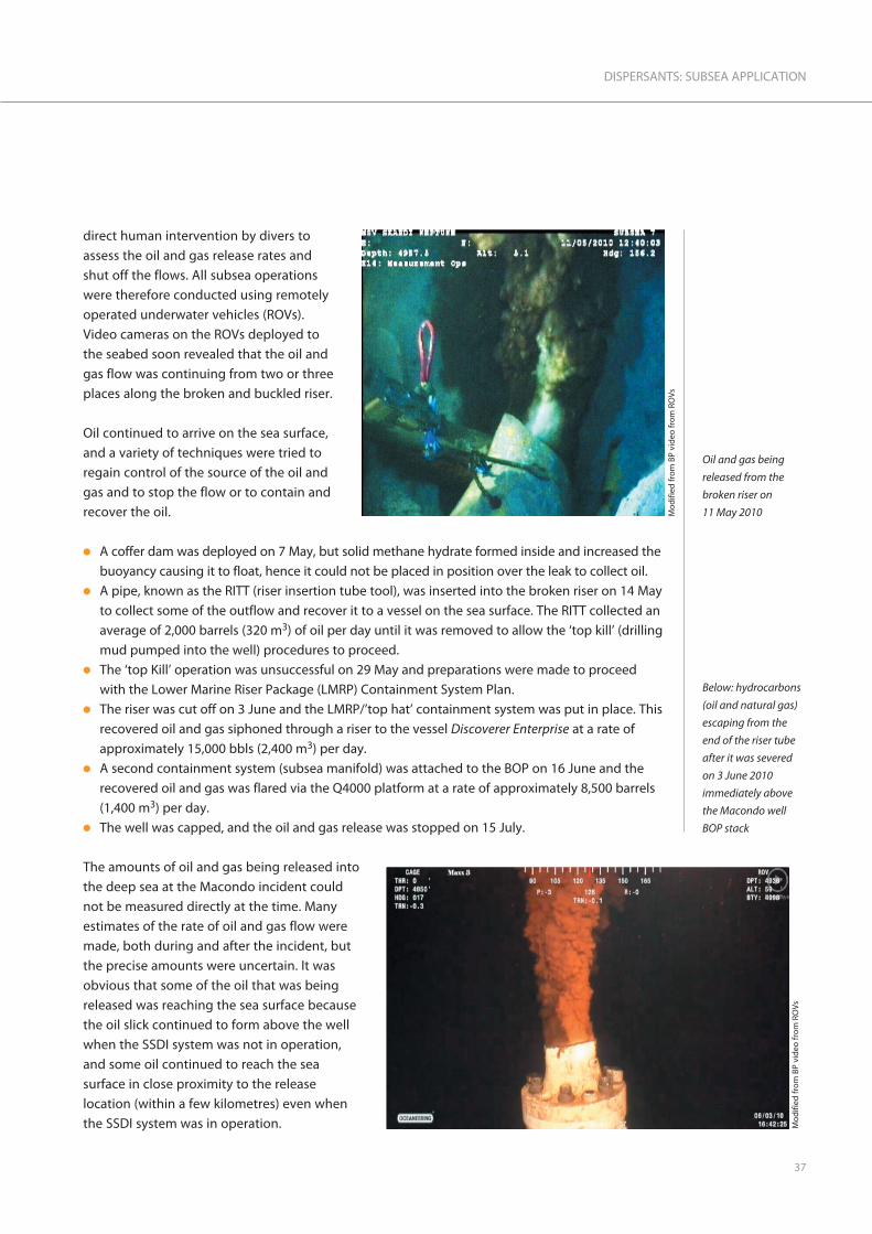
direct human intervention by divers to
assess the oil and gas release rates and
shut off the flows. All subsea operations
were therefore conducted using remotely
operated underwater vehicles (ROVs).
Video cameras on the ROVs deployed to
the seabed soon revealed that the oil and
gas flow was continuing from two or three
places along the broken and buckled riser.
Oil continued to arrive on the sea surface,
and a variety of techniques were tried to
regain control of the source of the oil and
gas and to stop the flow or to contain and
recover the oil.
l A coffer dam was deployed on 7 May, but solid methane hydrate formed inside and increased the
buoyancy causing it to float, hence it could not be placed in position over the leak to collect oil.l A pipe, known as the RITT (riser insertion tube tool), was inserted into the broken riser on 14 May
to collect some of the outflow and recover it to a vessel on the sea surface. The RITT collected an
average of 2,000 barrels (320 m3) of oil per day until it was removed to allow the ‘top kill’ (drilling
mud pumped into the well) procedures to proceed.l The ‘top Kill’ operation was unsuccessful on 29 May and preparations were made to proceed
with the Lower Marine Riser Package (LMRP) Containment System Plan.l The riser was cut off on 3 June and the LMRP/’top hat’ containment system was put in place. This
recovered oil and gas siphoned through a riser to the vessel Discoverer Enterprise at a rate of
approximately 15,000 bbls (2,400 m3) per day.l A second containment system (subsea manifold) was attached to the BOP on 16 June and the
recovered oil and gas was flared via the Q4000 platform at a rate of approximately 8,500 barrels
(1,400 m3) per day.l The well was capped, and the oil and gas release was stopped on 15 July.
The amounts of oil and gas being released into
the deep sea at the Macondo incident could
not be measured directly at the time. Many
estimates of the rate of oil and gas flow were
made, both during and after the incident, but
the precise amounts were uncertain. It was
obvious that some of the oil that was being
released was reaching the sea surface because
the oil slick continued to form above the well
when the SSDI system was not in operation,
and some oil continued to reach the sea
surface in close proximity to the release
location (within a few kilometres) even when
the SSDI system was in operation.
37
DISPERSANTS: SUBSEA APPLICATION
Mod
ified
from
BP
vide
o fr
om R
OVs
Oil and gas being
released from the
broken riser on
11 May 2010
Mod
ified
from
BP
vide
o fr
om R
OVs
Below: hydrocarbons
(oil and natural gas)
escaping from the
end of the riser tube
after it was severed
on 3 June 2010
immediately above
the Macondo well
BOP stack

The oil slicks and sheens on the sea surface then began to break up and drift away under the
effects of the prevailing winds and currents. However, water sampling showed that a proportion of
the oil released at the source did not subsequently arrive on the sea surface and was being
dispersed into the water column, both by the inherent mixing energy of the release and by the
SSDI system.
The oil was not being released as a continuous stream of liquid. Instead, due to the turbulence
created by the release conditions, the oil and gas were being released into the water as a plume of
small oil droplets and gas bubbles. The size distribution of the oil droplets and gas bubbles
produced would have been a function of several parameters including:l the flow rates of the gas and oil, and the gas-to-oil ratio;l the pressures and temperatures of the released fluids (the Macondo well was being drilled into
a high-pressure, high-temperature oil and gas reservoir);l the size and configuration of the orifices through which the oil and gas was being released; and l the pressure and temperature of the water into which the oil and gas were being released.
As noted above, some of these parameters are known with certainty and precision, but others can
only be estimated with much less certainty or accuracy. Studies and modelling conducted after the
Macondo incident (for example Socolofsky, 2012), plus measurements made at the time of the
incident and in the months afterward (OSAT, 2010), confirmed the general characteristics of the oil
behaviour previously shown in Figure 4 on page 18.
Dispersant use at the Macondo well
Dispersant use on oil on the sea surface
Aircraft first sprayed dispersant on to floating oil on 22 April. This was done under the direction of
the Federal On-Scene Coordinator (FOSC), and dispersant use had been pre-authorized in the
Regional Response Team’s (RRT’s) oil spill contingency plan. Aircraft sprayed dispersant onto oil
outside a five nautical-mile radius safety exclusion zone imposed around the vessels dealing with
the source control efforts. Dispersant spraying was conducted closer to the source from ships and
boats. The objective was to disperse the floating oil into the water column and also to suppress
the build-up of VOCs in the air so that response personnel would not be exposed to them.
As the oil spill response operation grew, more aircraft were used for spraying dispersant onto the
floating oil. The amount of dispersant sprayed from aircraft one week into the response was
138,024 US gallons (522.5 m3) and was rising rapidly. As response operations continued, there was
growing concern about the quantity of dispersant that might be needed to address surface slicks.
This included concern about the ability to manufacture and buy the volume of dispersant that
might be needed, as well as concern about the potential effects of dispersants on the
environment. Some response workers and members of the public also expressed concern about
the potential for people to be exposed to dispersant chemicals or dispersed oil.
IPIECA • IOGP
38

Consideration of subsea dispersant use
More effective ways of using dispersant were evaluated. Adding dispersant subsea, directly to the
oil as it was released, was considered. Subsea dispersant addition could have several possible
advantages: l It would enhance the safety of the oil spill response and source control efforts by reducing the
amount of oil on the sea surface. This would reduce the potential exposure of response
personnel on the surface vessels to VOCs evaporating from the oil.l It would reduce the need for subsequent at-sea containment and recovery, controlled in-situ
burning, surface dispersant use and shoreline protection/treatment by reducing the amount of
floating oil.l It would have a higher encounter rate compared to spraying dispersant onto floating oil. The
dispersant would be effective at lower treatment rates and this could reduce the total amount of
dispersant needed for the response.l It would be able to proceed continuously day and night (24/7) while dispersant could only be
sprayed from aircraft during daylight hours.l It would not be affected by the majority of inclement weather and sea conditions that would
prevent or limit other at-sea response methods.
However, there were also many uncertainties and questions about subsea dispersant addition,
including:l Subsea dispersant addition had never been done before. Would it work? And if it did, what
would be the consequences?l What would be the long-term effects of subsea dispersant use?
l What would be the effects of generating large amounts of dispersed oil near the source for
prolonged periods of time?l How should a net environmental benefit analysis (NEBA) be conducted if the subsea
environment has not been extensively studied?l Would biodegradation of the dispersed oil occur in the low-temperature water at significant depth?
l If biodegradation did occur, would oxygen be depleted to very low levels?
Testing subsea dispersant use
The regulators (the Federal On-Scene Coordinator for oil spill response (FOSC) and the US EPA)
authorized BP to conduct tests of this new subsea dispersant approach. A series of tests with
limited amounts of dispersant were conducted on 30 April, 2–4 May and 10–11 May.
A series of aerial photographs taken during the tests with subsea dispersant injection conducted
from 9–12 May are presented and discussed in Box 3 on page 40. Although it is difficult to
accurately quantify the total amount of oil on the sea surface from such photographs, they supply
good qualitative evidence of the effect of subsea dispersant use. The photographer was able to
confirm that the observed reduction in surface expression of oil extended beyond the area
covered by the images.
39
DISPERSANTS: SUBSEA APPLICATION

IPIECA • IOGP
40
Box 3 Visual evidence of the effectiveness of SSDI
Imag
es c
opyr
ight
Oce
an Im
agin
g
9 May, 08:52
This photograph was taken prior to dispersant injection.The floating oil above the release source forms acontinuous layer. Oil being released from the brokenriser is constantly rising up through the water columnand arriving on the sea surface.
10 May, 08:40
The same aerial view three hours after dispersant started tobe injected into the oil and gas flowing out of the end ofthe broken riser through a pipe guided in by the ROV.
The area of floating oil is clearly a lot less than that in theprevious photograph. A reasonable interpretation is thatmost of the oil was no longer arriving at the sea surface.
10 May, 17:05
The floating oil after eleven hours of dispersant beinginjected subsea. Only scattered remnants of oil are visibleon the sea surface.
Subsea dispersant injection was then stopped.
11 May, 09:10
This photograph was taken five hours after the subseadispersant injection was stopped, and shows that theextent of the floating oil had increased significantly. Thisindicated that oil that had previously been dispersedsubsea by the dispersant injection was now reaching thesea surface.
12 May, 08:35
Taken 28 hours after dispersant injection had ceased, thisimage shows that the extent of floating oil is similar to thatbefore subsea injection was tested, although the oil is nowdrifting to the north due to changes in the wind.

41
DISPERSANTS: SUBSEA APPLICATION
Subsea dispersant application
Subsea methodDispersant was injected into the oil and gas
flowing out of the end of the broken riser
through a pipe guided in by the ROV until 3
June when the broken riser was removed.
Dispersant was then added to the oil and
gas flowing from the well head and then the
LMRP, until the oil flow was stopped on
15 July.
The dispersant was added by a ‘lance’ or
‘wand’ held by a ROV and guided by the
ROV operator. The live video feeds showed
that the lance was being moved around into
the release of oil and gas, plus the water
that was being entrained in the plume, a
few feet (around 1 m) above the well head
or LMRP. Dispersant addition using lances,
or wands, of various configurations was
tried (see photographs on right).
Subsea dispersant treatment rateSince the oil and gas flow rates were not known and could not be measured, it was not possible to
specify a dispersant treatment rate in terms of the dispersant-to-oil ratio (DOR) that needed to be
achieved. In early tests of the SSDI system in May 2010, dispersant was added at rates ranging
from an average of 4.6 to 10 gal/min (17.4 to 37.9 l/min).
Tests were conducted to determine the most effective application rate within the tested range,
and to evaluate whether the addition of subsea dispersant could reduce the total amount of
dispersant that would be required in the response. These tests considered whether the addition of
dispersant directly into the oil flowing out of the well head would be effective, and whether it
could be effective using a substantially smaller volume of dispersant than the aerial dispersant
team was spraying onto scattered floating oil on a daily basis. These test showed that subsea
application could prevent oil from reaching the sea surface above and in the vicinity of the well.
However, the tested application rate was not sufficient to disperse all of the oil subsea. Some
partially degraded and weathered oil continued to reach the sea surface several kilometres away
from the well, and dispersant spraying from aircraft continued to address that surface oil.
On 26 May, the US EPA and the US Coast Guard (USCG) issued a directive (US EPA, 2010a) requiring
that the total volume of dispersant applied (on oil on the sea surface and subsea) be reduced by
75% from the maximum daily amount being used. The directive ordered the responsible party to
stop using surface dispersants in the absence of prior written authorization from the USCG. It
allowed subsea dispersant use to continue, but only at a maximum of 15,000 gal/day, equivalent
to 10.4 gal/min (39.4 l/min, equivalent to 357 barrels of dispersant/day).
Mod
ified
from
BP
vide
o fr
om R
OVs

Amount of dispersant used
A total of just over 1.8 million gallons (nearly 7,000 m3) of dispersant was used during the response
to the Macondo incident.
More than 40% (771,272 gallons or 2,920 m3) of the total amount of dispersant was injected subsea.
IPIECA • IOGP
42
Table 9 Dispersant used at the Macondo incident
Dispersant used m3US gallons (to nearest thousand)
Sprayed from aircraft
Sprayed from ships
Applied subsea
Totals
976,000
94,000
771,000
1,841,000
3,700
360
2,920
6,980
After the test applications conducted at the end of April and during early May, the daily amount of
subsea dispersant used rose to 15,000 gal/day (55 m3/day) with an average dispersant pump rate
of 10 gal/min (37.9 l/min) (Figure 6). The data in Table 9 and Figure 6 are derived from daily reports
published by BP on their incident website.
After the EPA’s Directive of 26 May, there was a substantial decline in the average daily volume of
dispersant used in the incident response. Surface spraying of dispersants was prohibited on some
days, and authorized at substantially lower daily volumes on other days when it was needed.
During 3–5 June, at the time the riser was removed and the LRMP was fitted, the subsea dispersant
application rate was briefly increased to 20,000 gal/day (76 m3/day), equivalent to 14 gal/min. At
other times, the daily dispersant subsea usage continued at an average rate that varied between
approximately 8,000 to 15,000 gal/day (30 to 55 m3/day), equivalent to 6 to 10.4 gal/min (22.7 to
39.4 l/min), until the oil flow stopped on 15 July.
(�E���
(�E���
#�E���
#�E���
�E���
�
������������� #� (� '� )� �� D� C� F� <�
����
����
����
����
����
���*G
4���
�� ��
! F�
D�
)�
(�
����
����
����
����
����
���*�
' !
Figure 6 Dispersant application subsea during the Macondo incident

Water column monitoring requirements
Subsea dispersant use had never been attempted as an oil spill response method prior to the
Macondo incident, and the use of dispersants in such large quantities as a response was without
precedent. Monitoring of the water column was required to address the questions and concerns
about subsea dispersant use, namely:l Would the subsea addition of dispersant to the oil and gas release work? l If subsea dispersant addition did work, what would be the consequences?
l Where would the plumes of dispersed oil be transported to by the prevailing currents?l What would be the concentrations of dispersed oil in these plumes?l Could these concentrations of dispersed oil cause harm to the marine organisms exposed to
them?l Would biodegradation of the dispersed oil occur in the cold, deep water? l If biodegradation did occur, would it deplete the oxygen in the water to very low levels and
cause harm to marine organisms?
The US EPA required monitoring of subsea dispersant during the response to indicate the overall
effectiveness of the dispersant added. They also wished to have indications of the transport of
dispersed oil in the water column.
On 10 May the US EPA issued a Directive (EPA, 2010b) establishing a three-part monitoring plan
required for subsea dispersant use to proceed. Part 1 monitoring was required to indicate whether
subsea dispersant use was being successful, i.e. dispersing the oil subsea, and employed:l the use of towed fluorimeter (Turner Designs C3 fluorimeter) used at 1 m water depth to
measure the concentrations of oil in water;l particle size analysis using a LISST (laser in-situ scattering and transmissometry) analyser
(Sequoia Scientific, Inc.) at various intervals from the surface to a water depth of 550 m to
measure oil droplet size distributions;l measurements of dissolved oxygen at various intervals from the surface to a water depth of
550 m to detect any oxygen depletion due to biodegradation of oil;l use of a CTD device to measure conductivity, temperature and depth at various intervals from
the surface to a water depth of 550 m;l water sampling from the surface to a water depth of 550 m for PAH (polycyclic aromatic
hydrocarbon) analysis; andl aerial visual observation (weather permitting).
Part 2 monitoring was required when the Part 1 monitoring indicated that subsea dispersant use
was being effective. This extended the required monitoring of Part 1 to be undertaken to the sea
floor at a water depth of 1500 m. In addition, some extra monitoring requirements were added:l cast (i.e. lowered, not towed) fluorimeter measurements, from the surface to the sea floor;l Rototox™ toxicity testing; andl UV-fluorescence testing to detect higher molecular weight (> 3-ring) PAH fractions.
Part 3 outlined the operational procedures for subsurface injection of the dispersant and included
parameters such as the types of dispersant to be used, the rate of dispersant injection, how the
pumping rate will be monitored, and procedures for the FOSC to start and stop injection.
43
DISPERSANTS: SUBSEA APPLICATION
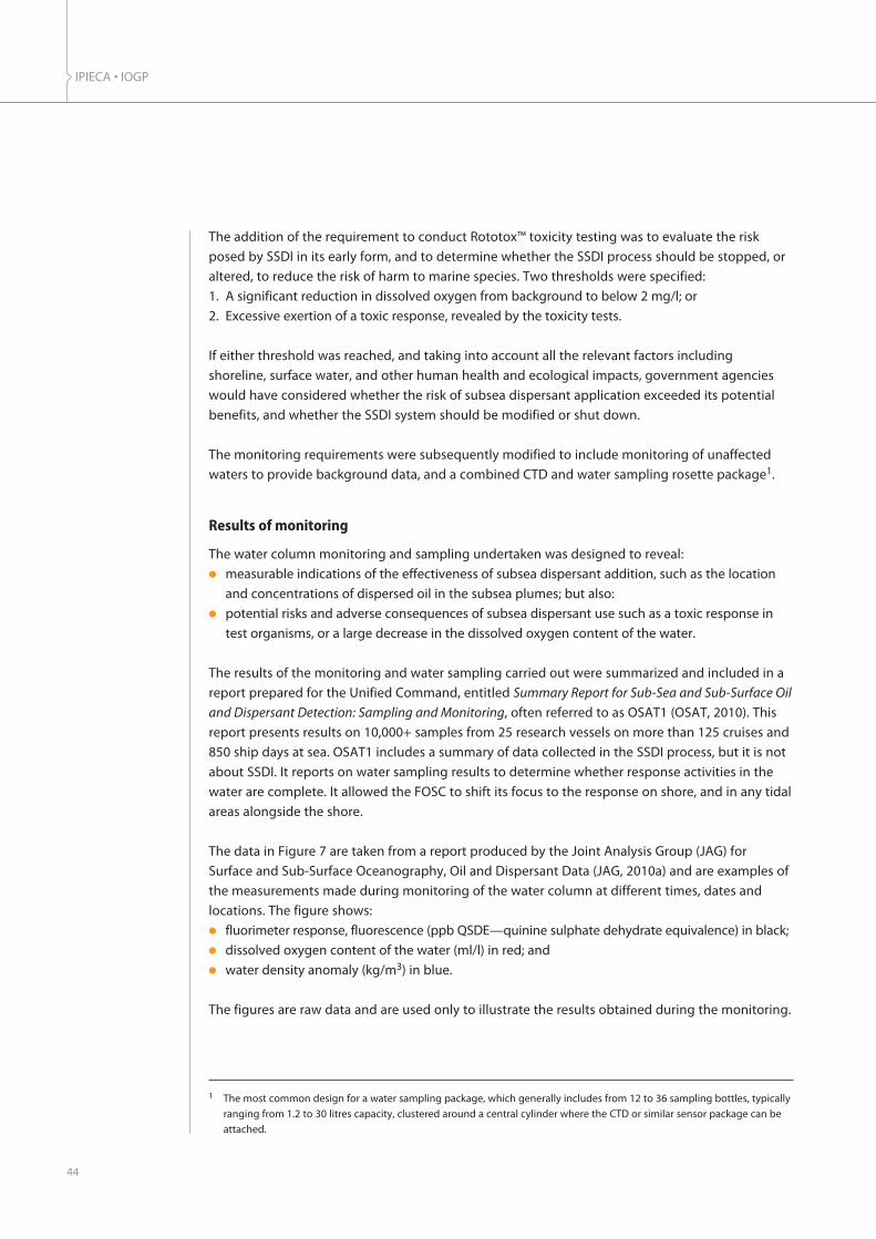
The addition of the requirement to conduct Rototox™ toxicity testing was to evaluate the risk
posed by SSDI in its early form, and to determine whether the SSDI process should be stopped, or
altered, to reduce the risk of harm to marine species. Two thresholds were specified:
1. A significant reduction in dissolved oxygen from background to below 2 mg/l; or
2. Excessive exertion of a toxic response, revealed by the toxicity tests.
If either threshold was reached, and taking into account all the relevant factors including
shoreline, surface water, and other human health and ecological impacts, government agencies
would have considered whether the risk of subsea dispersant application exceeded its potential
benefits, and whether the SSDI system should be modified or shut down.
The monitoring requirements were subsequently modified to include monitoring of unaffected
waters to provide background data, and a combined CTD and water sampling rosette package1.
Results of monitoring
The water column monitoring and sampling undertaken was designed to reveal:l measurable indications of the effectiveness of subsea dispersant addition, such as the location
and concentrations of dispersed oil in the subsea plumes; but also:l potential risks and adverse consequences of subsea dispersant use such as a toxic response in
test organisms, or a large decrease in the dissolved oxygen content of the water.
The results of the monitoring and water sampling carried out were summarized and included in a
report prepared for the Unified Command, entitled Summary Report for Sub-Sea and Sub-Surface Oil
and Dispersant Detection: Sampling and Monitoring, often referred to as OSAT1 (OSAT, 2010). This
report presents results on 10,000+ samples from 25 research vessels on more than 125 cruises and
850 ship days at sea. OSAT1 includes a summary of data collected in the SSDI process, but it is not
about SSDI. It reports on water sampling results to determine whether response activities in the
water are complete. It allowed the FOSC to shift its focus to the response on shore, and in any tidal
areas alongside the shore.
The data in Figure 7 are taken from a report produced by the Joint Analysis Group (JAG) for
Surface and Sub-Surface Oceanography, Oil and Dispersant Data (JAG, 2010a) and are examples of
the measurements made during monitoring of the water column at different times, dates and
locations. The figure shows:l fluorimeter response, fluorescence (ppb QSDE—quinine sulphate dehydrate equivalence) in black;l dissolved oxygen content of the water (ml/l) in red; andl water density anomaly (kg/m3) in blue.
The figures are raw data and are used only to illustrate the results obtained during the monitoring.
IPIECA • IOGP
44
1 The most common design for a water sampling package, which generally includes from 12 to 36 sampling bottles, typicallyranging from 1.2 to 30 litres capacity, clustered around a central cylinder where the CTD or similar sensor package can beattached.

Fluorimetry measurements and water chemical analysis
As reported by the JAG, dispersed oil (including both oil that is physically dispersed by the
turbulence of the release conditions and oil dispersed as a result of chemically enhanced
dispersion caused by subsea dispersant addition) was detected by fluorimetry as a dilute plume of
dispersed oil at a water depth of approximately 1,200 m, i.e. 300 m above the oil and gas release.
The readings were highest near the release site, generally decreasing with distance, and trending
primarily southwest to the north-east, consistent with the measured water current (JAG, 2010a).
A further JAG report (JAG, 2012) concluded that:l The oil that was detected was classified into volatile fraction hydrocarbons (partly water soluble)
and semi-volatile fraction hydrocarbons. Separately reporting these two classes of hydrocarbons
allowed differences in the fate of these fractions observed early in the spill to be distinguished.
Some evidence shows that the most easily biodegraded fractions of the oil, the volatile fraction
hydrocarbons, were preferentially consumed.l The observed decreases in hydrocarbon concentrations with increasing distance from the well
head were likely due to multiple factors, primarily dilution and biodegradation; other factors,
such as particulate adsorption, could have also contributed to the decreases.l The highest concentration of volatile hydrocarbons detected in water between the depths of
900 m and 1,300 m was 2,112 parts per billion (ppb) found in a sample 1.2 km from the well head.
Beyond 20 km from the well head, volatile hydrocarbon concentrations were below 100 ppb and
values beyond 100 km from the well head were below analytical method detection levels. l The levels of semi-volatile fraction hydrocarbons at depths between 900 m and 1,300 m were
primarily in the 1–10 ppb range at distances of >10 km from the well. The highest semi-volatile
45
DISPERSANTS: SUBSEA APPLICATION
Figure 7 Examples of the many measurements made during monitoring of the water column
$,�-��.���/����������������������02���'#E�(�#��*(F�)(0'���F�6�FF�()0�<<�"!
$,�#/����,������������������������B����#)E�(�#��*(F�)�0#�D<D�6�FF�(�0)�)FD�"!
�
)��
F��
#E(��
#ED��� � #� #� (� (�
(' () (� (D (C (F, ������������������ �����*��H�'!
�5�2��� �������*����I45+!
�5��� ����� .�����*�JHJ!
( ) D
5��
���*�
! &�� .������� ��
�
)��
F��
#E(��
#ED��� � #� #� (� (�
(' () (� (D (C (F, ������������������ �����*��H�'!
�5�2��� �������*����I45+!
�5��� ����� .�����*�JHJ!
( ) D
&�� .������� ��
JAG
, 201
0a

hydrocarbon level in a water sample was 485 ppb, also found in a sample 1.2 km from the well
head. Measurable amounts of semi-volatile hydrocarbons were found 400 km from the well
head; values above 10 ppb were found up to about 275 km from the well head.
Dissolved oxygen measurements
The dissolved oxygen content of the water was depleted to some degree in the vicinity of the
dispersed oil plume, but the subsea dispersant operation did not create any oxygen-depleted
zones that would harm the marine organisms.
Water column sampling and analysis results
Water samples were collected in the locations where fluorimetry had indicated the highest
dispersed oil concentrations, and these water samples were analysed for specific hydrocarbons.
Human health benchmarksHuman health benchmarks developed by the US EPA in coordination with the US Department of
Health and Human Services are used to assess potential human health risks from exposure to
oil-contaminated water. The benchmark consists of screening levels for a number of compounds,
including VOCs, PAHs and metals.
A total of 11,634 (6,090 nearshore, 750 offshore and 4,794 in deep water) samples were analysed
for comparison to the human health benchmark. None of samples exceeded the EPA benchmark.
Aquatic life benchmarksThe EPA established benchmark ‘levels of concern’ for PAH concentrations in water and sediment
to screen for potential adverse impacts on aquatic life. The water samples were analysed for a total
of 41 oil chemical compounds, including 7 volatile organic compounds, 16 parent PAHs and 18
alkylated homologues of the parent PAHs. Each of the individual chemical compounds were
assigned a potential toxicity so that the cumulative toxicity (acute or chronic) of the mixture of
compounds in each sample could be calculated. These aquatic life benchmarks were established
on the basis of a suite of laboratory toxicity evaluations using contaminated water and various
species, life stages, end points and exposure durations.
A total of 10,578 (6,090 nearshore, 749 offshore and 3,739 in deep water) samples were analysed
for comparison to the aquatic life benchmark. As reported (OSAT, 2010 and OSAT, 2011)
approximately 1% of the total samples were consistent with Macondo oil and above US EPA
benchmarks, with 1% from sediment locations and <1% from water locations.
Dispersant benchmarksThe water samples were analysed for four dispersant constituents:l 2-butoxyethanol (found only in COREXIT® 9527 that was used until May when supply ran out);l dipropylene glycol n-butyl ether (DPnB);l propylene glycol; andl di-iso-octylsulphosuccinate (DOSS).
IPIECA • IOGP
46

Benchmarks, based on dissolved seawater concentrations for the individual compounds, were
used to establish ‘levels of concern’ based on available biological effects data and were
conservatively designed to protect aquatic life.
A total of 10,178 (5,262 nearshore, 682 offshore and 4,334 in deep water) samples were analysed for
comparison to the dispersant benchmark. As reported by OSAT, no exceedances were observed
Toxicity testing
Laboratory testing done using the standard Rototox™ protocols and Macondo crude oil dispersed
with COREXIT® 9500A indicated that the LC50 value for the rotifer, B. plicatilis was in the range of
10 to 17 ppm. The highest observed total petroleum hydrocarbons (TPH) values in the field where
toxicity tests were conducted were considerably less than this. It is therefore not surprising that no
signs of toxic response were revealed in the Rototox™ toxicity testing conducted as Part 2 of the
required water column monitoring.
In addition, toxicity tests were also conducted on various benthic and pelagic species (Table 10).
47
DISPERSANTS: SUBSEA APPLICATION
Table 10 Tests carried out on various benthic and pelagic species during the Macondo incident
Sample type Test type Duration End point No. of tests
Survival
Survival, growth,biomass
Survival
Survival, growth,fecundity, biomass
Survival
Fertilization
Survival, embryodevelopment
Growth
Growth
Survival, growth
Survival, growth,reburial
Survival
Survival
Survival, growth
Fertilization/embryodevelopment
126
36
93
30
88
2
20
68
68
74
505
112
256
65
66
96 hours
7 days
96 hours
7 days
7 days
2 hours
48 hours
96 hours
96 hours
96 hours
10 days
10 days
48 hours
96 hours
60 minutes/ 48 hours
Fish
Mysid shrimp
Pink shrimp
Sea urchin
Mollusc
Diatom
Algae
Amphipod
Worm
Mysid
Sea urchin
Water
Sediment
Sour
ce: O
SAT,
201
1

A total of 3,548 toxicity tests were conducted during the spill and the associated response, making
it the most extensive testing programme ever conducted to characterize the effects of an oil spill
in the marine environment. Overall, 90% of these tests showed no statistically significant effects.
None of the concentrations of dispersant-related constituents found in the sediment and water
samples collected after 3 August 2010 in the nearshore zone exceeded the US EPA’s chronic
aquatic benchmarks (OSAT, 2011).
Addressing concerns over seafood
To address concerns about the potential effect of oil and dispersants on seafood, in June 2010,
the National Oceanic and Atmospheric Administration (NOAA) and the US Food and Drug
Administration (FDA), in consultation with the US EPA and the Gulf states, agreed to an extensive
sampling and testing procedure. Areas once closed to fishing were reopened only when all
seafood sampled in the area passed both the established sensory and chemical testing. While
initial testing was focused on oil contaminants, in October 2010, the FDA and NOAA created a
new test that could detect traces of dispersant constituents in fish tissue (US FDA, 2010). Every
sample tested was well below FDA levels of concern, with 99% of the samples showing no
detectable residue.
To date, none of the seafood tested by the FDA, NOAA and the Gulf states has exceeded the
FDA’s human health thresholds. Gulf of Mexico seafood is among the most rigorously tested
sources of seafood on the US market. Since May 2010, the FDA, NOAA and the Gulf states have
tested more than 10,000 finfish and shellfish specimens, and levels of PAH in seafood have
consistently tested 100 to 1,000 times lower than FDA safety thresholds (US FDA, 2012).
Natural Resource Damage Assessment
In the USA, the Oil Pollution Act of 1990 addresses environmental impacts from a spill through two
types of activities:l Response: actions taken to contain and remove oil from the water and shoreline, and minimize
damage to the public health and welfare.l Restoration: actions taken to restore or replace injured natural resources and compensate the
public for temporary lost use of those resources.
Scientists working on response and natural resource assessment and restoration actions were in
the field within days after the incident occurred, collecting data that would be used to evaluate
the potential impact of oil and dispersants on wildlife and habitats, as well as lost recreational use
of these resources. This was the start of the Natural Resource Damage Assessment (NRDA)—the
largest such environmental assessment ever performed. By early 2015, NRDA scientists had
conducted more than 240 studies including investigations of potential benthic impacts. Data analysis
and potential injury assessment were still under way at the time of preparation of this guide.
IPIECA • IOGP
48

The basic operations of subsea dispersant use are as follows:l A surface vessel is used to transport a supply of dispersant and the required application
equipment to the site of the subsea oil release.l The equipment is deployed and, if possible, subsea monitoring is conducted to characterize the
subsea oil release.l Dispersant is pumped from the surface to a subsea manifold. A jumper from the manifold is
connected to a nozzle held by a remotely operated vehicle (ROV) located close to the release.l The ROV positions the nozzle to inject dispersant directly into the flow of oil or as close to the
release point as possible. l Dispersant is pumped at a controlled rate from the deck of the surface vessel through the nozzle
and into the oil.l The subsea dispersant use is monitored to assess whether it is being effective and to provide
information about the locations of dispersed oil plumes in the water column and their potential
risk to marine organisms.
Equipment needs
The first step is to mobilize the necessary equipment to the well source-control location. Table 11
presents an example preparedness checklist to assist in mobilizing the appropriate resources.
49
DISPERSANTS: SUBSEA APPLICATION
Operational aspects—an overview
Table 11 Example preparedness checklist for subsea dispersant injection
Resource type Specific equipment, supplies or other items
l Offshore construction vessel to transport and deploy subsea dispersant injectionsystem, and dispersant supply shuttle vessel(s) to transport dispersant supply
l Dispersant
l Multiple ROVS to assist in installation/operation l Coil tubing unit l Subsea manifoldl Dispersant pumping system l Vessel-to-vessel hose and equipment for refilling dispersant storage tanks
l Research vessell Specialized instrumentation for conducting monitoring of subsea dispersant
injection operationl Science team to support monitoring operation
l Installation/operation procedures customized for the responder’s vessel(s)
l Dispersant deployment plan (ISO tanks to vessel) l Dispersant injection plans (ratio of oil flow to dispersant injection or DOR) l Transfer plan for restocking pumping operations l Dispersant monitoring planning l Contingency planning for installation
l Staging/sequencing plan for arrival of dispersant tanks at shore base l Ensure vessel charter agreements include dispersant
l Agreement with dispersant supplier to purchase additional dispersant
Vessel
Chemical supplies
Operating equipment
Subsea dispersantmonitoring kit
Procedures
Planning/procedures
Planning
Agreements
Cou
rtes
y of
MW
CC

Dispersant stockpiles
Dispersant stockpiles are maintained worldwide as part of Oil Spill Response Limited’s (OSRL’s)
global dispersant stockpile (GDS) of 5,000 m3 (or 5 million litres) of dispersant. The stockpiles are
positioned to enable quick access to dispersants and to ensure that sufficient stock can be
mobilized for an individual spill response incident. Access to the GDS is available to all of OSRL’s
members who sign the GDS supplementary agreement. Other response organizations such as the
Marine Well Containment Company (MWCC) in the Gulf of Mexico and the Australian Marine Oil
Spill Centre (AMOSC) in Australia have also developed site-specific dispersant stockpiles.
Deployment of SSDI equipment
Once the SSDI equipment arrives on-scene at the source-control area, the dispersant supply vessel
is positioned on the surface above the well head. Due to other operations that may be occurring
near the well head (e.g. cap and containment activities, debris removal, relief well drilling, etc.), all
vessels and activities must be carefully coordinated through a central command system known as
Simultaneous Operations command (SIMOPS). SIMOPS exists to coordinate all activities on the
ocean surface and subsea to ensure the safety of all vessels that are operating in close proximity.
After the vessel is in position, surface dispersant hoses are attached to the dispersant supply tanks.
The dispersant manifold and clump weights with the coiled tubing are then deployed from the
vessel. ROVs are used to connect the various components of the subsea dispersant injection system.
IPIECA • IOGP
50
SWRP
/SW
IS
Figure 8 The SWIS subsea first response toolkit
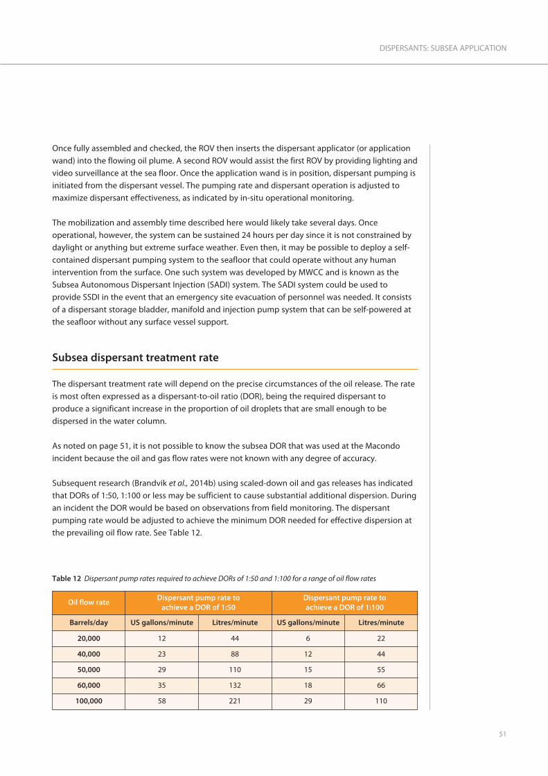
Once fully assembled and checked, the ROV then inserts the dispersant applicator (or application
wand) into the flowing oil plume. A second ROV would assist the first ROV by providing lighting and
video surveillance at the sea floor. Once the application wand is in position, dispersant pumping is
initiated from the dispersant vessel. The pumping rate and dispersant operation is adjusted to
maximize dispersant effectiveness, as indicated by in-situ operational monitoring.
The mobilization and assembly time described here would likely take several days. Once
operational, however, the system can be sustained 24 hours per day since it is not constrained by
daylight or anything but extreme surface weather. Even then, it may be possible to deploy a self-
contained dispersant pumping system to the seafloor that could operate without any human
intervention from the surface. One such system was developed by MWCC and is known as the
Subsea Autonomous Dispersant Injection (SADI) system. The SADI system could be used to
provide SSDI in the event that an emergency site evacuation of personnel was needed. It consists
of a dispersant storage bladder, manifold and injection pump system that can be self-powered at
the seafloor without any surface vessel support.
Subsea dispersant treatment rate
The dispersant treatment rate will depend on the precise circumstances of the oil release. The rate
is most often expressed as a dispersant-to-oil ratio (DOR), being the required dispersant to
produce a significant increase in the proportion of oil droplets that are small enough to be
dispersed in the water column.
As noted on page 51, it is not possible to know the subsea DOR that was used at the Macondo
incident because the oil and gas flow rates were not known with any degree of accuracy.
Subsequent research (Brandvik et al., 2014b) using scaled-down oil and gas releases has indicated
that DORs of 1:50, 1:100 or less may be sufficient to cause substantial additional dispersion. During
an incident the DOR would be based on observations from field monitoring. The dispersant
pumping rate would be adjusted to achieve the minimum DOR needed for effective dispersion at
the prevailing oil flow rate. See Table 12.
51
DISPERSANTS: SUBSEA APPLICATION
Table 12 Dispersant pump rates required to achieve DORs of 1:50 and 1:100 for a range of oil flow rates
Oil flow rateDispersant pump rate to
achieve a DOR of 1:50Dispersant pump rate toachieve a DOR of 1:100
US gallons/minute Litres/minute US gallons/minute Litres/minuteBarrels/day
20,000
40,000
50,000
60,000
100,000
12
23
29
35
58
44
88
110
132
221
6
12
15
18
29
22
44
55
66
110

Purposes of subsea monitoring and sampling
Monitoring of a subsea dispersant operation
Although SSDI is an effective response method, some of the oil may rise to the surface where more
traditional oil spill monitoring techniques, such as the use of the SMART (Special Monitoring of
Applied Response Technologies) protocols, can be used. Subsea monitoring programmes,
therefore, will likely be implemented in conjunction with surface oil monitoring programmes.
The API has developed guidance for industry that is concerned primarily with operational
monitoring (API, 2013). Its focus is to collect real-time or near real-time monitoring data that can
be used to inform operational decisions for the current day or the next day. Monitoring data that
takes days to collect and analyse does not support operational decision making. The API guidance
groups monitoring activities into three phases which address:
IPIECA • IOGP
52
Figure 9 Testing of Oseberg crude oil with, and without, dispersant added (source: SINTEF)
(a)
(i) (ii)
(b) (c)
Left: testing of Oseberg crude oil with:
(a) no COREXIT® 9500 dispersant
(b) a DOR of 1:100
(c) a DOR of 1:50
The jars show the sampled water with:
(i) no dispersant
(ii) a DOR of 1:100
The graph below compares droplet size
(a) when no dispersant is used; and
(b) with a DOR of 1:100.
#(
#�
F
D
)
(
�
� ��
���
����
�����
� ��
*� �
K!
'0F #�0( (C0C C)0C (#<�� ����������*L�!
��������������� � �����������
������� ����*�������� ��������������������� ����!
� ����� ����*�������� ������!

l the assessment of subsea dispersant use effectiveness;l characterization of the nature and extent of subsea, or near-surface, dispersed oil plumes; andl an initial assessment of potential ecological effects as they relate to operational response
decision making.
These phases are initiated in the order listed below, but each phase is based on information
produced by the one that preceded it. Each phase is intended to be implemented on a time line
that parallels the deployment of subsea dispersant injection resources during the response phase.
Phase 1: Assessment of subsea dispersant effectiveness
The initial question that must be answered by the subsea monitoring programme is, ‘Is SSDI likely
to be effective?’
Initially, monitoring at the release point is required to characterize the nature of the subsea oil
release, estimate the oil and gas flow rates, and determine the properties and behaviour of the
released oil. This information serves as pre-dispersant application background data and is used to
guide the selection of dispersant injection methods and application rates.
Dispersant effectiveness can be estimated by comparing baseline data collected prior to
dispersant application (i.e. visual appearance, air and water quality data) with data collected after
initiation of dispersant application. Dispersant effectiveness can be assessed:l Visually, by examining the output from video cameras on ROVs to assess whether the shape or
colour of the oil discharge changes with dispersant addition.l Acoustically, by analysing backscatter data generated from a ROV-mounted sonar. Sonar imaging
of the jet of oil before and after dispersant injection can also give an indication of dispersant
effectiveness. This is because sonar at the appropriate wavelength should give a strong backscatter
signal prior to injection of dispersant and a much weaker backscatter signal after injection. l Visually, by analysing the area of oil on the sea surface in aerial photographs. Aerial photography
should be conducted before and during the subsea injection of dispersant to determine whether
the use of dispersant is reducing the amount of oil reaching the surface.l By air monitoring for VOCs and percentage lower explosive limit (LEL) on vessels in close
proximity to the well site before and after dispersant addition.
None of these techniques taken individually can directly quantify dispersant effectiveness, but
collectively, the data produced can provide sufficient evidence to support operational decisions to
continue or modify dispersant use. Note that changes in surface expression of the oil will take time
to express depending on surface winds/currents and the expected rise time of oil through the
water column.
Phase 2: Characterization of the nature and extent of subsea, or near surface, dispersed
oil plumes
Once it is assessed that SSDI is effective, the next phase of monitoring seeks to define the
magnitude and behaviour of subsea dispersed oil plumes. The purposes of this monitoring phase
are to:
53
DISPERSANTS: SUBSEA APPLICATION
l determine the location, extent, and characteristics of the dissolved and dispersed oil within the
water column;l characterize the lateral and vertical movement of the dissolved and dispersed oil; and l document changes in the concentration of oil as it moves away from the source.
Local oceanographic data together with hydrodynamic models, if available, will determine the
likely direction of movement of the subsurface oil.
Water column monitoringThe primary monitoring strategy involves using a research vessel outfitted with an A-frame and
winch to conduct sampling casts using a CTD instrument and rosette sampler. The CTD is outfitted
with a fluorimeter, dissolved oxygen sensor, and a deep-water laser-light scattering particle size
analyser (e.g. LISST).
Using this strategy, water samples are collected and stored for subsequent detailed chemical
analysis from depths determined by the results of the CTD casts for selected stations. Water
samples for shipboard dissolved oxygen measurements should be collected at depths above, in
and below any observed increase in fluorimetric response.
A laser-light scattering particle size analyser provides real-time in-situ measurements of the
dispersed oil droplet size distribution. A significant shift from larger to smaller droplets sizes is
indicative of dispersion of the oil.
Water samplingThe determination of water sampling site locations should be based on information from a reliable
3-D subsea oil spill model. If no such models are available, a sampling grid should be developed
and centred on the spill location. Stations should be established in a radial pattern moving out
from the centre, and fluorimeter readings from CTD casts and light scattering measurements
should be used to determine the path of the dispersed oil.
Following retrieval of the instruments, the water samples should be transferred into suitable
containers and stored until subsequent analysis.
Phase 3: Initial assessment of potential for ecological effects
This phase of monitoring seeks to fully characterize all water samples collected by CTD casts, using
state-of-the-art laboratory analytical techniques for petroleum analytes and dispersant marker
analysis. Once water samples are collected, they must be returned to land for rapid transfer to a
certified, accredited laboratory utilizing appropriate chain-of-custody procedures. Vessel transit
time, sample transfer time and laboratory processing can equate to a minimum of five days to
process a sample, depending on the incident location. In the case of a larger spill event where
significant numbers of samples are collected, it could take at least 7–10 days to receive detailed
analytical results that have met quality assurance and control (QA/QC) standards. It is unlikely that
many locations in the world would have sufficient laboratory facilities to sustain the level of
toxicology and analytical chemistry required during the water sampling and monitoring phase of
the dispersant response to the Macondo incident.
IPIECA • IOGP
54

The reason for using dispersants, whether applied to oil floating on the surface or to a subsea
release, is the same: to minimize the overall ecological and socio-economic damage, by preventing
the released oil from drifting into nearshore or coastal habitats and onto the shore. Dispersant use
on floating oil causes it to disperse into the upper layer of the water column where it is rapidly
diluted and subsequently biodegraded. Subsea dispersant injection (SSDI) aims to prevent the oil
released subsea from reaching the sea surface by dispersing it into the water close to the release.
This provides a major health and safety benefit by greatly reducing the exposure of personnel
responding near the release site to volatile organic compounds (VOCs).
The experience of subsea dispersant use gained at the Macondo incident in 2010 has shown that
SSDI can be an effective response method for subsea oil and gas blowouts. More oil would have
come ashore if subsea dispersant use had not been undertaken. The challenges of conducting a
response to oil released 5,100 feet (1,550 m) below the sea surface using a method that had never
been used before were considerable. A great deal of ingenuity and expertise were required to
develop subsea dispersant injection (SSDI) into a viable response during the largest oil spill
response ever conducted.
As a response to a subsea oil release, SSDI has many advantages over the strategy of responding
to the released oil after it has reached the sea surface. Using SSDI: l treats the oil at the point of release;l uses less dispersant compared to surface application;l reduces the potential exposure of responders to VOCs and oil;l can be conducted continuously, day and night and in practically any weather conditions, unlike
response methods used on the sea surface.
Using SSDI to disperse released oil into the water column has capabilities and limitations plus
potential benefits and risks. When considering the use of SSDI, or any other response method, the
associated benefits and risks need to be addressed by conducting a net environmental benefit
analysis (NEBA). The addition of dispersant will cause more of the released oil to be produced as
smaller oil droplets that will be diluted in the water column and subsequently biodegraded to a
very large extent. The use of SSDI has the following benefits:l Effectively dispersing the released oil into the water column prevents the oil from reaching the
sea surface, from where it could drift ashore, potentially causing serious damage to oil-sensitive
coastal habitats and disrupting socio-economic activities.l Dispersing the oil into the water as small oil droplets permits rapid colonization by petroleum
degrading microorganisms that occur naturally in ocean environments. These microorganisms
will substantially biodegrade the majority of the oil within days and weeks. The dispersant will
also be biodegraded.
However, increasing the amount and concentrations of dispersed oil in the water increases the risk
of potential harm to marine organisms by exposure to dispersed oil, particularly in the vicinity of
the source.
The trade-offs involved in using SSDI need to be understood by all concerned and, ideally, should
be addressed during oil spill contingency planning.
55
DISPERSANTS: SUBSEA APPLICATION
Conclusion

The logistics of conducting SSDI require considerable specialist equipment, trained personnel and
support. Multiple ROVs will be required with dedicated offshore supply vessels. Subsea dispersant
use requires subsea monitoring to assess whether it is effective and where the subsea plumes of
oil would be transported by the prevailing deep water currents. To address concerns about the
possibility of toxic effects on marine organisms from the dispersed oil, it may be appropriate to
conduct extensive water monitoring and water-sampling surveys with subsequent chemical
analysis and toxicity testing. This was done at the Macondo incident. Although research is still
under way at the time of preparation of this guide, available data indicate that concerns about
substantial toxicity to marine organisms, oxygen depletion in the water due to biodegradation
and the persistence of dispersant in the water column were demonstrated to be unfounded, and
subsea dispersant use proved to be a very effective spill response tool.
IPIECA • IOGP
56

57
DISPERSANTS: SUBSEA APPLICATION
Annex: Outline of NEBA for four subsea releaseplanning scenarios
Scenario 1
An exploration well suffers loss of control including failure of the blowout preventer. Crude
oil and gas are released, with the oil estimated to be flowing at 3,000 m3 (19,000 bbls) per day.
Summary of NEBA
Evaluate data
With no intervention and under prevailing conditions, modelling predicts an 80% probability
that surfacing spilled oil would reach the shore, with oil reaching the coast after four days.
During this time the spilled oil would become progressively ‘weathered’ and emulsified. The
spilled oil volume would initially decrease due to evaporative loss, but then increase due to
emulsification. This could result in up to 10,000 m3 per day of emulsified oil threatening the
coast after four days. Gas released within the well fluids would dissolve before reaching the
surface.
Predict outcomes
The nearshore and coastal sensitivities are very high and their protection from oil would result
in high environmental benefit. The estuarine mudflat is biologically productive and difficult to
either protect with booms or clean up if oiled. The seabird colony does not contain threatened
species but adds to the attraction of the area for tourists, with daily boat trips. The tourist
resorts are a major part of the regional economy, relying on popular sandy beaches and
watersports. The tourism is seasonal but this scenario falls within the main season. The threat
to beaches would cause significant immediate disruption and has the potential to dent
confidence in the area and reduce future reservations. The inshore fishery is locally important
but economically small in relation to tourism.
l The well is in a water depth of 1,100 m.
l Surfacing oil slicks are drifting towards the
shore under the influence of a prevailing
15-knot wind and surface current.
l A subsea current runs parallel to the coast
l Wave height is around 1.5 m.
l There are fishing grounds closer to the
coast and seagrass beds in shallow water.
l Coastal resources that could be impacted
by the oil include an estuarine mudflat that
supports a large population of wading
birds. An offshore island supports a seabird
colony. There are three popular tourist
resorts in the vicinity.
�������������������������������
������#E�����
�����������
������#����
�������������
����
continued …
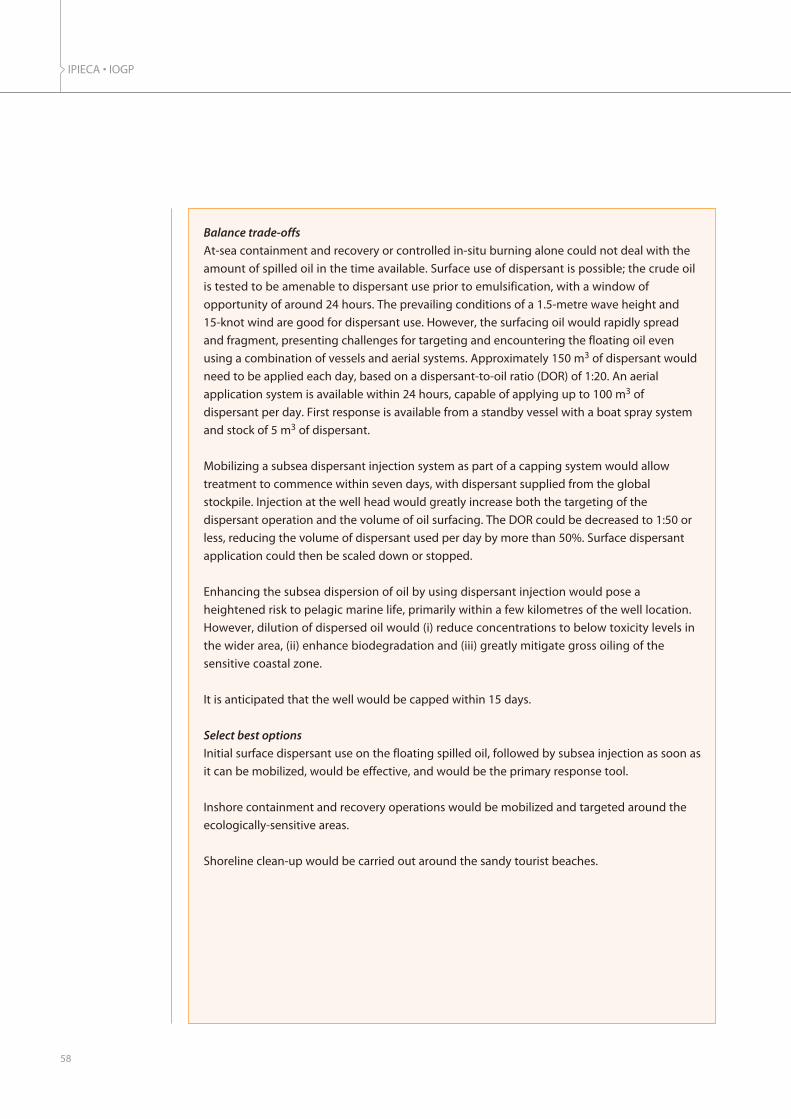
IPIECA • IOGP
58
Balance trade-offs
At-sea containment and recovery or controlled in-situ burning alone could not deal with the
amount of spilled oil in the time available. Surface use of dispersant is possible; the crude oil
is tested to be amenable to dispersant use prior to emulsification, with a window of
opportunity of around 24 hours. The prevailing conditions of a 1.5-metre wave height and
15-knot wind are good for dispersant use. However, the surfacing oil would rapidly spread
and fragment, presenting challenges for targeting and encountering the floating oil even
using a combination of vessels and aerial systems. Approximately 150 m3 of dispersant would
need to be applied each day, based on a dispersant-to-oil ratio (DOR) of 1:20. An aerial
application system is available within 24 hours, capable of applying up to 100 m3 of
dispersant per day. First response is available from a standby vessel with a boat spray system
and stock of 5 m3 of dispersant.
Mobilizing a subsea dispersant injection system as part of a capping system would allow
treatment to commence within seven days, with dispersant supplied from the global
stockpile. Injection at the well head would greatly increase both the targeting of the
dispersant operation and the volume of oil surfacing. The DOR could be decreased to 1:50 or
less, reducing the volume of dispersant used per day by more than 50%. Surface dispersant
application could then be scaled down or stopped.
Enhancing the subsea dispersion of oil by using dispersant injection would pose a
heightened risk to pelagic marine life, primarily within a few kilometres of the well location.
However, dilution of dispersed oil would (i) reduce concentrations to below toxicity levels in
the wider area, (ii) enhance biodegradation and (iii) greatly mitigate gross oiling of the
sensitive coastal zone.
It is anticipated that the well would be capped within 15 days.
Select best options
Initial surface dispersant use on the floating spilled oil, followed by subsea injection as soon as
it can be mobilized, would be effective, and would be the primary response tool.
Inshore containment and recovery operations would be mobilized and targeted around the
ecologically-sensitive areas.
Shoreline clean-up would be carried out around the sandy tourist beaches.
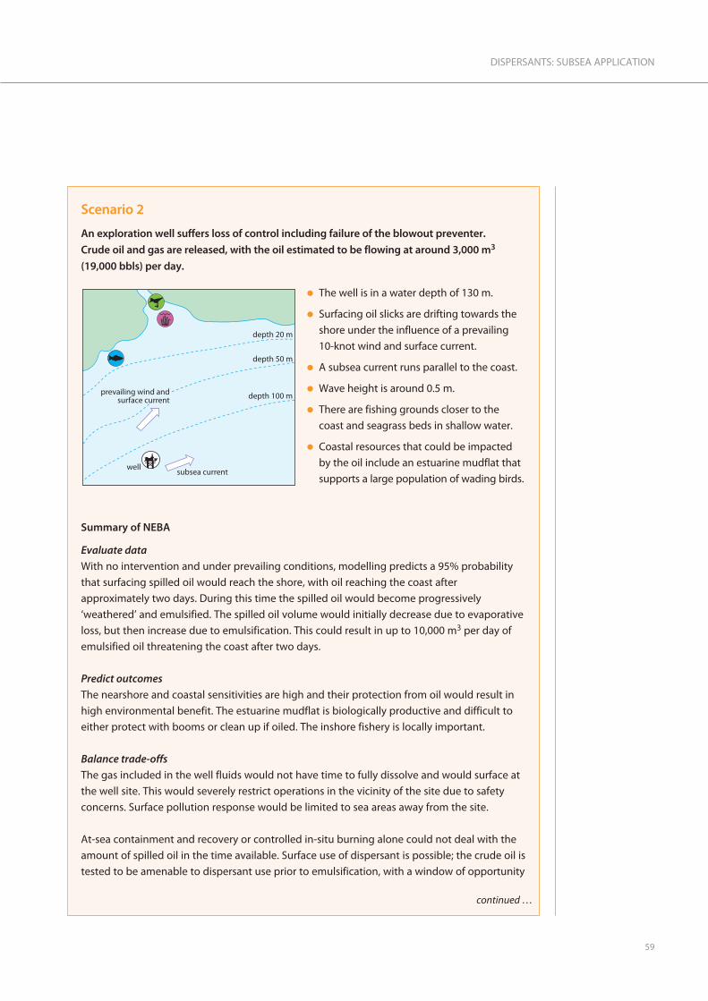
59
DISPERSANTS: SUBSEA APPLICATION
Scenario 2
An exploration well suffers loss of control including failure of the blowout preventer.
Crude oil and gas are released, with the oil estimated to be flowing at around 3,000 m3
(19,000 bbls) per day.
Summary of NEBA
Evaluate data
With no intervention and under prevailing conditions, modelling predicts a 95% probability
that surfacing spilled oil would reach the shore, with oil reaching the coast after
approximately two days. During this time the spilled oil would become progressively
‘weathered’ and emulsified. The spilled oil volume would initially decrease due to evaporative
loss, but then increase due to emulsification. This could result in up to 10,000 m3 per day of
emulsified oil threatening the coast after two days.
Predict outcomes
The nearshore and coastal sensitivities are high and their protection from oil would result in
high environmental benefit. The estuarine mudflat is biologically productive and difficult to
either protect with booms or clean up if oiled. The inshore fishery is locally important.
Balance trade-offs
The gas included in the well fluids would not have time to fully dissolve and would surface at
the well site. This would severely restrict operations in the vicinity of the site due to safety
concerns. Surface pollution response would be limited to sea areas away from the site.
At-sea containment and recovery or controlled in-situ burning alone could not deal with the
amount of spilled oil in the time available. Surface use of dispersant is possible; the crude oil is
tested to be amenable to dispersant use prior to emulsification, with a window of opportunity
l The well is in a water depth of 130 m.
l Surfacing oil slicks are drifting towards the
shore under the influence of a prevailing
10-knot wind and surface current.
l A subsea current runs parallel to the coast.
l Wave height is around 0.5 m.
l There are fishing grounds closer to the
coast and seagrass beds in shallow water.
l Coastal resources that could be impacted
by the oil include an estuarine mudflat that
supports a large population of wading birds.
������������������������������� ������#����
���� �������������
����������
������(���
continued …

IPIECA • IOGP
60
of around 24 hours. The prevailing conditions of a 0.5-metre wave height and 10-knot wind
are good for dispersant use. However, the surfacing oil would spread rapidly and fragment,
especially under the influence of gas within the well fluids, presenting challenges for
targeting and encountering the floating oil even using a combination of vessels and aerial
systems. Approximately 150 m3 of dispersant would need to be applied each day to treat all
the oil, based on a dispersant-to-oil ratio (DOR) of 1:20. An aerial application system is
available within 24 hours, capable of applying up to 100 m3 of dispersant per day. First
response is available from a standby vessel with a boat spray system and stock of 5 m3 of
dispersant. Spraying would be allowed up to the 20-m depth contour in line with national
regulations.
Mobilizing a subsea dispersant injection system may be delayed or restricted by the
presence of gas at the surface. Specific assessments would be carried out to investigate the
feasibility of deploying a subsea injection system. If it was considered feasible, injection at
the well head would greatly increase the targeting of the dispersant operation and reduce by
a large amount the volume of oil surfacing. The DOR could be decreased to 1:50 or less,
which could also lead to a reduction in the volume of dispersant used per day by more the
50%. In this circumstance, the gas lift may bring dispersed oil into the upper water column,
rather than creating a subsea plume. Surface dispersant application could be greatly scaled
down or stopped.
The enhancement of subsea dispersed oil through dispersant injection would pose a
heightened risk to pelagic marine life, primarily within a few kilometres of the well location.
Dilution of dispersed oil would (i) reduce concentrations to below toxicity levels in the
wider area, (ii) enhance biodegradation and (iii) greatly mitigate gross oiling of the sensitive
coastal zone.
Depending on the circumstances, the well would either be capped within 15 days or the flow
stopped when a relief well could be drilled.
Select best options
Initial surface dispersant use on the floating spilled oil, followed by subsea injection if it can
be safely mobilized and deployed, would be an effective part of the response.
Inshore containment and recovery operations would be mobilized and targeted around the
ecologically sensitive inlet. As the area is remote from major population and habitations,
inshore in-situ burning would be mobilized.
Shoreline clean-up options would be considered in the light of the extent and type of coastal
habitats affected.

61
DISPERSANTS: SUBSEA APPLICATION
Scenario 3
An exploration well suffers loss of control including failure of the blowout preventer. Crude
oil and gas are released, with the oil estimated to be flowing at around 2,000 m3 (12,500 bbls)
per day.
Summary of NEBA
Evaluate data
With no intervention and under prevailing conditions, modelling predicts a 0% probability
that surfacing spilled oil would reach the shore. The modelling predicts that a significant
proportion of the subsea release will disperse naturally. Furthermore, surfacing oil will break-
up and dissipate under the prevailing rough sea conditions resulting in only transient surface
oil slicks. Gas released within the well fluids would dissolve before reaching the surface.
Predict outcomes
The nearshore and coastal sensitivities are very high and their protection from oil would result
in high environmental benefit. However, the current prevailing weather conditions indicate
that the coastal resources are not under immediate threat of oiling.
Balance trade-offs
Prevailing rough sea conditions would preclude the use of at-sea containment and recovery
or in-situ controlled burning, leaving subsea dispersant injection and surface dispersant
application as the only viable active response options to treat any floating oil.
������������������������������� ������#E�����
����
�������������
�����������
������#����
l The well is in a water depth of 1,200 m.
l Surfacing oil slicks are drifting away from the
shore under the influence of a prevailing
20–25 knot wind and surface current.
l A subsea current runs parallel to the coast.
l Wave height is around 2.5 m.
l There are fishing grounds closer to the coast
and seagrass beds in shallow water but
these are currently not being threatened.
l However, coastal resources that could be
impacted by the oil if the wind changed
direction include an estuarine mudflat that
supports a large population of wading
birds. An offshore island supports a seabird
colony. There are three popular tourist
resorts in the vicinity.
continued …

IPIECA • IOGP
62
The current predictions are for continuing offshore prevailing winds between 20–25 knots for
the next 3–5 days. Modelling indicates that this will continue to break up any surfacing oil,
without the formation of persistent slicks.
Select best options
Aerial surveillance and monitoring of the offshore area around the release is required to assess
and verify modelling predictions, including the rapid dissipation of any surfacing oil slicks.
The mobilization to a standby condition of subsea dispersant injection and surface application
capability would be undertaken as a precaution. The dispersant option would only be utilized
if the weather abated to the extent that observed persistent surface slicks began to form. The
initial preference would then be to inject dispersant subsea, to provide the most efficient
means to reduce or prevent oil from reaching the surface.
Continual monitoring of the 5–10 day weather forecast would inform any decisions to
mobilize other response tools, including at-sea containment and recovery systems and
shoreline protection capability. However, the locality has persistent offshore winds during the
season in which this incident has occurred, and it is therefore unlikely that these resources will
be needed in the medium term.
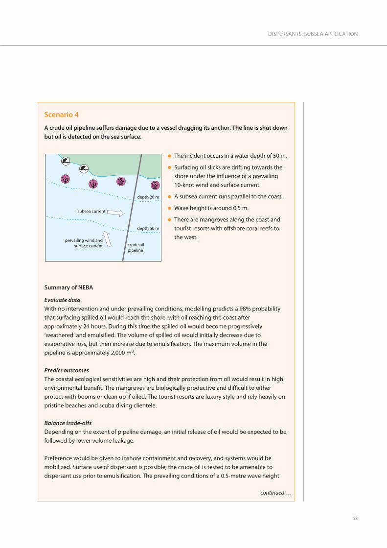
63
DISPERSANTS: SUBSEA APPLICATION
Scenario 4
A crude oil pipeline suffers damage due to a vessel dragging its anchor. The line is shut down
but oil is detected on the sea surface.
Summary of NEBA
Evaluate data
With no intervention and under prevailing conditions, modelling predicts a 98% probability
that surfacing spilled oil would reach the shore, with oil reaching the coast after
approximately 24 hours. During this time the spilled oil would become progressively
‘weathered’ and emulsified. The volume of spilled oil would initially decrease due to
evaporative loss, but then increase due to emulsification. The maximum volume in the
pipeline is approximately 2,000 m3.
Predict outcomes
The coastal ecological sensitivities are high and their protection from oil would result in high
environmental benefit. The mangroves are biologically productive and difficult to either
protect with booms or clean up if oiled. The tourist resorts are luxury style and rely heavily on
pristine beaches and scuba diving clientele.
Balance trade-offs
Depending on the extent of pipeline damage, an initial release of oil would be expected to be
followed by lower volume leakage.
Preference would be given to inshore containment and recovery, and systems would be
mobilized. Surface use of dispersant is possible; the crude oil is tested to be amenable to
dispersant use prior to emulsification. The prevailing conditions of a 0.5-metre wave height
�������������������������������
����������
������(���
�������������
����� ����������
l The incident occurs in a water depth of 50 m.
l Surfacing oil slicks are drifting towards the
shore under the influence of a prevailing
10-knot wind and surface current.
l A subsea current runs parallel to the coast.
l Wave height is around 0.5 m.
l There are mangroves along the coast and
tourist resorts with offshore coral reefs to
the west.
continued …

IPIECA • IOGP
64
and 10-knot wind are good for both recovery and dispersant use. An aerial application system
is available within 6 hours, capable of applying up to 15 m3 of dispersant per day. Spraying
would be allowed up to the 20 m depth contour and more than 2 km away from coral reefs in
line with national regulations.
Mobilizing a subsea dispersant injection system would not be feasible, as there is no suitable
subsea mixing energy from such a pipeline release.
Select best options
Initial surface dispersant use on the floating spilled oil would provide the most rapid
response and provide the best option for protection of the critically important mangrove
habitat. This would be supported by the use of containment and recovery operations inside
the 20-m contour. Preparations would be made for clean-up of tourist resort beaches where
appropriate.

65
DISPERSANTS: SUBSEA APPLICATION
References
Adams, E. E., and Socolofsky, S. A. (2005). Review of Deep Oil Spill Modeling Activity Supported by the
DeepSpill JIP and Offshore Operators Committee. December 2004, revised 2005.
www.researchgate.net/publication/265031649_DEEP_OIL_SPILL_MODELING_ACTIVITY_SUPPORTED_
BY_THE_DEEPSPILL_JIP_AND_OFFSHORE_OPERATORS_COMMITTEE
Al-Sabagh, A. M., El-Hamouly, S. H., Atta, A. M., El-Din, M. R. N. and Gabr, M. M. (2007). Synthesis of
some oil spill dispersants based on sorbitol esters and their capability to disperse crude oil on
seawater to alleviate its accumulation and environmental impact. In Journal of Dispersion Science
and Technology, Vol. 28, Issue 5, pp. 661-670.
American Academy of Microbiology. (2011). Microbes & Oil Spills FAQs. A report from the American
Academy of Microbiology, 1752 N Street, NW Washington, DC 20036. www.asm.org.
Anderson, J., Neff, J., Cox, B., Tatem, H. and Hightower G. M. (1974). Characteristics of dispersions
and water-soluble extracts of crude and refined oils and their toxicity to estuarine crustaceans and
fish. In Marine Biology, Vol. 27, Issue 1, pp. 75-88.
API (2013). Industry Recommended Subsea Dispersant Monitoring Plan. Version 1.0. American
Petroleum Institute (API) Technical Report 1152, September 2013. 20pp.
Atlas, R. M. and Bartha, R. (1992). Hydrocarbon Biodegradation and Oil Spill Bioremediation. In
Advances in Microbial Ecology, Vol. 12, pp. 287–338.
Atlas, R. M. and Cerniglia, C. E. (1995). Bioremediation of Petroleum Pollutants: Diversity and
environmental aspects of hydrocarbon biodegradation. In BioScience, Vol. 45, Issue 5, pp. 332-338.
Brandvik, P. J. and Daling, P.S. (1998). Optimisation of oil spill dispersant composition by mixture
design and response surface methods. In Chemometrics and Intelligent Laboratory Systems, Vol. 42,
pages 63-72. ISSN:0169-7439. DOI:10.1016/S0169-7439(98)00009-4
Brandvik, P. J., Johansen, Ø., Leirvik, F., Farooq, U. and Daling, P. S. (2013). Droplet breakup in
subsurface oil releases – Part 1: Experimental study of droplet breakup and effectiveness of
dispersant injection. In Marine Pollution Bulletin, Vol. 73, Issue 1, pp. 319-326.
doi:10.1016/j.marpolbul.2013.05.020
Brandvik, P. J., Johansen, Ø. and Farooq, U. (2014a). Subsea Release of Oil & Gas – A Downscaled
Laboratory Study Focused on Initial Droplet Formation and the Effect of Dispersant Injection.
International Oil Spill Conference Proceedings: May 2014, Vol. 2014, No. 1, pp. 283-298.
Brandvik, P. J., Johansen, Ø., Farooq, O., Angell, G. and Leirvik, F. (2014b). Subsurface oil releases -
Experimental study of droplet distributions and different dispersant injection techniques Version 2. A
scaled experimental approach using the SINTEF Tower basin. SINTEF report no. A26122.
Trondheim, Norway.
Brochu, C., Pelletier, É., Caron, G. and Desnoyers, J. E. (1986). Dispersion of crude oil in seawater:
the role of synthetic surfactants. In Oil and Chemical Pollution, Vol. 3, No. 4, 257-279.

IPIECA • IOGP
66
Campo, P., Venosa, A. D. and Suidan, M. T. (2013). Biodegradability of COREXIT 9500 and Dispersed
South Louisiana Crude Oil at 5 and 25 °C. In Environmental Science & Technology, Vol. 47, No. 4,
pp. 1960-1967.
Chevron, 2012. Frade Response: Updates and Information on Our Work to Resolve the Frade Field
Incident in Brazil’s Campos Basin. www.chevron.com/fraderesponse
Di Toro, D. M., McGrath, J. A. and Stubblefield, W. A. (2007). Predicting the toxicity of neat and
weathered crude oil: Toxic potential and the toxicity of saturated mixtures. In Environmental
Toxicology and Chemistry, Vol. 26, Issue 1, pp. 24-36.
Farrington, J. (1980). NOAA Ship RESEARCHER/Contract Vessel PIERCE Cruise to IXTOC-I Oil Spill:
Overview and Integrative Data Assessment and Interpretation. A summary and assessment report of
data collected during research cruises in the Gulf of Mexico during the Ixtoc I oil spill. Woods Hole
Oceanographic Institution. www.whoi.edu/oil/ixtoc-I
Fiocco, R. J., Lessard, R. R., Canevari, G. P., Becker K. W. and Daling, P. S. (1995). The Impact of Oil
Dispersant Solvent on Performance. In The use of Chemicals in Oil Spill Response. ASTM STP 1252, P.
Lane, Ed., American Society for Testing and Materials, Philadelphia, USA.
GESAMP (2014). Revised GESAMP Hazard Evaluation Procedure for Chemical Substances Carried by
Ships, 2nd Edition (IMO/FAO/UNESCO-IOC/WMO/IAEA/UN/UNEP/UNIDO/UNDP) Joint Group of
Experts on the Scientific Aspects of Marine Environmental Protection, Rep. Stud. GESAMP No. 64.
www.gesamp.org/publications/publicationdisplaypages/rs64
Hazen, T. C., Dubinsky, E. A., DeSantis, T. Z., Andersen, G. L., Piceno, Y. M., Singh, N., Jansson, J. K.,
Probst, A., Borglin, S. E., Fortney, J. L., Stringfellow, W. T., Bill, M., Conrad, M. E., Tom, L. M.,
Chavarria, K. L., Alusi, T. R., Lamendella, R., Joyner, D. C., Spier, C., Baelum, J., Auer, M., Zemla, M. L.,
Chakraborty, R., Sonnenthal, E. L., D’haeseleer, P., Holman, H-Y. N., Osman, S., Lu, Z., Van Nostrand,
J. D., Deng, Y., Zhou, J. and Mason, O. U. (2010). Deep-Sea Oil Plume Enriches Indigenous Oil-
Degrading Bacteria. In Science, Vol. 330, No. 6001, pp. 204-208. DOI:10.1126/science.1195979.
Heitkamp, M. A. and Cerniglia, C. E. (1987). Effects of chemical-structure and exposure on the
microbialdegradation of polycyclic aromatic-hydrocarbons in freshwater and estuarine
ecosystems. In Environmental Toxicology and Chemistry, Vol. 6, Issue 7, pp. 535-546.
Hemmer, M J., Barron, M. G. and Greene, R. M. (2010). Comparative Toxicity of Eight Oil Dispersant
Products on Two Gulf of Mexico Aquatic Test Species. U.S. Environmental Protection Agency Office of
Research and Development. U.S.EPA/ORD Contributors: National Health and Environmental Effects
Research Laboratory.
IPIECA/IMO/IOGP (2012). Sensitivity mapping for oil spill response. IPIECA-IOGP Good Practice Guide
Series, Oil Spill Response Joint Industry Project (OSR-JIP). IOGP Report 477.
http://oilspillresponseproject.org

67
DISPERSANTS: SUBSEA APPLICATION
IPIECA-IOGP (2014). Regulatory approval of dispersant products and authorization for their use.
Report of the IOGP Global Industry Response Group (GIRG) response to the Macondo incident in
the Gulf of Mexico in April 2010, Oil Spill Response Joint Industry Project (OSR-JIP).
http://oilspillresponseproject.org
IPIECA-IOGP (2015). Dispersants: surface application. IPIECA-IOGP Good Practice Guide Series, Oil
Spill Response Joint Industry Project (OSR-JIP). IOGP Report 532. http://oilspillresponseproject.org
IPIECA-IOGP (2015a). Impacts of oil spills on marine ecology. IPIECA-IOGP Good Practice Guide
Series, Oil Spill Response Joint Industry Project (OSR-JIP). IOGP Report 525.
http://oilspillresponseproject.org
IPIECA-IOGP (2015b). Response strategy development using net environmental benefit analysis (NEBA).
IPIECA-IOGP Good Practice Guide Series, Oil Spill Response Joint Industry Project (OSR-JIP). IOGP
Report 527. http://oilspillresponseproject.org
IPIECA-IOGP (2015c). Contingency planning for oil spills on water. IPIECA-IOGP Good Practice Guide
Series, Oil Spill Response Joint Industry Project (OSR-JIP). IOGP Report 519.
http://oilspillresponseproject.org
IPIECA-IOGP (2016). Impacts of oil spills on shorelines. IPIECA-IOGP Good Practice Guide Series, Oil
Spill Response Joint Industry Project (OSR-JIP). IOGP Report 534.
http://oilspillresponseproject.org/completed-products
JAG (2010a). Review of Preliminary Data to Examine Subsurface Oil In the Vicinity of MC252#1, May 19
to June 19, 2010. Joint Analysis Group (JAG) for Surface and Sub-Surface Oceanography, Oil and
Dispersant Data. http://service.ncddc.noaa.gov/rdn/www/activities/healthy-
oceans/jag/reports/documents/JAG_Data_Report_2_FINAL.pdf
JAG (2010b). Review of R/V Brooks McCall Data to Examine Subsurface Oil. Joint Analysis Group
(JAG) for Surface and Sub-Surface Oceanography, Oil and Dispersant Data.
http://www.noaa.gov/sciencemissions/PDFs/JAG_Report_1_BrooksMcCall_Final_June20.pdf
JAG (2012). Review of Subsurface Dispersed Oil and Oxygen Levels Associated with the Deepwater
Horizon MC252 Spill of National Significance. NOAA Technical Report NOS OR&R 27, pp. 95. Joint
Analysis Group (JAG) for Surface and Sub-Surface Oceanography, Oil and Dispersant Data.
Johansen, Ø., Brandvik, P. J. and Farooq, U. (2013). Droplet breakup in subsea oil releases – Part 2:
Predictions of droplet size distributions with and without injection of chemical dispersants. In
Marine Pollution Bulletin, Vol. 73,Issue 1, pp. 327-335. doi:10.1016/j.marpolbul.2013.04.012
Johansen, Ø., Rye, H. and Cooper, C. (2003). DeepSpill—Field Study of a Simulated Oil and Gas
Blowout in Deep Water. In Spill Science & Technology Bulletin, Vol. 8, Issues 5–6, pp. 433–443.
doi:10.1016/S1353-2561(02)00123-8.

IPIECA • IOGP
68
Johansen, Ø., Rye, H., Melbye, A. G., Jensen, H. V., Serigstad, B. and Knutsen, T. (2001). Deepspill JIP
experimental discharges of gas and oil at Helland Hansen. SINTEF Technical Report, June 2000.
King, G. M., Kostka, J. E., Hazen, T. and Sobecky, P. (2014). Microbial Responses to the Deepwater
Horizon Oil Spill: From Coastal Wetlands to the Deep Sea. In Annual Review of Marine Science, Vol. 7,
pp. 377-401. DOI:10.1146/annurev-marine-010814-015543.
www.annualreviews.org/doi/abs/10.1146/annurev-marine-010814-015543
Kvenvolden, K. A. (2003). Natural seepage of crude oil into the marine environment. In Geo-Marine
Letters, Vol. 23, Issues 3-4, pp.140-146.
Lindstrom, J. E. and Braddock, J. F. (2002). Biodegradation of petroleum hydrocarbons at low
temperature in the presence of the dispersant COREXIT 9500. In Marine Pollution Bulletin, Vol. 44,
Issue 8, pp.739-747.
MacNaughton, S. J., Swannell, R. P. J., Daniel, F. and Bristow, L. (2003). Biodegradation of dispersed
Forties crude and Alaskan North Slope oils in microcosms under simulated marine conditions. In
Spill Science and Technology Bulletin, Vol. 8, Issue 2, pp. 179-186.
Neff, J. M. and Burns, W. A. (1996). Estimation of Polycyclic Aromatic Hydrocarbon Concentrations
in the Water Column Based on Tissue Residues in Mussels and Salmon: An Equilibrium Partitioning
Approach. In Journal of Environmental Toxicology and Chemistry, Vol. 15, Issue 12, pp. 2240–2253.
NOAA (2010). Analysis of Hydrocarbons in Samples Provided from the Cruise of the R/V
WEATHERBIRD II, May 23-26, 2010. National Oceanic and Atmospheric Administration (NOAA), Silver
Spring, Maryland, USA. www.noaanews.noaa.gov/stories2010/.../noaa_weatherbird_analysis.pdf
NRT (2013). Environmental Monitoring for Atypical Dispersant Operations: Including Guidance for:
Subsea Application; Prolonged surface Application. U.S. National Response Team (NRT).
www.nrt.org/production/NRT/NRTWeb.nsf/PagesByLevelCat/Level3Oil?Opendocument
OSAT (2010). Summary Report for Sub-Sea and Sub-Surface Oil and Dispersant Detection: Sampling
and Monitoring. Report prepared by the Operational Science Advisory Team (OSAT), Unified Area
Command, for the US Coast Guard, 17 December 2010.
www.restorethegulf.gov/sites/default/files/documents/pdf/OSAT_Report_FINAL_17DEC.pdf
OSAT (2011) Summary Report for Sub-Sea and Sub-Surface Oil and Dispersant Detection: Ecotoxicity
Addendum. Report prepared by the Operational Science Advisory Team (OSAT), Gulf Coast Incident
Management Team, for the US Coast Guard, 8 July 2011.
www.restorethegulf.gov/sites/default/files/u306/FINAL%20OSAT%20Ecotox%20Addendum.pdf
Prince, R. C. (1997). Bioremediation of marine oil spills. In Trends in Biotechnology, Vol. 15, Issue 5,
pp. 158-160.
Prince, R. C., McFarlin, K. M., Butler, J. D., Febbo, E. J., Wang, F. C. Y. and Nedwed, T. J. (2013). The
primary biodegradation of dispersed crude oil in the sea. In Chemosphere, Vol. 90, Issue 2, pp. 521-526.
69
DISPERSANTS: SUBSEA APPLICATION
Singer, M. E. and Finnerty, W. R. (1984). Microbial metabolism of straight-chain and branched alkanes.
In Atlas, R. M. (Ed.) Petroleum Microbiology, pp. 1-59. Macmillan Publishing Company, New York.
Smith, J. E. (1968). Torrey Canyon Pollution and Marine Life. Cambridge University Press, New York.
Socolofsky, S. A. (2012). Integral plume modeling of subsea accidental oil-well blowouts. Presentation
to the Nearfield Modeling ListServe, 11 June 2012.
https://ceprofs.civil.tamu.edu/ssocolofsky/nfm/Downloads/socolofsky_Jun_11.pdf
US EPA (2010). Comparative Toxicity of Louisiana Sweet Crude Oil (LSC) and Chemically Dispersed LSC
to Two Gulf of Mexico Aquatic Test Species. August 2010 and the updated report of September 2010.
Environmental Protection Agency, Office of Research and Development. Available at:
www.epa.gov/bpspill/dispersants-testing.html
US EPA (2010a). Dispersant Monitoring and Assessment Directive—Addendum 3. US Environmental
Protection Agency Archive Document, 26 May 2010. www.epa.gov/bpspill/dispersants/directive-
addendum3.pdf
US EPA (2010b). Dispersant Monitoring and Assessment Directive for Subsurface Dispersant
Application. US Environmental Protection Agency Archive Document, 10 May 2010.
www.epa.gov/bpspill/dispersants/subsurface-dispersant-directive-final.pdf
US EPA (2012). Ecotoxicity categories for terrestrial and aquatic organisms. (Website—updated on
10 February 2015). www.epa.gov/oppefed1/ecorisk_ders/toera_analysis_eco.htm
US FDA (2010). NOAA and FDA announce chemical test for dispersant in Gulf seafood: all samples test
within safety threshold. US Food and Drug Administration (FDA) website archives. 29 October 2010.
www.fda.gov/NewsEvents/Newsroom/PressAnnouncements/2010/ucm231653.htm
US FDA (2012). Gulf Seafood is Safe to Eat after Oil Spill. ‘FDA Voice’ — the official blog of the US Food
and Drug Administration (FDA), 11 January 2012. http://blogs.fda.gov/fdavoice/?tag=gulf-seafood

IPIECA • IOGP
70
Acknowledgements
This document was authored by Alun Lewis (Alun Lewis Consulting) and Peter Taylor (Petronia).
The authors would like to thank the following for contributing their valuable expertise, input and
advice in developing the content of this document: Gina Coelho (HDR Engineering, Inc.), Richard
Santner (BP), Victoria Broje (Shell), Marty Cramer (ConocoPhillips), Anette Boye (Statoil), Tim Lunel
(ITOPF), Tim Nedwed (ExxonMobil) and Tom Coolbaugh (ExxonMobil).

This page is intentionally blank

This page is intentionally blank

This page is intentionally blank

IOGP represents the upstream oil and gas industry before
international organizations including the International Maritime
Organization, the United Nations Environment Programme (UNEP)
Regional Seas Conventions and other groups under the UN umbrella.
At the regional level, IOGP is the industry representative to the
European Commission and Parliament and the OSPAR Commission for
the North East Atlantic. Equally important is IOGP’s role in
promulgating best practices, particularly in the areas of health, safety,
the environment and social responsibility.
www.iogp.org
IPIECA is the global oil and gas industry association for environmental and
social issues. It develops, shares and promotes good practices and
knowledge to help the industry improve its environmental and social
performance; and is the industry’s principal channel of communication
with the United Nations. Through its member led working groups and
executive leadership, IPIECA brings together the collective expertise of oil
and gas companies and associations. Its unique position within the
industry enables its members to respond effectively to key environmental
and social issues.
www.ipieca.org
© IPIECA-IOGP 2015 All rights reserved.


![Controlled polymers for pigment dispersants€¦ · pigment dispersants [6]. In this contribution acrylic block copolymer type "controlled pigment dispersants" are presented based](https://img.pdfslide.net/doc/110x75/5ea9e9ef0447ea48144fa6b6/controlled-polymers-for-pigment-pigment-dispersants-6-in-this-contribution-acrylic.jpg)