Embed Size (px)
Citation preview
Displacement-based Seismic Design and Experimental Response of a 7-
Story Full-Scale Building
Marios Panagiotou
Assistant Professor Civil and Environmental Engineering
University of California, Berkeley 1

Contents
1. (a) Displacement-based Seismic Design of RC Wall Buildings and
(b) Dual Plastic Hinge Design of Tall RC Buildings
2. Observations from a Shake Table Test of a Full-Scale 7-Story Building Slice
2

1. How important is the interaction between the walls and elements framing to them (slab, gravity system) in RC wall buildings ?
2. Are the effects of higher modes negligible, or should they be accounted for in design ?
3. How well can current seismic design methods estimate structural and nonstructural component response for different hazard levels ?
3

PART I
Displacement-based Seismic Design of RC Wall Buildings
4
Considering the effects of kinematic system overstrength and
higher mode of response

Displacement-based Design for 2 Performance Levels
Immediate Occupancy in frequent EQs Collapse Prevention in rare EQs
Δio
θ1%
Minimize non structural damage Interstory drift θ ≤ 1%
Prevent bar buckling, fracture εs
≤ 5%, εc ≤ 2 %
Δu
εs
εc φu
For the predefined strains φu ≈ 10~15 φy
εs
εc φ
Performance objectives are tunable !
εs : Steel tensile strain εc : Concrete compr. strain
5

Explicit Selection of Mechanism of Inelastic Response – Basic Mechanics
Design to ensure Elastic Response
Δu= Δy+ Δp
H
Δu
Elastic Range :
Δy
Detail to ensure Inelastic Response
φp
Δp
θp
Inelastic Range :
Enough Shear Strength
Which is the Δu corresponding to the predefined objectives ?
6
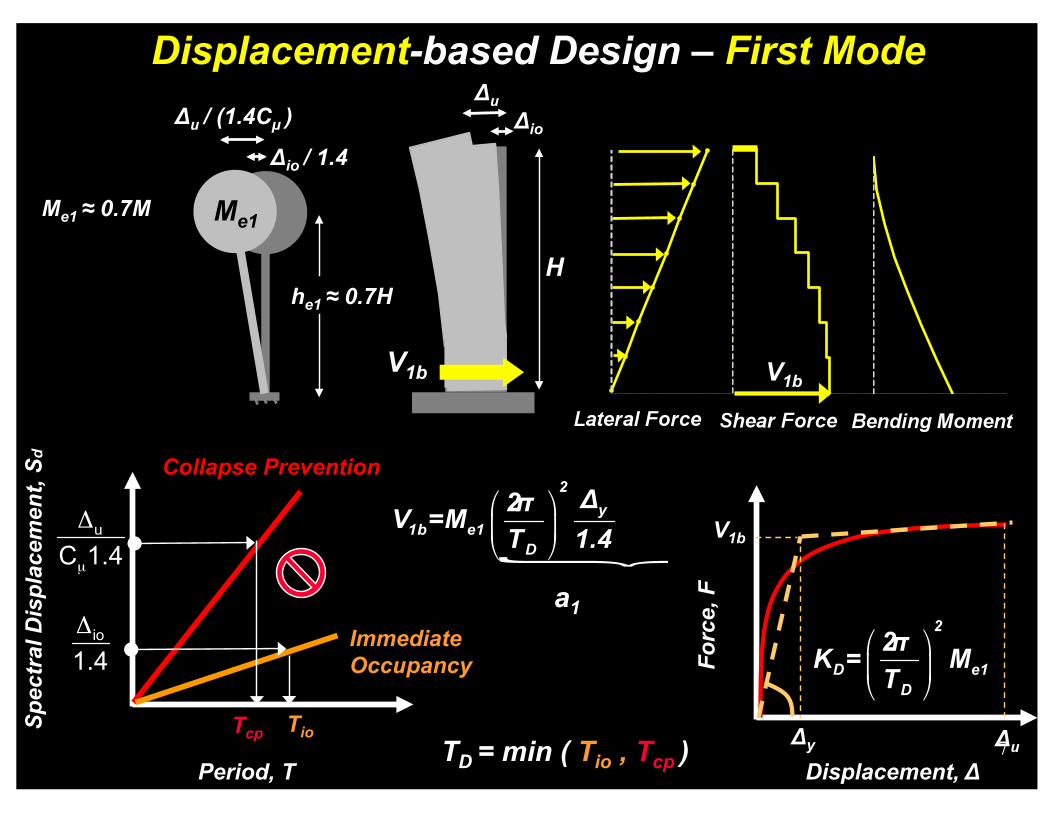
Displacement-based Design – First Mode
Collapse Prevention
Immediate Occupancy
Period, T
Spec
tral
Dis
plac
emen
t, S d
Tio Tcp
V1b
TD = min ( Tio , Tcp )
H
Δu Δio
V1b
a1
Forc
e, F
Displacement, Δ Δy
V1b
Δu
Δu / (1.4Cµ )
Δio / 1.4
Me1 ≈ 0.7M Me1
he1 ≈ 0.7H
7

Kinematic System Overstrength Framing Effects
Lf
1
2
3
floor i
n
Lw
Tensile Chord Growing
Compressive Chord Shortening
8

Kinematic System Overstrength Framing Effects
Lf
1
2
3
n
Lw
The additional lateral forces have to be resisted by the walls !
In a more “aggressive” design we can take advantage of increased OTM capacity
Mf
Vf
Lf
Vf = 2Mf / Lf
Vf
Mf
hi
floor i
9

Displacement-based Design - Static Part
ΩV1b
ΩV1b
ΩV1b+ΔVf
ΩV1b+ΔVf
Mf , Vf For a 7-Story Wall
and Mf = 2%Mbo , Lw=Lf
100% Increase of base shear due to frame action !
ΔVf = V1b
Mbo
Mbo
10
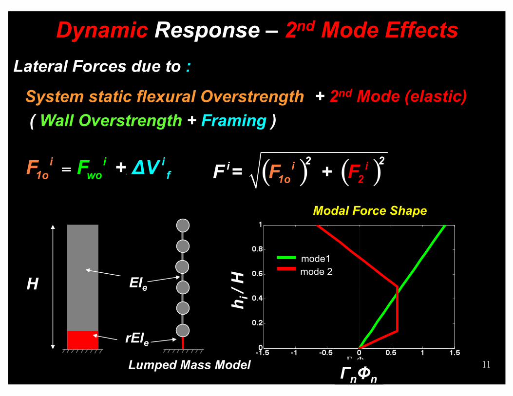
Dynamic Response – 2nd Mode Effects Lateral Forces due to :
System static flexural Overstrength ( Wall Overstrength + Framing )
+ 2nd Mode (elastic)
rEIe
EIe
Lumped Mass Model
H mode1 mode 2
ΓnΦn
h i /
H
Modal Force Shape
11

Summary
ΩV1b+ΔVf
ΩV1b+ΔVf Wall Overstrength +
Framing
ΩV1b
ΩV1b Wall Overstrength
ΩV1b+ΔVf+V2b
ΩV1b+ΔVf+V2b
Wall Overstrength + Framing + 2nd Mode
12

2nd Mode Effects -3 Design Cases of Cantilever Walls
Cantilever Walls
Capacity Design (CD) Elastic response
EC-8 Design Single Plastic Hinge (SPH)
Plastic hinge at base
Dual Plastic Hinge (DPH)
2 potential plastic hinges
CD
CD
Potential plasticity into “elastic” regions ?
ACI-318 Design
Plastic hinge at base
Boundary elements
13

Design and analysis of 10-, 20- and 40-story cantilever walls
for 3 near-fault records
14

Bending Moment Envelopes – Comparison of designs
Reduction of mid-height moment demand with DPH
Large mid-height moment demand with SPH
15

Curvature Ductility Envelopes - Comparison of designs
Large µФ demand in unexpected regions with ACI design
16
Control of inelastic response in two regions with DPH design

PART II
Observations from the UCSD Full-Scale 7-Story Building Slice Shake Table Test
17

Test Structure
7-story building slice with cantilever wall as the lateral force resisting system
Tallest building structure ever tested on a shake table
Single axis of input ground motion in the plane of the wall
Phase 1 Testing: 12ft long rectangular wall
Phase 2 Testing: 14ft-8in long T-wall
Cantilever web wall
PT wall
Gravity columns
63 ft
Flange wall
18

Objective Verify the seismic performance of medium rise RC wall
buildings designed with displacement-based method (DbD)
Los Angeles
V = 0.15 W (Te=1.05 sec)
Displacement-based Design Te=1.05 sec
ASCE-7: Force-based Design – Site Class C less than 2 km from fault – R=5
V = 0.28 W (T=0.63 sec)
ASCE-7
Period T and R unknown until the end of the design 19

Acceleration Response Spectra damping=5%
ξ=5%
Cracked Period before EQ4 T = 0.88 sec
Uncracked Period T = 0.51 sec
20

EQ4: Roof Drift Ratio 2.1%, PGA = 0.93g
21

EQ4: Level 1 – Plastic Hinge Region
22

EQ4: max Steel Tensile Strain εs=2.7%
23

Experimental Response – Observations
1. The performance objectives were met for significantly reduced (50%) design seismic forces
2. Kinematic system overstrength increased the system moment capacity and the corresponding developed shear forces
3. Higher mode effects, additionally increased shear forces and floor accelerations
24

Observation 2. Kinematic System Overstrength
Hysteretic Response - Phase I
25

Observ. 2&3. System Overstrength & Higher Modes
Shear Force Envelope - Phase I
Design Shear Strength
Vn=360 kips
Vn=325 kips
+ Section Overstrength
+ Kinematic Overstrength
+ Higher Modes
From First Mode Forces
26

27

Framing between web wall - slab – gravity columns
Observation 3. Kinematic System Overstrength
28

Framing between web wall – slotted slab – flange wall
Observation 3. Kinematic System Overstrength
29

Rectangle of Test Structure
Plan of 7-Story Prototype Building
64 ft
15 ft
15 ft
8 @ 28 ft = 224 ft
30

Conclusions
1. The 7-story building test verified the Db seismic design approach indicating the important effects of system overstrength and higher modes of response
2. The dual plastic hinge design concept can improve the performance and construction efficiency of tall RC wall buildings
31

Relation of Linear and Nonlinear Displacement Demand SDOF - Statistical Results
Fe
Fy
Δe Δi Δy
Displacement, Δ
Forc
e , F
Ke
Δi
Excitation
F
Ke ,Te
Me
Period, T
median
90th percentile
Cµ
0
1
Tcr ≈ 1
32

Dual Plastic Hinge Design Concept
Design based on ACI-318 may result in unintended concentration of inelastic deformations higher up in the walls
Design according to EC-8 may result in large moment demand and high reinf. steel ratios on the upper part of the building which is supposed to remain elastic
The dual plastic hinge design can reduce the mid-height moment demand and control the inelastic response
33

Test Regime
Testing at the NEES@UCSD Large High-Performance Outdoor Shake Table between October 2005 and May 2006
Structure tested under increased intensity historical earthquake records and with low-intensity white noise in between
600 Sensors for measuring the dynamic response 34

Phase I - EQ4 - 6th Floor – Inner Hinge
35

Dynamic Response – 2nd Mode Effect
HMEI
2nd Mode
V1b=F1
0.7H Mbo
0.7M F1
T2 ≈ T1 / 5
0.1H
V2b=F2
0.2M F2
H
Dimensionless Response am: modal acceleration
1st Mode
36

Observation 1. Strain Performance Objectives Met
Levels 1 and 2 - Tensile Strain Envelope
37

Effect of Higher Modes – Numerical Example
How can we handle the large bending moment demand ?
38

Effect of Higher Modes – Numerical Example Analysis of 4 Cantiliver Wall Buildings with Sylmar OV Record
ASCE-7 design with MRSA (R=5)
Plastic hinge extends to about 10% of building’s height H 40 story T1 = 3.9 sec
20 story T1 = 1.9 sec
14 story T1 = 1.3 sec
7 story T1 = 0.7 sec
H
0.1H
Elastic
Plastic Hinge 39

Stiffness in RC structures is Strength dependent
Lw RC Wall – Cross Section
εy
εy
φy
εy : Steel yield strain
EI strength independent φy strength dependent
Curvature, φ
Myth
φy1 φy2
EI
EIe strength dependent
φy strength independent
EIt
Realistic Approximation
My1
φy Curvature, φ
Mom
ent,
M
φu
My2
EIe2
EIe1
40

Stiffness in RC structures is Strength dependent
Lw
Effective stiffness EIe and period Te unknown till the end of the design ( My )
RC Wall – Cross Section
EIe strength dependent
φy strength independent
εy
εy
φy
εy : Steel yield strain
For large curvature ductility µφ = φu / φy :
EIt • Uncracked stiffness EIt is immaterial
• Demand (φu ) depends on effective stiffness EIe
My1
φy Curvature, φ
Mom
ent,
M
φu
My2
EIe2
EIe1
41
Realistic Approximation

UCSD 7-Story Building Slice - 3%g RMS WN Test
42

Force-based Design
Design only for Collapse Prevention Performance Objective How about Immediate Occupancy?
Displacement, Δ
Bas
e Sh
ear F
orce
, V
Δy
Ve Elastic Response R=1
R=5
R=2
R=3
V2
V3
V5
Force reduction factor R, and Structural Period T (Stiffness) are chosen in advance!
Sa (g)
T (sec)
Base Shear: V = MSa / R
M: 100% of seismic mass
T
Sa
43

Phase I - Summary Detailing – Web Wall Aiming at Construction Optimization :
– Plastic hinge detailing on level 1 (Electrowelded Baugrid) – 1 Reinforcement curtain on levels 2-7
ρl = 0.87% ρt = 0.4% ρv = 0
Web Wall – Levels 2-7
6 in.
4#7 @ 4in. 11#4 @ 10in. #4@8 in. (H)
8 in.
ρl = 0.65% ρt = 0.31% ρv = 1.36%
Web Wall – Level 1
12 ft.
13#4 @ 10in. 8#5 @ 4in. #4@8 in. (H) #3@4 in. (H)
44

Wall Reinforcement Level 1
45

Instant of max measured Base Shear
Observ. 3&4. System Overstrength & Higher Modes
46

Resultant Lateral Seismic Force
heff
H
Acceleration Profile at max Base Shear - Phase I
Observ. 3&4. System Overstrength & Higher Modes
47

Summary Detailing – T Wall – Level 1
8 in.
13#4 @ 10in. 8#5 @ 4in.
14 ft.- 8 in.
6#4@ 12 in.
8#4 @ 4 in.
16 ft.
#3@4 in. (H)
#4@12 in. (H)
#4@8 in. (H)
48

Summary Detailing – T -Wall – Level 2-7
6 in.
11#4 @ 10in. 4#7 @ 4in.
14 ft.- 8 in.
6#4@ 12 in.
2#6 @ 12 in.
16 ft.
#4@12 in. (H)
#4@8 in. (H)
49

Interstory Drift Envelopes – Comparison of designs • Reduced interstory drifts with DPH in comparison with ACI
50