Embed Size (px)
Citation preview
Mechanics and Mechanical EngineeringVol. 20, No. 3 (2016) 209–231c⃝ Lodz University of Technology
Dispresion Analysis in a Fluid–Filled and Immersed TransverselyIsotropic Thermo–Electro–Elastic Hollow Cylinder
R. Selvamani
Department of Mechanical MathematicsKarunya University, Coimbatore
TamilNadu, [email protected]
Received (22 January 2016)Revised (16 February 2016)Accepted (24 March 2016)
The dispersion analysis in a fluid filled and immersed thermo–electro elastic hollow cylin-der composed of homogeneous, transversely isotropic material is studied within the framework of linear theory of elasticity. The motions of the cylinder are formulated using theconstitutive equations of a transversely isotropic piezo–thermo elastic material with apreferred material direction collinear with the longitudinal axis of the cylinder. The equa-tions of motion of the internal and external fluids are formulated using the constitutiveequations of an inviscid fluid. Displacement potentials are used to solve the equations ofmotion of the hollow cylinder and the fluids. The perfect–slip boundary condition is em-ployed at the fluid–solid interface to find the frequency equation of the coupled systemconsisting of the cylinder, internal and external fluid. The non–dimensional frequen-cies obtained by the author are compared with the result of Paul and Raju [Paul, H. S.,Raju, D. P, Asymptotic analysis of the modes of wave propagation in a piezoelectric solidcylinder. J. Acoust. Soc. Am. 71(2)( 1982) 255–263] which matches well and showsthe exactness of the author’s method. The computed dimensionless frequency, phasevelocity, attenuation, thermo mechanical coupling factor and specific loss are plotted inthe form of dispersion curves for the material PZT-5A.
Keywords: wave propagation in piezoelectric cylinder/plates, solid–fluid interaction,thermal cylinders/plates, mechanical vibrations, cylinder immersed in fluid, Bessel/Hankelfunctions, sensors/actuators.
1. Introduction
Piezoelectric materials have been used extensively in the construction of sensorsand transducers due to their direct and converse piezoelectricity effects. The directpiezoelectric effect is used in sensing applications, such as in force or displacementsensors. The converse piezoelectric effects are used in transduction applications,such as in motors and device that precisely control positioning, and in generatingsonic and ultra sonic signals. The piezoelectric materials are physically strong and
210 Selvamani, R.
chemically inert, and they are relatively inexpensive to manufacture. The composi-tion, shape and dimension of piezoelectric ceramic elements can be tailored to meetthe requirements of a specific purpose. Ceramics manufactured from formulationsof lead zirconate / lead titanate exhibit greater sensitivity and higher operatingtemperatures, relative to ceramics of other compositions and the materials PZT-5Aare most widely used piezoelectric ceramics.
Early studies in elastic wave propagation in cylindrical waveguides are mostlyconcerned with isotropic cylinders. The historical development of the problem hasbeen given by Meeker and Meitzler [1].Two–part study by Mirsky [2] was devotedto the problem of longitudinal waves propagation in transversely isotropic circu-lar cylinders using an approach based on potential functions.The propagation ofcompressional elastic waves along an anisotropic circular cylinder with hexagonalsymmetry was first studied by Morse [3].
Theoretical studies on electroelastic wave propagation in anisotropic piezoce-ramic cylinders have also been pursued for many years. The approach usually ap-plied for piezoelectric solids is the simplification of Maxwell’s equations by neglectingmagnetic effects, conduction, free charges, and displacement currents. Studies byTiersten [4]should be mentioned among the early notable contributions to the topicof the mechanics of piezoelectric solids. Electro elastic governing equations of piezo-electric materials are presented by Parton and Kudryavtsev [5]. Shul’ga [6] studiedthe propagation of axisymmetric and non–axisymmetric waves in anisotropic piezo-ceramic cylinders with various prepolarization directions and boundary conditions.
Rajapakse and Shou [7] solved the coupled electroelastic equations for a longpiezoceramic cylinder by applying Fourier integral transforms. Paper by Wang [8]should be mentioned among the studies of cylindrical shells with a piezoelectriccoat. Ebenezer and Ramesh [9] analyzed axially polarized piezoelectric cylinderswith arbitrary boundary conditions on the flat surfaces using the Bessel series. Berget al. [10] assumed electric field not to be constant over the thickness of piezoceramiccylindrical shells. Later, Botta and Cerri [11] extended this approach and comparedtheir results with those in which the effect of variable electric potential was notconsidered. Kim and Lee [12] studied piezoelectric cylindrical transducers withradial polarization and compared their results with those obtained experimentallyand numerically by the finite element method.
The coupling between the thermal/electric/elastic fields in piezo electric mate-rials provides a mechanism for sensing thermo mechanical disturbances from mea-surements of induced electric potentials, and for altering structural responses viaapplied electric fields. One of the applications of the piezo-thermoelastic materialis to detect the responses of a structure by measuring the electric charge, sensingor to reduce excessive responses by applying additional electric forces or thermalforces actuating. If sensing and actuating can be integrated smartly, a so–calledintelligent structure can be designed. The coupling between the thermo-elastic andpyro–electric effects is important to qualify the effect of heat dissipation on thepropagation of wave at low and high frequencies.
The thermo- piezoelectric theory was first proposed by Mindlin [13], later hederived the governing equations of a thermo–piezoelectric plate [14]. The phys-ical laws for the thermo–piezoelectric materials have been discussed by Nowacki[15, 16]. Chandrasekhariah [17, 18] presented the generalized theory of thermo–
Dispresion Analysis in a Fluid–Filled ... 211
piezoelectricity by taking into account the finite speed of propagation of thermaldisturbance. Yang and Batra [19] studied the effect of heat conduction on shift inthe frequencies of a freely vibrating linear piezoelectric body with the help of per-turbation methods. Sharma and Pal [20] discussed the propagation of Lamb wavesin a transversely isotropic piezothermoelastic plate. Sharma et al [21]investigatedthe free vibration analysis of a homogeneous, transversely isotropic, piezothermoe-lastic cylindrical panel based on three dimensional piezoelectric thermoelasticity.Ponnusamy [22] studied the wave propagation in generalized thermo-elastic cylin-der of arbitrary cross section using Fourier collocation method.Dispersion analysisof generalized magneto-thermoelastic waves in a transversely isotropic cylindricalpanel is analyzed by Ponnusamy and Selvamani [23].
Sinha et al [24] have studied the axisymmetric wave propagation in circularcylindrical shell immersed in a fluid, in two parts. In Part I, the theoretical analy-sis of the propagation modes is discussed and in Part II, the axisymmetric modesexcluding tensional modes are obtained theoretically and experimentally and arecompared. Berliner and Solecki [25] have studied the wave propagation in a fluidloaded transversely isotropic cylinder. In that paper, Part I consists of the analyt-ical formulation of the frequency equation of the coupled system consisting of thecylinder with inner and outer fluid and Part II gives the numerical results.
Selvamani and Ponnusamy [26] studied the wave propagation in a generalizedthermo elastic plate immersed in fluid. Recently, the dynamic response of a solidbar of cardioidal cross–sections immersed in an inviscid fluid was performed bySelvamani and Ponnusamy [27]. Dayal [28] investigated the free vibrations of afluid loaded transversely isotropic rod based on uncoupling the radial and axialwave equations by introducing scalar and vector potentials. Nagy [29] studied thepropagation of longitudinal guided waves in fluid–loaded transversely isotropic rodbased on the superposition of partial waves.
The present article emphasis the dispersion analysis in a fluid filled thermo–piezo elastic hollow cylinder immersed in an inviscid fluid. The frequency equationsare obtained from the solid–fluid interfacial boundary conditions. The computeddimensionless frequency, phase velocity, attenuation, thermo mechanical couplingfactor and specific loss are plotted in the form of dispersion curves for the materialPZT-5A.To discuss the accuracy of the author’s result with the existing literature,the frequency equations are first solved by omitting the fluid medium and thermocoupling and the dimensionless eigen frequencies are obtained. The frequenciesare compared with the frequencies obtained by Paul and Raju [30] for longitudinalmode, and it is noted that all in agreement with the author’s result as shown inTab. 1.
2. Formulation of the problem
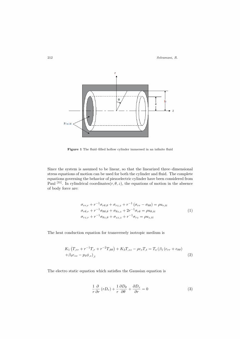
The system under consideration is shown in Fig. 1. It consists of an infinitely longlinearly elastic homogeneous transversely isotropic piezo–thermo elastic cylinderwith inner radius aand outer radius bThe cylinder is filled with an irrotational,inviscid fluid with density ρf1 and an acoustic phase velocityc1. The cylinder is also
immersed in a second irrotational, inviscid fluid with density ρf2 .
212 Selvamani, R.
Figure 1 The fluid–filled hollow cylinder immersed in an infinite fluid
Since the system is assumed to be linear, so that the linearized three–dimensionalstress equations of motion can be used for both the cylinder and fluid. The completeequations governing the behavior of piezoelectric cylinder have been considered fromPaul [31]. In cylindrical coordinates(r, θ, z), the equations of motion in the absenceof body force are:
σrr,r + r−1σrθ,θ + σrz,z + r−1 (σrr − σθθ) = ρur,tt
σrθ,r + r−1σθθ,θ + σθz,z + 2r−1σrθ = ρuθ,tt (1)
σrz,r + r−1σθz,θ + σzz,z + r−1σrz = ρuz,tt
The heat conduction equation for transversely isotropic medium is
K1
(T,rr + r−1T,r + r−2T,θθ
)+K3T,zz − ρcvT,t = To (β1 (err + eθθ)
+β3ezz − p3ϕ,z),t (2)
The electro static equation which satisfies the Gaussian equation is
1
r
∂
∂r(rDr) +
1
r
∂Dθ
∂θ+∂Dz
∂r= 0 (3)
Dispresion Analysis in a Fluid–Filled ... 213
The elastic, the piezoelectric and dielectric matrices of the 6mm crystal class, thepiezoelectric relations are:
σrr = c11err + c12eθθ + c13ezz − β1T − e31Ez
σθθ = c12err + c11eθθ + c13ezz − β1T − e31Ez
σzz = c13err + c13eθθ + c33ezz − β3T − e33Ez
σrθ = c66erθ
σθz = c44eθz − r−1e15Eθ (4)
σrz = 2c44erz − e15Er
Dr = e15erz + ε11Er
Dθ = e15eθz + r−1ε11Eθ
Dz = e31 (err + eθθ) + e33ezz + ε33Ez + p3T
where σrr, σθθ, σzz, σrθ, σθz, σrz are the stress components, err, eθθ, ezz, erθ, eθz,erz are the strain components, T is the temperature change about the equilibriumtemperature To, c11, c12, c13, c33, c44 and c66 = (c11 − c12)/2 are the five elasticconstants, β1, β3 and K1, K3 respectively thermal expansion coefficients and ther-mal conductivities along and perpendicular to the symmetry, ρ is the mass density,cv is the specific heat capacity, p3is the pyroelectric effect.
The strain eij are related to the displacements are given by:
err = ur,r eθθ = r−1 (ur + uθ,θ) ezz = uz,z
erθ = uθ,r + r−1 (ur,θ − uθ) ezθ =(uθ,z + r−1uz,θ
)(5)
erz = uz,r + ur,z
Substituting the Eqs. (4) and (5) in the Eqs. (1)–(3), results in the followingthree–dimensional equations of motion, heat and electric conductions as follows:
c11(urr,r + r−1ur,r − r−2ur
)− r−2 (c11 + c66)uθ,θ + r−2c66ur,θθ + c44ur,zz
+(c44 + c13)uz,rz + r−1 (c66 + c12)uθ,rθ + (e31 + e15)V,rz = ρur,tt
r−1 (c12 + c66)ur,rθ + r−2 (c66 + c11)ur,θ + c66(uθ,rr + r−1uθ,r − r−2uθ
)+r−2c11uθ,θθ + c44uθ,zz + r−1 (c44 + c13)uz,θz + (e31 + e15)V,θz = ρuθ,tt
c44(uz,rr + r−1uz,r + r−2uz,θθ
)+ r−1 (c44 + c13) (ur,z + uθ,θz)
+ (c44 + c13)ur,rz + c33uz,zz + e33V,zz + e15(V,rr + r−1V,r + r−2V,θθ
)= ρuz,tt
K1
(T,rr + r−1T,r + r−2T,θθ
)+K3T,zz − ρcvT,t = To
(β1(ur,r + r−1uθ,θ (6)
+r−1ur) + β3uz,z − p3ϕ,z),t
e15(uz,rr + r−1uz,r + r−2uz,θθ
)+ (e31 + e15)
(ur,zr + r−1ur,z + r−1uθ,zθ
)+e33uz,zz − ε33V,zz − ε11
(V,rr + r−1V,r + r−2V,θθ
)= 0
3. Boundary conditions
3.1. Mechanical boundary conditions
In the solid–fluid interface problems, the normal stress of the cylinder is equal to thenegative of the pressure exerted by the fluid and the displacement component in the
214 Selvamani, R.
normal direction of the lateral surface of the cylinder is equal to the displacementof the fluid in the same direction. These conditions are due to the continuity ofthe stresses and displacements of the solid and fluid boundaries. Since the fluidinviscid, it cannot sustain shear stress, the shear stress of the outer fluid is equal tozero.
[σrr, σrθ, σrz, ur] =[−pf1 , 0, 0, ufr
], r = a
(7)
[σrr, σrθ, σrz, ur] =[−pf2 , 0, 0, ufr
], r = b
3.2. Thermal boundary conditions
Isothermal surfaces
T = 0 (8)
Thermally insulated surfaces
T,r = 0
3.3. Electrical boundary conditions
Electrically shorted (Closed circuits) surfaces
Dr = 0
Charge free (Open circuits) surfaces
V = 0 (9)
4. Solutions of the field equation
The Eqs. (6) are coupled partial differential equations of the three displacementcomponents. This system of equations can be uncoupled by eliminating two of thethree displacement components through two of the three equations, but this resultin partial differential equations of sixth order. To uncouple the Eqs. (6), we followPaul [31] and assuming the solution of Eqs. (6) as follows:
ur (r, θ, z, t) =(ϕ,r + r−1ψ,θ
)ei(kz+ωt)
uθ (r, θ, z, t) =(r−1ϕ,θ − ψ,r
)ei(kz+ωt)
uz (r, θ, z, t) =
(i
a
)Wei(kz+ωt)
T (r, θ, z, t) =c44β3a2
Tei(kz+ωt) (10)
V (r, θ, z, t) = iV ei(kz+ωt)
Er (r, θ, z, t) = −E,rei(kz+ωt)
Eθ (r, θ, z, t) = −r−1E,θei(kz+ωt)
Ez (r, θ, z, t) = E,zei(kz+ωt)
Dispresion Analysis in a Fluid–Filled ... 215
where i =√−1, k is the wave number, ω is the angular frequency, ϕ (r, θ) , W (r, θ),
ψ (r, θ) and E (r, θ) , T (r, θ) are the displacement potentials and V (r, θ) is the elec-tric potentials and a is the geometrical parameter of the cylinder.
By introducing the dimensionless quantities such as x = r/a, ζ = ka, Ω2 =ρω2a2/c44, c11 = c11/c44, c13 = c13/c44, c33 = c33/c44, e13 = e13/e33, e15 = e15/e33,ε11 = ε11/ε33 ,c66 = c66/c44 and substituting Eq. (10) in Eq. (6), we obtain:
(c11∇2 +
(Ω2 − ζ2
))ϕ− ζ (1 + c13)W − ζ (e31 + e15)V = 0
ζ (1 + c13)∇2ϕ+(∇2 +
(Ω2 − ζ2c33
))W +
(e15∇2 − ζ2
)V = 0 (11)
β∇2ϕ− ζW +(d+ ik1∇2 − ik3ζ
2)T + ζp3V = 0
ζ (e31 + e15)∇2ϕ+(e15∇2 − ζ2
)W +
(ζ2ε33 − ε11∇2
)V = 0
and (c66∇2 +
(Ω2 − ζ2
))ψ = 0 (12)
where
∇2 =∂2
∂x2+ x−1 ∂
∂x+ x−2 ∂
2
∂θ2
The Eq. (11) can be written as the vanishing determinant form∣∣∣∣∣∣∣∣d11 d12 d13 d14d21 d22 d23 d24d31 d32 d33 d34d41 d42 d43
∣∣∣∣∣∣∣∣ (ϕ,W, T, V ) = 0 (13)
where:
d11 = c11∇2 +(Ω2 − ζ2
)d12 = −ζ (1 + c13)
d13 = −β d14 = −ζ (e31 + e15)
d21 = ζ (1 + c13)∇2 d22 =(∇2 +
(Ω2 − ζ2c33
))d23 = −ζ d24 =
(e15∇2 − ζ2
)d31 = β∇2 d32 = −ζd33 =
(d+ ik1∇2 − ik3ζ
2)
d34 = ζp3
d41 = ζ (e31 + e15)∇2 d42 =(e15∇2 − ζ2
)d43 = ζp3 d44 =
(ζ2ε33 − ε11∇2
)Evaluating the determinant given in Eq.(13), we obtain a partial differential equa-tion of the form(
A∇8 +B∇6 + C∇4 +D∇2 + E)(ϕ,W, T, V ) = 0 (14)
216 Selvamani, R.
where:
A = −ik1c11g18B = c11
(g9 − ik1ε11g2 + e15g17
)+ ik1
(g1g18 − ζ2g23
)− β
2g18
C = c11(g2g9 + ζ2(g5 + ε11 + 2e15g8 − ik1ζ2)) + g1(g9 − ik1ε11g2 + e15g17)
−β(βε11g2 − ζ2(βε33 − p3g3 − g3e15 + 2βe15)) + ζ2g4(g4g14 + βe15 + ζg3g15)
−ζ2g3(ik1e15g4 + β(p3 + e15)− g3(g16 + ik1g2))
D = ζ2c11(g2g5 − ζ2(g8 − g7)) + g1(g2g9 + ζ2(g5 + ε11 + 2e15g8 − ik1ζ2)
+ζ2g4(g4(g11 + p3ζε11)− ζg3g12 − βζ(ζ + p23))
−βζ2(g4g13 − g2(βε33 − p3g3)− ζ(g3 − β))
−ζ2g3(g4g11 + g2(βp3 − g3g16) + ζ2(g3 − β))
E = ζ2g1g2g5 − ζ2(g1g8 − g1g7 + g24g6 + βg4g7 − g4g3g8
)in which:
g1 = Ω2 − ζ2 g2 = Ω2 − ζ2c33 g3 = e31 + e15 g4 = 1 + c13
g5 = dε3 − ik3ε33ζ2 − p23 g6 = d+ p3ζε33 g7 = p3 − ε33 g8 = d− p3 − ik3ζ
2
g9 = ik1ζ2ε33 + ik3ε11ζ
2 − dε11 g10 = ε11 + 2e15g8 − ik1ζ2
g11 = de15 − ik1ζ2 − ik3ζ
2e15 g12 = ζ2ε33 + dp3 − ik3p3ζ2
g13 = ε11 − p3e15 g14 = i(k1e15 + k3
)g15 = ε11 − ip3k1 g16 = d
2 − ζ2ik3
g17 = ik1ζ2 − g11 g18 = ε11 + e215
Factorizing the relation given in Eq. (14) into biquadratic equation for (αia)2,
(i = 1, 2, 3, 4), the solutions for the symmetric modes are obtained as:
ϕ =4∑
i=1
[AiJn (αiax) +BiYn (αiax)] cosnθ
W =4∑
i=1
ai [AiJn (αiax) +BiYn (αiax)] cosnθ
T =4∑
i=1
bi [AiJn (αiax) +BiYn (αiax)] cosnθ (15)
V =4∑
i=1
ci [AiJn (αiax) +BiYn (αiax)] cosnθ
Here (αia)2> 0, (i = 1, 2, 3, 4) are the roots of the algebraic equation
A (αa)8 −B (αa)
6+ C (αa)
4 −D (αa)2+ E = 0 (16)
The solutions corresponding to the root (αia)2= 0 is not considered here, since
Jn (0) is zero, except forn = 0. The Bessel function Jn is used when the roots
Dispresion Analysis in a Fluid–Filled ... 217
(αia)2, (i = 1, 2, 3, 4)are real or complex and the modified Bessel function Inis used
when the roots (αia)2, (i = 1, 2, 3, 4)are imaginary.
The constants ai, bi and ci defined in the Eq. (14) can be calculated from theequations:
ai =(βp3 − g3L
)/(g4L+ β
)bi = −
(g3β (αia)
2+ p3
(g1 + c11 (αia)
2))/(
g4L+ β)
(17)
ci =((αia)
2 (g4β − c11
)− g1
)/(g4L+ β
)where
L =(d− ik1 (αia)
2 − ik3ζ2)
Solving the Eq. (10), the solution to the anti-symmetric mode is obtained as
ψ = A5 [Jn (α5ax) + Yn (α5ax)] sinnθ (18)
where (α5a)2= Ω2 − ζ2. If (α5a)
2< 0, the Bessel function Jn is replaced by the
modified Bessel function In.
5. Equations of motion of the fluid
In cylindrical polar coordinates r, θ and z the acoustic pressure and radial displace-ment equation of motion for an invicid fluid are of the form Achenbach [32]
pf = −Bf(ufr,r + r−1(ufr + ufθ,θ) + ufz,z
)(19)
and
c−2f ufr,tt = ∆,r (20)
respectively where Bf , is the adiabatic bulk modulus, ρf is the density,
cf =√Bf
/ρf is the acoustic phase velocity in the fluid, and
(ufr , u
fθ , u
fz
)is the
displacement vector.
∆ =(ufr,r + r−1(ufr + ufθ,θ) + ufz,z
)(21)
Substituting
ufr = ϕf,r, ufθ = r−1ϕf,θ andu
fz = ϕf,z (22)
and seeking the solution of (21) in the form
ϕf (r, θ, z, t) =
∞∑n=0
ϕf (r) cosnθei(kz+ωt) (23)
the oscillating waves propagating in the inner fluid located in the annulus is givenby
ϕf = A5Jn(α5ax) (24)
218 Selvamani, R.
where (α5a)2= Ω2
/ρf1B
f
1 − ς2, in which ρf1 = ρ1/ρf ,B
f
1 = Bf1
/c44. If (α5a)
2< 0,
the Bessel function Jn in (24) is to be replaced by modified Bessel function In.Similarly, for the outer fluid that represents the oscillatory waves propagating awayis given as
ϕf = B5H(2)n (α6ax) (25)
where (α6a)2= Ω2
/ρf2B
f
2 − ς2, in which ρf2 = ρ2/ρf , B
f
2 = Bf2
/c44, H
(2)n is the
Hankel function of the second kind. If (α6a)2 < 0, then the Hankel function of
second kind is to be replaced by Kn, where Kn is the modified Bessel function ofthe second kind. By substituting Eq. (22) in (19) along with (24) and (25), theacoustic pressure for the inner fluid can be expressed as
pf1 = A5Ω2ρ1Jn(α5ax) cosnθe
i(ςz+ΩTa) (26)
and for the outer fluid is
pf2 = B5Ω2ρ2H
(2)n (α6ax) cosnθe
i(ςz+ΩTa) (27)
6. Frequency equations
Substituting the solutions given in the Eqs. (15), (18), (26) and (27) in the bound-ary conditions given in the Eqs. (7), we obtain a system of eight linear algebraicequations as follows
[A] X = 0 (28)
where [A] is a 12 × 12 matrix of unknown wave amplitudes, and X is an12×1 column vector of the unknown amplitude coefficients A1, B1, A2, B2, A3, B3,A4, B4, and A5, B5.... The solution of Eq. (28) is nontrivial when the determinantof the coefficient of the wave amplitudes X vanishes, that is |A| = 0.
Dispresion Analysis in a Fluid–Filled ... 219
The elements in the above determinant is defined as:
a1i = 2c66 n (n− 1) Jn (αiax) + (αiax)Jn+1 (αiax)
−x2[(αia)
2c11 + ζc13ai + ζbi + βci
]Jn (αiax) i = 1, 2, 3, 4
a14 = 2c66n (n− 1)Jn (α4a)− (α4a)Jn+1 (α4a)a15 = 2c66n (n− 1)Yn (α4a)− (α4a)Yn+1 (α4a)
a1i = 2c66
n (n− 1)− c11 (αia)
2 − ς (c13ai + e31bi)Yn (αia)
+2c66 (αia)Yn+1 (αia) i = 6, 7, 8
a19 = ρ1Ω2Jn (α5a) a10 = ρ2Ω
2H(2)n (α6a) a1i = 0 i = 11, 12
a2i = 2n (n− 1) Jn (αia) + (αia)Jn+1 (αia) i = 1, 2, 3
a24 =[
(α4a)2 − 2n (n− 1)
]Jn (α4a)− 2 (α4a) Jn+1 (α4a)
a25 =
[(α4a)
2 − 2n (n− 1)]Yn (α4a)− 2 (α4a)Yn+1 (α4a)
a2i = 2n (n− 1)Yn (αia) + (αia)Yn+1 (αia) i = 6, 7, 8
a2i = 0, i = 9, 10, 11, 12
a3i = ((ς + ai) + e15bi) nJn (αia)− (αia)Jn+1 (αia) i = 1, 2, 3
a34 = nςJn (α4a) a35 = nςYn (α4a)
a3i = ((ς + ai) + e15bi) nJn (αia)− (αia)Jn+1 (αia) i = 6, 7, 8
a3i = 0, i = 9, 10, 11, 12
a4i = biJn (αia) i = 1, 2, 3 a44 = 0 a45 = 0
a4i = biYn (αia) i = 6, 7, 8 a4i = 0 i = 9, 10, 11, 12
a5i = nJn (αia)− (αia)Jn+1 (αia) i = 1, 2, 3 a54 = nJn (α4a)
a55 = nYn (α4a) a5i = nYn (αia)− (αia)Yn+1 (αia) i = 6, 7, 8
a59 = Ω2ρ1 nJn (α5a)− (α5a) Jn+1 (α5a)
a510 = Ω2ρ2
nH(2)
n (α6a)− (α6a)H(2)n+1 (α6a)
a5i = 0 i = 11, 12
a6i = ci nJn (αiax)− (αiax)Jn+1 (αiax) i = 1, 2, 3a64 = nJn (α4a)
a65 = nYn (α4a)
a6i = ((ς + ai) + e15bi) nJn (αia)− (αia)Jn+1 (αia) i = 6, 7, 8
a6i = 0, i = 9, 10, 11, 12
The complex secular Eq. (28) contains complete information regarding wave num-ber, phase velocity and attenuation coefficient and other propagation characteristicsof the considered surface waves. In order to solve this equation we take
c−1 = v−1 + iω−1q (29)
where ζ = R+iq, R = ωv and R, q are real numbers. Here it may be noted that v and
q respectively represent the phase velocity and attenuation coefficient of the waves.Upon using the representation (29) in Eq. (28) and various relevant relations, thecomplex roots αi(i = 1, 2, 3, 4) of the Eq. (15) can be computed with the help of
220 Selvamani, R.
Secant method. The characteristics roots αi(i = 1, 2, 3, 4) are further used to solvethe Eq. (28) to obtain phase velocity(v) and attenuation coefficient (q) by usingthe functional iteration numerical technique as given below.
The Eq.(28) is of the form F (C) = 0 which upon using representation (29) leadsto a system of two real equations f(v, q) = 0 and g(v, q) = 0. In order to applyfunctional iteration method, we write v = f∗(v, q) and q = g∗(v, q), where thefunctions f∗ and g∗ are selected in such a way that they satisfies the conditions∣∣∣∣∂f∗∂v
∣∣∣∣+ ∣∣∣∣∂g∗∂q∣∣∣∣ < 1
∣∣∣∣∂g∗∂v∣∣∣∣+ ∣∣∣∣∂f∗∂q
∣∣∣∣ < 1 (30)
For all v, q in the neighborhood of the roots. If (v0, q0) be the initial approximationof the root, then we construct a successive approximation according to the formulae:
v1 = f∗(v0, q0) q1 = g∗(v1, q0)v2 = f∗(v1, q1) q2 = g∗(v2, q1)v3 = f∗(v2, q2) q3 = g∗(v3, q2)....................... .......................vn = f∗(vn, qn) qn = g∗(vn+1, qn)
(31)
The sequence vn, qn of approximation to the root will converge to the actual value(v0, q0) of the root provided(v0, q0)lie in the neighborhood of the actual root. Forthe initial value c = c0 = (v0, q0), the roots αi(i = 1, 2, 3, 4) are computed fromthe Eq. (15) by using Secant method for each value of the wave number ζ, forassigned frequency. The values of αi(i = 1, 2, 3, 4) so obtained are then used inthe Eq.(28) to obtained the current values of v and q each time which are furtherused to generate the sequence (30). This process is terminated as and when thecondition |vn+1 − vn| < ε, ε being arbitrary small number to be selected at randomto achieve the accuracy level, is satisfied. The procedure is continually repeated fordifferent values of the wave number (ζ) to obtain the corresponding values of thephase velocity (v) and attenuation coefficient (q).
6.1. Particular case
The frequency equation for a piezoelectric solid circular cylinder is obtained discard-ing the inner and outer fluid medium, thermal field in the corresponding equationsand solutions along with the outer boundary conditions, and substitute in the solu-tion and frequency equations Yn and Yn+1 is equal to zero. The frequency equationsobtained in this method matches well with the frequency equations of Paul and Raju[31] which shows the exactness of this method.
6.2. Specific loss
The internal energy of a material is defined by specific loss. The specific loss is theratio of the amount of energy (∆E) dissipated in a specimen through a stress cycleto the elastic energy (E) stored in that specimen at a maximum strain. Accordingto Kolsky [33], specific loss (∆E/E) is equal to 4π times the absolute value of theimaginary part of ζ to the real part of ζ, therefore we have
S.L = |∆E/E| = 4π |Im (ζ)/Re (ζ)| = |vq/ω| (32)
Dispresion Analysis in a Fluid–Filled ... 221
The real and imaginary parts of the wave number is obtained from the relationζ = R+ iq, where R = ω/ν and the wave speed (v) and the attenuation coefficient(q) are real numbers.
6.3. Thermo mechanical coupling
The coupling effect between thermal and elasticity in a thermo elastic material pro-vides a mechanism for sensing thermo mechanical disturbance from measurementsof induced magnetic potentials, and for altering structural responses through ap-plied magnetic fields in the design of sensors and surface acoustic damping wavefilters. Thermo mechanical coupling factor is defined as
κ2 =
∣∣∣∣V1 − V2V2
∣∣∣∣ (33)
where V1 is the phase velocity of the wave under thermally insulated boundary andV2phase velocity of the wave under isothermal boundary.
7. Numerical examples and discussion
The frequency equation given in Eq. (28) is transcendental in nature with unknownfrequency and wave number. The solutions of the frequency equation are obtainednumerically by fixing the non–dimensional wave number. The material properties ofPZT-5A and PZT-4A are taken from Berlincourt et al [34] are used for the numericalcalculation is given below:Example 1: Consider the fluid filled and immersed piezo-thermo elastic hollowcylinder with the material properties of PZT-5A
c11 = 13.9× 10¹⁰Nm−2 c12 = 7.78× 10¹⁰Nm−2 c13 = 7.43× 10¹⁰Nm−2
c33 = 11.3× 10¹⁰Nm−2 c44 = 2.56× 10¹⁰Nm−2 c66 = 3.06× 10¹⁰Nm−2
β1 = 1.52× 10⁶NK−1m−2 β3 = 1.53× 10⁶NK−1m−2
T0 = 298K cv = 420 Jkg−1K−1 p3 = −452× 10−6CK−1m−2
K1 = K3 = 1.5 Wm−1K−1 e13 = −6.98Cm−2 e33 = 13.8Cm−2
e51 = 13.4Cm−2 ε11 = 60.0× 10⁻¹⁰C2N−1m−2
ε33 = 54.7× 10⁻¹⁰C2N−1m−2 ρ = 7500Kgm−2
and for fluid the density ρf = 1000 Kgm−3, phase velocity c = 1500 m/s−1 andused for the numerical calculations.
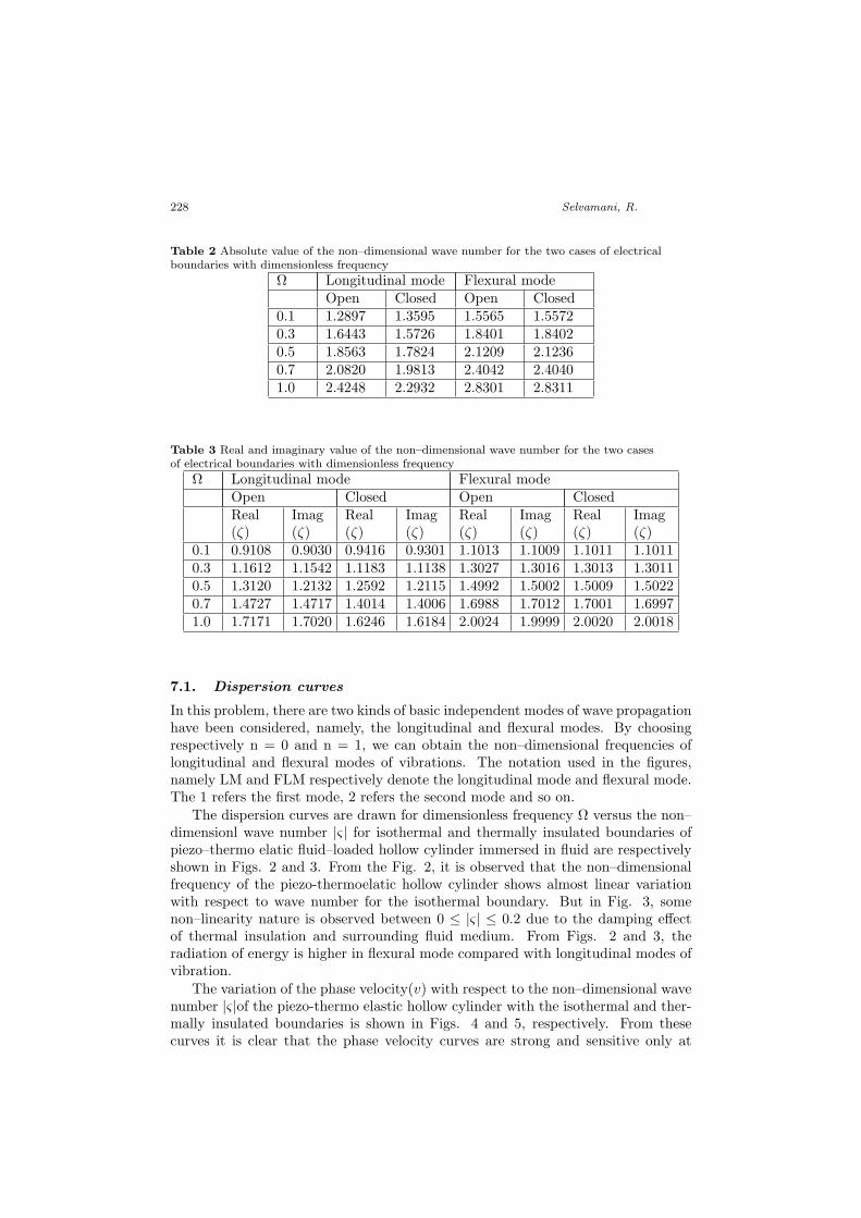
In Tabs 2 and 3 the absolute, real and imaginary values the non–dimensionalwave number are given against dimensionless frequency for the two cases of electri-cally shorted (Closed circuits) and charge free (Open circuits) boundary conditions.The Tabs 2 and 3 clarifies that as the dimensionless frequency increases the non–dimensional wave number also increases in both the electrical boundary conditions.The computed dimensionless frequency, phase velocity, attenuation, thermo elasticcoupling and specific loss are plotted in the form of dispersion curves in Fig. 2–11.
222 Selvamani, R.
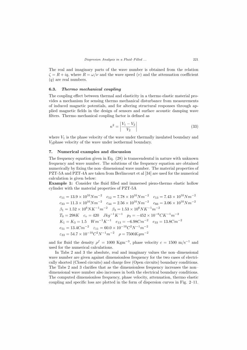
Figure 2 Dimensionless frequency versus non–dimensional wave number |for isothermal modes offluid–loaded piezo–thermo elastic cylinder immersed in fluid
Figure 3 Dimensionless frequency versus non–dimensional wave number for thermally insulatedmodes of fluid–loaded piezo–thermo elastic cylinder immersed in fluid
Dispresion Analysis in a Fluid–Filled ... 223
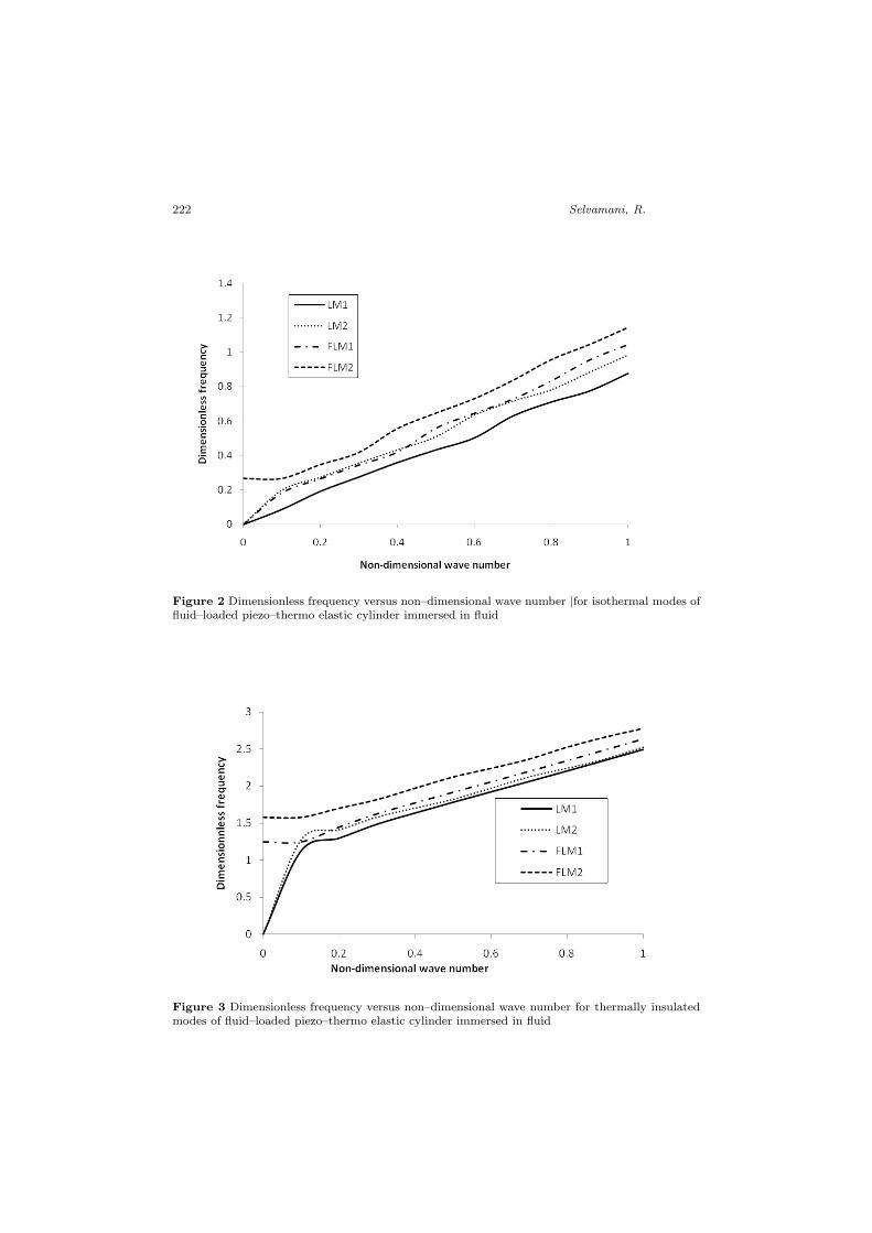
Figure 4 Phase velocity versus non–dimensional wave number for isothermal modes of fluid–loadedpiezo–thermo elastic cylinder immersed in fluid
Figure 5 Phase velocity versus non–dimensional wave number for thermally insulated modes offluid–loaded piezo–thermo elastic cylinder immersed in fluid
224 Selvamani, R.
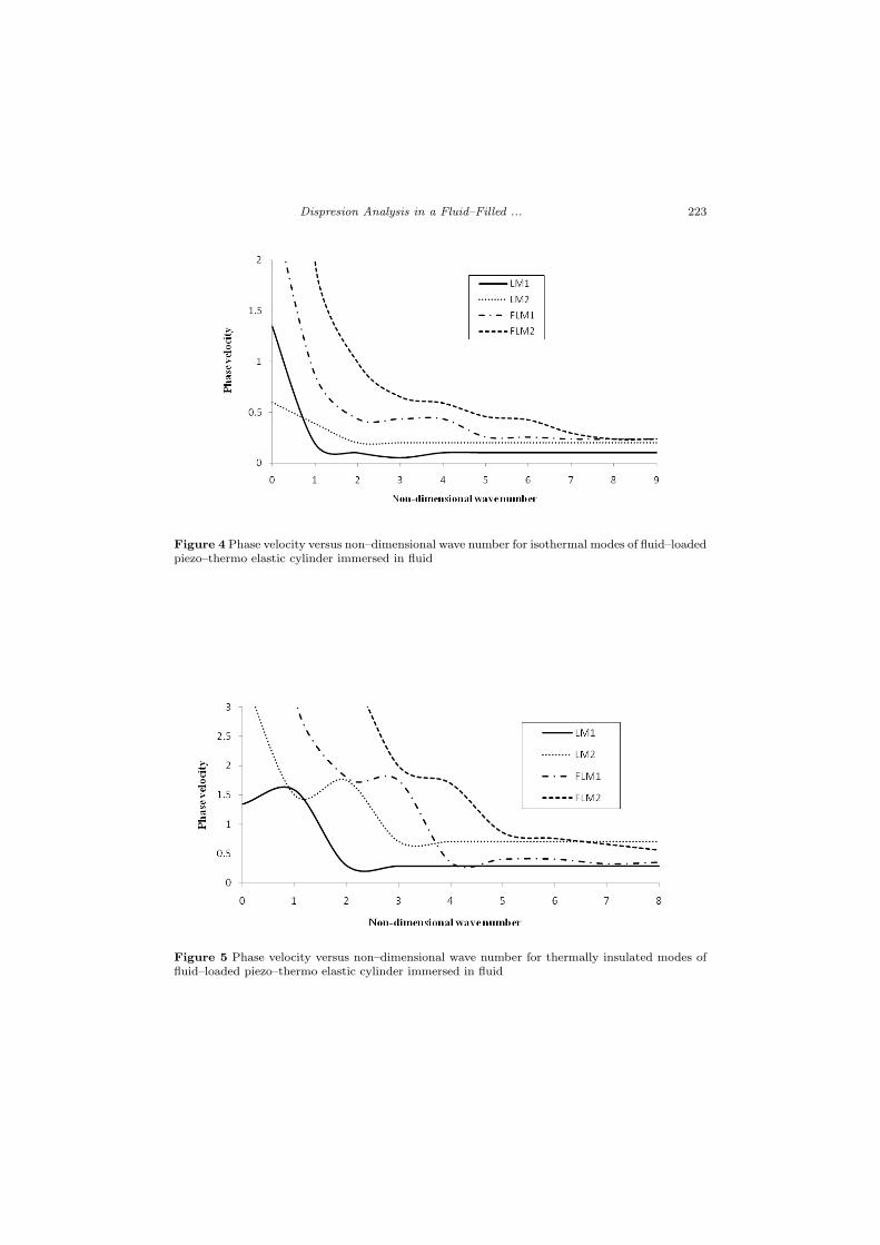
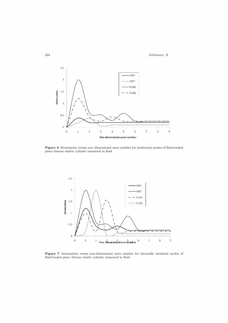
Figure 6 Attenuation versus non–dimensional wave number for isothermal modes of fluid-loadedpiezo–thermo elastic cylinder immersed in fluid
Figure 7 Attenuation versus non-dimensional wave number for thermally insulated modes offluid-loaded piezo–thermo elastic cylinder immersed in fluid
Dispresion Analysis in a Fluid–Filled ... 225
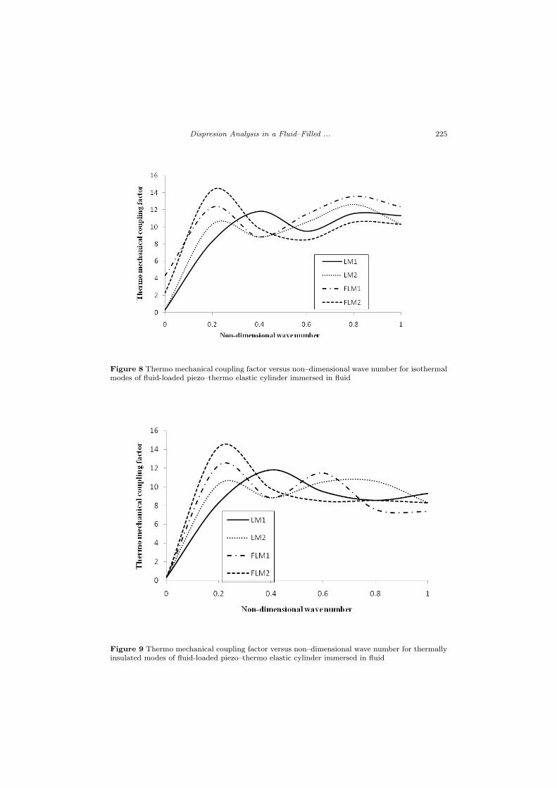
Figure 8 Thermo mechanical coupling factor versus non–dimensional wave number for isothermalmodes of fluid-loaded piezo–thermo elastic cylinder immersed in fluid
Figure 9 Thermo mechanical coupling factor versus non–dimensional wave number for thermallyinsulated modes of fluid-loaded piezo–thermo elastic cylinder immersed in fluid
226 Selvamani, R.
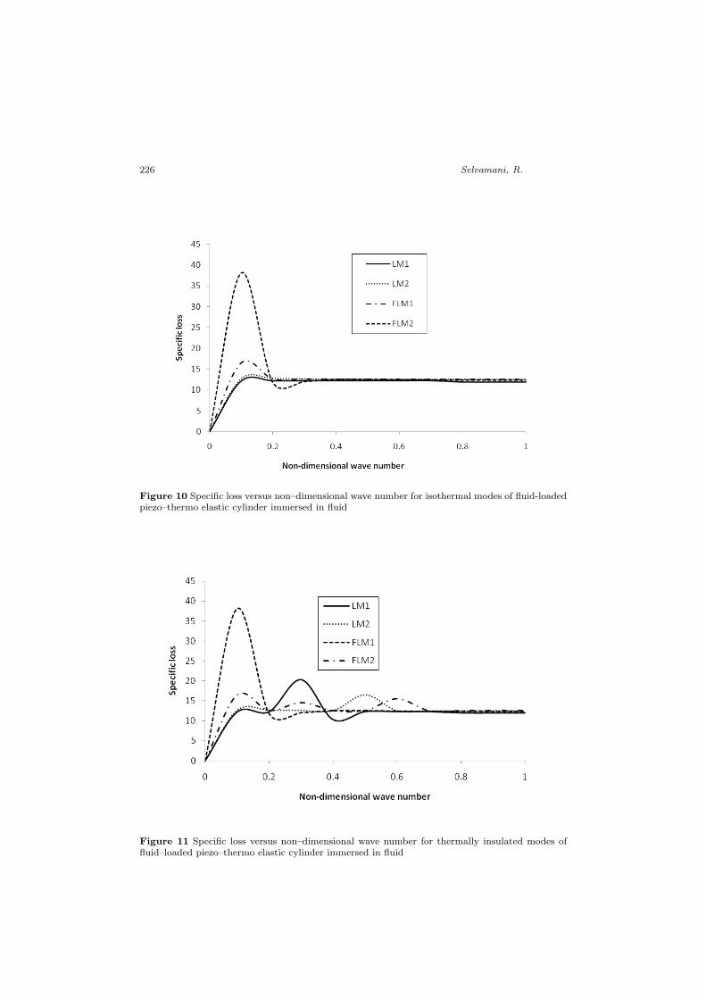
Figure 10 Specific loss versus non–dimensional wave number for isothermal modes of fluid-loadedpiezo–thermo elastic cylinder immersed in fluid
Figure 11 Specific loss versus non–dimensional wave number for thermally insulated modes offluid–loaded piezo–thermo elastic cylinder immersed in fluid
Dispresion Analysis in a Fluid–Filled ... 227
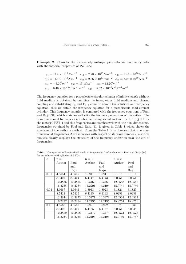
Example 2: Consider the transversely isotropic piezo–electric circular cylinderwith the material properties of PZT-4A:
c11 = 13.9× 10¹⁰Nm−2 c12 = 7.78× 10¹⁰Nm−2 c13 = 7.43× 10¹⁰Nm−2
c33 = 11.5× 10¹⁰Nm−2 c44 = 2.56× 10¹⁰Nm−2 c66 = 3.06× 10¹⁰Nm−2
e31 = −5.2Cm−2 e33 = 15.1Cm−2 e15 = 12.7Cm−2
ε11 = 6.46× 10⁻⁹C2N−1m−2 ε33 = 5.62× 10⁻⁹C2N−1m−2
The frequency equation for a piezoelectric circular cylinder of infinite length withoutfluid medium is obtained by omitting the inner, outer fluid medium and thermocoupling and substituting Yn and Yn+1 equal to zero in the solutions and frequencyequation, thus we obtain the frequency equation for a piezoelectric solid circularcylinder. This frequency equation is compared with the frequency equations of Pauland Raju [31], which matches well with the frequency equations of the author. Thenon-dimensional frequencies are obtained using secant method for 0 < ς ≤ 0.1 forthe material PZT-4 and this frequencies are matches well with the non–dimensionalfrequencies obtained by Paul and Raju [31] is given in Table 1 which shows theexactness of the author’s method. From the Table 1, it is observed that, the non–dimensional frequencies Ω are increases with respect to its wave number ς, also thisanalysis clearly displays the structure of the frequency spectrum near the cut offrequencies.
Table 1 Comparison of longitudinal mode of frequencies Ω of author with Paul and Raju [31]for an infinite solid cylinder of PZT-4
ς n = 0 n = 1 n = 2Author Paul
andRaju
Author PaulandRaju
Author PaulandRaju
0.01 4.6654 4.6655 1.8911 1.8911 3.1815 3.18168.5421 8.5424 6.4147 6.4143 8.0351 8.035112.3876 12.3875 10.3462 10.3469 12.0568 12.056116.2235 16.2234 14.2201 14.2195 15.9751 15.9750
0.04 4.6667 4.6641 1.8913 1.8923 3.1824 3.18258.5423 8.5425 6.4145 6.4142 8.0351 8.035112.3844 12.3873 10.3471 10.3479 12.0564 12.056316.2237 16.2234 14.2195 14.2195 15.9754 15.9751
0.1 4.6566 4.6566 1.8991 1.8992 3.1870 3.18698.5426 8.5427 6.4135 6.4137 8.0351 8.034812.3859 12.3858 10.3472 10.3475 12.0573 12.057816.2234 16.2235 14.2193 14.2195 15.9756 15.9757
228 Selvamani, R.
Table 2 Absolute value of the non–dimensional wave number for the two cases of electricalboundaries with dimensionless frequency
Ω Longitudinal mode Flexural modeOpen Closed Open Closed
0.1 1.2897 1.3595 1.5565 1.55720.3 1.6443 1.5726 1.8401 1.84020.5 1.8563 1.7824 2.1209 2.12360.7 2.0820 1.9813 2.4042 2.40401.0 2.4248 2.2932 2.8301 2.8311
Table 3 Real and imaginary value of the non–dimensional wave number for the two casesof electrical boundaries with dimensionless frequency
Ω Longitudinal mode Flexural modeOpen Closed Open ClosedReal(ζ)
Imag(ζ)
Real(ζ)
Imag(ζ)
Real(ζ)
Imag(ζ)
Real(ζ)
Imag(ζ)
0.1 0.9108 0.9030 0.9416 0.9301 1.1013 1.1009 1.1011 1.10110.3 1.1612 1.1542 1.1183 1.1138 1.3027 1.3016 1.3013 1.30110.5 1.3120 1.2132 1.2592 1.2115 1.4992 1.5002 1.5009 1.50220.7 1.4727 1.4717 1.4014 1.4006 1.6988 1.7012 1.7001 1.69971.0 1.7171 1.7020 1.6246 1.6184 2.0024 1.9999 2.0020 2.0018
7.1. Dispersion curves
In this problem, there are two kinds of basic independent modes of wave propagationhave been considered, namely, the longitudinal and flexural modes. By choosingrespectively n = 0 and n = 1, we can obtain the non–dimensional frequencies oflongitudinal and flexural modes of vibrations. The notation used in the figures,namely LM and FLM respectively denote the longitudinal mode and flexural mode.The 1 refers the first mode, 2 refers the second mode and so on.
The dispersion curves are drawn for dimensionless frequency Ω versus the non–dimensionl wave number |ς| for isothermal and thermally insulated boundaries ofpiezo–thermo elatic fluid–loaded hollow cylinder immersed in fluid are respectivelyshown in Figs. 2 and 3. From the Fig. 2, it is observed that the non–dimensionalfrequency of the piezo-thermoelatic hollow cylinder shows almost linear variationwith respect to wave number for the isothermal boundary. But in Fig. 3, somenon–linearity nature is observed between 0 ≤ |ς| ≤ 0.2 due to the damping effectof thermal insulation and surrounding fluid medium. From Figs. 2 and 3, theradiation of energy is higher in flexural mode compared with longitudinal modes ofvibration.
The variation of the phase velocity(v) with respect to the non–dimensional wavenumber |ς|of the piezo-thermo elastic hollow cylinder with the isothermal and ther-mally insulated boundaries is shown in Figs. 4 and 5, respectively. From thesecurves it is clear that the phase velocity curves are strong and sensitive only at
Dispresion Analysis in a Fluid–Filled ... 229
the small values of wave number in the range 0 ≤ |ς| ≤ 4 in Figs. 3 and 4, butfor higher values of wave number, these become linear and non–dispersive for boththe boundaries of thermally insulated and isothermal. This type of phenomenonexplains the concept that, as the wave goes to the deeper in the medium (Higherwave number) the coupling effect of various interacting fields increases which leadsto lower phase velocity. But there is a small oscillation of cut of frequency in Fig.5 which might happen because of the radiation of the sound energy in to the fluidproduces damping in the system.
The dispersion of attenuation coefficient (q) with respect to the non–dimensionalwave number |ς| of the fluid filled and immersed piezo-thermo elastic hollow cylinderis discussed for the two cases of isothermal and thermally insulated boundariesin Fig. 6 and 7. The amplitude of displacement of the attenuation coefficientincreases monotonically to attain maximum value in 0 ≤ |ς| ≤ 2 and slashes downto became asymptotically linear in the remaining range of the wave number in Fig.6. The variation of attenuation coefficient for longitudinal and flexural modes ofvibration is oscillating in the starting range of wave number as shown in Fig. 7 forthermally insulated boundary. From Fig. 6 and 7, it is clear that the attenuationprofiles exhibits high oscillating nature in the small wave number range since, theenergy radiation is more sensitive in the surface areas. The cross over points in thevibrational modes indicates the energy transfer between the solid and fluid medium.
In Fig. 8 and 9 the effect of the specific loss (S.L) factor for isothermal andthermally insulated boundaries are discussed non–dimensional wave number |ς|.The magnitude of the energy dissipation (specific loss) factor is attaining maximumvalue at 0 ≤ |ς| ≤ 0.2 for the fluid filled and immersed piezo–thermo elastic hollowcylinder in Fig. 8. But for thermally insulated mode, the specific loss is gettingoscillating trend up to |ς| ≤ 0.7. On comparison of Fig. 8 and 9 it is clear that thespecific loss factor is quiet high when the wave penetrates deep in to the medium.
Fig. 10 and 11 represents the variation of the thermo mechanical coupling(κ2
)factor with non–dimensional wave number |ς| for isothermal and thermally insulatedfluid filled and immersed piezo–thermo elastic hollow cylinder. The magnitude ofthe coupling factor increasing monotonically at small wave number and becomesteady for higher wave number for both isothermal and thermally insulated bound-aries. The effect of thermo mechanical coupling factor is high at lower wave numberbecause of the dissipation of energy is more sensitive on the surface of the hollowcylinder.
8. Conclusions
The dispersion equation of a transversely isotropic piezo–thermo elastic cylinderthat is fluid-filled and immersed in fluid is developed from the three-dimensionalequations of elasticity and the assumptions of perfect–slip boundary conditions atthe solid fluid interfaces. The frequency equations are obtained for longitudinal andflexural modes of vibration and are studied numerically for the material PZT-5A,which is fluid–filled and immersed in fluid. The computed dimensionless frequency,phase velocity, attenuation, thermo mechanical coupling factor and specific loss areplotted in the form of dispersion curves for the material PZT-5A. Discarding thefluid medium and thermo coupling, a comparison is made between the frequency
230 Selvamani, R.
response of a piezoelectric solid circular cylinder with the existing literature resultsof Paul and Raju [31], which shows very good agreement. The obtained resultsare valuable for the analysis of design of piezo thermo elastic transducer and sen-sors using composite materials and can be utilized in electronics and navigationapplications.
References
[1] Meeker, T. R. and Meitzler, A. H.: Guided wave propagation in elonged cylindersand plates, in: Mason, W.P. (Ed.), Physical Acoustics, Academic, New York, 1964.
[2] Mirsky, I.: Wave propagation in transversely isotropic circular cylinders, Part I:Theory, Part II: Numerical results, Journal of Acoustical Society of America, 37,1016–1026, 1965.
[3] Morse, R. W.: Compressional waves along an anisotropic circular cylinder havinghexagonal symmetry, Journal of Acoustical Society of America, 26, 1018–1021, 1954.
[4] Tiersten, H. F.: Linear piezoelectric plate vibrations, Plenum, New York, 1969.
[5] Parton, V.Z. and Kudryavtsev, B.A.: Electromagnetoelasticity. Gordon andBreach, New York,1988.
[6] Shul’ga, N. A.: Propagation of harmonic waves in anisotropic piezoelectric cylinders.Homogeneous piezoceramic wave guides, International Journal of Applied Mechanics,38(12), 933–953, 2002.
[7] Rajapakse, R. K. N. D. and Zhou, Y.: Stress analysis of piezo-ceramic cylinders,Smart Material and Structures, 6, 169–177, 1997.
[8] Wang, Q.: Axi–symmetric wave propagation in cylinder coated with a piezoelectriclayer, International journal of Solids and Structures, 39, 3023–3037, 2002.
[9] Ebenezer, D. D. and Ramesh, R.: Analysis of axially polarized piezoelectriccylinders with arbitrary boundary conditions on the flat surfaces, Journal of AcousticalSociety of America, 113(4), 1900–1908, 2003.
[10] Berg, M. and Hagedorn, P. S.: Gutschmidt, on the dynamics of piezoelectriccylindrical shell, Journal of Sound and Vibration, 274, 91–109, 2004.
[11] Botta, F. and Cerri, G.: Wave propagation in Reissner–Mindlin piezoelectric cou-pled cylinder with non–constant electric field through the thickness, InternationalJournal of Solids and Structures, 44, 6201–6219, 2007.
[12] Kim, J. O. and Lee, J. G.: Dynamic characteristics of piezoelectric cylindricaltransducers with radial polarization, Journal of Sound and Vibration, 300, 241–249,2007.
[13] Mindlin, R. D.: On the equations of motion of piezoelectric crystals, in: Problemsof continuum mechanics, SIAM, Philadelphia, 70, 282–290, 1961.
[14] Mindlin, R. D.: Equation of high frequency vibrations of thermo-piezoelectric, crys-tal plates, Interactions in Elastic Solids, Springer, Wien, 1979.
[15] Nowacki, W.: Foundations of linear piezoelectricity, in H. Parkus (Ed.), Electromag-netic Interactions in Elastic Solids, Springer, Wien, (1),1979.
[16] Nowacki, W.: Some general theorems of thermo-piezoelectricity, Journal of ThermalStresses, 171–182, 1978.
[17] Chandrasekhariah, D. S.: A temperature rate dependent theory of piezoelectricity,Journal of thermal stresses, 7, 293–306, 1984.
[18] Chandrasekhariah, D. S.: A generalized linear thermoelasticity theory of piezo-electric media, Acta Mechanica, 71, 39–49, 1988.
Dispresion Analysis in a Fluid–Filled ... 231
[19] Yang, J. S. and Batra, R. C.: Free vibrations of a linear thermo–piezoelectricbody, Journal of thermal stresses, 18, 247–262, 1995.
[20] Sharma, J. N. and Pal, M.: Propagation of Lamb waves in a transversely isotropicpiezothermoelastic plate, Journal of Sound and Vibration, 270, 587–610, 2004.
[21] Sharma, J. N., Pal, M and Chand, D.: Three dimensional vibrational analysis ofa piezothermoelastic cylindrical panel, International Journal of Engineering Science,42, 1655–1673, 2004.
[22] Ponnusamy, P.: Wave propagation in a generalized thermo elastic solid cylinder ofarbitrary cross–section, International Journal of Solids and Structures, 44, 5336–5348,2007.
[23] Ponnusamy, P. and Selvamani, R.: Dispersion analysis of generalized magneto–thermoelastic waves in a transversely isotropic cylindrical panel, Journal of ThermalStresses, 35, 1119–1142, 2012.
[24] Sinha, K., Plona, J., Kostek, S and Chang, S.: Axisymmetric wave propagationin a fluid–loaded cylindrical shell I: Theory; II Theory versus experiment, Journal ofAcoustical Society of America, 92, 1132–1155, 1992.
[25] Berliner, J. and Solecki, R.: Wave propagation in a fluid-loaded, transverselyisotropic cylinders, Part I Analytical Formulation; Part II Numerical results, Journalof Acoustical Society of America, 99, 1841–1853, 1996.
[26] Selvamani, R. and Ponnusamy, P.: Wave propagation in a generalized thermoelastic plate immersed in fluid, Structural Engineering and Mechanics, 46(6), 827–842,2013.
[27] Selvamani, R. and Ponnusamy, P.: Dynamic response of a solid bar of cardioidalcross–sections immersed in an inviscid fluid, Applied Mathematics and InformationSciences, 8(6), 2909–2919, 2014.
[28] Dayal, V.: Longitudinal waves in homogeneous anisotropic cylindrical bars immersedin fluid, Journal of Acoustical Society of America, 93, 1249–1255, 1993.
[29] Nagy, B.: Longitudinal guided wave propagation in a transversely isotropic rod im-mersed in fluid, Journal of Acoustical Society of America, 98(1), 454–457,1995.
[30] Paul, H.S. and Raju, D.P.: Asymptotic analysis of the modes of wave propagationin a piezoelectric solid cylinder, Journal of Acoustical Society of America, 71(2), 255–263, 1982.
[31] Paul, H.S.: Vibrations of circular cylindrical shells of piezo-electric silver iodidecrystals, Journal of Acoustical Society of America, 40(5), 1077–1080, 1966.
[32] Achenbach, J. D.: Wave motion in elastic solids, North-Holland: Amsterdam, 1973.
[33] Kolsky, H.: Stress waves in solids, New York, London: Dover Press, 1935.
[34] Berlincourt, D. A., Curran D. R and Jaffe, H.: Piezoelectric and piezomagneticmaterials and their function in transducers, New York and London, Academic Press,1964.