Embed Size (px)
Citation preview

Dissemination workshop Madrid
Review of DEMO 3
MadridNovember 21-22, 2017
1

1st Steering Committee / 29th October 2014 / Rome
Technological innovation by Toshiba’s VSC system
2
WP 5 (DEMO 3 R&D)
• Task 5.7: HVDC
converter
technology
WP 10 (DEMO 3 - demonstration)
• Task 10.4: Manufacturing, installation and testing the converter demonstrator
• Task 10.5: Experimentation and assessment of the overall solution

1st Steering Committee / 29th October 2014 / Rome
Technological innovation by Toshiba’s VSC system
• Focus on the “SACOI”
rehabilitation by VSC
• Identification of new
converters & controls
technologies / solutions
complying with “SACOI"
operating requirements
• Analyses and studies on
system integration of
the enhanced SACOI by
Toshiba’s VSC (ready for
WP10 demonstration)
3
Task 5.7 (HVDC converter technology) –WP 5: D5.7 “Innovative HVDC converter technology” – July 28, 2017

1st Steering Committee / 29th October 2014 / Rome
Technological innovation by Toshiba’s VSC system
• Focus on VSC & controls
technical specification
• Factory Acceptance Tests
• Demonstration Tests
4
Task 10.4 (Manufacturing, installation and testing the converter demonstrator) –WP 10: D10.9 “Construction of the HVDC converter”

1st Steering Committee / 29th October 2014 / Rome
Technological innovation by Toshiba’s VSC system
Demo Work-scope
Summary
Design, Supply, Erection & Commissioning of buffer-reactor free, Half-B VSC
• Full current (1200 A) - Pro-rated voltage (10 kV) - Asymmetric monopole
• Real scale MMC modules and controls
Operational Testing
5

1st Steering Committee / 29th October 2014 / Rome
Technological innovation by Toshiba’s VSC system
6
VSC Demo configuration:
• DC back-to-back connection
• DC asymmetrical configuration
• Point of common AC coupling
VSC Demo operation:
• Active power recirculating
• Reactive power management

1st Steering Committee / 29th October 2014 / Rome
Technological innovation by Toshiba’s VSC system
7
VSC Demo Layout

1st Steering Committee / 29th October 2014 / Rome
Technological innovation by Toshiba’s VSC system
8
VSC-MMC valves
&
shielding
enclosure

1st Steering Committee / 29th October 2014 / Rome
Technological innovation by Toshiba’s VSC system
9
VSC-MMC
Charging
Resistors

1st Steering Committee / 29th October 2014 / Rome
Technological innovation by Toshiba’s VSC system
10
VSC-MMC Converter Transformer

1st Steering Committee / 29th October 2014 / Rome
Technological innovation by Toshiba’s VSC system
11
VSC-MMC Converter Transformer

1st Steering Committee / 29th October 2014 / Rome
Technological innovation by Toshiba’s VSC system
12
VSC-MMC DC side disconnectors & grounding

1st Steering Committee / 29th October 2014 / Rome
Technological innovation by Toshiba’s VSC system
13
VSC Control Cabinets

1st Steering Committee / 29th October 2014 / Rome
Technological innovation by Toshiba’s VSC system
14
Demo Activities Planning
Status of Demo-related Activities (on November 2017)
• Installation Site Selection………………………………….…..Completed
• AC network connection…………………………………….……. Completed
Converter Transformers:
• Specification………………………..………….….Completed• Procurement………………………….............Completed• Delivery on site………………………... Completed
• IEGT Valves and Converter Control:
• Design…………………………………………………Completed• Delivery on site…………………………Completed
• Erection Works………………………………………………………November 2017 (E)
• Site Tests………………………………………………………………December 2017
• Grid Connection Tests…………………………………………….February 2018
• Demonstration Tests……………………………………………...April 2018

1st Steering Committee / 29th October 2014 / Rome
Context• SACOI HVDC connects 2 / 3 AC islands: Sardinia, Corsica, mainland
• Large RES penetration and conventional generation displacementin Sardinia stability issues
• Another HVDC (LCC) from Sardinia to mainland Italy operational complexity
• 3 market zones involved
Objectives
• Stable operation
• Restoration
• Evaluation of admissible
RES increase
• Cost-Benefit Analyses (CBA) Sardinia (IT)
Corsica (F)
Mainland IT

1st Steering Committee / 29th October 2014 / Rome
Stable operation with SACOI VSC
16
Impact of power reversal Impact of fast Frequency response
Under-frequency in Sardinia due to 280 MW generation loss Scenario V1, modified with less traditional generation

1st Steering Committee / 29th October 2014 / Rome
Restoration: SACOI VSC used as…
17
•1. Black start unit
• Fast and reliableload reconnection
• Load connection possible also during thermal unit ramp
2. STATCOM
0 10 20 30 40 50 600.999
1
1.001
time, min
p.u.
Rotor speed (blue) and mechanical power (green curve) of G3 at F. Santo PP
0 10 20 30 40 50 600
0.2
0.4
rotor speed, p.u.
mechanical power, p.u.
≈ Constant1 p.u. speed
Unperturbedpower ramp
Black start power plant
Thermalpower plant

1st Steering Committee / 29th October 2014 / Rome
Analysis of Sardinian operational security with respect to frequency stability limits
18
18
Market simulator - 2030 scenario
Hourly conventional generation unit commitment & dispatchHourly values of load, wind and PV
Assessment of available reserve
Hourly reserve margin supplied by: thermal p.p, programmable hydro p.p., pumped storage p.p., battery storage, HVDC links , RES (only downward
reserve)
Assessment of reserve requirements
Hourly needed FCR reserve (maximum unbalance), FRR reserve (ENTSO-E formula), RR reserve (probabilistic combination of maximum generation loss and load,
wind, PV uncertainties)
Assessment of control actions in order to assure RESERVEREQ ≤ RESERVEAVAILABLE , or Assessment of maximum increment of SA.CO.I. and SA.PE.I. flow (e.g. due to RES)
Number of critical hours and hourly quantities of insufficient upward or downward reserve in Sardinia requiring preventive and/or corrective actions

1st Steering Committee / 29th October 2014 / Rome
Analysis of Sardinian operational security with respect to frequency stability
Missing upward reserve – PRATED_SA.CO.I.= 2 x 300 MW
2030 Vision 1 “slow progress” 2030 Vision 3 “green transition”
Number of critical hoursScenario Power reversal
No Yes
V1 82 (0.9% of annual total) 0
V3 324 (3.7% of total annual) 0
Downward reserve always sufficient Big margin available from RES
Without power reversalWithout power reversal
With power reversal With power reversal

1st Steering Committee / 29th October 2014 / Rome
Cost-Benefit Analyses (CBA) of the upgraded SACOI 3 three-terminal link
20
The methodology focuses on several aspects contemplated by ENTSO-E CBA 1.0 methodology, namely:Reliability (B1), Socio-Economic Welfare (B2), RES integration (B3), grid losses (B4), CO2 emissions (B5)
Based on ENTSOE TYNDP 2016 Vision 1 and Vision 3 scenarios for 2030, zonal and nodal models.
Two OPF (Optimal Power Flow) simulation tools based, for zonal and nodal analyses respectively, were applied to deal with the three-terminal SACOI 3 study case.
The simulations so far conducted have identified the key techno-economic benefits provided by a three-terminal HVDC system such as the SACOI 3 both in the European context and in the Italy+Corsica grids.
Source: ENTSO-E CBA methodology

1st Steering Committee / 29th October 2014 / Rome21
CBA Key provisional results
Benefits introduced by SACOI3, with respect to the case «without SACOI3»
V1400 MW
V3400 MW
Zon
alap
pro
ach
B1 – Expected Energy Not Supplied EENS
(MWh/year)
0 0
B2 – Socio-economic welfare SEW (M€/year) + 66.5 + 65.6
B3 – Expected Energy Not Produced EENP
(MWh/year)
0 - 111 500
B4 – Joule Losses (GWh/year) n/a n/a
B5 – CO2 emissions (kton/year) + 358 - 47
No
dal
app
roac
h
B1 – EENS (MWh/year) 0 0
B2 – SEW (M€/year) + 37.9 + 12.7
B3 – EENP (MWh/year) + 3 - 70 336
B4 – Joule Losses (GWh/year) - 59 - 9
B5 – CO2 emissions (kton/year) + 180 - 78
Variations on «with – without» SACOI 3:• Zonal approach results: pan-European system• Nodal approach results: Italian grid system + network of Corsica
(EENS: Expected Energy Not Supplied; EENP: Expected Energy Not Produced; SEW: Socio-Economic Welfare)
1st Steering Committee / 29th October 2014 / Rome22
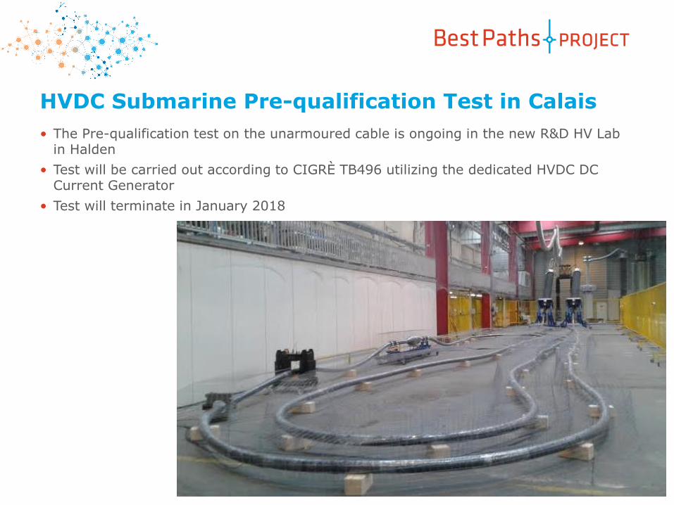
HVDC Submarine Pre-qualification Test in Calais
• The Pre-qualification test on the unarmoured cable is ongoing in the new R&D HV Lab in Halden
• Test will be carried out according to CIGRÈ TB496 utilizing the dedicated HVDC DC Current Generator
• Test will terminate in January 2018

1st Steering Committee / 29th October 2014 / Rome23
HVDC Land Pre-qualification Test in Calais
• The Pre-qualification test on the fully armoured cable has been interrupted after a breakdown in the cable.
• A new production run is planned for 3Q 2017 to eneble testing of Land System
• Test Voltage has been selected at 500kV
• New Test will initiate in 1Q 2018

1st Steering Committee / 29th October 2014 / Rome
HVDC Extruded Submarine
400 kV cable
• Not a small cable (43 kg/m)
• As compact as possible
• Very strong (can resist without damage to
50 tons of pull
• Completely impervious to water ingress
• Fondamentally the same as your pc cable
Just slightly bigger
24

1st Steering Committee / 29th October 2014 / Rome25
HVDC Submarine Pre-qualification Test in Halden
• The Pre-qualification test on the fully armoured cable is ongoing in the new R&D HV Lab in Halden
• Test will be carried out according to CIGRÈ TB496 utilizing the dedicated HVDC DC Current Generator
• Test will terminate in August 2018
1st Steering Committee / 29th October 2014 / Rome
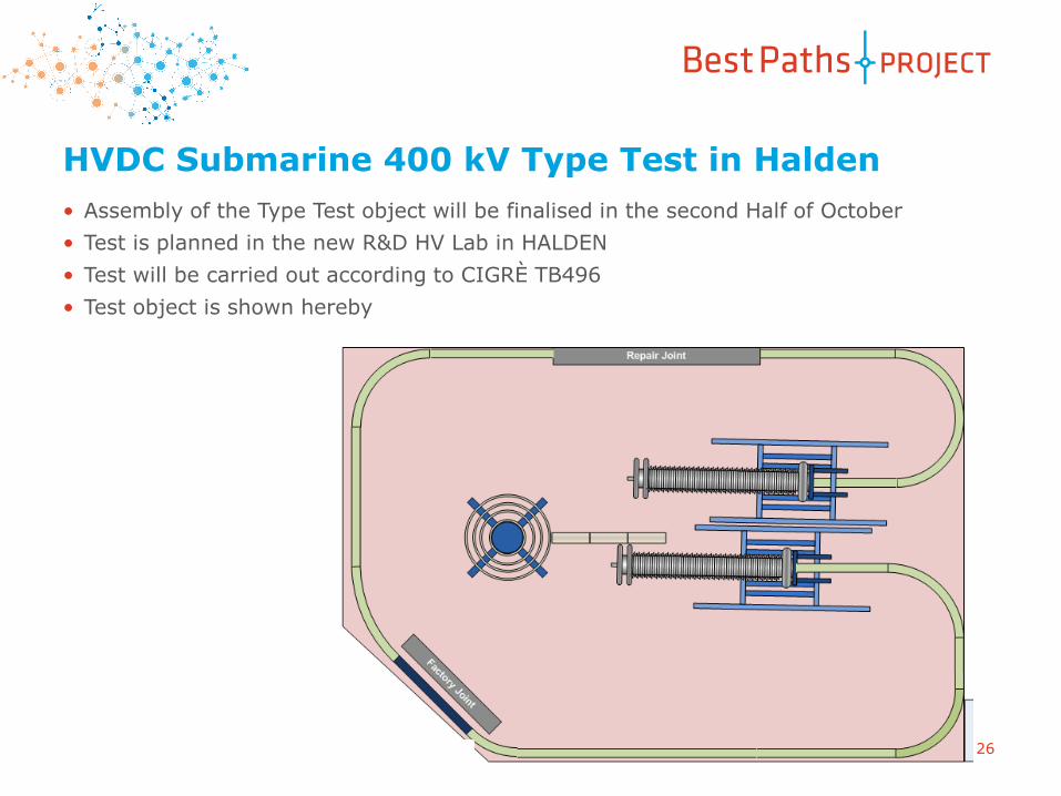
HVDC Submarine 400 kV Type Test in Halden
• Assembly of the Type Test object will be finalised in the second Half of October
• Test is planned in the new R&D HV Lab in HALDEN
• Test will be carried out according to CIGRÈ TB496
• Test object is shown hereby
26

1st Steering Committee / 29th October 2014 / Rome
ACFR Conductor
Kevlar® Fibres Core
Aramid fibre core

1st Steering Committee / 29th October 2014 / Rome
ACFR Kevlar ConductorRECAP:
•Characterizations test @RSE lab
• Stress Strain
• Tensile strength
• Sag and coefficient of thermal expansion determination
• Thermal cycling
• Fittings Stability
• Self Damping

1st Steering Committee / 29th October 2014 / Rome
Aluminium Alloy wires
Carbon core multistrand
Extruded tube
Tape
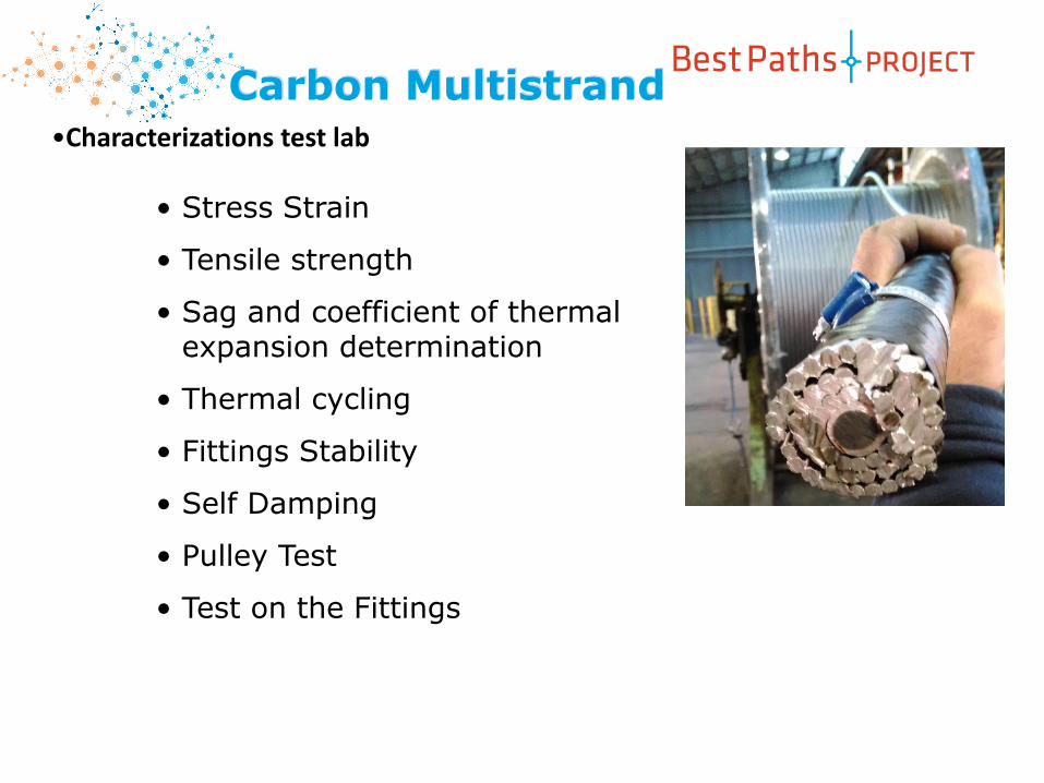
Carbon Multistrand
1st Steering Committee / 29th October 2014 / Rome
Carbon Multistrand•Characterizations test lab
• Stress Strain
• Tensile strength
• Sag and coefficient of thermal expansion determination
• Thermal cycling
• Fittings Stability
• Self Damping
• Pulley Test
• Test on the Fittings

1st Steering Committee / 29th October 2014 / Rome31
Next Steps
• Continue of the characterization test @RSE lab
• Installation test beginning 2018
• Installation pilot line
Carbon Fiber Conductor:
• Continue of the characterizations test @RSE lab
• Installation test
• Installation pilot line
ACFR Conductor:

1st Steering Committee / 29th October 2014 / Rome32
Task5.4: “Requirements and specifications for optimal sizing of insulation”
Task 5.4• Long duration multi-stress
ageing test on RTV, fullyand partially, coveredinsulator chains: aftermore than 1000h (the testduration is 2000h) the firstphenomena of erosionsare taking place on someof the chains under test.The measured leakagecurrents are on the order,at max, of 20-30 mA(relatively low values).

1st Steering Committee / 29th October 2014 / Rome33