Embed Size (px)
Citation preview

Dissertationsubmittedto the
CombinedFacultiesfor theNaturalSciencesandfor Mathematicsof theRuperto-CarolaUniversityof Heidelberg, Germany
for thedegreeofDoctorof NaturalSciences
presentedbyDipl.-Phys.Udo Eisenbarth
bornin Koblenz
Oralexamination:21thNovember2001

ii

iii
Laser cooling of fast stored ion beams to extremephase-space densities
Referees:Priv.-Doz.Dr. MatthiasWeidemuller
Priv.-Doz.Dr. WolfgangQuint

iv
v
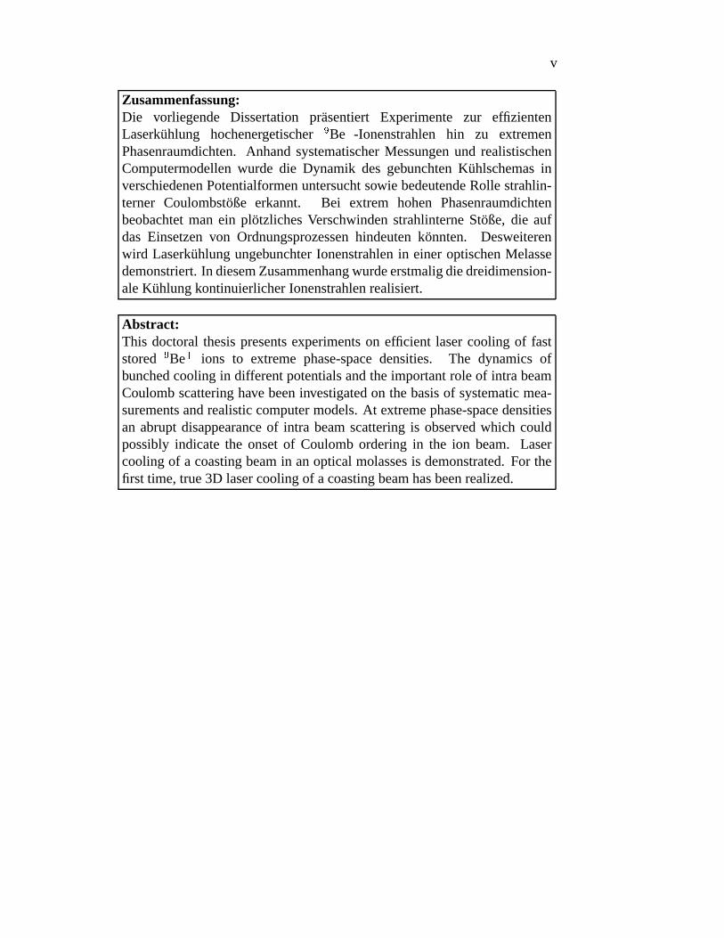
Zusammenfassung:Die vorliegende Dissertation prasentiert Experimente zur effizientenLaserkuhlung hochenergetischer
�Be�
-Ionenstrahlen hin zu extremenPhasenraumdichten.AnhandsystematischerMessungenund realistischenComputermodellenwurde die Dynamik des gebunchtenKuhlschemasinverschiedenenPotentialformenuntersuchtsowie bedeutendeRolle strahlin-terner Coulombstoße erkannt. Bei extrem hohen Phasenraumdichtenbeobachtetman ein plotzlichesVerschwindenstrahlinterneStoße,die aufdas Einsetzenvon Ordnungsprozessenhindeutenkonnten. Desweiterenwird LaserkuhlungungebunchterIonenstrahlenin eineroptischenMelassedemonstriert.In diesemZusammenhangwurdeerstmaligdiedreidimension-aleKuhlungkontinuierlicherIonenstrahlenrealisiert.
Abstract:This doctoralthesispresentsexperimentson efficient lasercooling of faststored
�Be�
ions to extreme phase-spacedensities. The dynamicsofbunchedcoolingin differentpotentialsandtheimportantrole of intra beamCoulombscatteringhave beeninvestigatedon thebasisof systematicmea-surementsandrealisticcomputermodels.At extremephase-spacedensitiesan abruptdisappearanceof intra beamscatteringis observed which couldpossibly indicatethe onsetof Coulombordering in the ion beam. Lasercoolingof a coastingbeamin anopticalmolassesis demonstrated.For thefirst time, true3D lasercoolingof acoastingbeamhasbeenrealized.

vi

Contents
1 Intr oduction 1
2 Basicsof ion beamcooling 72.1 Faststoredion beams. . . . . . . . . . . . . . . . . . . . . . . . 72.2 Cold ion beams . . . . . . . . . . . . . . . . . . . . . . . . . . . 8
2.2.1 Beamtemperatures. . . . . . . . . . . . . . . . . . . . . 82.2.2 Intrabeamscattering. . . . . . . . . . . . . . . . . . . . 102.2.3 Coolingrate. . . . . . . . . . . . . . . . . . . . . . . . . 112.2.4 Beamcrystallization . . . . . . . . . . . . . . . . . . . . 12
2.3 Lasercooling . . . . . . . . . . . . . . . . . . . . . . . . . . . . 142.3.1 Longitudinalcooling . . . . . . . . . . . . . . . . . . . . 152.3.2 Transversecooling . . . . . . . . . . . . . . . . . . . . . 17
2.4 Experimentaltechniques . . . . . . . . . . . . . . . . . . . . . . 202.4.1 Lasersystemat 300nm . . . . . . . . . . . . . . . . . . . 212.4.2 Beambunching . . . . . . . . . . . . . . . . . . . . . . . 222.4.3 Diagnostictools . . . . . . . . . . . . . . . . . . . . . . 262.4.4 Coolingprocedure . . . . . . . . . . . . . . . . . . . . . 32
3 Anomalousbehavior of laser-cooledbunchedbeams 353.1 Lasercoolingof bunchedbeams . . . . . . . . . . . . . . . . . . 353.2 Systematicmeasurements& comparisonwith simulations. . . . . 37
3.2.1 Longitudinaldynamics:observations . . . . . . . . . . . 373.2.2 Longitudinaldynamics:model . . . . . . . . . . . . . . . 403.2.3 Longitudinaldynamics:comparisonof bunchforms . . . 433.2.4 Transversedynamics . . . . . . . . . . . . . . . . . . . . 47
3.3 Anomalousbeambehavior at extremephase-spacedensities . . . 493.3.1 Longitudinaldynamics. . . . . . . . . . . . . . . . . . . 503.3.2 Transversedynamics . . . . . . . . . . . . . . . . . . . . 55
3.4 Conclusion . . . . . . . . . . . . . . . . . . . . . . . . . . . . . 56
vii
viii CONTENTS
4 Coastingbeamcooling in an optical molasses 594.1 Lasersystemat 326nm . . . . . . . . . . . . . . . . . . . . . . . 60
4.1.1 Frequency doubling . . . . . . . . . . . . . . . . . . . . 614.1.2 Experimentalrealization . . . . . . . . . . . . . . . . . . 62
4.2 Measurements. . . . . . . . . . . . . . . . . . . . . . . . . . . . 704.2.1 Dopplerthermometry. . . . . . . . . . . . . . . . . . . . 704.2.2 Longitudinalcooling . . . . . . . . . . . . . . . . . . . . 734.2.3 Transversecooling . . . . . . . . . . . . . . . . . . . . . 85
4.3 Conclusion . . . . . . . . . . . . . . . . . . . . . . . . . . . . . 88
5 Outlook 89
A Electron cooling forcemeasurementsusingbarrier buckets 91A.1 Introduction . . . . . . . . . . . . . . . . . . . . . . . . . . . . . 91A.2 Descriptionof themethod . . . . . . . . . . . . . . . . . . . . . 92A.3 ExperimentalRealization. . . . . . . . . . . . . . . . . . . . . . 95A.4 Forcemeasurement. . . . . . . . . . . . . . . . . . . . . . . . . 97A.5 Conclusion . . . . . . . . . . . . . . . . . . . . . . . . . . . . . 98
B Measurementsystem 99

Chapter 1
Intr oduction
Over the years, the physics with fast stored ion beams has evolved intoa large researchfield with many dedicatedacceleratorand storagefacilitiesaround the world. With the advance of cooling techniques[Møller, 1994]suchas electroncooling and stochasticcooling a new classof high-precisionexperimentsbecamepossible. Cold ion beams in a storage ring can beused to perform high-precision mass measurements(Schottky mass spec-trometry) [Radonet al., 1997], investigationsof short-living isotopescooledand stored in traps [Bollen et al., 1996] and precise tests of special relativ-ity [Grieseret al., 1994]. By recombinationexperiments, atomic structures[Wolf et al., 2000] andQED effects[Brandauet al., 1999] areinvestigated.Coldion beamscould also becomean important tool in inertial fusion reactions[Bock, 1997]. The studyof the dynamicsof storedcold ion beamsitself deliv-ersimportantresultson thephysicsof non-neutralcold plasmasat high centerofmassenergies[Miesner, 1995, Lauer, 1999, Madsenet al., 1999].
All cooling methodsusedat storagerings have to fight againstextremelystrongheatingprocesses.This heatingessentiallystemsfrom envelopeoscilla-tions due to the alternatingfocusingof the beamalong the ring in connectionto intra beamCoulombscattering(IBS) [Sørensen,1987]. Figure1.1 shows thecoupling of the degreesof freedomfor ions in a storagering. The energy forIBS heatingcomesfrom the kinetic beamenergy which representsa hugeheatbath. Sincethe collision rate dependson the phase-spacedensity, this heatingmechanismbecomesevenstrongerduringthecoolingprocessfinally limiting theachievabletemperatures.
Lasercooling is a techniqueto achieve muchhighercooling ratesIt is par-ticularly suitedfor low-charged ions whereelectroncooling becomesratherin-efficient. Laser cooling relies on the radiation-pressureforce exerted by res-onancelaser light on the ions. The light force arises from repeatedmo-mentumtransfer in a seriesof many absorption-spontaneousemissioncycles
1

2 Chapter1. Introduction
dispersion
envelopeoszillation
envelopeoszillation
Be ions @ 7.3MeVbeam energy
laser cooling
betatron coupling
dispersion
horizontalmotion
verticalmotion
longitudinalmotion
IBS
Figure 1.1: Couplingsbetweenthedegreesof freedomfor an ion beamat a highcenterof massenergy.
[Metcalf andvanderStraten,1999]. For moving ions the Doppler effect trans-latesthis frequency dependency force into velocity-dependentfriction force. Ata storagering lasercoolingcanberealizedby merging a laserbeamwith theionbeamalonga straightsectionof the storagering (figure 1.2). Onetheonehand
laser beam
TSR
1 m
D D
D
D
DD
D
D
injection
laser cooling section
Figure 1.2: Implementationof lasercoolingat theHeidelberg TestStorageRing(TSR).For laser cooling the ion beamis merged with a laser beamwhosefre-quencyis nearlyresonantwith a Doppler-shiftedtransitionline of theions.
lasercooling is restrictedto somelight ions suchas Li�
, Be�
or Mg�
having

3
an optical transitionwith a wavelengthaccessibleto a lasersystem.However itturnedout that lasercooling is anextremelyefficient cooling processleadingtophase-spacedensitiesthatcannotbeachievedwith othercooling techniquesat astoragering. Lasercooling experimentshave beenperformedwith Lithium andBeryllium ionsat TSR[Schroderet al., 1990] at beamenergiesof MeV andwithMagnesiumionsat 100keV in theASTRID storagering [Hangstet al., 1991].
Sincethelaserforceonly eitheracceleratesor deceleratestheions,beamcool-ing canonly be realizedby providing an additionalcounterforce.In early lasercooling experimentsthis counterforcewaseither realizedusinga secondcoun-terpropagatinglaser[Schroderet al., 1990]or an inductionaccelerator(INDAC)[Ellert et al., 1992, Petrichet al., 1993]. Theseexperimentsrevealedthe impor-tant role of hard Coulombcollisions leadingto ion velocity changesof about1000m/s. The collisions lead to lossesfor the cooling processdue the smallcapturerangeof the laserforce ( � �����
m/s). Theselossescould be suppressedby the useof a capturerangeextensionrealizedthrougha rapid adiabaticpas-sage[Wanneretal., 1998]. With theintroductionof beambunchingto realizethecounterforceby theapplicationof apseudopotentialconfiningtheionsin thelon-gitudinaldirectionit waspossibleto overcomethetime limitation of theINDACmethod[Hangstetal., 1995b, Miesneretal., 1996a].Bunchedcoolingalsoleadsto a“recycling” of ionsthathaveundergoneaCoulombcollisionoutof thecapturerange.
Lasercoolingcandirectly cool only the longitudinaldegreeof freedom.Di-rect transverselasercoolingby shiningin light perpendicularto thedirectionofmotion is practically not possible. The reasonsare the short interactiontimesandthe sensitivity to tiny angledeviationsbetweenlaserand ion beamleadingto large Doppler shifts. However, methodshave beendevelopedto also coolthe beamtransversally: sincethe degreesof freedomare coupledthroughcol-lisions, the directly cooledlongitudinaldirectionactsasa heatsink which alsoleadsto a temperaturereductionof the transversedirections(indirect cooling)[Miesneretal., 1996b]. In addition the ring dispersion leadsto a coupling be-tweenthe horizontalposition of the closedorbit and the longitudinal ion mo-mentum(figure1.1.Combiningdispersivecouplingwith linearbetatroncoupling[Bryant,1994] we realizedfull 3D lasercooling which doesnot dependon thephase-spacedensity[Laueret al., 1998].
In theframework of this thesis,systematicmeasurementson lasercoolingofbunchedbeamsin variouspotentialshapeshave beenperformed.Theseexperi-mentsgive a very clearpictureof the short-andthe long-termdynamicsof thecoolingprocess.Realisticcomputersimulationshave beendevelopedto identifykineticeffectsof theion ensembleexperiencingnon-linearcoolingforcesandtheinfluenceof differentbunchingpotentialson thecoolingdynamics.Furthermorethe implementationof collisions into the modelgivesa detailedinsight on the

4 Chapter1. Introduction
crucialrole of intra beamscatteringfor thelasercoolingdynamics.With theseexperimentsthecoolingparametershavebeenoptimizedto achieve
efficient 3D coolingto unprecendentedphase-spacedensitiesin storagerings. Inthisextremeregimeweobservedasuddenanomalousbeambehavior whichshowsthe signatureof Coulombordering: at very high phase-spacedensitiesthe mu-tual Coulombrepulsionof the ions significantly influencesthe behavior of thebeam. In particular, if the thermalenergy becomescomparableto the Coulombenergy which is expressedby theplasmaparameter ���� ����������������������! "�$# �
,ions can no longer overtake eachother. For �&% ��'�(
the formation of theseWigner crystalshasalreadybeenobserved andstudiedin variousion trapsforensemblesat rest[Walther, 1993]. For low kinetic energiesof about1eV recentexperimentsdemonstratedthe formationof a laser-cooledcrystallizedion beamrevolving in a small circular quadrupoletrap (PALLAS) [Schatzet al., 2001].The questionof a possibleCoulomb ordering in an ion beamrevolving withsomepercentof thespeedof light is onemotivationfor our coolingexperiments[HabsandGrimm,1995]. A crystallineion beamrepresentsthe ultimatephase-spacedensityreachableat a storagering. Orderingphenomenaat beamener-giesof several hundredMeV have beenobserved for electron-cooledbeamsofhighly chargedions [Stecketal., 1996]. In this casethe experimentshave beenperformedwith anextremelysmallnumberof ions. Typical ion distancesareontheorderof severalcentimetersupto meters.Coulomborderingtakesplacein thesensethattwo revolving ionsdonotovertakeeachother, but they arereflecteddueto theelectrostaticrepulsion[Hasse,1999]. However, dueto the largedistancesonedoesnotachievecrystallinestructureswith a long-rangeorder.
Theoreticalcalculations[HasseandSchiffer, 1990] show that thestructureofa crystallizedion beamstronglydependson the ion number. The lowestcrys-talline structureis theone-dimensionallinearchainwhereion aremoving alongthe closedorbit with well-defineddistancesfrom eachother. For higher beamdensitiesthe ions startevadingfrom eachotherforming a two-dimensionalzig-zagarrangementor higher3D structures.Moleculardynamicssimulationsdonefor ourexperimentalconditions(
�Be�
ionsat7.3MeV in theHeidelberg teststor-agering TSR)predictthatonly the linearchainandpossiblytheverticalzig-zagarestablystoragable[Wei et al., 1995]. Higherorder3D structureswould bede-stroyeddueto shearforceoccurringin thebendingmagnetsof thestoragering.Themaximumtotal ion numberfor theformationof a linearion chainat theTSRaccordingto thesimulationwouldbe
����).
Our experimentsindeedshow a suddendisappearanceof intra beamscatter-ing during the cooling processat the predictedparticlenumber. This would bethe signaturefor the formation of orderedstructures: for a crystallizedbeam,collisions are completelysuppresseddue to the fixed relative ion positionsinthe beam. However, other interpretationsof this phenomenonassumingad-

5
ditional heatingprocessesor effects of the bunchedcooling mechanismitselfcannotbe excluded. Anomalousbeambehavior during lasercooling hasalsobeenobserved at ASTRID leading to density limitations [Madsenet al., 1999]and suddentransversebeamblowups monitoredwith real-timeimaging meth-ods[Kjærgaardet al., 2000]. However, theseeffectshavenot beenobservedwithdispersively cooledbeams.
In orderto ruleouteffectsrelatedto thebunchedcoolingmethod,experimentsoncoastingbeamcoolingin aone-dimensionalopticalmolasseshavebeencarriedout. Cooling of a coastingbeamis achievedusinga secondcounterpropagatinglaserto apply a deceleratingforce thus forming a one-dimensionaloptical mo-lasses.We presentthe technicalaspectsof this coolingschemesuchasthe lasersystemaswell asadetailedinvestigationof thecoolingdynamics.In additionwedemonstratethefirst realizationof full 3D lasercoolingof acoastingion beaminastoragering.
Thisthesisis organizedasfollows: Chapter2 givesanintroductionto thebasicprinciplesaswell astheexperimentaltechniquesneededfor efficient lasercoolingof faststoredions. The dynamicsof bunchedlasercooling on the basisof sys-tematicmeasurementsandcomputersimulationsis presentedin chapter3. Herewe alsodescribethesuddenanomalousbehavior of the laser-cooledion beamatextremephase-spacedensities.Chapter4 coversthe descriptionandthe resultsof coastingbeamcoolingexperimentsin a one-dimensionalopticalmolasses.Anoutlookto futureexperimentsis givenin chapter5.

6 Chapter1. Introduction

Chapter 2
Basicsof ion beamcooling
2.1 Fast stored ion beams
Fast ion beamsmoving with velocitiesin the orderof the speedof light canbestoredin anultra-highvacuumpipeemploying theLorentzianforce *+ -,/. *0�1 *243via magneticfields [Wille, 1996]. Magneticdipole fields perpendicularto thedirectionof motion areusedto deflectthe beamin orderto form a closedorbit(figure2.1).
laser beam
TSRelectroncooler
1 m
D D
D
D
DD
D
D
extractioninjection
beam profile
laser cooling section
monitor
Figure2.1: Schematicpictureof theHeidelberg TestStorageRing(TSR).
Due to the mutualrepulsive Coulombinteractionandthe unavoidableanglespreadin thedirectionof motion,thebeamhasalsoto beconfinedin thetransverse
7

8 Chapter2. Basicsof ion beamcooling
degreeof freedomin order to producestableparticle trajectories. A magneticquadrupolefield providesa focusingforce in onedirectionanda defocusingonein the other. It hasbeenshown that the useof quadrupolepairs can be usedto confinethemotion of the revolving ions in bothdirections(alternategradientfocusing)[CourantandSnyder, 1958]. In this magneticstructure(lattice), ionsperformanoscillatorymotionaroundtheclosedorbit (betatronoscillation). Thismotion in the transversedegreeof freedom5 for a longitudinalposition 6 in thestoragering is describedby57.86 3 :9 ;=<>.86 3@?BA�CED .F6 3 G
(2.1)
The amplitudeconsistsof the emittance; which is a constantof motion corre-spondingto theoccupiedphase-spacevolumeandthestoragering function <H.F6 3whichrelatesto thefocusingstrengthof thequadrupolemagnets.Thephase
D .F6 3is calculatedas
D .86 3 JIEKLNM 6POQ�R<>.86BO 3 . The numberof oscillationper round-trip(tune S D .FT 3 � 'VU , T : ring circumference)must not be an integer numberwhich would drive thebetatronoscillationleadingto an immediateparticleloss(storagering resonance).
Thevelocity dependenceof theLorentzianforce leadsto a differentbendingradiusfor ionsmoving with differentvelocities.Hence,theclosedorbit grows orshrinkswith respectto thelongitudinalmomentum(storagering dispersion). Theorbital displacementWX5 in the horizontaldegreeof freedomwith respectto therelativechangeof longitudinalmomentumis describedbyWX57.86 3 -YZ.F6 3 W\[[ G
(2.2)
As we will see,this importantcouplingmechanismbetweenthe longitudinalionmotionandits transversepositionwill beexploited for efficient transversebeamcooling.
2.2 Cold ion beams
2.2.1 Beamtemperatures
Strictly speaking,theterm temperature is only definedfor particleensemblesbe-ing in thermalequilibrium.As wewill seein thefollowing sections,this is not thecasefor beamcoolingat a storagering. Thecorrectthermodynamicdescriptionwould requirea Fokker-Planckapproach[Risken,1989]. This equationdeliverscorrectresultsfor electron-cooledbeams.However in caseof lasercooling theassumptionof a constantdiffusioncoefficient is no longervalid dueto thesignif-icantinfluenceof intra beamscatteringon thecoolingprocess(section2.2.2).

2.2. Cold ion beams 9
All known techniquesusedfor beamcoolingat storageringsshow a stronglydifferentcoolingdynamicsfor thetransverseandthelongitudinaldegreesof free-dom. This leadsto a stronganisotropy of the 3D ensemble.Sincethe numberdensityof the ion beamis low enoughto neglect all thermalcouplingsin firstorderapproximation,onecantreatthe threedegreesof freedomasdistinct ther-modynamicensemblesinteractingwith eachother(figure 2.2). In caseof lasercooling,eventhelongitudinalphase-spaceitself doesnot reachanequilibriumina thermodynamicsensebut a steadystateonly. The reasonfor that is thestrongnon-linearityof thecoolingforce(section2.3).
For the longitudinal degreeof freedomit is convenient for the descriptionto usea frame moving with the main velocity of the circulating ions. In thispicturethedescriptiononly includesthe position W]6 andthevelocity W 0 of theions with respectto the moving frame. The longitudinal energy is the sum ofpotentialan kinetic energy �^._W`6�abW 0 3 �Ncd�e�b.FW]6 3gf �Nhji�kl.FW 0 3 . Sincethereareno additionalmechanismsleadingto anenergy termwhich dependson bothvelocityandposition,thephase-spacecanbeseparatedin a spatialandavelocitydistribution.
Although the longitudinal ion ensembleis not in thermalequilibrium, onecanascribea measurefor the velocity spreadof the distribution which hasthedimensionof a temperature m n &o �Nhpi�kl.FW 0 3=qr � a (2.3)
where o �Nhji�ks.FW 0 3=q is the meankinetic energy of the ion beamin the comovingframe. It can be calculatedfrom the variance tvuw of the velocity distribution( o �Nhji�k q yxztvuw ). Thereforeonegetsm n xr � t uw a (2.4)
( x : ion mass).Onehasto bearin mind that thevelocity spreadt w is not boundto a certain shapeof the velocity distribution but follows the generalrelationt w 9 o W 0 q|{ o ._W 0 3 u q . For a thermallyequilibratedensembleonewould ex-pectaGaussianshapeaccordingBoltzmann’sdistribution . In this casetheaboverelationcorrespondsexactly to thethermodynamicdefinitionof a temperature.
In orderto geta temperatureof the transversedegreeof freedomwe canex-presstheenergy �^.}5~a=5 O 3 by theparticlemomentumandthelatticefunctions��a�<[Wille, 1996]. Again, thetransversebeamenergy is thesumof potentialandki-netic energy. Without any cooling mechanisms,the transversebeamenergy isa constantof motion. The potentialenergy resultsfrom the focusingstructure(quadrupolemagnets)of thestoragering. Sincethefocusingstrengthis not con-stantalong the ring position,also the transversekinetic energy dependson the
10 Chapter2. Basicsof ion beamcooling
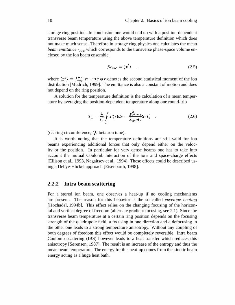
storagering position. In conclusiononewould endup with a position-dependenttransversebeamtemperatureusingthe above temperaturedefinition which doesnot make muchsense.Thereforein storagering physicsonecalculatesthemeanbeamemittance;j ���� whichcorrespondsto thetransversephase-spacevolumeen-closedby theion beamensemble.<�;j "���� o 5 u q G
(2.5)
where o 5�u q �I ���� � 5�uN����.}5 3 M 5 denotesthesecondstatisticalmomentof the iondistribution[Mudrich, 1999]. Theemittanceis alsoaconstantof motionanddoesnotdependon thering position.
A solutionfor thetemperaturedefinitionis thecalculationof a meantemper-atureby averagingtheposition-dependenttemperaturealongoneround-tripm � �T���
m .86 3 M 6� [ uL ;j "���rs� x�T 'VU S G(2.6)
( T : ring circumference,S : betatrontune).It is worth noting that the temperaturedefinitions are still valid for ion
beamsexperiencingadditional forces that only dependeither on the veloc-ity or the position. In particular for very densebeamsone has to take intoaccountthe mutual Coulomb interactionof the ions and space-charge effects[Ellison et al., 1993, Nagaitsev et al., 1994]. Theseeffectscouldbedescribedus-ing aDebye-Huckel approach[Eisenbarth,1998].
2.2.2 Intra beamscattering
For a stored ion beam, one observes a heat-up if no cooling mechanismsare present. The reasonfor this behavior is the so called envelope heating[Hochadel,1994b]. This effect relieson the changingfocusingof the horizon-tal andverticaldegreeof freedom(alternategradientfocusing,see2.1).Sincethetransversebeamtemperatureat a certainring positiondependson the focusingstrengthof the quadrupolefield, a focusingin onedirectionanda defocusingintheotheroneleadsto a strongtemperatureanisotropy. Without any couplingofboth degreesof freedomthis effect would be completelyreversible. Intra beamCoulombscattering(IBS) however leadsto a heat transferwhich reducesthisanisotropy [Sørensen,1987]. Theresultis anincreaseof theentropy andthusthemeanbeamtemperature.Theenergy for thisheat-upcomesfrom thekineticbeamenergy actingasahugeheatbath.
2.2. Cold ion beams 11
relaxation
dispersion
envelopeoszillation
evelopeoszillation
T
long
hor
T
Tver
kineticenergy
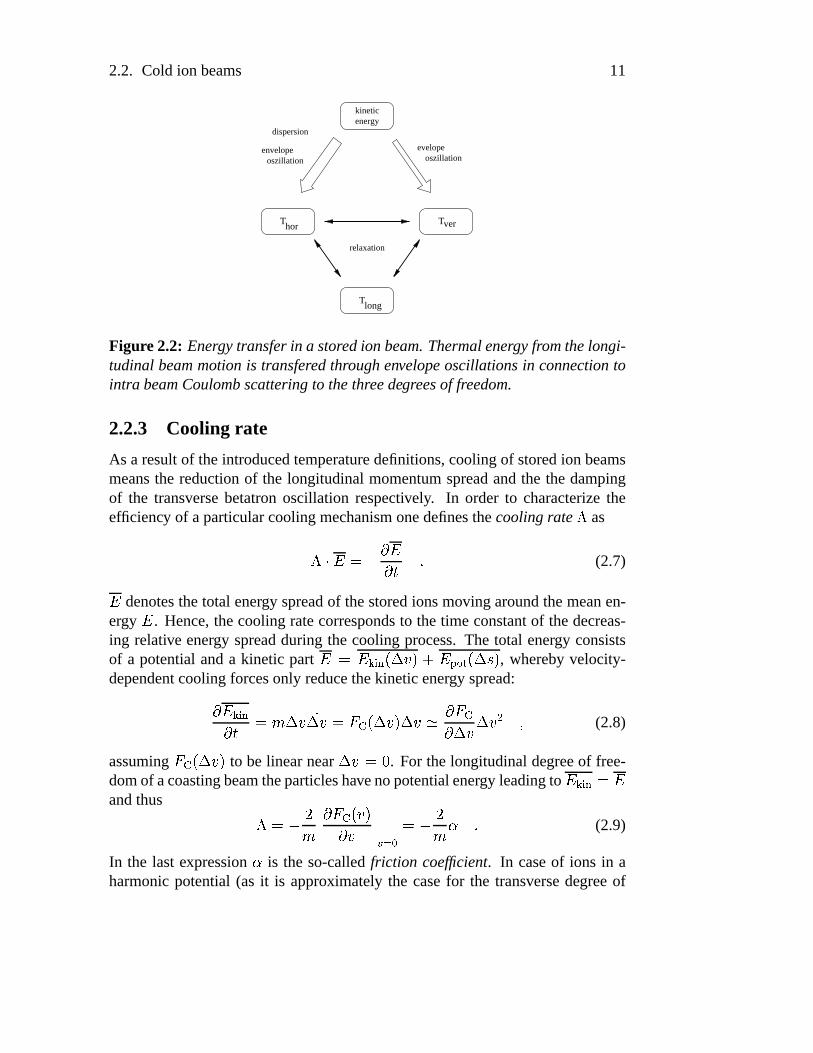
Figure2.2: Energy transferin a storedion beam.Thermalenergy fromthelongi-tudinal beammotionis transferedthroughenvelopeoscillationsin connectiontointra beamCoulombscatteringto thethreedegreesof freedom.
2.2.3 Cooling rate
As a resultof theintroducedtemperaturedefinitions,coolingof storedion beamsmeansthe reductionof the longitudinalmomentumspreadandthe the dampingof the transversebetatronoscillation respectively. In order to characterizetheefficiency of aparticularcoolingmechanismonedefinesthecoolingrate � as��� �� {�� ��/� G
(2.7)� denotesthetotal energy spreadof thestoredionsmoving aroundthemeanen-ergy � . Hence,thecoolingratecorrespondsto thetime constantof thedecreas-ing relative energy spreadduring the cooling process.The total energy consistsof a potentialanda kinetic part �� �Nhpi�k�.FW 0 3�f �Ncd�e�b.FW]6 3 , wherebyvelocity-dependentcoolingforcesonly reducethekineticenergy spread:� �Nhpi�k�/� -x�W 0��W 0 + �.FW 0 3 W 0 # � + � W 0 W 0 u a (2.8)
assuming+ ~.FW 0 3 to be linearnear W 0 �
. For thelongitudinaldegreeof free-domof acoastingbeamtheparticleshavenopotentialenergy leadingto �Nhji�k� �andthus �� { 'x � + �. 0 3� 0 ����� wj� L { 'x � G
(2.9)
In the last expression� is the so-calledfriction coefficient. In caseof ions in aharmonicpotential(as it is approximatelythe casefor the transversedegreeof

12 Chapter2. Basicsof ion beamcooling
freedom)theviral theoremrequiresthat o �Nhpi�k q o �Ncd�e� q . Hence,thecoolingratewouldbehalf thevalueof Equation.2.9.
2.2.4 Beamcrystallization
During beamcooling the phase-spacedensityof the ensemblebecomessteadilyhigherandhigher. In this casethemutualCoulombinteractionof theionscannolongerbeneglected.Thewholedynamicsof suchacoldbeambecomesmoreandmoredominatedthetheintra-beaminteractions.
A faststoredion beamof high phases-spacedensitycanbetreatedasa one-component,non-neutralandspace-charge dominatedplasma. Sucha plasmaischaracterizedby theplasmaparameter�Z �� �������������������! "� � U ; L � , u¡ r�� m (2.10)
which representsthe ratio of the Coulombenergy due to the repulsive electro-staticforcesbetweenneighboringionsandthetemperatureof theensemble.Foranisotropicplasma,thecharacteristicdistance¡ becomestheWigner-Seitzradius¡ ¢9 £ �/. U � 3 where � is thespatialnumberdensity[HabsandGrimm,1995].With this definitiona thermalweaklycoupledplasmais expressedby �¥¤ �
. Ashort-rangeonedimensionalliquid-likestatewouldbeexpectedfor �¦� �
. In thiscasethethermalenergy is in thesameorderof theCoulombenergy. This meansthattwo storedion moving with slightly differentvelocitiescannotovertakeeachotherdueto their Coulombrepulsion.In this case,theion beamshouldshow uporderingeffects.A long-rangeorderis expectedfor �¥% ��(��
[Hasse,1999]. Theshapeof this orderedstructuredependson theion density. At largeion distancesthelowestorderstructurewould bea linearchain.With decreasingdistancestheionsstartevadingfrom eachotherforming a zig-zagline or helix-like structures[HasseandSchiffer, 1990]. For anion beamstoredin theTSRit is expectedthatonly the linearchainandpossiblytheverticalzig-zagstructureto bestablystor-agable.Higherorder3D structureswould experiencestrongshearforcesduringbeamdeflectionat thebendingmagnets.
For thetreatmentof laser-cooledion beamsonehasto take into accountthatthe3D ensembleof thecooledbeamis far away from thermalequilibrium. Dueto theextremetemperatureanisotropy (
m n # �K,
m �-§ '����K) a morerealistic
pictureof anorderedbeamis shown in figure2.3. While a laser-cooledion beamhasa very smallvelocity spread,thetransversedegreeof freedomis comparablyweakly cooled. An orderedbeamwould thereforeleadto a spatialdistribution,whereionshaveawell-definedlongitudinalintermediatedistancefrom eachotherbut theirbetatronamplitudesarestill large.Theion beamcanthereforebeseenas

2.2. Cold ion beams 13
v0
s
x d
Figure 2.3: Disk modelof a crystallizedion beam.Whileionshavewell-definedlongitudinaldistancesthey still oscillatewith largebetatronamplitudes.
asetof chargediskswith adistanceM anda transversesizeof t assumingaradialGaussiancharge distribution. Obviously, in this casethe above definitionof theplasmaparameterdoesnot make senseany longer. However, a one-dimensionalplasmaparametercanbe definedrepresentingthe ratio of the Coulombenergyof two chargedisksandthethermalenergy of thelongitudinaldegreeof freedom( � n $�N����k�¨�. M a�t 3 �����"�=�_ ��N. m n 3 ). TheCoulombenergy of two chargediskswith theradialchargedistributions ©@ª«. *5 3 © u . *5 O 3 is calculatedas
�N����k�¨�. M a�t 3 ¬� � + ��.F®�a�t 3 M ® a (2.11)
with + ��.F®�a�t 3 � U ; L Ms¯ 5 Ms¯ 5 O ©@ªB. *5 3 © u . *5�O 3° *5 { *5 O ° .86 { 6 O 3 G(2.12)
Throughthe intermediatedistanceM this definition also take the linear numberdensityinto accountby
� � M Ml± � M 6 . Note,that this definitiongivesno quanti-tativemeasurein case� n ¤ �
for phase-spacebut aqualitativedeviation from anorderedstate.
For very low beamdensities,the intermediateparticle distance M is smallcomparedto the amplitude 5 of the betatronoscillation. In this case,the one-dimensionaldefinitionof theplasmaparametergivesway to the3D definition. Inthe comoving frame,the transversallyoscillatingions approacheachotheruntilthey are reflecteddue to the repulsive Coulombinteraction(figure 2.4. In thispicture,it is possibleto estimateatransversebeamtemperatureneededto observeCoulombordering:Theminimumdistancebetweento approachingionsisM � U ; L � ,Rur�� m n G
(2.13)

14 Chapter2. Basicsof ion beamcooling
d
x closed orbit
Figure 2.4: Beamcrystallizationcanbetreatedasa one-dimensionalproblemifthe intermediatedistanceM is small compared to thebetatron amplitude5 . Ionsapproach each otherandare reflecteddueto therepulsiveCoulombinteraction.
Thebetatronamplitudecanbeestimatedas5�:² ' r��m �x � �'VU�³�´ a (2.14)
with the betatronfrequency³Vµ·¶ � ¡ . The combinationof both equationswith the
assumption5z¤ M leadsto anestimationof thetransversetemperaturefor agivenlongitudinaltemperaturer�� m � ¤ x '¹¸ ³�´' ; L � ,Vurs� m n�º u G
(2.15)
At theexperimentalconditions(�Be�
atTSR),a longitudinaltemperatureof
m n #�K leadsto
m � ¤ �K. For
m n # �P���mK atransversetemperatureof
m � ¤ �����K
wouldbenecessary.
2.3 Laser cooling
As shown above,beamcoolingmeansareductionof thevelocityspreadof theionensemble.Accordingto Liouville’ s theorem,phase-spacedensityis aconstantofmotion if oneusesonly conservative forces. Hence,oneway to achieve beamcoolingis theuseof velocity-dependentfriction forces.This forcemustbeabletoaccelerateionsmoving tooslow aswell asdecelerateionsmoving toofast.At thestoragering, two methodsareusedto compressphase-space:electroncoolingandlasercooling.For electroncoolingthehot ion beamis mergedwith acoldelectronbeam.ThroughCoulombcollisionsbetweenionsandelectrons,theelectronbeamactsasaheatsinkfor theion beam.Ionsmoving to slow areacceleratedby theionbeamandviceversa.Themeanvelocitywheretherevolving ionsaredrawn to isdeterminedby thevelocityof theelectronbeam.In our experiments,theelectroncooleris usedto precoolthehot ion beamright afterinjectionbeforestartinglasercooling. A moredetaileddescriptionof electroncoolingis givenin AppendixA.On the otherhand,laserbeamsbeingresonantwith an atomic transitionof thestoredion speciesoffersanelegantway to applyfriction forcesto thebeam.
2.3. Lasercooling 15
2.3.1 Longitudinal cooling
Lasercoolingexploits the resonantlight pressureforceactingon ionsor neutralatomswhile interactingwith photons[Metcalf andvanderStraten,1994]. Dur-ing repeatedabsorptionandemissionprocessestheatomexperiencesmomentumexchangeswith thephotons.While themomentumtransferduringanabsorptionprocessalwaystakesplacein directionof thelaserbeam,aspontaneousemissionemits the photonstatisticallyin any direction. Therefore,the meanmomentumtransferover many emissioncyclesvanishes( op»¼ *r q �
). For theabsorptionpro-cesshowever, themeantransferredmomentumbecomeso *[ q »¼ *r . Theresultingforceactingon the ion is theproductof themomentumtransferandthe scatter-ing rate ½@.}¾7¿ 3 for a givenlaserfrequency ¾7¿ which correspondsto a Lorentzianfunction: ½@.}¾7¿ 3 � ' � À� f À f¹Á u=ÂÄÃVÅ � Ã�ÆÇ È u (2.16)
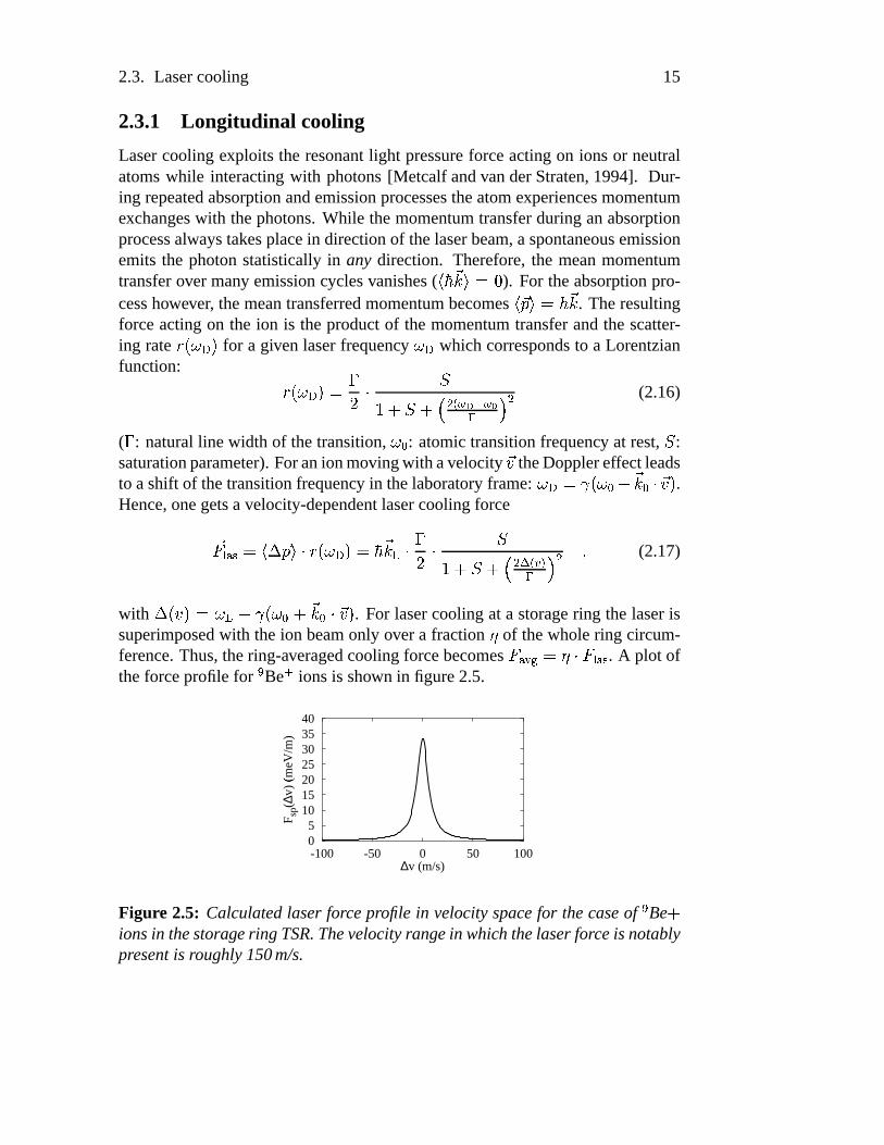
( � : naturalline width of thetransition,¾ L : atomictransitionfrequency at rest, À :saturationparameter).Foranionmovingwith avelocity *0 theDopplereffectleadsto ashift of thetransitionfrequency in thelaboratoryframe: ¾É¿ÊyË|.̾ L f *r L � *0 3 .Hence,onegetsa velocity-dependentlasercoolingforce*+ �ÎÍe�7 o W *[ q ��½@.}¾7¿ 3 »¼ *r�Ï � � ' � À� f À f¹Á u�Ð7 wjÑÇ È u a (2.17)
with WÊ. 0 3 Ò¾ Ï { ËÉ.}¾ L f *r L � *0 3 . For lasercoolingat a storagering the laserissuperimposedwith theion beamonly overa fraction Ó of thewholering circum-ference.Thus,thering-averagedcoolingforcebecomes
+ Í_Ôj¨ÕÖÓ×� + �ÎÍe� . A plot oftheforceprofile for
�Be�
ionsis shown in figure2.5.
05
10152025303540
-100 -50 0 50 100
F sp(
∆v)
(meV
/m)Ø
∆v (m/s)
Figure 2.5: Calculatedlaser forceprofile in velocityspacefor thecaseof�Bef
ionsin thestoragering TSR.Thevelocityrangein which thelaserforceis notablypresentis roughly150m/s.

16 Chapter2. Basicsof ion beamcooling
In caseof a copropagatingbeam,oneattainsanacceleratingforce. As men-tionedabove,beamcoolingrequirestheexistenceof bothacceleratinganddecel-eratingforces. Hence,an additionalcounterforcehasto be applied. First cool-ing experimentsat TSRwereperformedwith an inductionaccelerator(INDAC)[Ellert et al., 1992]. This device exploits the transformerprinciple to generateacounterforce: AccordingFaraday’s law, a linearcurrentrampin a coil coveringthe beampipe leadsto an inductionvoltagein the secondcoil which is in ourcasethe ion beamitself. This inductionvoltageleadsto a constantacceleratingor deceleratingforce actingon the ions whosestrengthdependson the slopeofthecurrentramp. Togetherwith the laserinteraction,the resultingcooling forceprofile is shown in figure2.6Sincethemaximumcurrentin theprimarycoil must
F
v0
F
v
aux
*lv
capture range
Figure 2.6: Lasercooling with a constantcounterforce as providedby the in-ductionaccelerator. Thevelocity 0�Ù denotesthestablepoint of thecoolingforcewhere the ions are drawn to. Thesecondzero crossing 0 ª is an unstablepoint.Ionsarepushedapart fromit.
not exceeda given limit, the counterforcecan only be generatedfor a limitedamountof time. One thereforehasto find a compromisebetweenthe strengthof thecounterforcewhich determinesthecoolingrateandthetime this forcecanbegenerated.A comparablyweekcounterforceof
+ Íe�=Ú]� �meV/mwould lead
to a maximumcooling time of 10 secondswhile a forceof � �PÛmeV/mlowers
this limit to lessthan60ms. Hence,a detailedinvestigationof long-termbeamdynamicsduringcoolingis notpossible.
In this work, two more elegant methodsare presentedto realizea counterforce.Ontheonehandwemakeuseof anexternallongitudinalconfiningpotentialachievedby beambunchingaspresentedin chapter3. A counterforcecanalsoberealizedby applying a secondcounterpropagatinglaserwhich leadsto a forceprofile depictedin figure 2.7. Experimentsusing this schemeare presentedinchapter4.
Both forceprofile have a stablepoint 0�Ù in velocity spacewherethecoolingforcevanishes.Dueto thenegativederivative( � + � � 0zÜ �
), ionsaredrawn to this
2.3. Lasercooling 17
-40
-20
0
20
40
-100 -50 0 50 100
F (
meV
/m)Ý
∆v (m/s)
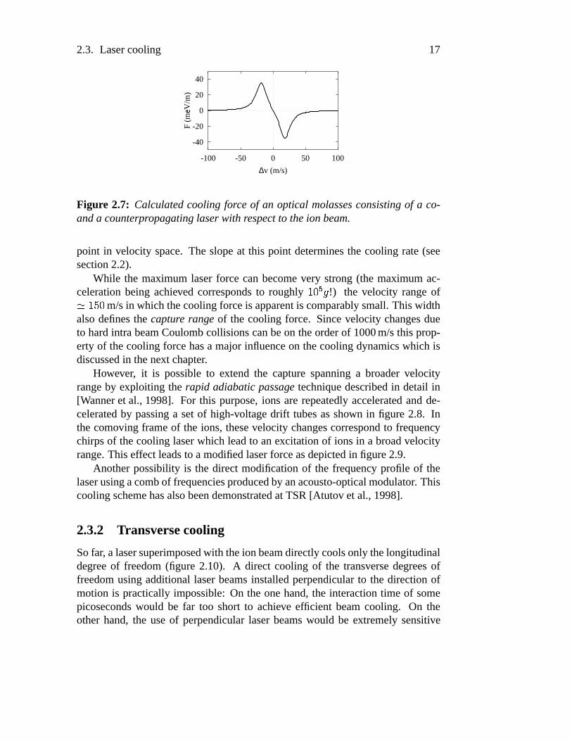
Figure 2.7: Calculatedcooling forceof an optical molassesconsistingof a co-anda counterpropagatinglaserwith respectto theion beam.
point in velocity space.The slopeat this point determinesthe cooling rate(seesection2.2).
While the maximumlaserforce canbecomevery strong(the maximumac-celerationbeing achieved correspondsto roughly
����Þ=ß!) the velocity rangeof# �����
m/sin which thecoolingforceis apparentis comparablysmall.Thiswidthalsodefinesthe capture range of the cooling force. Sincevelocity changesdueto hardintra beamCoulombcollisionscanbeon theorderof 1000m/sthis prop-erty of thecoolingforcehasa major influenceon thecoolingdynamicswhich isdiscussedin thenext chapter.
However, it is possibleto extend the capturespanninga broadervelocityrangeby exploiting the rapid adiabaticpassage techniquedescribedin detail in[Wanneret al., 1998]. For this purpose,ions arerepeatedlyacceleratedandde-celeratedby passinga setof high-voltagedrift tubesasshown in figure 2.8. Inthecomoving frameof the ions, thesevelocity changescorrespondto frequencychirpsof thecoolinglaserwhich leadto anexcitationof ionsin a broadvelocityrange.Thiseffect leadsto amodifiedlaserforceasdepictedin figure2.9.
Anotherpossibility is the direct modificationof the frequency profile of thelaserusingacombof frequenciesproducedby anacousto-opticalmodulator. Thiscoolingschemehasalsobeendemonstratedat TSR[Atutov et al., 1998].
2.3.2 Transversecooling
Sofar, a lasersuperimposedwith theion beamdirectlycoolsonly thelongitudinaldegreeof freedom(figure 2.10). A direct cooling of the transversedegreesoffreedomusingadditionallaserbeamsinstalledperpendicularto the directionofmotion is practicallyimpossible:On the onehand,the interactiontime of somepicosecondswould be far too short to achieve efficient beamcooling. On theother hand,the useof perpendicularlaserbeamswould be extremelysensitive

18 Chapter2. Basicsof ion beamcooling
0
200
400
600
800
−200
1000
−200 0 200 400 600 800 1000
pote
ntia
l (V
)
longitudinal position (mm)
−700 V
+1000 V
+1500 V
Figure2.8: Calculatedpotentialprofileof thedrift tubesectionfor therealizationof a rapidadiabaticpassage. Therepeatedvelocitychangesof passingionsleadsto a broadbandexcitationwhich is exploitedasa capturerangeof thelaserforce.
to small angledeviations. Even an anglemisadjustmenton the orderof àRáÒ#� G �â��ãrad would leadto a Dopplershift of roughly oneatomicresonancewidth
( à ³ #�ä � MHz), sothattheion wouldno longerexperiencethelaserforce.
However, cooling of the transverse degree of freedom can be indirectlyachieved exploiting coupling mechanismsbetweenthe longitudinal and trans-versedirections. As describedin section2.2.2IBS permanentlyleadsto a ther-mal relaxationbetweenall degreesof freedom. In this system,the longitudinalvery efficiently cooleddegreeof freedomactsasa heatsink for the transversedirection.Therefore,therelaxationprocessalsoleadsto a reductionof thetrans-versetemperature[Miesneretal., 1996b]. The couplingandthusthe transversecooling rate strongly dependson the collision rate of the ions. This rate itselfdependson the ion density. Hence,this cooling mechanismis a multi-particleeffect and becomesinefficient for very dilute beams. In addition, for a beamcrystallizationone expectsa completedisappearanceof IBS which also stopstransversecooling. Therefore,the observation of Coulomborderingrequiresa

2.3. Lasercooling 19
Figure2.9: Calculatedlaserforceprofileusingthecapturerangeextension.Evenions far awayfromthe laser resonancein velocityspacestill experiencea lightpressure force.
single-particlecoolingmechanism.Sucha coolingmechanismhasbeenrealizedin [Laueret al., 1998, Lauer, 1999, Grimm et al., 1998].Thismethodemploysthecouplingthroughthestoragering dispersion(seesection2.1) in connectionwiththehorizontalgradientof thelongitudinallasercoolingforce. Figure2.11showsin two extremecasestheinfluenceof thedispersiononanion performingbetatronoscillationsaroundits closedorbit while changingthelongitudinalmomentumbyphotonabsorption.In thefirst case(a), theion changesits momentumat theouterturningpointof theoscillation.Theshift of theclosedorbit leadsto adampingofthebetatronamplitude.In picture(b) theion absorbsaphotonbeingon theoppo-siteturningpointof theoscillation.Theion is acceleratedwhichleadsto thesameorbit shift asin thefirst case.This leadsto a driving of theoscillation. Thefirstprocesscorrespondsto horizontalcoolingandcanbepreferredagainstthesecondprocessby a horizontalshift of theGaussianintensitylaserprofile outwardswithrespectto thepositionof maximumintensityof theion beam.A shift of thelaserinwardsthereforeleadsto aheatingof thebeam.Themaximumcoolingor eatingratecanbeachievedwith ahorizontallasershift correspondingto ahalf Gaussianbeamwaist( ¾ L � ' ). Sincea storagering hasonly a notabledispersionin thehor-izontaldegreeof freedom,thepresentedcoolingmethodwould belimited to thisdirection. However, it is possibleto coupleboth transversedegreesof freedomthroughlinear betatron coupling [Bryant,1994]. In this casethe horizontalandthetransversetunesareequaldueto anadjustmentof themagneticring lattice. Inthefollowing, this 3D coolingmethodis calleddispersivecooling.

20 Chapter2. Basicsof ion beamcooling
relaxation
dispersion
envelopeoszillation
envelopeoszillation
T
long
hor
T
Tver
energykinetic
laser cooling
betatron coupling
dispersion
Figure 2.10: Heat transferof a cooledion beam.For transversebeamcooling,thering dispersioncanbeexploitedprovidinga couplingbetweenthelongitudinaland the transversedegreeof freedom.Full 3D cooling is realizedusing linearbetatroncoupling.
2.4 Experimental techniques
Theexperimentsareperformedat theHeidelberg TestStorageRing (TSR)withsingly charged
�Be�
ions at an energy of 7.3MeV which correspondsto 4.1%of the speedof light. A ring circumferenceof 55.4m leadsto an ion revo-lution frequency of 225kHz. A typical ion current after multi-turn injection[Bisoffi etal., 1990] of 1
ãA correspondsto
����åions in total. The lifetime of the
x∆
p∆
p∆
x∆
s
}
x
outward
inward
orbit
}
x
outward
orbit
s
(a) (b)cooling heating
inward
Figure 2.11: Dispersivecoolingprinciple. A longitudinal change of momentumleadsto a shift of theclosedorbit which canbeexploitedto damp(a) or drive (b)thetransversebetatronoscillation.

2.4. Experimentaltechniques 21
storedbeamlimited dueto collisionswith restgasatomsis about30secondsat avacuumof
� � ��� � ª�ª mbar.
2.4.1 Laser systemat 300nm
For lasercooling, oneusesthe u À ªFæ uZç u¦è ¯ æ u transitionwith a wavelengthofé £ � £ G � £ nm at rest.Thecorrespondinglevel diagramis shown in figure2.12.Thelifetime of ê^ Û G £ � ��� � � s leadsto aresonancewidth of �ë ��ì G
MHz. TheíîíîíîíîíîíîíîíîíïîïîïîïîïîïîïîïîïBe9 +
(1s) (2p) P2 1
3/22
∆ν= 1.25 GHz(1s) (2s) S1/22 1 2
λ=313.13 nm
F = 0...3 < 4 MHz∆ν
F = 1
F = 2
Figure 2.12: Term schemeof�Beryllium
�. For laser cooling, the transitionu À ªFæ uNç u>è ¯ æ u is used.
beamenergy of 7.3MeV correspondingto a velocityof� G ' � ��� å m/s( # G ��ðîñ
)leadsto a Dopplershift of 12.83nm. Due to a groundstatehyperfinesplittingof 1.3GHz (in laboratoryframe) a secondaccordinglydetunedlasersystemisneededto avoid optical pumpingbetweenboth states.Note, that the u è ¯ æ u levelis also hyperfinesplit in 4 levels. However the splitting of theselevels is lessthan4MHz which is smallerthanthenaturalline width of thecoolingtransition,so that theselines cannotbe resolved. The wavelengthsare generatedby twoArgon-ionlasers(CoherentINNOVA 200and400)with anoutputlight power ofabout90mW each(figure2.13).In orderto achievestablecoolingconditionsthemasterlaseris frequency locked againstan ultra-stableHelium-Neonlaserby aFabry-Perotresonator[Becker, 1992, Gruber, 1993]. The detuningbetweenthemasterand the slave laseris stabilizedby a direct measurementof the beatingsignalof both superimposedlaserbeamswith a fastavalanchephotodiode.Themeasuredfrequency is comparedwith a localquartzoscillatorin orderto produceanerrorsignalwhichis usedto changethefrequency of theslavelaseraccordingly[Schunemannet al., 1999]. Themergedlaserbeamsgo througha telescopesuchthatthefocusis exactly in themiddleof thecoolingsectionin thestoragering. Achangeof the lensconfigurationmakesit possibleto adjustthe laserbeamwaistin the experimentsection. The overall distancebetweenthe lasersystemand

22 Chapter2. Basicsof ion beamcooling
/2 plateλ
polarization plateMaster laser
Slave laser
photodiode∆ stab.ν
ν stab. telescope
pos. stab.
position detector
HeNe laser
cooling section inside TSR
pos. stab.
Figure 2.13: Basiclaser setup. Two argon ion lasers at 300nm with a relativedetuningof 1.3GHzaresuperimposedin order to avoidopticalpumpingbetweenthehyperfine-splitgroundstates.
the ring sectionis about23m. Due to mechanicalvibrationsandchangesin therefractive index of theair the laserbeamshows positionfluctuationsthatcannotbeneglected.To suppressthesefluctuationsandto preciselypositionthebeamweuseanactive regulationsystemconsistingof a setof piezomirrorsandposition-sensitive photodiodes[Wernøe,1993]. The achievable positioningaccuracy isabout100
ãm. With this techniqueit is possibleto attain an overlap with the
ion beamof morethen5m.
2.4.2 Beambunching
For lasercooling, an additionalconterforcehas to be provided. One methodto realizethis counterforceis beambunchingwherethe ions are longitudinallyconfined in a pseudopotential. Beam bunching is a well-establishedmethodfor the generationof ion beamsmoving in separateparticle packets (bunches)[Wille, 1996]. For beambunching in a storagering, ions passa longitudinalelectricalradio frequency field tunedat a harmonic
¼of the ion revolution fre-
quency³ "�}Ô (
³ �ò� ¼ ³ "�}Ô ). Usually, theRFfield is appliedby adedicatedresonant

2.4. Experimentaltechniques 23
bunchingdevice[Blum, 1989]which is limited to theuseof sinusoidalpotentials.For our purposes,non-sinusoidalwaveformshavebeenappliedto a non-resonantkicker device. This device consistsof a pair of parallelplateswith a lengthofó � 'R�
cm asshown in figure2.14.Eachkickerplateis setto thesamepotential,
ion beam
rf signal
Figure 2.14: Experimentalsetupfor beambunching usingnon-resonantkickerplates.
sothationsonly experienceforcesalongthebeamaxisexploiting thestrayfields.Due to thesestrayfields ions effectively seea longersetof platesexpressedbythe effective length
ó �}ô . This lengthcanbe indirectly measuredusingSchottkyanalysisasexplainedin AppendixA.
Ionsenterthepair of platesat thevoltage õX. � 3 andleaveat õX. � f W � 3 , whereW � is thetime neededfor passage.Therefore,theionsrun throughanetpotentialdifferenceW�õX. � 3 ÒõX. � 3P{ õX. � f W � 3 � �õî. � 3 W � assumingW � to beshort.Thisre-sultsin a phase-dependent,ring-averagedforce
+ öò�. � 3 ¶ W�õX. � 3 ��T in thelongi-tudinaldirection( T : ring circumference).With therelation � .F6 3 yËEubÓ ¼ 6V�@. ³ öòFT 3betweentime andthelongitudinalposition 6 in thecomoving frame( Ë÷� �
: rel-ativistic parameter,
¼harmonicnumber, Ó machineparameter)onecalculatesthe
position-dependentforce + öò=.86 3 ¶T W^õ�. � .86 3j3 G(2.18)
Furthermore,onecanascribea longitudinalpseudopotentialto this force:ø �ò~ ¶ ó �}ô ³ �òË u Ó 0 i���k õX. � .F6 3j3 (2.19)
Note that the pseudopotentialcorrespondsto a simple linear transformationoftheappliedRF-voltage,andtheshapeof thepotentialreflectstheRF-waveform.Thebunchingfrequency definesthesynchronousvelocity 0 ��ùjk�úÌ�X ³ öò8Tû� ¼ of thepseudopotentialmoving in thering. Theharmonicnumberdeterminesthenumberof bunchesperround-tripandthereforethebunchlength ®�����k�ú"�ûÖTû� ¼ .

24 Chapter2. Basicsof ion beamcooling
In chapter3 we investigatethe influenceof differentpotentialshapeson theefficiency of lasercooling. Besidesthesinusoidalpotentialwe madeuseof ded-icated barrier buckets that are of particular interestto study the dynamicsofthe cooling process[Eisenbarthet al., 2000a]. The barrier potentialconsistsofa square-wellpotentialwhich longitudinally confinesthe ions, anda bottomofconstantslopein order to counteractthe laserforce. A plot a typical potentialandthecorrespondingforceis shown in figure2.15. In contrastto sinusoidalpo-
HF
F
s
s
V
Figure 2.15: Schematicpicture of the barrier bucket potential consistingof asquare-wellpotentialan a bottomof constantslope. Thecorrespondingresultingforceprofile is plottedbelow.
tentials,thebarrierbucketprovidesaconstant,position-independentcounterforcefor theconfinedions. Therefore,it is possibleto producea laser-cooledion en-semblewith analmostconstantlongitudinalion density. This would correspondto a coastingchoppedion beam. This waveform is of particularinterestfor theobservation of Coulombordering. The longitudinal ion distancebeing a criti-cal parameterfor thecrystallization(seesection2.2.4)is alsoconstantinsidethebunch.Thecombinationof thelaserforceandthecounterforceproducedby thepotentialslopeform anunstableequilibrium: evenslight changesin thecoolingconditionhaveastronginfluenceonthelongitudinalion distributionwhichmakesthis methodto asensitive tool to investigatethecoolingdynamics.
While cooling in barrier buckets only compressesthe ensemblein velocityspace,a sinusoidalpotentialalsocompressesthelongitudinalspatialdistribution.However, an increasein the numberdensityleadsto an unavoidableincreaseofintrabeamscatteringwhich furthercontributesto theheatingratein this system.
Ions confinedin barrierbucketsperforman an-harmonicoscillatorymotionin thecomoving frame. The longitudinalphase-spacediagramfor particleswith

2.4. Experimentaltechniques 25
separatrix
Figure 2.16: phase-spacetrajectoriesof a bunchedion
differentkinetic energiesis depictedin figure 2.16. Ions confinedin the bucketarereflectedat the bucket walls. Without any cooling, the potentialslopeleadsto a biasingof themotiontowardstheright wall. Ionswith velocitieslargerthenthe bucket acceptancearenot trappedin the potentialandperforman unboundmotion.Thetrajectorybetweenbothtypesof motionis theseparatrix.
Figure 2.15 and 2.16 take into accountthat the potentialwalls have finiteslopesin reality. This comesfrom the fact that for fastvoltagestepsasit is thecasefor barrier buckets the approximationü�ý þ ÿý������pü�� is no longer valid.The ionsaretherefore“smoothly” reflectedat thewalls which resultsin thearc-shapedtrajectoriesat the potentialborders. For sinusoidalpotentials,ions withsmallamplitudesoscillatein anearlyharmonicpotentialwhich resultsin asinglevelocity-independentsynchrotronfrequency
��� � ����� ����������� ý���! #" ��$&% ' (2.20)
For the rectangularwaveform, the oscillationfrequency dependson the dif-ference ü�( � ()+* �-, ( �� �.�0/ of the ion velocity and the synchroneousveloc-ity: ��13254�� � ü�(76�� � $98 � with the duty cycle 8 correspondingto the on-off ratioof the square-wellwaveform. The maximumfrequency limited by the bucketacceptanceis about100Hz assuminga typical potential depthof ý � :<; V.This leadsto a maximumvelocity deviation from the synchronousvelocity ofü�(=?>A@ � BCD;E; m/s. The synchrotronfrequency is several ordersof magnitude

26 Chapter2. Basicsof ion beamcooling
vIon
photomultiplier
0U
Figure 2.17: High voltage drift tubesare installedat the positionof the photo-multipliers in order to locally accelerateor deceleratetheions.
smallerthanthebetatronfrequency �F ��G > �IH9�J�K 6DL þNM ;<; kHz ( H þ � 'PO ).2.4.3 Diagnostictools
Thevariousdiagnostictoolspresentedin the following allow the observationofthecompletethreedimensionalphasespace.The dataacquisitionsystemto ac-tually recordandstorethe signalsfor further dataanalysisis describedin Ap-pendixB.
Fluorescencemeasurement
The fluorescencelight producedby the ions in resonancewith the cooling laseris measuredwith two photomultipliertubesinstalledperpendicularwith respectto the beampipe and2.3m apartfrom eachother. The count ratecorrespondsdirectly to thenumberof ions in resonancewith the laser. This tool canbeusedto optimize the overlapbetweenthe laserandthe ion beamby maximizing thefluorescencecountrate. Furthermore,the useof two photomultipliersallows tominimizedtheanglebetweenbothbeams.Thismethodleadsto anangleaccuracyof betterthen100 Q rad. In addition,a setof cylindrical high-voltagedrift tubesinstalledaroundeachphotomultiplierareusedto locally accelerateor deceleratethen ions throughelectric fields (figure 2.17). The velocity changeof the ionsüR( � � ý G0S F � 6UTWV leadsto achangingDopplershift of theabsorptionfrequency. Inthecomoving framethe ionsexperiencea shift of the laserfrequency. A voltage

2.4. Experimentaltechniques 27
rampappliedto thedrift tubesthereforecorrespondsto acontinuoussweepof thelaserfrequency. Duringthissweepeveryvelocityclassof thelongitudinalthermalion distribution becomeslocally resonantwith the laser. Thenumberof ions fora given velocity is measuredthroughthe particularfluorescencerate. With thisso-calledHV-scanthewhole longitudinalvelocity distribution canbemeasured.For onemeasuredcycle a typical voltagerampgoesfrom -1.5kV to +1.5kV in100mscorrespondingto ascanrangeof 1300m/sin velocityspace.
For theresultingvelocityprofilesonehasto considertheuseof abichromaticlight field driving two atomictransitions.Figure2.18showsthephysicalsituationin the comoving frameof the ion. The atomicresonancefrequenciesaredrawn
1.3 GHz
f
t
laser
Figure 2.18: Theuseof a bichromaticlight field and two atomictransitionfre-quenciesleads to a characteristic three-peakstructure during a HV-scan(seetext).
asdashedhorizontallines. Both laserfrequenciesbeingscannedshow up asdi-agonalsolid lines. Eachintersectionof both linescorrespondsto a fluorescencepeakin thespectrum.Theresultingplot is shown below andconsistsof a middlepeakandtwo crossover sidepeaks.Thedistancebetweenthepeakscorrespondsexactly to thehyperfinesplitting andis usedto calibratethespectrum.Thelongi-tudinal temperaturecannow becalculatedfrom the X -width of themiddlepeak.Mathematicallyspoken, the observed profile representsa convolution of the ac-tual velocity distribution with the the Lorentzian-shapedabsorptionprobabilityof theatomictransition.For a Gaussianvelocity distribution, theresultingcurvewould bea Voigt profile. It turnedout thatdueto thesmallnaturalline width incomparisonwith theDopplerbroadeningtheconvolution effectsonly play a rolefor very low temperatures( Y C<; mK) andhavebeenneglectedin thetemperaturemeasurementspresentedin this work.

28 Chapter2. Basicsof ion beamcooling
Pickup measurements
For a coasting(unbunched)beamit doesnot make senseto measurethe longitu-dinal spatialion distribution which would bea constant.However, for a bunchedbeamseparateion packets (bunches) revolve in the storagering confinedby anexternalpotential(seenext chapter).At agivenlocationof thering, oneobservesafluctuatingion currentdueto theseparatebunchespassingby. Thelongitudinalion distribution insidea bunchgiving valuableinformationon the cooling pro-cesscanbe measuredwith an electrostaticpickup device [Albrecht,1993]. Thepickupconsistsof a shortmetaltube(length Z �\[ cm) enclosingthe ion beam(figure2.19).A changingion currentinfluencesmirror chargefluctuationswhich
PC
Roszilloscope
storage
L
ion beam
Figure2.19: Experimentalsetupof theelectrostaticpickupsystemto measurethelongitudinalion distribution.
canbemeasuredasa voltagesignalover a very largeresistor( ]_^ �M ` ). The
chargefluctuationsin themetalring arecalculatedasÿHa�cb )+* � ����� ,db )+* � ��� , ü���� þ ÿb )+* � �����jü�� ' (2.21)
For short timesof flight ü�� throughthe metal ring (in our caseü���þeM ns) anintegrationdelivers ý������ � ]fZ( $hg b )+* � ����� i (2.22)
with $ ��B � ; pFasthecapacitanceof thewholesystem.Thespatialion distribu-tion thereforecorrespondsto themeasuredvoltagesignalin thetimedomain.Thevoltageis amplifiedandfed to a digitizing scopewhich canbereadout by a PC.Sincethis methodis non-destructive theion distribution canbemonitoredonline

2.4. Experimentaltechniques 29
duringthecoolingprocess.Thepickupdevice hasa electronichigh-passcharac-teristicwith acutoff frequency of B 6<] $ þ C<; kHz (3dB point). For dataanalysis,this behavior hasto becorrectedby performinga Fouriertransformandapplyinganinverseresponsefunctionto compensatethedampingof high frequency com-ponents.A subsequentbacktransformdeliverstheactualion distribution. A moredetaileddescriptionof thecorrectionis givenin [Mudrich, 1999].
Beamprofile monitor
Thetransversedegreeof freedomcanbeobservedwith thebeamprofile monitor(BPM) [Hochadel,1994a]. At a given location of the storagering it is possi-ble to measurethe horizontalandvertical densitydistribution of the ion beam.Fromthesedataonecandeterminetheemittancesor transversetemperaturesre-spectively usingtheknown jk�ml�� functionat this position. For themeasurement,onemakesuseof the restgasatomsin thevacuumpipe thatareionizedthroughcollisionswith theion beam.Theratefor this processdependson thebeamden-sity at a given position. The ionizedatomsareacceleratedby an electric field( nEop � M ; kV/m) towardsa micro-channelplatedetectorwherethey canbe spa-tially resolved.Themeasureddistributionof restgasionscorrespondsto theshapeof thebeam.At this point,onehasto considerthattheBPM hasa limited spatialresolutiondueto its function principle. Even for an infinitely narrow ion beamonemeasuresaGaussianprofilewith a limited resolutionwidth X J � � , which relieson the fact that the recordedrestgasions have a thermalenergy of aboutroomtemperature.During thedrift from thepositionof ionizationto themicro-channelplate,the thermalmotion leadsto a smearout of the initial transversepositions.Hence,themeasureddistributionis aconvolutionof theactualtransverseionbeamprofile andthe resolutionwidth of theBPM. Sincethe beamprofile of a cooledion beamalsohasan almostGaussianshape,the actualwidth X�)+* � canis deter-minedby quadraticsubtractionof the measuredwidth X�= � > � and the resolution( X �)+* � � X �= � > � , X �J � � . Theresolutionwidth canbedeterminedby extrapolatingtheBPM measurementsof long-termelectroncooling measurements[Lauer, 1999].A typical valuefor theresolutionwidth is X J � � þ ; ' : mm. Theuncertaintyof thetransversetemperatureresultingfrom themeasurementitself andthesubtractionof theresolutionwidth canbeestimatedwith 150Kelvin.
Due to the goodvacuumof CrqIBs;utWv3v mbar, the BPM count ratebecomesvery smallespeciallyfor low densitybeams.Thecountratecouldbeincreasebylocally heatingthebeampipearoundthepositionof theBPM to about60w Celsius.Thisleadsto adesorptionof particlesfromtheinnersurfaceincreasingthenumberof restgasatoms.Oneachievesthiswayanincreaseof thecountrateby afactoroften. On theotherhand,thelifetime of theion beamis reducedby a factorof twodueto theworsethevacuum.However, this reductionis practicallyno limitation

30 Chapter2. Basicsof ion beamcooling
for thecoolingexperiments.
beamion
horizontal detector
vertical detector
vacuum chamber
10 cm
Figure2.20: Schematicpictureof thebeamprofilemonitor(BPM).Restgasatomsionized by the ion beamare accelerated in an electric field towards a multi-channelplatedetectorto bespatiallyresolved.
Recently, a new magneto-opticaltrap was install at the storagering whichturnedout to be an extremely sensitive target for the ion beam[Luger, 1999,Eike,1999, Eikeet al., 2000]. This device will make it possibleto measurelow-densitybeamswith muchbetterstatisticsandanimprovedspatialresolution.
Schottky noiseanalysis
A coastingbeamoffers an additionalpossibility for a non-destructive measure-mentof the longitudinalvelocity distribution relying in Schottky noiseanalysis[Boussard,1995].
For asingleparticlecirculatingin thestoragering (charge x , revolutionperiody �zB 6E{ ) the beamcurrent,at a given location in the ring, is composedof aninfinite train of deltapulsesseparatedin time by
yasshown in figure 2.21. In
frequency domain,this periodicwaveformis representedby a line spectrum,thedistancebetweenlinesbeing { �}| 6 �� .
~ ����� � x<{��W���s� t � ����U�D�
(2.23)

2.4. Experimentaltechniques 31
T+ T∆
Fourier transform
η∆f/f= p/p∆
revolving ion
U(t)
t
T
f
n f. rev
Figure2.21: Principleof Schottky analysis.Onerevolvingionsproducesa seriesof deltaspikesin anelectrostaticpickupdevicereflectingits revolutionfrequency.Anensembleof ionsproducesa noisesignal.A Fourier transformleadsto thedis-tributionof revolutionfrequenciesandtherefore thevelocityspreadof thebeam.
Looking atpositive frequenciesonly:~ ����� � x<{R� � x<{e�W���s� t �-���<� L| � (2.24)
For � particlesrandomlydistributedalong the ring circumferenceandmovingwith differentrevolution frequencies,eachline at frequency L�{ will bereplacedby a frequency band(Schottky band) whosewidth is simplyü�{ � L�{�V gs� ü�TT ' (2.25)
{V is theaveragerevolution frequency and � theso-calledslip factor, a machine-specificparameter( �D�7� � ��; 'P� [�C ) [HofmannandKalisch,1996].Hence,thefre-quency width is proportionalto therelative longitudinalmomentumspreadü�T�6�T

32 Chapter2. Basicsof ion beamcooling
of theion beam.Fromthemomentumspreadonecandirectlycalculatethelongi-tudinalbeamtemperature.Whenaveragingequation2.24over N particles,onlytheDC termsremain(
~��W� � �rx<{�V ), theothercomponentscanceldueto theran-domphasefactor. However, the r.m.scurrentper frequency bandwhich is givenby thesum � ~ �U� ��� � xE{V� � �E�¢¡ v � ���<�¢¡ � � gsgsg � � �E�¢¡s£ �3¤ � (2.26)
doesnotvanishbecauseof the � �E�¢¡ � terms.Oneobtains:
~ J = �!�¦¥ � ~ � � � � x<{�V ¥ � � � �E��¡ � � �� � x<{�V � � � (2.27)
Thus,the spectralpower density� ~ � � per frequency bandis proportionalto the
numberof ionsin theensemble.Due to technicalreasons(bandwidthlimitations of the usedamplifier, fre-
quency propertiesof the pickup device) all experimentsusedthe 15th harmonicof the revolution frequency ( | v5§ G /r¨©: ' B MHz). Note, that Schottky noiseanal-ysis canonly be usedfor a coastingbeam. In a bunchedbeam,the revolutionfrequency of theion packetsleadto ahugepeakin thefrequency spectrumwhichmakesit almostimpossibleto deriveinformationsonthelongitudinalvelocitydis-tribution. However, with thismethodit is possibleto measurethefrequency of theionsoscillatingin a harmonicbunchpotential(synchrotronoscillation)which isdescribedin AppendixA.
2.4.4 Time schemeof the coolingprocedure
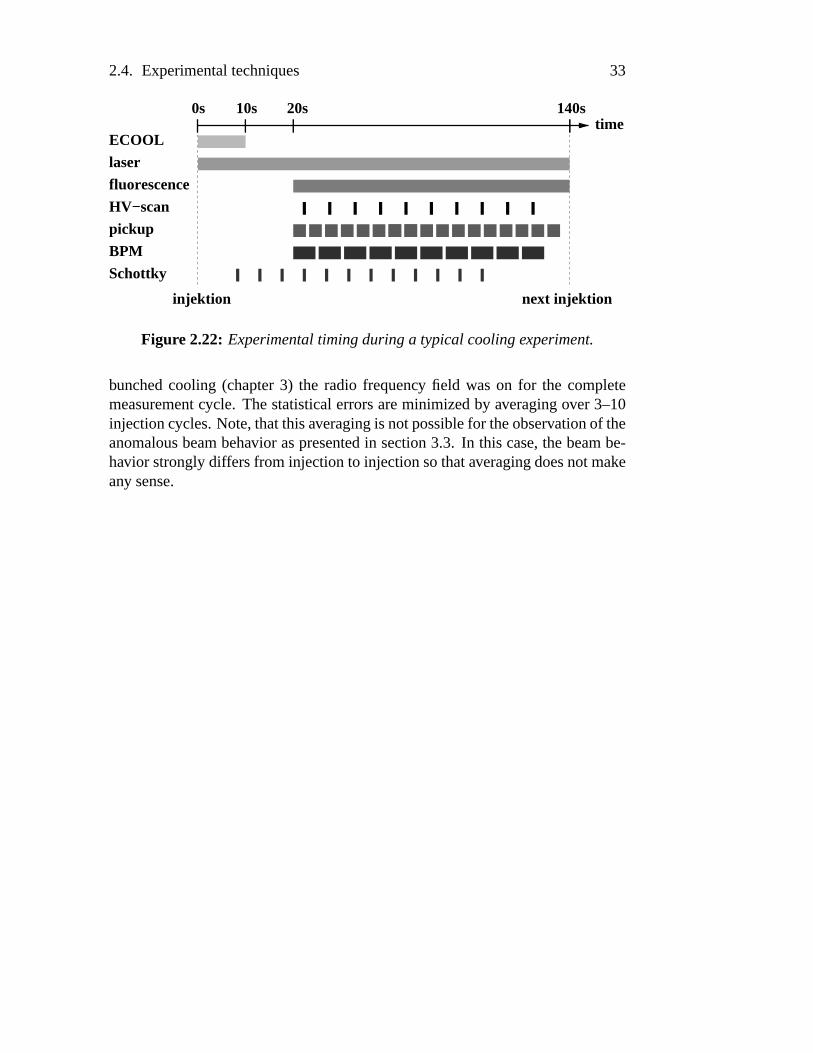
Thetime for onecoolingexperimentis typically about2 to 4 beamlifetimes(50–200s). Duringlasercoolingthesteadystatefor thelongitudinaldegreeof freedom(direct lasercooling) is reachedafter roughly 1ms. Sincemuch lower coolingratesfor the transversecooling process(indirect cooling throughcollisionsandring dispersion)areachieved,thetime for relaxationof thesedegreesof freedomis in the orderof seconds.The longercooling timesareusedto observe the in-fluencesof the decreasingparticlenumberon the cooling process.Many of thepresenteddiagnosticmethodsareperformedin parallel. Hence,it is possibletogeta full pictureof the3D phase-spacedevelopmentduringthecoolingprocess.A typical schemeof the experimentaltiming is shown in figure 2.22. Right af-ter beaminjection, the ionsareprecooledfor 6–12s by theelectroncoolerfrominitial temperaturesof roughly20,000K down to room temperature.During thesubsequentactuallasercoolingphasethefluorescencecountrateis permanentlyrecorded.HV-scans,beamprofile andpickupmeasurementsareperiodicallyper-formedat well-definedtimes. Therepetitionratefor theSchottky noiseanalysisis limited by the time neededfor transferringthe datato the computer. During
2.4. Experimentaltechniques 33
time140s20s10s0s
laser
fluorescence
HV−scan
pickup
BPM
ECOOL
Schottky
injektion next injektion
Figure2.22: Experimentaltimingduring a typical coolingexperiment.
bunchedcooling (chapter3) the radio frequency field wason for the completemeasurementcycle. Thestatisticalerrorsareminimizedby averagingover 3–10injectioncycles.Note,thatthisaveragingis notpossiblefor theobservationof theanomalousbeambehavior aspresentedin section3.3. In this case,thebeambe-havior stronglydiffersfrom injectionto injectionsothataveragingdoesnotmakeany sense.

34 Chapter2. Basicsof ion beamcooling
Chapter 3
Anomalousbehavior of laser-cooledbunchedbeams
This chapterinvestigateslasercoolingof bunchedbeams,wheretheionsarelon-gitudinally confinedby a pseudopotentialand its correspondingforce counter-actsthelaser. First experimentsof bunchedlasercoolingusingsinusoidalbunchpotentialswere performedat the ASTRID storagering [Hangstet al., 1995b].ThiscoolingschemewasfurtherinvestigatedatTSR[Madert,1995, Luger, 1996,Miesneret al., 1996a] andextendedto efficient three-dimensionalcooling usingthedispersivecoolingmethod[Laueretal., 1998].
Here,new systematicmeasurementson thecoolingprocessin non-sinusoidalbunchpotentialsarepresented.Theuseof a sinusoidalconfiningbunchpotentialleadsto an inhomogeneouslongitudinal ion densitydistribution. As describedin section2.2.4the observation of Coulomborderinghowever stronglydependson the ion distancewhich is not constantin a sinusoidalbunchedbeam.There-fore, lasercooling was investigatedin novel dedicatedbunch potentialscalledbarrier buckets(section2.4.2).Experimentswereperformedin orderto examineandcomparethecoolingdynamicsof threedifferentbunchpotentials:sinusoidalpotential,barrierpotentialanda puresquare-wellpotential. In addition,newlydevelopedsimulationsincludingtheeffectof hardCoulombcollisionsgiveaveryclearpictureonthephysicsof lasercoolingof fastion beams.At veryhighphase-spacedensitiesoneobservesasuddenchangeof thebeambehavior whichclearlyshowsanabruptdisappearanceof intra beamcollisions.
3.1 Laser cooling of bunchedbeams
Figure 3.1a)shows the calculatedphase-spacetrajectoryof an ion in a barrierbucketexperiencingthelaserforcein aframemovingwith thesynchronousveloc-
35

36 Chapter3. Anomalousbehavior of laser-cooledbunchedbeams
ity. Theion experiencesaposition-dependentforceresultingfrom beambunchingwhich plot above thegraph.Thevelocity-dependentlaserforceis depictedverti-cally on theright side.Duringanoscillationcycle, theion is drawn over thelaserresonance.In thecaseshown, the lasercounteractthe ion motion. This leadstoa dampingof the oscillation. The laserthereforeactsasa friction force. Note,thatduringthefirst oscillationcyclestheion interactswith thelaserfor veryshorttime. Hence,thedampingof theoscillationis small. After severalcyclesthe in-teractiontime becomesgraduallylongerandlongeruntil the ion is drawn to thesynchronousvelocity ( üR( �ª; m/s) in an over-dampedmotion. The oscillationcan also be driven by the laserforce if the ion comesin resonanceat positivedeviation from thesynchronousvelocityasshown in figure3.1b).
a) b)
-400
-200
0
200
400
-4 -2 0 2 4
v (m
/s)
0 20 40F (meV/m)
-200
20
F
(meV
/m)
HF
∆
Cs (m)∆
-400
-200
0
200
400
-4 -2 0 2 4 0 20 40F (meV/m)
-200
20
Cs (m)∆
v (m
/s)
∆F
(m
eV/m
)H
F
Figure 3.1: Phase-spaceplotsof a bunchedion cooled(a) aswell asheated(b)by thelaserforce.
Dependingon thelaserpositionin velocity spacewith respectto theion mo-tion it is possibleto eitherheator cool thebeamlongitudinally. Becausetheex-perimentalsetupusesfixed-frequency lasers,thepositionof thelaserwith respectto the bucket canbe adjustedby changingthe synchronousvelocity, which de-pendson thebunchingfrequency. A shift of thebunchingfrequency correspondsto ashift of thevelocityzeroline in theshown phase-spacediagrams.
In this systemtwo velocitiesaredefined:thesynchronousvelocity ( ����.�«/ de-finedby thebunchingfrequency andthe“stablevelocity” ( � G > F.¬ � determinedby theequilibriumof thelaserforceandthecounterforce �0¬ *3® � whichis producedby theslopeof thebarrierbucket (figure3.2).A mismatchbetweenbothvelocitiesleadsto anadditionalconstantforce ¯=!) � actingon theion. During thecoolingprocesstheion in this casepushedtowardsthefront or therearbucket borderdependingon thesignof theforce. In anotherpicture,anion is cooledto thestablevelocity.Thebunchpotentialhowever moveswith thesynchronousvelocity. Hencein thecomoving frametheion is pushedtowardsoneof thebucket boundaries.
For asetof ionsdistributedarounda velocityonehasto usethemeanvalues.

3.2. Systematicmeasurements& comparisonwith simulations 37
stablesynch
Fslope
v
F
0Fmis
vv
Figure 3.2: A mismatch betweenthe stablevelocity ( � G > F.¬ � and the synchronousvelocity ( ����.�«/ leadsto anadditionalconstantforce ¯=!) � actingon theion.
Thereforethemeanmismatchforceactingon theion ensembleis calculatedas� ¯=!) � � �I° g� ( � G > F.¬ � � , ( �� � �«/ i (3.1)
with the friction coefficient ° . In the experimentsthe mismatchforce leadingto inhomogeneouslongitudinalion distributionscanbeavoidedby adjustingthebunchingfrequency, so that thesynchronousvelocity exactly matchesthestablevelocity.
3.2 Systematic measurements & comparison withsimulations
3.2.1 Longitudinal dynamics: observations
To introducetheconceptsof lasercoolingin bunchedbeams,we first show sometypical results. The experimentspresentedhereweredonewith barrierbuckets.Theexperimentswereperformedat a laserpower of ± ¨ � ; mW at a laserbeamwaist of ²³V÷þ B 'PO mm. For optimum dispersive cooling of the transversede-greesof freedoma relative ion-laserbeamoffset of ü�´ � M ;E; Q m waschosen.Beambunchingwasdoneat the third harmonicof the ion revolution frequency( �J�Kµ� M O M kHz). Thedetuningof thebunchingfrequency with respectto thelaservelocity was ¶ �·�h¸ Hz which turnedout to be the optimumvaluesto achieveefficient longitudinalcooling.
As describedin chapter2 the longitudinal velocity distribution is measuredwith theHV-scanmethod.A typicalpictureis shown in figure3.3(very left plot).

38 Chapter3. Anomalousbehavior of laser-cooledbunchedbeams
Thevelocity distribution shows thetypical three-peakstructuredueto thehyper-finesplittingasexplainedin 2.4.Theoreticallythisstructurecouldbedeconvolvedin two steps.In thefirst stepthespectrumis correctedconsideringthebichromatic
Figure3.3: ThemeasuredHV-scanis deconvolvedin twosteps.Sincethisprocessis numericallyunstablethe data has beenfit by a et Gaussianfunctions. Theactualvelocitydistributionderivedthis wayis shownin theveryright plot.
laserfield with thevaluesof the laserfrequency widthsandtheir relative detun-ing. This leadsto a two-peakstructure(secondplot) reflectingthetwo hyperfinegroundstatesof Beryllium. A seconddeconvolution with theatomicthree-levelschemethen leadsto the actuallongitudinalvelocity distribution of the ion en-semble(third plot). However it turnedout thatthetwo stepdeconvolutionprocesscarriedoutwith experimentalnoisydatasetsis numericallyratherunstable.Evenslight differencesbetweenthe experimentalandthe assumedlaserdetuningforexampleleadsto anoscillationin theresultingprofile. This canalsobeobservedin thepresentedcalculation.Thedeterminationaswell asananalysisof thedistri-butionshapeis thereforealmostimpossible.To avoid theseproblemstheoriginaldatawasfit with asumof six Gaussiandistributions.For thefit procedurecertainparameterssuchasthepositionof thepeaksarekeptfixed. In addition,thewidthof eachpeakshouldgivethesamevelocityspread.Theserestrictionsimprovethenumericalstability of thefit. Fromthe resulttheactualvelocity distribution canbederived(figure3.3,very right plot)
Figure3.4showsthelongitudinalvelocitydistributionmeasuredwith theHV-Scanmethodaswell asthecorrespondingspatialion distribution in thebunchingpotentialobservedwith theelectrostaticpickup. Thedataon theright sidecorre-spondsto thesamecoolingconditionsason but with theuseof thecapturerangeextension(seesection2.3). The plot shows the ion distribution 5 secondsafterstartinglasercooling.Fromthis plot oneextractsa characteristictwo-componentdistribution: Thevelocityensembleconsistsof anarrow andpeakwith awidth ontheorderof 10m/saswell asa broadpedestalcoveringa velocity rangeof about1000m/s. In addition,onenoticesan asymmetryof the peak. The peakshowsa sharpedgeon the left anda smootherdecreaseon the right side. The useof

3.2. Systematicmeasurements& comparisonwith simulations 39
a) b)
Figure 3.4: Laser-cooledvelocityandspatialdistributionswithout (a) andwith(b) thecapture rangeextension.
thecapturerangeextensionsignificantlychangestheshapeof thevelocity distri-bution (right plot). As describedin section2.3 the capturerangeextensionalsoleadsto an excitation of ions not beingat the resonancevelocity of the coolinglaser. Thereforemainly theshapeof thebroadpedestalof ionsnot in resonancewith thelaseris modified.Theuseof thecapturerangeextensionleadsto acom-pressionof theion background.Ionsapartfrom thestablepoint in velocity pointaremoreefficiently drawn to thelaserresonance.Thevelocity width of thepeakis almostunchanged.The temperaturederived from the velocity spreadof thepeakis
yµ¹ þ B K withoutandyµ¹ þ B ' C K with thecapturerangeextension.
The lower row of figure3.4 shows thespatiallongitudinalion distribution inthebarrierbunchpotential,which is sketchedbelow theplot. Without thecapturerangeextensiononeobservesanincreaseof theion densityat theleft sideof thebunchingpotential. For the ions sitting at the left bucket borderthe laserforceis obviously not strongenoughto compensatethe counterforceproducedby thepotentialslope.This is thecasefor ionsbeingpartof thepedestalof thevelocitydistributionsincetheseionsarenot in resonancewith thelaser. In theright picture

40 Chapter3. Anomalousbehavior of laser-cooledbunchedbeams
measuredwith the capturerangeextensiononeobservesan almostconstantiondistribution. Theextendedlaserforcein velocity spaceleadsto thesituationthatalso ions apartfrom the stablepoint experiencea notablelaserforce. The ionensemblestandsin equilibriumwith the counterforceproducedby the bunchingpotential.Therefore,theresultingion distribution is balanced.
3.2.2 Longitudinal dynamics: model
In orderto geta further insight into the ion dynamicsandto modeltheobservedeffects,a computersimulationprogramwaswritten which calculatesthe ion tra-jectoriesin longitudinalphasespace.It numericallysolvestheequationof motionfor arbitrarypseudopotentialsandvelocity-dependentforces. The repeatedcal-culation of the single-particlemotion beginning with a set of different startingconditionsallows thesimulationof thephase-spaceevolutionof anion ensemble.Theinfluenceof the transverse-longitudinalcouplingis taken into accountusingaMonte-Carloapproach.
Consideringonly the longitudinalmotion of the ions onehasto solve New-tons’sequationof motion »ºl � J�K �Al�!�¼ ¬ > � � ÿl� (3.2)
(
: ion mass,l : longitudinalcoordinatealongthebunchpotential).Theforce J�Kproducedby beambunchingandthelaserforce ¬ > � aredefinedin equation.2.18and2.17 respectively. The above equationrepresentsa second-ordernon-linearordinarydifferentialequation(ODE)whichhasnoanalyticalsolutionfor arbitrarybunchingpotentials.ThecomputercodeusestheRunge-Kuttamethodwith adap-tive stepwidth [Presset al., 1992]. The computationaccuracy canbe controlledby aparameter½ definingtheaveragestepwidth. Thevalueof ½ wasoptimized,sothat therelative deviation of thetotal energy afteronesecondof integrationtimewasbelow 1%. This valuesturnedout to be a goodtrade-off betweenaccuracyandcalculationtime.
The effect of intra beamscattering(seesection2.2.2)hasbeenincludedbya Monte-Carlomodel. In particular, the influenceof hard Coulombcollisionswith large velocity changesduring the scatteringprocesshasto be considereddue to the small capturerangeof the lasercooling force (see2.3). During thecalculationof a single-particletrajectorythe time for the occurrenceof a scat-teringprocessis randomlydeterminedassuminga givenconstantscatteringrate¾ which is a free parameterin the simulation. A scatteringprocesschangesthelongitudinalvelocity of theparticleby ¶( . ¶�( is againrandomlydeterminedac-cordingto a given probability function ¿À�m¶(7� . For the probability function we

3.2. Systematicmeasurements& comparisonwith simulations 41
set[Miesner, 1995, Lauer, 1999]
¿Á�5¶�(7� �Á¦ÃÃëÄ5Å ÆÇ�ÈmÉÄmÅËÊ ÃÃÃ�Ì n+¶(!n�^}¶( � S G; Ì �<Í Î�Ï�ÐËÑÓÒ0� Ï(3.3)
with thecutoff velocity ¶�( � S G which is neededto normalizethedistribution func-tion. It is the secondfree parameterof this model. This relation resultsfromthe theory of binary collisions basedon Rutherford’s scatteringformula. In[Miesner, 1995] the probability for a collision outsidethe capturerange ( 4 wascalculatedas ¿ Ô B 6�( �4 . A differentiationdelivers ¿Á�5¶�(7�ÕÔ B 6D¶�( % . A plotof theprobability function3.3 is shown in figure3.5. This modelneglectscolli-
Figure 3.5: Plot of theprobability function ¿À�m¶(Ö� usedfor determiningthelon-gitudinal velocitychangeaftera simulatedcollision.
sionswith smallenergy transferswhich would correspondto a diffusionprocess.Thisassumptionis valid dueto thefactthatonly thehardCoulombcollisionsno-tably contribute to theheatingratebecauseof thesmall capturerange.Ions thathave undergonevelocity changessmallerthanthecapturerangeareimmediatelycooledback.Thecutoff velocity in this simulationis setto ¶�( � S G �×BØ; m/swhichis smallerthanthevelocityspreadof thelaserforce.
Typical phase-spacetrajectoriesof a singlelaser-cooledion areshown in fig-ure 3.6. The plots show the cooling dynamicsfor a barrierpotential. The leftplot showstheparticlemotionwithoutcollisions.Theright plot demonstratedtheinfluenceof collisionsusingthemodeldescribedabove. Without any collisions,the ion is drawn to thesynchronousvelocity sitting at theright bucket wall. Thepresenceof scatteringprocessesleadsto a permanentchangeof the ion velocityeither within or outsidethe capturerange. In the first casethe is immediately

42 Chapter3. Anomalousbehavior of laser-cooledbunchedbeams
s (m)∆s (m)∆
v∆
Figure3.6: Simulatedtrajectorieswithout(a) andwith (b) collisions.
drawn backto the stablepoint in an over-dampedmotion. In the latter casetheion startsoscillationagainandit takesseveralcyclesto reachthestablevelocity.
Thesetwo typesof motion(oscillatingandover-damped)arethereasonfor theexperimentallyobserved two-componentdistribution in velocity space:the coldpeakcorrespondsto the particleswithin the capturerangeof the cooling force.The hot pedestalconsistsof ions that have undergonea hardCoulombcollisionoutof thecapturerangeandarenow oscillatingagain.Theprocessof coolingbacktheseions takesseveraloscillationcyclesso that onealwayshasa subensembleof hot ionsunderlyingthecold ensemblebeingat thestablepoint of thecoolingforce. Furthermore,onecansaythat thepresenceof a hot backgroundis a clearsignaturefor theexistenceof hardCoulombcollisionsin theion beam.In steadystate,the ratio of the numberof ions in the hot andthe cold fraction is therebydeterminedby thescatteringrateandthecoolingrateof thelaser. Thescatteringrate therebydependson the 3D ion density. The cooling rate is determinedbyseveralexperimentalparameters:potentialshapeanddepth,bunchingfrequencyandthe laserintensity. Sinceall theseparameterscandirectly be measuredthetwo remainingparametersof thesimulation(cutoff frequency ¶( � S G & scatteringrate ¾ ) havebeenfitted to matchtheexperimentaldata.
Thecomputermodelalsosimulatesthe influenceof thecapturerangeexten-sion.For thispurpose,thelaserforceprofile is modifiedaccordinglyto figure2.9.Thismodifiedcoolingforcealsoactson ionsnotbeingat thestablepoint. There-fore,scatteredionsthatoscillatein thebucketcanbefastercooledback.In steadystate,this leadsto acompressionanda reductionof thehot pedestal.

3.2. Systematicmeasurements& comparisonwith simulations 43
3.2.3 Longitudinal dynamics: comparisonof bunch forms
Furthermore,we investigatedthe influenceof different potentialshapeson thecoolingdynamics.Figure3.7shows ion distributionsin longitudinalvelocityandrealspacethatarecooledin thebunchingpotentialsschematicallydepictedabovethedata.
Figure3.7: Experimentalion distribution in differentbunch potentials.
For the sinusoidalpotentialthe cold peaksarenarrower thanfor the barrierbucket which indicatesa bettercooling in the sinusoidalpotential. In caseofthe pure square-wellbucket the peaksare hard to distinguishfrom the broadpedestal.The spatialion distribution in the barrierbucket is homogeneousbutslightly shiftedto the left potentialwall. This is theresultfrom a misadjustmentof thepotentialslopewith respectto thelaserforce.For thesquare-wellpotentialtheionsarepushedagainstthepotentialwall. In additiononemeasuresa secondsetof ionsalmosthomogeneouslydistributedalongthebunch.Themaximumion

44 Chapter3. Anomalousbehavior of laser-cooledbunchedbeams
distribution in thesinusoidalpotentialis markedly shiftedto theleft. In addition,the ion distribution shows a characteristic“shoulder” locatednearthe centerofthepotential.
Although the longitudinalvelocity distribution of a laser-cooledion beamisnot in thermalequilibrium it turnedout that the spatialdistribution LÙ�Al� of anion ensemble(longitudinaltemperature
yµ¹) in anexternalpotential Ú � @ G �ml�� is de-
scribedby Boltzmann’s law
LÙ�Al� � LÛV g � tµÜ3Ý�ÞÉAßáà«âãAäsåçæ ' (3.4)
Sinceatemperaturein athermodynamicalsenseis only definedfor anion ensem-blebeingin thermalequilibriumonehasto put in thetemperaturedefinitiongivenin section2.2.
A potentialslope Ú � @ G �Al� � ��¬ *3® � l given by the barrier potentialthereforeleadsto anexponentialdistribution
Lè�ml�� � LéV g � tµê ëíì î�ï ÝàãAäsåçæ ' (3.5)
As mentionedabove,for anexactequilibriumbetween �0¬ *3® � and ¬ > � � J ionsinsidethebunchingpotentialexperienceno net forces. Theeffective externalpotentialbecomesconstant( Ú � @ G �Al� � Ú¢V ). The ions are thereforehomogeneouslydis-tributedin thebunch. LÙ�Al� � LÛV g � t Ü3ðãAäsåçæ ' (3.6)
A sinusoidalpotentialwhich canbeapproximatedby a parabolaÚ � @ G �Al� �òñ l �for smalloscillationamplitudesthusgivesaGaussiandistribution
LÙ�Al� � LÛV g � tRó à ÆãAäsåçæ ' (3.7)
One has to bear in mind that this descriptioncan only be an approximationdue to the obviously invalid assumptionof having an ion ensemblebeing inthermalequilibrium. In particular the effect of a two componentdistributionleadsto notabledeviationsfrom the theoreticallyexpecteddensitydistributions.It is possibleto extend the descriptionassumingthat the measureddistribu-tion is a superpositionof two ensembles(a hot and a cold one) with differentforce conditions. While the backgroundensembleonly experiencesthe forcesproducedby the bunching potential the cold ensemblealso interactswith thelaser force. In addition the effect of space-charge is neglected. An exten-sion of this modelwould alsobe possibleleadingto a Debye-Huckel approach[Fowler andGuggenheim,1956,Eisenbarth,1998].
A full understandingof theexperimentalobservationsis possiblewith theuseof the computermodel. Responsiblefor the different cooling dynamicsis the

3.2. Systematicmeasurements& comparisonwith simulations 45
s (m)∆
v∆
s (m)∆ s (m)∆
Figure 3.8: Simulatedcoolingtrajectoriesin differentbunch potentials:barrierbucket (left), sinusoidalbucket (middle) and square-well potential (right). Theplotsshowthetrajectoriesfor equalsimulationtimes.
characteristicmotionof a particlein thebunchingpotentialsassimulatedin fig-ure 3.8. The simulationtime for the threepseudopotentialsaswell asthe laserpositionin velocity spacewerethesame.Also thestartingvelocitiesof the ionswereequal.Themiddleplot shows thesituationfor a sinusoidal-bunchedbeam.Under theseconditions,the ion is drawn to the stablepoint after lessthanonesynchrotroncycle. Thestablepoint in realspaceis slightly shiftedwith respecttothepotentialminimum. At this point, thecounterforceis in equilibriumwith thelaserforce.For thepuresquare-wellpotential,theion performsseveraloscillationcyclesuntil thestablepoint is reached.Sincethereis no counterforcepresentin-sidethebucket,theion is pushedagainsttheleft bucketborder. Themotionof thebarrierbucket lies in betweenthedescribedcases.Thefinal spatialpositionof theion dependson thestartparameters(velocityandposition).Sincethereis no lon-gitudinalpositionpreferred,an ion ensemblewill behomogeneouslydistributedin thepotential.Experimentally, oneobservesa biasingof thespatialdistributiontowardsthe left bucket border. The comesfrom a misadjustmentof the bunch-ing frequency which definesthe synchronousvelocity of the ions andthestablevelocitydeterminedby thelaserforceandthepotentialslope.
The cooling dynamicsin the threepotentialshapesthereforemainly differsin the time neededto cool an ion to thestablepoint. The time for cooling backan ion is determinedby theaveragetime an ion beingresonantwith thecoolinglaserwhile oscillatingin thebucket. Thesinusoidalpotentialsteadilychangestheion velocity. In contrast,the ideal square-wellpotentialwould only changethe

46 Chapter3. Anomalousbehavior of laser-cooledbunchedbeams
directionof motionwhile beingreflectedat thebucket wall. Thevery shorttimewhentheion becomesresonantwith thelaserleadsto aweakdamping.
Thedifferenttimesneededto cool ionsto thestablepoint explain theratio ofhot andcold ions in the two-componentdistribution. The recycling of ions thathave undergonea Coulombcollision in a square-wellpotentialthereforetakesalong time. In steadystate,the hot fraction is comparablylarge. With respectto the shortertime neededto recoolscatteredions in the sinusoidalbucket, thehot fraction is in this casemuchsmaller. The numberof hot ions in the barrierbucket lies in between.A simulationof a particleensembleincludingcollisionsasdescribedabove is shown in figure3.9. Theusedparameterscorrespondto theexperimentalconditionsleadingto thedistributionsshown in figure3.7.
ôÓôÓôôÓôÓôôÓôÓôôÓôÓôôÓôÓôôÓôÓôôÓôÓôôÓôÓôôÓôÓôôÓôÓôôÓôÓôôÓôÓôôÓôÓôôÓôÓôôÓôÓôôÓôÓôôÓôÓôôÓôÓôôÓôÓôôÓôÓôôÓôÓôôÓôÓôôÓôÓôôÓôÓôôÓôÓô
õÓõÓõõÓõÓõõÓõÓõõÓõÓõõÓõÓõõÓõÓõõÓõÓõõÓõÓõõÓõÓõõÓõÓõõÓõÓõõÓõÓõõÓõÓõõÓõÓõõÓõÓõõÓõÓõõÓõÓõõÓõÓõõÓõÓõõÓõÓõõÓõÓõõÓõÓõõÓõÓõõÓõÓõõÓõÓõ
öÓöÓööÓöÓööÓöÓööÓöÓööÓöÓööÓöÓööÓöÓööÓöÓööÓöÓööÓöÓööÓöÓööÓöÓööÓöÓööÓöÓööÓöÓööÓöÓööÓöÓööÓöÓööÓöÓööÓöÓööÓöÓööÓöÓööÓöÓööÓöÓööÓöÓööÓöÓö
÷Ó÷Ó÷÷Ó÷Ó÷÷Ó÷Ó÷÷Ó÷Ó÷÷Ó÷Ó÷÷Ó÷Ó÷÷Ó÷Ó÷÷Ó÷Ó÷÷Ó÷Ó÷÷Ó÷Ó÷÷Ó÷Ó÷÷Ó÷Ó÷÷Ó÷Ó÷÷Ó÷Ó÷÷Ó÷Ó÷÷Ó÷Ó÷÷Ó÷Ó÷÷Ó÷Ó÷÷Ó÷Ó÷÷Ó÷Ó÷÷Ó÷Ó÷÷Ó÷Ó÷÷Ó÷Ó÷÷Ó÷Ó÷÷Ó÷Ó÷÷Ó÷Ó÷ øÓøÓøÓøÓøÓøÓøÓøÓøÓøÓøÓøÓøÓøÓøÓøÓøÓøÓøÓøÓøÓøÓøÓøÓøÓøÓøÓøÓøÓøÓøÓøÓøÓøÓøÓøÓøÓøøÓøÓøÓøÓøÓøÓøÓøÓøÓøÓøÓøÓøÓøÓøÓøÓøÓøÓøÓøÓøÓøÓøÓøÓøÓøÓøÓøÓøÓøÓøÓøÓøÓøÓøÓøÓøÓøøÓøÓøÓøÓøÓøÓøÓøÓøÓøÓøÓøÓøÓøÓøÓøÓøÓøÓøÓøÓøÓøÓøÓøÓøÓøÓøÓøÓøÓøÓøÓøÓøÓøÓøÓøÓøÓøøÓøÓøÓøÓøÓøÓøÓøÓøÓøÓøÓøÓøÓøÓøÓøÓøÓøÓøÓøÓøÓøÓøÓøÓøÓøÓøÓøÓøÓøÓøÓøÓøÓøÓøÓøÓøÓøøÓøÓøÓøÓøÓøÓøÓøÓøÓøÓøÓøÓøÓøÓøÓøÓøÓøÓøÓøÓøÓøÓøÓøÓøÓøÓøÓøÓøÓøÓøÓøÓøÓøÓøÓøÓøÓøøÓøÓøÓøÓøÓøÓøÓøÓøÓøÓøÓøÓøÓøÓøÓøÓøÓøÓøÓøÓøÓøÓøÓøÓøÓøÓøÓøÓøÓøÓøÓøÓøÓøÓøÓøÓøÓøùÓùÓùÓùÓùÓùÓùÓùÓùÓùÓùÓùÓùÓùÓùÓùÓùÓùÓùÓùÓùÓùÓùÓùÓùÓùÓùÓùÓùÓùÓùÓùÓùÓùÓùÓùÓùÓùùÓùÓùÓùÓùÓùÓùÓùÓùÓùÓùÓùÓùÓùÓùÓùÓùÓùÓùÓùÓùÓùÓùÓùÓùÓùÓùÓùÓùÓùÓùÓùÓùÓùÓùÓùÓùÓùùÓùÓùÓùÓùÓùÓùÓùÓùÓùÓùÓùÓùÓùÓùÓùÓùÓùÓùÓùÓùÓùÓùÓùÓùÓùÓùÓùÓùÓùÓùÓùÓùÓùÓùÓùÓùÓùùÓùÓùÓùÓùÓùÓùÓùÓùÓùÓùÓùÓùÓùÓùÓùÓùÓùÓùÓùÓùÓùÓùÓùÓùÓùÓùÓùÓùÓùÓùÓùÓùÓùÓùÓùÓùÓùùÓùÓùÓùÓùÓùÓùÓùÓùÓùÓùÓùÓùÓùÓùÓùÓùÓùÓùÓùÓùÓùÓùÓùÓùÓùÓùÓùÓùÓùÓùÓùÓùÓùÓùÓùÓùÓùùÓùÓùÓùÓùÓùÓùÓùÓùÓùÓùÓùÓùÓùÓùÓùÓùÓùÓùÓùÓùÓùÓùÓùÓùÓùÓùÓùÓùÓùÓùÓùÓùÓùÓùÓùÓùÓù
úÓúÓúÓúÓúÓúÓúÓúÓúÓúÓúÓúÓúÓúÓúÓúÓúÓúÓúÓúÓúÓúÓúÓúÓúÓúÓúÓúÓúÓúÓúÓúÓúÓúÓúÓúÓúÓúúÓúÓúÓúÓúÓúÓúÓúÓúÓúÓúÓúÓúÓúÓúÓúÓúÓúÓúÓúÓúÓúÓúÓúÓúÓúÓúÓúÓúÓúÓúÓúÓúÓúÓúÓúÓúÓúúÓúÓúÓúÓúÓúÓúÓúÓúÓúÓúÓúÓúÓúÓúÓúÓúÓúÓúÓúÓúÓúÓúÓúÓúÓúÓúÓúÓúÓúÓúÓúÓúÓúÓúÓúÓúÓúúÓúÓúÓúÓúÓúÓúÓúÓúÓúÓúÓúÓúÓúÓúÓúÓúÓúÓúÓúÓúÓúÓúÓúÓúÓúÓúÓúÓúÓúÓúÓúÓúÓúÓúÓúÓúÓúúÓúÓúÓúÓúÓúÓúÓúÓúÓúÓúÓúÓúÓúÓúÓúÓúÓúÓúÓúÓúÓúÓúÓúÓúÓúÓúÓúÓúÓúÓúÓúÓúÓúÓúÓúÓúÓúûÓûÓûÓûÓûÓûÓûÓûÓûÓûÓûÓûÓûÓûÓûÓûÓûÓûÓûÓûÓûÓûÓûÓûÓûÓûÓûÓûÓûÓûÓûÓûÓûÓûÓûÓûÓûÓûûÓûÓûÓûÓûÓûÓûÓûÓûÓûÓûÓûÓûÓûÓûÓûÓûÓûÓûÓûÓûÓûÓûÓûÓûÓûÓûÓûÓûÓûÓûÓûÓûÓûÓûÓûÓûÓûûÓûÓûÓûÓûÓûÓûÓûÓûÓûÓûÓûÓûÓûÓûÓûÓûÓûÓûÓûÓûÓûÓûÓûÓûÓûÓûÓûÓûÓûÓûÓûÓûÓûÓûÓûÓûÓûûÓûÓûÓûÓûÓûÓûÓûÓûÓûÓûÓûÓûÓûÓûÓûÓûÓûÓûÓûÓûÓûÓûÓûÓûÓûÓûÓûÓûÓûÓûÓûÓûÓûÓûÓûÓûÓûûÓûÓûÓûÓûÓûÓûÓûÓûÓûÓûÓûÓûÓûÓûÓûÓûÓûÓûÓûÓûÓûÓûÓûÓûÓûÓûÓûÓûÓûÓûÓûÓûÓûÓûÓûÓûÓû
P(
s)d
s∆∆
P(
v)d
v∆
∆
v (100 m/s)∆
s (m)∆
Figure 3.9: Simulateddistributionsof laser-cooledions in different bunch po-tentials.Thesimulationparameterscorrespondto theexperimentalconditionsinfigure3.7.
The simulationresultsagreequalitatively with the experimentaldata. Since

3.2. Systematicmeasurements& comparisonwith simulations 47
thesimulationconsidersanopticaltwo-level systemandonly onelaserfrequency,thecalculatedprofilesreflecttheactualvelocity distribution anddo not show thethree-peakstructureresultingfrom the HV-scan. Oneclearly observesthe two-componentstructure.Also the asymmetryof the cold peakis visible. The spa-tial distribution matchesthemain featuresof theexperimentaldatabut therearesomedifferences.Thesimulationalsoshowsatwo-componentdistributionin realspace.Thiscomesfrom thefactthatthehotandthecoldsubensembleexperiencedifferentforces. The hot ions arenot in resonancewith the laser. Hence,theseions only experiencethe forcesproducedby the bunchpotential. This leadstoa constantdistribution in caseof thesquare-wellpotentialanda Gaussianshapefor thesinusoidalbucket, which is visible in theplots. Thecold distribution be-ing in resonancewith the laseralsoexperiencesthe light pressureforce. Hence,theseionsarepushedto thebucket wall in therectangularwaveformandpushedslightly out of thepotentialminimumof thesinusoidalbucket. Thesumof bothdistributionsleadto thedescribeddensityprofiles.
Thebarrierbucket andthesquare-wellpotentialshow distributionswith verysharppeaksin the longitudinal ion density. The experimentaldistributionsaremuchbroader. Thismayrely onthecompleteneglectof inter-particleeffectssuchas spacecharge. The repulsive mutual Coulombinteractionof the ions wouldsmearout thesehigh ion densities.
Theevolution of longitudinalphasespacewasmeasuredover four beamlife-timesto studythelong-termdynamicsof a lasercooledion beam.In figure.3.10onecancomparethe temperaturesof thecold fractionaswell astheratio of thecold fractionandthetotal ion numberwith respectto thecooling time. This hasagainbeenmeasuredfor thethreebunchpotentialswith andwithout thecapturerangeextension.While thetemperaturesfor eachdatasetshow almostnochangeduring the cooling process,the fraction of ions in the cold sectionwith respectto thetotal ion numbersteadilyincreases.Thedecreasingion numberleadsto adecreasingIBS ratewhich is responsiblefor theexistenceof thehot backgroundensemble.Hence,thesizeof thehot fractionsteadilyshrinks.It turnsout,thatthelargestcold fractionis achievedusingthesinusoidalbunchpotentialwhich leadsto thebestrecycling rateasshown above. Thesinusoidalbunchalsoleadsto thelowesttemperaturesof aboutoneKelvin. Thetemperaturesfor thebarrierbucketsareslightly above. For the rectangularwaveform, the temperaturemeasurementhasahugeuncertaintysinceit is hardto distinguishbetweenthecold fractionandthebackground(seefigure3.7).
3.2.4 Transversedynamics
Thetransversebeamtemperaturesweredeterminedusingthebeamprofile moni-tor. A Gaussianfit on thehorizontalbeamprofilestogetherwith thestoragering

48 Chapter3. Anomalousbehavior of laser-cooledbunchedbeams
N p
eak/
Nto
tal
a) b)
barriersquare−wellsinusoidal
Figure3.10: Timeevolutionof laser-cooledion beamundervariouscoolingcon-ditions: Thefirstrowshowsthefractionof hot ionsfromthetotal ion number. Thesecondrowdepictsthelongitudinaltemperaturesof thecold fraction.
function j at the positionof the BPM allows the calculationof the beamemit-tanceor thetemperaturerespectively. Figure3.11showsthetimeevolutionof thehorizontalbeamtemperaturesfor thesameexperimentalconditionsasdiscussedabove. The vertical temperaturesareexactly equalduea well-adjustedbetatroncoupling. Therefore,we will only considerthe horizontaldegreeof freedom.Eachdatapoint wastakenat thesametime wherea measurementof thelongitu-dinal temperaturewasmadein figure3.10. Dueto thelow ion beamcurrent,thecountratesof theBPM arevery small. This leadsto a comparablylargescatter-ing of thetransversetemperaturedata.Without thecapturerangeextension(leftdiagram)thetemperaturesof thesinusoidalandthebarrierbucket arealmostthesame. Startingat
y�ü þýM ;E; K the transversetemperaturessteadilydecreasetoy�ü þ � ;E; K after four beamlifetimes. This againresultsfrom the decreasingheatingratedue to IBS with a decreasingbeamcurrent. The puresquare-wellpotentialshowssignificantlyhighertemperaturesof morethe
y�ü þ O ;E; K duetoa muchlower longitudinalcooling rate. The useof the capturerangerangeex-

3.3. Anomalousbeambehavior at extremephase-spacedensities 49
a) b)
barrierrectangularsinusoidal
Figure3.11: Timeevolutionof thehorizontalbeamtemperaturesduringthelasercoolingprocessin differentbunch potentialswith andwithout thecapture rangeextension.
tension(right diagram)hasonly little influenceon thesinusoidalandthebarrierbucket data. However, the temperaturesfor square-wellpotentialarenoticeablylower. As alreadyseenfor the longitudinaldegreeof freedom,dueto the poorrecycling of hot backgroundions in the square-wellpotentialthe capturerangeextensionhasa stronginfluenceon the overall longitudinal velocity spread. Asmallerlongitudinalvelocity spreadactsasa betterheatsink for the transversedegreeof freedomwhile coolingthroughcollisions.
As a result of the systematicmeasurementsonecansay that the sinusoidalandthebarrierbunchpotentialsgivethebestresultsfor efficient lasercoolingof abunchedbeam.In view of theobservationof Coulombordering,thebarrierbucketgeneratingconstantlongitudinaldensitydistributionswouldbepreferred.
3.3 Anomalous beam behavior at extreme phase-spacedensities
During lasercooling in a barrierbunchedbeamandcarefullyoptimizedcoolingconditionswe observed a dramaticchangein the beamdynamics. For a diluteion beam,we measureda suddendisappearanceof hot backgroundions accom-paniedbea drop in the longitudinaltemperature[Eisenbarthet al., 2000b]. Thiseffect hasbeenfirst observedduringa beamtime in November’98 andcouldbereproducedin severalsucceedingmeasurementsessions.

50 Chapter3. Anomalousbehavior of laser-cooledbunchedbeams
For themeasurementsweinjectedasmallbeamcurrentof b )+* � þ :E; nA whichcorrespondsto Bs;<þ storedionsin total. For beambunchingweusedour“standard”conditions: The bunchingfrequency �sJ�Kÿ� M O M kHz correspondingto the thirdharmonicof therevolution frequency. Theappliedrf voltagewas32V ������� corre-spondingto abucketacceptanceof 1300m/s.Thevoltageslopeof 12V alongthebucket lengthleadsto a counterforceof �0¬ *3® � � meV/m. Thewaistof the laserbeamwas ²³V ��B ' [ mmwith thefocusexactlyin themiddleof thecoolingsectionof the storagering. A relative horizontaldisplacementof 400 Q m ring outwardswith respectto theion beamleadsto weakdispersivecooling. Thecapturerangeextensionwaspermanentlyin use. The detuningof the bunchingfrequency ¶ �hasbeenvariedwithin
�1Hz around¶ �-�a; . This variationis in thesameorder
asfluctuationsof the revolution frequency producedby drifts of thestorageringitself. Theoccurrenceof theabruptchangein thebeambehavior wasextremelysensitiveto changesin thebunchingfrequency. A negativedetuningdirectly leadsto a longitudinalheatingof thebeamanda positivedetuningapartfrom theopti-mumsignificantlylowersthecoolingrate.So,theeffectpresentedhereis afragilephenomenonbut a reproducibleone.
3.3.1 Longitudinal dynamics
A very dramaticexamplefor the suddenanomalousbehavior is depictedin fig-ure 3.12monitoringthe temporalevolution of the fluorescencecountratesovermorethanfive beamlifetimes. Thefluorescencerateis measuredwith two pho-tomultipliers locatedat separatedrift tubesets(seefigure 2.17). The first pho-tomultiplier v measuresthefluorescencelight arounda groundeddrift tubeset.Therefore,thecountratecorrespondsto thenumberof ionsbeingdirectly in res-onancewith thecooling laser(upperplot). This alsocorrespondsto thenumberof ions in thecold fraction of the longitudinaltwo-componentdistribution. Thesecondphotomultiplier � is locatedat thedrift tubesetwhich realizesthecap-turerangeextensionby repeatedlyacceleratinganddeceleratingtheions(middleplot). This leadsto thebroadbandexcitationof ionsoutsidethe laserresonance.Thecountratemeasuredwith thisphotomultiplierthuscorrespondsto thenumberof ionsbeingpartof thehot fractionin longitudinalvelocity space.
During the first 90s the fluorescenceratesexponentiallydecreasewhich re-lies on thedecreasingion currentdueto collisionswith restgasatoms.After 90soneobservesa suddenincreaseof thefluorescencesignalin v accompaniedbya dropof thecountratein � down to straylight level. Subsequentdropsin the v signalssynchronouslygo with anincreasein � , which pointsto a timecorre-lationbetweenbothsignals.Theweightedsumof bothsignals � S = � v � ° �is depictedin thelower plot. Theweightingresultsfrom thedifferentscalingbe-tweenfluorescencecount rateandthe correspondingnumberof ions. The sum

3.3. Anomalousbeambehavior at extremephase-spacedensities 51
time after injection (s)
ion
num
ber
ion
num
ber
cold fraction
hot fraction
sum signal
Figure3.12: Timeevolutionof thefluorescencesignalsmeasuredwith photomul-tiplier 1 (uppergraph)and2 (middlegraph). Thelower plot showstheweightedsumof both.
signalclearlyshows, that thefluctuationsseenin onephotomultiplierareexactlycompensatedby theotherone.Theresultingcurveshowsanalmostperfectexpo-nentialdecrease.The time constantof � � ¸ C s matchesthebeamlife time thathasbeenverified measuringthe integral count rateof the BPM. The remainingslight increasein thenoiseof thesumdataafter100s relieson themeasurementprocess.The fluorescencecountsaremeasuredin discretetime bins. The noisecomesfrom the statisticalrate fluctuationswithin one bin due to the low totalcountrate.
The exponentialdecaywith a time constantof the beamlifetime obviouslyexcludesa lossof ions with the occurrenceof the phenomenon.Onecanalsorule out lossesdueto anextremedispersive transverseheatingwhich would lead

52 Chapter3. Anomalousbehavior of laser-cooledbunchedbeams
to a strongdecreaseof bothfluorescencesignals.Hence,thetransitionafter90sleadsto anabrupttransferof ions formerly in thehot subensembleinto thecoldfraction.Thiseffectmustbeexplainedwith amoreefficient longitudinalcooling.This caneitherbe causedby an increasedcooling rateor a greatly diminishedheatingrate.Botheffectsindicateasuddendisappearanceof intrabeamCoulombscattering.In particular, the absenceof hardCoulombcollisionssuppressesthetransferof cold ions into thehot background.In addition,thevelocity spreadofthe remainingcold ensemblebecomesthat narrow that all ion becomeresonantwith thecoolinglaserfor a bunchfrequency detuningnear ¶ � þ ; . This leadstothemaximumcoolingrateachievablein this system.
Thedrawn conclusionsareconfirmedby themeasurementof thelongitudinalvelocity distribution usingHV-scansdepictedin figure 3.13. The experimental
N=1.2x10⁶
N=9.7x10⁵
N=8.1x10⁵
N=6.5x10⁵
Figure 3.13: Longitudinal velocity distribution measured before and after thetransition.Oneobservesa disappearanceof thehot backgroundafter 27s andareductionof thevelocityspreadin thecold fraction.
conditionswerethesameexceptthenumberof ionsduring injection. This leadsto theobservationof theeffect alreadyafter �Hþ � O s. However, theestimatedto-tal ion numberof roughly10þ at thetime of thetransitioncorrespondsto thefirstobservation. Onenoticesa suddendisappearanceof thehot backgroundaccom-paniedby anobviousshrinkingof thecoldvelocitywidth reachingtheapparativeresolutionlimit.
For a further analysis,the HV-Scandatahasbeenfitted using a sum func-tion of six Gaussiandistributions.For eachpeakoneassumesa superpositionsofa narrow Gaussianpeakanda broadoneto model the two-componentdistribu-tion. Sincethe intermediatedistanceof thepeakscorrespondsto theknown hy-perfinesplitting, thepositionsarekeptconstantduring thefitting process,whichreducesthe setof variationparameters.From the fitted dataonecalculatestheratio of hot ions with respectto the total ion number(figure 3.14). The widthof the cold subensemblewas usedto determinethe longitudinal temperatures.

3.3. Anomalousbeambehavior at extremephase-spacedensities 53
The relatively poor counting statisticsand the complex fitting procedurecon-tributesto an estimatedstatisticalandsystematicaluncertaintyof ü y ¹ ¨ ; ' � Kand üÕ�5� / * G 6�� Í �<Í � � ¨N; ' B . However, after23soneclearlyobservesasharpdrop
Figure 3.14: Thetransitionobservedin the fluorescencesignals(upperplot) isaccompaniedbya drop in thelongitudinalbeamtemperature.
in the longitudinaltemperaturefromy ¹ �hB ' � K to 200mK. During thesemea-
surementsboth photomultipliersignalswereonline monitoredwith a digitizingoscilloscope(TektronixTDS 210). A screenshotis alsopresentedin figure3.14.The temperaturedrop and the disappearanceof hot ions is coincidentwith thesuddenchangeof thefluorescencesignals.Theperiodicaldipsandspikesin thefluorescencesignalsresult from the HV-scanswhich disturbthe ion distributiondueto the accelerationat the the drift tubesection. During the scan,the signalof photomultiplier1 (cold fraction)producesadip while theseconddetector(hotfraction) shows a spike. This might indicatea transferof cold ions into the hotbackgrounddueto thedisturbanceof thesystem.After thescanhasbeenfinished,thehot ionsarecooledbackto thecoldsubensemble.
The repeatedtransferof ions betweenthe hot andthe cold subensemblecanalreadybe seenin the first presentedfluorescencemeasurement(figure .3.12).Although the systemwas not disturbedby velocity measurements,one noticesrepeatedchangesof the fluorescenceratebetweentwo levels. The hot fractionfluorescencefluctuatesbetweenstraylightlevel anda signalratethatcorrespondsto theusualexponentialdecreaseof theion current.Thesimilar casefor thecolddistribution: Theincreasedfluorescencerateafterthetransitionfrom timeto time

54 Chapter3. Anomalousbehavior of laser-cooledbunchedbeams
dropsto the rateexpectedfor a regular beambehavior. The fluctuationsin thefluorescencesignalsbetweentwo stateswithout changingthecoolingconditionsdemonstratethe fragility of the effect. The fluctuationsmight be causedby thelimited stability of thestoragering components.Therelative currentstability ofthe dipole magnetsis on the orderof Bs; tu§ . Thesesmall drifts in the magneticfield leadto shifts of the closedorbit andthusto changesin the ion revolutionfrequency. Theestimatedfluctuationwould be ü �sJ�K³¨ � ; ' C Hz, which stronglyinfluencesthecoolingrate.
For theobservationof thelongitudinalspatialdistributionin thebarrierbucket,aseriesof pickupmeasurementshasbeentakenduringthecoolingprocesswhichis depictedin figure3.15.
6N=1.5x10 N=1.3x10 N=1.1x10 N=0.9x10⁶ 6 6
Figure 3.15: Longitudinal ion distribution before and after the transitionmea-sured with the electrostatic pickup. The bunch potential is sketched below theplot. After the transition,the ion ensembleis pushedagainstthepotentialslopetowardstheleft potentialwall.
Each pickup diagramshows the longitudinal density distribution of threebunchescirculatingin thering. Thebunchpotentialis sketchedbelow theplots.The datahasbeencarefully smoothedusing a Gaussianfilter to get rid off alarge noisebackground. In the first two pictures,the ions are homogeneouslydistributedalongthebucket. After 15s oneobservesa significantincreaseof theion densityat the left bucket border. This effect occursat thetime of thedropinthe fluorescencesignalfor the hot ions. This behavior stronglydiffers from thelongitudinalion dynamicsof a transversetemperatureincreasedueto dispersiveheatingasdemonstratedin [Mudrich, 1999]. In this case,thebeamtransversallyblows up, so that its diameterbecomeslarger than the laserbeamwaist. Ionsexperiencea reducedaveragelaserforce becauseof their worsespatialoverlap.Hence,ions are no longer in equilibrium with the counterforce of the barrier

3.3. Anomalousbeambehavior at extremephase-spacedensities 55
bucket,which leadsto adensityincreaseat theloweredgeof thebucket(therightside in figure 3.15). The observation presentedhereshows an oppositebehav-ior. Ionsarepushedagainstthecounterforcetowardstheleft bucket wall. Sincethe strengthof the counterforce doesnot changeduring the cooling process,itfollows thattheionsmustexperiencea muchstrongerlaserforceaftertheoccur-renceof the transition. This resultagreeswith the increaseof the fluorescencesignalcorrespondingto thecoldsubensemble.
The onsetof the anomalousbeambehavior clearly dependson the numberof ions stored. Experimentswith higher beamcurrentsat injection time leadsto a disappearanceof hot ions at later timesrespectively. Theestimatedparticlenumberfor the transitionis Bs; þ . Additional experimentswereperformedunderthesameconditionsbut with sinusoidalbunchpotentials.Thefluorescencesignalsshow a similar behavior asalreadydescribed.However, thepickupdistributionsshowedabehavior which clearlyindicatea transverseheat-up.
3.3.2 Transversedynamics
For the examinationof the transversebeamdynamics,the beamprofile monitor(BPM) wasused.Dueto thelow beamcurrentthecountratewasextremelysmall.It is not possibleto measurea completetime seriesof profile picturesduringthecoolingprocessaspresentedfor theothermeasurements.Hence,weaccumulateda histogramof the transversedistribution over ten secondsduring the time ofregularbeambehavior. A secondmeasurementwasmaderight afterthetransitionfor anotherten seconds.Afterwards,the still very noisy datasetswerefilteredusingthe Savitzky-Golaymethodwhich widely conservesthe zerothandhigherorder statisticalmomentsof the distribution [Presset al., 1992]. The resultingbeamprofiles beforeand after the transitionare depictedin figure 3.16. Oneobservesanincreaseof thebeamdiameterwith thedescribedchangeof thebeambehavior. Therefore,the transitionseemsto be connectedto an increaseof thetransversebeamtemperature.Gaussianfits consideringtheapparative resolutionlimit of theBPM leadto a temperatureof
yÛü�� J �� 3S ¬ > Jè¨ÁB � ;E; K for theregularandyÛü�� > � *3= ¨ C<;E;<; K for theanomalousbeambehavior. ThedashedcurvesrepresenttheGaussianintensityprofileof thecoolinglaser. Theseprofileshavebeenscaledto takeinto accountthatthefocusingstrengthof theBPM positiondiffersfrom theaveragestrengthalongthelasercoolingsection,which is expressedby theratioofthebetafunctions( j ¬ > � � J 6Dj������Öþ B ' : ). Themeasuredbeamdynamicsobviouslyindicatea transverseheatingeffect. However, this heat-updiffers significantlyfrom the blow-up behavior throughdispersive heating,which would lead to atemperatureincreaseof
y�ü / * G�� � ;E;E;<; K. In our case,we observed a limitedheat-upwherethe ion beamstaysinside the laser intensity profile. The beamdiameterdoesnotbroadenoverall limits but stabilizesat ahighervalue.

56 Chapter3. Anomalousbehavior of laser-cooledbunchedbeams
Figure3.16: transversebeamprofilesbeforeandafter thetransition
3.4 Conclusion
Theobservationof theanomalousbeambehavior canbesummarizedasfollows:For a laser-cooled,barrier-bunchedbeamwith weakdispersivecooling,anabruptchangeof the cooling dynamicsis observed at a given particle number. Theanomalousbeambehavior is measuredby characteristicchangesin themeasure-mentdata:
� Fluorescencescan:Increaseof countratein PM 1 accompaniedby a dropof PM2 countratedown to straylight level.
� HV-scan:suddendisappearanceof hot backgroundions, longitudinaltem-peraturedropof thecolddistribution.
� Pickup:sharppeakat theleft bucketborder.
� BPM: limited broadeningof thetransversebeamprofile.
The measuredlaserbeamblow-up could indicatea transverseheatingprocess.This blow-up also leadsto a decreasein the phase-spacedensityandthusa re-ductionof the intra beamcollision rate. Hence,a transverseheatingwould alsoexplain the disappearanceof hot backgroundions dueto a completevanish(orstrongsuppression)of IBS heating.However, oneobservesonly a limited heat-ing. AlthoughtheBPM statisticsis quitepoor, thewidth of theion beamdoesnotbecomewider thanthelaserwidth. This factis alsoconfirmedby theobservationthat the ion ensemblejumpsrepeatedlybetweenthe regular andthe anomalousstatebackandforth. An unlimited blow-up with a beamdiametermuchbiggerthanthespatiallaserwidth wouldbeirreversible[Mudrich, 1999]. Therefore,theion beamrevealsabistablelongitudinal-transversalcoupleddynamics.

3.4. Conclusion 57
A possibleinterpretationof thepresentedeffectswouldbea one-dimensionalbeamcrystallization.Theoretically, acondensationwouldbeconnectedto acom-pletedisappearanceof IBS.Thisinterpretationwouldalsobecarriedby moleculardynamicssimulationsdonefor theTSRlatticethatpredicta1D beamcrystalliza-tion for inter-particledistancesof 30 Q m which correspondto theexperimentallyachieved total ion numberof Bs; þ . The measuredincreaseof the beam-diameterhoweverwouldstayin contradictionto theassumptionof Coulombordering.Dueto thestrongshearforcesanion crystalwould experiencewhile passinga dipolemagnetit is notexpectedto observeCoulomborderingfor beamswith transversediameterslarger than the meanlongitudinal particle distance. In addition, thetypical 1D longitudinalplasmaparameter(asdefinedin section2.2.4)right afterthe observed effect derived from the experimentaldata(longitudinal/transversetemperaturesanddensities)is � v � þ ; ' B . This valueis oneorderof magnitudesmallerthanthevalue( � v � þ B ) for theexpectedonsetof Coulombordering.
For the beamprofile measurement,onehasto considerthe very poor statis-tics which leadto a largeuncertaintyin thedeterminationof thebeamwidth. Inaddition,theBPM measurementhasbeenintegratedover ten seconds.Theper-manentfluctuationsduringthis timeseenin thefluorescencesignalscouldnot beresolved. Furthermore,the broadeningof the BPM signaldoesnot necessarilyneedto be causedby a heat-upof the beam. Onecould possiblythink of a co-herenthorizontaloscillationof thewholebuncharoundtheclosedorbit. Suchaphenomenonhasactuallybeenobserved for crystallinebeamsin small ion traps(PALLAS,[Schatzet al., 2001]).
An alternative interpretationfor thedescribedeffect relieson a weakdisper-sive heating:Oneassumesthe the positionshift of the laserwidth with respectto theion beamleadsto a very weaktransverseheating.For a high beamcurrenthowever, the indirectcoolingmechanismdueto IBS still overcomesthis heatingwhichavoidsabeamblow-up. With thedecreasingion currentduringthecoolingprocess,IBS coolingbecomesmoreandmoreinefficient until dispersive heatingovercomestheindirectcooling.Theresultingblow-upfurtherreducesIBS whichleadsto a strongsuppressionof scatteredbackgroundionsin thelongitudinalde-greeof freedom. The longitudinalvelocity distribution collapsesandalmostallionsbecomeresonantwith thelaser. Theresultingsignificantlyenhancedcoolingrate thenmight possiblystabilizethe transversebeamdynamics. However, thestabilizationof thetransversedegreeof freedomcontradictstheassumptionof ex-tremelyweakcouplingthroughIBS. In addition,for thepresentedexperimentsweadjustedandrepeatedlyverifiedthehorizontallaserpositionto ensuredispersivecooling.
Furtherpossibilitiesfor theinterpretationof theeffectsassumingweakdisper-sivecoolingwould includeadditionalmechanismsthatdependonthephase-spacedensityor thebeamwidth. It is known thatspacechargecouldproducea shift of

58 Chapter3. Anomalousbehavior of laser-cooledbunchedbeams
the betatrontune. Sucha shift could also lead to beaminstabilities(ring reso-nances).An instability would reducethe space-charge effect and thereforethetuneshift which leadsto astabilization.Higherordercouplingeffectssuchasthestoragering chromaticitycouldalsobepossiblecandidatesfor a heatingmecha-nism. Thecouplingthroughchromaticitywould dependon thebeamwidth or itsshaperespectively. In this case,thedecreasingbeamdiameterduringthecoolingprocesswouldcauseanadditionalheatingeffect. Thebeamblow-upwouldagainleadto stabilization. However, this mechanismwould not suddenlyoccur in anabruptstepasexperimentallyobserved.
In conclusion,theexperimentallyobservedeffectscannot fully beexplainedin a consistentpicture. In particular, thetransversedynamicshasto beexaminedin muchmoredetail with the help of improved diagnostictools. In the future,therecentlyinstalledmagneto-opticaltrappossiblyallowsa furtherinsightto thisphenomenon.Ontheotherhand,thepresentedexperimentsrepresentthephysicalandtechnicallimit for thecoolingratethatcanbeachievedusingbunchedbeams.In particular, theadjustmentof thebunchingfrequency turnedout to beverycrit-ical. At verysmalldetunings¶ � þ ; neededto achievehigh longitudinalcoolingratesonecomescloseto theregimeof stronglongitudinalheatingfor ¶ � slightlybelow zero.Thistricky adjustmentmakesit hardto achievethepresentedextremephase-spacedensitiesnever reachedbeforeat a storagering. Therefore,the fol-lowing experimentsemploy a completelydifferentmethodto achieve a counterforceusingasecondcounterpropagatinglaser.

Chapter 4
Coastingbeamcooling in an opticalmolasses
The following chapterdescribesfirst experimentson lasercooling of coasting(unbunched)ion beamsusingaso-calledopticalmolasses.For bunchedbeamsthecoolingforcesconsistedof thecopropagatingargonion laseracceleratingtheionandthebunchingpotentialproducingtheneededcounterforceto deceleratethem.The cooling schemepresentedheremakesuseof a secondcounterpropagatinglaserto realizethecounterforce.Thismethodovercomesseverallimitationsof thebunchedcoolingscheme.Sincelaserforcesaremuchstrongerthantheforcesthattechnicallybereachedthroughbeambunchingit is in principlepossibleto achievemuchhigher friction coefficientsusing two laserbeamsasshown in figure 4.1.Higher friction coefficients leadto highercooling ratesandthusto lower beam
Faux 00 v
F
00
v
F
50meV/m50meV/m
Figure4.1: Schematicforceprofilesin caseof bunchedcoolingin barrier buckets(left) and molassescooling (right). It is possibleto achieve higher friction co-efficients(representedby theslopesin theplots) in an optical molassesthan forbunchedbeamcooling.
59

60 Chapter4. Coastingbeamcoolingin anopticalmolasses
temperatures(section2.2.3).Furthermore,acoastingbeamis muchbettersuitedin view of theobservation
of Coulombordering.Sincethereareno forcesconfiningtheionslongitudinally,thenumberdensityalongtheclosedorbit andthereforetheintermediateion dis-tanceis homogeneous.In particular, thelongitudinalspatialdistribution remainsconstantindependentlyfrom thecoolingconditions.
Anothercritical point of bunchedcoolingis extremesensitivity of thecoolingprocesson thebunchingfrequency especiallyduringtheobservationof thedisap-pearanceof hotbackgroundions.Thecoolingconditionsduringmolassescoolingarealmostindependentfrom drifts of thestoragering. They areonly definedbythepropertiesof thelasersystem(frequencies,intensities).
Theuseof a second,frequency-tunablelasersystemoffers thepossibility ofan additional longitudinal velocity measurement(Doppler thermometry). Fur-thermore,for a coastingbeam,Schottky analysisbecomesa valuabletool for anon-destructive investigationof longitudinalphasespace.Thereforethe coolingdynamicscanbeexaminedin evenmoredetail thanin caseof bunchedcooling.
The transitionwavelengthof Beryllium ions at rest is � � :ÖBØ: ' BØ: nm. Thevelocityof 4.1%of thespeedof light leadsto aDopplershift of 13nm,sothatthe300.13nm line of theargonion laseris usedfor thecopropagatingdirection.Forthecounterpropagatingdirectionthesignof theDopplershift is reversed.Hence,thenew coolingmethodrequiresasecondtunablelasersystemwith awavelengthof � � : � M nm. Sincethereis no lasersystemcommerciallyavailable whichdirectlydeliversthiswavelength,webuilt upafrequency-doublingsystemto con-vert laserlight at � � M C � nmdeliveredby adyelaserto theneededwavelength.
4.1 Laser systemat 326nm
Theuseof afixed-frequency argonion lasersystemat � ��:E;E; nmfor thecoprop-agatingdirectionmakesit necessaryto build up a frequency-tunablelasersystemat � �I: � M nmfor thecopropagatingdirection.ThereareHelium-Cadmiumlasersystemsavailable providing light with � þ : � M nm at an cw output power of± ¨ Bs;<; mW. Unfortunately, theselasersarefixed-frequency systemsandcanonly befrequency-tunedin narrow rangeof lessthan500MHz. For bunchedcool-ing, theoptimumcooling conditionsareadjustedby a variationof thebunchingfrequency whichshiftstheionsin longitudinalvelocityspaceto becomeresonantwith the cooling laser. For coastingbeamcooling, the ions have to be resonantwith bothlaserswhich canpracticallyonly berealizedby a lasersystemwith anadjustablelight frequency. For lasercooling,theneededfrequency rangeshouldbeat least25GHzaroundtheoptimumadjustment.For our purposes,theneededwavelengthis producedby frequency doublingacommerciallyavailabledyelaser

4.1. Lasersystemat 326nm 61
system.The dye laser(CoherentINNOVA CR-699,laserdye: DCM) produceslight with a wavelengthof 652nm with a typical cw outputpower of 700mW.Thissystemis pumpedby afrequency-doubledNd:YAG laser(CoherentVERDI-10) at 532nm anda power of typically 6Watts. Thewavelengthof thedye lasersystemcanbemechanicallytunedover70nm. At agivenwavelength,thelaserisableto performacontinuousfrequency scanover30GHz in 5 seconds.
For the frequency doublingprocessonemakesuseof a specialcrystalwithnon-linearopticalproperties.For anefficient light conversionprocess,high inputlight power is needed,which canbeachievedby theuseof anoptical resonator.Someyearsago,sucha lasersystemhasalreadybeenbuilt up [Horvath,1994]for longitudinalbeamdiagnostics[Stoessel,1997]. However, theoutputpowerofaboutonemilliw att wastoo small to usethis systemto counteracttheargon ionlaser. Thereasonfor thatwastheresonatorgeometrywhich madeit necessarytousecrystalswith ananti-reflective coating. It turnedout that the low destructionlimit of thecoatinggreatlylimited theachievableoutputpower. To overcomethislimitation, a new resonatorgeometrywaschosenwherethenon-linearcrystaliscut in a Brewsterangleto avoid reflectionlosses.A detaileddescriptionof thenew experimentalsetupis givenin [Friedmann,2001].
4.1.1 Frequencydoubling
In the linearoptical regime,oneassumestheconservationof frequency for lightpassingmatterandthevalidity of thesuperpositionprinciple.Two differentelec-tromagneticwaves can overlay without influencingeachother. However, bothassumptionsareonly correctfor small light intensitiesasproducedby conven-tional light sources.Therefore,thelinearrelationbetweenthepolarization o± of amediumandtheelectricfield op is a valid approximationfor smallfield strengthsonly: o± � ½ V�� op (4.1)
( ½ V : electricfield constant,� : electricsusceptibility).This linearity relieson theharmonicatomicbindingpotentialfor electronsoscillatingwith smallamplitudes.For largeramplitudesdueto a strongerelectricdriving field, electronsmoreandmoreexperiencedeviation from theparabolashapeof thepotential.Theoscilla-tion becomesan-harmonic.In thiscase,thesusceptibility� is nolongeraconstantbut alsodependson theelectricfield strength
o± � ½ V��k�¯op ��op ' (4.2)
This relationcanbeexpandedin aTaylor series
o± � ½ V���� v op ��� � op � ��� % op % � gsgsg � ' (4.3)

62 Chapter4. Coastingbeamcoolingin anopticalmolasses
For anelectromagneticwave op � op V ��Ò� � | �¯���! E� oneattainsbesidesthe linear
termof thepolarizationfor thequadraticpart
o± � � ½ V�� � op �V ��Ò� � � | �!�"�! �� (4.4)� B� ½ V�� � op �V � ½ V�� � op �V ���<� �
� | �!�"�! �� ' (4.5)
Hence,the polarizationoscillateswith the double frequency of the the drivingfield. This is thebasicprincipleof optical frequency doubling(secondharmonicgeneration,SHG).The following third andhigherordercorrectionsleadto fre-quency tripling andso forth respectively. A further detaileddescriptioncanbefoundin [Frankenetal., 1961]. Fromtheaboveequation,onecanderive anotherimportantpropertyof frequency doubling:Sincethelight intensityis proportionalto thesquareof theelectricfield ( b$# op �V ), onegetstherelationb � � | � #Ib � � | � ' (4.6)
Therefore, the intensity of the fundamentallight wave fed to the non-linearmediumstronglyinfluencestheefficiency of theconversionprocess.
4.1.2 Experimental realization
Typical valuesfor thecoefficients � v i%� � i '�'Ø' arein theorderof
� v þ B i � � þ Bs; tWv V �&' i � % þ Bs; tWv)( �
& �' � ' (4.7)
Dueto thesmallvaluesof � � and � % , high intensitiesareneededto have notablenon-lineareffectsfor light goingthroughmatter. In orderto achieveUV light witha power of somemilliw atts,the neededinput intensityfed into the crystalmustbe in the rangeof somemegawatts/cm� . To achieve theseextremeintensitiesone can focus the beamto very small beamwaists. However, a focus areaof: g BØ; tu§ cm� (beamwaist
� [ Q m) still leadsto a neededinput power of sometenwatts,which is not achievablewith todaysavailablecw dye lasersystems.Theneededinput power canbeproducedby enhancingthedyelaserlight throughanopticalresonator. Thelight continuouslyfed into anopticalresonatoris storedinit whichleadsto asumm-upof thelight powerinsidethisresonator[Lange,1994].
The non-linear crystal
An importantfactorfor optimumfrequency conversionis thechoiceof the rightcrystaltype.For thegivenconversionprocess(652nm * 326nm)Lithium iodate

4.1. Lasersystemat 326nm 63
(LiIO � ) hasthe highestconversionefficiency � + � � ' M C g Bs; t-, /W of all crys-talscommerciallyavailable.Furthermore,optimumconversionstronglydependson the focusingof the fundamentallight wave. At this point, one hasto findthe optimum trade-off betweendifferent effects: On the one hand,a small fo-cusproduceshigh intensitiesimportantfor theconversionprocess.On theotherhand,anextremelyfocussedbeamhasa largedivergence.Theextremelight in-tensity is thuslimited to a comparablysmall range(Rayleighrange)aroundthefocuson theopticalaxis. Consideringseveral furtherparameterssuchascrystallength,absorption,phase-matchingconditions[Frankenetal., 1961] etc,anopti-mizationprocedure[Boyd andKleinmann,1968] leadsto an optimumGaussianbeamwaistof ² *3® G � � [ Q m for agivencrystallengthof � � 6mm. Theoptimumbeamwaist insidethe crystal is alsothe startingpoint for the calculationof theopticalresonator.
Optical resonator
For thesetupof opticalresonatorsdifferentarrangementsof mirrorsarepossible.Theeasiestsetupis thewell-known Fabry-Perotresonatorconsistingof two mir-rors facingeachother. This typecannot beusedsinceUV light generationof acrystalplacedinsidewould go in bothdirectionsalongtheopticalaxis. A com-parisonof differentpossibleresonatordesignswith theirparticularadvantagesanddisadvantagesis presentedin [Horvath,1994].
For our doublingsystem,we chosea resonatordesignconsistingof two con-caveandtwo plainmirrorsarrangedin “bow-tie” (double-Z)geometryasdepictedin figure4.2.Thenon-linearcrystalis placedin betweentheconcavemirrors.Thecrystalsurfacesarearrangedin aBrewsteranglewith respectto theopticalaxisinorderto avoid lossesdueto reflections.As mentioned,this designdoesnot needany anti-reflective coatingson thecrystalsurfaceswhich limited theinput powerin formerSHGsystems.Thedimensionsof theresonatorhavebeencalculatedus-ing Gaussianmatrixoptics[Kogelnik,1966] with thegoaltoproducetheoptimumfocus .0/2143 insidethecrystalasderivedabove. Furthermore,themirror distanceshaveto becalculatedin view of anmaximumopticalstability [Lange,1994]. Thismeansthattheresonatoris mostinsensitiveto smallgeometrydeviationsfrom thecalculatedoptimum.This is comparableto thesituationof thestoragering whereonehasto ensurestableion trajectories.The bow-tie designhasthe advantage,thatopticalaberrationssuchasbeamastigmatismproducedby theconcave mir-rorscanbeexactlycompensatedby theBrewstergeometryof thecrystal.
For an enhancementof the input power, oneadditionalcondition hasto befulfilled: Theopticallengthof theresonatormustexactlymatchanintegernumberof 5�687 , sothatthesystemactuallybecomesresonant.In this case,all light powerfed into the systemis coherentlysummedup. From the experimentalpoint of

64 Chapter4. Coastingbeamcoolingin anopticalmolasses
inside: HR 97,5% 652nm
inside: HR>99,8% 652nmconcave: f=−50mmassembled on fast piezo
inside: HR>99,8% 652nmconcave: f=−50mmtransparent for 326nm
~~~~wedge angle: 0,5
outside: AR 652nm
assembled on slow piezo
output light forHaensch−Couillaudregulation
inside: HR>99,8% 652nm
LiIO crystal3
280.1mm
17.3
mirror 3:
112.3mm
61.1mm
mirror 4:
mirror 1:
UV output
326nm
mirror 2:
temperature−stabilizedBrewster cut
O
dye laser input326 nm
Figure 4.2: Schematic picture of the frequencydoubling system(AR: anti-reflectivecoating, HR: high-reflectivecoating).Thenon-linearcrystalis centeredbetweenbothconcavemirrors that producetheoptimumbeamwaist for thesec-ondharmonicgeneration (SHG).
view, this meansthat the optical length must be kept constanton a nanometerscaleto achieve stableconditionsof operation. For this purpose,the resonatorlength is actively stabilizedby mountingtwo of the resonatormirrors on piezoactuators. Thesepiezo elementscan compensateunavoidablefluctuationsdueto acousticandothermechanicaldisturbancesfrom the environmentaswell astemperaturedrifts.
Resonatorstabilization
For the regulation, one makes use of a locking schemefirst demonstratedbyHanschandCouillaud[HanschandCouillaud,1980]. This methodderivesaner-ror signalby measuringtherelative phasebetweenthelight reflectedat theinputcouplingmirror andthewave thathaspassedanintegernumberof round-tripsoftheresonator. In caseof resonance,thephaseis exactlyzero.For apositivelengthdeviation, thephaseshift is alsopositive andvice versa.Hence,theerror signalderivedfrom thephaseshift canbeusedto producea control voltagethat is ap-plied to thepiezomirrors. Theresonancepropertiesaswell asthecorrespondingregulationsignalis shown in figure4.3. Theupperpictureshows thelight powerdirectly measuredbehinda resonatormirror (mirror 2 in figure4.2) by a photo-diode. The measuredpower of light passingthe mirror due to the non-perfectreflectivity is proportionalto thelight power in theresonator. To demonstratetheresonancebehavior, the lengthof the systemis continuouslysweptby applying

4.1. Lasersystemat 326nm 65
0
inte
nsity 100 MHz
0
inte
nsity
erro
r vo
ltage
erro
r si
gnal
0 0
a) b)
phase
phase0 π 2π
2ππ0
phase
frequency
Figure4.3: Modespectrumanderror signalfor theresonatorstabilizationusingthemethodof Hansch andCouillaud. Theleft sideshowsthetheoretical signalswhile thecorrespondingmeasureddatais depictedin theright column.
a linearvoltagerampto onepiezo. During thescan,for well-definedlengthstheresonanceconditionis fulfilled andthelight power is stronglyenhancedwhichre-sultsin theseriesof peaks.Thelower plot shows thecorrespondingerrorsignal.At theresonancemaximumthesignalcrossesthezeroline. For lengthstabiliza-tion theelectronicregulationsystem(three-pointPID regulator)changesthepiezovoltage(andthusthe resonatorlength),so that this signalis keptzero. Thedis-tancebetweentwo resonancepeakscorrespondsto thefreespectral range 9;:<4= oftheresonator. Thisvaluecorrespondsto thefrequency thelaserhasto bedetunedto hopfromoneresonanceto thenext one.It canbecalculatedas 9;:<4=?>A@B68C with@ : speedof light and C : optical resonatorlength. Thefrequency width (FWHM)D 9 of the resonancepeakdeterminesthe quality of the resonatormainly influ-encedby thereflectivity of themirrorsandlossesdueto crystalabsorptionaswellasthewantedconversionprocessitself. Theratio of thefrequency width andthefreespectralrangeis theso-calledfinesseEF> D 9G6�9;:<4= . This valuecanbe in-terpretedastheaveragenumberof round-tripsaphotonperformsin theresonatoruntil it is lost or convertedrespectively. An characteristicvalueis thelight ampli-

66 Chapter4. Coastingbeamcoolingin anopticalmolasses
ficationfactor H which is theratioof thelight power insidetheresonatorIKJML�N andthepower fed into IPORQ . It canbecalculatedfrom thefinesseE andthereflectivityS O of theinput couplingmirror: HT>TIKJML�N�68IPORQU>TEUVXW�Y[Z S O]\46_^`V . Typical valuesof thewholesetuparegivenin table4.1.
Basicdatabasicwavelength 5!ab>dcfe�7 nm
UV wavelength 5 V ab>dgf78c nmcrystaltype LiIO V , Brewstercut
crystallength Cihj>Ac mmrefractive index k�l_Wnmo\p>qY�rts�u8v
crystalphasematching angle-tuned,wB14x�y�NMLz>de8v!r{s�|crystalfocus .}lo>~78vp� m
Resonatordataopticalresonatorlength CiJ�L)N�>ds���g!rt7 mm
freespectralrangeD 9��~gfu8g MHz
resonancewidth �9b��7 MHzfinesse Eq��Y�s�g
typ. input power IKORQ��~c���� mWpowerenhancement Hd�~s�c
input couplingefficiency �z��u�e��light power in resonator IKJML�N����-e W
typ. outputpower IK/2�43��~gfe mW
Table4.1: Importanttechnicalspecificationsof thefrequency-doublingsystem.
As mentioned,two of thefour mirrorsareequippedwith piezoactuators.Thefirst piezoelementproducesmaximumelongationsof 8 � m andcanbedrivenwithfrequenciesup to 8kHz. Thefrequency limit of thesecondpiezois about10Hzbut with a biggerelongationof 35 � m. While thefirst actuatorcompensatesfastacousticandothermechanicalvibrations,theslow piezocompensateslong-termfluctuationssuchas temperaturedrifts. Furthermore,the slow piezo is neededto keepthesystemin resonancewhile performinga frequency scanwith thedyelaser.
Picture4.4 shows theachievedUV light power with respectto the input dyelaserpower. Oneclearlyobservesthequadraticdependency asdescribedin equa-tion 4.6. The solid line is a fit throughthe experimentaldata. From this curve,onecalculatesaconversionefficiency of �_��>�u�r{vo�BY�����V /W. Thequadraticdepen-dency over thewholeinput power rangeshows thatthis systemis not limited dueto thermallensesor crystaldegenerationwhich shouldresult in deviationsfromthefit curve for higherinput intensities.

4.1. Lasersystemat 326nm 67
Figure 4.4: Convertedultravioletoutputpower( 5�����>�gf78c nm)plottedagainstthe dye laser input power ( 5�����L~> cfe�7 nm). One observesthe characteris-tic quadratic dependencyfor a frequencydoubling system.The solid line is aquadratic fit throughtheexperimentaldata.
Beamshaping
Likeall technicallyusednon-linearopticalcrystals,theusedlithium iodatecrystalis birefringent.Thecrystalhastwo opticalaxeswith differentrefractive indices.An incomingbeamnot alignedalongoneof theseaxesis split up in two beams(ordinary and extraordinarybeam)with a walk-off angle. For frequency dou-bling, the refractive index of the fundamentallight frequency mustbe equaltothe index of thedoubledfrequency ( kiWnmo\�>�kiW 7;mo\ ). This is theso-calledphasematching condition. This condition is in our casebe fulfilled by shining in thefundamentalfrequency with a well-definedangle( wb>�e8v!r{s�| ) with respectto theordinaryoptical crystalaxis. This leadsto the describedbeamwalk-off for thefrequency-doubledlight comingout of the crystal. Due to the modifiedoutputangle,the frequency-doubledlight hits the outputcrystalsurfaceaswell as theoutputcouplingmirror of theresonatorsuchthattheintensityprofile is no longerradial-symmetric.Theoutcominglight hasanelliptic crosssection.Thiseffect isknown asbeamastigmatism.In orderto producea symmetricGaussianbeam,atelescopeof cylindric lenseswassetup,whichmodifiesonly thehorizontalbeamwaist. In our case,a telescopeconsistingof a convex (f=300mm) anda concave(f=-300mm) lens with an intermediatedistanceof 610mm positioned375mmapartfrom theresonatorresultsin analmostperfectGaussianbeamprofile.

68 Chapter4. Coastingbeamcoolingin anopticalmolasses
Beamguidance
Thesetupfor beamguidanceis similar to theargonion lasersystemasshown infigure4.5.A secondlaserbeampositioningandstabilizationsystemwasinstalled
positionstabilization
positionstabilization
beam section
argon ion laser system
300nm 326nm
resonator
dye laser+Verdi
ions
Figure 4.5: Experimentalsetupfor molassescooling. Similar to thecopropagat-ing argonion laserbeam,thefrequency-doubledlight is guidedbya setof mirrorsto thecoolingsectionof thestoragering.
to alsoensurea perfectoverlapwith the ion beamaswell asthe copropagatinglasersystemovermorethanfivemeters.A perfectalignmentof bothlasersystemshowever would lead to a reflectionof the 300nm light from the copropagatingargon ion laserback to the frequency doublingsystemleadingto disturbances.To avoid this, oneof the dielectricmirrors waschosento be high reflective fora wavelengthof 5¡>¢gf78c nm andhasananti-reflective coatingfor 300nm light,thus blocking the argon ion laserlight. Due to the lower output power of thefrequency-doubledlight thebeamwasfocussedto acomparablysmallbeamwaistof .}£ V2¤ ��Y mmat thestoragering in orderto increasetheintensity. Furthermore,the small diameterreducesthe influencesof the non-perfectGaussianintensityprofileon thecoolingprocess.
A frequency scanof thedyelasersystemis performedby applyinganexternalcontrolvoltage(between¥¦Y�� V) to thecontrolsystemof thelaser. In our experi-ments,thisvoltagewassuppliedby anarbitraryfunctiongenerator(HP33120A).A scanwasdoneby sendinga trigger signal to this device which feedsa pre-programmedvoltagerampto the lasersystem. This setupgivesus an extremeflexibility for diagnosticsscansaswell asa very precisecontrol of the coolingconditions.

4.1. Lasersystemat 326nm 69
Generationof the secondfr equency
Similar to the argon ion lasersystemone hasto provide two laserfrequenciesto avoid optical pumping betweenboth hyperfine-splitground states(seefig-ure2.12). Thatwasthereasonwhy two separateargon ion laserswith a relativedetuningof 1.3GHz(dueto theDoppler-shiftedsplittingof 1.25GHzatrest)wereused.For efficient coolingof a coastingbeam,onealsohasto provide a secondlaserfrequency for thecounterpropagatingdirection. which mustbedetunedby1.2GHz dueto thenegativeDopplershift. This secondlaserbeamwasproducedby frequency shifting apartof thegeneratedUV light throughanacousto-opticalmodulator(AOM). An AOM consistsof a crystalor glassmaterial. An acousticwave( 9;§�¨G© ) is fedinto thismediumwhichleadsto thegenerationof aphononlat-tice inside.Laserlight ( 9Xª«y�N ) goingthroughcandoBraggscatteringon this latticewhich resultsin a secondbeamdiffractedby a definiteangle.Scatteredphotonspick up thephononmomentumwhich leadsto a frequency shift of thedeflectedbeam 9XNMh)y 3¬3ML�J�>9;ª«y�N�®q9;§�¨G© . Sincethe diffraction efficiency of AOM systemswith anacousticfrequency of 1.2GHz is extremelylow ( ¯7�� ) we madeuseofa double-passtechniqueschematicallydepictedin figure4.6. For this method,an
°1°
1
°3
°1 +
°1
°2
λ2
λ4 °
1 326nm=°2 326nm+ 600MHz=°3 326nm+ 1,2GHz=
tolaser cooling
°3
°1 +
PBS
mirror AOMlens lens
600 MHz @ 2Wrf signal
Figure 4.6: Thesecondlaserfrequencydetunedby1200MHz is generatedusingan acoustooptical modulatorsystemin double-passtechnique.
AOM with 9;§�¨G©A>±c8��� MHz (BrimroseUV series,input power 2 Watts)is usedandthe laserfrequency is shiftedin two steps.Theoriginal laserfrequency ( 9f² )deliveredby the SHG systemfirst passesa polarizingbeamsplitter cube(PBS)with maximumtransmissiondueto a well-adjustedpolarizationangle(half-waveplate). ThefocussedbeamgoesthroughtheAOM producinga seconddiffractedbeam9 V >~9f²!®³c���� MHz. A secondlensandamirror arearrangedin a“cat’seyeconfiguration”,which leadsto aperfectbackreflectionof laserrayscomingfrom

70 Chapter4. Coastingbeamcoolingin anopticalmolasses
theAOM regardlessof their particularanglesto theoptical axis. The diffractedbeam9 V passestheAOM for a secondtime whereagaina partof it is diffractedbackto theoriginaldirectionwith a frequency 9;£0>~9�²�®�7[�´c��8� MHz. Thisbeamis exactlycollinearwith thelaserlight at 9�² thathaspassedthesetupwithout anydeflections.A quarter-waveplatein front of the mirror leadsto a rotationof thebeampolarizationaxisby 90 degreeswhile passingit two times(forth andback).Dueto thechangedpolarizationof thebeams9�² & 9_£ they arereflectedoutat thebeamsplittercube.Thesuperpositionof thesetwo beamsis thenguidedthrougha telescopeto thelasercoolingsectionof thestoragering.
The measureddiffraction efficiency of the AOM is �µ� e8�f� accordingitsspecifications.Hence,onewould theoreticallyexpectanoutputefficiency of 25%( ¶>¦W e8���b\�V ) for eachbeam( 9f² & 9_£ ). The remaining50% of the original inputpower is lost at the secondAOM passconsistingof deflectedlight 9f² and theundisturbedpart of 9 V going straightly through. Experimentally, oneachievesausableoutputpower of typically I�·4¸�¹G·2º¼»½Y;e mW with I�·2º¼»¾� mW and I�·4¸[»Y�Y mW.
4.2 Measurements
4.2.1 Doppler thermometry
Experimentsusingthis new systemwereperformedin December2000. A firstproof-of-principleexperimentwasdoneby measuringthe longitudinal velocitydistributionof anelectron-cooledion beam.For this purpose,only thenew coun-terpropagatinglaser systemwas used,which actedas a diagnostictool. TheAOM systemwasswitchedoff so that only one laserfrequency wasused. Af-ter beaminjection, the ionswereelectron-cooledfor tensecondsuntil the beamreachestemperatureequilibrium. After that a frequency scanover a UV rangeof 15GHz (correspondingto a dye laserscanof 7.5MHz) wasstarted.Thescantime wasfive seconds.The fluorescencelight of ions beingexcitedby the laserwasrecordedwith thephotomultipliers.Duringthelaserscan,eachvelocityclassof theelectron-cooledion ensemblewith its particularDoppler-shiftedtransitionfrequency becomesresonantwith the laser. The time profile of the fluorescencecountratethuscorrespondsto thelongitudinalvelocitydistributionof theion en-semble.Suchatypicaldiagnosticscanis depictedin figure4.7wherethehorizon-tal timeaxisis translatedinto afrequency axisof thescannedlaser. Themeasuredprofile matchesa Gaussiandistribution. A fit to the dataleadsto a sigmawidthof ¿�·�>½Y�r{s GHz. This frequency width canbe translatedto a velocity width of

4.2. Measurements 71
σv=550 m/s
fluor
esce
nce
coun
t rat
e (1
000/
s)
T=340 K
2 GHz
laser frequency
Figure 4.7: Velocity profile of an electron-cooledbeammeasured through thefluorescencecountrateduring a frequencyscanof thecounterpropagatinglaser.
¿GÀÁ>~e�e8� m/susingtheDopplerformula
¿GÀ[>d¿�·}� 5GOR/2Q à (4.8)
with thetransitionwavelength5GOR/2Q at restandtherelativistic factor  . Themea-suredvelocity spreadcorrespondsto a longitudinal temperatureof ÄPÅb>Æg8�f� Kwhich is a typical valueof anelectron-cooledion distribution. This scanmethodcorrespondsto measurementsusingHV-scansthatleadto similarvelocitywidths.Insteadof changingthe ion velocity usingdrift tubes,onenow changesthe laserfrequency.
Although the laserscandoesnot deliver complementaryinformationon thecoolingprocesswith respectto theHV-scan,thismethoddoesnotnotablydisturbthevelocitydistributionfor smalllaserintensities.This is of particularinterestfortheobservationof orderedion beams.
Doppler-fr eespectroscopyof the Ç -resonance
Thenew lasersystemcanalsobe usedto performDoppler-freespectroscopy ofthe “ 5 -shaped”level schemeof Beryllium. For this purpose,oneusesonefixedargon ion laserfrequency beingresonantwith the transitionfrom the upperhy-perfinegroundstateto theexcitedstateasshown in figure4.8 (left). Due to theDopplereffect, this is only thecasefor a certainvelocity classof the ion beam.
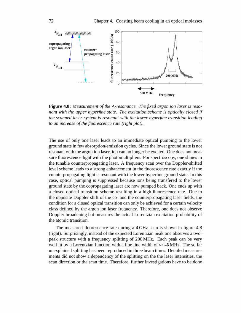
72 Chapter4. Coastingbeamcoolingin anopticalmolasses
500 MHz
200 MHz
frequency
fluor
esce
nce
coun
t rat
e (1
000/
s)
counter−
copropagatingargon ion laser
propagating laser
ÈzÈzÈzÈzÈzÈzÈzÈÉzÉzÉzÉzÉzÉzÉzÉP2
3/2
S21/2
Figure 4.8: Measurementof the Ç -resonance. Thefixedargon ion laser is reso-nant with the upperhyperfinestate. Theexcitation schemeis optically closedifthescannedlaser systemis resonantwith the lower hyperfinetransitionleadingto an increaseof thefluorescencerate(right plot).
The useof only one laserleadsto an immediateoptical pumpingto the lowergroundstatein few absorption/emissioncycles.Sincethelowergroundstateis notresonantwith theargonion laser, ion cannolongerbeexcited.Onedoesnotmea-surefluorescencelight with thephotomultipliers.For spectroscopy, oneshinesinthetunablecounterpropagatinglaser. A frequency scanover theDoppler-shiftedlevel schemeleadsto a strongenhancementin thefluorescencerateexactly if thecounterpropagatinglight is resonantwith thelowerhyperfinegroundstate.In thiscase,optical pumpingis suppressedbecauseions being transferedto the lowergroundstateby thecopropagatinglaserarenow pumpedback.Oneendsup witha closedoptical transitionschemeresultingin a high fluorescencerate. Due totheoppositeDopplershift of theco- andthecounterpropagatinglaserfields, theconditionfor aclosedopticaltransitioncanonly beachievedfor acertainvelocityclassdefinedby the argon ion laserfrequency. Therefore,onedoesnot observeDopplerbroadeningbut measurestheactualLorentzianexcitationprobabilityoftheatomictransition.
The measuredfluorescencerateduring a 4GHz scanis shown in figure 4.8(right). Surprisingly, insteadof theexpectedLorentzianpeakoneobservesa two-peakstructurewith a frequency splitting of 200MHz. Eachpeakcan be verywell fit by a Lorentzianfunctionwith a line line width of ���-e MHz. Thesofarunexplainedsplittinghasbeenreproducedin threebeamtimes.Detailedmeasure-mentsdid not show a dependency of thesplitting on thethe laserintensities,thescandirectionor thescantime. Therefore,further investigationshave to bedone

4.2. Measurements 73
to explain this effect.This methodrepresentsan elegantway of Doppler-free spectroscopy of fast
moving ions. Similar experimentsarecurrentlyperformedin a meta-stableLi ¹systemto exactly measuretherelativistic Dopplershift of particlesmoving withsomepercentof the speedof light. The goal of theseexperimentsis a high-precisiontestof specialrelativity [Grieseretal., 1994]. Thesmall line widthsoftheBeryllium systemwould suffice the requirementsfor a precisiontest,so thatthis ion speciesis alsoa possiblecandidatefor a relavitity experiment.
4.2.2 Longitudinal cooling
For thefirst coolingexperimentsbothlasersystemswereused.TheAOM systemwasswitchedon,sothatfour laserfrequencies(two copropagatingandtwo coun-terpropagating)wereactingon theion beam.Right after injection,thebeamwasprecooledby the electroncoolerfor 12 seconds.After that, repeatedfrequencyscansof thecounterpropagatinglaserwith a spanof 3.4GHz forth andbackovertheion resonancefrequency havebeenperformed.Thetimeevolutionof themea-suredfluorescencelight duringthesescansis depictedin figure4.9. Thescanof
ν dye
3.4
GH
z
Figure 4.9: First observationof molassescooling during repeatedfrequencyscansof the counterpropagating laser over the ion resonance. One observesasymmetricpeaksin the fluorescencesignal that appearonly during an upwardfrequencyramp.
the laserfrequency is schematicallyshown below the plot. During thesescans,oneobservestwo narrow asymmetricpeaks:Thesignalincreasessmoothly(left

74 Chapter4. Coastingbeamcoolingin anopticalmolasses
sideof thepeak)but suddenlydropsdown producinga sharpedge.Furthermore,thepeaksonly occurif thefrequency rampgoesupwards(from “red-detuned”to“blue-detuned”).This is thefirst clearsignatureof longitudinalbeamcoolingasexplainedin thefollowing.
Figure4.10showstheforceprofilesof bothlasersin velocityspaceaswell asa zoomof thefluorescencedataof thepreviousfigure. Thecopropagatingargon
Ar laser+Ar laser+
coun
t rat
e (H
z)
3.4 GHz
fluor
esce
nce
coun
t rat
e (H
z)
3.4 GHz
fluor
esce
nce
force
v
frequency−doubled dye laser
force
v
frequency−doubled dye laser
Figure4.10: Theion ensembleis eithercompressedin velocityspace(left picture)or pushedapart (right picture)dependingon thescandirection.
ion laseracceleratesthe ions (positive force) while thecounterpropagatinglasersystemdeceleratesthem(negative force). For a fixedlight frequency, ionssittingaroundtheresonanceof thecounterpropagatinglaserin velocity spacewould beshifted to lower velocities. Becauseof the changingDoppler shift, theseionsimmediatelyrun out of resonanceandno longerexperiencethe laserforce. Dueto thefrequency scanhowever, thedeceleratingforceprofile is shiftedin velocityspace.
In the left picture the frequency scangoesupwardswhich leadsto a shifttowardslower velocities. The above particlesdeceleratedby the laserbecomeresonantagainandarethusfurtherdecelerated.Thescanninglaserthereforecol-lectstheions in velocity spaceandpushesthemaheadlike a waterwave in frontof a ship’s bow. This is the basicprinciple of the chirped laser cooling scheme[Ertmeret al., 1985]. Thewholeensembleis shiftedtowardslowervelocitiesuntil
4.2. Measurements 75
thedistributionbecomesresonantwith thecopropagatinglaser. Bothforceprofilesleadsto a velocity confinementof the ionssitting in between.While therelativedetuningof the lasersbecomessmallerandsmallerthe force profilesapproacheachother. Theion distribution is graduallyfurthercompressedin velocityspace.More andmoreionsbecomeresonantwith thelaserswhich leadsto a continuousincreaseof the fluorescencerate. This works until the relative detuningof bothlasersbecomeszero. For equallaserintensitiesthe cooling forcewould exactlyvanish.In ourexperimentwith adeceleratinglaserof lower intensityoneendsupwith a weakacceleratingforcepushingthe ion ensembleto highervelocitiesoutof thelaserresonance.Hence,anabruptdropin thefluorescencerateoccursasex-perimentallyobserved.A furthernegativedetuningof thecoolinglasersdoesnotchangethesituation:ionssitting aroundtheargonion laserforceareaccelerated,andionsbeingresonantwith thefrequency-doubledlaserarefurtherdecelerated.
The oppositesituation is depictedin the right picture. Ions sitting aroundthecounterpropagatinglaserforceprofile arestill deceleratedasin thefirst case.However, the frequency scanto lower frequenciesleadsto a shift of the forceprofile towardshighervelocities. Therefore,ions that have beendeceleratedbythe lasernever becomeresonantwith the laseragainduring the scan. Hence,areversedfrequency scandoesnot leadto a collectionof ionsin velocity space.Inaddition,thenegativedetuningleadsto anunstablepoint in thecoolingforcepro-file. Sincethereis no velocity compressionof theparticleensembleandionsarepermanentlypushedout of the laserresonanceonedoesnot observe an increaseof thefluorescencerate.
Note,thattheion ensembleis notheatedfor negativedetuningsasit is thecasefor thebunchedcoolingschemewherethelaserdrivesthesynchrotronoscillation.Theionsareonly pushedaway from bothlasers.Outsidethelaserresonance,theparticlesexperiencealmostno laserforces. This is the reasonfor the observedbehavior thatevenafterafrequency scanin the“wrong” direction,theionscanbecooledbackin asucceedingscanin directionof increasingfrequencies.
Theexperimentwascarriedout with a total light power of thecounterpropa-gatinglaser(two frequencies)of 10mW. For a reducedlaserpower of ¯¢Y mWas it was the casein former experiments(with almost the samebeamwaist)[Horvath,1994, Stoessel,1997] one observesalmostno cooling effect. In thiscase,the scannedlaseractsas a diagnostictool not effecting the longitudinalvelocity distribution, which leadsto symmetricpeaksthat appearindependentlyfrom thescandirection.
The presentedobservationsclearly demonstratethe compressionof the ionensemblein velocity space.Thenew counterpropagatinglasersystemin connec-tion with the secondfrequency of the AOM systemobviously producesa coun-terforcewell suitedfor coastingbeamcooling. Sincethe ion ensembleis in theabove experimentonly cooledfor a very shorttime while the two force profiles

76 Chapter4. Coastingbeamcoolingin anopticalmolasses
approachingeachotherthenext measurementinvestigatescoastingbeamcoolingfor longertimes.
Long-term cooling
An ion ensemblecanbe cooledfor longertimesby stoppingthe laserscanat agivenrelative detuning.As in thepreviousexperimentthe ion ensembleis com-pressedduringthelaserscan.However thefrequency scanis stoppedjust beforethemaximaof bothlaserforceprofilesareat thesamepositionin velocity space(zerodetuning).The developmentof the fluorescencesignalduring suchan ex-perimentis shown in figure4.11.Theion beamis againprecooledby theelectron
coun
t rat
e (1
000H
z)flu
ores
cenc
e
time (s)
lase
r fr
eque
ncy
time
counterpropagating laser
copropagating laser
rel. detuning
Figure 4.11: Fluorescencesignalduring long-termmolassescooling. Thecoun-terpropagatinglaserscanstoppedat a givenrelativedetuning(schematicpicturebelowtheplot). Thealmostconstantfluorescencerateindicatesthat theionscanbeholdat thestablepoint in velocityspace.
coolerfor 12seconds.Thefrequency scanover1.4GHzstarts15safterinjection.At arelativedetuningof ��YX�8� MHz thescanis stopped.Oneobservesanincreaseof thefluorescencerateduringthescanover a time rangeof seconds.During thelaserfrequency scanions arecollectedandcompressedin velocity spacewhichleadsto theincreaseof thefluorescencesignalat Êp>~7 s. After stoppingthescan,the count rate remainsalmostconstantfor several seconds. The constantrateshows thattheion ensemblestaysresonantwith thelasers.Theparticlesarecon-fined betweenthe co- andthe counterpropagatinglaserforcesin velocity space.

4.2. Measurements 77
Therefore,oneobserveslongitudinallong-termcoolingof a fastion beamby anopticalmolasses.
Fluorescencemeasurementsover longer times show a slow exponentialde-creasewhosetimeconstantof ��Y�s secondsis only slightly shorterthanthebeamlifetime ( ËÌ>T7� s). Theshortertime constantis causedby thelossof ionsout ofthe capturerangeof the cooling force profile dueto intra beamscattering.Ionsscatteredout of the capturerangein velocity spaceexperiencealmostno laserforcesthat couldcool thembackto thestablepoint. Therefore,ionsarelost forthecoolingprocess.In thebunchedcoolingscheme,theseionswould startoscil-lating againin thebunchpotentialwhile they arecooledbackto thestablepoint.However, theslight reductionof thetimeconstantshowsthatunderthepresentedconditions,lossesthroughIBS arealmostnegligible.
One possiblereasonfor this small influence of cooling processon hardCoulombcollisionsmight be the ion beamwasstill possiblytransversallyhot.As shown in chapter3 a transversehot beamleadsto a large beamdiameterre-sulting in a low ion density. The low densitystronglyreducesthe collision rateandthereforethelossesfor thecoolingprocess.A transversallycoldbeamwouldlead to a highercollision rate. Thesecollision would then result in higher ionlossesfor thecoolingprocess.However, thelossescouldbesuppressesby theuseof a capturerangeextensionsuchasa rapid adiabaticpassage(seesection2.3).Thispointwill beexaminedin moredetailduringthenext beamtime(chapter5).
Capturing ions in an optical molasses
A coolingeffect canalsobeobservedusingfixedlaserfrequencieswithout scan-ning. This is demonstratedin figure 4.12 showing the fluorescencecount rateduring this cooling process.The lasersystemwasadjustedwith a fixed relativedetuningof 160MHz. The injectedion beamwaselectron-cooledfor ten sec-onds.Thestablepointof theelectroncoolingforcein velocityspacewasadjustedto beseveral100m/sawayfrom thestablepointproducedby theopticalmolasses.Thecapturingprocessis schematicallydepictedabove thefluorescenceplot. Thefirst sketchshowsthesituationduringelectroncooling.Theelectroncoolingforcedrawstheionsto its stablepointresultingin aGaussiandistributionwhichis apartfrom thelaserforces.Thereforetheion beamis not resonantwith thelasers.Oneobservesalmostno fluorescencelight. After the electroncooleris switchedoff,theion ensemblemovesapartdueto diffusionandintra beamscattering.Theve-locity distributionbroadens(secondsketch).A partof thisdistributionapproachesthemolassesforceprofile andis drawn to its stablepoint. Ionsarecontinuouslycapturedin themolasses.Theseionsarenow resonantwith thelasers.Therefore,thefluorescencecountrateincreasesaswell which is shown in theplot. Thetimeaxisstartsright afterswitchingof theelectroncooler. Theion ensemblebroaden-

78 Chapter4. Coastingbeamcoolingin anopticalmolasses
velocity
coun
t rat
e (H
z)flu
ores
cenc
e
time (s)
velocity
electron−cooled distribution molasses cooling
velocity
Figure 4.12: Increasingfluorescencesignal during the collection of electron-cooledions into the molassesusing fixed laser frequencies.The measurementstartsright afterswitchingoff theelectroncooler. Thecapturingprocessin veloc-ity spaceis sketchedfor threetimesabovetheplot.
ing in velocityspacereachestheopticalmolassesafterapproximatelyonesecond.Thefluorescencerateincreasessteadilyup to ÊÍ>±Y�� swereit decreasesagaindueto thelimited beamlifetime.
Although oneobservescooling, this methodis not very efficient sinceonlya small fraction of the electron-cooleddistribution is capturedby the molasses.A frequency scanof thecounterpropagatinglaserhowever cancollectalmostallions of the electron-cooledbeamif the broadprecooledensembleis initially inbetweenbothfar-detunedlasers.Ontheotherhand,thisexperimentdemonstratesthecaptureof ionsin themolassesduringthecoolingprocess.

4.2. Measurements 79
Longitudinal temperatures
During the presentedlong-termmolassescooling experiments,the longitudinalvelocity distribution wasmeasuredusingan HV-scan. A typical scanis shownin figure 4.13. The measuredprofile shows somecharacteristicdifferencesto
Figure4.13: LongitudinalvelocitydistributionduringmolassescoolingusingtheHV-scanmethod.
thescanstakenduringbunchedlasercooling. Oneobservesa narrow peakwithalmostno pedestal.Thesignificantsuppressionof a broadbackgroundensemblereflectsthefactthationsundergoingacollisionprocessarenotcooledback.Thisagainshows theeffect of thesmallcapturerangeof theopticalmolasses.
Furthermorein contrastto bunchedcooling, the narrow peakis now almostsymmetric.Thereasonfor that is thedifferentmotion in phasespace:Sincethecoolingforcein in opticalmolassesis symmetric,ionsmoving with aslightveloc-ity deviation aredrawn backto thestablepoint with thesameforce independentfrom thesignof thedeviation. This is not thecasein thebunchedcoolingscheme.Ions with a slightly lower velocity experiencea strongacceleratingforce fromthecopropagatingargonion laser. Ionsmoving too fasthoweveronly experiencethemuchsmallercounterforceproducedby thebunchpotential.This leadsto thecharacteristicsharpedgeof thecold peaksasshown in figure3.4. Theremainingslight asymmetryin figure4.13might rely on the fact that theco- andthecoun-terpropagatinglaserbeamshave differentlaserintensities.Very first resultsfromthecomputersimulationthathasbeenmodifiedfor molassescoolingvalidatethisinterpretation.
Thecoolingexperimentswerealsodonewith differentrelativelaserdetuningsafter thefrequency scan.For eachexperimentthevelocity distribution wasmea-suredthreesecondsafterthelaserscanstoppedusingHV-scans.Thelongitudinaltemperaturesaswell asthe ion numbersof thecold subensemblewith respecttothe relative detuningis depictedin figure 4.14. With decreasinglaserdetuning,

80 Chapter4. Coastingbeamcoolingin anopticalmolasses
Figure 4.14: Longitudinaltemperatures(left) andparticlenumbers (right) of thecold ion ensemblecaptured out of the ECOOL distribution with respectto therelativedetuningof thecoolinglasersmeasuredwith theHV-scanmethod.
theresultinglongitudinaltemperaturealsobecomeslower andlower. This is theeffect of theincreasingslopeat thestablepoint of thelaserforceprofile with de-creasingdetuningasdepictedin figure 4.15. This slopedeterminesthe friction
00 v
F
00
F
v
capture rangecapture range
Figure4.15: Schematicpicturesof thecoolingforceprofilesfor differentrelativedetunings.Thedistanceof the accelerating and the decelerating laser forcesinvelocityspacestronglyinfluencesthefriction coefficientrepresentedbytheslopesat thestablepoint.
coefficientandthereforethecoolingrate(section2.2.3).Theoretically, thetemperaturelimit of lasermolassescoolingis theso-called
Doppler limit [Metcalf andvanderStraten,1999]: As shown in section2.3 themomentumtransferaveragedover many spontaneousemissionprocessesof anexcited ion vanishes( Î8ÏÐÒÑ >Ó� ). Thesquareof themomentumhowever doesnot

4.2. Measurements 81
disappear( Î8ÏÐ V Ñ >Ô� ). A laser-cooledion performsa randomwalk which corre-spondsto a heatingprocess.The diffusion constantof this motion therebyde-terminesthe heatingrate. The resultingtemperatureis determinedby the ratioof thecoolingandtheheatingratewhich leadsto theexpressionfor theDopplertemperatureÎ Õ}��ORQ Ñ�Ö /21%1%ª�>T×�Ø!Ä Ö /21%1%ª�>¾ÙÚ�Û 6�7 (
Û: naturalline width of theatomic
transition).In ourcase,theDopplerlimit for Beryllium ionsis gf7�ei� K. Thissmallvalueindicates,thatthecoolingmethodis in our casenot limited by photonscat-tering and thus the lasercooling processitself. The main reasonfor the muchhigher temperaturesof someKelvin is the existenceof the very strongheatingprocessdueto intrabeamscattering.
Theright pictureshowsthenumberof particlesbeingin thenarrow peakof thevelocity distribution. With smallerdetuningsthenumberof ions alsodecreases.The reasonfor that is the capturerangeof the cooling force. The capturerangefor molassescooling is givenby thevelocity interval definedby both laserforceprofiles(roughlydepictedasbracesin figure4.15. Ionsbeingoutsidethis inter-val arenot cooledandarepartof thebroadbackgroundensemble.Thevelocityinterval andthusthecaptureis proportionalto therelative detuningof thelasers.For anarrow capturerange,evenionsthathaveundergoneacollisionwith asmallvelocity changearepushedoutsidethe molasses.Hence,the numberof ions inthecooledpeakdecreaseswith smaller-gettingdetuning.
Both experimentalresultsdemonstratethesignificantrole of intra beamscat-tering for coolingof faststoredion beams.On theonehandtheheatingprocessinducedby IBS is themain limiting factorfor thebeamtemperaturesthatcanbeexperimentallyachieved. In connectionto thecapturerangeof thecoolingforce,intra beamscatteringalsosignificantlyinfluencesthenumberof ions in thecoldpeak.
The time evolution of themolassescoolingprocesswasexaminedby takinga seriesof HV-scansat differenttimesafter the laserfrequency scan.Thecorre-spondingtemperaturesof the cold subensembleareshown in figure 4.16. Fromthebeamlifetime onecancalculatethe total numberof ionsstoredin thering atthetimeof theparticularmeasurement.Sincethenumberof ionsright afterinjec-tion aswell asthefractionof particlesbeingin thecoldensembleis currentlynotknown, theparticlenumberis givenin arbitraryunits.
Oneobservesadecreaseof thelongitudinaltemperatureswith precedingcool-ing time. This behavior canon theonehandbeexplainedby thetime neededforrelaxationof the longitudinal ion ensembleexperiencingthe laserforce. Rightafterthefrequency scanit takessometime to draw theion ensembleto thestablepoint. On theotherhand,thedecreasingbeamcurrentleadsto a reductionof in-tra beamscatteringandthusa decreasingheatingrate.Furthermore,asdescribedabove, ions scatteredfar away from the capturerangeare lost for the coolingprocessandno longernotablycontribute to the cooling dynamics. Hence,this

82 Chapter4. Coastingbeamcoolingin anopticalmolasses
Figure4.16: Longitudinalbeamtemperaturesduringmolassescoolingat a fixedrelativelaserdetuningwith respectto theparticlenumber.
measurementdirectly demonstratesthe influenceof intra beamscatteringon thelasercoolingprocess.
Schottky noiseanalysis
Asdescribedin section2.4.3for coastingbeamsit is possibleto measurethedistri-bution of theion revolution frequenciesby Schottky noiseanalysis.This methodallowsanon-destructivemeasurementof thelongitudinalvelocitydistribution. Inaddition,thismethodhastheadvantagethatthatdistribution is nothiddenbehindthe three-peakstructureas in HV-scans.Figure4.17 shows longitudinalveloc-ity distributionsusingSchottky noiseanalysisfor differentlaserdetunings.Thefirst plot (left) is measuredfor a largedetuningof 600MHz. Oneendsup with aratherbroadvelocity distribution. In this caseit is not possibleto fit anexpectedGaussiandistribution to the data. A smallerdetuning(middle plot) of 110MHzhowevershows analmostGaussianpeakwith a sigmawidth of 45m/s. Thethirdpictureshows a laserdetuningvery closeto zero.Oneobservesa significantlossof ionswhosetotalnumbercorrespondsto theareaunderthepeakof theSchottkyspectrum.Most of the ion ensembleis alreadypushedaway by the laserforce.The velocity spreadof the remainingions of 28m/s is somewhat smallercom-paredto themiddleplot. Themeasuredlongitudinaltemperaturesfit very well tothevaluesdeterminedby HV-scanmeasurements.
With this method,it is alsopossibleto monitor the longitudinalcooling dy-namicsduring the frequency scanand thereforethe processof collecting andcompressingtheion ensemble.For this purpose,we performeda very slow laserfrequency scanover 15secondscovering a frequency rangeof 2GHz. The fre-

4.2. Measurements 83
=600 MHz∆ν =110 MHz∆ν ~0 MHz∆ν
Figure 4.17: Longitudinal temperatureswith respectto the relativedetuningofthecopropagating laser measuredby Schottky noiseanalysis.Thethick lines inthemiddleandtheright plot arefit curvesassuminga Gaussiandistribution.
quency scanwasstartedfivesecondsafterfinishinga tensecondelectroncoolingphase.Schottky pictureswere taken every secondduring the laserscan. Sincethe maximumdataacquisitionratewasoneSchottky analysisin threeseconds,severalinjectioncycleshavebeenusedwith shiftedmeasurementtimes:ThefirstinjectionwasperformedtakingSchottky picturesafter ÊÍ>d� s, ÊÍ>Ag s, Êi>�c setc.For thesecondinjectionthemeasurementtimeswere Êj>�Y s, ÊÍ>d� s, Êj>�u s etc.andfor third one Êo>q7 s, Ê0>qe s, Êo>�s s etc. Therefore,with threeinjectionsthelongitudinalvelocitydistributioncouldbeobservedwith a time resolutionof onesecond.A seriesof selectedSchottky picturesis shown in figure4.18. Thefirstplot wasrecordedduringtheelectroncoolingphase.Oneobservesa comparablybroadvelocity distribution which correspondsto the equilibrium temperatureofanelectron-cooledion beam.Thenext plot shows ionsthatarepushedby thear-gonion laseroutsideits resonancerangetowardshighervelocities.At this point,theforceprofile of thecounterpropagatinglaseris outsidethedrawing area.Thefrequency scanstartsright afterthethird picture.In thefollowing for pictures,oneobservesthe compressionof thevelocity distribution. Oneclearlyseesthe con-tinuousshift of theright borderof thedistributiontowardsthevelocitypositionofthecopropagatingargonion laser. Thesignalheightsteadilyincreasessincemoreandmoreionsareconcentratedon a narrowing velocity interval. In the last twopictures,therelativedetuningbecomespositive,sothatthereis no longerastablepoint in velocity space.This correspondsto thesharpdropof in thefluorescencesignalin figure4.9. TheSchottky plotsshow anabruptdisappearanceof almost

84 Chapter4. Coastingbeamcoolingin anopticalmolasses
x 1/4
Figure4.18: Longitudinaldynamicsduringa slowdyerampmonitoredbySchot-tky analysis.Thedashedline denotesthepositionof theargonion laser.
the completeion ensemble.Thereareonly a coupleof ions left beingpushedawayby theargonion laserasit wasthecaseright afterelectroncooling(secondpicture).
Theshapeof theSchottky signalsduringlasercoolinghasalsobeendiscussedin [Hangstet al., 1995a, Lebedev et al., 1995]. It turnedout thatadditionaleffectssuchasLandaudampingand the occurrenceof plasmawavesalong the closedorbit influencethemeasurement.Theseeffectscanalsobeobservedin our mea-surementsasa two peakstructureemerging e.g at Êb>Üu s. Theseobservationshave to be further investigated.Nevertheless,the presentedmethodallows therealtimeobservationof thelongitudinalvelocity distribution duringthescanningandcoolingprocess.This tool will alsobecomeof particularinterestfor theob-servationof Coulombordering.
4.2. Measurements 85
4.2.3 Transversecooling
The transversedynamicsduring coastingbeamcooling is monitoredwith thebeamprofile monitor (BPM) asfor the caseof bunchedbeams.During the en-tire measurementcycle, a setof beamprofileswasrecordedby accumulatingthesignalcountsfor threesecondsperprofile. Therefore,thetotalmeasurementtimeof of 39 secondsdeliversa setof 13 beamprofile pictures,which shows thetimedevelopmentof thetransversephase-space.In addition,themeasurementwasav-eragedover threeinjectionsto improvesignal/noiseratiodueto thelow ion beamcurrent.Theresultingprofileswerefit accordingaGaussiandistributionfunction.Thesigmawidthsdeterminedfrom thefit areusedto calculatethehorizontalandverticalbeamemittancesof thering-averagedtemperaturesrespectively usingtheknown valuesof thebetafunctionat thepositionof theBPM asdescribedin sec-tion 2.2.Furthermore,thedatahasbeencorrectedconsideringthefinite resolutiontemperatureof theBPM (section2.4.3).
The ion beamwaselectron-cooledfor ten secondsright after injection. Thecounterpropagatinglaserbeamwasadjustedin maximumoverlappositionwithrespectto thebeam.Theoptimumoverlapwasdeterminedwith anuncertaintyof�ÝY;e8�p� m by maximizingthefluorescencesignalswhile scanningthe laseroverthe electron-cooledvelocity distribution. The beamwaist of this systemsittingin thecenterof thecoolingsectionof thestoragering was Þ}£ V2¤ �½Y�rte mm. Theoverlappositionof thecopropagatingargonion laserwith abeamwaistof Þ}£2l2l0�7�rße mm wasalsooptimizedby maximizingthefluorescencerateduringrepeatedHV-scans.
Right afterelectroncooling,thefrequency-doubledlasersystemwasscannedover2.5GHzin 1.5secondsto collecttheionsin velocityspaceasalreadydemon-stratedin section4.2.2.Thescanstoppedat a relativedetuningof 200MHz. Thestoragering wasoparatedin betatroncouplingmode(section2.3.2) to ensureacouplingof both transversedegreesof freedom.In this case,thedispersive cou-pling, normally only presentbetweenthe longitudinaland the horizontalbeamdirection, leadsto a heatingor cooling of the completetransversephase-space.Dispersive heatingandcooling of a coastingbeamis demonstratedby separatemeasurementsat different horizontalpositionsof the copropagatingargon ionlaserinwardsandoutwardswith respectto theion beam.Thecounterpropagatinglasersystemwaskept in the optimumoverlappositionwith the ion beam. Themeasuredtime developmentof transversephase-spaceat four differentcopropa-gatinglaserpositionsis shown in figure4.19.
Thevery left columnschematicallydepictsthehorizontalpositionsof theco-propagating(300nm) andthecounterpropagating(326nm) laserbeamswith re-spectto the ions. The middle and the right columnsshow the horizontalandverticalring-averagedbeamtemperatureswith respectto thetime after injection.

86 Chapter4. Coastingbeamcoolingin anopticalmolasses
326nm300nm
ion beam
horizontal verticalhor. laser positions
Figure 4.19: Developmentof thetransversetemperaturesfor differenthorizontallaserpositions.Oneobserveseitherdispersiveheating(firstrow)or cooling(thirdrow).
Thefirst two datapointsin eachplot correspondto theequilibriumtemperatureoftheelectron-cooledbeam.Theveryfirst datapointat àÍá�â shasbeenexcludedinall theplotsbecauseat this time theextremelyhot ion beamright after injectionis not yet cooleddown leadingto temperatureshigherthan20,000Kelvin.
In thefirst row, theargonion laserwasdisplaced0.5mminwardscorrespond-ing to 1/4 of its beamwaist. After switchingoff electroncooling ( àãáFäXå s) oneclearly observesa steadyheat-upof the horizontaltemperature.This measure-mentimpressivelyshowstheeffectof dispersiveheating.Dueto apartlydamagedmulti-channelplateof theverticalBPM thecountratesarereducedby a factoroftwo with respectto the horizontaldirection. This leadsto a comparablylargerscatteringof the datapoint. Neverthelessonealso observesan increaseof thevertical temperaturewhich clearly shows the effect of betatroncoupling. With-out this coupling the heat-upwould have only beenmeasuredin the horizontal

4.2. Measurements 87
degreeof freedom.Theobserveddispersive heatingalsoovercomesthe indirectcooling throughintra beamscattering:Without dispersive cooling, the ion beamwould be transversallycooleddue to a heatexchangewith the very efficientlycooledlongitudinaldegreeof freedom(seesection2.3.2).Themeasuredheat-upis thereforean unambigoussignatureof the dispersive coupling. The dispersiveheatingincreasesthebeamdiameterandlowersthecollision rate.Thereforeindi-rectcoolingis reducedwhich leadsto a furtherheat-upof thebeam.
For thenext measurement(secondrow in figure4.19). theargon ion laserisplacedin theoptimumoverlappositionwith theion beam.Thelasershouldnowneitherdispersively heatnor cool the beam. This horizontalpositionrepresentsan unstableequilibrium. Evenslight horizontalshifts from this overlappositionwould leadto dispersivecoolingor heating.Thebeamprofile measurementsstillindicateanincreaseof thetransversetemperatureduringmolassescooling.How-ever, theheatingrateis noticeablysmallerthenin thefirst experiment.Obviouslytheoverlappositionasdeterminedasdescribedabove is still slightly shiftedringinwardscorrespondingto weakdispersiveheating.
In the third casethe copropagatinglaserwasshifted0.5mm ring outwards,a symmetricalhorizontalshift in the oppositedirectionwith respectto the firstexperiment.After theelectroncoolingphase,thebeamdoesnot blow up but thetransversetemperaturesremainalmostconstant.In thiscase,oneclearlyobservesdispersive cooling. The cooling of both degreesof freedomagaindemonstratesthe effect of betatroncoupling. Both transversecoolingmechanisms,dispersivecoolingandindirectcoolingthroughcollisionsworksin thesamedirection.Dis-persive cooling reducesthe beamdiameterresulting in a higher collision rate.This increasesthetransversal/longitudinalIBS couplingwhich leadsto astrongerindirectcoolingaswell. Thisexperimentrepresentsthefirst 3D lasercoolingof afastcoastingion beam.
A furtherlaserbeamdisplacementof 0.9mmoutwardsfrom theoverlapposi-tion is shown in thelastrow of figure4.19.Thedisplacementroughlycorrespondsto onesigmawidth of the laserbeam.Theplot againshows a slight increaseoftheemittancesalthoughthebeamis still dispersivelycooled.Thisbehavior canbeexplainedwith a significantlyreducedlongitudinalcoolingratedueto theratherworseoverlapwith the ion beam. This worselongitudinalcooling alsoreducestheindirecttransversecoolingleadingto somewhathighertemperatures.
The presentedexperimentclearly shows that the dispersive cooling mecha-nismalsoworksvery well for thecoastingbeamcoolingscheme.Theachievedtransversetemperaturesof aboutæ�çéè�ê8ë8å K for thecaseof dispersivecoolingarecomparableto thevaluesmeasuredwith thebunchedcooling technique.Duringdataanalysistherelativedetuningof ì�ê8å�å MHz turnedoutnotto betheoptimumvaluefor longitudinalcooling(seefigure4.14).Therefore,highercoolingrateforthelongitudinalandthusthetransversedegreesof freedomaresurelyachievable.
88 Chapter4. Coastingbeamcoolingin anopticalmolasses
A furtherimprovementof transversecoolingwouldpossiblybethehorizontaldis-placementof thecounterpropagatinglaserbeamto alsoachievedispersivecoolingwith this lasersystem.In this case,onehasto considerthat thesign of the hor-izontal displacement(inwardsor outwards)in orderto attaincooling or heatingarereversedwith respectto theargonion laser. Sincethecounterpropagatinglaserdeceleratestheions,thebetatronoscillationis dampedif thelaseris displacedin-wardswith respectto theion beam(comparethiswith figure2.11)andviceversa.However, thesmallbeamwaistonly allows rathertiny displacementsof lessthan300 í m sincelargerdisplacementswouldstronglyreducethelongitudinalcoolingrate.
4.3 Conclusion
Thepresentedexperimentsdemonstratefirst coolingof acoastingBeryllium beamby a one-dimensionalopticalmolasses.Up to now thephase-spacedensitiesarecomparableto the densitiesachieved with the bunchedcooling method. In ad-dition we presentedfirst true 3D cooling of a coastingbeamemploying the dis-persive coupling. While the longtudinalcooling parameterswere the optimumvalues,transversecooling will be furtheroptimizedin the next beamtime. Fur-thermorethecomputermodelmodifiedfor coastingbeamcoolingwill givemoreinsightinto thedynamicsof coastingbeamcooling.
All coastingbeamcooling experimentshave beencarriedout with total ionnumbersof äXå�î . AccordingthemoleculardynamicssimulationsCoulomborder-ing is expectedfor particlenumberslower than äXåï . Thereforeorderingeffectsarenot expected.However, next beamtime we will reducethe particlenumberand try to reproducethe observation of a suddendissappearanceof intra beamscattering.
Chapter 5
Outlook
Thegoalof all presentedlasercoolingexperimentsis still to answerthequestionwhetherit is possibleto achieve a beamcrystallizationandto find out the ulti-matelimits of the phase-spacedensity. The suddendisappearanceof Coulombcollisionsduring lasercoolingof bunchedbeams(section3.3)alreadyshows thesignatureof an orderingprocess.However due to the ambiguity of the resultsrequirefurtherexperimentsto getaclearproofof acrystallization.In orderto im-prove thecoolingratesandto investigatethat theobservationsarenot connectedto thebunchedcoolingschemeitself, a new seriesof coastingbeamcoolingex-perimentshave beencarriedout (chapter4). Theseexperimentshave beendonewith ion numbersof about äXå8î in orderto examinethenew coolingdynamicswithsignalrateseasyto handle.Thetransitionin bunchedbeamshowever took placeat äXå ï ionsin agreementwith thetheoreticalpredictionsfor theformationof a lin-earchain.Thenext stepto reproducetheanomalousbehavior in a coastingbeamwould thereforebecoolingof muchmoredilute beamswith ion numbersbelowä�å ï .
In particularfor coastingbeamcoolingdu to the limited capturerangeof thecooling force andthe fact that scatteredions cannotbe cooledback, the useofa capturerangeextensioncould be very interesting. As shown in figure 2.9 arapid adiabaticpassagecanextendthe force profile to a velocity rangeto about1000m/s. This is sufficient to completelysuppressany lossesfor the coolingprocessdueto IBS. Unfortunatelya rapid adiabaticpassagerealizedby a setofdrift tubesin thecoolingsectionof thestoragering (section2.3.1)would modifytheforceprofilesof theco- andthecounterpropagatinglaserin thesamemannerasschematicallydepictedin figure5.1a. Both profileswould beextendedin thesamedirectionin velocity space.Onepossiblesolutionto this problemcouldbea further relative laserdetuningof roughly 2GHz (figure5.1b). In this casethestablepoint would beproducedby themainpeakof onelaserandthe“wing” ofthecapturerangeextensionof theotherlaser. This experimentwill bedonenext
89

90 Chapter5. Outlook
b)a)
F F
vv
Figure 5.1: Thecapture range extensionthroughrapid adiabaticpassage leadsto an extensionof bothco- andcounterpropagatingmolasseslasers towards thesamedirectionin velocityspace(a). A solutioncouldbea further relativelaserdetuning(b).
beamtime.Anotherpossibleextensionof theexperimentwould possiblybesympathetic
coolingof ð)ñ Oò�ó by thelaser-cooledBeryllium beam.Besidestiny isotopicshifts,the oxygenbeamhasthe samemagneticrigidity as ô Beó . It could thereforeinprinciplebestoredsimultaneouslywith theBeryllium beamin thering atthesamevelocity. While theBeryllium beamis efficiently lasercooled,collisionsbetweenbothion speciesleadto aheatexchange,sothattheoxygenbeamcouldbecooledaswell. This is similar to thesituationof electroncoolingwherea cold electronbeamis mergedwith an ion beam.This experimentwould give someimportantinsighton thecoolingprocessthroughcollisionswhich is alsointerestingfor thefurtherunderstandingof electroncooling.
A completelydifferent regime would be lasercooling of very densebeamswith particle numbersof more than äXå ô . In the nearfuture, the productionofthesedensebeamswill bepossiblewith therecentlyinstalledhigh currentinjec-tor (HCI). The investigationof lasercooling in a strongIBS regime could leadto a furthergoingunderstandingof the influenceof collisionsto thecoolingpro-cess.Furthermorehigh currentbeamsof extremephase-spacedensitiesrepresentauniquetool to observeeffectssuchastune-shifts,selfbunchingandstorageringinstabilities.

Appendix A
Electron cooling forcemeasurementsusing barrier buckets
A.1 Intr oduction
Over the years,electroncooling hasbecomea standardcooling techniqueusedin storagerings[Poth,1990]. In contrastto othertechniquessuchaslasercool-ing [Petrichet al., 1993], electroncooling is a universalmethodwith no limita-tion to a certainion species.However, it is surprisingthat only a few system-atic measurementsexist which quantitatively determinethe influenceof variouscoolerparameters(electrondensity, guidingfields,expansionfactorsetc.) on thecooling process.In particular, oneis interestedin the cooling ratesthat canbeachieved, sincethis determinesthe cooling timesandequilibrium temperaturesof the ion beams.Themajor reasonfor this situationis the lack of simplemeth-odsto measurethe cooling force profile. Up to now, thereareonly two knowntechniquesto measurethe force profile: Onecanperforma controlledheat-upof the ions by applyinga white-noisesourceof definedpower to the ion beam[Winkler etal., 1997, Beutelspacher, 2000]. Thevelocitydependency of thecool-ing force can then be calculatedby solving a Fokker-Planckequationwith themeasuredthermodynamicion distribution and the appliedheatingpower as in-put values.On theotherhand,thecooling forcecanbemeasuredby applyingacounterforce to the ionsusingan inductionaccelerator[Ellert et al., 1992]. Themeasurementof therevolutionfrequency of theelectron-cooledionsin forceequi-librium with respectto thestrengthof thecounterforcedirectlydeliverstheforceprofile. While the heatingmethodallows the measurementof the force profileover a large velocity rangeincluding the non-linearpart of it, the accuracy ofthis techniquestronglydependson theunderlyingmodelbeingused.Thesecondmethodmeasuresthecoolingforcedirectly but requiresan inductionaccelerator
91
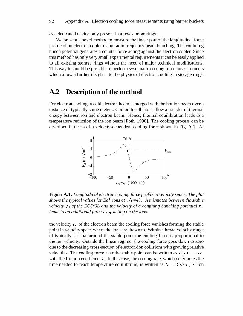
92 AppendixA. Electroncoolingforcemeasurementsusingbarrierbuckets
asadedicateddeviceonly presentin a few storagerings.Wepresentanovel methodto measurethelinearpartof thelongitudinalforce
profileof anelectroncoolerusingradiofrequency beambunching.Theconfiningbunchpotentialgeneratesacounterforceactingagainsttheelectroncooler. Sincethismethodhasonly verysmallexperimentalrequirementsit canbeeasilyappliedto all existing storagerings without the needof major technicalmodifications.Thisway it shouldbepossibleto performsystematiccoolingforcemeasurementswhichallow a furtherinsightinto thephysicsof electroncoolingin storagerings.
A.2 Description of the method
For electroncooling,acoldelectronbeamis mergedwith thehot ion beamoveradistanceof typically somemeters.Coulombcollisionsallow atransferof thermalenergy betweenion andelectronbeam. Hence,thermalequilibrationleadsto atemperaturereductionof the ion beam[Poth,1990]. Thecoolingprocesscanbedescribedin termsof a velocity-dependentcooling force shown in Fig. A.1. At
F
(meV
/m)
el
Fbias
vrf vel
v −v (1000 m/s)ion el
−50 0 50 100
0
4
8
−100−8
−4
FigureA.1: Longitudinalelectroncoolingforceprofilein velocityspace. Theplotshowsthetypical valuesfor Beó ionsat õ�ö8÷ =4%. A mismatch betweenthestablevelocity õ_ø�ù of theECOOLand thevelocityof a confiningbunching potential õ;ú�ûleadsto an additionalforce üKý%þ«ÿ�� actingon theions.
thevelocity õ_ø�ù of theelectronbeamthecoolingforcevanishesforming thestablepoint in velocityspacewheretheionsaredrawn to. Within abroadvelocityrangeof typically äXå � m/s aroundthe stablepoint the cooling force is proportionaltothe ion velocity. Outsidethe linear regime, the cooling forcegoesdown to zerodueto thedecreasingcross-sectionof electron-ioncollisionswith growing relativevelocities.Thecoolingforcenearthestablepoint canbewritten as ü � õ��já����õwith thefriction coefficient � . In thiscase,thecoolingrate,whichdeterminesthetime neededto reachtemperatureequilibrium, is written as ±áÔê��iö�� ( � : ion

A.2. Descriptionof themethod 93
mass).Thebeambunchingmethodcanbeusedto measurethis linearpartof theforceprofileandthereforethecoolingrate.
Themeasurementof thevelocitydependency canbedoneby applyingawell-knownvelocity-independentprobeforceactingontheionbeamwhichcounteractsthecoolingforceto bemeasured.Then,onehasto determinethevelocity of theionsbeingin forceequilibriumwith thecooling forceandtheprobeforce. Thisway, by changingtheprobeforce,theforceprofileof thecoolerin velocity spacecanbemeasured.
Oneway to producea constantforcefor a limited time is theuseof aninduc-tion accelerator[Ellert et al., 1992]. Theinductionacceleratorappliesa forceonthe coastingion beamexploiting the transformerprinciple. A currentrampin acoil enclosingthe beampipe inducesa voltagein the ion beamrepresentingthesecondcoil. This way, a longitudinalforcecanbeappliedfor a limited time. Fora measurementof theelectroncoolingforceoneusesdifferentcurrentrampsandmeasuresthecorrespondingchangeof velocity by monitoringthe ion revolutionfrequency via Schottky analysis.
Beambunchingoffers a way to generatea counterforce without any timelimitations. In this case,a pseudopotentialconfinesthe ions in the longitudi-nal direction. The potentialshapecanbe adjustedto generatea counterforce.For radio frequency beambunching,the ion beampassesa radio frequency fieldtunedat a harmonicof therevolution frequency. While passingthrough,theionsareacceleratedor decelerateddependingon their particularphasewith respecttotheelectricalfield. The ionsarethereforeconfinedin the longitudinaldegreeoffreedom.
The confinementcanbe describedin termsof a pseudopotential(“bucket”)moving with the ions. The velocity of this bucket is determinedby the bunch-ing frequency Xú�û : õ;ú�ûzá��� Xú�û�ö�� with thering circumference� andtheharmonicnumber � . In thecomoving frame,the ions performanoscillatorymotion (syn-chrotronoscillation) in this potential. A detaileddescriptionof beambunchingwith non-sinusoidalpotentialshapescan be found in [Eisenbarthet al., 2000a].Thepresentedexperimentsmeasuringthecoolingforcemakeuseof aspecialpo-tential shapecalledbarrier bucketssketchedin Fig. A.2. This potentialconsistsof a square-wellpotentialwith a bottomof constantslope. The ions oscillatingin thebucket arereflectedat thesteeppotentialwalls resultingin a well-definedbunchlengthwhich is independentfrom the relative kinetic energy of the ions.Insidethebucket, ionsexperienceaconstantforcedueto thepotentialslope.Thespatialtime-averageddistributionof thethermalion ensemblein thelongitudinaldegreeof freedomis givenby Boltzmann’sdistribution:
� ��� �Íá �������������! "��#%$&$(')�!*,+.-/$ 0�: longitudinalposition, æ : longitudinal ion temperature,1Gú�û : pseudopotential,

94 AppendixA. Electroncoolingforcemeasurementsusingbarrierbuckets
Uslope
+ =
s s s
−FV V
.sV
slope
Figure A.2: The barrier-bucket potential usedfor beambunching consistsofa square-well potentialwith a bottomof constantslope. The slopedefinesthestrengthof theprobeforce ü2�Mù4365 ø .
798: Boltzmann’sconstant.
A constantpotentialbottom(puresquare-wellpotential)leadsto a constantdensitydistribution. Theshapeof thedistributionis independentof thebeamtem-perature.A potentialslopepushesthe ions eithertowardsthe rearor front walldependenton thesignof theslope.In this case,theion ensembleis exponentiallydistributedalongthe longitudinalaxis within the bucket. In addition,the distri-bution is stronglydependenton thebeamtemperature.For measuringthecoolingforce, the derivative of this potentialslopeprovidesthe force counteractingtheelectroncooler.
For a bunchedelectron-cooledbeamtwo velocitiesaredefined: On the onehandthevelocity of theelectronbeamõ_ø�ù andon theotherhandthe ion velocitydeterminedby the bunchfrequency õ;ú�û . If õ_ú¬û is not equalto õ;ø)ù ions still expe-riencea velocity-dependentcooling force. However, the cooling force now hasan offset describedby üKý%þ«ÿ�� á � � õ;ø�ù:�~õ;ú�û�� (seeFig. A.1). Hence,ions expe-riencean acceleratingor deceleratingforce inside the bunch respectively. Thecalculatedmotion of oneparticle in a puresquare-wellpotentialin longitudinalphase-spacefor both mismatchedcasesõ;ú�û<;Ôõ;ø�ù , õ_ú¬û>=Fõ_ø�ù and in caseof per-fect match õ_ú¬û}á�õ;ø�ù is shown in Fig. A.3 (left column). Oneobservesa dampedan-harmonicoscillationwhich is drawn to onesideof thebunchpotentialin bothmismatchedcases.In thematchedcasetheion movementendssomewherein thepotentialdependingon thestartingpoint of thesimulation.
In abarrier-bunchedbeam,theoffset üPý4þ«ÿ�� canbeexactlycompensatedby ad-justingthepotentialslopecounteractingtheoffset. In thiscase,ionsoscillatinginthebucketdono longerexperienceany netforceinsideof it, leadingto aconstantlongitudinalion densitydistribution. Sincethepotentialslopeof thebucket andthereforethecounterforceis preciselyknown, onecanmeasurethecoolingforcefor acertainion velocityby adjustingtheslopeuntil theion distributionbecomesconstant.Theion velocity is thendeterminedby thebunchingfrequency.

A.3. ExperimentalRealization 95
a)
−600
0
600
−6 −4 −2 0 2 4 6
v (m
/s)
−2 0 2
−2000
200
F
(meV
/m)
∆
s (m) F (meV/m)
300
−300
rf
el
b)
−600
0
600
−6 −4 −2 0 2 4 6
v (m
/s)
0 2
−2000
200
F
(meV
/m)
300
−300∆rf
s (m) F (meV/m)el
−2
c)
−600
0
600
−4 −2 0 2 4
v (m
/s)
−2 0 2
−2000
200
F
(meV
/m)
∆
s (m) F (meV/m)el
300
−300
rf
Figure A.3: Calculatedphase-spacediagramsof an electron-cooledbunchedbeamfor two bunching frequencies:lower (a), higher (b) andequal(c) with re-spectto the correspondingelectron beamvelocity. Theright columnshowsthelongitudinal ion distribution measured with an electrostatic pickup. The fittedtheoreticalBoltzmanndistributionsareshownassolid lines.
A.3 Experimental Realization
The experimentsareperformedat the Heidelberg TestStorageRing (TSR) withô Beó ionsat7.3MeV correspondingto 4%of thespeedof light. Thetypicalbeamcurrentis 3 í A correspondingto ë@?_äXå ï storedionsin total. A restgaspressureofâA?fäXå � ð2ð mbarleadsto a1/� lifetime of 35s.
The electroncooler superimposesa cold electronbeamover a distanceof1.2m with theion beam.Theelectronbeamcurrentof typically 12mA is guidedthrougha toroid field of 400Gaussresultingin a beamof 3cm in diameterandanumberdensityof BDC!EF?fäXå ï cm�HG . Theaccelerationvoltageof 480V in combina-tion with anadiabaticexpansion(factor9.8) of thetransversedegreeof freedomleadsto an electronbeamtemperatureof about2K. The resultingequilibrium

96 AppendixA. Electroncoolingforcemeasurementsusingbarrierbuckets
temperatureof the Beó -beamafter typically ten secondscooling time is about300K.
Beambunchingis performedusinga pair of non-resonanthorizontalkickerplatesseton thesamepotential.Theradiofrequency wasproducedwith anarbi-trary functiongenerator(Hewlett Packard33120A).This device givesusa greatflexibility in modelingour potentialshapes.A 10W broadbandrf amplifierfeedsthesignalto themetalplatesterminatedby 50Ohmdummyloads.An importantpoint is thepreciseknowledgeof thebunchingpotentialasseenby theion beam.Sincetwo kicker plateswith thesamepotentialareused,bunchingforcesactontheionsonly while enteringor leaving theplates.Theeffectivebunchpotentialisthereforecalculatedas:
1�ú¬ûPáI øKJ � �L òNM �
O
( 1Gú�û : potential amplitudeseenby the ions,I øKJ : effective length of the kicker
plates, � : harmonicnumber, L : relativistic factor, M : machine-specificslip fac-tor [HofmannandKalisch,1996] ( M�P�Q,R =0.895),� :ring circumference,
O:voltage
amplitudeappliedto thekickerplates)Theeffectivelengthof thekickerplatestakesstrayfieldsinto account.Theac-
tualshapeof thebunchingdevicedoesnotplayany rolefor themeasurementsincethis lengthcanbeexactly determinedby measuringtheion oscillationfrequencyin aharmonicbunchingpotential(synchrotronfrequency S�&TVU)W ) via Schottky anal-ysis. For this purpose,a sinusoidalwaveformis appliedto thekicker plates.Theoscillatingionsproducemotionalsidebandsapartfrom thecarrierfrequency in theSchottky spectrum.Thedifferenceof sidebandandcarrierfrequency directlycor-respondsto theion oscillationfrequency. This frequency dependson thestrengthof thebunchingpotentialseenby theions.For agivenbunchingamplitudeappliedto thekickerplates,theeffective length
I øXJ is calculatedas
I øKJ�á êZY:� L ò � G� ò � O ò�(U,TNW C
With theslopeof thebarrierbucket, thecounterforceactingagainsttheelectroncooleris calculatedas
üPú¬ûPáI øKJ � � òL ò�M � ò ?
O ��ù4365´ø[ 0
whereO ��ù4365´ø is thevoltageslopeof thebucket (seeFig. A.2) and
[theon-off ratio
(dutycycle)of thesquare-wellpotential.The longitudinal ion distribution inside a bunch is observed with an elec-
trostaticpickup device [Albrecht,1993]. The changingcurrentof the bunchedion beaminducesmirror chargefluctuationson a metalring enclosingthebeam.Thesechargefluctuationscanbemeasuredoveralargeresistorasavoltagesignal.

A.4. Forcemeasurement 97
Theamplifiedsignalis displayedwith anoscilloscopegiving usarealtimepictureof thelongitudinalion distribution.
A.4 Forcemeasurement
We first measuredthesynchrotronfrequency with our setupto determinetheef-fective lengthof our kicker plates.A sinusoidalrf voltagewith an amplitudeof30Volts at the 15th harmonicgave a synchrotronfrequency of 200Hz. Hence,theeffective lengthof ourkickerplatesis 60cm. For theforcemeasurementwithbarrierbucketswe useda bunchingfrequency of 676kHz correspondingto thethird harmonicof therevolution frequency. Thedutycyclewas50%(
[=0.5).The
rf amplitudeof 30V 5,5 allows a maximumion velocity spreadthatcanbehold inthebucket (bucket acceptance)of 1500m/s.
For theECOOLforcemeasurement,theinjectedion beamis cooleduntil equi-librium temperatureis reached.Then,the barrierbucket potentialwith a givenslope
O �Mù4365 ø is switchedon. Theresultingion distributioninsidethebunchis mon-itoredonlinewith thepickupdevice. Thebunchingfrequency is adjusteduntil theions areevenly distributed. Even a slight frequency mismatchis clearly visiblein thepickupsignalasanion distribution pushedto onesideof thebucket walls(seeFig. A.3,right) sincethe interplayof electroncoolerandbunchingpotentialformsanunstableequilibrium.If thebunchingfrequency Xú�û for thebalanceddis-tribution is found,theion velocity is calculatedas õ;þ436T á\ Xú�û%�jö�� . At this point invelocity spacethecoolingforceis exactly equalto thecounterforcebeingcalcu-latedfrom
O �Mù4365 ø asdescribedabove. The forceprofile is measuredby applyingdifferentpotentialslopesandadjustingthe bunch frequency until oneattainsahomogeneousion distribution. Themeasureddatapointsaredepictedin fig. A.4(filled circles). Theplot shows the linearpartof thecoolingforceprofile aroundthestablepoint of theelectroncooler.
A changeof the bunchingfrequency by one Hertz correspondsto velocitychangeof 1.8m/s. A frequency mismatchof 10Hz (18m/s) is clearly observ-able as an ion ensemblepushedto one of the potentialwalls. This valuealsodefinesthe uncertaintyof the velocity measurementwhich is negligibly small.The uncertaintyof the appliedcounterforce mainly dependson the uncertaintyof the effective kicker length. From the measurementwe estimatethe accuracyto ]¦ü[ö8ü =15%. The slopeof the linear part determinesthe cooling rateof theelectroncooler. For ourcasethis rateamountsto zú�û`á±ä.^`_�ê � � ð . Thisstandsinperfectagreementto theresultsusingtheinductionacceleratormethod(Fig. A.4,opencircles)performedright after. In addition,theresultsagreesvery well withpreviousmeasurements[Pastuszkaet al., 1996].
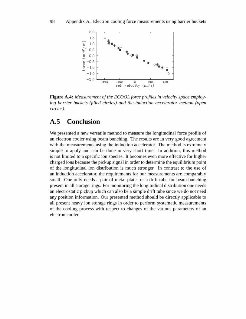
98 AppendixA. Electroncoolingforcemeasurementsusingbarrierbuckets
FigureA.4: Measurementof theECOOLforceprofilesin velocityspaceemploy-ing barrier buckets (filled circles) and the induction accelerator method(opencircles).
A.5 Conclusion
We presenteda new versatilemethodto measurethelongitudinalforceprofile ofanelectroncoolerusingbeambunching.Theresultsarein very goodagreementwith themeasurementsusingtheinductionaccelerator. Themethodis extremelysimple to apply and can be donein very short time. In addition, this methodis not limited to a specificion species.It becomesevenmoreeffective for higherchargedionsbecausethepickupsignalin orderto determinetheequilibriumpointof the longitudinal ion distribution is much stronger. In contrastto the useofan inductionaccelerator, therequirementsfor our measurementsarecomparablysmall. Oneonly needsa pair of metalplatesor a drift tubefor beambunchingpresentin all storagerings.For monitoringthelongitudinaldistributiononeneedsanelectrostaticpickupwhichcanalsobeasimpledrift tubesincewedonotneedany positioninformation. Our presentedmethodshouldbedirectly applicabletoall presentheavy ion storagerings in orderto performsystematicmeasurementsof the cooling processwith respectto changesof the variousparametersof anelectroncooler.

Appendix B
Measurementsystem
Thevariousdiagnostictoolspresentedin chapter2 arelocatedat differentposi-tionsalongthestoragering. For dataacquisitionwe setup a decentralizedarchi-tectureasdepictedin figure B.1. Eachdiagnosticdevice hasits own computersystemthat recordsthesignalsandperformsa little datapre-analysis.All mea-surementsystemsareconnectedto aethernetnetwork basedontheTCP/IPproto-col. Themeasureddatais transmittedover this network. In addition,thenetworkis usedto controlall themeasurementsystemsfrom aLinux-PC(denotedasUserPCin thepicture).
The pickupdevice is readout by a digitizing scope(Model Hewlett Packard54510A)which alsoaveragesthe tiny voltagesover several scans. The dataisreadoutby a Linux PC usinga GPIB (IEEE 488) interface. The readoutcanbeperformedlocally by a programmor is transmittedvia network to the UserPC,which alsocontrolsthe acquisitionparameterssuchasthe numberof averages,thetime resolutionetc.
For the readoutof the photomultipliersand the control of the high voltagetubesoneusesa CAMAC systemwhich is controlledby a computerbasedon aVME-busarchitecture.Thiscomputerworkswith a realtimeUnix derivatecalledLynxOS.Thephotomultiplierpulsesareamplified,shapedandconvertedto logi-cal signalsusingconventionalNIM devices.Theselogic pulsesarefed to a mul-tiscalerCAMAC module. This modulecontainsan internalhistogrammemorywherethe photomultiplierpulsesaresummedup. The multiscalermodulealsoallows themeasurementof a time seriesby countingthepulsesinto a channelofthehistogrammemoryfor agiventimeandthansteppingto thenext channel.Themoduleproducessynchroneouslya controlvoltagereflectingthecurrentchannelnumber. A time seriesmeasurementis thereforebeconnectedto a voltagerampwhich can be amplified with an high voltageamplifier andappliedto the drifttubesof thestoragering. This way theHV-scanis realized.After a HV-scanorfluorescencescanis finishedthewholetime seriesis readoutfrom thehistogram
99

100 AppendixB. Measurementsystem
SpectrumAnalyzer
BPM Schottky Fluo/HV−Scan Pickup
PC
Scope
GPIB
LAN
CAMAC
VME VME
TC
P/IP
TC
P/IP
GP
IB
CAMACT
CP
/IP
PMTHVamp
User PC
TC
P/IP
ion beam
Figure B.1: Thedataacquisitionsystemfor each measuringinstrumentconsistsof separatecomputersconnectedvia a network.

101
memoryby theVME computerwhich furthertransmitsthedatato thenetwork.For Schottky analysis,thenoisesignaltakenfrom anelectrostaticpickupwas
fed into a spectrumanalyzer(Hewlett Packard). The fast Fourier transformisinternallyperformedusingdedicateddigital signalprocessors(DSPs).Underourconditions,this systemproducesup to 10 frequency spectraper second. Thisallowsa realtimeobservationof thelongitudinalcoolingdynamics.However, thereadoutvia GPIBto thePC(whichis alsothecontrolPCin thesetup)significantlylimits the acquisitionrate to oneSchottky picture in threeseconds.The multi-channelplatesof thebeamprofile monitorarealsoreadoutby a VME computerwhich transmitsthedatato thenetwork.
The usedsetupensuresthe realtimecapabilitiesof the particulardiagnostictools beingreadout by separatedataacquisitionsubsystems.The decentralizedstructurealsomakes this systemrelatively robust againsthardware failures. Inaddition,furthermeasurementdevicescanbeaddedwithoutmucheffort.

102 AppendixB. Measurementsystem

Bibliography
[Albrecht,1993] Albrecht,F. (1993). EntwicklungeinesStrahllagemeßsystemsfur denHeidelbergerTestspeicherringTSR. DiplomarbeitUniversitat Heidel-berg undMax-Planck-Institutfur Kernphysik.
[Atutov et al., 1998] Atutov, S., Calabrese,R., Grimm, R., Guidi, V., Lauer, I.,Lenisa,P., Luger, V., Mariotti, E.,Moi, L., Peters,A., Schramm,U., andStoßel,M. (1998).“White-light” Lasercoolingof aFastStoredIon Beams.Phys.Rev.Lett.80, 2129.
[Becker, 1992] Becker, C. (1992). Frequenzstabilisierungvon Argon-Ionen-Lasernim Langzeitbereichfur die Laserkuhlungvon ô Beó -Ionen. Diplomar-beitUniversitatHeidelberg undMax-Planck-Institutfur Kernphysik.
[Beutelspacher, 2000] Beutelspacher, M. (2000).SystematischeUntersuchungenzur ELektronenkuhlungam Heidelberge Schwerionenspeicherring TSR. Dis-sertationUniversitatHeidelberg undMax-Planck-Institutfur Kernphysik,MPIH-V18-2000.
[Bisoffi et al., 1990] Bisoffi, G.,Grieser, M., Jaeschke,E.,Kramer, D., andNoda,A. (1990). Radiofrequency StackingExperimentsat theHeidelberg TestStor-ageRing. Nucl. Instr. Meth.A 287.
[Blum, 1989] Blum, M. (1989). Entwicklung einer neuartigen Synchrotron-Beschleunigerkavitat fur den TSR. DissertationUniversitat Heidelberg undMax-Planck-Institutfur Kernphysik.
[Bock, 1997] Bock, R. (1997). Ion BeamInertial Fusion. In: Jungmann,K.,Kowalski, J., Reinhard,I., andTrager, F. (Eds.),AtomicPhysicsMethodsinModernResearch , pp.211–229.Springer-Verlag.
[Bollen et al., 1996] Bollen,G. etal. (1996).ISOLTRAP:a tandemPenningtrapsystemfor accurateon-linemassdeterminationof short-livedisotopes.Nucl.Instr. Meth.A 368, 675.
103

104 BIBLIOGRAPHY
[Boussard,1995] Boussard,D. (1995).Schottky noiseandbeamtransferfunctiondiagnostics. In: Turner, S. (Ed.), Cern Accelerator School, Fifth AdvancedAccelerator PhysicsCourseVol. 2 of CERN95-06, pp.794–782.
[Boyd andKleinmann,1968] Boyd, G. andKleinmann,D. (1968). ParametricInteractionof focusedGaussianlight beams.J. Appl.Phys.39, 3597.
[Brandauet al., 1999] Brandau,C., Bartsch,T., Bohme,C., Bosch,F., Dunn,G.,Franzke,B., Hoffknecht,A., Knopp,H., Kozhuharov, C., Kramer, A., Mokler,P., Muller, A., Nolden, F., Schippers,S., Stachura,Z., Steck,M., Stohlker,T., Winkler, T., and Wolf, A. (1999). RecombinationMeasurementsof theHeaviestIons. PhysicaScriptaT80, 318.
[Bryant,1994] Bryant, P. (1994). Simple theory for weak betatroncoupling.In: Turner, S. (Ed.),Proc.CERNAccelerator School,University of Jyvaskyla,1992Vol. 1 , p. 207.Genf.
[CourantandSnyder, 1958] Courant,E. andSnyder, H. (1958). Theoryof theAlternatingGradientSynchrotron.Annalsof Physics3.
[Eike,1999] Eike,B. (1999). AufbaueinemagnetooptischenFalle zur transver-salenStrahldiagnoseam Heidelberger TestspeicherringTSR. DiplomarbeitUniversitatHeidelberg undMax-Planck-Institutfur Kernphysik.
[Eikeet al., 2000] Eike, B., Luger, V., Manek-Honninger, I., Grimm, R., andSchwalm, D. (2000). Laser-trappedatomsasa precisiontarget for the stor-agering TSR. Nucl. Instr. andMeth.A 441, 81.
[Eisenbarth,1998] Eisenbarth,U. (1998). Kuhlung hochenergetischerIonen-strahlenamTSR:neueBunchformenundRaumladungseffekte. DiplomarbeitUniversitatHeidelberg undMax-Planck-Institutfur Kernphysik.
[Eisenbarthet al., 2000a] Eisenbarth,U., Eike, B., Grieser, M., Grimm, R.,Lauer, I., Lenisa, P., Luger, V., Mudrich, M., Schatz, T., Schramm,U.,Schwalm, D., andWeidemuller, M. (2000a).Lasercoolingof faststoredionsin barrierbuckets.Nucl. Instr. andMeth.A 441, 209.
[Eisenbarthet al., 2000b] Eisenbarth,U., Mudrich, M., Eike, B., Grieser, M.,Grimm, R., Luger, V., Schatz, T., Schramm,U., Schwalm, D., and Wei-demuller, M. (2000b). Anomalousbehaviour of laser-cooledfast ion beams.Hyp. Int. 127, 223.
[Ellert et al., 1992] Ellert, C. etal. (1992).An InductionAcceleratorfor theHei-delberg TestStorageRing TSR. Nucl. Instr. Meth.A 314, 399.

BIBLIOGRAPHY 105
[Ellison et al., 1993] Ellison,T. J.P., Nagaitsev, S.S.,Ball, M. S.,Caussyn,D. D.,Ellison,M. J.,andHamilton,B. J. (1993).Attainmentof Space-ChargeDomi-natedBeamsin aSynchrotron.Phys.Rev. Lett.70, 790.
[Ertmeret al., 1985] Ertmer, W., Blatt, R., Hall, J., andZhu, M. (1985). Lasermanipulationof atomicbeamvelocities:Demonstrationof stoppedatomsandvelocity reversal.Phys.Rev. Lett.54, 996.
[Fowler andGuggenheim,1956] Fowler, R. andGuggenheim,E. (1956). Statis-tical Thermodynamics. CambridgeUniv. Press.LondonandNew York.
[Frankenetal., 1961] Franken,P., Hill, A., Peters,C., andG., W. (1961).Gener-ationof OpticalHarmonics.Phys.Rev. Lett.7, 118.
[Friedmann,2001] Friedmann,P. (2001).FrequenzverdoppeltesLasersystembei326nm fur die LaserkuhlunghochenergetischerIonenstrahlen.DiplomarbeitUniversitatHeidelberg undMax-Planck-Institutfur Kernphysik.
[Grieseret al., 1994] Grieser, R., Klein, R., Huber, G., Dickopf, S., Klaft, I.,Knobloch,P., Merz, P., Albrecht,F., Grieser, M., Habs,D., Schwalm, D., andKuhl, T. (1994). A testof specialrelativity with storedlithium ions. Appl.Phys.B 59, 127.
[Grimm et al., 1998] Grimm, R., Eisenbarth,U., Grieser, M., Lenisa,P., Lauer,I., Luger, V., Schatz, T., Schramm,U., Schwalm, D., and Weidemuller, M.(1998). TransverseLaserCoolingof fastion beamsat theStorageRing TSR.In: Chen,P. (Ed.),Proceedingsof theworkshopon quantumaspectsof beamphysics. Monterey.
[Gruber, 1993] Gruber, A. (1993). VerbesserungdesLaserfrequenz-Stabilisier-ungssystemszur Kuhlungvon ô Beó -IonenamTSR. DiplomarbeitUniversitatHeidelberg undMax-Planck-Institutfur Kernphysik.
[HabsandGrimm,1995] Habs, D. and Grimm, R. (1995). Crystalline IonBeams.Annu.Rev. Nucl.Part. Sci.45, 391.
[Hangstet al., 1991] Hangst,J.,Kristensen,M., Nielsen,J.,Poulsen,O.,Schiffer,J.,andShi,P. (1991).LaserCoolingof a fastStoredIon Beamto 1mK. Phys.Rev. Lett.67, 1238.
[Hangstet al., 1995a] Hangst,J.,Labrador, A., Lebedev, V., Madsen,N., Nielsen,J.,Poulsen,O.,andShi,P. (1995a).AnomalousSchottky Signalsfrom aLaser-CooledIon Beam.Phys.Rev. Lett.74, 86.

106 BIBLIOGRAPHY
[Hangstet al., 1995b] Hangst,J.,Nielsen,J.,Poulsen,O.,Shi,P., andSchiffer, J.(1995b). LaserCooling of a BunchedBeamin a SynchrotronStorageRing.Phys.Rev. Lett.74, 4432.
[HanschandCouillaud,1980] Hansch,T. andCouillaud,B. (1980). LaserFre-quency Stabilisationby PolarizationSpectroscopy of a ReflectingReferenceCavity. Opt.Comm.35.
[Hasse,1999] Hasse,R. (1999). TheoreticalVerificationof CoulombOrderofIonsin aStorageRing. Phys.Rev. Lett.83, 3430.
[HasseandSchiffer, 1990] Hasse,R.andSchiffer, J.(1990).TheStructureof theCylindrically ConfinedCoulombLattice. Annalsof Physics203, 419.
[Hochadel,1994a] Hochadel,B. (1994a). Residual-gasionizationbeamprofilemonitorfor theHeidelberg teststoragering TSR. Nucl. Inst.andMeth.A 343,401.
[Hochadel,1994b] Hochadel,B. (1994b).UntersuchungenzumIntrabeamScat-tering am TSR. DissertationUniversitat Heidelberg und Max-Planck-Institutfur Kernphysik.
[HofmannandKalisch,1996] Hofmann, I. and Kalisch, G. (1996). Space-charge-dominatedbunchedbeamsin the frequency domain. Phys.Rev. E 53,2807.
[Horvath,1994] Horvath, C. (1994). Aufbau einesdurchstimmbarenoptischenVerdopplungsresonatorsfur Laserkuhlexperimenteam ô Beó -IonenstrahlimHeidelberger SpeicherringTSR. Diplomarbeit Universitat Heidelberg undMax-Planck-Insitutfur Kernphysik.
[Kjærgaardet al., 2000] Kjærgaard,N., Aggerholm,S.,Bowe, P., Hornekær, L.,Madsen,N., Nielsen,J.,Schiffer, J.,Siegfried, L., andHangst,J. (2000). Re-centresultsfrom lasercooling experimentsin ASTRID-real-timeimagingofion beams.Nucl. Instr. Meth.A 441, 196.
[Kogelnik,1966] Kogelnik, L. anf Li, T. (1966). LaserBeamsandResonators.Appl.Opt.5.
[Lange,1994] Lange,W. (1994). Einfuhrungin die Laserphysik. Wissenschaft-licheBuchgesellschaft.Darmstadt.
[Lauer, 1999] Lauer, I. (1999). Transversale Dynamik lasergekuhlter ô Beó -IonenstrahlenimSpeicherringTSR. DissertationMax-Planck-InstitutfurKern-physik,MPI H-V15-1999.

BIBLIOGRAPHY 107
[Laueret al., 1998] Lauer, I., Eisenbarth,U., Grieser, M., Grimm,R., Lenisa,P.,Luger, V., Schatz,T., Schramm,U., Schwalm,D., andWeidemuller, M. (1998).Transverselasercoolingof a faststoredion beamthroughdispersivecoupling.Phys.Rev. Lett.81, 2052.
[Lebedev etal., 1995] Lebedev, V., Hangst,J., andNielsen,J. (1995). Schottkynoisein a laser-cooledion beam.Phys.Rev. E 52, 4345.
[Luger, 1996] Luger, V. (1996).Untersuchungenzur StrukturgekuhlterBunche.DiplomarbeitUniversitatHeidelberg undMax-Planck-Institutfur Kernphysik,MPI H-V15-1996.
[Luger, 1999] Luger, V. (1999). Ein Speicherringtarget fur hochpraziseStrahl-profil-Diagnoseauf Basiseiner Magneto-optischen Atomfalle. DissertationUniversitatHeidelberg undMax-Planck-Institutfur Kernphysik.
[Madert,1995] Madert, M. (1995). Laserkuhlen gebunchter Ionenstrahlen.DiplomarbeitUniversitatHeidelberg undMax-Planck-Institutfur Kernphysik,MPI H-V9-1995.
[Madsenetal., 1999] Madsen,N., Bowe, P., Drewsen,M., Hornekær, L., Kijær-gaard,N., Labrador, A., Nielsen,J.,Schiffer, J.,Shi,P., andHangst,J. (1999).DensityLimitations in a StoredLaser-cooledIon Beam. Phys.Rev. Lett. 83,4301.
[Metcalf andvanderStraten,1994] Metcalf, H. andvan der Straten,P. (1994).CoolingandTrappingof NeutralAtoms. PhysicsReports244, 205.
[Metcalf andvanderStraten,1999] Metcalf, H. andvan der Straten,P. (1999).LaserCoolingandTrapping. Springer-Verlag.New York, Berlin, Heidelberg.
[Miesner, 1995] Miesner, H.-J.(1995).LaserkuhlungdichterIonenstrahlen. Dis-sertationMax-Planck-Institutfur Kernphysik,MPI H-V23-1995.
[Miesneretal., 1996a] Miesner, H.-J.,Grimm,R.,etal. (1996a).Transverselasercoolingof a radio-frequency bunchedion beamin thestoragering TSR. Nucl.Instr. Meth.A 383, 634.
[Miesneretal., 1996b] Miesner, H.-J.,Grimm,R.,Habs,D., Schwalm,D., Wan-ner, B., andWolf, A. (1996b). Efficient, IndirectTransverseLaserCoolingofa fastStoredIon Beam.Phys.Rev. Lett.77, 623.
[Møller, 1994] Møller, S.(1994).CoolingTechniques.In: Turner, S.(Ed.),CernAccelerator SchoolCERN94-01Vol. 2 , p. 601.Universityof Jyvaskyla,Finn-land.

108 BIBLIOGRAPHY
[Mudrich, 1999] Mudrich, M. (1999). Langzeitdynamiklasergekuhlter Ionen-strahlenamSpeicherringTSR.DiplomarbeitUniversitatHeidelberg undMax-Planck-Insitutfur Kernphysik.
[Nagaitsev et al., 1994] Nagaitsev, S.S.,Ellison,T. J.,Ellison,M. J.,andAnder-son,D. (1994). The investigationof spacecharge dominatedcooledbunchedbeamsin asynchrotron.In: Bosser, J.(Ed.),Proc.WorkshoponBeamCoolingandRelatedTopics,Montreux, pp.405–410.ReportCERN94-03.Genf.
[Pastuszkaet al., 1996] Pastuszka,S., Schramm,U., Grieser, M., Broude, C.,Grimm, R., Habs,D., Kenntner, J., Miesner, H.-J., Schußler, T., Schwalm,D., andWolf, A. (1996).Electroncoolingandrecombinationexperimentswithanadiabaticallyexpandedelectronbeam.Nucl. Inst.Meth.A 396, 11.
[Petrichet al., 1993] Petrich, W. et al. (1993). Laser cooling of storedhigh-velocity ionsby meansof thespontaneousforce. Phys.Rev. A 48.
[Poth,1990] Poth,H. (1990). Electroncooling: theory, experiment,application.Phys.Rep.196.
[Presset al., 1992] Press,W. H., Teukolsky, S. A., Vetterling,W. T., andFlan-nery, B. P. (1992). NumericalRecipesin C, TheArt of ScientificComputing.CambridgeUniversityPress.2 edition.
[Radonet al., 1997] Radon,T., Kerscher, T., Schlitt, B., Beckert, K., Beha,T.,Bosch,F., Eickhoff, H., Franzke, B., Fujita, Y., Geissel,H., Hausmann,M.,Irnich, H., Jung,H. C., Klepper, O., Kluge, H.-J.,Kozhuharov, C., Kraus,G.,Lobner, K. E. G., Munzenberg, G., Novikov, Y., Nickel, F., Nolden,F., Patyk,Z., Reich,H., Scheidenberger, C., Schwab,W., Steck,M., Summerer, K., andWollnik, H. (1997).Schottky MassMeasurementsof CooledProton-RichNu-clei at theGSIExperimentalStorageRing. Phys.Rev. Lett.78, 4701.
[Risken,1989] Risken,H. (1989).TheFokker-Planck Equation. Springer-Verlag.Berlin, Heidelberg, New York, London,Paris,Tokyo 2. edition.
[Schatzet al., 2001] Schatz,T., Schramm,U., andHabs,D. (2001). Crystallineion beams.Nature412, 717.
[Schroderet al., 1990] Schroder, S., Klein, R., Boos,N., Gerhard,M., Grieser,R.,Huber, G., Karafillidis, A., Krieg, M., Schmidt,N., Kuhl, T., Neumann,R.,Balykin, V., Grieser, M., Habs,D., Jaeschke, E., Kramer, D., Kristensen,M.,Music, M., Petrich,W., Schwalm, D., Sigray, P., Steck,M., Wanner, B., andWolf, A. (1990). First LaserCooling of Relativistic Ions in a StorageRing.Phys.Rev. Lett.64, 2901.
BIBLIOGRAPHY 109
[Schunemannet al., 1999] Schunemann,U., Engler, H., Grimm, R., Weidemul-ler, M., andZielonkow ski, M. (1999). Simpleschemefor tunablefrequencyoffsetlocking of two lasers.Rev. Sci.Inst.70, 242.
[Sørensen,1987] Sørensen,A. H. (1987). Introductionto IntrabeamScattering.In: Turner, S. (Ed.),CERNAccelerator School. ReportCERN87-10.
[Stecket al., 1996] Steck,M., Beckert,K., Eickhoff, H., Franzke,B., Nolden,F.,Reich,H., Schlitt,B., andWinkler, T. (1996).AnomalousTemperatureReduc-tion of Electron-cooledHeavy Ion Beamsin theStorageRingESR.Phys.Rev.Lett.77, 3803.
[Stoessel,1997] Stoessel,M. (1997). LogitudinaleDiagnosegekuhlter ô Beó -Ionenstrahlenmit einem frequenzverdoppeltenLasersystem. DiplomarbeitUniversitat Heidelberg undMax-Planck-Institutfur Kernhpysik, MPI H-V15-1996.
[Walther, 1993] Walther, H. (1993).Phasetransitionsof storedlaser-cooledions.In: Advancesin atomic,molecular, andoptical physicsVol. 42 , pp.137–182.AcademicPress.
[Wanneret al., 1998] Wanner, B., Grimm,R.,Gruber, A., Habs,D., Miesner, H.-J., Nielsen,J. S., andSchwalm, D. (1998). Rapidadiabaticpassagein lasercoolingof faststoredion beams.Phys.Rev. A 58, 2242.
[Wei et al., 1995] Wei, J., Li, X.-P., and Sessler, A. (1995). CrystallineBeamPropertiesAs PredictedFor TheStorageRingsASTRID andTSR. In: Proc.of theParticle Accelerator ConferenceandInternationalConferenceonHigh-EnergyAccelerators,Dallas,Texas, p. 2946.
[Wernøe,1993] Wernøe,H. (1993). Laserstrahlpositionierungund -lagestabili-sierungamTSR.DiplomarbeitUniversitatHeidelbergundMax-Planck-Institutfur Kernphysik,MPIH-V8-1993.
[Wille, 1996] Wille, K. (1996). Physikder Teilchenbeschleuniger undSynchro-tronstrahlungsquellen. TeubnerStudienbucher. Stuttgart2. edition.
[Winkler etal., 1997] Winkler, T., Beckert, T., Bosch,F., Eickhoff, H., Franzke,B., Nolden,F., Reich,H., Schlitt, B., andSteck,M. (1997). Electroncoolingfor highly chargedionsin theESR.Nucl. Instr. andMeth.A 391, 12.
[Wolf et al., 2000] Wolf, A., Gwinner, G., Linkemann,J., Saghiri,A., Schmitt,M., Schwalm, D., Grieser, M., Beutelspacher, M., Bartsch,T., Brandau,C.,Hoffknecht,A., Muller, A., Schippers,S., Uwira, O., andSavin, D. (2000).Recombinationin electroncoolers.Nucl. Inst.Meth.A 441, 183.

110 BIBLIOGRAPHY

Dankeschon
NacheinigenWochendesZusammenschreibensdieserArbeit ist nun der Zeit-punktgekommen,alle diejenigenlobendzu erwahnen,die entschiedenenAnteilam GelingendieserArbeit hatten. Naturlich ist dasExperimentierenan einersolchgroßenAnlagewie demSpeicherringnicht alleinezu bewerkstelligen,wasim Text oft mit einemeinfachen“Wir” zum Ausdruckgebrachtwurde. Bekan-ntermaßenbieteteineDanksagungein weitesFeld fur diverse“Fettnapfchen”indie mantretenkann,wennmaneinePersonzuwenig,anderfalschenStelleoderdurch eine ungeschickteWortwahl honoriert. Ich gebedahermein Bestesundhoffe, dasssichniemandauf denSchlipsgetretenfuhlt ;-)
NebenRudi Grimm, dermich vor seinemWechselnachInnsbruckim erstenJahrbetreute,gehtmeinDankandDirk Schwalm undMatthiasWeidemuller, diemir dieseArbeit ermoglicht und immer wiederdurchwertvolle Diskussionenindie richtigenBahnengelenkthaben.Vor allem Matthiashat mehrereVersionendieserArbeit gelesenundunddurchkonstruktiveKritik entscheidendaufgewertet.Ebensomochteich michbeiWolfgangQuintbedanken,dersichbereiterklarthat,die Zweitbegutachtungzu ubernehmen.
Desweiterengilt mein besondererDankMarcel Mudrich, Patrick FriedmannundSandroHannemann,die wahrendmeinerZeit alsDiplomandenandemPro-jekt gearbeitethaben.Viele Ergebnisse,die in meinerArbeit auftauchen,sindzueinemgroßenAnteil auch“auf derenMist gewachsen”.
DievielenStrahlzeitenwarennichtzubewaltigengewesenohnedietatkraftigeUnterstutzungvon Bjorn Eike (“Yesyesyes”),JanKleinert, Guido Saathoff undSergei Karpuksowie die MunchnerDelegationTobiasSchatzundUli Schramm.Die vielenStundenamSpeicherringim Kampf gegendie Lasersystemeundan-deremtechnischenEquipmentmachtenuns zu einemeingeschworenenTeam.Gleichwohl werdeichdenzumEndeeinerStrahlzeithin immerseltsamerwerden-denHumor(“Stuhl!!!”) nicht vergessen.Mein ganzspeziellerDankgehtauchanHelgaKrieger, die sichin aufopferungsvoller Hingabevor allemstetsum ein rei-bungslosesFunktionierenderLasersystemegekummerthat.Viel zuoft wurdeihreArbeitenfastalsselbstverstandlichangenommen.Der Kampf gegendie TuckendesTSRwurdevom “Herr derRinge” ManfredGriesersowie Kurt Horn bestrit-
111

112 BIBLIOGRAPHY
ten. Fur die vielenunverzichtbarenelektronischenSchaltungenmochteich michvor allembeiOliverKoschorrekbedanken.
Nicht zu unterschatzen sind die vielen Gesprache und Diskussionenmitanderenaktuellenund ehemaligenMitgliedern unsererGruppe: Hans Engler,MarkusHammes,Selim Jochim,StephanKraft, Allard Mosk, HenningMoritz,David RychtarikundKilian Singer. SiehabenentscheidendzumsehrgutenGrup-penklimabeigetragen.
Mein Dank gehtnaturlich nicht zuletztauchan meineEltern, die mich im-merwiederunterstutztenundermutigten,wennauchabundzu “mal ’wasschiefgegangenist”.


![Index [application.wiley-vch.de] · anomalous diffusion, 787 ... beryllium, 421 Bi–Ag alloy nanospheres, 623 ... – side effects, 992 – sponges ––morphology, 1148](https://img.pdfslide.net/doc/110x75/5b84be1f7f8b9aef498ceeb3/index-anomalous-diffusion-787-beryllium-421-biag-alloy-nanospheres.jpg)