Embed Size (px)
Citation preview
T. PusateriINTERNET DRAFT Juniper NetworksObsoletes: RFC 1075 August 2000draft-ietf-idmr-dvmrp-v3-10 Expires: February 4, 2001
Distance Vector Multicast Routing Protocol
Status of this Memo
This document is an Internet-Draft and is in full conformance with all provisions of Section 10 of RFC2026.
Internet-Drafts are working documents of the Internet Engineering Task Force (IETF), its areas, and itsworking groups. Note that other groups may also distribute working documents as Internet-Drafts.
Internet-Drafts are draft documents valid for a maximum of six months and may be updated, replaced, orobsoleted by other documents at any time. It is inappropriate to use Internet- Drafts as reference material or tocite them other than as "work in progress."
The list of current Internet-Drafts can be accessed at http://www.ietf.org/ietf/1id-abstracts.txt
The list of Internet-Draft Shadow Directories can be accessed at http://www.ietf.org/shadow.html.
Abstract
DVMRP is an Internet routing protocol that provides an efficient mechanism for connection-less datagramdelivery to a group of hosts across an internetwork. It is a distributed protocol that dynamically generates IPMulticast delivery trees using a technique called Reverse Path Multicasting (RPM) [Deer90]. This document isan update to Version 1 of the protocol specified in RFC 1075 [Wait88].
Pusateri [Page 1]
INTERNET-DRAFT DVMRP Version 3 August 2000
1. Introduction
DVMRP uses a distance vector distributed routing algorithm in order to build per-source-group multicastdelivery trees. A good introduction to distance vector routing can be found in [Perl92]. The application ofdistance vector routing to multicast tree formulation is described in [Deer91].
1.1. Requirements Terminology
The keywords MUST, MUST NOT, REQUIRED, SHALL, SHALL NOT, SHOULD, SHOULD NOT,RECOMMENDED, MAY, and OPTIONAL, when they appear in this document, are to be interpreted asdescribed in [RFC-2119].
1.2. Reverse Path Multicasting
Datagrams follow multicast delivery trees from a source to all members of a multicast group [Deer89],replicating the packet only at necessary branches in the delivery tree. The trees are calculated and updateddynamically to track the membership of individual groups. When a datagram arrives on an interface, thereverse path to the source of the datagram is determined by examining a DVMRP routing table of knownsource networks. If the datagram arrives on an interface that would be used to transmit datagrams back to thesource, then it is forwarded to the appropriate list of downstream interfaces. Otherwise, it is not on the optimaldelivery tree and should be discarded. In this way duplicate packets can be filtered when loops exist in thenetwork topology. The source specific delivery trees are automatically pruned back as group membershipchanges or routers determine that no group members are present. This keeps the delivery trees to the minimumbranches necessary to reach all of the group members. New sections of the tree can also be added dynamicallyas new members join the multicast group by grafting the new sections onto the delivery trees.
1.3. Tunnel Encapsulation
Because not all IP routers support native multicast routing, DVMRP includes direct support for tunneling IPMulticast datagrams through routers. The IP Multicast datagrams are encapsulated in unicast IP packets andaddressed to the routers that do support native multicast routing. DVMRP treats tunnel interfaces in anidentical manner to physical network interfaces.
In previous implementations, DVMRP protocol messages were sent un-encapsulated to the unicast tunnelendpoint address. While this was more direct, it increased the complexity of firewall configuration. The mostnoticeable change in this specification regarding tunnels is that all DVMRP protocol messages should be sentencapsulated across the tunnel. Previously, protocol messages were sent un-encapsulated directly to the tunnelendpoint. See Appendix C for backward compatibility issues.
Note: All protocol messages sent on point-to-point links (including tunnels) should use a destination address ofAll-DVMRP-Routers. This change will allow the protocol messages to be forwarded across multicast-onlytunnels without making encapsulation and decapsulation difficult.
In practice, tunnels typically use either IP-IP [Perk96] or Generic Routing Encapsulation (GRE)[Han94a,Han94b], although, other encapsulation methods are acceptable.
Pusateri [Page 2]
INTERNET-DRAFT DVMRP Version 3 August 2000
1.4. Document Overview
Section 2 provides an overview of the protocol and the different message types exchanged by DVMRP routers.Those who wish to gain a general understanding of the protocol but are not interested in the more precisedetails may wish to only read this section. Section 3 explains the detailed operation of the protocol toaccommodate developers needing to provide inter-operable implementations. Included in Appendix A, is asummary of the DVMRP parameters. A section on DVMRP support for tracing and troubleshooting is the topicof Appendix B. Finally, a short DVMRP version compatibility section is provided in Appendix C to assist withbackward compatibility issues.
2. Protocol Overview
DVMRP can be summarized as a "broadcast & prune" multicast routing protocol. It builds per-sourcebroadcast trees based upon routing exchanges, then dynamically creates per-source-group multicast deliverytrees by pruning (removing branches from) the source’s truncated broadcast tree. It performs Reverse PathForwarding checks to determine when multicast traffic should be forwarded to downstream interfaces. In thisway, source-rooted shortest path trees can be formed to reach all group members from each source network ofmulticast traffic.
2.1. Neighbor Discovery
Neighbor DVMRP routers are discovered dynamically by sending Neighbor Probe Messages on local multicastcapable network interfaces and tunnel pseudo interfaces. These messages are sent periodically to the All-DVMRP-Routers [Reyn94] IP Multicast group address. (See Appendix C for backwards compatibility issues.)The IP TTL of these messages MUST be set to 1.
Each Neighbor Probe message contains the list of Neighbor DVMRP routers for which Neighbor Probemessages have been received on that interface. In this way, Neighbor DVMRP routers can ensure that they areseen by each other.
Once you have received a Probe from a neighbor that contains your address in the neighbor list, you haveestablished a two-way neighbor adjacency with this router.
2.2. Source Location
When an IP Multicast datagram is received by a router running DVMRP, it first looks up the source network inthe DVMRP routing table. The interface on which the best route to the source of the datagram was received iscalled the upstream (also called RPF) interface. If the datagram arrived on the correct upstream interface, thenit is a candidate for forwarding to one or more downstream interfaces. If the datagram did not arrive on theanticipated upstream interface, it is discarded. This check is known as a reverse path forwarding check andmust be performed by all DVMRP routers.
In order to ensure that all DVMRP routers have a consistent view of the path back to a source, a routing table ispropagated to all DVMRP routers as an integral part of the protocol. Each router advertises the network
Pusateri [Page 3]
INTERNET-DRAFT DVMRP Version 3 August 2000
number and mask of the interfaces it is directly connected to as well as relaying the routes received fromneighbor routers. DVMRP requires an interface metric to be configured on all physical and tunnel interfaces.When a route is received, the metric of the interface over which the datagram was received must be added tothe metric of the route being advertised in the route report message. This adjusted metric should be used whencomparing metrics to determine the best upstream neighbor.
Although there is certainly additional overhead associated with propagating a separate DVMRP routing table,it does provide two nice features. First, since all DVMRP routers are exchanging the same routes, there are noinconsistencies between routers when determining the upstream interface (aside from normal convergenceissues related to distance vector routing protocols). By placing the burden of synchronization on the protocolas opposed to the network manager, DVMRP reduces the risk of creating routing loops or black holes due todisagreement between neighbor routers on the upstream interface.
Second, by propagating its own routing table, DVMRP makes it convenient to have separate paths for unicastversus multicast datagrams. Although, ideally, many network managers would prefer to keep their unicast andmulticast traffic aligned, tunneled multicast topologies may prevent this causing the unicast and multicast pathsto diverge. Additionally, service providers may prefer to keep the unicast and multicast traffic separate forrouting policy reasons as they experiment with IP multicast routing and begin to offer it as a service.
2.3. Dependent Downstream Routers
In addition to providing a consistent view of source networks, the exchange of routes in DVMRP provides oneother important feature. DVMRP uses the route exchange as a mechanism for upstream routers to determine ifany downstream routers depend on them for forwarding from particular source networks. DVMRPaccomplishes this by using a technique called "Poison Reverse". If a downstream router selects an upstreamrouter as the best next hop to a particular source network, this is indicated by echoing back the route on theupstream interface with a metric equal to the original metric plus infinity. When the upstream router receivesthe report and sees a metric that lies between infinity and twice infinity, it can then add the downstream routerfrom which it received the report to a list of dependent routers for this source.
This list of dependent routers per source network built by the "Poison Reverse" technique will provide thefoundation necessary to determine when it is appropriate to prune back the IP source specific multicast trees.
2.4. Designated Forwarder
When two or more multicast routers are connected to a multi-access network, it could be possible for duplicatepackets to be forwarded on the network (one copy from each router). DVMRP prevents this possibility byelecting a forwarder for each source as a side effect of its route exchange. When two routers on a multi-accessnetwork exchange source networks, each of the routers will know the others metric back to each sourcenetwork. Therefore, of all the DVMRP routers on a shared network, the router with the lowest metric to asource network is responsible for forwarding data on to the shared network. If two or more routers have anequally low metric, the router with the lowest IP address becomes the designated forwarder for the network. Inthis way, DVMRP does an implicit designated forwarder election for each source network on each downstreaminterface.
Pusateri [Page 4]
INTERNET-DRAFT DVMRP Version 3 August 2000
2.5. Building Multicast Trees
As previously mentioned, when an IP multicast datagram arrives, the upstream interface is determined bylooking up the interface on which the best route to the source of the datagram was received. If the upstreaminterface is correct, then a DVMRP router will forward the datagram to a list of downstream interfaces.
2.5.1. Adding Local Group Members
The IGMP local group database is maintained by all IP multicast routers on each physical, multicast capablenetwork [Fenn97]. If the destination group address is listed in the local group database, and the router is thedesignated forwarder for the source, then the interface is included in the list of downstream interfaces. If thereare no group members on the interface, then the interface is removed from the outgoing interface list.
2.5.2. Adding Interfaces with Neighbors
Initially, all interfaces with downstream dependent neighbors should be included in the downstream interfacelist when a forwarding cache entry is first created. This allows the downstream routers to be aware of trafficdestined for a particular (source network, group) pair. The downstream routers will then have the option tosend prunes and subsequent grafts for this (source network, group) pair as requirements change from theirrespective downstream routers and local group members.
2.6. Pruning Multicast Trees
As mentioned above, routers at the edges will remove their interfaces that have no group members associatedwith an IP multicast datagram. If a router removes all of its downstream interfaces, it notifies the upstreamrouter that it no longer wants traffic destined for a particular (source network, group) pair. This is accomplishedby sending a DVMRP Prune message upstream to the router it expects to forward datagrams from a particularsource.
Recall that a downstream router will inform an upstream router that it depends on the upstream router toreceive datagrams from particular source networks by using the "Poison Reverse" technique during theexchange of DVMRP routes. This method allows the upstream router to build a list of downstream routers oneach interface that are dependent upon it for datagrams from a particular source network. If the upstreamrouter receives prune messages from each one of the dependent downstream routers on an interface, then theupstream router can in turn remove this interface from its downstream interface list. If the upstream router isable to remove all of its downstream interfaces in this way, it can then send a DVMRP Prune message to itsupstream router. This continues until the unneeded branches are removed from the delivery tree.
In order to remove old prune state information for (source network, group) pairs that are no longer active, it isnecessary to limit the life of a prune and periodically resume the broadcasting procedure. The prune messagecontains a prune lifetime, indicating the length of time that the prune should remain in effect. When the prunelifetime expires, the interface is joined back onto the multicast delivery tree. If unwanted multicast datagramscontinue to arrive, the prune mechanism will be re-initiated and the cycle will continue. If all of thedownstream interfaces are removed from a multicast delivery tree causing a DVMRP Prune message to be sent
Pusateri [Page 5]
INTERNET-DRAFT DVMRP Version 3 August 2000
upstream, the lifetime of the prune sent must be equal to the minimum of the remaining lifetimes of thereceived prunes.
2.7. Grafting Multicast Trees
Once a tree branch has been pruned from a multicast delivery tree, packets from the corresponding (sourcenetwork, group) pair will no longer be forwarded. However, since IP multicast supports dynamic groupmembership, hosts may join a multicast group at any time. In this case, DVMRP routers use Grafts to cancelthe prunes that are in place from the host back on to the multicast delivery tree. A router will send a Graftmessage to its upstream neighbor if a group join occurs for a group that the router has previously sent a prune.Separate Graft messages must be sent to the appropriate upstream neighbor for each source network that hasbeen pruned. Since there would be no way to tell if a Graft message sent upstream was lost or the sourcesimply quit sending traffic, it is necessary to acknowledge each Graft message with a DVMRP Graft Ackmessage. If an acknowledgment is not received within a Graft Time-out period, the Graft message should beretransmitted using binary exponential back-off between retransmissions. Duplicate Graft Ack messagesshould simply be ignored. The purpose of the Graft Ack message is to simply acknowledge the receipt of aGraft message. It does not imply that any action was taken as a result of receiving the Graft message.Therefore, all Graft messages received from a neighbor with whom a two-way neighbor relationship has beenformed should be acknowledged whether or not they cause an action on the receiving router.
3. Detailed Protocol Operation
This section contains a detailed description of DVMRP. It covers sending and receiving of DVMRP messagesas well as the generation and maintenance of IP Multicast forwarding cache entries.
3.1. Protocol Header
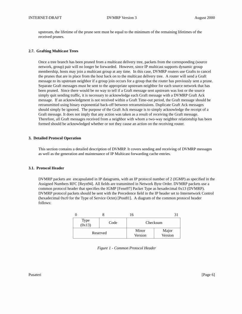
DVMRP packets are encapsulated in IP datagrams, with an IP protocol number of 2 (IGMP) as specified in theAssigned Numbers RFC [Reyn94]. All fields are transmitted in Network Byte Order. DVMRP packets use acommon protocol header that specifies the IGMP [Fenn97] Packet Type as hexadecimal 0x13 (DVMRP).DVMRP protocol packets should be sent with the Precedence field in the IP header set to Internetwork Control(hexadecimal 0xc0 for the Type of Service Octet) [Post81]. A diagram of the common protocol headerfollows:
0 8 16 31
Type(0x13)
Code Checksum
Minor MajorVersion Version
Reserved
Figure 1 - Common Protocol Header
Pusateri [Page 6]
INTERNET-DRAFT DVMRP Version 3 August 2000
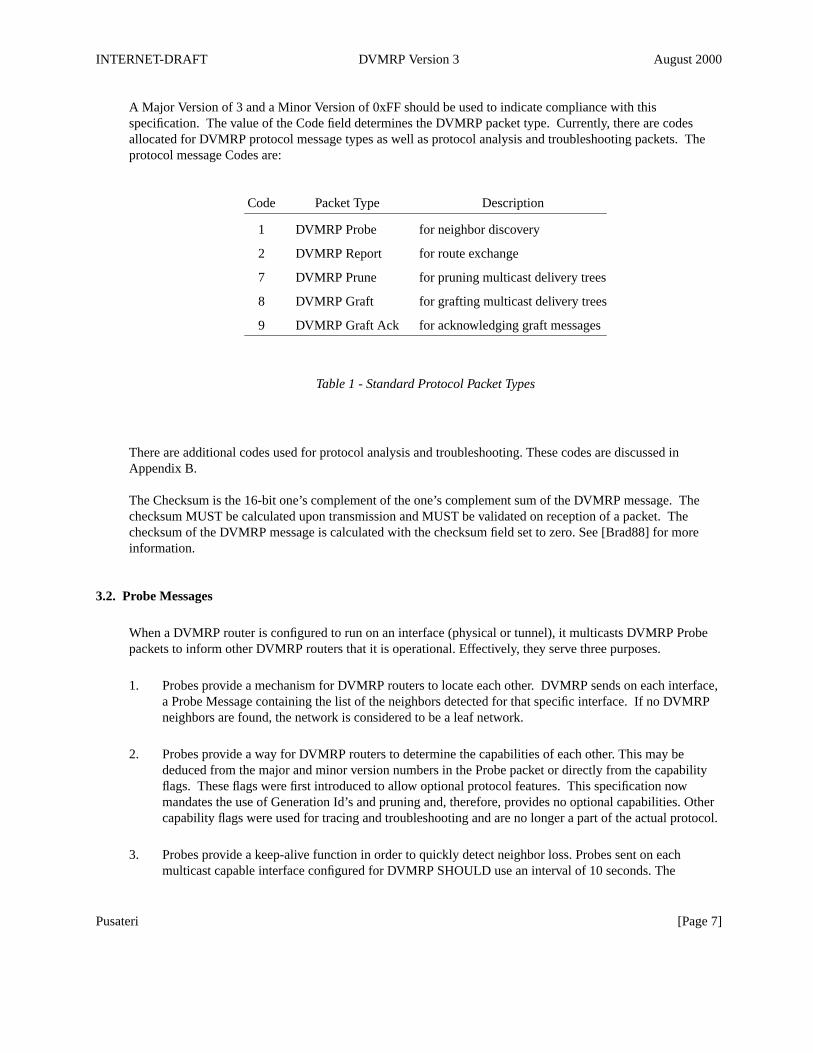
A Major Version of 3 and a Minor Version of 0xFF should be used to indicate compliance with thisspecification. The value of the Code field determines the DVMRP packet type. Currently, there are codesallocated for DVMRP protocol message types as well as protocol analysis and troubleshooting packets. Theprotocol message Codes are:
Code Packet Type Description
1 DVMRP Probe for neighbor discovery
2 DVMRP Report for route exchange
7 DVMRP Prune for pruning multicast delivery trees
8 DVMRP Graft for grafting multicast delivery trees
9 DVMRP Graft Ack for acknowledging graft messages
Table 1 - Standard Protocol Packet Types
There are additional codes used for protocol analysis and troubleshooting. These codes are discussed inAppendix B.
The Checksum is the 16-bit one’s complement of the one’s complement sum of the DVMRP message. Thechecksum MUST be calculated upon transmission and MUST be validated on reception of a packet. Thechecksum of the DVMRP message is calculated with the checksum field set to zero. See [Brad88] for moreinformation.
3.2. Probe Messages
When a DVMRP router is configured to run on an interface (physical or tunnel), it multicasts DVMRP Probepackets to inform other DVMRP routers that it is operational. Effectively, they serve three purposes.
1. Probes provide a mechanism for DVMRP routers to locate each other. DVMRP sends on each interface,a Probe Message containing the list of the neighbors detected for that specific interface. If no DVMRPneighbors are found, the network is considered to be a leaf network.
2. Probes provide a way for DVMRP routers to determine the capabilities of each other. This may bededuced from the major and minor version numbers in the Probe packet or directly from the capabilityflags. These flags were first introduced to allow optional protocol features. This specification nowmandates the use of Generation Id’s and pruning and, therefore, provides no optional capabilities. Othercapability flags were used for tracing and troubleshooting and are no longer a part of the actual protocol.
3. Probes provide a keep-alive function in order to quickly detect neighbor loss. Probes sent on eachmulticast capable interface configured for DVMRP SHOULD use an interval of 10 seconds. The
Pusateri [Page 7]
INTERNET-DRAFT DVMRP Version 3 August 2000
neighbor time-out interval SHOULD be set at 35 seconds. This allows fairly early detection of a lostneighbor yet provides tolerance for busy multicast routers. These values MUST be coordinated betweenall DVMRP routers on a physical network segment.
3.2.1. Router Capabilities
In the past, there have been many versions of DVMRP in use with a wide range of capabilities. Practicalconsiderations require a current implementation to inter-operate with these older implementations that don’tformally specify their capabilities and are not compliant with this specification. For instance, for majorversions less than 3, it can be assumed that the neighbor does not support pruning. The formal capability flagswere first introduced in an well known implementation (Mrouted version 3.5) in an attempt to take the guesswork out which features are supported by a neighbor. Many of these flags are no longer necessary since theyare now a required part of the protocol, however, special consideration is necessary to not confuse olderimplementations that expect these flags to be set. Appendix C was written to assist with these and otherbackward compatibility issues.
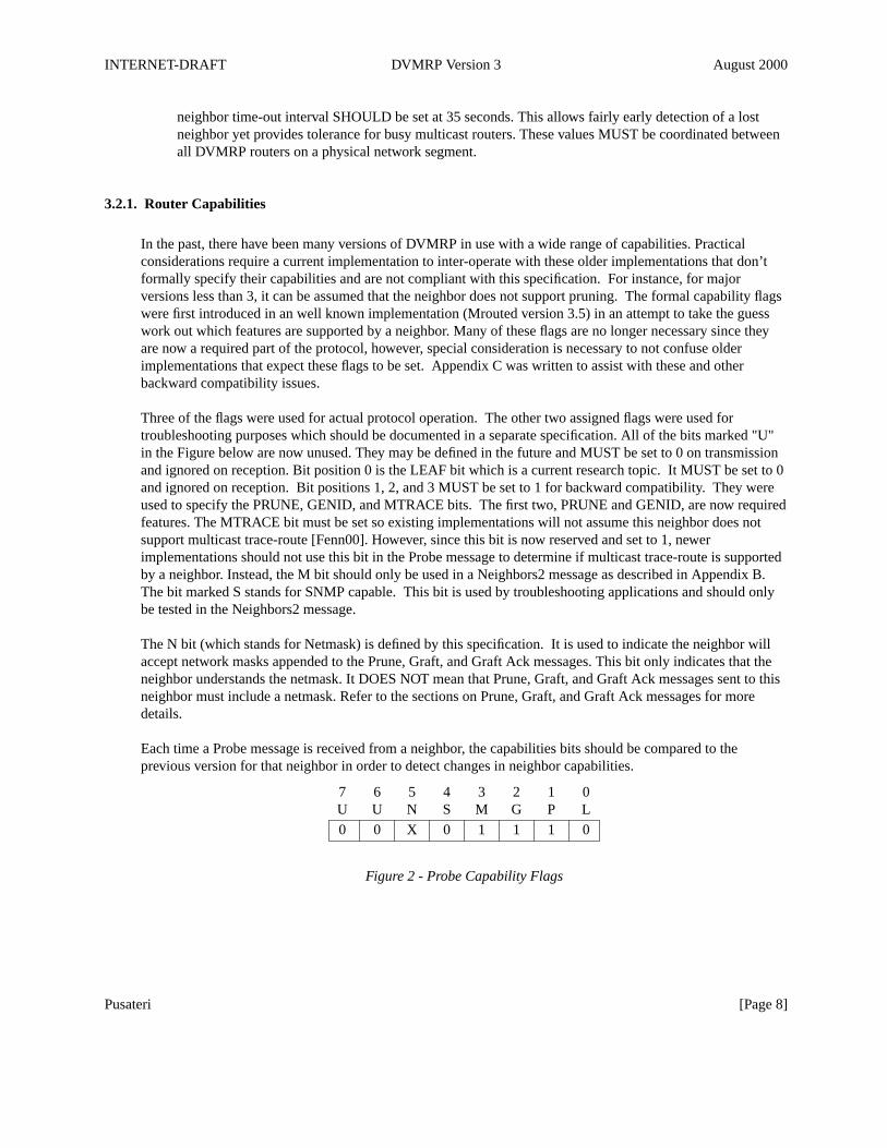
Three of the flags were used for actual protocol operation. The other two assigned flags were used fortroubleshooting purposes which should be documented in a separate specification. All of the bits marked "U"in the Figure below are now unused. They may be defined in the future and MUST be set to 0 on transmissionand ignored on reception. Bit position 0 is the LEAF bit which is a current research topic. It MUST be set to 0and ignored on reception. Bit positions 1, 2, and 3 MUST be set to 1 for backward compatibility. They wereused to specify the PRUNE, GENID, and MTRACE bits. The first two, PRUNE and GENID, are now requiredfeatures. The MTRACE bit must be set so existing implementations will not assume this neighbor does notsupport multicast trace-route [Fenn00]. However, since this bit is now reserved and set to 1, newerimplementations should not use this bit in the Probe message to determine if multicast trace-route is supportedby a neighbor. Instead, the M bit should only be used in a Neighbors2 message as described in Appendix B.The bit marked S stands for SNMP capable. This bit is used by troubleshooting applications and should onlybe tested in the Neighbors2 message.
The N bit (which stands for Netmask) is defined by this specification. It is used to indicate the neighbor willaccept network masks appended to the Prune, Graft, and Graft Ack messages. This bit only indicates that theneighbor understands the netmask. It DOES NOT mean that Prune, Graft, and Graft Ack messages sent to thisneighbor must include a netmask. Refer to the sections on Prune, Graft, and Graft Ack messages for moredetails.
Each time a Probe message is received from a neighbor, the capabilities bits should be compared to theprevious version for that neighbor in order to detect changes in neighbor capabilities.
7 6 5 4 3 2 1 0U U N S M G P L
0 0 X 0 1 1 1 0
Figure 2 - Probe Capability Flags
Pusateri [Page 8]

INTERNET-DRAFT DVMRP Version 3 August 2000
3.2.2. Generation ID
If a DVMRP router is restarted, it will not be aware of any previous prunes that it had sent or received. Inorder for the neighbor to detect that the router has restarted, a non-decreasing number is placed in the periodicprobe message called the generation ID. When a change in the generation ID is detected, any pruneinformation received from the router is no longer valid and should be flushed. If this prune state has causedprune information to be sent upstream, a graft will need to be sent upstream just as though a new member hasjoined below. Once data begins to be delivered downstream, if the downstream router again decides to bepruned from the delivery tree, a new prune can be sent upstream at that time.
In addition, the effects of a restart can be minimized if the router can learn all of the routes known by itsneighbors without having to wait for an entire report interval to pass. When a router detects a change in thegeneration ID of a neighbor, it should send a unicast copy of its entire routing table to the neighbor.
In addition to restarting, a router may also miss prune information while an interface has transitioned to a downstate. Therefore, a change in the generation ID is necessary when an interface transitions to the up state. Inorder to prevent all prune state from being flushed on a router when a single interface transitions, a DVMRProuter should keep seperate generation ID numbers per interface.
A time of day clock provides a good source for a non-decreasing 32 bit integer.
3.2.3. Neighbor Addresses
As a DVMRP router sees Probe messages from its DVMRP neighbors, it records the neighbor addresses oneach interface and places them in the Probe message sent on the particular interface. This allows the neighborrouter to know that its probes have been received by the sending router.
In order to minimize one-way neighbor relationships, a router MUST delay sending poison route reports inresponse to routes advertised by a neighbor until the neighbor includes the routers address in its probemessages. On point-to-point interfaces and tunnel pseudo-interfaces, this means that no packets should beforwarded onto these interfaces until two-way neighbor relationships have formed.
Implementations written before this specification will not wait before sending reports nor will they ignorereports sent. Therefore, reports from these implementations SHOULD be accepted whether or not a probewith the routers address has been received.
3.2.4. Neighbor Expiry
When a neighbor expires, the following steps should be taken:
1. All routes learned from this neighbor should be immediately placed in hold-down. All downstreamdependencies ON this neighbor should be removed.
2. If this neighbor is considered to be the designated forwarder for any of the routes it is advertising, a newdesignated forwarder for each source network should be selected.
Pusateri [Page 9]
INTERNET-DRAFT DVMRP Version 3 August 2000
3. Any forwarding cache entries based on this upstream neighbor should be flushed.
4. Any outstanding Grafts awaiting acknowledgments from this router should be flushed.
5. All downstream dependencies received FROM this neighbor should be removed. Forwarding cacheentries should be checked to see if this is the last downstream dependent neighbor on the interface. If so,and this router isn’t the designated forwarder (with local group members present), the interface should beremoved.
It is possible as an optimization to send a prune upstream if this causes the last downstream interface tobe removed. However, this prune could be unnecessary if no more traffic is arriving. It is also acceptableto simply wait for traffic to arrive before sending the prune upstream.
3.2.5. Probe Packet Format
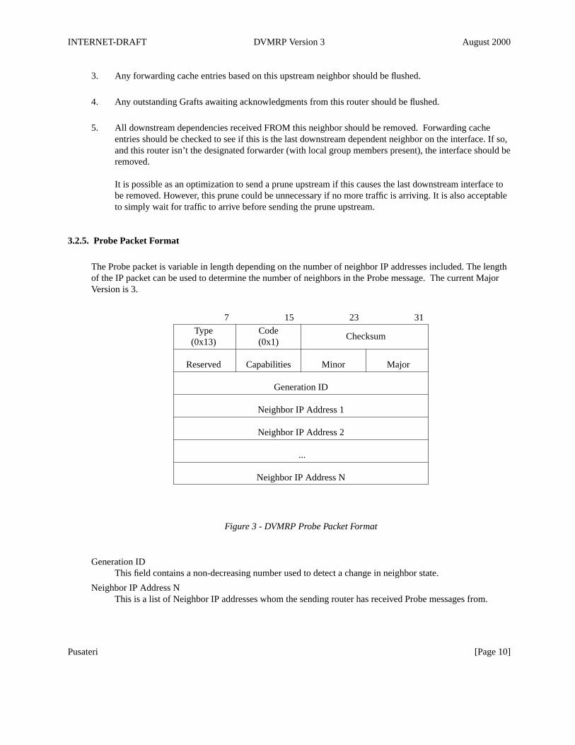
The Probe packet is variable in length depending on the number of neighbor IP addresses included. The lengthof the IP packet can be used to determine the number of neighbors in the Probe message. The current MajorVersion is 3.
7 15 23 31
Type Code(0x13) (0x1)
Checksum
Reserved Capabilities Minor Major
Generation ID
Neighbor IP Address 1
Neighbor IP Address 2
...
Neighbor IP Address N
Figure 3 - DVMRP Probe Packet Format
Generation IDThis field contains a non-decreasing number used to detect a change in neighbor state.
Neighbor IP Address NThis is a list of Neighbor IP addresses whom the sending router has received Probe messages from.
Pusateri [Page 10]
INTERNET-DRAFT DVMRP Version 3 August 2000
3.2.6. IGMP Designated Querier Election
Since it is wasteful to have more than a single router sending IGMP Host Membership Queries on a givenphysical network, a single router on each physical network is elected as the Designated Querier. This electionwas formerly a part of DVMRP. Howev er, this is now specified as a part of the IGMP version 2 protocol. SeeAppendix C for details on backwards compatibility.
Even though only one router will act as the IGMP designated querier, all DVMRP routers must use IGMP tolearn local group memberships.
3.3. Multicast Forwarding
DVMRP can forward multicast packets by building the downstream interface list for each packet as it arrives.However, to reduce per packet processing time, the result of the first lookup MAY be cached in a forwardingtable. Then, as routes, downstream dependent neighbors, or group membership change, the cache forwardingtable entries MUST be updated to reflect these changes.
3.3.1. Designated Forwarder
Initially, a DVMRP router should assume it is the designated forwarder for all source networks on alldownstream interfaces. As it receives route reports, it can determine if other routers on multi-access networkshave better routes back to a particular source network. A route is considered better if the adjusted receivedmetric is less than the metric that it will advertise for the source network on the received interface or if themetrics are the same but the IP address of the neighbor is lower.
If this neighbor becomes unreachable or starts advertising a worse metric, then the router should become thedesignated forwarder for this source network again on the downstream interface until it hears from a bettercandidate.
If the upstream RPF interface changes, then the router should become the designated forwarder on the previousupstream interface (which is now a potential downstream interface) until it hears from a better candidate.
3.3.2. Determining the upstream interface
When a multicast packet arrives, a DVMRP router will use the DVMRP routing table to determine whichinterface leads back to the source. If the packet did not arrive on that interface, it MUST be discarded withoutfurther processing. Each multicast forwarding entry should cache the upstream interface for a particular sourcehost or source network after looking this up in the DVMRP routing table.
3.3.3. Determining the downstream interface list
The downstream interface list is built by starting with the list of non-leaf interfaces. The upstream interfaceMUST be removed from this list. Then any interfaces on the list where all of the downstream dependents have
Pusateri [Page 11]
INTERNET-DRAFT DVMRP Version 3 August 2000
sent prunes upstream MUST be removed. Next, any interfaces for which the router is the designated forwarderand local group members are present MUST be added to the list.
3.4. Route Exchange
The routing information propagated by DVMRP is used for determining the reverse path neighbor back to thesource of the multicast traffic. The interface used to reach this neighbor is called the upstream interface. Tunnelpseudo-interfaces are considered to be distinct from the physical interface on which the packet is actuallytransmitted for the purpose of determining upstream and downstream interfaces.
The routing information that is propagated by DVMRP contains a list of source networks and an appropriatemetric. The metric used is a hop count which is incremented by the cost of the incoming interface metric.Traditionally, physical interfaces use a metric of 1 while the metric of a tunnel interface varies with thedistance and bandwidth in the path between the two tunnel endpoints. Users are encouraged to configuretunnels with the same metric in each direction to create symmetric routing and provide for easier problemdetermination although the protocol does not strictly enforce this.
3.4.1. Source Network Aggregation
Implementations may wish to provide a mechanism to aggregate source networks to reduce the size of therouting table. All implementations should be able to accept reports for aggregated source networks inaccordance with Classless Inter-Domain Routing (CIDR) as described in [Rekh93] and [Full93].
There are two places where aggregation is particularly useful.
1. At organizational boundaries to limit the number of source networks advertised out of the organization.
2. Within an organization to summarize non-local routing information by using a default (0/0) route.
If an implementation wishes to support source aggregation, it MUST transmit Prune and Graft messagesaccording to the following rules:
A. If a Prune is received on a downstream interface for which the source network advertised to thatneighbor is an aggregate, then if a prune is sent upstream, it should only be sent for the contributingroute based on the source address in the received prune.
If additional data is received for sources within the range of the aggregate, then this SHOULD triggeradditional prunes to be sent upstream for these sources.
There may be active forwarding cache entries for other contributing routes to the aggregate. Prunesshould not be sent upstream to the contributing routes that have no forwarding state.
B. If a Graft is received on a downstream interface for which the source network advertised to that neighboris an aggregate generated by the receiving router, then Graft messages MUST be sent upstream (ifnecessary) for each route that contributed to the aggregate that had been previously pruned.
Pusateri [Page 12]
INTERNET-DRAFT DVMRP Version 3 August 2000
3.4.2. Route Packing and Ordering
Since DVMRP Route Reports may need to refresh several thousand routes each report interval, routers MUSTattempt to spread the routes reported across the whole route update interval. This reduces the chance ofsynchronized route reports causing routers to become overwhelmed for a few seconds each report interval.Since the route report interval is 60 seconds, it is suggested that the total number routes being updated be splitacross multiple Route Reports sent at regular intervals. There was an earlier requirement that Route ReportsMUST contain source network/mask pairs sorted first by increasing network mask and then by increasingsource network. This restriction has been lifted. Implementations conforming to this specification MUST beable to receive Route Reports containing any mixture of network masks and source networks.
In order to pack more source networks into a route report, source networks are often represented by less than 4octets. The number of non-zero bytes in the mask value is used to determine the number of octets used torepresent each source network within that particular mask value. For instance if the mask value of 255.255.0.0is being reported, the source networks would only contain 2 octets each. DVMRP assumes that sourcenetworks will never be aggregated into networks whose prefix length is less than 8. Therefore, it does not carrythe first octet of the mask in the Route Report since, given this assumption, the first octet will always be 0xFF.This means that the netmask value will always be represented in 3 octets. This method of specifying sourcenetwork masks is compatible with techniques described in [Rekh93] and [Full93] to group traditional Class Cnetworks into super-nets and to allow different subnets of the same Class A network to be discontinuous. Itdoes not, however, allow grouping class A networks into super-nets since the first octet of the netmask isalways assumed to be 255.
In this notation, the default route is represented as the least three significant octets of the netmask [00 00 00],followed by one octet for the network number [00]. This special case MUST be interpreted as 0.0.0.0/0.0.0.0and NOT 0.0.0.0/255.0.0.0.
3.4.3. Route Metrics
For each source network reported, a route metric is associated with the route being reported. The metric is thesum of the interface metrics between the router originating the report and the source network. For the purposesof DVMRP, the Infinity metric is defined to be 32. This limits the breadth across the whole DVMRP networkand is necessary to place an upper bound on the convergence time of the protocol.
As seen in the packet format below, Route Reports do not contain a count of the number of routes reported foreach netmask. Instead, a "Last" bit is defined as the high order bit of the octet following the network address.This bit is set to signify when the last route is being reported for a particular mask value. When the "Last" bitis set and the end of the message has not been reached, the next value will be a new netmask to be applied tothe subsequent list of routes.
3.4.4. Route Dependencies
In order for pruning to work correctly, each DVMRP router needs to know which downstream routers dependon it for receiving datagrams from particular source networks. Initially, when a new datagram arrives from aparticular source/group pair, it is broadcasted to all downstream interfaces that have DVMRP neighbors whohave indicated a dependency on the receiving DVMRP router for that particular source. A downstream
Pusateri [Page 13]
INTERNET-DRAFT DVMRP Version 3 August 2000
interface can only be removed when the router has received Prune messages from each of the dependentrouters on that interface. Each downstream router uses Poison Reverse to indicate for which source networks itis dependent upon the upstream router. The downstream router indicates this by echoing back the sourcenetworks it expects to receive from the upstream router with infinity added to the advertised metric. This meansthat the legal values for the metric now become between 1 and (2 × Infinity - 1) or 1 and 63. Values between 1and 31 indicate reachable source networks. The value Infinity (32) indicates the source network is notreachable. Values between 33 and 63 indicate that the downstream router originating the Report is dependingupon the upstream router to provide multicast datagrams from the corresponding source network.
3.4.5. Sending Route Reports
All of the active routes MUST be advertised over all interfaces with neighbors present each Route ReportInterval. In addition, flash updates MAY be sent as needed but flash updates MUST NOT happen more oftenthan the Minimum Flash Update Interval (5 seconds). Flash updates reduce the chances of routing loops andblack holes occurring when source networks become unreachable through a particular path. Flash updatesneed only contain the source networks that have changed.
When a router sees its own address in a neighbor probe packet for the first time, it should send a unicast copyof its entire routing table to the neighbor to reduce start-up time.
Reports should not be sent to a neighbor until a router has seen its own address in the neighbors Probe routerlist. See Appendix C for exceptions.
3.4.6. Receiving Route Reports
After receiving a route report, a check should be made to verify it is from a known neighbor. Two-wayneighbor relationships are essential for proper DVMRP operation. Therefore, route reports from unknownneighbors MUST be discarded.
In the following discussion, "Metric" refers to the metric of the route as received in the route report. "AdjustedMetric" refers to the metric of the route after the incoming interface metric has been added.
If the metric received is less than infinity but the Adjusted Metric is greater than or equal to infinity, theAdjusted Metric should be set to infinity.
If the metric is greater than or equal to infinity, then no adjustment of the metric should be made.
Each route in the report is then parsed and processed according to the following rules:
A. If the route is new and the Adjusted Metric is less than infinity, the route should be added.
B. If the route already exists, several checks must be performed.
1. Received Metric < infinity
If the neighbor was considered a downstream dependent neighbor, the dependency is canceled.
Pusateri [Page 14]
INTERNET-DRAFT DVMRP Version 3 August 2000
In the following cases, the designated forwarder on one of the downstream interfaces should beupdated:
- If the Metric received would cause the router to advertise a better metric on a downstreaminterface than the existing designated forwarder for the source network on that interface (oradvertised metric would be the same but the router’s IP address is lower than the existingdesignated forwarder on that interface). Then the receiving router becomes the newdesignated forwarder for that source network on that interface. If this router had sent a pruneupstream that is still active, it will need to send a graft.
- If the metric being advertised by the current designated forwarder is worse than thereceiving routers metric that it would advertise on the receiving interface (from learning thesame route from a neighbor on another interface) or the metric is the same but the receivingrouter has a lower IP address, then the receiving router becomes the new designatedforwarder on that interface. This may trigger a graft to be sent upstream.
- If the metric received for the source network is better than the metric of the existingdesignated forwarder, sav e the new designated forwarder and the metric it is advertising. Itis necessary to maintain knowledge of the current designated forwarder for each sourcenetwork in case the time-out value for this neighbor is reached. If the time-out is reached,then the designated forwarder responsibility for the source network should be assumed.
A route is considered better when either the received Metric is lower than the existing metric orthe received Metric is the same but the advertising router’s IP address is lower.
a. Adjusted Metric > existing metric
If the Adjusted Metric is greater than the existing metric, then check to see if the sameneighbor is reporting the route. If so, update the route metric and schedule a flash updatecontaining the route. Otherwise, skip to the next route in the report.
b. Adjusted Metric < existing metric
Update the metric for the route and if the neighbor reporting the route is different, updatethe upstream neighbor in the routing table. Schedule a flash update containing the route todownstream neighbors and a flash poison update containing the route should be sentupstream indicating a change in downstream dependency (ev en if its on the same upstreaminterface).
c. Adjusted metric = existing metric
If the neighbor reporting the route is the same as the existing upstream neighbor, thensimply refresh the route. If the neighbor is the same and the route is in hold-down, it ispermissible to prematurely take the route out of hold-down and begin advertising it with anon-infinity metric. If the route is taken out of hold-down, a flash update containing theroute should be scheduled on all DVMRP interfaces except the one over which it wasreceived.
If the neighbor reporting the route has a lower IP address than the existing upstreamneighbor, then switch to this neighbor as the best route. Schedule a flash update containingthe route to downstream neighbors and a flash poison update containing the route should besent upstream indicating a change in downstream dependency (ev en if its on the sameupstream interface).
Pusateri [Page 15]
INTERNET-DRAFT DVMRP Version 3 August 2000
2. Received Metric = infinityIf the neighbor was considered to be the designated forwarder, the receiving router shouldnow become the designated forwarder for the source network on this interface.
a. Next hop = existing next hop
If the existing metric was less than infinity, the route is now unreachable. Delete the routeand schedule a flash update containing the route to all interfaces for which you are thedesignated forwarder or have downstream dependents.
b. Next hop ≠ existing next hop
The route can be ignored since the existing next hop has a metric better than or equal to thisnext hop.
If the neighbor was considered a downstream dependent neighbor, this should be canceled.
3. infinity < Received Metric < 2 × infinity
The neighbor considers the receiving router to be upstream for the route and is indicating it isdependent on the receiving router.
If the neighbor was considered to be the designated forwarder, the receiving router should nowbecome the designated forwarder for the source network on this interface.
a. Neighbor on downstream interface
If the sending neighbor is considered to be on a downstream interface for that route then theneighbor is to be registered as a downstream dependent router for that route.
If this is the first time the neighbor has indicated downstream dependence for this sourceand one or more prunes have been sent upstream containing this source network, then Graftmessages MUST be sent upstream in the direction of the source network for each groupwith existing prune state.
b. Neighbor on upstream interface
If the receiving router thinks the neighbor is on the upstream interface, then the route shouldbe treated as if an infinity metric was received (See Received Metric = infinity).
4. 2 × infinity ≤ Received Metric
If the Received Metric is greater than or equal to 2 × infinity, the Metric is illegal and the routeshould be ignored.
3.4.7. Route Expiration
Pusateri [Page 16]
INTERNET-DRAFT DVMRP Version 3 August 2000
A route expires if it has not been refreshed within the Route Expiration time. This should be set to 2 × RouteReport Interval + 20 (or 140) seconds. Due to flash updates, routes will typically not expire but instead beremoved in response to receiving an infinity metric for the route. However, since not all existingimplementations implement flash updates, route expiration is necessary.
3.4.8. Route Hold-down
When a route is deleted (because it expires, the neighbor it was learned from goes away, or an infinity metric isreceived for the route) a router may be able to reach the source network described by the route through analternate gateway. Howev er, in the presence of complex topologies, often, the alternate gateway may only beechoing back the same route learned via a different path. If this occurs, the route will continue to be propagatedlong after it is no longer valid.
In order to prevent this, it is common in distance vector protocols to continue to advertise a route that has beendeleted with a metric of infinity for one or more report intervals. This is called Hold-down. A route MUSTonly be advertised with an infinity metric while it is in hold-down. The hold-down period is 2 Report Intervals.
When a route goes into hold-down, all forwarding cache entries based on the route should be flushed.
During the hold-down period, the route may be learned via a different gateway or the same gateway with adifferent metric. The router MAY use this new route for delivering to local group members. Also, installing anew route during the hold-down period allows the route to be advertised with a non-infinity metric morequickly once the hold-down period is over.
In order to minimize outages caused by flapping routes, it is permissible to prematurely take a route out ofhold-down ONLY if the route is re-learned from the SAME router with the SAME metric.
Route hold-down is not effective if only some routers implement it. Therefore, it is now a REQUIRED part ofthe protocol.
3.4.9. Graceful Shutdown
During a graceful shutdown, an implementation MAY want to inform neighbor routers that it is terminating.Routes that have been advertised with a metric less than infinity should now be advertised with a metric equalto infinity. This will allow neighbor routers to switch more quickly to an alternate path for a source network ifone exists.
Routes that have been advertised with a metric between infinity and 2 × infinity (indicating downstreamneighbor dependence) should now be advertised with a metric equal to infinity (canceling the downstreamdependence).
3.4.10. Route Report Packet Format
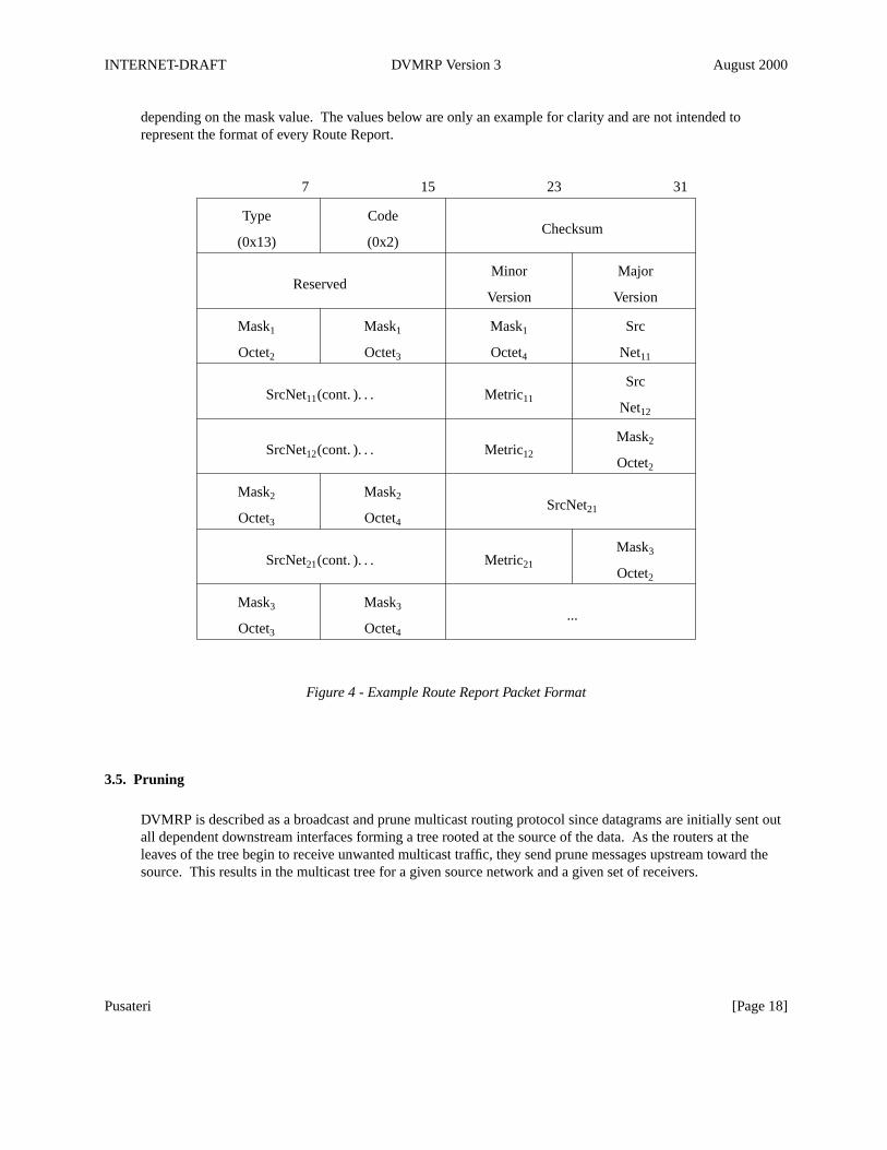
The format of a sample Route Report Packet is shown in Figure 4 below. The packet shown is an example ofhow the source networks are packed into a Report. The number of octets in each Source Network will vary
Pusateri [Page 17]
INTERNET-DRAFT DVMRP Version 3 August 2000
depending on the mask value. The values below are only an example for clarity and are not intended torepresent the format of every Route Report.
7 15 23 31
Type Code
(0x13) (0x2)Checksum
Minor Major
Version VersionReserved
Mask1 Mask1 Mask1 Src
Octet2 Octet3 Octet4 Net11
Src
Net12
SrcNet11(cont. ). . . Metric11
Mask2
Octet2SrcNet12(cont. ). . . Metric12
Mask2 Mask2
Octet3 Octet4SrcNet21
Mask3
Octet2SrcNet21(cont. ). . . Metric21
Mask3 Mask3
Octet3 Octet4...
Figure 4 - Example Route Report Packet Format
3.5. Pruning
DVMRP is described as a broadcast and prune multicast routing protocol since datagrams are initially sent outall dependent downstream interfaces forming a tree rooted at the source of the data. As the routers at theleaves of the tree begin to receive unwanted multicast traffic, they send prune messages upstream toward thesource. This results in the multicast tree for a given source network and a given set of receivers.
Pusateri [Page 18]
INTERNET-DRAFT DVMRP Version 3 August 2000
3.5.1. Leaf Networks
Detection of leaf networks is very important to the pruning process. Routers at the end of a source specificmulticast delivery tree must detect that there are no further downstream dependent routers. This detectionmechanism is covered above in section 3.2 titled Probe Messages. If there are no group members present for aparticular multicast datagram received, the leaf routers will start the pruning process by removing theirdownstream interfaces and sending a prune to the upstream router for that source.
3.5.2. Source Networks
By default, prunes are meant to be applied to a group and source network. However, it is possible to include aNetmask in the Prune message to alter this behavior. If no Netmask is included, a prune sent upstreamtriggered by traffic received from a particular source applies to all sources on that network. If a Netmask isincluded, it MUST first be validated. If the Netmask is a host mask, only that source address should be pruned.Otherwise, the Netmask MUST match the mask sent to the downstream router for that source. If it does notmatch the mask that the upstream router expected, the upstream router MUST ignore the prune and should logan error. When a aggregate source network is advertised downstream, the Netmask in the prune will match themask of the aggregate route that was advertised.
If the Prune message only contains the host address of the source (and not the corresponding Netmask), thesource network can be determined easily by a best-match lookup using the routing table distributed as a part ofDVMRP.
3.5.3. Receiving a Prune
When a prune is received, the following steps should be taken:
1. If the neighbor is unknown, discard the received prune.
2. Ensure the prune message contains at least the correct amount of data.
3. Copy the source address, group address, and prune time-out value. If it is available in the packet, copy theNetmask value. Determine route to which prune applies.
4. If there is no active source information for the (source network, group) pair, then ignore the prune.
5. Verify that the prune was received from a dependent neighbor for the source network. If not, discard theprune.
6. Determine if a prune is currently active from the same dependent neighbor for this (source network,group) pair.
Pusateri [Page 19]

INTERNET-DRAFT DVMRP Version 3 August 2000
7. If so, reset the timer to the new time-out value. Otherwise, create state for the new prune and set a timerfor the prune lifetime.
8. Determine if all dependent downstream routers on the interface from which the prune was received hav enow sent prunes.
9. If so, then determine if there are group members active on the interface and if this router is the designatedforwarder for the network.
10. If not, then remove the interface from all forwarding cache entries for this group instantiated using theroute to which the prune applies.
3.5.4. Sending a Prune
When a forwarding cache is being used, there is a trade-off that should be considered when deciding when Prunemessages should be sent upstream. In all cases, when a data packet arrives and the downstream interface list isempty, a prune is sent upstream. However, when a forwarding cache entry transistions to an empty downstreaminterface list it is possible as an optimization to send a prune at this time as well. This prune will possibly stopunwanted traffic sooner at the expense of sending extra prune traffic for sources that are no longer sending.
When sending a prune upstream, the following steps should be taken:
1. Decide if upstream neighbor is capable of receiving prunes.
2. If not, then proceed no further.
3. Stop any pending Grafts awaiting acknowledgments.
4. Determine the prune lifetime. This value should be the minimum of the default prune lifetime(randomized to prevent synchronization) and the remaining prune lifetimes of the downstreamneighbors.
5. Form and transmit the packet to the upstream neighbor for the source.
3.5.5. Retransmitting a Prune
By increasing the prune lifetime to ˜2 hours, the effect of a lost prune message becomes more apparent.Therefore, an implementation SHOULD retransmit prunes messages using binary exponential back-off duringthe lifetime of the prune if traffic is still arriving on the upstream interface.
One way to implement this would be to send a prune, install a negative cache entry for 3 seconds while waitingfor the prune to take effect. Then remove the negative cache entry. If traffic continues to arrive, a newforwarding cache request will be generated. The prune can be resent with the remaining prune lifetime and anegative cache entry can be installed for 6 seconds. After this, the negative cache entry is removed. This
Pusateri [Page 20]
INTERNET-DRAFT DVMRP Version 3 August 2000
procedure is repeated while each time doubling the length of time the negative cache entry is installed.
In addition to using binary exponential back-off, the interval between subsequent retransmissions should alsobe randomized to prevent synchronization.
On multi-access networks, even if a prune is received by the upstream router, data may still be received due toother receivers (i.e. group members or other downstream dependent routers) on the network.
3.5.6. Prune Packet Format
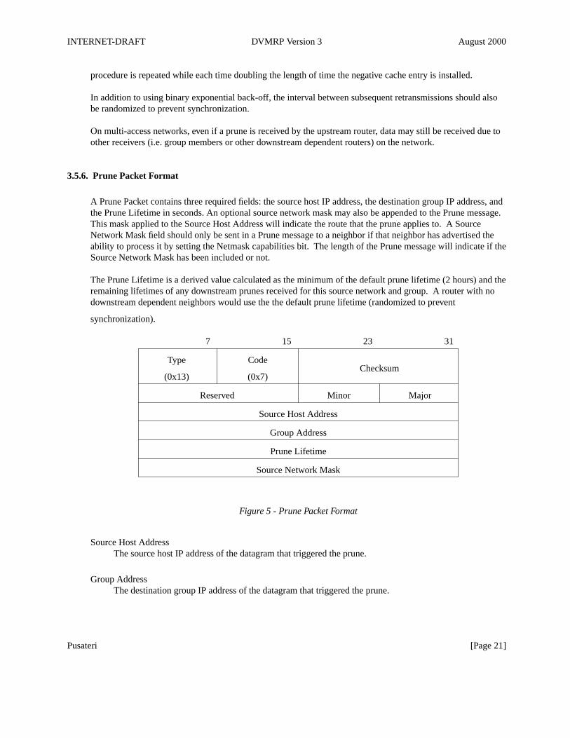
A Prune Packet contains three required fields: the source host IP address, the destination group IP address, andthe Prune Lifetime in seconds. An optional source network mask may also be appended to the Prune message.This mask applied to the Source Host Address will indicate the route that the prune applies to. A SourceNetwork Mask field should only be sent in a Prune message to a neighbor if that neighbor has advertised theability to process it by setting the Netmask capabilities bit. The length of the Prune message will indicate if theSource Network Mask has been included or not.
The Prune Lifetime is a derived value calculated as the minimum of the default prune lifetime (2 hours) and theremaining lifetimes of any downstream prunes received for this source network and group. A router with nodownstream dependent neighbors would use the the default prune lifetime (randomized to prevent
synchronization).
7 15 23 31
Type Code
(0x13) (0x7)Checksum
Reserved Minor Major
Source Host Address
Group Address
Prune Lifetime
Source Network Mask
Figure 5 - Prune Packet Format
Source Host AddressThe source host IP address of the datagram that triggered the prune.
Group AddressThe destination group IP address of the datagram that triggered the prune.
Pusateri [Page 21]
INTERNET-DRAFT DVMRP Version 3 August 2000
Prune LifetimeThe number of seconds for which the upstream neighbor should keep this prune active.
Source Network MaskThe (optional) netmask of the route this prune applies to.
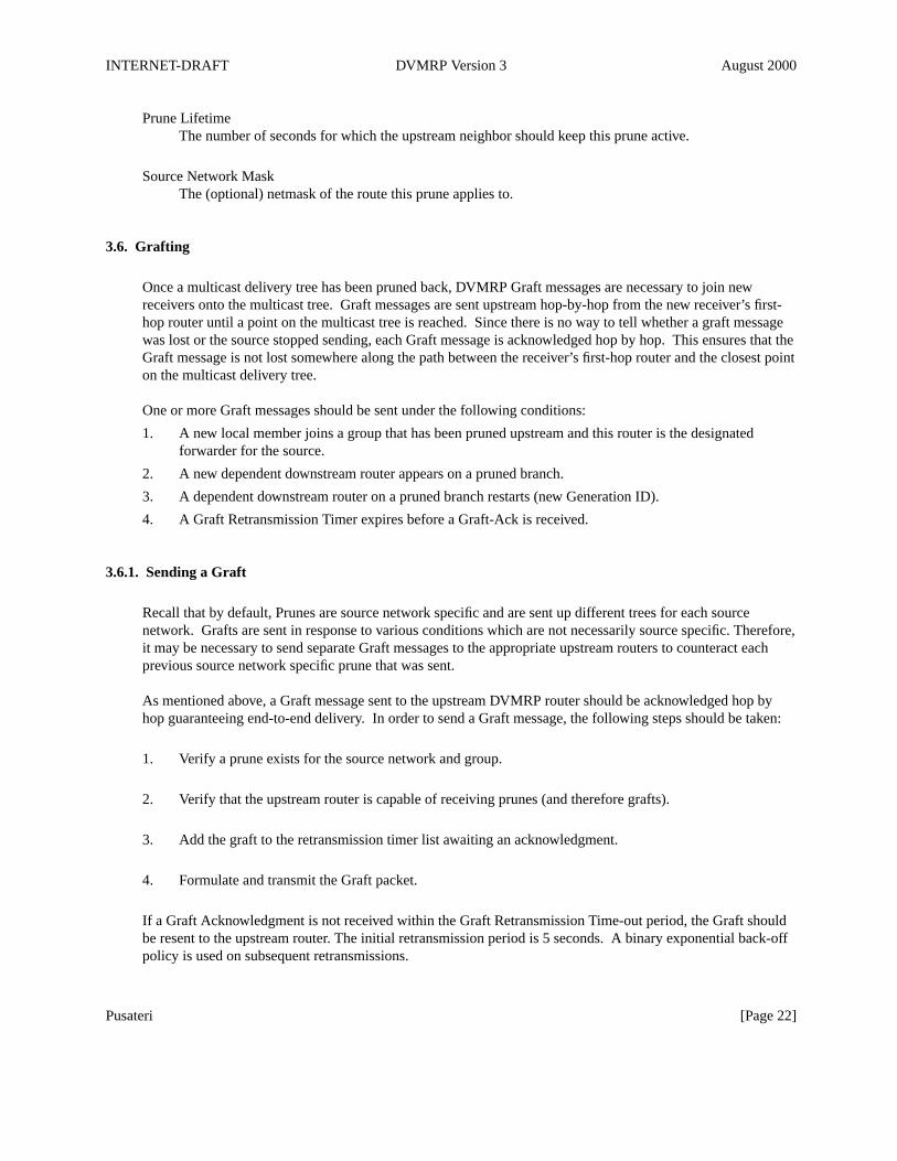
3.6. Grafting
Once a multicast delivery tree has been pruned back, DVMRP Graft messages are necessary to join newreceivers onto the multicast tree. Graft messages are sent upstream hop-by-hop from the new receiver’s first-hop router until a point on the multicast tree is reached. Since there is no way to tell whether a graft messagewas lost or the source stopped sending, each Graft message is acknowledged hop by hop. This ensures that theGraft message is not lost somewhere along the path between the receiver’s first-hop router and the closest pointon the multicast delivery tree.
One or more Graft messages should be sent under the following conditions:
1. A new local member joins a group that has been pruned upstream and this router is the designatedforwarder for the source.
2. A new dependent downstream router appears on a pruned branch.
3. A dependent downstream router on a pruned branch restarts (new Generation ID).
4. A Graft Retransmission Timer expires before a Graft-Ack is received.
3.6.1. Sending a Graft
Recall that by default, Prunes are source network specific and are sent up different trees for each sourcenetwork. Grafts are sent in response to various conditions which are not necessarily source specific. Therefore,it may be necessary to send separate Graft messages to the appropriate upstream routers to counteract eachprevious source network specific prune that was sent.
As mentioned above, a Graft message sent to the upstream DVMRP router should be acknowledged hop byhop guaranteeing end-to-end delivery. In order to send a Graft message, the following steps should be taken:
1. Verify a prune exists for the source network and group.
2. Verify that the upstream router is capable of receiving prunes (and therefore grafts).
3. Add the graft to the retransmission timer list awaiting an acknowledgment.
4. Formulate and transmit the Graft packet.
If a Graft Acknowledgment is not received within the Graft Retransmission Time-out period, the Graft shouldbe resent to the upstream router. The initial retransmission period is 5 seconds. A binary exponential back-offpolicy is used on subsequent retransmissions.
Pusateri [Page 22]
INTERNET-DRAFT DVMRP Version 3 August 2000
3.6.2. Receiving a Graft
1. If the neighbor is unknown, discard the received graft.
2. Ensure the graft message contains at least the correct amount of data.
3. Send back a Graft Ack to the sender.
4. If the sender was a downstream dependent neighbor from which a prune had previously been received,then remove the prune state for this neighbor. If necessary, any forwarding cache entries based on this(source, group) pair should be updated to include this downstream interface.
5. If a prune had been sent upstream, this may trigger a graft to now be sent to the upstream router.
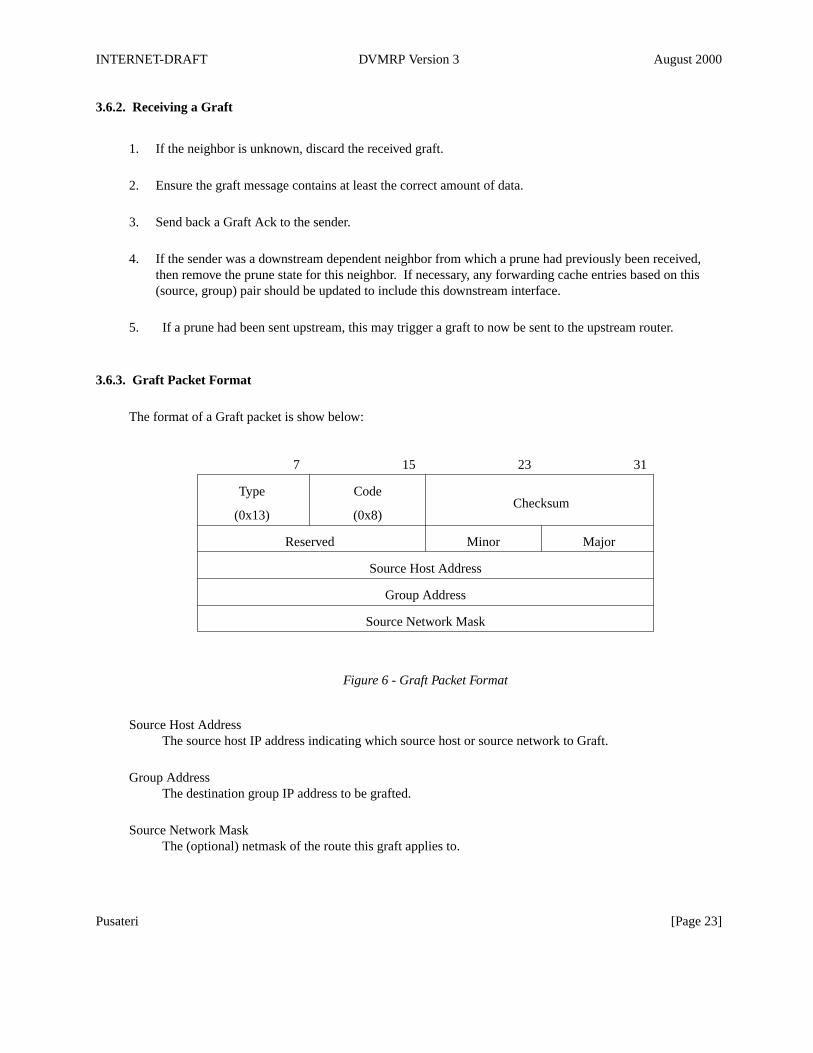
3.6.3. Graft Packet Format
The format of a Graft packet is show below:
7 15 23 31
Type Code
(0x13) (0x8)Checksum
Reserved Minor Major
Source Host Address
Group Address
Source Network Mask
Figure 6 - Graft Packet Format
Source Host AddressThe source host IP address indicating which source host or source network to Graft.
Group AddressThe destination group IP address to be grafted.
Source Network MaskThe (optional) netmask of the route this graft applies to.
Pusateri [Page 23]
INTERNET-DRAFT DVMRP Version 3 August 2000
3.6.4. Sending a Graft Acknowledgment
A Graft Acknowledgment packet is sent to a downstream neighbor in response to receiving a Graft message.All Graft messages MUST be acknowledged. This is true even if no other action is taken in response toreceiving the Graft to prevent the source from continually re-transmitting the Graft message. The GraftAcknowledgment packet is identical to the Graft packet except that the DVMRP code in the common header isset to Graft Ack. This allows the receiver of the Graft Ack message to correctly identify which Graft wasacknowledged and stop the appropriate retransmission timer.
3.6.5. Receiving a Graft Acknowledgment
When a Graft Acknowledgment is received, ensure the message contains at least the correct amount of data.The (source address, group) pair in the packet can be used to determine if a Graft was sent to this particularupstream router. If no Graft was sent, the Graft Ack can simply be ignored. If a Graft was sent, and theacknowledgment has come from the correct upstream router, then it has been successfully received and theretransmission timer for the Graft can be stopped.
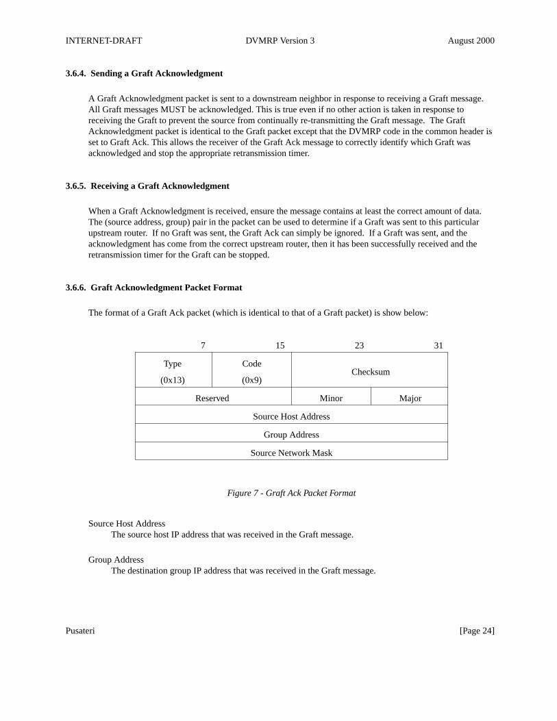
3.6.6. Graft Acknowledgment Packet Format
The format of a Graft Ack packet (which is identical to that of a Graft packet) is show below:
7 15 23 31
Type Code
(0x13) (0x9)Checksum
Reserved Minor Major
Source Host Address
Group Address
Source Network Mask
Figure 7 - Graft Ack Packet Format
Source Host AddressThe source host IP address that was received in the Graft message.
Group AddressThe destination group IP address that was received in the Graft message.
Pusateri [Page 24]
INTERNET-DRAFT DVMRP Version 3 August 2000
Source Network MaskThe (optional) netmask of the route this Graft Ack applies to.
3.7. Interfaces
Interfaces running DVMRP will either be multicast capable physical interfaces or encapsulated tunnel pseudo-interfaces. Physical interfaces may either be multi-access networks or point-to-point networks. Tunnelinterfaces are used when there are non-multicast capable routers between DVMRP neighbors. Protocolmessages and multicast data traffic are sent between tunnel endpoints using a standard encapsulation method[Perk96,Han94a,Han94b]. The unicast IP addresses of the tunnel endpoints are used as the source anddestination IP addresses in the outer IP header. The inner IP header remains unchanged from the originalpacket.
Protocol messages on point-to-point links should always use a destination IP address of All-DVMRP-Routersfor ALL message types. While Prune, Graft, and Graft-Ack messages are only intended for a single recipient,the use of a multicast destination address is necessary for un-numbered links and encapsulated interfaces.
When multiple addresses are configured on a single interface, it is necessary that all routers on the interfaceknow about the same set of network addresses. In this way, each router will make the same choice for thedesignated forwarder for each source. In addition, a router configured with multiple addresses on an interfaceshould consistently use the same address when sending DVMRP control messages.
The maximum packet length of any DVMRP message should be the maximum packet size required to beforwarded without fragmenting. The use of Path MTU Discovery [Mogu90] is encouraged to determine thissize. In the absence of Path MTU, the Requirements for Internet Hosts [Brad89] specifies this number as 576octets. Be sure to consider the size of the encapsulated IP header as well when calculating the maximum sizeof a DVMRP protocol message.
3.7.1. Interface transitions
When an interface transitions to the up state, the generation ID of that interface should be updated so thatDVMRP neighbors know to resend prune information.
When an interface transitions to the down state, all neighbors on that interface should be expired. All actionsassociated with an expired neighbor should be taken as specified in the Neighbor Expiry section.
4. IANA Considerations
The Internet Assigned Numbers Authority (IANA) is the central coordinator for the assignment of uniqueparameter values for Internet protocols. DVMRP uses IGMP [Fenn97] IP protocol messages to communicatebetween routers. The IGMP Type field is hexadecimal 0x13.
On IP multicast capable networks, DVMRP uses the All-DVMRP-Routers local multicast group. This groupaddress is 224.0.0.4.
Pusateri [Page 25]
INTERNET-DRAFT DVMRP Version 3 August 2000
5. Network Management Considerations
DVMRP provides several methods for network management monitoring and troubleshooting. Appendix Bdescribes a request/response mechanism to directly query DVMRP neighbor information. In addition, aManagement Information Base for DVMRP is defined in [Thal97].
A Management Information Base for the multicast forwarding cache is defined in [McCl00].
Also, a protocol independent multicast trace-route facility is defined in [Fenn00].
6. Security Considerations
Security for DVMRP follows the general security architecture provided for the Internet Protocol [Ken98a].This framework provides for both privacy and authentication. It recommends the use of the IP AuthenticationHeader [Ken98b] to provide trusted neighbor relationships. Confidentiality is provided by the addition of the IPEncapsulating Security Payload [Ken98c].
7. References
[Brad88] Braden, R., Borman, D., Partridge, C., "Computing the Internet Checksum", RFC 1071,September 1988.
[Brad89] Braden, R., "Requirements for Internet Hosts -- Communication Layers", RFC 1122, October1989.
[Deer89] Deering, S., "Host Extensions for IP Multicasting", RFC 1112, August 1989.
[Deer90] Deering, S., Cheriton, D., "Multicast Routing in Datagram Internetworks and Extended LANs",ACM Transactions on Computer Systems, Vol. 8, No. 2, May 1990, pp. 85-110.
[Deer91] Deering, S., "Multicast Routing in a Datagram Internetwork", PhD thesis, Electric EngineeringDept., Stanford University, December 1991.
[Fenn97] Fenner, W., "Internet Group Management Protocol, Version 2", RFC 2236, November 1997.
[Fenn00] Fenner, W., Casner, S., "A "traceroute" facility for IP Multicast", Work In Progress, July 2000.
[Full93] Fuller, V., T. Li, J. Yu, and K. Varadhan, "Classless Inter-Domain Routing (CIDR): an AddressAssignment and Aggregation Strategy", RFC 1519, September 1993.
[Han94a] Hanks, S., Li, T, Farinacci, D., and P. Traina, "Generic Routing Encapsulation", RFC 1701,NetSmiths, Ltd., and cisco Systems, October 1994.
[Han94b] Hanks, S., Li, T., Farinacci, D., and P. Traina, "Generic Routing Encapsulation over IPv4networks", RFC 1702, NetSmiths, Ltd., cisco Systems, October 1994.
[Ken98a] Kent, S., Atkinson, R. "Security Architecture for the Internet Protocol", RFC 2401, November1998.
[Ken98b] Kent, S., Atkinson, R., "IP Authentication Header", RFC 2402, November 1998.
[Ken98c] Kent, S., Atkinson, R., "IP Encapsulating Security Payload (ESP)", RFC 2406, November 1998.
Pusateri [Page 26]
INTERNET-DRAFT DVMRP Version 3 August 2000
[McCl00] McCloghrie, K., Farinacci, D., Thaler, D., "IP Multicast Routing MIB", Work In Progress, July2000.
[Mogu90] Mogul, J., Deering, S., "Path MTU Discovery", RFC 1191, November 1990.
[Perk96] Perkins, C., "IP Encapsulation within IP", RFC 2003, October 1996.
[Perl92] Perlman, R., "Interconnections: Bridges and Routers", Addison-Wesley, May 1992, pp. 205-211.
[Post81] Postel, J., "Internet Protocol", RFC 791, September, 1981.
[Rekh93] Rekhter, Y., and T. Li, "An Architecture for IP Address Allocation with CIDR", RFC 1518,September 1993.
[Reyn94] Reynolds, J., Postel, J., "Assigned Numbers", STD 0002, October 1994.
[Thal97] Thaler, D., "Distance-Vector Multicast Routing Protocol MIB", Work In Progress, April 1997.
[Wait88] Waitzman, D., Partridge, C., Deering, S., "Distance Vector Multicast Routing Protocol", RFC1075, November 1988.
8. Author’s Address
Thomas PusateriJuniper Networks, Inc.1194 North Mathilda AvenueSunnyvale, CA 94089 USAPhone: (408) 734-7690EMail: [email protected]
9. Acknowledgments
The author would like to acknowledge the original designers of the protocol, Steve Deering, Craig Partridge,and David Waitzman. Version 3 of the protocol would not have been possible without the original work of AjitThyagarajan and the ongoing (and seemingly endless) work of Bill Fenner. Credit also goes to Danny Mitzeland Dave Thaler for the careful review of this document and Nitin Jain, Dave LeRoy, Charles Mumford, RaviShekhar, and Shuching Shieh for their helpful comments.
Pusateri [Page 27]
INTERNET-DRAFT DVMRP Version 3 August 2000
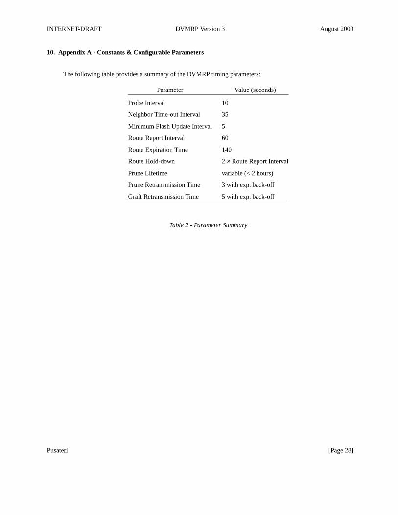
10. Appendix A - Constants & Configurable Parameters
The following table provides a summary of the DVMRP timing parameters:
Parameter Value (seconds)
Probe Interval 10
Neighbor Time-out Interval 35
Minimum Flash Update Interval 5
Route Report Interval 60
Route Expiration Time 140
Route Hold-down 2 × Route Report Interval
Prune Lifetime variable (< 2 hours)
Prune Retransmission Time 3 with exp. back-off
Graft Retransmission Time 5 with exp. back-off
Table 2 - Parameter Summary
Pusateri [Page 28]
INTERNET-DRAFT DVMRP Version 3 August 2000
11. Appendix B - Tracing and Troubleshooting support
There are several packet types used to gather DVMRP specific information. They are generally used fordiagnosing problems or gathering topology information. The first two messages are now obsoleted and shouldnot be used. The remaining two messages provide a request/response mechanism to determine the versions andcapabilities of a particular DVMRP router.
Code Packet Type Description
3 DVMRP Ask Neighbors Obsolete
4 DVMRP Neighbors Obsolete
5 DVMRP Ask Neighbors 2 Request Neighbor List
6 DVMRP Neighbors 2 Respond with Neighbor List
Table 3 - Debugging Packet Types
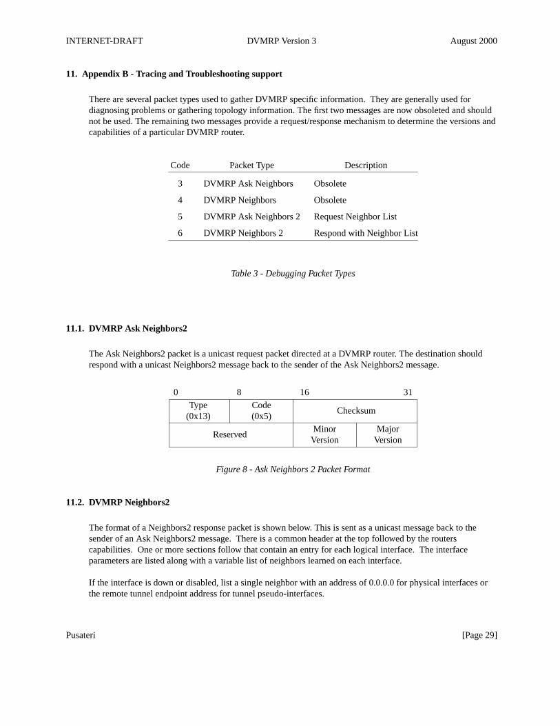
11.1. DVMRP Ask Neighbors2
The Ask Neighbors2 packet is a unicast request packet directed at a DVMRP router. The destination shouldrespond with a unicast Neighbors2 message back to the sender of the Ask Neighbors2 message.
0 8 16 31
Type Code(0x13) (0x5)
Checksum
Minor MajorVersion Version
Reserved
Figure 8 - Ask Neighbors 2 Packet Format
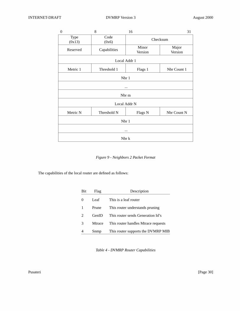
11.2. DVMRP Neighbors2
The format of a Neighbors2 response packet is shown below. This is sent as a unicast message back to thesender of an Ask Neighbors2 message. There is a common header at the top followed by the routerscapabilities. One or more sections follow that contain an entry for each logical interface. The interfaceparameters are listed along with a variable list of neighbors learned on each interface.
If the interface is down or disabled, list a single neighbor with an address of 0.0.0.0 for physical interfaces orthe remote tunnel endpoint address for tunnel pseudo-interfaces.
Pusateri [Page 29]
INTERNET-DRAFT DVMRP Version 3 August 2000
0 8 16 31
Type Code(0x13) (0x6)
Checksum
Minor MajorVersion Version
Reserved Capabilities
Local Addr 1
Metric 1 Threshold 1 Flags 1 Nbr Count 1
Nbr 1
...
Nbr m
Local Addr N
Metric N Threshold N Flags N Nbr Count N
Nbr 1
...
Nbr k
Figure 9 - Neighbors 2 Packet Format
The capabilities of the local router are defined as follows:
Bit Flag Description
0 Leaf This is a leaf router
1 Prune This router understands pruning
2 GenID This router sends Generation Id’s
3 Mtrace This router handles Mtrace requests
4 Snmp This router supports the DVMRP MIB
Table 4 - DVMRP Router Capabilities
Pusateri [Page 30]
INTERNET-DRAFT DVMRP Version 3 August 2000
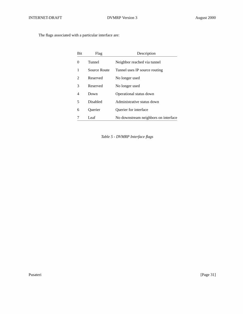
The flags associated with a particular interface are:
Bit Flag Description
0 Tunnel Neighbor reached via tunnel
1 Source Route Tunnel uses IP source routing
2 Reserved No longer used
3 Reserved No longer used
4 Down Operational status down
5 Disabled Administrative status down
6 Querier Querier for interface
7 Leaf No downstream neighbors on interface
Table 5 - DVMRP Interface flags
Pusateri [Page 31]
INTERNET-DRAFT DVMRP Version 3 August 2000
12. Appendix C - Version Compatibility
There have been two previous major versions of DVMRP with implementations still in circulation. If thereceipt of a Probe message reveals a major version of 1 or 2, then it can be assumed that this neighbor does notsupport pruning or the use of the Generation ID in the Probe message. However, since these olderimplementations are known to safely ignore the Generation ID and neighbor information in the Probe packet, itis not necessary to send specially formatted Probe packets to these neighbors.
There were three minor versions (0, 1, and 2) of major version 3 that did support pruning but did not supportthe Generation ID or capability flags. These special cases will have to be accounted for.
Any other minor versions of major version 3 closely compare to this specification.
In addition, cisco Systems is known to use their software major and minor release number as the DVMRPmajor and minor version number. These will typically be 10 or 11 for the major version number. Pruning wasintroduced in Version 11.
Implementations prior to this specification may not wait to send route reports until probe messages have beenreceived with the routers address listed. Reports SHOULD be sent to these neighbors without first requiring areceived probe with the routers address in it as well as reports from these neighbors SHOULD be accepted.Although, this allows one-way neighbor relationships to occur, it does maintain backward compatibility.
It may be necessary to form neighbor relationships based solely on Route Report messages. Neighbor time-outvalues may need to be configured to a value greater than the Route Report Interval for these neighbors.
Implementations that do not monitor Generation ID changes can create more noticeable black holes whenusing long prune lifetimes such as ˜2 hours. This happens when a long prune is sent upstream and then therouter that sent the long prune restarts. If the upstream router ignores the new Generation ID, the prunereceived by the upstream router will not be flushed and the downstream router will have no knowledge of theupstream prune. For this reason, prunes sent upstream to routers that are known to ignore Generation IDchanges should have short lifetimes.
If the router must run IGMP version 1 on an interface for backwards compatibility, DVMRP must elect theDVMRP router with the highest IP address as the IGMP querier.
Some implementations of tools that send DVMRP Ask Neighbors2 requests and receive Neighbors2 responsemessages require a neighbor address of 0.0.0.0 when no neighbors are listed in the response packet. (Mrinfo)
When DVMRP protocol packets are sent to tunnel endpoints, some implementations do not accept packetsaddressed to the All-DVMRP-Routers address and then encapsulated with the tunnel endpoint address.Mrouted versions 3.9beta2 and earlier are known to have this problem.
Pusateri [Page 32]
INTERNET-DRAFT DVMRP Version 3 August 2000
13. Intellectual Property Rights Notice
The IETF takes no position regarding the validity or scope of any intellectual property or other rights thatmight be claimed to pertain to the implementation or use of the technology described in this document or theextent to which any license under such rights might or might not be available; neither does it represent that ithas made any effort to identify any such rights. Information on the IETF’s procedures with respect to rights instandards-track and standards-related documentation can be found in BCP-11. Copies of claims of rights madeavailable for publication and any assurances of licenses to be made available, or the result of an attempt madeto obtain a general license or permission for the use of such proprietary rights by implementors or users of thisspecification can be obtained from the IETF Secretariat.
The IETF invites any interested party to bring to its attention any copyrights, patents or patent applications, orother proprietary rights which may cover technology that may be required to practice this standard. Pleaseaddress the information to the IETF Executive Director.
14. Full Copyright Statement
Copyright (C) The Internet Society (date). All Rights Reserved.
This document and translations of it may be copied and furnished to others, and derivative works that commenton or otherwise explain it or assist in its implmentation may be prepared, copied, published and distributed, inwhole or in part, without restriction of any kind, provided that the above copyright notice and this paragraphare included on all such copies and derivative works. However, this document itself may not be modified inany way, such as by removing the copyright notice or references to the Internet Society or other Internetorganizations, except as needed for the purpose of developing Internet standards in which case the proceduresfor copyrights defined in the Internet Standards process must be followed, or as required to translate it intolanguages other than English.
The limited permissions granted above are perpetual and will not be revoked by the Internet Society or itssuccessors or assigns.
This document and the information contained herein is provided on an "AS IS" basis and THE INTERNETSOCIETY AND THE INTERNET ENGINEERING TASK FORCE DISCLAIMS ALL WARRANTIES,EXPRESS OR IMPLIED, INCLUDING BUT NOT LIMITED TO ANY WARRANTY THAT THE USE OFTHE INFORMATION HEREIN WILL NOT INFRINGE ANY RIGHTS OR ANY IMPLIED WARRANTIESOF MERCHANTABILITY OR FITNESS FOR A PARTICULAR PURPOSE.
Pusateri [Page 33]
Table of Contents
1. Introduction . . . . . . . . . . . . . . . . . . . . . . . . . . . . . 21.1. Requirements Terminology . . . . . . . . . . . . . . . . . . . . . . . . 21.2. Reverse Path Multicasting . . . . . . . . . . . . . . . . . . . . . . . . 21.3. Tunnel Encapsulation . . . . . . . . . . . . . . . . . . . . . . . . . 21.4. Document Overview . . . . . . . . . . . . . . . . . . . . . . . . . . 32. Protocol Overview . . . . . . . . . . . . . . . . . . . . . . . . . . . 32.1. Neighbor Discovery . . . . . . . . . . . . . . . . . . . . . . . . . . 32.2. Source Location . . . . . . . . . . . . . . . . . . . . . . . . . . . 32.3. Dependent Downstream Routers . . . . . . . . . . . . . . . . . . . . . . 42.4. Designated Forwarder . . . . . . . . . . . . . . . . . . . . . . . . . 42.5. Building Multicast Trees . . . . . . . . . . . . . . . . . . . . . . . . 52.6. Pruning Multicast Trees . . . . . . . . . . . . . . . . . . . . . . . . . 52.7. Grafting Multicast Trees . . . . . . . . . . . . . . . . . . . . . . . . 63. Detailed Protocol Operation . . . . . . . . . . . . . . . . . . . . . . . . 63.1. Protocol Header . . . . . . . . . . . . . . . . . . . . . . . . . . . 63.2. Probe Messages . . . . . . . . . . . . . . . . . . . . . . . . . . . 73.3. Multicast Forwarding . . . . . . . . . . . . . . . . . . . . . . . . . 113.4. Route Exchange . . . . . . . . . . . . . . . . . . . . . . . . . . . 123.5. Pruning . . . . . . . . . . . . . . . . . . . . . . . . . . . . . . 183.6. Grafting . . . . . . . . . . . . . . . . . . . . . . . . . . . . . . 223.7. Interfaces . . . . . . . . . . . . . . . . . . . . . . . . . . . . . 254. IANA Considerations . . . . . . . . . . . . . . . . . . . . . . . . . . 255. Network Management Considerations . . . . . . . . . . . . . . . . . . . . . 266. Security Considerations . . . . . . . . . . . . . . . . . . . . . . . . . 267. References . . . . . . . . . . . . . . . . . . . . . . . . . . . . . 268. Author’s Address . . . . . . . . . . . . . . . . . . . . . . . . . . . 279. Acknowledgments . . . . . . . . . . . . . . . . . . . . . . . . . . . 2710. Appendix A - Constants & Configurable Parameters . . . . . . . . . . . . . . . . 2811. Appendix B - Tracing and Troubleshooting support . . . . . . . . . . . . . . . . 2911.1. DVMRP Ask Neighbors2 . . . . . . . . . . . . . . . . . . . . . . . . 2911.2. DVMRP Neighbors2 . . . . . . . . . . . . . . . . . . . . . . . . . 2912. Appendix C - Version Compatibility . . . . . . . . . . . . . . . . . . . . . 3213. Intellectual Property Rights Notice . . . . . . . . . . . . . . . . . . . . . 3314. Full Copyright Statement . . . . . . . . . . . . . . . . . . . . . . . . 33
Pusateri [Page i]