Embed Size (px)
Citation preview
Imperial College of Science, Technology and MedicineUniversity Of London
[MEng] Computing Final Year Project Report
Distributed Abductive Reasoning Systemand
Abduction In the Small
Author:
Jiefei Ma
Supervisors:
Dr. Krysia Broda, Dr. Alessandra Russo
June 22, 2007http://www.doc.ic.ac.uk/~jm103/project
Abstract
Abductive reasoning (abduction) is a powerful reasoning method that can be used in manyapplications such as fault diagnosis, medical diagnosis and automated planning. Recently, italso has attracted many interests from the world of ubiquitous computing – Tiny devices areeverywhere. How can we have small devices with limited computational power and space toperform the abductive reasoning tasks? Also, can we have a collection of devices to performabductive reasoning collaboratively?
The traditional proof procedures of abductive reasoning are computationally hungry. Inorder to have small devices to do abduction, we need to have an efficient enough implemen-tation of the proof procedures to run on them. This may involves various optimisations. Tohave a collection of devices to collaborate in reasoning tasks is an even harder problem –How can we make sure the reasoning result is consistent among the devices?
This report first describes how to implement the Kakas-Mancarella proof procedure forabductive reasoning efficiently and to run it on a tiny Gumstix computer. The report thendescribes the development of a multi-agent system DARES (Distributed Abductive REason-ing System). DARES allows a group of agents to collaborate in abductive reasoning tasks –it allows the agents to seek help form others during the reasoning process and guarantees theresults obtained are globally consistent among the agents. DARES also provides an efficientmechanism for the agents to exchange tasks and results among themselves. The report finallydescribes how to deploy DARES to the Gumstix computers.
Acknowledgements
First of all, I would like to thank my supervisors, Dr. Krysia Broda and Dr. AlessandraRusso, for their enormous support and encouragement during my project. They have alwaysbeen excited about my work and have given me lots of valuable inspirations.
Secondly, I would like to thank Dr. Emil Lupu and Professor Morris Sloman for theideas about the applications for the project and providing me the Gumstix computers for theproject.
I would like to my personal tutor, Professor Susan Eisenbach, for introducing me to mysupervisors.
I also would like to thank the the following people:
• Professor Murray Shanahan for discussion and ideas about abductive planning.
• Professor Keith Clark for the discussion and ideas about multi-agent systems.
• Peter Robinson, the author of QuProlog, for supporting my evaluation of Pedro andQuProlog.
• Peter Collingbourne for giving me help during the initial porting of YAP Prolog
Finally, I would like to thank my parents who have sponsored me to study in the UK forthe past 6 years, and thank my girl friend Sylvaine for looking after me while I was too busywith my project.
i
Contents
1 Introduction 11.1 Objectives . . . . . . . . . . . . . . . . . . . . . . . . . . . . . . . . . . . . . . 31.2 Contributions . . . . . . . . . . . . . . . . . . . . . . . . . . . . . . . . . . . . 3
2 Background 52.1 Logic Programming . . . . . . . . . . . . . . . . . . . . . . . . . . . . . . . . 5
2.1.1 Syntax and Informal Semantics of Prolog . . . . . . . . . . . . . . . . 52.1.2 Query Evaluation in Prolog . . . . . . . . . . . . . . . . . . . . . . . . 72.1.3 Prolog Compilers and the Warren Abstract Machine . . . . . . . . . . 10
2.2 Partial Evaluation in Logic Programs . . . . . . . . . . . . . . . . . . . . . . . 152.2.1 Partial Evaluation . . . . . . . . . . . . . . . . . . . . . . . . . . . . . 152.2.2 A Meta-Interpreter of Prolog . . . . . . . . . . . . . . . . . . . . . . . 172.2.3 A Partial Evaluated Meta-Interpreter . . . . . . . . . . . . . . . . . . 18
2.3 Abductive Reasoning . . . . . . . . . . . . . . . . . . . . . . . . . . . . . . . . 202.3.1 Logical Reasoning . . . . . . . . . . . . . . . . . . . . . . . . . . . . . 202.3.2 Formal Definition . . . . . . . . . . . . . . . . . . . . . . . . . . . . . . 202.3.3 Proof Procedure . . . . . . . . . . . . . . . . . . . . . . . . . . . . . . 212.3.4 Applications . . . . . . . . . . . . . . . . . . . . . . . . . . . . . . . . 23
2.4 Event Calculus and Abductive Planning . . . . . . . . . . . . . . . . . . . . . 242.4.1 Introduction to Event Calculus . . . . . . . . . . . . . . . . . . . . . . 242.4.2 Planning with Abductive Reasoning . . . . . . . . . . . . . . . . . . . 25
2.5 Agent Communications in Multi-Agent Systems . . . . . . . . . . . . . . . . . 252.5.1 KQML . . . . . . . . . . . . . . . . . . . . . . . . . . . . . . . . . . . . 262.5.2 Mediation Services with KQML . . . . . . . . . . . . . . . . . . . . . . 27
2.6 Abductive LogIc Agent System – ALIAS . . . . . . . . . . . . . . . . . . . . . 282.6.1 The Architecture . . . . . . . . . . . . . . . . . . . . . . . . . . . . . . 292.6.2 The LAILA Language . . . . . . . . . . . . . . . . . . . . . . . . . . . 292.6.3 Proposed Applications . . . . . . . . . . . . . . . . . . . . . . . . . . . 31
2.7 Target Device – Gumstix . . . . . . . . . . . . . . . . . . . . . . . . . . . . . 312.7.1 Specification . . . . . . . . . . . . . . . . . . . . . . . . . . . . . . . . 322.7.2 Resources . . . . . . . . . . . . . . . . . . . . . . . . . . . . . . . . . . 33
2.8 QuProlog . . . . . . . . . . . . . . . . . . . . . . . . . . . . . . . . . . . . . . 332.8.1 Multi-threads Support . . . . . . . . . . . . . . . . . . . . . . . . . . . 342.8.2 Inter-agent Communications Model (ICM) . . . . . . . . . . . . . . . . 342.8.3 Pedro . . . . . . . . . . . . . . . . . . . . . . . . . . . . . . . . . . . . 35
ii
CONTENTS iii
3 Investigation of Abductive Reasoning 363.1 Abductive Meta-Interpreters . . . . . . . . . . . . . . . . . . . . . . . . . . . 36
3.1.1 Re-engineering the Kakas’ ALP Meta-Interpreter . . . . . . . . . . . . 363.1.2 Benchmarking . . . . . . . . . . . . . . . . . . . . . . . . . . . . . . . 393.1.3 Running On a Gumstix . . . . . . . . . . . . . . . . . . . . . . . . . . 40
3.2 Optimisation by Partial Evaluation . . . . . . . . . . . . . . . . . . . . . . . . 403.2.1 Observations of the Abductive Meta-interpreter . . . . . . . . . . . . . 403.2.2 Compiling Away the Meta-Interpreter . . . . . . . . . . . . . . . . . . 413.2.3 Benchmarking . . . . . . . . . . . . . . . . . . . . . . . . . . . . . . . 443.2.4 Conclusion . . . . . . . . . . . . . . . . . . . . . . . . . . . . . . . . . 45
4 Distributed Reasoning System 464.1 Overview . . . . . . . . . . . . . . . . . . . . . . . . . . . . . . . . . . . . . . 46
4.1.1 Motivation . . . . . . . . . . . . . . . . . . . . . . . . . . . . . . . . . 464.1.2 Limitations of ALIAS . . . . . . . . . . . . . . . . . . . . . . . . . . . 474.1.3 Basic Assumptions . . . . . . . . . . . . . . . . . . . . . . . . . . . . . 474.1.4 Desired Properties . . . . . . . . . . . . . . . . . . . . . . . . . . . . . 48
4.2 System Version 1 . . . . . . . . . . . . . . . . . . . . . . . . . . . . . . . . . . 494.2.1 Architecture Overview . . . . . . . . . . . . . . . . . . . . . . . . . . . 494.2.2 Inter-agent Communication . . . . . . . . . . . . . . . . . . . . . . . . 514.2.3 The Central Directory Server . . . . . . . . . . . . . . . . . . . . . . . 524.2.4 Reasoning Agents . . . . . . . . . . . . . . . . . . . . . . . . . . . . . 55
4.3 System Version 2 . . . . . . . . . . . . . . . . . . . . . . . . . . . . . . . . . . 614.3.1 Architecture Overview . . . . . . . . . . . . . . . . . . . . . . . . . . . 614.3.2 Inter-agent Communication . . . . . . . . . . . . . . . . . . . . . . . . 614.3.3 Reasoning Agents . . . . . . . . . . . . . . . . . . . . . . . . . . . . . 63
4.4 Comparison of Two Versions . . . . . . . . . . . . . . . . . . . . . . . . . . . 644.4.1 Conclusion . . . . . . . . . . . . . . . . . . . . . . . . . . . . . . . . . 65
4.5 Example of Multi-Agent Reasoning . . . . . . . . . . . . . . . . . . . . . . . . 654.5.1 A Distributed Deductive Meta-Interpreter . . . . . . . . . . . . . . . . 654.5.2 The Sample Database – Family Tree . . . . . . . . . . . . . . . . . . . 68
5 Distributed Abductive Meta-Interpreters 695.1 General Purpose Distributed AbductiveMeta-Interpreter . . . . . . . . . . . . 69
5.1.1 Scenario . . . . . . . . . . . . . . . . . . . . . . . . . . . . . . . . . . . 695.1.2 Proof Procedure . . . . . . . . . . . . . . . . . . . . . . . . . . . . . . 705.1.3 Correctness of the Procedure . . . . . . . . . . . . . . . . . . . . . . . 745.1.4 Optimisation . . . . . . . . . . . . . . . . . . . . . . . . . . . . . . . . 75
5.2 Distributed Abductive Event Calculus Planner . . . . . . . . . . . . . . . . . 765.2.1 Scenario . . . . . . . . . . . . . . . . . . . . . . . . . . . . . . . . . . . 765.2.2 Planner as Meta-Interpreter . . . . . . . . . . . . . . . . . . . . . . . . 795.2.3 Optimisations . . . . . . . . . . . . . . . . . . . . . . . . . . . . . . . . 83
6 Porting to the Gumstix 846.1 Cross Compiling the Prolog Engines . . . . . . . . . . . . . . . . . . . . . . . 84
6.1.1 Selecting the Suitable Prolog Engines . . . . . . . . . . . . . . . . . . 856.1.2 The Cross-Compilation Process . . . . . . . . . . . . . . . . . . . . . . 866.1.3 Network Setup . . . . . . . . . . . . . . . . . . . . . . . . . . . . . . . 88
6.2 Testing and Benchmarking . . . . . . . . . . . . . . . . . . . . . . . . . . . . . 89
CONTENTS iv
7 Conclusion 917.1 Summary . . . . . . . . . . . . . . . . . . . . . . . . . . . . . . . . . . . . . . 917.2 Further Work . . . . . . . . . . . . . . . . . . . . . . . . . . . . . . . . . . . . 92
7.2.1 Optimisations and Extensions of DARES . . . . . . . . . . . . . . . . 927.2.2 Identify Potential Applications . . . . . . . . . . . . . . . . . . . . . . 93
7.3 Final Thoughts . . . . . . . . . . . . . . . . . . . . . . . . . . . . . . . . . . . 93
A Sample Code 96A.1 Kakas ALP Meta-Interpreter . . . . . . . . . . . . . . . . . . . . . . . . . . . 96A.2 The Distributed Family Tree Database . . . . . . . . . . . . . . . . . . . . . . 100
Chapter 1
Introduction
Abductive Reasoning (Abduction) is a method of reasoning and has been studied for a while.It has a number of proposed applications such as fault diagnosis, medical diagnosis andautomated planning.
Though the applications have been investigated and some prototypes have been created,the use of abduction is still at a theoretical or experimental stage. The first difficulty ofapplying abduction is how to represent the knowledge in a declarative means and the seconddifficulty is how to reasoning from the knowledge efficiently. There has been a number ofabductive proof procedures proposed over the years and implemented in a logic programminglanguage (i.e. Prolog). Some implementations of the proof procedures (e.g. Kakas-Mancarellaprocedure[17]) are tested on modern standard PC and have given promising results.
However, are they really practical enough for real world pervasive computing applications?For example, we have a few Gumstix computers, each of which is as small as a chewing gumand has a 400MHz processor and only 64MB memory. Can we have an efficient enoughimplementation of any abductive proof procedure to turn these small yet functional devicesinto intelligent agents that can perform abductive reasoning?
Another interesting problem that attracts more and more attentions is how to have a setof intelligent agents to collaborate on an abductive reasoning task? Consider the followingscenario (three fellows are having a conversation):
A : How about having steamed rice tonight?
C : Nice! But do you know how to make streamed rice?
A : Yes, it is very easy, we just need a rice cooker and the rice. But where do we get thecooker from?
B : How about we buy it from Argos?
A : OK. But What about the rice?
C : I know Tesco sells rice. So we can buy the rice there.
A : Sounds good! But.. We don’t have enough money to buy both the cooker and the rice.What else can we do?
B : Hmm, I may be able to borrow the rice cooker from one of my friends.
A : And the rice?
1
CHAPTER 1. INTRODUCTION 2
C : Buy it from Tesco!
A : Great! That’s the plan then.
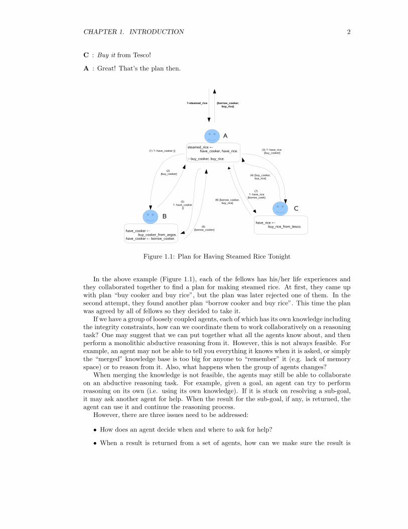
Figure 1.1: Plan for Having Steamed Rice Tonight
In the above example (Figure 1.1), each of the fellows has his/her life experiences andthey collaborated together to find a plan for making steamed rice. At first, they came upwith plan “buy cooker and buy rice”, but the plan was later rejected one of them. In thesecond attempt, they found another plan “borrow cooker and buy rice”. This time the planwas agreed by all of fellows so they decided to take it.
If we have a group of loosely coupled agents, each of which has its own knowledge includingthe integrity constraints, how can we coordinate them to work collaboratively on a reasoningtask? One may suggest that we can put together what all the agents know about, and thenperform a monolithic abductive reasoning from it. However, this is not always feasible. Forexample, an agent may not be able to tell you everything it knows when it is asked, or simplythe “merged” knowledge base is too big for anyone to “remember” it (e.g. lack of memoryspace) or to reason from it. Also, what happens when the group of agents changes?
When merging the knowledge is not feasible, the agents may still be able to collaborateon an abductive reasoning task. For example, given a goal, an agent can try to performreasoning on its own (i.e. using its own knowledge). If it is stuck on resolving a sub-goal,it may ask another agent for help. When the result for the sub-goal, if any, is returned, theagent can use it and continue the reasoning process.
However, there are three issues need to be addressed:
• How does an agent decide when and where to ask for help?
• When a result is returned from a set of agents, how can we make sure the result is
CHAPTER 1. INTRODUCTION 3
indeed agreed by all the agents in the set (i.e. it does not violate any of the agents’integrity constraints)?
• Again, how practical is it?
If the above problems can be resolved and such a distributed abductive reasoning frame-work/system is developed, it will benefit the world of pervasive computing. For example, acollection of body sensors may be able to reasoning about the monitored data collaborativelyand hence decide a suitable action (e.g. raising an alarm).
The topic of this project is firstly to investigate how to implement the Kakas-Mancarellaprocedure efficiently for running on the Gumstix computers, and the possibility of optimisingit by partial evaluation. Then, to resolve the issues raised for distributed abductive reasoning,design and implement a multi-agent system for a set of abductive agents to perform reasoningconsistently. The final but ambitious goal is to deploy a collection of Gumstix computersinto set of intelligent abductive reasoning agents by running the developed system on it.
1.1 Objectives
The contributions of this project include:
Abduction In the Small which is to run abduction on the Gumstix computers. Thisinvolves the following tasks:
1. To develop an efficient implementation of the Kakas-Mancarella proof procedurefor abductive reasoning with integrity constraints check.
2. To investigate whether partial evaluation can help to speed up the abductivereasoning process.
3. To have the gumstix computer capable of performing abductive reasoning.
Distributed Abduction which is to develop a suitable multi-agent system for a group ofagents to collaborate in abductive reasoning tasks, and it involves the following tasks:
1. To identify the requirements of system and to investigate the possible solutions.
2. To design and implement the system
3. To identify the potential applications for the system.
4. To run the system on the gumstix computers.
1.2 Contributions
For this project, my contributions include:
1. Re-engineered an abductive meta-interpreter by Kakas’ efficiently. The new meta-interpreter runs about 43% faster and requires about 53% less memory for the Stack.The meta-interpreter can also be run on the Gumstix computers. (See Chapter 3Investigation).
2. Investigated how partial evaluation may help to further speed-up the abductive rea-soning process (for ground applications). This is done by compiling the abductive logicprogram with the meta-interpreter to obtain a self-abductive logic program. The initial
CHAPTER 1. INTRODUCTION 4
experimental results show that it can further speed-up the reasoning process (compar-ing to the re-engineered meta-interpreter) by about 56.3%. However, the tradeoff isthat much more memory is required for the self-abductive logic program so it is notgood for using on the Gumstix computers. (See Chapter 3 Investigation).
3. Designed and implemented a multi-agent system for coordinating a group of agentsin collaborative reasoning tasks. The system also evolved from version 1 to version 2along the project. (See Chapter 4 Distributed Reasoning System).
4. Proposed and implemented two distributed abductive meta-interpreters that can beintegrated to the distributed reasoning system. The first meta-interpreter is basedon the Kakas-Mancarella Procedure but allows agents to collaborate during reasoning.This can be considered as a general purpose distributed meta-interpreter. The secondmeta-interpreter is based on the abductive event calculus planner by Murray [22]. The“vanilla” planner allows several agents to collaborate during the planning process forsimple reasoning tasks. The abductive meta-interpreter together with the distributedreasoning system are called Distributed Abductive REasoning System (DARES). (SeeChapter 5 Distributed Meta-Interpreters).
5. Ported YAP Prolog and QuProlog for ARM Linux so that DARES can run on the Gum-stix computers. This enables the Gumstix computers to behave like intelligent agentsand collaborate in simple reasoning tasks. (See Chapter 6 Porting to Gumstix).
6. As “side-contributions” of the project, I helped the Gumstix community by providingthe ported Prolog systems so that people can develop applications in Prolog for theGumstix computers. I also helped the author of QuProlog to evaluate and test QuPro-log version 8.0 and its new publish/subscribe server Pedro. Several bugs have beendiscovered, reported or fixed.
In addition to the Chapters mentioned above, Chapter 2 Background gives the knowl-edge you will need to understanding this project. It first gives the concept of logic program-ming and the “trick” of partial evaluation with logic programs. It then introduces AbductiveLogic Reasoning and its current applications, in particular planning with event calculus. Italso briefly describes the existing ALIAS system that coordinates abductive logic reasoningbetween agents. In the end, it introduces the hardware and software required for this project.
Finally, Chapter 7 Conclusion summaries what I have done and learnt from this project.It also outlines the ideas of future development of DARES and other related research work Iwish to pursue after the project.
Chapter 2
Background
2.1 Logic Programming
In 1958, John McCarthy (the father of A.I.)[20] proposed that mathematical logic to be usedfor programming and invented Lisp. Since then, Lisp has become the dominated program-ming language for A.I in America. Later around 1972, Alain Colmerauer and Phillipe Rousselof University of Aix-Marseille, collaborated with Robert Kowalski of the University of Edin-burgh to create Prolog (abbreviation for “PROgramming in LOGic”) as an alternative toLisp. Now, Prolog has become the dominated programming language for A.I. in the rest ofthe world.
The following is a short recap of the Prolog language. First, it gives the syntax and theinformal semantics for the language, then it briefly explains the algorithm Prolog uses toevaluate queries, and finally it describes an efficient implementation for most of the modernProlog engines – Warren Abstract Machine.
2.1.1 Syntax and Informal Semantics of Prolog
Prolog Term
The single data type of Prolog is called term. A term can be a constant, a variable or acompound term.
Constant The constant terms include integers, floats and atoms:
Integer can be represented in decimal (e.g. 0, 1, 123, -123), in binary (e.g. 0b1101),in octal (e.g. 0o16) and in hexadecimal (e.g. 0xff).
Float such as 1.0, -3.14, 3.0e8
Atom may be in any of the following forms:
1. Any sequence of alphanumeric characters (including ‘ ’), starting with a lowercase letter (e.g. agent, directory server).
2. Any sequence from the following set of characters:+ - * / \ ^ < > = ~ : . ? @ # $ &
3. Any sequence of characters surrounded by single quotes (e.g. ‘Jeffrey’,‘artificial intelligence’).
5
CHAPTER 2. BACKGROUND 6
Variable A variable term may be any sequence of alphanumeric characters (including ‘ ’)starting with either a captital letter or ‘ ’, e.g. X, Depth, length. If a variable onlyappears once in a Prolog program or query (introduced later), we can call it anonymousvariable and use the underline character ‘ ’ to represent it.
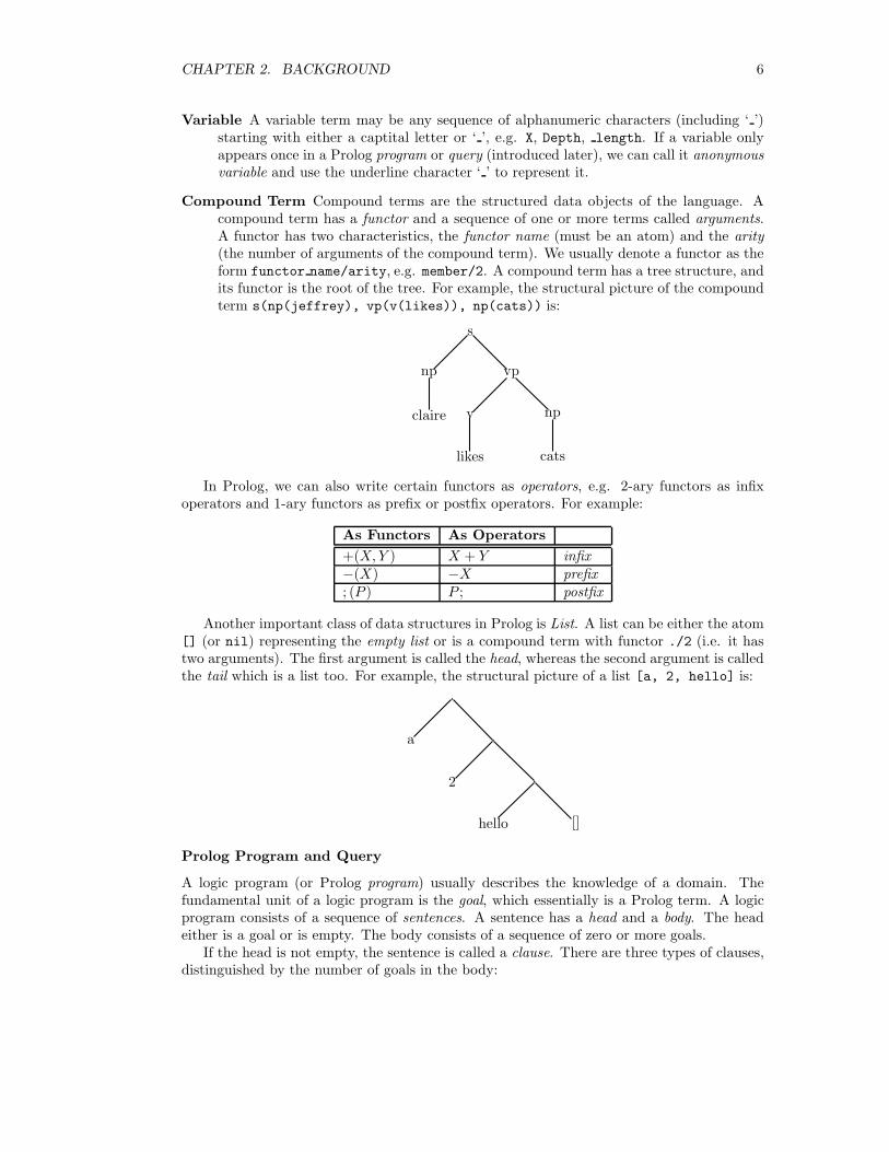
Compound Term Compound terms are the structured data objects of the language. Acompound term has a functor and a sequence of one or more terms called arguments.A functor has two characteristics, the functor name (must be an atom) and the arity(the number of arguments of the compound term). We usually denote a functor as theform functor name/arity, e.g. member/2. A compound term has a tree structure, andits functor is the root of the tree. For example, the structural picture of the compoundterm s(np(jeffrey), vp(v(likes)), np(cats)) is:
s
np vp
claire v np
likes cats
In Prolog, we can also write certain functors as operators, e.g. 2-ary functors as infixoperators and 1-ary functors as prefix or postfix operators. For example:
As Functors As Operators
+(X, Y ) X + Y infix−(X) −X prefix; (P ) P ; postfix
Another important class of data structures in Prolog is List. A list can be either the atom[] (or nil) representing the empty list or is a compound term with functor ./2 (i.e. it hastwo arguments). The first argument is called the head, whereas the second argument is calledthe tail which is a list too. For example, the structural picture of a list [a, 2, hello] is:
.
.
.
a
2
hello []
Prolog Program and Query
A logic program (or Prolog program) usually describes the knowledge of a domain. Thefundamental unit of a logic program is the goal, which essentially is a Prolog term. A logicprogram consists of a sequence of sentences. A sentence has a head and a body. The headeither is a goal or is empty. The body consists of a sequence of zero or more goals.
If the head is not empty, the sentence is called a clause. There are three types of clauses,distinguished by the number of goals in the body:
CHAPTER 2. BACKGROUND 7
unit clause whose body is empty. For example:
P.
where P is the head goal and the it can be interpreted as:
Goals matching P are true.
chain clause whose body contains exactly one goal. For example:
P : −Q.
which can be interpreted as:
P is true if Q is true.
deep rule whose body has two or more goals. For example:
P : −Q1, Q2, Q3.
which can be interpreted as:
P is true if all of Q1, Q2 and Q3 are true.
If the head is empty, the sentence is called a directive. For example:
: −P, Q.
can be read as:
Can P and Q be shown (or executed)?
Programs are usually defined and saved in text files known as the Prolog source files.When the programs are read by a Prolog interpreter, it will contributed to the knowledgebase. A user can then submit a query about the domain the knowledge base describes tothe interpreter and wait for the answer(s). A Prolog query is essentially a list of goals. Forexample:
?P, Q.
which means:
Are P and Q true?
2.1.2 Query Evaluation in Prolog
After a Prolog program source file is read by the interpreter, the interpreter will “store”the program’s clauses in its dynamic database. Upon receiving a query (a conjunction ofgoals) from the user, the interpreter will scan the database (possibly multiple times) tryingto “resolve” all of the goals and to return a set of answers if successful.
CHAPTER 2. BACKGROUND 8
Term Unification
During the query evaluation, the most basic and important operation is to match two Prologterms, and this process is called term unification. The process takes two terms and returnsa unifier for them if one exists:
Definition 2.1 Let S1 and S2 be terms and θ be a substitution, if S1θ = S2θ then θ is aunifier of S1 and S2.
In Prolog, the process of matching two terms P and Q can be described as below:
1. If P and Q are constants then P and Q match only if they are the same object (i.e.have the same value for integers or floats, or have the same name/value for atoms).
2. If P is a variable and Q is anything, then they match, and P is instantiated to Q.Conversely, if Q is a variable then Q is instantiated to P .
3. If P and Q are compound terms, then they match if and only if:
(a) P and Q have the same functor and arity, and
(b) all of their arguments (subterms) match.
For example, parent(X, bob) and parent(jim, Y) can be unified with the unifier {X= jim, Y = bob}, whereas happy(bob) and sad(jim) don’t have a unifier and they don’tmatch.
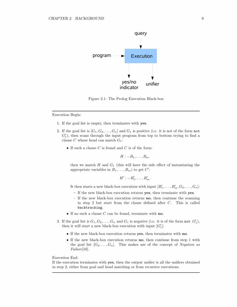
The Execution Black-box
The process of how Prolog evaluates a query can be illustrated as a “black-box” execution(See Figure 2.1):
Input :
program A list of clauses.
query A list of goals.
Output :
yes/no indicator It will return yes if the black-box execution succeeds and no oth-erwise.
unifier It will return the instantiation of variables during the execution if the executionsucceeds, and an empty list if the execution fails.
The algorithm/procedure used by the black-box is called SLDNF and it can be describedas below:
CHAPTER 2. BACKGROUND 9
Figure 2.1: The Prolog Execution Black-box
Execution Begin:
1. If the goal list is empty, then terminates with yes.
2. If the goal list is [G1, G2, . . . , Gn] and G1 is positive (i.e. it is not of the form not
G′
1), then scans through the input program from top to bottom trying to find a
clause C whose head can match G1:
• If such a clause C is found and C is of the form:
H : −B1, . . . , Bm.
then we match H and G1 (this will have the side effect of instantiating theappropriate variables in B1, . . . , Bm) to get C′:
H ′ : −B′
1, . . . , B′
m.
It then starts a new black-box execution with input [B′
1, . . . , B′
m, G2, . . . , Gn]:
– If the new black-box execution returns yes, then terminate with yes.
– If the new black-box execution returns no, then continue the scanningin step 2 but start from the clause defined after C. This is calledbacktracking.
• If no such a clause C can be found, terminate with no.
3. If the goal list is G1, G2, . . . , Gn and G1 is negative (i.e. it is of the form not G′
1),
then it will start a new black-box execution with input [G′
1]:
• If the new black-box execution returns yes, then terminates with no.
• If the new black-box execution returns no, then continue from step 1 withthe goal list [G2, . . . , Gn]. This makes use of the concept of Negation asFailure[10].
Execution End.If the execution terminates with yes, then the output unifier is all the unifiers obtainedin step 2, either from goal and head matching or from recursive executions.
CHAPTER 2. BACKGROUND 10
For example, consider the following Prolog program:
1 edge(1 ,2).
2 edge(1 ,3).
3 edge(3 ,4).
45 path(X,Y) :- edge(X,Y).
6 path(X,Y) :- edge(X,Z),path(Z,Y).
Listing 2.1: Prolog Program – Paths
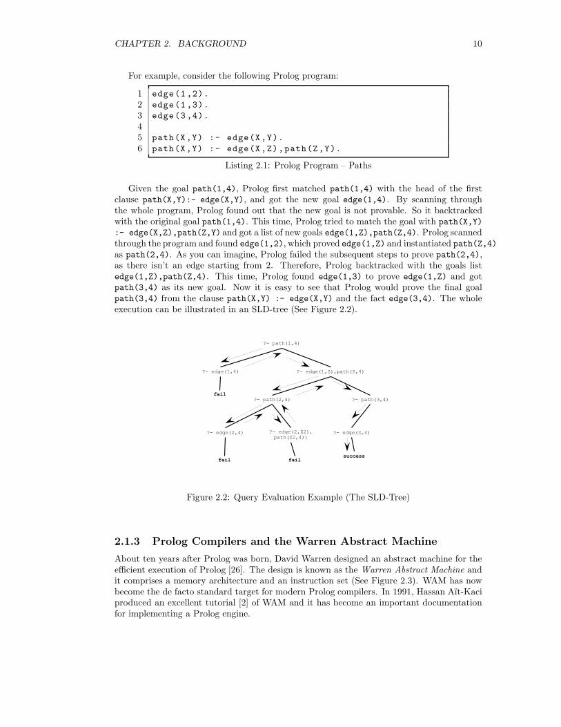
Given the goal path(1,4), Prolog first matched path(1,4) with the head of the firstclause path(X,Y):- edge(X,Y), and got the new goal edge(1,4). By scanning throughthe whole program, Prolog found out that the new goal is not provable. So it backtrackedwith the original goal path(1,4). This time, Prolog tried to match the goal with path(X,Y)
:- edge(X,Z),path(Z,Y) and got a list of new goals edge(1,Z),path(Z,4). Prolog scannedthrough the program and found edge(1,2), which proved edge(1,Z) and instantiated path(Z,4)
as path(2,4). As you can imagine, Prolog failed the subsequent steps to prove path(2,4),as there isn’t an edge starting from 2. Therefore, Prolog backtracked with the goals listedge(1,Z),path(Z,4). This time, Prolog found edge(1,3) to prove edge(1,Z) and gotpath(3,4) as its new goal. Now it is easy to see that Prolog would prove the final goalpath(3,4) from the clause path(X,Y) :- edge(X,Y) and the fact edge(3,4). The wholeexecution can be illustrated in an SLD-tree (See Figure 2.2).
Figure 2.2: Query Evaluation Example (The SLD-Tree)
2.1.3 Prolog Compilers and the Warren Abstract Machine
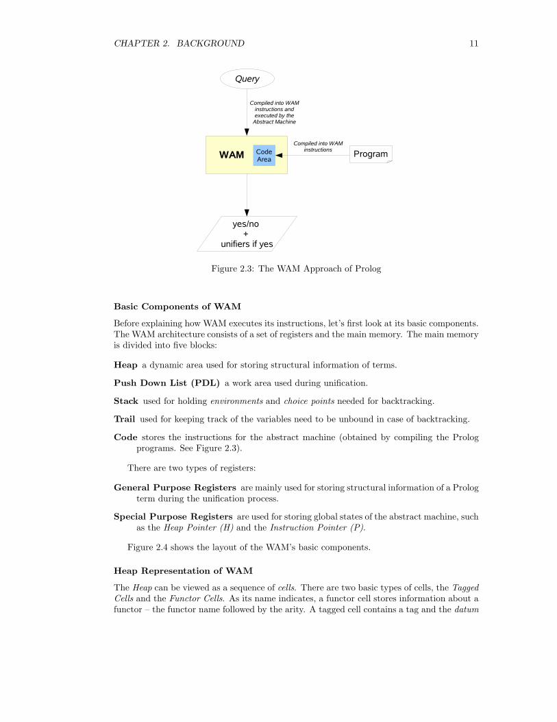
About ten years after Prolog was born, David Warren designed an abstract machine for theefficient execution of Prolog [26]. The design is known as the Warren Abstract Machine andit comprises a memory architecture and an instruction set (See Figure 2.3). WAM has nowbecome the de facto standard target for modern Prolog compilers. In 1991, Hassan Aı̈t-Kaciproduced an excellent tutorial [2] of WAM and it has become an important documentationfor implementing a Prolog engine.
CHAPTER 2. BACKGROUND 11
Figure 2.3: The WAM Approach of Prolog
Basic Components of WAM
Before explaining how WAM executes its instructions, let’s first look at its basic components.The WAM architecture consists of a set of registers and the main memory. The main memoryis divided into five blocks:
Heap a dynamic area used for storing structural information of terms.
Push Down List (PDL) a work area used during unification.
Stack used for holding environments and choice points needed for backtracking.
Trail used for keeping track of the variables need to be unbound in case of backtracking.
Code stores the instructions for the abstract machine (obtained by compiling the Prologprograms. See Figure 2.3).
There are two types of registers:
General Purpose Registers are mainly used for storing structural information of a Prologterm during the unification process.
Special Purpose Registers are used for storing global states of the abstract machine, suchas the Heap Pointer (H) and the Instruction Pointer (P).
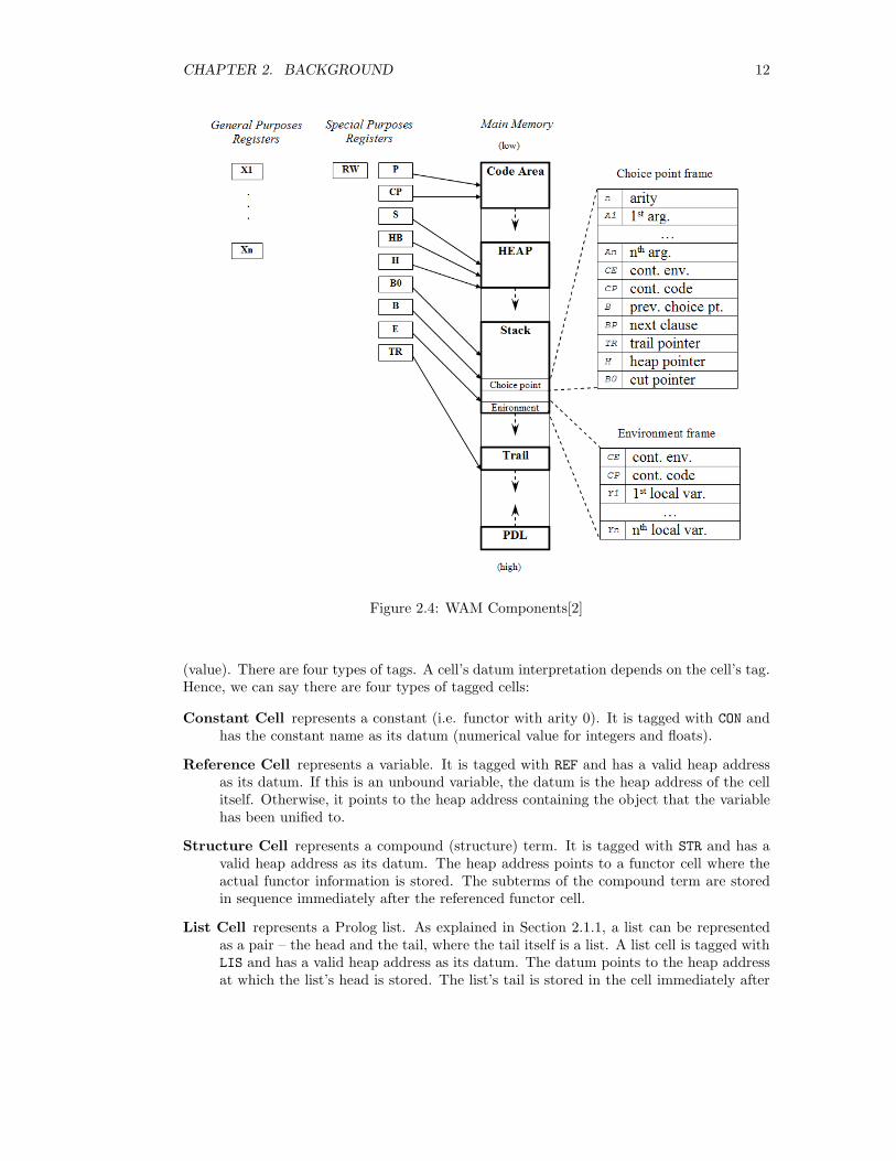
Figure 2.4 shows the layout of the WAM’s basic components.
Heap Representation of WAM
The Heap can be viewed as a sequence of cells. There are two basic types of cells, the TaggedCells and the Functor Cells. As its name indicates, a functor cell stores information about afunctor – the functor name followed by the arity. A tagged cell contains a tag and the datum
CHAPTER 2. BACKGROUND 12
Figure 2.4: WAM Components[2]
(value). There are four types of tags. A cell’s datum interpretation depends on the cell’s tag.Hence, we can say there are four types of tagged cells:
Constant Cell represents a constant (i.e. functor with arity 0). It is tagged with CON andhas the constant name as its datum (numerical value for integers and floats).
Reference Cell represents a variable. It is tagged with REF and has a valid heap addressas its datum. If this is an unbound variable, the datum is the heap address of the cellitself. Otherwise, it points to the heap address containing the object that the variablehas been unified to.
Structure Cell represents a compound (structure) term. It is tagged with STR and has avalid heap address as its datum. The heap address points to a functor cell where theactual functor information is stored. The subterms of the compound term are storedin sequence immediately after the referenced functor cell.
List Cell represents a Prolog list. As explained in Section 2.1.1, a list can be representedas a pair – the head and the tail, where the tail itself is a list. A list cell is tagged withLIS and has a valid heap address as its datum. The datum points to the heap addressat which the list’s head is stored. The list’s tail is stored in the cell immediately after
CHAPTER 2. BACKGROUND 13
the head’s cell, e.g. another list cell. An empty list is stored as a constant, e.g. nil or[].
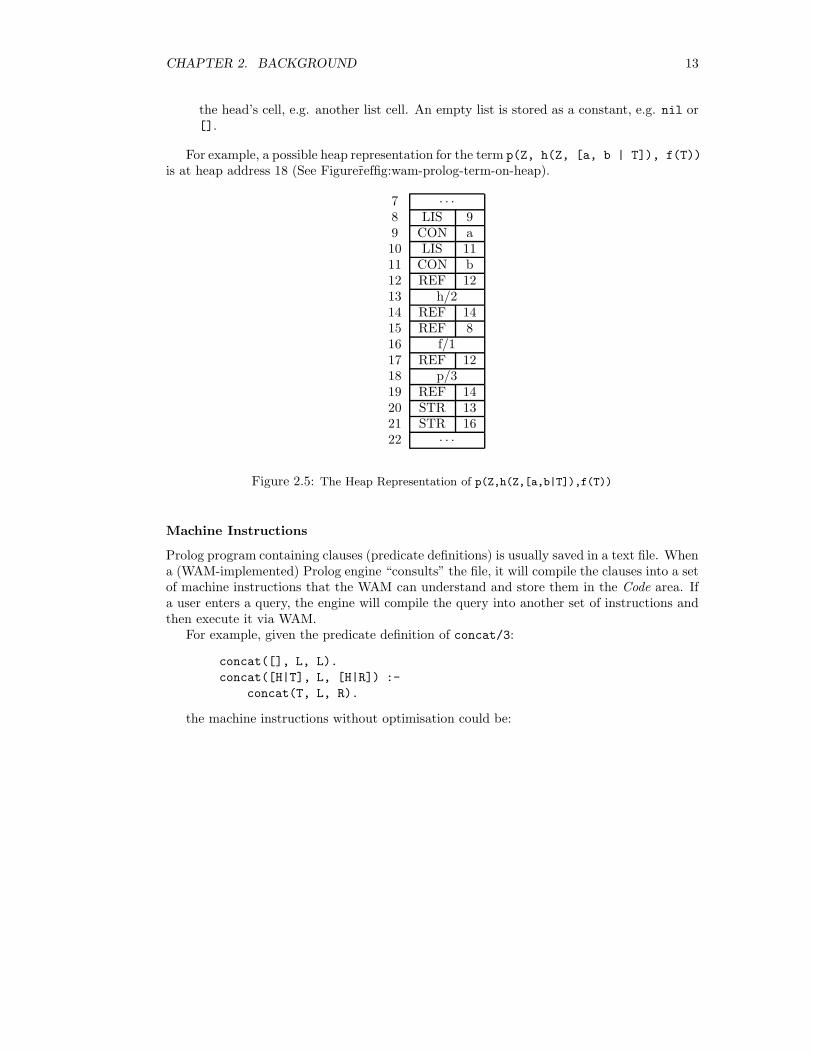
For example, a possible heap representation for the term p(Z, h(Z, [a, b | T]), f(T))
is at heap address 18 (See Figurer̃effig:wam-prolog-term-on-heap).
7 · · ·8 LIS 99 CON a10 LIS 1111 CON b12 REF 1213 h/214 REF 1415 REF 816 f/117 REF 1218 p/319 REF 1420 STR 1321 STR 1622 · · ·
Figure 2.5: The Heap Representation of p(Z,h(Z,[a,b|T]),f(T))
Machine Instructions
Prolog program containing clauses (predicate definitions) is usually saved in a text file. Whena (WAM-implemented) Prolog engine “consults” the file, it will compile the clauses into a setof machine instructions that the WAM can understand and store them in the Code area. Ifa user enters a query, the engine will compile the query into another set of instructions andthen execute it via WAM.
For example, given the predicate definition of concat/3:
concat([], L, L).
concat([H|T], L, [H|R]) :-
concat(T, L, R).
the machine instructions without optimisation could be:
CHAPTER 2. BACKGROUND 14
concat/3:
try_me_else L1
get_nil X1 % []
get_value X2,X3 % L,L
proceed
L1:
trust_me_else_fail
get_list X1 % [
unify_variable X4 % H|
unify_variable X1 % T1],L2,
get_list X3 % [
unify_value X4 % H|
unify_variable X3 % T2]
execute concat/3
In the above example, the instruction try me else L1 means “Should this clause fails,backtrack to the clause labeled with L1”. The instruction get nil X1 means “Is the derefer-enced value of register X1 an empty list, or an unbound variable so that it can be binded to anempty list?”. The instruction get value X2, X3 means “Try to unify the content of registerX2 and that of register X3 and backtrack on failure”. Finally, proceed simply means “Theexecution of instructions of the current goal succeeds, so continue to execute the instructionsof the next goal of the query”. For a complete description of the WAM instruction set, pleaserefer to [2].
Structure Copying
WAM is in fact a copying implementation – it tries to build copies of structures on the heap.Let’s first consider the very basic operation – Term Unification. As we have already known,term is the basic object type of Prolog. Let’s specify two sorts of terms: a program term anda query term. Both program term and query term are first-order terms but not variables.
The idea of term unification is simple: having defined a program term p, one can submitany query ?− q and execution either fails if p and q do not unify, or succeeds with a bindingof the variables in q obtained by unifying it with p.
From the WAM’s point of view, the unification process (of two terms) is to:
1. execute the instructions for q to build an exemplar of q on the heap from q’s textualform.
2. execute the instructions for p and try to “match” p with the exemplar of q on the heap.
The matching of exemplar will behave differently according to whether it is in the readmode or in the write mode. The mode is set after executing one of the follow two instructions:
get_structure F,A
get_list A
WAM checks the argument A:
• if A is an unbound variable, the mode is set to write and the following instructions areto build a copy of the structure on the heap.
• if A is a bound, the mode is set to read and the following instructions are to checkwhether A is referencing to the right kind of structure and will execute the unify oper-ation which makes use of the PDL (See Figure 2.4).
CHAPTER 2. BACKGROUND 15
Compiling Clauses
A clause can be compiled to a set of instructions:
• the head of the clause is compiled as a program term.
• the body of the clause is compiled as a list of query terms.
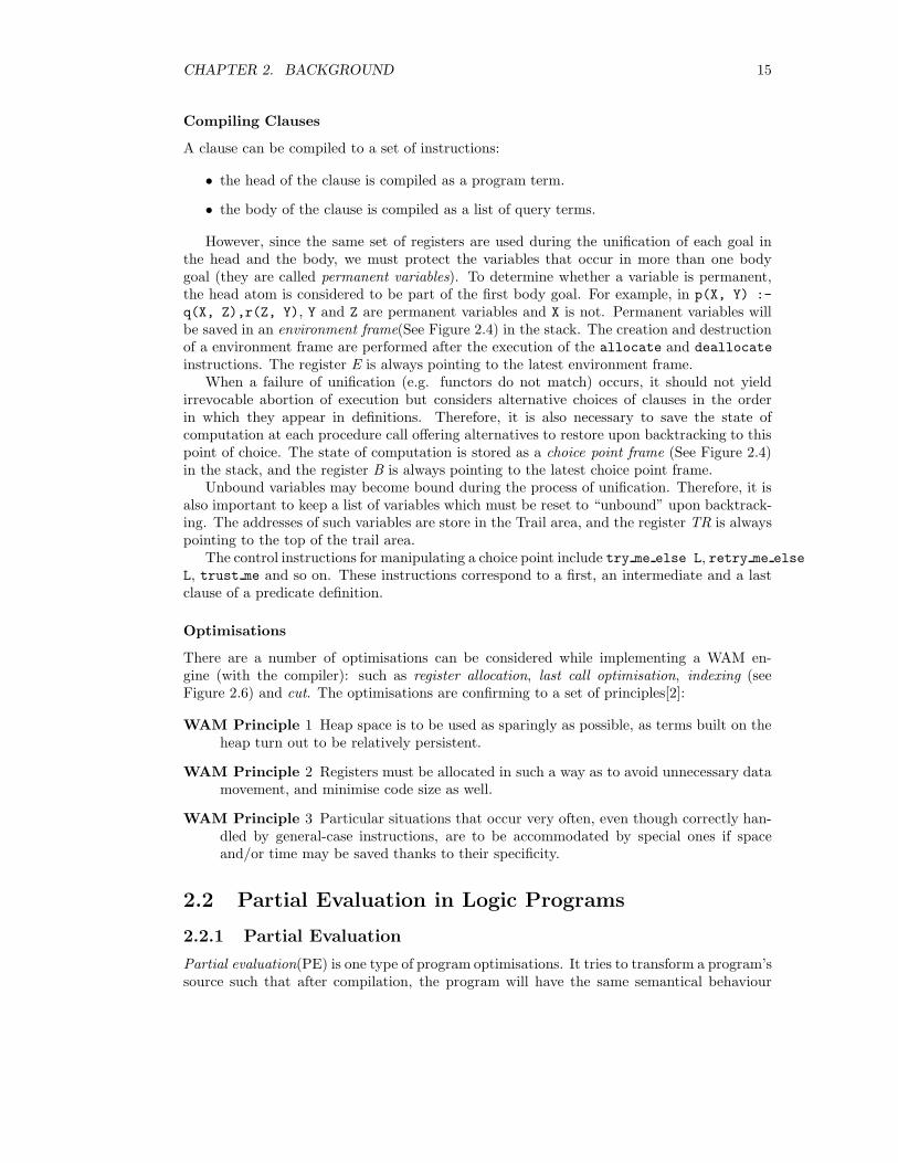
However, since the same set of registers are used during the unification of each goal inthe head and the body, we must protect the variables that occur in more than one bodygoal (they are called permanent variables). To determine whether a variable is permanent,the head atom is considered to be part of the first body goal. For example, in p(X, Y) :-
q(X, Z),r(Z, Y), Y and Z are permanent variables and X is not. Permanent variables willbe saved in an environment frame(See Figure 2.4) in the stack. The creation and destructionof a environment frame are performed after the execution of the allocate and deallocate
instructions. The register E is always pointing to the latest environment frame.When a failure of unification (e.g. functors do not match) occurs, it should not yield
irrevocable abortion of execution but considers alternative choices of clauses in the orderin which they appear in definitions. Therefore, it is also necessary to save the state ofcomputation at each procedure call offering alternatives to restore upon backtracking to thispoint of choice. The state of computation is stored as a choice point frame (See Figure 2.4)in the stack, and the register B is always pointing to the latest choice point frame.
Unbound variables may become bound during the process of unification. Therefore, it isalso important to keep a list of variables which must be reset to “unbound” upon backtrack-ing. The addresses of such variables are store in the Trail area, and the register TR is alwayspointing to the top of the trail area.
The control instructions for manipulating a choice point include try me else L, retry me else
L, trust me and so on. These instructions correspond to a first, an intermediate and a lastclause of a predicate definition.
Optimisations
There are a number of optimisations can be considered while implementing a WAM en-gine (with the compiler): such as register allocation, last call optimisation, indexing (seeFigure 2.6) and cut. The optimisations are confirming to a set of principles[2]:
WAM Principle 1 Heap space is to be used as sparingly as possible, as terms built on theheap turn out to be relatively persistent.
WAM Principle 2 Registers must be allocated in such a way as to avoid unnecessary datamovement, and minimise code size as well.
WAM Principle 3 Particular situations that occur very often, even though correctly han-dled by general-case instructions, are to be accommodated by special ones if spaceand/or time may be saved thanks to their specificity.
2.2 Partial Evaluation in Logic Programs
2.2.1 Partial Evaluation
Partial evaluation(PE) is one type of program optimisations. It tries to transform a program’ssource such that after compilation, the program will have the same semantical behaviour
CHAPTER 2. BACKGROUND 16
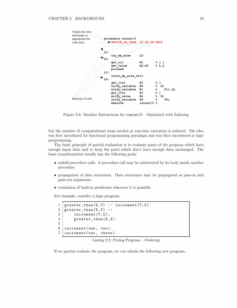
Figure 2.6: Machine Instructions for concat/3 – Optimised with Indexing
but the number of computational steps needed at run-time execution is reduced. The ideawas first introduced for functional programming paradigm and was then introduced in logicprogramming.
The basic principle of partial evaluation is to evaluate parts of the program which haveenough input data and to keep the parts which don’t have enough data unchanged. Thebasic transformation usually has the following goals:
• unfold procedure calls. A procedure call may be substituted by its body inside anotherprocedure.
• propagation of data structures. Data structures may be propagated as pass-in andpass-out arguments.
• evaluation of built-in predicates wherever it is possible.
For example, consider a logic program:
1 greater_than(X,Y) :- increment(Y,X).
2 greater_than(X,Y) :-
3 increment(Y,Z),
4 greater_than(X,Z).
56 increment(one , two).
7 increment(two , three).
Listing 2.2: Prolog Program – Ordering
If we partial evaluate the program, we can obtain the following new program:
CHAPTER 2. BACKGROUND 17
1 greater_than(two ,one).
2 greater_than(three ,two).
3 greater_than(three ,one).
45 increment(one , two).
6 increment(two , three).
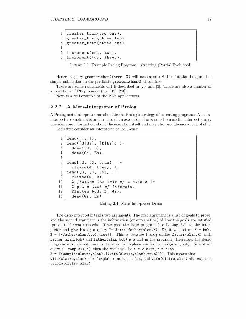
Listing 2.3: Example Prolog Program – Ordering (Partial Evaluated)
Hence, a query greater than(three, X) will not cause a SLD-refutation but just thesimple unification on the predicate greater than/2 at runtime.
There are some refinements of PE described in [25] and [3]. There are also a number ofapplications of PE proposed (e.g. [19], [23]).
Next is a real example of the PE’s applications.
2.2.2 A Meta-Interpreter of Prolog
A Prolog meta interpreter can simulate the Prolog’s strategy of executing programs. A meta-interpreter sometimes is preferred to plain execution of programs because the interpreter mayprovide more information about the execution itself and may also provide more control of it.
Let’s first consider an interpreter called Demo:
1 demo([] ,[]).
2 demo([G|Gs], [E|Es]) :-
3 demo1(G, E),
4 demo(Gs , Es).
56 demo1(G, (G, true)) :-
7 clause(G, true), !.
8 demo1(G, (G, Es)) :-
9 clause(G, B),
10 % flatten the body of a clause to
11 % get a list of literals.
12 flatten_body(B, Gs),
13 demo(Gs , Es).
Listing 2.4: Meta-Interpreter Demo
The demo interpreter takes two arguments. The first argument is a list of goals to prove,and the second argument is the information (or explanation) of how the goals are satisfied(proven), if demo succeeds. If we pass the logic program (see Listing 2.5) to the inter-preter and give Prolog a query ?- demo([father(alan,X)],E), it will return X = bob,
E = [(father(alan,bob),true)]. This is because Prolog unifies father(alan,X) withfather(alan,bob) and father(alan,bob) is a fact in the program. Therefore, the demoprogram succeeds with simply true as the explanation for father(alan,bob). Now if wequery ?- couple(X,Y), then the result will be X = claire, Y = alan,E = [(couple(claire,alan),[(wife(claire,alan),true)])]. This means thatwife(claire,alan) is self-explained as it is a fact, and wife(claire,alan) also explainscouple(claire,alan).

CHAPTER 2. BACKGROUND 18
1 parent(X,Y) :- father(X,Y).
2 parent(X,Y) :- mother(X,Y).
3 parent(X,Y) :- couple(X,Z), parent(Z,Y).
45 couple(X,Y) :- wife(X,Y).
6 couple(X,Y) :- husband(X,Y).
78 sibling(X,Y) :- parent(Z,X), parent(Z,Y).
910 father(alan , bob).
11 mother(claire , david).
12 wife(claire, alan).
Listing 2.5: Example Prolog Program – Family Tree
For a even more complicated query, we can ask ?- demo([sibling(bob,david)],E) andthe expected result will be:
E = [
(sibling(bob,david),
[
(parent(claire,bob),
[ (couple(claire,alan), [(wife(claire,alan),true)]),
(parent(alan,bob),[(father(alan,bob),true)])]),
(parent(claire,david),[(mother(claire,david),true)])
])
]
2.2.3 A Partial Evaluated Meta-Interpreter
The results of the queries in Section 2.2.2 gave the full explanations to the user instead ofsimply answering yes. However, it involved a lot of computations as you could imagine.Surely we can apply the partial evaluation tricks to “compile”1 the logic program togetherwith the demo interpreter to reduce the computation overheads. Papers proposing such ausage include [23] and [16].
For our example, one of the possible transformation would be:
1Some papers call it “compile” but it is still a source-level transformation. So please do not confuse itwith the “compile” described in Section 2.1.3
CHAPTER 2. BACKGROUND 19
1 parent(X, Y, (parent(X, Y), [E])) :-
2 father(X, Y, E).
3 parent(X, Y, (parent(X, Y), [E])) :-
4 mother(X, Y, E).
5 parent(X, Y, (parent(X, Y), [E1 ,E2])) :-
6 couple(X, Z, E1), parent(Z, Y, E2).
78 couple(X, Y, (couple(X, Y), [E])) :-
9 wife(X, Y, E).
10 couple(X, Y, (couple(X, Y), [E])) :-
11 husband(X, Y, E).
1213 sibling(X, Y, (sibling(X, Y), [E1,E2])) :-
14 parent(Z, X, E1),
15 parent(Z, Y, E2).
1617 father(alan , bob , (father(alan , bob), true)).
18 mother(claire, david , (mother(claire, david), true)).
19 wife(claire , alan , (wife(claire ,alan), true)).
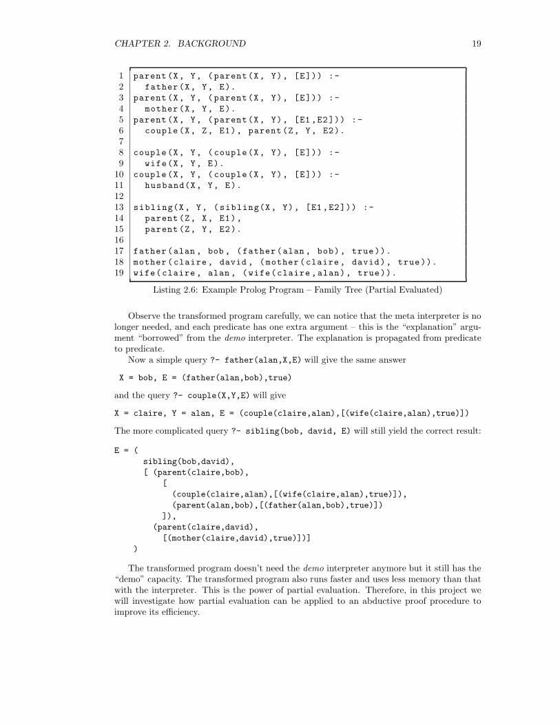
Listing 2.6: Example Prolog Program – Family Tree (Partial Evaluated)
Observe the transformed program carefully, we can notice that the meta interpreter is nolonger needed, and each predicate has one extra argument – this is the “explanation” argu-ment “borrowed” from the demo interpreter. The explanation is propagated from predicateto predicate.
Now a simple query ?- father(alan,X,E) will give the same answer
X = bob, E = (father(alan,bob),true)
and the query ?- couple(X,Y,E) will give
X = claire, Y = alan, E = (couple(claire,alan),[(wife(claire,alan),true)])
The more complicated query ?- sibling(bob, david, E) will still yield the correct result:
E = (
sibling(bob,david),
[ (parent(claire,bob),
[
(couple(claire,alan),[(wife(claire,alan),true)]),
(parent(alan,bob),[(father(alan,bob),true)])
]),
(parent(claire,david),
[(mother(claire,david),true)])]
)
The transformed program doesn’t need the demo interpreter anymore but it still has the“demo” capacity. The transformed program also runs faster and uses less memory than thatwith the interpreter. This is the power of partial evaluation. Therefore, in this project wewill investigate how partial evaluation can be applied to an abductive proof procedure toimprove its efficiency.
CHAPTER 2. BACKGROUND 20
2.3 Abductive Reasoning
2.3.1 Logical Reasoning
There are three methods of logical reasoning: deduction, induction and abduction.
Definition 2.2 Given a rule R: β ← α (read as α therefore β or β if α):
Deduction means determining β – using the rule R and its precondition α to make a con-clusion (i.e. α ∧R⇒ β).
Induction means determining R – learning R after a large number of examples of α and β.
Abduction means determining α – using the rule R and its postcondition β to assume thatthe precondition α could explain β (i.e. β ∧R⇒ α).
Abduction could be considered as the reverse of deduction. Here is an example, considerthe following database:
shoes are wet ← grass is wet ∧ walked on grass
grass is wet ← rained last night
grass is wet ← sprinkler was on
If we have walked on the grass and we know that it rained last night, we can deduce thatthe grass is wet and our shoes will become wet. This is deductive reasoning.
However, if we observed that our shoes were wet, then we may guess that we walked onthe grass and the grass was wet. We may also guess that it rained last night. The guessingof an explanation to the observations is abductive reasoning.
2.3.2 Formal Definition
An abductive framework < T, A >can be defined as follow:
Definition 2.3 Given a set of rules T (or called theory), a goal O (or called observation),and a set of possible hypotheses A (or called abducibles), abduction is to find a set of expla-nation ∆ such that ∆ ⊂ A and ∆ satisfies:
1. T ∪∆ |= O
2. T ∪∆ is consistent.
Additional restrictions on explanations
In the previous example, if the set of abducibles is {grass is wet, walked on grass,
rained last night, sprinkler was on}, then all of
∆1 = {grass is wet, walked on grass, rained last night}∆2 = {walked on grass, sprinkler was on}∆3 = {walked on grass, rained last night}∆4 = {walked on grass, rained last night, sprinkler was on}
are possible explanations for shoes are wet.However, sometimes it is desired to reduce the number of candidate explanations. This
can be achieved by imposing additional restrictions to the framework. Such restrictions canbe:
CHAPTER 2. BACKGROUND 21
• An explanation should be basic this means an explanation should not be explained byanother. For example, grass is wet in ∆1 can be explained by ∆3 (grass is wet ←rained last night). We can avoid this by restricting that no abducible predicate canappear as the head of a rule R in the theory T .
• An explanation must be minimal this means an explanation candidate cannot be sub-sumed by another. For example, in the theory T ′
grass is wet ← rained last night
grass is wet ← rained last night ∧ sprinkler was on
, {rained last night} is a minimal explanation for grass is wetwhere {rained last night,
sprinkler was on} is not.
• An explanation must satisfy all of the integrity constraints (see next).
Integrity Constraints
An integrity constraint is a rule used for further restricting what abducibles can be presentin a candidate explanation. For example, if we add a constraint rule
← rained last night ∧ sprinkler was on
(which can be read as it is impossible that it rained last night and the sprinkler was on)to T , then ∆4 will not be a possible explanation anymore.
With integrity constraints, the definition of an abductive framework < T, A, I > nowbecomes:
Definition 2.4 Given a set of rules T , a goal O, a set of possible hypotheses A and a set ofintegrity constraints I, abduction is to find a set of explanation ∆ such that ∆ ⊂ A and:
1. T ∪∆ |= O;
2. T ∪∆ is consistent;
3. T ∪∆ satisfies I.
2.3.3 Proof Procedure
Logic Programs as Abductive Framework
The similarity [12] between abduction and Negation as Failure [10](NAF) can be used to givean abductive interpretation of NAF. In the interpretation, negative literals are interpretedas abductive hypotheses that can be assumed to hold provided that they satisfy a set ofintegrity constraints together with the logic program. Hence, we can transform a generallogic program P into an abductive framework (see Section 2.3.2)< P ∗, A∗, I∗ > where:
1. P ∗ is the logic program obtained from P by replacing each negative literal ¬p(t) by anew positive literal p∗(t).
2. A∗ is the set of predicate symbols introduced in 1.
3. I∗ is a set of all integrity constraints of the form:
∀x¬[p(x) ∧ p∗(x)] and ∀x[p(x) ∨ p∗(x)]

CHAPTER 2. BACKGROUND 22
Hence, the meaning of the set of integrity constraints I∗ can be defined as: for everyvariable-free atom t,
• P ∗ ∪∆ 2 t ∧ t∗
• P ∗ ∪∆ |= t or P ∗ ∪∆ |= t∗
Kakas-Mancarella’s Abductive Proof Procedure
A number of abductive proof procedures and their extensions have been proposed over theyears. The most influential ones are Kakas-Mancarella [17], SLDNFA [11] and IFF [15]. Forthis project, we will focus on the Kakas-Mancarella procedure.
It is worth noting that the original Kakas-Mancarella procedure presented was restrictedsuch that ∆ can only contain ground atoms and it doesn’t do integrity constraint checking.The proof procedure is an interleaving of two phases:
• The Abductive Phase which is a standard SLD-resolution – reasoning backwards for arefutation collecting any required abductive assumption.
• The Consistency Phase which checks for the consistency of the assumptions.
In the procedure, abducibles are divided into two sets: base abducibles and non-baseabducibles. A non-base abducible is basically the negation of an original non-abducible anda base abducible is an original abducible or its negation. A refined version of the procedurecan be described as follow:
G is a list of ground sub-goals to be explained and has the form ← L1, . . . , Lk, where Li
is either a positive or negative literal. If k = 0, then G is []. The complement of L is writtenas L∗. A top-down proof procedure interleaves the local abductive derivation and the localconsistency derivation, to reduce G to [] (the empty list). The ∆ (a set of ground abducibles)is collected along the procedure.
Abductive Derivation
The abductive derivation succeeds if G is empty. Otherwise, G′ is obtained by removinga literal L from G, ∆′ is the set of ground abducibles obtained after applying one of thefollowing rules:
1. If L is a non-abducible. If a rule whose head can match L exists, and the instantiatedbody is C, then continue the abductive derivation on C ∪G′ with ∆′ = ∆. Otherwise,the derivation fails.
2. If L is an abducible and L∗ is already in ∆, the derivation fails.
3. If L is an abducible and L is already in ∆, then continue the abductive derivation onG′ with ∆′ = ∆.
4. If L is a base abducible and neither L nor L∗ is in ∆, then continue the abductivederivation on G′ with ∆′ = {L} ∪∆.
5. If L is a non-base abducible and L is not in ∆, if there exists a consistency derivationon {← L∗} with ∆′′ = ∆ ∪ {L}, then continue the abductive derivation on G′ with ∆′
where ∆′ is obtained after the consistency derivation. Otherwise, the derivation fails.
CHAPTER 2. BACKGROUND 23
Consistency Derivation
In the consistency derivation, F is a set of goals to be checked for consistency. The consis-tency derivation succeeds if F is empty. The consistency derivation fails if F contains [].Otherwise, let F ′ ∪G = F and G′ is obtained by removing a literal L from G and ∆′ is theset of abducibles after applying a rule. The rules in the consistency derivation are:
1. If L is a non abducible. C is the set of all the instantiated non empty bodies of therules in the database whose heads can match L, continue the consistency derivation onC ∪ F ′ with ∆.
2. If L is abducible and L is already in ∆, continue the consistency derivation on F ′ ∪G′
with ∆′ = ∆.
3. If L is abducible and L∗ is already in ∆, then continue the consistency derivation withF ′ and ∆′ = ∆ .
4. If L is base abducible and neither L nor L∗ is in ∆, then continue the consistencyderivation with F ′ and ∆′ = ∆ ∪ L∗.
5. If L is non-base abducible and L is not in ∆, if there exists an successful abductivederivation on {← L∗} with ∆, then continue the consistency derivation on F ′ with ∆′
where ∆′ is obtained from the abductive derivation.
Now, consider an example: Let T ∗ be
a ← b, c.
b ← d∗, e.
d ← f.
c ← g.
, let A∗ be {e,f,g,a∗,b∗,c∗,d∗,e∗,f∗,g∗} and let G be ← a.First, it will start an abductive derivation on G0 =← a with ∆0 = {}. a is a non abducible,
and b, c is a resolvent of a, so G1 =← b, c and ∆1 = ∆0. b is a non abducible too and d∗, eis the resolvent of b, so G2 =← d∗, e, c and ∆2 = ∆1. Since d∗ is a non-base abducible,it puts d∗ to ∆2 and start a consistency derivation on F0 =← d with ∆′
2 = {d∗}. In theconsistency derivation, d is a non abducible and f is a resolvent to d, so it becomes F1 =← fand ∆′′
2= ∆′
2. f is a base abducible and both f and f∗ are not in ∆′′
2, so it can put f∗ into
∆′′
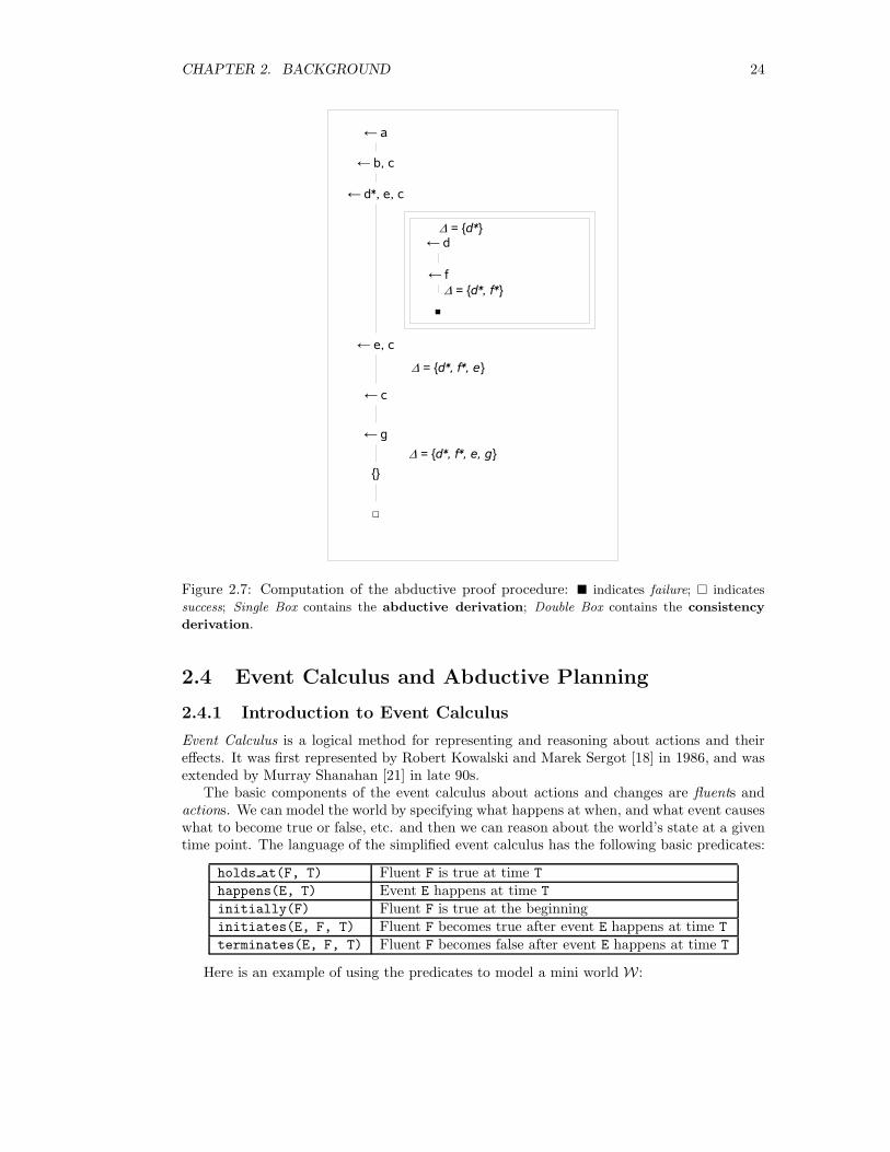
2 and terminates the consistency derivation with success. Now it returns to the abductivederivation with G3 =← e, c and ∆3 = {d∗, f∗}. If we carry on the procedure, it is easy to seethat it will eventually reduce G to {} and obtain ∆ = {d∗, f∗, e, g}, and the procedure willterminate with success. The computation can also be illustrated using nested boxes (SeeFigure 2.7).
2.3.4 Applications
Abduction is mainly used in many application categories such as fault diagnosis(e.g. medicaldiagnosis), high level vision, natural language understanding and planning.
Medical diagnosis and planning with abduction [13] have been studied for a while. Inmedical diagnosis, the causes (diseases) may be modeled as the hypotheses and the obser-vations are the symptoms to be explained. In planning problems, the domain knowledge isusually modeled with event calculus(See Section 2.4.1). Given a goal state at a time point,abduction is used to find a sequence of actions that will lead to the desired state at thedesired time. Section 2.4.2 gives an example of planning with abduction.
CHAPTER 2. BACKGROUND 24
Figure 2.7: Computation of the abductive proof procedure: � indicates failure; � indicates
success; Single Box contains the abductive derivation; Double Box contains the consistency
derivation.
2.4 Event Calculus and Abductive Planning
2.4.1 Introduction to Event Calculus
Event Calculus is a logical method for representing and reasoning about actions and theireffects. It was first represented by Robert Kowalski and Marek Sergot [18] in 1986, and wasextended by Murray Shanahan [21] in late 90s.
The basic components of the event calculus about actions and changes are fluents andactions. We can model the world by specifying what happens at when, and what event causeswhat to become true or false, etc. and then we can reason about the world’s state at a giventime point. The language of the simplified event calculus has the following basic predicates:
holds at(F, T) Fluent F is true at time T
happens(E, T) Event E happens at time T
initially(F) Fluent F is true at the beginninginitiates(E, F, T) Fluent F becomes true after event E happens at time T
terminates(E, F, T) Fluent F becomes false after event E happens at time T
Here is an example of using the predicates to model a mini world W :
CHAPTER 2. BACKGROUND 25
initially(have(alice, ticket)).happens(give(alice, bob, ticket), 3).happens(give(bob, alice, ticket), 5).initiates(give(X, Y, W), have(Y, W), T) ← holds at(have(X, W), T).terminates(give(X, Y, W), have(X, W), T).
The simplified event calculus also has a set of rules EC for computing the state of theworld:
holds at(F, T) ←initially(F), not(broken(F, 0, T)).
holds at(F, T) ←happens(E, T1), before(T1, T),
initiates(E, F, T1), not(broken(F, T1, T)).
broken(F, T1, T2) ←happens(E, T1), terminates(E, F, T),
before(T1, T), before(T, T2).
Now we can reasoning about whether some fluents are true or not at a given time in ourmini world. Let Γ be a set of holds ats, Γ is true iff:
W ∪ EC � Γ
For our mini-world example, it is easy to compute that holds at(have(alice, ticket),
1) and holds at(have(bob, ticket), 4) are true but holds at(have(bob, ticket), 7)
is false.
2.4.2 Planning with Abductive Reasoning
In the planning problems with event calculus, we can do the opposite as reasoning with eventcalculus.
Definition 2.5 Let EC be the event calculus rules, let Σ be a set of initiates and terminates,let Γ be a set of holds at representing the goal state of the world. Planning with event cal-culus is to find a set ∆ containing initially and happens such that
EC ∪Σ ∪∆ � Γ
That is, given the effects of the events and the event calculus rules, planning is to find aset of events occur in some certain order that will lead to the desired goal state. The processof finding such set of events can be viewed as abductive reasoning. Shanahan presented anabductive event calculus planner in [22].
2.5 Agent Communications in Multi-Agent Systems
A multi-agent system (MAS)2 is a system composed of a several agents, collec-tively capable of reaching goals that are difficult to achieve by an individual agentor monolithic system.
2http://en.wikipedia.org/wiki/Multi-agent_systems

CHAPTER 2. BACKGROUND 26
MAS has been a well-established research area and lots of efforts have been put intoformalising the agent communication language and protocols. Two of the well-known agentcommunications languages are KQML [1] (Knowledge Query and Manipulation Language, SeeSection 2.5.1) and FIPA-ACL [14] (Agent Communications Language standard by Foundationfor Intelligent Physical Agents3). Though KQML is superseded by FIPA-ACL, it is still usedin many applications nowadays.
2.5.1 KQML
KQML was developed in early 1990s as part of the Knowledge Sharing Effort (insert refer-ence). It can be used as a language for knowledge sharing between intelligent systems. Itproposed a standard of message format and a set of performatives.
A KQML message has the format of:
(performative
:attribute_name1 attribute_value1
:attribute_name2 attribute_value2
...
:attribute_nameN attribute_valueN
)
Some of the reserved performatives [8] include:
Type PerformativeBasic query ask-if, ask-one, ask-all
Multi-response stream-about, stream-all-eos, subscribe
Single-response reply, sorry, error, tell, deny
Generic Informational tell, untell, deny, achieve, unachieve
Generator standby, ready, next, rest, discard
Capability advertise, unadvertise, broker-one, broker-all
recommend-one, recommend-all, recruit-one, recruit-all
Example of using the performatives for Request-response
Below is an example of using KQML messages for request-response communication betweentwo agent.
Alice sends a request to the directoryserver:
(ask-one
:sender alice
:receiver directory_server
:reply_with bob_s_number
:language Prolog
:ontology contact_details
:content "work_phone(bob, Tel)"
)
3http://www.fipa.org/
CHAPTER 2. BACKGROUND 27
Directory responses with:
(ask-one
:sender directory_server
:receiver alice
:in_reply_to bob_s_number
:language Prolog
:ontology contact_details
:content "work_phone(bob, 12345)"
)
2.5.2 Mediation Services with KQML
KQML messages can be used in three type of mediation services [8] – Yellow Page Direc-tory, Mediator and Broker. The main performatives used included advertise, recommend,recruit, broker and other query and response performatives.
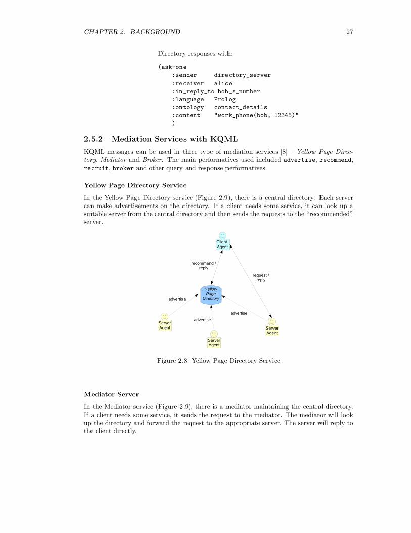
Yellow Page Directory Service
In the Yellow Page Directory service (Figure 2.9), there is a central directory. Each servercan make advertisements on the directory. If a client needs some service, it can look up asuitable server from the central directory and then sends the requests to the “recommended”server.
Figure 2.8: Yellow Page Directory Service
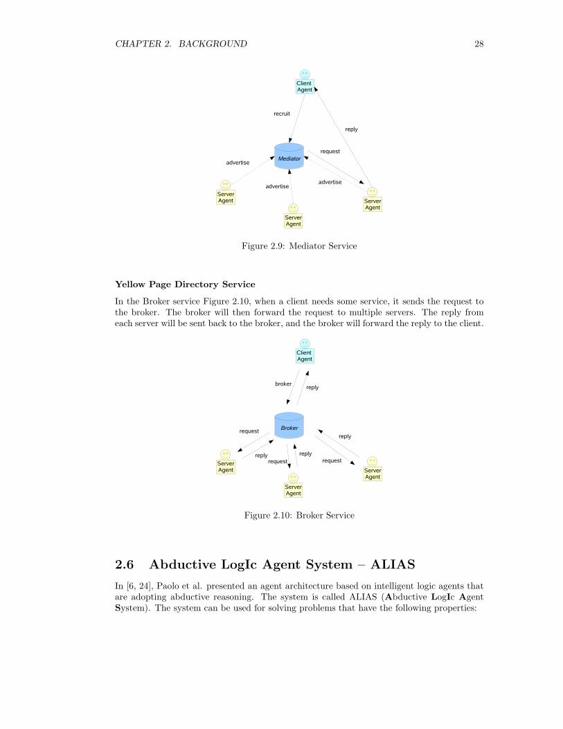
Mediator Server
In the Mediator service (Figure 2.9), there is a mediator maintaining the central directory.If a client needs some service, it sends the request to the mediator. The mediator will lookup the directory and forward the request to the appropriate server. The server will reply tothe client directly.
CHAPTER 2. BACKGROUND 28
Figure 2.9: Mediator Service
Yellow Page Directory Service
In the Broker service Figure 2.10, when a client needs some service, it sends the request tothe broker. The broker will then forward the request to multiple servers. The reply fromeach server will be sent back to the broker, and the broker will forward the reply to the client.
Figure 2.10: Broker Service
2.6 Abductive LogIc Agent System – ALIAS
In [6, 24], Paolo et al. presented an agent architecture based on intelligent logic agents thatare adopting abductive reasoning. The system is called ALIAS (Abductive LogIc AgentSystem). The system can be used for solving problems that have the following properties:
CHAPTER 2. BACKGROUND 29
• the knowledge is incomplete
• the agents may need to find explanations about the goal domain with other agents
• the explanations have to be globally consistent over the set of agents
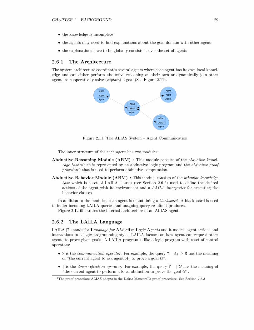
2.6.1 The Architecture
The system architecture coordinates several agents where each agent has its own local knowl-edge and can either perform abductive reasoning on their own or dynamically join otheragents to cooperatively solve (explain) a goal (See Figure 2.11).
Figure 2.11: The ALIAS System – Agent Communication
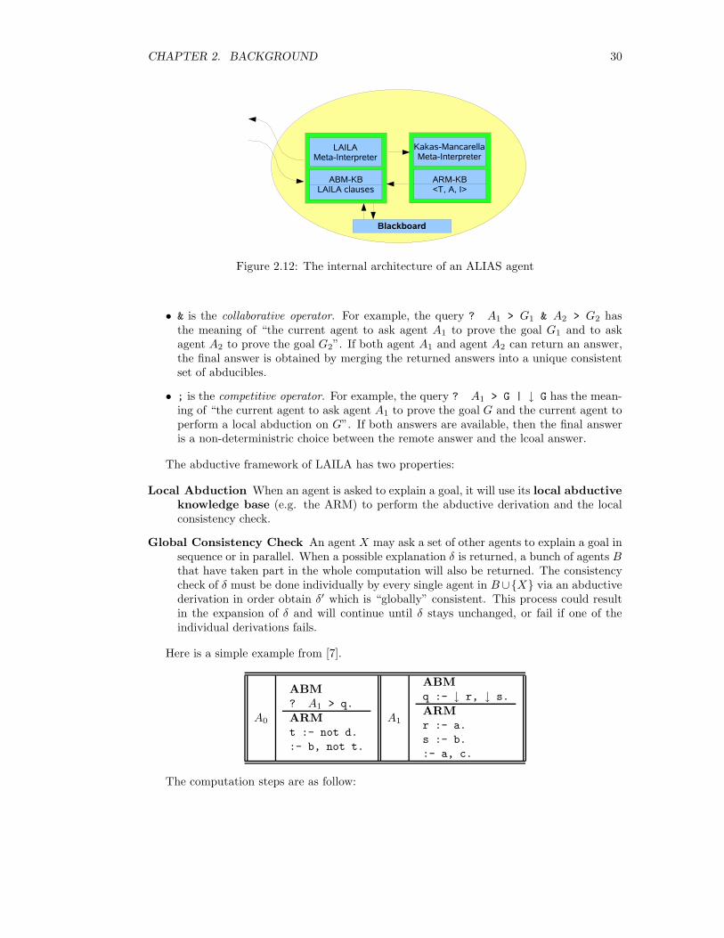
The inner structure of the each agent has two modules:
Abductive Reasoning Module (ARM) : This module consists of the abductive knowl-edge base which is represented by an abductive logic program and the abductive proofprocedure4 that is used to perform abductive computation.
Abductive Behavior Module (ABM) : This module consists of the behavior knowledgebase which is a set of LAILA clauses (see Section 2.6.2) used to define the desiredactions of the agent with its environment and a LAILA interpreter for executing thebehavior clauses.
In addition to the modules, each agent is maintaining a blackboard. A blackboard is usedto buffer incoming LAILA queries and outgoing query results it produces.
Figure 2.12 illustrates the internal architecture of an ALIAS agent.
2.6.2 The LAILA Language
LAILA [7] stands for Language for AbductIve Logic Agents and it models agent actions andinteractions in a logic programming style. LAILA focuses on how agent can request otheragents to prove given goals. A LAILA program is like a logic program with a set of controloperators:
• > is the communication operator. For example, the query ? A1 > G has the meaningof “the current agent to ask agent A1 to prove a goal G”.
• ↓ is the down-reflection operator. For example, the query ? ↓ G has the meaning of“the current agent to perform a local abduction to prove the goal G”.
4The proof procedure ALIAS adopts is the Kakas-Mancarella proof procedure. See Section 2.3.3
CHAPTER 2. BACKGROUND 30
Figure 2.12: The internal architecture of an ALIAS agent
• & is the collaborative operator. For example, the query ? A1 > G1 & A2 > G2 hasthe meaning of “the current agent to ask agent A1 to prove the goal G1 and to askagent A2 to prove the goal G2”. If both agent A1 and agent A2 can return an answer,the final answer is obtained by merging the returned answers into a unique consistentset of abducibles.
• ; is the competitive operator. For example, the query ? A1 > G | ↓ G has the mean-ing of “the current agent to ask agent A1 to prove the goal G and the current agent toperform a local abduction on G”. If both answers are available, then the final answeris a non-deterministric choice between the remote answer and the lcoal answer.
The abductive framework of LAILA has two properties:
Local Abduction When an agent is asked to explain a goal, it will use its local abductiveknowledge base (e.g. the ARM) to perform the abductive derivation and the localconsistency check.
Global Consistency Check An agent X may ask a set of other agents to explain a goal insequence or in parallel. When a possible explanation δ is returned, a bunch of agents Bthat have taken part in the whole computation will also be returned. The consistencycheck of δ must be done individually by every single agent in B∪{X} via an abductivederivation in order obtain δ′ which is “globally” consistent. This process could resultin the expansion of δ and will continue until δ stays unchanged, or fail if one of theindividual derivations fails.
Here is a simple example from [7].
A0
ABM? A1 > q.
ARMt :- not d.
:- b, not t.
A1
ABMq :- ↓ r, ↓ s.
ARMr :- a.
s :- b.
:- a, c.
The computation steps are as follow:
CHAPTER 2. BACKGROUND 31
1. A0 asked A1 about q.
2. A1 performed a local abductive derivation and local consistency check and δ1 = {a, b, not c}was returned to A0.
3. A0 performed a local abductive derivation of δ1 and obtained δ2 = {a, b, not c, not d}because of :- b, not t. and t :- not d.
4. A1 was then called to perform an abductive derivation on δ2 but δ2 stayed unchanged.The whole computation terminated with the final explanation δ2.
However, it is worth noting that the final explanation obtained by the bunch of agentscould be different from that obtained by a single abduction computation over the union ofall agents’ knowledge bases. Consider the following example:
A0
ABM? A1 > q.
ARMt :- not a.
:- b, not t.
A1
ABMq :- ↓ r, ↓ s.
ARMr :- a.
s :- b.
t :- not d.
:- a, c.
Notice that t :- not d in A0 becomes t :- not a and t :- not d is now in A1. Thefirst two computation steps are still the same. However, in step 3, A0 will fail the consistencycheck because a is in δ1 but we need to prove t and not a. However, if the ARM of A0
was merged with that of A1, they should have obtained same globally consistent explanationδ2 = {a, b, not c, not d} because we could prove t with not d. The main reason for ALIASnot putting all the knowledge bases together is to avoid serious computational problems.
2.6.3 Proposed Applications
There are two proposed applications for ALIAS.The first one is to model judicial evaluation[5]. The idea is to model each character in the
trial as an agent and represent the trial knowledge by means of abductive logic programming.The agents then perform colaborative/competitive reasoning on the trial data in order totoobtain a consistent set of hypotheses that explains the given data.
The second application is for medical diagnosis [4]. In this application, the medical doctorsare modeled as agents and their knowledge are represented declaratively. Given the symptomsof a patient, the doctors try work collaborately/competitively to find the hypothesis (i.e. adisease).
2.7 Target Device – Gumstix
For this project, we’d like to run experimental abductive reasoning applications on the smalldevices. We chose gumstix computer5 as our target device because of its relatively low costand open development.

CHAPTER 2. BACKGROUND 32
Figure 2.13: Gumstix 400xm-bt Motherboard
Figure 2.14: Gumstix CFStix for Memory Card or Wifi Card
2.7.1 Specification
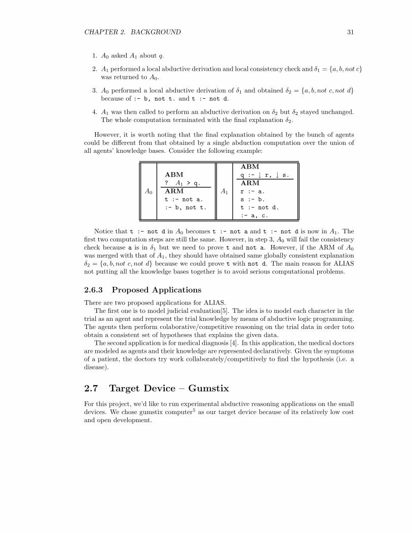
A typical Gumstix computer consists of a mother board and some optional expansion boards.Our perspective ones will have a connex 400xm-bt (See Figure 2.13) motherboard, a cfstix(See Figure 2.14) and a waysmall-STUART (See Figure 2.15) expansion boards. Below isthe specification of the hardware:
• Processor Speed: 400 MHz
• RAM: 64 MB
• Flash Memory: 16 MB
• Extended Storage: 1 GB (via cfstix with a 1 GB CompactFlash flash Card).
• Connectivity:
– Telnet from a PC to the Gumstix – via bf waysmall-STUART and serial ports.
– Wifi – via cfstix with a CF wifi card.
– Bluetooth – via the on-board bluetooth module.
– Ethernet (USBnet) – via the USB client.
5Gumstix, Way Small Computing http://www.gumstix.com
CHAPTER 2. BACKGROUND 33
Figure 2.15: Gumstix WaySmall-STUART for Communications via Serial Port and USB
The Gumstix computers are running (ARM-)Linux as their operating system. The oper-ating system and the utility applications are compiled with ARM cross-compilers and writteninto a file system image in jiff2 format. The file system image can then be downloaded tothe Gumstix’s flash memory via the serial port. The process is called reflashing.
Below is a list of software required for application development/porting for the Gumstix:
• HyperTerminal (Private Edition): For communications between a Windows PC andthe Gumstix including Telnet and Reflashing.
• Buildroot: It is used for cross-compiling the Linux kernel and other applications. It isalso used to build the file system image.
• Linux Kernel and its packages: For utilising the Gumstix hardware.
2.7.2 Resources
The Gumstix computers don’t come with any proper user guides or manuals. This makesthe porting and interfacing somewhat not so straight forward. The identified resources thatmay help in working with Gumstix are:
• Gumstix Wiki (http://docwiki.gumstix.org/): contains informal documentationsand short tutorials.
• Mailing List and Email Archive(http://sourceforge.net/mailarchive/forum.php?forum=gumstix-users): can bevery useful as frequent answered questions can be searched from or posted to it.
2.8 QuProlog
QuProlog is a Prolog system developed by the University of Queensland. QuProlog is de-signed primarily as a prototyping and tactic language for interactive theorem provers. Itprovides multi-threaded supports and high-level communications between threads, processand machines. Hence, it is an ideal Prolog system for this project.
CHAPTER 2. BACKGROUND 34
QuProlog 7.4 uses ICM (See Section 2.8.2) for peer to peer communications and usesElvin [9] for publish/subscribe communications. However, ICM is no longer supported andElvin package is no longer available or supported.
QuProlog 8.0 uses a new publish/subscribe server called Pedro (See Section 2.8.3) insteadof ICM and Elvin.
2.8.1 Multi-threads Support
In QuProlog, one can create a new thread simply using
thread fork(ThreadName, Goal, Sizes)
If ThreadName is not given, a new one will be generated automatically. Sizes is optionaland is used for specifying how much memory should be allocated to this thread (e.g. stacksize, code size).
An thread can retrieve its name and change its name using
thread symbol(Myname).
andthread set symbol(newname).
A thread can “push” a goal to another thread using
thread push goal(Thread, Goal).
or to “kill” another thread using
thread exit(Thread).
2.8.2 Inter-agent Communications Model (ICM)
This is for QuProlog 7.4 or earlier only.The Inter-agent Communications Model (ICM) is a model of communication oriented
towards the needs of inter-agent communication. It uses a store and forward architecturewhich allows asynchronous communication between the agents: it maintains a message bufferfor each agent. The message buffer acts like a mailbox so an agent needs not to be onlinewhen a message is sent to it.
When a QuProlog process starts up, it may register with an ICM daemon (either run-ning locally or remotely) using the switch -A processName. After registered with the ICMdaemon, each thread in QuProlog will have a unique handle. For example,
server:agent1@shell1
is the thread called server within a QuProlog process called agent1 running on shell1
machine.If a thread wants to send a message Msg to a thread with handle B in QuProlog, it
simply does
Msg ->> B
.If a thread wants to fetch the first message from its message buffer, it does
CHAPTER 2. BACKGROUND 35
Msg <<- W
then Msg will be unified to the message and W will be the sender’s handle. A threadcan also search its message buffer for a message unifiable with Msg by Msg <<= W. <<- and<<= will suspends the thread if no such message is available.
Another powerful predicate of QuProlog is the message choice:
message_choice (
M1 <<- W1 :: Test1 -> Call1;
M2 <<- W2 :: Test2 -> Call2;
...
timeout(T) -> CallTimeout
)
When is predicate is called, it will scan through the rules from the top. It tries to searchfor a message unifiable with M and satisfies the condition Test1. If succeeds, it will removethe message from the buffer and call Call1. Otherwise, it moves to check the next rule. Ifnot rule is met, it will suspends the thread until a new message arrives (or timeout).
2.8.3 Pedro
For QuProlog 8.0 only.Pedro is a new version (currently 0.1) of publish/subscribe server designed to replace ICM
and Elvin. It supports both peer-to-peer communications and publish/subscribe communi-cations.
Differently from ICM, all the processes/threads have to connect to the same Pedro daemonin order to have the peer-to-peer and publish/subscribe communications between them.
When a QuProlog process starts, it uses -A procName -N pedroMachine -P pedroPort
to register with the Pedro server. Then the peer-to-peer messaging predicates are the sameas in QuProlog 7.4.
For publish/subscribe support, any thread can publish a message Msg to the server using
pedro notify(Msg).
A thread needs to subscribe from the server before receiving any subscriptions. The callfor subscribe is
pedro subscribe(Head, Body, ID)
After doing that, any future published message unifiable with Head and satisfies Body willbe placed in the thread’s message buffer and the thread can retrieve it just like a peer-to-peermessage (whose sender is pedro. The output ID is used for unsubscription, e.g.
pedro unsubscribe(ID).
Pedro also provides API for C, Java and Python. Hence, one can write applications tocommunicate with Pedro. This is good for writing debugger user interface.
Chapter 3
Investigation of AbductiveReasoning
The first phase of my project is to investigate how the abductive logic reasoning can beimplemented efficiently or optimised so that it can be run on small devices (e.g. Gumstix).
For the investigation, I have evaluated an abductive logic reasoning meta-interpreter1
written by Antonis Kakas. I have also re-engineered the meta-interpreter so it runs fasterthan the original one (Section 3.1.1). Further more, I have tested it with a ported Prologengine on Gumstix. For the optimisation, I have investigated how partial evaluation couldhelp to speed up the abductive reasoning process (Section 3.2).
3.1 Abductive Meta-Interpreters
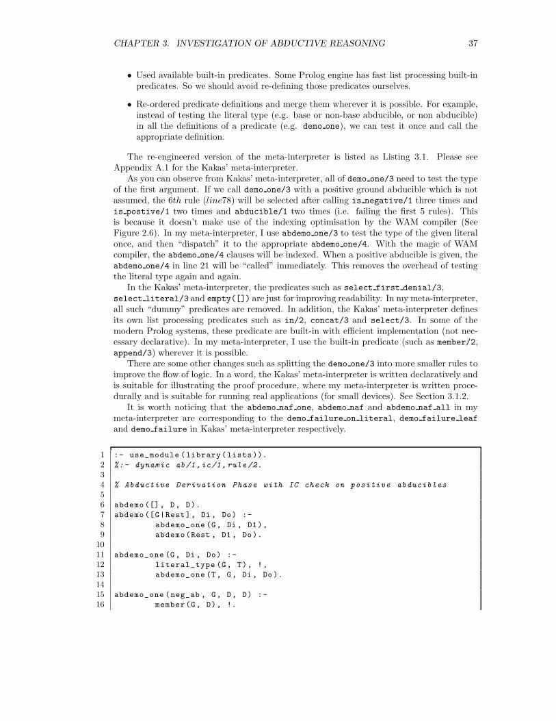
The Kakas’ meta-interpreter implements the KM proof procedure described in Section 2.3.3but with integrity constraint checks for positive abducibles. There is a very important as-sumption for Kakas’ Meta-interpreter – all abducibles in the program must be ground at thetime of call. This assumption helps to avoid the flundering problem (which occurs when anegative non-ground atom is put into the set of abducibles).
3.1.1 Re-engineering the Kakas’ ALP Meta-Interpreter
The Kakas’ meta-interpreter is implemented for illustrating the proof procedure. It definesits own list processing predicates (e.g. in/2 (= member/2), concat/3) and has quite a fewauxiliary predicates (e.g. empty([]).) for improving the readability of the program. How-ever, if we want to run the the meta-interpreter on a small device, we are more interestedin efficiency rather than readability. Therefore, I re-engineered Kakas’ meta-interpreter withthe following modifications:
• Re-ordered the predicate arguments so that a Prolog compiler may perform “indexing”optimisation.
• Made use of cut (!) whenever it is possible.
• Removed auxiliary predicates with empty bodies.
1The source code can be found at http://www.cs.ucy.ac.cy/aclp/
36
CHAPTER 3. INVESTIGATION OF ABDUCTIVE REASONING 37
• Used available built-in predicates. Some Prolog engine has fast list processing built-inpredicates. So we should avoid re-defining those predicates ourselves.
• Re-ordered predicate definitions and merge them wherever it is possible. For example,instead of testing the literal type (e.g. base or non-base abducible, or non abducible)in all the definitions of a predicate (e.g. demo one), we can test it once and call theappropriate definition.
The re-engineered version of the meta-interpreter is listed as Listing 3.1. Please seeAppendix A.1 for the Kakas’ meta-interpreter.
As you can observe from Kakas’ meta-interpreter, all of demo one/3 need to test the typeof the first argument. If we call demo one/3 with a positive ground abducible which is notassumed, the 6th rule (line78) will be selected after calling is negative/1 three times andis postive/1 two times and abducible/1 two times (i.e. failing the first 5 rules). Thisis because it doesn’t make use of the indexing optimisation by the WAM compiler (SeeFigure 2.6). In my meta-interpreter, I use abdemo one/3 to test the type of the given literalonce, and then “dispatch” it to the appropriate abdemo one/4. With the magic of WAMcompiler, the abdemo one/4 clauses will be indexed. When a positive abducible is given, theabdemo one/4 in line 21 will be “called” immediately. This removes the overhead of testingthe literal type again and again.
In the Kakas’ meta-interpreter, the predicates such as select first denial/3,select literal/3 and empty([]) are just for improving readability. In my meta-interpreter,all such “dummy” predicates are removed. In addition, the Kakas’ meta-interpreter definesits own list processing predicates such as in/2, concat/3 and select/3. In some of themodern Prolog systems, these predicate are built-in with efficient implementation (not nec-essary declarative). In my meta-interpreter, I use the built-in predicate (such as member/2,append/3) wherever it is possible.
There are some other changes such as splitting the demo one/3 into more smaller rules toimprove the flow of logic. In a word, the Kakas’ meta-interpreter is written declaratively andis suitable for illustrating the proof procedure, where my meta-interpreter is written proce-durally and is suitable for running real applications (for small devices). See Section 3.1.2.
It is worth noticing that the abdemo naf one, abdemo naf and abdemo naf all in mymeta-interpreter are corresponding to the demo failure on literal, demo failure leaf
and demo failure in Kakas’ meta-interpreter respectively.
1 :- use_module (library(lists )).
2 %:- dynamic ab/1,ic/1, rule /2.
3
4 % Abductive Derivation Phase with IC check on positive abducibles
5
6 abdemo ([], D, D).
7 abdemo ([G|Rest ], Di , Do) :-
8 abdemo_one (G, Di , D1),
9 abdemo(Rest , D1 , Do).
10
11 abdemo_one (G, Di , Do) :-
12 literal_type (G, T), !,
13 abdemo_one (T, G, Di , Do ).
14
15 abdemo_one (neg_ab , G, D, D) :-
16 member(G, D), !.
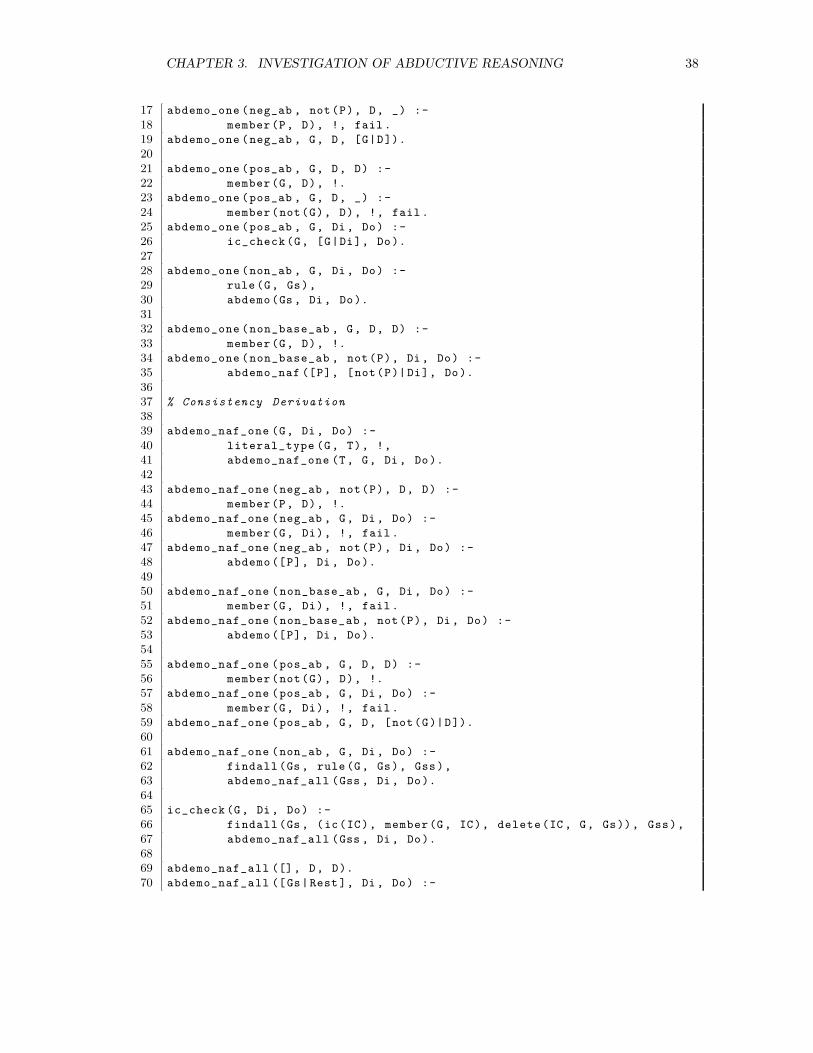
CHAPTER 3. INVESTIGATION OF ABDUCTIVE REASONING 38
17 abdemo_one (neg_ab , not(P), D, _) :-
18 member(P, D), !, fail .
19 abdemo_one (neg_ab , G, D, [G|D]).
20
21 abdemo_one (pos_ab , G, D, D) :-
22 member(G, D), !.
23 abdemo_one (pos_ab , G, D, _) :-
24 member(not(G), D), !, fail .
25 abdemo_one (pos_ab , G, Di , Do) :-
26 ic_check (G, [G|Di], Do).
27
28 abdemo_one (non_ab , G, Di , Do) :-
29 rule (G, Gs),
30 abdemo(Gs , Di , Do).
31
32 abdemo_one (non_base_ab , G, D, D) :-
33 member(G, D), !.
34 abdemo_one (non_base_ab , not(P), Di , Do) :-
35 abdemo_naf ([P], [not(P)| Di], Do).
36
37 % Consistency Derivation
38
39 abdemo_naf_one (G, Di , Do) :-
40 literal_type (G, T), !,
41 abdemo_naf_one (T, G, Di , Do).
42
43 abdemo_naf_one (neg_ab , not(P), D, D) :-
44 member(P, D), !.
45 abdemo_naf_one (neg_ab , G, Di , Do) :-
46 member(G, Di), !, fail .
47 abdemo_naf_one (neg_ab , not(P), Di , Do) :-
48 abdemo ([P], Di , Do).
49
50 abdemo_naf_one (non_base_ab , G, Di , Do) :-
51 member(G, Di), !, fail .
52 abdemo_naf_one (non_base_ab , not(P), Di , Do) :-
53 abdemo ([P], Di , Do).
54
55 abdemo_naf_one (pos_ab , G, D, D) :-
56 member(not(G), D), !.
57 abdemo_naf_one (pos_ab , G, Di , Do) :-
58 member(G, Di), !, fail .
59 abdemo_naf_one (pos_ab , G, D, [not(G)|D]).
60
61 abdemo_naf_one (non_ab , G, Di , Do) :-
62 findall (Gs , rule (G, Gs), Gss),
63 abdemo_naf_all (Gss , Di , Do).
64
65 ic_check (G, Di , Do) :-
66 findall (Gs , (ic(IC), member(G, IC), delete(IC , G, Gs)), Gss),
67 abdemo_naf_all (Gss , Di , Do).
68
69 abdemo_naf_all ([], D, D).
70 abdemo_naf_all ([Gs|Rest ], Di , Do) :-
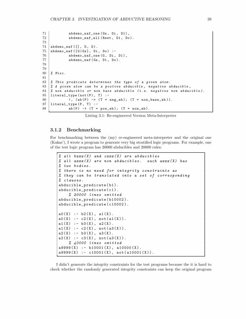
CHAPTER 3. INVESTIGATION OF ABDUCTIVE REASONING 39
71 abdemo_naf_one (Gs , Di , D1),
72 abdemo_naf_all (Rest , D1 , Do).
73
74 abdemo_naf ([], D, D).
75 abdemo_naf ([G|Gs], Di , Do) :-
76 abdemo_naf_one (G, Di , D1),
77 abdemo_naf (Gs , D1 , Do).
78
79
80 % Misc .
81
82 % This predicate determines the type of a given atom .
83 % A given atom can be a postive abducible , negative abducible ,
84 % non abducible or non base abducible (i.e. negative non abducible ).
85 literal_type (not(P), T) :-
86 !, (ab(P) -> (T = neg_ab ); (T = non_base_ab )).
87 literal_type (P, T) :-
88 ab(P) -> (T = pos_ab ); (T = non_ab ).
Listing 3.1: Re-engineered Version Meta-Interpreter
3.1.2 Benchmarking
For benchmarking between the (my) re-engineered meta-interpreter and the original one(Kakas’), I wrote a program to generate very big stratified logic programs. For example, oneof the test logic program has 20000 abducibles and 20000 rules:
% all bxxx(X) and cxxx(X) are abducibles
% all axxx(X) are non abducibles. each axxx(X) has
% two bodies.
% there is no need for integrity constraints as
% they can be translated into a set of corresponding
% clauses.
abducible_predicate(b1).
abducible_predicate(c1).
% 20000 lines omitted
abducible_predicate(b10002 ).
abducible_predicate(c10002 ).
a0(X) :- b2(X), a1(X).
a0(X) :- c2(X), not(a1(X)).
a1(X) :- b3(X), a2(X).
a1(X) :- c2(X), not(a3(X)).
a2(X) :- b3(X), a3(X).
a2(X) :- c3(X), not(a3(X)).
% 40000 lines omitted
a9999(X) :- b10001(X), a10000(X).
a9999(X) :- c10001(X), not(a10001(X)).
I didn’t generate the integrity constraints for the test programs because the it is hard tocheck whether the randomly generated integrity constraints can keep the original program

CHAPTER 3. INVESTIGATION OF ABDUCTIVE REASONING 40
stratified. If the test program is not stratified, then both of the two meta-interpreters may notterminate (because SLD is not complete). In fact, the process of integrity constraint checkis similar to the process of failing a non-abducible (e.g. it needs to fail all the resolvents).Therefore, using the above generated test programs will not lose generality.
I tested the two meta-interpreters with a number of queries. They were run with YAPProlog on an Linux machine with Pentium(R) 4 HT 3.20GHz processor and 1GB memory.They gave the same answers and a segment of the performance comparison table is shownbelow:
Queries Re-engineered Version Kakas’ VersionCPU Time Max. Stack CPU Time Max. Stack(seconds) (bytes) (seconds) (bytes)
a0(test) 3.163 1073152 5.104 2286668a1(test) 2.781 1073152 5.356 2286332a2(test) 1.876 1073152 5.076 2285963
Other queries and random generated logic programs were also tested. On average, there-engineered meta-interpreter runs 43.11% faster and requires 53.06% less memory.
3.1.3 Running On a Gumstix
The re-engineered meta-interpreter was also run on a Gumstix with the ported YAP Prologengine (See Chapter 6). For testing and benchmarking results, please see Section 6.2.
3.2 Optimisation by Partial Evaluation
In Secton 2.2, there is an example showing how partial evaluation may “compile away” thedeductive meta-interpreter demo/2 (See Listing 2.4) and improve the runtime performance.By observation, we know that there is a similarity between demo/2 and the abductive meta-interpreters: in demo/2, the justification of each successful goal is collected and returnedat the end. In the abductive meta-interpreter, the list of abducibles (∆) is collected andreturned at the end. However, the difference is, the justification collected by demo/2 doesn’taffect the execution of demo, but the ∆ for the abductive meta-interpreters does – e.g. itneeds to be checked for consistency before adding any new abducible.
In this project, I have investigated the idea of “compiling away” the abductive meta-interpreter in attempt to improve the runtime performance of the abductive reasoning pro-cedure. The investigation result shows that partial evaluation does help to speed up thereasoning process and requires smaller stack size. However, the trade off is that the code sizeof a transformed program is much bigger than the original one. I have also written a partialevaluator for compiling away the abductive interpreter.
3.2.1 Observations of the Abductive Meta-interpreter
Let’s look at the re-engineered version of the meta-interpreter(See Listing 3.1) carefully.There are some interesting observations.
Observations for base abducibles
Base abducibles are literals with abducible predicates. By comparing the abdemo one/4
for negative base abducibles (line15 ∼ line19) and the abdemo naf one/4 for positive base
CHAPTER 3. INVESTIGATION OF ABDUCTIVE REASONING 41
abducibles (line55 ∼ line59), we can see that they have one to one corresponding identicaldefinitions. This is the same for abdemo one/4 for positive base abducibles (line21 ∼ line26)and the abdemo naf one/4 for the negative abducibles (line43 ∼ line48). Their first twodefinitions (for ∆ check) are the identical. In addition, the definition
abdemo_naf_one(neg_ab , not(P), Di, Do) :-
abdemo ([P], Di , Do).
first calls abdemo/3, and then will call
abdemo_one(pos_ab, G, Di , Do) :-
ic_check(G, [G|Di], Do).
So they are the same again.According to our observation, we know that the abductive derivation phase and the
consistency derivation phase for base abducibles are symmetric, therefore, we should beable to merge the 12 rules into 6. Further more, the delta checks are the same too – i.e. ifthe complement of the base abducible is in ∆ then the abdemo/4 fails; if the base abducibleis already in ∆, then the abdemo/4 succeeds. Hence, we should also be able to merge thethe 4 check delta rules into 2. In conclusion, we only need 4 abdemo one rules for both thepositive and negative in both the abductive and consistency derivations.
Observations for non base abducibles and non abducibles
Non base abducibles are negative literals with non-abducible predicates, where non abduciblesare positive literals with non-abducible predicates. Let’s look at the abdemo one/4 (line28)and abdemo naf one (line61) for non abducibles. The abdemo one/4 succeeds if it cansucceed in an abductive derivation for at least one but any one resolvent of the currentnon-abducible, where the abdemo naf one/4 succeeds only if it can fail every consistencyderivation for all the resolvent of the current non abducible.
Let’s look at the case for non-base abducible. There are two rules for abdemo one/4 andabdemo naf one/4 respectively. The first rules of them are symmetric. But second rulesseem to be symmetric by not exactly – i.e. the one of abdemo naf one/4 adds the non-baseabducible to ∆ where the other one doesn’t.
In conclusion, we need 6 rules for the the non-base abducibles and non abducibles in theabductive and consistency derivations.
3.2.2 Compiling Away the Meta-Interpreter
After the observation, we can try to transform a logic program into a hybrid program thaton its own can perform abductive reasoning. I will explain this process with an example.Below is a normal logic program for diagnosis of a car.
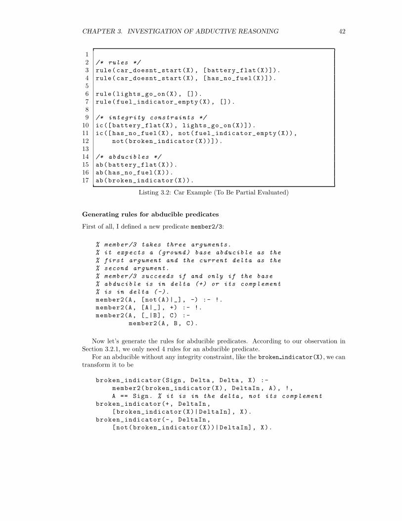
CHAPTER 3. INVESTIGATION OF ABDUCTIVE REASONING 42
12 /* rules */
3 rule( car_doesnt_start(X), [battery_flat(X)]).
4 rule( car_doesnt_start(X), [has_no_fuel(X)]).
56 rule(lights_go_on(X), []).
7 rule( fuel_indicator_empty(X), []).
89 /* integrity constraints */
10 ic([ battery_flat(X), lights_go_on(X)]).
11 ic([ has_no_fuel(X), not(fuel_indicator_empty(X)),
12 not(broken_indicator(X))]).
1314 /* abducibles */
15 ab(battery_flat(X)).
16 ab(has_no_fuel(X)).
17 ab(broken_indicator(X)).
Listing 3.2: Car Example (To Be Partial Evaluated)
Generating rules for abducible predicates
First of all, I defined a new predicate member2/3:
% member /3 takes three arguments.
% it expects a (ground) base abducible as the
% first argument and the current delta as the
% second argument.
% member /3 succeeds if and only if the base
% abducible is in delta (+) or its complement
% is in delta (-).
member2(A, [not(A)|_], -) :- !.
member2(A, [A|_], +) :- !.
member2(A, [_|B], C) :-
member2(A, B, C).
Now let’s generate the rules for abducible predicates. According to our observation inSection 3.2.1, we only need 4 rules for an abducible predicate.
For an abducible without any integrity constraint, like the broken indicator(X), we cantransform it to be
broken_indicator(Sign , Delta , Delta , X) :-
member2(broken_indicator(X), DeltaIn , A), !,
A == Sign. % it is in the delta , not its complement
broken_indicator(+, DeltaIn ,
[ broken_indicator(X)|DeltaIn], X).
broken_indicator(-, DeltaIn ,
[not(broken_indicator(X))|DeltaIn], X).
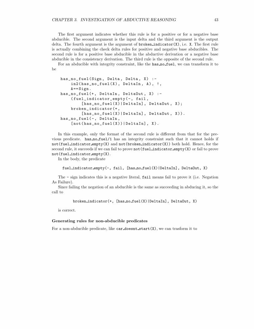
CHAPTER 3. INVESTIGATION OF ABDUCTIVE REASONING 43
The first argument indicates whether this rule is for a positive or for a negative baseabducible. The second argument is the input delta and the third argument is the outputdelta. The fourth argument is the argument of broken indicator(X), i.e. X. The first ruleis actually combining the check delta rules for positive and negative base abducibles. Thesecond rule is for a positive base abducible in the abductive derivation or a negative baseabducible in the consistency derivation. The third rule is the opposite of the second rule.
For an abducible with integrity constraint, like the has no fuel, we can transform it tobe
has_no_fuel(Sign , Delta , Delta , X) :-
in2(has_no_fuel(X), DeltaIn , A), !,
A==Sign.
has_no_fuel(+, DeltaIn , DeltaOut , X) :-
( fuel_indicator_empty(-, fail ,
[has_no_fuel(X)| DeltaIn], DeltaOut , X);
broken_indicator(+,
[has_no_fuel(X)| DeltaIn], DeltaOut , X)).
has_no_fuel(-, DeltaIn ,
[not(has_no_fuel(X))|DeltaIn], X).
In this example, only the format of the second rule is different from that for the pre-vious predicate. has no fuel/1 has an integrity constraint such that it cannot holds ifnot(fuel indicator empty(X) and not(broken indicator(X)) both hold. Hence, for thesecond rule, it succeeds if we can fail to prove not(fuel indicator empty(X) or fail to provenot(fuel indicator empty(X).
In the body, the predicate
fuel indicator empty(-, fail, [has no fuel(X)|DeltaIn], DeltaOut, X)
The - sign indicates this is a negative literal, fail means fail to prove it (i.e. NegationAs Failure).
Since failing the negation of an abducible is the same as succeeding in abducing it, so thecall to
broken indicator(+, [has no fuel(X)|DeltaIn], DeltaOut, X)
is correct.
Generating rules for non-abducible predicates
For a non-abducible predicate, like car doesnt start(X), we can trasform it to
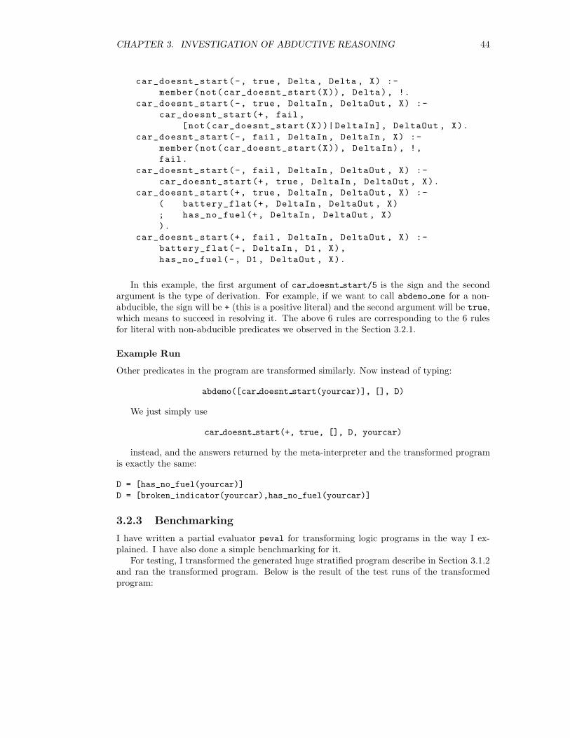
CHAPTER 3. INVESTIGATION OF ABDUCTIVE REASONING 44
car_doesnt_start(-, true , Delta , Delta , X) :-
member(not( car_doesnt_start(X)), Delta), !.
car_doesnt_start(-, true , DeltaIn , DeltaOut , X) :-
car_doesnt_start(+, fail ,
[not(car_doesnt_start(X))|DeltaIn], DeltaOut , X).
car_doesnt_start(-, fail , DeltaIn , DeltaIn , X) :-
member(not( car_doesnt_start(X)), DeltaIn), !,
fail.
car_doesnt_start(-, fail , DeltaIn , DeltaOut , X) :-
car_doesnt_start(+, true , DeltaIn , DeltaOut , X).
car_doesnt_start(+, true , DeltaIn , DeltaOut , X) :-
( battery_flat(+, DeltaIn , DeltaOut , X)
; has_no_fuel(+, DeltaIn , DeltaOut , X)
).
car_doesnt_start(+, fail , DeltaIn , DeltaOut , X) :-
battery_flat(-, DeltaIn , D1 , X),
has_no_fuel(-, D1 , DeltaOut , X).
In this example, the first argument of car doesnt start/5 is the sign and the secondargument is the type of derivation. For example, if we want to call abdemo one for a non-abducible, the sign will be + (this is a positive literal) and the second argument will be true,which means to succeed in resolving it. The above 6 rules are corresponding to the 6 rulesfor literal with non-abducible predicates we observed in the Section 3.2.1.
Example Run
Other predicates in the program are transformed similarly. Now instead of typing:
abdemo([car doesnt start(yourcar)], [], D)
We just simply use
car doesnt start(+, true, [], D, yourcar)
instead, and the answers returned by the meta-interpreter and the transformed programis exactly the same:
D = [has_no_fuel(yourcar)]
D = [broken_indicator(yourcar),has_no_fuel(yourcar)]
3.2.3 Benchmarking
I have written a partial evaluator peval for transforming logic programs in the way I ex-plained. I have also done a simple benchmarking for it.
For testing, I transformed the generated huge stratified program describe in Section 3.1.2and ran the transformed program. Below is the result of the test runs of the transformedprogram:
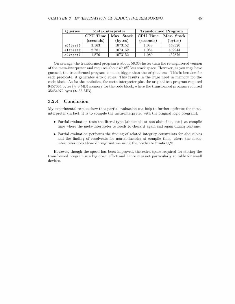
CHAPTER 3. INVESTIGATION OF ABDUCTIVE REASONING 45
Queries Meta-Interpreter Transformed ProgramCPU Time Max. Stack CPU Time Max. Stack(seconds) (bytes) (seconds) (bytes)
a0(test) 3.163 1073152 1.088 448320a1(test) 2.781 1073152 1.084 452944a2(test) 1.876 1073152 1.080 452876
On average, the transformed program is about 56.3% faster than the re-engineered versionof the meta-interpreter and requires about 57.8% less stack space. However, as you may haveguessed, the transformed program is much bigger than the original one. This is because foreach predicate, it generates 4 to 6 rules. This results in the huge need in memory for thecode block. As for the statistics, the meta-interpreter plus the original test program required9457664 bytes (≈ 9 MB) memory for the code block, where the transformed program required35454972 byes (≈ 35 MB).
3.2.4 Conclusion
My experimental results show that partial evaluation can help to further optimise the meta-interpreter (in fact, it is to compile the meta-interpreter with the original logic program):
• Partial evaluation tests the literal type (abducible or non-abducible, etc.) at compiletime where the meta-interpreter to needs to check it again and again during runtime.
• Partial evaluation performs the finding of related integrity constraints for abduciblesand the finding of resolvents for non-abducibles at compile time, where the meta-interpreter does those during runtime using the predicate findall/3.
However, though the speed has been improved, the extra space required for storing thetransformed program is a big down effect and hence it is not particularly suitable for smalldevices.
Chapter 4
Distributed Reasoning System
As for the second goal of this project, I have designed and implemented a system that allowsa group of agents to perform collaborative reasoning tasks. The system allows the looselycoupled agents to discover and ask suitable helpers during the reasoning process. The systemalso provides an efficient way for agent interaction. This chapters presents the design of thesystem.
4.1 Overview
4.1.1 Motivation
In some simple reasoning system, there is only one agent. The agent is responsible forboth maintaining the the single knowledge base and performing reasoning on the domain itsknowledge describes. However, the “God” agent approach implies that the single reasoningagent must:
1. know almost everything about the domain and the sub-domains.
2. do all the reasoning on its own.
In practice, this is not ideal because it is often that the knowledge base is incompleteand/or the agent’s computational power is limited. To be more sufficiently intelligent, areasoning system may be engineered as a collection of many loosely coupled but cooperativereasoning agents.
For example, in a diagnosis system comprises a number of “expert” agents. Each agenthas its own expertise about a sub-domain but doesn’t want to share all of its knowledge withothers. When a fault in the target system is observed, the experts will need to collaboratetogether to find a possible explanation to the fault. During the collaboration, when an expertcouldn’t explain a “goal” with only its own knowledge, some other agents may help to explainit according to their expertise. When an expert raises an explanation, it also needs to checkthe explanation with all other experts in order to make sure the explanation is consistent(agreed by every expert).
Here is another situation where there is a collection of robots working distributivelywithin an environment. Each robot may have some certain perceptions and may performsome certain actions. Therefore, each robot is maintaining its own knowledge about theregion it is currently in. Given a goal state of the environment, the robots may need to
46
CHAPTER 4. DISTRIBUTED REASONING SYSTEM 47
collaborate together to find a consistent plan (sequence of actions) for it. Alternatively, thecollection of robots may use their perceptions to reasoning about the environment.
Sometimes it is possible to re-engineer the multi-agent systems in the previous examplesto be the single-agent systems, i.e. merge together all the agents’ knowledge base and performa single abductive reasoning or planning from the “global” knowledge base. However, usingthe multi-agent approach will have the following major advantages:
• It makes use of parallelism. For example, a goal can be sent to several agents so thatthey can try to solve it simultaneously. In the situation where the agent knowledgebases are big and disjunctive, this advatange is significant comparing to a single multi-thread agent with a single knowledge base.
• It makes hierarchical planning more efficient. For example, we can have a coordinaterobot to find a top level plan comprises decomposable goals and then send the goals todifferent robots to solve.
In the cases where the knowledge base is not mergeable, the multi-agent approach isunavoidable and hence distributed reasoning is needed.
4.1.2 Limitations of ALIAS
ALIAS, as introduced in Section 2.6, is a system for coordinating the collaboration betweena set of abductive reasoning agents. However, there are some limitations of it:
• The interactions between the agents are pre-defined by a set of “rules” written withthe LAILA language. Therefore, when an agent fails to prove a goal alone, it cannotask for help from other agents if the LAILA rules do not instruct it to do so.
• It assumes that each agent knows about its helpers all the time. A new agent cannotcontribute to a reasoning task until the behavioral knowledge bases of some of theexisting agents are changed so that the new agent’s existence is awared by them.
• It only works for abductive reasoning agents.
Hence, the ALIAS system is not what exactly we are looking for. However, it does givesome valuable ideas about how to coordinate a set of abductive reasoning agents during theircollaborations. These ideas have helped me to design a more generic and flexible system forcoordinating multi-agent reasoning.
4.1.3 Basic Assumptions
The system should be generic enough for a collection of agents to perform various reasoningtasks. “generic” means that the system is independent from how the global knowledge baseis distributed across the agents, and what type of reasoning (for this project I focused on thedeductive and abductive reasoning only) the agents are performing.
Assumption 4.1 The knowledge base of the agents in the system can be overlapped or dis-joint. Two knowledge bases are disjoint if they do not share the the same definition for apredicate.
This (version of the) system is designed for coordinating collaborative reasoning. There-fore, it is not designed for handling various network attacks or fatal network failures. Also,it is assumed that each agent is rational and can be trusted by each other.
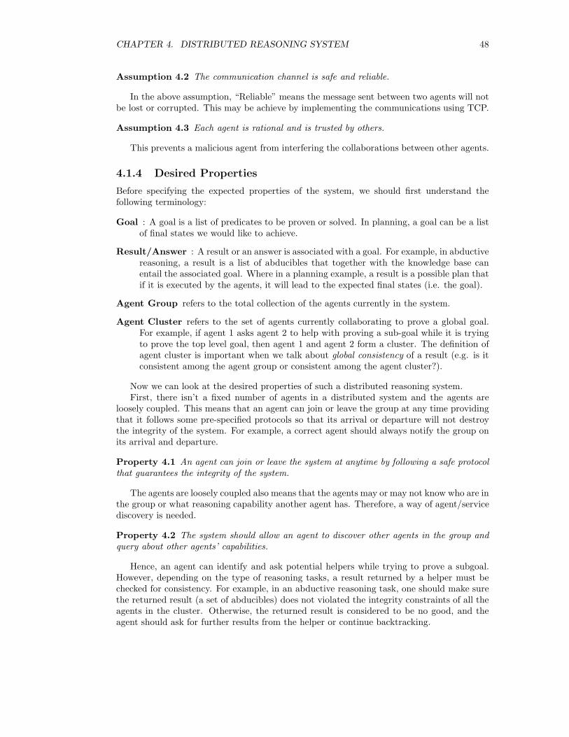
CHAPTER 4. DISTRIBUTED REASONING SYSTEM 48
Assumption 4.2 The communication channel is safe and reliable.
In the above assumption, “Reliable” means the message sent between two agents will notbe lost or corrupted. This may be achieve by implementing the communications using TCP.
Assumption 4.3 Each agent is rational and is trusted by others.
This prevents a malicious agent from interfering the collaborations between other agents.
4.1.4 Desired Properties
Before specifying the expected properties of the system, we should first understand thefollowing terminology:
Goal : A goal is a list of predicates to be proven or solved. In planning, a goal can be a listof final states we would like to achieve.
Result/Answer : A result or an answer is associated with a goal. For example, in abductivereasoning, a result is a list of abducibles that together with the knowledge base canentail the associated goal. Where in a planning example, a result is a possible plan thatif it is executed by the agents, it will lead to the expected final states (i.e. the goal).
Agent Group refers to the total collection of the agents currently in the system.
Agent Cluster refers to the set of agents currently collaborating to prove a global goal.For example, if agent 1 asks agent 2 to help with proving a sub-goal while it is tryingto prove the top level goal, then agent 1 and agent 2 form a cluster. The definition ofagent cluster is important when we talk about global consistency of a result (e.g. is itconsistent among the agent group or consistent among the agent cluster?).
Now we can look at the desired properties of such a distributed reasoning system.First, there isn’t a fixed number of agents in a distributed system and the agents are
loosely coupled. This means that an agent can join or leave the group at any time providingthat it follows some pre-specified protocols so that its arrival or departure will not destroythe integrity of the system. For example, a correct agent should always notify the group onits arrival and departure.
Property 4.1 An agent can join or leave the system at anytime by following a safe protocolthat guarantees the integrity of the system.
The agents are loosely coupled also means that the agents may or may not know who are inthe group or what reasoning capability another agent has. Therefore, a way of agent/servicediscovery is needed.
Property 4.2 The system should allow an agent to discover other agents in the group andquery about other agents’ capabilities.
Hence, an agent can identify and ask potential helpers while trying to prove a subgoal.However, depending on the type of reasoning tasks, a result returned by a helper must bechecked for consistency. For example, in an abductive reasoning task, one should make surethe returned result (a set of abducibles) does not violated the integrity constraints of all theagents in the cluster. Otherwise, the returned result is considered to be no good, and theagent should ask for further results from the helper or continue backtracking.
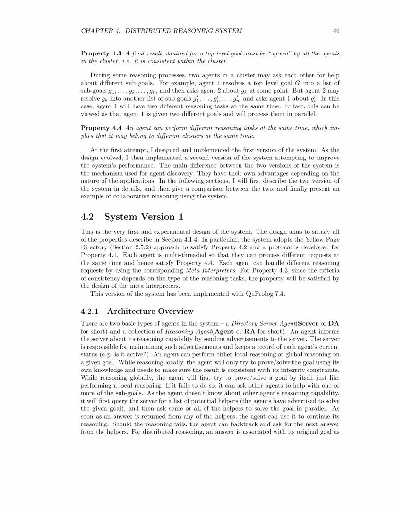
CHAPTER 4. DISTRIBUTED REASONING SYSTEM 49
Property 4.3 A final result obtained for a top level goal must be “agreed” by all the agentsin the cluster, i.e. it is consistent within the cluster.
During some reasoning processes, two agents in a cluster may ask each other for helpabout different sub goals. For example, agent 1 resolves a top level goal G into a list ofsub-goals g1, . . . , gk, . . . , gn, and then asks agent 2 about gk at some point. But agent 2 mayresolve gk into another list of sub-goals g′
1, . . . , g′i, . . . , g
′
m and asks agent 1 about g′i. In thiscase, agent 1 will have two different reasoning tasks at the same time. In fact, this can beviewed as that agent 1 is given two different goals and will process them in parallel.
Property 4.4 An agent can perform different reasoning tasks at the same time, which im-plies that it may belong to different clusters at the same time.
At the first attempt, I designed and implemented the first version of the system. As thedesign evolved, I then implemented a second version of the system attempting to improvethe system’s performance. The main difference between the two versions of the system isthe mechanism used for agent discovery. They have their own advantages depending on thenature of the applications. In the following sections, I will first describe the two version ofthe system in details, and then give a comparison between the two, and finally present anexample of collaborative reasoning using the system.
4.2 System Version 1
This is the very first and experimental design of the system. The design aims to satisfy allof the properties describe in Section 4.1.4. In particular, the system adopts the Yellow PageDirectory (Section 2.5.2) approach to satisfy Property 4.2 and a protocol is developed forProperty 4.1. Each agent is multi-threaded so that they can process different requests atthe same time and hence satisfy Property 4.4. Each agent can handle different reasoningrequests by using the corresponding Meta-Interpreters. For Property 4.3, since the criteriaof consistency depends on the type of the reasoning tasks, the property will be satisfied bythe design of the meta interpreters.
This version of the system has been implemented with QuProlog 7.4.
4.2.1 Architecture Overview
There are two basic types of agents in the system – a Directory Server Agent(Server or DAfor short) and a collection of Reasoning Agent(Agent or RA for short). An agent informsthe server about its reasoning capability by sending advertisements to the server. The serveris responsible for maintaining such advertisements and keeps a record of each agent’s currentstatus (e.g. is it active?). An agent can perform either local reasoning or global reasoning ona given goal. While reasoning locally, the agent will only try to prove/solve the goal using itsown knowledge and needs to make sure the result is consistent with its integrity constraints.While reasoning globally, the agent will first try to prove/solve a goal by itself just likeperforming a local reasoning. If it fails to do so, it can ask other agents to help with one ormore of the sub-goals. As the agent doesn’t know about other agent’s reasoning capability,it will first query the server for a list of potential helpers (the agents have advertised to solvethe given goal), and then ask some or all of the helpers to solve the goal in parallel. Assoon as an answer is returned from any of the helpers, the agent can use it to continue itsreasoning. Should the reasoning fails, the agent can backtrack and ask for the next answerfrom the helpers. For distributed reasoning, an answer is associated with its original goal as
CHAPTER 4. DISTRIBUTED REASONING SYSTEM 50
well as an agent cluster. If a helper is asked to solve a goal and succeeds in doing so, it (andwhoever it also asks) will be added to the agent cluster where the request agent is in. Eitherthe helper or the request agent must make sure the returned answer is consistent within theassociated agent cluster before it is used for the rest of the reasoning process.
Figure 4.1: System 1: Server, Agents and Clusters
Figure 4.1 shows an overview of the relationship between the server and agents and therelationship between the agents and clusters. Initially, each agent doesn’t know each otherand tries to perform reasoning on its own (by default). E.g. RA9 alone forms a cluster.Whenever an answer is returned from RA9, it is associated with cluster 4.
When an agent fails to solve a goal on its own, it may query the server and ask for helpfrom potential helpers. E.g. RA1 queries the server and discovers RA2 and RA3. It thenasks them simultaneously. RA3 can solve the given sub-goal alone, but it needs to check withRA1 to make sure that the answer it produces is consistent between them. So RA1 and RA3form a cluster. On the other hand, RA2 cannot solve the given sub-goal itself. However, itmay break the sub-goal into another list of smaller sub-goals and ask other agents to helpto solve them all. In this example, RA2 queries the server and discovers RA4, and they canindeed solve the RA1’s sub-goal together. Similarly, they need to check their answer withRA1 for consistency. Hence, RA1, RA2 and RA4 form another cluster. Finally, RA1 willhave two different answers for its top level goal – one is associated with cluster 1 and theother is associated with cluster 2.
There is another case in the example: RA5 asks RA6 to prove a sub-goal and receivesan answer. At that moment, cluster 3 contains RA5 and RA6. Then RA5 continues thereasoning process with the received answer. Later it gets stuck again and asks RA7 to solveanother sub-goal. RA7 solves that with RA8. Now cluster 3 expands and contains all ofthe four agents, and the answer returned from RA7 to RA5 must be checked for consistency
CHAPTER 4. DISTRIBUTED REASONING SYSTEM 51
among the agents in cluster 3. If at the end RA5 solve all the rest of the sub-goals withoutasking any more new agents, the final answer produced by RA5 will also be associated withcluster 3 – they have participated in the reasoning process so the final conclusion (answer)must be agreed by all of them.
4.2.2 Inter-agent Communication
Two agents must be able to talk to each other in order to collaborate in a reasoning process.A good communication protocol can avoid chaos during agent collaboration. For example,if an agent asks a large number of helpers simultaneously, and all the helpers try to send allthe answers they produced to the agent roughly at the same time, then the communicationchannel is likely to be jammed. Also for example, an agent can ask for help at some point andask for help again later during a reasoning process, how can the agent handle the receivedanswers correctly during backtracking?
In this section, I will focus on the high-level aspect (i.e. message format, message order)and the low-level aspect (i.e. how a message is delivered and buffered) of the agent commu-nication. In Section 4.2.4, I will talk about how an agent handles incoming and outgoingmessages.
Low Level Communication
This version of system makes use of ICM(See Section 2.8.2) for inter-agent communication (aswell as inter-thread communication within an agent). Each agent (strictly speaking, “eachthread” within an agent. See Section 4.2.4) has its own message (buffer) queue maintainedby a ICM daemon on the local host. When an agent wants to send a message to a targetagent, it will pass the message and the target agent’s handle to the local ICM daemon. Thelocal ICM daemon will then sends the message with the source agent’s and target agent’shandles to the ICM daemon on the host machine where the target agent is running on viaa TCP connection. Upon receiving the message, the target ICM daemon will associate themessage with the source agent’s handle and place it to the target agent’s message queue. Thetarget agent can retrieve the message anytime it wants. Figure 4.2 illustrates the process.
Figure 4.2: Agent Communication via ICM
The communications between agents on the same host and the communications betweenthreads of an agent process is the same except that the source ICM daemon is the targetICM daemon (i.e. no network communication needed).
When an agent’s message queue is maintained by an ICM daemon, the agent can manip-ulate the queue in three ways:
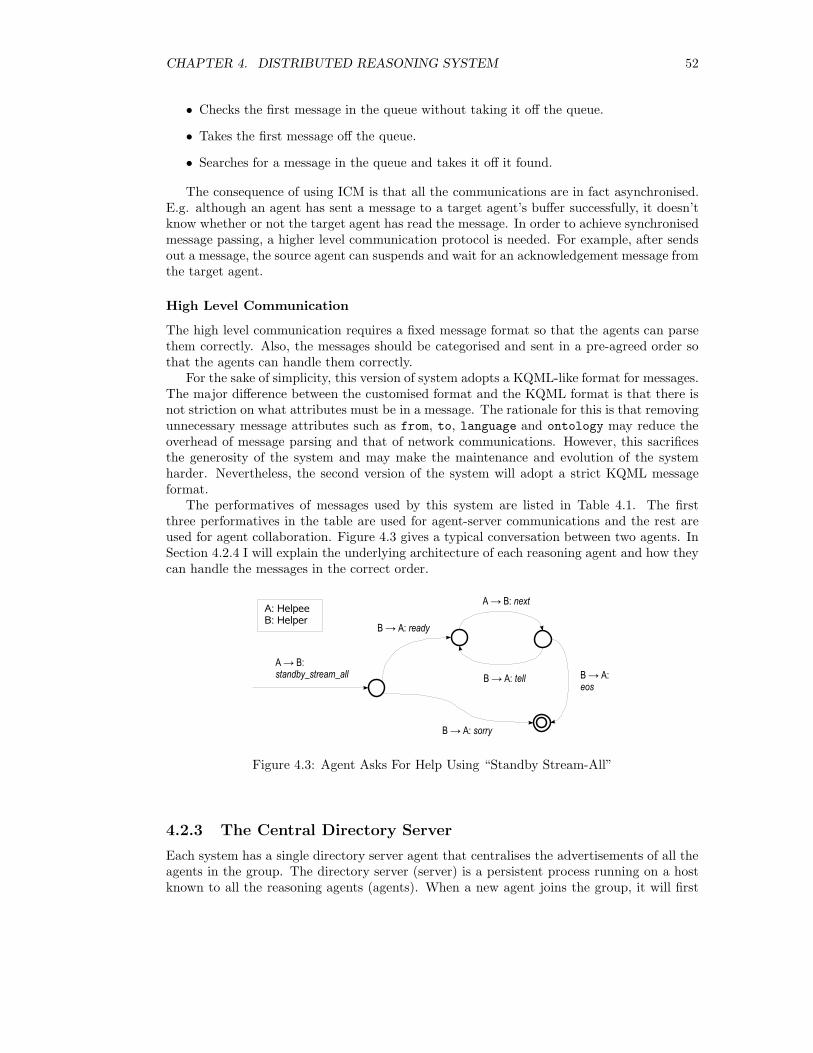
CHAPTER 4. DISTRIBUTED REASONING SYSTEM 52
• Checks the first message in the queue without taking it off the queue.
• Takes the first message off the queue.
• Searches for a message in the queue and takes it off it found.
The consequence of using ICM is that all the communications are in fact asynchronised.E.g. although an agent has sent a message to a target agent’s buffer successfully, it doesn’tknow whether or not the target agent has read the message. In order to achieve synchronisedmessage passing, a higher level communication protocol is needed. For example, after sendsout a message, the source agent can suspends and wait for an acknowledgement message fromthe target agent.
High Level Communication
The high level communication requires a fixed message format so that the agents can parsethem correctly. Also, the messages should be categorised and sent in a pre-agreed order sothat the agents can handle them correctly.
For the sake of simplicity, this version of system adopts a KQML-like format for messages.The major difference between the customised format and the KQML format is that there isnot striction on what attributes must be in a message. The rationale for this is that removingunnecessary message attributes such as from, to, language and ontology may reduce theoverhead of message parsing and that of network communications. However, this sacrificesthe generosity of the system and may make the maintenance and evolution of the systemharder. Nevertheless, the second version of the system will adopt a strict KQML messageformat.
The performatives of messages used by this system are listed in Table 4.1. The firstthree performatives in the table are used for agent-server communications and the rest areused for agent collaboration. Figure 4.3 gives a typical conversation between two agents. InSection 4.2.4 I will explain the underlying architecture of each reasoning agent and how theycan handle the messages in the correct order.
Figure 4.3: Agent Asks For Help Using “Standby Stream-All”
4.2.3 The Central Directory Server
Each system has a single directory server agent that centralises the advertisements of all theagents in the group. The directory server (server) is a persistent process running on a hostknown to all the reasoning agents (agents). When a new agent joins the group, it will first
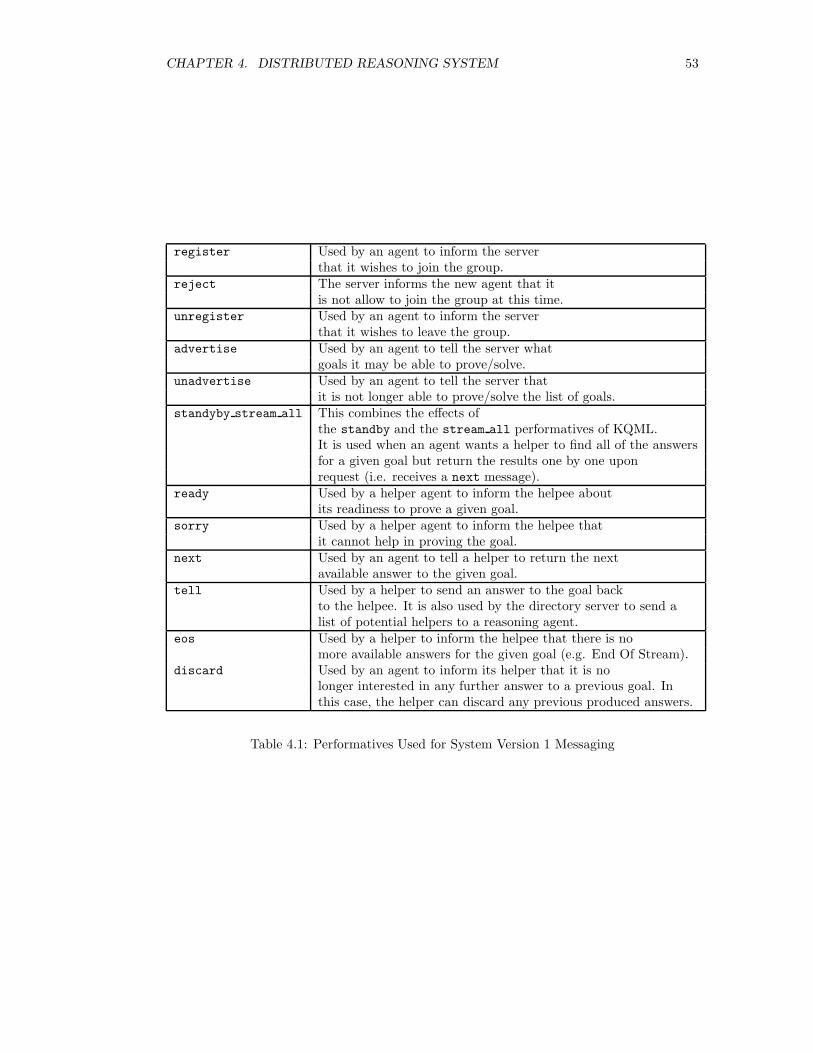
CHAPTER 4. DISTRIBUTED REASONING SYSTEM 53
register Used by an agent to inform the serverthat it wishes to join the group.
reject The server informs the new agent that itis not allow to join the group at this time.
unregister Used by an agent to inform the serverthat it wishes to leave the group.
advertise Used by an agent to tell the server whatgoals it may be able to prove/solve.
unadvertise Used by an agent to tell the server thatit is not longer able to prove/solve the list of goals.
standyby stream all This combines the effects ofthe standby and the stream all performatives of KQML.It is used when an agent wants a helper to find all of the answersfor a given goal but return the results one by one uponrequest (i.e. receives a next message).
ready Used by a helper agent to inform the helpee aboutits readiness to prove a given goal.
sorry Used by a helper agent to inform the helpee thatit cannot help in proving the goal.
next Used by an agent to tell a helper to return the nextavailable answer to the given goal.
tell Used by a helper to send an answer to the goal backto the helpee. It is also used by the directory server to send alist of potential helpers to a reasoning agent.
eos Used by a helper to inform the helpee that there is nomore available answers for the given goal (e.g. End Of Stream).
discard Used by an agent to inform its helper that it is nolonger interested in any further answer to a previous goal. Inthis case, the helper can discard any previous produced answers.
Table 4.1: Performatives Used for System Version 1 Messaging
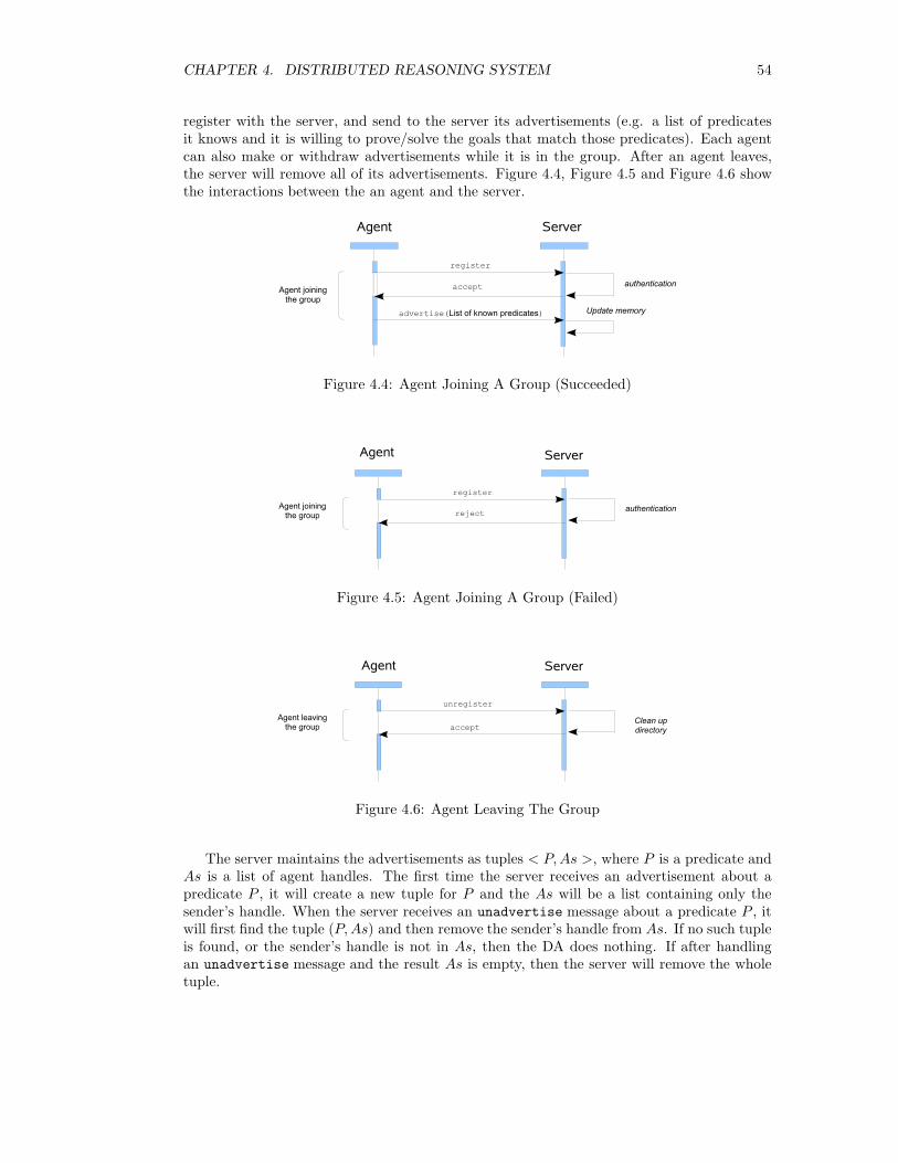
CHAPTER 4. DISTRIBUTED REASONING SYSTEM 54
register with the server, and send to the server its advertisements (e.g. a list of predicatesit knows and it is willing to prove/solve the goals that match those predicates). Each agentcan also make or withdraw advertisements while it is in the group. After an agent leaves,the server will remove all of its advertisements. Figure 4.4, Figure 4.5 and Figure 4.6 showthe interactions between the an agent and the server.
Figure 4.4: Agent Joining A Group (Succeeded)
Figure 4.5: Agent Joining A Group (Failed)
Figure 4.6: Agent Leaving The Group
The server maintains the advertisements as tuples < P, As >, where P is a predicate andAs is a list of agent handles. The first time the server receives an advertisement about apredicate P , it will create a new tuple for P and the As will be a list containing only thesender’s handle. When the server receives an unadvertise message about a predicate P , itwill first find the tuple (P, As) and then remove the sender’s handle from As. If no such tupleis found, or the sender’s handle is not in As, then the DA does nothing. If after handlingan unadvertise message and the result As is empty, then the server will remove the wholetuple.
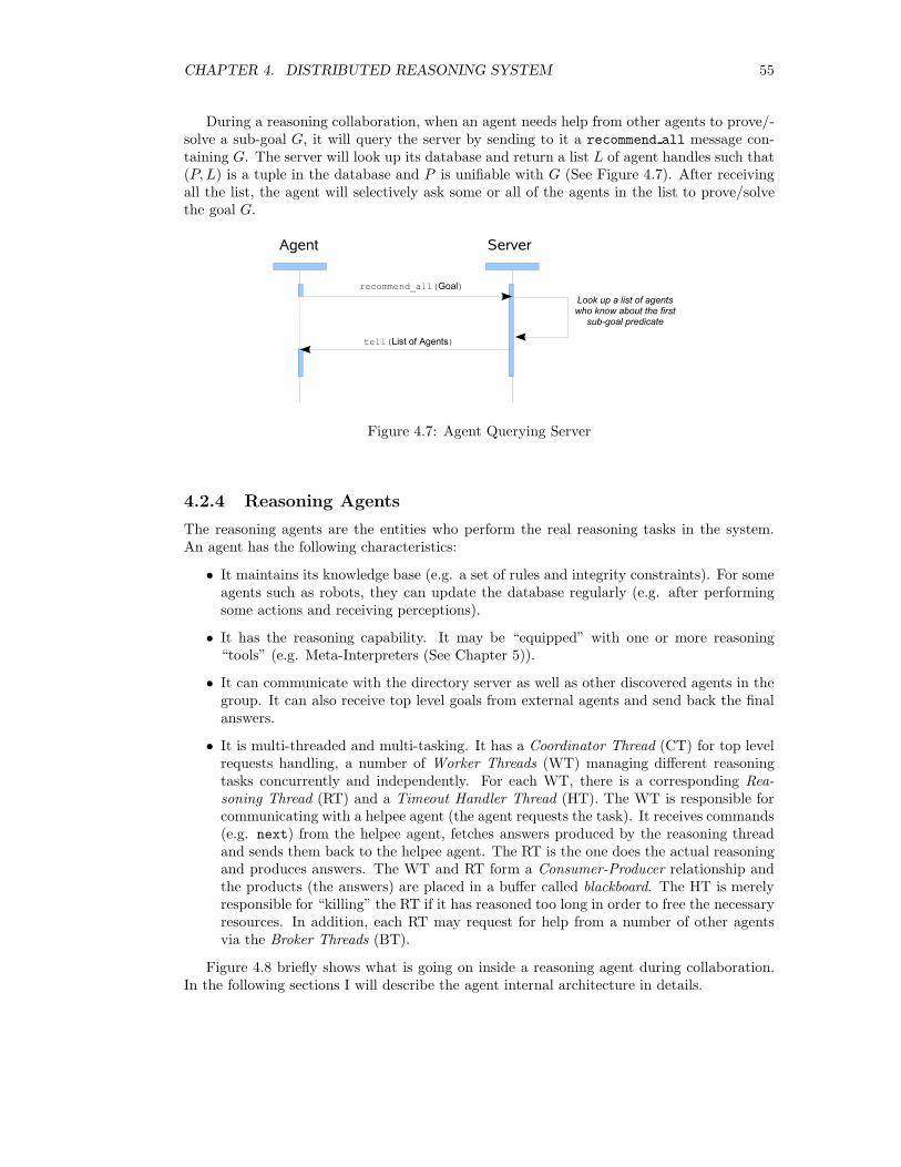
CHAPTER 4. DISTRIBUTED REASONING SYSTEM 55
During a reasoning collaboration, when an agent needs help from other agents to prove/-solve a sub-goal G, it will query the server by sending to it a recommend all message con-taining G. The server will look up its database and return a list L of agent handles such that(P, L) is a tuple in the database and P is unifiable with G (See Figure 4.7). After receivingall the list, the agent will selectively ask some or all of the agents in the list to prove/solvethe goal G.
Figure 4.7: Agent Querying Server
4.2.4 Reasoning Agents
The reasoning agents are the entities who perform the real reasoning tasks in the system.An agent has the following characteristics:
• It maintains its knowledge base (e.g. a set of rules and integrity constraints). For someagents such as robots, they can update the database regularly (e.g. after performingsome actions and receiving perceptions).
• It has the reasoning capability. It may be “equipped” with one or more reasoning“tools” (e.g. Meta-Interpreters (See Chapter 5)).
• It can communicate with the directory server as well as other discovered agents in thegroup. It can also receive top level goals from external agents and send back the finalanswers.
• It is multi-threaded and multi-tasking. It has a Coordinator Thread (CT) for top levelrequests handling, a number of Worker Threads (WT) managing different reasoningtasks concurrently and independently. For each WT, there is a corresponding Rea-soning Thread (RT) and a Timeout Handler Thread (HT). The WT is responsible forcommunicating with a helpee agent (the agent requests the task). It receives commands(e.g. next) from the helpee agent, fetches answers produced by the reasoning threadand sends them back to the helpee agent. The RT is the one does the actual reasoningand produces answers. The WT and RT form a Consumer-Producer relationship andthe products (the answers) are placed in a buffer called blackboard. The HT is merelyresponsible for “killing” the RT if it has reasoned too long in order to free the necessaryresources. In addition, each RT may request for help from a number of other agentsvia the Broker Threads (BT).
Figure 4.8 briefly shows what is going on inside a reasoning agent during collaboration.In the following sections I will describe the agent internal architecture in details.
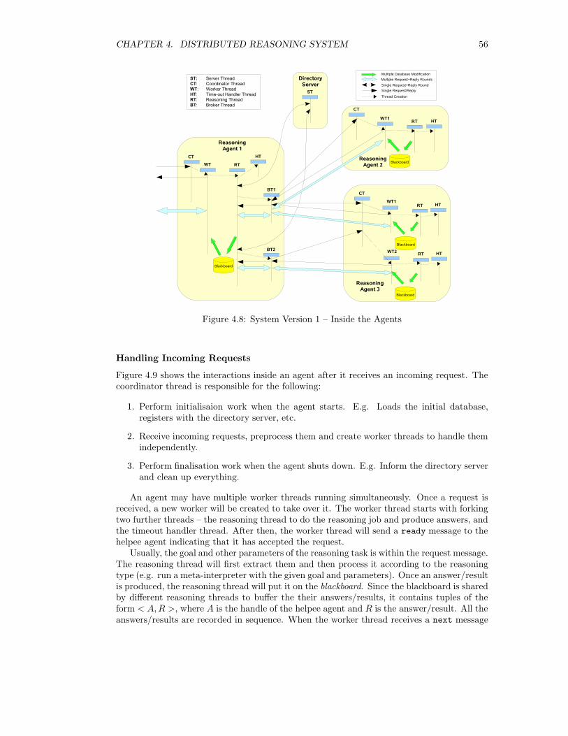
CHAPTER 4. DISTRIBUTED REASONING SYSTEM 56
Figure 4.8: System Version 1 – Inside the Agents
Handling Incoming Requests
Figure 4.9 shows the interactions inside an agent after it receives an incoming request. Thecoordinator thread is responsible for the following:
1. Perform initialisaion work when the agent starts. E.g. Loads the initial database,registers with the directory server, etc.
2. Receive incoming requests, preprocess them and create worker threads to handle themindependently.
3. Perform finalisation work when the agent shuts down. E.g. Inform the directory serverand clean up everything.
An agent may have multiple worker threads running simultaneously. Once a request isreceived, a new worker will be created to take over it. The worker thread starts with forkingtwo further threads – the reasoning thread to do the reasoning job and produce answers, andthe timeout handler thread. After then, the worker thread will send a ready message to thehelpee agent indicating that it has accepted the request.
Usually, the goal and other parameters of the reasoning task is within the request message.The reasoning thread will first extract them and then process it according to the reasoningtype (e.g. run a meta-interpreter with the given goal and parameters). Once an answer/resultis produced, the reasoning thread will put it on the blackboard. Since the blackboard is sharedby different reasoning threads to buffer the their answers/results, it contains tuples of theform < A, R >, where A is the handle of the helpee agent and R is the answer/result. All theanswers/results are recorded in sequence. When the worker thread receives a next message
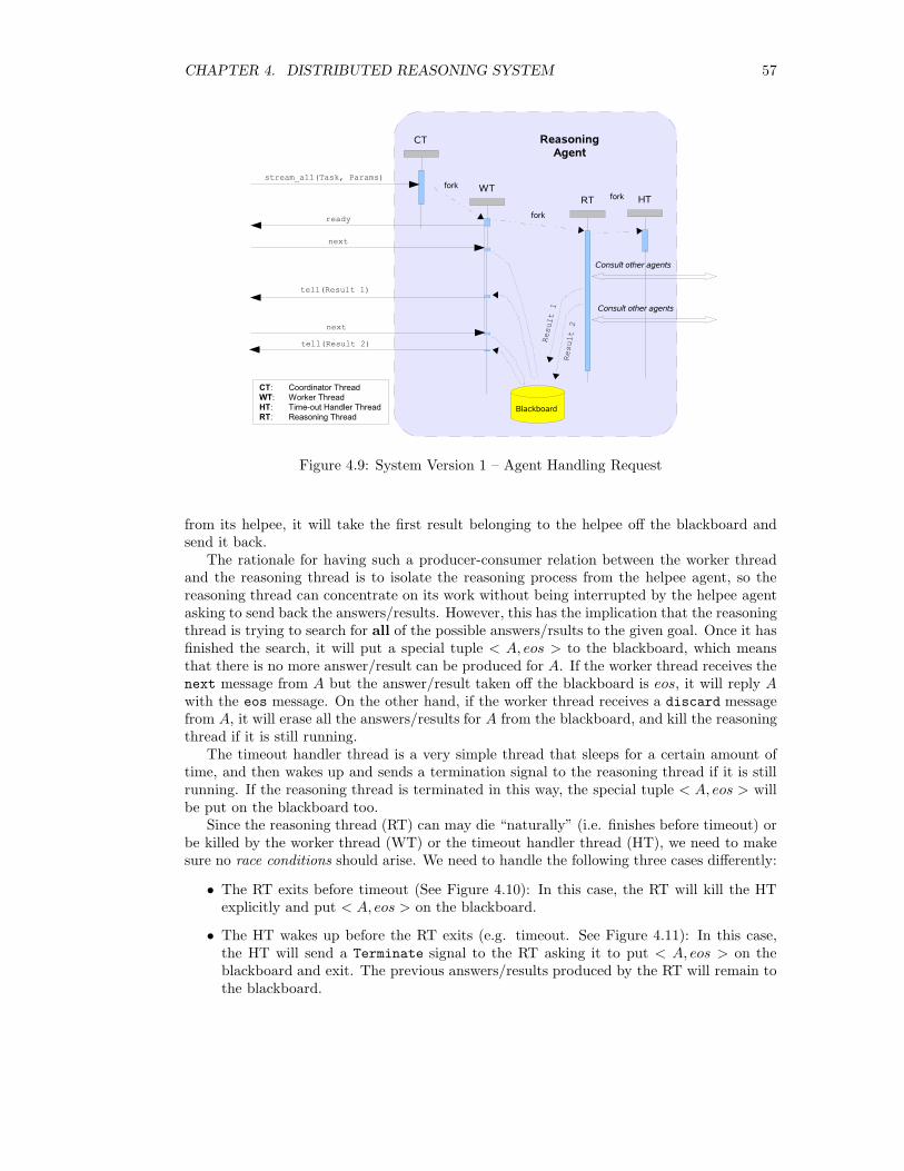
CHAPTER 4. DISTRIBUTED REASONING SYSTEM 57
Figure 4.9: System Version 1 – Agent Handling Request
from its helpee, it will take the first result belonging to the helpee off the blackboard andsend it back.
The rationale for having such a producer-consumer relation between the worker threadand the reasoning thread is to isolate the reasoning process from the helpee agent, so thereasoning thread can concentrate on its work without being interrupted by the helpee agentasking to send back the answers/results. However, this has the implication that the reasoningthread is trying to search for all of the possible answers/rsults to the given goal. Once it hasfinished the search, it will put a special tuple < A, eos > to the blackboard, which meansthat there is no more answer/result can be produced for A. If the worker thread receives thenext message from A but the answer/result taken off the blackboard is eos, it will reply Awith the eos message. On the other hand, if the worker thread receives a discard messagefrom A, it will erase all the answers/results for A from the blackboard, and kill the reasoningthread if it is still running.
The timeout handler thread is a very simple thread that sleeps for a certain amount oftime, and then wakes up and sends a termination signal to the reasoning thread if it is stillrunning. If the reasoning thread is terminated in this way, the special tuple < A, eos > willbe put on the blackboard too.
Since the reasoning thread (RT) can may die “naturally” (i.e. finishes before timeout) orbe killed by the worker thread (WT) or the timeout handler thread (HT), we need to makesure no race conditions should arise. We need to handle the following three cases differently:
• The RT exits before timeout (See Figure 4.10): In this case, the RT will kill the HTexplicitly and put < A, eos > on the blackboard.
• The HT wakes up before the RT exits (e.g. timeout. See Figure 4.11): In this case,the HT will send a Terminate signal to the RT asking it to put < A, eos > on theblackboard and exit. The previous answers/results produced by the RT will remain tothe blackboard.
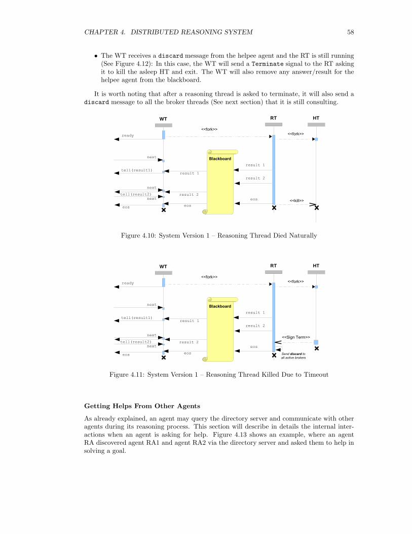
CHAPTER 4. DISTRIBUTED REASONING SYSTEM 58
• The WT receives a discard message from the helpee agent and the RT is still running(See Figure 4.12): In this case, the WT will send a Terminate signal to the RT askingit to kill the asleep HT and exit. The WT will also remove any answer/result for thehelpee agent from the blackboard.
It is worth noting that after a reasoning thread is asked to terminate, it will also send adiscard message to all the broker threads (See next section) that it is still consulting.
Figure 4.10: System Version 1 – Reasoning Thread Died Naturally
Figure 4.11: System Version 1 – Reasoning Thread Killed Due to Timeout
Getting Helps From Other Agents
As already explained, an agent may query the directory server and communicate with otheragents during its reasoning process. This section will describe in details the internal inter-actions when an agent is asking for help. Figure 4.13 shows an example, where an agentRA discovered agent RA1 and agent RA2 via the directory server and asked them to help insolving a goal.
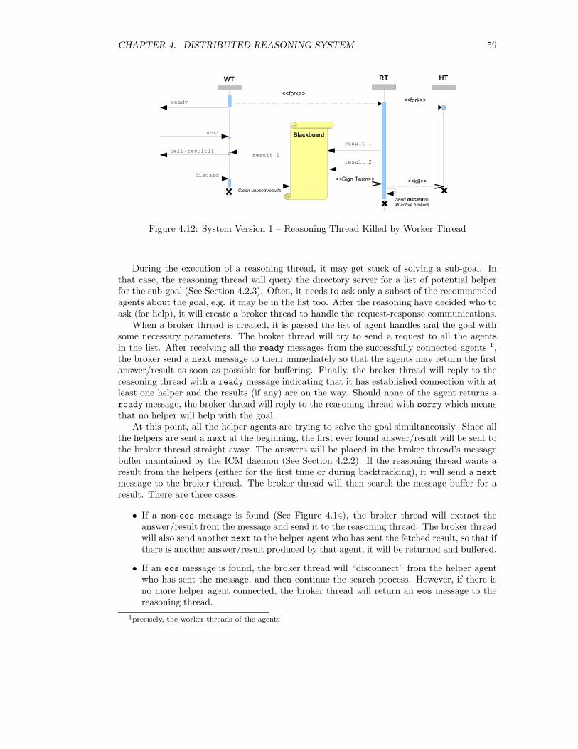
CHAPTER 4. DISTRIBUTED REASONING SYSTEM 59
Figure 4.12: System Version 1 – Reasoning Thread Killed by Worker Thread
During the execution of a reasoning thread, it may get stuck of solving a sub-goal. Inthat case, the reasoning thread will query the directory server for a list of potential helperfor the sub-goal (See Section 4.2.3). Often, it needs to ask only a subset of the recommendedagents about the goal, e.g. it may be in the list too. After the reasoning have decided who toask (for help), it will create a broker thread to handle the request-response communications.
When a broker thread is created, it is passed the list of agent handles and the goal withsome necessary parameters. The broker thread will try to send a request to all the agentsin the list. After receiving all the ready messages from the successfully connected agents 1,the broker send a next message to them immediately so that the agents may return the firstanswer/result as soon as possible for buffering. Finally, the broker thread will reply to thereasoning thread with a ready message indicating that it has established connection with atleast one helper and the results (if any) are on the way. Should none of the agent returns aready message, the broker thread will reply to the reasoning thread with sorry which meansthat no helper will help with the goal.
At this point, all the helper agents are trying to solve the goal simultaneously. Since allthe helpers are sent a next at the beginning, the first ever found answer/result will be sent tothe broker thread straight away. The answers will be placed in the broker thread’s messagebuffer maintained by the ICM daemon (See Section 4.2.2). If the reasoning thread wants aresult from the helpers (either for the first time or during backtracking), it will send a next
message to the broker thread. The broker thread will then search the message buffer for aresult. There are three cases:
• If a non-eos message is found (See Figure 4.14), the broker thread will extract theanswer/result from the message and send it to the reasoning thread. The broker threadwill also send another next to the helper agent who has sent the fetched result, so that ifthere is another answer/result produced by that agent, it will be returned and buffered.
• If an eos message is found, the broker thread will “disconnect” from the helper agentwho has sent the message, and then continue the search process. However, if there isno more helper agent connected, the broker thread will return an eos message to thereasoning thread.
1precisely, the worker threads of the agents
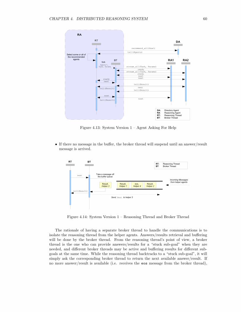
CHAPTER 4. DISTRIBUTED REASONING SYSTEM 60
Figure 4.13: System Version 1 – Agent Asking For Help
• If there no message in the buffer, the broker thread will suspend until an answer/resultmessage is arrived.
Figure 4.14: System Version 1 – Reasoning Thread and Broker Thread
The rationale of having a separate broker thread to handle the communications is toisolate the reasoning thread from the helper agents. Answers/results retrieval and bufferingwill be done by the broker thread. From the reasoning thread’s point of view, a brokerthread is the one who can provide answers/results for a “stuck sub-goal” when they areneeded, and different broker threads may be active and buffering results for different sub-goals at the same time. While the reasoning thread backtracks to a “stuck sub-goal”, it willsimply ask the corresponding broker thread to return the next available answer/result. Ifno more answer/result is available (i.e. receives the eos message from the broker thread),
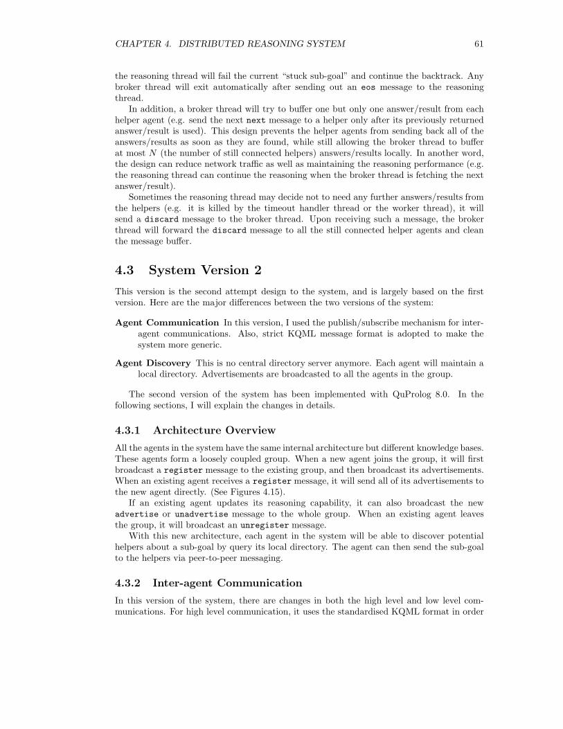
CHAPTER 4. DISTRIBUTED REASONING SYSTEM 61
the reasoning thread will fail the current “stuck sub-goal” and continue the backtrack. Anybroker thread will exit automatically after sending out an eos message to the reasoningthread.
In addition, a broker thread will try to buffer one but only one answer/result from eachhelper agent (e.g. send the next next message to a helper only after its previously returnedanswer/result is used). This design prevents the helper agents from sending back all of theanswers/results as soon as they are found, while still allowing the broker thread to bufferat most N (the number of still connected helpers) answers/results locally. In another word,the design can reduce network traffic as well as maintaining the reasoning performance (e.g.the reasoning thread can continue the reasoning when the broker thread is fetching the nextanswer/result).
Sometimes the reasoning thread may decide not to need any further answers/results fromthe helpers (e.g. it is killed by the timeout handler thread or the worker thread), it willsend a discard message to the broker thread. Upon receiving such a message, the brokerthread will forward the discard message to all the still connected helper agents and cleanthe message buffer.
4.3 System Version 2
This version is the second attempt design to the system, and is largely based on the firstversion. Here are the major differences between the two versions of the system:
Agent Communication In this version, I used the publish/subscribe mechanism for inter-agent communications. Also, strict KQML message format is adopted to make thesystem more generic.
Agent Discovery This is no central directory server anymore. Each agent will maintain alocal directory. Advertisements are broadcasted to all the agents in the group.
The second version of the system has been implemented with QuProlog 8.0. In thefollowing sections, I will explain the changes in details.
4.3.1 Architecture Overview
All the agents in the system have the same internal architecture but different knowledge bases.These agents form a loosely coupled group. When a new agent joins the group, it will firstbroadcast a register message to the existing group, and then broadcast its advertisements.When an existing agent receives a register message, it will send all of its advertisements tothe new agent directly. (See Figures 4.15).
If an existing agent updates its reasoning capability, it can also broadcast the newadvertise or unadvertise message to the whole group. When an existing agent leavesthe group, it will broadcast an unregister message.
With this new architecture, each agent in the system will be able to discover potentialhelpers about a sub-goal by query its local directory. The agent can then send the sub-goalto the helpers via peer-to-peer messaging.
4.3.2 Inter-agent Communication
In this version of the system, there are changes in both the high level and low level com-munications. For high level communication, it uses the standardised KQML format in order
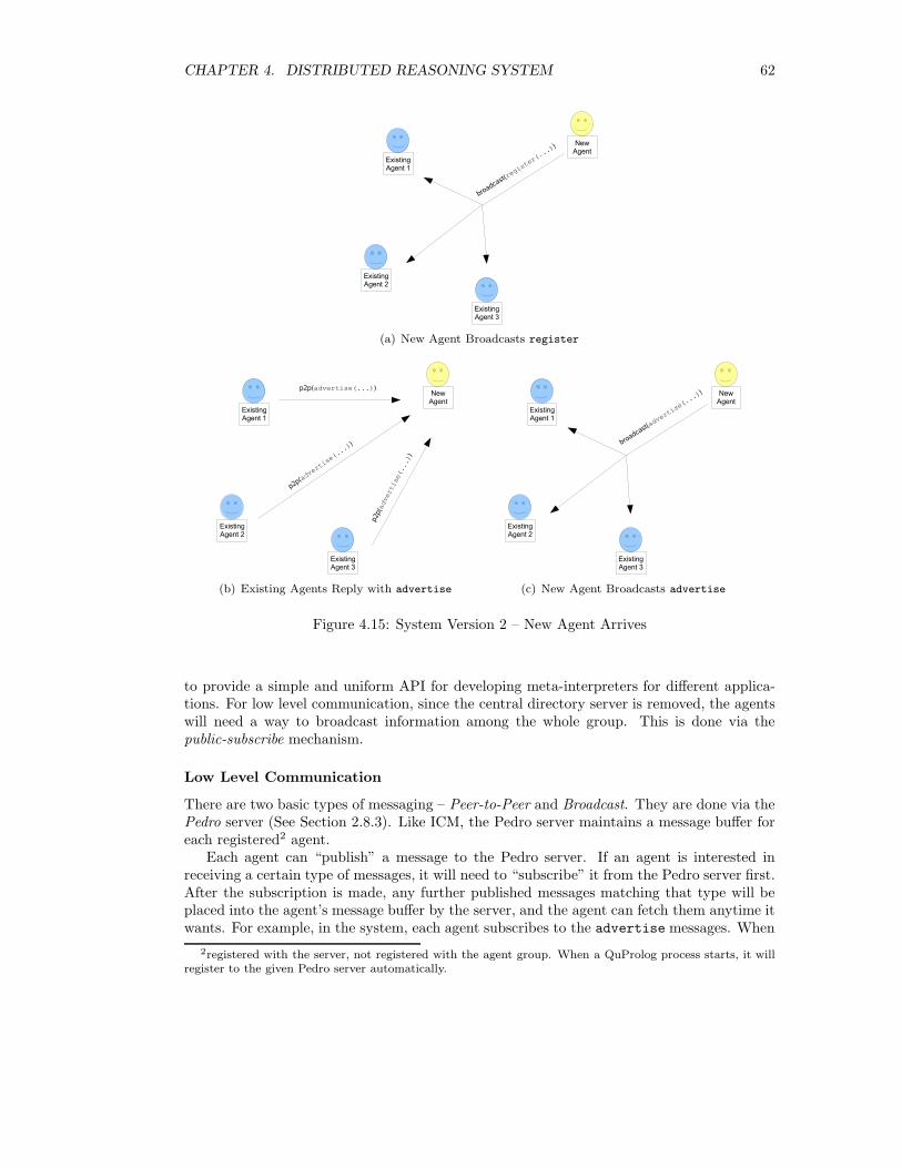
CHAPTER 4. DISTRIBUTED REASONING SYSTEM 62
(a) New Agent Broadcasts register
(b) Existing Agents Reply with advertise (c) New Agent Broadcasts advertise
Figure 4.15: System Version 2 – New Agent Arrives
to provide a simple and uniform API for developing meta-interpreters for different applica-tions. For low level communication, since the central directory server is removed, the agentswill need a way to broadcast information among the whole group. This is done via thepublic-subscribe mechanism.
Low Level Communication
There are two basic types of messaging – Peer-to-Peer and Broadcast. They are done via thePedro server (See Section 2.8.3). Like ICM, the Pedro server maintains a message buffer foreach registered2 agent.
Each agent can “publish” a message to the Pedro server. If an agent is interested inreceiving a certain type of messages, it will need to “subscribe” it from the Pedro server first.After the subscription is made, any further published messages matching that type will beplaced into the agent’s message buffer by the server, and the agent can fetch them anytime itwants. For example, in the system, each agent subscribes to the advertise messages. When
2registered with the server, not registered with the agent group. When a QuProlog process starts, it willregister to the given Pedro server automatically.
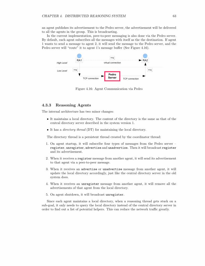
CHAPTER 4. DISTRIBUTED REASONING SYSTEM 63
an agent publishes its advertisement to the Pedro server, the advertisement will be deliveredto all the agents in the group. This is broadcasting.
In the current implementation, peer-to-peer messaging is also done via the Pedro server.By default, each agent subscribes all the messages with itself as the the destination. If agent1 wants to send a message to agent 2, it will send the message to the Pedro server, and thePedro server will “route” it to agent 1’s message buffer (See Figure 4.16).
Figure 4.16: Agent Communication via Pedro
4.3.3 Reasoning Agents
The internal architecture has two minor changes:
• It maintains a local directory. The content of the directory is the same as that of thecentral directory server described in the system version 1.
• It has a directory thread (DT) for maintaining the local directory.
The directory thread is a persistent thread created by the coordinator thread:
1. On agent startup, it will subscribe four types of messages from the Pedro server –register, unregister, advertise and unadvertise. Then it will broadcast registerand its advertisement.
2. When it receives a register message from another agent, it will send its advertisementto that agent via a peer-to-peer message.
3. When it receives an advertise or unadvertise message from another agent, it willupdate the local directory accordingly, just like the central directory server in the oldsystem does.
4. When it receives an unregister message from another agent, it will remove all theadvertisements of that agent from the local directory.
5. On agent shutdown, it will broadcast unregister.
Since each agent maintains a local directory, when a reasoning thread gets stuck on asub-goal, it only needs to query the local directory instead of the central directory server inorder to find out a list of potential helpers. This can reduce the network traffic greatly.
CHAPTER 4. DISTRIBUTED REASONING SYSTEM 64
4.4 Comparison of Two Versions
Though there are several architectural differences between the two versions of the system,their functionalities are the same, and they both have the Property 4.1, Property 4.2 andProperty 4.4. The changes in version 2 have pros and cons and they are depending on theactual applications.
Central Directory vs. Local Directory
In the central directory approach, the maintenance work is relatively easy because there isonly a single copy of the directory in the whole system. In the local directory approach, sinceevery agent has its own copy of the directory, we need to make sure all these directories areconsistent all the time. Also, if the directory is big, we also need to make sure each agenthas the sufficient resource (e.g. memory) to hold the directory.
For performance: in the central directory approach, every time when an agent needs toask for help, it has to query the server via a network connection. In the local directoryapproach, the agent only needs to query the local directory. Hence, if in an applicationrequires lots of agent collaborations, the local directory approach can reduce the networktraffic significantly.
Self-Invented Message Format vs. KQML Message Format
Using the well-known and fully documented KQML format can give generosity to the system.It will make the evolution of the system easier in the long run. It can also provide a uniformAPI for customising the system for different applications. However, the generic KQML formattends to make a message unnecessarily big, and the complex message structure will cause theagent to take more time to parse a message. Below are two sample messages carrying thesame information:
stream_all(abdemo,
[[car_doesnt_start(my_car)], [lights_go_on(my_car)], 4]).
and
stream_all([
from(agent1),
content([
task(abdemo),
goal([car_doesnt_start(my_car)]),
delta([lights_go_on(my_car)]),
depth(4)
])
]).
The first message is used for system version 1 and its structure is assumed to be understoodby both the sender and receiver – the first argument of stream all/2 is the reasoning typeand the second argument is a list of parameters such as the goal, the current delta and thesearch depth. The second message has the KQML format and is used for the system version2. It is easy to see that the second message is bigger and more complex, but more generic.
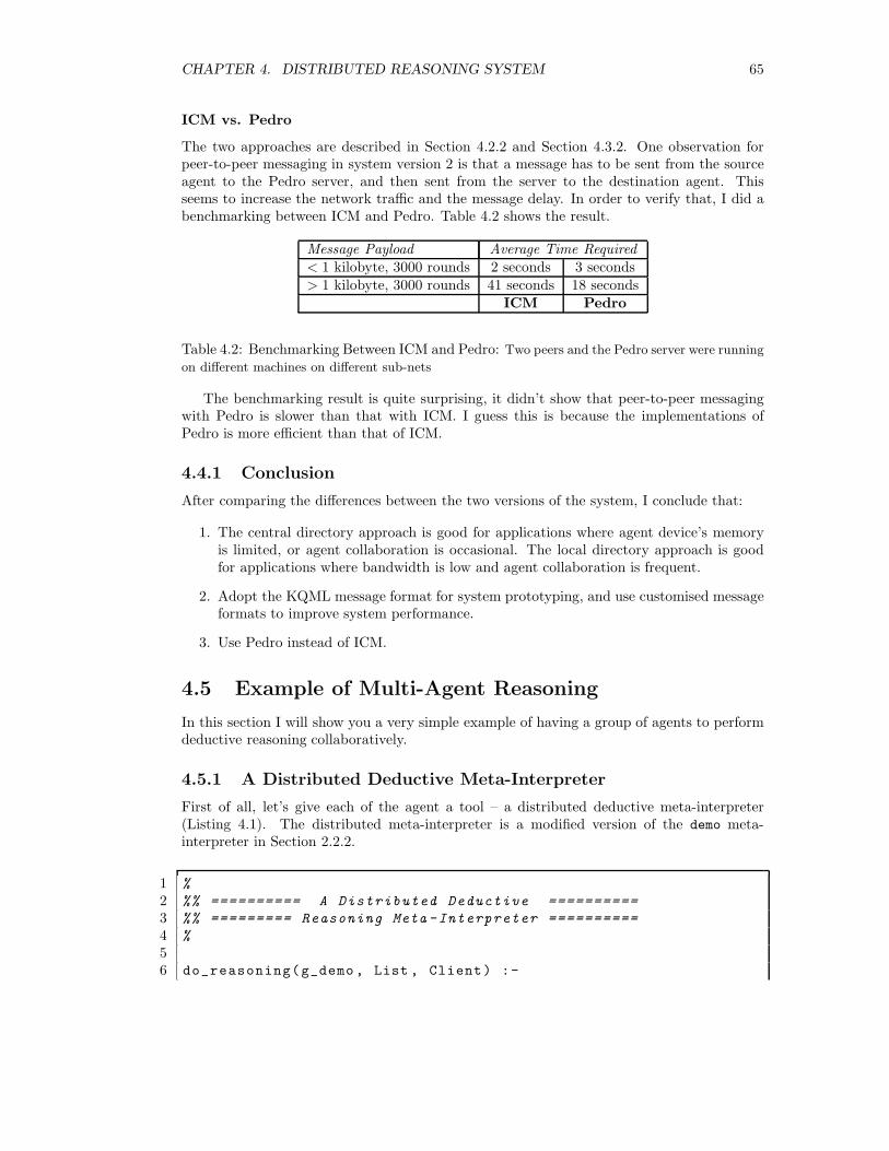
CHAPTER 4. DISTRIBUTED REASONING SYSTEM 65
ICM vs. Pedro
The two approaches are described in Section 4.2.2 and Section 4.3.2. One observation forpeer-to-peer messaging in system version 2 is that a message has to be sent from the sourceagent to the Pedro server, and then sent from the server to the destination agent. Thisseems to increase the network traffic and the message delay. In order to verify that, I did abenchmarking between ICM and Pedro. Table 4.2 shows the result.
Message Payload Average Time Required< 1 kilobyte, 3000 rounds 2 seconds 3 seconds> 1 kilobyte, 3000 rounds 41 seconds 18 seconds
ICM Pedro
Table 4.2: Benchmarking Between ICM and Pedro: Two peers and the Pedro server were running
on different machines on different sub-nets
The benchmarking result is quite surprising, it didn’t show that peer-to-peer messagingwith Pedro is slower than that with ICM. I guess this is because the implementations ofPedro is more efficient than that of ICM.
4.4.1 Conclusion
After comparing the differences between the two versions of the system, I conclude that:
1. The central directory approach is good for applications where agent device’s memoryis limited, or agent collaboration is occasional. The local directory approach is goodfor applications where bandwidth is low and agent collaboration is frequent.
2. Adopt the KQML message format for system prototyping, and use customised messageformats to improve system performance.
3. Use Pedro instead of ICM.
4.5 Example of Multi-Agent Reasoning
In this section I will show you a very simple example of having a group of agents to performdeductive reasoning collaboratively.
4.5.1 A Distributed Deductive Meta-Interpreter
First of all, let’s give each of the agent a tool – a distributed deductive meta-interpreter(Listing 4.1). The distributed meta-interpreter is a modified version of the demo meta-interpreter in Section 2.2.2.
1 %
2 %% ========== A Distributed Deductive ==========
3 %% ========= Reasoning Meta -Interpreter ==========
4 %
56 do_reasoning(g_demo, List , Client) :-
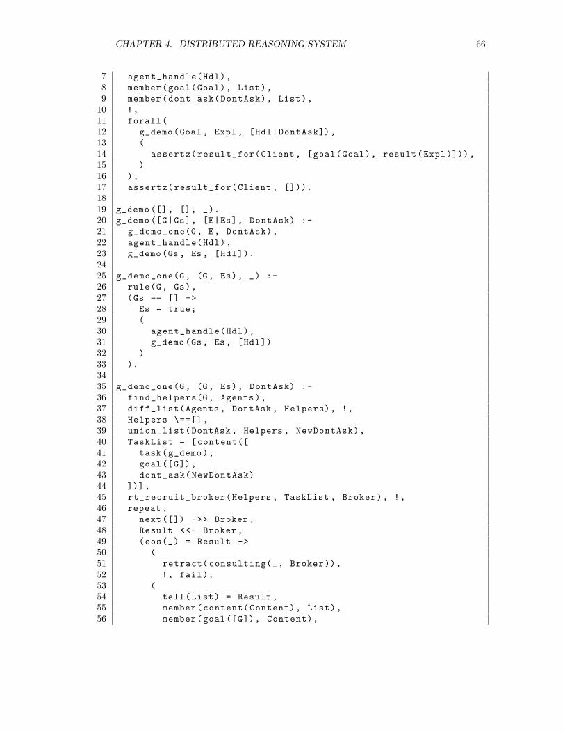
CHAPTER 4. DISTRIBUTED REASONING SYSTEM 66
7 agent_handle(Hdl),
8 member(goal(Goal), List),
9 member(dont_ask(DontAsk), List),
10 !,
11 forall(
12 g_demo(Goal , Expl , [Hdl|DontAsk]),
13 (
14 assertz(result_for(Client , [goal(Goal), result(Expl)])),
15 )
16 ),
17 assertz(result_for(Client , [])).
1819 g_demo ([], [], _).
20 g_demo ([G|Gs], [E|Es], DontAsk) :-
21 g_demo_one(G, E, DontAsk),
22 agent_handle(Hdl),
23 g_demo(Gs , Es , [Hdl]).
2425 g_demo_one(G, (G, Es), _) :-
26 rule(G, Gs),
27 (Gs == [] ->
28 Es = true;
29 (
30 agent_handle(Hdl),
31 g_demo(Gs , Es, [Hdl])
32 )
33 ).
3435 g_demo_one(G, (G, Es), DontAsk) :-
36 find_helpers(G, Agents),
37 diff_list(Agents , DontAsk , Helpers), !,
38 Helpers \==[] ,
39 union_list(DontAsk , Helpers , NewDontAsk),
40 TaskList = [content([
41 task(g_demo),
42 goal([G]),
43 dont_ask(NewDontAsk)
44 ])],
45 rt_recruit_broker(Helpers , TaskList , Broker), !,
46 repeat ,
47 next([]) ->> Broker,
48 Result <<- Broker ,
49 (eos(_) = Result ->
50 (
51 retract(consulting(_, Broker)),
52 !, fail);
53 (
54 tell(List) = Result ,
55 member(content(Content), List),
56 member(goal([G]), Content),
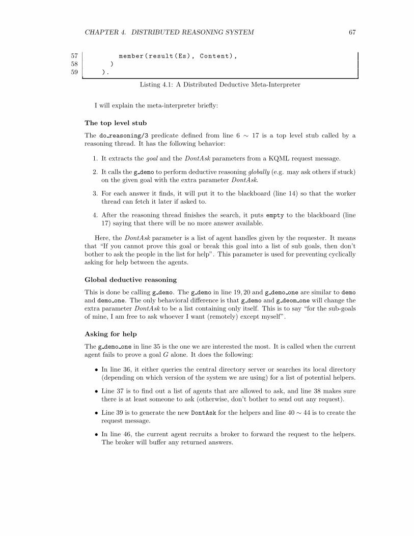
CHAPTER 4. DISTRIBUTED REASONING SYSTEM 67
57 member(result(Es), Content),
58 )
59 ).
Listing 4.1: A Distributed Deductive Meta-Interpreter
I will explain the meta-interpreter briefly:
The top level stub
The do reasoning/3 predicate defined from line 6 ∼ 17 is a top level stub called by areasoning thread. It has the following behavior:
1. It extracts the goal and the DontAsk parameters from a KQML request message.
2. It calls the g demo to perform deductive reasoning globally (e.g. may ask others if stuck)on the given goal with the extra parameter DontAsk.
3. For each answer it finds, it will put it to the blackboard (line 14) so that the workerthread can fetch it later if asked to.
4. After the reasoning thread finishes the search, it puts empty to the blackboard (line17) saying that there will be no more answer available.
Here, the DontAsk parameter is a list of agent handles given by the requester. It meansthat “If you cannot prove this goal or break this goal into a list of sub goals, then don’tbother to ask the people in the list for help”. This parameter is used for preventing cyclicallyasking for help between the agents.
Global deductive reasoning
This is done be calling g demo. The g demo in line 19, 20 and g demo one are similar to demo
and demo one. The only behavioral difference is that g demo and g deom one will change theextra parameter DontAsk to be a list containing only itself. This is to say “for the sub-goalsof mine, I am free to ask whoever I want (remotely) except myself”.
Asking for help
The g demo one in line 35 is the one we are interested the most. It is called when the currentagent fails to prove a goal G alone. It does the following:
• In line 36, it either queries the central directory server or searches its local directory(depending on which version of the system we are using) for a list of potential helpers.
• Line 37 is to find out a list of agents that are allowed to ask, and line 38 makes surethere is at least someone to ask (otherwise, don’t bother to send out any request).
• Line 39 is to generate the new DontAsk for the helpers and line 40 ∼ 44 is to create therequest message.
• In line 46, the current agent recruits a broker to forward the request to the helpers.The broker will buffer any returned answers.
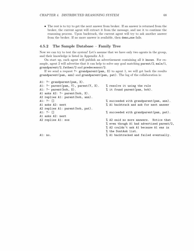
CHAPTER 4. DISTRIBUTED REASONING SYSTEM 68
• The rest is to try to get the next answer from broker. If an answer is returned from thebroker, the current agent will extract it from the message, and use it to continue thereasoning process. Upon backtrack, the current agent will try to ask another answerfrom the broker. If no more answer is available, then demo one fails.
4.5.2 The Sample Database – Family Tree
Now we can try to test the system! Let’s assume that we have only two agents in the group,and their knowledge is listed in Appendix A.2.
On start up, each agent will publish an advertisement containing all it knows. For ex-ample, agent 2 will advertise that it can help to solve any goal matching parent/2, male/1,grandparent/2, father/2 and predecessor/2.
If we send a request ?- grandparent(pam, X) to agent 1, we will get back the resultsgrandparent(pam, ann) and grandparent(pam, pat). The log of the collaboration is:
A1: ?- grandparent(pam, X).
A1: ?- parent(pam, Y), parent(Y, X). % resolve it using the rule
A1: ?- parent(bob, X). % it found parent(pam, bob).
A1 asks A2: ?- parent(bob, X).
A2 replies A1: parent(bob, ann).
A1: ?- [] % succeeded with grandparent(pam, ann).
A1 asks A2: next % A1 backtrack and ask for next answer
A2 replies A1: parent(bob, pat).
A1: ?- [] % succeeded with grandparent(pam, pat).
A1 asks A2: next
A2 replies A1: eos % A2 said no more answers. Notice that
% even though A1 had advertised parent/2,
% A2 couldn’t ask A1 because A1 was in
% the DontAsk list.
A1: no. % A1 backtracked and failed eventually.
Chapter 5
Distributed AbductiveMeta-Interpreters
Chapter 4 presents a multi-agent system for coordinating a collection of agents to performreasoning tasks. In order to give the agents the ability to perform collaborative abductivereasoning from their knowledge, I have also proposed two abductive meta-interpreters. Thefirst one is a general purpose meta-interpreter based on the Kakas-Mancarella proof pro-cedure. The second one is a simple abductive planner for planning with simplified eventcalculus.
Since the multi-agent system and the meta-interpreter relies on each other to achievethe objective of letting agents to perform distributed abduction, we call them DistributedAbductive REasoning System (DARES).
This chapter describes the two meta-interpreters in two sections.
5.1 General Purpose Distributed Abductive
Meta-Interpreter
5.1.1 Scenario
In some applications, agents may need to collaborate to explain a given goal G. Since eachagent will have its knowledge base Tn and set of integrity constraints In, let ∆ be the finalexplanation (result) obtained, and As be the cluster of agents that collaborated together togive ∆ (each agent must either have resolved a non-abducible sub-goal or have abduced anew abducible sub-goal). Assuming that:
• All the agents in the group agree to the set of abducible predicates.
•⋃
n∈As Tn is consistent.
∆ must satisfy the following:
•⋃
n∈As Tn ∪∆ � G;
•⋃
n∈As Tn ∪∆ is consistent;
•⋃
n∈As Tn ∪∆ satisfies⋃
n∈As In
69
CHAPTER 5. DISTRIBUTED ABDUCTIVE META-INTERPRETERS 70
This implies that the result obtained from the cluster of agents must not violate theintegrity constraints of each agent in the cluster, i.e. satisfies Property 4.3 (See Section 4.1.4).
Let’s look at a very simple diagnosis example with two agents. The set of abduciblepredicates is {battery flat(X), has no fule(X), broken indicator(X)} The knowledgebase and integrity constraints of each agent is listed below:
Agent 1
car doesnt start(X) ← has no fuel(X).
lights go on(mycar).
← has no fuel(X), not fuel indicator empty(X),
not broken indicator(X).
Agent 2
car doesnt start(X) ← battery flat(X).
fuel indicator empty(mycar).
← battery flat(X), lights go on(X).
If we ask the agents to explain car doesnt start(mycar), any of the follow answerswould satisfy the requirements:
1. As = [agent1], ∆ = {broken indicator(mycar), has no fuel(mycar)}
2. As = [agent2], ∆ = {flat battery(mycar)}
3. As = [agent1, agent2], ∆ = {broken indicator(mycar), has no fuel(mycar)}
5.1.2 Proof Procedure
In this section explains the proof procedure for the meta-interpreter.Same as before, abducibles are divided into two sets: base abducibles and non-base ab-
ducibles. A base abducible is a positive literal or a negative literal with abducible predicate.A non-base abducible is a negative literal with a non-abducible predicate. Non-abduciblesare positive literals with non-abducible predicates.
G is a list of ground sub-goals to be explained and has the form ← L1, . . . , Lk, where Li
is either a positive or negative literal. If k = 0 then G = []. The complement of L is writtenas L∗. A top-down proof procedure interleaves the global abductive derivation, the globalconsistency derivation, the local abductive derivation and the local consistency derivation, toreduce G to [] (the empty list). The ∆ (a set of ground abducibles) is collected and As (theset of the agents in the cluster) is expanded along the procedure. Initially, ∆ is empty andAs contains only the current agent.
Global Abductive Derivation
The global abductive derivation succeeds if G is empty. Otherwise, G′ is obtained byremoving a literal L from G, ∆′ and As′ are the set of ground abducibles and the agentcluster obtained after applying one of the following rules:

CHAPTER 5. DISTRIBUTED ABDUCTIVE META-INTERPRETERS 71
1. If L is a non-abducible. If a rule whose head can match L exists, and the instantiatedbody is C, then the current agent continues the global abductive derivation on C ∪G′
with ∆′ = ∆ and As′ = As.
2. If L is a non-abducible and the previous rule fails, the current agent will try to ask ahelper agent A to perform a global abductive derivation on← L. If A ∈ As then A willperform the global abductive derivation on ← L with ∆ and As. If A /∈ As, then Awill first perform a global consistency derivation on ∆ with A ∪As, and then performa global abductive derivation on ← L with ∆′′ and A∪As, where ∆′′ is obtained aftera successful global consistency derivation.
• If A succeeds in a global abductive derivation and returns ∆′ and As′, then thecurrent agent continues the current global abductive derivation on G′ with ∆′ andAs′.
• otherwise, the current derivation fails.
3. If L is an abducible and L∗ is already in ∆, the derivation fails.
4. If L is an abducible and L is already in ∆, then the current agent continues the globalabductive derivation on G′ with ∆′ = ∆ and As′ = As.
5. If L is a base abducible and neither L nor L∗ is in ∆, if there exists a global consis-tency derivation on {L} ∪∆ with As, and ∆′ is obtained after the global consistencyderivation, then the current agent continues the global abductive derivation on G′ with∆′ and As′ = As.
6. If L is a non-base abducible and L is not in ∆, if there exists a local consistencyderivation on {← L∗} with ∆′′ = ∆ ∪ {L}, and if there exists a global consistencyderivation on ∆′′′ with As, where ∆′′′ is obtained after the local consistency derivation,then the current agent continues the global abductive derivation on G′ with ∆′ andAs′ = As where ∆′ is obtained after the global consistency derivation. Otherwise, thecurrent derivation fails.
Global Consistency Derivation
In global consistency derivation, ∆0 is the given set of abducibles and As is the set of agentsin the cluster.
∆′ is obtained by passing ∆ around the agents in As exactly once. The agents in As arelabeled as A1, . . . , An. For one round consistency check on ∆:
1. At first, ∆ is passed to A1. If there is a local abductive derivation on ∆ (∆ is consideredas a list of goals) by A1 and ∆1 is obtained after the derivation, then ∆1 is passed toA2.
2. Finally, if ∆n−1 is passed to An and ∆′ is obtained after a successful local abductivederivation by An on ∆n−1, then the current round of consistency check finishes.
If one round consistency check finishes and ∆′ = ∆, then the global consistency derivationsucceeds. If one round consistency check finishes but ∆′ 6= ∆ (i.e. ∆ expands to become∆′), then start another round of consistency check. The global consistency check continuesuntil ∆ remains the unexpanded after one successful round of consistency check. The final∆′ obtained is the result for the successful global consistency derivation.
If one round consistency check cannot finishes (i.e. ∆ cannot satisfy an agent’s integrityconstraints), then the global consistency derivation fails.
CHAPTER 5. DISTRIBUTED ABDUCTIVE META-INTERPRETERS 72
Local Abductive Derivation
The local abductive derivation is similar to the abductive derivation of the Kakas-Mancarellaproof procedure described in Section 2.3.3. The difference is that this one checks integrityconstraints.
The local abductive derivation succeeds if G is empty. Otherwise, G′ is obtained byremoving a literal L from G, ∆′ is the set of ground abducibles obtained after applying oneof the following rules:
1. If L is a non-abducible. If a rule whose head can match L exists, and the instantiatedbody is C, then the current agent continues the local abductive derivation on C ∪ G′
with ∆′ = ∆. Otherwise, the derivation fails.
2. If L is an abducible and L∗ is already in ∆, the derivation fails.
3. If L is an abducible and L is already in ∆, then agent continues the local abductivederivation on G′ with ∆′ = ∆.
4. If L is a base abducible and neither L nor L∗ is in ∆. Let C be the set of integrityconstraints containing L, and C′ be the set obtained by removing L from each constraintin C. If there exists a successful local consistency derivation on C′, then the agentcontinues the local abductive derivation on G′ with ∆′ = {L}.
5. If L is a non-base abducible and L is not in ∆. Let C be the set of integrity constraintscontaining L, and C′ be the set obtained by removing L from each constraint in C. Ifthere exists a local consistency derivation on {C′∪ ← L∗} with ∆′′ = ∆ ∪ {L}, thenthe agent continues the local abductive derivation on G′ with ∆′ where ∆′ is obtainedafter the local consistency derivation. Otherwise, the derivation fails.
Local Consistency Derivation
The local consistency derivation is the same as the consistency derivation of the Kakas-Mancarella proof procedure described in Section 2.3.3. I included it here for easy reading.
In the consistency derivation, F is a set of goals to be checked for consistency. Theconsistency derivation succeeds if F is empty. The consistency derivation fails if F contains[]. Otherwise, let F ′ ∪ G = F and G′ is obtained by removing a literal L from G and ∆′ isthe set of abducibles after applying a rule. The rules in the consistency derivation are:
1. If L is a non abducible. C is the set of all the instantiated non empty bodies of therules in the database whose heads can match L, continue the consistency derivation onC ∪ F ′ with ∆.
2. If L is abducible and L is already in ∆, continue the consistency derivation on F ′ ∪G′
with ∆′ = ∆.
3. If L is abducible and L∗ is already in ∆, then continue the consistency derivation withF ′ and ∆′ = ∆ .
4. If L is base abducible and neither L nor L∗ is in ∆, then continue the consistencyderivation with F ′ and ∆′ = ∆ ∪ L∗.
5. If L is non-base abducible and L is not in ∆, if there exists an successful abductivederivation on {← L∗} with ∆, then continue the consistency derivation on F ′ with ∆′
where ∆′ is obtained from the abductive derivation.
CHAPTER 5. DISTRIBUTED ABDUCTIVE META-INTERPRETERS 73
Example Run of the Meta-Interpreter
Let’s try out the example described in Section 5.1.1 with the distributed reasoning systemand and the meta-interpreter.
When we asked agent 1 to explain car doesnt start(mycar), we got As = [agent1],
∆ = {broken indicator(mycar), has no fuel(mycar)}:
1. Initially, only agent 1 was in the cluster.
2. Agent 1 resolved the non-abducible car doesnt start(mycar) to has no fuel(mycar),and then tried to check the integrity constraint ← has no fuel(mycar),
not fuel indicator empty(mycar), not broken indicator(mycar).
3. Agent 1 could not fail to prove the non-base abducible not fuel indicator empty(mycar),so it abduced broken indicator(mycar).
4. Since agent 1 was still the only one in the cluster, and the result∆ = {broken indicator(mycar), has no fuel(mycar)} is consistent with its knowl-edge base and integrity constraint, it was returned.
5. Then agent 1 backtracked and asked agent 2 to prove car doesnt start(mycar).
6. agent 2 abduced battery flat(mycar) in the global abductive derivation and abducednot lights go on in the local consistency derivation. However, during the globalconsistency derivation, agent 1 failed to prove not lights go on(mycar) so it rejectedit.
7. agent 2 backtracked and couldn’t find any more answer. So none answer was returnedfrom agent 2 to agent 1.
8. Finally, agent 1 finished the backtracking without finding any more results.
When we asked agent 2 to explain car doesnt start(mycar), we received
As = [agent2], ∆ = {battery flat(mycar)}
, and
As = [agent1, agent2], ∆ = {broken indicator(mycar), has no fuel(mycar)}
:
1. Initially, only agent 2 was in the cluster.
2. Agent 2 resolved car doesnt start(mycar) to battery flat(mycar), and abducedbattery flat(mycar). In its local consistency check, it didn’t know lights go on(mycar)so the integrity constraint← battery flat(mycar), lights go on(mycar) is consis-tent. Agent 2 returned As = [agent2], ∆ = {battery flat(mycar)} as the firstanswer.
3. Agent 2 backtracked and asked agent 1 to prove car doesnt start(mycar). Agentabduced broken indicator(mycar) and has no fuel(mycar), and they passed theglobal consistency check between agent 1 and agent 2, so As = [agent1, agent2], ∆= {broken indicator(mycar), has no fuel(mycar)} was returned from agent 1 toagent 2, and agent 2 returned it to us as the second answer.
CHAPTER 5. DISTRIBUTED ABDUCTIVE META-INTERPRETERS 74
4. Finally, agent 2 finished the backracking without finding any more results.
Clearly, those answers satisfied the requirements. Further more, it can be observed thatthe more agents in the cluster, the better “quality” the returned answer is. Hence, for a realapplication, we may do the following:
• Ask the agents to returned a number of answers, and select the one with the clustercontain the most agents.
• Ask the an agent to prove a goal with a predefined cluster, i.e. force the agent to checkall of its answers with the given “experts” before returning them.
5.1.3 Correctness of the Procedure
In this section, I attempt to show that the proof procedure I have proposed indeed satisfiesProperty 4.3.
First of all, the local abductive derivation and the local consistent derivation are basicallythe Kakas-Mancarella proof procedure with integrity constraint check. So their correctnessis based on Kakas’s work[17].
Lemma 5.1 The local abductive derivation and the local consistent derivation together willgive a correct answer that satisfies the agent’s local integrity constraints.
Secondly, the ∆ obtained after a global consistent derivation satisfies all the integrityconstraints of all the agents in the cluster:
1. When an agent is passed a ∆, it will consider it as a goal and perform a local abductionon it. Since the ∆ contains only abducibles, the local abduction will have the sameeffect of checking whether the abducibles are consistent with the agent’s database andsatisfy the agent’s integrity constraints.
2. If the ∆ expands in a round of global consistency, it will be checked for another round.Therefore, all the agents will have the chance to check every new abducibles abducedby an agent after them.
3. If one round is finished and the ∆ doesn’t change, then the ∆ must be consistent withevery agent’s database and satisfies every agent’s integrity constraint (by Lemma 5.1).
4. The global consistency check will eventually terminate because the set of all groundabducibles is finite.
Lemma 5.2 The ∆ obtained by a successful global consistent derivation will satisfy all theintegrity constraints of all the agents in the cluster. I.e. it satisfies Property 4.3.
Finally, I need to show that the result produced by a successful global abductive derivationwill satisfy all the integrity constraints of all the agents in the cluster. This is done as follow:
1. Base case: Let A be an agent who has never asked any other agent to resolve a sub-goal during the global abductive derivation, i.e. rule 2 is never selected. For A, the ∆would change only after applying rule 5 or rule 6. But the ∆′ obtained after applyingrule 5 or rule 6 must have gone through a global consistency check. So (by Lemma 5.2)the ∆ return from A after a successful global abductive derivation satisfy Property 4.3.
CHAPTER 5. DISTRIBUTED ABDUCTIVE META-INTERPRETERS 75
2. Induction Assumption: The current ∆ is consistent with the integrity constraintsof each agent in the current cluster.
3. Induction Step: Let A′ be an agent who has asked some other agents to help inresolving some sub-goals, i.e. rule 2 is applied (one or more times), and all the ∆′
returned from the helper agents satisfies Property 4.3 (If the agent being asked is a newagent to the cluster, according to the global abductive derivation, it will first performa global consistency derivation before starting the global abductive derivation. Theglobal consistency derivation guarantees the new agent joins the cluster consistently).Similarly to the base case, the ∆ would ever change again after applying rule 5 or6. But the global consistency derivation in these rules will guarantee that changed ∆satisfy Property 4.3. Therefore, the result returned from A′ will satisfy Property 4.3too.
In conclusion:
Lemma 5.3 The ∆ obtained by a successful global abductive derivation will satisfy all theintegrity constraints of all the agents in the cluster. I.e. it satisfies Property 4.3.
and therefore, my proposed proof procedure (and the meta-interpreter) will also satisfiesProperty 4.3.
5.1.4 Optimisation
When implementing the meta-interpreter, there are several optimisations possible. One majoroptimisation I made to the meta-interpreter is in the global consistency derivation.
In the original proof procedure, we can observe that during the each round of consistencycheck among the agent in the cluster, each agent needs to perform a local abduction using∆ as the goal. If one new abducible is added to the ∆, then in the next round, each agentswill need to perform another local abduction on the expanded ∆. In fact, in each round,we only expect each agent to check the newly added abducibles for consistency, i.e. performlocal abduction using the set of newly added abducibles as the goal and the original ∆ asthe input ∆. Therefore, in my optimised version of the meta-interpreter:
1. In the four derivations, current ∆ is divided into two disjunctive subset – ∆fixed and∆new. ∆fixed is the set of abducibles given to each derivation at the beginning andthe set will remain unchanged during the current derivation. Any abducibles addedduring this derivation will be put into ∆new. When the derivation succeeds, ∆′ =∆fixed ∪∆new .
2. Whenever a new abducible L is about to add to ∆new in the global abductive derivation,a global consistency derivation will start with ∆′
fixed = ∆fixed ∪∆new and {L}:
(a) In the first round, agent A1 will perform a local abduction with {L} as the goal,∆′
fixed as the input fixed set of abducibles. If the local abduction succeeds, and∆′
new1is the output set of (new) abducibles, then ∆′
fixed and ∆′
new1will be passed
to the next agent.
(b) When the round is finished, if obtained ∆′
newn
is equal to {L}, then the globalconsistency derivation succeeds. Otherwise, we will start another round with∆′
newn
−{L} as the initial goal and ∆′
fixed∪{L} as the new fixed set of abducibles.
Hence, the optimised meta-interpreter will do consistency check on ∆ incrementally in-stead of bruteforce checking.
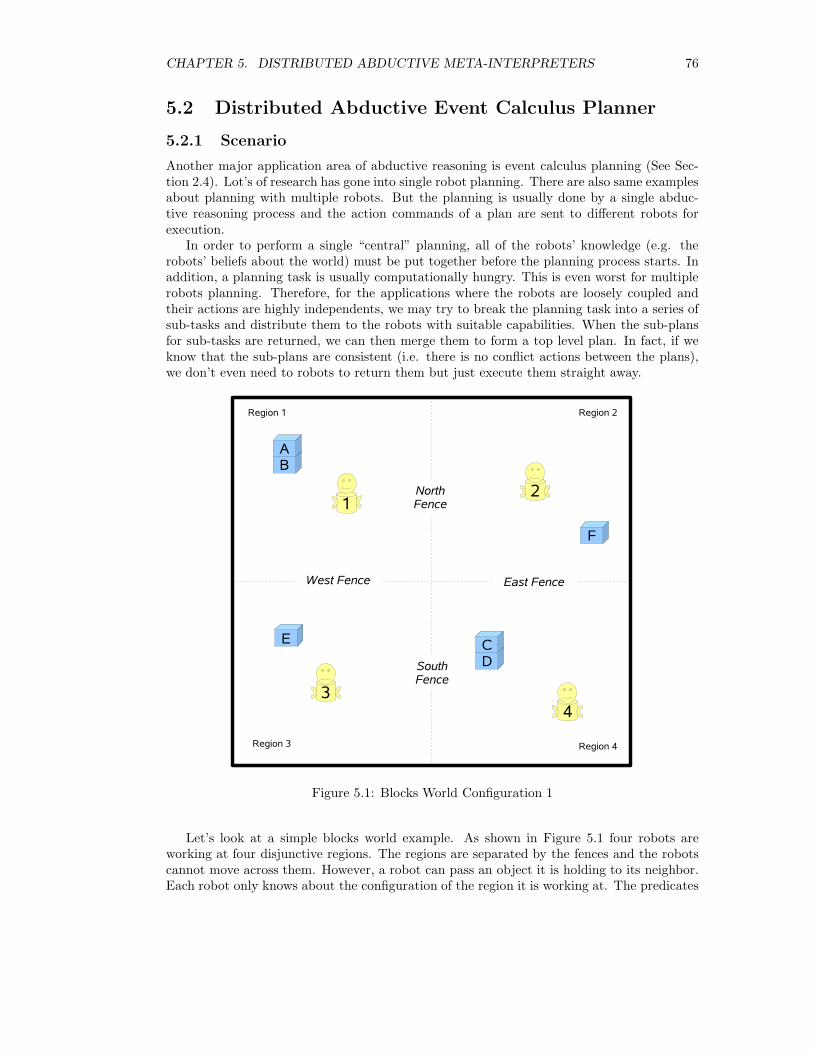
CHAPTER 5. DISTRIBUTED ABDUCTIVE META-INTERPRETERS 76
5.2 Distributed Abductive Event Calculus Planner
5.2.1 Scenario
Another major application area of abductive reasoning is event calculus planning (See Sec-tion 2.4). Lot’s of research has gone into single robot planning. There are also same examplesabout planning with multiple robots. But the planning is usually done by a single abduc-tive reasoning process and the action commands of a plan are sent to different robots forexecution.
In order to perform a single “central” planning, all of the robots’ knowledge (e.g. therobots’ beliefs about the world) must be put together before the planning process starts. Inaddition, a planning task is usually computationally hungry. This is even worst for multiplerobots planning. Therefore, for the applications where the robots are loosely coupled andtheir actions are highly independents, we may try to break the planning task into a series ofsub-tasks and distribute them to the robots with suitable capabilities. When the sub-plansfor sub-tasks are returned, we can then merge them to form a top level plan. In fact, if weknow that the sub-plans are consistent (i.e. there is no conflict actions between the plans),we don’t even need to robots to return them but just execute them straight away.
Figure 5.1: Blocks World Configuration 1
Let’s look at a simple blocks world example. As shown in Figure 5.1 four robots areworking at four disjunctive regions. The regions are separated by the fences and the robotscannot move across them. However, a robot can pass an object it is holding to its neighbor.Each robot only knows about the configuration of the region it is working at. The predicates
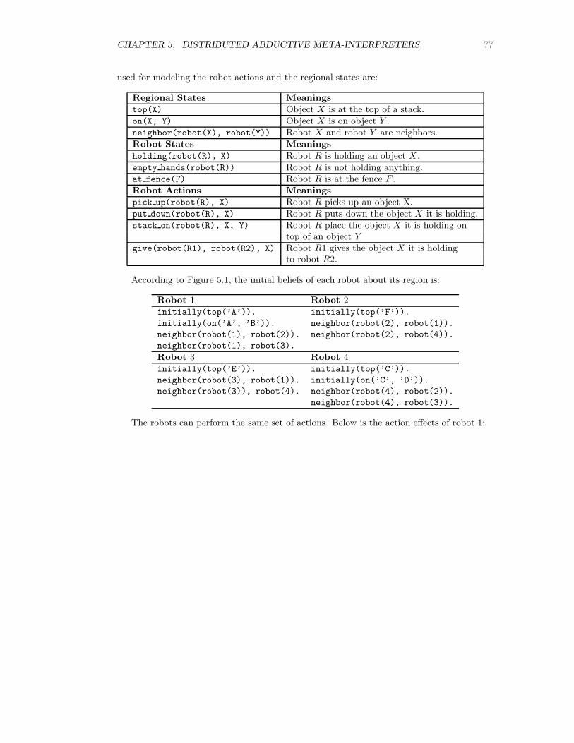
CHAPTER 5. DISTRIBUTED ABDUCTIVE META-INTERPRETERS 77
used for modeling the robot actions and the regional states are:
Regional States Meaningstop(X) Object X is at the top of a stack.on(X, Y) Object X is on object Y .neighbor(robot(X), robot(Y)) Robot X and robot Y are neighbors.Robot States Meaningsholding(robot(R), X) Robot R is holding an object X .empty hands(robot(R)) Robot R is not holding anything.at fence(F) Robot R is at the fence F .Robot Actions Meaningspick up(robot(R), X) Robot R picks up an object X.put down(robot(R), X) Robot R puts down the object X it is holding.stack on(robot(R), X, Y) Robot R place the object X it is holding on
top of an object Ygive(robot(R1), robot(R2), X) Robot R1 gives the object X it is holding
to robot R2.
According to Figure 5.1, the initial beliefs of each robot about its region is:
Robot 1 Robot 2initially(top(’A’)). initially(top(’F’)).
initially(on(’A’, ’B’)). neighbor(robot(2), robot(1)).
neighbor(robot(1), robot(2)). neighbor(robot(2), robot(4)).
neighbor(robot(1), robot(3).
Robot 3 Robot 4initially(top(’E’)). initially(top(’C’)).
neighbor(robot(3), robot(1)). initially(on(’C’, ’D’)).
neighbor(robot(3)), robot(4). neighbor(robot(4), robot(2)).
neighbor(robot(4), robot(3)).
The robots can perform the same set of actions. Below is the action effects of robot 1:
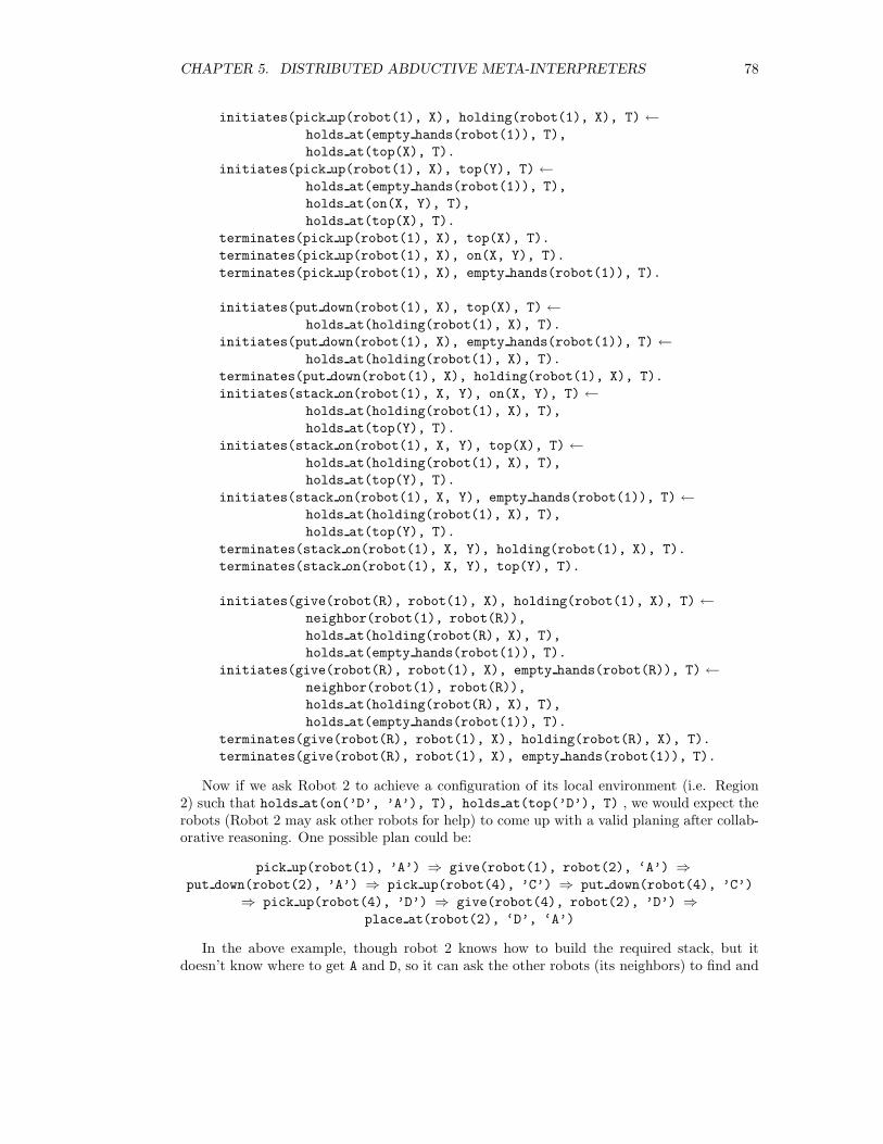
CHAPTER 5. DISTRIBUTED ABDUCTIVE META-INTERPRETERS 78
initiates(pick up(robot(1), X), holding(robot(1), X), T) ←holds at(empty hands(robot(1)), T),
holds at(top(X), T).
initiates(pick up(robot(1), X), top(Y), T) ←holds at(empty hands(robot(1)), T),
holds at(on(X, Y), T),
holds at(top(X), T).
terminates(pick up(robot(1), X), top(X), T).
terminates(pick up(robot(1), X), on(X, Y), T).
terminates(pick up(robot(1), X), empty hands(robot(1)), T).
initiates(put down(robot(1), X), top(X), T) ←holds at(holding(robot(1), X), T).
initiates(put down(robot(1), X), empty hands(robot(1)), T) ←holds at(holding(robot(1), X), T).
terminates(put down(robot(1), X), holding(robot(1), X), T).
initiates(stack on(robot(1), X, Y), on(X, Y), T) ←holds at(holding(robot(1), X), T),
holds at(top(Y), T).
initiates(stack on(robot(1), X, Y), top(X), T) ←holds at(holding(robot(1), X), T),
holds at(top(Y), T).
initiates(stack on(robot(1), X, Y), empty hands(robot(1)), T) ←holds at(holding(robot(1), X), T),
holds at(top(Y), T).
terminates(stack on(robot(1), X, Y), holding(robot(1), X), T).
terminates(stack on(robot(1), X, Y), top(Y), T).
initiates(give(robot(R), robot(1), X), holding(robot(1), X), T) ←neighbor(robot(1), robot(R)),
holds at(holding(robot(R), X), T),
holds at(empty hands(robot(1)), T).
initiates(give(robot(R), robot(1), X), empty hands(robot(R)), T) ←neighbor(robot(1), robot(R)),
holds at(holding(robot(R), X), T),
holds at(empty hands(robot(1)), T).
terminates(give(robot(R), robot(1), X), holding(robot(R), X), T).
terminates(give(robot(R), robot(1), X), empty hands(robot(1)), T).
Now if we ask Robot 2 to achieve a configuration of its local environment (i.e. Region2) such that holds at(on(’D’, ’A’), T), holds at(top(’D’), T) , we would expect therobots (Robot 2 may ask other robots for help) to come up with a valid planing after collab-orative reasoning. One possible plan could be:
pick up(robot(1), ’A’) ⇒ give(robot(1), robot(2), ‘A’) ⇒put down(robot(2), ’A’) ⇒ pick up(robot(4), ’C’) ⇒ put down(robot(4), ’C’)
⇒ pick up(robot(4), ’D’) ⇒ give(robot(4), robot(2), ’D’) ⇒place at(robot(2), ‘D’, ‘A’)
In the above example, though robot 2 knows how to build the required stack, but itdoesn’t know where to get A and D, so it can ask the other robots (its neighbors) to find and
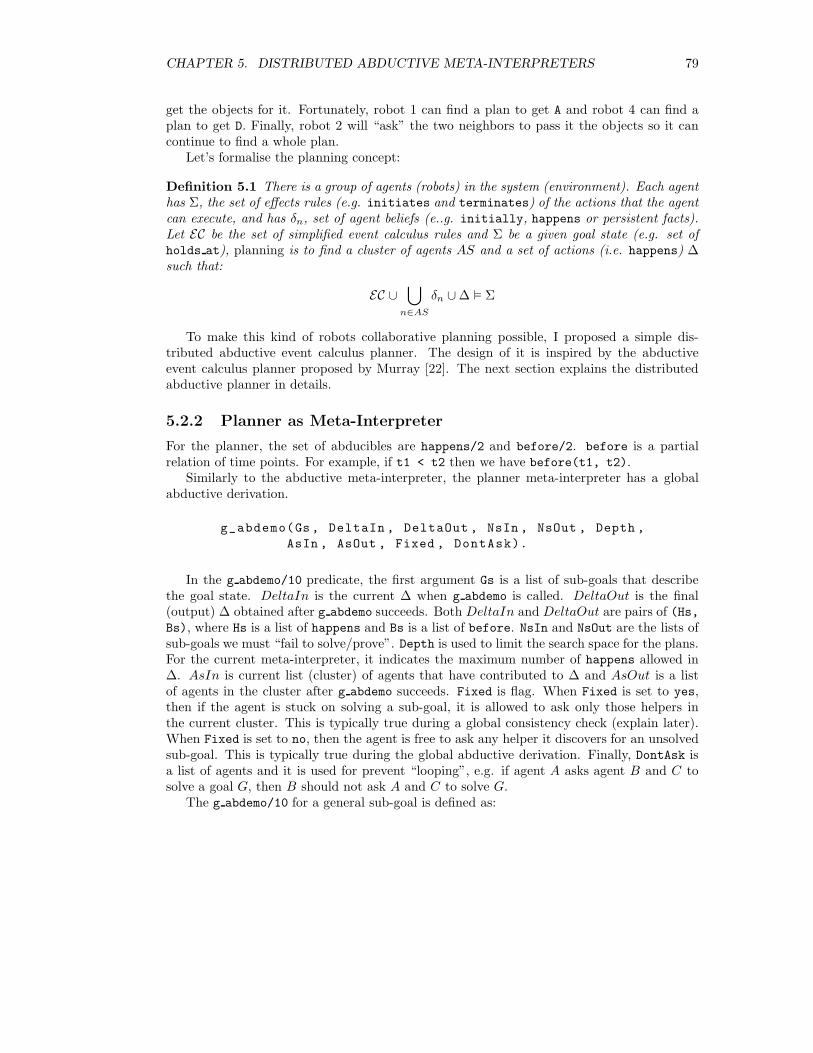
CHAPTER 5. DISTRIBUTED ABDUCTIVE META-INTERPRETERS 79
get the objects for it. Fortunately, robot 1 can find a plan to get A and robot 4 can find aplan to get D. Finally, robot 2 will “ask” the two neighbors to pass it the objects so it cancontinue to find a whole plan.
Let’s formalise the planning concept:
Definition 5.1 There is a group of agents (robots) in the system (environment). Each agenthas Σ, the set of effects rules (e.g. initiates and terminates) of the actions that the agentcan execute, and has δn, set of agent beliefs (e..g. initially, happens or persistent facts).Let EC be the set of simplified event calculus rules and Σ be a given goal state (e.g. set ofholds at), planning is to find a cluster of agents AS and a set of actions (i.e. happens) ∆such that:
EC ∪⋃
n∈AS
δn ∪∆ � Σ
To make this kind of robots collaborative planning possible, I proposed a simple dis-tributed abductive event calculus planner. The design of it is inspired by the abductiveevent calculus planner proposed by Murray [22]. The next section explains the distributedabductive planner in details.
5.2.2 Planner as Meta-Interpreter
For the planner, the set of abducibles are happens/2 and before/2. before is a partialrelation of time points. For example, if t1 < t2 then we have before(t1, t2).
Similarly to the abductive meta-interpreter, the planner meta-interpreter has a globalabductive derivation.
g_abdemo(Gs, DeltaIn , DeltaOut , NsIn , NsOut , Depth ,
AsIn , AsOut , Fixed , DontAsk).
In the g abdemo/10 predicate, the first argument Gs is a list of sub-goals that describethe goal state. DeltaIn is the current ∆ when g abdemo is called. DeltaOut is the final(output) ∆ obtained after g abdemo succeeds. Both DeltaIn and DeltaOut are pairs of (Hs,Bs), where Hs is a list of happens and Bs is a list of before. NsIn and NsOut are the lists ofsub-goals we must “fail to solve/prove”. Depth is used to limit the search space for the plans.For the current meta-interpreter, it indicates the maximum number of happens allowed in∆. AsIn is current list (cluster) of agents that have contributed to ∆ and AsOut is a listof agents in the cluster after g abdemo succeeds. Fixed is flag. When Fixed is set to yes,then if the agent is stuck on solving a sub-goal, it is allowed to ask only those helpers inthe current cluster. This is typically true during a global consistency check (explain later).When Fixed is set to no, then the agent is free to ask any helper it discovers for an unsolvedsub-goal. This is typically true during the global abductive derivation. Finally, DontAsk isa list of agents and it is used for prevent “looping”, e.g. if agent A asks agent B and C tosolve a goal G, then B should not ask A and C to solve G.
The g abdemo/10 for a general sub-goal is defined as:
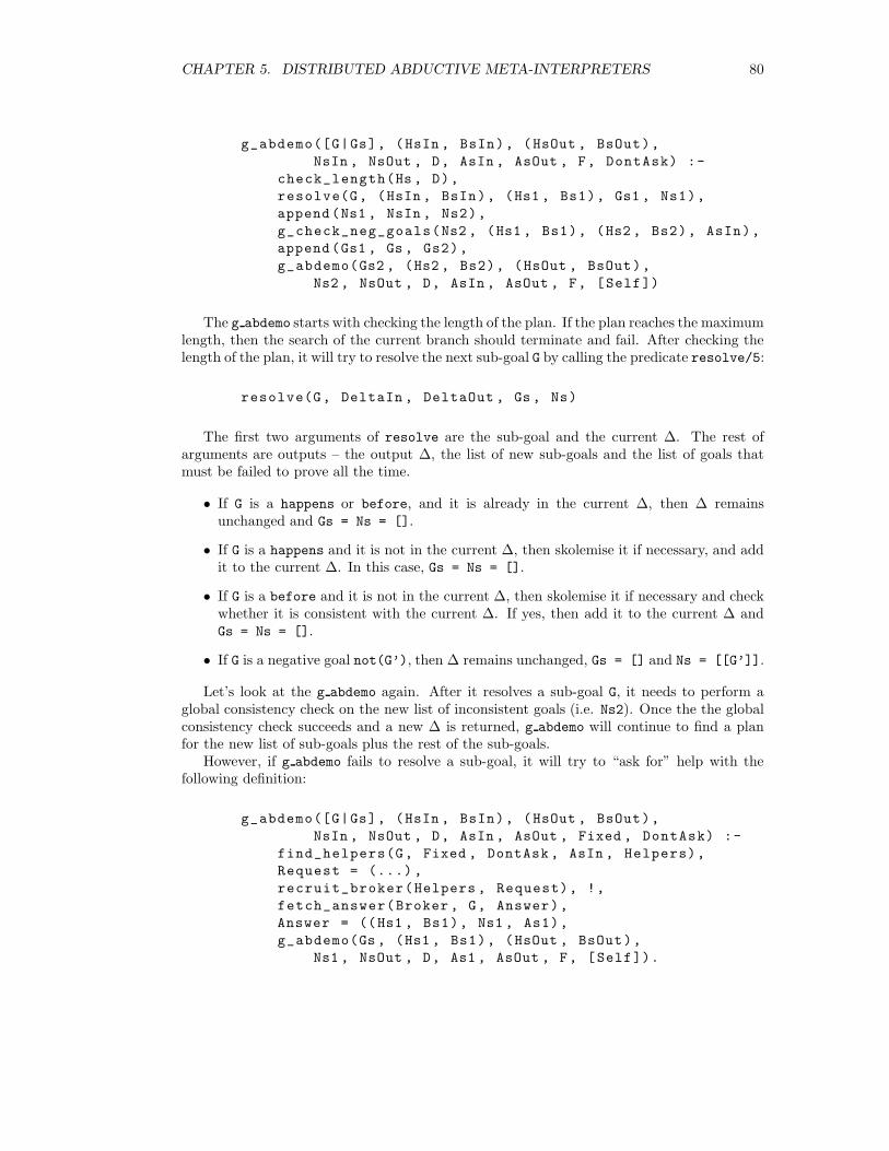
CHAPTER 5. DISTRIBUTED ABDUCTIVE META-INTERPRETERS 80
g_abdemo([G|Gs], (HsIn , BsIn), (HsOut , BsOut),
NsIn , NsOut , D, AsIn , AsOut , F, DontAsk) :-
check_length(Hs , D),
resolve(G, (HsIn , BsIn), (Hs1 , Bs1), Gs1 , Ns1),
append(Ns1 , NsIn , Ns2),
g_check_neg_goals(Ns2 , (Hs1 , Bs1), (Hs2 , Bs2), AsIn),
append(Gs1 , Gs , Gs2),
g_abdemo(Gs2 , (Hs2 , Bs2), (HsOut , BsOut),
Ns2 , NsOut , D, AsIn , AsOut , F, [Self])
The g abdemo starts with checking the length of the plan. If the plan reaches the maximumlength, then the search of the current branch should terminate and fail. After checking thelength of the plan, it will try to resolve the next sub-goal G by calling the predicate resolve/5:
resolve(G, DeltaIn , DeltaOut , Gs , Ns)
The first two arguments of resolve are the sub-goal and the current ∆. The rest ofarguments are outputs – the output ∆, the list of new sub-goals and the list of goals thatmust be failed to prove all the time.
• If G is a happens or before, and it is already in the current ∆, then ∆ remainsunchanged and Gs = Ns = [].
• If G is a happens and it is not in the current ∆, then skolemise it if necessary, and addit to the current ∆. In this case, Gs = Ns = [].
• If G is a before and it is not in the current ∆, then skolemise it if necessary and checkwhether it is consistent with the current ∆. If yes, then add it to the current ∆ andGs = Ns = [].
• If G is a negative goal not(G’), then ∆ remains unchanged, Gs = [] and Ns = [[G’]].
Let’s look at the g abdemo again. After it resolves a sub-goal G, it needs to perform aglobal consistency check on the new list of inconsistent goals (i.e. Ns2). Once the the globalconsistency check succeeds and a new ∆ is returned, g abdemo will continue to find a planfor the new list of sub-goals plus the rest of the sub-goals.
However, if g abdemo fails to resolve a sub-goal, it will try to “ask for” help with thefollowing definition:
g_abdemo([G|Gs], (HsIn , BsIn), (HsOut , BsOut),
NsIn , NsOut , D, AsIn , AsOut , Fixed , DontAsk) :-
find_helpers(G, Fixed , DontAsk , AsIn , Helpers),
Request = (...) ,
recruit_broker(Helpers , Request), !,
fetch_answer(Broker , G, Answer),
Answer = ((Hs1 , Bs1), Ns1 , As1),
g_abdemo(Gs , (Hs1 , Bs1), (HsOut , BsOut),
Ns1 , NsOut , D, As1 , AsOut , F, [Self]).
CHAPTER 5. DISTRIBUTED ABDUCTIVE META-INTERPRETERS 81
This version of g abdemo does the following:
1. It looks up a list of PotentialHelpers either from the central directory or from thelocal directory. If Fixed == yes, then Helper = (PotentialHelper−DontAsk)∩AsIn;otherwise, Helper = PotentialHelper− DontAsk.
2. It creates a request message to be sent to the helpers. If using system version 2, thiswill be a KQML message.
3. It asks a broker thread to send out the requests to the helpers and to buffer returninganswers/sub-plans (See Section 4.2.4).
4. If an answer/sub-plan is found and returned, then continue to find a plan for theremaining sub-goals.
5. While backtrack to fetch answer/3, the next buffered answer/sub-plan will be re-turned. If there is no more buffered answer/sub-plan, then backtrack fails.
Now let’s look at the global consistency check:
g_check_neg_goals(Ns, (HsIn , BsIn), (HsOut , BsOut), As).
The global consistency check is similar to the global consistency derivation describedin Section 5.1.2. g check neg goals takes a list of inconsistent goals, the current ∆ andthe agent clusters as input argument. It will pass the inconsistent goals and ∆ around theagents. ∆ may expand after one round consistency check. If this is the case, another roundof consistency check will be initiated again and again until ∆ becomes “stable”. and thenthe global consistency check will succeed and the “stable” ∆ will be returned.
During one consistency check round, when an agent receives the inconsistent goals andthe input ∆, it will try to “fail” all the inconsistent goals by calling:
g_abdemo_fail_all([], Delta , Delta , As).
g_abdemo_fail_all([Gs|Gss], DeltaIn , DeltaOut , As) :-
g_abdemo_fail_any(Gs, DeltaIn , D1, As),
g_abdemo_fail_all(Gss , D1 , DeltaOut , As).
That is, for each inconsistent goal, the agent only needs to any of its sub-goals. Theg abdemo fail any succeeds if and only if:
1. There is a sub-goal before(X, Y), and X == Y.
2. There is a sub-goal before(X, Y), and ∆ � before(Y, X).
3. There is a sub-goal before(X, Y) and ∆ 2 before(X, Y), then before(Y, X) is addedto ∆.
4. There is a sub-goal happens(E, T) and happens(E, T) /∈ ∆.
5. There is a non-abducible sub-goal and it cannot be resolved.
6. There is a negative sub-goal not(G), and g abdemo succeeds with [G] as the goal, ∆as the initial ∆, Fixed set to yes.
CHAPTER 5. DISTRIBUTED ABDUCTIVE META-INTERPRETERS 82
Example Run of the Planner
The distributed planner has been implemented basing on the second version of the distributedreasoning system.
Let’s try out the example described in Section 5.2.1.When the robots started up and joined the group, they broadcasted their advertisements.
For example, robot 1 broadcasted the advertisement:
advertise([
from(robot(1)),
content([
holds_at(holding(robot(1), _), _),
holds_at(empty_hands(robot(1)), _)
])
]).
When we asked robot 2 to find a plan for holds at(top(’B’), T) with depth 5, itreturned a plan of As = [robot(1), robot(2)] and ∆ = (Hs, Bs) where:
Hs = [ happens(pick_up(robot(1), ’A’), r1_t3),
happens(put_down(robot(1), ’A’), r1_t2),
happens(pick_up(robot(1), ’B’), r1_t1),
happens(give(robot(1), robot(2), ’B’), r2_t2),
happens(put_down(robot(2), ’B’), r2_t1 )].
Bs = [ before(r1_t3 , r1_t2),
before(r1_t2 , r1_t1),
before(r1_t1 , r2_t2),
before(r2_t2 , r2_t1)].
If we topologically sort the actions, we will have a plan:
pick up(robot(1), ’A’) ⇒ put down(robot(1), ’A’) ⇒ pick up(robot(1), ’B’)
⇒ give(robot(1), robot(2), ’B’) ⇒ put down(robot(2), ’B’)
The trace of the planning is:
1. robot 2 picked the rule initiates(pick up(robot(1), ’B’), top(’B’), T) but laterfailed because it couldn’t find a plan with length less than or equal to the depth.
2. robot 2 picked the rule initiates(put down(robot(1), ’B’), top(’B’), T) andhad holds at(holding(robot(1), ’B’), T) as the new sub-goal. Since it didn’t see’B’ initially, there was only candidate rule – initiates(give(robot(R), robot(2),
’B’), holding(robot(2), ’B’), T). So it picked that rule. At the first attempt, itresolved neighbor(robot(2), robot(1)) and it had holds at(holding(robot(1),
’B’), T) as one of the sub-goals. Robot 2 couldn’t solve it but robot 1 had made suchan advertisement. So robot 2 asked robot 1 to solve the goal. Luckily, robot 1 founda sub-plan for that goal and it passed the global consistency check between the tworobots.
CHAPTER 5. DISTRIBUTED ABDUCTIVE META-INTERPRETERS 83
3. robot 2 received the sub-plan from robot 1 and had only holds at(empty hands(robot(r2)),
T) as its last sub-goal. The last sub-goal was easily solved and hence the plan was re-turned.
4. backtracking, etc.
In fact, another plan returned by robot 2 is As = [robot(1), robot(2)] and the sortedactions are:
pick up(robot(1), ’A’) ⇒ put down(robot(1), ’A’) ⇒ pick up(robot(1), ’B’)
⇒ give(robot(1), robot(2), ’B’) ⇒ stack on(robot(2), ’F’)
5.2.3 Optimisations
While implementing the distributed planner, quite a few optimisations are possible. Themost important optimisation is to reduce the communications during the global consistencychecks. In fact, for some applications like the blocks world we looked at, we can observethat the actions of each robot such as pick up and put down are independent. For example,robot 1 picks up object X in region 1 will not cause any conflict while robot 2 is putting downobject Y in region 2. In this case, each robot doesn’t have to perform a global consistencycheck after it adds an abducible action to the ∆. It can perform a local consistency checkinstead. However, for other applications such as two robots working in the same region, thenthe global consistency checks are unavoidable.
The second possible optimisation is to maintain a transitive closure of the before relationsin ∆, i.e. every time when before(T1, T2) is added to Bs of ∆, recompute Bs to get thetransitive closure. Whenever we want to for consistency of a before and ∆, we just needto check whether Bs of ∆ contains it or not. Maintaining the transitive closure may alsohelp to speed up global consistent check. For example, if we don’t maintain the closure, thenduring a round of consistency check if an agent adds a consistent before(T1, T2) to the ∆,we will have to start another round of consistency check. However, the downside of keepingthe closure is that it will increase the size of ∆ and hence increase the payload of a requestmessage when an agent is asking for help (because ∆ needs to be sent with the goal).
The third possible optimisation is to modify the way the planner abduces befores. Wemay abduce a set of happens first, and then pass it with the action effect rules to a constraintsolver and find out the order between the actions. This sounds promising but needs to befurther investigated.
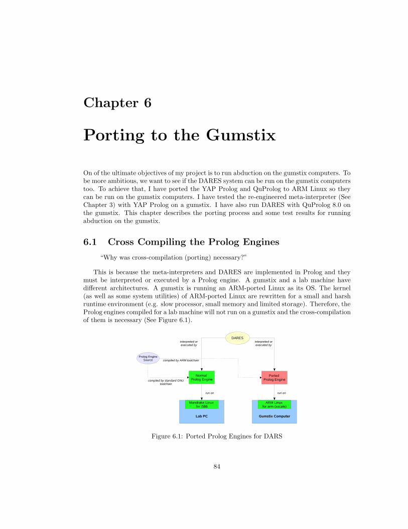
Chapter 6
Porting to the Gumstix
On of the ultimate objectives of my project is to run abduction on the gumstix computers. Tobe more ambitious, we want to see if the DARES system can be run on the gumstix computerstoo. To achieve that, I have ported the YAP Prolog and QuProlog to ARM Linux so theycan be run on the gumstix computers. I have tested the re-engineered meta-interpreter (SeeChapter 3) with YAP Prolog on a gumstix. I have also run DARES with QuProlog 8.0 onthe gumstix. This chapter describes the porting process and some test results for runningabduction on the gumstix.
6.1 Cross Compiling the Prolog Engines
“Why was cross-compilation (porting) necessary?”
This is because the meta-interpreters and DARES are implemented in Prolog and theymust be interpreted or executed by a Prolog engine. A gumstix and a lab machine havedifferent architectures. A gumstix is running an ARM-ported Linux as its OS. The kernel(as well as some system utilities) of ARM-ported Linux are rewritten for a small and harshruntime environment (e.g. slow processor, small memory and limited storage). Therefore, theProlog engines compiled for a lab machine will not run on a gumstix and the cross-compilationof them is necessary (See Figure 6.1).
Figure 6.1: Ported Prolog Engines for DARS
84
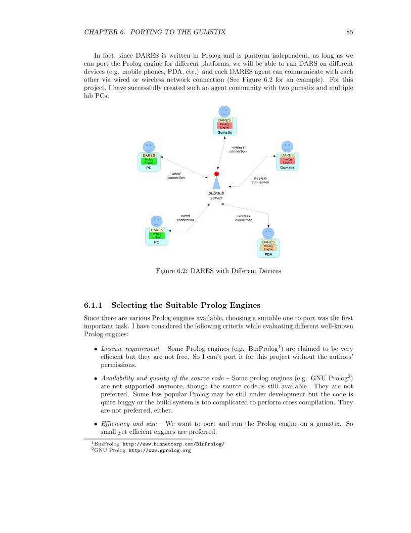
CHAPTER 6. PORTING TO THE GUMSTIX 85
In fact, since DARES is written in Prolog and is platform independent, as long as wecan port the Prolog engine for different platforms, we will be able to run DARS on differentdevices (e.g. mobile phones, PDA, etc.) and each DARES agent can communicate with eachother via wired or wireless network connection (See Figure 6.2 for an example). For thisproject, I have successfully created such an agent community with two gumstix and multiplelab PCs.
Figure 6.2: DARES with Different Devices
6.1.1 Selecting the Suitable Prolog Engines
Since there are various Prolog engines available, choosing a suitable one to port was the firstimportant task. I have considered the following criteria while evaluating different well-knownProlog engines:
• License requirement – Some Prolog engines (e.g. BinProlog1) are claimed to be veryefficient but they are not free. So I can’t port it for this project without the authors’permissions.
• Availability and quality of the source code – Some prolog engines (e.g. GNU Prolog2)are not supported anymore, though the source code is still available. They are notpreferred. Some less popular Prolog may be still under development but the code isquite buggy or the build system is too complicated to perform cross compilation. Theyare not preferred, either.
• Efficiency and size – We want to port and run the Prolog engine on a gumstix. Sosmall yet efficient engines are preferred.
1BinProlog, http://www.binnetcorp.com/BinProlog/2GNU Prolog, http://www.gprolog.org
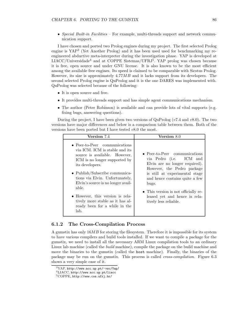
CHAPTER 6. PORTING TO THE GUMSTIX 86
• Special Built-in Facilities – For example, multi-threads support and network commu-nication support.
I have chosen and ported two Prolog engines during my project. The first selected Prologengine is YAP3 (Yet Another Prolog) and it has been used used for benchmarking my re-engineered abductive meta-interpreter during the investigation phase. YAP is developed atLIACC/Universidade4 and at COPPE Sistemas/UFRJ5. YAP prolog was chosen becauseit is free, open source and under GNU license. It is also known to be the most efficientamong the available free engines. Its speed is claimed to be comparable with Sicstus Prolog.However, its size is approximately 4.77MB and it lacks support from its developers. Thesecond selected Prolog engine is QuProlog and it is the one DARES was implemented with.QuProlog was selected because of the following:
• It is open source and free.
• It provides multi-threads support and has simple agent communications mechanism.
• The author (Peter Robinson) is available and can provide lots of vital supports (e.g.fixing bugs, answering questions).
During the project, I have been given two versions of QuProlog (v7.4 and v8.0). The twoversions have major differences and below is a comparison table between them. Both of theversions have been ported but I have tested v8.0 the most.
Version 7.4 Version 8.0
• Peer-to-Peer communicationsvia ICM. ICM is stable and itssource is available. However,ICM is no longer supported byits developers.
• Publish/Subscribe communica-tions via Elvin. Unfortunately,Elvin’s source is no longer avail-able.
• However, this version is rela-tively more stable as it has al-ready been for a while in thelab.
• Peer-to-Peer communicationsvia Pedro (i.e. ICM andElvin are no longer required).However, the Pedro packageis still at experimental stageand hence contains quite a fewbugs.
• This version is not officially re-leased yet and hence is rela-tively less reliable.
6.1.2 The Cross-Compilation Process
A gumstix has only 16MB for storing the filesystem. Therefore it is impossible for its systemto have various compilers and build tools installed. If we want to compile a package for thegumstix, we need to install all the necessary ARM Linux compilation tools to an ordinaryLinux lab machine (called the build machine), compile the package on the build machine andmove the binaries to the gumstix (called the host machine). Finally, the binaries of thepackage may be run on the gumstix. This process is called cross-compilation. Figure 6.3shows a very simple case of it.
3YAP, http://www.ncc.up.pt/~vsc/Yap/4LIACC, http://www.ncc.up.pt/liacc5COPPE, http://www.cos.ufrj.br/
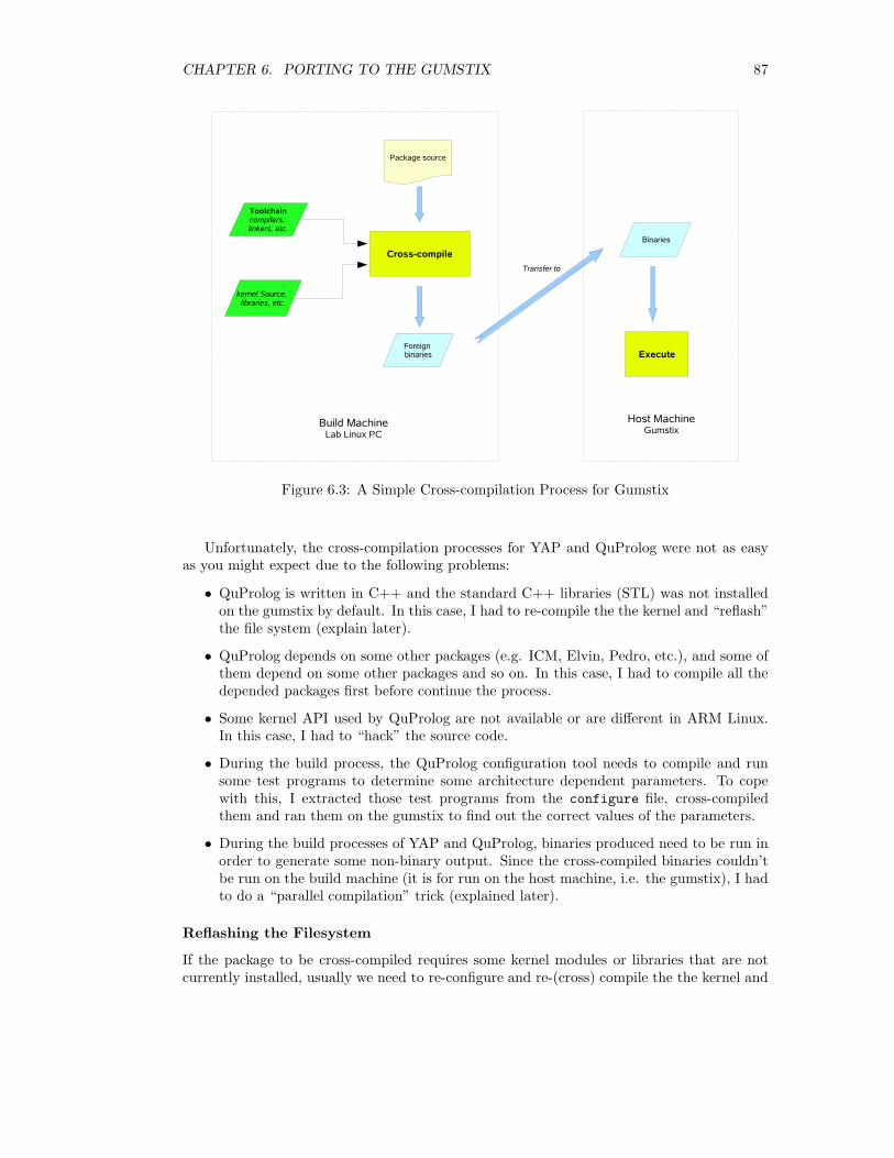
CHAPTER 6. PORTING TO THE GUMSTIX 87
Figure 6.3: A Simple Cross-compilation Process for Gumstix
Unfortunately, the cross-compilation processes for YAP and QuProlog were not as easyas you might expect due to the following problems:
• QuProlog is written in C++ and the standard C++ libraries (STL) was not installedon the gumstix by default. In this case, I had to re-compile the the kernel and “reflash”the file system (explain later).
• QuProlog depends on some other packages (e.g. ICM, Elvin, Pedro, etc.), and some ofthem depend on some other packages and so on. In this case, I had to compile all thedepended packages first before continue the process.
• Some kernel API used by QuProlog are not available or are different in ARM Linux.In this case, I had to “hack” the source code.
• During the build process, the QuProlog configuration tool needs to compile and runsome test programs to determine some architecture dependent parameters. To copewith this, I extracted those test programs from the configure file, cross-compiledthem and ran them on the gumstix to find out the correct values of the parameters.
• During the build processes of YAP and QuProlog, binaries produced need to be run inorder to generate some non-binary output. Since the cross-compiled binaries couldn’tbe run on the build machine (it is for run on the host machine, i.e. the gumstix), I hadto do a “parallel compilation” trick (explained later).
Reflashing the Filesystem
If the package to be cross-compiled requires some kernel modules or libraries that are notcurrently installed, usually we need to re-configure and re-(cross) compile the the kernel and
CHAPTER 6. PORTING TO THE GUMSTIX 88
the filesystem. Again, this is done on the build machine. A new filesystem will be created afterthe cross-compilation. We then need to “upload” the filesystem image the ROM (16MB) ofthe gumstix via serial port. The previous filesystem will be erased. Figure 6.4 illustrates theprocess.
Figure 6.4: Reflashing the Filesystem for Gumstix
Parallel Compilation
Parallel Compilation is needed when a cross-compilation needs to execute the generatedbinaries during the build process. For example, after the YAP compiler binaries are produced,the build process needs to execute it to compile some default Prolog libraries for the engine.Also, after the engine binaries are produced, the build process will need to run the engineonce to generate some necessary bootstrap files. Since the build machine doesn’t understandthese foreign binaries, it cannot execute it in anyway and the build process will fail. One workaround (See Figure 6.5) for this is to compile a normal version of YAP (same as QuProlog)for the build machine first. When the build process fails to execute the foreign binaries andstops, we can manually execute the native binaries to generate those necessary non-binaryfiles and resume the build process. At the end, we copy all the foreign binaries and thenon-binaries to the host machine. However, this trick does not always work!
6.1.3 Network Setup
Before running DARES on the gumstix computers, we need to connect them to a network.For testing, I have used the Department of Computing departmental network. Lab machinesrunning as DARES agents have already been wired into the network. The two gumstix areconnected to the wireless network and are given the names (gumstix2 and gumstix3) andfixed addresses (146.169.25.60 and 146.169.25.59). While testing the second version ofDARES, it is recommended to run the Pedro server on a reliable machine with fast networkconnection. I have run Pedro on shell1 for the testing.
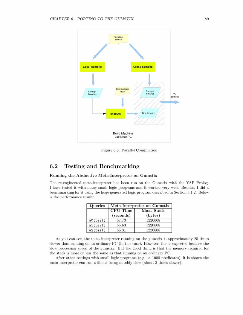
CHAPTER 6. PORTING TO THE GUMSTIX 89
Figure 6.5: Parallel Compilation
6.2 Testing and Benchmarking
Running the Abductive Meta-Interpreter on Gumstix
The re-engineered meta-interpreter has been run on the Gumstix with the YAP Prolog.I have tested it with many small logic programs and it worked very well. Besides, I did abenchmarking for it using the huge generated logic program described in Section 3.1.2. Belowis the performance result:
Queries Meta-Interpreter on GumstixCPU Time Max. Stack(seconds) (bytes)
a0(test) 57.73 1220608a1(test) 55.63 1220608a2(test) 55.31 1220608
As you can see, the meta-interpreter running on the gumstix is approximately 25 timesslower than running on an ordinary PC (in this case). However, this is expected because theslow processing speed of the gumstix. But the good thing is that the memory required forthe stack is more or less the same as that running on an ordinary PC.
After other testings with small logic programs (e.g. < 1000 predicates), it is shown themeta-interpreter can run without being notably slow (about 3 times slower).

CHAPTER 6. PORTING TO THE GUMSTIX 90
In conclusion, it is practical to run abduction on the Gumstix computers with the re-engineered abductive meta-interpreter.
Running DARES on Gumstix
The DARES system version 2 has also been tested on the Gumstix with QuProlog 8.0. Itested the general purpose distributed abductive meta-interpreter with small logic programsand they all gave correct results. I also tested the simple abductive planner with the blocksworld example and with very simple queries. However, since there are several bugs in Pedro(e.g. it couldn’t handle message with size greater than 1KB), I haven’t done a quantitativeevaluation with DARES using larger examples or queries. A quantitative benchmarking ofDARES will be conducted as soon as the Pedro bugs are fixed.
Chapter 7
Conclusion
In the end of this project, I have achieved the initial objectives. The experiences I gained andlessons I learned are summarised in Section 7.1. As this is also an open ended project, manyinteresting ideas/findings are worth further investigation. There are also many possibilitiesfor improving and extending DARES. The ideas and future developments are outlined inSection 7.2. Finally, Section 7.3 briefly talks about the challenges I faced during the projectand how I would tackle them differently if I were to do the project again.
7.1 Summary
This project can be divided into three phases.In the first phases, I have focused on the initial investigation of aduction. Re-engineering
the abductive meta-interpreter (Section 3.1.1) by Kakas has helped me to understand theKakas-Mancarella proof procedure in depth. The re-engineered meta-interpreter is notablyfast comparing to the original one so it has been integrated as part of the general purposedistributed abductive meta-interpreter (Section 5.1.2). During the investigation, I have alsotried out the idea of using partial evaluation to speed up the reasoning process (Section 3.2).A partial evaluator has been written to transform the logic programs into self-abductivelogic programs. The initial results verify that partial evaluation can indeed help to speedup abductive reasoning with (ground) programs. However, due the to huge size of thetransformed logic program, this optimisation is not particularly suitable for use on gumstixor other devices.
In the second phase, I have identified the basic assumptions (Section 4.1.3) and the desiredproperties (Section 4.1.4) of a distributed reasoning system. I have designed and implementedthe first prototype (Section ??) of the system. In this version, the system consists of a centraldirectory server and a group of reasoning agents. The reasoning agents are multi-threadedand can find their helpers when needed via the central server. The system has evolved toversion 2 (Section 4.3) later in the project. The new version removes the central directoryserver. Each agent maintains a local directory and hence is able to look up potential helperslocally. This change reduces the number of message sent over the network during agentscollaborations and therefore is more preferred for running on small devices. Evaluationsbetween the two versions also show that the adoption of KQML message format will reducethe efficiency of agent communications, though on the other hand it can provide generic-ness.
In the third phase, I have proposed a general purpose meta-interpreter and a simpleevent calculus planner (Section 5.2). I have also outlined the proof of correctness for former
91
CHAPTER 7. CONCLUSION 92
in Section 5.1.2. The multi-agent system together with the meta-interpreters finally give theDistributed Abductive REasoning System (DARES). DARES solves the issues described inChapter 1 Introduction by:
• allowing a agent to discover helpers when it needs help.
• forcing global consistency check between the agents during collaborations and henceguarantees that the returned result is consistent among the agents.
As for the ambitious goal, DARES has been run and tested on both ordinary lab PCs andthe gumstix computers. That is, the gumstix computers can act like intelligent agents andcan perform (simple) abductive reasoning tasks collaboratively. My practical experiences ofporting YAP Prolog and QuProlog have been described in Chapter 6.
7.2 Further Work
During this project, I have touched quite a few new ideas that I haven’t had time to furtherinvestigate. In addition, after testing the system on the actual gumstix computers, I learnbetter about the system’s performance and I come up with new ideas to further improve it.The following parts of this section summarises the extension work and issues that I wish todo or investigate in the future.
7.2.1 Optimisations and Extensions of DARES
There are a few possible optimisations that may push DARES to version 3.
• First of all, I would like to implement a graphical user interface for human user tointeract with the agents in the system. The user interface can also be used for systemdebug.
• We have learned that the KQML will increase the message payload quite significantly.In the next version of DARES, I would like to look at some other better industrialstandards or to formalise a new standard of message format.
• For the current version of the system, new threads are created for each incoming requestand will be destroyed after the reasoning task is finished. The creation and destructionof threads will incur overhead. One possible improvement is to maintain a worker pooland allocate idle threads for incoming requests.
Since DARES is designed as a generic framework for cooperative reasoning, we may adaptother reasoning procedure to it:
• There are other well known proof procedure existing for abductive reasoning. I wouldlike to investigate how they can be “port”ed to DARES.
• I also would like to investigate how the existing (and future) meta-interpreters canbe enhanced or optimised. For example, the abductive planner I have proposed is fordemonstration of the collaborative planning with DARES. To apply it to real worldapplications, it needs to be modified to work with the full version of event calculus.

CHAPTER 7. CONCLUSION 93
7.2.2 Identify Potential Applications
For this project, DARES has been developed as a prototype. There are two identified poten-tial applications for it:
• The use in sensor networks. Each sensor can receive monitoring data and representit in declarative form. The sensors may reason collaboratively from the data to findexplanations for the current reading, and then decide a suitable action for some certain(abnormal) situations.
• Planning in robotics. We can use the gumstix computers as robot controllers and runDARES on them. This will allow the robots to reasoning together on their perception,and will also allow them perform planning together.
In the future, I hope to investigate the above applications as well as to find more suitableapplications for DARES.
7.3 Final Thoughts
This is a research and development project. It requires both the work of theoretical A.I. andPractical A.I.
During the project, some of the main challenges I have faced are:
• There wasn’t much help about using the Gumstix computers. I had to find out how tomake them work myself. When I encountered problems, the only place I could hope toget help from was the user group. However, many times after I posted the questions,no one seemed to be able to or bother to answer them.
• In order to get the most from QuProlog, I used its latest (but not yet released) version8.0 for implementing DARES. There were several bugs in both QuProlog and Pedro.Sometimes it took me hours or days to debug my system, but at the end it turned outto be the problem of Pedro (e.g. couldn’t parse some Prolog terms correctly or couldn’tsend big messages of the size greater than 1K). But fortunately, the author Robinsonwas very helpful and helped me to fixed most of the bugs promptly.
• Lots of work but not enough time. Many new ideas and objectives were added alongthe course of the project.
I think the project has been successful and I have delivered the expected outputs. How-ever, if I were to do the project again, I would try to limit the scope of it and focus on onetask at a time. Also, I would try to avoid using un-tested software and hardware to minimisethe time wasted on fixing problems unrelated to the project’s main goals.

Bibliography
[1] UMBC Agent Web – KQML.
[2] Hassan Aı̈t-Kaci. Warren’s abstract machine: a tutorial reconstruction. MIT Press,Cambridge, MA, USA, 1991.
[3] Michele Bugliesi and F. Russo. Partial evaluation in prolog: Some improvements aboutcut. In NACLP, pages 645–660, 1989.
[4] A. Ciampolini, P. Mello, and S. Storari. Distributed medical diagnosis with abductivelogic agents.
[5] A. Ciampolini and P. Torroni. Using abductive logic agents for modeling the judicialevaluation of criminal evidence. Applied Artificial Intelligence, 18:251–275(25), March -April 2004.
[6] Anna Ciampolini, Evelina Lamma, Paola Mello, Francesca Toni, and Paolo Torroni.Cooperation and competition in alias: a logic framework for agents that negotiate.Annals of Mathematics and Artificial Intelligence, 37(1–2):65–91, 2003.
[7] Anna Ciampolini, Evelina Lamma, Paola Mello, and Paolo Torroni. LAILA: a languagefor coordinating abductive reasoning among logic agents. 27(4):137–161, December 2001.
[8] Keith Clark. Multi-agent systems lecture notes. Agent Communication Languages, 2007.
[9] Keith Clark. Multi-agent systems lecture notes. Introduction to QuProlog 7.4, 2007.
[10] K.L. Clark. Negation as failure. Logic and Data Bases, pages 293–322, 1978.
[11] Marc Denecker and Danny De Schreye. SLDNFA: An abductive procedure for abductivelogic programs. Journal of Logic Programming, 34(2):111–167, 1998.
[12] K. Eshghi and R.A.Kowalski. Abduction compared with negation by failure. In Pro-ceedings of the 6th ICLP. MIT Press, 1989.
[13] Kave Eshghi. Abductive planning with event calculus. In ICLP/SLP, pages 562–579,1988.
[14] Foundation for Intelligent Physical Agents. FIPA-ACL.
[15] Tzee Ho Fung and Robert A. Kowalski. The iff proof procedure for abductive logicprogramming. J. Log. Program., 33(2):151–165, 1997.
[16] M.M. Huntbach. Meta-interpreters and partial evaluation in parlog. Formal Aspects ofComputing, 1(2):193–211, 1989.
94
BIBLIOGRAPHY 95
[17] Antonis C. Kakas and Paolo Mancarella. Database updates through abduction. In VLDB’90: Proceedings of the 16th International Conference on Very Large Data Bases, pages650–661, San Francisco, CA, USA, 1990. Morgan Kaufmann Publishers Inc.
[18] Robert Kowalski and Marek Sergot. A logic-based calculus of events. pages 23–51, 1989.
[19] Michael Leuschel. Partial evaluation of the ‘real thing’. In Laurent Fribourg and FrancoTurini, editors, Logic Programming Synthesis and Transformation, Meta-Programmingin Logic: Fourth International Workshops, LOBSTR’94 and META’94, Pisa, Italy,pages 122–137. Springer-Verlag, Berlin, 1994.
[20] John McCarthy. Programs with common sense. In Proceedings of the Teddington Con-ference on the Mechanization of Thought Processes, pages 75–91, London, 1959. HerMajesty’s Stationary Office.
[21] Murray Shanahan. Solving the frame problem: a mathematical investigation of the com-mon sense law of inertia. MIT Press, Cambridge, MA, USA, 1997.
[22] Murray Shanahan. An abductive event calculus planner. Journal of Logic Programming,44(1-3):207–240, 2000.
[23] A. Takeuchi and K. Furukawa. Partial evaluation of prolog programs and its applicationto meta-programming. In Logic Programming Conference (Tokyo), 1985.
[24] Paolo Torroni. Reasoning and Interaction in Logic-Based Multi-Agent Systems. PhD the-sis, Department of Electronics, Computer Science and Systems, University of Bologna,Italy, 2002.
[25] R. Venken and B. Demoen. A partial evaluation system for prolog: some practicalconsiderations. New Gen. Comput., 6(2-3):279–290, 1988.
[26] David H. D. Warren. An abstract prolog instruction set. Technical Report 309, ArtificialIntelligence Center, SRI International, Menlo Park, CA, October 1983.
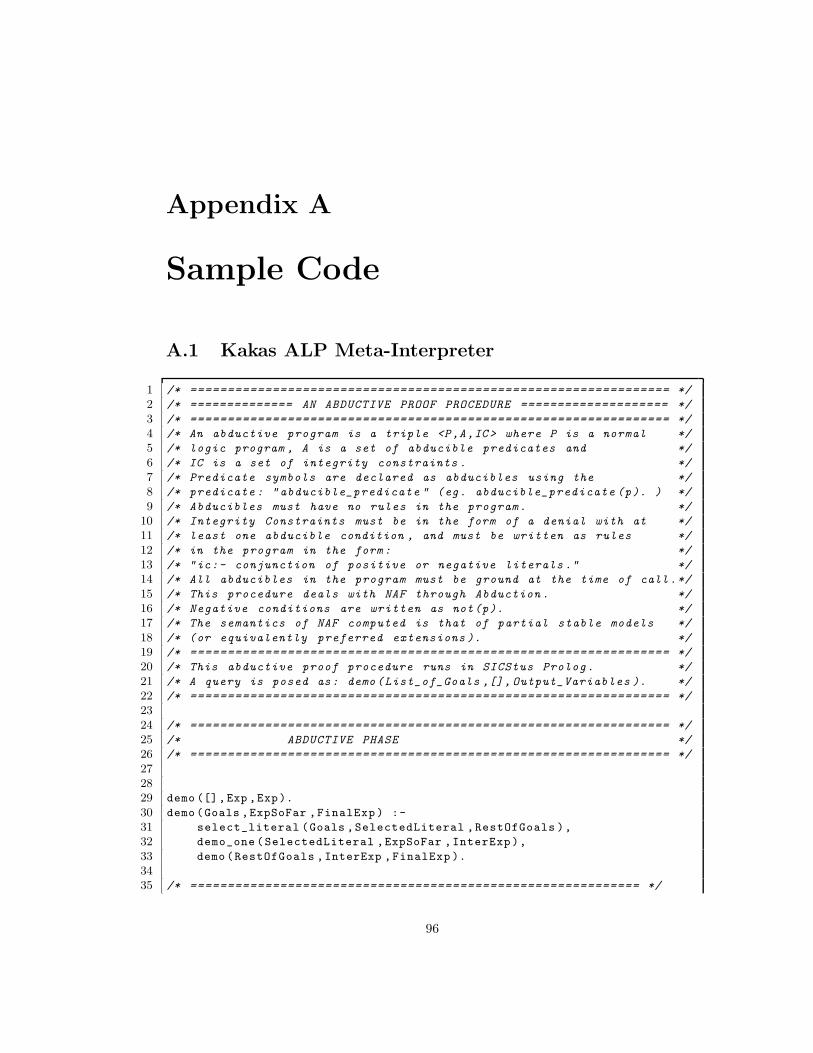
Appendix A
Sample Code
A.1 Kakas ALP Meta-Interpreter
1 /* ================================================================ */
2 /* ============== AN ABDUCTIVE PROOF PROCEDURE ==================== */
3 /* ================================================================ */
4 /* An abductive program is a triple <P,A,IC > where P is a normal */
5 /* logic program , A is a set of abducible predicates and */
6 /* IC is a set of integrity constraints . */
7 /* Predicate symbols are declared as abducibles using the */
8 /* predicate : " abducible_predicate " (eg. abducible_predicate (p). ) */
9 /* Abducibles must have no rules in the program. */
10 /* Integrity Constraints must be in the form of a denial with at */
11 /* least one abducible condition , and must be written as rules */
12 /* in the program in the form : */
13 /* "ic:- conjunction of positive or negative literals ." */
14 /* All abducibles in the program must be ground at the time of call .*/
15 /* This procedure deals with NAF through Abduction . */
16 /* Negative conditions are written as not(p). */
17 /* The semantics of NAF computed is that of partial stable models */
18 /* (or equivalently preferred extensions ). */
19 /* ================================================================ */
20 /* This abductive proof procedure runs in SICStus Prolog. */
21 /* A query is posed as: demo (List_of_Goals ,[], Output_Variables ). */
22 /* ================================================================ */
23
24 /* ================================================================ */
25 /* ABDUCTIVE PHASE */
26 /* ================================================================ */
27
28
29 demo ([],Exp ,Exp).
30 demo (Goals ,ExpSoFar ,FinalExp ) :-
31 select_literal (Goals ,SelectedLiteral ,RestOfGoals ),
32 demo_one (SelectedLiteral ,ExpSoFar ,InterExp ),
33 demo (RestOfGoals ,InterExp ,FinalExp ).
34
35 /* ============================================================ */
96
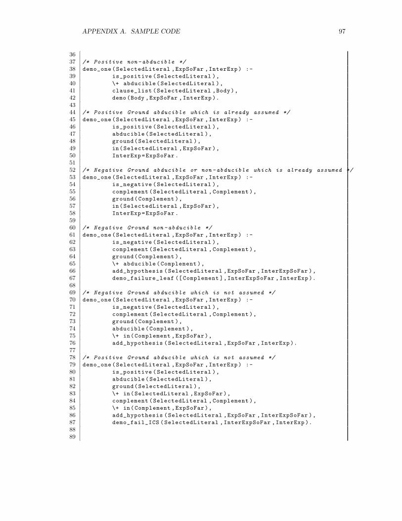
APPENDIX A. SAMPLE CODE 97
36
37 /* Positive non -abducible */
38 demo_one (SelectedLiteral ,ExpSoFar ,InterExp ) :-
39 is_positive ( SelectedLiteral ),
40 \+ abducible ( SelectedLiteral ),
41 clause_list (SelectedLiteral ,Body ),
42 demo (Body ,ExpSoFar ,InterExp ).
43
44 /* Positive Ground abducible which is already assumed */
45 demo_one (SelectedLiteral ,ExpSoFar ,InterExp ) :-
46 is_positive ( SelectedLiteral ),
47 abducible ( SelectedLiteral ),
48 ground(SelectedLiteral ),
49 in(SelectedLiteral ,ExpSoFar ),
50 InterExp =ExpSoFar .
51
52 /* Negative Ground abducible or non -abducible which is already assumed */
53 demo_one (SelectedLiteral ,ExpSoFar ,InterExp ) :-
54 is_negative ( SelectedLiteral ),
55 complement (SelectedLiteral , Complement ),
56 ground(Complement ),
57 in(SelectedLiteral ,ExpSoFar ),
58 InterExp =ExpSoFar .
59
60 /* Negative Ground non -abducible */
61 demo_one (SelectedLiteral ,ExpSoFar ,InterExp ) :-
62 is_negative ( SelectedLiteral ),
63 complement (SelectedLiteral , Complement ),
64 ground(Complement ),
65 \+ abducible ( Complement ),
66 add_hypothesis (SelectedLiteral ,ExpSoFar , InterExpSoFar ),
67 demo_failure_leaf ([ Complement ],InterExpSoFar ,InterExp ).
68
69 /* Negative Ground abducible which is not assumed */
70 demo_one (SelectedLiteral ,ExpSoFar ,InterExp ) :-
71 is_negative ( SelectedLiteral ),
72 complement (SelectedLiteral , Complement ),
73 ground(Complement ),
74 abducible (Complement ),
75 \+ in(Complement ,ExpSoFar ),
76 add_hypothesis (SelectedLiteral ,ExpSoFar , InterExp ).
77
78 /* Positive Ground abducible which is not assumed */
79 demo_one (SelectedLiteral ,ExpSoFar ,InterExp ) :-
80 is_positive ( SelectedLiteral ),
81 abducible ( SelectedLiteral ),
82 ground(SelectedLiteral ),
83 \+ in(SelectedLiteral ,ExpSoFar ),
84 complement (SelectedLiteral , Complement ),
85 \+ in(Complement ,ExpSoFar ),
86 add_hypothesis (SelectedLiteral ,ExpSoFar , InterExpSoFar ),
87 demo_fail_ICS ( SelectedLiteral ,InterExpSoFar ,InterExp ).
88
89
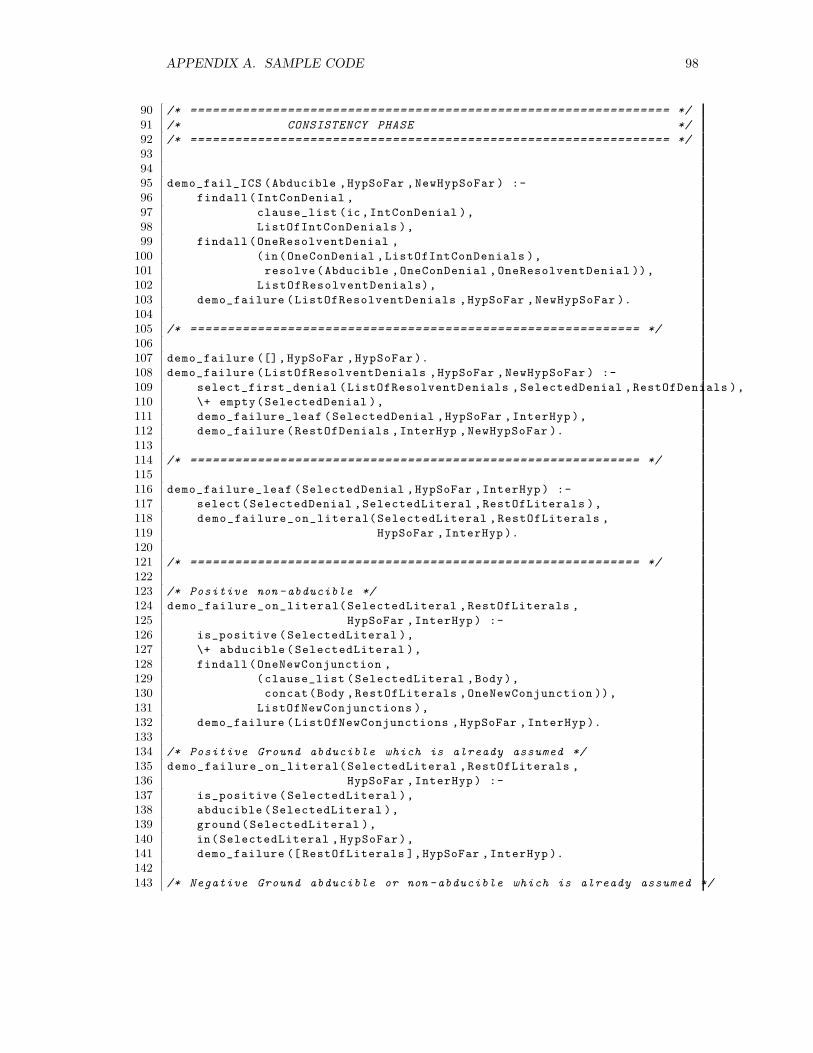
APPENDIX A. SAMPLE CODE 98
90 /* ================================================================ */
91 /* CONSISTENCY PHASE */
92 /* ================================================================ */
93
94
95 demo_fail_ICS (Abducible ,HypSoFar , NewHypSoFar ) :-
96 findall (IntConDenial ,
97 clause_list (ic ,IntConDenial ),
98 ListOfIntConDenials ),
99 findall (OneResolventDenial ,
100 (in(OneConDenial , ListOfIntConDenials ),
101 resolve(Abducible ,OneConDenial , OneResolventDenial )),
102 ListOfResolventDenials),
103 demo_failure (ListOfResolventDenials ,HypSoFar , NewHypSoFar ).
104
105 /* ============================================================ */
106
107 demo_failure ([], HypSoFar ,HypSoFar ).
108 demo_failure (ListOfResolventDenials ,HypSoFar , NewHypSoFar ) :-
109 select_first_denial (ListOfResolventDenials ,SelectedDenial , RestOfDenials ),
110 \+ empty(SelectedDenial ),
111 demo_failure_leaf (SelectedDenial ,HypSoFar ,InterHyp ),
112 demo_failure (RestOfDenials ,InterHyp ,NewHypSoFar ).
113
114 /* ============================================================ */
115
116 demo_failure_leaf (SelectedDenial ,HypSoFar ,InterHyp ) :-
117 select(SelectedDenial ,SelectedLiteral ,RestOfLiterals ),
118 demo_failure_on_literal(SelectedLiteral ,RestOfLiterals ,
119 HypSoFar ,InterHyp ).
120
121 /* ============================================================ */
122
123 /* Positive non -abducible */
124 demo_failure_on_literal(SelectedLiteral ,RestOfLiterals ,
125 HypSoFar ,InterHyp ) :-
126 is_positive ( SelectedLiteral ),
127 \+ abducible ( SelectedLiteral ),
128 findall (OneNewConjunction ,
129 (clause_list (SelectedLiteral ,Body ),
130 concat(Body ,RestOfLiterals ,OneNewConjunction )),
131 ListOfNewConjunctions ),
132 demo_failure (ListOfNewConjunctions ,HypSoFar , InterHyp ).
133
134 /* Positive Ground abducible which is already assumed */
135 demo_failure_on_literal(SelectedLiteral ,RestOfLiterals ,
136 HypSoFar ,InterHyp ) :-
137 is_positive ( SelectedLiteral ),
138 abducible (SelectedLiteral ),
139 ground(SelectedLiteral ),
140 in(SelectedLiteral ,HypSoFar ),
141 demo_failure ([ RestOfLiterals ],HypSoFar ,InterHyp ).
142
143 /* Negative Ground abducible or non -abducible which is already assumed */
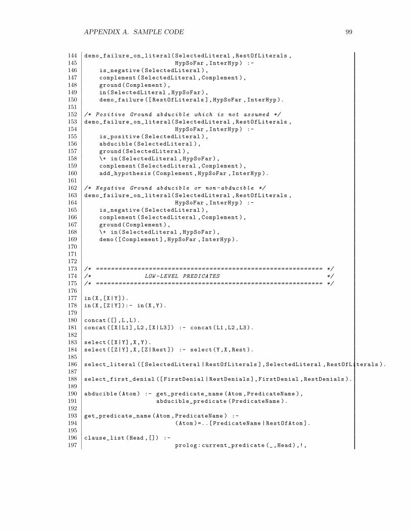
APPENDIX A. SAMPLE CODE 99
144 demo_failure_on_literal(SelectedLiteral ,RestOfLiterals ,
145 HypSoFar ,InterHyp ) :-
146 is_negative ( SelectedLiteral ),
147 complement (SelectedLiteral ,Complement ),
148 ground(Complement ),
149 in(SelectedLiteral ,HypSoFar ),
150 demo_failure ([ RestOfLiterals ],HypSoFar ,InterHyp ).
151
152 /* Positive Ground abducible which is not assumed */
153 demo_failure_on_literal(SelectedLiteral ,RestOfLiterals ,
154 HypSoFar ,InterHyp ) :-
155 is_positive ( SelectedLiteral ),
156 abducible (SelectedLiteral ),
157 ground(SelectedLiteral ),
158 \+ in(SelectedLiteral ,HypSoFar ),
159 complement (SelectedLiteral ,Complement ),
160 add_hypothesis (Complement ,HypSoFar ,InterHyp ).
161
162 /* Negative Ground abducible or non -abducible */
163 demo_failure_on_literal(SelectedLiteral ,RestOfLiterals ,
164 HypSoFar ,InterHyp ) :-
165 is_negative ( SelectedLiteral ),
166 complement (SelectedLiteral ,Complement ),
167 ground(Complement ),
168 \+ in(SelectedLiteral ,HypSoFar ),
169 demo ([ Complement ],HypSoFar ,InterHyp ).
170
171
172
173 /* ============================================================ */
174 /* LOW -LEVEL PREDICATES */
175 /* ============================================================ */
176
177 in(X,[X|Y]).
178 in(X,[Z|Y]):- in(X,Y).
179
180 concat ([],L,L).
181 concat ([X|L1],L2 ,[X|L3]) :- concat(L1 ,L2 ,L3).
182
183 select ([X|Y],X,Y).
184 select ([Z|Y],X,[Z|Rest ]) :- select(Y,X,Rest ).
185
186 select_literal ([ SelectedLiteral | RestOfLiterals ],SelectedLiteral ,RestOfLiterals ).
187
188 select_first_denial ([ FirstDenial | RestDenials ],FirstDenial ,RestDenials ).
189
190 abducible (Atom ) :- get_predicate_name (Atom ,PredicateName ),
191 abducible_predicate (PredicateName ).
192
193 get_predicate_name (Atom ,PredicateName ) :-
194 (Atom )=..[ PredicateName | RestOfAtom ].
195
196 clause_list (Head ,[]) :-
197 prolog: current_predicate (_,Head ),!,
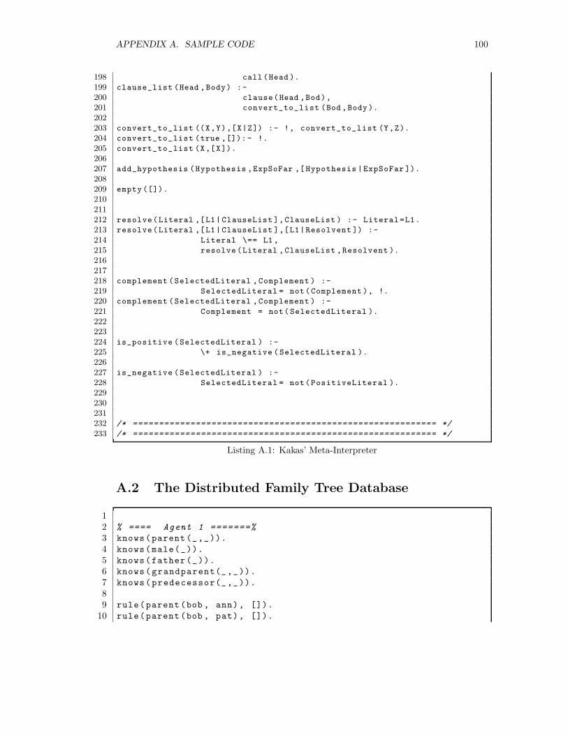
APPENDIX A. SAMPLE CODE 100
198 call (Head ).
199 clause_list (Head ,Body) :-
200 clause(Head ,Bod),
201 convert_to_list (Bod ,Body ).
202
203 convert_to_list ((X,Y),[X|Z]) :- !, convert_to_list (Y,Z).
204 convert_to_list (true ,[]): - !.
205 convert_to_list (X,[X]).
206
207 add_hypothesis (Hypothesis ,ExpSoFar ,[ Hypothesis |ExpSoFar ]).
208
209 empty ([]).
210
211
212 resolve(Literal ,[L1| ClauseList ],ClauseList ) :- Literal =L1.
213 resolve(Literal ,[L1| ClauseList ],[L1|Resolvent ]) :-
214 Literal \== L1 ,
215 resolve (Literal ,ClauseList ,Resolvent ).
216
217
218 complement (SelectedLiteral ,Complement ) :-
219 SelectedLiteral = not(Complement ), !.
220 complement (SelectedLiteral ,Complement ) :-
221 Complement = not( SelectedLiteral ).
222
223
224 is_positive (SelectedLiteral ) :-
225 \+ is_negative ( SelectedLiteral ).
226
227 is_negative (SelectedLiteral ) :-
228 SelectedLiteral = not(PositiveLiteral ).
229
230
231
232 /* ========================================================== */
233 /* ========================================================== */
Listing A.1: Kakas’ Meta-Interpreter
A.2 The Distributed Family Tree Database
12 % ==== Agent 1 =======%
3 knows(parent(_,_)).
4 knows(male(_)).
5 knows(father(_)).
6 knows(grandparent(_,_)).
7 knows(predecessor(_,_)).
89 rule(parent(bob , ann), []).
10 rule(parent(bob , pat), []).
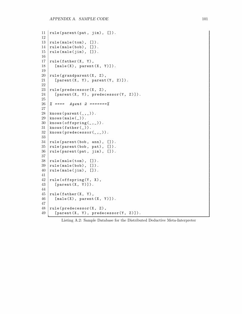
APPENDIX A. SAMPLE CODE 101
11 rule(parent(pat , jim), []).
1213 rule(male(tom), []).
14 rule(male(bob), []).
15 rule(male(jim), []).
1617 rule(father(X, Y),
18 [male(X), parent(X, Y)]).
1920 rule(grandparent(X, Z),
21 [parent(X, Y), parent(Y, Z)]).
2223 rule(predecessor(X, Z),
24 [parent(X, Y), predecessor(Y, Z)]).
2526 % ==== Agent 2 =======%
2728 knows(parent(_,_)).
29 knows(male(_)).
30 knows(offspring(_,_)).
31 knows(father(_)).
32 knows(predecessor(_,_)).
3334 rule(parent(bob , ann), []).
35 rule(parent(bob , pat), []).
36 rule(parent(pat , jim), []).
3738 rule(male(tom), []).
39 rule(male(bob), []).
40 rule(male(jim), []).
4142 rule(offspring(Y, X),
43 [parent(X, Y)]).
4445 rule(father(X, Y),
46 [male(X), parent(X, Y)]).
4748 rule(predecessor(X, Z),
49 [parent(X, Y), predecessor(Y, Z)]).
Listing A.2: Sample Database for the Distributed Deductive Meta-Interpreter


![User Guide of the SICStus abduction module: Abductive ...jm103/abduction/docs.pdf · duction and logic programming, called abductive logic programming (ALP) [1], allows many AI problems](https://img.pdfslide.net/doc/110x75/5cc592dd88c993474e8da661/user-guide-of-the-sicstus-abduction-module-abductive-jm103abductiondocspdf.jpg)