Embed Size (px)
Citation preview

1
Distributed Algorithm for Collision Avoidance at RoadIntersections in the Presence of Communication Failures
Vladimir Savic, Elad M. Schiller, and Marina Papatriantafilou
Dept. of Computer Science and Engineering, Chalmers University of Technology, SwedenEmails: {savicv, elad, ptrianta}@chalmers.se
Abstract
Vehicle-to-vehicle (V2V) communication is a crucial component of the future autonomous drivingsystems since it enables improved awareness of the surrounding environment, even without extensiveprocessing of sensory information. However, V2V communication is prone to failures and delays, so adistributed fault-tolerant approach is required for safe and efficient transportation. In this paper, wefocus on the intersection crossing (IC) problem with autonomous vehicles that cooperate via V2Vcommunications, and propose a novel distributed IC algorithm that can handle an unknown numberof communication failures. Our analysis shows that both safety and liveness requirements are satisfiedin all realistic situations. We also found, based on a real data set, that the crossing delay is only slightlyincreased even in the presence of highly correlated failures.
I. INTRODUCTION
1 Future autonomous vehicles will enable safer, more efficient and more comfortable transportation[1]. They will be equipped with a wide range of sensors [2], such as Global Positioning System (GPS)receivers, radars, lidars, cameras, and inertial measurement unit (IMU). In addition, they are expected tohave radios for wireless communication [3], [4] that would be used to exchange all relevant informationwith nearby vehicles and the infrastructure. This would facilitate increased awareness of surroundingenvironment, including the distant objects out of the sensing horizon. Moreover, the vehicles wouldbe able to optimize their trajectory using the sensory information and the future positions from nearbyvehicles. This work focuses on fully autonomous vehicles with a vehicle-to-vehicle (V2V) communicationunit and a minimal set of sensors (e.g., GPS and IMU) required for safe and efficient transportation. Ourapproach is extendable and can include, for redundancy sake, other sources of sensory information, thatwould increase the robustness to unforeseen failures, and would detect the passive objects that are notable (or not willing) to communicate.
In particular, we focus here on intersections since these parts of the roads account for almost half of allaccidents [5]. The intersections are typically managed by traffic lights and stops signs, but these systems
1Copyright (c) 2017 IEEE. Personal use of this material is permitted. However, permission to use this material for any otherpurposes must be obtained from the IEEE by sending a request to [email protected]. The original version of this paperis submitted to IEEE Intelligent Vehicles Symposium (IV’2017).
August 20, 2018 DRAFT
arX
iv:1
701.
0264
1v1
[cs
.NI]
10
Jan
2017
2
would cause an excessive delay with autonomous vehicles. On the other hand, since wireless communi-cation is prone to failures and delays, a centralized intersection manager is not a desirable solution. Werather consider a distributed method in which the vehicles need to agree, via V2V communication, on theorder in which they should cross the intersection. Our solution advances the state of the art (see SectionII-A) because we ensure collision avoidance in the presence of an unknown number of communicationfailures, and without a significant increase in the crossing delay.
The remainder of this paper is organized as follows. In Section II, we provide the background and therelated work for the problem at hand, and in Section III we formulate the problem and provide modelsfor intersection crossing (IC), including the position-related information and the message format. Then, inSection IV, we provide our novel algorithm for distributed IC in the presence of communication failures,and, in Section V, we analyse numerically the expected delay caused by these failures. Finally, in SectionVI, we summarize our results and provide suggestions for future work.
II. BACKGROUND
Autonomous driving is a multi-discipline problem [1], mainly consisting of sensor fusion, communi-cation and control units that interact between each other. Sensor fusion unit is responsible for acquiring,processing and fusing all available data. This data is obtained from a wide variety of on-board sensors,and also received from the nearby vehicles. The final estimates are then used to feed the control unit,which is responsible to handle the vehicle, i.e., ensure that the vehicle is moving according to the desiredvelocity and acceleration. Finally, the communication unit allows vehicles to exchange the relevant datawhich are then used, in combination with local data, to generate an appropriate control action. Since thecommunication range is typically larger than the sensing range, the vehicles will have more time to makean appropriate decision. However, wireless communication is prone to failures and delays, so a robustsolution is required for a reliable communication. We focus on this problem in this paper.
A. Related Work
We overview here the state-of-the-art on IC algorithms for autonomous and semi-autonomous vehicles.In [2], the authors provide a survey on vehicle detection techniques, with a focus on vision-based
detection. The sensors are first classified into two groups: active (such as lasers, radars and lidars) andpassive (such as cameras, and acoustic sensors), and then compared to each other in terms of range,cost and other features. The radar is considered as the best active sensor, since it provides long-range(> 150m) real-time detection even under bad weather (e.g., foggy, rainy) conditions. On the other hand,a radar is not able to estimate the shape of the object, which can be done with lidar, a costly alternative.These problems encouraged authors to focus on passive sensors such as cameras. Cameras are low-costsensors, able to provide a very precise information about the objects. However, their main drawback is ahigh complexity of data processing, low range during nights, and sensitivity to weather conditions. Notethat authors did not consider any kind of communication between vehicles, that would resolve some ofthe sensors’ problems.
August 20, 2018 DRAFT

3
In [3], the authors use V2V for decentralized and cooperative collision avoidance for semi-autonomousvehicles, in which the control is taken from the driver once the car enters a critical area. The algorithm istested using vehicles equipped with: differential GPS (DGPS), IMU, dedicated short-range communication(DSRC) unit, and an interface with actuators. Their solution aims to compute appropriate throttle/brakecontrol to avoid entering the capture area, in which no control action can prevent a collision. The esti-mation of longitudinal displacement, velocity and acceleration is performed using Kalman filtering. Thisestimation takes into account a bounded communication delay found experimentally. Their experimentalresults showed that all collisions are averted, and that the algorithm does not introduce a significant delay.
The work in [5] develops reliable and efficient intersection protocols using V2V communication. Theproposed solutions are able to avoid deadlocks and vehicle collisions at intersections. The protocolsare fully distributed since they do not rely on any centralized unit such as intersection manager. Theautonomous vehicles are equipped with a similar set of sensors as in [3], and also a DSRC unit for V2Vcommunication. The vehicles interact with each other using standardized basic safety messages (BSM)adapted for intersection crossing. The proposed protocols are tested using AutoSim simulator/emulator,which utilizes a real city topography. The results showed that the proposed protocols outperform thetraditional traffic light protocols in terms of trip delay, especially with an asymmetric traffic volume.
Cooperative collision avoidance with imperfect vehicle-to-infrastructure (and vice-versa) communica-tion is analyzed in [6]. The centralized supervisor, located at the intersection, acquires the positions,velocities, and accelerations of the incoming vehicles, and then decides either to allow vehicles’ desiredinputs, or to override them with a safe set of inputs. The communication is subject to failures, with thesuccess reception probability based on the Rayleigh fading model. According to their simulation results,the mean time between the accidents is significantly increased, but a collision may happen if the overridemessage has been lost.
A hybrid centralized/distributed architecture that ensures both safety (no collisions), and liveness (afinite crossing time), at intersections without stop signs and traffic lights, is proposed in [7]. The vehiclesare equipped with a positioning unit, internal sensors, and a V2V communication unit. To resolve theproblem with a bounded communication delay and packet losses, the rear car needs to break withmaximum deceleration. They compared the proposed solution with stop-sign and traffic-light technologiesand found that the average travel time is significantly reduced.
B. Our contributions
Although state-of-the-art provide solutions for many different problems, to the best of our knowledge,there is no solution that can handle an unknown number of communication failures. For instance, thesolution in [6] cannot handle the failure in the override message, while solutions in [3], [7] can handleonly a predefined communication delay. The solutions in [5] count on other sensors to avoid collisionin the presence of communication failures. In contrast to these solutions, we aim to provide a solutionthat can handle an unknown and large (yet finite) number of communication failures, and preserve otherimportant characteristics of the state-of-the-art methods such as distributed implementation and position-aware decisions. We also provide an analysis that show that both safety and liveness requirements are
August 20, 2018 DRAFT

4
Fig. 1: An illustration of 2-lane road intersection with two incoming cars.
satisfied, and the numerical results, based on a real data set, that show that the crossing delay is onlyslightly increased even in the presence of highly correlated failures.
III. PROBLEM FORMULATION
We consider two fully autonomous cars (C1, C2) on different lanes, competing to cross a roadintersection as depicted in Fig. 1. They are equipped with V2V communication unit, GPS or DGPSfor position estimation, and an IMU for velocity/acceleration estimation [8], [9]. Moreover, they havean equal size and weight, and unique identifier. Initially, no car has a priority to cross the intersection.Both cars are moving towards the intersection, and when necessary they can slow-down/speed-up witha constant acceleration/deceleration. We neglect the velocity and acceleration errors, but not the positionerrors since they may be large.2
The road has 2 lanes, so the intersection (S) can be divided into four subsections (S1, S2, S3, S4).In each of these subsections, collision may occur if two cars occupy it simultaneously. Since cars’acceleration is limited by their inertia, we also define a capture area (CA), i.e., the area in which nocontrol action can stop the entrance to the intersection. Note that the capture area is not constant, and itdepends on the cars’ dynamics.
2These assumptions are made to facilitate the presentation of the main idea, but an extension to more complex models ispossible.
August 20, 2018 DRAFT
5
A. Position-related information
Let us define the following variables:
UIDj - unique identifier of Cj ,xtj - true longitudinal (1D) position of Cj at time t,xtj - estimated longitudinal (1D) position of Cj at time t,σx,j - standard deviation of the position estimate of Cj ,vtj - true longitudinal (1D) velocity of Cj at time t,atj - true longitudinal (1D) acceleration of Cj at time t,Θtj - set with absolute (2D) position, velocity, and acceleration of Cj at time t,
xS - the central point of the intersection S,CLANEj - current lane, before crossing the intersection (CLANEj ∈ {H1R, H2R, H3R, H4R}),NLANEj - next lane, after crossing the intersection (NLANEj ∈ {H1L, H2L, H3L, H4L}\HjL).
Time index t = 1, . . . , Nt represents the discrete time slot, and the time interval between two time slotsis denoted with T . Both positioning and the distributed IC algorithm uses the same time slot. Note thatthe time indexes are omitted for variables that remain constant with time.
We assume that cars periodically (with period T ) broadcast a heart-beat (HB) message. This message(to be defined in the next section) is transmitted in all empty time slots (i.e., when there are no othermessages), to ensure that both cars can detect each other. Once car Cj (j = 1, 2) gets close enough tothe capture area, it sends the ’ENTER’ message. Since this is a safety-critical problem, this message willbe sent as soon as the following condition is satisfied:
COND1 : P tj,CA = Prob {xt+tj,1j ∈ CA} ≥ ε (1)
where ε is the desired tolerance (e.g., ε = 10−9), and tj,1 is the number of time slots before Cj getsthe intersection. This number should be set to the value that would allow car to start communication assoon as it is within the communication range (R) of another car. For example, given the current velocity(vtj), and assuming zero acceleration (atj = 0), we can set tj,1 = dR/(vtj · T )e where d e is the ceilingoperator.
Once car Cj crosses the intersection, it sends the ’EXIT’ message, and this will happen once:
COND2 : P tj,N = Prob {xtj ∈ NLANEj} ≥ 1− ε (2)
The probability P tj,CA needs to be computed at each time slot before Cj sends the ’ENTER’ message, andthe probability P tj,N only after Cj decides to cross the intersection. These probabilities can be computedfrom the predictive probability distribution, and posterior probability distribution, which can be foundvia Kalman or Particle filtering [10].
Now we define the parameter that will be used to determine the priority for intersection crossing. Onemay assign the priorities a priori (e.g., via UIDs, such as in [5]) based on the type and the importanceof the car (e.g., a police car would go first), but this would cause an additional delay. We instead use thecurrent position estimate and the cars’ dynamics to compute the mean time to intersection (MTI). The
August 20, 2018 DRAFT

6
MTI of Cj at time t is given by:
τ tMTI,j =−vtj +
√(vtj)
2 + 2atj(xS − xtj)
atj(3)
The car with lower MTI will first cross the intersection, while the other car would need to wait for the’EXIT’ message. In the rare situation, in which MTIs are equal, we use instead UIDs as a tie-breaker.Note that the priority management is not a safe-critical operation, so we do not need to consider thevariance of the GPS estimate.
B. Message format and failures
The messages should include all relevant information required for safe and efficient IC. We use herea similar set of messages as in [5], which are defined according to DSRC SAE J2735 standard [11].To adapt to our problem, we make three modifications: (i) we do not transmit the data not needed forIC (such as trajectory list), (ii) we do not transmit a ’CROSS’ message since the crossing time intervalis implicitly available from other messages, and (iii) we introduce a ’HB’ message in order to handlefailures.
The format of the messages is given as follows:
1) ’HB’ message: MSGHBtj = {UIDj ,MSGTY PEj ,Θ
tj}
2) ’ENTER’ message: MSGENTERtj = {UIDj ,MSGTY PEj , CLANEj , NLANEj , τtMTI,j}
3) ’EXIT’ message: MSGEXIT tj = {UIDj ,MSGTY PEj , NLANEj}where MSGTY PEj ∈ {′HB′, ′ENTER′, ′EXIT′}. We also make the following assumptions:
• Cars can experience an unknown number of consecutive receive-omission failures (i.e., fail to receivethe message). Without loss of generality, we consider one burst of errors, and denote it by fj (fj ≥ 0)for car Cj .
• Cars will eventually (i.e., in round fj + 1) succeed to receive the sent ’ENTER’ and the ’EXIT’messages.
• The ’HB’ message must be received at least once before the IC algorithm starts.• Each message (’HB’, ’ENTER’, or ’EXIT’) is sent within one packet, so any of them will be either
fully delivered, or completely lost.• If the transmitted message is not received in the same time slot, it is considered outdated and
discarded.• Cars are able to successfully transmit all messages, and the delivered packet does not contain
erroneous data.• Cars are fully cooperative and they never send malicious messages.
Based on these assumptions, we focus on the most frequent failures caused by obstructed wirelesschannel (e.g., non-line-of-sight, jammers, interference). We also do not make any assumption about thechannel model (such as Rayleigh fading [6]), nor predefine the number of failures. However, we do notconsider send-omissions, nor erroneous data, since these problems are highly unlikely with a well-tested
August 20, 2018 DRAFT

7
equipment and an appropriate error-correcting code [7]. Regarding ’HB’ messages, since they are sentin each time slot before the ’ENTER’ message, and that communication range is typically large (fewhundred meters), it is reasonable to assume that at least one of them will be received.3 Other problems,such as malicious behavior, are out of focus of this paper, but can be partially resolved using anothertype of algorithms [12].
C. Control actions
We define here control actions that should be performed in the presence of failure (SAFECTRL),and after the agreement is established (MAINCTRL).
Once the distributed algorithm is performed, both cars have access to each others ’ENTER’ messages.Therefore, using τ tMTI,j , CLANEj and NLANEj , both cars can determine if collision is possible. Thereare two situations in which the collision cannot happen: (i) cars never occupy the same subsection, and(ii) cars do not occupy the same subsection simultaneously. Otherwise, the collision is likely to happen.The collision area (COL) depends on the cars’ routes and may be any of the subsections (S1, S2, S3, S4)or a combination of them. It is also possible that the collision area is empty (COL = ∅), e.g., if bothcars intend to turn right.
Therefore, MAINCTRL should let C1 to proceed with the desired acceleration if COL = ∅ or∣∣∣τ tMTI,1 − τ tMTI,2
∣∣∣ > τTH where τTH is the threshold that depends on cars’ velocity, and the minimumsafety distance. Otherwise, the collision is possible, so C1 can proceed either if τ tMTI,1 < τ tMTI,2 orτ tMTI,1 = τ tMTI,2 & UID1 > UID2. As we can see, the identifiers are used as a tie-breaker in the rarecircumstances in which the MTIs are exactly the same.
Whether Cj (j = 1, 2) has a priority or a collision is not possible, it can keep moving with the desiredacceleration aj,PR, for example, equal to the current acceleration:
aj,PR = at+1j = at+2
j = . . . = atj (4)
Otherwise, it needs to slow down just little bit to avoid collision. Assuming that we want to reducecars’ displacement for D (which should be at least equal to the width of the COL), this acceleration(aj,NOPR) can be found using standard kinematic equations:
aj,NOPR = at+1j = at+2
j = . . . = atj −2D
(τ t+1j,COL)2
(5)
τ t+1j,COL is the worst-case remaining time to the collision area (assuming constant acceleration), and is
given by:
τ t+1j,COL =
−vt+1j +
√(vt+1j )2 + 2at+1
j (xCOL − xt+1j,MAX)
at+1j
(6)
3If this condition is not satisfied, the communication link is permanently damaged and the cars need to rely on other sensors(see Section II-A), such as radar or camera. Therefore, it is strongly advisable to have multiple technologies that operateindependently.
August 20, 2018 DRAFT

8
where xCOL is the entrance point of the collision area, and xt+1j,MAX is near-worst-case position estimate
of Cj (e.g., xt+1j,MAX = xt+1
j + l · σx,j with l ≥ 3). Note that this computation needs to be done at time t,so predictive probability distributions are required. Once Cj receives the ’EXIT’ message, it will increasethe acceleration to the desired value aj,EXIT > aj,NOPR, e.g., to the same value as in (4).
Now we define SAFECTRL, which should be performed in the presence of communication failure.Once Cj becomes aware of its own or other’s car failure, it needs to decelerate fast enough so that it canstop before entering the COL. This can be ensured by setting the acceleration to the value that wouldensure zero velocity at the entrance of the COL:
aj,SAFE = at+1j = at+2
j = . . . = −vt+1j
τ t+1j,COL
(7)
Note that aj,SAFE is feasible since the Cj is by assumption out of the CA. Once the failure problemis resolved, MAINCTRL can be again executed. Consequently, the car that stayed longer in this state(with sharp deceleration) will lose the priority. In case of too many failures, both cars would stop, so(τ tMTI,1, τ
tMTI,2)→ (∞,∞), and the UIDs would be used to choose the priority.
The integration of these control actions within the distributed IC algorithm are provided in the followingsection.
IV. DISTRIBUTED IC ALGORITHM IN THE PRESENCE OF COMMUNICATION FAILURES
Given the models from the previous section, we now propose a distributed IC algorithm that ensuressafe and efficient intersection crossing in the presence of unknown number of communication failures.
A. Algorithm description
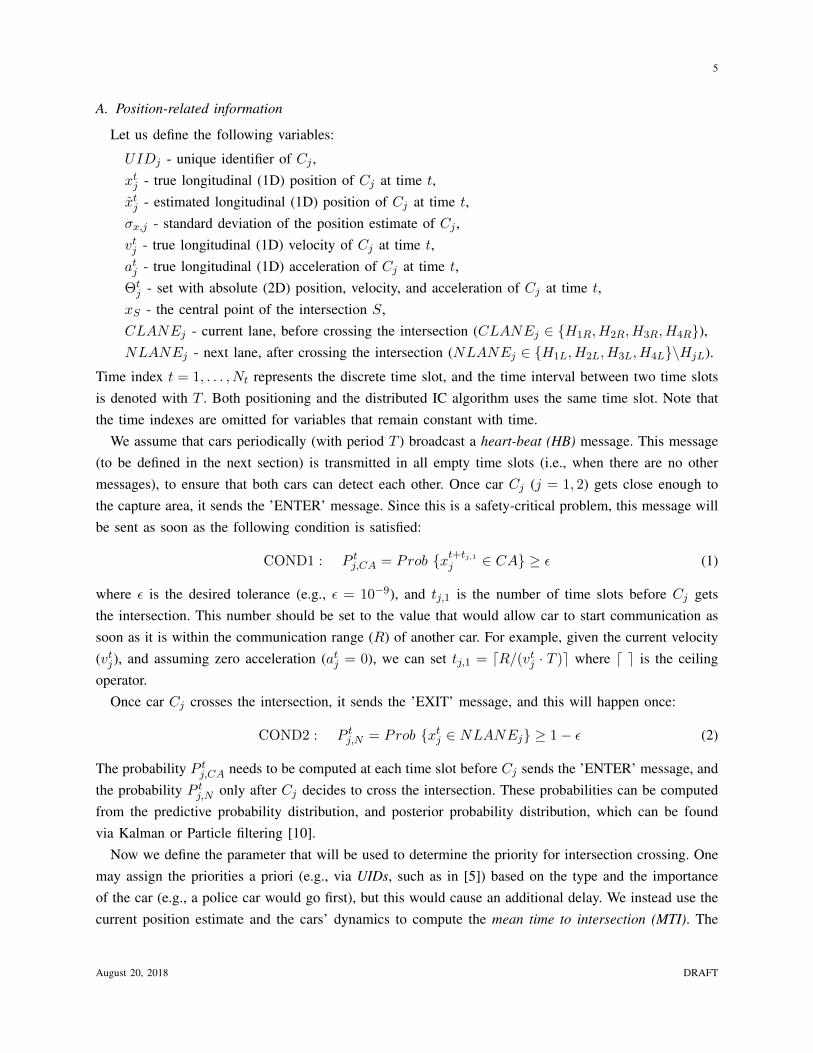
The flow-chart of the algorithm, shown in Fig. 2, consists of the following modules: (i) before ENTER,(ii) ENTER, (iii) wait for EXIT (only for the car without priority), and iv) EXIT. Here we provide thedescription of these modules:
1) Before ENTER: This module is a simple event detector, in which car waits for COND1 to besatisfied. Once that happen, the car is aware that it will soon reach the intersection and may collidewith another car.
2) ENTER: Once COND1 is satisfied for Cj , this car will attempt to send the ’ENTER’ message, andthen check if the same message from the other car is received. This messages may not be receivedeither because of the failure, or because other car is still waiting for COND1 to be satisfied. In thatcase, Cj will repeat sending of the ’ENTER’ message and initiate SAFECTRL. Then, once the’ENTER’ message from the other car is received, Cj will check if the ’HB’ message is received.This message serves as an acknowledgment that the ’ENTER’ message is received by the other car.If it is not received, Cj will repeat it, and initiate SAFECTRL. Otherwise, Cj has already receivedthe ’ENTER’ message, and is aware that other car has received its ’ENTER’ message. Therefore,both cars will initiate MAINCTRL action.
August 20, 2018 DRAFT
9
Is COND1 satisfied?
t=t+1,Send MSGHB
t=t+1,Send MSGENTER
t=0
No
Yes
Is MSGENTERfrom other car
received?
No
Yes
t=t+1,Send MSGHB
Is MSGHBfrom other car
received?
t=t+1,Send MSGENTER,Initiate SAFECTRL
t=t+1,Send MSGHB
No
Yes
Do I have priority?
t=t+1,Send MSGHB
YesNo
Is MSGEXITfrom other
car received?
Is COND2 satisfied?
t=t+1,Send MSGEXIT
Yes
No No
Yes
Is MSGEXITfrom other
car received?
t=t+1,Send MSGHB
No
Yes
t=t+1,Send MSGHB,
Initiate MAINCTRL
t=t+1,Send MSGHB,
Initiate MAINCTRL
t=t+1,Send MSGENTER,Initiate SAFECTRL
t=t+1,Send MSGHB
Is COND2 satisfied?
No
t=t+1,Send MSGEXIT
Yes
Is MSGHBfrom other car
received?
No
Yes
t=t+1,Send MSGHB
before ENTER
ENTEREXIT
EXIT
wait for EXIT
Fig. 2: Flowchart of the IC algorithm for car Cj . The time and car indexes are omitted for ease of presentation.
3) Wait for EXIT: This module is only executed for the car without priority. This car will wait forthe other car to execute MAINCTRL, exit the intersection, and confirm it by sending the ’EXIT’message.
4) EXIT: While executing MAINCTRL, the car with priority will wait for COND2 to be satisfied,then send the ’EXIT’ message to the other car, and check if the ’EXIT’ from the other car is received.The ’EXIT’ message will permit the car without priority to execute MAINCTRL, check if COND2is satisfied, then send its ’EXIT’ message, and finally, check if the other car has received it. The’EXIT’ messages are repeated in case of failures, but there is no need to execute SAFECTRLsince collision is now impossible.
August 20, 2018 DRAFT

10
t=1 t=2 t=3 t=4 t=5 t=6 t=7
MSGHB
MSGHB
COND1=Yes
COND1=No
MSGHB
MSGENTER
COND1=Yes
MSGENTER not received
MSGENTER
MSGENTER
MSGENTER received
MSGENTER received
MSGHB
MSGHB
MSGHB received
MSGHB received
MSGHB
MSGHB
MAINCTRL
MAINCTRL
no priority
priority
MSGHB
MSGHB
COND2=No
MSGEXIT not received
t=8+r t=9+r t=10+r
r more rounds, same as previous
MSGHB
MSGHB
COND2=Yes
MSGEXIT not received
t=11+r
MSGEXIT
MSGHB
MSGEXIT
MSGHB
MSGEXIT received
MSGEXIT not received
MAINCTRL
SAFECTRL
COND2=No
MSGEXIT not received
q more rounds, same as previous
MSGEXIT
MSGHB
COND2=Yes
MSGEXIT not received
MSGEXIT
MSGEXIT
MSGEXIT received
MSGHB not received
MSGHB
MSGEXIT
MSGHB received
t=12+r+q t=13+r+q t=14+r+q t=15+r+q
Fig. 3: The time diagram of the full IC algorithm without failures.
Note that the cars also execute other tasks simultaneously (e.g., an algorithm for pedestrian detec-tion or rear-end collision avoidance) that are not shown in this algorithm, and they also may triggerSAFECTRL. Note also that control actions (MAINCTRL and SAFECTRL) are only initiatedwithin one time slot, but their full execution will take much longer.
B. Time diagrams
We start with the example of time diagram (Fig. 3) for the execution without failures. We note thatcrossing the intersection will take many rounds, which depends on the cars’ dynamics. For instance,if communication round takes 100 ms, and the crossing time takes 3 s, the crossing would take 30communication rounds. Therefore, any failure would just slightly increase the total delay. We can alsosee the MAINCTRL is executed in the same round (t = 5), when both cars have available both’ENTER’ messages. SAFECTRL is initiated by C2 because C1 sent its ’ENTER’ message one roundlater. However, since this action is overwritten by MAINCTRL just two rounds later, there would notbe enough time for a noticeable deceleration. After initiating MAINCTRL, C1 would get priority (asan example), while C2 would need to slow down little bit to avoid collision. Then, after C1 exits theintersection, it will send the ’EXIT’ message, and keep repeating it until it gets the ’EXIT’ message fromC2 (which will happen once C2 exits the intersection). Finally, in the last two rounds, both cars becomeaware that the other car performed the required actions.
We now analyse the examples with communication failures. As shown in Fig. 4, we consider thefollowing situations: (f1, f2) = (0, 1) and (f1, f2) = (0, 3). We focus only on the ENTER part of the
August 20, 2018 DRAFT

11
t=1 t=2 t=3 t=4 t=5 t=6
MSGENTER
MSGENTER
MSGENTER not received
MSGENTER received
failure
MSGHB
MSGENTER
SAFECTRL MSGENTER not received
MSGHB not received
SAFECTRL
SAFECTRL
MSGENTER
MSGENTER
MSGENTER received
MSGHB
MSGHB
MSGHB received
MSGHB received
MSGHB
MSGHB
MAINCTRL
MAINCTRL
priority?
priority?
(a)
t=1 t=2 t=3 t=4 t=5 t=6
MSGENTER
MSGENTER
MSGENTER not received
MSGENTER received
failure
MSGHB
MSGENTER
SAFECTRL MSGENTER not received
MSGHB not received
SAFECTRL
SAFECTRL
MSGENTER
MSGENTER
MSGENTER not received
MSGHB
MSGENTER
MSGENTERnot received
MSGHB not received
MSGENTER
MSGENTER
SAFECTRL
SAFECTRL
MSGENTERreceived
failure failure
SAFECTRL
MSGHB
MSGHB
MSGHB
MSGHB
MSGHB received
MSGHB received
MAINCTRL
MAINCTRL
priority?
priority?
t=7 t=8
(b)
Fig. 4: Time diagrams of the ’ENTER’ part of the IC algorithm for different number of failures: (a) (f1, f2) = (0, 1), (b)(f1, f2) = (0, 3)
.
algorithm, since this is the most critical part in which a collision may happen. According to Fig. 3, thispart takes tEN = 3 rounds without failures.
In the first example (Fig. 4a), C2 fails to receive once the ’ENTER’ message sent by C1. Therefore,it will initiate SAFECTRL and repeat the ’ENTER’ message. Meanwhile, C1 received the ’ENTER’message, so it can transmit the ’HB’ message to confirm it. C1 also expects to receive ’HB’ messagefrom C2, but it will receive ’ENTER’ instead, and figure out that there is a failure at C2. Consequently,C1 will send again ’ENTER’ message and initiate SAFECTRL. This message will be received by C2,so it can transmit the ’HB’ message. The same message is also sent by C1 in the same round. Then,both cars will execute MAINCTRL in the same round and decide about the priority. The total delayin this example is tEN = 5.
In the second example, C2 fails to receive the message for three consecutive rounds. We note thatin the second round ’HB’ message is not received by C2 in contrast to previous example. Since thismessage is not needed, the second failure would not cause extra rounds. However, the third failure will
August 20, 2018 DRAFT

12
cause extra two rounds since a new ’ENTER’ message will not be available in the round following thisfailure. Then, the last four rounds of the diagram are the same as in the previous example, and the totaldelay is tEN = 7.
In summary, the total delay depends only on the maximum number of failures, and only an odd failure(3, 5, 7, etc.) increases the delay for two extra rounds. Therefore, it follows (by induction) that the totaldelay of the ENTER part is given by: tEN = 2dmax (f1, f2)/2e+ 3.
V. NUMERICAL RESULTS
Our goal is to analyze the delay caused by communication failures. For that purpose, we use thereal measurements of the packet delivery ratio (PPDR), available in [13]. In this work, authors analyzed802.11p based DSRC communication for V2V communication, and characterized communication andapplication level reliability of the wireless channel. They used General Motors cars equipped with aDSRC radio, omni-directional antenna and a GPS receiver. The transmission power was 20 dBm, thecommunication range was about 500 m, and the sampling interval was 100 ms. The experiments wereconducted on GM test freeways under open-field environment (without any obstacles) and a realisticharsh environment (with many obstacles such as tunnels and bridges).
We use the measurements of PPDR as a function of distance between the cars, for both open-field andharsh environment. Then, we used exponential model (e−λd, where λ is the decay rate [m−1], and d isthe distance [m]) to model PPDR as a function of distance. The results are shown in Fig. 5a and Fig.5c, and the corresponding decay rates are 0.00063 and 0.0013.
We then compute the expected delay of the ENTER part of the algorithm (tEN ) by averaging overdifferent number of communication failures. We consider the scenario in which one car commits fconsecutive failures, while other car commits no failures. Assuming independence, the likelihood of mconsecutive failures is given by geometrical distribution: p(f = m) = (1− PPDR)m · PPDR, so we cancompute the delay as follows:
tEN =
∑Mm=0 p(f = m) · tEN (f = m)∑M
m=0 p(f = m)(8)
where M is the maximum number of failures (we set it to M = 50 since more failures would causea negligible delay). However, although the independence assumption is experimentally justified in [13],it may not be the case if there is a long obstruction of the channel (e.g., due to the large truck infront of the car). For this case, we define a transitional probability ξ = p(f = m|f = m − 1) whichgives us an information about the likelihood of the failure in the current round, given that failuresalready happened in the previous round. The likelihood of m consecutive failures is now given by:p(f = m) = (1− PPDR) · PPDR · ξm−1, and tEN can be again computed using (8).
The results of tEN as a function of distance for different values of are shown in Fig. 5b and Fig. 5dfor both open-field and harsh environment, respectively. As expected, the open-field environment leadsto consistently lower delay, but the difference is not significant (≤ 20%). However, high transitionalprobabilities can cause a significant delay, especially for ξ = 0.9, but this delay is still much lower
August 20, 2018 DRAFT

13
0 50 100 150 200 250 300 350 400 450 500
distance [m]
0
0.2
0.4
0.6
0.8
1packet deliv
ery
ratio
samples
exp. model
(a)
0 50 100 150 200 250 300 350 400 450 500
distance [m]
3
4
5
6
7
8
9
10
11
12
exp
ecte
d d
ela
y [
rou
nd
s]
independent
transProb=0.5
transProb=0.6
transProb=0.7
transProb=0.8
transProb=0.9
(b)
0 50 100 150 200 250 300 350 400 450 500
distance [m]
0
0.2
0.4
0.6
0.8
1
packet deliv
ery
ratio
samples
exp. model
(c)
0 50 100 150 200 250 300 350 400 450 500
distance [m]
3
4
5
6
7
8
9
10
11
12
exp
ecte
d d
ela
y [
rou
nd
s]
independent
transProb=0.5
transProb=0.6
transProb=0.7
transProb=0.8
transProb=0.9
(d)
Fig. 5: (a) Packet delivery ratio vs distance (open-field), (b) Expected delay vs distance (open-field), (c) Packet delivery ratiovs distance (harsh), (d) Expected delay vs distance (harsh).
comparing with the total crossing time that typically takes few seconds. However, in highly unlikelyscenario in which ξ is too close to 1, the delay would be too large (infinite, for ξ = 1), so in that casean alternative technology should be used.
VI. CONCLUSIONS
We proposed a novel IC algorithm that can handle an unknown nymber of communication failures.In order to avoid collision and minimize the delay, our algorithm uses the cars’ positions and theirdynamics to adapt their actions. The algorithms is fully distributed, so no centralized intersection manageris required. We provided an analysis of time diagrams that show that both safety and liveness are satisfiedin all realistic situations. According to our numerical results, which are based on real measurements, thecrossing delay is just slightly increased even in the presence of correlated failures. Our future work willfocus on the extension of this algorithm for a variable number of cars, and its implementation withinstandardized traffic simulators. One may also consider other challenging problems, such as developmentof a rear-end collision avoidance algorithms in the presence of communication failures, and development
August 20, 2018 DRAFT

14
of an IC algorithm that can handle malicious massages.
ACKNOWLEDGMENT
This work was supported by Area of Advance Transport, Chalmers University of Technology.
REFERENCES
[1] H. Wymeersch, G. R. de Campos, P. Falcone, L. Svensson, and E. G. Strom, “Challenges for cooperative ITS: Improvingroad safety through the integration of wireless communications, control, and positioning,” in Intl. Conf. on Computing,Networking and Communications (ICNC), pp. 573–578, Feb 2015.
[2] A. Mukhtar, L. Xia, and T. B. Tang, “Vehicle detection techniques for collision avoidance systems: A review,” IEEE Trans.on Intelligent Transportation Systems, vol. 16, pp. 2318–2338, Oct 2015.
[3] M. R. Hafner, D. Cunningham, L. Caminiti, and D. D. Vecchio, “Cooperative collision avoidance at intersections:Algorithms and experiments,” IEEE Trans. on Intelligent Transportation Systems, vol. 14, pp. 1162–1175, Sept 2013.
[4] A. Casimiro, J. Kaiser, E. M. Schiller, P. Costa, J. Parizi, R. Johansson, and R. Librino, “The KARYON project: Predictableand safe coordination in cooperative vehicular systems,” in 43rd Annual IEEE/IFIP Conf. on Dependable Systems andNetworks, pp. 1–12, IEEE, 2013.
[5] S. Azimi, G. Bhatia, R. Rajkumar, and P. Mudalige, “Reliable intersection protocols using vehicular networks,” in Proc.of ACM/IEEE Intl. Conf. on Cyber-Physical Systems (ICCPS), pp. 1–10, April 2013.
[6] A. Colombo and H. Wymeersch, “Cooperative intersection collision avoidance in a constrained communication environ-ment,” in Proc. of IEEE 18th Intl. Conf. on Intelligent Transportation Systems (ITS), pp. 375–380, Sept 2015.
[7] H. Kowshik, D. Caveney, and P. R. Kumar, “Provable systemwide safety in intelligent intersections,” IEEE Trans. onVehicular Technology, vol. 60, pp. 804–818, March 2011.
[8] I. Skog and P. Handel, “In-car positioning and navigation technologies - a survey,” IEEE Trans. on Intelligent TransportationSystems, vol. 10, pp. 4–21, March 2009.
[9] A. Vu, J. A. Farrell, and M. Barth, “Centimeter-accuracy smoothed vehicle trajectory estimation,” IEEE IntelligentTransportation Systems Magazine, vol. 5, pp. 121–135, winter 2013.
[10] M. S. Arulampalam, S. Maskell, N. G. Gordon, and T. Clapp, “A tutorial on particle filters for online nonlinear/non-GaussianBayesian tracking,” IEEE Trans. on Signal Processing, vol. 50, pp. 174–188, Feb. 2002.
[11] SAE International, “Dedicated short range (DSRC) message set dictionary.” http://standards.sae.org/j2735 200911/, Nov.2009.
[12] M. Raynal, Fault-tolerant Agreement in Synchronous Message-passing Systems. Morgan & Claypool, 2010.[13] F. Bai and H. Krishnan, “Reliability analysis of DSRC wireless communication for vehicle safety applications,” in Proc.
of IEEE Intelligent Transportation Systems Conf., pp. 355–362, Sept 2006.
August 20, 2018 DRAFT