Embed Size (px)
Citation preview
AD-754 280
IR WINDOW STUDIES
John H. Marburger
University of Southern California
V,
Prepared for:
Air Force Cambridge Research Laboratories
29 September 197 2
DISTRIBUTED BY:
National Technical Information Service U. S. DEPARTMENT OF COMMERCE 5285 Port Royal Road, Springfield Va. 22151
o USCEE No. 431
/
UNIVERSITY OF SOUTHERN CALIFORNIA
IR WINDOW STUDIES
John H. Marburger
Contract No. F19628-72-C-0275
ARPA Order No. 2055
QUARTERLY TECHNICAL REPORT NO. 1
For the Period Ending 31 August 1972
D a av r?mr?nnm?
-IM n m ITElu
Contract Monitor: Charles E. Ryan
Solid State Sciences Laboratory
AIR FORCE CAMBRIDGE RESEARCH LABORATORIES AIR FORCE SYSTEMS COMMAND
UNITED STATES AIR FORCE BEDFORD, MASSACHUSETTS 01730
ELECTRONIC SCIENCES LABORATORY Approved for public release; distribution unlimited
Reproduced by
NATIONAL TECHNICAL INFORMATION SERVICE
U S Department of Commerce Springfield VA 22131
C^///7///rjfV$//si "/•
4>
Security Cl»a»ificatk>n
DOCUMENT CONTROL DATA R&D (Sacur/ir clmnlllcmllon ol llllm, bodf ol mbtltmct mnd IndrnMlng mmoiailon mutrt he mnfwd urhan ihm ommll rmpon Im clattHlmd)
l ORIGINATING ACTIVITY tCorpormlm mulhat)
Electronic Sciences Laboratory University of Southern California I cs Angeles, California 90007
ia.Btt'OHT SECUniTV CLASSIFICATION
UNCLASSIFIED Zb CROUP
3 REPORT TITLE
IR WINDOW STUDIES
4 DESCRIPTIVE HOTE9 (Typm ol rmpatl mnd Inclumlrm dmlmm)
Scientific 8 AurnOKiS) (Flrml nmmm, jiU'dB* Inltlml, Immt nmmm)
John H. Marourger, et al. (see pages 4, 5 and 6. )
< REPOR T UA TE
29 September 1972 •a. COHTHACT OR GRANT NO
F19628-72-C-0275 b. PROJEC T NO
ARPA Order No. 2055
Ta. TOT^L NO OF PASES
-4%- SO lb. NO OF REFS
•«. ORIGINATOR'S REPORT NUUaCROI
•b OTHER RCPORT NOISl (Any olhmt numtbvrm Html mmy b« mmml0imd IMm rmporl)
10 DISTRIHUTION STATEMENT
Approved for public release; distribution unlimited II SUPPLEMENTARV NOTES
TECH, OTHER
II SPONSORING MILITARY ACTIVITY
Air Force Cambridge Research Laboratoriqs L . G. Hanscom Field Bedford, Massachusetts 01730
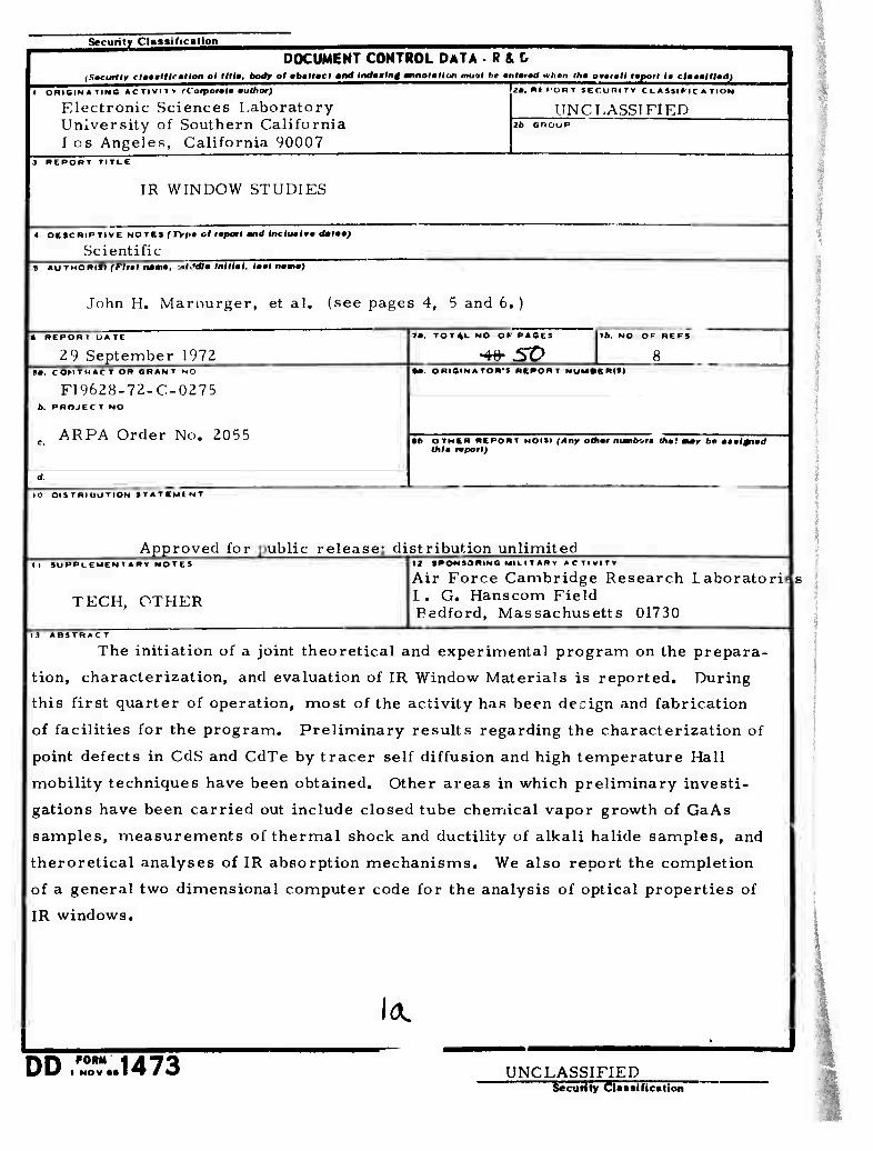
13 ABSTRAC T
The initiation of a joint theoretical and experimental program on the prepara-
tion, characterization, and evaluation of IR Window Materials is reported. During
this first quarter of operation, most of the activity has been decign and fabrication
of facilities for the program. Preliminary results regarding the characterization of
point defects in CdS and CdTe by tracer self diffusion and high temperature Hall
mobility techniques have been obtained. Other areas in which preliminary investi-
gations have been carried out include closed tube chemical vapor growth of GaAs
samples, measurements of thermal shock and ductility of alkali halide samples, and
theroretical analyses of IR absorption mechanisms. We also report the completion
of a general two dimensional computer code for the analysis of optical properties of
IR windows.
I A.
■
DD FORM 1473 UNCLASSIFIED "— Security Classirication
Security Classification
KEY WORDS
IR Windows
Alkali Halides
III-V Semiconductors
II-VI Semiconductors
Thermal lensing
lb Security Classification
IR WINDOW STUDIES
John H. Marburger
QUARTERLY TECHNICAL REPORT NO. 1
For the Period Ending 31 August 1972
ELECTRONIC SCIENCES LABORATORY SCHOOL OF ENGINEERING
UNIVERSITY OF SOUTHERN CALIFORNIA LOS ANGELES, CALIFORNIA 90007
Sponsored by
Defense Advanced Research Projects Agency
ARPA Order No. 2055
Monitored by
Air Force Cambridge Research Laboratories
IC
ARPA Order Number
2055
Contract Number
F19628-72-C-0275
Program Code Number
None
Principal Investigators
F. Kroger
213 746-6224/5
J. Marburger
213 746-2227/9
Name of Contractor
University of Southern California
AFCRL Project fcientist
C. Ryan
617 861-4062
Effective Date of Contract
1 June 1972 Id Contract Expiration Date
30 November 1973
CONTENTS
d. 1 Surface and Interface 1R Absorption
f. 1 Techniques for Indirect Measur -ment of Small Absorptive Losses
Page
ABSTRACT 1
1. INTRODUCTION
1.1 General Objectives 3
1.2 Work Statement and Project Identification 4
2. PROGRESS BY PROJECT
a. 1 Effect of Oxygen and Other Impurities on I. R. Absorption 7 in II-VI and III-V Compounds
a. 2 Optimization of Alkali Halide Window Materials 8
a. 3 Growth of Crystals for IR Window Research 13
b. 1 Fabrication of Polycrystalline IR Window Materials 16
c.l Mechanical Behavior of III-V and II-VI Compounds 19
20
d.2 Study of Defects in II-VI Compounds 2 3
e. 1 Theoretical Studies of Absorption Mechanisms in IR Window 27 Materials
30
g. 1 Characterization of Optical Performance of IR Window 32 Systems
3. DISCUSSION 44
4. SUMMARY 45
1. INTRODUCTION
1.1. General Objectives
The infrared window program at the University of Southern California
is a cooperative effort involving faculty from the departments of Electrical
Engineering, Materials Science, and Physics. Each of the projects in this
program falls under one of the following general categories
A. Materials growth and window fabrication
B. Materials characterization
C. Materials evaluation for window applications.
Projects in category A include the preparation of crystals of alkali I
halides. GaAs and other promising semiconductor materials; liquid epitaxial
growth of very high purity GaAs and hot pressing of semiconducting compounds
for window fabrication. Category B includes mechanical characterization
of semiconductors and alkali halides. defect characterization through
absorption spectroscopy, tracer self diffusion, high temperature Hall effect
measurements, and X ray and electron microprobe techniques when relevant.
In this category also falls studies of surface absorption and conductivity,
and theoretical analysis of IR absorption mechanisms. Category C includes
calorimetric determination of absorption coefficients, investigations of
possibly more sensitive absorbance measuring techniques, mechanical
testing of windows, and numerical simulation of optical and thermal window performance.
The general objectives in the initial phase of of the program are:
1. Establish a local facility for calorimetric determination of
small IR absorbances using a powerful C02 laser tunable from 9 to II am.
2. Establish facilities for the preparation of materials used in the program.
3. Establish a basis for theoretical support of the program objectives.
4. Redirect continuing USC programs (some supported by other
contracts in the past) toward objectives relevant to the IR window problems.
c. "Investigate the mechanical properties of different window candidate materials and their modification by different processing techniques. "
c. 1 Mechanical Behavior of III-V and II-VI Compounds
S. M. Copley
(a. 2 also includes mechanical testing)
d. "Characterize the candidate window materials by chemical, physical, metallurgical and other processes,, This includes materials obtained from other sources as well as those prepared under subparagraph a. above. Particular emphasis will be placed on the understanding and control of the mechanisms by which chemical and physical defects modify the properties of the materials. "
d. 1 Surface and Interface IR Absorption
C. R. Crowell, J. M. Whelan
d, 2 Study of Defects in II-VI Compounds
F. A. Kroger, M. Gershenzon
d. 3 Determination of Maximuir Acceptable Impurity Concentrations in IR Window Materials
Mo Gershenzon
e. "Conduct theoretical investigations to enhance the understanding of the basic mechanisms of absorption of optical energy, particularly but not restricted to, the region around 10.6 micrometers wavelength. Emphasis will be on those mechanisms which may dominate the residual absorption, i.e. the very low loss materials (for example, potassium chloride). "
e. I Theoretical Studies of Absorption Mechanisms in IR Window Materials
R. W. Hellwarth
f. "Investigate and improve methods of measuring the optical absorption of materials which have very low losses at 10.6 microiaeters in order to correlate theoretical and experimental data on candidate window materials. "
f, 1 Techniques for Indirect Measurement of Small Absorptive Losses
W. H. Steier
g. "Evaluate the optical performance of candidate window materials. This investigation shall include detailed studies of the influence of physical material parameters on degradation of the optical perfor- mance of the window materials (for example, thermal lensing). The study of promising window designs, such as multiple component windows and material criteria for these designs, will be considered."
g. 1 Characterization of Optical Performance of IR Window Systems
J. H. Marburger
If additional projects are ado^d during the course of the contract, they will be assigned codes according to this scheme»
..'■
2. PROGRESS BY PROJECT
a. 1 Effect of OxyKen and Other Impurities on IR Absorption in II-VI and III-V Compounds
J.M. Whelan, M. Gershenzon
A system has been designed for growing high purity selectively doped
GaAs films to be used in surface and bulk defect Absorption studies.
It is based on low temperature solution growth of thin films and can be
operated in a temperature gradient made to grow relatively thick films.
Features of this system include a horizoital sliding boat-substrate
holder arrangement for limiting the effective solution volume.
Variations of this have been used for some time. A much less common
feature willbe the use of a spdcia.ily designed furnace in which the
longitudinal temperature gradients are rriinimized without giving up the
provision for temperature control to within +_ 0. 02-0. 05OC. Materials
for this system are on order and the initial fabrication has begun.
a. 2. Optimization of Alkali Halide Window Materials
P. J. Shlichta
The objectives of the first phase of this program are:
(1) Growth of high-purity and doped NaCl and KC1 crystals.
(2) Testing to determine the effect of each impurity or defect on:
(a) Optical absorption at 10.4 microns
(b) Thermal shock resistance
(c) Yield stress
(d) Brittle-ductile transition temperature
Thus far the following activities have been initiated:
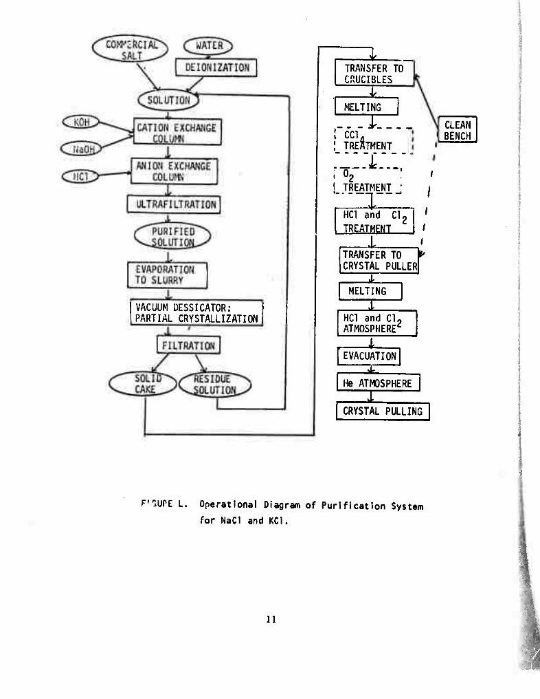
Purification of NaCl and KC1: On the basis of a recent review of
purification techniques (ref. 1), it was decided that both ion-exchange
and gas treatment (i.e. , v/ith HC1 and Cl,) would be necessary.
Moreover, it was decided that, for reasons of speed and reliability, it
was preferable to undertake these activities at USC rather than rely on
an outside contractor. The proposed purification scheme is outlined
in Figure 1. This scheme provides us with several options with respect
to controversial aspects of purification:
(1) It has been reported (ref. 2) that treatment of the molten salt with
CGI vapor removes anionic impurities much more rapidly and completely
than HC1 treatment. However, this procedure may leave behind impurities
such as CO= and CO?Cl = .
(2) Treatment with Cl may be insufficient to burn off traces of organic
material, in which case it may be necessary to follow Grundig's procedure
(ref. 3) of treating the solid salt with 10 mm of 02 at 500 C.
(3) It is uncertain whether the purified salt can be melted in fused
silica without introducing silicate as an impurity. Accordingly the
apparatus has been designed to provide alternatives for each of the above
steps. Thus far, all the necessary equipment has been ordered and it is
hoped that the system will be operational by the end of the year.
Crystal Growth: A Lepel crystal puller is being modified so as to eliminate
all metal parts from the growth chamber, e. g. the seed holder and pull
rod are being replaced by carbon parts and new polycarbonate end plates
are being made. This apparatus should be operational by the end of
the year. In addition, an auxiliary puller will be mounted onto the gas
treatment apparatus so that crystals for analytical and optical
measurements can be grown during the purification process.
Thermal Shock; Preliminary tests of thermal-shock resistance were
made by impinging a 2 mm oxyuen-propane torch flame on the center
of 20 x 20 x 2 mm NaCl plates for five seconds. When the plates were
initially at room temperature, the thermal shock invariably initiated
cleavage cracks. However, when the crystals were preheated to
300 C (i.e., well above the brittle ductile transition temperature), no
cracking resulted, even when the flame was allowed to melt a bead on
the face of the crystal. Further experiments showed that preheated
crystals could even bs welded together by the gas torch.
In the next quarter, these tests will be continued using a focused
laser beam in place of the gas flame.
Ductility; According to the literature, (refs. 4, 5), there exists a
brittle-ductile transition temperature below which, alkali halide
crystals are ductile in certain modes of deformation (such as [100]
tension or compression and [100]/[001] bending) but brittle in others
(such as [lll]tension or compression or [100] torsion). Above the
transition temperature, the crystals are completely ductile.
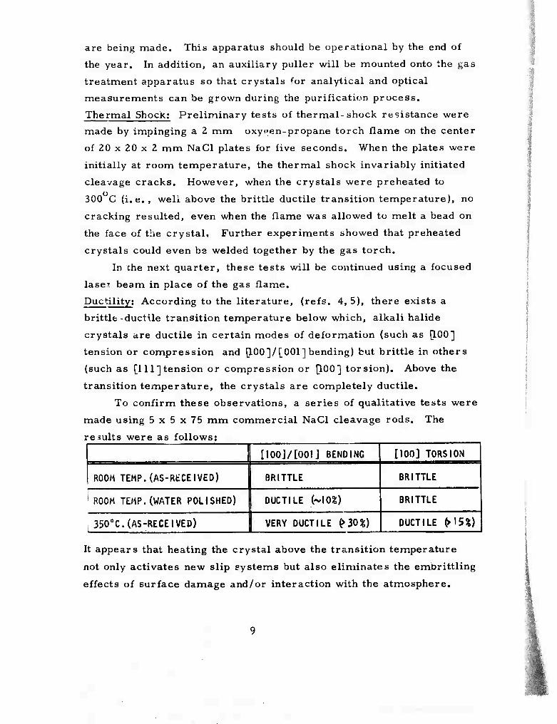
To confirm these observations, a series of qualitative tests were
made using 5 x 5 x 75 mm commercial NaCl cleavage rods. The
results were as follows;
I100j/[001] BENDING 1100] TORSION
ROOM TEMP. (AS-RtCEIVED) BRITTLE BRITTLE
1 ROOM TEMP. (WATER POLISHED) DUCTILE (~m) BRITTLE
, 350oC. (AS-RECEIVED) VERY DUCTILE ^30^) DUCTILE H5%)
It appears that heating the crystal above the transition temperature
not only activates new slip systems but also eliminates the embrittling
effects of surface damage and/or interaction with the atmosphere.
With respect to experiment design, the data above suggest that
[100] torsion in a thermal gradient will provide the quickest method of
determining the approximate transition temperature for a given specimen.
Such an apparatus is being constructed and should be operational some-
time during the next quarter. More precise measurements of the yield
stress above and below the transition temperature will probably be made
by [111] and [100] compression tests.
Application to Laser Windows: The most likely failure modes of a CO-
laser window are (a) cracking, (b) sagging or other plastic deformation,
(c) differential heating and consequent optical "blooming", and
(d) excessive light scattering. Of these, (a) would appear to be the most
catastrophic since it can destroy the entire system. This, apparently,
can be avoided by heating the entire window so that all parts of it are
above the transition temperature; the thermal shock experiments reported
above seem to confirm this concept. Unfortunately, this remedy for
cracking will almost certainly increase the tendency of sagging, the
critical parameter being the yield stress just above the transition
temperature. According to this approach, window performance might be
optimized by (1) purifying the material so as to minimize the transition
temperature, and (2) finding an impurity or defect which raises the yield
stress but does not raise the transition temperature or the infrared absorption.
An alternative approach would be to use "forged" polycrystalline
windows. Because of latent hardening (ref. 6), the yield stress would be
almost a magnitude higher. However, unless the grain size is exceedingly
small, the tendency toward cracking would be comparable to that of
single crystals; therefore, such windows would probably also have to be
operated above the transition temperature. Even in this region, however,
they would have several times the yield stress of single crystals, (ref. 4)
The --.se of such windows may, however, be limited by their tendency to excessive light scattering.
10
VACUUM DESSICATOR: PARTIAL CRYSTALLIZATION
TRANSFER TO CRUCIBLES
MELTING
irrxr.. ; TREATMENT
:;::£:.:; i o2 : ! TREATMENT
CLEAN BENCH
X HC1 and Cl, TREATMENT
.L i TRANSFER TO CRYSTAL PULLERl r MELTING
HC1 and Cl. ATMOSPHERE'
EVACUATION
He ATMOSPHERE
I CRYSTAL PULLING
F"JUPE L. Operational Diagram of Purification System
for NaCI and KC1.
11
REFERENCES
1. Rosenberger, Franz, "Purification of Alkali Halides" (review),
in TechnJrjUt s of Ultrapurity, by M. Zeif and B. Speights (ed. ),
(Marcel Dekker) in press.
\ 2. Lebl, M., and Trnka, J., Z. Physik 186, (1965) p. 128.
3. Fischer, F., Grundig, H. , and Hilech, R., Z. Physik 189,
(1966) p. 79.
4. Stokes, R. J., Proc. Brit. Ceram. Soc. 6, (1966); see also Stokes,
R. J. , and Li, "Disclocations and the Strength of Polycrystalline
Ceramics", 15th technical report of Honeywell Research Center
(Ili-pk'ns, Minn. ) to Office of Naval Research, Proj. Nonr 2456(00)
NR-032-451 (1962) 42 pp.
5. Johnston, T. L. , Stokes, R. J. , and Li, C, H. , Phil. Mag. 4,
(1959) pp. 1316-24.
6. Alden, T. H., J. Metals 15, (1963) p. 116; see also Alden, T. H. ,
Acta Metall. 11, (1963) pp. 103-5.
12
a. 3. Growth of Crystals for IR Window Research
W. R. Wilcox
(Chemical Vapor Deposition of Gallium Arsenide)
1. Purpose
This study is being undertaken in an attempt to produce high purity
GaAs as needed for IR laser window research. The major advantage
of a C.V.D. process over other methods of GaAs growth, is
that growth can take place at lower temperatures, thus minimizing
the problems of impurity solubility at high temperatures and
crucible contamination.
2. Basic Reactions
The basic chemical reaction in the CVD process involves the
transport of Ga as either a volatile halide, oxide, or alkyl compound
from a hot to a cold zone of a reaction tube. For example in our
preliminary work, an amount of !_ or HC1 (to give « 1 atm. pressure
at 900OC) was added to an evacuated tube containing GaAs. The
tube was subsequently sealed. The initial reaction between GaAs
and 1- is:
2GaAs + I- ^ZGal, j + jAs4. .
Gal now reacts with arsenic vapor forming Gal- and GaAs according to:
3GaI(g) + iAs4(g)^=: Gal3(g) . 2GaAs(s)
Transport may be cotained from a hot to a cold area since this
equilibrium favors GaAs deposition in the cold zone.
3. Experimental Work When nucleation occurs in the tip of a capillary, there is an increased
chance that as growtl. proceeds up the capillary, one crystallite may
dominate the growth pattern. Therefore various tube geometries
and methods of applying a cold spot were tested. Several tests were
conducted using capillary tips and forced air cooling to induce
crystallization in the tip. Also thd tubes were placed in a furnace
with a 50-100OC temperature difference between the feed and seed
13
zone. In a few cases promising results were obtained. Although
the crystals grown were polycrystalline, there were only small
voids in them. In addition the growing surface was convex with
respect to the solid. This will tend to produce minimal dislocations
since dislocations tend to propagate normal to the growing interface,
and in this case will tend to grow out of the crystal. In a typical
example (Run #8) a polycrystalline sample is grown by the HCI
transport method using a copper wire cemented to the end of the
tube as a heat sink. The temperature of the feed and seed i:one
were 880 and 820 C respectively. The crystal was cut and
mechanically polished, and then submitted to Dr. Steier's group for
IR absorption measurements by calorimetric methods.
In some of the preceeding experiments, it was observed that
nucleation of individual crystallites occured on the sides of the
capillary along with nucleation in the tip. This could be due to
insufficient temperature difference between the cold spot in the tip
and the walls, especially as the growing crystal advances.
An alternative that may alleviate this problem is the travelling
heater method. A sealed tube containing GaAs + I? is drawn
through a sharp temperature gradient at a slow rate of approx.
1 mm per day. In this way the growing crystal can establish a
steady state growth rate vs. distance profile with respect to the
temperature gradient. Two travelling heater furnaces were
constructed and preliminary runs indicate the need for a small
vapor space for transport. This small vapor space is also needed
to minimize the effect of the vapor phase analog of constitutional
supercooling. This can be a problem, bec?:iü6e of concentration
gradients caused by diffusion or connection, the partial pressures
of AS.+ Gal may be greater than the equilibrium partial pressures
at the particular growth site.
We also foond that it was necessary to obtain GaAs starting mate-
rial free from excess gallium. It was observed in several cases with
14
excessGa in the starting material, no crystal growth would
take place, only Ga transport occured. This will create some
experimental problems in sealing quartz tubes with a small vapor
space because of thermal decomposition of GaAs,
4. Future Work
Further experiments with various tube geomr^ries are planned. One
particular tube design consists of an internal projection with a small
flat surface cooled by a stream of air. An advantage of such a design
is that crystal growth from such a projection would be free of
constraints from the walls of the tube.
Several more travelling heater furnaces are to be placed in operation
in order to investigate this method of growth in a reasonable period
of time. In addition, further work is planned for stationary tube
methods, mainly in controlling the temperature profile at the seed
end, and testing different capillary sizes and shapes.
5. Open Tube CVD Facility
A system has been designed and parts ordered for a CVD open tube
system that will allow one to investigate several transport techniques.
It is planned to investigate Ga transport by volatile HC1, HI, and H20
vapor compounds.
Special attention will b<i directed toward investigation of CVD processes
using alkyl gallium compounds and arsine as transporting agents.
Thick films C* 1 mm thick) have been grown at very fast rates
(w 1 mm/day) using this method. Since arsine is highly toxic, the
whole system will be installed in a special hood which is now under
construction.
15
b. 1. Fabrication of Polycrystalline IR Window Materials
S. M. Copley, J. M. Whelan
The goal of this portion of the program is to produce samples of
polycrystalline gallium arsenide by a novel hot pressing technique
involving ths, use of volatile sintering aids. Working drawings of the
special hot press have been prepared and materials for its fabri-
cation have been ordered.
In our technique, excess arsenic will be employed to enhance the
sintering of gallium arsenide powder. In addition to the "lubricating"
properties of molten arsenic which will enhance particle rearrange-
ment during sintering, the high volatility of arsenic and its oxides
will be helpful in removing the excess lubricating arsenic and
contaminating oxides from the pressed compact. However, the high
vapor pressure of molten arsenic (28 atmospheres) presents a
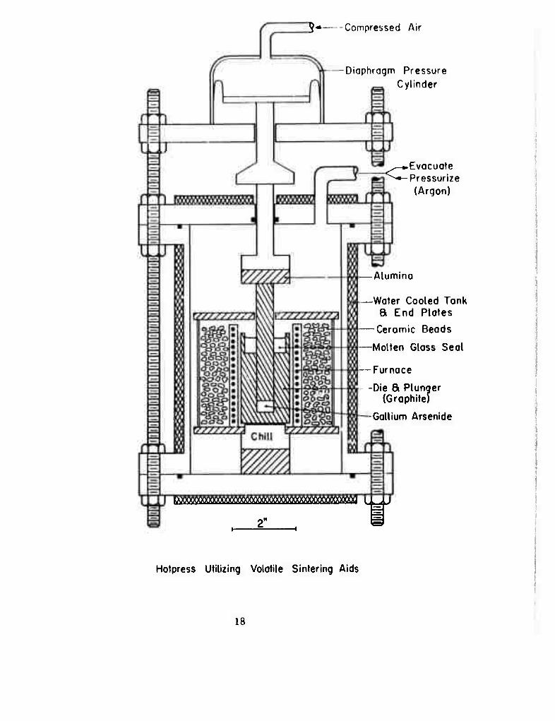
containment problem. A schematic diagram of the hotpress is shown
in Fig. 1. It is planned to seal the arsenic vapor in the hotpress
die using a molten glass which will be retained in a well on top of
the die by pressurizing the hotpress chamber with argon.
The following operating procedure is envisioned. First the die (loaded
with gallium arsenide powder, and containing chips of glass in the
recess on top) will be installed in the furnace chamber which will then
be evacuated. A load will then be applied to the die plunger by
pressurizing the diaphragm cylinder. Then, while evacuation continues,
the furnace will be heated to melt the glass with the chill operating to
keep the excess arsenic cool (below 250 C). When the glass is molten,
the vessb' will be pressuri/.ed with argon, the chill will be turned off,
and the \urnace temperature will be adjusted to the desired hotpressing
value.
After compaction the furnace will be allowed to cool, and the applied
load said argon pressure will be removed. Gallium ar ienide has an
unusually low coefficient of thermal expansion (6 x 10 / C) and the
16
graphite die may contract around the pressed compact during cooling.
The use of expendable dies has been considered.
After cooling, the arsenic rich compact is removed from the die.
Post curing of the compact for final adjustment of arsenic content
is beini' considered.
Production is planned for gallium arsenide dies 1/2" diameter by
1/8" thick. Hotpressing capabilities to 5000 psi (on 1/2" diameter
ram; and 1200 C are planned.
During the next quarterly period the hot press will be fabricated at
the USC Engineering Machine Shop.
17
5* Compressed Air
Diaphragm Pressure Cylinder
^—••Evacuate ^•-Pressurize
(Argon)
-Alumina
-Water Cooled Tank S End Plates
-Ceramic Beads
-Molten Glass Seal
Furnace
-Die & Plunaer (Graphite)
-Gallium Arsenide
DMMMM^^ » , .T
Hotpress Utilizing Volatile Sintering Aids
18
c.l. Mechanical Behavior of III-V and II-VI Compounds
S. Mo Copley
This investigation is concerned with a determination of the mechanical
behavior of various window candidate materials. A study of the
mechanical behavior of single crystals of GaAs doped with Si has been
initiated.
A 350 gm melt grown single crystal of Si-doped GaAs with <* carrier 18 3 2
concentration of 1.8x10 /cm , a mobility of 1900cm /v. sec and a
resistivity of 1.89x10' 0 cm was obtained from Crystal Specialties, Inc. v
Compression specimens with length to width ratios of 1, 1. 5 and 3.0
were prepared by a series of operations including initial shaping with
a precision cut-off wheel, two-circle goniometer unit to give selected
orientations and precision grinding. Specimens with <100> and <ill>
stress axes were selected for the initial stress-strain experiments on
the basis of Schmid factor considerations. The < 100> stress axis favors
slip on {ill] <n0>, the previously observed slip system, while the
<111> stress axis favors slip on other systems.
A graduate student has been trained to carry out the stress-strain
experiments on the CGS Lawrence Mechanical Testing System. In the
next quarterly report, stress strain data should be available at various
temperatures. This data will indicate the operative slip modes in GaAs
single crystals and the temperature dependence of the critical resolved
shear stress for these modes. It will also indicate the effect of varying
the length over width ratio of the specimens on stress-strain results.
:Crystal Specialties, Inc. 419 W. Maple Monrovia, California 91016
19
^ S^ace and Interface TR AWrption Under Intense Illurrinab-nn C. R. Crowell. & J. M. Whelan
We have undertaken to attempt to find evideuce for surface and
interface IR absorption through electrical measurement of conductivity
and interface charge in GaAs MOS type structures with air gap
insulation and with typical antireflection coatings. During this initial
period we have taken preliminary steps toward establishing a sample geometry.
To study the air-GaAs interface we h^ve decided on the geometry which will be described below in detail.
Since most antireflection coatings used for IR laser windows can
be deposited fairly easily on semiconductors, a typical structure will
be used for antireflection coating-GaAs interface absorption studies.
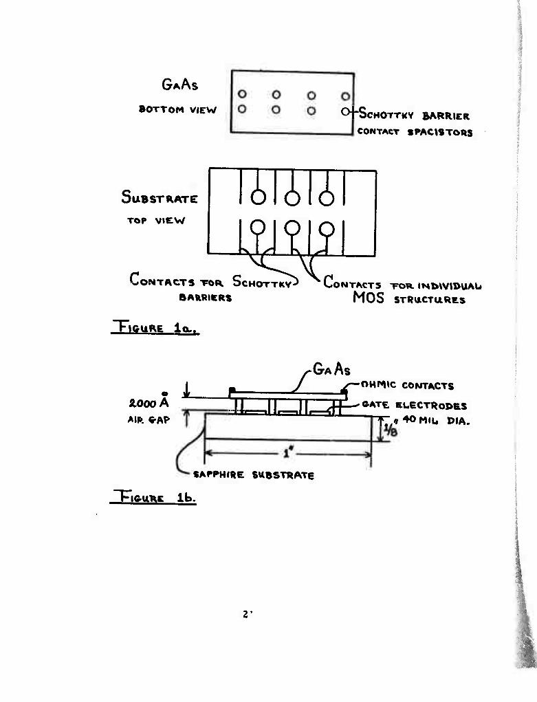
Structure for the Study of Air-GaAs Interface- (Figure 1)
For this structure gate electrodes are evaporated on optically flat
substrate and Schottky barrier spacistors are deposited on freshly
prepared flat GaAs surfaces. Evaporated ohmic contacts are used for
ohmic contacts on GaAs and present techniques for making ohmic contact? appear adequaLe.
For sensitivity in investigating surface states with an air dielectric
structure the large difference in dielectric constant between the air
and the GaAs demands that the air gap thickness be as small as
current fabrication techniques make possible. We are initially aiming
at < 2000A0. This places importance on the flatness of GaAs surface and gate electrodes.
We have attempted to establish the thickness of the air gap by the
thickness of the evaporated metal film on the GaAs. The film is
deposited in a pattern determined by a shadow mask which was designed
and fabricated during this reporting period. During device operation
this film will be contacted by the metallized registered pattern deposited
20
GAAS
BOTTOM VIEW C+ScHOTTKV BARRIER CONTACT SPACtSTORS
SUBSTRATE
TOP view
mi CONTACTS TOR SCHOTTKV-
BARRISRS
"FIGURE iou.
. L 2.000 A
CONTACTS TOR IN^WIDUAU
MOS STRUCTURES
ZGAAS >^—OHMIC CONTACTS ^T'
AIR C-AP- IJ—[QBfci!^! MC^OI>RS
SAPPHIRE SUBSTRATE
"FlC-URE lb.
2'
on the insulating substrate ^vhich is also used to support the gate
electrode. The registering pattern and metal gate is deposited
simultaneously. Thus we have both MOS and Schottky barrier
electrodes to compare the behavior of the GaAs bulk and the sum
of surface and bulk effects. Considering the order of thickness
dimensions, for dimensional integrity we would like to stay away
from photoresist techniques.
We have also initiated studies to improve the flatness of our polished
GaAs samples. A preliminary examination of chemically-mechanically
polished GaAs by multiple beam interferometry suggested that
flatness within 2000A0 could be achieved relatively easily over a
40 mil diameter area. This should be satisfactory for MOS-type
studies but may not be adequate for a MOSFET stripe geometry
which we also plan to use in our experiments.
During the next quarter, we will continue our work on preparing
flat GaAs samples and begin work on the appropriate circuitry for
pilot electrical measurements.
22
d, 2, Study of Defects in IT-VIJ3ompounds_
F.A. Kroger, M. Gershenzon, S.S. Chern, H. R. Vydyanath
The long wavelength optical absorption of 2-6 compoands
depends to a large extent on the prustace of point defects, atomic
defects such as vacancies and interstitials as well as free electrons
or holes. Minimalization of absorption near 10. 6 (i as required for
an ir window requires minimalization of the defects giving rise to
absorption in that range. This can be done only if w« know what
types of defects are present and how their concentration depends
on the condilions of preparation, and what is the absorption due to
each defect. The latter is related to the position of the energy levels
of the defect in the forbidden gap.
Determination of the defects präsent and the ways in which
their concentration varies with the conditions of preparation is one
of the goals we have set ourselves. Methods to achieve this goal
include measurements of self diffusion of the components and the
Hall effect, each as a function of temperature and the component
activities. Earlier work on CdS has shown that the following species
are involved: V" ' , Cd! , V" , SX , e' , h' . We expect similar b i Cd i
species in CdTe. This is born out by evidence available so far; the x
only difference being that Cd! ' appears instead of Cd! { and Te.
instead of S. ). Since free carriers are known to absorb in the infra
rsd, steps have to be taken to minimize the concentration of electrons
and holes. For CdS this can be done by heating at a high sulfur
pressure and/or by doping with acceptors. Silver may be a suitable
dopant. For CdTe, in which both n- and p-type conduction has been
observed, it is necessary to stabilize the Fermi level near the middle
of the gap. This has been found to be difficult if not impossible in
undoped material, but is possible upon weak doping with don&rs combined
with preparation in a tellurium atmosphere. Unde r these conditions,
the donor ( In, Cl ) is compensated by native defects ( V , or S. )
23
level 0. 05 eV below the. conduction band is probably also due to
one of these defects ( the A" center ). In any case, it must be
the one present as a minority. If foreign donors such as In ars
present, associates ( In_ ,V_ , ),or ( In_ .Te. )' may also be Ca Cd Cd i
präsent, and the levels caused by these species have to be
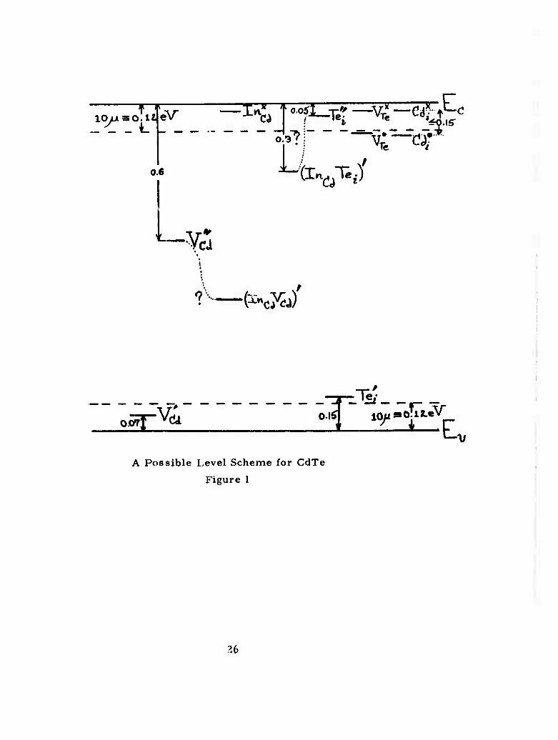
considered, A possible level scheme for CdTe is shown in Fig. 1.
At any level involving Te. or V , these symbols may be inter-
changed, V levels being Te. levels, and vice versa, the energy
separation corresponding to a wavelength of 10. 6 u is also
indicated. For a good window material all levels having a
separation frum the bands of this order :jr less must be empty
( when close to the conduction band ) or occupied ( when close to
the valence hand ): the Fermi level should be more than 0. 2 eV
from the ban' ed^es. Experiments carried out under the contract
and other ones Kended to be carrUd out in the next period are
listed below.
1. Concentration profiles of Indium diffusing inlo CdS and CdTe at
800 C show an abnormal S shape, indicating a diffusion coefficient
varying from medium at the surface, to large « 200 a bslow the
surface, to small deeper into the crystal. The reaaon for this
behavior is not clear. *
2. Te tracer self diffusion in CdTe at low p is known to occur by * 1/2 1
neutral interstitials, D^ « p^ « p , At high p a different
* mechanism is expected, D increasing with p_ , . So far we have
* 12 2 l obtained one value, ( D_ ) = 3. 5 X 10 cm sec ,
■is , «««<>^, . 1000 C,p_=4atm « ^d
3. Cd tracer self diffusion work by other workers has indicated that *
DCd '9 in^ePen^e'lt of Pr-cT 0ur EXPerirnent:9 confirm this only at
low pcd; at higher pCd, D goes through a weak minimum, then
increases « p . This indicates diffusion by doubly charged inter-
24
stitial cadmium, Cd. ' , the low«r constant Di, , at low D being i Cd ' CH e> Cd v" ''Cd
due to V formed by Frenkel disorder of Cd or J/ interstitial
disorder. ( The latter involving Te'^nd Cd* * , ) i ' *
4. Doping with indium has been found to reiuM D_ at high p Cd ° rCd
( by reducing the Cd.' ' concentration ) but increases D at i Cd
low pCd ( by increasing [ V^ J).
5. High temperature Hall effect measursments in silver doped CdS
crystals show that silver has a weak donor acfion, increasing the '7 18 3
electron concentration from 10' to 10 cm" , at high p , but Cd
gives rise to almost intrinsic CdS at low p , Curvature of the
Hall constant as f{pcd) indicates the presence of holes, with
[ h ] > [ e ] , but still with an n-type sign due to a mobility ratio
v / v. » 1 . e h
The overall behavior indicates amphoteric behavior of Ag, leading
to compensated samples at larger concentrations.
Intended Experiments
I) Investigations of the indium diffusion anomalies by a study with
varying indium surface activities, and diffusion times. *
II) Extension of Te diffusion at high p to other p and T ( owing
to the smallness of D , diffusion times of «a 1 month per run are
involved ). *
III) Extension of Cd tracer exparlments in indium doped crystals at
various pCd, T and [ In ] to defect mobilities and thermodynamic
parameters of defect formation.
iV) Determination of the dominant defect compensating for In' at Cd
lOW PCd ^ Te"/ 0r Vc'd^ by accur^te measurements cf the lattice
constant and the density as f([ln] ) .
V) Carry out high-temperature Hall eff jet measurements on CdTe-In.
VI) Determine the solubility of silver in pure and doped CdS, CdTe to see
whether oppositely charged Ag species are present.
25
lOyjiaO.lJ _ _ _ L - — — '-— — — —I T> :— -" —-=—"«H
0.6
•Yes
l$fj~c 0.3 ■v;
iö.is-
Cr^T^)'
•(^C^J)
0;^-V(U >4
TeJ
JZLJ c
A Possible Level Scheme for CdTe
Figure 1
26
e. 1. Theoretical Studies of Absorption Mechanisms in IR Window Materials
R. W. Hellwarth
In order to assess the potential performance of various can-
didate materials for high-power laser windows, we have embarked on
calculations of the lower limit placed on the infrared and optical ab-
sorption coefficient at "window" wavelengths by various fundamental ab-
sorption mechanisms. At frequencies below the electronic band edge,
the universal exponential dropoff in absorption (Urbach tail) seems to
be fairly well understood. However, at frequencies between 2 and 50
times the fundamental lattice absorption frequency (the lattice absorp-
tion tail) the limiting absorption is not understood. It is in this lattice
absorption tail where high power operation is currently of most interest
and where the measured absorption in candidate materials is generally
unacceptably high.
In a perfectly insulating lattice with no vacancies, interstitial
ions, or impurities, two mechanisms give rise to the lattice absorp-
tion tail: (a) the small anharmonicity in inter-nuclear forces permits
the decay of a virtual phonon, created by a photon, into several (n)
phonons whose energy adds to that of the absorbed photon; and (b) the
(slightly) nonlinear dependence of the electric dipole moment on the
lattice coordinates permits the direct decay of a photon into several
phonons. Of course vacancies and interstitials always exist at finite
temperatures, but our present feeling xs that their main effect on the
lattice absorption tail appears via altered anharmonicity and nonlinearity
parameters in the "anharmonic lattice" and "anharmonic moment"
mechanisms of (a.) and (b) above. Therefore we have concentrated our
efforts in calculating the absorption from these mechanisms for various
models. We have not yet found a method of treatment of this absorption
wnich is both tractible and for which the errors can be estimated. There- fore in this report »ve will simply describe some of the theoretical
problems which we are studying.
In principle li? anharmonic lattice contributions to absorption
can be calculated by standard many-body diagrammatic perturbation.
The application of this method to lattice absorption has been reviewed 2
by Cowley. However this method presents formidable difficulties
27
when the number n of phonons created by an absorbed photon is much
larger than 1:
1) There are an infinite number of types of interaction vertices
corresponding to the terms in the infinite Taylor expansion series for
the internuclear potentials (in powers of the deviations of their positions
from equilibrium). This is in contrast to electrodynamics where there
is only one type of vertex to use in diagrams. The coefficients in this
series constitute an infinite set of perturbation expansion parameters
which, however, can be related to each other arbitrarily for calcula-
tional convenience.
2) There is no known algorithm for counting the number of
diagrams oi a given order in the expansion parameters of the perturba- 2
tion theory. The number of diagramu for large n becomes very large
and there is no way of knowing when one or more have been omitted.
Such inadvertant omissions abound in many-body calculations in the
literature and in much less complex situations. However, if, in time,
enough people work on a problem, the possible diagrams tend to cotne
to light and be counted. Perhaps diagram-counting alogorithms can be
discovered to relieve this problem.
3) The coefficient of a certain type of diagram may appear to
be smaller than of other types of diagrams and one may therefore be
tempted to neglect such terms. However the unknown number of such
smaller terms may be large enough to make them important.
4) Unlike in electrodynamics and in electron-hole problems in
solid state, "Umklapp" processes are important in the lattice absorp-
tion problem. This greatly complicates the integrations over phonon
wavevectors which, rather than being constrained to add to zero, need
only add to a reciprocal lattice vector. The "Umklapp" processes be-
come more numerous rapidly as n increases.
The approaches we are currently exploring to overcome the dif-
ficulties of diagrammatic perturbation theory at large n include:
1) Development of an iterative method for proceeding from
terms n to n + 1 which in essence automatically constructs all possible
diagrams for certain models.
2) Development of space-time perturbation theory to replace the
28
usual frequency-momentum formulation, thereby omitting specific need
to deal with "Umklapp" integrations.
3) The study of the absorption at vibrational harmonics of in-
dividual molecules (unit cells), which can be calculated by ordinary
Rayleigh-Schrodinger percurbation theory. The possible relation of
the discrete-line absorption spectrum of a small number of coupled ionb
to tho spectrum of coupled cells is being sought for high-n.
Typical of our piecemeal results to date is the following obser-
vation on the absorption by a molecule at a vibrational harmonic: Here
the most complicated terms in the perturbation theory are the most
important. I, e. terms that contain the largest number of factors of the
total nonlinear potential that contribute for a given n have the largest
coefficients, if one assumes for the inter-ionic potentials those derived
for the alkali halides with hard-core parameters chosen to give the best 3 fit to the bulk moduli.
REFERENCES
1. J. D. Dow and D. Redfield, Phys. Rev. Letters 26, 762(1971).
2. R. A. Cowley, Phonons in Perfect Lattices , ed. R. W. H.
Stevenson (Plenum Press, New York, 1966).
3. M. P. Tosi, Sol. State Phys. _16, 1 (1964).
29
f. 1 Techniques for Indirect Measurement of Small Absorptive Losses W. H. Steier
A preliminary version of a calorimetric optical absorption measur- ing apparatus has been constructed and tested with samples borrowed from AFCRL.
The calorimeter consists of a sample mount with dual thermocouples as temperature sensing elements. A long cylindrical plexiglass shield is used to minimize air currents. A powerful (50 watts per line cw), tunable (grating tuned). CO, laser is used as the source. TEM00 mode operation of the laser is maintained and to further reduce the spot-siz^, a focusing mirror (R - 3M) is used.
Through careful study of the work by other researchers making calorimetric measurements and from the experience gained through our own measurements, we have come to the following conclusions:
1. In making a measurement, it is not absolutely necessary to place the sample in a vacuum. In fact, multiple reflections between the sample and the windows can introduce large errors in the results.
2. It is important to eliminate direct illumination of thermocouples through scattering of the CO2 laser. This can be accomplished by making sure there is no instantaneous change of thermo- couple voltage when the laser is turned on or off.
3. Attachment of thermocouples to the sampls must be done with great care. Errors are sometimes introduced through thermal resistance between the sample and the thermocouple. Good agreement between thermocouples placed at opposite sides of the sample indicates that thermocouples are properly attached.
4. During laser illumination, even though different parts of the sample are not at the same temperature, the rate of tempera- ture rise is the same at any point on the sample. Therefore, we are justified to calculate the absorption coefficient from measuring the rate of temperature rise. V/e believe this is simpler and more accurate than illuminating the sample for a known period of time and then measuring the final equilib- rium temperature of the sample.
30
f. 1 continued
5. The niost time-consuming part of the measurement is in direct- ing the COo beam such that it passes through the center of the sample and that it is perpendicular to the sample faces. A HeNe laser is aligned exactly with the CO2 laser, consequently, the alignment of the sample with the CO2 laser beam is achieved very conveniently.
6. Two important factors influencing the accuracy and repeat- ability of the measurement results are the polish and cleanli- ness of the sample surfaces and the amplitude stability of the COT laser.
We asked for and received some IR window samples from AFCRL. One CdTe sample (#8A) had an average absorption coefficient, as determined by the AFCRL group of 0. 03cm' . However, in this particular sample, the absorption coefficient is known to be non- uniform across the sample face. Using the apparatus built in our laboratory, we made a series of seven measurements and obtained absorption coefficients of 0. 0490, 0.0467, 0.0330, 0.0495, 0.448, 0.0416, 0.0371cm-1. The average absorption coefficient is 0.0431cm-1. One particular difficulty we had was to eliminate certain residual direct illumination of the thermocouple by scattered 10. 6u radiation. That may explain why our measured vrlues are consistently higher than the AFCRL value. To correct this problem we are inserting a diaphram in the laser cavity to obtain better control of the trans- verse modes and instead of a focusing lens we are usiag a focusing mirror to reduce th«. spot-size of the 10. 6 p beam. The wide fluctua- tions in our measured results can probably be attributed to the non- uniformity of the sample. Further tests will be conducted on a more uniform sample.
31
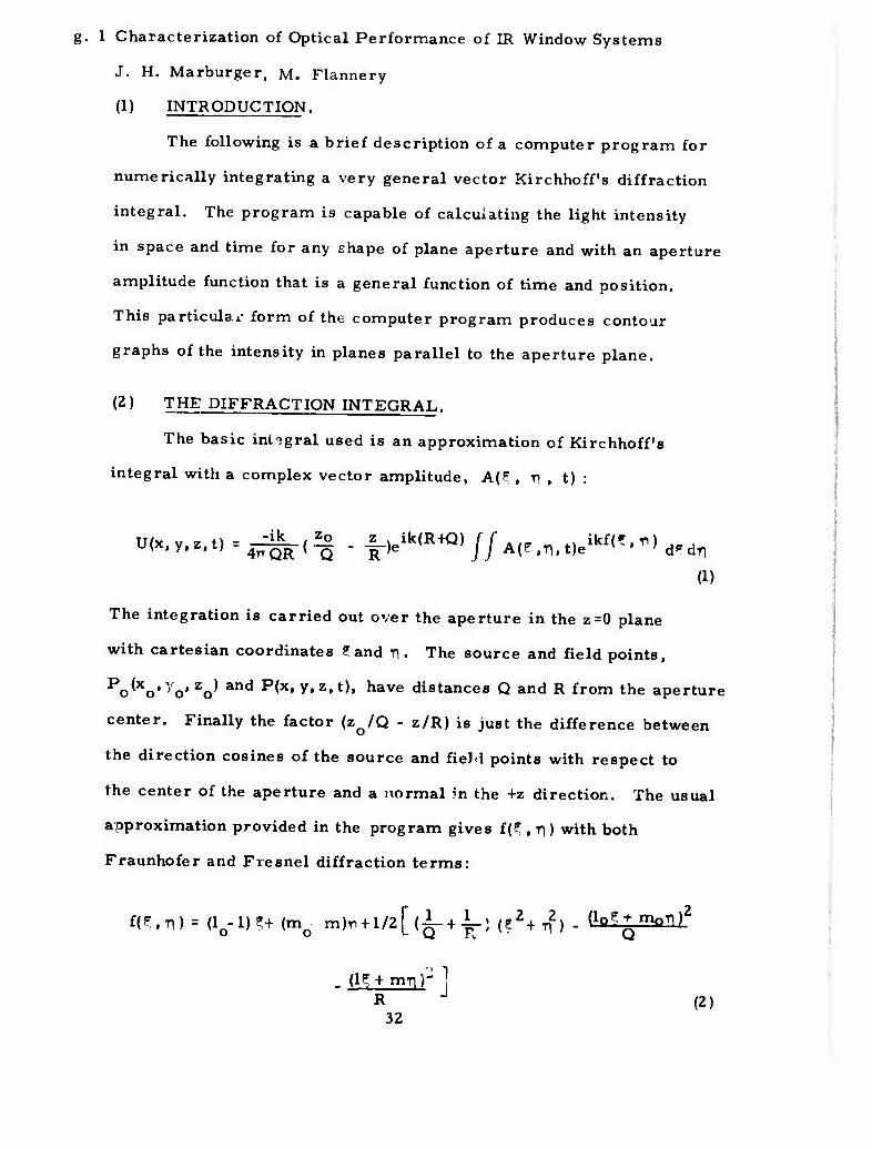
g. 1 Characterization of Optical Performance of IR Window Systems
J. H. Marburger, M. Flannery
(1) INTRODUCTION.
The following is a brief description of a computer program for
numerically integrating a very general vector Kirchhoff's diffraction
integral. The program is capable of calculating the light intensity
in space and time for any shape of plane aperture and with an aperture
amplitude function that is a general function of time and position.
This particulai- form of the computer program produces contour
graphs of the intensity in planes parallel to the aperture plane.
(2) THE DIFFRACTION INTEGRAL.
The basic integral used is an approximation of Kirchhoff's
integral with a complex vector amplitude, A(F , T) , t) :
U'x'^>%fir<i! - |-)eik(R+Q)//^^.t,ei^.-)d.d.
a)
The integration is carried out over the aperture in the z=0 plane
with cartesian coordinates ?and Ti, The source and field points,
^^o'^'o'Zo^ and ^»y»2»*)» have distances Q and R from the aperture
center. Finally the factor (zjQ - z/R) is just the difference between
the direction cosines of the source and field points with respect to
the center of the aperture and a normal m the +z direction. The usual
approximation provided in the program gives f(? , Ti) with both
Fraunhofer and Fresnel diffraction terms:
m.r\) = (lo-l)?+(mo m)r« + l/2[(-L-+-L> (lZ+i$) - (bi+i5alll2
. (l^ + mn'r 1 R J (2)
32
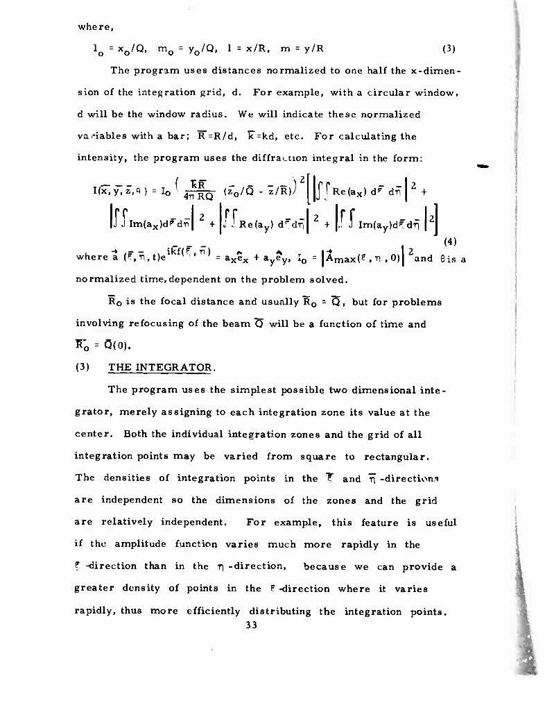
where,
lo=x0/Q. m0 = y0/Q. 1 = x/R, m = y/R (3)
The program uses distances normalized to one half the x-dimen-
sion of the integration grid, d. For example, with a circular window,
d will be the window radius. We will indicate these normalized
variables with a bar; R =R/d, F = kd, etc. For calculating the
intensity, the program uses the diffraction integral in the form:
I(x,y,Z.fl ) = I0 \ ^g^- (z0/Q - z/K)J
IJT - - 2 Im(ax)dpdTi +
J|Re{ax) dP dfl2 f
f[R e(ay) drdri -.-lajff. ..-.-u
w
(4)
s a
Imlayld^ dt)
here a (f,:n,t)e1 (F ' ^ ' - axex + ayey, I0 = |Amax(P , T) , 0)| 2and 01
normalized time,dependent on the problem solved.
R0 is the focal distance and usually R0 = Q , but for problems
involving refocusing of the beam 75 will be a function of time and
K'o = Q(0).
(3) THE INTEGRATOR.
The program uses the simplest possible two dimensional inte-
grator, merely assigning to each integration zone its value at the
center. Both the individual integration zones and the grid of all
integration points may be varied from square to rectangular.
The densities of integration points in the T and rf -directions
are independent so the dimensions of the zones and the grid
are relatively independent. For example, this feature is useful
if the amplitude function varies much more rapidly in the
? -direction than in the T] -direction, because we can provide a
greater density of points in the P -direction where it varies
rapidly, thus more efficiently distributing the integration points. 33
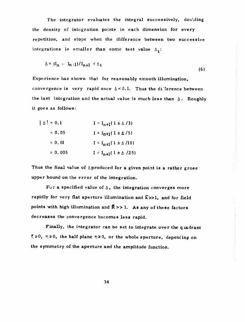
The integrator evaluates the integral successively, dovibling
the density olr integration points in each dimension for every
repetition, and stops when the difference between two successive
integrations is smaller than some test value A.:
A= (In - Inil)/In+l «At (6)
Experience has shown that for reasonably smooth illumination,
convergence is very rapid once A<0.1. Thus the difference between
the last integration and the actual value is much less than A. Roughly
it goes as follows:
I A! = 0.1 I = In+1(l±A/3)
= 0.05 1 = In+1(l ±A/5)
= 0. 01 I = In+1( 1 ± A /10)
= 0.005 I = In+i(l iA /25)
Thus the final value of Aproduced for a given point is a rather gross
upper bound on the error of the integration.
Fur a specified value of A, the integration converges more
rapidly for very flat aperture illumination and C»l, and for field
points with high illumination and R>> 1. As any of these factors
decreases the convergence becomes less rapid.
Finally, the integrator can be set to integrate over the qaadrant
^s0, r]*0, the half plane riaO, or the whole aperture, depencing on
the symmetry of the aperture and the amplitude function.
34
(4) THE APERTURE AND ITS BOUNDARY.
The program can accept any shape of plane aperture through
several subroutines that determine the location of integration points
with respect to the boundary and correct for edge effects when the
points are on or near the boundary. The correction merely adjusts
the area of the zone, removing the area outside the boundary.
In most cases it is important to provide good edge corrections
to avoid a number of pathologies. First, the integrator spreads
points uniformly over the integration grid rather than concentrating
them near the aperture edges. Thus in cases where the illumination
is large at the edges and very smooth in the aperture, the convergence
will be limited by edge effects and the integration points inefficiently
used unless proper edge corrections are made.
As another example we can consider a rectangular aperture
which has one side 1/ing just inside a line of integration points while
the opposite side is just outside such a line. This can effectively
shift the position of the aperture sideways by about one zone width.
While that may be only 1% or less of the aperture width, it moves the
focal point an equal amount, which may be several spot diameters. In
thin case one might end up searching a much larger field area than
necessary.
In the case of circular boundaries, if no edge corrections are
made, the fecal pattern has slight bulges that make the pattern a
very rounded square instead of a circle.
Finally it should be noted that time dependent aperture shapes
can easily be included in the program.
35
(5) THE AMPLITUDE FUNCTION.
Through this subroutine we provide the program with any general
time dependent vector amplitude function. There are no limitations
on the function although functions with rapid intensity or phase changes
may require a large number of integration points for proper convergence.
We have made teat runs with circular Gaussian beams and checked
the results against previous integrations using a one dimensional
integrator. Trial runs have also been made for Gaussian beams
heating circular isotropic windows, including strain effects, and these
calculations agree with a one dimensional program designed specifi-
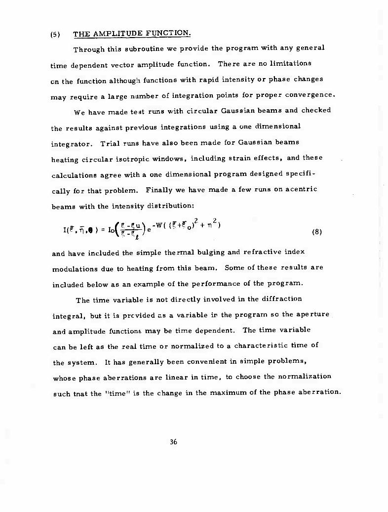
cally for that problem. Finally we have made a few runs on acentric
beams with the intensity distribution:
and have included the simple thermal bulging and refractive index
modulations due to heating from this beam. Some of these results are
included below as an example of the performance of the program.
The time variable is not directly involved in the diffraction
integral, but it is provided as a variable in the program so the aperture
and amplitude functions may be time dependent. The time variable
can be left as the real time or normalized to a characteristic time of
the system. It has generally been convenient in simple problems,
whose phase aberrations are linear in time, to choose the normalization
such tnat the "time" is the change in the maximum of the phase aberration.
36
(6) VARIATION IN TIME AND SPACE.
The program is designed to provide a picture of the beam in
time and space. To accomplish this th^ integrator is nested within
four do-loops that vary the time, and z-dimension and then the x and
y -dimensions. For a given z-plane, x and y are varied so that the
intensity is calculated in the center, (0, O.Z.T ), and then at a sequence
of points forming successive squares around that central point. This
method was chosen so that the power in the plane could be calculated
in each successive square. It is possible to provide x and y with
different inciements so the region is a rectangle instead of a square.
The output values can be calculated over the regions:
eighth of a plane: x 2 0, x ^y
quadrant: x SO, y 5 0,
half plane: y ^ 0,
or a whole plane.
The output is normalized to any value of the intensity on the
z-axis, and is printed both numerically and in contour plots of each
plane.
There are also a series of checks to prevent calculation of field
values in areas where the power or intensity is too small to be of
interest.
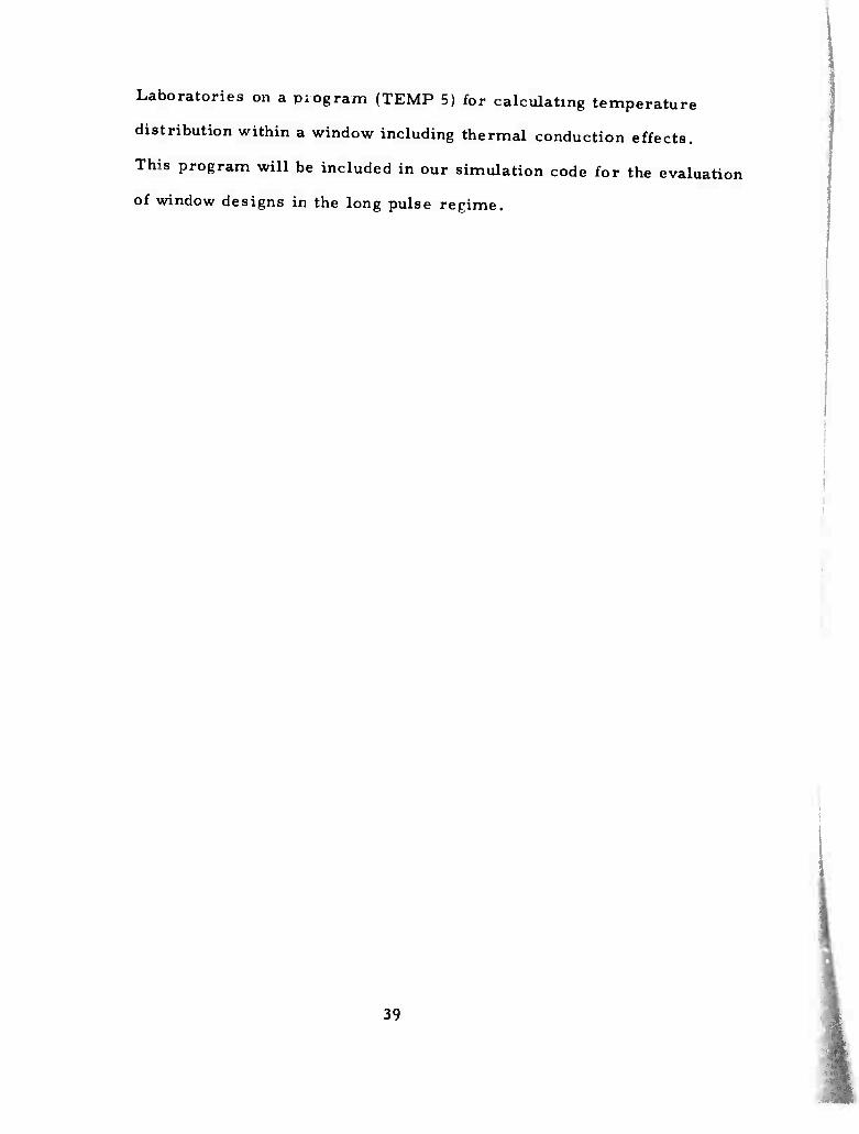
(7) SAMPLE PROBLEM.
The intensity function of equation (8) was run as an example
problem with the parameters "^=2, £o = 0.4, ^u=l. 0, T.=l.2 and
a circular aperture of radius d. The aperture intensity is plotted in
Fig. 1 with its maximum value normalized to unity.
37
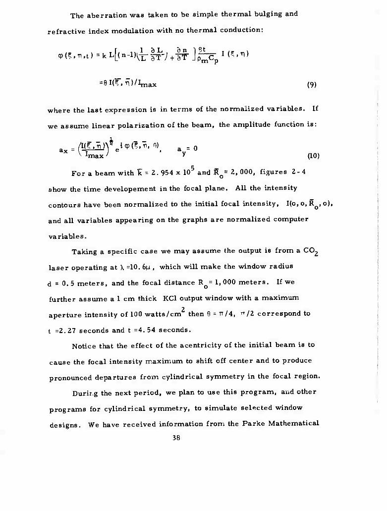
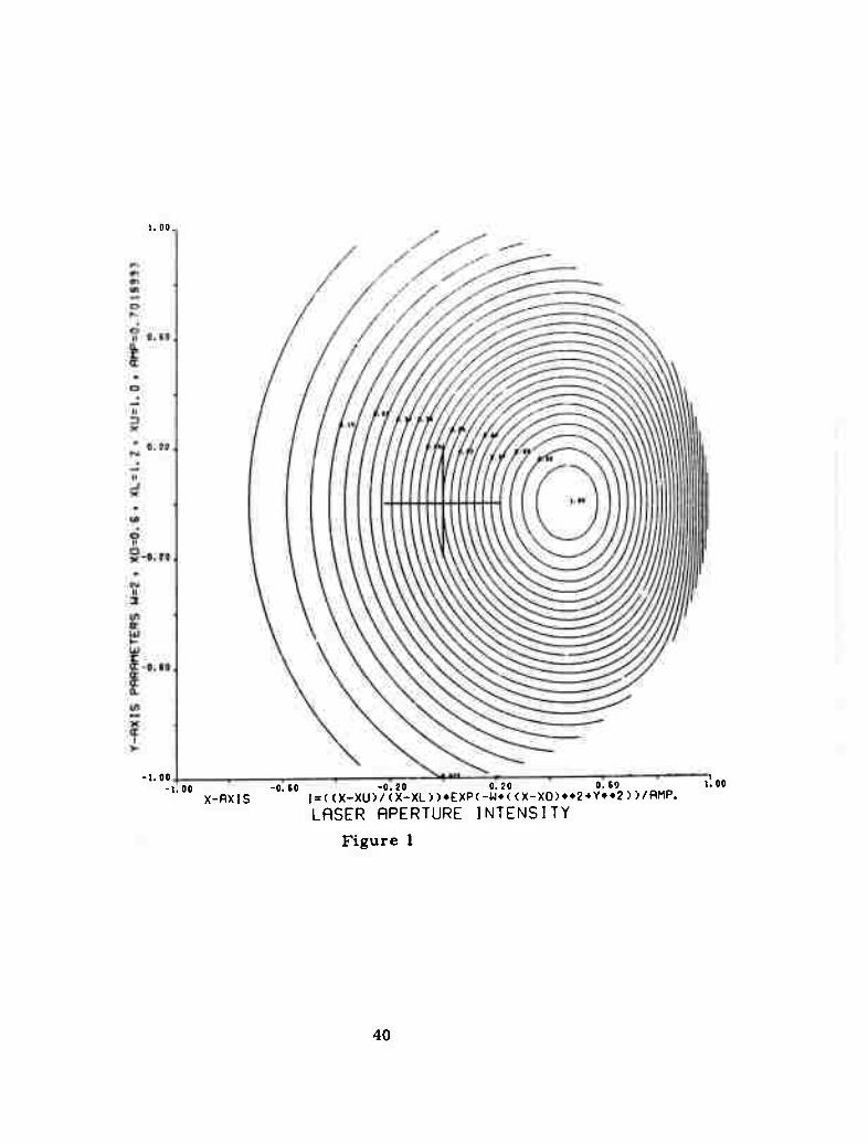
The aberration was taken to be simple thermal bulging and
refractive index modulation with no thermal conduction:
cp(?.T1.t)=kL[(n-l)^||J-;+|f J^CpM^.ri)
= eirf, ^)/Imax (9)
where the last expression is in terms of the normalized variables. If
we assume linear polarization of the beam, the amplitude function is:
x V imax) y (10)
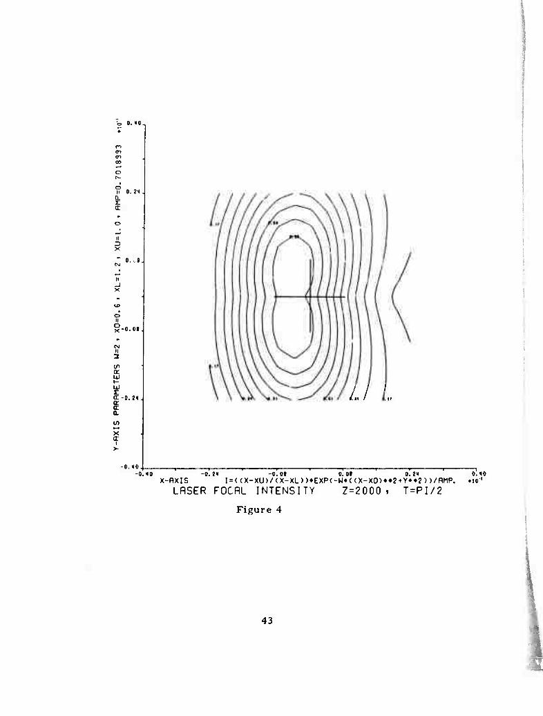
— 5 — For a beam with k = 2. 954 x 10 and Ro= 2, 000, figures 2-4
show the time developement in the focal plane. All the intensity
contours have been normalized to the initial focal intensity, I(o,o, Ro,o),
and all variables appearing on the graphs are normalized computer
va riable s.
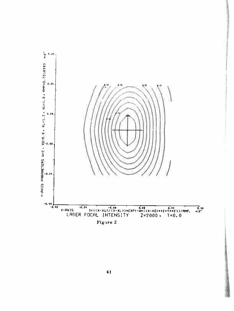
Taking a specific case we may assume the output is from a CC^
laser operating at \ =10. 6n , which will make the window radius
d = 0.5 meters, and the focal distance R = 1,000 meters. If we
further assume a 1 cm thick KC1 output window with a maximum
aperture intensity of 100 watts/cm then 9 = TT/4, TT/2 correspond to
t =2.27 seconds and t =4. 54 seconds.
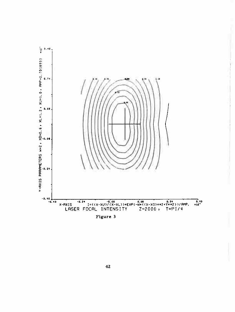
Notice that the effect of the acentricity of the initial beam is to
cause the focal intensity maximum to shift off center and to produce
pronounced departures from cylindrical symmetry in the focal region.
Durir.g the next period, we plan to use this program, and other
programs for cylindrical symmetry, to simulate selected window
designs. We have received information from the Parke Mathematical
38
Laboratories on a piogram (TEMP 5) for calculating temperature
distribution within a window including thermal conduction effects.
This program will be included in our simulation code for the evaluation
of window designs in the long pulse regime.
39
1.00
-1.00 -1.00
X-flXIS -0.(0 -0.20 0.20 0. SO
l=(<X-XU>/<X-XL))»EXP(-W«((X-XO)~2*Y»»2>)/flMP.
LASER RPERTURE INTENSITY
Figure 1
I. oo
40
P. IC.
er a.
o II
CL
a:
n
0. ?« .
0. 0(
II _J
o
S-O.OI.
M
in or
(t-o. ?«. a. a a.
X a.
-0.10.
-«•"' v OVIC -o.M -o.oi ÖT« o^ X-flXIS I = ((X-XU)/(X-XL))»EXP(-W»<(X-XO)«*2-»Y»»2))/RMP.
LRSER FOCAL INTENSITY
Figure 2
o. «o »10"'
Z=2000 . T = 0.0
41
0. 10.
II 0. ?t
z.
II Z) X
0.01.
II _l X
u>
o M g-0.0«.
II
Ul a: ui »- UJ r cr-o. a (t a.
x (T
I >-
2<l .
-0.10. -0. <I0 -0.?» -0.01
X-flXIS I=((X-XU)/(X-XL))»EXP<
LASER FOCRL INTENSITY
0.0( 0.21 0. «0 -W»<(X-XO)*»2-»Y»»2))/RMP. .lO-'
Z = 2000 , T=PI/'4
Figure 3
42
O.HO.
r-i <n <n a>
o
o li a
ii
X
0. ?«.
0. .«.
II _l
o II O x' 0.0«.
II 3
a: UJ i- ui r cr-o.?ii. S a a. in x <r
i
/./ /..
-o.to. -0.<0
X-RXIS LRSER
-0.?« -0.01 I=((X-XU)/(X-XL))»EXP<
FOCflL INTENSITY
0.01 0.24 0.10 W»<(X-XO)»»2-»Y«»2))/flMP. «to'
Z = 2000 . T=PI/2
Figure 4
43
3. DISCUSSION
When the proposal for this contract was prepared, GaAs was regarded as an important candidate for the first IP. windows. This, and USC's ex*«ifiive previous experience with GaAs growth and prop- erties, caused the initial program effort to be strongly oriented toward GaAs. Now that other materials are attracting more attention for window applications, our own attitude toward GaAs has changed somewhat. We feel that in view of the excellent mechanical properties and well-developed technology associated with GaAs, it is extremely important to determine once and for all whether the comparatively high observed absorption at 10.6 pm is intrinsic or a consequence of im- purities. The fact that no instance of low absorption has been observed may be related to the fact that virtually all reported measurements have been made on samples grown from the melt, an inherently "dirty" technique. Therefore, we plan to continue those projects whose aim is primarily to grow and to characterize very pure GaAs with controlled impurity content (projects a. I, a. 3, d. 3). However, we shall broaden the scope of the other projects, where appropriate, to include other promising materials.
During this period. Prof. W. Faust accepted a post at the Naval Research Laboratories, and will no longer participate in the program. The tunable CO2 laser facility which he constructed, and which we are using for our calorimetry is now being operated by Prof. Steier and Prof. S. P. S. Porto.
Professor Gershenzon, who directs project d. 3, was absent on jury duty during this period. The experimental program for this project is being designed, and a detailed description will be included in the second quarterly report.
During the next quarter, we plan to explore a novel method of probing surface properties under intense 10^m illumination suggested by Prof. Joel Parks. This method employs phase sensitive detection of microwave surface acoustic waves launched across the illuminated region by an array of transducers deposited on the surface. The technique is sensitive to very small changes of temperature near the surface, ai d could possibly be used to distinguish between surface and bulk optical absorption. All the technology for these studies is avail- able in-house at USC, and experiments involving acoustic surface waves for other purposes are performed routinely in Prof. K. Lakin's labora- tory here.
Several useful discussions were held with AFCRL personnel, partic- ularly Dr. L. Skolnik, regarding our calorimetry apparatus.
44
4. SUMMARY
A major effort has been initiated at USC to prepare, characterize, and evaluate IR window materials. Initial emphasis is on GaAs be- cause of USC's expertise in this compound, but mo^t studies being undertaken will include other promising window materials.
Preliminary tests of thermal shock resistance of NaCl plates have been conducted. When these were heated above the brittle- ductile phase transition temperature, thermal shock effects were dramatically reduced.
Samples of high purity GaAs were prepared by a closed tube chemical vapor deposition technique. The samples are large enough for optical absorption measurements which i re now in progress.
An apparatus for the calorimetric measurement of optical ab- sorption as a function of wavelength in the 9 to 11 u m region has been constructed and tested. It gave results for a test sample comparable with measurements performed at AFCRL. Design modifications aimed at greater repeatability are now being implemented.
A mask has been fabricated for the deposition of MOS and Schottky barrier structures on semiconductor surfaces for studies of surface and interface IR absorption.
Abnormal concentration profiles of Indium diffusing into CdS and CdTe at 800° C have been observed, indicating unusual behavior of the diffusion coefficient as a function of depth from the surface in these materials. The • eason for this behavior is unclear, and will be in- vestigated during the next quarter. Other studies of the kinetics of defects in these materials were also carried out.
Theoretical studies of simple models for multiphonon absorption processes in "transparent" materials have led to a simple criterion for determining the most important terms in perturbation theory which contribute to the absorbance in a certain order. This result is important for the estimation of intrinsic lower limit on absorbance expected for a substance.
A general two-dimensional code has been prepared for the numer- ical simulation of the optical performance of IR windows. The code differs from previous work in being able to simulate non-cylindrically symmetric situations such as elliptical, acentric, or skewed beams. The code allows the computation of the properties of the optical field as it propagates beyond a thermally distorted window. The effects of
45
Summary continued
induced birefringence are included. The previously unstudied effect of thermally induced skewing of acentric beams is being examined with this code. (Similar studies have been made elsewhere in the context of atmospheric propagation of intense beams. )
46