Embed Size (px)
Citation preview
AD-774 390
AN ANALYSIS OF STEADY ASYMMETRICVORTEX SHEDDING FROM A MISSILE ATHIGH ANGLES OF ATTACK
John S. Kubin
Air Force Institute of Technology
Prepared for:
Air Force Flight Dynamics Laboratory
November 1973
DISTRIBUTED BY:
NHatonal Technical Information ServiceU. S. DEPARTMENT OF COMMERCE5285 Port Royal Road, Springfield Va. 22151
-,Unclassified
DOCUMENT CONTROL DATARD 77(Sfcurity eltsualicaeton of title. body of abstrlct and indeving anrlantn n non ms be enterd ,he r verall reoott is cloltlledl
* ORIGINATING ACTIVITY (Corpoate aut.'Jor) . .NPORr SECURITY C.ASIFIATICN
Air Force Institute of Technology (AFIT-EN) Unclassified
Wright-Patterson AFB, Ohio 45433 O
3.IXPORT TITLE
An Analysis of Steady Asymmetric Vortex Shedding From a Missile at High Angles of
Attack
4. DESCRIPTIvE NOTES ()pe of repoel and Inclusive dates)
AFIT thesisS. AUTHORISI (First name, middle inilial. laet name)
John S. Kubin - ..... -
Major USAF
4. REPORT DATE 70. TOTAL NO. OF (GES I7b. NO. OF REFS
December_1973 2_________ 4____a, CONTRACT OR GRANT NO. 91. ORIGIMATOR'S RIEPORT NUMBER(S)
LPROJECT NO. GAM/AEJ734-13
9b. OTHER REPORT NO(S) (Any other numberse thal may be assignedthles report)
d.
to. OISTf111SUTION STATEMENT
Approved for public release; distribution unlimited.
AIV F B V M ', f fl '1A fl ff r ele s e; A W " F R 1 0 -11 3PO SOPING MILITARY ACTIVITY i s L b r t y/ i ,." f( , , / Air Force Flight Dynamics Laboratory
JERRY C. HIX, Captafit, USAF Wright-Patterson AFB, OhioDirector of Information AFFDL/, F GC .......I3. ABSTRACT
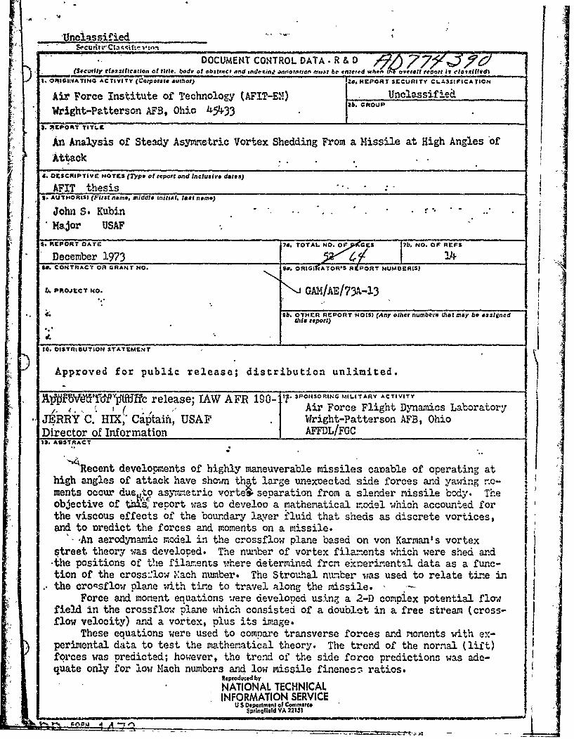
Recent developments of highly maneuverable missiles cacable of operating athigh angles of attack have showm that large unexoected side forces and yawing no-ments occur due to asynetric vorte4 separation from a slender missile body. The Vobjective of =-s, report was to develop a mathematical mcodel which accounted forthe viscous effects of the boundary layer fluid that sheds as discrete vortices,and to Dredict the forces and moments on a missile.
-An aerodynamic model in the crossflow plane based on von Karman's vortexstreet theory was developed. The numiber of vortex fila-ents which were shed and-the positions of the filaments ,;here determined frcm eknerimenta l data as a func-tion of the cross::low 'Yach number. The Stroruhal nuber was used to relate time inthe croqsflowr plane with tine to travel along the missile.
Force and moment equations were developed using a 2-D compiex potential flowfield in the crossflow plane which consisted of a doublet in a free stream (cross-flow velocity) and a vortex, plus its image.
These equations were used to compare transverse forces and moments with ex-perimental data to test the mathematical theory. The trend of the normal (lift)forces was predicted; however, the trend of the side force predictions was ade-quate only for low Mach numbers and low missile fineness ratios.
Reproduced byNATIONAL TECHNICALINFORMATION SERVICE
mUiS D ipaile.t cV Commerce$prlngfleld VA 22151

* oi
y i.rLINK A LINa LIN C
ROLE ivY ROLE jWT RZOLC w'?
Missile Aerodynarmics
Missiles at High Angles of Attack
Side Forces and YawiAng Moments on Slender Bodies
Spacing,, Position, and Strength of Vortices
Symetric and Asymetric Vortex Sepaation
Viscous Effects Over Slender Inclined Bodies
4
U si
I 'S
/
"" .... nclassified1
AN ANALYSIS OF
STEADY ASYMMETRIC VORTEX SHEDDINGFROM A MISSILE AT HIGH ANGLES OF ATTACK
THESIS
GAM/AE/73A-13 John S. KubinMaj or USAF
Approved for public release; distribution unlimited

TAN ANALYSIS OF STEADY ASYMMETRIC VORTEXSHEDDING FROM A MISSILE AT HIGH ANGLES OF ATTACK
THESIS
Presented to the Faculty of the School of Engineeringof the Air Force Institute of Technology
Air University
in Partial Fulfillment of theRequirements for the Degree of
)Master of Science
by
John S. KubinMajor USAF
Graduate Aerospace-Mechanical Engineering
November 1973
Approved for public release; distribution unlimited
Li
The recent development of highly maneuverable missiles has prompted
.renewed interest in the basic aerodynamics of slender bodies of revolu-
tion. Historically, potential flow analysis has been used to analyze
slender bodies to determine the associated forces and moments; however,
the presence of viscosity has altered the flow characteristics dramat!-
aally. Unexpected side forces and yewing moments at high angles of attack
have been observed in wind tunnel tests of slender bodied missiles.
My objective in this report was to attempt to extend the slender-body
theory to relatively high angles of attack in order to predict the forces
and moments induced by steady asymmetric vortex shedding on a slender mis-
sile configuration.
I wish to thank Major Carl G. Stolberg, Assistant Professor of Mechani-
cal Engineering, Aero-Mechanical Engineering Department, for his support
and guidance throughout this study. Also, i wish to express my gratitude
to Mr. Robert C. Nelson, Stability and Control Prediction Methods Group,
Air Force Flight Dynamics Laboratory, for his assistance and cooperation.
Both of these men have been extremely helpful and have made this study a
rewarding academic experience for me. Finally, I would like to thank my
most gracious wife, for her patience, understanding, and cheerfulness,
without which I could not have completed this study.
John S. Kubin
0ii
WA73A-23
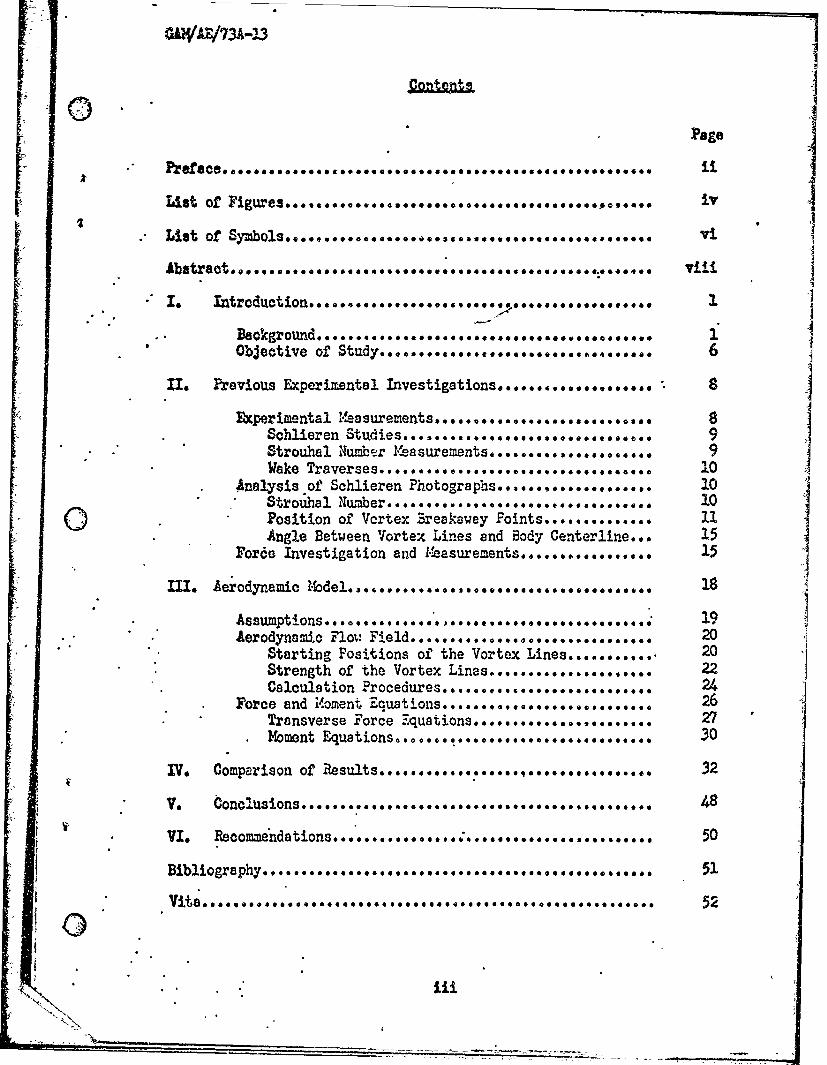
Page
List of Figures..........,.......................,.,°.,..
List of o ViAbstract.,............................................... viii
f1 revious Experimental Investigations.............,...... ]Experimental !aumet. 0**** ,* *...8
Schieren S.... s .......... ...... 9....... ..... 1 I
Strouhal Number Iesernt1 ......... 9 ~Wake Trvre. . 06..... ........ 10
* Analysis of Schlieren hotorahs............,..... 10Stroual .10Q Position of Vortex reakawey Points.............. 11Angle Between Vforte Lines and Body Centerline... 15
For Investigation and r15
MI. Aerodynamic Model...*e0 00,.*****00 004*01
AerodynaricnFlot 2e0....................Starting Positions of the Vortex 20......Strength of the Vortex Lie,.....*....22Calculation rure s.t...., ...................
F tal M ments 26Transverse Force quations........... ............ 27Moment Equations............................. 30
oV. 48 3
VI. Recomyndatione..............,...........,........ 50
Bibliogroyni Flay i l. 5
trn on ... .
Strngh f he orexLies.,.........7..71

GAWW/73A-13
rPage
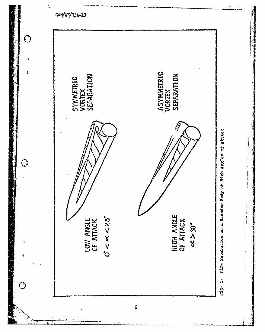
1 Flow Separation on a Slender Body at High Angles of Attack.. 2
2 Sketch of Wake from Slender Cone-Cylinder at Large Angles of4
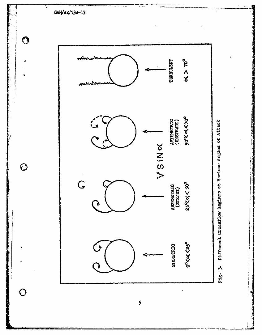
3 Different Crosaflow Regimes at Various Angles of Attack..... 5
,4 Crosaflov Strouhal No. Variation with Crossflow 14ach No.... 12
5 Starting Position of all Vortices in the Wake at Subcritical.Reynolds Numbers .13
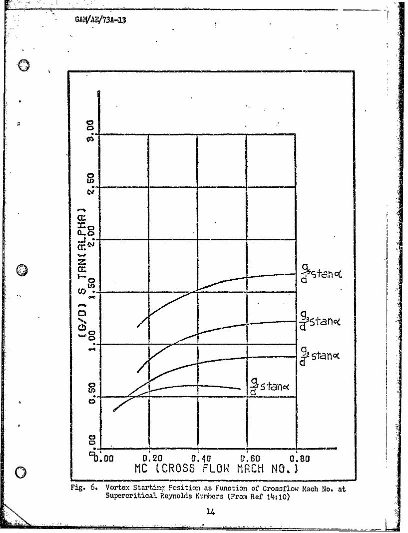
6 Vortex Starting Position as Function of Crossflow Iach No.at Supercritical Reynolds Numbers.................,.,..... 34
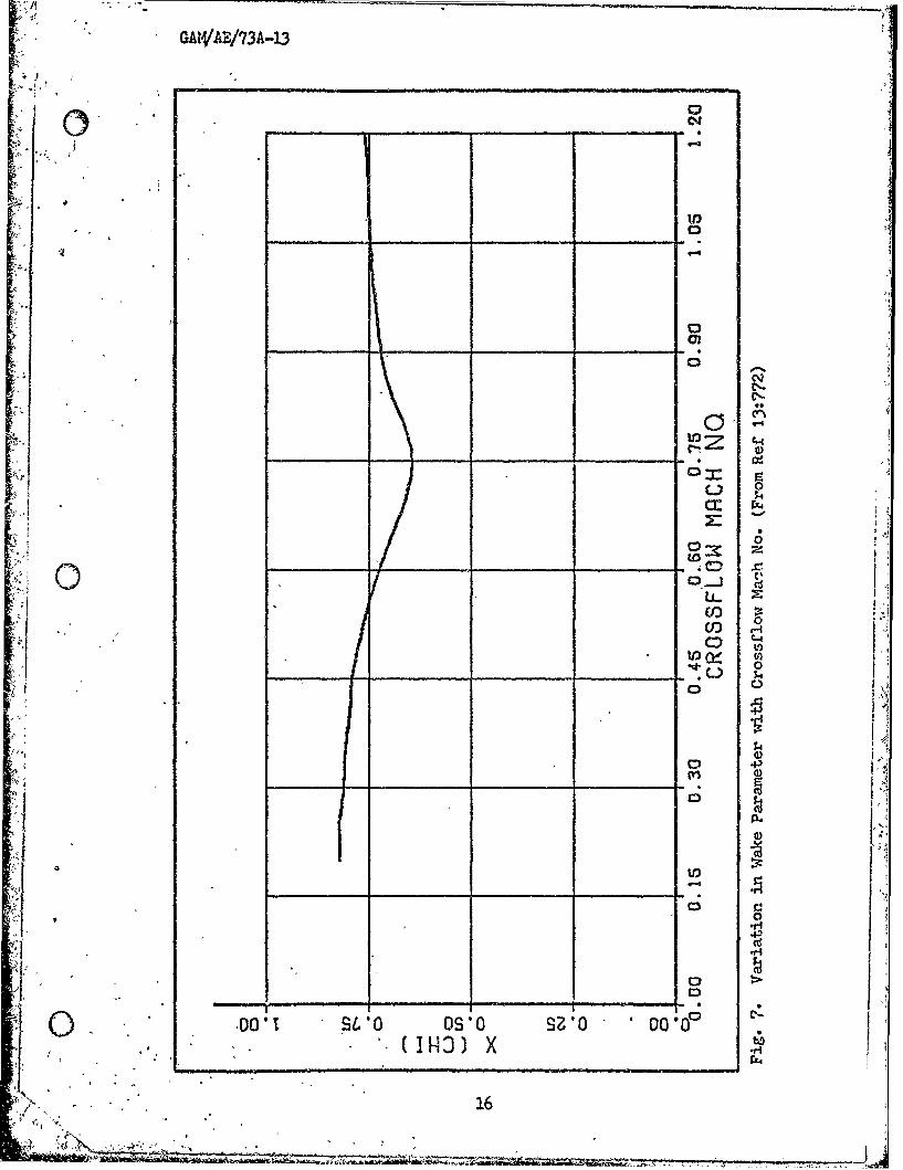
7 Variation in Wake Parameter with Crossflow 14ach No........ 16%
8 Slender Body 2bdel: 21
9 Vortex Strength Parameter as Function of Crossflow Mach No.. 25
100 Crossflow Plane .7
11 0give-Miisile Configuration from Pick.......,.............. 35
12 Ogive-Missile Configuration from.Krouse................... 35.
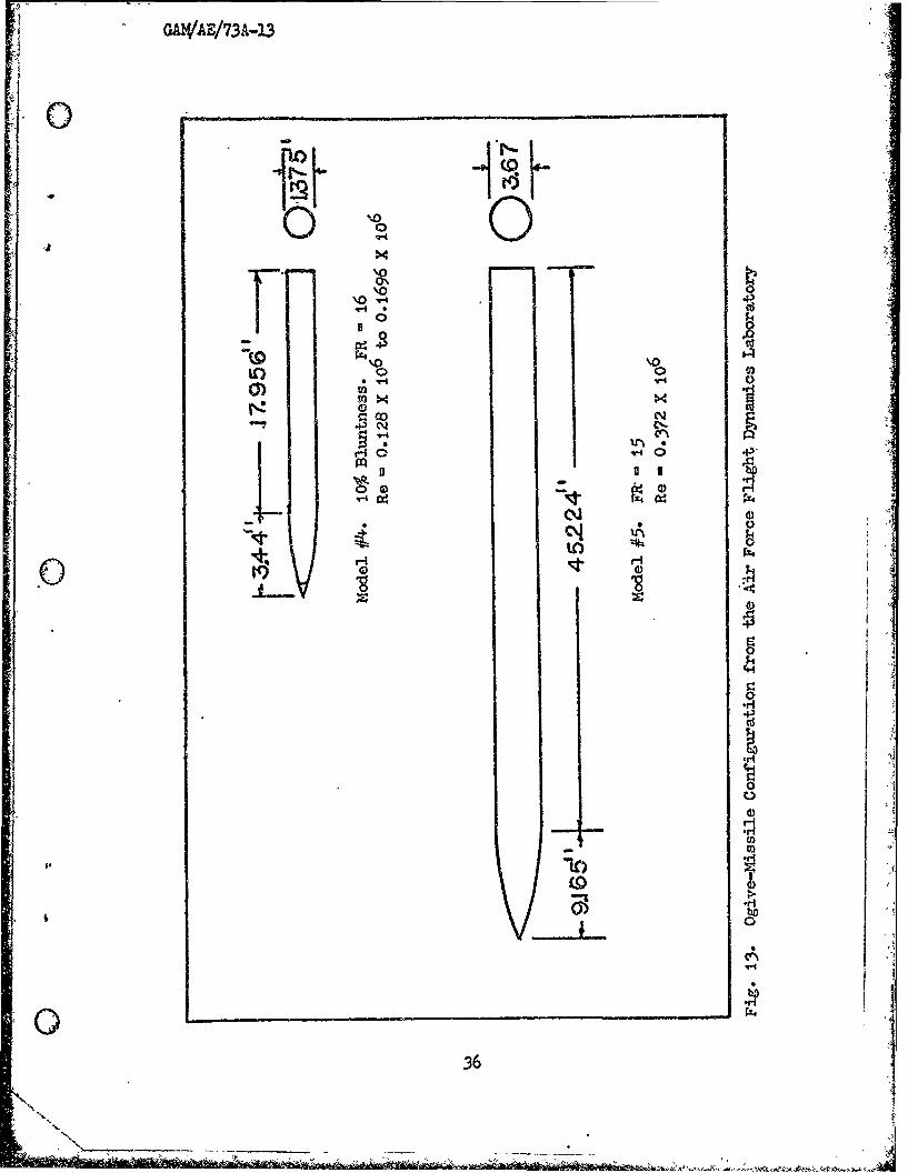
33 Ogive-Missile Configuration from the Air Force Fligkt Dynam-ics Laboratory. 36
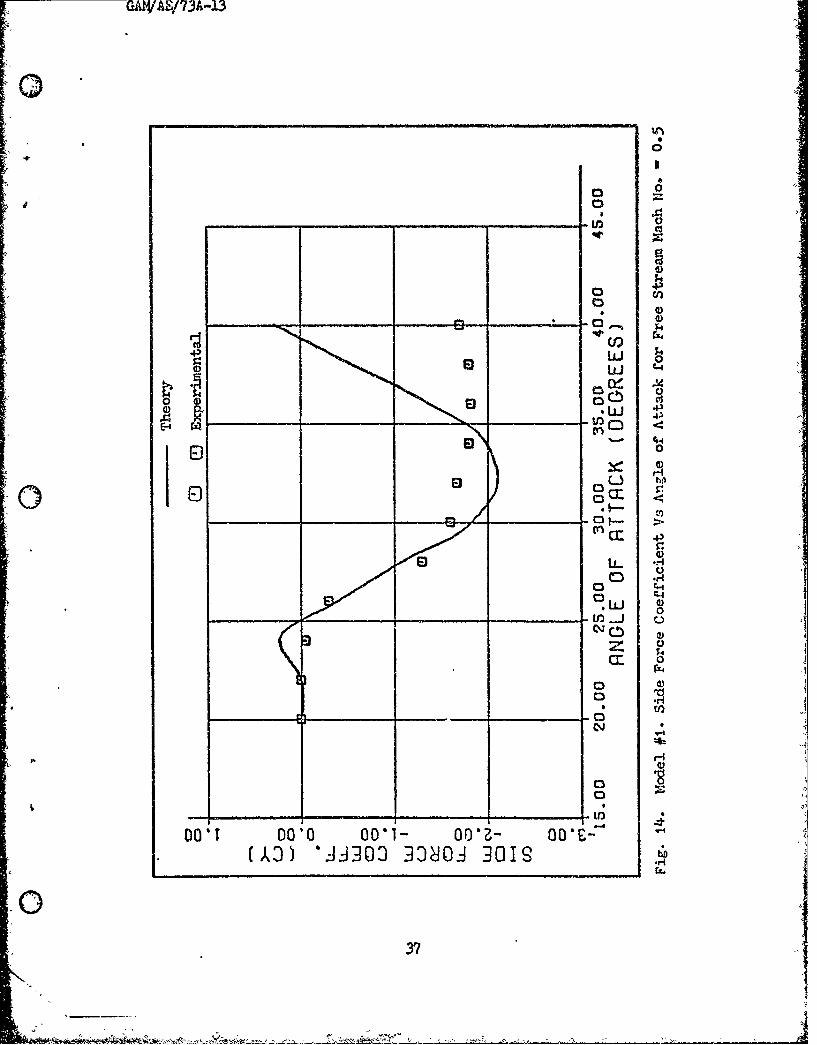
14 Model #1. Side Force Coefficient Vs Angle of Attack forFree Stream alch No. = 0.5 ...•. ...•• ••.•• .,• • , • ....... 37
15 Model #1. Side Force Coefficient Vs Angle of Attack forFree Stream 1,1ch No. 0.6 38
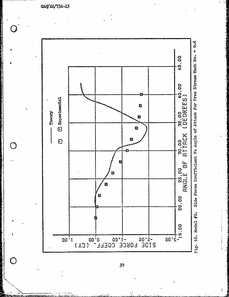
16 Model #2. Side Force Coefficient Vs Angle of Attack forFree Stream Mach No. = 0.6 . 39
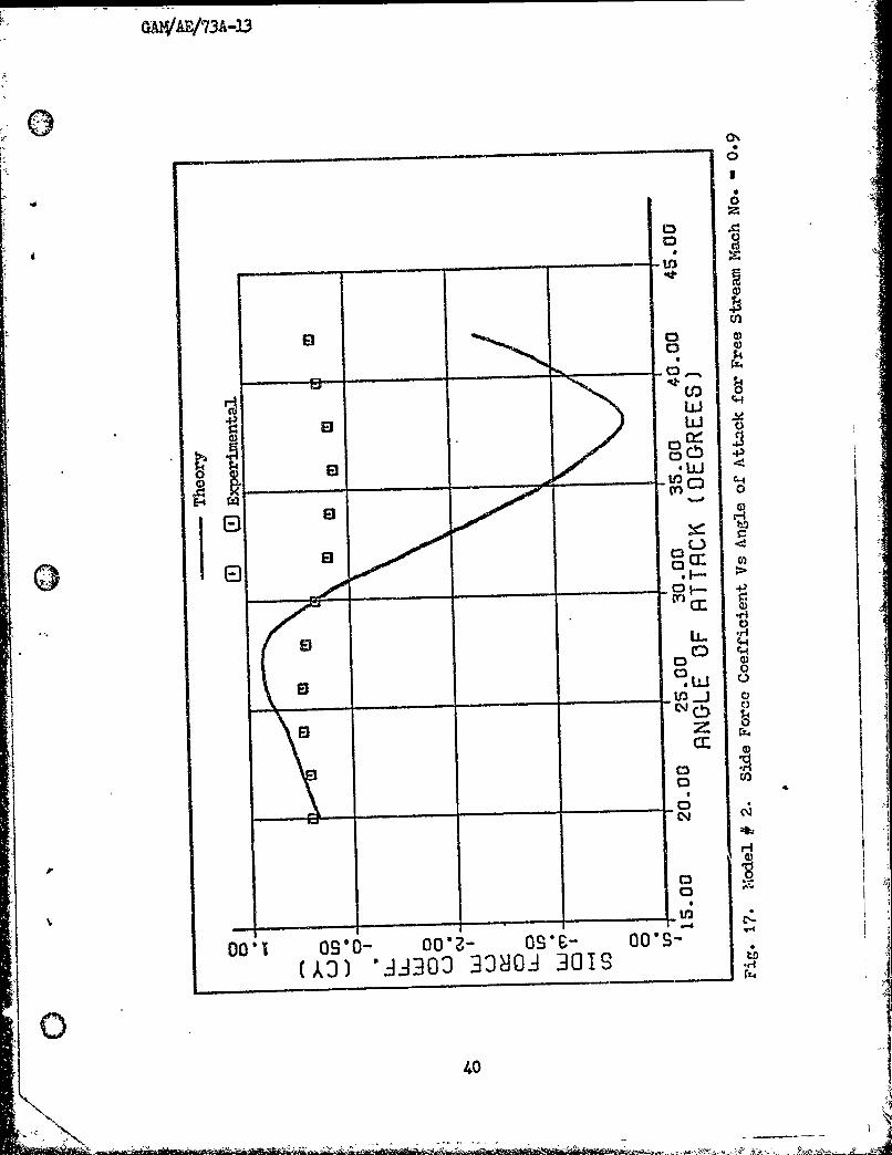
17 Model #2. Side Force Coefficient Vs Angle of Attack forFree Stream ,Mach No. = 0.9 ......... ....................... 40
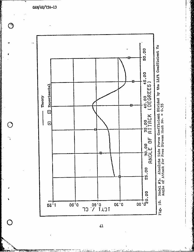
18 Model #3. Absolute Side Force Coefficient Divided by theLift Coefficient Vs Angle of Attack for Free Stream Mach No.=0.55 ........................... 41
iv
Ac - - .- -A

GAL'iAF/7A43
I: ;ure Page
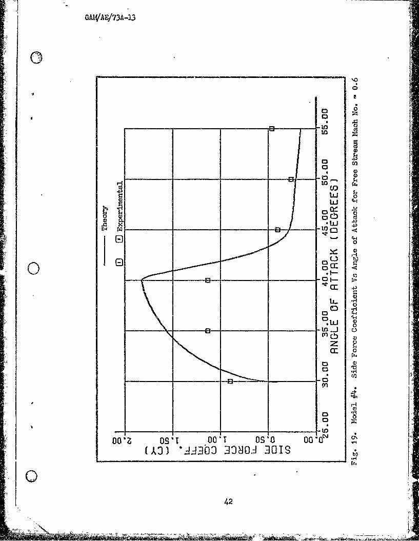
-19 Model #4. Side Forge Coefficient Vs Angle of Attack for FreeStream Mach No. = 0.6 ... ,...... .,,...,............,., 42
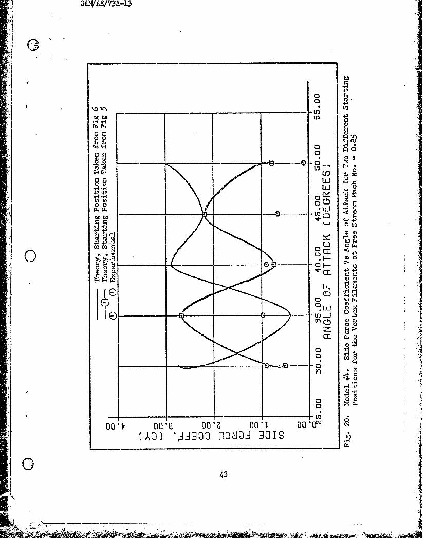
20 Model #4. Side Force Coefficient Vi Angle of AttackL for TwoDifferent Starting Positions for the Vortex Filaments at FreeStream Iach NO. = 0.85 .... 43
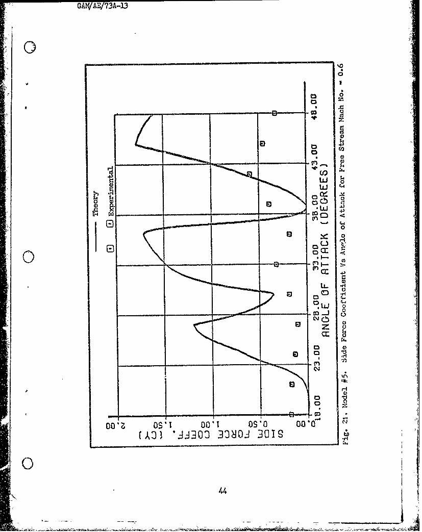
21 Mdel #5. Side Force Coefficient Vs Angle of Attack for FreeStream i4ch No. = 0.6 . 4
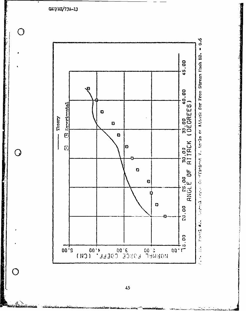
22, Model #2. Normal Force Coefficient Vs Angle of Attack forFree Stream Mach No. =0.6 a .,o.......,.,,o......,....., 45
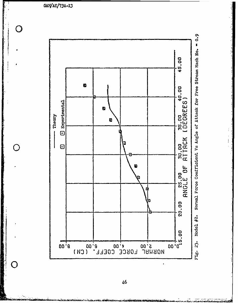
23 Model #2. Normal Force Coefficient Vs Angle of Attack forFree Stream Mach No. = 0.9 •............................ 46
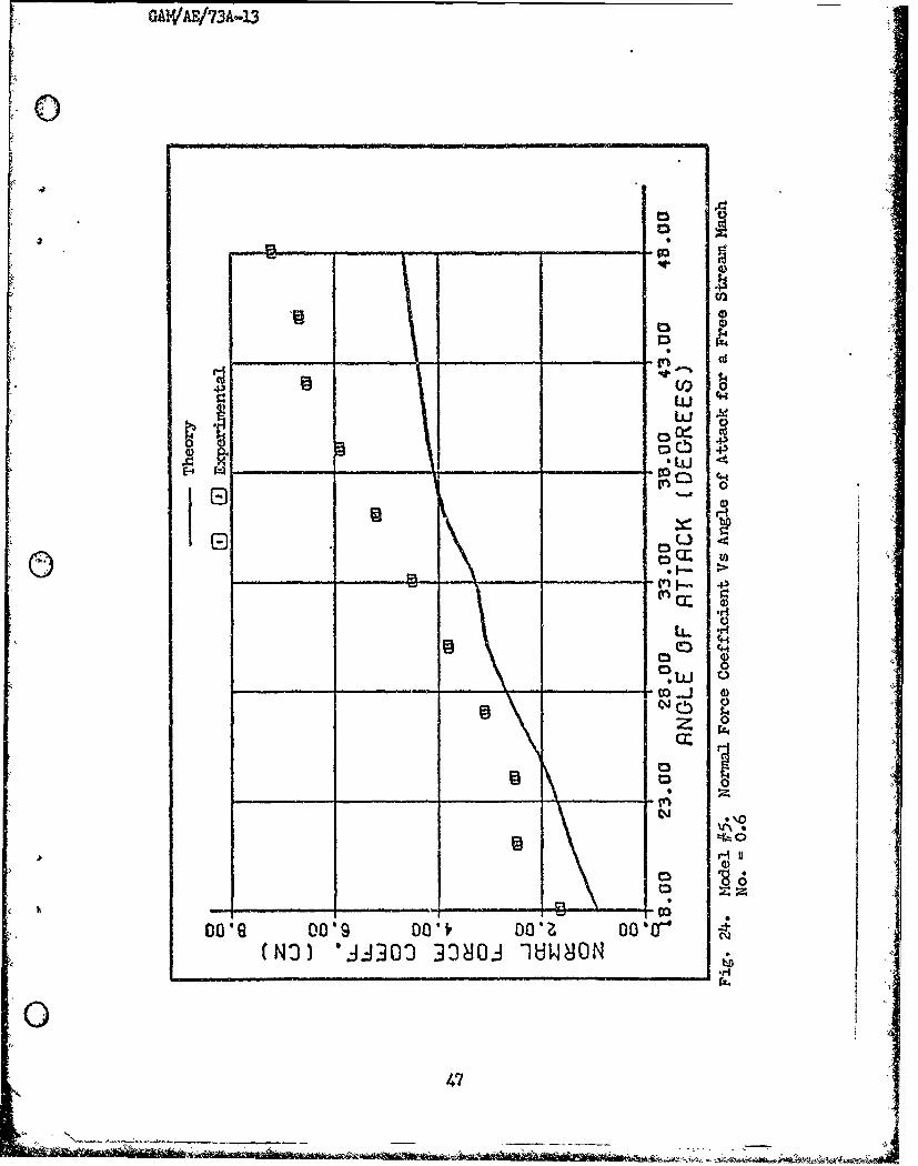
24 Model #5. Normal Force Coefficient Vs Angle of Attack forFree Stream Mach"No. =0. o *..... ......... ,................. 4?
vj
It
0
-c GAWA/73A-13
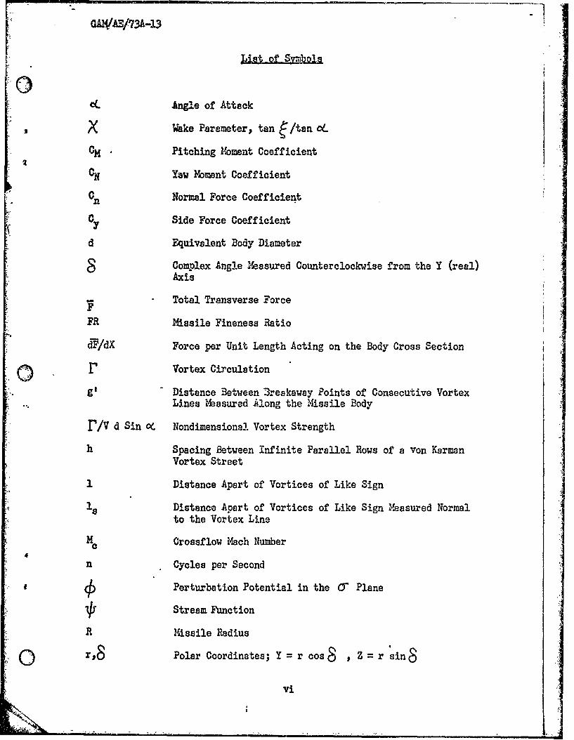
List ot Svbols
OIL dAngle of Attack
X Wake Parameter, tan A/tan CIL
CH. Pitching Moment Coefficient
ON Yaw Moment Coefficient
Normal Force Coefficient
OY Side Force Coefficient
dEquivalent Body Diameter
Complex Angle Masured Counterclockwise from the Y (real)Axis
Total Transverse Force
FR Missile Fineness Ratio
dF/dX Force per Unit Length Acting on the Body Cross Section
r Vortex Circulation
g' Distance Between 3reakaway Points of Consecutive VortexLines Measured Along the Missile Body
r/V d Sin oC Nondimensiona! Vortex Strength
h Spacing Between infinite Parallel Rows of a Von KermanVortex Street
I Distance Apart of Vortices of Like Sign
Distance Apart of Vortices of Like Sign Measured Normalto the Vortex Line
Mc Crossflow Mach Number
n Cycles per Second
£4Perturbation Potential in the O Plane
Stream Function
R Missile Radius
0 r,8 Polar Coordinates; Y =r cos ,Z r sin
vi
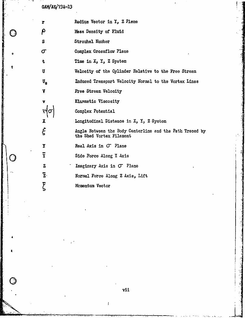
GAWAE/73A -
r Radius Vector in Y, Z Plane
() 1bas Density of Fluid
S Strouhal Number
CT Complex Crossflow Plane
t Time in X, Y, Z Systemr
U Velocity of the Cylinder Relative to the Free Stream
Us Induced Transport Velocity Normal to the Vortex Lines
V Free Stream Velocity
v Kinwmatic Viscosity
w'0i Complex Potential
X Longitudinal Distance in X, Y, Z System
Angle Between the Body Centerline and the Path Traced bythe Shed Vortex Filament
Y Real Axis in (7 Plane
O Side Force Along Y Axis
Z Imaginary Axis in 0- Plane
Z- Normal Force Along Z Axis, Lift
Momentum Vector
vii
GAWAE/73A-23
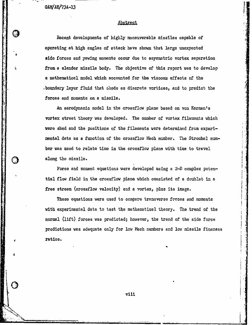
Recent developments of highly maneuverable missiles capable of
operating at high angles of attack have shown that large unexpected
side forces and yawing moments occur due to asymmetrio vortex separation
from a slender missile body. The objective of this report was to develop
a mathematical model which accounted for the viscoum effects of the
4boundary layer fluid that 6heds as discrete vortices, and to predict the
forces and moments on a missile.
An aerodynamic model in the crossflow plane based on von Kerman's
vortex street theory was developed. The number of vortex filaments which
were shed and the positions of the filaments were determined from experi-
mental data as a function of the crossflow Mach number. The Strouhal num-
ber was used to relate time in the crossflow plane with time to travel
Q along the missile.
Force and moment equations were developed using a 2-D complex poten-
tial flow field in the crossflow plane which consisted of a doublet in a
free stream (crossflow velocity) and a vortex, plus its image.
These equations were used to compare transverse forces and moments
with experimental data to test the mathematical theory. The trend of the
normal (lift) forces was predicted; however, the trend of the side force
predictions was adequate only for low Mach numbers and low missile fineness
ratios.
viii
GAWjAE/73A-13
AN ANALYSIS OF STEADY ASY1,TRIC VORTEXSHEDDING FRO4 A MISSILE AT HIGH ANGLES OF ATTACK
I. Inroucioa
Bagkgrund
The Air Force and Navy are currently developing highly maneuverable
missiles capable of operating at high angles of attack. This develop-
ment has prompted renewed interest in the basic aerodynamics of slender
bodies of revolution. These early flight vehicles flew relatively straight
trajectories at low angles of attack; consequently, their aerodynamic per-
formance was predictable through the use of potential flow analysis (Ref
4:2). Potential flow theory was based upon inviscid, incompressible flow,
which predicts the lifting forces on a slender body at low angles of attack
and can be extended to moderate supersonic speeds.
It was recognized by early investigators that an attempt to extend
potential flow analysis beyond small angles of attack would require con-
sideration of viscosity and would drastically alter the flow characteristics.
The way viscosity alters the flow regime is illustrated in Fig 1. Boundary
layer separation causes an adverse crosaflow pressure gradient on the lee
Is side of the body, and the boundary layer fluid "rolls ap" into two cores of
concentrated vorticity. The low pressures produced on the lee side of the
missile increase the lift and drag forces above those values predicted by
the linear potential theories (Ref 4:2).
I01%
Iv
CD)
100
GAWAB/73A-13
This problem, which has plagued the Air Force and Navy during the jrecent development of highly maneuverable missiles, is due to the large
unexpected forces and moments that occur at high angles of attack. These
forces and yawing moments were initially observed with the missile mounted
at zero sideslip during wind tunnel tests at high angles of attack. -
was initially assumed that turbulent flow in the wind tunnel or possible
missile misalignment was the cause of these forces. It was subsequently
determined from tunnel tests that asymmetric shedding of vortices from the
body caused these unexpected forces. This shedding can be symmetrical or
asymmetrical, as well as steady or unsteady.
For crossflow over a cylinder, the vortices on the lee side of the
cylinder form from the separated boundary layer fluid. The patt"--
these vortices behind the cylinder is dependent on the Reynolds number
(Ref 6). The wake behind a missile is similar to the wake which develops
behind a two-dimensional cylinder as viewed in successive crossflw planes
along the missile. Initially as shown in Section A of Fig 2, a p3ir of
vortex sheets are formed which then roll up into a pair of vortex lines.
At later cross sections, as shown in Sectin B of Fig 2, only a single
vortex sheet is for.d which rolls up into a vortex line near the body.
The previous rolled up vcrtex chcet3 appcor as vortex lines in an asy-.t-
rical pattern bchind the missile.
The pattern of the vortex fil-_cnts (s9yitrlc, asy-ztric) r-i~rily
depends upon the cro~sflow -,ynolds nu -cr, hille the no-ce sh~,o nose
fineness, and overoll fticnZ-s ratio haveo a minLr influence on thn vortex
filament pattcrn. At high anlcs if attack end high croz~flcw I:auh
o
--l

GAWA?/73A-13
numbers, the vortex filments which trail behind the missile appear in
the crosaflow plane to be similar to a von Karman vortek street (Ref 9:
0 377-384)0
In general, the vortex pattern can e described by four s'eparate
flov regimes as shown in Fig 3. At angles of attack from 5 to 25 degrees,
a symmetric v-,rtex pair is shed; consequently, no side forces exist.
Beyond 25 degrees angle of attack, the vortex cores become asymmetric
and alternately discharge from the missile body. It has been shown experi-
mentally that when asymmetrical vortices exist, considerable side force
and yawing moments are produced, especially at subsonic speeds. The
asyxsetrio vortex pattern remains steady until an angle of attack of 50-
70 degrees. Here, the asymetric pattern becomes unsteady and alternates
bock and forth. Above 70 degrees angle of attack, the flow pattern degen-
erates into a completely turbulent wake.
©A
00
* I0 ~llg 2. Sketch of W3ke from Slender Cone-Cylinder at Large Anlo
of Attack (Aef 13:752).
,=4
J I I I IIIll m-
CA) jAS/73A-3
CIA w
00
.4 0
0E0g4. n
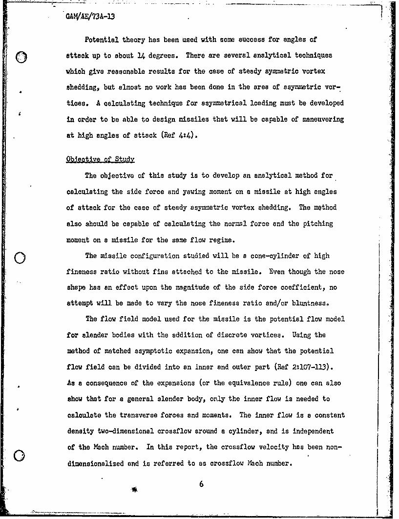
Potential theory has been used with some success for angles of
AMA&attack up to about 14 degrees. There are several analytical techniques
which give reasonable results for the case of steady symmetric vortex
shedding, but almost no work has been done in the area of asymmetric vor-
tices. A calculating technique for asymmetrical loading must be developed
in order to be able to design missiles that will be capable of maneuvering
at high angles of attack (Ref 4:4).
ObJective of Study
The objective of this study is to develop an analytical method for
calculating the side force and yawing moment on a missile at high angles
of attack for the case of steady asymmetric vortex shedding. The method
also should be capable of calculating the normal force and the pitching
moment on a missile for the same flow regime.
The missile configuxattion studied will be a cone-cylinder of high
fineness ratio without fins attached to the missile. Even though the nose
shape has an effect upon the magnitude of the side force coefficient, no
attempt will be made to vary the nose fineness ratio and/or bluntness.
The flow field model used for the missile is the potential flow model
for slender bodies with the addition of discrete vortices. Using the
method of matched asymptotic expansion, one can show that the potential
flow field can be divided into an inner and outer part (Ref 2:107-113).
As a consequence of the expansions (or the equivalence rule) one can also
show that for a general slender body, only the inner flow is needed to
calculate the transverse forces and moments. The inner flow is a constant
density two-dimensional crossflow around a cylinder, and is independent
of the Mach number. In this report, the crossflow velocity has been non-
dimensionalized and is referred to as crossflow Mach number.
qA1W 73A. -13'
The potential flow used to model the crossflow plane is that of an
expending cylinder with the addition of discrete vortices. The discrete
vortices are introduced to model the viscous effect of the boundary layet
fluid being shed from the cylinder as the vortex sheets which roll up
into line vortices.
The succeeding section describes previous experimental end theoreti-
cal efforts in the symmetrical and asymmetrical vortex shedding regimes.
7
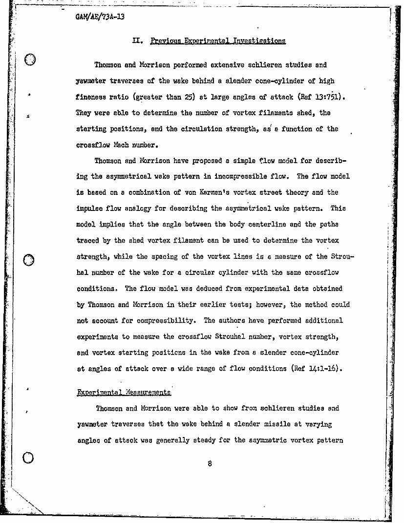
II. Prevlous Experimenptal nvegtiPations
Thomson and orrison performed extensive schlieren studies and
yawmeter traverses of the wake behind a slender cone-cylinder of high
fineness ratio (greater than 25) at large angles of attack (Ref 13:751).
They were able to determine the number of vortex filaments shed, the
starting positions, and the circulation strength, as a function of the
crossflow Mach number.
Thomson and Ylorrison have proposed a simple flow model for describ-
ing the asymmetrical wake pattern in incompressible flow. The flow model
is based on a combination of von Karmen's vortex street theory and the
impulse flow analogy for describing the asymmetrical wake pattern. This
model implies that the angle between the body centerline and the paths
traced by the shed vortex filament can be used to determine the vortex
0strength, while the spacing of the vortex lines is a measure of the Strou-hal number of the wake for a circular cylinder with the same crossflow
conditions. The flow model was deduced from experimental data obtained
by Thomson and Morrison in their earlier tests; however, the method could
not account for compressibility. The authors have performed additional
experiments to measure the crossflow Strouhal number, vortex strength,
and vortex starting positicns in the wake from a slender cone-cylinder
at angles of attack over a wide range of flow conditions (Ref 14:1-16).
Expermenta eosurewent s
Thomson and Morrison were able to show from schlieren studies and
yawmeter traverses that the wake behind a slender missile at varying
angles of attack was generally steady for the asymmetric vortex pattern
o''x) 8
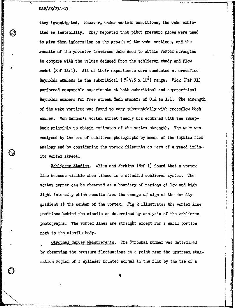
they investigated. However, under certain conditions, the wake exhib-
0 ited an instability. They reportsd that pitot pressure plots were used
to give them information on the growth of the wake vortices, and the
results of the yawmeter traverses were used to obtain vertex strengths
to compare with the values deduced from the schlieren study and flow
model (Ref 14 1). All of their experiments were conducted at crossflow
Reynolds numbers in the subcritical (:5 7.5 x IO ) range. Pick (Ref 11)
performed comparable experiments at both subcritical and supercritical
Reynolds numbers for free stream A'ch numbers of 0.4 to 1.1. The strength
of the wake vortices was found to vary substantially with crossflow Iach
number. Von Karman's vortex street theory was combined with the sweep-
back principle to obtain estimates of the vortex strength. The wake was
analyzed by the use of schlieren photographs by means of the impulse flow
analogy and by considering the vortex filaments as part of a yawed infin-
ite vortex street.
Schlieren- Studle. Allen and Perkins (Ref 1) found that a vortex
line becomes visible when viewed in a standard schlieren system. The
vortex center can be observed as a boundary of regions of low and high
light intensity which results from the change of sign of the density
gradient at the center of the vortex. Fig 2 illustrates the vortex line
positions behind the missile as determined by analysis of the schlieren
photographs. The vortex lines are straight except for a small portion
next to the missile body.
Strouhal Number teureents. The Strouhal number was determined
by observing the pressure fluctuations at a point near the upstream stag-
nation region of a cylinder mounted normal to the flow by the use of a
0 9
",',
CAVAE/73A413
piezo-electric transducer. The frequency of the pressure fluctuation is
identical with the frequency of vortex shedding in the wake- thus, the
Strouhal number can be readily obtained (Ref 14:5). These results agree
quite accurately with those of Fang (Ref 5:801). Also, Thomson and
Yorrison determined that the Reynolds number was not a significant param-
eter in the Hach number range covered by these tests.
M. TThomson and Mcrrison performed six experimental
investigations of the flow within the compressible wake. They also used
an experiment conducted at 100 ft/sec by Griss (Ref 7) to provide data
at incompressible speeds.
The pattern of vortices behlInd the missile can be as shown in Sec-
tion B of Fig 2 or an opposite pattern (mirror image) which is primarily
dependent upon the misalignment of the nose of the mfssile. Thomson and
Morrison determined that only a slight rotation of the body about its
axis could change the pattern from one vortex sequence to another. In
order to preclude the alternate shedding, the missile was mounted as a
fixed body and the probe was moved by the means of a separate traversing
mechanism.
Analysis of Scbhlieren Ph"'oqa Phs
Strouhal ftI mor. The values of the Strouhal number have been deter-
mined by measuring values of (g'/d) from photographs and then inserting
(g'/d) into the equation
S d Tanc ()2g'
where S is the Strouhal number, g' is the distance between breakway points
of consecutive vortices measured along the body, d is the body diameter,
and oL is the anglo of attack.
10
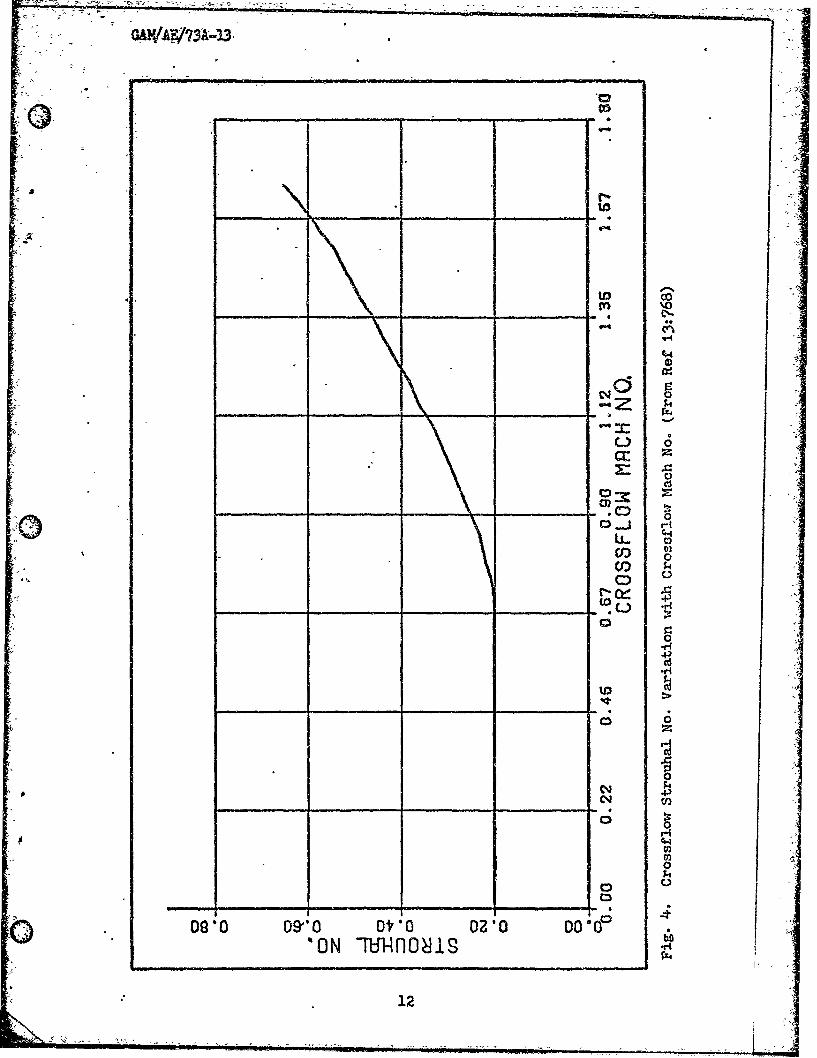
A curve generated from data of the Strouhal number versus crosaflow
M aoh number is shown in Fig-4. The measured value of the Strouhal num-
ber remains constant until the crossflw Lach number reaches approximately
0.7, which corresponds to the formation of shock waves on the lee side
of the missile body. Then, the Strouhal number increases with increasing
crossflow %bch number. The measured Strouhal number of 0.2 for crossflow
Vbch numbers less than 0.7 is very close to the value for a circular cylin-
der for subcritical Reynolds number (Ref 14:9).
Egg of o Bre, ay Points. As mentioned earlier, the nose
misalignment determines the pattern of the vortices. A few degrees rota-
tion of the body or a slight change in angle of attack can cause the vor-
tices to adjust from one pattern to another. Also, the entire sequence
of vortices can shift slightly forward or aft along the missile; conse-
quently, the date analysis for the breakaway points contains appreciable
scatter (Ref 13:768).
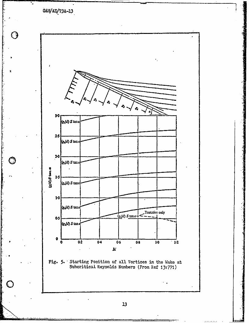
* *.The starting position of all vortices in the wake for subcritical
Reynolds number is shown in Fig 5, and for supercritical Reynolds number
regime in Fig 6. The analysis is based on a non-dimensional parametric
representation by the rearrangement of Eq (1) which shows that the spac-
ing between vortex cores is related to the shedding frequency of a circu-
lar cylinder in the following equation:
0,5(2d S Tan (2)
A Consecutive vortices are spaced apart a distance g'. One can readily
observe in Fig 2 that the first two vortex filaments are influenced by
the expanding portion of the nose section of the missile. Thomson and
Morrison observed from schlieren photographs that the strength of the
11
GAW$43A3 .
'0
$X4
cc:
00
0 -
0!
0
.qr.
Oslo ~~~~ 090 t1 300 l
122
- 3I0
:.05
2004~d 0S Una0 1'
Fig. S Starng Poiinoaalotcsi h aeaSubcriical RynoldsNumbes.(Fro..e.... :771
<1C
(gild)S tan
OAV/A41/3A413
I~SC .
a10r ~ tnc
* __ __ __ __ _ __ __ __ __ __ __ __ __ _ __ __ __d_
09U)ane
* C -~9 st nc
O tan
AWNC : go0:20 .0 G. s
HC (ROSSFLOWMRCHN csFi.6 otxSariffPsto sFnto o rsfo ahN.a
Sueciia0enlsNmes(rmRf1:0
14tac
GAM/AEI7I
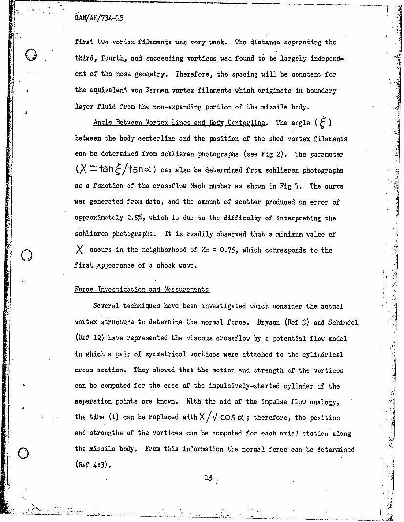
first two vortex filaments was very weak.. The distance separating the
third, fourth, and succeeding vortices was found to be largely independ-
ant of the nose geometry. Therefore, the spacing will be constant for
the equivalent von Karman vortex filaments which originate in boundary
layer fluid from the non-expanding portion of the missile body.
Ange gBtWeen Vortex Lines end Body Centerline. The angle ( )
between the body centerline and the position of the shed vortex filaments
can be determined from schlieren photographs (see Fig 2). The parameter
(X -tan 6/tc3no) can also be determined from schlieren photographs
as a function of the crossflow Mach number as shown in Fig 7. The curve
was generated from data, and the amount of scatter produced an error of
approximately 2.5%, which is due to the difficulty of interpreting the
Schlieren photographs. It is readily observed that a minimum value of
X occurs in the neighborhood of ;-So 0.75, which corresponds to the
J first .appearance of a shock wave.
Force Investigzation and 1'asurenents
Several techniques have been investigated which consider the actual
vortex structure to determine the normal force. Bryson (Ref 3) and Schindel
(Ref 12) have represented the viscous crossflow by a potential flow model
in which a pair of symmetrical vortices were attached to the cylindrical
cross section. They showed that the motion and strength of the vortices
can be computed for the case of the impulsively-started cylinder if the
sepWation points are known. With the aid of the impulse flow analogy,
the time (t) can be replaced with X/V COS cC; therefore, the position
and strengths of the vortices can be computed for each axial station along
the missile body. From this information the normal force can be determined
(Ref 4:3).
15.
- N ... #
r~'~~'.
GA! VAE/73A-13
0
cbJ
oQ
C44
C00?
40
_ _ _ _ o p
IHO) X
16K

GAWAE/713A 3
Pick (Rof 11) and Yrouze (2d 8) -.aswed side force associated
0 with asyrmtric vortex sheddir,3. Additional unpublihed data vas obtained
by the Air Force FliEht Dynamics Laboratory. Xrouse invostirated the
flow around a tangent-ogivo cylinder with nose lenath-to-diateter ratio
of 4.89 and overall fineness ratio of 10 for Mch numbers of 0.55 and
0.80 with a crossflow Reynolds number of 4.5 x 10⁵ to 8.0 x 10⁵. Pick
conducted similar investigations for ogive-cylindors vith various nose
bluntnesses and overa.ll fineness ratio of about 11, and for free stream
1Mch numbers from 0.5 to 1.1. Both Krouse and Pick used missile shapes
of much less fineness ratio than Thomson and Morrison. Krouse measured
side forces that were approximately 60 to 70 per cent of the values of
the normal lift force on the missile at angles of attack between 30-40
degrees. Pick studied the effects of nose fineness and bluntness ratio
on the magnitude of the side forces produced by asymmetrical flow sepra-
tion on ogive-cylinder bodies. Tie concluded that an increase in the
Sfineness ratio resulted in an increase in the side force, and conversely,
an increase in the nose bluntness resulted in a decrease in the maximum
side force. Pick concluded that the induced side forces can be dramatically
reduced by generating a turbulent boundary layer, which results in delayed
separation.
In the following sections an approximate flow field model will be
postulated so that the position and strength of the rolled up vortex
sheets may be calculated. Next, from slender body theory, the equations
required to calculate the transverse forces and moments acting on the
missile will be developed. Finally, the equations will be applied to
calculate the forces and moments for several missile configurations and
(the results compared to experimental data.
17
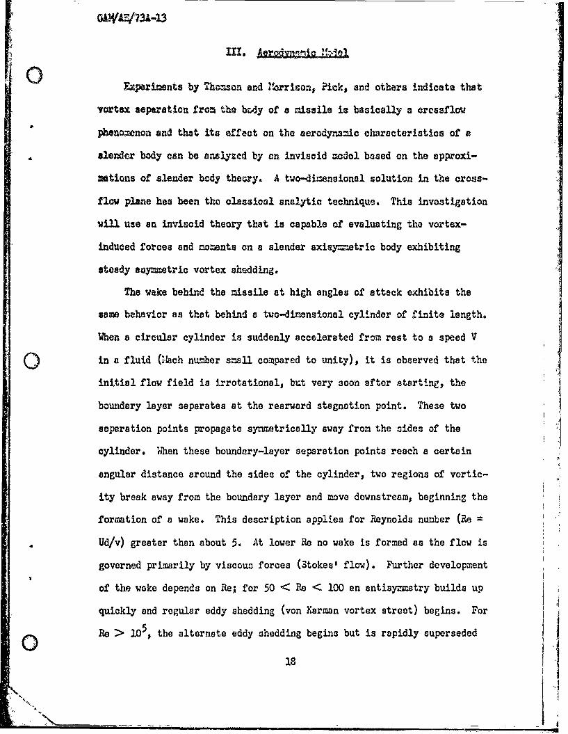
xperiments by Thomon and 4rrison. Pick, and others indicate that
vortex separation fron the bcdy of a missile is basically a ercssflow
phenomenon and that its effect on the aerodynamic characteristics of a
slender body can be analyzcd by an inviscid mcdol based on the approxi-
rtions of slender body theory. A two-dimensional solution in the cross-
flow plane hes been the classical analytic technique. This investigation
will use an invisoid theory that is capable of evaluating the vortex-
induced forces and moments on a slender axisy=-etric body exhibiting
steady aoymmetric vortex shedding.
The wake behind the missile at high angles of attack exhibits the
same behavior as that behind a two-dimensional cylinder of finite length.
When a circular cylinder is suddenly accelerated from rest to 8 speed V
Qin a fluid (s'ach number small compared to unity), it is observed that the
initial flow field is irrotational, but very soon after starting, the
boundary layer separates at the rearward stagnation point. These two
separation points propagate symmetrically away from the sides of the
cylinder. When these boundary-layer separation points reach a certain
angular distance around the sides of the cylinder, two regions of vortic-
ity break away from the boundary layer and move downstream, beginning the
formation of a wake. This description applies for Reynolds nunber (Re =
d Ud/v) greater than about 5. At lower Re no wake is formed as the flow is
governed primarily by viscous forces (Stokes' flow). Further development
of the wake depends on Re, for 50 < Re < 100 an antisymmetry builds up
quickly and regular eddy shedding (von Karman vortex street) begins. For
o Re > 105, the alternate eddy shedding begins but is rapidly superseded
18I
GAWA/731-13
by a completely turbulent flow in the wake (Ref 3). The analysis in this
0 report is concerned with antisy~metric shedding.
The major assumptions used in developing the analysis are:
a. The vortex sheets roll up into vortex lines of constant strength.
It has been observed that a vortex sheet that is shed from the cylinder
rolUs up within a distance of one diameter; consequently, it seems plausi-
ble to model the shed vortex sheet as a line of constant strength. Also,
the vortex sheet that is attached to the missile will be modeled as a
filament line at the edge of the vortex sheet that has the same strength
as the other vortex lines.
b. It is assumed that an empirically modified vortex street analysis
will properly predict the strengths and position of the rolled up vortex
0sheets. Since it is observed that the vortex sheets roll up in the wakeof the missile and appear as stationary lines in schlieren photographs
(Ref 13:784), a von Kerman vortex street analysis will be used. The results
of measurements from the schlieren photographs will be used in conjunction
with vortex street'analysis to estimate the strength and position of the
rolled up vortex sheets.
c. It is assumed that even for high angles of attack, slender body
theory will give approximate equations to calculate the transverse force
and moments if the small angle approxi.mation is modified by using the
sine and cosine functions.
d. Compressibility effects can be neglected. The assumption of
constant density will be made since slender, body theory in the crossflow
plane and the von Karman vortex street analysis is one of constant density.
19
~" k
GAWAu4-73A-l3
A result of slender body theory is that the flow in the crossflow plane
0is independent of I-ach number; and that the transverse forces and moments
depend only on the flow in the crosaflow plane.
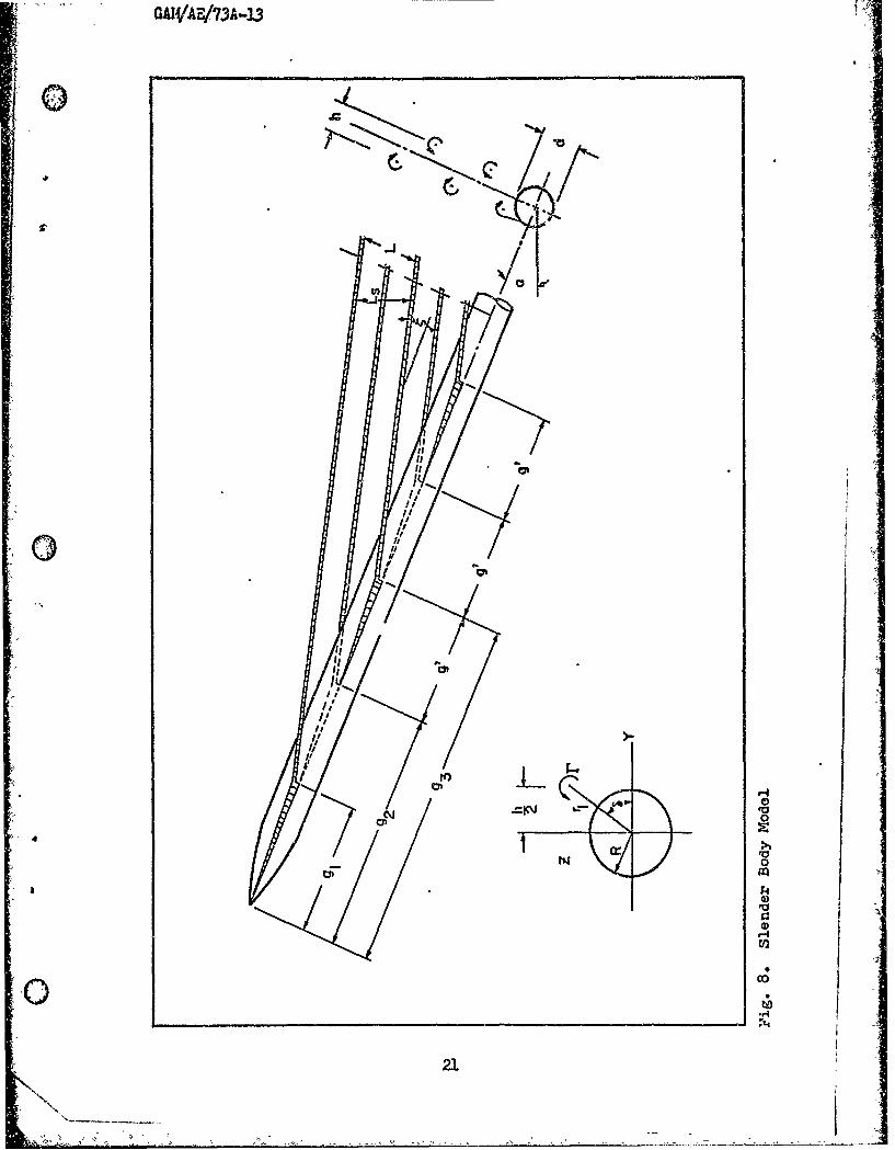
A sketch of the vortex system behind a slender cone-cylindr at an
angle of attack is shown in Fig 8. The flow pattern will be analyzed by
considering the vortex pattern to be a steady yawed vortex street for
which vortex street theory may be applied.
St artin' Positions of the Vortex Lines. The parameter for describ-
ing the periodic shedding of vortices from a circular cylinder in two
dimensions is the Strouhal number (S),
S -nd- -U (3)
where n is the frequency of shedding vortices of like sign, d is the
diameter of the cylinder, and U is the velocity of the cylinder relative
to the free stream. Considering a cylinder yawed at an angle (C) to
the free stream velocity (V), the velocity at right angles to the cylinder
is
U -V sinc (x)
and hence
_ nd (5)V - sin (
In 2-D theory, 1/n represents the time interval between the instants of
shedding of vortices of like sign; here the interval is taken as the time
fo. the component of flow along the body (V COS OC) to travel a distance
2 gf. Thus
20
GA!
~0
.c /4'-
-a
IIII -ID. 01
/1~~ii
I,i/
N
(
Ig
I,
Jg%~I,
I;I;
'IIII,
I,6'
'I,
'-40
N0
4
V
0
*0
V
a,'-4(I)
0
o w.r4*14
2).
GAWAE/73A-3
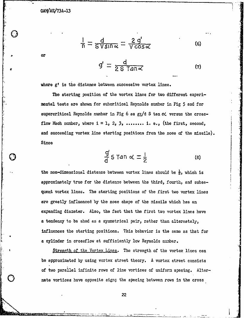
0 : _ d _ 2q (6
" -n -- Vsin -v Vcoso (
or
28Tan (7)
where g' is the distance between successive vortex lines.
The starting position of the vortex lines for two different experi-
mental tests are shown for subcritical Reynolds number in Fig 5 and for
supercritical Reynolds number in Fig 6 as gi/d S tan o/ versus the cross-
flow Mach number, where i = I, 2, 3, ....... i. e., (the first, second,
and succeeding vortex line starting positions from the nose of the missile).
Since
STaI (8)d 2~
the non-dimensional distance between vortex lines should be i, which is
approximately true for the distance between the third, fourth, and subse-
quent vortex lines. The starting positions of the first two vortex lines
are greatly influenced by the nose shape of the missile which has an
expanding diameter. Also, the fact that the first two vortex lines have
a tendency to be shed as a symmetrical pair, rather than alternately,
influences the starting positions. This behavior is the same as that for
a cylinder in crossflow at sufficiently low Reynolds number.
Streneth of the Vortex Lines. The strength of the vortex lines can
be approximated by using vortex street theory. A vortex street consists
of two parallel infinite rows of line vortices of uniform spacing. Alter-
nate vortices have opposite sign; the spacing between rows in the cross
22
LA**

section view are shown in Fig 8. In vortex street analysis for .ncom-
0 pressible two-dimensional flowj, the self-induced transport velocity (Us )
of the vortex street normal to the vortex lines is given byTc n h (9)
vhere r is the vortex strength and I is the distance between vortices
of like sign measured norzal to the vortex lines. Theory also shows that
an array of two parallel rows of vortex lines will be stable if the spac-
ing ratio is
S "- IT .8l(0
where h is the distance between the infinite parallel rows of vortices.
Since the vortex lines are stationary, the self-induced velocity Us must
be countered by the component of the free stream velocity normal to the
vortex lines as follows:
Vs = v Sifnl C (3.)
From the geometry in Fig 8, the following relations can be deduced:
Cos (12)
Tar e 219' (1)
Equating Eqs (9) and (11) and using Eqs (10, 12, and 13) gives
r - cot 1Tan1 (I 2 T (14)
or upon using Eq (9)
F coth coTan Tan ) (1)Vd sincj S- Ta n o Tan (
2
GAN/A.E/73A-13
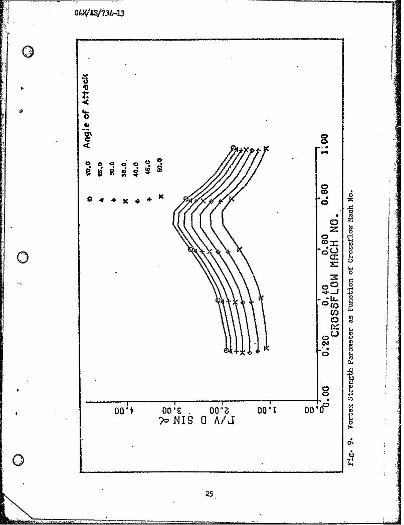
The parameter r/V d 5iA i - (nondimencional vortex strength) can be
determined if the values of the Strouhal number end the angle 6 between
the vortex lines and the missile are knewn for a given angle of attack.
The value of Strouhal number as a function of the crossflow 1ach number
can be determined experimentally as shown in Fig 4. Also, the parameter
X as a function of the crossflow Mach number can be determined experi-
mentally from schlieren photographs, as shown in Fig 7, where
X - Ta3 (16)
Using the experimental values of Strouhl number (S) and the parameter
X as a function of crossflow Mach number from Fig 7, the value of
S/V d 5in cc can be computed using Eq (15). The nond iensional vor-
tex strength as a function of the crossflow Mach number and angle of
attack is shown in Fig 9. Thomson and 14orrison (Wf 13:774) displayed
a similar plot of vortex strength estimated from schlieren photographs
and wake traverses for a 30 degree angle of attack. It can be seen from
Fig 9 that the vortex strength increases with increased crossflow Mach
number (Mc ) to a maximum value at 0.75, and then decreases. The peakvalue corresponds to a 2.ch range where compressibility effects begin
to be significant. It is observed that as the angle of attack is increased,
the magnitudes of the nondimensional vortex strength decrease in value.
PUlculatign Procedures. From the above aerodynamic flow field analy-
sis, the position and the strengths of vortex filaments in the wake of a
missile at a high angle of attack may be determined. For a given missile
operating At a specified angle of attack and crossflow i ach number, if
one proceeds according to the following steps, the position and strength
of each vortex line can be calculated.
24
GDA'AZ'7A-13 -
.0D
00"CO
00
-C;4
oooooo)
0
ho
?o NI A:CC
25.9

S.-Step 2 Obtain missile geometry, angle of attack (cC), and the
0oroseflow %ch number.
Step 2 Determine the Strouhal number from Fig 4.
Stop 3 Determine the starting position of the first three vortex
lines from Fig 5 if subcritical Reynolds number, or Fig 6
for supercritical Reynolds number. Then determine the start-
ing position of the subsequent vortices using equation
d g =(8)2- ZSTa3n C/
• Step 4 Determine the angle from Fig 7 and Eq (17).
.Stop 5 Determine the vortex strength according to
r c oth / -2 C02( Tan (15)
0 Step 6 Finally, determine 1 and h from
I 2 9'Tan o,- (17).
Sh- - -9' sin (8)• IT • ,K
orcejend 1-o10m!en;t Eoupt ics
As a result of slender body theory, the transverse force and moments
acting on the missile can be calculated if the incompressible two-dimen-
,, sional potential field for the crossflow plane is known. The potential
field for the crossflow plane as a function of distance (X) along the
missile body can be related to the two-dimensional unsteady wake develop-
Mont behind a cylinder (P-f 3:643). Thus, if one imagines a plane fixed
0 in the fluid perpendicular to the missile axis, then as.the missile pierces
this plane, the time required to traverse a distance X along the missile
body is given by t X/(V cos o(), where a'is the angle of attack. The
26
GAVa/73A43
time in the two-dimensional unsteady problem is therefore related to the
distance along the missile in the slender body problem.
For the problem of a two-dimensional unsteady wake development behind
a cylinder, a force can be calculated as a result of the impulse produced
by a pair of vortices of equal and opposite strength r , which are a com-
plex distance apart. The instantaneous force per unit length for a system
vithout potential energy is equal to the instantaneous time rate of change
of linear momentum. For a vortex pair, the total Kelvin impulse per unit
length is equal to the linear momentum (Ref 2:45).
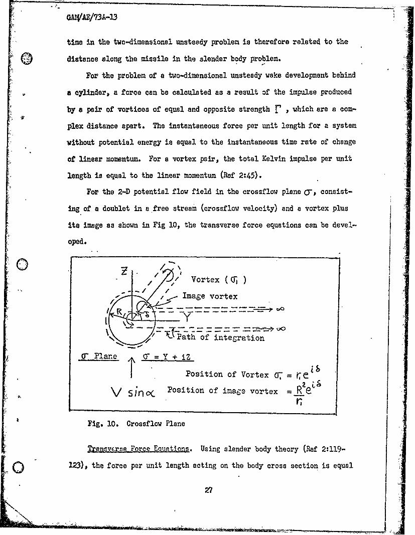
For the 2-D potential flow field in the crossflow plane a-, consist-
Ing of a doublet in a free stream (crossflow velocity) and a vortex plus
its image as shown in Fig 10, the transverse force equations can be devel-
oped.
/ // Vortex(0 )- -/Image vortex
' --PPat ho:Finteg-ration
Cf Plane Y + iZ
Position of Vortex = e
V sinl o. Position of image vortex = R e
Fig. 10. Crossflow Plane
Transv.rse Force Equations. Using slender body theory (Ref 2:119-
123), the force per unit length acting on the body cross section is equal
27
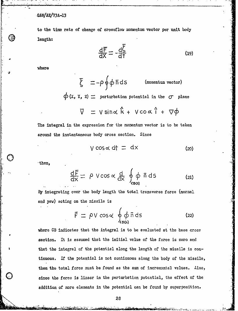
[ , GAW/AE/?3A-3
to the time rate of change of crossflow momentum vector per unit body
length:
dFx d ()
a..
where
t - f~p ffds (momentum vector)
4(X, Y, Z) perturbation potential in the CT plane
Ain koLk+ V co c(t +
The integral in the expression for the momentum vector is to be taken
around the instantaneous body cross section. Since
Vcos c dt dx (20)
*then,
dxd-X f A (21)- P vcos~ ndsCBc
By integrating over the body length the total transverse force (normal
and yaw) acting on the missile is
pVcos0 n ds (22)
where CB indicates that the integral is to be evaluated at the base cross
section. It is assumed that the initial value of the force is zero and
that the integral of the potential along the length of the missile is con-
tinuous. If the potential is not continuous along the body of the missile,
then the total force must be found as the sum of increm ntal values. Also,
0 since the force is linear in the perturbation potential, the effect of the
addition of more elements in the potential can be found by superposition.
28

Expressing the force in terms of complex variables ano letting
+J) ± V 5i fl (23)
then F - Y -+ i " - -ip v C 0o5 , . d o " ,
+ ipV cos < sin c Z dc -(24)
-4
or
i Z 4pVCOSC OdCr-ip Vcosinq7TR2 (25) A
Introducing the complex potential W' (C " for the related flow which has -'A
a zero normal velocity at the contour and a velocity at infinity of V 4
sin 6, thenIIY z -ipv cosc W' ( -do-
-i V2 Co 5 t s in TrR (26)
where
w'(C0) ck+ i~(27)
The potential(R can be replaced by W' (0-) since the stream function
*1 is constant along the cross section contour. For the complex .potential
W H __i V S i n oC 0 - 2 # n o - - n - t (28 )
I -
L
The potential for a missile of circular cross section consists of a doub-
let in the crossflow stream, a vortex, and its image. Evaluating the con-
tour integral for the path shown in Fig 10 yields
29
%~
W od.r i_VsincR 27r2 (29)
Then the forces are
i = i i ~ cs ip c<F + (Zo)tIZ i 7 5 O,( (30)
or in coefficient form
-a! r ReZI1- Y 2Pcos, co . (31)
and
sinl2L + 2 Fcos cr ROnr /2 V ff, s i n 8 (32)10
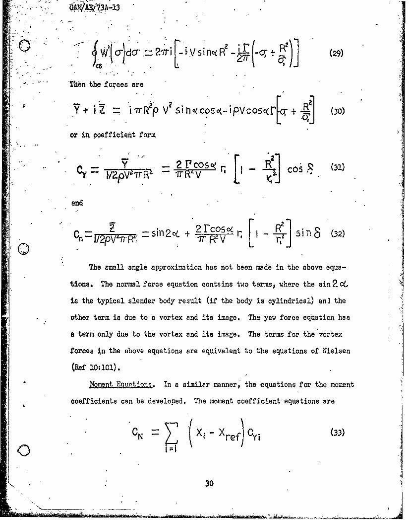
The small angle approximation has not been made in the above equa-
tions. The normal force equation contains two terms, where the sin 2 C(
is the typical slender body result (if the body is cylindrical) an] the
other term is due to a vortex and its image. The yaw force equation has
a term only due to the vortex and its image. The terms for the vortex
forces in the above equations are equivalent to the equations of Nielsen
(W~e 10:101).
Moment Eq32tions. In a similar manner,' the equations for the moment
coefficients can be developed. The moment coefficient equations are
"" \ i
30

GAUW 73A-13
arid
)~ (Yj ref)Oni (4
where the index i indicates the incremental force. The distances are
evaluated at selected crossflow planes over the length of the missile.
031 :
GMNVA/73A-).3
IV. Coriosrison of Reults
The primary objective of this study was to derive a slender-body
mathematical model to predict the forces and moments on a slender mis-
sile configuration at angles of attack where asymmetric vortex shedding
ocourred. Results of these calculations were compared with existing
experimental data to test the validity of the mathematical theory.
Experimental data available for comparison of the calculated normal
and side force coefficients was obtained from Krouse (Ref 8), Pick (Ref
Ii), and unpublished data from the Air Force Flight Dynamics Laboratory.
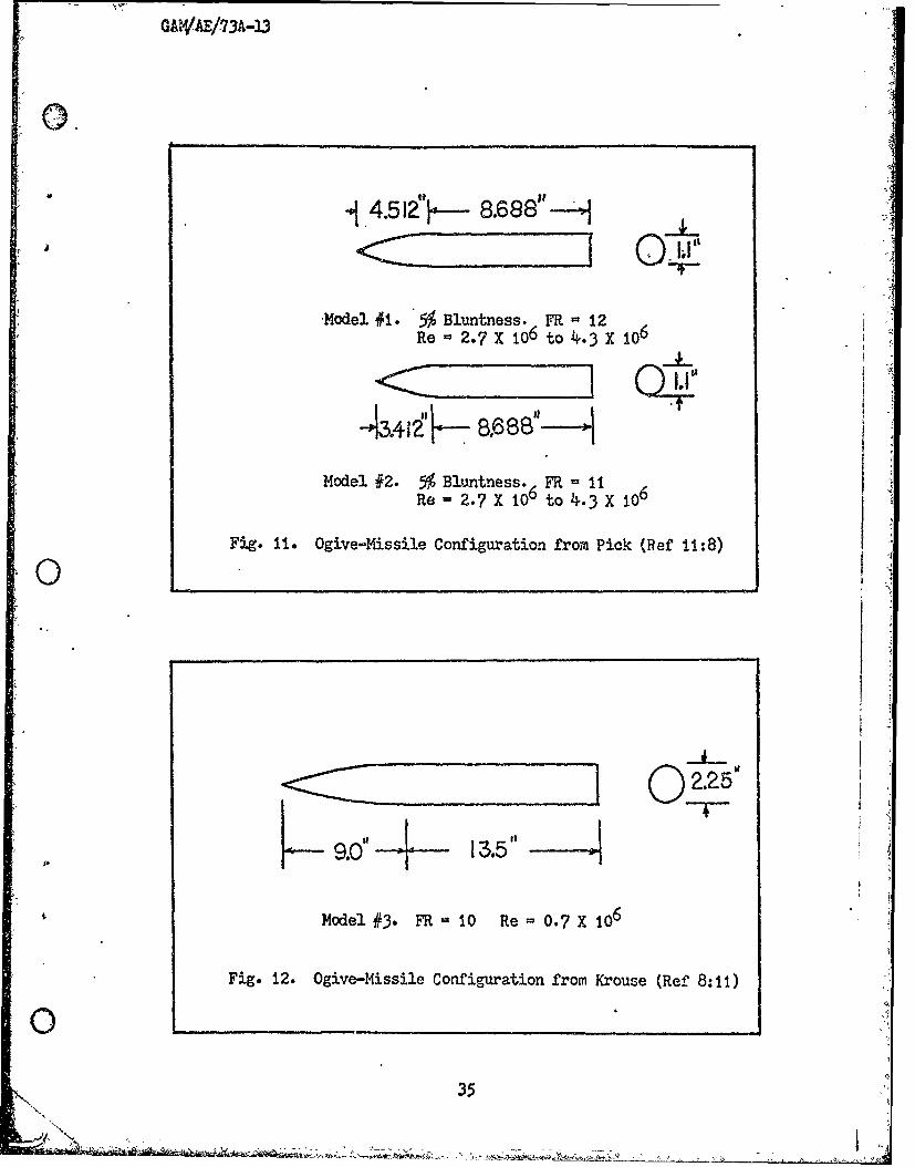
Schematic diagrams of the missile configurations tested are shown in
Figures 11 and 12, page 34, and Fig 13, page 35. Figures 14-21 (pages
36-43) show the calculated and experimental side force coefficients, and
Figures 22-24, pages 44-46, compare normal forces. The first compari-
sons were made with date obtained by Pick on a small fineness ratio mis-
sile configuration. As can be seen in Figures 14, 15, and 16, the side
forces agree adequately for angles of attack up to approximately 36-38
degrees. Then, thp slender-body model breaks down and the calculated
curves depart dramatically from the experimental values. Also, at higher
free stream 'Mch numbers (Fig 17), the calculated values of side force
are inaccurate. The slender-body theory, due to compressibility effects,
cannot be readily extended to high angles of attack without empirically
determined correction factors applied to the model.
Another contributing factor at angles of attack greater than 35
degrees is that g' (the spacing between alternate vortex filaments)
decreases in length rapidly as the angle of attack is increased. This
shifts the vortex lines forward toward the nose of the missile, and also
32

GAWAU/73A-13 *causes an incresse in the number of filaments which are shed. hen an
odd number of vortex filaments are shed, the side forces are apparently
altered sufficiently that divergence from the predicted results occurs.
Results from models of high missile fineness ratio are plotted in
Fig 18 (Model #3), Figures 19 and 20 (Model #4), and Fig 21 (Model #5);
consequently, many vortex filaments are shed due to the increased mis-
sile body length. It was found that at the higher free stream Mach num-
bers the calculated values of side force (Figures 20 and 21) tend to dis-
play discontinuities.
The plots in Fig 20 were determined by shifting the starting posi-
tions of the vortex lines along the missile body axis to show the sensi-
tivity that results. Each succeeding vortex filament sheds on opposite
sides of the missile; consequently, the side forces induced on the missile
are of opposite sense. Also, a shift in the starting position of the
vortex lines can alter the total number of vortex filaments shed which
can result in a change of the total induced side force. However, the
total normal force is less sensitive to this shift because each left and
right handed filament always produces a positive normal force.
The final set of data was obtained from Krouse (Ref 8) from a free
stream Mach number of 0.55 and 0.8. Krouse divided the absolute values
of the side force coefficient by the lift coefficient and plotted these
values versus the angle of attack. Krouse measured side forces that were
approximately 60-70 per cent as large as the lift force on his tunnel
model. The results are plotted in Fig 18. Krouse's model displayed
similar characteristics for a high missile fineness ratio model.
The normal force distribution (lift), which includes a term from
slender-body theory, gives reasonably accurate results when compared with
N 33
ij
GAWA/73A-13
experimental data as shown in Figures 22-24. Again, at the higher angles
of attack (greater than 40 degrees) and at greater free stream Mach num-
beve, the extension of the slender-body model becomes inadequate. Shock
waves in the flow field are evidently weak until the crossflow Mach num-
ber exceeds about 0.7. Below this value, the drag is predominately due
to the wake vortices, but wave drag becomes progressively more important
for high .abch numbers.
34
.. II
i'Io"I
A
'N'
GAWAE/73A-13
° 4.51Z"-- 8.688".
Model #1. 5 Bluntness. FR - 12Re - 2.7 X 10⁶ to 4.3 X 10⁶
Model #2. 5% Bluntness. FR = 11Re - 2.7 X 166 to 43 X 106
Fig. 11. Ogive-Missile Configuration from Pick (Ref 11:8)
CZ~iIII 02.25'--9.0" f
Model #3. FR 10 Re= 0.7 X 10⁶
Fig. 12. Ogive-Missile Configuration from Krouse (Ref 8:11)
0'
35
N-
GAW4A/73A-13
-44
<0 -
0)0(D0ri4 Cl)
0)'
- aH
0
(4
360
LJ 0
El 0
_CC 4_ _
U,-
DO 000 6 - o o - 0(0)~~~L OHN O ADi
Q 07

9.5
O3
N >0
rUcv-
00 O"- 0 - 0"g 0 0 ,c -r.'
tit-
00.)
o " i
0 00
3380A 30I
__ __8C,
GAf/AB/73A-13
0U
00 0 -
0 o0
0
LU'w 4)
0
z t)
SC3
o /
0- -1 ------ ---
Doll 00,10 0061- 0003- 0o''
(0O) "3.A303 33HOA 3019
.)
39
"xo
GAWAB/73A-13
0I,
oo
El
E-t (1 0
0L)
0 r
0 '- 4)
InCC
o0 00 0
S0
0K
rii400
'S.,.
SNIS
"
GAWAE/73A-13
0
Qj 0)
4)4 bJ
TOT
41X~ 41
GiAIVAE/73A-13.
t3. Lt0 b
* 0 Z
_____ 3
bb
________c !2___
El~110in
H
LO-01- C
02I T o Olo D
( O) jj- 3080 100 b30X
42L
* GA1W.AE/73A-13
io.*o
to
5 r0~ 0
0
0 z
*.rI H ~
00
tobDo
C-)
0 4
0~
I r C7.
6O 0046 00~ oz06Do 4e C1
43
GA E '73A-13
'0
0 01
0
LJ-0 0
0 +
0
S cc
4)
*AJDOODONJ 019 -
441
00
S0 --
0
00-
- 0- '- 2
0 ti. -
6 0
00
cI5 -
0
V) C)
E-4 00
CC0
U-
0
8z
C,-
CV
00a 0 ol 00z o0(NO)*JJ30 300J -UW80
46.
MAEA/73A-13
:0044
4*
ILJ
E-0 ___ 44.
G~ 0r
LL -
o
§ 54
0q a_ _ _ _ _ )
N h'Col 00z7 oo-
(NO) '.iJ3OJ 3080J "1UW8ONrz.
47
GAW AE/73A-13
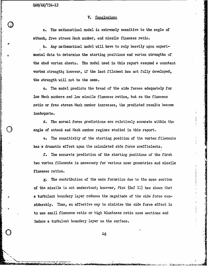
V. C-gomisgn§
a. The mathematical model is extremely sensitive to the angle of
attack, free stream Mach number, and missile fineness ratio.
b. Any mathematical model will have to rely heavily upon experi-
mental data to determine the starting positions and vortex strengths of
the shed vortex sheets. The model used in this report assumed a constant
vortex strength; however, if the last filament has not fully developed,
the strength will not be the same.
c. The model predicts the trend of the side forces adequately for
low Mach numbers and low missile fineness ratios, but as the fineness
ratio or free stream Mach number increases, the predicted results become
inadequate.
d. The normal force predictions are relatively accurate within the
0 angle of attack and Mach number regimes studied in this report.
e. The sensitivity of the starting position of the vortex filaments
has a dramatic effect upon the calculated side force coefficients.
f. The accurate prediction of the starting positions of the first
two vortex filaments is necessary for various nose geometries and missile
fineness ratios.
g. The contribution of the wake formation due to the nose section
of the missile is not understood; however, Pick (IRef II) has shown that
a turbulent boundary layer reduces the magnitude of the side force con-
siderably. Thus, an effective way to minimize the side force effect is
to use small fineness ratio or high bluntness ratio nose sections and
induce a turbulent boundary layer on the surface.
GAI4AB/73A-13
V. CglQojsna
a. The mathematical model is extremely sensitive to the angle of
attack, free stream iach number, and missile fineness ratio.
b. Any mathematical model will have to rely heavily upon experi-
mantal data to determine the starting positions and vortex strengths of
the shed vortex sheets. The model used in this report assured a constant
vortex strength; however, if the last filament has not fully developed,
the strength will not be the same.
c. The model predicts the trend of the side forces adequately for
-ow Mach numbers and low missile fineness ratios, but as the fineness
ratio or free stream Mach number increases, the predicted results become
inadequate.
d. The normal force predictions are relatively accurate within the I -
angle of attack and lach number regimes studied in this report.
e. The sensitivity of the starting position of the vortex filaments
has a dramatic effect upon the calculated side force coefficients.
f. The accurate prediction of the starting positions of the first
two vortex filaments is necessary for various nose geometries and missile
fineness ratios.
g. The contribution of the wake for:mtion due to the nose section
of the missile is not understood; however, Pick (Ref 11) has shown that
a turbulent boundary layer reduces the magnitude of the side force con-
siderably. Thus, an effective way to minimize the side force effect is
to use small fineness ratio or high bluntness ratio nose sections and
induce a turbulent boundary layer on the surface.
0 48
- "'°,,. I

GAWAEr/73A-13
h. The discrepancies at the higher Mach numbers are due to the
unknown size of the wave drag which is produced by shock waves in the
flow.
Unfortunately, there is little quantitative experimental data avail-
able to determine the root causes and effects of asymmetrical vortex
wakes behind a missile in the Mach number and Reynolds number regimes
investigated in this report. Therefore, the validity of the theory and 4
subsequent developed mathematical model cannot be completely verified.
The results obtained indicated that the method yields reasonable results
for low fineness ratio missile configuration for angles of attack (cC)
up to 40 degrees. Based on the success for the low fineness ratio mis-
sile configurations, the model might be extended to higher fineness ratio
missiles, provided suitable experimental data become available to permit
empirical prediction of the location of the vortex separation points.
49
49
.N , ; o, ... ..
VI. ecommendation
The problem of asymmetric vortex shedding definitely warrants fur-
ther investigation since there are many unanswered questions concerning
the stability and control of a missile which may operate at large angles
of attack.
At this time there are no analytical techniques for quantitatively
describing the side forces and yawing moments induced on a slender mis-
sile at relatively high angles of attack. Therefore, the proposed model,
which was based upon slender-body theory and vortex street enalysis,
could possibly be refined for various missile configurations provided a
systematic study is made to determine:
a. The effects of nose bluntness, fineness ratio, and overall mis-
sile fineness ratio on the starting position of the vortex filaments
0b. Mhether at subsonic free stream flight speeds, some type of
equivalent Kutta condition, which influences the breakaway position of
the vortex filaments, prevails at the base of a finite missile
c. The angle of attack ranges and free stream Mach numbers which
characterize a particular wake flow phenomena (steady, unsteady, symmetric,
asymmetric, and/or turbulent)
d. If the diameter of an aft-mounted sting, which has nearly the
same diameter as that of the tunnel model being tested, alters the flow
field significantly since the missile now has a higher fineness ratio
than the simulated free-flight model
e. The accuracy of the circulation strength of the vortex filaments
f. The effects of the vortex induced flow field on the roll moment
0above what is normally experienced on a finned missile configuration
50

GAIVAE/73A-13
Bibl fect--o Vicol o
1. Allen, H. J. and Perkins, E. W. A Study of ffects of Vscositfv onFlow Over SlendeL Inclined Bodies of .evolutioa. NACA TR No. 1043
6(1951).
2. Ashley, H. and Landehl, M. Aerodynamics of Wings and Bodies. New York:Addison-Wesley Publishing Co., Inc. (1965).
3. Bryson, A. E. "Symmetric Vortex Separation on Circular Cylinders andCones." ASM,1 Journal of Aolied .6chn8s, (1
4. Clark, William H. and Peoples, John R. "Occurrence and Inhibition ofLarge Yawing ioments During High Incidence Flight of Slender MissileConfiguration." AIAA Poper '!o. 72-968 (September 1972).
5. Fung, Y. C. "Fluctuating Lift and Drag Acting on a Cylinder in a Flowat Supercritical Reynolds Numbers." Journal of The Aerosoace Scienc,2:801 (1960).
6. Goldstein, S. M.odern Develonpents in Fluid Dynamics. New York:DoverPublishing, Inc., Vol I (1964).
7. Griss, R. J. "Velocity Traverse in the Wake of a Ya.ed Cylinder."ARL Aerodynamic Technical :,emorandum No. 230 (1967).
8. Krouse, J. R. "Induced Side Forces on Slender Bodies at High Anglesof Attack and :ach Numbers of 0155 to 018." NSRDC Test Report No. A-79(1971).
9. Milne-Thomson, L. M. Theoretical Hydrodynamics. New York: MacMillanCo.(1960).
10. Nielsen, Jack N. Migsileg Aerodynamlcgs. New York: McGraw-Hill Book Co.,Inc. (1960).
11. Pick, G. S. "Investigation of Side Forces on Ogive Cylinder Bodies atHigh Angles of Attack in the 14 = 0.5 to 1.1 Range." AIAA Lth Fluidsand Plesa Dyvnnnics Conference. No. 71-570 (1971).
12. Schindel, L. H. "Effect of Vortex Separation on the Lift Distributionon Bodies of Elliptic Cross Section." Journal of Aircraft, 6:537-543(1969).
13. Thomson, K. D. and Morrison, D. F. "The Spacing, Position and Strengthof Vortices in the Wake of Slender Cylindrical 3odies at Large Inci-dence." Journpl-of Fluid !!chnics, 5_:751-783 (1971).
14. Thomson, K. D. and Morrison, D. F. "The Spacing, ?osition and Strengthof Vortices in the Wake of Slender Cylindrical Bodies at Large Inci-dence." Australian Department of Supply, WPZ Aeport ILA25 (1969).
5 .
N, -
GAkVAE/73,A-13
(I)
Major John S. Kubin vas born on in
the son of Stanley C. and Rose E. 'ubin Aft r gradurtion from Crosby
High School in 1954, he enrolled -t Texas A & M Univernity. In January
1959, he graduated with a degree of B helor of Science in Mechanical
Engineering and was awarded a commissibn as a Second Lieutenant in the
United States Air Force Reserves. He 'egan flight training upon enter-
ing active duty in April 1959, nd subsequently graduated as a V AF Pilot
in June 1960.
Pri.or to coming to the Air Force Institutc of Technology in rune
1972, h:,s Air Force assignments included: five years as an Instructor
Pilot at Webb AFB, Big Sprin, Tesas; a year's flying combat tour at
Tan Son Nhut AB, Republic of Soutl Viet-am; three years on the
26th Tactical Recon Wing Staff at 7amstein AB, Germiy; e'.d thrr years
as a Strategic Air Co=sand KC-135 ?ilot/Instructor-ilot t Barlsdsle AFB,
Louisinna.
P 3rmsnent address: WN N "
Thin theJis was typed by Betty Armentrout.
C