Embed Size (px)
Citation preview
September 2002 • NREL/SR-560-32459
N.R. Friedman Resource Dynamics Corporation Vienna, Virginia
Distributed Energy Resources Interconnection Systems: Technology Review and Research Needs
National Renewable Energy Laboratory 1617 Cole Boulevard Golden, Colorado 80401-3393 NREL is a U.S. Department of Energy Laboratory Operated by Midwest Research Institute • Battelle • Bechtel
Contract No. DE-AC36-99-GO10337

September 2002 • NREL/SR-560-32459
Distributed Energy Resources Interconnection Systems: Technology Review and Research Needs
N.R. Friedman Resource Dynamics Corporation Vienna, Virginia
NREL Technical Monitor: Thomas Basso Prepared under Subcontract No. LAD-1-31613-01
National Renewable Energy Laboratory 1617 Cole Boulevard Golden, Colorado 80401-3393 NREL is a U.S. Department of Energy Laboratory Operated by Midwest Research Institute • Battelle • Bechtel
Contract No. DE-AC36-99-GO10337
NOTICE This report was prepared as an account of work sponsored by an agency of the United States government. Neither the United States government nor any agency thereof, nor any of their employees, makes any warranty, express or implied, or assumes any legal liability or responsibility for the accuracy, completeness, or usefulness of any information, apparatus, product, or process disclosed, or represents that its use would not infringe privately owned rights. Reference herein to any specific commercial product, process, or service by trade name, trademark, manufacturer, or otherwise does not necessarily constitute or imply its endorsement, recommendation, or favoring by the United States government or any agency thereof. The views and opinions of authors expressed herein do not necessarily state or reflect those of the United States government or any agency thereof.
Available electronically at http://www.osti.gov/bridge
Available for a processing fee to U.S. Department of Energy and its contractors, in paper, from:
U.S. Department of Energy Office of Scientific and Technical Information P.O. Box 62 Oak Ridge, TN 37831-0062 phone: 865.576.8401 fax: 865.576.5728 email: [email protected]
Available for sale to the public, in paper, from:
U.S. Department of Commerce National Technical Information Service 5285 Port Royal Road Springfield, VA 22161 phone: 800.553.6847 fax: 703.605.6900 email: [email protected] online ordering: http://www.ntis.gov/ordering.htm
Printed on paper containing at least 50% wastepaper, including 20% postconsumer waste

FOREWORD This report was developed as an outgrowth of the Department of Energy/National Renewable Energy Laboratory (DOE/NREL) Distributed Energy Resources Systems Interconnection Technologies Workshop held July 24, 2001. The report was prepared by the Resource Dynamics Corporation under contract to NREL. This work supports the US DOE Distribution and Interconnection R&D activities, furthering the development and safe and reliable integration of distributed energy resources interconnected to our nation’s electric power systems. The key to this is system integration and technology development of the interconnection devices that perform the functions necessary to maintain the safety, power quality, and reliability of the electric power system when distributed energy resources are connected to it. This report includes not only information from the DOE/NREL workshop exchanges but also information from the Institute of Electrical and Electronic Engineers (IEEE) interconnection standards development meetings, various conferences since the DOE/NREL workshop, and manufacturer, supplier, and vendor literature, Web sites, and discussions. At the DOE/NREL workshop, participants reviewed the status of systems interconnection technology for distributed energy resources applications, explained and addressed issues associated with moving toward a universal plug-and-play interconnection technology base, and identified potential areas for further technology development. This report summarizes the workshop information and, additionally, identifies manufacturers and suppliers of interconnection equipment, characterizes and describes typical products and their configurations used in interconnection system arrangements, and presents the interim status of the identification of areas that can benefit from interconnection technology development. The information in this report is representative of the interim status of interconnection technology and is not an exhaustive compilation. Similarly, the identification of equipment, system configurations, applications, manufacturers, suppliers, and vendors is representative and not all-inclusive. We encourage readers of this report to become familiar with the US DOE and NREL additional work and related activities under way designed to further distributed energy resources interconnected to our nation’s electric power systems. As a start, such information can be accessed at the DOE Distribution and Interconnection R&D (formerly Distributed Power Program) Web site at www.eren.doe.gov/distributedpower. We also encourage interested parties to participate in ongoing activities to further distributed energy resources interconnected to our nation’s electric power systems. Joseph F. Galdo Manager, Distribution and Interconnection R&D Distributed Energy and Electric Reliability Office of Technology Development Energy Efficiency and Renewable Energy U.S. Department of Energy Richard DeBlasio Technology Manager, NREL Distributed Energy Resources National Renewable Energy Laboratory
i
ACKNOWLEDGEMENTS The Resource Dynamics Corporation expresses its appreciation to the many equipment manufacturers, distributed generation stakeholders, and others who enabled the development of this report. More than 70 companies supported this effort by supplying needed information — including product, pricing, and other data — and through their contributions to the discussion of the key issues impacting the interconnection market. These companies and other contributors also provided invaluable assistance by reviewing early drafts of the information as it was produced. A special thanks to Thomas Basso and Richard DeBlasio of the National Renewable Energy Laboratory, whose counsel and advice guided this project from its beginning. Resource Dynamics Corporation Vienna, Virginia August 2002
ii
TABLE OF CONTENTS EXECUTIVE SUMMARY .............................................................................................. vii BACKGROUND AND INTRODUCTION .................................................................... 1-1
Background .................................................................................................................. 1-1 Report Objectives and Approach ................................................................................. 1-4 DER Integration into the Electric Power System ........................................................ 1-4 Ability of Current Interconnection Technology to Get the Job Done ......................... 1-5 Trends in Interconnection Systems Technology Development ................................... 1-6 Structure of the Report................................................................................................. 1-6
THE INTERCONNECTION SYSTEM .......................................................................... 2-1 Typical Interconnection Systems and Configurations ................................................. 2-4 Interconnection Technology Attributes ....................................................................... 2-8 Interconnection Systems Functions and Functionality .............................................. 2-13 Interconnection Codes and Standards........................................................................ 2-14
INTERCONNECTION SYSTEM COMPONENTS....................................................... 3-1 Interconnection System Components .......................................................................... 3-1 Transfer Switches......................................................................................................... 3-2 Paralleling Switchgear ................................................................................................. 3-3 Dispatch, Communication, and Control....................................................................... 3-4 DER Controls............................................................................................................... 3-6 Power Conversion and Conditioning (Including Inverters)......................................... 3-7 Metering and Monitoring............................................................................................. 3-8 Relays and Protective Relaying ................................................................................... 3-9
COMMERCIAL STATUS OF INTERCONNECTION EQUIPMENT ......................... 4-1 Manufacturers of Interconnection Equipment Products .............................................. 4-1 Interconnection Equipment Product Pricing................................................................ 4-5
INTERCONNECTION TRENDS AND NEEDS............................................................ 5-1 DER Systems Interconnection Technologies Workshop............................................. 5-1 Standards and Regulatory Impact ................................................................................ 5-6
CONCLUSIONS AND RECOMMENDATIONS .......................................................... 6-1 Interconnection Technology RD&D Needs................................................................. 6-2 Implementation Strategy.............................................................................................. 6-6 Summary...................................................................................................................... 6-9
APPENDIX A: INTERCONNECTION TECHNOLOGY ATTRIBUTES ................... A-1 Voltage Regulation ..................................................................................................... A-1 Integration with Area Electric Power System Grounding .......................................... A-2 Synchronization .......................................................................................................... A-2 Power Conversion Technology................................................................................... A-2 Monitoring .................................................................................................................. A-5 Isolation....................................................................................................................... A-5 Voltage Disturbance Handling.................................................................................... A-6 Frequency Disturbance Handling ............................................................................... A-7 Disconnection for Faults ............................................................................................. A-8 Loss of Synchronism................................................................................................... A-9
iii
Generator Out-of-Synchronism Operations................................................................ A-9 Feeder Reclosing Coordination................................................................................. A-10 DC Injection.............................................................................................................. A-11 Voltage Flicker.......................................................................................................... A-11 Harmonics ................................................................................................................. A-12 Immunity Protection ................................................................................................. A-14 Surge Capability........................................................................................................ A-14 Islanding.................................................................................................................... A-15 Summary................................................................................................................... A-15
APPENDIX B: INTERCONNECTION CODES AND STANDARDS ........................ B-1 Institute of Electrical and Electronics Engineers (IEEE)............................................ B-5 National Fire Protection Association (NFPA) ............................................................ B-6 Underwriters Laboratories (UL) ................................................................................. B-7 Other Standards........................................................................................................... B-8 Institute of Electrical and Electronics Engineers (IEEE)............................................ B-8 National Fire Protection Association (NFPA) .......................................................... B-13 Underwriters Laboratories (UL) ............................................................................... B-14 International Electrotechnical Commission (IEC).................................................... B-19 American National Standards Institute (ANSI) ........................................................ B-21 American Society of Mechanical Engineers (ASME).............................................. B-22 American Gas Association........................................................................................ B-22 National Electrical Manufacturers Association (NEMA)......................................... B-22 Electrical Generating Systems Association (EGSA) ................................................ B-22 Federal Specifications............................................................................................... B-23 State Governments .................................................................................................... B-23
APPENDIX C: INTERCONNECTION PRODUCT OFFERINGS............................... C-1 APPENDIX D: SUMMARY OF JULY 2001 DOE/NREL SYSTEMS INTERCONNECTION TECHNOLOGIES WORKSHOP............................................ D-1
Program Agenda ......................................................................................................... D-1 Summary..................................................................................................................... D-3 Attendees..................................................................................................................... D-5
iv

LIST OF TABLES Table 2-1. Interface Configurations Used for DER Applications.................................... 2-1 Table 2-2. Interconnection Technology Attributes.......................................................... 2-8 Table 3-1. Relay Function and IEEE Standard Device Function Number.............................. 3-10 Table 4-1. Interconnection Technology Product Offerings by Manufacturer ................. 4-2 Table 5-1. Internet-Based Automatic Dispatch Products ................................................ 5-4 Table 5-2. Typical Costs per Kilowatt ............................................................................. 5-8 Table 5-3. Net Metering Program Summary ................................................................. 5-10 Table A-1. Interconnection System Response to Abnormal Voltages ........................... A-7 Table A-2. Maximum Harmonic Current Distortion in Percent of Current (I) ............ A-12 Table B-1. Codes and Standards Applicable to Interconnection Equipment.................. B-2 Table C-1. Transfer Switch Offerings by Manufacturer................................................. C-3 Table C-2. Paralleling Switchgear Offerings by Manufacturer .................................... C-10 Table C-3. Dispatch, Communication, and Control Offerings by Manufacturer ......... C-13 Table C-4. DER Control Offerings by Manufacturer ................................................... C-16 Table C-5. Power Conversion (Including Inverters) Offerings by Manufacturer ........ C-23 Table C-6. Metering and Monitoring Offerings by Manufacturer................................ C-27 Table C-7. Relays and Protective Relaying Offerings by Manufacturer ...................... C-38
v
LIST OF FIGURES Figure ES-1. Interconnection system functional schematic............................................ viii Figure 1-1. Interconnection system functional schematic .............................................. 1-2 Figure 2-1. Interconnection system functional schematic ............................................... 2-2 Figure 2-2. Reciprocating engine/combustion turbine used for emergency/backup
power........................................................................................................................ 2-5 Figure 2-3. Reciprocating engine/combustion turbine used for premium power ............ 2-6 Figure 2-4. Reciprocating engine/combustion turbine used for backup and as a
dispatchable peaker .................................................................................................. 2-6 Figure 2-5. Microturbine used for prime power, as a peaking unit, for backup, or for
power export ............................................................................................................ 2-7 Figure 2-6. Small PV system with net metering .............................................................. 2-7 Figure 2-7. Fuel cell used for prime power...................................................................... 2-8 Figure 2-8. Interconnection system functionality ......................................................... 2-13 Figure 3-1. Detroit Diesel DER prime mover.................................................................. 3-1 Figure 3-2. Thomson Technology automatic transfer switch .......................................... 3-2 Figure 3-3. Enercon switchgear ....................................................................................... 3-3 Figure 3-4. Shallbetter switchgear ................................................................................... 3-4 Figure 3-5. Enercon SCADA system............................................................................... 3-5 Figure 3-6. Woodward EGCP-2 DER control system..................................................... 3-7 Figure 3-7. Galaxy inverters ............................................................................................ 3-8 Figure 3-8. ZTR-Lynx™ metering and control system ................................................... 3-9 Figure 3-9. Schweitzer multifunction relay ................................................................... 3-11 Figure 4-1. Static transfer switch pricing......................................................................... 4-5 Figure 4-2. Automatic transfer switch pricing................................................................. 4-6 Figure 4-3. Manual transfer switch pricing...................................................................... 4-6 Figure 4-4. Typical inverter costs .................................................................................... 4-7 Figure 5-1. Layers of service in the power generation system ........................................ 5-5 Figure 5-2. Typical interconnecting voltages .................................................................. 5-5 Figure 5-3. Interconnection application by DER size range.......................................... 5-10 Figure A-1. Current wave of switched mode power supply ......................................... A-13 Figure B-1. IEEE P1547 ................................................................................................. B-5
vi
EXECUTIVE SUMMARY DISTRIBUTED ENERGY RESOURCES INTERCONNECTION SYSTEMS: TECHNOLOGY REVIEW AND RESEARCH NEEDS Distributed energy resources (DER), as used in this report, refers to a variety of small, modular electricity-generating or storage technologies that are located close to the load they serve. This report focuses on the technologies required to interconnect DER systems with the grid. Recent increases in electric grid prices coupled with electric generation capacity shortages have prompted some industrial and commercial customers to evaluate DER solutions for their energy needs. Many DER applications require interconnection with the grid. Proper interconnection equipment allows the facility operating the DER the ability to: • Operate the DER equipment in a prime power mode and supplement peak power
demands with grid power purchases,
• Obtain backup power from the area electric power system (Area EPS) in the event of a DER system outage, eliminating the need for complete system redundancy,
• Take advantage of the opportunity to export power to the Area EPS or to the power pool in deregulated markets,
• Improve overall customer system reliability by providing an alternative power supply option, and
• Take advantage of special electric rate structures.
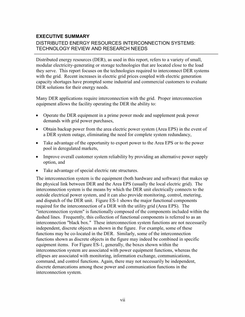
The interconnection system is the equipment (both hardware and software) that makes up the physical link between DER and the Area EPS (usually the local electric grid). The interconnection system is the means by which the DER unit electrically connects to the outside electrical power system, and it can also provide monitoring, control, metering, and dispatch of the DER unit. Figure ES-1 shows the major functional components required for the interconnection of a DER with the utility grid (Area EPS). The "interconnection system" is functionally composed of the components included within the dashed lines. Frequently, this collection of functional components is referred to as an interconnection "black box." These interconnection system functions are not necessarily independent, discrete objects as shown in the figure. For example, some of these functions may be co-located in the DER. Similarly, some of the interconnection functions shown as discrete objects in the figure may indeed be combined in specific equipment items. For Figure ES-1, generally, the boxes shown within the interconnection system are associated with power equipment functions, whereas the ellipses are associated with monitoring, information exchange, communications, command, and control functions. Again, there may not necessarily be independent, discrete demarcations among these power and communication functions in the interconnection system.
vii

Figure ES-1. Interconnection system functional schematic Interconnecting DER to the Area EPS involves system engineering, safety, and reliability considerations. A broad range of industry representatives has been participating in the development of a new standard for DER grid interconnection under the Standards Board of the Institute of Electrical and Electronic Engineers (IEEE). The IEEE Standard for Interconnecting Distributed Resources with Electric Power Systems, IEEE P1547, seeks to provide a uniform standard for interconnection of distributed resources with electric power systems. Requirements included in the standard relate to the performance, operation, testing, safety considerations, and maintenance of the interconnection. The development of IEEE P1547 was initiated in response to the changes in the environment for production and delivery of electricity and builds on prior IEEE recommended practices and guidelines developed for the application of distributed power sources to the Area EPS. To support this standard, users and manufacturers alike have been focusing on the development and availability of hardware and software that allow interconnections to occur smoothly, safely, and economically.
DER
Power Conversion
and/orConditioning
Local EPS
Protective
Relaying
Area EPS
Protective
Relaying
Interconnection System
TransferSwitch or
ParallelingSwitchgear
AC
Loads
Area Electric
Power System
(Grid)
Power
Distribution
Power Flow
Communication
Poin
t of C
omm
on C
oupl
ing
Meter
DER Monitoring
and Metering
Dispatch
and ControlDER Control
DC
Loads
This report is an outgrowth of the Department of Energy/National Renewable Energy Laboratory (DOE/NREL) DER Systems Interconnection Technologies Workshop on July 24, 2001, which reviewed the status of systems interconnection technology. Details of this conference are provided in Appendix D of this report. Further input into project research was obtained from DOE/NREL participation in the IEEE interconnection standards development process. This participation provided major insight into issues and suggestions for future activities. The research team leveraged on various other conference sessions over the past year that addressed this topic. In addition, a substantial library of DER equipment manufacturer catalogues was developed to characterize systems interconnection technology availability, performance, and costs. Contacts with manufacturers and suppliers helped build and supplement this library. DER developers
viii

and installers were contacted to determine how their equipment is typically used in interconnection system arrangements. Collectively, this information was used to meet the project objectives and to suggest directions for both research, development, and demonstration (RD&D) and future work. This report has several objectives. The first is to identify the current manufacturers and suppliers of interconnection equipment, focusing on emerging inverter-based technology. The second objective is to characterize the performance of the products supplied by these vendors. The third is to describe typical system configurations used in interconnection arrangements. The final objective is to identify areas that can benefit from technology development and demonstration. DER interconnection technology development is at a crossroads today. Electromechanical “discrete” relays, which dominated utility interconnection, protection, and coordination for years, are being supplanted by digitally based equipment, frequently with multi-function capability. Utilities themselves are gravitating toward digital, programmable relays. The rise of inverter technology as an alternative to rotating power conversion technology (i.e., induction and synchronous generators) has opened the door to integrated, inverter-based protective relaying. It is this trend that has created one of the major hurdles to streamlined interconnection, with utility engineers only recently beginning to reach a comfort level with digital circuitry. These digital circuit designs are often presented as proprietary, making the approval process challenging for the utility and the limited group of third-party certification organizations. A select set of interconnection system issues must be discussed and understood before framing the research, development, and demonstration needed to make interconnection less expensive, more reliable, and more automated. A list of interconnection system issues was identified at the DER Systems Interconnection Technologies Workshop. The results of this workshop and subsequent research for this report suggest that the four most dominant of these issues are: • Interconnection requirements from ISOs/RTOs and utilities, • Metering and monitoring requirements, • Role of automatic power system dispatch, and • Interconnection voltage and generator sizes. In addition to these key issues, four marketplace and regulatory issues that will affect interconnection RD&D must also be considered. These issues include the siting process, DER unit size, net metering, and the acceptance of type testing and pre-certification. Further, re-examination of many utility regulatory concepts such as “customer retention” rates, the public interest basis of standby and backup rates, and the right to interconnect will also be required. Consideration of these issues will help create the foundation for the development of an RD&D agenda designed to cost effectively improve the capabilities of interconnection packages and support their commercial deployment.
ix
This report also identifies a number of technical questions that need to be addressed as part of any interconnection RD&D activity. These questions were discussed during the July 2001 DOE/NREL Systems Interconnection Technologies Workshop and include: • What is the balance between cost and functionality in each component of the
interconnection system? • What should the interface standards be between DER and the interconnection
package, and should such standards be universal in a move toward plug-and-play capability?
• Should interconnection controls, meters, and monitoring functions be included as part
of the genset, or should they be located in a separate interconnection package? • What is the preferred approach: building a single, integrated interconnection package
or designing an assembly of subsets that can be engineered and combined at the DER site to perform customized interconnection operation?
• To what degree should flexibility be designed into an interconnection package such
that it can be scaled to different power levels or to multiple DER units? Over the past decade, many advanced interconnection technologies have been commercialized and are beginning to cost effectively address the concerns of utilities for reliability and safety while also providing value-added features for DER system owners and operators. However, more can be done, especially in lowering costs. One important step is the establishment of DOE’s DER Distribution and Interconnection R&D activities. Building on the July 2001 Systems Interconnection Technologies Workshop and the research completed as part of the development of this report, the following were identified as forming the core foundation of such an RD&D activity: 1. Work with industry to standardize interconnection architectures, 2. Simplify technical and design aspects of DER interconnection, 3. Enhance functionality to mitigate technical issues, 4. Establish the ability to enhance grid operability and intelligence, 5. Develop advanced communication and software platforms, 6. Address technical needs for future optimal use of DER interconnection and
integration technology needed to realize the full value of DER, and 7. Remove regulatory and institutional barriers. Creating the foundation for robust RD&D activities requires an active implementation strategy. Five elements of such a strategy stand out: 1. Public-private partnerships, 2. Technology roadmapping, 3. Testing and certification practices review,
x

4. Consensus standards development, and 5. Market information development. Interconnection technology research, development, and demonstration need to focus on technology development as well as technology implementation and demonstration. Interconnection technology is currently being used for many types of DER applications, and while RD&D efforts are making incremental improvements to the technology, these efforts are primarily improving interconnection system economics. However, many barriers remain, including nontechnical barriers that technology improvements can only partially address. Although the long-term goal is a plug-and-play interconnection system, this goal may primarily apply to smaller DER units with less complex interconnection schemes. Larger DER units typically have more stringent utility interconnection requirements as well as greater siting complexity. Thus, there may eventually be two distinct DER markets: one for type-tested, plug-and-play, residential and small commercial units and one for larger site-specific DER units. Regardless of these market categorizations, functional compatibility of interconnection technology architecture and components among different manufacturers and vendors would prove fruitful. Recent interconnection-related RD&D efforts highlight trends across both the private and public sectors. Along with the RD&D activities identified in this report, DOE/NREL needs to monitor other ongoing efforts, perhaps supporting coordinated research as part of any agreed-upon industry roadmap. Further, as standards and certification methods evolve during this review process, additional RD&D may be necessary to respond to any new requirements.
xi

xii
1 BACKGROUND AND INTRODUCTION
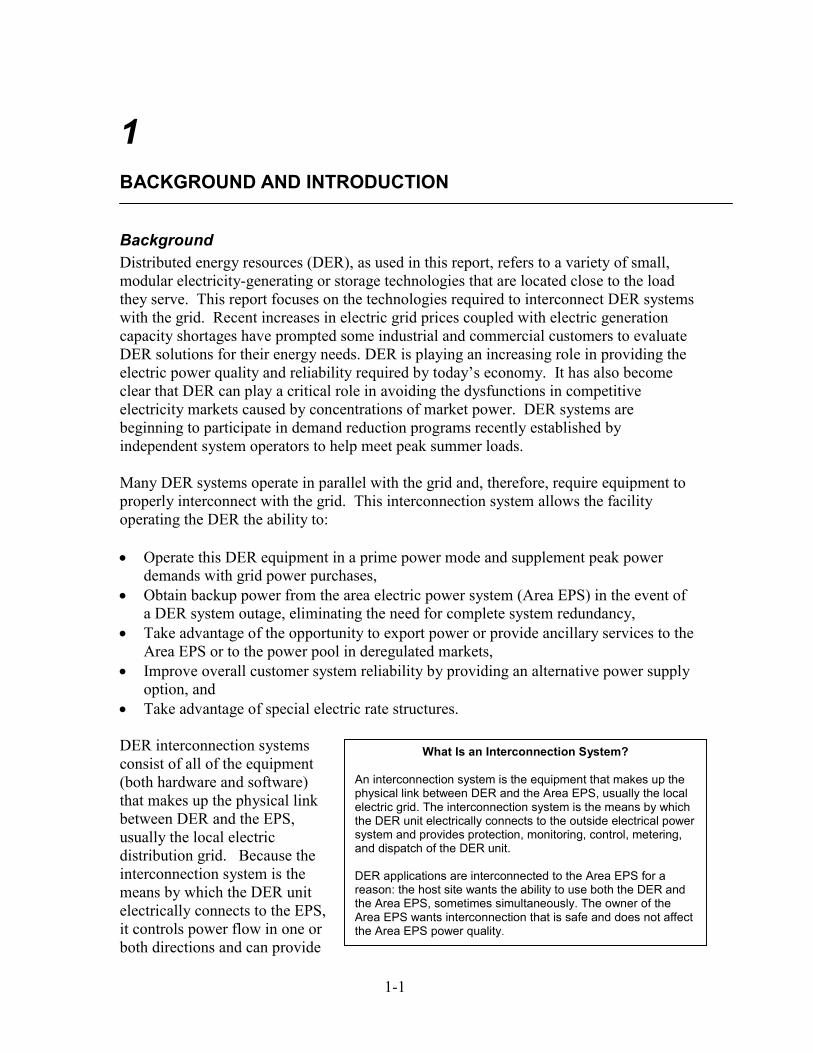
Background Distributed energy resources (DER), as used in this report, refers to a variety of small, modular electricity-generating or storage technologies that are located close to the load they serve. This report focuses on the technologies required to interconnect DER systems with the grid. Recent increases in electric grid prices coupled with electric generation capacity shortages have prompted some industrial and commercial customers to evaluate DER solutions for their energy needs. DER is playing an increasing role in providing the electric power quality and reliability required by today’s economy. It has also become clear that DER can play a critical role in avoiding the dysfunctions in competitive electricity markets caused by concentrations of market power. DER systems are beginning to participate in demand reduction programs recently established by independent system operators to help meet peak summer loads. Many DER systems operate in parallel with the grid and, therefore, require equipment to properly interconnect with the grid. This interconnection system allows the facility operating the DER the ability to: • Operate this DER equipment in a prime power mode and supplement peak power
demands with grid power purchases, • Obtain backup power from the area electric power system (Area EPS) in the event of
a DER system outage, eliminating the need for complete system redundancy, • Take advantage of the opportunity to export power or provide ancillary services to the
Area EPS or to the power pool in deregulated markets, • Improve overall customer system reliability by providing an alternative power supply
option, and
An interconphysical linelectric gridthe DER unsystem andand dispatc DER applicreason: thethe Area EPArea EPS wthe Area EP
• Take advantage of special electric rate structures. DER interconnection systems consist of all of the equipment (both hardware and software) that makes up the physical link between DER and the EPS, usually the local electric distribution grid. Because the interconnection system is the means by which the DER unit electrically connects to the EPS, it controls power flow in one or both directions and can provide
1-1
What Is an Interconnection System?
nection system is the equipment that makes up the k between DER and the Area EPS, usually the local . The interconnection system is the means by which it electrically connects to the outside electrical power provides protection, monitoring, control, metering, h of the DER unit.
ations are interconnected to the Area EPS for a host site wants the ability to use both the DER and S, sometimes simultaneously. The owner of the ants interconnection that is safe and does not affect S power quality.

autonomous and semi-autonomous functions supporting the operations of both the EPS and the DER facility (e.g., monitoring, control, metering, and dispatch of the DER unit). Figure 1-1 shows the major interconnection system functional components, with the distribution interconnection system being all the components within the dashed lines. Frequently, this collection of functional components is referred to as an interconnection "black box" even though all the components of the interconnection system may not physically be located in a single "box." These interconnection system functions are not necessarily independent, discrete objects as shown in the figure. For example, some of these functions may be co-located in the DER. Similarly, some of the interconnection functions shown as discrete objects in the figure may indeed be combined in specific equipment items. For Figure 1-1, generally, the boxes shown within the interconnection system are associated with power equipment functions, whereas the ellipses are associated with monitoring, information exchange, communications, command, and control functions. Again, there may not necessarily be independent, discrete demarcations among these power and communication functions in the interconnection system. As Figure 1-1 indicates, the interconnection system connects the DER and electrical energy storage not only to the EPS but also to the local load. It essentially integrates the DER into an energy system and provides a convenient means for interfacing the DER with building or enterprise energy management applications.
DER
Power Conversion
and/orConditioning
Local EPS
Protective
Relaying
Area EPS
Protective
Relaying
Interconnection System
TransferSwitch orParallelingSwitchgear
AC
Loads
Area Electric
Power System
(Grid)
Power
Distribution
Power Flow
Communication
Poin
t of C
omm
on C
oupl
ing
Meter
DER Monitoring
and Metering
Dispatch
and ControlDER Control
DC
Loads
Figure 1-1. Interconnection system functional schematic
1-2

Functions that may be included in whole or part in an interconnection system include: • Power conversion and conditioning
o Power conversion — If necessary, the power conversion functions change one type of electricity to another to make it EPS-compatible. For example, photovoltaics (PV), fuel cells, and battery storage produce DC power, and microturbines produce high-frequency AC.
o Power conditioning — This function provides the basic power quality to supply clean AC power to the load.
• Protection functions — The protection functions monitor the EPS point of common coupling and the input and output power of the DER and disconnect from the EPS when normal operating conditions do not exist per IEEE P1547 (see below). (Note there is both an opportunity and an intention in the next generation of P1547 to develop procedures for maintaining DER on the grid as support.) Examples of these functions are over- and under-voltage/frequency protective settings and anti-islanding schemes.
• Autonomous and semi-autonomous functions and operations
o DER and load controls — These control the status and operation of the DER and any local loads. The status can include on/off and power level commands. This function can also control hardware to disconnect from the EPS.
o Ancillary services — These services include voltage support, regulation, operating reserve, and backup supply.
o Communications — Communications allow the DER and local loads to interact and operate as part of a larger network of power systems or microgrids.
o Metering — The metering function allows billing for the DER energy production and local loads.
Interconnecting DER to the Area EPS involves system engineering, safety, and reliability considerations. A broad range of industry representatives have been participating in the development of a new standard for DER project grid interconnection under the Standards Board of the Institute of Electrical and Electronic Engineers (IEEE). The proposed IEEE Standard for Interconnecting Distributed Resources with Electric Power Systems, or IEEE P1547, seeks to provide a uniform standard for interconnection of distributed resources with electric power systems. Requirements included in the standard relate to the performance, operation, testing, safety considerations, and maintenance of the interconnection. The development of IEEE P1547 was initiated in response to changes in the environment for production and delivery of electricity and builds on prior IEEE recommended practices and guidelines developed for the application of distributed power sources to the Area EPS. To support this standard, users and manufacturers alike have been focusing on the development and availability of hardware and software that allows interconnections to occur smoothly, safely, and economically. For smaller DER, that is, 300 kW or less, interconnection can account for 30% or more of the installed system cost. RD&D on interconnection technology is important, then, not only for ensuring safe and reliable interconnection with the grid but also for significantly
1-3
reducing the installed cost of DER and increasing DER market share by providing the desired functionality within market-driven cost constraints required for commercially successful applications and business models.
Report Objectives and Approach This report was initiated with several objectives in mind. The first is to identify the current manufacturers and suppliers of interconnection equipment, focusing on emerging inverter-based technology. The second objective is to characterize the cost and performance of the products supplied by these vendors. The third is to describe typical system configurations used in interconnection arrangements. The final objective is to identify areas that can benefit from technology research, development, and demonstration (RD&D). This report is an outgrowth of the DOE/NREL DER Systems Interconnection Technologies Workshop on July 24, 2001, which reviewed the status of systems interconnection technology. Details of this conference are provided in Appendix D of this report. Further input into project research was obtained from various other conference sessions over the past year that addressed this topic. In addition, a substantial library of DER equipment manufacturer catalogues was developed to characterize systems interconnection technology availability, performance, and costs. Contacts with manufacturers and suppliers helped build and supplement this library. DER developers and installers were contacted to determine how their equipment is typically used in interconnection system arrangements. Collectively, this information was used to meet the report objectives and to suggest directions for both RD&D and future work.
DER Integration into the Electric Power System Understanding interconnection system market requirements is important to understanding the future role of and barriers to distributed power. The integrated power electronics technology that provides the foundation of the interconnection package is advancing quickly, with functional performance available today that was not possible even a year ago. Developments in digital design and advanced processors have boosted performance to impressive levels, and a convergence of software and hardware engineering is equipping state-of-the-art digital technology to provide protective relaying and coordination functions at lower cost and higher reliability. However, the market for these products remains mixed and is still forming, with hardware companies moving into the software business and software companies moving into the supply of interconnection hardware. The successful integration of any distributed power generation technology into the Area EPS on a dispatchable basis (or in a parallel operating mode at a minimum) is dependent on the capabilities, compatibility, and certification1 of the interconnection package. Exactly what is included by the manufacturer in the interconnection system package is a 1 Certification may be required to new standards such as IEEE 1547, when they are available, and standards such as UL 1741 (limited to PV inverters at this point), UL 2200 (e.g., booster compressors for microturbines), UL 1778, ANSI C84.1, and others.
1-4
key issue, one driven by code and market requirements. For example, currently, generator control system vendors offer a variety of products for the interconnection and control of small power generators. Some of these products offer a full range of capabilities for interconnection, but others offer a minimal set of capabilities so as not to price their product out of the market. A “seamless”2 transfer of power from the Area EPS to the DER genset or vice versa requires a number of special provisions in the interconnection package, but design flexibility must be built in. One practical approach is to include base capabilities with options for full grid integration. Accomplishing this seamless power transfer requires special control systems, paralleling switchgear, or automatic transfer switches and synchronization relays to be in place. Typical requirements for seamless transfer include the following: • An exciter control system for the generators; • A synchronizer for the reliable transfer of power between the generators and the grid; • An automatic transfer switch control; • Import/export control; • Protective relay functions, including over/under frequency and voltage at the
interconnection points, directional real and reactive power flow, and phase-to-phase current balance; and
• Remote communications capabilities to accommodate control from remote control centers (e.g., direct transfer trip, in some cases).
Ability of Current Interconnection Technology to Get the Job Done The collective difficulties of interconnection of DER with the Area EPS have often been held up as an example of a major barrier to DER market development. In reality, there are few (if any) technology obstacles to DER interconnection. The interconnection system increasingly provides a combination of functions including power conversion, performance monitoring, protective relaying, and generator control and protection. When “seamless” power transfer is the goal, the interconnection system complexity increases. This being said, interconnection technology cost and demonstrated (certifiable and verifiable) performance remain as issues. Successful integration of any distributed power generation technology into the Area EPS promises benefits to the customer as well as to the 2 Taking normal-duty backup generator systems as an example, there is a momentary interruption of power when the load is transferred from one source of power to an alternate source. This interruption occurs because of the typical “break-before-make” transfer switch design, commonly known as open transition. Although this momentary outage is acceptable for many installations, there are cases where even the briefest outage could be expensive to the customer in terms of lost data or production downtime. A “seamless” transfer of power supply can be accomplished by active control of the generator set, followed by a closed transition, “make-before-break” transfer operation. During this operation, the load is gradually transferred from one available source to the other source. Several manufacturers supply this type of closed transition switch.
1-5
electric power system. The capabilities, compatibility, and certification of the interconnection package will ultimately determine in part the longer-term penetration of DER into the market. Technical standards and local building codes will also have a major impact on DER penetration in the shorter term. One of the pressing challenges in the maturation of the DER market is the evolving role of special control systems, paralleling switchgear, and transfer switches, all representing the foundation of interconnection and protective relaying. To the extent that manufacturers and equipment designers can build design flexibility into the interconnection system, all market participants will be well served.
Trends in Interconnection Systems Technology Development DER interconnection technology development is at a crossroads today. Electromechanical “discrete” relays — which dominated utility interconnection, protection, and coordination for years — are being supplanted by digitally based equipment, frequently with multi-function capability. Utilities themselves are gravitating toward digital, programmable relays, raising the issues of field calibration and certification. The rise of inverter technology as an alternative to rotating power conversion technology (i.e., induction and synchronous generators) has opened the door to integrated, microprocessor-based protective relaying. It is this trend that has created one of the major hurdles to streamlined interconnection, with utility engineers only recently beginning to reach a comfort level with digital circuitry. These digital circuit designs are often presented as proprietary, which can be an obstacle to streamlined product approval. However, there is a group of third-party certification organizations available to support this process. There is also a trend to develop a modular universal interconnection technology. This idea would define a standard architecture for functions to be included in the interconnection system. These functions could include power conversion, power conditioning and quality, protection functions, DER (both generation and storage) and load controls, ancillary services, communications, and metering. The previous list of functions could then be included as needed in the interconnection systems in a modular software or hardware platform. The standard architecture would allow both DER manufacturers and end-users to easily integrate their power systems with the Area EPS.
Structure of the Report Chapters 2 through 5 review DER technology issues, DER commercial availability, DER application configurations, and DER interconnection issues that help indicate where future RD&D will be needed. Chapter 6 summarizes interconnection RD&D, including ongoing research and commercial development efforts while noting the relationship between technology development and both marketplace and regulatory changes and challenges. Suggestions are made for future RD&D efforts and for follow-on work. A series of appendices follow. Appendices A and B provide further details on interconnection technology attributes and interconnection codes and standards. Appendix C provides a comprehensive listing of manufacturers of components used in DER
1-6
interconnection as well as select pricing data. Appendix D summarizes the conclusions at the July 2001 DOE/NREL Systems Interconnection Technologies Workshop.
1-7

1-8
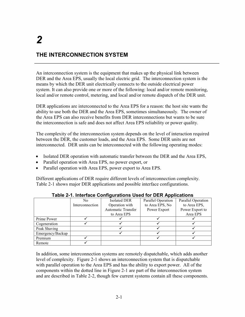
2 THE INTERCONNECTION SYSTEM An interconnection system is the equipment that makes up the physical link between DER and the Area EPS, usually the local electric grid. The interconnection system is the means by which the DER unit electrically connects to the outside electrical power system. It can also provide one or more of the following: local and/or remote monitoring, local and/or remote control, metering, and local and/or remote dispatch of the DER unit. DER applications are interconnected to the Area EPS for a reason: the host site wants the ability to use both the DER and the Area EPS, sometimes simultaneously. The owner of the Area EPS can also receive benefits from DER interconnections but wants to be sure the interconnection is safe and does not affect Area EPS reliability or power quality. The complexity of the interconnection system depends on the level of interaction required between the DER, the customer loads, and the Area EPS. Some DER units are not interconnected. DER units can be interconnected with the following operating modes: • Isolated DER operation with automatic transfer between the DER and the Area EPS, • Parallel operation with Area EPS, no power export, or • Parallel operation with Area EPS, power export to Area EPS. Different applications of DER require different levels of interconnection complexity. Table 2-1 shows major DER applications and possible interface configurations.
Table 2-1. Interface Configurations Used for DER Applications No
Interconnection Isolated DER
Operation with Automatic Transfer
to Area EPS
Parallel Operation to Area EPS, No
Power Export
Parallel Operation to Area EPS,
Power Export to Area EPS
Prime Power Cogeneration Peak Shaving Emergency/Backup Premium Remote In addition, some interconnection systems are remotely dispatchable, which adds another level of complexity. Figure 2-1 shows an interconnection system that is dispatchable with parallel operation to the Area EPS and has the ability to export power. All of the components within the dotted line in Figure 2-1 are part of the interconnection system and are described in Table 2-2, though few current systems contain all these components.
2-1

mm
DER
Power Conversion
and/orConditioning
Local EPS
Protective
Relaying
Area EPS
Protective
Relaying
Interconnection System
TransferSwitch orParallelingSwitchgear
AC
Loads
Area Electric
Power System
(Grid)
Power
Distribution
Power Flow
Communication
Poin
t of C
oon
Cou
plin
g
Meter
DER Monitoring
and Metering
Dispatch
and ControlDER Control
DC
Loads
Figure 2-1. Interconnection system functional schematic
2-2
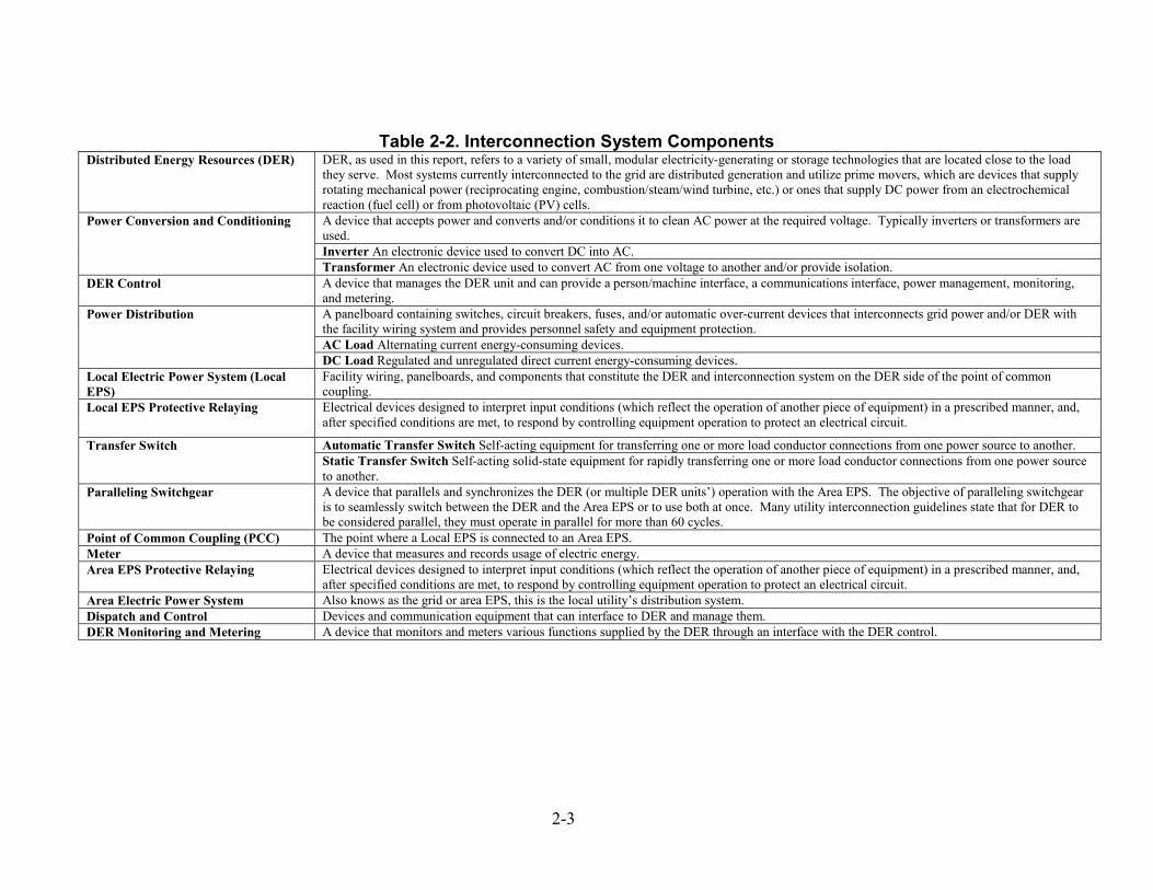
Table 2-2. Interconnection System Components Distributed Energy Resources (DER) DER, as used in this report, refers to a variety of small, modular electricity-generating or storage technologies that are located close to the load
they serve. Most systems currently interconnected to the grid are distributed generation and utilize prime movers, which are devices that supply rotating mechanical power (reciprocating engine, combustion/steam/wind turbine, etc.) or ones that supply DC power from an electrochemical reaction (fuel cell) or from photovoltaic (PV) cells. A device that accepts power and converts and/or conditions it to clean AC power at the required voltage. Typically inverters or transformers are used. Inverter An electronic device used to convert DC into AC.
Power Conversion and Conditioning
Transformer An electronic device used to convert AC from one voltage to another and/or provide isolation. DER Control A device that manages the DER unit and can provide a person/machine interface, a communications interface, power management, monitoring,
and metering. A panelboard containing switches, circuit breakers, fuses, and/or automatic over-current devices that interconnects grid power and/or DER with the facility wiring system and provides personnel safety and equipment protection. AC Load Alternating current energy-consuming devices.
Power Distribution
DC Load Regulated and unregulated direct current energy-consuming devices. Local Electric Power System (Local EPS)
Facility wiring, panelboards, and components that constitute the DER and interconnection system on the DER side of the point of common coupling.
Local EPS Protective Relaying Electrical devices designed to interpret input conditions (which reflect the operation of another piece of equipment) in a prescribed manner, and, after specified conditions are met, to respond by controlling equipment operation to protect an electrical circuit.
Automatic Transfer Switch Self-acting equipment for transferring one or more load conductor connections from one power source to another. Transfer Switch Static Transfer Switch Self-acting solid-state equipment for rapidly transferring one or more load conductor connections from one power source to another.
Paralleling Switchgear A device that parallels and synchronizes the DER (or multiple DER units’) operation with the Area EPS. The objective of paralleling switchgear is to seamlessly switch between the DER and the Area EPS or to use both at once. Many utility interconnection guidelines state that for DER to be considered parallel, they must operate in parallel for more than 60 cycles.
Point of Common Coupling (PCC) The point where a Local EPS is connected to an Area EPS. Meter A device that measures and records usage of electric energy. Area EPS Protective Relaying Electrical devices designed to interpret input conditions (which reflect the operation of another piece of equipment) in a prescribed manner, and,
after specified conditions are met, to respond by controlling equipment operation to protect an electrical circuit. Area Electric Power System Also knows as the grid or area EPS, this is the local utility’s distribution system. Dispatch and Control Devices and communication equipment that can interface to DER and manage them. DER Monitoring and Metering A device that monitors and meters various functions supplied by the DER through an interface with the DER control.
2-3

The interconnection system (within the dotted line) is designed to interact with and serve as the communication and control highway between the DER, the Area EPS, and the customer loads. These interactions can occur quickly (e.g., on the order of milliseconds or cycles) in the case of voltage and frequency regulation, reactive power supply, and fault protection and coordination or more slowly (e.g., on the order of seconds or minutes) in the case of power export or peak shaving. A detailed description of these interconnection system components is provided in Chapter 3.
Typical Interconnection Systems and Configurations The following questions can be used to differentiate DER interconnection systems: 1. Does the system use an inverter? 2. Does the system have a parallel connection to the Area EPS? 3. Can the system export power to the Area EPS? 4. Is the system remotely dispatchable? Some observations follow based on how these questions are answered. 1. Inverter-based systems are used in fuel cell, photovoltaic (PV), and microturbine applications. Fuel cells and PVs generate DC power, and the inverter converts the DC power to AC power. Most microturbines generate very high frequency AC power. This is converted to DC and then to 50 Hz or 60 Hz AC. Inverter-based systems designed for parallel operation with the Area EPS have built-in protective relays and perform the basic requirements of the interconnection system. 2. Systems that run in parallel with the Area EPS have an interconnection system that connects the DER and the Area EPS to the same common bus in synchronization. These systems are used for some DER applications, including peak shaving, prime power, cogeneration, and some emergency/standby power applications. 3. Exporting power to the Area EPS requires an interconnection system that parallels with the grid and has adequate protective relays to ensure both systems can run together safely. 4. Interconnection systems can be configured to be remotely dispatchable so that utilities, aggregators, Distcos, or ISOs/RTOs can start up and stop operation of the DER remotely on a real-time basis. This requires additional metering, monitoring, and control equipment. The DER application being served or the type of DER technology being used can also classify interconnection systems. An interconnection system for emergency power is designed and configured very differently from a premium power installation even if, for example, both use reciprocating engines as their DER technology. For a peak shaving
2-4
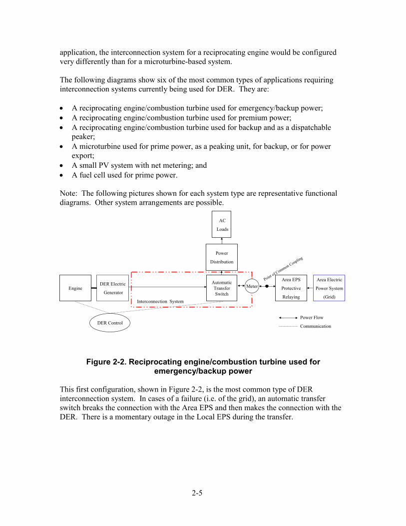
application, the interconnection system for a reciprocating engine would be configured very differently than for a microturbine-based system. The following diagrams show six of the most common types of applications requiring interconnection systems currently being used for DER. They are: • A reciprocating engine/combustion turbine used for emergency/backup power; • A reciprocating engine/combustion turbine used for premium power; • A reciprocating engine/combustion turbine used for backup and as a dispatchable
peaker; • A microturbine used for prime power, as a peaking unit, for backup, or for power
export; • A small PV system with net metering; and • A fuel cell used for prime power. Note: The following pictures shown for each system type are representative functional diagrams. Other system arrangements are possible.
EngineDER Electric
Generator
Area EPS
Protective
RelayingInterconnection System
AutomaticTransferSwitch
AC
Loads
Area Electric
Power System
(Grid)
Power
Distribution
Power Flow
Communication
Point of Common Coupling
Meter
DER Control
Figure 2-2. Reciprocating engine/combustion turbine used for
emergency/backup power This first configuration, shown in Figure 2-2, is the most common type of DER interconnection system. In cases of a failure (i.e. of the grid), an automatic transfer switch breaks the connection with the Area EPS and then makes the connection with the DER. There is a momentary outage in the Local EPS during the transfer.
2-5
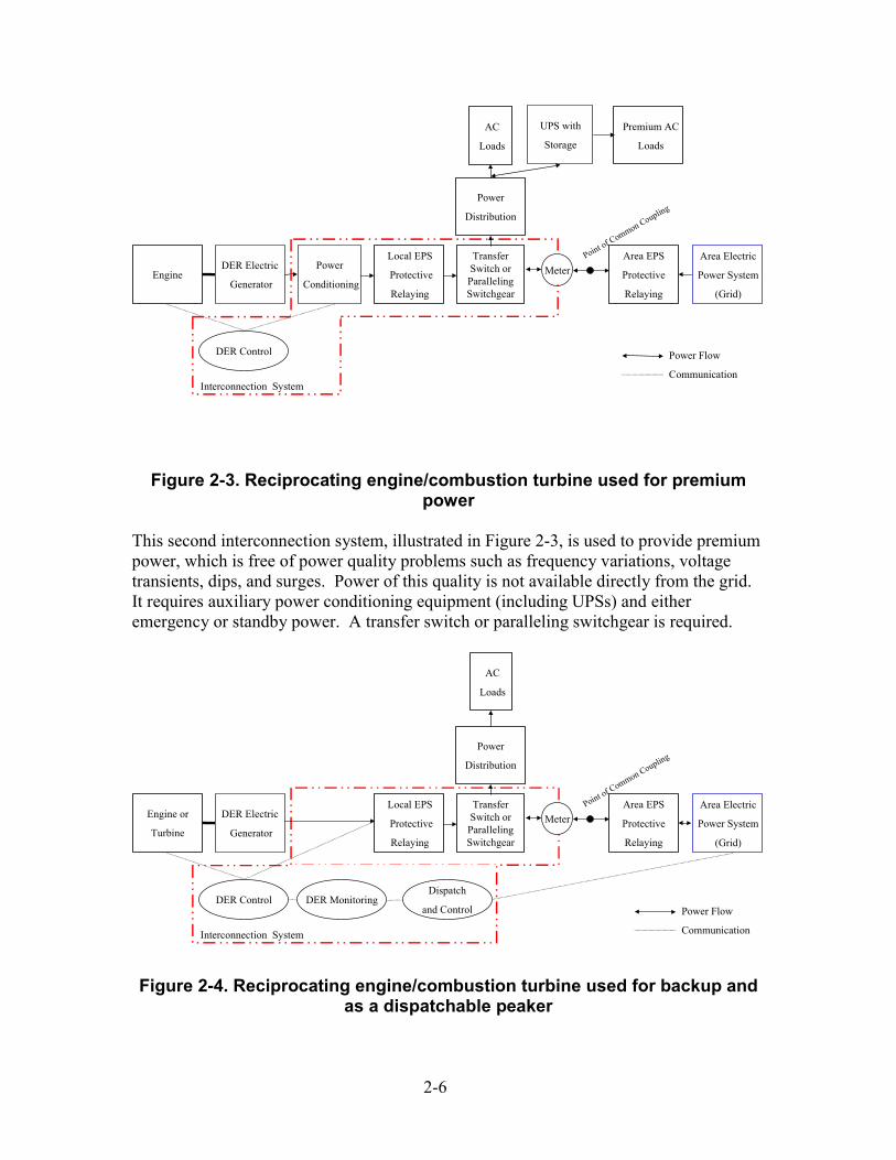
Premium AC
Loads
Point of Common Coupling
MeterEngineDER Electric
Generator
Power
Conditioning
Local EPS
Protective
Relaying
Area EPS
Protective
Relaying
Interconnection System
TransferSwitch or
ParallelingSwitchgear
AC
Loads
Area Electric
Power System
(Grid)
UPS with
Storage
Power
Distribution
Power Flow
Communication
DER Control
Figure 2-3. Reciprocating engine/combustion turbine used for premium
power This second interconnection system, illustrated in Figure 2-3, is used to provide premium power, which is free of power quality problems such as frequency variations, voltage transients, dips, and surges. Power of this quality is not available directly from the grid. It requires auxiliary power conditioning equipment (including UPSs) and either emergency or standby power. A transfer switch or paralleling switchgear is required.
Engine or
Turbine
DER Electric
Generator
Local EPS
Protective
Relaying
Area EPS
Protective
Relaying
Interconnection System
TransferSwitch or
ParallelingSwitchgear
AC
Loads
Area Electric
Power System
(Grid)
Power
Distribution
Power Flow
Communication
DER MonitoringDispatch
and ControlDER Control
Point of Common Coupling
Meter
Figure 2-4. Reciprocating engine/combustion turbine used for backup and
as a dispatchable peaker
2-6

Some interconnection equipment manufacturers have designed systems in which backup systems can be converted to allow them to be dispatchable. These systems, like that shown in Figure 2-4, allow the DER customer or the Area EPS the ability to run the unit on demand. Currently, most utility dispatchable systems use a local utility remote terminal unit (RTU) to communicate to the DER. Typically, a dry set of contacts is used to initiate system transfers to DER. The DER can be operated in a manner to assume all customer load only or customer load and export excess power back to the utility.
Power Electronics (Inverter): Power Conversion and Conditioning Synchronization for Paralleling Operation Local EPS and Area EPS Protective Relaying DER Control and Monitoring Dispatch and Control
MicroturbineDER Electric
Generator
Interconnection System
AC
Loads
Area Electric
Power System
(Grid)
Power
Distribution
Power Flow
Point of Common Coupling
Meter
DC
Loads
Figure 2-5. Microturbine used for prime power, as a peaking unit, for
backup, or for power export Most microturbine interconnection systems use inverter-based interconnection systems (Figure 2-5). These units use software algorithms to provide functions such as protective relaying.
PV Modules
Power Electronics (Inverter): Power Conversion and Conditioning Undervoltage /Overvoltage Under Frequency/Overfrequency Overcurrent Synchronization Ground Fault Overvoltage Active-Anti Island Function
Interconnection System
AC
Loads
Power
Distribution
Point of Common Coupling
Net Meter
DC
Loads
Power Flow
Area Electric
Power System
(Grid)
Figure 2-6. Small PV system with net metering
Small photovoltaic systems use interver-based interconnection systems, and some state PUCs require utilities to allow for net metering systems (Figure 2-6).
2-7

FuelCell
Power Electronics (Inverter): Power Conversion and Conditioning Synchronization for Paralleling Operation Local EPS and Area EPS Protective Relaying DER Control and Monitoring
Interconnection System
AC
Loads
Area Electric
Power System
(Grid)
Power
Distribution
Power Flow
Point of Common Coupling
Meter
DC
Loads
Figure 2-7. Fuel cell used for prime power
Most fuel cells are used to produce premium power and use inverter-based interconnection systems (Figure 2-7). These units use software algorithms to provide functions such as protective relaying.
Interconnection Technology Attributes Interconnection technologies have a number of attributes that affect how the DER units operate and how they are integrated both into a Local EPS and with an Area EPS. Eighteen of the attributes are described below in Table 2-2. These attributes influence the design, commercialization, and use of DER interconnection systems and the components that must be built into an interconnection system. As each utility or Distco has often had its own requirements for addressing these 18 technical attributes, interconnection systems have not been pre-certified for inexpensive mass installation. Thus, there has been a tendency to design, license, install, test, and operate each DER system uniquely to meet the myriad interconnection codes and standards set for interconnection equipment. Future RD&D needs are largely driven by this situation. Many of these attribute descriptions were taken from the Application Guide for Distributed Generation Interconnection: The NRECA Guide to IEEE 1547 written by Resource Dynamics Corporation. For a more thorough discussion of these attributes, see Appendix A of this report.
Table 2-2. Interconnection Technology Attributes Voltage Regulation
Voltage regulation is the term used to describe the process and equipment used by an Area EPS operator to maintain approximately constant voltage to users despite the normal variations in voltage caused by changing loads. The effect of DER on Area EPS voltage regulation can cause changes in power system voltage by: (1) the generator offsetting the load current and (2) the DER attempting to regulate voltage. Most types of DER generators and utility-interactive inverters strive to maintain an approximately constant power factor at any voltage within their rating; accordingly, the primary impact of DER on voltage regulation is the result of the DER offsetting the load current.
2-8

Table 2-2. Interconnection Technology Attributes Integration with Area Electric Power System Grounding
A grounding system consists of all interconnected grounding connections in a specific power system and is defined by its isolation or lack of isolation from adjacent grounding systems. The isolation is provided by transformer primary and secondary windings that are coupled only by magnetic means. The interconnection of the DER with the Area EPS needs to be coordinated with the neutral grounding method in use on the Area EPS. Use of a DER source that does not appear as an effectively grounded source connected to such systems may lead to over-voltages during line to ground faults on the Area EPS. This condition is especially dangerous if a generation island develops and continues to serve a group of customers on a faulted distribution system.
Synchronization To synchronize the DER with the Area EPS, the output of the DER and the input of the Area EPS must have the same voltage magnitude, frequency, and phase angle. With polyphase machines, the direction of phase rotation must also be the same. This is typically checked at the time of installation, the phases being connected to the switches such that the phase rotation will always be correct. IEEE P1547 requires demonstration that the interconnection system, at each point where synchronization is required, should not connect the associated DER unit (or aggregation of DER units) to an Area EPS except when all of the appropriate conditions are satisfied. If these conditions are met, the DER will synchronize with the Area EPS with any voltage fluctuation limited to ± 5% of nominal voltage.
Power Conversion Technology
Electric energy generated by a DER may be directly connected to an Area EPS or indirectly connected through a static power converter. Directly connected synchronous generators must run at a synchronous shaft speed so power output is electrically in synchronism with the Area EPS. Directly connected induction generators are asynchronous (not in synchronism). They operate at a rotational speed that varies with the prime mover and is slightly higher than that required by a synchronous generator. Indirect connection through a static power converter allows the electric energy source to operate independently of the Area EPS voltage and frequency. Interconnecting any of these energy sources to the Area EPS depends on the type of generation, its characteristics, its capacity, and the type of Area EPS service available at the site.
Induction
An induction generator is an asynchronous machine that requires an external source to provide the magnetizing (reactive) current necessary to establish the magnetic field across the air gap between the generator rotor and stator. In certain instances, an induction generator may continue to generate electric power after the Area EPS source is removed. This phenomenon, known as self–excitation, can occur whenever there is sufficient capacitance in parallel with the induction generator to provide the necessary excitation and when the connected load has certain resistive characteristics. Induction generators operate at a rotational speed determined by the prime mover and that is slightly higher than that required for exact synchronism. Below synchronous speed, these machines operate as induction motors and thus become a load on the Area EPS. An induction generator, regardless of load, draws reactive power from the Area EPS and may adversely affect the voltage regulation on the circuit to which it is connected. The induction generator is then “sucking vars” from the system; it is important to consider the addition of capacitors to improve power factor and reduce reactive power draw.
2-9
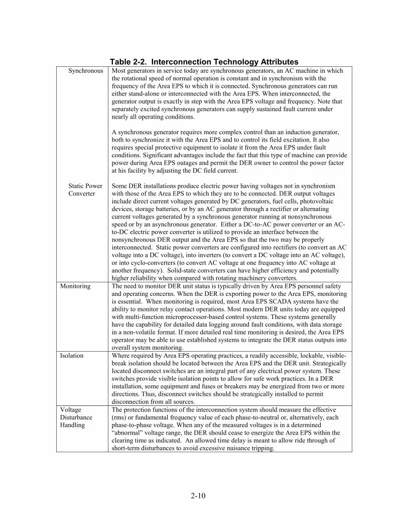
Table 2-2. Interconnection Technology Attributes
Synchronous Most generators in service today are synchronous generators, an AC machine in which the rotational speed of normal operation is constant and in synchronism with the frequency of the Area EPS to which it is connected. Synchronous generators can run either stand-alone or interconnected with the Area EPS. When interconnected, the generator output is exactly in step with the Area EPS voltage and frequency. Note that separately excited synchronous generators can supply sustained fault current under nearly all operating conditions. A synchronous generator requires more complex control than an induction generator, both to synchronize it with the Area EPS and to control its field excitation. It also requires special protective equipment to isolate it from the Area EPS under fault conditions. Significant advantages include the fact that this type of machine can provide power during Area EPS outages and permit the DER owner to control the power factor at his facility by adjusting the DC field current.
Static Power Converter
Some DER installations produce electric power having voltages not in synchronism with those of the Area EPS to which they are to be connected. DER output voltages include direct current voltages generated by DC generators, fuel cells, photovoltaic devices, storage batteries, or by an AC generator through a rectifier or alternating current voltages generated by a synchronous generator running at nonsynchronous speed or by an asynchronous generator. Either a DC-to-AC power converter or an AC-to-DC electric power converter is utilized to provide an interface between the nonsynchronous DER output and the Area EPS so that the two may be properly interconnected. Static power converters are configured into rectifiers (to convert an AC voltage into a DC voltage), into inverters (to convert a DC voltage into an AC voltage), or into cyclo-converters (to convert AC voltage at one frequency into AC voltage at another frequency). Solid-state converters can have higher efficiency and potentially higher reliability when compared with rotating machinery converters.
Monitoring The need to monitor DER unit status is typically driven by Area EPS personnel safety and operating concerns. When the DER is exporting power to the Area EPS, monitoring is essential. When monitoring is required, most Area EPS SCADA systems have the ability to monitor relay contact operations. Most modern DER units today are equipped with multi-function microprocessor-based control systems. These systems generally have the capability for detailed data logging around fault conditions, with data storage in a non-volatile format. If more detailed real time monitoring is desired, the Area EPS operator may be able to use established systems to integrate the DER status outputs into overall system monitoring.
Isolation Where required by Area EPS operating practices, a readily accessible, lockable, visible-break isolation should be located between the Area EPS and the DER unit. Strategically located disconnect switches are an integral part of any electrical power system. These switches provide visible isolation points to allow for safe work practices. In a DER installation, some equipment and fuses or breakers may be energized from two or more directions. Thus, disconnect switches should be strategically installed to permit disconnection from all sources.
Voltage Disturbance Handling
The protection functions of the interconnection system should measure the effective (rms) or fundamental frequency value of each phase-to-neutral or, alternatively, each phase-to-phase voltage. When any of the measured voltages is in a determined “abnormal” voltage range, the DER should cease to energize the Area EPS within the clearing time as indicated. An allowed time delay is meant to allow ride through of short-term disturbances to avoid excessive nuisance tripping.
2-10
Table 2-2. Interconnection Technology Attributes Frequency Disturbance Handling
Under and over frequency protective functions are among the most important means of preventing the establishment of a DER island. Maintaining stable Area EPS operations depends on the DER clearing off line whenever Area EPS voltage and/or frequency are out of agreed-upon operating ranges. It is desirable for these protections to operate promptly, but nuisance trips need to be avoided.
Disconnection for Faults
Clearing times for short circuits on distribution circuits vary widely, depending on magnitude and the type of protective equipment installed. In general, on most circuits, large current faults will be cleared in 0.1 second or less. Low current faults frequently require clearing times of 5-10 seconds or more, and some very low level but potentially dangerous ground faults may not be cleared at all, except by manual disconnection of the circuit. The DER system should be designed with adequate protection and control equipment, including an interrupting device that will disconnect the generator if the Area EPS that connects to the DER system or the DER system itself experiences a fault. The DER system should have an interrupting device with sufficient capacity to interrupt maximum available fault current at its location. A failure of the DER system's protection and control equipment, including loss of control power, should automatically open the disconnecting device, thus disconnecting the DER system from the Area EPS.
Loss of Synchronism
A synchronous generator typically employs three-phase stator winding, which, when connected to the Area EPS three-phase source, creates a rotating magnetic field inside the stator and cutting through the rotor. The rotor is excited with a DC current that creates a fixed field. The rotor, if spun around at the speed of the stator field, will “lock” its fixed field into synchronism with the rotating stator field. An island is formed when a relay-initiated trip causes a section of the Area EPS containing DER to become separated from the main section of the Area EPS. The main section of the Area EPS and the island will then operate out of synchronism. If an isolation is reclosed between the main section of the Area EPS and the island, a voltage and current transient will occur while the island is brought into synchronism with the remainder of the Area EPS. The severity of this transient will depend upon the voltage phase-angle separation magnitude across the isolation when the reclosing event occurs. This is sometimes not required for the connection of a DER at the Area EPS distribution level and sometimes not required for DER rated 10 MWA and less.
Generator Out-of-Synchronism Operations
Synchronous Generator: Operation of a generator out-of-synchronism with excitation places a severe type of duty on the DER unit. Out-of-synchronism must be identified promptly and the condition remedied, possibly through removal of the DER from interconnection with the Area EPS. Induction Generator: Because induction generators cannot generally supply sustained fault current or, in many instances, supply isolated load, they do not normally require the same level of protective relays as a synchronous machine. When self-excitation is possible, relaying similar to that installed for a synchronous generator will be required. This is sometimes not required for the connection of a DER at the Area EPS distribution level and sometimes not required for DER rated 10 MWA and less.
Feeder Reclosing Coordination
Seventy percent to ninety-five percent of line faults are temporary if the faulted circuit is quickly disconnected from the system. Modern distribution feeders reclose (re-energize the feeder) automatically after a trip resulting from a feeder fault. This allows immediate testing of a previously faulted portion of the feeder and makes it possible to restore service if the fault is no longer present. The DER unit must be coordinated with the reclosing strategy of the isolations within the Area EPS to prevent possible damage to Area EPS equipment and to equipment connected to the Area EPS other than the DER.
2-11

Table 2-2. Interconnection Technology Attributes DC Injection DC injection produces a DC offset in the basic power system waveform. This offset
increases the peak voltage of one half of the power system waveform (and decreases the peak voltage in the other half of the waveform). The increased half-cycle voltage has the potential to increase saturation of magnetic components, such as cores of distribution transformers. This saturation, in turn, causes increased power system distortion. There is a concern that transformerless inverters may inject sufficient current into distribution circuits to cause distribution transformer saturation. New PWM inverter types are so well controlled that DC injection is not an issue.
Voltage Flicker Flicker is a relatively old subject that has recently gained considerable attention because of the increased awareness of issues concerning power quality. Flicker problems can result from basic generator starting conditions or output fluctuations. Identifying and solving these types of flicker problems when they arise can be difficult, and the engineer must have a keen understanding of the interactions between the DER unit and the Area EPS.
Harmonics Harmonic distortion is a form of electrical noise; harmonics are electrical signals at multiple frequencies of the power line frequency. Harmonic currents cause transformers to overheat, in turn overheating neutral conductors that may cause erroneous tripping of circuit breakers and other equipment malfunctions. The voltage distortion created by nonlinear loads may create voltage distortion beyond the premise’s wiring system, through the Area EPS system, to another user. The type and severity of harmonic contributions from a DER unit will depend on the power converter technology, its filtering, and its interconnection configuration. Most new inverter designs are based on newer solid-state technology that uses pulse width modulation to generate the injected alternating current. In general, harmonic contributions from DER units are less an issue than problems associated with other equipment on the distribution system.
Immunity Protection
The influence of electromagnetic interference (EMI) should not result in a change in state or misoperation of the interconnection system. The use of hand-held transceivers (walkie-talkies) and cell phones has increased dramatically over the past few years. When operated in close proximity to a static protective relay, these transceivers will produce local, high field-strength electromagnetic radiation that may affect protective relay performance. This interaction has driven the need for a standard on radiated interference and withstand capability for static protective relays.
Surge Capability
The interconnection system should have the capability to withstand voltage and current surges in accordance with the environments defined in IEEE/ANSI C62.41 or IEEE C37.90.1 as appropriate. There is no independent, meaningful, and self-contained description of a surge in terms of energy alone. The energy delivered to the end-equipment is the significant factor, but it depends on the distribution between the source and the load (equipment or surge-diverting protective device or both). Transient surge voltages occurring in AC power circuits can be the cause of operational upset or product failure in industrial and residential systems and equipment
Islanding For an unintentional island in which the DER and a portion of the Area EPS remain energized through the PCC, the DER should cease to energize the Area EPS within 2 seconds of the formation of an island. In most cases, it is not desirable for a DER to island with any part of the Area EPS on an unplanned basis; this can lead to safety and power quality problems. DER islanding can expose utility workers to circuits that otherwise would be de-energized (and the workers believe to be de-energized). This situation can pose a threat to the public as well. Service restoration can also be delayed as line crews seek to ensure that DER islanding is not a problem.
2-12
Interconnection Systems Functions and Functionality
The interconnection technology attributes described above reflect the specific requirements for protective relaying and coordination for integration with utility operations. Additionally, the interconnection system can interact with building loads, utility revenue metering, utility or ISO/RTO dispatch, and overall coordination of distribution system coordinated protection and control. As shown in Figure 2-8, the following groups of increasingly complex and integrated functions can be addressed by the interconnection system: (1) local protection, (2) local control, (3) coordinated protection and control, (4) commerce functions, and (5) enterprise energy control.
Coordinated Protection and Control
advanced anti- islandingadvanced voltage regulation blackstart restoration reconfiguration schedule/dispatch
Local Control voltage regulationfrequency regulationsynchronizing controllocal eps pf controlpower qualityfunctions
Local Protection (P1547 Functions)
o/v, u/v u/f, o/f o/c sync check dead circuit check fault detection anti-islanding
Enterprise Energy Control
building energy(heat/cooling)process energyload management
Commerce Functions (Metering)
power (time) reactive power (time) energy (time) ancillary services
• spinning reserve • voltage support
real-time/spot price other market signals power quality metering
Figure 2-8. Interconnection system functionality (Based on presentation by GE at Distributed Power Program
2002 Annual Review)
2-13
Interconnection Codes and Standards The interconnection of DER to the Area EPS is regulated by codes and standards put in place to address safety and power quality issues. These codes and standards set requirements for DER interconnection equipment manufacture, installation, and operation. Three organizations are major players in the DER interconnection codes and standards arena:
• The Institute of Electrical and Electronics Engineers (IEEE), • The National Fire Protection Association (NFPA), and • Underwriters Laboratories (UL).
Some state public utility commissions (PUCs) have issued DER interconnection manuals, requirements, or guidelines that contain codes and standards for interconnection that apply to any DER installation in the state connected to the grid. In addition, local electric utilities and Distcos (collectively, organizations that own and operate distribution and/or transmission systems) have interconnection standards for non-utility owned generation with requirements for interconnection, operation, and metering. Also, many locations have county or city regulations, such as a permitting process or building codes that may place restrictions or requirements on interconnected DER systems. Because DER installations are becoming more prevalent, there has been a push for a national standard for DER interconnection. IEEE is in the process of developing IEEE P1547 – Standard for Distributed Resources Interconnected with Electric Power Systems. This standard will define the minimum functional technical requirements that are universally needed to ensure a technically sound interconnection. The standard provides uniform criteria and requirements relevant to the performance, operation, testing, safety, and maintenance of the interconnection equipment. The standard is currently unapproved and under revision. Once IEEE P1547 is finalized and approved, it will likely be adopted by most state PUCs, Distcos, and electric utilities (although electric utilities are expected to have additional codes and standards because of each distribution system’s particular design and layout and may have different requirements depending on where the DER is located in the distribution system). In the meantime, DER interconnection must conform to the local PUC and electric utility or Distco requirements, which reference national codes and standards issued by organizations such as the NFPA, IEEE, and UL.
Additional information about interconnection codes and standards can be found in Appendix B.
2-14
3 INTERCONNECTION SYSTEM COMPONENTS The successful integration of any distributed power generation technology into the Area EPS on a dispatchable basis (or in a parallel operating mode at a minimum) depends on what is installed in the interconnection system. The choice of interconnection system components, in turn, is driven by the market requirements, technical attributes, codes, and standards discussed earlier in this report.
Current generator control system vendors offer a variety of products for the interconnection and control of small power generators. Some of these products offer a full range of capabilities for interconnection, but others offer a minimal set of capabilities so as not to price their product out of the market. A “seamless” transfer of power from the Area EPS to the DER prime mover or vice versa requires a number of special provisions in the interconnection package, but design flexibility must be built in. Accomplishing this necessitates the use of a variety of interconnection equipment.
Figure 3-1. Detroit Diesel DER prime mover
Interconnection System Components Any division of the component parts used in interconnection is somewhat arbitrary because components may be engineered, assembled, and sold in many different configurations. Nonetheless, as depicted in Figure 2-1, it is useful to categorize equipment into seven groups by the functions they perform: • Transfer switches; • Paralleling switchgear; • Dispatch, communication, and control; • DER controls; • Power conversion (including inverters); • Metering and monitoring; and • Relays and protective relaying. Each of these seven categories is defined below with examples provided to illustrate typical equipment included in the category. Figures are shown for illustrative purposes only and are not product endorsements by DOE.
3-1
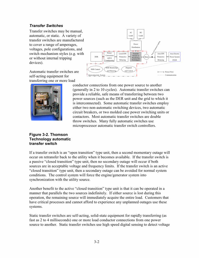
3-2
Transfer Switches Transfer switches may be manual, automatic, or static. A variety of transfer switches are manufactured to cover a range of amperages, voltages, pole configurations, and switch mechanism styles (e.g. with or without internal tripping devices). Automatic transfer switches are self-acting equipment for transferring one or more load
conductor connections from one power source to another (generally in 2 to 10 cycles). Automatic transfer switches can provide a reliable, safe means of transferring between two power sources (such as the DER unit and the grid to which it is interconnected). Some automatic transfer switches employ either two non-automatic switching devices, two automatic circuit breakers, or two molded case power switching units or contactors. Most automatic transfer switches are double throw switches. Many fully automatic switches use microprocessor automatic transfer switch controllers.
Figure 3-2. Thomson Technology automatic transfer switch If a transfer switch is an “open transition” type unit, then a second momentary outage will occur on retransfer back to the utility when it becomes available. If the transfer switch is a passive “closed transition” type unit, then no secondary outage will occur if both sources are in acceptable voltage and frequency limits. If the transfer switch is an active “closed transition” type unit, then a secondary outage can be avoided for normal system conditions. The control system will force the engine/generator system into synchronization with the utility source. Another benefit to the active “closed transition” type unit is that it can be operated in a manner that parallels the two sources indefinitely. If either source is lost during this operation, the remaining source will immediately acquire the entire load. Customers that have critical processes and cannot afford to experience any unplanned outages use these systems. Static transfer switches are self-acting, solid-state equipment for rapidly transferring (as fast as 2 to 4 milliseconds) one or more load conductor connections from one power source to another. Static transfer switches use high speed digital sensing to detect voltage
DER
Power Conversion
and/orConditioning
Local EPS
Protective
Relaying
Area EPS
Protective
Relaying
Interconnection System
TransferSwitch orParallelingSwitchgear
AC
Loads
Area Electric
Power System
(Grid)
Power
Distribution
Power Flow
Communication
Poin
t of C
omm
on C
oupl
ing
Meter
DER Monitoring
and Metering
Dispatch
and ControlDER Control
DC
Loads
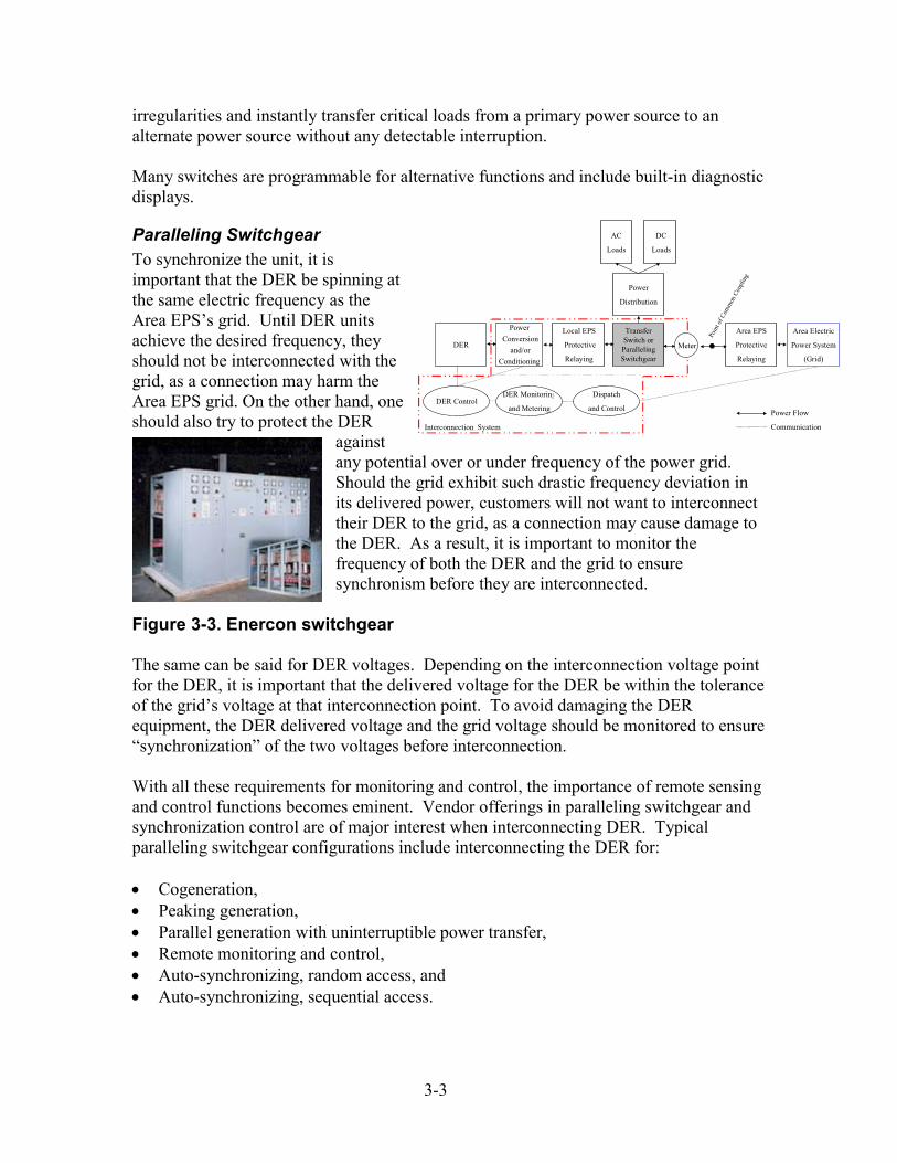
3-3
irregularities and instantly transfer critical loads from a primary power source to an alternate power source without any detectable interruption. Many switches are programmable for alternative functions and include built-in diagnostic displays.
Paralleling Switchgear To synchronize the unit, it is important that the DER be spinning at the same electric frequency as the Area EPS’s grid. Until DER units achieve the desired frequency, they should not be interconnected with the grid, as a connection may harm the Area EPS grid. On the other hand, one should also try to protect the DER
against any potential over or under frequency of the power grid. Should the grid exhibit such drastic frequency deviation in its delivered power, customers will not want to interconnect their DER to the grid, as a connection may cause damage to the DER. As a result, it is important to monitor the frequency of both the DER and the grid to ensure synchronism before they are interconnected.
Figure 3-3. Enercon switchgear
DER
Power Conversion
and/orConditioning
Local EPS
Protective
Relaying
Area EPS
Protective
Relaying
Interconnection System
TransferSwitch orParallelingSwitchgear
AC
Loads
Area Electric
Power System
(Grid)
Power
Distribution
Power Flow
Communication
Poin
t of C
omm
on C
oupl
ing
Meter
DER Monitoring
and Metering
Dispatch
and ControlDER Control
DC
Loads
The same can be said for DER voltages. Depending on the interconnection voltage point for the DER, it is important that the delivered voltage for the DER be within the tolerance of the grid’s voltage at that interconnection point. To avoid damaging the DER equipment, the DER delivered voltage and the grid voltage should be monitored to ensure “synchronization” of the two voltages before interconnection. With all these requirements for monitoring and control, the importance of remote sensing and control functions becomes eminent. Vendor offerings in paralleling switchgear and synchronization control are of major interest when interconnecting DER. Typical paralleling switchgear configurations include interconnecting the DER for: • Cogeneration, • Peaking generation, • Parallel generation with uninterruptible power transfer, • Remote monitoring and control, • Auto-synchronizing, random access, and • Auto-synchronizing, sequential access.
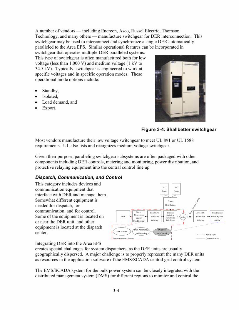
3-4
A number of vendors — including Enercon, Asco, Russel Electric, Thomson Technology, and many others — manufacture switchgear for DER interconnection. This switchgear may be used to interconnect and synchronize a single DER automatically paralleled to the Area EPS. Similar operational features can be incorporated in switchgear that operates multiple-DER paralleled systems. This type of switchgear is often manufactured both for low voltage (less than 1,000 V) and medium voltage (1 kV to 34.5 kV). Typically, switchgear is engineered to work at specific voltages and in specific operation modes. These operational mode options include: • Standby, • Isolated, • Load demand, and • Export.
Figure 3-4. Shallbetter switchgear Most vendors manufacture their low voltage switchgear to meet UL 891 or UL 1588 requirements. UL also lists and recognizes medium voltage switchgear. Given their purpose, paralleling switchgear subsystems are often packaged with other components including DER controls, metering and monitoring, power distribution, and protective relaying equipment into the central control line up.
Dispatch, Communication, and Control This category includes devices and communication equipment that interface with DER and manage them. Somewhat different equipment is needed for dispatch, for communication, and for control. Some of the equipment is located on or near the DER unit, and other equipment is located at the dispatch center. Integrating DER into the Area EPS creates special challenges for system dispatchers, as the DER units are usually geographically dispersed. A major challenge is to properly represent the many DER units as resources in the application software of the EMS/SCADA central grid control system.
Dispatch
and Control
DER
Power Conversion
and/orConditioning
Local EPS
Protective
Relaying
Area EPS
Protective
Relaying
Interconnection System
TransferSwitch orParallelingSwitchgear
AC
Loads
Area Electric
Power System
(Grid)
Power
Distribution
Power Flow
Communication
Poin
t of C
omm
on C
oupl
ing
Meter
DER Monitoring
and MeteringDER Control
DC
Loads
The EMS/SCADA system for the bulk power system can be closely integrated with the distributed management system (DMS) for different regions to monitor and control the
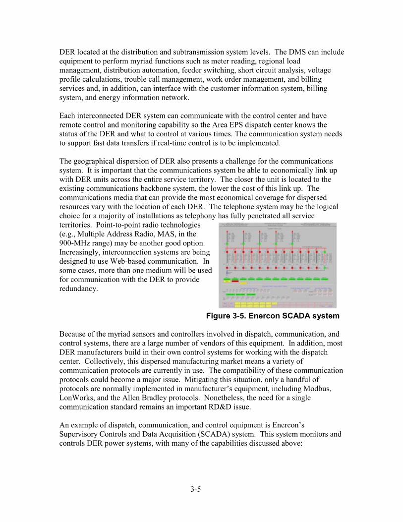
3-5
DER located at the distribution and subtransmission system levels. The DMS can include equipment to perform myriad functions such as meter reading, regional load management, distribution automation, feeder switching, short circuit analysis, voltage profile calculations, trouble call management, work order management, and billing services and, in addition, can interface with the customer information system, billing system, and energy information network. Each interconnected DER system can communicate with the control center and have remote control and monitoring capability so the Area EPS dispatch center knows the status of the DER and what to control at various times. The communication system needs to support fast data transfers if real-time control is to be implemented. The geographical dispersion of DER also presents a challenge for the communications system. It is important that the communications system be able to economically link up with DER units across the entire service territory. The closer the unit is located to the existing communications backbone system, the lower the cost of this link up. The communications media that can provide the most economical coverage for dispersed resources vary with the location of each DER. The telephone system may be the logical choice for a majority of installations as telephony has fully penetrated all service territories. Point-to-point radio technologies (e.g., Multiple Address Radio, MAS, in the 900-MHz range) may be another good option. Increasingly, interconnection systems are being designed to use Web-based communication. In some cases, more than one medium will be used for communication with the DER to provide redundancy.
Figure 3-5. Enercon SCADA system
Because of the myriad sensors and controllers involved in dispatch, communication, and control systems, there are a large number of vendors of this equipment. In addition, most DER manufacturers build in their own control systems for working with the dispatch center. Collectively, this dispersed manufacturing market means a variety of communication protocols are currently in use. The compatibility of these communication protocols could become a major issue. Mitigating this situation, only a handful of protocols are normally implemented in manufacturer’s equipment, including Modbus, LonWorks, and the Allen Bradley protocols. Nonetheless, the need for a single communication standard remains an important RD&D issue. An example of dispatch, communication, and control equipment is Enercon’s Supervisory Controls and Data Acquisition (SCADA) system. This system monitors and controls DER power systems, with many of the capabilities discussed above:
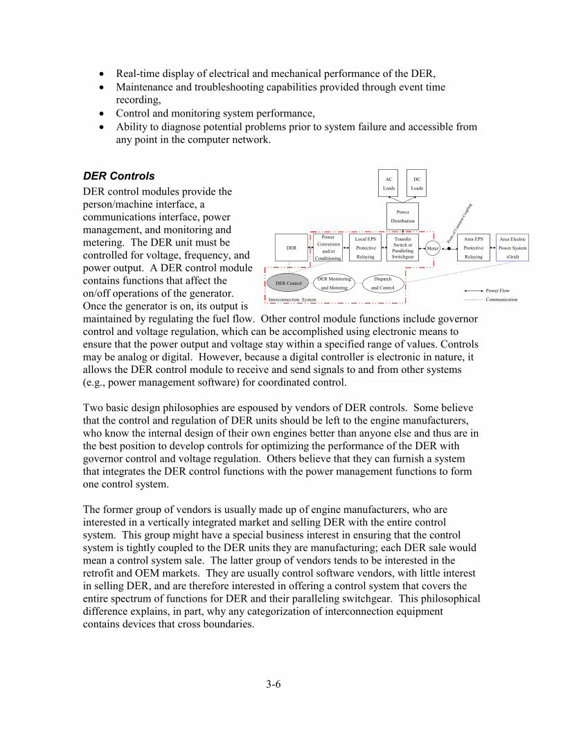
3-6
• Real-time display of electrical and mechanical performance of the DER, • Maintenance and troubleshooting capabilities provided through event time
recording, • Control and monitoring system performance, • Ability to diagnose potential problems prior to system failure and accessible from
any point in the computer network.
DER Controls DER control modules provide the person/machine interface, a communications interface, power management, and monitoring and metering. The DER unit must be controlled for voltage, frequency, and power output. A DER control module contains functions that affect the on/off operations of the generator. Once the generator is on, its output is maintained by regulating the fuel flow. Other control module functions include governor control and voltage regulation, which can be accomplished using electronic means to ensure that the power output and voltage stay within a specified range of values. Controls may be analog or digital. However, because a digital controller is electronic in nature, it allows the DER control module to receive and send signals to and from other systems (e.g., power management software) for coordinated control.
Dispatch
and ControlDER Control
DER
Power Conversion
and/orConditioning
Local EPS
Protective
Relaying
Area EPS
Protective
Relaying
Interconnection System
TransferSwitch orParallelingSwitchgear
AC
Loads
Area Electric
Power System
(Grid)
Power
Distribution
Power Flow
Communication
Poin
t of C
omm
on C
oupl
ing
Meter
DER Monitoring
and Metering
DC
Loads
Two basic design philosophies are espoused by vendors of DER controls. Some believe that the control and regulation of DER units should be left to the engine manufacturers, who know the internal design of their own engines better than anyone else and thus are in the best position to develop controls for optimizing the performance of the DER with governor control and voltage regulation. Others believe that they can furnish a system that integrates the DER control functions with the power management functions to form one control system. The former group of vendors is usually made up of engine manufacturers, who are interested in a vertically integrated market and selling DER with the entire control system. This group might have a special business interest in ensuring that the control system is tightly coupled to the DER units they are manufacturing; each DER sale would mean a control system sale. The latter group of vendors tends to be interested in the retrofit and OEM markets. They are usually control software vendors, with little interest in selling DER, and are therefore interested in offering a control system that covers the entire spectrum of functions for DER and their paralleling switchgear. This philosophical difference explains, in part, why any categorization of interconnection equipment contains devices that cross boundaries.
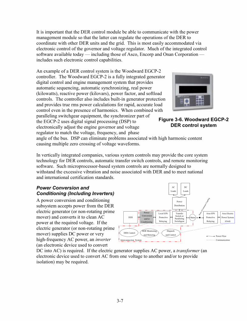
3-7
It is important that the DER control module be able to communicate with the power management module so that the latter can regulate the operations of the DER to coordinate with other DER units and the grid. This is most easily accommodated via electronic control of the governor and voltage regulator. Much of the integrated control software available today — including those of Asco, Encorp and Onan Corporation — includes such electronic control capabilities. An example of a DER control system is the Woodward EGCP-2 controller. The Woodward EGCP-2 is a fully integrated generator digital control and engine management system that provides automatic sequencing, automatic synchronizing, real power (kilowatts), reactive power (kilovars), power factor, and softload controls. The controller also includes built-in generator protection and provides true rms power calculations for rapid, accurate load control even in the presence of harmonics. When combined with paralleling switchgear equipment, the synchronizer part of the EGCP-2 uses digital signal processing (DSP) to electronically adjust the engine governor and voltage regulator to match the voltage, frequency, and phase angle of the bus. DSP can eliminate problems associated with high harmonic content causing multiple zero crossing of voltage waveforms.
Figure 3-6. Woodward EGCP-2 DER control system
In vertically integrated companies, various system controls may provide the core system technology for DER controls, automatic transfer switch controls, and remote monitoring software. Such microprocessor-based system controls are normally designed to withstand the excessive vibration and noise associated with DER and to meet national and international certification standards.
Power Conversion and Conditioning (Including Inverters) A power conversion and conditioning subsystem accepts power from the DER electric generator (or non-rotating prime mover) and converts it to clean AC power at the required voltage. If the electric generator (or non-rotating prime mover) supplies DC power or very high-frequency AC power, an inverter (an electronic device used to convert DC into AC) is required. If the electric generator supplies AC power, a transformer (an electronic device used to convert AC from one voltage to another and/or to provide isolation) may be required.
Dispatch
and ControlDER Control
DER
Power Conversion
and/orConditioning
Local EPS
Protective
Relaying
Area EPS
Protective
Relaying
Interconnection System
TransferSwitch orParallelingSwitchgear
AC
Loads
Area Electric
Power System
(Grid)
Power
Distribution
Power Flow
Communication
Poin
t of C
omm
on C
oupl
ing
Meter
DER Monitoring
and Metering
DC
Loads
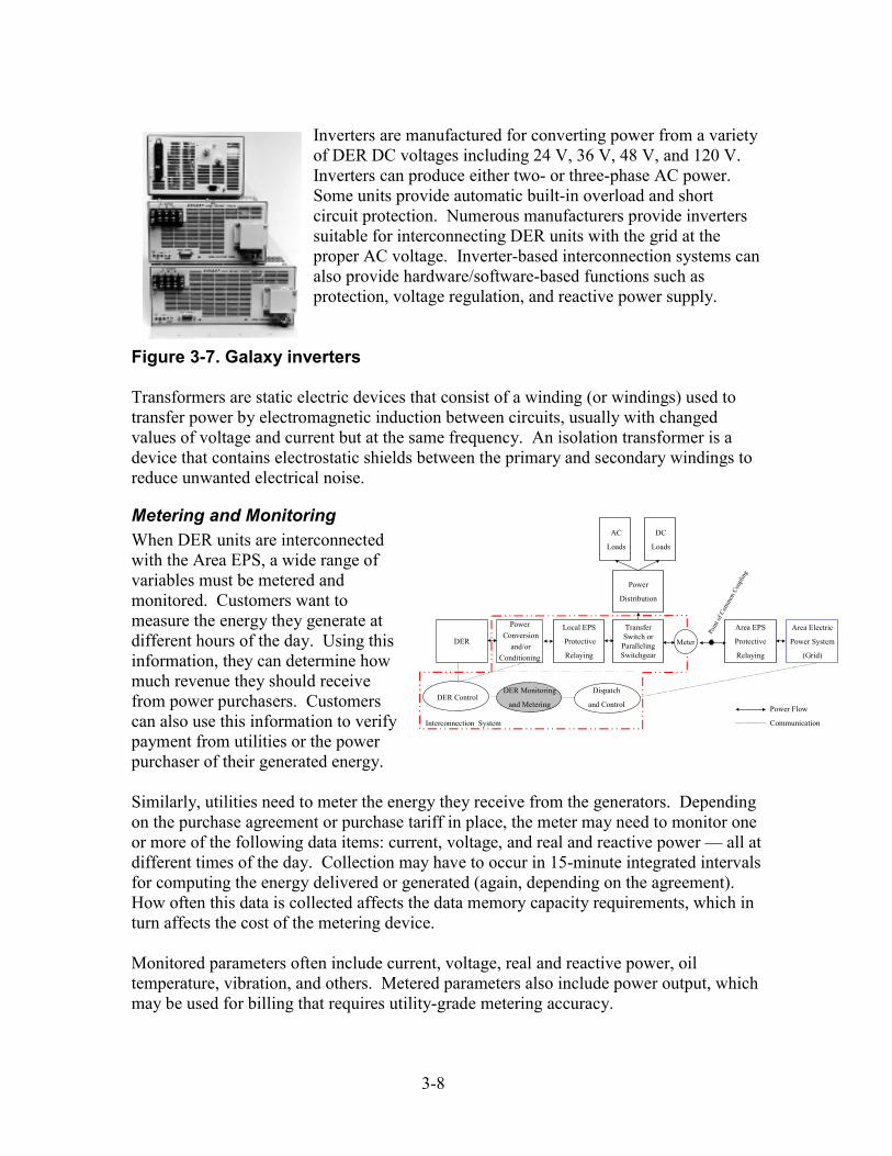
3-8
Inverters are manufactured for converting power from a variety of DER DC voltages including 24 V, 36 V, 48 V, and 120 V. Inverters can produce either two- or three-phase AC power. Some units provide automatic built-in overload and short circuit protection. Numerous manufacturers provide inverters suitable for interconnecting DER units with the grid at the proper AC voltage. Inverter-based interconnection systems can also provide hardware/software-based functions such as protection, voltage regulation, and reactive power supply.
Figure 3-7. Galaxy inverters Transformers are static electric devices that consist of a winding (or windings) used to transfer power by electromagnetic induction between circuits, usually with changed values of voltage and current but at the same frequency. An isolation transformer is a device that contains electrostatic shields between the primary and secondary windings to reduce unwanted electrical noise.
Metering and Monitoring
Dispatch
and ControlDER Control
DER Monitoring
and Metering
DER
Power Conversion
and/orConditioning
Local EPS
Protective
Relaying
Area EPS
Protective
Relaying
Interconnection System
TransferSwitch orParallelingSwitchgear
AC
Loads
Area Electric
Power System
(Grid)
Power
Distribution
Power Flow
Communication
Poin
t of C
omm
on C
oupl
ing
Meter
DC
LoadsWhen DER units are interconnected with the Area EPS, a wide range of variables must be metered and monitored. Customers want to measure the energy they generate at different hours of the day. Using this information, they can determine how much revenue they should receive from power purchasers. Customers can also use this information to verify payment from utilities or the power purchaser of their generated energy. Similarly, utilities need to meter the energy they receive from the generators. Depending on the purchase agreement or purchase tariff in place, the meter may need to monitor one or more of the following data items: current, voltage, and real and reactive power — all at different times of the day. Collection may have to occur in 15-minute integrated intervals for computing the energy delivered or generated (again, depending on the agreement). How often this data is collected affects the data memory capacity requirements, which in turn affects the cost of the metering device. Monitored parameters often include current, voltage, real and reactive power, oil temperature, vibration, and others. Metered parameters also include power output, which may be used for billing that requires utility-grade metering accuracy.
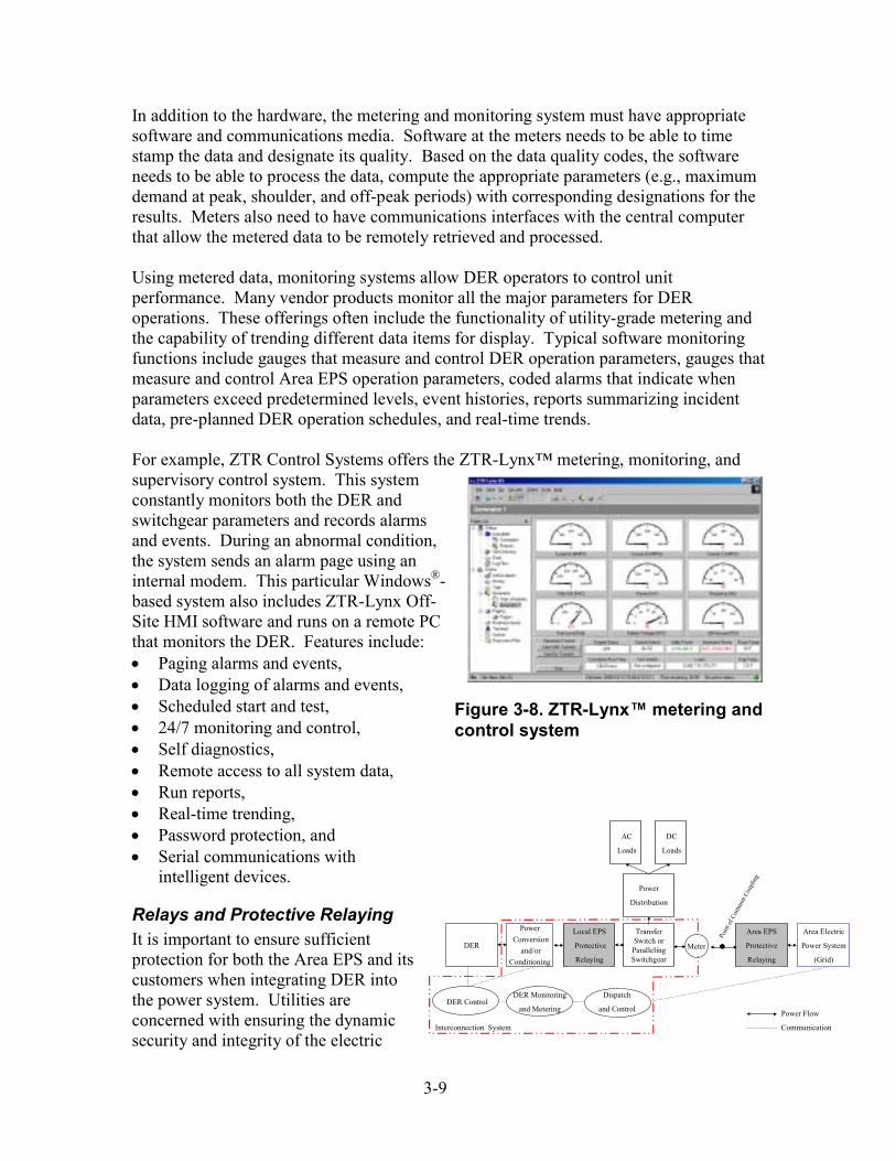
3-9
In addition to the hardware, the metering and monitoring system must have appropriate software and communications media. Software at the meters needs to be able to time stamp the data and designate its quality. Based on the data quality codes, the software needs to be able to process the data, compute the appropriate parameters (e.g., maximum demand at peak, shoulder, and off-peak periods) with corresponding designations for the results. Meters also need to have communications interfaces with the central computer that allow the metered data to be remotely retrieved and processed. Using metered data, monitoring systems allow DER operators to control unit performance. Many vendor products monitor all the major parameters for DER operations. These offerings often include the functionality of utility-grade metering and the capability of trending different data items for display. Typical software monitoring functions include gauges that measure and control DER operation parameters, gauges that measure and control Area EPS operation parameters, coded alarms that indicate when parameters exceed predetermined levels, event histories, reports summarizing incident data, pre-planned DER operation schedules, and real-time trends. For example, ZTR Control Systems offers the ZTR-Lynx™ metering, monitoring, and supervisory control system. This system constantly monitors both the DER and switchgear parameters and records alarms and events. During an abnormal condition, the system sends an alarm page using an internal modem. This particular Windows®-based system also includes ZTR-Lynx Off-Site HMI software and runs on a remote PC that monitors the DER. Features include: • Paging alarms and events, • Data logging of alarms and events, • Scheduled start and test, Figure 3-8. ZTR-Lynx™ metering and
control system • 24/7 monitoring and control, • Self diagnostics, • Remote access to all system data, • Run reports, • Real-time trending,
Dispatch
and ControlDER Control
• Password protection, and
DER
Power Conversion
and/orConditioning
Local EPS
Protective
Relaying
Area EPS
Protective
Relaying
Interconnection System
TransferSwitch orParallelingSwitchgear
AC
Loads
Area Electric
Power System
(Grid)
Power
Distribution
Power Flow
Communication
Poin
t of C
omm
on C
oupl
ing
Meter
DER Monitoring
and Metering
DC
Loads• Serial communications with intelligent devices.
Relays and Protective Relaying It is important to ensure sufficient protection for both the Area EPS and its customers when integrating DER into the power system. Utilities are concerned with ensuring the dynamic security and integrity of the electric
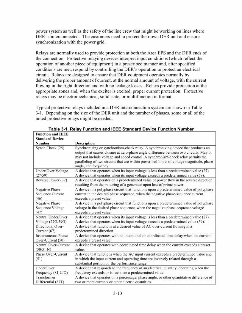
power system as well as the safety of the line crew that might be working on lines where DER is interconnected. The customers need to protect their own DER unit and ensure synchronization with the power grid. Relays are normally used to provide protection at both the Area EPS and the DER ends of the connection. Protective relaying devices interpret input conditions (which reflect the operation of another piece of equipment) in a prescribed manner and, after specified conditions are met, respond by controlling the DER’s operation to protect an electrical circuit. Relays are designed to ensure that DER equipment operates normally by delivering the proper amount of current, at the normal amount of voltage, with the current flowing in the right direction and with no leakage losses. Relays provide protection at the appropriate zones and, when the exciter is excited, proper current protection. Protective relays may be electromechanical, solid state, or multifunction in format. Typical protective relays included in a DER interconnection system are shown in Table 3-1. Depending on the size of the DER unit and the number of phases, some or all of the noted protective relays might be needed.
Table 3-1. Relay Function and IEEE Standard Device Function Number Function and IEEE Standard Device Number
Description
Synch Check (25) Synchronizing or synchronism-check relay. A synchronizing device that produces an output that causes closure at zero-phase angle difference between two circuits. May or may not include voltage and speed control. A synchronism-check relay permits the paralleling of two circuits that are within prescribed limits of voltage magnitude, phase angle, and frequency.
Under/Over Voltage (27/59)
A device that operates when its input voltage is less than a predetermined value (27). A device that operates when its input voltage exceeds a predetermined value (59).
Reverse Power (32) A device that operates on a predetermined value of power flow in the reverse direction resulting from the motoring of a generator upon loss of prime power.
Negative Phase Sequence Current (46)
A device in a polyphase circuit that functions upon a predetermined value of polyphase current in the desired phase sequence, when the negative phase-sequence current exceeds a preset value.
Negative Phase Sequence Voltage (47)
A device in a polyphase circuit that functions upon a predetermined value of polyphase voltage in the desired phase sequence, when the negative phase-sequence voltage exceeds a preset value.
Neutral Under/Over Voltage (27G/59G)
A device that operates when its input voltage is less than a predetermined value (27). A device that operates when its input voltage exceeds a predetermined value (59).
Directional Over-Current (67)
A device that functions at a desired value of AC over-current flowing in a predetermined direction.
Instantaneous Phase Over-Current (50)
A device that operates with no intentional or coordinated time delay when the current exceeds a preset value.
Neutral Over-Current (50/51 N)
A device that operates with coordinated time delay when the current exceeds a preset value.
Phase Over-Current (51)
A device that functions when the AC input current exceeds a predetermined value and in which the input current and operating time are inversely related through a substantial portion of the performance range.
Under/Over Frequency (81 U/O)
A device that responds to the frequency of an electrical quantity, operating when the frequency exceeds or is less than a predetermined value.
Transformer Differential (87T)
A device that operates on a percentage, phase angle, or other quantitative difference of two or more currents or other electric quantities.
3-10
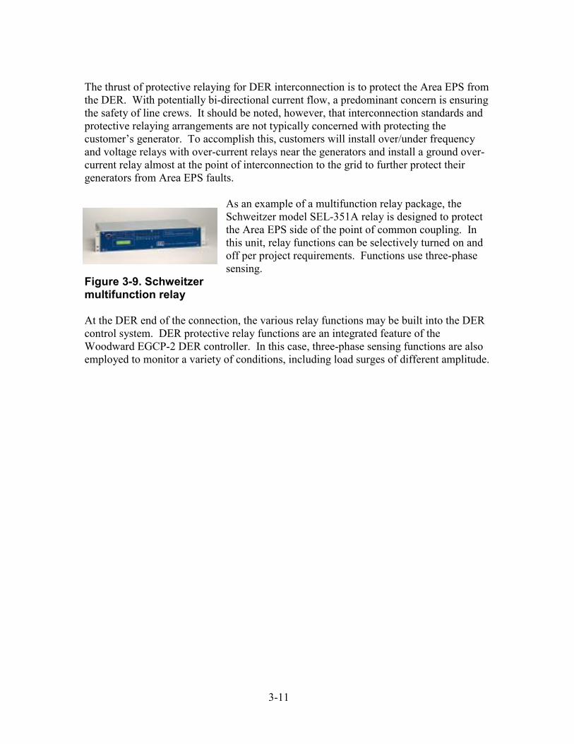
3-11
The thrust of protective relaying for DER interconnection is to protect the Area EPS from the DER. With potentially bi-directional current flow, a predominant concern is ensuring the safety of line crews. It should be noted, however, that interconnection standards and protective relaying arrangements are not typically concerned with protecting the customer’s generator. To accomplish this, customers will install over/under frequency and voltage relays with over-current relays near the generators and install a ground over-current relay almost at the point of interconnection to the grid to further protect their generators from Area EPS faults.
As an example of a multifunction relay package, the Schweitzer model SEL-351A relay is designed to protect the Area EPS side of the point of common coupling. In this unit, relay functions can be selectively turned on and off per project requirements. Functions use three-phase sensing.
Figure 3-9. Schweitzer multifunction relay At the DER end of the connection, the various relay functions may be built into the DER control system. DER protective relay functions are an integrated feature of the Woodward EGCP-2 DER controller. In this case, three-phase sensing functions are also employed to monitor a variety of conditions, including load surges of different amplitude.

3-12
4 COMMERCIAL STATUS OF INTERCONNECTION EQUIPMENT As demonstrated in Table 4-1, components that may go into an interconnection system are available both from a large number of manufacturers and a large number of vendors. However, most interconnection today is still performed on a site-specific and unique DER equipment basis. This greatly increases the cost compared with what it would be if the interconnection system was both plug-and-play and pre-certified for installation for particular DER units. There has been movement in this direction. For example, most DER manufacturers have been either building in or offering as an option some of the key interconnection equipment components as part of their DER genset offering. This simplifies interconnection for new DER purchasers, but they still must obtain permits and licenses and meet utility or Distco interconnection requirements. Some third-party manufacturers are assembling systems of components to build complete interconnection systems out of other manufacturers’ parts. Often these assemblies are referred to as “switchgear,” where all the necessary components are built into panelboards, switchboards, or other suitable cabinets. (The term “switchgear” should not be confused with the term “paralleling switchgear” as used in this report, which is just one component of a complete interconnection system.) The systems described above are pre-engineered, noninverter-based systems, and many are currently being marketed to convert backup generators to peak shavers. Inverter-based systems are also being sold by some manufacturers, primarily for the photovoltaic market. In addition, at least 10 firms are building interconnection systems out of the seven component types noted in Table 4-1 specifically to retrofit the existing DER units of various manufacturers. With hundreds of thousands of standby generators already installed, the retrofit market is large and growing. A number of companies have recently begun converting standby generators for use in peak shaving and other applications.
Manufacturers of Interconnection Equipment Products Table 4-1 notes some manufacturers of the DER interconnection components discussed above. Many manufacturers produce more than one type of equipment. Almost all the DER unit vendors offer DER controls and protective relaying that work with their own units. Vertically integrated companies often use the same relays, sensors, or microprocessors in systems classified in several of these categories. A detailed breakdown of product offerings and details for each of the seven types of equipment are presented in Tables C-1 through C-7 in Appendix C. A description of the most important technical characteristics of components in each category is also provided in this
4-1
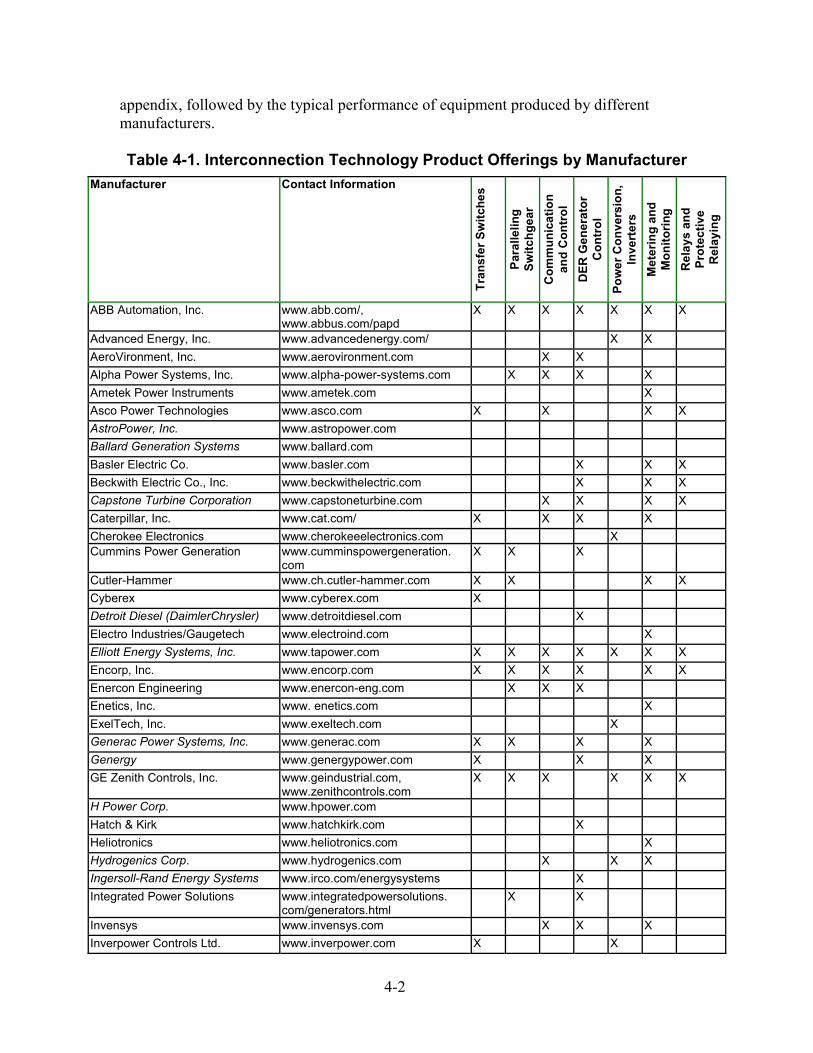
appendix, followed by the typical performance of equipment produced by different manufacturers. Table 4-1. Interconnection Technology Product Offerings by Manufacturer
Manufacturer Contact Information
Tran
sfer
Sw
itche
s
Para
llelin
g Sw
itchg
ear
Com
mun
icat
ion
and
Con
trol
D
ER G
ener
ator
C
ontr
ol
Pow
er C
onve
rsio
n,
Inve
rter
s M
eter
ing
and
Mon
itorin
g R
elay
s an
d Pr
otec
tive
Rel
ayin
g
ABB Automation, Inc. www.abb.com/, www.abbus.com/papd
X X X X X X X
Advanced Energy, Inc. www.advancedenergy.com/ X X AeroVironment, Inc. www.aerovironment.com X X Alpha Power Systems, Inc. www.alpha-power-systems.com X X X X Ametek Power Instruments www.ametek.com X Asco Power Technologies www.asco.com X X X X AstroPower, Inc. www.astropower.com Ballard Generation Systems www.ballard.com Basler Electric Co. www.basler.com X X X Beckwith Electric Co., Inc. www.beckwithelectric.com X X X Capstone Turbine Corporation www.capstoneturbine.com X X X X Caterpillar, Inc. www.cat.com/ X X X X Cherokee Electronics www.cherokeeelectronics.com X Cummins Power Generation www.cumminspowergeneration.
com X X X
Cutler-Hammer www.ch.cutler-hammer.com X X X X Cyberex www.cyberex.com X Detroit Diesel (DaimlerChrysler) www.detroitdiesel.com X Electro Industries/Gaugetech www.electroind.com X Elliott Energy Systems, Inc. www.tapower.com X X X X X X X Encorp, Inc. www.encorp.com X X X X X X Enercon Engineering www.enercon-eng.com X X X Enetics, Inc. www. enetics.com X ExelTech, Inc. www.exeltech.com X Generac Power Systems, Inc. www.generac.com X X X X Genergy www.genergypower.com X X X GE Zenith Controls, Inc. www.geindustrial.com,
www.zenithcontrols.com X X X X X X
H Power Corp. www.hpower.com Hatch & Kirk www.hatchkirk.com X Heliotronics www.heliotronics.com X Hydrogenics Corp. www.hydrogenics.com X X X Ingersoll-Rand Energy Systems www.irco.com/energysystems X Integrated Power Solutions www.integratedpowersolutions.
com/generators.html X X
Invensys www.invensys.com X X X Inverpower Controls Ltd. www.inverpower.com X X
4-2
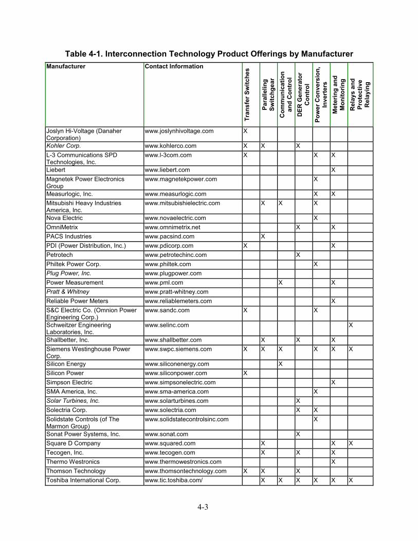
Table 4-1. Interconnection Technology Product Offerings by Manufacturer Manufacturer Contact Information
Tran
sfer
Sw
itche
s
Para
llelin
g Sw
itchg
ear
Com
mun
icat
ion
and
Con
trol
D
ER G
ener
ator
C
ontr
ol
Pow
er C
onve
rsio
n,
Inve
rter
s M
eter
ing
and
Mon
itorin
g R
elay
s an
d Pr
otec
tive
Rel
ayin
g
Joslyn Hi-Voltage (Danaher Corporation)
www.joslynhivoltage.com X
Kohler Corp. www.kohlerco.com X X X L-3 Communications SPD Technologies, Inc.
www.l-3com.com X X X
Liebert www.liebert.com X Magnetek Power Electronics Group
www.magnetekpower.com X
Measurlogic, Inc. www.measurlogic.com X X Mitsubishi Heavy Industries America, Inc.
www.mitsubishielectric.com X X X
Nova Electric www.novaelectric.com X OmniMetrix www.omnimetrix.net X X PACS Industries www.pacsind.com X PDI (Power Distribution, Inc.) www.pdicorp.com X X Petrotech www.petrotechinc.com X Philtek Power Corp. www.philtek.com X Plug Power, Inc. www.plugpower.com Power Measurement www.pml.com X X Pratt & Whitney www.pratt-whitney.com Reliable Power Meters www.reliablemeters.com X S&C Electric Co. (Omnion Power Engineering Corp.)
www.sandc.com X X
Schweitzer Engineering Laboratories, Inc.
www.selinc.com X
Shallbetter, Inc. www.shallbetter.com X X X Siemens Westinghouse Power Corp.
www.swpc.siemens.com X X X X X X
Silicon Energy www.siliconenergy.com X Silicon Power www.siliconpower.com X Simpson Electric www.simpsonelectric.com X SMA America, Inc. www.sma-america.com X Solar Turbines, Inc. www.solarturbines.com X Solectria Corp. www.solectria.com X X Solidstate Controls (of The Marmon Group)
www.solidstatecontrolsinc.com X
Sonat Power Systems, Inc. www.sonat.com X Square D Company www.squared.com X X X Tecogen, Inc. www.tecogen.com X X X Thermo Westronics www.thermowestronics.com X Thomson Technology www.thomsontechnology.com X X X Toshiba International Corp. www.tic.toshiba.com/ X X X X X X
4-3
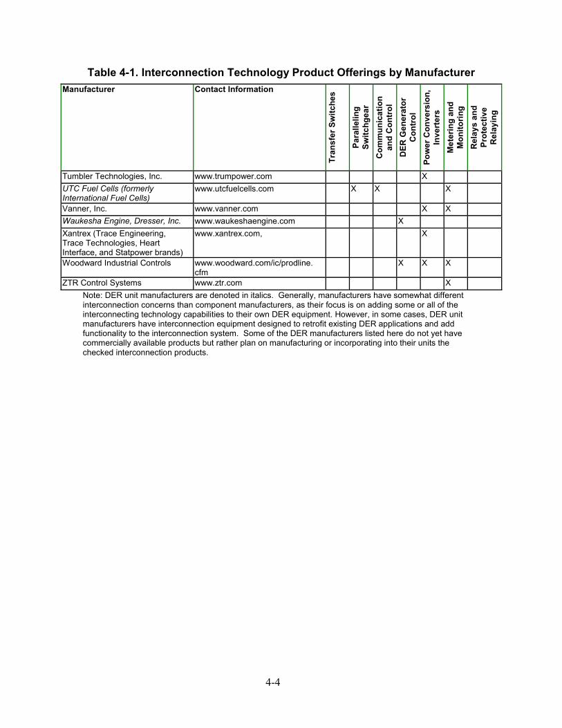
Table 4-1. Interconnection Technology Product Offerings by Manufacturer Manufacturer Contact Information
Tran
sfer
Sw
itche
s
Para
llelin
g Sw
itchg
ear
Com
mun
icat
ion
and
Con
trol
D
ER G
ener
ator
C
ontr
ol
Pow
er C
onve
rsio
n,
Inve
rter
s M
eter
ing
and
Mon
itorin
g R
elay
s an
d Pr
otec
tive
Rel
ayin
g
Tumbler Technologies, Inc. www.trumpower.com X UTC Fuel Cells (formerly International Fuel Cells)
www.utcfuelcells.com X X X
Vanner, Inc. www.vanner.com X X Waukesha Engine, Dresser, Inc. www.waukeshaengine.com X Xantrex (Trace Engineering, Trace Technologies, Heart Interface, and Statpower brands)
www.xantrex.com, X
Woodward Industrial Controls www.woodward.com/ic/prodline. cfm
X X X
ZTR Control Systems www.ztr.com X Note: DER unit manufacturers are denoted in italics. Generally, manufacturers have somewhat different interconnection concerns than component manufacturers, as their focus is on adding some or all of the interconnecting technology capabilities to their own DER equipment. However, in some cases, DER unit manufacturers have interconnection equipment designed to retrofit existing DER applications and add functionality to the interconnection system. Some of the DER manufacturers listed here do not yet have commercially available products but rather plan on manufacturing or incorporating into their units the checked interconnection products.
4-4

Interconnection Equipment Product Pricing Both automatic and manual transfer switches are common electrical items and are available from a number of vendors. Static transfer switches are less common, but they are becoming more so. Figures 4-1 through 4-4 illustrate typical per-kilowatt price ranges.
Static Transfer Switches (STS) These switches range in cost from $850/kW to $150/kW (see Figure 4-1), with the price band shown representing a 480-V rating for switches from 100 A to 400 A. The pricing reflects a discounted STS with the power distribution unit (PDU) included. Figure 4-1 represents 28 price points collected from multiple vendors.
$0
$100
$200
$300
$400
$500
$600
$700
$800
$900
0 50 100 150 200 250
kW
$/kW
Figure 4-1. Static transfer switch pricing
Automatic Transfer Switches (ATS) This product line ranges in cost from $75/kW at the high end down to $15/kW for the larger switches in the 200-kW range. ATS are generally electromechanical in design, with Figure 4-2 pricing for 250-V and 600-V ratings and 100 to 400 ampacities (reflected by the pricing band width). These switches are available up to 2 MW in the low voltage class (through 600 VAC). Figure 4-2 represents 32 list price points collected from multiple vendors.
4-5
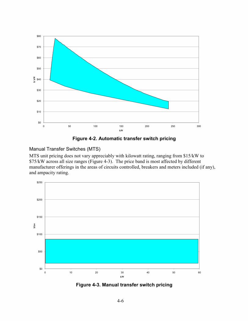
$0
$10
$20
$30
$40
$50
$60
$70
$80
0 50 100 150 200 250 300
kW
$/ k
W
Figure 4-2. Automatic transfer switch pricing
Manual Transfer Switches (MTS) MTS unit pricing does not vary appreciably with kilowatt rating, ranging from $15/kW to $75/kW across all size ranges (Figure 4-3). The price band is most affected by different manufacturer offerings in the areas of circuits controlled, breakers and meters included (if any), and ampacity rating.
$0
$50
$100
$150
$200
$250
0 10 20 30 40 50 60
kW
$/kw
Figure 4-3. Manual transfer switch pricing
4-6
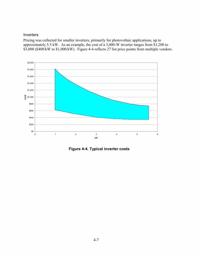
Inverters Pricing was collected for smaller inverters, primarily for photovoltaic applications, up to approximately 5.5 kW. As an example, the cost of a 3,000-W inverter ranges from $1,200 to $3,000 ($400/kW to $1,000/kW). Figure 4-4 reflects 27 list price points from multiple vendors.
$0
$200
$400
$600
$800
$1,000
$1,200
$1,400
$1,600
$1,800
$2,000
0 1 2 3 4 5 6
kW
$/kW
Figure 4-4. Typical inverter costs
4-7

4-8
5 INTERCONNECTION TRENDS AND NEEDS Interconnection-related workshops, standards and regulation efforts, and current RD&D all affect interconnection trends and needs. This chapter summarizes the trends and needs that have been identified during these activities.
DER Systems Interconnection Technologies Workshop A select set of interconnection system issues must be discussed and understood before framing the RD&D needs. Many of these key issues were identified during the DOE/NREL workshop on DER systems interconnection technologies held July 24, 2001, in Washington, D.C. At this workshop, presented by Distribution and Interconnection R&D, participants discussed the current status of system interconnection technologies for DER applications. The goal was to determine the technology RD&D needed to achieve a universal plug-and-play P1547-compliant interconnection technology that is applicable across DER technologies. More than 70 participants at this workshop — representing more than 30 companies, universities, and research organizations — highlighted the following key issues driving RD&D needs: • Functionality of the interconnection package, • Interconnection requirements from utilities and ISOs/RTOs and grid versus customer
standards, • Metering and monitoring requirements, • The role of automatic power system dispatch, • Where to include the capabilities necessary for interconnection (in the “black box,” generator
controls, etc.), • Interconnection voltage and generator sizes and the interface standards between DER and the
interconnection package, • Scaling to different power levels, and • The needs for lower cost and better performance. In reviewing these issues during the preparation of this report, researchers concluded that four issues represented some of the dominant effects on DER interconnection. These four issues were: • Interconnection requirements from ISOs/RTOs and utilities, • Metering and monitoring requirements, • The role of automatic power system dispatch, and • Interconnection voltage and generator sizes. Each of these issues is discussed below.
5-1

Interconnection Requirements from ISOs/RTOs and Utilities Interconnection requirements may take on additional complexities if the DER units are to participate as part of an ISO/RTO’s resources in addition to paralleling with the grid. This becomes an especially relevant issue in today’s partially deregulated generation market with open transmission access dispatched by a neutral party such as an ISO/RTO. As in California, DER units could participate in the day-ahead and hour-ahead energy markets as well as in the ancillary services market. In that case, additional ISO/RTO interconnection requirements could include the following: load shape metering, proper time stamping of load data for billing and paper trailing, remote communications with the scheduling coordinator and ISO/RTO, monitoring of breaker and other transfer trip status, and other ISO/RTO requirements pertaining to generation protective control (e.g., calibration of the power system stabilizers). DER that participate in ISO/RTO dispatch, and that would need to meet this set of additional requirements, have in the past tended to be large (e.g., 10 MW or larger). However, small units, involving as few as 100 kW, are beginning to be able to participate in such markets (such as the PJM pilot project). Thus, with the competitive generation market beginning to blossom, an increasing number of small and dispersed DER may participate in the energy market. Utility interconnection requirements include the overriding technical requirements as well as business-related applications, policies, and procedures. In most states, each utility has different requirements. Utility requirements have been sited as a barrier to DER implementation.
Metering and Monitoring “Metering” suggests a recording of energy consumed or generated for billing or payment purposes. “Monitoring” applies to the tracking of generator performance to support operating practices. From an interconnection issues perspective, metering is the key concern. There is a need for metering when integrating DER into the Area EPS. Customers measure the energy they generate at different hours of the day to determine how much revenue they should receive from power purchasers. Similarly, utilities need to meter the energy they receive from the generators. The metering system should be designed to consider both the data memory capacity resident on the meters and the data retrieval frequency of the computer software, taking into account the reliability of the communications media. The size of the metering interval affects the frequency of data retrieval because of the expensive nature of data memory. For example, if the data sampling period is every five minutes (a very small metering interval), then it would be costly to provide enough memory to cover the usual billing period of one month. For cost considerations, the meter design engineer may decide to reduce this memory capacity and increase the data retrieval frequency. In this way, the system will operate in such a way as to ensure no data loss. As there are many types of data to be collected, including, in some instances, real energy (kilowatt-hours) and reactive energy (kilovar-hours), the meter may need to have more than one channel. Additional channels will be required if the meter is expected to serve other functions (e.g., cool and heat conditioned air). The meters should meet utility accuracy and dependability
5-2
requirements and also must have the appropriate software and communications media. Meters should also have communications interfaces with the central dispatching computer. Such interfaces allow the metered data to be remotely retrieved and processed at the central computer. However, a myriad of communications media leads to the issue of compatibility. Communications protocol standards may be needed to facilitate the metering of DER.
Automatic Power System Dispatch Integrating DER into the Area EPS offers special challenges for system dispatchers. The geographical dispersion of DER introduces a much higher degree of complexity to the power system dynamic security problem. DER potentially offer a better solution to potential system security problems. For instance, if DER are located at critical links on the transmission system, they could offer relief to the regional bottleneck as well as voltage and VAR support. However, the major challenge is to properly represent the DER units as resources in the application software of the EMS/SCADA system. A large number of DER generators, if residential applications become popular, could place a heavy burden on the modeling of such resources. Accurately and precisely modeling each DER at the appropriate geographical location may be overly detailed, but a way must be found to group DER together so that their geographical location is still accurately represented and their individual heat rate curves can be aggregated and averaged to represent the aggregated sum of such DER. Modeling DER will be a challenge for many application programs on the EMS/SCADA system, including optimal power flow, load flow, contingency analysis model, distribution factor calculations, unit commitment, economic dispatch, transaction evaluation, state estimation, and security analysis. The challenge will become even more daunting if the DER resources are to be used to relieve regional overload as part of an integrated resource plan. In this case, more details on the DER with respect to their geographical and technical specifications will be needed. To monitor and control the DER that are located at the distribution and sub-transmission system level, the EMS/SCADA system for the bulk power system will have to be closely integrated with the DMS for different regions. It is envisioned that the DMS could include the functions of dispatching and scheduling the DER in coordination with the bulk power system dispatch strategies. In addition, the load flow model may have to include three-phase flow instead of a single-phase model. The concern for system security and unit dispatch could be similar to the bulk power system dispatch, even though the voltage level and the magnitude of the dispatch quantities are smaller. These interconnection system issues point to RD&D needs for a single communication standard, enhanced metering built into the interconnection system, and improved EMS/SCADA software for dealing with numerous, dispersed DER units. Several vendors have developed software products for automatically dispatching networks of DER units. Generally, these systems combine distributed computing with distributed intelligence to provide real-time control and communication capabilities to a microgrid of DER units. In addition to turning generators on and off, these systems take advantage of feedback signals describing how the overall system is operating, including the prime mover, the electric generator, load controls, and the ESP’s transmission and distribution system. For example, they
5-3
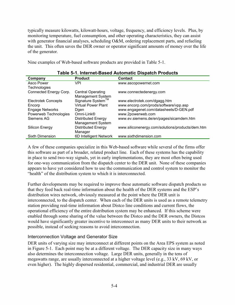
typically measure kilowatts, kilowatt-hours, voltage, frequency, and efficiency levels. Plus, by monitoring temperature, fuel consumption, and other operating characteristics, they can assist with generator financial analyses, scheduling O&M, ordering replacement parts, and refueling the unit. This often saves the DER owner or operator significant amounts of money over the life of the generator. Nine examples of Web-based software products are provided in Table 5-1.
Table 5-1. Internet-Based Automatic Dispatch Products Company Product Contact Asco Power Technologies
VPI www.ascopowernet.com
Connected Energy Corp. Central Operating Management System
www.connectedenergy.com
Electrotek Concepts Signature SystemTM www.electrotek.com/dgagg.htm Encorp Virtual Power Plant www.encorp.com/prods/software/vpp.asp Engage Networks Dgen www.engagenet.com/datasheets/D-GEN.pdf Powerweb Technologies Omni-Link® www.2powerweb.com Siemens AG Distributed Energy
Management System www.ev.siemens.de/en/pages/sicamdem.htm
Silicon Energy Distributed Energy Manager
www.siliconenergy.com/solutions/products/dem.htm
Sixth Dimension 6D Intelligent Network www.sixthdimension.com A few of these companies specialize in this Web-based software while several of the firms offer this software as part of a broader, related product line. Each of these systems has the capability in place to send two-way signals, yet in early implementations, they are most often being used for one-way communication from the dispatch center to the DER unit. None of these companies appears to have yet considered how to use the communication and control system to monitor the “health” of the distribution system to which it is interconnected. Further developments may be required to improve these automatic software dispatch products so that they feed back real-time information about the health of the DER systems and the ESP’s distribution wires network, obviously measured at the point where the DER unit is interconnected, to the dispatch center. When each of the DER units is used as a remote telemetry station providing real-time information about Distco line conditions and current flows, the operational efficiency of the entire distribution system may be enhanced. If this scheme were enabled through some sharing of the value between the Distco and the DER owners, the Distcos would have significantly greater incentive to interconnect as many DER units to their network as possible, instead of seeking reasons to avoid interconnection.
Interconnection Voltage and Generator Size DER units of varying size may interconnect at different points on the Area EPS system as noted in Figure 5-1. Each point may be at a different voltage. The DER capacity size in many ways also determines the interconnection voltage. Large DER units, generally in the tens of megawatts range, are usually interconnected at a higher voltage level (e.g., 33 kV, 69 kV, or even higher). The highly dispersed residential, commercial, and industrial DER are usually
5-4

interconnected at the Area EPS delivery voltage, 15 kV, 5 kV, and 480/240/120 V. Figure 5-2 illustrates some typical interconnecting voltages.
DERDER
DER
DERDER
Figure 5-1. Layers of service in the power generation system
Figure 5-2. Typical interconnecting voltages
5-5
Interconnection Voltage and Generator Size — Lack of Standard Design by Users and Utilities Interconnection voltage and generator size interconnection issues are strongly coupled with inherent technical concerns that may be collectively considered as lack of standard designs on both the consumer side (the local Area EPS) and the utility side (Area EPS) of the interconnection. The system interconnection voltage and the specific location of the interconnection, for the large part, add to the complexity and cost of interconnection. Utility (Area EPS) prescriptive (nonstandard) requirements, including differing requirements mandated by the site-specific location of the interconnection, also contribute to the added complexity. Similarly, DER generator size contributes to interconnection technical requirements complexity and cost issues. Examples of generator size issues and concerns include available short circuit current, protection requirements, interrupting device size, switchgear size, DER generator size (kW), control system requirements, and testing requirements (factory, third-party, field, periodic, etc.). On the consumer side, a lack of standard designs and a lack of standard needs (e.g., site-specific and consumer operation practices) similarly lead to increased complexity and cost issues for the interconnection system. Interconnection Voltage and Generator Size — Power Dispatch Interconnection voltage and generator size also affects power dispatch systems. Power system dispatch in the past has usually been designed to monitor and control devices at the higher voltage circuits. Thus, integrating large DER into system dispatch is relatively simple. There are existing communications backbone systems and load flow models that allow for simple modifications to the dispatch database. However, integrating DER that is interconnected at lower voltage into the bulk power dispatch system is not so straightforward. The database of the EMS/SCADA system does not often include such low voltage points. State estimator programs are not configured to show power flow status at these low voltage points. In addition, although the telecommunications “backbone” may traverse throughout the transmission system, it may not be physically located so that it can communicate with DER at the distribution level. New investment may be required to reach the points where residential DER are located. However, Web-based communication and control may provide a cost-effective means to capture DER data. Voltage would be less of a problem if utilities decided to implement a hierarchical control system concept, whereby a higher-level control system would direct lower levels of control systems in the case of a vertically integrated utility. In this situation, the control of lower voltage DER would fall under the distribution management system (DMS). This is the equivalent of an EMS/SCADA system, but it includes many more customer service functions and is a concept applicable to Distcos.
Standards and Regulatory Impact Standards and regulations can have an effect on interconnection trends and needs. During the development of IEEE P1547, a number of issues arose that are beyond the stated scope of standards development but still need to be addressed. In addition, state regulations, such as
5-6
California’s Rule 21, can affect the interconnection market. Regulatory issues include the siting process, regulations and DER unit size, net metering, and the acceptance of type testing and pre-certification. Consideration of these issues will help create the foundation for the development of an RD&D agenda designed to cost effectively improve the capabilities of interconnection packages and support their commercial deployment.
IEEE P1547 IEEE P1547 is a standard that will define the minimum functional technical requirements that are universally needed to ensure a technically sound interconnection. The standard will provide uniform criteria and requirements relevant to the performance, operation, testing, safety, and maintenance for the interconnection equipment. The standard is currently unapproved and under revision. A number of important interconnection trends and needs have arisen during the development of IEEE P1547, including:
• Type testing versus field testing, • Secondary grid and spot networks, • Grid-DG monitoring/control/communications, • Voltage regulation/stability, • Grounding/faults, and • DG penetration/aggregation.
Additional technical issues have also arisen during P1547 development, as shown in the following list. However, many of these detailed issues are beyond the stated scope of P1547 (e.g., operational practices and site-specific or equipment-specific applications).
• Improper protective device coordination, • Nuisance fuse blowing, • Reclosing, • Installation of transfer trip relaying, • Islanding, • Equipment overvoltage, • Resonant overvoltage, • Harmonics, • Sectionalizers, • Power relay, • Voltage regulation, • DER system interaction, • Transformers – LTC, • Feeder breaker, • Low impedance DER transformer, • Reclosers, • DER system interaction (long feeders), • DER system interaction (loss of excitation for DR), • DER system interaction (faults on adjacent feeder), • Switchgear,
5-7
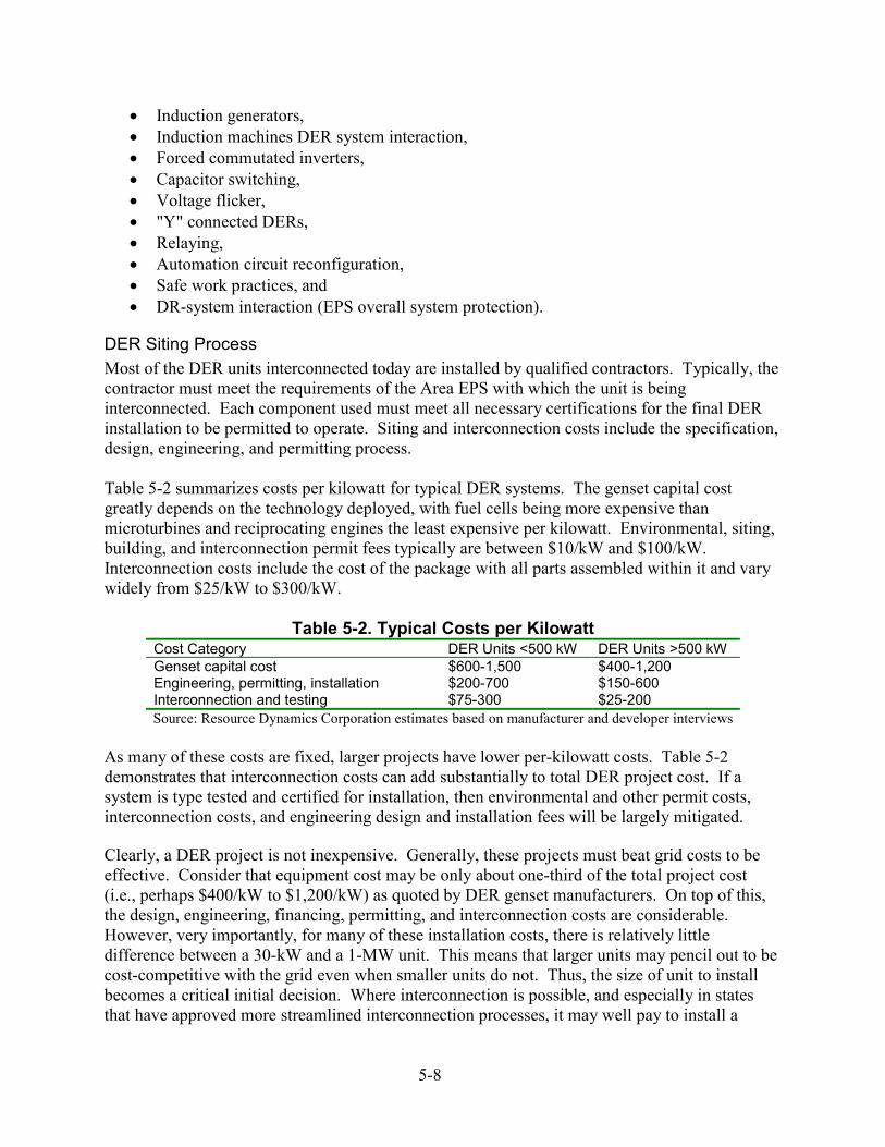
• Induction generators, • Induction machines DER system interaction, • Forced commutated inverters, • Capacitor switching, • Voltage flicker, • "Y" connected DERs, • Relaying, • Automation circuit reconfiguration, • Safe work practices, and • DR-system interaction (EPS overall system protection).
DER Siting Process Most of the DER units interconnected today are installed by qualified contractors. Typically, the contractor must meet the requirements of the Area EPS with which the unit is being interconnected. Each component used must meet all necessary certifications for the final DER installation to be permitted to operate. Siting and interconnection costs include the specification, design, engineering, and permitting process. Table 5-2 summarizes costs per kilowatt for typical DER systems. The genset capital cost greatly depends on the technology deployed, with fuel cells being more expensive than microturbines and reciprocating engines the least expensive per kilowatt. Environmental, siting, building, and interconnection permit fees typically are between $10/kW and $100/kW. Interconnection costs include the cost of the package with all parts assembled within it and vary widely from $25/kW to $300/kW.
Table 5-2. Typical Costs per Kilowatt Cost Category DER Units <500 kW DER Units >500 kW Genset capital cost $600-1,500 $400-1,200 Engineering, permitting, installation $200-700 $150-600 Interconnection and testing $75-300 $25-200 Source: Resource Dynamics Corporation estimates based on manufacturer and developer interviews
As many of these costs are fixed, larger projects have lower per-kilowatt costs. Table 5-2 demonstrates that interconnection costs can add substantially to total DER project cost. If a system is type tested and certified for installation, then environmental and other permit costs, interconnection costs, and engineering design and installation fees will be largely mitigated. Clearly, a DER project is not inexpensive. Generally, these projects must beat grid costs to be effective. Consider that equipment cost may be only about one-third of the total project cost (i.e., perhaps $400/kW to $1,200/kW) as quoted by DER genset manufacturers. On top of this, the design, engineering, financing, permitting, and interconnection costs are considerable. However, very importantly, for many of these installation costs, there is relatively little difference between a 30-kW and a 1-MW unit. This means that larger units may pencil out to be cost-competitive with the grid even when smaller units do not. Thus, the size of unit to install becomes a critical initial decision. Where interconnection is possible, and especially in states that have approved more streamlined interconnection processes, it may well pay to install a
5-8
larger unit and sell any excess generation back to the grid. For these DER owners, the desire to reliably serve their own load is not the only objective considered. This may lead to larger DER unit installations on average. The expense of this siting process suggests that RD&D leading to more modular interconnection components and toward equipment that can be type tested would be cost-effective.
Regulations and DER Unit Size Texas published its Distributed Generation Interconnection Manual in March 2001. In addition, California is in the process of specifying new interconnection standards for DER. New York and other states have established interconnection guidelines. IEEE P1547 is nearing completion this year. Of the states making progress in DG interconnection rulemaking, California provides just one example of how marketplace and technology issues may be resolved in the regulatory arena. Although no particular size range for allowable interconnection is specified under California’s regulations, there are differences in requirements for units smaller than 11 kVA, which are mostly residential photovoltaic panels less than 10 kW in size. (Similarly, IEEE Standard 929-2000, established in January 2000, applies to photovoltaics less than 10 kW in size.) For example, to reduce the cost and time duration of interconnection approval, California allows some smaller DER units to be approved under a simplified interconnection scheme. Under Rule 21 in California, a DER unit may qualify for simplified interconnection, if, among other requirements: • The aggregate DER unit(s’) capacity on the Area EPS serving line section is less than 15% of
line section peak load (the thinking is that a low penetration of DER installations will have a minimal impact on distribution system and load operation and power restoration) and
• The gross nameplate rating of the DER unit is 11 kVA or less (similarly, the thinking is that small DER units have minimal impact on fault current levels and any potential line over-voltages from loss of system neutral grounding).
In addition, the Rule 21 language allows exemptions from visible disconnect devices for DER units less than 1 kVA. Finally, the rule provides for less expensive telemetering requirements for DER units less than 1 MW in size. As a result, RD&D interconnection efforts may vary somewhat by size of DER equipment. To assess the effect of Rule 21 in California, consider that during the year from September 2000 to August 2001, applications for 126 DER interconnections were received by the three large utilities in the state. Figure 5-3 illustrates the number of these applications in each DER unit size range. The majority of applications are for DER units less than 5 MW in size. One-third of the applications were for units less than 500 kW in size. Only one of these applications was for a DER less than 10 kW, thereby falling under the simplified interconnection scheme.
5-9
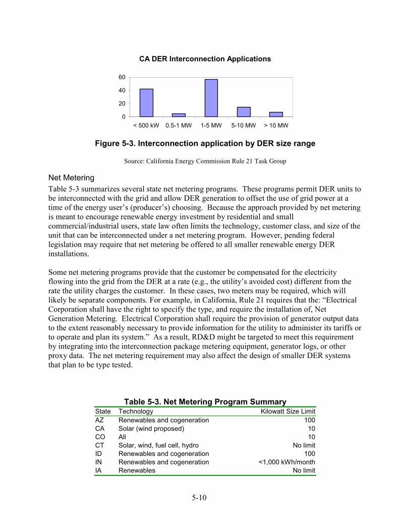
CA DER Interconnection Applications
0
20
40
60
< 500 kW 0.5-1 MW 1-5 MW 5-10 MW > 10 MW
Figure 5-3. Interconnection application by DER size range
Source: California Energy Commission Rule 21 Task Group
Net Metering Table 5-3 summarizes several state net metering programs. These programs permit DER units to be interconnected with the grid and allow DER generation to offset the use of grid power at a time of the energy user’s (producer’s) choosing. Because the approach provided by net metering is meant to encourage renewable energy investment by residential and small commercial/industrial users, state law often limits the technology, customer class, and size of the unit that can be interconnected under a net metering program. However, pending federal legislation may require that net metering be offered to all smaller renewable energy DER installations. Some net metering programs provide that the customer be compensated for the electricity flowing into the grid from the DER at a rate (e.g., the utility’s avoided cost) different from the rate the utility charges the customer. In these cases, two meters may be required, which will likely be separate components. For example, in California, Rule 21 requires that the: “Electrical Corporation shall have the right to specify the type, and require the installation of, Net Generation Metering. Electrical Corporation shall require the provision of generator output data to the extent reasonably necessary to provide information for the utility to administer its tariffs or to operate and plan its system.” As a result, RD&D might be targeted to meet this requirement by integrating into the interconnection package metering equipment, generator logs, or other proxy data. The net metering requirement may also affect the design of smaller DER systems that plan to be type tested.
Table 5-3. Net Metering Program Summary State Technology Kilowatt Size Limit AZ Renewables and cogeneration 100 CA Solar (wind proposed) 10 CO All 10 CT Solar, wind, fuel cell, hydro No limit ID Renewables and cogeneration 100 IN Renewables and cogeneration <1,000 kWh/month IA Renewables No limit
5-10
ME Renewables and cogeneration 100 MD Solar 80 MA Renewables and cogeneration 60 MN Renewables and cogeneration 40 NV Solar and wind 10 NH Renewables, waste, biomass 25 NM Renewables and cogeneration 100 NY Solar 10 ND Renewables and cogeneration 100 OK Renewables and cogeneration 100 and <25,000 kWh/year PA Renewables 50 RI Renewables and cogeneration 15 TX Renewables 50 VT Solar, wind, fuel cells 15 WA Solar, wind, hydro 25 WI All 20
Source: National Wind Coordinating Committee
Type Testing and Pre-Certification It is anticipated that RD&D leading to interconnection equipment standardization will greatly assist marketplace deployment of DER units by lowering installation costs. However, type testing has not yet been accepted by most utilities. Some states, such as California, have developed rules for the type testing of genset and related interconnection equipment. Under the California rules, provided a piece of equipment can pass UL 1741 certification by an independent lab, that piece of equipment may be installed with relatively minimal additional cost. Going beyond this, New York’s Department of Public Service publishes a list of interconnection equipment from nine manufacturers that has been type tested and approved for use by DER developers. In the end, even with extensive RD&D efforts, it may only be possible to achieve plug-and-play status for smaller DER units. Larger units will likely continue to be designed, engineered, installed, interconnected, and tested on a site-specific basis. Since 2000, there has been an increase in the number of integrated solution providers (ISPs) that specialize in installing DER equipment. Such companies shepherd a DER owner/user through the siting process. If interconnection RD&D manages to achieve type testing for smaller DER units, ISPs may evolve to support installation of mostly larger DER units. At the development end of RD&D, one goal might be to design interconnection equipment sufficiently flexible that they not only meet certifications and receive type testing approval but also can be used in a variety of installation applications. At the demonstration end of the RD&D spectrum, procedures need to be established that support type testing of specific equipment. Overview of Current RD&D Efforts A number of interconnection-related RD&D efforts are under way. Both interconnection equipment manufacturers and DER manufacturers have been working to improve the interconnection package. Generally, the industry is moving toward the use of more integrated power electronics technology.
5-11
Trends in RD&D interconnection include: • A movement toward integrating interconnection equipment with the genset.
For example, Integrated Power Solutions systems have built in to their gensets fully integrated industrial control systems for all engine, power plant, load balancing, switchgear control, and safety shutdowns. It has eliminated switchgear systems through the application of advanced digital technology, thereby decreasing the DER footprint and reducing cost.
• The use of more reliable, lower cost components.
Often, this involves digital design and the use of advanced processors. As better electrical components are designed and manufactured, they are being built into interconnection components.
• More convergence of hardware and software components in protective relaying and
communication devices, creating lower cost, higher reliability, and improved functionality. In turn, improved communication and telemetry has led to increased automatic deployment of switchgear, including early efforts at Web-based dispatch of DER.
Specific recent industry efforts are: • Improving protective relay performance, • Producing more accurate and reliable meters, • Increasing surge withstand immunity, • Improving communication and control device flexibility so that components may be
networked, • Adapting communications and control systems to handle multiple gensets, • Increasing the type of information logged by data systems and improving event sequencing
analysis, • Providing better feedback and alarm controls for a larger variety of electronic metrics, and • Providing controls for real-time operation and monitoring. These activities are part of the industry’s competitive effort to build less expensive, more reliable, and more flexible components with greater functionality. Technologically, the move is toward an invisible (i.e., a plug-and-play) interconnection.
5-12

6 CONCLUSIONS AND RECOMMENDATIONS Today, the utility interconnection requirements and processes and the siting of DER, even for small units, are far from plug-and-play. Some states are developing certification and more standardized environmental and other interconnection and permit programs to help streamline the process. However, utility interconnection and building permit issues will likely continue to keep the process duration at months and not weeks. Even so, improvements are expected to lower the cost of obtaining permits and interconnecting and thus improve DER’s position relative to grid-based power. Approval of the IEEE P1547 interconnection standard and statewide interconnection standards will also mitigate interconnection uncertainties, but interconnection approval is expected to remain a major time and cost issue. Any RD&D that removes uncertainties will reduce the cost of interconnection equipment and lower engineering costs associated with interconnection. Additionally, type testing of interconnection equipment will lower installation costs and thereby increase market deployment of DER. Aside from the market requirements and regulatory issues discussed in the previous section, there are a number of technical questions that need to be answered as part of any interconnection RD&D activity. These questions were discussed during the July 2001 DOE/NREL Systems Interconnection Technologies Workshop and include: • What is the balance between cost and functionality in each component of the
interconnection system? • What should the interface standards be between DER and the interconnection
package, and should such standards be universal in a move toward plug-and-play capability?
• Should interconnection controls, meters, and monitoring functions be included as part
of the genset, or should they be located in a separate interconnection package? • What is the preferred approach: building a single integrated interconnection package
or designing an assembly of subsets that can be engineered and combined at the DER site to perform customized interconnection operation?
• To what degree should flexibility be designed into an interconnection package such
that it can be scaled to different power levels or to multiple DER units? Over the past decade, many advanced, microprocessor-based grid interconnection generator protective relay systems, improved transfer switches, DER system controls, remote monitoring, and communication control technologies have been commercialized.
6-1
Together, these developments are beginning to cost effectively address the concerns of utilities for reliability and safety while also providing value-added features for DER system owners and operators. Generally, the equipment exists to implement the IEEE P1547 standard. However, more can be done, especially in lowering costs while increasing the functionality of the interconnection system. Expanding this functionality is a key element in helping modernize the grid, creating an even more effective electric power system.
Interconnection Technology RD&D Needs Building on the July 2001 Systems Interconnection Technologies Workshop and the research completed as part of report development, the following were identified as forming the core foundation for RD&D activities: 1. Work with industry to standardize interconnection architectures, 2. Simplify the technical and design aspects of DER interconnection, 3. Enhance interconnection system functionality to mitigate existing technical
interconnection issues, 4. Establish the ability to enhance grid operability and intelligence, 5. Develop advanced communication and software platforms, 6. Address technical needs for future full value of DER interconnection and integration,
and 7. Remove regulatory and institutional barriers. RD&D needs and activities in each of these areas are discussed in detail below.
Standardize the Design, Engineering, and Installation of DER Technologies Generally, IEEE P1547 establishes the basic, universal technical requirements for interconnection that will allow manufacturers and system designers to prepare technical specifications of various functions and interfaces. This will result in components and systems designed to a common nationwide standard that will move first toward component plug-and-play and eventually complete interconnection system plug-and-play. However, going beyond IEEE P1547, there are additional standards and recommended practices — based on evolving industry, market, and policy determinations — that need to be established regarding safety, reliability, and the future potential of DER. These other standards include: • Guide to applying the interconnection technical requirements, • Testing and certification, and • Communication and control.
Development of a modular universal interconnection architecture with standard functions for power conversion, power conditioning and quality, protection, DER and load controls, communications, ancillary services, and metering is the cornerstone of streamlined DER interconnection. Similarly, developing standard certification and testing procedures for all interconnection components and then deploying and field-testing many of the recently commercialized interconnection devices is a needed step in
6-2
the process. Monitoring experience with these devices should demonstrate which work and which need further development efforts. Although complexities will likely require specific permits, contracts, and engineering during the siting process, the more a genset and its interconnection assemblies can be type tested, the less expensive installation will be. RD&D should not only aim to produce equipment that can be type tested but also attempt to build in sufficient equipment flexibility so that assemblies of components can readily be mixed and matched with one another during the engineering process.
Simplify the Technical and Design Aspects of DER Interconnection Component integration is the single most important step in streamlining interconnection. Research is needed to help increase component integration capabilities, with the focus on developing a functional system architecture. This approach is indifferent to equipment specifications and seeks the development of a set of plug-and-play functional components that readily work with one another, regardless of who makes the component. Equipment performance improvements (e.g., increasing the efficiency, surge capacity, and reliability of inverters so they become less expensive to operate and have a mean time to first failure of greater than 10 years) and the design of more reliable, smaller, and more durable packaging for combining the interconnection components can hasten interconnection simplification. For smaller units, complete power electronic subsystems may be assembled as a single unit that can be readily integrated with either a high-speed engine or high-frequency alternator to produce output power in the 110-V or 220-V range at 50 Hz to 60 Hz. Expanding on this approach, it may be possible to develop a simple plug-and-play interconnection package for smaller DER units. The ideal is a package with two power cords. In this vision, one cord plugs into the DER unit. The other cord has a standard 220-V plug that fits into the Area EPS via a standard 220-V socket. This may require the development of inverter-based systems that work with a variety of genset technologies.
Enhance Interconnection System Functionality to Mitigate Existing Technical Interconnection Issues The complexity of the interconnection system extends beyond a basic set of requirements in the case of application-specific or equipment-specific issues. The “basic” set of interconnection requirements is being addressed during the development of IEEE 1547. During the numerous IEEE 1547 technical debates, and through discussions with vendors and manufacturers, various “extended” issues were raised that might be addressed by enhanced interconnection system functionality. These “extended” issues (extending beyond the basic interconnection requirements) tend to be extremely site- and application-specific and are often driven by the unique aspects of specific equipment design or operating characteristics. Examples of these extended issues include: • Transformer connections and performance, • DER operation on secondary grid and spot networks, • Capacitor switching for power factor correction and VAR control,
6-3
• Direct DER dispatch and control, especially focusing on Area EPS transfer-trip, and • Distribution feeder sectionalizing and recloser operation and coordination.
Establish the Ability to Enhance Grid Operability and Intelligence Perhaps one of the greatest barriers to DER interconnection is the uncertain effect of DER on the stable and safe operation of the Area EPS distribution feeder. Although the effect of small and medium-sized DER on grid operations is expected to be minimal, concerns nevertheless remain on the part of utilities. This utility concern is driven in part by a stark fact of utility distribution circuit operations: most utilities have very little, if any, real-time information about the location or status of specific faults occurring beyond the distribution substation. Fault clearing is typically accomplished when the line crew, driving down the feeder path, comes across the fault location. The DER could be equipped with the capabilities to monitor feeder status both upstream and downstream of the point of common coupling and to communicate this information to the Area EPS operator. When this is accomplished, the ability of the Area EPS operator to manage grid operations is dramatically enhanced. Under this scenario, each time a DER unit is interconnected, the grid becomes instantly smarter, integration of the DER into grid operations is simplified, and grid operability, intelligence, and efficiency is improved. Carrying this concept to the next level, armed with the new information resulting from DER interconnection and enhanced grid operability, utilities could begin to encourage DER development and interconnection (or install DER themselves) at points on the system that may allow the deferral of distribution system construction or actually strengthen a weak point on the system. Other sample RD&D areas include: • Identifying ways to perform DER startup more quickly and ways to more rapidly
dispatch this power synchronously to the grid, • In cases in which net metering is available to smaller generators, equipping smaller
gensets with built-in, integrated bi-directional meters or logging software that monitor power flows so genset owners can readily take advantage of net metering laws, and
• Identifying ways to perform rapid DER startup in larger units, especially because these are more often used in large commercial and industrial applications that have mission-critical power reliability and quality needs.
Develop Advanced Communication and Software Platforms A reduced set communications protocol (“grid to chip”) that defines how DER units communicate with the grid is essential for DER to (1) fully operate in parallel with the grid and (2) allow the grid’s independent system operator to automatically dispatch DER generation. Presently, vendors are building their own communication systems, which may or may not create conflicts at the dispatch center. A universally-compatible communications protocol will allow different genset manufacturers to build the communications function into their gensets while ensuring that the output will be usable by other interconnection components. Beyond the protocol, further improvements in the
6-4
communications system technology allowing an ISO/RTO to dispatch multiple DER units on a real-time basis, perhaps via the Internet, would greatly increase the potential benefits of a network of DER units. DER development will be supported by enhanced hardware and automatic dispatch software so that they provide real-time signals (that meet the single communications protocol just described) about the status of the distribution feeder to the Area EPS dispatch center. This may be done by expanding interconnection distributed intelligence and distributed computing capabilities using many existing components such as digital sensors, processors, communication devices, and software. This feature would give utilities an incentive to interconnect as many DER units as possible. Other development options include building more extensive metering, logging, and communications functions into both transfer switches and protective relays so that these devices move toward being plug-and-play components. Ensuring that meters can handle the requirements of both net metering and significant data loads can also be beneficial. Upgrading the EMS/SCADA system to be able to handle numerous, dispersed DER units is the key to widespread acceptance of DER. Additionally, the concept of a single communications protocol is particularly important for larger DER because it is a network of larger power-producing units that can most affect the grid when dispatched in real-time by the ISO/RTO. These steps will also support the enhancement of grid intelligence, lowering the barriers to DER interconnection.
Address Technical Needs for Full Value of DER Interconnection and Integration The approach currently being taken to standardize interconnection is appropriately concentrating on the dominant and essential requirements relevant to the effect of DER on grid operations. As described in IEEE 1547, these essential requirements relate to the “performance, operation, testing, safety considerations, and maintenance” of the interconnection only. No requirements are being developed under IEEE 1547 regarding customer operation of the DER (except as it relates to grid effects) or to operation or maintenance of the Area EPS. It is clear, however, that to realize the full benefits of DER interconnection and integration into the Area EPS, some advanced operational concepts need to be characterized and developed. Examples of needs that could be met by some of these advanced concepts include: • Semi-autonomous and autonomous interfaces, • Improved dispatchability algorithms, responding to both ISO/RTO price signals and
Area EPS tariffs, • Distribution feeder support designed to directly respond to evolving Area EPS needs, • Ancillary services (e.g., including VAR support, improved voltage, and frequency
regulation and control), • Advanced fault clearing/feeder and circuit reconfiguration on an emergency or short-
term basis, • DER integration with distribution network circuits, • Planned reconfiguring of grid (substation) feeders and circuits,
6-5
• Monitoring (and correction) of power quality problems on the Area EPS feeder, and • Monitoring and tracking of DER system impacts (on Area EPS operations). A number of DER configurations and operating scenarios can also benefit from the development of advanced operational concepts. These include: • Microgrids (e.g., powerparks), • Planned or intentional islanding arrangements, possibly with full cooperation and
participation of the Area EPS, • Evaluation and prediction of DER impacts associated with varying levels of feeder
penetration, • Benefits associated with DER aggregation and planned dispatch for power export,
and • Periodic field testing and validation of interconnection system performance, most
likely based on microprocessor design.
Remove Regulatory and Institutional Barriers Each utility presently has its own set of business conditions that developers seeking to interconnect must meet. A common set of business terms would reduce the cost of installing and operating DER. Regulation of the electric power and DER industries occurs largely at the state level. In addition, regulations are often promulgated by agencies with competing agendas in energy, environment, building codes, fire, and safety. This fractured system of regulations raises costs and decreases the rate of DER deployment. Leading states need to demonstrate how to effectively regulate the DER industry in such a way as to balance DER’s introduction with the safety, reliability, and planned growth of the total electric system. It would be helpful for DOE to continue to sponsor conferences in which state regulators exchange information on this topic. Additionally, DOE’s Distribution and Interconnection R&D activities should leverage on its series of workshops for state utility regulators and for local code officials. DOE should also consider hosting conferences about interconnection, encouraging manufacturers of both gensets and interconnection equipment to participate. In particular, IEEE P1547 may result in technology changes in communication, control, monitoring, and protective relay components, and a conference reviewing the standard and its implications for further RD&D efforts may prove beneficial. Aside from exchanging information, panels focusing on RD&D needs might subsequently facilitate collaboration in key areas.
Implementation Strategy Creating the foundation for robust RD&D activities requires an active implementation strategy. Five elements of such a strategy stand out as summarized below.
6-6
Public-Private Partnerships Assembling industry consortiums to work on specific shared RD&D – This might be modeled on existing efforts such as Sematech. Using public/private partnerships for some RD&D – It would extend the industry consortium idea to include national lab researchers and state governments as part of the RD&D effort. This applies more to basic engineering research and standards development than to development, demonstration, or implementation efforts.
Technology Roadmapping Technology roadmapping has been shown to be a powerful tool in charting the course of government-industry collaborative RD&D. Building the foundation of an interconnection systems technology roadmap requires bringing together the right stakeholders to collectively explore (1) the needed functions, functionality, and features of the interconnection system of the future; (2) current technology capability; (3) technology gaps and RD&D needs; and (4) the appropriate role for government-sponsored RD&D. Several workshops are being conducted to create this foundation, all designed to lead to the interconnection roadmap process. Facilitated by DOE, the development of an interconnection technology roadmap would bring together representatives of all stakeholders in the process, including DER genset manufacturers, interconnection device manufacturers, DER users, regulatory agencies, and government researchers. Collectively, these stakeholders can systematically identify necessary RD&D and then prioritize and sequence the RD&D efforts into strategic order. This approach has worked well in other DOE research areas.
Testing and Certification Practices Review To reduce costs, uniform testing and certification procedures need to be promulgated. Further, once IEEE P1547 is adopted, it may be necessary to revisit UL and other certification standards to ensure that the new IEEE standard and the details of certifications are consistent with one another. For example, UL 1741 is being expanded to cover all DER interconnection technologies including inverters, converters, and controllers for rotating generators. And, after the standards are revised, groups including the American Society of Mechanical Engineers, the American National Standards Institute, and IEEE need to begin the training, certification, and lab accreditation of nationally recognized testing laboratories. All these efforts require coordination — both domestically, across North America, and at an international level. Some of this coordination is currently taking place through U.S. representative participation in International Electrotechnical Commission (IEC) standards development.
Consensus Standards Development Industry-driven, voluntary technical standards developed on a consensus basis with full participation of all stakeholders have proved to be used and useful and represent the best approach to standards development. The IEEE Standards Board has the responsibility to promote the development of standards in the areas of electrotechnology and allied sciences and the application of those technologies. IEEE is a world leader in the
6-7

development and dissemination of voluntary, consensus-based standards for electrical and electronic equipment, and these standards are developed with balloting rules so that equipment manufacturers, users, utilities, and general interest groups are involved. Widespread support of the consensus standards development process is needed if the goal of DER interconnection standardization is to be realized. The importance and impact of the process is underscored by the practice of most state PUCs and Area EPS interconnection requirements in referencing applicable IEEE standards. In addition, most UL standards relating to interconnection ensure the equipment is manufactured to comply with IEEE standards. DOE/NREL has been supporting the accelerated development of IEEE 1547 for the past several years, and this continued support is critical in ensuring that standardization begins and continues. As noted earlier in this report, several new IEEE standards projects have been initiated, all designed to support and enhance the application of IEEE 1547 as well as the increased deployment of DER. In summary, the development of consensus standards supporting DER application and interconnection offers a range of potential benefits, including: • Lower equipment cost through standardization, • Expanded interoperability of interconnection systems, • Increased functionality beyond Area EPS integration (e.g., grid dispatch, load
control), • Greater modularity of design and installation, • Greater ease of application of testing and certification procedures, and • Accelerated development of distributed power control and communication
technology, equipment, and systems. The key to a comprehensive body of standards supporting an interconnection infrastructure as part of a modern grid is the consensus approach.
Market Information Development It would be useful to create a directory of interconnection component manufacturers. Appendix C provides a starting point. This directory would be especially useful to DER developers and installers. In addition, it may be helpful to continually update this manufacturer list, possibly by hosting the information on a Web site. The creation of a directory of DER installers would beneficially affect market deployment of DER. One market barrier is a lack of information about what applications work, what technologies work, and who has experience with actual interconnections. Case study interconnection installations need to be evaluated for reliability and O&M costs over time. There are differences between what a system “can” do and what it has been proved to do.
6-8
Summary Interconnection technology RD&D needs to focus on technology development as well as technology implementation and demonstration. Interconnection technology is currently being used for many types of DER applications. Although RD&D efforts are making incremental improvements to the technology, these efforts are primarily improving interconnection system economics. However, many barriers remain, including nontechnical barriers that technology improvements can only partially address. Although the long-term goal is a plug-and-play interconnection system, this goal may primarily apply to smaller DER units with less complex interconnection schemes. Larger DER units typically have more stringent utility interconnection requirements and greater siting complexity. Thus, there may eventually be two distinct DER markets: one for type tested plug-and-play residential and small commercial units and one for larger site-specific DER units. Accompanying the RD&D activities, ongoing manufacturer RD&D efforts need to be monitored, perhaps with DOE/NREL support of coordinated research as part of any agreed-upon industry roadmap. Further, as standards and certification methods evolve during this review process, additional RD&D may be necessary to respond to any new requirements.
6-9

6-10
A APPENDIX A: INTERCONNECTION TECHNOLOGY ATTRIBUTES Interconnection technologies have a number of attributes that affect how the units operate and how they are integrated into a Local EPS and with an Area EPS. Eighteen of the attributes are described below. Each attribute has been considered in the proposed IEEE P1547 interconnection standard and will influence the design, commercialization, and use of DER interconnection systems. Many of these attribute descriptions were taken from the Application Guide for Distributed Generation Interconnection, The NRECA Guide to IEEE 1547 written by Resource Dynamics Corporation.
Voltage Regulation “Voltage regulation” is the term used to describe the process and equipment used by an electric power system (Area EPS) operator to maintain approximately constant voltage to users despite the normal variations in voltage caused by changing loads. Voltage regulation and voltage stability are important factors that affect the operation of a power distribution system. If a system is not well regulated or stable, machines receiving power from the system will not operate efficiently.
DER interconnection equipment should not degrade the voltage provided to the customers of the Area EPS to service voltages outside the limits of ANSI C84.1, Range A. Apart from the effect on the voltage of the Area EPS because of the real power generation of the DER, the DER should not attempt to oppose or regulate changes in the prevailing voltage level of the Area EPS at the PCC, except that DER generators can use automatic voltage regulation when it is accomplished without detriment to either the Area EPS or Local EPS.
Voltage regulation practice is based on radial power flows from the substation to the loads. DER introduces “meshed” power flows that may interfere with the effectiveness of standard voltage regulation practice. The effect of DER on Area EPS voltage regulation can cause changes in power system voltage by (1) the generator offsetting the load current and (2) the DER attempting to regulate voltage. Most types of DER generators and utility-interactive inverters should strive to maintain an approximately constant power factor at any voltage within their rating; accordingly, the primary impact of DER on voltage regulation is the result of the DER offsetting the load current. This is especially important in ensuring that a DER installation will meet the intent of the proposed IEEE P1547 standard requiring the DER not to “attempt to oppose or regulate changes in the prevailing voltage level of the Area EPS.”
A-1

Integration with Area Electric Power System Grounding A grounding system consists of all interconnected grounding connections in a specific power system and is defined by its isolation or lack of isolation from adjacent grounding systems. The isolation is provided by transformer primary and secondary windings that are coupled only by magnetic means. The interconnection of the DER with the Area EPS needs to be coordinated with the neutral grounding method in use on the Area EPS. Use of a DER source that does not appear as an effectively grounded source connected to such systems may lead to over-voltages during line to ground faults on the Area EPS. This condition is especially dangerous if a generation island develops and continues to serve a group of customers on a faulted distribution system. Customers on the unfaulted phases could, in the worst case, see their voltage increase to 173% of the prefault voltage level for an indefinite period. At this high level, utility and customer equipment would almost certainly be damaged. Saturation of distribution transformers will help slightly to limit this voltage rise. Nonetheless, the voltage can still become quite high (150% or higher).
Synchronization To synchronize the DER with the Area EPS, the output of the DER and the input of the Area EPS must have the same voltage magnitude, frequency, phase rotation, and phase angle. Synchronization is the act of checking that the four variables above are within an acceptable range (or acceptable ranges). For synchronism to occur, the output variables of the DER must match the input variables of the Area EPS. With polyphase machines, the direction of phase rotation must also be the same. This is typically checked at the time of installation, the phases being connected to the switches such that the phase rotation will always be correct. Phase rotation is not usually checked again unless wiring changes have been made on either the generator or inverter or the Area EPS. The testing provisions of IEEE P1547 require the test to demonstrate that the interconnection system, at each point where synchronization is required, does not connect the associated DER unit (or aggregation of DER units) to an Area EPS except when all of the appropriate conditions are satisfied. If these conditions are met, the DER will synchronize with the Area EPS with any voltage fluctuation limited to ± 5% of nominal voltage.
Power Conversion Technology Electric energy generated by a DER may be directly connected to an Area EPS or indirectly connected through a static power converter. Directly connected synchronous generators must run at a synchronous shaft speed so that the power output is electrically in synchronism with the Area EPS. Directly connected induction generators are asynchronous (not in synchronism). They operate at a rotational speed that varies with the prime mover and is slightly higher than that required by a synchronous generator. Indirect connection through a static power converter allows the electric energy source to operate independently of the Area EPS voltage and frequency. The method chosen to interconnect any of these energy sources to the Area EPS is dependent on the type of
A-2
generation, its characteristics, its capacity, and the type of Area EPS service available at the site.
Induction An induction generator is an asynchronous machine that requires an external source to provide the magnetizing (reactive) current necessary to establish the magnetic field across the air gap between the generator rotor and stator. Without such a source, an induction generator cannot supply electric power but must always operate in parallel with an Area EPS, a synchronous machine, or a capacitor that can supply the reactive requirements of the induction generator. In certain instances, an induction generator may continue to generate electric power after the Area EPS source is removed. This phenomenon, known as self-excitation, can occur whenever there is sufficient capacitance in parallel with the induction generator to provide the necessary excitation and when the connected load has certain resistive characteristics. This external capacitance may be part of the DER system or may consist of power factor correction capacitors located on the Area EPS circuit to which the DER is directly connected. Induction generators operate at a rotational speed that is determined by the prime mover and is slightly higher than that required for exact synchronism. Below synchronous speed, these machines operate as induction motors and thus become a load on the Area EPS. Some advantages of the induction generator are:
• It needs only a very basic control system because its operation is relatively
simple. • It does not require special procedures to synchronize with the Area EPS because
this occurs essentially automatically. • It will normally cease to operate when an Area EPS outage occurs.
A disadvantage of an induction generator is its response when some types are connected to the Area EPS at speeds significantly below synchronous speed. In this case, potentially damaging inrush currents and associated torques can result. An induction generator, regardless of load, draws reactive power from the Area EPS and may adversely affect the voltage regulation on the circuit to which it is connected. The induction generator is then “sucking vars” from the system; it is important to consider the addition of capacitors to improve power factor and reduce reactive power draw.
Synchronous Most generators in service today are synchronous generators. A synchronous generator is an AC machine in which the rotational speed of normal operation is constant and in synchronism with the frequency of the Area EPS to which it is connected. Synchronous generators have their DER field excitation supplied either by a separate motor-generator
A-3
set, a directly coupled self-excited DC generator, or a brushless exciter that does not require an outside electrical source; therefore, this type of generator can run either stand-alone or interconnected with the Area EPS. When interconnected, the generator output is exactly in step with the Area EPS voltage and frequency. Note that separately excited synchronous generators can supply sustained fault current under nearly all operating conditions. A synchronous generator requires more complex control than an induction generator, both to synchronize it with the Area EPS and to control its field excitation. It also requires special protective equipment to isolate it from the Area EPS under fault conditions. Significant advantages include the fact that this type of machine can provide power during Area EPS outages and it permits the DER owner to control the power factor at his facility by adjusting the DC field current.
Static Power Converter Some DER installations produce electric power having voltages not in synchronism with those of the Area EPS to which they are to be connected. The purpose of an electric power converter is to provide an interface between the nonsynchronous DER output and the Area EPS so that the two may be properly interconnected. Two categories of nonsynchronous DER output voltages are as follows:
(1) Direct current voltages generated by DC generators, by fuel cells, by photovoltaic devices, by storage batteries, or by an AC generator through a rectifier.
(2) Alternating current voltages generated by a synchronous generator running at nonsynchronous speed or by an asynchronous generator.
As a consequence of these two broad categories of nonsynchronous DER output voltages, two broad categories of electric power converters can be used to connect the DER to the Area EPS:
(1) DC-to-AC power converter (inverter). In this case, the input voltage to the device is generally a nonregulated DC voltage. The output of the device is at the appropriate frequency and voltage magnitude as specified by the local utility or Distco. This is the dominant means of small and renewable DER interconnection.
(2) AC-to-DC electric power converter. In this case, the input frequency and voltage
magnitude to the device, or both, are not at levels that meet Area EPS requirements. The output of the converter device is at the appropriate frequency and voltage magnitude as specified by the Area EPS in cases in which DC power can be utilized. This approach is not widely used.
The profusion of data centers and other customers using essentially DC power supplies (such as the power supplied by electronic ballasts) has opened the door to either a direct DC or DC-to-AC converter designed to deliver the DC output of small DER units directly to the application.
A-4

Static power converters are built using diodes, transistors, and thyristors, with ratings compatible with DER applications. These solid-state devices are configured into rectifiers (to convert an AC voltage into a DC voltage), into inverters (to convert a DC voltage into an AC voltage), or into cyclo-converters (to convert AC voltage at one frequency into AC voltage at another frequency). Some types require the Area EPS to operate, while others may continue to function normally after an Area EPS failure. The major advantages of solid-state converters are their higher efficiency and their potentially higher reliability as compared with rotating machinery converters. Additionally, this technology offers increased flexibility with the incorporation of protective relaying, coordination, and communications options.
Monitoring The need to monitor DER unit status is typically driven by Area EPS personnel safety and operating concerns. When there is no power export, and when reverse power relaying and/or power inverter logic prevents power export, monitoring is usually not required. From a safety perspective, however, monitoring is still considered in some cases. When the DER is exporting power to the Area EPS, monitoring is essential. Larger capacity DER installations may be located at a site with a relatively high electrical load. If the size of the DER is less than the size of the load but is significant compared with the capability of the Area EPS serving the site, an operational basis may exist for monitoring. When monitoring is required, most Area EPS SCADA systems have the ability to monitor relay contact operations, and this capability can be used to provide core information about system status to the Area EPS operator. Most modern DER units today are equipped with multi-function microprocessor-based control systems. These systems generally have the capability for detailed data logging around fault conditions, with data storage in a non-volatile format. Accordingly, this information should be readily available to service personnel investigating fault conditions. If more detailed real time monitoring is desired, the Area EPS operator may be able to use established systems to integrate the DER status outputs into overall system monitoring.
Isolation Where required by Area EPS operating practices, a readily accessible, lockable, visible-break isolation should be located between the Area EPS and the DER unit. Strategically located disconnect switches are an integral part of any electrical power system. These switches provide visible isolation points to allow for safe work practices. The National Electrical Code (NEC) dictates the requirements for disconnect devices, which allow for safe operation and maintenance of the electrical power systems within public or private buildings and structures. This requirement deals specifically with disconnect switches required to ensure safe work practices taking place on the Area EPS and not addressed by the National Electrical Code.
A-5
Similar to the National Electrical Code, all electric utilities have established practices and procedures that ensure safe operation of the electrical power system under both normal and abnormal conditions. Several of these procedures identify methods that ensure that the electrical system has been properly configured to provide safe working conditions for Area EPS line and service personnel. Although these procedures may vary somewhat between utilities, the underlying intent of the procedures is to establish “safe work area clearances” to allow Area EPS line and service personnel to operate safely in proximity to the electrical power system. To achieve this result, electric utilities have developed procedures that require visible isolation, protective grounding and jurisdictional tagging of the portion of the electrical power system where clearance is to be gained. These procedures, in unison with other safety procedures and sound judgment based on knowledge and experience, have resulted in an essentially hazard-free work environment for Area EPS personnel. In a DER installation, some equipment and fuses or breakers may be energized from two or more directions. Thus, disconnect switches should be strategically installed to permit disconnection from all sources. Typically, the load-side contacts (switch blades) of a disconnect switch are de-energized when the switch is open. However, this is not necessarily the case when a DER is connected to the Area EPS system, so a safety label should be placed on the switch to warn that the load-side contacts may still be energized when the switch is in the open position. Also, a means should be provided for fuse replacement (in fused switches) without exposing the worker to energized parts.
Voltage Disturbance Handling The protection functions of the interconnection system should measure the effective (rms) or fundamental frequency value of each phase-to-neutral or, alternatively, each phase-to-phase voltage. When any of the measured voltages is in any voltage range noted in Table A-1, the DER should cease to energize the Area EPS within the clearing time as indicated. Clearing time is the time between the start of the abnormal condition and the DER ceasing to energize the Area EPS. For DER less than or equal to 30 kW in peak capacity, the voltage set points and clearing times should be either fixed or field adjustable. For DER greater than 30 kW, the voltage set points should be field adjustable. The voltages should be measured at the point of DER connection when any of the following conditions exist:
(a) The aggregate capacity of DER systems connected to a single PCC is less than or equal to 30 kW;
(b) The interconnection equipment is certified to pass a non-islanding test; and (c) The aggregate DER capacity is less than 50% of the total Local EPS minimum
electrical demand, and export of real or reactive power to the Area EPS is not permitted.
A-6
Table A-1. Interconnection System Response to Abnormal Voltages (on a 120-V, 60-Hz Base)
Voltage Range (Volts) Clearing Time (Seconds)*
V <60 0.16
60≤ V <106 2
132< V <144 1
144≤ V 0.16
* DER ≤ 30 kW, maximum clearing times; DER > 30 kW, default clearing times The purpose of the allowed time delay is to ride through short-term disturbances to avoid excessive nuisance tripping. For systems less than 30 kW in peak capacity, the above set points are to be protected against unauthorized adjustment. Adjustment by a qualified individual (or automatic adjustment for prevailing conditions) is desirable to allow compensation for voltage difference between the inverter and the PCC.
Frequency Disturbance Handling Under and over frequency protective functions are among the most important means of preventing the establishment of a DER island. It is desirable for these protections to operate promptly, but nuisance trips need to be avoided. At the point of generation, the frequency in a typical Area EPS is very stable. However, voltage phase-angle swings can occur in transmission and distribution lines because of sudden changes in feeder loading and load current. Over a short enough measurement time, these voltage swings can cause nuisance trips of under or over frequency protective functions. Frequency excursions do typically occur on the Area EPS during distribution system operations. Maintaining stable Area EPS operations depends on the DER clearing off line whenever Area EPS voltage and/or frequency are out of agreed-upon operating ranges. Smaller DER units less than 30 kW potentially have less impact on system operations and typically can disconnect from the Area EPS well within 10 cycles clearing time. DER units larger than 30 kW can have an impact on distribution system security. The proposed IEEE P1547 requirement takes this into account by allowing the Area EPS operator to specify the frequency setting and time delay for under frequency trips down to 57 Hz. Area EPS security depends on the system’s ability to withstand the outage of certain lines or equipment without being forced into a system emergency. Security also depends on the proper matching of system load and generation. When generation is inadequately matched with system load, the Area EPS frequency will decline. When this happens, the
A-7
system operator seeks to quickly match load with the available generation. Under frequency relays are installed on the distribution system to automatically shed load to stabilize operations. This is the purpose of allowing the Area EPS to determine the setting of the DER under frequency trip relay. Some of these under frequency relays are sensitive to the rate of Area EPS frequency decay, providing information to the system operator to assist in the timing of load shedding. Similar problems on the Area EPS can occur when generation exceeds the available load, as in the case when a large block load is suddenly lost or when the tie lines exporting power relay are quickly closed. Over frequency is much less of a problem to system operations than under frequency. In large power systems, frequency changes are rare. However, with installed DER, some frequency change is unavoidable when blocks of load are switched. With a modern synchronous governor or static transfer switch used on a distribution system feeder, these disturbances should be under 5% frequency change and less than 5 seconds duration, even for full load switching. Both the frequency and voltage trip pickup settings for induction generators and static power converters may be relaxed at the discretion of the Area EPS if it appears that the DER will experience too many nuisance trips. Synchronous generator trip settings can also be relaxed but not too much because of the increased threat of islanding. The frequency trip points should be adjustable in increments with a setting resolution of 1/2 Hz or better. Internal microprocessor protection functions in static power converters units may be substituted for external relays if they provide suitable accuracy. External test ports for periodic utility or Distco testing of the trip pickup settings should be included in the interconnection package. Operation at under frequency may result in synchronous generator hot spots and higher than normal generator insulation temperature.
Disconnection for Faults Short circuit currents on distribution circuits in the United States are from more than 20,000 A to values less than 1 A for high-impedance single-phase-to-ground faults. The maximum fault can be controlled by system design. Area EPSs are designed not to exceed the rating of distribution line equipment. Maximum faults are limited by restricting substation transformer size or impedance or both, by installing bus or circuit reactors, or by inserting reactance or resistance in the transformer neutral. Minimum fault magnitude is largely dependent on fault resistance that cannot be controlled. These faults are the most dangerous and difficult to detect. Clearing times for short circuits on distribution circuits vary widely, depending on magnitude and the type of protective equipment installed. In general, on most circuits, large current faults will be cleared in 0.1 second or faster. Low current faults frequently require clearing times of 5-10 seconds or longer, and some very low level but potentially
A-8
dangerous ground faults may not be cleared at all, except by manual disconnection of the circuit. The DER system should be designed with adequate protection and control equipment, including an interrupting device that will disconnect the generator if the Area EPS that connects to the DER system or the DER system itself experiences a fault. The DER system should have, as a minimum, an interrupting device with the following characteristics:
• Sufficient capacity to interrupt maximum available fault current at its location; • Sized to meet all applicable ANSI and IEEE standards; and • Installed to meet all local, state, and federal codes. A failure of the DER system's protection and control equipment, including loss of control power, should automatically open the disconnecting device, thus disconnecting the DER system from the Area EPS (i.e., fail safe).
Loss of Synchronism A synchronous generator typically employs three-phase stator winding that, when connected to the Area EPS three-phase source, creates a rotating magnetic field inside the stator and cutting through the rotor. The rotor is excited with a DC current that creates a fixed field. The rotor, if spun around at the speed of the stator field, will “lock” its fixed field into synchronism with the rotating stator field. Force (torque) applied to the rotor in this synchronous state will cause power to be generated as long as the force is not so great that the rotor pulls out of step with the stator field. An island is formed when a relay-initiated trip causes a section of the Area EPS containing DER to become separated from the main section of the Area EPS. The main section of the Area EPS and the island will then operate out of synchronism. If an isolation is reclosed between the main section of the Area EPS and the island, a voltage and current transient will occur while the island is brought into synchronism with the remainder of the Area EPS. The severity of this transient will depend upon the voltage phase-angle separation magnitude across the isolation when the reclosing event occurs.
Generator Out-of-Synchronism Operations
Synchronous Generator Operation of a generator out of synchronism with excitation places a severe type of duty on the DER unit. Such operation produces heavy surge currents in the armature windings of a magnitude that may exceed those associated with the machine short-circuit requirements and may cause serious damage to the winding. Out-of-synchronism operation also produces torque reversals that create, in many parts of the unit, high mechanical stresses of magnitudes that may be several times those produced by rated torque. High induced voltages and currents in the field circuit may
A-9
cause flashover of the collector rings and of the commutator of an associated exciter and may cause damage to solid-state exciter components and systems. For these reasons, out-of-synchronism operation must be identified promptly and the condition remedied. Possible corrective action includes removal of the DER from interconnection with the Area EPS.
Induction Generator Because induction generators cannot generally supply sustained fault current or, in many instances, supply isolated load, they do not normally require the same level of protective relays as a synchronous machine. When self-excitation is possible, relaying similar to that installed for a synchronous generator will be required. In such cases, the overvoltage protective function must be instantaneous to minimize potential damage from high voltage. To determine the potential for self-excitation and the need for additional relaying, it is necessary to review the capacitors in service on the distribution line supplying the induction generator as well as any capacitors the DER may be using for power-factor correction.
Feeder Reclosing Coordination Experience has shown that 70% to 95% of line faults are temporary if the faulted circuit is quickly disconnected from the system. Most line faults are caused by lightning. If the resulting arcing at the fault does not continue long enough to damage conductors or insulators, the line can be returned to service quickly. Modern distribution feeders reclose (reenergize the feeder) automatically after a trip resulting from a feeder fault. This trip-reclose sequence may be initiated by reclosing relays controlling the corresponding feeder breaker at the substation or by pole-mounted reclosers or sectionalizers located on the feeder away from the substation. Pole-mounted reclosers or sectionalizers are strategically placed so as to limit the number of customers affected per given feeder fault. Automatic reclosing allows immediate testing of a previously faulted portion of the feeder and makes it possible to restore service if the fault is no longer present. Depending on the fault magnitude, the first reclosing try can occur very fast, sometimes within 0.2 second. This short time interval assumes settings of an instantaneous trip followed by an instantaneous reclosing. It is common practice for Distcos to attempt to automatically reclose their circuit breakers following a relay-initiated trip. The time delay between tripping and the initial reclose attempt can range from 0.2 second (12 cycles) to 15 seconds (or more). For radial feeders, this initial attempt is then usually followed by two more time-delayed attempts, normally with 30- to 90-second intervals. If none of the reclose attempts is successful, the feeder will then lock out. The reclose attempts are normally performed without any synchronism-check supervision because the feeders are radial in design with the Area EPS being the only source of power.
A-10
In the case of an Area EPS protection function initiating a trip of an Area EPS protective device in reaction to a fault on the Area EPS, the DER unit must be designed to coordinate with the Area EPS reclosing practices of that protective device. The response of the DER unit must be coordinated with the reclosing strategy of the isolations within the Area EPS. Coordination is required to prevent possible damage to Area EPS equipment and to equipment connected to the Area EPS other than the DER. The DER and the Area EPS reclosing strategy will be coordinated if one or more of the following conditions are met for all reclosing events: 1. The DER is designed to cease to energize the Area EPS before the reclosing event. 2. The reclosing device is designed to delay the reclosing event until after the DER has
ceased to energize the Area EPS. 3. The DER is controlled to ensure that the voltage phase-angle separation magnitude
across the isolation is less than one-quarter of a cycle when the reclosing event occurs.
4. The reclosing device is controlled to ensure that the voltage phase-angle separation magnitude across the isolation is less than one-quarter of a cycle when the reclosing event occurs.
5. The DER capacity is less than 33% of the minimum load on the feeder.
DC Injection DC injection produces a DC offset in the basic power system waveform. This offset increases the peak voltage of one-half of the power system waveform (and decreases the peak voltage in the other half of the waveform). The increased half-cycle voltage has the potential to increase saturation of magnetic components, such as cores of distribution transformers. This saturation, in turn, causes increased power system distortion. DC injection is an issue because of the economics of magnetic component design. These economics dictate using the smallest amount of magnetic core material possible to accomplish the needed task. This results in the magnetic circuit of the component operating near that part of the B-H curve where the curve begins to become very non-linear. There is a concern that transformerless inverters may inject sufficient current into distribution circuits to cause distribution transformer saturation. Distribution transformers range in size from 25 kVA to more than 100 kVA. A 25-kVA transformer would typically supply power for 4 to 6 houses. A 100-kVA unit typically supplies power for 14 to 18 houses. These numbers vary depending on the amount of electric heating that is used but average about 5 kVA per residence.
Voltage Flicker Flicker is a relatively old subject that has recently gained considerable attention because of the increased awareness of issues concerning power quality. Power engineers first dealt with flicker in the 1880s when the decision of using AC over DC was of concern.
A-11
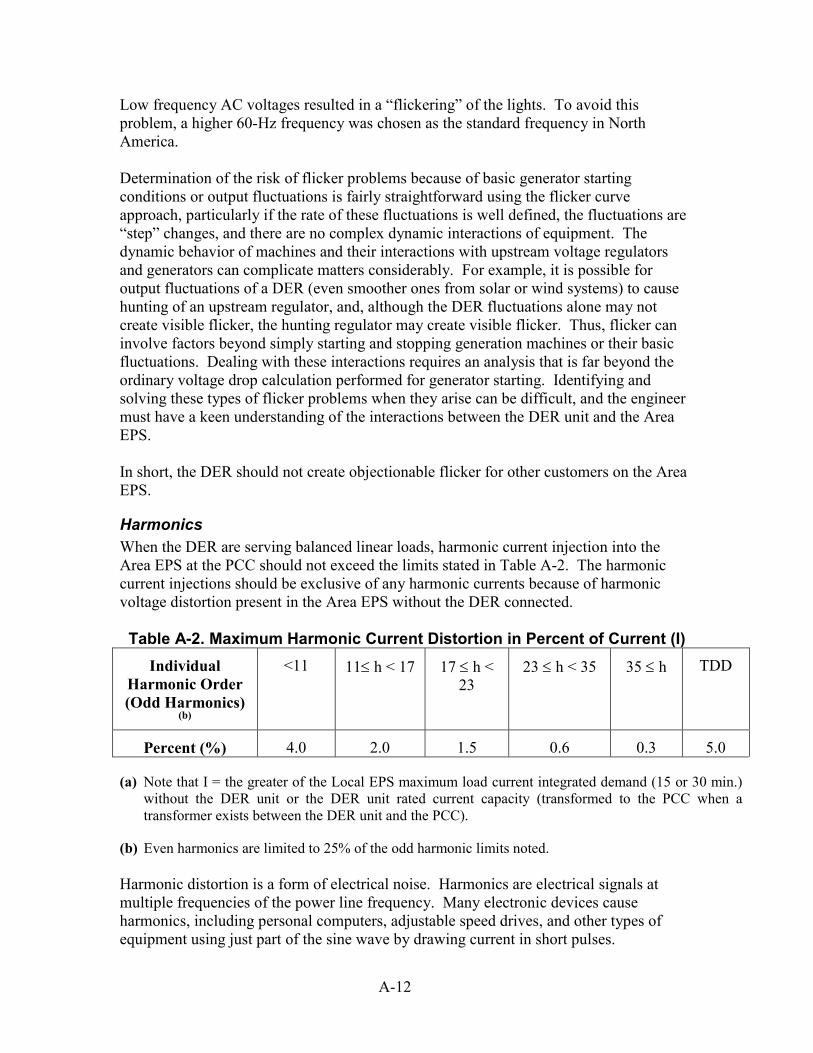
Low frequency AC voltages resulted in a “flickering” of the lights. To avoid this problem, a higher 60-Hz frequency was chosen as the standard frequency in North America. Determination of the risk of flicker problems because of basic generator starting conditions or output fluctuations is fairly straightforward using the flicker curve approach, particularly if the rate of these fluctuations is well defined, the fluctuations are “step” changes, and there are no complex dynamic interactions of equipment. The dynamic behavior of machines and their interactions with upstream voltage regulators and generators can complicate matters considerably. For example, it is possible for output fluctuations of a DER (even smoother ones from solar or wind systems) to cause hunting of an upstream regulator, and, although the DER fluctuations alone may not create visible flicker, the hunting regulator may create visible flicker. Thus, flicker can involve factors beyond simply starting and stopping generation machines or their basic fluctuations. Dealing with these interactions requires an analysis that is far beyond the ordinary voltage drop calculation performed for generator starting. Identifying and solving these types of flicker problems when they arise can be difficult, and the engineer must have a keen understanding of the interactions between the DER unit and the Area EPS. In short, the DER should not create objectionable flicker for other customers on the Area EPS.
Harmonics When the DER are serving balanced linear loads, harmonic current injection into the Area EPS at the PCC should not exceed the limits stated in Table A-2. The harmonic current injections should be exclusive of any harmonic currents because of harmonic voltage distortion present in the Area EPS without the DER connected. Table A-2. Maximum Harmonic Current Distortion in Percent of Current (I)
Individual Harmonic Order (Odd Harmonics)
(b)
<11 11≤ h < 17 17 ≤ h < 23
23 ≤ h < 35 35 ≤ h TDD
Percent (%) 4.0 2.0 1.5 0.6 0.3 5.0
(a) Note that I = the greater of the Local EPS maximum load current integrated demand (15 or 30 min.) without the DER unit or the DER unit rated current capacity (transformed to the PCC when a transformer exists between the DER unit and the PCC).
(b) Even harmonics are limited to 25% of the odd harmonic limits noted. Harmonic distortion is a form of electrical noise. Harmonics are electrical signals at multiple frequencies of the power line frequency. Many electronic devices cause harmonics, including personal computers, adjustable speed drives, and other types of equipment using just part of the sine wave by drawing current in short pulses.
A-12
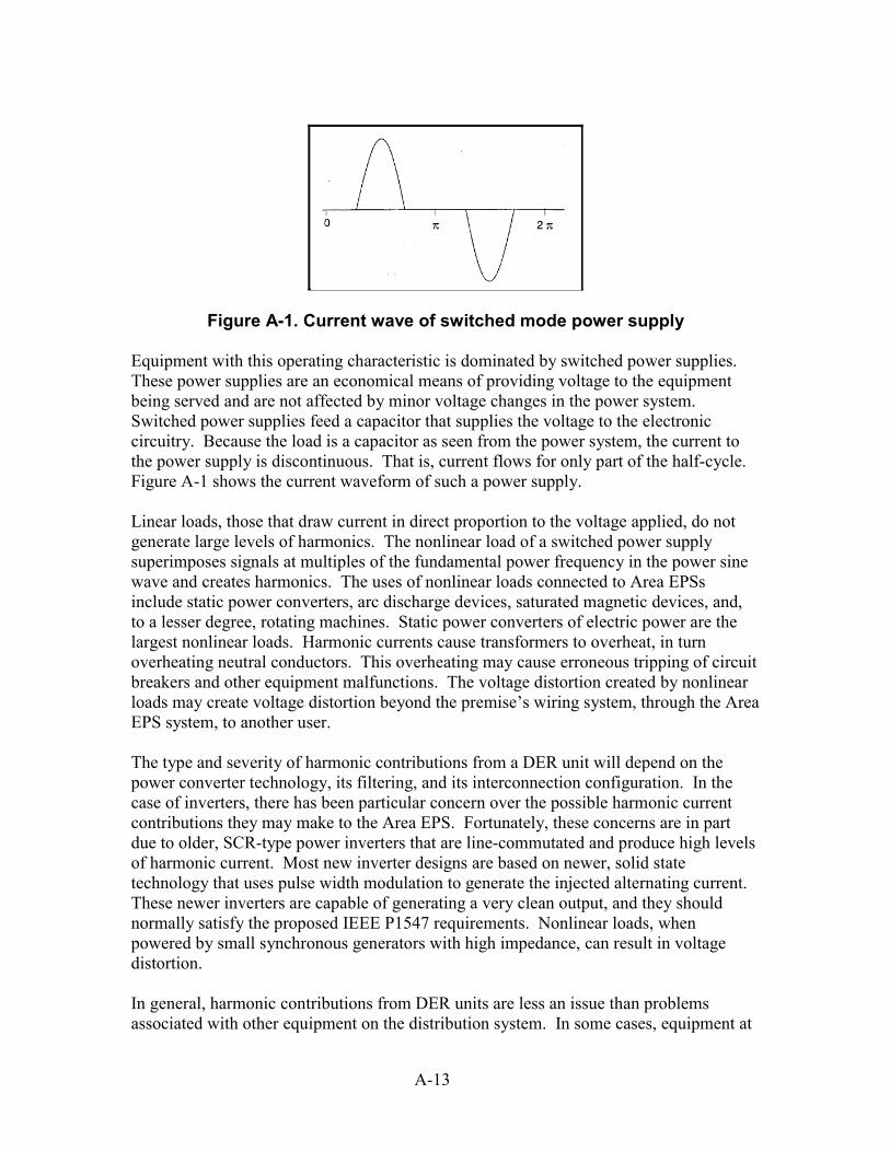
Figure A-1. Current wave of switched mode power supply Equipment with this operating characteristic is dominated by switched power supplies. These power supplies are an economical means of providing voltage to the equipment being served and are not affected by minor voltage changes in the power system. Switched power supplies feed a capacitor that supplies the voltage to the electronic circuitry. Because the load is a capacitor as seen from the power system, the current to the power supply is discontinuous. That is, current flows for only part of the half-cycle. Figure A-1 shows the current waveform of such a power supply. Linear loads, those that draw current in direct proportion to the voltage applied, do not generate large levels of harmonics. The nonlinear load of a switched power supply superimposes signals at multiples of the fundamental power frequency in the power sine wave and creates harmonics. The uses of nonlinear loads connected to Area EPSs include static power converters, arc discharge devices, saturated magnetic devices, and, to a lesser degree, rotating machines. Static power converters of electric power are the largest nonlinear loads. Harmonic currents cause transformers to overheat, in turn overheating neutral conductors. This overheating may cause erroneous tripping of circuit breakers and other equipment malfunctions. The voltage distortion created by nonlinear loads may create voltage distortion beyond the premise’s wiring system, through the Area EPS system, to another user. The type and severity of harmonic contributions from a DER unit will depend on the power converter technology, its filtering, and its interconnection configuration. In the case of inverters, there has been particular concern over the possible harmonic current contributions they may make to the Area EPS. Fortunately, these concerns are in part due to older, SCR-type power inverters that are line-commutated and produce high levels of harmonic current. Most new inverter designs are based on newer, solid state technology that uses pulse width modulation to generate the injected alternating current. These newer inverters are capable of generating a very clean output, and they should normally satisfy the proposed IEEE P1547 requirements. Nonlinear loads, when powered by small synchronous generators with high impedance, can result in voltage distortion. In general, harmonic contributions from DER units are less an issue than problems associated with other equipment on the distribution system. In some cases, equipment at
A-13
the DER site may need to be derated because of added heating caused by harmonics elsewhere on the system. Filters and other mitigation approaches are sometimes required.
Immunity Protection The influence of electromagnetic interference (EMI) should not result in a change in state or misoperation of the interconnection system. The use of hand-held transceivers (walkie-talkies) has increased dramatically over the past few years. When operated in close proximity to a static protective relay, these transceivers will produce local, high field-strength electromagnetic radiation that may affect protective relay performance. This interaction has driven the need for a standard on radiated interference and withstand capability for static protective relays. The test field-strength level has been increased from 10-20 V/m to 35 V/m. The 35 V/m level is intended to roughly approximate the effect of a walkie-talkie operated at 15 cm (6 inches) from the exposed surface of the relay. This proposed IEEE P1547 requirement, along with the subsequent surge withstand capability (SWC) requirement, differs from the previous issue on the ability of the interconnection system to prevent any negative DER impact on Area EPS safety or operating stability. This requirement focuses exclusively on the continued operation of the interconnection system after EMI exposure. The DER interconnection system is essentially being held to the same standard of performance as generators, protective relaying, and other electrical equipment.
Surge Capability The interconnection system should have the capability to withstand voltage and current surges in accordance with the environments defined in IEEE/ANSI C62.41 or IEEE C37.90.1 as appropriate. Occasionally, attempts will be made to describe surges in terms of “energy” to help select the rating of a candidate surge-protective device. However, this concept can be a misleading oversimplification because the energy distribution among the circuit elements involved in a surge event depends on the impedance of the source (including the AC mains) as well as on the impedance of the surge-protective device called upon to divert the surge. There is no independent, meaningful, and self-contained description of a surge in terms of energy alone. The energy delivered to the end-equipment is the significant factor, but it depends on the distribution between the source and the load (equipment or surge-diverting protective device or both). Transient surge voltages occurring in AC power circuits can be the cause of operational upset or product failure in industrial and residential systems and equipment. These problems have received increased attention in recent years because of the widespread application of complex semiconductor devices that are more sensitive to voltage surges than vacuum tubes, relays, and earlier generations of semiconductor devices. Logical and
A-14

economical design of circuits to protect vulnerable electronic systems from upset or failure requires knowledge of or an estimate of: 1. Transient voltage and current waveforms, 2. Frequency of occurrence of transients with various energy levels, 3. Particular environmental variations such as amplitudes, and 4. Upset or failure threshold of the particular equipment to be protected.
Islanding For an unintentional island in which the DER and a portion of the Area EPS remain energized through the PCC, the DER should cease to energize the Area EPS within 10 seconds of the formation of an island. Islanding occurs when the DER (or a group of DER) continues to energize a portion of the Area EPS that has been separated from the rest of the Area EPS. This separation could be due to operation of an upstream breaker, fuse, or automatic sectionalizing switch. Manual switching or “open” upstream conductors could also lead to islanding. Islanding can occur only if the DER continues to serve a load in the islanded section.
In most cases, it is not desirable for a DER to island with any part of the Area EPS on an unplanned basis; this can lead to safety and power quality problems that will affect the Area EPS and local loads. During utility or Distco repair operations, such as dealing with downed conductors, DER islanding can expose utility workers to circuits that otherwise would be de-energized (and that the workers believe to be de-energized). This situation can pose a threat to the public as well. Service restoration can also be delayed as line crews seek to ensure that DER islanding is not a problem.
Summary Each of these 18 technology attributes affects the interconnection process. Accordingly, they influence the components that must be built into an interconnection system. In turn, these technical issues have heavily contributed to the manner in which DER units have generally been interconnected to date – that is, as individual installations. Because each utility or Distco has often had its own requirements for meeting these 18 technical attributes, interconnection systems have not been pre-certified for inexpensive mass installation. Thus, there has been a tendency to design, license, install, test, and operate each DER system uniquely. Additionally, these technical issues have led to myriad interconnection codes and standards that must be met by interconnection equipment. Future RD&D needs are largely driven by this situation.
A-15

A-16
B APPENDIX B: INTERCONNECTION CODES AND STANDARDS The interconnection of DER to the Area EPS transmission and distribution system is regulated by codes and standards put in place to address safety and power quality issues. These codes and standards set requirements for DER interconnection equipment manufacture, installation, and operation. Table B-1 shows codes and standards relevant to DER interconnection and the type of equipment to which they apply.
B-1
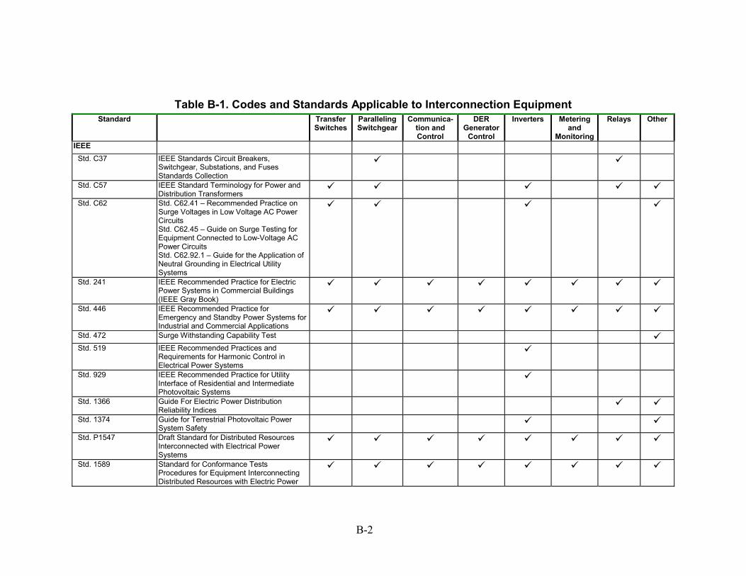
Table B-1. Codes and Standards Applicable to Interconnection Equipment
Standard TransferSwitches
Paralleling Switchgear
Communica-tion and Control
DER Generator
Control
Inverters Meteringand
Monitoring
Relays Other
IEEE Std. C37 IEEE Standards Circuit Breakers,
Switchgear, Substations, and Fuses Standards Collection
Std. C57 IEEE Standard Terminology for Power and Distribution Transformers
Std. C62 Std. C62.41 – Recommended Practice on
Surge Voltages in Low Voltage AC Power Circuits Std. C62.45 – Guide on Surge Testing for Equipment Connected to Low-Voltage AC Power Circuits Std. C62.92.1 – Guide for the Application of Neutral Grounding in Electrical Utility Systems
Std. 241 IEEE Recommended Practice for Electric Power Systems in Commercial Buildings (IEEE Gray Book)
Std. 446 IEEE Recommended Practice for Emergency and Standby Power Systems for Industrial and Commercial Applications
Std. 472 Surge Withstanding Capability Test Std. 519 IEEE Recommended Practices and
Requirements for Harmonic Control in Electrical Power Systems
Std. 929 IEEE Recommended Practice for Utility Interface of Residential and Intermediate Photovoltaic Systems
Std. 1366 Guide For Electric Power Distribution Reliability Indices
Std. 1374 Guide for Terrestrial Photovoltaic Power
System Safety
Std. P1547 Draft Standard for Distributed Resources Interconnected with Electrical Power Systems
Std. 1589 Standard for Conformance Tests Procedures for Equipment Interconnecting Distributed Resources with Electric Power
B-2
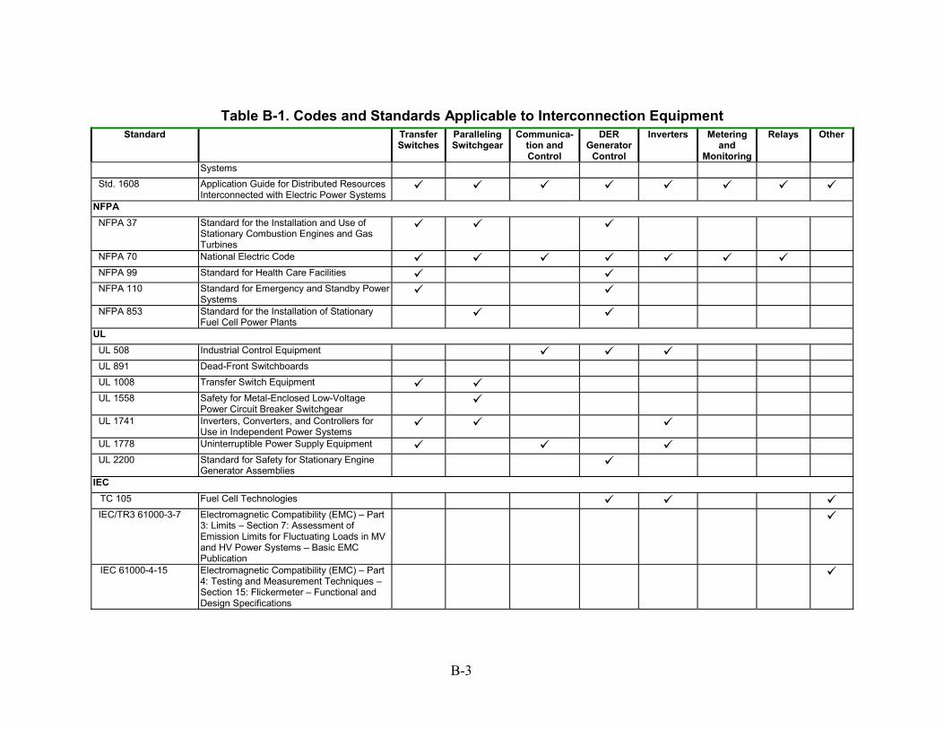
Table B-1. Codes and Standards Applicable to Interconnection Equipment
Standard Transfer Switches
Paralleling Switchgear
Communica-tion and Control
DER Generator
Control
Inverters Metering and
Monitoring
Relays Other
Systems Std. 1608 Application Guide for Distributed Resources
Interconnected with Electric Power Systems
NFPA NFPA 37 Standard for the Installation and Use of
Stationary Combustion Engines and Gas Turbines
NFPA 70 National Electric Code NFPA 99 Standard for Health Care Facilities NFPA 110 Standard for Emergency and Standby Power
Systems
NFPA 853 Standard for the Installation of Stationary Fuel Cell Power Plants
UL UL 508 Industrial Control Equipment UL 891 Dead-Front Switchboards UL 1008 Transfer Switch Equipment UL 1558 Safety for Metal-Enclosed Low-Voltage
Power Circuit Breaker Switchgear
UL 1741 Inverters, Converters, and Controllers for Use in Independent Power Systems
UL 1778 Uninterruptible Power Supply Equipment UL 2200 Standard for Safety for Stationary Engine
Generator Assemblies
IEC TC 105 Fuel Cell Technologies IEC/TR3 61000-3-7 Electromagnetic Compatibility (EMC) – Part
3: Limits – Section 7: Assessment of Emission Limits for Fluctuating Loads in MV and HV Power Systems – Basic EMC Publication
IEC 61000-4-15 Electromagnetic Compatibility (EMC) – Part 4: Testing and Measurement Techniques – Section 15: Flickermeter – Functional and Design Specifications
B-3
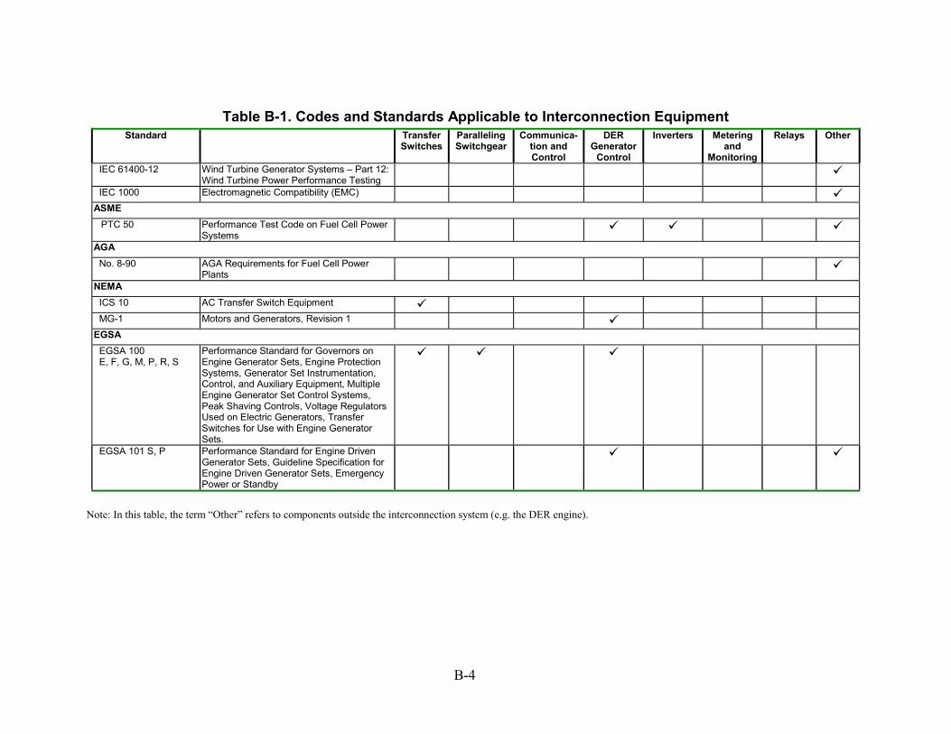
Table B-1. Codes and Standards Applicable to Interconnection Equipment
Standard Transfer Switches
Paralleling Switchgear
Communica-tion and Control
DER Generator
Control
Inverters Metering and
Monitoring
Relays Other
IEC 61400-12 Wind Turbine Generator Systems – Part 12: Wind Turbine Power Performance Testing
IEC 1000 Electromagnetic Compatibility (EMC) ASME PTC 50 Performance Test Code on Fuel Cell Power
Systems
AGA No. 8-90 AGA Requirements for Fuel Cell Power
Plants
NEMA ICS 10 AC Transfer Switch Equipment MG-1 Motors and Generators, Revision 1 EGSA EGSA 100 E, F, G, M, P, R, S
Performance Standard for Governors on Engine Generator Sets, Engine Protection Systems, Generator Set Instrumentation, Control, and Auxiliary Equipment, Multiple Engine Generator Set Control Systems, Peak Shaving Controls, Voltage Regulators Used on Electric Generators, Transfer Switches for Use with Engine Generator Sets.
EGSA 101 S, P Performance Standard for Engine Driven Generator Sets, Guideline Specification for Engine Driven Generator Sets, Emergency Power or Standby
Note: In this table, the term “Other” refers to components outside the interconnection system (e.g. the DER engine).
B-4
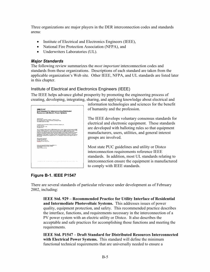
Three organizations are major players in the DER interconnection codes and standards arena:
• Institute of Electrical and Electronics Engineers (IEEE), • National Fire Protection Association (NFPA), and • Underwriters Laboratories (UL).
Major Standards The following review summarizes the most important interconnection codes and standards from these organizations. Descriptions of each standard are taken from the applicable organization’s Web site. Other IEEE, NFPA, and UL standards are listed later in this chapter.
Institute of Electrical and Electronics Engineers (IEEE) The IEEE helps advance global prosperity by promoting the engineering process of creating, developing, integrating, sharing, and applying knowledge about electrical and
information technologies and sciences for the benefit of humanity and the profession. The IEEE develops voluntary consensus standards for electrical and electronic equipment. These standards are developed with balloting rules so that equipment manufacturers, users, utilities, and general interest groups are involved. Most state PUC guidelines and utility or Distco interconnection requirements reference IEEE standards. In addition, most UL standards relating to interconnection ensure the equipment is manufactured to comply with IEEE standards.
Figure B-1. IEEE P1547 There are several standards of particular relevance under development as of February 2002, including:
IEEE Std. 929 – Recommended Practice for Utility Interface of Residential and Intermediate Photovoltaic Systems. This addresses issues of power quality, equipment protection, and safety. This recommended practice describes the interface, functions, and requirements necessary in the interconnection of a PV power system with an electric utility or Distco. It also describes the acceptable and safe practices for accomplishing those functions and meeting the requirements.
IEEE Std. P1547 – Draft Standard for Distributed Resources Interconnected with Electrical Power Systems. This standard will define the minimum functional technical requirements that are universally needed to ensure a
B-5
technically sound interconnection. The standard provides uniform criteria and requirements relevant to the performance, operation, testing, safety, and maintenance for the interconnection equipment. The standard is currently unapproved and under revision.
IEEE Std. 1548 – Draft Standard for Conformance Tests Procedures for Equipment Interconnecting Distributed Resources with Electric Power Systems. This standard specifies the type, production, and commissioning tests that shall be performed to demonstrate that the interconnection functions and equipment of a DER conform to IEEE Standard P1547. Standardized test procedures are necessary to establish and verify compliance with those requirements. These test procedures must provide both repeatable results, independent of test location, and flexibility to accommodate a variety of DER technologies.
IEEE Std. P1608 – Draft Application Guide for IEEE Standard 1547, Interconnecting Distributed Resources with Electric Power Systems. This guide provides technical background and application details to support the understanding of IEEE 1547, Standard for Interconnecting Distributed Resources with Electric Power Systems. This document characterizes the various forms of distributed resource technologies and the associated interconnection issue and discusses the background and rationale of the technical requirements in terms of the operation of the distributed resource interconnection with the electric power system.
To order copies of these and other IEEE standards, visit the IEEE Web site at http://standards.ieee.org/.
National Fire Protection Association (NFPA) NFPA has been a worldwide leader in providing fire, electrical, and life safety to the public since 1896. The mission of the nonprofit organization is to reduce the worldwide burden of fire and other hazards on the quality of life by providing and advocating scientifically based consensus codes and standards, research, training, and education.
Figure B-2. National Electrical Code 2002
The NFPA publishes the National Electrical Code (NEC) (NFPA-70), which covers electrical equipment wiring and safety on the customer’s side of the point of common coupling. The NFPA also publishes other standards relating to DER interconnection. NFPA 70 – National Electrical Code. Covers electric conductors and equipment installed within or on public and private buildings or other structures, including mobile homes and recreational vehicles, floating buildings, and other premises such as yards, carnivals, parking and other lots, and industrial substations; conductors that connect the installations to a supply of electricity and other outside conductors and equipment on the premises;
B-6
optical fiber cable; and buildings used by the electric utility, such as office buildings, warehouses, garages, machine shops, and recreational buildings that are not an integral part of a generating plant, substation, or control center. Some NEC Articles related to interconnection are described below.
Article 230 – Services. Includes provisions and requirements for electric service to a building, including emergency, backup, and parallel power production.
Article 690 – Solar Photovoltaic Systems. Mentions interconnection to the grid but focuses on descriptions of components and proper system wiring. Article 692 – Fuel Cells. Covers stationary fuel cells for power production. Article 700 – Emergency Systems. Includes provisions that apply to emergency power systems together with information on interconnection such as references to transfer switches. Article 701 – Legally Required Standby Systems. Includes provisions that apply to standby power systems. Has some information on interconnection such as references to transfer switches, UPSs, generators, etc. Article 702 – Optional Standby Systems. Includes provisions that apply to standby systems that are not legally required. Has some information on interconnection such as references to transfer switches, grounding, circuit wiring, etc. Article 705 – Interconnected Electrical Power Production Systems. Broadly covers DER interconnection.
To find out more about or to order NFPA standards, visit the NFPA Web site at http://www.nfpa.org/Codes/index.asp.
Underwriters Laboratories (UL) Underwriters Laboratories, Inc. (UL) is an independent, not-for-profit product safety testing and certification organization. UL has tested products for public safety for more than a century and is the leader in U.S. electrical product safety and certification. UL has a number of certifications that apply to DER interconnection equipment. UL 1741 – Inverters, Converters, and Controllers for Use in Independent Power Systems. These requirements cover inverters, converters, charge controllers, and output controllers intended for use in stand-alone (not grid-connected) or utility-interactive (grid-connected) power systems. Utility-interactive inverters and converters are intended to be installed in parallel with an Area EPS or for an electric utility to supply common loads.
B-7

For information about obtaining copies of this and other UL standards, visit the UL Web site at http://www.ul.com/info/standard.htm. Other Standards Other standards from IEEE, NFPA, and UL are listed below. In addition, a number of other organizations issue codes and standards that may apply to distributed generation interconnection equipment, and these are also listed below.
Institute of Electrical and Electronics Engineers (IEEE) Std. C37 – IEEE Standards Circuit Breakers, Switchgear, Substations, and Fuses Standards Collection. This all-inclusive volume is the single source of IEEE and ANSI switchgear and substation standards covering circuit breakers, switchgear assemblies, switches, fuses, reclosures and sectionalizers, and related substation aspects of equipment. The 99 standards contained in this thorough collection provide for the safe and reliable application of electrical systems switchgear and substation operation and maintenance.
Std. C37.2 – IEEE Standard Electrical Power System Device Function Numbers. The definition and application of function numbers for devices used in electrical substations and generating plants and in installations of power utilization and conversion apparatus are covered. The purpose of the numbers is discussed, and 94 numbers are assigned. The use of prefixes and suffixes to provide a more specific definition of each function is considered. Device contact designation is also covered.
Std. C37.04 – IEEE Standard Rating Structure for AC High-Voltage Circuit Breakers Rated on a Symmetrical Current Basis. A rating structure for AC high-voltage circuit breakers rated on a symmetrical current basis is established. The rating structure applies to indoor and outdoor types of AC high-voltage circuit breakers rated above 1,000 V. Service conditions, construction, and nameplate markings are also considered.
Std. C37.06 – IEEE Standard for AC High-Voltage Circuit Breakers Rated on Symmetrical Current Basis – Preferred Ratings and Related Required Capabilities.
Std. C37.13 – IEEE Standard for Low-Voltage AC Power Circuit Breakers Used in Enclosures. This standard covers enclosed low-voltage AC power circuit breakers of the stationary or draw-out type of two- or three-pole construction, with one or more rated maximum voltages of 635 V (600 V for units incorporating fuses), 508 V, and 254 V for application on systems having nominal voltages of 600 V, 480 V, and 240 V; with unfused or fused circuit breakers; manually or power operated; and with or without electromechanical or solid-state trip devices. It deals with service conditions, ratings, functional components, temperature limitations and classifications of insulating materials, insulation (dielectric) withstand voltage requirements, test procedures, and application.
B-8
Std. C37.14 – IEEE Standard for Low-Voltage DC Power Circuit Breakers Used in Enclosures. This standard covers enclosed low-voltage DC power circuit breakers of the stationary or draw-out type of single- or two-pole construction with one or more rated maximum voltages of 300 V, 325 V, 800 V, 1,000 V, 1,600 V, or 3,200 V for applications on systems having nominal voltages of 250 V, 275 V, 750 V, 850 V, 1,500 V, or 3,000 V, with general-purpose, high-speed, semi-high-speed and rectifier circuit breakers; manually or power operated; and with or without electromechanical or solid-state trip devices. This standard deals with service conditions, ratings, functional components, temperature limitations and classifications of insulating materials, insulation (dielectric) withstand voltage requirements, test procedures, and application. Std. C37.16 – IEEE Standard for Low-Voltage Power Circuit Breakers and AC Power Circuit Protectors – Preferred Ratings, Related Requirements, and Application. Std. C37.18 – IEEE Standard Enclosed Field Discharge Circuit Breakers for Rotating Electric Machinery. Low-voltage power circuit breakers that are intended for use in field circuits of apparatus such as generators, motors, synchronous condensers, or exciters and that embody contacts for establishing field discharge circuits are covered. Service conditions, ratings, and functional components are discussed. Temperature limitations and classification of insulating materials, insulation (dielectric) withstand voltage requirements, and test requirements are addressed. An application guide is included.
Std. C37.27 – IEEE Standard Application Guide for Low-Voltage AC Nonintegrally Fused Power Circuit Breakers (Using Separately Mounted Current-Limiting Fuses). Low-voltage power circuit breakers of the 600-V insulation class with separately mounted current-limiting fuses, for use on AC circuits with available short-circuit current of 200,000 A (rms symmetrical) or less, are covered. Guidance is provided respecting coordination of circuit breaker and fuse, location of fuses, open fuse trip devices, addition of fuses to existing installations, protection of connected equipment, and tested combinations of circuit breakers and fuses.
Std. C37.29 – IEEE Standard for Low-Voltage AC Power Circuit Protectors Used in Enclosures. This standard covers enclosed low-voltage AC power circuit protectors that are manually operated or power operated. Addressed are circuit protectors of the stationary type with two-pole or three-pole construction, having one or more rated maximum voltages of 508 V and 254 V rms, for application on systems having nominal voltages of 480 V and 240 V rms. The circuit protectors considered are furnished with current-limiting fuses such that the entire device is suitable for application on circuits capable of delivering not more than 200,000 A rms symmetrical short-circuit current. Service conditions and ratings are discussed, and the functional components of the circuit protectors
B-9
are described. Temperature limitations and classification of insulating materials are covered. Insulation (dielectric) withstand voltage requirements are specified, and an application guide is given. Test procedures are also specified.
Std. C37.50 – ANSI/IEEE Standard Test Procedures for Low-Voltage AC Circuit Breakers Used in Enclosures. Covers the test procedures for enclosed low-voltage AC power circuit breakers.
Std. C37.51 – ANSI/IEEE Standard Conformance Test Procedure for Metal Enclosed Low-Voltage AC Power Circuit-Breaker Switchgear Assemblies. This standard applies to metal-enclosed, low-voltage power circuit-breaker switchgear assemblies and covers the conformance test procedures for the basic switchgear section, which include the structure, circuit-breaker compartments, instrument compartments, buses, and internal connections.
Std. C37.52 – ANSI/IEEE Standard Test Procedures for Low-Voltage AC Power Circuit Protectors Used in Enclosures. Covers the test procedures for enclosed low-voltage AC power circuit protectors.
Std. C37.90 – IEEE Standard for Relays and Relay Systems Associated with Electric Power Apparatus. This standard applies to relay systems that protect and control apparatus that generate and distribute and use electric power. This standard defines service conditions and specifies relay performance requirements and performance information that relay manufacturers shall provide. Std. C37.95 – IEEE Guide for Protective Relaying of Utility Consumer Interconnections. Information on a number of different protective relaying practices for the utility-consumer interconnection is provided. The following are covered: establishing consumer service requirements and supply method, typical utility-consumer interconnection configurations, protection theory, system studies, and interconnection examples. The information is provided only for applications involving service to a consumer that normally requires a transformation between the Area EPS's supply voltage and the consumer's utilization voltage. Interconnections supplied at the ultimate utilization voltage are not covered.
C37.100 – IEEE Standard Definitions for Power Switchgear. Terms that encompass the products within the scope of the C37 project are defined. These include power switchgear for switching, interrupting, metering, protection, and regulating purposes as used primarily in connection with generation, transmission, distribution, and conversion of electric power.
Std. C37.108-1989 (R1994) – IEEE Guide for the Protection of Network Transformers. This guide will be revised to aid relay protection engineers, vendors, and Area EPS customers to address the use of network transformer protection by independent power producers. Additionally, the guide will be revised to introduce new transformer protection and techniques that may include
B-10
the computer type relays, fiber optics, ultra-violet detectors, and current limiting protection devices.
Std. C57 – IEEE Standard Terminology for Power and Distribution Transformers. This standard is a compilation of terminology and definitions primarily related to electrical transformers and associated apparatus included within the scope of ANSI Committee C57, Transformers, Regulators, and Reactors. It also includes similar data relating to power systems and insulation that is commonly involved in transformer technology. Std. C62.41 – IEEE Recommended Practice on Surge Voltages in Low-Voltage AC Power Circuits. A practical basis is provided for the selection of voltage and current tests to be applied in evaluating the surge withstand capability of equipment connected to Area EPS power circuits, primarily in residential, commercial, and light industrial applications. The recommended practice covers the origin of surge voltages, rate of occurrence and voltage levels in unprotected circuits, waveshapes of representative surge voltages, energy, and source and impedance. Three location categories are defined according to their relative position from the building service entrance. For each category, representative waveforms of surge voltages and surge currents are described, organized in two recommended "standard waveforms" and three suggested "additional waveforms." Std. C62.45 – IEEE Guide on Surge Testing for Equipment Connected to Low-Voltage AC Power Circuits. Guidance is provided for applying surge testing to AC power interfaces of equipment connected to low-voltage AC power circuits that are subject to transient over-voltages. Signal and data lines are not addressed in this document, nor are any specifications stated on the withstand levels that might be assigned to specific equipment. An important objective of the document is to call attention to the safety aspects of surge testing. Std. C62.92.1 – IEEE Guide for the Application of Neutral Grounding in Electrical Utility Systems. Some basic considerations for the selection of neutral grounding parameters that will provide for the control of ground-fault current and over-voltage on all portions of three-phase electric Area EPS are presented. These considerations apply specifically to Area EPS and do not recognize the neutral grounding requirements for dispersed storage and generation. They are intended to serve as an introduction to a series of standards on neutral grounding in Area EPS systems. Std. 241 – IEEE Recommended Practice for Electric Power Systems in Commercial Buildings (IEEE Gray Book). A guide and general reference on electrical design for commercial buildings is provided. It covers load characteristics; voltage considerations; power sources and distribution systems; power distribution apparatus; controllers; services, vaults, and electrical equipment rooms; wiring systems; systems protection and coordination; lighting; electric space conditioning; transportation; communication systems planning; facility automation; expansion, modernization, and rehabilitation; special requirements by occupancy; and electrical energy management. Although directed to the power-oriented engineer with limited commercial building experience, it can be an aid to all engineers responsible for the electrical design of commercial
B-11
buildings. This recommended practice is not intended to be a complete handbook; however, it can direct the engineer to texts, periodicals, and references for commercial buildings and act as a guide through the myriad of codes, standards, and practices published by the IEEE, other professional associations, and governmental bodies. Std. 446 – IEEE Recommended Practice for Emergency and Standby Power Systems for Industrial and Commercial Applications. This recommended practice addresses the uses, power sources, design, and maintenance of emergency and standby power systems. Chapter 3 is a general discussion of needs for and the configuration of emergency and standby systems. Chapter 9 lists the power needs for specific industries. Chapters 4 and 5 deal with the selection of power sources. Chapter 6 provides recommendations for protecting both power sources and switching equipment during fault conditions. Chapter 7 provides recommendations for the design of system grounding, and Chapter 10 provides recommendations for designing to reliability objectives. Chapter 8 provides recommended maintenance practices. Std. 472 – Surge Withstanding Capability Test. Std. 519 – IEEE Recommended Practices and Requirements for Harmonic Control in Electrical Power Systems. This guide applies to all types of static power converters used in industrial and commercial power systems. The problems involved in the harmonic control and reactive compensation of such converters are addressed, and an application guide is provided. Limits of disturbances to the AC power distribution system that affect other equipment and communications are recommended. This guide is not intended to cover the effect of radio frequency interference. Std. 929 – IEEE Recommended Practice for Utility Interface of Residential and Intermediate Photovoltaic Systems. Addresses issues of power quality, equipment protection, and safety. This recommended practice describes the interface, functions, and requirements necessary in the interconnection of a PV power system with an electric utility or Distco. It also describes the acceptable and safe practices for accomplishing those functions and meeting the requirements. Std. 1366 – Guide For Electric Power Distribution Reliability Indices. This guide identifies useful electric power distribution system reliability indices and factors that affect their calculation. It includes indices that are useful today as well as ones that may be useful in the future. The indices are intended to apply to distribution systems, substations, circuits, and defined regions. Std. 1374 – Guide for Terrestrial Photovoltaic Power System Safety. Photovoltaic power system designers and installers have a wide range of utility-grade, industrial, commercial, and special purpose cables, over-current devices, disconnects, power conditioners, modules, and other optional equipment to choose from in the design and installation of electrically safe systems. The selection and application of the available equipment is not generally covered in existing standards. This guide will suggest good engineering safety practices for PV system design, equipment selection, and hardware installation.
B-12
In addition, there are several relevant standards under development as of February 2002, including:
Std. P1547 – Draft Standard for Distributed Resources Interconnected with Electrical Power Systems. This standard will define the minimum functional technical requirements that are universally needed to ensure a technically sound interconnection. The standard provides uniform criteria and requirements relevant to the performance, operation, testing, safety considerations, and maintenance for the interconnection equipment. The standard is currently unapproved and under revision. Std. 1589 – Standard for Conformance Tests Procedures for Equipment Interconnecting Distributed Resources with Electric Power Systems. This standard specifies the type, production, and commissioning tests that shall be performed to demonstrate that the interconnection functions and equipment of a DER conform to IEEE Standard P1547. Standardized test procedures are necessary to establish and verify compliance with those requirements. These test procedures must provide both repeatable results, independent of test location, and flexibility to accommodate a variety of DER technologies. Std. 1608 – Application Guide for Distributed Resources Interconnected with Electric Power Systems. This document facilitates the use of IEEE 1547 by characterizing the various forms of distributed resource technologies and the associated interconnection issues. Additionally, the background and rationale of the technical requirements are discussed in terms of the operation of the distributed resource interconnection with the electric power system. Presented in the document are technical descriptions and schematics, applications guidance, and interconnection examples to enhance the use of IEEE P1547.
A few IEEE standards relating to DER interconnection have been withdrawn, including: • Std. 1001 – Guide for Interfacing Dispersed Storage and Generation Facilities
with Electrical Utility Systems, • Std. 1021 – Recommended Practice for Utility Interconnection of Small Wind
Energy Conversion System, and • Std. 1035 – Recommended Practice: Test Procedure for Utility-Interconnected
Static Power Converters.
National Fire Protection Association (NFPA) NFPA 37 – Standard for the Installation and Use of Stationary Combustion Engines and Gas Turbines. Covers the installation and operation of stationary combustion engines and gas turbines. Also covers portable engines that remain connected for use in the same location for a period of one week or more and that are used instead of or to supplement stationary engines.
B-13
NFPA 99 – Standard for Health Care Facilities. Covers criteria to minimize the hazards of fire, explosion, and electricity in health care facilities. NFPA 110 – Standard for Emergency and Standby Power Systems. Covers performance requirements for power systems providing an alternate source of electrical power to loads in buildings and facilities in the event that the normal power source fails. NFPA 853 – Standard for the Installation of Stationary Fuel Cell Power Plants. Applies to the design and installation of the following stationary fuel cell power plant applications: (a) a singular prepackaged self-contained power plant unit, (b) a combination of prepackaged self-contained units, and (c) power plant units composed of two or more factory matched modular components intended to be assembled in the field.
Underwriters Laboratories (UL) UL 508 – Industrial Control Equipment. These requirements cover industrial control devices and devices accessory thereto, for starting, stopping, regulating, controlling, or protecting electric motors. These requirements also cover industrial control devices or systems that store or process information and are provided with an output motor control function. This equipment is for use in ordinary locations in accordance with the National Electrical Code, NFPA 70. These requirements cover devices rated 1,500 V or less. Industrial control equipment covered by these requirements is intended for use in an ambient temperature of 0°C– 40°C (32°F–104°F) unless specifically indicated for use in other conditions. UL 508 also covers industrial control panels that are assemblies of industrial control devices and other devices associated with the control of motor-operated and related industrial equipment. Examples of devices in an industrial control panel are industrial control devices, disconnecting means, motor branch circuit protective devices, temperature control devices, and electrical instruments. Examples of industrial control devices include: • Manual, magnetic, and solid-state starters and controllers; • Thermal, magnetic, and solid-state overload relays; • Pushbutton stations, including selector switches and pilot lights; • Control circuit switches and relays; • Float, flow, pressure, and vacuum-operated switches; • Resistors and rheostats; • Proximity switches; • Time-delay relays and switches; • Resistors and rheostats intended for industrial heating and lighting, including those
for motor generator fields; • Control devices intended for industrial heating and lighting; • Solid-state time-delay relays;
B-14
• Programmable controllers; • Numerical control systems; • Lighting dimmer systems and controls; • Mercury-tube switches; • Definite purpose controllers; • Solid-state logic controllers; • Industrial microprocessor/computer systems; • Variable voltage autotransformer; and • Motor starting autotransformer. Electrical instruments are covered by the Standard for Electrical Analog Instruments – Panel Board Types, UL 1437. UL 508A – Industrial Control Panels. These requirements cover industrial control panels intended for general industrial use, operating from a voltage of 600 V or less. This equipment is intended for installation in ordinary locations, in accordance with the National Electrical Code, ANSI/NFPA 70, where the ambient temperature does not exceed 40°C (104°F). UL 508A also covers industrial control panel enclosures and industrial control panels intended for flame safety supervision of combustible fuel type equipment, elevator control, crane or hoist control, service equipment use, marine use, air conditioning and refrigeration equipment, and for control of industrial machinery including metalworking machine tools, power press controls, and plastic injection molding machinery. This equipment consists of assemblies of two or more components, such as motor controllers, overload relays, fused disconnect switches, circuit breakers, and related control devices such as pushbuttons, pilot lights, selector switches, timers, control relays, and similar devices, with associated wiring, terminal blocks, and similar components. Equipment intended for use in hazardous locations, as defined in the National Electrical Code, ANSI/NFPA 70, is covered by UL 698, Standard for Industrial Control Equipment for Use in Hazardous (Classified) Locations. Industrial control panels incorporating intrinsic safety barriers and intended for connection to circuits residing in hazardous locations are covered by UL 698A, Standard for Industrial Control Panels Relating to Hazardous (Classified) Locations. UL 508C – Power Conversion Equipment. These requirements cover open or enclosed equipment that supply power to control a motor or motors operating at a frequency or voltage different from that of the input supply. These requirements also cover power-supply modules, input/output modules, silicon controlled rectifier (SCR) or transistor output modules, dynamic braking units, and input/output accessory kits for use with power conversion equipment. This equipment is for use in ordinary locations in accordance with Articles 430 and 440 of the National Electrical Code, NFPA 70-1996.
B-15
These requirements cover devices rated 1,500 V or less. Equipment intended for use in hazardous locations as defined by the National Electrical Code, NFPA 70-1996, shall be evaluated to the Standard for Industrial Control Equipment for Use in Hazardous (Classified) Locations, UL 698. UL 891 – Dead-Front Switchboards. These requirements cover dead-front switchboard sections, interiors, and enclosures rated 600 volts maximum and intended to be employed as dead-front switchboards in accordance with the National Electrical Code, NFPA 70. In this standard, the term switchboard is intended to refer to a dead-front switchboard. UL 1008 – Transfer Switch Equipment. These requirements cover automatic, non-automatic (manual), and bypass/isolation transfer switches intended for use in ordinary locations to provide for lighting and power as follows: 1. Automatic transfer switches and bypass/isolation switches for use in emergency
systems in accordance with Articles 517 – Health Care Facilities, 700 – Emergency Systems, 701 – Legally Required Standby Systems, and 702 – Optional Standby Systems of the National Electrical Code, ANSI/NFPA 70, and the National Fire Protection Association Standard for Health Care Facilities ANSI/NFPA 99.
2. Transfer switches for use in optional stand-by systems in accordance with Article 702
of the National Electrical Code, ANSI/NFPA 70. 3. In legally required stand-by systems in accordance with Article 701 of the National
Electrical Code, ANSI/NFPA 70. 4. Automatic transfer switches and bypass/isolation switches for use in accordance with
the National Fire Protection Association Standard for Centrifugal Fire Pumps, ANSI/NFPA 20.
5. Non-automatic transfer switches for use in accordance with Articles 517 – Health
Care Facilities and 702 – Optional Standby Systems of the National Electrical Code, ANSI/NFPA 70, and the National Fire Protection Association Standard for Health Care Facilities, ANSI/NFPA 99.
An automatic transfer switch for use in a legally required standby system is identical to that used for an emergency system. These requirements cover transfer switch equipment rated at 6,000 A or less and 600 V or less. These requirements also cover transfer switches together with their associated control devices, including voltage sensing relays, frequency sensing relays, time delay relays, and the like. An automatic transfer switch as covered by these requirements is a device that automatically transfers a common load from a normal supply to an alternate supply in the event of failure of the normal supply and automatically returns the load to the normal supply when the normal supply is restored. An automatic transfer switch is allowed to be provided with a logic control circuit that inhibits automatic operation of the device from either a normal to an alternate supply or from an alternate to a normal supply when the
B-16

switch reverts to automatic operation upon loss of power to the load. Automatic transfer switches may be either open of closed transition transfer. A non-automatic transfer switch as covered by these requirements is a device, operated manually by a physical action or electrically by a remote control, for transferring a common load between a normal and alternate supply. A transfer switch may incorporate over-current protection for the main power circuits. UL 1008 requirements cover completely enclosed transfer switches and also open types intended for mounting in other equipment such as switchboards. Transfer switches are rated in amperes and are generally considered to be acceptable for total system transfer, which includes control of motors, electric-discharge lamps, electric-heating loads, and tungsten-filament lamp loads. A transfer switch intended for total system transfer is considered to be acceptable for the control of tungsten-filament lamp loads not exceeding 30% of the switch ampere rating unless the switch has been investigated for a higher percentage of lamp load and marked accordingly. A transfer switch may be limited to use with one or more specific types of load if investigated accordingly and appropriately marked. These requirements also cover bypass/isolation switches that can be used to manually select an available power source to feed load circuits and to provide for total isolation of an automatic transfer switch. These switches may be completely enclosed, enclosed with transfer switch, or the open type intended for mounting in other equipment. A product that contains features, characteristics, components, materials, or systems new or different from those covered by the requirements in this standard and that involve a risk of fire or of electric shock or injury to persons shall be evaluated using appropriate additional components and end-product requirements to maintain the level of safety as originally anticipated by the intent of this standard. A product whose features, characteristics, components, materials, or systems conflict with specific requirements or provisions of this standard does not comply with this standard. Revision of requirements shall be proposed and adopted in conformance with the methods employed for development, revision, and implementation of this standard. UL 1558 – Safety for Metal-Enclosed Low-Voltage Power Circuit Breaker Switchgear. These requirements cover metal-enclosed low-voltage power circuit breaker switchgear assemblies containing but not limited to such devices as low-voltage power circuit breakers; other interrupting devices, switches, control, instrumentation, and metering; and protective and regulating equipment. These requirements cover equipment intended for use in ordinary locations in accordance with the National Electrical Code. UL 1558 requirements are intended to supplement and be used in conjunction with the Standard for Metal-Enclosed Low-Voltage Power Circuit Breaker Switchgear, ANSI C37.20.1, and the Standard for Conformance Testing of Metal-Enclosed Low-Voltage
B-17
AC Power Circuit Breaker Switchgear Assemblies, ANSI C37.51. These requirements cover equipment rated 600 V AC or less nominal, 635 V AC maximum. UL 1778 – Uninterruptible Power Supply Equipment. These requirements cover uninterruptible power supplies (UPSs) rated 600 V or less AC or DC that are intended for installation in accordance with the National Electrical Code, NFPA 70. During normal operation, the UPS allows the primary or normal power source to deliver AC power to the protected load through either the power conversion portion of the UPS or a bypass source. The power conversion portion of the UPS consists of a rectifier, an inverter, or both. During periods of power fluctuations, power outages, or both, the connected load receives AC power from the battery supply and power conversion portion of the UPS. Products that are used with a UPS and that are covered by this standard include: • Remote battery supply cabinets with or without batteries; • Remote status panels; • Bypass switches; • Maintenance bypass switches; • Rectifier, power conversion units, or both; and • Power distribution panels. A battery supply used with a UPS covered by this standard may consist of any of the following: • A battery supply that is integral with the UPS. The batteries may or may not be
furnished with the UPS.
• A battery supply that is contained in a remote cabinet. For a cord-and-plug-connected UPS having an AC input rating of 20 A or less and 125 V AC maximum, the battery supply is furnished with the UPS. For all other UPS intended for use with a remote battery and cabinet assembly, the battery supply may or may not be furnished with the UPS.
• A battery supply that is contained in a separate battery room. This type of battery supply may or may not be furnished with the UPS.
These requirements cover static type UPS, not rotary type UPS. Uninterruptible power supplies for use in health care facilities are covered by these requirements in addition to the applicable requirements in the Standard for Electric Medical and Dental Equipment, UL 544. These requirements cover UPS equipment that may be installed in accordance with the Standard for Protection of Electronic Computer/Data-Processing Equipment, ANSI/NFPA 75. This equipment must be marked indicating that it is suitable for such use.
B-18
Engine-driven, DC power generators intended to provide backup power for the battery supply circuit of UPS units are investigated for compliance with the requirements in the Standard for Engine-Generator Assemblies for Use in Recreational Vehicles, UL 1248. These requirements do not cover UPS units for use as emergency systems or legally required standby systems described in Articles 700 and 701 respectively of the National Electrical Code, ANSI/NFPA 70. UL 2200 – Standard for Safety for Stationary Engine Generator Assemblies. These requirements cover stationary engine generator assemblies rated 600 V or less that are intended for installation and use in ordinary locations in accordance with the National Electrical Code NFPA 70; the Standard for the Installation and Use of Stationary Combustion Engines and Gas Turbines, NFPA 37; the Standard for Health Care Facilities, NFPA 99; and the Standard for Emergency and Standby Power Systems, NFPA 110. These requirements do not cover generators for use in hazardous (classified) locations. That equipment is covered by the Standard for Electric Motors and Generators for Hazardous (Classified) Locations, UL 674. In turn, these requirements do not cover UPS equipment. That equipment is covered by the Standard for Uninterruptible Power Supply Equipment, UL 1778. These requirements do not cover generators for marine use, which are covered by the Standard for Marine Electric Motors and Generators, UL 1112.
International Electrotechnical Commission (IEC) Technical Committee 105 – Fuel Cell Technologies. Developed to prepare international standards regarding fuel cell (FC) technologies for all FC applications such as stationary FC power plants, FC for transportation such as FC propulsion systems and auxiliary power units, and portable FC power generation systems. IEC/TR3 61000-3-7 – Electromagnetic Compatibility (EMC) – Part 3: Limits – Section 7: Assessment of Emission Limits for Fluctuating Loads in MV and HV Power Systems. Basic EMC Publication. This technical report outlines principles that are intended to be used as the basis for determining the requirements for connecting large fluctuating loads (producing flicker) to public power systems. The primary objective is to provide guidance for engineering practices that will ensure adequate quality for all connected consumers. This report primarily focuses on controlling or limiting flicker, but a clause is included to address voltage magnitude changes and their effects. IEC 61000-4-15 – Electromagnetic Compatibility (EMC) – Part 4: Testing and Measurement Techniques – Section 15: Flickermeter – Functional and Design Specifications. Gives functional and design specifications for flicker measuring apparatus intended to indicate the correct flicker perception level for all practical voltage fluctuation waveforms. Information is presented to enable such an instrument to be constructed. A method is given for the evaluation of flicker severity on the basis of the output of flickermeters complying with this standard.
B-19

IEC 61400-12 – Wind Turbine Generator Systems – Part 12: Wind Turbine Power Performance Testing. Specifies a procedure for measuring the power performance characteristics of a single wind turbine generator system (WTGS) and applies to the testing of WTGSs of all types and sizes connected to the electrical network. IEC 61000-3-3 – Electromagnetic Compatibility (EMC) – Part 3: Limits – Section 3: Limitation of Voltage Fluctuations and Flicker in Low-Voltage Supply Systems for Equipment with Rated Current < 16 A. This section of IEC 61000-3 is concerned with the limitation of voltage fluctuations and flicker impressed on the public low-voltage system. It specifies limits of voltage changes that may be produced by equipment tested under specified conditions and gives guidance on methods of assessment. This section is applicable to electrical and electronic equipment having an input current up to and including 16 A per phase and intended to be connected to public low-voltage distribution systems of between 220 V and 250 V at 50 Hz line to neutral. This publication supersedes IEC 60555-3. IEC 61000-3-5 – Electromagnetic Compatibility (EMC) – Part 3: Limits – Section 5: Limitation of Voltage Fluctuations and Flicker in Low-Voltage Power Supply Systems for Equipment with Rated Current Greater than 16 A. The recommendations in this technical report are applicable to electrical and electronic equipment intended to be connected to a public low-voltage AC distribution system where the equipment has a rated input current exceeding 16 A per phase or has a lower rated current but requires the special consent of the supply authority. This publication has the status of a technical report, type 2. IEC 61000-4-2 – Electromagnetic Compatibility (EMC) – Part 4: Testing and Measurement Techniques – Section 2: Electrostatic Discharge Immunity Test. This publication is based on IEC 60801-2 (second edition: 1991). It relates to the immunity requirements and test methods for electrical and electronic equipment subjected to static electricity discharges, from operators directly, and to adjacent objects. It additionally defines ranges of test levels that relate to different environmental and installation conditions and establishes test procedures. The object of this standard is to establish a common and reproducible basis for evaluating the performance of electrical and electronic equipment when subjected to electrostatic discharges. In addition, it includes electrostatic discharges that may occur from personnel to objects near vital equipment. IEC 61000-4-3 – Electromagnetic Compatibility (EMC) – Part 4: Testing and Measurement Techniques – Section 3: Radiated, Radio-Frequency, Electromagnetic Field Immunity Test. Applies to the immunity of electrical and electronic equipment to radiated electromagnetic energy. Establishes test levels and the required test procedures. Establishes a common reference for evaluating the performance of electrical and electronic equipment when subjected to radio-frequency electromagnetic fields. IEC 61000-4-4 – Electromagnetic Compatibility (EMC) – Part 4: Testing and Measurement Techniques – Section 4: Electrical Fast Transient/Burst Immunity Test. Basic EMC Publication. Relates to the immunity requirements and test methods
B-20
for electrical and electronic equipment to repetitive electrical fast transients. Additionally defines ranges of test levels and establishes test procedures. The object of this standard is to establish a common and reproducible basis for evaluating the performance of electrical and electronic equipment when subjected to repetitive fast transients (bursts) on supply, signal, and control ports. The test is intended to demonstrate the immunity of electrical and electronic equipment when subjected to types of transient disturbances such as those originating from switching transients (interruption of inductive loads, relay contact bounce, etc.). The standard defines:
• Test voltage waveform; • Range of test levels; • Test equipment; • Test set-up; and • Test procedure.
IEC 61000-4-5 – Electromagnetic Compatibility (EMC) – Part 4: Testing and Measurement Techniques – Section 5: Surge Immunity Test. Relates to the immunity requirements, test methods, and range of recommended test levels for equipment to unidirectional surges caused by over-voltages from switching and lightning transients. Several test levels that relate to different environment and installation conditions are defined. These requirements are developed for and are applicable to electrical and electronic equipment. They establish a common reference for evaluating the performance of equipment when subjected to high-energy disturbances on the power and interconnection lines. IEC 61000-4-6 – Immunity to Conducted R.F. Voltage. This standard describes the conducted immunity requirements of electrical and electronic equipment to continuous electromagnetic interference coming from intended radio-frequency (RF) transmitters in the frequency range of 150 kHz to 80 MHz. Equipment that does not have at least one conducting cable (such as a power cord, I/O - signal line or earth connection, which could make the equipment susceptible to interfering RF fields) is exempt from this testing. Test methods were designed for measuring the effect that conducted RF voltages, induced by electromagnetic radiation, have on the equipment being tested. The generation and measurement of these conducted voltages as shown in the standard is not intended for the "quantitative determination of effects." The test procedures are designed for the primary objective of establishing reasonable repeatability of the test results at various testing facilities. Other organization involved in interconnection codes and standards include the American National standards Institute, the American Society of Mechanical Engineers, the American Gas Association, the National Electrical Manufacturers Associations, the Electrical Generating Systems Associations, and Federal and State governments. These organizations standards are summarized below.
American National Standards Institute (ANSI) Many of the IEEE standards listed are joint ANSI/IEEE standards.
B-21
American Society of Mechanical Engineers (ASME) ASME PTC 50 – Performance Test Code on Fuel Cell Power Systems. A draft of the proposed ASME Performance Test Code 50 on Fuel Cell Power Systems Performance has been submitted for industry review. It is a consensus document developed over a 5-year period by a committee of industry experts representing manufacturers, users, and the general-interest community. The code will provide test procedures, methods, and definitions for the performance characterization of all fuel cell power systems regardless of output, type, or system application.
American Gas Association No. 8-90 – AGA Requirements for Fuel Cell Power Plants. This requirement specification covers fuel cells that are constructed at one location and shipped as a packaged unit for installation at another site. No. 8-90 references numerous national codes and standards.
National Electrical Manufacturers Association (NEMA) ICS 10 (which supersedes ICS 2-447) – AC Transfer Switch Equipment. MG 1 (2000) – Motors and Generators, Revision 1. Assists users in the proper selection and application of motors and generators. Revised periodically, the standard provides for changes in user needs, advances in technology, and changing economic trends. Practical information concerning performance, safety, testing, construction, and manufacture of AC and DC motors and generators is included.
Electrical Generating Systems Association (EGSA) EGSA 100E-1992 – Performance Standard for Governors on Engine Generator Sets. Contains classifications, performance requirements, and optional accessories for generator set engine governors. EGSA 100F-1992 – Performance Standard for Engine Protection Systems. Contains performance specifications for engine control systems including temperature, level, pressure, and speed sensing. EGSA 100G-1992 – Performance Standard for Generator Set Instrumentation, Control, and Auxiliary Equipment. Contains requirements for generator set engine starting controls, instrumentation, and auxiliary equipment. EGSA 100M-1992 – Performance Standard for Multiple Engine Generator Set Control Systems. Contains performance requirements for manual, automatic fixed sequence, and random access generator set paralleling systems EGSA 100P-1005 – Performance Standard for Peak Shaving Controls. Contains requirements for parallel operation and load transfer peak load reduction controls.
B-22

EGSA 100R-1002 – Performance Standard for Voltage Regulators Used on Electric Generators. Contains application and performance requirements for generator voltage regulators. EGSA 100S-1996 – Performance Standard for Transfer Switches for Use with Engine Generator Sets. Contains classifications, applications, and performance requirements for transfer switches for emergency and standby transfer switches. EGSA 101P-1995 – Performance Standard for Engine Driven Generator Sets. Contains classifications of use, prime mover configurations and ratings, and performance requirements for complete generator sets. EGSA 101S-1995 – Guideline Specification for Engine Driven Generator Sets, Emergency Power or Standby. Guideline specification in blank form for preparing specifications for emergency or standby generator sets.
Federal Specifications W-P-115c – Panel, Power Distribution. This specification was canceled in 2001 without replacement, but many equipment manufacturers still reference compliance with it. The standard covered panelboards for the control and protection of power circuits.
State Governments Public utility commissions in numerous states have issued DG interconnection manuals, requirements, or guidelines that contain codes and standards for interconnection that apply to any DG installation in the state. Four of these are described below. New York – Standardized Interconnection Requirements, Application Process, Contract and Application Forms for New Distributed Generators, 300 Kilovolt - Amperes Or Less, Connected in Parallel with Radial Distribution Lines. This section provides a framework for processing applications to interconnect new distributed generation facilities with a nameplate rating of 300 kVA or less (aggregated on the customer side of the point of common coupling) connected in parallel to radial distribution feeders. Generation not operating in parallel is not subject to these requirements. Texas – Distributed Generation Interconnection Manual, Public Utility Commission of Texas. The manual was prepared to guide the inclusion of distributed generation into the Texas electric system. It is intended for use by utility engineers processing distributed generation interconnection applications as well as those persons considering or proposing the interconnection of distributed generation with a transmission and distribution utility . California – Publication #700-00-006 – Final Energy Commission Recommendation Regarding Distributed Generation Interconnection Rules and Supplemental Recommendation Regarding Distributed Generation Interconnection Rules. Requires DG interconnection equipment to conform to standards by Underwriter’s
B-23

Laboratories, the Institute of Electrical and Electronics Engineers, and the International Electrotechnical Commission. Equipment tested and approved by an accredited, nationally recognized testing laboratory is considered certified for interconnection purposes. Certification may apply to either a pre-packaged system or an assembly of components that address the necessary functions. Arizona – #E-00000-A-9-0491 – Arizona State Draft Interconnection Requirements for Distributed Generation. This document specifies the Arizona utility requirements for safe and effective interconnection of distributed generation with a utility radial distribution system. (The committee has not reached a consensus on allowing distributed generators on non-radial systems). Interconnection requirements as outlined are for those installations that will be connected to the utility electric power distribution system and do not backfeed onto the utility transmission system. Installations that interconnect to, or backfeed onto, the transmission system may have additional utility requirements and will also need to comply with all applicable WSCC (Western Systems Coordinating Council), AZ-ISA (Arizona Independent Scheduling Administrator), Desert STAR Independent System Operator, NERC (North American Electric Reliability Council), and RTO (Regional Transmission Operator) requirements as applicable. Facilities that will be connected directly to the transmission system will be reviewed by the utility on an individual basis. The required protective relaying and/or safety devices and requirements specified in this document are for protecting only utility facilities and other utility customers' equipment from damage or disruptions caused by a fault, malfunction, or improper operation of the distributed generating facility. They are also necessary to ensure the safety of utility workers and the public. The requirements specified do not include additional relaying, protective, or safety devices as may be required by industry and/or government codes and standards, equipment manufacturer requirements, and prudent engineering design and practice to fully protect the customer’s generating facility or facilities; those are the sole responsibility of the customer. In addition to all applicable regulatory, technical, safety, and electrical requirements and codes, customers are subject to contractual and other legal requirements, which will govern over the general provisions in this document.
B-24
C APPENDIX C: INTERCONNECTION PRODUCT OFFERINGS Interconnection system components are available from a large number of manufacturers and vendors. DER manufacturers have joined in the market by either building some of the key interconnection into or offering these components as an option for their DER gensets. Some third-party manufacturers are assembling “black box” interconnection systems using components produced by other manufacturers.
Manufacturers of Interconnection Equipment Products The tables below provide a listing of manufacturers of the DER interconnection components discussed in Chapters 3 and 4 as well as detailed breakdowns of product offerings. A description of the most important technical characteristics of each component is also provided in this appendix. Many manufacturers produce more than one type of equipment and therefore have multiple listings. Almost all the DER unit vendors offer DER controls and protective relaying that work with their own units. Vertically integrated companies often use the same relays, sensors, or microprocessors in systems classified in several of these categories.
C-1
Transfer Switches Table C-1 shows manufacturers of transfer switches. Information on the following attributes is provided: Switch Type – Manual, automatic, or static. Continuous Current (Amps) – Maximum rated current. Nominal Voltage (Volts) – Nominal voltage input/output. Phases/Poles – Number of phases (e.g., single-phase, three-phase). Transfer Time – Time to transfer voltage from one source to the other (seconds). Short Circuit Withstand – The level of fault current (amps) the equipment can withstand without sustaining damage. Manual or Automatic Setpoints – DER functions, attributes, and states (e.g., under-voltage, phase angle) that are controlled by setpoints. Metering – Metering capability (yes/no). Logs – Data logging capability and type. Installation and Enclosure – Type of enclosure (e.g., metal, NEMA 1). Enclosures are cabinets or specially designed boxes in which electrical controls and apparatus are housed. They are usually manufactured of steel, galvanized or stainless steel, aluminum, or suitable non-metallic materials including fiberglass. Certifications – Standards and codes that the switchgear meets or has been certified to. Comments – Notes on unit design and operation.
C-2

Table C-1. Transfer Switch Offerings by Manufacturer
Manufacturer
ype
m
s)
hort
anor
Model
Switc
h T C
ontin
uous
C
urre
nt
(Aps
) N
omin
al
Volta
ge
(Vol
tPh
ases
/ Po
les
Tran
sfer
Ti
me
S
Circ
uit
With
stan
d
Mua
l
Aut
omat
ic
Setp
oint
s
Met
erin
g
Logs
Installation and Enclosure
Certifications Comments
ABB, Inc. PTMV, PTHV, ETI Divisions www.abb.com
Various Various Fullrange
Full range
1, 3 Various Full range Both Yes Yes Standard or custom
All applicable ANSI, IEC specs
Series 165 Automatic Transfer Switch
Auto-matic
100, 200 120/240 V
Single- 15 sec. To 10,000 A No Type I and 3R UL 1008, NEC, NFPA
Residential, light commercial
Series 300 Automatic Transfer Switch
Auto-matic
30-3,000 120–480 VAC
Single- or 3-phase; 2,3, & 4 pole
0–20 sec. adjustable
To 100,000 A
Selective load disconnect, 7-day engine exerciser
No Type I, 3R, 4, and 12
UL 1008, NEC, CSA C22.2 No. 178
Emergency and standby applications
Asco Power Technologies www.asco.com
Series 7000 Automatic Transfer Switch
Auto-matic
30-4,000 To 600 VAC
Single- or 3-phase
0–6 sec. To 200,000 A
Voltage and frequency settings, 7-day engine exerciser
Yes Last 99events
NEMA type 1, 3R, 4, 12
CE Marked, IEC 60947-6-1, UL 1008, CSA
Critical loads. Operating temp -20°C to +60° C
Capstone Turbine Corporation www.capstoneturbine.com
Automatic Dual Mode Controller (DMC)
Auto-matic
52 400–480 VAC
4–7 min. NEMA 12/4 UL
Caterpillar, Inc. www.cat.com
Automatic Transfer Switch
Auto-matic
100-2,600
600 VAC 3-phase on normal; single-phase voltage and frequency on standby
0.1–10 sec.
NEMA 12 or 1, NEMA 3R optional for outdoor applications
UL 1008; NFPA 99, 110, & 70; NEC 517 & 90
PowerCom-mand LT Models (30, 60, 100, 150, 200, 250) ATS
40-300 120–600VAC
Cummins Power Generation www.cummins.com
RST Automatic Transfer Panel Series
Auto-matic
60, 100, 200
120–240 V, 1 phase
3 sec. Withstandand closing 00,000 A, 600 VAC
UL type 1 UL 1008; NEMA ICS 10; NFPA 70, 99, 110; CAS approved to 600 VAC
Under-voltage sensing normal and emergency, -40°C to 50°C
C-3

Table C-1. Transfer Switch Offerings by Manufacturer Manufacturer Model
Switc
h Ty
pe
Con
tinuo
us
Cur
rent
(A
mps
) N
omin
al
Volta
ge
(Vol
ts)
Phas
es/
Pole
s
Tran
sfer
Ti
me
Shor
t C
ircui
t W
ithst
and
Man
ual o
r A
utom
atic
Se
tpoi
nts
Met
erin
g
Logs
Installation and Enclosure
Certifications Comments
Residential Automatic
30 - 200 240Vac Single 13 seconds
100kA Both No No NEMA 1 and 3R UL 1008, UL 489, NEC Articles 517, 700, 701, 702, NFPA 110, NFPA99 EGSA 100S, NEMA ICS10, UBC and BOCA Zone 4, ISO9001 and 14001, CSA 22.2 No. 178
Manual Manual 30 -1000
600Vac Single or3-phase, 2, 3 or 4-pole
N/A Up to 100kA Both No No NEMA 1, 3R, 4, 4X, 12
UL 1008, UL 489, NEC Articles 517, 700, 701, 702, NFPA 110, NFPA99 EGSA 100S, NEMA ICS10, UBC and BOCA Zone 4, ISO9001 and 14001, CSA 22.2 No. 178
Non-Automatic Manual 30-4000 600Vac Single or3-phase, 2, 3 or 4-pole
N/A Up to 100kA Both Yes No NEMA 1, 3R, 4, 4X, 12
UL 1008, UL 489, NEC Articles 517, 700, 701, 702, NFPA 110, NFPA99 EGSA 100S, NEMA ICS10, UBC and BOCA Zone 4, ISO9001 and 14001, CSA 22.2 No. 178
Cutler-Hammer www.cutler-hammer.eaton.com
Maintenance Bypass
Manual 100-1000
600Vac Single or3-phase, 2, 3 or 4-pole
N/A Up to 100kA Both Yes No NEMA 1, 3R, 4, 4X, 12
UL 1008, UL 489, NEC Articles 517, 700, 701, 702, NFPA 110, NFPA99 EGSA 100S, NEMA ICS10, UBC and BOCA Zone 4, ISO9001 and 14001, CSA 22.2 No. 178
C-4
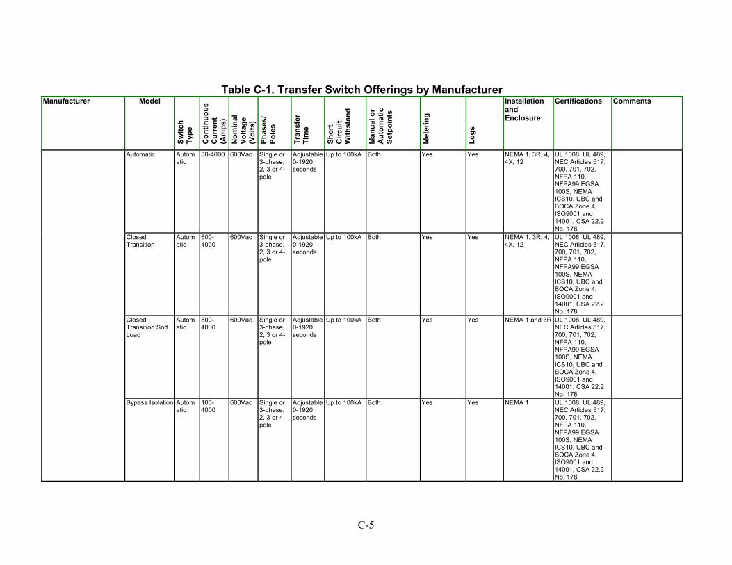
Table C-1. Transfer Switch Offerings by Manufacturer Manufacturer Model
Switc
h Ty
pe
Con
tinuo
us
Cur
rent
(A
mps
) N
omin
al
Volta
ge
(Vol
ts)
Phas
es/
Pole
s
Tran
sfer
Ti
me
Shor
t C
ircui
t W
ithst
and
Man
ual o
r A
utom
atic
Se
tpoi
nts
Met
erin
g
Logs
Installation and Enclosure
Certifications Comments
Automatic Automatic
30-4000 600Vac Single or 3-phase, 2, 3 or 4-pole
Adjustable 0-1920 seconds
Up to 100kA Both Yes Yes NEMA 1, 3R, 4, 4X, 12
UL 1008, UL 489, NEC Articles 517, 700, 701, 702, NFPA 110, NFPA99 EGSA 100S, NEMA ICS10, UBC and BOCA Zone 4, ISO9001 and 14001, CSA 22.2 No. 178
Closed Transition
Automatic
600-4000
600Vac Single or3-phase, 2, 3 or 4-pole
Adjustable 0-1920 seconds
Up to 100kA Both Yes Yes NEMA 1, 3R, 4, 4X, 12
UL 1008, UL 489, NEC Articles 517, 700, 701, 702, NFPA 110, NFPA99 EGSA 100S, NEMA ICS10, UBC and BOCA Zone 4, ISO9001 and 14001, CSA 22.2 No. 178
Closed Transition Soft Load
Automatic
800-4000
600Vac Single or3-phase, 2, 3 or 4-pole
Adjustable 0-1920 seconds
Up to 100kA Both Yes Yes NEMA 1 and 3R UL 1008, UL 489, NEC Articles 517, 700, 701, 702, NFPA 110, NFPA99 EGSA 100S, NEMA ICS10, UBC and BOCA Zone 4, ISO9001 and 14001, CSA 22.2 No. 178
Bypass Isolation Automatic
100-4000
600Vac Single or3-phase, 2, 3 or 4-pole
Adjustable 0-1920 seconds
Up to 100kA Both Yes Yes NEMA 1 UL 1008, UL 489, NEC Articles 517, 700, 701, 702, NFPA 110, NFPA99 EGSA 100S, NEMA ICS10, UBC and BOCA Zone 4, ISO9001 and 14001, CSA 22.2 No. 178
C-5

Table C-1. Transfer Switch Offerings by Manufacturer Manufacturer Model
Switc
h Ty
pe
Con
tinuo
us
Cur
rent
(A
mps
) N
omin
al
Volta
ge
(Vol
ts)
Phas
es/
Pole
s
Tran
sfer
Ti
me
Shor
t C
ircui
t W
ithst
and
Man
ual o
r A
utom
atic
Se
tpoi
nts
Met
erin
g
Logs
Installation and Enclosure
Certifications Comments
Closed Transition Bypass Isolation
Automatic
800-4000
600Vac Single or3-phase, 2, 3 or 4-pole
Adjustable 0-1920 seconds
Up to 100kA Both Yes Yes NEMA 2 UL 1008, UL 489, NEC Articles 517, 700, 701, 702, NFPA 110, NFPA99 EGSA 100S, NEMA ICS10, UBC and BOCA Zone 4, ISO9001 and 14001, CSA 22.2 No. 178
Peaking Switch Automatic
400-4000
600Vac Single or3-phase, 2, 3 or 4-pole
Adjustable 0-1920 seconds
Up to 100kA Both Yes Yes NEMA 1, 3R, 4, 4X, 12
UL 1008, UL 489, NEC Articles 517, 700, 701, 702, NFPA 110, NFPA99 EGSA 100S, NEMA ICS10, UBC and BOCA Zone 4, ISO9001 and 14001, CSA 22.2 No. 178
Digital Static Transfer Switch, Type I
Static 100–600 208, 480 3/3 4 ms 65 kA at 480 V
Under-/over-voltage, over-/ under frequency, speed, phase, overcurrent transfer inhibiting
KVa, Ka, Ipeak, phase, current, voltage, frequency
Alarm log, history and event log
Wall or aisle mounted, front/ rear access, or front/side
NEMA, UL 1008, IEEE c2.41, FIPS Pub 94
2 or 3 sources, 0°C–40°C, <65 dBA
Digital Static Transfer Switch, Type II
Static 100–600 208, 480 3/3 4 ms 100 kA at 480 V
Same as above Same as above
Same as above
Same as above NEMA, UL 1008, IEEE c2.41, FIPS Pub 94
2 or 3 sources 2.41, FIPS Pub 94, 0°C–40°C, <50 dBA (<400A), <65 dBA (<600 A)
Digital Static Transfer Switch, Type III
Static 100–600 208, 480 3/3 4 ms 65 kA at 480 V
Same as above Same as above
Same as above
Same as above NEMA, UL 1008, IEEE c2.41, FIPS Pub 94
2 or 3 sources, 0°C–40°C, <50 dBA (<400A), <65 dBA (<600 A)
Digital Static Transfer Switch
Static 800–1,200
208, 480 3/3 4 ms 65 kA at 480 V
Same as above Same as above
Same as above
Same as above NEMA, UL 1008, IEEE c2.41, FIPS Pub 94
2 or 3 sources, 0°C–40°C operating temp, <65 dBA
Cyberex www.cyberex.com
Digital Static Transfer Switch
Static 1,600–4,000
208, 480 3/3 4 ms 65 kA at 480 V
Same as above Same as above
Same as above
Same as above NEMA, UL 1008, IEEE c2.41, FIPS Pub 94
2 or 3 sources, 0°C–40°C operating temp, <65 dBA
C-6
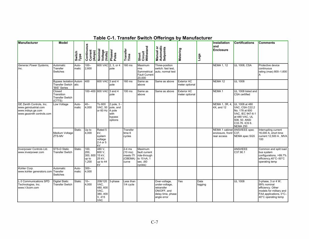
C-7
Table C-1. Transfer Switch Offerings by Manufacturer Manufacturer Model
Switc
h Ty
pe
Con
tinuo
us
Cur
rent
(A
mps
) N
omin
al
Volta
ge
(Vol
ts)
Phas
es/
Pole
s
Tran
sfer
Ti
me
Shor
t C
ircui
t W
ithst
and
Man
ual o
r A
utom
atic
Se
tpoi
nts
Met
erin
g
Logs
Installation and Enclosure
Certifications Comments
Automatic Transfer Switches
Auto-matic
100–2,600
600 VAC 2, 3, or 4 pole
160 ms Maximum rms Symmetrical Fault Current 20,000
Three-position switch: fast test, auto, normal test
NEMA 1, 12 UL 1008, CSA Protective device continuous rating (max) 800–1,600 A
Bypass Isolation Transfer Switch “BIS” Series
Automatic
400 600 VAC 3 and 4 pole
160 ms Same as above
Same as above Exterior AC meter optional
NEMA 12 UL 1008
Generac Power Systems, Inc.
Closed Transition Transfer Switch (CTTS)
100–400 600 VAC 3 and 4 pole
100 ms Same as above
Same as above Exterior AC meter optional
NEMA 1 UL 1008 listed and CSA certified
Low Voltage Auto-matic
40–4,000
To 600 VAC, 50 or 60 Hz
2 pole, 3 -pole, and 4 pole with bypass options
NEMA 1, 3R, 4, 4X, and 12
UL 1008 at 480 VAC, CSA C22.2 No. 178 at 600 VAC, IEC 947-6-1 at 480 VAC, UL 508, 50. ANSI C33.76. ICS 6. NEMA 250
GE Zenith Controls, Inc. www.geindustrial.com www.indsys.ge.com www.gezenith controls.com
Medium Voltage ZTS-MV
Static Up to4,000
Rated 5 kV, system voltage 2.4 or 5 kV
Transfertime 6 cycles
NEMA 1 cabinetenclosure, front/ rear access
ANSI/IEEE spec C37, NEMA spec SG5
Interrupting current 16,000 A, short time current 12,500 A , MVA 100
Inverpower Controls Ltd. www.inverpower.com
STS-D Static Transfer Switch
Static 100,200, 300, 600 up to 1,200
480 V, 600 V, 15 kV, 25 kV, up to 44 kV
2-4 ms(10 ms); meets ITI (CBEMA) curve
Maximum fault current ride-through to 10 kA, 1 sec. (60 cycles)
ANSI/IEEEC37.90.1
Common and split load bus system configurations, >99.7% efficiency,40°C–50°C operating temp
Kohler Corp. www.kohler generators.com
Automatic Transfer Switches
Auto-matic
300–4,000
L-3 Communications SPD Technologies, Inc. www.l-3com.com
Digital Static Transfer Switch
Static 10–4,000
208/120VAC, 480, 600 VAC, 380, 400 V, 415 VAC
3-phase Less than1/4 cycle
Over-voltage,under-voltage, retransfer ON/OFF, and delay time, phase angle error
Yes Datalogging
UL 1008 3-phase, 3 or 4 W; 99% nominal efficiency. Other models for military and FAA applications, 0°C–40°C operating temp
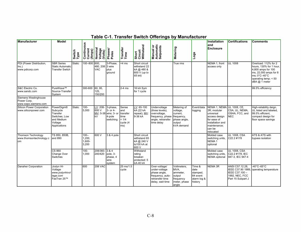
Table C-1. Transfer Switch Offerings by Manufacturer Manufacturer Model
Switc
h Ty
pe
Con
tinuo
us
Cur
rent
(A
mps
) N
omin
al
Volta
ge
(Vol
ts)
Phas
es/
Pole
s
Tran
sfer
Ti
me
Shor
t C
ircui
t W
ithst
and
Man
ual o
r A
utom
atic
Se
tpoi
nts
Met
erin
g
Logs
Installation and Enclosure
Certifications Comments
PDI (Power Distribution, Inc.) www.pdicorp.com
SBR Series Static Automatic Transfer Switch
Static 100–800 600,480, 208 VAC
3-Phase, 3 wire plus ground
<4 ms Short circuit withstand 22 kA @ 480 & 600 V (up to 65 kA)
True rms NEMA 1, front access only
UL 1008
Overload: 112% for 2 hours, 130% for 1 hour, 4,800 amps for 100 ms, 22,000 amps for 8 ms; 0°C–40°C operating temp; < 50 dBA @ 1 meter
S&C Electric Co. www.sandc.com
PureWave™ Source-Transfer System
300-600 60, 95,125, 150/200
2-4 ms 16 kA Sym for 1 cycle
99.5% efficiency
Siemens Westinghouse Power Corp. www.swpc.siemens.com
Silicon Power Corporation www.siliconpower.com
PowerDigm® Subcycle Transfer Switches, Low and Medium Voltage Applications
Static 100-5,000
LV: 208-600 V MV: 5-38 kV
3-phase, 3- or 4-wire; 3- or 4-pole switching
Sense and transfer time < 1/4 cycle (4 ms)
LV: 65-100 kA (22 kA repeat), MV: 9-36 kA
Undervoltage (three levels), overvoltage, frequency, phase angle, retransfer time delay
Metering of voltage, current, frequency, phase angle, output kVA demand
Event/data logging
NEMA 1, NEMA 3R; modular universal access design for ease of installation and maintenance; can be relocated
UL 1008, CE, CSA, UL, NEMA, OSHA, FCC, and NEC
High-reliability deign, UL listed and labeled, 99.5% efficient, compact design for floor space savings
TS 850, 850B, and 890
100–1,200, 1,600-3,200
600 V 3 & 4 pole Short circuit withstand 65 kA @ 240 V to100 kA at 600 V
Molded caseswitching units, NEMA 1
UL 1008, CSA C22.2 #178
optional
ATS & ATS with bypass isolation
Thomson Technology www.thomsontechnology.com
CS 860 Change Over Switches
100-1,000
208/360-240/420
3 & 4 pole, 3-phase, 4 wire system
Withstandrating breaker-protected: 5 kA-40 kA
Molded caseswitching units, NEMA optional
UL 1008, CSA C22.2 #178, IEC 947-3, IEC 947-4
Danaher Corporation Joslyn Hi-Voltage www.joslynhivoltage.com FasTran 25™
600 208 VAC
25 ms/1.5cycle
Over-voltage/under-voltage phase angle, frequency, auto-retransfer time delay, wait time
Voltmeters, MVA, ammeter, output frequency meter, phase angle
Time & date stamped, 64 event alarm log & history
NEMA 3R ANSI C57.12.28, IEEE C37.90 1989, IEEE C37.100 – 1992, NEC, FCC Part 15 Subpart J
-40°C–65°C operating temperature
C-8
Paralleling Switchgear Table C-2 shows manufacturers of paralleling switchgear. Information on the following attributes is provided: Current (Amps) – Maximum rated current. Voltage (Volts) – Voltage input/output. Remote Dispatch – Can the unit be remote dispatched (yes/no). Communication – Can the unit communicate with external devices other than the prime mover (yes/no)? Functions – Functions, attributes, and states (e.g., load following, load shedding) the unit can provide. Software – Does the switchgear use software or firmware (yes/no) or just hardware? Alarms, Monitoring – Alarm and shutdown alarm (yes/no). Certifications – Standards and codes that the switchgear meets or for which it has been certified. Comments – Notes on unit design and operation.
C-9
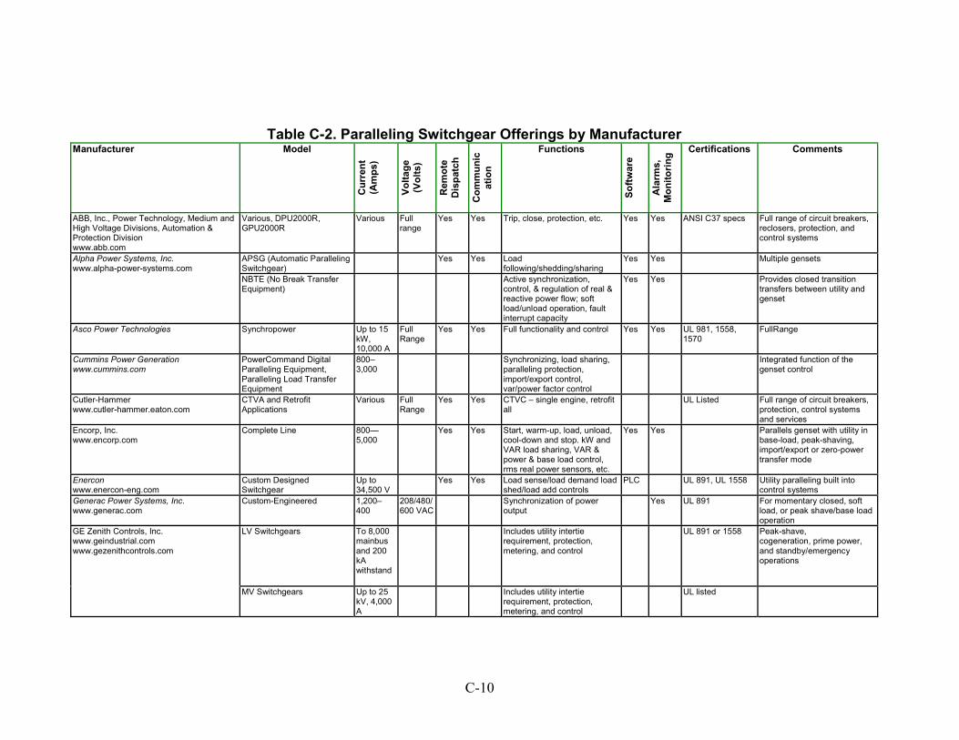
Table C-2. Paralleling Switchgear Offerings by Manufacturer
Manufacturer
rent
A
m o)
patc
h
mn
on
Model
Cur (
ps)
Vlta
ge
(Vol
ts
Rem
ote
Dis
Com
unic
atio
Functions
Softw
are
Ala
rms,
M
itorin
g Certifications Comments
ABB, Inc., Power Technology, Medium and High Voltage Divisions, Automation & Protection Division www.abb.com
Various, DPU2000R, GPU2000R
Various Fullrange
Yes Yes Trip, close, protection, etc. Yes Yes ANSI C37 specs Full range of circuit breakers, reclosers, protection, and control systems
APSG (Automatic Paralleling Switchgear)
Yes Yes Loadfollowing/shedding/sharing
Yes Yes Multiple gensetsAlpha Power Systems, Inc. www.alpha-power-systems.com
NBTE (No Break Transfer Equipment)
Active synchronization,control, & regulation of real & reactive power flow; soft load/unload operation, fault interrupt capacity
Yes
Yes Provides closed transition transfers between utility and genset
Asco Power Technologies Synchropower Up to 15 kW, 10,000 A
Full Range
Yes Yes Full functionality and control Yes Yes UL 981, 1558, 1570
FullRange
Cummins Power Generation www.cummins.com
PowerCommand Digital Paralleling Equipment, Paralleling Load Transfer Equipment
800–3,000
Synchronizing, load sharing,paralleling protection, import/export control, var/power factor control
Integrated function of the genset control
Cutler-Hammer www.cutler-hammer.eaton.com
CTVA and Retrofit Applications
Various FullRange
Yes Yes CTVC – single engine, retrofit all
UL Listed Full range of circuit breakers, protection, control systems and services
Encorp, Inc. www.encorp.com
Complete Line 800—5,000
Yes Yes Start, warm-up, load, unload,cool-down and stop. kW and VAR load sharing, VAR & power & base load control, rms real power sensors, etc.
Yes Yes Parallels genset with utility in base-load, peak-shaving, import/export or zero-power transfer mode
Enercon www.enercon-eng.com
Custom Designed Switchgear
Up to 34,500 V
Yes Yes Load sense/load demand loadshed/load add controls
PLC UL 891, UL 1558 Utility paralleling built into control systems
Generac Power Systems, Inc. www.generac.com
Custom-Engineered 1,200–400
208/480/600 VAC
Synchronization of poweroutput
Yes UL 891 For momentary closed, soft load, or peak shave/base load operation
LV Switchgears To 8,000 mainbus and 200 kA withstand
Includes utility intertierequirement, protection, metering, and control
UL 891 or 1558 Peak-shave, cogeneration, prime power, and standby/emergency operations
GE Zenith Controls, Inc. www.geindustrial.com www.gezenithcontrols.com
MV Switchgears Up to 25 kV, 4,000 A
Includes utility intertierequirement, protection, metering, and control
UL listed
C-10
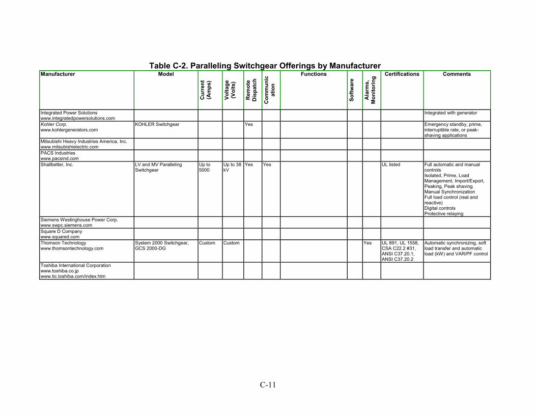
Table C-2. Paralleling Switchgear Offerings by Manufacturer Manufacturer Model
Cur
rent
(A
mps
)
Volta
ge
(Vol
ts)
Rem
ote
Dis
patc
h
Com
mun
icat
ion
Functions
Softw
are
Ala
rms,
M
onito
ring Certifications Comments
Integrated Power Solutions www.integratedpowersolutions.com
Integrated with generator
Kohler Corp. www.kohlergenerators.com
KOHLER Switchgear Yes Emergency standby, prime,interruptible rate, or peak-shaving applications
Mitsubishi Heavy Industries America, Inc. www.mitsubishielectric.com
PACS Industries www.pacsind.com
Shallbetter, Inc. LV and MV Paralleling Switchgear
Up to 5000
Up to 38 kV
Yes Yes UL listed Full automatic and manualcontrols Isolated, Prime, Load Management, Import/Export, Peaking, Peak shaving. Manual Synchronization Full load control (real and reactive) Digital controls Protective relaying
Siemens Westinghouse Power Corp. www.swpc.siemens.com
Square D Company www.squared.com
Thomson Technology www.thomsontechnology.com
System 2000 Switchgear, GCS 2000-DG
Custom Custom Yes UL 891, UL 1558,CSA C22.2 #31, ANSI C37.20.1, ANSI C37.20.2
Automatic synchronizing, soft load transfer and automatic load (kW) and VAR/PF control
Toshiba International Corporation www.toshiba.co.jp www.tic.toshiba.com/index.htm
C-11
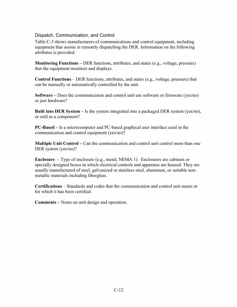
Dispatch, Communication, and Control Table C-3 shows manufacturers of communications and control equipment, including equipment that assists in remotely dispatching the DER. Information on the following attributes is provided: Monitoring Functions – DER functions, attributes, and states (e.g., voltage, pressure) that the equipment monitors and displays. Control Functions – DER functions, attributes, and states (e.g., voltage, pressure) that can be manually or automatically controlled by the unit. Software – Does the communication and control unit use software or firmware (yes/no) or just hardware? Built into DER System – Is the system integrated into a packaged DER system (yes/no), or sold as a component? PC-Based – Is a microcomputer and PC-based graphical user interface used in the communication and control equipment (yes/no)? Multiple Unit Control – Can the communication and control unit control more than one DER system (yes/no)? Enclosure – Type of enclosure (e.g., metal, NEMA 1). Enclosures are cabinets or specially designed boxes in which electrical controls and apparatus are housed. They are usually manufactured of steel, galvanized or stainless steel, aluminum, or suitable non-metallic materials including fiberglass. Certifications – Standards and codes that the communication and control unit meets or for which it has been certified. Comments – Notes on unit design and operation.
C-12
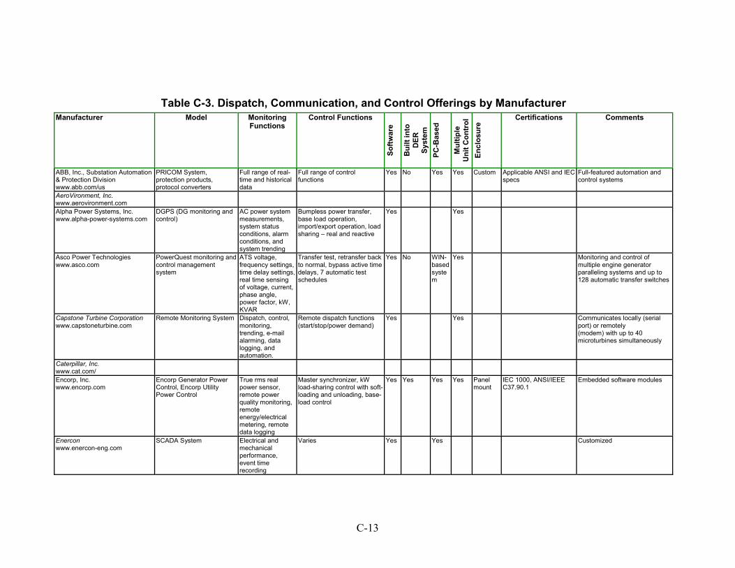
Table C-3. Dispatch, Communication, and Control Offerings by Manufacturer
Manufacturer Model Monitoring Functions
Control Functions
Softw
are
Bui
lt in
to
DER
Sy
st
em
PC-B
ased
Mul
tiple
U
nit C
ontr
ol
Encl
osur
e
Certifications Comments
ABB, Inc., Substation Automation & Protection Division www.abb.com/us
PRICOM System, protection products, protocol converters
Full range of real-time and historical data
Full range of control functions
Yes No Yes Yes Custom Applicable ANSI and IEC specs
Full-featured automation and control systems
AeroVironment, Inc. www.aerovironment.com
Alpha Power Systems, Inc. www.alpha-power-systems.com
DGPS (DG monitoring and control)
AC power system measurements, system status conditions, alarm conditions, and system trending
Bumpless power transfer, base load operation, import/export operation, load sharing – real and reactive
Yes Yes
Asco Power Technologies www.asco.com
PowerQuest monitoring and control management system
ATS voltage, frequency settings, time delay settings,real time sensing of voltage, current, phase angle, power factor, kW, KVAR
Transfer test, retransfer back to normal, bypass active time delays, 7 automatic test schedules
Yes No WIN-based system
Yes Monitoring and control of multiple engine generator paralleling systems and up to 128 automatic transfer switches
Capstone Turbine Corporation www.capstoneturbine.com
Remote Monitoring System
Dispatch, control, monitoring, trending, e-mail alarming, data logging, and automation.
Remote dispatch functions (start/stop/power demand)
Yes Yes Communicates locally (serialport) or remotely (modem) with up to 40 microturbines simultaneously
Caterpillar, Inc. www.cat.com/
Encorp, Inc. www.encorp.com
Encorp Generator Power Control, Encorp Utility Power Control
True rms real power sensor, remote power quality monitoring, remote energy/electrical metering, remote data logging
Master synchronizer, kW load-sharing control with soft-loading and unloading, base-load control
Yes Yes Yes Yes Panelmount
IEC 1000, ANSI/IEEE C37.90.1
Embedded software modules
Enercon www.enercon-eng.com
SCADA System Electrical and mechanical performance, event time recording
Varies Yes Yes Customized
C-13
Table C-3. Dispatch, Communication, and Control Offerings by Manufacturer Manufacturer Model Monitoring
Functions Control Functions
Softw
are
Bui
lt in
to
DER
Sy
stem
PC
-Bas
ed
Mul
tiple
U
nit C
ontr
ol
Encl
osur
e
Certifications Comments
GE Zenith Controls, Inc. www.geindustrial.com www.indsys.ge.com
Hydrogenics www.hydrogenics.com
FCATS series fuel cell test stations
Gas inlet, differential pressures; gas flows and temps; coolant pressure, pressure drop, temperature, flow, and resistivity; water temps and flows; condensed water collection rate; individual cell and overall stack voltages; stack current and temps, hydrogen leak
Gas composition; inlet pressures; gas flow rate; saturator, inlet and stack temperatures; coolant pressure, flow, and temperature; load bank current and voltage; relay, valve, and pump outputs
Yes Yes
Invensys www.invensys.com
Mitsubishi Heavy Industries America, Inc. www.mitsubishielectric.com
Power Measurement www.pml.com
ION Enterprise™ Web-ready software
Transients, harmonics, or sags, power quality, energy, and load profile
Load shedding, generator startup, or relay control; implement distributed control in response to interruptible rates or real-time pricing
Yes No Yes Yes Software suite that integrates metering, monitoring, control of multiple systems (electricity, gas, water, steam, air, etc.)
Siemens Westinghouse Power Corp. www.swpc.siemens.com
Silicon Energy www.siliconenergy.com
EEM Suite with Distributed Energy Manager, Alarm Manager, Analytic Workbench, Cost Analyst, more
Peak approach, power spikes, surges, sags, deviations from baseline, device operating state and environmental conditions
Deployment control, aggregate capacity
Yes No Analysis tools, external data sources, data visualization, and Internet-based monitoring and control of energy assets
Toshiba International Corporation www.toshiba.co.jp
C-14
DER Controls Table C-4 shows manufacturers of DER generator control equipment. Information on the following attributes is provided: Power Supply – Voltage level (in volts) supplied by the built-in generator control power supply. This voltage is required by the generator control system. It may be AC or DC. Monitoring Functions – Generator functions, attributes, and states that the equipment monitors and displays. Control Functions – Generator functions, attributes, and states that the unit can manually or automatically control. Pre-Alarms and Alarms – Pre-alarm, alarm, and shutdown alarm types (e.g., overcrank, undercrank, low oil pressure). Software Included – Does the generator control unit use software or firmware (yes/no) or just hardware? PC-Based – Is a microcomputer and PC-based graphical user interface used in the generator control equipment (yes/no)? Microprocessor-Based Design – Does the generator control system have a microprocessor-based design (yes/no)? Enclosure Type – Type of enclosure (e.g., metal, NEMA 1). Enclosures are cabinets or specially designed boxes in which electrical controls and apparatus are housed. They are usually manufactured of steel, galvanized or stainless steel, aluminum, or suitable non-metallic materials including fiberglass. Certifications – Standards and codes that the generator control unit meets or for which the unit has been certified. Comments – Notes on unit design and operation.
C-15
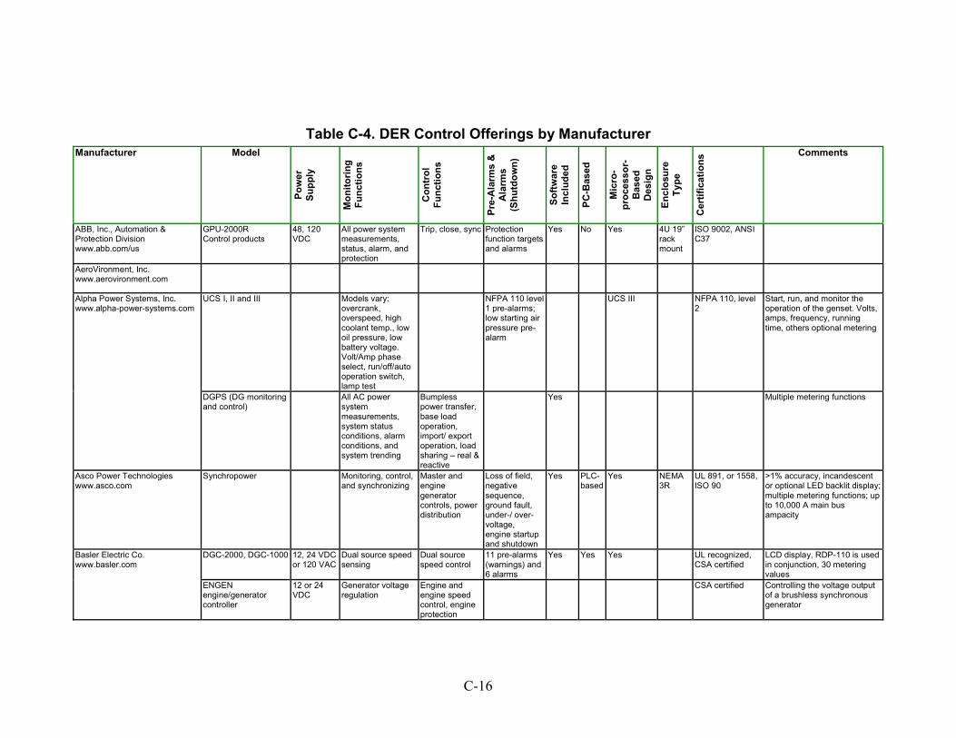
Table C-4. DER Control Offerings by Manufacturer
Manufacturer
olun
c
rm o war
e
roce
ssor
-as
ed
nyp
e
Model
Pow
er
Supp
ly
Mon
itorin
g Fu
nctio
ns
Con
tr
Ftio
ns
Pre-
Ala
s &
A
larm
s (S
hutd
wn)
Soft
Incl
uded
PC-B
ased
Mic
ro-
pB Des
ign
Ecl
osur
e T
Cer
tific
atio
ns Comments
ABB, Inc., Automation & Protection Division www.abb.com/us
GPU-2000R Control products
48, 120 VDC
All power system measurements, status, alarm, and protection
Trip, close, sync Protection function targets and alarms
Yes No Yes 4U 19”rack mount
ISO 9002, ANSI C37
AeroVironment, Inc. www.aerovironment.com
UCS III NFPA 110, level 2
Start, run, and monitor the operation of the genset. Volts, amps, frequency, running time, others optional metering
DGPS (DG monitoring and control)
All AC power system measurements, system status conditions, alarm conditions, and system trending
Bumpless power transfer, base load operation, import/ export operation, load sharing – real & reactive
Yes Multiple metering functions
Asco Power Technologies www.asco.com
Synchropower Monitoring, control,and synchronizing
Master and engine generator controls, power distribution
Loss of field, negative sequence, ground fault, under-/ over-voltage, engine startup and shutdown
Yes PLC-based
Yes NEMA3R
UL 891, or 1558, ISO 90
>1% accuracy, incandescent or optional LED backlit display; multiple metering functions; up to 10,000 A main bus ampacity
DGC-2000, DGC-1000 12, 24 VDC or 120 VAC
Dual source speed sensing
Dual source speed control
11 pre-alarms (warnings) and 6 alarms
Yes Yes Yes UL recognized,CSA certified
LCD display, RDP-110 is used in conjunction, 30 metering values
Basler Electric Co. www.basler.com
ENGEN engine/generator controller
12 or 24 VDC
Generator voltage regulation
Engine and engine speed control, engine protection
CSA certified
Controlling the voltage output of a brushless synchronous generator
UCS I, II and III Models vary: overcrank, overspeed, high coolant temp., low oil pressure, low battery voltage. Volt/Amp phase select, run/off/auto operation switch, lamp test
NFPA 110 level 1 pre-alarms; low starting air pressure pre-alarm
Alpha Power Systems, Inc. www.alpha-power-systems.com
C-16
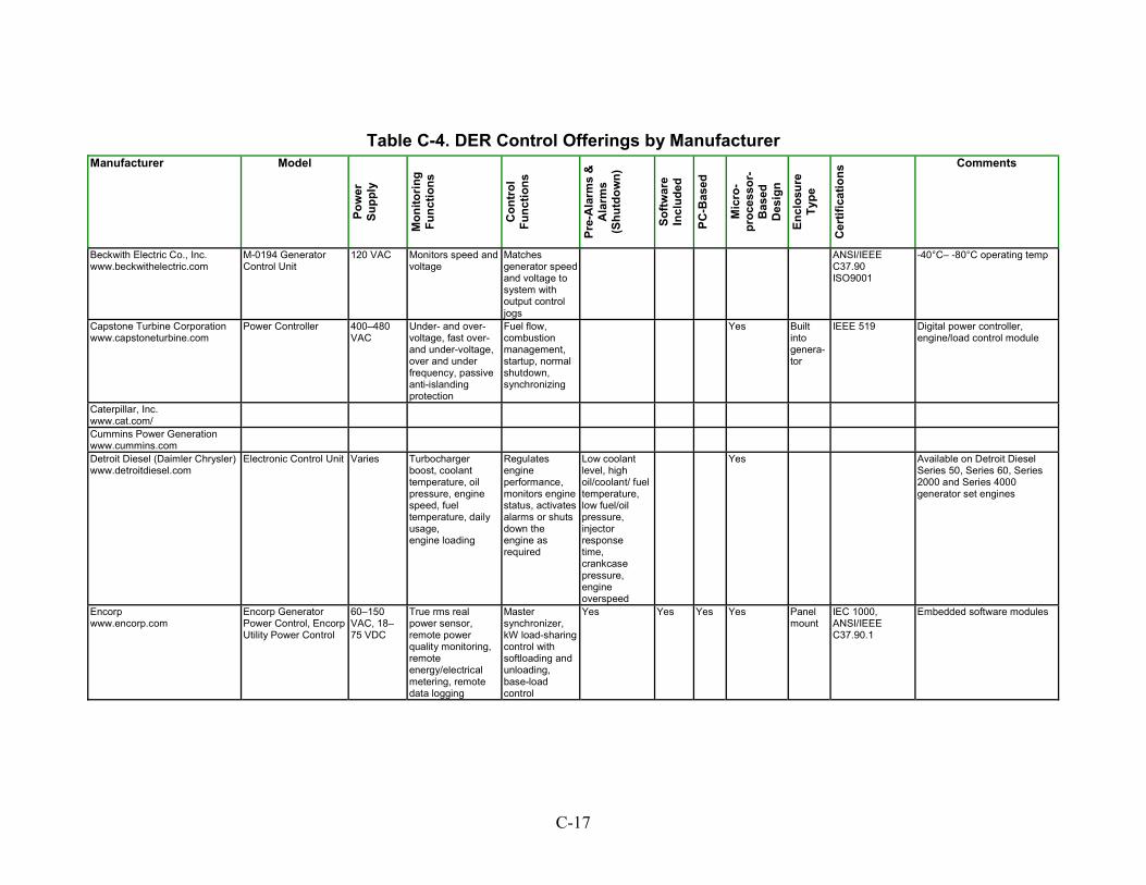
Table C-4. DER Control Offerings by Manufacturer Manufacturer Model
Pow
er
Supp
ly
Mon
itorin
g Fu
nctio
ns
Con
trol
Fu
nctio
ns
Pre-
Ala
rms
&
Ala
rms
(Shu
tdow
n)
Softw
are
Incl
uded
PC-B
ased
Mic
ro-
proc
esso
r-B
ased
D
esig
n
Encl
osur
e Ty
pe
Cer
tific
atio
ns Comments
Beckwith Electric Co., Inc. www.beckwithelectric.com
M-0194 Generator Control Unit
120 VAC Monitors speed and voltage
Matches generator speed and voltage to system with output control jogs
ANSI/IEEEC37.90
-40°C– -80°C operating temp
ISO9001
Capstone Turbine Corporation www.capstoneturbine.com
Power Controller 400–480 VAC
Under- and over-voltage, fast over- and under-voltage, over and under frequency, passive anti-islanding protection
Fuel flow, combustion management, startup, normal shutdown, synchronizing
Yes Builtinto genera-tor
IEEE 519 Digital power controller, engine/load control module
Caterpillar, Inc. www.cat.com/
Cummins Power Generation www.cummins.com
Detroit Diesel (Daimler Chrysler) www.detroitdiesel.com
Electronic Control Unit Varies Turbochargerboost, coolant temperature, oil pressure, engine speed, fuel temperature, daily usage, engine loading
Regulates engine performance, monitors engine status, activates alarms or shuts down the engine as required
Low coolant level, high oil/coolant/ fuel temperature, low fuel/oil pressure, injector response time, crankcase pressure, engine overspeed
Yes Available on Detroit Diesel Series 50, Series 60, Series 2000 and Series 4000 generator set engines
Encorp www.encorp.com
Encorp Generator Power Control, Encorp Utility Power Control
60–150 VAC, 18–75 VDC
True rms real power sensor, remote power quality monitoring, remote energy/electrical metering, remote data logging
Master synchronizer, kW load-sharing control with softloading and unloading, base-load control
Yes Yes Yes Yes Panelmount
IEC 1000, ANSI/IEEE C37.90.1
Embedded software modules
C-17
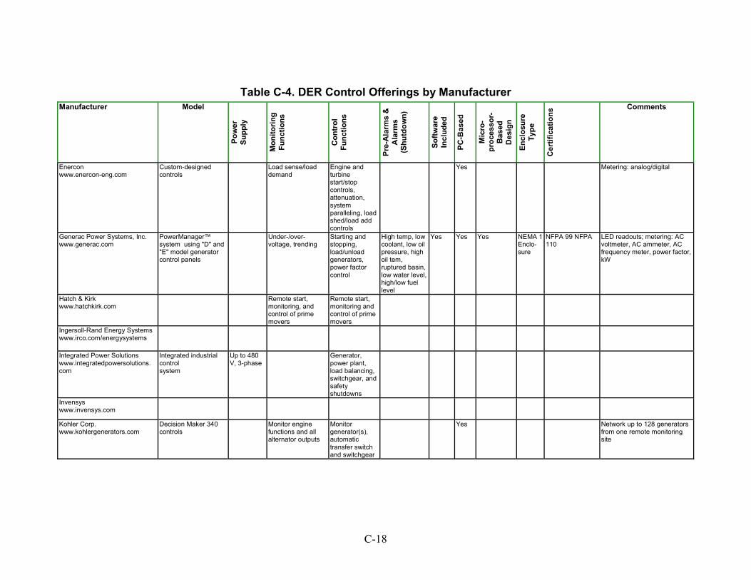
Table C-4. DER Control Offerings by Manufacturer Manufacturer Model
Pow
er
Supp
ly
Mon
itorin
g Fu
nctio
ns
Con
trol
Fu
nctio
ns
Pre-
Ala
rms
&
Ala
rms
(Shu
tdow
n)
Softw
are
Incl
uded
PC-B
ased
Mic
ro-
proc
esso
r-B
ased
D
esig
n
Encl
osur
e Ty
pe
Cer
tific
atio
ns Comments
Enercon www.enercon-eng.com
Custom-designed controls
Load sense/loaddemand
Engine and turbine start/stop controls,
attenuation, system paralleling, load shed/load add controls
Yes Metering: analog/digital
Generac Power Systems, Inc. www.generac.com
PowerManager™ system using "D" and "E" model generator control panels
Under-/over-voltage, trending
Starting and stopping, load/unload generators, power factor control
High temp, low coolant, low oil pressure, high oil tem, ruptured basin, low water level, high/low fuel level
Yes Yes Yes NEMA 1Enclo-sure
NFPA 99 NFPA 110
LED readouts; metering: AC voltmeter, AC ammeter, AC frequency meter, power factor, kW
Hatch & Kirk www.hatchkirk.com
Remote start,monitoring, and control of prime movers
Remote start, monitoring and control of prime movers
Ingersoll-Rand Energy Systems www.irco.com/energysystems
Integrated Power Solutions www.integratedpowersolutions. com
Integrated industrial control system
Up to 480 V, 3-phase
Generator,power plant, load balancing, switchgear, andsafety shutdowns
Invensys www.invensys.com
Kohler Corp. www.kohlergenerators.com
Decision Maker 340 controls
Monitor enginefunctions and all alternator outputs
Monitor generator(s), automatic transfer switch and switchgear
Yes Network up to 128 generators from one remote monitoring site
C-18

Table C-4. DER Control Offerings by Manufacturer Manufacturer Model
Pow
er
Supp
ly
Mon
itorin
g Fu
nctio
ns
Con
trol
Fu
nctio
ns
Pre-
Ala
rms
&
Ala
rms
(Shu
tdow
n)
Softw
are
Incl
uded
PC-B
ased
Mic
ro-
proc
esso
r-B
ased
D
esig
n
Encl
osur
e Ty
pe
Cer
tific
atio
ns Comments
Petrotech www.petrotechinc.com
Turnkey control systems, specializing in retrofit
System status,trending, and data logging
Complete driver and load control, sequencing and protection
Yes Custom
Solectria Corporation www.solectria.com
DMOC845 (preliminary specifications)
Up to 400 VDC
Diagnostics and data visualization; over-voltage, under-voltage, and over-current protection; analog over-current watchdog
Regenerative braking, inverter and motor over- temperature protection, over-speed torque limit
96–98% unit efficiency,operating temps: -40ºC–75ºC
Sonat Power Systems, Inc.
Thomson Technology www.thomsontechnology.com
GS 2000 series paralleling switchgear and control
Custom Utility import-monitoring feature
Control logic and software programming for automatic synchronizing, soft load transfer and automatic load (kilowatt) and VAR/PF control, start/stop
Available Yes UL 508• CSA 22.2 #14
DG, auto-standby, and prime power applications; control of single or multiple generator sets
MEC 2, MEC 20 Engine Generator and Cogeneration Controller
10–30 VDC
Voltage monitoring, current monitoring, engine speed sensing 100–10,000 Hz, 3–20 VAC, rms
Emergency stop, over-voltage
Overcrank, overspeed, loss of speed signal, low oil pressure, high engine temp.,15–28 alarm/ shutdown fault circuits
Yes NEMA12
NFPA 110 level 1, CSA C282, UL #508, CSA 22.2 #14
Accuracy: ± 1% @ 25°C Volts, Amps, ± 2% @ 25°C KVA, LCD screen; 3-phase voltage, 3-phase current, KVA, frequency metering; 15°C–50°C operating temp
Toshiba International Corporation www.toshiba.co.jp
C-19
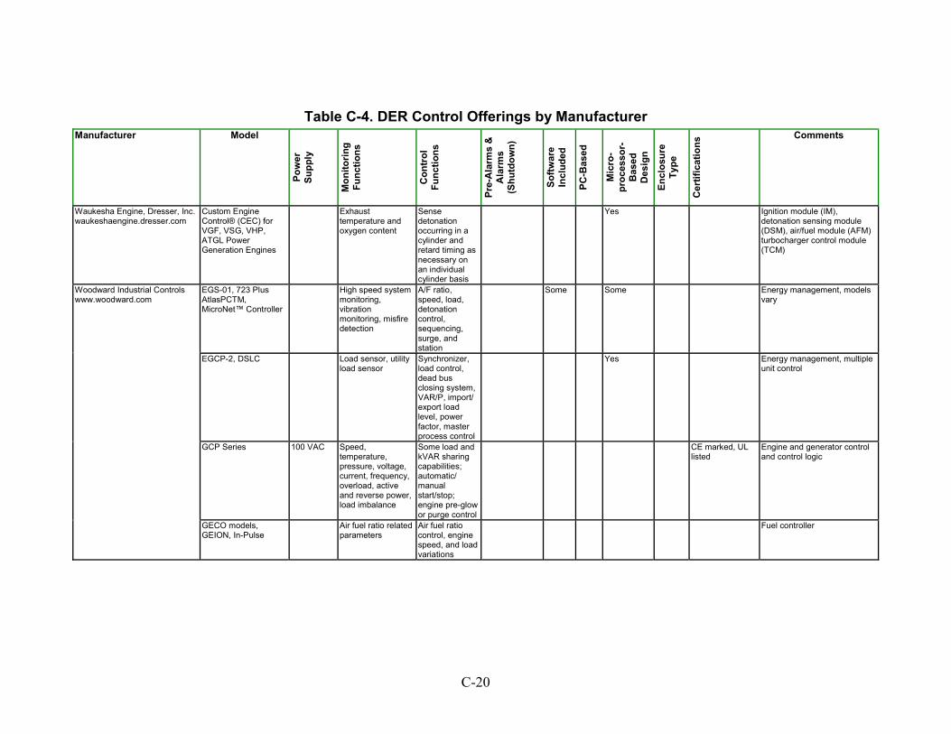
Table C-4. DER Control Offerings by Manufacturer Manufacturer Model
Pow
er
Supp
ly
Mon
itorin
g Fu
nctio
ns
Con
trol
Fu
nctio
ns
Pre-
Ala
rms
&
Ala
rms
(Shu
tdow
n)
Softw
are
Incl
uded
PC-B
ased
Mic
ro-
proc
esso
r-B
ased
D
esig
n
Encl
osur
e Ty
pe
Cer
tific
atio
ns Comments
Waukesha Engine, Dresser, Inc. waukeshaengine.dresser.com
Custom Engine Control® (CEC) for VGF, VSG, VHP, ATGL Power Generation Engines
Exhausttemperature and oxygen content
Sense detonation occurring in a cylinder and retard timing as necessary on an individual cylinder basis
Yes Ignition module (IM), detonation sensing module (DSM), air/fuel module (AFM) turbocharger control module (TCM)
EGS-01, 723 Plus AtlasPCTM, MicroNet™ Controller
High speed systemmonitoring, vibration
A/F ratio, speed, load, detonation control, sequencing, surge, and station
monitoring, misfire detection
Some Some Energy management, models vary
EGCP-2, DSLC
Load sensor, utility load sensor
Synchronizer, load control, dead bus closing system, VAR/P, import/ export load level, power factor, master process control
Yes Energy management, multiple unit control
GCP Series 100 VAC Speed, temperature, pressure, voltage, current, frequency, overload, active and reverse power, load imbalance
Some load and kVAR sharing capabilities; automatic/ manual start/stop; engine pre-glow or purge control
CE marked, UL listed
Engine and generator control and control logic
Woodward Industrial Controls www.woodward.com
GECO models, GEION, In-Pulse
Air fuel ratio related parameters
Air fuel ratio control, engine speed, and load variations
Fuel controller
C-20
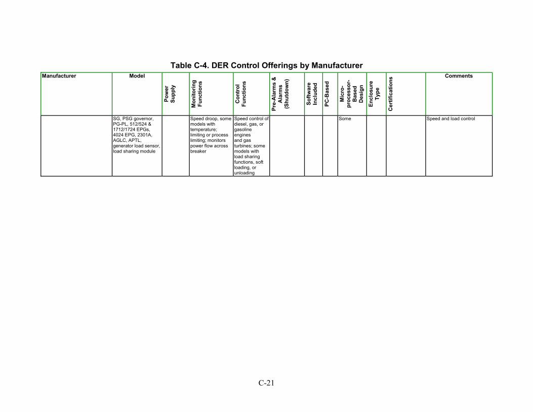
Table C-4. DER Control Offerings by Manufacturer Manufacturer Model
Pow
er
Supp
ly
Mon
itorin
g Fu
nctio
ns
Con
trol
Fu
nctio
ns
Pre-
Ala
rms
&
Ala
rms
(Shu
tdow
n)
Softw
are
Incl
uded
PC-B
ased
Mic
ro-
proc
esso
r-B
ased
D
esig
n
Encl
osur
e Ty
pe
Cer
tific
atio
ns Comments
SG, PSG governor,PG-PL, 512/524 & 1712/1724 EPGs, 4024 EPG, 2301A, AGLC, APTL, generator load sensor, load sharing module
Speed droop, some models with temperature; limiting or process limiting; monitors power flow across breaker
Speed control of diesel, gas, or gasoline engines and gas turbines; some models with load sharing functions, soft loading, or unloading
Some Speed and load control
C-21
Power Conversion (Including Inverters) Table C-5 shows manufacturers of power conversion equipment. This includes inverters as described earlier. Information on the following attributes is provided: Continuous Power Output – Power output (continuous) in W, kW, VA, or kVA. DC Input – Input voltage. Output – Output voltage. Phases – Number of output phases (e.g., single-phase, three-phase). Enclosure Type – Type of enclosure (e.g., metal, NEMA 1). Enclosures are cabinets or specially designed boxes in which electrical controls and apparatus are housed. They are usually manufactured of steel, galvanized or stainless steel, aluminum, or suitable non-metallic materials including fiberglass. Surge Capacity – Surge capacity power output (W or kVA). Certifications – Standards and codes that the power conversion unit meets or for which it has been certified. Comments – Notes on unit design and operation.
C-22
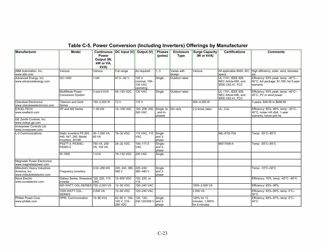
Table C-5. Power Conversion (Including Inverters) Offerings by Manufacturer
Manufacturer Model ContinuousPower
Output (W, kW or VA,
kVA)
DC Input (V) Output (V) Phases (poles)
Enclosure Type
Surge Capacity (W or kVA)
Certifications Comments
ABB Automation, Inc. www.abb.com
Various Various Full range As required 1, 3 Varies with design
Various All applicable ANSI, IEC specs
High efficiency, solar, wind, biomass, etc.
GC-1000 1 kW 47.5–-92 V 120 V nominal, 106–130 VAC operating
Single Outdoor rated UL 1741, IEEE 929, NEC Article 690, and IEEE C62.41, FCC
Efficiency: 93% peak; temp: -40°C–60°C; full package: $1,785; list 5-year warranty
Advanced Energy, Inc. www.advancedenergy.com
MultiMode Power Conversion System
3 and 5 kVA 44–120 VDC 120 VAC Single Outdoor rated UL 1741, IEEE 929, NEC Article 690, and IEEE C62.41, FCC
Efficiency: 93% peak; temp: -40°C–45°C, PV or wind power
Cherokee Electronics www.cherokeeelectronics.com
Titanium and Gold Series
150–2,500 W 12 V 110 V 500–4,000 W 3 years, $49.95 to $699.95
EXCELTECH www.exeltech.com
XP and MX Series 1–60 kW 12–108 VDC 120, 208, 230, 240 VAC
Single, bi-, and tri-phases
Din rack 2.2 times rates UL, CUL Efficiency: 85%–88%; temp: -25°C- 40°C; noise:<45 dbA, 1-year warranty, future grid tie
GE Zenith Controls, Inc. www.indsys.ge.com
Inverpower Controls Ltd. www.inverpower.com
Static Inverters PS 293, 440, 447, 285, Model Inverters, 3010R
30–1,000 VA, 40 VA
19–32 VDC
115 VAC, 110 VAC
Single and 3-phase
MIL-STD-704 Temp: -55°C–85°C
PS277-3, PS304C, PS283-3
750 VA, 250 VA, 100 VA
24–32 VDC
100–117.5 VAC
Single- and 3-phase
MS17406-4 Temp: -55°C–85°C
L-3 Communications
W-1000 1 kVA
19–132 VDC 230 VAC
Single
Magnetek Power Electronics www.magnetekpower.com
Mitsubishi Heavy Industries America, Inc. www.mitsubishielectric.com
Frequency Inverters
0.02–280 kW 220, 240, 380, 480 V
220–240, 380–480 V
Single and 3-phase
Temp: -10°C–50°C
Galaxy Series, Sinewave inverter
120, 220, 115 VAC
12–600 VDC 120, 220, or 115
Efficiency: 70%, temp: -40°C –60°C
600 WATT CGL-SERIES 700–2,000 VA 12–56 VDC 100–240 VAC 1000–2,500 VA Efficiency: 83%–90%
Nova Electric www.novaelectric.com
1500 WATT CGL-SERIES
2,000 VA 12–56 VDC 120–240 VAC 2,500 VA Efficiency: 83%–90%, temp: 0°C–50°C
Philtek Power Corp. www.philtek.com
HPRi, Communication 15–90 kVA 42–60 V, 105–145 V, 210–290 VDC
120, 120–240,120/208 V
Single and 3-phase
120% for 12minutes, 1,000% for 8 minutes
Efficiency: 84%–87%, temp: 0°C–40°C
C-23
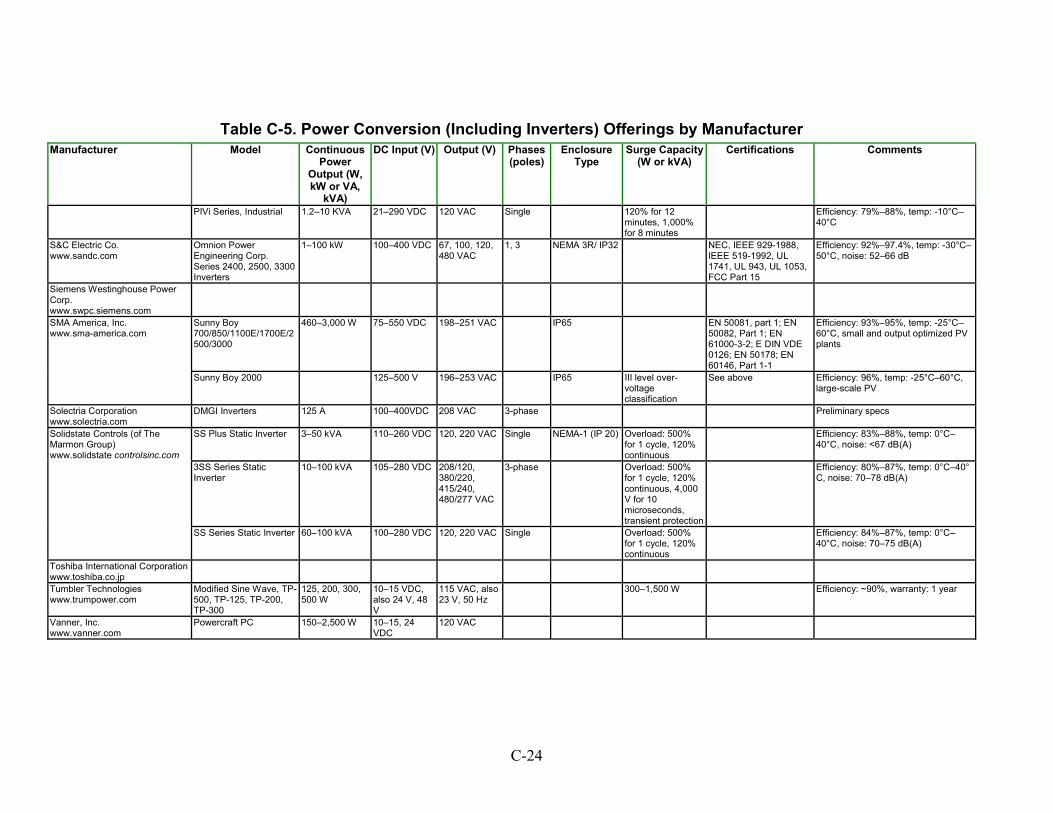
Table C-5. Power Conversion (Including Inverters) Offerings by Manufacturer Manufacturer Model Continuous
Power Output (W, kW or VA,
kVA)
DC Input (V) Output (V) Phases (poles)
Enclosure Type
Surge Capacity (W or kVA)
Certifications Comments
PIVi Series, Industrial 1.2–10 KVA 21–290 VDC 120 VAC Single 120% for 12minutes, 1,000% for 8 minutes
Efficiency: 79%–88%, temp: -10°C–40°C
S&C Electric Co. www.sandc.com
Omnion Power Engineering Corp. Series 2400, 2500, 3300 Inverters
1–100 kW 100–400 VDC 67, 100, 120, 480 VAC
1, 3 NEMA 3R/ IP32 NEC, IEEE 929-1988, IEEE 519-1992, UL 1741, UL 943, UL 1053, FCC Part 15
Efficiency: 92%–97.4%, temp: -30°C–50°C, noise: 52–66 dB
Siemens Westinghouse Power Corp. www.swpc.siemens.com
Sunny Boy 700/850/1100E/1700E/2500/3000
460–3,000 W 75–550 VDC 198–251 VAC IP65 EN 50081, part 1; EN 50082, Part 1; EN 61000-3-2; E DIN VDE 0126; EN 50178; EN 60146, Part 1-1
Efficiency: 93%–95%, temp: -25°C–60°C, small and output optimized PV plants
SMA America, Inc. www.sma-america.com
Sunny Boy 2000 125–500 V 196–253 VAC IP65 III level over-voltage classification
See above Efficiency: 96%, temp: -25°C–60°C, large-scale PV
Solectria Corporation www.solectria.com
DMGI Inverters 125 A 100–400VDC 208 VAC 3-phase Preliminary specs
SS Plus Static Inverter 3–50 kVA 110–260 VDC 120, 220 VAC Single NEMA-1 (IP 20) Overload: 500% for 1 cycle, 120% continuous
Efficiency: 83%–88%, temp: 0°C–40°C, noise: <67 dB(A)
3SS Series Static Inverter
10–100 kVA 105–280 VDC 208/120, 380/220, 415/240, 480/277 VAC
3-phase Overload: 500%for 1 cycle, 120% continuous, 4,000 V for 10 microseconds, transient protection
Efficiency: 80%–87%, temp: 0°C–40° C, noise: 70–78 dB(A)
Solidstate Controls (of The Marmon Group) www.solidstate controlsinc.com
SS Series Static Inverter 60–100 kVA 100–280 VDC 120, 220 VAC Single Overload: 500% for 1 cycle, 120% continuous
Efficiency: 84%–87%, temp: 0°C–40°C, noise: 70–75 dB(A)
Toshiba International Corporation www.toshiba.co.jp
Tumbler Technologies www.trumpower.com
Modified Sine Wave, TP-500, TP-125, TP-200, TP-300
125, 200, 300, 500 W
10–15 VDC, also 24 V, 48 V
115 VAC, also 23 V, 50 Hz
300–1,500 W Efficiency: ~90%, warranty: 1 year
Vanner, Inc. www.vanner.com
Powercraft PC 150–2,500 W 10–15, 24 VDC
120 VAC
C-24
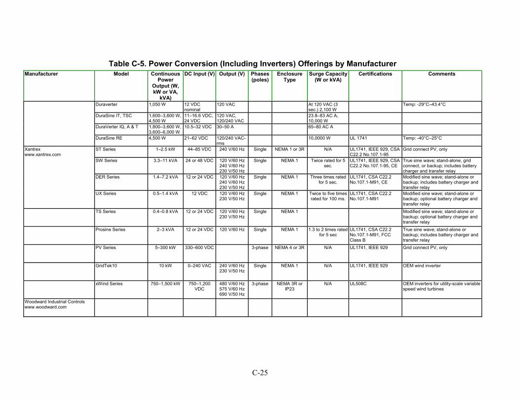
Table C-5. Power Conversion (Including Inverters) Offerings by Manufacturer Manufacturer Model Continuous
Power Output (W, kW or VA,
kVA)
DC Input (V) Output (V) Phases (poles)
Enclosure Type
Surge Capacity (W or kVA)
Certifications Comments
Duraverter 1,050 W 12 VDCnominal
120 VAC At 120 VAC (3 sec.) 2,100 W
Temp: -29°C–43.4°C
DuraSine IT, TSC 1,600–3,600 W, 4,500 W
11–16.6 VDC, 24 VDC
120 VAC, 120/240 VAC
23.8–83 AC A, 10,000 W
DuraVerter IQ, A & T 1,800–3,600 W, 3,600–6,000 W
10.5–32 VDC 30–50 A 65–80 AC A
DuraSine RE 4,500 W 21–62 VDC 120/240 VAC-rms
10,0000 W UL 1741 Temp: -40°C–25°C
ST Series 1–2.5 kW 44–85 VDC 240 V/60 Hz Single NEMA 1 or 3R N/A UL1741, IEEE 929, CSA C22.2 No.107.1-95
Grid connect PV, only
SW Series 3.3–11 kVA 24 or 48 VDC 120 V/60 Hz 240 V/60 Hz 230 V/50 Hz
Single NEMA 1 Twice rated for 5 sec.
UL1741, IEEE 929, CSA C22.2 No.107.1-95, CE
True sine wave; stand-alone, grid connect, or backup; includes battery charger and transfer relay
DER Series 1.4–7.2 kVA 12 or 24 VDC 120 V/60 Hz 240 V/60 Hz 230 V/50 Hz
Single NEMA 1 Three times rated for 5 sec.
UL1741, CSA C22.2 No.107.1-M91, CE
Modified sine wave; stand-alone or backup; includes battery charger and transfer relay
Xantrex www.xantrex.com
UX Series 0.5–1.4 kVA 12 VDC 120 V/60 Hz 230 V/50 Hz
Single NEMA 1 Twice to five times rated for 100 ms.
UL1741, CSA C22.2 No.107.1-M91
Modified sine wave; stand-alone or backup; optional battery charger and transfer relay
TS Series 0.4–0.8 kVA 12 or 24 VDC 120 V/60 Hz 230 V/50 Hz
Single NEMA 1 Modified sine wave; stand-alone or backup; optional battery charger and transfer relay
Prosine Series 2–3 kVA 12 or 24 VDC 120 V/60 Hz Single NEMA 1 1.3 to 2 times rated for 5 sec
UL1741, CSA C22.2 No.107.1-M91, FCC Class B
True sine wave; stand-alone or backup; includes battery charger and transfer relay
PV Series 5–300 kW 330–600 VDC 3-phase NEMA 4 or 3R N/A UL1741, IEEE 929 Grid connect PV, only
GridTek10 10 kW 0–240 VAC 240 V/60 Hz 230 V/50 Hz
Single NEMA 1 N/A UL1741, IEEE 929 OEM wind inverter
xWind Series 750–1,500 kW 750–1,200 VDC
480 V/60 Hz 575 V/60 Hz 690 V/50 Hz
3-phase NEMA 3R or IP23
N/A UL508C OEM inverters for utility-scale variable speed wind turbines
Woodward Industrial Controls www.woodward.com
C-25
Metering and Monitoring Table C-6 shows manufacturers of metering and monitoring equipment. Information on the following attributes is provided: Load Monitored – Voltage level (volts) or power (kW) and number of units of load being metered/monitored; may be in AC or DC. Functions Metered/Monitored – DER functions, attributes, and states (e.g., voltage, current) that are metered/monitored by the unit. PC Interfacing/Networkable – Does the metering/monitoring unit have an interface that allows it to interface with a PC (yes/no). Storage – Data logging capability. Real Time Display – Visual display of functions being metered/monitored (yes/no). Forward and Reverse Power – Unit can meter power flow to and from the Local EPS (yes/no). Certifications – Standards and codes that the metering/monitoring unit meets or for which it has been certified. Comments – Notes on unit design and operation.
C-26
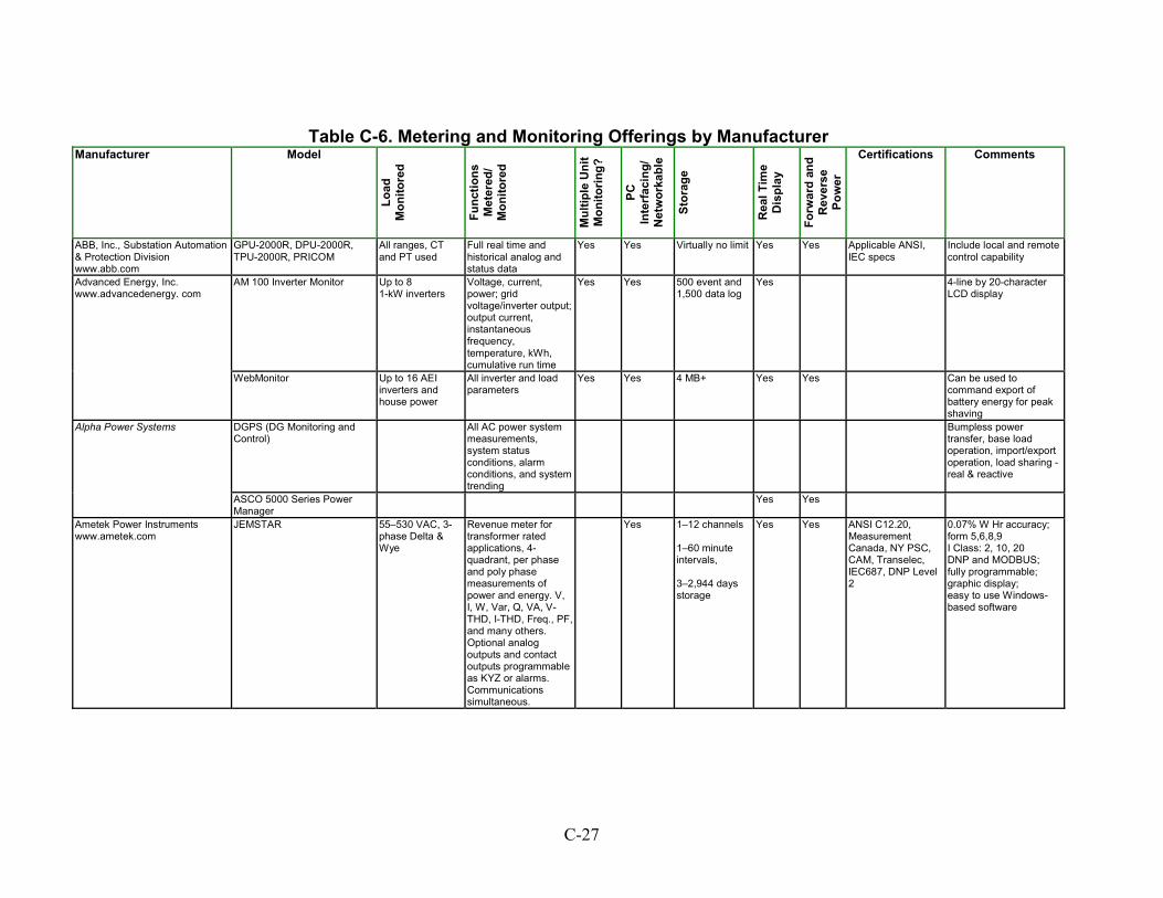
Table C-6. Metering and Monitoring Offerings by Manufacturer
Manufacturer
oad
o unc
edo on
?
C
etw
orka
b
ever
se
Model
LM
nito
red
Ftio
ns
Met
er/
Mni
tore
d
Mul
tiple
Uni
t M
itorin
g
P
Inte
rfac
ing/
N
le
Stor
age
Rea
l Tim
e D
ispl
ay
Forw
ard
and
R Pow
er
Certifications Comments
ABB, Inc., Substation Automation & Protection Division www.abb.com
GPU-2000R, DPU-2000R, TPU-2000R, PRICOM
All ranges, CT and PT used
Full real time and historical analog and status data
Yes Yes Yes Applicable ANSI,IEC specs
Include local and remote control capability
Up to 8 Voltage, current, power; grid voltage/inverter output; output current, instantaneous frequency, temperature, kWh, cumulative run time
Yes 500 event and1,500 data log
Yes 4-line by 20-character LCD display
www.advancedenergy. com
WebMonitor Up to 16 AEI inverters and house power
All inverter and load parameters
Yes Yes 4 MB+ Yes Yes Can be used to command export of battery energy for peak shaving
DGPS (DG Monitoring and Control)
All AC power system measurements, system status conditions, alarm conditions, and system trending
ASCO 5000 Series Power Manager
Yes
Ametek Power Instruments JEMSTAR
55–530 VAC, 3-phase Delta & Wye
1–12 channels
1–60 minute intervals,
3–2,944 days storage
Yes Yes 0.07% W Hr accuracy;
I Class: 2, 10, 20
fully programmable;
easy to use Windows-based software
Yes Virtually no limit
1-kW inverters YesAdvanced Energy, Inc.
AM 100 Inverter Monitor
Bumpless powertransfer, base load operation, import/export operation, load sharing - real & reactive
Alpha Power Systems
Yes
www.ametek.com Revenue meter for transformer rated applications, 4-quadrant, per phase and poly phase measurements of power and energy. V, I, W, Var, Q, VA, V-THD, I-THD, Freq., PF, and many others. Optional analog outputs and contact outputs programmable as KYZ or alarms. Communications simultaneous.
Yes
ANSI C12.20,Measurement Canada, NY PSC, CAM, Transelec, IEC687, DNP Level 2
form 5,6,8,9
DNP and MODBUS;
graphic display;
C-27
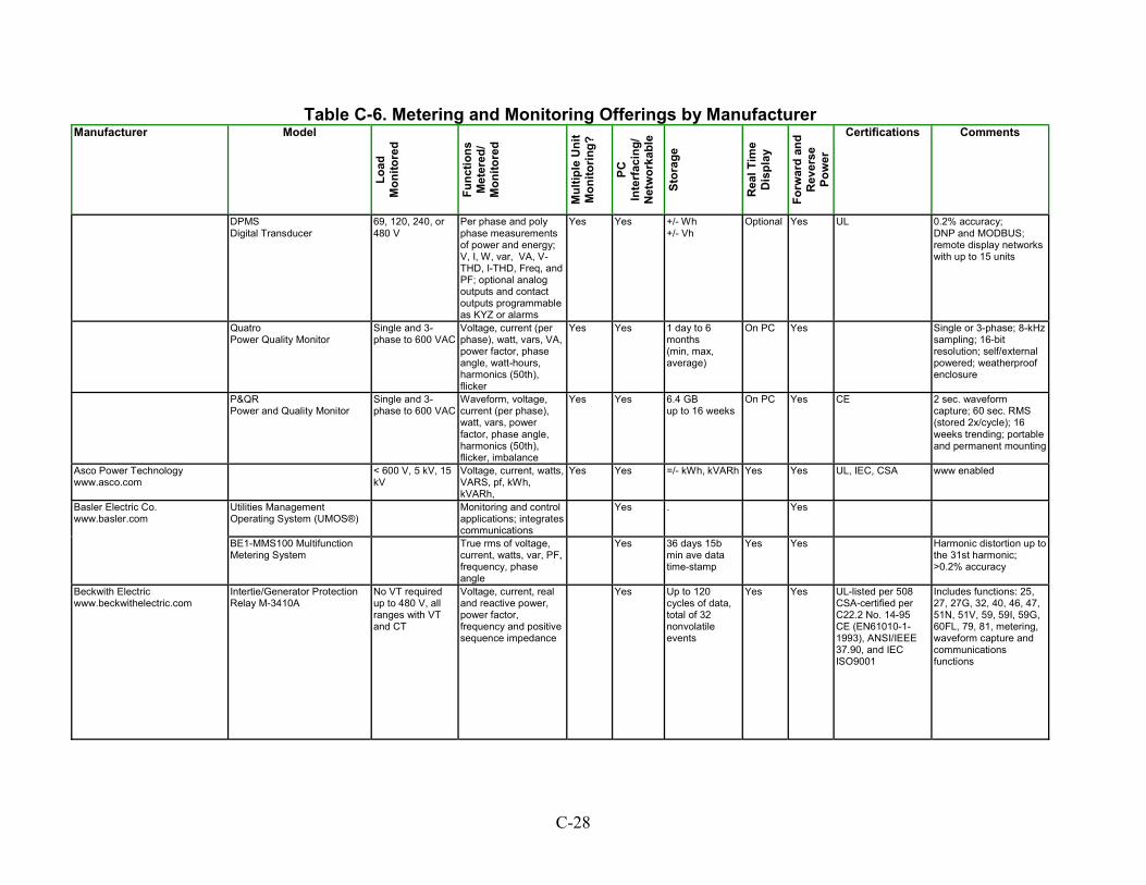
Table C-6. Metering and Monitoring Offerings by Manufacturer Manufacturer Model
Load
M
onito
red
Func
tions
M
eter
ed/
Mon
itore
d
Mul
tiple
Uni
t M
onito
ring?
PC
Inte
rfac
ing/
N
etw
orka
ble
Stor
age
Rea
l Tim
e D
ispl
ay
Forw
ard
and
Rev
erse
Po
wer
Certifications Comments
DPMSDigital Transducer
69, 120, 240, or 480 V
Per phase and poly phase measurements of power and energy; V, I, W, var, VA, V-THD, I-THD, Freq, and PF; optional analog outputs and contact outputs programmable as KYZ or alarms
Yes Yes +/- Wh+/- Vh
Yes UL 0.2% accuracy;
remote display networks with up to 15 units
Quat Single and 3-phase to 600 VAC
Yes On PC Power Quality Monitor
Voltage, current (per phase), watt, vars, VA, power factor, phase angle, watt-hours, harmonics (50th), flicker
Yes 1 day to 6 months (min, max, average)
Yes Single or 3-phase; 8-kHz sampling; 16-bit resolution; self/external powered; weatherproof enclosure
P&QRPower and Quality Monitor
Yesup to 16 weeks
Yes Single and 3-phase to 600 VAC
Waveform, voltage, current (per phase), watt, vars, power factor, phase angle, harmonics (50th), flicker, imbalance
Yes 6.4 GB On PC CE 2 sec. waveform capture; 60 sec. RMS (stored 2x/cycle); 16 weeks trending; portable and permanent mounting
Asco Power Technology www.asco.com
< 600 V, 5 kV, 15 kV
Voltage, current, watts, VARS, pf, kWh, kVARh,
Yes Yes =/- kWh, kVARh Yes Yes UL, IEC, CSA www enabled
Utilities Management Operating System (UMOS®)
Monitoring and control applications; integrates communications
Yes . YesBasler Electric Co. www.basler.com
BE1-MMS100 Multifunction Metering System
36 days 15bmin ave data time-stamp
Harmonic distortion up to the 31st harmonic; >0.2% accuracy
True rms of voltage, current, watts, var, PF, frequency, phase angle
Yes Yes Yes
Beckwith Electric www.beckwithelectric.com
No VT required up to 480 V, all ranges with VT and CT
Yes Up to 120 cycles of data, total of 32 nonvolatile events
Yes Yes UL-listed per 508CSA-certified per C22.2 No. 14-95 CE (EN61010-1-1993), ANSI/IEEE 37.90, and IEC ISO9001
Includes functions: 25, 27, 27G, 32, 40, 46, 47, 51N, 51V, 59, 59I, 59G, 60FL, 79, 81, metering, waveform capture and communications functions
OptionalDNP and MODBUS;
ro
Intertie/Generator Protection Relay M-3410A
Voltage, current, real and reactive power, power factor, frequency and positive sequence impedance
C-28

Table C-6. Metering and Monitoring Offerings by Manufacturer Manufacturer Model
Load
M
onito
red
Func
tions
M
eter
ed/
Mon
itore
d
Mul
tiple
Uni
t M
onito
ring?
PC
Inte
rfac
ing/
N
etw
orka
ble
Stor
age
Rea
l Tim
e D
ispl
ay
Forw
ard
and
Rev
erse
Po
wer
Certifications Comments
Intertie Protection Relay M-3520
Voltage, current, real and reactive power, power factor, frequency, and impedances
Yes Yes UL-listed per 508CSA-certified per C22.2 No. 14-95 ANSI/IEEE 37.90 and IEC ISO9001
Includes functions: 21, 25, 27, 27G, 32, 46, 47, 50, 50G, 51G, 51V, 59, 59I, 59G, 60FL, 67, 67N, 79, 81, 81R, metering, waveform capture, and communications functions
Capstone Turbine Corporation www.capstoneturbine.com
Remote Monitoring System Control parameters Yes Logs starts, stops, and faults
Caterpillar, Inc. www.cat.com/
IQ Sentinels 120/240, 240,208Y/120 220/380, 230/400,240/415 480, 480Y277 600, 600Y/347
Voltage, current, real, apparent, and reactive power, frequency, power factor, watts, watt hours, and watt demand
Yes Optional:IQ CED (Central Energy Display)
UL and CSA listed, CE marked
IQ 200/210 up to 600 V Voltage, current, real, reactive, and apparent power, watt, Var, and VA hours,frequency, power factor, min/max values, system demand, and KYZ pulse output
Yes Yes UL ,CSA, and CULlisted, IEC, and CE mark for applications where European compliance is required
ANSI C12.16
IQ 300/310 up to 600 V Voltage, current, real, reactive, and apparent power, watt, Var, and VA hours,frequency, power factor, min/max values, system demand, and KYZ pulse output
Yes Yes UL ,CSA, and CULlisted, IEC, and CE mark for applications where European compliance is required
ANSI C12.16
Cutler-Hammer www.cutler-hammer.eaton.com
IQDP 4000 up to 600 V RMS sensing, voltage, current, real, reactive, and apparent power, real, reactive, and apparent energy, frequency, power factor, voltage and current % THD, min/max values, and fixed or sliding demand windows
Yes Yes Yes UL, CUL, and CSA listed, and CE marked
Protective and event alarming: undervoltage, overvoltage, current and voltage phase loss, phase reversal, phase unbalance, and optional current and power demand thresholds
All ranges, CT and PT used
Up to 170 cycles of oscillograph data and 32 nonvolatile events
Yes
Yes
C-29
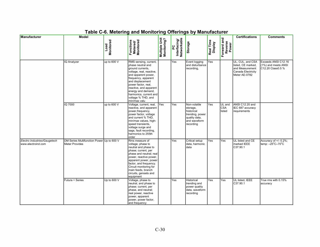
Table C-6. Metering and Monitoring Offerings by Manufacturer Manufacturer Model
Load
M
onito
red
Func
tions
M
eter
ed/
Mon
itore
d
Mul
tiple
Uni
t M
onito
ring?
PC
Inte
rfac
ing/
N
etw
orka
ble
Stor
age
Rea
l Tim
e D
ispl
ay
Forw
ard
and
Rev
erse
Po
wer
Certifications Comments
IQ Analyzer up to 600 V RMS sensing, current, phase neutral and ground currents, voltage, real, reactive, and apparent power, frequency, apparent and displacement power factor, real, reactive, and apparent energy and demand, harmonics, current and voltage % THD, and min/max valu
Yes Event loggingand disturbance recording,
Yes UL, CUL, and CSA listed, CE marked, and Measurement Canada Electricity Meter AE-0782
Exceeds ANSI C12.16 (1%) and meets ANSI C12.20 Class0.5 %
up to 600 V Voltage, current, real, reactive, and apparent power,frequency, power factor, voltage and current % THD, min/max values, high-speed transients, voltage surge and sags, fault recording, harmonics to 255th order
Yes Yes Non-volatilestorage, historical trending, power quality data, and waveform recording
Yes UL andCSA listed
ANSI C12.20 and IEC 687 accuracy requirements
DM Series Multifunction Power Meter Provides
Up to 600 V Yes Critical setupdata, harmonic data
Yes Yes UL listed and CE marked IEEE C37.90.1
Accuracy of +/- 0.2%; temp: –25oC–70oC
Electro Industries/Gaugetech www.electroind.com
Futura + Series Voltage, phase to neutral, and phase to phase; current, per phase, and neutral; real power, reactive power, apparent power, power factor, and frequency
Historicaltrending and power quality data, waveform recording
Yes Yes UL listed, IEEEC37.90.1
True rms with 0.15% accuracy
IQ 7000
Rms measure of voltage; phase to neutral and phase to phase; current, per phase and neutral; real power, reactive power, apparent power, power factor, and frequency. Circuit monitoring for main feeds, branch circuits, gensets and equipment
Up to 600 V Yes
C-30

Table C-6. Metering and Monitoring Offerings by Manufacturer Manufacturer Model
Load
M
onito
red
Func
tions
M
eter
ed/
Mon
itore
d
Mul
tiple
Uni
t M
onito
ring?
PC
Inte
rfac
ing/
N
etw
orka
ble
Stor
age
Rea
l Tim
e D
ispl
ay
Forw
ard
and
Rev
erse
Po
wer
Certifications Comments
NEXUS 1250 Power Monitor RTU
Up to 600 VAC Power usage and quality; high-speed transient; voltage surge; sag; fault recording; harmonic analysis to 255th order; current, phase A, B, C, N-measured and calculated
Yes Yes UL listed, ANSI C-12, and IEC 6
Revenue metering; ANSI C12.20 and IEC 687 accuracy requirements
Encorp Enpower MMC 3-phase power metering and monitoring
Rms, voltage, current, power factor, kW, kWh, kVa, kVAh, kVAR, kVARh, harmonic distortion, A-phase frequency, aux frequency
Yes Yes Yes Yes Yes IEC 1000-4ANSI/IEEE C37.90.1
Enetics, Inc. www.enetics.com
PowerNet Energy Management
20–600 VAC
Monitor and record power consumption and quality; harmonic and waveform recording, load control
Yes Yes Stored in a SQL database
PowerScape Softwareincluded
Industrial/Commercial Meters EPM 3720, EPM 4300S Multi-Point Sub-Meters, EPM 4400S Multi-Point Sub-Meters, EPM 4900S Basic Energy Meter, EPM 5000P, 5200P, EPM 5300P, EPM 5350P, EPM 7300 Basic Energy Meters, EPM 7430D, EPM 7450D Power Quality Meters, EPM 7600, EPM 7700 Power Transient Meters, 9450Q, EPM 9650Q Power Quality Meters, EPM for Retrofit Applications Basic Energy Meter, Panel-Mount EPM Basic Energy Meter
GE Zenith Controls Inc. www.geindustrial.com www.indsys.ge.com
Residential/Commercial Metering Panel - Single & Three Phase Meter Mod™ III, Metering Panel - Single Phase Mini Mod™ III
To 240 V ANSI C12.7, B. ANSI/NEMA PB 1, ANSI/NFPA 70, NEMA AB 1
Yes Non-volatilestorage; historical trending and power quality data, waveform recording
Accuracy: 0.2%, 25°C–70°C operating temp
Yes
C-31
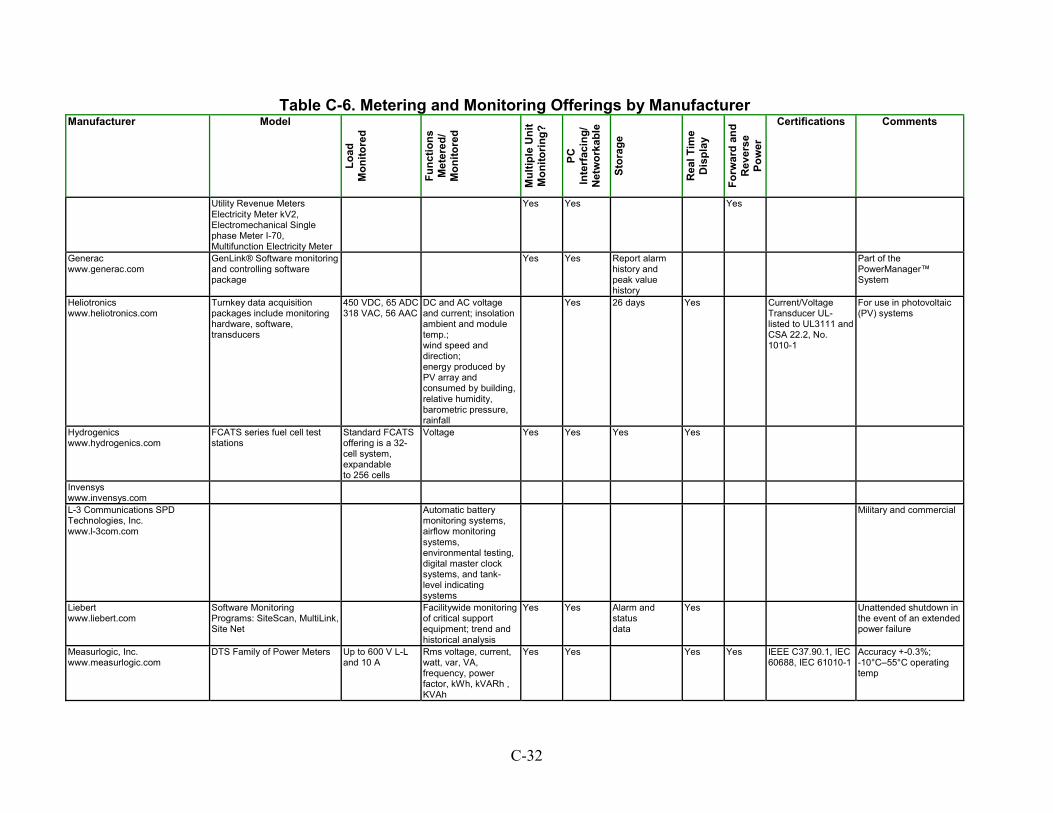
Table C-6. Metering and Monitoring Offerings by Manufacturer Manufacturer Model
Load
M
onito
red
Func
tions
M
eter
ed/
Mon
itore
d
Mul
tiple
Uni
t M
onito
ring?
PC
Inte
rfac
ing/
N
etw
orka
ble
Stor
age
Rea
l Tim
e D
ispl
ay
Forw
ard
and
Rev
erse
Po
wer
Certifications Comments
Utility Revenue Meters Electricity Meter kV2, Electromechanical Single phase Meter I-70, Multifunction Electricity Meter
Yes Yes Yes
Generac www.generac.com
GenLink® Software monitoring and controlling software package
Yes Yes Report alarmhistory and peak value history
Part of thePowerManager™ System
Heliotronics www.heliotronics.com
Turnkey data acquisition packages include monitoring hardware, software, transducers
450 VDC, 65 ADC318 VAC, 56 AAC
DC and AC voltage and current; insolation ambient and module temp.; wind speed and direction; energy produced by PV array and consumed by building, relative humidity, barometric pressure, rainfall
Yes 26 days Yes Current/VoltageTransducer UL-listed to UL3111 andCSA 22.2, No. 1010-1
For use in photovoltaic (PV) systems
Hydrogenics www.hydrogenics.com
FCATS series fuel cell test stations
Yes Yes Yes Yes
Invensys www.invensys.com
L-3 Communications SPD Technologies, Inc. www.l-3com.com
Automatic batterymonitoring systems, airflow monitoring systems, environmental testing, digital master clock systems, and tank-level indicating systems
Military and commercial
Liebert www.liebert.com
Software Monitoring Programs: SiteScan, MultiLink, Site Net
Facilitywide monitoringof critical support equipment; trend and historical analysis
Yes Yes Unattended shutdown in the event of an extended power failure
Measurlogic, Inc. Yes IEEE C37.90.1, IEC60688, IEC 61010-1www.measurlogic.com
DTS Family of Power Meters Up to 600 V L-L and 10 A
Rms voltage, current, watt, var, VA, frequency, power factor, kWh, kVARh , KVAh
Yes Yes Yes Accuracy +-0.3%; -10°C–55°C operating temp
Standard FCATS offering is a 32-cell system, expandable to 256 cells
Voltage
Alarm andstatus data
Yes
C-32

Table C-6. Metering and Monitoring Offerings by Manufacturer Manufacturer Model
Load
M
onito
red
Func
tions
M
eter
ed/
Mon
itore
d
Mul
tiple
Uni
t M
onito
ring?
PC
Inte
rfac
ing/
N
etw
orka
ble
Stor
age
Rea
l Tim
e D
ispl
ay
Forw
ard
and
Rev
erse
Po
wer
Certifications Comments
Impedograph Up to 600 V L-L and 7.5 A, 4 channels of voltage and 4 channels of current and 8 digital inputs
Rms voltage, current, watt, var, VA, frequency, power factor, kWh, kVARh , KVAh voltage sag, surge and impulse; harmonic analysis to 128th order
Yes Yes Yes Non-volatilestorage (32 MB); historical trending, power quality events and waveform recordings
Accuracy +-0.2%
OmniMetrix www.omnimetrix.net
G-series Generator Monitoring System
Compatible with any make or model of generator
Monitors, reports regularly scheduled, preprogrammed engine self-tests and events caused by actual loss of local grid power
Yes Yes Can be used to remotely start and stop power-generating machine, track portable assets using GPS
Load Reduction Transfer Switch
For use on gensets between 50 kW and 1 MW in size
Changing conditions of the machines, delivers power measurements on a 15-minute interval during machine run time
Yes Yes Also genset startup and load transfer
Power Distribution, Inc. www.pdicorp.com
Power Measurement www.pml.com
Revenue metering Metering models: ION 6200, ION 7300, ION 7330, ION 7350, ION 7500, ION 7600, ION 7700, ION 8300, ION 8400, ION 8500
Voltage/current: perphase, average, unbalance, power real, reactive, apparent, power factor, frequency, energy: total, import/export, net
Yes Timestamps,historical and waveform logs
Yes
Yes Configurable forIEEE 519-1992, IEEE 1159, SEMI
Reliable Power Meters www.reliablemeters.com
Siemens Westinghouse Power Corp. www.swpc.siemens.com
Simpson Electric www.simpsonelectric.com
Square D Company www.squared.com
Thermo Westronics www.thermowestronics.com
Toshiba International Corporation www.toshiba.co.jp
C-33
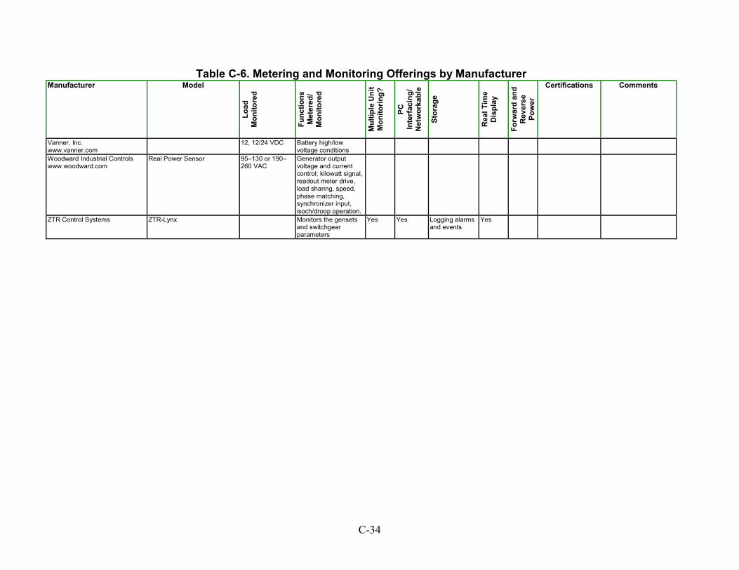
Table C-6. Metering and Monitoring Offerings by Manufacturer Manufacturer Model
Load
M
onito
red
Func
tions
M
eter
ed/
Mon
itore
d
Mul
tiple
Uni
t M
onito
ring?
PC
Inte
rfac
ing/
N
etw
orka
ble
Stor
age
Rea
l Tim
e D
ispl
ay
Forw
ard
and
Rev
erse
Po
wer
Certifications Comments
Vanner, Inc. www.vanner.com
Battery high/low voltage conditions
Real Power Sensor
95–130 or 190–260 VAC
Generator output voltage and current control; kilowatt signal, readout meter drive, load sharing, speed, phase matching, synchronizer input, isoch/droop operation.
ZTR Control Systems Logging alarms and events
YesMonitors the gensets and switchgear parameters
Yes Yes
12, 12/24 VDC
Woodward Industrial Controls www.woodward.com
ZTR-Lynx
C-34

Relays and Protective Relaying Table C-7 shows manufacturers of relaying and protective relaying equipment. DER interconnection systems require relays and protective relays with certain functions. Each function is listed in Table C-7, and an “X” indicates the manufacturer makes a relay with that function. The definitions given are from IEEE Standard Electrical Power System Device Function Numbers and Contact Designations. Synch Check (IEEE Standard Device Function Number 25) – Synchronizing or synchronism-check relay. A synchronizing device that produces an output that causes closure at zero-phase angle difference between two circuits. May or may not include voltage and speed control. A synchronism-check relay permits the paralleling of two circuits that are within prescribed limits of voltage magnitude, phase angle, and frequency.
Under/Over Voltage (IEEE Standard Device Function Number 27/59) – A device that operates when its input voltage in less than a predetermined value (27). A device that functions to short-circuit or ground a circuit in response to automatic or manual means (59). Reverse Power (IEEE Standard Device Function Number 32) – A device that operates on a predetermined value of power flow in the reverse direction resulting from the motoring of a generator upon loss of prime power.
Neutral Under/Over Voltage (IEEE Standard Device Function Number 27G/59G) – A device that operates when its input voltage is less than a predetermined value (27). A device that operates when its input voltage exceeds a predetermined value (59).
Negative Phase Sequence Current (IEEE Standard Device Function Number 46) – A device in a polyphase circuit that functions upon a predetermined value of polyphase current in the desired phase sequence when the negative phase-sequence current exceeds a preset value. Negative Phase Sequence Voltage (IEEE Standard Device Function Number 47) – A device in a polyphase circuit that functions upon a predetermined value of polyphase voltage in the desired phase sequence when the negative phase-sequence voltage exceeds a preset value.
Directional Over-Current (IEEE Standard Device Function Number 67) – A device that functions at a desired value of AC over-current flowing in a predetermined direction. Instantaneous Phase Over-Current (IEEE Standard Device Function Number 50) – A device that operates with no intentional time delay when the current exceeds a preset value.
C-36
Neutral Over-Current (IEEE Standard Device Function Number 50/51 N) – A device that operates with no intentional time delay when the current exceeds a preset value (50). Phase Over-Current (IEEE Standard Device Function Number 51) – A device that operates with no intentional time delay when the current exceeds a preset value. Under/Over Frequency (IEEE Standard Device Function Number 81 U/O) – A device that responds to the frequency of an electrical quantity, operating when the frequency or rate of change of frequency exceeds or is less than a predetermined value. Transformer Differential (IEEE Standard Device Function Number 87) – A device that operates on a percentage, phase angle, or other quantitative difference of two or more currents or other electric quantities. Comments – Notes on unit design and operation.
C-37
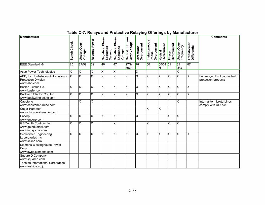
Table C-7. Relays and Protective Relaying Offerings by Manufacturer Manufacturer
Sync
h C
heck
Und
er-/O
ver-
Volta
ge
Rev
erse
Pow
er
Neg
ativ
e Ph
ase
Sequ
ence
C
urre
nt
Inst
anta
neou
s Ph
ase
Ove
rcur
rent
hase
Und
er-/O
ver-
Fr
eque
ncy
fere
ntia
l
Neg
ativ
e Ph
ase
Sequ
ence
Vo
ltage
N
eutr
al
Und
er-/
Ove
r-Vo
ltage
Dire
ctio
nal
Ove
rcur
rent
O Neu
tral
verc
urre
nt
P Ove
rcur
rent
Tran
sfor
mer
D
if
IEEE Standard 27/59 47 25 32 46 27G/59G
67 87
Comments
50 50/51N
51 81U/O
X X X X ABB, Inc., Substation Automation & Protection Division www.abb.com
X X X X X X X X X X X X Full range of utility-qualifiedprotection products
Basler Electric Co. www.basler.com
X X X X X X X X X X X X
Beckwith Electric Co., Inc. X X www.beckwithelectric.com
X X X X X X X X X X
Capstone www.capstoneturbine.com
X X Internal to microturbines,comply with UL1741
X
Cutler-Hammer www.ch.cutler-hammer.com
X X
Encorp www.encorp.com
X X X X X X XX
GE Zenith Controls, Inc.
www.indsys.ge.com www.geindustrial.com
X X X X X X X
Schweitzer Engineering Laboratories Inc. www.selinc.com
X X X X X X X X X X X X
Siemens Westinghouse Power Corp. www.swpc.siemens.com
Square D Company www.squared.com
Toshiba International Corporation www.toshiba.co.jp
Asco Power Technologies X X X
C-38
D APPENDIX D: SUMMARY OF JULY 2001 DOE/NREL SYSTEMS INTERCONNECTION TECHNOLOGIES WORKSHOP
Program Agenda
Welcome and Discussion of Workshop Purpose Joe Galdo, DOE Session 1: Inverter-Based Interconnection Systems Moderated by Sandia National Laboratories
1. Jim Munro, SatCon
DOE Distribution and Interconnection R&D (formerly Distributed Power Program) DER Systems Interconnection Technologies Workshop July 24, 2001 Washington Plaza Hotel Washington, D.C. A technical objective of the DOE Distribution and Interconnection R&D (formerly Distributed Power Program) is the development of a universal plug-and-play P1547-compliant interconnection technology that is applicable across DER technologies. The purpose of this workshop is to determine the current status of system interconnection technologies for DER applications and to determine the technology RD&D needed to achieve a universal plug-and-play interconnection environment. IEEE P1547 defines Interconnection System as the collection of all interconnection equipment, taken as a group, used to interconnect distributed resource units to an area electrical power system. Speakers will describe the status of their current equipment, packages and systems; explain their methodologies for system interconnection; and address the issues associated with moving toward the universal plug-and-play P1547 compliant technology for interconnection of distributed resources with electric power systems. Agenda
2. Clark Hochgraf, Visteon Distributed Generation 3. David Dorsey, Honeywell Power Systems 4. Ray Hudson, Xantrex 5. Panel Discussion
D-1

Session 2: Interconnection Technologies for Large Applications Moderated by Oak Ridge National Laboratory
1. Donald Hornak, Basler Electric 2. Charles Hardy, Schweitzer Engineering Labs 3. Ron Hartzel, Cutler-Hammer 4. David Leslie, GE-Zenith Controls
4. Howard Fiebus, Electrotek Concepts
5. Walter Zimmerman, Solar Turbines 6. Panel Discussion
Session 3: Integrated Interconnection Packages and Control Systems Moderated by the National Renewable Energy Laboratory
1. Thomas Widmer, Tecogen 2. Bhavesh Patel, ASCO Power Technologies 3. Larry Adams, Encorp
5. David Cohen, Silicon Energy 6. Panel Discussion
Session 4: Open Discussion on Status and RD&D Needs for System Interconnection Technologies Moderated by N. Richard Friedman (Resource Dynamics Corporation)
D-2
Summary
DOE Distribution and Interconnection R&D (formerly Distributed Power Program) DER Systems Interconnection Technologies Workshop
July 24, 2001
Washington Plaza Hotel Washington, D.C.
SUMMARY
The DOE/NREL workshop on DER systems interconnection technologies was held on July 24, 2001, in Washington, D.C. At this workshop, presented by the Distribution and Interconnection R&D (formerly Distributed Power Program), participants discussed the current status of system interconnection technologies for DER applications. The goal was to determine the technology RD&D needed to achieve the Distribution and Interconnection R&D’s objective of a universal plug-and-play P1547-compliant interconnection technology that is applicable across DER technologies. The workshop was divided into four sessions, each addressing a key issue in interconnection system development. • Session 1: Inverter-Based Interconnection Systems • Session 2: Interconnection Technologies for Large Applications • Session 3: Integrated Interconnection Packages and Control Systems
• Session 4: Open Discussion on Status and RD&D Needs for System Interconnection Technologies
Speakers from both the private and public sectors described the status of their current equipment, packages and systems, explained their methodologies for system interconnection, and addressed the issues associated with moving toward the universal plug-and-play P1547 compliant technology for interconnection of distributed resources with electric power systems. As a result of this workshop, key issues driving RD&D needs were discussed. These issues included:
• Functionality of the interconnection package, • Grid versus customer standards, • Where to include the capabilities necessary for interconnection (in the “black box,” generator
controls, etc.),
D-3
• Interface standards between DER and the interconnection package, • The issue of scaling to different power levels, and
− Start-up
− Environmental performance
• The need for lower cost and better performance.
Potential areas for RD&D were also identified: • “Universal plug and play” package • Utility versus customer standards, • Certification and testing
− Periodic performance validation, • Standard package for non-standard electric power systems, • Communications
− “Grid to chip” communications − Monitoring versus control − When needed versus operating mode (peaking, prime power, export, import),
• Controls packaging, • Revenue grade monitoring, and • Impact of interconnection control capacity on
− Predictive maintenance − Scheduled maintenance.
Workshop attendees encouraged the Distribution and Interconnection R&D to more closely examine both inverter-based and rotating power conversion technologies, and to begin to identify the current manufacturers and suppliers of interconnection equipment. Participants emphasized that an important part of this research was a characterization of the performance of the products supplied by these vendors, a description of typical system configurations used in interconnection arrangements, and identification of areas that can benefit from technology development and demonstration.
D-4

Attendees
ATTENDEES
Name Company ABB Automation
Larry Adams
Gary Bayles Satcon Technology Corp. Vijay Bhavaraju Ecostar Electric Powertrains Anne-Marie Borbely-Bartis
U.S. Department of Energy David Cohen Silicon Energy David M. Costyk Detroit Edison
DOE Distribution and Interconnection R&D (formerly Distributed Power Program) DER Systems Interconnection Technologies Workshop
July 24, 2001
Washington Plaza Hotel Washington, D.C.
William J. Ackerman Encorp, Inc.
Pirous Ahkami Solar Turbines, Inc. Thomas Basso National Renewable Energy Laboratory
US DOE DER Gary Burch
Richard DeBlasio National Renewable Energy Laboratory
David Dorsey Honeywell Power Systems Distributed Utility Associates Electrotek Concepts, Inc.
Bruce Field National Renewable Energy Laboratory Ronald Fiskum U.S. Department of Energy
Richard Friedman Resource Dynamics Corporation Joe Galdo U.S. Department of Energy Phyllis Gray Northern Power Systems
Charles Hardy Schweitzer Engineering Labs, Inc. Ronald D. Hartzel Cutler-Hammer
DOE-Office of Industrial Technologies Timothy Healy Northern Power Systems, Inc. Clark Hochgraf
Robert Dixon U.S. Department of Energy
Bill Erdman Howard Feibus
Judith Foster National Renewable Energy Laboratory
Imre Gyuk U.S. Department of Energy
Debbie Haught
Visteon Distributed Power Generation
D-5
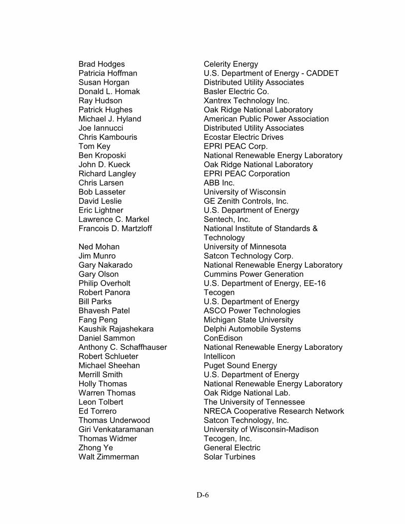
Brad Hodges Celerity Energy Patricia Hoffman Susan Horgan Distributed Utility Associates Donald L. Homak Basler Electric Co. Ray Hudson
Chris Kambouris Tom Key
John D. Kueck
Xantrex Technology Inc. Patrick Hughes Oak Ridge National Laboratory Michael J. Hyland American Public Power Association Joe Iannucci Distributed Utility Associates
Ecostar Electric Drives EPRI PEAC Corp.
Ben Kroposki National Renewable Energy Laboratory Oak Ridge National Laboratory
Richard Langley EPRI PEAC Corporation Chris Larsen ABB Inc. Bob Lasseter University of Wisconsin David Leslie GE Zenith Controls, Inc. Eric Lightner U.S. Department of Energy Lawrence C. Markel Sentech, Inc. Francois D. Martzloff National Institute of Standards &
Technology Ned Mohan University of Minnesota Jim Munro Satcon Technology Corp. Gary Nakarado National Renewable Energy Laboratory Gary Olson Cummins Power Generation Philip Overholt U.S. Department of Energy, EE-16 Robert Panora Tecogen Bill Parks U.S. Department of Energy Bhavesh Patel ASCO Power Technologies Fang Peng Michigan State University Kaushik Rajashekara Delphi Automobile Systems
ConEdison Anthony C. Schaffhauser National Renewable Energy Laboratory Robert Schlueter Intellicon Michael Sheehan Puget Sound Energy Merrill Smith U.S. Department of Energy Holly Thomas National Renewable Energy Laboratory
Oak Ridge National Lab. Leon Tolbert The University of Tennessee Ed Torrero NRECA Cooperative Research NetworkThomas Underwood Satcon Technology, Inc. Giri Venkataramanan University of Wisconsin-Madison Thomas Widmer Tecogen, Inc. Zhong Ye General Electric Walt Zimmerman Solar Turbines
U.S. Department of Energy - CADDET
Daniel Sammon
Warren Thomas
D-6
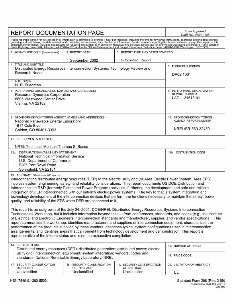
REPORT DOCUMENTATION PAGE
Form Approved OMB NO. 0704-0188
Public reporting burden for this collection of information is estimated to average 1 hour per response, including the time for reviewing instructions, searching existing data sources, gathering and maintaining the data needed, and completing and reviewing the collection of information. Send comments regarding this burden estimate or any other aspect of this collection of information, including suggestions for reducing this burden, to Washington Headquarters Services, Directorate for Information Operations and Reports, 1215 Jefferson Davis Highway, Suite 1204, Arlington, VA 22202-4302, and to the Office of Management and Budget, Paperwork Reduction Project (0704-0188), Washington, DC 20503. 1. AGENCY USE ONLY (Leave blank)
2. REPORT DATE
September 2002
3. REPORT TYPE AND DATES COVERED
Subcontract Report
4. TITLE AND SUBTITLE Distributed Energy Resources Interconnection Systems: Technology Review and Research Needs
6. AUTHOR(S)
N. R. Friedman
5. FUNDING NUMBERS
DP02.1001
7. PERFORMING ORGANIZATION NAME(S) AND ADDRESS(ES)
Resource Dynamics Corporation 8605 Westwood Center Drive Vienna, VA 22182
8. PERFORMING ORGANIZATION
REPORT NUMBER LAD-1-31613-01
9. SPONSORING/MONITORING AGENCY NAME(S) AND ADDRESS(ES)
National Renewable Energy Laboratory 1617 Cole Blvd. Golden, CO 80401-3393
10. SPONSORING/MONITORING
AGENCY REPORT NUMBER NREL/SR-560-32459
11. SUPPLEMENTARY NOTES
NREL Technical Monitor: Thomas S. Basso 12a. DISTRIBUTION/AVAILABILITY STATEMENT
National Technical Information Service U.S. Department of Commerce 5285 Port Royal Road
Springfield, VA 22161
12b. DISTRIBUTION CODE
13. ABSTRACT (Maximum 200 words) Interconnecting distributed energy resources (DER) to the electric utility grid (or Area Electric Power System, Area EPS) involves system engineering, safety, and reliability considerations. This report documents US DOE Distribution and Interconnection R&D (formerly Distributed Power Program) activities, furthering the development and safe and reliable integration of DER interconnected with our nation’s electric power systems. The key to that is system integration and technology development of the interconnection devices that perform the functions necessary to maintain the safety, power quality, and reliability of the EPS when DER are connected to it. This report is an outgrowth of the July 24, 2001, DOE/NREL Distributed Energy Resources Systems Interconnection Technologies Workshop, but it includes information beyond that — from conferences, standards, and codes (e.g., the Institute of Electrical and Electronic Engineers interconnection standards and manufacturer, supplier, and vendor specifications). This report summarizes the workshop, identifies manufacturers and suppliers of interconnection equipment, characterizes the performance of the products supplied by these vendors, describes typical system configurations used in interconnection arrangements, and identifies areas that can benefit from technology development and demonstration. This report is representative of the interim status and is not an exhaustive compilation.
15. NUMBER OF PAGES
14. SUBJECT TERMS
Distributed energy resources (DER); distributed generation; distributed power; electric utility grid; interconnection; equipment; system integration; vendors; codes and standards; National Renewable Energy Laboratory; NREL
16. PRICE CODE
17. SECURITY CLASSIFICATION
OF REPORT Unclassified
18. SECURITY CLASSIFICATION
OF THIS PAGE Unclassified
19. SECURITY CLASSIFICATION
OF ABSTRACT Unclassified
20. LIMITATION OF ABSTRACT
UL
NSN 7540-01-280-5500 Standard Form 298 (Rev. 2-89) Prescribed by ANSI Std. Z39-18 298-102