Embed Size (px)
Citation preview
1PCD Workshop Sept 2015
DECWGTM
Copyright Information
This document contains Copyright protected information; no copy or other use or dissemination can be made of this
information without the express written permission of the DECWGTM
Consortium.
Distributed Engine Control
Working Group
Presentation to Propulsion Controls and Diagnostics Working Group
September 16, 2015
Bruce Wood – DECWG™ Chairman
2PCD Workshop Sept 2015
TM
© DECWG™ 2015
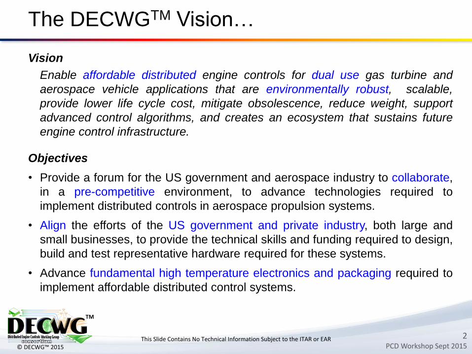
Vision
Enable affordable distributed engine controls for dual use gas turbine and
aerospace vehicle applications that are environmentally robust, scalable,
provide lower life cycle cost, mitigate obsolescence, reduce weight, support
advanced control algorithms, and creates an ecosystem that sustains future
engine control infrastructure.
Objectives
• Provide a forum for the US government and aerospace industry to collaborate,
in a pre-competitive environment, to advance technologies required to
implement distributed controls in aerospace propulsion systems.
• Align the efforts of the US government and private industry, both large and
small businesses, to provide the technical skills and funding required to design,
build and test representative hardware required for these systems.
• Advance fundamental high temperature electronics and packaging required to
implement affordable distributed control systems.
The DECWGTM Vision…
This Slide Contains No Technical Information Subject to the ITAR or EAR
3PCD Workshop Sept 2015
TM
© DECWG™ 2015
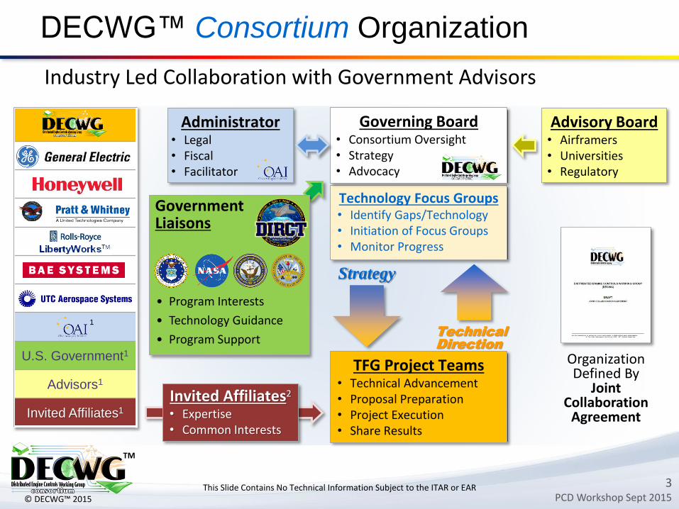
DECWG™ Consortium Organization
This Slide Contains No Technical Information Subject to the ITAR or EAR
Industry Led Collaboration with Government Advisors
1 Non-Voting Member
UTAS
U.S. Government1
Advisors1
Invited Affiliates1
1
TFG Project Teams • Technical Advancement• Proposal Preparation • Project Execution• Share Results
Technology Focus Groups• Identify Gaps/Technology• Initiation of Focus Groups• Monitor Progress
Governing Board• Consortium Oversight• Strategy• Advocacy
• Program Interests
• Technology Guidance
• Program Support
Government Liaisons
Administrator• Legal• Fiscal• Facilitator
Advisory Board• Airframers• Universities• Regulatory
Invited Affiliates2
• Expertise• Common Interests
OrganizationDefined By
JointCollaboration
Agreement
Strategy
2 Voting Member in TFGs
Technical
Direction
4PCD Workshop Sept 2015
TM
© DECWG™ 2015
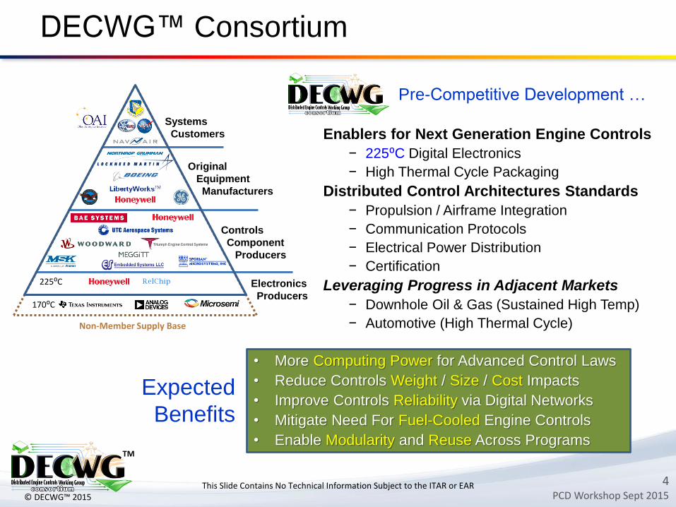
• More Computing Power for Advanced Control Laws
• Reduce Controls Weight / Size / Cost Impacts
• Improve Controls Reliability via Digital Networks
• Mitigate Need For Fuel-Cooled Engine Controls
• Enable Modularity and Reuse Across Programs
DECWG™ Consortium
Systems
Customers
Original
Equipment
Manufacturers
Controls
Component
Producers
Electronics
Producers170⁰C
225⁰C
Pre-Competitive Development …
Enablers for Next Generation Engine Controls
− 225⁰C Digital Electronics
− High Thermal Cycle Packaging
Distributed Control Architectures Standards
− Propulsion / Airframe Integration
− Communication Protocols
− Electrical Power Distribution
− Certification
Leveraging Progress in Adjacent Markets
− Downhole Oil & Gas (Sustained High Temp)
− Automotive (High Thermal Cycle)
Expected
Benefits
This Slide Contains No Technical Information Subject to the ITAR or EAR
Non-Member Supply Base
5PCD Workshop Sept 2015
TM
© DECWG™ 2015
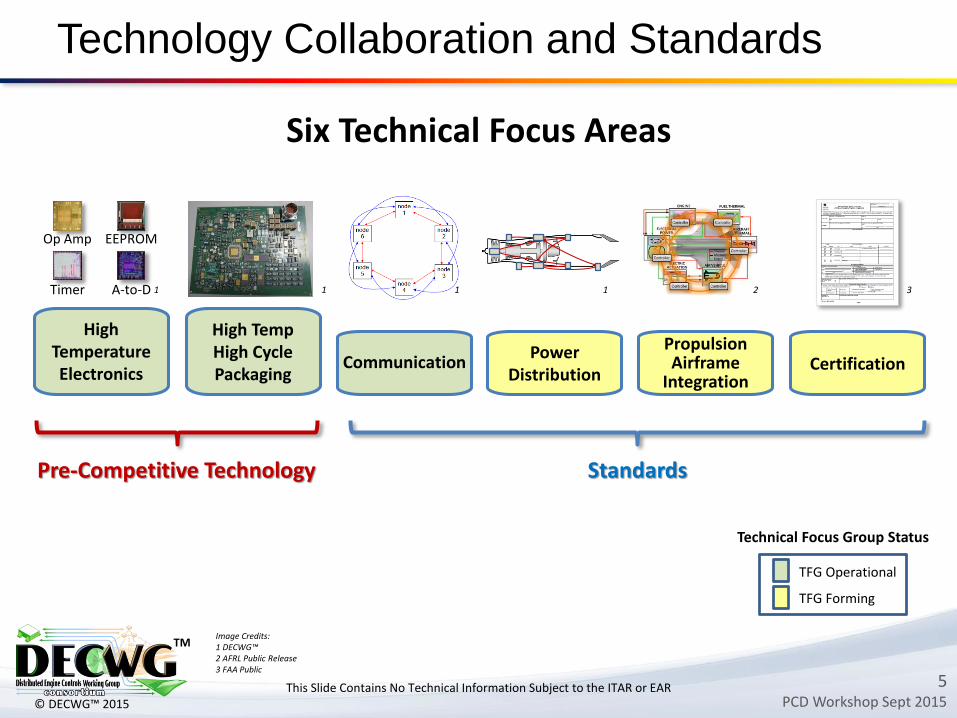
Technology Collaboration and Standards
High Temperature Electronics
High TempHigh Cycle Packaging
Power Distribution
CertificationPropulsion Airframe
Integration
Six Technical Focus Areas
Communication
TFG Operational
TFG Forming
EEPROMOp Amp
A-to-DTimer
Technical Focus Group Status
Image Credits:1 DECWG™2 AFRL Public Release3 FAA Public
1 1 1 1 2 3
This Slide Contains No Technical Information Subject to the ITAR or EAR
Pre-Competitive Technology Standards
6PCD Workshop Sept 2015
TM
© DECWG™ 2015
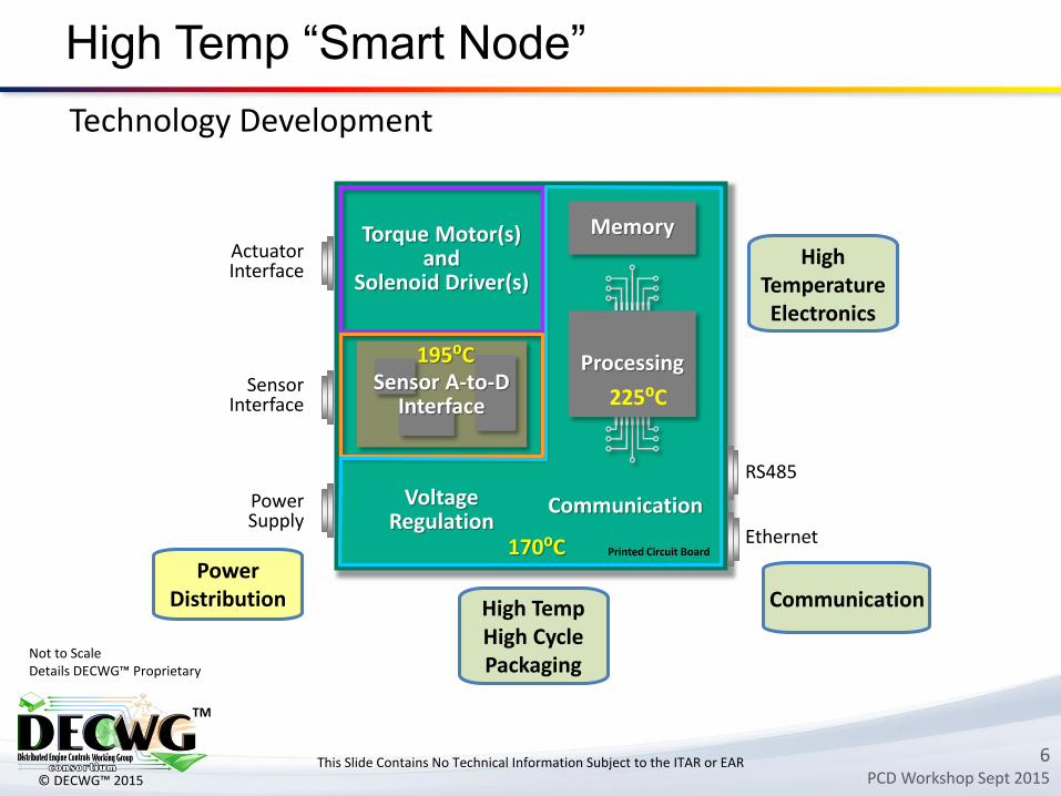
Ethernet
RS485
170⁰C Printed Circuit Board
High Temp “Smart Node”
Torque Motor(s) and
Solenoid Driver(s)
VoltageRegulation
Memory
Communication
Sensor A-to-DInterface
Processing195⁰C
225⁰C
Power Supply
SensorInterface
ActuatorInterface
This Slide Contains No Technical Information Subject to the ITAR or EAR
High Temperature Electronics
High TempHigh Cycle Packaging
CommunicationPower
Distribution
Not to ScaleDetails DECWG™ Proprietary
Technology Development
7PCD Workshop Sept 2015
TM
© DECWG™ 2015
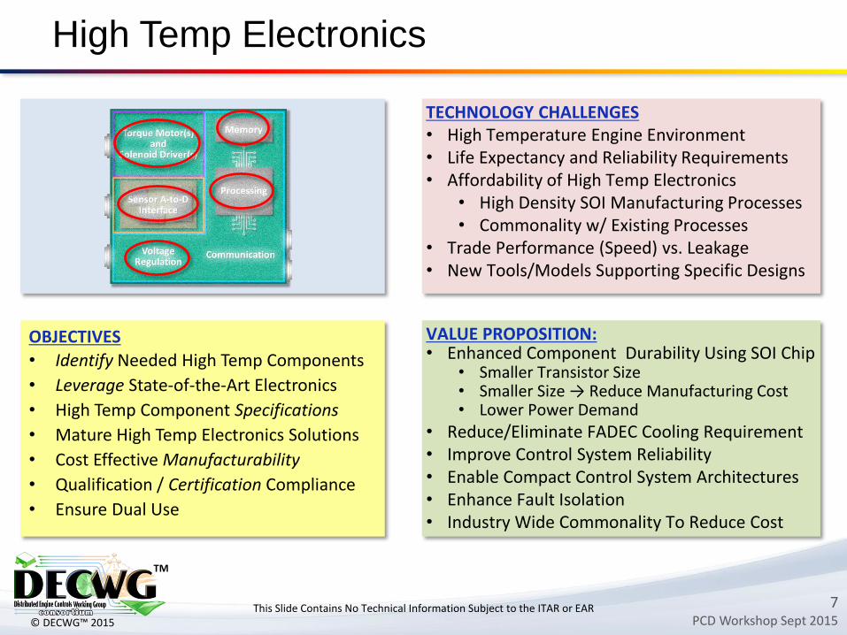
High Temp Electronics
TECHNOLOGY CHALLENGES• High Temperature Engine Environment• Life Expectancy and Reliability Requirements• Affordability of High Temp Electronics
• High Density SOI Manufacturing Processes• Commonality w/ Existing Processes
• Trade Performance (Speed) vs. Leakage• New Tools/Models Supporting Specific Designs
OBJECTIVES
• Identify Needed High Temp Components
• Leverage State-of-the-Art Electronics
• High Temp Component Specifications
• Mature High Temp Electronics Solutions
• Cost Effective Manufacturability
• Qualification / Certification Compliance
• Ensure Dual Use
VALUE PROPOSITION:• Enhanced Component Durability Using SOI Chip
• Smaller Transistor Size• Smaller Size → Reduce Manufacturing Cost • Lower Power Demand
• Reduce/Eliminate FADEC Cooling Requirement• Improve Control System Reliability• Enable Compact Control System Architectures• Enhance Fault Isolation• Industry Wide Commonality To Reduce Cost
This Slide Contains No Technical Information Subject to the ITAR or EAR
8PCD Workshop Sept 2015
TM
© DECWG™ 2015
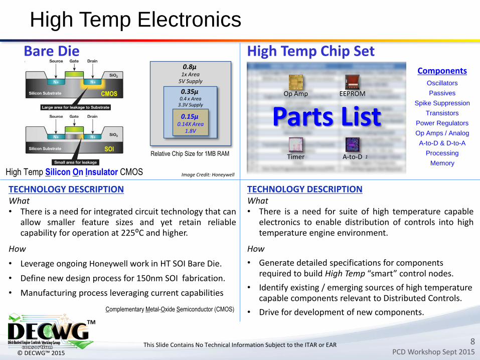
High Temp Electronics
TECHNOLOGY DESCRIPTIONWhat• There is a need for integrated circuit technology that can
allow smaller feature sizes and yet retain reliablecapability for operation at 225⁰C and higher.
How
• Leverage ongoing Honeywell work in HT SOI Bare Die.
• Define new design process for 150nm SOI fabrication.
• Manufacturing process leveraging current capabilities
Complementary Metal-Oxide Semiconductor (CMOS)
High Temp Silicon On Insulator CMOS
CMOS
SOIRelative Chip Size for 1MB RAM
0.8µ 1x Area
5V Supply
0.35µ 0.4 x Area
3.3V Supply
0.15µ 0.14X Area
1.8V
Image Credit: Honeywell
TECHNOLOGY DESCRIPTIONWhat• There is a need for suite of high temperature capable
electronics to enable distribution of controls into hightemperature engine environment.
How
• Generate detailed specifications for components required to build High Temp “smart” control nodes.
• Identify existing / emerging sources of high temperature capable components relevant to Distributed Controls.
• Drive for development of new components.
Parts List
This Slide Contains No Technical Information Subject to the ITAR or EAR
ComponentsOscillators
Passives
Spike Suppression
Transistors
Power Regulators
Op Amps / Analog
A-to-D & D-to-A
Processing
Memory
EEPROMOp Amp
A-to-DTimer 1
Bare Die High Temp Chip Set
9PCD Workshop Sept 2015
TM
© DECWG™ 2015
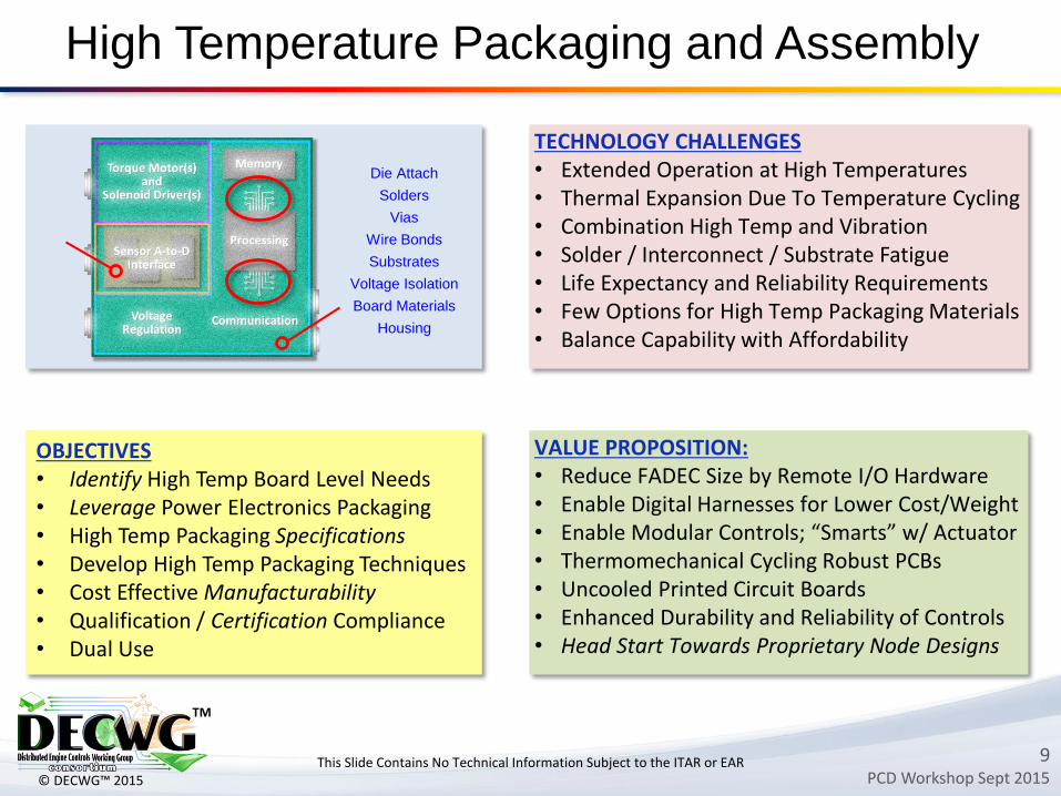
High Temperature Packaging and Assembly
TECHNOLOGY CHALLENGES• Extended Operation at High Temperatures• Thermal Expansion Due To Temperature Cycling• Combination High Temp and Vibration • Solder / Interconnect / Substrate Fatigue• Life Expectancy and Reliability Requirements• Few Options for High Temp Packaging Materials• Balance Capability with Affordability
VALUE PROPOSITION:• Reduce FADEC Size by Remote I/O Hardware• Enable Digital Harnesses for Lower Cost/Weight• Enable Modular Controls; “Smarts” w/ Actuator• Thermomechanical Cycling Robust PCBs• Uncooled Printed Circuit Boards• Enhanced Durability and Reliability of Controls• Head Start Towards Proprietary Node Designs
OBJECTIVES• Identify High Temp Board Level Needs• Leverage Power Electronics Packaging• High Temp Packaging Specifications• Develop High Temp Packaging Techniques • Cost Effective Manufacturability • Qualification / Certification Compliance • Dual Use
This Slide Contains No Technical Information Subject to the ITAR or EAR
Die Attach
Solders
Vias
Wire Bonds
Substrates
Voltage Isolation
Board Materials
Housing
10PCD Workshop Sept 2015
TM
© DECWG™ 2015
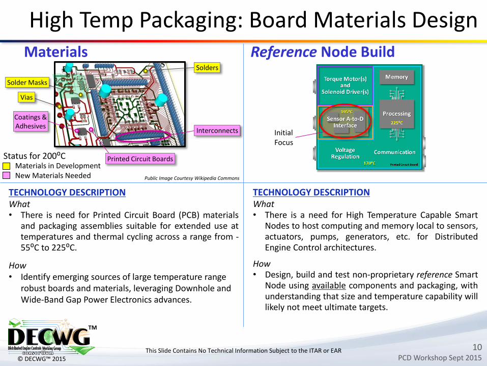
TECHNOLOGY DESCRIPTIONWhat• There is need for Printed Circuit Board (PCB) materials
and packaging assemblies suitable for extended use attemperatures and thermal cycling across a range from -55⁰C to 225⁰C.
How• Identify emerging sources of large temperature range
robust boards and materials, leveraging Downhole and Wide-Band Gap Power Electronics advances.
High Temp Packaging: Board Materials Design
Public Image Courtesy Wikipedia Commons
Printed Circuit Boards
Interconnects
Coatings &Adhesives
Solder Masks
Solders
Status for 200⁰CMaterials in DevelopmentNew Materials Needed
Vias
TECHNOLOGY DESCRIPTIONWhat• There is a need for High Temperature Capable Smart
Nodes to host computing and memory local to sensors,actuators, pumps, generators, etc. for DistributedEngine Control architectures.
How• Design, build and test non-proprietary reference Smart
Node using available components and packaging, withunderstanding that size and temperature capability willlikely not meet ultimate targets.
This Slide Contains No Technical Information Subject to the ITAR or EAR
InitialFocus
Materials Reference Node Build
11PCD Workshop Sept 2015
TM
© DECWG™ 2015
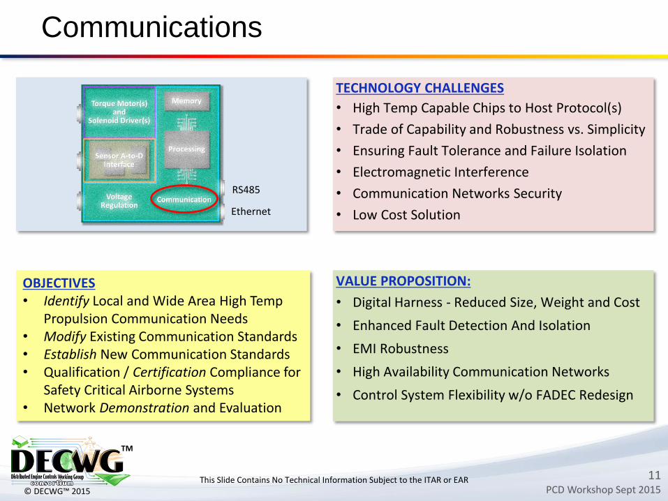
Communications
VALUE PROPOSITION:
• Digital Harness - Reduced Size, Weight and Cost
• Enhanced Fault Detection And Isolation
• EMI Robustness
• High Availability Communication Networks
• Control System Flexibility w/o FADEC Redesign
OBJECTIVES• Identify Local and Wide Area High Temp
Propulsion Communication Needs• Modify Existing Communication Standards • Establish New Communication Standards • Qualification / Certification Compliance for
Safety Critical Airborne Systems • Network Demonstration and Evaluation
This Slide Contains No Technical Information Subject to the ITAR or EAR
TECHNOLOGY CHALLENGES
• High Temp Capable Chips to Host Protocol(s)
• Trade of Capability and Robustness vs. Simplicity
• Ensuring Fault Tolerance and Failure Isolation
• Electromagnetic Interference
• Communication Networks Security
• Low Cost Solution
RS485
Ethernet
12PCD Workshop Sept 2015
TM
© DECWG™ 2015
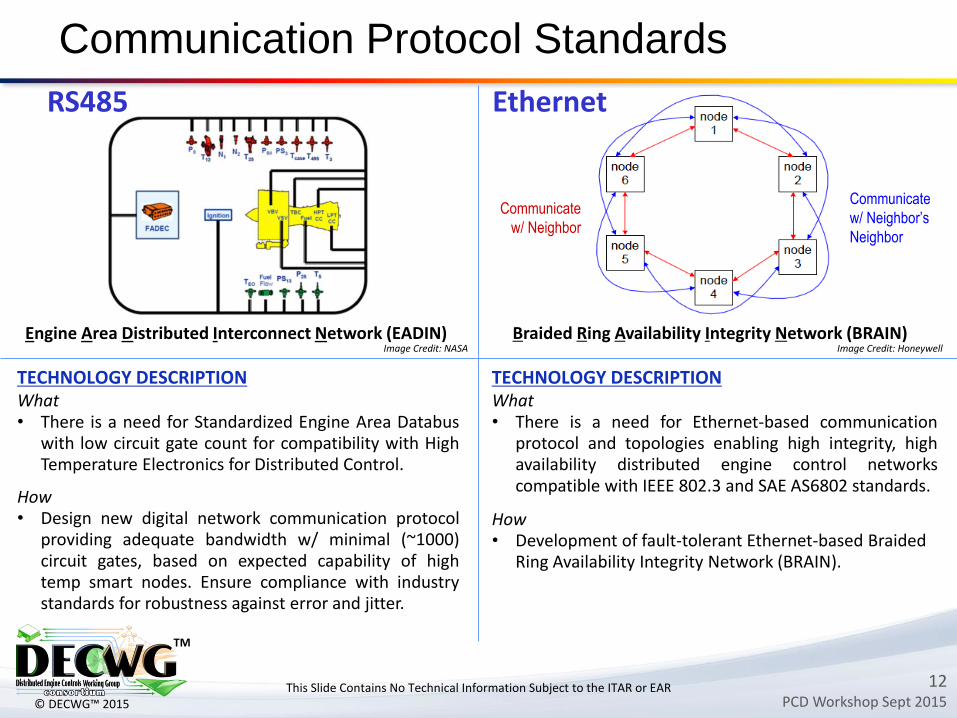
Communication Protocol Standards
TECHNOLOGY DESCRIPTIONWhat• There is a need for Standardized Engine Area Databus
with low circuit gate count for compatibility with HighTemperature Electronics for Distributed Control.
How• Design new digital network communication protocol
providing adequate bandwidth w/ minimal (~1000)circuit gates, based on expected capability of hightemp smart nodes. Ensure compliance with industrystandards for robustness against error and jitter.
Image Credit: NASA
TECHNOLOGY DESCRIPTIONWhat• There is a need for Ethernet-based communication
protocol and topologies enabling high integrity, highavailability distributed engine control networkscompatible with IEEE 802.3 and SAE AS6802 standards.
How• Development of fault-tolerant Ethernet-based Braided
Ring Availability Integrity Network (BRAIN).
Braided Ring Availability Integrity Network (BRAIN) Image Credit: Honeywell
Communicate
w/ Neighbor
Communicate
w/ Neighbor’s
Neighbor
Engine Area Distributed Interconnect Network (EADIN)
This Slide Contains No Technical Information Subject to the ITAR or EAR
RS485 Ethernet
13PCD Workshop Sept 2015
TM
© DECWG™ 2015
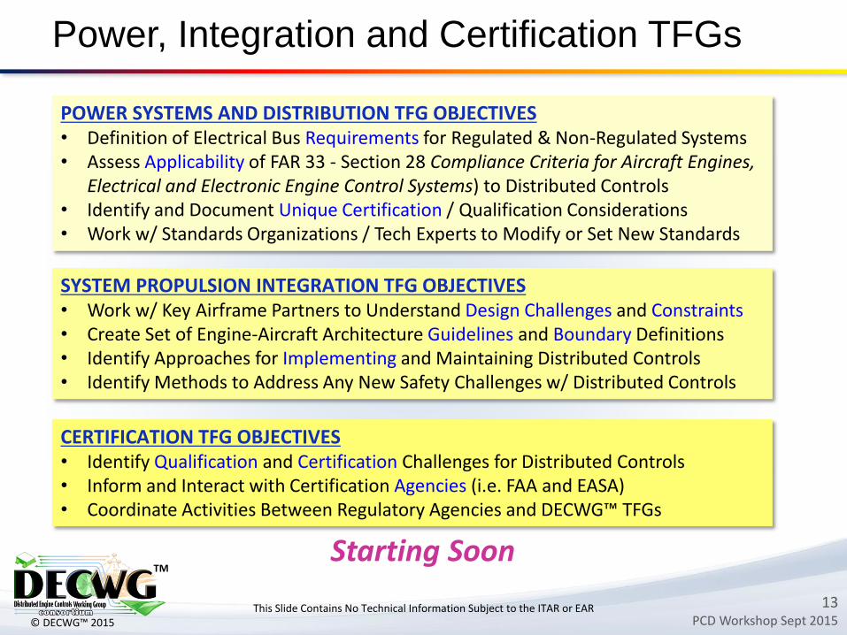
Power, Integration and Certification TFGs
POWER SYSTEMS AND DISTRIBUTION TFG OBJECTIVES• Definition of Electrical Bus Requirements for Regulated & Non-Regulated Systems • Assess Applicability of FAR 33 - Section 28 Compliance Criteria for Aircraft Engines,
Electrical and Electronic Engine Control Systems) to Distributed Controls• Identify and Document Unique Certification / Qualification Considerations • Work w/ Standards Organizations / Tech Experts to Modify or Set New Standards
This Slide Contains No Technical Information Subject to the ITAR or EAR
SYSTEM PROPULSION INTEGRATION TFG OBJECTIVES• Work w/ Key Airframe Partners to Understand Design Challenges and Constraints• Create Set of Engine-Aircraft Architecture Guidelines and Boundary Definitions• Identify Approaches for Implementing and Maintaining Distributed Controls • Identify Methods to Address Any New Safety Challenges w/ Distributed Controls
CERTIFICATION TFG OBJECTIVES• Identify Qualification and Certification Challenges for Distributed Controls• Inform and Interact with Certification Agencies (i.e. FAA and EASA)• Coordinate Activities Between Regulatory Agencies and DECWG™ TFGs
Starting Soon
14PCD Workshop Sept 2015
TM
© DECWG™ 2015
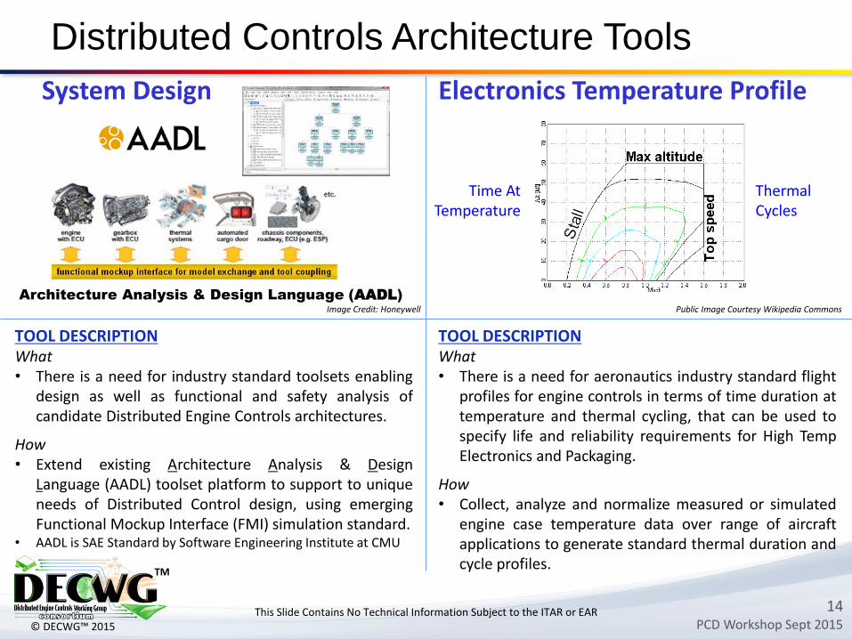
Distributed Controls Architecture Tools
Architecture Analysis & Design Language (AADL)
Image Credit: Honeywell
This Slide Contains No Technical Information Subject to the ITAR or EAR
TOOL DESCRIPTIONWhat• There is a need for aeronautics industry standard flight
profiles for engine controls in terms of time duration attemperature and thermal cycling, that can be used tospecify life and reliability requirements for High TempElectronics and Packaging.
How• Collect, analyze and normalize measured or simulated
engine case temperature data over range of aircraftapplications to generate standard thermal duration andcycle profiles.
Public Image Courtesy Wikipedia Commons
System Design Electronics Temperature Profile
Time AtTemperature
ThermalCycles
TOOL DESCRIPTIONWhat• There is a need for industry standard toolsets enabling
design as well as functional and safety analysis ofcandidate Distributed Engine Controls architectures.
How• Extend existing Architecture Analysis & Design
Language (AADL) toolset platform to support to uniqueneeds of Distributed Control design, using emergingFunctional Mockup Interface (FMI) simulation standard.
• AADL is SAE Standard by Software Engineering Institute at CMU
15PCD Workshop Sept 2015
TM
© DECWG™ 2015
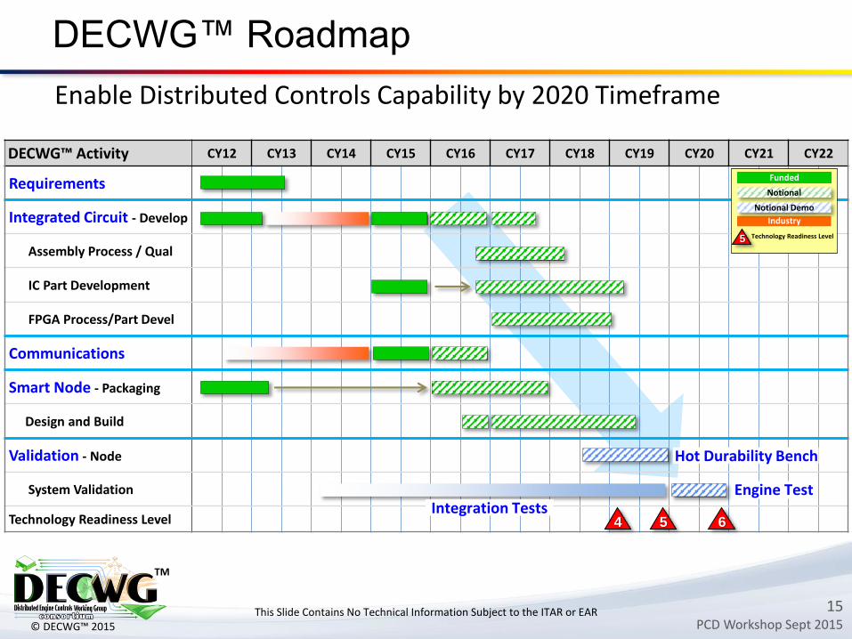
DECWG™ Roadmap
This Slide Contains No Technical Information Subject to the ITAR or EAR
DECWG™ Activity CY12 CY13 CY14 CY15 CY16 CY17 CY18 CY19 CY20 CY21 CY22
Requirements
Integrated Circuit - Develop
Assembly Process / Qual
IC Part Development
FPGA Process/Part Devel
Communications
Smart Node - Packaging
Design and Build
Validation - Node
System Validation
Technology Readiness Level
Industry
Funded
Technology Readiness Level
6
Hot Durability Bench
4 5
Enable Distributed Controls Capability by 2020 Timeframe
Notional
Engine Test
5
Notional Demo
Integration Tests
16PCD Workshop Sept 2015
TM
© DECWG™ 2015
Summary
DECWG™ Making Progress Towards 2020 Goals Consortium Formed Technical Focus Groups Initiated Roadmap w/ Government and Industry Funding
Seeking Broader Collaborationo Leverage Relevant Industry Developmento Coordinate with SBIRso Take Advantage of Synergistic DoD Activitieso Continued Proposals for Gov’t Partnerships
Invite Participationo If You Have Similar Interests … Talk with Us
DECWG™: Driving Transformational Change in Aerospace Propulsion Controls
This Slide Contains No Technical Information Subject to the ITAR or EAR