Embed Size (px)
Citation preview
1
Distributed Multimodal Interaction Protocol:
Enabling Transport of Distributed Interactions
by
Lucas Stephenson
A thesis submitted to the Faculty of Graduate and Postdoctoral Affairs in
partial fulfillment of the requirements for the degree of
Master of Applied Science
in
Human-Computer Interaction
Carleton University Ottawa, Ontario
© 2013
Lucas Stephenson
ii
Abstract
A growing number of areas in the world have ubiquitous access to mobile, personal technology
provided through a variety of hardware form factors; smartphones, tablets, and more. Despite
this, the ability to use these personal devices to control and interact with remote technology is
limited further progress is mired by proprietary technologies that places this form of remote
access technology in isolated software silos. This project provides an open standard networking
protocol to enable transport of multimodal interactions between disparate endpoints, with
minimal reliance on the personal devices’ software or hardware platform. This allows
technology enablers to more easily design, develop, deploy and maintain flexible software
solutions. Simplifying the software development life cycle allows for more access to technology
by end users and can increase the resources available for user experience considerations. The
defined protocol is validated through a number of sample implementation tests and by
verifying its ability to transport multimodal interaction information.

iii
Acknowledgements
I would like to express my very great appreciation to Dr. Anthony Whitehead for his valuable
and constructive suggestions during the planning and development of this research work. His
willingness to give his time so generously has been very much appreciated.
I would also like to thank the staff and students of the Carleton HCI program for their moral and
academic support.
Additionally I would like to thank Susan and Meaghan Pinard for their continued support.
Finally, I wish to thank my family for their support and encouragement throughout my
completion of this work.
iv
Table of Contents
Abstract ii
Acknowledgements ......................................................................................................................... iii
Table of Contents ............................................................................................................................ iv
List of Tables vii
List of Figures .................................................................................................................................. ix
List of Appendices ............................................................................................................................ x
Abbreviations and Terms ................................................................................................................ xi
1 Introduction ............................................................................................................... 1
1.1 Contributions .................................................................................................................. 3
2 Background ................................................................................................................ 5
2.1 Research Question .......................................................................................................... 5
2.2 Rationale ......................................................................................................................... 5
2.3 Barriers ............................................................................................................................ 6
2.4 Related Technologies ...................................................................................................... 7
3 Protocol Design ........................................................................................................ 13
3.1 Target Audience ............................................................................................................ 13
3.2 Requirements ................................................................................................................ 13
3.3 Methodology ................................................................................................................. 14
3.4 Supporting Technologies .............................................................................................. 15
4 Technology Overview .............................................................................................. 17
4.1 DMIP Clients .................................................................................................................. 17
4.2 DMIP Services ............................................................................................................... 18
4.3 DMIP Channels .............................................................................................................. 18
5 Protocol.................................................................................................................... 20
5.1 Protocol Applicability Statement .................................................................................. 20
5.2 Terminology .................................................................................................................. 20
5.3 Notation Conventions ................................................................................................... 21
5.4 Protocol Overview ........................................................................................................ 21
5.5 Channel Types ............................................................................................................... 22
5.5.1 Channel Type Definition.......................................................................................... 23
v
5.5.2 Channel Type Options ............................................................................................. 24
5.5.3 Channel Type Data .................................................................................................. 24
5.5.4 Standard Channels .................................................................................................. 24
5.5.5 Meta Channels ........................................................................................................ 30
5.5.6 Extension Channels ................................................................................................. 33
5.6 Messages ....................................................................................................................... 34
5.6.1 Header ..................................................................................................................... 34
5.6.2 Message Types ........................................................................................................ 35
5.7 Field Sizes ...................................................................................................................... 44
5.8 UDP Stream Data .......................................................................................................... 44
5.9 Layouts .......................................................................................................................... 44
5.10 Timeouts ....................................................................................................................... 45
6 Protocol Flow ........................................................................................................... 46
6.1 DMIP Session Overview ................................................................................................ 46
6.1.1 Session Initiation ..................................................................................................... 46
6.1.2 Channel Initiation .................................................................................................... 47
6.1.3 Active Channels ....................................................................................................... 47
6.1.4 Active Session ......................................................................................................... 48
6.1.5 Channel Termination .............................................................................................. 48
6.1.6 Session Termination ................................................................................................ 48
6.2 Examples of DMIP Message Passing ............................................................................. 49
6.2.1 Client Request Session ............................................................................................ 49
6.2.2 Adding Channels and Meta-Channels ..................................................................... 50
6.2.3 Sample Session, Button Based Menu ..................................................................... 52
6.2.4 Client Remove Abilities ........................................................................................... 54
7 Evaluation ................................................................................................................ 56
7.1 Validity of Channel Types System ................................................................................. 56
7.1.1 Common UI Controls ............................................................................................... 56
7.1.2 Raw Data Types ....................................................................................................... 57
7.1.3 Bernsen’s Multimodal Interface Modes ................................................................. 57
7.1.4 Interaction Ledger ................................................................................................... 58

vi
7.2 Protocol Implementations ............................................................................................ 59
7.2.1 The Protocol Package .............................................................................................. 59
7.2.2 Connection Class ..................................................................................................... 61
7.2.3 ChannelType Definitions ......................................................................................... 64
7.2.4 MessageType Definitions ........................................................................................ 64
7.2.5 Implementation Instances ...................................................................................... 65
7.2.6 Protocol Support and Augmentation ...................................................................... 74
8 Discussion ................................................................................................................ 77
8.1 Value and Testing .......................................................................................................... 77
8.2 Limitations..................................................................................................................... 77
8.3 Future Work .................................................................................................................. 78
8.3.1 Multi-User Scenarios ............................................................................................... 79
8.3.2 Additional Implementation Features ...................................................................... 79
8.3.3 Multi-User Scenarios ............................................................................................... 80
8.3.4 Integration with Other Technologies ...................................................................... 80
8.3.5 Standardization ....................................................................................................... 80
8.3.6 Service Endpoint Location ...................................................................................... 81
8.3.7 Transport Over HTTP and Websockets ................................................................... 81
8.3.8 User Friendly Clients ............................................................................................... 81
9 Conclusion ............................................................................................................... 82
References 84
Appendix A: Interaction Ledger ................................................................................................... 87
Survey ........................................................................................................................................ 87
Results ....................................................................................................................................... 87
Appendix B: PowerPoint Controller Show XML ........................................................................... 92
vii
List of Tables
Table 1: Channel Type Classes ...................................................................................................... 23
Table 2: Standardized Channels .................................................................................................... 23
Table 3 Range1D Options Payload ................................................................................................ 25
Table 4 Range1D Data Payload ..................................................................................................... 25
Table 5 Range1D Options Payload ................................................................................................ 26
Table 6 Range1D Data Payload ..................................................................................................... 26
Table 7 Relative3DStream Options Payload ................................................................................. 27
Table 8 Relative3DStream Data Payload ...................................................................................... 27
Table 9 Relative2DStream Options Payload ................................................................................. 28
Table 10 Relative2DStream Data Payload .................................................................................... 28
Table 11 Direction4 Data Payload................................................................................................. 29
Table 12 Chars Options Payload ................................................................................................... 29
Table 13 Chars Data Payload ........................................................................................................ 29
Table 14 Image2DView Data Payload ........................................................................................... 30
Table 15 Postionable3D Options and Data Payloads .................................................................... 32
Table 16 Interactable Interaction Types and Argument Types .................................................... 32
Table 17 Interactable Options Payload ......................................................................................... 33
Table 18 Chars Data Payload ........................................................................................................ 33
Table 19: DMIP Header ................................................................................................................. 34
Table 20: DMIP Message Types .................................................................................................... 37
Table 21 Acknowledge Message Structure ................................................................................... 37
Table 22 Error Message Structure ................................................................................................ 38
Table 23 Close Message Structure ................................................................................................ 38
Table 24: Abilities Message Structure .......................................................................................... 40
Table 25: Abilities Message Structure .......................................................................................... 40
Table 26: AddChannel Message Structure .................................................................................... 41
viii
Table 27: RemoveChannel Message Structure ............................................................................. 42
Table 28: SetChannelOpt Message Structure ............................................................................... 42
Table 29: Data Message Structure ................................................................................................ 43
Table 30: MultiPayload Message Structure .................................................................................. 43
Table 31. Implemented DMIP Channel Types .............................................................................. 66
ix
List of Figures
Figure 1: Iterative Design Methodology ....................................................................................... 15
Figure 2: Protocol Flow Overview ................................................................................................. 19
Figure 3: High Level DMIP Protocol Workflow ............................................................................. 22
Figure 4: Session Request and Initiation ....................................................................................... 50
Figure 5: Distinct Meta Channel Setup ......................................................................................... 51
Figure 6: Inclusive Meta Channel Setup ....................................................................................... 52
Figure 7: Simple User Menu .......................................................................................................... 53
Figure 8: PowerPoint Controller Menu to Show Layouts ............................................................. 54
Figure 9: Client Configuration Change .......................................................................................... 55
Figure 10: Interaction Ledger Results ........................................................................................... 58
Figure 11: Shared Protocol Package ............................................................................................. 60
Figure 12: Implementation Protocol Package .............................................................................. 60
Figure 13: Reading and Writing DMIP Payloads ........................................................................... 63
Figure 14: Windows Forms Client ................................................................................................. 67
Figure 15: Thermostat Service ...................................................................................................... 69
Figure 16: PowerPoint Controller from Android .......................................................................... 70
Figure 17: Network Sequence for Previous Slide.......................................................................... 71
Figure 18: Number Guess Service Progression ............................................................................. 72
Figure 19: Windows Mouse Control Service, Android Client ....................................................... 74
Figure 20: Sample XML Layout File Result .................................................................................... 76

x
List of Appendices
Appendix A: Interaction Ledger ................................................................................................... 87
Appendix B: PowerPoint Controller Show XML ........................................................................... 92

xi
Abbreviations and Terms
DMIP: Distributed Multimodal Interaction Protocol
The technology that is the subject of this thesis. An application protocol, using the
Internet protocol suite that allows flexible data types to be negotiated and
communicated.
Modality
Refers to the type of communication channel used to convey or acquire information. It
also covers the way an idea is expressed or perceived, or the manner an action is
performed [1].
DMIP Abilities (Abilities)
Refers to a listing of a DMIP client’s abilities. It includes what display layouts it supports
as well as an indication of which interaction modes it supports (by way of Channel Types,
see 5.5) as well as the number of instances of an interaction mode it supports.
Mode
Refers to a state that determines the way information is interpreted to extract or convey
meaning [1].
Multimodality
The capacity of the system to communicate with a user along different types of
communication channels and to extract and convey meaning automatically [1].
TCP/IP: Internet Protocol Suite
TCP/IP is a protocol set and model for inter connection between computers it provides
end-to-end connectivity specifying how data should be formatted, addressed,
xii
transmitted, routed and received at the destination. TCP/IP has 4 distinct, cumulative
layers: The link layer provides connection technologies for network segments, or links.
The internet layer allows the interconnection of segments to provide internetworking.
The transport layer provides protocols for communication low level octets between
network endpoints. The application layer provides protocols that provide specific data
communication over the underlying layers [2]. DMIP is an application layer protocol.
IP: Internet Protocol
The IP protocol, or Internet Protocol is the networking layer in the Internet protocol
suite that represents destination addresses and routing information for transmissible
data [2]. It is the base protocol upon which TCP, UDP and other TCP/IP transport layer
protocols are extended.
TCP: Transmission Control Protocol
TCP is a TCP/IP transport layer protocol that provides reliable, ordered, error-checked
delivery of a stream of octets between programs running on computers connected to a
local area network, intranet or the public Internet [2]. The primary transport mechanism
for DMIP.
UDP: User Datagram Protocol
UDP is a TCP/IP transport layer protocol that provides a low-overhead and low latency
transport mechanism, that does not provide error checking or receipt order verification
[2]. UDP is a secondary and optional transport mechanism for DMIP, ideal for latency
sensitive data streams.
Network Node or Endpoint
These terms are both used to represent a network enabled device that can
communicate over a TCP/IP network, and is therefore a potential DMIP capable device.
xiii
Data Type
A data type is strictly defined container for data. The general purpose of the DMIP is to
negotiate compatible data types and allow communication of data encoded in the
negotiated data types. Negotiable and transportable data types within DMIP are called
Channel Types (5.5), and are used to communicate input and output mode data as well
as pure data, such as text, video, images, etc.
Byte and Octet
The terms byte and octet are used interchangeably within this thesis and represents an
8-bit value. Historically, byte was not consistent, so networks used the term octet.
1
1 Introduction
Technology is everywhere within our homes, workplaces and places of leisure. The world is
replete with computing devices, many of which are interactive, and networking of these devices
has allowed basic interconnectedness among them. It is simple to envisage an environment
where everything is controllable in a user-friendly way, from a personal device. However, using
personal devices as general purpose controllers, providing human-usable methods of
interacting with other, remote devices is not widespread. Technology that allows remote
control has existed for well over a century for example, the remote control for your television.
In the majority of cases these technologies do not work together, and when they do, the
technology is often expensive, proprietary and requires the use of a single specific technology.
An example of a single controller interface that has been often demonstrated, but is not widely
accepted is home automation. The concept is a simple one; use any device to control and
manipulate the state of various devices in a home. Automatically turn off a light downstairs
when you fall asleep, pre-heat the oven on the way home from work, change the TV channel
from your phone, and monitor room temperature and security systems from afar. These home
automation tasks are all common tasks that are technically feasible and appealing to end users
and pieces of these exist [3] [4], and seem to work well. However, most of these solutions do
not work together, and rely on costly application and networking design and development time
because a common open standard for modal device to device communication is not available
and are not widely implemented or adopted. The primary goal of this work (Distributed
Multimodal Interaction Protocol: DMIP) is to allow intercommunication between devices using
a standards-based open protocol to transport user interactions between endpoints. In this way,
users can control their thermostat, TV, stove, or any other network connected device, from any
other single networked device that is able to provide a sufficient user interface. Put simply, a
user cannot currently use one general device to utilize the functionality of many others. This
2
work describes the effort made in designing and creating a mechanism that allows interaction
data to be remotely negotiated and transported.
DMIP aims to be able to provide a remote interface for any implementing devices. DMIP
classifies interaction and data so that it can be transported over the network in a standard way.
There is no open standard protocols that allow the transport of an expandable set of well-
defined data types that represent the information needed to provide a human-centric,
interactive experience. Providing a standard network protocol will enable more devices to
inter-communicate by reducing costs associated with developing externally/remotely
interactive devices. Some further examples of enabled scenarios are:
Users enter a shopping mall and use any phone to interact with a large display to: play
games with other shoppers, see specials, use interactive maps, and plan shopping
routes.
At a sports event, use the scoreboard display to play event-community games, polls, and
contests; engage the audience with reduced technology investment.
Use kiosks from personal devices, reduce the need for users to worry about interacting
using the kiosk’s touchpad and/or keypad, queue up actions before physically using the
device reducing queue time.
The availability of an increasing number of types of input modes on personal devices like mobile
telephones, music players and video game controllers as well as specialized input mode
devices, like gaze trackers, motion trackers and brain-computer interface (BCI) devices means
that users have an ever increasing number of ways of interacting. In addition to supporting
many interaction modalities, user focused design for interaction integrates interaction feedback
to aid the user’s understanding of the impact of their actions [5]. This work intends to provide
an open standard method for negotiating and communicating both emerging and existing
interaction mode data between network connected devices. To support the goal of this work,
3
an open standard was designed to aggregate, negotiate and communicate a variety of static
and interaction mode data signals so that they can be used by any platform adhering to it. This
removes reliance on specific applications or platforms and only requires an interpreter
application to be made available for client platforms. The intended result is a homogenous
application platform the can be used by application creators to provide a more accessible
access to technology. This decoupling of platform and data is accomplished through the
introduction of an application layer network protocol, distributed multimodal interaction
protocol (DMIP).
1.1 Contributions
This dissertation contributes to the human computer interaction field by providing a free and
open standard networking protocol, Distributed Multimodal Interaction Protocol (DMIP) that
allows classified interactions and data types to be negotiated and subsequently transported
between two network nodes. Substantial effort has been put into creating a well thought out
mechanism to transport all potential modal interaction data in a variety of situations and
scenarios.
To support the understanding and adoption of DMIP, a number of resources have been made
available, and discussed herein.
The DMIP protocol specification
Working implementations
o Two DMIP network layer implementations, .NET framework and Java for Android
o Two DMIP client application implementations, .NET Windows Forms and Java
for Android
o A DMIP service SDK for the .NET framework
o Three DMIP service implementation examples, using the above SDK, for the .NET
framework
4
An introductory conference paper, presented and published as part of the International
Conference on Multimedia and Human Computer Interaction, 2013.
A presentation made to, and discussed with the CapCHI society of Ottawa.
A website, (http://iv.csit.carleton.ca/~dmip/) has been created to host the protocol
specification, above listed resources and any additional future resources, updates or
discussions created to support DMIP and any future revisions of the protocol. In addition,
the website will be a central source of information about new, standardized Channel Types,
as discussed in 5.5.1.
5
2 Background
The basic premise of computer networking is to enable computing devices to intercommunicate
[6]. What information is communicated has largely been focused on computer formatted data,
high level abstractions of human knowledge and actions. Focusing on the communication of
human interaction elements allows the field of human computer interaction to be more directly
applied to the manipulation of distinct devices. This could allow applications to be built that
make use of a variety of interaction modes, giving application authors more ability to freely
design services that make use of alternate modes much more simply. Enabling human users to
use computers using their preferred input modes and devices. Similarly, providing a variety of
options for system feedback (output) allows a broader range of users and user scenarios to be
considered [7]. By providing more interaction options to the users to interact with remote
devices, accessibility to those devices and the services they provide is increased [8]. Efforts to
aggregate multimodal data exist, but are either not extendible, do not have a network
transmission focus or are not open and freely usable. In section 2.2 Rationale, we discuss the
need for this technology, from a point of technology ease of access evolution. Section 2.3
discusses reasons that such technology is not already widely available. In section 2.4, we
continue by examining related technologies and identify requirements for the proposed
protocol to overcome the deficiencies in what exists today.
2.1 Research Question
There is an ever-increasing ability for the user to generate data on personal devices, can this
data be simply consumed by remote computer devices to provide an interactive user based
experience for potentially any capable remote technology?
2.2 Rationale
The answer to the question posed in 2.1 represents an evolutionary step towards simpler
access to technology for end users. There are a number of reasons why it is needed to continue
the world’s population expanding access to technology. There exists an ever increasing use of
6
server defined applications, via the World Wide Web (WWW) [9]. However to support these
applications by providing improved usability and to make use of additional platform features on
small form factor devices, like smartphones or tablets, specific clients for the large variety of
hardware and software platforms are created and supported. This in turn generates a
significant cost to develop, maintain and support these applications. Removing application logic
and design from the client, so that a single application can be developed and maintained by
application authors reduces costs and increases accessibility for users by removing the cost to
create platform targeted applications and thus giving better access to the augmented
application by way of providing for a greater number of supported client devices. For example,
in a specific, single platform targeted scenario, there are at least two applications that need to
be designed and developed, a client application and the service itself. Revisions of the
functionality require careful consideration of client software. This issue is exacerbated when
there are multiple platforms (example: Android, iOS, Blackberry, Windows Phone) and even
further when considering variations in platforms, as well as the specific client device (abilities).
A solution must remove the additional development time caused by dealing with multiple client
targets, and removes the burden of carefully verifying every target device with every revision of
an application by only having one functional piece for application authors to design, develop
and maintain.
For end-users this is also partial solution to the problem of dealing with ever increasing
numbers of specific applications on their mobile devices, making it difficult to locate and use
them.
2.3 Barriers
While the technology herein is needed and has relevant rationale, prior to this work there did
not exist a sufficient solution. A number of related technologies are discussed in 2.4, but in
general they do not fulfill the requirements needed to fulfill the goals of a distributed
7
multimodal protocol. The reasons a prior solution did not exist is presumed to be a combination
of 2 main factors:
Using modes of interaction, besides mouse/keyboard are relatively novel
o Research efforts have created only protocols for very specific combinations of
modes.
o Using alternate, not specifically defined sets of interaction modes has not been
addressed.
Efforts to increase product line value by providing applications
o Generate specific product line applications meeting only the temporal goals of
the specific product line.
o Proprietary and not released or supported for external development.
o No perceived value to a production company for creating a standard to support
devices or services produced by competing companies.
2.4 Related Technologies
Transporting user interactions over networks is a complex issue impeding the more pervasive
spread of general human control of computers. There is a constant stream of new ways users
can interact with technology [10], as new interaction technology is introduced it adds to the
options available to application authors. Authors are confronted with design decisions that can
limit the adoption of the new technology, or alienate users who do not have access to it.
Furthermore, every application that makes use of the interaction data must encode data so
that it can be transformed into input actions or output signals. Disparate projects have different
goals and due to the proprietary nature of most of these works, the codification is not typically
useable universally between applications. There are some existing technologies that attempt to
simplify the transport and/or classification of multimodal data. Briefly, those most related to
our work are as follows:

8
Tangible User Interface Objects (TUIO) [11] is a spatial (touch, motion tracking) input
library that aims to aggregate these types of devices for use as an API.
Responsive Objects, Surfaces and Spaces (ROSS) [12] provides a development toolkit for
managing combinations of specific devices over a network.
HCI2 [13]is a tool for aggregating machine-local input, so they can be more uniformly
processed.
Extensible MultiModal Annotation (EMMA) [14] is an extensible markup language (XML)
W3C standard for encoding multimodal inputs.
OpenNI [15] is a tool that is aimed at processing and aggregating motion based inputs.
StreamInput is a project aimed at providing a flexible input API.
Radio Frequency for Consumer Electronics (RF4CE) [16] is a network protocol using low
power links to create a decentralized “mesh” network.
OpenRemote (http://www.openremote.com/) is a platform that focuses on home
automation and provides solutions for managing existing proprietary and fixed-
interaction home automation protocols.
Application specifics Projects – that separately implement the parts of functionality
required by the answer to the research question, but cannot work with one another
because their implementations are non-standardized and used fixed mode-sets.
These are partial works, but are not sufficient to provide an extensible framework for reusable
data type encoding and transmission. Next, we provide a detailed examination of each of these
related technologies.
TUIO is a network based system that aims at providing aggregate touch input data. The
purpose is to allow easier development of a variety of touch and other related continuous input
systems [17]. While this technology is extensible [11] and does approximate some of the
intentions of the proposed protocol, it is purely for input communication and does not have the
ability to negotiate the usage of modes; implementations have fixed message expressiveness.
9
Any application that needs to send data back to the client would not be directly implementable
using TUIO. For example, a simple thermostat app might let you send input to adjust the
temperature up or down, but the user would not be able to receive information about the
current temperature. In addition, TUIO is designed purely for aggregating touch data, other
interaction modes are not supported and negotiation of interaction modes, allowing variable
sets of even touch interaction modes is missing. TUIO data is assumed to be touch based, and
lacks the flexibility to simply define the data types needed for other interaction types. TUIO is
therefore insufficient for providing a general interaction mechanism for network connected
disparate devices.
ROSS is a development toolkit [12] for Tangible media [18] that provides a platform
independent method of consuming and aggregating multimodal inputs. ROSS provides explicit
input schema for devices connected to the system and operates over a TCP/IP network [12].
ROSS allows the development of applications that make use of specific devices. However, the
need for explicit input schema/device templates for each endpoint limits the system’s ability to
provide services to new, emerging and varied device capabilities. For example, a client device
might support 2D position data input using touch, mouse, gaze or through any number of other
modalities, or combinations thereof. Further, the device may support selection tasks through
varied modalities as well. In order for ROSS to interact with these devices, specific and fixed
schema have to be developed for each device implementation.
HCI 2: A Software Framework for Multimodal Human-Computer Interaction Systems
describes a modular platform that aims to support the development and research of
multimodal systems [13] [19]. This system provides a method of efficiently aggregating
machine-local input signals, so that they can be processed. The framework is a research
platform with a focus on performance, but there is no focus on raw data-type communication.
HCI2 does not provide any networking facilities. Potentially the solution could use the
aggregated local machine signals, provided by HCI2, to help communicate higher level user
10
intent. As HCI2 is a software platform, the relation to a networking protocol is perhaps not
obvious. However, its codification of input modes could be used on the service endpoint to help
interpret user intent of a variety of inputs within a solution. It could also be used to define a
specific method to carry HCI2 data, allowing endpoints to process signals for intent, and then
communicating that intent. HCI2 by itself is insufficient to meet the distributed/remote aspect
of a solution, however used in conjunction it could augment the other.
EMMA is an XML W3C standard [14] designed to alleviate the difficulty in aggregating and
augmenting through annotation multimodal inputs by providing a standard for communicating
them In XML format. EMMA is designed largely with speech audio data as the focus. An
applicable solution protocol must have the potential to support both audio streams and text
based data. However the overhead of EMMA’s XML formatted data means that it is not well
suited for a networked scenario. Additionally, the benefits of using a schema designed primarily
for speech are minimal when considering the solution protocol’s aims to be able to support the
transport of most, if not all conceivable modalities. The solution protocol must provide a means
to transport any type of modal data, potentially including EMMA’s XML format.
OpenNI is intended to provide an aggregation of processed continuous (primarily 3D vision)
inputs [15]. It allows applications to be developed based on processed inputs from various
sources. It does not provide a system for transport of these signals. A solution protocol must be
able to operate over a network and provide the ability to transport a variety of modal data
including potentially, 3D position and gesture data.
StreamInput is a project to create a cross-platform API to support application development for
new sensors. StreamInput is yet another system for aggregating interaction controls and does
not provide any transport of such signals. This project is not yet released, but mentioned here
as it may provide insight as to modes that should be supported in the future by the solution.
Unfortunately, because StreamInput is not yet available, it is difficult to assume what it can and
11
cannot it provide. However, seeing as the goals of the project are perceived to be similar to
HCI2, StreamInput could likely provide the basis for the definition of a specific interaction mode,
meant to carry StreamInput specific data.
RF4CE is a networking protocol designed to work over low power personal area networks to
create interconnected “meshes” not reliant on a centralized network structure. RF4CE could
potentially be used to find and connect to services, however it does not provide and explicit
method of negotiating data types with disparate clients to define sets of modalities to use with
clients. It provides a potential network connection option for the solution, but since the
physical link layer is usually abstracted by application protocols and efforts are being made to
provide a generalized TCP/IP abstraction (http://datatracker.ietf.org/doc/charter-ietf-
6lowpan/) for RF4CE.
OpenRemote appears to be a tool to enable aggregation and custom interfaces for other
network protocols that are focused on home automation. This is an approach to solving the end
users’ problem of interacting with a variety of technologies from their personal device.
However, since it relies of a fixed set of predefined modalities and data structures (from the
aggregated protocols,) adaptability for new client devices and novel modalities is not present. A
solution protocol must be able to represent a varying set of interaction modalities so that the
users can interact with the features and abilities they, through their devices have.
Specific Applications are everywhere, there is a veritable glut of specific remote-control
applications for phones and other handheld devices. Specific applications exist to control TV [3],
PowerPoint Presentations [20], thermostat [4] and any number of other network-able devices.
These types of applications have given users control over remote devices. However, there are
two main issues with this “scheme” of creating specific applications. It is difficult to first interact
with user-novel devices and development and maintenance of both endpoints is made
extremely complex.
12
All of the related technologies cited fall short of meeting the goals of a freely available standard
for multimodal remote negotiation and transport.
To first interact a remote device that uses a specific application, a compatible application must
be acquired. The user must know of, or be informed of the availability, have a method to
acquire the application, and then install and configure it. These steps can all be problematic for
users, notably if there is no information directly available about this function, there is no access
to the internet from the client device or the device does not allow installation of applications.
Furthermore, as the user acquires more specific applications, it is potentially difficult for the
end user to locate or recall how to access the functionality for subsequent sessions. A solution
provides applications as a network transported service, there are no requirements on the client
for any application to be installed for a specific service, and only a single application should be
required. A client needs only a network endpoint to connect to, something that could be
facilitated using a service location mechanism like Service Location Protocol (SLP).
13
3 Protocol Design
The need for a standard method of negotiating, defining and transporting multimodal data
between disparate devices, is supported in section 2. By examining related technologies,
barriers and the methods in which remote technology is currently accessed, a number of
requirements for a new protocol; DMIP, were generated. Section 3.4Error! Reference source
not found., Supporting Technologies introduces the technologies upon which the protocol is
built.
3.1 Target Audience
The goal of this work is to provide a tool to simplify development of applications that
communicate of variable set of interaction modalities. In turn, by providing a better tool for
application authors, we aim to help the end-user have increased access to technology. The
DMIP protocol, its specification (Section 5, Protocol) and associated resources (1.1
Contributions) are intended to be used by:
Authors of
o Client implementations
o Service implementations
Researchers intending to
o Extend or revise the protocol
o Create derivative works
3.2 Requirements
Section 2, identified a number of requirements for an answer to the research question. Many of
the related technologies deal with specific modalities or design-time fixed sets of modalities.
Many of the works cited are not licensed for general use, and others still are verbose and not
suitable for network transport. A formal list of identified requirements are compiled and
clarified below;
14
The system must:
i. Be format-flexible and have the potential to represent any type of computer data,
especially raw format data and interaction modalities
ii. Provide a means to negotiate supported data-types between devices at run-time
iii. Be able to and depend upon operation over a computer network
iv. Be able to send and receive data asynchronously
v. Be able to provide access to any modal-compatible service through a single application
vi. Be able to provide a single, flexible platform for application developers
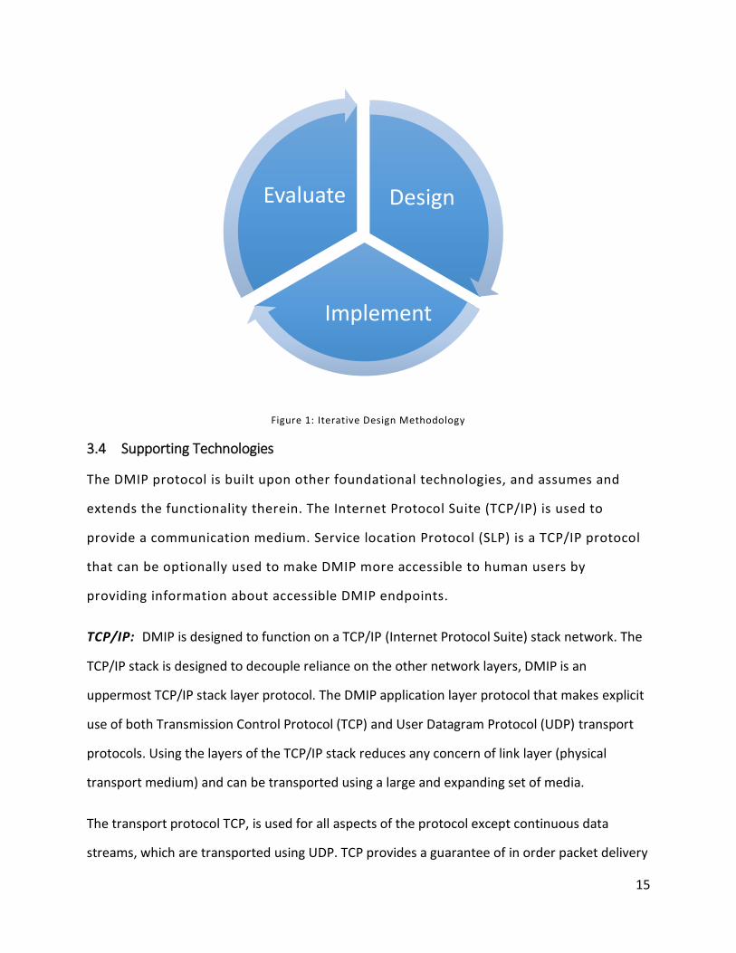
3.3 Methodology
Iterative design [21] a methodology frequently used in the HCI field was used during the
development of the protocol specification, a diagram of the methodology is provided below in
Figure 1: Iterative Design Methodology. Initially DMIP was designed based on requirements i, iii,
iv, v and vi. Then client and service implementations were created using the .NET framework
(see section 7.2 Protocol Implementations). These implementations were evaluated and the
protocol was revised to support (ii) and tested, subsequent iterations added modes, further
services test and augmentations as well as introducing the Android platform.
15
Figure 1: Iterative Design Methodology
3.4 Supporting Technologies
The DMIP protocol is built upon other foundational technologies, and assumes and
extends the functionality therein. The Internet Protocol Suite (TCP/IP) is used to
provide a communication medium. Service location Protocol (SLP) is a TCP/IP protocol
that can be optionally used to make DMIP more accessible to human users by
providing information about accessible DMIP endpoints.
TCP/IP: DMIP is designed to function on a TCP/IP (Internet Protocol Suite) stack network. The
TCP/IP stack is designed to decouple reliance on the other network layers, DMIP is an
uppermost TCP/IP stack layer protocol. The DMIP application layer protocol that makes explicit
use of both Transmission Control Protocol (TCP) and User Datagram Protocol (UDP) transport
protocols. Using the layers of the TCP/IP stack reduces any concern of link layer (physical
transport medium) and can be transported using a large and expanding set of media.
The transport protocol TCP, is used for all aspects of the protocol except continuous data
streams, which are transported using UDP. TCP provides a guarantee of in order packet delivery
Design
Implement
Evaluate
16
and is used primarily to ensure in order message delivery and processing, while UDP is used for
continuous data streams, where a dropped or out of order message is less significant than the
timeliness of message delivery [2]. The TCP/IP networking stack is broadly supported over a
variety of application platforms and network media including wired and wireless [22] [23]
technologies [2].
Service Location Protocol (SLP) [24]: DMIP is intended to be used in unfamiliar networks.
DMIP applications assume a TCP/IP link and a TCP/IP endpoint are known. The TCP/IP link is
generally configured by the user through their device, or automatically through applications on
the device. DMIP endpoints must however be identified so that devices can connect. In order to
provide a means of locating these DMIP endpoints, SLP is recommended as a solution. This
protocol allows the discovery and query of managed service endpoints through the use of IP
multicast. Further to identifying DMIP endpoints, basic attributes can be queried enabling
connecting devices to connect only to compatible endpoints. The query-able attributes are yet
to be defined and will be defined in future work by creating an SLP service template for DMIP
[25].

17
4 Technology Overview
On a TCP/IP network communication occurs primarily over an endpoint to endpoint link [26].
These two endpoints can typically send and receive data in the form of octet encoded data
from the other endpoint, using any number of supported transport layer protocols [2]. The
most common transport protocols, TCP and UDP both allow the transport of octet streams in
chunks. TCP provides a reliable mechanism with in-order guaranteed delivery of data while UDP
provides a lower latency, but does not guarantee delivery or order of delivery [2]. The DMIP
protocol uses primarily TCP connections, in order to provide a reliable end-user experience.
UDP may be optionally used for the transport of some time-sensitive data if it is supported by
both endpoints. DMIP is an application layer protocol that builds on transport layer protocols,
primarily TCP and optionally UDP. Within a DMIP session there are always 2 endpoints
(necessitated by TCP). One of these endpoints is a client (section 4.1), a DMIP implementing
application that connects to and negotiates a session with a service (section 4.2), a DMIP
application that “serves” the client the interface and can send and receive data using
negotiated channels. Both clients and service devices can support multiple simultaneous
sessions.
4.1 DMIP Clients
DMIP Clients are typically mobile devices that provide a remote, user-centric interface for a
service. Client implementations do not contain any service application specific logic or
presentation information. Clients initiate DMIP sessions by contacting a known network
endpoint over TCP. The discovery of the addresses of these endpoints can be facilitated nicely
using Service Location Protocol (SLP) [24].
Client DMIP applications are independent of services, a client that provides the minimum
channels required to access a service can consume that service. Similar to a web browser, a
single client implementation may be developed for a hardware device/platform, a user would
not generally need more than one client on their device. However, client implementations
18
could provide additional features by providing automatic service location, additional Channel
Types (section 5.5) or any number of other options. It is therefore imaginable that multiple,
potentially competing, clients for a platform might be developed.
4.2 DMIP Services
A DMIP service application is the functional piece. It is located at a known, advertised, or
discoverable network endpoint. Interaction sessions using DMIP have all program logic and
functionality, defined by the service application. To develop a DMIP service a developer creates
client layouts and behaviours to support different modes of interaction by the service
application.
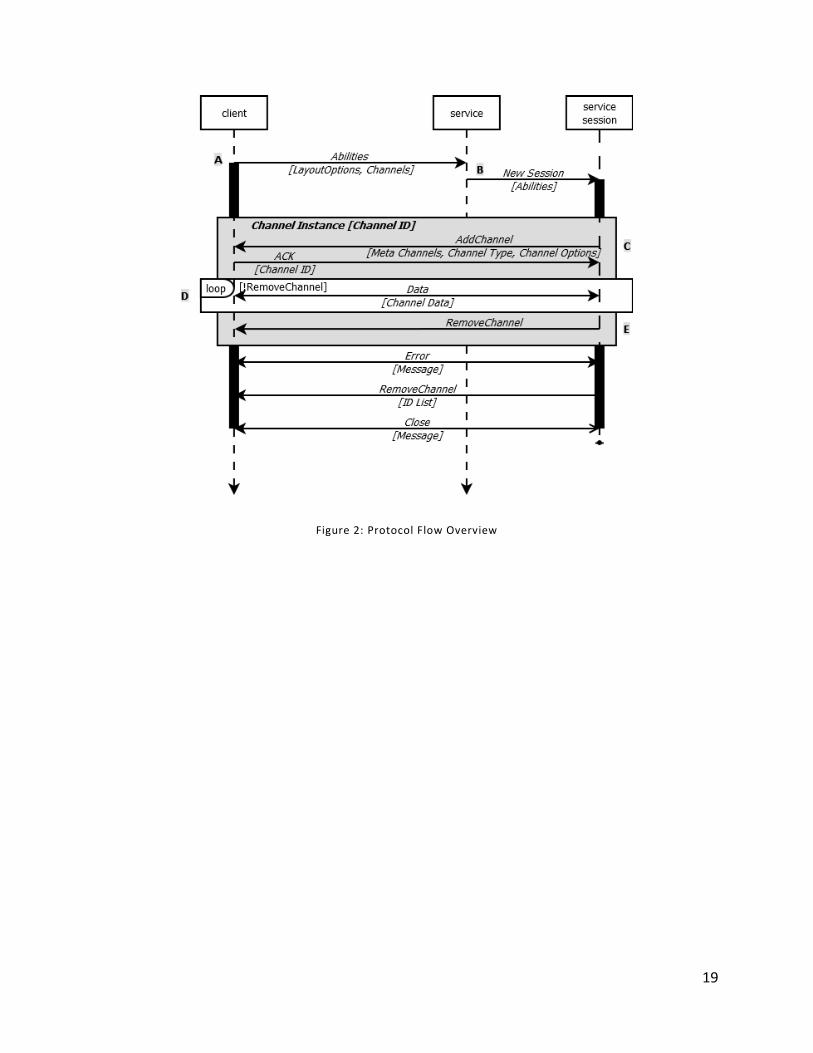
4.3 DMIP Channels
DMIP Channels carry data, formatted according to the enclosing Channel Type (section 5.5) and
represent input and/or output data from either endpoint. As shown in Figure 2: Protocol Flow
Overview, a client sends a listing of its Abilities, represented by the Channel Types it supports
(Label A). Then the service determines if it can interact with all, or a subset, of the presented
abilities, and what channels it will use (Label B). Instances of the chosen channels are created
(Label C). Once confirmed, a channel allows mode formatted data of that channel’s type to flow
(Label D). This data channel stream is valid until the connection times out (section 5.5), or is
explicitly removed (section 5.6.2.8), Label E.
19
Figure 2: Protocol Flow Overview
20
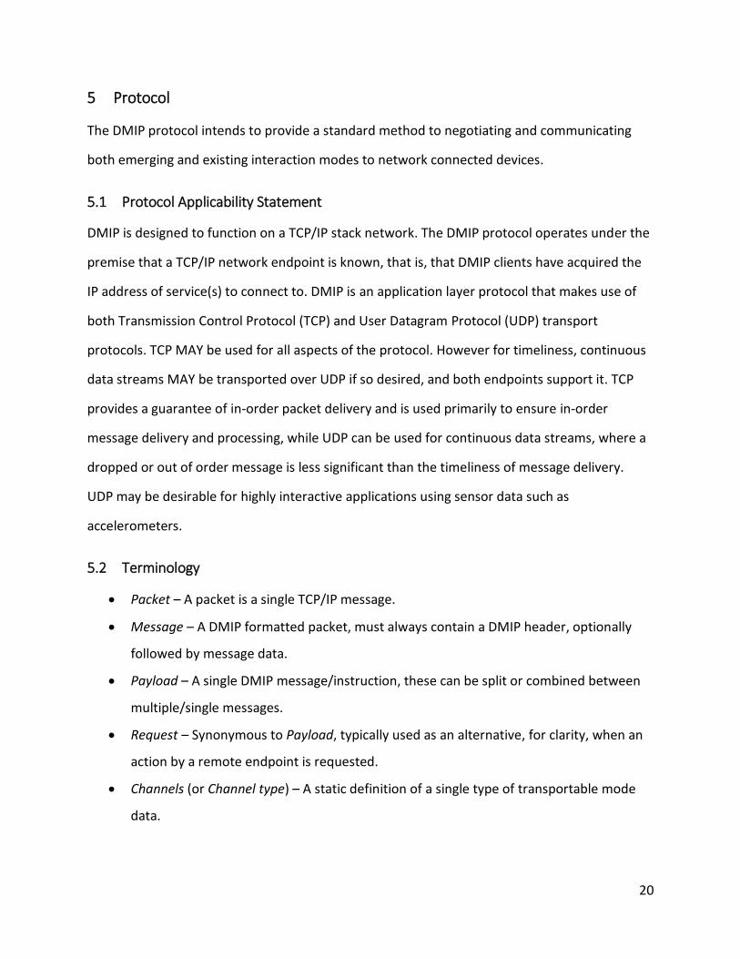
5 Protocol
The DMIP protocol intends to provide a standard method to negotiating and communicating
both emerging and existing interaction modes to network connected devices.
5.1 Protocol Applicability Statement
DMIP is designed to function on a TCP/IP stack network. The DMIP protocol operates under the
premise that a TCP/IP network endpoint is known, that is, that DMIP clients have acquired the
IP address of service(s) to connect to. DMIP is an application layer protocol that makes use of
both Transmission Control Protocol (TCP) and User Datagram Protocol (UDP) transport
protocols. TCP MAY be used for all aspects of the protocol. However for timeliness, continuous
data streams MAY be transported over UDP if so desired, and both endpoints support it. TCP
provides a guarantee of in-order packet delivery and is used primarily to ensure in-order
message delivery and processing, while UDP can be used for continuous data streams, where a
dropped or out of order message is less significant than the timeliness of message delivery.
UDP may be desirable for highly interactive applications using sensor data such as
accelerometers.
5.2 Terminology
Packet – A packet is a single TCP/IP message.
Message – A DMIP formatted packet, must always contain a DMIP header, optionally
followed by message data.
Payload – A single DMIP message/instruction, these can be split or combined between
multiple/single messages.
Request – Synonymous to Payload, typically used as an alternative, for clarity, when an
action by a remote endpoint is requested.
Channels (or Channel type) – A static definition of a single type of transportable mode
data.
21
Standard Channels – Channels included as part of the DMIP protocol definition (this
document).
Meta Channels - Channels used to augment other channel types, and can be associated
1 to 1.
Extension Channels – Channels created by 3rd party and/or in development stages, not
included within the protocol definition.
Channel (or Channel type Instance) – An instance of a channel type, within an active
DMIP session.
5.3 Notation Conventions
The key words "MUST", "MUST NOT", "REQUIRED", "SHALL", "SHALL NOT", "SHOULD",
"SHOULD NOT", "RECOMMENDED", "MAY", and "OPTIONAL" in this document are to be
interpreted as described in RFC 2119 [27].
If unspecified, binary data fields are to be interpreted as unsigned values.
5.4 Protocol Overview
The DMIP protocol provides a lightweight layer for communicating categorized interaction
mode data over a TCP/IP network. DMIP operates over TCP, and optionally UDP. The purpose
of the DMIP protocol is to provide functionality that simplifies the transport of interaction
mode channels. The purpose of the creation of this protocol is to enable the possibility of
making the devices around us to universally accessible This goal is accomplished by making a
reusable and extendible protocol that simplifies development of distributed, network based
applications, as it allows developers of service applications to focus on behaviours and
presentation rather than being concerned with networking nor the interpretation of a wide
range of input/output types over a range of platforms (OS/hardware). DMIP sessions are
designed to be event based. The implementing systems observe and respond to events, which
are generated by implementing systems when DMIP data is available.
22
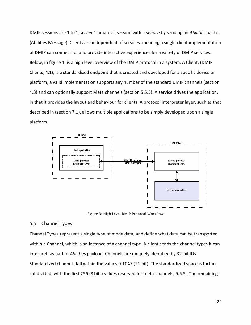
DMIP sessions are 1 to 1; a client initiates a session with a service by sending an Abilities packet
(Abilities Message). Clients are independent of services, meaning a single client implementation
of DMIP can connect to, and provide interactive experiences for a variety of DMIP services.
Below, in figure 1, is a high level overview of the DMIP protocol in a system. A Client, (DMIP
Clients, 4.1), is a standardized endpoint that is created and developed for a specific device or
platform, a valid implementation supports any number of the standard DMIP channels (section
4.3) and can optionally support Meta channels (section 5.5.5). A service drives the application,
in that it provides the layout and behaviour for clients. A protocol interpreter layer, such as that
described in (section 7.1), allows multiple applications to be simply developed upon a single
platform.
Figure 3: High Level DMIP Protocol Workflow
5.5 Channel Types
Channel Types represent a single type of mode data, and define what data can be transported
within a Channel, which is an instance of a channel type. A client sends the channel types it can
interpret, as part of Abilities payload. Channels are uniquely identified by 32-bit IDs.
Standardized channels fall within the values 0-1047 (11-bit). The standardized space is further
subdivided, with the first 256 (8 bits) values reserved for meta-channels, 5.5.5. The remaining
23
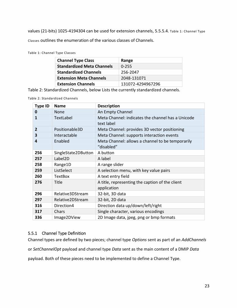
values (21-bits) 1025-4194304 can be used for extension channels, 5.5.5.4. Table 1: Channel Type
Classes outlines the enumeration of the various classes of Channels.
Table 1: Channel Type Classes
Channel Type Class Range
Standardized Meta Channels 0-255 Standardized Channels 256-2047
Extension Meta Channels 2048-131071 Extension Channels 131072-4294967296
Table 2: Standardized Channels, below Lists the currently standardized channels.
Table 2: Standardized Channels
Type ID Name Description
0 None An Empty Channel
1 TextLabel Meta Channel: indicates the channel has a Unicode text label
2 Positionable3D Meta Channel: provides 3D vector positioning 3 Interactable Meta Channel: supports interaction events 4 Enabled Meta Channel: allows a channel to be temporarily
“disabled” 256 SingleState2DButton A button 257 Label2D A label
258 Range1D A range slider 259 ListSelect A selection menu, with key value pairs
260 TextBox A text entry field 276 Title A title, representing the caption of the client
application 296 Relative3DStream 32-bit, 3D data
297 Relative2DStream 32-bit, 2D data
316 Direction4 Direction data up/down/left/right 317 Chars Single character, various encodings 336 Image2DView 2D Image data, jpeg, png or bmp formats
5.5.1 Channel Type Definition
Channel types are defined by two pieces; channel type Options sent as part of an AddChannels
or SetChannelOpt payload and channel type Data sent as the main content of a DMIP Data
payload. Both of these pieces need to be implemented to define a Channel Type.
24
Implementation of a channel type includes definition of what data is included, and how that
data is to be encoded/decoded into message data.
5.5.2 Channel Type Options
The Options payload of a channel is sent to provide initialization and configuration information
about the channel. An Options payload is sent to initialize a channel as part of an encapsulated
AddChannel payload. If options for a channel need to be reset, or initialized for a Meta Channel
they can be sent as part of a SetChannelOpt payload. Note that AddChannel messages are
ignored for already configured channels. Receipt of a SetChannelOpt payload indicates that the
channel, or Meta Channel should be reset to a default state with the Option payload data used
to re-initialize it.
5.5.3 Channel Type Data
The channel Data payload is sent as part of a DMIP Data message. Data payloads include
formatted data for the channel, and can be event based (discrete) or stream based
(continuous). When developing new or extension channel types the importance of in-order
delivery and the frequency of transmission should be considered, so that the Data payloads can
be developed accordingly, features could be added to channel type Data definitions that are
likely to be used over UDP to augment UDP support.
5.5.4 Standard Channels
5.5.4.1 None
The ChannelType enumeration value zero (0) is reserved and should be ignored by endpoints
implementing the protocol.
5.5.4.2 SingleState2DButton
The SingleState2DButton (256) channel is intended to be represented by a selectable button on
clients. The channel type is a skeleton that is intended to have meta-channels attached to it. It
is recommended to be implemented by a standard looking button according to the client
implementation platform’s standard user interface conventions, or as the developers sees fit.
25
The channel’s appearance, layout parameters and behaviours can be specified/augmented
through the use of meta-channels. Both SingleState2DButton Options and Data are zero length.
5.5.4.3 Label2D
The Label2D (257) channel is intended to be represented by a text label on connected clients.
The channel type is a skeleton that is intended to have meta-channels attached to it. It is
recommended to be implemented by a standard looking label according to the client
implementation platform’s standard user interface conventions, or as the developers sees fit.
The channel’s appearance, layout parameters and behaviours can be specified/augmented
through the use of meta-channels. Both Label2D Options and Data are zero length.
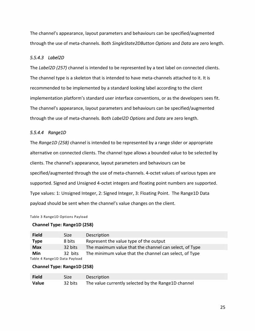
5.5.4.4 Range1D
The Range1D (258) channel is intended to be represented by a range slider or appropriate
alternative on connected clients. The channel type allows a bounded value to be selected by
clients. The channel’s appearance, layout parameters and behaviours can be
specified/augmented through the use of meta-channels. 4-octet values of various types are
supported. Signed and Unsigned 4-octet integers and floating point numbers are supported.
Type values: 1: Unsigned Integer, 2: Signed Integer, 3: Floating Point. The Range1D Data
payload should be sent when the channel’s value changes on the client.
Table 3 Range1D Options Payload
Channel Type: Range1D (258)
Field Size Description Type 8 bits Represent the value type of the output Max 32 bits The maximum value that the channel can select, of Type Min 32 bits The minimum value that the channel can select, of Type
Table 4 Range1D Data Payload
Channel Type: Range1D (258)
Field Size Description Value 32 bits The value currently selected by the Range1D channel
26
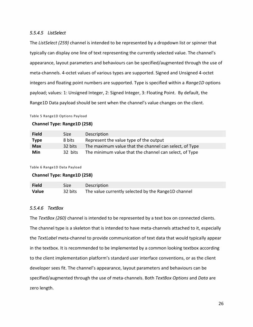
5.5.4.5 ListSelect
The ListSelect (259) channel is intended to be represented by a dropdown list or spinner that
typically can display one line of text representing the currently selected value. The channel’s
appearance, layout parameters and behaviours can be specified/augmented through the use of
meta-channels. 4-octet values of various types are supported. Signed and Unsigned 4-octet
integers and floating point numbers are supported. Type is specified within a Range1D options
payload; values: 1: Unsigned Integer, 2: Signed Integer, 3: Floating Point. By default, the
Range1D Data payload should be sent when the channel’s value changes on the client.
Table 5 Range1D Options Payload
Channel Type: Range1D (258)
Field Size Description Type 8 bits Represent the value type of the output Max 32 bits The maximum value that the channel can select, of Type Min 32 bits The minimum value that the channel can select, of Type
Table 6 Range1D Data Payload
Channel Type: Range1D (258)
Field Size Description Value 32 bits The value currently selected by the Range1D channel
5.5.4.6 TextBox
The TextBox (260) channel is intended to be represented by a text box on connected clients.
The channel type is a skeleton that is intended to have meta-channels attached to it, especially
the TextLabel meta-channel to provide communication of text data that would typically appear
in the textbox. It is recommended to be implemented by a common looking textbox according
to the client implementation platform’s standard user interface conventions, or as the client
developer sees fit. The channel’s appearance, layout parameters and behaviours can be
specified/augmented through the use of meta-channels. Both TextBox Options and Data are
zero length.
27
5.5.4.7 Title
The Title (276) channel is intended to represent a window or application caption, typically
shown in the title area of an application, and running application lists on clients. The channel
type is a skeleton that is intended to have meta-channels attached to it. It is recommended that
implementations implement at least the TextLabel Meta Channel, allowing a text label to be
specified. Both Title Options and Data are zero length.
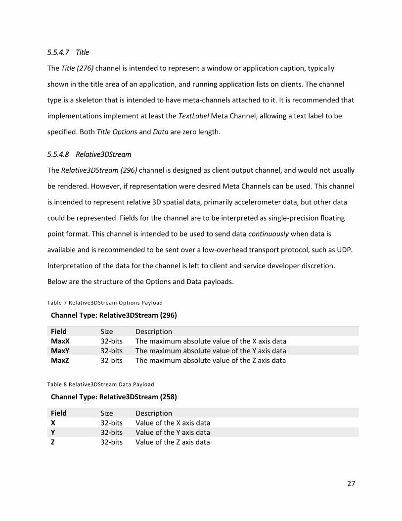
5.5.4.8 Relative3DStream
The Relative3DStream (296) channel is designed as client output channel, and would not usually
be rendered. However, if representation were desired Meta Channels can be used. This channel
is intended to represent relative 3D spatial data, primarily accelerometer data, but other data
could be represented. Fields for the channel are to be interpreted as single-precision floating
point format. This channel is intended to be used to send data continuously when data is
available and is recommended to be sent over a low-overhead transport protocol, such as UDP.
Interpretation of the data for the channel is left to client and service developer discretion.
Below are the structure of the Options and Data payloads.
Table 7 Relative3DStream Options Payload
Channel Type: Relative3DStream (296)
Field Size Description MaxX 32-bits The maximum absolute value of the X axis data MaxY 32-bits The maximum absolute value of the Y axis data MaxZ 32-bits The maximum absolute value of the Z axis data
Table 8 Relative3DStream Data Payload
Channel Type: Relative3DStream (258)
Field Size Description X 32-bits Value of the X axis data Y 32-bits Value of the Y axis data Z 32-bits Value of the Z axis data
28
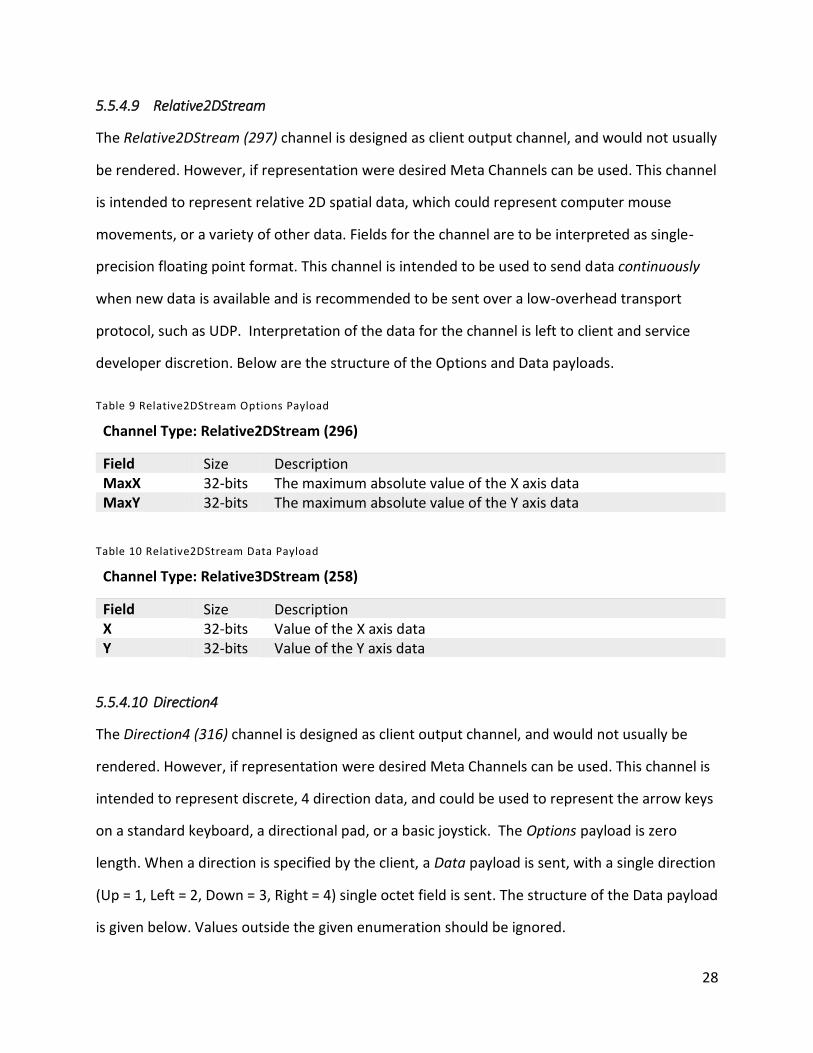
5.5.4.9 Relative2DStream
The Relative2DStream (297) channel is designed as client output channel, and would not usually
be rendered. However, if representation were desired Meta Channels can be used. This channel
is intended to represent relative 2D spatial data, which could represent computer mouse
movements, or a variety of other data. Fields for the channel are to be interpreted as single-
precision floating point format. This channel is intended to be used to send data continuously
when new data is available and is recommended to be sent over a low-overhead transport
protocol, such as UDP. Interpretation of the data for the channel is left to client and service
developer discretion. Below are the structure of the Options and Data payloads.
Table 9 Relative2DStream Options Payload
Channel Type: Relative2DStream (296)
Field Size Description MaxX 32-bits The maximum absolute value of the X axis data MaxY 32-bits The maximum absolute value of the Y axis data
Table 10 Relative2DStream Data Payload
Channel Type: Relative3DStream (258)
Field Size Description X 32-bits Value of the X axis data Y 32-bits Value of the Y axis data
5.5.4.10 Direction4
The Direction4 (316) channel is designed as client output channel, and would not usually be
rendered. However, if representation were desired Meta Channels can be used. This channel is
intended to represent discrete, 4 direction data, and could be used to represent the arrow keys
on a standard keyboard, a directional pad, or a basic joystick. The Options payload is zero
length. When a direction is specified by the client, a Data payload is sent, with a single direction
(Up = 1, Left = 2, Down = 3, Right = 4) single octet field is sent. The structure of the Data payload
is given below. Values outside the given enumeration should be ignored.
29
Table 11 Direction4 Data Payload
Channel Type: Direction4 (316)
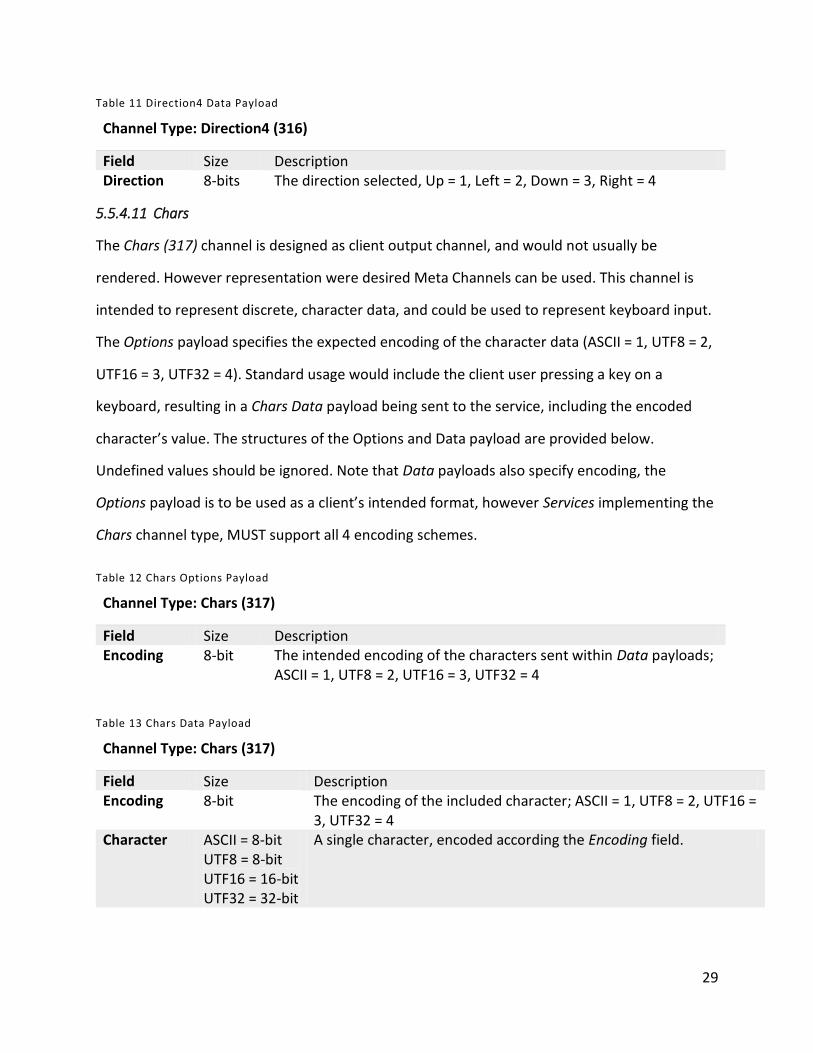
Field Size Description Direction 8-bits The direction selected, Up = 1, Left = 2, Down = 3, Right = 4
5.5.4.11 Chars
The Chars (317) channel is designed as client output channel, and would not usually be
rendered. However representation were desired Meta Channels can be used. This channel is
intended to represent discrete, character data, and could be used to represent keyboard input.
The Options payload specifies the expected encoding of the character data (ASCII = 1, UTF8 = 2,
UTF16 = 3, UTF32 = 4). Standard usage would include the client user pressing a key on a
keyboard, resulting in a Chars Data payload being sent to the service, including the encoded
character’s value. The structures of the Options and Data payload are provided below.
Undefined values should be ignored. Note that Data payloads also specify encoding, the
Options payload is to be used as a client’s intended format, however Services implementing the
Chars channel type, MUST support all 4 encoding schemes.
Table 12 Chars Options Payload
Channel Type: Chars (317)
Field Size Description Encoding 8-bit The intended encoding of the characters sent within Data payloads;
ASCII = 1, UTF8 = 2, UTF16 = 3, UTF32 = 4
Table 13 Chars Data Payload
Channel Type: Chars (317)
Field Size Description Encoding 8-bit The encoding of the included character; ASCII = 1, UTF8 = 2, UTF16 =
3, UTF32 = 4 Character ASCII = 8-bit
UTF8 = 8-bit UTF16 = 16-bit UTF32 = 32-bit
A single character, encoded according the Encoding field.
30
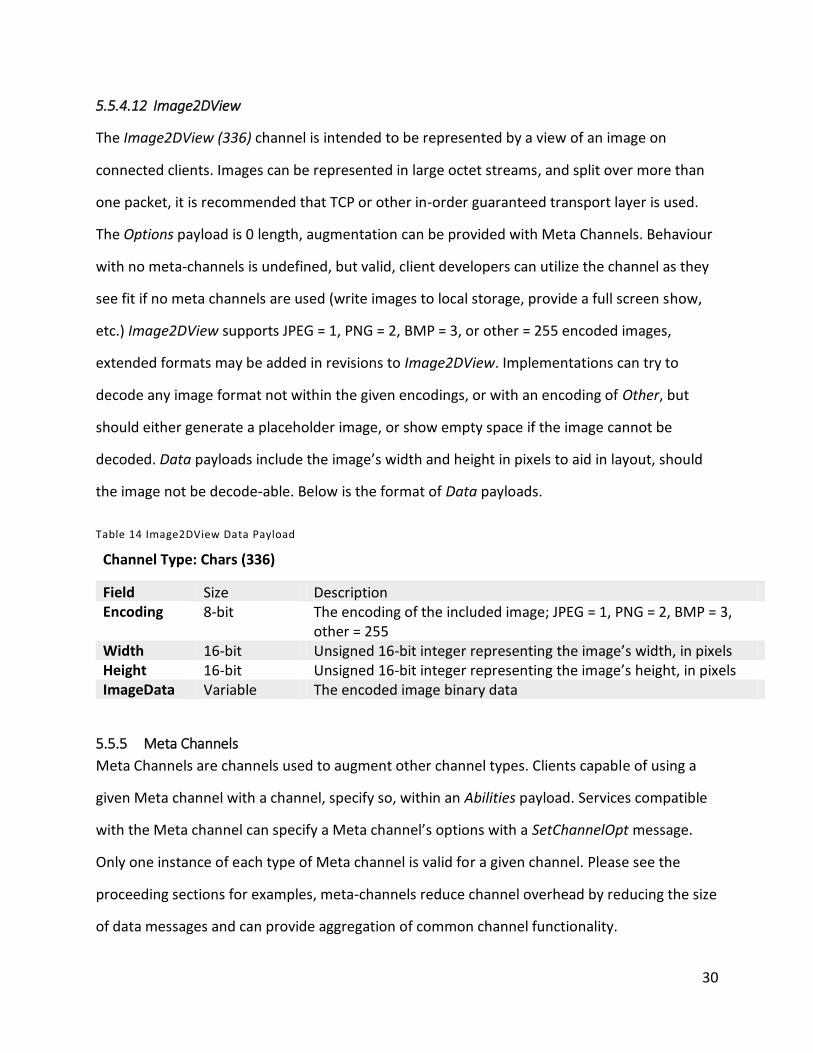
5.5.4.12 Image2DView
The Image2DView (336) channel is intended to be represented by a view of an image on
connected clients. Images can be represented in large octet streams, and split over more than
one packet, it is recommended that TCP or other in-order guaranteed transport layer is used.
The Options payload is 0 length, augmentation can be provided with Meta Channels. Behaviour
with no meta-channels is undefined, but valid, client developers can utilize the channel as they
see fit if no meta channels are used (write images to local storage, provide a full screen show,
etc.) Image2DView supports JPEG = 1, PNG = 2, BMP = 3, or other = 255 encoded images,
extended formats may be added in revisions to Image2DView. Implementations can try to
decode any image format not within the given encodings, or with an encoding of Other, but
should either generate a placeholder image, or show empty space if the image cannot be
decoded. Data payloads include the image’s width and height in pixels to aid in layout, should
the image not be decode-able. Below is the format of Data payloads.
Table 14 Image2DView Data Payload
Channel Type: Chars (336)
Field Size Description Encoding 8-bit The encoding of the included image; JPEG = 1, PNG = 2, BMP = 3,
other = 255 Width 16-bit Unsigned 16-bit integer representing the image’s width, in pixels Height 16-bit Unsigned 16-bit integer representing the image’s height, in pixels ImageData Variable The encoded image binary data
5.5.5 Meta Channels
Meta Channels are channels used to augment other channel types. Clients capable of using a
given Meta channel with a channel, specify so, within an Abilities payload. Services compatible
with the Meta channel can specify a Meta channel’s options with a SetChannelOpt message.
Only one instance of each type of Meta channel is valid for a given channel. Please see the
proceeding sections for examples, meta-channels reduce channel overhead by reducing the size
of data messages and can provide aggregation of common channel functionality.
31
5.5.5.1 TextLabel
The TextLabel (1) Meta Channel allows text strings to be associated to channels. For example,
with the currently implemented channels, it can be used to provide the text for a button,
application window or a label, or a caption for an image. Both the TextLabel Data and Options
payloads have identical structures, and contain only a string, a series of UTF-16 characters.
5.5.5.2 Positionable3D
The Positionable3D (2) Meta Channel allows client-rendered channels, that are representable as
user controls or widgets to be positioned in the application’s layout. Both Data and Option
payloads are identical. If a position is changed for an existing channel (using a Data payload),
the transition is undefined, but should not impede usage of the channel by the client’s user.
Three dimensional values are used to provide ordering using the depth dimension on 2D
displays, or to provide positioning in 3D environments. Positionable3D supports both scalar and
vector co-ordinates, the former can be used to allow vectored positions to be calculated within
the service using the dimensions provided as part of the LayoutOption within the initial Abilities
message. Scalar positions are communicated in 32-bit integer values. Vector values are
transported as 32-bit floating point values, from 0 to 1 representing the full range of the given
dimension. Negative values or values beyond 1 (or beyond the display’s maximum scalar value)
are valid and could be used to place controls partially, or entirely off screen. Within a single
payload, scalar and vector values cannot be mixed. Below is the structure of Positionable3D
payloads.
32
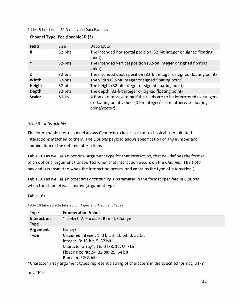
Table 15 Postionable3D Options and Data Payloads
Channel Type: Positionable3D (2)
Field Size Description X 32-bits The intended horizontal position (32-bit integer or signed floating
point) Y 32-bits The intended vertical position (32-bit integer or signed floating
point) Z 32-bits The intended depth position (32-bit integer or signed floating point) Width 32-bits The width (32-bit integer or signed floating point) Height 32-bits The height (32-bit integer or signed floating point) Depth 32-bits The depth (32-bit integer or signed floating point) Scalar 8-bits A Boolean representing if the fields are to be interpreted as integers
or floating point values (0 for integer/scalar, otherwise floating point/vector)
5.5.5.3 Interactable
The Interactable meta-channel allows Channels to have 1 or more classical user initiated
interactions attached to them. The Options payload allows specification of any number and
combination of the defined interactions
Table 16) as well as an optional argument type for that interaction, that will defines the format
of an optional argument transported when that interaction occurs on the Channel. The Data
payload is transmitted when the interaction occurs, and contains the type of interaction (
Table 16) as well as an octet array containing a parameter in the format specified in Options
when the channel was created (argument type,
Table 16).
Table 16 Interactable Interaction Types and Argument Types
Type Enumeration Values
Interaction Type
1: Select, 2: Focus, 3: Blur, 4: Change
Argument Type
None; 0 Unsigned Integer; 1: 8 bit, 2: 16 bit, 3: 32 bit Integer; 8: 16 bit, 9: 32 bit Character array*; 16: UTF8, 17: UTF16 Floating point; 24: 32 bit, 25: 64 bit, Boolean: 32: 8 bit;
*Character array argument types represent a string of characters in the specified format; UTF8
or UTF16.
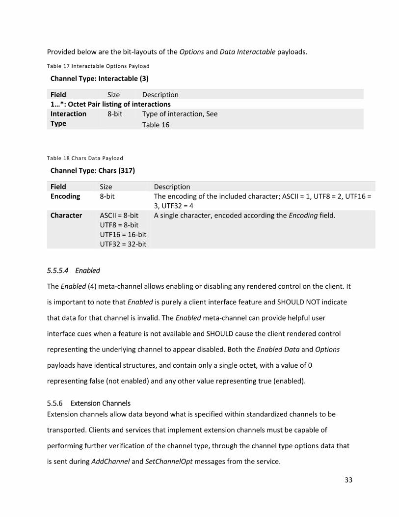
33
Provided below are the bit-layouts of the Options and Data Interactable payloads.
Table 17 Interactable Options Payload
Channel Type: Interactable (3)
Field Size Description 1…*: Octet Pair listing of interactions Interaction Type
8-bit Type of interaction, See
Table 16
Table 18 Chars Data Payload
Channel Type: Chars (317)
Field Size Description Encoding 8-bit The encoding of the included character; ASCII = 1, UTF8 = 2, UTF16 =
3, UTF32 = 4 Character ASCII = 8-bit
UTF8 = 8-bit UTF16 = 16-bit UTF32 = 32-bit
A single character, encoded according the Encoding field.
5.5.5.4 Enabled
The Enabled (4) meta-channel allows enabling or disabling any rendered control on the client. It
is important to note that Enabled is purely a client interface feature and SHOULD NOT indicate
that data for that channel is invalid. The Enabled meta-channel can provide helpful user
interface cues when a feature is not available and SHOULD cause the client rendered control
representing the underlying channel to appear disabled. Both the Enabled Data and Options
payloads have identical structures, and contain only a single octet, with a value of 0
representing false (not enabled) and any other value representing true (enabled).
5.5.6 Extension Channels
Extension channels allow data beyond what is specified within standardized channels to be
transported. Clients and services that implement extension channels must be capable of
performing further verification of the channel type, through the channel type options data that
is sent during AddChannel and SetChannelOpt messages from the service.
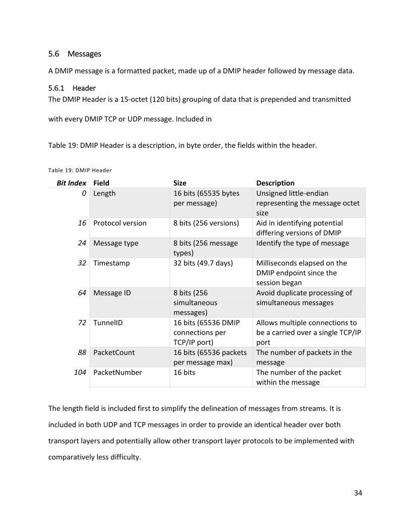
34
5.6 Messages
A DMIP message is a formatted packet, made up of a DMIP header followed by message data.
5.6.1 Header
The DMIP Header is a 15-octet (120 bits) grouping of data that is prepended and transmitted
with every DMIP TCP or UDP message. Included in
Table 19: DMIP Header is a description, in byte order, the fields within the header.
Table 19: DMIP Header
Bit Index Field Size Description
0 Length 16 bits (65535 bytes per message)
Unsigned little-endian representing the message octet size
16 Protocol version 8 bits (256 versions) Aid in identifying potential differing versions of DMIP
24 Message type 8 bits (256 message types)
Identify the type of message
32 Timestamp 32 bits (49.7 days) Milliseconds elapsed on the DMIP endpoint since the session began
64 Message ID 8 bits (256 simultaneous messages)
Avoid duplicate processing of simultaneous messages
72 TunnelID 16 bits (65536 DMIP connections per TCP/IP port)
Allows multiple connections to be a carried over a single TCP/IP port
88 PacketCount 16 bits (65536 packets per message max)
The number of packets in the message
104 PacketNumber 16 bits The number of the packet within the message
The length field is included first to simplify the delineation of messages from streams. It is
included in both UDP and TCP messages in order to provide an identical header over both
transport layers and potentially allow other transport layer protocols to be implemented with
comparatively less difficulty.
35
The protocol version will be 1 for the initial version of the protocol, and will be incremented if
changes are made that are not directly backward and forward compatible.
TunnelID is used to allow the transport of data for more than one interface over a single
connection. Messages using different TunnelIDs MUST be treated as part of an independent
session/connection.
Message types are an enumerated type and indicate how the message data will be interpreted,
message types and associated enumeration values are included in 5.6.2.
A timestamp field is used to allow messages from disparate clients to be synchronized on the
host; an intelligent multi-client host may use this information to compensate for network
latency. The timestamp can be used in conjunction with the Message ID to avoid duplicate
processing of messages, for example from UDP data messages, or multi-homed messages. The
message ID field should be unique for any given Timestamp.
The length field is used to allow split messages to be recombined correctly.
The PacketCount and PacketNumber fields allow messages to be split into smaller packets, this
can be used if a network endpoint has a preferred maximum, or there is a maximum TCP or
UDP packet size.
5.6.2 Message Types
The DMIP protocol is designed to be minimal, to ease development of compatible applications.
The message names and their corresponding message type are listed in

36
Table 20. A description of each message type, and the message data, if applicable follows the
table.
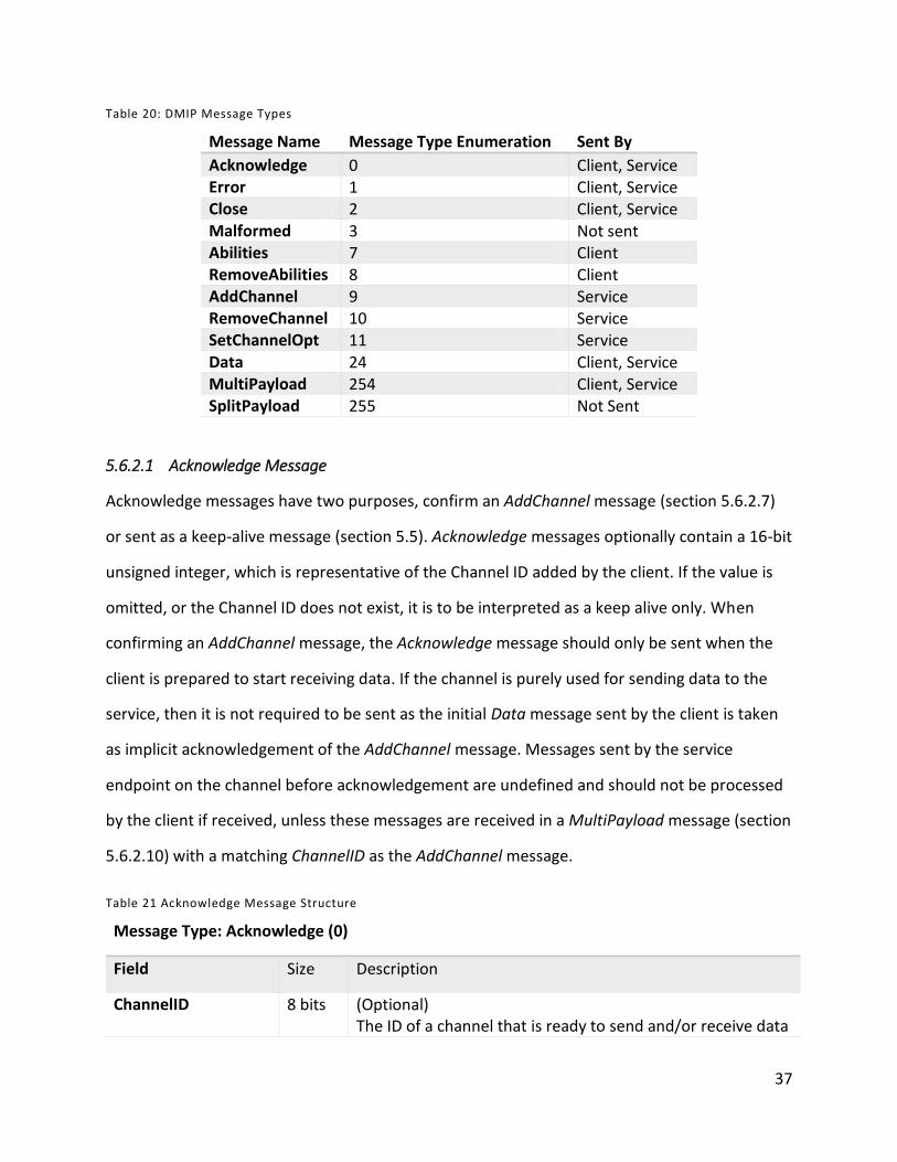
37
Table 20: DMIP Message Types
Message Name Message Type Enumeration Sent By
Acknowledge 0 Client, Service Error 1 Client, Service Close 2 Client, Service Malformed 3 Not sent Abilities 7 Client RemoveAbilities 8 Client AddChannel 9 Service RemoveChannel 10 Service SetChannelOpt 11 Service Data 24 Client, Service MultiPayload 254 Client, Service SplitPayload 255 Not Sent
5.6.2.1 Acknowledge Message
Acknowledge messages have two purposes, confirm an AddChannel message (section 5.6.2.7)
or sent as a keep-alive message (section 5.5). Acknowledge messages optionally contain a 16-bit
unsigned integer, which is representative of the Channel ID added by the client. If the value is
omitted, or the Channel ID does not exist, it is to be interpreted as a keep alive only. When
confirming an AddChannel message, the Acknowledge message should only be sent when the
client is prepared to start receiving data. If the channel is purely used for sending data to the
service, then it is not required to be sent as the initial Data message sent by the client is taken
as implicit acknowledgement of the AddChannel message. Messages sent by the service
endpoint on the channel before acknowledgement are undefined and should not be processed
by the client if received, unless these messages are received in a MultiPayload message (section
5.6.2.10) with a matching ChannelID as the AddChannel message.
Table 21 Acknowledge Message Structure
Message Type: Acknowledge (0)
Field Size Description
ChannelID 8 bits (Optional) The ID of a channel that is ready to send and/or receive data

38
5.6.2.2 Error Message
An Error message is a generic message passing mechanism, it allows passing of a 16-bit Unicode
formatted byte string representing an error message. The ChannelID field allows
communication of the specific channel generating the error, a value of 0 (zero) indicates an
error that is not channel specific. Error messages do not change the state of a DMIP session
(terminate a session nor indicate the removal of a channel). However Error messages should be
sent by clients when an AddChannel request (section 5.6.2.7) is not fulfilled, and thus can
represent the lack of a channel within a session.
Table 22 Error Message Structure
Message Type: Error (1)
Field Size Description ChannelID 8 bits The ChannelID of the channel generating the error Message variable A 16-bit UTF string, providing more information about the
error
5.6.2.3 Close Message
The close message is used to terminate a session, a Unicode byte stream is optionally attached.
To provide rationale/reasoning for the connection closing.
Table 23 Close Message Structure
Message Type: Close (2)
Field Size Description Message variable A 16-bit UTF string, providing more information about the
reason the connection was closed
5.6.2.4 Malformed Message
This Message type is reserved for internal use, and allows processing of incomplete or
malformed messages on either endpoint. It is not explicitly part of the network protocol, except
that the message type value (3) is reserved.

39
5.6.2.5 Abilities Message
The Abilities message is sent by a client device, it is the only message that can initiate a client-
service session. The purpose of the Abilities payload is twofold; to specify what kind of layouts
the device can support (if any) and which channel types a client can utilize. Subsequent Abilities
and RemoveAbilities messages can be sent to add and remove channels should the client’s
feature list change during an active session.
If an Abilities message is received within an active session (beyond the session initiating Abilities
message), it is to be processed cumulatively. These messages will add to the list of session
supported Channel Types or update the supported MetaChannels, toggle the IsDiscrete
parameter or change the Multiplicity for previous declared Channel Types. Subsequent
The Abilities message SHALL NOT trigger the direct removal of channels by the client, if
Multiplicity is updated to a value below the current number of active instances of the given
Channel Type the service MUST respond by explicitly removing (see RemoveChannel, 5.6.2.8)
select channels until the new Multiplicity limit is observed, or discontinue the session.
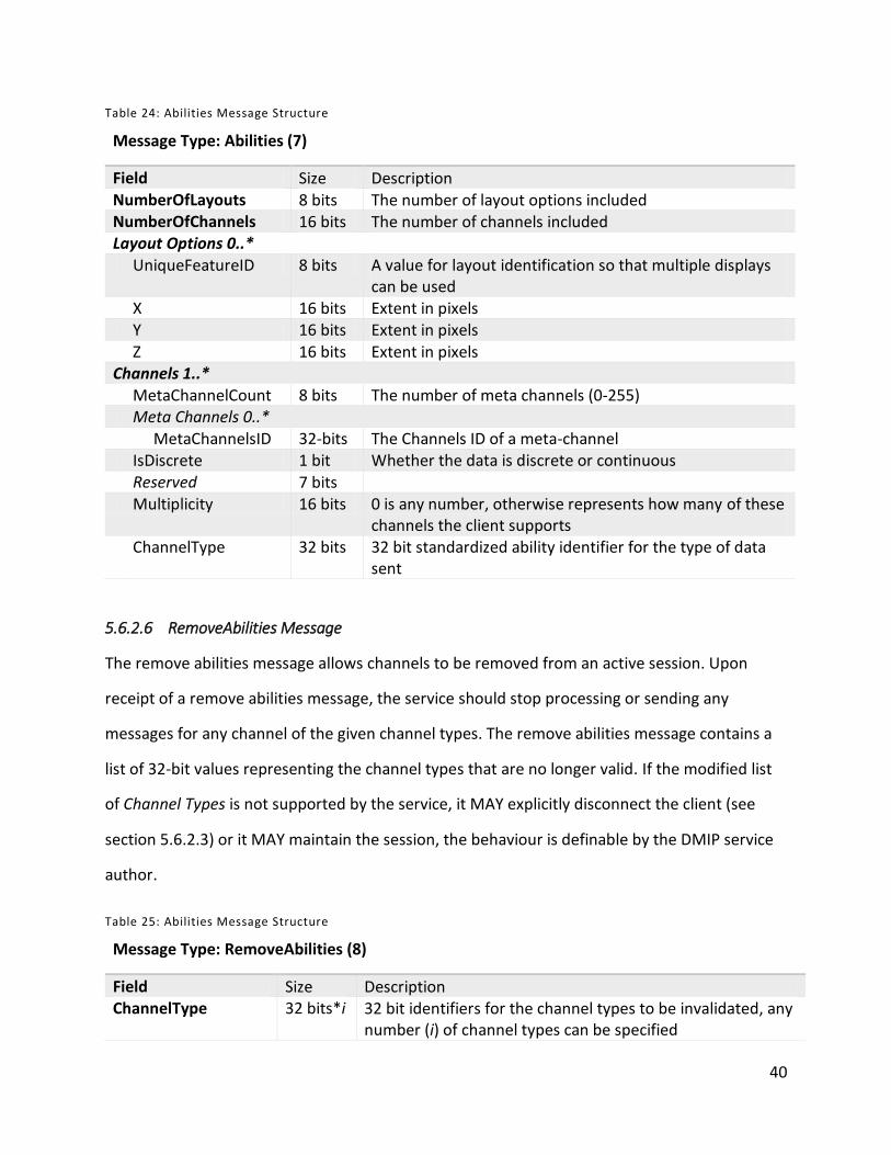
40
Table 24: Abilities Message Structure
Message Type: Abilities (7)
Field Size Description NumberOfLayouts 8 bits The number of layout options included NumberOfChannels 16 bits The number of channels included Layout Options 0..* UniqueFeatureID 8 bits A value for layout identification so that multiple displays
can be used X 16 bits Extent in pixels Y 16 bits Extent in pixels Z 16 bits Extent in pixels Channels 1..* MetaChannelCount 8 bits The number of meta channels (0-255) Meta Channels 0..* MetaChannelsID 32-bits The Channels ID of a meta-channel IsDiscrete 1 bit Whether the data is discrete or continuous Reserved 7 bits Multiplicity 16 bits 0 is any number, otherwise represents how many of these
channels the client supports ChannelType 32 bits 32 bit standardized ability identifier for the type of data
sent
5.6.2.6 RemoveAbilities Message
The remove abilities message allows channels to be removed from an active session. Upon
receipt of a remove abilities message, the service should stop processing or sending any
messages for any channel of the given channel types. The remove abilities message contains a
list of 32-bit values representing the channel types that are no longer valid. If the modified list
of Channel Types is not supported by the service, it MAY explicitly disconnect the client (see
section 5.6.2.3) or it MAY maintain the session, the behaviour is definable by the DMIP service
author.
Table 25: Abilities Message Structure
Message Type: RemoveAbilities (8)
Field Size Description ChannelType 32 bits*i 32 bit identifiers for the channel types to be invalidated, any
number (i) of channel types can be specified
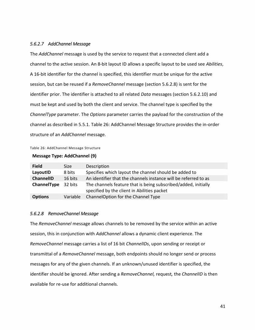
41
5.6.2.7 AddChannel Message
The AddChannel message is used by the service to request that a connected client add a
channel to the active session. An 8-bit layout ID allows a specific layout to be used see Abilities,
A 16-bit identifier for the channel is specified, this identifier must be unique for the active
session, but can be reused if a RemoveChannel message (section 5.6.2.8) is sent for the
identifier prior. The identifier is attached to all related Data messages (section 5.6.2.10) and
must be kept and used by both the client and service. The channel type is specified by the
ChannelType parameter. The Options parameter carries the payload for the construction of the
channel as described in 5.5.1. Table 26: AddChannel Message Structure provides the in-order
structure of an AddChannel message.
Table 26: AddChannel Message Structure
Message Type: AddChannel (9)
Field Size Description LayoutID 8 bits Specifies which layout the channel should be added to ChannelID 16 bits An identifier that the channels instance will be referred to as ChannelType 32 bits The channels feature that is being subscribed/added, initially
specified by the client in Abilities packet Options Variable ChannelOption for the Channel Type
5.6.2.8 RemoveChannel Message
The RemoveChannel message allows channels to be removed by the service within an active
session, this in conjunction with AddChannel allows a dynamic client experience. The
RemoveChannel message carries a list of 16 bit ChannelIDs, upon sending or receipt or
transmittal of a RemoveChannel message, both endpoints should no longer send or process
messages for any of the given channels. If an unknown/unused identifier is specified, the
identifier should be ignored. After sending a RemoveChannel, request, the ChannelID is then
available for re-use for additional channels.
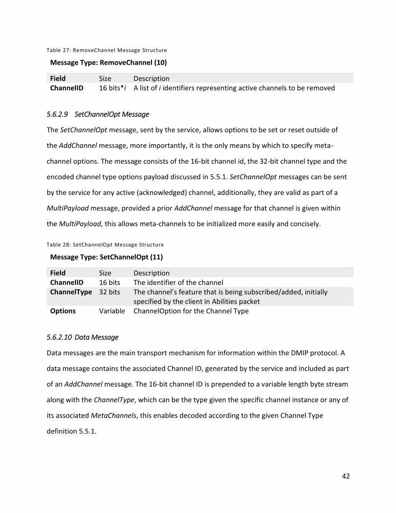
42
Table 27: RemoveChannel Message Structure
Message Type: RemoveChannel (10)
Field Size Description ChannelID 16 bits*i A list of i identifiers representing active channels to be removed
5.6.2.9 SetChannelOpt Message
The SetChannelOpt message, sent by the service, allows options to be set or reset outside of
the AddChannel message, more importantly, it is the only means by which to specify meta-
channel options. The message consists of the 16-bit channel id, the 32-bit channel type and the
encoded channel type options payload discussed in 5.5.1. SetChannelOpt messages can be sent
by the service for any active (acknowledged) channel, additionally, they are valid as part of a
MultiPayload message, provided a prior AddChannel message for that channel is given within
the MultiPayload, this allows meta-channels to be initialized more easily and concisely.
Table 28: SetChannelOpt Message Structure
Message Type: SetChannelOpt (11)
Field Size Description ChannelID 16 bits The identifier of the channel ChannelType 32 bits The channel’s feature that is being subscribed/added, initially
specified by the client in Abilities packet Options Variable ChannelOption for the Channel Type
5.6.2.10 Data Message
Data messages are the main transport mechanism for information within the DMIP protocol. A
data message contains the associated Channel ID, generated by the service and included as part
of an AddChannel message. The 16-bit channel ID is prepended to a variable length byte stream
along with the ChannelType, which can be the type given the specific channel instance or any of
its associated MetaChannels, this enables decoded according to the given Channel Type
definition 5.5.1.
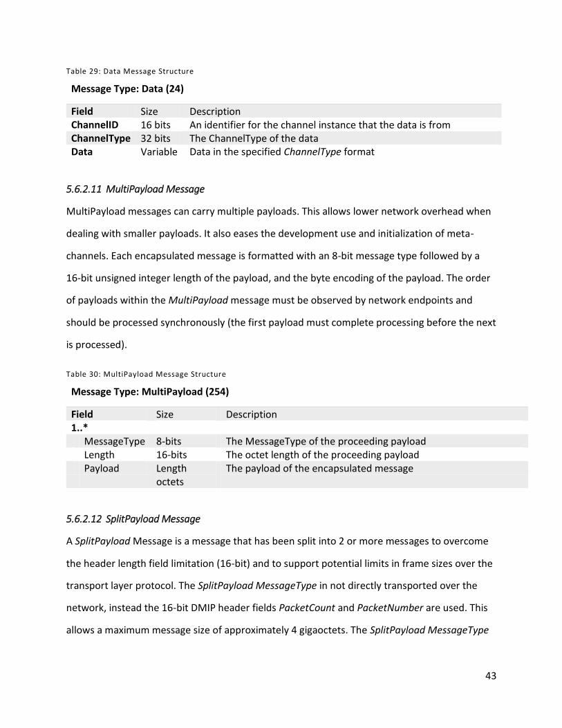
43
Table 29: Data Message Structure
Message Type: Data (24)
Field Size Description ChannelID 16 bits An identifier for the channel instance that the data is from ChannelType 32 bits The ChannelType of the data Data Variable Data in the specified ChannelType format
5.6.2.11 MultiPayload Message
MultiPayload messages can carry multiple payloads. This allows lower network overhead when
dealing with smaller payloads. It also eases the development use and initialization of meta-
channels. Each encapsulated message is formatted with an 8-bit message type followed by a
16-bit unsigned integer length of the payload, and the byte encoding of the payload. The order
of payloads within the MultiPayload message must be observed by network endpoints and
should be processed synchronously (the first payload must complete processing before the next
is processed).
Table 30: MultiPayload Message Structure
Message Type: MultiPayload (254)
Field Size Description 1..* MessageType 8-bits The MessageType of the proceeding payload Length 16-bits The octet length of the proceeding payload Payload Length
octets The payload of the encapsulated message
5.6.2.12 SplitPayload Message
A SplitPayload Message is a message that has been split into 2 or more messages to overcome
the header length field limitation (16-bit) and to support potential limits in frame sizes over the
transport layer protocol. The SplitPayload MessageType in not directly transported over the
network, instead the 16-bit DMIP header fields PacketCount and PacketNumber are used. This
allows a maximum message size of approximately 4 gigaoctets. The SplitPayload MessageType
44
enumeration value (255) is reserved to allow the SplitPayload MessageType to be more simply
represented in software implementations of the protocol.
5.7 Field Sizes
The design of a novel protocol requires estimation of a number of parameters, including the
size of fields and types of messages included. Every effort has been made to avoid choosing
values arbitrarily and to allow the representation of all imaginable types of data. Estimates
were aimed at keeping message header and overhead low as well as keeping data byte-aligned.
The result is that there are limits to several values within the protocol. Notably, there is a limit
of 232 different Channel Types that a client/service can understand, there is a limit of 216 active
Channels in a single DMIP session and a single DMIP message has a maximum size of 64
kilobytes. Maximum message size of 64 kilobytes combined with the 216 maximum number
messages within a single payload (Section 5.6.2.12 SplitPayload Message), means that a single
payload has maximum size of 4 gigabytes. Data types that are envisioned to potentially exceed
this limit MUST incorporate splitting/recombining within the Channel Type definition.
5.8 UDP Stream Data
The User Datagram Protocol allows lower latency [2], and MAY be used as a transport
mechanism for some Channels. DMIP services SHOULD have the ability to utilize UDP to send
or receive Data messages, but MUST only do so for a channel type whose abilities, specified by
the client include an IsDiscrete (Abilities Message, 5.6.2.5) property set to true (1).
5.9 Layouts
Layouts represent combination of channels on a client device. Allowing the specification of a
layout allows host devices to control how multimodal interaction channels will be displayed a
client device. In the current version of the protocol, only vector layouts are supported through
the use of the Positionable3D meta-channel. However, extension of the protocol could provide
meta-channels to support additional types of layout and positioning.
45
5.10 Timeouts
DMIP connections are considered terminated after 10 seconds (10,000 milliseconds) of
inactivity. Inactivity means no receipt of a message. Both clients and services should observe
this restriction. Sessions terminated due to timeout should send a close message (section
5.6.2.3) to the remote endpoint if the TCP socket is still available. Both endpoints should ensure
that a message is sent at least every 7 seconds, making use of the Acknowledge message
(section 5.6.2.1) as a keep alive message if necessary.
46
6 Protocol Flow
In order to describe the intended flow of DMIP sessions using the Protocol (section 5), this
section provides an overview of DMIP session flow (section 6.1). Additionally, a number of
examples of typical sessions are provided (section 6.2).
6.1 DMIP Session Overview
A DMIP session is a 1 to 1, single TCP endpoint to TCP connection, which can be supplemented
by UDP, all session management messages are, however sent using TCP to ensure, in order
delivery [2]. Sessions are initiated by clients (section 6.1.1), if services accept the clients, they
can add channels (section 6.1.2) to communicate (section 6.1.3), active sessions can have any
number of channels added to them, and they can be removed (section 6.1.5) allowing dynamic
user interfaces and other scenarios (section 6.1.4). Session are terminated by either endpoint
explicitly or implicitly after a timeout (section 6.1.6).
6.1.1 Session Initiation
A session is initiated from a client by sending an Abilities message (section 5.6.2.5), providing a
listing of Channel Types (section 5.5) it can support, Meta-channels (section 5.5.5) those
channels can support, as well as information about display devices available for Positionable3D
Channels (section 5.5.5.2). This information should be stored by the service so that it can
evaluate compatibility, and respond appropriately to the client during the session’s lifecycle.
Service applications can explicitly reject clients by sending a Close message (section 5.6.2.3) in
response to an initial Abilities message (section 5.6.2.5), this allows an explanation for
connection refusal to be provided. The service can reject a client for any reason. Wherever
possible, services should provide rationale for rejection, to enable user understanding [28].
Examples of reasons for rejection are; incompatible/insufficient Channel Types available on the
client and service capacity/user limits reached. Rejection is implied if the client does not receive
a response from the service within the timeout period (section 5.5). The rationale for this is to
handle situations where the service is unavailable/unable to respond, but should not be
47
purposely used by service authors, as doing so inhibits user understanding because it limits
visibility of system status [28].
6.1.2 Channel Initiation
If the service accepts the client, it can add compatible channels, using AddChannel (section
5.6.2.7) messages. A service should not send messages for a channel until either an initial Data
(section 5.6.2.10) or Acknowledge (section 5.6.2.1) message is received from the client for the
channel. If the client is unable to add a channel, it should send an Error message (section
5.6.2.2) containing the channel’s ChannelID, to the service.
Meta-channels provide augmentation of channels by allowing additional data types to be
specified for a channel (section 5.5.5). Meta-channels (as specified by the client during session
initiation, 6.1.1) for a channel are automatically available when it is added, default options are
however, undefined. Initial options for Meta-channels can be bundled in a MultiPayload
message (section 5.6.2.11) as SetChannelOpt messages (section 5.6.2.9) by the service if initial
values are required.
These channels are the method in which data is communicated within DMIP, the primary
identifier for a Channel is its ChannelID, this need to be registered by, and handled
appropriately at both endpoints.
6.1.3 Active Channels
Once a channel is added and acknowledged, the endpoints can communicate using Data
messages (section 5.6.2.10) in the format of the Channels Type’s associated data type,
described in 5.5.3. Meta-channel data is communicated using the same ChannelID as the
attached channel, with the Meta-Channel’s type as the channel type (allowing for only one
instance of each meta-channel per channel). Additionally options for the channel and
associated meta-channels can be updated by the service using SetChannelOpt messages. When
a complete Data or SetChannelOpt payload is received at an endpoint, it should be decoded
and processed to generate relevant actions.
48
6.1.4 Active Session
Within an initiated session, all valid DMIP messages are processed. Messages that refer to an
inactive channel are typically ignored. A client can modify its available channel type abilities by
sending Abilities or RemoveAbilities messages (section 5.6.2.8, 5.6.2.8). If a client removes a
channel type ability that is currently in use within the session the service should discontinue its
use, terminating the session with a Close message (section 5.6.2.3) if required. Channels
removed in this way are then considered inactive, and may require removal within the client’s
interface. Services may request the addition or removal of channels to the session at any time
through the use of AddChannel and RemoveChannel request, as described in 6.1.2 and 6.1.5
respectively. By removing and adding channels, services can generate dynamic applications that
can efficiently make use of the remote client’s abilities.
6.1.5 Channel Termination
Active channels can be terminated explicitly by way of a RemoveChannel request from the
service. When the service sends this request, it is indicating that it is not going to send or
process incoming additional messages referring to the channel. When the client receives a
RemoveChannel request, it stops initiating actions for that channel; Data messages are no
longer sent and any visual representations of the channel in the client interface are removed.
Channels can be implicitly removed through a RemoveAbilities request from the client, in which
case the channel should be explicitly removed from the client so that the ChannelID can be
reused and any interface elements relating to the channel are removed.
All active channels are also terminated when a session is terminated, and both endpoints can
safely perform removal and cleanup of any channels associated with the session.
6.1.6 Session Termination
Session can be terminated by either the client or the service within an active session by sending
a Close request. The Close should be the last message transmitted for any session. When an
endpoint receives a Close request it terminates the session and removes any resources
49
associated with the session. If a client receives a Close request, the message, within the device’s
interface should be communicated to the end user. The service may log the session, but should
not inhibit other users from connecting, initiating sessions, or using the service’s functionality.
Sessions can also end implicitly if the session is inactive for a duration that exceeds the timeout
length (section 5.5). Both endpoints follow the same steps as above, however both endpoints
can use a generic timeout message to show the user, or log, in absence of a Close Message.
6.2 Examples of DMIP Message Passing
Explanations and supporting diagrams demonstrating several DMIP session scenarios are
presented within this section, the rationale being that they provide specific visual examples to
aid in conveying DMIP usage scenarios. The examples provided assume context, meaning that it
is assumed that a DMIP client and service exist, and the client has the IP endpoint for the
service.
6.2.1 Client Request Session
After or asynchronous to a client acquiring a service endpoint, it must;
1. Initialize and enumerate its DMIP abilities.
Channel types it can support.
Layout format(s) and properties.
2. Create a DMIP Abilities (section 5.6.2.5) message.
3. Send the message over a TCP connection to the service’s IP endpoint.
4. Listen for and respond appropriately to messages.
With the same port and address the abilities message was sent from.
TCP must be listening, UDP is optional.
The service endpoint then takes action determining if the client’s Abilities are compatible and
can:
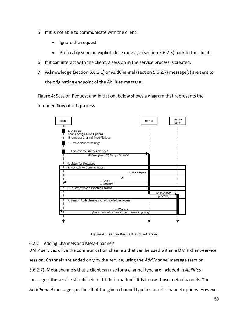
50
5. If it is not able to communicate with the client:
Ignore the request.
Preferably send an explicit close message (section 5.6.2.3) back to the client.
6. If it can interact with the client, a session in the service process is created.
7. Acknowledge (section 5.6.2.1) or AddChannel (section 5.6.2.7) message(s) are sent to
the originating endpoint of the Abilities message.
Figure 4: Session Request and Initiation, below shows a diagram that represents the
intended flow of this process.
Figure 4: Session Request and Initiation
6.2.2 Adding Channels and Meta-Channels
DMIP services drive the communication channels that can be used within a DMIP client-service
session. Channels are added only by the service, using the AddChannel message (section
5.6.2.7). Meta-channels that a client can use for a channel type are included in Abilities
messages, the service should retain this information if it is to use those meta-channels. The
AddChannel message specifies that the given channel type instance’s channel options. However
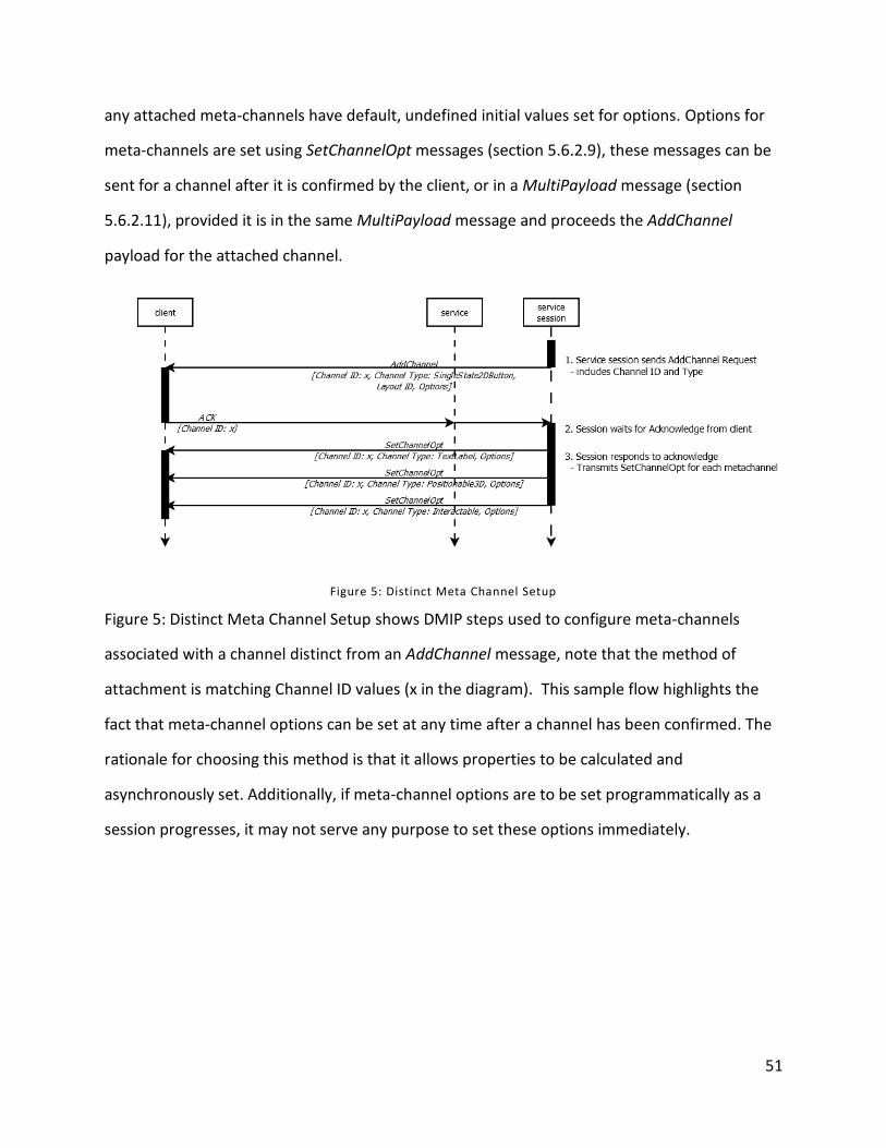
51
any attached meta-channels have default, undefined initial values set for options. Options for
meta-channels are set using SetChannelOpt messages (section 5.6.2.9), these messages can be
sent for a channel after it is confirmed by the client, or in a MultiPayload message (section
5.6.2.11), provided it is in the same MultiPayload message and proceeds the AddChannel
payload for the attached channel.
Figure 5: Distinct Meta Channel Setup
Figure 5: Distinct Meta Channel Setup shows DMIP steps used to configure meta-channels
associated with a channel distinct from an AddChannel message, note that the method of
attachment is matching Channel ID values (x in the diagram). This sample flow highlights the
fact that meta-channel options can be set at any time after a channel has been confirmed. The
rationale for choosing this method is that it allows properties to be calculated and
asynchronously set. Additionally, if meta-channel options are to be set programmatically as a
session progresses, it may not serve any purpose to set these options immediately.
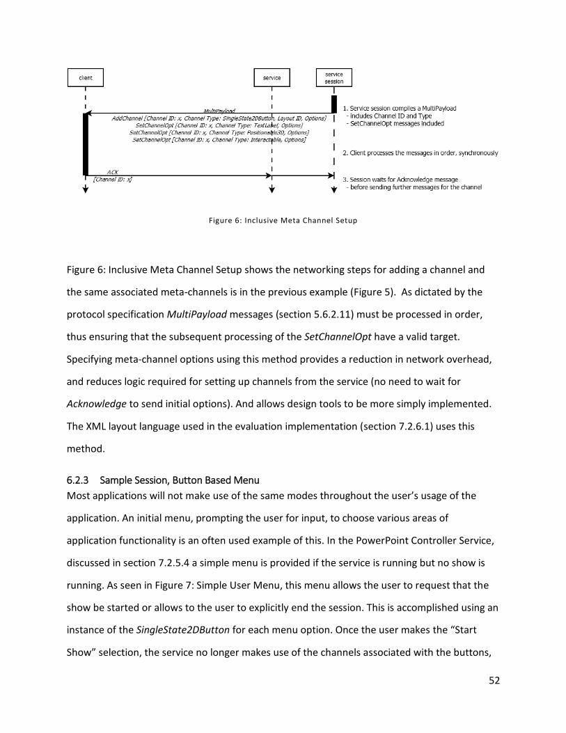
52
Figure 6: Inclusive Meta Channel Setup
Figure 6: Inclusive Meta Channel Setup shows the networking steps for adding a channel and
the same associated meta-channels is in the previous example (Figure 5). As dictated by the
protocol specification MultiPayload messages (section 5.6.2.11) must be processed in order,
thus ensuring that the subsequent processing of the SetChannelOpt have a valid target.
Specifying meta-channel options using this method provides a reduction in network overhead,
and reduces logic required for setting up channels from the service (no need to wait for
Acknowledge to send initial options). And allows design tools to be more simply implemented.
The XML layout language used in the evaluation implementation (section 7.2.6.1) uses this
method.
6.2.3 Sample Session, Button Based Menu
Most applications will not make use of the same modes throughout the user’s usage of the
application. An initial menu, prompting the user for input, to choose various areas of
application functionality is an often used example of this. In the PowerPoint Controller Service,
discussed in section 7.2.5.4 a simple menu is provided if the service is running but no show is
running. As seen in Figure 7: Simple User Menu, this menu allows the user to request that the
show be started or allows to the user to explicitly end the session. This is accomplished using an
instance of the SingleState2DButton for each menu option. Once the user makes the “Start
Show” selection, the service no longer makes use of the channels associated with the buttons,
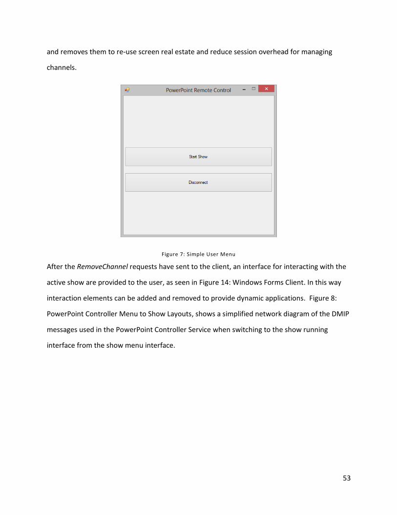
53
and removes them to re-use screen real estate and reduce session overhead for managing
channels.
Figure 7: Simple User Menu
After the RemoveChannel requests have sent to the client, an interface for interacting with the
active show are provided to the user, as seen in Figure 14: Windows Forms Client. In this way
interaction elements can be added and removed to provide dynamic applications. Figure 8:
PowerPoint Controller Menu to Show Layouts, shows a simplified network diagram of the DMIP
messages used in the PowerPoint Controller Service when switching to the show running
interface from the show menu interface.
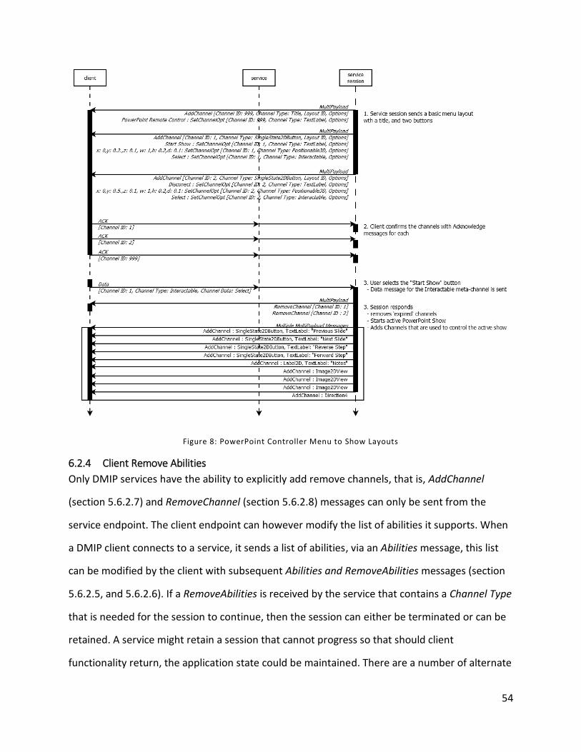
54
Figure 8: PowerPoint Controller Menu to Show Layouts
6.2.4 Client Remove Abilities
Only DMIP services have the ability to explicitly add remove channels, that is, AddChannel
(section 5.6.2.7) and RemoveChannel (section 5.6.2.8) messages can only be sent from the
service endpoint. The client endpoint can however modify the list of abilities it supports. When
a DMIP client connects to a service, it sends a list of abilities, via an Abilities message, this list
can be modified by the client with subsequent Abilities and RemoveAbilities messages (section
5.6.2.5, and 5.6.2.6). If a RemoveAbilities is received by the service that contains a Channel Type
that is needed for the session to continue, then the session can either be terminated or can be
retained. A service might retain a session that cannot progress so that should client
functionality return, the application state could be maintained. There are a number of alternate
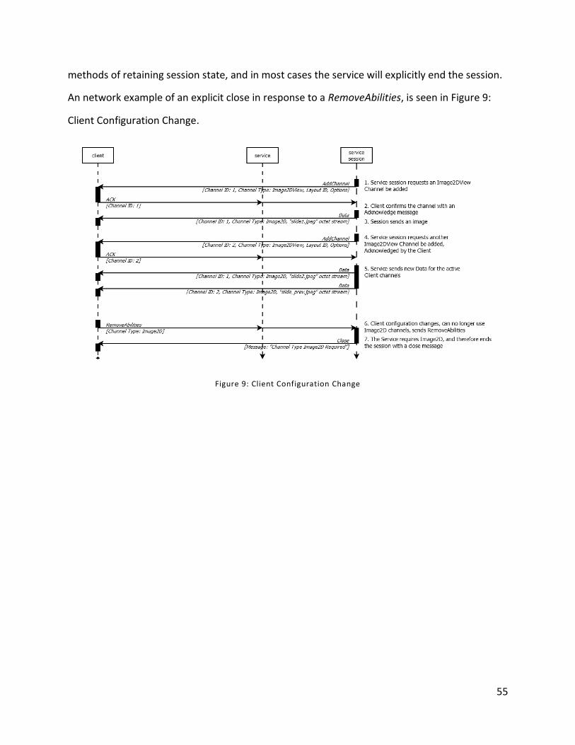
55
methods of retaining session state, and in most cases the service will explicitly end the session.
An network example of an explicit close in response to a RemoveAbilities, is seen in Figure 9:
Client Configuration Change.
Figure 9: Client Configuration Change
56
7 Evaluation
To validate that DMIP is able to meet the goals set out in (section 1), a review of potential data
types was performed further described in (section 7.1). To validate whether DMIP is functional
and can be used to meet the stated requirements, it was implemented on 2 platforms as
discussed in (section 7.2).
7.1 Validity of Channel Types System
Before the design process began it was thought that a system that could natively support any
interaction mode type could be designed. However it was noted that the resultant data
transferred would be too varied and it would not be possible to define what modes/abilities a
session could use and the data transferred would not contain enough intrinsic meaning to be
directly consumable. Therefore, this view was modified as development of the protocol
progressed and was replaced with the concept of providing an extensible framework that
defines strictly defined Channel Types and allows development of further Channel Types outside
the explicit protocol. This raised the concern that 3rd party developers may incorporate
proprietary Channel Types, limiting the cross compatibility of clients, counter to the goals of this
work. It is therefore our intention that extension Channel Types should be catalogued and
reviewed for standardization as part of future work.
Considering that development of additional standard Channel Types requiring minimal effort
and with inclusion of extensible Channel Types we aim to allow an expanding list of interaction
types to be supported by clients and services. To verify that all imaginable interaction types
could potentially be supported, a review of potential raw data types, common UI controls and
interaction modes defined by Bersen [29] was performed, as well as an informal web survey of
users, asking how they interacted with everyday objects.
7.1.1 Common UI Controls
Common user interface controls were observed by looking at user interface implementation
tools, namely Microsoft Visual Studio 2012 Windows Forms designer and the Android Layout
57
Editor plug-in for Eclipse. Rigorous evaluation was not performed as the controls used for these
platforms form the basis of how the protocol was designed. In these systems, various
properties for a control can be configured, this can be mapped directly onto Channel Type
Options (section 5.5.2). Common properties (those shared amongst most types of control and
across platforms) can be mapped to meta-channels (section 5.5.5). Controls typically generate
events indicating some status has changed or new data has arrived, these are often generated
by the user interacting with the control. Events are mapped to Channel Type Data (section
5.5.3) and while a single control might provide a variety of events, the design of Channel Type
Data types is flexible and thus could allow for any combination or digital events to be
represented.
7.1.2 Raw Data Types
Basic digital-format data types for example images, video, sound, and documents, are
represented by octet streams or blocks of binary encoded data and be simply transported using
Channel Type Data, and can be split up, or transmitted using UDP datagrams for timely data.
Raw files could be transferred in this way. Analog data sources could also be transmitted if they
are first converted to digital. This conversion has been shown to be possible for many kinds of
data, the discussion of which is beyond the scope of this thesis.
7.1.3 Bernsen’s Multimodal Interface Modes
Using Niels Ole Bersen’s generic taxonomy of unimodal modalities [29] as a guide provided a
comprehensive listing of potential data types to consider. These were reviewed and were found
to be directly translatable to digital raw data types or subject to analogue to digital signal
processing, which while potentially complicated, is required in order to capture/process that
data on the digital devices used by DMIP, and is therefore not actionable consideration for the
design of the protocol.
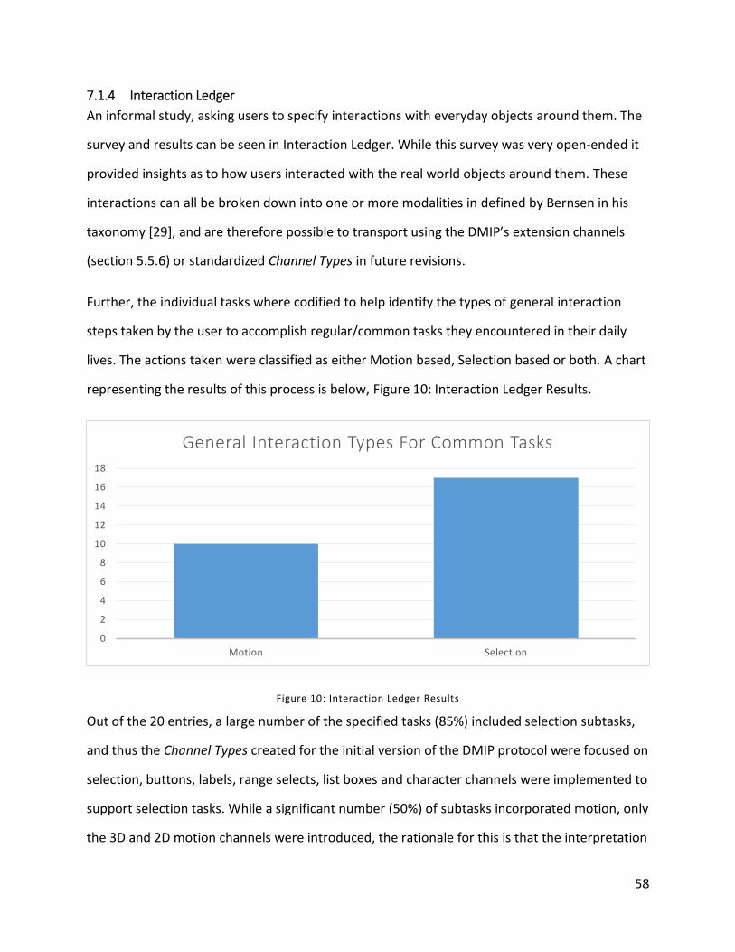
58
7.1.4 Interaction Ledger
An informal study, asking users to specify interactions with everyday objects around them. The
survey and results can be seen in Interaction Ledger. While this survey was very open-ended it
provided insights as to how users interacted with the real world objects around them. These
interactions can all be broken down into one or more modalities in defined by Bernsen in his
taxonomy [29], and are therefore possible to transport using the DMIP’s extension channels
(section 5.5.6) or standardized Channel Types in future revisions.
Further, the individual tasks where codified to help identify the types of general interaction
steps taken by the user to accomplish regular/common tasks they encountered in their daily
lives. The actions taken were classified as either Motion based, Selection based or both. A chart
representing the results of this process is below, Figure 10: Interaction Ledger Results.
Figure 10: Interaction Ledger Results
Out of the 20 entries, a large number of the specified tasks (85%) included selection subtasks,
and thus the Channel Types created for the initial version of the DMIP protocol were focused on
selection, buttons, labels, range selects, list boxes and character channels were implemented to
support selection tasks. While a significant number (50%) of subtasks incorporated motion, only
the 3D and 2D motion channels were introduced, the rationale for this is that the interpretation
0
2
4
6
8
10
12
14
16
18
Motion Selection
General Interaction Types For Common Tasks
59
of motion signals (or gestures) is beyond the scope of this work, but can be supported by these
two channels. The responses and the respective codification can be seen in Appendix A:
Interaction Ledger.
7.2 Protocol Implementations
Initially, an object oriented software design was created to fulfill the requirements set out by
the protocol. The design of the implementation application is focused on a central package,
called Protocol which encompasses all low level functionality for both clients and services. It
provides the transport functionality, message processing, channel type definitions, and event
dispatch as well as managing queues to support SplitPayload (section 5.6.2.12) and
MultiPayload (section 5.6.2.11) messages. Centralizing the common functionality reduces the
amount of effort required to implement the combination of clients and services, particularly
when they share the same platform. This benefit is generated by eliminating code duplication,
reducing the development time, errors and maintenance effort. Section 7.2.1 outlines the
pieces of the protocol package.
7.2.1 The Protocol Package
For the evaluation Implementation, a shared package that provides common DMIP functionality
for both clients and services was created. Both client and service APIs rely directly upon this,
the protocol package. A representation of the dependency is seen in Figure 11: Shared Protocol
Package.
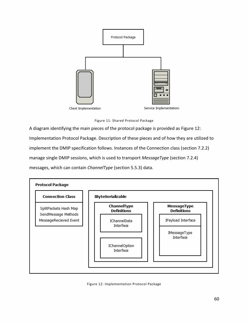
60
Figure 11: Shared Protocol Package
A diagram identifying the main pieces of the protocol package is provided as Figure 12:
Implementation Protocol Package. Description of these pieces and of how they are utilized to
implement the DMIP specification follows. Instances of the Connection class (section 7.2.2)
manage single DMIP sessions, which is used to transport MessageType (section 7.2.4)
messages, which can contain ChannelType (section 5.5.3) data.
Figure 12: Implementation Protocol Package
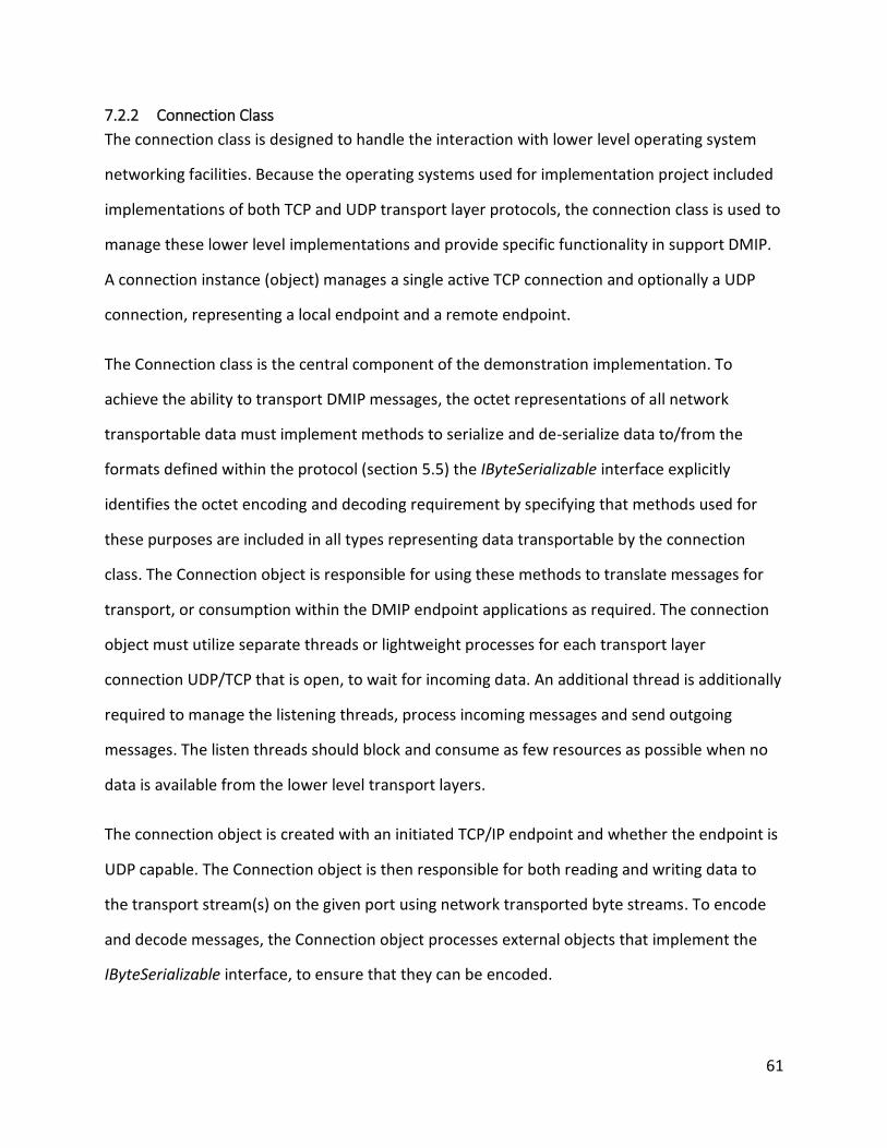
61
7.2.2 Connection Class
The connection class is designed to handle the interaction with lower level operating system
networking facilities. Because the operating systems used for implementation project included
implementations of both TCP and UDP transport layer protocols, the connection class is used to
manage these lower level implementations and provide specific functionality in support DMIP.
A connection instance (object) manages a single active TCP connection and optionally a UDP
connection, representing a local endpoint and a remote endpoint.
The Connection class is the central component of the demonstration implementation. To
achieve the ability to transport DMIP messages, the octet representations of all network
transportable data must implement methods to serialize and de-serialize data to/from the
formats defined within the protocol (section 5.5) the IByteSerializable interface explicitly
identifies the octet encoding and decoding requirement by specifying that methods used for
these purposes are included in all types representing data transportable by the connection
class. The Connection object is responsible for using these methods to translate messages for
transport, or consumption within the DMIP endpoint applications as required. The connection
object must utilize separate threads or lightweight processes for each transport layer
connection UDP/TCP that is open, to wait for incoming data. An additional thread is additionally
required to manage the listening threads, process incoming messages and send outgoing
messages. The listen threads should block and consume as few resources as possible when no
data is available from the lower level transport layers.
The connection object is created with an initiated TCP/IP endpoint and whether the endpoint is
UDP capable. The Connection object is then responsible for both reading and writing data to
the transport stream(s) on the given port using network transported byte streams. To encode
and decode messages, the Connection object processes external objects that implement the
IByteSerializable interface, to ensure that they can be encoded.
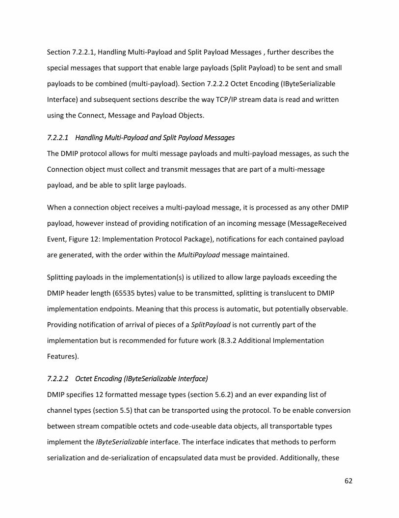
62
Section 7.2.2.1, Handling Multi-Payload and Split Payload Messages , further describes the
special messages that support that enable large payloads (Split Payload) to be sent and small
payloads to be combined (multi-payload). Section 7.2.2.2 Octet Encoding (IByteSerializable
Interface) and subsequent sections describe the way TCP/IP stream data is read and written
using the Connect, Message and Payload Objects.
7.2.2.1 Handling Multi-Payload and Split Payload Messages
The DMIP protocol allows for multi message payloads and multi-payload messages, as such the
Connection object must collect and transmit messages that are part of a multi-message
payload, and be able to split large payloads.
When a connection object receives a multi-payload message, it is processed as any other DMIP
payload, however instead of providing notification of an incoming message (MessageReceived
Event, Figure 12: Implementation Protocol Package), notifications for each contained payload
are generated, with the order within the MultiPayload message maintained.
Splitting payloads in the implementation(s) is utilized to allow large payloads exceeding the
DMIP header length (65535 bytes) value to be transmitted, splitting is translucent to DMIP
implementation endpoints. Meaning that this process is automatic, but potentially observable.
Providing notification of arrival of pieces of a SplitPayload is not currently part of the
implementation but is recommended for future work (8.3.2 Additional Implementation
Features).
7.2.2.2 Octet Encoding (IByteSerializable Interface)
DMIP specifies 12 formatted message types (section 5.6.2) and an ever expanding list of
channel types (section 5.5) that can be transported using the protocol. To be enable conversion
between stream compatible octets and code-useable data objects, all transportable types
implement the IByteSerializable interface. The interface indicates that methods to perform
serialization and de-serialization of encapsulated data must be provided. Additionally, these
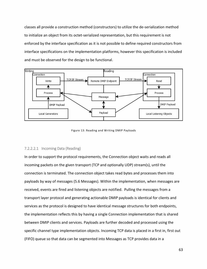
63
classes all provide a construction method (constructors) to utilize the de-serialization method
to initialize an object from its octet-serialized representation, but this requirement is not
enforced by the interface specification as it is not possible to define required constructors from
interface specifications on the implementation platforms, however this specification is included
and must be observed for the design to be functional.
Figure 13: Reading and Writing DMIP Payloads
7.2.2.2.1 Incoming Data (Reading)
In order to support the protocol requirements, the Connection object waits and reads all
incoming packets on the given transport (TCP and optionally UDP) stream(s), until the
connection is terminated. The connection object takes read bytes and processes them into
payloads by way of messages (5.6 Messages). Within the implementation, when messages are
received, events are fired and listening objects are notified. Pulling the messages from a
transport layer protocol and generating actionable DMIP payloads is identical for clients and
services as the protocol is designed to have identical message structures for both endpoints,
the implementation reflects this by having a single Connection implementation that is shared
between DMIP clients and services. Payloads are further decoded and processed using the
specific channel type implementation objects. Incoming TCP data is placed in a first in, first out
(FIFO) queue so that data can be segmented into Messages as TCP provides data in a
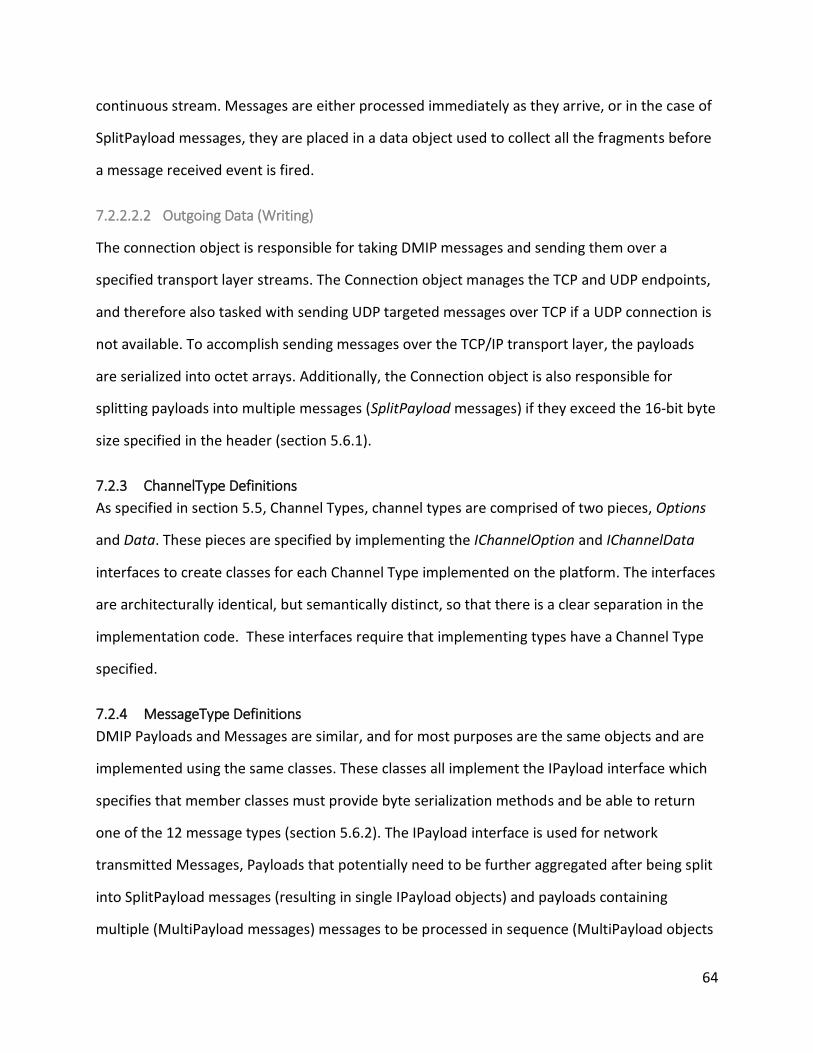
64
continuous stream. Messages are either processed immediately as they arrive, or in the case of
SplitPayload messages, they are placed in a data object used to collect all the fragments before
a message received event is fired.
7.2.2.2.2 Outgoing Data (Writing)
The connection object is responsible for taking DMIP messages and sending them over a
specified transport layer streams. The Connection object manages the TCP and UDP endpoints,
and therefore also tasked with sending UDP targeted messages over TCP if a UDP connection is
not available. To accomplish sending messages over the TCP/IP transport layer, the payloads
are serialized into octet arrays. Additionally, the Connection object is also responsible for
splitting payloads into multiple messages (SplitPayload messages) if they exceed the 16-bit byte
size specified in the header (section 5.6.1).
7.2.3 ChannelType Definitions
As specified in section 5.5, Channel Types, channel types are comprised of two pieces, Options
and Data. These pieces are specified by implementing the IChannelOption and IChannelData
interfaces to create classes for each Channel Type implemented on the platform. The interfaces
are architecturally identical, but semantically distinct, so that there is a clear separation in the
implementation code. These interfaces require that implementing types have a Channel Type
specified.
7.2.4 MessageType Definitions
DMIP Payloads and Messages are similar, and for most purposes are the same objects and are
implemented using the same classes. These classes all implement the IPayload interface which
specifies that member classes must provide byte serialization methods and be able to return
one of the 12 message types (section 5.6.2). The IPayload interface is used for network
transmitted Messages, Payloads that potentially need to be further aggregated after being split
into SplitPayload messages (resulting in single IPayload objects) and payloads containing
multiple (MultiPayload messages) messages to be processed in sequence (MultiPayload objects
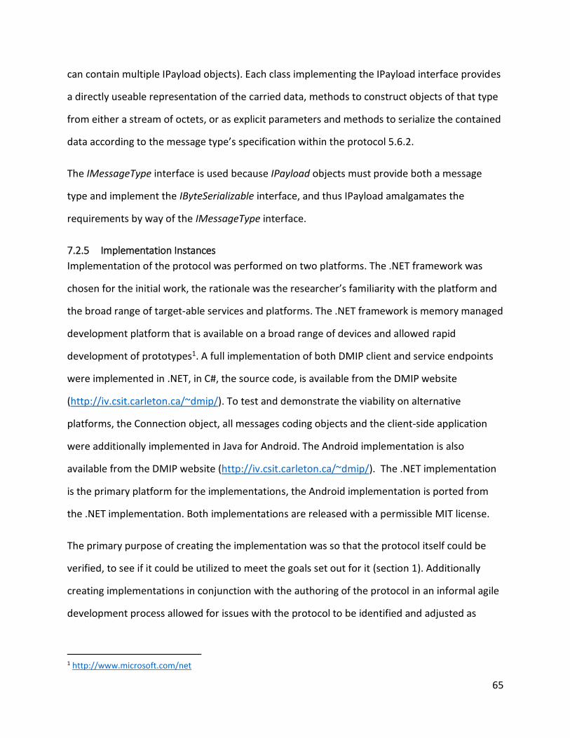
65
can contain multiple IPayload objects). Each class implementing the IPayload interface provides
a directly useable representation of the carried data, methods to construct objects of that type
from either a stream of octets, or as explicit parameters and methods to serialize the contained
data according to the message type’s specification within the protocol 5.6.2.
The IMessageType interface is used because IPayload objects must provide both a message
type and implement the IByteSerializable interface, and thus IPayload amalgamates the
requirements by way of the IMessageType interface.
7.2.5 Implementation Instances
Implementation of the protocol was performed on two platforms. The .NET framework was
chosen for the initial work, the rationale was the researcher’s familiarity with the platform and
the broad range of target-able services and platforms. The .NET framework is memory managed
development platform that is available on a broad range of devices and allowed rapid
development of prototypes1. A full implementation of both DMIP client and service endpoints
were implemented in .NET, in C#, the source code, is available from the DMIP website
(http://iv.csit.carleton.ca/~dmip/). To test and demonstrate the viability on alternative
platforms, the Connection object, all messages coding objects and the client-side application
were additionally implemented in Java for Android. The Android implementation is also
available from the DMIP website (http://iv.csit.carleton.ca/~dmip/). The .NET implementation
is the primary platform for the implementations, the Android implementation is ported from
the .NET implementation. Both implementations are released with a permissible MIT license.
The primary purpose of creating the implementation was so that the protocol itself could be
verified, to see if it could be utilized to meet the goals set out for it (section 1). Additionally
creating implementations in conjunction with the authoring of the protocol in an informal agile
development process allowed for issues with the protocol to be identified and adjusted as
1 http://www.microsoft.com/net
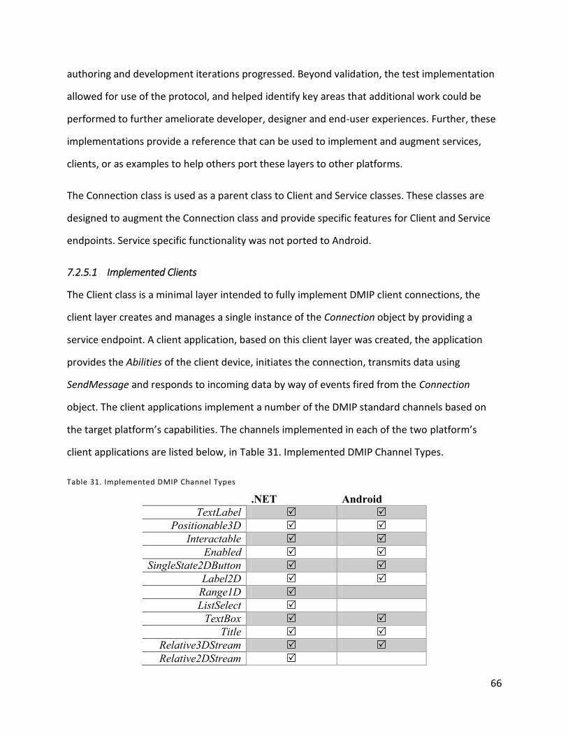
66
authoring and development iterations progressed. Beyond validation, the test implementation
allowed for use of the protocol, and helped identify key areas that additional work could be
performed to further ameliorate developer, designer and end-user experiences. Further, these
implementations provide a reference that can be used to implement and augment services,
clients, or as examples to help others port these layers to other platforms.
The Connection class is used as a parent class to Client and Service classes. These classes are
designed to augment the Connection class and provide specific features for Client and Service
endpoints. Service specific functionality was not ported to Android.
7.2.5.1 Implemented Clients
The Client class is a minimal layer intended to fully implement DMIP client connections, the
client layer creates and manages a single instance of the Connection object by providing a
service endpoint. A client application, based on this client layer was created, the application
provides the Abilities of the client device, initiates the connection, transmits data using
SendMessage and responds to incoming data by way of events fired from the Connection
object. The client applications implement a number of the DMIP standard channels based on
the target platform’s capabilities. The channels implemented in each of the two platform’s
client applications are listed below, in Table 31. Implemented DMIP Channel Types.
Table 31. Implemented DMIP Channel Types
.NET Android
TextLabel
Positionable3D
Interactable
Enabled
SingleState2DButton
Label2D
Range1D
ListSelect
TextBox
Title
Relative3DStream
Relative2DStream
67
Direction4
Chars
Image2DView
An image of the .NET windows forms implementation, connected to a PowerPoint controller
service, is provided in Figure 14: Windows Forms Client, below.
Figure 14: Windows Forms Client
The implementation of the client layer provided a validation of the DMIP protocol, and
programming reference for projects that intend to use DMIP.
7.2.5.2 Implemented Services
A .NET API supporting the authoring of services was created, this API provides common
functionality for services and is divided across 2 packages; Service and Library.
The Service package provides functionality for basic service implementations; it provides
session handling, basic layout definition from XML-format (7.2.6.1 XML Layout Language) files,
basic channel type compatibility checking.
The Library package provides additional augmentation/utility methods for services to ease
repetition of some common service coding tasks and make service development simpler,
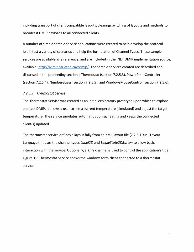
68
including transport of client compatible layouts, clearing/switching of layouts and methods to
broadcast DMIP payloads to all connected clients.
A number of simple sample service applications were created to help develop the protocol
itself, test a variety of scenarios and help the formulation of Channel Types. These sample
services are available as a reference, and are included in the .NET DMIP implementation source,
available: http://iv.csit.carleton.ca/~dmip/. The sample services created are described and
discussed in the proceeding sections; Thermostat (section 7.2.5.3), PowerPointController
(section 7.2.5.4), NumberGuess (section 7.2.5.5), and WindowsMouseControl (section 7.2.5.6).
7.2.5.3 Thermostat Service
The Thermostat Service was created as an initial exploratory prototype upon which to explore
and test DMIP. It allows a user to see a current temperature (simulated) and adjust the target
temperature. The service simulates automatic cooling/heating and keeps the connected
client(s) updated.
The thermostat service defines a layout fully from an XML-layout file (7.2.6.1 XML Layout
Language). It uses the channel types Label2D and SingleState2DButton to allow basic
interaction with the service. Optionally, a Title channel is used to control the application’s title.
Figure 15: Thermostat Service shows the windows form client connected to a thermostat
service.
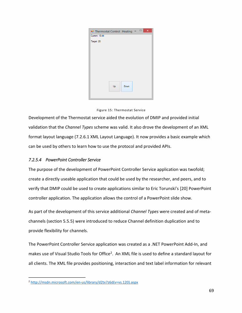
69
Figure 15: Thermostat Service
Development of the Thermostat service aided the evolution of DMIP and provided initial
validation that the Channel Types scheme was valid. It also drove the development of an XML
format layout language (7.2.6.1 XML Layout Language). It now provides a basic example which
can be used by others to learn how to use the protocol and provided APIs.
7.2.5.4 PowerPoint Controller Service
The purpose of the development of PowerPoint Controller Service application was twofold;
create a directly useable application that could be used by the researcher, and peers, and to
verify that DMIP could be used to create applications similar to Eric Torunski’s [20] PowerPoint
controller application. The application allows the control of a PowerPoint slide show.
As part of the development of this service additional Channel Types were created and of meta-
channels (section 5.5.5) were introduced to reduce Channel definition duplication and to
provide flexibility for channels.
The PowerPoint Controller Service application was created as a .NET PowerPoint Add-In, and
makes use of Visual Studio Tools for Office2. An XML file is used to define a standard layout for
all clients. The XML file provides positioning, interaction and text label information for relevant
2 http://msdn.microsoft.com/en-us/library/d2tx7z6d(v=vs.120).aspx
70
channel instances, as well as providing what channel types are required or optionally used by
the connecting clients. A view of the service from the windows forms client is seen in Figure 14:
Windows Forms Client, and from the android client in Figure 16: PowerPoint Controller from
Android.
Figure 16: PowerPoint Controller from Android
The channels Label2D and SingleState2DButton are required and enable the client to display
slide navigation buttons, and allow viewing the slide notes. Optionally the service supports
Direction4 to enable arrow key navigation, Title to provide a title caption for the client
application, Image2DView that enables a view of the current, previous and next slides in the
PowerPoint slide deck and ListSelect which gives a selectable list of slides that can be navigated
to. When a compatible client connects, it is provided with an interface generated by the service.
The network sequence diagram below in figure 4, shows the network messages used for the
“Previous” button, within the application.

71
Figure 17: Network Sequence for Previous Slide
7.2.5.5 Number Guess Service
The Number Guess Service was created to test multi-user scenarios. The service allows users to
join the game, each round the service randomly selects and integer and allows users to guess
the number. The specific user, by way of the client is informed if their guess is too high or too
low (or correct). Only one client is allowed to guess at a time, and the clients guess in sequence
until the number is guessed.
The Number Guess service was the first service created that required text/number input and
thus the TextBox channel type was developed, and the TextLabel meta-channel was introduced
to centralize Channel Type text data. The Enabled meta-channel was also developed to provide
a channel for visually enabling/disabling channels on clients.
Figure 18: Number Guess Service Progression shows the basic progression of a “game” in the
number guess service. Label 1 shows the initial client layout that allows users to input a name.
Label 2 shows the second layout that asks the user to enter a guess, but the “Guess” button is
disabled (via the Enabled meta-channel) because a round is not started (or it is not their turn).

72
Label 3 shows the service application, allows for a round to be started. Label 4 shows the
“Guess” button enabled, and Labels 5 and 6 show the win condition state on the client and
service respectively.
Figure 18: Number Guess Service Progression
To support multi-user scenarios, functionality was added to the service API to allow messages
to be broadcast to service connected clients. The service provides two layouts (login and play)
and thus switching of client layouts was developed for the service library package. The
development of this service provides validation of the possibility of handling multi-user
scenarios and a useable example thereof.
73
7.2.5.6 Windows Mouse Control Service
The Windows Mouse Control Service was created to test UDP channel data. The service allows
users to control the mouse on the service computer. Buttons are provided to emulate the
buttons on a mouse, and mouse position is controlled through either a Relative3DStream or
Relative2DStream channel. For timeliness UDP transport is used if the connection supports it.
The Android client implements Relative3DStream by way of the accelerometer, the service
merely takes data and moves the mouse on the service computer’s screen based on the data
provided by the Relative3DStream Data payloads.
This implementation is not useable with windows forms client, as the client buttons are not
selectable without moving the mouse, the default Data source for Relative2DStream.
Alternatively, the client would capture the local machine’s mouse movements and instead of
mouse clicks, use key presses, using the Chars channel.
A view of the Android client, connected to a Windows Mouse Control service is provided below,
in Figure 19: Windows Mouse Control Service, Android Client.
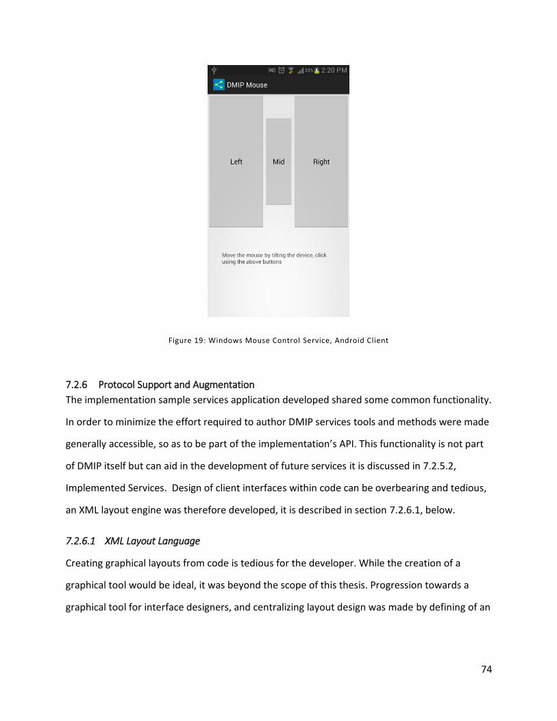
74
Figure 19: Windows Mouse Control Service, Android Client
7.2.6 Protocol Support and Augmentation
The implementation sample services application developed shared some common functionality.
In order to minimize the effort required to author DMIP services tools and methods were made
generally accessible, so as to be part of the implementation’s API. This functionality is not part
of DMIP itself but can aid in the development of future services it is discussed in 7.2.5.2,
Implemented Services. Design of client interfaces within code can be overbearing and tedious,
an XML layout engine was therefore developed, it is described in section 7.2.6.1, below.
7.2.6.1 XML Layout Language
Creating graphical layouts from code is tedious for the developer. While the creation of a
graphical tool would be ideal, it was beyond the scope of this thesis. Progression towards a
graphical tool for interface designers, and centralizing layout design was made by defining of an
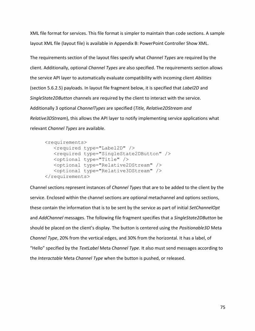
75
XML file format for services. This file format is simpler to maintain than code sections. A sample
layout XML file (layout file) is available in Appendix B: PowerPoint Controller Show XML.
The requirements section of the layout files specify what Channel Types are required by the
client. Additionally, optional Channel Types are also specified. The requirements section allows
the service API layer to automatically evaluate compatibility with incoming client Abilities
(section 5.6.2.5) payloads. In layout file fragment below, it is specified that Label2D and
SingleState2DButton channels are required by the client to interact with the service.
Additionally 3 optional ChannelTypes are specified (Title, Relative2DStream and
Relative3DStream), this allows the API layer to notify implementing service applications what
relevant Channel Types are available.
<requirements>
<required type="Label2D" />
<required type="SingleState2DButton" />
<optional type="Title" />
<optional type="Relative2DStream" />
<optional type="Relative3DStream" />
</requirements>
Channel sections represent instances of Channel Types that are to be added to the client by the
service. Enclosed within the channel sections are optional metachannel and options sections,
these contain the information that is to be sent by the service as part of initial SetChannelOpt
and AddChannel messages. The following file fragment specifies that a SingleState2DButton be
should be placed on the client’s display. The button is centered using the Positionable3D Meta
Channel Type, 20% from the vertical edges, and 30% from the horizontal. It has a label, of
“Hello” specified by the TextLabel Meta Channel Type. It also must send messages according to
the Interactable Meta Channel Type when the button is pushed, or released.
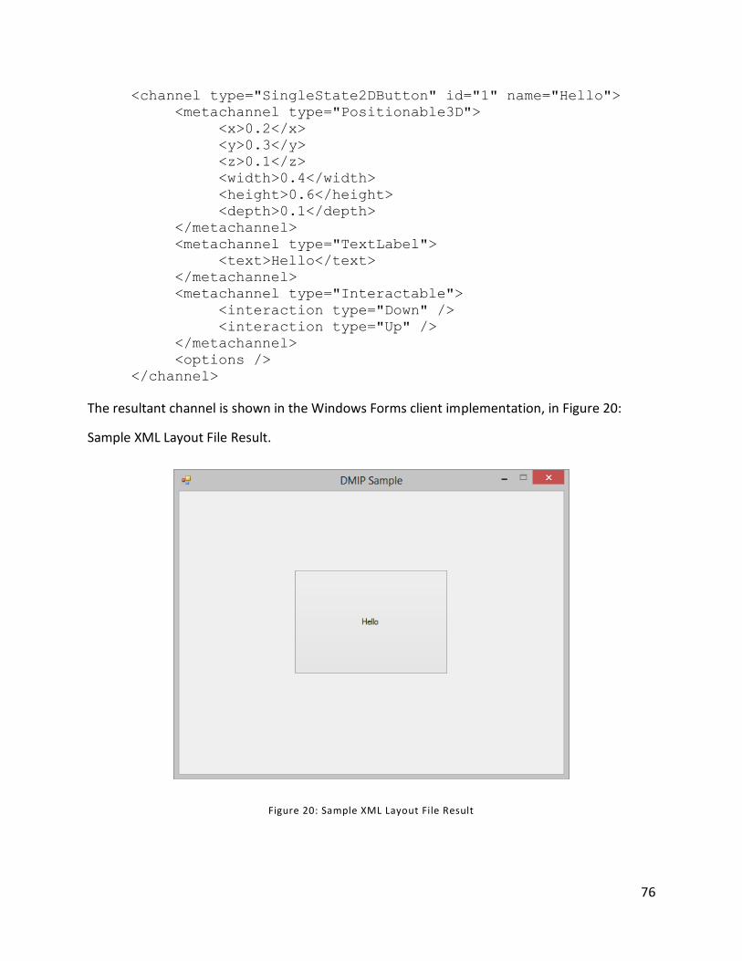
76
<channel type="SingleState2DButton" id="1" name="Hello">
<metachannel type="Positionable3D">
<x>0.2</x>
<y>0.3</y>
<z>0.1</z>
<width>0.4</width>
<height>0.6</height>
<depth>0.1</depth>
</metachannel>
<metachannel type="TextLabel">
<text>Hello</text>
</metachannel>
<metachannel type="Interactable">
<interaction type="Down" />
<interaction type="Up" />
</metachannel>
<options />
</channel>
The resultant channel is shown in the Windows Forms client implementation, in Figure 20:
Sample XML Layout File Result.
Figure 20: Sample XML Layout File Result
77
8 Discussion
DMIP currently provides a simplified development path to enable networked devices to utilize
network based services. Every effort has been made to validate DMIP, it has been validated for
several basic scenarios (section 7.2) however as a new technology there exists the possibility
that there are limitations. Section 8.2, discusses some potential limitations of DMIP. In order to
support and strengthen DMIP solutions further, related work is discussed and proposed in
section 8.3, Future Work.
8.1 Value and Testing
DMIP is a tool to aid authors of applications by providing them with a platform that reduces
concerns over networking and disparate device user-interaction capabilities. This, in turn can
provide greater access to the technology to the current and potential users of their applications
by making them immediately available to a greater number of client devices and providing a
flexible, yet consistent interface across devices. Testing usability of applications developed with
the tool is beyond the scope of this work, application design, while facilitated with DMIP,
remains part of the application development process. DMIP provides an application layout and
data-flow design platform. By targeting one effective platform, application authors can design,
deploy, evaluate and maintain a single application providing a higher return on investment and
additional resources for additional development. While effort has been made to communicate
with industry and interest has been shown, time limitations have reduced the ability to
evaluate the platform directly with developers.
8.2 Limitations
Despite extendibility, standardization of additional channel types can enable application
developers to more simply make use of more interaction modalities in their applications
potentially making the resultant applications more appealing to end users. Extension channel
types allow “3rd-party” channel types to be created, however it is unlikely that they will become
widespread without standardization centralizing the definition of novel channels.
78
Another potential improvement is security; while the underlying transport layer could provide
connection encryption [30] using a transport layer security scheme, it might be valuable to
encrypt specific channel instances and have protocol handling of security measures so that
users can view and manipulate the security information and/or to optimize transport of such
information.
DMIP relies on a TCP/IP based network to operate, as such, it is not directly compatible with
other remote technologies that do not include the TCP/IP stack. Lower level transport
mechanisms, such as Bluetooth, near field communication (NFC) and others could be used to
transport interaction data, but DMIP does not directly support these technologies.
It is possible that DMIP clients can support some channel types in different (multiple input
mechanisms) ways, or the same input could implement multiple channel types. For example the
Windows Mouse Control service (section 7.2.5.6), could potentially be provided the target
mouse co-ordinates in multiple ways, remote mouse co-ordinates, gaze tracking,
accelerometer, or any other input that could be provided in at least 2 dimensions. Currently,
the service application chooses between multiple channel types, whereas in the situation that
multiple client inputs could implement a channel type, it is left to the client developer to
choose, or provide configuration options so that the user can decide.
8.3 Future Work
To build upon and improve the DMIP specification, and supporting technologies developed for
this thesis, additional future work is proposed. The proceeding sections describe proposed
work. Section 8.3.1, Multi-User Scenarios discusses the use of DMIP to support multiple
simultaneous users. Section 8.3.2, Additional Implementation Features, describes additions
that could augment the API developed as part of the evaluation implementation (Section 7.2).
Section 8.3.4, Integration with Other Technologies, discusses integration with other modality
aggregation techniques as introduced in section 2.4 . Section 8.3.5 Standardization details
79
rationale and proposal for a means of standardizing DMIP and the supported Channel Types.
Service location, allowing automatic detection of DMIP services by clients is discussed in section
8.3.6. Service Endpoint Location and integration with popular web technologies, is discussed in
section 8.3.7 Transport Over HTTP and Websockets. And section 8.3.8, User Friendly Clients
discusses the opportunity for a variety of client DMIP implementing applications.
8.3.1 Multi-User Scenarios
It is simple to imagine DMIP working in multi-user scenarios, in fact perhaps most, if not all
scenarios can make use of multiple simultaneous client connections. While the DMIP protocol
focuses on a single Client-Service session, services are expected to be designed to support
multiple sessions. The number guessing game implementation (section 7.2.5.5) was created to
test the feasibility of this type of scenario. The other evaluation implementations created and
discussed in section 7.2.5 all work with multiple connected clients. However the number
guessing game manages a shared state for all connected clients, this functionality rests within
the service implementation’s code and the .NET service API, briefly discussed in section 7.2.6.
While ability for DMIP to support and enable multi-user scenarios is verified, it is suggested that
further examples and testing be completed, so that best practices can be compiled and the
service implementation API can be further developed.
8.3.2 Additional Implementation Features
The service implementation API described in section 7.2.5.2 provides developers with common
service functionality to make development of services implementing DMIP simpler and faster.
Implementing additional services would provide discovery of common features that could be
implemented in a re-useable API. One example feature that could be implemented would be
notification of incoming SplitPayload messages, so that partial data can be processed and
progress messages could be provided to end users on DMIP endpoints.
80
8.3.3 Multi-User Scenarios
It is simple to imagine DMIP working in multi-user scenarios, in fact perhaps most, if not all
scenarios can make use of multiple simultaneous client connections. While the DMIP protocol
focuses on a single Client-Service session, services are expected to be designed to support
multiple sessions. The number guessing game implementation (section 7.2.5.5) was created to
test the feasibility of this type of scenario. The other evaluation implementations created and
discussed in section 7.2.5 all work with multiple connected clients. However the number
guessing game manages a shared state for all connected clients, this functionality rests within
the service implementation’s code and the .NET service API, briefly discussed in section 7.2.6.
While ability for DMIP to support and enable multi-user scenarios is verified, it is suggested that
further examples and testing be completed, so that best practices can be compiled and the
service implementation API can be further developed.
8.3.4 Integration with Other Technologies
The related technologies section (2.4) discusses several related technologies that provide
methods of codifying, aggregating and consuming multimodal user data. DMIP Channel Types
could be created to support each these technologies by allowing transport of encapsulated
classified data.
8.3.5 Standardization
The authors of this work will be evaluating options for the standardization of DMIP. The goal of
standardization is to facilitate greater adoption of the technology and to aid in providing a
consistent target for application authors. However, standardization can take a long time, it is
therefore planned that Channel Types be removed from the formal standard and instead be
standardized and through less time-intensive process to allow faster reactions to changes in the
available interaction modalities. To enable the use of modalities not currently supported by the
existing Channel Types there exists the need to define community accepted means of
representing various modes. A standardization procedure needs to be created to support the
introduction of new transportable DMIP Channel Types.
81
8.3.6 Service Endpoint Location
To make the location and consumption of DMIP services simpler for end users, integration with
service location protocol (SLP) is proposed. SLP allows the location of service endpoints on local
networks [24]. A preliminary study was conducted to explore the feasibility of using SLP to
locate network endpoints for novel services, and it was successful3. A DMIP client able to
manage connect-able services and provide service endpoint location using SLP is therefore
proposed, in order to improve user experience by increasing accessibility of DMIP services.
8.3.7 Transport Over HTTP and Websockets
Higher level TCP/IP stack protocols, such as the Hypertext Transfer Protocol (HTTP) combined
with Websockets (WS) could be used to transport DMIP-like data, and could provide
opportunities for creating clients for web browsers if a DMIP-to HTTP/WS layer were created. It
is imagined that such clients would be able to provide flexible interaction services over the
internet and could be used to offer alternative/augmented ways of navigating the World Wide
Web.
8.3.8 User Friendly Clients
Despite considerations for things like SLP, there is further need for client implementations to
have their user experience evaluated and designed. Additional helpful features can be
imagined, configuration options and common endpoints are immediate candidates for
requirements lists. DMIP offers a method of negotiating, providing and consuming multimodal
data, however the design client applications is not defined. Future work should include a focus
on creating guidelines for DMIP client authors.
3 http://iv.csit.carleton.ca/~dmip/files/SLP.pptx Implementing Service Location Protocol
82
9 Conclusion
There is user desire to use mobile devices as “universal remote” controls, as it enables them to
access technology in new ways. Users that could not previously use a technology based service,
by not having access to specific equipment or because of a physical disability can use a broader
range of devices and human input and output devices if the technologies involved support
DMIP. Giving more ubiquitous access to consume and control technology is the purpose of
DMIP. For DMIP to become pervasive so that users can use the technology around them it
needs to have/support:
An expanding list of input/output modalities
Support for different configurations/combinations of these modalities
Be an accessible and open (free) standard
Have tools and sample code accessible to developers
Have tools for designers so that they can create useable interface designs
Be useable and simple to use for end users.
By providing the extensible modality system, DMIP can potentially support any human-
computer interaction modality (Section 7.1). DMIP also provides basic negotiation of these
modalities so that a dynamic set of remote client modalities can be used to interact with a
service application (section 5.5). DMIP is released to be freely and openly used by anyone, and
is provided with a permissive MIT license. Developing software that makes use of distributed
clients is much simplified by reducing concern about the client’s operating system, hardware
abilities and simplified network programming, additionally with the sample implementations
developers have tools, including sample code that can be used as a starting point so that
developers can more easily create DMIP capable services. An XML based file format has been
defined so that interfaces can be laid out external to service code (section 7.2.6.1). User
interface designer tools for DMIP are proposed, and could be developed by the public, given
the open-standard nature of the protocol. Beyond the core goal of DMIP, to provide a useable
83
interface for technology, the end user’s needs are not directly addressed (section 8.3.8) but
there exists opportunity for clients to be developed for many different devices and platforms.
The question posed in 2.1 Research Question:
There is an ever-increasing ability for the user to generate data on personal devices,
can this data be simply consumed by remote computer devices to provide an
interactive user based experience for potentially any capable remote technology?
Is answered and proven positive with the designed and evaluated protocol, DMIP. DMIP can
enable ubiquitous access to technology by providing an open standard means of negotiating
and transporting multi-modal interaction data. DMIP is a tool to help enable new scenarios, and
to increase access to existing ones. Although DMIP provides many features, it is at most a single
piece of any human-computer interaction. The implementations provided herein were created
primarily to aid in evaluating the protocol and to provide samples to interested parties. DMIP is
an enabling technology, or tool, and can be used in a potentially limitless number of scenarios.
DMIP aims to help application authors create new experiences for users. DMIP Implementation
and source code examples are available: http://iv.csit.carleton.ca/~dmip/.
84
References
[1] L. Nigay and J. Coutaz, "A design space for multimodal systems: concurrent processing and data fusion," in Human factors in computing systems , New York, 1993.
[2] W. R. Stevens, TCP/IP Illustrated: the protocols, Boston, Massachsetts: Addison-Wesley Professional, 1994.
[3] Rogers Communications, "Rogers Nextbox 2.0," [Online]. Available: http://www.rogers.com/web/content/Rogers-Nextbox2. [Accessed 15 July 2013].
[4] J. Rempel, "Control Your Thermostat from Almost Anywhere? There's an App for That: An Evaluation of the Nest Thermostat," AFB AccessWorld ® Magazine, vol. 13, no. 12, December 2012.
[5] J. Nielson and R. Molich, "Heuristic evaluation of user interfaces," Seattle, WA, 1990.
[6] Quinstreet Enterprise, "What is network? - A Definition From the Webopedia Computer Dictionary," [Online]. Available: http://www.webopedia.com/TERM/N/network.html. [Accessed 20 June 2013].
[7] T. Markku, H. Soronen, S. Pakarinen, J. Hella, T. Laivo, J. Hakulinen, A. Melto, J.-P. Rajaniemi, T. Miettinen, E. Mäkinen, T. Heimonen, J. Rantala, P. Valkama and R. Raisamo, "Accessible Multimodal Media Center Application for Blind and Partially Sighted People," Computers in Entertainment (CIE) - Theoretical and Practical Computer Applications in Entertainment, vol. 8, no. 3, p. Article 16, December 2010.
[8] P. Cohen and S. Oviatt, "Perceptual user interfaces: multimodal interfaces that process what comes naturally," Communications of the ACM, vol. 43, no. 3, pp. 45-53, 2000.
[9] A. Taivalsaari and T. Mikkonen, "The Web as an Application Platform: The Saga Continues," in Software Engineering and Advanced Applications (SEAA), Oulu, Finland, 2011.
[10] S. K. Card, J. D. Mackinlay and G. G. Robertson, "The design space of input devices," in CHI '90 Proceedings of the SIGCHI Conference on Human Factors in Computing, Seattle, USA, 1990.
[11] M. Kaltenbrunner, "reacTIVision and TUIO: A Tangible Tabletop Toolkit," in Interactive Tabletops and Surfaces, Banff, Canada, 2009.
85
[12] A. Wu, J. Jog, S. Mendenhall and A. Mazalek, "A Framework Interweaving Tangible Objects, Surfaces and Spaces," in HCI International, Orlando Florida, USA, 2011.
[13] J. Shen, S. Wenzhe and M. Pantic, "HCI 2 Workbench A development tool for multimodal human-computer interaction systems," in Automatic Face & Gesture Recognition and Workshops (FG 2011), Santa Barbara, CA, 2011.
[14] M. Johnston, "Building multimodal applications with EMMA," in 2009 international conference on Multimodal interfaces, Beijing, China, 2009.
[15] OpenNI, "OpenNI: Introduction," OpenNI, 27 November 2011. [Online]. Available: http://openni.org/Documentation/Reference/introduction.html. [Accessed 14 September 2012].
[16] K. Bonhyun, A. Taewon, I. JungSik, P. Youngsuk and S. Taesgik, "R-URC: RF4CE-Based Universal Remote Control Framework Using Smartphone," in Computational Science and Its Applications (ICCSA), Fukuoka, Japan, 2010.
[17] M. Kaltenbrunner, T. Bovermann, R. Bencina and E. Costanza, "TUIO - A Protocol for Table-Top Tangible User Interfaces," in 6th International Workshop on Gesture in Human-Computer Interaction and Simulation, Vannes, France, 2005.
[18] H. Ishii and B. Ullmer, "Tangible bits: towards seamless interfaces between people, bits and atoms," in SIGCHI conference on Human factors in computing systems (CHI '97), Atlanta, Georgia, USA, 1997.
[19] J. Shen and M. Pantic, "A software framework for multimodal humancomputer interaction systems," in IEEE International Conference on Systems, Man, and Cybernetics, San Antonio, TX, USA, 2009.
[20] E. Torunski, A. El Saddik and E. Petriu, "Gesture recognition on a mobile device for remote event generation,," in Multimedia and Expo (ICME), Barcelona, 2011.
[21] J. Nielson, "Iterative user-interface design," Computer, vol. 26, no. 11, pp. 32-41, 1993.
[22] N. Johansson, M. Kihl and U. Körner, "TCP/IP over the Bluetooth Wireless Ad-hoc Network," Department of Communication Systems, Lund University, Lund, Sweden, 2003.
[23] L. M. de Sales, H. O. Almeida and A. Perkusich, "On the performance of TCP, UDP and DCCP over 802.11 g networks," in ACM Symposium on Applied Computing, Ceará, Brazil, 2008.
[24] E. Guttman, C. Perkins, J. Veizades and M. Day, "Service Location Protocol, Version 2," June 1999. [Online]. Available: http://tools.ietf.org/html/rfc2608.
86
[25] E. Guttman, C. Perkins and J. Kempf, "Service Templates and Service: Schemes," June 1999. [Online]. Available: http://tools.ietf.org/html/rfc2609.
[26] R. Braden, "Requirements for Internet Hosts -- Communication Layers," October 1989. [Online]. Available: http://tools.ietf.org/html/rfc1122.
[27] S. Bradner, "Key words for use in RFCs to Indicate Requirement Levels," March 1997. [Online]. Available: http://tools.ietf.org/html/rfc2119. [Accessed 10 July 2013].
[28] J. Nielson, "10 Usability Heuristics for User Interface Design," 1 January 1995. [Online]. Available: http://www.nngroup.com/articles/ten-usability-heuristics/. [Accessed 9 March 2013].
[29] N. O. Bernsen, "Modality theory in support of multimodal interface design," in ERCIM Workshop on Multimodal Human-Computer Interaction, Roskilde, Denmark, 1994.
[30] T. Dierks and E. Rescorla, "The Transport Layer Security (TLS) Protocol, Version 1.2," August 2008. [Online]. Available: https://tools.ietf.org/html/rfc5246. [Accessed 2 February 2013].
[31] D. Mills, U. Delaware, J. Martin, J. Burbank and W. Kasch, "Network Time Protocol Version 4: Protocol and Algorithms Specification," June 2010. [Online]. Available: http://tools.ietf.org/html/rfc5905. [Accessed 3 September 2012].
[32] W3C, "The WebSocket API," 29 September 2011. [Online]. Available: http://www.w3.org/TR/websockets/. [Accessed 21 November 2011].

87
Appendix A: Interaction Ledger
Survey
Available: http://lucasstephenson.net/hcin5909/
Results
Interaction Object
Purpose Actions Performed Best Simulated Motion Selection
car opening, closing locking etc I use a smart key which means that my door can be locked and unlocked as long as I carry the key in my purse or pocket -
? I am not sure what to put here
User does a wrist motion
User selects key and
points to lock
computer mouse.
interacting with the object to perform desktop tasks. accomplishing: getting around the desktop and selecting pages I wish to see, i.e.: i would like to open a file so double click to open; or I would like to see below, so I scroll.
Actions: 1 - move, 2 - click, and 3 - scroll anticipated results: 1 - as i move the mouse, the cursor also moves on the computer screen, 2 and 3 -- as i click and scroll i expect a change within the interface.
Move mouse
cursor
Select items by clicking mouse
Keyboard attached to
my laptop
filling in this form. lol. However, entering text in any way necessary (word documents, emails, facebook, etc.)
What I did to the object was depress keys. The anticipated result was that the key I depressed would result in the corresponding character or symbol being displayed on
touch-screen key pad on screen. That\'s all I\'ve really got for this one.
Select items on
screen, select keys
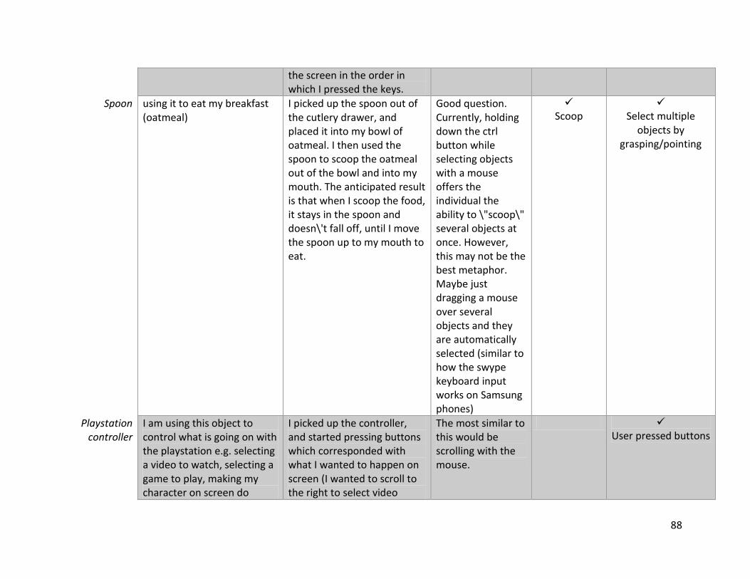
88
the screen in the order in which I pressed the keys.
Spoon using it to eat my breakfast (oatmeal)
I picked up the spoon out of the cutlery drawer, and placed it into my bowl of oatmeal. I then used the spoon to scoop the oatmeal out of the bowl and into my mouth. The anticipated result is that when I scoop the food, it stays in the spoon and doesn\'t fall off, until I move the spoon up to my mouth to eat.
Good question. Currently, holding down the ctrl button while selecting objects with a mouse offers the individual the ability to \"scoop\" several objects at once. However, this may not be the best metaphor. Maybe just dragging a mouse over several objects and they are automatically selected (similar to how the swype keyboard input works on Samsung phones)
Scoop
Select multiple
objects by grasping/pointing
Playstation controller
I am using this object to control what is going on with the playstation e.g. selecting a video to watch, selecting a game to play, making my character on screen do
I picked up the controller, and started pressing buttons which corresponded with what I wanted to happen on screen (I wanted to scroll to the right to select video
The most similar to this would be scrolling with the mouse.
User pressed buttons
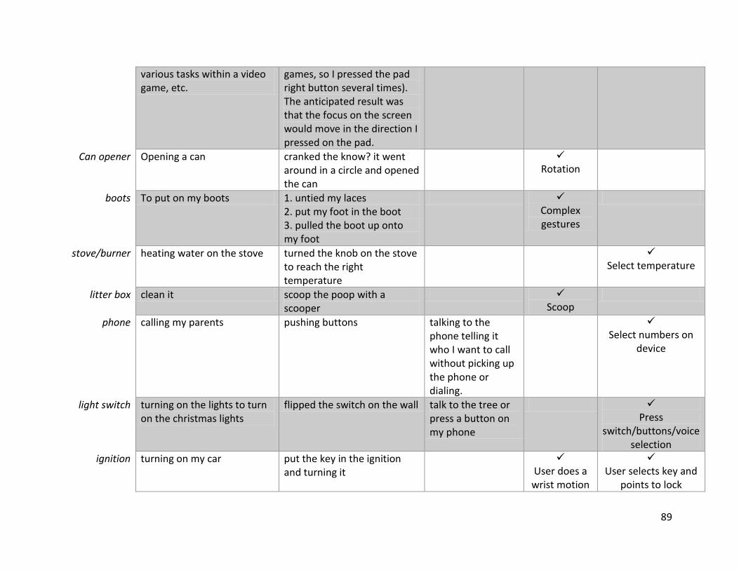
89
various tasks within a video game, etc.
games, so I pressed the pad right button several times). The anticipated result was that the focus on the screen would move in the direction I pressed on the pad.
Can opener Opening a can cranked the know? it went around in a circle and opened the can
Rotation
boots To put on my boots 1. untied my laces 2. put my foot in the boot 3. pulled the boot up onto my foot
Complex gestures
stove/burner heating water on the stove turned the knob on the stove to reach the right temperature
Select temperature
litter box clean it scoop the poop with a scooper
Scoop
phone calling my parents pushing buttons talking to the phone telling it who I want to call without picking up the phone or dialing.
Select numbers on
device
light switch turning on the lights to turn on the christmas lights
flipped the switch on the wall talk to the tree or press a button on my phone
Press
switch/buttons/voice selection
ignition turning on my car put the key in the ignition and turning it
User does a wrist motion
User selects key and
points to lock
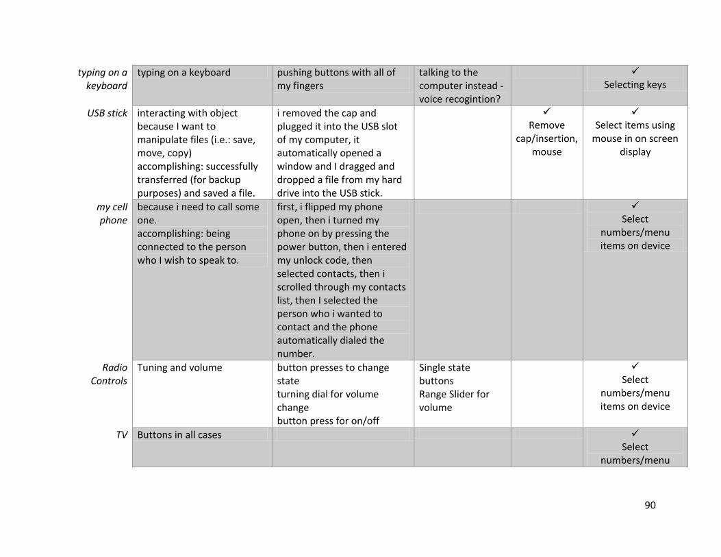
90
typing on a keyboard
typing on a keyboard pushing buttons with all of my fingers
talking to the computer instead - voice recogintion?
Selecting keys
USB stick interacting with object because I want to manipulate files (i.e.: save, move, copy) accomplishing: successfully transferred (for backup purposes) and saved a file.
i removed the cap and plugged it into the USB slot of my computer, it automatically opened a window and I dragged and dropped a file from my hard drive into the USB stick.
Remove
cap/insertion, mouse
Select items using
mouse in on screen display
my cell phone
because i need to call some one. accomplishing: being connected to the person who I wish to speak to.
first, i flipped my phone open, then i turned my phone on by pressing the power button, then i entered my unlock code, then selected contacts, then i scrolled through my contacts list, then I selected the person who i wanted to contact and the phone automatically dialed the number.
Select
numbers/menu items on device
Radio Controls
Tuning and volume button presses to change state turning dial for volume change button press for on/off
Single state buttons Range Slider for volume
Select
numbers/menu items on device
TV Buttons in all cases Select
numbers/menu
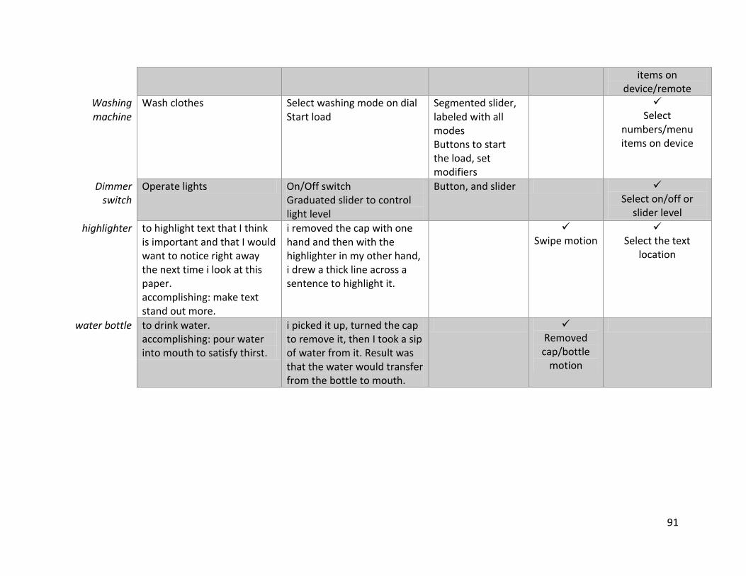
91
items on device/remote
Washing machine
Wash clothes Select washing mode on dial Start load
Segmented slider, labeled with all modes Buttons to start the load, set modifiers
Select
numbers/menu items on device
Dimmer switch
Operate lights On/Off switch Graduated slider to control light level
Button, and slider Select on/off or
slider level
highlighter to highlight text that I think is important and that I would want to notice right away the next time i look at this paper. accomplishing: make text stand out more.
i removed the cap with one hand and then with the highlighter in my other hand, i drew a thick line across a sentence to highlight it.
Swipe motion
Select the text
location
water bottle to drink water. accomplishing: pour water into mouth to satisfy thirst.
i picked it up, turned the cap to remove it, then I took a sip of water from it. Result was that the water would transfer from the bottle to mouth.
Removed cap/bottle
motion
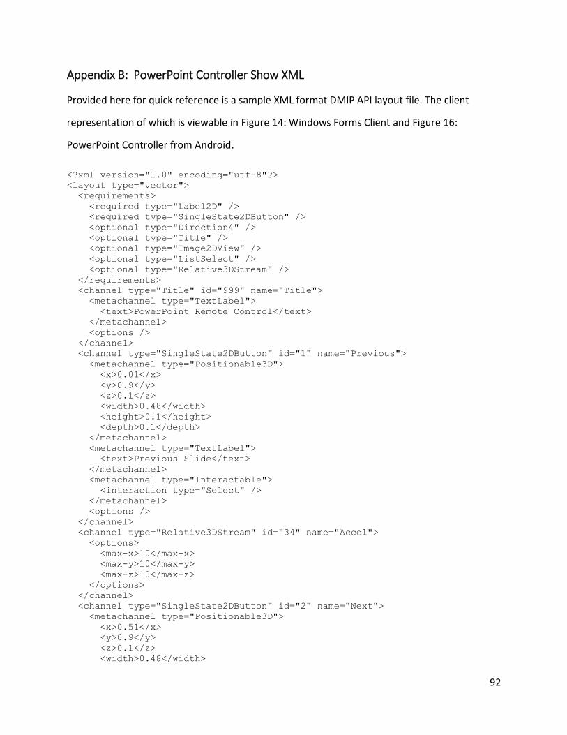
92
Appendix B: PowerPoint Controller Show XML
Provided here for quick reference is a sample XML format DMIP API layout file. The client
representation of which is viewable in Figure 14: Windows Forms Client and Figure 16:
PowerPoint Controller from Android.
<?xml version="1.0" encoding="utf-8"?>
<layout type="vector">
<requirements>
<required type="Label2D" />
<required type="SingleState2DButton" />
<optional type="Direction4" />
<optional type="Title" />
<optional type="Image2DView" />
<optional type="ListSelect" />
<optional type="Relative3DStream" />
</requirements>
<channel type="Title" id="999" name="Title">
<metachannel type="TextLabel">
<text>PowerPoint Remote Control</text>
</metachannel>
<options />
</channel>
<channel type="SingleState2DButton" id="1" name="Previous">
<metachannel type="Positionable3D">
<x>0.01</x>
<y>0.9</y>
<z>0.1</z>
<width>0.48</width>
<height>0.1</height>
<depth>0.1</depth>
</metachannel>
<metachannel type="TextLabel">
<text>Previous Slide</text>
</metachannel>
<metachannel type="Interactable">
<interaction type="Select" />
</metachannel>
<options />
</channel>
<channel type="Relative3DStream" id="34" name="Accel">
<options>
<max-x>10</max-x>
<max-y>10</max-y>
<max-z>10</max-z>
</options>
</channel>
<channel type="SingleState2DButton" id="2" name="Next">
<metachannel type="Positionable3D">
<x>0.51</x>
<y>0.9</y>
<z>0.1</z>
<width>0.48</width>
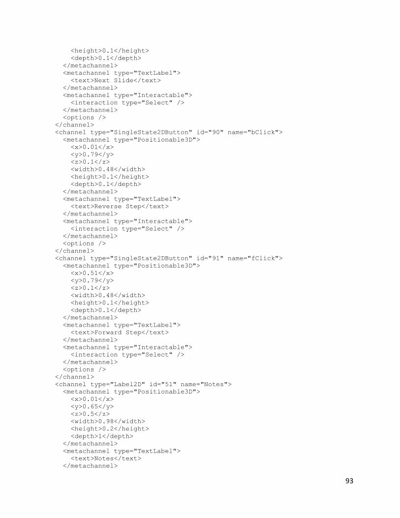
93
<height>0.1</height>
<depth>0.1</depth>
</metachannel>
<metachannel type="TextLabel">
<text>Next Slide</text>
</metachannel>
<metachannel type="Interactable">
<interaction type="Select" />
</metachannel>
<options />
</channel>
<channel type="SingleState2DButton" id="90" name="bClick">
<metachannel type="Positionable3D">
<x>0.01</x>
<y>0.79</y>
<z>0.1</z>
<width>0.48</width>
<height>0.1</height>
<depth>0.1</depth>
</metachannel>
<metachannel type="TextLabel">
<text>Reverse Step</text>
</metachannel>
<metachannel type="Interactable">
<interaction type="Select" />
</metachannel>
<options />
</channel>
<channel type="SingleState2DButton" id="91" name="fClick">
<metachannel type="Positionable3D">
<x>0.51</x>
<y>0.79</y>
<z>0.1</z>
<width>0.48</width>
<height>0.1</height>
<depth>0.1</depth>
</metachannel>
<metachannel type="TextLabel">
<text>Forward Step</text>
</metachannel>
<metachannel type="Interactable">
<interaction type="Select" />
</metachannel>
<options />
</channel>
<channel type="Label2D" id="51" name="Notes">
<metachannel type="Positionable3D">
<x>0.01</x>
<y>0.65</y>
<z>0.5</z>
<width>0.98</width>
<height>0.2</height>
<depth>1</depth>
</metachannel>
<metachannel type="TextLabel">
<text>Notes</text>
</metachannel>
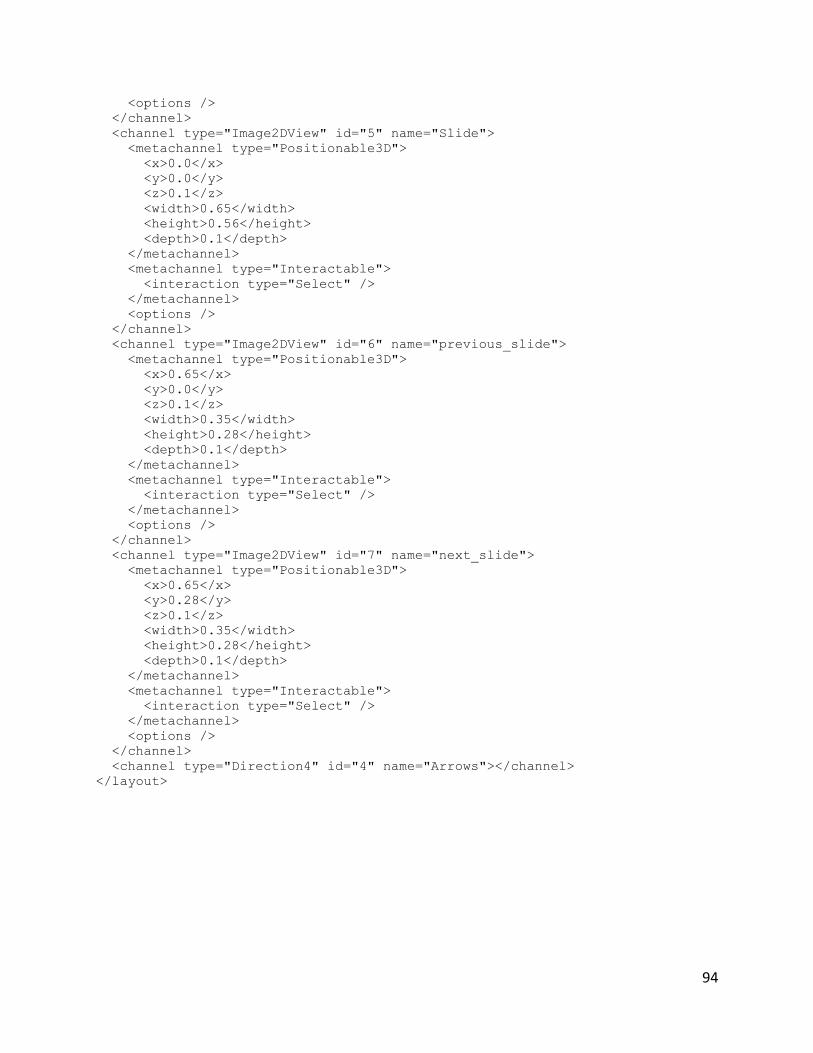
94
<options />
</channel>
<channel type="Image2DView" id="5" name="Slide">
<metachannel type="Positionable3D">
<x>0.0</x>
<y>0.0</y>
<z>0.1</z>
<width>0.65</width>
<height>0.56</height>
<depth>0.1</depth>
</metachannel>
<metachannel type="Interactable">
<interaction type="Select" />
</metachannel>
<options />
</channel>
<channel type="Image2DView" id="6" name="previous_slide">
<metachannel type="Positionable3D">
<x>0.65</x>
<y>0.0</y>
<z>0.1</z>
<width>0.35</width>
<height>0.28</height>
<depth>0.1</depth>
</metachannel>
<metachannel type="Interactable">
<interaction type="Select" />
</metachannel>
<options />
</channel>
<channel type="Image2DView" id="7" name="next_slide">
<metachannel type="Positionable3D">
<x>0.65</x>
<y>0.28</y>
<z>0.1</z>
<width>0.35</width>
<height>0.28</height>
<depth>0.1</depth>
</metachannel>
<metachannel type="Interactable">
<interaction type="Select" />
</metachannel>
<options />
</channel>
<channel type="Direction4" id="4" name="Arrows"></channel>
</layout>