Embed Size (px)
Citation preview

Distributed Planning and Coordination to Support Lean Construction
by
Hyun Jeong Choo
B.S. (Yonsei University) 1993 M.S. (Yonsei University) 1995
A dissertation submitted in partial satisfaction of the
requirements for the degree of
Doctor of Philosophy
in
Engineering-Civil and Environmental Engineering
in the
GRADUATE DIVISION
of the
UNIVERSITY OF CALIFORNIA, BERKELEY
Committee in charge:
Professor Iris D. Tommelein, Chair Professor Glenn Ballard Professor Phil Kaminsky
Spring 2003

Distributed Planning and Coordination to Support Lean Construction
Copyright (2003)
by
Hyun Jeong Choo

1
Abstract
Distributed Planning and Coordination to Support Lean Construction
by
Hyun Jeong Choo
Doctor of Philosophy
in
Engineering - Civil and Environmental Engineering
University of California, Berkeley
Professor Iris D. Tommelein, Chair
Construction planning is a complex process that involves coordination between many
project participants on- and off-site. As projects have been increasing in size and
complexity, the number of participants involved in a single project has also increased.
Numerous studies have suggested that the traditional project management tools, which
are often used in a centralized top-down control environment, do not meet the production
management requirements of today’s projects. They have reported that the current
communication tools do not adequately support the coordination efforts required to
successfully deliver projects.
This research presents a Distributed Planning and Control (DP&C) method based on a
distributed control paradigm. The DP&C helps in improving production planning
performance by adopting the Last Planner System (LPS) and thereby providing reliable
communication channels in order support the creation of coordinated schedules at
appropriate levels of detail.

2
The DP&C method is supported by a tool called WorkMovePlan, which extends the
Last Planner tools, WorkPlan and DePlan. WorkMovePlan uses synchronization
technology for the collaborative creation of coordinated production plans based on
explicit resource and space assignments. As proven during the conceptualization,
development, and validation of WorkMovePlan, technology is no longer a barrier to
implementing distributed planning and coordination thanks to wide acceptance of
personal computers, wireless computing, Internet connectivity, and programming
frameworks. The main barriers to implementation are (1) acknowledgement of
uncertainty and approaches for managing it, (2) acceptance of the underlying, distributed
control paradigm, and (3) willingness to break with traditional contractual arrangements,
organizational structures, and common practices of the construction industry. These
barriers suggest that many aspects of project management still need further investigation
in order to achieve better alignment with production management. It is the author’s belief
that project management and production management tools need to work hand-in-hand in
order to support the successful delivery of projects.
It is expected that the DP&C method or similar methods will gain in acceptance in the
construction industry as the shortcomings of the centralized control paradigm become
increasingly evident and as Lean Construction continues to prove that it is a theoretically
sound-, though radically different alternative to how projects are delivered.
__________________________________
Professor Iris D. Tommelein, Chair
i
TABLE OF CONTENTS
TABLE OF CONTENTS ..................................................................................................I
LIST OF FIGURES ......................................................................................................... V
LIST OF TABLES .......................................................................................................... IX
ACKNOWLEDGMENTS ............................................................................................... X
1 INTRODUCTION.................................................................................................... 1
2 OVERVIEW............................................................................................................. 8
2.1 THESIS STATEMENT .............................................................................................. 8
2.2 RESEARCH OBJECTIVES ........................................................................................ 9
2.2.1 Understand the Current Construction Planning Practice ................................ 9
2.2.2 Determine an Alternative Planning Methodology ........................................ 10
2.2.3 Develop a Methodology to Manage Interactive Planning ............................ 11
2.2.4 Develop a Computer Tool to Support Interactive Planning.......................... 16
2.3 SCOPE ................................................................................................................. 17
2.4 CONCLUSION ...................................................................................................... 17
3 LITERATURE REVIEW ..................................................................................... 19
3.1 CONSTRUCTION PLANNING................................................................................. 19
3.2 LEAN CONSTRUCTION......................................................................................... 23
3.3 MULTI-TIERED PLANNING AND SCHEDULING ..................................................... 25
3.3.1 Current Planning Model................................................................................ 27
ii
3.3.2 Last Planner System (LPS) ........................................................................... 37
3.4 RELATIONSHIP BETWEEN PDCA CYCLE, CURRENT PLANNING SYSTEM, AND LAST
PLANNER SYSTEM............................................................................................... 48
3.5 PLAN RELIABILITY.............................................................................................. 51
3.5.1 Automated Simulation of CPM Schedules using Stroboscope..................... 52
3.5.2 Planning Performance Criteria...................................................................... 57
3.5.3 Robustness .................................................................................................... 59
3.6 CONSTRUCTION COORDINATION......................................................................... 60
3.6.1 Coordination vs. Scheduling......................................................................... 60
3.6.2 Space Coordination....................................................................................... 64
3.7 EXISTING TECHNOLOGY ..................................................................................... 67
3.7.1 Internet-based Tools...................................................................................... 67
3.7.2 Information Exchange................................................................................... 68
3.8 OTHER AREAS OF RESEARCH IN DISTRIBUTED PLANNING AND COORDINATION 71
3.9 CONCLUSION ...................................................................................................... 74
4 APPLICATION OF LAST PLANNER SYSTEM TO DESIGN AND
CONSTRUCTION................................................................................................. 77
4.1 JOBSHOP SCHEDULING VS. PROJECT SCHEDULING.............................................. 78
4.2 COMMON DESIGN CHARACTERISTICS ................................................................. 84
4.3 WORKPLAN ........................................................................................................ 87
4.3.1 Design of WorkPlan...................................................................................... 87
4.3.2 Implementation of WorkPlan........................................................................ 88

iii
4.4 DEPLAN............................................................................................................ 115
4.4.1 Design of DePlan ........................................................................................ 115
4.4.2 Implementation of DePlan .......................................................................... 117
4.5 VALIDATION OF WORKPLAN AND DEPLAN ...................................................... 123
4.5.1 Feedback on Implementation...................................................................... 124
4.5.2 Requirements for Last Planner Tools ......................................................... 128
4.6 CONCLUSION .................................................................................................... 129
5 DISTRIBUTED PLANNING AND COORDINATION .................................. 130
5.1 COORDINATED PLANNING................................................................................. 132
5.2 WORK PACKAGE STRUCTURE TO SUPPORT MULTI-LEVEL PLANNING .............. 136
5.3 SPACE SCHEDULING.......................................................................................... 141
5.4 CONFLICT DETECTION ...................................................................................... 142
5.5 CONCLUSION .................................................................................................... 145
6 WORKMOVEPLAN ........................................................................................... 148
6.1 DESIGN ............................................................................................................. 148
6.1.1 System and Data Architecture of WorkMovePlan...................................... 148
6.1.2 Space Scheduling ........................................................................................ 150
6.2 IMPLEMENTATION............................................................................................. 154
6.3 VALIDATION ..................................................................................................... 159
7 CONCLUSIONS .................................................................................................. 163
7.1 RESEARCH SUMMARY....................................................................................... 163

iv
7.2 CONTRIBUTIONS TO KNOWLEDGE..................................................................... 166
7.2.1 Understanding of Current Project Planning Practices and Production
Planning Practices and Their Interrelationship .......................................... 166
7.2.2 Paradigm Shift from Centralized to Distributed Planning.......................... 167
7.2.3 Shifting Single-Focus Planning Focus to Dual-Focus Planning................. 168
7.2.4 Managing Uncertainty and Reliability........................................................ 169
7.2.5 Computer Tool for Production Planning in Construction Based on the Last
Planner ....................................................................................................... 170
7.2.6 Distributed Space Scheduling to Support Production Management........... 170
7.3 FUTURE RESEARCH ISSUES AND QUESTIONS .................................................... 170
7.3.1 Distributed Planning and Coordination Method......................................... 171
7.3.2 Shifting Single-Focus Planning Focus to Dual-Focus Planning................. 173
7.3.3 Computer Tool for Production Planning in Construction Based on the Last
Planner ....................................................................................................... 173
7.3.4 Distributed Space Scheduling to Support Production................................. 174
7.3.5 Impact of DP&C on Other Project Control Systems .................................. 174
7.4 CONCLUSION .................................................................................................... 175
8 BIBLIOGRAPHY................................................................................................ 176
v
LIST OF FIGURES
Figure 1. Research Scope.................................................................................................. 18
Figure 2. Scope of the Project Management Body of Knowledge (Project Management
Institute 1996, p. 9) ......................................................................................... 20
Figure 3. Project Schedule Development (derived from PMI 1996) ................................ 21
Figure 4. Lean Project Delivery System (Ballard 2000b)................................................. 26
Figure 5. Relationship between Project, Work Packages, Activities, and Schedule
(derived from PMI 1996) ................................................................................ 28
Figure 6. Sample of a Bar Chart-based Lookahead .......................................................... 33
Figure 7. Sample of a Hand-drawn Lookahead ................................................................ 35
Figure 8. Last Planner System (Lean Construction Institute 1999).................................. 40
Figure 9. Work Structuring ............................................................................................... 43
Figure 10. Advancement of Lookahead Window............................................................. 47
Figure 11. Relationship between PDCA Cycle, Current Planning System, and Last
Planner System................................................................................................ 49
Figure 12. Front-end of StroboCPM................................................................................. 53
Figure 13. Sample CPM Schedule .................................................................................... 54
Figure 14. Sample StroboCPM Chart ............................................................................... 55
Figure 15. Percentages of Normal Distribution ................................................................ 56
Figure 16. Importance of coordination. (Wall Street Journal).......................................... 61
Figure 17. Focus of WorkPlan and DePlan ...................................................................... 77
Figure 18. Spectrum of Manufacturing Processes ............................................................ 78
Figure 19. Job-Shop View vs. Project View..................................................................... 81

vi
Figure 20. Relationship between Projects and Subcontractors......................................... 84
Figure 21. WorkPlan Procedure Diagram......................................................................... 89
Figure 22. Startup Screen.................................................................................................. 90
Figure 23. Copyright Screen ............................................................................................. 90
Figure 24. Navigator Screen Page 1 ................................................................................. 91
Figure 25. Project Information.......................................................................................... 92
Figure 26. Work Package Information.............................................................................. 93
Figure 27. Laborer Information ........................................................................................ 94
Figure 28. Equipment Information ................................................................................... 94
Figure 29. Navigator Screen Page 2 ................................................................................. 95
Figure 30. Work Package Constraints Implementation I.................................................. 96
Figure 31. Work Package Constraints Implementation II ................................................ 96
Figure 32. Work Package Release .................................................................................. 100
Figure 33. Scheduling Week Selection........................................................................... 101
Figure 34. Schedule Work Packages Type I................................................................... 102
Figure 35. Resource Assignment .................................................................................... 103
Figure 36. Schedule Work Packages Type II.................................................................. 104
Figure 37. Sample Weekly Work Plan ........................................................................... 105
Figure 38. Updating Week.............................................................................................. 106
Figure 39. Update Work Packages.................................................................................. 107
Figure 40. Resource Assignment Update........................................................................ 108
Figure 41. Reasons for Incompletion.............................................................................. 109
Figure 42. Navigator Screen Page 3 ............................................................................... 110

vii
Figure 43. Report Manager ............................................................................................. 111
Figure 44. Trades Report ................................................................................................ 111
Figure 45. Constraint Analysis Report............................................................................ 112
Figure 46. Timesheet Report........................................................................................... 112
Figure 47. PPC with Reasons Report.............................................................................. 113
Figure 48. Detailed Reasons Report ............................................................................... 113
Figure 49. Navigator Screen Page 4 ............................................................................... 114
Figure 50. DePlan ........................................................................................................... 116
Figure 51. Sample Output Matrix Generated from ADePT............................................ 118
Figure 52. Constraint Matrix based on Figure 51 ........................................................... 118
Figure 53. Detailed Design Constraints for C1000-16 ................................................... 119
Figure 54. Detailed Constraints for C1000-16................................................................ 121
Figure 55. Weekly Work Plan Generated from Extended WorkPlan............................. 121
Figure 56. Lookahead Generated from Extended WorkPlan.......................................... 122
Figure 57. Communication Channel Scheme under Distributed Planning and
Coordination ................................................................................................. 133
Figure 58. Relationship between Schedules with Different Lookaheads ....................... 136
Figure 59. Relationship between Work Packages and Assignments .............................. 138
Figure 60. Relationship between General Contractor’s Lookahead and Two Specialty
Contractors’ Lookaheads .............................................................................. 140
Figure 61. Site Layouts for Third Week for Schedule in Figure 60. Left: site layout for
HVAC contractor; Right: site layout for the Electrical contractor ............... 145
Figure 62. Relationship between Private Information vs. Public Information ............... 149

viii
Figure 63. WorkMovePlan(WMP) Synchronization Scheme ........................................ 151
Figure 64. Space Scheduling Screen............................................................................... 153
Figure 65. Completed Space Scheduling Screen ............................................................ 154
Figure 66. Project Information........................................................................................ 155
Figure 67. Work Package Information............................................................................ 155
Figure 68. Sample Site Layout using VRML ................................................................. 156
Figure 69. WorkMovePlan Data Center ......................................................................... 158
Figure 70. Next Week’s Weekly Work Plan .................................................................. 159
Figure 71. Last Week’s Timesheet ................................................................................. 159
Figure 72. Constraints Report by Work Packages .......................................................... 161
Figure 73. Constraints Report by Responsibility (for responsible party BBB) .............. 161
Figure 74. Last Planner Software including WorkPlan, DePlan, and WorkMovePlan .. 165
ix
LIST OF TABLES
Table 1. Deficiencies in Assumptions and Theory of Current Project Management
(Howell and Koskela 2000) ............................................................................ 23
Table 2. Measurements Proposed by Kartam et al. (1995)............................................... 58
Table 3. Work Package Data Structure........................................................................... 140
Table 4. Space Requirement ........................................................................................... 142

x
ACKNOWLEDGMENTS
During this research, I have had the honor to work with the greatest minds in the field of
Lean Construction. It has been and will continue to be a great journey to further develop
lean ideas, surrounded by the founders and leaders of the field.
First, I would like to thank Prof. Iris Tommelein for her continuous guidance and
support. Throughout the years of my research, she has always been there to provide me
with valuable insights and challenges. Her dedication to her research and her students
deserve the greatest admiration. I would also like to thank Prof. Glenn Ballard for playing
a significant role in my journey. I am sure that I am in an envious position among the
students all over the world for having had easy access to the developer of the Last
Planner System and bounce off ideas with him. I also am grateful to Prof. Phil Kaminsky
for his teachings, patience, and support. His teachings have helped me gain additional
perspective on my research. I would like to thank all three professors for working around
the clock to help me finish my dissertation. I would also like to thank Prof. Won Cheol
Cho at Yonsei University for his support. His recommendation to go study abroad and
“the” plane ticket has finally reached its goal.
Second, I would like to thank Todd Zabelle, president of Pacific Contracting and
Strategic Project Solutions (SPS), for his continuous trust and support. He has helped me
during the early years of my research by providing me with experience and knowledge
and giving access to Pacific Contracting as a testing ground. I am also honored to now be
working at SPS. SPS has given me an opportunity to develop and implement Distributed
Planning and Coordination tools, based in part on ideas developed in this dissertation,
and apply them on several extremely large and complex projects. My gratitude goes out

xi
to all SPS team members for providing me with interesting challenges and making things
happen.
Third, I would like to thank the University of California and the National Science
Foundation (NSF). The implementation of WorkPlan was supported with funding from
the University of California, Berkeley. Subsequent research to expand WorkPlan’s
capabilities and the development of WorkMovePlan was funded by grant CMS-9622308
from NSF whose support is gratefully acknowledged. Any opinions, findings,
conclusions, or recommendations expressed in this paper are those of the authors and do
not necessarily reflect the views of the University of California, Berkeley, or of NSF.
Finally, I would like to express my gratitude to many people in my family. I would
like to thank my parents for their continuous love and support. They were always there
for me when I needed them. I would like to thank my parents-in-law for their continuous
caring and support. I would also like to thank Hyeon Cheol, my brother, for his love
despite the additional responsibilities he has had to accept since I left Korea. Finally, I
would like to thank Hye Won, my wife, for her continuous support and always being
understanding despite my crazy business travel schedules. I would also like to thank
Young Joo for being my daughter and the most beautiful child. Watching you grow is the
most amazing thing in the world.
May 22, 2003
Hyun Jeong Choo
1
1 INTRODUCTION
Planning during construction is a distributed and complex process that involves
coordination between many parties. As modern construction projects become
increasingly complex, dynamic, and pressed for time, the number of specialized parties
involved in each project has increased. Although specialization within projects may offer
flexibility and benefits to the industry, it has at the same time resulted in tremendous
costs in the form of fragmented decision-making (Howard et al. 1989). To make matters
more complicated, some general contractors have adopted a contract-brokering role
rather than the role of coordinating production (Tommelein and Ballard 1997a). This has
exacerbated the fragmentation among parties. As a direct result of general contractors
adopting the role of brokers and projects becoming more technologically complex
requiring specialized skills, specialty contractors have become responsible for a larger
percentage—if not all—of the on-site and off-site production work. As involvement of
specialized parties increase, the project organizations are also becoming larger both
vertically as well as horizontally. Therefore, coordinating the efforts of these parties to
successfully complete a project today is a difficult challenge. The solution to this
challenge does not solely depend on changing the way project participants work together
and the changing systems that support these participants. People and systems need to
work in a synergistic and self-reinforcing fashion to achieve true coordination
(Collaborative Process Institute 1997).
In efforts to improve the “people” aspect of coordination, some owners and
contractors have focused on improving the interaction between project participants. They
have implemented partnering sessions or similar team-building programs in order to
2
promote team-working relationships and improve communication in an effort to improve
coordination. However, these programs will only provide a partial solution to the problem
unless a total solution, i.e., process, system, and organizational structure, that reinforces
these programs, is put in place.
With advances in Internet and Intranet technology, many forms of online project
management tools have emerged, e.g. ProjectNet (Citadon 2001), Team Builder (E-
Builder 2001), ProjectPoint (Buzzsaw 2001), Constructw@re (Constructware 2001),
ProjectTalk (Meridian Project Systems 2001), Buildpoint (Buildpoint 2001),
Project|Center (Bricsnet 2001), etc. Most of these tools serve as a common platform for
project participants to share project-related documents, e.g., drawings (schematics,
engineering drawings, and shop drawings), requests for information (RFIs), requests for
quotation (RFQs), change orders, and schedules. Having one source for all relevant
information helps the project participants to have the latest information as soon as it
becomes available and to avoid the use of outdated material while minimizing the overall
cost and duration of communication. However, without a rethinking of processes which
use these tools, they alone provide only limited advantages.
O’Brien (2000a) states that processes of all project participants need to be
investigated in order to best design and use these tools to support daily operations.
Additionally, these coordination efforts usually remain at the project level and rarely
consider the production level. Coordination at the production level needs to complement
and reinforce these project level coordination efforts. To coordinate at the production
level, detailed information regarding logistic issues and work assignments is needed,

3
which includes the specification of labor, equipment, materials, and space use. Neither
the online project management tools nor partnering sessions get down to such specifics.
To successfully complete a project, some party (preferably one that has a large stake
in the project) needs to (re)assume the role of a production coordinator and guide the
efforts of specialty contractors. The role of the coordinator is not to exert centralized
control, but rather to provide a process, system, organizational structure, and culture to
empower and support specialty contractors to provide input and feedback.
Whoever assumes the coordination role needs to acknowledge that the best planning
solution cannot be guaranteed without the input and feedback from all (other) specialty
contractors because the information and means must be available to generate and evaluate
all alternatives. Developing alternatives requires collaborative process among all project
participants, with the coordinator assuming the role of a referee when alternatives
generated by different participants are in conflict. The optimal scenario is when special
contractors are persuaded that their own interests are best served by collaboration. When
each party is planning to optimize its own portion of work, the coordinator should try to
determine what alternative is best for the project as a whole. However, coordinator may
not have the knowledge to select what’s best for the project as a whole.
The coordinator does not need to resolve all conflicts. If several specialty contractors
find a solution to work out a foreseen conflict, the coordinator has only to see whether the
solution is in harmony with the overall project goal. Traditionally, this responsibility
would belong to a general contractor, but there have been situations where a specialty
contractor has taken on that role. For instance, a mechanical contractor working as the
prime contractor, and a traditional general contracting firm working as a subcontractor
4
for them, successfully completed a Silicon Valley project (Rosenbaum 1997). Specialty
contractors can also create self-governing teams that can perform coordination functions.
In this scenario, third-party coordinator is not required.
Coordination needs occur in two distinct but tightly linked areas. First are actual
physical production resources, e.g., labor, equipment, material, and space. Material not
only refers to raw material, but also work-in-process (WIP). Second is information.
Designers and engineers usually use some form of engineering drawings, specifications,
shop drawings, and sometimes 3-D models to express information regarding what to
build. Construction managers, superintendents, and foremen usually use some form of
schedule to express the sequence of construction, and assembly drawings to identify
interfaces fit between different parts and components. However, these forms of
information usually are not sufficient in meeting all informational requirements for
coordination. They need to be supported by additional information regarding resource
availability, site conditions, permit issues, etc. These additional pieces of information are
usually several horizontal and/or vertical levels removed within a project organization
from the party requiring the information. In some cases, they may reside among many
participants and/or several project organization levels (Cohenca-Zall et al. 1994). In other
cases, it may be unclear what information is required or the source of the information
may be unclear so that it needs to be located before information can be obtained.
These situations manifest short-comings in two distinct but related factors, i.e.,
communication and production planning. Well-structured communication will allow
project participants to easily locate and communicate with corresponding participants
about their informational needs. Well-structured planning at different levels as needed
5
will identify what information must be available in order to support coordination efforts.
Failure in either of these factors can be detrimental to coordination effort.
The participants of the project as a team, with the support of the planning and
communication system, has to be(come) responsible for “coordinating information
regarding the coordination of resources.” One way to represent the coordination
information is using a “coordination schedule” that explains how production units1 need
to interact in order to collaboratively attain the project goal. Creating coordination
schedules is not an easy task: planning during construction is an on-going and complex
process that involves many participants. Increasing numbers of project participants and
time pressure demands tighter coordination because the relationship between participants
and their tasks can no longer be thought of as purely sequential. In many cases, the
relationship tends to be reciprocal. This means that information or the work output from
one activity affecting the decisions made for another activity and vice versa at the same
time. Also, task sequencings based on resource dependencies and shared resources are
not strictly sequential, but can dynamically be changed based on decisions and
negotiations regarding resource loading. However, traditional CPM or PERT views have
largely neglected reciprocal dependencies and resource dependencies. Thus, an explicit
way to capture these relationships is needed. This representation needs to be reinforced
with continuous communication to insure that all relevant and up-to-date information is
1 Production unit (PU) refers to “a group of direct production workers that do or share
responsibility for similar work, drawing on the same skills and techniques” (Lean
Construction Institute 1999).

6
made available to the party that needs it and when it is needed (e.g., before an activity
starts). This effort not only needs to focus on notifying all participants of the assumptions
and decisions that have been made, but also on representing sets of alternatives for
consideration during schedule coordination.
Distributed planning and coordination (DP&C) involves interaction between all
participants at all levels in the project hierarchy, i.e., the owner, general contractor,
specialty contractors, and vendors/suppliers. The goal of the proposed distributed and
coordinated planning system is not to eliminate face-to-face weekly or daily production
meetings, but to make them more efficient by judiciously disseminating the necessary
and only relevant information to those participants that need it. A distributed planning
and coordination system will enable the involved participants to identify potential
conflicts ahead of time of their meeting. Affected participants can study identified
problems, obtain more information if needed before the meeting, and then spend meeting
time constructively solving coordination problems, rather than detecting them, or
generating creative alternatives. Even when there are no conflicts, participants can use
their shared plans to better understand how, when, where, and with whom they are going
to coordinate the use of shared resources.
The technological barriers to implementing a distributed planning and coordination
system no longer exist thanks to the wide use of personal computers, wireless computing,
Internet connectivity, and programming frameworks. However, to maximize the benefits
of these technological advancements, the computer tools must have an effective planning
process as a basis. The planning process advocated in this dissertation adopts a “bottom-
up planning with top-down guidance” approach. This approach extends the Last Planner
7
System (LPS) (Ballard and Howell 1994a, b) to support multiple dependent project
participants in the collaborative creation of reliable production plans.
This dissertation is composed of eight Chapters. Chapter 2 gives an overview of the
research including the thesis statement, scope, and objectives. Chapter 3 reviews the
literature and relevant research done by others. This review includes commercially
available computer software that is relevant to the research topic. Chapter 4 describes
computer programs, developed and implemented by the author, that extend the LPS to
construction and design. These implementations, namely WorkPlan and DePlan, deserve
a detailed explanation, as they are building blocks for a more comprehensive distributed
planning and coordination system, Chapter 5 explains the proposed distributed planning
and coordination method in detail, and Chapter 6 looks its implementation. This includes
WorkMovePlan, a database program that supports distributed planning and coordination,
as well as case studies. Chapter 7 presents the conclusions of the research by stating the
contributions to knowledge and future research issues. Chapter 8 lists the bibliography
and references cited in the dissertation.
8
2 OVERVIEW
2.1 THESIS STATEMENT
Construction planning is a distributed process done by many project participants on- and
off-site. The level of detail at which planning is appropriate differs according to the role
each person (or the party this person represents) plays in the project and the planning
window this person or the party focuses on. Centralized planning by a single party, e.g.,
planner(s), construction engineer(s), etc., for an entire project is seldom possible nor
desirable as no single party has all of the required specialty knowledge to enumerate the
alternatives and select the best option for the project. It is even less possible and desirable
as the level of plan detail increases.
Practically speaking, as the number of participants involved in a single project
increases and the work they perform becomes more complicated, coordination becomes a
daunting task. Thus, project participants end up making planning decisions without
having all relevant information, and information that becomes available may be left
unused because it is difficult to determine who needs it, when it needs to be delivered,
and how to deliver it.
Advancement of communication technology, such as Internet, Intranet, wireless
communication, cellular phones, and walkie-talkies, has opened up doors for
coordination. Nevertheless, current coordination tools do not adequately support
coordination at the production level and do not provide means to quantitatively measure
the quality of the resulting plans. The best coordination will result from up-to-date and
reliable information.
9
The thesis of this research therefore is that an interactive planning and coordination
method will help to decentralize and improve planning performance by providing
communication channels for reliably coordinating schedules at the appropriate level of
detail.
2.2 RESEARCH OBJECTIVES
The aim of this research was to develop a methodology and tool to facilitate the
interactive coordination of distributed planning information gathered from the owner,
general contractor, and specialty contractors, suppliers/vendors, and shipping agents.
2.2.1 Understand the Current Construction Planning Practice
In order to improve the current practice of construction planning, a clear understanding
and analysis of it is mandatory. This includes both project planning and production
planning that occurs throughout the life of a project. Developing this understanding and
analysis of the current planning practice includes the following steps.
2.2.1.1 Understand project planning during a construction project
It will be worthwhile to compare the current role vs. the intended role of
construction project planning. Many researchers and professionals have
advocated that project planning alone does not suffice in successfully managing
a complex construction project. Thus, it is important to review the current role
project management assumes during a construction project.
2.2.1.2 Understand production planning during a construction project
Some forms of production planning, explicit and implicit, currently exist in
construction projects. However, these practices do not necessary stem from a
strategically designed process; rather, they reflect the needs of field managers,
10
i.e., superintendents and foremen, to manage their own tasks and resources. A
clearer understanding of current practices will provide a better picture what
requirements production planning tools must meet.
2.2.1.3 Analyze the advantages/disadvantages of the current planning practice
Understanding project planning techniques and production planning techniques
in their current implementation will allow for better analysis of the advantages
and disadvantages of the current planning system. Project management and
production management must work in a coordinated fashion to maximize the
potential benefits of using each alone and both combined. To improve the
effectiveness of the current planning methodology, these benefits will need to
be maintained, if not strengthened, and disadvantages must be minimized.
2.2.2 Determine an Alternative Planning Methodology
A significant body of research in the area of construction planning has focused on the
improving the shortcomings of current planning system. Much of this research, therefore,
focuses on the master planning level using the Critical Path Method (CPM) (Kelley and
Walker 1959). Some researchers have proposed alternatives such as the Precedence
Diagramming Method (PDM) (Hajdu 1997) or the Critical Chain Planning Method
(CCPM) (Goldratt 1997) in order to overcome some of the shortcoming of CPM. Others
have focused on improving the current system by using the latest computer tools and
programming techniques to better capture and use scheduling knowledge. However, those
alternatives focused on project planning and neglected production planning. In contrast,
the present work is based on the realization that an alternate planning methodology is
needed that encompasses both project planning as well as production management.

11
2.2.2.1 Analyze the advantages/disadvantages of the alternative methodology
An alternative planning methodology must have clear advantages over the
widely accepted current practice of planning in order to survive the resistance of
the industry. The Last Planner System (LPS) (Lean Construction Institute 1999),
which specifically aims to improve planning reliability, forms the basis for the
alternative methodology proposed in this research. The LPS is not described in
detail, however, since it is the foundation of this research, a clear analysis of its
advantages over the current planning method is spelled out.
2.2.2.2 Determine the most effective way to implement the alternative methodology
A sound methodology cannot reach its full potential if it is not accompanied by
a sound implementation strategy. Project organizations are multi-tiered and
involve participants from multiple entities that have different scheduling
“philosophies.” Each company has its own culture, competencies, and processes
(e.g., “a way they have been doing scheduling)”. Any other way enforced
through contracts will be seen as additional work. Therefore, a sound
implementation strategy is needed that minimizes participants’ resistance to
change by understanding each participant’s needs while making sure that the
objectives of the alternative planning method are achieved.
2.2.3 Develop a Methodology to Manage Interactive Planning
In order to maximize the benefits of the LPS, all participants involved in a project, and
those doing production work, must adopt a new way of thinking. They must learn to
interactively generate and provide reliable information to others involved in the
production work. The term interactive refers to the exchange of planning information (1)
12
between the owner and the designer, (2) between the owner and the general contractor,
(3) between the general contractor and the specialty contractors, (4) among the specialty
contractors, and (5) between the general or specialty contractors and supplier/vendors or
shipping agents. Developing a methodology to manage interactive planning includes the
following objectives.
2.2.3.1 Develop a methodology to coordinate project planning with production
planning
Project planning and production planning need to work hand-in-hand in order to
successfully execute a project. Accordingly, determining the relationship
between the master schedule and lookahead, lookahead and weekly work plan,
and weekly work plan and master schedule is a key in understanding the link
between project planning and production planning.
2.2.3.2 Devise a scheme to coordinate project objectives and job-shop objectives
Project participants rarely work on a single project; rather, they work on several
at once. Each of their projects has milestone dates and quality criteria that need
to be met. At the same time, project participants have to make sure that the
company is profitable, reputable, and efficient. Under the current contracting
mechanism, they are constantly making tradeoffs between what is best for the
project versus what is best for the company. In order to assist planners in
making decisions regarding these tradeoffs, a multi-project planning scheme
that allows the planners to see across constituent projects is mandatory.
13
2.2.3.3 Develop a measurement for assessing the quality of the coordinated
schedule
How do we measure the quality of a schedule that has been created by multiple
project participants in a distributed fashion? The space of possible solutions for
developing a coordination schedule is too large to find the best solution.
Therefore, a schedule is usually accepted as long as it does not violate the needs
of the most powerful participants. If such a schedule cannot be developed, the
needs of the participants are modified until a solution is found. Hindsight
measurement can determine the quality of a schedule and can help improve the
planning process, but that measurement does not help in making decisions to
future actions. A method to gauge the quality of alternatives is, therefore,
needed.
2.2.3.4 Devise a language for depicting the relationship between different
scheduling units throughout the project organization
The schedule of a participant reflects the role that participant plays in the
project organization and its view of the project. Each level will, therefore, have
different scheduling units (e.g., time, space, contract, etc.) for describing the
project. Relationships between these scheduling units must be maintained in
order to facilitate interactive planning.
2.2.3.5 Articulate comparable level(s) of schedule detail to correspond to each level
in the project organization
In order to compare and coordinate schedules from multiple sources, each
source must provide a schedule with comparable detail. This level of detail can

14
be specified in terms of the scheduling time unit (e.g., months, weeks, or days)
and the scheduling window (e.g., one week, four weeks, two months, or whole
project duration). Not all specialty contractors, suppliers/vendors or shipping
agents can look into and reliably schedule work for the same amount of time
into the future. That is, a specialty contractor, supplier/vendor, or shipping agent
with a well defined work content and less interaction with other specialty
contractors may be able to look three months ahead whereas one with changing
work content and more interaction may be able to only look two weeks ahead. It
is important to realize that there is no benefit to looking much farther than their
scheduling reliability permits. Therefore, the scheduling window must allow for
flexibility depending on the situation each trade is in. Nevertheless, an overall
minimum scheduling window with acceptable reliability is mandatory, even if it
is only a week, to ensure that all party’s inputs are incorporated and the
resulting coordinated schedule is reliable.
Understanding what limits the length of the scheduling window in current
industry practice is essential in understanding how to minimize effects of
uncertainties in order to extend the scheduling window. A standard will not
guarantee the quality of the plan as that is set by the quality of information input
by the planners. Nevertheless, it may help planners to focus on their scheduling
responsibilities (i.e., scheduling windows and level of detail) and realize the role
he/she is playing in the generation of a coordinated schedule.
15
2.2.3.6 Determine level of abstraction required at each level
Decisions are delayed when decision makers are faced with more information
than they can process (Galbraith 1974). Thus, information must be screened and
rolled-up, i.e., abstracted, when it flows from a source to a destination to
minimize the recipients’ effort in examining the gathered information and
locating the problematic areas. This will also allow the source to maintain
security of any information that must remain inaccessible to others. For
example, the specialty contractors need to assign specific laborers to a work
package in order to calculate the cost of executing this work package. This
information, however, must not be exposed to the general contractor. An
automatic screening and abstraction process may reveal only the name of the
specialty contractor, start date, and end date.
2.2.3.7 Create a scheme to facilitate the detection of probable conflicts.
Using a coordinated schedule generated from multiple work plans, each planner
can anticipate conflicts that may occur on site. By examining the relationship
between the plans developed by multiple sources, conflicts can be anticipated
that one planner alone could not detect. The planner can, then, take measures to
avoid these conflicts before the work package is released for construction to
minimize confusion, wasted labor and equipment time, and rework.
2.2.3.8 Devise methodology to represent resource use with regards to the work
schedule
Often some material, equipment, or labor is available on-site before the start and
after the finish of actual production. Whether or not these inventories are the

16
result of deliberate planning, these resources usually take up holding space on
site. Planners should have provisions to notify others of these space uses so as
to diminish the likelihood of on-site conflicts. Associating these space uses with
their activities will allow easy identification of space uses if the related
activities need to be rescheduled. By allocating space use to start earlier or
finish later than scheduled production work, the planner can represent actual
space uses.
2.2.4 Develop a Computer Tool to Support Interactive Planning
A computer tool will assist production planners in developing schedules according to the
planning process that is proposed in this research. The tool should guide planners
throughout the planning process by providing only the necessary information and
functionality at each step to promote prompt decision-making and minimize confusion.
Development of the tool has occurred in two stages. The first stage of development
focused on a single production unit in a construction and design environment. After the
tool reached an acceptable level of development and validation, it was extended to
include distributed planning and coordination capabilities.
2.2.4.1 Determine appropriate system architecture for the computer tool
One objective of the computer-based tool is to allow each production planner to
develop a detailed production schedule by using their own resource uses. The
tool also needs to maintain a large amount of data regarding tasks, resources,
and their assignments. It also needs to function on-line and off-line, as the
computers on construction sites do not usually have permanent Internet
connectivity.
17
2.2.4.2 Apply the computer tool to construction and design
The application of the tool to construction and design provided user feedback
regarding the planning process and tool use, which helped reshaping of the
process and the tool. This was a very important development step as it pointed
out the requirements of the tool seen from the industry’s perspective. The main
challenge is in designing the tool to reflect the industry’s requirements, while at
the same time not sacrificing the main objective of changing the planning
process of the industry to reflect the LPS.
2.3 SCOPE
The distributed planning and coordination tool supports the generation of an execution
schedule through trial-and-error by allowing all project participants to share their latest
information.
For this research, implementation of the tool has been limited to coordination
between the general contractor and specialty contractors (Figure 1), thereby allowing this
research to focus on improvement the planning methodology of the project participants
that are directly responsible for production. The implementation also is based on the
assumption that the general contractor’s schedule can represent the requirements and
preferences of the owner and the specialty contractors’ schedules can represent the
delivery schedule of the supplier/vendors. Additionally, discussion will mainly explain
about the planning process and the tool when used in construction.
2.4 CONCLUSION
The objective of this research is to develop a distributed planning and coordination
method to support lean construction techniques. This objective consists of (1)

18
understanding the advantages and disadvantages of the current practice with regard to
planning and coordination of work done by specialty contractors, (2) developing an
alternative planning method to increase plan reliability by allowing multiple planners to
interactively create a coordinated production schedule, and (3) developing a tool to
support the alternative planning method.
Owner A/E
GeneralContractor
(GC)
SpecialtyContractor
(SC)
SpecialtyContractor
(SC)
SpecialtyContractor
(SC)
Supplier/Vendor
Supplier/Vendor
ResearchFocus
Figure 1. Research Scope
The research focuses on the construction phase of the project delivery process. Although
the author has been and is currently developing a distributed planning method and a
correspondingly suitable tool to support design and construction processes on several
very large and complex projects, neither direct references to that work nor the projects
will be given in this dissertation. This dissertation will, however, describe what the author
has learned up to now, hoping it will generate additional research into relevant areas.

19
3 LITERATURE REVIEW
3.1 CONSTRUCTION PLANNING
Managing construction projects requires understanding of both project management and
production management. Nevertheless, many publications on construction management
focus solely on the project management aspects of construction and say very little, if
anything at all, about the production management aspects of it. Many publications
describe project management techniques including planning and scheduling.
“A Guide to the Project Management Body of Knowledge” (PMBOK) published by
the Project Management Institute (PMI) (1996) captures many project management
techniques. PMBOK contains the “generally accepted project management knowledge
and practice” (Figure 2). It states, “many of the knowledge needed to manage projects is
unique or nearly unique to project management (e.g., critical path analysis and work
breakdown structure)” (Project Management Institute 1996, p. 8). For example, PMBOK
specifically categorizes critical path analysis and the work breakdown structure (WBS) as
project management-specific knowledge.
The construction industry uses PMBOK tools extensively in managing construction
projects especially during the project schedule development phase. Figure 3 shows the
whole project schedule development process based on the input and output lists of each
step from PMBOK. To summarize the process, project schedule development is the
sequencing of activities and the estimation of their durations. Groups of these activities
constitute work packages, i.e., the lowest level in the WBS. The sum of all work
packages constitutes the project scope, i.e., the product or deliverable to the owner.

20
Generally AcceptedProject Management
Knowledge and Practice
GeneralManagement
Knowledge andPractice
ApplicationArea
Knowledge andPractice
The ProjectManagement Body
of Knowledge
Figure 2. Scope of the Project Management Body of Knowledge (Project Management
Institute 1996, p. 9)
PMI (Project Management Institute 1996, p. 54) defines a work package as
“a deliverable-oriented grouping of project elements that organizes and
defines the total scope of the project: work not in the WBS is outside the
scope of the project.”
The National Aeronautics and Space Administration (NASA 1997) defines WBS as
“a top-level overview that provides the basis for monitoring a program or
project by subdividing the work into successively smaller increments until
a manageable element is reached. [The WBS] develops a program-team
consensus on what the customer wants. Together with a make/buy
determination, it can be a useful tool in deciding what elements are
performed by civil servants and by contractors. A good WBS assures that
significant tasks are not overlooked.”

21
Schedule DevelopmentMathematical AnalysisDuration CompressionSimulationResource Leveling HeuristicsProject Management Software
ProjectNetworkDiagram
Assump-tions
Constraints
Calendars
ResourcePool
Description
ResourceRequire-
ments
ActivityDuration
Estimates
Leads andLags
ScheduleManage-
ment Plan
SupportingDetail
ProjectSchedule
ResourceRequire-
mentUpdates
ActivityList
ResourceRequire-
ments
ResourceCapabilities
HistoricalInformation
Activity DurationEstimating
Expert JudgementAnalogous EstimatingSimulation
Activity ListUpdates
Basis ofEstimates
Activity SequencingPrecedence DiagrammingMethodArrow DiagrammingMethodConditional DIagrammingMethodNetwork Templates
ProductDescription
MandatoryDependen-
cies
Discretion-ary
Dependen-cies
ExternalDependen-
cies
Activity DefinitionDecompositionTemplates
WorkBreak-down
Structure
ScopeStatement
WorkBreakdownStructureUpdates
Scope DefinitionWork BreakdownStructure TemplateDecomposition
OtherPlanningOutputs
SupportingDetail
Figure 3. Project Schedule Development (derived from PMI 1996)
22
Note that this definition also contains a qualifying statement, which is
“When used, the WBS must avoid stifling innovative ideas. Rigid control
of every detail is neither necessary nor desirable. [The WBS] must not be
so explicit that there is no room for creative thinking or individual
empowerment, yet it must be sufficiently defined and all work elements
identified to permit inspection and acceptance.”
The document also gives a definition of Contract Work Breakdown Structure (CWBS),
which is “a hierarchical diagram for a specific contract.” Here the CWBS is qualified
again: “It identifies the requirements to be satisfied, leaving the contractor free to
determine how to achieve the desired result. … Remember, each level identified by the
Government … will limit the innovation and creativity allowed to the contractor on that
level.”
The literature suggests that WBS must reveal and define the project scope in
manageable pieces, while at the same time, not define it in such minute detail as to limit
the creativity and empowerment of the participants that are going to carry out the work.
In this view, “decomposition” is the main method of breaking the scope into work
packages and eventually into activities. PMBOK defines decomposition as “subdividing
the major project deliverables into smaller, more manageable components until the
deliverables are defined in sufficient detail to support future project activities (planning,
executing, controlling, and closing)” (Project Management Institute 1996, p. 53). This
view adopts the transformation (or conversion) model, which decomposes the overall
transformation, i.e., a project, into smaller transformations, i.e., activities and tasks
(Koskela 1992). Consequently, the goal of control is to independently manage these

23
smaller transformations in order to adhere to their original schedule and budget. Howell
and Ballard (1996) refer this control model as the “thermostat model” as the outputs
deviating from preset standards trigger actions and adjustments.
Howell and Koskela (2000) additionally point out that the current form of project
management is a system for managing contracts based on the assumption that all
coordination and operational issues reside within the contract boundaries. They list the
deficiencies in the assumptions and the theory of current production management (Table
1).
Table 1. Deficiencies in Assumptions and Theory of Current Project Management
(Howell and Koskela 2000)
Category Assumption and Theory Modern ProjectsUncertainty in Scope and Method Low HighRelationships between Activities Simple, Sequential Complex, IterativeActivity Boundary Rigid Loose
Performance Criteria Activity-based Need to Consider Flow Between Activities
Production Management Not Considered Needs to be Considered
Model Transformation
Needs to be Viewed as a combination of Transformation, Flow, and Value Generation
The Lean Construction research community (e.g., Lean Construction Institute,
International Group for Lean Construction, etc.) has led the introduction of production
management theory and techniques into construction, focusing especially on the theory
and techniques of Lean Manufacturing.
3.2 LEAN CONSTRUCTION
The success of lean production in manufacturing (Womack et al. 1990, Womack and
Jones 1996) has triggered the development of a lean production theory in construction,
24
referred to as Lean Construction. Comparison against craft and mass production clearly
distinguishes the characteristics of lean production (a term coined by International Motor
Vehicle Program researcher John Krafcik, to denote that this production method uses less
of everything compared to mass production) (Womack et al. 1990). Craft production
produces a customer product one at a time using highly skilled workers and simple and
flexible tools. The flexibility that craft production provides is an advantage, but it is
achieved at a cost. Mass production produces large volumes of standardized products
using unskilled or semi-skilled workers and expensive, single-purpose machines. In
contrast, lean production combines the advantages of craft and mass production. It
provides volumes of a variety of products at a relatively low cost by using teams of multi-
skilled workers at all levels of the organization and highly flexible, increasingly
automated machines (Womack et al. 1990).
Lean Construction views a construction project as a production system recognizing
the dependences and variations along supply and assembly chains of construction
projects and actively managing product and process uncertainties (Howell 1999).
Tommelein (1997b, 2000) identifies the product uncertainties as (1) configuration, (2)
dimensional tolerances, (3) dimensional variation, and (4) location and layout; and
process uncertainties as (1) scope of work, (2) duration of timing, (3) quality, (4) resource
assignment, and (5) flow path and sequencing.
Lean Construction thrives to achieve (1) a unique customer project, (2) delivered
instantly, with (3) nothing in store (Howell and Ballard 1998). This goal is impossible to
achieve. Nevertheless, this pursuit of perfection fuels continuous improvement in all
aspects of project delivery process including supply chains.
25
Lean Construction criticizes the single view (transformation) advocated by the
traditional project management model. Koskela (1992) first proposed a dual view
(transformation and flow) to emphasize the flow perspective. He then included the
perspective of value-creation and presented a tripartite view (transformation, flow, and
value) on production (Koskela 2000).
Researchers have conducted a number of studies to date in order to refine the thinking
process and the corresponding methods to implement lean production in construction.
These efforts span across the entire project delivery system. Figure 4 shows the lean
project delivery system developed by Glenn Ballard at Lean Construction Institute (LCI).
Many of the current research projects focus extensively on lean supply and lean assembly.
However, researchers are making advances into other areas as well. The author’s research
has been mostly focused on improving the area of lean assembly, namely detailed
construction planning process and providing computer tools to support the process (Choo
et al. 1998a, 1998b, Choo and Tommelein 1999a, 1999b, 2000a, 2000b). Hammond et al.
(2000) and Choo et al. (2001) have extended this research methodology and the computer
tool developed as part of this research to include the design process.
3.3 MULTI-TIERED PLANNING AND SCHEDULING
Mainly three tiers of schedules, formally and informally, exist on a construction project: a
master schedule, lookahead schedules (also called progress schedule), and weekly work
plans. Obvious differences among these schedules are the size of the scheduling window
and the level of detail. Each type of schedule serves or should serve a different purpose.
Many existing computer tools for master scheduling adopt CPM (Critical Path
Method), such as Primavera Project Planner (Primavera 2000b), SureTrak Project

26
Manager (Primavera 2000c), and Microsoft Project (Microsoft 2000c). These systems
base themselves on a purely hierarchical top-down approach where every activity is
broken down into smaller ones, i.e., they support the transformation view. For instance,
Primavera Project Planner provides “fragnets” so that users can reuse past schedules for
similar activities. Using any of these computer tools, general contractors prepare master
schedules to cover the entire project duration. In turn, their superintendents create
lookahead schedules that reveal more detail on upcoming activities in the near future
(typically 3 or 4 weeks out). Specialty contractors then prepare their own schedules to
meet the project’s deliverables and milestone dates. In turn, their crew details their work
in weekly work plans.
DesignConcept(s)
Design Criteria ProcessDesign
ProductDesign
DetailedEngineering
Fabrication &Logistics
Installation
Commissioning
ProductDefinition
Lean Design Lean Supply Lean Assembly
Production Control
Work Structuring
Purpose
Operations &Maintenance
Alteration &Decommi-ssioning
Use
Learning Loop
Figure 4. Lean Project Delivery System (Ballard 2000b)
The current planning model and the Last Planner System both use master schedule,
lookaheads, and weekly work plans. However, the Last Planner System specifically aims

27
to increase plan reliability. Accordingly, schedule development processes differ greatly.
The following two subsections will describe these two planning models.
3.3.1 Current Planning Model
The current planning model reflects the widely-accepted methods and practices for
developing a master schedule, lookaheads, and weekly work plans (Note that these terms
may have a different meaning here than they do in the LPS due to a different
conceptualization of the planning problem). This section describes the advantages and
disadvantages of applying this model as found in past research and using field-collected
examples.
3.3.1.1 Master Schedule
Activities, which are decomposed pieces of work packages, are the building blocks of the
master schedule. Traditionally speaking, ‘a work package is a sub-element of a
construction project on which both cost and time data are collected for project status
reporting. All work packages combined constitute a project’s work breakdown structure’
(Halpin 1985, p. 154). “A Guide to the Project Management Body of Knowledge” points
out that work packages are often the lowest level items of a Work Breakdown Structure
(WBS) (PMI 1996, p. 171). Figure 5 shows the relationship between a project, work
packages, activities, and a part of the schedule developed using these activities.
The manual creation of a master schedule can require a complex process. Some have
attempted to automate this process by adopting knowledge-based expert systems and
artificial intelligence programming techniques to construction planning and scheduling
resulting in several tools. CONSTRUCTION PLANEX (Hendrickson et al. 1987,
Zozaya-Gorostiza et al. 1989) automatically generated a project network and the schedule.

28
The program suggests construction methods based on given soil and site information,
resource productivity information, and other factors (such as weather); generates
activities based on the determined construction method; determines the precedence
between activities using physical relationship and resource information; estimates
durations using estimated work quantity and resource productivity information; and
estimates the cost using unit cost and scheduling information.
Project
WP1 WP2 WP3 WP5WP4 WP6
Activity 1-2Activity 1-3
Activity 1-5
Activity 1-1Activity 2-2Activity 2-3
Activity 2-1Activity 3-2Activity 3-3Activity 3-4
Activity 3-1Activity 4-2Activity 4-1
Activity 5-2Activity 5-3Activity 5-4Activity 5-5
Activity 5-1Activity 6-2Activity 6-3Activity 6-4
Activity 6-1
Activity 1-4
Activity 1-4
Activity 1-2
Activity 2-2
Activity 3-3
Activity 5-3Activity 6-2
Precedence Relationships
Figure 5. Relationship between Project, Work Packages, Activities, and Schedule
(derived from PMI 1996)
Navinchandra et al. (1988) developed GHOST (Generator of Hierarchical networks for
cOnSTruction), based on a blackboard architecture to determine precedence relationships
between activities. The program uses knowledge sources to critique an optimistic and
probably infeasible schedule in order to generate a feasible schedule. In this system,
physical relationships among project components determine the precedence relationships
between activities. GHOST implements subnetworks to detail work on each component.

29
Darwiche et al. (1988) developed OARPLAN (Object – Action – Resource Planning
System), which produces a plan for constructing a facility based on a CAD model. The
program determines activities and precedence between them using the physical CAD-
derived relationships between project components. SIPEC (Kartam and Levitt 1990,
Kartam 1995) applies the System for Interactive Planning and Execution (SIPE) to
construction planning of a multistory building, where C refers to construction. SIPEC’s
activity sequencing was determined by (1) ‘gravity support’ (physical relationship) and
(2) safety requirements (e.g., build decks to break falls). Cherneff et al. (1991) developed
BUILDER, which uses knowledge about construction sequence, material costs,
productivity rates and availability, and an estimating procedure to develop construction
schedules. Whereas previous tools drew physical information from external CAD tools,
BUILDER has a knowledge model that serves as both an enhanced CAD tool as well as
the interpreter for the knowledge-based planner. PLANEX, GHOST, and BUILDER take
a bottom-up approach to planning, starting from each component of the project model. In
contrast, OARPLAN and SIPEC take a top-down approach starting from the overall
project objective.
Some research focused on reusing experience from past projects to build a schedule
for a new project. CasePlan (Dzeng and Tommelein 1993, 1995, 1997, Dzeng 1995) used
case-based reasoning as a technique to develop a construction schedule by capturing
experience from previous projects. By matching the product model of captured cases to
the product model of the facility under consideration based on the facility’s design, its
construction schedule, and construction method and technology, CasePlan generates an
appropriate construction schedule. Fischer and Aalami (1996) developed computer-
30
interpretable construction method and resource models to formalize the assumptions of
planners so that planners can automatically develop schedules from a CAD drawing.
These models capture information about activity generation, sequencing, and resource
requirements (Aalami 1998). Aalami (1998) developed a prototype system called
Construction Method Modeler (CMM).
Other research focused on validating the sequence, assessing, or improving the
quality of a construction plan, or comparing alternative construction plans. Know-Plan
(Morad and Beliveau 1991) automatically generates a network and validates it through
visual simulation of the construction process. CIPROS (Odeh 1992, Odeh et al. 1992,
Tommelein et al. 1994) assesses the quality of a construction plan using discrete-event
simulation. Whereas Know-Plan validates the activity precedence relationship by
checking for geometrical conflict, CIPROS simulates the actual construction process by
explicitly representing involved resources and uncertainties about activity durations.
Adeli and Karim (1997) formulated construction scheduling as an optimization
problem with the objective of minimizing the direct cost given a fixed duration. They
assume the relationship between the direct cost and the duration of a task to be linear or
nonlinear. AbouRizk and Mather (1998) used an integrated CAD-based simulation
system. The CAD model provided the geometrical information required for the
simulations. They used the results from these simulations to compare different
construction plans.
Sucur and Grobler (1996) describe a representational and computational framework
for agent-based multi-project scheduling. The formulation of scheduling as a distributed
constraint satisfaction problem results in the problem of solving intra-agent constraints

31
and inter-agent constraints. The intra-agent is responsible for information exchange and
negotiation between different types of resources whereas the inter-agent is responsible for
information exchange and negotiation within a type of resource.
These models are well suited for developing a master schedule for a project in
creating the list of required activities, as well as preferred precedence relationships
between these activities under structural and safety constraints.
A large number of computer tools have been developed to assist project managers in
manually developing and maintaining a master schedule, using CPM as implemented in
Primavera Project Planner (Primavera 2000b), SureTrak Project Manager (Primavera
2000c), or Microsoft Project (Microsoft 2000c). These computer tools are widely
accepted by project managers as tools for planning and overseeing construction projects
in the process of administering contracts. They also serve as tools for generating a
common representation which depict predecessor relationships between activities where
each activity has a given duration and unit resources allocated to it. This representation
facilitates communication between different participants involved in a construction
project regarding who should be doing what work and when.
However, these tools are inadequate in terms of expressiveness when it comes to
supporting production planning and control, that is, to support those who are performing
construction work in the field. The productivity of field workers depends on the actual
availability of resources, and this availability is governed by resource flow prior to
installation, including the timely generation or procurement, release or delivery, and
allocation of their resources (Tommelein and Ballard 1997a). Nevertheless, these tools do
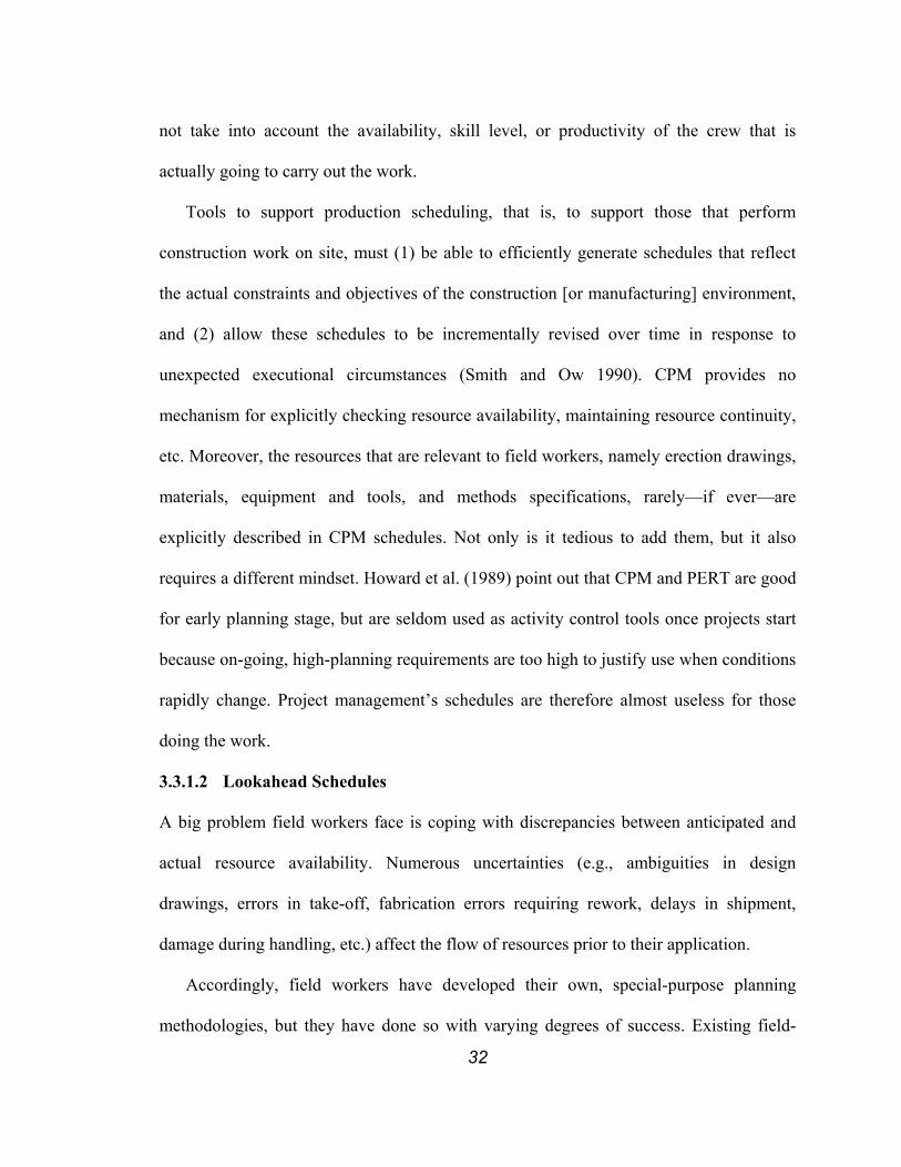
32
not take into account the availability, skill level, or productivity of the crew that is
actually going to carry out the work.
Tools to support production scheduling, that is, to support those that perform
construction work on site, must (1) be able to efficiently generate schedules that reflect
the actual constraints and objectives of the construction [or manufacturing] environment,
and (2) allow these schedules to be incrementally revised over time in response to
unexpected executional circumstances (Smith and Ow 1990). CPM provides no
mechanism for explicitly checking resource availability, maintaining resource continuity,
etc. Moreover, the resources that are relevant to field workers, namely erection drawings,
materials, equipment and tools, and methods specifications, rarely—if ever—are
explicitly described in CPM schedules. Not only is it tedious to add them, but it also
requires a different mindset. Howard et al. (1989) point out that CPM and PERT are good
for early planning stage, but are seldom used as activity control tools once projects start
because on-going, high-planning requirements are too high to justify use when conditions
rapidly change. Project management’s schedules are therefore almost useless for those
doing the work.
3.3.1.2 Lookahead Schedules
A big problem field workers face is coping with discrepancies between anticipated and
actual resource availability. Numerous uncertainties (e.g., ambiguities in design
drawings, errors in take-off, fabrication errors requiring rework, delays in shipment,
damage during handling, etc.) affect the flow of resources prior to their application.
Accordingly, field workers have developed their own, special-purpose planning
methodologies, but they have done so with varying degrees of success. Existing field-

33
level planning methodologies vary considerably from one construction superintendent or
foreman to the next. Figure 6 and Figure 7 are samples of two lookaheads that are used
on different building projects.
Figure 6. Sample of a Bar Chart-based Lookahead
The project engineer for the first project used master scheduling software to develop his
lookahead (Figure 6). He selected only the activities that started or finished within a
certain time frame, here a lookahead window spanning 6 weeks. In this case, the
lookahead is simply a dropout from the master schedule. The planner can choose to detail
the plan, as necessary, but would have to adhere to the representation of the CPM bar
chart.
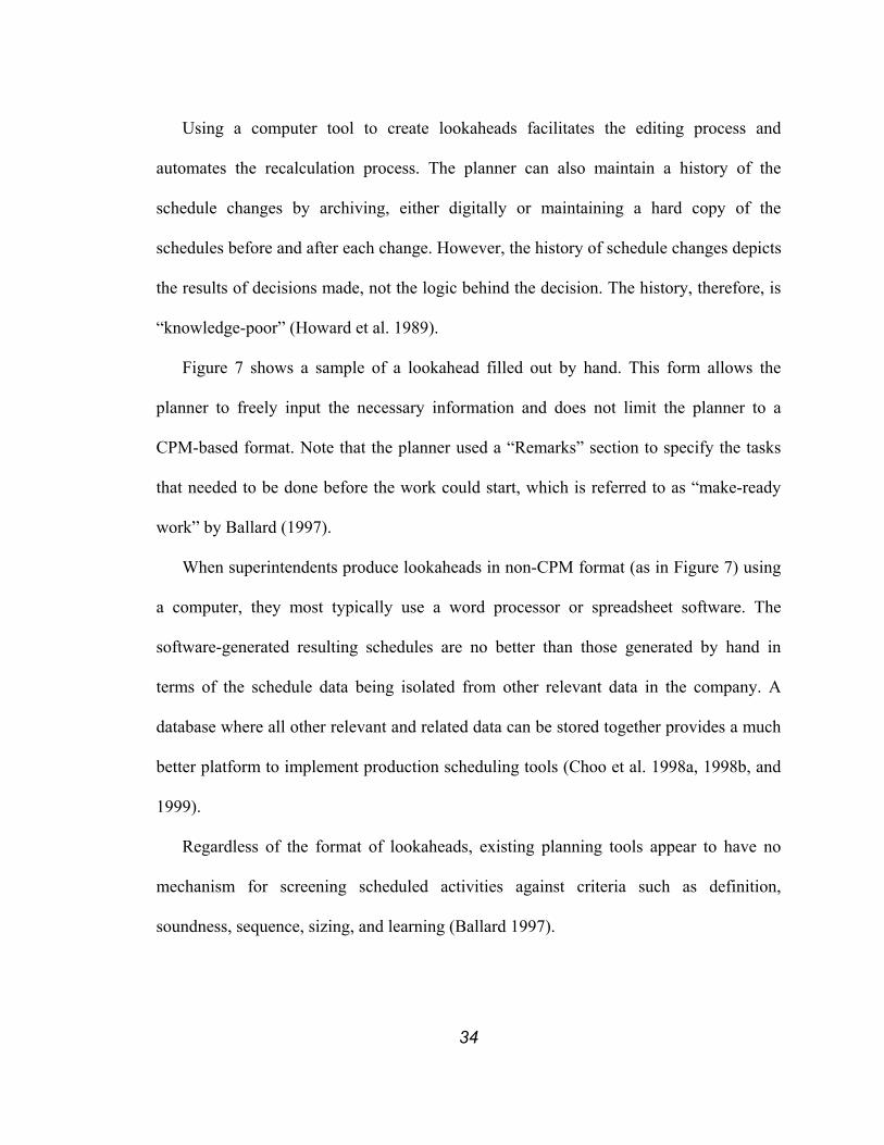
34
Using a computer tool to create lookaheads facilitates the editing process and
automates the recalculation process. The planner can also maintain a history of the
schedule changes by archiving, either digitally or maintaining a hard copy of the
schedules before and after each change. However, the history of schedule changes depicts
the results of decisions made, not the logic behind the decision. The history, therefore, is
“knowledge-poor” (Howard et al. 1989).
Figure 7 shows a sample of a lookahead filled out by hand. This form allows the
planner to freely input the necessary information and does not limit the planner to a
CPM-based format. Note that the planner used a “Remarks” section to specify the tasks
that needed to be done before the work could start, which is referred to as “make-ready
work” by Ballard (1997).
When superintendents produce lookaheads in non-CPM format (as in Figure 7) using
a computer, they most typically use a word processor or spreadsheet software. The
software-generated resulting schedules are no better than those generated by hand in
terms of the schedule data being isolated from other relevant data in the company. A
database where all other relevant and related data can be stored together provides a much
better platform to implement production scheduling tools (Choo et al. 1998a, 1998b, and
1999).
Regardless of the format of lookaheads, existing planning tools appear to have no
mechanism for screening scheduled activities against criteria such as definition,
soundness, sequence, sizing, and learning (Ballard 1997).

35
Figure 7. Sample of a Hand-drawn Lookahead
3.3.1.3 Weekly Work Plan
Weekly work plans are the most detailed plans2 developed by the foremen of specialty
contractors who will actually carry out the work. These specialty contractors can provide
knowledge regarding (1) development of creative solutions, (2) space needs associated
with construction processes, (3) fabrication and construction capabilities, and (4)
2 There may be more detailed plans in the form of methods of procedure, which are
presumably known to the members of the team that receive assignments via the
weekly work plan. Casten et al. (1995) recommended the use of first run studies to
develop these work methods or methods of procedure.
36
supplier’s lead-times and reliability (Gil et al. 2000). The information regarding
construction capability includes availability of labor, equipment, and tools. In terms of
labor, they know the skill level, productivity, and availability of each worker. This allows
the foremen to estimate the duration of each activity more realistically as compared to
durations developed for the master schedule, that had to be based on an assumed process
using a certain number of people with average skill level and productivity. Thus, the
quality of plans is better when the planning authority is pushed down (e.g., suggested by
Laufer (1992)).
However, as done for lookaheads, foremen usually develop weekly work plans using
forms filled out by hand, or spreadsheet or word processing software. Some foremen
create weekly work plans in their head and never formalize and share them with anyone
else, or –– if at all –– communicate them vaguely in meetings. The opportunity for
supervisors or management to receive feedback and learn is thereby lost. Ballard (2000a)
points out that coordination meeting times often are spent more on collecting data from
participants rather than on brainstorming to find creative solutions. Although weekly
work plans are a very important source for schedule development and control, they are
rarely included in a formal planning system. Crew supervisors usually discard paper-
based plans after they have served their purpose: crew supervisors use them as ‘crib
sheets’ to sequence work, assign work, and mobilize resources. Russell and Froese
(1997), thus, referred to them as “throw-away” schedules. Creating a weekly work plan to
determine the work to be done by one’s crew is important. It also is important to share
such plans with other participants for coordination purposes.

37
3.3.2 Last Planner System (LPS)
Lean production concepts support the development of a methodology for managing
construction planning, by emphasizing process efficiency and focusing on achieving
objectives (e.g., Faniran et al. 1997). The Last Planner System (LPS) refers to the process
of creating a master schedule, a lookahead, and a weekly work plan through front-end
planning, lookahead planning, and commitment planning, respectively, using Lean
Construction Planning techniques (Ballard and Howell 1994a). “Front-end planning” and
“lookahead planning” are terms that are also used in other planning systems. However,
“commitment planning” is a very different term. Weekly work planning is referred as
“commitment planning” because, at this stage, specific resource assignments need to be
made so that work can actually be performed.
Ballard and Howell (1994a, b) point out that the traditional construction management
approach is to define activities and schedule work to be done, prior to the start of
construction, in terms of what SHOULD be done. In this approach, resources simply are
assumed to be available when needed, so that SHOULD presumably is do-able and
guaranteed to result in DID. It is then up to production crews to gather what resources
they have on hand and to adhere to the schedule as well as they can. It is generally
expected that these production crews CAN DO the work regardless of the resource
availability.
The CAN-DO attitude has its root in the fact that the person or organization
responsible for producing the schedule does not have a clear understanding of the work to
be performed. Because they do not have the hands-on experience, they cannot clearly
define the full scope or assess the real nature of the work to be done, the methods to be
38
used, and the required capacity of the resources to be applied. Also, specific
circumstances of work execution are not predictable. Thus, the work cannot be planned in
far advance at the level of the detail that is required to optimally perform it and control
production. Therefore, the work force has traditionally been told what goals to
accomplish and it was left up to them to determine how to accomplish those goals (as
there are usually many ways to accomplish the same goal under the same time and
resource constraint), even though the means to achieve them may be beyond their control.
The reality is that the schedule reflects only anticipated resource availability, but actual
resource availability can differ substantially from it, so crews are bound to deviate from
that original schedule.
To alleviate this situation, Ballard and Howell (1994a, b) proposed the LPS, which
focuses on injecting reliability in planning by stabilizing workflow at the production level.
The main purpose of the LPS is to shield workers from the uncertainties they do not
control. They also propose that weekly work plans are effective when assignments3 meet
specific quality requirements for:
1. Definition: Are assignments specific enough so that the right type and amount
of materials can be collected, work can be coordinated with other trades, and
3 Assignment is defined as “a directive or order given to a worker or workers directly
producing or contributing to the production of design or construction.” (Lean
Construction Institute 1999)
39
it is possible to tell at the end of the week if the assignment has been
completed?
2. Soundness: Are all assignments workable? Are all materials on hand? Is
design complete? Is prerequisite work complete? Note that make-ready work
will remain for the foremen to do during the week, e.g., coordination with
trades working in the same area, movement of materials to the point of
installation, etc. Nonetheless, the intent is to do whatever can be done to get
the work ready before the week in which it is to be done.
3. Sequence: Are assignments selected form those that are sound in priority
order and in constructability order? Are additional, lower-priority assignments
identified as workable backlog, that is, are additional quality tasks available in
case assignments fail or productivity exceeds expectations?
4. Size: Are assignments sized to the productive capability of each crew or sub-
crew, while still being achievable within the plan period?
5. Learning: Are assignments that are not completed within the week tracked
and the reasons for deviation identified?
Having a plan meet the LPS quality criteria (Ballard 1997) does not guarantee that there
will be no plan failure at all. A plan could always fail upon execution. However, the
purpose of the LPS is to help minimize plan quality failures in order to avoid unnecessary
execution failures. Ballard and Howell therefore advocate that only assignments that meet
these quality criteria be put on a weekly work plan.
The LPS, which has started as a methodology for generating quality assignments in
weekly work planning, has been extended to the current form of LPS, which includes
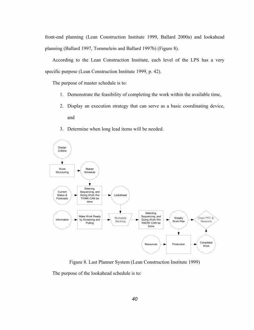
40
front-end planning (Lean Construction Institute 1999, Ballard 2000a) and lookahead
planning (Ballard 1997, Tommelein and Ballard 1997b) (Figure 8).
According to the Lean Construction Institute, each level of the LPS has a very
specific purpose (Lean Construction Institute 1999, p. 42).
The purpose of master schedule is to:
1. Demonstrate the feasibility of completing the work within the available time,
2. Display an execution strategy that can serve as a basic coordinating device,
and
3. Determine when long lead items will be needed.
WorkStructuring
DesignCriteria
Selecing,Sequencing, andSizing Work WeTHINK CAN be
done
MasterSchedule
CurrentStatus &Forecasts
Lookahead
Make Work Readyby Screening and
PullingInformation Weekly
Work PlanChart PPC &
ReasonsWorkableBacklog
Selecting,Sequencing, andSizing Work WeKNOW CAN be
Done
ProductionResources CompletedWork
Figure 8. Last Planner System (Lean Construction Institute 1999)
The purpose of the lookahead schedule is to:
41
1. Shape work flow in the best achievable sequence and rate for achieving
project objectives that are within the power of the organization at each point
in time,
2. Match labor and related resources to work flow,
3. Produce and maintain a backlog of assignments for each frontline supervisor
and crew, screened for design, materials, and completion of perquisite work at
the CPM level,
4. Group together work that is highly interdependent, so the work method can be
planned for the whole operation, and
5. Identify operations to be planned jointly by multiple trades.
The purpose of the weekly work plan is to:
1. Identify make ready actions and assessing their feasibility prior to making
assignments so as to shield production units from uncertainty.
2. Make best use of the production unit’s capacity and acknowledge individual’s
differences in light of the schedule loads.
Ballard and Howell also propose a new metric, PPC (Percent Plan Complete), for
gauging the reliability of the planning system. Unlike other project performance criteria
or variance analysis (e.g., earned value method) that measure whether the project is on
schedule (e.g., schedule index or schedule variance) or on budget (e.g., cost index or cost
variance), PPC measures whether the planning system is able to reliably anticipate what
will actually be done. Determining whether an assignment was completed or not
according to the plan is mandatory in calculating PPC, but elaborating on reasons for

42
failure to complete the work as planned is even more important. These learned reasons
will serve as valuable knowledge in elaboration of constraints in future planning efforts.
3.3.2.1 Front-end Planning
In the LPS, the master schedule is developed based on the design criteria using work
structuring (Figure 9). Work structuring is defined as “a process of breaking work into
pieces, where pieces will likely be different from one production unit to the next, so as to
promote flow and throughput” (Lean Construction Institute 1999, p. 54). These pieces are
termed “work chunks”, which are “the unit(s) of work that can be handed off from one
production unit to the next.” Work chunks may change as they move from one production
unit to the next (Ballard 1999b). The notion “breaking work into pieces” is consistent
with “grouping work” or “subdividing” as is done in the development of a WBS. The
main difference however is the goal of the breakdown. Currently, the contracts, the
history of the trades, and the traditions of the craft are the determining criteria for work
structuring practices (Tsao et al. 2000). In work structuring, a conscious effort is made to
structure the work to facilitate throughput with a goal to “make work flow more reliable
and quick while delivering value to the customer” (Ballard 2000b).
The relationships between work chunks are defined by deliverables, i.e., when, how
much, in which sequence, and what the other chunks need. These deliverables do not
conclusively determine sequencing, as relationships might be reciprocal. However, in the
current methodology, activities are linked by precedence relationship, which presumes
that as long as the sequencing of those activities is right, the output of the predecessor
will be compatible with the requirement of the successor. This is not necessarily the case.
For example, Tommelein (1997b) demonstrated the importance of timing and sequencing

43
of handoffs by simulating a given sequence of activities with different handoff scenarios,
i.e., pull vs. push.
HandoffRelationships
Project
Design Criteria 1
Design Criteria 2 Design Criteria 3
Figure 9. Work Structuring
However, as the definition of work structuring suggests, work structuring is not limited to
only developing master schedules, but it extends to developing operations and process
designs in alignment with product design, the structure of supply chains, the allocation of
resources, and the design-for-assembly efforts (Lean Construction Institute 2000).
3.3.2.2 Lookahead Planning
Ballard (2000c) defines “control” as “causing a desired future rather than identifying
variances between plan and actual.” In this regard, the LPS differs greatly from
traditional planning and control practices. In LPS, control consists of workflow control
and production unit control. Lookahead planning is mainly responsible for workflow
control whereas weekly work planning is mainly responsible for production unit control
(Ballard 2000b).

44
During lookahead planning, (1) explosion, (2) screening, and (3) make ready occur
(Ballard 1997). Explosion is detailing master schedule activities using the Activity
Definition Model (ADM)4 before they enter the lookahead window (Lean Construction
Institute 2000). Screening is “determining the status of tasks in the lookahead window
relative to their constraints, and choosing to advance or retard tasks based on their
constraint status and the probability of removing constraints (Lean Construction Institute
2000).
As the definition suggests, an important tool in screening is constraint analysis, which
consist of identifying constraints that prevent activities from starting and ending without
unplanned interruptions. For example, one constraint might pertain to procurement of
material. Having some unspecified amount of this material available to start work does
not automatically satisfy the constraint. The constraint is satisfied only when the crew has
the required, predetermined amount of material at hand to finish the predetermined
amount of work, or when it has a reliable schedule of material delivery to support
continuous installation.
4 Activity Definition Model (ADM) is “an input-process-output representation of
design tasks or construction processes. The model depicts the specification of
directives, prerequisites, and resources. It also shows an inspection process resulting
either to redo or release to the customer process. The model is used as a guide to
exploding scheduled tasks into a level of detail at which their readiness for execution
can be assessed and advanced.” (Lean Construction Institute 2000)
45
Constraint lists are not necessarily simple and single-tiered. Constraints can be multi-
tiered which means that a constraint can be exploded into multiple constraints which in
turn constrain other constraints and activities. The same logic can be extended to
constraints regarding equipment, labor, and information.
Make ready is (1) confirming lead-time, (2) pulling, and (3) expediting (Ballard
2000b). Lead-time is the duration of time required from order to delivery (Lean
Construction Institute 2000). Confirming lead-time allows the planner to determine
whether certain materials, equipment, labor, or information can be pulled. Pulling is
“instantiating the delivery of input based on the readiness of the process into which they
will enter for transformation into outputs” (Lean Construction Institute 2000). This is
counter to pushing, which is “releasing materials, information, or directives possibly
according to a plan but irrespectively of whether or not the downstream process is ready
to process them” (Lean Construction Institute 2000). It is a lean production ideal to pull
all input to site, just in time for installation. Advantages of pulling input to site are (1) it
eliminates the need to stock items on site and therefore alleviates site congestion, (2) it
minimizes the impacts of design change, (3) it minimizes misuse (material being used for
something that it was not intended for), vandalism, and wear and tear of material, (4) it
eliminates additional handling and supervision, and (5) it alleviates cash flow problem by
minimizing tied-up cost.
However, not all input can be pulled. In order to pull, the status of the consuming
activity at the time of delivery should be reliably estimable at the time of ordering. This
requires that the lead-time be reliably estimable as well. In other words, the order date
and consumption date should both appear within the lookahead window, i.e., the

46
lookahead window has to be larger than the lead-time. If the lookahead window is
smaller than the lead-time, the lookahead window has to be increased or the lead-time has
to be decreased in order to effectively pull (Lean Construction Institute 1998). If this
cannot be achieved, one has to resort to pushing.
One disadvantage of a push strategy is that pushed input usually ends up being piled
up until the consumption process consumes them. The inability to reliably estimate the
start date of a consumption process and its desired input sequencing is often a reason for
the pile up. However, one might deliberately allow for additional time and quantity when
pulling input in order to decouple consumption from procurement (Howell et al. 1993).
Additional time and quantity can be used as a buffer to minimize the effect of variation in
the duration of procurement, procurement sequencing, and productivity of the
consumption activity.
Tommelein and Ballard (1997b) discuss the application of screening and pulling on
lookahead planning and commitment planning. The difference between the advancement
of the lookahead window as traditionally viewed in CPM versus the LPS can best be
explained using an example. Figure 10 (a) shows a sample CPM schedule. Six activities
(hatched rectangles) and the precedence relationships between them (arrows) are shown.
Note that “activity F” does not have any precedence relationship with other activities.
Figure 10 (b) and (c) show the result of applying the traditional CPM vs. the LPS to
updating the schedule one week later, provided all work in week 1 was completed as
planned.

47
Last
Pla
nner
Week 1
Activity A
Activity B
Activity C
Week 2 Week 3
Activity D
Activity E
Week 2New Week 1
Activity A
Activity B
Activity C
Week 3New Week 2
Activity D
Activity E
Activity A
Activity B
Activity C
Week 4New Week 3
Activity D
Activity E
CPM
After one week
Activity DNot Ready
Activity F
Activity F
Activity F
(a)
(b)
(c)Week 2
New Week 1Week 3
New Week 2
Figure 10. Advancement of Lookahead Window
Now assume that site management is told that the material for “Activity D” won’t arrive
on site to meet the original schedule. Since CPM does not have any mechanism to
prevent an activity from advancing in the lookahead schedule, “Activity D” remains in its
scheduled position to be done in week 2 (new week 1). With the LPS, “Activity D”
cannot advance due to the screening mechanism. The question arises: When will it be
reasonably certain that the materials for activity D will be on site? Assume this to be in

48
week 3 (new week 2). Accordingly, “Activity D” is rescheduled to start then. This is a
very good and mandatory decision because “Activity D” will not be workable in the
second week due to lack of material, so it should not be scheduled for that week. There is
no use to pretending it will.
The decision to delay the start of “Activity D” may have created more problems than
what Figure 10 could describe. For instance, if the space freed up by the completion of
“Activity D” was to be used by “Activity F”, rescheduling of “Activity F” now also is
required. This schedule delay cannot readily be seen using a regular CPM schedule
because the (precedence) link that describes the space relationship is usually not
explicitly shown. Precedence relationships due to need of labor and equipment are not
readily shown in regular CPM schedules either.
3.3.2.3 Commitment Planning
Commitment planning in the LPS differs from the traditional weekly work planning in
that it explicitly recognizes uncertainties (as is done throughout the planning hierarchy)
and tries to shield (Ballard and Howell 1994a, b) construction crew from these
uncertainties that they do not control. It is also important to note that commitment plans
have to meet specific quality requirements as well, i.e., (1) definition, (2) soundness,
(3) sequence, (4) sizing, and (5) learning (Ballard and Howell 1997).
3.4 RELATIONSHIP BETWEEN PDCA CYCLE, CURRENT PLANNING SYSTEM, AND LAST
PLANNER SYSTEM
The Plan, Do, Check, Act (PDCA) Cycle (also called the Control Circle) is often used to
show continuous learning and improvement effort in a process. Although Deming (2000,
p. 88) named it The Shewhart cycle, it came to be known as The Deming Cycle. Each

49
step in the PDCA cycle can be related to each step of the current planning and control
system (middle circle in Figure 11) and to each step of the LPS (inner circle in Figure 11).
However, there are many differences between these planning systems. The goal,
approach and tools in “Plan” are very different for the two systems, as was explained in
earlier sections. The more important differences in terms of continuous improvement can
be seen in “Check” and “Act”.
Plan Do
CheckAct
CPM
PERT Const-ruction
Schedule Variance
Cost Variance
Recovery Schedule
Adhoc Work Plans
Work Structuring
Screening
Shielding
Const-ruction
Planning System
Performance
Root CauseAnalysis
Figure 11. Relationship between PDCA Cycle, Current Planning System, and Last
Planner System
The current planning system focuses on continuous learning and improvement of the
“project” whereas the LPS focuses on continuous learning and improvement of the
50
“planning system”. The current planning system “checks” how much the project is
deviating from its original target using schedule variance and cost variance and “acts” on
the project using a recovery schedule in an effort to bring the project to conform to its
original or re-determined target. “Check” and “act” are done every day, week, or month
depending on how often the project status data is collected and analyzed, thus, the notion
of cycle exists. This, arguably, supports “continuous learning and improvement of the
project”.
In contrast, the LPS “checks” how reliably Last Planners are able to plan their work
using PPC and “acts” on the root causes to prevent the same planning failure from
reoccurring. Frequency of “Checks” in LPS is the same as the frequency of planning. For
example, if the planning is done every week then “Check” is also carried out every week
and if planning is done every day then the “Check” is also carried out every day. “Act” in
LPS is a never-ending exercise as the LPS pursues “perfection”. By setting an almost
unachievable target, the LPS drives continuous learning and improvement. However, the
current planning system does not provide a target suited for continuous learning and
improvement but rather suited for recovery when necessary.
Another notable difference is in what is “learned.” The current planning system can
“teach” who delayed which activity, or whether the duration or the resource requirement
was over/under-estimated. Performance may be assessed using an earned value analysis.
Kim and Ballard (2000) explain how the current “check”, i.e., the earned value analysis,
might be a hindrance to planning to promote flow. This “learning” can either be useful or
useless depending on the characteristics of the future activities and projects. However, the

51
LPS improves the performance of the planning system, which will benefit all future
activities and projects; thus truly promoting continuous learning and improvement.
3.5 PLAN RELIABILITY
Dealing with uncertainty has always been and will remain a major issue for the
construction industry. The first step toward minimizing the effect of uncertainty is to
acknowledge its existence and explicitly represent it. A planner would be able to plan
work and possibly minimize the effect of uncertainty if at least a representation of
uncertainty were easy to create and understand.
Many types of uncertainty exist throughout the life cycle of a project, that is, from the
conceptual phase of the project to the handoff to the owner for commissioning. Many of
these uncertainties bring about changes to the schedule. Uncertainties in project scope
and design changes may increase or decrease work shown in the original schedule.
Planners can represent these changes as an addition/deletion of one or several activities,
increased/decreased duration of one or several activities, or changes in the dependencies.
Uncertainties involving resources (availability of material, space, and information and
variability in productivity of labor and equipment) can also influence the schedule.
Uncontrollable factors such as weather can also force the schedule to change.
Planners can employ two different approaches to minimize the effect of uncertainty.
One approach is to minimize the effect of uncertainty by identifying the causes of the
uncertainty and eliminating these causes as much as possible. Another approach is to
explicitly represent uncertainty using a probabilistic distribution, thereby planning
uncertainty into the plan and setting completion dates according to an acceptable level of
likelihood or confidence.
52
The LPS, developed to improve the reliability of the planning system uses the first
approach. The LPS as explained earlier is not a tool to explicitly represent uncertainty but
a tool to shield the production units from it thereby reducing to build time and resource
buffers into the schedule. The Project Evaluation and Review Technique (PERT)
(Malcolm et al. 1959) developed by the United States Department of Navy, is a method
that uses the second approach. It allows planners to explicitly represent uncertainty by
assigning probabilistic distributions to activity durations. It, then, allows planners to
associate a probability with a completion date. In the PERT methodology, all uncertainty
regardless of its cause(s) translates into duration variability of the affected activity. This
approach is not very popular in construction although its graphical representation is
widely used. One impediment to wide acceptance is that it is hard to assign a probabilistic
distribution to each project activity. Another impediment is that it is hard to describe
variability due to uncertainty in a text/graphical format that is easy for planners to
understand.
The Critical Chain Planning Method (CCPM) (Goldratt 1997) is a complementary
planning method to PERT in that it also uses the second approach. Strategically placed
time and resource buffers at merging points of an activity network prevent local variation
from affecting the whole network.
3.5.1 Automated Simulation of CPM Schedules using Stroboscope
Choo and Tommelein (unpublished 1998) created a graphical representation to depict
uncertainty in start/finish time and duration. As done in PERT, the duration distribution
of an activity represents all uncertainties that can increase or decrease the duration of an
activity. This research employed the Monte Carlo simulation tool, Stroboscope (Martinez
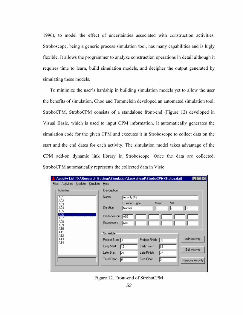
53
1996), to model the effect of uncertainties associated with construction activities.
Stroboscope, being a generic process simulation tool, has many capabilities and is higly
flexible. It allows the programmer to analyze construction operations in detail although it
requires time to learn, build simulation models, and decipher the output generated by
simulating these models.
To minimize the user’s hardship in building simulation models yet to allow the user
the benefits of simulation, Choo and Tommelein developed an automated simulation tool,
StroboCPM. StroboCPM consists of a standalone front-end (Figure 12) developed in
Visual Basic, which is used to input CPM information. It automatically generates the
simulation code for the given CPM and executes it in Stroboscope to collect data on the
start and the end dates for each activity. The simulation model takes advantage of the
CPM add-on dynamic link library in Stroboscope. Once the data are collected,
StroboCPM automatically represents the collected data in Visio.
Figure 12. Front-end of StroboCPM

54
A year after the author developed StroboCPM, the author learned that Martinez had
developed Stroboscope Prbschd (Martinez 1998), a program similar to StroboCPM,
which automatically generates a CPM bar chart from the collected data.
StroboCPM, like any other CPM tool, requires as input the list of activities including
their duration and the precedence relationships among them. In StroboCPM, however, the
planner can specify durations by means of a deterministic, normal, or PERT distribution
(specified in the CPM add-on dynamic link library). The program, then, automatically
develops Stroboscope source code and executes the simulation. The planner can review
or adjust the generated source code file if required. After simulation, the program saves
the output for review and represents the data by a simple graph. Figure 13 illustrates a
sample CPM schedule and Figure 14 shows the sample’s simulation result. Each activity
as shown in Figure 13 is represented by means of five arrows in Figure 14.
A1Pert[5,10,20]
A2Pert[3,7,10]
A3Pert[3,5,10]
A4D[1]
B1D[25]
Figure 13. Sample CPM Schedule
The tail of the first arrow represents the mean value of the start date less twice the
standard deviation of the start date. The head of the first arrow represents the mean value
of the end date less twice the standard deviation of the end date. Similarly, the tail and
head of the second arrow represent the mean less the standard deviation of the start and
end date. The tail and head of the third arrow represent the mean of the start and end date.
The tail and head of the fourth arrow represent the mean plus the standard deviation of

55
the start and end date. The tail and head of the fifth arrow represent the mean plus twice
the standard deviation of the start and end date. The slope of the line connecting the
arrows’ tails (or heads) represents the degree of uncertainty in start (or finish) of an
activity. The steeper the slope is, the smaller the uncertainty is.
101 2 3 4 5 6 7 8 9 2011 12 13 14 15 16 17 18 19 3021 22 23 24 25 26 27 28 29
A1
A2
A3
A4
B1
31
Working Days
Mean(ES) - 2 * SD(ES)Mean(ES) - SD(ES)
Mean(ES)Mean(ES) + SD(ES)
Mean(ES) + 2 * SD(ES)
Mean(EF) - 2 * SD(EF)Mean(EF) - SD(EF)
Mean(EF)Mean(EF) + SD(EF)
Mean(EF) + 2 * SD(EF) Figure 14. Sample StroboCPM Chart
Using this graph, a planner can associate probabilities with dates. For instance, the
planner is able to set up a milestone based on the anticipated chance of meeting it. In a
deterministic schedule, assuming the durations of activities are averages of normal
distributions, meeting a milestone date set on a finish date of an activity has 50% or less
chance. If the planner wants to increase the chance of meeting the milestone date, a
deterministic schedule does not provide any guidance. The StroboCPM chart shown in
Figure 14 can guide the planner to set the milestone date with a desired probability of
meeting it.
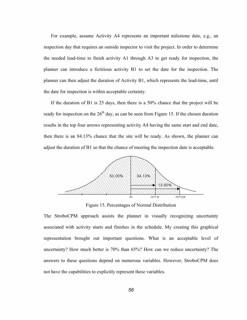
56
For example, assume Activity A4 represents an important milestone date, e.g., an
inspection day that requires an outside inspector to visit the project. In order to determine
the needed lead-time to finish activity A1 through A3 to get ready for inspection, the
planner can introduce a fictitious activity B1 to set the date for the inspection. The
planner can then adjust the duration of Activity B1, which represents the lead-time, until
the date for inspection is within acceptable certainty.
If the duration of B1 is 25 days, then there is a 50% chance that the project will be
ready for inspection on the 26th day, as can be seen from Figure 15. If the chosen duration
results in the top four arrows representing activity A4 having the same start and end date,
then there is an 84.13% chance that the site will be ready. As shown, the planner can
adjust the duration of B1 so that the chance of meeting the inspection date is acceptable.
m m+ σ m+2σ
50.00% 34.13%
13.60%
Figure 15. Percentages of Normal Distribution
The StroboCPM approach assists the planner in visually recognizing uncertainty
associated with activity starts and finishes in the schedule. My creating this graphical
representation brought out important questions. What is an acceptable level of
uncertainty? How much better is 70% than 65%? How can we reduce uncertainty? The
answers to these questions depend on numerous variables. However, StroboCPM does
not have the capabilities to explicitly represent these variables.
57
As StroboCPM adopts the CPM representation of a project, limitations of this
representation are also inherent in StroboCPM. For example, it assumes that the start/end
dates and duration of an activity represent all governing uncertainties of an activity
regardless of their sources. My research, therefore, shifted to a schedule with shorter time
span and more definition.
3.5.2 Planning Performance Criteria
In the construction industry, the term “reliable planning” is a relatively new one. Kaplan
and Norton (1992) point out that the existing project performance measurements are
based on financial measures. Kartam et al. (1995) point out that available models and
performance criteria are insufficient for analyzing and improving the performance of a
construction planning system. They also add that many project managers use project
performance criteria to control and punish poor performers rather than to improve project
performance. Lantelme and Formoso (2000) assert that managers regard measurement
only as a tool for controlling project participants’ behaviors and that it should be used to
communicate goals, share responsibilities, and promote learning in organization.
Therefore, in order to promote reliable planning, adequate measurements are necessary.
Kartam et al. proposed an alternative approach that uses a system model (workmap
(Ballard 1994)) and process models (interaction process model, and communication
process model). This approach also uses the responsibility matrix to show the participants
involved in the communication process model. The workmap depicts inputs, outputs,
directives, and feedback loops of a process and interactions with other processes. The
interaction process model and communication process model distinguish value adding
from non-value adding processes.

58
This approach adopts the LPCS system to weekly work planning in order to measure
and improve planning system reliability. They categorized the Percentage Assignments
Missed (PAM), which is equal to 100%-PAC (Percentage Assignments Completed), into
Percentage Assignments Execution Failure (PAEF) and Percentage Assignments
Selection Failure (PASF). PAC, PAEF, and PASF are termed PPC, Execution Failure,
and Plan Failure by Ballard (1994b), respectively. They also developed criteria for
evaluating the performance of the LPS. These criteria are listed in Table 2.
Table 2. Measurements Proposed by Kartam et al. (1995)
Production managers can use these measurements to gauge the status quo of their
planning system. However, these measurements do not gauge how sensitive each
schedule is to the manifestation of uncertainty. Too sensitive a schedule can very easily
become obsolete when it faces even the smallest uncertainty. The planner then has to
adjust the schedule to reflect changes brought by the uncertainties. The more sensitive the
schedule is, the more often the planner has to reschedule. Thus, one desirable

59
characteristic for a schedule is that it would be able to absorb a certain level of
uncertainty without bringing failure to the whole schedule. The term “robustness”
denotes this characteristic.
3.5.3 Robustness
As explained in earlier chapters, scheduling is an on-going effort. This effort consists of
two complementary scheduling approaches, i.e., predictive and reactive scheduling.
Predictive scheduling is “the task of finding a legal sequence and assigning start times to
operations before the actual production takes place” (REFRESH 2001). Reactive
scheduling is “the problem of updating schedules in the most effective way when the
constraints or assumptions on which they are based are changed or invalidated” (Aigner
et al. 2000).
One means to increase the robustness of a schedule is to have contingency plans that
can be followed without disturbing the whole project. In the LPS, workable backlogs are
used to increase the robustness of the weekly work plans. By having workable backlog,
the production units can create a “reactive schedule” by selecting one of the
“interchangeable” assignments when one of the assignments in a “predictive schedule”
cannot be executed. If the substituted work is truly “interchangeable”, then the failed
assignment can be executed when it is possible to do so without causing a major change
to the project schedule. Major changes occur when a disturbance in a weekly work plan is
passed up to the project schedule. Girsch (2000) points out that attempts to specify
production in too much detail can result in a schedule that is too nervous, which in turn
increases the reactive scheduling effort. Therefore, as pointed out earlier, a master
schedule needs to stay at a high level of abstraction to build robustness into the plan as
60
well as to promote the creativity and empowerment of the participants that are going to
carry out the work.
Another means to increase robustness is to build capacity and time buffers into the
schedule. Queuing theory, reiterated in the context of construction planning by Ballard
(1999a) suggests that the production units should be loaded less than 100% of their
capacity. They should have a capacity buffer, when developing detailed production plans,
i.e., weekly work plans, in order to promote work flow reliability. By having a capacity
buffer, the production units are able to recover from unforeseen uncertainties so that the
effects of these uncertainties do not carry over to the following weeks. CCPM, explained
earlier in Section 3.4, is one method that consciously builds time and resource buffers
into the plan.
3.6 CONSTRUCTION COORDINATION
3.6.1 Coordination vs. Scheduling
The successful delivery of a project does not only depend on a single contractor’s ability
to deliver but also on the whole project team’s ability to deliver. Currently most of the
coordination decisions are made during general coordination meetings. These meetings
are usually carried out once or twice each week and last from one to three hours. The
frequency and duration of these meeting depend on the level of complexity and urgency.
They are led by either a project engineer or a superintendent. During the meetings the
work to be carried out until the next meeting is discussed including milestones to be met,
special permitting issues, site logistics, and clarification of directions from other project
participants. However, not all issues are dealt with during the meeting, especially those
that relate to only one or a few specialty contractor(s). Trying to solve these issues during

61
the general coordination meeting will lengthen the meeting and would not be an effective
use of other contractors’ time.
Figure 16. Importance of coordination. (Wall Street Journal)
Used with permission from The Wall Street Journal, WSJ.com. Copyright 1998.
Dow Jones & Company, Inc. All rights reserved.
The complexity of production work can be categorized into complexity caused by
(1) technicality of the production work itself and (2) necessity for multiple trades to work
at the same time. Most of the general coordination is focused on issues related to the
second category, on simultaneity, while the dedicated coordination meeting is focused on
the issues belonging to the first category, on technicality. As more activities are carried
out simultaneously, the complexity due to simultaneity increases exponentially. The
coordination problem arises when one or more activities need the same resource,
especially labor, equipment, or space, at the same time, or when these activities are
performed out of sequence preventing or making it difficult for any successive activity to
62
be carried out. Simultaneity also poses the problem of balancing work flow and
appropriate spacing between trades. In order to provide a solution to this problem, the list
of activities to be carried out as well as the required and available resources for these
activities must be specified. The coordinator can make a general assumption to develop a
preliminary long-term plan. However, in developing an actual execution schedule, input
from each contractor regarding their preferred way of carrying out their portion of work
is mandatory. As each subcontractor is making an effort to minimize their own duration
as well as cost (which is rarely captured in a CPM-based master schedule), they will try
to create as many critical paths for their own crew as possible (Birrell 1980). They will
load their resources according to their own schedules as long as it does not violate the
contractual arrangement and milestone date set by the prime contractor. The coordinated
execution schedule must therefore account for each contractor’s schedule and preferences,
and take priority into consideration. As these schedules become building blocks for the
coordination schedule, they must be able to represent the actual work that can be carried
out (as proposed by the LPS) rather than work “wished” to be carried out. This is
especially important when successive trade(s) depend on predecessor trades to provide
output of the production work or release resources (labor, equipment, and space), which
usually is the case in a construction environment. The predecessor therefore must be able
to provide an accurate depiction of what and how much of it can be released to successors.
Tommelein (1997b, 1998) describes the effect of dependency and variability in terms
of what is released to successive trades and Tommelein et al. (1998) describe the effects
in terms of quantity released by simulating the “Dice Game” using discrete event
simulation with Stroboscope (Martinez 1996). Tommelein et al. coined the term “Parade
63
of Trades” from Gus Sestrup, a superintendent with Turner Construction, to represent
construction environments where multiple trades follow each other in a linear sequence
and work output by one trade is handed off to the next trade. Choo and Tommelein
(1999a) have created the “Parade of Trades” computer software to allow users to simulate
the “Dice Game.” Alarcon and Ashley (1999) used @Risk (1997) to simulate a slightly
modified Dice Game and analyzed the impact of variability on project cost and schedule.
As can be seen from the results of these different studies and implementations, it is
important for each schedule to contain reliable and explicit information regarding
resource assignments, specifying who or what will be used, and when and where each
activity will take place and occupy other supporting space. Since each contractor
develops its own work schedule based on the work content and productivity as well as
availability of crew and equipment, it is impossible for one planner to develop a detailed,
reliable schedule. An old saying, “the chain is only as strong as its weakest link,” best
explains the importance of each input schedule having to be reliable. Only when input
schedules are sound, can they be collected and compared to anticipate conflicts and
developed into an overall sound schedule. The coordinated schedule can be reliable only
if the individual schedules provided by all participants are reliable and well defined.
While schedules provide one means to show where coordination has to take place
(which work will be carried out simultaneously and where) one might argue that the
problem of simultaneity is not best solved through scheduling at all, but rather through
some type of mutual adjustment mechanism as advocated by Mintzberg (1973). A time
dated sequence of activities is needed less than a common plan of action (who goes first,
handoff criteria, etc.), rules for use of shared resources (e.g., the crane will be tied up for
64
placing concrete every morning, and it can load specialty contractor materials in the
afternoon), plus constant coordination and adjustment (A slows down to let B get a little
further ahead, D sends some people back to help C catch up, etc., as is needed when
partners are dancing). Coordination becomes more like how a single crew works together
with others, with each knowing what needs to be done and doing it. The requirements for
mutual adjustment are not captured in schedules, which pretend that work is sequential
and non-interfering, and that team boundaries are impermeable.
3.6.2 Space Coordination
Based on past research and the lack of available commercial tools, it can be inferred that
the management of space as compared to the management of other resources, i.e., labor,
material, equipment, time, money, is currently least well defined and supported in
construction. Nevertheless, a considerable amount of research has been done on space
allocation and scheduling. In industrial engineering, there are mainly two approaches, i.e.,
optimization algorithms and heuristic algorithms, for designing a facility layout (Heragu
1997). The heuristic algorithms can be further divided into construction algorithms,
improvement algorithms, and hybrid algorithms. The same categorization applies to
construction layout planning.
Artificial intelligence that mimics the site layout planning process performed by
human engineers has also been applied to layout planning and space scheduling
(Tommelein 1998, Tommelein et al. 1991, Tommelein et al. 1992a). Space scheduling
focuses on “the problem of allocating space to resources governed by a construction
schedule, and conversely, changing the schedule when space availability is inadequate”
65
(Tommelein and Zouein 1993). Another approach is heuristic-based optimization (Zouein
and Tommelein 1994, Zouein 1995).
Yeh (1995) formulated a construction site layout problem as a linear programming
problem and applied the simulated annealing technique to solve it, with as objective to
minimize the total cost of the layout, based on the user’s assessment of value of
individual locations.
Cheng and O’Connor (1996) developed a system called ArcSite that uses a travel
frequency matrix and an attract/repel relationship matrix in locating temporary facilities.
ArcSite uses a constructive placement procedure in generating a layout, placing one
temporary facility at a time. Travel frequency ratings were categorized as “very
frequently” (5+/day), “frequently” (3-4/day), “regularly” (1-2/day), “infrequently” (3-
4/week), “occasionally” (1-2/week), and “never” (0). The attractive relationship rating
ranged from -3 (strongest) to 0 (weakest). The site location for each facility was
determined by the solution that minimizes an objective function that incorporated the
travel frequency rating and attractive relationship rating.
Special-purpose layout planning tools have also been developed. Bohinsky and Fails
(1991) developed the Computer Aided Rigging (C.A.R.) system, which aids the rigging
superintendent in selection of crane equipment by simulating the rigging process.
Williams and Bennett (1996) describe the Automated Lift Planning System (ALPS)
developed to assist in the crane selection process. ALPS assist the user in selecting a
crane best suitable for the given lift situation from a library of cranes by considering the
capabilities of each crane. Lin and Haas (1996) developed an interactive critical
operations planning environment (COPE). COPE assists in planning construction
66
operations involving large semi-stationary equipment by considering the capabilities of
the equipment as a criterion for selection of the location. COPE integrated three software
components: (1) a CAD platform (MicroStation), (2) a database management system
(Oracle), and (3) a programming language (MDL).
Tommelein (1999) used the Stroboscope (Martinez 1996) discrete event simulation
system to evaluate the location and sizing of support facilities on a construction site.
Whereas traditional methods relied on heuristic methods and average values to determine
the support facilities, Tommelein modeled the variability in travel times using simulation.
The main purpose of these tools has been to support the planning process and
decision-making ability of a site engineer. Although most of these tools allowed a user to
modify the solution provided, the main focus of control resided with the computer.
SightView (Tommelein et al. 1991) and MovePlan (Tommelein and Zouein 1993)
actually brought the focus of control to the planner. SightView, which is the interactive
display system for SightPlan (Tommelein et al. 1987), allows the user to limit possible
positions of an object. This information is then input to SightPlan to propagate constraints
and regenerate the site layout. MovePlan tied layout planning to CPM scheduling. The
user of MovePlan is responsible for selecting layout time frames, generating alternatives,
and picking candidate solutions whereas the computer provides the calculation, solution
graphical and temporal representation and modeling capabilities. Simulation tools that
link a 3-D CAD model with a CPM schedule, i.e., 4-D CAD (McKinney et al. 1996) and
4D-Planner (Williams 1996) have been developed to validate the constructability of
construction schedules prior to construction.

67
Thabet (1992) applied the technique of blocking out rooms in a building for the
exclusive use of a trade to solve the space scheduling problem. Tommelein et al. (1993)
looked at the schedule implications of space conflicts. Akinci et al. (1998) created a
framework for predicting the behaviors of space-interfering activities and their schedule
impact given these time-space conflicts once the space-interference is detected. The same
methodology will be applied to the site layout tool developed in this research.
3.7 EXISTING TECHNOLOGY
Before the movement toward on-line integration and collaboration, the construction
industry has been working mostly with dedicated computer tools. Each of these tools
supported one or several functions needed to successfully carry out a project, e.g.,
estimating, drawing, scheduling, cost management, communication, etc. Howard et al.
(1989) reported that these tools exacerbated the fragmentation in planning, financing,
designing, constructing, and managing projects. They also reported that project
management tools were “knowledge-poor” because they store the decisions not the
decision making processes.
3.7.1 Internet-based Tools
With the advancement of communication technology especially the proliferation of the
Internet, many companies provide integrated on-line tools to assist with collaboration on
construction projects, e.g. ProjectNet (Citadon 2001), Team Builder (E-Builder 2001),
ProjectPoint (Buzzsaw 2001), Constructw@re (Constructware 2001), ProjectTalk
(Meridian Project Systems 2001), Buildpoint (Buildpoint 2001), Project|Center (Bricsnet
2001), etc. Most of these tools, listed above, provide similar functions, that is to support

68
document distribution and tracking. These documents can either be text files, pictures, or
drawings.
Many traditional standalone tools also were extended to have on-line capabilities,
e.g., Primavera Project Planner (Primavera 2001), Microsoft Project 2000 (Microsoft
Corporation 2000c), Prolog Website (Meridian Project Systems 2001), etc. So far, no one
clear standard-setting winner exists. Rose (2001) points out that traditional companies
may have an advantage over newcomers as they understand the needs of the customer
better and have proven technology. O’Brien (2000a) points out that the current generation
of websites is not designed to fully support the daily activity of the users. They are
mainly based on the concept that sharing information is beneficial and that the current
existing technology allows this data to be centrally maintained.
3.7.2 Information Exchange
Current on-line collaboration tools allow for real-time sharing of project related
information between different participants. By managing project-related information at a
single source, these tools alleviate the problem of information exchange between
different programs and platform. However, project participants still rely on many
standalone tools to carry out un-integrated project management functions. Scheduling is
one of these un-integrated functions. Most of the on-line tools allow project participants
to share schedule information by attaching the schedule data file to an email or the tool’s
internal message system as an attachment or by posting a static snap-shop of the schedule.
However, these tools do not provide an explicit means to support distributed planning,
i.e., creation of a coordinated schedule through collaboration of multiple participants at
69
multiple level of project hierarchy, because the schedule information is communicated
only in one direction.
Using a one-directional communication system, a central planner (coordinator) must
update the schedule with coordinated information after viewing or receiving schedules
from each participant. The coordinator must figure out which schedules result in conflicts
and then notify the corresponding participants to figure out ways to overcome these
conflicts without creating new conflicts with other participants’ schedules. Once all
conflicts have been detected and dealt with, the coordinator needs to update the original
schedule. Since the coordinator is responsible for making sure that the latest information
is made available to others, all participants are not guaranteed the latest information.
The schedules can be collected and compared automatically if communication takes
place in both directions. A participant’s schedule can automatically be incorporated into
the latest updated schedule and if a conflict is detected, it can automatically notify the
participant. In distributed planning, each participant is guaranteed the latest information
and consistency among the participants because everyone is working from a single source
of information.
A few scheduling-dedicated tools allow project participants to collaboratively create
project schedules. For example, Microsoft Project Central (Microsoft 2000c), which
extends the capabilities of a standalone Microsoft Project (Microsoft 2000c), allows
multiple project participants to collaboratively create a project schedule. However, it
remains to be seen how a tool based on a project-centric view, such as in Microsoft
Project Central, will be integrated into daily management of each project participant.

70
Currently, the construction industry uses many different scheduling tools. It is
common for project participants on a single project to use different tools, which vary
from scheduling-dedicated tools to generic spreadsheets. Therefore, it is critical for the
exchange of scheduling data to be flawless. Although many of these tools currently
support data exchange through import/export functions, not all the data can be yet
transported from one tool to another because all tools are based on proprietary formats.
These formats have different ways, e.g., of representing resource assignment, critical
information about resource assignments, which increases the likelihood of information
loss when schedule data is transferred from one tool to the next.
On some projects, the owner chooses a commercial scheduling tool and imposes its
use on all participants of the project. However, this does not necessarily guarantee a
smooth exchange of information because a contractor might be using some other tool to
support its internal planning effort while using the selected tool only for reporting
purposes. The simultaneous use of two or more tools for related purposes will invariably
lead to data being captured in one but not in the other. This makes it more difficult to
achieve the original purpose of making realistic information available to others.
Lack of standards is a key barrier to effective information exchange and perpetuates
the fragmentation of the construction industry (e.g., Arnold and Teicholz 1996). Efforts
are under way to develop standards for information technologies in the construction
industry. Examples of such efforts are STEP (Standard for the Exchange of Product
Model Data, ISO Standard 10303, Product Data Representation and Exchange) by ISO
(International Organization for Standardization) (see Froese 1996), EDI (Electronic Data
Interchange) standards by the United Nations EDIFACT organization (United Nations

71
Electronic Data Interchange for Administration, Commerce and Transport
(UN/EDIFACT) 2003), CALS (Continuous Acquisition and Life Cycle Support) by the
US Office of the Secretary of Defense (Naval Surface Warfare Center 2003), and IFC
(Industry Foundation Classes) by IAI (International Alliance for Interoperability)
(International Alliance for Interoperability 2000).
The U. S. Army Corps of Engineers has created a standard for exchanging scheduling
data: Standard Data Exchange Format (SDEF) for Project Scheduling (East and Kim
1993, U. S. Army Corps of Engineers 1996). This standard is, again, to support master
schedules only and there is no information on resource allocation. Additional data fields
are needed to convey material, labor, equipment and space allocation. Also, standards for
lookaheads and weekly work plans remain to be developed so that the information they
contain can be exchanged without losing data in the process.
Research also has been conducted on developing information classification systems
and automating communications. Luiten and Tolman (1997) automated communication
for constructability checking using a STEP model. Kang and Paulson (1998) proposed a
construction information classification system (CICS) to promote consistency of
representation in all phases of a construction project. By dividing the construction project
into four facets: facilities facet, spaces facet, element facet, and operations facet, they
provided a classification scheme that can be used for both cost estimating and network
scheduling.
3.8 OTHER AREAS OF RESEARCH IN DISTRIBUTED PLANNING AND COORDINATION
Although distributed planning and coordination is a fairly new concept, it has been
implemented in tools that are currently being used in many areas. Most of these tools
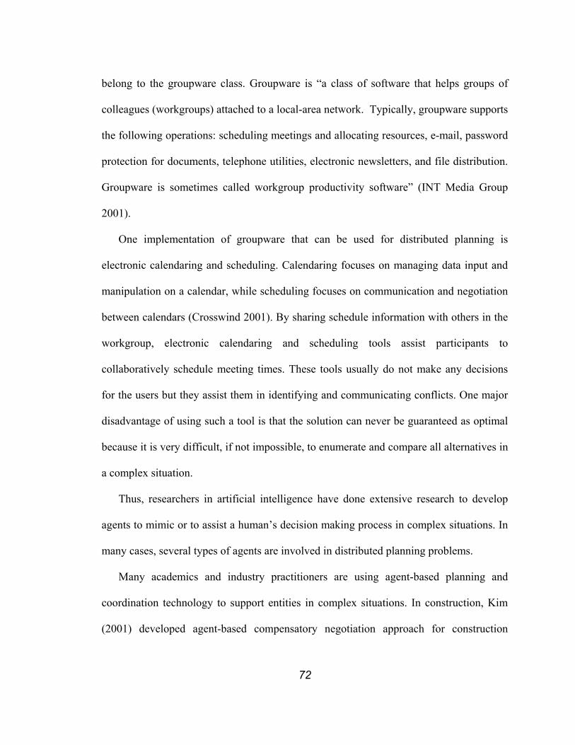
72
belong to the groupware class. Groupware is “a class of software that helps groups of
colleagues (workgroups) attached to a local-area network. Typically, groupware supports
the following operations: scheduling meetings and allocating resources, e-mail, password
protection for documents, telephone utilities, electronic newsletters, and file distribution.
Groupware is sometimes called workgroup productivity software” (INT Media Group
2001).
One implementation of groupware that can be used for distributed planning is
electronic calendaring and scheduling. Calendaring focuses on managing data input and
manipulation on a calendar, while scheduling focuses on communication and negotiation
between calendars (Crosswind 2001). By sharing schedule information with others in the
workgroup, electronic calendaring and scheduling tools assist participants to
collaboratively schedule meeting times. These tools usually do not make any decisions
for the users but they assist them in identifying and communicating conflicts. One major
disadvantage of using such a tool is that the solution can never be guaranteed as optimal
because it is very difficult, if not impossible, to enumerate and compare all alternatives in
a complex situation.
Thus, researchers in artificial intelligence have done extensive research to develop
agents to mimic or to assist a human’s decision making process in complex situations. In
many cases, several types of agents are involved in distributed planning problems.
Many academics and industry practitioners are using agent-based planning and
coordination technology to support entities in complex situations. In construction, Kim
(2001) developed agent-based compensatory negotiation approach for construction
73
projects in order to assist project participants in choosing the schedule alternatives that
minimize cost.
A distributed planning system using artificial intelligence has also been implemented
in battlefield simulations. Baxter and Hepplewhite (2000) depict a hierarchical distributed
planning framework to coordinate movement of tanks and troops. The scenario they
describe bears much resemblance to construction projects. Resemblances are:
1. Hierarchy of planning: multiple levels of planning and corresponding planning
horizons exist.
2. Short life of plans: No one can create a plan at the start of a campaign (war or a
project) and expect it to be valid throughout the campaign.
3. Self-managing resource: No matter how well the plans are laid out, soldiers on
battlefields or project participants can make decisions with no regard to existing
plans, thereby making these plans obsolete (Hughes et al. 1995).
A major difference is the level of command and control imposed on the lower level
participants and plans. In a battlefield, disregarding command is viewed as act of
disobedience and is treated with heavy penalty. It is, thus, less likely to have self-
management that results in obsolescence of plans in a battlefield. Despite this difference,
learning can be shared.
Large geographically distributed organizations also have been developing distributed
planning systems to support their own projects. Johnson Space Center and Lockheed-
Martin, for example, have been developing a distributed planning system for the
International Space Station (ISS) (Hagopian et al. 1994, Maxwell 2002). Maxwell (2002)
points out that a major lesson learned from his experience is to involve as many
74
stakeholders in design of the system early on and expect change. This is very consistent
with the author’s experience in developing a distributed planning and coordination
system. Backes et al. (2000) have developed an Internet-based task sequencing system to
coordinate the daily operational request of the Mars Polar Lander (MPL).
Zelewski and Siedentopf (1999) advocate that multiagent system research be a multi-
disciplinary research effort that combines the fields of “distributed artificial intelligence”
and “coordination science.” Closer observation into past and on-going research reveals
that two different coordination scenarios of distributed planning mainly exist. First is the
coordination of interactions or movements of multiple objects, usually people or
equipment, where a user or group of users has dedicated and/or shared control over one
or more of these objects. Second is coordination of actions for movements of a single
object, usually equipment, where a number of users have shared control over this object.
This dissertation discusses the first scenario where the goal is to co-create a plan of action
for multiple crews who have shared resources, such as special personnel (e.g., inspectors,
managers, administration staff), space (e.g., laydown area, work area, access path, etc.),
and equipment (e.g., cranes, elevators, scissor lifts).
3.9 CONCLUSION
Fragmentation between project planning and production planning in current construction
management practice impedes reliable execution of construction work. As a project gets
more complex, dynamic, and fast, it is virtually impossible for a single entity to detail out
the schedule for the total project and the schedule to remain valid for a majority of the
project duration. Project schedules become invalid as soon as unforeseen conditions are
encountered. Unforeseen conditions, by definition, refer to conditions that the planner did

75
not account for at the time of schedule construction. The severity of the effect on the
schedule varies according to the conditions. Nevertheless, the underlying condition will
continue to change throughout the project. Therefore, there is a need to develop a formal
means of predictive and reactive project and production scheduling that promotes
reliability. This research adopts the LPS in order to increase plan reliability through an
explicit predictive and reactive scheduling process.
Research in construction planning and scheduling until recently has focused mainly
on improving the effectiveness of project schedules or efficiency of the project schedule
creation processes. Since 1993, the Lean Construction research community led by Ballard
and Howell has specifically shifted their efforts to improving reliability of the production
schedule in order to promote better workflow. This proactive approach to uncertainty was
exactly what the author was seeking for. The author, therefore, adopted their approach to
uncertainty. During the author’s research, LPS evolved from the earlier form (Ballard and
Howell 1994a, b) to the current form of the LPS as discussed in this dissertation.
However, the author believes this system will continue to advance as several planning
challenges remain to be tackled.
Applying the LPS process alone to each project participant, however, does not
guarantee a realistic plan. Achieving a realistic plan involves communication among all
project participants. The communication between project participants regarding resource
use (including space use), activity sequencing, and hand-offs from one to the next must
accompany the planning process to succeed.
The current planning (PLAN) and control (CHECK and ACT) model assists
production units in conforming to the predetermined schedule assuming that it remains
76
valid during the project. In contrast, the LPS’s planning and control model guides the
production units to improve the reliability of their planning system in pursuit of
perfection. The author’s distributed planning and coordination model adopts the LPS
model.
Distributed planning and coordination currently is being researched in many areas
and in different forms of application. Current technology suggests that the technological
barriers to implement such tools are low. The challenges in implementing distributed
planning and coordination lies mainly in changing mental models of participants from
command and control as well as traditional organizational boundaries and work
structuring models.
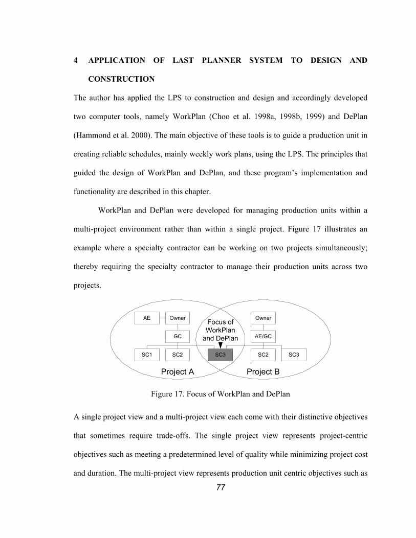
77
4 APPLICATION OF LAST PLANNER SYSTEM TO DESIGN AND
CONSTRUCTION
The author has applied the LPS to construction and design and accordingly developed
two computer tools, namely WorkPlan (Choo et al. 1998a, 1998b, 1999) and DePlan
(Hammond et al. 2000). The main objective of these tools is to guide a production unit in
creating reliable schedules, mainly weekly work plans, using the LPS. The principles that
guided the design of WorkPlan and DePlan, and these program’s implementation and
functionality are described in this chapter.
WorkPlan and DePlan were developed for managing production units within a
multi-project environment rather than within a single project. Figure 17 illustrates an
example where a specialty contractor can be working on two projects simultaneously;
thereby requiring the specialty contractor to manage their production units across two
projects.
Project A Project B
Owner
GC
SC1 SC2 SC3
AE Owner
AE/GC
SC2 SC3
Focus ofWorkPlan
and DePlan
Figure 17. Focus of WorkPlan and DePlan
A single project view and a multi-project view each come with their distinctive objectives
that sometimes require trade-offs. The single project view represents project-centric
objectives such as meeting a predetermined level of quality while minimizing project cost
and duration. The multi-project view represents production unit centric objectives such as

78
meeting a predetermined level of quality while making a profit on each job, maintaining a
continuous work flow, maintaining steady employment, maintaining or gaining a solid
reputation, and improving process efficiency.
4.1 JOBSHOP SCHEDULING VS. PROJECT SCHEDULING
Most commercially available computer programs for construction scheduling present a
model for project scheduling, since most of the products construction companies produce
are one-off (Allam 1988). These tools are useful in master-level scheduling but they tend
to break down when detail is added to the schedule as needed to describe day-to-day
work on site. However, scheduling for construction also can be viewed as job-shop
scheduling (Allam 1988, Tommelein and Ballard 1997a). Especially for the production
units doing the work, such as specialty contractors, scheduling requires an on-going effort
as new contracts are awarded continuously. Scheduling newly awarded projects
influences other ongoing and future projects in the company.
Schmenner (1993) proposes a spectrum of manufacturing processes that contains five
major manufacturing processes, i.e., project, job-shop, batch flow, line flow, and
continuous flow.
Project Continuous FlowLine FlowBatch FlowJob-Shop Figure 18. Spectrum of Manufacturing Processes
The project, which is at the left end of the spectrum, is characterized by (1) a unique
product, (2) a jumbled flow, and (3) loosely linked process segments. The continuous
flow, which is at the other end of the spectrum is characterizes by (1) high volumes of
standard products and (2) continuous, automated, and rigid flow, and (3) tightly linked

79
process segments. Job-shop is described as the most flexible process for creating variety
of products in large volumes. He points out that the job-shops viability is heavily depends
on information regarding costs, times (run times, set up times, labor content times),
routings, and process steps. He also points out that job-shops are hardest to schedule as
the flow processes are so disjointed and independent.
The goal of job-shops scheduling is to schedule a set of jobs on a limited number of
resources. These jobs have operations that need to be performed in certain order. These
operations may be different for each job. Job-shop scheduling problems are usually
formulated as Constraint Satisfaction Problem (CSP) (Montanari 1971, Dechter and Pearl
1988) or Constrained Optimization Problem (COP) (Papadimitriou and Stieglitz 1982,
Dechter et al. 1990). These problems are then generally solved using a backtrack search.
The solution is then measured based on four prevailing metrics.
• Tardiness: The amount of time a job completes past its due date. The total
(average) tardiness of a schedule is the total (average) job tardiness in that
schedule.
• Flowtime: The time spent by a job in the shop while being processed. It is
the length of the time interval that spans from the release of the job to its
completion. The total (average) flowtime of a schedule is the total
(average) job flowtime in that schedule.
• Earliness: The amount of time a job completes before its due date. The
total (average) earliness of a schedule is the total (average) job earliness in
that schedule.
80
• Makespan: The length of the time interval that spans from the start time of
the first released job to the completion time of the last completed job. This
measure is appropriate in project scheduling, where there is a finite
number of jobs to be carried out.
The similarity between job-shop scheduling and production planning is more apparent in
specialty contractor organizations where resources may be shared and alternate being
used on multiple projects. A specialty contractor’s resource-loaded schedule may contain
information about two types of resources, i.e., dedicated resources and shared resources.
Dedicated resources are committed exclusively to a single production unit on a single
project. Shared resources are committed to more than one production unit or to more than
one project. Some shared resources may serve multiple production units on multiple
projects, which complicates the coordination problem even more. Shared resources may
be project-shared or company-shared.
Project-shared-resources can be equipment such as cranes, elevators, site trailers, etc.,
personnel such as project management staff (project manager, project engineer,
superintendents, building inspectors, etc., and space such as material storage areas, pre-
installation and installation working areas, access paths, etc. Company-shared-resources
can be equipment such as expensive hoisting equipment, large plotters, etc., and
personnel such as a project manager, inspectors, laborers, etc. The scheduling effort for
multiple projects is further complicated as involvement of specialty contractor in any one
project tends to be intermittent and relatively short as compared to the total project
duration. General contractor organizations tend to have—relatively-speaking—more
dedicated resources for each project.
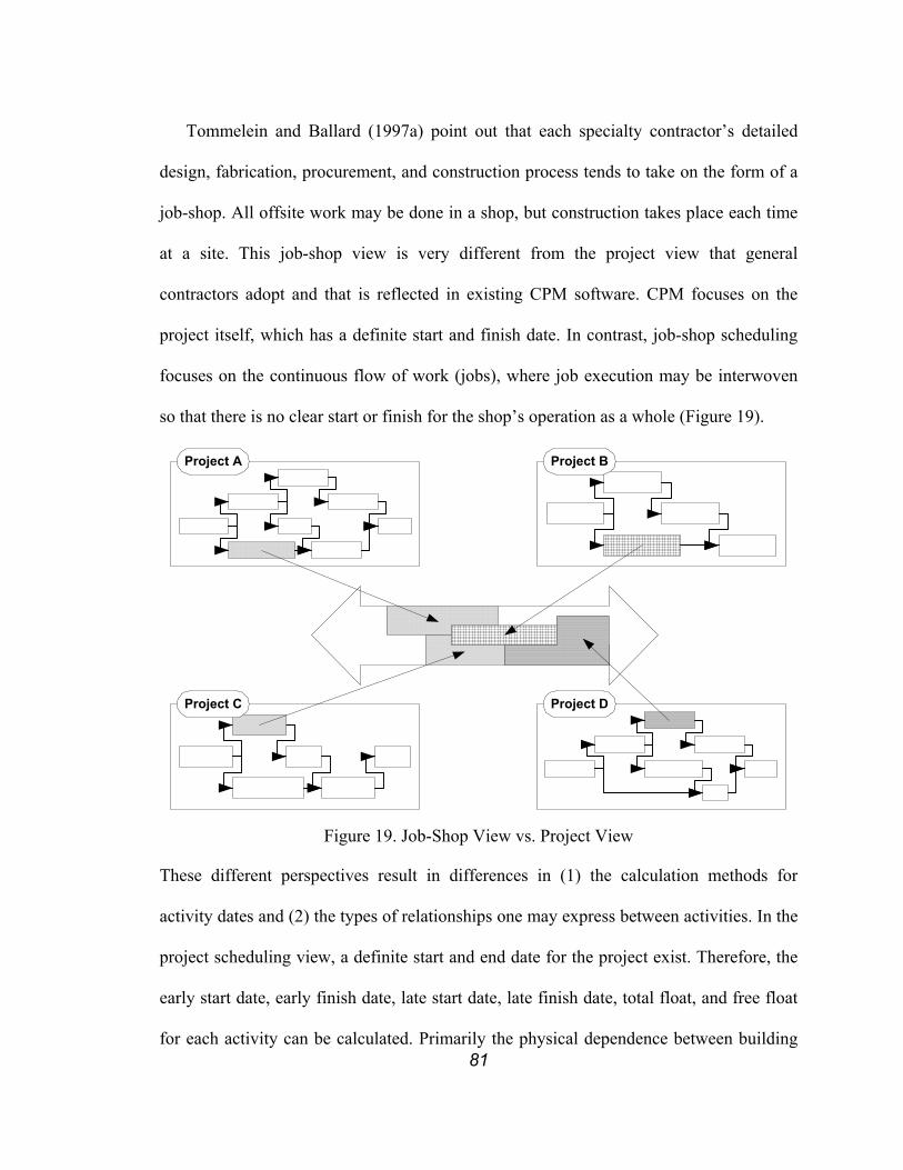
81
Tommelein and Ballard (1997a) point out that each specialty contractor’s detailed
design, fabrication, procurement, and construction process tends to take on the form of a
job-shop. All offsite work may be done in a shop, but construction takes place each time
at a site. This job-shop view is very different from the project view that general
contractors adopt and that is reflected in existing CPM software. CPM focuses on the
project itself, which has a definite start and finish date. In contrast, job-shop scheduling
focuses on the continuous flow of work (jobs), where job execution may be interwoven
so that there is no clear start or finish for the shop’s operation as a whole (Figure 19).
Project A Project B
Project DProject C
Project D
Figure 19. Job-Shop View vs. Project View
These different perspectives result in differences in (1) the calculation methods for
activity dates and (2) the types of relationships one may express between activities. In the
project scheduling view, a definite start and end date for the project exist. Therefore, the
early start date, early finish date, late start date, late finish date, total float, and free float
for each activity can be calculated. Primarily the physical dependence between building
82
components determines precedence relationships between activities. Planners then use
resource constraints to determine whether the plan is doable. If not, the precedence
between activities can be changed by changing construction methods or by delaying one
or more activities.
In the job-shop scheduling view, the planner can schedule each job to start as early as
possible as long as the required material is available, and as late as possible as long as it
does not delay its due date. The relationships between jobs are primarily determined by
resource constraints although activities in each job are primarily determined by physical
dependencies. Therefore, in a job-shop scheduling view, it is critical to maintain a steady
flow of work for all resources so that fluctuation of resource utilization, i.e., overload and
downtime, can be minimized. Resource overload (which is usually satisfied by overtime
or additional resources) and downtime result in additional costs.
In order to achieve a steady flow of work, foremen include in their schedule tasks that
are critical to following tasks and those that are used as ‘fillers’ (Senior 1996). These
fillers may be chosen from workable backlog, which is work that can be scheduled to
begin as soon as the required labor, equipment, and space become available.
Another way to achieve a steady flow of work is to move resources around to
different projects. This is inefficient because it requires movement of resource and
increased setups, which are non-value adding activities. It also impedes the learning
process, which could result in deterioration of productivity of the crews, the safety of the
work environment, or the quality of the product.
O’Brien (2000) discusses the implications of (re)allocation of subcontractors in a
multi-project environment. He points out that dynamically moving crews or equipment

83
from one site to another will result in added cost and time for the movement, plus the
additional cost and schedule impacts incurred by lost productivity. Regrettably, these
costs may be unavoidable in cases where the involvement of a specialty contractor is
intermittently required on a project. The impact of these cases can be minimized if the
need for involvement is predictable.
Another way to achieve a steady flow of work is to keep all resources busy by
varying their capacity, e.g., the number of workers in a crew or the number of equipment.
This is probably the worst case because, in addition to the problems of the previous case,
finding resources, especially people, at the required time might not be feasible.
Figure 20 shows CPM schedules of two projects, each presumably performed by a
different general contractor, but a single specialty contractor (shown by the cross-hatched
activity) involved for part of the work in both. Even though a specialty activity may be
unique in each project (activity “a” in “Project A” and activity “b” in “Project B”), the
work requires the repeated application of a specialty for specialty contractor “SC 1.” To
optimize performance, the specialty contractor is likely to try to schedule work in a
continuous flow, whereas the general contractor primarily must schedule a sequence of
dissimilar pieces of work in order to get them done within project time and budget
constraints. These two scheduling methodologies differ significantly from one another so
that different computer support tools are in order.
The job-shop view shares some traits with program management in that both adopt a
multi-project perspective and consider resource usage across those projects. Program
management is defined as “The effective implementation of change through multiple
projects to realize distinct and measurable benefits for an organization” (Becker 1999).
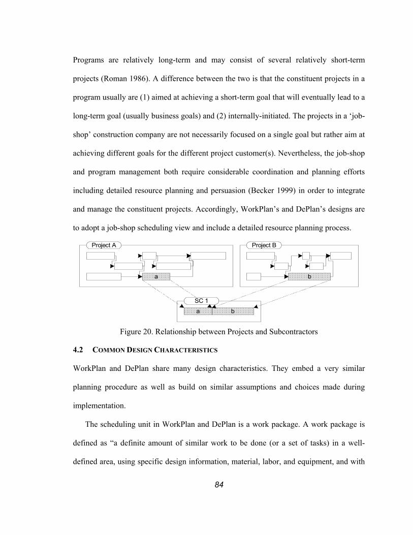
84
Programs are relatively long-term and may consist of several relatively short-term
projects (Roman 1986). A difference between the two is that the constituent projects in a
program usually are (1) aimed at achieving a short-term goal that will eventually lead to a
long-term goal (usually business goals) and (2) internally-initiated. The projects in a ‘job-
shop’ construction company are not necessarily focused on a single goal but rather aim at
achieving different goals for the different project customer(s). Nevertheless, the job-shop
and program management both require considerable coordination and planning efforts
including detailed resource planning and persuasion (Becker 1999) in order to integrate
and manage the constituent projects. Accordingly, WorkPlan’s and DePlan’s designs are
to adopt a job-shop scheduling view and include a detailed resource planning process.
a b
ba
Project A Project B
SC 1
Figure 20. Relationship between Projects and Subcontractors
4.2 COMMON DESIGN CHARACTERISTICS
WorkPlan and DePlan share many design characteristics. They embed a very similar
planning procedure as well as build on similar assumptions and choices made during
implementation.
The scheduling unit in WorkPlan and DePlan is a work package. A work package is
defined as “a definite amount of similar work to be done (or a set of tasks) in a well-
defined area, using specific design information, material, labor, and equipment, and with

85
prerequisite work completed” (Choo et al. 1998a). The work package defined here differs
from the work package developed from WBS (Project Management Institute 1996). As
the goal of the WBS is to provide a common system that can be applied at various levels
for both cost estimating and scheduling (Barrie and Paulson 1992), the work packages at
the WBS-level are created mainly for project control purposes. Therefore they tend to be
inadequate in terms of use and expressiveness when it comes to supporting production
planning and control, that is, supporting those who are performing construction work in
the field. Stanoevska-Slabeva et al. (1998) point out that traditionally planning was based
on quantitative knowledge but due to “increasing complexity and dynamics of
quantitative information, related qualitative information like additional explanation,
description premises are becoming more important.” WorkPlan and DePlan are designed
to capture and provide qualitative scheduling information as well as quantitative
scheduling information.
Work packaging is a planning process that requires detailed understanding of the
scope of work and the constraints that impact them. Without proper consideration of
constraints, work packages would not be an effective means of managing the job (Kim
and Ibbs 1995). Constraint analysis is a key component in the LPS and thus in WorkPlan
and DePlan.
Since constraint analysis entails detailing of constraints for each work package,
software designed to support this process must allow all records to be structured in
function of what may constrain the execution of a work package. This requires editing,
storing, and retrieving information regarding constraints as well as projects, work
packages, and production unit’s assignable resources (examples of such resources are
86
labor and equipment in WorkPlan, and designer and administrative services in DePlan).
This information usually already exists in electronic format in the company whether it is
in spreadsheets or word processor files. This information can be captured and used
throughout the project—a technique “capture information once and at the source”
recommended by process reengineering (Hammer 1990). Therefore, a database, namely
Microsoft Access (Microsoft Corporation 2000a), was selected as the platform to develop
WorkPlan and to develop the extended WorkPlan portion of DePlan.
Quite a few commercial database packages exist to track RFIs, submittals, drawings,
etc. Examples are Expedition (Primavera 2000) and ProLog (Meridian 2000). WorkPlan
and DePlan differ from these packages in terms of their primary objective, which is to
systematically check all constraints and prerequisite work before work packages are
released to construction, so that one can avoid making low-quality assignments, thereby
providing stability in the workflow of the construction process. Stability is a key aspect
of lean production theory (Howell and Ballard 1994).
WorkPlan and DePlan focus on some lean production techniques (Womack and Jones
1996) such as “stopping the assembly line to immediately repair quality defects” in that
they try to locate defective assignments early on before the assembly process (i.e.,
construction) and prevent them from being passed down (which corresponds to stopping
the assembly line). They also support “pulling materials through the production system to
meet specific customer demands” in that they help pull required resources (namely,
material, labor, equipment, space, information, etc.) by guiding the Last Planner in
developing resource constraints and then meeting these constraints. WorkPlan and
DePlan also support “synchronizing and physically aligning all steps in the production
87
process” in part by guiding the planner to carry out constraint analysis through work
structuring. They also support “clearly documenting, updating, and constantly reporting
the status of all process flows to all involved” at least in part by describing the status of
all planning process flows to all involved. Although is not explicitly supported, “reducing
overall process cycle time by minimizing each machine’s change-over time” is consistent
with the job-shop scheduling objective of supporting continuous work flow. By assisting
the planner in a multi-project scheduling environment, repeat efforts of mobilization and
demobilization can be detected and possibly avoided.
The main difference between WorkPlan and DePlan is that WorkPlan is designed to
support planning during construction and DePlan is intended to support planning during
design. The planning process is very similar in both cases. However, the difference in
intended use results in differences in external programs that the programs rely on for
front-end planning. It also results in differences in vocabulary and in some domain
specific views of data in the database.
4.3 WORKPLAN
WorkPlan is developed for managing a production unit working on multiple construction
projects, usually a specialty contractor or a general contractor with it’s own work force.
4.3.1 Design of WorkPlan
WorkPlan guides the planner through the process of (1) inputting required information to
support the Last Planner process, (2) carrying out the Last Planner process, and (3)
generating reports and charts from the actual construction schedule data. Figure 21 shows
the detailed planning procedure supported by WorkPlan. WorkPlan maintains detailed
information regarding laborers and equipment. Thus planners can make explicit resource

88
assignments by selecting specific resources from the list of resources maintained in the
database.
Important features in the design of WorkPlan included support for (1) explicit
resource assignment, (2) automatic cost calculation for alternative resource loading
analysis, timesheets, and total direct cost, and (3) generating reports to show PPC and
reasons for non-completion.
4.3.2 Implementation of WorkPlan
WorkPlan’s graphical user interfaces (GUI) are sequenced so as to guide planners
according to the procedure shown in Figure 21. The first two screens of WorkPlan
(Figure 22 and Figure 23) show the program authors’ names, the version of the software,
and copyright information. Early versions of WorkPlan were documented on several
occasions (Choo et al. 1998a, 1998b, 1998c and 1999). WorkPlan in its current form is
detailed next.
Once the planner agrees to the copyright information, which only appears the first
time WorkPlan is executed, the first page of the Navigator screen (Figure 24)
automatically appears. The Navigator serves as the main interface to WorkPlan. There are
four pages to the navigator; “Information”, “Scheduling”, “Reports”, and “Etc.” Each
page contains related functions, some of which must be done in a sequence. A detailed
description follows of the functions belonging to each page.
The first page of the Navigator is the “Information” page. The main purpose of this
screen is to maintain information regarding undertaken projects and company resources.
There is no sequential procedure to follow when inputting information regarding project
and work packages information, laborer information, and equipment information.

89
Laborer Information
Equipment Information
Input Projects
Import Work Packages
fromMS Project
Define Constraints
AllConstraints Satisfied?
SatisfyConstraints
Release Work Package
Schedule Work Package
No
Weekly Work Plan
Update Actual Schedule
Actual Schedule
Data
Construction
PPC Chart and Reasons
Analysis Report
Cost Reports
Timesheets
Done As Scheduled?
Generate Reports
Specify Reasons
Yes
Yes
No
Capacity Conflict?
No
Yes
Input Work Packages
Figure 21. WorkPlan Procedure Diagram

90
Figure 22. Startup Screen
Figure 23. Copyright Screen
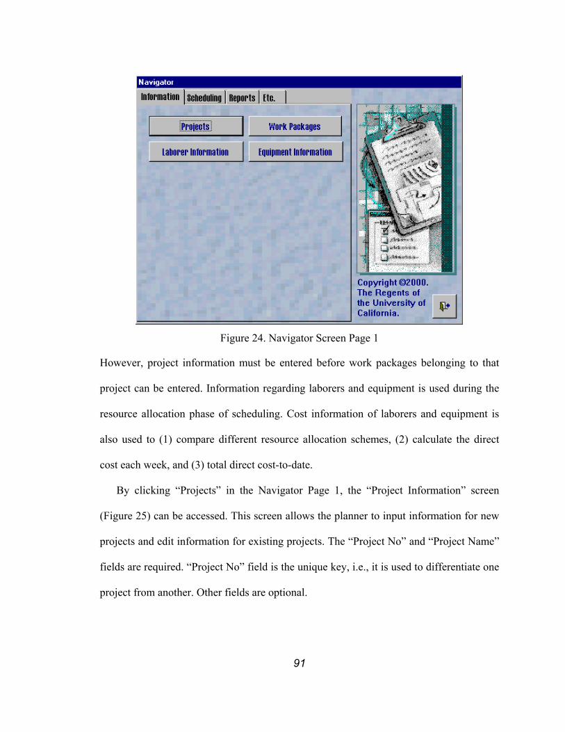
91
Figure 24. Navigator Screen Page 1
However, project information must be entered before work packages belonging to that
project can be entered. Information regarding laborers and equipment is used during the
resource allocation phase of scheduling. Cost information of laborers and equipment is
also used to (1) compare different resource allocation schemes, (2) calculate the direct
cost each week, and (3) total direct cost-to-date.
By clicking “Projects” in the Navigator Page 1, the “Project Information” screen
(Figure 25) can be accessed. This screen allows the planner to input information for new
projects and edit information for existing projects. The “Project No” and “Project Name”
fields are required. “Project No” field is the unique key, i.e., it is used to differentiate one
project from another. Other fields are optional.
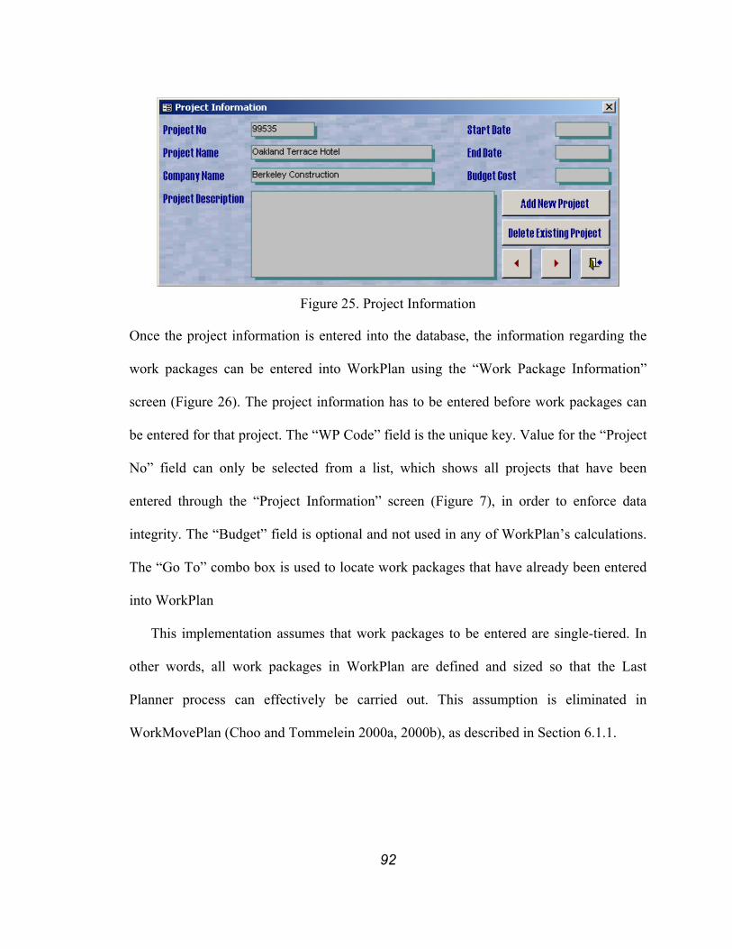
92
Figure 25. Project Information
Once the project information is entered into the database, the information regarding the
work packages can be entered into WorkPlan using the “Work Package Information”
screen (Figure 26). The project information has to be entered before work packages can
be entered for that project. The “WP Code” field is the unique key. Value for the “Project
No” field can only be selected from a list, which shows all projects that have been
entered through the “Project Information” screen (Figure 7), in order to enforce data
integrity. The “Budget” field is optional and not used in any of WorkPlan’s calculations.
The “Go To” combo box is used to locate work packages that have already been entered
into WorkPlan
This implementation assumes that work packages to be entered are single-tiered. In
other words, all work packages in WorkPlan are defined and sized so that the Last
Planner process can effectively be carried out. This assumption is eliminated in
WorkMovePlan (Choo and Tommelein 2000a, 2000b), as described in Section 6.1.1.

93
Figure 26. Work Package Information
Two distinct production unit resources are managed with WorkPlan. Information about
laborers can be entered using the “Labor Information screen” (Figure 27). The “ID” field
is the unique key. However, the value for the “Name” field is required so that the planner
can specify laborers by their name rather than their ID. The “Group” and “Position”
fields are optional. The “Trades” section is used to enter all trades that a laborer is
capable of performing (or skills that the laborer has) and the pay rates for performing
each may differ. This information is used during the scheduling process in specifying
what trade each laborer is expected to work on. This form can also be used to enter
information regarding crews, rather than individuals, or specialty contractors that are
working for the production unit (e.g., subcontractors). For each crew, the sum of the rates
for all crew members can be used, and for each specialty contractor, their unit cost or “0”
can be used depending on the contract.

94
Figure 27. Laborer Information
Information about equipment can be entered using the “Equipment Information” screen
(Figure 28). The “ID” field is again the unique key. The “Name” field is mandatory but
other fields, such as “Power”, “Weight”, “Reach”, “Depth”, and “Bucket”, are optional.
The second page of the Navigator screen (Figure 29) is used in scheduling and
recording the actual progress (as-built). The “For Planning Phase” section of the screen
allows the planner to schedule the work crew and equipment whereas the “For Updating
Phase” section allows the planner to input the as-built schedule.
Figure 28. Equipment Information
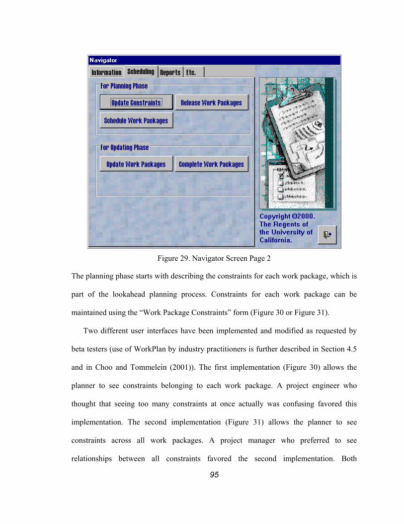
95
Figure 29. Navigator Screen Page 2
The planning phase starts with describing the constraints for each work package, which is
part of the lookahead planning process. Constraints for each work package can be
maintained using the “Work Package Constraints” form (Figure 30 or Figure 31).
Two different user interfaces have been implemented and modified as requested by
beta testers (use of WorkPlan by industry practitioners is further described in Section 4.5
and in Choo and Tommelein (2001)). The first implementation (Figure 30) allows the
planner to see constraints belonging to each work package. A project engineer who
thought that seeing too many constraints at once actually was confusing favored this
implementation. The second implementation (Figure 31) allows the planner to see
constraints across all work packages. A project manager who preferred to see
relationships between all constraints favored the second implementation. Both
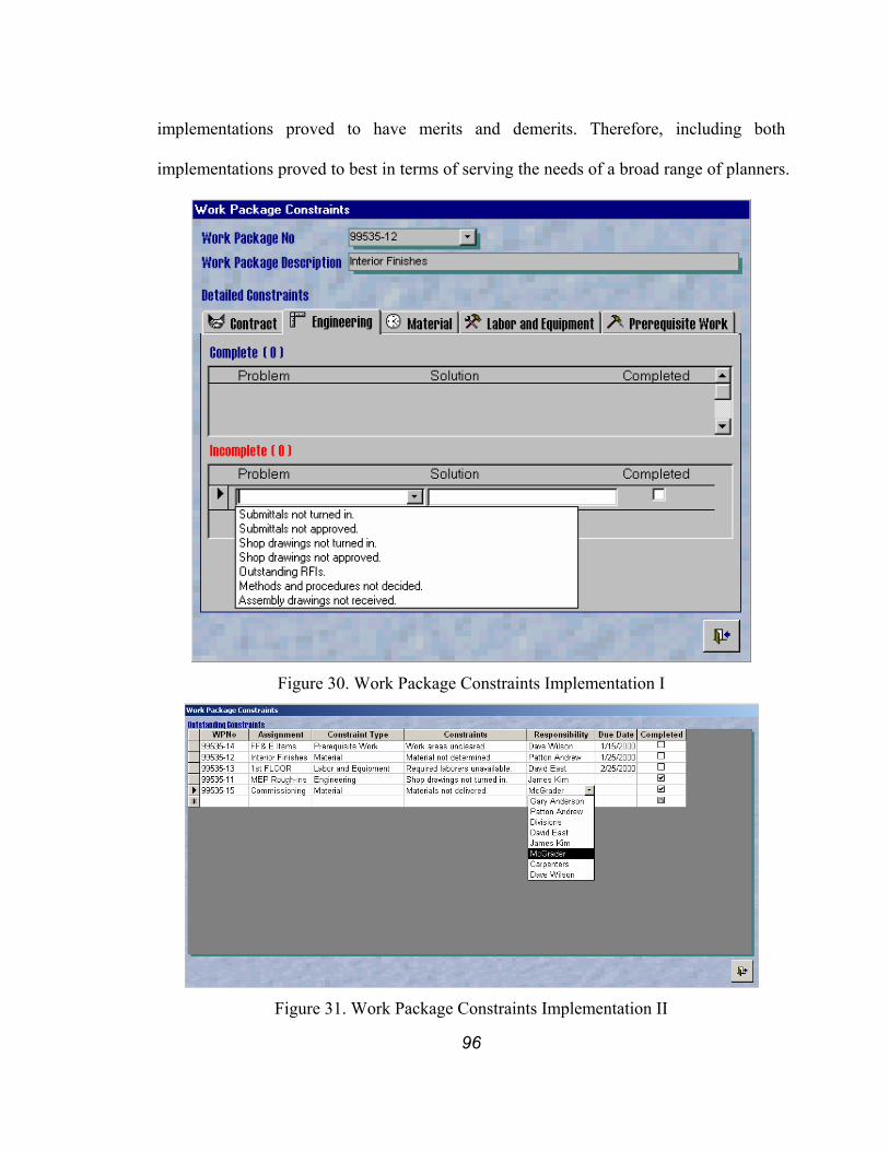
96
implementations proved to have merits and demerits. Therefore, including both
implementations proved to best in terms of serving the needs of a broad range of planners.
Figure 30. Work Package Constraints Implementation I
Figure 31. Work Package Constraints Implementation II

97
In both implementations, constraints can be categorized in one of five categories. Each
category contains a preloaded set of general constraints that appear to occur on projects
over and over again. These categories of constraints and preloaded examples are:
1. Contract
♦ Is this work package in the contract? Is it the result of a newly-issued change
order?
♦ Has all coordination information been confirmed?
♦ Has the subcontract been issued?
2. Engineering
♦ Have all submittals been turned in? Have all submittals been approved?
♦ Have all shop drawings been turned in? Have they all been approved?
♦ Are there any outstanding requests for information (RFIs)?
♦ Have all methods and procedures been decided?
♦ Have assembly drawings been received?
3. Materials
♦ Have all fabrication drawings been produced?
♦ Have all material requirements and sources for procurement been established?
♦ Have all requests for quotation (RFQs) been sent?
♦ Have all materials been purchased?
♦ Have all materials been fabricated?
♦ Have all materials been delivered?
♦ Have all the materials been allocated?
98
4. Labor and equipment
♦ Has the work package been scheduled?
♦ Are the required laborers available for the duration of the work?
♦ Is the required equipment available for the duration of the work?
5. Prerequisite work
♦ Has all prerequisite physical work been completed?
♦ Have all work areas been cleared so that the work package can begin?
The constraints may be selected from this preloaded list or be written in by the Last
Planner if they are not yet included or other wording is found to be more appropriate.
At the bottom of this screen are constraints that are still outstanding; at the top those
that have been solved. Once an outstanding constraint has been solved (checked), it
automatically moves up to the top. Solved constraints are not deleted from the database
even though they require no further attention. Keeping them serves two purposes, i.e., (1)
it confirms these constraints have been attended to, and (2) solved constraints can be used
to construct a knowledge base of constraints to help anticipate problems with similar
work in case of change orders or in the future on other projects.
Once all constraints for a work package are satisfied or are expected to be met by the
time the actual work starts, the work package can be released for construction. Released
work packages by default are considered “workable backlog,” which are “assignments
that have met all quality criteria, except that some must yet satisfy the sequence criterion
by prior execution of prerequisite work already scheduled” (Lean Construction Institute
2000). In WorkPlan, only released work packages can be scheduled to appear in weekly
work plans. ‘Unreleased’ work packages are prevented from being scheduled. If

99
execution of a released work is expected to cause difficulties or rework downstream, it
should not be scheduled weekly work plan.
The releasing can be done using the “Work Package Release” screen (Figure 32). It
lists ‘unreleased’ work packages at the top of the screen and released work packages at
the bottom of the same screen. By pressing the down-arrow button, an ‘unreleased’ work
package can be released; by pressing the up-arrow, a released work package can be
‘unreleased.’ There is no strict rule that prevents a work package from being released
even though there may still be outstanding constraints. Release is allowed because it
should be possible to schedule work with outstanding constraints as long as these
constraints are expected to be met by the time the actual work starts. The nature of
planning is such that it is done ahead of execution, so there will always be a need to
forecast, and correspondingly, uncertainty exists as to whether or not the forecast will
prove to be correct. ‘Unreleasing’ should occur in circumstances whenever the conditions
assumed in release are determined to be unavailable, for example if a previously
unidentified constraint crops up at the last minute or if a constraint is not satisfied to the
extent it was anticipated.
The work packages in the workable backlog can be selectively resource loaded to create
weekly work plans. Creating the weekly work plan starts by selecting a week to be
scheduled using the “Scheduling Week” screen (Figure 33). Clicking any day of the week
will result in that same week.
Two different resource-loading schemes have been implemented, i.e., a two-step
(Figure 34 and Figure 35) vs. a one-step scheme (Figure 36). In the two-step
implementation, a work package to be scheduled is first selected using the “Schedule
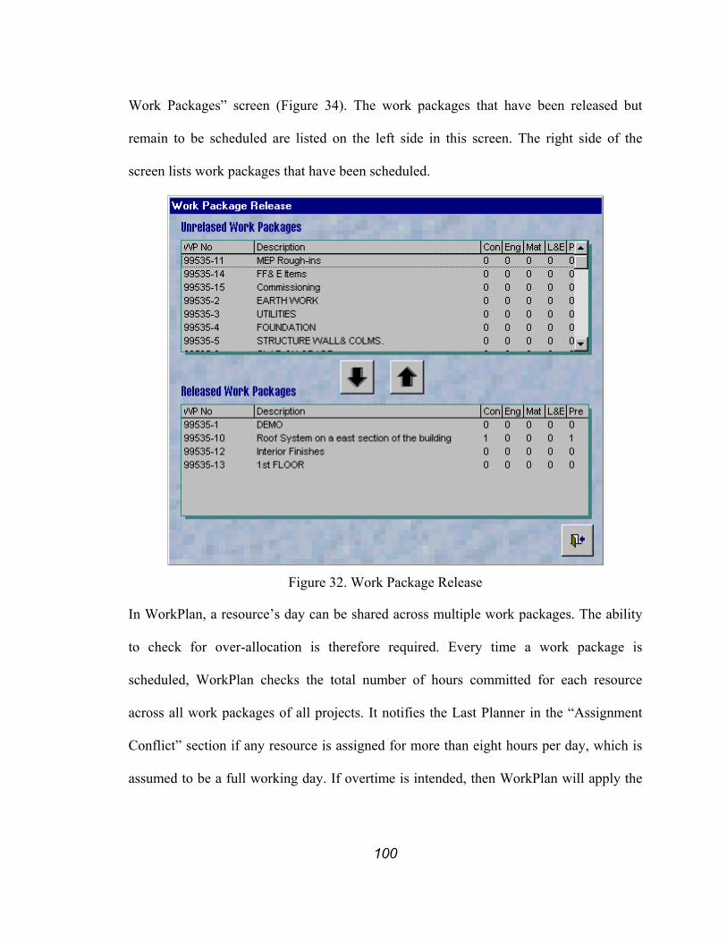
100
Work Packages” screen (Figure 34). The work packages that have been released but
remain to be scheduled are listed on the left side in this screen. The right side of the
screen lists work packages that have been scheduled.
Figure 32. Work Package Release
In WorkPlan, a resource’s day can be shared across multiple work packages. The ability
to check for over-allocation is therefore required. Every time a work package is
scheduled, WorkPlan checks the total number of hours committed for each resource
across all work packages of all projects. It notifies the Last Planner in the “Assignment
Conflict” section if any resource is assigned for more than eight hours per day, which is
assumed to be a full working day. If overtime is intended, then WorkPlan will apply the

101
corresponding hourly charges. If overtime is the result of oversight, the Last Planner must
revisit the work packages involved and reassign resources to balance them more evenly.
Figure 33. Scheduling Week Selection
The “Resource Assignment” screen (Figure 35) allows the Last Planner to explicitly
assign resources to a released work package. As shown in this screen capture, the names
of laborers and equipment to be assigned to a specific work package are selected from a
drop-down list using data stored in the database. The hours represent the time each
resource will work on the specific work package. Laborers and equipment can be shared
among multiple work packages in a day by dividing their workday into multiple work
packages. No differentiation is made between working on multiple work packages in a
day sequentially or simultaneously.
Studies have confirmed that multitasking is less efficient than working on a single job
(Arbulu and Tommelein 2002). However, it cannot be prevented in some cases, e.g.,
foremen overseeing multiple work packages, very specialized laborer (welder, riveter,
etc.), and intermittently used shared equipment (elevators, cranes, etc.).

102
Figure 34. Schedule Work Packages Type I
“Remaining work” is used by the Last Planner to estimate the total cost of the work
package based on the expected unit cost and quantity of work that is left to be done.
Every time the schedule is modified, the Last Planner has the option of updating the
estimate of the remaining work. This information is not automatically generated within
the database. It is based on the Last Planner’s estimate, which is in turn based on the
amount of work remaining. By estimating the total cost of each work package, a realistic
target cost can be set. In WorkPlan, this target cost is not compared with budget for this
work package as this comparison does not realistically provide status of the work.
Budgets for work packages are not developed based on specific resource assignments.
They are usually based on industry or company average resource assignments. While
aggregate of these budgets might allow the financiers to plan ahead for cash flow, it does
not provide Last Planners with an accurate picture of the status of each work package.

103
Figure 35. Resource Assignment
In the one-step implementation, the selection of a work package and resource assignment
is done using a single screen (Figure 36). This implementation allows the planner to see
all resource assignments regardless of the project or work package to which they belong.
Thus, it truly provides a view of a job-shop schedule.

104
Figure 36. Schedule Work Packages Type II
In either the one- or two-step implementation, the resource assignments can then be
printed in the format of a weekly work plan (Figure 37). This consists of two parts, the
top part shows the scheduled work packages and the bottom part shows the workable
backlog. The workable backlog serves as a guideline for field crew in selecting
replacement work when scheduled work cannot be performed for any reason. This plan
can be developed by a crew foreman, then printed out and handed to the field crew. Once
a work package has been completed, the crew is expected to fill out the actual number of
hours they worked on each specific work package for reporting purposes. They must
check whether or not the work package was completed as planned, and if not, provide

105
reasons for variance. This data is then entered into the computer to calculate the PPC and
create a detailed reasons report (explain later).
Figure 37. Sample Weekly Work Plan
After execution of a weekly work plan, that is, at the end of the week, “how each work
package was done” and reasons for variance (the difference between “what was listed to
be done within a week” and “what was actually done within that week”) are input, if
there are any. WorkPlan uses the “how” data to create timesheets and the “what” data to
create the PPC Report that represents the reliability of the current planning system
(explained in detail later). PPC is calculated by dividing the number of completed
assignments by the total number of assignments each week (Ballard and Howell 1997).
This recording procedure was created to allow for learning. It starts by selecting the week
to be updated using “Updating Week” screen (Figure 38). As done in “scheduling week”,
clicking any day of the week will result in the same week.
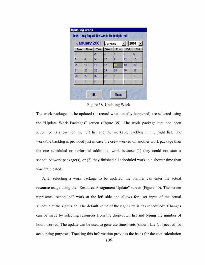
106
Figure 38. Updating Week
The work packages to be updated (to record what actually happened) are selected using
the “Update Work Packages” screen (Figure 39). The work package that had been
scheduled is shown on the left list and the workable backlog in the right list. The
workable backlog is provided just in case the crew worked on another work package than
the one scheduled or performed additional work because (1) they could not start a
scheduled work package(s), or (2) they finished all scheduled work in a shorter time than
was anticipated.
After selecting a work package to be updated, the planner can enter the actual
resource usage using the “Resource Assignment Update” screen (Figure 40). The screen
represents “scheduled” work at the left side and allows for user input of the actual
schedule at the right side. The default value of the right side is “as scheduled”. Changes
can be made by selecting resources from the drop-down list and typing the number of
hours worked. The update can be used to generate timesheets (shown later), if needed for
accounting purposes. Tracking this information provides the basis for the cost calculation

107
and, more importantly, allows for measurement of the reliability of the current scheduling
system. Here again, the Last Planner has the option to update the estimate of remaining
work.
Figure 39. Update Work Packages
In order to finish updating the work package, the Last Planner has to answer the question
“Was this week’s work for [Work Package No] completed as scheduled?” If the answer is
“Yes”, the process is finished. If the answer is “No”, the “Reasons for Incompletion”
screen (Figure 41) will appear. As long as the scheduled work is completed within the
week that it was scheduled for, the answer is “Yes”, even if it wasn’t completed exactly
as scheduled. This allows each production unit to have the flexibility to resolve
uncertainties that arise during the week. This flexibility suggests that the hand-offs
between production units are managed on a weekly basis. However, this flexibility may
not be ideal if it generates uncertainty for other production units that are closely related
by predecessor/successor relationship or resource dependency.

108
Figure 40. Resource Assignment Update
The “Reasons for Incompletion” screen allows the planner to enter the reasons for not
being able to execute the work packages as scheduled. Whereas the PPC report can be
used to measure the reliability of the planning system, the reasons provide insight and
direction into how to improve the planning system. The planner should try to describe the
root cause of the reason rather than simply describing what might be a superficial reason.
Acting on superficial reasons does not necessarily guarantee that the same failure will not
happen again. Only eradication of root causes will prevent the same failure from
happening again. 5 Why’s (asking 5 times in a row to get to the root cause) is a
continuous improvement technique that can be used to reveal the root cause for failure
(Ohno 1988, Womack et al. 1990).
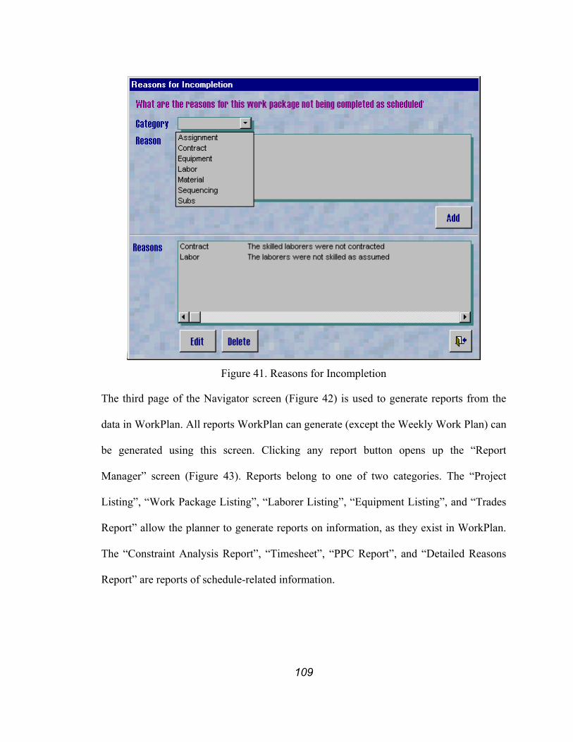
109
Figure 41. Reasons for Incompletion
The third page of the Navigator screen (Figure 42) is used to generate reports from the
data in WorkPlan. All reports WorkPlan can generate (except the Weekly Work Plan) can
be generated using this screen. Clicking any report button opens up the “Report
Manager” screen (Figure 43). Reports belong to one of two categories. The “Project
Listing”, “Work Package Listing”, “Laborer Listing”, “Equipment Listing”, and “Trades
Report” allow the planner to generate reports on information, as they exist in WorkPlan.
The “Constraint Analysis Report”, “Timesheet”, “PPC Report”, and “Detailed Reasons
Report” are reports of schedule-related information.
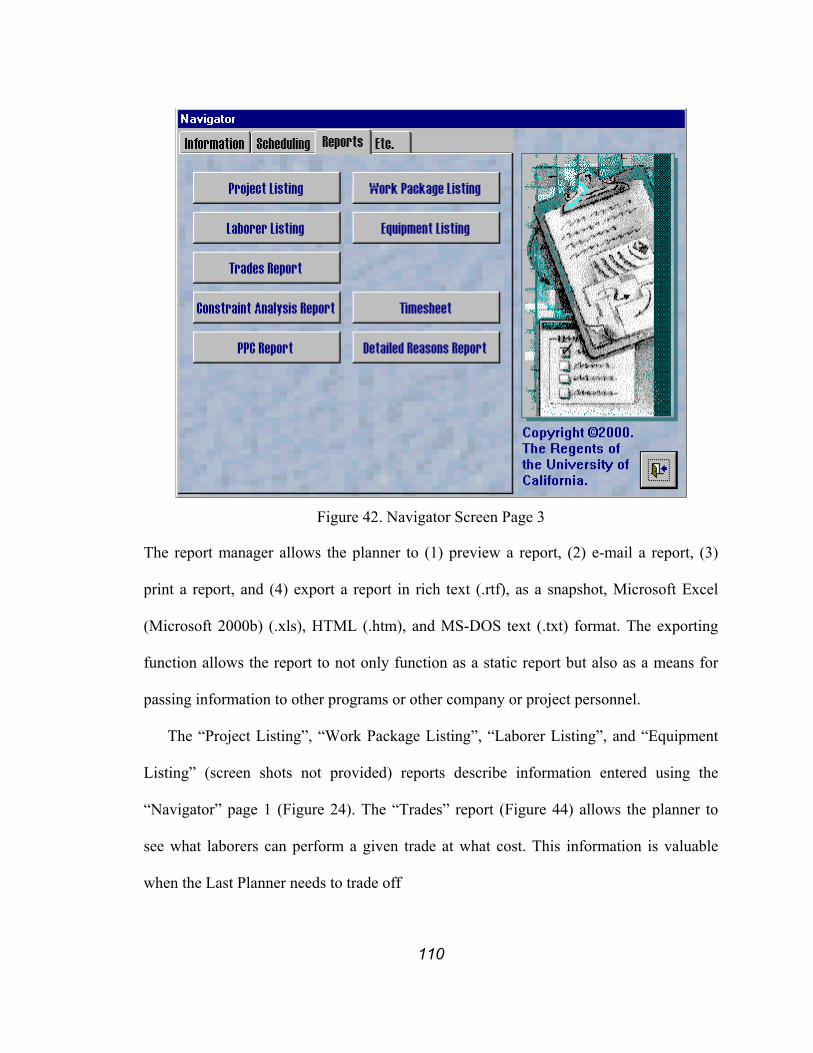
110
Figure 42. Navigator Screen Page 3
The report manager allows the planner to (1) preview a report, (2) e-mail a report, (3)
print a report, and (4) export a report in rich text (.rtf), as a snapshot, Microsoft Excel
(Microsoft 2000b) (.xls), HTML (.htm), and MS-DOS text (.txt) format. The exporting
function allows the report to not only function as a static report but also as a means for
passing information to other programs or other company or project personnel.
The “Project Listing”, “Work Package Listing”, “Laborer Listing”, and “Equipment
Listing” (screen shots not provided) reports describe information entered using the
“Navigator” page 1 (Figure 24). The “Trades” report (Figure 44) allows the planner to
see what laborers can perform a given trade at what cost. This information is valuable
when the Last Planner needs to trade off
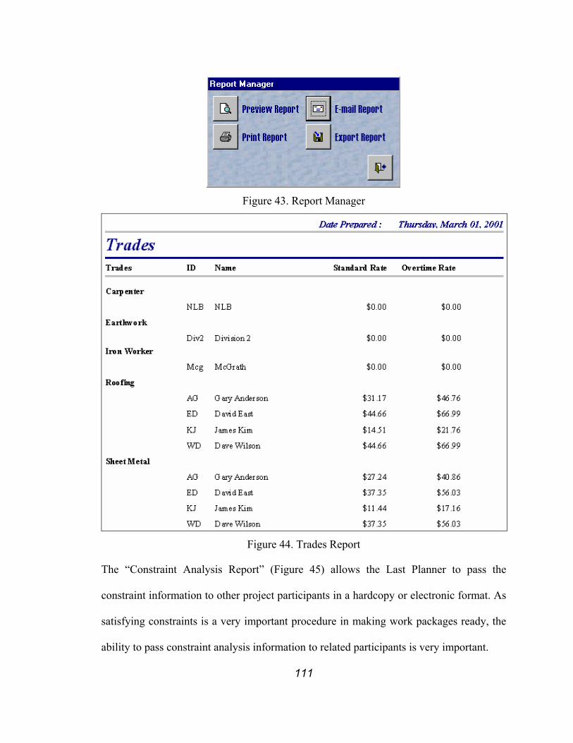
111
Figure 43. Report Manager
Figure 44. Trades Report
The “Constraint Analysis Report” (Figure 45) allows the Last Planner to pass the
constraint information to other project participants in a hardcopy or electronic format. As
satisfying constraints is a very important procedure in making work packages ready, the
ability to pass constraint analysis information to related participants is very important.

112
Figure 45. Constraint Analysis Report
The updated schedule information can be used to generate a “Timesheet” report (Figure
46). WorkPlan automatically groups the actual work completed by each laborer and
calculates the total direct cost for each work package.
Figure 46. Timesheet Report
The information collected during the schedule updating process is used to generate the
“PPC with Reasons” report (Figure 47) and the “Detailed Reasons Report” (Figure 48).
The “PPC with Reasons” report shows PPC computed on a weekly basis for the last
seven weeks. The vertical axis on the left shows the PPC computed on a weekly basis.
The solid line in the graph represents PPC. The axis on the right depicts the number of
occurrences of reasons for each category. The bars in the graph correspond to the number
of occurrences for each category as listed. The “Detailed Reasons Report” with
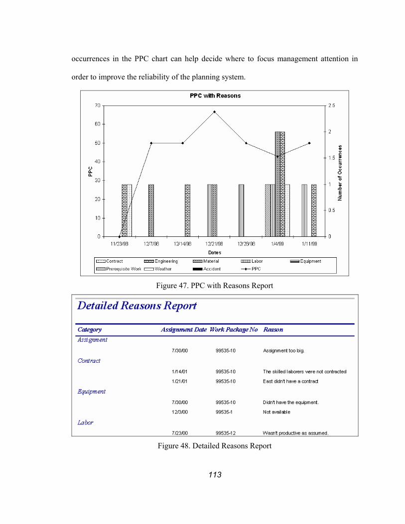
113
occurrences in the PPC chart can help decide where to focus management attention in
order to improve the reliability of the planning system.
Figure 47. PPC with Reasons Report
Figure 48. Detailed Reasons Report
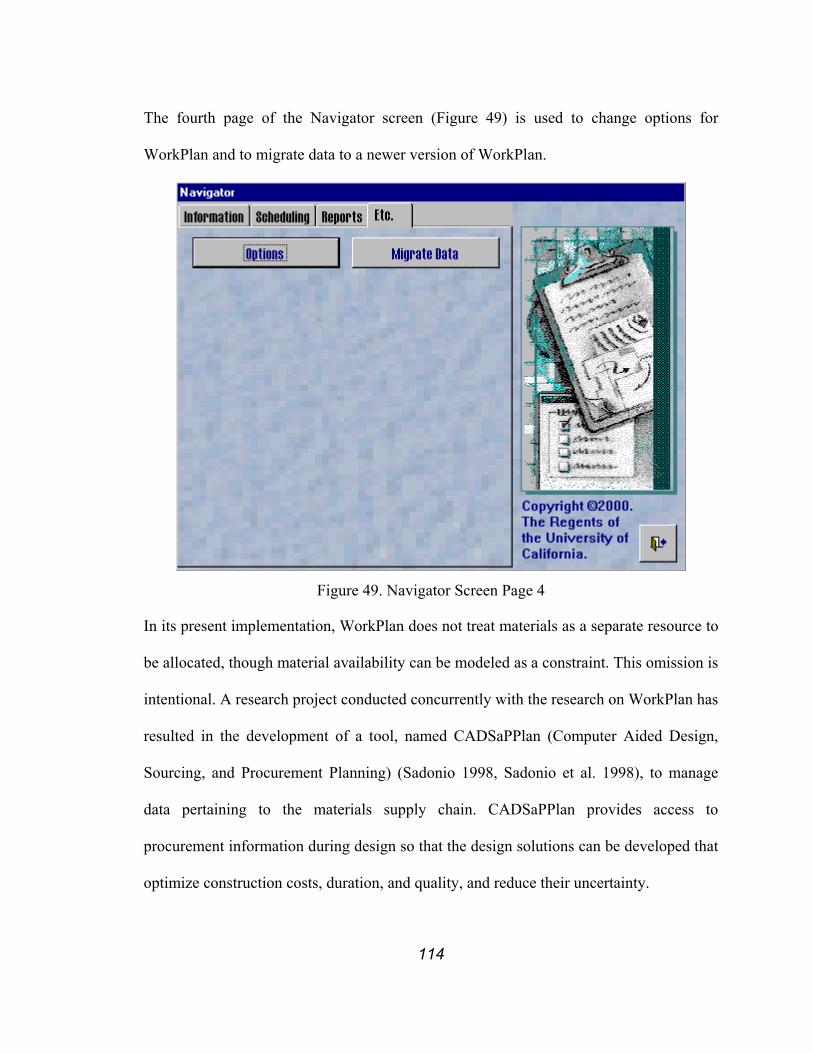
114
The fourth page of the Navigator screen (Figure 49) is used to change options for
WorkPlan and to migrate data to a newer version of WorkPlan.
Figure 49. Navigator Screen Page 4
In its present implementation, WorkPlan does not treat materials as a separate resource to
be allocated, though material availability can be modeled as a constraint. This omission is
intentional. A research project conducted concurrently with the research on WorkPlan has
resulted in the development of a tool, named CADSaPPlan (Computer Aided Design,
Sourcing, and Procurement Planning) (Sadonio 1998, Sadonio et al. 1998), to manage
data pertaining to the materials supply chain. CADSaPPlan provides access to
procurement information during design so that the design solutions can be developed that
optimize construction costs, duration, and quality, and reduce their uncertainty.

115
4.4 DEPLAN
DePlan is developed for managing a production unit working in a service-sector setting,
usually a designer with a team of design and engineering specialists.
4.4.1 Design of DePlan
DePlan (Hammond et al. 2000, Choo et al 2001) assists planners in planning, scheduling,
and controlling the design process according to the LPS. The term “planning” refers to
determining the required activities to meet the design goal, the relationships between
activities, and an optimal sequencing for these activities. The term “scheduling” refers to
assessing the status of activity readiness to be performed, assigning resources, and
determining the start time, duration, and completion time for each of the activities. The
term “controlling” refers to assessing the status of activities after completion of work, and
calculating resource use in terms of time and cost. Unlike the traditional meaning of
control, control as specified here also encompasses the make-ready process (Ballard and
Howell 1994a, 1994b), i.e., figuring out what needs to be done and attend to those needs
to make activities ready to be performed.
DePlan combines an extended version of WorkPlan with ADePT (Analytical Design
Planning Technique) (Austin et al. 1999a, 1999b, 1999c, 2000) (Figure 50). WorkPlan as
described in the previous section was extended to enable the data exchange with ADePT.
ADePT (top portion of Figure 50) improves design activity sequencing by allowing
design managers to focus on the flow of information between design tasks rather than
deliverable. DePlan thus combines the benefits from planning work using ADePT with
scheduling and controlling work using the extended WorkPlan production management
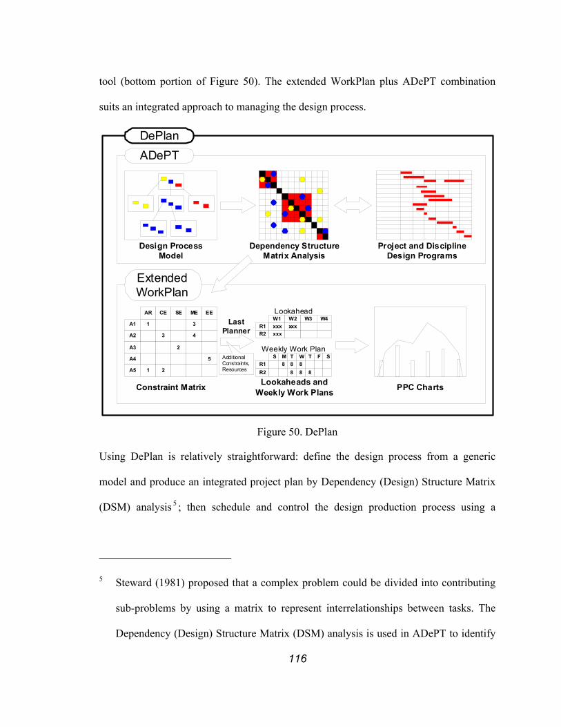
116
tool (bottom portion of Figure 50). The extended WorkPlan plus ADePT combination
suits an integrated approach to managing the design process.
Dependency StructureMatrix Analysis
Design ProcessModel
ADePT
Lookaheads andWeekly Work PlansConstraint Matrix
ExtendedWorkPlan
1
A2
AR CE SE ME EE
A1
3
3
4
A4
A3 2
5
1A5 2 R2R1
S M T W T8 8
888 8
F S
R1R2
W1 W2xxx xxx
W3 W4
xxx
Weekly Work Plan
Lookahead
AdditionalConstraints,Resources
LastPlanner
PPC Charts
Project and DisciplineDesign Programs
DePlan
Figure 50. DePlan
Using DePlan is relatively straightforward: define the design process from a generic
model and produce an integrated project plan by Dependency (Design) Structure Matrix
(DSM) analysis 5 ; then schedule and control the design production process using a
5 Steward (1981) proposed that a complex problem could be divided into contributing
sub-problems by using a matrix to represent interrelationships between tasks. The
Dependency (Design) Structure Matrix (DSM) analysis is used in ADePT to identify

117
lookahead plan and weekly work plans by assigning design activities to design teams, as
the required information and resources become available. Design is thus planned and
managed based on the generation of information with realistic and achievable activities.
The effects of change can be managed by further DSM analysis and process reliability
monitored by measuring PPC.
The input design model for ADePT (and thus for DePlan) was developed based on
UK industry practices; a similar model would have to be created based on US industry.
Data generated from the extended WorkPlan tool will facilitate the creation of this model
because it will reflect US practices by means of a description of activities and the
relationships between them. Nevertheless, developing a sufficiently generic design model
for use on a multitude of projects, does require a substantial amount of additional work
and this is beyond the scope of the present PhD research.
4.4.2 Implementation of DePlan
ADePT and extended WorkPlan were each developed by and are being improved by
students and faculty at educational institutions that are geographically distant. Therefore,
an ASCII file format rather than a dynamic link was chosen as the interface mechanism
between the two programs.
Extended WorkPlan allows the Last Planner to generate project data from the start but
is also capable of importing the ADePT output matrix (Figure 51), i.e., the list of
iterations within the design process and their relationships with tasks in the rest of the
matrix.

118
activities, the responsible disciplines for each activity, and the informational
dependencies.
Figure 51. Sample Output Matrix Generated from ADePT
The imported information is then automatically restructured to generate the constraint
matrix (Figure 52).
Figure 52. Constraint Matrix based on Figure 51
Each design activity corresponds to a work package in extended WorkPlan. The
constraint matrix shows the number of design activities that belong to each responsible
discipline. Completion of these activities will satisfy the informational constraints that
need to be met in order for each activity to be carried out successfully. By categorizing
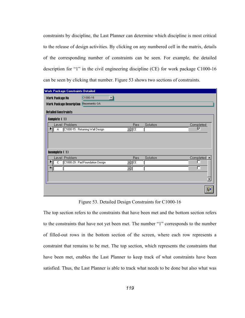
119
constraints by discipline, the Last Planner can determine which discipline is most critical
to the release of design activities. By clicking on any numbered cell in the matrix, details
of the corresponding number of constraints can be seen. For example, the detailed
description for “1” in the civil engineering discipline (CE) for work package C1000-16
can be seen by clicking that number. Figure 53 shows two sections of constraints.
Figure 53. Detailed Design Constraints for C1000-16
The top section refers to the constraints that have been met and the bottom section refers
to the constraints that have not yet been met. The number “1” corresponds to the number
of filled-out rows in the bottom section of the screen, where each row represents a
constraint that remains to be met. The top section, which represents the constraints that
have been met, enables the Last Planner to keep track of what constraints have been
satisfied. Thus, the Last Planner is able to track what needs to be done but also what was

120
done. This is valuable if the Last Planner needs to recheck the constraints due to
unforeseen changes that may occur to design activities.
In addition to constraints imported from ADePT, the planner can also add additional
constraints when they are identified during project execution. These constraints are
divided into five categories: (1) contract, (2) engineering, (3) samples, (4) resources, and
(5) design constraints (Figure 54). Contract refers to constraints regarding contractual
finalization, commercial constraints, permits, subcontracting, etc. Engineering refers to
constraints from other engineering functions such as construction management and
planning supervisors. Samples refer to instances where design is constrained by an
agreement to provide samples or mock-ups. Resources refer to constraints regarding
planning and management of resources, including designers and supporting services.
Design Constraints are information provided by ADePT. Design Constraints for all
disciplines are shown on “Work Package Constraints” screen (Figure 54). Figure 53
shows Design Constraints that belong to a single discipline where as Figure 54 shows
Design Constraints that belong to all disciplines as well as other types of constraints.
When constraints for a design activity are satisfied or are expected to be satisfied at
the time the activity is to start, this activity can be released for scheduling. In the
scheduling phase, explicit resources such as designers and supporting services
(accounting, administration, drafting department, etc.) are assigned to generate weekly
work plans (Figure 55). For tracking purposes, constraints that are expected to be
satisfied are automatically printed in the “make ready” section. Weekly work plans are
special purpose planning that is carried out with the highest level of detail prior to
carrying out the work. Ballard and Howell (1994a) refer to weekly work planning as

121
“commitment planning” because, at this stage, the specific resource assignments need to
be made so that work can actually be performed and promises are made between Last
Planners regarding handoffs. The scheduling window for weekly work plans is one week.
Figure 54. Detailed Constraints for C1000-16
Figure 55. Weekly Work Plan Generated from Extended WorkPlan
Design activities in the weeks beyond one week are scheduled using the lookahead
window (not shown). Since precisely determining which individual designers and
corresponding supporting services will be assigned to each design activity one week in
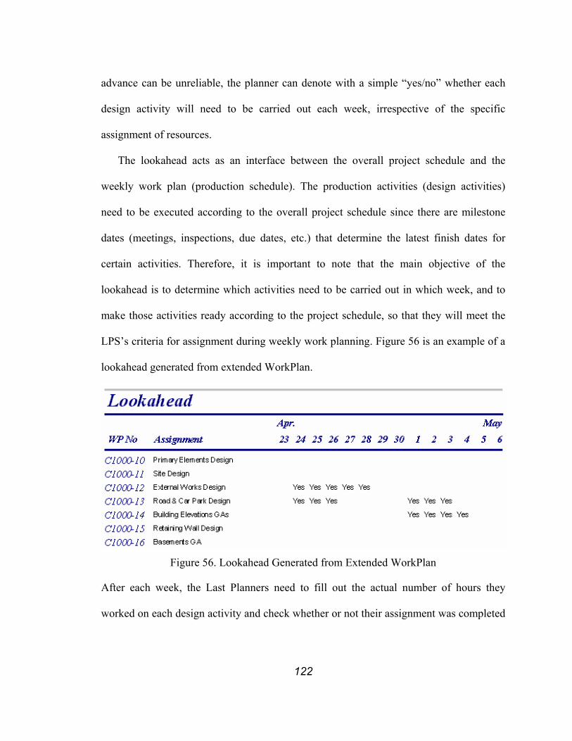
122
advance can be unreliable, the planner can denote with a simple “yes/no” whether each
design activity will need to be carried out each week, irrespective of the specific
assignment of resources.
The lookahead acts as an interface between the overall project schedule and the
weekly work plan (production schedule). The production activities (design activities)
need to be executed according to the overall project schedule since there are milestone
dates (meetings, inspections, due dates, etc.) that determine the latest finish dates for
certain activities. Therefore, it is important to note that the main objective of the
lookahead is to determine which activities need to be carried out in which week, and to
make those activities ready according to the project schedule, so that they will meet the
LPS’s criteria for assignment during weekly work planning. Figure 56 is an example of a
lookahead generated from extended WorkPlan.
Figure 56. Lookahead Generated from Extended WorkPlan
After each week, the Last Planners need to fill out the actual number of hours they
worked on each design activity and check whether or not their assignment was completed

123
as planned. If not, they must provide reasons for variance in order to allow for calculation
of PPC and root cause analysis.
4.5 VALIDATION OF WORKPLAN AND DEPLAN
WorkPlan and DePlan were validated and assessed in terms of usability through a process
of beta-testing. Beta-testers included three member companies of the Lean Construction
Institute (LCI) (Pacific Contracting, Oscar J. Boldt Construction, and Gowan Inc.) and
two academic institutions (Loughborough University in the U.K. and Universidad
Catolica de Chile). The beta-testers took anywhere from one day to two months to
become familiar with the software, use it, and then provide their assessment. The lessons
learned are described below. Several findings in this validation process helped to improve
WorkPlan and DePlan, but others had to be accommodated in yet another program,
namely WorkMovePlan. Where this is the case, WorkMovePlan is mentioned in the
following text and then described in detail in Section 6.2.
The beta-testers were familiar with the LPS, especially the part related to weekly
work planning, which enabled them to make suggestions. Some of them had developed
in-house spreadsheet applications to support the Last Planner process given their own
specific needs. These applications did not necessarily meet all their needs but they
provided a temporary solution. However, the main advantages of these spreadsheet tools
were simplicity of interface and ease of use6. The beta-testers had wish lists expressing
6 For Oscar J. Boldt Construction, the use of different software also emphasized the
difference between production control and scheduling. They are now turning to the
integration of scheduling and production control.

124
additional, desired features for the software. Their feedback and recommendations on
WorkPlan and DePlan ranged from suggestions regarding the addition and deletion of
fields in forms and reports (sometimes to make the forms and reports resemble their
own), to changing how the tools should be used or what additional capabilities they
should have (implementing their own wish lists). Having understood the LPS and having
been involved in creating their own tools allowed them to focus on making suggestions
on how to improve the tools, rather than first needing to be convinced that is was
worthwhile to adopt the Last Planner process. However, their previous knowledge of the
LPS also prevented them from assessing how well this methodology was in fact
embedded and enforced in WorkPlan and DePlan as the beta-tester could use the program
without the process guidance embedded in the tool.
4.5.1 Feedback on Implementation
One obstacle to the adoption of WorkPlan and DePlan is the industry’s reluctance and
often unwillingness to change especially when it comes to buying in to the latest
computer tools. “Don’t fix it if it ain’t broke” is an expression one often comes across
when talking to people in the industry. In order for new tools to be adopted, the industry
has to realize that the current planning methodology has faults, that it is broken and needs
to be fixed, or replaced by a new method. New methods often require new tools.
During the development of WorkPlan, Glenn Ballard (the developer of the Last
Planner concept) and Todd Zabelle of Pacific Contracting (President of a specialty
contracting firm and an early implementer of the LPS) provided valuable input to the
authors regarding the planning process itself as well as the functional requirements for

125
the development of the software. As the LPS itself was (and still is) evolving during the
development of WorkPlan, the software took on many different forms as well.
4.5.1.1 Work Package vs. Assignment
A key decision was made during the first implementation phase of WorkPlan regarding
whether or not to adopt a “work package” as the scheduling unit. The primary reason for
adopting a work package rather than a more detailed, smaller unit of work, was to prevent
general contractors from micro-managing specialty contractors. The specialty
contractor’s concern was “if we give them too detailed a schedule, we end up creating
smaller milestones for ourselves and lose the flexibility to do the job as we would like
to.” Although the term work package has not survived the conceptual evolution of the
LPS, it is still an intricate part of WorkPlan and DePlan
A closer observation of the primary reason for adopting a work package reveals its
usefulness. The weekly work planning effort to manage production units was complicated
by the need to report weekly work plans to general contractors. In order to prevent micro-
management, creating big enough units of work to hide detailed processes seemed
reasonable. However, if a work package is too big, it does not satisfy the sizing criterion
(Ballard 1997) of the LPS and it also makes managing production units less effective.
This finding led to formulating an important requirement specifically for distributed
planning and coordination: the unit of work for work planning does not necessarily have
to match the unit of work for reporting. However, if the units are not the same, the
relationship between them must be maintained explicitly. Consequently, WorkMovePlan
(which tackles distributed planning and coordination) incorporates a hierarchical work
package structure.
126
One project manager who applied the LPS to his project identified the need for
explicit links:
“We have convinced our subcontractors to tell us what they can do rather
than give us an unrealistic schedule. However, one subcontractor is right
now delaying our completion date. So we informed him that he was
delaying the completion date and would be charged a penalty accordingly.
However, he came back and told us that he could not be held responsible
because he just did what he was told, i.e., “tell us what you can do
[according to the Last Planner concept: what is on your weekly work plan
and what is your workable backlog?].”
In the first week on the project, this subcontractor did not know the
LPS and he submitted a schedule as usual showing what he should be
doing, namely complete four walls in a week. He ended up completing
only half of what he had said he was going to complete that week. So we
sat down with him to develop the following week’s weekly work plan,
with an aim to increase his planning reliability (PPC). He committed to
completing two walls. However, it was unclear what effect this change
would have on the total project duration until last week, when we updated
the master schedule. It would be great if somehow the weekly work plans
were linked to the master schedule.”
In discussing this case with other planners, the most common and immediate response
was “The duration should have been set in the contract.” This contracting mentality does
not create an environment where information can be shared freely. All too often,

127
information regarding failure to meet a schedule then is withheld until the last moment,
when it is too late to respond or inform others of the delays. In some cases, the schedule
in the contract is purely for contracting purposes and it is never enforced. One project
engineer on a building project presented this case:
“Completion of the building is going to be delayed by one subcontractor.
They submitted a schedule to finish their portion of work within a month
because that was the duration set forth by the owner’s master schedule.
But there is no way they can finish that work in a month. They know it
and we know it. So the schedule used for contracting sits in the cabinet
and we use another schedule developed by our superintendent.”
Contracting is not an effective means to coordinate the work of specialty contractors. A
hierarchical distributed planning system that effectively links project planning with
production planning helps to effectively coordinate specialty contractors.
4.5.1.2 Modifications regarding Interfaces and Reports
One project manager provided important feedback related to the distribution of
information. He requested that once constraint analysis and weekly work planning is
done, WorkPlan and DePlan automatically categorize the information according to the
responsible participants and then generate reports to send in electronic format or to print
and hand out as hardcopies. He wanted to have an efficient way to distribute the
constraints to each responsible group or participant right after the coordination meeting.
Specifically, he requested that the planner be able to generate reports from the constraint
list, categorized by work package and responsibility. These functionalities are available
in WorkMovePlan.
128
Many other suggestions related to additional fields were made, such as adding a
responsible participant to each work package and so on. Some suggested functions have
not been implemented as either they exceeded the scope of our research or we determined
them to be low in terms of implementation priority.
4.5.2 Requirements for Last Planner Tools
Based on experience in implementing and modifying WorkPlan and DePlan, several
requirements for the Last Planner computer tools became clear. These requirements are:
• Effective and Uncomplicated Last Planner Procedure
It goes without saying that the Last Planner computer tool needs to be based on
comprehensive understanding and effective translation of the LPS. This
methodology is based on a very different view of construction planning than the
view taken by traditional construction project managers. It may take some time
for some project participants, whether they work for the owner, engineering
design firm, general contractor, specialty contractors, or vendors/suppliers, to
change their traditional practice.
• Familiar User Interface and Data Structure
A familiar user interface and data structure will promote acceptance and avoid
confusion when planners migrate from paper-based tools or other computer
tools to the Last Planner tools. As pointed out earlier, some project managers
specifically asked that GUIs would look like Excel. Figure 31 and Figure 36 are
the results of these requests. Other project managers requested that reports look
exactly like the reports they had been using. Some but not all of these requests
have been realized, depending on whether or not they met general needs. In

129
terms of data structure, maintaining a level of detail for all information close to
the level planners currently are used to seeing is very important, unless there is
a strong reason to do otherwise.
• Other Requirements
The requirements listed above are either very important or they are
requirements specific to the Last Planner tools. However, other generic
requirements came to bear in the validation process. For instance, computer
tools should:
o be reliable, e.g., the software should not crash or compute erroneous
results
o allow for collection of information once and at the source, then allow for
re-use anywhere it is required
o be able to archive and recall past information
4.6 CONCLUSION
WorkPlan, DePlan, and WorkMovePlan, have gone through several stages of
modification from their inception until their current implementation, based on feedback
from beta-testers. Between each stage, the requirements for the Last Planner tools have
become clearer. Deepened understanding of requirements and barriers to implementation
will help in developing yet better specifications to enhance these tools.

130
5 DISTRIBUTED PLANNING AND COORDINATION
The coordination of project participants has become one of the most important, if not the
most important role of a prime contractor in delivering a successful project. The
involvement of specialty contractors in projects has increased due to increases in size and
technological complexity of projects and a decrease in the amount of work that is self-
performed by general contractors. Additionally, shortening project durations are forcing
more activities to be executed simultaneously. Thus, coordination of all project
participants is now more complex than ever before.
Cohenca-Zall et al. (1994) researched the involvement of project managers, general
superintendents, project engineers, home office personnel, and ‘externals’ (clients,
designers, subcontractors) in planning areas such as information gathering, development
of alternatives, and choice-making stages regarding engineering and method,
organization and contract, schedule, cost and cash flow, major equipment, layout and
logistics, work methods, manpower allocation, and materials allocation. They categorized
the level of involvement into six categories: (1) not at all, (2) very low, (3) low, (4)
medium, (5) high, and (6) very high. Their work shows that there is always more than
one party highly involved in any one of the planning areas at any stage. It also points out
that, more often than not, the participants making the decision are not those responsible
for gathering information or developing alternatives.
The “project coordinator”, a role that is often played by the prime contractor
(traditionally, a general contractor), has to coordinate the efforts of all project participants.
Solving this coordination problem is daunting, as it requires collection of information
from all participants that might not “speak the same language”, seeing the relationship

131
between these different bits of information, determining the best possible execution plan
that does not necessarily come at the expense of any one participant, and then distributing
that information to all participants. This coordination problem can be seen as a “wicked
problem” (Rittel and Webber 1973, Conklin and Weil 1998). Wicked problems are
defined as having the following characteristics.
1. The problem cannot be fully understood until it has been formulated
and perhaps even after a solution has been determined.
2. The stakeholders (those who have a stake in it’s the problem’s
solution) have radically differing world views.
First step in solving the coordination problem, in most cases, is to create a a tentative
solution whether it is based on a master schedule or on a mental picture in the project
coordinator’s head. However, these schedules seldom are carried out as planned. The
final solution is reached through trial-and-error. Each trial is tested according to the
delivery milestones, actual situation of the site, availability of resources, constructability,
regulations and permits, and execution preferences of the owner, prime contractor, and
specialty contractors. Once a conflict is detected, the problem is better defined as to
eliminate the conflict. The solution then can be adjusted until a satisfying solution is
reached. The merits and demerits of the decisions made at each coordination meeting
cannot be fully understood until the project is completed, as the impact of each decision
on the rest of the project is hard to quantify at the time the decision is made. The problem
is even more complicated as the project participants share a different view of the problem,
for example a project-view as opposed to a job shop-view as was explained in Section 4.1.
Thus the coordination problem must be solved opportunistically, where continuous

132
improvement or radical changes to the solution are pursued as more information becomes
available. However, a single party cannot fully furnish all information that is required to
generate a solution. The responsibility of coordination does not rest on a single party such
as the general contractor or any specialty contractor but it rests on all participants
involved in a project. The solution must be generated by incorporating information from
all the participants involved in a project. This approach promotes a distributed, bottom-up
approach to planning that complements the current centralized top-down approach. This
approach also radically differs from practices supported by existing computing tools
though it may more closely fill the needs of actual practice.
In such an environment, real-time information sharing is critical. The
communication channels between the specialty contractors are no longer “up and down
the chain” because these hugely increase the information turnaround time. Instead, the
communication channels will take on the form of a web, where all specialty contractors
can communicate directly with each other (Figure 57) and the information turnaround
time is short.
The specialty contractors will share necessary information, suggest alternatives, and
then decide among themselves. The project coordinator has to step in only when it is
necessary to make sure these decisions do not violate the overall objectives of the project
and when the specialty contractors cannot reach an agreement by themselves. Project
incentives and performance measurements can also be aligned to promote collaboration.
5.1 COORDINATED PLANNING
A company’s operational plan takes on the form of a job-shop schedule regardless of its
role within a project. Project schedules are part of that operational plan. Whether any one

133
project can be scheduled without regard to other projects depends on whether or not each
project participant is fully dedicated to that project. According to the author’s experience,
general contractors usually dedicate a team to work on a project during the whole
duration of that project although some upper managers might work on multiple projects
concurrently. In contrast, specialty contractors are rarely dedicated to a single project.
Coordinator
PU2
PU4
PU6
PU1
PU3PU5
Figure 57. Communication Channel Scheme under Distributed Planning and
Coordination
In section 3.1, the author has highlighted the lack of interrelationships between project
planning and production planning as described in the literature and also in current
practice. He chose as an alternative the Last Planner System as a means to increase plan
reliability. A comparison of these two systems using the PDCA cycle revealed that their
underlying philosophies are very different. Thus, the planner has to decide whether to
adopt one system or the other, but cannot adopt both. Specifically, in order to fully reap
the benefit of the LPS, the project participants at all levels, i.e., everyone involved in

134
creating, executing, and maintaining master schedules, lookahead plans, and weekly work
plans, must adopt the system.
Nevertheless, in this dissertation, the author has chosen (1) to focus on the creation of
the middle level- and the lower level plans, i.e., the lookahead plans and the weekly work
plans, (2) to develop computer tools for the application, and (3) to study the acceptance
of the proposed planning method by the participants responsible for production. The
author has taken the generation process of high level plans, i.e., master schedules, as a
given with one disclaimer: the master schedule must not have too much detail. Too much
detail would constrain the production planners’ ability to structure the work or further
break the work down and to consider different construction methods.
However, the author has maintained the link between the high level plan(s) and the
middle level plans by introducing “work package” as an interface between project
planning and production planning. This made the implementation of the proposed
planning method easier as the link across the planning hierarchy is loosely maintained at
the same time, meeting the requirements for the LPS.
The coordination approach followed in this research is different from the coordination
approach followed in currently available tools in that it allows planners to schedule their
own work for multiple projects within a job-shop environment. As each project
participant is trying to maximize the use of their resources by levelling them across
multiple projects within the boundaries of project milestone dates (called ‘due dates’ in
job shops), each project participant should be able to plan work for these projects as if
they were multiple orders in a job-shop.
135
The computer tool then should be able to selectively gather information that belongs
to each project and present it in such a way as to assist with collaborative scheduling.
However, gathering and presenting information is complicated by the fact that not all
project participants create schedules at the same time or at the same level of detail, with
the same lookahead duration, or with the same reliability. Figure 58 shows the
relationship between multiple schedules where project participants have a different
lookahead duration. In such a case, the coordinated schedule may show six weeks worth
of schedules (one week of weekly work plan and five weeks of lookahead). However,
only up to three weeks of coordinated schedule can be reliable (provided that the
lookaheads themselves are reliable) because specialty contractor 1 (SC1) has a lookahead
window of two weeks. After the completion of week 1, SC1 will start creating a
lookahead schedule for the fourth week. This information may create conflict with
information already input by other specialty contractors. Therefore, the reliability of the
coordinated schedule after the third week decreases due to lack of information. In order
to minimize unnecessary re-planning or miscommunication, it is desirable to have pre-
agreed lookahead windows of the same length at various times during project execution
for all project participants whose work must be coordinated.
As seen from the example, the quality of the coordinated schedule heavily depends on
the quality of the input schedules, which can be described in terms of (1) correctness, (2)
adequacy, (3) stability, and (4) timeliness. Correctness assures that the schedule contains
accurate information. Adequacy assures that the schedule is developed at a sufficient
level of detail. Stability assures that the information does not change (or seldom changes)
once it has been entered, especially at the level of weekly work planning. Timeliness

136
assures that the schedule is shared with other project participants with enough lead-time
to allow other project participants to detect conflicts and develop solutions for them.
The proposed planning and coordination methodology employs a work package
structure and a planning method in order to minimize the potential deterioration of
schedule quality due to variability in timing, detail, lookahead, and reliability.
2 WeeksSC1
SC2
SC3
CoordinatedSchedule
Master Schedule
SC4
GC
1 2 3 4 5 6
5 Weeks
3 Weeks
2 Weeks
5 Weeks
Weeks
Lookahead
Weekly Work Plan
Milestone
Figure 58. Relationship between Schedules with Different Lookaheads
5.2 WORK PACKAGE STRUCTURE TO SUPPORT MULTI-LEVEL PLANNING
In designing a work package structure to support multi-level planning, a key decision to
make during the first implementation phase was whether or not to adopt “work package”
as the scheduling unit, as was done in WorkPlan and DePlan.
In WorkPlan and DePlan, assignments were made at the work package level,
according to an early conception of the LPS. In the current conception of the LPS,
resource assignments are made at the assignment level. As said in 4.2, a work package is
defined as a definite amount of work to be done using specific design information,

137
material, labor, and equipment, and with prerequisite work completed (Choo et al. 1998a,
1998b, 1999). Assignments are “a directive or order given to a worker or workers directly
producing or contributing to the production of design or construction” (Lean
Construction Institute 1999). It is therefore necessary to maintain links between two
distinctively-sized units of works, namely work packages and assignments. These links,
shown in Figure 59, maintain the relationship between the project schedule and the
production schedule. Work packages refer to work that is assigned (or contracted for) by
a general contractor to a specialty contractor. The specialty contractor can then break
these work packages down into one or more assignments using the Activity Definition
Model (ADM) (Lean Construction Institute 2000). However, this breakdown may be
made visible or invisible to the general contractor depending on the specialty contractor’s
willingness to share that information. When the breakdown is made invisible, it is
presented to the general contractor as aggregated data.
Ballard uses phase schedules (2000b) and/or lookahead schedules (1997) to link the
project schedule to weekly work plans. However, maintaining an explicit link between
these three (four) requires effort. Different parties use different tools to develop these
schedules. Typically, project managers develop project schedules using CPM-based
scheduling tools; superintendents develop lookaheads using either scheduling tools or
spreadsheets; and specialty-contractor foremen develop weekly work plans using
spreadsheets or mere crib sheets. Any of these may be done on a computer. Currently no
single data repository or tool exists to support such different levels of scheduling by
different parties. As mentioned in Section 4.5.1.1, a project manager who applied the LPS
to his project identified the need for explicit links:

138
WP
Project
WP
WP WP WP WP WPInterfacebetweenGC andSC's
Assign-ments
Assign-ments
Assign-ments
Assign-ments
Assign-ments
Figure 59. Relationship between Work Packages and Assignments
In order to effectively carry out distributed planning and coordination, the definition and
data requirements for work packages and assignments need to be clear.
It is often taken for granted in construction that the fastest way to get the job done is
to get any work done whenever possible, but this assumption disregards the effort and
time that goes into mobilizing and demobilizing for any assignment. In order to avoid
repeated mobilization and demobilization, an assignment should not be started unless it
can be finished without interruptions and it has no negative downstream impacts; i.e., it’s
done in accordance with the sequence criterion. This criterion helps delimit an
assignment’s amount of work. Grouping of similar work allows for a continuous flow of
resources by moving the crew from one area to the next. Unnecessary interruptions can
thus be avoided. This enables the learning process, which in turn increases productivity
(cf. the ‘learning curve’).
In order for work packages to be useful in production management, that is, support
those who are performing construction work in the field, work packages at the master

139
schedule level need to be broken down and detailed so that the required resources and
construction methods can be specified. These work packages need to be detailed into
assignments, before resources can explicitly be assigned and be made ready for
construction before they are released to site as proposed in the Last Planner concept.
A work package at the master schedule level is divided into one or more work
packages at the phase schedule or lookahead level. A work package at the lookahead
level is also divided into one or more work packages at the weekly work plan level.
Therefore, a work package at a high level schedule (parent WP) is composed of multiple
work packages at a lower level schedule (child WP). A child WP must contain
information about which parent WP it belongs to. For instance, a parent WP can be ‘place
concrete’ and the child WPs of it can be ‘place formwork’, ‘place rebar’ and ‘pour
concrete’. If a work package in the lookahead or weekly work plan cannot be assigned to
any parent WP, the work is said to be ‘out of scope’ and therefore requires a change order
or at least an appropriate notification before work can begin. Table 3 shows the data
structure of a work package at the lookahead level. The sample work package in Table 3
is a part of work package 97-309-C-1000 at the master schedule level.
Figure 60 exemplifies relationships between work packages in a GC’s lookahead and
those in two specialty contractors’ lookaheads. Three work packages that are divided by
work area, i.e., room and floor, are shown in the general contractor’s lookahead.
Lookaheads of two specialty contractors, i.e., the HVAC and the electrical specialty
contractor, demonstrate the process of creating a coordinated schedule. This example
shows only two specialty contractors but in a real situation quite a few specialty
contractors may have to coordinate their schedules.

140
Table 3. Work Package Data Structure
Field Format Sample DataWork Package No TEXT "L-97-309-C-1000"Project No TEXT "97-309-C"Work Package Code LONG 1000Assignment TEXT "Roof-Area 2: Rough-In Roof Drains"Parent Work Package No TEXT "97-309-C-1000"Duration SINGLE 5Start Date DATE 4/1/1999Completion Date DATE 4/5/1999Budgeted Cost CURRENCY $2,900Cost-To-Date CURRENCY $200Released BOOLEAN YesCompleted BOOLEAN NoRemaining Unit Cost Labor CURRENCY 20Remaining Amount Labor SINGLE 30Remaining Unit Cost Equipment CURRENCY 100Remaining Amount Equipment SINGLE 20
First floorRoom 1-A
Second floorRoom 2-A
1 2 3 4 5 6 7Weeks
CoordinatedLookahead
First floorRoom 1-B
Electrical SCLookahead
Switchbox1-A
Switch box andoutlets 2-A
Routers, Hubs, Switchbox 1-B
1 2 3 4 5 6 7Weeks
HVACFans1- A HVAC
Fans2-A
HVAC Fans1-B
1 2 3 4 5 6 7Weeks
HVAC SCLookahead
First floorRoom 1-A
Second floorRoom 2-A
First floorRoom 1-B
1 2 3 4 5 6 7Weeks
GC Lookahead
Figure 60. Relationship between General Contractor’s Lookahead and Two Specialty
Contractors’ Lookaheads
Each specialty contractor developed a detailed schedule to a level appropriate for
carrying out the work. These schedules were then checked for potential conflict. The

141
coordinated schedule shows that the schedule for the 1st floor, room 1-B will have to start
a day earlier than originally scheduled in order for the electrical specialty contractor to
get their work done in time to meet the general contractor’s lookahead schedule. In
addition, the HVAC and the electrical specialty contractor will be working in the same
room and therefore need to coordinate space use to avoid conflicts. By keeping track of
parent WPs, schedule changes at the lower level schedule can be automatically
incorporated into a higher-level schedule.
5.3 SPACE SCHEDULING
The representation for planning of labor and equipment data is straightforward and well
established. It is described in terms of “WHO (or WHAT) is scheduled to be used WHEN
for HOW long”. The description for space scheduling can be similar to that for labor and
equipment: “WHERE is WHAT scheduled to be used WHEN for HOW long”. But there
is a large difference between WHO (or WHAT) and WHERE. WHO (or WHAT) can be
described with a name, a one-dimensional scalar variable. However, several components
are needed to describe WHERE. WHERE consists of the center (or any referential point)
of the location (X, Y, Z) and the dimension of space (X, Y, Z), thus making spatial data
not as easy to convey to other data. Therefore a 2-D or a 3-D drawing usually shows this
data.
Currently no commercially available project management tools include functions for
space scheduling. However, space allocation and coordination are primary tasks in the
coordination effort required in construction management. Thus, a distributed planning
and coordination tool must include space scheduling capabilities as well.
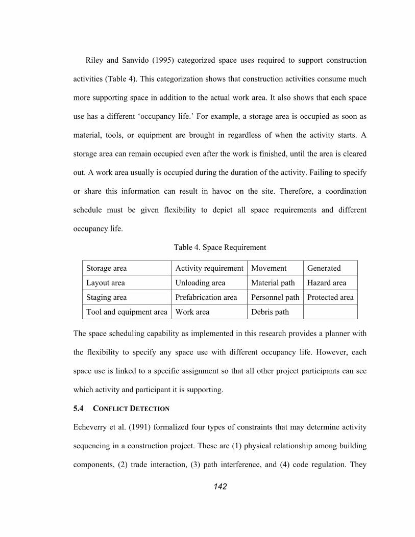
142
Riley and Sanvido (1995) categorized space uses required to support construction
activities (Table 4). This categorization shows that construction activities consume much
more supporting space in addition to the actual work area. It also shows that each space
use has a different ‘occupancy life.’ For example, a storage area is occupied as soon as
material, tools, or equipment are brought in regardless of when the activity starts. A
storage area can remain occupied even after the work is finished, until the area is cleared
out. A work area usually is occupied during the duration of the activity. Failing to specify
or share this information can result in havoc on the site. Therefore, a coordination
schedule must be given flexibility to depict all space requirements and different
occupancy life.
Table 4. Space Requirement
Storage area Activity requirement Movement Generated
Layout area Unloading area Material path Hazard area
Staging area Prefabrication area Personnel path Protected area
Tool and equipment area Work area Debris path The space scheduling capability as implemented in this research provides a planner with
the flexibility to specify any space use with different occupancy life. However, each
space use is linked to a specific assignment so that all other project participants can see
which activity and participant it is supporting.
5.4 CONFLICT DETECTION
Echeverry et al. (1991) formalized four types of constraints that may determine activity
sequencing in a construction project. These are (1) physical relationship among building
components, (2) trade interaction, (3) path interference, and (4) code regulation. They
143
also noted three time dependence constraints. These are (1) space competition, (2)
resource limitations, and (3) unsafe environment effects. Time dependence constraints are
those that can be checked for violation only after the activity start and finish time is
specified. In other words, time dependence constraints can be checked only after the
coordinated schedule has been developed.
The coordinated schedule can be used to detect potential conflicts before they occur
on site. A first potential conflict pertains to prerequisite work. One specialty contractor
may schedule work when prerequisite work has not yet been finished. The prerequisite
relationship must be carefully studied in order to ensure that it will not result in a conflict
on site. One way to avoid this conflict is to schedule the specialty contractor responsible
for the prerequisite work before scheduling the succeeding specialty contractor. These
specialty contractors will have to work together to develop a solution. The responsibility
for coordination does not rest on a single party such as the general contractor or any one
specialty contractor, but rests on several participants involved in a project. The project
coordination system can represent and distribute information about resource schedules
but solutions must come from the participants of the project.
A second potential conflict pertains to personnel and equipment. Since the work force
normally is unique for each specialty contractor, there is practically no chance for a
person to be assigned to work packages belonging to different specialty contractors. But
there is a chance of conflict involving general contractor-provided personnel or
equipment as they often are shared resources, e.g., inspectors, cranes, and elevators..
A third but not the least potential conflict pertains to space. Even though one of the
first duties of a superintendent on a new project is to prepare a job layout (Peurifoy 1956)
144
and field supervisors do spend a large portion of their time managing the site layout,
construction managers have been treating space scheduling as secondary to schedules of
material, equipment, laborers and prerequisite work. This can partially be attributed to
unavailability of a standard for representing space scheduling and tools to support it. A
challenge to be addressed in this research was thus to provide an effective scheduling tool
with a clear representation for space scheduling.
By explicitly assigning space as shown in Figure 61, it can be seen that the HVAC
and the electrical specialty contractors will occupy room 1-B at the same time. Since both
trades apparently require the whole room to execute their work, even though they may
not need all this space at once, they must coordinate by sequencing their work, e.g.,
HVAC may work on the left side of the room first while the electrical contractor works
on the right side first. If the two layouts were superimposed to produce a higher-level site
layout, it becomes obvious what work will be going on in room 1-A and 1-B on the first
floor during the third week.
Each party involved in a project can use PPC to measure whether planned work got
done by the end of a week. Accordingly, each party can achieve a perfect PPC while still
having flexibility within a week to juggle the plans as long as it can finish its work at the
end of a week. But some shared resources, such as a crane, a work area, or a staging area,
and the output of work may need to be handed off during the week. A perfect PPC does
not guarantee that a party has not disrupted another party’s schedule. By looking at the
coordinated plan, each party can determine whether scheduled work can be properly
performed without disrupting another party’s schedule. Numerous other conflicts could
arise.

145
HVACRoom
1-B
ELECRoom
1-B
ELECRoom
1-A
HVAC Electrical Figure 61. Site Layouts for Third Week for Schedule in Figure 60.
Left: site layout for HVAC contractor; Right: site layout for the Electrical contractor
5.5 CONCLUSION
Many obstacles that prevent the new planning methodology to become a new standard
still exist in the industry. One large obstacle is the dominance of the “centralized control”
view. During an interview with a project manager and a superintendent of one of the
largest contracting firms in California, it was clear that the notion of centralized control
prevails in our industry. The superintendent said, “You always want to have more
information than your subs, so that you have leverage over them.” This mentality is both
naive and short-sighted. The lack of transparency of information creates adversarial
relationships and risk. He also said, “We have a very detailed master schedule [with
activity durations no more than 4 to 5 days], so we can keep tight control over the
subcontractors.” When the project manager was asked to estimate PPC, he answered

146
35%. If that is indeed so, clearly, the superintendent’s “tight control” is not very tight.
However, tight control is rarely criticized as being the source of the problem, whereas the
lack of specialty contractors’ abilities to execute as planned often is. Therefore, “tighter
control” is exercised.
A project engineer working on a construction project, which implemented the LPS,
expressed his frustration when trying to shift the subcontractors’ thinking away from
centralized control to distributed control. He said that some subcontractors came back
and said, “Don’t ask us what we can do, but just tell us what to do.” Where these views of
construction management are predominant, acceptance of the Last Planner tools will not
be easy. However, he also commented that “Now they understand [the Last Planner] and
they have accepted it.”
Transitioning from centralized control to distributed control is not easy for all
participants, especially those primarily responsible for production, i.e., general
contractors and specialty contactors. However, with the increasing specialization of
specialty contractors and complexity of projects, and with the rapid advancements in
information technology and communication infrastructure, the change seems to be
underway.
Other obstacles are contracting strategies and performance indicators used on projects.
Current contracting strategy is to divide a project in to small commercial packages
(usually referred to as ‘work packages’) and contract out one or more of these packages
to a specialist. The owner (or prime contractor) then measures performance for each work
package. These performance measurements are usually linked to incentives, i.e., a bonus
or penalty for each specialist. The prevailing mental model for such contracting strategies

147
is the “win-lose” model, not a “win-win” model. In such cases, the guideline for making a
decision is “what is in it for me?” rather than “what is in it for the project/client?” The
“win-lose” model does not promote a cooperative environment. More research is needed
on contracting methods and performance indicators that are aligned with the LPS.

148
6 WORKMOVEPLAN
WorkMovePlan (Choo and Tommelein 1999) is an extension of WorkPlan developed to
support distributed planning and coordination. In WorkPlan and DePlan, coordination
information is managed by treating it as a constraint. However, even if all specialty
contractors (or other production units) developed quality weekly work plans, the
interaction between them would be coordinated better if managed explicitly to guarantee
a smooth execution of work. WorkMovePlan combines the LPS, implemented in
WorkPlan, with distributed scheduling and coordination, space scheduling, and web
posting features.
6.1 DESIGN
WorkMovePlan assists specialty contractors in the co-creation of coordinated weekly
work plans from each specialty contractor’s quality weekly work plan. The
implementation of WorkMovePlan inherits all functionality of WorkPlan and extends its
capability to support distributed planning and coordination as well as space scheduling.
The distributed planning and coordination capabilities allow production units to increase
the reliability of their plans by sharing work package-, space scheduling-, and constraint
information. The space scheduling capabilities allow each planner to explicitly allocate
space, including workspaces, laydown areas, storage areas, and access paths.
6.1.1 System and Data Architecture of WorkMovePlan
WorkMovePlan’s distributed planning and coordination feature is based on near real time
data sharing. Near real time data sharing is based on technology called synchronization,
meaning “the process of updating two replicas in which all updated records and objects
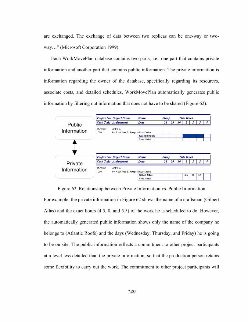
149
are exchanged. The exchange of data between two replicas can be one-way or two-
way…” (Microsoft Corporation 1999).
Each WorkMovePlan database contains two parts, i.e., one part that contains private
information and another part that contains public information. The private information is
information regarding the owner of the database, specifically regarding its resources,
associate costs, and detailed schedules. WorkMovePlan automatically generates public
information by filtering out information that does not have to be shared (Figure 62).
PublicInformation
PrivateInformation
Figure 62. Relationship between Private Information vs. Public Information
For example, the private information in Figure 62 shows the name of a craftsman (Gilbert
Atlas) and the exact hours (4.5, 8, and 5.5) of the work he is scheduled to do. However,
the automatically generated public information shows only the name of the company he
belongs to (Atlantic Roofs) and the days (Wednesday, Thursday, and Friday) he is going
to be on site. The public information reflects a commitment to other project participants
at a level less detailed than the private information, so that the production person retains
some flexibility to carry out the work. The commitment to other project participants will
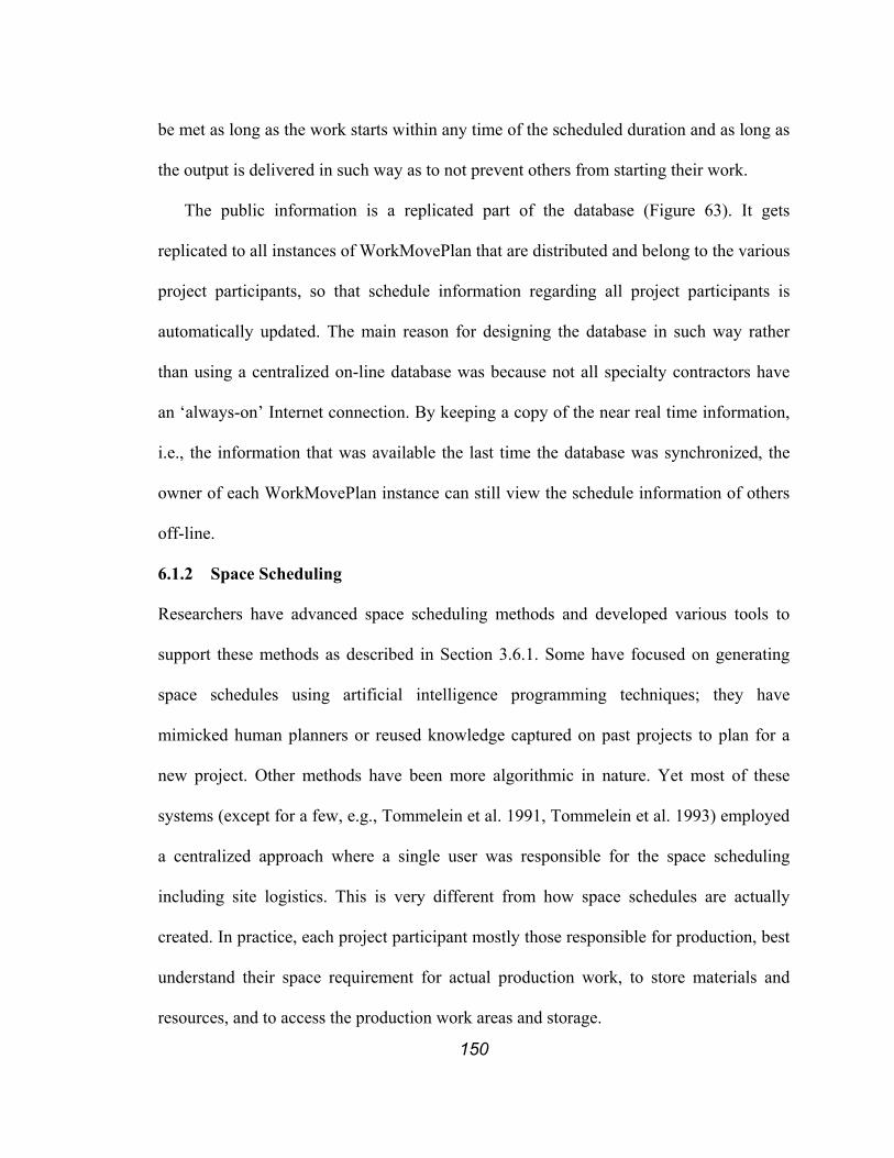
150
be met as long as the work starts within any time of the scheduled duration and as long as
the output is delivered in such way as to not prevent others from starting their work.
The public information is a replicated part of the database (Figure 63). It gets
replicated to all instances of WorkMovePlan that are distributed and belong to the various
project participants, so that schedule information regarding all project participants is
automatically updated. The main reason for designing the database in such way rather
than using a centralized on-line database was because not all specialty contractors have
an ‘always-on’ Internet connection. By keeping a copy of the near real time information,
i.e., the information that was available the last time the database was synchronized, the
owner of each WorkMovePlan instance can still view the schedule information of others
off-line.
6.1.2 Space Scheduling
Researchers have advanced space scheduling methods and developed various tools to
support these methods as described in Section 3.6.1. Some have focused on generating
space schedules using artificial intelligence programming techniques; they have
mimicked human planners or reused knowledge captured on past projects to plan for a
new project. Other methods have been more algorithmic in nature. Yet most of these
systems (except for a few, e.g., Tommelein et al. 1991, Tommelein et al. 1993) employed
a centralized approach where a single user was responsible for the space scheduling
including site logistics. This is very different from how space schedules are actually
created. In practice, each project participant mostly those responsible for production, best
understand their space requirement for actual production work, to store materials and
resources, and to access the production work areas and storage.
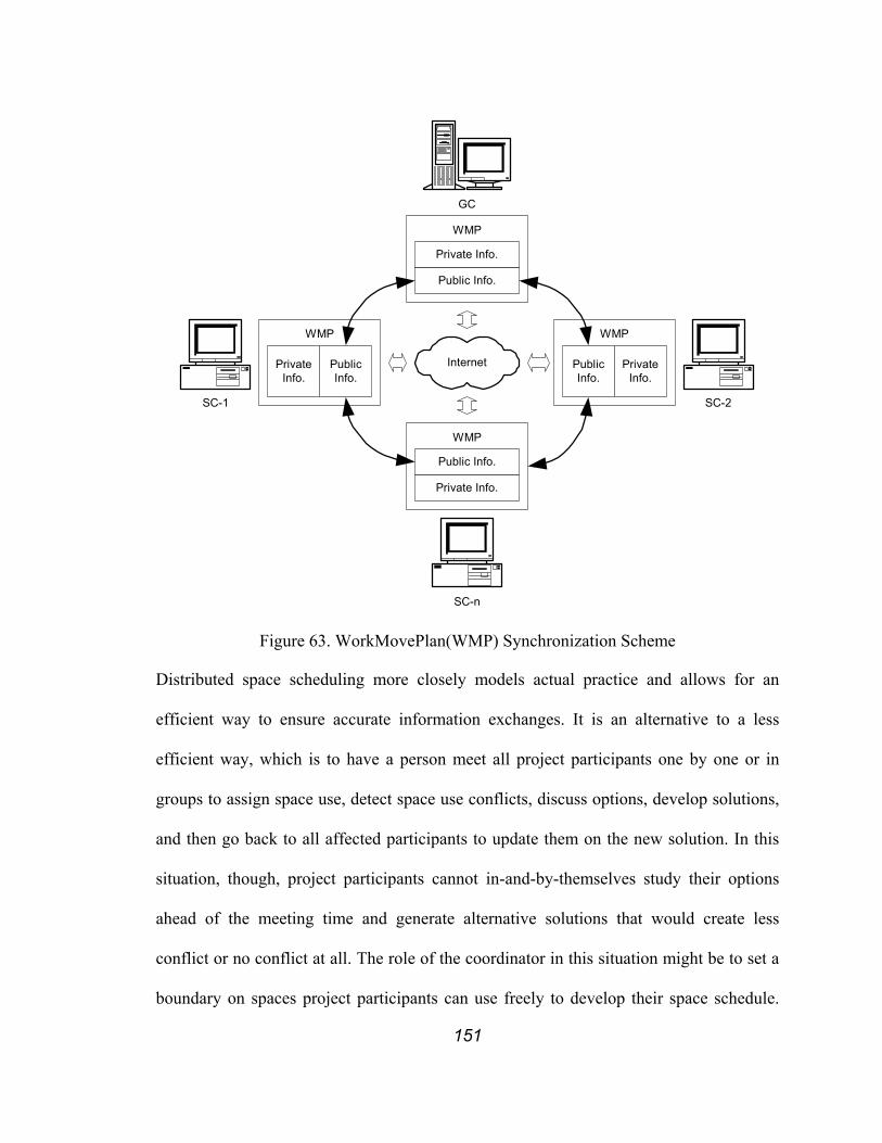
151
WMP
SC-1
GC
SC-2
SC-n
Internet
Private Info.
Public Info.
WMP
WMP
Public Info.
Private Info.
WMP
PublicInfo.
PrivateInfo.
PublicInfo.
PrivateInfo.
Figure 63. WorkMovePlan(WMP) Synchronization Scheme
Distributed space scheduling more closely models actual practice and allows for an
efficient way to ensure accurate information exchanges. It is an alternative to a less
efficient way, which is to have a person meet all project participants one by one or in
groups to assign space use, detect space use conflicts, discuss options, develop solutions,
and then go back to all affected participants to update them on the new solution. In this
situation, though, project participants cannot in-and-by-themselves study their options
ahead of the meeting time and generate alternative solutions that would create less
conflict or no conflict at all. The role of the coordinator in this situation might be to set a
boundary on spaces project participants can use freely to develop their space schedule.

152
Once all project participants have determined their space use within those boundaries,
these space schedules can be integrated to produce a total solution. If a project
participant’s space use extends beyond the boundaries, the boundaries and space use of
the affected participants will have to be revisited.
WorkMovePlan extends WorkPlan’s planning procedure for labor and equipment to
include space scheduling (explained in 5.3). A planner can specify site space needs on a
day-to-day basis for labor, equipment, and materials in terms of work-, laydown-, staging
area, or access path as needed throughout the execution of a work package.
WorkMovePlan requires the user to explicitly input information on resources that
need to be considered during space scheduling (Figure 64). Default categories refer to
material, equipment, and labor but others can be included, if needed. Shape refers to the
physical shape of the space required. X, Y, and Z refer to the dimensions of the space.
Elzarka and Bell (1995) integrated materials management with a scheduling system to
allow for the procurement schedule to be driven by construction. Such a system would
further benefit from integration with explicit information about the production work
performed on site so that procurement schedule can be developed and adjusted to meet
changing site needs.
Lean construction allows for “pulling” materials to the site by making information
about the production work explicit (e.g., Tommelein 1997a, 1997b). With this
information, procurement decisions can be made such as when and how much material
need to be pulled to which location. In addition, materials could be specified in terms of
the space they will require on site. If the start date of an activity can be anticipated with
more time than the lead-time needed to procure and deliver a material, then delivery dates
153
can be scheduled so that the material will arrive just-in-time or with only a minimal lead-
time.
Figure 64. Space Scheduling Screen
Doing so is far more advantageous (as discussed in Section 3.3.2.2) than following a
“push” approach where the material is purchased and delivered to the site not knowing
precisely when the activity actually will start. The planner then must allow for the
material to be delivered some additional time in advance of the anticipated activity start
so that the activity will not be delayed due to material shortage. This thinking can also be
applied to equipment. Therefore weekly work planning must include a material and

154
equipment schedule in addition to a laborer schedule so that space can be assigned to
them.
The list in the middle of the space scheduling screen (Figure 64) shows the schedule
for labor and equipment assigned to the selected work package. Although the default
schedule for space use is from the first day of labor or equipment assignment to the last
day, it can be adjusted to represent actual day-by-day needs.
The “Resources to be on site” list refers to all resources that have been input through
the space scheduling screen. These resources will share site space for the week under
consideration. Once all resources to be assigned are specified, their positions can be
selected using a GUI, namely Visio (Microsoft Corporation 2002). Figure 65 shows a
sample screen of the finished space schedule.
Figure 65. Completed Space Scheduling Screen
6.2 IMPLEMENTATION
The work package structure to support multi-level planning and explicit link to master
schedule (both discussed in Section 5.2) is implemented in WorkMovePlan. Figure 66
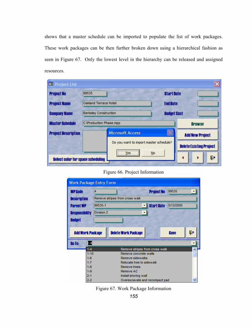
155
shows that a master schedule can be imported to populate the list of work packages.
These work packages can be then further broken down using a hierarchical fashion as
seen in Figure 67. Only the lowest level in the hierarchy can be released and assigned
resources.
Figure 66. Project Information
Figure 67. Work Package Information
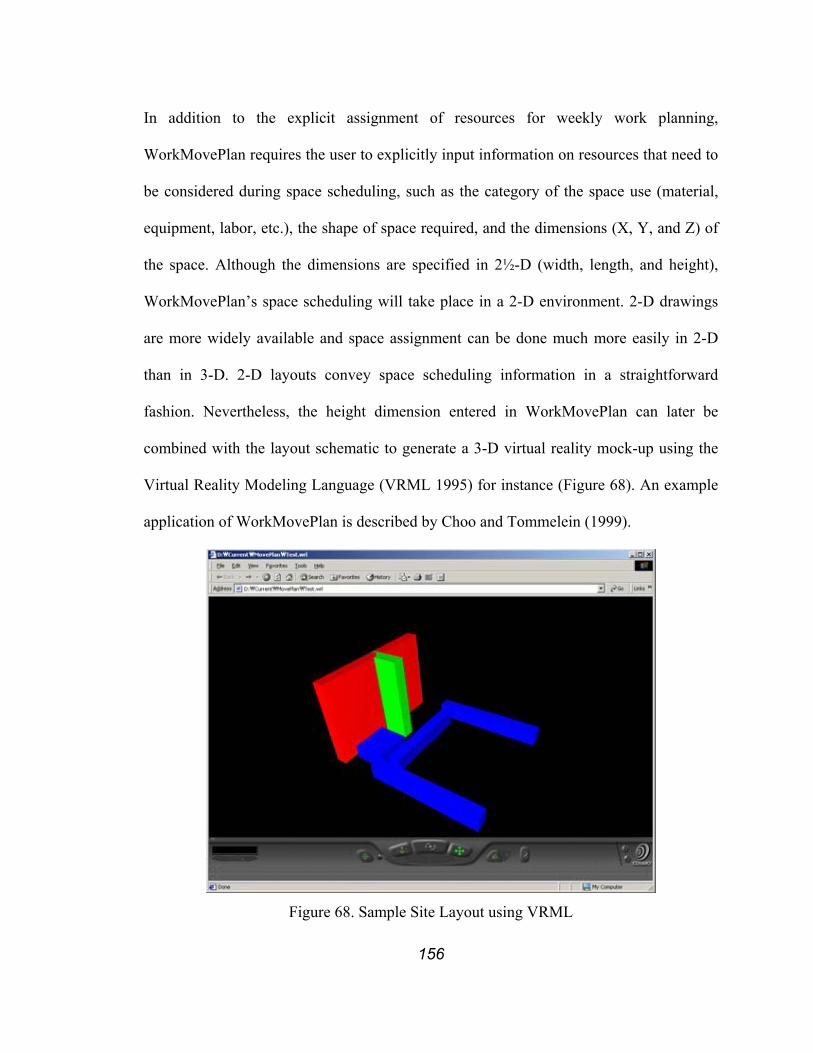
156
In addition to the explicit assignment of resources for weekly work planning,
WorkMovePlan requires the user to explicitly input information on resources that need to
be considered during space scheduling, such as the category of the space use (material,
equipment, labor, etc.), the shape of space required, and the dimensions (X, Y, and Z) of
the space. Although the dimensions are specified in 2½-D (width, length, and height),
WorkMovePlan’s space scheduling will take place in a 2-D environment. 2-D drawings
are more widely available and space assignment can be done much more easily in 2-D
than in 3-D. 2-D layouts convey space scheduling information in a straightforward
fashion. Nevertheless, the height dimension entered in WorkMovePlan can later be
combined with the layout schematic to generate a 3-D virtual reality mock-up using the
Virtual Reality Modeling Language (VRML 1995) for instance (Figure 68). An example
application of WorkMovePlan is described by Choo and Tommelein (1999).
Figure 68. Sample Site Layout using VRML
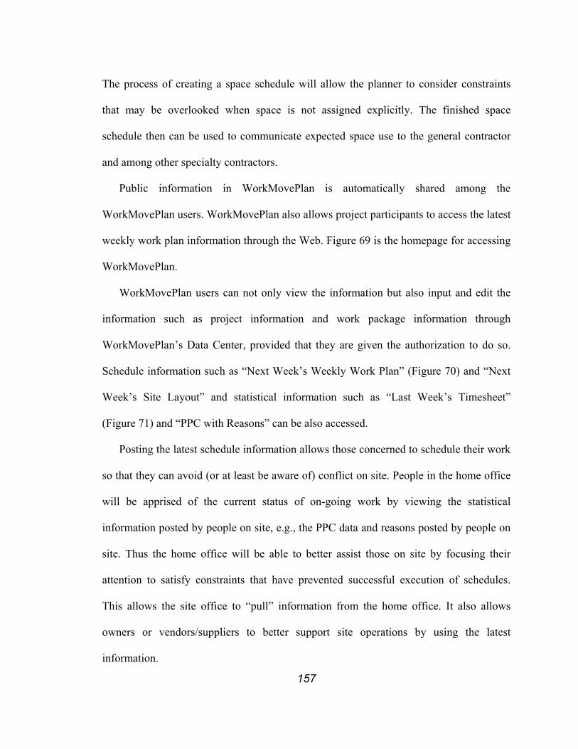
157
The process of creating a space schedule will allow the planner to consider constraints
that may be overlooked when space is not assigned explicitly. The finished space
schedule then can be used to communicate expected space use to the general contractor
and among other specialty contractors.
Public information in WorkMovePlan is automatically shared among the
WorkMovePlan users. WorkMovePlan also allows project participants to access the latest
weekly work plan information through the Web. Figure 69 is the homepage for accessing
WorkMovePlan.
WorkMovePlan users can not only view the information but also input and edit the
information such as project information and work package information through
WorkMovePlan’s Data Center, provided that they are given the authorization to do so.
Schedule information such as “Next Week’s Weekly Work Plan” (Figure 70) and “Next
Week’s Site Layout” and statistical information such as “Last Week’s Timesheet”
(Figure 71) and “PPC with Reasons” can be also accessed.
Posting the latest schedule information allows those concerned to schedule their work
so that they can avoid (or at least be aware of) conflict on site. People in the home office
will be apprised of the current status of on-going work by viewing the statistical
information posted by people on site, e.g., the PPC data and reasons posted by people on
site. Thus the home office will be able to better assist those on site by focusing their
attention to satisfy constraints that have prevented successful execution of schedules.
This allows the site office to “pull” information from the home office. It also allows
owners or vendors/suppliers to better support site operations by using the latest
information.

158
Figure 69. WorkMovePlan Data Center
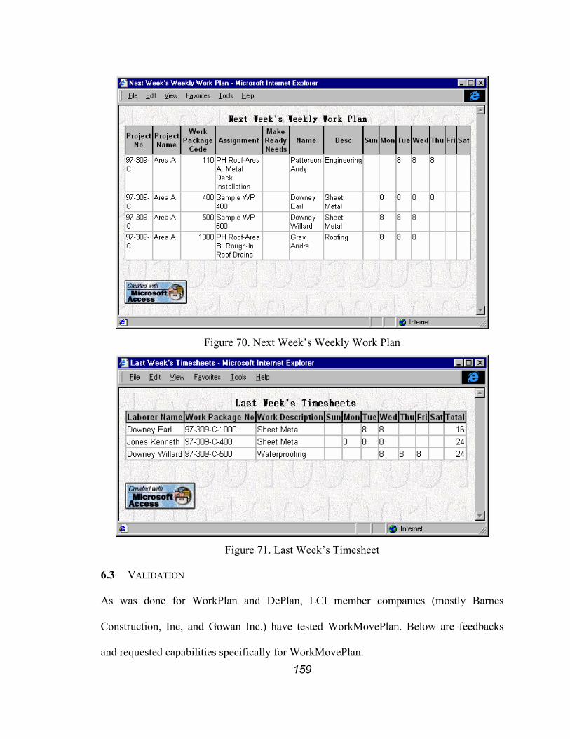
159
Figure 70. Next Week’s Weekly Work Plan
Figure 71. Last Week’s Timesheet
6.3 VALIDATION
As was done for WorkPlan and DePlan, LCI member companies (mostly Barnes
Construction, Inc, and Gowan Inc.) have tested WorkMovePlan. Below are feedbacks
and requested capabilities specifically for WorkMovePlan.

160
• Coordination Meeting Support
Implementation of the Last Planner process relies heavily on the ability to collect
information especially during the development of constraints, analysis of work
package status, and formulation of reasons for failure. Information collection can
occur either in a face-to-face meeting or in a distributed fashion. Regardless of
how information is collected, coordination meetings will be helpful for project
participants to get to know each other and establish a basis for communication, to
identify and resolve conflicts, and to clear up vague items. In these meetings, the
most up-to-date information needs to be available to the meeting participants in a
format that they can easily recognize and interpret. The tools should be easy-to-
use and easy-to-understand so that it could be used in the meeting if necessary.
• Effective Information Distribution
Once all updates have been collected and processed, the latest information needs
to be distributed either electronically or in hard-copy format. WorkMovePlan
automatically synchronizes with other instances WorkMovePlan to ensure that
every project participant has the latest information. WorkMovePlan also allows a
planner to view the latest information on the web. This information is either
pulled or pushed depending on the frequency of updates and their data formats.
WorkMovePlan already provides many preformatted reports, ready to be sent out
or printed. What additional information needs to be distributed and in which form
needs further study.
During the validation of WorkPlan and Deplan, it was identified that an
efficient way to distribute the constraints to each responsible party or person right
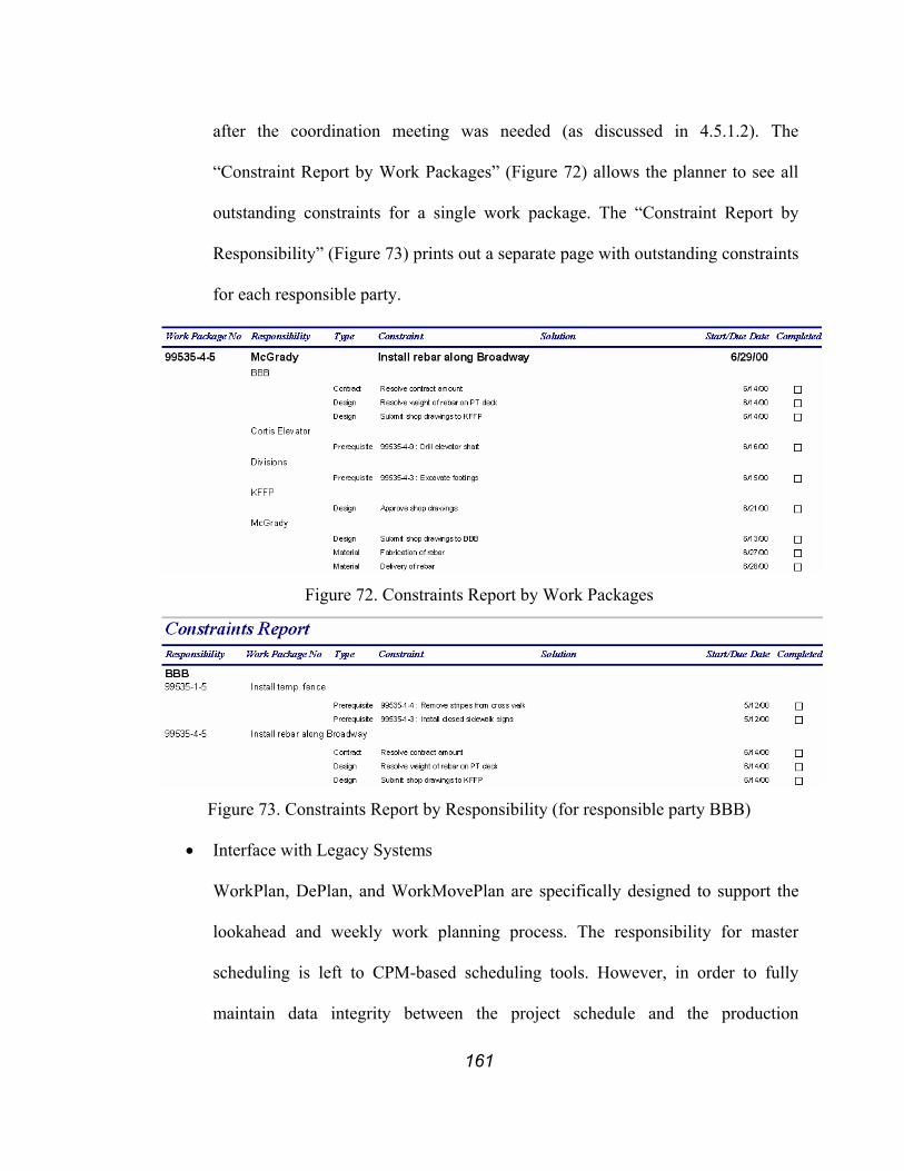
161
after the coordination meeting was needed (as discussed in 4.5.1.2). The
“Constraint Report by Work Packages” (Figure 72) allows the planner to see all
outstanding constraints for a single work package. The “Constraint Report by
Responsibility” (Figure 73) prints out a separate page with outstanding constraints
for each responsible party.
Figure 72. Constraints Report by Work Packages
Figure 73. Constraints Report by Responsibility (for responsible party BBB)
• Interface with Legacy Systems
WorkPlan, DePlan, and WorkMovePlan are specifically designed to support the
lookahead and weekly work planning process. The responsibility for master
scheduling is left to CPM-based scheduling tools. However, in order to fully
maintain data integrity between the project schedule and the production

162
schedules, WorkPlan, DePlan, or WorkMovePlan, and CPM-based master
scheduling tools need to work together. WorkMovePlan allows CPM-based
master schedule to be imported from Microsoft Project (Microsoft Corporation
2000c), as discussed in Section 6.2 to promote data integrity between the project
schedule and the production schedule. Capability to export to the CPM-based
master scheduling tool from WorkMovePlan has not been automated yet.
However, author is currently involved in a development of such a tool in a large
and complex project.
Additionally, many companies have their own accounting system and are not
keen on changing it in any way. Therefore, the Last Planner tools must be able to
interact with these systems as well. Other interfaces might include interfaces to a
personnel database, an equipment maintenance database, document control tools,
etc.
The latest version of WorkMovePlan already has most of these requested features.
Nevertheless, some feedbacks were not acted on because they were not directly aimed at
providing a reliable and easy to use tool that would promote higher plan reliability.
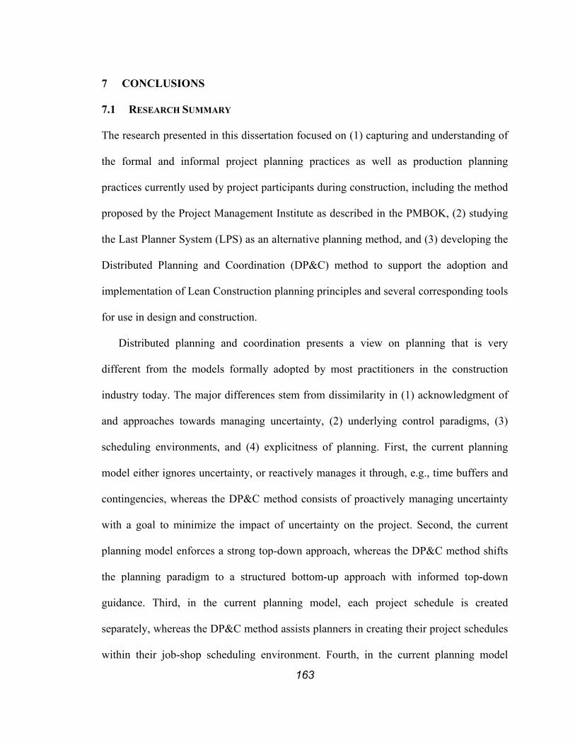
163
7 CONCLUSIONS
7.1 RESEARCH SUMMARY
The research presented in this dissertation focused on (1) capturing and understanding of
the formal and informal project planning practices as well as production planning
practices currently used by project participants during construction, including the method
proposed by the Project Management Institute as described in the PMBOK, (2) studying
the Last Planner System (LPS) as an alternative planning method, and (3) developing the
Distributed Planning and Coordination (DP&C) method to support the adoption and
implementation of Lean Construction planning principles and several corresponding tools
for use in design and construction.
Distributed planning and coordination presents a view on planning that is very
different from the models formally adopted by most practitioners in the construction
industry today. The major differences stem from dissimilarity in (1) acknowledgment of
and approaches towards managing uncertainty, (2) underlying control paradigms, (3)
scheduling environments, and (4) explicitness of planning. First, the current planning
model either ignores uncertainty, or reactively manages it through, e.g., time buffers and
contingencies, whereas the DP&C method consists of proactively managing uncertainty
with a goal to minimize the impact of uncertainty on the project. Second, the current
planning model enforces a strong top-down approach, whereas the DP&C method shifts
the planning paradigm to a structured bottom-up approach with informed top-down
guidance. Third, in the current planning model, each project schedule is created
separately, whereas the DP&C method assists planners in creating their project schedules
within their job-shop scheduling environment. Fourth, in the current planning model
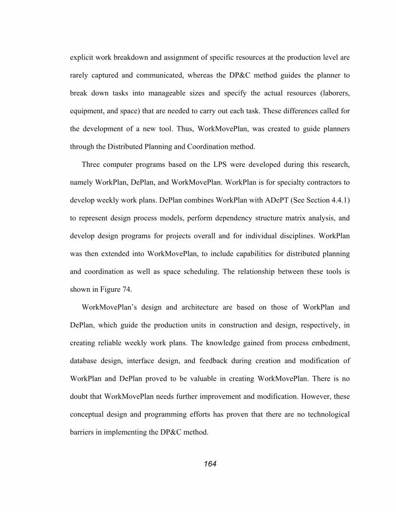
164
explicit work breakdown and assignment of specific resources at the production level are
rarely captured and communicated, whereas the DP&C method guides the planner to
break down tasks into manageable sizes and specify the actual resources (laborers,
equipment, and space) that are needed to carry out each task. These differences called for
the development of a new tool. Thus, WorkMovePlan, was created to guide planners
through the Distributed Planning and Coordination method.
Three computer programs based on the LPS were developed during this research,
namely WorkPlan, DePlan, and WorkMovePlan. WorkPlan is for specialty contractors to
develop weekly work plans. DePlan combines WorkPlan with ADePT (See Section 4.4.1)
to represent design process models, perform dependency structure matrix analysis, and
develop design programs for projects overall and for individual disciplines. WorkPlan
was then extended into WorkMovePlan, to include capabilities for distributed planning
and coordination as well as space scheduling. The relationship between these tools is
shown in Figure 74.
WorkMovePlan’s design and architecture are based on those of WorkPlan and
DePlan, which guide the production units in construction and design, respectively, in
creating reliable weekly work plans. The knowledge gained from process embedment,
database design, interface design, and feedback during creation and modification of
WorkPlan and DePlan proved to be valuable in creating WorkMovePlan. There is no
doubt that WorkMovePlan needs further improvement and modification. However, these
conceptual design and programming efforts has proven that there are no technological
barriers in implementing the DP&C method.
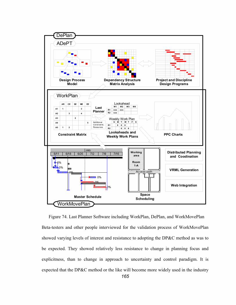
165
Dependency StructureMatrix Analysis
Design ProcessModel
ADePT
Lookaheads andWeekly Work PlansConstraint Matrix
WorkPlan
1
A2
AR CE SE ME EE
A1
3
3
4
A4
A3 2
5
1A5 2 R2R1
S M T W T8 8
888 8
F S
R1R2
W1 W2xxx xxx
W3 W4
xxx
Weekly Work Plan
Lookahead
AdditionalConstraints ,Resources
LastPlanner
PPC Charts
Project and DisciplineDesign Programs
DePlan
Workingarea
Room1-A
Access path
WorkMovePlanMaster Schedule Space
Scheduling
Distributed Planningand Coodination
VRML Generation
Web Integration
Figure 74. Last Planner Software including WorkPlan, DePlan, and WorkMovePlan
Beta-testers and other people interviewed for the validation process of WorkMovePlan
showed varying levels of interest and resistance to adopting the DP&C method as was to
be expected. They showed relatively less resistance to change in planning focus and
explicitness, than to change in approach to uncertainty and control paradigm. It is
expected that the DP&C method or the like will become more widely used in the industry
166
as inefficiencies of tight centralized control are becoming untenable and Lean
Construction gains momentum in changing how projects are delivered.
7.2 CONTRIBUTIONS TO KNOWLEDGE
The thesis set forth in this dissertation, i.e., that an interactive planning and coordination
method will help to decentralize and improve planning performance by providing
communication channels for reliably coordinating schedules at the appropriate level of
detail, and the corresponding research, have resulted in several contributions to
knowledge.
7.2.1 Understanding of Current Project Planning Practices and Production
Planning Practices and Their Interrelationship
This dissertation has presented an overall picture of formal and informal planning,
scheduling, and coordinating practices currently used in the construction industry; it also
described the interrelationships between those practices. An overall picture was compiled
from findings based on (1) review of the literature on various planning methods and
planning tools, (2) interviews with project managers, project engineers, superintendents,
and foremen from construction companies of varying sizes, and (3) feedback received
during implementation and testing of WorkPlan, DePlan, and WorkMovePlan.
On one hand, project planning techniques based on network models (such as CPM)
were widely accepted. However, interviewees more often than not complained about their
ineffectiveness in managing the production according to the schedule. These findings
were consistent with findings of numerous other researchers. On the other hand,
superintendents and foremen were using some form of production planning tool to
execute their projects. These tools were neither systemized nor formalized. A clearer

167
understanding of the current practices has pointed out a direction for improvement and a
need for tools to support the transition towards integrated project- and production
planning.
7.2.2 Paradigm Shift from Centralized to Distributed Planning
The Distributed Planning and Coordination (DP&C) method presents a model that is very
different from the widely accepted practice of centralized planning, where a single or
several planner(s) from a general contractor’s organization (or an external planning
specialist such as a construction management firm) creates a detailed project schedule
with limited input from the specialty contractors. These inputs are usually reactive
feedback on planning decisions already made by the project scheduler(s). The DP&C
method is based on a distributed control view, where the decision-making responsibility
is pushed down to the production units with minimal if any constraints added by the
project scheduler(s).
The detailed production plans created in such a distributed environment does not
necessarily guarantee the “optimal” solution in terms of duration or cost. It, however,
guarantees the accuracy of information regarding activity description, activity duration,
activity sequencing, and resource assignment. It also facilitates the buy-in of the
production teams that will execute the plans as it is created by them. Thus, it could be
argued that the “optimality” of the production plans created in a DP&C environment is
measured in terms of how accurately and reliably the plan describes the execution of plan.
The advancement of the Internet as well as other wireless communication technology
has brought an end to many formal routes of communication. They have opened up many
unorthodox routes for communication between participants. There is practically no way

168
to prevent anyone or any organization from communicating with one another. These
communication channels will enable planners to have more accurate and timely
information. However, these communication channels may violate or eliminate need for
some of the existing channels. These violations may have legal implications. The author
has many instances where a more efficient route of communication had to be altered for
the sake of meeting legal requirements. Nevertheless, some industry leaders are making
effort to minimize such instances.
The trend towards decentralization of decision-making is consistent with movements
in other industries. Distributed planning and coordination will create a need for more
effective yet more unorthodox routes of communication.
7.2.3 Shifting Single-Focus Planning Focus to Dual-Focus Planning
Specialty contractors’ involvement on a project tends to be intermittent and relatively
short compared to the total project schedule. Additionally, the required capacity required
from them varies from project to project. In order to effectively use their production
capacity, specialty contractors work on multiple projects simultaneously or move to and
from jobsites as needed. Thus, their planning efforts resemble those used in job-shop
scheduling where each job is a designated portion of the project, i.e., their scope of work.
A change or a conflict in one project can effect the start date, end date, or resource
availability for another project. A shift is thus needed from single-focus planning, which
means that specialty contractors’ schedules for each project is created independent of
each specialty contractor’s resource loads and dependencies across multiple projects, to
dual-focus planning, which means that specialty contractors’ schedules need to be created
within a framework that allows their resource loads and dependencies across multiple

169
projects to be explicitly described and managed. WorkMovePlan supports dual-focus
planning where specialty contractors can plan their project schedule under a job-shop
environment while maintaining links to project information.
7.2.4 Managing Uncertainty and Reliability
The author learned from attending many design and construction coordination meetings
and studying planning system performance on several projects that much disturbance can
be avoided with proactive management of uncertainty through reliable planning and
communication among project participants.
Two by-products of preliminary research, namely the StroboCPM and the ‘Parade of
Trades’ software the author developed, graphically demonstrate the effect of uncertainty
and dependency in construction projects. StroboCPM allows users to graphically view the
effect of uncertainty on the project duration. The Parade of Trades allows users to
graphically view the importance of reliable planning. The author has used the Parade of
Trades discussed in 3.6) in many presentations for educational purposes. This software is
being freely distributed in order to promote need for better management of uncertainty
(http://www.ce.berkeley.edu/~tommelein/parade.htm). The author has also participated in
many workshops held by Strategic Project Solutions, Inc. and Lean Construction Institute
where the Dice Game (discussed in 3.6) is used to demonstrate the effect of uncertainty
and dependency. After the result of the game is reviewed, most of the workshop
participants report that the construction industry currently lacks the understanding of
effect of uncertainty and dependency. They also suggest that a revolution in thinking is
needed in order to move toward recognizing and then proactively managing uncertainty
and dependency.
170
7.2.5 Computer Tool for Production Planning in Construction Based on the Last
Planner
Three computer tools have resulted from this research, namely WorkPlan, DePlan, and
WorkMovePlan.These are among the first computer-based production planning tools
created specifically for use in construction. These tools offer a very different approach to
planning than commercially available tools.
The use of these Last Planner tools is closely tied to the adoption of the LPS.
Currently, practitioners first adopt the LPS, and then look for supporting computer tools.
It remains to be seen whether the use of tools, such as those presented here, can lead to
the wide acceptance of lean construction principles with the LPS in its broadest sense,
encompassing front-end planning and lookahead planning as well.
7.2.6 Distributed Space Scheduling to Support Production Management
WorkMovePlan adopts the DP&C method to space scheduling. The program facilitates
distributed space scheduling by allowing users to create their own space schedules and
communicating these schedules to all project participants. Project participants can, thus,
have the latest space schedules available and plan their space use accordingly. This
research represents one among the first suggestions that space scheduling for construction
be done in a distributed fashion. Although much more robust and user-friendly tools are
desired, WorkMovePlan has created a platform for further research in this area.
7.3 FUTURE RESEARCH ISSUES AND QUESTIONS
The author is currently working for a company that is implementing an ASP version of a
distributed planning and coordination system, similar to the DP&C system presented in
this dissertation, as part of a solution for a very large and complex project. The author’s

171
main role is to lead the design process and to program the system, as well as to
implement the methodology and the tools to support the design and construction phase of
this project. Many research questions remain and new issues have come to bear as this
project is advancing.
7.3.1 Distributed Planning and Coordination Method
The author is in the process of further improving the DP&C method. Some questions that
need more research are the following:
1. “What is the best work structuring strategy DP&C?”
The latest understanding of the requirements suggests using “work package” as the
interface between the general contractor and assignments to support detailing of the
production work done by specialty contractors. However, this does not guarantee that the
schedules will have adequate detail or an adequate level of abstraction for others to
understand what is really going on, as many project participants speak a “different
language.” Since the schedule serves as a communication tool in the distributed planning
scheme, it must be explicit enough for other participants to be comprehensive while at the
same time showing enough detail to support coordination effort and conflict detection.
Ballard (2000b) proposes phase scheduling as the mechanism for defining handoffs
between specialists and between scheduling and control. A further study is required to
determine what the right levels of detail are adequate for coordination at the phase
scheduling level and production level. The answer to this question also heavily depends
on the answers to the next questions.
2. “What is the best organizational structure DP&C?”
172
The discussion and examples in this research used a specialty-based organization
structure, where a WorkMovePlan user corresponds to a specialty contractor. However,
the author’s current endeavour suggests that a cross-functional group of project
participants that represent an area, a product, or a system may be a better organizational
structure for DP&C in a large, complex project. This organizational structure allows
project participants who need to coordinate their actions more frequently to co-create a
solution before it is communicated to others who have fewer coordination needs.
3. “Will participants be willing to detail their schedule and reveal it to others?”
Revealing a detailed schedule to others may commit that party to performing exactly
what is in the schedule. Participants fear, if they are unable to deliver, that this will get
them into claims and disputes as is all too true when CPM schedules are being misused.
Clearly, performance data needs to be used for improving planning performance, rather
than for all-too-closely monitoring production units. Also, if the planning system is
reliable so that what is scheduled can be delivered, there is less of a chance for a claim or
dispute. If claims or disputes do occur, the party that has maintained explicit data on the
issue at hand is more likely to be successful to get their point across.
4. “What is the impact of DP&C on the overall system?”
Planning is only one managerial task in administering a construction project. The impact
of distributed planning and coordination on other aspects of construction project delivery
such as contracts, accounting, or project controls, remains to be studied.
5. “What is the best way to implement the DP&C?”
As discussed in Section 5.5, the main barriers to implementation of DP&C are not
technology but many current mental models and contracting strategies. Therefore, project

173
participants need to be continuously taught and trained so that DP&C can be properly
implemented. Their contractual relationship with other participants as well as their
individual needs must be addressed as well.
7.3.2 Shifting Single-Focus Planning Focus to Dual-Focus Planning
The dual-focus planning system closely resembles the planning process production units
actually use in practice today. WorkMovePlan systemizes the process, and may be a first
in that regard. In WorkMovePlan, the planners are required to explicitly represent their
planning decision. How to best represent data to accommodate both the project centric as
well as the production unit centric view at the same time needs further research. Also, the
tool needs to be further developed to accommodate “what-if” analyses to better assist
planners in developing alternatives and making choices.
7.3.3 Computer Tool for Production Planning in Construction Based on the Last
Planner
WorkPlan, DePlan, and WorkMovePlan acan be further improved and expanded.
Changes need to occur in architecture, operating platform, and user interface. The scope
of the tools needs to expand to include master scheduling including work structuring and
supply chain management. The author’s experience during this research as well as on-
going commercial efforts will allow him to better understand the requirements for these
tools.
Various companies and researchers are toying with computer implementations of the
LPS. The author hopes that the computer tools developed in this research will encourage
others to do the same, so that lean construction will be practiced on a broader scale.
174
7.3.4 Distributed Space Scheduling to Support Production
The distributed space scheduling system developed as part of WorkMovePlan uses 2½D
dimensions to specify space uses. However, for more accurate analysis of alternative
space uses and access, the tool needs to be linked with a 3-D product model. As
footprints and heights for material and equipment change according to their orientation
and stacking method, value may be derived from using 3-D objects.
Also, a scheme to accommodate hierarchical space scheduling has to be developed.
As done for planning and scheduling of tasks, space scheduling needs to be developed in
a hierarchical fashion (e.g., Tommelein (1989), Thabet (1992)). The general contractor
can designate certain areas for each specialty contractor. Then each specialty contractor
can develop a more detailed space schedule as space requirements become clearer. In the
current implementation of WorkMovePlan, space uses can be overlapped to represent
different detail levels of space assignment. However, there is no direct link to
accommodate automatic abstraction and grouping of the space use.
7.3.5 Impact of DP&C on Other Project Control Systems
Most large and complex projects use many different computer-based systems including
budget and cost monitoring tools, contract management tools, document management
tools, drafting tools, 3-D modeling tools, and other planning tools. How DP&C affects
the use of these other systems has yet to be made clear. For example, Kim and Ballard
(2000) have pointed out that using earned value analysis to measure project progress is
contrary to the spirit of the LPS, and the author is currently involved in designing the
architecture to use 3-D modeling to enforce the LPS. However, more research is desired
regarding these and other project control systems.

175
7.4 CONCLUSION
The research presented in this dissertation captures the theory and the practice of current
project- and production planning and presents the Last Planner System (LPS) as an
alternative planning method. The research also presents Distributed Planning and
Coordination (DP&C) method as a production management strategy that promotes the
adoption and the implementation of the Lean Construction planning principles.
Accordingly, the research has resulted in the conceptualization, development, and
validation of several tools, namely WorkPlan, DePlan, and WorkMovePlan, for
production planning in design and construction. It has also resulted in tools, such as
StroboCPM and Parade of Trades, for use in training.
The DP&C method as well as the tools have revealed that the largest obstacle to
adoption of distributed planning and coordination is not the technology but the
underlying mental model of practitioners that is based on traditional contractual
arrangements, organizational structures, and common practices of the construction
industry. As the construction industry learns to adopt the distributed control paradigm
rather than the centralized control paradigm and develops better understanding and
management process of uncertainties, continuous improvement in the quality of project
delivery can be expected.
176
8 BIBLIOGRAPHY
Aalami, F. (1998). Using Method Models to Generate 4D Production Models. Ph.D.
Dissertation, Civil and Environmental Engineering Department, Stanford University,
CA, USA.
AboutRizk, S. and Mather, K. (1998). “A CAD-Based Simulation Tool for Earthmoving
Construction Method Selection.” Proc. Comp. in Civil Engrg., ASCE, 39-52.
Adeli, H. and Karim, A. (1997). “Scheduling/Cost optimization and Neural Dynamics
Model for Construction.” J. of Constr. Engrg. and Mgmt., ASCE, 123(4), 450-458.
Akinci, B., Fischer, M., and Zabelle, T. (1998). “Proactive Approach for Reducing Non-
value Adding Activities Due To Time-Space Conflicts.” Proc. 6th Ann. Conf. Intl.
Group for Lean Constr. (IGLC-6), August 13-15, Guaruja, Brazil.
Alarcon, L. (Ed.) (1997). Lean Construction. A.A. Balkema, Rotterdam, The Netherlands,
497 pp.
Alarcon, L.F. and Ashley, D.B. (1999). “Playing Games: Evaluating the Impact of Lean
Production Strategies on Project Cost and Schedule.” Proc. 7th Annual Conf. of the Intl.
Group for Lean Constr. (IGLC-7), July 26-28, Univ. of California, Berkeley, CA, USA,
263-273.
Allam, S.G. (1988). “Multi-project scheduling: a new categorization for heuristic
scheduling rules in construction scheduling problems.” Construction Management and
Economics, (6), 93-115.
Arbulu, R.J. and Tommelein, I.D. (2002c). "Contributors to Lead Time in Construction
Supply Chains: Case of Pipe Supports Used in Power Plants." Proc. Winter Simulation

177
Conference 2002 (WSC02), Exploring New Frontiers, December 8-11, San Diego, CA,
USA, 1745-1751.
Arnold, J.A. and Teicholz, P. (1996). “Data Exchange: File Transfer, Transaction
Processing and Application Interoperability.” Proc. 3rd Congress Comp. in Civil
Engrg., Vanegas J. and Chinowsky, P. (Eds.), 438-444.
Austin, S., Baldwin, A., Li, B., and Waskett, P.R. (1999a). “Analytical Design Planning
Technique: a model of the detailed building design process.” Design Studies, (20), 279-
296.
Austin, S.A., Baldwin, A.N., Li, B., and Waskett, P.R. (1999b). “Analytical Design
Planning Technique (ADePT): programming the building design process.” Proc. of
Institution of Civil Engineers; Structures and Buildings, (134), 111-118.
Austin, S., Baldwin, A., Li, B., and Waskett, P.R. (1999c). “Analytical Design Planning
Technique (ADePT): A Dependency Structure Matrix Tool to Schedule the Building
Design Process.” Construction Management and Economics, (17), 155-167.
Austin, S., Baldwin, A., Li, B., and Waskett, P.R. (2000). “Application of the Analytical
Design Planning Technique to Construction Project Management.” Project
Management Journal, 31(2), 48-59.
Backes, P., Norris, J.S., Slostad, J., Bonitz, R., Tso, K., and Tharp, G. (2000). “Mars Polar
Lander Mission Distributed Operations.” IEEE Aerospace 2000, March, 9 pp.
Ballard, G. (1997). “Lookahead Planning: The Missing Link in Production Control.” Proc.
5th Annl. Conf. Intl. Group for Lean Constr. (IGLC-5), Griffith Univ., Gold Coast
Campus, Australia.
178
Ballard, G. (1999a). “Improving Work Flow Reliability.” Proc. 7th Ann. Conf. Intl. Group
for Lean Constr. (IGLC-7), July 26-28, Univ. of California, Berkeley, CA, USA, 275-
286.
Ballard, G. (1999b). “Work Structuring.” LCI Whitepaper-5 (unpublished), Lean
Construction Institute, <http://www.leanconstruction.org>, visited on 11/5/2000.
Ballard, H.G. (2000a). Last Planner System of Production Control. Ph.D. Dissertation,
School of Civil Engineering, The University of Birmingham, UK, May, 192 pp.
Ballard. H.G. (2000b). “Phase Scheduling.” LCI White Paper-7 (unpublished), Lean
Construction Institute, <http://www.leanconstruction.org>, visited on 11/5/2000.
Ballard. H.G. (2000c). “Lean Project Delivery System (Revision 1).” LCI White Paper-8
(unpublished), Lean Construction Institute, <http://www.leanconstruction.org/>, visited
on 11/5/2000.
Ballard, G. and Howell, G. (1994a). “Implementing Lean Construction: Stabilizing Work
Flow.” Proc. 2nd Ann. Conf. Intl. Group for Lean Constr. (IGLC-2), Pontificia Univ.
Catolica de Chile, Santiago, Sept., reprinted in Alarcon (1997).
Ballard, G. and Howell, G. (1994b). “Implementing Lean Construction: Improving
Downstream Performance.” Proc. 2nd Ann. Conf. on Lean Constr. (IGLC-2), Pontificia
Univ. Catolica de Chile, Santiago, Sept., reprinted in Alarcon (1997).
Ballard, G. and Howell, G. (1997). Shielding Production: An Essential Step in Production
Control. Technical Report No. 97-1, Construction Engineering and Management
Program, Civil and Envir. Engrg. Dept., Univ. of California, Berkeley, CA, USA.

179
Ballard, G. and Howell, G. (1998). “Shielding Production: An Essential Step in Production
Control.” J. of Constr. Engrg. and Mgmt., ASCE, 124 (1), 18-24.
Ballard, G. and Howell, G. (1998). “What Kind of Production is Construction?” Proc. 6th
Annl. Conf. Intl. Group for Lean Constr. (IGLC-6), August 13-15, Guaruja, Brazil.
Ballard, G., Howell, G., and Kartam, S. (1994). “Re-Designing Job Site Planning System.”
Proceeding of the ASCE 1st Congress on Computing in Civil Engineering, Washington,
D.C.
Barrie, D.S. and Paulson Jr., B.C. (1992). Professional Construction Management.
McGraw-Hill, Inc., New York, 577 pp.
Baxter, J. and Hepplewhite, R. (2000). “A Hierarchical Distributed Planning Framework
for Simulated Battlefield Entities.” Proc. of 19th Workshop of the UK Planning and
Scheduling Special Interest Group (PLANSIG 2000), December, 10 pp.
Becker, M. (1999). “Project or Program Management?” PM Network, October, 78-79.
BidCom (1999). BidCom. <http://www.bidcom.com/>, visited on 5/5/2000.
Birrell, G.S. (1980). “Construction Planning – Beyond the Critical Path.” Journal of the
Construction Division, ASCE, 106(C03), 389-407.
Birrell, G.S. (1985). “General Contractors’ Management: How Subs Evaluate It.” J. of
Constr. Engrg. and Mgmt., ASCE, 111(3), 244-259.
Bohinsky, J.A. and Fails, D.W. (1991). “Computer Aided Rigging System.” Proc. 7th Conf.
Comp. in Civ. Engrg. and Database Symp., ASCE, Cohn, L.F. and Rasdorf, W. (Eds.),
710-718.

180
BlueLine Online. (1999). BlueLine Online. <http://www.bluelineonline.com>, visited on
11/5/1999.
Bricsnet (2001). Bricsnet. <http://www.bricsnet.com>, visited on 5/15/01.
Buildpoint (2001). Buildpoint <http://www.buildpoint.com>, visited on 5/15/01.
Buzzsaw (2001). Buzzsaw <http://www.buzzsaw.com>, visited on 5/15/01.
Casten, M., Ballard, G., and Howell, G. (1995). First Run Studies. Maraven Refinery,
Cardon, Venezuela.
Cheng, M.Y. and O’Connor, J.T. (1996). “ArcSite: Enhanced GIS for Construction Site
Layout.” J. of Constr. Engrg. and Mgmt., ASCE, 122(4), 329-336.
Cherneff, J., Logcher R., and Sriram, D. (1991). “Integrating CAD with Construction-
Schedule Generation.” J. of Comp. in Civil Engrg., ASCE, 5(1), 64-84.
Choo, H.J., Hammond, J., Tommelein, I.D., Ballard, G., and Austin, S. (2001). “ DePlan:
Tool for Integrated Design Management.” Submitted for review in Automation in
Construction (AIC).
Choo, H.J. and Tommelein, I.D. (1999a). Parade of Trades: A Game for Understanding
Variability and Dependence. Technical Report No. 99-1, Construction Engineering and
Management Program, Civil and Envir. Engrg. Dept., Univ. of California, Berkeley,
CA, USA, <http://www.ce.berkeley.edu/~tommelein/parade.htm>.
Choo, H.J. and Tommelein, I.D. (1999b). “Space Scheduling Using Flow Analysis.” Proc.
7th Ann. Conf. Intl. Group for Lean Constr. (IGLC-7), Univ. of California, Berkeley,
CA, USA, 299-311.

181
Choo, H.J. and Tommelein, I.D. (2000a). “WorkMovePlan: Database for Distributed
Planning and Coordination.” Proc. 8th Ann. Conf. Intl. Group for Lean Constr. (IGLC-
8), July 17-19, Brighton, UK.
Choo, H.J. and Tommelein, I.D. (2000b). “Interactive Coordination of Distributed Work
Plans.” Proc. Construction Congress VI, ASCE, February 20-22, Orlando, Florida,
USA, 11-20.
Choo, H.J. and Tommelein, I.D. (2001). "Requirements and Barriers to Adoption of Last
Planner Computer Tools." Proc. 9th Ann. Conf. of the Intl. Group for Lean Constr.
(IGLC-9), 6-8 August, Singapore.
Choo, H.J., Tommelein, I.D., Ballard, G., and Zabelle, T.R. (1998a). “Constraint-Based
Database for Work Package Scheduling.” Proc. Comp. Congress ‘98, ASCE, 169-180.
Choo, H.J., Tommelein, I.D., Ballard, G., and Zabelle, T.R. (1998b). “WorkPlan Database
for Work Package Production Scheduling.” Proc. 6th Annl. Conf. of the Intl. Group for
Lean Constr. (IGLC-6), August 13-15, Guaruja, Brazil, 12 pp.
Choo, H.J., Tommelein, I.D., Ballard, G., and Zabelle, T.R. (1999). “WorkPlan: Constraint-
based Database for Work Package Scheduling.” J. of Constr. Engrg. and Mgmt.,
ASCE, 125(3), 151-160.
Chua, D.K.H., Jun, S.L., and Hwee, B.S. (1999). “Integrated Production Scheduler for
Construction Look-ahead Planning.” Proc. 7th Ann. Conf. Intl. Group for Lean Constr.
(IGLC-7), Univ. of California, Berkeley, CA, USA, 287-298.
Citadon (2001). Citadon. <http://www.citadon.com>, visited on 5/15/01

182
Cohenca-Zall, D., Laufer, A., Shapira, A., and Howell, G.A. (1994). “Processing of
Planning during Construction.” J. of Constr. Engrg. and Mgmt., ASCE, 120(3), 561-
568.
Collaborative Process Institute (1997). Collaboration in the Building Process. Available at
<http://www.cpinst.org/white.html> visited on 5/20/1998.
Collaborative Structures (1999). Collaborative Structures.
<http://www.costructures.com/home.htm>, visited on 6/20/1999.
Constructware (2001). Constructware. <http://www.constructware.com>, visited on 5/15/01.
Conklin, E.J. and Weil, W. (1998). “Wicked Problems: Naming the Pain in Organizations.”
<http://www.leanconstruction.org/pdf/wicked.pdf>, visited on 3/5/2001.
Darwiche, A., Levitt, R.E., and Hayes-Roth, B. (1988). “OARPLAN: Generating Project
Plans by Reasoning about Objects, Actions, and Resources.” AI EDAM, 2(3), 169-181.
Deming, W.E. (2000). Out of Crisis. MIT Press, Cambridge, MA, 507 pp.
Dechter, R. and Pearl, J (1988). "Network-Based Heuristics for Constraint Satisfaction
Problems." Artificial Intelligence 34(1):1-38, 1988.
Dechter, R., Dechter, A., and Pearl, J. (1990). Optimization in Constraint Networks,
Influence Diagrams, Belief Nets, and Decision Analysis. John Wiley and Suns, Ltd.,
West Sussex, England.
Dzeng, R.J. (1995). CasePlan: A Case-Based Planner and Scheduler for Construction
Using Product Modeling. Ph.D. Dissertation, Civil & Envir. Engrg. Dept., University of
Michigan, Ann Arbor, MI, USA, 327 pp.

183
Dzeng, R.J. and Tommelein, I.D. (1993). “Using Product Models to Plan Construction.”
Proc. 5th Intl. Conf. On Comp. in Civil and Building Engrg., June 7-9, Anaheim, CA,
ASCE, New York, NY, 1778-1785.
Dzeng, R.J. and Tommelein, I.D. (1995). “Case-Based Scheduling Using Product Models.”
2nd Congress on Comp. in Civil Engrg., June 5-8, Atlanta, GA, ASCE, New York, NY,
163-170.
Dzeng, R.J. and Tommelein, I.D. (1997). “Boiler Erection Scheduling Using Product
Models and Case-Based Reasoning.” J. of Constr. Engrg. and Mgmt., ASCE, 123(3),
338-347.
East, E.W. and Kim, S. (1993). “Standardizing Scheduling Data Exchange.” J. of Constr.
Engrg. and Mgmt., ASCE, 119(2), 215-225.
Eastman, C.M. (1972). “Preliminary Report on a System for General Space Planning.”
Communications of the ACM, 15(2), 76-87.
E-Builder (2001). E-builder. <http://www.e-builders.net>, visited on 11/5/2001.
Elzarka, H.M. and Bell, L.C. (1995). “Object-Oriented Methodology for Materials-
Management Systems.” J. of Constr. Engrg. and Mgmt., ASCE, 121(4), 438-445.
Echeverry D., Ibbs, C.W., and Kim, S. (1991). “Sequencing Knowledge for Construction
Scheduling.” J. of Constr. Engrg. and Mgmt., ASCE, 117(1), 118-130.
Faniran O., Oluwoye J., and Lenard D. (1997). “Application of the Lean Production
Concept to Improving the Construction Planning Process.” Proc. 5th Ann. Conf. Intl.
Group for Lean Constr. (IGLC-5), Griffith Univ., Gold Coast Campus, Australia.

184
Fischer, M.A. and Aalami, F. (1996). “Scheduling with Computer-Interpretable
Construction Method Models.” J. of Constr. Engrg. and Mgmt., ASCE, 122(4), 337-
347.
Fischer, M.A., Liston, K., and Kunz, J. (2000). “Requirements and Benefits of Interactive
Workspaces in Construction.” Proc. 8th Intl. Conf. on Comp. in Civil and Building
Engrg., August, Stanford University, CA, USA.
Francis, R.L., McGinnis, L.F. Jr., and White, J.A. (1992). Facility Layout and Location: An
Analytical Approach. Prentice-Hall, Englewood Cliffs, New Jersey, 589 pp.
Froese, T. (1996). “STEP and the Building Construction Core Model.” Proc. 3rd Congress
on Comp. in Civil and Building Engrg., Vanegas J. and Chinowsky, P. (Eds.), ASCE,
New York, NY, 445-451.
Galbraith, J.R. (1974). “Organizational Design: An Information Processing View.”
Interfaces, 4(3), 28-36
Gil, N., Tommelein, I. D., Kirkendall, R.L., and Ballard, G. (2000). "Contribution of
Specialty Contractor Knowledge to Early Design." Proc. 8th Ann. Conf. Intl. Group for
Lean Const. (IGLC-8), 17-19 July, held in Brighton, UK.
Girsch, M. (2000). “Requirements of Reactive Scheduling Systems.” Report on REFRESH
- A Reusable and Extendible Framework for REactive ScHeduling, Institute of
Information Systems, Database & Expert Systems Group, Vienna University of
Technology, Vienna, Austria.
Goldratt, Y.M. (1997). Critical Chain. North River Press Publishing Corporation, Great
Barrington, MA, 246 pp.
185
Hagopian, J., Maxwell, T., and Reed, T. (1994). “A Distributed Planning Concept for Space
Station Payload Operations.” Third Symposium on Space Mission Operations and
Ground Data Systems, Greenbelt, MD.
Hajdu, M. (1997). Network Scheduling Techniques for Construction Project Management.
Kluwer Academic Publishers, 3300 AA Dordrecht, The Netherlands, 133-165.
Halpin, D. (1985). Financial and Cost Concepts for Construction Management. John Wiley
& Sons, Hoboken, NJ, 432 pp.
Halpin, D.W. and Riggs, L.S. (1992). Planning and Analysis of Construction Operations.
Wiley-Interscience, New York, NY, 381 pp.
Hammer, M. (1990). “Reengineering Work: Don’t Automate, Obliterate”, Harvard
Business Review, July-August, 104- 112
Hammond, J., Choo, H.J., Austin, S., Tommelein, I.D., and Ballard, G. (2000). “Integrating
Design Planning, Scheduling, and Control with DePlan.” Proc. 8th Ann. Conf. Intl.
Group for Lean Constr. (IGLC-8), July 26-28, Brighton, UK.
Hendrickson, C., Zozaya-Gorostiza, C., Rehak, D., Baracco-Miller, E., and Lim. P. (1987).
“Expert System for Construction Planning.” J. of Comp. in Civil Engrg., ASCE, 1(4),
253-269.
Heragu, S. (1997). Facilities Design. PWS Publishing Company, Boston, MA, 656 pp.
Hinze, J. and Tracey, A. (1994). “The Contractor-Subcontractor Relationship: The
Subcontractor’s View.” J. of Constr. Engrg. and Mgmt., ASCE, 120(2), 274-287.
186
Howard, H.C., Levitt, R.E., Paulson, B.C., Pohl, J.G., and Tatum, C.B. (1989). “Computer
Integration: Reducing Fragmentation in AEC Industry.” J. of Comp. in Civil Engrg.,
3(1), 18-32.
Howell, G.A. (1999). “What is Lean Construction – 1999” Proc. 7th Ann. Conf. Intl. Group
for Lean Constr. (IGLC-7), July 26-28, Univ. of California, Berkeley, CA, USA, 1-10.
Howell, G. and Ballard, G. (1994). “Lean Production Theory: Moving beyond ‘Can-Do’.”
Proc. 2nd Ann. Conf. on Lean Const., Pontificia Universidad Catolica de Chile,
Santiago, September, <http://www.vtt.fi/rte/lean/santiago.htm>, reprinted in Alarcon
(1997).
Howell, G. and Ballard, G. (1996). “Can Project Controls Do Its Job?” Proc. 4th Intl. Conf.
on Lean Constr., August, Birminghan, U.K.
Howell, G. and Ballard, G. (1998). “Implementing Lean Construction: Understanding and
Action.” Proc. 6th Annl. Conf. Intl. Group for Lean Constr. (IGLC-6), Guaruja, Brazil.
Howell, G.A. and Koskela, L. (2000). “Reforming Project Management: The Role of Lean
Construction.” Proc. 8th Ann. Conf. Intl. Group for Lean Constr. (IGLC-8), July 17-19,
Brighton, UK.
Howell, G., Laufer, A., and Ballard, G. (1993). “Interaction Between Subcycles: One Key
To Improved Methods.” J. of Constr. Engrg. and Mgmt., ASCE, 119(4), 1-15.
Hughes, D.J. (Editor), Bell, H. (Translator), and Rothenberg, G.E. (1995). Moltke on the
Art of War: Selected Writings. Presidio Press, Novato, CA, 288 pp.
International Alliance for Interoperability (2000). Industry Foundation Classes Release 2.X.
<http://cig.bre.co.uk/iai_uk/copyright_ifc2x.htm>, visited on 5/3/2001.
187
INT Media Group (2001). Webopedia. <http://webopedia.internet.com/>, 6/20/2001/
Ishikawa, K. (1985). What is Total Quality Control? The Japanese Way. Lu. D. J. (trans.)
Prentice-Hall Inc., Englewood Cliffs, NJ. 240 pp.
Jin, Y., Christiansen, T., Levitt, R.E., and Teicholz, P. (1996). “Process Modeling for
Design-Build Project Management.” Proc. 3rd Congress on Comp. in Civil Engrg,
Vanegas J. and Chinowsky, P. (Eds.), ASCE, 642-648.
Jun, S.L, Chua, D.K.H, and Hwee, B.S. (2000). “Distributed Scheduling with Integrated
Production Scheduler.” Proc. 8th Annual Conf. Intl. Group for Lean Constr. (IGLC-8),
July 26-28, Brighton, UK.
Kang, L.S. and Paulson, B.C. (1998). “Information Management to Integrate Cost and
Schedule for Civil Engineering Projects.” J. of Constr. Engrg. and Mgmt., ASCE,
124(5), 381-389.
Kartam, S. (1995). Reengineering Construction Planning Systems. Ph.D. Dissertation,
Department of Civil and Envir. Engrg. Dept., Univ. of California, Berkeley, CA, USA.
Kartam, N.A., Ibbs, C.W., and Ballard, H.G. (1995). Reengineering Construction Planning
Systems. Technical Report No. 22, Construction Engineering and Management
Program, Civil and Envir. Engrg. Dept., Univ. of California, Berkeley, CA, USA.
Kartam, N.A. and Levitt, R.E. (1990). “Intelligent Planning of Construction Projects.” J. of
Comp. in Civil Engrg., ASCE, 4(2), 115-176.
Kelley, J.E. and Walker, M.R. (1959). “Critical-Path Planning and Scheduling.” Proc.
Eastern Joint Comp. Conf., 160-173.

188
Kim, Y.W. and Ballard, G. (2000). “Is the Earned-Value Method an Enemy of Workflow?”
Proc. 8th Ann. Conf. Intl. Group for Lean Constr. (IGLC-8), July 17-19, Brighton, UK.
Kim, J.J. and Ibbs, C.W. (1995). “Work-Package-Process Model for Piping Construction.”
J. of Constr. Engrg. and Mgmt., ASCE, 121(4), 381-387
Kim, K. (2001). Distributed Coordination of Project Schedule Changes: An Agent-Based
Compensatory Negotiation Approach. Technical Report No. 130, CIFE (Center for
Integrated Facility Engineering) Stanford University, CA, USA.
Knudsen, C. and Wellington, D. (2001). “How Calendaring & Scheduling Are Joining The
Web Revolution.” Available at <http://www.crosswind.com/wpoffer2.htm>, visited on
3/29/2001.
Koskela, L. (1992). Application of The New Production Philosophy To Construction.”
Technical Report No. 72, CIFE (Center for Integrated Facility Engineering), Stanford
University, CA, USA.
Koskela, L. (1996). “Towards The Theory of (Lean) Construction.” Proc. 4th Annl. Conf.
Intl. Group for Lean Constr. (IGLC-4), Birmingham, UK.
Koskela, L. (2000). An Exploration Towards a Production Theory and its Application to
Construction. Ph.D. Dissertation, VTT Building Technology, Espoo, Finland, 296 pp.
Lantelme, E. and Formoso, C.T. (2000). “Improving Performance Through Measurement:
The Application of Lean Production and Organizational Learning Principles.” Proc. 8th
Ann. Conf. Intl. Group for Lean Constr. (IGLC-8), July 17-19, Brighton, UK.
Laufer, A. (1992). Project Management Conference. Proctor and Gamble, Cincinnati, Ohio.
189
Lean Construction Institute. (1998). “Pulling Materials and Information.” LCI White Paper-
1, Lean Construction Institute, <http://www.leanconstruction.org>, visited on 5/25/1998.
Lean Construction Institute. (1999). “Lookahead Planning: Streamlining the Work Flow
that Supports Last Planner.” Workbook T5, Lean Construction Institute,
<http://www.leanconstruction.org>, visited on 3/30/2000.
Lean Construction Institute. (2000). Lean Construction Glossary. Lean Construction
Institute, <http://www.leanconstruction.org>, visited on 1/30/2001.
Law, A.M. and Kelton, W.D. (1991). Simulation Modeling and Analysis. 2nd ed., McGraw-
Hill, Inc., New York, NY, 759 pp.
Li, S. (1996). “New Approach for Optimization of Overall Construction Schedule.” J. of
Constr. Engrg. and Mgmt., ASCE,122(1), 7-13.
Lin, K.-L. and Haas, C.T. (1996). “An Interactive Planning Environment for Critical
Operations.” J. of Constr. Engrg. and Mgmt., ASCE, 112(3), 212-222.
Liu, L.Y., Stumpf, A.L., and Chin, S.Y. (1996). “Global Project Documentation and
Communications Using HTML on the World Wide Web.” Proc. Comp. in Civil Engrg.,
ASCE, 15-20.
Luiten, G.T. and Tolman, F.P. (1997). “Automating Communication in Civil Engineering.”
J. of Constr. Engrg. and Mgmt., ASCE, 123(2), 113-120.
Lundberg E.J. and Beliveau, Y.J. (1989). “Automated Lay-Down Yard Control System-
ALYC.” J. of Constr. Engrg. and Mgmt., ASCE, 115(4), 535-544.

190
Malcolm, D., Roseboom, J., Clark, C. and Fazar, W. (1959). “Application of a Technique
for Research and Development Program Evaluation,” Operations Research, 7(5), 646-
669.
Martinez, J.C. (1996). STROBOSCOPE State and Resource Based Simulation of
Construction Processes. Ph.D. Dissertation, Civil & Envir. Engrg. Dept., Univ. of
Michigan, Ann Arbor, MI, USA, 518 pp.
Martinez, J.C. (1998). ProbSched: Probabilistic Scheduling Add-On with GUI for
STROBOSCOPE and Visio. <http://strobos.ce.vt.edu/DownloadProbSched.htm>,
visited on 5/13/1999.
Maxwell, T.G. (2002). “Lessons Learned in Developing Multiple Distributed Planning
Systems for the ISS.” SpaceOps 2002. October 9-12, Houston, TX, USA, 10 pp.
Microsoft Corporation (1999). Synchronization, Microsoft Corporation, Redmond, WA,
USA, <http://msdn.microsoft.com/library/default.asp?url=/library/en-
us/dao360/html/rpldefsynchronization.asp>, visited on 11/30/1999.
Microsoft Corporation (2000a). Microsoft Access 2000, Microsoft Corporation, Redmond,
WA.
Microsoft Corporation (2000b). Microsoft Excel 2000, Microsoft Corporation, Redmond,
WA.
Microsoft Corporation (2000c). Microsoft Project 2000, Microsoft Corporation, Redmond,
WA.
Microsoft Corporation (2002a). Microsoft Outlook 2002, Microsoft Corporation, Redmond,
WA.
191
Microsoft Corporation (2002b). Microsoft Visio 2002, Microsoft Corporation, Redmond,
WA.
Mintzberg H. (1973). “The Nature of Managerial Work.” Harper & Row.
McKinney, K., Kim, J., Fischer, M., and Howard, C. (1996). “Interactive 4D-CAD.” Proc.
3rd Congress on Comp. in Civil Engrg., Vanegas J. and Chinowsky, P. (Eds.), 383-389.
Meridian (1998). Prolog Manager. Brochure from Meridian Project Systems, Inc.,
Sacramento, CA, USA.
Montanari, U. (1971). Networks of Constraints: Fundamental Properties and Applications
to Picture Processing. Technical Report, Department of Computer Science, Carnegie
Mellon University, Pittsburgh, PA 15213, 1971.
Morad, A.A. and Beliveau, Y.J. (1991). “Knowledge-based Planning System.” J. of Constr.
Engrg. and Mgmt., ASCE, 117(1), 113-120.
NASA (1997). Statement of Work (SOW): NASA Guidance for Writing Work Statements.
National Aeronautics and Space Administration, NPG 5600.2B,
<http://www.hq.nasa.gov/office/procurement/newreq1.htm>
Naval Surface Warfare Center (2003). CALS Standards/Performance Specifications.
<http://navycals.dt.navy.mil/cals/calsstds.html>.
Navinchandra, D., Sriram D., Logcher, R.D. (1988). “GHOST: Project Network
Generator.” J. of Comp. in Civil Engrg., ASCE, 2(3), 239-254.
O’Brien, J.J. (1993). CPM in Construction Management, 4th Ed., McGraw-Hill, Inc., New
York, NY, 544 pp.
192
O’Brien, W.J. (2000a). “Implementation Issues in Project Web-Sites: A Practitioner’s
View.” ASCE J. of Mgmt in Engrg, Feature Article, May, 16(3), 34-39.
O’Brien, W.J. (2000b). “Multi-project Resource Allocation: Parametric Models and
Managerial Implications.” Proc. 8th Ann. Conf. Intl. Group for Lean Constr. (IGLC-8),
July 17-19, Brighton, UK.
Odeh, A.M. (1992). CIPROS: Knowledge-based Construction Integrated Project and
Process Planning Simulation System. Ph.D. Dissertation, Civil & Envir. Engrg. Dept.,
Univ. of Michigan, Ann Arbor, MI, USA.
Odeh, A.M., Tommelein, I.D., and Carr, R.I. (1992). “Knowledge-Based Simulation of
Construction Plans.” Proc. 8th Conf. on Comp. in Civil Engrg., Goodno B.J. and
Wright J.R. (Eds.), June 7-9, Dallas, TX, ASCE, New York, NY, 1042-1049.
Oglesby, C.H., Parker, H.W., and Howell, G.A. (1989). Productivity Improvement in
Construction. McGraw-Hill Inc, New York, NY, 588 pp.
Ohno, T. (1988). Toyota Production System: Beyond Large-Scale Production, Productivity
Press, Portland, OR, 163 pp.
Papadimitriou, C.H. and Stieglitz, K. (1982) Combinatorial Optimization: Algorithms and
Complexity. Prentice-Hall, 1982.
Peurifoy, R.L. (1956). Construction Planning, Equipment, and Methods. McGraw-Hill,
New York, NY, 534 pp.
PMI (1996). A Guide to the Project Management Body of Knowledge, Project Management
Institute, Upper Darby, PA, USA, 176 pp.
193
Primavera (2000a). Expedition 7.0. Primavera Systems Inc., Bala Cynwyd, PA, USA,
<http://www.primavera.com/products/exp.html>
Primavera (2000b). Primavera Project Planner 3.0. Primavera Systems Inc., Bala Cynwyd,
PA, USA, <http://www.primavera.com/products/p3.html>.
Primavera (2000c). Suretrak Project Planner 3.0. Primavera Systems Inc., Bala Cynwyd,
PA, USA, <http://www.primavera.com/products/st.html>.
Proof (1995). Using Proof Animation. 2nd ed., Wolverine Softw. Corp., Annandale, VA,
USA.
Raz, T. and Globerson, S. (1998). “Effective Sizing and Content Definition of Work
Packages.” Project Management Journal, 29(4), 17-23.
Riley, D.R. and Sanvido, V.E. (1995). “Patterns of Construction-Space Use in Multistory
Building.” J. Constr. Engrg. and Mgmt., ASCE, 1(4), 464-473.
Riley, D.R. and Tommelein, I.D. (1996). “Space Planning Tools for Multi-story
Construction.” Proc. 3rd Congress Comp. in Civil Engrg., Vanegas, J. and Chinowsky,
P. (Eds.), ASCE, New York, NY, 718-724.
Rittel, H. and Webber, M. (1973) "Dilemmas in a General Theory of Planning." Policy
Sciences (4), Elsevier Scientific Publishing Company, Inc. Amsterdam, pp 155-169
@RISK (1997). Advanced Risk Analysis for Spreadsheets: User Manual. Palisade Corp.,
Newfield, NY, USA.
Roman, D.D. (1986). Managing Projects: A Systems Approach. Elsevier Science
Publishing Co., Inc., New York, NY, 454 pp.

194
Rose, B. (2001). “Project Management Software Predictions.” e-Constructor.com. Jan.
<http://www.e-constructor.com/techjournal/jan01.htm>.
Rosenbaum, D.B. (1997). “Mechanical Sub Working as Prime Speeds Work on Plant.”
ENR, April 14, 18 and 22.
Rother, M. and Shook, J. (1998). Learning to See: Value Stream Mapping to Create Value
and Eliminate Muda. v.1.1, October, The Lean Enterprise Inst., Brookline, MA, USA.
Russell, A.D. (1993) “Computerized Daily Site Reporting.” J. of Constr. Engrg. and
Mgmt., ASCE, 119(2), 385-402
Russell, A. and Froese, T. (1997). “Challenges and a Vision For Computer-Integrated
Management Systems For Medium-Sized Contractors.” Canadian Journal of Civil
Engineering, April, 24(2), 180-190.
Sadonio, M.J. (1998). CADSaPPlan: The Last Designer’s CAD-Database System that
Integrates Sourcing, Design, and Procurement Planning. M.Eng. Report, Construction
Engineering and Management Program, Civil and Envir. Engrg. Dept., Univ. of
California, Berkeley, CA, USA.
Sadonio, M., Tommelein, I.D., and Zabelle, T.R. (1998). The LAST DESIGNER’S
Database-CAD for Sourcing, Procurement, and Planning. Technical Report No. 98-2,
Constr. Engrg. and Mgmt. Program, Civil and Envir. Engrg. Dept., Univ. of California,
Berkeley, CA. Also, Proc. Computing Congress ‘98, ASCE, 364-375.
Sanvido, V.E. and Paulson, B.C. (1992). “Site-Level Construction Information System.” J.
of Constr. Engrg. and Mgmt., ASCE, 118(4), 701-715.
195
Schmenner, R.W. (1993). Production/Operations Management. Macmillan Publishing
Company, 866 Third Avenue, New York, NY, 848 pp.
Schrage, M. (1997). “The Real Problem with Computers.” Harvard Business Review,
September-October, 178, 183, and 185-188.
Senior, B.A. (1996). “Electrical Construction Foreman Task Scheduling.” J. of Constr.
Engrg. and Mgmt., ASCE, 122(4), 363-369.
Senior, B.A. and Halpin, D.W. (1998). “Simplified Simulation System for Construction
Projects.” J. of Constr. Engrg. and Mgmt., ASCE, 124(1), 72-81.
Sink, D.S. and Tuttle, T.C. (1989). Planning and Measurement in Your Organization of the
Future. Industrial Engineering and Management Press. Norcross, GA.
Smith, S.F. and Ow, P.S. (1990). “OPIS: An Integrated Framework for Generating and
Revising Factory Schedules.” J. of Operations Research Society, 41(6), 539-552.
Stanoevska-Slabeva, K., Schmid, B.F., and Yu, L. (1998). “Supporting Distributed
Corporate Planning through New Coordination Technologies.” Proceedings of Ninth
International Workshop on Database and Expert Systems Applications, August 26-28,
Vienna, Austria.
Steward, D.V. (1981). Analysis and Management: Structure, Strategy and Design.
Petrocelli Books, USA.
Sucur, M. and Grobler, F. (1996). “Construction Planning through Multi-Agent Constraint
Satisfaction.” Proc. 3rd Congress on Comp. in Civil Engrg., Vanegas J. and
Chinowsky, P. (Eds.), 240-246.
196
Thabet, W.Y. (1992). A Space-Constrained Resource-Constrained Scheduling System for
Multi-Story Buildings. Ph.D. Dissertaion, Civil Engrg. Dept., Virginia Polytech. and
State Univ., Blacksburg, VA, 644 pp.
Tommelein, I.D. (1989). SightPlan—An Expert System that Models and Augments Human
Decision-Making for Designing Construction Site Layouts. Ph.D. Dissertation, Civil
and Environmental Engineering Department, Stanford University, CA, August.
Tommelein, I.D. (1994). “Materials Handling and Site Layout Control.” Proc. 11th Intl.
Symp. On Automation and Robotics in Construction (ISARC), D. A. Chamberlain (Ed.),
1994, 297-304.
Tommelein, I.D. (1995). “New Tools for Site Materials Handling and Layout Control.”
Proc. Construction Congress 95, C. W. Ibbs, (Ed.), ASCE, New York, NY, 479-486.
Tommelein, I.D. (1997a). “Discrete-Event Simulation of Lean Construction Processes.”
Proc. 5th Conf. Intl. Group for Lean Constr. (IGLC-5), July 16-17, Gold Coast,
Queensland, Australia, 121-135.
Tommelein, I.D. (1997b). “Models of Lean Construction Processes: Example of Pipe-Spool
Materials Management.” Construction Congress 97, ASCE, October 5-7, Minneapolis,
MN.
Tommelein, I.D. (1998). “Pull-driven Scheduling for Pipe-Spool Installation: Simulation of
Lean Construction Technique.” J. of Constr. Engrg. and Mgmt., ASCE, 124(4), 279-
288.
197
Tommelein, I.D. (1999). “Travel-Time Simulation to Locate and Staff Temporary Facilities
Under Changing Construction Demand.” Winter Simulation Conf. (WSC’99), December
5-8, Pheonix, Arizona, in Press.
Tommelein, I.D. (2000). “Impact of Variability and Uncertainty on Integrated Product and
Process Development.” Proc. Construction Congress VI, ASCE, February 20-22,
Orlando, Florida, 969-976.
Tommelein, I.D. and Ballard, G. (1997a). “Coordinating Specialists.” Tech. Report No. 97-
8, Construction Engineering and Management Program, Civil and Envir. Engrg. Dept.,
Univ. of California, Berkeley, CA. Also Proc. 2nd Intl. Seminar on Lean Construction,
October 20-21, Sao Paulo, Brazil, A.S.I. Conte, Logical Systems, São Paulo, Brazil.
Tommelein, I.D. and Ballard, G. (1997b). “Look-Ahead Planning: Screening and Pulling.”
2nd Intl. Seminar on Lean Constr., October 20-21, São Paulo, Brazil.
Tommelein, I.D. and Ballard, G. (2000). “Coordinating Specialist.” J. of Constr. Engrg.
and Mgmt., ASCE, in Review.
Tommelein, I.D., Carr, R.I., and, Odeh, A.M. (1994). “Assembly of Simulation Networks
Using Designs, Plans, and Methods.” J. of Constr. Engrg. and Mgmt., ASCE, 120(4),
796-815.
Tommelein, I.D., Castillo, J.G., and Zouein, P.P. (1992). “Space-Time Characterization for
Resource Management on Construction Sites.” 8th Conf. on Comp. in Civil Engrg. and
Geographic Information Systems Symposium, Goodno, B. and Wright, J. (Eds.), ASCE,
New York, NY, 623-630.
198
Tommelein, I.D., Dzeng, R.J., and Zouein, P.P. (1993). “Exchanging Layout and Schedule
Data in a Real-Time Distributed Environment.” Proc. 5th Intl. Conf. On Comp. in Civil
and Building Engrg., ASCE, New York, NY, 947-954.
Tommelein, I.D., Johnson Jr., M.V., Hayes-Roth, B. and Levitt, R.E. (1987).
“SIGHTPLAN: A Blackboard Expert System for Construction Site Layout.” Proc.
I.F.I.P. Working Conf. 5.2, Sydney, Australia, February 17-20, published in Gero, J.S.
(Ed.), Expert Systems in Computer-Aided Design, Amsterdam, 153-167.
Tommelein, I.D, Levitt, R.E., and, Hayes-Roth, B. (1992a). “SightPlan Model for Site
Layout.” J. of Constr. Engrg. and Mgmt., ASCE, 118(4), 749-766.
Tommelein, I.D., Levitt, R.E., and Hayes-Roth, B. (1992b). “Site-Layout Modeling: How
Can Artificial Intelligence Help?” J. of Constr. Engrg. and Mgmt., ASCE, 118(3),
September, 594-610.
Tommelein, I.D., Levitt, R.E., Hayes-Roth, B., and Confrey, T. (1991). “SightPlan
Experiments: Alternate Strategies for Site Layout Design.” J. of Comp. in Civil Engrg.,
ASCE, 5(1), 42-63.
Tommelein, I.D., Riley, D., and Howell, G.A. (1998). “Parade Game: Impact of Work Flow
Variability on Succeeding Trade Performance.“ Proc. 6th Annual Conf. of the Intl.
Group for Lean Constr., IGLC-6, August 13-15, Guaruja, Brazil, 14 pp.
Tommelein, I.D., Riley, D., and Howell, G.A. (1999). “Parade Game: Impact of Work Flow
Variability on Trade Performance.” J. of Constr. Engrg. and Mgmt., 125 (5), ASCE,
Sept./Oct. Issue.
199
Tommelein, I.D. and Zouein, P.P. (1993). “Interactive Dynamic Layout Planning.” J.
Constr. Engrg. and Mgmt., ASCE, 119(2), 266-287.
Tsao, C.C.Y., Tommelein, I.D., Swanlund, E., and Howell, G.A. (2000). "Case Study for
Work Structuring: Installation of Metal Door Frames." Proc. 8th Ann. Conf. Intl. Group
for Lean Constr. (IGLC-8), 17-19 July, held in Brighton, UK.
United Nations Electronic Data Interchange for Administration, Commerce and Transport
(UN/EDIFACT) (2003). United Nations Rules For Electronic Data Interchange For
Administration, Commerce And Transport,
<http://www.unece.org/trade/untdid/welcome.htm>.
U.S. Army Corps of Engineers, Construction Engineering Research Laboratories (1994).
Standard Data Exchange Format (SDEF) for Project Scheduling,
<http://www.cecer.army.mil/pl/sdef/homepage.html>.
VRML (1995). The Virtual Reality Modeling Language, Version 1.0 Specification, 26-
MAY-95, <http://www.virtpark.com/theme/vrml/>, visited on 7/16/99.
Wiest, J.D. (1964). “Some Properties of Schedules for Large Projects with Limited
Resources.” Operations Research, XII(3), May-June, 395-418.
Williams, M. (1996). “Graphical Simulation for Project Planner: 4D-Planner.” Proc. 3rd
Congress on Comp. in Civil Engrg., Vanegas J. and Chinowsky, P. (Eds.), 404-409.
Williams, M. and Bennett, C. (1996). “ALPS: The Automated Lift Planning System.” Proc.
3rd Congress on Comp. in Civil Engrg., Vanegas J. and Chinowsky, P. (Eds.), 812-817.
Womack, J.P. and Jones, D.T. (1996). Lean Thinking: Banish Waste and Create Wealth in
Your Corporation. Simon & Schuster, New York, NY, 350 pp.
200
Womack, J., Jones, D., and Roos, D. (1990). The Machine that Changed the World.
Rawson Associates, New York, NY, 323 pp.
Yeh, I.C. (1995). “Construction-Site Layout Using Annealed Neural Network.” J. of Comp.
in Civil Engrg., ASCE, 9(3), 201-208.
Yu, L. and Schmid, B.F. (1999). “A Conceptual Framework for Agent Oriented and Role
Based Workflow Modeling.” Presented at CaiSE Workshop on Agent Oriented
Information Systems (AOIS’99), Heidelberg, June 14-15,
http://www.knowledgemedia.org/netacademy/publications.nsf/all_pk/1318.
Zelewski, St. and Siedentopf, J. (1999). “Ontology-based Coordination of Planning
Activities in Networks of Autonomous Production Facilities Using Multiagent
Systems.” Workshop "Intelligente Softwareagenten und Betriebswirtschaftliche
Anwendungszenarien", Technische Universität Ilmenau, Ilmenau, 1999 S, 77-84.
Zouein, Pierrette P. (1995). MoveSchedule: A Planning Tool for Scheduling Space Use on
Construction Sites. Ph.D. Dissertaion, Civil & Envir. Engrg. Dept., Univ. of Michigan,
Ann Arbor, MI, December, 308 pp.
Zouein, P.P. and Tommelein, I.D. (1993). “Space Schedule Construction.” Proc. 5th Intl.
Conf. On Comp. in Civil and Building Engrg., June 7-9, Anaheim, CA., ASCE, New
York, N.Y., 1770-1777.
Zouein, P.P. and Tommelein, I.D. (1994). “Automating Dynamic Layout Construction.”
11th Intl. Symposium on Automation and Robotics in Constr., ISARC 94, May 24-26,
Brighton, England, UK, 409-416.

201
Zouein, P.P. and Tommelein, I.D. (1999). “Dynamic Layout Planning Using a Hybrid
Incremental Solution Method.” J. Constr. Engrg and Mgmt., ASCE, 125(6), 400-408.
Zozaya-Gorostiza, C., Hendrickson, C., and Rehak, D. (1989). Knowledge Based Process
Planning for Construction and Manufacturing, Academic Press, Cambridge, MA, USA.