Embed Size (px)
Citation preview

DISTRICT MAINTENANCE & OPERATIONS BUILDING
GALLOWAY TOWNSHIP PUBLIC SCHOOL DISTRICTGALLOWAY TOWNSHIP - ATLANTIC COUNTY - NEW JERSEY
New Jersey - PennsylvaniaW W W . F V H D P C . C O M
FVHD PROJECT #5195 / NJDOE# 1690-X01-20-1000
Consulting Engineers:Edwards Engineering GroupHarrison - Hamnett, P.C.Gillan & Hartmann, Inc.
April 15, 2020
VOLUME 2 OF 2
S P E C I F I C A T I O N Sfor
MAINTENANCE & OPERATIONS BUILDING103 South Reeds Road, Galloway, NJ 08205
for the
GALLOWAY TOWNSHIP SCHOOL DISTRICTGALLOWAY TOWNSHIP, ATLANTIC COUNTY, NEW JERSEY
FVHD PROJECT #5195 / NJDOE# 1690-X01-20-1000
FRAYTAK VEISZ HOPKINS DUTHIE, P.C.Architects – Planners1515 Lower Ferry Road, Trenton, NJ 08618Tel: 609.883.7101 - Fax: 609.883.2694 William D. Hopkins, III AIA, LEED AP, No. 21AI01706000
EDWARDS ENGINEERING GROUPCivil Consulting Engineers69 West End AvenueSomerville, NJ 08876William B. Edwards, P.E., No. GE36148
HARRISON - HAMNETT, PCConsulting Structural Engineers40 Knowles StreetPennington, NJ 08534John N. Harrison, P.E., No. 31198
GILLAN & HARTMANN, INC.Consulting Engineers140 Whitaker Avenue, Suite 300Mont Clare, PA 19453Michael S. Gillan, P.E., No. 24GE4470000
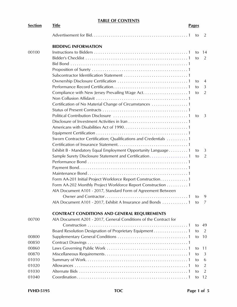
TABLE OF CONTENTSSection Title Pages
Advertisement for Bid. . . . . . . . . . . . . . . . . . . . . . . . . . . . . . . . . . . . . . . . . . . . . 1 to 2
BIDDING INFORMATION
00100 Instructions to Bidders . . . . . . . . . . . . . . . . . . . . . . . . . . . . . . . . . . . . . . . . . . . . 1 to 14
Bidder's Checklist . . . . . . . . . . . . . . . . . . . . . . . . . . . . . . . . . . . . . . . . . . . . . . . . 1 to 2
Bid Bond . . . . . . . . . . . . . . . . . . . . . . . . . . . . . . . . . . . . . . . . . . . . . . . . . . . . . . . 1
Proposition of Surety . . . . . . . . . . . . . . . . . . . . . . . . . . . . . . . . . . . . . . . . . . . . . 1
Subcontractor Identification Statement . . . . . . . . . . . . . . . . . . . . . . . . . . . . . . 1
Ownership Disclosure Certification . . . . . . . . . . . . . . . . . . . . . . . . . . . . . . . . . 1 to 4
Performance Record Certification. . . . . . . . . . . . . . . . . . . . . . . . . . . . . . . . . . . 1 to 3
Compliance with New Jersey Prevailing Wage Act. . . . . . . . . . . . . . . . . . . . . 1 to 2
Non Collusion Affidavit . . . . . . . . . . . . . . . . . . . . . . . . . . . . . . . . . . . . . . . . . . . 1
Certification of No Material Change of Circumstances . . . . . . . . . . . . . . . . . 1
Status of Present Contracts . . . . . . . . . . . . . . . . . . . . . . . . . . . . . . . . . . . . . . . . 1
Political Contribution Disclosure . . . . . . . . . . . . . . . . . . . . . . . . . . . . . . . . . . . 1 to 3
Disclosure of Investment Activities in Iran . . . . . . . . . . . . . . . . . . . . . . . . . . . . 1
Americans with Disabilities Act of 1990. . . . . . . . . . . . . . . . . . . . . . . . . . . . . . 1
Equipment Certification . . . . . . . . . . . . . . . . . . . . . . . . . . . . . . . . . . . . . . . . . . . 1
Sworn Contractor Certification; Qualifications and Credentials . . . . . . . . . . 1
Certification of Insurance Statement. . . . . . . . . . . . . . . . . . . . . . . . . . . . . . . . . 1
Exhibit B - Mandatory Equal Employment Opportunity Language . . . . . . . . . 1 to 3
Sample Surety Disclosure Statement and Certification . . . . . . . . . . . . . . . . . . 1 to 2
Performance Bond . . . . . . . . . . . . . . . . . . . . . . . . . . . . . . . . . . . . . . . . . . . . . . . 1
Payment Bond. . . . . . . . . . . . . . . . . . . . . . . . . . . . . . . . . . . . . . . . . . . . . . . . . . . 1
Maintenance Bond . . . . . . . . . . . . . . . . . . . . . . . . . . . . . . . . . . . . . . . . . . . . . . . 1
Form AA-201 Initial Project Workforce Report Construction. . . . . . . . . . . . . 1
Form AA-202 Monthly Project Workforce Report Construction . . . . . . . . . . 1
AIA Document A101 - 2017, Standard Form of Agreement Between
Owner and Contractor . . . . . . . . . . . . . . . . . . . . . . . . . . . . . . . . . . . . . . . 1 to 9
AIA Document A101 - 2017, Exhibit A Insurance and Bonds . . . . . . . . . . . . 1 to 7
CONTRACT CONDITIONS AND GENERAL REQUIREMENTS
00700 AIA Document A201 - 2017, General Conditions of the Contract for
Construction . . . . . . . . . . . . . . . . . . . . . . . . . . . . . . . . . . . . . . . . . . . . . . . 1 to 49
Board Resolution Designation of Proprietary Equipment . . . . . . . . . . . . . . . . 1 to 2
00800 Supplementary General Conditions . . . . . . . . . . . . . . . . . . . . . . . . . . . . . . . . . 1 to 10
00850 Contract Drawings . . . . . . . . . . . . . . . . . . . . . . . . . . . . . . . . . . . . . . . . . . . . . . . 1
00860 Laws Governing Public Work . . . . . . . . . . . . . . . . . . . . . . . . . . . . . . . . . . . . . . 1 to 11
00870 Miscellaneous Requirements . . . . . . . . . . . . . . . . . . . . . . . . . . . . . . . . . . . . . . . 1 to 3
01010 Summary of Work. . . . . . . . . . . . . . . . . . . . . . . . . . . . . . . . . . . . . . . . . . . . . . . . 1 to 6
01020 Allowances . . . . . . . . . . . . . . . . . . . . . . . . . . . . . . . . . . . . . . . . . . . . . . . . . . . . . 1 to 2
01030 Alternate Bids . . . . . . . . . . . . . . . . . . . . . . . . . . . . . . . . . . . . . . . . . . . . . . . . . . . 1 to 2
01040 Coordination . . . . . . . . . . . . . . . . . . . . . . . . . . . . . . . . . . . . . . . . . . . . . . . . . . . . 1 to 12
FVHD-5195 TOC Page 1 of 5
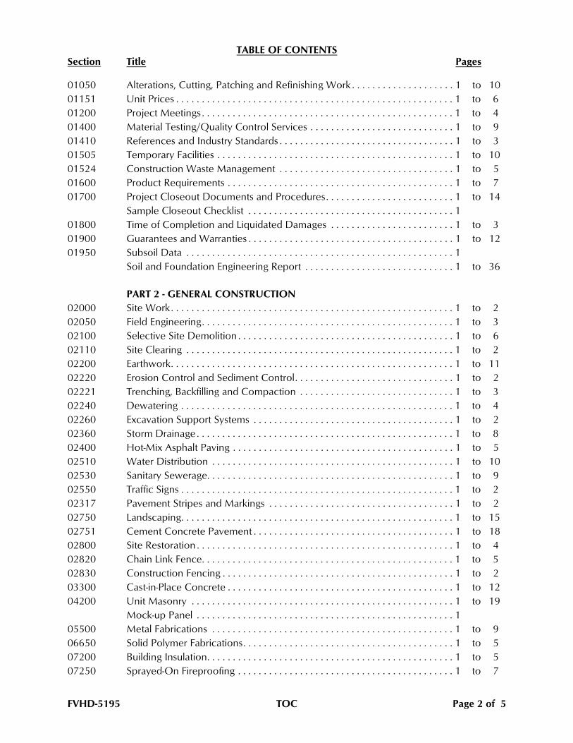
TABLE OF CONTENTSSection Title Pages
01050 Alterations, Cutting, Patching and Refinishing Work . . . . . . . . . . . . . . . . . . . . 1 to 10
01151 Unit Prices . . . . . . . . . . . . . . . . . . . . . . . . . . . . . . . . . . . . . . . . . . . . . . . . . . . . . . 1 to 6
01200 Project Meetings . . . . . . . . . . . . . . . . . . . . . . . . . . . . . . . . . . . . . . . . . . . . . . . . . 1 to 4
01400 Material Testing/Quality Control Services . . . . . . . . . . . . . . . . . . . . . . . . . . . . 1 to 9
01410 References and Industry Standards . . . . . . . . . . . . . . . . . . . . . . . . . . . . . . . . . . 1 to 3
01505 Temporary Facilities . . . . . . . . . . . . . . . . . . . . . . . . . . . . . . . . . . . . . . . . . . . . . . 1 to 10
01524 Construction Waste Management . . . . . . . . . . . . . . . . . . . . . . . . . . . . . . . . . . 1 to 5
01600 Product Requirements . . . . . . . . . . . . . . . . . . . . . . . . . . . . . . . . . . . . . . . . . . . . 1 to 7
01700 Project Closeout Documents and Procedures. . . . . . . . . . . . . . . . . . . . . . . . . 1 to 14
Sample Closeout Checklist . . . . . . . . . . . . . . . . . . . . . . . . . . . . . . . . . . . . . . . . 1
01800 Time of Completion and Liquidated Damages . . . . . . . . . . . . . . . . . . . . . . . . 1 to 3
01900 Guarantees and Warranties . . . . . . . . . . . . . . . . . . . . . . . . . . . . . . . . . . . . . . . . 1 to 12
01950 Subsoil Data . . . . . . . . . . . . . . . . . . . . . . . . . . . . . . . . . . . . . . . . . . . . . . . . . . . . 1
Soil and Foundation Engineering Report . . . . . . . . . . . . . . . . . . . . . . . . . . . . . 1 to 36
PART 2 - GENERAL CONSTRUCTION
02000 Site Work. . . . . . . . . . . . . . . . . . . . . . . . . . . . . . . . . . . . . . . . . . . . . . . . . . . . . . . 1 to 2
02050 Field Engineering. . . . . . . . . . . . . . . . . . . . . . . . . . . . . . . . . . . . . . . . . . . . . . . . . 1 to 3
02100 Selective Site Demolition . . . . . . . . . . . . . . . . . . . . . . . . . . . . . . . . . . . . . . . . . . 1 to 6
02110 Site Clearing . . . . . . . . . . . . . . . . . . . . . . . . . . . . . . . . . . . . . . . . . . . . . . . . . . . . 1 to 2
02200 Earthwork. . . . . . . . . . . . . . . . . . . . . . . . . . . . . . . . . . . . . . . . . . . . . . . . . . . . . . . 1 to 11
02220 Erosion Control and Sediment Control. . . . . . . . . . . . . . . . . . . . . . . . . . . . . . . 1 to 2
02221 Trenching, Backfilling and Compaction . . . . . . . . . . . . . . . . . . . . . . . . . . . . . . 1 to 3
02240 Dewatering . . . . . . . . . . . . . . . . . . . . . . . . . . . . . . . . . . . . . . . . . . . . . . . . . . . . . 1 to 4
02260 Excavation Support Systems . . . . . . . . . . . . . . . . . . . . . . . . . . . . . . . . . . . . . . . 1 to 2
02360 Storm Drainage . . . . . . . . . . . . . . . . . . . . . . . . . . . . . . . . . . . . . . . . . . . . . . . . . . 1 to 8
02400 Hot-Mix Asphalt Paving . . . . . . . . . . . . . . . . . . . . . . . . . . . . . . . . . . . . . . . . . . . 1 to 5
02510 Water Distribution . . . . . . . . . . . . . . . . . . . . . . . . . . . . . . . . . . . . . . . . . . . . . . . 1 to 10
02530 Sanitary Sewerage. . . . . . . . . . . . . . . . . . . . . . . . . . . . . . . . . . . . . . . . . . . . . . . . 1 to 9
02550 Traffic Signs . . . . . . . . . . . . . . . . . . . . . . . . . . . . . . . . . . . . . . . . . . . . . . . . . . . . . 1 to 2
02317 Pavement Stripes and Markings . . . . . . . . . . . . . . . . . . . . . . . . . . . . . . . . . . . . 1 to 2
02750 Landscaping. . . . . . . . . . . . . . . . . . . . . . . . . . . . . . . . . . . . . . . . . . . . . . . . . . . . . 1 to 15
02751 Cement Concrete Pavement . . . . . . . . . . . . . . . . . . . . . . . . . . . . . . . . . . . . . . . 1 to 18
02800 Site Restoration . . . . . . . . . . . . . . . . . . . . . . . . . . . . . . . . . . . . . . . . . . . . . . . . . . 1 to 4
02820 Chain Link Fence. . . . . . . . . . . . . . . . . . . . . . . . . . . . . . . . . . . . . . . . . . . . . . . . . 1 to 5
02830 Construction Fencing . . . . . . . . . . . . . . . . . . . . . . . . . . . . . . . . . . . . . . . . . . . . . 1 to 2
03300 Cast-in-Place Concrete . . . . . . . . . . . . . . . . . . . . . . . . . . . . . . . . . . . . . . . . . . . . 1 to 12
04200 Unit Masonry . . . . . . . . . . . . . . . . . . . . . . . . . . . . . . . . . . . . . . . . . . . . . . . . . . . 1 to 19
Mock-up Panel . . . . . . . . . . . . . . . . . . . . . . . . . . . . . . . . . . . . . . . . . . . . . . . . . . 1
05500 Metal Fabrications . . . . . . . . . . . . . . . . . . . . . . . . . . . . . . . . . . . . . . . . . . . . . . . 1 to 9
06650 Solid Polymer Fabrications. . . . . . . . . . . . . . . . . . . . . . . . . . . . . . . . . . . . . . . . . 1 to 5
07200 Building Insulation. . . . . . . . . . . . . . . . . . . . . . . . . . . . . . . . . . . . . . . . . . . . . . . . 1 to 5
07250 Sprayed-On Fireproofing . . . . . . . . . . . . . . . . . . . . . . . . . . . . . . . . . . . . . . . . . . 1 to 7
FVHD-5195 TOC Page 2 of 5
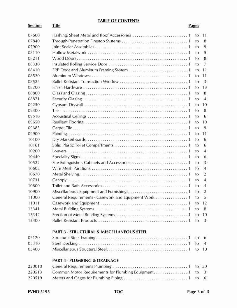
TABLE OF CONTENTSSection Title Pages
07600 Flashing, Sheet Metal and Roof Accessories . . . . . . . . . . . . . . . . . . . . . . . . . . 1 to 11
07840 Through-Penetration Firestop Systems . . . . . . . . . . . . . . . . . . . . . . . . . . . . . . . 1 to 8
07900 Joint Sealer Assemblies. . . . . . . . . . . . . . . . . . . . . . . . . . . . . . . . . . . . . . . . . . . . 1 to 9
08110 Hollow Metalwork . . . . . . . . . . . . . . . . . . . . . . . . . . . . . . . . . . . . . . . . . . . . . . . 1 to 5
08211 Wood Doors . . . . . . . . . . . . . . . . . . . . . . . . . . . . . . . . . . . . . . . . . . . . . . . . . . . . 1 to 8
08330 Insulated Rolling Service Door . . . . . . . . . . . . . . . . . . . . . . . . . . . . . . . . . . . . . 1 to 7
08410 FRP Door and Aluminum Framing System . . . . . . . . . . . . . . . . . . . . . . . . . . . . 1 to 11
08520 Aluminum Windows. . . . . . . . . . . . . . . . . . . . . . . . . . . . . . . . . . . . . . . . . . . . . . 1 to 11
08524 Bullet Resistant Transaction Window . . . . . . . . . . . . . . . . . . . . . . . . . . . . . . . . 1 to 3
08700 Finish Hardware . . . . . . . . . . . . . . . . . . . . . . . . . . . . . . . . . . . . . . . . . . . . . . . . . 1 to 18
08800 Glass and Glazing . . . . . . . . . . . . . . . . . . . . . . . . . . . . . . . . . . . . . . . . . . . . . . . . 1 to 8
08871 Security Glazing . . . . . . . . . . . . . . . . . . . . . . . . . . . . . . . . . . . . . . . . . . . . . . . . . 1 to 4
09250 Gypsum Drywall . . . . . . . . . . . . . . . . . . . . . . . . . . . . . . . . . . . . . . . . . . . . . . . . . 1 to 10
09300 Tile . . . . . . . . . . . . . . . . . . . . . . . . . . . . . . . . . . . . . . . . . . . . . . . . . . . . . . . . . . 1 to 8
09510 Acoustical Ceilings . . . . . . . . . . . . . . . . . . . . . . . . . . . . . . . . . . . . . . . . . . . . . . . 1 to 6
09650 Resilient Flooring. . . . . . . . . . . . . . . . . . . . . . . . . . . . . . . . . . . . . . . . . . . . . . . . . 1 to 10
09685 Carpet Tile . . . . . . . . . . . . . . . . . . . . . . . . . . . . . . . . . . . . . . . . . . . . . . . . . . . . . . 1 to 9
09900 Painting . . . . . . . . . . . . . . . . . . . . . . . . . . . . . . . . . . . . . . . . . . . . . . . . . . . . . . . . 1 to 11
10100 Dry Markerboards. . . . . . . . . . . . . . . . . . . . . . . . . . . . . . . . . . . . . . . . . . . . . . . . 1 to 6
10161 Solid Plastic Toilet Compartments. . . . . . . . . . . . . . . . . . . . . . . . . . . . . . . . . . . 1 to 6
10200 Louvers . . . . . . . . . . . . . . . . . . . . . . . . . . . . . . . . . . . . . . . . . . . . . . . . . . . . . . . . 1 to 4
10440 Speciality Signs . . . . . . . . . . . . . . . . . . . . . . . . . . . . . . . . . . . . . . . . . . . . . . . . . . 1 to 6
10522 Fire Extinguisher, Cabinets and Accessories. . . . . . . . . . . . . . . . . . . . . . . . . . . 1 to 3
10605 Wire Mesh Partitions . . . . . . . . . . . . . . . . . . . . . . . . . . . . . . . . . . . . . . . . . . . . . 1 to 4
10670 Metal Shelving. . . . . . . . . . . . . . . . . . . . . . . . . . . . . . . . . . . . . . . . . . . . . . . . . . . 1 to 2
10731 Canopy . . . . . . . . . . . . . . . . . . . . . . . . . . . . . . . . . . . . . . . . . . . . . . . . . . . . . . . . 1 to 4
10800 Toilet and Bath Accessories . . . . . . . . . . . . . . . . . . . . . . . . . . . . . . . . . . . . . . . . 1 to 4
10900 Miscellaneous Equipment and Furnishings. . . . . . . . . . . . . . . . . . . . . . . . . . . . 1 to 2
11000 General Requirements - Casework and Equipment Work . . . . . . . . . . . . . . . 1 to 5
11011 Casework and Equipment . . . . . . . . . . . . . . . . . . . . . . . . . . . . . . . . . . . . . . . . . 1 to 12
13341 Metal Building Systems . . . . . . . . . . . . . . . . . . . . . . . . . . . . . . . . . . . . . . . . . . . 1 to 8
13342 Erection of Metal Building Systems . . . . . . . . . . . . . . . . . . . . . . . . . . . . . . . . . . 1 to 10
13400 Bullet Resistant Products . . . . . . . . . . . . . . . . . . . . . . . . . . . . . . . . . . . . . . . . . . 1 to 3
PART 3 - STRUCTURAL & MISCELLANEOUS STEEL
05120 Structural Steel Framing . . . . . . . . . . . . . . . . . . . . . . . . . . . . . . . . . . . . . . . . . . . 1 to 6
05310 Steel Decking . . . . . . . . . . . . . . . . . . . . . . . . . . . . . . . . . . . . . . . . . . . . . . . . . . . 1 to 4
05400 Miscellaneous Structural Steel . . . . . . . . . . . . . . . . . . . . . . . . . . . . . . . . . . . . . . 1 to 10
PART 4 - PLUMBING & DRAINAGE
220010 General Requirements Plumbing. . . . . . . . . . . . . . . . . . . . . . . . . . . . . . . . . . . . 1 to 50
220513 Common Motor Requirements for Plumbing Equipment . . . . . . . . . . . . . . . . 1 to 3
220519 Meters and Gages for Plumbing Piping . . . . . . . . . . . . . . . . . . . . . . . . . . . . . . 1 to 6
FVHD-5195 TOC Page 3 of 5
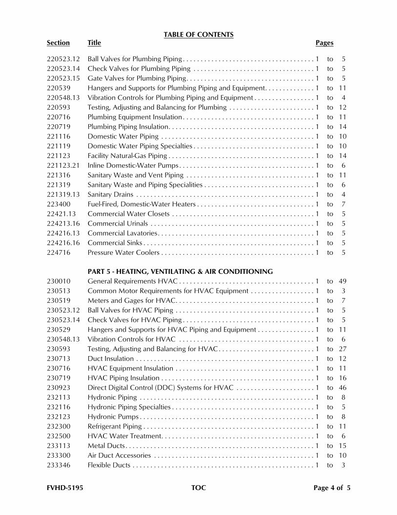
TABLE OF CONTENTSSection Title Pages
220523.12 Ball Valves for Plumbing Piping . . . . . . . . . . . . . . . . . . . . . . . . . . . . . . . . . . . . . 1 to 5
220523.14 Check Valves for Plumbing Piping . . . . . . . . . . . . . . . . . . . . . . . . . . . . . . . . . . 1 to 5
220523.15 Gate Valves for Plumbing Piping. . . . . . . . . . . . . . . . . . . . . . . . . . . . . . . . . . . . 1 to 5
220539 Hangers and Supports for Plumbing Piping and Equipment. . . . . . . . . . . . . . 1 to 11
220548.13 Vibration Controls for Plumbing Piping and Equipment . . . . . . . . . . . . . . . . . 1 to 4
220593 Testing, Adjusting and Balancing for Plumbing . . . . . . . . . . . . . . . . . . . . . . . . 1 to 12
220716 Plumbing Equipment Insulation . . . . . . . . . . . . . . . . . . . . . . . . . . . . . . . . . . . . . 1 to 11
220719 Plumbing Piping Insulation. . . . . . . . . . . . . . . . . . . . . . . . . . . . . . . . . . . . . . . . . 1 to 14
221116 Domestic Water Piping . . . . . . . . . . . . . . . . . . . . . . . . . . . . . . . . . . . . . . . . . . . 1 to 10
221119 Domestic Water Piping Specialties . . . . . . . . . . . . . . . . . . . . . . . . . . . . . . . . . . 1 to 10
221123 Facility Natural-Gas Piping . . . . . . . . . . . . . . . . . . . . . . . . . . . . . . . . . . . . . . . . . 1 to 14
221123.21 Inline Domestic-Water Pumps . . . . . . . . . . . . . . . . . . . . . . . . . . . . . . . . . . . . . . 1 to 6
221316 Sanitary Waste and Vent Piping . . . . . . . . . . . . . . . . . . . . . . . . . . . . . . . . . . . . 1 to 11
221319 Sanitary Waste and Piping Specialities . . . . . . . . . . . . . . . . . . . . . . . . . . . . . . . 1 to 6
221319.13 Sanitary Drains . . . . . . . . . . . . . . . . . . . . . . . . . . . . . . . . . . . . . . . . . . . . . . . . . . 1 to 4
223400 Fuel-Fired, Domestic-Water Heaters . . . . . . . . . . . . . . . . . . . . . . . . . . . . . . . . . 1 to 7
22421.13 Commercial Water Closets . . . . . . . . . . . . . . . . . . . . . . . . . . . . . . . . . . . . . . . . 1 to 5
224213.16 Commercial Urinals . . . . . . . . . . . . . . . . . . . . . . . . . . . . . . . . . . . . . . . . . . . . . . 1 to 5
224216.13 Commercial Lavatories. . . . . . . . . . . . . . . . . . . . . . . . . . . . . . . . . . . . . . . . . . . . 1 to 5
224216.16 Commercial Sinks . . . . . . . . . . . . . . . . . . . . . . . . . . . . . . . . . . . . . . . . . . . . . . . . 1 to 5
224716 Pressure Water Coolers . . . . . . . . . . . . . . . . . . . . . . . . . . . . . . . . . . . . . . . . . . . 1 to 5
PART 5 - HEATING, VENTILATING & AIR CONDITIONING
230010 General Requirements HVAC . . . . . . . . . . . . . . . . . . . . . . . . . . . . . . . . . . . . . . 1 to 49
230513 Common Motor Requirements for HVAC Equipment . . . . . . . . . . . . . . . . . . 1 to 3
230519 Meters and Gages for HVAC. . . . . . . . . . . . . . . . . . . . . . . . . . . . . . . . . . . . . . . 1 to 7
230523.12 Ball Valves for HVAC Piping . . . . . . . . . . . . . . . . . . . . . . . . . . . . . . . . . . . . . . . 1 to 5
230523.14 Check Valves for HVAC Piping . . . . . . . . . . . . . . . . . . . . . . . . . . . . . . . . . . . . . 1 to 5
230529 Hangers and Supports for HVAC Piping and Equipment . . . . . . . . . . . . . . . . 1 to 11
230548.13 Vibration Controls for HVAC . . . . . . . . . . . . . . . . . . . . . . . . . . . . . . . . . . . . . . 1 to 6
230593 Testing, Adjusting and Balancing for HVAC . . . . . . . . . . . . . . . . . . . . . . . . . . . 1 to 27
230713 Duct Insulation . . . . . . . . . . . . . . . . . . . . . . . . . . . . . . . . . . . . . . . . . . . . . . . . . . 1 to 12
230716 HVAC Equipment Insulation . . . . . . . . . . . . . . . . . . . . . . . . . . . . . . . . . . . . . . . 1 to 11
230719 HVAC Piping Insulation . . . . . . . . . . . . . . . . . . . . . . . . . . . . . . . . . . . . . . . . . . . 1 to 16
230923 Direct Digital Control (DDC) Systems for HVAC . . . . . . . . . . . . . . . . . . . . . . 1 to 46
232113 Hydronic Piping . . . . . . . . . . . . . . . . . . . . . . . . . . . . . . . . . . . . . . . . . . . . . . . . . 1 to 8
232116 Hydronic Piping Specialties . . . . . . . . . . . . . . . . . . . . . . . . . . . . . . . . . . . . . . . . 1 to 5
232123 Hydronic Pumps . . . . . . . . . . . . . . . . . . . . . . . . . . . . . . . . . . . . . . . . . . . . . . . . . 1 to 8
232300 Refrigerant Piping . . . . . . . . . . . . . . . . . . . . . . . . . . . . . . . . . . . . . . . . . . . . . . . . 1 to 11
232500 HVAC Water Treatment. . . . . . . . . . . . . . . . . . . . . . . . . . . . . . . . . . . . . . . . . . . 1 to 6
233113 Metal Ducts . . . . . . . . . . . . . . . . . . . . . . . . . . . . . . . . . . . . . . . . . . . . . . . . . . . . . 1 to 15
233300 Air Duct Accessories . . . . . . . . . . . . . . . . . . . . . . . . . . . . . . . . . . . . . . . . . . . . . 1 to 10
233346 Flexible Ducts . . . . . . . . . . . . . . . . . . . . . . . . . . . . . . . . . . . . . . . . . . . . . . . . . . . 1 to 3
FVHD-5195 TOC Page 4 of 5
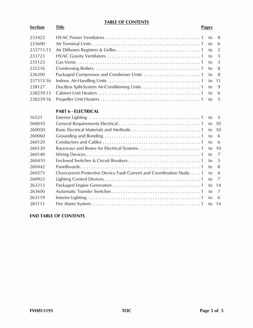
TABLE OF CONTENTSSection Title Pages
233423 HVAC Power Ventilators . . . . . . . . . . . . . . . . . . . . . . . . . . . . . . . . . . . . . . . . . . 1 to 8
233600 Air Terminal Units . . . . . . . . . . . . . . . . . . . . . . . . . . . . . . . . . . . . . . . . . . . . . . . . 1 to 6
233713.13 Air Diffusers Registers & Grilles . . . . . . . . . . . . . . . . . . . . . . . . . . . . . . . . . . . . . 1 to 5
233723 HVAC Gravity Ventilators . . . . . . . . . . . . . . . . . . . . . . . . . . . . . . . . . . . . . . . . . 1 to 5
235123 Gas Vents . . . . . . . . . . . . . . . . . . . . . . . . . . . . . . . . . . . . . . . . . . . . . . . . . . . . . . 1 to 3
235216 Condensing Boilers. . . . . . . . . . . . . . . . . . . . . . . . . . . . . . . . . . . . . . . . . . . . . . . 1 to 8
236200 Packaged Compressor and Condenser Units . . . . . . . . . . . . . . . . . . . . . . . . . 1 to 8
237313.16 Indoor, Air-Handling Units . . . . . . . . . . . . . . . . . . . . . . . . . . . . . . . . . . . . . . . . . 1 to 11
238127 Ductless Split-System Air-Conditioning Units . . . . . . . . . . . . . . . . . . . . . . . . . . 1 to 9
238239.13 Cabinet Unit Heaters . . . . . . . . . . . . . . . . . . . . . . . . . . . . . . . . . . . . . . . . . . . . . 1 to 6
238239.16 Propeller Unit Heaters . . . . . . . . . . . . . . . . . . . . . . . . . . . . . . . . . . . . . . . . . . . . 1 to 5
PART 6 - ELECTRICAL
16521 Exterior Lighting . . . . . . . . . . . . . . . . . . . . . . . . . . . . . . . . . . . . . . . . . . . . . . . . . 1 to 5
260010 General Requirements Electrical . . . . . . . . . . . . . . . . . . . . . . . . . . . . . . . . . . . . 1 to 50
260050 Basic Electrical Materials and Methods. . . . . . . . . . . . . . . . . . . . . . . . . . . . . . . 1 to 10
260060 Grounding and Bonding. . . . . . . . . . . . . . . . . . . . . . . . . . . . . . . . . . . . . . . . . . . 1 to 6
260120 Conductors and Cables . . . . . . . . . . . . . . . . . . . . . . . . . . . . . . . . . . . . . . . . . . . 1 to 6
260130 Raceways and Boxes for Electrical Systems . . . . . . . . . . . . . . . . . . . . . . . . . . . 1 to 10
260140 Wiring Devices . . . . . . . . . . . . . . . . . . . . . . . . . . . . . . . . . . . . . . . . . . . . . . . . . . 1 to 7
260410 Enclosed Switches & Circuit Breakers . . . . . . . . . . . . . . . . . . . . . . . . . . . . . . . . 1 to 5
260442 Panelboards. . . . . . . . . . . . . . . . . . . . . . . . . . . . . . . . . . . . . . . . . . . . . . . . . . . . . 1 to 8
260573 Overcurrent Protective Device Fault Current and Coordination Study. . . . . 1 to 6
260923 Lighting Control Devices . . . . . . . . . . . . . . . . . . . . . . . . . . . . . . . . . . . . . . . . . . 1 to 7
263213 Packaged Engine Generators. . . . . . . . . . . . . . . . . . . . . . . . . . . . . . . . . . . . . . . 1 to 14
263600 Automatic Transfer Switches . . . . . . . . . . . . . . . . . . . . . . . . . . . . . . . . . . . . . . . 1 to 7
265119 Interior Lighting . . . . . . . . . . . . . . . . . . . . . . . . . . . . . . . . . . . . . . . . . . . . . . . . . . 1 to 6
283111 Fire Alarm System . . . . . . . . . . . . . . . . . . . . . . . . . . . . . . . . . . . . . . . . . . . . . . . . 1 to 14
END TABLE OF CONTENTS
FVHD-5195 TOC Page 5 of 5

PART 4 - PLUMBING WORK
FVHD 5195 4:220010 - 1 June 19, 2020
SECTION 220010 - GENERAL REQUIREMENTS PLUMBING
PART 1 - GENERAL REQUIREMENTS PLUMBING
1.1 GENERAL 1.2 SCOPE AND OBJECTIVES OF THE PLUMBING WORK 1.3 INTENT OF THE PLUMBING CONTRACT DOCUMENT 1.4 PROPOSAL PREPARATION 1.5 HAZARDOUS MATERIALS 1.6 DRAWINGS AND SPECIFICATIONS 1.7 LAWS, ORDINANCES, REGULATIONS AND PERMITS 1.8 CONNECTIONS TO UTILITIES 1.9 TESTS 1.10 CLEANING 1.11 INSTRUCTING OWNER'S PERSONNEL 1.12 OPERATING AND MAINTENANCE INSTRUCTIONS 1.13 GUARANTEE 1.14 ENTRANCE OF EQUIPMENT 1.15 VISIT TO SITE 1.16 REQUESTS FOR INFORMATION, RFI(s) 1.17 AS-BUILT DRAWINGS 1.18 SERVICING OF EQUIPMENT AND SYSTEMS 1.19 EXCAVATION AND BACKFILLING 1.20 CONTINUITY OF SERVICES 1.21 CONTINUITY OF INTERIOR BUILDING SERVICE UTILITIES 1.22 TEMPORARY FACILITIES, UTILITIES AND HEATING 1.23 SMOKE AND FIRESTOPPING (GENERAL) 1.24 COORDINATION DRAWINGS 1.25 BREECHING, VENT, NATURAL GAS AND EXHAUST PIPING SUBMITTALS 1.26 TRADE CONTRACTOR'S CERTIFICATION
PART 2 - PRODUCTS
2.1 MANUFACTURER'S AND SUB-CONTRACTORS LIST, KEYMEN RESUMES 2.2 SUBMITTALS 2.3 MATERIALS AND EQUIPMENT 2.4 EQUIPMENT VARIATIONS AND SUBSTITUTIONS 2.5 VIBRATION ELIMINATION 2.6 NOISE CONTROL 2.7 INSERTS, HANGER SUPPORTS, CLAMPS, FASTENINGS 2.8 ACCESS DOORS AND PANELS 2.9 EQUIPMENT ANCHOR BOLTS 2.10 PIPING AND CONDUIT SLEEVES 2.11 SMOKE/FIRESTOPPING (MATERIALS)
PART 3 - EXECUTION
3.1 METHOD OF PROCEDURE
FVHD 5195 4:220010 - 2 June 19, 2020
3.2 PROTECTION OF WORK 3.3 CUTTING AND PATCHING 3.4 CONCRETE AND MASONRY 3.5 SUPPORTS 3.6 ESCUTCHEONS 3.7 MACHINERY GUARDS 3.8 ROOFING WORK 3.9 PAINTING AND FINISHING 3.10 LUBRICATION 3.11 PLUMBING TRADE - ELECTRICAL TRADE COORDINATION 3.12 ELECTRICAL MOTORS AND STARTERS 3.13 ELECTRICAL PROVISIONS FOR PACKAGED PLUMBING EQUIPMENT 3.14 PIPING AND CONDUIT UNDER FLOORS 3.15 PIPING AND EQUIPMENT IDENTIFICATION 3.16 ABANDONMENT, REMOVAL AND RELOCATION 3.17 SMOKE AND FIRESTOPPING (METHODS) 3.18 SUBSURFACE CONCEALED UNKNOWN PHYSICAL CONDITIONS 3.19 CONCRETE PATCHING (PROCEDURE) 3.20 TEMPORARY PARTITIONS 3.21 INITIAL APPLICATION FOR PAYMENT 3.22 FINAL APPLICATION FOR PAYMENT 3.23 INDEMNIFICATION 3.24 ADDITIONAL PLUMBING TRADE CONTRACTOR PAID FEES AND EXPENSES 3.25 FORMS
FVHD 5195 4:220010 - 3 June 19, 2020
PART 1 - GENERAL REQUIREMENTS PLUMBING
1.1 GENERAL
A. The conditions of Divisions 00 and 01 apply to each and every Trade Contractor or other
person or persons supplying any material or labor entering this building and/or site, either
directly or indirectly. In the event of a conflict between Section 220010 and Divisions 00
and 01, the terms of Divisions 00 and 01 shall govern.
B. One Building Trade, the Plumbing Building Trade, will be covered by these General
Requirements Plumbing.
C. For simplicity, this Building Trade will be referred to further herein as the Plumbing Trade
Contractor. The Plumbing Specifications and all Plumbing Drawings, together with all
addenda make-up the Plumbing Contract Documents, and are a part of the “Project
Contract Documents”, as described throughout these specifications.
D. The term “Electrical Trade” as used in the Contract Documents, means the Electrical
Building Trade.
E. The term “indicated” means all information included, detailed, shown and/or implied on
the Contract Documents.
F. The term “existing” is used generally in reference to renovation projects. On new
construction projects, the term “existing” is intended to mean work already in place.
1.2 SCOPE AND OBJECTIVES OF THE PLUMBING WORK
A. Scope of work includes, but is not limited to, the following:
1. Submittals including product data, shop drawings and samples;
2. Plumbing fixtures and trim;
3. Piping, insulation and valves;
4. Domestic water heaters;
5. Domestic water pumps and trim;
6. Sanitary piping and specialties
7. Equipment start-up;
8. Owner training;
9. Testing, adjusting and balancing of plumbing systems;
10. Preparation of coordination drawings;
11. Preparation of as-built drawings in AutoCad format;
12. Periodic inspection of completed work to confirm compliance with Contract
Documents;
13. Refer to Division 01 Section “Summary” for additional information.

FVHD 5195 4:220010 - 4 June 19, 2020
1.3 INTENT OF THE PLUMBING CONTRACT DOCUMENT
A. The intent of the Plumbing Contract Documents is to include all items and labor
necessary for the proper execution and completion of the Work of the Plumbing Trade
Contractor. The Contract Documents of all Trades are complimentary to each other;
what is required by one shall be as binding as if required by all. Performance of the
Plumbing Trade Contractor is required only to the extent consistent with the Project
Contract Documents and reasonably inferable from them as being necessary to produce
the desired results.
B. It is expressly stipulated that neither the Drawings nor the Specifications shall take
precedence over the other, and it is further stipulated that the Architect/Engineer may
interpret or construe the Drawings and Specifications so as to secure in all cases the
result most consistent with the needs and requirements of the work. In the event of such
ambiguity or discrepancy, comply with the higher cost product (material plus labor), the
more stringent requirement, and supply the better quality or greater quantity of work.
1.4 PROPOSAL PREPARATION
A. Prior to submitting a pricing quotation/proposal, proceed as follows, and include the
following:
1. Visit the site, survey, record, confirm and include in the scope of work, all material
and labor necessary to install the equipment and systems indicated. Use the
Contract Documents as diagrammatic in nature, since they are not intended to
show all details which may affect the plumbing bid proposal.
2. Include the work, as applicable, to remove and dispose of plumbing fixtures,
piping, insulation, equipment and appurtenances, not required for new work,
unless otherwise indicated to be abandoned in place.
3. Include all disconnections, removals and temporary provisions required to permit
rigging, installation, connection, testing and operation of the new equipment.
Include all such provisions whether or not shown, detailed or specified within
technical sections of the Contract Documents.
4. Include in the work, providing the labor of Keymen, including, but not limited to
the following:
a. One Project Manager;
b. One Project Foreman.
5. Foreman must refine the detail, layout, coordination and fit of all of the plumbing
equipment. Plan all disconnections, removals, offsets, temporary provisions, as
required, to fit the new equipment into the space, and as required to accommodate
maintenance accessibility and service access.
6. Project Manager must maintain and submit for approval, a written project
schedule, on a weekly basis.
7. All Project Manager must organize, administrate, control and log the RFI process
for their respective trade. Where applicable, submit all RFI(s) for master RFI log
maintained by Lead/Prime Contractor.
FVHD 5195 4:220010 - 5 June 19, 2020
B. In preparing a Bid Price:
1. Thoroughly review and confirm all existing conditions and Contract Document
information. Make note in writing of any exceptions, misunderstandings, unclear
areas, unclear directions, and any aspects which will prohibit completion of the
work, in total. Failing to supply such notice, all bidders will be accountable for
having accepted all conditions at the site which affect their work and their costs.
By submitting a bid price, all Trade Contractors certify that the Contract Documents
have been thoroughly reviewed and are sufficient for construction, and that the
bidding Trade Contractors have adequate information to establish and determine
their responsibility for materials, methods, costs, and schedule for their work.
2. Incorporate all requirements of all sections of the Contract Documents.
3. Include the following with the Manufacturer’s and Sub-Contractor’s Lists:
a. The name and telephone number of all Sub-Contractors.
b. The manufacturer and model numbers of all equipment proposed by the
bidder and as listed on all of the equipment schedules and specified in the
Contract Documents.
1.5 HAZARDOUS MATERIALS
A. The use of asbestos, PCB’s or any material or product containing hazardous materials in
the performance of this contract is not permitted. Certify, in writing, that no hazardous
material or product containing a hazardous material, has been furnished or installed.
1.6 DRAWINGS AND SPECIFICATIONS
A. It is the intent of the specifications and drawings to include under each item all materials,
apparatus and labor necessary to properly install, equip, adjust and put into perfect
operation the respective portions of the installations specified and to so interconnect the
various items or sections of the work as to form a complete and properly operating
whole.
B. Any apparatus, machinery, small items not mentioned in detail which are necessary to
complete or perfect any portion of the installation in a substantial manner and in
compliance with the requirements stated, implied or intended must be furnished and/or
installed without extra cost to the Project. This includes all materials, devices or methods
peculiar to the machinery, apparatus or systems furnished and/or installed by the
Plumbing Trade Contractor.
C. In referring to drawings, figured dimensions take precedence over scale measurements.
Verify all wall locations, ceiling heights, elevations, dimensions, etc. on the architectural
drawings, where applicable. Discrepancies must be referred to the Engineer for decision.
Certify and verify all dimensions, routings and layouts in the field and on the
coordination drawings before ordering material or commencing work.

FVHD 5195 4:220010 - 6 June 19, 2020
D. Any work called for in the specifications, but not mentioned or shown on the drawings,
or called for on the drawings, but not mentioned in the specifications, must be furnished
and/or installed as though called for in both.
E. When any device or part of equipment is herein referred to in the singular number, such
as "the pump" such reference is deemed to apply to as many such devices as required to
complete the installation.
F. The term "Provide" means "Furnish and Install". Neither term will be used generally in
these specifications, but will be assumed. The term "Furnish" means to obtain and deliver
to the job site for installation by other trades.
1.7 LAWS, ORDINANCES, REGULATIONS AND PERMITS
A. The entire plumbing system in all and/or in part must conform to all pertinent laws,
ordinances and regulations of all bodies having jurisdiction, notwithstanding anything in
these drawings or specifications to the contrary.
B. Pay all fees and obtain and pay for all permits and inspections required by any authority
having jurisdiction in connection with the work under this contract.
C. Electrical work performed by the Plumbing Trade Contractor must comply with the
requirements of the National Electrical Code, NFPA and other boards and departments
having local jurisdiction. Obtain and pay for an Independent Inspection by an authorized
Electrical Inspection Agency (EIA) and by local, municipal and state approving agencies.
Inspections performed by the local inspector do not substitute for obtaining Independent
Inspection by an authorized independent Electrical Inspection Agency.
1. Qualifications: The EIA is to be an independent company from the Plumbing Trade
Contractor, registered with the State and a Master certified member of the
International Association of Electrical Inspectors.
2. Prepare and submit for review and comment to the Engineer a schedule of
inspections to be performed in coordination with the construction schedule.
3. At a minimum, inspections shall be performed at the Rough-in, Progress and Final
levels.
4. The EIA shall submit written report for each level of inspection to the Engineer to
document compliance with current code requirements, including deficiencies and
associated required remedial action.
1.8 CONNECTIONS TO UTILITIES
A. Apply for and obtain services from Utility Companies and municipalities. All charges for
which Utility Companies and municipalities must be reimbursed must be paid for by the
Plumbing Trade Contractor at no additional cost to the Project.
FVHD 5195 4:220010 - 7 June 19, 2020
1.9 TESTS
A. The following requirements are supplementary to tests specified for individual equipment
or systems in other specification sections. Give written notice of date of test in ample
time to all concerned.
B. Concealed or insulated work must remain uncovered until all required tests have been
completed; but if construction schedule requires, arrange for partial tests on portions of
systems as approved. If a Prime Contractor covers or directs a Sub-Contractor to cover
plumbing work prior to completing the required tests, the Prime Contractor is responsible
for any additional costs related to completing the required tests.
C. As soon as conditions permit, conduct preliminary tests of equipment to ascertain
compliance with specified requirements. Make needed changes, adjustments and/or
replacements as preliminary tests may indicate, prior to acceptance tests.
D. Conduct pressure, performance and operating tests as specified or required for each
system or piece of equipment installed, modified or affected under this contract in
presence of the Engineer or Owner as well as a representative of agencies having
jurisdiction.
E. Obtain Certificates of Approval and/or Acceptance as specified or required in compliance
with regulations of agencies having jurisdiction. Work will not be deemed complete
until such Certificates have been delivered to the Engineer.
F. Prove conclusively, by testing, that Plumbing systems operate properly, efficiently and
quietly in accordance with intent of drawings, specifications and most widely used
construction practices.
1.10 CLEANING
A. Be responsible for the following:
1. Removal of all lumber, refuse, metal, piping and debris from site resulting from
plumbing work.
2. Cleaning drippings created by the plumbing work, from finished work of other
Trades.
3. Cleaning, polishing, waxing of plumbing work as required.
B. After testing, and acceptance of all work by the Engineer and the Owner, thoroughly
clean all plumbing equipment and material to the satisfaction of the Engineer.
1.11 INSTRUCTING OWNER'S PERSONNEL
A. After all tests and adjustments have been made, fully instruct the representatives of the
Owner in all details of operation of the equipment installed under the Plumbing Contract
Documents.
FVHD 5195 4:220010 - 8 June 19, 2020
B. Operate equipment for sufficient length of time to satisfy Engineer that requirements of
Contract Documents have been fulfilled.
C. Prepare digital recording of each Owner training session on USB thumb Drive.
1.12 OPERATING AND MAINTENANCE INSTRUCTIONS
A. Provide in accordance with Division 01.
B. Submit digital format PDF of Operating and Maintenance Instructions to the Engineer for
review and processing.
C. Upon completion of the Engineer’s review and processing of digital format PDF of the
Operating and Maintenance Instructions, submit three (3) copies of the final version of
the printed instructions to the Owner. Bind instructions in separate, hardback, 3-ring
loose leaf binders.
D. Prepare instruction books by sections and include detailed Operating and Maintenance
Instructions for all components of all systems, including wiring, and piping diagrams
necessary for clarity. Identify the covers with the name of the project and the words
"Operating and Maintenance Instructions - Plumbing".
E. Each section must have labeled tabs and be clearly marked with equipment or system
name and contain detailed parts list data, ordering information therefore and the name,
address and telephone number of the closest supply source.
F. All instructional data must be neatly and completely prepared to the satisfaction of the
Engineer.
G. Provide complete copy of all warranties in separate tab with the binder.
H. Provide copies of the as-built drawings in the manuals.
I. Provide copy of each submittal for each piece of equipment on the project, complete
with all tag numbers, Contractor’s Transmittal Cover Sheet and Engineer’s final Submittal
Review Sheet.
J. Provide USB Drive of Owner training sessions with the manuals.
K. Provide complete copy of the final Plumbing Testing, Adjusting and Balancing Report.
L. All listed items are to be included in the O&M submission for the Engineer’s review.
Partial submissions are NOT acceptable.
1.13 GUARANTEE
A. All material, equipment and workmanship must be in first class operating condition in
every respect at time of acceptance by Owner. Acceptance by the Owner will be by
letter written to the Plumbing Trade Contractor.
FVHD 5195 4:220010 - 9 June 19, 2020
B. Unconditionally guarantee in writing all materials, equipment and workmanship for a
period of one (1) year from date of acceptance by Owner. During the guarantee period,
repair or replace, at the Plumbing Trade Contractor’s expense, any materials, equipment
or workmanship in which defects may develop and provide free service for all equipment
and systems involved in the contract during this guarantee period. Beneficial use of any
system by the any of the Trade Contractors during construction does not constitute
acceptance by the Owner. Time period of this beneficial use cannot be included in the
guarantee period.
C. Guarantee must also include restoration to its original condition of all adjacent work that
is disturbed in fulfilling this guarantee.
D. All such repairs and/or replacements must be made without delay and at the convenience
of the Owner.
E. Guarantees furnished by Trade Contractors and/or equipment manufacturers must be
counter-signed by the related Trade Contractor for joint and/or individual responsibility
for subject item.
F. Manufacturers’ equipment guarantees or warranties extending beyond the guarantee
period described in item B above must be transferred to the Owner along with the Trade
Contractor's guarantees.
1.14 ENTRANCE OF EQUIPMENT
A. Determine the method of equipment entrance during initial site visit prior to bidding. Do
not scale building openings, door widths, and equipment or component sizes off the
drawings. Determine sizes from site measurements and the equipment manufacturer.
Include cost of equipment manufacturer's knockdown, use of field assembled equipment,
field assembly, all work required for access, removals, replacements, general
construction, and the like, as required. During preparation of submittals, verify whether
knocked-down or pre-disassembled equipment have been proposed all to the extent
required to permit entry of equipment to final location. Verify that the use of field
assembled (not pre-assembled) equipment complies with manufacturer’s warranty,
guarantee, listings and requirements.
B. Perform all necessary rigging required for completion of plumbing work.
C. Deliver products to the site properly identified with names, model numbers, types,
grades, compliance labels and other information needed for identification. Deliver
products and equipment to the site properly weatherproofed.
D. The Trade Contractor who furnishes or purchases the product or equipment is responsible
to provide and maintain protection from the weather, dust, dirt, construction debris, etc.
until the project is complete.
E. For all products and equipment which, when installed, have an opening into the building
must be provided with a plywood cover, or similar protection, to prevent debris, rain, etc.
FVHD 5195 4:220010 - 10 June 19, 2020
from entering the building. The Trade Contractor who installs the product or equipment
is responsible for such protection beginning at the time of installation.
1.15 VISIT TO SITE
A. Due to the nature of the work involved under these Contract Documents, all bidders are
recommended to thoroughly examine the site. Coordinate and schedule all site visits
with the Owner.
B. Thoroughly review Contract Documents prior to visiting the site, take Contract
Documents to site and thoroughly explore to any extent necessary, the existing
conditions as relating to fulfilling the requirements of these Contract Documents.
C. If discrepancies are noted between requirements of Contract Documents and existing
conditions, Trade Contractors must so indicate to Engineer during bidding period and
receive clarification before bidding. Failure to comply with this requirement will result in
Engineer's interpretation during the construction period such that the Engineer's decision
will be final and binding as the sole interpreter of the contract requirements.
D. Extras will not be considered for any work relating to connections with existing systems
or adaptability of new systems to existing structures.
E. Submission of proposals will be considered evidence that Trade Contractors have
complied with the requirements of this Article.
1.16 REQUESTS FOR INFORMATION, RFI(s)
A. Manage RFI(s) in a formal manner. Preparation and submission must comply with the
process specified herein to be of maximum benefit to the project. RFI(s) which do not
comply with this process will be returned without comment.
B. All RFI(s):
1. Must be submitted in written form to the party designated at the construction phase
kick-off meeting;
2. Must be consecutively numbered, dated, and logged as directed, during the kick-off
meeting;
3. Those which are follow-up RFI(s), must use the same RFI number, with a sequential
submission number;
4. Must list the RFI number of any reference RFI(s) used in the narrative;
5. Must present: background; related drawings; specification articles; room, space
locations (as designated on Contract Documents including wing, column line
designation, floor designation, and/or north, south, and the like), and must be
presented as complete, clearly written thoughts, in legibly printed or typed form;
6. Must be completed by the Plumbing Trade Contractor’s Designated Project
Foreman, under the control and overview of the Plumbing Trade Contractor’s
Project Manager;
FVHD 5195 4:220010 - 11 June 19, 2020
7. Must include Plumbing Trade Contractor’s Project Foreman’s suggested resolution
to RFI;
8. Must evidence a high level of fluency with the Contract Documents, all job
progress correspondence, all Addenda, all Construction Bulletins, and specifically
the Mechanical/Electrical Specifications including: Section 210010; the sections of
Division 21; Division 22; Division 23; Division 26; Division 27; Division 28; and
special system and equipment divisions of the specification Divisions 02 thru 33
inclusive.
C. The Plumbing Trade Contractor’s designated Project Manager must demonstrate
familiarity with and responsibility for all RFI(s) prepared by the Project Foreman and must
periodically submit an initialed log of RFI(s) signifying control of RFI(s) relating to
specification and job scope issues.
D. Issues relating to job scope, work included, methods and means which are either clearly
discernable from the Contract Documents and/or clearly the responsibility of the
Plumbing Trade Contractor must be answered by Plumbing Trade Contractor’s Project
Manager and resolved between the Foreman and Project Manager prior to resorting to
written RFI(s). The work of the Project Manager must evidence: fluency with the
methods and means anticipated by the Plumbing Trade Contractor during the bid phase
to plan and complete the work; fluency with the Contract Documents, and all
administrative issues related thereto.
E. Items or issues which relate to non-compliance to associated codes or regulations must
reference code interpretations or the published adopted code or regulation. The
reference must be either an excerpt of the code or regulation, published addenda to the
code or regulation, a formal interpretation written by a representative of the associated
agency, or letter of non-compliance from the Authority Having Jurisdiction. All cited
code requirements must include the applicable code title, code version or date, and code
section number designation. If the RFI does not contain the required information, the RFI
will be returned without comment.
1.17 AS-BUILT DRAWINGS
A. Prepare reproducible (paper) and electronic (cd) record documents in AUTOCAD .dwg
format (Version 2000 or later) in accordance with the requirements in Division 01. Use
commercial CAD drafting service if Plumbing Trade Contractor does not have CAD
capabilities in-house. As an option, if requested by the Plumbing Trade Contractor, an
electronic copy (AutoCad .dwg format) of any of the Plumbing Contract Drawings may be
provided by the Engineer at a cost of $55.00, billable to the requesting Contractor. In
addition to the requirements specified in Division 01, indicate the following installed
conditions:
1. Mains and branches of piping systems, with valves and control devices located and
numbered, concealed unions located, and with items requiring maintenance
located (i.e., traps, strainers, expansion compensators, tanks, and the like). Valve
location diagrams, complete with valve tag chart. Indicate actual inverts and
horizontal locations of underground piping, and the like.
FVHD 5195 4:220010 - 12 June 19, 2020
2. Equipment locations (exposed and concealed), dimensioned from prominent
building lines and annotated with permanent equipment number approved by
Owner. Include Code and equipment service clearances.
3. Approved substitutions, Addenda and Bulletin Contract Modifications, and actual
equipment and materials installed
B. Engage the services of a Land Surveyor or Professional Engineer registered in the state in
which the project is located, as specified in Division 01, to record the locations and
invert elevations of the underground plumbing work.
1.18 SERVICING OF EQUIPMENT AND SYSTEMS
A. After work has been completed in accordance with the Contract Documents, and prior to
final acceptance tests, each Trade Contractor must have manufacturers or their
authorized agents of the equipment installed, completely check their equipment and put
equipment into proper operation. In each case, the respective Trade Contractor must
have the manufacturers thoroughly check the complete installation of the equipment,
furnished by the manufacturer, for proper and correct operation under the service
intended.
B. Six months after final acceptance of the work under the Contract Documents, each of the
Trade Contractors must have the manufacturers again check their equipment for proper
operation and lubrication. Coincidentally, these Trade Contractors must assure that the
Owner is properly instructed in the servicing of the equipment.
C. Prior to expiration of the guarantee period, each Trade Contractor must check all
equipment, materials and systems for which he is responsible, make necessary
adjustments and/or replacements, and leave systems in first class operating condition.
1.19 EXCAVATION AND BACKFILLING
A. Perform all excavation, backfilling and pumping necessary for completion of plumbing
work. All excavation is considered classified.
B. Remove from premises or deposit as directed by Engineer all material excavated and not
required or suitable for backfilling.
C. Carefully remove and store topsoil, shrubbery and sod until underground work is
complete and trenches are backfilled and then re-install. Replace any damaged items to
the satisfaction of the Engineer.
D. Allow adequate cover over piping and conduit in trenches as applicable. Trench walls
must be perpendicular to the top of piping and conduits and trench bottoms must be
instrument graded in the direction of flow as required. Earth must be scooped out under
pipe hubs to provide a solid bearing for the pipe, duct or conduit on undisturbed earth.
Cinder fill, stones or bricks beneath piping are prohibited. Pipe, and conduits less than 6-
inches in outside diameter which do not require sloping, shall have hard trench bottoms
and shall be supported on undisturbed subgrade. Trench bottoms for sloping utilities,
FVHD 5195 4:220010 - 13 June 19, 2020
pipes, and conduits over 6-inches in outside diameter shall be excavated 6-inches deeper
than elevation and a 6-inch thick tamped bedding shall be installed. Bedding shall be
naturally or artificially graded mixture of natural or crushed gravel, crushed stone, and
natural or crushed sand; ASTM D2940; except with 100 percent passing a 1-inch sieve
and not more than 8 percent passing a No. 200 sieve.
E. Provide sheathing, shoring and bracing necessary to complete excavation and backfilling
work and exercise every precaution necessary to prevent accident, injury or death to any
human and damage to property of others. Remove all debris, sheathing, shoring and
bracing upon completion of work.
F. It is the responsibility of each Trade Contractor to check with the various Utility
Companies and make the necessary arrangements to avoid damage to their property.
Each Trade Contractor is responsible for damage during excavation to existing
underground structures including, but not limited to electric, structural, piping or
equipment. Such damage must be repaired promptly without cost to the Project. Do not
dig until all underground utilities are identified and located.
G. Backfill after inspection and approval. Backfill must be made with clean earth, free from
rocks, frozen particles, debris or other foreign materials. Deposit in uniform layers not
over six inches (6") thick with each layer mechanically tamped before the next layer is
applied. When approved backfill material is not available from the site, each Trade
Contractor, at no additional cost to the project, must provide additional select backfill to
complete installation. Partial backfill on piping leaving all joints exposed is mandatory for
all underground gas and underground domestic water systems. Final backfill only after
testing procedures have been approved.
H. All trenches that pass under wall foundations must be backfilled with lean concrete, full
height, directly under wall footing, and at a 1:1 slope away from wall or column footing.
Trenches that are parallel with and deeper than wall foundations must be backfilled with
lean concrete on a 1:1 slope away from the bottom of the wall or column footing.
I. Perform all cutting and patching to driveways, sidewalks, curbs, bituminous paving,
walls, and the like, required by performance of excavation and backfilling. Install and
maintain temporary paving as directed by Engineer. Make repairs to sidewalks in
complete blocks, partial patching will not be acceptable. Provide all materials for
patching in strict accordance with applicable Articles of Divisions 01 through 33 of the
Contract Specifications. All patching to match adjacent construction.
J. Where rock is encountered during installation of underground piping systems, carry
trenches to a point six inches (6") below invert of pipe and provide a six inch (6") layer of
crushed stone or gravel as a cushion.
K. All excavation work must include all pumping equipment, materials and labor necessary
to keep all excavations free of water. Provide well points as required with disposition of
water as directed by Architect/Engineer.
L. Provide suitable indemnity for all accidents to humans, animals or equipment caused by
excavating and backfilling work. Provide suitable guards, barricades, red lanterns, flares
and take the necessary precaution for an approved and safe installation. All trenches
FVHD 5195 4:220010 - 14 June 19, 2020
must be backfilled at the end of each working day. Where a trench must be left open,
provide coverings of adequate size and strength over entire open area.
M. Detectable Warning Tape: Acid and alkali-resistant polyethylene film warning tape
manufactured for marking and identifying underground utilities, minimum 6-inches (150
mm) wide and 4 mils (0.1 mm) thick, continuously inscribed with a description of utility,
with metallic core encased in a protective jacket for corrosion protection, detectable by
metal detector when tape is buried up to 30 inches (750 mm) deep; colored as follows:
1. Red: Electric.
2. Yellow: Gas, oil and dangerous materials.
3. Blue: Water systems.
4. Green: Sewer systems.
N. Trade Contractors shall engage the services of a Utility Identification Sub-Contractor to
identify all existing underground utilities in the path of the proposed trench excavation. It
shall be the Utility Identification Sub-Contractor's sole responsibility to search,
investigate, test and identify existing underground utilities such as, but not limited to the
following: gas piping, water piping, steam piping, condensate piping, electrical lines,
sanitary piping, storm water piping, data, telephone, fiber optics and any other utility
service, piping, lines or trenches. Before excavation can begin, the Trade Contractors
shall provide all utility data concerning the underground utilities to Design Professional,
and Owner. Data shall be in the form of a scaled drawing of the proposed excavation
with all utilities clearly indicated.
1.20 CONTINUITY OF SERVICES
A. Generally, no actions can be taken by the Plumbing Trade Contractor that will interrupt
any of the existing building services for these buildings or any other building until
previously arranged and scheduled with the Engineer and Owner.
B. Should any service be interrupted by the Plumbing Trade Contractor, immediately
provide all labor, including overtime if necessary, and all material and equipment
necessary for restoration of such service, at no additional cost to the Project.
1.21 CONTINUITY OF INTERIOR BUILDING SERVICE UTILITIES
A. For the purposes of this specification section, “Building Service Utilities” include, but are
not limited to:
1. Exterior: electrical; domestic water; fire protection water; sanitary; storm; chilled
water; space heating water; fuel lines; communication cable; fire alarm; remote
metering lines; telemetry lines; and the like;
2. Heating piping systems, complete;
3. Chilled water piping systems, complete;
4. Heating and process steam/condensate systems, complete;
5. Ductwork systems, complete;
6. Medical gas systems, complete;
FVHD 5195 4:220010 - 15 June 19, 2020
7. Fire protection systems, complete;
8. Control systems, complete;
9. Plumbing, drainage and storm systems, complete;
10. Process piping systems, complete;
11. Electrical conduit and wiring systems, complete;
12. Electrical lighting and wiring devices, complete;
13. Electrical fire alarm and security systems, complete;
14. Electrical communication systems, complete.
B. Building Service Utilities are defined for the purposes of this project, and as used in these
specifications as:
1. TYPE A Utility System Services. New Internal Building Services, serving: new
and/or modified system functions; new and/or modified equipment;
2. TYPE B Utility System Services. Existing Internal Building Services serving:
unmodified systems; unmodified equipment; building spaces for which mechanical
and electrical systems, and internal operational equipment have not been modified
by this project;
3. TYPE C Utility System Services. Existing Utility Systems Building Services, external
to the individual building, or buildings, addressed by the work of this project;
4. TYPE D Utility System Services. New Utility Systems Building Services, external to
the individual building, or buildings, addressed by the Work of this project.
C. Plan work and schedule to prevent interruption of TYPE B, and/or TYPE C Utility System
Services. Refer to the “Scope and Objectives of the Plumbing Work,” of this Section for a
description of: unmodified systems, unmodified equipment; spaces wherein mechanical
and electrical systems are unmodified; and Utility System Services external to the
individual building or buildings addressed by the work of this project.
D. Plan work and schedule installation and connections of TYPE A and TYPE D Utilities to
minimize or prevent interruption of TYPE B, and or TYPE C Utility System Services. Refer
to “General Requirements Plumbing,” Article “Scope and Objectives of the Plumbing
Work.”
E. The work required for continuity of these systems on this project includes, but is not
limited to, providing all labor and material required for: site investigation/verification;
disconnect; removal; rerouting; reconnection; as-built drawing documentation; testing
and check out of mechanical and electrical services serving equipment which are
implied to be, or specifically indicated to be, continued in operation.
F. All materials required for relocation work must comply with these specifications.
Carefully review all phasing drawings, all Construction Trade drawings, and complete all
necessary and prudent site visits to become familiar with all existing building operations,
systems and equipment which may be continued, independent of the work of this
project, and include all required relocation work described in this section.
1.22 TEMPORARY FACILITIES, UTILITIES AND HEATING
A. Refer to Division 01 of these specifications.

FVHD 5195 4:220010 - 16 June 19, 2020
1.23 SMOKE AND FIRESTOPPING (GENERAL)
A. Furnish and install a material or a combination of materials to form an effective barrier
against the spread of flame, smoke and gases, and to maintain the integrity of the “fire
and/or smoke” rated construction. Refer to Division 07 of these specifications. Fire and
smoke rated construction is identified on the Architectural Drawings. Provide
firestopping in the following locations:
1. Pipe and conduit penetrations through above grade floor slabs and through “fire
and/or smoke”-rated partitions and fire walls.
2. Penetrations of vertical shafts including, but not limited to pipe chases, duct chases,
elevator shafts, and utility chutes.
3. Other locations where indicated or required.
B. Prepare submittals and submit for approval. Include manufacturer's descriptive data,
typical details, installation instructions and the fire/smoke test data and/or report as
appropriate for the time rated construction and location. The fire/smoke test data must
include a certification by a nationally recognized testing authority that the material has
been tested in accordance with ASTM E 814, or UL 1479 fire tests.
C. Deliver materials in the original unopened packages or containers showing name of the
manufacturer and the brand name. Store materials off the ground, and protect from
damage and exposure to elements. Damaged, deteriorated or outdated shelf life
materials shall not be used and must be removed from the site.
1.24 COORDINATION DRAWINGS
A. The HVAC Trade Contractor will initiate preparation of coordination drawings, control
original reproducibles, collect, organize and facilitate the work/input of General
Construction Trade Contractor and all other building trades, as applicable, relative to the
100% final submission of the coordination drawings. Coordination drawings will be
prepared in accordance with Division 01, to a scale of 1/4"=1'-0" or larger; detailing
major elements, components, and systems of equipment and materials in relationship
with other systems, installations, and building components. Use proposed equipment
submittals, which include certified dimensions, service clearances, etc., to assist in
preparation of the coordination drawings. If equipment is submitted for review after
completion of the coordination drawings and rejected during the submittal review
process, because the equipment fails to meet the project specifications, the HVAC Trade
Contractor is responsible to revise the coordination drawings and layout the work using
equipment which meets the project specifications. HVAC Trade Contractor will
designate all specified return air plenums, locations where space is limited for installation
and access and where sequencing and coordination of installations are of importance to
the efficient flow of the Work, including (but not necessarily limited to) the following:
1. Proposed locations of piping, ductwork, equipment, and materials. The following
shall be included:
a. Clearances for installing and maintaining insulation.
FVHD 5195 4:220010 - 17 June 19, 2020
b. Clearances for servicing and maintaining equipment, including tube removal,
filter removal, and space for equipment disassembly required for periodic
maintenance.
c. Equipment connections and support details.
d. Exterior wall and foundation penetrations.
e. Fire-rated wall and floor penetrations.
f. Sizes and location of required concrete pads and bases.
g. Valve stem movement.
h. Service clearance for equipment behind access doors.
i. Location of structural columns, beams and supports.
2. Scheduling, sequencing, movement, and positioning of large equipment into the
building during construction.
3. Floor plans, elevations, and details to indicate penetrations in floors, walls and
ceilings and their relationship to other penetrations and installations.
4. Reflected ceiling plans to coordinate and integrate installation of air outlets and
inlets, light fixtures, communication systems components, sprinklers, and other
ceiling mounted items.
5. The foregoing information and coordination work must be provided by the
applicable Trade Contractor using the coordination drawings as initiated by the
HVAC Trade Contractor.
6. The HVAC Trade Contractor must submit completed coordination drawings for
record purposes, not for technical review and approval, but as proof that the
coordination drawings have been completed. The coordination drawings must be
completed and submitted for record in advance of submission of sheet metal shop
drawings.
B. Coordinate with, and provide the HVAC Trade Contractor, all plumbing system and
equipment information, locations, and clearances required, to prepare the coordination
drawings.
1.25 BREECHING, VENT, NATURAL GAS AND EXHAUST PIPING SUBMITTALS
A. Sizes specified for materials such as gas vents, natural gas piping, breeching, and
emergency generator exhaust piping are included in the Contract Documents and
intended for bidding purposes. Actual sizes required for approved system performance
depend on the actual length of runs, routing, bends, offsets, fittings and elbows, planned
by the Plumbing Trade Contractor during layout of the Plumbing work and must account
for existing/new field conditions.
B. Submit product data and shop drawings, as applicable to each Trade Contractor, for the
following; vent piping, gas piping, breeching, emergency generator coolant piping, and
exhaust piping. Submittals shall indicate all aspects of the work layout including:
materials; length; routing; bends; offsets; fittings; mufflers; elbows; and compliance with
equipment manufacturer’s directions (specifications, limitations, sizing tables, etc.
required to meet such specifications). Attach copies of manufacturer’s specifications and
performance tables to required equipment submittals.
FVHD 5195 4:220010 - 18 June 19, 2020
C. Processing of vent, gas, breeching and emergency generator piping submittals and piping
layout shop drawings will be handled in a manner identical to sheet metal shop drawings
(conformance to SMACNA recommendations for example) which require the Plumbing
Trade Contractor to conform to accepted standards relative to sizing, pressure drop limits,
manufacturer’s recommendations, NFPA, and Fuel Gas Code.
D. Submit Manufacturer’s or Trade Contractor’s confirming calculations of pressure drops,
and/or sizing resulting from all of the variables controlled by the Plumbing Trade
Contractor during layout of the Plumbing work for review by the Engineer as part of the
submittal review process.
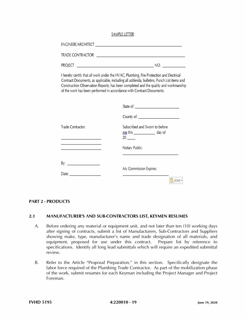
1.26 TRADE CONTRACTOR'S CERTIFICATION
A. Upon final completion of all work, each Trade Contractor must provide a notarized letter
on Corporate letterhead, executed by a Corporate Officer, or Company Partner, stating
that the work has been completed in accordance with the Contract Documents,
Addenda, Bulletins, Trade Contractor’s Punch List items and Architect’s/Engineer’s
Construction Observation Report(s). Final Payment will not be approved until the
notarized letter has been provided. Refer to the following sample letter.
FVHD 5195 4:220010 - 19 June 19, 2020
PART 2 - PRODUCTS
2.1 MANUFACTURER'S AND SUB-CONTRACTORS LIST, KEYMEN RESUMES
A. Before ordering any material or equipment unit, and not later than ten (10) working days
after signing of contracts, submit a list of Manufacturers, Sub-Contractors and Suppliers
showing make, type, manufacturer’s name and trade designation of all materials, and
equipment, proposed for use under this contract. Prepare list by reference to
specifications. Identify all long lead submittals which will require an expedited submittal
review.
B. Refer to the Article “Proposal Preparation,” in this section. Specifically designate the
labor force required of the Plumbing Trade Contractor. As part of the mobilization phase
of the work, submit resumes for each Keyman including the Project Manager and Project
Foreman.
FVHD 5195 4:220010 - 20 June 19, 2020
C. These lists, when approved, will be supplementary to specifications, and no variations
therefrom will be permitted except with the approval of the Engineer.
D. Prepare the list using the “PROPOSED MANUFACTURERS AND SUB-CONTRACTORS
LIST” located at the end of this section.
E. Submittals will not be processed until the requirements of this Article are satisfactorily
completed.
2.2 SUBMITTALS
A. Provide digital submissions (.pdf format) for all material and equipment as noted in
Proposed Manufacturer's and Sub-Contractors List, except where indicated otherwise
herein.
1. Prior to submission of product data, shop drawings, and samples, notify the
Engineer/Architect of any site conditions differing from those indicated or specified.
2. Prior to submission of product data, shop drawings and samples to the design
professional, the Plumbing Trade Contractor shall submit all submittals which
require electrical power to the Project Electrical Trade Contractor for the Plumbing
Trade Contractor’s and Electrical Trade Contractor’s coordination and review.
Electrical Trade Contractor shall provide approval of electrical power requirements
for the Plumbing Trade Contractor’s proposed equipment.
3. All submittals of equipment requiring electrical power must be accompanied by the
“PLUMBING AND ELECTRICAL CONTRACTORS’ COORDINATION OF
PLUMBING EQUIPMENT ELECTRICAL REQUIREMENTS TRANSMITTAL COVER
SHEET” located at the end of this section. Submittals without this Cover Sheet or
an incomplete Cover Sheet will be rejected without review.
4. All submittals must be accompanied by the “PLUMBING CONTRACTOR’S
TRANSMITTAL COVER SHEET” located at the end of this section. Submittals
without this cover sheet or with an incomplete cover sheet, will be rejected without
review.
5. All submittals must be accompanied by the “PLUMBING SUBMITTAL LOG”,
located at the end of this section. Submit log after final acceptance of the proposed
Manufacturer’s and Sub-Contractor’s list. Revise and update the log with each
submittal. Submittals without these logs or without an updated log will be rejected
without review.
6. Specifically annotate and sign all exceptions, deletions and additions that vary from
the Project Contract Documents. Failing to provide signed annotations for all
deletions and additions, recognize and accept that Contract Documents will
govern, and will be used to resolve disputes.
B. Prepare submittals by careful reference to: drawings and specifications; preparatory
layout of all work; coordination with all proposed equipment; coordination with related
submittals and the work of all other Trade Contractors; space requirements; and TYPE A,
TYPE B, TYPE C, and TYPE D Utilities defined in this Section. A review of such
submittals by the Engineer/Architect, which include drawings, schedules, and catalog
cuts provided by the Trade Contractors, their Sub-Contractors, manufacturers, and
FVHD 5195 4:220010 - 21 June 19, 2020
vendors, shall not relieve the Trade Contractors from the responsibility for correcting all
errors of any sort in the submittals, either identified or undetected by such review.
C. Regularly provide and update submittal log sheets listing submittal number, product,
applicable specification section, dates of submittal and receipt and status. Identify each
submittal by Job Name, log number and reference to applicable Specification Article
number.
D. All equipment submittals must include, but not be limited to, the following:
1. Manufacturers' catalog designation, photographs and specifications.
2. Full electrical data, including specifically, electrical characteristics.
3. Full General Construction data, including operating weights, dimensional data
including service access space. Data shall be given to the General Construction
Trade Contractor, where applicable, for use in setting steel, supports, and
attachments.
4. Full wiring diagrams, including clearly identified power connections and control
connections. Data and diagrams shall be given to the Electrical Trade Contractor
and Automatic Temperature Control (ATC) Trade Sub-Contractor for their use and
inclusion into their submittals.
5. Listing of specific performance, calculations and data.
6. Dimensions, capacities, ratings, material and finish.
7. Complete the submittal by listing all available options, accessories, configurations
and materials, and legibly strike out with single thin line all proposed deletions.
Clearly signify whether each and every manufacturer's option, accessory,
configuration and material choice is included and which is excluded by the
submission.
8. Annotation of equipment, devices, systems as indicated by the Contract Documents
(WC-1, LAV-2, etc.).
9. Certification of testing by agencies such as ETL, ARI, UL, etc.
10. Such other detailed information as required for proper evaluation.
E. Review Time:
1. Allow two (2) weeks after Engineer’s receipt for the Engineer's processing of each
submittal, exclusive of Owner’s, or other’s review in the processing chain. Allow a
longer time period where processing must be delayed for coordination with
subsequent submittals.
F. Submittals for electric motor starters must include a tabulation listing the following:
1. The equipment the starter is intended to control.
2. Horsepower and starter size.
3. Voltage.
4. Phase.
5. Full load amperes.
6. The manufacturer's number or type.
7. Heater numbers and amperage.
8. Quantity of auxiliary contacts required by ATC and fire alarm systems.
9. Pushbutton arrangement.
FVHD 5195 4:220010 - 22 June 19, 2020
10. Pilot light arrangement if applicable.
G. Submittals for automatic temperature controls must be coordinated with: 1) all plumbing
equipment manufacturers’ and vendors’ submittals including review of plumbing
submittals by ATC Sub-Contractor for conformance with sequences of operation for each
piece of equipment; 2) all electrical requirements of ATC System with Electrical Trade
Contractor; and 3) all fire and safety requirements of the Fire Alarm System. ATC
submittals shall include copies of all wiring diagrams for all plumbing equipment with
points of connections clearly identified. ATC submittals shall not be developed and
submitted until Plumbing Trade Contractor provides all equipment submittals for review.
H. The Engineer’s recommendation of acceptance of the equipment proposed by the
Plumbing Trade Contractor is conditional upon the Plumbing Trade Contractor fulfilling
all obligations of the Contract Documents. By furnishing the proposed equipment, the
Plumbing Trade Contractor acknowledges compliance with all of the following:
1. Field layout is completed and planning of proposed equipment has coordinated
with all related submittals, related trades and space requirements.
2. The Plumbing Trade Contractor has reviewed and approved all submittals prior to
submission. Provide all submittals with a signed approval stamp, signifying the
following: 1) all field measurements, field construction criteria, materials,
dimensions, catalog numbers and similar data have been verified; 2) the
Engineer/Architect has been notified of all site conditions which affect the work,
and which require design resolution, as opposed to resolution by trade decisions;
3) all items are approved by the Plumbing Trade Contractor, and have been
coordinated and checked with other applicable submittals, and contract
requirements; 4) submission is clearly marked to indicate which manufacturer’s
options are provided and which are not provided for the proposed equipment; and
5) manufacturers and/or equipment suppliers have been given a set of the contract
documents for their review and use as the basis of the submittals.
3. Any and all exceptions requested by the Plumbing Trade Contractor are provided
in writing with the submittals. All exceptions, deletions and additions that vary
from the Contract Documents have been specifically annotated and initialed.
Failing to provide initialed annotations for all deletions and additions, the Plumbing
Trade Contractor accepts the condition that the Contract Documents will govern,
and will be used to resolve disputes.
4. Submittals without the Plumbing Trade Contractor's signed stamp of approval will
be returned without review. Initialed approval stamps are not acceptable.
5. The Engineer’s acceptance of the proposed equipment constitutes the Engineer’s
formal approval that the engineering performance and operational utility
requirements, of the proposed equipment, match the Engineer’s specified and
designed performance requirements. By entering into these Contracts, the Trade
Contractors agree that the purpose of submittals is to demonstrate to the Engineer
that the Trade Contractors understand the design concept and that they
demonstrate their understanding by indicating which materials and equipment they
intends to furnish, install and use.
I. Secure submittals smaller than 8-1/2 x 11 to paper of this size.
FVHD 5195 4:220010 - 23 June 19, 2020
J. Material and equipment fabricated, furnished and/or installed or used without the
Engineer’s review are subject to rejection by the Engineer.
K. The HVAC Trade Contractor shall prepare 1/4" minimum scale sheet metal shop
drawings at the earliest practicable time and coordinate these drawings with the other
Trade Contractors prior to erection or fabrication of the sheet metal work in order to
effect timely resolution of all conflicts with the work of other Trade Contractors. Sheet
metal shop drawings shall cover all metal work on the project, including but not limited
to environmental air, exhaust air, make-up air, and products of combustion venting
systems. Designate on sheet metal shop drawings all specified return air plenums, fire
dampers, and smoke dampers. Designate all transfer air openings specified under
General Construction, by reference to general construction drawings detailing fire rated
assemblies, and smoke dampers. Refer to Article, "Coordination Drawings," in Part 1 of
this section
L. Corrections or comments made on submittals during review by the Engineer do not
relieve the Plumbing Trade Contractor from compliance with the requirements of the
Contract Documents. Such review will be only for general conformance with the design
concept, and the information given in the Contract Documents and does not include
review of quantities, dimensions, sizing, pressure drops, weights or gauges, fabrication
processes, construction methods, coordination with the work of other trades, or
construction safety precautions, all of which are the sole responsibility of the Plumbing
Trade Contractor. Review of a specific item does not indicate acceptance of an
assembly of which the item is a component. The Engineer is not responsible for any
deviations from the Contract Documents that are not clearly noted by the Plumbing Trade
Contractor. The Engineer will not review partial submissions or those for which
submissions for correlated items have not been received. The Plumbing Trade Contractor
is responsible for: confirming and correlating all quantities, clearance, and dimensions;
selecting fabrication processes and techniques of construction; coordinating work with all
other Trades, and performing his work in a safe and satisfactory manner.
M. All submittals must be able to be reproduced. The Plumbing Trade Contractor is
responsible for all reproduction and distribution to the General Construction Trade
Contractor and all other Trade Contractors as applicable.
N. If requested for the Plumbing Trade Contractor’s use in the preparation of submittals, an
electronic copy (AutoCad .dwg format) of any of the Plumbing Contract Drawings may be
provided by the Engineer, after receipt of a signed indemnification agreement, at a cost of
$55.00, billable to the Plumbing Trade Contractor.
O. For additional requirements regarding submittals, refer to Article “Additional Trade
Contractor Paid fees and Expenses” in Part 3 of this section.
2.3 MATERIALS AND EQUIPMENT
A. All materials and equipment must be new and conform to the grade, quality and
standards specified herein.
FVHD 5195 4:220010 - 24 June 19, 2020
B. All equipment offered under these specifications is limited to products regularly produced
and recommended for service ratings in accordance with engineering data or other
comprehensive literature made available to the public and in effect at the time of opening
of bids. Testing agency seals, decals and/or nameplate shall be attached to and visible on
all equipment.
C. Items such as valves, motors, starting equipment, vibration isolating devices, and all other
equipment and material, where applicable and practicable, must each be of one
manufacturer.
D. Install equipment in strict accordance with manufacturer’s instructions for type and
capacity of each piece of equipment used. Obtain these instructions, which will be
considered part of these specifications. Type, capacity and application of equipment
must be suitable and operate satisfactorily for the purpose intended in the plumbing
systems.
2.4 EQUIPMENT VARIATIONS AND SUBSTITUTIONS
A. Equipment Substitution Definition as follows:
1. A product that is neither the Basis of Design, nor one of the named Alternative
Manufacturing Sources.
2. Unless noted otherwise in the Contract Documents, substitutions may be
considered after the award of Contracts. Subsequent requests will be considered
only when, through no fault of the Plumbing Trade Contractor, none of the
specified products are available.
B. Equipment Variation Definition as follows:
1. A product that is not the Basis of Design, but is named as one of the specified
Alternative Manufacturing Sources.
C. The manufacturers listed in Part 2 of all technical specifications are considered
Alternative Manufacturing Sources as described in Paragraphs A and B above.
D. “Subject to compliance”, as used in these specifications, means compliance with all the
requirements of the Contract Documents.
E. The materials and products mentioned in these Contract Documents are specified to
establish a standard of: material of manufacture; independent testing agency
certifications; quality; function; design; and performance. The phrases “Basis of Design,”
“standard of design,” and “equivalent acceptable,” are used to indicate that other similar,
comparable products may be used provided such substitutes or variations are accepted
by the Engineer as meeting all the salient characteristics and standards necessary, such
as: material of manufacture; independent testing agency certifications; quality; function;
design; and performance, to meet the Owner’s needs and meet the objectives of the
Engineer’s Project Design.
F. Where Alternative Manufacturer Sources are listed for an item:
FVHD 5195 4:220010 - 25 June 19, 2020
1. Selection must be either the Basis of Design or one of those listed Alternative
Manufacturing Sources.
2. There is no guarantee implied that each and every manufacturer listed can meet or
exceed the salient characteristics, such as: material of manufacture; independent
testing agency certifications; quality; function; design; and performance of the
product specified as Basis of Design.
G. Each Trade Contractor is responsible to contact his proposed equipment manufacturer’s
representative and confirm, prior to preparing submittals, the proposed manufacturer’s
product meets or exceeds the: material of manufacture; independent testing agency
certifications; quality; function; design; and performance of the product specified as the
Basis of Design. Final acceptance will be determined by the Engineer, whose decision is
final.
H. Submittals offered as an Equipment Variation from the Basis of Design shall include a
letter, on the product manufacturer’s letterhead, certifying that the proposed product is a
Comparable Product to the product specified as the Basis of Design and conforms to all
the salient characteristics, including: material of manufacture; quality; function; design;
and performance of the product specified as the Basis of Design. If directed by the
Engineer for Products offered as an Equipment Variation, the Offerer shall provide a Letter
of Confirmation from a Registered, Professional Engineer attesting that the Proposed
Equipment Variation conforms to all the salient characteristics, including: material of
manufacture; independent testing agency certifications; quality; function; design; and
performance of the product specified as the Basis of Design.
I. Specific products specified without use of the term: equal; equivalent; comparable
product; substitution; or similar term; constitute a proprietary specification, and must be
provided as specified, unless a written request is submitted to the Engineer for approval
up to ten (10) days after the date of project award. Such requests must include a
complete description of the proposed product, along with sufficient documentation and
other information necessary for a complete evaluation of the proposed product. Such
Trade Contractor Requests shall include a letter, on the product manufacturer’s
letterhead, certifying that the proposed product is a Comparable Product and conforms to
all the salient characteristics, including: material of manufacture; independent testing
agency certifications; quality; function, design; and performance of the specified product.
If approved, the proposed product will be listed in an addendum to notify all bidders that
such acceptance has been granted by the Engineer. If not approved, provide the
specified product.
J. Provide Calculations, signed and sealed by a Professional Engineer registered in the State
in which the work is taking place, engaged by the Plumbing Trade Contractor, confirming
that the equipment proposed as either a Substitution, or Variation, is a Comparable
Product to the product specified as the Basis of Design and conforms to all the salient
characteristics, including: material of manufacturer; independent testing agency
certifications; quality; function; design; and performance of the product specified as the
Basis of Design. Provide such calculations for major pieces of equipment (water heaters,
medical gas equipment, fire pumps, etc.). The Engineer, whose decision will be final,
will determine which products will require calculations during the submittal review
process.
FVHD 5195 4:220010 - 26 June 19, 2020
K. The Contract Documents have been founded upon Engineering Design selection of
materials, products, and pieces of equipment listed at the Basis of Design. In the event
that the incorporation of an approved Substitution, Variation, or assembly, into the work,
requires revisions or additions to the contractual requirements of either the Trade
Contractor proposing the substitution or variation, or any other Trade Contractor, the
Trade Contractor proposing the substitution or variation, shall bear the cost of: such
revisions or additions to the work of the Trade Contractor proposing such Substitution
and/or Variation; any expenses of all affected trades; and all engineering or architectural
services required at no change in the contract sum.
L. The equipment specifications indicated on the drawings, or in Part 2 of each of the
technical specifications, may or may not indicate or include all of the required salient
characteristics, components and accessories included with the specified product. Include
cost for all such characteristics, components and accessories required to meet or exceed
the: material of manufacture; independent testing agency certifications; quality; function;
design; and performance of the product specified as the Basis of Design.
M. For requirements regarding equipment variations after bid award, refer to Article
“Additional Trade Contractor Paid Fees and Expenses” in Part 3 of this section.
N. Each Trade Contractor negotiating for pricing advantages affecting the Trade Contractor’s
Bid shall comply with the directives included herein, bear full responsibility for the
accuracy and completeness of the submissions required of the Vendor selected by the
Trade Contractor. The Proposing Trade Contractor shall bear full responsibility for all
extra costs of the Engineer shown to have resulted from inaccurate, and/or incomplete
compliance with the directives included in this Specification Article.
O. All decisions provided by the Engineer, described herein, shall be final.
2.5 VIBRATION ELIMINATION
A. Provide vibration isolation support provisions for all moving or rotating equipment,
machinery and transformers when such provisions are not furnished and/or integrally
mounted by the equipment manufacturers. Basis of Design is Amber/Booth Company.
Comparable product by Korfund Company, Inc. or Mason Industries may be submitted
for review. Install in accordance with vibration isolation manufacturer's
recommendations unless specified otherwise herein.
B. Provide all rotating or moving machinery or equipment mounted on, or suspended from,
building structure with approved resilient suspension isolation mountings.
C. Provide vibration isolating connections between all pumps and connecting piping.
Length, size, and stiffness as recommended by vibration isolator manufacturer.
D. Use flexible metallic conduit for all electrical connections to moving or vibrating
equipment, such as motors, and the like.
E. Rigid pipes, conduit or other extended machine assemblies connected to vibration
isolated equipment are not permitted to be tied in directly with the building construction.
FVHD 5195 4:220010 - 27 June 19, 2020
Connect such elements to the equipment through flexible fittings, and support using
isolating equipment as required.
F. All systems must operate free from objectionable vibration and noise. Take all necessary
steps required to achieve this result without additional cost to the Project.
2.6 NOISE CONTROL
A. Noise levels in all 8 octave bands due to equipment and duct systems shall not exceed
NC 35 within the occupied room, except as follows:
TYPE OF ROOM NC LEVEL
Offices, large open 40
Lobbies, Waiting Areas 40
Corridors 40
Bath Rooms and Toilet Rooms 40
Kitchens, Locker Rooms, Warehouses, Shop, Laundries
Gymnasiums, Recreation Rooms 50
General Work Rooms 40
B. For equipment which has no sound power ratings scheduled on the plans, select
equipment such that the fore-going noise criteria, local ordinance noise levels, and
OSHA requirements are not exceeded. Selection procedure shall be in accordance with
ASHRAE 2015 HVAC Applications Handbook, Chapter 48, NOISE AND VIBRATION
CONTROL.
C. An allowance, not to exceed 5db, may be added to the measured value to compensate
for the variation of the room attenuating effect between room test condition prior to
occupancy and design condition after occupancy which may include the addition of
sound absorbing material, such as, furniture. This allowance may not be taken after
occupancy. The room attenuating effect is defined as the difference between sound
power level emitted to room and sound pressure level in room.
D. In absence of specified measurement requirements, measure equipment noise levels three
feet from equipment and at an elevation of maximum noise generation.
E. If sound levels are exceeded, provide sound reducing devices, including, but not limited
to: sound attenuators; acoustic enclosures; additional equipment insulation or vibration
isolators to conform to these specifications. Provide required material and labor at no
additional cost to the project.
2.7 INSERTS, HANGER SUPPORTS, CLAMPS, FASTENINGS
A. All materials, designs and types of inserts, hanger supports and clamps must meet the
requirements of the latest edition of the Manufacturers Standardization Society Document
MSS-SP-58, Underwriters Laboratories, Inc., National Electrical Code and Factory Mutual
FVHD 5195 4:220010 - 28 June 19, 2020
Engineering Division Standards where applicable. Insert, hanger support and clamp
types referenced herein are shown in MSS-SP-58.
B. Provide all necessary inserts, hanger supports, fastenings, clamps and attachments
necessary for support of the plumbing work. Select the types of all inserts, hanger
supports, fastenings, clamps and attachments to suit both new and existing building
construction conditions specifically for the purposes intended.
C. In new overhead cast-in-place concrete construction, provide type 19 steel concrete
inserts and fasten to form work before concrete is cast. For cast concrete floor or roof
sections too thin to permit the use of inserts, extend the hanger rod through the slab and
terminate with a nut and large washer, recessed into the top face of the slab as approved
by the Structural Engineer.
D. Clamps and attachments to steel beams and bar joists must be made using types 20, 21,
23, 25, 27, 28, 29 or 30 as applicable to suit conditions of construction. Clamps and
attachments must be selected on the basis of the required load to be supported. Provide
all necessary steel angle iron or channel between bar joists, or steel beams where direct
attachment cannot be made. Holes are not permitted to be drilled or burned in structural
building steel for hanger rod supports. Welding of hangers or supports to structural steel
is prohibited unless approved beforehand by the Structural Engineer.
E. Metallic masonry anchors may be provided for all pre-cast concrete, masonry and cast
concrete construction as an alternate to item (C) above. Locate in pre-cast and cast-in-
place concrete as directed by the Structural Engineer. Anchor Basis of Design: Dynabolt,
Ram-In and/or Tru-Bolt masonry anchors as manufactured by Ramset. Select and install
as recommended by the anchor manufacturer for the various applications, stresses and
services involved. Comparable products by Redhead, Hilti or Wej-It may be submitted
for review. Installation of masonry anchors must be accomplished by pre-drilling
concrete or masonry to diameters and depths required to properly accommodate anchor
bolts.
F. Toggle bolts may be used in dry wall and lath and block plaster walls. The use of toggle
bolts is restricted to the weight limitations imposed by the toggle bolt manufacturer for
the size used.
G. Except where noted otherwise herein, attachment to wood or material of similar fibrous
nature must be made with lag screws and/or wood screws of required size.
H. Screws with wooden or plastic plugs, or lead anchors are not acceptable.
2.8 ACCESS DOORS AND PANELS
A. For projects which include the work of a General Construction Trade Contractor, furnish
and locate for installation under General Construction, all access doors and panels for
concealed portions of plumbing work requiring accessibility for operation and
maintenance. If project does not include a General Construction Trade Contractor,
provide access doors as required.
FVHD 5195 4:220010 - 29 June 19, 2020
B. Access doors and panels may not be installed without specific approval of the
Architect/Engineer as to location. The proposed location of access doors and panels must
be reviewed with the Architect/Engineer and the General Construction Trade Foreman,
where applicable, and the locations indicated on the coordination drawings prior to
installation of equipment, access doors or panels. Controversies must be resolved at no
cost to the Project.
C. Minimum size of 24" x 18" unless shown, specified or approved otherwise.
D. Sixteen (16) gauge minimum construction with concealed spring hinges, screw fasteners
and painted finish. Color by Architect.
E. Subject to compliance with the requirements, provide products by one of the following:
1. Milcor.
2. Karp.
3. Mifab.
F. For access doors in drywall, provide drywall bead flange.
G. For access doors in hard plaster or ceramic tile, provide expanded metal casing bead.
H. For access doors in unplastered masonry and concrete, provide one piece frame for flush
mounting.
I. For access doors in acoustic tile ceilings, provide recessed door panel with room to
receive acoustic tile.
J. Underwriters "B" label access doors where required for access to shafts, corridors, and
where located in fire walls and partitions.
2.9 EQUIPMENT ANCHOR BOLTS
A. Provide and set in place at the time concrete foundations, bases or curbs are poured or
formed, all necessary anchor bolts as required for the various equipment specified herein,
with hook type anchor bolts of proper size and length to suit the apparatus as
recommended by the equipment manufacturer. Set bolts in pipe sleeves of
approximately twice the bolt diameter and of length equal to the embedded length of the
bolt, with sleeves terminating flush with finished surfaces of foundations, bases or curbs.
B. When the equipment is set in its proper position and aligned with the anchor bolts, the
space between the anchor bolts and the inside wall of the sleeves must be completely
filled with non-shrink cementitious grout. Grout Basis of Design: Crystex as manufactured
by L & M Construction Chemicals, Inc. Comparable product by Master Builders or BASF
may be submitted for review.
C. When a General Construction Trade Contractor provides concrete foundations, bases or
curbs, the Plumbing Trade Contractor is responsible for all anchor bolts required by the
equipment he provides, under the Contract Documents. Assign a supervisory
FVHD 5195 4:220010 - 30 June 19, 2020
representative to be present at the time foundations, bases or curbs are poured or formed.
For projects wherein there is no General Construction Trade Contractor, the Plumbing
Trade Contractor is responsible for pouring, locating, and setting equipment foundations,
bases and curbs and the location of anchor bolts for the equipment provided or installed
by him on this Project.
D. All anchor bolts must be of sufficient strength to withstand any loading imposed by the
attached materials or equipment.
2.10 PIPING AND CONDUIT SLEEVES
A. Provide all sleeves required for plumbing work and be fully responsible for the final and
permanent locations thereof.
B. Provide sleeves in the following locations:
1. All pipes and conduits passing through all cast-in-place concrete construction and
masonry walls.
2. All pipes and conduits passing through cast-in-place waterproof concrete
construction and waterproof masonry walls.
C. Extend through construction and finish flush with each surface except where noted
otherwise. Provide for a minimum ½" clearance around conduit, pipe or its covering in
the instance of pipe covered with insulation.
D. All sleeves in waterproof walls and floors must be fitted and sealed with positive
hydrostatic mechanical seals. Provide Basis of Design Product "Link Seal" as
manufactured by Thunderline Corporation or Comparable Product by Advance Products
and Systems, Inc. or Proco Products, Inc. Sleeves must be sized accordingly.
Mechanical seals must be placed around piping and/or conduit and inserted into void
between inner wall of sleeve and piping and/or conduit. Tighten mechanical seals as
required for watertight seal.
E. All sleeves must be Schedule 40 steel pipe finished with smooth edges. Sleeves in
waterproof walls and floors must be fabricated with minimum 1/4" thick rectangular steel
plate placed around mid-point of sleeve, continuously welded to sleeve and then place
the entire/plate assembly into proper position prior to erection of walls and floors.
Otherwise, provide sleeves with a minimum of three (3) lugs for anchoring.
F. Pack voids between sleeves, piping or conduit, where located in fire or smoke rated
assemblies, in accordance with UL Fire Resistance Directory.
G. Set all sleeves prior to or during erection of walls and floors. In the event that sleeves are
omitted or incorrectly located in new walls or slabs, submit a location plan and method
of cutting and installing sleeves to the Engineer for review prior to carrying out the work.
H. If sleeves are omitted or located incorrectly, the particular Trade Contractor who is at
fault, at no additional cost to the project, must engage the trade which originally installed
the work, to cut and patch to the satisfaction of the Engineer.
FVHD 5195 4:220010 - 31 June 19, 2020
I. Provide mechanical seals and insert into voids between piping and conduits that pass
through floors, and which will be exposed in finished areas that have floor drains,
including spaces classified as “Janitors Closets,” “Toilet Rooms,” and the like.
J. Where cutting is required, use hand or small power tools designed for sawing or grinding,
not hammering and chopping. Cut through concrete and masonry using a cutting
machine, such as a masonry saw or core drill, to insure a neat hole.
2.11 SMOKE/FIRESTOPPING (MATERIALS)
A. Firestopping materials and systems must consist of commercially manufactured products
complying with the following minimum requirements and be asbestos and PCB free:
1. Flame Spread Index: Twenty-five or less when tested in accordance with ASTM E
84.
2. Smoke Density Index: Fifty or less when tested in accordance with ASTM E 84.
3. Nontoxicity: Nontoxic to human beings at all stages of application and during fire
conditions.
4. Systems shall comply with Underwriter’s Laboratory Listing Requirements.
5. Fire Resistance:
a. Materials and systems used to seal penetrations in time rated assemblies must
be capable of preventing the passage of flame and hot gases sufficient to
ignite cotton waste when subjected to ASTM E 119 time temperature fire
conditions for 3 hours.
b. Materials must not require a rise in temperature to install or activate seal.
c. Materials must not contain solvents or require hazardous waste disposal.
d. Firestop material must not dissolve in water after curing.
B. Basis of Design for smoke and firestopping material is Rectorshield, Inc. Comparable
product by Hilti, or 3M may be submitted for review. Refer to Division 07 of these
specifications.
C. Smoke stopping materials must be approved by the authority having jurisdiction.
PART 3 - EXECUTION
3.1 METHOD OF PROCEDURE
A. The drawings accompanying these specifications are diagrammatic and intended to cover
the approximate and relative locations of the building systems.
B. Installation, connection and interconnection of all components of these systems must be
complete and made in accordance with the manufacturers’ instructions and best trade
practices.
FVHD 5195 4:220010 - 32 June 19, 2020
C. Erect all parts of equipment furnished at such time and in such manner as not to delay or
interfere with other Trade Contractors and their work.
D. Plug all piping, conduit and ductwork as required during construction to prevent entering
of dirt.
E. Before material is ordered or fabricated, or any work is performed, verify all calculations,
sizing, measurements, including lines, grades, pipes and conduit elevations at the
building, as applicable, and be responsible for the correctness thereof. No extra
compensation will be allowed on account of differences between actual dimensions,
routing and measurements and those indicated in the Contract Documents. Any
discrepancies discovered must be submitted to the Engineer for consideration before
proceeding with the work.
F. Lay out work and be responsible for the establishment of heights, grades, and the like, for
all interior and exterior equipment and systems as applicable, including piping, drains,
fixtures, conduit, and the like, included in Contract Documents, in strict accordance with
the intent expressed thereby; and all the physical conditions to be met at the building and
finished grade, and be responsible for accuracy thereof. The establishment of the
location of all work must be performed in consideration of the finished work. In case of
conflict, equipment and/or materials must be relocated without cost to the Project, as
directed by the Engineer, regardless of which equipment was installed first. Refer to
Article, “Coordination Drawings”, in Part 1 of this section.
G. Cooperate with other Trade Contractors for the proper securing and anchoring of all work
included within these specifications. Use extraordinary care in the erection and
installation of all equipment and materials to avoid marring surfaces of the work of other
Trade Contractors, as each Trade Contractor will be held financially responsible for all
such injury caused by the lack of precaution and due to negligence on the part of the
Trade Contractor’s work force.
H. Do not run pipe or conduit in any concrete slab three inches (3") or less in thickness. Do
not place any pipe or conduit in any slab where the outside diameter of the pipe or
conduit is more than one-quarter the thickness of the slab. The sweep of pipe or conduit
elbows emerging through concrete slabs must not create any hazard or obstructions.
I. All piping, conduit and other materials and equipment shown to be mounted below
ceilings are to be kept as close to ceiling areas as possible unless otherwise noted.
J. Install and arrange all equipment, such as valves, air vents, cleanouts, traps and the like,
which will be concealed in construction, to be fully accessible for adjustment, service
and maintenance. Furnish access doors where required for installation under the General
Construction Contract, where applicable. Otherwise, furnish and install all required
access doors.
3.2 PROTECTION OF WORK
A. Provide all piping, equipment, materials and accessories having polished or plated
surfaces, machined finishes or unpainted surfaces with a thick coat of a neutral protection
FVHD 5195 4:220010 - 33 June 19, 2020
grease and carefully cover with thick cloth or heavy building paper held securely in place
to protect the finish against damage during the entire period of construction. Protect
equipment by the use of canvas tarps, vinyl sheeting or similar materials held securely in
place.
B. Seal all openings in pipes, fittings, conduit and all other materials to exclude dirt, sand,
and other foreign materials.
C. Exercise every precaution to exclude dust, dirt and all other foreign materials from
switchgear rooms, transformers, and all mechanical equipment rooms during
construction. Rooms and equipment contained therein must be swept and vacuum
cleaned at regular intervals. All relays, meters and plumbing equipment containing
electrical components must be protected with heavy paper held in place with approved
mastic tape to exclude fine dust and particles. Install and maintain sufficient electric
heaters in equipment rooms and transformer compartments to keep equipment dry during
construction.
3.3 CUTTING AND PATCHING
A. New Construction:
1. Perform cutting and patching in accordance with Division 01.
2. Provide and set all sleeves, inserts and other items required for the installation of
the Plumbing work, and take responsibility for their final and permanent locations.
3. Confer with, and give the General Construction Trade Contractor, where
applicable, complete information as to size of openings in all construction, so that
such openings may be provided as the building progresses. Otherwise, provide
openings as required for the plumbing work.
4. If openings are omitted or incorrect through failure to follow these instructions the
particular Trade Contractor must, at no additional cost to the project, engage the
trade which originally installed the work to cut and patch to the satisfaction of the
Engineer.
3.4 CONCRETE AND MASONRY
A. Provide all cast-in-place concrete, pre-cast concrete and masonry work (brick and block)
required for completion of the plumbing work, including interior and exterior concrete
slabs.
B. Engineer will review and approve materials used.
C. Unless shown or specified otherwise, all equipment foundations and housekeeping pads
must be six inches (6") minimum height from floor, of sufficient mass, and secured to the
floor.
D. Refer to Division 03 for concrete specifications.
FVHD 5195 4:220010 - 34 June 19, 2020
E. Unless noted otherwise, concrete bases must be 4" larger than the largest dimension of
the base of the supported equipment in both directions. Use 3000 psi, 28 day
compressive strength concrete and reinforcement.
3.5 SUPPORTS
A. Except where noted otherwise in the specifications and shown on drawings, provide all
materials, including, but not limited to, equipment supports, supplies and labor necessary
as required to adequately support, brace and strengthen new and/or existing equipment
and materials installed under/or affected by the plumbing work.
B. The design, materials, fabrication and erection of structural steel supports must conform
to "Specification for Design, Fabrication and Erection of Structural Steel for Buildings" of
the American Institute of Steel Construction, "Code of Standard Practice for Steel
Buildings and Bridges". Welding, where required, must conform to "Code of Arc and
Gas Welding in Building Construction" of the American Welding Society.
3.6 ESCUTCHEONS
A. Except as noted otherwise, provide heavy solid pattern, steel, cast iron or malleable iron
escutcheons with set screws and prime coat of paint on all uninsulated piping and
conduit exposed to view within structure where passing through floors, partitions, walls
or ceilings. Escutcheons are not required in equipment rooms, boiler rooms or other
unfinished areas.
B. For piping with sleeves extending above floor, provide escutcheons with deep recesses.
C. Provide solid pattern, smooth chrome plated cast brass escutcheons for all chrome plated
pipe fixture connections.
D. Provide nickel plated cast iron escutcheons where pipes pass through toilet rooms, walls
or ceilings.
3.7 MACHINERY GUARDS
A. Provide OSHA approved expanded sheet steel metal guards over all belt drives,
couplings and other moving equipment to protect personnel from injury.
B. Machinery guards shall comply with OSHA Standards 29 CFR STANDARD NUMBER
1910.212 General Requirements for all Machines; Subpart Number 0; Subtitle -
Machinery and Machine Guarding; STANDARD NUMBER 1910.219; Standard Title -
Mechanical Power - Transmission Apparatus; Subpart Number 0; Subpart Title -
Machinery and Machine Guarding.
FVHD 5195 4:220010 - 35 June 19, 2020
3.8 ROOFING WORK
A. Refer to the Architectural Documents for roofing Manufacturer’s and Installer’s
Warranties. HVAC Trade Contractor shall have all roofing and flashing work performed
by warranted roofing installer. Contact Owner or original installer for further
information. New penetrations through the roof shall be in full warranty condition. If
required by the roof warranty, engage the original roofing installer to perform all roofing
and flashing work. Refer to Division 07 of these specifications.
3.9 PAINTING AND FINISHING
A. All painting, generally, will be provided by the General Construction Trade Contractor,
where applicable, except where specifically noted otherwise in the Plumbing
Specifications. Otherwise, all Trade Contractors are responsible for their own painting
and finishing.
B. Equipment and material furnished with factory enamel finish will not be painted unless
finish has been damaged, in which case the equipment or material must be refinished by
the Trade Contractor who furnished it, to the satisfaction of the Engineer.
3.10 LUBRICATION
A. Provide proper and necessary lubrication of any items of operating, rotating or moving
equipment which is furnished, installed or which must operate as part of the plumbing
system.
B. When an item of operating equipment is furnished and installed by a Trade Contractor, it
will be that Trade Contractor’s responsibility to accomplish the lubrication.
C. When an item of operating equipment is furnished by one Trade Contractor and installed
by another, it is the responsibility of the Trade Contractor furnishing the equipment to
apply the lubricants.
D. All rotating or moving equipment must be lubricated prior to energizing and operating
the equipment. Should the Trade Contractor responsible for the lubrication fail to apply
lubricants prior to initial start-up and the equipment is damaged as a result of that Trade
Contractor’s negligence, that Trade Contractor is required to provide all corrective action
necessary including replacement, if required, for the proper operation of equipment.
E. Lubrication must be accomplished in the manner prescribed or recommended by the
manufacturer of the specific item. For motor driven equipment this precaution of
lubrication will apply individually to the driver and the driven component.
F. The lubricants must be of the type, grade, specification and manufacture as prescribed or
recommended by the manufacturer of the specific equipment item.
G. Extend lubrication fittings where required to allow maintenance personnel to lubricate
the equipment easily and efficiently.
FVHD 5195 4:220010 - 36 June 19, 2020
H. The Trade Contractor who supplies any item of rotating equipment will have the
responsibility of securing written instructions on the lubricating procedure and must
furnish not less than one year's supply of all necessary lubricants properly identified so
they can be replaced.
I. Any moving or rotating equipment furnished by the Owner that is to be installed, reused
and/or serviced must also be lubricated. Except where noted otherwise in the Contract
Documents, the Trade Contractor installing, reusing and/or servicing all such equipment
is responsible for the proper lubrication thereof, including obtaining proper lubricating
instructions from the various manufacturers involved, furnishing and applying the
necessary lubricants and leaving the Owner with a one (1) year supply of lubricant.
3.11 PLUMBING TRADE - ELECTRICAL TRADE COORDINATION
A. Furnish equipment with electrical current characteristics as shown on electrical drawings
and specifications.
B. The nameplate voltage of all motors furnished with mechanical equipment must be
within the range of the voltage shown for use with the motor as the upper limit, and 5%
less than this voltage as the lower limit.
C. Plumbing Trade Contractor must furnish all motors, motor starters, specialty motor
controllers, float and pressure switches, temperature control, other special automatic
controls as indicated in the Contract Documents for all equipment furnished and/or
installed under the plumbing contract except where noted otherwise.
D. All electrical equipment furnished by the Plumbing Trade Contractor must be as
recommended by the equipment manufacturers, in accordance with the Electrical
Specifications for similar items, and of such type as to work properly with automatic
temperature control sequences where required.
E. The Electrical Trade Contractor will provide all push-buttons, safety switches for motors,
and wiring from starters to motors and install all starters furnished to him by the Plumbing
Trade Contractor unless otherwise indicated in the Contract Documents.
F. Where controllers and/or starters are furnished as an integral part of any equipment, the
Trade Contractor supplying the equipment must furnish complete wiring between
controllers, starters and motors.
G. The Electrical Trade Contractor must provide disconnect switches for all equipment
furnished and/or installed by other Trade Contractors, except where such switches are an
integral part of equipment.
H. Plumbing Trade Contractor must set all motors and furnish, set and pipe as necessary,
float switches, temperature control and other special automatic temperature controls.
I. Plumbing Trade Contractor must provide all power and control wiring required by the
respective sections of the specifications. The Electrical Trade Contractor will provide all
other wiring required for the completion of the work of the Plumbing Trade Contractor.
FVHD 5195 4:220010 - 37 June 19, 2020
J. Plumbing Trade Contractor must furnish the Electrical Trade Contractor with complete
wiring diagrams as required.
K. Any electrical work performed by the Plumbing Trade Contractor must be performed in
accordance with the requirements of the ELECTRICAL Section of these specifications.
L. For additional coordination items, refer to Article 2.2, “Submittals”.
3.12 ELECTRICAL MOTORS AND STARTERS
A. All motors furnished by all Trade Contractors, unless specified to the contrary in Contract
Documents, must conform to the following requirements:
1. Characteristics, dimensions, tolerances, temperature rise, insulation, rating, noise,
vibration, and all other characteristics in accordance with the latest standards of
IEEE or NEMA.
2. Unless required by the driven unit, motors must have normal starting torque,
NEMA Design B characteristics. Horsepower rating of motor must be equal to or
greater than that required by driven equipment. Current density design of motor
rating must be limited so that overload protection provided by standard motor
starters will be adequate to prevent damaging overheating during stall, single
phasing or slightly prolonged acceleration.
3. Use NEMA Class A or B insulation with motor frames amply sized to provide a
1.15 service factor at an ambient of 40 deg. C maximum. Insulation systems must
be designed for an average life of 60,000 hours.
4. All motors must be high efficiency. Meet or exceed requirements in NEMA
Standard MG1, Table 12-10.
5. Running power factor must be higher than 0.85 for motors 5 HP to 30 HP and
higher than 0.90 for motors 40 HP or larger.
6. Each motor must be mounted on the same bedplate as the equipment driven and
be complete with pulleys, slide rails or flexible couplings as required.
7. Each Trade Contractor is responsible in each instance for the proper selection of
motors of suitable characteristics with details submitted for approval to the
Engineer prior to installation.
B. All starters furnished by all Trade Contractors must conform with the following
requirements, unless specified to the contrary in the Contract Documents:
1. All starters for 3-phase equipment must be fully enclosed, across-the-line type
equipped with solid state overload protection as herein specified for all three
phases, low voltage protection, all necessary auxiliary contacts as required and
indicating pilot lights. Starters which are controlled automatically must have two-
wire control with "ON-OFF-AUTO" switches. Starters which are controlled
manually must have 3-wire control with Start-Stop pushbuttons.
2. All 3-phase starters remotely controlled must have 120 volt coils and control
transformers with disconnecting means. Starters for single phase motors shall be
manual toggle switches with thermal overload protection and pilot light. Omit
pilot light for unit heaters.

FVHD 5195 4:220010 - 38 June 19, 2020
3. General Purpose NEMA-1 enclosure for indoor use under normal atmospheric
conditions. Watertight enclosure NEMA-4 or NEMA-5 for outdoor use or where
starters are subjected to the splashing or dripping of water. Explosion-proof
enclosure NEMA-7, 9 or 12 for dusty or hazardous locations as required by Article
500 of the National Electrical Code.
4. Individually equip all starters for three phase motors with solid state adjustable
overload protection with automatic protection to prevent single phase operation
with the following features:
a. Three phase, self-powered with current sensing, phase unbalance and phase
loss protection, visible trip indication, trip test function, and power “LED.”
b. Phase loss protection to include automatic restart with a selectable manual
switch.
C. All controllers, starters and other electrical components furnished as an integral part of
any apparatus must be furnished complete with integral wiring as required.
D. So far as is practical, all motors and starters must be of one manufacturer. Basis of
Design: General Electric Co. Comparable products by Westinghouse Co., Square-D Co.,
or Allen-Bradley Co. may be submitted for review.
E. Submittals for motors and starters must be coordinated with Electrical Trade Contractor.
3.13 ELECTRICAL PROVISIONS FOR PACKAGED PLUMBING EQUIPMENT
A. Unless otherwise noted in Plumbing Specifications, all packaged equipment furnished by
Plumbing Trade Contractor must be complete with the following electrical provisions:
1. General compliance with provisions of the preceding Article, ELECTRICAL
MOTORS AND STARTERS.
2. Starting electrical characteristics of all motors and/or starters must be approved by
local utility company and Electrical Engineer.
B. Approved, factory installed and wired starting, operating and control equipment,
terminating in terminal strip for single point power wiring connections by Electrical Trade
Contractor must conform with the ELECTRICAL Section of these specifications and must
include approved branch fuses for branch power circuits.
3.14 PIPING AND CONDUIT UNDER FLOORS
A. Wherever piping, conduit or piping enclosures are run under a floor slab on grade, the
work is to be installed after the General Construction Trade Contractor, where applicable,
has brought the sub-grade to the proper level.
B. Excavate and backfill as required for the installation of plumbing work. The excavation
of the sub-grade where required for the installation of the work must be performed,
including that for piping, conduit and piping enclosures, by the Plumbing Trade
Contractor. When the installation is completed and satisfactorily tested, the remaining
FVHD 5195 4:220010 - 39 June 19, 2020
space shall be filled with crushed stone or other material similar to that to be used by the
General Construction Trade Contractor, where applicable, for the sub-base. The backfill
must be stabilized by hand or pneumatic tamping as directed by the Engineer and must
be returned to the original sub-grade level.
C. No piping, conduit or piping enclosures is to be installed in the stone sub-base which is
part of the General Construction Trade Contractor's work, where applicable, unless
specific permission is granted by the Engineer.
D. Where piping is noted to be installed in enclosures, such as split terra cotta pipe,
necessary protection of the insulation, arrangement and installation will be as hereinafter
described in the detailed technical specifications.
E. Where required by drawing notes, specifications, or applicable electrical codes, conduits
installed under floors must be encased in concrete, conforming to the Division 03
specifications.
3.15 PIPING AND EQUIPMENT IDENTIFICATION
A. Basis of Design for pipe markers is Setmark snap on type SNA by Seton Nameplate
Corporation. Comparable products by Marking Services, Inc. or Brady Worldwide may
be submitted for review. Pipe markers must comply with OSHA Standards. Wording and
color coding must conform to the current edition of ANSI/ASME A13.1.
B. Mark all systems of piping with markers 12 foot maximum centers.
C. Markers must indicate the following:
1. Pipe contents in legend form.
2. Size of piping.
3. Direction of flow in piping.
D. Identify all valves, controls, dampers and other parts of plumbing systems by means of 2"
round brass, aluminum or plastic tags. Tags must have engraved or stamped letters or
numbers ½" high. Fasten tags securely with brass "S" hooks or chains. Basis of Design
for tags is Seton Corporation. Comparable products by Marking Services, Inc. or Brady
Worldwide may be submitted for review.
E. Provide ½" scale diagrams showing location, number and service or function of each
tagged item. Frame diagrams in approved frame with clear Lucite front, secured to walls
in location as directed by Owner. Provide two (2) separate copies of each diagram,
permanently framed and covered as two (2) separate items.
F. Identify all equipment as to nature, service and purpose by means of permanently
attached plastic nameplates having ½” high letters, dull black outside and white core.
Nameplates of approved size, beveled edges and engraved through black to white core.
Basis of Design for nameplates is Seton Corp. Comparable products by Marking Services,
or Brady Worldwide may be submitted for review. Nameplates shall indicate equipment
identification names and numbers as approved by the Owner.
FVHD 5195 4:220010 - 40 June 19, 2020
3.16 ABANDONMENT, REMOVAL AND RELOCATION
A. Removals shown on drawings are a general indication only, and may not necessarily
indicate the full extent of removals which may be required to complete this work.
B. Where existing partitions, walls, ceilings and floors are to be removed, all piping,
conduits, materials, fixtures and equipment attached or fastened thereto or within, as
applicable, must be carefully removed.
C. Where work under this contract interferes with the existing construction, ductwork,
piping, conduit or equipment, remove all such materials and route new work to clear the
obstruction. Provide additional piping, conduits and material of the same design and
quality if the piping and/or conduit is to be continued in use.
D. Disconnect and remove all accessible piping, conduit, ductwork, materials, fixtures and
equipment not required in the new systems. Plug all outlets at the main or riser
connection.
E. Removed materials not desired by the Owner and not to be reset and not specified nor
indicated to be reused, become the property of the Plumbing Trade Contractor and must
be promptly removed from site.
F. All demolition work is subject to the direction and approval of the Engineer and must be
performed in such manner as not to interfere with the normal operation of the building.
G. Relocate existing utilities and/or equipment that must remain to maintain operation of
building or parts of building outside the work area.
H. Equipment Pad Removal:
1. Remove all concrete pads and equipment support structure material related to the
Plumbing trade, not indicated or specified for reuse. Remove concrete pads to one
(1) inch below adjacent concrete floor surface. Exterior slabs shall be broken and
removed as waste materials.
2. Cut-off reinforcement and anchor bolts at or below level of pad removal.
a. Resurface area level with adjacent concrete floor surface using a heavy duty
aggregate concrete topping consisting of Portland cement Type I or Type III
conforming to ASTM C150 with aggregate graded by weight to pass sieves as
follows:
Fine (Thin Coat) or Course (Heavy Coat)
3/8" 100% 1/2" 100%
No. 4 95-100% 3/8" 30-50%
No. 8 65-80% No. 4 0-15%
No. 16 45-65% No. 8 0-5%
No. 30 25-45% No. 100 0-5%
FVHD 5195 4:220010 - 41 June 19, 2020
b. Topping mix must contain a high range water reducing admixture (super
plasticizer) ASTM C494, Type F or Type G.
c. Coat surface with epoxy bonding agent prior to application of concrete
topping.
d. Produce a heavy duty concrete topping with the following characteristics:
Compressive Strength 5000 psi at 28 days
Slump 8" maximum
Water to Cement Ratio 0.44.
3.17 SMOKE AND FIRESTOPPING (METHODS)
A. Installation of materials must be performed by applicator/installers qualified, trained and
approved by the manufacturer of the materials, and be installed in accordance with
ASTM E 814.
Install smoke and firestopping at locations required, shown, or specified in accordance
with applicable codes, manufacturer's written instructions, and test report, applying to
the specific trade equipment as applicable. Cutting and patching of construction and
providing sleeves, where required, is shown on drawings or specified in other sections.
1. Filling of Voids: Smoke and firestopping materials must completely fill void spaces
regardless of geometric configuration, subject to tolerances established by the
manufacturer. Smoke and firestopping for filling voids in floors in which the
smallest dimension of the void is 4 in. or more must support the same load as the
floor is designed to support or must be protected by a permanent barrier to prevent
loading or traffic in the smoke or firestopped areas.
2. Insulated Pipes: Insulated equipment penetrating rated floors and walls must be
insulated with materials which provide the same performance as the smoke and
firestopping material. This material must extend a minimum of 6 in. on each side
of the opening. Vapor barrier of such insulation must have a perm rating of 0.03
maximum.
3. Electrical Cables or Conduits: Smoke and firestopping at penetrations of electrical
cables or conduits must comply with the requirements of NFPA 70.
4. Where smoke and firestopping of penetrations in floors, walls and partitions that
will be exposed in completed construction, provide protection as necessary to
prevent damage to adjacent surfaces and finishes, and provide escutcheons or
other trim.
5. Schedule the installation and required inspection of smoke and firestops for
penetrations that will be concealed in completed construction prior to erection of
floors, walls, and partitions that would permanently conceal the penetrations.
B. All areas of smoke and firestopping installation must be accessible until inspection by the
applicable code authorities.
FVHD 5195 4:220010 - 42 June 19, 2020
3.18 SUBSURFACE CONCEALED UNKNOWN PHYSICAL CONDITIONS
A. Subsurface, or otherwise concealed physical conditions which (1) do not differ materially
from those indicated in the Project Contract Documents; (2) affect plumbing and
electrical work; (3) do not differ materially from those ordinarily found to exist, and
which are generally recognized as inherent in the mechanical and electrical construction
activities of the character provided for in the Project Contract Documents, are to be
anticipated by the Plumbing Trade Contractor, and included in the basic plumbing work.
B. Unknown physical conditions: which are of an unusual nature; which are materially
different in subsurface (otherwise concealed) physical conditions; which affect plumbing
and/or electrical work; which differ materially from those ordinarily found to exist and
generally recognized as inherent in construction activities of the character found in the
Project Contract Documents, are the basis for, and require notice by, the applicable
Trade Contractor, promptly, before such conditions are disturbed. Such conditions may
become the basis for a legitimate claim under “Changed Conditions,” affecting the cost,
and/or schedule of the work. During the work, the Plumbing Trade Contractor shall
provide reasonable, incidental on-site review, survey and measurements to assist in
quantification of such conditions.
3.19 CONCRETE PATCHING (PROCEDURE)
A. Remove any loose debris, chipped or cracked portions of concrete, and any grease, oil,
dirt or other coating materials from the concrete to be patched.
B. Apply epoxy bonding adhesive to the clean dry surface with a brush or roller to briefly
flood the surface allowing good penetration, if completely absorbed, apply additional
material. Adhesive Basis of Design: Edison Coatings Inc. Flexi-Bond 540. Comparable
product by Sika Corp. or Euclid Chemical Co. may be submitted for review. Refer to
Division 03 of these specifications.
C. Apply new cementitious mortar patch to surface immediately after applying bonding
adhesive, bonding agent should be wet while applying concrete patch. Mortar patch
equal to Moxie International 2000 Super Patch. Comparable product by Sika Corp. or
Euclid Chemical Co. may be submitted for review. Refer to Division 03 of these
specifications.
D. Work patch into any cracks or crevices with a brush, then apply remainder of patch and
trowel until level and smooth.
E. Do not apply patch below 45 deg. F.
3.20 TEMPORARY PARTITIONS
A. Provide and maintain temporary partitions or dust barriers adequate to prevent the spread
of dust and dirt to adjacent areas. Refer to Division 01 of these specifications.
FVHD 5195 4:220010 - 43 June 19, 2020
3.21 INITIAL APPLICATION FOR PAYMENT
A. Provide the following prior to submitting the initial application for payment:
1. Copy of Plumbing Trade Contractor’s and Sub-Contractors’ licenses for the state in
which the work is being performed.
2. Resumes for the designated Project Manager and Project Foreman.
3. List of independent agencies who will be engaged by the Plumbing Trade
Contractor to perform tests, provide certifications, conduct inspections, etc. as
required by Contract Documents.
B. The initial application for payment will not be processed until the items above are
submitted.
C. Provide line items for:
1. Coordination Drawings.
2. Plumbing TAB Report.
3.22 FINAL APPLICATION FOR PAYMENT
A. Provide the following prior to submitting the final application for payment:
1. Refer to Division 01 of these specifications.
2. Pipe Pressure Test Reports.
3. Equipment Start-Up Reports for each piece of plumbing equipment.
4. Operation and Maintenance Manuals and Data.
5. Testing, Adjusting and Balancing Report for plumbing systems.
6. Plumbing Systems Commissioning Report.
7. Plumbing system and equipment warranties.
8. Plumbing Contractor Closeout Checklist indicating dates of submitted
requirements.
9. Plumbing Contractor’s Punch List of incomplete work items with reason why each
work item is not complete and anticipated schedule for completion. Submit at
least one week prior to Engineer’s final Construction Observation Report site visit.
10. Plumbing Trade Contractor’s notarized certification letter.
11. As-built drawings as described in Part 1 of this specification section.
B. Final payment is contingent upon completion of all items listed above.
3.23 INDEMNIFICATION
A. The drawings and specifications covering the work of Divisions 22 and 26, as applicable,
shall not be interpreted by the Plumbing Trade Contractor as quantification, and/or
classification of the construction methods, and/or construction means required to carry
out the required construction. There is no explicit or implicit representation that any
portion of this work can be installed and/or constructed through any particular normal,
reasonable, abnormal, or unusual means and methods. By submission of a pricing bid
FVHD 5195 4:220010 - 44 June 19, 2020
for this work, the Plumbing Trade Contractor shall accept sole and individual
responsibility for the determination and execution of the methods and means selected to
complete this work.
B. The Plumbing Trade Contractor, to the fullest extent permitted by law, agrees to
indemnify, hold harmless, and defend Gillan & Hartmann, Inc., its consultants, and the
employees and agents of any of them from and against any and all claims, suits,
demands, liabilities, losses, damages, and costs (“Losses”), including but not limited to
costs of reasonable defense, arising in whole or in part out of the negligence of the
Plumbing Trade Contractor, its Sub-Contractors, the officers, employees, agents, and Sub-
Contractors of any of them, or anyone for whose acts any of them may be liable,
regardless of whether or not such Losses are caused in part by a party indemnified
hereunder. Specifically excluded from the foregoing are Losses arising out of (1) the
preparation or approval of maps, drawings, opinions, reports, surveys, change orders,
designs, or specifications, and (2) the giving of or failure to give directions by Gillan &
Hartmann, Inc., its consultants, and the agents and employees of any of them, provided
such giving or failure to give is the primary cause of Loss.
C. The Plumbing Trade Contractor shall name Gillan & Hartmann, Inc., its agents and
consultants on the Plumbing Trade Contractor’s policy or policies of comprehensive or
commercial general liability insurance. Such insurance shall include products and
completed operations and contractual liability coverages, shall be primary and
noncontributing with any insurance maintained by Gillan & Hartmann, Inc. or its agents
and consultants, and shall provide that Gillan & Hartmann, Inc. be given thirty days,
unqualified written notice prior to any cancellation thereof.
3.24 ADDITIONAL PLUMBING TRADE CONTRACTOR PAID FEES AND EXPENSES
A. As a material part of Plumbing Trade Contractor’s Agreement to complete the work of this
Contract, the Plumbing Trade Contractor agrees to reimburse Gillan & Hartmann, Inc.
(“Engineer”) for the below listed extra engineering work under the following conditions:
1. Engineer’s hourly billing rate shall be $250.00 per hour for all related office hours,
travel time and as applicable, on-site time;
2. Contractor’s request(s) for substitution;
a. When such requests for substitution are not the result of a bonafide delivery
problem or design related problem, and;
b. When such requests do not address items of equipment for which the
specifications list the basis of design with at least one comparable product,
and;
c. The Plumbing Trade Contractor’s request(s) for substitution must be
submitted in writing, and;
d. The Engineer will provide the Plumbing Trade Contractor with a written
budget, not to exceed quotation for the Engineer’s billing, and;
e. The Plumbing Trade Contractor shall render written acceptance of the
Engineer’s extra charges, and;
f. The Plumbing Trade Contractor shall pay a retainer, in advance, equal to
80% of the established budget for the Engineer’s extra work.
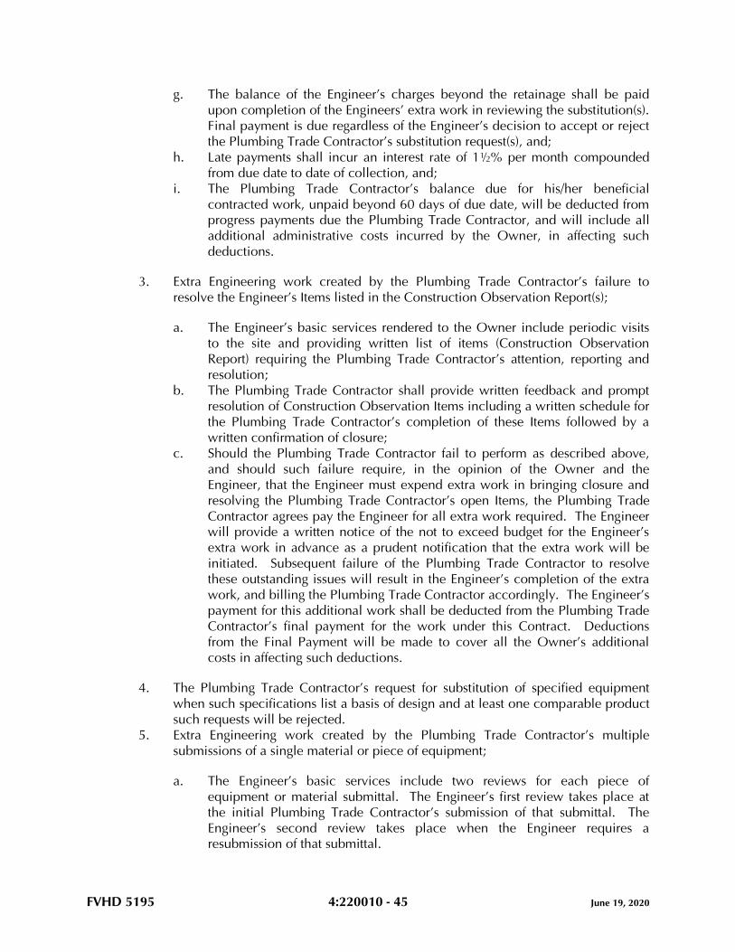
FVHD 5195 4:220010 - 45 June 19, 2020
g. The balance of the Engineer’s charges beyond the retainage shall be paid
upon completion of the Engineers’ extra work in reviewing the substitution(s).
Final payment is due regardless of the Engineer’s decision to accept or reject
the Plumbing Trade Contractor’s substitution request(s), and;
h. Late payments shall incur an interest rate of 1½% per month compounded
from due date to date of collection, and;
i. The Plumbing Trade Contractor’s balance due for his/her beneficial
contracted work, unpaid beyond 60 days of due date, will be deducted from
progress payments due the Plumbing Trade Contractor, and will include all
additional administrative costs incurred by the Owner, in affecting such
deductions.
3. Extra Engineering work created by the Plumbing Trade Contractor’s failure to
resolve the Engineer’s Items listed in the Construction Observation Report(s);
a. The Engineer’s basic services rendered to the Owner include periodic visits
to the site and providing written list of items (Construction Observation
Report) requiring the Plumbing Trade Contractor’s attention, reporting and
resolution;
b. The Plumbing Trade Contractor shall provide written feedback and prompt
resolution of Construction Observation Items including a written schedule for
the Plumbing Trade Contractor’s completion of these Items followed by a
written confirmation of closure;
c. Should the Plumbing Trade Contractor fail to perform as described above,
and should such failure require, in the opinion of the Owner and the
Engineer, that the Engineer must expend extra work in bringing closure and
resolving the Plumbing Trade Contractor’s open Items, the Plumbing Trade
Contractor agrees pay the Engineer for all extra work required. The Engineer
will provide a written notice of the not to exceed budget for the Engineer’s
extra work in advance as a prudent notification that the extra work will be
initiated. Subsequent failure of the Plumbing Trade Contractor to resolve
these outstanding issues will result in the Engineer’s completion of the extra
work, and billing the Plumbing Trade Contractor accordingly. The Engineer’s
payment for this additional work shall be deducted from the Plumbing Trade
Contractor’s final payment for the work under this Contract. Deductions
from the Final Payment will be made to cover all the Owner’s additional
costs in affecting such deductions.
4. The Plumbing Trade Contractor’s request for substitution of specified equipment
when such specifications list a basis of design and at least one comparable product
such requests will be rejected.
5. Extra Engineering work created by the Plumbing Trade Contractor’s multiple
submissions of a single material or piece of equipment;
a. The Engineer’s basic services include two reviews for each piece of
equipment or material submittal. The Engineer’s first review takes place at
the initial Plumbing Trade Contractor’s submission of that submittal. The
Engineer’s second review takes place when the Engineer requires a
resubmission of that submittal.
FVHD 5195 4:220010 - 46 June 19, 2020
b. If the Engineer’s third review of a particular submittal is required for reasons
due to the Plumbing Trade Contractor, the Engineer will provide the
Plumbing Trade Contractor with a written budget, not to exceed quotation for
the Engineer’s extra work in reviewing the submittal.
c. The Plumbing Trade Contractor shall render written acceptance of the
Engineer’s extra charges.
d. The Plumbing Trade Contractor shall pay a retainer, in advance, equal to
80% of the established budget for the Engineer’s extra work.
e. The balance of the Engineer’s charges beyond the retainage shall be paid
upon completion of the Engineers’ extra work in reviewing the submittal.
f. Late payments shall incur an interest rate of 1½% per month compounded
from due date to date of collection.
g. The Plumbing Trade Contractor’s balance, unpaid beyond 60 days of due
date, will be deducted from progress payments due the Plumbing Trade
Contractor for work under this Contract and will include additional
administrative costs incurred by the Owner in affecting all such deductions.
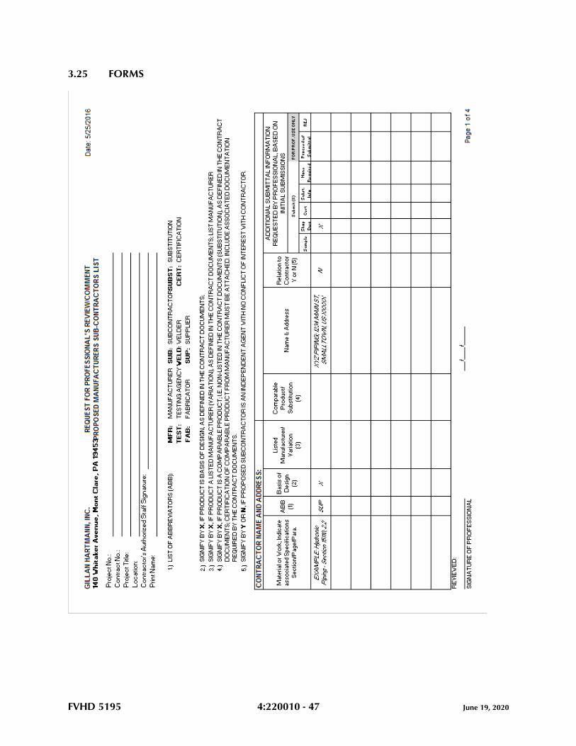
FVHD 5195 4:220010 - 47 June 19, 2020
3.25 FORMS
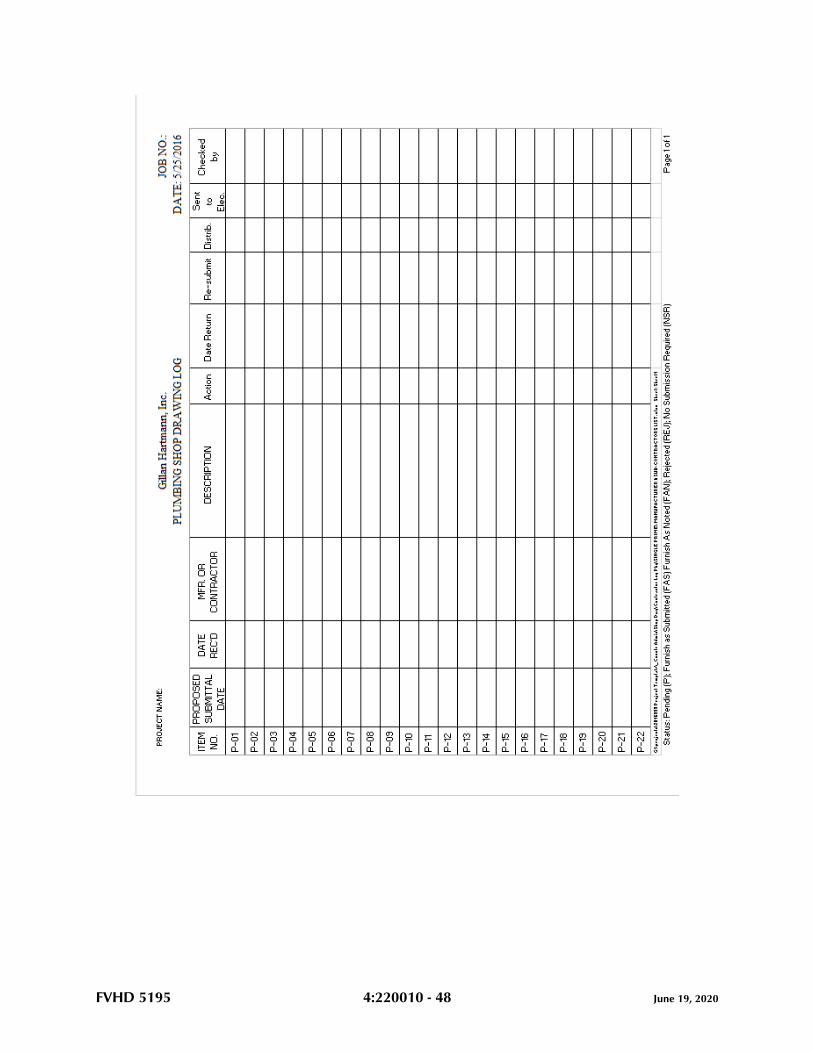
FVHD 5195 4:220010 - 48 June 19, 2020
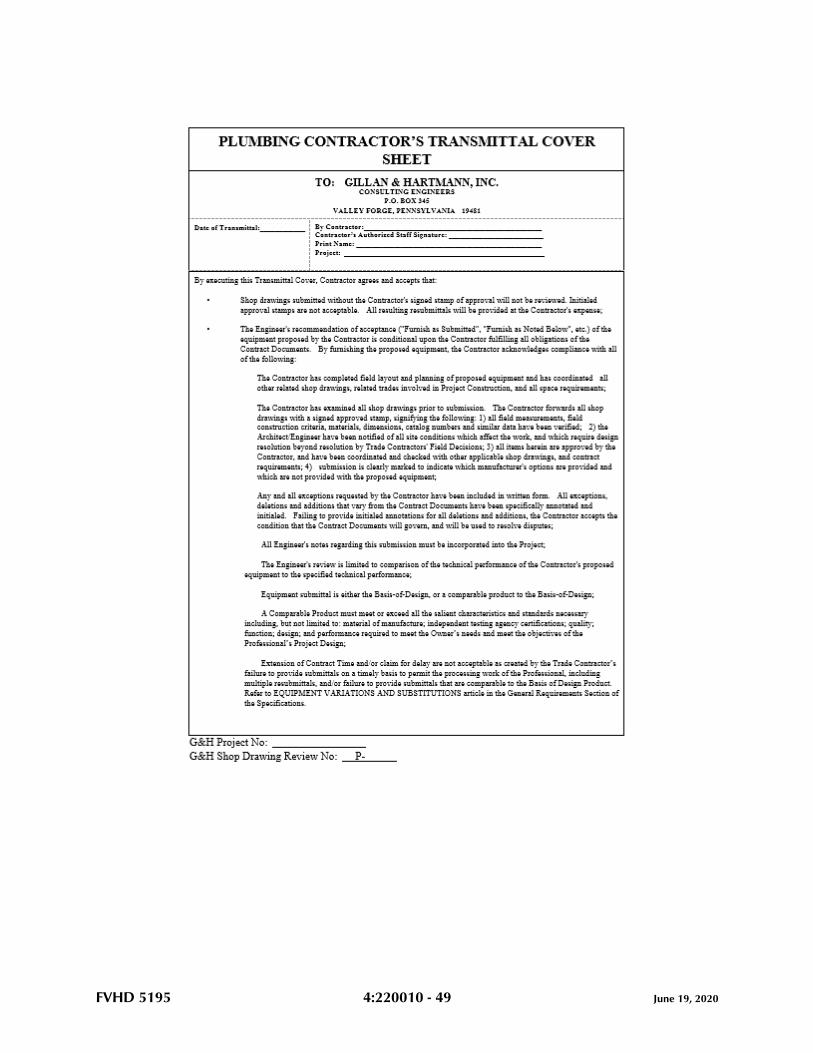
FVHD 5195 4:220010 - 49 June 19, 2020
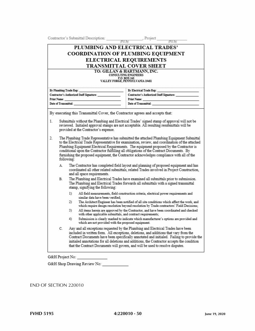
FVHD 5195 4:220010 - 50 June 19, 2020
END OF SECTION 220010
FVHD 5195 4:220513 - 1 June 19, 2020
SECTION 220513 - COMMON MOTOR REQUIREMENTS FOR PLUMBING EQUIPMENT
PART 1 - GENERAL
1.1 RELATED DOCUMENTS
A. Drawings and general provisions of the Contract, including General and Supplementary
Conditions and Division 01 Specification Sections, apply to this Section.
1.2 SUMMARY
A. Section includes general requirements for single-phase and polyphase, general-purpose,
horizontal, small and medium, squirrel-cage induction motors for use on alternating-
current power systems up to 600 V and installed at equipment manufacturer's factory or
shipped separately by equipment manufacturer for field installation.
1.3 COORDINATION
A. Coordinate features of motors, installed units, and accessory devices to be compatible
with the following:
1. Motor controllers.
2. Torque, speed, and horsepower requirements of the load.
3. Ratings and characteristics of supply circuit and required control sequence.
4. Ambient and environmental conditions of installation location.
PART 2 - PRODUCTS
2.1 GENERAL MOTOR REQUIREMENTS
A. Comply with NEMA MG 1 unless otherwise indicated.
2.2 MOTOR CHARACTERISTICS
A. Duty: Continuous duty at ambient temperature of 40 deg C and at altitude of 3300 feet
above sea level.
B. Capacity and Torque Characteristics: Sufficient to start, accelerate, and operate
connected loads at designated speeds, at installed altitude and environment, with
indicated operating sequence, and without exceeding nameplate ratings or considering
service factor.
FVHD 5195 4:220513 - 2 June 19, 2020
2.3 POLYPHASE MOTORS
A. Description: NEMA MG 1, Design B, medium induction motor.
B. Efficiency: Premium efficient, as defined in NEMA MG 1.
C. Service Factor: 1.15.
D. Multispeed Motors: Variable torque.
1. For motors with 2:1 speed ratio, consequent pole, single winding.
2. For motors with other than 2:1 speed ratio, separate winding for each speed.
E. Multispeed Motors: Separate winding for each speed.
F. Rotor: Random-wound, squirrel cage.
G. Bearings: Regreasable, shielded, antifriction ball bearings suitable for radial and thrust
loading.
H. Temperature Rise: Match insulation rating.
I. Insulation: Class F.
J. Code Letter Designation:
1. Motors 15 HP and Larger: NEMA starting Code F or Code G.
2. Motors Smaller Than 15 HP: Manufacturer's standard starting characteristic.
K. Enclosure Material: Cast iron for motor frame sizes 324T and larger; rolled steel for motor
frame sizes smaller than 324T.
2.4 ADDITIONAL REQUIREMENTS FOR POLYPHASE MOTORS
A. Motors Used with Reduced-Voltage and Multispeed Controllers: Match wiring
connection requirements for controller with required motor leads. Provide terminals in
motor terminal box, suited to control method.
B. Motors Used with Variable-Frequency Controllers: Ratings, characteristics, and features
coordinated with and approved by controller manufacturer.
1. Windings: Copper magnet wire with moisture-resistant insulation varnish, designed
and tested to resist transient spikes, high frequencies, and short time rise pulses
produced by pulse-width-modulated inverters.
2. Inverter-Duty Motors: Class F temperature rise; Class H insulation.
3. Thermal Protection: Comply with NEMA MG 1 requirements for thermally
protected motors.

FVHD 5195 4:220513 - 3 June 19, 2020
2.5 SINGLE-PHASE MOTORS
A. Motors larger than 1/20 hp shall be one of the following, to suit starting torque and
requirements of specific motor application:
1. Permanent-split capacitor.
2. Split phase.
3. Capacitor start, inductor run.
4. Capacitor start, capacitor run.
B. Multispeed Motors: Variable-torque, permanent-split-capacitor type.
C. Bearings: Prelubricated, antifriction ball bearings or sleeve bearings suitable for radial
and thrust loading.
D. Motors 1/20 HP and Smaller: Shaded-pole type.
E. Thermal Protection: Internal protection to automatically open power supply circuit to
motor when winding temperature exceeds a safe value calibrated to temperature rating of
motor insulation. Thermal-protection device shall automatically reset when motor
temperature returns to normal range.
PART 3 - EXECUTION (Not Applicable)
END OF SECTION 220513
FVHD 5195 4:220519 - 1 June 19, 2020
SECTION 220519 - METERS AND GAGES FOR PLUMBING PIPING
PART 1 - GENERAL
1.1 RELATED DOCUMENTS
A. Drawings and general provisions of the Contract, including General and Supplementary
Conditions and Division 01 Specification Sections, apply to this Section.
1.2 SUMMARY
A. Section Includes:
1. Filled-system thermometers.
2. Liquid-in-glass thermometers.
3. Thermowells.
4. Dial-type pressure gages.
5. Gage attachments.
6. Test plugs.
7. Test-plug kits.
1.3 ACTION SUBMITTALS
A. Product Data: For each type of product.
1.4 INFORMATIONAL SUBMITTALS
A. Product Certificates: For each type of meter and gage.
1.5 CLOSEOUT SUBMITTALS
A. Operation and Maintenance Data: For meters and gages to include in operation and
maintenance manuals.
PART 2 - PRODUCTS
2.1 FILLED-SYSTEM THERMOMETERS
A. Direct-Mounted, Metal-Case, Vapor-Actuated Thermometers:
1. Manufacturers: Subject to compliance with requirements, provide products by one
of the following:
FVHD 5195 4:220519 - 2 June 19, 2020
a. Miljoco Corporation.
b. Trerice, H. O. Co.
c. Weiss Instruments, Inc.
B. Standard: ASME B40.200.
1. Case: Sealed type, cast aluminum or drawn steel; 4-1/2-inch nominal diameter.
2. Element: Bourdon tube or other type of pressure element.
3. Movement: Mechanical, with link to pressure element and connection to pointer.
4. Dial: Nonreflective aluminum with permanently etched scale markings graduated
in deg F.
5. Pointer: Dark-colored metal.
6. Window: Glass.
7. Ring: Metal.
8. Connector Type(s): Union joint, adjustable, 180 degrees in vertical plane, 360
degrees in horizontal plane, with locking device; with ASME B1.1 screw threads.
9. Thermal System: Liquid-filled bulb in copper-plated steel, aluminum, or brass stem
and of length to suit installation.
a. Design for Thermowell Installation: Bare stem.
10. Accuracy: Plus or minus 1 percent of scale range.
2.2 LIQUID-IN-GLASS THERMOMETERS
A. Metal-Case, Industrial-Style, Liquid-in-Glass Thermometers:
1. Manufacturers: Subject to compliance with requirements, provide products by one
of the following:
a. Miljoco Corporation.
b. Trerice, H. O. Co.
c. Weiss Instruments, Inc.
2. Standard: ASME B40.200.
3. Case: Cast aluminum; 9-inch nominal size unless otherwise indicated.
4. Case Form: Adjustable angle unless otherwise indicated.
5. Tube: Glass with magnifying lens and blue or red organic liquid.
6. Tube Background: Nonreflective aluminum with permanently etched scale
markings graduated in deg F.
7. Window: Glass.
8. Stem: Aluminum and of length to suit installation.
a. Design for Thermowell Installation: Bare stem.
9. Connector: 1-1/4 inches, with ASME B1.1 screw threads.
10. Accuracy: Plus or minus 1 percent of scale range or one scale division, to a
maximum of 1.5 percent of scale range.
FVHD 5195 4:220519 - 3 June 19, 2020
2.3 THERMOWELLS
A. Thermowells:
1. Standard: ASME B40.200.
2. Description: Pressure-tight, socket-type fitting made for insertion into piping tee
fitting.
3. Material for Use with Copper Tubing: CNR.
4. Material for Use with Steel Piping: CRES.
5. Type: Stepped shank unless straight or tapered shank is indicated.
6. External Threads: NPS 1/2, NPS 3/4, or NPS 1, ASME B1.20.1 pipe threads.
7. Internal Threads: 1/2, 3/4, and 1 inch, with ASME B1.1 screw threads.
8. Bore: Diameter required to match thermometer bulb or stem.
9. Insertion Length: Length required to match thermometer bulb or stem.
10. Lagging Extension: Include on thermowells for insulated piping and tubing.
11. Bushings: For converting size of thermowell's internal screw thread to size of
thermometer connection.
B. Heat-Transfer Medium: Mixture of graphite and glycerin.
2.4 PRESSURE GAGES
A. Direct-Mounted, Metal-Case, Dial-Type Pressure Gages:
1. Manufacturers: Subject to compliance with requirements, provide products by one
of the following:
a. Miljoco Corporation.
b. Trerice, H. O. Co.
c. Weiss Instruments, Inc.
d. Weksler Glass Thermometer Corp.
2. Standard: ASME B40.100.
3. Case: Liquid-filled type(s); cast aluminum or drawn steel; 4-1/2-inch nominal
diameter.
4. Pressure-Element Assembly: Bourdon tube unless otherwise indicated.
5. Pressure Connection: Brass, with NPS 1/4 or NPS 1/2, ASME B1.20.1 pipe threads
and bottom-outlet type unless back-outlet type is indicated.
6. Movement: Mechanical, with link to pressure element and connection to pointer.
7. Dial: Nonreflective aluminum with permanently etched scale markings graduated
in psi.
8. Pointer: Dark-colored metal.
9. Window: Glass.
10. Ring: Stainless steel.
11. Accuracy: Grade A, plus or minus 1 percent of middle half of scale range.
FVHD 5195 4:220519 - 4 June 19, 2020
2.5 GAGE ATTACHMENTS
A. Snubbers: ASME B40.100, brass; with NPS 1/4 or NPS 1/2, ASME B1.20.1 pipe threads
and porous-metal-type surge-dampening device. Include extension for use on insulated
piping.
B. Valves: Brass ball, with NPS 1/4 or NPS 1/2, ASME B1.20.1 pipe threads.
2.6 TEST PLUGS
A. Manufacturers: Subject to compliance with requirements, provide products by one of the
following:
1. Miljoco Corporation.
2. Trerice, H. O. Co.
3. Weiss Instruments, Inc.
B. Description: Test-station fitting made for insertion into piping tee fitting.
C. Body: Brass or stainless steel with core inserts and gasketed and threaded cap. Include
extended stem on units to be installed in insulated piping.
D. Thread Size: NPS 1/4 or NPS 1/2, ASME B1.20.1 pipe thread.
E. Minimum Pressure and Temperature Rating: 500 psig at 200 deg F.
F. Core Inserts: EPDM self-sealing rubber.
2.7 TEST-PLUG KITS
A. Manufacturers: Subject to compliance with requirements, provide products by one of the
following:
1. Miljoco Corporation.
2. Trerice, H. O. Co.
3. WATTS.
B. Furnish one test-plug kit(s) containing two thermometer(s), one pressure gage and
adapter, and carrying case. Thermometer sensing elements, pressure gage, and adapter
probes shall be of diameter to fit test plugs and of length to project into piping.
C. Low-Range Thermometer: Small, bimetallic insertion type with 1- to 2-inch-diameter dial
and tapered-end sensing element. Dial range shall be at least 25 to 125 deg F.
D. High-Range Thermometer: Small, bimetallic insertion type with 1- to 2-inch-diameter dial
and tapered-end sensing element. Dial range shall be at least 0 to 220 deg F.
E. Pressure Gage: Small, Bourdon-tube insertion type with 2- to 3-inch-diameter dial and
probe. Dial range shall be at least 0 to 200 psig.
FVHD 5195 4:220519 - 5 June 19, 2020
F. Carrying Case: Metal or plastic, with formed instrument padding.
PART 3 - EXECUTION
3.1 INSTALLATION
A. Install thermowells with socket extending to center of pipe and in vertical position in
piping tees.
B. Install thermowells of sizes required to match thermometer connectors. Include bushings
if required to match sizes.
C. Install thermowells with extension on insulated piping.
D. Fill thermowells with heat-transfer medium.
E. Install direct-mounted thermometers in thermowells and adjust vertical and tilted
positions.
F. Install direct-mounted pressure gages in piping tees with pressure gage located on pipe at
the most readable position.
G. Install valve and snubber in piping for each pressure gage for fluids.
H. Install test plugs in piping tees.
I. Install thermometers in the following locations:
1. Inlet and outlet of each water heater.
2. Inlet and outlet of each domestic hot-water storage tank.
3. Other locations indicated by the Drawings and applicable Division 22 Sections.
J. Install pressure gages in the following locations:
1. Inlet and outlet of each pressure-reducing valve.
2. Suction and discharge of each domestic water pump.
3. Other locations indicated by the Drawings and applicable Division 22 Sections.
3.2 CONNECTIONS
A. Install meters and gages adjacent to machines and equipment to allow service and
maintenance of meters, gages, machines, and equipment.
3.3 ADJUSTING
A. Adjust faces of meters and gages to proper angle for best visibility.
FVHD 5195 4:220519 - 6 June 19, 2020
3.4 THERMOMETER SCHEDULE
A. Thermometers at inlet and outlet of each domestic water heater shall be one of the
following:
1. Direct-mounted, metal-case, vapor-actuated type.
2. Metal case, industrial-style, liquid-in-glass type.
B. Thermometer stems shall be of length to match thermowell insertion length.
3.5 THERMOMETER SCALE-RANGE SCHEDULE
A. Scale Range for Domestic Cold-Water Piping: 0 to 100 deg F.
B. Scale Range for Domestic Hot-Water Piping: 30 to 240 deg F.
3.6 PRESSURE-GAGE SCHEDULE
A. Pressure gages at inlet and outlet of each water pressure-reducing valve shall be one of
the following:
1. Liquid-filled, direct-mounted, metal case.
2. Test plug with EPDM self-sealing rubber inserts.
a. Test plugs are only permitted on the inlet side
B. Pressure gages at suction and discharge of each domestic water pump shall be one of the
following:
1. Liquid-filled, direct-mounted, metal case.
C. Natural Gas piping:
1. Stainless steel test plug with chloroprene based (Neoprene) rubber inserts suitable
for natural gas piping.
3.7 PRESSURE-GAGE SCALE-RANGE SCHEDULE
A. Scale Range for Domestic Water Piping: 0 to 160 psi.
END OF SECTION 220519
FVHD 5195 4:220523.12 - 1 June 19, 2020
SECTION 220523.12 - BALL VALVES FOR PLUMBING PIPING
PART 1 - GENERAL
1.1 RELATED DOCUMENTS
A. Drawings and general provisions of the Contract, including General and Supplementary
Conditions and Division 01 Specification Sections, apply to this Section.
1.2 SUMMARY
A. Section Includes:
1. Brass ball valves.
2. Bronze ball valves.
1.3 DEFINITIONS
A. CWP: Cold working pressure.
B. Press-end connection: Valves suitable for connection to a pressure-sealed system.
1.4 ACTION SUBMITTALS
A. Product Data: For each type of valve.
1. Certification that products comply with NSF 61and NSF 372.
1.5 DELIVERY, STORAGE, AND HANDLING
A. Prepare valves for shipping as follows:
1. Protect internal parts against rust and corrosion.
2. Protect threads, flange faces, and soldered ends.
3. Set ball valves open to minimize exposure of functional surfaces.
B. Use the following precautions during storage:
1. Maintain valve end protection.
2. Store valves indoors and maintain at higher-than-ambient-dew-point temperature. If
outdoor storage is necessary, store valves off the ground in watertight enclosures.
C. Use sling to handle large valves; rig sling to avoid damage to exposed parts. Do not use
operating handles or stems as lifting or rigging points.
FVHD 5195 4:220523.12 - 2 June 19, 2020
PART 2 - PRODUCTS
2.1 GENERAL REQUIREMENTS FOR VALVES
A. Source Limitations for Valves: Obtain each type of valve from single source from single
manufacturer.
B. ASME Compliance:
1. ASME B1.20.1 for threads for threaded end valves.
2. ASME B16.10 and ASME B16.34 for ferrous valve dimensions and design criteria.
3. ASME B16.18 for solder-joint connections.
4. ASME B31.9 for building services piping valves.
C. NSF Compliance: NSF 61 and NSF 372 for valve materials for potable-water service.
D. Bronze valves shall be made with dezincification-resistant materials. Bronze valves made
with copper alloy (brass) containing more than 15 percent zinc are not permitted.
E. Valve Pressure-Temperature Ratings: Not less than indicated and as required for system
pressures and temperatures.
F. Valve Sizes: Same as upstream piping unless otherwise indicated.
G. Valve Actuator Types:
1. Gear Actuator: For quarter-turn valves NPS 4 and larger.
2. Handlever: For quarter-turn valves smaller than NPS 4.
H. Valves in Insulated Piping:
1. Include 2-inch stem extensions.
2. Extended operating handles of nonthermal-conductive material and protective
sleeves that allow operation of valves without breaking vapor seals or disturbing
insulation.
3. Memory stops that are fully adjustable after insulation is applied.
2.2 BRASS BALL VALVES
A. Brass Ball Valves, Two-Piece with Full Port and Brass Trim, Threaded or Soldered Ends:
1. Basis-of-Design Product: Subject to compliance with requirements, provide NIBCO
INC.; or a comparable product by one of the following:
a. Apollo Flow Controls; Conbraco Industries, Inc.
b. Milwaukee Valve Company.
c. Stockham; Crane Energy Flow Solutions.
2. Description:
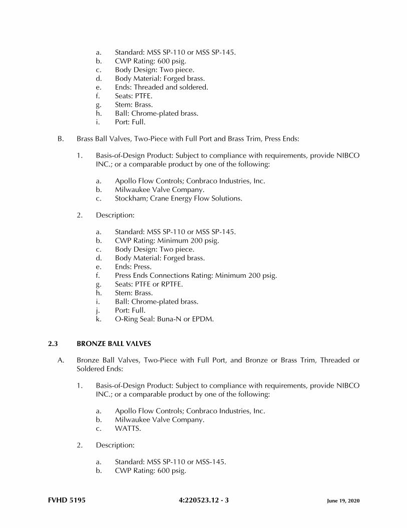
FVHD 5195 4:220523.12 - 3 June 19, 2020
a. Standard: MSS SP-110 or MSS SP-145.
b. CWP Rating: 600 psig.
c. Body Design: Two piece.
d. Body Material: Forged brass.
e. Ends: Threaded and soldered.
f. Seats: PTFE.
g. Stem: Brass.
h. Ball: Chrome-plated brass.
i. Port: Full.
B. Brass Ball Valves, Two-Piece with Full Port and Brass Trim, Press Ends:
1. Basis-of-Design Product: Subject to compliance with requirements, provide NIBCO
INC.; or a comparable product by one of the following:
a. Apollo Flow Controls; Conbraco Industries, Inc.
b. Milwaukee Valve Company.
c. Stockham; Crane Energy Flow Solutions.
2. Description:
a. Standard: MSS SP-110 or MSS SP-145.
b. CWP Rating: Minimum 200 psig.
c. Body Design: Two piece.
d. Body Material: Forged brass.
e. Ends: Press.
f. Press Ends Connections Rating: Minimum 200 psig.
g. Seats: PTFE or RPTFE.
h. Stem: Brass.
i. Ball: Chrome-plated brass.
j. Port: Full.
k. O-Ring Seal: Buna-N or EPDM.
2.3 BRONZE BALL VALVES
A. Bronze Ball Valves, Two-Piece with Full Port, and Bronze or Brass Trim, Threaded or
Soldered Ends:
1. Basis-of-Design Product: Subject to compliance with requirements, provide NIBCO
INC.; or a comparable product by one of the following:
a. Apollo Flow Controls; Conbraco Industries, Inc.
b. Milwaukee Valve Company.
c. WATTS.
2. Description:
a. Standard: MSS SP-110 or MSS-145.
b. CWP Rating: 600 psig.
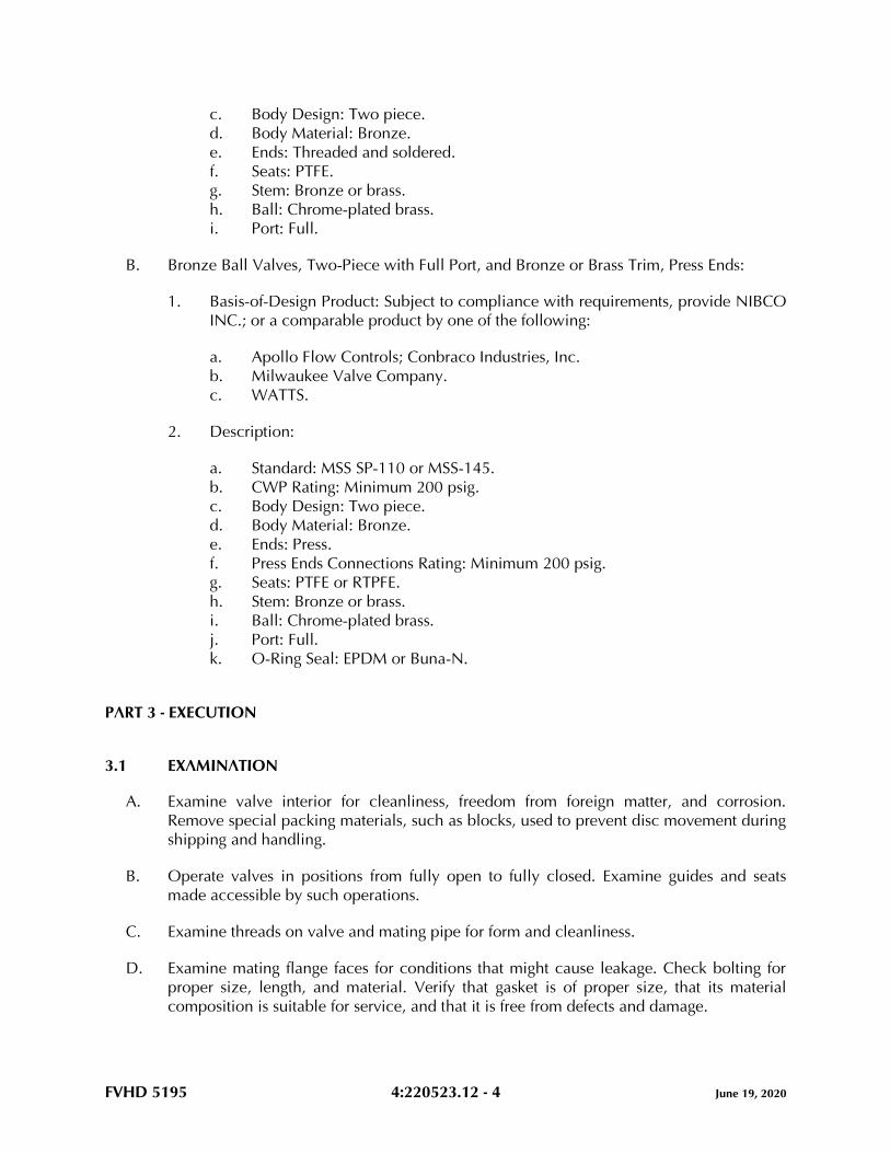
FVHD 5195 4:220523.12 - 4 June 19, 2020
c. Body Design: Two piece.
d. Body Material: Bronze.
e. Ends: Threaded and soldered.
f. Seats: PTFE.
g. Stem: Bronze or brass.
h. Ball: Chrome-plated brass.
i. Port: Full.
B. Bronze Ball Valves, Two-Piece with Full Port, and Bronze or Brass Trim, Press Ends:
1. Basis-of-Design Product: Subject to compliance with requirements, provide NIBCO
INC.; or a comparable product by one of the following:
a. Apollo Flow Controls; Conbraco Industries, Inc.
b. Milwaukee Valve Company.
c. WATTS.
2. Description:
a. Standard: MSS SP-110 or MSS-145.
b. CWP Rating: Minimum 200 psig.
c. Body Design: Two piece.
d. Body Material: Bronze.
e. Ends: Press.
f. Press Ends Connections Rating: Minimum 200 psig.
g. Seats: PTFE or RTPFE.
h. Stem: Bronze or brass.
i. Ball: Chrome-plated brass.
j. Port: Full.
k. O-Ring Seal: EPDM or Buna-N.
PART 3 - EXECUTION
3.1 EXAMINATION
A. Examine valve interior for cleanliness, freedom from foreign matter, and corrosion.
Remove special packing materials, such as blocks, used to prevent disc movement during
shipping and handling.
B. Operate valves in positions from fully open to fully closed. Examine guides and seats
made accessible by such operations.
C. Examine threads on valve and mating pipe for form and cleanliness.
D. Examine mating flange faces for conditions that might cause leakage. Check bolting for
proper size, length, and material. Verify that gasket is of proper size, that its material
composition is suitable for service, and that it is free from defects and damage.
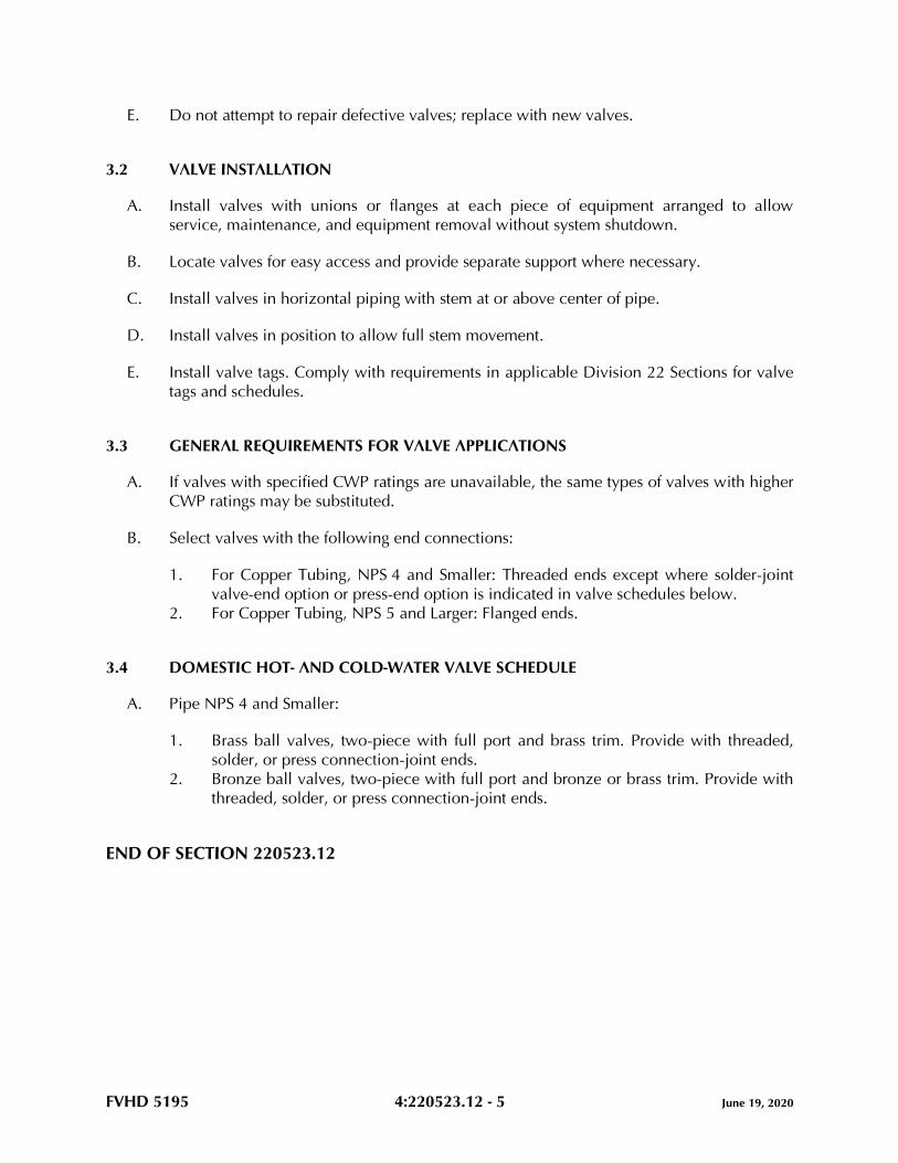
FVHD 5195 4:220523.12 - 5 June 19, 2020
E. Do not attempt to repair defective valves; replace with new valves.
3.2 VALVE INSTALLATION
A. Install valves with unions or flanges at each piece of equipment arranged to allow
service, maintenance, and equipment removal without system shutdown.
B. Locate valves for easy access and provide separate support where necessary.
C. Install valves in horizontal piping with stem at or above center of pipe.
D. Install valves in position to allow full stem movement.
E. Install valve tags. Comply with requirements in applicable Division 22 Sections for valve
tags and schedules.
3.3 GENERAL REQUIREMENTS FOR VALVE APPLICATIONS
A. If valves with specified CWP ratings are unavailable, the same types of valves with higher
CWP ratings may be substituted.
B. Select valves with the following end connections:
1. For Copper Tubing, NPS 4 and Smaller: Threaded ends except where solder-joint
valve-end option or press-end option is indicated in valve schedules below.
2. For Copper Tubing, NPS 5 and Larger: Flanged ends.
3.4 DOMESTIC HOT- AND COLD-WATER VALVE SCHEDULE
A. Pipe NPS 4 and Smaller:
1. Brass ball valves, two-piece with full port and brass trim. Provide with threaded,
solder, or press connection-joint ends.
2. Bronze ball valves, two-piece with full port and bronze or brass trim. Provide with
threaded, solder, or press connection-joint ends.
END OF SECTION 220523.12
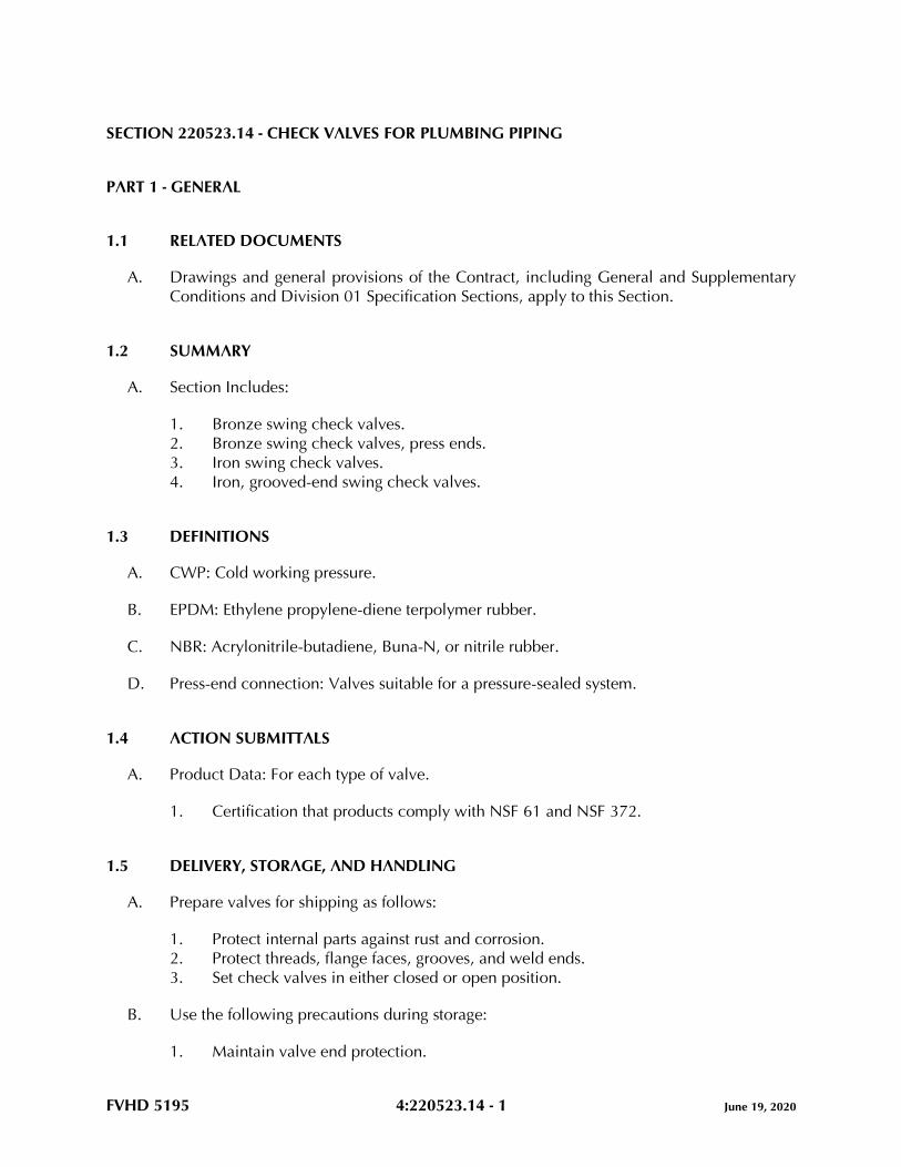
FVHD 5195 4:220523.14 - 1 June 19, 2020
SECTION 220523.14 - CHECK VALVES FOR PLUMBING PIPING
PART 1 - GENERAL
1.1 RELATED DOCUMENTS
A. Drawings and general provisions of the Contract, including General and Supplementary
Conditions and Division 01 Specification Sections, apply to this Section.
1.2 SUMMARY
A. Section Includes:
1. Bronze swing check valves.
2. Bronze swing check valves, press ends.
3. Iron swing check valves.
4. Iron, grooved-end swing check valves.
1.3 DEFINITIONS
A. CWP: Cold working pressure.
B. EPDM: Ethylene propylene-diene terpolymer rubber.
C. NBR: Acrylonitrile-butadiene, Buna-N, or nitrile rubber.
D. Press-end connection: Valves suitable for a pressure-sealed system.
1.4 ACTION SUBMITTALS
A. Product Data: For each type of valve.
1. Certification that products comply with NSF 61 and NSF 372.
1.5 DELIVERY, STORAGE, AND HANDLING
A. Prepare valves for shipping as follows:
1. Protect internal parts against rust and corrosion.
2. Protect threads, flange faces, grooves, and weld ends.
3. Set check valves in either closed or open position.
B. Use the following precautions during storage:
1. Maintain valve end protection.
FVHD 5195 4:220523.14 - 2 June 19, 2020
2. Store valves indoors and maintain at higher-than-ambient-dew-point temperature. If
outdoor storage is necessary, store valves off the ground in watertight enclosures.
C. Use sling to handle large valves; rig sling to avoid damage to exposed parts. Do not use
handwheels or stems as lifting or rigging points.
PART 2 - PRODUCTS
2.1 GENERAL REQUIREMENTS FOR VALVES
A. Source Limitations for Valves: Obtain each type of valve from single source from single
manufacturer.
B. ASME Compliance:
1. ASME B1.20.1 for threads for threaded end valves.
2. ASME B16.1 for flanges on iron valves.
3. ASME B16.10 and ASME B16.34 for ferrous valve dimensions and design criteria.
4. ASME B16.18 for solder joint.
5. ASME B31.9 for building services piping valves.
C. AWWA Compliance: Comply with AWWA C606 for grooved-end connections.
D. Drinking Water System Components - Health Effects and Drinking Water System
Components - Lead Content Compliance: NSF 61 and NSF 372.
E. Bronze valves shall be made with dezincification-resistant materials. Bronze valves made
with copper alloy (brass) containing more than 15 percent zinc are not permitted.
F. Valve Pressure-Temperature Ratings: Not less than indicated and as required for system
pressures and temperatures.
G. Valve Sizes: Same as upstream piping unless otherwise indicated.
H. Valve Bypass and Drain Connections: MSS SP-45.
2.2 BRONZE SWING CHECK VALVES
A. Bronze Swing Check Valves with Bronze Disc, Class 125:
1. Basis-of-Design Product: Subject to compliance with requirements, provide NIBCO
INC.; or a comparable product by one of the following:
a. Apollo Flow Controls; Conbraco Industries, Inc.
b. Stockham; Crane Energy Flow Solutions.
c. WATTS.
2. Description:
FVHD 5195 4:220523.14 - 3 June 19, 2020
a. Standard: MSS SP-80, Type 3.
b. CWP Rating: 200 psig.
c. Body Design: Horizontal flow.
d. Body Material: ASTM B62, bronze.
e. Ends: Threaded or soldered. See valve schedule articles.
f. Disc: Bronze.
B. Bronze Swing Check Valves, Press Ends:
1. Basis-of-Design Product: Subject to compliance with requirements, provide NIBCO
INC.; or a comparable product by one of the following:
a. Apollo Flow Controls; Conbraco Industries, Inc.
b. Elkhart Products Corporation.
c. Milwaukee Valve Company.
2. Description:
a. Standard: MSS SP-80 and MSS SP-139.
b. CWP Rating: Minimum 200 psig.
c. Body Design: Horizontal flow.
d. Body Material: ASTM B584, bronze.
e. Ends: Press.
f. Press Ends Connection Rating: Minimum 200 psig
g. Disc: Brass or bronze.
2.3 IRON SWING CHECK VALVES
A. Iron Swing Check Valves with Metal Seats, Class 125:
1. Basis-of-Design Product: Subject to compliance with requirements, provide NIBCO
INC.; or a comparable product by one of the following:
a. Apollo Flow Controls; Conbraco Industries, Inc.
b. Stockham; Crane Energy Flow Solutions.
c. WATTS.
2. Description:
a. Standard: MSS SP-71, Type I.
b. CWP Rating: 200 psig.
c. Body Design: Clear or full waterway.
d. Body Material: ASTM A126, gray iron with bolted bonnet.
e. Ends: Flanged or threaded. See valve schedule articles.
f. Trim: Bronze.
g. Gasket: Asbestos free.
FVHD 5195 4:220523.14 - 4 June 19, 2020
2.4 IRON, GROOVED-END SWING CHECK VALVES
A. Iron, Grooved-End Swing Check Valves, 300 CWP:
1. Basis-of-Design Product: Subject to compliance with requirements, provide
Victaulic Company; or a comparable product by one of the following:
a. Shurjoint-Apollo Piping Products USA Inc.
b. Tyco by Johnson Controls Company.
2. Description:
a. CWP Rating: 300 psig.
b. Body Material: ASTM A536, ductile iron.
c. Seal: EPDM.
d. Disc: Spring operated, ductile iron or stainless steel.
PART 3 - EXECUTION
3.1 EXAMINATION
A. Examine valve interior for cleanliness, freedom from foreign matter, and corrosion.
Remove special packing materials, such as blocks, used to prevent disc movement during
shipping and handling.
B. Operate valves in positions from fully open to fully closed. Examine guides and seats
made accessible by such operations.
C. Examine threads on valve and mating pipe for form and cleanliness.
D. Examine mating flange faces for conditions that might cause leakage. Check bolting for
proper size, length, and material. Verify that gasket is of proper size, that its material
composition is suitable for service, and that it is free from defects and damage.
E. Do not attempt to repair defective valves; replace with new valves.
3.2 VALVE INSTALLATION
A. Install valves with unions or flanges at each piece of equipment arranged to allow
service, maintenance, and equipment removal without system shutdown.
B. Locate valves for easy access and provide separate support where necessary.
C. Install valves in horizontal piping with stem at or above center of pipe.
D. Install valves in position to allow full stem movement.
E. Check Valves: Install check valves for proper direction of flow.
FVHD 5195 4:220523.14 - 5 June 19, 2020
1. Swing Check Valves: In horizontal position with hinge pin level.
F. Install valve tags. Comply with requirements in applicable Division 22 Sections for valve
tags and schedules.
3.3 ADJUSTING
A. Adjust or replace valve packing after piping systems have been tested and put into service
but before final adjusting and balancing. Replace valves if persistent leaking occurs.
3.4 GENERAL REQUIREMENTS FOR VALVE APPLICATIONS
A. If valves with specified CWP ratings are unavailable, the same types of valves with higher
CWP ratings may be substituted.
B. End Connections:
1. For Copper Tubing, NPS 2 and Smaller: Threaded or soldered or press-ends.
2. For Copper Tubing, NPS 2-1/2 to NPS 4: Flanged or threaded.
3. For Copper Tubing, NPS 5 and Larger: Flanged.
4. For Grooved-End Copper Tubing: Grooved.
3.5 DOMESTIC HOT- AND COLD-WATER VALVE SCHEDULE
A. Pipe NPS 2 and Smaller:
1. Bronze swing check valves with bronze disc, Class 125, with soldered or threaded
end connections.
2. Bronze swing check valves with press-end connections.
B. Pipe NPS 2-1/2 and Larger:
1. Iron swing check valves with metal seats, Class 125, with threaded or flanged end
connections.
2. Iron, grooved-end swing check valves, 300 CWP.
END OF SECTION 220523.14
FVHD 5195 4:220523.15 - 1 June 19, 2020
SECTION 220523.15 - GATE VALVES FOR PLUMBING PIPING
PART 1 - GENERAL
1.1 RELATED DOCUMENTS
A. Drawings and general provisions of the Contract, including General and Supplementary
Conditions and Division 01 Specification Sections, apply to this Section.
1.2 SUMMARY
A. Section Includes:
1. Bronze gate valves.
2. Iron gate valves.
3. Chainwheels.
1.3 DEFINITIONS
A. CWP: Cold working pressure.
B. NRS: Nonrising stem.
C. OS&Y: Outside screw and yoke.
D. RS: Rising stem.
1.4 ACTION SUBMITTALS
A. Product Data: For each type of valve.
1. Certification that products comply with NSF 61 and NSF 372.
1.5 DELIVERY, STORAGE, AND HANDLING
A. Prepare valves for shipping as follows:
1. Protect internal parts against rust and corrosion.
2. Protect threads, flange faces, grooves, and weld ends.
3. Set gate valves closed to prevent rattling.
B. Use the following precautions during storage:
1. Maintain valve end protection.
FVHD 5195 4:220523.15 - 2 June 19, 2020
2. Store valves indoors and maintain at higher-than-ambient-dew-point temperature. If
outdoor storage is necessary, store valves off the ground in watertight enclosures.
C. Use sling to handle large valves; rig sling to avoid damage to exposed parts. Do not use
handwheels or stems as lifting or rigging points.
PART 2 - PRODUCTS
2.1 GENERAL REQUIREMENTS FOR VALVES
A. Source Limitations for Valves: Obtain each type of valve from single source from single
manufacturer.
B. ASME Compliance:
1. ASME B1.20.1 for threads for threaded end valves.
2. ASME B16.1 for flanges on iron valves.
3. ASME B16.10 and ASME B16.34 for ferrous valve dimensions and design criteria.
4. ASME B16.18 for solder joint.
5. ASME B31.9 for building services piping valves.
C. NSF Compliance: NSF 61 and NSP 372 for valve materials for potable-water service.
D. Bronze valves shall be made with dezincification-resistant materials. Bronze valves made
with copper alloy (brass) containing more than 15 percent zinc are not permitted.
E. Valve Pressure-Temperature Ratings: Not less than indicated and as required for system
pressures and temperatures.
F. Valve Sizes: Same as upstream piping unless otherwise indicated.
G. RS Valves in Insulated Piping: With 2-inch stem extensions.
H. Valve Bypass and Drain Connections: MSS SP-45.
2.2 BRONZE GATE VALVES
A. Bronze Gate Valves, RS, Class 125:
1. Manufacturers: Subject to compliance with requirements, provide products by one
of the following:
a. Apollo Flow Controls; Conbraco Industries, Inc.
b. NIBCO INC.
c. Stockham; a Crane brand.
2. Description:

FVHD 5195 4:220523.15 - 3 June 19, 2020
a. Standard: MSS SP-80, Type 2.
b. CWP Rating: 200 psig.
c. Body Material: Bronze with integral seat and screw-in bonnet.
d. Ends: Threaded or solder joint.
e. Stem: Bronze.
f. Disc: Solid wedge; bronze.
g. Packing: Asbestos free.
h. Handwheel: Malleable iron, bronze, or aluminum.
2.3 IRON GATE VALVES
A. Iron Gate Valves, OS&Y, Class 125:
1. Manufacturers: Subject to compliance with requirements, provide products by one
of the following:
a. Apollo Flow Controls; Conbraco Industries, Inc.
b. NIBCO INC.
c. Stockham; a Crane brand.
d. WATTS.
2. Description:
a. Standard: MSS SP-70, Type I.
b. CWP Rating: 200 psig.
c. Body Material: Gray iron with bolted bonnet.
d. Ends: Flanged.
e. Trim: Bronze.
f. Disc: Solid wedge.
g. Packing and Gasket: Asbestos free.
2.4 CHAINWHEELS
A. Manufacturers: Subject to compliance with requirements, provide products by one of the
following:
1. Babbitt Steam Specialty Co.
2. Roto Hammer Industries.
B. Description: Valve actuation assembly with sprocket rim, chain guides, chain, and
attachment brackets for mounting chainwheels directly to hand wheels.
1. Sprocket Rim with Chain Guides: Ductile or cast iron, of type and size required for
valve.
2. Chain: Hot-dip galvanized steel, of size required to fit sprocket rim.
FVHD 5195 4:220523.15 - 4 June 19, 2020
PART 3 - EXECUTION
3.1 EXAMINATION
A. Examine valve interior for cleanliness, freedom from foreign matter, and corrosion.
Remove special packing materials, such as blocks, used to prevent disc movement during
shipping and handling.
B. Operate valves in positions from fully open to fully closed. Examine guides and seats
made accessible by such operations.
C. Examine threads on valve and mating pipe for form and cleanliness.
D. Examine mating flange faces for conditions that might cause leakage. Check bolting for
proper size, length, and material. Verify that gasket is of proper size, that its material
composition is suitable for service, and that it is free from defects and damage.
E. Do not attempt to repair defective valves; replace with new valves.
3.2 VALVE INSTALLATION
A. Install valves with unions or flanges at each piece of equipment arranged to allow
service, maintenance, and equipment removal without system shutdown.
B. Locate valves for easy access and provide separate support where necessary.
C. Install valves in horizontal piping with stem at or above center of pipe.
D. Install valves in position to allow full stem movement.
E. Install chainwheels on operators for gate valves NPS 4 and larger and more than 96
inches above floor. Extend chains to 60 inches above finished floor.
F. Install valve tags. Comply with requirements in applicable Division 22 Sections for valve
tags and schedules.
3.3 ADJUSTING
A. Adjust or replace valve packing after piping systems have been tested and put into service
but before final adjusting and balancing. Replace valves if persistent leaking occurs.
3.4 GENERAL REQUIREMENTS FOR VALVE APPLICATIONS
A. Use gate valves for shutoff service only.
B. If valves with specified CWP ratings are unavailable, the same types of valves with higher
CWP ratings may be substituted.
FVHD 5195 4:220523.15 - 5 June 19, 2020
3.5 DOMESTIC HOT- AND COLD-WATER VALVE SCHEDULE
A. Pipe NPS 2 and Smaller:
1. Bronze gate valves, RS, Class 125 with soldered or threaded ends.
B. Pipe NPS 2-1/2 and Larger: Iron gate valves, OS&Y, Class 125 with flanged ends.
END OF SECTION 220523.15
FVHD 5195 4:220529 - 1 June 19, 2020
SECTION 220529 - HANGERS AND SUPPORTS FOR PLUMBING PIPING AND EQUIPMENT
PART 1 - GENERAL
1.1 RELATED DOCUMENTS
A. Drawings and general provisions of the Contract, including General and Supplementary
Conditions and Division 01 Specification Sections, apply to this Section.
1.2 SUMMARY
A. Section Includes:
1. Metal pipe hangers and supports.
2. Trapeze pipe hangers.
3. Metal framing systems.
4. Thermal hanger-shield inserts.
5. Fastener systems.
6. Pipe-positioning systems.
7. Equipment supports.
1.3 ACTION SUBMITTALS
A. Product Data: For each type of product.
B. Shop Drawings: Show fabrication and installation details and include calculations for the
following; maximum weights supported, maximum pipe dimensions supported, support
intervals, etc. Include Product Data for components:
1. Trapeze pipe hangers. Include Product Data for components.
a. Shop Drawings to be signed and sealed by a qualified professional engineer.
2. Metal framing systems. Include Product Data for components.
3. Equipment supports. Include Product Data for components.
a. Shop Drawings to be signed and sealed by a qualified professional engineer.
1.4 INFORMATIONAL SUBMITTALS
A. Welding certificates.
FVHD 5195 4:220529 - 2 June 19, 2020
1.5 QUALITY ASSURANCE
A. Structural-Steel Welding Qualifications: Qualify procedures and personnel according to
AWS D1.1/D1.1M.
B. Pipe Welding Qualifications: Qualify procedures and operators according to 2015 ASME
Boiler and Pressure Vessel Code, Section IX.
PART 2 - PRODUCTS
2.1 PERFORMANCE REQUIREMENTS
A. Delegated Design: Engage a qualified professional engineer, as indicated, as defined in
applicable Division 01 Sections, to design trapeze pipe hangers and equipment supports.
B. Structural Performance: Hangers and supports for plumbing piping and equipment shall
withstand the effects of gravity loads and stresses within limits and under conditions
indicated according to ASCE/SEI 7.
1. Design supports for multiple pipes, capable of supporting combined weight of
supported systems, system contents, and test water.
2. Design equipment supports capable of supporting combined operating weight of
supported equipment and connected systems and components.
2.2 METAL PIPE HANGERS AND SUPPORTS
A. Carbon-Steel Pipe Hangers and Supports:
1. Description: MSS SP-58, Types 1 through 58, factory-fabricated components.
2. Galvanized Metallic Coatings: Pregalvanized, hot-dip galvanized, or electro-
galvanized.
3. Nonmetallic Coatings: Plastic coated or epoxy powder coated.
4. Padded Hangers: Hanger with fiberglass or other pipe insulation pad or cushion to
support bearing surface of piping.
5. Hanger Rods: Continuous-thread rod, nuts, and washer made of carbon steel.
B. Copper Pipe and Tube Hangers:
1. Description: MSS SP-58, Types 1 through 58, copper-coated-steel, factory-
fabricated components.
2. Hanger Rods: Continuous-thread rod, nuts, and washer made of copper-coated
steel.
2.3 TRAPEZE PIPE HANGERS
A. Description: MSS SP-58, Type 59, shop- or field-fabricated pipe-support assembly, made
from structural-carbon-steel shapes, with MSS SP-58 carbon-steel hanger rods, nuts,
saddles, and U-bolts.
FVHD 5195 4:220529 - 3 June 19, 2020
2.4 METAL FRAMING SYSTEMS
A. MFMA Manufacturer Metal Framing Systems:
1. Manufacturers: Subject to compliance with requirements, provide products by one
of the following:
a. B-line, an Eaton business.
b. Flex-Strut Inc.
c. Unistrut; Part of Atkore International.
2. Description: Shop- or field-fabricated pipe-support assembly, made of steel
channels, accessories, fittings, and other components for supporting multiple
parallel pipes.
3. Standard: Comply with MFMA-4, factory-fabricated components for field assembly.
4. Channels: Continuous slotted carbon-steel channel with inturned lips.
5. Channel Width: Selected for applicable load criteria.
6. Channel Nuts: Formed or stamped nuts or other devices designed to fit into
channel slot and, when tightened, prevent slipping along channel.
7. Hanger Rods: Continuous-thread rod, nuts, and washer made of carbon steel.
8. Metallic Coating: Pregalvanized G90, Electroplated zinc, or Hot-dip galvanized.
9. Plastic Coating: PVC.
2.5 THERMAL HANGER-SHIELD INSERTS
A. Manufacturers: Subject to compliance with requirements, provide products by one of the
following:
1. ERICO International Corporation.
2. Pipe Shields Inc.
3. Piping Technology & Products, Inc.
4. Rilco Manufacturing Co., Inc.
B. Insulation-Insert Material for Cold Piping: ASTM C552, Type II cellular glass with 100-
psig minimum compressive strength and vapor barrier.
C. Insulation-Insert Material for Hot Piping: ASTM C552, Type II cellular glass with 100-
psig minimum compressive strength.
D. For Trapeze or Clamped Systems: Insert and shield shall cover entire circumference of
pipe.
E. For Clevis or Band Hangers: Insert and shield shall cover lower 180 degrees of pipe.
F. Insert Length: Extend 2 inches beyond sheet metal shield for piping operating below
ambient air temperature.
FVHD 5195 4:220529 - 4 June 19, 2020
2.6 FASTENER SYSTEMS
A. Powder-Actuated Fasteners: Threaded-steel stud, for use in hardened portland cement
concrete, with pull-out, tension, and shear capacities appropriate for supported loads and
building materials where used.
B. Mechanical-Expansion Anchors: Insert-wedge-type anchors, for use in hardened portland
cement concrete, with pull-out, tension, and shear capacities appropriate for supported
loads and building materials where used.
1. Indoor Applications: Zinc-coated or stainless steel.
2. Outdoor Applications: Stainless steel.
2.7 PIPE-POSITIONING SYSTEMS
A. Description: IAPMO PS 42 positioning system composed of metal brackets, clips, and
straps for positioning piping in pipe spaces; for plumbing fixtures in commercial
applications.
2.8 EQUIPMENT SUPPORTS
A. Description: Welded, shop- or field-fabricated equipment support made from structural-
carbon-steel shapes.
2.9 MATERIALS
A. Aluminum: ASTM B221.
B. Carbon Steel: ASTM A1011/A1011M.
C. Structural Steel: ASTM A36/A36M carbon-steel plates, shapes, and bars; black and
galvanized.
D. Stainless Steel: ASTM A240/A240M.
E. Grout: ASTM C1107/C1107M, factory-mixed and -packaged, dry, hydraulic-cement,
nonshrink and nonmetallic grout; suitable for interior and exterior applications.
1. Properties: Nonstaining, noncorrosive, and nongaseous.
2. Design Mix: 5000-psi, 28-day compressive strength.
PART 3 - EXECUTION
3.1 APPLICATION
A. Comply with requirements in applicable Division 07 Sections for firestopping materials
and installation, for penetrations through fire-rated walls, ceilings, and assemblies.
FVHD 5195 4:220529 - 5 June 19, 2020
B. Strength of Support Assemblies: Where not indicated, select sizes of components, so
strength will be adequate to carry present and future static loads within specified loading
limits. Minimum static design load used for strength determination shall be weight of
supported components plus 200 lb.
3.2 HANGER AND SUPPORT INSTALLATION
A. Metal Pipe-Hanger Installation: Comply with MSS SP-58. Install hangers, supports,
clamps, and attachments as required to properly support piping from building structure.
B. Metal Trapeze Pipe-Hanger Installation: Comply with MSS SP-58. Arrange for grouping of
parallel runs of horizontal piping, and support together on field-fabricated trapeze pipe
hangers.
1. Pipes of Various Sizes: Support together and space trapezes for smallest pipe size,
or install intermediate supports for smaller-diameter pipes as specified for
individual pipe hangers.
2. Field fabricate from ASTM A36/A36M carbon-steel shapes selected for loads being
supported. Weld steel according to AWS D1.1/D1.1M.
C. Metal Framing System Installation: Arrange for grouping of parallel runs of piping, and
support together on field-assembled metal framing systems.
D. Thermal Hanger-Shield Installation: Install in pipe hanger or shield for insulated piping.
E. Fastener System Installation:
1. Install powder-actuated fasteners for use in lightweight concrete or concrete slabs
less than 4 inches thick in concrete, after concrete is placed and completely cured.
Use operators that are licensed by powder-actuated tool manufacturer. Install
fasteners according to powder-actuated tool manufacturer's operating manual.
2. Install mechanical-expansion anchors in concrete, after concrete is placed and
completely cured. Install fasteners according to manufacturer's written instructions.
F. Pipe-Positioning-System Installation: Install support devices to make rigid supply and
waste piping connections to each plumbing fixture.
G. Install hangers and supports complete with necessary attachments, inserts, bolts, rods,
nuts, washers, and other accessories.
H. Equipment Support Installation: Fabricate from welded-structural-steel shapes.
I. Install hangers and supports to allow controlled thermal and seismic movement of piping
systems, to permit freedom of movement between pipe anchors, and to facilitate action of
expansion joints, expansion loops, expansion bends, and similar units.
J. Install lateral bracing with pipe hangers and supports to prevent swaying.
K. Install building attachments within concrete slabs or attach to structural steel. Install
additional attachments at concentrated loads, including valves, flanges, and strainers,
FVHD 5195 4:220529 - 6 June 19, 2020
NPS 2-1/2 and larger and at changes in direction of piping. Install concrete inserts before
concrete is placed; fasten inserts to forms, and install reinforcing bars through openings at
top of inserts.
L. Load Distribution: Install hangers and supports, so that piping live and dead loads and
stresses from movement will not be transmitted to connected equipment.
M. Pipe Slopes: Install hangers and supports to provide indicated pipe slopes and to not
exceed maximum pipe deflections allowed by ASME B31.9 for building services piping.
N. Insulated Piping:
1. Attach clamps and spacers to piping.
a. Piping Operating Above Ambient Air Temperature: Clamp may project
through insulation.
b. Piping Operating Below Ambient Air Temperature: Use thermal hanger-
shield insert with clamp sized to match OD of insert.
c. Do not exceed pipe stress limits allowed by ASME B31.9 for building services
piping.
2. Install MSS SP-58, Type 39 protection saddles if insulation without vapor barrier is
indicated. Fill interior voids with insulation that matches adjoining insulation.
a. Option: Thermal hanger-shield inserts may be used. Include steel weight-
distribution plate for pipe NPS 4 and larger if pipe is installed on rollers.
3. Install MSS SP-58, Type 40 protective shields on cold piping with vapor barrier.
Shields shall span an arc of 180 degrees.
a. Option: Thermal hanger-shield inserts may be used. Include steel weight-
distribution plate for pipe NPS 4 and larger if pipe is installed on rollers.
4. Shield Dimensions for Pipe: Not less than the following:
a. NPS 1/4 to NPS 3-1/2: 12 inches long and 0.048 inch thick.
b. NPS 4: 12 inches long and 0.06 inch thick.
c. NPS 5 and NPS 6: 18 inches long and 0.06 inch thick.
d. NPS 8 to NPS 14: 24 inches long and 0.075 inch thick.
e. NPS 16 to NPS 24: 24 inches long and 0.105 inch thick.
5. Pipes NPS 8 and Larger: Include wood or reinforced calcium-silicate-insulation
inserts of length at least as long as protective shield.
6. Thermal Hanger Shields: Install with insulation of same thickness as piping
insulation.
3.3 EQUIPMENT SUPPORTS
A. Fabricate structural-steel stands to suspend equipment from structure overhead or to
support equipment above floor.
FVHD 5195 4:220529 - 7 June 19, 2020
B. Grouting: Place grout under supports for equipment, and make bearing surface smooth.
C. Provide lateral bracing, to prevent swaying, for equipment supports.
3.4 METAL FABRICATIONS
A. Cut, drill, and fit miscellaneous metal fabrications for trapeze pipe hangers and
equipment supports.
B. Fit exposed connections together to form hairline joints. Field weld connections that
cannot be shop welded because of shipping size limitations.
C. Field Welding: Comply with AWS D1.1/D1.1M procedures for shielded, metal arc
welding; appearance and quality of welds; and methods used in correcting welding work;
and with the following:
1. Use materials and methods that minimize distortion and develop strength and
corrosion resistance of base metals.
2. Obtain fusion without undercut or overlap.
3. Remove welding flux immediately.
4. Finish welds at exposed connections, so no roughness shows after finishing and so
contours of welded surfaces match adjacent contours.
3.5 ADJUSTING
A. Hanger Adjustments: Adjust hangers to distribute loads equally on attachments and to
achieve indicated slope of pipe.
B. Trim excess length of continuous-thread hanger and support rods to 1-1/2 inches.
3.6 PAINTING
A. Touchup: Clean field welds and abraded, shop-painted areas. Paint exposed areas
immediately after erecting hangers and supports. Use same materials as those used for
shop painting. Comply with SSPC-PA 1 requirements for touching up field-painted
surfaces.
1. Apply paint by brush or spray to provide a minimum dry film thickness of 2.0 mils.
B. Touchup: Cleaning and touchup painting of field welds, bolted connections, and
abraded, shop-painted areas on miscellaneous metal are specified in applicable Division
09 Sections.
C. Galvanized Surfaces: Clean welds, bolted connections, and abraded areas, and apply
galvanizing-repair paint to comply with ASTM A780/A780M.
FVHD 5195 4:220529 - 8 June 19, 2020
3.7 HANGER AND SUPPORT SCHEDULE
A. Specific hanger and support requirements are in Sections specifying piping systems and
equipment.
B. Comply with MSS SP-58 for pipe-hanger selections and applications that are not specified
in piping system Sections.
C. Use hangers and supports with galvanized metallic coatings for piping and equipment
that will not have field-applied finishes.
D. Use nonmetallic coatings on attachments for electrolytic protection where attachments
are in direct contact with copper tubing.
E. Use carbon-steel pipe hangers and supports, metal trapeze pipe hangers, and metal
framing systems and attachments for general service applications.
F. Use copper-plated pipe hangers and copper or stainless-steel attachments for copper
piping and tubing.
G. Use padded hangers for piping that is subject to scratching.
H. Use thermal hanger-shield inserts for insulated piping and tubing.
I. Horizontal-Piping Hangers and Supports: Unless otherwise indicated and except as
specified in piping system Sections, install the following types:
1. Adjustable, Steel Clevis Hangers (MSS Type 1): For suspension of noninsulated or
insulated, stationary pipes NPS 1/2 to NPS 30.
2. Yoke-Type Pipe Clamps (MSS Type 2): For suspension of up to 1050 deg F pipes
NPS 4 to NPS 24, requiring up to 4 inches of insulation.
3. Carbon- or Alloy-Steel, Double-Bolt Pipe Clamps (MSS Type 3): For suspension of
pipes NPS 3/4 to NPS 36, requiring clamp flexibility and up to 4 inches of
insulation.
4. Steel Pipe Clamps (MSS Type 4): For suspension of cold and hot pipes NPS 1/2 to
NPS 24 if little or no insulation is required.
5. Pipe Hangers (MSS Type 5): For suspension of pipes NPS 1/2 to NPS 4, to allow off-
center closure for hanger installation before pipe erection.
6. Adjustable, Swivel Split- or Solid-Ring Hangers (MSS Type 6): For suspension of
noninsulated, stationary pipes NPS 3/4 to NPS 8.
7. Adjustable, Steel Band Hangers (MSS Type 7): For suspension of noninsulated,
stationary pipes NPS 1/2 to NPS 8.
8. Adjustable Band Hangers (MSS Type 9): For suspension of noninsulated, stationary
pipes NPS 1/2 to NPS 8.
9. Adjustable, Swivel-Ring Band Hangers (MSS Type 10): For suspension of
noninsulated, stationary pipes NPS 1/2 to NPS 8.
10. Split Pipe Ring with or without Turnbuckle Hangers (MSS Type 11): For suspension
of noninsulated, stationary pipes NPS 3/8 to NPS 8.
11. Extension Hinged or Two-Bolt Split Pipe Clamps (MSS Type 12): For suspension of
noninsulated, stationary pipes NPS 3/8 to NPS 3.
12. U-Bolts (MSS Type 24): For support of heavy pipes NPS 1/2 to NPS 30.
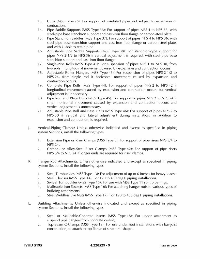
FVHD 5195 4:220529 - 9 June 19, 2020
13. Clips (MSS Type 26): For support of insulated pipes not subject to expansion or
contraction.
14. Pipe Saddle Supports (MSS Type 36): For support of pipes NPS 4 to NPS 36, with
steel-pipe base stanchion support and cast-iron floor flange or carbon-steel plate.
15. Pipe Stanchion Saddles (MSS Type 37): For support of pipes NPS 4 to NPS 36, with
steel-pipe base stanchion support and cast-iron floor flange or carbon-steel plate,
and with U-bolt to retain pipe.
16. Adjustable Pipe Saddle Supports (MSS Type 38): For stanchion-type support for
pipes NPS 2-1/2 to NPS 36 if vertical adjustment is required, with steel-pipe base
stanchion support and cast-iron floor flange.
17. Single-Pipe Rolls (MSS Type 41): For suspension of pipes NPS 1 to NPS 30, from
two rods if longitudinal movement caused by expansion and contraction occurs.
18. Adjustable Roller Hangers (MSS Type 43): For suspension of pipes NPS 2-1/2 to
NPS 24, from single rod if horizontal movement caused by expansion and
contraction occurs.
19. Complete Pipe Rolls (MSS Type 44): For support of pipes NPS 2 to NPS 42 if
longitudinal movement caused by expansion and contraction occurs but vertical
adjustment is unnecessary.
20. Pipe Roll and Plate Units (MSS Type 45): For support of pipes NPS 2 to NPS 24 if
small horizontal movement caused by expansion and contraction occurs and
vertical adjustment is unnecessary.
21. Adjustable Pipe Roll and Base Units (MSS Type 46): For support of pipes NPS 2 to
NPS 30 if vertical and lateral adjustment during installation, in addition to
expansion and contraction, is required.
J. Vertical-Piping Clamps: Unless otherwise indicated and except as specified in piping
system Sections, install the following types:
1. Extension Pipe or Riser Clamps (MSS Type 8): For support of pipe risers NPS 3/4 to
NPS 24.
2. Carbon- or Alloy-Steel Riser Clamps (MSS Type 42): For support of pipe risers
NPS 3/4 to NPS 24 if longer ends are required for riser clamps.
K. Hanger-Rod Attachments: Unless otherwise indicated and except as specified in piping
system Sections, install the following types:
1. Steel Turnbuckles (MSS Type 13): For adjustment of up to 6 inches for heavy loads.
2. Steel Clevises (MSS Type 14): For 120 to 450 deg F piping installations.
3. Swivel Turnbuckles (MSS Type 15): For use with MSS Type 11 split pipe rings.
4. Malleable-Iron Sockets (MSS Type 16): For attaching hanger rods to various types of
building attachments.
5. Steel Weldless Eye Nuts (MSS Type 17): For 120 to 450 deg F piping installations.
L. Building Attachments: Unless otherwise indicated and except as specified in piping
system Sections, install the following types:
1. Steel or Malleable-Concrete Inserts (MSS Type 18): For upper attachment to
suspend pipe hangers from concrete ceiling.
2. Top-Beam C-Clamps (MSS Type 19): For use under roof installations with bar-joist
construction, to attach to top flange of structural shape.

FVHD 5195 4:220529 - 10 June 19, 2020
3. Side-Beam or Channel Clamps (MSS Type 20): For attaching to bottom flange of
beams, channels, or angles.
4. Center-Beam Clamps (MSS Type 21): For attaching to center of bottom flange of
beams.
5. Welded Beam Attachments (MSS Type 22): For attaching to bottom of beams if
loads are considerable and rod sizes are large.
6. C-Clamps (MSS Type 23): For structural shapes.
7. Top-Beam Clamps (MSS Type 25): For top of beams if hanger rod is required
tangent to flange edge.
8. Side-Beam Clamps (MSS Type 27): For bottom of steel I-beams.
9. Steel-Beam Clamps with Eye Nuts (MSS Type 28): For attaching to bottom of steel I-
beams for heavy loads.
10. Linked-Steel Clamps with Eye Nuts (MSS Type 29): For attaching to bottom of steel
I-beams for heavy loads, with link extensions.
11. Malleable-Beam Clamps with Extension Pieces (MSS Type 30): For attaching to
structural steel.
12. Welded-Steel Brackets: For support of pipes from below or for suspending from
above by using clip and rod. Use one of the following for indicated loads:
a. Light (MSS Type 31): 750 lb.
b. Medium (MSS Type 32): 1500 lb.
c. Heavy (MSS Type 33): 3000 lb.
13. Side-Beam Brackets (MSS Type 34): For sides of steel or wooden beams.
14. Plate Lugs (MSS Type 57): For attaching to steel beams if flexibility at beam is
required.
15. Horizontal Travelers (MSS Type 58): For supporting piping systems subject to linear
horizontal movement where headroom is limited.
M. Saddles and Shields: Unless otherwise indicated and except as specified in piping system
Sections, install the following types:
1. Steel-Pipe-Covering Protection Saddles (MSS Type 39): To fill interior voids with
insulation that matches adjoining insulation.
2. Protection Shields (MSS Type 40): Of length recommended in writing by
manufacturer to prevent crushing insulation.
3. Thermal Hanger-Shield Inserts: For supporting insulated pipe.
N. Spring Hangers and Supports: Unless otherwise indicated and except as specified in
piping system Sections, install the following types:
1. Restraint-Control Devices (MSS Type 47): Where indicated to control piping
movement.
2. Spring Cushions (MSS Type 48): For light loads if vertical movement does not
exceed 1-1/4 inches.
3. Spring-Cushion Roll Hangers (MSS Type 49): For equipping Type 41 roll hanger
with springs.
4. Spring Sway Braces (MSS Type 50): To retard sway, shock, vibration, or thermal
expansion in piping systems.
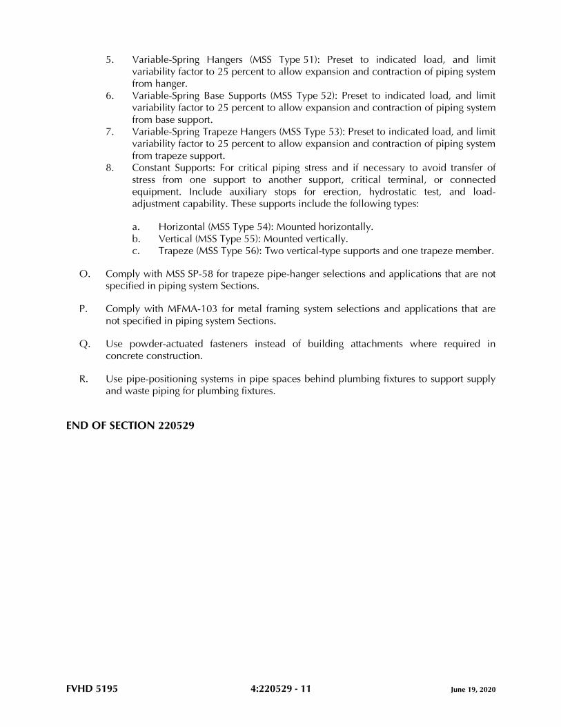
FVHD 5195 4:220529 - 11 June 19, 2020
5. Variable-Spring Hangers (MSS Type 51): Preset to indicated load, and limit
variability factor to 25 percent to allow expansion and contraction of piping system
from hanger.
6. Variable-Spring Base Supports (MSS Type 52): Preset to indicated load, and limit
variability factor to 25 percent to allow expansion and contraction of piping system
from base support.
7. Variable-Spring Trapeze Hangers (MSS Type 53): Preset to indicated load, and limit
variability factor to 25 percent to allow expansion and contraction of piping system
from trapeze support.
8. Constant Supports: For critical piping stress and if necessary to avoid transfer of
stress from one support to another support, critical terminal, or connected
equipment. Include auxiliary stops for erection, hydrostatic test, and load-
adjustment capability. These supports include the following types:
a. Horizontal (MSS Type 54): Mounted horizontally.
b. Vertical (MSS Type 55): Mounted vertically.
c. Trapeze (MSS Type 56): Two vertical-type supports and one trapeze member.
O. Comply with MSS SP-58 for trapeze pipe-hanger selections and applications that are not
specified in piping system Sections.
P. Comply with MFMA-103 for metal framing system selections and applications that are
not specified in piping system Sections.
Q. Use powder-actuated fasteners instead of building attachments where required in
concrete construction.
R. Use pipe-positioning systems in pipe spaces behind plumbing fixtures to support supply
and waste piping for plumbing fixtures.
END OF SECTION 220529
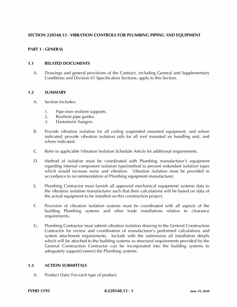
FVHD 5195 4:220548.13 - 1 June 19, 2020
SECTION 220548.13 - VIBRATION CONTROLS FOR PLUMBING PIPING AND EQUIPMENT
PART 1 - GENERAL
1.1 RELATED DOCUMENTS
A. Drawings and general provisions of the Contract, including General and Supplementary
Conditions and Division 01 Specification Sections, apply to this Section.
1.2 SUMMARY
A. Section Includes:
1. Pipe-riser resilient supports.
2. Resilient pipe guides.
3. Elastomeric hangers.
B. Provide vibration isolation for all ceiling suspended mounted equipment, and where
indicated; provide vibration isolation rails for all roof mounted air handling unit, and
where indicated.
C. Refer to applicable Vibration Isolation Schedule Article for additional requirements.
D. Method of isolation must be coordinated with Plumbing manufacturer’s equipment
regarding internal component isolation type/method to prevent redundant isolation types
which would increase noise and vibration. Vibration isolation must be provided in
accordance to recommendation of Plumbing equipment manufacturer.
E. Plumbing Contractor must furnish all approved mechanical equipment/ systems data to
the vibration isolation manufacturer such that their calculations will be based on data of
the actual equipment to be installed on this construction project.
F. Provision of vibration isolation systems must be coordinated with all aspects of the
building Plumbing systems and other trade installations relative to clearance
requirements.
G. Plumbing Contractor must submit vibration isolation drawing to the General Construction
Contractor for review and coordination of manufacturer’s performed calculations and
system attachment requirements. Include with the submission all installation details
which will be attached to the building systems so structural requirements provided by the
General Construction Contractor can be incorporated into the building systems to
adequately support/connect the Plumbing systems.
1.3 ACTION SUBMITTALS
A. Product Data: For each type of product.
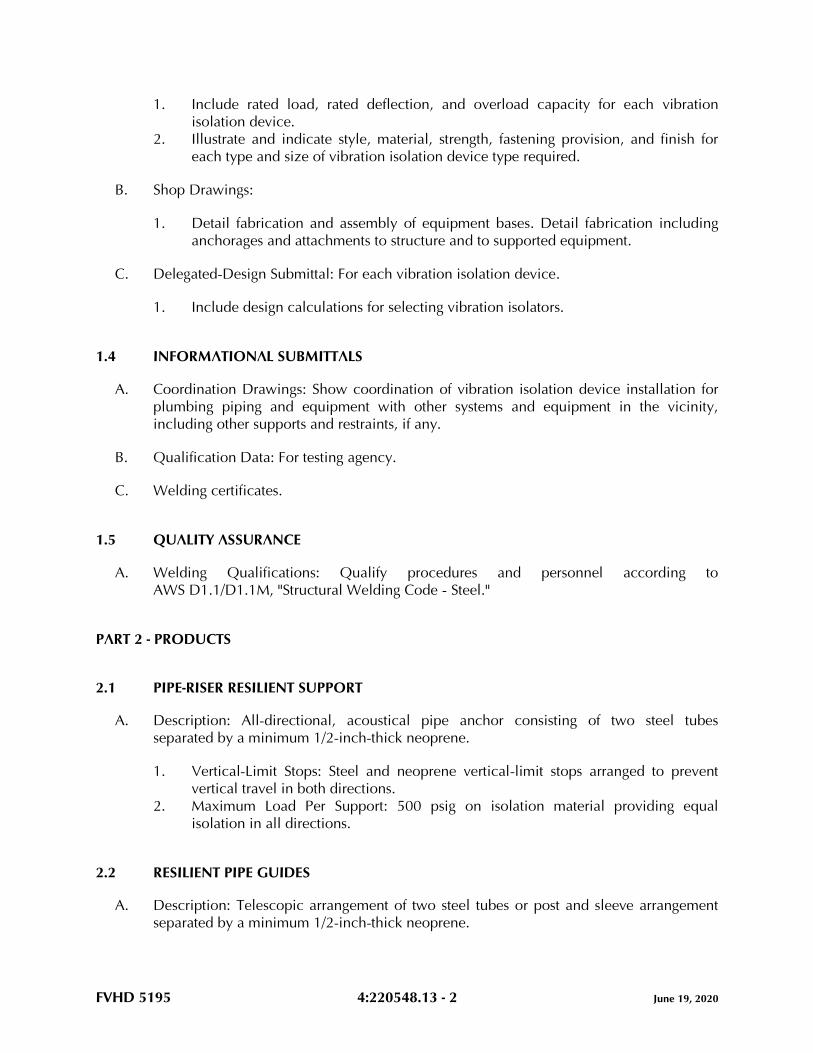
FVHD 5195 4:220548.13 - 2 June 19, 2020
1. Include rated load, rated deflection, and overload capacity for each vibration
isolation device.
2. Illustrate and indicate style, material, strength, fastening provision, and finish for
each type and size of vibration isolation device type required.
B. Shop Drawings:
1. Detail fabrication and assembly of equipment bases. Detail fabrication including
anchorages and attachments to structure and to supported equipment.
C. Delegated-Design Submittal: For each vibration isolation device.
1. Include design calculations for selecting vibration isolators.
1.4 INFORMATIONAL SUBMITTALS
A. Coordination Drawings: Show coordination of vibration isolation device installation for
plumbing piping and equipment with other systems and equipment in the vicinity,
including other supports and restraints, if any.
B. Qualification Data: For testing agency.
C. Welding certificates.
1.5 QUALITY ASSURANCE
A. Welding Qualifications: Qualify procedures and personnel according to
AWS D1.1/D1.1M, "Structural Welding Code - Steel."
PART 2 - PRODUCTS
2.1 PIPE-RISER RESILIENT SUPPORT
A. Description: All-directional, acoustical pipe anchor consisting of two steel tubes
separated by a minimum 1/2-inch-thick neoprene.
1. Vertical-Limit Stops: Steel and neoprene vertical-limit stops arranged to prevent
vertical travel in both directions.
2. Maximum Load Per Support: 500 psig on isolation material providing equal
isolation in all directions.
2.2 RESILIENT PIPE GUIDES
A. Description: Telescopic arrangement of two steel tubes or post and sleeve arrangement
separated by a minimum 1/2-inch-thick neoprene.
FVHD 5195 4:220548.13 - 3 June 19, 2020
1. Factory-Set Height Guide with Shear Pin: Shear pin shall be removable and
reinsertable to allow for selection of pipe movement. Guides shall be capable of
motion to meet location requirements.
2.3 ELASTOMERIC HANGERS
A. Elastomeric Mount in a Steel Frame with Upper and Lower Steel Hanger Rods.
1. Manufacturers: Subject to compliance with requirements, provide products by one
of the following:
a. Ace Mountings Co., Inc.
b. Kinetics Noise Control, Inc.
c. Mason Industries, Inc.
d. Vibration Eliminator Co., Inc.
2. Frame: Steel, fabricated with a connection for an upper threaded hanger rod and an
opening on the underside to allow for a maximum of 30 degrees of angular lower
hanger-rod misalignment without binding or reducing isolation efficiency.
3. Dampening Element: Molded, oil-resistant rubber, neoprene, or other elastomeric
material with a projecting bushing for the underside opening preventing steel to
steel contact.
PART 3 - EXECUTION
3.1 EXAMINATION
A. Examine areas and equipment to receive vibration isolation control devices for
compliance with requirements for installation tolerances and other conditions affecting
performance of the Work.
B. Examine roughing-in of reinforcement and cast-in-place anchors to verify actual locations
before installation.
C. Proceed with installation only after unsatisfactory conditions have been corrected.
3.2 VIBRATION CONTROL DEVICE INSTALLATION
A. Installation of vibration isolators must not cause any change of position of equipment,
piping, or ductwork resulting in stresses or misalignment.
3.3 VIBRATION ISOLATION SCHEDULE
A. Unless noted otherwise on the Drawings, or in other Division 22 Sections, provide
vibration isolation method as indicated.
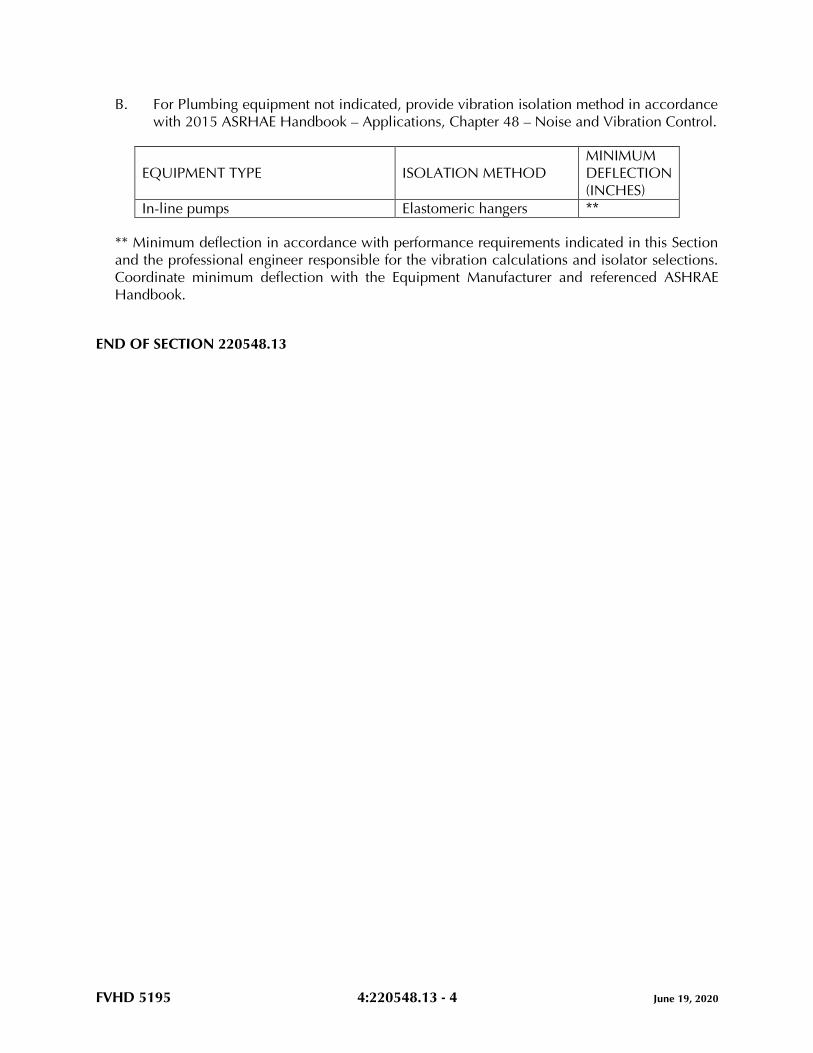
FVHD 5195 4:220548.13 - 4 June 19, 2020
B. For Plumbing equipment not indicated, provide vibration isolation method in accordance
with 2015 ASRHAE Handbook – Applications, Chapter 48 – Noise and Vibration Control.
EQUIPMENT TYPE ISOLATION METHOD
MINIMUM
DEFLECTION
(INCHES)
In-line pumps Elastomeric hangers **
** Minimum deflection in accordance with performance requirements indicated in this Section
and the professional engineer responsible for the vibration calculations and isolator selections.
Coordinate minimum deflection with the Equipment Manufacturer and referenced ASHRAE
Handbook.
END OF SECTION 220548.13
FVHD 5195 4:220593 - 1 June 19, 2020
SECTION 220593 - TESTING, ADJUSTING, AND BALANCING FOR PLUMBING
PART 1 - GENERAL
1.1 RELATED DOCUMENTS
A. Drawings and general provisions of the Contract, including General and Supplementary
Conditions and Division 01 Specification Sections, apply to this Section.
1.2 SUMMARY
A. Section Includes:
1. Testing, Adjusting and Balancing of Plumbing Systems:
a. Domestic Water Heaters.
b. Hot Water Recirculation Pumps.
c. Thermostatic Mixing Valves.
d. Water Pressure Reducing Valves.
e. Domestic Hot Water Recirculation Balancing Valves.
1.3 DEFINITIONS
A. AABC: Associated Air Balance Council.
B. NEBB: National Environmental Balancing Bureau.
C. TAB: Testing, adjusting, and balancing.
D. TABB: Testing, Adjusting, and Balancing Bureau.
E. TAB Specialist: An entity engaged to perform TAB Work.
1.4 PREINSTALLATION MEETINGS
A. TAB Conference: If requested by the Owner, conduct a TAB conference at Project site
after approval of the TAB strategies and procedures plan to develop a mutual
understanding of the details. Provide a minimum of 14 days' advance notice of scheduled
meeting time and location.
1. Minimum Agenda Items:
a. The Contract Documents examination report.
b. The TAB plan.
c. Needs for coordination and cooperation of trades and subcontractors.
FVHD 5195 4:220593 - 2 June 19, 2020
d. Proposed procedures for documentation and communication flow.
e. Coordination regarding scheduling of areas for turnover to the Owner.
f. Coordination and scheduling with HVAC Commissioning.
1.5 INFORMATIONAL SUBMITTALS
A. Qualification Data: Within 30 days of Contractor's Notice to Proceed, submit
documentation that the TAB specialist and this Project's TAB team members meet the
qualifications specified in "Quality Assurance" Article.
B. Contract Documents Examination Report: Within 30 days of Contractor's Notice to
Proceed, submit the Contract Documents review report as specified in Part 3.
C. Strategies and Procedures Plan: Within 30 days of Contractor's Notice to Proceed, submit
TAB strategies and step-by-step procedures as specified in "Preparation" Article.
D. System Readiness Checklists: Within 30 days of Contractor's Notice to Proceed, submit
system readiness checklists as specified in "Preparation" Article.
E. Examination Report: Submit a summary report of the examination review required in
"Examination" Article.
F. Certified TAB reports.
G. Sample report forms.
H. Instrument calibration reports, to include the following:
1. Instrument type and make.
2. Serial number.
3. Application.
4. Dates of use.
5. Dates of calibration.
1.6 QUALITY ASSURANCE
A. TAB Specialists Qualifications: Certified by AABC.
1. TAB Field Supervisor: Employee of the TAB specialist and certified by AABC.
2. TAB Technician: Employee of the TAB specialist and certified by AABC as a TAB
technician.
B. TAB Specialists Qualifications: Certified by NEBB or TABB.
1. TAB Field Supervisor: Employee of the TAB specialist and certified by NEBB or
TABB.
2. TAB Technician: Employee of the TAB specialist and certified by NEBB or TABB as
a TAB technician.
FVHD 5195 4:220593 - 3 June 19, 2020
C. Instrumentation Type, Quantity, Accuracy, and Calibration: Comply with requirements in
ASHRAE 111, Section 4, "Instrumentation."
D. ASHRAE/IES 90.1 Compliance: Applicable requirements in ASHRAE/IES 90.1,
Section 6.7.2.3 - "System Balancing."
1.7 PROJECT CONDITIONS
A. Partial Owner Occupancy: Owner may occupy completed areas of building before
Substantial Completion. Cooperate with Owner during TAB operations to minimize
conflicts with Owner's operations.
PART 2 - PRODUCTS (Not Applicable)
PART 3 - EXECUTION
3.1 EXAMINATION
A. Examine the Contract Documents to become familiar with Project requirements and to
discover conditions in systems' designs that may preclude proper TAB of systems and
equipment.
B. Examine systems for installed balancing devices, such as test ports, gage cocks,
thermometer wells, flow-control devices, balancing valves and fittings. Verify that
locations of these balancing devices are accessible.
C. Examine the approved submittals for plumbing systems and equipment.
D. Examine design data including plumbing system descriptions, statements of design
assumptions for environmental conditions and systems' output, and statements of
philosophies and assumptions about plumbing system and equipment controls.
E. Examine equipment performance data including fan and pump curves.
1. Relate performance data to Project conditions and requirements, including system
effects that can create undesired or unpredicted conditions that cause reduced
capacities in all or part of a system.
2. Calculate system-effect factors to reduce performance ratings of plumbing
equipment when installed under conditions different from the conditions used to
rate equipment performance.
F. Examine system and equipment installations and verify that field quality-control testing,
cleaning, and adjusting specified in individual Sections have been performed.
G. Examine test reports specified in individual system and equipment Sections.
FVHD 5195 4:220593 - 4 June 19, 2020
H. Examine plumbing equipment and verify that bearings are greased, and equipment with
functioning controls is ready for operation.
I. Examine strainers. Verify that startup screens are replaced by permanent screens with
indicated perforations.
J. Examine three-way valves for proper installation for their intended function of diverting
or mixing fluid flows.
K. Examine system pumps to ensure absence of entrained air in the suction piping.
L. Examine operating safety interlocks and controls on plumbing equipment.
M. Report deficiencies discovered before and during performance of TAB procedures.
Observe and record system reactions to changes in conditions. Record default set points
if different from indicated values.
3.2 PREPARATION
A. Prepare a TAB plan that includes strategies and step-by-step procedures.
B. Complete system-readiness checks and prepare reports. Verify the following:
1. Permanent electrical-power wiring is complete.
2. Plumbing systems are filled, clean, and free of air.
3. Automatic temperature-control systems are operational.
4. Equipment access doors are securely closed.
5. Isolating and balancing valves are open and control valves are operational.
6. Ceilings are installed in critical areas where air-pattern adjustments are required
and access to balancing devices is provided.
3.3 GENERAL PROCEDURES FOR TESTING AND BALANCING
A. Perform testing and balancing procedures on each system according to the equipment
manufacturer’s recommended procedures and the procedures contained in this Section.
B. Cut insulation, pipes, and equipment cabinets for installation of test probes to the
minimum extent necessary for TAB procedures.
1. Install and join new insulation that matches removed materials. Restore insulation,
coverings, vapor barrier, and finish according to Section 221123 “Domestic Water
Pumps” and Section 221123.13 “Domestic Water Packaged Booster Pumps.”
C. Mark equipment and balancing devices, including valve position indicators, and similar
controls and devices, with paint or other suitable, permanent identification material to
show final settings.
D. Take and report testing and balancing measurements in inch-pound (IP) units.
FVHD 5195 4:220593 - 5 June 19, 2020
3.4 GENERAL PROCEDURES FOR PLUMBING SYSTEMS
A. Prepare test reports with pertinent design data, and number in sequence starting at pump
to end of system. Check the sum of branch-circuit flows against the approved pump flow
rate. Correct variations that exceed plus or minus 5 percent.
B. Prepare schematic diagrams of systems' "as-built" piping layouts.
C. Prepare plumbing systems for testing and balancing according to the following, in
addition to the general preparation procedures specified above:
1. Open all manual valves for maximum flow.
2. Check pump-motor load. If motor is overloaded, throttle main flow-balancing
device so motor nameplate rating is not exceeded.
3.5 PROCEDURES FOR CONSTANT-FLOW PLUMBING SYSTEMS
A. Measure water flow at pumps. Use the following procedures except for positive-
displacement pumps:
1. Verify impeller size by operating the pump with the discharge valve closed. Read
pressure differential across the pump. Convert pressure to head and correct for
differences in gage heights. Note the point on manufacturer's pump curve at zero
flow and verify that the pump has the intended impeller size.
a. If impeller sizes must be adjusted to achieve pump performance, obtain
approval from Architect and comply with requirements in applicable
Division 22 Sections.
2. Check system resistance. With all valves open, read pressure differential across the
pump and mark pump manufacturer's head-capacity curve. Adjust pump discharge
valve until indicated water flow is achieved.
a. Monitor motor performance during procedures and do not operate motors in
overload conditions.
3. Verify pump-motor brake horsepower. Calculate the intended brake horsepower for
the system based on pump manufacturer's performance data. Compare calculated
brake horsepower with nameplate data on the pump motor. Report conditions
where actual amperage exceeds motor nameplate amperage.
4. Report flow rates that are not within plus or minus 10 percent of design.
B. Measure flow at all automatic flow control valves to verify that valves are functioning as
designed.
C. Measure flow at all pressure-independent characterized control valves, with valves in
fully open position, to verify that valves are functioning as designed.
D. Set calibrated balancing valves, if installed, at calculated presettings.
FVHD 5195 4:220593 - 6 June 19, 2020
E. Measure flow at all stations and adjust, where necessary, to obtain first balance.
1. System components that have Cv rating or an accurately cataloged flow-pressure-
drop relationship may be used as a flow-indicating device.
F. Adjust balancing stations to within specified tolerances of indicated flow rate as follows:
1. Determine the balancing station with the highest percentage over indicated flow.
2. Adjust each station in turn, beginning with the station with the highest percentage
over indicated flow and proceeding to the station with the lowest percentage over
indicated flow.
3. Record settings and mark balancing devices.
G. Measure pump flow rate and make final measurements of pump amperage, voltage, rpm,
pump heads, and systems' pressures and temperatures.
H. Measure the differential-pressure-control-valve settings existing at the conclusion of
balancing.
I. Check settings and operation of each safety valve. Record settings.
3.6 PROCEDURES FOR MOTORS
A. Motors, 1/2 HP and Larger: Test at final balanced conditions and record the following
data:
1. Manufacturer's name, model number, and serial number.
2. Motor horsepower rating.
3. Motor rpm.
4. Efficiency rating.
5. Nameplate and measured voltage, each phase.
6. Nameplate and measured amperage, each phase.
7. Starter thermal-protection-element rating.
B. Motors Driven by Variable-Frequency Controllers: Test for proper operation at speeds
varying from minimum to maximum. Test the manual bypass of the controller to prove
proper operation. Record observations including name of controller manufacturer, model
number, serial number, and nameplate data.
3.7 PROCEDURES FOR DOMESTIC WATER HEATERS
A. For gas-fired water heaters, check and adjust burners and controls for proper operation.
B. Adjust temperature sensors to provide leaving water temperature as indicated.

FVHD 5195 4:220593 - 7 June 19, 2020
3.8 PROCEDURES FOR THERMOSTATIC MIXING VALVES
A. Adjust leaving water temperature to setpoint indicated with flow rate in accordance with
the valve manufacturer’s recommendations.
B. For valves with recirculation setup, make adjustments until there is no increase in water
temperature with the valve operating at a no flow condition. Follow valve manufacturer’s
written procedures
3.9 PROCEDURES FOR WATER PRESSURE REDUCING VALVES
A. Setup and adjust to value indicated per valve manufacturer’s recommendations.
B. Measure downstream pressure to confirm setpoint is accurate.
3.10 PROCEDURES FOR GAS PRESSURE REDUCING VALVES
A. Setup and adjust to value indicated per valve manufacturer’s recommendations.
B. Measure downstream pressure to confirm setpoint is accurate.
3.11 PROCEDURES FOR TESTING, ADJUSTING, AND BALANCING EXISTING SYSTEMS
A. Perform a preconstruction inspection of existing equipment that is to remain and be
reused.
B. Before performing testing and balancing of existing systems, inspect existing equipment
that is to remain and be reused to verify that existing equipment has been cleaned and
refurbished. Verify the following:
1. Strainers are clean.
2. Bearings and other parts are properly lubricated.
3. Deficiencies noted in the preconstruction report are corrected.
C. Perform testing and balancing of existing systems to the extent that existing systems are
affected by the renovation work.
3.12 TOLERANCES
A. Set plumbing system's water flow rates within the following tolerances:
1. Domestic Water Flow Rates: Plus or minus 10 percent.
FVHD 5195 4:220593 - 8 June 19, 2020
3.13 REPORTING
A. Initial Construction-Phase Report: Based on examination of the Contract Documents as
specified in "Examination" Article, prepare a report on the adequacy of design for
systems' balancing devices. Recommend changes and additions to systems' balancing
devices to facilitate proper performance measuring and balancing. Recommend changes
and additions to plumbing systems and general construction to allow access for
performance measuring and balancing devices.
B. Status Reports: Prepare biweekly progress reports to describe completed procedures,
procedures in progress, and scheduled procedures. Include a list of deficiencies and
problems found in systems being tested and balanced. Prepare a separate report for each
system and each building floor for systems serving multiple floors.
3.14 FINAL REPORT
A. General: Prepare a certified written report; tabulate and divide the report into separate
sections for tested systems and balanced systems.
1. Include a certification sheet at the front of the report's binder, signed and sealed by
the certified testing and balancing engineer.
2. Include a list of instruments used for procedures, along with proof of calibration.
B. Final Report Contents: In addition to certified field-report data, include the following:
1. Pump curves.
2. Manufacturers' test data.
3. Field test reports prepared by system and equipment installers.
4. Other information relative to equipment performance; do not include Shop
Drawings and product data.
C. General Report Data: In addition to form titles and entries, include the following data:
1. Title page.
2. Name and address of the TAB contractor.
3. Project name.
4. Project location.
5. Architect's name and address.
6. Engineer's name and address.
7. Contractor's name and address.
8. Report date.
9. Signature of TAB supervisor who certifies the report.
10. Table of Contents with the total number of pages defined for each section of the
report. Number each page in the report.
11. Summary of contents including the following:
a. Indicated versus final performance.
b. Notable characteristics of systems.
FVHD 5195 4:220593 - 9 June 19, 2020
c. Description of system operation sequence if it varies from the Contract
Documents.
12. Nomenclature sheets for each item of equipment.
13. Notes to explain why certain final data in the body of reports vary from indicated
values.
D. System Diagrams: Include schematic layouts of plumbing distribution systems. Present
each system with single-line diagram and include the following:
1. Water flow rates.
2. Pipe and valve sizes and locations.
3. Balancing stations.
4. Position of balancing devices.
E. Gas-Fired Water Heater Test Reports: In addition to manufacturer's factory startup
equipment reports, include the following:
1. Unit Data:
a. System identification.
b. Location.
c. Make and type.
d. Model number and unit size.
e. Manufacturer's serial number.
f. Fuel type in input data.
g. Output capacity in Btu/h.
h. Ignition type.
i. Burner-control types.
j. Motor horsepower and rpm.
k. Motor volts, phase, and hertz.
l. Motor full-load amperage and service factor.
F. Pump Test Reports: Calculate impeller size by plotting the shutoff head on pump curves
and include the following:
1. Unit Data:
a. Unit identification.
b. Location.
c. Service.
d. Make and size.
e. Model number and serial number.
f. Water flow rate in gpm.
g. Water pressure differential in feet of head or psig.
h. Required net positive suction head in feet of head or psig.
i. Pump rpm.
j. Impeller diameter in inches.
k. Motor make and frame size.
l. Motor horsepower and rpm.
FVHD 5195 4:220593 - 10 June 19, 2020
m. Voltage at each connection.
n. Amperage for each phase.
o. Full-load amperage and service factor.
p. Seal type.
2. Test Data (Indicated and Actual Values):
a. Static head in feet of head or psig.
b. Pump shutoff pressure in feet of head or psig.
c. Actual impeller size in inches.
d. Full-open flow rate in gpm.
e. Full-open pressure in feet of head or psig.
f. Final discharge pressure in feet of head or psig.
g. Final suction pressure in feet of head or psig.
h. Final total pressure in feet of head or psig.
i. Final water flow rate in gpm.
j. Voltage at each connection.
k. Amperage for each phase.
G. Thermostatic Mixing Valve Reports:
1. Unit Data:
a. Unit identification.
b. Location.
c. Service.
d. Make and size.
e. Model number and serial number.
2. Test Data:
a. Tempered water flow rate.
b. Outlet temperature.
H. Water Pressure Reducing Valve:
1. Unit Data:
a. Unit identification.
b. Location.
c. Service.
d. Make and size.
e. Model number and serial number.
f. Water flow rate in gpm.
2. Test Data:
a. Inlet Pressure in psig.
b. Outlet Pressure in psig.
FVHD 5195 4:220593 - 11 June 19, 2020
I. Natural Gas Pressure Reducing Valve:
1. Unit Data:
a. Unit identification.
b. Location.
c. Service.
d. Make and size.
e. Model number and serial number.
f. Gas flow rate in CFH.
2. Test Data:
a. Inlet Pressure in psig.
b. Outlet Pressure in psig.
J. Instrument Calibration Reports:
1. Report Data:
a. Instrument type and make.
b. Serial number.
c. Application.
d. Dates of use.
e. Dates of calibration.
3.15 VERIFICATION OF TAB REPORT
A. The TAB specialist's test and balance engineer shall conduct the inspection in the
presence of commissioning authority.
B. Architect shall randomly select measurements, documented in the final report, to be
rechecked. Rechecking shall be limited to either 10 percent of the total measurements
recorded or the extent of measurements that can be accomplished in a normal 8-hour
business day.
C. If rechecks yield measurements that differ from the measurements documented in the
final report by more than the tolerances allowed, the measurements shall be noted as
"FAILED."
D. If the number of "FAILED" measurements is greater than 10 percent of the total
measurements checked during the final inspection, the testing and balancing shall be
considered incomplete and shall be rejected.
E. If TAB work fails, proceed as follows:
1. TAB specialists shall recheck all measurements and make adjustments. Revise the
final report and balancing device settings to include all changes; resubmit the final
report and request a second final inspection.

FVHD 5195 4:220593 - 12 June 19, 2020
2. If the second final inspection also fails, Owner may contract the services of another
TAB specialist to complete TAB work according to the Contract Documents and
deduct the cost of the services from the original TAB specialist's final payment.
3. If the second verification also fails, design professional may contact AABC
Headquarters regarding the AABC National Performance Guaranty.
F. Prepare test and inspection reports.
3.16 ADDITIONAL TESTS
A. Within 90 days of completing TAB, perform additional TAB to verify that balanced
conditions are being maintained throughout and to correct unusual conditions.
B. Seasonal Periods: If initial TAB procedures were not performed during near-peak summer
and winter conditions, perform additional TAB during near-peak summer and winter
conditions.
END OF SECTION 220593
FVHD 5195 4:220716 - 1 June 19, 2020
SECTION 220716 - PLUMBING EQUIPMENT INSULATION
PART 1 - GENERAL
1.1 RELATED DOCUMENTS
A. Drawings and general provisions of the Contract, including General and Supplementary
Conditions and Division 01 Specification Sections, apply to this Section.
1.2 SUMMARY
A. Section includes insulating the following plumbing equipment that is not factory
insulated:
1. Domestic water heater breechings (for non-factory insulated breechings).
2. Domestic water, hot-water pumps.
3. Domestic water storage tanks.
1.3 ACTION SUBMITTALS
A. Product Data: For each type of product. Include thermal conductivity, water-vapor
permeance thickness, and jackets (both factory and field applied, if any).
B. Shop Drawings: Include plans, elevations, sections, details, and attachments to other
work.
1. Detail removable insulation at equipment connections.
2. Detail application of field-applied jackets.
3. Detail application at linkages of control devices.
4. Detail field application for each equipment type.
1.4 INFORMATIONAL SUBMITTALS
A. Qualification Data: For qualified Installer.
B. Material Test Reports: From a qualified testing agency acceptable to authorities having
jurisdiction indicating, interpreting, and certifying test results for compliance of insulation
materials, sealers, attachments, cements, and jackets, with requirements indicated.
Include dates of tests and test methods employed.
C. Field quality-control reports.
FVHD 5195 4:220716 - 2 June 19, 2020
1.5 QUALITY ASSURANCE
A. Installer Qualifications: Skilled mechanics who have successfully completed an
apprenticeship program or another craft training program certified by the Department of
Labor, Bureau of Apprenticeship and Training.
B. Surface-Burning Characteristics: For insulation and related materials, as determined by
testing identical products in accordance with ASTM E84, by a testing agency acceptable
to authorities having jurisdiction. Factory label insulation and jacket materials and
adhesive, mastic, tapes, and cement material containers, with appropriate markings of
applicable testing agency.
1. Insulation Installed Indoors: Flame-spread index of 25 or less and smoke-developed
index of 50 or less.
2. Insulation Installed Outdoors: Flame-spread index of 75 or less and smoke-
developed index of 150 or less.
1.6 DELIVERY, STORAGE, AND HANDLING
A. Packaging: Insulation material containers shall be marked by manufacturer with
appropriate ASTM standard designation, type and grade, and maximum use temperature.
1.7 COORDINATION
A. Coordinate sizes and locations of supports, hangers, and insulation shields specified in
applicable Division 22 Sections.
B. Coordinate clearance requirements with equipment Installer for equipment insulation
application.
C. Coordinate installation and testing of heat tracing.
1.8 SCHEDULING
A. Schedule insulation application after pressure testing systems and, where required, after
installing and testing heat tracing. Insulation application may begin on segments that
have satisfactory test results.
B. Complete installation and concealment of plastic materials as rapidly as possible in each
area of construction.
FVHD 5195 4:220716 - 3 June 19, 2020
PART 2 - PRODUCTS
2.1 INSULATION MATERIALS
A. Comply with requirements in "Equipment Insulation Schedule" articles for where
insulating materials shall be applied.
B. Products shall not contain asbestos, lead, mercury, or mercury compounds.
C. Products that come into contact with stainless steel shall have a leachable chloride
content of less than 50 ppm when tested in accordance with ASTM C871.
D. Insulation materials for use on austenitic stainless steel shall be qualified as acceptable in
accordance with ASTM C795.
E. Foam insulation materials shall not use CFC or HCFC blowing agents in the
manufacturing process.
F. High-Temperature, Mineral-Fiber Blanket: Mineral or glass fibers bonded with a
thermosetting resin. Comply with ASTM C553, Type V, without factory-applied jacket.
1. Basis-of-Design Product: Subject to compliance with requirements, provide Johns
Manville; a Berkshire Hathaway company; or a comparable product by one of the
following:
a. Knauf Insulation.
b. Manson Insulation Inc.
c. Owens Corning.
G. Mineral-Fiber Board: Mineral or glass fibers bonded with a thermosetting resin. Comply
with ASTM C612, Type IA or Type IB. Provide insulation with factory-applied ASJ.
Factory-applied jacket requirements are specified in "Factory-Applied Jackets" Article.
1. Basis-of-Design Product: Subject to compliance with requirements, provide Knauf
Insulation; or a comparable product by one of the following:
a. CertainTeed Corporation.
b. Johns Manville; a Berkshire Hathaway company.
c. Manson Insulation Inc.
H. High-Temperature, Mineral-Fiber Board: Mineral or glass fibers bonded with a
thermosetting resin. Comply with ASTM C612, Type III, without factory-applied jacket.
1. Basis-of-Design Product: Subject to compliance with requirements, provide Johns
Manville; a Berkshire Hathaway company; or a comparable product by one of the
following:
a. Knauf Insulation.
b. Manson Insulation Inc.
FVHD 5195 4:220716 - 4 June 19, 2020
c. Owens Corning.
I. Mineral-Fiber, Pipe and Tank: Mineral or glass fibers bonded with a thermosetting resin.
Comply with ASTM C1393.
1. Basis-of-Design Product: Subject to compliance with requirements, provide Johns
Manville; a Berkshire Hathaway company; or a comparable product by one of the
following:
a. CertainTeed Corporation.
b. Knauf Insulation.
c. Manson Insulation Inc.
2. Semirigid board material with factory-applied ASJ jacket.
3. Nominal density is 2.5 lb/cu. ft. or more.
4. Thermal conductivity (k-value) at 100 deg F is 0.29 Btu x in./h x sq. ft. x deg F or
less.
5. Factory-applied jacket requirements are specified in "Factory-Applied Jackets"
Article.
2.2 INSULATING CEMENTS
A. Mineral-Fiber Insulating Cement: Comply with ASTM C195.
2.3 ADHESIVES
A. Materials shall be compatible with insulation materials, jackets, and substrates and for
bonding insulation to itself and to surfaces to be insulated unless otherwise indicated.
B. Mineral-Fiber Adhesive: Comply with MIL-A-3316C, Class 2, Grade A.
C. ASJ Adhesive, and FSK Jacket Adhesive: Comply with MIL-A-3316C, Class 2, Grade A for
bonding insulation jacket lap seams and joints.
2.4 MASTICS AND COATINGS
A. Materials shall be compatible with insulation materials, jackets, and substrates.
B. Vapor-Retarder Mastic, Water Based: Suitable for indoor use on below-ambient services.
1. Water-Vapor Permeance: Comply with ASTM E96/E96M or ASTM F1249.
2. Service Temperature Range: Minus 20 to plus 180 deg F.
3. Comply with MIL-PRF-19565C, Type II, for permeance requirements.
4. Color: White.
C. Vapor-Retarder Mastic, Solvent Based, Outdoor Use: Suitable for outdoor use on below-
ambient services.
FVHD 5195 4:220716 - 5 June 19, 2020
1. Water-Vapor Permeance: Comply with ASTM E96/E96M or ASTM F1249.
2. Service Temperature Range: Minus 50 to plus 220 deg F.
3. Color: White.
D. Breather Mastic: Water based; suitable for indoor and outdoor use on above-ambient
services.
1. Water-Vapor Permeance: ASTM E96/E96M, greater than 1.0 perm at
manufacturer's recommended dry film thickness.
2. Service Temperature Range: Minus 20 to plus 180 deg F.
3. Color: White.
2.5 LAGGING ADHESIVES
A. Description: Comply with MIL-A-3316C, Class I, Grade A, and shall be compatible with
insulation materials, jackets, and substrates.
1. Fire-resistant, water-based lagging adhesive and coating for use indoors to adhere
fire-resistant lagging cloths over insulation.
2. Service Temperature Range: 0 to plus 180 deg F.
3. Color: White.
2.6 SEALANTS
A. Materials shall be as recommended by the insulation manufacturer and shall be
compatible with insulation materials, jackets, and substrates.
B. ASJ Flashing Sealants and Vinyl, PVDC, and PVC Jacket Flashing Sealants:
1. Fire- and water-resistant, flexible, elastomeric sealant.
2. Service Temperature Range: Minus 40 to plus 250 deg F.
3. Color: White.
2.7 FACTORY-APPLIED JACKETS
A. Insulation system schedules indicate factory-applied jackets on various applications.
When factory-applied jackets are indicated, comply with the following:
1. ASJ: White, kraft-paper, fiberglass-reinforced scrim with aluminum-foil backing;
complying with ASTM C1136, Type I.
2.8 TAPES
A. ASJ Tape: White vapor-retarder tape matching factory-applied jacket with acrylic
adhesive, complying with ASTM C1136.
1. Width: 3 inches.
FVHD 5195 4:220716 - 6 June 19, 2020
2. Thickness: 11.5 mils.
3. Adhesion: 90 ounces force/inch in width.
4. Elongation: 2 percent.
5. Tensile Strength: 40 lbf/inch in width.
6. ASJ Tape Disks and Squares: Precut disks or squares of ASJ tape.
2.9 SECUREMENTS
A. Bands:
1. Stainless Steel: ASTM A240/A240M, Type 304 or Type 316; 0.015 inch thick, 3/4
inch wide with wing seal.
B. Insulation Pins and Hangers:
1. Capacitor-Discharge-Weld Pins: Copper- or zinc-coated steel pin, fully annealed
for capacitor-discharge welding; 0.135-inch- diameter shank, length to suit depth
of insulation indicated.
C. Staples: Outward-clinching insulation staples, nominal 3/4-inch-wide, stainless steel or
Monel.
D. Wire: 0.062-inch soft-annealed, stainless steel.
2.10 CORNER ANGLES
A. Aluminum Corner Angles: 0.040-inch thick, minimum 1- by 1-inch, aluminum in
accordance with ASTM B209, Alloy 3003, 3005, 3105, or 5005; Temper H-14.
PART 3 - EXECUTION
3.1 EXAMINATION
A. Examine substrates and conditions for compliance with requirements for installation
tolerances and other conditions affecting performance of insulation application.
1. Verify that systems and equipment to be insulated have been tested and are free of
defects.
2. Verify that surfaces to be insulated are clean and dry.
B. Proceed with installation only after unsatisfactory conditions have been corrected.
3.2 PREPARATION
A. Clean and dry surfaces to receive insulation. Remove materials that will adversely affect
insulation application.
FVHD 5195 4:220716 - 7 June 19, 2020
B. Mix insulating cements with clean potable water; if insulating cements are to be in
contact with stainless steel surfaces, use demineralized water.
3.3 GENERAL INSTALLATION REQUIREMENTS
A. Install insulation materials, accessories, and finishes with smooth, straight, and even
surfaces; free of voids throughout the length of equipment.
B. Install insulation materials, forms, vapor barriers or retarders, jackets, and of thicknesses
required for each item of equipment, as specified in insulation system schedules.
C. Install accessories compatible with insulation materials and suitable for the service. Install
accessories that do not corrode, soften, or otherwise attack insulation or jacket in either
wet or dry state.
D. Install insulation with longitudinal seams at top and bottom of horizontal runs.
E. Install multiple layers of insulation with longitudinal and end seams staggered.
F. Keep insulation materials dry during storage, application, and finishing. Replace
insulation materials that get wet.
G. Install insulation with tight longitudinal seams and end joints. Bond seams and joints with
adhesive recommended by insulation material manufacturer.
H. Install insulation with least number of joints practical.
I. Where vapor barrier is indicated, seal joints, seams, and penetrations in insulation at
hangers, supports, anchors, and other projections with vapor-barrier mastic.
1. Install insulation continuously through hangers and around anchor attachments.
2. For insulation application where vapor barriers are indicated, extend insulation on
anchor legs from point of attachment to supported item to point of attachment to
structure. Taper and seal ends attached to structure with vapor-barrier mastic.
3. Install insert materials and insulation to tightly join the insert. Seal insulation to
insulation inserts with adhesive or sealing compound recommended by insulation
material manufacturer.
4. Cover inserts with jacket material matching adjacent insulation. Install shields over
jacket, arranged to protect jacket from tear or puncture by hanger, support, and
shield.
J. Apply adhesives, mastics, and sealants at manufacturer's recommended coverage rate
and wet and dry film thicknesses.
K. Install insulation with factory-applied jackets as follows:
1. Draw jacket tight and smooth.
FVHD 5195 4:220716 - 8 June 19, 2020
2. Cover circumferential joints with 3-inch-wide strips, of same material as insulation
jacket. Secure strips with adhesive and outward-clinching staples along both edges
of strip, spaced 4 inches o.c.
3. Overlap jacket longitudinal seams at least 1-1/2 inches. Clean and dry surface to
receive self-sealing lap. Staple laps with outward-clinching staples along edge at 4
inches o.c.
a. For below-ambient services, apply vapor-barrier mastic over staples.
4. Cover joints and seams with tape, in accordance with insulation material
manufacturer's written instructions, to maintain vapor seal.
5. Where vapor barriers are indicated, apply vapor-barrier mastic on seams and joints.
L. Cut insulation in a manner to avoid compressing insulation more than 25 percent of its
nominal thickness.
M. Finish installation with systems at operating conditions. Repair joint separations and
cracking due to thermal movement.
N. Repair damaged insulation facings by applying same facing material over damaged areas.
Extend patches at least 4 inches beyond damaged areas. Adhere, staple, and seal patches
in similar fashion to butt joints.
O. For above-ambient services, do not install insulation to the following:
1. Vibration-control devices.
2. Testing agency labels and stamps.
3. Nameplates and data plates.
4. Manholes.
5. Handholes.
6. Cleanouts.
3.4 INSTALLATION OF EQUIPMENT, TANK, AND VESSEL INSULATION
A. Mineral-Fiber, Pipe and Tank Insulation Installation for Tanks and Vessels: Secure
insulation with adhesive and anchor pins and speed washers.
1. Apply adhesives in accordance with manufacturer's recommended coverage rates
per unit area, for minimum of 50 percent coverage of tank and vessel surfaces.
2. Groove and score insulation materials to fit as closely as possible to equipment,
including contours. Bevel insulation edges for cylindrical surfaces for tight joints.
Stagger end joints.
3. Protect exposed corners with secured corner angles.
4. Install adhesively attached or self-sticking insulation hangers and speed washers on
sides of tanks and vessels as follows:
a. Do not weld anchor pins to ASME-labeled pressure vessels.
b. Select insulation hangers and adhesive that are compatible with service
temperature and with substrate.
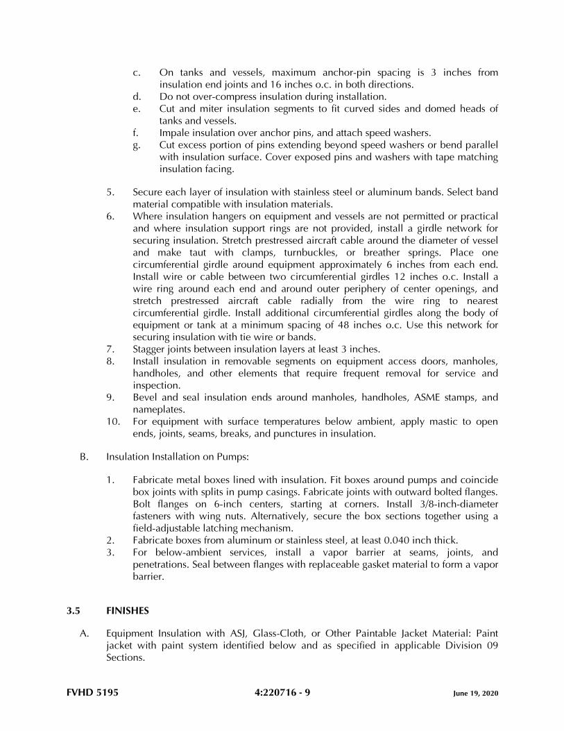
FVHD 5195 4:220716 - 9 June 19, 2020
c. On tanks and vessels, maximum anchor-pin spacing is 3 inches from
insulation end joints and 16 inches o.c. in both directions.
d. Do not over-compress insulation during installation.
e. Cut and miter insulation segments to fit curved sides and domed heads of
tanks and vessels.
f. Impale insulation over anchor pins, and attach speed washers.
g. Cut excess portion of pins extending beyond speed washers or bend parallel
with insulation surface. Cover exposed pins and washers with tape matching
insulation facing.
5. Secure each layer of insulation with stainless steel or aluminum bands. Select band
material compatible with insulation materials.
6. Where insulation hangers on equipment and vessels are not permitted or practical
and where insulation support rings are not provided, install a girdle network for
securing insulation. Stretch prestressed aircraft cable around the diameter of vessel
and make taut with clamps, turnbuckles, or breather springs. Place one
circumferential girdle around equipment approximately 6 inches from each end.
Install wire or cable between two circumferential girdles 12 inches o.c. Install a
wire ring around each end and around outer periphery of center openings, and
stretch prestressed aircraft cable radially from the wire ring to nearest
circumferential girdle. Install additional circumferential girdles along the body of
equipment or tank at a minimum spacing of 48 inches o.c. Use this network for
securing insulation with tie wire or bands.
7. Stagger joints between insulation layers at least 3 inches.
8. Install insulation in removable segments on equipment access doors, manholes,
handholes, and other elements that require frequent removal for service and
inspection.
9. Bevel and seal insulation ends around manholes, handholes, ASME stamps, and
nameplates.
10. For equipment with surface temperatures below ambient, apply mastic to open
ends, joints, seams, breaks, and punctures in insulation.
B. Insulation Installation on Pumps:
1. Fabricate metal boxes lined with insulation. Fit boxes around pumps and coincide
box joints with splits in pump casings. Fabricate joints with outward bolted flanges.
Bolt flanges on 6-inch centers, starting at corners. Install 3/8-inch-diameter
fasteners with wing nuts. Alternatively, secure the box sections together using a
field-adjustable latching mechanism.
2. Fabricate boxes from aluminum or stainless steel, at least 0.040 inch thick.
3. For below-ambient services, install a vapor barrier at seams, joints, and
penetrations. Seal between flanges with replaceable gasket material to form a vapor
barrier.
3.5 FINISHES
A. Equipment Insulation with ASJ, Glass-Cloth, or Other Paintable Jacket Material: Paint
jacket with paint system identified below and as specified in applicable Division 09
Sections.
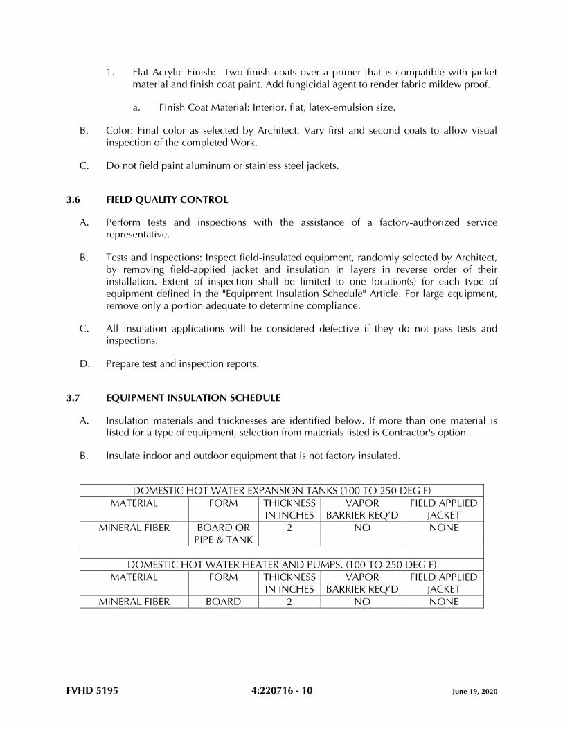
FVHD 5195 4:220716 - 10 June 19, 2020
1. Flat Acrylic Finish: Two finish coats over a primer that is compatible with jacket
material and finish coat paint. Add fungicidal agent to render fabric mildew proof.
a. Finish Coat Material: Interior, flat, latex-emulsion size.
B. Color: Final color as selected by Architect. Vary first and second coats to allow visual
inspection of the completed Work.
C. Do not field paint aluminum or stainless steel jackets.
3.6 FIELD QUALITY CONTROL
A. Perform tests and inspections with the assistance of a factory-authorized service
representative.
B. Tests and Inspections: Inspect field-insulated equipment, randomly selected by Architect,
by removing field-applied jacket and insulation in layers in reverse order of their
installation. Extent of inspection shall be limited to one location(s) for each type of
equipment defined in the "Equipment Insulation Schedule" Article. For large equipment,
remove only a portion adequate to determine compliance.
C. All insulation applications will be considered defective if they do not pass tests and
inspections.
D. Prepare test and inspection reports.
3.7 EQUIPMENT INSULATION SCHEDULE
A. Insulation materials and thicknesses are identified below. If more than one material is
listed for a type of equipment, selection from materials listed is Contractor's option.
B. Insulate indoor and outdoor equipment that is not factory insulated.
DOMESTIC HOT WATER EXPANSION TANKS (100 TO 250 DEG F)
MATERIAL FORM THICKNESS
IN INCHES
VAPOR
BARRIER REQ’D
FIELD APPLIED
JACKET
MINERAL FIBER BOARD OR
PIPE & TANK
2 NO NONE
DOMESTIC HOT WATER HEATER AND PUMPS, (100 TO 250 DEG F)
MATERIAL FORM THICKNESS
IN INCHES
VAPOR
BARRIER REQ’D
FIELD APPLIED
JACKET
MINERAL FIBER BOARD 2 NO NONE
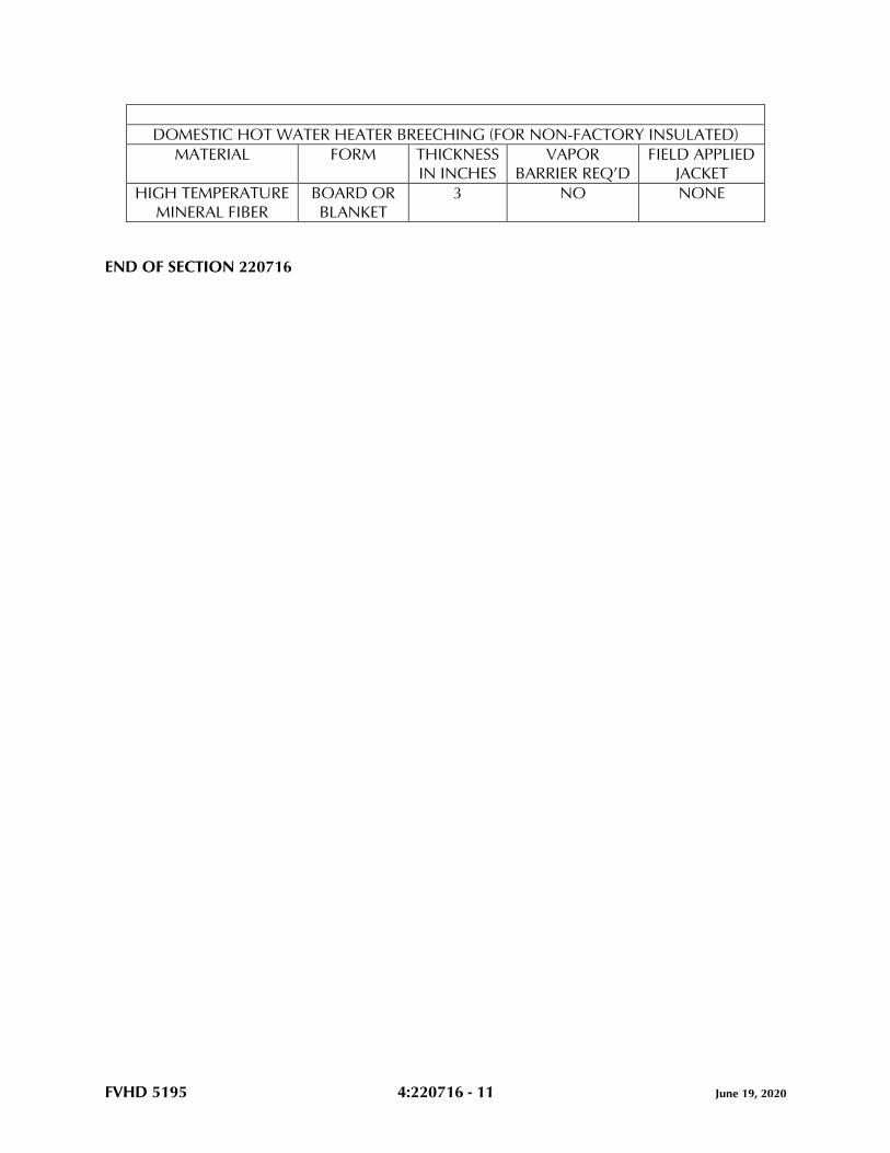
FVHD 5195 4:220716 - 11 June 19, 2020
DOMESTIC HOT WATER HEATER BREECHING (FOR NON-FACTORY INSULATED)
MATERIAL FORM THICKNESS
IN INCHES
VAPOR
BARRIER REQ’D
FIELD APPLIED
JACKET
HIGH TEMPERATURE
MINERAL FIBER
BOARD OR
BLANKET
3 NO NONE
END OF SECTION 220716
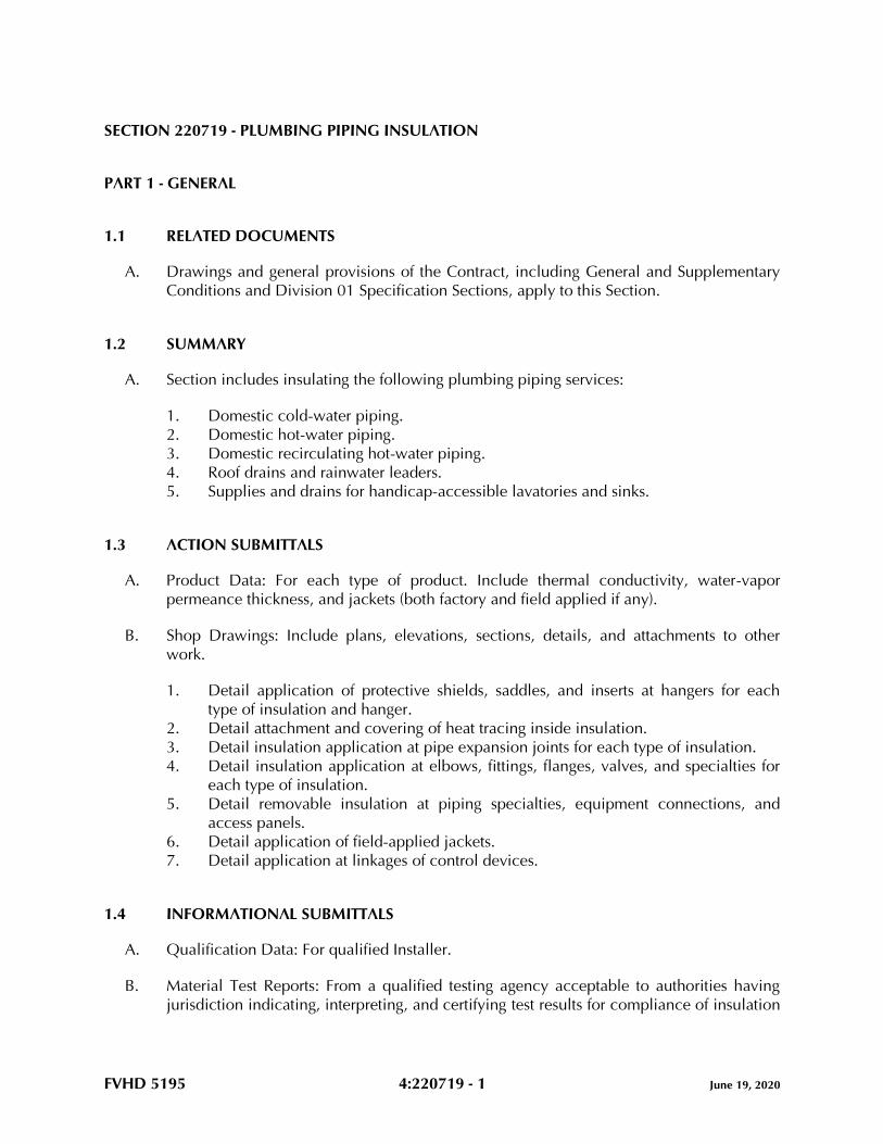
FVHD 5195 4:220719 - 1 June 19, 2020
SECTION 220719 - PLUMBING PIPING INSULATION
PART 1 - GENERAL
1.1 RELATED DOCUMENTS
A. Drawings and general provisions of the Contract, including General and Supplementary
Conditions and Division 01 Specification Sections, apply to this Section.
1.2 SUMMARY
A. Section includes insulating the following plumbing piping services:
1. Domestic cold-water piping.
2. Domestic hot-water piping.
3. Domestic recirculating hot-water piping.
4. Roof drains and rainwater leaders.
5. Supplies and drains for handicap-accessible lavatories and sinks.
1.3 ACTION SUBMITTALS
A. Product Data: For each type of product. Include thermal conductivity, water-vapor
permeance thickness, and jackets (both factory and field applied if any).
B. Shop Drawings: Include plans, elevations, sections, details, and attachments to other
work.
1. Detail application of protective shields, saddles, and inserts at hangers for each
type of insulation and hanger.
2. Detail attachment and covering of heat tracing inside insulation.
3. Detail insulation application at pipe expansion joints for each type of insulation.
4. Detail insulation application at elbows, fittings, flanges, valves, and specialties for
each type of insulation.
5. Detail removable insulation at piping specialties, equipment connections, and
access panels.
6. Detail application of field-applied jackets.
7. Detail application at linkages of control devices.
1.4 INFORMATIONAL SUBMITTALS
A. Qualification Data: For qualified Installer.
B. Material Test Reports: From a qualified testing agency acceptable to authorities having
jurisdiction indicating, interpreting, and certifying test results for compliance of insulation
FVHD 5195 4:220719 - 2 June 19, 2020
materials, sealers, attachments, cements, and jackets, with requirements indicated.
Include dates of tests and test methods employed.
C. Field quality-control reports.
1.5 QUALITY ASSURANCE
A. Installer Qualifications: Skilled mechanics who have successfully completed an
apprenticeship program or another craft training program certified by the Department of
Labor, Bureau of Apprenticeship and Training.
B. Surface-Burning Characteristics: For insulation and related materials, as determined by
testing identical products in accordance with ASTM E84 by a testing agency acceptable
to authorities having jurisdiction. Factory label insulation and jacket materials and
adhesive, mastic, tapes, and cement material containers, with appropriate markings of
applicable testing agency.
1. Insulation Installed Indoors: Flame-spread index of 25 or less and smoke-developed
index of 50 or less.
2. Insulation Installed Outdoors: Flame-spread index of 75 or less and smoke-
developed index of 150 or less.
1.6 DELIVERY, STORAGE, AND HANDLING
A. Packaging: Insulation material containers shall be marked by manufacturer with
appropriate ASTM standard designation, type and grade, and maximum use temperature.
1.7 COORDINATION
A. Coordinate sizes and locations of supports, hangers, and insulation shields specified in
applicable Division 22 Sections.
B. Coordinate clearance requirements with piping Installer for piping insulation application.
Before preparing piping Shop Drawings, establish and maintain clearance requirements
for installation of insulation and field-applied jackets and finishes and for space required
for maintenance.
1.8 SCHEDULING
A. Schedule insulation application after pressure testing systems and, where required, after
installing and testing heat tracing. Insulation application may begin on segments that
have satisfactory test results.
B. Complete installation and concealment of plastic materials as rapidly as possible in each
area of construction.
FVHD 5195 4:220719 - 3 June 19, 2020
PART 2 - PRODUCTS
2.1 INSULATION MATERIALS
A. Comply with requirements in "Piping Insulation Schedule, General" articles for where
insulating materials shall be applied.
B. Products shall not contain asbestos, lead, mercury, or mercury compounds.
C. Products that come into contact with stainless steel shall have a leachable chloride
content of less than 50 ppm when tested in accordance with ASTM C871.
D. Insulation materials for use on austenitic stainless steel shall be qualified as acceptable in
accordance with ASTM C795.
E. Foam insulation materials shall not use CFC or HCFC blowing agents in the
manufacturing process.
F. Mineral-Fiber, Preformed Pipe: Mineral or glass fibers bonded with a thermosetting resin.
Comply with ASTM C547.
1. Basis-of-Design Product: Subject to compliance with requirements, provide Johns
Manville; a Berkshire Hathaway company ; Micro-Lok. or a comparable product by
one of the following:
a. Knauf Insulation.
b. Manson Insulation Inc.
c. Owens Corning.
2. Preformed Pipe Insulation: Type I, Grade A with factory-applied ASJ-SSL.
3. 850 deg F.
4. Factory fabricate shapes in accordance with ASTM C450 and ASTM C585.
5. Factory-applied jacket requirements are specified in "Factory-Applied Jackets"
Article.
2.2 INSULATING CEMENTS
A. Mineral-Fiber Insulating Cement: Comply with ASTM C195.
B. Mineral-Fiber, Hydraulic-Setting Insulating and Finishing Cement: Comply with
ASTM C449.
2.3 ADHESIVES
A. Materials shall be compatible with insulation materials, jackets, and substrates and for
bonding insulation to itself and to surfaces to be insulated unless otherwise indicated.
B. Mineral-Fiber Adhesive: Comply with MIL-A-3316C, Class 2, Grade A.

FVHD 5195 4:220719 - 4 June 19, 2020
C. PVC Jacket Adhesive: Compatible with PVC jacket.
2.4 MASTICS AND COATINGS
A. Materials shall be compatible with insulation materials, jackets, and substrates.
B. Vapor-Retarder Mastic, Water Based: Suitable for indoor use on below-ambient services.
1. Water-Vapor Permeance: Comply with ASTM E96/E96M or ASTM F1249.
2. Service Temperature Range: Minus 20 to plus 180 deg F.
3. Comply with MIL-PRF-19565C, Type II, for permeance requirements.
4. Color: White.
C. Vapor-Retarder Mastic, Solvent Based, Outdoor Use: Suitable for outdoor use on below-
ambient services.
1. Water-Vapor Permeance: Comply with ASTM E96/E96M or ASTM F1249.
2. Service Temperature Range: Minus 50 to plus 220 deg F.
3. Color: White.
D. Breather Mastic: Water based; suitable for indoor and outdoor use on above-ambient
services.
1. Water-Vapor Permeance: ASTM E96/E96M, greater than 1.0 perm at
manufacturer's recommended dry film thickness.
2. Service Temperature Range: Minus 20 to plus 180 deg F.
3. Color: White.
2.5 LAGGING ADHESIVES
A. Adhesives shall comply with MIL-A-3316C, Class I, Grade A, and shall be compatible
with insulation materials, jackets, and substrates.
1. Fire-resistant, water-based lagging adhesive and coating for use indoors to adhere
fire-resistant lagging cloths over pipe insulation.
2. Service Temperature Range: 0 to plus 180 deg F.
3. Color: White.
2.6 SEALANTS
A. Materials shall be as recommended by the insulation manufacturer and shall be
compatible with insulation materials, jackets, and substrates.
B. ASJ Flashing Sealants and PVC Jacket Flashing Sealants:
1. Fire- and water-resistant, flexible, elastomeric sealant.
2. Service Temperature Range: Minus 40 to plus 250 deg F.
3. Color: White.
FVHD 5195 4:220719 - 5 June 19, 2020
2.7 FACTORY-APPLIED JACKETS
A. Insulation system schedules indicate factory-applied jackets on various applications.
When factory-applied jackets are indicated, comply with the following:
1. ASJ-SSL: ASJ with self-sealing, pressure-sensitive, acrylic-based adhesive covered
by a removable protective strip; complying with ASTM C1136, Type I.
2.8 FIELD-APPLIED CLOTHS
A. Woven Glass-Fiber Fabric: Comply with MIL-C-20079H, Type I, plain weave, and
presized a minimum of 8 oz./sq. yd.
2.9 FIELD-APPLIED JACKETS
A. Field-applied jackets shall comply with ASTM C1136, Type I, unless otherwise indicated.
B. PVC Jacket: High-impact-resistant, UV-resistant PVC complying with ASTM D1784,
Class 16354-C; thickness as scheduled; roll stock ready for shop or field cutting and
forming. Thickness is indicated in field-applied jacket schedules.
1. Adhesive: As recommended by jacket material manufacturer.
2. Color: White.
3. Factory-fabricated fitting covers to match jacket if available; otherwise, field
fabricate.
a. Shapes: 45- and 90-degree, short- and long-radius elbows, tees, valves,
flanges, unions, reducers, end caps, soil-pipe hubs, traps, mechanical joints,
and P-trap and supply covers for lavatories.
2.10 TAPES
A. ASJ Tape: White vapor-retarder tape matching factory-applied jacket with acrylic
adhesive, complying with ASTM C1136.
1. Width: 3 inches.
2. Thickness: 11.5 mils.
3. Adhesion: 90 ounces force/inch in width.
4. Elongation: 2 percent.
5. Tensile Strength: 40 lbf/inch in width.
6. ASJ Tape Disks and Squares: Precut disks or squares of ASJ tape.
B. PVC Tape: White vapor-retarder tape matching field-applied PVC jacket with acrylic
adhesive; suitable for indoor and outdoor applications.
1. Width: 2 inches.
2. Thickness: 6 mils.
3. Adhesion: 64 ounces force/inch in width.
FVHD 5195 4:220719 - 6 June 19, 2020
4. Elongation: 500 percent.
5. Tensile Strength: 18 lbf/inch in width.
2.11 SECUREMENTS
A. Bands:
1. Stainless Steel: ASTM A240/A240M, Type 304 or Type 316; 0.015 inch thick, 3/4
inch wide with wing seal.
B. Staples: Outward-clinching insulation staples, nominal 3/4-inch-wide, stainless steel or
Monel.
C. Wire: 0.062-inch soft-annealed, stainless steel.
2.12 PROTECTIVE SHIELDING GUARDS
A. Protective Shielding Piping Enclosure:
1. Basis-of-Design Product: Subject to compliance with requirements, provide
Truebro, LavShield; or a comparable product by one of the following:
a. Zurn Industries, LLC.
b. Or approved equal.
2. Description: Manufactured plastic enclosure for covering plumbing fixture hot- and
cold-water supplies and trap and drain piping. Comply with ADA requirements.
3. Length: Coordinate with field conditions and trim to suit.
4. Color: Coordinate with the Architect.
PART 3 - EXECUTION
3.1 EXAMINATION
A. Examine substrates and conditions for compliance with requirements for installation
tolerances and other conditions affecting performance of insulation application.
1. Verify that systems to be insulated have been tested and are free of defects.
2. Verify that surfaces to be insulated are clean and dry.
B. Proceed with installation only after unsatisfactory conditions have been corrected.
3.2 PREPARATION
A. Clean and dry surfaces to receive insulation. Remove materials that will adversely affect
insulation application.

FVHD 5195 4:220719 - 7 June 19, 2020
B. Coordinate insulation installation with the tradesman installing heat tracing. Comply with
requirements for heat tracing that apply to insulation.
C. Mix insulating cements with clean potable water; if insulating cements are to be in
contact with stainless steel surfaces, use demineralized water.
3.3 GENERAL INSTALLATION REQUIREMENTS
A. Install insulation materials, accessories, and finishes with smooth, straight, and even
surfaces; free of voids throughout the length of piping, including fittings, valves, and
specialties.
B. Install insulation materials, forms, vapor barriers or retarders, jackets, and of thicknesses
required for each item of pipe system, as specified in insulation system schedules.
C. Install accessories compatible with insulation materials and suitable for the service. Install
accessories that do not corrode, soften, or otherwise attack insulation or jacket in either
wet or dry state.
D. Install insulation with longitudinal seams at top and bottom of horizontal runs.
E. Install multiple layers of insulation with longitudinal and end seams staggered.
F. Do not weld brackets, clips, or other attachment devices to piping, fittings, and
specialties.
G. Keep insulation materials dry during storage, application, and finishing. Replace
insulation materials that get wet.
H. Install insulation with tight longitudinal seams and end joints. Bond seams and joints with
adhesive recommended by insulation material manufacturer.
I. Install insulation with least number of joints practical.
J. Where vapor barrier is indicated, seal joints, seams, and penetrations in insulation at
hangers, supports, anchors, and other projections with vapor-barrier mastic.
1. Install insulation continuously through hangers and around anchor attachments.
2. For insulation application where vapor barriers are indicated, extend insulation on
anchor legs from point of attachment to supported item to point of attachment to
structure. Taper and seal ends attached to structure with vapor-barrier mastic.
3. Install insert materials and insulation to tightly join the insert. Seal insulation to
insulation inserts with adhesive or sealing compound recommended by insulation
material manufacturer.
4. Cover inserts with jacket material matching adjacent pipe insulation. Install shields
over jacket, arranged to protect jacket from tear or puncture by hanger, support,
and shield.
FVHD 5195 4:220719 - 8 June 19, 2020
K. Apply adhesives, mastics, and sealants at manufacturer's recommended coverage rate
and wet and dry film thicknesses.
L. Install insulation with factory-applied jackets as follows:
1. Draw jacket tight and smooth.
2. Cover circumferential joints with 3-inch-wide strips, of same material as insulation
jacket. Secure strips with adhesive and outward-clinching staples along both edges
of strip, spaced 4 inches o.c.
3. Overlap jacket longitudinal seams at least 1-1/2 inches. Install insulation with
longitudinal seams at bottom of pipe. Clean and dry surface to receive self-sealing
lap. Staple laps with outward-clinching staples along edge at 4 inches o.c.
a. For below-ambient services, apply vapor-barrier mastic over staples.
4. Cover joints and seams with tape, in accordance with insulation material
manufacturer's written instructions, to maintain vapor seal.
5. Where vapor barriers are indicated, apply vapor-barrier mastic on seams and joints
and at ends adjacent to pipe flanges and fittings.
M. Cut insulation in a manner to avoid compressing insulation more than 25 percent of its
nominal thickness.
N. Finish installation with systems at operating conditions. Repair joint separations and
cracking due to thermal movement.
O. Repair damaged insulation facings by applying same facing material over damaged areas.
Extend patches at least 4 inches beyond damaged areas. Adhere, staple, and seal patches
in similar fashion to butt joints.
P. For above-ambient services, do not install insulation to the following:
1. Vibration-control devices.
2. Testing agency labels and stamps.
3. Nameplates and data plates.
4. Cleanouts.
3.4 PENETRATIONS
A. Insulation Installation at Roof Penetrations: Install insulation continuously through roof
penetrations.
1. Seal penetrations with flashing sealant.
2. For applications requiring only indoor insulation, terminate insulation above roof
surface and seal with joint sealant. For applications requiring indoor and outdoor
insulation, install insulation for outdoor applications tightly joined to indoor
insulation ends. Seal joint with joint sealant.
3. Extend jacket of outdoor insulation outside roof flashing at least 2 inches below top
of roof flashing.
FVHD 5195 4:220719 - 9 June 19, 2020
4. Seal jacket to roof flashing with flashing sealant.
B. Insulation Installation at Underground Exterior Wall Penetrations: Terminate insulation
flush with sleeve seal. Seal terminations with flashing sealant.
C. Insulation Installation at Aboveground Exterior Wall Penetrations: Install insulation
continuously through wall penetrations.
1. Seal penetrations with flashing sealant.
2. For applications requiring only indoor insulation, terminate insulation inside wall
surface and seal with joint sealant. For applications requiring indoor and outdoor
insulation, install insulation for outdoor applications tightly joined to indoor
insulation ends. Seal joint with joint sealant.
3. Extend jacket of outdoor insulation outside wall flashing and overlap wall flashing
at least 2 inches.
4. Seal jacket to wall flashing with flashing sealant.
D. Insulation Installation at Interior Wall and Partition Penetrations (That Are Not Fire
Rated): Install insulation continuously through walls and partitions.
E. Insulation Installation at Fire-Rated Wall and Partition Penetrations: Install insulation
continuously through penetrations of fire-rated walls and partitions.
1. Comply with requirements in applicable Division 07 Sections for firestopping and
fire-resistive joint sealers.
F. Insulation Installation at Floor Penetrations:
1. Pipe: Install insulation continuously through floor penetrations.
2. Seal penetrations through fire-rated assemblies. Comply with requirements in
applicable Division 07 Sections.
3.5 GENERAL PIPE INSULATION INSTALLATION
A. Requirements in this article generally apply to all insulation materials, except where more
specific requirements are specified in various pipe insulation material installation articles.
B. Insulation Installation on Fittings, Valves, Strainers, Flanges, Mechanical Couplings, and
Unions:
1. Install insulation over fittings, valves, strainers, flanges, mechanical couplings,
unions, and other specialties with continuous thermal and vapor-retarder integrity
unless otherwise indicated.
2. Insulate pipe elbows using preformed fitting insulation made from same material
and density as that of adjacent pipe insulation. Each piece shall be butted tightly
against adjoining piece and bonded with adhesive. Fill joints, seams, voids, and
irregular surfaces with insulating cement finished to a smooth, hard, and uniform
contour that is uniform with adjoining pipe insulation.
FVHD 5195 4:220719 - 10 June 19, 2020
3. Insulate tee fittings with preformed fitting insulation of same material and thickness
as that used for adjacent pipe. Cut sectional pipe insulation to fit. Butt each section
closely to the next and hold in place with tie wire. Bond pieces with adhesive.
4. Insulate valves using preformed fitting insulation of same material, density, and
thickness as that used for adjacent pipe. Overlap adjoining pipe insulation by not
less than 2 times the thickness of pipe insulation, or one pipe diameter, whichever
is thicker. For valves, insulate up to and including the bonnets, valve stuffing-box
studs, bolts, and nuts. Fill joints, seams, and irregular surfaces with insulating
cement.
5. Insulate strainers using preformed fitting insulation of same material, density, and
thickness as used for adjacent pipe. Overlap adjoining pipe insulation by not less
than 2 times the thickness of pipe insulation, or one pipe diameter, whichever is
thicker. Fill joints, seams, and irregular surfaces with insulating cement. Insulate
strainers, so strainer basket flange or plug can be easily removed and replaced
without damaging the insulation and jacket. Provide a removable reusable
insulation cover. For below-ambient services, provide a design that maintains
vapor barrier.
6. Insulate flanges, mechanical couplings, and unions, using a section of oversized
preformed pipe insulation. Overlap adjoining pipe insulation by not less than 2
times the thickness of pipe insulation, or one pipe diameter, whichever is thicker.
Stencil or label the outside insulation jacket of each union with the word "union"
matching size and color of pipe labels.
7. Cover segmented insulated surfaces with a layer of finishing cement and coat with
a mastic. Install vapor-barrier mastic for below-ambient services and a breather
mastic for above-ambient services. Reinforce the mastic with fabric-reinforcing
mesh. Trowel the mastic to a smooth and well-shaped contour.
8. For services not specified to receive a field-applied jacket, except for flexible
elastomeric and polyolefin, install fitted PVC cover over elbows, tees, strainers,
valves, flanges, and unions. Terminate ends with PVC end caps. Tape PVC covers
to adjoining insulation facing, using PVC tape.
C. Insulate instrument connections for thermometers, pressure gages, pressure temperature
taps, test connections, flow meters, sensors, switches, and transmitters on insulated pipes.
Shape insulation at these connections by tapering it to and around the connection with
insulating cement and finish with finishing cement, mastic, and flashing sealant.
D. Install removable insulation covers at locations indicated. Installation shall conform to
the following:
1. Make removable flange and union insulation from sectional pipe insulation of same
thickness as that on adjoining pipe. Install same insulation jacket as that of
adjoining pipe insulation.
2. When flange and union covers are made from sectional pipe insulation, extend
insulation from flanges or union at least 2 times the insulation thickness over
adjacent pipe insulation on each side of flange or union. Secure flange cover in
place with stainless steel or aluminum bands. Select band material compatible with
insulation and jacket.
3. Construct removable valve insulation covers in same manner as for flanges, except
divide the two-part section on the vertical center line of valve body.
FVHD 5195 4:220719 - 11 June 19, 2020
4. When covers are made from block insulation, make two halves, each consisting of
mitered blocks wired to stainless steel fabric. Secure this wire frame, with its
attached insulation, to flanges with tie wire. Extend insulation at least 2 inches over
adjacent pipe insulation on each side of valve. Fill space between flange or union
cover and pipe insulation with insulating cement. Finish cover assembly with
insulating cement applied in two coats. After first coat is dry, apply and trowel
second coat to a smooth finish.
5. Unless a PVC jacket is indicated in field-applied jacket schedules, finish exposed
surfaces with a metal jacket.
3.6 INSTALLATION OF MINERAL-FIBER INSULATION
A. Insulation Installation on Straight Pipes and Tubes:
1. Secure each layer of preformed pipe insulation to pipe with wire or bands, and
tighten bands without deforming insulation materials.
2. Where vapor barriers are indicated, seal longitudinal seams, end joints, and
protrusions with vapor-barrier mastic and joint sealant.
3. For insulation with factory-applied jackets on above-ambient surfaces, secure laps
with outward-clinched staples at 6 inches o.c.
4. For insulation with factory-applied jackets on below-ambient surfaces, do not
staple longitudinal tabs. Instead, secure tabs with additional adhesive, as
recommended by insulation material manufacturer, and seal with vapor-barrier
mastic and flashing sealant.
B. Insulation Installation on Pipe Flanges:
1. Install preformed pipe insulation to outer diameter of pipe flange.
2. Make width of insulation section same as overall width of flange and bolts, plus
twice the thickness of pipe insulation.
3. Fill voids between inner circumference of flange insulation and outer
circumference of adjacent straight pipe segments with mineral-fiber blanket
insulation.
4. Install jacket material with manufacturer's recommended adhesive, overlap seams
at least 1 inch, and seal joints with flashing sealant.
C. Insulation Installation on Pipe Fittings and Elbows:
1. Install preformed sections of same material as that of straight segments of pipe
insulation when available.
2. When preformed insulation elbows and fittings are not available, install mitered
sections of pipe insulation, to a thickness equal to adjoining pipe insulation. Secure
insulation materials with wire or bands.
D. Insulation Installation on Valves and Pipe Specialties:
1. Install preformed sections of same material as that of straight segments of pipe
insulation when available.
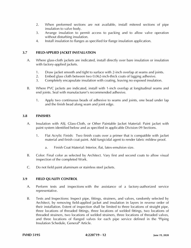
FVHD 5195 4:220719 - 12 June 19, 2020
2. When preformed sections are not available, install mitered sections of pipe
insulation to valve body.
3. Arrange insulation to permit access to packing and to allow valve operation
without disturbing insulation.
4. Install insulation to flanges as specified for flange insulation application.
3.7 FIELD-APPLIED JACKET INSTALLATION
A. Where glass-cloth jackets are indicated, install directly over bare insulation or insulation
with factory-applied jackets.
1. Draw jacket smooth and tight to surface with 2-inch overlap at seams and joints.
2. Embed glass cloth between two 0.062-inch-thick coats of lagging adhesive.
3. Completely encapsulate insulation with coating, leaving no exposed insulation.
B. Where PVC jackets are indicated, install with 1-inch overlap at longitudinal seams and
end joints. Seal with manufacturer's recommended adhesive.
1. Apply two continuous beads of adhesive to seams and joints, one bead under lap
and the finish bead along seam and joint edge.
3.8 FINISHES
A. Insulation with ASJ, Glass-Cloth, or Other Paintable Jacket Material: Paint jacket with
paint system identified below and as specified in applicable Division 09 Sections.
1. Flat Acrylic Finish: Two finish coats over a primer that is compatible with jacket
material and finish coat paint. Add fungicidal agent to render fabric mildew proof.
a. Finish Coat Material: Interior, flat, latex-emulsion size.
B. Color: Final color as selected by Architect. Vary first and second coats to allow visual
inspection of the completed Work.
C. Do not field paint aluminum or stainless steel jackets.
3.9 FIELD QUALITY CONTROL
A. Perform tests and inspections with the assistance of a factory-authorized service
representative.
B. Tests and Inspections: Inspect pipe, fittings, strainers, and valves, randomly selected by
Architect, by removing field-applied jacket and insulation in layers in reverse order of
their installation. Extent of inspection shall be limited to three locations of straight pipe,
three locations of threaded fittings, three locations of welded fittings, two locations of
threaded strainers, two locations of welded strainers, three locations of threaded valves,
and three locations of flanged valves for each pipe service defined in the "Piping
Insulation Schedule, General" Article.

FVHD 5195 4:220719 - 13 June 19, 2020
C. All insulation applications will be considered defective if they do not pass tests and
inspections.
D. Prepare test and inspection reports.
3.10 PIPING INSULATION SCHEDULE, GENERAL
A. Acceptable preformed pipe and tubular insulation materials and thicknesses are identified
for each piping system and pipe size range. If more than one material is listed for a piping
system, selection from materials listed is Contractor's option.
B. Items Not Insulated: Unless otherwise indicated, do not install insulation on the
following:
1. Drainage piping located in crawl spaces.
2. Underground piping.
3. Chrome-plated pipes and fittings unless there is a potential for personnel injury.
C. Provide PVC fittings on all piping unless otherwise noted.
INTERIOR DOMESTIC HOT WATER AND RECIRC (105 TO 140 DEG F) PIPING, CONCEALED
PIPE SIZES
(NPS) MATERIALS
THICKNESS IN
INCHES
VAPOR BARRIER
REQ’D
FIELD APPLIED
JACKET
1/2 TO 1-1/4 MINERAL FIBER 1 NO NONE
1-1/2 AND
LARGER MINERAL FIBER 1-1/2 NO NONE
INTERIOR DOMESTIC HOT WATER AND RECIRC (105 TO 140 DEG F) PIPING, EXPOSED
PIPE SIZES
(NPS) MATERIALS
THICKNESS IN
INCHES
VAPOR BARRIER
REQ’D
FIELD APPLIED
JACKET
1/2 TO 1-1/4 MINERAL FIBER 1 NO P
1-1/2 AND
LARGER MINERAL FIBER 1-1/2 NO P
INTERIOR DOMESTIC COLD WATER (40 TO 60 DEG F) PIPING, CONCEALED
PIPE SIZES
(NPS) MATERIALS
THICKNESS IN
INCHES
VAPOR BARRIER
REQ’D
FIELD APPLIED
JACKET
1/2 TO 1-1/4 MINERAL FIBER 1/2 YES NONE
1-1/2 AND
LARGER
MINERAL FIBER 1 YES NONE
INTERIOR DOMESTIC COLD WATER (40 TO 60 DEG F) PIPING, ABOVESLAB, EXPOSED
PIPE SIZES
(NPS) MATERIALS
THICKNESS IN
INCHES
VAPOR BARRIER
REQ’D
FIELD APPLIED
JACKET
1/2 TO 1-1/4 MINERAL FIBER 1/2 YES P
1-1/2 AND
LARGER MINERAL FIBER 1 YES P
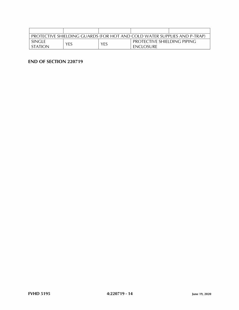
FVHD 5195 4:220719 - 14 June 19, 2020
PROTECTIVE SHIELDING GUARDS (FOR HOT AND COLD WATER SUPPLIES AND P-TRAP)
SINGLE
STATION YES YES
PROTECTIVE SHIELDING PIPING
ENCLOSURE
END OF SECTION 220719
FVHD 5195 4:221116 - 1 June 19, 2020
SECTION 221116 - DOMESTIC WATER PIPING
PART 1 - GENERAL
1.1 RELATED DOCUMENTS
A. Drawings and general provisions of the Contract, including General and Supplementary
Conditions and Division 01 Specification Sections, apply to this Section.
1.2 SUMMARY
A. Section Includes:
1. Copper tube and fittings.
2. Piping joining materials.
3. Encasement for piping.
4. Dielectric fittings.
1.3 ACTION SUBMITTALS
A. Product Data:
1. Pipe and tube.
2. Fittings.
3. Joining materials.
4. Transition fittings.
1.4 INFORMATIONAL SUBMITTALS
A. Coordination Drawings: Piping layout, or BIM model, drawn to scale, showing the items
described in this Section, and coordinated with all building trades.
B. System purging and disinfecting activities report.
C. Field quality-control reports.
1.5 FIELD CONDITIONS
A. Interruption of Existing Water Service: Do not interrupt water service to facilities
occupied by Owner or others unless permitted under the following conditions and then
only after arranging to provide temporary water service according to requirements
indicated:

FVHD 5195 4:221116 - 2 June 19, 2020
1. Notify Owner no fewer than two days in advance of proposed interruption of water
service.
2. Do not interrupt water service without Owner's written permission.
PART 2 - PRODUCTS
2.1 PIPING MATERIALS
A. Potable-water piping and components shall comply with NSF 14, NSF 61, and NSF 372.
2.2 COPPER TUBE AND FITTINGS
A. Drawn-Temper Copper Tube: ASTM B88, Type L.
B. Annealed-Temper Copper Tube: ASTM B88, Type L.
C. Wrought-Copper, Solder-Joint Fittings: ASME B16.22, pressure fittings.
D. Bronze Flanges: ASME B16.24, Class 150, with solder-joint ends.
E. Wrought Copper Unions: ASME B16.22.
F. Grooved, Mechanical-Joint, Copper Tube Appurtenances:
1. Basis-of-Design Product: Subject to compliance with requirements, provide
Victaulic Company; or a comparable product by one of the following:
a. Anvil International.
b. Grinnell Mechanical Products.
c. Shurjoint Piping Products USA Inc.
2. Grooved-End, Copper Fittings: ASTM B75 copper tube or ASTM B584 bronze
castings.
3. Grooved-End-Tube Couplings: To fit copper-tube dimensions; rigid pattern unless
otherwise indicated; gasketed fitting, EPDM-rubber gasket, UL classified per NSF
61 and NSF 372, and rated for minimum 180 deg F, for use with ferrous housing
and steel bolts and nuts; 300 psig minimum CWP pressure rating.
G. Copper Tube, Pressure-Seal-Joint Fittings:
1. Basis-of-Design Product: Subject to compliance with requirements, provide Viega
LLC or comparable product by one of the following:
a. Apollo Flow Controls; Conbraco Industries, Inc.
b. NIBCO INC.
2. Fittings: Cast-brass, cast-bronze, or wrought-copper with EPDM O-ring seal in each
end.

FVHD 5195 4:221116 - 3 June 19, 2020
3. Minimum 200-psig working-pressure rating at 250 deg F.
2.3 PIPING JOINING MATERIALS
A. Pipe-Flange Gasket Materials:
1. AWWA C110/A21.10, rubber, flat face, 1/8 inch thick or ASME B16.21,
nonmetallic and asbestos free unless otherwise indicated.
2. Full-face or ring type unless otherwise indicated.
B. Metal, Pipe-Flange Bolts and Nuts: ASME B18.2.1, carbon steel unless otherwise
indicated.
C. Solder Filler Metals: ASTM B32, lead-free alloys.
D. Flux: ASTM B813, water flushable.
E. Brazing Filler Metals: AWS A5.8M/A5.8, BCuP Series, copper-phosphorus alloys for
general-duty brazing unless otherwise indicated.
2.4 ENCASEMENT FOR PIPING
A. Standard: ASTM A674 or AWWA C105/A21.5.
B. Form: Sheet or tube.
C. Color: Black.
2.5 DIELECTRIC FITTINGS
A. General Requirements: Assembly of copper alloy and ferrous materials with separating
nonconductive insulating material. Include end connections compatible with pipes to be
joined.
B. Dielectric Nipples:
1. Manufacturers: Subject to compliance with requirements, provide products by one
of the following:
a. Grinnell G-Fire by Johnson Controls Company.
b. Precision Plumbing Products.
c. Victaulic Company.
2. Standard: IAPMO PS 66.
3. Electroplated steel nipple complying with ASTM F1545.
4. Pressure Rating and Temperature: 300 psig at 225 deg F.
5. End Connections: Male threaded or grooved.
6. Lining: Inert and noncorrosive, propylene.
FVHD 5195 4:221116 - 4 June 19, 2020
PART 3 - EXECUTION
3.1 PIPING APPLICATIONS
A. Transition and special fittings with pressure ratings at least equal to piping rating may be
used in applications below unless otherwise indicated.
B. Flanges and unions may be used for aboveground piping joints unless otherwise
indicated.
C. Fitting Option: Extruded-tee connections and brazed joints may be used on aboveground
copper tubing.
D. Under-building-slab, domestic water, building-service piping, NPS 3 and smaller, shall
be the following:
1. Annealed-temper copper tube, ASTM B88, Type L; wrought-copper, solder-joint
fittings; and brazed joints.
E. Under-building-slab, domestic water piping, NPS 2 and smaller, shall be the following:
1. Annealed-temper copper tube, ASTM B88, Type L; wrought-copper, solder-joint
fittings; and brazed joints or copper pressure-seal-joint fittings; and pressure-sealed
joints.
F. Aboveground domestic water piping, NPS 2 and smaller, shall be one of the following:
1. Drawn-temper copper tube, ASTM B88, Type L; wrought-copper, solder-joint
fittings; and soldered joints.
2. Drawn-temper copper tube, ASTM B88, Type L; copper pressure-seal-joint fittings;
and pressure-sealed joints.
G. Aboveground domestic water piping, NPS 2-1/2 to NPS 4, shall be one of the following:
1. Drawn-temper copper tube, ASTM B88, Type L; wrought-copper, solder-joint
fittings; and soldered joints.
2. Drawn-temper copper tube, ASTM B88, Type L; copper pressure-seal-joint fittings;
and pressure-sealed joints.
3. Drawn-temper copper tube, ASTM B88, Type L; grooved-joint, copper-tube
appurtenances; and grooved joints.
3.2 EARTHWORK
A. Comply with requirements in applicable Sections for excavating, trenching, and
backfilling.
FVHD 5195 4:221116 - 5 June 19, 2020
3.3 INSTALLATION OF PIPING
A. Drawing plans, schematics, and diagrams indicate general location and arrangement of
domestic water piping. Indicated locations and arrangements are used to size pipe and
calculate friction loss, expansion, and other design considerations. Install piping as
indicated unless deviations to layout are approved on coordination drawings.
B. Install copper tubing under building slab according to CDA's "Copper Tube Handbook."
C. Install underground copper tube in PE encasement according to ASTM A674 or
AWWA C105/A21.5.
D. Install valves according to the following applicable Division 22 Sections.
E. Install water-pressure-reducing valves downstream from shutoff valves. Comply with
requirements for pressure-reducing valves in applicable Division 22 Sections.
F. Install domestic water piping level with 0.25 percent slope downward toward drain and
plumb.
G. Install piping concealed from view and protected from physical contact by building
occupants unless otherwise indicated and except in equipment rooms and service areas.
H. Install piping indicated to be exposed and piping in equipment rooms and service areas
at right angles or parallel to building walls. Diagonal runs are prohibited unless
specifically indicated otherwise.
I. Install piping above accessible ceilings to allow sufficient space for ceiling panel
removal, and coordinate with other services occupying that space.
J. Install piping to permit valve servicing.
K. Install nipples, unions, special fittings, and valves with pressure ratings the same as or
higher than the system pressure rating used in applications below unless otherwise
indicated.
L. Install piping free of sags and bends.
M. Install fittings for changes in direction and branch connections.
N. Install unions in copper tubing at final connection to each piece of equipment, machine,
and specialty.
O. Install pressure gauges on suction and discharge piping for each plumbing pump. Comply
with requirements for pressure gauges in applicable Division 22 Sections.
P. Install thermostats in hot-water circulation piping. Comply with requirements for
thermostats in applicable Division 22 Sections.
Q. Install thermometers on inlet and outlet piping from each water heater. Comply with
requirements for thermometers in applicable Division 22 Sections.
FVHD 5195 4:221116 - 6 June 19, 2020
R. Install sleeves for piping penetrations of walls, ceilings, and floors. Comply with
requirements for sleeves specified in applicable Division 22 Sections.
S. Install sleeve seals for piping penetrations of concrete walls and slabs. Comply with
requirements for sleeve seals specified in applicable Division 22 Sections.
T. Install escutcheons for piping penetrations of walls, ceilings, and floors. Comply with
requirements for escutcheons specified in applicable Division 22 Sections.
3.4 JOINT CONSTRUCTION
A. Ream ends of pipes and tubes and remove burrs. Bevel plain ends of steel pipe.
B. Remove scale, slag, dirt, and debris from inside and outside of pipes, tubes, and fittings
before assembly.
C. Threaded Joints: Thread pipe with tapered pipe threads according to ASME B1.20.1. Cut
threads full and clean using sharp dies. Ream threaded pipe ends to remove burrs and
restore full ID. Join pipe fittings and valves as follows:
1. Apply appropriate tape or thread compound to external pipe threads.
2. Damaged Threads: Do not use pipe or pipe fittings with threads that are corroded
or damaged.
D. Brazed Joints for Copper Tubing: Comply with CDA's "Copper Tube Handbook," "Brazed
Joints" chapter.
E. Soldered Joints for Copper Tubing: Apply ASTM B813, water-flushable flux to end of
tube. Join copper tube and fittings according to ASTM B828 or CDA's "Copper Tube
Handbook."
F. Pressure-Sealed Joints for Copper Tubing: Join copper tube and pressure-seal fittings with
tools and procedure recommended by pressure-seal-fitting manufacturer. Leave insertion
marks on pipe after assembly.
G. Joint Construction for Grooved-End Copper Tubing: Make joints according to
AWWA C606. Roll groove ends of tubes. Lubricate and install gasket over ends of tubes
or tube and fitting. Install coupling housing sections over gasket with keys seated in
tubing grooves. Install and tighten housing bolts.
H. Flanged Joints: Select appropriate asbestos-free, nonmetallic gasket material in size, type,
and thickness suitable for domestic water service. Join flanges with gasket and bolts
according to ASME B31.9.
I. Joints for Dissimilar-Material Piping: Make joints using adapters compatible with
materials of both piping systems.
FVHD 5195 4:221116 - 7 June 19, 2020
3.5 INSTALLATION OF DIELECTRIC FITTINGS
A. Install dielectric fittings in piping at connections of dissimilar metal piping and tubing.
B. Dielectric Fittings for NPS 4 and Smaller: Use dielectric nipples.
3.6 INSTALLATION OF HANGERS AND SUPPORTS
A. Comply with requirements for hangers, supports, and anchor devices in applicable
Division 22 Sections.
B. Install hangers for copper tubing and piping, with maximum horizontal spacing and
minimum rod diameters, to comply with MSS-58, locally enforced codes, and authorities
having jurisdiction requirements, whichever are most stringent.
C. Support horizontal piping within 12 inches of each fitting.
D. Support vertical runs of copper tubing and piping to comply with MSS-58, locally
enforced codes, and authorities having jurisdiction requirements, whichever are most
stringent.
3.7 CONNECTIONS
A. Drawings indicate general arrangement of piping, fittings, and specialties.
B. When installing piping adjacent to equipment and machines, allow space for service and
maintenance.
C. Connect domestic water piping to exterior water-service piping. Use transition fitting to
join dissimilar piping materials.
D. Connect domestic water piping to water-service piping with shutoff valve; extend and
connect to the following:
1. Water Heaters: Cold-water inlet and hot-water outlet piping in sizes indicated, but
not smaller than sizes of water heater connections.
2. Plumbing Fixtures: Cold- and hot-water-supply piping in sizes indicated, but not
smaller than that required by plumbing code.
3. Equipment: Cold- and hot-water-supply piping as indicated, but not smaller than
equipment connections. Provide shutoff valve and union for each connection. Use
flanges instead of unions for NPS 2-1/2 and larger.
3.8 IDENTIFICATION
A. Identify system components. Comply with requirements for identification materials and
installation in applicable Division 22 Sections.
FVHD 5195 4:221116 - 8 June 19, 2020
3.9 ADJUSTING
A. Perform the following adjustments before operation:
1. Close drain valves, hydrants, and hose bibbs.
2. Open shutoff valves to fully open position.
3. Open throttling valves to proper setting.
4. Adjust balancing valves in hot-water-circulation return piping to provide adequate
flow.
a. Manually adjust ball-type balancing valves in hot-water-circulation return
piping to provide hot-water flow in each branch.
b. Adjust calibrated balancing valves to flows indicated.
5. Remove plugs used during testing of piping and for temporary sealing of piping
during installation.
6. Remove and clean strainer screens. Close drain valves and replace drain plugs.
7. Remove filter cartridges from housings and verify that cartridges are as specified for
application where used and are clean and ready for use.
8. Check plumbing specialties and verify proper settings, adjustments, and operation.
3.10 FIELD QUALITY CONTROL
A. Perform the following tests and inspections:
1. Piping Inspections:
a. Do not enclose, cover, or put piping into operation until it has been
inspected and approved by authorities having jurisdiction.
b. During installation, notify authorities having jurisdiction at least one day
before inspection must be made. Perform tests specified below in presence of
authorities having jurisdiction:
1) Roughing-in Inspection: Arrange for inspection of piping before
concealing or closing in after roughing in and before setting fixtures.
2) Final Inspection: Arrange for authorities having jurisdiction to observe
tests specified in "Piping Tests" Subparagraph below and to ensure
compliance with requirements.
c. Reinspection: If authorities having jurisdiction find that piping will not pass
tests or inspections, make required corrections and arrange for reinspection.
d. Reports: Prepare inspection reports and have them signed by authorities
having jurisdiction.
2. Piping Tests:
a. Fill domestic water piping. Check components to determine that they are not
air bound and that piping is full of water.
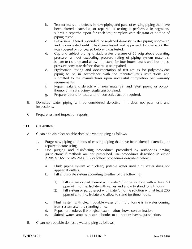
FVHD 5195 4:221116 - 9 June 19, 2020
b. Test for leaks and defects in new piping and parts of existing piping that have
been altered, extended, or repaired. If testing is performed in segments,
submit a separate report for each test, complete with diagram of portion of
piping tested.
c. Leave new, altered, extended, or replaced domestic water piping uncovered
and unconcealed until it has been tested and approved. Expose work that
was covered or concealed before it was tested.
d. Cap and subject piping to static water pressure of 50 psig above operating
pressure, without exceeding pressure rating of piping system materials.
Isolate test source and allow it to stand for four hours. Leaks and loss in test
pressure constitute defects that must be repaired.
e. Hydrostatic testing and documentation of test results for polypropylene
piping to be in accordance with the manufacturer's instructions and
submitted to the manufacturer upon successful completion per warranty
requirements.
f. Repair leaks and defects with new materials, and retest piping or portion
thereof until satisfactory results are obtained.
g. Prepare reports for tests and for corrective action required.
B. Domestic water piping will be considered defective if it does not pass tests and
inspections.
C. Prepare test and inspection reports.
3.11 CLEANING
A. Clean and disinfect potable domestic water piping as follows:
1. Purge new piping and parts of existing piping that have been altered, extended, or
repaired before using.
2. Use purging and disinfecting procedures prescribed by authorities having
jurisdiction; if methods are not prescribed, use procedures described in either
AWWA C651 or AWWA C652 or follow procedures described below:
a. Flush piping system with clean, potable water until dirty water does not
appear at outlets.
b. Fill and isolate system according to either of the following:
1) Fill system or part thereof with water/chlorine solution with at least 50
ppm of chlorine. Isolate with valves and allow to stand for 24 hours.
2) Fill system or part thereof with water/chlorine solution with at least 200
ppm of chlorine. Isolate and allow to stand for three hours.
c. Flush system with clean, potable water until no chlorine is in water coming
from system after the standing time.
d. Repeat procedures if biological examination shows contamination.
e. Submit water samples in sterile bottles to authorities having jurisdiction.
B. Clean non-potable domestic water piping as follows:
FVHD 5195 4:221116 - 10 June 19, 2020
1. Purge new piping and parts of existing piping that have been altered, extended, or
repaired before using.
2. Use purging procedures prescribed by authorities having jurisdiction or; if methods
are not prescribed, follow procedures described below:
a. Flush piping system with clean, potable water until dirty water does not
appear at outlets.
b. Submit water samples in sterile bottles to authorities having jurisdiction.
Repeat procedures if biological examination shows contamination.
C. Prepare and submit reports of purging and disinfecting activities. Include copies of water-
sample approvals from authorities having jurisdiction.
D. Clean interior of domestic water piping system. Remove dirt and debris as work
progresses.
END OF SECTION 221116
FVHD 5195 4:221119 - 1 June 19, 2020
SECTION 221119 - DOMESTIC WATER PIPING SPECIALTIES
PART 1 - GENERAL
1.1 RELATED DOCUMENTS
A. Drawings and general provisions of the Contract, including General and Supplementary
Conditions and Division 01 Specification Sections, apply to this Section.
1.2 SUMMARY
A. Section Includes:
1. Backflow preventers.
2. Water pressure-reducing valves.
3. Balancing valves.
4. Temperature-actuated, water mixing valves.
5. Strainers for domestic water piping.
6. Wall hydrants.
7. Drain valves.
8. Water-hammer arresters.
9. Trap-seal primer device.
10. Flexible connectors.
1.3 DEFINITIONS
A. AMI: Advanced Metering Infrastructure.
B. AMR: Automatic Meter Reading.
C. FKM: A family of fluroelastomer materials defined by ASTM D1418.
1.4 ACTION SUBMITTALS
A. Product Data: For each type of product.
B. Shop Drawings: For domestic water piping specialties.
1. Include diagrams for power, signal, and control wiring.
1.5 INFORMATIONAL SUBMITTALS
A. Test and inspection reports.

FVHD 5195 4:221119 - 2 June 19, 2020
B. Field quality-control reports.
1.6 CLOSEOUT SUBMITTALS
A. Operation and Maintenance Data: For domestic water piping specialties to include in
emergency, operation, and maintenance manuals.
PART 2 - PRODUCTS
2.1 GENERAL REQUIREMENTS FOR PIPING SPECIALTIES
A. Domestic water piping specialties intended to convey or dispense water for human
consumption are to comply with the SDWA, requirements of authorities having
jurisdiction, and NSF 61 and NSF 372, or to be certified in compliance with NSF 61 and
NSF 372 by an American National Standards Institute (ANSI)-accredited third-party
certification body that the weighted average lead content at wetted surfaces is less than or
equal to 0.25 percent.
2.2 PERFORMANCE REQUIREMENTS
A. Minimum Working Pressure for Domestic Water Piping Specialties: 125 psig unless
otherwise indicated.
2.3 BACKFLOW PREVENTERS
A. Reduced-Pressure-Principle Backflow Preventers:
1. Basis-of-Design Product: Subject to compliance with requirements, provide Zurn
Industries, LLC or a comparable product by one of the following:
a. Ames Fire & Waterworks; A WATTS Brand.
b. WATTS.
2. Standard: ASSE 1013.
3. Operation: Continuous-pressure applications.
4. Pressure Loss: 12 psig maximum, through middle third of flow range.
5. Body: Bronze for NPS 2 and smaller; ductile or cast iron with interior lining that
complies with AWWA C550 or that is FDA approved for NPS 2-1/2 and larger.
6. End Connections: Threaded for NPS 2 and smaller; flanged for NPS 2-1/2 and
larger.
7. Configuration: Designed for horizontal, straight-through flow.
8. Accessories:
a. Valves NPS 2 and Smaller: Ball type with threaded ends on inlet and outlet.
b. Valves NPS 2-1/2 and Larger: Outside-screw and yoke-gate type with flanged
ends on inlet and outlet.
FVHD 5195 4:221119 - 3 June 19, 2020
c. Air-Gap Fitting: ASME A112.1.2, matching backflow-preventer connection.
B. Double-Check, Backflow-Prevention Assemblies:
1. Manufacturers: Subject to compliance with requirements, provide products by one
of the following:
a. Ames Fire & Waterworks; A WATTS Brand.
b. Apollo Flow Controls; Conbraco Industries, Inc.
c. WATTS.
2. Standard: ASSE 1015.
3. Operation: Continuous-pressure applications unless otherwise indicated.
4. Pressure Loss: 5 psig maximum, through middle third of flow range.
5. Body: Bronze for NPS 2 and smaller; ductile or cast iron with interior lining that
complies with AWWA C550 or that is FDA approved for NPS 2-1/2 and larger.
6. End Connections: Threaded for NPS 2 and smaller; flanged for NPS 2-1/2 and
larger.
7. Configuration: Designed for horizontal, straight-through flow.
8. Accessories:
a. Valves NPS 2 and Smaller: Ball type with threaded ends on inlet and outlet.
b. Valves NPS 2-1/2 and Larger: Outside-screw and yoke-gate type with flanged
ends on inlet and outlet.
2.4 WATER PRESSURE-REDUCING VALVES
A. Water Regulators:
1. Manufacturers: Subject to compliance with requirements, provide products by one
of the following:
a. Apollo Flow Controls; Conbraco Industries, Inc.
b. WATTS.
c. Zurn Industries, LLC.
2. Standard: ASSE 1003.
3. Pressure Rating: Initial working pressure of 150 psig.
4. Body: Bronze for NPS 2 and smaller; cast iron with interior lining that complies
with AWWA C550 or that is FDA approved for NPS 2-1/2 and NPS 3.
5. Valves for Booster Heater Water Supply: Include integral bypass.
6. End Connections: Threaded or solder for NPS 2 and smaller; flanged or solder for
NPS 2-1/2 and NPS 3.
2.5 BALANCING VALVES
A. Memory-Stop Balancing Valves:
FVHD 5195 4:221119 - 4 June 19, 2020
1. Manufacturers: Subject to compliance with requirements, provide products by one
of the following:
a. Apollo Flow Controls; Conbraco Industries, Inc.
b. Milwaukee Valve Company.
c. Stockham; a Crane brand.
2. Standard: MSS SP-110 for two-piece, copper-alloy ball valves.
3. Pressure Rating: 400-psig minimum CWP.
4. Size: NPS 2 or smaller.
5. Body: Copper alloy.
6. Port: Standard or full port.
7. Ball: Chrome-plated brass or stainless steel.
8. Seats and Seals: Replaceable.
9. End Connections: Solder joint or threaded.
10. Handle: Vinyl-covered steel with memory-setting device.
2.6 TEMPERATURE-ACTUATED, WATER MIXING VALVES
A. Primary, Thermostatic, Water Mixing Valves, MV-1:
1. Basis-of-Design Product: Subject to compliance with requirements, provide product
indicated on Drawings or comparable product by one of the following:
a. Lawler Manufacturing Company, Inc.
b. Leonard Valve Company.
c. POWERS; A WATTS Brand.
2. Standard: ASSE 1017.
3. Pressure Rating: 125 psig minimum unless otherwise indicated.
4. Type: Cabinet-type, thermostatically controlled, water mixing valve.
5. Material: Bronze body with corrosion-resistant interior components.
6. Connections: Threaded inlets and outlet.
7. Accessories: Manual temperature control, check stops on hot- and cold-water
supplies, and adjustable, temperature-control handle.
8. Valve Finish: Chrome plated.
9. Piping Finish: Copper.
10. Cabinet: Factory fabricated, stainless steel, for surface mounting and with hinged,
stainless steel door.
B. Individual-Fixture, Water Tempering Valves, MV-2:
1. Basis-of-Design Product: Subject to compliance with requirements, provide product
indicated on Drawings or comparable product by one of the following:
a. Lawler Manufacturing Company, Inc.
b. Leonard Valve Company.
c. POWERS; A WATTS Brand.
FVHD 5195 4:221119 - 5 June 19, 2020
2. Standard: ASSE 1017 and ASSE 1070, thermostatically controlled, water tempering
valve.
3. Pressure Rating: 125 psig minimum unless otherwise indicated.
4. Material: Bronze body with corrosion-resistant interior components.
5. Temperature Control: Adjustable.
6. Connections: Threaded inlets and outlet.
7. Finish: Chrome plated.
2.7 STRAINERS FOR DOMESTIC WATER PIPING
A. Y-Pattern Strainers:
1. Pressure Rating: 125 psig minimum unless otherwise indicated.
2. Body: Bronze for NPS 2 and smaller; cast iron with interior lining that complies
with AWWA C550 or that is FDA approved, epoxy coated and for NPS 2-1/2 and
larger.
3. End Connections: Threaded for NPS 2 and smaller; flanged for NPS 2-1/2 and
larger.
4. Screen: Stainless steel with round perforations unless otherwise indicated.
5. Perforation Size:
a. Strainers NPS 2 and Smaller: 0.033 inch.
b. Strainers NPS 2-1/2 to NPS 4: 0.062 inch.
6. Drain: Factory-installed, hose-end drain valve.
2.8 WALL HYDRANTS
A. Nonfreeze Wall Hydrants, WH-1:
1. Basis-of-Design Product: Subject to compliance with requirements, provide product
indicated on Drawings or comparable product by one of the following:
a. Jay R. Smith Mfg Co; a division of Morris Group International.
b. WATTS.
c. Zurn Industries, LLC.
2. Standard: ASME A112.21.3M for concealed-outlet, self-draining wall hydrants.
3. Pressure Rating: 125 psig.
4. Operation: Loose key.
5. Casing and Operating Rod: Of length required to match wall thickness. Include
wall clamp.
6. Inlet: NPS 3/4 or NPS 1.
7. Outlet, Concealed: With integral vacuum breaker and garden-hose thread
complying with ASME B1.20.7.
8. Box: Deep, flush mounted with cover.
9. Box and Cover Finish: Polished nickel bronze.
10. Operating Keys(s): Two with each wall hydrant.
FVHD 5195 4:221119 - 6 June 19, 2020
B. Moderate-Climate Wall Hydrants, WH-2:
1. Basis-of-Design Product: Subject to compliance with requirements, provide product
indicated on Drawings or comparable product by one of the following:
a. Jay R. Smith Mfg Co; a division of Morris Group International.
b. WATTS.
c. Zurn Industries, LLC.
2. Standard: ASME A112.21.3M for concealed-outlet, self-draining wall hydrants.
3. Pressure Rating: 125 psig.
4. Operation: Loose key.
5. Inlet: NPS 3/4 or NPS 1.
6. Outlet, Concealed:
a. With integral vacuum breaker or nonremovable hose-connection vacuum
breaker complying with ASSE 1011 or backflow preventer complying with
ASSE 1052.
b. Garden-hose thread complying with ASME B1.20.7.
7. Box: Deep, flush mounted with cover.
8. Box and Cover Finish: Polished nickel bronze.
9. Operating Key(s): Two with each wall hydrant.
2.9 DRAIN VALVES
A. Ball-Valve-Type, Hose-End Drain Valves:
1. Standard: MSS SP-110 for standard-port, two-piece ball valves.
2. Pressure Rating: 400-psig minimum CWP.
3. Size: NPS 3/4.
4. Body: Copper alloy.
5. Ball: Chrome-plated brass.
6. Seats and Seals: Replaceable.
7. Handle: Vinyl-covered steel.
8. Inlet: Threaded or solder joint.
9. Outlet: Threaded, short nipple with garden-hose thread complying with
ASME B1.20.7 and cap with brass chain.
2.10 WATER-HAMMER ARRESTERS
A. Water-Hammer Arresters:
1. Manufacturers: Subject to compliance with requirements, provide products by one
of the following:
a. AMTROL, Inc.
b. Jay R. Smith Mfg Co; a division of Morris Group International.
FVHD 5195 4:221119 - 7 June 19, 2020
c. Josam Company.
d. WATTS.
2. Standard: ASSE 1010 or PDI-WH 201.
3. Type: Piston.
4. Size: ASSE 1010, Sizes AA and A through F, or PDI-WH 201, Sizes A through F.
2.11 TRAP-SEAL PRIMER DEVICE
A. Supply-Type, Trap-Seal Primer Device:
1. Manufacturers: Subject to compliance with requirements, provide products by one
of the following:
a. Jay R. Smith Mfg Co; a division of Morris Group International.
b. WATTS.
c. Zurn Industries, LLC.
2. Standard: ASSE 1018.
3. Pressure Rating: 125 psig minimum.
4. Body: Bronze.
5. Inlet and Outlet Connections: NPS 1/2 threaded, union, or solder joint.
6. Gravity Drain Outlet Connection: NPS 1/2 threaded or solder joint.
7. Finish: Chrome plated, or rough bronze for units used with pipe or tube that is not
chrome finished.
2.12 FLEXIBLE CONNECTORS
A. Manufacturers: Subject to compliance with requirements, provide products by one of the
following:
1. Flex-Hose Co., Inc.
2. Mason Industries, Inc.
3. Metraflex Company (The).
B. Stainless Steel-Hose Flexible Connectors: Corrugated-stainless steel tubing with stainless
steel wire-braid covering and ends welded to inner tubing.
1. Working-Pressure Rating: Minimum 200 psig.
2. End Connections NPS 2 and Smaller: Threaded steel-pipe nipple.
3. End Connections NPS 2-1/2 and Larger: Flanged steel nipple.
FVHD 5195 4:221119 - 8 June 19, 2020
PART 3 - EXECUTION
3.1 INSTALLATION OF PIPING SPECIALTIES
A. Backflow Preventers: Install in each water supply to mechanical equipment and systems
and to other equipment and water systems that may be sources of contamination.
Comply with authorities having jurisdiction.
1. Locate backflow preventers in same room as connected equipment or system.
2. Install drain for backflow preventers with atmospheric-vent drain connection with
air-gap fitting, fixed air-gap fitting, or equivalent positive pipe separation of at least
two pipe diameters in drain piping and pipe-to-floor drain. Locate air-gap device
attached to or under backflow preventer. Simple air breaks are unacceptable for
this application.
3. Do not install bypass piping around backflow preventers.
B. Water Regulators: Install with inlet and outlet shutoff valves. Install pressure gauges on
inlet and outlet.
C. Balancing Valves: Install in locations where they can easily be adjusted. Set at indicated
design flow rates.
D. Temperature-Actuated, Water Mixing Valves: Install with check stops or shutoff valves on
inlets and with shutoff valve on outlet.
1. Install cabinet-type units recessed in or surface mounted on wall as specified.
E. Y-Pattern Strainers: For water, install on supply side of each water pressure-reducing
valve and pump.
F. Water-Hammer Arresters: Install in water piping in accordance with PDI-WH 201.
G. Supply-Type, Trap-Seal Primer Device: Install with outlet piping pitched down toward
drain trap a minimum of 1 percent, and connect to floor-drain body, trap, or inlet fitting.
Adjust valve for proper flow.
3.2 PIPING CONNECTIONS
A. Drawings indicate general arrangement of piping, fittings, and specialties.
B. When installing piping specialties adjacent to equipment and machines, allow space for
service and maintenance.
3.3 ELECTRICAL CONNECTIONS
A. Connect wiring in accordance with applicable Division 26 Sections.
B. Ground equipment in accordance with applicable Division 26 Sections.
FVHD 5195 4:221119 - 9 June 19, 2020
C. Install electrical devices furnished by manufacturer, but not factory mounted, in
accordance with NFPA 70 and NECA 1.
3.4 CONTROL CONNECTIONS
A. Connect control wiring in accordance with applicable Division 26 Sections.
3.5 IDENTIFICATION
A. Plastic Labels for Equipment: Install engraved plastic-laminate equipment nameplate or
sign on or near each of the following:
1. Backflow preventers.
2. Water pressure-reducing valves.
3. Balancing valves.
4. Temperature-actuated, water mixing valves.
5. Wall hydrants.
6. Trap-seal primer device.
7. Water meters.
B. Distinguish among multiple units, inform operator of operational requirements, indicate
safety and emergency precautions, and warn of hazards and improper operations, in
addition to identifying unit. Nameplates and signs are specified in other Division 22
Sections.
3.6 ADJUSTING
A. Set field-adjustable pressure set points of water pressure-reducing valves.
B. Set field-adjustable flow set points of balancing valves.
C. Set field-adjustable temperature set points of temperature-actuated, water mixing valves.
D. Adjust each reduced-pressure-principle backflow preventer and double-check, backflow-
prevention assembly in accordance with manufacturer's written instructions, authorities
having jurisdiction and the device's reference standard.
3.7 FIELD QUALITY CONTROL
A. Manufacturer's Field Service: Engage a factory-authorized service representative to test
and inspect components, assemblies, and equipment installations, including connections.
1. Test each reduced-pressure-principle backflow preventer and double-check,
backflow-prevention assembly according to authorities having jurisdiction and the
device's reference standard.
2. Leak Test: After installation, charge system and test for leaks. Repair leaks and retest
until no leaks exist.
FVHD 5195 4:221119 - 10 June 19, 2020
3. Operational Test: After electrical circuitry has been energized, start units to confirm
unit operation.
4. Test and adjust controls and safeties. Replace damaged and malfunctioning
controls and equipment.
B. Domestic water piping specialties will be considered defective if they do not pass tests
and inspections.
C. Prepare test and inspection reports.
END OF SECTION 221119
FVHD 5195 4:221123 - 1 June 19, 2020
SECTION 221123 - FACILITY NATURAL-GAS PIPING
PART 1 - GENERAL
1.1 RELATED DOCUMENTS
A. Drawings and general provisions of the Contract, including General and Supplementary
Conditions and Division 01 Specification Sections, apply to this Section.
1.2 SUMMARY
A. Section Includes:
1. Pipes, tubes, and fittings.
2. Piping specialties.
3. Piping and tubing joining materials.
4. Manual gas shutoff valves.
5. Pressure regulators.
6. Dielectric fittings.
1.3 DEFINITIONS
A. Exposed, Exterior Installations: Exposed to view outdoors or subject to outdoor ambient
temperatures and weather conditions. Examples include rooftop locations.
B. Exposed, Interior Installations: Exposed to view indoors. Examples include finished
occupied spaces and mechanical equipment rooms.
C. Finished Spaces: Spaces other than mechanical and electrical equipment rooms, furred
spaces, pipe and duct shafts, unheated spaces immediately below roof, spaces above
ceilings, unexcavated spaces, crawlspaces, and tunnels.
1.4 ACTION SUBMITTALS
A. Product Data: For each type of the following:
1. Piping specialties.
2. Corrugated, stainless-steel tubing with associated components.
3. Valves. Include pressure rating, capacity, settings, and electrical connection data of
selected models.
4. Pressure regulators. Indicate pressure ratings and capacities.
5. Dielectric fittings.
B. Shop Drawings: For facility natural-gas piping layout. Include plans, piping layout and
elevations, sections, and details for fabrication of pipe anchors, hangers, supports for
FVHD 5195 4:221123 - 2 June 19, 2020
multiple pipes, alignment guides, expansion joints and loops, and attachments of the
same to building structure. Detail location of anchors, alignment guides, and expansion
joints and loops.
1. Shop Drawing Scale: 1/4 inch per foot.
2. Detail mounting, supports, and valve arrangements for pressure regulator assembly.
1.5 INFORMATIONAL SUBMITTALS
A. Coordination Drawings: Plans and details, drawn to scale, on which natural-gas piping is
shown and coordinated with other installations, using input from installers of the items
involved.
B. Site Survey: Plans, drawn to scale, on which natural-gas piping is shown and coordinated
with other services and utilities.
C. Qualification Data: For qualified professional engineer.
D. Welding certificates.
E. Field quality-control reports.
1.6 CLOSEOUT SUBMITTALS
A. Operation and Maintenance Data: For pressure regulators to include in emergency,
operation, and maintenance manuals.
1.7 QUALITY ASSURANCE
A. Steel Support Welding Qualifications: Qualify procedures and personnel according to
AWS D1.1/D1.1M, "Structural Welding Code - Steel."
B. Pipe Welding Qualifications: Qualify procedures and operators according to ASME Boiler
and Pressure Vessel Code.
C. Electrical Components, Devices, and Accessories: Listed and labeled as defined in
NFPA 70, by a qualified testing agency, and marked for intended location and
application.
1.8 DELIVERY, STORAGE, AND HANDLING
A. Handling Flammable Liquids: Remove and dispose of liquids from existing natural-gas
piping according to requirements of authorities having jurisdiction.
B. Deliver pipes and tubes with factory-applied end caps. Maintain end caps through
shipping, storage, and handling to prevent pipe end damage and to prevent entrance of
dirt, debris, and moisture.
FVHD 5195 4:221123 - 3 June 19, 2020
C. Store and handle pipes and tubes having factory-applied protective coatings to avoid
damaging coating, and protect from direct sunlight.
1.9 PROJECT CONDITIONS
A. Perform site survey, research public utility records, and verify existing utility locations.
Contact utility-locating service for area where Project is located.
B. Interruption of Existing Natural-Gas Service: Do not interrupt natural-gas service to
facilities occupied by Owner or others unless permitted under the following conditions
and then only after arranging to provide purging and startup of natural-gas supply
according to requirements indicated:
1. Notify Architect no fewer than two days in advance of proposed interruption of
natural-gas service.
2. Do not proceed with interruption of natural-gas service without Architect's written
permission.
1.10 COORDINATION
A. Coordinate sizes and locations of concrete bases with actual equipment provided.
B. Coordinate requirements for access panels and doors for valves installed concealed
behind finished surfaces. Comply with requirements in applicable Division 08 Sections.
PART 2 - PRODUCTS
2.1 PERFORMANCE REQUIREMENTS
A. Minimum Operating-Pressure Ratings:
1. Piping and Valves: 100 psig minimum unless otherwise indicated.
B. Natural-Gas System Pressures within Buildings: Two pressure ranges. Primary pressure is
more than 0.5 psig but not more than 2 psig, and is reduced to secondary pressure of 0.5
psig or less.
2.2 PIPES, TUBES, AND FITTINGS
A. Steel Pipe: ASTM A53/A53M, black steel, Schedule 40, Type E or S, Grade B.
1. Malleable-Iron Threaded Fittings: ASME B16.3, Class 150, standard pattern.
2. Wrought-Steel Welding Fittings: ASTM A234/A234M for butt welding and socket
welding.
3. Unions: ASME B16.39, Class 150, malleable iron with brass-to-iron seat, ground
joint, and threaded ends.
FVHD 5195 4:221123 - 4 June 19, 2020
4. Forged-Steel Flanges and Flanged Fittings: ASME B16.5, minimum Class 150,
including bolts, nuts, and gaskets of the following material group, end connections,
and facings:
a. Material Group: 1.1.
b. End Connections: Threaded or butt welding to match pipe.
c. Lapped Face: Not permitted underground.
d. Gasket Materials: ASME B16.20, metallic, flat, asbestos free, aluminum o-
rings, and spiral-wound metal gaskets.
e. Bolts and Nuts: ASME B18.2.1, carbon steel aboveground and stainless steel
underground.
5. Steel Pressure Seal Fittings: Viega MegaPress for Natural Fuel Gas Systems or equal.
Fittings to conform to material requirements in ASTM A420 or ASME B16.3 and
performance criteria of ANSI/CSA LC4. Sealing elements shall be HNBR
(Hydrogenated Nitrile Butadiene Rubber). Utilize Manufacturer’s special tools and
ensure joints are rated for 180 deg F and 125 psig.”
B. PE Pipe: ASTM D2513, SDR 11.
1. PE Fittings: ASTM D2683, socket-fusion type or ASTM D3261, butt-fusion type with
dimensions matching PE pipe.
2. PE Transition Fittings: Factory-fabricated fittings with PE pipe complying with
ASTM D2513, SDR 11; and steel pipe complying with ASTM A53/A53M, black
steel, Schedule 40, Type E or S, Grade B.
3. Anodeless Service-Line Risers: Factory fabricated and leak tested.
a. Underground Portion: PE pipe complying with ASTM D2513, SDR 11 inlet.
b. Casing: Steel pipe complying with ASTM A53/A53M, Schedule 40, black
steel, Type E or S, Grade B, with corrosion-protective coating covering.
c. Aboveground Portion: PE transition fitting.
d. Outlet shall be threaded or flanged or suitable for welded connection.
e. Tracer wire connection.
f. Ultraviolet shield.
g. Stake supports with factory finish to match steel pipe casing or carrier pipe.
4. Plastic Mechanical Couplings, NPS 1-1/2 and Smaller: Capable of joining PE pipe
to PE pipe.
a. PE body with molded-in, stainless-steel support ring.
b. Buna-nitrile seals.
c. Acetal collets.
d. Electro-zinc-plated steel stiffener.
5. Plastic Mechanical Couplings, NPS 2 and Larger: Capable of joining PE pipe to PE
pipe, steel pipe to PE pipe, or steel pipe to steel pipe.
a. Fiber-reinforced plastic body.
b. PE body tube.
c. Buna-nitrile seals.
FVHD 5195 4:221123 - 5 June 19, 2020
d. Acetal collets.
e. Stainless-steel bolts, nuts, and washers.
6. Steel Mechanical Couplings: Capable of joining plain-end PE pipe to PE pipe, steel
pipe to PE pipe, or steel pipe to steel pipe.
a. Steel flanges and tube with epoxy finish.
b. Buna-nitrile seals.
c. Steel bolts, washers, and nuts.
d. Factory-installed anode for steel-body couplings installed underground.
2.3 PIPING SPECIALTIES
A. Appliance Flexible Connectors:
1. Indoor, Fixed-Appliance Flexible Connectors: Comply with ANSI Z21.24.
2. Indoor, Movable-Appliance Flexible Connectors: Comply with ANSI Z21.69.
3. Outdoor, Appliance Flexible Connectors: Comply with ANSI Z21.75.
4. Corrugated stainless-steel tubing with polymer coating.
5. Operating-Pressure Rating: 0.5 psig.
6. End Fittings: Zinc-coated steel.
7. Threaded Ends: Comply with ASME B1.20.1.
8. Maximum Length: 72 inches
B. Y-Pattern Strainers:
1. Body: ASTM A126, Class B, cast iron with bolted cover and bottom drain
connection.
2. End Connections: Threaded ends for NPS 2 and smaller; flanged ends for NPS 2-1/2
and larger.
3. Strainer Screen: 40-mesh startup strainer, and perforated stainless-steel basket with
50 percent free area.
4. CWP Rating: 125 psig.
2.4 JOINING MATERIALS
A. Joint Compound and Tape: Suitable for natural gas.
B. Welding Filler Metals: Comply with AWS D10.12/D10.12M for welding materials
appropriate for wall thickness and chemical analysis of steel pipe being welded.
2.5 MANUAL GAS SHUTOFF VALVES
A. See "Aboveground Manual Gas Shutoff Valve Schedule" Articles for where each valve
type is applied in various services.
B. General Requirements for Metallic Valves, NPS 2 and Smaller: Comply with
ASME B16.33.

FVHD 5195 4:221123 - 6 June 19, 2020
1. CWP Rating: 125 psig.
2. Threaded Ends: Comply with ASME B1.20.1.
3. Dryseal Threads on Flare Ends: Comply with ASME B1.20.3.
4. Tamperproof Feature: Locking feature for valves indicated in "Underground Manual
Gas Shutoff Valve Schedule" and "Aboveground Manual Gas Shutoff Valve
Schedule" Articles.
5. Listing: Listed and labeled by an NRTL acceptable to authorities having jurisdiction
for valves 1 inch and smaller.
6. Service Mark: Valves 1-1/4 inches to NPS 2 shall have initials "WOG" permanently
marked on valve body.
C. General Requirements for Metallic Valves, NPS 2-1/2 and Larger: Comply with
ASME B16.38.
1. CWP Rating: 125 psig.
2. Flanged Ends: Comply with ASME B16.5 for steel flanges.
3. Tamperproof Feature: Locking feature for valves indicated in "Underground Manual
Gas Shutoff Valve Schedule" and "Aboveground Manual Gas Shutoff Valve
Schedule" Articles.
4. Service Mark: Initials "WOG" shall be permanently marked on valve body.
D. Two-Piece, Full-Port, Bronze Ball Valves with Bronze Trim: MSS SP-110.
1. Manufacturers: Subject to compliance with requirements, provide products by one
of the following:
a. Nibco, Inc.
b. A.Y. McDonald Mfg. Co.
c. Apollo Flow Controls; Conbraco Industries, Inc.
d. Perfection Corporation.
2. Body: Bronze, complying with ASTM B584.
3. Ball: Chrome-plated bronze.
4. Stem: Bronze; blowout proof.
5. Seats: Reinforced TFE; blowout proof.
6. Packing: Threaded-body packnut design with adjustable-stem packing.
7. Ends: Threaded, flared, or socket as indicated in "Aboveground Manual Gas Shutoff
Valve Schedule" Articles.
8. CWP Rating: 600 psig.
9. Listing: Valves NPS 1 and smaller shall be listed and labeled by an NRTL
acceptable to authorities having jurisdiction.
10. Service: Suitable for natural-gas service with "WOG" indicated on valve body.
E. Cast-Iron, Nonlubricated Plug Valves: MSS SP-78.
1. Manufacturers: Subject to compliance with requirements, provide products by one
of the following:
a. A.Y. McDonald Mfg. Co.
b. Mueller Co.

FVHD 5195 4:221123 - 7 June 19, 2020
c. Xomox Corporation.
2. Body: Cast iron, complying with ASTM A126, Class B.
3. Plug: Bronze or nickel-plated cast iron.
4. Seat: Coated with thermoplastic.
5. Stem Seal: Compatible with natural gas.
6. Ends: Threaded or flanged as indicated in "Aboveground Manual Gas Shutoff Valve
Schedule" Articles.
7. Operator: Square head or lug type with tamperproof feature where indicated.
8. Pressure Class: 125 psig.
9. Listing: Valves NPS 1 and smaller shall be listed and labeled by an NRTL
acceptable to authorities having jurisdiction.
10. Service: Suitable for natural-gas service with "WOG" indicated on valve body.
2.6 PRESSURE REGULATORS
A. General Requirements:
1. Single stage and suitable for natural gas.
2. Steel jacket and corrosion-resistant components.
3. Elevation compensator.
4. End Connections: Threaded for regulators NPS 2 and smaller; flanged for regulators
NPS 2-1/2 and larger.
B. Appliance Pressure Regulators: Comply with ANSI Z21.18.
1. Basis-of-Design Product: Subject to compliance with requirements, provide
Maxitrol Company; or a comparable product by one of the following:
a. Eaton.
b. Harper Wyman Co.
c. SCP, Inc.
2. Body and Diaphragm Case: Die-cast aluminum.
3. Springs: Zinc-plated steel; interchangeable.
4. Diaphragm Plate: Zinc-plated steel.
5. Seat Disc: Nitrile rubber.
6. Seal Plug: Ultraviolet-stabilized, mineral-filled nylon.
7. Factory-Applied Finish: Minimum three-layer polyester and polyurethane paint
finish.
8. Regulator may include vent limiting device, instead of vent connection, if approved
by authorities having jurisdiction.
9. Maximum Inlet Pressure: 5 psig.
FVHD 5195 4:221123 - 8 June 19, 2020
2.7 DIELECTRIC FITTINGS
A. General Requirements: Assembly of copper alloy and ferrous materials with separating
nonconductive insulating material. Include end connections compatible with pipes to be
joined.
B. Dielectric Unions:
1. Description:
a. Standard: ASSE 1079.
b. Pressure Rating: 125 psig minimum at 180 deg F.
c. End Connections: Solder-joint copper alloy and threaded ferrous.
C. Dielectric Flanges:
1. Description:
a. Standard: ASSE 1079.
b. Factory-fabricated, bolted, companion-flange assembly.
c. Pressure Rating: 125 psig minimum at 180 deg F.
d. End Connections: Solder-joint copper alloy and threaded ferrous; threaded
solder-joint copper alloy and threaded ferrous.
PART 3 - EXECUTION
3.1 EXAMINATION
A. Examine roughing-in for natural-gas piping system to verify actual locations of piping
connections before equipment installation.
B. Proceed with installation only after unsatisfactory conditions have been corrected.
3.2 PREPARATION
A. Close equipment shutoff valves before turning off natural gas to premises or piping
section.
B. Inspect natural-gas piping according to the International Fuel Gas Code to determine that
natural-gas utilization devices are turned off in piping section affected.
C. Comply with the International Fuel Gas Code requirements for prevention of accidental
ignition.
FVHD 5195 4:221123 - 9 June 19, 2020
3.3 OUTDOOR PIPING INSTALLATION
A. Comply with the International Fuel Gas Code for installation and purging of natural-gas
piping.
B. Install underground, natural-gas piping buried at least 36 inches (900 mm) below finished
grade. Comply with requirements in other Sections for excavating, trenching, and
backfilling.
C. Install underground, PE, natural-gas piping according to ASTM D2774.
D. Steel Piping with Protective Coating:
1. Apply joint cover kits to pipe after joining to cover, seal, and protect joints.
2. Repair damage to PE coating on pipe as recommended in writing by protective
coating manufacturer.
3. Replace pipe having damaged PE coating with new pipe.
E. Install fittings for changes in direction and branch connections.
F. Install pressure gage downstream from service regulator. Pressure gages are specified in
other Division 22 Sections.
3.4 INDOOR PIPING INSTALLATION
A. Comply with the International Fuel Gas Code for installation and purging of natural-gas
piping.
B. Drawing plans, schematics, and diagrams indicate general location and arrangement of
piping systems. Indicated locations and arrangements are used to size pipe and calculate
friction loss, expansion, and other design considerations. Install piping as indicated
unless deviations to layout are approved on Coordination Drawings.
C. Arrange for pipe spaces, chases, slots, sleeves, and openings in building structure during
progress of construction, to allow for mechanical installations.
D. Install piping in concealed locations unless otherwise indicated and except in equipment
rooms and service areas.
E. Install piping indicated to be exposed and piping in equipment rooms and service areas
at right angles or parallel to building walls. Diagonal runs are prohibited unless
specifically indicated otherwise.
F. Install piping above accessible ceilings to allow sufficient space for ceiling panel
removal.
G. Locate valves for easy access.
H. Install natural-gas piping at uniform grade of 2 percent down toward drip and sediment
traps.
FVHD 5195 4:221123 - 10 June 19, 2020
I. Install piping free of sags and bends.
J. Install fittings for changes in direction and branch connections.
K. Verify final equipment locations for roughing-in.
L. Comply with requirements in Sections specifying gas-fired appliances and equipment for
roughing-in requirements.
M. Drips and Sediment Traps: Install drips at points where condensate may collect, including
service-meter outlets. Locate where accessible to permit cleaning and emptying. Do not
install where condensate is subject to freezing.
1. Construct drips and sediment traps using tee fitting with bottom outlet plugged or
capped. Use nipple a minimum length of 3 pipe diameters, but not less than 3
inches long and same size as connected pipe. Install with space below bottom of
drip to remove plug or cap.
N. Extend relief vent connections for service regulators, line regulators, and overpressure
protection devices to outdoors and terminate with weatherproof vent cap.
O. Conceal pipe installations in walls, pipe spaces, utility spaces, above ceilings, below
grade or floors, and in floor channels unless indicated to be exposed to view.
P. Concealed Location Installations: Except as specified below, install concealed natural-gas
piping and piping installed under the building in containment conduit constructed of
steel pipe with welded joints as described in Part 2. Install a vent pipe from containment
conduit to outdoors and terminate with weatherproof vent cap.
1. Above Accessible Ceilings: Natural-gas piping, fittings, valves, and regulators may
be installed in accessible spaces without containment conduit.
2. In Walls or Partitions: Protect tubing installed inside partitions or hollow walls from
physical damage using steel striker barriers at rigid supports.
a. Exception: Tubing passing through partitions or walls does not require striker
barriers.
3. Prohibited Locations:
a. Do not install natural-gas piping in or through circulating air ducts, clothes or
trash chutes, chimneys or gas vents (flues), ventilating ducts, or dumbwaiter
or elevator shafts.
b. Do not install natural-gas piping in solid walls or partitions.
Q. Use eccentric reducer fittings to make reductions in pipe sizes. Install fittings with level
side down.
R. Connect branch piping from top or side of horizontal piping.
FVHD 5195 4:221123 - 11 June 19, 2020
S. Install unions in pipes NPS 2 and smaller, adjacent to each valve, at final connection to
each piece of equipment. Unions are not required at flanged connections.
T. Do not use natural-gas piping as grounding electrode.
U. Install strainer on inlet of each line-pressure regulator and automatic or electrically
operated valve.
V. Install pressure gage upstream and downstream from each line/appliance regulator.
Pressure gages are specified in applicable Division 22 Sections.
W. Install sleeves for piping penetrations of walls, ceilings, and floors. Comply with
requirements for sleeves specified in applicable Division 22 Sections.
X. Install sleeve seals for piping penetrations of concrete walls and slabs. Comply with
requirements for sleeve seals specified in applicable Division 22 Sections.
Y. Install escutcheons for piping penetrations of walls, ceilings, and floors. Comply with
requirements for escutcheons specified in applicable Division 22 Sections.
3.5 VALVE INSTALLATION
A. Install manual gas shutoff valve for each gas appliance ahead of corrugated stainless-steel
tubing, aluminum, or copper connector.
B. Install regulators and overpressure protection devices with maintenance access space
adequate for servicing and testing.
3.6 PIPING JOINT CONSTRUCTION
A. Ream ends of pipes and tubes and remove burrs.
B. Remove scale, slag, dirt, and debris from inside and outside of pipe and fittings before
assembly.
C. Threaded Joints:
1. Thread pipe with tapered pipe threads complying with ASME B1.20.1.
2. Cut threads full and clean using sharp dies.
3. Ream threaded pipe ends to remove burrs and restore full inside diameter of pipe.
4. Apply appropriate tape or thread compound to external pipe threads unless dryseal
threading is specified.
5. Damaged Threads: Do not use pipe or pipe fittings with threads that are corroded
or damaged. Do not use pipe sections that have cracked or open welds.
D. Welded Joints:
1. Construct joints according to AWS D10.12/D10.12M, using qualified processes
and welding operators.
FVHD 5195 4:221123 - 12 June 19, 2020
2. Bevel plain ends of steel pipe.
3. Patch factory-applied protective coating as recommended by manufacturer at field
welds and where damage to coating occurs during construction.
E. Flanged Joints: Install gasket material, size, type, and thickness appropriate for natural-gas
service. Install gasket concentrically positioned.
3.7 HANGER AND SUPPORT INSTALLATION
A. Comply with requirements for pipe hangers and supports specified in applicable Division
22 Sections.
B. Install hangers for steel piping, with maximum horizontal spacing and minimum rod
diameters, to comply with MSS-58, locally enforced codes, and authorities having
jurisdiction requirements, whichever are most stringent.
C. Install hangers for corrugated stainless-steel tubing, with maximum horizontal spacing
and minimum rod diameters, to comply with manufacturer's written instructions, locally
enforced codes, and authorities having jurisdiction requirements, whichever are most
stringent.
D. Support horizontal piping within 12 inches of each fitting.
E. Support vertical runs of steel piping to comply with MSS-58, locally enforced codes, and
authorities having jurisdiction requirements, whichever are most stringent.
F. Support vertical runs of corrugated stainless-steel tubing to comply with manufacturer's
written instructions, locally enforced codes, and authorities having jurisdiction
requirements, whichever are most stringent.
3.8 CONNECTIONS
A. Connect to utility's gas main according to utility's procedures and requirements.
B. Install natural-gas piping electrically continuous, and bonded to gas appliance equipment
grounding conductor of the circuit powering the appliance according to NFPA 70.
C. Install piping adjacent to appliances to allow service and maintenance of appliances.
D. Connect piping to appliances using manual gas shutoff valves and unions. Install valve
within 72 inches of each gas-fired appliance and equipment. Install union between valve
and appliances or equipment.
E. Sediment Traps: Install tee fitting with capped nipple in bottom to form drip, as close as
practical to inlet of each appliance.
FVHD 5195 4:221123 - 13 June 19, 2020
3.9 LABELING AND IDENTIFYING
A. Comply with requirements in applicable Division 22 Sections for piping and valve
identification.
3.10 PAINTING
A. Comply with requirements in applicable Division 09 Sections for painting interior and
exterior natural-gas piping.
B. Paint exposed, exterior metal piping, valves, and piping specialties, except components,
with factory-applied paint or protective coating.
1. Alkyd System: MPI EXT 5.1D.
a. Prime Coat: Alkyd anticorrosive metal primer.
b. Intermediate Coat: Exterior alkyd enamel matching topcoat.
c. Topcoat: Exterior alkyd enamel.
d. Color: Yellow.
C. Paint exposed, interior metal piping, valves, and piping specialties, except components,
with factory-applied paint or protective coating.
1. Alkyd System: MPI INT 5.1E.
a. Prime Coat: Alkyd anticorrosive metal primer.
b. Intermediate Coat: Interior alkyd matching topcoat.
c. Topcoat: Interior alkyd.
d. Color: Yellow.
D. Damage and Touchup: Repair marred and damaged factory-applied finishes with
materials and by procedures to match original factory finish.
3.11 FIELD QUALITY CONTROL
A. Perform tests and inspections.
B. Tests and Inspections:
1. Test, inspect, and purge natural gas according to the International Fuel Gas Code
and authorities having jurisdiction.
C. Natural-gas piping will be considered defective if it does not pass tests and inspections.
D. Prepare test and inspection reports.
FVHD 5195 4:221123 - 14 June 19, 2020
3.12 OUTDOOR PIPING SCHEDULE
A. Underground natural-gas piping shall be the following:
1. PE pipe and fittings joined by heat fusion, or mechanical couplings; service-line
risers with tracer wire terminated in an accessible location.
B. Aboveground natural-gas piping shall be one of the following:
1. Steel pipe with malleable-iron fittings and threaded joints, or pressure-sealed joints.
2. Steel pipe with wrought-steel fittings and welded joints.
3.13 INDOOR PIPING SCHEDULE FOR SYSTEM PRESSURES LESS THAN 5 PSIG
A. Aboveground, distribution piping shall be one of the following:
1. Steel pipe with malleable-iron fittings and threaded joints, or pressured sealed
joints.
2. Steel pipe with steel welding fittings and welded joints.
3.14 ABOVEGROUND MANUAL GAS SHUTOFF VALVE SCHEDULE
A. Distribution piping valves for pipe sizes NPS 2 and smaller shall be the following:
1. Two-piece, full-port, bronze ball valves with bronze trim.
B. Distribution piping valves for pipe sizes NPS 2-1/2 and larger shall be one of the
following:
1. Two-piece, full-port, bronze ball valves with bronze trim.
2. Cast-iron, nonlubricated plug valve.
C. Valves in branch piping for single appliance shall be the following:
1. Two-piece, full-port, bronze ball valves with bronze trim.
END OF SECTION 221123
FVHD 5195 4:221123.21 - 1 June 19, 2020
SECTION 221123.21 - INLINE, DOMESTIC-WATER PUMPS
PART 1 - GENERAL
1.1 RELATED DOCUMENTS
A. Drawings and general provisions of the Contract, including General and Supplementary
Conditions and Division 01 Specification Sections, apply to this Section.
1.2 SUMMARY
A. Section Includes:
1. In-line pumps.
1.3 ACTION SUBMITTALS
A. Product Data: For each type of product. Include construction materials, rated capacities,
certified performance curves with operating points plotted on curves, operating
characteristics, electrical characteristics, and furnished specialties and accessories.
1.4 INFORMATIONAL SUBMITTALS
A. Coordination Drawings: Detail pumps and adjacent equipment. Show support locations,
type of support, weight on each support, required clearances, and other details, drawn to
scale, on which the following items are shown and coordinated with each other, using
input from installers of the items involved:
1. Structural members to which pumps will be attached.
2. Size and location of initial access modules for acoustical tile.
B. Field quality-control reports.
1.5 CLOSEOUT SUBMITTALS
A. Operation and Maintenance Data: For inline, domestic-water pumps to include in
operation and maintenance manuals.
1.6 DELIVERY, STORAGE, AND HANDLING
A. Retain shipping flange protective covers and protective coatings during storage.
B. Protect bearings and couplings against damage.
FVHD 5195 4:221123.21 - 2 June 19, 2020
C. Comply with pump manufacturer's written instructions for handling.
PART 2 - PRODUCTS
2.1 PERFORMANCE REQUIREMENTS
A. Electrical Components, Devices, and Accessories: Listed and labeled as defined in
NFPA 70, by a qualified testing agency, and marked for intended location and
application.
B. UL Compliance: UL 778 for motor-operated water pumps.
C. Drinking Water System Components - Health Effects and Drinking Water System
Components - Lead Content Compliance: NSF 61 and NSF 372.
2.2 IN-LINE PUMPS
A. Description: Factory-assembled and -tested, in-line pumps.
B. Basis-of-Design Product: Subject to compliance with requirements, provide product
indicated on Drawings; or comparable product by one of the following:
1. Armstrong Pumps Inc.
2. Bell & Gossett; a Xylem brand.
3. TACO Comfort Solutions, Inc.
C. Pump Construction:
1. The pump shall be a wet rotor inline pump, in cast lead free bronze body
construction. Pump shall be constructed for 230 deg F and 175 psig working
pressures
2. Pump construction shall be capable of being serviced without disturbing the piping
connections.
3. The pump internals shall be capable of being serviced without disturbing piping
connections.
4. Pump shall be equipped with a water-tight seal to prevent leakage.
5. Pump volute shall be of a lead free bronze for domestic water systems. The
connection style shall be flanged.
D. Motor: Motor shall be a synchronous, permanent-magnet (PM) motor and tested with the
pump as one unit. Conventional induction motors will not be acceptable.
1. Each motor shall have an Integrated Variable Frequency Drive tested as one unit by
the manufacturer.
2. Integrated motor protection shall be verified by UL to protect the pump against
over/under voltage, over temperature of motor and/or electronics, over current,
locked rotor and dry run (no load condition).
3. Pump shall have BACnet connections built into the VFD.
FVHD 5195 4:221123.21 - 3 June 19, 2020
4. Provide analog inputs, such as 0-10V and 4-20mA, built into the VFD.
5. Each pump shall be factory performance tested before shipment.
2.3 MOTORS
A. Comply with NEMA designation, temperature rating, service factor, enclosure type, and
efficiency requirements for motors specified in applicable Division 22 Sections.
1. Motor Sizes: Minimum size as indicated. If not indicated, large enough so driven
load will not require motor to operate in service factor range above 1.0.
2.4 CONTROLS
A. Thermostats: Electric; adjustable for control of hot-water circulation pump.
1. Type: Water-immersion temperature sensor, for installation in piping.
2. Range: 65 to 200 deg F.
3. Enclosure: NEMA 250, Type 4X.
4. Operation of Pump: On or off.
5. Transformer: Provide if required.
6. Power Requirement: 120 V ac.
7. Settings: Start pump at 115 deg F and stop pump at 120 deg F.
B. Control Sequence: Vary the speed of the pump in order to maintain a constant differential
temperature between the built-in temperature sensor and external temperature sensor.
PART 3 - EXECUTION
3.1 EXAMINATION
A. Examine roughing-in for domestic-water-piping system to verify actual locations of piping
connections before pump installation.
3.2 PUMP INSTALLATION
A. Comply with HI 1.4.
B. Mount pumps in orientation complying with manufacturer's written instructions.
C. Install continuous-thread hanger rods and vibration isolation of size required to support
pump weight.
1. Comply with requirements for vibration isolation devices specified in applicable
Division 22 Sections. Fabricate brackets or supports as required.
2. Comply with requirements for hangers and supports specified in applicable
Division 22 Sections.
FVHD 5195 4:221123.21 - 4 June 19, 2020
D. Install pressure switches in water-supply piping.
E. Install thermostats in hot-water return piping.
F. Install timers.
G. Install time-delay relays in piping between water heaters and hot-water storage tanks.
3.3 PIPING CONNECTIONS
A. Comply with requirements for piping specified in Applicable Division 22 Sections.
Drawings indicate general arrangement of piping, fittings, and specialties.
B. Where installing piping adjacent to inline, domestic-water pumps, allow space for service
and maintenance.
C. Connect domestic-water piping to pumps. Install suction and discharge piping equal to or
greater than size of pump nozzles.
1. Install flexible connectors adjacent to pumps in suction and discharge piping of the
following pumps:
a. Horizontally mounted, in-line pumps.
b. Comply with requirements for flexible connectors specified in applicable
Division 22 Sections.
D. Install shutoff valve and strainer on suction side of each pump, and check, shutoff, and
throttling valves on discharge side of each pump. Install valves same size as connected
piping. Comply with requirements for strainers specified in applicable Division 22
Sections. Comply with requirements for valves specified in other Division 22 Sections.
1. Install pressure gauge at suction of each pump and pressure gauge at discharge of
each pump. Install at integral pressure-gauge tappings where provided or install
pressure-gauge connectors in suction and discharge piping around pumps. Comply
with requirements for pressure gauges and snubbers specified in applicable
Division 22 Sections.
3.4 CONTROL CONNECTIONS
A. Install control and electrical power wiring to field-mounted control devices.
B. Connect control wiring between temperature controllers and devices.
C. Interlock pump between water heater and hot-water storage tank with water heater
burner and time-delay relay.
FVHD 5195 4:221123.21 - 5 June 19, 2020
3.5 IDENTIFICATION
A. Identify system components. Comply with requirements for identification specified in
applicable Division 22 Sections for identification of pumps.
3.6 FIELD QUALITY CONTROL
A. Manufacturer's Field Service: Engage a factory-authorized service representative to test
and inspect components, assemblies, and equipment installations, including connections.
B. Tests and Inspections:
1. Leak Test: After installation, charge system and test for leaks. Repair leaks and retest
until no leaks exist.
2. Operational Test: After electrical circuitry has been energized, start units to confirm
proper motor rotation and unit operation.
3. Test and adjust controls and safeties. Replace damaged and malfunctioning
controls and equipment.
C. Inline, domestic-water pump will be considered defective if it does not pass tests and
inspections.
D. Prepare test and inspection reports.
3.7 STARTUP SERVICE
A. Engage a factory-authorized service representative to perform startup service.
1. Complete installation and startup checks according to manufacturer's written
instructions.
2. Check piping connections for tightness.
3. Clean strainers on suction piping.
4. Set pressure switches, thermostats, timers, and time-delay relays for automatic
starting and stopping operation of pumps.
5. Perform the following startup checks for each pump before starting:
a. Verify bearing lubrication.
b. Verify that pump is free to rotate by hand and that pump for handling hot
liquid is free to rotate with pump hot and cold. If pump is bound or drags, do
not operate until cause of trouble is determined and corrected.
c. Verify that pump is rotating in the correct direction.
6. Prime pump by opening suction valves and closing drains, and prepare pump for
operation.
7. Start motor.
8. Open discharge valve slowly.
9. Adjust temperature settings on thermostats.
10. Adjust timer settings.

FVHD 5195 4:221123.21 - 6 June 19, 2020
3.8 ADJUSTING
A. Adjust inline, domestic-water pumps to function smoothly, and lubricate as
recommended by manufacturer.
B. Adjust initial temperature set points.
C. Set field-adjustable switches and circuit-breaker trip ranges as indicated.
3.9 DEMONSTRATION
A. Train Owner's maintenance personnel to adjust, operate, and maintain in-line domestic
water pumps.
1. Train maintenance personnel for 1 hour minimum on procedures and schedules for
starting and stopping, troubleshooting, servicing, and maintaining pumps.
2. Review data in maintenance manuals.
3. Schedule training with at least seven days' advance notice.
END OF SECTION 221123.21
FVHD 5195 4:221316 - 1 June 19, 2020
SECTION 221316 - SANITARY WASTE AND VENT PIPING
PART 1 - GENERAL
1.1 RELATED DOCUMENTS
A. Drawings and general provisions of the Contract, including General and Supplementary
Conditions and Division 01 Specification Sections, apply to this Section.
1.2 SUMMARY
A. Section Includes:
1. Hub-and-spigot, cast-iron soil pipe and fittings.
2. Hubless, cast-iron soil pipe and fittings.
3. Copper tube and fittings.
4. Specialty pipe fittings.
5. Encasement for underground metal piping.
1.3 ACTION SUBMITTALS
A. Product Data: For each type of product.
B. Shop Drawings: For hubless, single-stack drainage system. Include plans, elevations,
sections, and details.
1.4 INFORMATIONAL SUBMITTALS
A. Field quality-control reports.
1.5 FIELD CONDITIONS
A. Interruption of Existing Sanitary Waste Service: Do not interrupt service to facilities
occupied by Owner or others unless permitted under the following conditions and then
only after arranging to provide temporary service according to requirements indicated:
1. Notify Owner no fewer than two days in advance of proposed interruption of
sanitary waste service.
2. Do not proceed with interruption of sanitary waste service without Owner's written
permission.
FVHD 5195 4:221316 - 2 June 19, 2020
1.6 WARRANTY
A. Listed manufacturers to provide labeling and warranty of their respective products.
PART 2 - PRODUCTS
2.1 PERFORMANCE REQUIREMENTS
A. Components and installation shall be capable of withstanding the following minimum
working pressure unless otherwise indicated:
1. Soil, Waste, and Vent Piping: 10-foot head of water.
2.2 PIPING MATERIALS
A. Piping materials shall bear label, stamp, or other markings of specified testing agency.
B. Comply with requirements in "Piping Schedule" Article for applications of pipe, tube,
fitting materials, and joining methods for specific services, service locations, and pipe
sizes.
2.3 HUB-AND-SPIGOT, CAST-IRON SOIL PIPE AND FITTINGS
A. Manufacturers: Subject to compliance with requirements, provide products by one of the
following:
1. AB & I Foundry; a part of the McWane family of companies.
2. Charlotte Pipe and Foundry Company.
3. Tyler Pipe; a part of McWane family of companies.
B. Pipe and Fittings: ASTM A 74, Service class.
C. Gaskets: ASTM C 564, rubber.
D. Caulking Materials: ASTM B 29, pure lead and oakum or hemp fiber.
2.4 HUBLESS, CAST-IRON SOIL PIPE AND FITTINGS
A. Manufacturers: Subject to compliance with requirements, provide products by one of the
following:
1. AB & I Foundry; a part of the McWane family of companies.
2. Charlotte Pipe and Foundry Company.
3. Tyler Pipe; a part of McWane family of companies.
B. Pipe and Fittings: ASTM A 888 or CISPI 301.
FVHD 5195 4:221316 - 3 June 19, 2020
C. CISPI, Hubless-Piping Couplings:
1. Basis-of-Design Product: Subject to compliance with requirements, provide
Charlotte Pipe and Foundry Company; or a comparable product by one of the
following:
a. MIFAB, Inc.
b. Tyler Pipe; a subsidiary of McWane Inc.
2. Standards: ASTM C 1277 and CISPI 310.
3. Description: Stainless-steel corrugated shield with stainless-steel bands and
tightening devices; and ASTM C 564, rubber sleeve with integral, center pipe stop.
2.5 COPPER TUBE AND FITTINGS
A. Copper Type DWV Tube: ASTM B 306, drainage tube, drawn temper.
B. Copper Drainage Fittings: ASME B16.23, cast copper or ASME B16.29, wrought copper,
solder-joint fittings.
C. Solder: ASTM B 32, lead free with ASTM B 813, water-flushable flux.
2.6 SPECIALTY PIPE FITTINGS
A. Transition Couplings:
1. Fitting-Type Transition Couplings: Manufactured piping coupling or specified
piping system fitting.
2. Shielded, Nonpressure Transition Couplings:
a. Standard: ASTM C 1460.
b. Description: Elastomeric or rubber sleeve with full-length, corrosion-resistant
outer shield and corrosion-resistant-metal tension band and tightening
mechanism on each end.
c. End Connections: Same size as and compatible with pipes to be joined.
B. Dielectric Fittings:
1. Dielectric-Flange Insulating Kits:
a. Description:
1) Nonconducting materials for field assembly of companion flanges.
2) Pressure Rating: 150 psig.
3) Gasket: Neoprene or phenolic.
4) Bolt Sleeves: Phenolic or polyethylene.
5) Washers: Phenolic with steel backing washers.
FVHD 5195 4:221316 - 4 June 19, 2020
2. Dielectric Nipples:
a. Description:
1) Standard: IAPMO PS 66.
2) Electroplated steel nipple.
3) Pressure Rating: 300 psig at 225 deg F.
4) End Connections: Male threaded or grooved.
5) Lining: Inert and noncorrosive, propylene.
2.7 ENCASEMENT FOR UNDERGROUND METAL PIPING
A. Standard: ASTM A 674 or AWWA C105/A 21.5.
B. Material: Linear low-density polyethylene film of 0.008-inch minimum thickness.
C. Form: Sheet or tube.
D. Color: Black.
PART 3 - EXECUTION
3.1 EARTH MOVING
A. Comply with requirements for excavating, trenching, and backfilling specified in other
Sections.
3.2 PIPING INSTALLATION
A. Drawing plans, schematics, and diagrams indicate general location and arrangement of
piping systems.
1. Indicated locations and arrangements were used to size pipe and calculate friction
loss, expansion, pump sizing, and other design considerations.
2. Install piping as indicated unless deviations to layout are approved on coordination
drawings.
B. Install piping in concealed locations unless otherwise indicated and except in equipment
rooms and service areas.
C. Install piping indicated to be exposed and piping in equipment rooms and service areas
at right angles or parallel to building walls. Diagonal runs are prohibited unless
specifically indicated otherwise.
D. Install piping above accessible ceilings to allow sufficient space for ceiling panel
removal.
FVHD 5195 4:221316 - 5 June 19, 2020
E. Install piping to permit valve servicing.
F. Install piping at indicated slopes.
G. Install piping free of sags and bends.
H. Install fittings for changes in direction and branch connections.
I. Install piping to allow application of insulation.
J. Make changes in direction for soil and waste drainage and vent piping using appropriate
branches, bends, and long-sweep bends.
1. Sanitary tees and short-sweep 1/4 bends may be used on vertical stacks if change in
direction of flow is from horizontal to vertical.
2. Use long-turn, double Y-branch and 1/8-bend fittings if two fixtures are installed
back to back or side by side with common drain pipe.
a. Straight tees, elbows, and crosses may be used on vent lines.
3. Do not change direction of flow more than 90 degrees.
4. Use proper size of standard increasers and reducers if pipes of different sizes are
connected.
a. Reducing size of waste piping in direction of flow is prohibited.
K. Lay buried building waste piping beginning at low point of each system.
1. Install true to grades and alignment indicated, with unbroken continuity of invert.
Place hub ends of piping upstream.
2. Install required gaskets according to manufacturer's written instructions for use of
lubricants, cements, and other installation requirements.
3. Maintain swab in piping and pull past each joint as completed.
L. Install soil and waste and vent piping at the following minimum slopes unless otherwise
indicated:
1. Building Sanitary Waste: 2 percent downward in direction of flow for piping NPS 3
and smaller; 1 percent downward in direction of flow for piping NPS 4 and larger.
2. Horizontal Sanitary Waste Piping: 2 percent downward in direction of flow.
3. Vent Piping: 1 percent down toward vertical fixture vent or toward vent stack.
M. Install cast-iron soil piping according to CISPI's "Cast Iron Soil Pipe and Fittings
Handbook," Chapter IV, "Installation of Cast Iron Soil Pipe and Fittings."
1. Install encasement on underground piping according to ASTM A 674 or
AWWA C105/A 21.5.
N. Install aboveground copper tubing according to CDA's "Copper Tube Handbook."
FVHD 5195 4:221316 - 6 June 19, 2020
O. Install engineered soil and waste and vent piping systems as follows:
1. Combination Waste and Vent: Comply with standards of authorities having
jurisdiction.
P. Plumbing Specialties:
1. Install cleanouts at grade and extend to where building sanitary drains connect to
building sanitary sewers in sanitary waste gravity-flow piping.
a. Install cleanout fitting with closure plug inside the building in sanitary
drainage force-main piping.
b. Comply with requirements for cleanouts specified in applicable Division 22
Sections.
2. Install drains in sanitary waste gravity-flow piping.
a. Comply with requirements for drains specified in applicable Division 22
Sections.
Q. Do not enclose, cover, or put piping into operation until it is inspected and approved by
authorities having jurisdiction.
R. Install sleeves for piping penetrations of walls, ceilings, and floors.
1. Comply with requirements for sleeves specified in applicable Division 22 Sections.
S. Install sleeve seals for piping penetrations of concrete walls and slabs.
1. Comply with requirements for sleeve seals specified in applicable Division 22
Sections.
T. Install escutcheons for piping penetrations of walls, ceilings, and floors.
1. Comply with requirements for escutcheons specified in applicable Division 22
Sections.
3.3 JOINT CONSTRUCTION
A. Join hub-and-spigot, cast-iron soil piping with gasket joints according to CISPI's "Cast Iron
Soil Pipe and Fittings Handbook" for compression joints.
B. Join hubless, cast-iron soil piping according to CISPI 310 and CISPI's "Cast Iron Soil Pipe
and Fittings Handbook" for hubless-piping coupling joints.
C. Threaded Joints: Thread pipe with tapered pipe threads according to ASME B1.20.1.
1. Cut threads full and clean using sharp dies.
2. Ream threaded pipe ends to remove burrs and restore full ID. Join pipe fittings and
valves as follows:
FVHD 5195 4:221316 - 7 June 19, 2020
a. Apply appropriate tape or thread compound to external pipe threads unless
dry seal threading is specified.
b. Damaged Threads: Do not use pipe or pipe fittings with threads that are
corroded or damaged.
c. Do not use pipe sections that have cracked or open welds.
D. Join copper tube and fittings with soldered joints according to ASTM B 828. Use
ASTM B 813, water-flushable, lead-free flux and ASTM B 32, lead-free-alloy solder.
E. Flanged Joints: Align bolt holes. Select appropriate gasket material, size, type, and
thickness. Install gasket concentrically positioned. Use suitable lubricants on bolt threads.
Torque bolts in cross pattern.
3.4 SPECIALTY PIPE FITTING INSTALLATION
A. Transition Couplings:
1. Install transition couplings at joints of piping with small differences in ODs.
2. In Waste Drainage Piping: Shielded, nonpressure transition couplings.
B. Dielectric Fittings:
1. Install dielectric fittings in piping at connections of dissimilar metal piping and
tubing.
2. Dielectric Fittings for NPS 4 and Smaller: Use dielectric nipples.
3. Dielectric Fittings for NPS 5 and Larger: Use dielectric flange kits.
3.5 VALVE INSTALLATION
A. Comply with requirements in applicable Division 22 Sections for general-duty valve
installation requirements.
3.6 INSTALLATION OF HANGERS AND SUPPORTS
A. Comply with requirements for pipe hanger and support devices and installation specified
in applicable Division 22 Sections.
1. Install carbon-steel pipe hangers for horizontal piping in noncorrosive
environments.
2. Install carbon-steel pipe support clamps for vertical piping in noncorrosive
environments.
3. Vertical Piping: MSS Type 8 or Type 42, clamps.
4. Install individual, straight, horizontal piping runs:
a. 100 Feet and Less: MSS Type 1, adjustable, steel clevis hangers.
b. Longer Than 100 Feet: MSS Type 43, adjustable roller hangers.
c. Longer Than 100 Feet if Indicated: MSS Type 49, spring cushion rolls.
FVHD 5195 4:221316 - 8 June 19, 2020
5. Multiple, Straight, Horizontal Piping Runs 100 Feet or Longer: MSS Type 44, pipe
rolls. Support pipe rolls on trapeze.
6. Base of Vertical Piping: MSS Type 52, spring hangers.
B. Install hangers for cast-iron and copper soil piping, with maximum horizontal spacing
and minimum rod diameters, to comply with MSS-58, locally enforced codes, and
authorities having jurisdiction requirements, whichever are most stringent.
C. Support horizontal piping and tubing within 12 inches of each fitting and coupling.
D. Support vertical runs of cast iron and copper soil piping to comply with MSS-58, locally
enforced codes, and authorities having jurisdiction requirements, whichever are most
stringent.
3.7 CONNECTIONS
A. Drawings indicate general arrangement of piping, fittings, and specialties.
B. Connect soil and waste piping to exterior sanitary sewerage piping. Use transition fitting
to join dissimilar piping materials.
C. Connect waste and vent piping to the following:
1. Plumbing Fixtures: Connect waste piping in sizes indicated, but not smaller than
required by plumbing code.
2. Plumbing Fixtures and Equipment: Connect atmospheric vent piping in sizes
indicated, but not smaller than required by authorities having jurisdiction.
3. Plumbing Specialties: Connect waste and vent piping in sizes indicated, but not
smaller than required by plumbing code.
4. Install test tees (wall cleanouts) in conductors near floor and floor cleanouts with
cover flush with floor.
5. Comply with requirements for cleanouts and drains specified in applicable Division
22 Sections.
6. Equipment: Connect waste piping as indicated.
a. Provide shutoff valve if indicated and union for each connection.
b. Use flanges instead of unions for connections NPS 2-1/2 and larger.
D. Connect force-main piping to the following:
1. Sanitary Sewer: To exterior force main.
2. Sewage Pump: To sewage pump discharge.
E. Where installing piping adjacent to equipment, allow space for service and maintenance
of equipment.
F. Make connections according to the following unless otherwise indicated:
FVHD 5195 4:221316 - 9 June 19, 2020
1. Install unions, in piping NPS 2 and smaller, adjacent to each valve and at final
connection to each piece of equipment.
2. Install flanges, in piping NPS 2-1/2 and larger, adjacent to flanged valves and at
final connection to each piece of equipment.
3.8 IDENTIFICATION
A. Identify exposed sanitary waste and vent piping.
B. Comply with requirements for identification specified in applicable Division 22 Sections.
3.9 FIELD QUALITY CONTROL
A. During installation, notify authorities having jurisdiction at least 24 hours before
inspection must be made. Perform tests specified below in presence of authorities having
jurisdiction.
1. Roughing-in Inspection: Arrange for inspection of piping before concealing or
closing-in after roughing-in and before setting fixtures.
2. Final Inspection: Arrange for final inspection by authorities having jurisdiction to
observe tests specified below and to ensure compliance with requirements.
B. Reinspection: If authorities having jurisdiction find that piping will not pass test or
inspection, make required corrections and arrange for reinspection.
C. Reports: Prepare inspection reports and have them signed by authorities having
jurisdiction.
D. Test sanitary waste and vent piping according to procedures of authorities having
jurisdiction or, in absence of published procedures, as follows:
1. Test for leaks and defects in new piping and parts of existing piping that have been
altered, extended, or repaired.
a. If testing is performed in segments, submit separate report for each test,
complete with diagram of portion of piping tested.
2. Leave uncovered and unconcealed new, altered, extended, or replaced waste and
vent piping until it has been tested and approved.
a. Expose work that was covered or concealed before it was tested.
3. Roughing-in Plumbing Test Procedure: Test waste and vent piping except outside
leaders on completion of roughing-in.
a. Close openings in piping system and fill with water to point of overflow, but
not less than 10-foot head of water.
b. From 15 minutes before inspection starts to completion of inspection, water
level must not drop.
FVHD 5195 4:221316 - 10 June 19, 2020
c. Inspect joints for leaks.
4. Finished Plumbing Test Procedure: After plumbing fixtures have been set and traps
filled with water, test connections and prove they are gastight and watertight.
a. Plug vent-stack openings on roof and building drains where they leave
building. Introduce air into piping system equal to pressure of 1-inch wg.
b. Use U-tube or manometer inserted in trap of water closet to measure this
pressure.
c. Air pressure must remain constant without introducing additional air
throughout period of inspection.
d. Inspect plumbing fixture connections for gas and water leaks.
5. Repair leaks and defects with new materials and retest piping, or portion thereof,
until satisfactory results are obtained.
6. Prepare reports for tests and required corrective action.
3.10 CLEANING AND PROTECTION
A. Clean interior of piping. Remove dirt and debris as work progresses.
B. Protect sanitary waste and vent piping during remainder of construction period to avoid
clogging with dirt and debris and to prevent damage from traffic and construction work.
C. Place plugs in ends of uncompleted piping at end of day and when work stops.
D. Repair damage to adjacent materials caused by waste and vent piping installation.
3.11 PIPING SCHEDULE
A. Flanges and unions may be used on aboveground pressure piping unless otherwise
indicated.
B. Aboveground, soil and waste piping NPS 2 and smaller shall be any of the following:
1. Service class, cast-iron soil pipe and fittings; gaskets; and gasketed joints.
2. Hubless, cast-iron soil pipe and fittings; CISPI hubless-piping couplings; and
coupled joints.
3. Copper Type DWV tube, copper drainage fittings, and soldered joints.
4. Dissimilar Pipe-Material Couplings: Shielded, nonpressure transition couplings.
C. Aboveground, soil and waste piping NPS 2-1/2 and larger shall be any of the following:
1. Service class, cast-iron soil pipe and fittings; gaskets; and gasketed joints.
2. Hubless, cast-iron soil pipe and fittings; CISPI hubless-piping couplings; and
coupled joints.
3. Dissimilar Pipe-Material Couplings: Shielded, nonpressure transition couplings.
D. Aboveground, vent piping NPS 2 and smaller shall be any of the following:
FVHD 5195 4:221316 - 11 June 19, 2020
1. Service class, cast-iron soil pipe and fittings; gaskets; and gasketed joints.
2. Hubless, cast-iron soil pipe and fittings; CISPI hubless-piping couplings; and
coupled joints.
3. Copper Type DWV tube, copper drainage fittings, and soldered joints.
4. Dissimilar Pipe-Material Couplings: Shielded, nonpressure transition couplings.
E. Aboveground, vent piping NPS 2-1/2 and larger shall be any of the following:
1. Service class, cast-iron soil pipe and fittings; gaskets; and gasketed joints.
2. Hubless, cast-iron soil pipe and fittings; CISPI hubless-piping couplings; and
coupled joints.
3. Dissimilar Pipe-Material Couplings: Shielded, nonpressure transition couplings.
F. Underground, soil, waste, and vent piping shall be the following:
1. Service class, cast-iron soil piping; gaskets; and gasketed joints.
2. Dissimilar Pipe-Material Couplings: Shielded, nonpressure transition couplings.
END OF SECTION 221316
FVHD 5195 4:221319 - 1 June 19, 2020
SECTION 221319 - SANITARY WASTE PIPING SPECIALTIES
PART 1 - GENERAL
1.1 RELATED DOCUMENTS
A. Drawings and general provisions of the Contract, including General and Supplementary
Conditions and Division 01 Specification Sections, apply to this Section.
1.2 SUMMARY
A. Section Includes:
1. Backwater valves.
2. Cleanouts.
3. Air-admittance valves.
4. Miscellaneous sanitary drainage piping specialties.
B. Related Requirements:
1. Section 076200 "Sheet Metal Flashing and Trim" for metal roof flashing assemblies.
2. Section 077200 "Roof Accessories" for preformed flashings.
3. Section 078413 "Penetration Firestopping" for through-penetration firestop
assemblies.
4. Section 221323 "Sanitary Waste Interceptors" for metal and concrete interceptors
outside the building, grease interceptors, grease-removal devices, oil interceptors,
and solids interceptors.
5. Section 221423 "Storm Drainage Piping Specialties" for trench drains for storm
water, channel drainage systems for storm water, roof drains, and catch basins.
6. Section 224300 "Healthcare Plumbing Fixtures" for plaster sink interceptors.
7. Section 334200 "Stormwater Conveyance" for storm drainage piping and piping
specialties outside the building.
1.3 DEFINITIONS
A. ABS: Acrylonitrile butadiene styrene.
B. PVC: Polyvinyl chloride.
1.4 ACTION SUBMITTALS
A. Product Data: For each type of product.
B. Shop Drawings:
FVHD 5195 4:221319 - 2 June 19, 2020
1. Show fabrication and installation details for frost-resistant vent terminals.
1.5 INFORMATIONAL SUBMITTALS
A. Field quality-control reports.
1.6 CLOSEOUT SUBMITTALS
A. Operation and Maintenance Data: For sanitary waste piping specialties to include in
emergency, operation, and maintenance manuals.
PART 2 - PRODUCTS
2.1 ASSEMBLY DESCRIPTIONS
A. Sanitary waste piping specialties shall bear label, stamp, or other markings of specified
testing agency.
2.2 CLEANOUTS
A. Cast-Iron Exposed Cleanouts:
1. Basis-of-Design Product: Subject to compliance with requirements, provide product
indicated on Drawings or comparable product by one of the following:
a. Jay R. Smith Mfg Co; a division of Morris Group International.
b. Josam Company.
c. WATTS.
d. Zurn Industries, LLC.
2. Standard: ASME A112.36.2M.
3. Size: Same as connected drainage piping
4. Body Material: Hub-and-spigot, cast-iron soil pipe T-branch or hubless, cast-iron
soil pipe test tee as required to match connected piping.
5. Closure: Countersunk, cast-iron plug.
6. Closure Plug Size: Same as or not more than one size smaller than cleanout size.
B. Cast-Iron Exposed Floor Cleanouts:
1. Basis-of-Design Product: Subject to compliance with requirements, provide product
indicated on Drawings or comparable product by one of the following:
a. Jay R. Smith Mfg Co; a division of Morris Group International.
b. Josam Company.
c. WATTS.
d. Zurn Industries, LLC.
FVHD 5195 4:221319 - 3 June 19, 2020
2. Standard: ASME A112.36.2M for adjustable housing cleanout.
3. Size: Same as connected branch.
4. Type: Adjustable housing.
5. Body or Ferrule: Cast iron.
6. Clamping Device: Required.
7. Outlet Connection: Spigot.
8. Closure: Brass plug with tapered threads.
9. Adjustable Housing Material: Cast iron with setscrews or other device.
10. Frame and Cover Material and Finish: Nickel-bronze, copper alloy.
11. Frame and Cover Shape: Round.
12. Top-Loading Classification: Medium Duty.
13. Riser: ASTM A74, Service Class, cast-iron drainage pipe fitting and riser to
cleanout.
C. Cast-Iron Wall Cleanouts:
1. Basis-of-Design Product: Subject to compliance with requirements, provide product
indicated on Drawings or comparable product by one of the following:
a. Jay R. Smith Mfg Co; a division of Morris Group International.
b. Josam Company.
c. WATTS.
d. Zurn Industries, LLC.
2. Standard: ASME A112.36.2M. Include wall access.
3. Size: Same as connected drainage piping.
4. Body: Hub-and-spigot, cast-iron soil pipe T-branch or hubless, cast-iron soil pipe
test tee as required to match connected piping.
5. Closure Plug:
a. Brass.
b. Countersunk or raised head.
c. Drilled and threaded for cover attachment screw.
d. Size: Same as or not more than one size smaller than cleanout size.
6. Wall Access, Cover Plate: Round, flat, chrome-plated brass or stainless steel cover
plate with screw.
2.3 MISCELLANEOUS SANITARY DRAINAGE PIPING SPECIALTIES
A. Deep-Seal Traps:
1. Description: Cast-iron or bronze casting, with inlet and outlet matching connected
piping and cleanout trap-seal primer valve connection.
2. Size: Same as connected waste piping.
a. NPS 2: 4-inch-minimum water seal.
b. NPS 2-1/2 and Larger: 5-inch-minimum water seal.
FVHD 5195 4:221319 - 4 June 19, 2020
B. Floor-Drain, Trap-Seal Primer Fittings:
1. Description: Cast iron, with threaded inlet and threaded or spigot outlet, and trap-
seal primer valve connection.
2. Size: Same as floor drain outlet with NPS 1/2 side inlet.
C. Air-Gap Fittings:
1. Standard: ASME A112.1.2, for fitting designed to ensure fixed, positive air gap
between installed inlet and outlet piping.
2. Body: Bronze or cast iron.
3. Inlet: Opening in top of body.
4. Outlet: Larger than inlet.
5. Size: Same as connected waste piping and with inlet large enough for associated
indirect waste piping.
D. Sleeve Flashing Device:
1. Description: Manufactured, cast-iron fitting, with clamping device that forms sleeve
for pipe floor penetrations of floor membrane. Include galvanized-steel pipe
extension in top of fitting that will extend 1 inch above finished floor and
galvanized-steel pipe extension in bottom of fitting that will extend through floor
slab.
2. Size: As required for close fit to riser or stack piping.
E. Stack Flashing Fittings:
1. Description: Counterflashing-type, cast-iron fitting, with bottom recess for
terminating roof membrane, and with threaded or hub top for extending vent pipe.
2. Size: Same as connected stack vent or vent stack.
F. Vent Caps:
1. Description: Cast-iron body with threaded or hub inlet and vandal-proof design.
Include vented hood and setscrews to secure to vent pipe.
2. Size: Same as connected stack vent or vent stack.
G. Frost-Resistant Vent Terminals:
1. Description: Manufactured or shop-fabricated assembly constructed of copper,
lead-coated copper, or galvanized steel.
2. Design: To provide 1-inch enclosed air space between outside of pipe and inside of
flashing collar extension, with counterflashing.
FVHD 5195 4:221319 - 5 June 19, 2020
PART 3 - EXECUTION
3.1 INSTALLATION
A. Install backwater valves in building drain piping.
1. For interior installation, provide cleanout deck plate flush with floor and centered
over backwater valve cover, and of adequate size to remove valve cover for
servicing.
B. Install cleanouts in aboveground piping and building drain piping according to the
following, unless otherwise indicated:
1. Size same as drainage piping up to NPS 4. Use NPS 4 for larger drainage piping
unless larger cleanout is indicated.
2. Locate at each change in direction of piping greater than 45 degrees.
3. Locate at minimum intervals of 50 feet for piping NPS 4 and smaller and 100 feet
for larger piping.
4. Locate at base of each vertical soil and waste stack.
C. For floor cleanouts for piping below floors, install cleanout deck plates with top flush
with finished floor.
D. For cleanouts located in concealed piping, install cleanout wall access covers, of types
indicated, with frame and cover flush with finished wall.
E. Install fixture air-admittance valves on fixture drain piping.
F. Install stack air-admittance valves at top of stack vent and vent stack piping.
G. Install air-admittance-valve wall boxes recessed in wall.
H. Assemble open drain fittings and install with top of hub 1 inch above floor.
I. Install deep-seal traps on floor drains and other waste outlets, if indicated.
J. Install floor-drain, trap-seal primer fittings on inlet to floor drains that require trap-seal
primer connection.
1. Exception: Fitting may be omitted if trap has trap-seal primer connection.
2. Size: Same as floor drain inlet.
K. Install air-gap fittings on draining-type backflow preventers and on indirect-waste piping
discharge into sanitary drainage system.
L. Install sleeve and sleeve seals with each riser and stack passing through floors with
waterproof membrane.
M. Install vent caps on each vent pipe passing through roof.
FVHD 5195 4:221319 - 6 June 19, 2020
N. Install frost-resistant vent terminals on each vent pipe passing through roof. Maintain 1-
inch clearance between vent pipe and roof substrate.
O. Install expansion joints on vertical stacks and conductors. Position expansion joints for
easy access and maintenance.
P. Install frost-proof vent caps on each vent pipe passing through roof. Maintain 1-inch
clearance between vent pipe and roof substrate.
Q. Install wood-blocking reinforcement for wall-mounting-type specialties.
R. Install traps on plumbing specialty drain outlets. Omit traps on indirect wastes unless trap
is indicated.
3.2 PIPING CONNECTIONS
A. Comply with requirements in applicable Division 22 Sections for piping installation
requirements. Drawings indicate general arrangement of piping, fittings, and specialties.
B. Install piping adjacent to equipment, to allow service and maintenance.
3.3 LABELING AND IDENTIFYING
A. Distinguish among multiple units, inform operator of operational requirements, indicate
safety and emergency precautions, and warn of hazards and improper operations, in
addition to identifying unit.
1. Nameplates and signs are specified in applicable Division 22 Sections.
3.4 PROTECTION
A. Protect drains during remainder of construction period to avoid clogging with dirt or
debris and to prevent damage from traffic or construction work.
B. Place plugs in ends of uncompleted piping at end of each day or when work stops.
END OF SECTION 221319
FVHD 5195 4:221319.13 - 1 June 19, 2020
SECTION 221319.13 - SANITARY DRAINS
PART 1 - GENERAL
1.1 RELATED DOCUMENTS
A. Drawings and general provisions of the Contract, including General and Supplementary
Conditions and Division 01 Specification Sections, apply to this Section.
1.2 SUMMARY
A. Section Includes:
1. Floor drains.
2. Floor sinks.
3. Trench drains.
4. Channel drainage systems.
1.3 DEFINITIONS
A. ABS: Acrylonitrile-butadiene styrene.
B. FRP: Fiberglass-reinforced plastic.
C. HDPE: High-density polyethylene.
D. PE: Polyethylene.
E. PP: Polypropylene.
F. PVC: Polyvinyl chloride.
1.4 ACTION SUBMITTALS
A. Product Data: For each type of product.
PART 2 - PRODUCTS
2.1 DRAIN ASSEMBLIES
A. Sanitary drains shall bear label, stamp, or other markings of specified testing agency.
FVHD 5195 4:221319.13 - 2 June 19, 2020
2.2 FLOOR DRAINS
A. Cast-Iron Floor Drains FD-1:
1. Basis-of-Design Product: Subject to compliance with requirements, provide product
indicated on Drawings or comparable product by one of the following:
a. Jay R. Smith Mfg Co; a division of Morris Group International.
b. Josam Company.
c. WATTS.
d. Zurn Industries, LLC.
2. Standard: ASME A112.6.3.
3. Pattern: Floor drain.
4. Body Material: Gray iron.
5. Seepage Flange: Required.
6. Anchor Flange: Required.
7. Clamping Device: Required.
8. Outlet: Bottom.
9. Backwater Valve: Not required.
10. Sediment Bucket: Not required.
11. Top or Strainer Material: Nickel bronze.
12. Top of Body and Strainer Finish: Nickel bronze.
13. Top Shape: Square.
14. Top Loading Classification: Medium Duty.
15. Funnel: Not required.
16. Inlet Fitting: Gray iron, with threaded inlet and threaded or spigot outlet, and trap-
seal primer valve connection.
17. Trap Material: Cast iron.
18. Trap Pattern: Standard P-trap.
B. Cast-Iron Floor Drains FD-2:
1. Basis-of-Design Product: Subject to compliance with requirements, provide product
indicated on Drawings or comparable product by one of the following:
a. Jay R. Smith Mfg Co; a division of Morris Group International.
b. Josam Company.
c. WATTS.
d. Zurn Industries, LLC.
2. Standard: ASME A112.6.3.
3. Pattern: Floor drain.
4. Body Material: Gray iron.
5. Seepage Flange: Required.
6. Anchor Flange: Not required.
7. Clamping Device: Required.
8. Outlet: Bottom.
9. Backwater Valve: Not required.
10. Sediment Bucket: Not required.

FVHD 5195 4:221319.13 - 3 June 19, 2020
11. Top or Strainer Material: Nickel bronze.
12. Top of Body and Strainer Finish: Nickel bronze.
13. Top Shape: Round.
14. Top Loading Classification: Medium Duty.
15. Funnel: Not required.
16. Inlet Fitting: Not required.
17. Trap Material: Cast iron.
18. Trap Pattern: Deep-seal P-trap.
19. Trap Features: Not required.
PART 3 - EXECUTION
3.1 INSTALLATION
A. Install floor drains at low points of surface areas to be drained. Set grates of drains flush
with finished floor, unless otherwise indicated.
1. Position floor drains for easy access and maintenance.
2. Set floor drains below elevation of surrounding finished floor to allow floor
drainage.
3. Set with grates depressed according to the following drainage area radii:
a. Radius, 30 Inches or Less: Equivalent to 1 percent slope, but not less than
1/4-inch total depression.
b. Radius, 30 to 60 Inches: Equivalent to 1 percent slope.
c. Radius, 60 Inches or Larger: Equivalent to 1 percent slope, but not greater
than 1-inch total depression.
4. Install floor-drain flashing collar or flange, so no leakage occurs between drain and
adjoining flooring.
a. Maintain integrity of waterproof membranes where penetrated.
5. Install individual traps for floor drains connected to sanitary building drain, unless
otherwise indicated.
3.2 CONNECTIONS
A. Comply with requirements in applicable Division 22 Sections for piping installation
requirements. Drawings indicate general arrangement of piping, fittings, and specialties.
B. Comply with requirements in applicable Division 22 Sections for miscellaneous sanitary
drainage piping specialties.
C. Install piping adjacent to equipment to allow service and maintenance.
FVHD 5195 4:221319.13 - 4 June 19, 2020
3.3 LABELING AND IDENTIFYING
A. Distinguish among multiple units, inform operator of operational requirements, indicate
safety and emergency precautions, and warn of hazards and improper operations, in
addition to identifying unit. Nameplates and signs are specified in applicable Division 22
Sections.
3.4 PROTECTION
A. Protect drains during remainder of construction period to avoid clogging with dirt or
debris and to prevent damage from traffic or construction work.
B. Place plugs in ends of uncompleted piping at end of each day or when work stops.
END OF SECTION 221319.13
FVHD 5195 4:223400 - 1 June 19, 2020
SECTION 223400 - FUEL-FIRED, DOMESTIC-WATER HEATERS
PART 1 - GENERAL
1.1 RELATED DOCUMENTS
A. Drawings and general provisions of the Contract, including General and Supplementary
Conditions and Division 01 Specification Sections, apply to this Section.
1.2 SUMMARY
A. Section Includes:
1. Commercial, gas-fired, high-efficiency, storage, domestic-water heaters.
2. Domestic-water heater accessories.
1.3 ACTION SUBMITTALS
A. Product Data: For each type of product. Include rated capacities, operating
characteristics, electrical characteristics, and furnished specialties and accessories.
B. Shop Drawings:
1. Include diagrams for power, signal, and control wiring.
1.4 INFORMATIONAL SUBMITTALS
A. Coordination Drawings: Equipment room drawing or BIM model, drawn to scale, on
which the items described in this Section are shown and coordinated with all building
trades.
B. Product Certificates: For each type of commercial, gas-fired, domestic-water heater.
C. Source quality-control reports.
D. Field quality-control reports.
E. Sample Warranty: For special warranty.
1.5 CLOSEOUT SUBMITTALS
A. Operation and Maintenance Data: For fuel-fired, domestic-water heaters to include in
emergency, operation, and maintenance manuals.
FVHD 5195 4:223400 - 2 June 19, 2020
1.6 COORDINATION
A. Coordinate sizes and locations of concrete bases with actual equipment provided.
1.7 WARRANTY
A. Special Warranty: Manufacturer agrees to repair or replace components of fuel-fired,
domestic-water heaters that fail in materials or workmanship within specified warranty
period.
1. Failures include, but are not limited to, the following:
a. Structural failures including storage tank and supports.
b. Faulty operation of controls.
c. Deterioration of metals, metal finishes, and other materials beyond normal
use.
2. Warranty Periods: From date of Substantial Completion.
a. Commercial, Gas-Fired, Storage, Domestic-Water Heaters:
1) Storage Tank: Five years.
2) Controls and Other Components: One year(s).
b. Expansion Tanks: Five years.
PART 2 - PRODUCTS
2.1 PERFORMANCE REQUIREMENTS
A. Electrical Components, Devices, and Accessories: Listed and labeled as defined in
NFPA 70, by an NRTL, and marked for intended location and use.
B. ASHRAE/IES Compliance: Fabricate and label fuel-fired, domestic-water heaters to
comply with ASHRAE/IES 90.1.
C. ASME Compliance:
1. Where ASME-code construction is indicated, fabricate and label commercial,
domestic-water heater storage tanks to comply with ASME Boiler and Pressure
Vessel Code: Section VIII, Division 1.
D. NSF Compliance: Fabricate and label equipment components that will be in contact with
potable water to comply with NSF 61 and NSF 372.
FVHD 5195 4:223400 - 3 June 19, 2020
2.2 COMMERCIAL, GAS-FIRED, STORAGE, DOMESTIC-WATER HEATERS
A. Commercial, Gas-Fired, High-Efficiency, Storage, Domestic-Water Heaters:
1. Basis-of-Design Product: Subject to compliance with requirements, provide product
indicated on Drawings or comparable product by one of the following:
a. A. O. Smith Corporation.
b. Bradford White Corporation.
c. PVI; A WATTS Brand.
2. Source Limitations: Obtain domestic-water heaters from single source from single
manufacturer.
3. Standard: ANSI Z21.10.3/CSA 4.3.
4. Description: Manufacturer's proprietary design to provide at least 95 percent
combustion efficiency at optimum operating conditions.
5. Storage-Tank Construction: ASME-code steel with 150-psig minimum working-
pressure rating.
a. Tappings: Factory fabricated of materials compatible with tank. Attach
tappings to tank before testing.
1) NPS 2 and Smaller: Threaded ends in accordance with ASME B1.20.1.
2) NPS 2-1/2 and Larger: Flanged ends in accordance with ASME B16.5
for steel and stainless steel flanges and in accordance with
ASME B16.24 for copper and copper-alloy flanges.
b. Interior Finish: Comply with NSF 61 and NSF 372 barrier materials for
potable-water tank linings, including extending finish into and through tank
fittings and outlets.
6. Factory-Installed, Storage-Tank Appurtenances:
a. Anode Rod: Replaceable magnesium.
b. Dip Tube: Required unless cold-water inlet is near bottom of tank.
c. Drain Valve: Corrosion-resistant metal with hose-end connection.
d. Insulation: Comply with ASHRAE/IES 90.1. Surround entire storage tank
except connections and controls.
e. Jacket: Steel with enameled finish.
f. Burner or Heat Exchanger: Comply with UL 795 or approved testing agency
requirements for gas-fired, high-efficiency, domestic-water heaters and
natural-gas fuel.
g. Temperature Control: Adjustable thermostat.
h. Safety Controls: Automatic, high-temperature-limit and low-water cutoff
devices or systems.
i. Combination Temperature-and-Pressure Relief Valves: ANSI Z21.22/CSA 4.4.
Include one or more relief valves with total relieving capacity at least as great
as heat input, and include pressure setting less than working-pressure rating
of domestic-water heater. Select one relief valve with sensing element that
extends into storage tank.
FVHD 5195 4:223400 - 4 June 19, 2020
2.3 DOMESTIC-WATER HEATER ACCESSORIES
A. Domestic-Water Expansion Tanks:
1. Basis-of-Design Product: Subject to compliance with requirements, provide product
indicated on Drawings or comparable product by one of the following:
a. A. O. Smith Corporation.
b. AMTROL, Inc.
c. TACO Comfort Solutions, Inc.
2. Source Limitations: Obtain domestic-water heaters from single source from single
manufacturer.
3. Description: Steel, pressure-rated tank constructed with welded joints and factory-
installed, butyl-rubber diaphragm. Include air precharge to minimum system-
operating pressure at tank.
4. Construction:
a. Tappings: Factory-fabricated steel, welded to tank before testing and labeling.
Include ASME B1.20.1 pipe thread.
b. Interior Finish: Comply with NSF 61 and NSF 372 barrier materials for
potable-water tank linings, including extending finish into and through tank
fittings and outlets.
c. Air-Charging Valve: Factory installed.
B. Drain Pans: Corrosion-resistant metal with raised edge. Include dimensions not less than
base of domestic-water heater, and include drain outlet not less than NPS 3/4 with
ASME B1.20.1 pipe threads.
C. Piping-Type Heat Traps: Field-fabricated piping arrangement in accordance with
ASHRAE/IES 90.1.
D. Comply with requirements for ball-type shutoff valves specified in applicable Division 22
Sections.
1. Comply with requirements for balancing valves specified in applicable Division 22
Sections.
E. Gas Shutoff Valves: ANSI Z21.15/CSA 9.1, manually operated. Furnish for installation in
piping.
F. Automatic Gas Valves: ANSI Z21.21/CSA 6.5, appliance, electrically operated, on-off
automatic valve.
G. Combination Temperature-and-Pressure Relief Valves: Include relieving capacity at least
as great as heat input, and include pressure setting less than working-pressure rating of
domestic-water heater. Select relief valves with sensing element that extends into storage
tank.
1. Gas-Fired, Domestic-Water Heaters: ANSI Z21.22/CSA 4.4.
FVHD 5195 4:223400 - 5 June 19, 2020
2.4 SOURCE QUALITY CONTROL
A. Factory Tests: Test and inspect assembled domestic-water heaters specified to be ASME-
code construction, in accordance with ASME Boiler and Pressure Vessel Code.
B. Hydrostatically test commercial domestic-water heaters to minimum of one and one-half
times pressure rating before shipment.
C. Domestic-water heaters will be considered defective if they do not pass tests and
inspections.
D. Prepare test and inspection reports.
PART 3 - EXECUTION
3.1 DOMESTIC-WATER HEATER INSTALLATION
A. Commercial, Domestic-Water Heater Mounting: Install commercial domestic-water
heaters on concrete base. Comply with requirements for concrete base specified in
applicable Division 03 Sections.
1. Exception: Omit concrete bases for commercial domestic-water heaters if
installation on stand, bracket, suspended platform, or directly on floor is indicated.
2. Maintain manufacturer's recommended clearances.
3. Arrange units so controls and devices that require servicing are accessible.
4. Install dowel rods to connect concrete base to concrete floor. Unless otherwise
indicated, install dowel rods on 18-inch centers around the full perimeter of
concrete base.
5. For supported equipment, install epoxy-coated anchor bolts that extend through
concrete base and anchor into structural concrete floor.
6. Place and secure anchorage devices. Use setting drawings, templates, diagrams,
instructions, and directions furnished with items to be embedded.
7. Install anchor bolts to elevations required for proper attachment to supported
equipment.
8. Anchor domestic-water heaters to substrate.
B. Install domestic-water heaters level and plumb, in accordance with layout drawings,
original design, and referenced standards. Maintain manufacturer's recommended
clearances. Arrange units so controls and devices needing service are accessible.
1. Install shutoff valves on domestic-water-supply piping to domestic-water heaters
and on domestic-hot-water outlet piping. Comply with requirements for shutoff
valves specified in applicable Division 22 Sections.
C. Install gas-fired, domestic-water heaters in accordance with NFPA 54.
1. Install gas shutoff valves on gas supply piping to gas-fired, domestic-water heaters
without shutoff valves.
FVHD 5195 4:223400 - 6 June 19, 2020
2. Install gas pressure regulators on gas supplies to gas-fired, domestic-water heaters
without gas pressure regulators if gas pressure regulators are required to reduce gas
pressure at burner.
3. Install automatic gas valves on gas supplies to gas-fired, domestic-water heaters if
required for operation of safety control.
4. Comply with requirements for gas shutoff valves, gas pressure regulators, and
automatic gas valves specified in applicable Division 22 Sections.
D. Install combination temperature-and-pressure relief valves in water piping for domestic-
water heaters with storage. Extend domestic-water-heater relief-valve outlet, with drain
piping same as domestic-water piping in continuous downward pitch, and discharge by
positive air gap onto closest floor drain.
E. Install water-heater drain piping as indirect waste to spill by positive air gap into open
drains or over floor drains. Install hose-end drain valves at low points in water piping for
domestic-water heaters that do not have tank drains. Comply with requirements for hose-
end drain valves specified in applicable Division 22 Sections.
F. Install thermometer on outlet piping of domestic-water heaters. Comply with
requirements for thermometers specified in applicable Division 22 Sections.
G. Assemble and install inlet and outlet piping manifold kits for multiple domestic-water
heaters. Fabricate, modify, or arrange manifolds for balanced water flow through each
domestic-water heater. Include shutoff valve and thermometer in each domestic-water
heater inlet and outlet, and throttling valve in each domestic-water heater outlet. Comply
with requirements for valves and thermometers specified in applicable Division 22
Sections.
H. Install piping-type heat traps on inlet and outlet piping of domestic-water heater storage
tanks without integral or fitting-type heat traps.
I. Fill domestic-water heaters with water.
J. Charge domestic-water expansion tanks with air to required system pressure.
K. Install dielectric fittings in all locations where piping of dissimilar metals is to be joined.
The wetted surface of the dielectric fitting contacted by potable water shall contain less
than 0.25 percent of lead by weight.
3.2 PIPING CONNECTIONS
A. Comply with requirements for domestic-water piping specified in applicable Division 22
Sections.
B. Comply with requirements for gas piping specified in applicable Division 22 Sections.
C. Drawings indicate general arrangement of piping, fittings, and specialties.
FVHD 5195 4:223400 - 7 June 19, 2020
D. Where installing piping adjacent to fuel-fired, domestic-water heaters, allow space for
service and maintenance of water heaters. Arrange piping for easy removal of domestic-
water heaters.
3.3 IDENTIFICATION
A. Identify system components. Comply with requirements for identification specified in
applicable Division 22 Sections.
3.4 FIELD QUALITY CONTROL
A. Manufacturer's Field Service: Engage a factory-authorized service representative to test
and inspect components, assemblies, and equipment installations, including connections.
B. Tests and Inspections:
1. Leak Test: After installation, charge system and test for leaks. Repair leaks and retest
until no leaks exist.
2. Operational Test: After electrical circuitry has been energized, start units to confirm
proper operation.
3. Test and adjust controls and safeties. Replace damaged and malfunctioning
controls and equipment.
C. Domestic-water heaters will be considered defective if they do not pass tests and
inspections.
D. Prepare test and inspection reports.
3.5 DEMONSTRATION
A. Engage a factory-authorized service representative to train Owner's maintenance
personnel to adjust, operate, and maintain commercial, gas-fired, storage, domestic-water
heaters.
1. Train maintenance personnel for 2 hours on procedures and schedules for starting
and stopping, troubleshooting, servicing, and maintaining water heaters.
2. Review data in maintenance manuals.
3. Schedule training with at least seven days' advance notice.
END OF SECTION 223400
FVHD 5195 4:224213.13 - 1 June 19, 2020
SECTION 224213.13 - COMMERCIAL WATER CLOSETS
PART 1 - GENERAL
1.1 RELATED DOCUMENTS
A. Drawings and general provisions of the Contract, including General and Supplementary
Conditions and Division 01 Specification Sections, apply to this Section.
1.2 SUMMARY
A. Section Includes:
1. Water closets.
2. Flushometer valves and tanks.
3. Toilet seats.
1.3 DEFINITIONS
A. Effective Flush Volume: Average of two reduced flushes and one full flush per fixture.
1.4 ACTION SUBMITTALS
A. Product Data: For each type of product.
1. Include construction details, material descriptions, dimensions of individual
components and profiles, and finishes for water closets.
2. Include rated capacities, operating characteristics, electrical characteristics, and
furnished specialties and accessories.
B. Shop Drawings: Include diagrams for power, signal, and control wiring.
1.5 CLOSEOUT SUBMITTALS
A. Operation and Maintenance Data: For flushometer valves and electronic sensors to
include in operation and maintenance manuals.
1.6 MAINTENANCE MATERIAL SUBMITTALS
A. Furnish extra materials that are packaged with protective covering for storage and
identified with labels describing contents.
FVHD 5195 4:224213.13 - 2 June 19, 2020
1. Flushometer-Valve Repair Kits: Equal to 10 percent of amount of each type
installed, but no fewer than one of each type.
PART 2 - PRODUCTS
2.1 FLOOR-MOUNTED, BOTTOM-OUTLET WATER CLOSETS
A. Water Closets WC-1: Floor mounted, bottom outlet, top spud.
1. Basis-of-Design Product: Subject to compliance with requirements, provide product
indicated on Drawings or comparable product by one of the following:
a. American Standard.
b. Kohler Co.
c. TOTO USA, INC.
2. Standard of Design: American Standard, Madera 3043.001.
3. Bowl:
a. Standards: ASME A112.19.2/CSA B45.1 and ASME A112.19.5.
b. Material: Vitreous china.
c. Type: Siphon jet.
d. Style: Flushometer valve.
e. Height: Handicapped/elderly, complying with ICC/ANSI A117.1.
f. Rim Contour: Elongated.
g. Water Consumption: 1.6 gal. per flush.
h. Spud Size and Location: NPS 1-1/2; top.
i. Color: White.
4. Bowl-to-Drain Connecting Fitting: ASME A112.4.3.
5. Flushometer Valve: Refer to the Flushometer Article.
6. Toilet Seat: Refer to the Toilet Seats Article.
B. Water Closets WC-2: Floor mounted, bottom outlet, top spud.
1. Basis-of-Design Product: Subject to compliance with requirements, provide product
indicated on Drawings or comparable product by one of the following:
a. American Standard.
b. Kohler Co.
c. TOTO USA, INC.
2. Standard of Design: American Standard, Madera 2234.001.
3. Bowl:
a. Standards: ASME A112.19.2/CSA B45.1 and ASME A112.19.5.
b. Material: Vitreous china.
c. Type: Siphon jet.
FVHD 5195 4:224213.13 - 3 June 19, 2020
d. Style: Flushometer valve.
e. Height: Standard.
f. Rim Contour: Elongated.
g. Water Consumption: 1.6 gal. per flush.
h. Spud Size and Location: NPS 1-1/2; top.
i. Color: White.
4. Bowl-to-Drain Connecting Fitting: ASME A112.4.3.
5. Flushometer Valve: Refer to the Flushometer Article.
6. Toilet Seat: Refer to the Toilet Seats Article.
2.2 FLUSHOMETER VALVES
A. Solenoid-Actuator, Diaphragm Flushometer Valves:
1. Basis-of-Design Product: Subject to compliance with requirements, provide product
indicated on Drawings or comparable product by one of the following:
a. Gerber Plumbing Fixtures LLC.
b. Sloan Valve Company.
c. Zurn Industries, LLC.
2. Standard of Design: Sloan G2 8111.
3. Standard: ASSE 1037.
4. Minimum Pressure Rating: 125 psig.
5. Features: Include integral check stop and backflow-prevention device (vacuum
breaker).
6. Material: Brass body with corrosion-resistant components.
7. Exposed Flushometer-Valve Finish: Chrome plated.
8. Panel Finish: Chrome plated or stainless steel.
9. Style: Exposed.
10. Actuator: Solenoid complying with UL 1951, and listed and labeled as defined in
NFPA 70, by a qualified testing agency, and marked for intended location and
application.
11. Trip Mechanism: Battery-powered electronic sensor complying with UL 1951, and
listed and labeled as defined in NFPA 70, by a qualified testing agency, and
marked for intended location and application.
12. Override Button: Required.
13. Consumption: 1.6 gal. per flush.
14. Minimum Inlet: NPS 1.
15. Minimum Outlet: NPS 1-1/4.
2.3 TOILET SEATS
A. Toilet Seats:
1. Manufacturers: Subject to compliance with requirements, provide products by one
of the following:
FVHD 5195 4:224213.13 - 4 June 19, 2020
a. American Standard America.
b. Bemis Manufacturing Company.
c. Kohler Co.
d. TOTO USA, INC.
2. Standard: IAPMO/ANSI Z124.5.
3. Material: Plastic.
4. Integral Anti-Microbial Coating: Required
5. Type: Commercial (Heavy duty).
6. Shape: Elongated rim, open front.
7. Hinge: Non-Self-sustaining.
8. Hinge Material: Noncorroding metal.
9. Seat Cover: Not required].
10. Color: White.
11. Standard of Design: Bemis Model 2155CT.
PART 3 - EXECUTION
3.1 EXAMINATION
A. Examine roughing-in of water supply and sanitary drainage and vent piping systems to
verify actual locations of piping connections before water-closet installation.
B. Examine walls and floors for suitable conditions where water closets will be installed.
C. Proceed with installation only after unsatisfactory conditions have been corrected.
3.2 INSTALLATION
A. Water-Closet Installation:
1. Install level and plumb according to roughing-in drawings.
2. Install floor-mounted water closets on bowl-to-drain connecting fitting attachments
to piping or building substrate.
B. Support Installation:
1. Install water closet flange for floor mounted, bottom discharge water closets.
C. Flushometer-Valve Installation:
1. Install flushometer-valve, water-supply fitting on each supply to each water closet.
2. Attach supply piping to supports or substrate within pipe spaces behind fixtures.
3. Install actuators in locations that are easy for people with disabilities to reach.
4. Install fresh batteries in battery-powered, electronic-sensor mechanisms.
D. Install toilet seats on water closets.
FVHD 5195 4:224213.13 - 5 June 19, 2020
E. Wall Flange and Escutcheon Installation:
1. Install wall flanges or escutcheons at piping wall penetrations in exposed, finished
locations and within cabinets and millwork.
2. Install deep-pattern escutcheons if required to conceal protruding fittings.
3. Comply with escutcheon requirements specified in other Division 22 Sections.
F. Joint Sealing:
1. Seal joints between water closets and walls and floors using sanitary-type, one-part,
mildew-resistant silicone sealant.
2. Match sealant color to water-closet color.
3. Comply with sealant requirements specified in applicable Division 07 Sections.
3.3 CONNECTIONS
A. Connect water closets with water supplies and soil, waste, and vent piping. Use size
fittings required to match water closets.
B. Comply with water piping requirements specified in applicable Division 22 Sections.
C. Comply with soil and waste piping requirements specified in applicable Division 22
Sections.
D. Where installing piping adjacent to water closets, allow space for service and
maintenance.
3.4 ADJUSTING
A. Operate and adjust water closets and controls. Replace damaged and malfunctioning
water closets, fittings, and controls.
B. Adjust water pressure at flushometer valves to produce proper flow.
C. Install fresh batteries in battery-powered, electronic-sensor mechanisms.
3.5 CLEANING AND PROTECTION
A. Clean water closets and fittings with manufacturers' recommended cleaning methods and
materials.
B. Install protective covering for installed water closets and fittings.
C. Do not allow use of water closets for temporary facilities unless approved in writing by
Owner.
END OF SECTION 224213.13
FVHD 5195 4:224213.16 - 1 June 19, 2020
SECTION 224213.16 - COMMERCIAL URINALS
PART 1 - GENERAL
1.1 RELATED DOCUMENTS
A. Drawings and general provisions of the Contract, including General and Supplementary
Conditions and Division 01 Specification Sections, apply to this Section.
1.2 SUMMARY
A. Section Includes:
1. Urinals.
2. Flushometer valves.
3. Supports.
1.3 ACTION SUBMITTALS
A. Product Data: For each type of product.
1. Include construction details, material descriptions, dimensions of individual
components and profiles, and finishes for urinals.
2. Include rated capacities, operating characteristics, electrical characteristics, and
furnished specialties and accessories.
B. Shop Drawings: Include diagrams for power, signal, and control wiring.
1.4 CLOSEOUT SUBMITTALS
A. Operation and Maintenance Data: For flushometer valves and electronic sensors to
include in operation and maintenance manuals.
1.5 MAINTENANCE MATERIAL SUBMITTALS
A. Furnish extra materials that are packaged with protective covering for storage and
identified with labels describing contents.
1. Flushometer-Valve Repair Kits: Equal to 10 percent of amount of each type
installed, but no fewer than one of each type.

FVHD 5195 4:224213.16 - 2 June 19, 2020
PART 2 - PRODUCTS
2.1 WALL-HUNG URINALS
A. Urinals UR-1: Wall hung, back outlet, washout, accessible.
1. Basis-of-Design Product: Subject to compliance with requirements, provide product
indicated on Drawings or comparable product by one of the following:
a. American Standard.
b. Kohler Co.
c. Zurn Industries, LLC.
2. Standard of Design: American Standard, Washbrook, 6590.001EC
3. Fixture:
a. Standards: ASME A112.19.2/CSA B45.1 and ASME A112.19.5.
b. Material: Vitreous china.
c. Type: Washout with extended shields.
d. Strainer or Trapway: Manufacturer's standard strainer with integral trap.
e. Water Consumption: Low.
f. Spud Size and Location: NPS 3/4, top.
g. Outlet Size and Location: NPS 2, back.
h. Color: White.
4. Flushometer Valve: Refer to the Flushometer Article.
5. Waste Fitting:
a. Standard: ASME A112.18.2/CSA B125.2 for coupling.
b. Size: NPS 2.
6. Support: Type I Urinal Carrier with fixture support plates and coupling with seal
and fixture bolts and hardware matching fixture. Include rectangular, steel uprights.
7. Urinal Mounting Height: Handicapped/elderly according to ICC A117.1.
2.2 URINAL FLUSHOMETER VALVES
A. Solenoid-Actuator, Diaphragm Flushometer Valves:
1. Basis-of-Design Product: Subject to compliance with requirements, provide product
indicated on Drawings or comparable product by one of the following:
a. Delany Products.
b. Sloan Valve Company.
c. Zurn Industries, LLC.
2. Standard: ASSE 1037.
3. Minimum Pressure Rating: 125 psig.
FVHD 5195 4:224213.16 - 3 June 19, 2020
4. Features: Include integral check stop and backflow-prevention device (vacuum
breaker).
5. Material: Brass body with corrosion-resistant components.
6. Exposed Flushometer-Valve Finish: Chrome plated.
7. Panel Finish: Chrome plated or stainless steel.
8. Style: Exposed.
9. Actuator: Solenoid complying with UL 1951; listed and labeled as defined in
NFPA 70, by a qualified testing agency; and marked for intended location and
application.
10. Trip Mechanism: Battery-powered electronic sensor complying with UL 1951;
listed and labeled as defined in NFPA 70, by a qualified testing agency; and
marked for intended location and application.
11. Override Button: Required.
12. Consumption: 0.125 gal. per flush.
13. Minimum Inlet: NPS 3/4.
14. Minimum Outlet: NPS 3/4.
15. Standard of Design: Sloan G2 8186.
2.3 SUPPORTS
A. Type I Urinal Carrier:
1. Manufacturers: Subject to compliance with requirements, provide products by one
of the following:
a. Jay R. Smith Mfg. Co.
b. Josam Company.
c. WATTS.
d. Zurn Industries, LLC.
2. Standard: ASME A112.6.1M.
PART 3 - EXECUTION
3.1 EXAMINATION
A. Examine roughing-in of water supply and sanitary drainage and vent piping systems to
verify actual locations of piping connections before urinal installation.
B. Examine walls and floors for suitable conditions where urinals will be installed.
C. Proceed with installation only after unsatisfactory conditions have been corrected.
3.2 INSTALLATION
A. Urinal Installation:
FVHD 5195 4:224213.16 - 4 June 19, 2020
1. Install urinals level and plumb according to roughing-in drawings.
2. Install wall-hung, back-outlet urinals onto waste fitting seals and attached to
supports.
3. Install accessible, wall-mounted urinals at mounting height for the
handicapped/elderly, according to ICC/ANSI A117.1.
B. Support Installation:
1. Install supports, affixed to building substrate, for wall-hung urinals.
2. Use off-floor carriers with waste fitting and seal for back-outlet urinals.
3. Use chair-type carrier supports with rectangular steel uprights for accessible
urinals.
C. Flushometer-Valve Installation:
1. Install flushometer-valve water-supply fitting on each supply to each urinal.
2. Attach supply piping to supports or substrate within pipe spaces behind fixtures.
3. Install lever-handle flushometer valves for accessible urinals with handle mounted
on open side of compartment.
4. Install fresh batteries in battery-powered, electronic-sensor mechanisms.
D. Wall Flange and Escutcheon Installation:
1. Install wall flanges or escutcheons at piping wall penetrations in exposed, finished
locations.
2. Install deep-pattern escutcheons if required to conceal protruding fittings.
3. Comply with escutcheon requirements specified in applicable Division 22
Sections.
E. Joint Sealing:
1. Seal joints between urinals and walls and floors using sanitary-type, one-part,
mildew-resistant silicone sealant.
2. Match sealant color to urinal color.
3. Comply with sealant requirements specified in applicable Division 07 Sections.
3.3 CONNECTIONS
A. Connect urinals with water supplies and soil, waste, and vent piping. Use size fittings
required to match urinals.
B. Comply with water piping requirements specified in applicable Division 22 Sections.
C. Comply with soil and waste piping requirements specified in other Division 22 Sections.
D. Where installing piping adjacent to urinals, allow space for service and maintenance.
FVHD 5195 4:224213.16 - 5 June 19, 2020
3.4 ADJUSTING
A. Operate and adjust urinals and controls. Replace damaged and malfunctioning urinals,
fittings, and controls.
B. Adjust water pressure at flushometer valves to produce proper flow.
C. Install fresh batteries in battery-powered, electronic-sensor mechanisms.
3.5 CLEANING AND PROTECTION
A. Clean urinals and fittings with manufacturers' recommended cleaning methods and
materials.
B. Install protective covering for installed urinals and fittings.
C. Do not allow use of urinals for temporary facilities unless approved in writing by Owner.
END OF SECTION 224213.16

FVHD 5195 4:224216.13 - 1 June 19, 2020
SECTION 224216.13 - COMMERCIAL LAVATORIES
PART 1 - GENERAL
1.1 RELATED DOCUMENTS
A. Drawings and general provisions of the Contract, including General and Supplementary
Conditions and Division 01 Specification Sections, apply to this Section.
1.2 SUMMARY
A. Section Includes:
1. Vitreous-china, wall-mounted lavatories.
2. Automatically operated lavatory faucets.
3. Supply fittings.
4. Waste fittings.
5. Lavatory supports.
1.3 ACTION SUBMITTALS
A. Product Data: For each type of product.
1. Include construction details, material descriptions, dimensions of individual
components and profiles, and finishes for lavatories.
2. Include rated capacities, operating characteristics, electrical characteristics, and
furnished specialties and accessories.
B. Shop Drawings: Include diagrams for power, signal, and control wiring of automatic
faucets.
1.4 INFORMATIONAL SUBMITTALS
A. Coordination Drawings: Counter cutout templates for mounting of counter-mounted
lavatories.
1.5 CLOSEOUT SUBMITTALS
A. Operation and Maintenance Data: For lavatories and faucets to include in operation and
maintenance manuals.
1. In addition to items specified in other Sections, include the following:
a. Servicing and adjustments of automatic faucets.

FVHD 5195 4:224216.13 - 2 June 19, 2020
1.6 MAINTENANCE MATERIAL SUBMITTALS
A. Furnish extra materials that match products installed and that are packaged with
protective covering for storage and identified with labels describing contents.
1. Faucet Washers and O-Rings: Equal to 10 percent of amount of each type and size
installed.
2. Faucet Cartridges and O-Rings: Equal to 5 percent of amount of each type and size
installed.
PART 2 - PRODUCTS
2.1 VITREOUS-CHINA, WALL-MOUNTED LAVATORIES
A. Lavatory - Vitreous China, Wall Mounted, with Back (LAV-1):
1. Basis-of-Design Product: Subject to compliance with requirements, provide product
indicated on Drawings or comparable product by one of the following:
a. American Standard.
b. Kohler Co.
c. Zurn Industries, LLC.
2. Fixture:
a. Standard: ASME A112.19.2/CSA B45.1.
b. Type: For wall hanging.
c. Nominal Size: Rectangular, 20 by 18 inches.
d. Faucet-Hole Punching: Three holes, 2-inch centers.
e. Faucet-Hole Location: Top.
f. Color: White.
g. Mounting Material: Chair carrier.
3. Faucet: Refer to "Automatically Operated Lavatory Faucets" Article.
4. Support: Type II, concealed-arm lavatory carrier.
5. Lavatory Mounting Height: Handicapped/elderly in accordance with ICC A117.1.
2.2 AUTOMATICALLY OPERATED LAVATORY FAUCETS
A. NSF Standard: Comply with NSF 61 and NSF 372 for faucet materials that will be in
contact with potable water.
B. Lavatory Faucets - Automatic Type: Battery Powered Electronic Sensor Operated,
Mixing:
1. Basis-of-Design Product: Subject to compliance with requirements, provide product
indicated on Drawings or comparable product by one of the following:
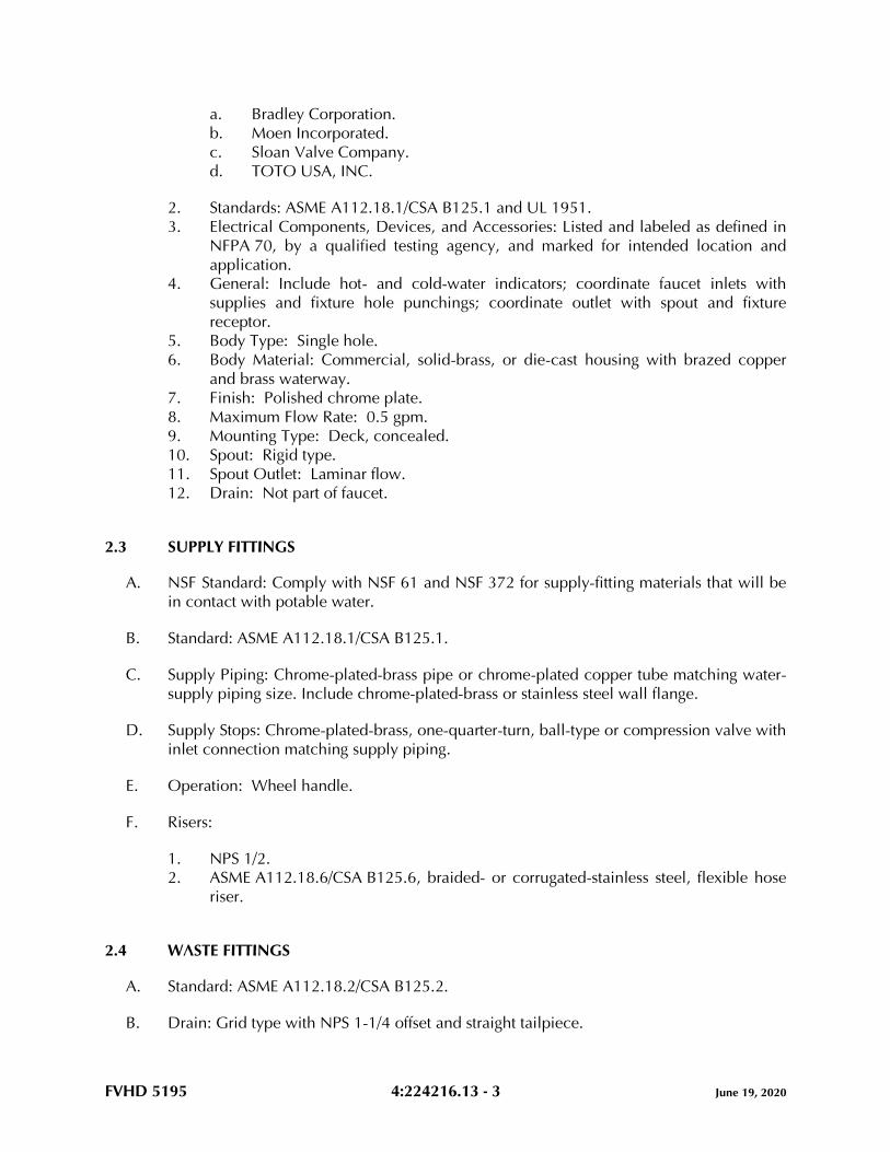
FVHD 5195 4:224216.13 - 3 June 19, 2020
a. Bradley Corporation.
b. Moen Incorporated.
c. Sloan Valve Company.
d. TOTO USA, INC.
2. Standards: ASME A112.18.1/CSA B125.1 and UL 1951.
3. Electrical Components, Devices, and Accessories: Listed and labeled as defined in
NFPA 70, by a qualified testing agency, and marked for intended location and
application.
4. General: Include hot- and cold-water indicators; coordinate faucet inlets with
supplies and fixture hole punchings; coordinate outlet with spout and fixture
receptor.
5. Body Type: Single hole.
6. Body Material: Commercial, solid-brass, or die-cast housing with brazed copper
and brass waterway.
7. Finish: Polished chrome plate.
8. Maximum Flow Rate: 0.5 gpm.
9. Mounting Type: Deck, concealed.
10. Spout: Rigid type.
11. Spout Outlet: Laminar flow.
12. Drain: Not part of faucet.
2.3 SUPPLY FITTINGS
A. NSF Standard: Comply with NSF 61 and NSF 372 for supply-fitting materials that will be
in contact with potable water.
B. Standard: ASME A112.18.1/CSA B125.1.
C. Supply Piping: Chrome-plated-brass pipe or chrome-plated copper tube matching water-
supply piping size. Include chrome-plated-brass or stainless steel wall flange.
D. Supply Stops: Chrome-plated-brass, one-quarter-turn, ball-type or compression valve with
inlet connection matching supply piping.
E. Operation: Wheel handle.
F. Risers:
1. NPS 1/2.
2. ASME A112.18.6/CSA B125.6, braided- or corrugated-stainless steel, flexible hose
riser.
2.4 WASTE FITTINGS
A. Standard: ASME A112.18.2/CSA B125.2.
B. Drain: Grid type with NPS 1-1/4 offset and straight tailpiece.
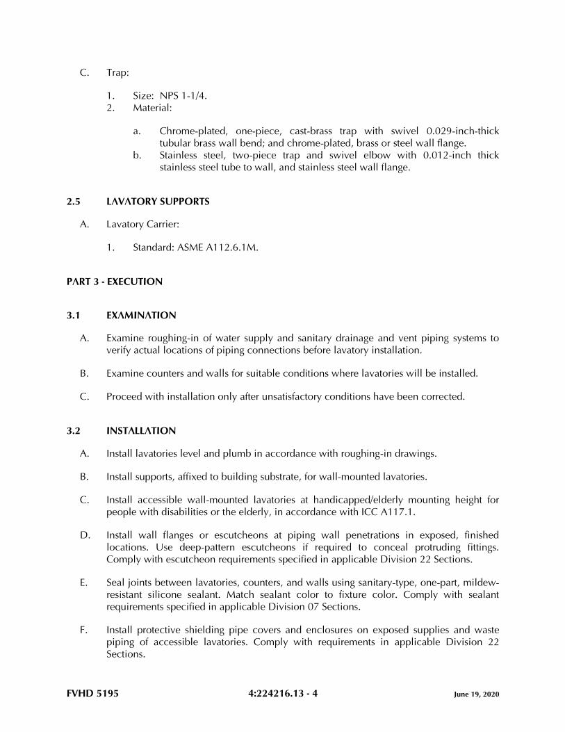
FVHD 5195 4:224216.13 - 4 June 19, 2020
C. Trap:
1. Size: NPS 1-1/4.
2. Material:
a. Chrome-plated, one-piece, cast-brass trap with swivel 0.029-inch-thick
tubular brass wall bend; and chrome-plated, brass or steel wall flange.
b. Stainless steel, two-piece trap and swivel elbow with 0.012-inch thick
stainless steel tube to wall, and stainless steel wall flange.
2.5 LAVATORY SUPPORTS
A. Lavatory Carrier:
1. Standard: ASME A112.6.1M.
PART 3 - EXECUTION
3.1 EXAMINATION
A. Examine roughing-in of water supply and sanitary drainage and vent piping systems to
verify actual locations of piping connections before lavatory installation.
B. Examine counters and walls for suitable conditions where lavatories will be installed.
C. Proceed with installation only after unsatisfactory conditions have been corrected.
3.2 INSTALLATION
A. Install lavatories level and plumb in accordance with roughing-in drawings.
B. Install supports, affixed to building substrate, for wall-mounted lavatories.
C. Install accessible wall-mounted lavatories at handicapped/elderly mounting height for
people with disabilities or the elderly, in accordance with ICC A117.1.
D. Install wall flanges or escutcheons at piping wall penetrations in exposed, finished
locations. Use deep-pattern escutcheons if required to conceal protruding fittings.
Comply with escutcheon requirements specified in applicable Division 22 Sections.
E. Seal joints between lavatories, counters, and walls using sanitary-type, one-part, mildew-
resistant silicone sealant. Match sealant color to fixture color. Comply with sealant
requirements specified in applicable Division 07 Sections.
F. Install protective shielding pipe covers and enclosures on exposed supplies and waste
piping of accessible lavatories. Comply with requirements in applicable Division 22
Sections.
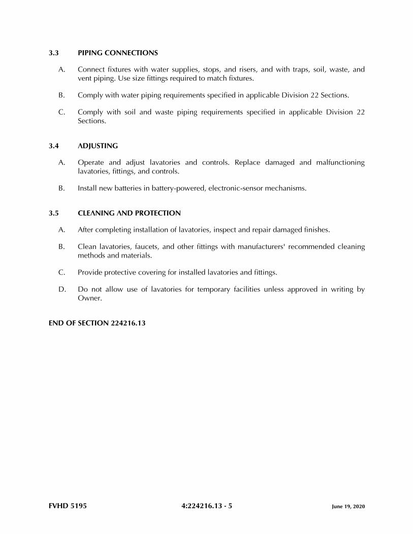
FVHD 5195 4:224216.13 - 5 June 19, 2020
3.3 PIPING CONNECTIONS
A. Connect fixtures with water supplies, stops, and risers, and with traps, soil, waste, and
vent piping. Use size fittings required to match fixtures.
B. Comply with water piping requirements specified in applicable Division 22 Sections.
C. Comply with soil and waste piping requirements specified in applicable Division 22
Sections.
3.4 ADJUSTING
A. Operate and adjust lavatories and controls. Replace damaged and malfunctioning
lavatories, fittings, and controls.
B. Install new batteries in battery-powered, electronic-sensor mechanisms.
3.5 CLEANING AND PROTECTION
A. After completing installation of lavatories, inspect and repair damaged finishes.
B. Clean lavatories, faucets, and other fittings with manufacturers' recommended cleaning
methods and materials.
C. Provide protective covering for installed lavatories and fittings.
D. Do not allow use of lavatories for temporary facilities unless approved in writing by
Owner.
END OF SECTION 224216.13
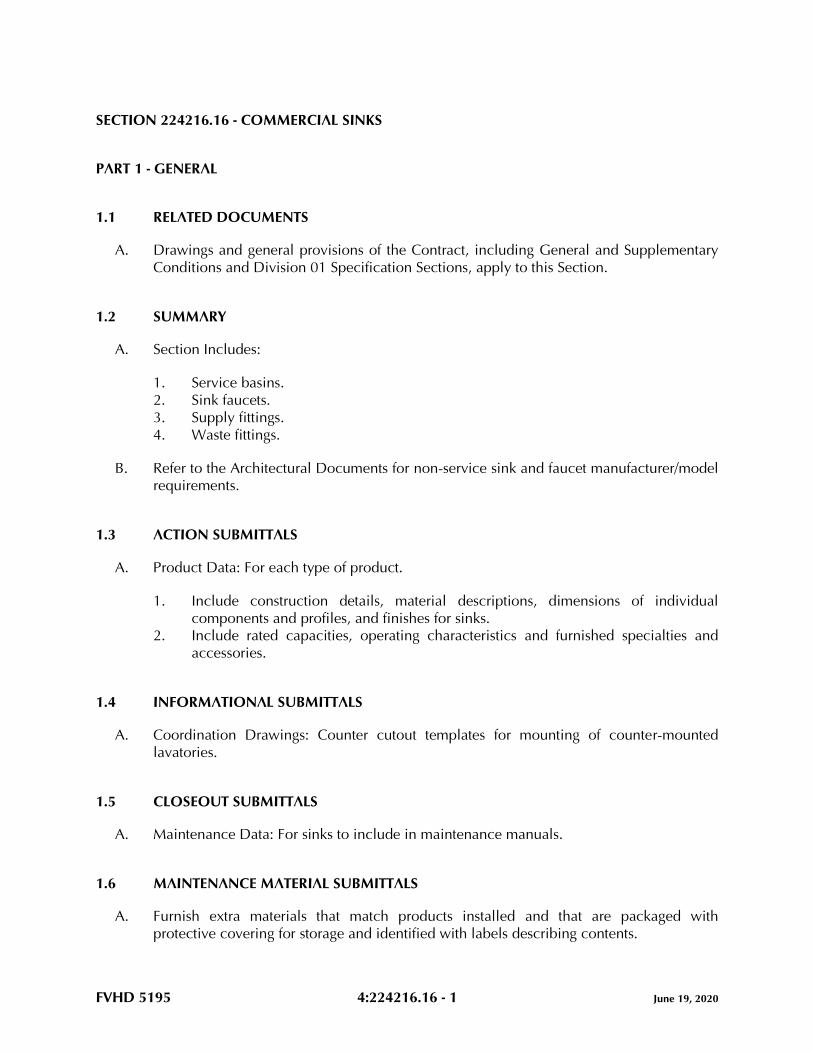
FVHD 5195 4:224216.16 - 1 June 19, 2020
SECTION 224216.16 - COMMERCIAL SINKS
PART 1 - GENERAL
1.1 RELATED DOCUMENTS
A. Drawings and general provisions of the Contract, including General and Supplementary
Conditions and Division 01 Specification Sections, apply to this Section.
1.2 SUMMARY
A. Section Includes:
1. Service basins.
2. Sink faucets.
3. Supply fittings.
4. Waste fittings.
B. Refer to the Architectural Documents for non-service sink and faucet manufacturer/model
requirements.
1.3 ACTION SUBMITTALS
A. Product Data: For each type of product.
1. Include construction details, material descriptions, dimensions of individual
components and profiles, and finishes for sinks.
2. Include rated capacities, operating characteristics and furnished specialties and
accessories.
1.4 INFORMATIONAL SUBMITTALS
A. Coordination Drawings: Counter cutout templates for mounting of counter-mounted
lavatories.
1.5 CLOSEOUT SUBMITTALS
A. Maintenance Data: For sinks to include in maintenance manuals.
1.6 MAINTENANCE MATERIAL SUBMITTALS
A. Furnish extra materials that match products installed and that are packaged with
protective covering for storage and identified with labels describing contents.
FVHD 5195 4:224216.16 - 2 June 19, 2020
1. Faucet Washers and O-Rings: Equal to 10 percent of amount of each type and size
installed.
2. Faucet Cartridges and O-Rings: Equal to 5 percent of amount of each type and size
installed.
PART 2 - PRODUCTS
2.1 SERVICE BASINS
A. Service Basins (MR-1): Terrazzo, floor mounted.
1. Basis-of-Design Product: Subject to compliance with requirements, provide product
indicated on Drawings or comparable product by one of the following:
a. Acorn Engineering Company; a Division of Morris Group International.
b. Fiat Products.
c. Florestone Products Co., Inc.
2. Fixture:
a. Standard: IAPMO PS 99.
b. Shape: Square.
c. Nominal Size: 24 by 24 inches.
d. Height: 6 inches.
e. Tiling Flange: On two sides.
f. Rim Guard: On all top surfaces.
g. Color: Not applicable.
h. Drain: Grid with NPS 3 outlet.
3. Mounting: On floor and flush to wall.
4. Faucet: MR-1 faucet.
2.2 SINK FAUCETS
A. NSF Standard: Comply with NSF 372 for faucet-spout materials that will be in contact
with potable water.
B. MR-1 Sink Faucets: Manual type, two lever handle mixing valve.
1. Commercial, Solid-Brass Faucets:
a. Basis-of-Design Product: Subject to compliance with requirements, provide
product indicated on Drawings or comparable product by one of the
following:
1) Chicago Faucets; Geberit Company.
2) Kohler Co.
3) Sloan Valve Company.
FVHD 5195 4:224216.16 - 3 June 19, 2020
4) T&S Brass and Bronze Works, Inc.
2. Standard: ASME A112.18.1/CSA B125.1.
3. General: Include hot- and cold-water indicators; coordinate faucet inlets with
supplies and fixture hole punchings; coordinate outlet with spout and sink receptor.
4. Body Material: Commercial, solid brass.
5. Finish: Polished chrome plate.
6. Maximum Flow Rate: 2.2 gpm.
7. Handle(s): Lever.
8. Mounting Type: Back/wall, exposed.
9. Spout Type: Rigid, solid brass with wall brace.
10. Vacuum Breaker: Required for hose outlet.
11. Spout Outlet: Hose thread according to ASME B1.20.7.
2.3 SUPPLY FITTINGS
A. NSF Standard: Comply with NSF 372 for supply-fitting materials that will be in contact
with potable water.
B. Standard: ASME A112.18.1/CSA B125.1.
C. Supply Piping: Chrome-plated brass pipe or chrome-plated copper tube matching water-
supply piping size. Include chrome-plated brass or stainless-steel wall flange.
D. Supply Stops: Chrome-plated brass, one-quarter-turn, ball-type or compression valve with
inlet connection matching supply piping.
E. Operation: Wheel handle.
F. Risers (for non-service sinks):
1. NPS 1/2.
2. ASME A112.18.6, braided or corrugated stainless-steel flexible hose.
2.4 WASTE FITTINGS
A. Standard: ASME A112.18.2/CSA B125.2.
B. Drain: Grid type with NPS 1-1/2 offset and straight tailpiece.
C. Trap:
1. Size: NPS 1-1/2.
2. Material: Chrome-plated, one-piece, cast-brass trap with swivel 0.029-inch-thick
tubular brass wall bend; and chrome-plated brass or steel wall flange.
FVHD 5195 4:224216.16 - 4 June 19, 2020
2.5 GROUT
A. Standard: ASTM C1107/C1107M, Grade B, post-hardening and volume-adjusting, dry,
hydraulic-cement grout.
B. Characteristics: Nonshrink; recommended for interior and exterior applications.
C. Design Mix: 5000-psi, 28-day compressive strength.
D. Packaging: Premixed and factory packaged.
PART 3 - EXECUTION
3.1 EXAMINATION
A. Examine roughing-in of water supply and sanitary drainage and vent piping systems to
verify actual locations of piping connections before sink installation.
B. Examine walls, floors, and counters for suitable conditions where sinks will be installed.
C. Proceed with installation only after unsatisfactory conditions have been corrected.
3.2 INSTALLATION
A. Install sinks level and plumb according to roughing-in drawings.
B. Install supports, affixed to building substrate, for wall-hung sinks.
C. Install accessible wall-mounted sinks at handicapped/elderly mounting height according
to ICC/ANSI A117.1.
D. Set floor-mounted sinks in leveling bed of cement grout.
E. Install water-supply piping with stop on each supply to each sink faucet.
1. Exception: Use ball or gate valves if supply stops are not specified with sink.
Comply with valve requirements specified in applicable Division 22 Sections.
2. Install stops in locations where they can be easily reached for operation.
F. Install wall flanges or escutcheons at piping wall penetrations in exposed, finished
locations. Use deep-pattern escutcheons if required to conceal protruding fittings.
Comply with escutcheon requirements specified in applicable Division 22 Sections.
G. Seal joints between sinks and counters, floors, and walls using sanitary-type, one-part,
mildew-resistant silicone sealant. Match sealant color to fixture color. Comply with
sealant requirements specified in applicable Division 07 Sections.
FVHD 5195 4:224216.16 - 5 June 19, 2020
3.3 CONNECTIONS
A. Connect sinks with water supplies, stops, and risers, and with traps, soil, waste, and vent
piping. Use size fittings required to match fixtures.
B. Comply with water piping requirements specified in applicable Division 22 Sections.
C. Comply with soil and waste piping requirements specified in applicable Division 22
Sections.
3.4 ADJUSTING
A. Operate and adjust sinks and controls. Replace damaged and malfunctioning sinks,
fittings, and controls.
B. Adjust water pressure at faucets to produce proper flow.
3.5 CLEANING AND PROTECTION
A. After completing installation of sinks, inspect and repair damaged finishes.
B. Clean sinks, faucets, and other fittings with manufacturers' recommended cleaning
methods and materials.
C. Provide protective covering for installed sinks and fittings.
D. Do not allow use of sinks for temporary facilities unless approved in writing by Owner.
END OF SECTION 224216.16

FVHD 5195 4:224716 - 1 June 19, 2020
SECTION 224716 - PRESSURE WATER COOLERS
PART 1 - GENERAL
1.1 RELATED DOCUMENTS
A. Drawings and general provisions of the Contract, including General and Supplementary
Conditions and Division 01 Specification Sections, apply to this Section.
1.2 SUMMARY
A. Section includes pressure water coolers and related components.
1.3 ACTION SUBMITTALS
A. Product Data: For each type of pressure water cooler.
1. Include construction details, material descriptions, dimensions of individual
components and profiles, and finishes.
2. Include rated capacities, operating characteristics, electrical characteristics, and
furnished specialties and accessories.
B. Shop Drawings: Include diagrams for power, signal, and control wiring.
1.4 CLOSEOUT SUBMITTALS
A. Maintenance Data: For pressure water coolers to include in maintenance manuals.
1.5 MAINTENANCE MATERIAL SUBMITTALS
A. Furnish extra materials that match products installed and that are packaged with
protective covering for storage and identified with labels describing contents.
1. Filter Cartridges: Equal to 5 percent of quantity installed for each type and size
indicated, but no fewer than 2 of each.
1.6 WARRANTY
A. Special Warranty: Manufacturer’s standard form in which manufacturer agrees to repair
or replace components of water cooler that fail in materials or workmanship within
specified warranty period
1. Failures include, but are not limited to, the following:
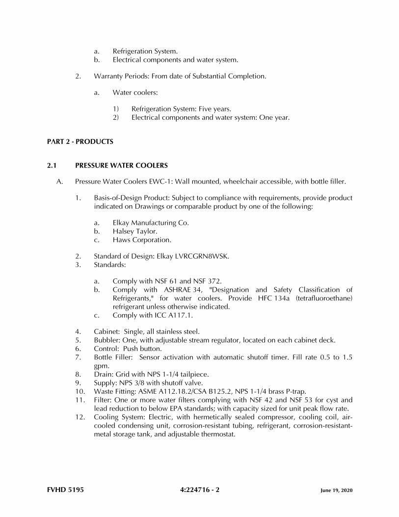
FVHD 5195 4:224716 - 2 June 19, 2020
a. Refrigeration System.
b. Electrical components and water system.
2. Warranty Periods: From date of Substantial Completion.
a. Water coolers:
1) Refrigeration System: Five years.
2) Electrical components and water system: One year.
PART 2 - PRODUCTS
2.1 PRESSURE WATER COOLERS
A. Pressure Water Coolers EWC-1: Wall mounted, wheelchair accessible, with bottle filler.
1. Basis-of-Design Product: Subject to compliance with requirements, provide product
indicated on Drawings or comparable product by one of the following:
a. Elkay Manufacturing Co.
b. Halsey Taylor.
c. Haws Corporation.
2. Standard of Design: Elkay LVRCGRN8WSK.
3. Standards:
a. Comply with NSF 61 and NSF 372.
b. Comply with ASHRAE 34, "Designation and Safety Classification of
Refrigerants," for water coolers. Provide HFC 134a (tetrafluoroethane)
refrigerant unless otherwise indicated.
c. Comply with ICC A117.1.
4. Cabinet: Single, all stainless steel.
5. Bubbler: One, with adjustable stream regulator, located on each cabinet deck.
6. Control: Push button.
7. Bottle Filler: Sensor activation with automatic shutoff timer. Fill rate 0.5 to 1.5
gpm.
8. Drain: Grid with NPS 1-1/4 tailpiece.
9. Supply: NPS 3/8 with shutoff valve.
10. Waste Fitting: ASME A112.18.2/CSA B125.2, NPS 1-1/4 brass P-trap.
11. Filter: One or more water filters complying with NSF 42 and NSF 53 for cyst and
lead reduction to below EPA standards; with capacity sized for unit peak flow rate.
12. Cooling System: Electric, with hermetically sealed compressor, cooling coil, air-
cooled condensing unit, corrosion-resistant tubing, refrigerant, corrosion-resistant-
metal storage tank, and adjustable thermostat.
FVHD 5195 4:224716 - 3 June 19, 2020
a. Electrical Components, Devices, and Accessories: Listed and labeled as
defined in NFPA 70, by a qualified testing agency, and marked for intended
location and application.
13. Capacities and Characteristics:
a. Cooled Water: 8 gph.
b. Ambient-Air Temperature: 90 deg F.
c. Inlet-Water Temperature: 80 deg F.
d. Cooled-Water Temperature: 50 deg F.
14. Support: Type I Water Cooler Carrier.
15. Water Cooler Mounting Height: Handicapped/elderly according to ICC A117.1.
2.2 SUPPORTS
A. Type I Water Cooler Carrier:
1. Manufacturers: Subject to compliance with requirements, provide products by one
of the following:
a. Jay R. Smith Mfg. Co.
b. Josam Company.
c. WATTS.
d. Zurn Industries, LLC.
2. Standard: ASME A112.6.1M.
PART 3 - EXECUTION
3.1 EXAMINATION
A. Examine roughing-in for water-supply and sanitary drainage and vent piping systems to
verify actual locations of piping connections before fixture installation.
B. Examine walls and floors for suitable conditions where fixtures will be installed.
C. Proceed with installation only after unsatisfactory conditions have been corrected.
3.2 INSTALLATION
A. Install fixtures level and plumb according to roughing-in drawings. For fixtures indicated
for children, install at height required by authorities having jurisdiction.
B. Install off-the-floor carrier supports, affixed to building substrate, for wall-mounted
fixtures.
FVHD 5195 4:224716 - 4 June 19, 2020
C. Install mounting frames, affixed to building construction, and attach recessed, pressure
water coolers, and in-wall bottle filling stations to mounting frames.
D. Install water-supply piping with shutoff valve on supply to each fixture to be connected to
domestic-water distribution piping. Use ball valve. Install valves in locations where they
can be easily reached for operation. Valves are specified in applicable Division 22
Sections.
E. Install trap and waste piping on drain outlet of each fixture to be connected to sanitary
drainage system.
F. Install wall flanges or escutcheons at piping wall penetrations in exposed, finished
locations. Use deep-pattern escutcheons where required to conceal protruding fittings.
Comply with escutcheon requirements specified in applicable Division 22 Sections.
G. Seal joints between fixtures and walls using sanitary-type, one-part, mildew-resistant,
silicone sealant. Match sealant color to fixture color. Comply with sealant requirements
specified in applicable Division 07 Sections.
3.3 CONNECTIONS
A. Connect fixtures with water supplies, stops, and risers, and with traps, soil, waste, and
vent piping. Use size fittings required to match fixtures.
B. Comply with water piping requirements specified in applicable Division 22 Sections.
C. Install ball shutoff valve on water supply to each fixture. Install valve upstream from filter
for water cooler. Comply with valve requirements specified in applicable Division 22
Sections.
D. Comply with soil and waste piping requirements specified in applicable Division 22
Sections.
3.4 ADJUSTING
A. Adjust fixture flow regulators for proper flow and stream height.
B. Adjust pressure water-cooler temperature settings.
3.5 CLEANING
A. After installing fixture, inspect unit. Remove paint splatters and other spots, dirt, and
debris. Repair damaged finish to match original finish.
B. Clean fixtures, on completion of installation, according to manufacturer's written
instructions.
C. Provide protective covering for installed fixtures.

FVHD 5195 4:224716 - 5 June 19, 2020
D. Do not allow use of fixtures for temporary facilities unless approved in writing by Owner.
END OF SECTION 224716

PART 5 - HVACR WORK
FVHD 5195 5:230010 - 1 June 19, 2020
SECTION 230010 - GENERAL REQUIREMENTS HVAC
PART 1 - GENERAL REQUIREMENTS HVAC
1.1 GENERAL 1.2 SCOPE AND OBJECTIVES OF THE HVAC WORK 1.3 INTENT OF THE HVAC CONTRACT DOCUMENTS 1.4 PROPOSAL PREPARATION 1.5 HAZARDOUS MATERIALS 1.6 DRAWINGS AND SPECIFICATIONS 1.7 LAWS, ORDINANCES, REGULATIONS AND PERMITS 1.8 CONNECTIONS TO UTILITIES 1.9 TESTS 1.10 CLEANING 1.11 INSTRUCTING OWNER'S PERSONNEL 1.12 OPERATING AND MAINTENANCE INSTRUCTIONS 1.13 GUARANTEE 1.14 ENTRANCE OF EQUIPMENT 1.15 VISIT TO SITE 1.16 REQUESTS FOR INFORMATION, RFI(s) 1.17 AS-BUILT DRAWINGS 1.18 SERVICING OF EQUIPMENT AND SYSTEMS 1.19 CONTINUITY OF SERVICES 1.20 CONTINUITY OF INTERIOR BUILDING SERVICE UTILITIES 1.21 TEMPORARY FACILITIES, UTILITIES AND HEATING 1.22 SMOKE AND FIRESTOPPING (GENERAL) 1.23 COORDINATION DRAWINGS 1.24 BREECHING, VENT, NATURAL GAS AND EXHAUST PIPING SUBMITTALS 1.25 TRADE CONTRACTOR'S CERTIFICATION
PART 2 - PRODUCTS
2.1 MANUFACTURER'S AND SUB-CONTRACTORS LIST, KEYMEN RESUMES 2.2 SUBMITTALS 2.3 MATERIALS AND EQUIPMENT 2.4 EQUIPMENT VARIATIONS AND SUBSTITUTIONS 2.5 VIBRATION ELIMINATION 2.6 NOISE CONTROL 2.7 INSERTS, HANGER SUPPORTS, CLAMPS, FASTENINGS 2.8 ACCESS DOORS AND PANELS 2.9 EQUIPMENT ANCHOR BOLTS 2.10 PIPING AND CONDUIT SLEEVES 2.11 SMOKE/FIRESTOPPING (MATERIALS) 2.12 FIRE/SMOKE DAMPERS, SMOKE DETECTORS/SMOKE DETECTOR CONTROL 2.13 COMPRESSORS 2.14 REFRIGERANT PIPING
PART 3 - EXECUTION
FVHD 5195 5:230010 - 2 June 19, 2020
3.1 METHOD OF PROCEDURE 3.2 PROTECTION OF WORK 3.3 CUTTING AND PATCHING 3.4 CONCRETE AND MASONRY 3.5 SUPPORTS 3.6 LINTELS 3.7 ESCUTCHEONS 3.8 MACHINERY GUARDS 3.9 ROOFING WORK 3.10 PAINTING AND FINISHING 3.11 LUBRICATION 3.12 HVAC TRADE - ELECTRICAL TRADE COORDINATION 3.13 ELECTRICAL MOTORS AND STARTERS 3.14 ELECTRICAL PROVISIONS FOR PACKAGED HVAC EQUIPMENT 3.15 PIPING, DUCTS AND CONDUIT UNDER FLOORS 3.16 PIPING AND EQUIPMENT IDENTIFICATION 3.17 ABANDONMENT, REMOVAL AND RELOCATION 3.18 SMOKE AND FIRESTOPPING (METHODS) 3.19 SUBSURFACE CONCEALED UNKNOWN PHYSICAL CONDITIONS 3.20 CONCRETE PATCHING (PROCEDURE) 3.21 TEMPORARY PARTITIONS 3.22 INITIAL APPLICATION FOR PAYMENT 3.23 FINAL APPLICATION FOR PAYMENT 3.24 INDEMNIFICATION 3.25 ADDITIONAL HVAC TRADE CONTRACTOR PAID FEES AND EXPENSES 3.26 FORMS
FVHD 5195 5:230010 - 3 June 19, 2020
PART 1 - GENERAL REQUIREMENTS HVAC
1.1 GENERAL
A. The conditions of Divisions 00 and 01 apply to each and every Trade Contractor or other
person or persons supplying any material or labor entering this building and/or site, either
directly or indirectly. In the event of a conflict between Section 230010 and Divisions 00
and 01, the terms of Divisions 00 and 01 shall govern.
B. One Building Trade, the Heating, Ventilating and Air Conditioning (HVAC) Building
Trade, will be covered by these General Requirements HVAC.
C. For simplicity, this Building Trade will be referred to further herein as the HVAC Trade
Contractor. The HVAC Specifications and all HVAC Drawings, together with all addenda
make-up the HVAC Contract Documents, and are a part of the “Project Contract
Documents”, as described throughout these specifications.
D. The term “Electrical Trade” as used in the Contract Documents, means the Electrical
Building Trade.
E. The term “indicated” means all information included, detailed, shown and/or implied on
the Contract Documents.
F. The term “existing” is used generally in reference to renovation projects. On new
construction projects, the term “existing” is intended to mean work already in place.
1.2 SCOPE AND OBJECTIVES OF THE HVAC WORK
A. The Scope and Objectives of the HVAC Work of this Project include, but are not limited
to:
1. Gas-fires boilers and associated piping;
2. Ductwork;
3. Piping;
4. Ductwork and piping insulation;
5. Automatic temperature controls;
6. Owner training;
7. Preparation of coordination drawings;
8. Preparation of as-built drawings in AutoCad format;
9. Periodic inspection of completed work to confirm compliance with Contract
Documents;
10. Refer to Division 01 Section “Summary” for additional information.
FVHD 5195 5:230010 - 4 June 19, 2020
1.3 INTENT OF THE HVAC CONTRACT DOCUMENTS
A. The intent of the HVAC Contract Documents is to include all items and labor necessary
for the proper execution and completion of the Work of the HVAC Trade Contractor.
The Contract Documents of all Trades are complimentary to each other; what is required
by one shall be as binding as if required by all. Performance of the HVAC Trade
Contractor is required only to the extent consistent with the Project Contract Documents
and reasonably inferable from them as being necessary to produce the desired results.
B. It is expressly stipulated that neither the Drawings nor the Specifications shall take
precedence over the other, and it is further stipulated that the Architect/Engineer may
interpret or construe the Drawings and Specifications so as to secure in all cases the
result most consistent with the needs and requirements of the work. In the event of such
ambiguity or discrepancy, comply with the higher cost product (material plus labor), the
more stringent requirement, and supply the better quality or greater quantity of work.
1.4 PROPOSAL PREPARATION
A. Prior to submitting a pricing quotation/proposal, proceed as follows, and include the
following:
1. Visit the site, survey, record, confirm and include in the scope of work, all material
and labor necessary to install the equipment and systems indicated. Use the
Contract Documents as diagrammatic in nature, since they are not intended to
show all details which may affect the HVAC bid proposal.
2. Include the work, as applicable, to remove and dispose of conduit, piping,
insulation, ductwork, equipment and appurtenances not required for new work,
unless otherwise indicated to be abandoned in place.
3. Include all disconnections, removals and temporary provisions required to permit
rigging, installation, connection, testing and operation of the new equipment.
Include all such provisions whether or not shown, detailed or specified within
technical sections of the Contract Documents.
4. Include in the work, providing the labor of Keymen, including, but not limited to
the following:
a. One Project Manager;
b. One Project Foreman;
c. Sheet Metal Sketcher.
1) It is recommended that the Sheet Metal Sketcher have a minimum of
10 years of applicable experience. Sheet Metal Sketcher shall prepare
all equipment arrangements and layout drawings, and initiate
coordination drawings.
5. Foreman must refine the detail, layout, coordination and fit of all of HVAC
equipment. Plan all disconnections, removals, offsets, temporary provisions, as
required, to fit the new equipment into the space, and as required to accommodate
maintenance accessibility and service access.
FVHD 5195 5:230010 - 5 June 19, 2020
6. Project Manager must maintain and submit for approval, a written project
schedule, on a weekly basis.
7. All Project Managers must organize, administrate, control and log the RFI process
for their respective trade. Where applicable, submit all RFI(s) for master RFI log
maintained by Lead/Prime Contractor.
B. In preparing a Bid Price:
1. Thoroughly review and confirm all existing conditions and Contract Document
information. Make note in writing of any exceptions, misunderstandings, unclear
areas, unclear directions, and any aspects which will prohibit completion of the
work, in total. Failing to supply such notice, all bidders will be accountable for
having accepted all conditions at the site which affect their work and their costs.
By submitting a bid price, all Trade Contractors certify that the Contract Documents
have been thoroughly reviewed and are sufficient for construction, and that the
bidding Trade Contractors have adequate information to establish and determine
their responsibility for materials, methods, costs, and schedule for their work.
2. Incorporate all requirements of all sections of the Contract Documents.
3. Include the following with the Manufacturer’s and Sub-Contractor’s Lists:
a. The name and telephone number of all Sub-Contractors.
b. The manufacturer and model numbers of all equipment proposed by the
bidder and as listed on all of the equipment schedules and specified in the
Contract Documents.
1.5 HAZARDOUS MATERIALS
A. The use of asbestos, PCB’s or any material or product containing hazardous materials in
the performance of this contract is not permitted. Certify, in writing, that no hazardous
material or product containing a hazardous material, has been furnished or installed.
1.6 DRAWINGS AND SPECIFICATIONS
A. It is the intent of the specifications and drawings to include under each item all materials,
apparatus and labor necessary to properly install, equip, adjust and put into perfect
operation the respective portions of the installations specified and to so interconnect the
various items or sections of the work as to form a complete and properly operating
whole.
B. Any apparatus, machinery, small items not mentioned in detail which are necessary to
complete or perfect any portion of the installation in a substantial manner and in
compliance with the requirements stated, implied or intended must be furnished and/or
installed without extra cost to the Project. This includes all materials, devices or methods
peculiar to the machinery, apparatus or systems furnished and/or installed by the HVAC
Trade Contractor.
C. In referring to drawings, figured dimensions take precedence over scale measurements.
Verify all wall locations, ceiling heights, elevations, dimensions, etc. on the architectural
FVHD 5195 5:230010 - 6 June 19, 2020
drawings, where applicable. Discrepancies must be referred to the Engineer for decision.
Certify and verify all dimensions, routings and layouts in the field and on the
coordination drawings before ordering material or commencing work.
D. Any work called for in the specifications, but not mentioned or shown on the drawings,
or called for on the drawings, but not mentioned in the specifications, must be furnished
and/or installed as though called for in both.
E. When any device or part of equipment is herein referred to in the singular number, such
as "the pump" such reference is deemed to apply to as many such devices as required to
complete the installation.
F. The term "Provide" means "Furnish and Install". Neither term will be used generally in
these specifications, but will be assumed. The term "Furnish" means to obtain and deliver
to the job site for installation by other trades.
1.7 LAWS, ORDINANCES, REGULATIONS AND PERMITS
A. The entire HVAC system in all and/or in part must conform to all pertinent laws,
ordinances and regulations of all bodies having jurisdiction, notwithstanding anything in
these drawings or specifications to the contrary.
B. Pay all fees and obtain and pay for all permits and inspections required by any authority
having jurisdiction in connection with the work under this contract.
C. Electrical work performed by the HVAC Trade Contractor must comply with the
requirements of the National Electrical Code, NFPA and other boards and departments
having local jurisdiction. Obtain and pay for an Independent Inspection by an authorized
Electrical Inspection Agency (EIA) and by local, municipal and state approving agencies.
Inspections performed by the local inspector do not substitute for obtaining Independent
Inspection by an authorized independent Electrical Inspection Agency.
1. Qualifications: The EIA is to be an independent company from the HVAC Trade
Contractor, registered with the State and a Master certified member of the
International Association of Electrical Inspectors.
2. Prepare and submit for review and comment to the Engineer a schedule of
inspections to be performed in coordination with the construction schedule.
3. At a minimum, inspections shall be performed at the Rough-in, Progress and Final
levels.
4. The EIA shall submit written report for each level of inspection to the Engineer to
document compliance with current code requirements, including deficiencies and
associated required remedial action.
1.8 CONNECTIONS TO UTILITIES
A. Apply for and obtain services from Utility Companies and municipalities. All charges for
which Utility Companies and municipalities must be reimbursed must be paid for by the
HVAC Trade Contractor at no additional cost to the Project.

FVHD 5195 5:230010 - 7 June 19, 2020
1.9 TESTS
A. The following requirements are supplementary to tests specified for individual equipment
or systems in other specification sections. Give written notice of date of test in ample
time to all concerned.
B. Concealed or insulated work must remain uncovered until all required tests have been
completed; but if construction schedule requires, arrange for partial tests on portions of
systems as approved. If a Prime Contractor covers or directs a Sub-Contractor to cover
HVAC work prior to completing the required tests, the Prime Contractor is responsible for
any additional costs related to completing the required tests.
C. As soon as conditions permit, conduct preliminary tests of equipment to ascertain
compliance with specified requirements. Make needed changes, adjustments and/or
replacements as preliminary tests may indicate, prior to acceptance tests.
D. Conduct pressure, performance and operating tests as specified or required for each
system or piece of equipment installed, modified or affected under this contract in
presence of the Engineer or Owner as well as a representative of agencies having
jurisdiction.
E. Obtain Certificates of Approval and/or Acceptance as specified or required in compliance
with regulations of agencies having jurisdiction. Work will not be deemed complete
until such Certificates have been delivered to the Engineer.
F. Prove conclusively, by testing, that HVAC systems operate properly, efficiently and
quietly in accordance with intent of drawings, specifications and most widely used
construction practices.
1.10 CLEANING
A. Be responsible for the following:
1. Removal of all lumber, refuse, metal, piping and debris from site resulting from
HVAC work.
2. Cleaning drippings created by the HVAC work, from finished work of other Trades.
3. Cleaning, polishing, waxing of HVAC work as required.
B. After testing, and acceptance of all work by the Engineer and the Owner, thoroughly
clean all HVAC equipment and material to the satisfaction of the Engineer.
1.11 INSTRUCTING OWNER'S PERSONNEL
A. After all tests and adjustments have been made, fully instruct the representatives of the
Owner in all details of operation of the equipment installed under the HVAC Contract
Documents.
FVHD 5195 5:230010 - 8 June 19, 2020
B. Operate HVAC equipment for sufficient length of time to satisfy Engineer that
requirements of Contract Documents have been fulfilled.
C. Prepare digital recording of each Owner training session on USB thumb Drive.
1.12 OPERATING AND MAINTENANCE INSTRUCTIONS
A. Provide in accordance with Division 01.
B. Submit digital format PDF of Operating and Maintenance Instructions to the Engineer for
review and processing.
C. Upon completion of the Engineer’s review and processing of digital format PDF of the
Operating and Maintenance Instructions, submit three (3) copies of the final version of
the printed instructions to the Owner. Bind instructions in separate, hardback, 3-ring
loose leaf binders.
D. Prepare instruction books by sections and include detailed Operating and Maintenance
Instructions for all components of all systems, including wiring, and piping diagrams
necessary for clarity. Identify the covers with the name of the project and the words
"Operating and Maintenance Instructions - HVAC".
E. Each section must have labeled tabs and be clearly marked with equipment or system
name and contain detailed parts list data, ordering information therefore and the name,
address and telephone number of the closest supply source.
F. All instructional data must be neatly and completely prepared to the satisfaction of the
Engineer.
G. Provide complete copy of all warranties in separate tab with the binder.
H. Provide copies of the as-built drawings in the manuals. (As-built drawings to be submitted
for review prior to O&M Submission).
I. Provide copy of each submittal for each piece of equipment on the project, complete
with all tag numbers, Contractor’s Transmittal Cover Sheet and Engineer’s final Submittal
Review Sheet.
J. Provide USB Drive of Owner training sessions with the manuals.
K. Provide complete copy of the final HVAC Testing, Adjusting and Balancing Report.
(HVAC Testing, Adjusting, and Balancing Report to be submitted for review prior to O&M
Submission).
L. Provide complete copy of the HVAC System Commissioning Report, if applicable.
M. Provide complete copy of the final Automatic Temperature Control (ATC) System
Commissioning Report, if applicable.
FVHD 5195 5:230010 - 9 June 19, 2020
N. All listed items are to be included in the O&M submission for the Engineer’s review.
Partial submissions are NOT acceptable.
1.13 GUARANTEE
A. All material, equipment and workmanship must be in first class operating condition in
every respect at time of acceptance by Owner. Acceptance by the Owner will be by
letter written to the HVAC Trade Contractor.
B. Unconditionally guarantee in writing all materials, equipment and workmanship for a
period of one (1) year from date of acceptance by Owner. During the guarantee period,
repair or replace, at the HVAC Trade Contractor’s expense, any materials, equipment or
workmanship in which defects may develop and provide free service for all equipment
and systems involved in the contract during this guarantee period. Beneficial use of any
system by any of the Trade Contractors during construction does not constitute
acceptance by the Owner. Time period of this beneficial use cannot be included in the
guarantee period.
C. Guarantee must also include restoration to its original condition of all adjacent work that
is disturbed in fulfilling this guarantee.
D. All such repairs and/or replacements must be made without delay and at the convenience
of the Owner.
E. Guarantees furnished by Trade Contractors and/or equipment manufacturers must be
counter-signed by the related Trade Contractor for joint and/or individual responsibility
for subject item.
F. Manufacturers’ equipment guarantees or warranties extending beyond the guarantee
period described in item B above must be transferred to the Owner along with the Trade
Contractor's guarantees.
1.14 ENTRANCE OF EQUIPMENT
A. Determine the method of equipment entrance during initial site visit prior to bidding. Do
not scale building openings, door widths and equipment or component sizes off the
drawings. Determine sizes from site measurements and equipment manufacturer.
Include cost of equipment manufacturer's knockdown, use of field assembled equipment,
field assembly, all work required for access, removals, replacements, general
construction, and the like, as required. During preparation of submittals, verify whether
knocked-down or pre-disassembled equipment have been proposed all to the extent
required to permit entry of equipment to final location. Verify that the use of field
assembled (not pre-assembled) equipment complies with manufacturer’s warranty,
guarantee, listings and requirements.
B. Perform all necessary rigging required for completion of HVAC work.
FVHD 5195 5:230010 - 10 June 19, 2020
C. Deliver products to the site properly identified with names, model numbers, types,
grades, compliance labels and other information needed for identification. Deliver
products and equipment to the site properly weatherproofed.
D. The Trade Contractor who furnishes or purchases the product or equipment is responsible
to provide and maintain protection from the weather, dust, dirt, construction debris, etc.
until the project is complete.
E. For all products and equipment which, when installed, have an opening into the building
must be provided with a plywood cover, or similar protection, to prevent debris, rain, etc.
from entering the building. The Trade Contractor who installs the product or equipment
is responsible for such protection beginning at the time of installation.
1.15 VISIT TO SITE
A. Due to the nature of the work involved under these Contract Documents, all bidders are
recommended to thoroughly examine the site. Coordinate and schedule all site visits
with the Owner.
B. Thoroughly review Contract Documents prior to visiting the site, take Contract
Documents to site and thoroughly explore to any extent necessary, the existing
conditions as relating to fulfilling the requirements of these Contract Documents.
C. If discrepancies are noted between requirements of Contract Documents and existing
conditions, Trade Contractors must so indicate to Engineer during bidding period and
receive clarification before bidding. Failure to comply with this requirement will result in
Engineer's interpretation during the construction period such that the Engineer's decision
will be final and binding as the sole interpreter of the contract requirements.
D. Extras will not be considered for any work relating to connections with existing systems
or adaptability of new systems to existing structures.
E. Submission of proposals will be considered evidence that Trade Contractors have
complied with the requirements of this Article.
1.16 REQUESTS FOR INFORMATION, RFI(s)
A. Manage RFI(s) in a formal manner. Preparation and submission must comply with the
process specified herein to be of maximum benefit to the project. RFI(s) which do not
comply with this process will be returned without comment.
B. All RFI(s):
1. Must be submitted in written form to the party designated at the construction phase
kick-off meeting;
2. Must be consecutively numbered, dated, and logged as directed, during the kick-off
meeting;
FVHD 5195 5:230010 - 11 June 19, 2020
3. Those which are follow-up RFI(s), must use the same RFI number, with a sequential
submission number;
4. Must list the RFI number of any reference RFI(s) used in the narrative;
5. Must present: background; related drawings; specification articles; room, space
locations (as designated on Contract Documents including wing, column line
designation, floor designation, and/or north, south, and the like), and must be
presented as complete, clearly written thoughts, in legibly printed or typed form;
6. Must be completed by the HVAC Trade Contractor’s Designated Project Foreman,
under the control and overview of the HVAC Trade Contractor’s Project Manager;
7. Must include HVAC Trade Contractor’s Project Foreman’s suggested resolution to
RFI;
8. Must evidence a high level of fluency with the Contract Documents, all job
progress correspondence, all Addenda, all Construction Bulletins, and specifically
the Mechanical/Electrical Specifications including: Section 230010; the sections of
Division 21; Division 22; Division 23; Division 26; Division 27; Division 28; and
special system and equipment divisions of the specification Divisions 02 thru 33
inclusive.
C. The HVAC Trade Contractor’s designated Project Manager must demonstrate familiarity
with and responsibility for all RFI(s) prepared by the Project Foreman and must
periodically submit an initialed log of RFI(s) signifying control of RFI(s) relating to
specification and job scope issues.
D. Issues relating to job scope, work included, methods and means which are either clearly
discernable from the Contract Documents and/or clearly the responsibility of the HVAC
Trade Contractor must be answered by the HVAC Trade Contractor’s Project Manager
and resolved between the Foreman and Project Manager prior to resorting to written
RFI(s). The work of the Project Manager must evidence: fluency with the methods and
means anticipated by the HVAC Trade Contractor during the bid phase to plan and
complete the work; fluency with the Contract Documents, and all administrative issues
related thereto.
E. Items or issues which relate to non-compliance to associated codes or regulations must
reference code interpretations or the published adopted code or regulation. The
reference must be either an excerpt of the code or regulation, published addenda to the
code or regulation, a formal interpretation written by a representative of the associated
agency, or letter of non-compliance from the Authority Having Jurisdiction. All cited
code requirements must include the applicable code title, code version or date, and code
section number designation. If the RFI does not contain the required information, the RFI
will be returned without comment.
1.17 AS-BUILT DRAWINGS
A. Prepare reproducible (paper) and electronic (cd) record documents in AUTOCAD .dwg
format (Version 2000 or later) in accordance with the requirements in Division 01. Use
commercial CAD drafting service if HVAC Trade Contractor does not have CAD
capabilities in-house. As an option, if requested by the HVAC Trade Contractor, an
electronic copy (AutoCad .dwg format) of any of the Division 23 Contract Drawings may
be provided by the Engineer at a cost of $55.00, billable to the requesting Contractor. In

FVHD 5195 5:230010 - 12 June 19, 2020
addition to the requirements specified in Division 01, indicate the following installed
conditions:
1. Ductwork mains and branches, gas and oil fired equipment vents, boiler breeching,
size and location, for both exterior and interior; locations of dampers and other
control devices; filters, boxes and terminal units requiring periodic maintenance or
repair.
2. Mains and branches of piping systems, with valves and control devices located and
numbered, concealed unions located, and with items requiring maintenance
located (i.e., traps, strainers, expansion compensators, tanks, and the like). Valve
location diagrams, complete with valve tag chart. Indicate actual inverts and
horizontal locations of underground piping, and the like.
3. Equipment locations (exposed and concealed), dimensioned from prominent
building lines and annotated with permanent equipment number approved by
Owner. Include code and equipment service clearances.
4. Approved substitutions, Addenda and Bulletin Contract Modifications, and actual
equipment and materials installed.
B. Engage the services of a Land Surveyor or Professional Engineer registered in the state in
which the project is located, as specified in Division 01, to record the locations and
invert elevations of the underground HVAC work.
1.18 SERVICING OF EQUIPMENT AND SYSTEMS
A. After work has been completed in accordance with the Contract Documents, and prior to
final acceptance tests, each Trade Contractor must have manufacturers or their
authorized agents of the equipment installed, completely check their equipment and put
equipment into proper operation. In each case, the respective Trade Contractor must
have the manufacturers thoroughly check the complete installation of the equipment,
furnished by the manufacturer, for proper and correct operation under the service
intended.
B. Six months after final acceptance of the work under the Contract Documents, each of the
Trade Contractors must have the manufacturers again check their equipment for proper
operation and lubrication. Coincidentally, these Trade Contractors must assure that the
Owner is properly instructed in the servicing of the equipment.
C. Prior to expiration of the guarantee period, each Trade Contractor must check all
equipment, materials and systems for which he is responsible, make necessary
adjustments and/or replacements, and leave systems in first class operating condition.
1.19 CONTINUITY OF SERVICES
A. Generally, no actions can be taken by the HVAC Trade Contractor that will interrupt any
of the existing building services for these buildings or any other building until previously
arranged and scheduled with the Engineer and Owner.
FVHD 5195 5:230010 - 13 June 19, 2020
B. Should any service be interrupted by the HVAC Trade Contractor, immediately provide
all labor, including overtime if necessary, and all material and equipment necessary for
restoration of such service, at no additional cost to the Project.
1.20 CONTINUITY OF INTERIOR BUILDING SERVICE UTILITIES
A. For the purposes of this specification section, “Building Service Utilities” include, but are
not limited to:
1. Exterior: electrical; domestic water; fire protection water; sanitary; storm; chilled
water; space heating water; fuel lines; communication cable; fire alarm; remote
metering lines; telemetry lines; and the like;
2. Heating piping systems, complete;
3. Chilled water piping systems, complete;
4. Heating and process steam/condensate systems, complete;
5. Ductwork systems, complete;
6. Medical gas systems, complete;
7. Fire protection systems, complete;
8. Plumbing, drainage and storm systems, complete;
9. Process piping systems, complete;
10. Electrical conduit and wiring systems, complete;
11. Electrical lighting and wiring devices, complete;
12. Electrical fire alarm and security systems, complete;
13. Electrical communication systems, complete.
B. Building Service Utilities are defined for the purposes of this project, and as used in these
specifications as:
1. TYPE A Utility System Services. New Internal Building Services, serving: new
and/or modified system functions; new and/or modified equipment;
2. TYPE B Utility System Services. Existing Internal Building Services serving:
unmodified systems; unmodified equipment; building spaces for which mechanical
and electrical systems, and internal operational equipment have not been modified
by this project;
3. TYPE C Utility System Services. Existing Utility Systems Building Services, external
to the individual building, or buildings, addressed by the work of this project;
4. TYPE D Utility System Services. New Utility Systems Building Services, external to
the individual building, or buildings, addressed by the Work of this project.
C. Plan work and schedule to prevent interruption of TYPE B, and/or TYPE C Utility System
Services. Refer to the “Scope and Objectives of the HVAC Work,” of this Section for a
description of: unmodified systems, unmodified equipment; spaces wherein mechanical
and electrical systems are unmodified; and Utility System Services external to the
individual building or buildings addressed by the work of this project.
D. Plan work and schedule installation and connections of TYPE A and TYPE D Utilities to
minimize or prevent interruption of TYPE B, and or TYPE C Utility System Services. Refer
to “General Requirements HVAC,” Article “Scope and Objectives of the HVAC Work.”
FVHD 5195 5:230010 - 14 June 19, 2020
E. The work required for continuity of these systems on this project includes, but is not
limited to, providing all labor and material required for: site investigation/verification;
disconnect; removal; rerouting; reconnection; as-built drawing documentation; testing
and check out of mechanical and electrical services serving equipment which are
implied to be, or specifically indicated to be, continued in operation.
F. All materials required for relocation work must comply with these specifications.
Carefully review all phasing drawings, all Construction Trade drawings, and complete all
necessary and prudent site visits to become familiar with all existing building operations,
systems and equipment which may be continued, independent of the work of this
project, and include all required relocation work described in this section.
1.21 TEMPORARY FACILITIES, UTILITIES AND HEATING
A. Refer to Division 01 of these specifications.
1.22 SMOKE AND FIRESTOPPING (GENERAL)
A. Furnish and install a material or a combination of materials to form an effective barrier
against the spread of flame, smoke and gases, and to maintain the integrity of the “fire
and/or smoke” rated construction. Refer to Division 07 of these specifications. Fire and
smoke rated construction is identified on the Architectural Drawings. Provide
firestopping in the following locations:
1. Pipe, ductwork and conduit penetrations through above grade floor slabs and
through “fire and/or smoke”-rated partitions and fire walls.
2. Penetrations of vertical shafts including, but not limited to pipe chases, duct chases,
elevator shafts, and utility chutes.
3. Other locations where indicated or required.
B. Prepare submittals and submit for approval. Include manufacturer's descriptive data,
typical details, installation instructions and the fire/smoke test data and/or report as
appropriate for the time rated construction and location. The fire/smoke test data must
include a certification by a nationally recognized testing authority that the material has
been tested in accordance with ASTM E 814, or UL 1479 fire tests.
C. Deliver materials in the original unopened packages or containers showing name of the
manufacturer and the brand name. Store materials off the ground, and protect from
damage and exposure to elements. Damaged, deteriorated or outdated shelf life
materials shall not be used and must be removed from the site.
1.23 COORDINATION DRAWINGS
A. The HVAC Trade Contractor must initiate preparation of coordination drawings, control
original reproducibles, collect, organize and facilitate the work/input of General
Construction Trade Contractor and all other building trades, as applicable, relative to the
100% final submission of the coordination drawings. Prepare coordination drawings in
FVHD 5195 5:230010 - 15 June 19, 2020
accordance with Division 01, to a scale of 1/4"=1'-0" or larger; detailing major elements,
components, and systems of equipment and materials in relationship with other systems,
installations, and building components. Use proposed equipment submittals, which
include certified dimensions, service clearances, etc., to prepare the coordination
drawings. If equipment is submitted for review after completion of the coordination
drawings and rejected during the submittal review process, because the equipment fails
to meet the project specifications, the HVAC Trade Contractor is responsible to revise the
coordination drawings and layout the work using equipment which meets the project
specifications. Designate all specified return air plenums, locations where space is
limited for installation and access and where sequencing and coordination of installations
are of importance to the efficient flow of the Work, including (but not necessarily limited
to) the following:
1. Indicate the proposed locations of piping, ductwork, equipment, and materials.
Include the following:
a. Clearances for installing and maintaining insulation.
b. Clearances for servicing and maintaining equipment, including tube removal,
filter removal, and space for equipment disassembly required for periodic
maintenance.
c. Equipment connections and support details.
d. Exterior wall and foundation penetrations.
e. Fire-rated wall and floor penetrations.
f. Sizes and location of required concrete pads and bases.
g. Valve stem movement.
h. Service clearance for equipment behind access doors.
i. Location of structural columns, beams and supports.
2. Indicate scheduling, sequencing, movement, and positioning of large equipment
into the building during construction.
3. Prepare floor plans, elevations, and details to indicate penetrations in floors, walls
and ceilings and their relationship to other penetrations and installations.
4. Prepare reflected ceiling plans to coordinate and integrate installation of air outlets
and inlets, light fixtures, communication systems components, sprinklers, and other
ceiling mounted items.
5. The foregoing information and coordination work must be provided by the
applicable Trade Contractor using the coordination drawings as initiated by the
HVAC Trade Contractor.
6. The HVAC Trade Contractor must submit completed coordination drawings for
record purposes, not for technical review and approval, but as proof that the
coordination drawings have been completed. The coordination drawings must be
completed and submitted for record in advance of submission of sheet metal shop
drawings.
1.24 BREECHING, VENT, NATURAL GAS AND EXHAUST PIPING SUBMITTALS
A. Sizes specified for materials such as gas vents, natural gas piping, breeching, and
emergency generator exhaust piping are included in the Contract Documents and
intended for bidding purposes as applicable to each Trade Contractor. Actual sizes
FVHD 5195 5:230010 - 16 June 19, 2020
required for approved system performance depend on the actual length of runs, routing,
bends, offsets, fittings and elbows, planned by the HVAC Trade Contractor during the
layout of the HVAC work and must account for existing/new field conditions.
B. Submit product data and shop drawings, as applicable to each Trade Contractor, for the
following; vent piping, gas piping, breeching, emergency generator coolant piping, and
exhaust piping. Submittals shall indicate all aspects of the work layout including:
materials; length; routing; bends; offsets; fittings; mufflers; elbows; and compliance with
equipment manufacturer’s directions (specifications, limitations, sizing tables, etc.
required to meet such specifications). Attach copies of manufacturer’s specifications and
performance tables to required equipment submittals.
C. Processing of vent, gas, breeching and emergency generator piping submittals and piping
layout shop drawings will be handled in a manner identical to sheet metal shop drawings
(conformance to SMACNA recommendations for example) which requires the HVAC
Trade Contractor to conform to accepted standards relative to sizing, pressure drop limits,
manufacturer’s recommendations, NFPA, and Fuel Gas Code.
D. Submit Manufacturer’s or Trade Contractor’s confirming calculations of pressure drops,
and/or sizing resulting from all of the variables controlled by the HVAC Trade Contractor
during layout of the HVAC work for review by the Engineer as part of the submittal
review process.
1.25 TRADE CONTRACTOR'S CERTIFICATION
A. Upon final completion of all work, each Trade Contractor must provide a notarized letter
on Corporate letterhead, executed by a Corporate Officer, or Company Partner, stating
that the work has been completed in accordance with the Contract Documents,
Addenda, Bulletins, Trade Contractor’s Punch List items and Architect’s/Engineer’s
Construction Observation Report(s). Final Payment will not be approved until the
notarized letter has been provided. Refer to the following sample letter.
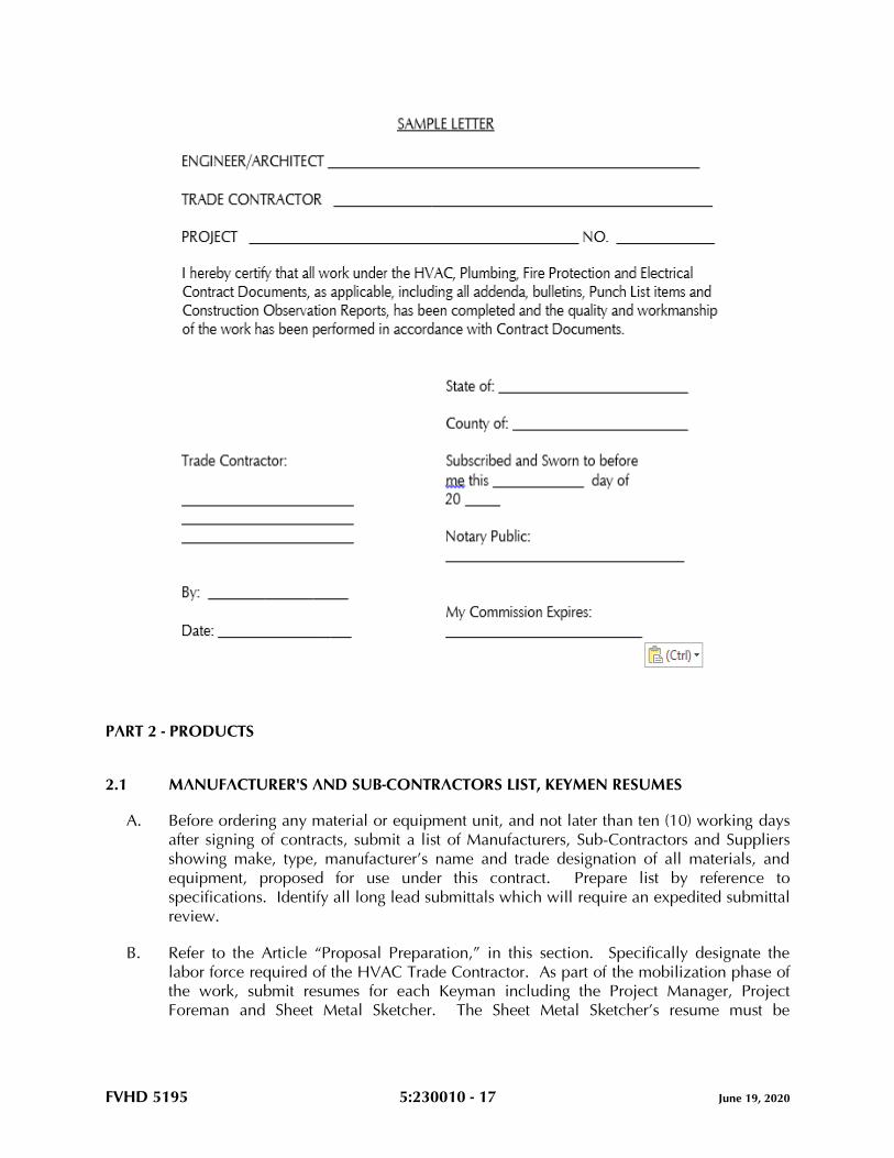
FVHD 5195 5:230010 - 17 June 19, 2020
PART 2 - PRODUCTS
2.1 MANUFACTURER'S AND SUB-CONTRACTORS LIST, KEYMEN RESUMES
A. Before ordering any material or equipment unit, and not later than ten (10) working days
after signing of contracts, submit a list of Manufacturers, Sub-Contractors and Suppliers
showing make, type, manufacturer’s name and trade designation of all materials, and
equipment, proposed for use under this contract. Prepare list by reference to
specifications. Identify all long lead submittals which will require an expedited submittal
review.
B. Refer to the Article “Proposal Preparation,” in this section. Specifically designate the
labor force required of the HVAC Trade Contractor. As part of the mobilization phase of
the work, submit resumes for each Keyman including the Project Manager, Project
Foreman and Sheet Metal Sketcher. The Sheet Metal Sketcher’s resume must be
FVHD 5195 5:230010 - 18 June 19, 2020
submitted and approved by the engineer prior to the preparation of sheet metal shop
drawings.
C. These lists, when approved, will be supplementary to specifications, and no variations
therefrom will be permitted except with the approval of the Engineer.
D. Prepare the list using the “PROPOSED MANUFACTURERS AND SUB-CONTRACTORS
LIST” located at the end of this section.
E. Submittals will not be processed until the requirements of this Article are satisfactorily
completed.
2.2 SUBMITTALS
A. Provide digital submissions (.pdf format) for all material and equipment as noted in
Proposed Manufacturer's and Sub-Contractors List, except where indicated otherwise
herein.
1. Prior to submission of product data, shop drawings, and samples, notify the
Engineer/Architect of any site conditions differing from those indicated or specified.
2. Prior to submission of product data, shop drawings and samples to the design
professional, the HVAC Trade Contractor shall submit all submittals which require
electrical power to the Project Electrical Trade Contractor for the HVAC Trade
Contractor’s and the Electrical Trade Contractor’s coordination and review.
Electrical Trade Contractor shall provide approval of electrical power requirements
for the HVAC Trade Contractor’s proposed equipment.
3. All submittals of equipment requiring electrical power must be accompanied by the
“HVAC AND ELECTRICAL CONTRACTORS’ COORDINATION OF HVAC
EQUIPMENT ELECTRICAL REQUIREMENTS TRANSMITTAL COVER SHEET”
located at the end of this section. Submittals without this Cover Sheet or an
incomplete Cover Sheet will be rejected without review.
4. All submittals must be accompanied by the “HVAC CONTRACTOR’S
TRANSMITTAL COVER SHEET” located at the end of this section. Submittals
without this cover sheet or with an incomplete cover sheet, will be rejected without
review.
5. All submittals must be accompanied by the “HVAC SUBMITTAL LOG”, located at
the end of this section. Submit log after final acceptance of the proposed
Manufacturer’s and Sub-Contractor’s list. Revise and update the log with each
submittal. Submittals without these logs or without an updated log will be rejected
without review.
6. Specifically annotate and sign all exceptions, deletions and additions that vary from
the Project Contract Documents. Failing to provide signed annotations for all
deletions and additions, recognize and accept that Contract Documents will
govern, and will be used to resolve disputes.
B. Prepare submittals by careful reference to: drawings and specifications; preparatory
layout of all work; coordination with all proposed equipment; coordination with related
submittals and the work of all other Trade Contractors; space requirements; and TYPE A,
TYPE B, TYPE C, and TYPE D Utilities defined in this Section. A review of such
FVHD 5195 5:230010 - 19 June 19, 2020
submittals by the Engineer/Architect, which include drawings, schedules, and catalog
cuts provided by the Trade Contractors, their Sub-Contractors, manufacturers, and
vendors, shall not relieve the Trade Contractors from the responsibility for correcting all
errors of any sort in the submittals, either identified or undetected by such review.
C. Regularly provide and update submittal log sheets listing submittal number, product,
applicable specification section, dates of submittal and receipt and status. Identify each
submittal by Job Name, log number and reference to applicable Specification Article
number.
D. All equipment submittals must include, but not be limited to, the following:
1. Manufacturers' catalog designation, photographs and specifications.
2. Full electrical data, including specifically, electrical characteristics.
3. Full General Construction data, including operating weights, dimensional data
including service access space. Data shall be given to the General Construction
Trade Contractor, where applicable, for use in setting steel, supports, and
attachments.
4. Full wiring diagrams, including clearly identified power connections and control
connections. Data and diagrams shall be given to the Electrical Trade Contractor
and Automatic Temperature Control (ATC) Trade Sub-Contractor for their use and
inclusion into their submittals.
5. Listing of specific HVAC performance, calculations and data.
6. Dimensions, capacities, ratings, material and finish.
7. Complete the submittal by listing all available options, accessories, configurations
and materials, and legibly strike out with single thin line all proposed deletions.
Clearly signify whether each and every manufacturer's option, accessory,
configuration and material choice is included and which is excluded by the
submission.
8. Annotation of equipment, devices, systems as indicated by the Contract Documents
(EF-1, AHU-2, etc.).
9. Certification of testing by agencies such as ETL, ARI, UL, etc.
10. Such other detailed information as required for proper evaluation.
E. Review Time:
1. Allow two (2) weeks after Engineer’s receipt for the Engineer's processing of each
submittal, exclusive of Owner’s, or other’s review in the processing chain. Allow a
longer time period where processing must be delayed for coordination with
subsequent submittals.
F. Submittals for electric motor starters must include a tabulation listing the following:
1. The equipment the starter is intended to control.
2. Horsepower and starter size.
3. Voltage.
4. Phase.
5. Full load amperes.
6. The manufacturer's number or type.
7. Heater numbers and amperage.
FVHD 5195 5:230010 - 20 June 19, 2020
8. Quantity of auxiliary contacts required by ATC and fire alarm systems.
9. Pushbutton arrangement.
10. Pilot light arrangement if applicable.
G. Submittals for automatic temperature controls must be coordinated with: 1) all HVAC
equipment manufacturers’ and vendors’ submittals including review of HVAC submittals
by ATC Sub-Contractor for conformance with sequences of operation for each piece of
equipment; 2) all electrical requirements of ATC System with Electrical Trade Contractor;
and 3) all fire and safety requirements of the Fire Alarm System. ATC submittals shall
include copies of all wiring diagrams for all HVAC equipment with points of connections
clearly identified. ATC submittals shall not be developed and submitted until HVAC
Trade Contractor provides all equipment submittals for review.
H. The Engineer’s recommendation of acceptance of the equipment proposed by the HVAC
Trade Contractor is conditional upon the HVAC Trade Contractor fulfilling all obligations
of the Contract Documents. By furnishing the proposed equipment, the HVAC Trade
Contractor acknowledges compliance with all of the following:
1. Field layout is completed and planning of proposed equipment has coordinated
with all related submittals, related trades and space requirements.
2. The HVAC Trade Contractor has reviewed and approved all submittals prior to
submission. Provide all submittals with a signed approval stamp, signifying the
following: 1) all field measurements, field construction criteria, materials,
dimensions, catalog numbers and similar data have been verified; 2) the
Engineer/Architect has been notified of all site conditions which affect the work,
and which require design resolution, as opposed to resolution by trade decisions;
3) all items are approved by the HVAC Trade Contractor, and have been
coordinated and checked with other applicable submittals, and contract
requirements; 4) submission is clearly marked to indicate which manufacturer’s
options are provided and which are not provided for the proposed equipment; and
5) manufacturers and/or equipment suppliers have been given a set of the contract
documents for their review and use as the basis of the submittals.
3. Any and all exceptions requested by the HVAC Trade Contractor are provided in
writing with the submittals. All exceptions, deletions and additions that vary from
the Contract Documents have been specifically annotated and initialed. Failing to
provide initialed annotations for all deletions and additions, the HVAC Trade
Contractor accepts the condition that the Contract Documents will govern, and will
be used to resolve disputes.
4. Submittals without the HVAC Trade Contractor's signed stamp of approval will be
returned without review. Initialed approval stamps are not acceptable.
5. The Engineer’s acceptance of the proposed equipment constitutes the Engineer’s
formal approval that the engineering performance and operational utility
requirements, of the proposed equipment, match the Engineer’s specified and
designed performance requirements. By entering into these Contracts, the Trade
Contractors agree that the purpose of submittals is to demonstrate to the Engineer
that the Trade Contractors understand the design concept and that they
demonstrate their understanding by indicating which materials and equipment they
intend to furnish, install and use.
FVHD 5195 5:230010 - 21 June 19, 2020
I. Secure submittals smaller than 8-1/2 x 11 to paper of this size.
J. Material and equipment fabricated, furnished and/or installed or used without the
Engineer’s review are subject to rejection by the Engineer.
K. Prepare 1/4" minimum scale sheet metal shop drawings at the earliest practicable time
and coordinate these drawings with the other Trade Contractors prior to erection or
fabrication of the sheet metal work in order to effect timely resolution of all conflicts with
the work of other Trade Contractors. Do not initiate sheet metal shop drawing
preparation until the resume for the Sheet Metal Sketcher has been reviewed and
approved by the Engineer. See Article “Initial Application for Payment” in this section.
Sheet metal shop drawings shall cover all metal work on the project, including but not
limited to environmental air, exhaust air, make-up air, and products of combustion
venting systems. Designate on sheet metal shop drawings all specified return air
plenums, fire dampers, and smoke dampers. Designate all transfer air openings specified
under General Construction, by reference to general construction drawings detailing fire
rated assemblies, and smoke dampers. Refer to Article “Coordination Drawings,” in Part
1 of this section.
L. Corrections or comments made on submittals during review by the Engineer do not
relieve the HVAC Trade Contractor from compliance with the requirements of the
Contract Documents. Such review will be only for general conformance with the design
concept, and the information given in the Contract Documents and does not include
review of quantities, dimensions, sizing, pressure drops, weights or gauges, fabrication
processes, construction methods, coordination with the work of other trades, or
construction safety precautions, all of which are the sole responsibility of the HVAC
Trade Contractor. Review of a specific item does not indicate acceptance of an
assembly of which the item is a component. The Engineer is not responsible for any
deviations from the Contract Documents that are not clearly noted by the HVAC Trade
Contractor. The Engineer will not review partial submissions or those for which
submissions for correlated items have not been received. The HVAC Trade Contractor is
responsible for: confirming and correlating all quantities, clearance, and dimensions;
selecting fabrication processes and techniques of construction; coordinating work with all
other Trades, and performing his work in a safe and satisfactory manner.
M. All submittals must be able to be reproduced. The HVAC Trade Contractor is responsible
for all reproduction and distribution to the General Construction Trade Contractor and all
other Trade Contractors as applicable.
N. If requested for the HVAC Trade Contractor’s use in the preparation of submittals, an
electronic copy (AutoCad .dwg format) of any of the HVAC Contract Drawings may be
provided by the Engineer, after receipt of a signed indemnification agreement, at a cost of
$55.00, billable to the HVAC Trade Contractor.
O. For additional requirements regarding submittals, refer to Article “Additional Trade
Contractor Paid fees and Expenses” in Part 3 of this section.
FVHD 5195 5:230010 - 22 June 19, 2020
2.3 MATERIALS AND EQUIPMENT
A. All materials and equipment must be new and conform to the grade, quality and
standards specified herein.
B. All equipment offered under these specifications is limited to products regularly produced
and recommended for service ratings in accordance with engineering data or other
comprehensive literature made available to the public and in effect at the time of opening
of bids. Testing agency seals, decals and/or nameplate shall be attached to and visible on
all equipment.
C. Items such as valves, motors, starting equipment, vibration isolating devices, and all other
equipment and material, where applicable and practicable, must each be of one
manufacturer.
D. Install equipment in strict accordance with manufacturer’s instructions for type and
capacity of each piece of equipment used. Obtain these instructions, which will be
considered part of these specifications. Type, capacity and application of equipment
must be suitable and operate satisfactorily for the purpose intended in the HVAC systems.
2.4 EQUIPMENT VARIATIONS AND SUBSTITUTIONS
A. Equipment Substitution Definition as follows:
1. A product that is neither the Basis of Design, nor one of the named Alternative
Manufacturing Sources.
2. Unless noted otherwise in the Contract Documents, substitutions may be
considered after the award of Contracts. Subsequent requests will be considered
only when, through no fault of the HVAC Trade Contractor, none of the specified
products are available.
B. Equipment Variation Definition as follows:
1. A product that is not the Basis of Design, but is named as one of the specified
Alternative Manufacturing Sources.
C. The manufacturers listed in Part 2 of all technical specifications are considered
Alternative Manufacturing Sources as described in Paragraphs A and B above.
D. “Subject to compliance”, as used in these specifications, means compliance with all the
requirements of the Contract Documents.
E. The materials and products mentioned in these Contract Documents are specified to
establish a standard of: material of manufacture; independent testing agency
certifications; quality; function; design; and performance. The phrases “Basis of Design,”
“standard of design,” and “equivalent acceptable,” are used to indicate that other similar,
comparable products may be used provided such substitutes or variations are accepted
by the Engineer as meeting all the salient characteristics and standards necessary, such
as: material of manufacture; independent testing agency certifications; quality; function;
FVHD 5195 5:230010 - 23 June 19, 2020
design; and performance, to meet the Owner’s needs and meet the objectives of the
Engineer’s Project Design.
F. Where Alternative Manufacturer Sources are listed for an item:
1. Selection must be either the Basis of Design or one of those listed Alternative
Manufacturing Sources.
2. There is no guarantee implied that each and every manufacturer listed can meet or
exceed the salient characteristics, such as: material of manufacture; independent
testing agency certifications; quality; function; design; and performance of the
product specified as Basis of Design.
G. Each Trade Contractor is responsible to contact each proposed equipment manufacturer’s
representative and confirm, prior to preparing submittals, the proposed manufacturer’s
product meets or exceeds the: material of manufacture; independent testing agency
certifications; quality; function; design; and performance of the product specified as the
Basis of Design. Final acceptance will be determined by the Engineer, whose decision is
final.
H. Submittals offered as an Equipment Variation from the Basis of Design shall include a
letter, on the product manufacturer’s letterhead, certifying that the proposed product is a
Comparable Product to the product specified as the Basis of Design and conforms to all
the salient characteristics, including: material of manufacture; quality; function; design;
and performance of the product specified as the Basis of Design. If directed by the
Engineer for Products offered as an Equipment Variation, the Offerer shall provide a Letter
of Confirmation from a Registered, Professional Engineer attesting that the Proposed
Equipment Variation conforms to all the salient characteristics, including: material of
manufacture; independent testing agency certifications; quality; function; design; and
performance of the product specified as the Basis of Design.
I. Specific products specified without use of the term: equal; equivalent; comparable
product; substitution; or similar term; constitute a proprietary specification, and must be
provided as specified, unless a written request is submitted to the Engineer for approval
up to ten (10) days after the date of project award. Such requests must include a
complete description of the proposed product, along with sufficient documentation and
other information necessary for a complete evaluation of the proposed product. Such
Trade Contractor Requests shall include a letter, on the product manufacturer’s
letterhead, certifying that the proposed product is a Comparable Product and conforms to
all the salient characteristics, including: material of manufacture; independent testing
agency certifications; quality; function, design; and performance of the specified product.
If approved, the proposed product will be listed in an addendum to notify all bidders that
such acceptance has been granted by the Engineer. If not approved, provide the
specified product.
J. Provide Calculations, signed and sealed by a Professional Engineer registered in the State
in which the work is taking place, engaged by the HVAC Trade Contractor, confirming
that the equipment proposed as either a Substitution, or Variation, is a Comparable
Product to the product specified as the Basis of Design and conforms to all the salient
characteristics, including: material of manufacturer; independent testing agency
certifications; quality; function; design; and performance of the product specified as the
FVHD 5195 5:230010 - 24 June 19, 2020
Basis of Design. Provide such calculations for major pieces of equipment (boilers, air
handling units, chillers, etc.). The Engineer, whose decision will be final, will determine
which products will require calculations during the submittal review process.
K. The Contract Documents have been founded upon Engineering Design selection of
materials, products, and pieces of equipment listed at the Basis of Design. In the event
that the incorporation of an approved Substitution, Variation, or assembly, into the work,
requires revisions or additions to the contractual requirements of either the Trade
Contractor proposing the substitution or variation, or any other Trade Contractor, the
Trade Contractor proposing the substitution or variation, shall bear the cost of: such
revisions or additions to the work of the Trade Contractor proposing such Substitution
and/or Variation; any expenses of all affected trades; and all engineering or architectural
services required at no change in the contract sum.
L. The equipment specifications indicated on the drawings, or in Part 2 of each of the
technical specifications, may or may not indicate or include all of the required salient
characteristics, components and accessories included with the specified product. Include
cost for all such characteristics, components and accessories required to meet or exceed
the: material of manufacture; independent testing agency certifications; quality; function;
design; and performance of the product specified as the Basis of Design.
M. For requirements regarding equipment variations after bid award, refer to Article
“Additional Trade Contractor Paid Fees and Expenses” in Part 3 of this section.
N. Each Trade Contractor negotiating for pricing advantages affecting the Trade Contractor’s
Bid shall comply with the directives included herein, bear full responsibility for the
accuracy and completeness of the submissions required of the Vendor selected by the
Trade Contractor. The Proposing Trade Contractor shall bear full responsibility for all
extra costs of the Engineer shown to have resulted from inaccurate, and/or incomplete
compliance with the directives included in this Specification Article.
O. All decisions provided by the Engineer, described herein, shall be final.
2.5 VIBRATION ELIMINATION
A. Provide vibration isolation support provisions for all moving or rotating equipment,
machinery and transformers when such provisions are not furnished and/or integrally
mounted by the equipment manufacturers. Basis of Design is Amber/Booth Company.
Comparable product by Korfund Company, Inc. or Mason Industries may be submitted
for review. Install in accordance with vibration isolation manufacturer's
recommendations unless specified otherwise herein.
B. Provide all rotating or moving machinery or equipment mounted on, or suspended from,
building structure with approved resilient suspension isolation mountings.
C. Provide vibration isolating connections between all pumps and connecting piping.
Length, size, and stiffness as recommended by vibration isolator manufacturer.
FVHD 5195 5:230010 - 25 June 19, 2020
D. Use flexible metallic conduit for all electrical connections to moving or vibrating
equipment, such as motors, pumps, fans and the like.
E. Rigid pipes, ducts, conduit or other extended machine assemblies connected to vibration
isolated equipment are not permitted to be tied in directly with the building construction.
Connect such elements to the equipment through flexible fittings, and support using
isolating equipment as required.
F. All systems must operate free from objectionable vibration and noise. Take all necessary
steps required to achieve this result without additional cost to the Project.
2.6 NOISE CONTROL
A. Noise levels in all 8 octave bands due to equipment and duct systems shall not exceed
NC 35 within the occupied room, except as follows:
TYPE OF ROOM NC LEVEL
Offices, large open 40
Lobbies, Waiting Areas 40
Corridors 40
Bath Rooms and Toilet Rooms 40
Kitchens, Locker Rooms, Warehouses, Shop, Laundries
Gymnasiums, Recreation Rooms 50
General Work Rooms 40
B. For equipment which has no sound power ratings scheduled on the plans, select
equipment such that the fore-going noise criteria, local ordinance noise levels, and
OSHA requirements are not exceeded. Selection procedure shall be in accordance with
ASHRAE 2015 HVAC Applications Handbook, Chapter 48, NOISE AND VIBRATION
CONTROL.
C. An allowance, not to exceed 5db, may be added to the measured value to compensate
for the variation of the room attenuating effect between room test condition prior to
occupancy and design condition after occupancy which may include the addition of
sound absorbing material, such as, furniture. This allowance may not be taken after
occupancy. The room attenuating effect is defined as the difference between sound
power level emitted to room and sound pressure level in room.
D. In absence of specified measurement requirements, measure equipment noise levels three
feet from equipment and at an elevation of maximum noise generation.
E. If sound levels are exceeded, provide sound reducing devices, including, but not limited
to: sound attenuators; acoustic enclosures; duct lining; additional equipment insulation
or vibration isolators to conform to these specifications. Provide required material and
labor at no additional cost to the project.
FVHD 5195 5:230010 - 26 June 19, 2020
2.7 INSERTS, HANGER SUPPORTS, CLAMPS, FASTENINGS
A. All materials, designs and types of inserts, hanger supports and clamps must meet the
requirements of the latest edition of the Manufacturers Standardization Society Document
MSS-SP-58, Underwriters Laboratories, Inc., National Electrical Code and Factory Mutual
Engineering Division Standards where applicable. Insert, hanger support and clamp
types referenced herein are shown in MSS-SP-58.
B. Provide all necessary inserts, hanger supports, fastenings, clamps and attachments
necessary for support of the HVAC work. Select the types of all inserts, hanger supports,
fastenings, clamps and attachments to suit both new and existing building construction
conditions specifically for the purposes intended.
C. In new overhead cast-in-place concrete construction, provide type 19 steel concrete
inserts and fasten to form work before concrete is cast. For cast concrete floor or roof
sections too thin to permit the use of inserts, extend the hanger rod through the slab and
terminate with a nut and large washer, recessed into the top face of the slab as approved
by the Structural Engineer.
D. Clamps and attachments to steel beams and bar joists must be made using types 20, 21,
23, 25, 27, 28, 29 or 30 as applicable to suit conditions of construction. Clamps and
attachments must be selected on the basis of the required load to be supported. Provide
all necessary steel angle iron or channel between bar joists, or steel beams where direct
attachment cannot be made. Holes are not permitted to be drilled or burned in structural
building steel for hanger rod supports. Welding of hangers or supports to structural steel
is prohibited unless approved beforehand by the Structural Engineer.
E. Metallic masonry anchors may be provided for all pre-cast concrete, masonry and cast
concrete construction as an alternate to item (C) above. Locate in pre-cast and cast-in-
place concrete as directed by the Structural Engineer. Anchor Basis of Design: Dynabolt,
Ram-In and/or Tru-Bolt masonry anchors as manufactured by Ramset. Select and install
as recommended by the anchor manufacturer for the various applications, stresses and
services involved. Comparable products by Redhead, Hilti or Wej-It may be submitted
for review. Installation of masonry anchors must be accomplished by pre-drilling
concrete or masonry to diameters and depths required to properly accommodate anchor
bolts.
F. Toggle bolts may be used in dry wall and lath and block plaster walls. The use of toggle
bolts is restricted to the weight limitations imposed by the toggle bolt manufacturer for
the size used.
G. Except where noted otherwise herein, attachment to wood or material of similar fibrous
nature must be made with lag screws and/or wood screws of required size.
H. Screws with wooden or plastic plugs, or lead anchors are not acceptable.

FVHD 5195 5:230010 - 27 June 19, 2020
2.8 ACCESS DOORS AND PANELS
A. For projects which include the work of a General Construction Trade Contractor, furnish
and locate for installation under General Construction, all access doors and panels for
concealed portions of HVAC work requiring accessibility for operation and maintenance.
If project does not include a General Construction Trade Contractor, provide access
doors as required.
B. Access doors and panels may not be installed without specific approval of the
Architect/Engineer as to location. The proposed location of access doors and panels must
be reviewed with the Architect/Engineer and the General Construction Trade Foreman,
where applicable, and the locations indicated on the coordination drawings prior to
installation of equipment, access doors or panels. Controversies must be resolved at no
cost to the Project.
C. Minimum size of 24" x 18" unless shown, specified or approved otherwise.
D. Sixteen (16) gauge minimum construction with concealed spring hinges, screw fasteners
and painted finish. Color by Architect.
E. Subject to compliance with the requirements, provide products by one of the following:
1. Milcor.
2. Karp.
3. Mifab.
F. For access doors in drywall, provide drywall bead flange.
G. For access doors in hard plaster or ceramic tile, provide expanded metal casing bead.
H. For access doors in unplastered masonry and concrete, provide one piece frame for flush
mounting.
I. For access doors in acoustic tile ceilings, provide recessed door panel with room to
receive acoustic tile.
J. Underwriters "B" label access doors where required for access to shafts, corridors, and
where located in fire walls and partitions.
2.9 EQUIPMENT ANCHOR BOLTS
A. Provide and set in place at the time concrete foundations, bases or curbs are poured or
formed, all necessary anchor bolts as required for the various equipment specified herein,
with hook type anchor bolts of proper size and length to suit the apparatus as
recommended by the equipment manufacturer. Set bolts in pipe sleeves of
approximately twice the bolt diameter and of length equal to the embedded length of the
bolt, with sleeves terminating flush with finished surfaces of foundations, bases or curbs.
FVHD 5195 5:230010 - 28 June 19, 2020
B. When the equipment is set in its proper position and aligned with the anchor bolts, the
space between the anchor bolts and the inside wall of the sleeves must be completely
filled with non-shrink cementitious grout. Grout Basis of Design: Crystex as
manufactured by L & M Construction Chemicals, Inc. Comparable product by Master
Builders or BASF may be submitted for review.
C. When a General Construction Trade Contractor provides concrete foundations, bases or
curbs, the HVAC Trade Contractor is responsible for all anchor bolts required by the
equipment he provides, under the Contract Documents. Assign a supervisory
representative to be present at the time foundations, bases or curbs are poured or formed.
For projects wherein there is no General Construction Trade Contractor, the HVAC Trade
Contractor is responsible for pouring, locating, and setting equipment foundations, bases
and curbs and the location of anchor bolts for the equipment provided or installed by
him on this Project.
D. All anchor bolts must be of sufficient strength to withstand any loading imposed by the
attached materials or equipment.
2.10 PIPING AND CONDUIT SLEEVES
A. Provide all sleeves required for HVAC work and be fully responsible for the final and
permanent locations thereof.
B. Provide sleeves in the following locations:
1. All pipes and conduits passing through all cast-in-place concrete construction and
masonry walls.
2. All pipes and conduits passing through cast-in-place waterproof concrete
construction and waterproof masonry walls.
C. Extend through construction and finish flush with each surface except where noted
otherwise. Provide for a minimum ½" clearance around conduit, pipe or its covering in
the instance of pipe covered with insulation.
D. All sleeves in waterproof walls and floors must be fitted and sealed with positive
hydrostatic mechanical seals. Provide Basis of Design Product "Link Seal" as
manufactured by Thunderline Corporation or Comparable Product by Advance Products
and Systems, Inc. or Proco Products, Inc. Sleeves must be sized accordingly.
Mechanical seals must be placed around piping and/or conduit and inserted into void
between inner wall of sleeve and piping and/or conduit. Tighten mechanical seals as
required for watertight seal.
E. All sleeves must be Schedule 40 steel pipe finished with smooth edges. Sleeves in
waterproof walls and floors must be fabricated with minimum 1/4" thick rectangular steel
plate placed around mid-point of sleeve, continuously welded to sleeve and then place
the entire/plate assembly into proper position prior to erection of walls and floors.
Otherwise, provide sleeves with a minimum of three (3) lugs for anchoring.
FVHD 5195 5:230010 - 29 June 19, 2020
F. Pack voids between sleeves, piping or conduit, where located in fire or smoke rated
assemblies, in accordance with UL Fire Resistance Directory.
G. Set all sleeves prior to or during erection of walls and floors. In the event that sleeves are
omitted or incorrectly located in new walls or slabs, submit a location plan and method
of cutting and installing sleeves to the Engineer for review prior to carrying out the work.
H. If sleeves are omitted or located incorrectly, the particular Trade Contractor who is at
fault, at no additional cost to the project, must engage the trade which originally installed
the work, to cut and patch to the satisfaction of the Engineer.
I. Provide mechanical seals and insert into voids between piping and conduits that pass
through floors, and which will be exposed in finished areas that have floor drains,
including spaces classified as “Janitors Closets,” “Toilet Rooms,” and the like.
J. Where cutting is required, use hand or small power tools designed for sawing or grinding,
not hammering and chopping. Cut through concrete and masonry using a cutting
machine, such as a masonry saw or core drill, to insure a neat hole.
2.11 SMOKE/FIRESTOPPING (MATERIALS)
A. Firestopping materials and systems must consist of commercially manufactured products
complying with the following minimum requirements and be asbestos and PCB free:
1. Flame Spread Index: Twenty-five or less when tested in accordance with ASTM E
84.
2. Smoke Density Index: Fifty or less when tested in accordance with ASTM E 84.
3. Nontoxicity: Nontoxic to human beings at all stages of application and during fire
conditions.
4. Systems shall comply with Underwriter’s Laboratory Listing Requirements.
5. Fire Resistance:
a. Materials and systems used to seal penetrations in time rated assemblies must
be capable of preventing the passage of flame and hot gases sufficient to
ignite cotton waste when subjected to ASTM E 119 time temperature fire
conditions for 3 hours.
b. Materials must not require a rise in temperature to install or activate seal.
c. Materials must not contain solvents or require hazardous waste disposal.
d. Firestop material must not dissolve in water after curing.
B. Basis of Design for smoke and firestopping materials is Rectorshield, Inc. Comparable
product by Hilti, or 3M may be submitted for review. Refer to Division 07 of these
specifications.
C. Smoke stopping materials must be approved by the authority having jurisdiction.
FVHD 5195 5:230010 - 30 June 19, 2020
2.12 FIRE/SMOKE DAMPERS, SMOKE DETECTORS/SMOKE DETECTOR CONTROL
A. All fire/smoke dampers for the project must be provided by the HVAC Trade Contractor.
B. Provide dynamic fire dampers or static fire dampers in all penetrations, transfer ducts and
openings, existing or new, in fire rated walls and where required by system operations or
applicable codes.
C. Refer to the Architectural Drawings, where applicable, for locations and classification
ratings for all smoke and fire rated walls, floors and assemblies, new and existing and
incorporate new dampers accordingly.
D. Duct mounted smoke detectors will be used to activate smoke dampers unless area
detectors are used to activate smoke damper. Tie detectors into the Building Automation
System (BAS) where applicable.
E. All new duct mounted smoke detectors shall be furnished by the Electrical Trade
Contractor and installed by the HVAC Trade Contractor, and shall be installed generally
as located on the HVAC drawings.
F. Wiring and connections for automatic shutdown of all air handling equipment shall be
provided by the HVAC Trade Contractor, and shall be in compliance with the ATC
Section of these specifications. Wiring and connections for fire alarm system shall be
provided by the Electrical Trade Contractor.
G. HVAC Trade Contractor shall clearly indicate location of all new smoke detectors
required in ductwork on sheet metal shop drawing submissions.
H. Area actuation signals and connections for smoke dampers shall be provided by the
Electrical Trade Contractor. Locate signal where visible to Building Personnel.
2.13 COMPRESSORS
A. For all equipment equipped with refrigerant compressors, provide equipment, options,
and accessories (cylinder unloaders, multiple compressors, etc.) to achieve the maximum
number of cooling steps available for the particular piece of equipment.
B. Include the required equipment, options, and accessories in the bid proposal. Extras for
these items after the submission of bids will not be considered.
2.14 REFRIGERANT PIPING
A. Refrigerant piping indicated on the drawings is diagrammatic. Based on the equipment
manufacturer’s performance requirements and recommendations, additional equipment,
accessories, options or components (piping, insulation, hot gas bypass, multiple sets of
refrigerant lines, sight glasses, solenoid valves, filter/driers, traps, etc.) may be required to
obtain a complete, fully operational system. Include the cost (labor and materials) to
provide these items in the bid proposal.
FVHD 5195 5:230010 - 31 June 19, 2020
PART 3 - EXECUTION
3.1 METHOD OF PROCEDURE
A. The drawings accompanying these specifications are diagrammatic and intended to cover
the approximate and relative locations of the building systems.
B. Installation, connection and interconnection of all components of these systems must be
complete and made in accordance with the manufacturers’ instructions and best trade
practices.
C. Erect all parts of equipment furnished at such time and in such manner as not to delay or
interfere with other Trade Contractors and their work.
D. Plug all piping, conduit and ductwork as required during construction to prevent entering
of dirt.
E. Before material is ordered or fabricated, or any work is performed, verify all calculations,
sizing, measurements, including lines, grades, pipes, conduit and ductwork elevations at
the building, as applicable, and be responsible for the correctness thereof. No extra
compensation will be allowed on account of differences between actual dimensions,
routing and measurements and those indicated in the Contract Documents. Any
discrepancies discovered must be submitted to the Engineer for consideration before
proceeding with the work.
F. Lay out work and be responsible for the establishment of heights, grades, and the like, for
all interior and exterior equipment and systems as applicable, including piping, drains,
fixtures, conduit, ductwork, and the like, included in Contract Documents, in strict
accordance with the intent expressed thereby; and all the physical conditions to be met
at the building and finished grade, and be responsible for accuracy thereof. The
establishment of the location of all work must be performed in consideration of the
finished work. In case of conflict, equipment and/or materials must be relocated without
cost to the Project, as directed by the Engineer, regardless of which equipment was
installed first. Refer to Article, “Coordination Drawings”, in Part 1 of this section.
G. Cooperate with other Trade Contractors for the proper securing and anchoring of all work
included within these specifications. Use extraordinary care in the erection and
installation of all equipment and materials to avoid marring surfaces of the work of other
Trade Contractors, as each Trade Contractor will be held financially responsible for all
such injury caused by the lack of precaution and due to negligence on the part of the
Trade Contractor’s work force.
H. Do not run pipe or conduit in any concrete slab three inches (3") or less in thickness. Do
not place any pipe or conduit in any slab where the outside diameter of the pipe or
conduit is more than one-quarter the thickness of the slab. The sweep of pipe or conduit
elbows emerging through concrete slabs must not create any hazard or obstructions.
I. All piping, ductwork, conduit and other materials and equipment shown to be mounted
below ceilings are to be kept as close to ceiling areas as possible unless otherwise noted.
FVHD 5195 5:230010 - 32 June 19, 2020
J. Install and arrange all equipment, such as valves, air vents, dampers, cleanouts, traps,
junction boxes, and the like, which will be concealed in construction, to be fully
accessible for adjustment, service and maintenance. Furnish access doors where
required for installation under the General Construction Contract, where applicable.
Otherwise, furnish and install all required access doors.
3.2 PROTECTION OF WORK
A. Provide all piping, equipment, materials and accessories having polished or plated
surfaces, machined finishes or unpainted surfaces with a thick coat of a neutral protection
grease and carefully cover with thick cloth or heavy building paper held securely in place
to protect the finish against damage during the entire period of construction. Protect
equipment by the use of canvas tarps, vinyl sheeting or similar materials held securely in
place.
B. Seal all openings in pipes, fittings, ductwork, conduit and all other materials to exclude
dirt, sand, and other foreign materials.
C. Exercise every precaution to exclude dust, dirt and all other foreign materials from
switchgear rooms, transformers, and all mechanical equipment rooms during
construction. Rooms and equipment contained therein must be swept and vacuum
cleaned at regular intervals. All relays, meters and HVAC equipment containing electrical
components must be protected with heavy paper held in place with approved mastic tape
to exclude fine dust and particles. Install and maintain sufficient electric heaters in
equipment rooms and transformer compartments to keep equipment dry during
construction.
3.3 CUTTING AND PATCHING
A. New Construction:
1. Perform cutting and patching in accordance with Division 01.
2. Provide and set all sleeves, inserts and other items required for the installation of
the HVAC work, and take responsibility for their final and permanent locations.
3. Confer with, and give the General Construction Trade Contractor, where
applicable, complete information as to size of openings in all construction, so that
such openings may be provided as the building progresses. Otherwise, provide
openings as required for the HVAC work.
4. If openings are omitted or incorrect through failure to follow these instructions the
particular Trade Contractor must, at no additional cost to the project, engage the
trade which originally installed the work to cut and patch to the satisfaction of the
Engineer.
3.4 CONCRETE AND MASONRY
A. Provide all cast-in-place concrete, pre-cast concrete and masonry work (brick and block)
required for completion of the HVAC work, including interior and exterior concrete slabs.

FVHD 5195 5:230010 - 33 June 19, 2020
B. Engineer will review and approve materials used.
C. Unless shown or specified otherwise, all equipment foundations and housekeeping pads
must be six inches (6") minimum height from floor, of sufficient mass, and secured to the
floor.
D. Refer to Division 03 for concrete specifications.
E. Unless noted otherwise, concrete bases must be 4" larger than the largest dimension of
the base of the supported equipment in both directions. Use 3000 psi, 28 day
compressive strength concrete and reinforcement.
3.5 SUPPORTS
A. Except where noted otherwise in the specifications and shown on drawings, provide all
materials, including, but not limited to, equipment supports, supplies and labor necessary
as required to adequately support, brace and strengthen new and/or existing equipment
and materials installed under/or affected by the HVAC work.
B. The design, materials, fabrication and erection of structural steel supports must conform
to "Specification for Design, Fabrication and Erection of Structural Steel for Buildings" of
the American Institute of Steel Construction, "Code of Standard Practice for Steel
Buildings and Bridges". Welding, where required, must conform to "Code of Arc and
Gas Welding in Building Construction" of the American Welding Society.
3.6 LINTELS
A. Lintel work to be performed in strict accordance with Division 01, and Architectural and
Structural drawings. Refer to Architectural and Structural Contract Documents for lintel
schedules and details.
B. Where lintels are not indicated as being provided by General Construction or Structural
Trade Contractors, the HVAC Trade Contractor must provide lintels required for the
installation and completion of HVAC work.
3.7 ESCUTCHEONS
A. Except as noted otherwise, provide heavy solid pattern, steel, cast iron or malleable iron
escutcheons with set screws and prime coat of paint on all uninsulated piping and
conduit exposed to view within structure where passing through floors, partitions, walls
or ceilings. Escutcheons are not required in equipment rooms, boiler rooms or other
unfinished areas.
B. For piping with sleeves extending above floor, provide escutcheons with deep recesses.
C. Provide solid pattern, smooth chrome plated cast brass escutcheons for all chrome plated
pipe fixture connections.
FVHD 5195 5:230010 - 34 June 19, 2020
D. Provide nickel plated cast iron escutcheons where pipes pass through toilet rooms, walls
or ceilings.
E. Provide collars of angle fabrication for duct passing through floors, walls and ceilings in
finished areas.
3.8 MACHINERY GUARDS
A. Provide OSHA approved expanded sheet steel metal guards over all belt drives,
couplings and other moving equipment to protect personnel from injury.
B. Machinery guards shall comply with OSHA Standards 29 CFR STANDARD NUMBER
1910.212 General Requirements for all Machines; Subpart Number 0; Subtitle -
Machinery and Machine Guarding; STANDARD NUMBER 1910.219; Standard Title -
Mechanical Power - Transmission Apparatus; Subpart Number 0; Subpart Title -
Machinery and Machine Guarding.
3.9 ROOFING WORK
A. Refer to the Architectural Documents for roofing Manufacturer’s and Installer’s
Warranties. HVAC Trade Contractor shall have all roofing and flashing work performed
by warranted roofing installer. Contact Owner or original installer for further
information. New penetrations through the roof shall be in full warranty condition. If
required by the roof warranty, engage the original roofing installer to perform all roofing
and flashing work. Refer to Division 07 of these specifications.
3.10 PAINTING AND FINISHING
A. All painting, generally, will be provided by the General Construction Trade Contractor,
where applicable, except where specifically noted otherwise in the HVAC Specifications.
Otherwise, all Trade Contractors are responsible for their own painting and finishing.
B. Equipment and material furnished with factory enamel finish will not be painted unless
finish has been damaged, in which case the equipment or material must be refinished by
the Trade Contractor who furnished it, to the satisfaction of the Engineer.
3.11 LUBRICATION
A. Provide proper and necessary lubrication of any items of operating, rotating or moving
equipment which is furnished, installed or which must operate as part of the HVAC
system.
B. When an item of operating equipment is furnished and installed by a Trade Contractor, it
will be that Trade Contractor’s responsibility to accomplish the lubrication.
FVHD 5195 5:230010 - 35 June 19, 2020
C. When an item of operating equipment is furnished by one Trade Contractor and installed
by another, it is the responsibility of the Trade Contractor furnishing the equipment to
apply the lubricants.
D. All rotating or moving equipment must be lubricated prior to energizing and operating
the equipment. Should the Trade Contractor responsible for the lubrication fail to apply
lubricants prior to initial start-up and the equipment is damaged as a result of that Trade
Contractor’s negligence, that Trade Contractor is required to provide all corrective action
necessary including replacement, if required, for the proper operation of equipment.
E. Lubrication must be accomplished in the manner prescribed or recommended by the
manufacturer of the specific item. For motor driven equipment this precaution of
lubrication will apply individually to the driver and the driven component.
F. The lubricants must be of the type, grade, specification and manufacture as prescribed or
recommended by the manufacturer of the specific equipment item.
G. Extend lubrication fittings where required to allow maintenance personnel to lubricate
the equipment easily and efficiently.
H. The Trade Contractor who supplies any item of rotating equipment will have the
responsibility of securing written instructions on the lubricating procedure and must
furnish not less than one year's supply of all necessary lubricants properly identified so
they can be replaced.
I. Any moving or rotating equipment furnished by the Owner that is to be installed, reused
and/or serviced must also be lubricated. Except where noted otherwise in the Contract
Documents, the Trade Contractor installing, reusing and/or servicing all such equipment
is responsible for the proper lubrication thereof, including obtaining proper lubricating
instructions from the various manufacturers involved, furnishing and applying the
necessary lubricants and leaving the Owner with a one (1) year supply of lubricant.
3.12 HVAC TRADE - ELECTRICAL TRADE COORDINATION
A. Furnish equipment with electrical current characteristics as shown on electrical drawings
and specifications.
B. The nameplate voltage of all motors furnished with mechanical equipment must be
within the range of the voltage shown for use with the motor as the upper limit, and 5%
less than this voltage as the lower limit.
C. HVAC Trade Contractor must furnish all motors, motor starters, specialty motor
controllers, float and pressure switches, temperature control, other special automatic
controls as indicated in the Contract Documents for all equipment furnished and/or
installed under the HVAC contract except where noted otherwise.
D. All electrical equipment furnished by the HVAC Trade Contractor must be as
recommended by the equipment manufacturers, in accordance with the Electrical
FVHD 5195 5:230010 - 36 June 19, 2020
Specifications for similar items, and of such type as to work properly with automatic
temperature control sequences where required.
E. The Electrical Trade Contractor will provide all push-buttons, safety switches for motors,
and wiring from starters to motors and install all starters furnished to him by the HVAC
Trade Contractor unless otherwise indicated in the Contract Documents.
F. Where controllers and/or starters are furnished as an integral part of any equipment, the
Trade Contractor supplying the equipment must furnish complete wiring between
controllers, starters and motors.
G. The Electrical Trade Contractor must provide disconnect switches for all equipment
furnished and/or installed by other Trade Contractors, except where such switches are an
integral part of equipment.
H. HVAC Trade Contractor must set all motors and furnish, set and pipe as necessary, float
switches, temperature control and other special automatic temperature controls.
I. HVAC Trade Contractor must provide all power and control wiring required by the
respective sections of the specifications. The Electrical Trade Contractor will provide all
other wiring required for the completion of the work of the HVAC Trade Contractor.
J. HVAC Trade Contractor must furnish the Electrical Trade Contractor with complete
wiring diagrams as required.
K. Any electrical work performed by the HVAC Trade Contractor must be performed in
accordance with the requirements of the ELECTRICAL Section of these specifications.
L. For additional coordination items, refer to Article 2.2, “Submittals”.
3.13 ELECTRICAL MOTORS AND STARTERS
A. All motors furnished by all Trade Contractors, unless specified to the contrary in Contract
Documents, must conform to the following requirements:
1. Characteristics, dimensions, tolerances, temperature rise, insulation, rating, noise,
vibration, and all other characteristics in accordance with the latest standards of
IEEE or NEMA.
2. Unless required by the driven unit, motors must have normal starting torque,
NEMA Design B characteristics. Horsepower rating of motor must be equal to or
greater than that required by driven equipment. Current density design of motor
rating must be limited so that overload protection provided by standard motor
starters will be adequate to prevent damaging overheating during stall, single
phasing or slightly prolonged acceleration.
3. Use NEMA Class A or B insulation with motor frames amply sized to provide a
1.15 service factor at an ambient of 40 deg. C maximum. Insulation systems must
be designed for an average life of 60,000 hours.
4. All motors must be high efficiency. Meet or exceed requirements in NEMA
Standard MG1, Table 12-10.
FVHD 5195 5:230010 - 37 June 19, 2020
5. Running power factor must be higher than 0.85 for motors 5 HP to 30 HP and
higher than 0.90 for motors 40 HP or larger.
6. Each motor must be mounted on the same bedplate as the equipment driven and
be complete with pulleys, slide rails or flexible couplings as required.
7. Each Trade Contractor is responsible in each instance for the proper selection of
motors of suitable characteristics with details submitted for approval to the
Engineer prior to installation.
B. All starters furnished by all Trade Contractors must conform with the following
requirements, unless specified to the contrary in the Contract Documents:
1. All starters for 3-phase equipment must be fully enclosed, across-the-line type
equipped with solid state overload protection as herein specified for all three
phases, low voltage protection, all necessary auxiliary contacts as required and
indicating pilot lights. Starters which are controlled automatically must have two-
wire control with "ON-OFF-AUTO" switches. Starters which are controlled
manually must have 3-wire control with Start-Stop pushbuttons.
2. All 3-phase starters remotely controlled must have 120 volt coils and control
transformers with disconnecting means. Starters for single phase motors shall be
manual toggle switches with thermal overload protection and pilot light. Omit
pilot light for unit heaters.
3. General Purpose NEMA-1 enclosure for indoor use under normal atmospheric
conditions. Watertight enclosure NEMA-4 or NEMA-5 for outdoor use or where
starters are subjected to the splashing or dripping of water. Explosion-proof
enclosure NEMA-7, 9 or 12 for dusty or hazardous locations as required by Article
500 of the National Electrical Code.
4. Individually equip all starters for three phase motors with solid state adjustable
overload protection with automatic protection to prevent single phase operation
with the following features:
a. Three phase, self-powered with current sensing, phase unbalance and phase
loss protection, visible trip indication, trip test function, and power “LED.”
b. Phase loss protection to include automatic restart with a selectable manual
switch.
C. All controllers, starters and other electrical components furnished as an integral part of
any apparatus must be furnished complete with integral wiring as required.
D. So far as is practical, all motors and starters must be of one manufacturer. Basis of
Design: General Electric Co. Comparable products by Westinghouse Co., Square-D Co.,
or Allen-Bradley Co. may be submitted for review.
E. Submittals for motors and starters must be coordinated with Electrical Trade Contractor.
3.14 ELECTRICAL PROVISIONS FOR PACKAGED HVAC EQUIPMENT
A. Unless otherwise noted in HVAC Specifications, all packaged equipment furnished by
HVAC Trade Contractor must be complete with the following electrical provisions:
FVHD 5195 5:230010 - 38 June 19, 2020
1. General compliance with provisions of the preceding Article, ELECTRICAL
MOTORS AND STARTERS.
2. Starting electrical characteristics of all motors and/or starters must be approved by
local utility company and Electrical Engineer.
B. Approved, factory installed and wired starting, operating and control equipment,
terminating in terminal strip for single point power wiring connections by Electrical Trade
Contractor must conform with the ELECTRICAL Section of these specifications and must
include approved branch fuses for branch power circuits.
3.15 PIPING, DUCTS AND CONDUIT UNDER FLOORS
A. Wherever piping, conduit, ducts or piping enclosures are run under a floor slab on grade,
the work is to be installed after the General Construction Trade Contractor, where
applicable, has brought the sub-grade to the proper level.
B. Excavate and backfill as required for the installation of HVAC work. The excavation of
the sub-grade where required for the installation of the work must be performed,
including that for piping, conduit, ducts and piping enclosures, by the HVAC Trade
Contractor. When the installation is completed and satisfactorily tested, the remaining
space shall be filled with crushed stone or other material similar to that to be used by the
General Construction Trade Contractor, where applicable, for the sub-base. The backfill
must be stabilized by hand or pneumatic tamping as directed by the Engineer and must
be returned to the original sub-grade level.
C. No piping, conduit, ducts or piping enclosures is to be installed in the stone sub-base
which is part of the General Construction Trade Contractor's work, where applicable,
unless specific permission is granted by the Engineer.
D. Where piping is noted to be installed in enclosures, such as split terra cotta pipe,
necessary protection of the insulation, arrangement and installation will be as hereinafter
described in the detailed technical specifications.
E. Where required by drawing notes, specifications, or applicable electrical codes, conduits
installed under floors must be encased in concrete, conforming to the Division 03
specifications.
3.16 PIPING AND EQUIPMENT IDENTIFICATION
A. Basis of Design for pipe markers is Setmark snap on type SNA by Seton Nameplate
Corporation. Comparable products by Marking Services, Inc. or Brady Worldwide may
be submitted for review. Pipe markers must comply with OSHA Standards. Wording and
color coding must conform to the current edition of ANSI/ASME A13.1.
B. Mark all systems of piping with markers 12 foot maximum centers.
C. Markers must indicate the following:
FVHD 5195 5:230010 - 39 June 19, 2020
1. Pipe contents in legend form.
2. Size of piping.
3. Direction of flow in piping.
D. Identify all valves, controls, dampers and other parts of HVAC systems by means of 2"
round brass, aluminum or plastic tags. Tags must have engraved or stamped letters or
numbers ½" high. Fasten tags securely with brass "S" hooks or chains. Basis of Design
for tags is Seton Corporation. Comparable products by Marking Services, Inc. or Brady
Worldwide may be submitted for review.
E. Provide ½" scale diagrams showing location, number and service or function of each
tagged item. Frame diagrams in approved frame with clear Lucite front, secured to walls
in location as directed by Owner. Provide two (2) separate copies of each diagram,
permanently framed and covered as two (2) separate items.
F. Identify all equipment as to nature, service and purpose by means of permanently
attached plastic nameplates having ½” high letters, dull black outside and white core.
Nameplates of approved size, beveled edges and engraved through black to white core.
Basis of Design for nameplates is Seton Corp. Comparable products by Marking Services,
Inc. or Brady Worldwide may be submitted for review. Nameplates shall indicate
equipment identification names and numbers as approved by the Owner.
3.17 ABANDONMENT, REMOVAL AND RELOCATION
A. Perform all abandonment, removal and relocation work required for completion of
HVAC systems.
B. Removals shown on drawings are a general indication only, and may not necessarily
indicate the full extent of removals which may be required to complete this work.
C. Where existing partitions, walls, ceilings and floors are to be removed, all ducts, piping,
conduits, materials and equipment attached or fastened thereto or within, as applicable,
must be carefully removed.
D. Where work under this contract interferes with the existing construction, ductwork,
piping, conduit or equipment, remove all such materials and route new work to clear the
obstruction. Provide additional piping, conduits, ducts, and material of the same design
and quality if the piping and/or conduit is to be continued in use.
E. Disconnect and remove all accessible piping, conduit, ductwork, materials, fixtures and
equipment not required in the new systems. Plug all outlets at the main or riser
connection.
F. Removed materials not desired by the Owner and not to be reset and not specified nor
indicated to be reused, become the property of the HVAC Trade Contractor and must be
promptly removed from site.
G. All demolition work is subject to the direction and approval of the Engineer and must be
performed in such manner as not to interfere with the normal operation of the building.
FVHD 5195 5:230010 - 40 June 19, 2020
H. Relocate existing utilities and/or equipment that must remain to maintain operation of
building or parts of building outside the work area.
I. Equipment Pad Removal:
1. Remove all concrete pads and equipment support structure material related to the
HVAC trade, not indicated or specified for reuse. Remove concrete pads to one (1)
inch below adjacent concrete floor surface. Exterior slabs shall be broken and
removed as waste materials.
2. Cut-off reinforcement and anchor bolts at or below level of pad removal.
a. Resurface area level with adjacent concrete floor surface using a heavy duty
aggregate concrete topping consisting of Portland cement Type I or Type III
conforming to ASTM C150 with aggregate graded by weight to pass sieves as
follows:
Fine (Thin Coat) or Course (Heavy Coat)
3/8" 100% 1/2" 100%
No. 4 95-100% 3/8" 30-50%
No. 8 65-80% No. 4 0-15%
No. 16 45-65% No. 8 0-5%
No. 30 25-45% No. 100 0-5%
b. Topping mix must contain a high range water reducing admixture (super
plasticizer) ASTM C494, Type F or Type G.
c. Coat surface with epoxy bonding agent prior to application of concrete
topping.
d. Produce a heavy duty concrete topping with the following characteristics:
Compressive Strength 5000 psi at 28 days
Slump 8" maximum
Water to Cement Ratio 0.44.
3.18 SMOKE AND FIRESTOPPING (METHODS)
A. Installation of materials must be performed by applicator/installers qualified, trained and
approved by the manufacturer of the materials, and be installed in accordance with
ASTM E 814.
B. Install smoke and firestopping at locations required, shown, or specified in accordance
with applicable codes, manufacturer's written instructions, and test report, applying to
the specific trade equipment as applicable. Cutting and patching of construction and
providing sleeves, where required, is shown on drawings or specified in other sections.
1. Filling of Voids: Smoke and firestopping materials must completely fill void spaces
regardless of geometric configuration, subject to tolerances established by the
manufacturer. Smoke and firestopping for filling voids in floors in which the
smallest dimension of the void is 4 in. or more must support the same load as the
FVHD 5195 5:230010 - 41 June 19, 2020
floor is designed to support or must be protected by a permanent barrier to prevent
loading or traffic in the smoke or firestopped areas.
2. Insulated Ductwork and Pipes: Insulated equipment penetrating rated floors and
walls must be insulated with materials which provide the same performance as the
smoke and firestopping material. This material must extend a minimum of 6 in. on
each side of the opening. Vapor barrier of such insulation must have a perm rating
of 0.03 maximum.
3. Electrical Cables or Conduits: Smoke and firestopping at penetrations of electrical
cables or conduits must comply with the requirements of NFPA 70.
4. Where smoke and firestopping of penetrations in floors, walls and partitions that
will be exposed in completed construction, provide protection as necessary to
prevent damage to adjacent surfaces and finishes, and provide escutcheons or
other trim.
5. Schedule the installation and required inspection of smoke and firestops for
penetrations that will be concealed in completed construction prior to erection of
floors, walls, and partitions that would permanently conceal the penetrations.
C. All areas of smoke and firestopping installation must be accessible until inspection by the
applicable code authorities.
3.19 SUBSURFACE CONCEALED UNKNOWN PHYSICAL CONDITIONS
A. Subsurface, or otherwise concealed physical conditions which (1) do not differ materially
from those indicated in the Project Contract Documents; (2) affect HVAC work; (3) do not
differ materially from those ordinarily found to exist, and which are generally recognized
as inherent in HVAC construction activities of the character provided for in the Project
Contract Documents, are to be anticipated by the HVAC Trade Contractor, and included
in the basic HVAC work.
B. Unknown physical conditions: which are of an unusual nature; which are materially
different in subsurface (otherwise concealed) physical conditions; which affect the HVAC
work; which differ materially from those ordinarily found to exist and generally
recognized as inherent in construction activities of the character found in the Project
Contract Documents, are the basis for, and require notice by, the applicable Trade
Contractor, promptly, before such conditions are disturbed. Such conditions may
become the basis for a legitimate claim under “Changed Conditions,” affecting the cost,
and/or schedule of the work. During the work, the HVAC Trade Contractor shall provide
reasonable, incidental on-site review, survey and measurements to assist in quantification
of such conditions.
3.20 CONCRETE PATCHING (PROCEDURE)
A. Remove any loose debris, chipped or cracked portions of concrete, and any grease, oil,
dirt or other coating materials from the concrete to be patched.
B. Apply epoxy bonding adhesive to the clean dry surface with a brush or roller to briefly
flood the surface allowing good penetration, if completely absorbed, apply additional
material. Adhesive Basis of Design: Edison Coatings Inc. Flexi-Bond 540. Comparable
FVHD 5195 5:230010 - 42 June 19, 2020
product by Sika Corp. or Euclid Chemical Co. may be submitted for review. Refer to
Division 03 of these specifications.
C. Apply new cementitious mortar patch to surface immediately after applying bonding
adhesive, bonding agent should be wet while applying concrete patch. Mortar patch
equal to Moxie International 2000 Super Patch. Comparable product by Sika Corp. or
Euclid Chemical Co. may be submitted for review. Refer to Division 03 of these
specifications.
D. Work patch into any cracks or crevices with a brush, then apply remainder of patch and
trowel until level and smooth.
E. Do not apply patch below 45 deg. F.
3.21 TEMPORARY PARTITIONS
A. Provide and maintain temporary partitions or dust barriers adequate to prevent the spread
of dust and dirt to adjacent areas. Refer to Division 01 of these specifications.
3.22 INITIAL APPLICATION FOR PAYMENT
A. Provide the following prior to submitting the initial application for payment:
1. Copy of the HVAC Trade Contractor’s and Sub-Contractors’ licenses for the state in
which the work is being performed.
2. Resumes for the designated Project Manager and Project Foreman.
3. Resume for the Sheet Metal Sketcher. This resume must be provided in advance of
the initiation of preparation of sheet metal shop drawings.
4. List of independent agencies who will be engaged by the HVAC Trade Contractor
to perform tests, provide certifications, conduct inspections, etc. as required by
Contract Documents.
B. The initial application for payment will not be processed until the items above are
submitted.
C. Provide line items for:
1. Coordination Drawings.
2. HVAC TAB Report.
3. ATC Commissioning Report.
3.23 FINAL APPLICATION FOR PAYMENT
A. Provide the following prior to submitting the final application for payment:
1. Refer to Division 01 of these specifications.
2. Duct Leakage Test Report.
3. Pipe Pressure Test Reports.
FVHD 5195 5:230010 - 43 June 19, 2020
4. Equipment Start-Up Reports for each piece of HVAC equipment.
5. Operation and Maintenance Manuals and Data.
6. Automatic Temperature Control System Commissioning Report.
7. Testing, Adjusting and Balancing Report for HVAC systems.
8. HVAC system and equipment warranties.
9. HVAC Contractor Closeout Checklist indicating dates of submitted requirements.
10. HVAC Contractor’s Punch List of incomplete work items with reason why each
work item is not complete and anticipated schedule for completion. Submit at
least one week prior to Engineer’s final Construction Observation Report site visit.
11. HVAC Trade Contractor’s notarized certification letter.
12. As-built drawings as described in Part 1 of this specification section.
B. Final payment is contingent upon completion of all items listed above.
3.24 INDEMNIFICATION
A. The drawings and specifications covering the work of Divisions 23 and 26 as applicable,
shall not be interpreted by the HVAC Trade Contractor as quantification, and/or
classification of the construction methods, and/or construction means required to carry
out the required construction. There is no explicit or implicit representation that any
portion of this work can be installed and/or constructed through any particular normal,
reasonable, abnormal, or unusual means and methods. By submission of a pricing bid
for this work, the HVAC Trade Contractor shall accept sole and individual responsibility
for the determination and execution of the methods and means selected to complete this
work.
B. The HVAC Trade Contractor, to the fullest extent permitted by law, agrees to indemnify,
hold harmless, and defend Gillan & Hartmann, Inc., its consultants, and the employees
and agents of any of them from and against any and all claims, suits, demands, liabilities,
losses, damages, and costs (“Losses”), including but not limited to costs of reasonable
defense, arising in whole or in part out of the negligence of the HVAC Trade Contractor,
its Sub-Contractors, the officers, employees, agents, and Sub-Contractors of any of them,
or anyone for whose acts any of them may be liable, regardless of whether or not such
Losses are caused in part by a party indemnified hereunder. Specifically excluded from
the foregoing are Losses arising out of (1) the preparation or approval of maps, drawings,
opinions, reports, surveys, change orders, designs, or specifications, and (2) the giving of
or failure to give directions by Gillan & Hartmann, Inc., its consultants, and the agents
and employees of any of them, provided such giving or failure to give is the primary
cause of Loss.
C. The HVAC Trade Contractor shall name Gillan & Hartmann, Inc., its agents and
consultants on the HVAC Trade Contractor’s policy or policies of comprehensive or
commercial general liability insurance. Such insurance shall include products and
completed operations and contractual liability coverages, shall be primary and
noncontributing with any insurance maintained by Gillan & Hartmann, Inc. or its agents
and consultants, and shall provide that Gillan & Hartmann, Inc. be given thirty days,
unqualified written notice prior to any cancellation thereof.
FVHD 5195 5:230010 - 44 June 19, 2020
3.25 ADDITIONAL HVAC TRADE CONTRACTOR PAID FEES AND EXPENSES
A. As a material part of the HVAC Trade Contractor’s Agreement to complete the work of
this Contract, the HVAC Trade Contractor agrees to reimburse Gillan & Hartmann, Inc.
(“Engineer”) for the below listed extra engineering work under the following conditions:
1. Engineer’s hourly billing rate shall be $250.00 per hour for all related office hours,
travel time and as applicable, on-site time;
2. HVAC Trade Contractor’s request(s) for substitution;
a. When such requests for substitution are not the result of a bonafide delivery
problem or design related problem, and;
b. When such requests do not address items of equipment for which the
specifications list the basis of design with at least one comparable product,
and;
c. The HVAC Trade Contractor’s request(s) for substitution must be submitted in
writing, and;
d. The Engineer will provide the HVAC Trade Contractor with a written budget,
not to exceed quotation for the Engineer’s billing, and;
e. The HVAC Trade Contractor shall render written acceptance of the
Engineer’s extra charges, and;
f. The HVAC Trade Contractor shall pay a retainer, in advance, equal to 80%
of the established budget for the Engineer’s extra work.
g. The balance of the Engineer’s charges beyond the retainage shall be paid
upon completion of the Engineers’ extra work in reviewing the substitution(s).
Final payment is due regardless of the Engineer’s decision to accept or reject
the HVAC Trade Contractor’s substitution request(s), and;
h. Late payments shall incur an interest rate of 1½% per month compounded
from due date to date of collection, and;
i. The HVAC Trade Contractor’s balance due for his/her beneficial contracted
work, unpaid beyond 60 days of due date, will be deducted from progress
payments due the HVAC Trade Contractor, and will include all additional
administrative costs incurred by the Owner, in affecting such deductions.
3. Extra Engineering work created by the HVAC Trade Contractor’s failure to resolve
the Engineer’s Items listed in the Construction Observation Report(s);
a. The Engineer’s basic services rendered to the Owner include periodic visits
to the site and providing written list of items (Construction Observation
Report) requiring the HVAC Trade Contractor’s attention, reporting and
resolution;
b. The HVAC Trade Contractor shall provide written feedback and prompt
resolution of Construction Observation Items including a written schedule for
the HVAC Trade Contractor’s completion of these Items followed by a
written confirmation of closure;
c. Should the HVAC Trade Contractor fail to perform as described above, and
should such failure require, in the opinion of the Owner and the Engineer,
that the Engineer must expend extra work in bringing closure and resolving
the HVAC Trade Contractor’s open Items, the HVAC Trade Contractor agrees
pay the Engineer for all extra work required. The Engineer will provide a
FVHD 5195 5:230010 - 45 June 19, 2020
written notice of the not to exceed budget for the Engineer’s extra work in
advance as a prudent notification that the extra work will be initiated.
Subsequent failure of the HVAC Trade Contractor to resolve these
outstanding issues will result in the Engineer’s completion of the extra work,
and billing the HVAC Trade Contractor accordingly. The Engineer’s payment
for this additional work shall be deducted from the HVAC Trade Contractor’s
final payment for the work under this Contract. Deductions from the Final
Payment will be made to cover all the Owner’s additional costs in affecting
such deductions.
4. The HVAC Trade Contractor’s request for substitution of specified equipment when
such specifications list a basis of design and at least one comparable product such
requests will be rejected.
5. Extra Engineering work created by the HVAC Trade Contractor’s multiple
submissions of a single material or piece of equipment;
a. The Engineer’s basic services include two reviews for each piece of
equipment or material submittal. The Engineer’s first review takes place at
the initial HVAC Trade Contractor’s submission of that submittal. The
Engineer’s second review takes place when the Engineer requires a
resubmission of that submittal.
b. If the Engineer’s third review of a particular submittal is required for reasons
due to the HVAC Trade Contractor, the Engineer will provide the HVAC
Trade Contractor with a written budget, not to exceed quotation for the
Engineer’s extra work in reviewing the submittal.
c. The HVAC Trade Contractor shall render written acceptance of the
Engineer’s extra charges.
d. The HVAC Trade Contractor shall pay a retainer, in advance, equal to 80%
of the established budget for the Engineer’s extra work.
e. The balance of the Engineer’s charges beyond the retainage shall be paid
upon completion of the Engineers’ extra work in reviewing the submittal.
f. Late payments shall incur an interest rate of 1½% per month compounded
from due date to date of collection.
g. The HVAC Trade Contractor’s balance, unpaid beyond 60 days of due date,
will be deducted from progress payments due the HVAC Trade Contractor for
work under this Contract and will include additional administrative costs
incurred by the Owner in affecting all such deductions.
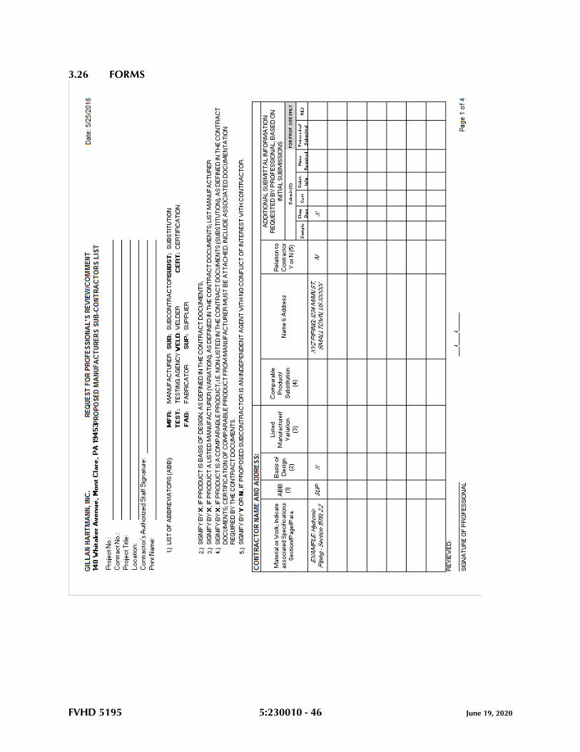
FVHD 5195 5:230010 - 46 June 19, 2020
3.26 FORMS
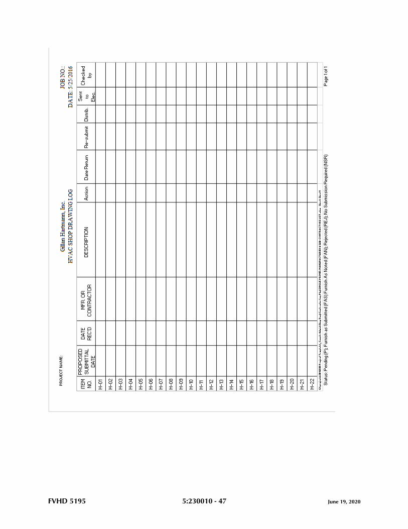
FVHD 5195 5:230010 - 47 June 19, 2020
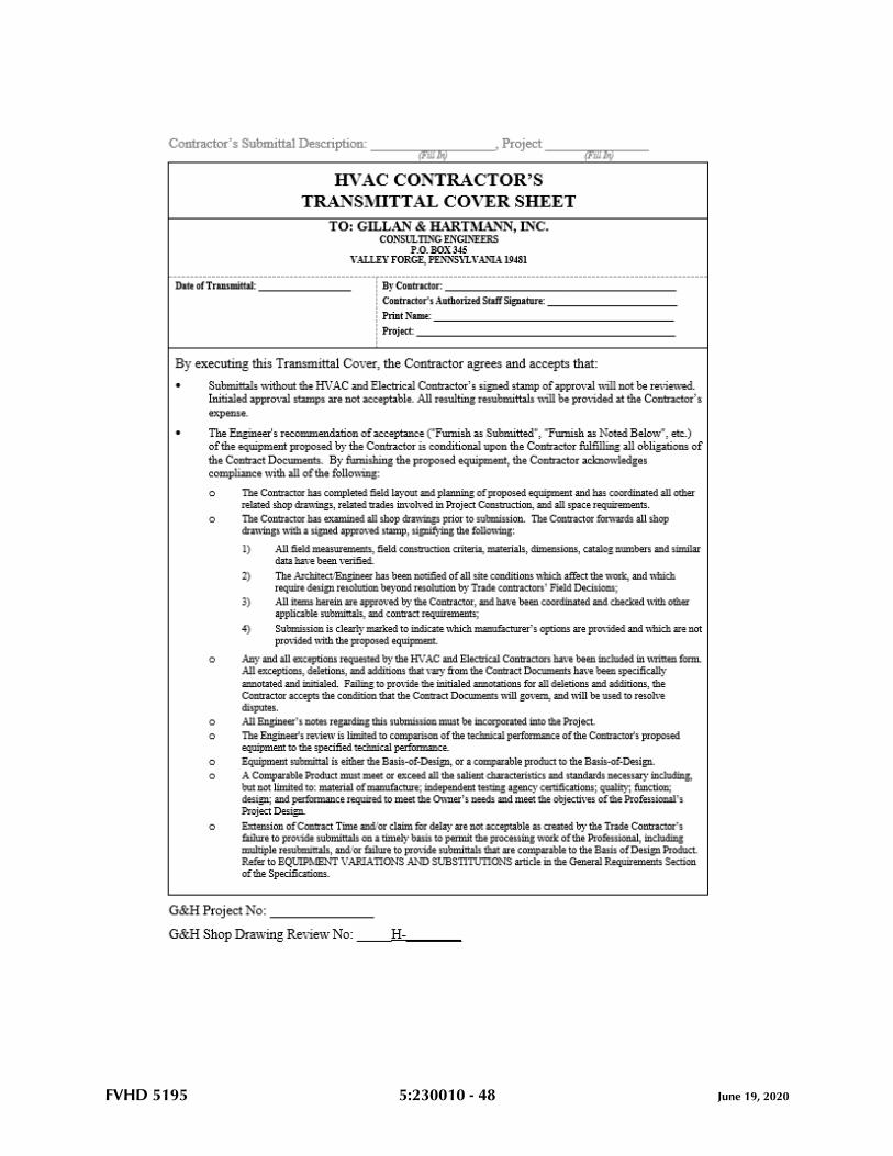
FVHD 5195 5:230010 - 48 June 19, 2020
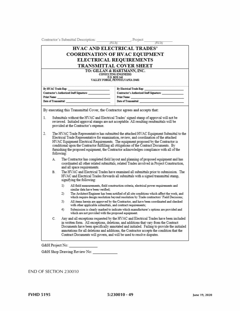
FVHD 5195 5:230010 - 49 June 19, 2020
END OF SECTION 230010
FVHD 5195 5:230513 - 1 June 19, 2020
SECTION 230513 - COMMON MOTOR REQUIREMENTS FOR HVAC EQUIPMENT
PART 1 - GENERAL
1.1 RELATED DOCUMENTS
A. Drawings and general provisions of the Contract, including General and Supplementary
Conditions and Division 01 Specification Sections, apply to this Section.
1.2 SUMMARY
A. Section includes general requirements for single-phase and polyphase, general-purpose,
horizontal, small and medium, squirrel-cage induction motors for use on alternating-
current power systems up to 600 V and installed at equipment manufacturer's factory or
shipped separately by equipment manufacturer for field installation.
1.3 COORDINATION
A. Coordinate features of motors, installed units, and accessory devices to be compatible
with the following:
1. Motor controllers.
2. Torque, speed, and horsepower requirements of the load.
3. Ratings and characteristics of supply circuit and required control sequence.
4. Ambient and environmental conditions of installation location.
PART 2 - PRODUCTS
2.1 GENERAL MOTOR REQUIREMENTS
A. Comply with NEMA MG 1 unless otherwise indicated.
B. Comply with IEEE 841 for severe-duty motors.
2.2 MOTOR CHARACTERISTICS
A. Duty: Continuous duty at ambient temperature of 40 deg C and at altitude of 3300 feet
above sea level.
B. Capacity and Torque Characteristics: Sufficient to start, accelerate, and operate
connected loads at designated speeds, at installed altitude and environment, with
indicated operating sequence, and without exceeding nameplate ratings or considering
service factor.
FVHD 5195 5:230513 - 2 June 19, 2020
2.3 POLYPHASE MOTORS
A. Description: NEMA MG 1, Design B, medium induction motor.
B. Efficiency: Premium efficient, as defined in NEMA MG 1.
C. Service Factor: 1.15.
D. Multispeed Motors: Variable torque.
1. For motors with 2:1 speed ratio, consequent pole, single winding.
2. For motors with other than 2:1 speed ratio, separate winding for each speed.
E. Multispeed Motors: Separate winding for each speed.
F. Rotor: Random-wound, squirrel cage.
G. Bearings: Regreasable, shielded, antifriction ball bearings suitable for radial and thrust
loading.
H. Temperature Rise: Match insulation rating.
I. Insulation: Class F.
J. Code Letter Designation:
1. Motors 15 HP and Larger: NEMA starting Code F or Code G.
2. Motors Smaller Than 15 HP: Manufacturer's standard starting characteristic.
K. Enclosure Material: Cast iron for motor frame sizes 324T and larger; rolled steel for motor
frame sizes smaller than 324T.
2.4 ADDITIONAL REQUIREMENTS FOR POLYPHASE MOTORS
A. Motors Used with Reduced-Voltage and Multispeed Controllers: Match wiring
connection requirements for controller with required motor leads. Provide terminals in
motor terminal box, suited to control method.
B. Motors Used with Variable-Frequency Controllers: Ratings, characteristics, and features
coordinated with and approved by controller manufacturer.
1. Windings: Copper magnet wire with moisture-resistant insulation varnish, designed
and tested to resist transient spikes, high frequencies, and short time rise pulses
produced by pulse-width-modulated inverters.
2. Premium-Efficient Motors: Class B temperature rise; Class F insulation.
3. Inverter-Duty Motors: Class F temperature rise; Class H insulation.
4. Thermal Protection: Comply with NEMA MG 1 requirements for thermally
protected motors.
C. Severe-Duty Motors: Comply with IEEE 841, with 1.15 minimum service factor.
FVHD 5195 5:230513 - 3 June 19, 2020
2.5 SINGLE-PHASE MOTORS
A. Motors larger than 1/20 hp shall be one of the following, to suit starting torque and
requirements of specific motor application:
1. Permanent-split capacitor.
2. Split phase.
3. Capacitor start, inductor run.
4. Capacitor start, capacitor run.
B. Multispeed Motors: Variable-torque, permanent-split-capacitor type.
C. Bearings: Prelubricated, antifriction ball bearings or sleeve bearings suitable for radial
and thrust loading.
D. Motors 1/20 HP and Smaller: Shaded-pole type.
E. Thermal Protection: Internal protection to automatically open power supply circuit to
motor when winding temperature exceeds a safe value calibrated to temperature rating of
motor insulation. Thermal-protection device shall automatically reset when motor
temperature returns to normal range.
PART 3 - EXECUTION (Not Applicable)
END OF SECTION 230513
FVHD 5195 5:230519 - 1 June 19, 2020
SECTION 230519 - METERS AND GAGES FOR HVAC PIPING
PART 1 - GENERAL
1.1 RELATED DOCUMENTS
A. Drawings and general provisions of the Contract, including General and Supplementary
Conditions and Division 01 Specification Sections, apply to this Section.
1.2 SUMMARY
A. Section Includes:
1. Filled-system thermometers.
2. Liquid-in-glass thermometers.
3. Duct-thermometer mounting brackets.
4. Thermowells.
5. Dial-type pressure gages.
6. Gage attachments.
7. Test plugs.
8. Test-plug kits.
1.3 ACTION SUBMITTALS
A. Product Data: For each type of product.
1. Include scale range, ratings, and calibrated performance curves for each meter,
gage, fitting, specialty, and accessory specified.
B. Shop Drawings:
1. Include diagrams for power, signal, and control wiring.
1.4 INFORMATIONAL SUBMITTALS
A. Product Certificates: For each type of meter and gage.
1.5 CLOSEOUT SUBMITTALS
A. Operation and Maintenance Data: For meters and gages to include in operation and
maintenance manuals.
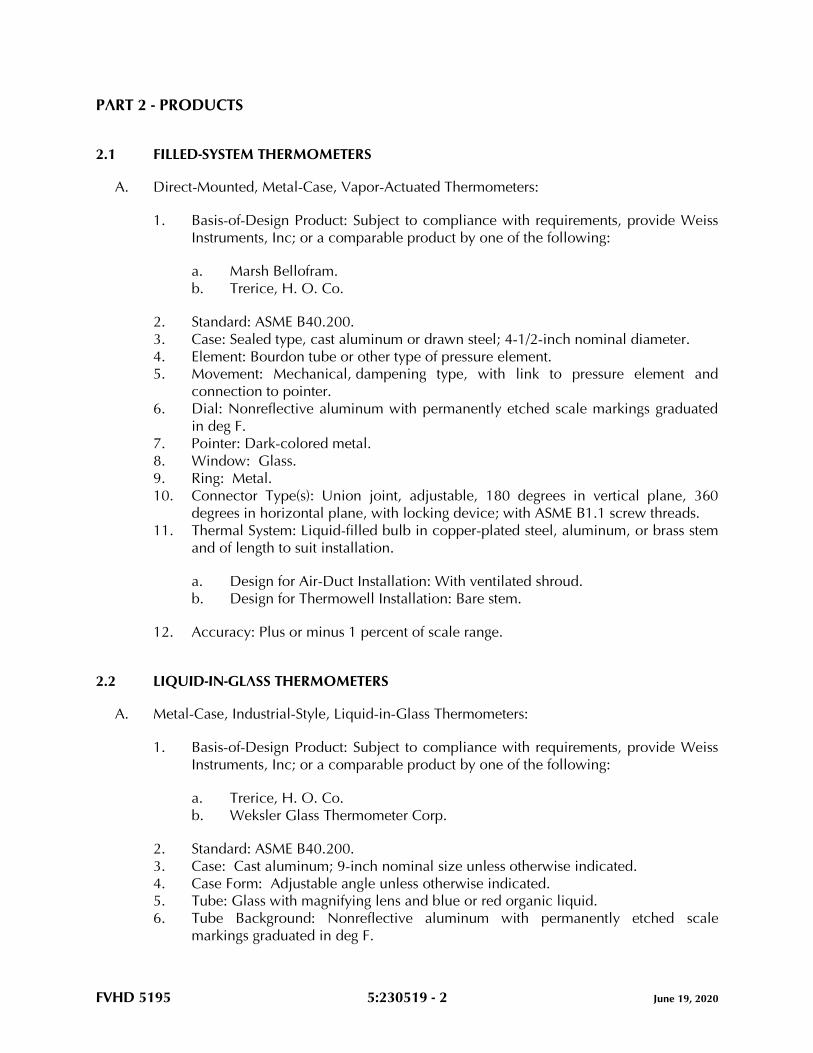
FVHD 5195 5:230519 - 2 June 19, 2020
PART 2 - PRODUCTS
2.1 FILLED-SYSTEM THERMOMETERS
A. Direct-Mounted, Metal-Case, Vapor-Actuated Thermometers:
1. Basis-of-Design Product: Subject to compliance with requirements, provide Weiss
Instruments, Inc; or a comparable product by one of the following:
a. Marsh Bellofram.
b. Trerice, H. O. Co.
2. Standard: ASME B40.200.
3. Case: Sealed type, cast aluminum or drawn steel; 4-1/2-inch nominal diameter.
4. Element: Bourdon tube or other type of pressure element.
5. Movement: Mechanical, dampening type, with link to pressure element and
connection to pointer.
6. Dial: Nonreflective aluminum with permanently etched scale markings graduated
in deg F.
7. Pointer: Dark-colored metal.
8. Window: Glass.
9. Ring: Metal.
10. Connector Type(s): Union joint, adjustable, 180 degrees in vertical plane, 360
degrees in horizontal plane, with locking device; with ASME B1.1 screw threads.
11. Thermal System: Liquid-filled bulb in copper-plated steel, aluminum, or brass stem
and of length to suit installation.
a. Design for Air-Duct Installation: With ventilated shroud.
b. Design for Thermowell Installation: Bare stem.
12. Accuracy: Plus or minus 1 percent of scale range.
2.2 LIQUID-IN-GLASS THERMOMETERS
A. Metal-Case, Industrial-Style, Liquid-in-Glass Thermometers:
1. Basis-of-Design Product: Subject to compliance with requirements, provide Weiss
Instruments, Inc; or a comparable product by one of the following:
a. Trerice, H. O. Co.
b. Weksler Glass Thermometer Corp.
2. Standard: ASME B40.200.
3. Case: Cast aluminum; 9-inch nominal size unless otherwise indicated.
4. Case Form: Adjustable angle unless otherwise indicated.
5. Tube: Glass with magnifying lens and blue or red organic liquid.
6. Tube Background: Nonreflective aluminum with permanently etched scale
markings graduated in deg F.

FVHD 5195 5:230519 - 3 June 19, 2020
7. Window: Glass.
8. Stem: Aluminum and of length to suit installation.
a. Design for Air-Duct Installation: With ventilated shroud.
b. Design for Thermowell Installation: Bare stem.
9. Connector: 1-1/4 inches, with ASME B1.1 screw threads.
10. Accuracy: Plus or minus 1 percent of scale range or one scale division, to a
maximum of 1.5 percent of scale range.
2.3 DUCT-THERMOMETER MOUNTING BRACKETS
A. Description: Flanged bracket with screw holes, for attachment to air duct and made to
hold thermometer stem.
2.4 THERMOWELLS
A. Thermowells:
1. Standard: ASME B40.200.
2. Description: Pressure-tight, socket-type fitting made for insertion in piping tee
fitting.
3. Material for Use with Copper Tubing: CNR.
4. Material for Use with Steel Piping: CRES.
5. Type: Stepped shank unless straight or tapered shank is indicated.
6. External Threads: NPS 1/2, NPS 3/4, or NPS 1, ASME B1.20.1 pipe threads.
7. Internal Threads: 1/2, 3/4, and 1 inch, with ASME B1.1 screw threads.
8. Bore: Diameter required to match thermometer bulb or stem.
9. Insertion Length: Length required to match thermometer bulb or stem.
10. Lagging Extension: Include on thermowells for insulated piping and tubing.
11. Bushings: For converting size of thermowell's internal screw thread to size of
thermometer connection.
B. Heat-Transfer Medium: Mixture of graphite and glycerin.
2.5 DIAL-TYPE PRESSURE GAGES
A. Direct-Mounted, Metal-Case, Dial-Type Pressure Gages:
1. Basis-of-Design Product: Subject to compliance with requirements, provide Weiss
Instruments, Inc; or a comparable product by one of the following:
a. Trerice, H. O. Co.
b. WATTS.
2. Standard: ASME B40.100.
3. Case: Liquid-filled type(s); cast aluminum or drawn steel; 4-1/2-inch nominal
diameter.
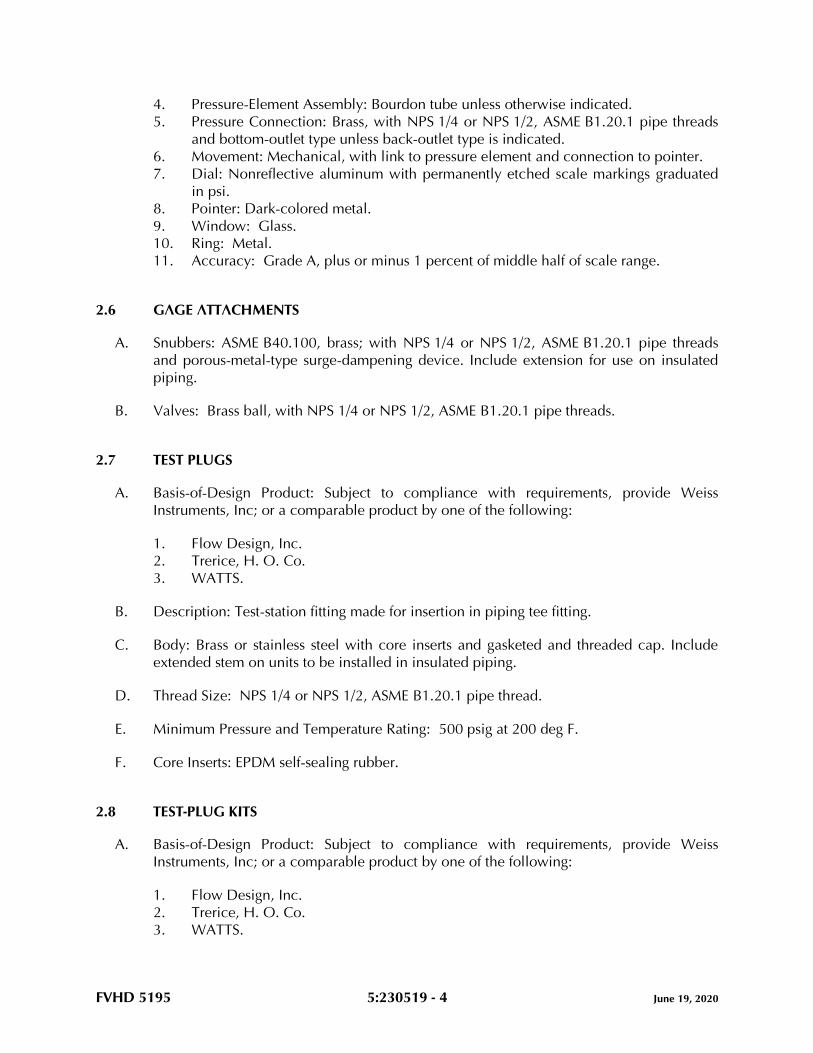
FVHD 5195 5:230519 - 4 June 19, 2020
4. Pressure-Element Assembly: Bourdon tube unless otherwise indicated.
5. Pressure Connection: Brass, with NPS 1/4 or NPS 1/2, ASME B1.20.1 pipe threads
and bottom-outlet type unless back-outlet type is indicated.
6. Movement: Mechanical, with link to pressure element and connection to pointer.
7. Dial: Nonreflective aluminum with permanently etched scale markings graduated
in psi.
8. Pointer: Dark-colored metal.
9. Window: Glass.
10. Ring: Metal.
11. Accuracy: Grade A, plus or minus 1 percent of middle half of scale range.
2.6 GAGE ATTACHMENTS
A. Snubbers: ASME B40.100, brass; with NPS 1/4 or NPS 1/2, ASME B1.20.1 pipe threads
and porous-metal-type surge-dampening device. Include extension for use on insulated
piping.
B. Valves: Brass ball, with NPS 1/4 or NPS 1/2, ASME B1.20.1 pipe threads.
2.7 TEST PLUGS
A. Basis-of-Design Product: Subject to compliance with requirements, provide Weiss
Instruments, Inc; or a comparable product by one of the following:
1. Flow Design, Inc.
2. Trerice, H. O. Co.
3. WATTS.
B. Description: Test-station fitting made for insertion in piping tee fitting.
C. Body: Brass or stainless steel with core inserts and gasketed and threaded cap. Include
extended stem on units to be installed in insulated piping.
D. Thread Size: NPS 1/4 or NPS 1/2, ASME B1.20.1 pipe thread.
E. Minimum Pressure and Temperature Rating: 500 psig at 200 deg F.
F. Core Inserts: EPDM self-sealing rubber.
2.8 TEST-PLUG KITS
A. Basis-of-Design Product: Subject to compliance with requirements, provide Weiss
Instruments, Inc; or a comparable product by one of the following:
1. Flow Design, Inc.
2. Trerice, H. O. Co.
3. WATTS.
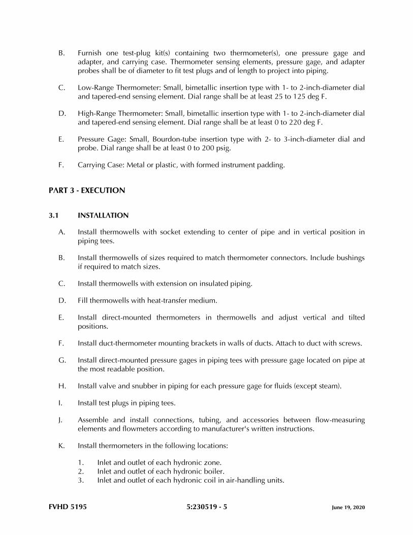
FVHD 5195 5:230519 - 5 June 19, 2020
B. Furnish one test-plug kit(s) containing two thermometer(s), one pressure gage and
adapter, and carrying case. Thermometer sensing elements, pressure gage, and adapter
probes shall be of diameter to fit test plugs and of length to project into piping.
C. Low-Range Thermometer: Small, bimetallic insertion type with 1- to 2-inch-diameter dial
and tapered-end sensing element. Dial range shall be at least 25 to 125 deg F.
D. High-Range Thermometer: Small, bimetallic insertion type with 1- to 2-inch-diameter dial
and tapered-end sensing element. Dial range shall be at least 0 to 220 deg F.
E. Pressure Gage: Small, Bourdon-tube insertion type with 2- to 3-inch-diameter dial and
probe. Dial range shall be at least 0 to 200 psig.
F. Carrying Case: Metal or plastic, with formed instrument padding.
PART 3 - EXECUTION
3.1 INSTALLATION
A. Install thermowells with socket extending to center of pipe and in vertical position in
piping tees.
B. Install thermowells of sizes required to match thermometer connectors. Include bushings
if required to match sizes.
C. Install thermowells with extension on insulated piping.
D. Fill thermowells with heat-transfer medium.
E. Install direct-mounted thermometers in thermowells and adjust vertical and tilted
positions.
F. Install duct-thermometer mounting brackets in walls of ducts. Attach to duct with screws.
G. Install direct-mounted pressure gages in piping tees with pressure gage located on pipe at
the most readable position.
H. Install valve and snubber in piping for each pressure gage for fluids (except steam).
I. Install test plugs in piping tees.
J. Assemble and install connections, tubing, and accessories between flow-measuring
elements and flowmeters according to manufacturer's written instructions.
K. Install thermometers in the following locations:
1. Inlet and outlet of each hydronic zone.
2. Inlet and outlet of each hydronic boiler.
3. Inlet and outlet of each hydronic coil in air-handling units.
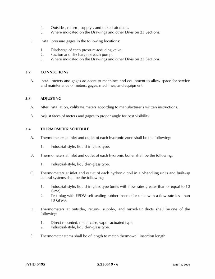
FVHD 5195 5:230519 - 6 June 19, 2020
4. Outside-, return-, supply-, and mixed-air ducts.
5. Where indicated on the Drawings and other Division 23 Sections.
L. Install pressure gages in the following locations:
1. Discharge of each pressure-reducing valve.
2. Suction and discharge of each pump.
3. Where indicated on the Drawings and other Division 23 Sections.
3.2 CONNECTIONS
A. Install meters and gages adjacent to machines and equipment to allow space for service
and maintenance of meters, gages, machines, and equipment.
3.3 ADJUSTING
A. After installation, calibrate meters according to manufacturer's written instructions.
B. Adjust faces of meters and gages to proper angle for best visibility.
3.4 THERMOMETER SCHEDULE
A. Thermometers at inlet and outlet of each hydronic zone shall be the following:
1. Industrial-style, liquid-in-glass type.
B. Thermometers at inlet and outlet of each hydronic boiler shall be the following:
1. Industrial-style, liquid-in-glass type.
C. Thermometers at inlet and outlet of each hydronic coil in air-handling units and built-up
central systems shall be the following:
1. Industrial-style, liquid-in-glass type (units with flow rates greater than or equal to 10
GPM).
2. Test plug with EPDM self-sealing rubber inserts (for units with a flow rate less than
10 GPM).
D. Thermometers at outside-, return-, supply-, and mixed-air ducts shall be one of the
following:
1. Direct-mounted, metal-case, vapor-actuated type.
2. Industrial-style, liquid-in-glass type.
E. Thermometer stems shall be of length to match thermowell insertion length.

FVHD 5195 5:230519 - 7 June 19, 2020
3.5 THERMOMETER SCALE-RANGE SCHEDULE
A. Scale Range for Heating, Hot-Water Piping: 0 to 250 deg F.
B. Scale Range for Air Ducts: Minus 40 to plus 110 deg F.
3.6 PRESSURE-GAGE SCHEDULE
A. Pressure gages at discharge of each pressure-reducing valve shall be the following:
1. Liquid-filled, direct-mounted, metal case.
B. Pressure gages at suction and discharge of each pump shall be the following:
1. Liquid-filled, direct-mounted, metal case.
C. Pressure gages at suction and discharge of each hydronic coil in air-handling units (units
with flow rates greater than or equal to 10 GPM) and built-up central systems shall
be one of the following:
1. Liquid-filled, direct-mounted, metal case.
D. Pressure gages at suction and discharge of each small HVAC equipment (units with flow
rates less than 10 GPM) shall be the following:
1. Test plug with EPDM self-sealing rubber inserts.
3.7 PRESSURE-GAGE SCALE-RANGE SCHEDULE
A. Scale Range for Heating, Hot-Water Piping: 0 to 160 psi.
END OF SECTION 230519

FVHD 5195 5:230523.12 - 1 June 19, 2020
SECTION 230523.12 - BALL VALVES FOR HVAC PIPING
PART 1 - GENERAL
1.1 RELATED DOCUMENTS
A. Drawings and general provisions of the Contract, including General and Supplementary
Conditions and Division 01 Specification Sections, apply to this Section.
1.2 SUMMARY
A. Section Includes:
1. Brass ball valves.
2. Bronze ball valves.
1.3 DEFINITIONS
A. CWP: Cold working pressure.
B. Press-end connection: Valves suitable for connection to a pressure-sealed system.
1.4 ACTION SUBMITTALS
A. Product Data: For each type of valve.
1.5 DELIVERY, STORAGE, AND HANDLING
A. Prepare valves for shipping as follows:
1. Protect internal parts against rust and corrosion.
2. Protect threads, flange faces, and weld ends.
3. Set ball valves open to minimize exposure of functional surfaces.
B. Use the following precautions during storage:
1. Maintain valve end protection.
2. Store valves indoors and maintain at higher-than-ambient-dew-point temperature. If
outdoor storage is necessary, store valves off the ground in watertight enclosures.
C. Use sling to handle large valves; rig sling to avoid damage to exposed parts. Do not use
operating handles or stems as lifting or rigging points.
FVHD 5195 5:230523.12 - 2 June 19, 2020
PART 2 - PRODUCTS
2.1 GENERAL REQUIREMENTS FOR VALVES
A. Source Limitations for Valves: Obtain each type of valve from single source from single
manufacturer.
B. ASME Compliance:
1. ASME B1.20.1 for threads for threaded-end valves.
2. ASME B16.10 and ASME B16.34 for ferrous valve dimensions and design criteria.
3. ASME B16.18 for solder-joint connections.
4. ASME B31.1 for power piping valves.
5. ASME B31.9 for building services piping valves.
C. Bronze valves shall be made with dezincification-resistant materials. Bronze valves made
with copper alloy (brass) containing more than 15 percent zinc are not permitted.
D. Refer to HVAC valve schedule articles for applications of valves.
E. Valve Pressure-Temperature Ratings: Not less than indicated and as required for system
pressures and temperatures.
F. Valve Sizes: Same as upstream piping unless otherwise indicated.
G. Valve Actuator Types:
1. Gear Actuator: For quarter-turn valves NPS 4 and larger.
2. Handlever: For quarter-turn valves smaller than NPS 4.
H. Valves in Insulated Piping:
1. Include 2-inch stem extensions.
2. Extended operating handle of nonthermal-conductive material, and protective
sleeves that allow operation of valves without breaking the vapor seals or
disturbing insulation.
3. Memory stops that are fully adjustable after insulation is applied.
I. Valve Bypass and Drain Connections: MSS SP-45.
2.2 BRASS BALL VALVES
A. Brass Ball Valves, Two-Piece with Full Port and Brass Trim, Threaded Ends:
1. Basis-of-Design Product: Subject to compliance with requirements, provide NIBCO
INC.; or a comparable product by one of the following:
a. Crane; Crane Energy Flow Solutions.
b. Milwaukee Valve Company.
FVHD 5195 5:230523.12 - 3 June 19, 2020
c. Red-White Valve Corp.
d. Stockham; Crane Energy Flow Solutions.
e. WATTS.
2. Description:
a. Standard: MSS SP-110.
b. CWP Rating: 600 psig.
c. Body Design: Two piece.
d. Body Material: Forged brass.
e. Ends: Threaded.
f. Seats: PTFE.
g. Stem: Brass.
h. Ball: Chrome-plated brass.
i. Port: Full.
B. Brass Ball Valves, Two-Piece with Full Port and Brass Trim, Press Ends:
1. Basis-of-Design Product: Subject to compliance with requirements, provide NIBCO
INC.; or a comparable product by one of the following:
a. Crane; Crane Energy Flow Solutions.
b. Milwaukee Valve Company.
c. Stockham; Crane Energy Flow Solutions.
2. Description:
a. Standard: MSS SP-110.
b. CWP Rating: 600 psig.
c. Body Design: Two piece.
d. Body Material: Forged brass.
e. Ends: Press.
f. Seats: PTFE or RPTFE.
g. Stem: Brass.
h. Ball: Chrome-plated brass.
i. Port: Full.
j. O-Ring Seal: Buna-N or EPDM.
2.3 BRONZE BALL VALVES
A. Bronze Ball Valves, Two-Piece with Full Port and Bronze or Brass Trim, Threaded Ends:
1. Basis-of-Design Product: Subject to compliance with requirements, provide NIBCO
INC.; or a comparable product by one of the following:
a. Crane; Crane Energy Flow Solutions.
b. Hammond Valve.
c. Milwaukee Valve Company.
d. Red-White Valve Corp.
FVHD 5195 5:230523.12 - 4 June 19, 2020
2. Description:
a. Standard: MSS SP-110.
b. CWP Rating: 600 psig.
c. Body Design: Two piece.
d. Body Material: Bronze.
e. Ends: Threaded.
f. Seats: PTFE.
g. Stem: Bronze.
h. Ball: Chrome-plated brass.
i. Port: Full.
B. Bronze Ball Valves, Two-Piece with Full Port and Bronze or Brass Trim, Press Ends:
1. Basis-of-Design Product: Subject to compliance with requirements, provide NIBCO
INC.; or a comparable product by one of the following:
a. Crane; Crane Energy Flow Solutions.
b. Hammond Valve.
c. Red White Valve Corp.
d. WATTS.
2. Description:
a. Standard: MSS SP-110.
b. CWP Rating: 600 psig.
c. Body Design: Two piece.
d. Body Material: Bronze.
e. Ends: Press.
f. Seats: PTFE.
g. Stem: Bronze.
h. Ball: Chrome-plated brass.
i. Port: Full.
PART 3 - EXECUTION
3.1 EXAMINATION
A. Examine valve interior for cleanliness, freedom from foreign matter, and corrosion.
Remove special packing materials, such as blocks, used to prevent disc movement during
shipping and handling.
B. Operate valves in positions from fully open to fully closed. Examine guides and seats
made accessible by such operations.
C. Examine threads on valve and mating pipe for form and cleanliness.
FVHD 5195 5:230523.12 - 5 June 19, 2020
D. Examine mating flange faces for conditions that might cause leakage. Check bolting for
proper size, length, and material. Verify that gasket is of proper size, that its material
composition is suitable for service, and that it is free from defects and damage.
E. Do not attempt to repair defective valves; replace with new valves.
3.2 VALVE INSTALLATION
A. Install valves with unions or flanges at each piece of equipment arranged to allow
service, maintenance, and equipment removal without system shutdown.
B. Locate valves for easy access and provide separate support where necessary.
C. Install valves in horizontal piping with stem at or above center of pipe.
D. Install valves in position to allow full stem movement.
E. Install valve tags. Comply with requirements in applicable Division 23 Sections for valve
tags and schedules.
3.3 GENERAL REQUIREMENTS FOR VALVE APPLICATIONS
A. If valves with specified CWP ratings are unavailable, the same types of valves with higher
CWP ratings may be substituted.
B. Select valves with the following end connections:
1. For Copper Tubing, NPS 2 and Smaller: Threaded ends except where solder-joint
valve-end option or press-end option is indicated in valve schedules below.
3.4 HEATING-WATER VALVE SCHEDULE
A. Pipe NPS 2 and Smaller: Brass or bronze ball valves, two piece with brass or bronze
trim, full port, and threaded, solder, or press connection-joint ends.
END OF SECTION 230523.12
FVHD 5195 5:230523.14 - 1 June 19, 2020
SECTION 230523.14 - CHECK VALVES FOR HVAC PIPING
PART 1 - GENERAL
1.1 RELATED DOCUMENTS
A. Drawings and general provisions of the Contract, including General and Supplementary
Conditions and Division 01 Specification Sections, apply to this Section.
1.2 SUMMARY
A. Section Includes:
1. Bronze swing check valves.
2. Iron swing check valves.
3. Iron, grooved-end swing check valves.
1.3 DEFINITIONS
A. CWP: Cold working pressure.
B. EPDM: Ethylene propylene copolymer rubber.
C. NBR: Acrylonitrile-butadiene, Buna-N, or nitrile rubber.
D. Press-end connection: Valves suitable for a pressure-sealed system.
1.4 ACTION SUBMITTALS
A. Product Data: For each type of valve.
1.5 DELIVERY, STORAGE, AND HANDLING
A. Prepare valves for shipping as follows:
1. Protect internal parts against rust and corrosion.
2. Protect threads, flange faces, grooves, and weld ends.
3. Block check valves in either closed or open position.
B. Use the following precautions during storage:
1. Maintain valve end protection.
2. Store valves indoors and maintain at higher than ambient dew point temperature. If
outdoor storage is necessary, store valves off the ground in watertight enclosures.
FVHD 5195 5:230523.14 - 2 June 19, 2020
C. Use sling to handle large valves; rig sling to avoid damage to exposed parts. Do not use
handwheels or stems as lifting or rigging points.
PART 2 - PRODUCTS
2.1 GENERAL REQUIREMENTS FOR VALVES
A. Source Limitations for Valves: Obtain each type of valve from single source from single
manufacturer.
B. ASME Compliance:
1. ASME B1.20.1 for threads for threaded-end valves.
2. ASME B16.1 for flanges on iron valves.
3. ASME B16.10 and ASME B16.34 for ferrous valve dimensions and design criteria.
4. ASME B16.18 for solder joint.
5. ASME B31.1 for power piping valves.
6. ASME B31.9 for building services piping valves.
C. AWWA Compliance: Comply with AWWA C606 for grooved-end connections.
D. Bronze valves shall be made with dezincification-resistant materials. Bronze valves made
with copper alloy (brass) containing more than 15 percent zinc are not permitted.
E. Valve Pressure-Temperature Ratings: Not less than indicated and as required for system
pressures and temperatures.
F. Valve Sizes: Same as upstream piping unless otherwise indicated.
G. Valve Bypass and Drain Connections: MSS SP-45.
2.2 BRONZE SWING CHECK VALVES
A. Bronze Swing Check Valves with Bronze Disc, Class 125:
1. Basis-of-Design Product: Subject to compliance with requirements, provide NIBCO
INC.; or a comparable product by one of the following:
a. Apollo Flow Controls; Conbraco Industries, Inc.
b. Milwaukee Valve Company.
c. Stockham; Crane Energy Flow Solutions.
2. Description:
a. Standard: MSS SP-80, Type 3.
b. CWP Rating: 200 psig.
c. Body Design: Horizontal flow.
d. Body Material: ASTM B62, bronze.

FVHD 5195 5:230523.14 - 3 June 19, 2020
e. Ends: Threaded.
f. Disc: Bronze.
B. Bronze Swing Check Valves, Press Ends:
1. Basis-of-Design Product: Subject to compliance with requirements, provide NIBCO
INC.; or a comparable product by one of the following:
a. Apollo Flow Controls; Conbraco Industries, Inc.
b. Elkhart Products Corporation.
c. Milwaukee Valve Company.
2. Description:
a. Standard: MSS SP-80 and MSS SP-139.
b. CWP Rating: Minimum 200 psig.
c. Body Design: Horizontal flow.
d. Body Material: ASTM B584, bronze.
e. Ends: Press.
f. Press Ends Connection Rating: Minimum 200 psig
g. Disc: Brass or bronze.
2.3 IRON SWING CHECK VALVES
A. Iron Swing Check Valves with Metal Seats, Class 125:
1. Basis-of-Design Product: Subject to compliance with requirements, provide NIBCO
INC.; or a comparable product by one of the following:
a. Apollo Flow Controls; Conbraco Industries, Inc.
b. Milwaukee Valve Company.
c. Stockham; Crane Energy Flow Solutions.
2. Description:
a. Standard: MSS SP-71, Type I.
b. NPS 2-1/2 to NPS 12, CWP Rating: 200 psig.
c. NPS 14 to NPS 24, CWP Rating: 150 psig.
d. Body Design: Clear or full waterway.
e. Body Material: ASTM A126, gray iron with bolted bonnet.
f. Ends: Flanged.
g. Trim: Bronze.
h. Gasket: Asbestos free.
2.4 IRON, GROOVED-END SWING CHECK VALVES
A. Iron, Grooved-End Swing Check Valves, 300 CWP:
FVHD 5195 5:230523.14 - 4 June 19, 2020
1. Basis-of-Design Product: Subject to compliance with requirements, provide
Victaulic Company; or a comparable product by one of the following:
a. Grinnell G-Fire by Johnson Controls Company.
b. Shurjoint-Apollo Piping Products USA Inc.
2. Description:
a. CWP Rating: 300 psig.
b. Body Material: ASTM A536, ductile iron.
c. Seal: EPDM.
d. Disc: Spring operated, ductile iron or stainless steel.
PART 3 - EXECUTION
3.1 EXAMINATION
A. Examine valve interior for cleanliness, freedom from foreign matter, and corrosion.
Remove special packing materials, such as blocks, used to prevent disc movement during
shipping and handling.
B. Operate valves in positions from fully open to fully closed. Examine guides and seats
made accessible by such operations.
C. Examine threads on valve and mating pipe for form and cleanliness.
D. Examine mating flange faces for conditions that might cause leakage. Check bolting for
proper size, length, and material. Verify that gasket is of proper size, that its material
composition is suitable for service, and that it is free from defects and damage.
E. Do not attempt to repair defective valves; replace with new valves.
3.2 VALVE INSTALLATION
A. Install valves with unions or flanges at each piece of equipment arranged to allow
service, maintenance, and equipment removal without system shutdown.
B. Locate valves for easy access and provide separate support where necessary.
C. Install valves in horizontal piping with stem at or above center of pipe.
D. Install valves in position to allow full stem movement.
E. Install check valves for proper direction of flow and as follows:
1. Swing Check Valves: In horizontal position with hinge pin level.
FVHD 5195 5:230523.14 - 5 June 19, 2020
F. Install valve tags. Comply with requirements for valve tags and schedules in applicable
Division 23 Sections.
3.3 ADJUSTING
A. Adjust or replace valve packing after piping systems have been tested and put into service
but before final adjusting and balancing. Replace valves if persistent leaking occurs.
3.4 GENERAL REQUIREMENTS FOR VALVE APPLICATIONS
A. If valve applications are not indicated, use the following:
1. Pump-Discharge Check Valves:
a. NPS 2 and Smaller: Bronze swing check valves with bronze disc.
b. NPS 2-1/2 and Larger: Iron swing check valves with lever and weight or with
spring or iron, center-guided, metal-seat check valves.
B. If valves with specified CWP ratings are unavailable, the same types of valves with higher
CWP ratings may be substituted.
C. Select valves, except wafer types, with the following end connections:
1. For Copper Tubing, NPS 2 and Smaller: Threaded ends or pressure sealed ends, or
solder-joint valve-end option is indicated in valve schedules.
2. For Steel Piping, NPS 2-1/2 to NPS 4: Flanged ends except where threaded valve-
end option is indicated in valve schedules.
3. For Steel Piping, NPS 5 and Larger: Flanged ends.
4. For Grooved-End Steel Piping: Valve ends may be grooved.
3.5 HEATING-WATER VALVE SCHEDULE
A. Pipe NPS 2 and Smaller:
1. Bronze Valves: May be provided with solder-joint or pressure sealed ends instead
of threaded ends.
2. Bronze swing check valves with bronze disc, Class 125.
B. Pipe NPS 2-1/2 and Larger:
1. NPS 2-1/2 to NPS 4: Iron valves may be provided with threaded ends instead of
flanged ends.
2. NPS 3 to NPS 12: Iron, grooved-end check valves, 300 CWP.
3. Iron swing check valves with metal seats, Class 125.
END OF SECTION 230523.14
FVHD 5195 5:230529 - 1 June 19, 2020
SECTION 230529 - HANGERS AND SUPPORTS FOR HVAC PIPING AND EQUIPMENT
PART 1 - GENERAL
1.1 RELATED DOCUMENTS
A. Drawings and general provisions of the Contract, including General and Supplementary
Conditions and Division 01 Specification Sections, apply to this Section.
1.2 SUMMARY
A. Section Includes:
1. Metal pipe hangers and supports.
2. Trapeze pipe hangers.
3. Metal framing systems.
4. Thermal-hanger shield inserts.
5. Fastener systems.
6. Equipment supports.
1.3 DEFINITIONS
A. MSS: Manufacturers Standardization Society of The Valve and Fittings Industry Inc.
B. Terminology: As defined in MSS SP-90, “Guidelines on Terminology for Pipe Hangers
and Supports.”
1.4 PERFORMANCE REQUIREMENTS
A. Delegated Design: Engage a qualified professional engineer, as defined in applicable
Division 01 Sections to design trapeze pipe hangers and equipment supports.
B. Structural Performance: Hangers and supports for HVAC piping and equipment shall
withstand the effects of gravity loads and stresses within limits and under conditions
indicated according to ASCE/SEI 7.
1. Design supports for multiple pipes, including pipe stands, capable of supporting
combined weight of supported systems, system contents, and test water.
2. Design equipment supports capable of supporting combined operating weight of
supported equipment and connected systems and components.
1.5 ACTION SUBMITTALS
A. Product Data: For each type of product indicated.
FVHD 5195 5:230529 - 2 June 19, 2020
1. Metal pipe hangers and supports.
2. Powder-actuated fastener systems.
B. Shop Drawings: Show fabrication and installation details and include calculations for the
following; maximum weights supported, maximum pipe dimensions supported, support
intervals, etc. Include Product Data for components:
1. Trapeze pipe hangers. Include Product Data for components.
a. Shop Drawings to be signed and sealed by a qualified professional engineer.
b. Refer to the applicable Delegated-Design requirements in this Section.
2. Metal framing systems. Include Product Data for components.
3. Field fabricated pipe stands. Include Product Data for components.
a. Shop Drawings to be signed and sealed by a qualified professional engineer.
b. Refer to the applicable Delegated-Design requirements in this Section.
4. Equipment supports. Include Product Data for components.
a. Shop Drawings to be signed and sealed by a qualified professional engineer.
b. Refer to the applicable Delegated-Design requirements in this Section.
C. Delegated-Design Submittal: For trapeze hangers indicated to comply with performance
requirements and design criteria, including analysis data signed and sealed by the
qualified professional engineer responsible for their preparation.
1. Detail fabrication and assembly of trapeze hangers.
2. Include design calculations for designing trapeze hangers.
1.6 INFORMATIONAL SUBMITTALS
A. Welding certificates.
1.7 QUALITY ASSURANCE
A. Structural-Steel Welding Qualifications: Qualify procedures and personnel according to
AWS D1.1/D1.1M, "Structural Welding Code - Steel."
B. Pipe Welding Qualifications: Qualify procedures and operators according to ASME Boiler
and Pressure Vessel Code, Section IX.
PART 2 - PRODUCTS
2.1 METAL PIPE HANGERS AND SUPPORTS
A. Carbon-Steel Pipe Hangers and Supports:
FVHD 5195 5:230529 - 3 June 19, 2020
1. Description: MSS SP-58, Types 1 through 58, factory-fabricated components.
2. Galvanized Metallic Coatings: Pregalvanized, hot-dip galvanized, or electro-
galvanized.
3. Nonmetallic Coatings: Plastic coated, or epoxy powder-coated.
4. Padded Hangers: Hanger with fiberglass or other pipe insulation pad or cushion to
support bearing surface of piping.
5. Hanger Rods: Continuous-thread rod, nuts, and washer made of carbon steel.
B. Stainless-Steel Pipe Hangers and Supports:
1. Description: MSS SP-58, Types 1 through 58, factory-fabricated components.
2. Padded Hangers: Hanger with fiberglass or other pipe insulation pad or cushion to
support bearing surface of piping.
3. Hanger Rods: Continuous-thread rod, nuts, and washer made of stainless steel.
C. Copper Pipe and Tube Hangers:
1. Description: MSS SP-58, Types 1 through 58, copper-plated steel, factory-
fabricated components.
2. Hanger Rods: Continuous-thread rod, nuts, and washer made of copper-plated
steel.
2.2 TRAPEZE PIPE HANGERS
A. Description: MSS SP-58, Type 59, shop- or field-fabricated pipe-support assembly made
from structural carbon-steel shapes with MSS SP-58 carbon-steel hanger rods, nuts,
saddles, and U-bolts.
2.3 METAL FRAMING SYSTEMS
A. MFMA Manufacturer Metal Framing Systems:
1. Manufacturers: Subject to compliance with requirements, provide products by one
of the following:
a. B-line, an Eaton business.
b. ERICO/Michigan Hanger Co.; ERISTRUT Div.
c. MIRO Industries.
d. Unistrut; Part of Atkore International.
2. Description: Shop- or field-fabricated, pipe-support assembly made of steel
channels, accessories, fittings, and other components for supporting multiple
parallel pipes.
3. Standard: Comply with MFMA-4 factory-fabricated components for field assembly.
4. Channels: Continuous slotted steel channel with inturned lips.
5. Channel Width: Selected for applicable load criteria.
6. Channel Nuts: Formed or stamped nuts or other devices designed to fit into
channel slot and, when tightened, prevent slipping along channel.
FVHD 5195 5:230529 - 4 June 19, 2020
7. Hanger Rods: Continuous-thread rod, nuts, and washer made of carbon steel.
8. Coatings: Manufacturer's standard finish, unless bare metal surfaces are indicated.
9. Nonmetallic Coatings: Plastic coating, jacket, or liner.
2.4 THERMAL-HANGER SHIELD INSERTS
A. Manufacturers: Subject to compliance with requirements, provide products by one of the
following:
1. ERICO International Corporation.
2. PHS Industries, Inc.
3. Pipe Shields Inc.
4. Rilco Manufacturing Co., Inc.
B. Insulation-Insert Material for Cold Piping: ASTM C552, Type II cellular glass with 100-psi
minimum compressive strength and vapor barrier.
C. Insulation-Insert Material for Hot Piping: ASTM C552, Type II cellular glass with 100-psi
minimum compressive strength.
D. For Trapeze or Clamped Systems: Insert and shield shall cover entire circumference of
pipe.
E. For Clevis or Band Hangers: Insert and shield shall cover lower 180 degrees of pipe.
F. Insert Length: Extend 2 inches beyond sheet metal shield for piping operating below
ambient air temperature.
2.5 FASTENER SYSTEMS
A. Manufacturers: Subject to compliance with requirements, provide products by one of the
following:
1. Hilti, Inc.
2. ITW Ramset/Red Head.
3. MKT Fastening, LLC.
4. Powers Fasteners.
B. Powder-Actuated Fasteners: Threaded-steel stud, for use in hardened portland cement
concrete with pull-out, tension, and shear capacities appropriate for supported loads and
building materials where used.
C. Mechanical-Expansion Anchors: Insert-wedge-type anchors for use in hardened portland
cement concrete; with pull-out, tension, and shear capacities appropriate for supported
loads and building materials where used.
1. Indoor Applications: Zinc-coated or stainless-steel.
2. Outdoor Applications: Stainless steel.
FVHD 5195 5:230529 - 5 June 19, 2020
2.6 EQUIPMENT SUPPORTS
A. Description: Welded, shop- or field-fabricated equipment support made from structural
carbon-steel shapes.
2.7 MATERIALS
A. Aluminum: ASTM B221.
B. Carbon Steel: ASTM A1011/A1011M.
C. Structural Steel: ASTM A36/A36M, carbon-steel plates, shapes, and bars; galvanized.
D. Stainless Steel: ASTM A240/A240M.
E. Threaded Rods: Continuously threaded. Zinc-plated or galvanized steel for indoor
applications and stainless steel for outdoor applications. Mating nuts and washers of
similar materials as rods.
F. Grout: ASTM C1107/C1107M, factory-mixed and -packaged, dry, hydraulic-cement,
nonshrink and nonmetallic grout; suitable for interior and exterior applications.
1. Properties: Nonstaining, noncorrosive, and nongaseous.
2. Design Mix: 5000-psi, 28-day compressive strength.
PART 3 - EXECUTION
3.1 APPLICATION
A. Comply with requirements in applicable Division 07 Sections for firestopping materials
and installation for penetrations through fire-rated walls, ceilings, and assemblies.
B. Strength of Support Assemblies: Where not indicated, select sizes of components so
strength will be adequate to carry present and future static loads within specified loading
limits. Minimum static design load used for strength determination shall be weight of
supported components plus 200 lb.
3.2 HANGER AND SUPPORT INSTALLATION
A. Metal Pipe-Hanger Installation: Comply with MSS SP-58. Install hangers, supports,
clamps, and attachments as required to properly support piping from the building
structure.
B. Metal Trapeze Pipe-Hanger Installation: Comply with MSS SP-58. Arrange for grouping of
parallel runs of horizontal piping, and support together on field-fabricated trapeze pipe
hangers.

FVHD 5195 5:230529 - 6 June 19, 2020
1. Pipes of Various Sizes: Support together and space trapezes for smallest pipe size or
install intermediate supports for smaller diameter pipes as specified for individual
pipe hangers.
2. Field fabricate from ASTM A36/A36M, carbon-steel shapes selected for loads being
supported. Weld steel according to AWS D1.1/D1.1M.
C. Metal Framing System Installation: Arrange for grouping of parallel runs of piping, and
support together on field-assembled strut systems.
D. Thermal-Hanger Shield Installation: Install in pipe hanger or shield for insulated piping.
E. Fastener System Installation:
1. Install powder-actuated fasteners for use in lightweight concrete or concrete slabs
less than 4 inches thick in concrete after concrete is placed and completely cured.
Use operators that are licensed by powder-actuated tool manufacturer. Install
fasteners according to powder-actuated tool manufacturer's operating manual.
2. Install mechanical-expansion anchors in concrete after concrete is placed and
completely cured. Install fasteners according to manufacturer's written instructions.
F. Install hangers and supports complete with necessary attachments, inserts, bolts, rods,
nuts, washers, and other accessories.
G. Equipment Support Installation: Fabricate from welded-structural-steel shapes.
H. Install hangers and supports to allow controlled thermal and seismic movement of piping
systems, to permit freedom of movement between pipe anchors, and to facilitate action of
expansion joints, expansion loops, expansion bends, and similar units.
I. Install lateral bracing with pipe hangers and supports to prevent swaying.
J. Install building attachments within concrete slabs or attach to structural steel. Install
additional attachments at concentrated loads, including valves, flanges, and strainers,
NPS 2-1/2 and larger and at changes in direction of piping. Install concrete inserts before
concrete is placed; fasten inserts to forms and install reinforcing bars through openings at
top of inserts.
K. Load Distribution: Install hangers and supports so that piping live and dead loads and
stresses from movement will not be transmitted to connected equipment.
L. Pipe Slopes: Install hangers and supports to provide indicated pipe slopes and to not
exceed maximum pipe deflections allowed by ASME B31.9 for building services piping.
M. Insulated Piping:
1. Attach clamps and spacers to piping.
a. Piping Operating above Ambient Air Temperature: Clamp may project
through insulation.
FVHD 5195 5:230529 - 7 June 19, 2020
b. Piping Operating below Ambient Air Temperature: Use thermal-hanger
shield insert with clamp sized to match OD of insert.
c. Do not exceed pipe stress limits allowed by ASME B31.9 for building services
piping.
2. Install MSS SP-58, Type 39, protection saddles if insulation without vapor barrier is
indicated. Fill interior voids with insulation that matches adjoining insulation.
a. Option: Thermal-hanger shield inserts may be used. Include steel weight-
distribution plate for pipe NPS 4 and larger if pipe is installed on rollers.
3. Install MSS SP-58, Type 40, protective shields on cold piping with vapor barrier.
Shields shall span an arc of 180 degrees.
a. Option: Thermal-hanger shield inserts may be used. Include steel weight-
distribution plate for pipe NPS 4 and larger if pipe is installed on rollers.
4. Shield Dimensions for Pipe: Not less than the following:
a. NPS 1/4 to NPS 3-1/2: 12 inches long and 0.048 inch thick.
b. NPS 4: 12 inches long and 0.06 inch thick.
c. NPS 5 and NPS 6: 18 inches long and 0.06 inch thick.
d. NPS 8 to NPS 14: 24 inches long and 0.075 inch thick.
e. NPS 16 to NPS 24: 24 inches long and 0.105 inch thick.
5. Pipes NPS 8 and Larger: Include wood or reinforced calcium-silicate-insulation
inserts of length at least as long as protective shield.
6. Thermal-Hanger Shields: Install with insulation same thickness as piping insulation.
3.3 EQUIPMENT SUPPORTS
A. Fabricate structural-steel stands to suspend equipment from structure overhead or to
support equipment above floor.
B. Grouting: Place grout under supports for equipment and make bearing surface smooth.
C. Provide lateral bracing, to prevent swaying, for equipment supports.
3.4 METAL FABRICATIONS
A. Cut, drill, and fit miscellaneous metal fabrications for trapeze pipe hangers and
equipment supports.
B. Fit exposed connections together to form hairline joints. Field weld connections that
cannot be shop welded because of shipping size limitations.
C. Field Welding: Comply with AWS D1.1/D1.1M procedures for shielded, metal arc
welding; appearance and quality of welds; and methods used in correcting welding work;
and with the following:
FVHD 5195 5:230529 - 8 June 19, 2020
1. Use materials and methods that minimize distortion and develop strength and
corrosion resistance of base metals.
2. Obtain fusion without undercut or overlap.
3. Remove welding flux immediately.
4. Finish welds at exposed connections so no roughness shows after finishing and so
contours of welded surfaces match adjacent contours.
3.5 ADJUSTING
A. Hanger Adjustments: Adjust hangers to distribute loads equally on attachments and to
achieve indicated slope of pipe.
B. Trim excess length of continuous-thread hanger and support rods to 1-1/2 inches.
3.6 PAINTING
A. Touchup: Clean field welds and abraded areas of shop paint. Paint exposed areas
immediately after erecting hangers and supports. Use same materials as used for shop
painting. Comply with SSPC-PA 1 requirements for touching up field-painted surfaces.
1. Apply paint by brush or spray to provide a minimum dry film thickness of 2.0 mils.
2. Refer to applicable Division 09 Sections for additional information.
B. Galvanized Surfaces: Clean welds, bolted connections, and abraded areas and apply
galvanizing-repair paint to comply with ASTM A780/A780M.
3.7 HANGER AND SUPPORT SCHEDULE
A. Specific hanger and support requirements are in Sections specifying piping systems and
equipment.
B. Comply with MSS SP-58 for pipe-hanger selections and applications that are not specified
in piping system Sections.
C. Use hangers and supports with galvanized metallic coatings for piping and equipment
that will not have field-applied finish.
D. Use nonmetallic coatings on attachments for electrolytic protection where attachments
are in direct contact with copper tubing.
E. Use carbon-steel pipe hangers and supports, metal trapeze pipe hangers, and metal
framing systems and attachments for general service applications.
F. Use stainless-steel pipe hangers and stainless-steel or corrosion-resistant attachments for
hostile environment applications.
G. Use copper-plated pipe hangers and copper or stainless-steel attachments for copper
piping and tubing.
FVHD 5195 5:230529 - 9 June 19, 2020
H. Use padded hangers for piping that is subject to scratching.
I. Use thermal-hanger shield inserts for insulated piping and tubing.
J. Horizontal-Piping Hangers and Supports: Unless otherwise indicated and except as
specified in piping system Sections, install the following types:
1. Adjustable, Steel Clevis Hangers (MSS Type 1): For suspension of noninsulated or
insulated, stationary pipes NPS 1/2 to NPS 30.
2. Yoke-Type Pipe Clamps (MSS Type 2): For suspension of up to 1050 deg F, pipes
NPS 4 to NPS 24, requiring up to 4 inches of insulation.
3. Carbon- or Alloy-Steel, Double-Bolt Pipe Clamps (MSS Type 3): For suspension of
pipes NPS 3/4 to NPS 36, requiring clamp flexibility and up to 4 inches of
insulation.
4. Steel Pipe Clamps (MSS Type 4): For suspension of cold and hot pipes NPS 1/2 to
NPS 24 if little or no insulation is required.
5. Pipe Hangers (MSS Type 5): For suspension of pipes NPS 1/2 to NPS 4, to allow off-
center closure for hanger installation before pipe erection.
6. U-Bolts (MSS Type 24): For support of heavy pipes NPS 1/2 to NPS 30.
7. Clips (MSS Type 26): For support of insulated pipes not subject to expansion or
contraction.
8. Pipe Saddle Supports (MSS Type 36): For support of pipes NPS 4 to NPS 36, with
steel-pipe base stanchion support and cast-iron floor flange or carbon-steel plate.
9. Pipe Stanchion Saddles (MSS Type 37): For support of pipes NPS 4 to NPS 36, with
steel-pipe base stanchion support and cast-iron floor flange or carbon-steel plate,
and with U-bolt to retain pipe.
10. Adjustable Pipe Saddle Supports (MSS Type 38): For stanchion-type support for
pipes NPS 2-1/2 to NPS 36 if vertical adjustment is required, with steel-pipe base
stanchion support and cast-iron floor flange.
11. Single-Pipe Rolls (MSS Type 41): For suspension of pipes NPS 1 to NPS 30, from
two rods if longitudinal movement caused by expansion and contraction might
occur.
12. Adjustable Roller Hangers (MSS Type 43): For suspension of pipes NPS 2-1/2 to
NPS 24, from single rod if horizontal movement caused by expansion and
contraction might occur.
13. Complete Pipe Rolls (MSS Type 44): For support of pipes NPS 2 to NPS 42 if
longitudinal movement caused by expansion and contraction might occur but
vertical adjustment is unnecessary.
14. Pipe Roll and Plate Units (MSS Type 45): For support of pipes NPS 2 to NPS 24 if
small horizontal movement caused by expansion and contraction might occur and
vertical adjustment is unnecessary.
15. Adjustable Pipe Roll and Base Units (MSS Type 46): For support of pipes NPS 2 to
NPS 30 if vertical and lateral adjustment during installation might be required in
addition to expansion and contraction.
K. Vertical-Piping Clamps: Unless otherwise indicated and except as specified in piping
system Sections, install the following types:
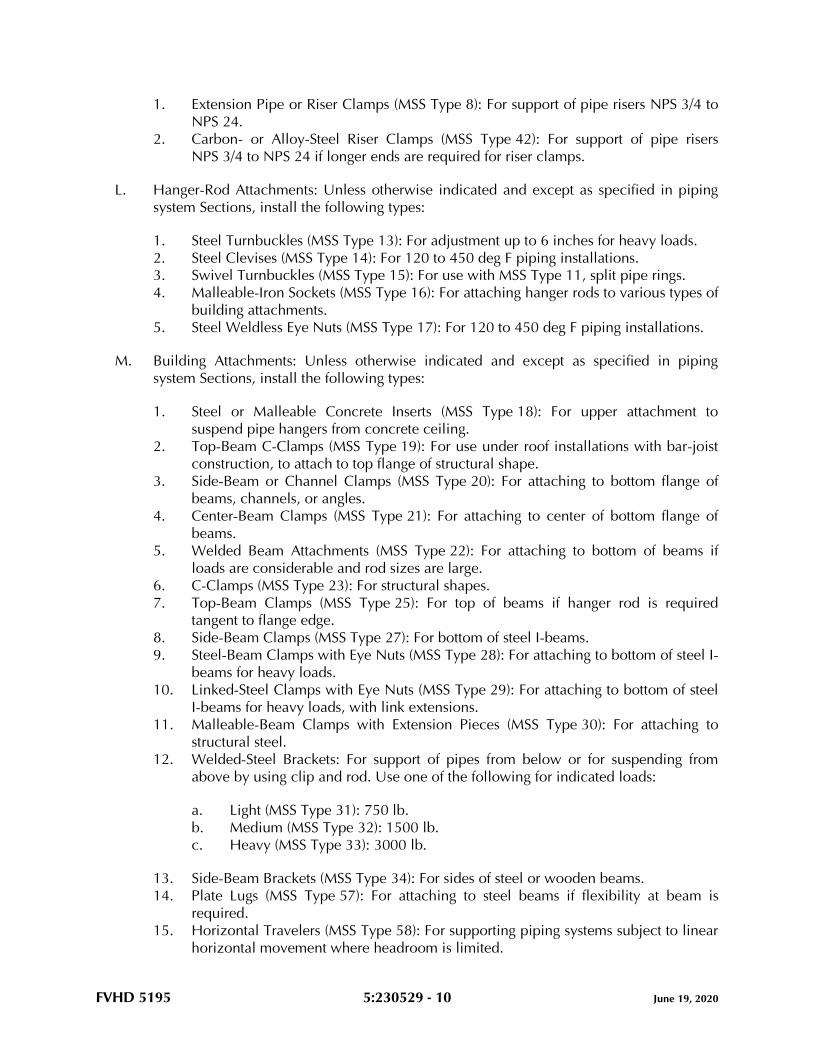
FVHD 5195 5:230529 - 10 June 19, 2020
1. Extension Pipe or Riser Clamps (MSS Type 8): For support of pipe risers NPS 3/4 to
NPS 24.
2. Carbon- or Alloy-Steel Riser Clamps (MSS Type 42): For support of pipe risers
NPS 3/4 to NPS 24 if longer ends are required for riser clamps.
L. Hanger-Rod Attachments: Unless otherwise indicated and except as specified in piping
system Sections, install the following types:
1. Steel Turnbuckles (MSS Type 13): For adjustment up to 6 inches for heavy loads.
2. Steel Clevises (MSS Type 14): For 120 to 450 deg F piping installations.
3. Swivel Turnbuckles (MSS Type 15): For use with MSS Type 11, split pipe rings.
4. Malleable-Iron Sockets (MSS Type 16): For attaching hanger rods to various types of
building attachments.
5. Steel Weldless Eye Nuts (MSS Type 17): For 120 to 450 deg F piping installations.
M. Building Attachments: Unless otherwise indicated and except as specified in piping
system Sections, install the following types:
1. Steel or Malleable Concrete Inserts (MSS Type 18): For upper attachment to
suspend pipe hangers from concrete ceiling.
2. Top-Beam C-Clamps (MSS Type 19): For use under roof installations with bar-joist
construction, to attach to top flange of structural shape.
3. Side-Beam or Channel Clamps (MSS Type 20): For attaching to bottom flange of
beams, channels, or angles.
4. Center-Beam Clamps (MSS Type 21): For attaching to center of bottom flange of
beams.
5. Welded Beam Attachments (MSS Type 22): For attaching to bottom of beams if
loads are considerable and rod sizes are large.
6. C-Clamps (MSS Type 23): For structural shapes.
7. Top-Beam Clamps (MSS Type 25): For top of beams if hanger rod is required
tangent to flange edge.
8. Side-Beam Clamps (MSS Type 27): For bottom of steel I-beams.
9. Steel-Beam Clamps with Eye Nuts (MSS Type 28): For attaching to bottom of steel I-
beams for heavy loads.
10. Linked-Steel Clamps with Eye Nuts (MSS Type 29): For attaching to bottom of steel
I-beams for heavy loads, with link extensions.
11. Malleable-Beam Clamps with Extension Pieces (MSS Type 30): For attaching to
structural steel.
12. Welded-Steel Brackets: For support of pipes from below or for suspending from
above by using clip and rod. Use one of the following for indicated loads:
a. Light (MSS Type 31): 750 lb.
b. Medium (MSS Type 32): 1500 lb.
c. Heavy (MSS Type 33): 3000 lb.
13. Side-Beam Brackets (MSS Type 34): For sides of steel or wooden beams.
14. Plate Lugs (MSS Type 57): For attaching to steel beams if flexibility at beam is
required.
15. Horizontal Travelers (MSS Type 58): For supporting piping systems subject to linear
horizontal movement where headroom is limited.
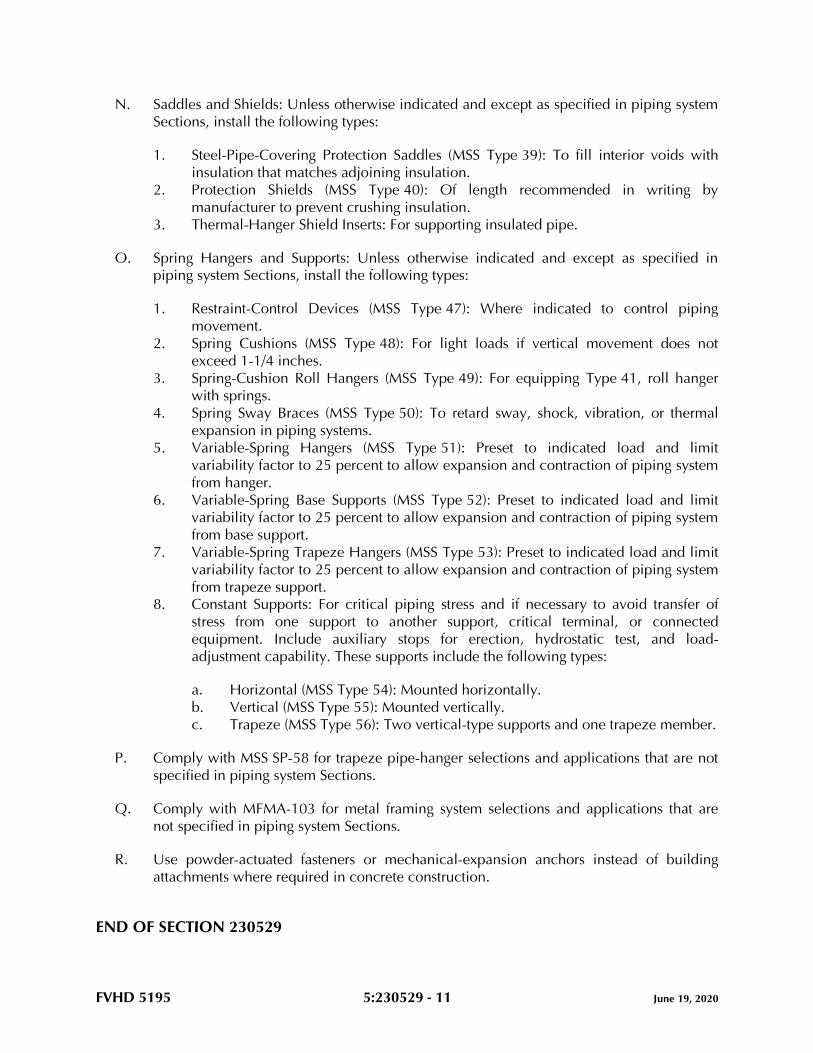
FVHD 5195 5:230529 - 11 June 19, 2020
N. Saddles and Shields: Unless otherwise indicated and except as specified in piping system
Sections, install the following types:
1. Steel-Pipe-Covering Protection Saddles (MSS Type 39): To fill interior voids with
insulation that matches adjoining insulation.
2. Protection Shields (MSS Type 40): Of length recommended in writing by
manufacturer to prevent crushing insulation.
3. Thermal-Hanger Shield Inserts: For supporting insulated pipe.
O. Spring Hangers and Supports: Unless otherwise indicated and except as specified in
piping system Sections, install the following types:
1. Restraint-Control Devices (MSS Type 47): Where indicated to control piping
movement.
2. Spring Cushions (MSS Type 48): For light loads if vertical movement does not
exceed 1-1/4 inches.
3. Spring-Cushion Roll Hangers (MSS Type 49): For equipping Type 41, roll hanger
with springs.
4. Spring Sway Braces (MSS Type 50): To retard sway, shock, vibration, or thermal
expansion in piping systems.
5. Variable-Spring Hangers (MSS Type 51): Preset to indicated load and limit
variability factor to 25 percent to allow expansion and contraction of piping system
from hanger.
6. Variable-Spring Base Supports (MSS Type 52): Preset to indicated load and limit
variability factor to 25 percent to allow expansion and contraction of piping system
from base support.
7. Variable-Spring Trapeze Hangers (MSS Type 53): Preset to indicated load and limit
variability factor to 25 percent to allow expansion and contraction of piping system
from trapeze support.
8. Constant Supports: For critical piping stress and if necessary to avoid transfer of
stress from one support to another support, critical terminal, or connected
equipment. Include auxiliary stops for erection, hydrostatic test, and load-
adjustment capability. These supports include the following types:
a. Horizontal (MSS Type 54): Mounted horizontally.
b. Vertical (MSS Type 55): Mounted vertically.
c. Trapeze (MSS Type 56): Two vertical-type supports and one trapeze member.
P. Comply with MSS SP-58 for trapeze pipe-hanger selections and applications that are not
specified in piping system Sections.
Q. Comply with MFMA-103 for metal framing system selections and applications that are
not specified in piping system Sections.
R. Use powder-actuated fasteners or mechanical-expansion anchors instead of building
attachments where required in concrete construction.
END OF SECTION 230529
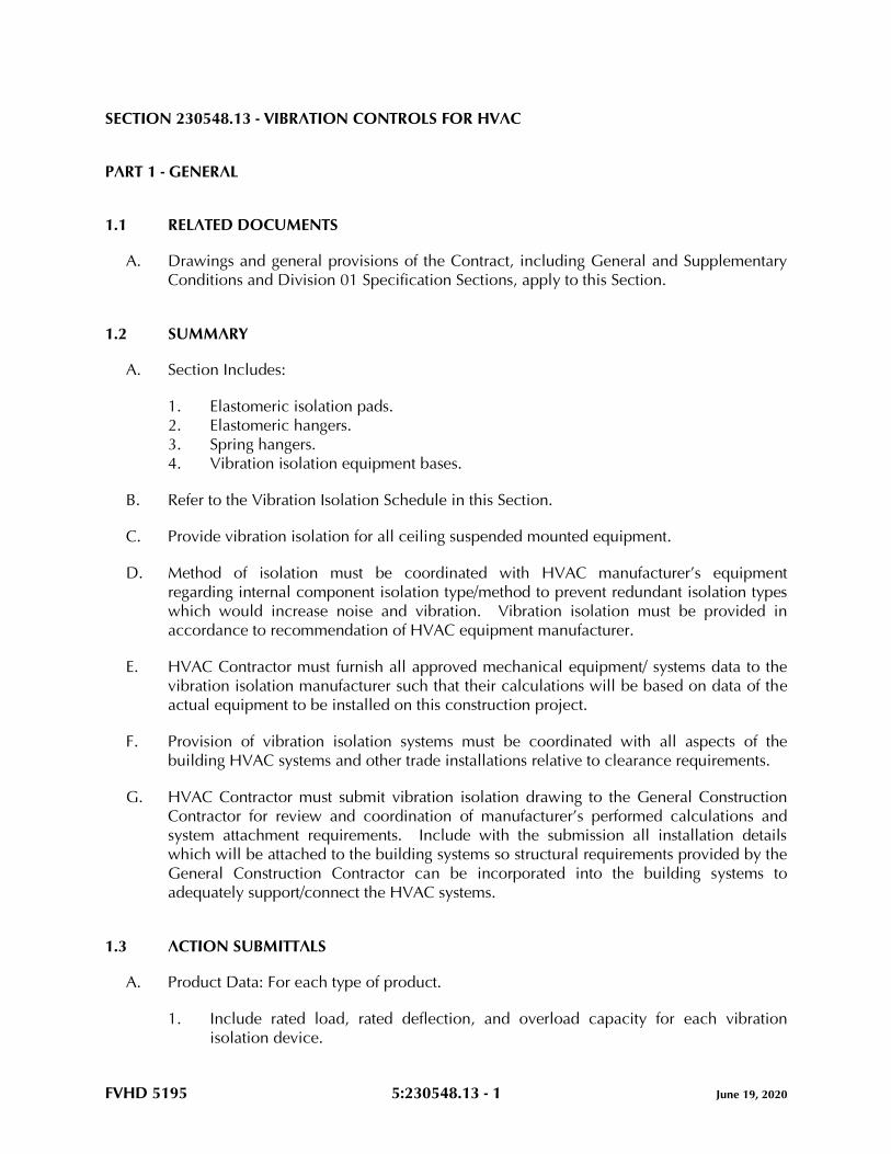
FVHD 5195 5:230548.13 - 1 June 19, 2020
SECTION 230548.13 - VIBRATION CONTROLS FOR HVAC
PART 1 - GENERAL
1.1 RELATED DOCUMENTS
A. Drawings and general provisions of the Contract, including General and Supplementary
Conditions and Division 01 Specification Sections, apply to this Section.
1.2 SUMMARY
A. Section Includes:
1. Elastomeric isolation pads.
2. Elastomeric hangers.
3. Spring hangers.
4. Vibration isolation equipment bases.
B. Refer to the Vibration Isolation Schedule in this Section.
C. Provide vibration isolation for all ceiling suspended mounted equipment.
D. Method of isolation must be coordinated with HVAC manufacturer’s equipment
regarding internal component isolation type/method to prevent redundant isolation types
which would increase noise and vibration. Vibration isolation must be provided in
accordance to recommendation of HVAC equipment manufacturer.
E. HVAC Contractor must furnish all approved mechanical equipment/ systems data to the
vibration isolation manufacturer such that their calculations will be based on data of the
actual equipment to be installed on this construction project.
F. Provision of vibration isolation systems must be coordinated with all aspects of the
building HVAC systems and other trade installations relative to clearance requirements.
G. HVAC Contractor must submit vibration isolation drawing to the General Construction
Contractor for review and coordination of manufacturer’s performed calculations and
system attachment requirements. Include with the submission all installation details
which will be attached to the building systems so structural requirements provided by the
General Construction Contractor can be incorporated into the building systems to
adequately support/connect the HVAC systems.
1.3 ACTION SUBMITTALS
A. Product Data: For each type of product.
1. Include rated load, rated deflection, and overload capacity for each vibration
isolation device.
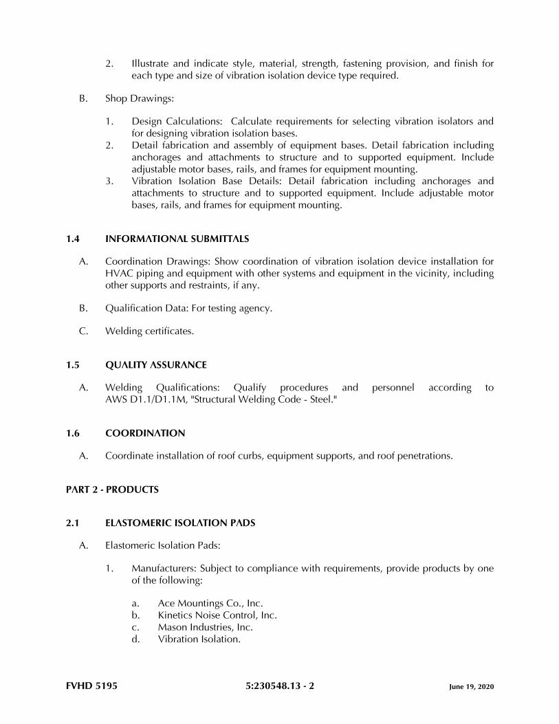
FVHD 5195 5:230548.13 - 2 June 19, 2020
2. Illustrate and indicate style, material, strength, fastening provision, and finish for
each type and size of vibration isolation device type required.
B. Shop Drawings:
1. Design Calculations: Calculate requirements for selecting vibration isolators and
for designing vibration isolation bases.
2. Detail fabrication and assembly of equipment bases. Detail fabrication including
anchorages and attachments to structure and to supported equipment. Include
adjustable motor bases, rails, and frames for equipment mounting.
3. Vibration Isolation Base Details: Detail fabrication including anchorages and
attachments to structure and to supported equipment. Include adjustable motor
bases, rails, and frames for equipment mounting.
1.4 INFORMATIONAL SUBMITTALS
A. Coordination Drawings: Show coordination of vibration isolation device installation for
HVAC piping and equipment with other systems and equipment in the vicinity, including
other supports and restraints, if any.
B. Qualification Data: For testing agency.
C. Welding certificates.
1.5 QUALITY ASSURANCE
A. Welding Qualifications: Qualify procedures and personnel according to
AWS D1.1/D1.1M, "Structural Welding Code - Steel."
1.6 COORDINATION
A. Coordinate installation of roof curbs, equipment supports, and roof penetrations.
PART 2 - PRODUCTS
2.1 ELASTOMERIC ISOLATION PADS
A. Elastomeric Isolation Pads:
1. Manufacturers: Subject to compliance with requirements, provide products by one
of the following:
a. Ace Mountings Co., Inc.
b. Kinetics Noise Control, Inc.
c. Mason Industries, Inc.
d. Vibration Isolation.
FVHD 5195 5:230548.13 - 3 June 19, 2020
2. Fabrication: Single or multiple layers of sufficient durometer stiffness for uniform
loading over pad area.
3. Size: Factory or field cut to match requirements of supported equipment.
4. Pad Material: Oil and water resistant with elastomeric properties.
5. Infused nonwoven cotton or synthetic fibers.
6. Rubber Isolator Pads: Elastomer (neoprene or silicone) arranged in single or
multiple layers and molded with a nonslip pattern and steel baseplates of sufficient
stiffness to provide uniform loading over the pad area.
7. Load Range: From 10 to 50 psig and a deflection not less than 0.08 inch per 1 inch
of thickness. Do not exceed a loading of 50 psig.
2.2 ELASTOMERIC HANGERS
A. Elastomeric Mount in a Steel Frame with Upper and Lower Steel Hanger Rods:
1. Manufacturers: Subject to compliance with requirements, provide products by one
of the following:
a. Ace Mountings Co., Inc.
b. Kinetics Noise Control, Inc.
c. Mason Industries, Inc.
d. Vibration Eliminator Co., Inc.
2. Frame: Steel, fabricated with a connection for an upper threaded hanger rod and an
opening on the underside to allow for a maximum of 30 degrees of angular lower
hanger-rod misalignment without binding or reducing isolation efficiency.
3. Dampening Element: Molded, oil-resistant rubber, neoprene, or other elastomeric
material with a projecting bushing for the underside opening preventing steel to
steel contact.
2.3 SPRING HANGERS
A. Combination Coil-Spring and Elastomeric-Insert Hanger with Spring and Insert in
Compression:
1. Manufacturers: Subject to compliance with requirements, provide products by one
of the following:
a. Ace Mountings Co., Inc.
b. Kinetics Noise Control, Inc.
c. Mason Industries, Inc.
d. Vibration Eliminator Co., Inc.
2. Frame: Steel, fabricated for connection to threaded hanger rods and to allow for a
maximum of 30 degrees of angular hanger-rod misalignment without binding or
reducing isolation efficiency.
3. Outside Spring Diameter: Not less than 80 percent of the compressed height of the
spring at rated load.
4. Minimum Additional Travel: 50 percent of the required deflection at rated load.
FVHD 5195 5:230548.13 - 4 June 19, 2020
5. Lateral Stiffness: More than 80 percent of rated vertical stiffness.
6. Overload Capacity: Support 200 percent of rated load, fully compressed, without
deformation or failure.
7. Elastomeric Element: Molded, oil-resistant rubber or neoprene. Steel-washer-
reinforced cup to support spring and bushing projecting through bottom of frame.
8. Adjustable Vertical Stop: Steel washer with neoprene washer "up-stop" on lower
threaded rod.
9. Self-centering hanger rod cap to ensure concentricity between hanger rod and
support spring coil.
2.4 VIBRATION ISOLATION EQUIPMENT BASES
A. Basis-of-Design Product: Subject to compliance with requirements, provide Kinetics
Noise Control, Inc; or a comparable product by one of the following:
1. Mason Industries, Inc.
2. Vibration Eliminator Co., Inc.
3. Vibration Isolation.
B. Steel Bases: Factory-fabricated, welded, structural-steel bases and rails.
1. Design Requirements: Lowest possible mounting height with not less than 1-inch
clearance above the floor. Include equipment anchor bolts and auxiliary motor
slide bases or rails.
2. Structural Steel: Steel shapes, plates, and bars complying with ASTM A36/A36M.
Bases shall have shape to accommodate supported equipment.
3. Support Brackets: Factory-welded steel brackets on frame for outrigger isolation
mountings and to provide for anchor bolts and equipment support.
PART 3 - EXECUTION
3.1 EXAMINATION
A. Examine areas and equipment to receive vibration isolation control devices for
compliance with requirements for installation tolerances and other conditions affecting
performance of the Work.
B. Examine roughing-in of reinforcement and cast-in-place anchors to verify actual locations
before installation.
C. Proceed with installation only after unsatisfactory conditions have been corrected.
3.2 VIBRATION CONTROL DEVICE INSTALLATION
A. Coordinate the location of embedded connection hardware with supported equipment
attachment and mounting points and with requirements for concrete reinforcement and
formwork specified in applicable Division 03 Sections.
FVHD 5195 5:230548.13 - 5 June 19, 2020
B. Installation of vibration isolators must not cause any change of position of equipment,
piping, or ductwork resulting in stresses or misalignment.
3.3 VIBRATION ISOLATION EQUIPMENT BASES INSTALLATION
A. Coordinate the location of embedded connection hardware with supported equipment
attachment and mounting points and with requirements for concrete reinforcement and
formwork specified in applicable Division 03 Sections.
3.4 FIELD QUALITY CONTROL
A. Testing: Engage a factory-authorized representative to perform the following field
quality-control testing:
B. Testing: Perform the following field quality-control testing:
1. Snubber minimum clearances.
2. Test and adjust controls and safeties. Replace damaged and malfunctioning
controls and equipment.
3.5 ADJUSTING
A. Adjust snubbers according to manufacturer's written recommendations.
B. Torque anchor bolts according to equipment manufacturer's written recommendations.
3.6 CLEANING
A. After completing equipment installation, inspect vibration isolation devices. Remove
paint splatters and other spots, dirt, and debris.
3.7 VIBRATION ISOLATION SCHEDULE
A. Unless noted otherwise on the Drawings, or in other Division 23 Sections, provide
vibration isolation method as indicated.
B. For HVAC equipment not indicated, provide vibration isolation method in accordance
with 2015 ASRHAE Handbook – Applications, Chapter 48 – Noise and Vibration Control.
EQUIPMENT TYPE ISOLATION METHOD
MINIMUM
DEFLECTION
(INCHES)
Ceiling recessed cabinet unit heaters Spring hangers ** Grade-mounted condensing units Elastomeric isolation pad **
Unit Heaters Elastomeric hangers **
In-line pumps Spring hangers **
FVHD 5195 5:230548.13 - 6 June 19, 2020
EQUIPMENT TYPE ISOLATION METHOD
MINIMUM
DEFLECTION
(INCHES)
Air handling units (AHU) installed on
the mezzanine floor
Vibration Isolation Equip-
ment Bases **
Air handling units (AHU) installed
from the overhead structure Spring hangers **
In-line Exhaust Fans (EF) Spring Hangers **
** Minimum deflection in accordance with performance requirements indicated in this Section
& the professional engineer responsible for the vibration calculations & isolator selections.
Coordinate minimum deflection with the applicable equipment manufacturer and referenced
ASHRAE Handbook.
END OF SECTION 230548.13

FVHD 5195 5:230593 - 1 June 19, 2020
SECTION 230593 - TESTING, ADJUSTING, AND BALANCING FOR HVAC
PART 1 - GENERAL
1.1 RELATED DOCUMENTS
A. Drawings and general provisions of the Contract, including General and Supplementary
Conditions and Division 01 Specification Sections, apply to this Section.
1.2 SUMMARY
A. Section Includes:
1. Balancing Air Systems:
a. Constant-volume air systems.
b. Variable-air-volume systems.
2. Balancing Hydronic Piping Systems:
a. Constant-flow hydronic systems.
b. Variable-flow hydronic systems.
c. Primary-secondary hydronic systems.
3. Testing, Adjusting, and Balancing Equipment:
a. Motors.
b. Condensing units.
c. Boilers.
d. Heat-transfer coils.
4. Sound tests. Refer to the Sound Tests Article.
5. Vibration tests.
6. Duct leakage tests.
7. Control system verification.
B. Provide vibration measurements and indicate analysis observations and
recommendations for any items to be corrected and/or measurements found to be
acceptable per industry standards and Specifications for design professional for review for
the following systems:
1. Mezzanine mounted air handling units:
a. AHU-01.
C. Replace fan and motor pulleys as required to achieve design conditions at no cost to the
project.
FVHD 5195 5:230593 - 2 June 19, 2020
D. Provide diagrams for all air and hydronic systems indicating device balanced values.
Diagrams must be with associated HVAC system.
E. Refer to all HVAC technical specification sections for additional TAB requirements, and
all necessary field support for coordination with the HVAC Commissioning Agent.
F. Provide Status Reports per the Progress Reporting Article.
1.3 DEFINITIONS
A. AABC: Associated Air Balance Council.
B. BAS: Building automation systems.
C. NEBB: National Environmental Balancing Bureau.
D. TAB: Testing, adjusting, and balancing.
E. TABB: Testing, Adjusting, and Balancing Bureau.
F. TAB Specialist: An independent entity meeting qualifications to perform TAB work.
G. TDH: Total dynamic head.
1.4 PREINSTALLATION MEETINGS
A. TAB Conference: If requested by the Owner, conduct a TAB conference at Project site
after approval of the TAB strategies and procedures plan to develop a mutual
understanding of the details. Provide a minimum of 14 days' advance notice of scheduled
meeting time and location.
1. Minimum Agenda Items:
a. The Contract Documents examination report.
b. The TAB plan.
c. Needs for coordination and cooperation of trades and subcontractors.
d. Proposed procedures for documentation and communication flow.
1.5 INFORMATIONAL SUBMITTALS
A. Qualification Data: Within 30 days of Contractor's Notice to Proceed, submit
documentation that the TAB specialist and this Project's TAB team members meet the
qualifications specified in "Quality Assurance" Article.
B. Contract Documents Examination Report: Within 30 days of Contractor's Notice to
Proceed, submit the Contract Documents review report as specified in Part 3.
FVHD 5195 5:230593 - 3 June 19, 2020
C. Strategies and Procedures Plan: Within 30 days of Contractor's Notice to Proceed, submit
TAB strategies and step-by-step procedures as specified in "Preparation" Article.
D. System Readiness Checklists: Within 30 days of Contractor's Notice to Proceed, submit
system readiness checklists as specified in "Preparation" Article.
E. Examination Report: Submit a summary report of the examination review required in
"Examination" Article.
F. Certified TAB reports.
G. Sample report forms.
H. Instrument calibration reports, to include the following:
1. Instrument type and make.
2. Serial number.
3. Application.
4. Dates of use.
5. Dates of calibration.
1.6 QUALITY ASSURANCE
A. TAB Specialists Qualifications: Certified by AABC.
1. TAB Field Supervisor: Employee of the TAB specialist and certified by AABC.
2. TAB Technician: Employee of the TAB specialist and certified by AABC as a TAB
technician.
B. TAB Specialists Qualifications: Certified by NEBB or TABB.
1. TAB Field Supervisor: Employee of the TAB specialist and certified by NEBB or
TABB.
2. TAB Technician: Employee of the TAB specialist and certified by NEBB or TABB as
a TAB technician.
C. Instrumentation Type, Quantity, Accuracy, and Calibration: Comply with requirements in
ASHRAE 111, Section 4, "Instrumentation."
D. ASHRAE/IES 90.1 Compliance: Applicable requirements in ASHRAE/IES 90.1,
Section 6.7.2.3 - "System Balancing."
1.7 FIELD CONDITIONS
A. Partial Owner Occupancy: Owner may occupy completed areas of building before
Substantial Completion. Cooperate with Owner during TAB operations to minimize
conflicts with Owner's operations.
FVHD 5195 5:230593 - 4 June 19, 2020
PART 2 - PRODUCTS (Not Applicable)
PART 3 - EXECUTION
3.1 EXAMINATION
A. Examine the Contract Documents to become familiar with Project requirements and to
discover conditions in systems designs that may preclude proper TAB of systems and
equipment.
B. Examine installed systems for balancing devices, such as test ports, gage cocks,
thermometer wells, flow-control devices, balancing valves and fittings, and manual
volume dampers. Verify that locations of these balancing devices are applicable for
intended purpose and are accessible.
C. Examine the approved submittals for HVAC systems and equipment.
D. Examine design data including HVAC system descriptions, statements of design
assumptions for environmental conditions and systems output, and statements of
philosophies and assumptions about HVAC system and equipment controls.
E. Examine ceiling plenums and underfloor air plenums used for supply, return, or relief air
to verify that they are properly separated from adjacent areas. Verify that penetrations in
plenum walls are sealed and fire-stopped if required.
F. Examine equipment performance data including fan and pump curves.
1. Relate performance data to Project conditions and requirements, including system
effects that can create undesired or unpredicted conditions that cause reduced
capacities in all or part of a system.
2. Calculate system-effect factors to reduce performance ratings of HVAC equipment
when installed under conditions different from the conditions used to rate
equipment performance. To calculate system effects for air systems, use tables and
charts found in AMCA 201, "Fans and Systems," or in SMACNA's "HVAC Systems -
Duct Design." Compare results with the design data and installed conditions.
G. Examine system and equipment installations and verify that field quality-control testing,
cleaning, and adjusting specified in individual Sections have been performed.
H. Examine test reports specified in individual system and equipment Sections.
I. Examine HVAC equipment and verify that bearings are greased, belts are aligned and
tight, filters are clean, and equipment with functioning controls is ready for operation.
J. Examine terminal units, such as variable-air-volume boxes, and verify that they are
accessible and their controls are connected and functioning.
K. Examine strainers. Verify that startup screens have been replaced by permanent screens
with indicated perforations.
FVHD 5195 5:230593 - 5 June 19, 2020
L. Examine control valves for proper installation for their intended function of throttling,
diverting, or mixing fluid flows.
M. Examine heat-transfer coils for correct piping connections and for clean and straight fins.
N. Examine system pumps to ensure absence of entrained air in the suction piping.
O. Examine operating safety interlocks and controls on HVAC equipment.
P. Report deficiencies discovered before and during performance of TAB procedures.
Observe and record system reactions to changes in conditions. Record default set points
if different from indicated values.
3.2 PREPARATION
A. Prepare a TAB plan that includes the following:
1. Equipment and systems to be tested.
2. Strategies and step-by-step procedures for balancing the systems.
3. Instrumentation to be used.
4. Sample forms with specific identification for all equipment.
B. Perform system-readiness checks of HVAC systems and equipment to verify system
readiness for TAB work. Include, at a minimum, the following:
1. Airside:
a. Verify that leakage and pressure tests on air distribution systems have been
satisfactorily completed.
b. Duct systems are complete with terminals installed.
c. Volume, smoke, and fire dampers are open and functional.
d. Clean filters are installed.
e. Fans are operating, free of vibration, and rotating in correct direction.
f. Variable-frequency controllers' startup is complete and safeties are verified.
g. Automatic temperature-control systems are operational.
h. Ceilings are installed.
i. Windows and doors are installed.
j. Suitable access to balancing devices and equipment is provided.
2. Hydronics:
a. Verify leakage and pressure tests on water distribution systems have been
satisfactorily completed.
b. Piping is complete with terminals installed.
c. Water treatment is complete.
d. Systems are flushed, filled, and air purged.
e. Strainers are pulled and cleaned.
f. Control valves are functioning per the sequence of operation.
g. Shutoff and balance valves have been verified to be 100 percent open.
FVHD 5195 5:230593 - 6 June 19, 2020
h. Pumps are started and proper rotation is verified.
i. Pump gage connections are installed directly at pump inlet and outlet flanges
or in discharge and suction pipe prior to valves or strainers.
j. Variable-frequency controllers' startup is complete and safeties are verified.
k. Suitable access to balancing devices and equipment is provided.
3.3 GENERAL PROCEDURES FOR TESTING AND BALANCING
A. Perform testing and balancing procedures on each system according to the procedures
contained in AABC's "National Standards for Total System Balance", NEBB's "Procedural
Standards for Testing, Adjusting, and Balancing of Environmental Systems", or SMACNA's
"HVAC Systems - Testing, Adjusting, and Balancing" and in this Section.
B. Cut insulation, ducts, pipes, and equipment cabinets for installation of test probes to the
minimum extent necessary for TAB procedures.
1. After testing and balancing, patch probe holes in ducts with same material and
thickness as used to construct ducts.
2. After testing and balancing, install test ports and duct access doors that comply
with requirements in applicable Division 23 Sections.
3. Install and join new insulation that matches removed materials. Restore insulation,
coverings, vapor barrier, and finish according to applicable Division 23 Sections.
C. Mark equipment and balancing devices, including damper-control positions, valve
position indicators, fan-speed-control levers, and similar controls and devices, with paint
or other suitable, permanent identification material to show final settings.
D. Take and report testing and balancing measurements in inch-pound (IP) units.
3.4 GENERAL PROCEDURES FOR BALANCING AIR SYSTEMS
A. Prepare test reports for both fans and outlets. Obtain manufacturer's outlet factors and
recommended testing procedures. Cross-check the summation of required outlet volumes
with required fan volumes.
B. Prepare schematic diagrams of systems' "as-built" duct layouts.
C. For variable-air-volume systems, develop a plan to simulate diversity.
D. Determine the best locations in main and branch ducts for accurate duct-airflow
measurements.
E. Check airflow patterns from the outdoor-air louvers and dampers and the return- and
exhaust-air dampers through the supply-fan discharge and mixing dampers.
F. Locate start-stop and disconnect switches, electrical interlocks, and motor starters.
G. Verify that motor starters are equipped with properly sized thermal protection.
FVHD 5195 5:230593 - 7 June 19, 2020
H. Check dampers for proper position to achieve desired airflow path.
I. Check for airflow blockages.
J. Check condensate drains for proper connections and functioning.
K. Check for proper sealing of air-handling-unit components.
L. Verify that air duct system is sealed as specified in applicable Division 23 Sections.
3.5 PROCEDURES FOR CONSTANT-VOLUME AIR SYSTEMS
A. Adjust fans to deliver total indicated airflows within the maximum allowable fan speed
listed by fan manufacturer.
1. Measure total airflow.
a. Set outside-air, return-air, and relief-air dampers for proper position that
simulates minimum outdoor-air conditions.
b. Where duct conditions allow, measure airflow by main Pitot-tube traverse. If
necessary, perform multiple Pitot-tube traverses, close to the fan and prior to
any outlets, to obtain total airflow.
c. Where duct conditions are not suitable for Pitot-tube traverse measurements,
a coil traverse may be acceptable.
2. Measure fan static pressures as follows:
a. Measure static pressure directly at the fan outlet or through the flexible
connection.
b. Measure static pressure directly at the fan inlet or through the flexible
connection.
c. Measure static pressure across each component that makes up the air-
handling system.
d. Report artificial loading of filters at the time static pressures are measured.
3. Review Record Documents to determine variations in design static pressures versus
actual static pressures. Calculate actual system-effect factors. Recommend
adjustments to accommodate actual conditions.
4. Obtain approval from Architect for adjustment of fan speed higher or lower than
indicated speed. Comply with requirements in HVAC Sections for air-handling
units for adjustment of fans, belts, and pulley sizes to achieve indicated air-
handling-unit performance.
5. Do not make fan-speed adjustments that result in motor overload. Consult
equipment manufacturers about fan-speed safety factors. Modulate dampers and
measure fan-motor amperage to ensure that no overload occurs. Measure
amperage in full-cooling, full-heating, economizer, and any other operating mode
to determine the maximum required brake horsepower.

FVHD 5195 5:230593 - 8 June 19, 2020
B. Adjust volume dampers for main duct, submain ducts, and major branch ducts to
indicated airflows.
1. Measure airflow of submain and branch ducts.
2. Adjust submain and branch duct volume dampers for specified airflow.
3. Re-measure each submain and branch duct after all have been adjusted.
C. Adjust air inlets and outlets for each space to indicated airflows.
1. Set airflow patterns of adjustable outlets for proper distribution without drafts.
2. Measure inlets and outlets airflow.
3. Adjust each inlet and outlet for specified airflow.
4. Re-measure each inlet and outlet after they have been adjusted.
D. Verify final system conditions.
1. Re-measure and confirm that minimum outdoor, return, and relief airflows are
within design. Readjust to design if necessary.
2. Re-measure and confirm that total airflow is within design.
3. Re-measure all final fan operating data, rpms, volts, amps, and static profile.
4. Mark all final settings.
5. Test system in economizer mode. Verify proper operation and adjust if necessary.
6. Measure and record all operating data.
7. Record final fan-performance data.
3.6 PROCEDURES FOR VARIABLE-AIR-VOLUME SYSTEMS
A. Adjust the variable-air-volume systems as follows:
1. Verify that the system static pressure sensor is located two-thirds of the distance
down the duct from the fan discharge.
2. Verify that the system is under static pressure control.
3. Select the terminal unit that is most critical to the supply-fan airflow. Measure inlet
static pressure, and adjust system static pressure control set point so the entering
static pressure for the critical terminal unit is not less than the sum of the terminal-
unit manufacturer's recommended minimum inlet static pressure plus the static
pressure needed to overcome terminal-unit discharge system losses.
4. Calibrate and balance each terminal unit for maximum and minimum design
airflow as follows:
a. Adjust controls so that terminal is calling for maximum airflow. Some
controllers require starting with minimum airflow. Verify calibration
procedure for specific project.
b. Measure airflow and adjust calibration factor as required for design
maximum airflow. Record calibration factor.
c. When maximum airflow is correct, balance the air outlets downstream from
terminal units.
d. Adjust controls so that terminal is calling for minimum airflow.
FVHD 5195 5:230593 - 9 June 19, 2020
e. Measure airflow and adjust calibration factor as required for design minimum
airflow. Record calibration factor. If no minimum calibration is available,
note any deviation from design airflow.
f. When in full cooling or full heating, ensure that there is no mixing of hot-
deck and cold-deck airstreams unless so designed.
g. On constant volume terminals, in critical areas where room pressure is to be
maintained, verify that the airflow remains constant over the full range of full
cooling to full heating. Note any deviation from design airflow or room
pressure.
5. After terminals have been calibrated and balanced, test and adjust system for total
airflow. Adjust fans to deliver total design airflows within the maximum allowable
fan speed listed by fan manufacturer.
a. Set outside-air, return-air, and relief-air dampers for proper position that
simulates minimum outdoor-air conditions.
b. Set terminals for maximum airflow. If system design includes diversity, adjust
terminals for maximum and minimum airflow so that connected total
matches fan selection and simulates actual load in the building.
c. Where duct conditions allow, measure airflow by Pitot-tube traverse. If
necessary, perform multiple Pitot-tube traverses to obtain total airflow.
d. Where duct conditions are not suitable for Pitot-tube traverse measurements,
a coil traverse may be acceptable.
e. If a reliable Pitot-tube traverse or coil traverse is not possible, measure
airflow at terminals and calculate the total airflow.
6. Measure fan static pressures as follows:
a. Measure static pressure directly at the fan outlet or through the flexible
connection.
b. Measure static pressure directly at the fan inlet or through the flexible
connection.
c. Measure static pressure across each component that makes up the air-
handling system.
d. Report any artificial loading of filters at the time static pressures are
measured.
7. Set final return and outside airflow to the fan while operating at maximum return
airflow and minimum outdoor airflow.
a. Balance the return-air ducts and inlets the same as described for constant-
volume air systems.
b. Verify that terminal units are meeting design airflow under system maximum
flow.
8. Re-measure the inlet static pressure at the most critical terminal unit and adjust the
system static pressure set point to the most energy-efficient set point to maintain the
optimum system static pressure. Record set point and give to controls contractor.
9. Verify final system conditions as follows:
FVHD 5195 5:230593 - 10 June 19, 2020
a. Re-measure and confirm that minimum outdoor, return, and relief airflows
are within design. Readjust to match design if necessary.
b. Re-measure and confirm that total airflow is within design.
c. Re-measure final fan operating data, rpms, volts, amps, and static profile.
d. Mark final settings.
e. Test system in economizer mode. Verify proper operation and adjust if
necessary. Measure and record all operating data.
f. Verify tracking between supply and return fans.
3.7 GENERAL PROCEDURES FOR HYDRONIC SYSTEMS
A. Prepare test reports for pumps, coils, and heat exchangers. Obtain approved submittals
and manufacturer-recommended testing procedures. Crosscheck the summation of
required coil and heat exchanger flow rates with pump design flow rate.
B. Prepare schematic diagrams of systems' "as-built" piping layouts.
C. In addition to requirements in "Preparation" Article, prepare hydronic systems for testing
and balancing as follows:
1. Check liquid level in expansion tank.
2. Check highest vent for adequate pressure.
3. Check flow-control valves for proper position.
4. Locate start-stop and disconnect switches, electrical interlocks, and motor starters.
5. Verify that motor starters are equipped with properly sized thermal protection.
6. Check that air has been purged from the system.
3.8 PROCEDURES FOR CONSTANT-FLOW HYDRONIC SYSTEMS
A. Adjust pumps to deliver total design gpm.
1. Measure total water flow.
a. Position valves for full flow through coils.
b. Measure flow by main flow meter, if installed.
c. If main flow meter is not installed, determine flow by pump TDH or
exchanger pressure drop.
2. Measure pump TDH as follows:
a. Measure discharge pressure directly at the pump outlet flange or in discharge
pipe prior to any valves.
b. Measure inlet pressure directly at the pump inlet flange or in suction pipe
prior to any valves or strainers.
c. Convert pressure to head and correct for differences in gage heights.
d. Verify pump impeller size by measuring the TDH with the discharge valve
closed. Note the point on manufacturer's pump curve at zero flow, and verify
that the pump has the intended impeller size.

FVHD 5195 5:230593 - 11 June 19, 2020
e. With valves open, read pump TDH. Adjust pump discharge valve until
design water flow is achieved.
3. Monitor motor performance during procedures and do not operate motor in an
overloaded condition.
B. Adjust flow-measuring devices installed in mains and branches to design water flows.
1. Measure flow in main and branch pipes.
2. Adjust main and branch balance valves for design flow.
3. Re-measure each main and branch after all have been adjusted.
C. Adjust flow-measuring devices installed at terminals for each space to design water flows.
1. Measure flow at terminals.
2. Adjust each terminal to design flow.
3. Re-measure each terminal after it is adjusted.
4. Position control valves to bypass the coil, and adjust the bypass valve to maintain
design flow.
5. Perform temperature tests after flows have been balanced.
D. For systems with pressure-independent valves at terminals:
1. Measure differential pressure and verify that it is within manufacturer's specified
range.
2. Perform temperature tests after flows have been verified.
E. For systems without pressure-independent valves or flow-measuring devices at terminals:
1. Measure and balance coils by either coil pressure drop or temperature method.
2. If balanced by coil pressure drop, perform temperature tests after flows have been
verified.
F. Verify final system conditions as follows:
1. Re-measure and confirm that total water flow is within design.
2. Re-measure final pumps' operating data, TDH, volts, amps, and static profile.
3. Mark final settings.
G. Verify that memory stops have been set.
3.9 PROCEDURES FOR VARIABLE-FLOW HYDRONIC SYSTEMS
A. Balance systems with automatic two- and three-way control valves by setting systems at
maximum flow through heat-exchange terminals, and proceed as specified above for
hydronic systems.
B. Adjust the variable-flow hydronic system as follows:
1. Verify that the differential-pressure sensor is located as indicated.
FVHD 5195 5:230593 - 12 June 19, 2020
2. Determine whether there is diversity in the system.
C. For systems with no diversity:
1. Adjust pumps to deliver total design gpm.
a. Measure total water flow.
1) Position valves for full flow through coils.
2) Measure flow by main flow meter, if installed.
3) If main flow meter is not installed, determine flow by pump TDH or
exchanger pressure drop.
b. Measure pump TDH as follows:
1) Measure discharge pressure directly at the pump outlet flange or in
discharge pipe prior to any valves.
2) Measure inlet pressure directly at the pump inlet flange or in suction
pipe prior to any valves or strainers.
3) Convert pressure to head and correct for differences in gage heights.
4) Verify pump impeller size by measuring the TDH with the discharge
valve closed. Note the point on manufacturer's pump curve at zero
flow and verify that the pump has the intended impeller size.
5) With valves open, read pump TDH. Adjust pump discharge valve until
design water flow is achieved.
c. Monitor motor performance during procedures and do not operate motor in
an overloaded condition.
2. Adjust flow-measuring devices installed in mains and branches to design water
flows.
a. Measure flow in main and branch pipes.
b. Adjust main and branch balance valves for design flow.
c. Re-measure each main and branch after all have been adjusted.
3. Adjust flow-measuring devices installed at terminals for each space to design water
flows.
a. Measure flow at terminals.
b. Adjust each terminal to design flow.
c. Re-measure each terminal after it is adjusted.
d. Position control valves to bypass the coil and adjust the bypass valve to
maintain design flow.
e. Perform temperature tests after flows have been balanced.
4. For systems with pressure-independent valves at terminals:
a. Measure differential pressure and verify that it is within manufacturer's
specified range.
FVHD 5195 5:230593 - 13 June 19, 2020
b. Perform temperature tests after flows have been verified.
5. For systems without pressure-independent valves or flow-measuring devices at
terminals:
a. Measure and balance coils by either coil pressure drop or temperature
method.
b. If balanced by coil pressure drop, perform temperature tests after flows have
been verified.
6. Prior to verifying final system conditions, determine the system differential-pressure
set point.
7. If the pump discharge valve was used to set total system flow with variable-
frequency controller at 60 Hz, at completion open discharge valve 100 percent and
allow variable-frequency controller to control system differential-pressure set point.
Record pump data under both conditions.
8. Mark final settings and verify that all memory stops have been set.
9. Verify final system conditions as follows:
a. Re-measure and confirm that total water flow is within design.
b. Re-measure final pumps' operating data, TDH, volts, amps, and static profile.
c. Mark final settings.
10. Verify that memory stops have been set.
D. For systems with diversity:
1. Determine diversity factor.
2. Simulate system diversity by closing required number of control valves, as
approved by the design engineer.
3. Adjust pumps to deliver total design gpm.
a. Measure total water flow.
1) Position valves for full flow through coils.
2) Measure flow by main flow meter, if installed.
3) If main flow meter is not installed, determine flow by pump TDH or
exchanger pressure drop.
b. Measure pump TDH as follows:
1) Measure discharge pressure directly at the pump outlet flange or in
discharge pipe prior to any valves.
2) Measure inlet pressure directly at the pump inlet flange or in suction
pipe prior to any valves or strainers.
3) Convert pressure to head and correct for differences in gage heights.
4) Verify pump impeller size by measuring the TDH with the discharge
valve closed. Note the point on manufacturer's pump curve at zero
flow and verify that the pump has the intended impeller size.

FVHD 5195 5:230593 - 14 June 19, 2020
5) With valves open, read pump TDH. Adjust pump discharge valve until
design water flow is achieved.
c. Monitor motor performance during procedures and do not operate motor in
an overloaded condition.
4. Adjust flow-measuring devices installed in mains and branches to design water
flows.
a. Measure flow in main and branch pipes.
b. Adjust main and branch balance valves for design flow.
c. Re-measure each main and branch after all have been adjusted.
5. Adjust flow-measuring devices installed at terminals for each space to design water
flows.
a. Measure flow at terminals.
b. Adjust each terminal to design flow.
c. Re-measure each terminal after it is adjusted.
d. Position control valves to bypass the coil, and adjust the bypass valve to
maintain design flow.
e. Perform temperature tests after flows have been balanced.
6. For systems with pressure-independent valves at terminals:
a. Measure differential pressure, and verify that it is within manufacturer's
specified range.
b. Perform temperature tests after flows have been verified.
7. For systems without pressure-independent valves or flow-measuring devices at
terminals:
a. Measure and balance coils by either coil pressure drop or temperature
method.
b. If balanced by coil pressure drop, perform temperature tests after flows have
been verified.
8. Open control valves that were shut. Close a sufficient number of control valves that
were previously open to maintain diversity, and balance terminals that were just
opened.
9. Prior to verifying final system conditions, determine system differential-pressure set
point.
10. If the pump discharge valve was used to set total system flow with variable-
frequency controller at 60 Hz, at completion open discharge valve 100 percent and
allow variable-frequency controller to control system differential-pressure set point.
Record pump data under both conditions.
11. Mark final settings and verify that memory stops have been set.
12. Verify final system conditions as follows:
a. Re-measure and confirm that total water flow is within design.
FVHD 5195 5:230593 - 15 June 19, 2020
b. Re-measure final pumps' operating data, TDH, volts, amps, and static profile.
c. Mark final settings.
13. Verify that memory stops have been set.
3.10 PROCEDURES FOR PRIMARY-SECONDARY HYDRONIC SYSTEMS
A. Balance the primary circuit flow first.
B. Balance the secondary circuits after the primary circuits are complete.
C. Adjust pumps to deliver total design gpm.
1. Measure total water flow.
a. Position valves for full flow through coils.
b. Measure flow by main flow meter, if installed.
c. If main flow meter is not installed, determine flow by pump TDH or
exchanger pressure drop.
2. Measure pump TDH as follows:
a. Measure discharge pressure directly at the pump outlet flange or in discharge
pipe prior to any valves.
b. Measure inlet pressure directly at the pump inlet flange or in suction pipe
prior to any valves or strainers.
c. Convert pressure to head and correct for differences in gage heights.
d. Verify pump impeller size by measuring the TDH with the discharge valve
closed. Note the point on manufacturer's pump curve at zero flow and verify
that the pump has the intended impeller size.
e. With valves open, read pump TDH. Adjust pump discharge valve until
design water flow is achieved.
3. Monitor motor performance during procedures and do not operate motor in an
overloaded condition.
D. Adjust flow-measuring devices installed in mains and branches to design water flows.
1. Measure flow in main and branch pipes.
2. Adjust main and branch balance valves for design flow.
3. Re-measure each main and branch after all have been adjusted.
E. Adjust flow-measuring devices installed at terminals for each space to design water flows.
1. Measure flow at terminals.
2. Adjust each terminal to design flow.
3. Re-measure each terminal after it is adjusted.
4. Position control valves to bypass the coil and adjust the bypass valve to maintain
design flow.
FVHD 5195 5:230593 - 16 June 19, 2020
5. Perform temperature tests after flows have been balanced.
F. For systems with pressure-independent valves at terminals:
1. Measure differential pressure and verify that it is within manufacturer's specified
range.
2. Perform temperature tests after flows have been verified.
G. For systems without pressure-independent valves or flow-measuring devices at terminals:
1. Measure and balance coils by either coil pressure drop or temperature method.
2. If balanced by coil pressure drop, perform temperature tests after flows have been
verified.
H. Verify final system conditions as follows:
1. Re-measure and confirm that total water flow is within design.
2. Re-measure final pumps' operating data, TDH, volts, amps, and static profile.
3. Mark final settings.
I. Verify that memory stops have been set.
3.11 PROCEDURES FOR MOTORS
A. Motors 1/2 HP and Larger: Test at final balanced conditions and record the following
data:
1. Manufacturer's name, model number, and serial number.
2. Motor horsepower rating.
3. Motor rpm.
4. Phase and hertz.
5. Nameplate and measured voltage, each phase.
6. Nameplate and measured amperage, each phase.
7. Starter size and thermal-protection-element rating.
8. Service factor and frame size.
B. Motors Driven by Variable-Frequency Controllers: Test manual bypass of controller to
prove proper operation.
3.12 PROCEDURES FOR CONDENSING UNITS
A. Verify proper rotation of fans.
B. Measure entering- and leaving-air temperatures.
C. Record fan and motor operating data.
FVHD 5195 5:230593 - 17 June 19, 2020
3.13 PROCEDURES FOR BOILERS
A. Hydronic Boilers:
1. Measure and record entering- and leaving-water temperatures.
2. Measure and record water flow.
3. Record relief valve pressure setting.
3.14 PROCEDURES FOR HEAT-TRANSFER COILS
A. Measure, adjust, and record the following data for each water coil:
1. Entering- and leaving-water temperature.
2. Water flow rate.
3. Water pressure drop for major (more than 20 gpm) equipment coils, excluding
unitary equipment such as reheat coils, unit heaters, and fan-coil units.
4. Dry-bulb temperature of entering and leaving air.
5. Wet-bulb temperature of entering and leaving air for cooling coils.
6. Airflow.
B. Measure, adjust, and record the following data for each refrigerant coil:
1. Dry-bulb temperature of entering and leaving air.
2. Wet-bulb temperature of entering and leaving air.
3. Airflow.
3.15 SOUND TESTS
A. After the systems are balanced and construction is Substantially Complete perform sound
testing at locations on Project for each of the following space types. For each space type
tested, select a measurement location that has the greatest sound level. If testing multiple
locations for each space type, select at least one location that is near and at least one
location that is remote from the predominant sound source.
1. Offices (Provide tests in 10% of spaces).
2. Conference Rooms.
3. Maintenance Spaces.
B. Instrumentation:
1. The sound-testing meter shall be a portable, general-purpose testing meter
consisting of a microphone, processing unit, and readout.
2. The sound-testing meter shall be capable of showing fluctuations at minimum and
maximum levels, and measuring the equivalent continuous sound pressure level
(LEQ).
3. The sound-testing meter must be capable of using 1/3 octave band filters to
measure mid-frequencies from 31.5 Hz to 8000 Hz.
4. The accuracy of the sound-testing meter shall be plus or minus one decibel.
FVHD 5195 5:230593 - 18 June 19, 2020
C. Test Procedures:
1. Perform test at quietest background noise period. Note cause of unpreventable
sound that affects test outcome.
2. Equipment should be operating at design values.
3. Calibrate the sound-testing meter prior to taking measurements.
4. Use a microphone suitable for the type of noise levels measured that is compatible
with meter. Provide a windshield for outside or in-duct measurements.
5. Record a set of background measurements in dBA and sound pressure levels in the
eight un-weighted octave bands 63 Hz to 8000 Hz (NC) with the equipment off.
6. Take sound readings in dBA and sound pressure levels in the eight un-weighted
octave bands 63 Hz to 8000 Hz (NC) with the equipment operating.
7. Take readings no closer than 36 inches from a wall or from the operating
equipment and approximately 60 inches from the floor, with the meter held or
mounted on a tripod.
8. For outdoor measurements, move sound-testing meter slowly and scan area that
has the most exposure to noise source being tested. Use A-weighted scale for this
type of reading.
D. Reporting:
1. Report shall record the following:
a. Location.
b. System tested.
c. dBA reading.
d. Sound pressure level in each octave band with equipment on and off.
2. Plot sound pressure levels on NC worksheet with equipment on and off.
3.16 VIBRATION TESTS
A. After systems are balanced and construction is Substantially Complete, measure and
record vibration levels on equipment listed in the Summary Article.
B. Instrumentation:
1. Use portable, battery-operated, and microprocessor-controlled vibration meter with
or without a built-in printer.
2. The meter shall automatically identify engineering units, filter bandwidth,
amplitude, and frequency scale values.
3. The meter shall be able to measure machine vibration displacement in mils of
deflection, velocity in inches per second, and acceleration in inches per second
squared.
4. Verify calibration date is current for vibration meter before taking readings.
C. Test Procedures:
FVHD 5195 5:230593 - 19 June 19, 2020
1. To ensure accurate readings, verify that accelerometer has a clean, flat surface and
is mounted properly.
2. With the unit running, set up vibration meter in a safe, secure location. Connect
transducer to meter with proper cables. Hold magnetic tip of transducer on top of
the bearing, and measure unit in mils of deflection. Record measurement, then
move transducer to the side of the bearing and record in mils of deflection. Record
an axial reading in mils of deflection by holding nonmagnetic, pointed transducer
tip on end of shaft.
3. Change vibration meter to velocity (inches per second) measurements. Repeat and
record above measurements.
4. Record CPM or rpm.
5. Read each bearing on motor, fan, and pump as required. Track and record
vibration levels from rotating component through casing to base.
D. Reporting:
1. Report shall record location and the system tested.
2. Include horizontal-vertical-axial measurements for tests.
3. Verify that vibration limits follow Specifications, or, if not specified, follow the
General Machinery Vibration Severity Chart or Vibration Acceleration General
Severity Chart from the AABC National Standards. Acceptable levels of vibration
are normally "smooth" to "good."
4. Include in report General Machinery Vibration Severity Chart, with conditions
plotted.
3.17 DUCT LEAKAGE TESTS
A. Witness the duct pressure testing performed by Installer.
B. Verify that proper test methods are used and that leakage rates are within specified
tolerances.
C. Report deficiencies observed.
3.18 CONTROLS VERIFICATION
A. In conjunction with system balancing, perform the following:
1. Verify temperature control system is operating within the design limitations.
2. Confirm that the sequences of operation are in compliance with Contract
Documents.
3. Verify that controllers are calibrated and function as intended.
4. Verify that controller set points are as indicated.
5. Verify the operation of lockout or interlock systems.
6. Verify the operation of valve and damper actuators.
7. Verify that controlled devices are properly installed and connected to correct
controller.
FVHD 5195 5:230593 - 20 June 19, 2020
8. Verify that controlled devices travel freely and are in position indicated by
controller: open, closed, or modulating.
9. Verify location and installation of sensors to ensure that they sense only intended
temperature, humidity, or pressure.
B. Reporting: Include a summary of verifications performed, remaining deficiencies, and
variations from indicated conditions.
3.19 TOLERANCES
A. Set HVAC system's airflow rates and water flow rates within the following tolerances:
1. Supply, Return, and Exhaust Fans and Equipment with Fans: Plus 0 to plus 10
percent.
2. Air Outlets and Inlets: Plus or minus 10 percent.
3. Heating-Water Flow Rate: Plus 0 to plus 10 percent.
B. Maintaining pressure relationships as designed shall have priority over the tolerances
specified above.
3.20 PROGRESS REPORTING
A. Initial Construction-Phase Report: Based on examination of the Contract Documents as
specified in "Examination" Article, prepare a report on the adequacy of design for systems
balancing devices. Recommend changes and additions to systems balancing devices to
facilitate proper performance measuring and balancing. Recommend changes and
additions to HVAC systems and general construction to allow access for performance
measuring and balancing devices.
B. Status Reports: Prepare biweekly progress reports to describe completed procedures,
procedures in progress, and scheduled procedures. Include a list of deficiencies and
problems found in systems being tested and balanced. Prepare a separate report for each
system and each building floor for systems serving multiple floors.
3.21 FINAL REPORT
A. General: Prepare a certified written report; tabulate and divide the report into separate
sections for tested systems and balanced systems.
1. Include a certification sheet at the front of the report's binder, signed and sealed by
the certified testing and balancing engineer.
2. Include a list of instruments used for procedures, along with proof of calibration.
3. Certify validity and accuracy of field data.
B. Final Report Contents: In addition to certified field-report data, include the following:
1. Pump curves.
2. Fan curves.
FVHD 5195 5:230593 - 21 June 19, 2020
3. Manufacturers' test data.
4. Field test reports prepared by system and equipment installers.
5. Other information relative to equipment performance; do not include Shop
Drawings and Product Data.
C. General Report Data: In addition to form titles and entries, include the following data:
1. Title page.
2. Name and address of the TAB specialist.
3. Project name.
4. Project location.
5. Architect's name and address.
6. Engineer's name and address.
7. Contractor's name and address.
8. Report date.
9. Signature of TAB supervisor who certifies the report.
10. Table of Contents with the total number of pages defined for each section of the
report. Number each page in the report.
11. Summary of contents including the following:
a. Indicated versus final performance.
b. Notable characteristics of systems.
c. Description of system operation sequence if it varies from the Contract
Documents.
12. Nomenclature sheets for each item of equipment.
13. Data for terminal units, including manufacturer's name, type, size, and fittings.
14. Notes to explain why certain final data in the body of reports vary from indicated
values.
15. Test conditions for fans and pump performance forms including the following:
a. Settings for outdoor-, return-, and exhaust-air dampers.
b. Conditions of filters.
c. Cooling coil, wet- and dry-bulb conditions.
d. Face and bypass damper settings at coils.
e. Fan drive settings including settings and percentage of maximum pitch
diameter.
f. Inlet vane settings for variable-air-volume systems.
g. Settings for supply-air, static-pressure controller.
h. Other system operating conditions that affect performance.
D. System Diagrams: Include schematic layouts of air and hydronic distribution systems.
Present each system with single-line diagram and include the following:
1. Quantities of outdoor, supply, return, and exhaust airflows.
2. Water and steam flow rates.
3. Duct, outlet, and inlet sizes.
4. Pipe and valve sizes and locations.
5. Terminal units.
6. Balancing stations.
FVHD 5195 5:230593 - 22 June 19, 2020
7. Position of balancing devices.
E. Air-Handling-Unit Test Reports: For air-handling units with coils, include the following:
1. Unit Data:
a. Unit identification.
b. Location.
c. Make and type.
d. Model number and unit size.
e. Manufacturer's serial number.
f. Unit arrangement and class.
g. Discharge arrangement.
h. Sheave make, size in inches, and bore.
i. Center-to-center dimensions of sheave and amount of adjustments in inches.
j. Number, make, and size of belts.
k. Number, type, and size of filters.
2. Motor Data:
a. Motor make, and frame type and size.
b. Horsepower and rpm.
c. Volts, phase, and hertz.
d. Full-load amperage and service factor.
e. Sheave make, size in inches, and bore.
f. Center-to-center dimensions of sheave and amount of adjustments in inches.
3. Test Data (Indicated and Actual Values):
a. Total airflow rate in cfm.
b. Total system static pressure in inches wg.
c. Fan rpm.
d. Discharge static pressure in inches wg.
e. Filter static-pressure differential in inches wg.
f. Preheat-coil static-pressure differential in inches wg.
g. Cooling-coil static-pressure differential in inches wg.
h. Heating-coil static-pressure differential in inches wg.
i. Outdoor airflow in cfm.
j. Return airflow in cfm.
k. Outdoor-air damper position.
l. Return-air damper position.
m. Vortex damper position.
F. Apparatus-Coil Test Reports:
1. Coil Data:
a. System identification.
b. Location.
c. Coil type.
FVHD 5195 5:230593 - 23 June 19, 2020
d. Number of rows.
e. Fin spacing in fins per inch o.c.
f. Make and model number.
g. Face area in sq. ft.
h. Tube size in NPS.
i. Tube and fin materials.
j. Circuiting arrangement.
2. Test Data (Indicated and Actual Values):
a. Airflow rate in cfm.
b. Average face velocity in fpm.
c. Air pressure drop in inches wg.
d. Outdoor-air, wet- and dry-bulb temperatures in deg F.
e. Return-air, wet- and dry-bulb temperatures in deg F.
f. Entering-air, wet- and dry-bulb temperatures in deg F.
g. Leaving-air, wet- and dry-bulb temperatures in deg F.
h. Water flow rate in gpm.
i. Water pressure differential in feet of head or psig.
j. Entering-water temperature in deg F.
k. Leaving-water temperature in deg F.
l. Refrigerant expansion valve and refrigerant types.
m. Refrigerant suction pressure in psig.
n. Refrigerant suction temperature in deg F.
o. Inlet steam pressure in psig.
G. Gas- and Oil-Fired Heat Apparatus Test Reports: In addition to manufacturer's factory
startup equipment reports, include the following:
1. Unit Data:
a. System identification.
b. Location.
c. Make and type.
d. Model number and unit size.
e. Manufacturer's serial number.
f. Fuel type in input data.
g. Output capacity in Btu/h.
h. Ignition type.
i. Burner-control types.
j. Motor horsepower and rpm.
k. Motor volts, phase, and hertz.
l. Motor full-load amperage and service factor.
m. Sheave make, size in inches, and bore.
n. Center-to-center dimensions of sheave and amount of adjustments in inches.
2. Test Data (Indicated and Actual Values):
a. Total airflow rate in cfm.
b. Entering-air temperature in deg F.
FVHD 5195 5:230593 - 24 June 19, 2020
c. Leaving-air temperature in deg F.
d. Air temperature differential in deg F.
e. Entering-air static pressure in inches wg.
f. Leaving-air static pressure in inches wg.
g. Air static-pressure differential in inches wg.
h. Low-fire fuel input in Btu/h.
i. High-fire fuel input in Btu/h.
j. Manifold pressure in psig.
k. High-temperature-limit setting in deg F.
l. Operating set point in Btu/h.
m. Motor voltage at each connection.
n. Motor amperage for each phase.
o. Heating value of fuel in Btu/h.
H. Fan Test Reports: For supply, return, and exhaust fans, include the following:
1. Fan Data:
a. System identification.
b. Location.
c. Make and type.
d. Model number and size.
e. Manufacturer's serial number.
f. Arrangement and class.
g. Sheave make, size in inches, and bore.
h. Center-to-center dimensions of sheave and amount of adjustments in inches.
2. Motor Data:
a. Motor make, and frame type and size.
b. Horsepower and rpm.
c. Volts, phase, and hertz.
d. Full-load amperage and service factor.
e. Sheave make, size in inches, and bore.
f. Center-to-center dimensions of sheave, and amount of adjustments in inches.
g. Number, make, and size of belts.
3. Test Data (Indicated and Actual Values):
a. Total airflow rate in cfm.
b. Total system static pressure in inches wg.
c. Fan rpm.
d. Discharge static pressure in inches wg.
e. Suction static pressure in inches wg.
I. Round, Flat-Oval, and Rectangular Duct Traverse Reports: Include a diagram with a grid
representing the duct cross-section and record the following:
1. Report Data:
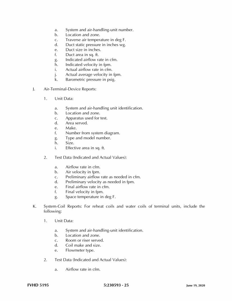
FVHD 5195 5:230593 - 25 June 19, 2020
a. System and air-handling-unit number.
b. Location and zone.
c. Traverse air temperature in deg F.
d. Duct static pressure in inches wg.
e. Duct size in inches.
f. Duct area in sq. ft.
g. Indicated airflow rate in cfm.
h. Indicated velocity in fpm.
i. Actual airflow rate in cfm.
j. Actual average velocity in fpm.
k. Barometric pressure in psig.
J. Air-Terminal-Device Reports:
1. Unit Data:
a. System and air-handling unit identification.
b. Location and zone.
c. Apparatus used for test.
d. Area served.
e. Make.
f. Number from system diagram.
g. Type and model number.
h. Size.
i. Effective area in sq. ft.
2. Test Data (Indicated and Actual Values):
a. Airflow rate in cfm.
b. Air velocity in fpm.
c. Preliminary airflow rate as needed in cfm.
d. Preliminary velocity as needed in fpm.
e. Final airflow rate in cfm.
f. Final velocity in fpm.
g. Space temperature in deg F.
K. System-Coil Reports: For reheat coils and water coils of terminal units, include the
following:
1. Unit Data:
a. System and air-handling-unit identification.
b. Location and zone.
c. Room or riser served.
d. Coil make and size.
e. Flowmeter type.
2. Test Data (Indicated and Actual Values):
a. Airflow rate in cfm.

FVHD 5195 5:230593 - 26 June 19, 2020
b. Entering-water temperature in deg F.
c. Leaving-water temperature in deg F.
d. Water pressure drop in feet of head or psig.
e. Entering-air temperature in deg F.
f. Leaving-air temperature in deg F.
L. Pump Test Reports: Calculate impeller size by plotting the shutoff head on pump curves
and include the following:
1. Unit Data:
a. Unit identification.
b. Location.
c. Service.
d. Make and size.
e. Model number and serial number.
f. Water flow rate in gpm.
g. Water pressure differential in feet of head or psig.
h. Required net positive suction head in feet of head or psig.
i. Pump rpm.
j. Impeller diameter in inches.
k. Motor make and frame size.
l. Motor horsepower and rpm.
m. Voltage at each connection.
n. Amperage for each phase.
o. Full-load amperage and service factor.
p. Seal type.
2. Test Data (Indicated and Actual Values):
a. Static head in feet of head or psig.
b. Pump shutoff pressure in feet of head or psig.
c. Actual impeller size in inches.
d. Full-open flow rate in gpm.
e. Full-open pressure in feet of head or psig.
f. Final discharge pressure in feet of head or psig.
g. Final suction pressure in feet of head or psig.
h. Final total pressure in feet of head or psig.
i. Final water flow rate in gpm.
j. Voltage at each connection.
k. Amperage for each phase.
M. Instrument Calibration Reports:
1. Report Data:
a. Instrument type and make.
b. Serial number.
c. Application.
d. Dates of use.
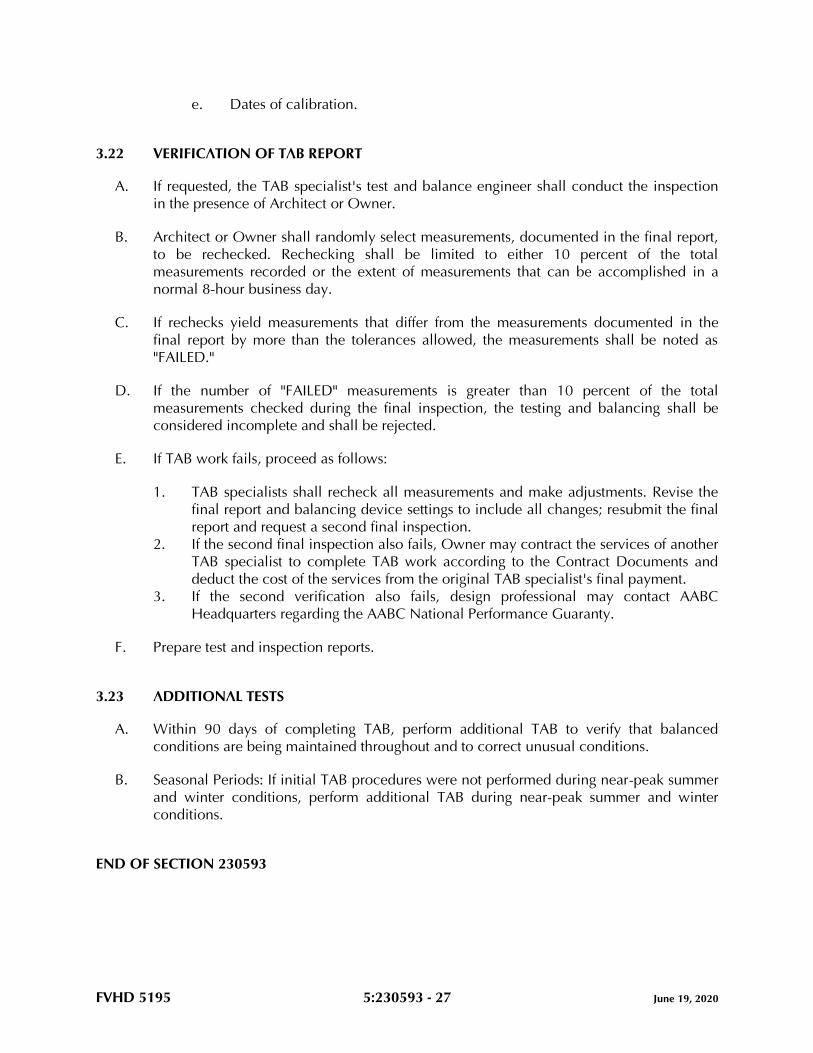
FVHD 5195 5:230593 - 27 June 19, 2020
e. Dates of calibration.
3.22 VERIFICATION OF TAB REPORT
A. If requested, the TAB specialist's test and balance engineer shall conduct the inspection
in the presence of Architect or Owner.
B. Architect or Owner shall randomly select measurements, documented in the final report,
to be rechecked. Rechecking shall be limited to either 10 percent of the total
measurements recorded or the extent of measurements that can be accomplished in a
normal 8-hour business day.
C. If rechecks yield measurements that differ from the measurements documented in the
final report by more than the tolerances allowed, the measurements shall be noted as
"FAILED."
D. If the number of "FAILED" measurements is greater than 10 percent of the total
measurements checked during the final inspection, the testing and balancing shall be
considered incomplete and shall be rejected.
E. If TAB work fails, proceed as follows:
1. TAB specialists shall recheck all measurements and make adjustments. Revise the
final report and balancing device settings to include all changes; resubmit the final
report and request a second final inspection.
2. If the second final inspection also fails, Owner may contract the services of another
TAB specialist to complete TAB work according to the Contract Documents and
deduct the cost of the services from the original TAB specialist's final payment.
3. If the second verification also fails, design professional may contact AABC
Headquarters regarding the AABC National Performance Guaranty.
F. Prepare test and inspection reports.
3.23 ADDITIONAL TESTS
A. Within 90 days of completing TAB, perform additional TAB to verify that balanced
conditions are being maintained throughout and to correct unusual conditions.
B. Seasonal Periods: If initial TAB procedures were not performed during near-peak summer
and winter conditions, perform additional TAB during near-peak summer and winter
conditions.
END OF SECTION 230593
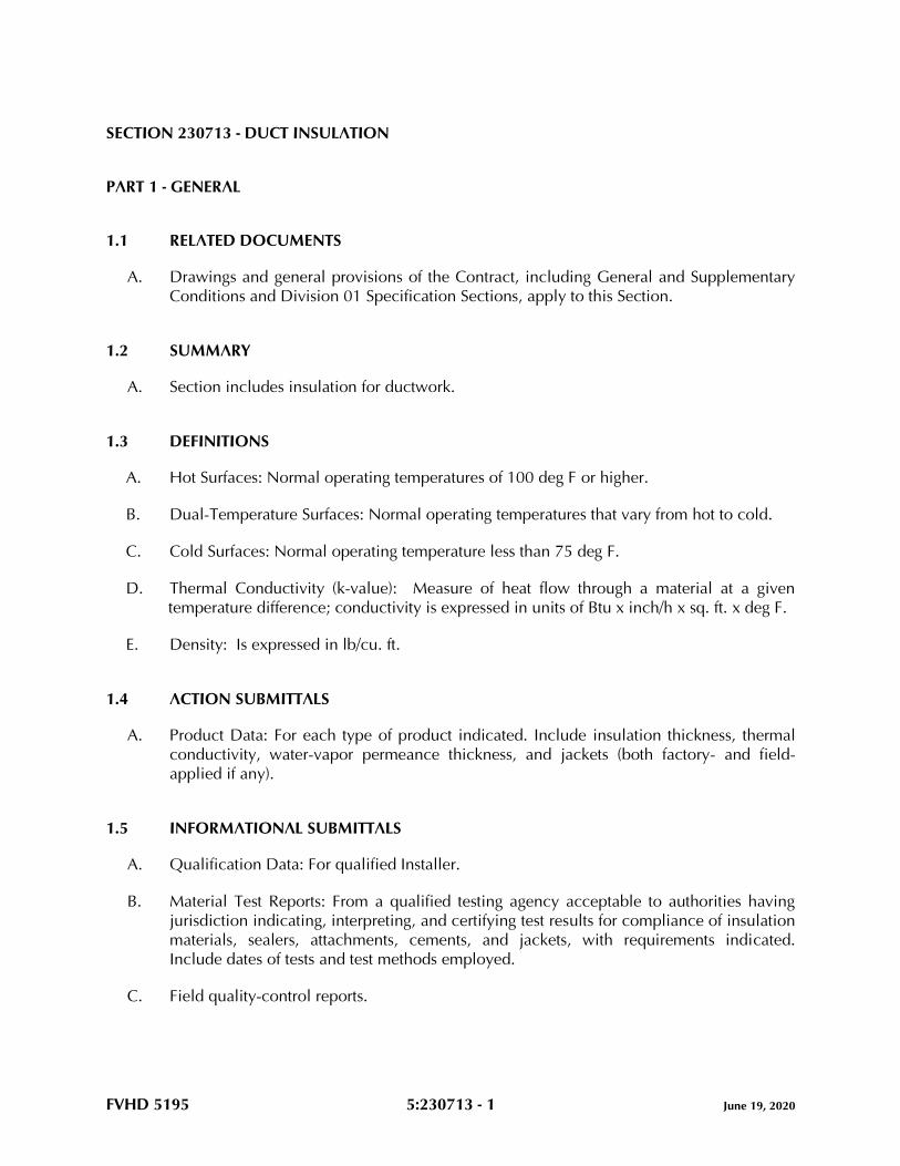
FVHD 5195 5:230713 - 1 June 19, 2020
SECTION 230713 - DUCT INSULATION
PART 1 - GENERAL
1.1 RELATED DOCUMENTS
A. Drawings and general provisions of the Contract, including General and Supplementary
Conditions and Division 01 Specification Sections, apply to this Section.
1.2 SUMMARY
A. Section includes insulation for ductwork.
1.3 DEFINITIONS
A. Hot Surfaces: Normal operating temperatures of 100 deg F or higher.
B. Dual-Temperature Surfaces: Normal operating temperatures that vary from hot to cold.
C. Cold Surfaces: Normal operating temperature less than 75 deg F.
D. Thermal Conductivity (k-value): Measure of heat flow through a material at a given
temperature difference; conductivity is expressed in units of Btu x inch/h x sq. ft. x deg F.
E. Density: Is expressed in lb/cu. ft.
1.4 ACTION SUBMITTALS
A. Product Data: For each type of product indicated. Include insulation thickness, thermal
conductivity, water-vapor permeance thickness, and jackets (both factory- and field-
applied if any).
1.5 INFORMATIONAL SUBMITTALS
A. Qualification Data: For qualified Installer.
B. Material Test Reports: From a qualified testing agency acceptable to authorities having
jurisdiction indicating, interpreting, and certifying test results for compliance of insulation
materials, sealers, attachments, cements, and jackets, with requirements indicated.
Include dates of tests and test methods employed.
C. Field quality-control reports.
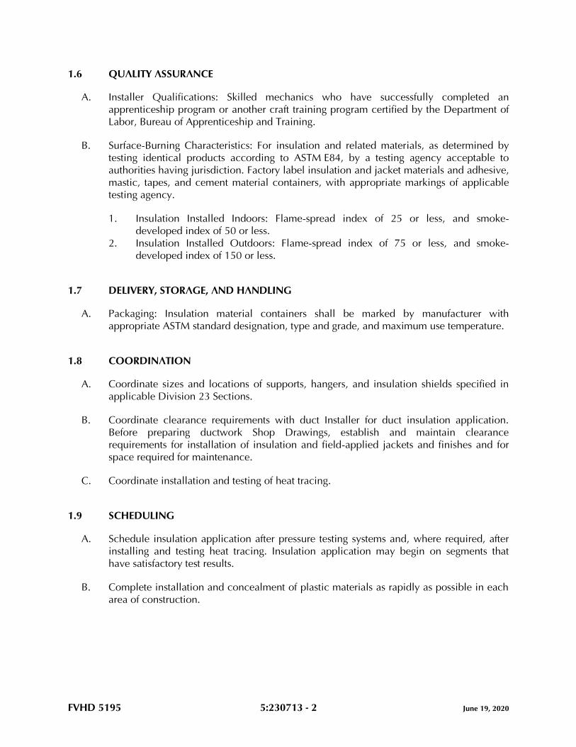
FVHD 5195 5:230713 - 2 June 19, 2020
1.6 QUALITY ASSURANCE
A. Installer Qualifications: Skilled mechanics who have successfully completed an
apprenticeship program or another craft training program certified by the Department of
Labor, Bureau of Apprenticeship and Training.
B. Surface-Burning Characteristics: For insulation and related materials, as determined by
testing identical products according to ASTM E84, by a testing agency acceptable to
authorities having jurisdiction. Factory label insulation and jacket materials and adhesive,
mastic, tapes, and cement material containers, with appropriate markings of applicable
testing agency.
1. Insulation Installed Indoors: Flame-spread index of 25 or less, and smoke-
developed index of 50 or less.
2. Insulation Installed Outdoors: Flame-spread index of 75 or less, and smoke-
developed index of 150 or less.
1.7 DELIVERY, STORAGE, AND HANDLING
A. Packaging: Insulation material containers shall be marked by manufacturer with
appropriate ASTM standard designation, type and grade, and maximum use temperature.
1.8 COORDINATION
A. Coordinate sizes and locations of supports, hangers, and insulation shields specified in
applicable Division 23 Sections.
B. Coordinate clearance requirements with duct Installer for duct insulation application.
Before preparing ductwork Shop Drawings, establish and maintain clearance
requirements for installation of insulation and field-applied jackets and finishes and for
space required for maintenance.
C. Coordinate installation and testing of heat tracing.
1.9 SCHEDULING
A. Schedule insulation application after pressure testing systems and, where required, after
installing and testing heat tracing. Insulation application may begin on segments that
have satisfactory test results.
B. Complete installation and concealment of plastic materials as rapidly as possible in each
area of construction.
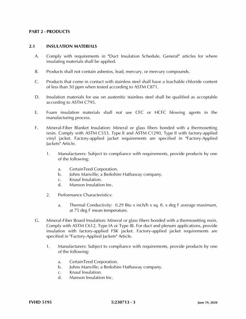
FVHD 5195 5:230713 - 3 June 19, 2020
PART 2 - PRODUCTS
2.1 INSULATION MATERIALS
A. Comply with requirements in "Duct Insulation Schedule, General" articles for where
insulating materials shall be applied.
B. Products shall not contain asbestos, lead, mercury, or mercury compounds.
C. Products that come in contact with stainless steel shall have a leachable chloride content
of less than 50 ppm when tested according to ASTM C871.
D. Insulation materials for use on austenitic stainless steel shall be qualified as acceptable
according to ASTM C795.
E. Foam insulation materials shall not use CFC or HCFC blowing agents in the
manufacturing process.
F. Mineral-Fiber Blanket Insulation: Mineral or glass fibers bonded with a thermosetting
resin. Comply with ASTM C553, Type II and ASTM C1290, Type II with factory-applied
vinyl jacket. Factory-applied jacket requirements are specified in "Factory-Applied
Jackets" Article.
1. Manufacturers: Subject to compliance with requirements, provide products by one
of the following:
a. CertainTeed Corporation.
b. Johns Manville; a Berkshire Hathaway company.
c. Knauf Insulation.
d. Manson Insulation Inc.
2. Performance Characteristics:
a. Thermal Conductivity: 0.29 Btu x inch/h x sq. ft. x deg F average maximum,
at 75 deg F mean temperature.
G. Mineral-Fiber Board Insulation: Mineral or glass fibers bonded with a thermosetting resin.
Comply with ASTM C612, Type IA or Type IB. For duct and plenum applications, provide
insulation with factory-applied FSK jacket. Factory-applied jacket requirements are
specified in "Factory-Applied Jackets" Article.
1. Manufacturers: Subject to compliance with requirements, provide products by one
of the following:
a. CertainTeed Corporation.
b. Johns Manville; a Berkshire Hathaway company.
c. Knauf Insulation.
d. Manson Insulation Inc.
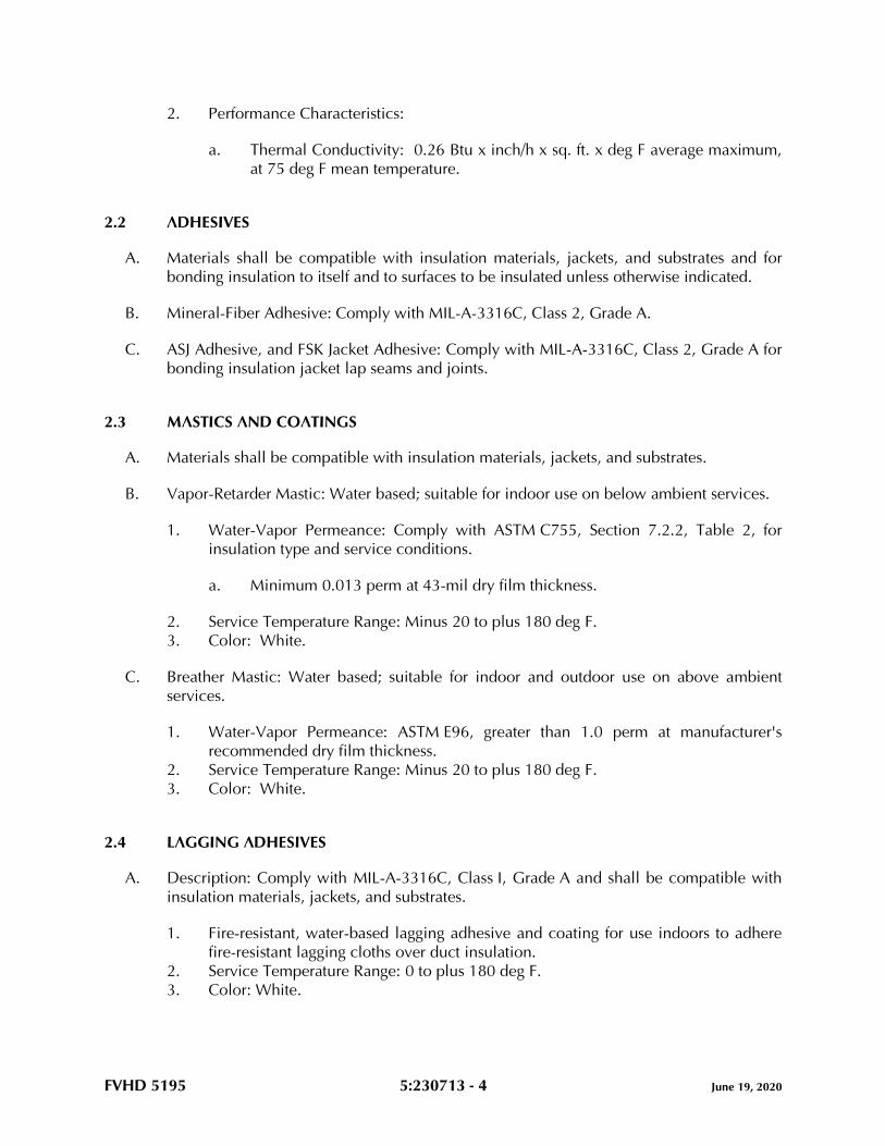
FVHD 5195 5:230713 - 4 June 19, 2020
2. Performance Characteristics:
a. Thermal Conductivity: 0.26 Btu x inch/h x sq. ft. x deg F average maximum,
at 75 deg F mean temperature.
2.2 ADHESIVES
A. Materials shall be compatible with insulation materials, jackets, and substrates and for
bonding insulation to itself and to surfaces to be insulated unless otherwise indicated.
B. Mineral-Fiber Adhesive: Comply with MIL-A-3316C, Class 2, Grade A.
C. ASJ Adhesive, and FSK Jacket Adhesive: Comply with MIL-A-3316C, Class 2, Grade A for
bonding insulation jacket lap seams and joints.
2.3 MASTICS AND COATINGS
A. Materials shall be compatible with insulation materials, jackets, and substrates.
B. Vapor-Retarder Mastic: Water based; suitable for indoor use on below ambient services.
1. Water-Vapor Permeance: Comply with ASTM C755, Section 7.2.2, Table 2, for
insulation type and service conditions.
a. Minimum 0.013 perm at 43-mil dry film thickness.
2. Service Temperature Range: Minus 20 to plus 180 deg F.
3. Color: White.
C. Breather Mastic: Water based; suitable for indoor and outdoor use on above ambient
services.
1. Water-Vapor Permeance: ASTM E96, greater than 1.0 perm at manufacturer's
recommended dry film thickness.
2. Service Temperature Range: Minus 20 to plus 180 deg F.
3. Color: White.
2.4 LAGGING ADHESIVES
A. Description: Comply with MIL-A-3316C, Class I, Grade A and shall be compatible with
insulation materials, jackets, and substrates.
1. Fire-resistant, water-based lagging adhesive and coating for use indoors to adhere
fire-resistant lagging cloths over duct insulation.
2. Service Temperature Range: 0 to plus 180 deg F.
3. Color: White.
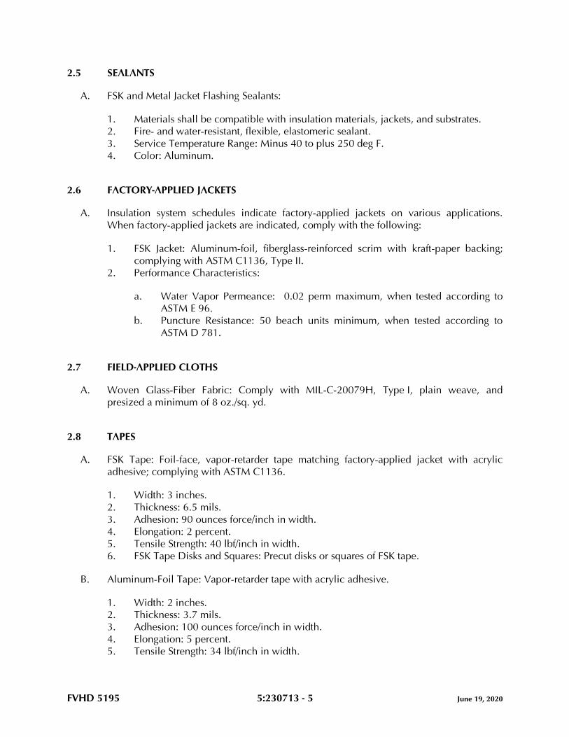
FVHD 5195 5:230713 - 5 June 19, 2020
2.5 SEALANTS
A. FSK and Metal Jacket Flashing Sealants:
1. Materials shall be compatible with insulation materials, jackets, and substrates.
2. Fire- and water-resistant, flexible, elastomeric sealant.
3. Service Temperature Range: Minus 40 to plus 250 deg F.
4. Color: Aluminum.
2.6 FACTORY-APPLIED JACKETS
A. Insulation system schedules indicate factory-applied jackets on various applications.
When factory-applied jackets are indicated, comply with the following:
1. FSK Jacket: Aluminum-foil, fiberglass-reinforced scrim with kraft-paper backing;
complying with ASTM C1136, Type II.
2. Performance Characteristics:
a. Water Vapor Permeance: 0.02 perm maximum, when tested according to
ASTM E 96.
b. Puncture Resistance: 50 beach units minimum, when tested according to
ASTM D 781.
2.7 FIELD-APPLIED CLOTHS
A. Woven Glass-Fiber Fabric: Comply with MIL-C-20079H, Type I, plain weave, and
presized a minimum of 8 oz./sq. yd.
2.8 TAPES
A. FSK Tape: Foil-face, vapor-retarder tape matching factory-applied jacket with acrylic
adhesive; complying with ASTM C1136.
1. Width: 3 inches.
2. Thickness: 6.5 mils.
3. Adhesion: 90 ounces force/inch in width.
4. Elongation: 2 percent.
5. Tensile Strength: 40 lbf/inch in width.
6. FSK Tape Disks and Squares: Precut disks or squares of FSK tape.
B. Aluminum-Foil Tape: Vapor-retarder tape with acrylic adhesive.
1. Width: 2 inches.
2. Thickness: 3.7 mils.
3. Adhesion: 100 ounces force/inch in width.
4. Elongation: 5 percent.
5. Tensile Strength: 34 lbf/inch in width.
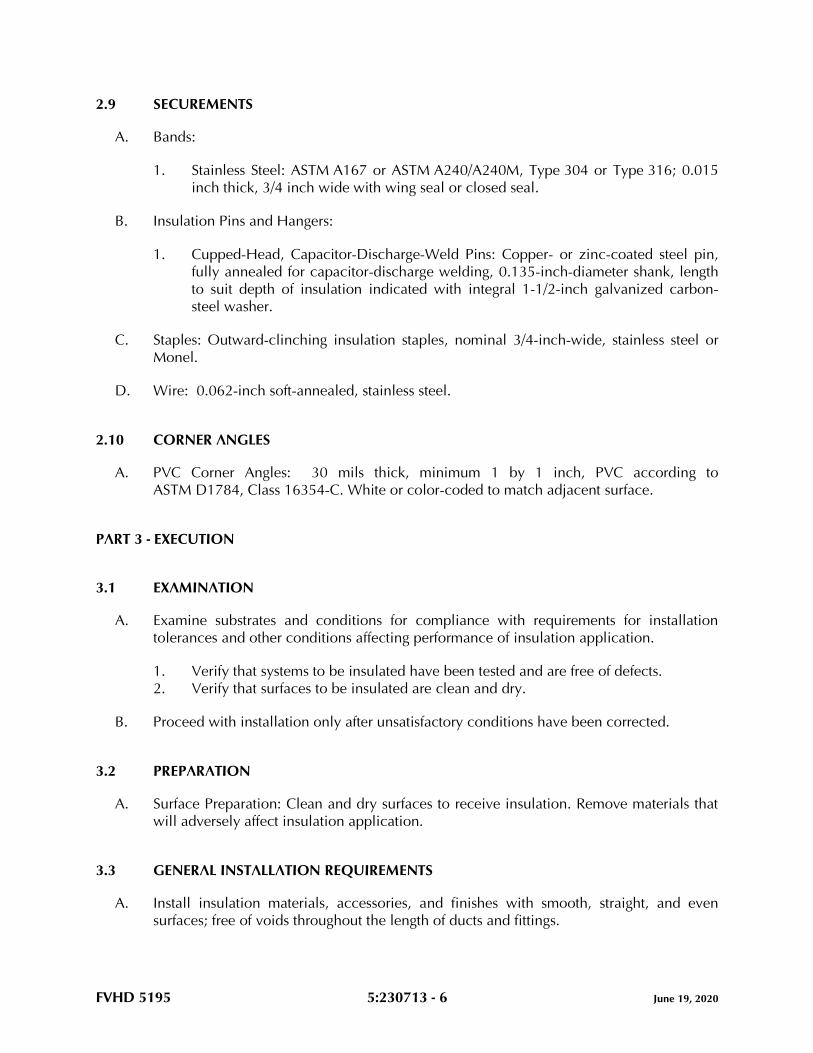
FVHD 5195 5:230713 - 6 June 19, 2020
2.9 SECUREMENTS
A. Bands:
1. Stainless Steel: ASTM A167 or ASTM A240/A240M, Type 304 or Type 316; 0.015
inch thick, 3/4 inch wide with wing seal or closed seal.
B. Insulation Pins and Hangers:
1. Cupped-Head, Capacitor-Discharge-Weld Pins: Copper- or zinc-coated steel pin,
fully annealed for capacitor-discharge welding, 0.135-inch-diameter shank, length
to suit depth of insulation indicated with integral 1-1/2-inch galvanized carbon-
steel washer.
C. Staples: Outward-clinching insulation staples, nominal 3/4-inch-wide, stainless steel or
Monel.
D. Wire: 0.062-inch soft-annealed, stainless steel.
2.10 CORNER ANGLES
A. PVC Corner Angles: 30 mils thick, minimum 1 by 1 inch, PVC according to
ASTM D1784, Class 16354-C. White or color-coded to match adjacent surface.
PART 3 - EXECUTION
3.1 EXAMINATION
A. Examine substrates and conditions for compliance with requirements for installation
tolerances and other conditions affecting performance of insulation application.
1. Verify that systems to be insulated have been tested and are free of defects.
2. Verify that surfaces to be insulated are clean and dry.
B. Proceed with installation only after unsatisfactory conditions have been corrected.
3.2 PREPARATION
A. Surface Preparation: Clean and dry surfaces to receive insulation. Remove materials that
will adversely affect insulation application.
3.3 GENERAL INSTALLATION REQUIREMENTS
A. Install insulation materials, accessories, and finishes with smooth, straight, and even
surfaces; free of voids throughout the length of ducts and fittings.
FVHD 5195 5:230713 - 7 June 19, 2020
B. Install insulation materials, vapor barriers or retarders, jackets, and thicknesses required
for each item of duct system as specified in insulation system schedules.
C. Install accessories compatible with insulation materials and suitable for the service. Install
accessories that do not corrode, soften, or otherwise attack insulation or jacket in either
wet or dry state.
D. Install insulation with longitudinal seams at top and bottom of horizontal runs.
E. Install multiple layers of insulation with longitudinal and end seams staggered.
F. Keep insulation materials dry during application and finishing.
G. Install insulation with tight longitudinal seams and end joints. Bond seams and joints with
adhesive recommended by insulation material manufacturer.
H. Install insulation with least number of joints practical.
I. Where vapor barrier is indicated, seal joints, seams, and penetrations in insulation at
hangers, supports, anchors, and other projections with vapor-barrier mastic.
1. Install insulation continuously through hangers and around anchor attachments.
2. For insulation application where vapor barriers are indicated, extend insulation on
anchor legs from point of attachment to supported item to point of attachment to
structure. Taper and seal ends at attachment to structure with vapor-barrier mastic.
3. Install insert materials and install insulation to tightly join the insert. Seal insulation
to insulation inserts with adhesive or sealing compound recommended by
insulation material manufacturer.
J. Apply adhesives, mastics, and sealants at manufacturer's recommended coverage rate
and wet and dry film thicknesses.
K. Install insulation with factory-applied jackets as follows:
1. Draw jacket tight and smooth.
2. Cover circumferential joints with 3-inch-wide strips, of same material as insulation
jacket. Secure strips with adhesive and outward clinching staples along both edges
of strip, spaced 4 inches o.c.
3. Overlap jacket longitudinal seams at least 1-1/2 inches. Clean and dry surface to
receive self-sealing lap. Staple laps with outward clinching staples along edge at 2
inches o.c.
a. For below ambient services, apply vapor-barrier mastic over staples.
4. Cover joints and seams with tape, according to insulation material manufacturer's
written instructions, to maintain vapor seal.
5. Where vapor barriers are indicated, apply vapor-barrier mastic on seams and joints
and at ends adjacent to duct flanges and fittings.
FVHD 5195 5:230713 - 8 June 19, 2020
L. Cut insulation in a manner to avoid compressing insulation more than 75 percent of its
nominal thickness.
M. Finish installation with systems at operating conditions. Repair joint separations and
cracking due to thermal movement.
N. Repair damaged insulation facings by applying same facing material over damaged areas.
Extend patches at least 4 inches beyond damaged areas. Adhere, staple, and seal patches
similar to butt joints.
3.4 PENETRATIONS
A. Insulation Installation at Roof Penetrations: Install insulation continuously through roof
penetrations.
1. Seal penetrations with flashing sealant.
2. For applications requiring only indoor insulation, terminate insulation above roof
surface and seal with joint sealant. For applications requiring indoor and outdoor
insulation, install insulation for outdoor applications tightly joined to indoor
insulation ends. Seal joint with joint sealant.
3. Extend jacket of outdoor insulation outside roof flashing at least 2 inches below top
of roof flashing.
4. Seal jacket to roof flashing with flashing sealant.
B. Insulation Installation at Aboveground Exterior Wall Penetrations: Install insulation
continuously through wall penetrations.
1. Seal penetrations with flashing sealant.
2. For applications requiring only indoor insulation, terminate insulation inside wall
surface and seal with joint sealant. For applications requiring indoor and outdoor
insulation, install insulation for outdoor applications tightly joined to indoor
insulation ends. Seal joint with joint sealant.
3. Extend jacket of outdoor insulation outside wall flashing and overlap wall flashing
at least 2 inches.
4. Seal jacket to wall flashing with flashing sealant.
C. Insulation Installation at Interior Wall and Partition Penetrations (That Are Not Fire
Rated): Install insulation continuously through walls and partitions.
D. Insulation Installation at Fire-Rated Wall and Partition Penetrations: Terminate insulation
at fire damper sleeves for fire-rated wall and partition penetrations. Externally insulate
damper sleeves to match adjacent insulation and overlap duct insulation at least 2
inches.
1. Comply with requirements in applicable Division 07 Sections.
FVHD 5195 5:230713 - 9 June 19, 2020
3.5 INSTALLATION OF MINERAL-FIBER INSULATION
A. Blanket Insulation Installation on Ducts and Plenums: Secure with adhesive and
insulation pins.
1. Apply adhesives according to manufacturer's recommended coverage rates per unit
area, for 50 percent coverage of duct and plenum surfaces.
2. Apply adhesive to entire circumference of ducts and to all surfaces of fittings and
transitions.
3. Install either capacitor-discharge-weld pins and speed washers or cupped-head,
capacitor-discharge-weld pins on sides and bottom of horizontal ducts and sides of
vertical ducts as follows:
a. On duct sides with dimensions 18 inches and smaller, place pins along
longitudinal centerline of duct. Space 3 inches maximum from insulation end
joints, and 16 inches o.c.
b. On duct sides with dimensions larger than 18 inches, place pins 16 inches
o.c. each way, and 3 inches maximum from insulation joints. Install
additional pins to hold insulation tightly against surface at cross bracing.
c. Pins may be omitted from top surface of horizontal, rectangular ducts and
plenums.
d. Do not overcompress insulation during installation.
e. Impale insulation over pins and attach speed washers.
f. Cut excess portion of pins extending beyond speed washers or bend parallel
with insulation surface. Cover exposed pins and washers with tape matching
insulation facing.
4. For ducts and plenums with surface temperatures below ambient, install a
continuous unbroken vapor barrier. Create a facing lap for longitudinal seams and
end joints with insulation by removing 2 inches from one edge and one end of
insulation segment. Secure laps to adjacent insulation section with 1/2-inch
outward-clinching staples, 1 inch o.c. Install vapor barrier consisting of factory- or
field-applied jacket, adhesive, vapor-barrier mastic, and sealant at joints, seams,
and protrusions.
a. Repair punctures, tears, and penetrations with tape or mastic to maintain
vapor-barrier seal.
b. Install vapor stops for ductwork and plenums operating below 50 deg F at
18-foot intervals. Vapor stops shall consist of vapor-barrier mastic applied in
a Z-shaped pattern over insulation face, along butt end of insulation, and
over the surface. Cover insulation face and surface to be insulated a width
equal to two times the insulation thickness, but not less than 3 inches.
5. Overlap unfaced blankets a minimum of 2 inches on longitudinal seams and end
joints. At end joints, secure with steel bands spaced a maximum of 18 inches o.c.
6. Install insulation on rectangular duct elbows and transitions with a full insulation
section for each surface. Install insulation on round and flat-oval duct elbows with
individually mitered gores cut to fit the elbow.
FVHD 5195 5:230713 - 10 June 19, 2020
7. Insulate duct stiffeners, hangers, and flanges that protrude beyond insulation
surface with 6-inch-wide strips of same material used to insulate duct. Secure on
alternating sides of stiffener, hanger, and flange with pins spaced 6 inches o.c.
B. Board Insulation Installation on Ducts and Plenums: Secure with adhesive and insulation
pins.
1. Apply adhesives according to manufacturer's recommended coverage rates per unit
area, for 50 percent coverage of duct and plenum surfaces.
2. Apply adhesive to entire circumference of ducts and to all surfaces of fittings and
transitions.
3. Install either capacitor-discharge-weld pins and speed washers or cupped-head,
capacitor-discharge-weld pins on sides and bottom of horizontal ducts and sides of
vertical ducts as follows:
a. On duct sides with dimensions 18 inches and smaller, place pins along
longitudinal centerline of duct. Space 3 inches maximum from insulation end
joints, and 16 inches o.c.
b. On duct sides with dimensions larger than 18 inches, space pins 16 inches
o.c. each way, and 3 inches maximum from insulation joints. Install
additional pins to hold insulation tightly against surface at cross bracing.
c. Pins may be omitted from top surface of horizontal, rectangular ducts and
plenums.
d. Do not overcompress insulation during installation.
e. Cut excess portion of pins extending beyond speed washers or bend parallel
with insulation surface. Cover exposed pins and washers with tape matching
insulation facing.
4. For ducts and plenums with surface temperatures below ambient, install a
continuous unbroken vapor barrier. Create a facing lap for longitudinal seams and
end joints with insulation by removing 2 inches from one edge and one end of
insulation segment. Secure laps to adjacent insulation section with 1/2-inch
outward-clinching staples, 1 inch o.c. Install vapor barrier consisting of factory- or
field-applied jacket, adhesive, vapor-barrier mastic, and sealant at joints, seams,
and protrusions.
a. Repair punctures, tears, and penetrations with tape or mastic to maintain
vapor-barrier seal.
b. Install vapor stops for ductwork and plenums operating below 50 deg F at
18-foot intervals. Vapor stops shall consist of vapor-barrier mastic applied in
a Z-shaped pattern over insulation face, along butt end of insulation, and
over the surface. Cover insulation face and surface to be insulated a width
equal to two times the insulation thickness, but not less than 3 inches.
5. Install insulation on rectangular duct elbows and transitions with a full insulation
section for each surface. Groove and score insulation to fit as closely as possible to
outside and inside radius of elbows. Install insulation on round and flat-oval duct
elbows with individually mitered gores cut to fit the elbow.
FVHD 5195 5:230713 - 11 June 19, 2020
6. Insulate duct stiffeners, hangers, and flanges that protrude beyond insulation
surface with 6-inch-wide strips of same material used to insulate duct. Secure on
alternating sides of stiffener, hanger, and flange with pins spaced 6 inches o.c.
3.6 FINISHES
A. Insulation with ASJ, Glass-Cloth, or Other Paintable Jacket Material: Paint jacket with
paint system identified below and as specified in applicable Division 09 Sections.
1. Flat Acrylic Finish: Two finish coats over a primer that is compatible with jacket
material and finish coat paint. Add fungicidal agent to render fabric mildew proof.
a. Finish Coat Material: Interior, flat, latex-emulsion size.
B. Flexible Elastomeric Thermal Insulation: After adhesive has fully cured, apply two coats
of insulation manufacturer's recommended protective coating.
C. Color: Final color as selected by Architect. Vary first and second coats to allow visual
inspection of the completed Work.
D. Do not field paint aluminum or stainless-steel jackets.
3.7 FIELD QUALITY CONTROL
A. Perform tests and inspections.
B. Tests and Inspections:
1. Inspect ductwork, randomly selected by Architect, by removing field-applied jacket
and insulation in layers in reverse order of their installation. Extent of inspection
shall be limited to two location(s) for each duct system defined in the "Duct
Insulation Schedule, General" Article.
C. All insulation applications will be considered defective Work if sample inspection reveals
noncompliance with requirements.
3.8 DUCT INSULATION SCHEDULE, GENERAL
A. Plenums and Ducts Requiring Insulation:
1. Indoor, concealed supply and outdoor air.
2. Indoor, exposed supply and outdoor air.
3. Indoor, concealed return located in unconditioned space.
4. Indoor, exposed return located in unconditioned space.
5. Indoor, concealed exhaust between isolation damper and penetration of building
exterior.
6. Indoor, exposed exhaust between isolation damper and penetration of building
exterior.
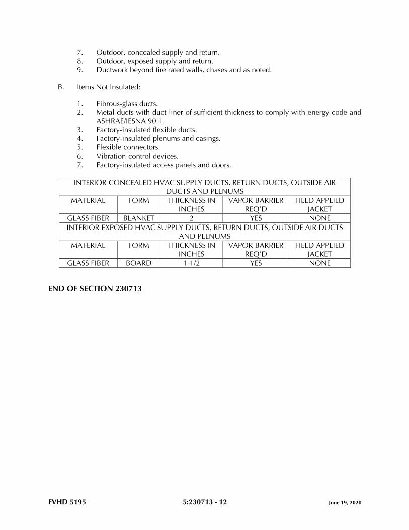
FVHD 5195 5:230713 - 12 June 19, 2020
7. Outdoor, concealed supply and return.
8. Outdoor, exposed supply and return.
9. Ductwork beyond fire rated walls, chases and as noted.
B. Items Not Insulated:
1. Fibrous-glass ducts.
2. Metal ducts with duct liner of sufficient thickness to comply with energy code and
ASHRAE/IESNA 90.1.
3. Factory-insulated flexible ducts.
4. Factory-insulated plenums and casings.
5. Flexible connectors.
6. Vibration-control devices.
7. Factory-insulated access panels and doors.
INTERIOR CONCEALED HVAC SUPPLY DUCTS, RETURN DUCTS, OUTSIDE AIR
DUCTS AND PLENUMS
MATERIAL FORM THICKNESS IN
INCHES
VAPOR BARRIER
REQ’D
FIELD APPLIED
JACKET
GLASS FIBER BLANKET 2 YES NONE
INTERIOR EXPOSED HVAC SUPPLY DUCTS, RETURN DUCTS, OUTSIDE AIR DUCTS
AND PLENUMS
MATERIAL FORM THICKNESS IN
INCHES
VAPOR BARRIER
REQ’D
FIELD APPLIED
JACKET
GLASS FIBER BOARD 1-1/2 YES NONE
END OF SECTION 230713
FVHD 5195 5:230716 - 1 June 19, 2020
SECTION 230716 - HVAC EQUIPMENT INSULATION
PART 1 - GENERAL
1.1 RELATED DOCUMENTS
A. Drawings and general provisions of the Contract, including General and Supplementary
Conditions and Division 01 Specification Sections, apply to this Section.
1.2 SUMMARY
A. Section includes insulating HVAC equipment that is not factory insulated.
1. Note: Gas boiler breechings to be factory fabricated and insulated. Field insulation
of breeching piping is NOT acceptable.
1.3 ACTION SUBMITTALS
A. Product Data: For each type of product. Include thermal conductivity, water-vapor
permeance thickness, and jackets (both factory and field applied if any).
B. Shop Drawings: Include plans, elevations, sections, details, and attachments to other
work.
1. Detail removable insulation at equipment connections.
2. Detail application of field-applied jackets.
3. Detail application at linkages of control devices.
4. Detail field application for each equipment type.
1.4 INFORMATIONAL SUBMITTALS
A. Qualification Data: For qualified Installer.
B. Field quality-control reports.
1.5 QUALITY ASSURANCE
A. Installer Qualifications: Skilled mechanics who have successfully completed an
apprenticeship program or another craft training program certified by the Department of
Labor, Bureau of Apprenticeship and Training.
B. Surface-Burning Characteristics: For insulation and related materials, as determined by
testing identical products in accordance with ASTM E84, by a testing agency acceptable
to authorities having jurisdiction. Factory label insulation and jacket materials and
FVHD 5195 5:230716 - 2 June 19, 2020
adhesive, mastic, tapes, and cement material containers, with appropriate markings of
applicable testing agency.
1. Insulation Installed Indoors: Flame-spread index of 25 or less and smoke-developed
index of 50 or less.
C. Insulation Installed Outdoors: Flame-spread index of 75 or less and smoke-developed
index of 150 or less.
1.6 DELIVERY, STORAGE, AND HANDLING
A. Packaging: Insulation material containers shall be marked by manufacturer with
appropriate ASTM standard designation, type and grade, and maximum use temperature.
1.7 COORDINATION
A. Coordinate sizes and locations of supports, hangers, and insulation shields specified in
applicable Division 22 Sections.
B. Coordinate clearance requirements with equipment Installer for equipment insulation
application.
1.8 SCHEDULING
A. Schedule insulation application after pressure testing systems and, where required, after
installing and testing heat tracing. Insulation application may begin on segments that
have satisfactory test results.
B. Complete installation and concealment of plastic materials as rapidly as possible in each
area of construction.
PART 2 - PRODUCTS
2.1 PERFORMANCE REQUIREMENTS
A. Surface-Burning Characteristics: For insulation and related materials, as determined by
testing identical products in accordance with ASTM E84, by a testing agency acceptable
to authorities having jurisdiction. Factory label insulation and jacket materials and
adhesive, mastic, tapes, and cement material containers, with appropriate markings of
applicable testing agency.
1. Insulation Installed Indoors: Flame-spread index of 25 or less, and smoke-
developed index of 50 or less.
2. Insulation Installed Outdoors: Flame-spread index of 75 or less, and smoke-
developed index of 150 or less.
FVHD 5195 5:230716 - 3 June 19, 2020
2.2 INSULATION MATERIALS
A. Comply with requirements in “Equipment Insulation Schedule" articles for where
insulating materials shall be applied.
B. Products shall not contain asbestos, lead, mercury, or mercury compounds.
C. Products that come in contact with stainless steel shall have a leachable chloride content
of less than 50 ppm when tested in accordance with ASTM C871.
D. Insulation materials for use on austenitic stainless steel shall be qualified as acceptable in
accordance with ASTM C795.
E. Foam insulation materials shall not use CFC or HCFC blowing agents in the
manufacturing process.
F. Mineral-Fiber Board: Mineral or glass fibers bonded with a thermosetting resin. Comply
with ASTM C612, Type IA or Type IB. Provide insulation with factory-applied FSK jacket.
Factory-applied jacket requirements are specified in "Factory-Applied Jackets" Article.
1. Basis-of-Design Product: Subject to compliance with requirements, provide Johns
Manville; a Berkshire Hathaway company; or a comparable product by one of the
following:
a. CertainTeed Corporation.
b. Knauf Insulation.
c. Owens Corning.
G. Mineral-Fiber, Pipe and Tank: Mineral or glass fibers bonded with a thermosetting resin.
Comply with ASTM C1393.
1. Basis-of-Design Product: Subject to compliance with requirements, provide Johns
Manville; a Berkshire Hathaway company; or a comparable product by one of the
following:
a. CertainTeed Corporation.
b. Knauf Insulation.
c. Owens Corning.
2. Semirigid board material with factory-applied FSK jacket.
3. Nominal density is 2.5 lb/cu. ft. or more.
4. Thermal conductivity (k-value) at 100 deg F is 0.29 Btu x in./h x sq. ft. x deg F or
less.
5. Factory-applied jacket requirements are specified in "Factory-Applied Jackets"
Article.
2.3 INSULATING CEMENTS
A. Mineral-Fiber Insulating Cement: Comply with ASTM C195.
FVHD 5195 5:230716 - 4 June 19, 2020
B. Mineral-Fiber, Hydraulic-Setting Insulating and Finishing Cement: Comply with
ASTM C449.
2.4 ADHESIVES
A. Materials shall be compatible with insulation materials, jackets, and substrates and for
bonding insulation to itself and to surfaces to be insulated unless otherwise indicated.
B. Mineral-Fiber Adhesive: Comply with MIL-A-3316C, Class 2, Grade A.
C. ASJ Adhesive and FSK and PVDC Jacket Adhesive: Comply with MIL-A-3316C, Class 2,
Grade A for bonding insulation jacket lap seams and joints.
2.5 MASTICS AND COATINGS
A. Materials shall be compatible with insulation materials, jackets, and substrates.
B. Vapor-Retarder Mastic, Water Based: Suitable for indoor and outdoor use on below-
ambient services.
1. Water-Vapor Permeance: Comply with ASTM E96/E96M or ASTM F1249.
2. Service Temperature Range: Minus 20 to plus 180 deg F.
3. Comply with MIL-PRF-19565C, Type II, for permeance requirements.
4. Color: White.
C. Vapor-Retarder Mastic, Solvent Based, Outdoor Use: Suitable for outdoor use on below-
ambient services.
1. Water-Vapor Permeance: Comply with ASTM E96/E96M or ASTM F1249.
2. Service Temperature Range: Minus 50 to plus 220 deg F.
3. Color: White.
D. Breather Mastic: Water based; suitable for indoor and outdoor use on above-ambient
services.
1. Water-Vapor Permeance: ASTM E96/E96M, greater than 1.0 perm at
manufacturer's recommended dry film thickness.
2. Service Temperature Range: Minus 20 to plus 180 deg F.
3. Color: White.
2.6 LAGGING ADHESIVES
A. Adhesives shall comply with MIL-A-3316C, Class I, Grade A and shall be compatible
with insulation materials, jackets, and substrates.
1. Fire-resistant, water-based lagging adhesive and coating for use indoors to adhere
fire-resistant lagging cloths over equipment insulation.
2. Service Temperature Range: 0 to plus 180 deg F.

FVHD 5195 5:230716 - 5 June 19, 2020
3. Color: White.
2.7 SEALANTS
A. Materials shall be as recommended by the insulation manufacturer and shall be
compatible with insulation materials, jackets, and substrates.
B. Joint Sealants:
1. Permanently flexible, elastomeric sealant.
2. Service Temperature Range: Minus 100 to plus 300 deg F.
3. Color: White or gray.
C. FSK and Metal Jacket Flashing Sealants:
1. Fire- and water-resistant, flexible, elastomeric sealant.
2. Service Temperature Range: Minus 40 to plus 250 deg F.
3. Color: Aluminum.
2.8 FACTORY-APPLIED JACKETS
A. Insulation system schedules indicate factory-applied jackets on various applications.
When factory-applied jackets are indicated, comply with the following:
1. FSK Jacket: Aluminum-foil, fiberglass-reinforced scrim with kraft-paper backing;
complying with ASTM C1136, Type II.
2.9 FIELD-APPLIED CLOTHS
A. Woven Glass-Fiber Fabric: Comply with MIL-C-20079H, Type I, plain weave, and
presized a minimum of 8 oz./sq. yd.
2.10 TAPES
A. FSK Tape: Foil-face, vapor-retarder tape matching factory-applied jacket with acrylic
adhesive; complying with ASTM C1136.
1. Width: 3 inches.
2. Thickness: 6.5 mils.
3. Adhesion: 90 ounces force/inch in width.
4. Elongation: 2 percent.
5. Tensile Strength: 40 lbf/inch in width.
6. FSK Tape Disks and Squares: Precut disks or squares of FSK tape.
FVHD 5195 5:230716 - 6 June 19, 2020
2.11 SECUREMENTS
A. Bands:
1. Stainless Steel: ASTM A240/A240M, Type 304 or Type 316; 0.015 inch thick, 3/4
inch wide with closed seal.
2. Springs: Twin spring set constructed of stainless steel with ends flat and slotted to
accept metal bands. Spring size is determined by manufacturer for application.
B. Insulation Pins and Hangers:
1. Capacitor-Discharge-Weld Pins: Copper- or zinc-coated steel pin, fully annealed
for capacitor-discharge welding; 0.135-inch- diameter shank, length to suit depth
of insulation indicated.
C. Staples: Outward-clinching insulation staples, nominal 3/4-inch-wide, stainless steel or
Monel.
D. Wire: 0.062-inch soft-annealed, stainless steel.
2.12 CORNER ANGLES
A. PVC Corner Angles: 30-mils- thick, minimum 1- by 1-inch PVC in accordance with
ASTM D1784, Class 16354-C, white or color-coded to match adjacent surface.
PART 3 - EXECUTION
3.1 EXAMINATION
A. Examine substrates and conditions for compliance with requirements for installation
tolerances and other conditions affecting performance of insulation application.
1. Verify that systems and equipment to be insulated have been tested and are free of
defects.
2. Verify that surfaces to be insulated are clean and dry.
B. Proceed with installation only after unsatisfactory conditions have been corrected.
3.2 PREPARATION
A. Clean and dry surfaces to receive insulation. Remove materials that will adversely affect
insulation application.
B. Clean and prepare surfaces to be insulated. Before insulating, apply a corrosion coating
to insulated surfaces as follows:
FVHD 5195 5:230716 - 7 June 19, 2020
1. Stainless Steel: Coat 300 series stainless steel with an epoxy primer 5 mils thick and
an epoxy finish 5 mils thick if operating in a temperature range of between 140 and
300 deg F. Consult coating manufacturer for appropriate coating materials and
application methods for operating temperature range.
2. Carbon Steel: Coat carbon steel operating at a service temperature of between 32
and 300 deg F with an epoxy coating. Consult coating manufacturer for appropriate
coating materials and application methods for operating temperature range.
C. Coordinate insulation installation with the tradesman installing heat tracing. Comply with
requirements for heat tracing that apply to insulation.
D. Mix insulating cements with clean potable water; if insulating cements are to be in
contact with stainless steel surfaces, use demineralized water.
3.3 GENERAL INSTALLATION REQUIREMENTS
A. Install insulation materials, accessories, and finishes with smooth, straight, and even
surfaces; free of voids throughout the length of equipment.
B. Install insulation materials, forms, vapor barriers or retarders, and jackets, of thicknesses
required for each item of equipment, as specified in insulation system schedules.
C. Install accessories compatible with insulation materials and suitable for the service. Install
accessories that do not corrode, soften, or otherwise attack insulation or jacket in either
wet or dry state.
D. Install insulation with longitudinal seams at top and bottom of horizontal runs.
E. Install multiple layers of insulation with longitudinal and end seams staggered.
F. Keep insulation materials dry during storage, application, and finishing. Replace
insulation materials that get wet.
G. Install insulation with tight longitudinal seams and end joints. Bond seams and joints with
adhesive recommended by insulation material manufacturer.
H. Install insulation with least number of joints practical.
I. Where vapor barrier is indicated, seal joints, seams, and penetrations in insulation at
hangers, supports, anchors, and other projections with vapor-barrier mastic.
1. Install insulation continuously through hangers and around anchor attachments.
2. For insulation application where vapor barriers are indicated, extend insulation on
anchor legs from point of attachment to supported item to point of attachment to
structure. Taper and seal ends attached to structure with vapor-barrier mastic.
3. Install insert materials and install insulation to tightly join the insert. Seal insulation
to insulation inserts with adhesive or sealing compound recommended by
insulation material manufacturer.
FVHD 5195 5:230716 - 8 June 19, 2020
4. Cover inserts with jacket material matching adjacent insulation. Install shields over
jacket, arranged to protect jacket from tear or puncture by hanger, support, and
shield.
J. Apply adhesives, mastics, and sealants at manufacturer's recommended coverage rate
and wet and dry film thicknesses.
K. Install insulation with factory-applied jackets as follows:
1. Draw jacket tight and smooth.
2. Cover circumferential joints with 3-inch-wide strips, of same material as insulation
jacket. Secure strips with adhesive and outward-clinching staples along both edges
of strip, spaced 4 inches o.c.
3. Overlap jacket longitudinal seams at least 1-1/2 inches. Clean and dry surface to
receive self-sealing lap. Staple laps with outward-clinching staples along edge at 4
inches o.c.
a. For below-ambient services, apply vapor-barrier mastic over staples.
4. Cover joints and seams with tape, in accordance with insulation material
manufacturer's written instructions, to maintain vapor seal.
5. Where vapor barriers are indicated, apply vapor-barrier mastic on seams and joints.
L. Cut insulation in a manner to avoid compressing insulation more than 25 percent of its
nominal thickness.
M. Finish installation with systems at operating conditions. Repair joint separations and
cracking due to thermal movement.
N. Repair damaged insulation facings by applying same facing material over damaged areas.
Extend patches at least 4 inches beyond damaged areas. Adhere, staple, and seal patches
in similar fashion to butt joints.
O. For above-ambient services, do not install insulation to the following:
1. Vibration-control devices.
2. Testing agency labels and stamps.
3. Nameplates and data plates.
4. Manholes.
5. Handholes.
6. Cleanouts.
3.4 INSTALLATION OF EQUIPMENT, TANK, AND VESSEL INSULATION
A. Mineral-Fiber, Pipe and Tank Insulation Installation for Tanks and Vessels: Secure
insulation with adhesive, anchor pins, and speed washers.
1. Apply adhesives in accordance with manufacturer's recommended coverage rates
per unit area, for 100 percent coverage of tank and vessel surfaces.
FVHD 5195 5:230716 - 9 June 19, 2020
2. Groove and score insulation materials to fit as closely as possible to equipment,
including contours. Bevel insulation edges for cylindrical surfaces for tight joints.
Stagger end joints.
3. Protect exposed corners with secured corner angles.
4. Install adhesively attached or self-sticking insulation hangers and speed washers on
sides of tanks and vessels as follows:
a. Do not weld anchor pins to ASME-labeled pressure vessels.
b. Select insulation hangers and adhesive that are compatible with service
temperature and with substrate.
c. On tanks and vessels, maximum anchor-pin spacing is 3 inches from
insulation end joints and 16 inches o.c. in both directions.
d. Do not over-compress insulation during installation.
e. Cut and miter insulation segments to fit curved sides and domed heads of
tanks and vessels.
f. Impale insulation over anchor pins, and attach speed washers.
g. Cut excess portion of pins extending beyond speed washers or bend parallel
with insulation surface. Cover exposed pins and washers with tape matching
insulation facing.
5. Secure each layer of insulation with stainless steel or aluminum bands. Select band
material compatible with insulation materials.
6. Where insulation hangers on equipment and vessels are not permitted or practical
and where insulation support rings are not provided, install a girdle network for
securing insulation. Stretch prestressed aircraft cable around the diameter of vessel
and make taut with clamps, turnbuckles, or breather springs. Place one
circumferential girdle around equipment approximately 6 inches from each end.
Install wire or cable between two circumferential girdles 12 inches o.c. Install a
wire ring around each end and around outer periphery of center openings, and
stretch prestressed aircraft cable radially from the wire ring to nearest
circumferential girdle. Install additional circumferential girdles along the body of
equipment or tank at a minimum spacing of 48 inches o.c. Use this network for
securing insulation with tie wire or bands.
7. Stagger joints between insulation layers at least 3 inches.
8. Install insulation in removable segments on equipment access doors, manholes,
handholes, and other elements that require frequent removal for service and
inspection.
9. Bevel and seal insulation ends around manholes, handholes, ASME stamps, and
nameplates.
10. For equipment with surface temperatures below ambient, apply mastic to open
ends, joints, seams, breaks, and punctures in insulation.
B. Insulation Installation on Pumps:
1. Fabricate metal boxes lined with insulation. Fit boxes around pumps and coincide
box joints with splits in pump casings. Fabricate joints with outward bolted flanges.
Bolt flanges on 6-inch centers, starting at corners. Install 3/8-inch-diameter
fasteners with wing nuts. Alternatively, secure the box sections together using a
field-adjustable latching mechanism.

FVHD 5195 5:230716 - 10 June 19, 2020
2. Fabricate boxes from galvanized steel, at least 0.040 inch thick.
3. For below-ambient services, install a vapor barrier at seams, joints, and
penetrations. Seal between flanges with replaceable gasket material to form a vapor
barrier.
3.5 FINISHES
A. Color: Final color as selected by Architect. Vary first and second coats to allow visual
inspection of the completed Work.
B. Do not field paint aluminum or stainless-steel jackets.
3.6 FIELD QUALITY CONTROL
A. Perform tests and inspections with the assistance of a factory-authorized service
representative.
B. Tests and Inspections: Inspect field-insulated equipment, randomly selected by Architect,
by removing field-applied jacket and insulation in layers in reverse order of their
installation. Extent of inspection shall be limited to one location(s) for each type of
equipment defined in " Equipment Insulation Schedule" articles. For large equipment,
remove only a portion adequate to determine compliance.
C. All insulation applications will be considered defective if they do not pass tests and
inspections.
D. Prepare test and inspection reports.
3.1 EQUIPMENT INSULATION SCHEDULE
A. Insulation conductivity and thickness per pipe size shall comply with schedules in this
Section or with requirements of authorities having jurisdiction, whichever is more
stringent.
B. Acceptable insulation materials and thicknesses are identified for each piping system and
pipe size range. If more than one material is listed for a piping system, selection from
materials is Contractor's option.
C. Insulate indoor and outdoor equipment that is not factory insulated.
HEATING HOT WATER EXPANSION TANKS AND AIR SEPARATORS (100 TO 250 DEG F)
MATERIAL FORM THICKNESS
IN INCHES
VAPOR BARRIER
REQ’D
FIELD APPLIED
JACKET
MINERAL
FIBER
BOARD OR
PIPE & TANK
2 NO NONE
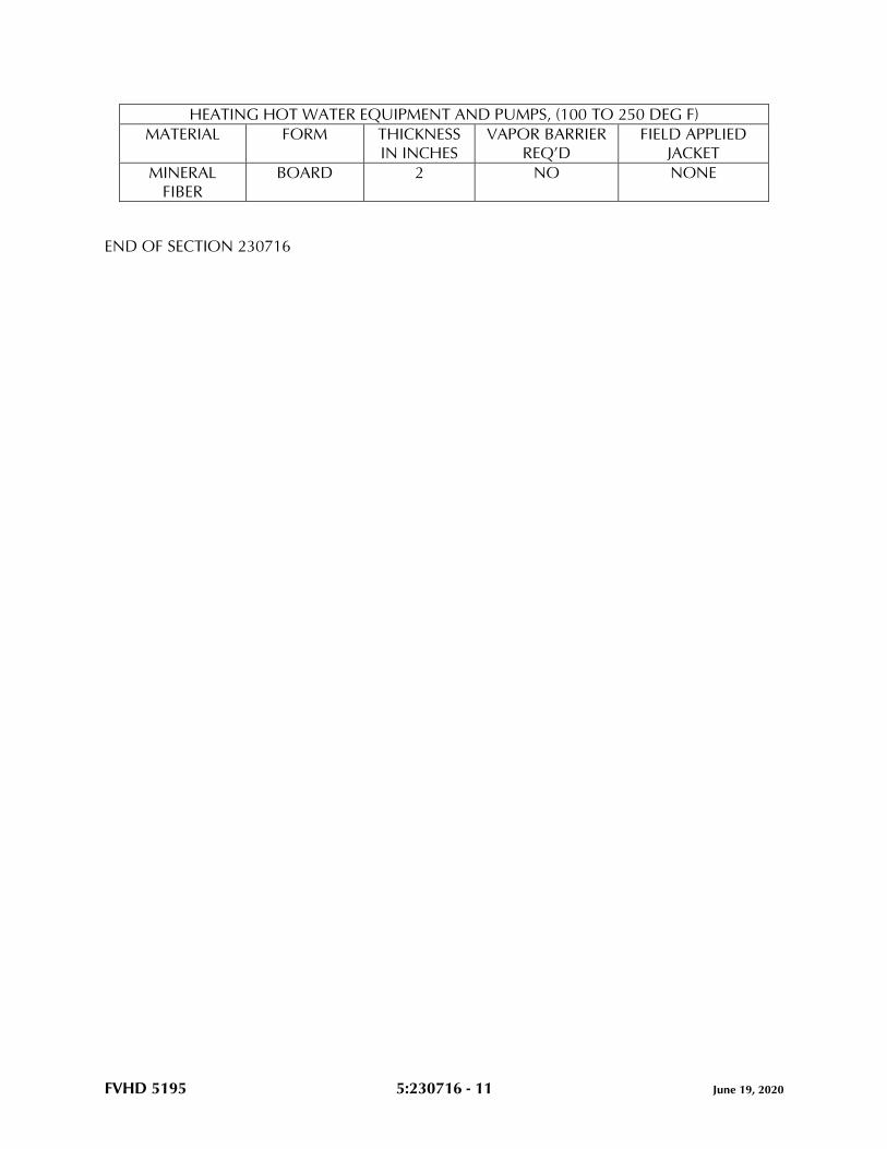
FVHD 5195 5:230716 - 11 June 19, 2020
HEATING HOT WATER EQUIPMENT AND PUMPS, (100 TO 250 DEG F)
MATERIAL FORM THICKNESS
IN INCHES
VAPOR BARRIER
REQ’D
FIELD APPLIED
JACKET
MINERAL
FIBER
BOARD 2 NO NONE
END OF SECTION 230716

FVHD 5195 5:230719 - 1 June 19, 2020
SECTION 230719 - HVAC PIPING INSULATION
PART 1 - GENERAL
1.1 RELATED DOCUMENTS
A. Drawings and general provisions of the Contract, including General and Supplementary
Conditions and Division 01 Specification Sections, apply to this Section.
1.2 SUMMARY
A. Section includes insulation for HVAC piping systems.
1.3 DEFINITIONS
A. Hot Surfaces: Normal operating temperatures of 100 deg F or higher.
B. Cold Surfaces: Normal operating temperatures less than 75 deg F.
C. Thermal Conductivity (k-value): Measure of heat flow through a material at a given
temperature difference; conductivity is expressed in units of Btu x inch/h x sq. ft. x deg F.
D. Density: Is expressed in pcf.
1.4 ACTION SUBMITTALS
A. Product Data: For each type of product. Include insulation thickness, thermal
conductivity, water-vapor permeance thickness, and jackets (both factory and field
applied if any).
1.5 INFORMATIONAL SUBMITTALS
A. Qualification Data: For qualified Installer.
B. Material Test Reports: From a qualified testing agency acceptable to authorities having
jurisdiction indicating, interpreting, and certifying test results for compliance of insulation
materials, sealers, attachments, cements, and jackets, with requirements indicated.
Include dates of tests and test methods employed.
C. Field quality-control reports.
FVHD 5195 5:230719 - 2 June 19, 2020
1.6 QUALITY ASSURANCE
A. Installer Qualifications: Skilled mechanics who have successfully completed an
apprenticeship program or another craft training program certified by the Department of
Labor, Bureau of Apprenticeship and Training.
B. Surface-Burning Characteristics: For insulation and related materials, as determined by
testing identical products in accordance with ASTM E84, by a testing agency acceptable
to authorities having jurisdiction. Factory label insulation and jacket materials and
adhesive, mastic, tapes, and cement material containers, with appropriate markings of
applicable testing agency.
1. Insulation Installed Indoors: Flame-spread index of 25 or less, and smoke-
developed index of 50 or less.
2. Insulation Installed Outdoors: Flame-spread index of 75 or less, and smoke-
developed index of 150 or less.
1.7 DELIVERY, STORAGE, AND HANDLING
A. Packaging: Insulation material containers shall be marked by manufacturer with
appropriate ASTM standard designation, type and grade, and maximum use temperature.
1.8 COORDINATION
A. Coordinate sizes and locations of supports, hangers, and insulation shields specified in
applicable Division 23 Sections.
B. Coordinate clearance requirements with piping Installer for piping insulation application.
Before preparing piping Shop Drawings, establish and maintain clearance requirements
for installation of insulation and field-applied jackets and finishes and for space required
for maintenance.
1.9 SCHEDULING
A. Schedule insulation application after pressure testing systems and, where required, after
installing and testing heat tracing. Insulation application may begin on segments that
have satisfactory test results.
B. Complete installation and concealment of plastic materials as rapidly as possible in each
area of construction.

FVHD 5195 5:230719 - 3 June 19, 2020
PART 2 - PRODUCTS
2.1 INSULATION MATERIALS
A. Comply with requirements in "Piping Insulation Schedule, General," article for where
insulating materials shall be applied.
B. Products shall not contain asbestos, lead, mercury, or mercury compounds.
C. Products that come into contact with stainless steel shall have a leachable chloride
content of less than 50 ppm when tested in accordance with ASTM C871.
D. Insulation materials for use on austenitic stainless steel shall be qualified as acceptable in
accordance with ASTM C795.
E. Foam insulation materials shall not use CFC or HCFC blowing agents in the
manufacturing process.
F. Flexible Elastomeric: Closed-cell, sponge- or expanded-rubber materials. Comply with
ASTM C534/C534M, Type I for tubular materials, Type II for sheet materials.
1. Basis-of-Design Product: Subject to compliance with requirements, provide
Armacell LLC ; AP Armaflex Tube Insulation. or a comparable product by one of
the following:
a. Aeroflex USA, Inc.
b. K-Flex USA.
G. Mineral-Fiber, Preformed Pipe: Mineral or glass fibers bonded with a thermosetting resin.
Comply with ASTM C547.
1. Basis-of-Design Product: Subject to compliance with requirements, provide Johns
Manville; a Berkshire Hathaway company ; Micro-Lok. or a comparable product by
one of the following:
a. Knauf Insulation.
b. Manson Insulation Inc.
2. Preformed Pipe Insulation: Type I, Grade A with factory-applied ASJ-SSL.
3. Minimum Temperature Rating: 850 deg F.
4. Factory fabricate shapes in accordance with ASTM C450 and ASTM C585.
5. Factory-applied jacket requirements are specified in "Factory-Applied Jackets"
Article.
6. Thermal conductivity (k-value) at 100 deg F is 0.29 Btu x in./h x sq. ft. x deg F or
less
2.2 INSULATING CEMENTS
A. Mineral-Fiber Insulating Cement: Comply with ASTM C 195.
FVHD 5195 5:230719 - 4 June 19, 2020
1. Thermal Conductivity: 1.0 Btu x inch/h x sq. ft. x deg F average maximum at 500
deg F mean temperature.
2. Compressive Strength: 10 psi at 5 percent deformation.
B. Mineral-Fiber, Hydraulic-Setting Insulating and Finishing Cement: Comply with
ASTM C 449.
1. Thermal Conductivity: 1.2 Btu x inch/h x sq. ft. x deg F average maximum at 500
deg F mean temperature.
2. Compressive Strength: 100 psi at 5 percent deformation.
2.3 ADHESIVES
A. Materials shall be compatible with insulation materials, jackets, and substrates and for
bonding insulation to itself and to surfaces to be insulated unless otherwise indicated.
B. Flexible Elastomeric and Polyolefin Adhesive: Solvent-based adhesive.
1. Flame-spread index shall be 25 or less and smoke-developed index shall be 50 or
less as tested in accordance with ASTM E84.
2. Wet Flash Point: Below 0 deg F.
3. Service Temperature Range: 40 to 200 deg F.
4. Color: Black.
C. Mineral-Fiber Adhesive: Comply with MIL-A-3316C, Class 2, Grade A.
1. Produced under the UL Classification and Follow-up service.
2. Type: Non-flammable, solvent-based.
3. Service Temperature Range: Minus 20 to 180 deg F.
D. ASJ Adhesive and FSK and PVDC Jacket Adhesive: Comply with MIL-A-3316C, Class 2,
Grade A, for bonding insulation jacket lap seams and joints.
E. PVC Jacket Adhesive: Compatible with PVC jacket.
2.4 MASTICS AND COATINGS
A. Materials shall be compatible with insulation materials, jackets, and substrates.
B. Vapor-Retarder Mastic, Water Based: Suitable for indoor use on below-ambient services.
1. Water-Vapor Permeance: Comply with ASTM E96/E96M or ASTM F1249.
2. Service Temperature Range: 0 to plus 180 deg F.
3. Comply with MIL-PRF-19565C, Type II, for permeance requirements.
4. Color: White.
C. Breather Mastic: Water based; suitable for indoor and outdoor use on above-ambient
services.
FVHD 5195 5:230719 - 5 June 19, 2020
1. Water-Vapor Permeance: ASTM E96/E96M, greater than 1.0 perm at
manufacturer's recommended dry film thickness.
2. Service Temperature Range: 0 to plus 180 deg F.
3. Color: White.
2.5 LAGGING ADHESIVES
A. Adhesives shall comply with MIL-A-3316C, Class I, Grade A, and shall be compatible
with insulation materials, jackets, and substrates.
1. Fire-resistant, water-based lagging adhesive and coating for use indoors to adhere
fire-resistant lagging cloths over pipe insulation.
2. Service Temperature Range: 0 to plus 180 deg F.
3. Color: White.
2.6 SEALANTS
A. Materials shall be as recommended by the insulation manufacturer and shall be
compatible with insulation materials, jackets, and substrates.
B. Joint Sealants:
1. Permanently flexible, elastomeric sealant.
a. Service Temperature Range: Minus 150 to plus 250 deg F.
b. Color: White or gray.
C. ASJ Flashing Sealants and PVDC and PVC Jacket Flashing Sealants:
1. Fire- and water-resistant, flexible, elastomeric sealant.
2. Service Temperature Range: Minus 40 to plus 250 deg F.
3. Color: White.
2.7 FACTORY-APPLIED JACKETS
A. Insulation system schedules indicate factory-applied jackets on various applications.
When factory-applied jackets are indicated, comply with the following:
1. ASJ-SSL: ASJ with self-sealing, pressure-sensitive, acrylic-based adhesive covered
by a removable protective strip; complying with ASTM C1136, Type I.
2.8 FIELD-APPLIED CLOTHS
A. Woven Glass-Fiber Fabric: Comply with MIL-C-20079H, Type I, plain weave, and
presized a minimum of 8 oz./sq. yd.
FVHD 5195 5:230719 - 6 June 19, 2020
2.9 FIELD-APPLIED JACKETS
A. Field-applied jackets shall comply with ASTM C1136, Type I, unless otherwise indicated.
B. FSK Jacket: Aluminum-foil-face, fiberglass-reinforced scrim with kraft-paper backing.
C. PVC Jacket: High-impact-resistant, UV-resistant PVC complying with ASTM D1784,
Class 16354-C; thickness as scheduled; roll stock ready for shop or field cutting and
forming.
1. Adhesive: As recommended by jacket material manufacturer.
2. Color: White.
3. Factory-fabricated fitting covers to match jacket if available; otherwise, field
fabricate.
a. Shapes: 45- and 90-degree, short- and long-radius elbows, tees, valves,
flanges, unions, reducers, end caps, soil-pipe hubs, traps, mechanical joints,
and P-trap and supply covers for lavatories.
D. Metal Jacket:
1. Aluminum Jacket: Comply with ASTM B209, Alloy 3003, 3005, 3105, or 5005,
Temper H-14.
a. Factory cut and rolled to size.
b. Finish and thickness are indicated in field-applied jacket schedules.
c. Moisture Barrier for Outdoor Applications: 3-mil-thick, heat-bonded
polyethylene and kraft paper.
d. Factory-Fabricated Fitting Covers:
1) Same material, finish, and thickness as jacket.
2) Preformed two-piece or gore, 45- and 90-degree, short- and long-
radius elbows.
3) Tee covers.
4) Flange and union covers.
5) End caps.
6) Beveled collars.
7) Valve covers.
8) Field fabricate fitting covers only if factory-fabricated fitting covers are
not available.
2.10 TAPES
A. ASJ Tape: White vapor-retarder tape matching factory-applied jacket with acrylic
adhesive, complying with ASTM C1136.
1. Width: 3 inches.
2. Thickness: 11.5 mils.
3. Adhesion: 90 ounces force/inch in width.

FVHD 5195 5:230719 - 7 June 19, 2020
4. Elongation: 2 percent.
5. Tensile Strength: 40 lbf/inch in width.
6. ASJ Tape Disks and Squares: Precut disks or squares of ASJ tape.
B. PVC Tape: White vapor-retarder tape matching field-applied PVC jacket with acrylic
adhesive; suitable for indoor and outdoor applications.
1. Width: 2 inches.
2. Thickness: 6 mils.
3. Adhesion: 64 ounces force/inch in width.
4. Elongation: 500 percent.
5. Tensile Strength: 18 lbf/inch in width.
C. Aluminum-Foil Tape: Vapor-retarder tape with acrylic adhesive.
1. Width: 2 inches.
2. Thickness: 3.7 mils.
3. Adhesion: 100 ounces force/inch in width.
4. Elongation: 5 percent.
5. Tensile Strength: 34 lbf/inch in width.
2.11 SECUREMENTS
A. Bands:
1. Stainless Steel: ASTM A240/A240M, Type 304 or Type 316; 0.015 inch thick, 3/4
inch wide with wing seal or closed seal.
B. Staples: Outward-clinching insulation staples, nominal 3/4 inch wide, stainless steel or
Monel.
C. Wire: 0.062-inch soft-annealed, stainless steel.
PART 3 - EXECUTION
3.1 EXAMINATION
A. Examine substrates and conditions for compliance with requirements for installation
tolerances and other conditions affecting performance of insulation application.
1. Verify that systems to be insulated have been tested and are free of defects.
2. Verify that surfaces to be insulated are clean and dry.
B. Proceed with installation only after unsatisfactory conditions have been corrected.
FVHD 5195 5:230719 - 8 June 19, 2020
3.2 PREPARATION
A. Clean and dry surfaces to receive insulation. Remove materials that will adversely affect
insulation application.
B. For corrosive areas: Clean and prepare surfaces to be insulated. Before insulating, apply a
corrosion coating to insulated surfaces as follows:
1. Stainless Steel: Coat 300 series stainless steel with an epoxy primer 5 mils thick and
an epoxy finish 5 mils thick if operating in a temperature range between 140 and
300 deg F. Consult coating manufacturer for appropriate coating materials and
application methods for operating temperature range.
2. Carbon Steel: Coat carbon steel operating at a service temperature of between 32
and 300 deg F with an epoxy coating. Consult coating manufacturer for appropriate
coating materials and application methods for operating temperature range.
C. Mix insulating cements with clean potable water; if insulating cements are to be in
contact with stainless steel surfaces, use demineralized water.
3.3 GENERAL INSTALLATION REQUIREMENTS
A. Install insulation materials, accessories, and finishes with smooth, straight, and even
surfaces; free of voids throughout the length of piping, including fittings, valves, and
specialties.
B. Install insulation materials, forms, vapor barriers or retarders, jackets, and of thicknesses
required for each item of pipe system, as specified in insulation system schedules.
C. Install accessories compatible with insulation materials and suitable for the service. Install
accessories that do not corrode, soften, or otherwise attack insulation or jacket in either
wet or dry state.
D. Install insulation with longitudinal seams at top and bottom of horizontal runs.
E. Install multiple layers of insulation with longitudinal and end seams staggered.
F. Do not weld brackets, clips, or other attachment devices to piping, fittings, and
specialties.
G. Keep insulation materials dry during storage, application, and finishing. Replace
insulation materials that get wet.
H. Install insulation with tight longitudinal seams and end joints. Bond seams and joints with
adhesive recommended by insulation material manufacturer.
I. Install insulation with least number of joints practical.
J. Where vapor barrier is indicated, seal joints, seams, and penetrations in insulation at
hangers, supports, anchors, and other projections with vapor-barrier mastic.
FVHD 5195 5:230719 - 9 June 19, 2020
1. Install insulation continuously through hangers and around anchor attachments.
2. For insulation application where vapor barriers are indicated, extend insulation on
anchor legs from point of attachment to supported item to point of attachment to
structure. Taper and seal ends attached to structure with vapor-barrier mastic.
3. Install insert materials and insulation to tightly join the insert. Seal insulation to
insulation inserts with adhesive or sealing compound recommended by insulation
material manufacturer.
4. Cover inserts with jacket material matching adjacent pipe insulation. Install shields
over jacket, arranged to protect jacket from tear or puncture by hanger, support,
and shield.
K. Apply adhesives, mastics, and sealants at manufacturer's recommended coverage rate
and wet and dry film thicknesses.
L. Install insulation with factory-applied jackets as follows:
1. Draw jacket tight and smooth.
2. Cover circumferential joints with 3-inch-wide strips, of same material as insulation
jacket. Secure strips with adhesive and outward-clinching staples along both edges
of strip, spaced 4 inches o.c.
3. Overlap jacket longitudinal seams at least 1-1/2 inches. Install insulation with
longitudinal seams at bottom of pipe. Clean and dry surface to receive self-sealing
lap. Staple laps with outward-clinching staples along edge at 2 inches o.c.
a. For below-ambient services, apply vapor-barrier mastic over staples.
4. Cover joints and seams with tape, in accordance with insulation material
manufacturer's written instructions, to maintain vapor seal.
5. Where vapor barriers are indicated, apply vapor-barrier mastic on seams and joints
and at ends adjacent to pipe flanges and fittings.
M. Cut insulation in a manner to avoid compressing insulation more than 25 percent of its
nominal thickness.
N. Finish installation with systems at operating conditions. Repair joint separations and
cracking due to thermal movement.
O. Repair damaged insulation facings by applying same facing material over damaged areas.
Extend patches at least 4 inches beyond damaged areas. Adhere, staple, and seal patches
in similar fashion to butt joints.
P. For above-ambient services, do not install insulation to the following:
1. Vibration-control devices.
2. Testing agency labels and stamps.
3. Nameplates and data plates.
FVHD 5195 5:230719 - 10 June 19, 2020
3.4 PENETRATIONS
A. Insulation Installation at Roof Penetrations: Install insulation continuously through roof
penetrations.
1. Seal penetrations with flashing sealant.
2. For applications requiring only indoor insulation, terminate insulation above roof
surface and seal with joint sealant. For applications requiring indoor and outdoor
insulation, install insulation for outdoor applications tightly joined to indoor
insulation ends. Seal joint with joint sealant.
3. Extend jacket of outdoor insulation outside roof flashing at least 2 inches below top
of roof flashing.
4. Seal jacket to roof flashing with flashing sealant.
B. Insulation Installation at Aboveground Exterior Wall Penetrations: Install insulation
continuously through wall penetrations.
1. Seal penetrations with flashing sealant.
2. For applications requiring only indoor insulation, terminate insulation inside wall
surface and seal with joint sealant. For applications requiring indoor and outdoor
insulation, install insulation for outdoor applications tightly joined to indoor
insulation ends. Seal joint with joint sealant.
3. Extend jacket of outdoor insulation outside wall flashing and overlap wall flashing
at least 2 inches.
4. Seal jacket to wall flashing with flashing sealant.
C. Insulation Installation at Interior Wall and Partition Penetrations (That Are Not Fire
Rated): Install insulation continuously through walls and partitions.
D. Insulation Installation at Fire-Rated Wall and Partition Penetrations: Install insulation
continuously through penetrations of fire-rated walls and partitions.
1. Comply with requirements in applicable Division 07 Sections for firestopping and
fire-resistive joint sealers.
E. Insulation Installation at Floor Penetrations:
1. Pipe: Install insulation continuously through floor penetrations.
2. Seal penetrations through fire-rated assemblies. Comply with requirements in
applicable Division 07 Sections.
3.5 GENERAL PIPE INSULATION INSTALLATION
A. Requirements in this article generally apply to all insulation materials, except where more
specific requirements are specified in various pipe insulation material installation articles.
B. Insulation Installation on Fittings, Valves, Strainers, Flanges, Mechanical Couplings, and
Unions:
FVHD 5195 5:230719 - 11 June 19, 2020
1. Install insulation over fittings, valves, strainers, flanges, mechanical couplings,
unions, and other specialties with continuous thermal and vapor-retarder integrity
unless otherwise indicated.
2. Insulate pipe elbows using preformed fitting insulation made from same material
and density as that of adjacent pipe insulation. Each piece shall be butted tightly
against adjoining piece and bonded with adhesive. Fill joints, seams, voids, and
irregular surfaces with insulating cement finished to a smooth, hard, and uniform
contour that is uniform with adjoining pipe insulation.
3. Insulate tee fittings with preformed fitting insulation of same material and thickness
as that used for adjacent pipe. Cut sectional pipe insulation to fit. Butt each section
closely to the next and hold in place with tie wire. Bond pieces with adhesive.
4. Insulate valves using preformed fitting insulation of same material, density, and
thickness as that used for adjacent pipe. Overlap adjoining pipe insulation by not
less than 2 times the thickness of pipe insulation, or one pipe diameter, whichever
is thicker. For valves, insulate up to and including the bonnets, valve stuffing-box
studs, bolts, and nuts. Fill joints, seams, and irregular surfaces with insulating
cement.
5. Insulate strainers using preformed fitting insulation of same material, density, and
thickness as that used for adjacent pipe. Overlap adjoining pipe insulation by not
less than 2 times the thickness of pipe insulation, or one pipe diameter, whichever
is thicker. Fill joints, seams, and irregular surfaces with insulating cement. Insulate
strainers, so strainer basket flange or plug can be easily removed and replaced
without damaging the insulation and jacket. Provide a removable reusable
insulation cover. For below-ambient services, provide a design that maintains
vapor barrier.
6. Insulate flanges, mechanical couplings, and unions using a section of oversized
preformed pipe insulation to fit. Overlap adjoining pipe insulation by not less than
2 times the thickness of pipe insulation, or one pipe diameter, whichever is thicker.
Stencil or label the outside insulation jacket of each union with the word "union"
matching size and color of pipe labels.
7. Cover segmented insulated surfaces with a layer of finishing cement and coat with
a mastic. Install vapor-barrier mastic for below-ambient services and a breather
mastic for above-ambient services. Reinforce the mastic with fabric-reinforcing
mesh. Trowel the mastic to a smooth and well-shaped contour.
8. For services not specified to receive a field-applied jacket, except for flexible
elastomeric and polyolefin, install fitted PVC cover over elbows, tees, strainers,
valves, flanges, and unions. Terminate ends with PVC end caps. Tape PVC covers
to adjoining insulation facing, using PVC tape.
C. Insulate instrument connections for thermometers, pressure gages, pressure temperature
taps, test connections, flow meters, sensors, switches, and transmitters on insulated pipes.
Shape insulation at these connections by tapering it to and around the connection with
insulating cement and finish with finishing cement, mastic, and flashing sealant.
D. Install removable insulation covers. Installation shall conform to the following:
1. Make removable flange and union insulation from sectional pipe insulation of same
thickness as that on adjoining pipe. Install same insulation jacket as that of
adjoining pipe insulation.
FVHD 5195 5:230719 - 12 June 19, 2020
2. When flange and union covers are made from sectional pipe insulation, extend
insulation from flanges or union at least 2 times the insulation thickness over
adjacent pipe insulation on each side of flange or union. Secure flange cover in
place with stainless steel or aluminum bands. Select band material compatible with
insulation and jacket.
3. Construct removable valve insulation covers in same manner as for flanges, except
divide the two-part section on the vertical center line of valve body.
4. When covers are made from block insulation, make two halves, each consisting of
mitered blocks wired to stainless steel fabric. Secure this wire frame, with its
attached insulation, to flanges with tie wire. Extend insulation at least 2 inches over
adjacent pipe insulation on each side of valve. Fill space between flange or union
cover and pipe insulation with insulating cement. Finish cover assembly with
insulating cement applied in two coats. After first coat is dry, apply and trowel
second coat to a smooth finish.
5. Unless a PVC jacket is indicated in field-applied jacket schedules, finish exposed
surfaces with a metal jacket.
3.6 INSTALLATION OF FLEXIBLE ELASTOMERIC INSULATION
A. Seal longitudinal seams and end joints with manufacturer's recommended adhesive to
eliminate openings in insulation that allow passage of air to surface being insulated.
B. Insulation Installation on Pipe Flanges:
1. Install pipe insulation to outer diameter of pipe flange.
2. Make width of insulation section same as overall width of flange and bolts, plus
twice the thickness of pipe insulation.
3. Fill voids between inner circumference of flange insulation and outer
circumference of adjacent straight pipe segments with cut sections of sheet
insulation of same thickness as that of pipe insulation.
4. Secure insulation to flanges and seal seams with manufacturer's recommended
adhesive to eliminate openings in insulation that allow passage of air to surface
being insulated.
C. Insulation Installation on Pipe Fittings and Elbows:
1. Install mitered sections of pipe insulation.
2. Secure insulation materials and seal seams with manufacturer's recommended
adhesive to eliminate openings in insulation that allow passage of air to surface
being insulated.
D. Insulation Installation on Valves and Pipe Specialties:
1. Install preformed valve covers manufactured of same material as that of pipe
insulation when available.
2. When preformed valve covers are not available, install cut sections of pipe and
sheet insulation to valve body. Arrange insulation to permit access to packing and
to allow valve operation without disturbing insulation.
3. Install insulation to flanges as specified for flange insulation application.

FVHD 5195 5:230719 - 13 June 19, 2020
4. Secure insulation to valves and specialties, and seal seams with manufacturer's
recommended adhesive to eliminate openings in insulation that allow passage of
air to surface being insulated.
3.7 INSTALLATION OF MINERAL-FIBER INSULATION
A. Insulation Installation on Straight Pipes and Tubes:
1. Secure each layer of preformed pipe insulation to pipe with wire or bands, and
tighten bands without deforming insulation materials.
2. Where vapor barriers are indicated, seal longitudinal seams, end joints, and
protrusions with vapor-barrier mastic and joint sealant.
3. For insulation with factory-applied jackets on above-ambient surfaces, secure laps
with outward-clinched staples at 6 inches o.c.
4. For insulation with factory-applied jackets on below-ambient surfaces, do not
staple longitudinal tabs. Instead, secure tabs with additional adhesive, as
recommended by insulation material manufacturer, and seal with vapor-barrier
mastic and flashing sealant.
B. Insulation Installation on Pipe Flanges:
1. Install preformed pipe insulation to outer diameter of pipe flange.
2. Make width of insulation section same as overall width of flange and bolts, plus
twice the thickness of pipe insulation.
3. Fill voids between inner circumference of flange insulation and outer
circumference of adjacent straight pipe segments with mineral-fiber blanket
insulation.
4. Install jacket material with manufacturer's recommended adhesive, overlap seams
at least 1 inch, and seal joints with flashing sealant.
C. Insulation Installation on Pipe Fittings and Elbows:
1. Install preformed sections of same material as that of straight segments of pipe
insulation when available.
2. When preformed insulation elbows and fittings are not available, install mitered
sections of pipe insulation, to a thickness equal to adjoining pipe insulation. Secure
insulation materials with wire or bands.
D. Insulation Installation on Valves and Pipe Specialties:
1. Install preformed sections of same material as that of straight segments of pipe
insulation when available.
2. When preformed sections are not available, install mitered sections of pipe
insulation to valve body.
3. Arrange insulation to permit access to packing and to allow valve operation
without disturbing insulation.
4. Install insulation to flanges as specified for flange insulation application.
FVHD 5195 5:230719 - 14 June 19, 2020
3.8 FIELD-APPLIED JACKET INSTALLATION
A. Where glass-cloth jackets are indicated, install directly over bare insulation or insulation
with factory-applied jackets.
1. Draw jacket smooth and tight to surface with 2-inch overlap at seams and joints.
2. Embed glass cloth between two 0.062-inch-thick coats of lagging adhesive.
3. Completely encapsulate insulation with coating, leaving no exposed insulation.
B. Where PVC jackets are indicated and for horizontal applications, install with 1-inch
overlap at longitudinal seams and end joints. Seal with manufacturer's recommended
adhesive.
1. Apply two continuous beads of adhesive to seams and joints, one bead under lap
and the finish bead along seam and joint edge.
C. Where metal jackets are indicated, install with 2-inch overlap at longitudinal seams and
end joints. Overlap longitudinal seams arranged to shed water. Seal end joints with
weatherproof sealant recommended by insulation manufacturer. Secure jacket with
stainless steel bands 12 inches o.c. and at end joints.
3.9 FINISHES
A. Insulation with ASJ, Glass-Cloth, or Other Paintable Jacket Material: Paint jacket with
paint system identified below and as specified in applicable Division 09 Sections.
1. Flat Acrylic Finish: Two finish coats over a primer that is compatible with jacket
material and finish coat paint. Add fungicidal agent to render fabric mildew proof.
a. Finish Coat Material: Interior, flat, latex-emulsion size.
B. Flexible Elastomeric Thermal Insulation: After adhesive has fully cured, apply two coats
of insulation manufacturer's recommended protective coating.
C. Color: Final color as selected by Architect. Vary first and second coats to allow visual
inspection of the completed Work.
D. Do not field paint aluminum or stainless steel jackets.
3.10 FIELD QUALITY CONTROL
A. Perform tests and inspections with the assistance of a factory-authorized service
representative.
B. Tests and Inspections: Inspect pipe, fittings, strainers, and valves, randomly selected by
Architect, by removing field-applied jacket and insulation in layers in reverse order of
their installation. Extent of inspection shall be limited to three locations of straight pipe,
three locations of threaded fittings, three locations of welded fittings, two locations of
threaded strainers, two locations of welded strainers, three locations of threaded valves,
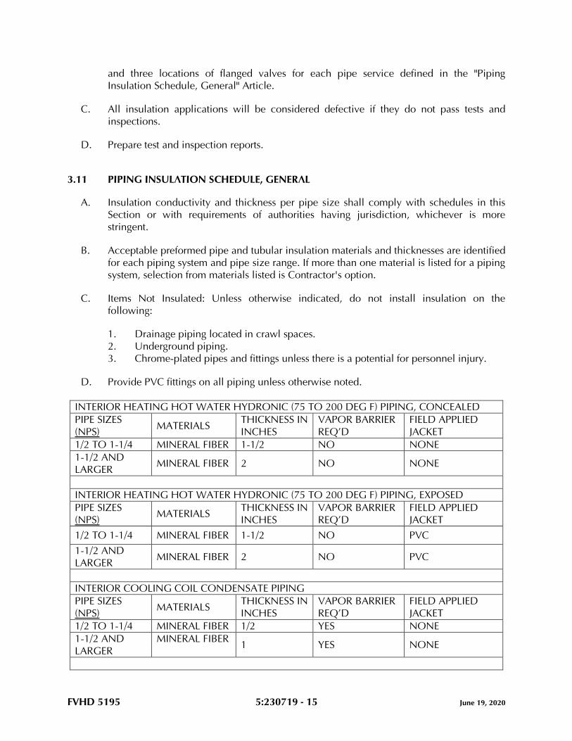
FVHD 5195 5:230719 - 15 June 19, 2020
and three locations of flanged valves for each pipe service defined in the "Piping
Insulation Schedule, General" Article.
C. All insulation applications will be considered defective if they do not pass tests and
inspections.
D. Prepare test and inspection reports.
3.11 PIPING INSULATION SCHEDULE, GENERAL
A. Insulation conductivity and thickness per pipe size shall comply with schedules in this
Section or with requirements of authorities having jurisdiction, whichever is more
stringent.
B. Acceptable preformed pipe and tubular insulation materials and thicknesses are identified
for each piping system and pipe size range. If more than one material is listed for a piping
system, selection from materials listed is Contractor's option.
C. Items Not Insulated: Unless otherwise indicated, do not install insulation on the
following:
1. Drainage piping located in crawl spaces.
2. Underground piping.
3. Chrome-plated pipes and fittings unless there is a potential for personnel injury.
D. Provide PVC fittings on all piping unless otherwise noted.
INTERIOR HEATING HOT WATER HYDRONIC (75 TO 200 DEG F) PIPING, CONCEALED
PIPE SIZES
(NPS) MATERIALS
THICKNESS IN
INCHES
VAPOR BARRIER
REQ’D
FIELD APPLIED
JACKET
1/2 TO 1-1/4 MINERAL FIBER 1-1/2 NO NONE
1-1/2 AND
LARGER MINERAL FIBER 2 NO NONE
INTERIOR HEATING HOT WATER HYDRONIC (75 TO 200 DEG F) PIPING, EXPOSED
PIPE SIZES
(NPS) MATERIALS
THICKNESS IN
INCHES
VAPOR BARRIER
REQ’D
FIELD APPLIED
JACKET
1/2 TO 1-1/4 MINERAL FIBER 1-1/2 NO PVC
1-1/2 AND
LARGER MINERAL FIBER 2 NO PVC
INTERIOR COOLING COIL CONDENSATE PIPING
PIPE SIZES
(NPS) MATERIALS
THICKNESS IN
INCHES
VAPOR BARRIER
REQ’D
FIELD APPLIED
JACKET
1/2 TO 1-1/4 MINERAL FIBER 1/2 YES NONE
1-1/2 AND
LARGER
MINERAL FIBER 1 YES NONE
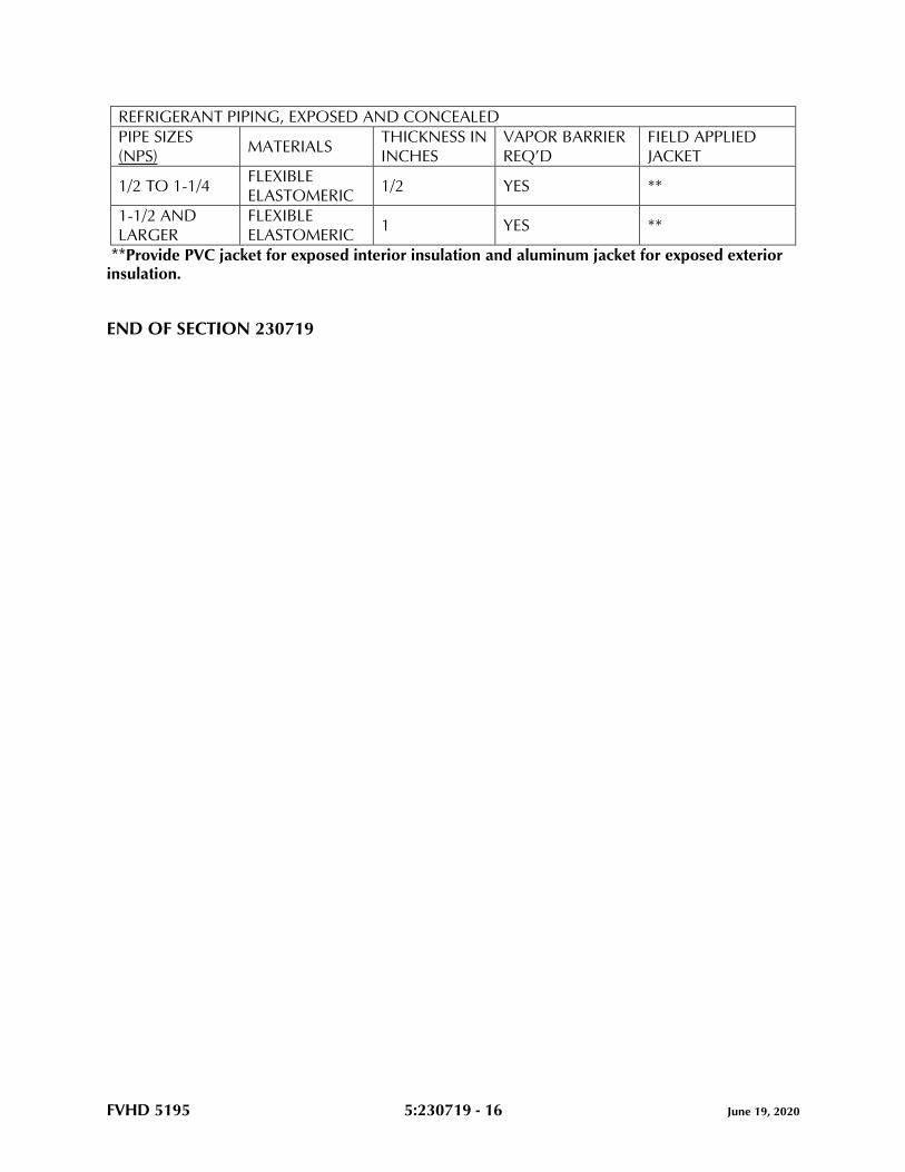
FVHD 5195 5:230719 - 16 June 19, 2020
REFRIGERANT PIPING, EXPOSED AND CONCEALED
PIPE SIZES
(NPS) MATERIALS
THICKNESS IN
INCHES
VAPOR BARRIER
REQ’D
FIELD APPLIED
JACKET
1/2 TO 1-1/4 FLEXIBLE
ELASTOMERIC 1/2 YES **
1-1/2 AND
LARGER
FLEXIBLE
ELASTOMERIC 1 YES **
**Provide PVC jacket for exposed interior insulation and aluminum jacket for exposed exterior insulation.
END OF SECTION 230719
FVHD 5195 5:230923 - 1 June 19, 2020
SECTION 230923 – DIRECT DIGITAL CONTROL (DDC) SYSTEM FOR HVAC
PART 1 - GENERAL
1.1 RELATED DOCUMENTS
A. Drawings and general provisions of the Contract, including General and Supplementary
Conditions and Division 01 Specification Sections, apply to this Section.
1.2 SUMMARY
A. Provide a new building wide Building Management System/Direct Digital Control System
(BMS/DDC) for all new equipment and associated plants.
B. Provide additional programming points, as indicated, for the Owner to utilize at their
discretion.
1. 30 additional Points.
C. The work under this Section of the Specification shall include all labor, materials,
equipment, software, licenses, and services necessary for and incidental to the proper
completion of the new Building Management System (BMS) and related work shown,
implied or specified, but is not limited to the following as described hereinafter.
D. Provide a new BMS for a complete turnkey, stand-alone, fully operational BACnet top to
bottom Direct Digital Control (DDC) System.
E. Discharge Air Temperature Sensors:
1. Provide discharge air temperature sensors for all air-side HVAC equipment
including but not limited to Air Handling Units, Variable Air Volume Boxes, etc.
F. General: The control system shall consist of a high-speed, peer-to-peer network of DDC
controllers and a web-based system, and capable of connecting to a web server with a
network interface.
G. The system shall directly control HVAC equipment as specified hereinafter in the
Sequence of Operation and Drawing Equipment Schedules. Each zone controller shall
provide occupied and unoccupied modes of operation by individual zone. Furnish
energy conversation features such as optimal start and stop, night setback, request-based
logic, and demand level adjustment of setpoints.
H. System shall use the BACnet protocol for communication to the main panel CPU for
communication between control modules. Schedules, setpoints, trends, and alarms
specified in Sequences of Operation shall be BACnet objects.
FVHD 5195 5:230923 - 2 June 19, 2020
I. All points of user interface shall be on standard PCs that do not require the purchase of
any special software from the BMS manufacturer for use as a building operations
terminal. The primary point of interface on these PCs will be a standard Web Browser
such as Internet Explorer or Mozilla Firefox.
J. Control system must comply with the standard of ASHRAE/ANSI 135-(latest edition) Data
Communication Protocol for Building Automation and Control Systems (BACnet).
K. Prior to the submission of the ATC system shop drawing, submit a letter or contract from
specified manufacturer indicating authorization from contracting firm to procure, install,
and service specified manufacturer’s equipment. The ATC shop drawing will not be
reviewed until such document is reviewed and approved by Engineer.
L. Provide sufficient site visits to complete installation and provide startup and commission
controls for each completed phase of the project, including change of seasons for re-
commissioning during alternate mode of operation.
M. The ATC scope includes the provision of the pump variable frequency drives specified in
other Division 23 Sections.
N. Exposed ATC panel in finished spaces as shown on drawings shall be painted by the
General Construction Prime Contractor. These panels shall include same key locks.
O. The ATC system shall be powered from the building power. Provide wiring and devices
as required to extend wires and conduits from the local panels where not indicated on
the Electrical Drawings. Wiring shall meet the requirements of national, state and local
codes.
P. The ATC scope includes providing 24V power to the VAV boxes indicated on the
Drawings. Power to be provided via the ATC panel.
Q. All setpoints shall be adjustable through the new head end controller, or any PC
connected to the internet via password protection.
1.3 WORK INCLUDED
A. Provide a new BACnet Building Management System (BMS) incorporating Direct Digital
Control (DDC), equipment monitoring, and control consisting of microcomputer based
network controls, digital electronic controllers and unit specific controllers interfacing
directly with sensors, actuators and environmental delivery systems (i.e., VAV boxes, unit
ventilators, fin tube radiation, air handling equipment, rooftop unit, pumps, etc.); electric
controls and mechanical devices for items indicated on drawings or described herein
including dampers, valves, panels; a primary communication network to allow data
exchange; microcomputer based digital control modules interfacing with sensors,
actuators, and terminal equipment control devices; and secondary communication
networks interfacing network devices. All Network Control Units and Equipment
Controllers shall be tied to the new Building Management System DDC system front-end.
FVHD 5195 5:230923 - 3 June 19, 2020
B. Provide all submittals, data entry, and electrical installation where indicated,
programming, start-up, test and validation acceptance documentation, and system
warranty.
C. The control system shall consist of all sensors, transmitters, controllers, control panels,
software, programming service tools, interconnecting wiring, power wiring and any other
devices or installation materials needed to fill the intent of the specification, the
Sequence of Operation and to provide for a complete and operable system.
D. All wiring, including interlock and power wiring, required for the operation of the control
system shall be provided by the control specialist, except where specifically noted
elsewhere. Wiring shall meet the requirements of National, State, and Local codes and
the Electrical Sections of this specification.
E. The engineering, installation, calibration, programming and commissioning necessary for
a complete and fully operational control system, as specified, shall be provided by the
Controls Specialist.
F. Provide surge protection for wiring and all system components.
G. Provide conduit for exposed BMS communication wiring.
H. Label all ATC control wiring as “BMS Cabling” with self-adhering markers at 20' intervals
on straight runs, at change of direction and at entrance and exit points through walls,
floors and ceilings.
I. All controllers and control points shall be programmed for trending capability and
activated through the frontend.
J. Coordinate with the Owner the required levels of alarms, assignments of defined levels
and dial out sequences. Remove all nuisance alarms that have been pre-programmed
into the software, review with the Owner.
K. Points List, Sequence of Operations and Specification Parts 1, 2 and 3 of this section and
sequence indicated in Division 23 sections makeup the entire DDC system requirements
including, but not limited to control devices, controller types, O/I’s and accessories
required to facilitate system sequences and complex operations, and shall be
incorporated as a comprehensive Digital/Analog/I/O control solution. Work shall not be
limited to only the scheduled I/O list.
L. All setpoints shall be adjustable through the front-end software.
M. Conceal all control wiring in occupied spaces within walls.
N. Provide transducers for air flow measuring devices that are provided by the HVAC Prime
Contractor.
O. Provide VAV box discharge air temperature control to prevent subcooling/overheating of
LAT and individual spaces.
FVHD 5195 5:230923 - 4 June 19, 2020
P. All cabling to be plenum rated and supported in accordance with the project electrical
specifications, local codes and NEC.
1.4 DEFINITIONS
A. Algorithm: A logical procedure for solving a recurrent mathematical problem. A
prescribed set of well-defined rules or processes for solving a problem in a finite number
of steps.
B. Analog: A continuously varying signal value, such as current, flow, pressure, or
temperature.
C. BACnet Specific Definitions:
1. BACnet: Building Automation Control Network Protocol, ASHRAE 135. A
communications protocol allowing devices to communicate data over and services
over a network.
2. BACnet Interoperability Building Blocks (BIBBs): BIBB defines a small portion of
BACnet functionality that is needed to perform a particular task. BIBBs are
combined to build the BACnet functional requirements for a device.
3. BACnet/IP: Defines and allows using a reserved UDP socket to transmit BACnet
messages over IP networks. A BACnet/IP network is a collection of one or more IP
subnetworks that share the same BACnet network number.
4. BACnet Testing Laboratories (BTL): Organization responsible for testing products
for compliance with ASHRAE 135, operated under direction of BACnet
International.
5. PICS (Protocol Implementation Conformance Statement): Written document that
identifies the particular options specified by BACnet that are implemented in a
device.
D. Binary: Two-state signal where a high signal level represents ON" or "OPEN" condition
and a low signal level represents "OFF" or "CLOSED" condition. "Digital" is sometimes
used interchangeably with "Binary" to indicate a two-state signal.
E. Controller: Generic term for any standalone, microprocessor-based, digital controller
residing on a network, used for local or global control. Three types of controllers are
indicated: Network Controller, Programmable Application Controller, and Application-
Specific Controller.
F. Control System Integrator: An entity that assists in expansion of existing enterprise system
and support of additional operator interfaces to I/O being added to existing enterprise
system.
G. E/P: Voltage to pneumatic.
H. Gateway: Bidirectional protocol translator that connects control systems that use different
communication protocols.
FVHD 5195 5:230923 - 5 June 19, 2020
I. I/O: System through which information is received and transmitted. I/O refers to analog
input (AI), binary input (BI), analog output (AO) and binary output (BO). Analog signals
are continuous and represent control influences such as flow, level, moisture, pressure,
and temperature. Binary signals convert electronic signals to digital pulses (values) and
generally represent two-position operating and alarm status. "Digital," (DI and (DO), is
sometimes used interchangeably with "Binary," (BI) and (BO), respectively.
J. LAN: Local area network.
K. Low Voltage: As defined in NFPA 70 for circuits and equipment operating at less than
50 V or for remote-control, signaling power-limited circuits.
L. Modbus TCP/IP: An open protocol for exchange of process data.
M. MS/TP: Master-slave/token-passing, IEE 8802-3. Datalink protocol LAN option that uses
twisted-pair wire for low-speed communication.
N. MTBF: Mean time between failures.
O. Network Controller: Digital controller, which supports a family of programmable
application controllers and application-specific controllers, that communicates on peer-
to-peer network for transmission of global data.
P. Network Repeater: Device that receives data packet from one network and rebroadcasts
it to another network. No routing information is added to protocol.
Q. Peer to Peer: Networking architecture that treats all network stations as equal partners.
R. RAM: Random access memory.
S. Router: Device connecting two or more networks at network layer.
T. Server: Computer used to maintain system configuration, historical and programming
database.
U. TCP/IP: Transport control protocol/Internet protocol incorporated into Microsoft
Windows.
V. UPS: Uninterruptible power supply.
W. USB: Universal Serial Bus.
X. User Datagram Protocol (UDP): This protocol assumes that the IP is used as the
underlying protocol.
Y. VAV: Variable air volume.
Z. WLED: White light emitting diode.
FVHD 5195 5:230923 - 6 June 19, 2020
1.5 WORK BY OTHERS
A. Access doors and setting in place of valves, water pressure and differential taps, flow
switches, thermal wells and dampers by HVAC Prime Contractor.
B. Prime Electrical Contractor shall provide normal power circuits to each control panel as
indicated on the electrical drawings. ATC work shall include all other electrical power,
wiring and devices as indicate and required. Wiring shall meet the requirements of
national, state and local codes.
C. Prime Electrical Contractor shall provide normal power to designated ATC control panels
and indicated units.
1. ATC scope includes providing low voltage power to serve adjacent equipment
(including VAV boxes). Wiring and transformers shall meet the requirements of
national, state, and local codes.
2. Refer to electrical drawings for locations of power feeds to the ATC Panels.
3. ATC scope shall include the provision of all other electrical wiring and devices as
indicated and required for a complete and operational system. Wiring shall meet
the requirements of national, state and local codes.
D. Where indicated on the plans, occupancy sensors are furnished and installed by the
Prime Electrical Contractor with a dry contact for ATC interface. Coordinate work with
the Prime Electrical Contractor.
1.6 PREINSTALLATION MEETINGS
A. Preinstallation Conference: Conduct conference at Project site with Owner’s
representative, Balancing Specialist, and HVAC Prime Contractor. Identify meeting time
and date with design professional a minimum of 7 days prior to the meeting taking place.
B. Include on the Agenda a review of the graphics and control sequences, phasing
coordination, and final locations of the workstation.
C. Record and product meeting minute notes and submit a copy to the design professional.
1.7 SEQUENCES OF OPERATION
A. Central System Control: Occupied/unoccupied shall be determined by the timed event
software. The Direct Digital Control, DDC panel shall control the indicated sequence of
operation.
B. Heating Hot Water System:
1. The boilers shall be partially under the control of the BMS Direct Digital Controller
(DDC) panel which shall enable boiler control panels and allow setpoint
adjustments. The boiler controller shall energize boiler circulator pump (primary),
capacity control, initiate alarms, sequences, part loads, stages, and interface with
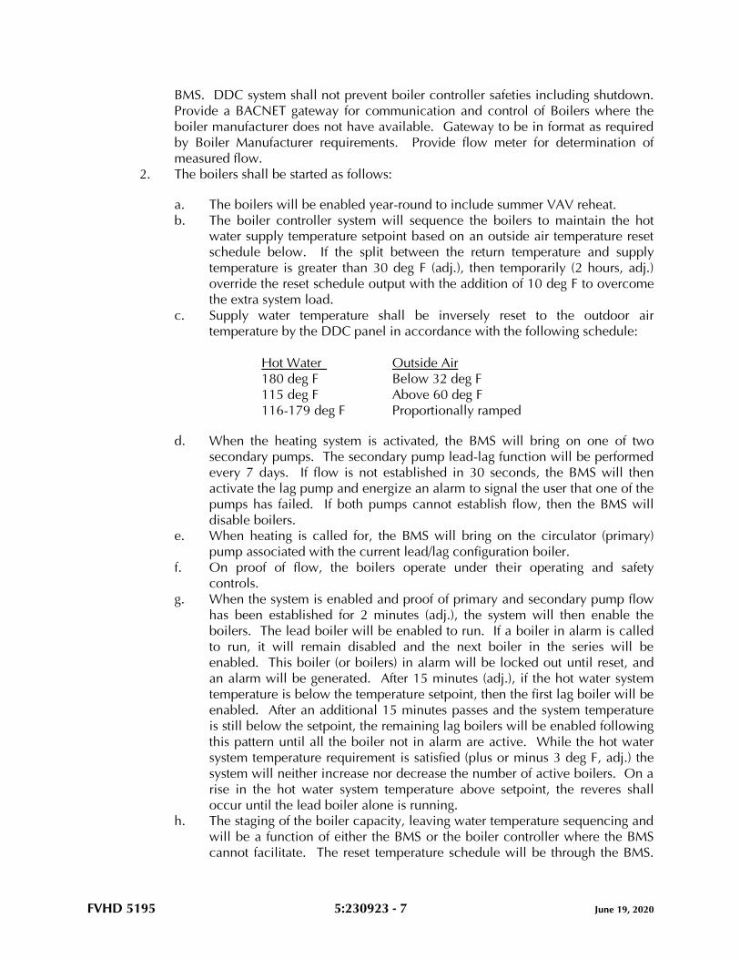
FVHD 5195 5:230923 - 7 June 19, 2020
BMS. DDC system shall not prevent boiler controller safeties including shutdown.
Provide a BACNET gateway for communication and control of Boilers where the
boiler manufacturer does not have available. Gateway to be in format as required
by Boiler Manufacturer requirements. Provide flow meter for determination of
measured flow.
2. The boilers shall be started as follows:
a. The boilers will be enabled year-round to include summer VAV reheat.
b. The boiler controller system will sequence the boilers to maintain the hot
water supply temperature setpoint based on an outside air temperature reset
schedule below. If the split between the return temperature and supply
temperature is greater than 30 deg F (adj.), then temporarily (2 hours, adj.)
override the reset schedule output with the addition of 10 deg F to overcome
the extra system load.
c. Supply water temperature shall be inversely reset to the outdoor air
temperature by the DDC panel in accordance with the following schedule:
Hot Water Outside Air
180 deg F Below 32 deg F
115 deg F Above 60 deg F
116-179 deg F Proportionally ramped
d. When the heating system is activated, the BMS will bring on one of two
secondary pumps. The secondary pump lead-lag function will be performed
every 7 days. If flow is not established in 30 seconds, the BMS will then
activate the lag pump and energize an alarm to signal the user that one of the
pumps has failed. If both pumps cannot establish flow, then the BMS will
disable boilers.
e. When heating is called for, the BMS will bring on the circulator (primary)
pump associated with the current lead/lag configuration boiler.
f. On proof of flow, the boilers operate under their operating and safety
controls.
g. When the system is enabled and proof of primary and secondary pump flow
has been established for 2 minutes (adj.), the system will then enable the
boilers. The lead boiler will be enabled to run. If a boiler in alarm is called
to run, it will remain disabled and the next boiler in the series will be
enabled. This boiler (or boilers) in alarm will be locked out until reset, and
an alarm will be generated. After 15 minutes (adj.), if the hot water system
temperature is below the temperature setpoint, then the first lag boiler will be
enabled. After an additional 15 minutes passes and the system temperature
is still below the setpoint, the remaining lag boilers will be enabled following
this pattern until all the boiler not in alarm are active. While the hot water
system temperature requirement is satisfied (plus or minus 3 deg F, adj.) the
system will neither increase nor decrease the number of active boilers. On a
rise in the hot water system temperature above setpoint, the reveres shall
occur until the lead boiler alone is running.
h. The staging of the boiler capacity, leaving water temperature sequencing and
will be a function of either the BMS or the boiler controller where the BMS
cannot facilitate. The reset temperature schedule will be through the BMS.
FVHD 5195 5:230923 - 8 June 19, 2020
The entering fluid temperature sensor monitors changes in entering fluid
temperature to anticipate changes in the heating load. Based on leaving fluid
temperature, the boiler controller will add or subtract capacity to maintain a
constant secondary loop fluid temperature.
i. Run time equalization will direct the boilers without regard to numbered
sequence and focus only on run time hours. Upon a call for heat the DDC
will look at the total run time for each unit and identify and select the unit
with the least total hours to be the lead boiler. Additional boilers will be
energized utilizing an identical selection process.
3. During early morning warm-up mode add 20 deg F to hot water discharge
temperature schedule and proportionally ramp. Setpoint warm-up to occupied
period switching shall be ramped such that the change occurs over a 15 minute
time duration.
4. The hot water secondary pumps alternate to equalize runtime. Selection of the lead
pump is evaluated on a weekly basis. The pump with the least runtime is the lead
pump. If the lead pump fails to start, the lag pump will be energized. An alarm will
be sent to the front-end.
5. When the hot water system is on (indicated by a call for heating), the lead pump
starts. If all the hot water valves are closed in the system for more than 5 minutes
then the pump will stop. The variable frequency drive modulates pump speed to
maintain system differential pressure (psi) as sensed near the end of the piping run.
6. The DDC system uses current switches to confirm the lead pump is in the desired
state (i.e. on or off) and generates an alarm if status deviates from DDC start/stop
control.
7. Variable Speed Pump:
a. The BMS will sequence the pump variable frequency drives and the drives
will control the pumps.
b. The lead water pump shall be energized.
c. The system shall consist of one duty pump/AFD set, one standby pump/AFD
set, with duty-standby pump selection, automatic alternation and automatic
transfer to the standby pump.
d. The pumping system shall operate automatically.
e. Sensor/transmitters (2) shall be installed by the HVAC Contractor and
furnished and wired by the ATC subcontractor.
f. The sensor/transmitters shall send a 4-20 mA signal to the building control
system and indicate of process variable condition.
g. The DDC will sequence the control operation. The BMS shall compare each
signal to the independent, user determined setpoints.
h. When all setpoints (as determined by the ATC Contractor based on actual
location, field conditions and point pressure) are satisfied by the process
variable, the pump speed shall remain constant at the optimum energy
consumption level.
i. The DDC shall continuously scan and compare each process variable to its
individual setpoint and control to the least satisfied zone.
j. As the piping system pressure deviates from setpoint, the DDC shall send the
appropriate analog signal to the VFD to speed up or slow down the
pump/motor.
FVHD 5195 5:230923 - 9 June 19, 2020
k. The redundant variable speed system shall be started through the DDC.
l. In the event of a system differential pressure failure due to a pump or VFD
fault, the DDC automatically initiates a timed sequence of operation to start
the redundant pump/VFD set in the variable speed mode.
m. In the event of the failure of a zone sensor/transmitter, its process variable
signal shall be removed from the scan/compare program. Alternative zone
sensor/transmitter shall remain in the scan/compare program for control.
n. In the event of failure to receive all zone process variable signals, the VFD
shall maintain a predetermined speed, reset shall be automatic upon
correction of the zone failure.
8. The hot water flow through the secondary loop system will vary and minimum flow
relative to the boiler requirements must be maintained. As each boiler is
sequenced ON the boiler the associated circulator pump will be energized and the
system flow passing the boiler connection must not be less the circulator pump
flow rate or sum of the energized boiler pumps flow rates. Provide a secondary
flow meter for determination of flow.
9. The hot water system flow shall not be less than the lead or the sum of the boiler
design flows. In the event the distribution loop flow reaches the boiler (or sum of
the boilers) circulation flow, the bypass valve will slowly modulated open and
maintain minimum flow as sensed by the flow meter. The system differential
pressure devices will verify the required minimum hot water flow and override in
the event of a flow meter malfunction. Program the VFD not to go below the boiler
circulator flow rate or sum of operating boiler.
10. Hot water system controls valve shall be slow acting and the building control
system programming must be design to facilitate operation of a boiler(s).
11. When the emergency wall gas switch is depressed, all boilers will be disabled and
gas valves will fully close.
C. RTU/AHU Control Scheme Summary:
1. AHU-01: VAV with hydronic heating and split DX cooling.
2. AHU-02: Variable speed single zone with hydronic heating and split system DX
cooling.
a. Demand Control Ventilation Strategy to be employed for the following units:
AHU-02.
D. Air Handling Unit (VAV split DX cooling with unit mounted hot water heating coil)
1. General: Provide factory mounted DDC controls and all field installed accessories
as required to provide the following basic programmable functions and intended
operations. The PI control of installed DDC devices will maintain tight control of
temperature and humidity setpoints. AHU Manufacturer to provide all unit
mounted controls including, but not limited to thermostat, humidistat, control
wiring and LCD access programmable controller.
a. Provide additional controllers, input/output devices, wiring, programming,
etc. to meet the sequences of operation, associated points list, and interface
with the building LAN and BMS.
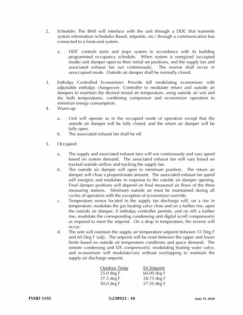
FVHD 5195 5:230923 - 10 June 19, 2020
2. Schedule: The BMS will interface with the unit through a DDC that transmits
system information (schedules Based, setpoints, etc.) through a communication bus
connected to a front-end system.
a. DDC controls starts and stops system in accordance with its building
programmed occupancy schedule. When system is energized (occupied
mode) unit damper open to their initial set positions, and the supply fan and
associated exhaust fan run continuously. The reverse shall occur in
unoccupied mode. Outside air damper shall be normally closed.
3. Enthalpy Controlled Economizer: Provide full modulating economizer with
adjustable enthalpy changeover. Controller to modulate return and outside air
dampers to maintain the desired mixed air temperature, using outside air wet and
dry bulb temperatures, combining compressor and economizer operation to
minimize energy consumption.
4. Warm-up:
a. Unit will operate as in the occupied mode of operation except that the
outside air damper will be fully closed, and the return air damper will be
fully open.
b. The associated exhaust fan shall be off.
5. Occupied:
a. The supply and associated exhaust fans will run continuously and vary speed
based on system demand. The associated exhaust fan will vary based on
tracked outside airflow and tracking the supply fan.
b. The outside air damper will open to minimum position. The return air
damper will close a proportionate amount. The associated exhaust fan speed
will energize and modulate in response to the outside air damper opening.
Final damper positions will depend on final measured air flows of the three
measuring stations. Minimum outside air must be maintained during all
cycles of operation with the exception of economizer override.
c. Temperature sensor located in the supply fan discharge will, on a rise in
temperature, modulate the gas heating valve close and on a further rise, open
the outside air damper, if enthalpy controller permits, and on still a further
rise, modulate the corresponding condensing unit digital scroll compressor(s)
as required to meet the setpoint. On a drop in temperature, the reverse will
occur.
d. The unit will maintain the supply air temperature setpoint between 55 Deg F
and 60 Deg F (adj). The setpoint will be reset between the upper and lower
limits based on outside air temperature conditions and space demand. The
remote condensing unit DX compressor(s), modulating heating water valve,
and economizer will modulate/vary without overlapping to maintain the
supply air discharge setpoint.
Outdoor Temp SA Setpoint
25.0 deg F 60.00 deg F
37.5 deg F 58.75 deg F
50.0 deg F 57.50 deg F
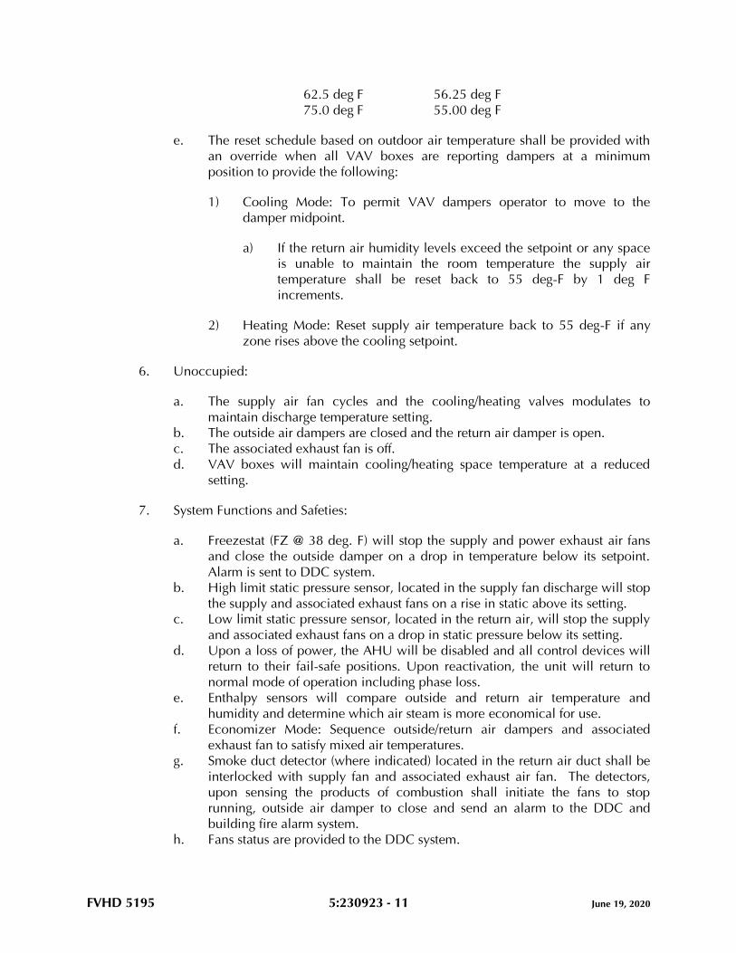
FVHD 5195 5:230923 - 11 June 19, 2020
62.5 deg F 56.25 deg F
75.0 deg F 55.00 deg F
e. The reset schedule based on outdoor air temperature shall be provided with
an override when all VAV boxes are reporting dampers at a minimum
position to provide the following:
1) Cooling Mode: To permit VAV dampers operator to move to the
damper midpoint.
a) If the return air humidity levels exceed the setpoint or any space
is unable to maintain the room temperature the supply air
temperature shall be reset back to 55 deg-F by 1 deg F
increments.
2) Heating Mode: Reset supply air temperature back to 55 deg-F if any
zone rises above the cooling setpoint.
6. Unoccupied:
a. The supply air fan cycles and the cooling/heating valves modulates to
maintain discharge temperature setting.
b. The outside air dampers are closed and the return air damper is open.
c. The associated exhaust fan is off.
d. VAV boxes will maintain cooling/heating space temperature at a reduced
setting.
7. System Functions and Safeties:
a. Freezestat (FZ @ 38 deg. F) will stop the supply and power exhaust air fans
and close the outside damper on a drop in temperature below its setpoint.
Alarm is sent to DDC system.
b. High limit static pressure sensor, located in the supply fan discharge will stop
the supply and associated exhaust fans on a rise in static above its setting.
c. Low limit static pressure sensor, located in the return air, will stop the supply
and associated exhaust fans on a drop in static pressure below its setting.
d. Upon a loss of power, the AHU will be disabled and all control devices will
return to their fail-safe positions. Upon reactivation, the unit will return to
normal mode of operation including phase loss.
e. Enthalpy sensors will compare outside and return air temperature and
humidity and determine which air steam is more economical for use.
f. Economizer Mode: Sequence outside/return air dampers and associated
exhaust fan to satisfy mixed air temperatures.
g. Smoke duct detector (where indicated) located in the return air duct shall be
interlocked with supply fan and associated exhaust air fan. The detectors,
upon sensing the products of combustion shall initiate the fans to stop
running, outside air damper to close and send an alarm to the DDC and
building fire alarm system.
h. Fans status are provided to the DDC system.
FVHD 5195 5:230923 - 12 June 19, 2020
8. Air Flow, Measurement and Control
a. Static Pressure Control: Supply fan modulates to maintain a constant static
pressure in the supply duct. A differential pressure transmitter located in the
supply air ductwork (located approximately 75% of distance downstream
from supply fan) maintains duct static pressure setting (adjustable) by
modulating the supply fan variable speed controller.
b. Airflow Measuring: Flow measuring stations, located at the supply and
exhaust fans transmit volume signals to the DDC panel. The DDC panel will
compare the two volumes and adjust the exhaust air fan variable speed drive
to the balance of the exhaust, return and outside air to closely match supply
air. The outside airflow will be measured in the outside air ductwork and
controlled to maintain a constant minimum air flow as the return air, and
exhaust air vary in volume. When the economizer cycle is enabled the
outside air damper and bypass damper will modulate open as the return air
damper closes a proportional amount, the exhaust fan speed varies while
maintaining discharge setpoint temperature.
1) Air flow measuring stations associated with supply fan to be flow-
shaping bellmouth inlet type, or as approved by the AHU
manufacturer.
2) Airflow measuring station associated with outside air to be pitot tube
array mounted in the O/A duct main.
3) The associated exhaust fan will vary the fan speed to maintain the
required exhaust airflow (relief) rate.
9. Associated exhaust fan (EF-01):
a. Refer to the applicable sequence for pressurization control (EF-01)
E. Air Handling Unit (Single Zone VAV split DX cooling with unit mounted hot water
heating coil)
1. General: Provide factory mounted DDC controls and all field installed accessories
as required to provide the following basic programmable functions and intended
operations. The PI control of installed DDC devices will maintain tight control of
temperature and humidity setpoints. AHU Manufacturer to provide all unit
mounted controls including, but not limited to thermostat, humidistat, control
wiring and LCD access programmable controller.
a. Provide additional controllers, input/output devices, wiring, programming,
etc. to meet the sequences of operation, associated points list, and interface
with the building LAN and BMS.
2. Schedule: The BMS will interface with the unit through a DDC that transmits
system information (schedules Based, setpoints, etc.) through a communication bus
connected to a front-end system.
a. DDC controls starts and stops system in accordance with its building
programmed occupancy schedule. When system is energized (occupied
FVHD 5195 5:230923 - 13 June 19, 2020
mode) unit damper open to their initial set positions, and the supply fan and
associated exhaust fan run continuously. The reverse shall occur in
unoccupied mode. Outside and exhaust air dampers shall be normally
closed.
3. Warm-up:
a. Unit will operate as in the occupied mode of operation except that the
outside air damper will be fully closed, and the return air damper will be
fully open.
b. The associated exhaust fan shall be off.
4. Occupied:
a. Setpoints:
1) Space Heating Temperature: 70 deg F (adj).
2) Space Cooling Temperature: 75 deg F, 50% RH (adj).
3) Space Humidity (for dehumidification): 55% RH (adj).
4) Heating Limiting Temperature Setpoint: 80 deg F (adj.)
b. The supply fans will run continuously and vary speed based on system
demand.
c. The outside air damper will open to minimum position. The return air
damper will close a proportionate amount. Final damper positions will
depend on final measured air flows of the measuring stations. Minimum
outside air must be maintained during all cycles of operation with the
exception of CO2 and economizer override.
d. Cooling mode:
1) When space temperature rises above the cooling setpoint, the supply
fan, at the minimum speed will gradually increase speed to satisfy the
space temperature sensor in conjunction with the supply cooling and
the system will perform the most efficient means to provide space
cooling.
2) The economizer will be energized as the first stage of cooling.
3) The economizer controller will check outside air temperature and
humidity and modulate the associated dampers.
4) When the cooling demand increases more than the economizer mode
is capable of cooling the system shall revert back to minimum outside
air, and the electric refrigeration shall be staged by the microprocessor
controller by varying combinations of compressors and modulate the
refrigerant hot gas reheat coil to attain setpoint temperature and
dehumidification to maintain the air temperature setpoint as the supply
fan speed increases to satisfy the space demand.
5) The controller will maintain the discharge air temperature setpoint 56
deg F (adj) as sensed by the temperature sensor downstream of the fan
discharge. If the discharge air temperature as sensed by unit discharge
sensor rises 1 deg F (adj) above setpoint for more than 5 minutes, the
compressor will be enabled for cooling. The hot gas reheat coil will
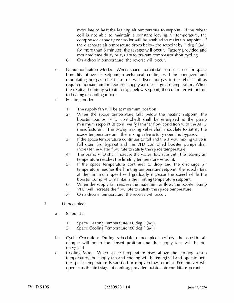
FVHD 5195 5:230923 - 14 June 19, 2020
modulate to heat the leaving air temperature to setpoint. If the reheat
coil is not able to maintain a constant leaving air temperature, the
compressor capacity controller will be enabled to maintain setpoint. If
the discharge air temperature drops below the setpoint by 1 deg F (adj)
for more than 5 minutes, the reverse will occur. Factory provided and
mounted time delay relays are to prevent compressor short cycling
6) On a drop in temperature, the reverse will occur.
e. Dehumidification Mode: When space humidistat senses a rise in space
humidity above its setpoint, mechanical cooling will be energized and
modulating hot gas reheat controls will divert hot gas to the reheat coil as
required to maintain the required supply air discharge air temperature. When
the relative humidity setpoint drops below setpoint, the controller will return
to heating or cooling mode.
f. Heating mode:
1) The supply fan will be at minimum position.
2) When the space temperature falls below the heating setpoint, the
booster pumps (VFD controlled) shall be energized at the pump
minimum setpoint (8 gpm, verify laminar flow condition with the AHU
manufacturer). The 3-way mixing valve shall modulate to satisfy the
space temperature until the mixing valve is fully open (no bypass).
3) If the space temperature continues to fall and the 3-way mixing valve is
full open (no bypass) and the VFD controlled booster pumps shall
increase the water flow rate to satisfy the space temperature.
4) The pump VFD shall increase the water flow rate until the leaving air
temperature reaches the limiting temperature setpoint.
5) If the space temperature continues to drop and the discharge air
temperature reaches the limiting temperature setpoint, the supply fan,
at the minimum speed will gradually increase the speed while the
booster pump VFD maintains the limiting temperature setpoint.
6) When the supply fan reaches the maximum airflow, the booster pump
VFD will increase the flow rate to satisfy the space temperature.
7) On a drop in temperature, the reverse will occur.
5. Unoccupied:
a. Setpoints:
1) Space Heating Temperature: 60 deg F (adj).
2) Space Cooling Temperature: 80 deg F (adj).
b. Cycle Operation: During schedule unoccupied periods, the outside air
damper will be in the closed position and the supply fans will be de-
energized.
c. Cooling Mode: When space temperature rises above the cooling set-up
temperature, the supply fan and cooling will be energized and operate until
the space temperature is satisfied or drops below setpoint. Economizer will
operate as the first stage of cooling, provided outside air conditions permit.
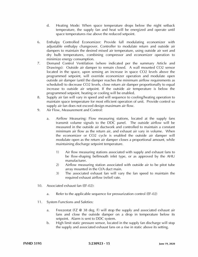
FVHD 5195 5:230923 - 15 June 19, 2020
d. Heating Mode: When space temperature drops below the night setback
temperature, the supply fan and heat will be energized and operate until
space temperatures rise above the reduced setpoint.
6. Enthalpy Controlled Economizer: Provide full modulating economizer with
adjustable enthalpy changeover. Controller to modulate return and outside air
dampers to maintain the desired mixed air temperature, using outside air wet and
dry bulb temperatures, combining compressor and economizer operation to
minimize energy consumption.
7. Demand Control Ventilation (where indicated per the summary Article and
Drawings): Outside air damper to remain closed. A wall mounted CO2 sensor
located in the space, upon sensing an increase in space CO2 levels above the
programmed setpoint, will override economizer operation and modulate open
outside air damper (until the damper reaches the minimum airflow requirements as
scheduled) to decrease CO2 levels, close return air damper proportionally to equal
increase to outside air setpoint. If the outside air temperature is below the
programmed setpoint, heating or cooling will be enabled.
8. Supply air fan will vary in speed and will sequence to cooling/heating operation to
maintain space temperature for most efficient operation of unit. Provide control so
supply air fan does not exceed design maximum air flow.
9. Air Flow, Measurement and Control:
a. Airflow Measuring: Flow measuring stations, located at the supply fans
transmit volume signals to the DDC panel. The outside airflow will be
measured in the outside air ductwork and controlled to maintain a constant
minimum air flow as the return air, and exhaust air vary in volume. When
the economizer or CO2 cycle is enabled the outside air damper will
modulate open as the return air damper closes a proportional amount, while
maintaining discharge setpoint temperature.
1) Air flow measuring stations associated with supply and exhaust fans to
be flow-shaping bellmouth inlet type, or as approved by the AHU
manufacturer.
2) Airflow measuring station associated with outside air to be pitot tube
array mounted in the O/A duct main.
3) The associated exhaust fan will vary the fan speed to maintain the
required exhaust airflow (relief) rate.
10. Associated exhaust fan (EF-02):
a. Refer to the applicable sequence for pressurization control (EF-02)
11. System Functions and Safeties:
a. Freezestat (FZ @ 38 deg. F) will stop the supply and associated exhaust air
fans and close the outside damper on a drop in temperature below its
setpoint. Alarm is sent to DDC system.
b. High limit static pressure sensor, located in the supply fan discharge will stop
the supply and associated exhaust fans on a rise in static above its setting.
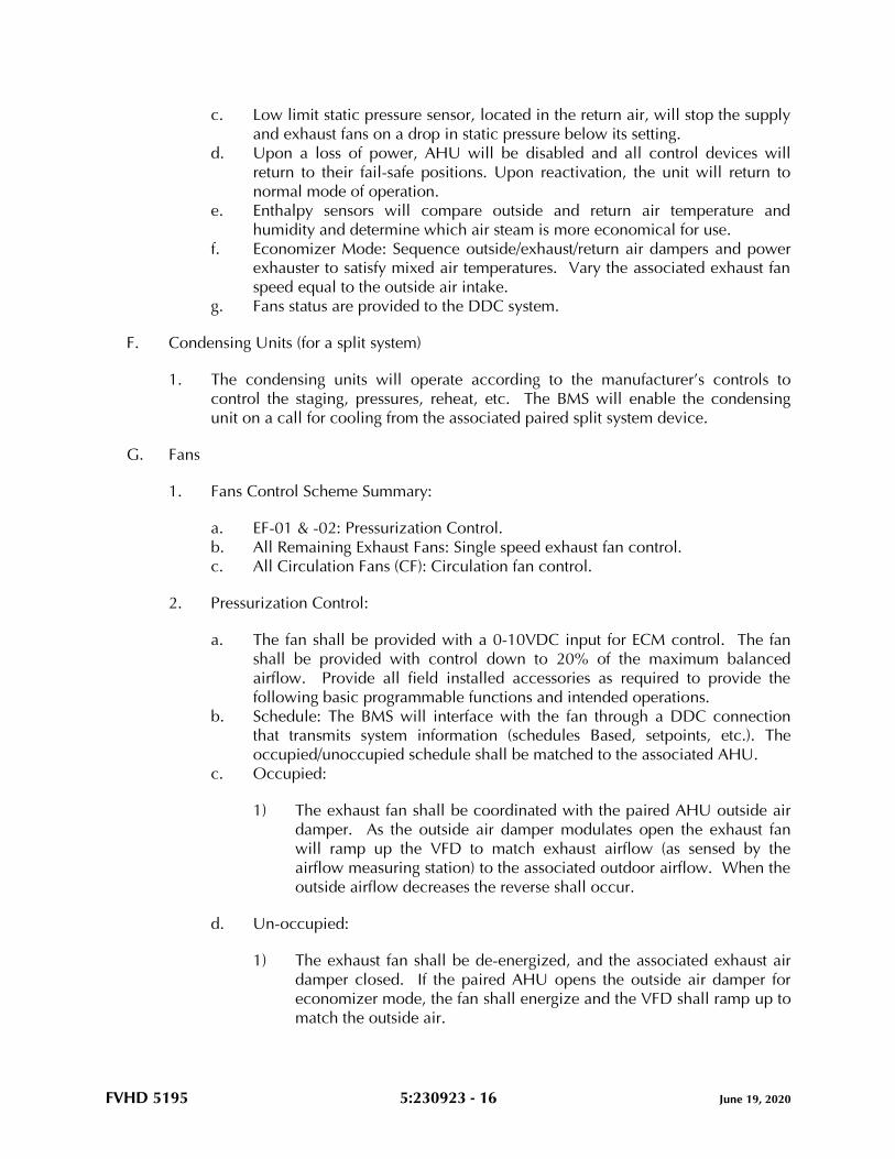
FVHD 5195 5:230923 - 16 June 19, 2020
c. Low limit static pressure sensor, located in the return air, will stop the supply
and exhaust fans on a drop in static pressure below its setting.
d. Upon a loss of power, AHU will be disabled and all control devices will
return to their fail-safe positions. Upon reactivation, the unit will return to
normal mode of operation.
e. Enthalpy sensors will compare outside and return air temperature and
humidity and determine which air steam is more economical for use.
f. Economizer Mode: Sequence outside/exhaust/return air dampers and power
exhauster to satisfy mixed air temperatures. Vary the associated exhaust fan
speed equal to the outside air intake.
g. Fans status are provided to the DDC system.
F. Condensing Units (for a split system)
1. The condensing units will operate according to the manufacturer’s controls to
control the staging, pressures, reheat, etc. The BMS will enable the condensing
unit on a call for cooling from the associated paired split system device.
G. Fans
1. Fans Control Scheme Summary:
a. EF-01 & -02: Pressurization Control.
b. All Remaining Exhaust Fans: Single speed exhaust fan control.
c. All Circulation Fans (CF): Circulation fan control.
2. Pressurization Control:
a. The fan shall be provided with a 0-10VDC input for ECM control. The fan
shall be provided with control down to 20% of the maximum balanced
airflow. Provide all field installed accessories as required to provide the
following basic programmable functions and intended operations.
b. Schedule: The BMS will interface with the fan through a DDC connection
that transmits system information (schedules Based, setpoints, etc.). The
occupied/unoccupied schedule shall be matched to the associated AHU.
c. Occupied:
1) The exhaust fan shall be coordinated with the paired AHU outside air
damper. As the outside air damper modulates open the exhaust fan
will ramp up the VFD to match exhaust airflow (as sensed by the
airflow measuring station) to the associated outdoor airflow. When the
outside airflow decreases the reverse shall occur.
d. Un-occupied:
1) The exhaust fan shall be de-energized, and the associated exhaust air
damper closed. If the paired AHU opens the outside air damper for
economizer mode, the fan shall energize and the VFD shall ramp up to
match the outside air.
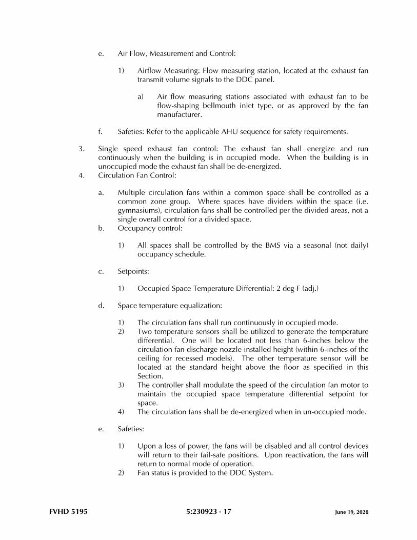
FVHD 5195 5:230923 - 17 June 19, 2020
e. Air Flow, Measurement and Control:
1) Airflow Measuring: Flow measuring station, located at the exhaust fan
transmit volume signals to the DDC panel.
a) Air flow measuring stations associated with exhaust fan to be
flow-shaping bellmouth inlet type, or as approved by the fan
manufacturer.
f. Safeties: Refer to the applicable AHU sequence for safety requirements.
3. Single speed exhaust fan control: The exhaust fan shall energize and run
continuously when the building is in occupied mode. When the building is in
unoccupied mode the exhaust fan shall be de-energized.
4. Circulation Fan Control:
a. Multiple circulation fans within a common space shall be controlled as a
common zone group. Where spaces have dividers within the space (i.e.
gymnasiums), circulation fans shall be controlled per the divided areas, not a
single overall control for a divided space.
b. Occupancy control:
1) All spaces shall be controlled by the BMS via a seasonal (not daily)
occupancy schedule.
c. Setpoints:
1) Occupied Space Temperature Differential: 2 deg F (adj.)
d. Space temperature equalization:
1) The circulation fans shall run continuously in occupied mode.
2) Two temperature sensors shall be utilized to generate the temperature
differential. One will be located not less than 6-inches below the
circulation fan discharge nozzle installed height (within 6-inches of the
ceiling for recessed models). The other temperature sensor will be
located at the standard height above the floor as specified in this
Section.
3) The controller shall modulate the speed of the circulation fan motor to
maintain the occupied space temperature differential setpoint for
space.
4) The circulation fans shall be de-energized when in un-occupied mode.
e. Safeties:
1) Upon a loss of power, the fans will be disabled and all control devices
will return to their fail-safe positions. Upon reactivation, the fans will
return to normal mode of operation.
2) Fan status is provided to the DDC System.
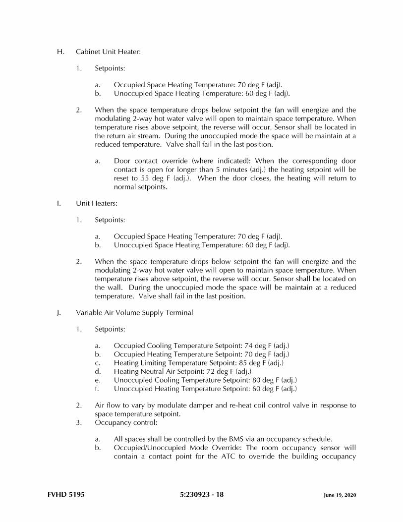
FVHD 5195 5:230923 - 18 June 19, 2020
H. Cabinet Unit Heater:
1. Setpoints:
a. Occupied Space Heating Temperature: 70 deg F (adj).
b. Unoccupied Space Heating Temperature: 60 deg F (adj).
2. When the space temperature drops below setpoint the fan will energize and the
modulating 2-way hot water valve will open to maintain space temperature. When
temperature rises above setpoint, the reverse will occur. Sensor shall be located in
the return air stream. During the unoccupied mode the space will be maintain at a
reduced temperature. Valve shall fail in the last position.
a. Door contact override (where indicated): When the corresponding door
contact is open for longer than 5 minutes (adj.) the heating setpoint will be
reset to 55 deg F (adj.). When the door closes, the heating will return to
normal setpoints.
I. Unit Heaters:
1. Setpoints:
a. Occupied Space Heating Temperature: 70 deg F (adj).
b. Unoccupied Space Heating Temperature: 60 deg F (adj).
2. When the space temperature drops below setpoint the fan will energize and the
modulating 2-way hot water valve will open to maintain space temperature. When
temperature rises above setpoint, the reverse will occur. Sensor shall be located on
the wall. During the unoccupied mode the space will be maintain at a reduced
temperature. Valve shall fail in the last position.
J. Variable Air Volume Supply Terminal
1. Setpoints:
a. Occupied Cooling Temperature Setpoint: 74 deg F (adj.)
b. Occupied Heating Temperature Setpoint: 70 deg F (adj.)
c. Heating Limiting Temperature Setpoint: 85 deg F (adj.)
d. Heating Neutral Air Setpoint: 72 deg F (adj.)
e. Unoccupied Cooling Temperature Setpoint: 80 deg F (adj.)
f. Unoccupied Heating Temperature Setpoint: 60 deg F (adj.)
2. Air flow to vary by modulate damper and re-heat coil control valve in response to
space temperature setpoint.
3. Occupancy control:
a. All spaces shall be controlled by the BMS via an occupancy schedule.
b. Occupied/Unoccupied Mode Override: The room occupancy sensor will
contain a contact point for the ATC to override the building occupancy
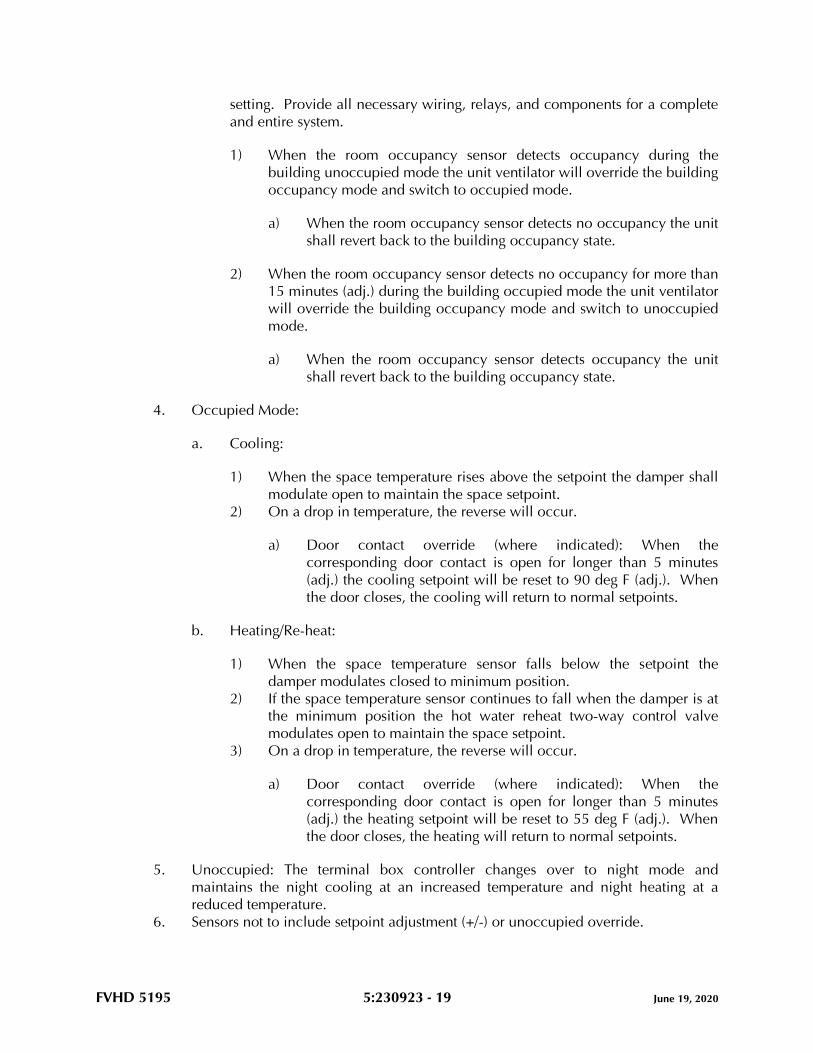
FVHD 5195 5:230923 - 19 June 19, 2020
setting. Provide all necessary wiring, relays, and components for a complete
and entire system.
1) When the room occupancy sensor detects occupancy during the
building unoccupied mode the unit ventilator will override the building
occupancy mode and switch to occupied mode.
a) When the room occupancy sensor detects no occupancy the unit
shall revert back to the building occupancy state.
2) When the room occupancy sensor detects no occupancy for more than
15 minutes (adj.) during the building occupied mode the unit ventilator
will override the building occupancy mode and switch to unoccupied
mode.
a) When the room occupancy sensor detects occupancy the unit
shall revert back to the building occupancy state.
4. Occupied Mode:
a. Cooling:
1) When the space temperature rises above the setpoint the damper shall
modulate open to maintain the space setpoint.
2) On a drop in temperature, the reverse will occur.
a) Door contact override (where indicated): When the
corresponding door contact is open for longer than 5 minutes
(adj.) the cooling setpoint will be reset to 90 deg F (adj.). When
the door closes, the cooling will return to normal setpoints.
b. Heating/Re-heat:
1) When the space temperature sensor falls below the setpoint the
damper modulates closed to minimum position.
2) If the space temperature sensor continues to fall when the damper is at
the minimum position the hot water reheat two-way control valve
modulates open to maintain the space setpoint.
3) On a drop in temperature, the reverse will occur.
a) Door contact override (where indicated): When the
corresponding door contact is open for longer than 5 minutes
(adj.) the heating setpoint will be reset to 55 deg F (adj.). When
the door closes, the heating will return to normal setpoints.
5. Unoccupied: The terminal box controller changes over to night mode and
maintains the night cooling at an increased temperature and night heating at a
reduced temperature.
6. Sensors not to include setpoint adjustment (+/-) or unoccupied override.
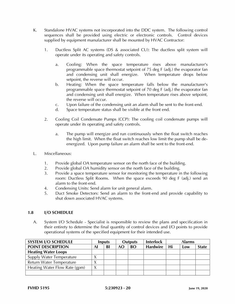
FVHD 5195 5:230923 - 20 June 19, 2020
K. Standalone HVAC systems not incorporated into the DDC system. The following control
sequences shall be provided using electric or electronic controls. Control devices
supplied by equipment manufacturer shall be mounted by HVAC Contractor:
1. Ductless Split AC systems (DS & associated CU): The ductless split system will
operate under its operating and safety controls.
a. Cooling: When the space temperature rises above manufacturer's
programmable space thermostat setpoint of 75 deg F (adj.) the evaporator fan
and condensing unit shall energize. When temperature drops below
setpoint, the reverse will occur.
b. Heating: When the space temperature falls below the manufacturer's
programmable space thermostat setpoint of 70 deg F (adj.) the evaporator fan
and condensing unit shall energize. When temperature rises above setpoint,
the reverse will occur.
c. Upon failure of the condensing unit an alarm shall be sent to the front-end.
d. Space temperature status shall be visible at the front end.
2. Cooling Coil Condensate Pumps (CCP): The cooling coil condensate pumps will
operate under its operating and safety controls.
a. The pump will energize and run continuously when the float switch reaches
the high limit. When the float switch reaches low limit the pump shall be de-
energized. Upon pump failure an alarm shall be sent to the front-end.
L. Miscellaneous:
1. Provide global OA temperature sensor on the north face of the building.
2. Provide global OA humidity sensor on the north face of the building.
3. Provide a space temperature sensor for monitoring the temperature in the following
room: Ductless Split Rooms. When the space exceeds 90 deg F (adj.) send an
alarm to the front-end.
4. Condensing Units: Send alarm for unit general alarm.
5. Duct Smoke Detectors: Send an alarm to the front-end and provide capability to
shut down associated HVAC systems.
1.8 I/O SCHEDULE
A. System I/O Schedule - Specialist is responsible to review the plans and specification in
their entirety to determine the final quantity of control devices and I/O points to provide
operational systems of the specified equipment for their intended use.
SYSTEM I/O SCHEDULE Inputs Outputs Interlock Alarms POINT DESCRIPTION AI BI AO BO Hardwire Hi Low State Heating Water Loops
Supply Water Temperature X
Return Water Temperature X
Heating Water Flow Rate (gpm) X
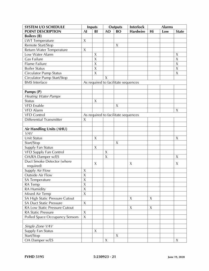
FVHD 5195 5:230923 - 21 June 19, 2020
SYSTEM I/O SCHEDULE Inputs Outputs Interlock Alarms POINT DESCRIPTION AI BI AO BO Hardwire Hi Low State Boilers (B)
LWT Temperature X
Remote Start/Stop X
Return Water Temperature X
Low Water Alarm X X
Gas Failure X X
Flame Failure X X
Boiler Status X X
Circulator Pump Status X X
Circulator Pump Start/Stop X
BMS Interface As required to facilitate sequences
Pumps (P)
Heating Water Pumps
Status X
VFD Enable X
VFD Alarm X
VFD Control As required to facilitate sequences
Differential Transmitter X
Air Handling Units (AHU)
VAV
Unit Status X X
Start/Stop X
Supply Fan Status X
VFD Supply Fan Control X
OA/RA Damper w/ES X X
Duct Smoke Detector (where
required) X X X
Supply Air Flow X
Outside Air Flow X
SA Temperature X
RA Temp X
RA Humidity X
Mixed Air Temp X
SA High Static Pressure Cutout X X
SA Duct Static Pressure X
RA Low Static Pressure Cutout X X
RA Static Pressure X
Polled Space Occupancy Sensors X
Single Zone VAV
Supply Fan Status X
Start/Stop X
OA Damper w/ES X X
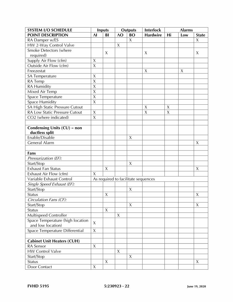
FVHD 5195 5:230923 - 22 June 19, 2020
SYSTEM I/O SCHEDULE Inputs Outputs Interlock Alarms POINT DESCRIPTION AI BI AO BO Hardwire Hi Low State RA Damper w/ES X X
HW 2-Way Control Valve X
Smoke Detectors (where
required) X X X
Supply Air Flow (cfm) X
Outside Air Flow (cfm) X
Freezestat X X
SA Temperature X
RA Temp X
RA Humidity X
Mixed Air Temp X
Space Temperature X
Space Humidity X
SA High Static Pressure Cutout X X
RA Low Static Pressure Cutout X X X
CO2 (where indicated) X
Condensing Units (CU) – non ductless split
Enable/Disable X
General Alarm X
Fans
Pressurization (EF):
Start/Stop X
Exhaust Fan Status X X
Exhaust Air Flow (cfm) X
Variable Exhaust Control As required to facilitate sequences
Single Speed Exhaust (EF):
Start/Stop X
Status X X
Circulation Fans (CF):
Start/Stop X X
Status X
Multispeed Controller X
Space Temperature (high location
and low location) X
Space Temperature Differential X
Cabinet Unit Heaters (CUH)
RA Sensor X
HW Control Valve X
Start/Stop X
Status X X
Door Contact X
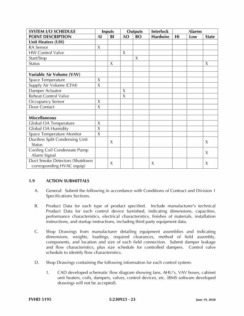
FVHD 5195 5:230923 - 23 June 19, 2020
SYSTEM I/O SCHEDULE Inputs Outputs Interlock Alarms POINT DESCRIPTION AI BI AO BO Hardwire Hi Low State Unit Heaters (UH)
RA Sensor X
HW Control Valve X
Start/Stop X
Status X X
Variable Air Volume (VAV)
Space Temperature X
Supply Air Volume (CFM) X
Damper Actuator X
Reheat Control Valve X
Occupancy Sensor X
Door Contact X
Miscellaneous
Global OA Temperature X
Global OA Humidity X
Space Temperature Monitor X
Ductless Split Condensing Unit
Status X X
Cooling Coil Condensate Pump
Alarm Signal X
Duct Smoke Detectors (Shutdown
corresponding HVAC equip) X X X
1.9 ACTION SUBMITTALS
A. General: Submit the following in accordance with Conditions of Contract and Division 1
Specifications Sections.
B. Product Data for each type of product specified. Include manufacturer's technical
Product Data for each control device furnished, indicating dimensions, capacities,
performance characteristics, electrical characteristics, finishes of materials, installation
instructions, and startup instructions, including third party equipment data.
C. Shop Drawings from manufacturer detailing equipment assemblies and indicating
dimensions, weights, loadings, required clearances, method of field assembly,
components, and location and size of each field connection. Submit damper leakage
and flow characteristics, plus size schedule for controlled dampers. Control valve
schedule to identify flow characteristics.
D. Shop Drawings containing the following information for each control system:
1. CAD developed schematic flow diagram showing fans, AHU’s, VAV boxes, cabinet
unit heaters, coils, dampers, valves, control devices, etc. (BMS software developed
drawings will not be accepted).
FVHD 5195 5:230923 - 24 June 19, 2020
2. Each control device labeled with setting or adjustable range of control.
3. Diagrams for all required electrical wiring. Clearly differentiate between factory-
installed and field-installed wiring.
4. Details of control panel faces, including controls, instruments, and labeling.
5. Written description of sequence of operation.
6. Trunk cable schematic showing programmable control unit locations and trunk
data conductors.
7. Listing of connected data points, including connected control unit and input
device.
8. System graphics indicating monitored systems, data (connected and calculated)
point addresses, and operator notations.
9. System configuration showing peripheral devices, batteries, power supplies,
diagrams, modems, and interconnections.
10. Software description and sequence of operation.
11. Building wiring diagram including panel locations and connection to bus line.
12. Bill of materials.
13. Provide panel layout including controllers, electronic devices and unused I/O’s.
Include panel dimensions.
14. Provide bus (network) wiring riser diagrams.
15. Provide controller terminal diagrams, points, point names and field device
connections, field device points, and field device names. Label and color code
wiring connections.
16. Details of third party compatible devices including wiring diagrams, integrators and
devices.
E. Submittal shall consist of:
1. System architecture showing all digital devices.
2. Equipment lists of all proposed devices and equipment including data sheets of all
products, including third party equipment.
3. Valve, damper, and well and tap schedules showing size, configuration, capacity
and location of all equipment.
4. Wiring and piping interconnection diagrams including panel and device power and
sources, including third party diagrams, with terminal point designation for each
wire connection.
F. Wiring diagrams detailing wiring for power, signal, and control systems and
differentiating clearly between manufacturer-installed and field-installed wiring.
G. Samples of each type of furnished thermostat/sensor cover according to requirements of
Division 01.
H. Maintenance data for control systems equipment to include in the operation and
maintenance manual. Include the following:
1. Maintenance instructions and spare parts lists for each type of control device and
compressed-air stations (if required).
2. Interconnection wiring diagrams with identified and numbered system components
and devices.
FVHD 5195 5:230923 - 25 June 19, 2020
3. Keyboard illustrations and step-by-step procedures indexed for each operator
function.
4. Inspection period, cleaning methods, cleaning materials recommended, and
calibration tolerances.
5. Calibration records and list of set points.
I. Field Test Reports: Procedure and certification of the control system, communication
wiring, sensor wiring, and all bus wiring.
J. Project Record Documents: Record actual locations of control components, including
control units, thermostats, and sensors. Revise Shop Drawings to reflect actual
installation and operating sequences, including all third party vendor information.
Provide all BMS files developed specifically for installed system such as graphics, control
programming and network communications.
K. Software Manuals: The software manual shall describe programming and testing, starting
with a system overview and proceeding to a detailed description of each software feature.
The manual shall instruct the user on programming or re-programming any portions of
the BMS. This shall include all control programs, algorithms, mathematical equations,
variables, set points, time periods, messages, and other information necessary to load,
alter, test and execute the system. The manual shall include:
1. Complete description of programming language, including commands, editing and
writing control programs, algorithms, printouts and logs, mathematical calculations
and passwords.
2. Instructions on modifying any control algorithm or parameter, verifying errors,
status, changing passwords and initiating or disabling control programs.
L. Software Documentation: All software programs shall be easily referenced from
summary sheets which compare control programs with pertinent information about
hardware and wiring information in the field. Documentation shall include:
1. Complete point identification, including terminal number, symbol, engineering
units and control program reference number.
2. Field information including location, device, device type and function, electrical
parameters and installation drawing number.
3. Location identification BMS control hardware.
M. Software: Upon successful completion of the operational acceptance test, provide a
medium, and hardware for bulk storage of the accepted versions and an untranslated (not
complied) copy of the program database.
N. Commissioning Summary Forms: Provide data summary forms to be approved by the
Engineer to define the following information for inclusion into the BMS for each point in
the system by the ATC Specialist:
1. Description of each piece of equipment and the functions to be controlled.
2. For each BMS function, a listing of digital and/or analog hardware required to
interface the BMS to the equipment.
3. Listing of all digital and analog alarms.
FVHD 5195 5:230923 - 26 June 19, 2020
4. Listing of all BMS application programs associated with each piece of equipment.
This listing shall include all control algorithms and mathematical equations. The
listing shall be in easy to understand English format.
O. All application programs must be submitted. No unauthorized BMS manufacturers
proprietary control front-ends will be accepted.
P. BMS Manufacturer authorized Contractors must submit letter or contract from specified manufacturer indicating authorization from contracting firm to procure, install and service specified manufacturer’s equipment.
Q. Licenses, guarantees, and warranty documents for equipment and systems.
1.10 CLOSEOUT SUBMITTALS
A. Operation and Maintenance Data: For DDC system to include in emergency, operation
and maintenance manuals.
1. In addition to items specified in applicable Division 01 sections include the
following:
a. Project Record Drawings of as-built versions of submittal Shop Drawings
provided in electronic PDF format.
b. Testing and commissioning reports and checklists of completed final versions
of reports, checklists, and trend logs.
c. As-built versions of submittal Product Data.
d. Names, addresses, e-mail addresses and 24-hour telephone numbers of
Installer and service representatives for DDC system and products.
e. Operator's manual with procedures for operating control systems including
logging on and off, handling alarms, producing point reports, trending data,
overriding computer control and changing set points and variables.
f. Programming manuals with description of programming language and
syntax, of statements for algorithms and calculations used, of point database
creation and modification, of program creation and modification, and of
editor use.
g. Engineering, installation, and maintenance manuals that explain how to:
1) Design and install new points, panels, and other hardware.
2) Perform preventive maintenance and calibration.
3) Debug hardware problems.
4) Repair or replace hardware.
h. Documentation of all programs created using custom programming language
including set points, tuning parameters, and object database.
i. Backup copy of graphic files, programs, and database on electronic media
such as DVDs.
j. List of recommended spare parts with part numbers and suppliers.
FVHD 5195 5:230923 - 27 June 19, 2020
k. Complete original-issue documentation, installation, and maintenance
information for furnished third-party hardware including computer
equipment and sensors.
l. Complete original-issue copies of furnished software, including operating
systems, custom programming language, operator workstation software, and
graphics software.
m. Licenses, guarantees, and warranty documents.
n. Recommended preventive maintenance procedures for system components,
including schedule of tasks such as inspection, cleaning, and calibration;
time between tasks; and task descriptions.
o. Owner training materials.
1.11 QUALITY ASSURANCE
A. Prime Contractor Qualifications: Engage an experienced specialist specializing in direct
digital control system installations. Specialist shall be certified in writing by BMS
manufacturer.
B. Manufacturer Qualifications: Engage a firm experienced in manufacturing control
systems similar to those indicated for this Project and that have a record of successful in-
service performance.
C. The complete BMS installation shall be in strict accordance to the national and local
electrical codes and the electrical section of these specifications. All devices designed
for or used in line voltage applications shall be UL listed. All microprocessor based
remote and central devices connection onto the primary bus (including link devices) shall
be UL864 Listed.
D. Provide satisfactory operation without damage at 110% above and 85% below rated
voltage and at 3 hertz variation in line frequency. Provide static, transient, and short
circuit protection on all inputs and outputs. Communication lines shall be protected
against incorrect wiring, static transients lightning strikes, and induced magnetic
interference. All bus connected devices shall be a.c. coupled, or equivalent so that any
single device failure will not disrupt or halt bus communication. Surge suppression and
isolations devices shall be provided.
E. Startup Personnel Qualifications: Engage specially trained personnel in direct employ of
manufacturer of primary temperature control system. Personnel shall be capable of
administering training, system diagnostics, and trouble shooting.
F. Comply with NFPA 90A.
G. Comply with NFPA 70.
H. Coordinate equipment selection with applicable Division 26 Sections to achieve
compatibility with equipment that interfaces with the fire alarm system.
I. All wiring between controller and sensors and control devices including any power
wiring of devices and necessary conduit shall be provided under this section of the
FVHD 5195 5:230923 - 28 June 19, 2020
specification. All control and power wiring which is provided under this section of the
specification shall be in accordance with requirements set forth in the National Electrical
Code (NEC) latest edition.
1.12 CONDITIONS:
A. Bids by Wholesalers, Contractors, Franchised Dealers or any firm whose principal
business is not that of installing automatic temperature control systems shall not be
acceptable.
B. The system shall be engineered, programmed, and installed by personnel trained and
regularly employed by the BMS manufacturer, or certified contractors.
C. Manufacturer and specialist shall have an in-place support facility within 100 miles of the
site with technical staff, spare parts inventory and all necessary test and diagnostic
equipment.
1.13 DELIVERY, STORAGE, AND HANDLING
A. Store equipment and materials inside and protected from weather.
B. Factory-Mounted Components: Where control devices specified in this Section are
indicated to be factory mounted on equipment, arrange for shipping control devices to
unit manufacturer and in factory testing of components installed in designated
equipment.
1.14 COORDINATION
A. Coordinate location of thermostats, humidistats, and other exposed control sensors with
plans and room details before installation.
B. Coordinate supply of conditioned electrical branch circuits for control units and operator
workstation.
C. Coordinate equipment with applicable Division 26 Sections to achieve compatibility with
starter coils and annunciation devices for panelboards.
D. Coordinate equipment with applicable Division 26 Sections to achieve compatibility with
motor starters and annunciation devices.
1.15 WARRANTY
A. Warrant labor and materials for specified control system free from defects for a period of
12 months after project substantial completion. Control system failures during warranty
period shall be adjusted, repaired, or replaced at no additional cost or reduction in
service to Owner. Respond during normal business hours within 24 hours of Owner’s
warranty service request.
FVHD 5195 5:230923 - 29 June 19, 2020
B. Work shall have a single warranty date, even if Owner received beneficial use due to
early system start-up. If specified work is split into multiple contracts or a multi-phase
contract, each contract or phase shall have a separate warranty start date and period.
C. Provide an extended service contract beyond first year warranty period if so desired by
Owner.
PART 2 - PRODUCTS
2.1 MANUFACTURERS
A. Acceptable manufacturers/Authorized Installer:
1. Honeywell (Basis of Design).
2. Johnson Controls.
3. Schneider Electric.
B. Building Management System and Components
1. Honeywell: WEBs-N4 BACnet system (Basis of Design).
2. Johnson Controls: Facility Explorer (BACnet) Control System.
3. Schneider Electric: SmartStruxure (BACnet) Control System.
C. Authorized ATC Provider:
1. Honeywell: Authorized Control Integrator (ACI) Contractor.
2. Johnson Controls: Authorized Building Controls Specialist (ABCS) Contractor.
3. Schneider Electric: Authorized Contractor/Dealer.
D. Building Management System Architecture:
1. The BMS system architecture will be BACnet top to bottom with a web base
server/controller.
2. Control products, communication media, connectors, repeaters, hubs, and routers
shall comprise a BACnet internetwork. Controller and operator interface
communication shall conform to ASHRAE/ANSI Standard BACnet.
3. Web server and controllers shall communicate using BACnet protocol. Web server
network backbone shall communicate using ISO 8802-3 (Ethernet) Data
Link/Physical layer protocol and BACnet/IP addressing as specified in ASHRAE/
ANSI 135-2003, BACnet Annex J. Provide data drop for IT/internet access.
4. The network shall be based on a PC industry standard of Ethernet TCP/IP. Where
used, LAN controller cards shall be standard “off the shelf” products available
through normal PC vendor channels. All controllers on the BMS shall
communicate via BACnet MS/TP protocol. The BMS shall network multiple user
interface clients, universal network controllers, system controllers and application-
specific controllers.
5. Access to system shall not be restricted by the hardware configuration of the
building management system. The hardware configuration of the BMS shall be
FVHD 5195 5:230923 - 30 June 19, 2020
totally transparent to the user when accessing data or developing control network
programs from either over the IT LAN or remote access.
6. Controller/panels to be wired to the server and the server to be connected to IT
LAN for remote access. Provide an Ethernet drop for connection to School
District’s IT LAN at each school.
7. Controller/panels to be wired to the master CPU serve and connected to IT LAN for
front-end access. Provide an Ethernet drop for connection to IT LAN, BMS
programming and provide technical support for setup and interface with the IT
LAN. The Owner will provide a fixed IP Address, Domain and IT LAN system
programming to facilitate BMS access through the LAN/Firewall to the WAN for
remote access.
8. Graphics will be developed using the manufacturer’s graphics software.
Coordinate graphics with the Owner.
9. BMS is to be a full open system for modification and upgrades, and is the licensed
Institution with all password knowledge.
10. Provide gateway interface in appropriate protocol as required.
11. Provide LCD access at the master panels (2).
12. Provide pump variable frequency drives that are fully functional with installed
control system.
13. Building controls to be tied into front-end.
2.2 DDC SYSTEM DESCRIPTION
A. Microprocessor-based monitoring and control including analog/digital conversion and
program logic. A control loop or subsystem in which digital and analog information is
received and processed by a microprocessor, and digital control signals are generated
based on control algorithms and transmitted to field devices to achieve a set of
predefined conditions.
1. DDC system shall consist of a high-speed, peer-to-peer network of distributed DDC
controllers, other network devices, operator interfaces, and software.
B. Electrical Components, Devices, and Accessories: Listed and labeled as defined in
NFPA 70, by a qualified testing agency, and marked for intended location and
application.
2.3 CONTROLLER HARDWARE
A. The Building Management System (BMS) shall integrate multiple building functions
including equipment supervision and control, alarm management, energy management
and historical data collection.
B. The system shall be a modular distributed control system. Expansion in capacity and
functionality shall be provided through the addition of sensors, actuators, standalone
DDC panels and operator devices.
C. System architectural design shall eliminate dependence upon any single device for alarm
reporting and control execution. Each DDC panel/controller shall operate independently
FVHD 5195 5:230923 - 31 June 19, 2020
by performing its own specified control, alarm management, operator I/O, and historical
data collection functions. The failure of any single component or network connection
(including a wire break) shall not interrupt the execution of any control strategy,
reporting, alarming and trending function, or any function at any operator interface
device.
D. Network Control Units shall be highest available capacity with a minimum 32-bit
microprocessor based within panel operating system. DDC programs and data files shall
be non-volatile memory or flash memory to allow simple and reliable additions and
changes. Each unit shall have an on-board 30-day battery backed real-time clock. Unit(s)
shall be provided where shown or specified with capacity to accommodate input/output
(I/O) points required for the application. Each panel shall be provided with a socket for a
Portable Network Terminal, and a port for network communications. Units outputs shall
be binary for On-Off control, and true variable voltage (0-10v) for driving analog or
pneumatic transducer devices. Analog outputs shall have a minimum incremental
resolution of one percent of the operating range of the controlled device. Units shall have
LEDs for continuous indication of all bus communications, power, and operational status.
All panel electronics and associated equipment shall be installed in suitable enclosures.
E. DEC (Digital Electronic Controllers) control modules or unit specific DDC controllers
shall be UL916 standalone digital based configured to perform the sequences specified,
and with I/O selected for the application. Controller enclosures shall be compact plastic
conforming to UL94-5V or plated steel. Each device shall be provided with LED type
annunciation to continually display its operational mode; power, normal, or in an alarm
state.
F. Network terminal shall be provided for mounting in network control panel.
G. System integrator shall monitor and control all third party equipment. HVAC Contractor
and ATC Specialist shall coordinate all devices and determine unit mounted third party
items vs. field installed devices
2.4 SYSTEM SOFTWARE
A. Control Software:
1. Time Programs: Each control unit shall contain up to 20 unique user modifiable
time programs (TP). Each TP shall consist of daily, weekly, and annual programs
plus a "TODAY" temporary function. DAILY programs shall be definable for day
types such as working day, half day, holiday, weekend, etc. Each daily program
shall allow a list of time based (or optimum time based) analog and digital
commands to be issued to user selected plant elements and points. WEEKLY
programs shall allow a user selected set of daily programs to be defined for each
day of the week (Monday through Sunday). The ANNUAL program shall initially be
an automatic compilation of 52 weekly programs. Selecting a date of the ANNUAL
program shall allow modification of the daily selection entered into the weekly
program (such as changing Dec. 25 from a working day to a holiday).
2. Control Application Software shall be customized to meet the detailed
requirements of the "Sequence of Operation". Control units, control modules and
FVHD 5195 5:230923 - 32 June 19, 2020
unit specific controllers network management devices shall be programmable. All
BMS control software shall be designed via a graphic programming facility, the
flow chart output of which shall be provided as system documentation.
3. In addition to Proportional, Proportional-Plus-Integral (PI), and Proportional-Plus-
Integral-Plus-Derivative (PID) algorithms, an HVAC enhanced PID (EPID) algorithm
shall be provided and implemented where specified. The EPID shall be a full PID,
but modified and/or appended to perform as follows:
a. The user shall be allowed to specify a start output value to which subsequent
corrective signals are added. For example, a variable speed pump may be
specified to start at 20% to assure a timely proof-of-operation signal to result
without false failure-to-respond alarms being issued during slow startups; or a
discharge air EPID loop may be specified to start at 33% (at which point the
heating and cooling valves and the outside air damper are all closed) and
enter into control without overshoot or undershoot.
b. The user shall be allowed to specify a start-up ramp duration of 1 to 300
seconds, during which time the error (EPID set point minus EPID input) varies
from 0 to the actual value, thus allowing gradual and direct assumption of
control with no hunting, overshoot, or undershoot. Ramping of the PID
output (which will cause integral wind-up) is not allowed.
c. The EPID shall be provided with a limit signal port such that the connection
of an external limit signal (such as providing a fan discharge pressure high
limit signal into a VAV duct static pressure control EPID) allows the limit
signal to override the EPID without integral windup occurring during the
limit-control period.
B. Management Software:
1. Trending: In addition to supporting temperature and humidity trending specified
elsewhere, each network control unit shall be provided with a trend archive of at
least the last 8000 events (digital transitions or analog value changes) of any user
selected group of up to 50 points. A stored event shall include date and time, and
value or status. Events occurring in excess of 8000 shall overwrite the oldest
events.
2. Alarms: BMS shall monitor and report all analog input points and specified digital
points for off-normal conditions. Each alarm shall have an "alarm delay" attribute
which shall determine how long (in seconds) a point must be off-normal prior to
being considered in an alarm state.
3. DEC Support: Network control units and devices managing sub-networks of DECs
shall report DEC alarms and shall be programmed to perform data reduction,
sorting, and optimizing routines.
2.5 SOFTWARE
A. Software shall be configured to meet the requirements of the "Sequence of Operation"
specified and shall be field reconfigurable. Software shall support full PID control, and
shall utilize separate PID gains for heating and cooling. Where space sensors are
provided with temperature set point knobs, DDC controllers shall be provided with
unique software set point limits. Each controller shall have continuously running
FVHD 5195 5:230923 - 33 June 19, 2020
hardware diagnostics to detect malfunctions of the flow sensor, the temperature sensor,
the remote set point sensor, and the A to D converter.
B. Controllers shall have preconfigured air flow calibration software to assist the test and
balance (TAB) specialist in final calibrations. Using the DEC contractors calibration tool,
the TAB Specialist shall be provided with a display allowing a simple command entry to
place the DEC in zero, minimum, and maximum CFM control modes. At each mode, a
display field shall be provided for the T&B Specialist to enter the actual measured value
in CFM. Upon completion of entering the three values, the DEC shall automatically
recalibrate based upon the actual values
2.6 WORKSTATION
A. Provide one workstation per facility.
B. One (1) PC-Based, Pentium microprocessor (control manufacturer approved, including
operating system), Windows 10 Pro Operating System (control manufacturer approved),
Operator Workstation, shall be provided and located as directed by Owner. Provide all
necessary cabling, etc. to Owner approved location. Workstation shall be provided with
a printer, modem, and UPS/power conditioner. All the necessary cables, paper supplies,
interface cards, power strips, CD +/- RW, DVD +/- RW, monitor, disk holders, and disks
shall be provided. A computer table/workstation unit shall be provided to house and
support all the workstation equipment.
1. Provide one (1) PC-Based, Core i7 microprocessor and Windows 10 Operating
System (control manufacturer approved), Operator Workstation, shall be provided
and located as directed by Owner. Provide all necessary cabling, etc. to Owner
approved location. Provide all the necessary cables, interface cards, power strips,
DVD +/- RW, monitor, and software.
2. Computer workstations shall be recognizable manufacturer. Systems shall utilize
industry standard components and system configurations. Custom built computers
are not acceptable.
3. The operator's workstation shall be an assemblage of peripherals, hardware and
software to serve as a supervisory operator interface for monitoring and controlling
the system.
4. Workstation shall consist of a color monitor, full tower case personal computer
with minimum 12 GB PC3-12800 DDR3 SDRAM, 2 TB hard drive (7,200 rpm),
read/write DVD, Intel HD graphics, 4600 mouse 100 MHZ enthernet card, 4 USB
4.0 and 101-key enhanced keyboard. Personal computer shall be an IBM
compatible and shall include a minimum i7 core, 3GHZ processor speed, 6 MB
cache.
5. The primary display terminal provided for system shall be a LED flat screen,
twenty-one inches (21") and a minimum display resolution of no less than 1920 x
1080 pixels, 16:9 aspect ratio, 60HZ, 1000:1 static and 5,000,000:1 dynamic.
Separate controls shall be provided for color, contrasts and brightness. The screen
shall be non-reflective.
6. The computer shall come pre-installed with individual licensed BMS software,
system graphics, Windows 10 or version compatible with BMS software Internet
software, browser, peripheral software, and all necessary software for in-house

FVHD 5195 5:230923 - 34 June 19, 2020
access and operation. Workstations shall come pre-installed with latest version of
Excel for Windows.
7. Workstation to be located as requested by Owner. Provide necessary wiring and
controller appurtenances to facilitate.
C. Workstations shall include pre-installed software per the licensing agreements of
manufacturers. Original registered software and manuals shall be submitted to the
Owner.
2.7 DATA COMMUNICATIONS
A. All network control unit and DEC network management devices shall be interconnected
and tied into the communications network. DECs shall also be connected together via
secondary networks managed by network management devices to provide data
concentration and parallel processing such that system expansion does not noticeably
affect system response. All communications shall be via three wire, shielded where
required, RS-485. DDC microprocessor failures shall not cause loss of communications
of the remainder of any network. All networks shall support sensor sharing, global
application programs, and bus-to-bus communications in a true peer-to-peer token
passing manner.
B. For reliability, maintainability, and performance communication busses shall be
extendible to 4000 feet without active links, hubs, or repeaters.
C. DECs shall be managed by network management devices to provide alarm detection and
reporting, data sharing, trending, and response to data requests and commands.
2.8 COLLECTION AND ANALYSIS OF HISTORICAL DATA
A. Provide trending capabilities that allow the user to easily monitor and preserve records of
system activity over an extended period of time. Any system point may be trended
automatically at time-based intervals or changes of value, both of which shall be user-
definable. Trend data must be automatically stored on hard disk for future diagnostics
and reporting.
B. Trend data report graphics shall be provided to allow the user to view all trended point
data. Reports may be customized to include individual points or pre-defined groups of at
least 6 points. Provide additional functionality to allow any trended data to be transferred
easily to an off-the-shelf spreadsheet package such as Excel. This shall allow the user to
perform custom calculations such as energy usage, equipment efficiency and energy
costs and shall allow for generation of these reports on high-quality plots, graphs and
charts.
C. Provide additional functionality that allows the user to view trended data on trend graph
displays. Displays shall be actual plots of both static and/or real-time dynamic point
data. A minimum of 4 points may be viewed simultaneously on a single graph, with
color selection and line type for each points being user-definable. Displays shall include
an ‘X’ axis indicating elapsed time and a ‘Y’ axis indicating a range scale in engineering
FVHD 5195 5:230923 - 35 June 19, 2020
units for each point. The ‘Y’ axis shall have the ability to be manually or automatically
scaled at the user’s option. Different ranges for each point may be used with minimum
and maximum values listed at the bottom and top of the ‘Y’ axis. All ‘Y’ axis data shall
be color-coded to match the line color for the corresponding point.
1. Static graphs shall represent actual point data that has been trended and stored on
disk. Exact point values may be viewed on a data window by pointing or scrolling
to the place of interest along the graph. Provide capability to print any graph on
the system printer for use as a building management and diagnostics tool.
2. Dynamic graphs shall represent real-time point data. Any point or group of points
may be graphed, regardless of whether they have been predefined for trending.
The graphs shall continuously update point values. At any time the user may
redefine sampling times or range scales for any point. In addition, the user may
pause the graph and take “snapshots” of screens to be stored on the workstation
disk for future recall and analysis. As with static graphs, exact point values may be
viewed and the graphs may be printed.
2.9 DYNAMIC COLOR GRAPHIC DISPLAYS
A. Color graphic floor plan displays and system schematics for each piece of mechanical
equipment. Provide optimize system performance analysis and speed alarm recognition
as required by the Owner and this specification.
B. The operator interface shall allow users to access the various system schematics and floor
plans via a graphical penetration scheme, menu selection or text-based commands.
C. Dynamic temperature values, humidity values, flow values and status indication shall be
shown in their actual respective locations and shall automatically update to represent
current conditions without operator intervention.
D. The windowing environment of the PC operator workstation shall allow the user to
simultaneously view several graphics at a time to analyze total building operation or to
allow the display of a graphic associated with an alarm to be viewed without interrupting
work in progress.
E. Provide a dynamic display of the site specific BMS architecture indicating the status of all
controllers, PC workstations and networks.
2.10 ELECTRIC AND MECHANICAL DEVICES
A. Provide Building Controllers (BC), Advanced Application Controllers (AAC), Application
Specific Controllers (ASC), Smart Actuators (SA), and Smart Sensors (SS) as required to
achieve performance specified Article System Performance. Every device in the system
which executes control logic and directly controls HVAC equipment must conform to a
standard BACnet Device Profile as specified in ASHRAE/ANSI 135-2003, BACnet Annex
L. Unless otherwise specified, hardwired actuators and sensors may be used in lieu of
BACnet Smart Actuators and Smart Sensors.
FVHD 5195 5:230923 - 36 June 19, 2020
B. All electric switch devices shall be selected for the applied load and UL listed for the
application. Miscellaneous, electric, pneumatic, and mechanical devices shall include:
1. Automatic control valves 2 1/2 " and smaller shall be screwed type, and valves 3"
and larger shall be flanged. Valves shall be ANSI-rated to withstand the pressures
and temperatures encountered. Valves shall have stainless-steel stems and spring
loaded Teflon packaging with replaceable discs.
a. All modulating straight-through water valves shall be provided with equal-
percentage contoured throttling plugs. Valves shall be sized for a pressure
drop equal to the coil they serve but not to exceed 4 psi.
b. Unitary valves shall be straight-through type as specified in the sequence of
operation. Stems shall be polished stainless-steel and packing shall be
ethylene-propylene suitable for both chilled water service. Pressure ratings
shall be as required for the intended service.
C. All automatically controlled devices, unless specified otherwise elsewhere, shall be
provided with electric actuators sized to operate their appropriate loads with sufficient
reserve power to provide smooth modulating action or two-position action and tight
close-off.
D. Transformers: Provide step-down control transformers where required to power controls.
Control transformers shall be sized such that 80% of the rated capacity equals the
connected load.
2.11 ACTUATORS
A. Electric Motors: Size to operate with sufficient reserve power to provide smooth
modulating action or 2-position action.
1. Permanent Split-Capacitor or Shaded-Pole Type: Gear trains completely oil
immersed and sealed. Equip spring-return motors with integral spiral-spring
mechanism in housings designed for easy removal for service or adjustment of limit
switches, auxiliary switches, or feedback potentiometer.
2. Nonspring-Return Motors for Valves Larger than 2-1/2 Inches: Size for running
torque of 150 inch-pounds and breakaway torque of 300 inch-pounds.
3. Spring-Return Motors for Valves Larger than 2-1/2 Inches: Size for running and
breakaway torque of 150 inch-pounds.
4. Nonspring-Return Motors for Dampers Larger than 25 sq. ft.: Size for running
torque of 150 inch-pounds and breakaway torque of 300 inch-pounds.
5. Spring-Return Motors for Dampers Larger than 25 sq. ft.: Size for running and
breakaway torque of 150 inch-pounds.
2.12 DATA INPUTS AND OUTPUTS
A. Input/output sensors and devices shall be closely matched to the requirements of the
remote panel for accurate, responsive, noise-free signal input/output. Control input
FVHD 5195 5:230923 - 37 June 19, 2020
response shall be high sensitivity and matched to the loop gain requirements for precise
and responsive control.
B. Temperature sensors shall be thermistor type of 10,000 ohm at 77deg F, equal to PreCon
Type III. Sensors shall have + or - 0.36 deg F accuracy between 32deg F and 158 deg F.
1. DEC space temperature sensors shall be provided with blank commercial type
locking covers with the following features:
a. Sensors shall be provided with plug-in port to respective network for software
maintenance and/or reconfiguration. Each part to be wired for
communication. Plastic used on subbase or housing shall be UL94-5V rated.
b. Do not included override switch to initiate change from unoccupied to
occupied mode.
c. Do not include setpoint adjustment by occupant limited by programmable
range +/- setting (do not provide temperature gradients, provide tick marks),
unless otherwise noted.
d. Do not provide LED display, unless otherwise noted.
e. Space sensors to be sensor type only where adjustments are made through
front-end, unless otherwise noted.
f. Space temperature adjustments and displays shall be provided for the
following locations and systems:
1) Classrooms
2) Spaces which are served by VAV boxes
3) Spaces which are unit ventilators.
2. Duct temperature sensors shall be rigid stem or averaging type as specified in the
sequence of operation. Water sensors shall be provided with a separable copper,
monel or stainless-steel well.
3. Outside Air Sensors: Watertight inlet fitting, shielded from direct sunlight.
C. Current sensing relays used for proof-of-loading for fans and pumps shall be suitable for 2
to 200 amperes and shall have adjustable trip thresholds of plus or minus two percent of
range. Each relay shall be provided with an LED to allow ready observation of the relay
status.
D. All Inputs and Outputs (including I/O Summary) shall be displayed and commandable
from all workstations, including all off-site PC computers.
E. Provide field mounted differential pressure sensor transmitter as indicated on the plans.
Unit shall transmit an isolated 4-20 mA DC signal indicative of process variable to the
pump logic controller via standard two wire 24 DC system. Unit shall have stainless steel
wetted parts with two 0.25" male NPT process connections. It shall be protected against
radio frequency interference and shall have a watertight, NEMA 4 electrical enclosure
capable of withstanding 2000 PSI static pressure with a 0.5" NPT conduit connection.
Accuracy shall be within 0.25% of full span.
F. Humidity Sensors: Bulk polymer sensor element.
FVHD 5195 5:230923 - 38 June 19, 2020
1. Duct and room sensors shall have a sensing range of 20%-80%.
2. Duct sensors shall have a sampling chamber.
3. Outdoor air humidity sensors shall have a sensing range of 20%-95% RH and shall
be suitable for ambient conditions of 40 deg F -170 deg F.
4. Humidity sensors shall not drift more than 1% of full scale annually.
G. Static-Pressure Transmitter: Nondirectional sensor with suitable range for expected input,
temperature compensated.
1. Accuracy: 2 percent of full scale with repeatability of 0.5 percent.
2. Output: 4 to 20 mA.
3. Building Static-Pressure Range: 0 to 0.25 inch wg.
4. Duct Static-Pressure Range: 0 to 5 inches wg.
H. All Inputs and Outputs (including I/O Summary) shall be displayed and commandable
from all workstations, including off-site PC computers.
I. Relays:
1. Control Relays: Control relays shall be plug-in type, UL listed, and shall have dust
cover and LED “energized” indicator. Contact rating, configuration, and coil
voltage shall be suitable for application.
2. Time Delay Relays. Time delay relays shall be solid-state plug-in type, UL listed,
and shall have adjustable time delay. Delay shall be adjustable +/-100% from
setpoint shown. Contact rating, configuration, and coil voltage shall be suitable for
application. Provide NEMA 1 enclosure for relays not installed in local control
panel.
J. Current Transformer:
1. AC current transformer shall be UL/CSA recognized and shall be completely
encased (except for terminals) in approved plastic material.
2. Transformers shall be available in various current ratios and shall be selected for
+/-1% accuracy at 5 A full-scale output.
3. Use fixed-core transformers for new wiring installation.
K. Voltage Transmitters:
1. AC voltage transmitters shall be self-powered single-loop (two-wire) type, 4-20 mA
output with zero and span adjustment.
2. Adjustable full-scale unit ranges shall be 100-130 Vac, 200-250 Vac, 25-330 Vac,
and 400-600 Vac. Unit accuracy shall be +/-1% full-scale at 500 ohm maximum
burden.
3. Transmitters shall meet or exceed ANSI/ISA S50.1 requirements and shall be
UL/CSA recognized at 600 Vac rating.
L. Voltage Transformers:
1. AC voltage transformers shall be UL/CSA recognized, 600 Vac rated, and shall
have built-in fuse protection.
FVHD 5195 5:230923 - 39 June 19, 2020
2. Transformers shall be suitable for ambient temperatures of 40 deg F - 130 deg F
and shall provide +/-0.5% accuracy at 24 Vac and 5 VA load.
3. Windings (except for terminals) shall be completely enclosed with metal or plastic.
M. Carbon Dioxide Sensor and Transmitter: Single detectors using solid-state infrared
sensors; suitable over a temperature range of 23 to 130 deg F and calibrated for 0 to 2
percent, with continuous or averaged reading, 4- to 20-mA output; for wall mounting.
N. Occupancy Sensors: Occupancy sensors shall be dual-technology (ultrasonic and passive
infrared) wall mounted sensors, equal to Leviton OSW series. Sensor to include
minimum 110-degree field of view for corner installation, UL Listed, with 24 VAC power
and adjustable time delays (set for 15 minutes). Sensor shall be selected for applicable
square footage (1000 sf standard). Coordinate final square footage with field conditions.
2.13 CONTROL PANELS
A. Local Control Panels: Unitized cabinet with suitable brackets for wall or floor mounting,
located adjacent to each system under automatic control. Provide common keying for all
panels.
1. Fabricate panels of 0.06-inch-thick, furniture-quality steel, or extruded-aluminum
alloy, totally enclosed, with hinged doors and keyed lock, with manufacturer's
standard shop-painted finish and color.
2. Panel-Mounted Equipment: Temperature relays, and automatic switches; except
safety devices.
3. Provide clear plastic pocket bonded to door and copies of as-built control
diagrams, wiring diagrams, and sequences of operation enclosed inside pocket
2.14 UNINTERRUPTIBLE POWER
A. Battery Backup: The BMS panels shall include lithium batteries to prevent memory loss
and provide soft boot to restart system.
B. The battery shall be able to support all memory within the field panel if the commercial
power to the field panel is interrupted.
C. Power Failure and Automatic Restart:
1. Power Failures: Upon failure of power, the internal clock, of the BMS shall
continue to operate on battery backup.
2. Power Failure Recovery: Upon restoration of power, the BMS shall automatically
and without human intervention:
a. Reboot and reinstall BMS program.
b. Update all monitored functions.
c. Resume operation based on current time and status.
d. Implement special building start-up strategies as required.
FVHD 5195 5:230923 - 40 June 19, 2020
PART 3 - EXECUTION
3.1 GENERAL
A. The BMS shall be designed, installed, and commissioned in a turnkey operational
manner; including all labor not noted in Work by Others paragraph of PART I of this
section of these specifications, and not noted in other sections of these specifications.
3.2 EXAMINATION
A. Verify that conditioned power supply is available to control units and operator
workstation. Verify that field end devices, wiring, and communication network are
installed before proceeding with installation. Proceed with installation only after
unsatisfactory conditions have been corrected.
3.3 DATA CONTROL (D/C) AND GRAPHICS SUMMARY
A. All hardware, custom software, application software, graphics, etc., necessary to
accomplish the control sequences and display the graphics specified shall be provided as
part of this contract. Provide all controllers, inputs, outputs, valves, dampers, actuators
and flow meters required to provide the control and graphic data described. Provide
software set points required for display in logical groups and graphics.
B. Each digital output shall have a software-associated monitored input. Any time the
monitored input does not track it's associated command output within a programmable
time interval, a "command failed" alarm shall be reported.
C. Where calculated points (such as CFM) are shown, they shall appear in their respective
logical groups.
D. Unless otherwise specified or approved prior to bidding, the primary analog input and
the analog output of each DDC loop shall be resident in a single remote panel containing
the DDC algorithm and shall function independent of any primary or DEC
communication links. Secondary (reset type) analog inputs may be received from the
primary network, but approved default values and/or procedures shall be substituted in
the DDC algorithm for this secondary input if network communications fail or if the
secondary input becomes erroneous or invalid.
E. In addition to Graphics of building systems with dynamic data points as noted in the
following Data and Control and Graphic Summary, the following additional graphics
shall be provided:
1. Hot Water Distribution Systems with Temperatures and Flows.
2. Pumps.
3. Boilers.
4. Chillers
5. Cooling Towers.
FVHD 5195 5:230923 - 41 June 19, 2020
6. Air handling equipment (AHU, RTU, DOAS).
7. Classroom Unit Ventilators.
8. VAV boxes.
9. Condensing Units.
10. Exhaust Fans.
11. Cabinet Unit Heaters
12. Alarmed and Monitored Equipment.
13. Building graphic including one-touch to system graphic access and exit control.
One-touch seamless automatic dial-out sequence for remote building BMS access
with exit to main screen.
14. Provide text file library to electronically store HVAC, etc. written sequences of
operation.
15. Each HVAC graphics display screen shall include a hot key to access the associated
systems written sequence of operation, wiring diagrams and control diagrams.
F. The graphics shall be displayed on workstations.
3.4 DATA ENTRY
A. Perform all data entry into the Building Management System, in consultation with the
Owner. The following data shall be reviewed with the Owner and specific information
developed as a prerequisite to data entry.
1. Occupancy Schedules.
2. Alarm Limits (high, low and critical).
3. All temperature setpoints for occupied and unoccupied times.
4. Passwords and priority levels.
5. Alarm and maintenance messages.
6. All input and output point names and symbols, including specific names indicated
in this specification section.
B. As needed, changes in the programming shall be performed by the Specialist using dial-
up telephone access.
3.5 INSTALLATION
A. All wiring shall be properly supported and run in a neat and workmanlike manner. All
wiring exposed and in equipment rooms shall run parallel to or at right angles to the
building structure. All wiring within enclosures shall be neatly bundled and anchored to
prevent obstruction to devices and terminals. All wiring shall be in accordance with all
local and national codes. All line voltage wiring, all wiring exposed, and all wiring in
equipment rooms shall be installed in conduit in accordance to the electrical
specifications. All electronic wiring shall be #18 AWG minimum THHN and shielded if
required, except standard network (Ethernet, Eschelon, etc.) cabling shall be as tested and
recommended.
FVHD 5195 5:230923 - 42 June 19, 2020
B. Communication network shall be an overall shielded cable to prevent electrical noise
from interfering with data transmission. All network cable splices shall be at controller
locations. Splices elsewhere in the communication network are not acceptable.
C. Enter all computer data into the related computers including all graphics, control
programs and initial approved parameters and settings, and English descriptors. Maintain
USB drive copies of all data file and application software for reload use in the event of a
system crash or memory failure including an untranslated copy (2nd copy provided to
Owner). One copy shall be delivered to the Owner during training sessions, and one
copy shall be archived in the BMS Specialist’s local software vault.
D. Install equipment as indicated to comply with manufacturer's written instructions.
E. Verify location of space sensors, thermostats, and other exposed control sensors with
plans and room details before installation. Locate concealed type space sensors 60
inches above floor, otherwise, 48 inches above floor from center of highest operable
adjustment control in accordance to ADA requirements. Space mounted devices are to
be identical in appearance. All devices shall be mounted under the same style cover.
F. Install labels and nameplates to identify control components according to Division 23
Sections specifying mechanical identification.
G. Install hydronic instrument wells, valves, and other accessories according.
H. Install controls so that adjustments and calibrations can be readily made. Controls are to
be installed by the control equipment manufacturer.
I. Provide all relays, switches, sources of electricity and all other auxiliaries, accessories
and connections necessary to make a complete operable system in accordance with the
sequences specified.
J. Patch all ductwork and floor penetrations resulting in either equipment removal or new
work. Patch to match existing materials and finishes.
K. Install labels and nameplates to identify control components according to applicable
Division 23 Sections specifying mechanical identification.
L. Install control valves horizontally with the power unit up.
M. General System Requirements:
1. Time of Day Scheduling
a. The Building Management System (BMS) shall be programmed to start and
stop the HVAC equipment based on occupancy schedules coordinated with
the Owner. The BMS shall also provide equipment interlocks as required.
2. All safeties shall be automatically and remotely reset from BMS.
3. All setpoints shall be adjustable from BMS console via single point commands.
FVHD 5195 5:230923 - 43 June 19, 2020
4. All reset schedule parameters shall be adjustable from BMS console via single point
commands.
3.6 ELECTRICAL WIRING AND CONNECTIONS
A. Install raceways, boxes, and cabinets according to applicable Division 26 Section.
B. Install building wire and cable according to applicable Division 26 Section.
C. Install signal and communication cable according to BMS manufacturer’s written
instructions.
1. Conceal cable, except in mechanical rooms and areas where other conduit and
piping are exposed.
2. Install exposed cable in raceway.
3. Install concealed cable in raceway.
4. Bundle and harness multiconductor instrument cable in place of single cables
where a number of cables follow a common path.
5. Fasten flexible conductors, bridging cabinets and doors, neatly along hinge side;
protect against abrasion. Tie and support conductors neatly.
6. Number-code or color-code conductors, except local individual room controls, for
future identification and servicing of control system.
D. Connect electrical components to wiring systems and to ground as indicated and
instructed by manufacturer. Tighten connectors and terminals, including screws and
bolts, according to equipment manufacturer's published torque-tightening values for
equipment connectors. Where manufacturer's torquing requirements are not indicated,
tighten connectors and terminals according to tightening requirements specified in UL
486A.
E. Connect manual reset limit controls independent of manual control switch positions.
Automatic duct heater resets may be connected in interlock circuit of power controllers.
F. Connect HAND-OFF-AUTO selector switches to override automatic interlock controls
when switch is in HAND position.
G. Provide and install low voltage transformers connected to spare circuits in electrical
panels. Install power wiring from spare breaker to transformer. Run all low voltage
control wiring.
H. Provide 120V power to all ATC panels not shown on the Electrical Documents, required
by the ATC system.
3.7 START-UP
A. Manufacturer’s Field Services: Provide the services of a factory-authorized service
representative to start control systems, load all software, configure network
FVHD 5195 5:230923 - 44 June 19, 2020
communications, inspect installation of HVAC equipment, obtain and coordinate third
party controls, and provide a written report.
B. The BMS Specialist shall completely check out, calibrate and test all connected hardware
and software to insure that the system performs in accordance with the approved
specifications and sequences of operation approved.
C. Witnessed acceptance demonstration shall display and demonstrate each type of data
entry to show site specific customizing capability; demonstrate parameter changes;
execute digital and analog commands; and demonstrate DDC loop stability via trend of
inputs and outputs, verify component’s address and communication loop functions.
D. Test and adjust controls and safeties. Provide copies of alarm logs to verify alarm
operation.
E. Replace damaged or malfunctioning controls and equipment.
F. Start, test, and adjust control systems. Provide programming of schedules and operating
units after consultant with Owner’s Representative and Building’s Operating Personnel.
G. Demonstrate compliance with requirements.
H. Adjust, calibrate, and fine tune circuits and equipment to achieve sequence of operation
specified.
I. Assist testing, balancing, and adjusting specialist.
3.8 ATC COMMISSIONING
A. Manufacturer's Field Services: Provide the services of a factory-authorized service
representative to start control systems.
B. The ATC Specialist shall perform a commissioning procedure consisting of field I/O
calibration and commissioning, system commissioning and integrated system program
commissioning. Document all commissioning information on commissioning data sheets
which shall be submitted to the engineer. The commissioning must be coordinated with
the Owner to ensure systems are available when needed. Notify the Owner in writing of
the testing schedule so that authorized personnel from the Owner are present throughout
the commissioning procedure.
1. Field I/O Calibration and Commissioning: Prior to system program commissioning,
verify that each control panel has been installed according to plans, specifications
and approved shop drawings. Test, calibrate and bring on line each control sensor
and device. Commissioning to include, but not limited to:
a. Sensor accuracy at setpoint.
b. Sensor range.
c. Verify analog limit and binary alarm reporting.
d. Point value reporting.
FVHD 5195 5:230923 - 45 June 19, 2020
e. Binary alarm and switch settings.
f. Actuator and positioner spring ranges.
g. Fail safe operation on loss of control signal, electric power, network
communications, etc.
2. Record calibration and test data on commissioning data sheets. Sufficient space
should be provided near each point name for sign off.
3. Comply with standards and documentation formats as indicated in ASHRAE
Guidelines 1989 for commissioning of HVAC systems.
4. Submit completed (description filled-in) “Input/Output Summary Table” to Engineer
as shown in ASHRAE Guidelines prior to commissioning for Engineer’s review.
Commissioning shall not start until Specialist receives approved data sheets from
Engineer.
C. System Programming Commissioning:
1. After control devices have been commissioned (i.e. calibrated, tested and signed
off), each DDC program shall be put on line and commissioned. The Specialist
shall, in the presence of Owner personnel, demonstrate each programmed
sequence of operation and compare the results in writing. In addition, each control
loop shall be tested to verify proper response and stable control, within specified
accuracy’s. System program test results shall be recorded on commissioning data
sheets and submitted for record. Any discrepancies between the specification and
the actual performance will be immediately rectified and retested.
D. Integrated System Commissioning:
1. After all DDC programs have been commissioned, the Specialist shall verify the
overall system performance as specified. Tests shall include, but not be limited to:
a. Data communication, both normal and failure modes.
b. Impact of component failures on system performance and system operation.
c. Time/Date changes.
d. Global application programs and point sharing.
e. System backup and reloading.
f. System status displays.
g. Diagnostic functions.
h. Power failure routines.
i. Battery backup.
j. Testing of all electrical and HVAC systems. Train Owner’s maintenance
personnel on procedures and schedules related to startup and shutdown,
troubleshooting, servicing, and preventive maintenance.
3.9 INSTRUCTION OF OWNER’S PERSONNEL
A. Provide the services of controls manufacturer’s authorized instructors who will give full
instruction to designated personnel in the operation, maintenance and programming of
the DDC system. Orient the training specifically to the system installed rather than a
general training course. Instructors shall be thoroughly familiar with the subject matter
FVHD 5195 5:230923 - 46 June 19, 2020
they are to teach. A minimum of forty (40) hours of training shall be provided. Three (3)
eight (8) hour training sessions shall be conducted at system completion, and the other
two (2) eight (8) hour (four sessions) shall be conducted forty-five (45) days after system
completion.
B. Training on the functional operation of the system shall include.
1. Operation of equipment.
2. Programming.
3. Diagnostics.
4. Failure recovery procedures.
5. Alarm formats (where applicable).
6. Modifying text and graphics.
7. Password assignment and modifications
8. Report eventing and modification.
9. Sequence of Operation review.
10. Use of operators’ terminals.
11. Maintenance and calibration.
12. Trouble shooting, diagnostics, and repair instructions.
C. Provide an additional twenty four (24) hours of programming time for Owner
requirements and sequencing refinement. During the first year of operation, trends and
equipment operations reports are to be used as a tool in determining actual operating
characteristics of the building which will allow setpoint adjustments and modification of
software programming to adapt to the building’s operating parameters.
END OF SECTION 230923
FVHD 5195 5:232113 - 1 June 19, 2020
SECTION 232113 - HYDRONIC PIPING
PART 1 - GENERAL
1.1 RELATED DOCUMENTS
A. Drawings and general provisions of the Contract, including General and Supplementary
Conditions and Division 01 Specification Sections, apply to this Section.
1.2 SUMMARY
A. Section Includes:
1. Copper tube and fittings.
2. Steel pipe and fittings.
3. Joining materials.
4. Dielectric fittings.
1.3 ACTION SUBMITTALS
A. Product Data: For each type of the following:
1. Pipe and tube.
2. Fittings.
3. Joining materials.
4. Transition fittings.
5. Bypass chemical feeder.
B. Delegated-Design Submittal:
1. Design calculations and detailed fabrication and assembly of pipe anchors and
alignment guides, hangers and supports for multiple pipes, expansion joints and
loops, and attachments of the same to the building structure.
2. Locations of pipe anchors and alignment guides and expansion joints and loops.
3. Locations of and details for penetrations, including sleeves and sleeve seals for
exterior walls, floors, basement, and foundation walls.
4. Locations of and details for penetration and firestopping for fire- and smoke-rated
wall and floor and ceiling assemblies.
1.4 INFORMATIONAL SUBMITTALS
A. Coordination Drawings: Piping layout, or BIM model, drawn to scale, showing the items
described in this Section, and coordinated with all building trades.
B. Qualification Data: For Installer.
FVHD 5195 5:232113 - 2 June 19, 2020
C. Welding certificates.
D. Field quality-control reports.
1.5 QUALITY ASSURANCE
A. Installer Qualifications:
1. Installers of Pressure-Sealed Joints: Installers shall be certified by pressure-seal joint
manufacturer as having been trained and qualified to join piping with pressure-seal
pipe couplings and fittings.
B. Steel Support Welding: Qualify procedures and personnel according to
AWS D1.1/D1.1M, "Structural Welding Code - Steel."
C. Pipe Welding: Qualify procedures and operators according to ASME Boiler and Pressure
Vessel Code: Section IX.
1. Comply with ASME B31.9, "Building Services Piping," for materials, products, and
installation.
2. Certify that each welder has passed AWS qualification tests for welding processes
involved and that certification is current.
PART 2 - PRODUCTS
2.1 PERFORMANCE REQUIREMENTS
A. Hydronic piping components and installation shall be capable of withstanding the
following minimum working pressure and temperature unless otherwise indicated:
1. Hot-Water Heating Piping: 100 psig at 200 deg F.
2. Makeup-Water Piping: 80 psig at 73 deg F.
3. Condensate-Drain Piping: 180 deg F.
4. Blowdown-Drain Piping: 180 deg F.
5. Air-Vent Piping: 180 deg F.
6. Safety-Valve-Inlet and -Outlet Piping: Equal to the pressure of the piping system to
which it is attached.
2.2 COPPER TUBE AND FITTINGS
A. Drawn-Temper Copper Tube: ASTM B88, Type L.
B. DWV Copper Tube: ASTM B306, Type DWV.
C. Wrought-Copper, Solder-Joint Fittings: ASME B16.22, pressure fittings.
D. Bronze Flanges: ASME B16.24, Class 150, with solder-joint ends.
FVHD 5195 5:232113 - 3 June 19, 2020
E. Wrought Copper Unions: ASME B16.22.
F. Copper-Tube, Pressure-Seal-Joint Fittings:
1. Basis-of-Design Product: Subject to compliance with requirements, provide Viega
LLC; or a comparable product by one of the following:
a. Elkhart Products Corporation.
b. NIBCO INC.
2. Fittings: Cast-brass, cast-bronze, or wrought-copper with EPDM O-ring seal in each
end.
3. Minimum 200-psig working-pressure rating at 250 deg F.
2.3 JOINING MATERIALS
A. Pipe-Flange Gasket Materials: Suitable for chemical and thermal conditions of piping
system contents.
1. ASME B16.21, nonmetallic, flat, asbestos free, 1/8-inch maximum thickness unless
otherwise indicated.
a. Full-Face Type: For flat-face, Class 125, cast-iron and cast-bronze flanges.
b. Narrow-Face Type: For raised-face, Class 250, cast-iron and steel flanges.
B. Flange Bolts and Nuts: ASME B18.2.1, carbon steel, unless otherwise indicated.
C. Solder Filler Metals: ASTM B32, lead-free alloys. Include water-flushable flux according
to ASTM B813.
2.4 DIELECTRIC FITTINGS
A. General Requirements: Assembly of copper alloy and ferrous materials with separating
nonconductive insulating material. Include end connections compatible with pipes to be
joined.
B. Dielectric Nipples:
1. Description:
a. Standard: IAPMO PS 66.
b. Electroplated steel nipple, complying with ASTM F1545.
c. Pressure Rating: 300 psig at 225 deg F.
d. End Connections: Male threaded or grooved.
e. Lining: Inert and noncorrosive, propylene.
FVHD 5195 5:232113 - 4 June 19, 2020
PART 3 - EXECUTION
3.1 PIPING APPLICATIONS
A. Hot-water heating piping, aboveground, NPS 2 and smaller, shall be the following:
1. Type L, drawn-temper copper tubing, wrought-copper fittings, and soldered or
pressure-seal joints.
B. Makeup-water piping installed aboveground shall be the following:
1. Type L, drawn-temper copper tubing, wrought-copper fittings, and soldered joints.
C. Condensate-Drain Piping, Copper: Type DWV, drawn-temper copper tubing, wrought-
copper fittings, and soldered joints.
D. Blowdown-Drain Piping: Same materials and joining methods as for piping specified for
the service in which blowdown drain is installed.
E. Air-Vent Piping:
1. Inlet: Same as service where installed with metal-to-plastic transition fittings for
plastic piping systems according to piping manufacturer's written instructions.
2. Outlet: Type K, annealed-temper copper tubing with soldered or flared joints.
F. Safety-Valve-Inlet and -Outlet Piping for Hot-Water Piping: Same materials and joining
methods as for piping specified for the service in which safety valve is installed with
metal-to-plastic transition fittings for plastic piping systems according to piping
manufacturer's written instructions.
3.2 INSTALLATION OF PIPING
A. Drawing plans, schematics, and diagrams indicate general location and arrangement of
piping systems. Indicated locations and arrangements are used to size pipe and calculate
friction loss, expansion, and other design considerations. Install piping as indicated
unless deviations to layout are approved on Coordination Drawings.
B. Install piping in concealed locations unless otherwise indicated and except in equipment
rooms and service areas.
C. Install piping indicated to be exposed and piping in equipment rooms and service areas
at right angles or parallel to building walls. Diagonal runs are prohibited unless
specifically indicated otherwise.
D. Install piping above accessible ceilings to allow sufficient space for ceiling panel
removal.
E. Install piping to permit valve servicing.
FVHD 5195 5:232113 - 5 June 19, 2020
F. Install piping at indicated slopes.
G. Install piping free of sags and bends.
H. Install fittings for changes in direction and branch connections.
I. Install piping to allow application of insulation.
J. Select system components with pressure rating equal to or greater than system operating
pressure.
K. Install groups of pipes parallel to each other, spaced to permit applying insulation and
servicing of valves.
L. Install drains, consisting of a tee fitting, NPS 3/4 ball valve, and short NPS 3/4 threaded
nipple with cap, at low points in piping system mains and elsewhere as required for
system drainage.
M. Install piping at a uniform grade of 0.2 percent upward in direction of flow.
N. Reduce pipe sizes using eccentric reducer fitting installed with level side up.
O. Install branch connections to mains using tee fittings in main pipe, with the branch
connected to the bottom of the main pipe. For up-feed risers, connect the branch to the
top of the main pipe.
P. Install valves according to applicable Division 23 Sections.
Q. Install unions in piping, NPS 2 and smaller, adjacent to valves, at final connections of
equipment, and elsewhere as indicated.
R. Install shutoff valve immediately upstream of each dielectric fitting.
S. Comply with requirements in applicable Division 23 Sections for identifying piping.
T. Install sleeves for piping penetrations of walls, ceilings, and floors. Comply with
requirements for sleeves specified in applicable Division 23 Sections.
U. Install escutcheons for piping penetrations of walls, ceilings, and floors. Comply with
requirements for escutcheons specified in applicable Division 23 Sections.
3.3 JOINT CONSTRUCTION
A. Ream ends of pipes and tubes and remove burrs. Bevel plain ends of steel pipe.
B. Remove scale, slag, dirt, and debris from inside and outside of pipe and fittings before
assembly.
FVHD 5195 5:232113 - 6 June 19, 2020
C. Soldered Joints: Apply ASTM B813, water-flushable flux, unless otherwise indicated, to
tube end. Construct joints according to ASTM B828 or CDA's "Copper Tube Handbook,"
using lead-free solder alloy complying with ASTM B32.
D. Threaded Joints: Thread pipe with tapered pipe threads according to ASME B1.20.1. Cut
threads full and clean using sharp dies. Ream threaded pipe ends to remove burrs and
restore full ID. Join pipe fittings and valves as follows:
1. Apply appropriate tape or thread compound to external pipe threads unless dry seal
threading is specified.
2. Damaged Threads: Do not use pipe or pipe fittings with threads that are corroded
or damaged. Do not use pipe sections that have cracked or open welds.
E. Flanged Joints: Select appropriate gasket material, size, type, and thickness for service
application. Install gasket concentrically positioned. Use suitable lubricants on bolt
threads.
F. Pressure-Sealed Joints: Use manufacturer-recommended tools and procedure. Leave
insertion marks on pipe after assembly.
3.4 INSTALLATION OF DIELECTRIC FITTINGS
A. Install dielectric fittings in piping at connections of dissimilar metal piping and tubing.
B. Dielectric Fittings for NPS 2 and Smaller: Use dielectric nipples.
3.5 INSTALLATION OF HANGERS AND SUPPORTS
A. Comply with requirements in applicable Division 23 Sections for hangers, supports, and
anchor devices.
B. Install hangers for copper tubing, with maximum horizontal spacing and minimum rod
diameters, to comply with MSS-58, locally enforced codes, and authorities having
jurisdiction requirements, whichever are most stringent.
C. Support horizontal piping within 12 inches of each fitting and coupling.
D. Support vertical runs of copper tubing to comply with MSS-58, locally enforced codes,
and authorities having jurisdiction requirements, whichever are most stringent.
3.6 TERMINAL EQUIPMENT CONNECTIONS
A. Sizes for supply and return piping connections shall be the same as or larger than
equipment connections.
B. Install control valves in accessible locations close to connected equipment.
FVHD 5195 5:232113 - 7 June 19, 2020
C. Install ports for pressure gauges and thermometers at coil inlet and outlet connections.
Comply with requirements in applicable Division 23 Sections.
3.7 IDENTIFICATION
A. Identify system components. Comply with requirements for identification materials and
installation in applicable Division 23 Sections
3.8 FIELD QUALITY CONTROL
A. Prepare hydronic piping according to ASME B31.9 and as follows:
1. Leave joints, including welds, uninsulated and exposed for examination during test.
2. Provide temporary restraints for expansion joints that cannot sustain reactions due
to test pressure. If temporary restraints are impractical, isolate expansion joints from
testing.
3. Flush hydronic piping systems with clean water; then remove and clean or replace
strainer screens.
4. Isolate equipment from piping. If a valve is used to isolate equipment, its closure
shall be capable of sealing against test pressure without damage to valve. Install
blinds in flanged joints to isolate equipment.
5. Install safety valve, set at a pressure no more than one-third higher than test
pressure, to protect against damage by expanding liquid or other source of
overpressure during test.
B. Perform the following tests on hydronic piping:
1. Comply with current International Mechanical Code for test procedures and
pressure (for reference, IMC 2018, Section 1208).
2. Use ambient temperature water as a testing medium unless there is risk of damage
due to freezing. Another liquid that is safe for workers and compatible with piping
may be used.
3. While filling system, use vents installed at high points of system to release air. Use
drains installed at low points for complete draining of test liquid.
4. Isolate expansion tanks and determine that hydronic system is full of water.
5. Subject piping system to hydrostatic test pressure that is not less than 1.5 times the
system's working pressure. Test pressure shall not exceed maximum pressure for
any vessel, pump, valve, or other component in system under test. Verify that stress
due to pressure at bottom of vertical runs does not exceed 90 percent of specified
minimum yield strength or 1.7 times the "SE" value in Appendix A in ASME B31.9,
"Building Services Piping."
6. After hydrostatic test pressure has been applied for at least 10 minutes, examine
piping, joints, and connections for leakage. Eliminate leaks by tightening, repairing,
or replacing components, and repeat hydrostatic test until there are no leaks.
7. Prepare written report of testing.
C. Perform the following before operating the system:
FVHD 5195 5:232113 - 8 June 19, 2020
1. Open manual valves fully.
2. Inspect pumps for proper rotation.
3. Set makeup pressure-reducing valves for required system pressure.
4. Inspect air vents at high points of system and determine if all are installed and
operating freely (automatic type), or bleed air completely (manual type).
5. Set temperature controls so all coils are calling for full flow.
6. Inspect and set operating temperatures of hydronic equipment, such as boilers,
chillers, cooling towers, to specified values.
7. Verify lubrication of motors and bearings.
END OF SECTION 232113
FVHD 5195 5:232116 - 1 June 19, 2020
SECTION 232116 - HYDRONIC PIPING SPECIALTIES
PART 1 - GENERAL
1.1 RELATED DOCUMENTS
A. Drawings and general provisions of the Contract, including General and Supplementary
Conditions and Division 01 Specification Sections, apply to this Section.
1.2 SUMMARY
A. Section Includes:
1. Hydronic specialty valves.
2. Air-control devices.
3. Strainers.
4. Connectors.
1.3 ACTION SUBMITTALS
A. Product Data: For each type of product:
1. Include construction details and material descriptions for hydronic piping
specialties.
2. Include rated capacities, operating characteristics, and furnished specialties and
accessories.
3. Include flow and pressure drop curves based on manufacturer's testing for
calibrated-orifice balancing valves and automatic flow-control valves.
1.4 CLOSEOUT SUBMITTALS
A. Operation and Maintenance Data: For hydronic piping specialties to include in
emergency, operation, and maintenance manuals.
1.5 MAINTENANCE MATERIAL SUBMITTALS
A. Differential Pressure Meter: For each type of balancing valve and automatic flow control
valve, include flowmeter, probes, hoses, flow charts, and carrying case.
1.6 QUALITY ASSURANCE
A. Pipe Welding: Qualify procedures and operators according to ASME Boiler and Pressure
Vessel Code: Section IX.
FVHD 5195 5:232116 - 2 June 19, 2020
B. Safety Valves and Pressure Vessels: Shall bear the appropriate ASME label. Fabricate and
stamp air separators and expansion tanks to comply with ASME Boiler and Pressure
Vessel Code: Section VIII, Division 1.
PART 2 - PRODUCTS
2.1 HYDRONIC SPECIALTY VALVES
A. Bronze, Calibrated-Orifice, Balancing Valves:
1. Basis-of-Design Product: Subject to compliance with requirements, provide Bell &
Gossett; a Xylem brand; or a comparable product by one of the following:
a. NIBCO INC.
b. TACO Comfort Solutions, Inc.
c. Victaulic Company.
2. Body: Bronze, ball or plug type with calibrated orifice or venturi.
3. Ball: Brass or stainless steel.
4. Plug: Resin.
5. Seat: PTFE.
6. End Connections: Threaded or socket.
7. Pressure Gage Connections: Integral seals for portable differential pressure meter.
8. Handle Style: Lever, with memory stop to retain set position.
9. CWP Rating: Minimum 125 psig.
10. Maximum Operating Temperature: 250 deg F.
B. Diaphragm-Operated Safety Valves: ASME labeled.
1. Manufacturers: Subject to compliance with requirements, provide products by one
of the following:
a. AMTROL, Inc.
b. Bell & Gossett; a Xylem brand.
c. WATTS.
2. Body: Bronze or brass.
3. Disc: Glass and carbon-filled PTFE.
4. Seat: Brass.
5. Stem Seals: EPDM O-rings.
6. Diaphragm: EPT.
7. Wetted, Internal Work Parts: Brass and rubber.
8. Valve Seat and Stem: Noncorrosive.
9. Valve Size, Capacity, and Operating Pressure: Comply with ASME Boiler and
Pressure Vessel Code: Section IV, and selected to suit system in which installed,
with operating pressure and capacity factory set and field adjustable.
FVHD 5195 5:232116 - 3 June 19, 2020
2.2 AIR-CONTROL DEVICES
A. Manual Air Vents:
1. Manufacturers: Subject to compliance with requirements, provide products by one
of the following:
a. AMTROL, Inc.
b. Armstrong Pumps, Inc.
c. Bell & Gossett; a Xylem brand.
d. TACO Comfort Solutions, Inc.
2. Body: Bronze.
3. Internal Parts: Nonferrous.
4. Operator: Screwdriver or thumbscrew.
5. Inlet Connection: NPS 1/2.
6. Discharge Connection: NPS 1/8.
7. CWP Rating: 150 psig.
8. Maximum Operating Temperature: 225 deg F.
B. Automatic Air Vents:
1. Manufacturers: Subject to compliance with requirements, provide products by one
of the following:
a. AMTROL, Inc.
b. Armstrong Pumps, Inc.
c. Bell & Gossett; a Xylem brand.
d. TACO Comfort Solutions, Inc.
2. Body: Bronze or cast iron.
3. Internal Parts: Nonferrous.
4. Operator: Noncorrosive metal float.
5. Inlet Connection: NPS 1/2.
6. Discharge Connection: NPS 1/4.
7. CWP Rating: 150 psig.
8. Maximum Operating Temperature: 240 deg F.
C. Bladder-Type ASME Expansion Tanks:
1. Basis-of-Design Product: Subject to compliance with requirements, provide product
indicated on Drawings or comparable product by one of the following:
a. AMTROL, Inc.
b. Bell & Gossett; a Xylem brand.
c. TACO Comfort Solutions, Inc.
2. Tank: Welded steel, rated for 125-psig working pressure and 375 deg F maximum
operating temperature. Factory test after taps are fabricated and supports installed
FVHD 5195 5:232116 - 4 June 19, 2020
and are labeled according to ASME Boiler and Pressure Vessel Code: Section VIII,
Division 1.
3. Bladder: Securely sealed into tank to separate air charge from system water to
maintain required expansion capacity.
4. Air-Charge Fittings: Schrader valve, stainless steel with EPDM seats.
D. In-Line Air Separators:
1. Basis-of-Design Product: Subject to compliance with requirements, provide product
indicated on Drawings or comparable product by one of the following:
a. AMTROL, Inc.
b. Bell & Gossett; a Xylem brand.
c. TACO Comfort Solutions, Inc.
2. Tank: One-piece cast iron with an integral weir constructed to decelerate system
flow to maximize air separation.
3. Maximum Working Pressure: Up to 175 psig.
4. Maximum Operating Temperature: Up to 300 deg F.
2.3 STRAINERS
A. Y-Pattern Strainers:
1. Body: ASTM A126, Class B, cast iron with bolted cover and bottom drain
connection.
2. End Connections: Threaded ends for NPS 2 and smaller; flanged ends for NPS 2-1/2
and larger.
3. Strainer Screen: Stainless-steel, 40-mesh strainer, or perforated stainless-steel
basket.
4. CWP Rating: 125 psig.
2.4 CONNECTORS
A. Stainless-Steel Bellow, Flexible Connectors:
1. Body: Stainless-steel bellows with woven, flexible, bronze, wire-reinforcing
protective jacket.
2. End Connections: Threaded or flanged to match equipment connected.
3. Performance: Capable of 3/4-inch misalignment.
4. CWP Rating: 150 psig.
5. Maximum Operating Temperature: 250 deg F.
6. Maximum length: 12-inches.

FVHD 5195 5:232116 - 5 June 19, 2020
PART 3 - EXECUTION
3.1 VALVE APPLICATIONS
A. Install shutoff-duty valves at each branch connection to supply mains and at supply
connection to each piece of equipment.
B. Install calibrated-orifice, balancing valves at each branch connection to return main.
C. Install calibrated-orifice, balancing valves in the return pipe of each heating or cooling
terminal.
D. Install check valves at each pump discharge and elsewhere as required to control flow
direction.
E. Install safety valves at hot-water generators and elsewhere as required by ASME Boiler
and Pressure Vessel Code. Install drip-pan elbow on safety-valve outlet and pipe without
valves to the outdoors; pipe drain to nearest floor drain or as indicated on Drawings.
Comply with ASME Boiler and Pressure Vessel Code: Section VIII, Division 1, for
installation requirements.
F. Install pressure-reducing valves at makeup-water connection to regulate system fill
pressure.
3.2 HYDRONIC SPECIALTIES INSTALLATION
A. Install manual air vents at high points in piping, at heat-transfer coils, and elsewhere as
required for system air venting.
B. Install automatic air vents at high points of system piping in mechanical equipment
rooms only. Install manual vents at heat-transfer coils and elsewhere as required for air
venting.
C. Install piping from boiler air outlet, air separator, or air purger to expansion tank with a 2
percent upward slope toward tank.
D. Install in-line air separators in pump suction. Install drain valve on air separators NPS 2
and larger.
E. Install expansion tanks on the floor. Vent and purge air from hydronic system, and ensure
that tank is properly charged with air to suit system Project requirements.
END OF SECTION 232116
FVHD 5195 5:232123 - 1 June 19, 2020
SECTION 232123 - HYDRONIC PUMPS
PART 1 - GENERAL
1.1 RELATED DOCUMENTS
A. Drawings and general provisions of the Contract, including General and Supplementary
Conditions and Division 01 Specification Sections, apply to this Section.
1.2 SUMMARY
A. Section Includes:
1. Close-coupled, in-line centrifugal pumps.
2. Automatic condensate pump units.
1.3 DEFINITIONS
A. Buna-N: Nitrile rubber.
B. EPT: Ethylene propylene terpolymer.
1.4 ACTION SUBMITTALS
A. Product Data: For each type of pump. Include certified performance curves and rated
capacities, operating characteristics, furnished specialties, final impeller dimensions, and
accessories for each type of product indicated. Indicate pump's operating point on
curves.
B. Shop Drawings: For each pump.
1. Show pump layout and connections.
2. Include setting drawings with templates for installing foundation and anchor bolts
and other anchorages.
3. Include diagrams for power, signal, and control wiring.
1.5 CLOSEOUT SUBMITTALS
A. Operation and Maintenance Data: For pumps to include in emergency, operation, and
maintenance manuals.
FVHD 5195 5:232123 - 2 June 19, 2020
1.6 MAINTENANCE MATERIAL SUBMITTALS
A. Furnish extra materials described below that match products installed and that are
packaged with protective covering for storage and identified with labels describing
contents.
1. Mechanical Seals: One mechanical seal(s) for each pump.
PART 2 - PRODUCTS
2.1 CLOSE-COUPLED, IN-LINE CENTRIFUGAL PUMPS
A. Basis-of-Design Product: Subject to compliance with requirements, provide product
indicated on Drawings or comparable product by one of the following:
1. Bell & Gossett; an Xlyem Brand.
2. Armstrong Pumps, Inc.
3. TACO Comfort Solutions, Inc.
B. Description: Factory-assembled and -tested, centrifugal, overhung-impeller, close-
coupled, in-line pump as defined in HI 1.1-1.2 and HI 1.3; designed for installation with
pump and motor shafts mounted horizontally or vertically.
C. Pump Construction:
1. Casing: Radially split, cast iron, with threaded gage tappings at inlet and
outlet, replaceable bronze wear rings, and threaded companion-flange
connections.
2. Impeller: ASTM B584, cast bronze; statically and dynamically balanced, keyed to
shaft, and secured with a locking cap screw. For constant-speed pumps, trim
impeller to match specified performance.
3. Pump Shaft: Stainless steel.
4. Seal: Mechanical seal consisting of carbon rotating ring against a ceramic seat held
by a stainless-steel spring, and EPT bellows and gasket. Include water slinger on
shaft between motor and seal.
5. Pump Bearings: Permanently lubricated ball bearings.
D. Shaft Coupling: Rigid, axially-split spacer coupling to allow service of pump seal without
disturbing pump or motor.
E. Motor: Comply with NEMA designation, temperature rating, service factor, and efficiency
requirements for motors specified in appliable Division 23 Sections.
1. Enclosure : Totally enclosed, fan cooled.
2. NEMA Premium Efficient motors as defined in NEMA MG 1.
3. Motor Sizes: Minimum size as indicated. If not indicated, large enough so driven
load will not require motor to operate in service factor range above 1.0.
FVHD 5195 5:232123 - 3 June 19, 2020
4. Controllers, Electrical Devices, and Wiring: Comply with requirements for
electrical devices and connections specified in electrical Sections.
5. Single or Variable-speed motor, as indicated.
6. Provide integral pump motor variable-speed controller.
F. Variable Frequency Controllers:
1. Description: NEMA ICS 2, IGBT, PWM, VFC; listed and labeled as a complete unit
and arranged to provide variable speed of an NEMA MG 1, Design B, 3-phase
induction motor by adjusting output voltage and frequency.
2. Output Rating: 3-phase; 6 to 60 Hz, with voltage proportional to frequency
throughout voltage range.
3. Unit Operating Requirements:
a. Input ac voltage tolerance of 380 to 500 V, plus or minus 10 percent.
b. Input frequency tolerance of 06/11 Hz, plus or minus 6 percent.
c. Minimum Efficiency: 96 percent at 60 Hz, full load.
d. Minimum Displacement Primary-Side Power Factor: 96 percent.
e. Overload Capability: 1.1 times the base load current for 60 seconds; 2.0
times the base load current for 3 seconds.
f. Starting Torque: 100 percent of rated torque or as indicated.
g. Speed Regulation: Plus or minus 1 percent.
4. Isolated control interface to allow controller to follow control signal over an 11:1
speed range.
5. Internal Adjustability Capabilities:
a. Minimum Speed: 5 to 25 percent of maximum rpm.
b. Maximum Speed: 80 to 100 percent of maximum rpm.
c. Acceleration: 2 to a minimum of 22 seconds.
d. Deceleration: 2 to a minimum of 22 seconds.
e. Current Limit: 50 to a minimum of 110 percent of maximum rating.
6. Self-Protection and Reliability Features:
a. Input transient protection by means of surge protection device (SPD).
b. Undervoltage and overvoltage trips; inverter overtemperature, overload, and
overcurrent trips.
c. Adjustable motor overload relays capable of NEMA ICS 2, Class 10
performance.
d. Notch filter to prevent operation of the controller-motor-load combination at
a natural frequency of the combination.
e. Instantaneous line-to-line and line-to-ground overcurrent trips.
f. Loss-of-phase protection.
g. Reverse-phase protection.
h. Short-circuit protection.
i. Motor overtemperature fault.
7. VFD shall limit the distortion to voltage and frequency to less than 3-percent by
providing line reactors or filtering.
FVHD 5195 5:232123 - 4 June 19, 2020
8. Automatic Reset/Restart: Attempts three restarts after controller fault or on return of
power after an interruption and before shutting down for manual reset or fault
correction. Bidirectional autospeed search shall be capable of starting into rotating
loads spinning in either direction and returning motor to set speed in proper
direction, without damage to controller, motor, or load.
9. Power-Interruption Protection: To prevent motor from re-energizing after a power
interruption until motor has stopped.
10. Torque Boost: Automatically varies starting and continuous torque to at least 1.5
times the minimum torque to ensure high-starting torque and increased torque at
slow speeds.
11. Motor Temperature Compensation at Slow Speeds: Adjustable current fall-back
based on output frequency for temperature protection of self-cooled, fan-ventilated
motors at slow speeds.
12. Door-mounted LED status lights shall indicate the following conditions:
a. Power on.
b. Run.
c. Overvoltage.
d. Line fault.
e. Overcurrent.
f. External fault.
13. Panel-Mounted Operator Station: Start-stop and auto-manual selector switches with
manual-speed-control potentiometer and elapsed time meter.
14. Meters or digital readout devices and selector switch, mounted flush in controller
door and connected to indicate the following controller parameters:
a. Output frequency (Hertz).
b. Motor speed (rpm).
c. Motor status (running, stop, fault).
d. Motor current (amperes).
e. Motor torque (percent).
f. Fault or alarming status (code).
g. Proportional-integral-derivative (PID) feedback signal (percent).
h. DC-link voltage (volts direct current).
i. Set-point frequency (Hertz).
j. Motor output voltage (volts).
15. Control Signal Interface:
a. Electric Input Signal Interface: A minimum of 2 analog inputs (0 to 10 V or
0/4-20 mA) and 6 programmable digital inputs.
b. Remote signal inputs capable of accepting any of the following speed-setting
input signals from the control system:
1) 0 to 10-V dc.
2) 0-20 or 4-20 mA.
3) Potentiometer using up/down digital inputs.
4) Fixed frequencies using digital inputs.
5) RS485.
FVHD 5195 5:232123 - 5 June 19, 2020
6) Keypad display for local hand operation.
c. Output signal interface with a minimum of 1 analog output signal (0/4-20
mA), which can be programmed to any of the following:
1) Output frequency (Hertz).
2) Output current (load).
3) DC-link voltage (volts direct current).
4) Motor torque (percent).
5) Motor speed (rpm).
6) Set-point frequency (Hertz).
16. Communications: RS485 interface allows VFC to be used with an external system
within a multidrop LAN configuration. Interface shall allow all parameter settings of
VFC to be programmed via BMS control. Provide capability for VFC to retain these
settings within the nonvolatile memory.
17. Integral Disconnecting Means: NEMA AB 1, molded-case switch with lockable
handle.
18. Accessories:
a. Devices shall be factory installed in controller enclosure unless otherwise
indicated.
b. Push-Button Stations, Pilot Lights, and Selector Switches: NEMA ICS 2,
heavy-duty type.
c. Standard Displays:
1) Output frequency (Hertz).
2) Set-point frequency (Hertz).
3) Motor current (amperes).
4) DC-link voltage (volts direct current).
5) Motor torque (percent).
6) Motor speed (rpm).
7) Motor output voltage (volts).
2.2 AUTOMATIC CONDENSATE PUMP UNITS
A. Basis-of-Design Product: Subject to compliance with requirements, provide product
indicated on Drawings or comparable product by one of the following:
1. Beckett Corporation.
2. Hartell Pumps; Milton Roy.
3. Little Giant Pump Co.
B. Description: Packaged units with corrosion-resistant pump, plastic tank with cover, and
automatic controls. Include factory- or field-installed check valve and a 72-inch-
minimum, electrical power cord with plug or terminal strip as indicated.
FVHD 5195 5:232123 - 6 June 19, 2020
2.3 PUMP SPECIALTY FITTINGS
A. Triple-Duty Valve:
1. Angle or straight pattern.
2. 175-psig pressure rating, ductile-iron body, pump-discharge fitting.
3. Drain plug and bronze-fitted shutoff, balancing, and check valve features.
4. Brass gage ports with integral check valve and orifice for flow measurement.
PART 3 - EXECUTION
3.1 EXAMINATION
A. Examine equipment foundations and anchor-bolt locations for compliance with
requirements for installation tolerances and other conditions affecting performance of the
Work.
B. Examine roughing-in for piping systems to verify actual locations of piping connections
before pump installation.
C. Examine foundations and inertia bases for suitable conditions where pumps are to be
installed.
D. Proceed with installation only after unsatisfactory conditions have been corrected.
3.2 PUMP INSTALLATION
A. Comply with HI 1.4.
B. Install pumps to provide access for periodic maintenance including removing motors,
impellers, couplings, and accessories.
C. Independently support pumps and piping so weight of piping is not supported by pumps
and weight of pumps is not supported by piping.
D. Automatic Condensate Pump Units: Install units for collecting condensate and extend to
open drain.
E. Equipment Mounting: Install in-line pumps with continuous-thread hanger rods and
spring hangers of size required to support weight of in-line pumps.
1. Comply with requirements for hangers and supports specified in applicable
Division 23 Sections.
3.3 ALIGNMENT
A. Engage a factory-authorized service representative to perform alignment service.
FVHD 5195 5:232123 - 7 June 19, 2020
B. Comply with requirements in Hydronics Institute standards for alignment of pump and
motor shaft. Add shims to the motor feet and bolt motor to base frame. Do not use grout
between motor feet and base frame.
C. Comply with pump and coupling manufacturers' written instructions.
D. After alignment is correct, tighten foundation bolts evenly but not too firmly. Completely
fill baseplate with nonshrink, nonmetallic grout while metal blocks and shims or wedges
are in place. After grout has cured, fully tighten foundation bolts.
3.4 CONNECTIONS
A. Comply with requirements for piping specified in applicable Division 23 Sections.
Drawings indicate general arrangement of piping, fittings, and specialties.
B. Where installing piping adjacent to pump, allow space for service and maintenance.
C. Connect piping to pumps. Install valves that are same size as piping connected to pumps.
D. Install suction and discharge pipe sizes equal to or greater than diameter of pump
nozzles.
E. Install triple-duty valve] on discharge side of pumps.
F. Install Y-type strainer, suction diffuser, and shutoff valve on suction side of pumps.
G. Install flexible connectors on suction and discharge sides of base-mounted pumps
between pump casing and valves.
H. Install pressure gages on pump suction and discharge or at integral pressure-gage tapping,
or install single gage with multiple-input selector valve.
I. Install check valve and gate or ball valve on each condensate pump unit discharge.
J. Ground equipment according to applicable Division 26 Sections.
K. Connect wiring according to applicable Division 26 Sections.
3.5 STARTUP SERVICE
A. Engage a factory-authorized service representative to perform startup service.
1. Complete installation and startup checks according to manufacturer's written
instructions.
2. Check piping connections for tightness.
3. Clean strainers on suction piping.
4. Perform the following startup checks for each pump before starting:
a. Verify bearing lubrication.
FVHD 5195 5:232123 - 8 June 19, 2020
b. Verify that pump is free to rotate by hand and that pump for handling hot
liquid is free to rotate with pump hot and cold. If pump is bound or drags, do
not operate until cause of trouble is determined and corrected.
c. Verify that pump is rotating in the correct direction.
5. Prime pump by opening suction valves and closing drains, and prepare pump for
operation.
6. Start motor.
7. Open discharge valve slowly.
3.6 DEMONSTRATION
A. Engage a factory-authorized service representative to train Owner's maintenance
personnel to adjust, operate, and maintain hydronic pumps.
1. Train Owner’s maintenance personnel for 3 hours (1 hour in-line pumps with VFD,
1 hour in-line pumps without VFD, 1 hour automatic condensate pump) minimum
on procedures and schedules for starting and stopping, troubleshooting, servicing,
and maintaining pumps and VFDs.
2. Review data in maintenance manuals.
3. Schedule training with at least seven days' advance notice.
END OF SECTION 232123

FVHD 5195 5:232300 - 1 June 19, 2020
SECTION 232300 - REFRIGERANT PIPING
PART 1 - GENERAL
1.1 RELATED DOCUMENTS
A. Drawings and general provisions of the Contract, including General and Supplementary
Conditions and Division 01 Specification Sections, apply to this Section.
1.2 SUMMARY
A. Section Includes:
1. Refrigerant pipes and fittings.
2. Refrigerant piping valves and specialties.
3. Refrigerants.
1.3 PERFORMANCE REQUIREMENTS
A. Line Test Pressure for Refrigerant R-410A:
1. Suction Lines for Air-Conditioning Applications: 300 psig.
2. Suction Lines for Heat-Pump Applications: 535 psig.
3. Hot-Gas and Liquid Lines: 535 psig.
1.4 ACTION SUBMITTALS
A. Product Data: For each type of valve, refrigerant piping, and piping specialty.
1. Include pressure drop, based on manufacturer's test data, for the following:
a. Thermostatic expansion valves.
b. Solenoid valves.
c. Hot-gas bypass valves.
d. Filter dryers.
e. Strainers.
f. Pressure-regulating valves.
B. Shop Drawings:
1. Show layout of refrigerant piping and specialties, including pipe, tube, and fitting
sizes; flow capacities; valve arrangements and locations; slopes of horizontal runs;
oil traps; double risers; wall and floor penetrations; and equipment connection
details.
FVHD 5195 5:232300 - 2 June 19, 2020
2. Show piping size and piping layout, including oil traps, double risers, specialties,
and pipe and tube sizes to accommodate, as a minimum, equipment provided,
elevation difference between compressor and evaporator, and length of piping to
ensure proper operation and compliance with warranties of connected equipment.
3. Show interface and spatial relationships between piping and equipment.
4. Shop Drawing Scale: 1/4 inch equals 1 foot.
1.5 INFORMATIONAL SUBMITTALS
A. Welding certificates.
B. Field quality-control reports.
1.6 CLOSEOUT SUBMITTALS
A. Operation and Maintenance Data: For refrigerant valves and piping specialties to include
in maintenance manuals.
1.7 QUALITY ASSURANCE
A. Welding Qualifications: Qualify procedures and personnel according to 2010 ASME
Boiler and Pressure Vessel Code: Section IX, "Welding and Brazing Qualifications."
B. Comply with ASHRAE 15, "Safety Code for Refrigeration Systems."
C. Comply with ASME B31.5, "Refrigeration Piping and Heat Transfer Components."
D. UL Standard: Provide products complying with UL 207, "Refrigerant-Containing
Components and Accessories, Nonelectrical"; or UL 429, "Electrically Operated Valves."
E. Listing and Labeling: Provide products specified in this Section that are UL listed and
labeled.
1.8 PRODUCT STORAGE AND HANDLING
A. Store piping with end caps in place to ensure that piping interior and exterior are clean
when installed.
PART 2 - PRODUCTS
2.1 COPPER TUBE AND FITTINGS
A. Copper Tube: ASTM B 280, Type ACR.
B. Wrought-Copper Fittings: ASME B16.22.
FVHD 5195 5:232300 - 3 June 19, 2020
C. Wrought-Copper Unions: ASME B16.22.
D. Brazing Filler Metals: AWS A5.8/A5.8M.
2.2 VALVES AND SPECIALTIES
A. Refrigerant Valves and Specialties Manufacturers:
1. Basis-of-Design Product: Subject to compliance with requirements, provide Parker-
Hannifin Corp.; Refrigeration & Air Conditioning Division; or a comparable
product by one of the following:
a. Danfoss Electronics, Inc.
b. Sporlan Valve Company.
B. Diaphragm Packless Valves:
1. Body and Bonnet: Forged brass or cast bronze; globe design with straight-through
or angle pattern.
2. Diaphragm: Phosphor bronze and stainless steel with stainless-steel spring.
3. Operator: Rising stem and hand wheel.
4. Seat: Nylon.
5. End Connections: Socket, union, or flanged.
6. Working Pressure Rating: 500 psig.
7. Maximum Operating Temperature: 275 deg F.
C. Packed-Angle Valves:
1. Body and Bonnet: Forged brass or cast bronze.
2. Packing: Molded stem, back seating, and replaceable under pressure.
3. Operator: Rising stem.
4. Seat: Nonrotating, self-aligning polytetrafluoroethylene.
5. Seal Cap: Forged-brass or valox hex cap.
6. End Connections: Socket, union, threaded, or flanged.
7. Working Pressure Rating: 500 psig.
8. Maximum Operating Temperature: 275 deg F.
D. Check Valves:
1. Body: Ductile iron, forged brass, or cast bronze; globe pattern.
2. Bonnet: Bolted ductile iron, forged brass, or cast bronze; or brass hex plug.
3. Piston: Removable polytetrafluoroethylene seat.
4. Closing Spring: Stainless steel.
5. Manual Opening Stem: Seal cap, plated-steel stem, and graphite seal.
6. End Connections: Socket, union, threaded, or flanged.
7. Maximum Opening Pressure: 0.50 psig.
8. Working Pressure Rating: 500 psig.
9. Maximum Operating Temperature: 275 deg F.
FVHD 5195 5:232300 - 4 June 19, 2020
E. Service Valves:
1. Body: Forged brass with brass cap including key end to remove core.
2. Core: Removable ball-type check valve with stainless-steel spring.
3. Seat: Polytetrafluoroethylene.
4. End Connections: Copper spring.
5. Working Pressure Rating: 500 psig.
F. Solenoid Valves: Comply with AHRI 760 and UL 429; listed and labeled by a National
Recognized Testing Laboratory (NRTL).
1. Body and Bonnet: Plated steel.
2. Solenoid Tube, Plunger, Closing Spring, and Seat Orifice: Stainless steel.
3. Seat: Polytetrafluoroethylene.
4. End Connections: Threaded.
5. Electrical: Molded, watertight coil in NEMA 250 enclosure of type required by
location with 1/2-inch conduit adapter, and 24-V ac coil.
6. Working Pressure Rating: 400 psig.
7. Maximum Operating Temperature: 240 deg F.
G. Safety Relief Valves: Comply with 2010 ASME Boiler and Pressure Vessel Code; listed
and labeled by an NRTL.
1. Body and Bonnet: Ductile iron and steel, with neoprene O-ring seal.
2. Piston, Closing Spring, and Seat Insert: Stainless steel.
3. Seat: Polytetrafluoroethylene.
4. End Connections: Threaded.
5. Working Pressure Rating: 400 psig.
6. Maximum Operating Temperature: 240 deg F.
H. Thermostatic Expansion Valves: Comply with AHRI 750.
1. Body, Bonnet, and Seal Cap: Forged brass or steel.
2. Diaphragm, Piston, Closing Spring, and Seat Insert: Stainless steel.
3. Packing and Gaskets: Non-asbestos.
4. Capillary and Bulb: Copper tubing filled with refrigerant charge.
5. Suction Temperature: 40 deg F.
6. Superheat: Adjustable.
7. Reverse-flow option (for heat-pump applications).
8. End Connections: Socket, flare, or threaded union.
9. Working Pressure Rating: 700 psig.
I. Hot-Gas Bypass Valves: Comply with UL 429; listed and labeled by an NRTL.
1. Body, Bonnet, and Seal Cap: Ductile iron or steel.
2. Diaphragm, Piston, Closing Spring, and Seat Insert: Stainless steel.
3. Packing and Gaskets: Non-asbestos.
4. Solenoid Tube, Plunger, Closing Spring, and Seat Orifice: Stainless steel.
5. Seat: Polytetrafluoroethylene.
6. Equalizer: Internal.
FVHD 5195 5:232300 - 5 June 19, 2020
7. Electrical: Molded, watertight coil in NEMA 250 enclosure of type required by
location with 1/2-inch conduit adapter and 24-V ac coil.
8. End Connections: Socket.
9. Set Pressure: Per System Requirements.
10. Throttling Range: Maximum 5 psig.
11. Working Pressure Rating: 500 psig.
12. Maximum Operating Temperature: 240 deg F.
J. Straight-Type Strainers:
1. Body: Welded steel with corrosion-resistant coating.
2. Screen: 100-mesh stainless steel.
3. End Connections: Socket or flare.
4. Working Pressure Rating: 500 psig.
5. Maximum Operating Temperature: 275 deg F.
K. Angle-Type Strainers:
1. Body: Forged brass or cast bronze.
2. Drain Plug: Brass hex plug.
3. Screen: 100-mesh monel.
4. End Connections: Socket or flare.
5. Working Pressure Rating: 500 psig.
6. Maximum Operating Temperature: 275 deg F.
L. Moisture/Liquid Indicators:
1. Body: Forged brass.
2. Window: Replaceable, clear, fused glass window with indicating element protected
by filter screen.
3. Indicator: Color coded to show moisture content in parts per million (ppm).
4. Minimum Moisture Indicator Sensitivity: Indicate moisture above 60 ppm.
5. End Connections: Socket or flare.
6. Working Pressure Rating: 500 psig.
7. Maximum Operating Temperature: 240 deg F.
M. Replaceable-Core Filter Dryers: Comply with AHRI 730.
1. Body and Cover: Painted-steel shell with ductile-iron cover, stainless-steel screws,
and neoprene gaskets.
2. Filter Media: 10 micron, pleated with integral end rings; stainless-steel support.
3. Desiccant Media: Activated alumina.
4. Designed for reverse flow (for heat-pump applications).
5. End Connections: Socket.
6. Access Ports: NPS 1/4 connections at entering and leaving sides for pressure
differential measurement.
7. Maximum Pressure Loss: 2 psig.
8. Rated Flow: Per application.
9. Working Pressure Rating: 500 psig.
10. Maximum Operating Temperature: 240 deg F.
FVHD 5195 5:232300 - 6 June 19, 2020
N. Permanent Filter Dryers: Comply with AHRI 730.
1. Body and Cover: Painted-steel shell.
2. Filter Media: 10 micron, pleated with integral end rings; stainless-steel support.
3. Desiccant Media: Activated alumina.
4. Designed for reverse flow (for heat-pump applications).
5. End Connections: Socket.
6. Access Ports: NPS 1/4 connections at entering and leaving sides for pressure
differential measurement.
7. Maximum Pressure Loss: 2 psig.
8. Rated Flow: Per application.
9. Working Pressure Rating: 500 psig.
10. Maximum Operating Temperature: 240 deg F.
2.3 REFRIGERANTS
A. ASHRAE 34, R-410A: Pentafluoroethane/Difluoromethane.
PART 3 - EXECUTION
3.1 EXAMINATION
A. Examine roughing-in for compliance with requirements for installation tolerances and
other conditions affecting performance of refrigerant piping. Do not proceed with
installation until unsatisfactory conditions have been corrected.
3.2 PIPING APPLICATIONS FOR REFRIGERANT R-410A
A. Suction Lines for Conventional Air-Conditioning Applications: Copper, Type ACR,
annealed-temper tubing and wrought-copper fittings with brazed joints.
B. Hot-Gas and Liquid Lines, and Suction Lines for Heat-Pump Applications: Copper,
Type ACR, annealed- or drawn-temper tubing and wrought-copper fittings with brazed
joints.
C. Safety-Relief-Valve Discharge Piping: Copper, Type ACR, annealed- or drawn-temper
tubing and wrought-copper fittings with brazed joints.
3.3 VALVE AND SPECIALTY APPLICATIONS
A. Install diaphragm packless or packed-angle valves in suction and discharge lines of
compressor.
B. Install service valves for gage taps at inlet and outlet of hot-gas bypass valves and
strainers if they are not an integral part of valves and strainers.
FVHD 5195 5:232300 - 7 June 19, 2020
C. Install a check valve at the compressor discharge and a liquid accumulator at the
compressor suction connection.
D. Except as otherwise indicated, install packed-angle valves on inlet and outlet side of filter
dryers.
E. Install solenoid valves upstream from each expansion valve and hot-gas bypass valve.
Install solenoid valves in horizontal lines with coil at top.
F. Install thermostatic expansion valves as close as possible to distributors on evaporators.
1. Install valve so diaphragm case is warmer than bulb.
2. Secure bulb to clean, straight, horizontal section of suction line using two bulb
straps. Do not mount bulb in a trap or at bottom of the line.
3. If external equalizer lines are required, make connection where it will reflect
suction-line pressure at bulb location.
G. Install safety relief valves where required by 2010 ASME Boiler and Pressure Vessel Code.
Pipe safety-relief-valve discharge line to outside according to ASHRAE 15.
H. Install moisture/liquid indicators in liquid line at the inlet of the thermostatic expansion
valve or at the inlet of the evaporator coil capillary tube.
I. Install strainers upstream from and adjacent to the following unless they are furnished as
an integral assembly for the device being protected:
1. Solenoid valves.
2. Thermostatic expansion valves.
3. Hot-gas bypass valves.
4. Compressor.
J. Install filter dryers in liquid line between compressor and thermostatic expansion valve.
K. Install receivers sized to accommodate pump-down charge.
3.4 PIPING INSTALLATION
A. Drawing plans, schematics, and diagrams indicate general location and arrangement of
piping systems; indicated locations and arrangements were used to size pipe and
calculate friction loss, expansion, pump sizing, and other design considerations. Install
piping as indicated unless deviations to layout are approved on Shop Drawings.
B. Install refrigerant piping according to ASHRAE 15.
C. Install piping in concealed locations unless otherwise indicated and except in equipment
rooms and service areas.
FVHD 5195 5:232300 - 8 June 19, 2020
D. Install piping indicated to be exposed and piping in equipment rooms and service areas
at right angles or parallel to building walls. Diagonal runs are prohibited unless
specifically indicated otherwise.
E. Install piping above accessible ceilings to allow sufficient space for ceiling panel
removal.
F. Install piping adjacent to machines to allow service and maintenance.
G. Install piping free of sags and bends.
H. Install fittings for changes in direction and branch connections.
I. Select system components with pressure rating equal to or greater than system operating
pressure.
J. Install piping as short and direct as possible, with a minimum number of joints, elbows,
and fittings.
K. Arrange piping to allow inspection and service of refrigeration equipment. Install valves
and specialties in accessible locations to allow for service and inspection. Install access
doors or panels as specified in applicable Division 08 Sections if valves or equipment
requiring maintenance is concealed behind finished surfaces.
L. Install refrigerant piping in protective conduit where installed belowground.
M. Install refrigerant piping in rigid or flexible conduit in locations where exposed to
mechanical injury.
N. Slope refrigerant piping as follows:
1. Install horizontal hot-gas discharge piping with a uniform slope downward away
from compressor.
2. Install horizontal suction lines with a uniform slope downward to compressor.
3. Install traps and double risers to entrain oil in vertical runs.
4. Liquid lines may be installed level.
O. When brazing or soldering, remove solenoid-valve coils and sight glasses; also remove
valve stems, seats, and packing, and accessible internal parts of refrigerant specialties. Do
not apply heat near expansion-valve bulb.
P. Install piping with adequate clearance between pipe and adjacent walls and hangers or
between pipes for insulation installation.
Q. Identify refrigerant piping and valves according to applicable Division 23 Sections.
R. Install sleeves for piping penetrations of walls, ceilings, and floors. Comply with
requirements for sleeves specified in applicable Division 23 Sections.
FVHD 5195 5:232300 - 9 June 19, 2020
S. Install sleeve seals for piping penetrations of concrete walls and slabs. Comply with
requirements for sleeve seals specified in applicable Division 23 Sections.
T. Install escutcheons for piping penetrations of walls, ceilings, and floors. Comply with
requirements for escutcheons specified in applicable Division 23 Sections.
3.5 PIPE JOINT CONSTRUCTION
A. Ream ends of pipes and tubes and remove burrs. Bevel plain ends of steel pipe.
B. Remove scale, slag, dirt, and debris from inside and outside of pipe and fittings before
assembly.
C. Brazed Joints: Construct joints according to AWS's "Brazing Handbook," Chapter "Pipe
and Tube."
1. Use Type BCuP (copper-phosphorus) alloy for joining copper socket fittings with
copper pipe.
2. Use Type BAg (cadmium-free silver) alloy for joining copper with bronze or steel.
3.6 INSTALLATION OF HANGERS AND SUPPORTS
A. Comply with applicable Division 23 Sections for hangers, supports, and anchor devices.
B. Install the following pipe attachments:
1. Adjustable steel clevis hangers for individual horizontal runs less than 20 feet long.
2. Roller hangers and spring hangers for individual horizontal runs 20 feet or longer.
3. Pipe Roller: MSS SP-58, Type 44 for multiple horizontal piping 20 feet or longer,
supported on a trapeze.
4. Spring hangers to support vertical runs.
5. Copper-clad hangers and supports for hangers and supports in direct contact with
copper pipe.
C. Install hangers for copper tubing, with maximum horizontal spacing and minimum rod
diameters, to comply with MSS-58, locally enforced codes, and authorities having
jurisdiction requirements, whichever are most stringent.
D. Support horizontal piping within 12 inches of each fitting.
E. Support vertical runs of copper tubing to comply with MSS-58, locally enforced codes,
and authorities having jurisdiction requirements, whichever are most stringent.
F. Refrigerant piping running across the roof horizontally shall be supported using roof pipe
stands as manufactured by Micro Industries or B-Line. Pipe supports shall by Model 24R.
High density, rubber pads shall be installed on the refrigerant piping where piping crosses
pipe support to protect piping insulation. Shim as required to obtain pipe slope.
FVHD 5195 5:232300 - 10 June 19, 2020
3.7 FIELD QUALITY CONTROL
A. Perform the following tests and inspections:
1. Comply with ASME B31.5, Chapter VI.
2. Test refrigerant piping, specialties, and receivers. Isolate compressor, condenser,
evaporator, and safety devices from test pressure if they are not rated above the test
pressure.
3. Test high- and low-pressure side piping of each system separately at not less than
the pressures indicated in "Performance Requirements" Article.
a. Fill system with nitrogen to the required test pressure.
b. System shall maintain test pressure at the manifold gage throughout duration
of test.
c. Test joints and fittings with electronic leak detector or by brushing a small
amount of soap and glycerin solution over joints.
d. Remake leaking joints using new materials, and retest until satisfactory results
are achieved.
B. Prepare test and inspection reports.
3.8 SYSTEM CHARGING
A. Charge system using the following procedures:
1. Install core in filter dryers after leak test but before evacuation.
2. Evacuate entire refrigerant system with a vacuum pump to 500 micrometers. If
vacuum holds for 12 hours, system is ready for charging.
3. Break vacuum with refrigerant gas, allowing pressure to build up to 2 psig.
4. Charge system with a new filter-dryer core in charging line.
3.9 ADJUSTING
A. Adjust thermostatic expansion valve to obtain proper evaporator superheat.
B. Adjust high- and low-pressure switch settings to avoid short cycling in response to
fluctuating suction pressure.
C. Adjust set-point temperature of air-conditioning or chilled-water controllers to the system
design temperature.
D. Perform the following adjustments before operating the refrigeration system, according to
manufacturer's written instructions:
1. Open shutoff valves in condenser water circuit.
2. Verify that compressor oil level is correct.
3. Open compressor suction and discharge valves.
4. Open refrigerant valves except bypass valves that are used for other purposes.
FVHD 5195 5:232300 - 11 June 19, 2020
5. Check open compressor-motor alignment and verify lubrication for motors and
bearings.
E. Replace core of replaceable filter dryer after system has been adjusted and after design
flow rates and pressures are established.
END OF SECTION 232300
FVHD 5195 5:232500 - 1 June 19, 2020
SECTION 232500 - HVAC WATER TREATMENT
PART 1 - GENERAL
1.1 RELATED DOCUMENTS
A. Drawings and general provisions of the Contract, including General and Supplementary
Conditions and Division 01 Specification Sections, apply to this Section.
1.2 SUMMARY
A. Section includes HVAC water-treatment systems for the following:
1. Hot-water heating systems (closed system).
1.3 DEFINITIONS
A. EEPROM: Electrically erasable, programmable read-only memory.
B. PPM: Parts per million.
C. TDS: Total dissolved solids consist of salts and other materials that combine with water as
a solution.
D. TSS: Total suspended solids include both organic and inorganic solids that are suspended
in the water. These solids may include silt, plankton, and industrial wastes.
1.4 ACTION SUBMITTALS
A. Product Data: Include rated capacities, operating characteristics, and furnished
specialties and accessories for the following products:
1. Bypass feeders.
1.5 INFORMATIONAL SUBMITTALS
A. Water-Analysis Provider Qualifications: Verification of experience and capability of
HVAC water-treatment service provider.
B. Field quality-control reports.
C. Water-Treatment Program: Written sequence of operation on an annual basis for the
application equipment required to achieve water quality defined in "Performance
Requirements" Article.
FVHD 5195 5:232500 - 2 June 19, 2020
D. Water Analysis: Illustrate water quality available at Project site.
1.6 CLOSEOUT SUBMITTALS
A. Operation and Maintenance Data: For sensors, bypass feeders, injection pumps, and
controllers to include in emergency, operation, and maintenance manuals.
1.7 QUALITY ASSURANCE
A. HVAC Water-Treatment Service Provider Qualifications: An experienced HVAC water-
treatment service provider, capable of analyzing water qualities, installing water-
treatment equipment, and applying water treatment as specified in this Section.
PART 2 - PRODUCTS
2.1 HVAC WATER-TREATMENT MANUFACTURERS
A. Basis-of-Design Product: Subject to compliance with requirements, provide Aqua-Chem,
Inc.; or a comparable product by one of the following:
1. Cascade Water Services, Inc.
2. Nalco; an Ecolab company.
2.2 PERFORMANCE REQUIREMENTS
A. Provide all hardware, chemicals, and other material necessary to maintain HVAC water
quality in all systems as indicated in this Specification. Water quality for HVAC systems
shall minimize corrosion, scale buildup, and biological growth for optimum efficiency of
HVAC equipment without creating a hazard to operating personnel or to the
environment.
B. Base HVAC water treatment on quality of water available at Project site, HVAC system
equipment material characteristics and functional performance characteristics, operating
personnel capabilities, and requirements and guidelines of authorities having jurisdiction.
C. Verify all water quality conditions with the boiler manufacturer.
D. Closed hydronic systems, including hot-water heating below 250 deg F shall have the
following water qualities:
1. pH: Maintain a value within 9.0 to 10.5.
2. "P" Alkalinity: Maintain a value within 100 to 500 ppm.
3. Boron: Maintain a value within 100 to 200 ppm.
4. Chemical Oxygen Demand: Maintain a maximum value of 100 ppm.
5. Soluble Copper: Maintain a maximum value of 0.20 ppm.
6. TSS: Maintain a maximum value of 10 ppm.
7. Ammonia: Maintain a maximum value of 20 ppm.
FVHD 5195 5:232500 - 3 June 19, 2020
8. Free Caustic Alkalinity: Maintain a maximum value of 20 ppm.
9. Microbiological Limits:
a. Total Aerobic Plate Count: Maintain a maximum value of 1000
organisms/mL.
b. Total Anaerobic Plate Count: Maintain a maximum value of 100
organisms/mL.
c. Nitrate Reducers: Maintain a maximum value of 100 organisms/mL.
d. Sulfate Reducers: Maintain a maximum value of zero organisms/mL.
e. Iron Bacteria: Maintain a maximum value of zero organisms/mL.
2.3 MANUAL CHEMICAL-FEED EQUIPMENT
A. Bypass Feeders: Steel, with corrosion-resistant exterior coating, minimum 3-1/2-inch fill
opening in the top, and NPS 3/4 bottom inlet and top side outlet. Provide quarter- turn or
threaded fill cap with gasket seal and diaphragm arranged to lock the top onto the feeder
when exposed to system pressure in the vessel. Provide a NPS 3/4 IN quarter-turn valve
on inlet and outlet.
1. Capacity: 5 gal.
2. Minimum Working Pressure: 125 psig.
2.4 CHEMICALS
A. Chemicals shall be as recommended by water-treatment system manufacturer that are
compatible with piping system components and connected equipment and that can attain
water quality specified in "Performance Requirements" Article.
B. System Cleaner: Liquid alkaline compound with emulsifying agents and detergents to
remove grease and petroleum products.
C. Closed System (Water) Chemicals: Sequestering agent to reduce deposits and adjust pH,
corrosion inhibitors, and conductivity enhancers.
PART 3 - EXECUTION
3.1 WATER ANALYSIS
A. Perform an analysis of supply water to determine quality of water available at Project site.
3.2 INSTALLATION
A. Install chemical-application equipment on concrete bases, level and plumb. Maintain
manufacturer's recommended clearances. Arrange units, so controls and devices that
require servicing are accessible. Anchor chemical tanks and floor-mounting accessories
FVHD 5195 5:232500 - 4 June 19, 2020
to substrate. Install all chemical application equipment within a spill-containment area
without floor drains.
B. Install water-testing equipment on wall near water-chemical-application equipment.
C. Install interconnecting control wiring for chemical-treatment controls and sensors.
D. Mount sensors and injectors in piping circuits.
E. Bypass Feeders: Install in closed hydronic systems, including hot-water heating and equip
with the following:
1. Install bypass feeder in a bypass circuit around circulating pumps unless otherwise
indicated on Drawings.
2. Install water meter in makeup-water supply.
3. Install test-coupon assembly in bypass circuit around circulating pumps unless
otherwise indicated on Drawings.
4. Install a gate or full-port ball isolation valves on inlet, outlet, and drain below
feeder inlet.
5. Install a swing check on inlet after the isolation valve.
3.3 PIPING CONNECTIONS
A. Piping installation requirements are specified in other Sections. Drawings indicate
general arrangement of piping, fittings, and specialties.
B. Where installing piping adjacent to equipment, allow space for service and maintenance.
C. Make piping connections between HVAC water-treatment equipment and dissimilar-
metal piping with dielectric fittings. Dielectric fittings are specified in applicable Division
23 Sections.
D. Install shutoff valves on HVAC water-treatment equipment inlet and outlet. Metal
general-duty valves are specified in applicable Division 23 Sections.
E. See applicable Division 22 Sections for backflow preventers required in makeup-water
connections to potable-water systems.
3.4 ELECTRICAL CONNECTIONS
A. Confirm applicable electrical requirements in electrical Sections for connecting electrical
equipment.
B. Ground equipment in accordance with applicable Division 26 Sections.
C. Connect wiring in accordance with applicable Division 26 Sections.
FVHD 5195 5:232500 - 5 June 19, 2020
3.5 FIELD QUALITY CONTROL
A. Manufacturer's Field Service: Engage a factory-authorized service representative to test
and inspect components, assemblies, and equipment installations, including connections.
B. Tests and Inspections:
1. Inspect field-assembled components and equipment installation, including piping
and electrical connections.
2. Inspect piping and equipment to determine that systems and equipment have been
cleaned, flushed, and filled with water, and are fully operational before introducing
chemicals for water-treatment system.
3. Place HVAC water-treatment system into operation, and calibrate controls during
the preliminary phase of HVAC system's startup procedures.
4. Do not enclose, cover, or put piping into operation until it is tested and satisfactory
test results are achieved.
5. Test for leaks and defects. If testing is performed in segments, submit separate
report for each test, complete with diagram of portion of piping tested.
6. Leave uncovered and unconcealed new, altered, extended, and replaced water
piping until it has been tested and approved. Expose work that has been covered or
concealed before it has been tested and approved.
7. Cap and subject piping to static water pressure of 50 psig above operating pressure,
without exceeding pressure rating of piping system materials. Isolate test source
and allow test pressure to stand for four hours. Leaks and loss in test pressure
constitute defects.
8. Repair leaks and defects with new materials, and retest piping until no leaks exist.
C. Equipment will be considered defective if it does not pass tests and inspections.
D. Prepare test and inspection reports.
E. Comply with ASTM D3370 and with the following standards:
1. Silica: ASTM D859.
2. Steam System: ASTM D1066.
3. Acidity and Alkalinity: ASTM D1067.
4. Iron: ASTM D1068.
5. Water Hardness: ASTM D1126.
3.6 MAINTENANCE SERVICE
A. Scope of Maintenance Service: Provide chemicals and service program to maintain water
conditions required above to inhibit corrosion, scale formation, and biological growth for
heating, hot-water piping and equipment. Services and chemicals shall be provided for a
period of one year from date of Substantial Completion and shall include the following:
1. Initial water analysis and HVAC water-treatment recommendations.
2. Startup assistance for Contractor to flush the systems, clean with detergents, and
initially fill systems with required chemical treatment prior to operation.
FVHD 5195 5:232500 - 6 June 19, 2020
3. Periodic field service and consultation.
4. Customer report charts and log sheets.
5. Laboratory technical analysis.
6. Analyses and reports of all chemical items concerning safety and compliance with
government regulations.
3.7 DEMONSTRATION
A. Engage a factory-authorized service representative to train Owner's maintenance
personnel to adjust, operate, and maintain HVAC water-treatment systems and
equipment.
1. Train maintenance personnel for 1 hour minimum on procedures and schedules for
starting and stopping, troubleshooting, servicing, and maintaining water treatment
systems.
2. Review data in maintenance manuals.
3. Schedule training with at least seven days' advance notice.
END OF SECTION 232500
FVHD 5195 5:233113 - 1 June 19, 2020
SECTION 233113 - METAL DUCTS
PART 1 - GENERAL
1.1 RELATED DOCUMENTS
A. Drawings and general provisions of the Contract, including General and Supplementary
Conditions and Division 01 Specification Sections, apply to this Section.
1.2 SUMMARY
A. Section Includes:
1. Single-wall rectangular ducts and fittings.
2. Single-wall round ducts and fittings.
3. Sheet metal materials.
4. Duct liner.
5. Sealants and gaskets.
6. Hangers and supports.
B. Construction Requirements:
1. Sound Sensitive Locations – Spaces with an NC rating less than or equal to 30 (i.e.
Conference Rooms, etc.):
a. Rooftop unit (RTU) Systems – Exposed: Exposed supply air duct to be pre-
fabricated painted single-wall lined round (unless specifically noted on the
plans as rectangular ductwork), and exposed return air duct to be pre-
insulated, painted, single-wall lined round duct (unless specifically noted on
the plans as rectangular ductwork) and where shown on drawings, but not
part of this list.
1) Liner Thickness: 1-inches.
2) Liner Material: Flexible Elastomeric.
b. Rooftop unit (RTU) Systems – Concealed: Concealed above ceiling supply air
and return air ductwork to be rectangular and/or round ductwork as
indicated on the plans. Internally line supply and return ductwork from the
unit vertical discharge/intake connection to a minimum of the first 10-feet
(horizontal) from the bottom duct riser of the rooftop unit. Provide additional
liner as indicated by the plans.
1) Liner Thickness: 1-inches.
2) Liner Material: Flexible Elastomeric.
2. Paint all exposed ductwork, hangers, and support unless otherwise noted. Color to
be approved by Architect.
FVHD 5195 5:233113 - 2 June 19, 2020
3. Indicated duct sizes shown on drawings are internal dimensions.
4. Systems associated with the various HVAC units (AHU, etc.) and general exhaust
systems to be galvanized steel.
5. Construct all ductwork to achieve a Seal Class A per SMACNA Construction
Standards.
1.3 DEFINITIONS
A. Thermal Conductivity and Apparent Thermal Conductivity (k-Value): As defined in
ASTM C 168. In this Section, these values are the result of the formula Btu x in./h x sq. ft.
x deg F or W/m x K at the temperature differences specified. Values are expressed as Btu
or W.
1. Example: Apparent Thermal Conductivity (k-Value): 0.26 or 0.037
1.4 SYSTEM DESCRIPTION
A. Duct system design, as indicated, has been used to select and size air-moving and -
distribution equipment and other components of air system. Changes to layout or
configuration of duct system must be specifically approved in writing by the Architect.
Accompany requests for layout modifications with calculations showing that proposed
layout will provide original design results without increasing system total pressure.
1.5 PERFORMANCE REQUIREMENTS
A. Duct Design: Duct construction, including sheet metal thicknesses, seam and joint
construction, reinforcements, and hangers and supports, shall comply with SMACNA's
"HVAC Duct Construction Standards - Metal and Flexible" and with performance
requirements and design criteria indicated in "Duct Schedule" Article.
B. Structural Performance: Duct hangers and supports shall withstand the effects of gravity
loads and stresses within limits and under conditions described in SMACNA's "HVAC
Duct Construction Standards - Metal and Flexible".
C. Airstream Surfaces: Surfaces in contact with airstream shall comply with requirements in
ASHRAE 62.1.
D. ASHRAE/IES Compliance: Applicable requirements in ASHRAE/IES 90.1, Section 6.4.4 -
"HVAC System Construction and Insulation."
1.6 ACTION SUBMITTALS
A. Product Data: For each type of the following products:
1. Liners and adhesives.
2. Sealants and gaskets.
3. Seismic-restraint devices.
FVHD 5195 5:233113 - 3 June 19, 2020
B. Shop Drawings:
1. Fabrication, assembly, and installation, including plans, elevations, sections,
components, and attachments to other work.
2. Factory- and shop-fabricated ducts and fittings.
3. Duct layout indicating sizes, configuration, liner material, and static-pressure
classes.
4. Elevation of top of ducts.
5. Dimensions of main duct runs from building grid lines.
6. Fittings.
7. Reinforcement and spacing.
8. Seam and joint construction.
9. Penetrations through fire-rated and other partitions.
10. Equipment installation based on equipment being used on Project.
11. Locations for duct accessories, including dampers, turning vanes, and access doors
and panels.
12. Hangers and supports, including methods for duct and building attachment and
vibration isolation.
1.7 INFORMATIONAL SUBMITTALS
A. Coordination Drawings: A single set of plans, drawn to scale, showing the items
described in this Section, and coordinated with all building trades.
1. Duct installation in congested spaces, indicating coordination with general
construction, building components, and other building services (piping, conduits,
etc.). Indicate proposed changes to duct layout.
2. Suspended ceiling components.
3. Structural members to which duct will be attached.
4. Size and location of initial access modules for acoustical tile.
5. Penetrations of smoke barriers and fire-rated construction.
6. Items penetrating finished ceiling including the following:
a. Luminaires.
b. Air outlets and inlets.
c. Speakers.
d. Sprinklers.
e. Access panels.
f. Perimeter moldings.
B. Welding certificates.
C. Field quality-control reports.
D. Record Drawings (As-Built): Indicate actual routing, fitting details, reinforcement,
support, and installed accessories and devices.
FVHD 5195 5:233113 - 4 June 19, 2020
1.8 QUALITY ASSURANCE
A. Welding Qualifications: Qualify procedures and personnel in accordance with the
following:
1. AWS D1.1/D1.1M, "Structural Welding Code - Steel," for hangers and supports.
2. AWS D1.2/D1.2M, "Structural Welding Code - Aluminum," for aluminum supports.
3. AWS D9.1/D9.1M, "Sheet Metal Welding Code," for duct joint and seam welding.
1.9 DELIVERY, STORAGE, AND HANDLING
A. Deliver sealant and firestopping materials to site in original unopened containers or
bundles with labels indicating manufacturer, product name and designation, color,
expiration period for use, pot life, curing time, and mixing instructions for
multicomponent materials.
B. Store and handle sealant and firestopping materials according to manufacturer's written
recommendations.
C. Deliver and store stainless-steel sheets with mill-applied adhesive protective paper
maintained through fabrication and installation.
D. Duct is to be delivered to the construction site either fully wrapped in plastic or openings
are capped with thick plastic to prevent construction debris entering inside duct.
E. Deliver, store, and protect ductwork from weather damage and physical damage.
Provide temporary plastic end caps on open duct ends as work is performed in stages and
install as the end of the days’ work is completed. Remove the temporary caps as the
work progresses.
PART 2 - PRODUCTS
2.1 SHEET METAL MATERIALS
A. General Material Requirements: Comply with SMACNA's "HVAC Duct Construction
Standards - Metal and Flexible" for acceptable materials, material thicknesses, and duct
construction methods unless otherwise indicated. Sheet metal materials shall be free of
pitting, seam marks, roller marks, stains, discolorations, and other imperfections.
B. Galvanized Sheet Steel: Comply with ASTM A653/A653M.
1. Galvanized Coating Designation: G90.
2. Finishes for Surfaces Exposed to View: Mill phosphatized.
C. Carbon-Steel Sheets: Comply with ASTM A1008/A1008M, with oiled, matte finish for
exposed ducts.
FVHD 5195 5:233113 - 5 June 19, 2020
D. Aluminum Sheets: Comply with ASTM B209 Alloy 3003, H14 temper; with mill finish for
concealed ducts, and standard, one-side bright finish for duct surfaces exposed to view.
E. Reinforcement Shapes and Plates: ASTM A36/A36M, steel plates, shapes, and bars; black
and galvanized.
1. Where black- and galvanized-steel shapes and plates are used to reinforce
aluminum ducts, isolate the different metals with butyl rubber, neoprene, or EPDM
gasket materials.
F. Tie Rods: Galvanized steel, 1/4-inch-minimum diameter for lengths 36 inches or less;
3/8-inch-minimum diameter for lengths longer than 36 inches.
2.2 SINGLE-WALL RECTANGULAR DUCTS AND FITTINGS
A. General Fabrication Requirements: Comply with SMACNA's "HVAC Duct Construction
Standards - Metal and Flexible" based on indicated static-pressure class unless otherwise
indicated.
B. Transverse Joints: Fabricate joints in accordance with SMACNA's "HVAC Duct
Construction Standards - Metal and Flexible," Figure 2-1, "Rectangular Duct/Transverse
Joints," for static-pressure class, applicable sealing requirements, materials involved, duct-
support intervals, and other provisions in SMACNA's "HVAC Duct Construction
Standards - Metal and Flexible."
1. For ducts with longest side less than 36 inches, select joint types in accordance
with Figure 2-1.
2. For ducts with longest side 36 inches or greater, use flange joint connector Type T-
22, T-24, T-24A, T-25a, or T-25b. Factory-fabricated flanged duct connection
system may be used if submitted and approved by engineer of record.
C. Longitudinal Seams: Select seam types and fabricate in accordance with SMACNA's
"HVAC Duct Construction Standards - Metal and Flexible," Figure 2-2, "Rectangular
Duct/Longitudinal Seams," for static-pressure class, applicable sealing requirements,
materials involved, duct-support intervals, and other provisions in SMACNA's "HVAC
Duct Construction Standards - Metal and Flexible."
D. Elbows, Transitions, Offsets, Branch Connections, and Other Duct Construction: Select
types and fabricate in accordance with SMACNA's "HVAC Duct Construction Standards -
Metal and Flexible," Ch. 4, "Fittings and Other Construction," for static-pressure class,
applicable sealing requirements, materials involved, duct-support intervals, and other
provisions in SMACNA's "HVAC Duct Construction Standards - Metal and Flexible."
2.3 SINGLE-WALL ROUND DUCTS AND FITTINGS
A. General Fabrication Requirements: Comply with SMACNA's "HVAC Duct Construction
Standards - Metal and Flexible," Ch. 3, "Round, Oval, and Flexible Duct," based on
indicated static-pressure class unless otherwise indicated.
FVHD 5195 5:233113 - 6 June 19, 2020
B. Transverse Joints: Select joint types and fabricate in accordance with SMACNA's "HVAC
Duct Construction Standards - Metal and Flexible," Figure 3-1, "Round Duct Transverse
Joints," for static-pressure class, applicable sealing requirements, materials involved, duct-
support intervals, and other provisions in SMACNA's "HVAC Duct Construction
Standards - Metal and Flexible."
1. Transverse Joints in Ducts Larger Than 60 Inches in Diameter: Flanged.
C. Longitudinal Seams: Select seam types and fabricate in accordance with SMACNA's
"HVAC Duct Construction Standards - Metal and Flexible," Figure 3-2, "Round Duct
Longitudinal Seams," for static-pressure class, applicable sealing requirements, materials
involved, duct-support intervals, and other provisions in SMACNA's "HVAC Duct
Construction Standards - Metal and Flexible."
1. Fabricate round ducts larger than 90 inches in diameter with butt-welded
longitudinal seams.
2. Fabricate flat-oval ducts larger than 72 inches in width (major dimension) with
butt-welded longitudinal seams.
D. Tees and Laterals: Select types and fabricate in accordance with SMACNA's "HVAC Duct
Construction Standards - Metal and Flexible," Figure 3-5, "90 Degree Tees and Laterals,"
and Figure 3-6, "Conical Tees," for static-pressure class, applicable sealing requirements,
materials involved, duct-support intervals, and other provisions in SMACNA's "HVAC
Duct Construction Standards - Metal and Flexible."
E. Diverging-Flow Fittings: Fabricate with a reduced entrance to branch taps with no excess
material projecting from body onto branch tap entrance.
F. Elbows: Fabricate in die-formed, gored, pleated, or mitered construction. Fabricate bend
radius of die-formed, gored, and pleated elbows one and one-half times elbow diameter.
Unless elbow construction type is indicated, fabricate elbows as follows:
1. Mitered-Elbow Radius and Number of Pieces: Welded construction complying
with SMACNA, unless otherwise indicated.
2. Round Mitered Elbows: Welded construction with the following metal thickness
for pressure classes from minus 2- to plus 2-inch wg:
a. Ducts 3 to 26 Inches in Diameter: 0.028 inch.
b. Ducts 27 to 36 Inches in Diameter: 0.034 inch.
3. Round Mitered Elbows: Welded construction with the following metal thickness
for pressure classes from 2- to 10-inch wg:
a. Ducts 3 to 14 Inches in Diameter: 0.028 inch.
b. Ducts 15 to 26 Inches in Diameter: 0.034 inch.
c. Ducts 27 to 50 Inches in Diameter: 0.040 inch.
4. 90-Degree, Two-Piece, Mitered Elbows: Use only for supply systems, or exhaust
systems for material-handling classes A and B; and only where space restrictions do
FVHD 5195 5:233113 - 7 June 19, 2020
not permit using 1.5 bend radius elbows. Fabricate with single-thickness turning
vanes.
5. Round Elbows, 8 Inches and Smaller: Fabricate die-formed elbows for 45- and 90-
degree elbows and pleated elbows for 30, 45, 60, and 90 degrees only. Fabricate
nonstandard bend-angle configuration or nonstandard diameter elbows with gored
construction.
6. Round Elbows, 9 through 14 Inches: Fabricate gored or pleated elbows for 30, 45,
60, and 90 degrees, unless space restrictions require a mitered elbow. Fabricate
nonstandard bend-angle configuration or nonstandard diameter elbows with gored
construction.
7. Round Elbows, Larger Than 14 Inches, and All Flat-Oval Elbows: Fabricate gored
elbows, unless space restrictions require a mitered elbow.
8. Die-Formed Elbows for Sizes through 8 Inches and All Pressures: 0.040 inch thick
with two-piece welded construction.
9. Round Gored-Elbow Metal Thickness: Same as non-elbow fittings specified above.
10. Pleated Elbows for Sizes through 14 Inches and Pressures through 10-Inch wg:
0.022 inch.
2.4 STATIC PRESSURE CLASSIFICATIONS
A. Static-Pressure Classifications for Ductwork Construction:
1. Supply ductwork downstream of VAV or constant volume boxes: 1" wg; positive
pressure.
2. Supply ductwork (except as noted otherwise): Pressure classification per the
equipment scheduled discharge static pressure; positive pressure (rated for a
minimum 2-inches water column).
3. Return ductwork: Pressure classification per the equipment scheduled discharge
static pressure; negative pressure (rated for a minimum 2-inches water column).
4. Outside air ductwork: Pressure classification per the equipment scheduled
discharge static pressure; negative pressure (rated for a minimum 2-inches water
column).
5. Relief air ductwork: Pressure classification per the equipment scheduled discharge
static pressure (rated for a minimum 2-inches water column).
6. Exhaust air ductwork (fan suction side): Pressure classification per the equipment
scheduled discharge static pressure; negative pressure (rated for a minimum 2-
inches water column).
2.5 DUCT LINER
A. Fibrous-Glass Duct Liner: Comply with ASTM C1071, NFPA 90A, or NFPA 90B; and with
NAIMA AH124, "Fibrous Glass Duct Liner Standard."
1. Manufacturers: Subject to compliance with requirements, provide products by one
of the following:
a. CertainTeed Corporation.
b. Johns Manville; a Berkshire Hathaway company.
FVHD 5195 5:233113 - 8 June 19, 2020
c. Knauf Insulation.
d. Owens Corning.
2. Maximum Thermal Conductivity:
a. Type II, Rigid: 0.23 Btu x in./h x sq. ft. x deg F at 75 deg F mean
temperature.
3. Antimicrobial Erosion-Resistant Coating: Apply to the surface of the liner that will
form the interior surface of the duct to act as a moisture repellent and erosion-
resistant coating. Antimicrobial compound shall be tested for efficacy by an NRTL
and registered by the EPA for use in HVAC systems.
4. Liner Adhesive: Comply with NFPA 90A or NFPA 90B and with ASTM C916 and
liner manufacturer’s requirements.
B. Flexible Elastomeric Duct Liner: Preformed, cellular, closed-cell, sheet materials
complying with ASTM C534/C534M, Type II, Grade 1; and with NFPA 90A or
NFPA 90B.
1. Basis-of-Design Product: Subject to compliance with requirements, provide
Armacell LLC; or a comparable product by one of the following:
a. Aeroflex USA, Inc.
b. Ductmate Industries, Inc.
c. K-Flex USA.
2. Surface-Burning Characteristics: Maximum flame-spread index of 25 and maximum
smoke-developed index of 50 when tested in accordance with UL 723; certified by
an NRTL.
3. Liner Adhesive: As recommended by insulation manufacturer and complying with
NFPA 90A or NFPA 90B.
C. Insulation Pins and Washers:
1. Cupped-Head, Capacitor-Discharge-Weld Pins: Copper- or zinc-coated steel pin,
fully annealed for capacitor-discharge welding, 0.135-inch-diameter shank, length
to suit depth of insulation indicated with integral 1-1/2-inch galvanized carbon-
steel washer.
2. Insulation-Retaining Washers: Self-locking washers formed from 0.016-inch-thick
galvanized steel; with beveled edge sized as required to hold insulation securely in
place, but not less than 1-1/2 inches in diameter.
D. Shop Application of Duct Liner: Comply with SMACNA's "HVAC Duct Construction
Standards - Metal and Flexible," Figure 7-11, "Flexible Duct Liner Installation."
1. Adhere a single layer of indicated thickness of duct liner with at least 90 percent
adhesive coverage at liner contact surface area. Attaining indicated thickness with
multiple layers of duct liner is prohibited.
2. Apply adhesive to transverse edges of liner facing upstream that do not receive
metal nosing.
FVHD 5195 5:233113 - 9 June 19, 2020
3. Butt transverse joints without gaps, and coat joint with adhesive.
4. Fold and compress liner in corners of rectangular ducts or cut and fit to ensure
butted-edge overlapping.
5. Do not apply liner in rectangular ducts with longitudinal joints, except at corners of
ducts, unless duct size and dimensions of standard liner make longitudinal joints
necessary.
6. Apply adhesive coating on longitudinal seams in ducts with air velocity of 2500
fpm or greater.
7. Secure liner with mechanical fasteners 4 inches from corners and at intervals not
exceeding 12 inches transversely; at 3 inches from transverse joints and at intervals
not exceeding 18 inches longitudinally.
8. Secure transversely oriented liner edges facing the airstream with metal nosings that
have either channel or "Z" profiles or are integrally formed from duct wall.
Fabricate edge facings at the following locations:
a. Fan discharges.
b. Intervals of lined duct preceding unlined duct.
c. Upstream edges of transverse joints in ducts where air velocities are higher
than 2500 fpm or where indicated.
9. Terminate inner ducts with buildouts attached to fire-damper sleeves, dampers,
turning vane assemblies, or other devices. Fabricated buildouts (metal hat sections)
or other buildout means are optional; when used, secure buildouts to duct walls
with bolts, screws, rivets, or welds.
2.6 SEALANT AND GASKETS
A. Indoor Ductwork Sealant: UL Classified and Listed, NFPA 90A and 90B compliant, 0
flame spread/smoke developed ratings, water based, non-flammable, acrylic copolymer
with 70% ± 2% solids content, 24 to 72 hour cure time, for use up to 15-inch wg and
SMACNA Class A seals. Design Polymerics “DP 1010" or equal.
B. Outdoor Ductwork Sealant: UL Classified and Listed, 5 flame spread/0 smoke developed
ratings, acrylic emulsion with 73% plus/minus 2% solids content by weight, 12 to 24
hour cure time, for use up to 16-inch wg and SMACNA Class A seal. Polymer Adhesive
“Airseal #11" or equal.
C. Flanged Joint Sealant: Comply with ASTM C 920.
1. General: Single-component, acid-curing, silicone, elastomeric.
2. Type: S.
3. Grade: NS.
4. Class: 25.
5. Use: O.
D. Flange Gaskets: Butyl rubber, neoprene, or EPDM polymer with polyisobutylene
plasticizer.
E. Round Duct Joint O-Ring Seals:
FVHD 5195 5:233113 - 10 June 19, 2020
1. Seal shall provide maximum leakage class of 3 cfm/100 sq. ft. at 1-inch wg and
shall be rated for10-inch wg static-pressure class, positive or negative.
2.7 HANGERS AND SUPPORTS
A. Hanger Rods for Noncorrosive Environments: Galvanized-steel rods and nuts.
B. Hanger Rods for Corrosive Environments: Electrogalvanized, all-thread rods or galvanized
rods with threads painted with zinc-chromate primer after installation.
C. Strap and Rod Sizes: Comply with SMACNA's "HVAC Duct Construction Standards -
Metal and Flexible," Table 5-1, "Rectangular Duct Hangers Minimum Size," and Table 5-
2, "Minimum Hanger Sizes for Round Duct."
D. Steel Cables for Galvanized-Steel Ducts: Galvanized steel complying with ASTM A603.
E. Steel Cable End Connections: Galvanized-steel assemblies with brackets, swivel, and
bolts designed for duct hanger service; with an automatic-locking and clamping device.
F. Duct Attachments: Sheet metal screws, blind rivets, or self-tapping metal screws;
compatible with duct materials.
G. Trapeze and Riser Supports:
1. Supports for Galvanized-Steel Ducts: Galvanized-steel shapes and plates.
2. Supports for Aluminum Ducts: Aluminum or galvanized steel coated with zinc
chromate.
PART 3 - EXECUTION
3.1 DUCT INSTALLATION
A. Drawing plans, schematics, and diagrams indicate general location and arrangement of
duct system. Indicated duct locations, configurations, and arrangements were used to size
ducts and calculate friction loss for air-handling equipment sizing and for other design
considerations. Install duct systems as indicated unless deviations to layout are approved
on Shop Drawings and coordination drawings.
B. Install ducts in accordance with SMACNA's "HVAC Duct Construction Standards - Metal
and Flexible" unless otherwise indicated.
C. Install ducts in maximum practical lengths with fewest possible joints.
D. Install factory- or shop-fabricated fittings for changes in direction, size, and shape and for
branch connections.
E. Unless otherwise indicated, install ducts vertically and horizontally, and parallel and
perpendicular to building lines.
FVHD 5195 5:233113 - 11 June 19, 2020
F. Install ducts close to walls, overhead construction, columns, and other structural and
permanent enclosure elements of building.
G. Install ducts with a clearance of 1 inch, plus allowance for insulation thickness.
H. Route ducts to avoid passing through transformer vaults and electrical equipment rooms
and enclosures.
I. Where ducts pass through non-fire-rated interior partitions and exterior walls and are
exposed to view, cover the opening between the partition and duct or duct insulation
with sheet metal flanges of same metal thickness as the duct. Overlap openings on four
sides by at least 1-1/2 inches.
J. Install fire and smoke dampers where indicated on Drawings and as required by code,
and by local authorities having jurisdiction. Comply with requirements in applicable
Division 23 Sections for fire and smoke dampers and specific installation requirements of
the damper UL listing.
K. Install heating coils, cooling coils, air filters, dampers, and all other duct-mounted
accessories in air ducts where indicated on Drawings.
L. Protect duct interiors from moisture, construction debris and dust, and other foreign
materials both before and after installation.
M. Conceal ducts from view in finished spaces. Do not encase horizontal runs in solid
partitions, unless specifically indicated.
N. Coordinate layout with suspended ceiling, fire- and smoke-control dampers, lighting
layouts, and similar finished work.
O. Elbows: Use long-radius elbows wherever they fit.
1. Fabricate 90-degree rectangular mitered elbows to include turning vanes.
2. Fabricate 90-degree round elbows with a minimum of three segments for 12 inches
and smaller and a minimum of five segments for 14 inches and larger.
P. Branch Connections: Use lateral or conical branch connections.
3.2 INSTALLATION OF EXPOSED DUCTWORK
A. Protect ducts exposed in finished spaces from being dented, scratched, or damaged.
B. Trim duct sealants flush with metal. Create a smooth and uniform exposed bead. Do not
use two-part tape sealing system.
C. Grind welds to provide smooth surface free of burrs, sharp edges, and weld splatter.
When welding stainless steel with a No. 3 or 4 finish, grind the welds flush, polish the
exposed welds, and treat the welds to remove discoloration caused by welding.
FVHD 5195 5:233113 - 12 June 19, 2020
D. Maintain consistency, symmetry, and uniformity in arrangement and fabrication of
fittings, hangers and supports, duct accessories, and air outlets.
E. Repair or replace damaged sections and finished work that does not comply with these
requirements.
3.3 DUCTWORK EXPOSED TO WEATHER
A. All external joints are to be welded. Seal all openings to provide weatherproof
construction.
B. Construct ductwork to resist external loads of wind, snow, ice, and other effects of
weather. Provide necessary supporting structures.
3.4 DUCT SEALING
A. Seal ducts for duct static-pressure, seal classes, and leakage classes specified in
"Construction Requirements" Article in accordance with SMACNA's "HVAC Duct
Construction Standards - Metal and Flexible."
3.5 HANGER AND SUPPORT INSTALLATION
A. Comply with SMACNA's "HVAC Duct Construction Standards - Metal and Flexible,"
Chapter 5, "Hangers and Supports."
B. Building Attachments: Concrete inserts, powder-actuated fasteners, or structural-steel
fasteners appropriate for construction materials to which hangers are being attached.
1. Where practical, install concrete inserts before placing concrete.
2. Install powder-actuated concrete fasteners after concrete is placed and completely
cured.
3. Use powder-actuated concrete fasteners for standard-weight aggregate concretes or
for slabs more than 4 inches thick.
4. Do not use powder-actuated concrete fasteners for lightweight-aggregate concretes
or for slabs less than 4 inches thick.
5. Do not use powder-actuated concrete fasteners for seismic restraints.
C. Hanger Spacing: Comply with SMACNA's "HVAC Duct Construction Standards - Metal
and Flexible," Table 5-1, "Rectangular Duct Hangers Minimum Size," and Table 5-2,
"Minimum Hanger Sizes for Round Duct," for maximum hanger spacing; install hangers
and supports within 24 inches of each elbow and within 48 inches of each branch
intersection.
D. Hangers Exposed to View: Threaded rod and angle or channel supports.
E. Support vertical ducts with steel angles or channel secured to the sides of the duct with
welds, bolts, sheet metal screws, or blind rivets; support at each floor and at a maximum
intervals of 16 feet.
FVHD 5195 5:233113 - 13 June 19, 2020
F. Install upper attachments to structures. Select and size upper attachments with pull-out,
tension, and shear capacities appropriate for supported loads and building materials
where used.
3.6 CONNECTIONS
A. Make connections to equipment with flexible connectors complying with applicable
Division 23 Sections.
B. Comply with SMACNA's "HVAC Duct Construction Standards - Metal and Flexible" for
branch, outlet and inlet, and terminal unit connections.
3.7 PAINTING
A. Paint interior of metal ducts that are visible through registers and grilles and that do not
have duct liner. Apply one coat of flat, black, latex paint over a compatible galvanized-
steel primer. Paint materials and application requirements are specified in other Division
09 Sections.
3.8 FIELD QUALITY CONTROL
A. Perform tests and inspections.
B. Leakage Tests:
1. Comply with SMACNA's "HVAC Air Duct Leakage Test Manual." Submit a test
report for each test.
2. Test the following systems:
a. Ducts with a Pressure Class Higher Than 3-Inch wg: Test representative duct
sections totaling no less than 25 percent of total installed duct area for each
designated pressure class.
b. Exterior Ducts: Test representative duct sections totaling no less than 100
percent of total installed duct area for each designated pressure class.
3. Disassemble, reassemble, and seal segments of systems to accommodate leakage
testing and for compliance with test requirements.
4. Testing of each duct section is to be performed with access doors, coils, filters,
dampers, and other duct-mounted devices in place as designed. No devices are to
be removed or blanked off so as to reduce or prevent additional leakage.
5. Test for leaks before applying external insulation.
6. Conduct tests at static pressures equal to maximum design pressure of system or
section being tested. If static-pressure classes are not indicated, test system at
maximum system design pressure. Do not pressurize systems above maximum
design operating pressure.
7. Give seven days' advance notice for testing.
FVHD 5195 5:233113 - 14 June 19, 2020
C. Duct System Cleanliness Tests:
1. Visually inspect duct system to ensure that no visible contaminants are present.
2. Test sections of metal duct system, chosen randomly by Owner, for cleanliness in
accordance with "Description of Method 3 - NADCA Vacuum Test" in
NADCA ACR, "Assessment, Cleaning and Restoration of HVAC Systems."
a. Acceptable Cleanliness Level: Net weight of debris collected on the filter
media shall not exceed 0.75 mg/100 sq. cm.
D. Duct system will be considered defective if it does not pass tests and inspections.
E. Prepare test and inspection reports.
3.9 DUCT CLEANING
A. Clean new duct system(s) before testing, adjusting, and balancing.
B. Use duct cleaning methodology as indicated in NADCA ACR.
C. Use service openings for entry and inspection.
1. Provide openings with access panels appropriate for duct static-pressure and
leakage class at dampers, coils, and any other locations where required for
inspection and cleaning access. Provide insulated panels for insulated or lined
duct. Patch insulation and liner as recommended by duct liner manufacturer.
Comply with applicable Division 23 Sections for access panels and doors.
2. Disconnect and reconnect flexible ducts as needed for cleaning and inspection.
3. Remove and reinstall ceiling to gain access during the cleaning process.
D. Particulate Collection and Odor Control:
1. When venting vacuuming system inside the building, use HEPA filtration with
99.97 percent collection efficiency for 0.3-micron-size (or larger) particles.
2. When venting vacuuming system to outdoors, use filter to collect debris removed
from HVAC system, and locate exhaust downwind and away from air intakes and
other points of entry into building.
E. Clean the following components by removing surface contaminants and deposits:
1. Air outlets and inlets (registers, grilles, and diffusers).
2. Supply, return, and exhaust fans including fan housings, plenums (except ceiling
supply and return plenums), scrolls, blades or vanes, shafts, baffles, dampers, and
drive assemblies.
3. Air-handling unit internal surfaces and components including mixing box, coil
section, air wash systems, spray eliminators, condensate drain pans, humidifiers
and dehumidifiers, filters and filter sections, and condensate collectors and drains.
4. Coils and related components.

FVHD 5195 5:233113 - 15 June 19, 2020
5. Return-air ducts, dampers, actuators, and turning vanes except in ceiling plenums
and mechanical equipment rooms.
6. Supply-air ducts, dampers, actuators, and turning vanes.
7. Dedicated exhaust and ventilation components and makeup air systems.
F. Mechanical Cleaning Methodology:
1. Clean metal duct systems using mechanical cleaning methods that extract
contaminants from within duct systems and remove contaminants from building.
2. Use vacuum-collection devices that are operated continuously during cleaning.
Connect vacuum device to downstream end of duct sections so areas being
cleaned are under negative pressure.
3. Use mechanical agitation to dislodge debris adhered to interior duct surfaces
without damaging integrity of metal ducts, duct liner, or duct accessories.
4. Clean fibrous-glass duct liner with HEPA vacuuming equipment; do not permit duct
liner to get wet. Replace fibrous-glass duct liner that is damaged, deteriorated, or
delaminated or that has friable material, mold, or fungus growth.
5. Clean coils and coil drain pans in accordance with NADCA ACR. Keep drain pan
operational. Rinse coils with clean water to remove latent residues and cleaning
materials; comb and straighten fins.
6. Provide drainage and cleanup for wash-down procedures.
7. Antimicrobial Agents and Coatings: Apply EPA-registered antimicrobial agents if
fungus is present. Apply antimicrobial agents in accordance with manufacturer's
written instructions after removal of surface deposits and debris.
G. Submit Duct Cleaning report including before and after photos.
3.10 STARTUP
A. Air Balance: Comply with requirements in applicable Division 23 Sections.
END OF SECTION 233113
FVHD 5195 5:233300 - 1 June 19, 2020
SECTION 233300 - AIR DUCT ACCESSORIES
PART 1 - GENERAL
1.1 RELATED DOCUMENTS
A. Drawings and general provisions of the Contract, including General and Supplementary
Conditions and Division 01 Specification Sections, apply to this Section.
1.2 SUMMARY
A. Section Includes:
1. Manual volume dampers.
2. Control/Motor operated dampers.
3. Fire dampers.
4. Turning vanes.
5. Remote damper operators.
6. Duct-mounted access doors.
7. Flexible connectors.
8. Duct accessory hardware.
9. Rectangular to round boot take offs.
1.3 ACTION SUBMITTALS
A. Product Data: For each type of product.
B. Shop Drawings: For duct accessories. Include plans, elevations, sections, details, and
attachments to other work.
1. Detail duct accessories' fabrication and installation in ducts and other construction.
Include dimensions, weights, loads, and required clearances; and method of field
assembly into duct systems and other construction. Include the following:
a. Special fittings.
b. Manual volume damper installations.
c. Control-damper installations.
d. Fire-damper, smoke-damper, combination fire- and smoke-damper, ceiling,
and corridor-damper installations, including sleeves; and duct-mounted
access doors and remote damper operators.
e. Include diagrams for power, signal, and control wiring.
FVHD 5195 5:233300 - 2 June 19, 2020
1.4 INFORMATIONAL SUBMITTALS
A. Coordination Drawings: Reflected ceiling plans, or BIM model, drawn to scale, on which
ceiling-mounted access panels and access doors required for access to duct accessories
are shown and coordinated with each other, using input from installers of the items
involved.
B. Source quality-control reports.
1.5 CLOSEOUT SUBMITTALS
A. Operation and Maintenance Data: For air duct accessories to include in operation and
maintenance manuals.
1.6 MAINTENANCE MATERIAL SUBMITTALS
A. Furnish extra materials that match products installed and that are packaged with
protective covering for storage and identified with labels describing contents.
1. Fusible Links: Furnish quantity equal to 10 percent of amount installed.
PART 2 - PRODUCTS
2.1 PERFORMANCE REQUIREMENTS
A. Comply with NFPA 90A and NFPA 90B.
B. Comply with SMACNA's "HVAC Duct Construction Standards - Metal and Flexible" for
acceptable materials, material thicknesses, and duct construction methods unless
otherwise indicated. Sheet metal materials shall be free of pitting, seam marks, roller
marks, stains, discolorations, and other imperfections.
2.2 MANUAL VOLUME DAMPERS
A. Standard, Steel, Manual Volume Dampers:
1. Performance:
a. Leakage Rating Class III: Leakage not exceeding 40 cfm/sq. ft. against 1-inch
wg differential static pressure.
2. Construction:
a. Linkage out of airstream.
b. Suitable for horizontal or vertical airflow applications.
FVHD 5195 5:233300 - 3 June 19, 2020
3. Frames:
a. Hat-shaped, 16-gauge-thick, galvanized sheet steel.
b. Mitered and welded corners.
c. Flanges for attaching to walls and flangeless frames for installing in ducts.
4. Blades:
a. Multiple or single blade.
b. Parallel- or opposed-blade design.
c. Stiffen damper blades for stability.
d. Galvanized steel; 16 gauge thick.
5. Blade Axles: Galvanized steel.
6. Bearings:
a. Oil-impregnated bronze.
b. Dampers mounted with vertical blades to have thrust bearing at each end of
every blade.
7. Tie Bars and Brackets: Galvanized steel.
8. Locking device to hold damper blades in a fixed position without vibration.
B. Jackshaft:
1. Size: 0.5-inch diameter.
2. Material: Galvanized-steel pipe rotating within pipe-bearing assembly mounted on
supports at each mullion and at each end of multiple-damper assemblies.
3. Length and Number of Mountings: As required to connect linkage of each damper
in multiple-damper assembly.
C. Damper Hardware:
1. Zinc-plated, die-cast core with dial and handle, made of 3/32-inch-thick zinc-
plated steel, and a 3/4-inch hexagon locking nut.
2. Include center hole to suit damper operating-rod size.
3. Include elevated platform for insulated duct mounting.
2.3 CONTROL/MOTOR OPERATED DAMPERS
A. General Requirements:
1. Unless otherwise indicated, use parallel-blade configuration for two-position
control, equipment isolation service, and when mixing two airstreams. For other
applications, use opposed-blade configuration.
2. Factory or field assemble multiple damper sections to provide a single damper
assembly of size required by the application.
B. Performance:
FVHD 5195 5:233300 - 4 June 19, 2020
1. AMCA Certification: Test and rate in accordance with AMCA 511.
2. Leakage:
a. Class II: Leakage shall not exceed 10 cfm/sq. ft. against 1-inch wg differential
static pressure.
3. Pressure Drop: 0.05 inch wg at 1500 fpm across a 24-by-24-inch damper when
tested in accordance with AMCA 500-D, Figure 5.3.
4. Velocity: Up to 3000 fpm.
5. Temperature: Minus 25 to plus 180 deg F.
6. Pressure Rating: Damper close-off pressure equal to fan shutoff pressure with a
maximum blade deflection of 1/200 of blade length.
C. Construction:
1. Linkage out of airstream.
2. Suitable for horizontal or vertical airflow applications.
3. Frames:
a. Hat, U, or angle shaped.
b. 16-gauge-thick, galvanized sheet steel.
c. Mitered and welded corners.
d. Flanges for attaching to walls and flangeless frames for installing in ducts.
4. Blades:
a. Multiple blade with maximum blade width of 6 inches.
b. Parallel or opposed-blade design.
c. Galvanized steel.
d. 16-gauge-thick single skin.
5. Blade Edging Seals:
a. Replaceable Closed-cell neoprene.
6. Blade Jamb Seal: Flexible stainless steel, compression type.
7. Blade Axles: 1/2-inch diameter; galvanized steel.
8. Blade-Linkage Hardware: Zinc-plated steel and brass; ends sealed against blade
bearings. Linkage mounted out of air stream.
9. Bearings:
a. Oil-impregnated bronze.
b. Dampers mounted with vertical blades to have thrust bearings at each end of
every blade.
D. Damper Actuator - Electric:
1. Electric - 24 V. Coordinate with the Automatic Temperature Control Specialist.
2. UL 873, plenum rated.
3. Fully modulating with fail-safe spring return.
FVHD 5195 5:233300 - 5 June 19, 2020
a. Sufficient motor torque to drive damper fully open and fully closed with
adequate force to achieve required damper seal.
b. Minimum 90-degree drive rotation.
4. Clockwise or counterclockwise drive rotation as required for application.
5. Environmental Operating Range:
a. Temperature: Minus 40 to plus 130 deg F.
b. Humidity: 5 to 95 percent relative humidity noncondensing.
6. Environmental enclosure: NEMA 2.
7. Actuator to be factory mounted and provided with a single-point wiring
connection.
2.4 FIRE DAMPERS
A. Manufacturers: Subject to compliance with requirements, provide products by one of the
following:
1. Greenheck Fan Corporation.
2. Pottorff.
3. Ruskin Company.
B. Type: Dynamic; rated and labeled in accordance with UL 555 by an NRTL.
C. Closing rating in ducts up to 4-inch wg static pressure class and minimum 2000 fpm
velocity.
D. Fire Rating: 1-1/2 and 3 hours, as required.
E. Frame: Curtain type with blades outside airstream except when located behind grille
where blades may be inside airstream; fabricated with roll-formed galvanized steel; with
mitered and interlocking corners; gauge in accordance with UL listing.
F. Mounting Sleeve: Factory- or field-installed, galvanized sheet steel; gauge in accordance
with UL listing.
G. Mounting Orientation: Vertical or horizontal as indicated.
H. Blades: Roll-formed galvanized sheet steel, interlocking full-length steel blade
connectors. Material gauge is to be in accordance with UL listing.
I. Horizontal Dampers: Include blade lock and stainless steel closure spring.
J. Heat-Responsive Device:
1. Replaceable, 165 deg F rated, fusible links.
FVHD 5195 5:233300 - 6 June 19, 2020
2.5 TURNING VANES
A. Manufactured Turning Vanes for Metal Ducts: Fabricate curved blades of galvanized
sheet steel; support with bars perpendicular to blades set; set into vane runners suitable
for duct mounting.
1. Acoustic Turning Vanes: Fabricate airfoil-shaped aluminum extrusions with
perforated faces and fibrous-glass fill.
B. General Requirements: Comply with SMACNA's "HVAC Duct Construction Standards -
Metal and Flexible"; Figure 4-3, "Vanes and Vane Runners," and Figure 4-4, "Vane
Support in Elbows."
C. Vane Construction:
1. Single wall for ducts up to 48 inches wide and double wall for larger dimensions.
2.6 REMOTE DAMPER OPERATORS
A. Description: Cable system designed for remote manual damper adjustment.
B. Tubing: Brass.
C. Cable: Stainless steel.
D. Wall-Box Mounting: Surface.
E. Wall-Box Cover-Plate Material: Steel.
2.7 DUCT-MOUNTED ACCESS DOORS
A. Duct-Mounted Access Doors: Fabricate access panels in accordance with SMACNA's
"HVAC Duct Construction Standards - Metal and Flexible"; Figure 7-2 (7-2M), "Duct
Access Doors and Panels," and Figure 7-3, "Access Doors - Round Duct."
1. Door:
a. Double wall, rectangular.
b. Galvanized sheet metal with insulation fill and thickness as indicated for duct
pressure class.
c. Vision panel.
d. Hinges and Latches: 1-by-1-inch butt or piano hinge and cam latches.
e. Fabricate doors airtight and suitable for duct pressure class.
2. Frame: Galvanized sheet steel, with bend-over tabs and foam gaskets.
3. Number of Hinges and Locks:
a. Access Doors Less Than 12 Inches Square: No hinges and two sash locks.
b. Access Doors up to 18 Inches Square: Two hinges and two sash locks.
FVHD 5195 5:233300 - 7 June 19, 2020
c. Access Doors up to 24 by 48 Inches: Three hinges and two compression
latches with outside and inside handles.
d. Access Doors Larger Than 24 by 48 Inches: Four hinges and two
compression latches with outside and inside handles.
2.8 FLEXIBLE CONNECTORS
A. Fire-Performance Characteristics: Adhesives, sealants, fabric materials, and accessory
materials shall have flame-spread index not exceeding 25 and smoke-developed index
not exceeding 50 when tested in accordance with ASTM E84.
B. Airstream Surfaces: Surfaces in contact with the airstream shall comply with requirements
in ASHRAE 62.1.
C. Materials: Flame-retardant or noncombustible fabrics.
D. Coatings and Adhesives: Comply with UL 181, Class 1.
E. Metal-Edged Connectors: Factory fabricated with a fabric strip 3-1/2 inches wide attached
to two strips of 2-3/4-inch-wide, 0.028-inch- thick, galvanized sheet steel or 0.032-inch-
thick aluminum sheets. Provide metal compatible with connected ducts.
F. Indoor System, Flexible Connector Fabric: Glass fabric double coated with neoprene.
1. Minimum Weight: 26 oz./sq. yd.
2. Tensile Strength: 480 lbf/inch in the warp and 360 lbf/inch in the filling.
3. Service Temperature: Minus 40 to plus 200 deg F.
2.9 DUCT ACCESSORY HARDWARE
A. Instrument Test Holes: Cast iron or cast aluminum to suit duct material, including screw
cap and gasket. Size to allow insertion of pitot tube and other testing instruments and of
length to suit duct-insulation thickness.
B. Adhesives: High strength, quick setting, neoprene based, waterproof, and resistant to
gasoline and grease.
2.10 MATERIALS
A. Galvanized Sheet Steel: Comply with ASTM A653/A653M.
1. Galvanized Coating Designation: G90.
2. Exposed-Surface Finish: Mill phosphatized.
B. Reinforcement Shapes and Plates: Galvanized-steel reinforcement where installed on
galvanized sheet metal ducts; compatible materials for aluminum and stainless steel
ducts.
FVHD 5195 5:233300 - 8 June 19, 2020
C. Tie Rods: Galvanized steel, 1/4-inch minimum diameter for lengths 36 inches or less;
3/8-inch minimum diameter for lengths longer than 36 inches.
2.11 RECTANGULAR TO ROUND BOOT TAKEOFFS
A. Provide rectangular to round book takeoff fitting as manufactured by Buckley, Model
3300 or equal, with integral volume damper for all takeoffs from rectangular ducts to
round ducts. Takeoff to have gasketed flange to provide an air tight connection. The
damper blade to be a minimum of 26 gauge galvanized steel. Residential type 45 degree
takeoff will not be acceptable.
B. Provide rectangular boot-to-round fitting for all flexible duct connections to rectangular
mains.
PART 3 - EXECUTION
3.1 INSTALLATION
A. Install duct accessories in accordance with applicable details in SMACNA's "HVAC Duct
Construction Standards - Metal and Flexible" for metal ducts and in NAIMA AH116 for
fibrous-glass ducts.
B. Install duct accessories of materials suited to duct materials; use galvanized-steel
accessories in galvanized-steel and fibrous-glass ducts, stainless steel accessories in
stainless steel ducts, and aluminum accessories in aluminum ducts.
C. Comply with ASHRAE/IESNA 90.1-2016 includes Section 6.4.3.3.3 - "Shutoff Damper
Controls," Install control dampers at inlet of exhaust fans or exhaust ducts as close as
possible to exhaust fan unless otherwise indicated.
D. Where multiple damper sections are necessary to achieve required dimensions, provide
reinforcement to fully support damper assembly when fully closed at full system design
static pressure.
E. Install volume dampers at points on supply, return, and exhaust systems where branches
extend from larger ducts. Where dampers are installed in ducts having duct liner, install
dampers with hat channels of same depth as liner, and terminate liner with nosing at hat
channel.
1. Install steel volume dampers in steel ducts.
2. Install aluminum volume dampers in aluminum ducts.
F. Set dampers to fully open position before testing, adjusting, and balancing.
G. Install test holes at fan inlets and outlets and elsewhere as indicated and as needed for
testing and balancing.
H. Install fire dampers in accordance with UL listing.

FVHD 5195 5:233300 - 9 June 19, 2020
I. Install duct access doors on sides of ducts to allow for inspecting, adjusting, and
maintaining accessories and equipment at the following locations:
1. On both sides of duct coils.
2. Upstream from duct filters.
3. At outdoor-air intakes and mixed-air plenums.
4. At drain pans and seals.
5. Downstream from manual volume dampers, control dampers, backdraft dampers,
and equipment.
6. Adjacent to and close enough to fire or smoke dampers, to reset or reinstall fusible
links. Access doors for access to fire or smoke dampers having fusible links shall be
pressure relief access doors and shall be outward operation for access doors
installed upstream from dampers and inward operation for access doors installed
downstream from dampers.
7. At each change in direction and at maximum 50-ft. spacing.
8. Upstream and downstream from turning vanes.
9. Control devices requiring inspection.
10. Elsewhere as indicated.
J. Install access doors with swing against duct static pressure.
K. Access Door Sizes:
1. One-Hand or Inspection Access: 8 by 5 inches.
2. Two-Hand Access: 12 by 6 inches.
3. Head and Hand Access: 18 by 10 inches.
4. Head and Shoulders Access: 21 by 14 inches.
5. Body Access: 25 by 14 inches.
6. Body plus Ladder Access: 25 by 17 inches.
L. Label access doors according to applicable Division 23 Sections indicate the purpose of
access door.
M. Install flexible connectors to connect ducts to equipment.
N. For fans developing static pressures of 5 inches wg and more, cover flexible connectors
with loaded vinyl sheet held in place with metal straps.
O. Install duct test holes where required for testing and balancing purposes.
3.2 FIELD QUALITY CONTROL
A. Tests and Inspections:
1. Operate dampers to verify full range of movement.
2. Inspect locations of access doors, and verify that size and location of access doors
are adequate to perform required operation.
3. Operate fire dampers to verify full range of movement and that proper heat-
response device is installed.
FVHD 5195 5:233300 - 10 June 19, 2020
4. Inspect turning vanes for proper and secure installation, and verify that vanes do
not move or rattle.
5. Operate remote damper operators to verify full range of movement of operator and
damper.
3.3 ADJUSTING
A. Adjust duct accessories for proper settings.
B. Adjust fire dampers for proper action.
C. Final positioning of manual-volume dampers is specified in applicable Division 23
Section.
END OF SECTION 233300
FVHD 5195 5:233346 - 1 June 19, 2020
SECTION 233346 - FLEXIBLE DUCTS
PART 1 - GENERAL
1.1 RELATED DOCUMENTS
A. Drawings and general provisions of the Contract, including General and Supplementary
Conditions and Division 01 Specification Sections, apply to this Section.
1.2 SUMMARY
A. Section Includes:
1. Insulated flexible ducts.
1.3 ACTION SUBMITTALS
A. Product Data: For each type of product.
B. Shop Drawings: For flexible ducts.
1. Include plans showing locations and mounting and attachment details.
1.4 INFORMATIONAL SUBMITTALS
A. Coordination Drawings: Reflected ceiling plans, drawn to scale, on which ceiling-
mounted access panels and access doors required for access to duct accessories are
shown and coordinated with each other, using input from installers of the items involved.
PART 2 - PRODUCTS
2.1 ASSEMBLY DESCRIPTION
A. Comply with NFPA 90A, "Installation of Air Conditioning and Ventilating Systems," and
with NFPA 90B, "Installation of Warm Air Heating and Air Conditioning Systems."
B. Comply with SMACNA's "HVAC Duct Construction Standards - Metal and Flexible" for
acceptable materials, material thicknesses, and duct construction methods unless
otherwise indicated. Sheet metal materials shall be free of pitting, seam marks, roller
marks, stains, discolorations, and other imperfections.
C. Comply with the Air Diffusion Council's "ADC Flexible Air Duct Test Code FD 72-R1."
FVHD 5195 5:233346 - 2 June 19, 2020
D. Comply with ASTM E96/E96M, "Test Methods for Water Vapor Transmission of
Materials."
2.2 INSULATED FLEXIBLE DUCTS
A. Insulated, Flexible Duct: UL 181, Class 1, two-ply vinyl film supported by helically
wound, spring-steel wire; fibrous-glass insulation; polyethylene vapor-barrier film.
1. Pressure Rating: 10-inch wg positive and 1.0-inch wg negative.
2. Maximum Air Velocity: 4000 fpm.
3. Temperature Range: Minus 10 to plus 160 deg F.
4. Insulation R-Value: R6 (1.5-inch thickness for a 0.29 k-factor).
5. Include continuous hanging tabs, integral fibrous-glass tape and nylon hanging
cord.
6. Coordinate flexible ductwork with diffuser connections and provide transitions for
final connection.
7. Work must be in accordance with SMACNA published details and manufacturer’s
recommendations.
2.3 FLEXIBLE DUCT CONNECTORS
A. Clamps: Stainless-steel band with cadmium-plated hex screw to tighten band with a
worm-gear action in sizes 3 through 18 inches, to suit duct size.
PART 3 - EXECUTION
3.1 INSTALLATION
A. Install flexible ducts according to applicable details in SMACNA's "HVAC Duct
Construction Standards - Metal and Flexible" for metal ducts and in NAIMA AH116,
"Fibrous Glass Duct Construction Standards," for fibrous-glass ducts.
B. Install in indoor applications only. Flexible ductwork should not be exposed to UV
lighting.
C. Install duct test holes where required for testing and balancing purposes.
D. Installation:
1. Install ducts fully extended.
2. Do not bend ducts across sharp corners.
3. Bends of flexible ducting shall not exceed a minimum of one duct diameter.
4. Avoid contact with metal fixtures, water lines, pipes, or conduits.
5. Install flexible ducts in a direct line, without sags, twists, or turns.
E. Supporting Flexible Ducts:

FVHD 5195 5:233346 - 3 June 19, 2020
1. Suspend flexible ducts with bands 1-1/2 inches wide or wider and spaced a
maximum of 48 inches apart. Maximum centerline sag between supports shall not
exceed 1/2 inch per 12 inches.
2. Install extra supports at bends placed approximately one duct diameter from center
line of the bend.
3. Ducts may rest on ceiling joists or truss supports. Spacing between supports shall
not exceed the maximum spacing per manufacturer's written installation
instructions.
4. Vertically installed ducts shall be stabilized by support straps at a maximum of 72
inches o.c.
END OF SECTION 233346
FVHD 5195 5:233423 - 1 June 19, 2020
SECTION 233423 - HVAC POWER VENTILATORS
PART 1 - GENERAL
1.1 RELATED DOCUMENTS
A. Drawings and general provisions of the Contract, including General and Supplementary
Conditions and Division 01 Specification Sections, apply to this Section.
1.2 SUMMARY
A. Section Includes:
1. Centrifugal ventilators - roof.
2. Square in-line centrifugal fans.
3. Destratification/circulation fans for thermal equalization.
1.3 ACTION SUBMITTALS
A. Product Data: For each type of product.
1. Construction details, material descriptions, dimensions of individual components
and profiles, and finishes for fans.
2. Rated capacities, operating characteristics, and furnished specialties and
accessories.
3. Certified fan performance curves with system operating conditions indicated.
4. Certified fan sound-power ratings.
5. Motor ratings and electrical characteristics, plus motor and electrical accessories.
6. Material thickness and finishes, including color charts.
7. Dampers, including housings, linkages, and operators.
8. Prefabricated roof curbs.
9. Fan speed controllers.
B. Shop Drawings:
1. Include plans, elevations, sections, and attachment details.
2. Include details of equipment assemblies. Indicate dimensions, weights, loads,
required clearances, method of field assembly, components, and location and size
of each field connection.
3. Include diagrams for power, signal, and control wiring.
FVHD 5195 5:233423 - 2 June 19, 2020
1.4 INFORMATIONAL SUBMITTALS
A. Coordination Drawings: Floor plans, reflected ceiling plans, and other details, or BIM
model, drawn to scale, showing the items described in this Section and coordinated with
all building trades.
B. Field quality-control reports.
1.5 CLOSEOUT SUBMITTALS
A. Operation and Maintenance Data: For HVAC power ventilators to include in normal and
emergency operation, and maintenance manuals.
1.6 MAINTENANCE MATERIAL SUBMITTALS
A. Furnish extra materials that match products installed and that are packaged with
protective covering for storage and identified with labels describing contents.
1. Belts: One set(s) for each belt-driven unit.
1.7 COORDINATION
A. Coordinate size and location of structural-steel support members.
B. Coordinate sizes and locations of roof curbs, equipment supports, and roof penetrations
with actual equipment provided.
1.8 PROJECT CONDITIONS
A. Field Measurements: Verify dimensions by field measurements. Verify clearances.
B. Do not operate fans until ductwork is clean, filters are in place, bearings are lubricated,
and fans have been commissioned.
PART 2 - PRODUCTS
2.1 PERFORMANCE REQUIREMENTS
A. Project Altitude: Base fan-performance ratings on sea level.
B. Operating Limits: Classify according to AMCA 99.
FVHD 5195 5:233423 - 3 June 19, 2020
2.2 CENTRIFUGAL VENTILATORS - ROOF DOWNBLAST
A. Basis-of-Design Product: Subject to compliance with requirements, provide product
indicated on Drawings or comparable product by one of the following:
1. Greenheck Fan Corporation.
2. Loren Cook Company.
3. PennBarry.
B. Housing: Downblast; removable spun-aluminum dome top and outlet baffle; square, one-
piece aluminum base with venturi inlet cone.
C. Fan Wheels: Aluminum hub and wheel with backward-inclined blades.
D. Accessories:
1. Variable-Frequency Motor Controller: Solid-state control to reduce speed from 100
to less than 50 percent.
2. Disconnect Switch: Nonfusible type, with thermal-overload protection mounted
inside fan housing, factory wired through an internal aluminum conduit.
3. Bird Screens: Removable, 1/2-inch mesh, aluminum or brass wire.
4. Dampers: Counterbalanced, parallel-blade, backdraft dampers mounted in curb
base; factory set to close when fan stops.
5. Motorized Dampers: Parallel-blade dampers mounted in curb base with electric
actuator; wired to close when fan stops.
6. Mounting Pedestal: Galvanized steel with removable access panel.
E. Prefabricated Roof Curbs and adapters: Galvanized steel; mitered and welded corners; 1-
1/2-inch-thick, rigid, fiberglass insulation adhered to inside walls; and 1-1/2-inch wood
nailer. Size as required to suit roof opening and fan base.
1. Configuration: Built-in raised cant and mounting flange.
2. Overall Height: 12 inches.
3. Pitch Mounting: Manufacture curb for roof slope.
4. Metal Liner: Galvanized steel.
5. Mounting Pedestal: Galvanized steel with removable access panel.
6. Coordinate adapter curb size with existing roof opening.
2.3 SQUARE IN-LINE CENTRIFUGAL FANS
A. Basis-of-Design Product: Subject to compliance with requirements, provide product
indicated on Drawings or comparable product by one of the following:
1. Greenheck Fan Corporation.
2. Loren Cook Company.
3. PennBarry.
B. Description: Square in-line centrifugal fans.
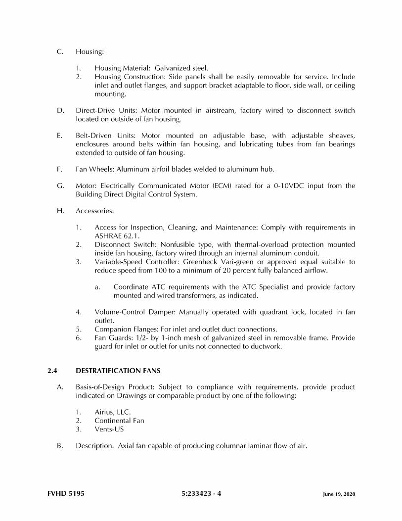
FVHD 5195 5:233423 - 4 June 19, 2020
C. Housing:
1. Housing Material: Galvanized steel.
2. Housing Construction: Side panels shall be easily removable for service. Include
inlet and outlet flanges, and support bracket adaptable to floor, side wall, or ceiling
mounting.
D. Direct-Drive Units: Motor mounted in airstream, factory wired to disconnect switch
located on outside of fan housing.
E. Belt-Driven Units: Motor mounted on adjustable base, with adjustable sheaves,
enclosures around belts within fan housing, and lubricating tubes from fan bearings
extended to outside of fan housing.
F. Fan Wheels: Aluminum airfoil blades welded to aluminum hub.
G. Motor: Electrically Communicated Motor (ECM) rated for a 0-10VDC input from the
Building Direct Digital Control System.
H. Accessories:
1. Access for Inspection, Cleaning, and Maintenance: Comply with requirements in
ASHRAE 62.1.
2. Disconnect Switch: Nonfusible type, with thermal-overload protection mounted
inside fan housing, factory wired through an internal aluminum conduit.
3. Variable-Speed Controller: Greenheck Vari-green or approved equal suitable to
reduce speed from 100 to a minimum of 20 percent fully balanced airflow.
a. Coordinate ATC requirements with the ATC Specialist and provide factory
mounted and wired transformers, as indicated.
4. Volume-Control Damper: Manually operated with quadrant lock, located in fan
outlet.
5. Companion Flanges: For inlet and outlet duct connections.
6. Fan Guards: 1/2- by 1-inch mesh of galvanized steel in removable frame. Provide
guard for inlet or outlet for units not connected to ductwork.
2.4 DESTRATIFICATION FANS
A. Basis-of-Design Product: Subject to compliance with requirements, provide product
indicated on Drawings or comparable product by one of the following:
1. Airius, LLC.
2. Continental Fan
3. Vents-US
B. Description: Axial fan capable of producing columnar laminar flow of air.
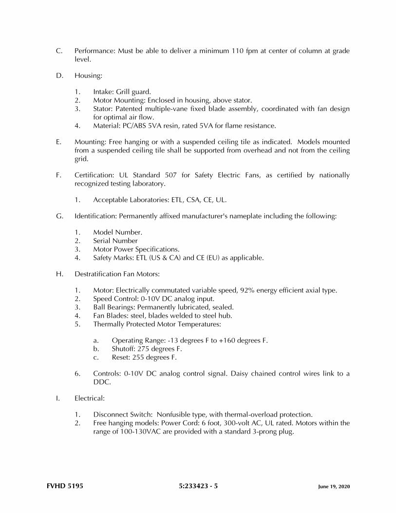
FVHD 5195 5:233423 - 5 June 19, 2020
C. Performance: Must be able to deliver a minimum 110 fpm at center of column at grade
level.
D. Housing:
1. Intake: Grill guard.
2. Motor Mounting: Enclosed in housing, above stator.
3. Stator: Patented multiple-vane fixed blade assembly, coordinated with fan design
for optimal air flow.
4. Material: PC/ABS 5VA resin, rated 5VA for flame resistance.
E. Mounting: Free hanging or with a suspended ceiling tile as indicated. Models mounted
from a suspended ceiling tile shall be supported from overhead and not from the ceiling
grid.
F. Certification: UL Standard 507 for Safety Electric Fans, as certified by nationally
recognized testing laboratory.
1. Acceptable Laboratories: ETL, CSA, CE, UL.
G. Identification: Permanently affixed manufacturer's nameplate including the following:
1. Model Number.
2. Serial Number
3. Motor Power Specifications.
4. Safety Marks: ETL (US & CA) and CE (EU) as applicable.
H. Destratification Fan Motors:
1. Motor: Electrically commutated variable speed, 92% energy efficient axial type.
2. Speed Control: 0-10V DC analog input.
3. Ball Bearings: Permanently lubricated, sealed.
4. Fan Blades: steel, blades welded to steel hub.
5. Thermally Protected Motor Temperatures:
a. Operating Range: -13 degrees F to +160 degrees F.
b. Shutoff: 275 degrees F.
c. Reset: 255 degrees F.
6. Controls: 0-10V DC analog control signal. Daisy chained control wires link to a
DDC.
I. Electrical:
1. Disconnect Switch: Nonfusible type, with thermal-overload protection.
2. Free hanging models: Power Cord: 6 foot, 300-volt AC, UL rated. Motors within the
range of 100-130VAC are provided with a standard 3-prong plug.

FVHD 5195 5:233423 - 6 June 19, 2020
2.5 MOTORS
A. Comply with NEMA designation, temperature rating, service factor, and efficiency
requirements for motors specified in applicable Division 23 Sections.
1. Motor Sizes: Minimum size as indicated. If not indicated, large enough so driven
load will not require motor to operate in service factor range above 1.0.
2.6 FACTORY FINISHES
A. Sheet Metal Parts: Prime coat before final assembly.
B. Exterior Surfaces: Baked-enamel finish coat after assembly.
2.7 SOURCE QUALITY CONTROL
A. Electrical Components, Devices, and Accessories: Listed and labeled as defined in
NFPA 70, by an NRTL, and marked for intended location and application.
B. AMCA Certification: Fans shall comply with AMCA 11 and bear the AMCA-Certified
Ratings Seal.
C. Fan Sound Ratings: Comply with AMCA 311, and label fans with the AMCA-Certified
Ratings Seal. Sound ratings shall comply with AMCA 301. The fans shall be tested
according to AMCA 300.
D. Fan Performance Ratings: Comply with AMCA 211 and label fans with AMCA-Certified
Rating Seal. The fans shall be tested for air performance - flow rate, fan pressure, power,
fan efficiency, air density, speed of rotation, and fan efficiency - according to
AMCA 210/ASHRAE 51.
E. Operating Limits: Classify according to AMCA 99.
F. UL Standards: Power ventilators shall comply with UL 705.
2.8 OPERATION
A. Contractor to provide all necessary controls, wiring, wiring conduits, manufacturer’s
recommended equipment and installation options, and system appurtenances to facilitate
the intended use and satisfy the requirements for a fully operational system.
PART 3 - EXECUTION
3.1 INSTALLATION OF HVAC POWER VENTILATORS
A. Install power ventilators level and plumb.
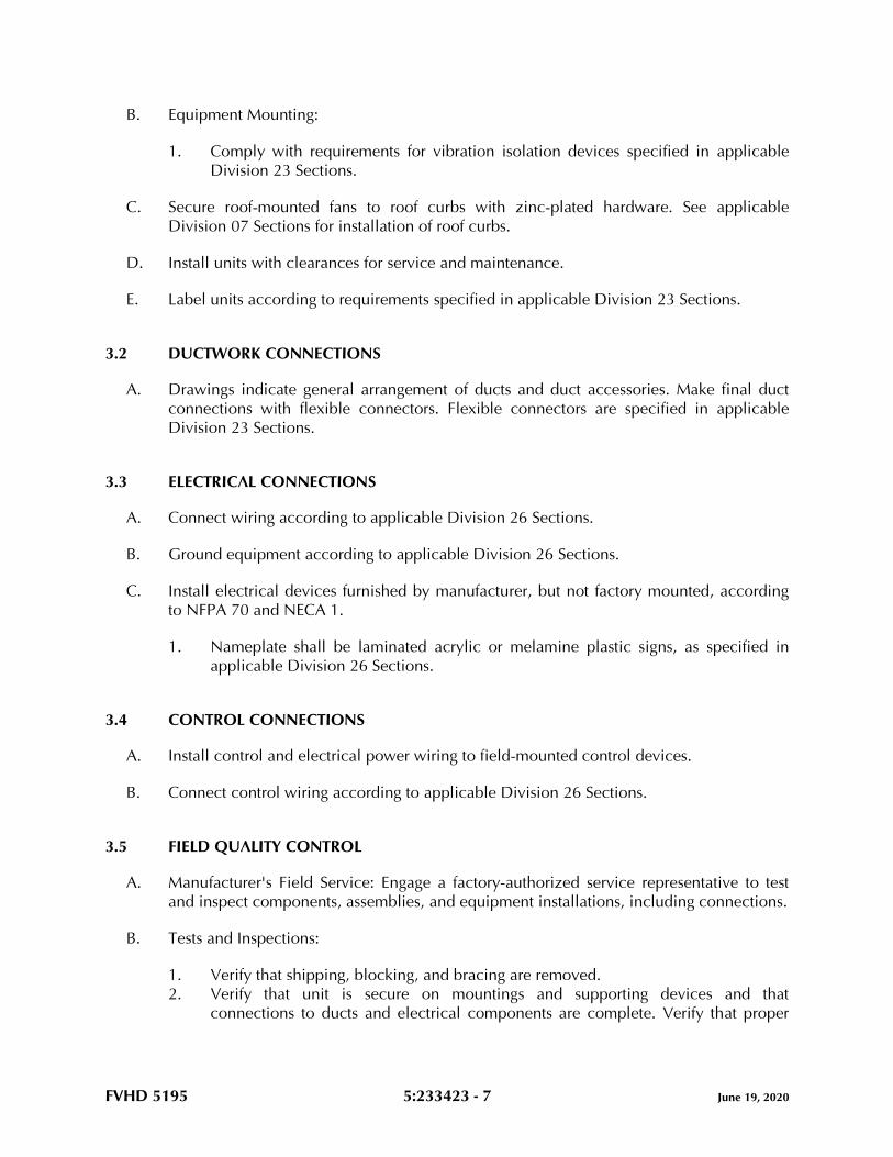
FVHD 5195 5:233423 - 7 June 19, 2020
B. Equipment Mounting:
1. Comply with requirements for vibration isolation devices specified in applicable
Division 23 Sections.
C. Secure roof-mounted fans to roof curbs with zinc-plated hardware. See applicable
Division 07 Sections for installation of roof curbs.
D. Install units with clearances for service and maintenance.
E. Label units according to requirements specified in applicable Division 23 Sections.
3.2 DUCTWORK CONNECTIONS
A. Drawings indicate general arrangement of ducts and duct accessories. Make final duct
connections with flexible connectors. Flexible connectors are specified in applicable
Division 23 Sections.
3.3 ELECTRICAL CONNECTIONS
A. Connect wiring according to applicable Division 26 Sections.
B. Ground equipment according to applicable Division 26 Sections.
C. Install electrical devices furnished by manufacturer, but not factory mounted, according
to NFPA 70 and NECA 1.
1. Nameplate shall be laminated acrylic or melamine plastic signs, as specified in
applicable Division 26 Sections.
3.4 CONTROL CONNECTIONS
A. Install control and electrical power wiring to field-mounted control devices.
B. Connect control wiring according to applicable Division 26 Sections.
3.5 FIELD QUALITY CONTROL
A. Manufacturer's Field Service: Engage a factory-authorized service representative to test
and inspect components, assemblies, and equipment installations, including connections.
B. Tests and Inspections:
1. Verify that shipping, blocking, and bracing are removed.
2. Verify that unit is secure on mountings and supporting devices and that
connections to ducts and electrical components are complete. Verify that proper
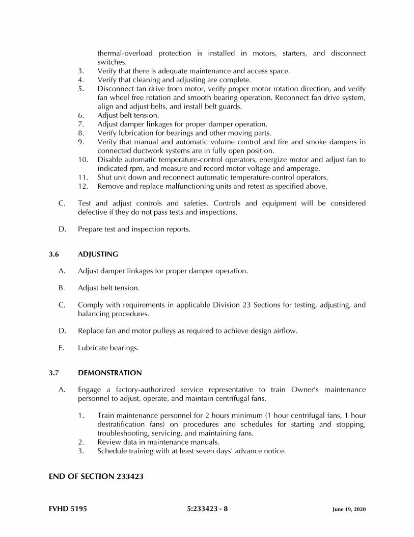
FVHD 5195 5:233423 - 8 June 19, 2020
thermal-overload protection is installed in motors, starters, and disconnect
switches.
3. Verify that there is adequate maintenance and access space.
4. Verify that cleaning and adjusting are complete.
5. Disconnect fan drive from motor, verify proper motor rotation direction, and verify
fan wheel free rotation and smooth bearing operation. Reconnect fan drive system,
align and adjust belts, and install belt guards.
6. Adjust belt tension.
7. Adjust damper linkages for proper damper operation.
8. Verify lubrication for bearings and other moving parts.
9. Verify that manual and automatic volume control and fire and smoke dampers in
connected ductwork systems are in fully open position.
10. Disable automatic temperature-control operators, energize motor and adjust fan to
indicated rpm, and measure and record motor voltage and amperage.
11. Shut unit down and reconnect automatic temperature-control operators.
12. Remove and replace malfunctioning units and retest as specified above.
C. Test and adjust controls and safeties. Controls and equipment will be considered
defective if they do not pass tests and inspections.
D. Prepare test and inspection reports.
3.6 ADJUSTING
A. Adjust damper linkages for proper damper operation.
B. Adjust belt tension.
C. Comply with requirements in applicable Division 23 Sections for testing, adjusting, and
balancing procedures.
D. Replace fan and motor pulleys as required to achieve design airflow.
E. Lubricate bearings.
3.7 DEMONSTRATION
A. Engage a factory-authorized service representative to train Owner's maintenance
personnel to adjust, operate, and maintain centrifugal fans.
1. Train maintenance personnel for 2 hours minimum (1 hour centrifugal fans, 1 hour
destratification fans) on procedures and schedules for starting and stopping,
troubleshooting, servicing, and maintaining fans.
2. Review data in maintenance manuals.
3. Schedule training with at least seven days' advance notice.
END OF SECTION 233423
FVHD 5195 5:233600 - 1 June 19, 2020
SECTION 233600 - AIR TERMINAL UNITS
PART 1 - GENERAL
1.1 RELATED DOCUMENTS
A. Drawings and general provisions of the Contract, including General and Supplementary
Conditions and Division 01 Specification Sections, apply to this Section.
1.2 SUMMARY
A. Section Includes:
1. Single-duct air terminal units.
2. Casing liner.
1.3 ACTION SUBMITTALS
A. Product Data: For each type of air terminal unit.
1. Include construction details, material descriptions, dimensions of individual
components and profiles, and finishes for air terminal units.
2. Include rated capacities (including minimum and maximum airflows), operating
characteristics, electrical characteristics, and furnished specialties and accessories.
a. Rated capacities include AHRI rated sound performance.
3. Shop Drawings: For air terminal units.
4. Include plans, elevations, sections, and mounting details.
5. Include details of equipment assemblies. Indicate dimensions, weights, loads,
required clearances, method of field assembly, components, and location and size
of each field connection.
6. Include diagrams for power, signal, and control wiring.
7. Hangers and supports, including methods for duct and building attachment.
1.4 INFORMATIONAL SUBMITTALS
A. Coordination Drawings: Reflected ceiling plans, drawn to scale, on which the following
items are shown and coordinated with each other, using input from installers of the items
involved:
1. Ceiling suspension assembly members.
2. Size and location of initial access modules for acoustic tile.
3. Ceiling-mounted items including lighting fixtures, diffusers, grilles, speakers,
sprinklers, access panels, and special moldings.
FVHD 5195 5:233600 - 2 June 19, 2020
B. Field quality-control reports.
1.5 CLOSEOUT SUBMITTALS
A. Operation and Maintenance Data: For air terminal units to include in emergency,
operation, and maintenance manuals.
1. In addition to items specified in applicable Division 01 Sections, include the
following:
a. Instructions for resetting minimum and maximum air volumes.
b. Instructions for adjusting software set points.
PART 2 - PRODUCTS
2.1 SYSTEM DESCRIPTION
A. Electrical Components, Devices, and Accessories: Listed and labeled as defined in
NFPA 70, by a qualified testing agency, and marked for intended location and
application.
B. ASHRAE Compliance: Applicable requirements in ASHRAE 62.1, Section 5 - "Systems
and Equipment" and Section 7 - "Construction and System Start-up."
C. ASHRAE Compliance: Applicable requirements in ASHRAE/IES 90.1, "Section 6 -
Heating, Ventilating, and Air Conditioning."
2.2 SINGLE-DUCT AIR TERMINAL UNITS
A. Basis-of-Design Product: Subject to compliance with requirements, provide product
indicated on Drawings or comparable product by one of the following:
1. ENVIRO-TEC; by Johnson Controls, Inc.
2. Krueger.
3. Titus.
B. Configuration: Volume-damper assembly inside unit casing with control components
inside a protective metal shroud.
C. Casing: 0.034-inch- thick galvanized steel, single wall.
1. Casing Liner: Comply with requirements in "Casing Liner" Article for flexible
elastomeric duct liner.
2. Air Inlet: Round stub connection or S-slip and drive connections for duct
attachment.
3. Air Outlet: S-slip and drive connections.
FVHD 5195 5:233600 - 3 June 19, 2020
4. Access: Removable panels for access to parts requiring service, adjustment, or
maintenance; with airtight gasket.
5. Airstream Surfaces: Surfaces in contact with the airstream shall comply with
requirements in ASHRAE 62.1.
D. Volume Damper: Galvanized steel with peripheral gasket and self-lubricating bearings.
1. Maximum Damper Leakage: AHRI 880 rated, 3 percent of nominal airflow at 3-
inch wg inlet static pressure.
2. Damper Position: Normally open.
E. Hydronic Heating Coils: Copper tube, with mechanically bonded aluminum fins spaced
no closer than 0.1 inch, and rated for a minimum working pressure of 200 psig and a
maximum entering-water temperature of 220 deg F. Include manual air vent and drain
valve.
F. Control devices shall be compatible with temperature controls system specified in other
Division 23 Sections.
1. Electric Damper Actuator: 24 V, powered from the ATC System.
2. Electronic Velocity Controller: Factory calibrated and field adjustable to minimum
and maximum air volumes; shall maintain constant airflow dictated by thermostat
within 5 percent of set point while compensating for inlet static-pressure variations
up to 4-inch wg; and shall have a multipoint velocity sensor at air inlet.
3. Room Sensor: Wall mounted with temperature set-point adjustment and access for
connection of portable operator terminal.
2.3 CASING LINER
A. Casing Liner: Flexible elastomeric duct liner fabricated of preformed, cellular, closed-cell,
sheet materials complying with ASTM C534, Type II, Grade 1; and with NFPA 90A or
NFPA 90B.
1. Minimum Thickness: 1/2 inch.
2. Surface-Burning Characteristics: Maximum flame-spread index of 25 and maximum
smoke-developed index of 50 when tested according to UL 723; certified by an
NRTL.
3. Liner Adhesive: As recommended by insulation manufacturer and complying with
NFPA 90A or NFPA 90B.
2.4 SOURCE QUALITY CONTROL
A. Factory Tests: Test assembled air terminal units according to AHRI 880.
1. Label each air terminal unit with plan number, nominal airflow, maximum and
minimum factory-set airflows, coil type, and AHRI certification seal.
FVHD 5195 5:233600 - 4 June 19, 2020
PART 3 - EXECUTION
3.1 HANGER AND SUPPORT INSTALLATION
A. Comply with SMACNA's "HVAC Duct Construction Standards - Metal and Flexible,"
Ch. 5, "Hangers and Supports" and with applicable Division 23 Sections.
B. Building Attachments: Concrete inserts, powder-actuated fasteners, or structural-steel
fasteners appropriate for construction materials to which hangers are being attached.
1. Where practical, install concrete inserts before placing concrete.
2. Install powder-actuated concrete fasteners after concrete is placed and completely
cured.
3. Use powder-actuated concrete fasteners for standard-weight aggregate concretes
and for slabs more than 4 inches thick.
4. Do not use powder-actuated concrete fasteners for lightweight-aggregate concretes
and for slabs less than 4 inches thick.
C. Hangers Exposed to View: Threaded rod and angle or channel supports.
D. Install upper attachments to structures. Select and size upper attachments with pull-out,
tension, and shear capacities appropriate for supported loads and building materials
where used.
3.2 TERMINAL UNIT INSTALLATION
A. Install air terminal units according to NFPA 90A, "Standard for the Installation of Air
Conditioning and Ventilating Systems."
B. Install air terminal units level and plumb. Maintain sufficient clearance for normal service
and maintenance.
3.3 CONNECTIONS
A. Where installing piping adjacent to air terminal unit, allow space for service and
maintenance.
B. Hot-Water Piping: Comply with requirements noted on the Drawings and in applicable
Division 23 Sections and connect heating coils to supply with shutoff valve, strainer,
control valve, and union or flange; and to return with balancing valve and union or
flange.
C. Comply with requirements in applicable Division 23 Sections for connecting ducts to air
terminal units.
D. Make connections to air terminal units with flexible connectors complying with
requirements in applicable Division 23 Sections.
FVHD 5195 5:233600 - 5 June 19, 2020
3.4 IDENTIFICATION
A. Label each air terminal unit with plan number, nominal airflow, and maximum and
minimum factory-set airflows. Comply with requirements in applicable Division 23
Sections for equipment labels and warning signs and labels.
3.5 FIELD QUALITY CONTROL
A. Perform the following tests and inspections with the assistance of a factory-authorized
service representative:
1. After installing air terminal units and after electrical circuitry has been energized,
test for compliance with requirements.
2. Leak Test: After installation, fill water coils and test for leaks. Repair leaks and retest
until no leaks exist.
3. Operational Test: After electrical circuitry has been energized, start units to confirm
proper motor rotation and unit operation.
4. Test and adjust controls and safeties. Replace damaged and malfunctioning
controls and equipment.
B. Air terminal unit will be considered defective if it does not pass tests and inspections.
C. Prepare test and inspection reports.
3.6 STARTUP SERVICE
A. Perform startup service.
1. Complete installation and startup checks according to manufacturer's written
instructions.
2. Verify that inlet duct connections are as recommended by air terminal unit
manufacturer to achieve proper performance.
3. Verify that controls and control enclosure are accessible.
4. Verify that control connections are complete.
5. Verify that nameplate and identification tag are visible.
6. Verify that controls respond to inputs as specified.
3.7 DEMONSTRATION
A. Engage a factory-authorized service representative to train Owner's maintenance
personnel to adjust, operate, and maintain air terminal units.
1. Train maintenance personnel for 1 hours minimum on procedures and schedules
for starting and stopping, troubleshooting, servicing, and maintaining air terminal
units.
2. Review data in maintenance manuals.
FVHD 5195 5:233600 - 6 June 19, 2020
3. Schedule training with at least seven days' advance notice.
END OF SECTION 233600
FVHD 5195 5:233713.13 - 1 June 19, 2020
SECTION 233713.13 - AIR DIFFUSERS, REGISTERS, AND GRILLES
PART 1 - GENERAL
1.1 RELATED DOCUMENTS
A. Drawings and general provisions of the Contract, including General and Supplementary
Conditions and Division 01 Specification Sections, apply to this Section.
1.2 SUMMARY
A. Section Includes ceiling and wall mounted diffusers, registers, and grilles.
1.3 DEFINITIONS
A. Diffuser: Circular, square, or rectangular air distribution outlet, generally located in the
ceiling and comprised of deflecting members discharging supply air in various directions
and planes and arranged to promote mixing of primary air with secondary room air.
B. Grille: A louvered covering for an opening in an air passage, which can be located in a
sidewall, ceiling, or floor.
C. Register: A combination grille and damper assembly over an air opening.
1.4 ACTION SUBMITTALS
A. Product Data: For each type of product.
1. Data Sheet: For each type of air outlet and inlet and accessory furnished; indicate
materials of construction, finish, and mounting details
2. Performance data including throw and drop, static-pressure drop, and noise ratings.
a. Provide breakouts by neck size and indicate associated airflow ranges.
Indicate minimum and maximum throw & drop data, static-pressure drop,
and noise ratings for each indicated neck size and airflow range.
b. Manufacturer’s standard performance data is NOT ACCEPTABLE.
3. Schedule of diffusers and registers: Indicate drawing designation, room location,
quantity, model number, size, and accessories furnished.
4. Assembly Drawings: For each type of air outlet and inlet; indicate materials and
methods of assembly of components.
B. Samples for Initial Selection: For diffusers with factory-applied color finishes. Actual size
of smallest diffuser indicated.
FVHD 5195 5:233713.13 - 2 June 19, 2020
1.5 INFORMATIONAL SUBMITTALS
A. Coordination Drawings: Reflected ceiling plans, drawn to scale, on which the following
items are shown and coordinated with each other, using input from installers of the items
involved:
1. Ceiling suspension assembly members.
2. Method of attaching hangers to building structure.
3. Size and location of initial access modules for acoustical tile.
4. Ceiling-mounted items including lighting fixtures, diffusers, grilles, speakers,
sprinklers, access panels, and special moldings.
5. Duct access panels.
B. Source quality-control reports.
1.6 QUALITY ASSURANCE
A. Product Options: Drawings and schedules indicate specific requirements of diffusers,
registers, and grilles and are based on the specific requirements of the systems indicated.
Other manufacturers' products with equal performance characteristics may be
considered. Refer to Division 01.
B. NFPA Compliance: Install diffusers, registers, and grilles according to NFPA 90A,
"Standard for the Installation of Air-Conditioning and Ventilating Systems."
C. Single Source Responsibility: Diffusers, registers, and grilles of the Type identified shall be
provided from manufacturer.
PART 2 - PRODUCTS
2.1 MANUFACTURED UNITS
A. Manufacturers.
1. Basis-of-Design Product: Subject to compliance with requirements, provide Titus
model indicated, or comparable product by one of the following:
a. Tuttle & Bailey.
b. Krueger.
B. Diffusers, registers, and grilles.
1. Type ‘A’ – Supply Registers: 300 L (Titus” 300 series with individually adjustable
blades) description on construction documents shall indicate size and damper type.
2. Type ‘B’ – Diffusers: TDC (“Titus” model TDC) description in construction
documents shall indicate size and air flow pattern.
3. Type ‘C’ – Return and Exhaust Grilles/Registers: 350 L (“Titus” 350 series)
description in construction documents shall indicate size and damper type.
FVHD 5195 5:233713.13 - 3 June 19, 2020
4. Type ‘D’ Supply Diffusers: TMS (“Titus” TMS series) description on construction
documents shall indicate size and damper type.
2.2 PRODUCT
A. 300 L – Type ‘A’:
1. Supply register with double deflection blades on 3/4" centers (adjustable), exposed
blades parallel to the long dimension.
2. Where indicated: Border shall be 1-1/4" wide on all sides with countersunk screw
holes, all corners shall be welded.
3. Deflection blades shall be contoured and spaced on 3/4" centers having steel
friction pivots on both ends to allow individual adjustment.
4. Finish shall be anodic acrylic paint, baked.
5. Integral dampers - double thickness roll-formed steel blades. Opposed blade
damper designed for key or screwdriver operation.
B. TDC – Type ‘B’:
1. The ceiling diffuses shall be fixed, horizontal discharge pattern.
2. The diffusers shall consist of an outer frame assembly of the sizes and mounting
types shown on the plans and outlet schedule.
3. A square or rectangular inlet shall be an integral part of the frame assembly and a
transition piece shall be available to facilitate attachment of round duct.
4. An inner core assembly consisting of fixed deflection louvers shall be available in
one-, two-, three- or four-way horizontal discharge patterns.
5. The inner core assembly must be removable in the field without tools for easy
installation, cleaning or damper adjustment.
6. Finish shall be anodic acrylic paint, baked.
7. Provide for tee bar lay in ceiling systems.
C. 350 L – Type ‘C’:
1. Return grilles and registers have fixed horizontal bars spaced 3/4 inch centers with
35 deg face deflection, unless otherwise noted, blades parallel to the long
dimension.
2. Where indicated: overlap margin – 1-1/4 inch nominal width. Furnished with
countersunk screw holes and mounting screws, or tee bar lay in panel.
3. Construction - rigid heavy-gauge margins with reinforced mitered corners.
4. Roll-formed bars - streamlined shaped rigid steel bars on 3/4 inch centers,
deflected. Bars driven on swaged pins are firmly held by mullions welded behind
grille face.
5. Integral dampers - double thickness roll-formed steel blades. Opposed blade
damper designed for key or screwdriver operation.
6. Provide panels for tee bar lay in ceiling systems.
7. Finish shall be anodic acrylic paint, baked.
D. TMS – Type ‘D’:
FVHD 5195 5:233713.13 - 4 June 19, 2020
1. The diffuser shall have three cones, which give a uniform face size and appearance
when different neck sizes are used in the same area.
2. All cones shall be one piece precision die-stamped; the back cone shall also
include an integrally drawn inlet (welded-in inlets and corner joints are not
acceptable).
3. The two inner cones shall be constructed as a single, removable inner cone
assembly for easy installation and cleaning.
4. The inner cone assembly must have a hole with removable plug in the center to
allow quick adjustment of an optional inlet damper without removing the inner
cone assembly.
5. Finish shall be anodic acrylic paint, baked.
E. Steel construction unless otherwise noted.
F. Toilet rooms, locker rooms, and janitors closets to be aluminum construction, and where
noted in the plans and specifications.
G. Provide opposed blade dampers on air devices.
H. Noise level not to exceed effective total noise of 25 NC for classrooms (based on air
device quantities), otherwise not to exceed 35 NC, or as noted.
I. Provide lay-in panels for T-bar ceiling types (supply, return and exhaust air systems).
J. Drywall: Mounting frame type (surface mount).
K. Finish to be baked enamel (unless otherwise noted), color to be approved by Architect.
Provide color chart.
L. Static pressure not to exceed as scheduled or 0.1-inches w.c. except where indicated on
schedule.
2.3 SOURCE QUALITY CONTROL
A. Verification of Performance: Rate diffusers according to ASHRAE 70, "Method of Testing
for Rating the Performance of Air Outlets and Inlets."
PART 3 - EXECUTION
3.1 EXAMINATION
A. Examine areas where diffusers are installed for compliance with requirements for
installation tolerances and other conditions affecting performance of equipment.
B. Proceed with installation only after unsatisfactory conditions have been corrected.
FVHD 5195 5:233713.13 - 5 June 19, 2020
3.2 INSTALLATION
A. Install diffusers level and plumb.
B. Ceiling-Mounted Outlets and Inlets: Drawings indicate general arrangement of ducts,
fittings, and accessories. Air outlet and inlet locations have been indicated to achieve
design requirements for air volume, noise criteria, airflow pattern, throw, and pressure
drop. Make final locations where indicated, as much as practical. For units installed in
lay-in ceiling panels, locate units in the center of panel. Where architectural features or
other items conflict with installation, notify Architect for a determination of final location.
C. Install diffusers with airtight connections to ducts and to allow service and maintenance
of dampers, air extractors, and fire dampers.
3.3 ADJUSTING
A. After installation, adjust diffusers to air patterns indicated, or as directed, before starting
air balancing.
3.4 CLEANING
A. After installation of diffusers, registers, and grilles, inspect exposed finish. Clean exposed
surfaces to remove burrs, dirt, and smudges. Replace diffusers, registers, and grilles that
have damaged finishes.
END OF SECTION 233713.13
FVHD 5195 5:233723 - 1 June 19, 2020
SECTION 233723 - HVAC GRAVITY VENTILATORS
PART 1 - GENERAL
1.1 RELATED DOCUMENTS
A. Drawings and general provisions of the Contract, including General and Supplementary
Conditions and Division 01 Specification Sections, apply to this Section.
1.2 SUMMARY
A. Section Includes:
1. Hooded ventilators.
1.3 ACTION SUBMITTALS
A. Product Data: For each type of product.
B. Shop Drawings: For gravity ventilators.
1. Include plans, elevations, sections, details, ventilator attachments to curbs, and
curb attachments to roof structure.
2. Show weep paths, gaskets, flashing, sealant, and other means of preventing water
intrusion.
C. Samples for Initial Selection: For units with factory-applied color finishes.
1.4 INFORMATIONAL SUBMITTALS
A. Coordination Drawings: Roof-framing plans and other details, drawn to scale, and
coordinated with each other, based on input from installers of the items involved:
B. Welding certificates.
1.5 QUALITY ASSURANCE
A. Welding Qualifications: Qualify procedures and personnel according to the following:
1. AWS D1.2/D1.2M, "Structural Welding Code - Aluminum."
2. AWS D1.3/D1.3M, "Structural Welding Code - Sheet Steel."
FVHD 5195 5:233723 - 2 June 19, 2020
1.6 COORDINATION
A. Coordinate sizes and locations of roof curbs, equipment supports, and roof penetrations
with actual equipment provided.
1.7 DELIVERY, STORAGE, AND HANDLING
A. Deliver ventilators as per manufacturer’s recommendations with protective crating and
covering.
B. Lift and support units with manufacturer’s designated lifting or supporting points.
PART 2 - PRODUCTS
2.1 PERFORMANCE REQUIREMENTS
A. Structural Performance: Ventilators shall withstand the effects of gravity loads and the
following loads and stresses within limits and under conditions indicated without
permanent deformation of ventilator components, noise or metal fatigue caused by
ventilator blade rattle or flutter, or permanent damage to fasteners and anchors. Wind
pressures shall be considered to act normal to the face of the building.
B. ASHRAE/IES 90.1 Compliance: Applicable requirements in ASHRAE/IES 90.1.
C. ASHRAE 62.1 Compliance: Section 5, "Systems and Equipment" and Section 7,
"Construction and System Start-up."
D. Water Entrainment: Limit water penetration through unit to comply with ASHRAE 62.1.
2.2 FABRICATION
A. Factory or shop fabricate gravity ventilators to minimize field splicing and assembly.
Disassemble units to the minimum extent as necessary for shipping and handling. Clearly
mark units for reassembly and coordinated installation.
B. Fabricate frames, including integral bases, to fit in openings of sizes indicated, with
allowances made for fabrication and installation tolerances, adjoining material
tolerances, and perimeter sealant joints.
C. Fabricate units with closely fitted joints and exposed connections accurately located and
secured.
D. Fabricate supports, anchorages, and accessories required for complete assembly.
E. Perform shop welding by AWS-certified procedures and personnel.
FVHD 5195 5:233723 - 3 June 19, 2020
2.3 HOODED VENTILATORS
A. Description: Hooded rectangular penthouse for intake or relief air, as indicated.
B. Basis-of-Design Product: Subject to compliance with requirements, provide product
indicated on Drawings or comparable product by one of the following:
1. Greenheck Fan Corporation.
2. Loren Cook Company.
3. PennBarry.
C. Source Limitations: Obtain hooded ventilators from single manufacturer.
D. Construction:
1. Material: Galvanized steel, of thickness required to comply with structural
performance requirements, but not less than 0.064-inch-thick base and 0.040-inch-
thick hood; suitably reinforced.
2. Insulation: Mineral-fiber insulation and vapor barrier.
3. Bird Screening: Galvanized-steel, 1/2-inch-square mesh wire.
E. Galvanized-Steel Finish:
1. Surface Preparation: Clean surfaces of dirt, grease, and other contaminants. Clean
welds, mechanical connections, and abraded areas, and repair galvanizing
according to ASTM A780/A780M. Apply a conversion coating suited to the organic
coating to be applied over it.
2. Factory Priming for Field-Painted Finish: Where field painting after installation is
indicated, apply an air-dried primer immediately after cleaning and pretreating.
3. Baked-Enamel Finish: Immediately after cleaning and pretreating, apply
manufacturer's standard finish consisting of prime coat and thermosetting topcoat,
with a minimum dry film thickness of 1 mil for topcoat and an overall minimum
dry film thickness of 2 mils.
a. Color and Gloss: As selected by Architect from manufacturer's full range.
F. Dampers:
1. Location: Hood neck.
2. Control: Motorized.
3. Tray: Provide damper tray or shelf with opening 3 inches less than interior curb
dimensions indicated.
G. Roof Curbs: Galvanized-steel sheet; with mitered and welded corners; 1-1/2-inch-thick,
rigid fiberglass insulation adhered to inside walls; and 1-1/2-inch wood nailer. Size as
required to fit roof opening and ventilator base.
1. Configuration: Built-in raised cant and mounting flange.
2. Overall Height: 12 inches.
FVHD 5195 5:233723 - 4 June 19, 2020
2.4 MATERIALS
A. Galvanized-Steel Sheet: ASTM A653/A653M, G90 zinc coating, mill phosphatized.
B. Fasteners: Same basic metal and alloy as fastened metal or 300 Series stainless steel
unless otherwise indicated. Do not use metals that are incompatible with joined
materials.
1. Use types and sizes to suit unit installation conditions.
2. Use hex-head or Phillips pan-head screws for exposed fasteners unless otherwise
indicated.
C. Post-Installed Fasteners for Concrete and Masonry: Torque-controlled expansion anchors
made from stainless-steel components, with capability to sustain without failure a load
equal to 4 times the loads imposed for concrete, or 6 times the load imposed for
masonry, as determined by testing according to ASTM E488/E488M, conducted by a
qualified independent testing agency.
D. Bituminous Paint: Cold-applied asphalt emulsion complying with
ASTM D1187/D1187M.
PART 3 - EXECUTION
3.1 INSTALLATION
A. Install gravity ventilators level, plumb, and at indicated alignment with adjacent work.
B. Secure gravity ventilators to roof curbs with zinc-plated hardware. Use concealed
anchorages where possible. Refer to applicable Division 07 Sections.
C. Install goosenecks on curb base where throat size exceeds 9 by 9 inches.
D. Install gravity ventilators with clearances for service and maintenance.
E. Install perimeter reveals and openings of uniform width for sealants and joint fillers, as
indicated.
F. Install concealed gaskets, flashings, joint fillers, and insulation as installation progresses.
Comply with applicable Division 07 Sections for sealants applied during installation.
G. Label gravity ventilators according to requirements specified in applicable Division 23
Sections.
H. Protect galvanized and nonferrous-metal surfaces from corrosion or galvanic action by
applying a heavy coating of bituminous paint on surfaces that will be in contact with
concrete, masonry, or dissimilar metals.
I. Repair finishes damaged by cutting, welding, soldering, and grinding. Restore finishes, so
no evidence remains of corrective work. Return items that cannot be refinished in the
FVHD 5195 5:233723 - 5 June 19, 2020
field to the factory, make required alterations, and refinish entire unit or provide new
units.
J. Refer to applicable Division 07 Sections for flashing and counterflashing of roof curbs.
3.2 CONNECTIONS
A. Duct installation and connection requirements are specified in applicable Division 23
Sections. Drawings indicate general arrangement of ducts and duct accessories.
3.3 ADJUSTING
A. Adjust damper linkages for proper damper operation.
3.4 CLEANING
A. After completing installation, inspect exposed finish. Remove burrs, dirt, and
construction debris, and repair damaged finishes including chips, scratches, and
abrasions.
END OF SECTION 233723
FVHD 5195 5:235123 - 1 June 19, 2020
SECTION 235123 - GAS VENTS
PART 1 - GENERAL
1.1 RELATED DOCUMENTS
A. Drawings and general provisions of the Contract, including General and Supplementary
Conditions and Division 01 Specification Sections, apply to this Section.
1.2 SUMMARY
A. Section Includes:
1. Listed double-wall vents.
1.3 ACTION SUBMITTALS
A. Product Data: For each type of product.
1. Include construction details, material descriptions, dimensions of individual
components and profiles, and finishes for product.
B. Shop Drawings: For vents.
1. Include plans, elevations, sections, and attachment details.
2. Include details of equipment assemblies. Indicate dimensions, weights, loads,
required clearances, method of field assembly, components, and location and size
of each field connection.
3. Detail fabrication and assembly of hangers.
C. The breeching and stack shall be verified by the manufacturer’s computations. The
computation shall be technically sound, shall follow ASHRAE calculation methods, and
incorporate the specific flow characteristics of the pipe. The Contractor shall furnish the
exact equipment (boiler, etc.) model and operating characteristics to the factory
representative. Operating characteristics shall include flue gas flow rate, BTU input,
outlet temperature, local altitude, stack layout, and available external pressure at boiler
outlet, etc., necessary to determine system operation at maximum and minimum levels of
burner turndown range and boiler staging.
1.4 INFORMATIONAL SUBMITTALS
A. Welding certificates.
B. Sample Warranty: For special warranty.
FVHD 5195 5:235123 - 2 June 19, 2020
1.5 QUALITY ASSURANCE
A. Welding Qualifications: Qualify procedures and personnel according to the following:
1. AWS D1.1/D1.1M, "Structural Welding Code - Steel," for hangers and supports.
2. AWS D9.1/D9.1M, "Sheet Metal Welding Code," for shop and field welding of
joints and seams in vents.
B. Certified Sizing Calculations: Manufacturer shall certify venting system sizing
calculations.
C. Electrical Components, Devices, and Accessories: Listed and labeled as defined in NFPA
70, Article 100, by a testing agency acceptable to authorities having jurisdiction.
D. Comply with SMACNA's "Guide for Steel Stack Design and Construction."
PART 2 - PRODUCTS
2.1 LISTED SPECIAL GAS VENTS
A. Basis-of-Design Product: Subject to compliance with requirements, provide Metal-Fab,
Inc; or a comparable product by one of the following:
1. Heatfab Saf-T Vent.
2. Z-Flex; a division of the Novaflex Group.
B. Description: Double-wall metal vents tested according to UL 1738 and rated for 480
deg F continuously, with positive or negative flue pressure complying with NFPA 211.
C. Construction: Inner shell and outer jacket separated by at least a 1/2-inch airspace.
D. Inner Shell: ASTM A959, Type 29-4C stainless steel.
E. Outer Jacket: Stainless steel.
F. Accessories: Tees, elbows, increasers, draft-hood connectors, terminations, adjustable
roof flashings, storm collars, support assemblies, thimbles, firestop spacers, and fasteners;
fabricated from similar materials and designs as vent-pipe straight sections; all listed for
same assembly.
1. Termination: Stack cap designed to exclude minimum 90 percent of rainfall.
G. Warranty Period: 10 years from date of substantial completion.
2.2 GALVANIZED COMBUSTION AIR
A. Comply with National and Local codes. Install and seal per manufacturer’s
recommendations.
FVHD 5195 5:235123 - 3 June 19, 2020
B. Combustion air piping to be insulated (1" fiberglass with jacket) galvanized sheet metal at
gauge recommended by manufacturers.
C. Provide manufacturer UL Listed combustion air termination caps.
D. Accessories: Elbows, supports, wall pipe sleeves, and fasteners.
PART 3 - EXECUTION
3.1 EXAMINATION
A. Examine areas and conditions for compliance with requirements for installation
tolerances and other conditions affecting performance of work.
B. Proceed with installation only after unsatisfactory conditions have been corrected.
3.2 APPLICATION
A. Listed Special Gas Vent: Condensing gas appliances.
3.3 INSTALLATION OF LISTED VENTS
A. Coordinate installation of roof curbs, equipment supports, and roof penetrations. Comply
with requirements in applicable Division 07 Sections.
B. Comply with minimum clearances from combustibles and minimum termination heights
according to product listing or NFPA 211, whichever is most stringent.
C. Support vents at intervals recommended by manufacturer to support weight of vents and
all accessories, without exceeding appliance loading.
D. Lap joints in direction of flow.
3.4 CLEANING
A. After completing system installation, including outlet fittings and devices, inspect
exposed finish. Remove burrs, dirt, and construction debris, and repair damaged finishes.
END OF SECTION 235123
FVHD 5195 5:235216 - 1 June 19, 2020
SECTION 235216 - CONDENSING BOILERS
PART 1 - GENERAL
1.1 RELATED DOCUMENTS
A. Drawings and general provisions of the Contract, including General and Supplementary
Conditions and Division 01 Specification Sections, apply to this Section.
1.2 SUMMARY
A. Section includes gas-fired, fire-tube wall-hung condensing boilers, trim, and accessories
for generating hot water.
1.3 ACTION SUBMITTALS
A. Product Data: For each type of product.
1. Include construction details, material descriptions, dimensions of individual
components and profiles, and finishes for boilers.
2. Include rated capacities, operating characteristics, and furnished specialties and
accessories.
B. Shop Drawings: For boilers, boiler trim, and accessories.
1. Include plans, elevations, sections, and mounting details.
2. Include details of equipment assemblies. Indicate dimensions, weights, loads,
required clearances, method of field assembly, components, and location and size
of each field connection.
3. Include diagrams for power, signal, and control wiring.
1.4 INFORMATIONAL SUBMITTALS
A. Coordination Drawings: Plans and sections, drawn to scale and coordinated with each
other, using input from installers of the items involved.
B. Source quality-control reports.
C. Field quality-control reports.
D. Sample Warranty: For special warranty.
E. Product Certificates:
FVHD 5195 5:235216 - 2 June 19, 2020
1. ASME Stamp Certification and Report: Submit "A," "S," or "PP" stamp certificate of
authorization, as required by authorities having jurisdiction, and document
hydrostatic testing of piping external to boiler.
1.5 CLOSEOUT SUBMITTALS
A. Operation and Maintenance Data: For boilers to include in emergency, operation, and
maintenance manuals.
1.6 WARRANTY
A. Manufacturer's Warranty: Manufacturer agrees to repair or replace components of boilers
that fail in materials or workmanship within specified warranty period.
1. Warranty Period for Wall-Hung Fire-Tube Condensing Boilers:
a. Heat Exchanger and Tank: Free from defects in material and workmanship.
b. Warranty Coverage: 10 years from date of Substantial Completion.
PART 2 - PRODUCTS
2.1 PERFORMANCE REQUIREMENTS
A. Electrical Components, Devices, and Accessories: Listed and labeled as defined in
NFPA 70, by a qualified testing agency, and marked for intended location and
application.
B. ASME Compliance: Fabricate and label boilers to comply with ASME Boiler and Pressure
Vessel Code.
C. ASHRAE/IES 90.1 Compliance: Boilers shall have minimum efficiency in accordance with
Table 6.8.1-6 and other requirements in Ch. 6 of ASHRAE/IES 90.1.
D. DOE Compliance: Minimum efficiency shall comply with 10 CFR 431, Subpart E,
Appendix N.
E. Mounting Base: For securing boiler to wall and corresponding metal framing supports.
2.2 WALL-HUNG, FIRE-TUBE CONDENSING BOILERS
A. Basis-of-Design Product: Subject to compliance with requirements, provide product
indicated on Drawings or comparable product by one of the following:
1. Heat Transfer Products, Inc.
2. Laars Heating Systems Company; a subsidiary of Bradford White Corporation.
3. U.S. Boiler Company; Burnham.
FVHD 5195 5:235216 - 3 June 19, 2020
B. Description: Factory-fabricated, -assembled, and -tested, fire-tube, forced-draft,
condensing boiler with heat exchanger sealed pressure tight, built on a steel base,
including insulated jacket; flue-gas vent; combustion-air intake connections; water
supply, return, and condensate drain connections; and controls. Units are to be for water-
heating service only.
C. Heat Exchanger: Corrosion-resistant Type 316 stainless steel.
D. Fire Tubes: Corrosion-resistant Type 316 stainless steel.
E. Combustion Chamber and Flue Pipes: Corrosion-resistant stainless steel.
F. Burner: Natural gas, forced draft.
G. Blower: Centrifugal fan to operate during each burner-firing sequence and to prepurge
and postpurge the combustion chamber.
1. Motors: Comply with NEMA designation, temperature rating, service factor, and
efficiency requirements for motors specified in applicable Division 23 Sections.
a. Motor Sizes: Large enough so driven load will not require motor to operate in
service factor range above 1.0.
H. Gas Train: Combination gas valve with manual shutoff and pressure regulator.
I. Ignition: Direct-spark ignition or silicone carbide hot-surface ignition with 100 percent
main-valve shutoff and electronic flame supervision.
J. Casing:
1. Jacket: Sheet metal, with snap-in or interlocking closures.
2. Control Compartment Enclosures: NEMA 250, Type 1A.
3. Finish: Stainless steel protective finish.
4. Insulation: Minimum 2-inch-thick, mineral-fiber insulation surrounding the heat
exchanger.
5. Combustion-Air Connections: Inlet and vent duct collars.
2.3 TRIM - FOR HOT-WATER BOILERS
A. Include devices sized to comply with ASME B31.9.
B. Aquastat Controllers: Operating, firing rate, and high limit with reset.
C. Safety Relief Valve: ASME rated.
D. Pressure and Temperature Gauge: Minimum 3-1/2-inch-diameter, combination water-
pressure and -temperature gauge. Gauges shall have operating-pressure and -temperature
ranges, so normal operating range is about 50 percent of full range.
E. High and low gas-pressure switches.
FVHD 5195 5:235216 - 4 June 19, 2020
F. Alarm bell with silence switch.
G. Boiler Air Vent: Automatic.
H. Drain Valve: Minimum NPS 3/4 hose-end gate valve.
2.4 CONTROLS
A. Refer to applicable Division 23 Sections.
B. Burner Operating Controls: To maintain safe operating conditions, burner safety controls
limit burner operation.
1. High Cutoff: Reset stops burner if operating conditions rise above maximum boiler
design temperature.
2. Low-Water Cutoff Switch: Electronic probe shall prevent burner operation on low
water. Cutoff switch shall be automatic-reset type.
3. Blocked Inlet Safety Switch: Manual-reset pressure switch factory mounted on
boiler combustion-air inlet.
4. Audible Alarm: Factory mounted on control panel with silence switch; shall sound
alarm for above conditions.
2.5 ELECTRICAL POWER
A. Controllers, Electrical Devices, and Wiring: Electrical devices and connections are shown
on Drawings and specified in electrical Sections.
B. Single-Point Field Power Connection: Factory-installed and -wired switches, motor
controllers, transformers, and other electrical devices necessary shall provide a single-
point field power connection to boiler.
1. House in NEMA 250, Type 1 enclosure.
2. Wiring shall be numbered and color coded to match wiring diagram.
3. Install factory wiring outside of an enclosure in a raceway.
4. Field power interface shall be to nonfused disconnect switch.
5. Provide branch power circuit to each motor and to controls with a disconnect
switch or circuit breaker.
6. Provide each motor with overcurrent protection.
2.6 CONDENSATE-NEUTRALIZATION UNITS
A. Condensate-neutralization units must be procured from the boiler manufacturer.
B. Description: Factory-fabricated and -assembled condensate-neutralizing assembly of
corrosion-resistant plastic material with threaded or flanged inlet and outlet pipe
connections. Device functions to prevent acidic condensate from damaging grain system.
It is to be piped to receive acidic condensate discharged from condensing boiler and
FVHD 5195 5:235216 - 5 June 19, 2020
neutralize it by chemical reaction with replaceable neutralizing agent. Neutralized
condensate is then piped to suitable drain.
C. Neutralization assembly features:
1. All corrosion-resistant material.
2. Suitable for use on all natural gas and propane boilers.
3. Includes initial charge of neutralizing agent.
4. Neutralizing agent to be easily replaceable when exhausted.
5. Inlet and outlet pipe connections.
2.7 SOURCE QUALITY CONTROL
A. UL Compliance, Gas-Fired: Test gas-fired boilers for compliance with UL 2764. Boilers
shall be listed and labeled by a testing agency acceptable to authorities having
jurisdiction.
B. Performance Testing: Test and label boilers for efficiency to comply with AHRI 1500.
C. Burner and Hydrostatic Test: Factory adjust burner to eliminate excess oxygen, carbon
dioxide, oxides of nitrogen emissions, and carbon monoxide in flue gas and to achieve
combustion efficiency; perform hydrostatic test.
D. Test and inspect factory-assembled boilers, before shipping, in accordance with 2017
ASME Boiler and Pressure Vessel Code. Factory test boilers for safety and functionality;
fill boiler with water, and fire throughout firing range, to prove operation of all safety
components.
PART 3 - EXECUTION
3.1 EXAMINATION
A. Examine roughing-in for concrete equipment bases, anchor-bolt sizes and locations, and
piping and electrical connections to verify actual locations, sizes, and other conditions
affecting performance of the Work.
1. Final boiler locations indicated on Drawings are approximate. Determine exact
locations before roughing-in for piping and electrical connections.
B. Examine mechanical spaces for suitable conditions where boilers will be installed.
C. Proceed with installation only after unsatisfactory conditions have been corrected.
3.2 BOILER INSTALLATION
A. Equipment Mounting:
FVHD 5195 5:235216 - 6 June 19, 2020
1. Install wall-hung boilers where indicated on Drawings using suitable hangers.
Comply with manufacturer's mounting instructions. Provide additional cross
bracing as required.
B. Install gas-fired boilers according to International Fuel Gas Code.
C. Assemble and install boiler trim.
D. Install electrical devices furnished with boiler but not specified to be factory mounted.
E. Install control wiring to field-mounted electrical devices.
3.3 PIPING CONNECTIONS
A. Comply with requirements for hydronic piping specified in applicable Division 23
Sections.
B. Connect piping to boilers, except safety relief valve connections, with flexible connectors
of materials suitable for service. Flexible connectors and their installation are specified in
applicable Division 23 Sections.
C. Drawings indicate general arrangement of piping, fittings, and specialties.
D. When installing piping adjacent to boiler, allow space for service and maintenance of
condensing boilers. Arrange piping for easy removal of condensing boilers.
E. Install condensate drain piping to condensate-neutralization unit and from neutralization
unit to nearest floor drain. Piping shall be at least full size of connection. Install piping
with a minimum of 2 percent downward slope in direction of flow.
F. Connect gas piping to boiler gas-train inlet with union. Piping shall be at least full size of
gas-train connection. Provide a reducer if required.
G. Connect hot-water piping to supply- and return-boiler tappings with shutoff valve, and
union or flange at each connection.
H. Install piping from safety relief valves to nearest floor drain.
3.4 DUCT CONNECTIONS
A. Boiler Venting:
1. Comply with requirements in applicable Division 23 Sections.
2. Comply with all boiler manufacturer's installation instructions.
3.5 ELECTRICAL CONNECTIONS
A. Connect wiring in accordance with applicable Division 26 Sections.
FVHD 5195 5:235216 - 7 June 19, 2020
B. Ground equipment according to applicable Division 26 Sections.
C. Install electrical devices furnished by manufacturer, but not factory mounted, according
to NFPA 70 and NECA 1.
D. Install nameplate for each electrical connection, indicating electrical equipment
designation and circuit number feeding connection.
1. Nameplate shall be laminated acrylic or melamine plastic signs, as specified in
applicable Division 26 Sections.
3.6 CONTROL CONNECTIONS
A. Install control and electrical power wiring to field-mounted control devices.
B. Connect control wiring in accordance with applicable Division 26 Sections.
C. Install nameplate for each control connection, indicating field control panel designation
and I/O control designation feeding connection.
1. Nameplate shall be laminated acrylic or melamine plastic signs, as specified in
applicable Division 26 Sections.
3.7 FIELD QUALITY CONTROL
A. Manufacturer's Field Service: Engage a factory-authorized service representative to test
and inspect components, assemblies, and equipment installations, including connections.
B. Tests and Inspections:
1. Perform installation and startup checks in accordance with manufacturer's written
instructions.
2. Leak Test: Hydrostatic test. Repair leaks and retest until no leaks exist.
3. Operational Test: Start units to confirm proper motor rotation and unit operation.
Adjust air-fuel ratio and combustion.
4. Test and adjust controls and safeties. Replace damaged and malfunctioning
controls and equipment.
a. Check and adjust initial operating set points and high- and low-limit safety
set points of fuel supply, water level, and water temperature.
b. Set field-adjustable switches and circuit-breaker trip ranges as indicated.
C. Boiler will be considered defective if it does not pass tests and inspections.
D. Prepare test and inspection reports.
E. Occupancy Adjustments: When requested within 12 months of date of Substantial
Completion, provide on-site assistance in adjusting system to suit actual occupied
FVHD 5195 5:235216 - 8 June 19, 2020
conditions. Provide up to two visits to Project during other-than-normal occupancy hours
for this purpose.
3.8 DEMONSTRATION
A. Engage a factory-authorized service representative to train Owner's maintenance
personnel to adjust, operate, and maintain boilers. Refer to applicable Division 01
Sections. Video record the training sessions and provide electronic copy to Owner.
1. Instructor shall be factory trained and certified.
2. Provide not less than two hours of training.
3. Train personnel in operation and maintenance and to obtain maximum efficiency
in plant operation.
4. Provide instructional videos showing general operation and maintenance that are
coordinated with operation and maintenance manuals.
5. Obtain Owner sign-off that training is complete.
6. Owner training shall be held at Project site.
END OF SECTION 235216
FVHD 5195 5:236200 - 1 June 19, 2020
SECTION 236200 - PACKAGED COMPRESSOR AND CONDENSER UNITS
PART 1 - GENERAL
1.1 RELATED DOCUMENTS
A. Drawings and general provisions of the Contract, including General and Supplementary
Conditions and Division 01 Specification Sections, apply to this Section.
1.2 SUMMARY
A. Section includes packaged, refrigerant compressor and condenser units for outdoor
installation, which is not part of a ductless split system assembly.
1. Condensing units that are part of ductless split system assembly are specified in the
applicable Division 23 Section.
2. Provide all accessories, appurtenances and associated devices per the condensing
unit manufacturer’s recommendations for a complete and operable system.
3. The paired AHU and CU must be submitted as one submittal. The AHU and CU
are required to be manufactured by the same company.
1.3 ACTION SUBMITTALS
A. Product Data: For each compressor and condenser unit. Include rated capacities,
operating characteristics, and furnished specialties and accessories. Include equipment
dimensions, weights and structural loads, required clearances, method of field assembly,
components, and location and size of each field connection.
B. Shop Drawings: For compressor and condenser units. Include plans, elevations, sections,
details, and attachments to other work.
1. Wiring Diagrams: For power, signal, and control wiring.
1.4 INFORMATIONAL SUBMITTALS
A. Coordination Drawings: Plans, drawn to scale, on which the following items are shown
and coordinated with each other, based on input from installers of the items involved:
1. Structural members to which compressor and condenser units will be attached.
2. Liquid and vapor pipe sizes.
3. Refrigerant specialties.
4. Piping including connections, oil traps, and double risers.
5. Compressors.
6. Evaporators.
FVHD 5195 5:236200 - 2 June 19, 2020
B. Field quality-control reports.
C. Warranty: Sample of special warranty.
1.5 CLOSEOUT SUBMITTALS
A. Operation and Maintenance Data: For compressor and condenser units to include in
emergency, operation, and maintenance manuals.
1.6 QUALITY ASSURANCE
A. Electrical Components, Devices, and Accessories: Listed and labeled as defined in
NFPA 70, by a qualified testing agency, and marked for intended location and
application.
B. Fabricate and label refrigeration system according to ASHRAE 15, "Safety Standard for
Refrigeration Systems."
C. ASHRAE/IESNA 90.1 Compliance: Applicable requirements in ASHRAE/IESNA 90.1,
Section 6, "Heating, Ventilating, and Air-Conditioning."
1.7 COORDINATION
A. Coordinate sizes and locations of concrete bases. Cast anchor-bolt inserts into bases.
Concrete, reinforcement, and formwork requirements are specified in applicable Division
03 Sections.
B. Coordinate location of piping and electrical rough-ins.
1.8 WARRANTY
A. Special Warranty: Manufacturer's standard form in which manufacturer agrees to repair
or replace components of compressor and condenser units that fail in materials or
workmanship within specified warranty period.
1. Failures include, but are not limited to, the following:
a. Compressor failure.
b. Condenser coil leak.
2. Warranty Period (Compressor Only): Five years from date of Substantial
Completion.
3. Warranty Period (Components Other Than Compressor): One years from date of
Substantial Completion.
FVHD 5195 5:236200 - 3 June 19, 2020
PART 2 - PRODUCTS
2.1 COMPRESSOR AND CONDENSER UNITS, AIR COOLED
A. Basis-of-Design Product: Subject to compliance with requirements, provide product
indicated on Drawings or comparable product by one of the following:
1. Aaon.
2. Carrier Corporation; a unit of United Technologies Corp.
3. Daikin Applied.
B. General Description:
1. Condensing unit shall include compressors, air-cooled condenser coils, condenser
fans, suction and liquid connection valves.
2. Unit shall be factory assembled and tested including leak testing of the coil and run
testing of the completed unit. Run test report shall be supplied with the unit in the
controls compartment. 3. Unit shall have decals and tags to indicate lifting and rigging, service areas and
caution areas for safety and to assist service personnel. 4. Unit components shall be labeled, including split system piping stub outs,
refrigeration system components and electrical and controls components. 5. Installation, Operation and Maintenance manual shall be supplied within the unit. 6. Laminated color-coded wiring diagram shall match factory installed wiring and
shall be affixed to the interior of the control compartment’s access door. 7. Unit nameplate shall be provided in two locations on the unit, affixed to the
exterior of the unit and affixed to the interior of the control compartment.
C. Construction:
1. Unit shall be completely factory assembled, piped, wired and shipped in one
section.
2. Unit shall be specifically designed for outdoor application. 3. Access to compressors and controls components shall be through hinged access
doors with quarter turn, lockable handles.
4. Access to condenser coils and fans is through removable access panels. 5. Exterior paint finish shall be capable of withstanding at least 2,500 hours, with no
visible corrosive effects, when tested in a salt spray and fog atmosphere in
accordance with ASTM B 117-95 test procedure. 6. Unit shall include lifting lugs and shall be designed with forklift slots. 7. Unit shall include factory wired control panel compartment LED service lights. 8. Unit shall include factory installed, painted galvanized steel condenser coil guards
on the face of the condenser coil.
D. Electrical
1. Unit shall be provided with standard power block for connecting power to the unit.
2. Control circuit transformer and wiring shall provide 24 VAC control voltage from
the line voltage provided to the unit.
FVHD 5195 5:236200 - 4 June 19, 2020
3. Unit shall have a 5kAIC SCCR.
4. Unit shall be provided with a factory installed and factory wired, non-fused
disconnect switch.
5. Unit shall be provided with factory installed and factory wired 115V, 12 amp GFI
outlet in the unit control panel.
6. Unit shall be provided with phase and brown out protection which shuts down all
motors in the unit if the electrical phases are more that 10% out of balance on
voltage, the voltage is more that 10% under design voltage, or on phase reversal.
E. Refrigeration System
1. Compressors shall be R-410A scroll type with thermal overload protection and
individually circuited. Each compressor shall be furnished with a crankcase heater.
2. Compressors shall be mounted in an isolated service compartment which can be
accessed without affecting unit operation. Lockable hinged access doors shall
provide access to the compressors.
3. Compressors shall be isolated from the base pan with the compressor
manufacturer’s recommended rubber vibration isolators, to reduce any
transmission of sound from the compressors into the building area.
4. Each refrigeration circuit shall be equipped with automatic reset low pressure and
manual reset high pressure refrigerant safety controls, Schrader type service fittings
on both the high pressure and low pressure sides, and service valves for liquid and
suction connections. Liquid line filter driers shall be factory provided and installed.
Field installed refrigerant circuits shall include the low side cooling components,
refrigerant, thermal expansion valve, liquid line, insulated hot gas line and
insulated suction line.
5. Unit shall include a factory holding charge of R-410A refrigerant and oil.
6. Each capacity stage shall be equipped with a 5 minute off delay timer to prevent
compressor short cycling. Each capacity stage shall be equipped with an
adjustable 20 second delay timer to prevent multiple capacity stages from starting
simultaneously.
7. The unit shall be capable of stable cooling operation to a minimum of 55 deg F
outdoor temperature.
8. Lead refrigeration circuit(s) shall include a 10-100% variable capacity compressor.
9. Where hot gas reheat is indicated: Lead refrigeration circuit shall be provided with
modulating hot gas reheat valve, electronic controller, liquid line receiver, supply
air temperature sensor and a dehumidification control signal terminal that enables
the dehumidification mode of operation, and includes supply air temperature
control to prevent supply air temperature swings and overcooling of the space. The
matching indoor air handler must include a hot gas reheat coil.
10. Units shall be provided with a suction pressure transducer on each refrigeration
circuit.
F. Fans
1. Condenser fans shall be vertical discharge, axial flow, direct drive fans.
2. Fan motor shall be weather protected, single phase, direct drive, and open drip
proof with inherent overload protection.
FVHD 5195 5:236200 - 5 June 19, 2020
3. Condenser fans shall be high efficiency electronically commutated motor driven
with factory installed head pressure control module. Condenser airflow shall
continuously modulate based on head pressure and cooling operation shall be
allowed down to 35 deg F.
G. Coils
1. Coils shall be designed for use with R-410A refrigerant and constructed of copper
tubes with aluminum fins mechanically bonded to the tubes and aluminum end
casings. Fin design shall be sine wave rippled.
2. Coils shall be designed for a minimum of 10 deg F of refrigerant sub-cooling.
3. Coils shall be hydrogen or helium leak tested.
H. Controls:
1. Unit shall be provided with factory supplied and factory installed controller with
the paired air handling unit.
2. Start up and maintenance requirements shall be complied with to ensure safe and
correct operation of the unit.
3. Minimum control functions shall include:
a. Control wire terminal blocks.
b. Compressor lockout on auto-reset safety until reset from thermostat.
c. Unit shall utilize the Condensing units manufacturer’s diagnostic board that
provides:
1) System Pressure Trip fault code indication.
2) Short Cycling fault code indication.
3) Locked Rotor fault code indication.
4) Open Circuit fault code indication.
5) Reverse Phase 3 fault code indication.
6) Low Voltage fault code indication.
7) Anti-short cycle protection.
8) Phase reversal protection.
4. Minimum safety devices which are equipped with automatic reset shall include:
a. High discharge pressure cutout (manual reset).
b. Low pressure cutout.
5. Refer to applicable Division 23 Sections for additional requirements.
2.2 MOTORS
A. Comply with NEMA designation, temperature rating, service factor, enclosure type, and
efficiency requirements for motors specified in applicable Division 23 Sections.
1. Motor Sizes: Minimum size as indicated. If not indicated, large enough so driven
load will not require motor to operate in service factor range above 1.0.
FVHD 5195 5:236200 - 6 June 19, 2020
2. Mount unit-mounted disconnect switches on exterior of unit. Provide unistrut
frame for disconnect switch mounting and attach to the roof curb. Provide
crossbracing as required to ensure a stable support system. Do not mount
disconnect switch to impede airflow.
2.3 SOURCE QUALITY CONTROL
A. Verification of Performance: Rate compressor and condenser units according to ARI 460.
B. Energy Efficiency: Equal to or greater than prescribed by ASHRAE/IESNA 90.1, "Energy
Efficient Design of New Buildings except Low-Rise Residential Buildings," Section 6,
"Heating, Ventilating, and Air-Conditioning."
C. Testing Requirements: Factory test sound-power-level ratings according to ARI 270.
PART 3 - EXECUTION
3.1 EXAMINATION
A. Examine substrates, areas, and conditions, with Installer present, for compliance with
requirements for installation tolerances and other conditions affecting performance of
compressor and condenser units.
B. Examine roughing-in for refrigerant piping systems to verify actual locations of piping
connections before equipment installation.
C. Examine walls, floors, and roofs for suitable conditions where compressor and condenser
units will be installed.
D. Proceed with installation only after unsatisfactory conditions have been corrected.
3.2 INSTALLATION
A. Install units level and plumb, firmly anchored in locations indicated.
B. Equipment Mounting:
1. Install compressor and condenser units on cast-in-place concrete equipment bases.
Comply with requirements for equipment bases and foundations specified in
applicable Division 23 Sections.
2. Comply with requirements for vibration isolation devices specified in applicable
Division 23 Sections.
C. Maintain manufacturer's recommended clearances for service and maintenance.
D. Loose Components: Install electrical components, devices, and accessories that are not
factory mounted.
FVHD 5195 5:236200 - 7 June 19, 2020
3.3 CONNECTIONS
A. Where installing piping adjacent to equipment, allow space for service and maintenance
of equipment.
B. Connect refrigerant piping to air-cooled compressor and condenser units; maintain
required access to unit. Install furnished field-mounted accessories. Refrigerant piping
and specialties are specified in applicable Division 23 Sections.
3.4 FIELD QUALITY CONTROL
A. Perform tests and inspections.
1. Manufacturer's Field Service: Engage a factory-authorized service representative to
inspect, test, and adjust components, assemblies, and equipment installations,
including connections, and to assist in testing.
B. Tests and Inspections:
1. Perform each visual and mechanical inspection and electrical test. Certify
compliance with test parameters.
2. Leak Test: After installation, charge system with refrigerant and oil and test for
leaks. Repair leaks, replace lost refrigerant and oil, and retest until no leaks exist.
3. Operational Test: After electrical circuitry has been energized, start units to confirm
proper motor operation and unit operation, product capability, and compliance
with requirements.
4. Test and adjust controls and safeties. Replace damaged and malfunctioning
controls and equipment.
5. Verify proper airflow over coils.
C. Compressor and condenser units will be considered defective if they do not pass tests and
inspections.
D. Prepare test and inspection reports.
3.5 STARTUP SERVICE
A. Engage a factory-authorized service representative to perform startup service.
1. Complete installation and startup checks according to manufacturer's written
instructions and perform the following:
a. Inspect for physical damage to unit casing.
b. Verify that access doors move freely and are weathertight.
c. Clean units and inspect for construction debris.
d. Verify that all bolts and screws are tight.
e. Adjust vibration isolation and flexible connections.
f. Verify that controls are connected and operational.
FVHD 5195 5:236200 - 8 June 19, 2020
2. Lubricate bearings on fan motors.
3. Verify that fan wheel is rotating in the correct direction and is not vibrating or
binding.
4. Adjust fan belts to proper alignment and tension.
5. Start unit according to manufacturer's written instructions and complete
manufacturer's startup checklist.
6. Measure and record airflow and air temperature rise over coils.
7. Verify proper operation of condenser capacity control device.
8. Verify that vibration isolation and flexible connections properly dampen vibration
transmission to structure.
9. After startup and performance test, lubricate bearings.
3.6 DEMONSTRATION
A. Engage a factory-authorized service representative to train Owner's maintenance
personnel to adjust, operate, and maintain compressor and condenser units.
1. Train maintenance personnel for 4 hours minimum on procedures and schedules
for starting and stopping, troubleshooting, servicing, and maintaining unit.
2. Review data in maintenance manuals.
3. Schedule training with at least seven days' advance notice.
END OF SECTION 236200
FVHD 5195 5:237313.16 - 1 June 19, 2020
SECTION 237313.16 - INDOOR, AIR-HANDLING UNITS
PART 1 - GENERAL
1.1 RELATED DOCUMENTS
A. Drawings and general provisions of the Contract, including General and Supplementary
Conditions and Division 01 Specification Sections, apply to this Section.
1.2 SUMMARY
A. Section includes indoor, air-handling units that are factory assembled.
1.3 ACTION SUBMITTALS
A. Product Data: For each air-handling unit.
1. Include construction details, material descriptions, dimensions of individual
components and profiles, and finishes.
2. Include rated capacities, operating characteristics, electrical characteristics, and
furnished specialties and accessories.
3. Include unit dimensions and weight.
4. Include cabinet material, metal thickness, finishes, insulation, and accessories.
5. Fans:
a. Include certified fan-performance curves with system operating conditions
indicated.
b. Include certified fan-sound power ratings.
c. Include fan construction and accessories.
d. Include motor ratings, electrical characteristics, and motor accessories.
6. Include certified coil-performance ratings with system operating conditions
indicated.
7. Include filters with performance characteristics.
8. Include dampers, including housings, linkages, and operators.
B. Shop Drawings: For each type and configuration of indoor, semi-custom air handling
unit.
1. Include plans, elevations, sections, and mounting details.
2. Include details of equipment assemblies. Indicate dimensions, weights, loads,
required clearances, method of field assembly, components, and location and size
of each field connection.
3. Detail fabrication and assembly of indoor, semi-custom air-handling units, as well
as procedures and diagrams.
4. Include diagrams for power, signal, and control wiring.
FVHD 5195 5:237313.16 - 2 June 19, 2020
1.4 INFORMATIONAL SUBMITTALS
A. Coordination Drawings: Floor plans and other details, or BIM model, drawn to scale,
showing the items described in this Section, and coordinated with all building trades.
B. Source quality-control reports.
C. Startup service reports.
D. Field quality-control reports.
E. Sample Warranty: For manufacturer's warranty.
1.5 CLOSEOUT SUBMITTALS
A. Operation and Maintenance Data: For air-handling units to include in emergency,
operation, and maintenance manuals.
1.6 MAINTENANCE MATERIAL SUBMITTALS
A. Furnish extra materials that match products installed and that are packaged with
protective covering for storage and identified with labels describing contents.
1. Filters: One set(s) for each air-handling unit.
2. Gaskets: One set(s) for each access door.
1.7 WARRANTY
A. Manufacturer shall provide a limited “parts only” warranty for a period of 12 months
from the date of equipment start up or 18 months from the date of original equipment
shipment from the factory, whichever is less. Warranty shall cover material and
workmanship that prove defective, within the specified warranty period, provided
manufacturer’s written instructions for installation, operation, and maintenance have
been followed. Warranty excludes parts associated with routine maintenance, such as
belts and air filters.
1.8 SOURCE QUALITY CONTROL
A. Unit shall be certified in accordance with UL Standard 1995/CSA C22.2 No. 236, Safety
Standard for Heating and Cooling Equipment.
B. Unit shall be certified in accordance with UL Standard 1995/CSA C22.2 No. 236, Safety
Standard for Heating and Cooling Equipment.
C. Unit shall be safety certified by ETL and ETL US listed. Unit nameplate shall include the
ETL/ETL Canada label.
D. Air-handling units and their components shall be factory tested according to AHRI 430
and shall be listed and labeled by AHRI.

FVHD 5195 5:237313.16 - 3 June 19, 2020
E. AMCA 301 or AHRI 260: Air-handling unit fan sound ratings shall comply with
AMCA 301, "Methods for Calculating Fan Sound Ratings from Laboratory Test Data," or
AHRI 260, "Sound Rating of Ducted Air Moving and Conditioning Equipment."
F. Water Coils: Factory tested to 300 psig according to AHRI 410 and ASHRAE 33.
G. Refrigerant Coils: Factory tested to minimum 450-psig internal pressure and to minimum
300-psig internal pressure while underwater, according to AHRI 410 and ASHRAE 33.
1.9 DELIVERY, STORAGE, AND HANDLING
A. Unit shall be wrapped in plastic prior to shipment to prevent damage during transport
and thereafter while in storage awaiting installation.
B. Follow Installation, Operation and Maintenance manual instructions for rigging, moving,
and unloading the unit at its final location.
C. Unit shall be handled carefully to avoid damage to components, enclosures and finish.
D. Unit shall be stored in a clean, dry place protected from construction traffic in
accordance with the Installation, Operation and Maintenance manual.
1.10 COORDINATION
A. Coordinate sizes and locations of concrete bases with actual equipment provided.
PART 2 - PRODUCTS
2.1 PERFORMANCE REQUIREMENTS
A. Electrical Components, Devices, and Accessories: Listed and labeled as defined in
NFPA 70, by a qualified testing agency, and marked for intended location and
application.
B. NFPA Compliance: Comply with NFPA 90A for design, fabrication, and installation of
air-handling units and components.
C. ASHRAE 62.1 Compliance: Applicable requirements in ASHRAE 62.1, Section 5 -
"Systems and Equipment" and Section 7 - "Construction and Startup."
D. ASHRAE/IES 90.1 Compliance: Applicable requirements in ASHRAE/IES 90.1, Section 6 -
"Heating, Ventilating, and Air-Conditioning."
E. Structural Performance: Casing panels shall be self-supporting and capable of
withstanding positive/negative 8-inch wg of internal static pressure, without exceeding a
midpoint deflection of 0.0042 inch/inch of panel span.
F. Casing Leakage Performance: ASHRAE 111, Class 6 leakage or better at plus or minus 8
inch wg.

FVHD 5195 5:237313.16 - 4 June 19, 2020
2.2 MANUFACTURERS
A. Basis-of-Design Product: Subject to compliance with requirements, provide product
indicated on Drawings or comparable product by one of the following:
1. Aaon.
2. Carrier Corporation; a unit of United Technologies Corp.
3. Daikin Applied.
2.3 GENERAL DESCRIPTION
A. Indoor air handling units shall include filters, supply fans, DX evaporator coil, reheat coil
(where indicated), hot water coil, mixing box, and unit controls.
B. Unit shall have a draw-through supply fan configuration and discharge air vertically.
C. Unit shall be factory assembled and tested including leak testing of the DX coil, leak
testing of the hot water coil, and run testing of the supply fans and factory wired electrical
system. Run test report shall be supplied with the unit.
D. Unit shall have decals and tags to indicate lifting and rigging, service areas and caution
areas for safety and to assist service personnel.
E. Unit components shall be labeled, including pipe stub outs, refrigeration system
components and electrical and controls components.
F. Installation, Operation and Maintenance manual shall be supplied within the unit.
G. Laminated color-coded wiring diagram shall match factory installed wiring and shall be
affixed to the interior of the control compartment’s hinged access door.
H. Unit nameplate shall be provided in two locations on the unit, affixed to the exterior of
the unit and affixed to the interior of the control compartment’s hinged access door.
2.4 UNIT CONSTRUCTION
A. All cabinet walls, access doors, and roof shall be fabricated of double wall, impact
resistant, rigid polyurethane foam panels.
B. Unit insulation shall have a minimum thermal resistance R-value of 6.25. Foam
insulation shall have a minimum density of 2 pounds/cubic foot and shall be tested in
accordance with ASTM D1929-11 for a minimum flash ignition temperature of 610°F.
C. Unit construction shall be double wall with G90 galvanized steel on both sides and a
thermal break. Double wall construction with a thermal break prevents moisture
accumulation on the insulation, provides a cleanable interior, prevents heat transfer
through the panel and prevents exterior condensation on the panel.
D. Unit shall be designed to reduce air leakage and infiltration through the cabinet. Sealing
shall be included between panels and between access doors and openings to reduce air
FVHD 5195 5:237313.16 - 5 June 19, 2020
leakage. Piping and electrical conduit through cabinet panels shall include sealing to
reduce air leakage.
E. Access to filters shall be through hinged access door with quarter turn fasteners.
F. Access to cooling coil shall be through hinged access door with lockable quarter turn
handles.
G. Access to heating coil shall be through hinged access door with lockable quarter turn
handles.
H. Access to external control panel shall be through hinged access door with tooled entry.
I. Access to supply fan shall be through an access door with removable pin hinges and
lockable quarter turn handles.
J. Access doors shall be flush mounted to cabinetry.
K. Units with a cooling coil shall include sloped 304 stainless steel drain pan with a 1" MPT
fitting connection.
L. Cooling coil shall be mechanically supported above the drain pan by multiple supports
that allow drain pan cleaning and coil removal.
M. Unit shall include factory wired control panel compartment LED service lights.
2.5 ELECTRICAL
A. Unit shall be provided with an external control panel with separate low voltage control
wiring with conduit and high voltage power wiring with conduit between the control
panel and the unit. Control panel shall be field mounted.
B. Unit shall be provided with standard power block for connecting power to the unit.
C. Unit shall include a factory installed 24V control circuit transformer.
D. Unit shall be provided with phase and brown out protection which shuts down all motors
in the unit if the electrical phases are more than 10% out of balance on voltage, the
voltage is more than 10% under design voltage or on phase reversal.
2.6 SUPPLY FANS
A. Unit shall include direct drive, unhoused, backward curved, plenum supply fans.
B. Blower and motor assembly shall be dynamically balanced.
C. Motor shall be a high efficiency electronically commutated motor (ECM).
D. Blower and motor assembly shall be mounted on rubber isolators.
E. ECM driven supply fan CFM setpoint shall be set with factory installed controller.
FVHD 5195 5:237313.16 - 6 June 19, 2020
2.7 COOLING COIL
A. Comply with AHRI 410.
B. Coil shall be designed for use with R-410A refrigerant and constructed of copper tubes
with aluminum fins mechanically bonded to the tubes and aluminum end casings. Fin
design shall be sine wave rippled.
C. Coil shall two circuits and interlaced circuitry.
D. Coil shall be hydrogen or helium leak tested.
E. Coil shall be furnished with factory installed thermostatic expansion valves. The sensing
bulbs shall be field installed on the suction line immediately outside the cabinet.
F. Coil shall have external piping connections. Liquid and suction connections shall be
sweat connection. Coil connections shall be labeled, extend beyond the unit casing, and
be factory sealed on both the interior and exterior of the unit casing to minimize air
leakage.
2.8 REFRIGERATION SYSTEM
A. Air handling unit and matching condensing unit shall be capable of operation as an R-
410A split system air conditioner.
B. Each refrigeration circuit shall be equipped with thermostatic expansion valve type
refrigerant flow control.
C. Hot gas reheat (where indicated):
1. Modulating hot gas reheat shall be provided on the refrigeration circuit. Air
handling unit shall be provided with hot gas reheat coil, a check valve on the
liquid line, and a check valve on the hot gas reheat line. The matching
condensing unit must include modulating 3-way reheat valve, liquid line receiver,
electronic controller, supply air temperature sensor and a dehumidification control
signal terminal. This allows the system to have a dehumidification mode of
operation and includes supply air temperature control to prevent supply air
temperature swings and overcooling of the space. Reheat line connections shall be
labeled, extend beyond the unit casing and be located near the suction and liquid
line connections for ease of field connection. Connections shall be factory sealed
on both the interior and exterior of the unit casing to minimize air leakage.
2.9 HEATING COIL
A. Comply with AHRI 410.
B. Coil shall be certified in accordance with AHRI Standard 410 and be hydrogen or helium
leak tested.
FVHD 5195 5:237313.16 - 7 June 19, 2020
C. Coil shall be designed and constructed of copper tubes with aluminum fins mechanically
bonded to the tubes and aluminum end casings. Fin design shall be sine wave rippled.
D. Coil shall have external piping connections. Supply and return connections shall be
sweat connection. Coil connections shall be labeled, extend beyond the unit casing, and
be factory sealed on both the interior and exterior of the unit casing to minimize air
leakage.
E. Control valves shall be field supplied and field installed.
F. Coils shall be located in the preheat position upstream of the cooling coil.
2.10 FILTERS
A. Unit shall include 4 inch thick, pleated panel filters with an MERV rating of 8, upstream
of the cooling coil.
2.11 MIXING BOX
A. Damper access shall be through service access door.
B. Unit shall contain a mixing box with return air opening and outside air opening.
C. Return air opening shall contain an adjustable, motor operated outside air damper
assembly constructed of extruded aluminum, hollow core, airfoil blades with rubber edge
seals and end seals. Damper blades shall be gear driven and designed to have no more
than 20 cfm of leakage per sq ft. at 4 in. w.g. air pressure differential across the damper.
Low leakage dampers shall be Class 2 AMCA certified, in accordance with AMCA
Standard 511. Dampers shall be controlled by a 2-position actuator.
D. Outside air opening shall contain an adjustable, motor operated outside air damper
assembly constructed of extruded aluminum, hollow core, airfoil blades with rubber edge
seals and end seals. Damper blades shall be gear driven and designed to have no more
than 20 cfm of leakage per sq ft. at 4 in. w.g. air pressure differential across the damper.
Low leakage dampers shall be Class 2 AMCA certified, in accordance with AMCA
Standard 511. Dampers shall be controlled by a 2-position actuator.
2.12 CONTROLS
A. Unit shall be provided with an external control panel with separate low voltage control
wiring with conduit and high voltage power wiring with conduit between the control
panel and the unit. Control panel shall be field mounted.
B. Unit controller shall be capable of controlling all features and options of the unit.
Controller shall be factory installed in the unit controls compartment and factory tested.
C. Controller shall be capable of stand-alone operation with unit configuration, setpoint
adjustment, sensor status viewing, unit alarm viewing, and occupancy scheduling
available without dependence on a building management system.
FVHD 5195 5:237313.16 - 8 June 19, 2020
D. Controller shall have an onboard clock and calendar functions that allow for occupancy
scheduling.
E. Controller shall include non-volatile memory to retain all programmed values without the
use of a battery, in the event of a power failure.
A. Refer to applicable Division 23 Sections for Sequences of Operation and additional
Control Features.
1. Provide additional controllers and I/O devices as required in the applicable
Division 23 Sections to facilitate the sequence of operation and associated points
list.
B. Unit configuration, setpoint adjustment, sensor status viewing, unit alarm viewing, and
occupancy scheduling shall be accomplished with connection to interface module with
LCD screen and input keypad, interface module with touch screen, or with connection to
PC with free configuration software. Controller shall be capable of connection with other
factory installed and factory provided unit controllers with individual unit configuration,
setpoint adjustment, sensor status viewing, and occupancy scheduling available from a
single unit. Connection between unit controllers shall be with a modular cable.
Controller shall be capable of communicating and integrating with a LonWorks or
BACnet network.
PART 3 - EXECUTION
3.1 EXAMINATION
A. Examine areas and conditions, with Installer present, for compliance with requirements
for installation tolerances and other conditions affecting performance of the Work.
B. Examine casing insulation materials and filter media before air-handling unit installation.
Reject insulation materials and filter media that are wet, moisture damaged, or mold
damaged.
C. Examine roughing-in for hydronic, refrigerant, and condensate drainage piping systems
and electrical services to verify actual locations of connections before installation.
D. Proceed with installation only after unsatisfactory conditions have been corrected.
3.2 INSTALLATION
A. Equipment Mounting:
1. Install air-handling units on cast-in-place concrete equipment bases. Coordinate
sizes and locations of concrete bases with actual equipment provided. Comply
with requirements for equipment bases and foundations specified in applicable
Division 03 Sections.
2. Comply with requirements for vibration isolation devices specified in applicable
Division 23 Sections.
FVHD 5195 5:237313.16 - 9 June 19, 2020
B. Suspended Units: Suspend units from structural-steel support frame using threaded steel
rods and spring hangers. Comply with requirements for vibration isolation devices
specified in applicable Division 23 Sections.
C. Arrange installation of units to provide access space around air-handling units for service
and maintenance.
D. Do not operate fan system until filters (temporary or permanent) are in place. Replace
temporary filters used during construction and testing, with new, clean filters.
E. Install filter-gauge, static-pressure taps upstream and downstream of filters. Mount filter
gauges on outside of filter housing or filter plenum in accessible position. Provide filter
gauges on filter banks, installed with separate static-pressure taps upstream and
downstream of filters.
F. Connect duct to air-handling units with flexible connections. Comply with requirements
in applicable Division 23 Sections.
3.3 PIPING CONNECTIONS
A. Piping installation requirements are specified in other Sections. Drawings indicate
general arrangement of piping, fittings, and specialties.
B. Where installing piping adjacent to air-handling unit, allow for service and maintenance.
C. Connect piping to air-handling units mounted on vibration isolators with flexible
connectors.
D. Connect condensate drain pans using, ASTM B88, Type DWV copper tubing. Extend to
nearest equipment or floor drain. Construct deep trap at connection to drain pan and
install cleanouts at changes in direction.
E. Hot-Water Piping: Comply with applicable requirements in applicable Division 23
Sections. Install shutoff valve and union or flange at each coil supply connection. Install
balancing valve and union or flange at each coil return connection.
F. Refrigerant Piping: Comply with applicable requirements in applicable Division 23
Sections. Install shutoff valve and union or flange at each supply and return connection.
3.4 ELECTRICAL CONNECTIONS
A. Connect wiring according to applicable Division 26 Sections.
B. Ground equipment according to applicable Division 26 Sections.
C. Install electrical devices furnished by manufacturer, but not factory mounted, according
to NFPA 70 and NECA 1.
D. Install nameplate for each electrical connection, indicating electrical equipment
designation and circuit number feeding connection.
FVHD 5195 5:237313.16 - 10 June 19, 2020
1. Nameplate shall be laminated acrylic or melamine plastic signs, as specified in
applicable Division 26 Sections.
3.5 CONTROL CONNECTIONS
A. Install control and electrical power wiring to field-mounted control devices.
B. Connect control wiring according to applicable Division 23 and Division 26 Sections.
3.6 STARTUP SERVICE
A. Engage a factory-authorized service representative to perform startup service.
1. Complete installation and startup checks according to manufacturer's written
instructions.
2. Verify that shipping, blocking, and bracing are removed.
3. Verify that unit is secure on mountings and supporting devices and that
connections to piping, ducts, and electrical systems are complete. Verify that
proper thermal-overload protection is installed in motors, controllers, and switches.
4. Verify proper motor rotation direction, free fan wheel rotation, and smooth bearing
operations. Reconnect fan drive system, align belts, and install belt guards.
5. Verify that bearings, pulleys, belts, and other moving parts are lubricated with
factory-recommended lubricants.
6. Verify that zone dampers fully open and close for each zone.
7. Verify that face-and-bypass dampers provide full face flow.
8. Verify that outdoor- and return-air mixing dampers open and close, and maintain
minimum outdoor-air setting.
9. Comb coil fins for parallel orientation.
10. Verify that proper thermal-overload protection is installed for electric coils.
11. Install new, clean filters.
12. Verify that manual and automatic volume control and fire and smoke dampers in
connected duct systems are in fully open position.
B. Starting procedures for air-handling units include the following:
1. Energize motor; verify proper operation of motor, drive system, and fan wheel.
Adjust fan to indicated rpm.
2. Measure and record motor electrical values for voltage and amperage.
3. Manually operate dampers from fully closed to fully open position and record fan
performance.
3.7 ADJUSTING
A. Adjust damper linkages for proper damper operation.
B. Comply with requirements in Section 230593 "Testing, Adjusting, and Balancing for
HVAC" for air-handling system testing, adjusting, and balancing.
C. Occupancy Adjustments: When requested within 12 months from date of Substantial
Completion, provide on-site assistance in adjusting system to suit actual occupied
FVHD 5195 5:237313.16 - 11 June 19, 2020
conditions. Provide up to two visits to Project during other-than-normal occupancy hours
for this purpose.
3.8 CLEANING
A. After completing system installation and testing, adjusting, and balancing air-handling
unit and air-distribution systems and after completing startup service, clean air-handling
units internally to remove foreign material and construction dirt and dust. Clean fan
wheels, cabinets, dampers, coils, and filter housings, and install new, clean filters.
3.9 FIELD QUALITY CONTROL
A. Manufacturer's Field Service: Engage a factory-authorized service representative to test
and inspect components, assemblies, and equipment installations, including connections.
1. Leak Test: After installation, fill water and steam coils with water, and test coils and
connections for leaks.
2. Charge refrigerant coils with refrigerant and test for leaks.
3. Fan Operational Test: After electrical circuitry has been energized, start units to
confirm proper motor rotation and unit operation.
4. Test and adjust controls and safeties. Replace damaged and malfunctioning
controls and equipment.
B. Air-handling unit or components will be considered defective if unit or components do
not pass tests and inspections.
C. Prepare test and inspection reports.
3.10 DEMONSTRATION
A. Engage a factory-authorized service representative to train Owner's maintenance
personnel to adjust, operate, and maintain air-handling units.
1. Train maintenance personnel for 4 hours minimum on procedures and schedules
for starting and stopping, troubleshooting, servicing, and maintaining unit.
2. Review data in maintenance manuals.
3. Schedule training with at least seven days' advance notice.
END OF SECTION 237313.16
FVHD 5195 5:238127 - 1 June 19, 2020
SECTION 238127 – DUCTLESS SPLIT-SYSTEM AIR-CONDITIONING UNITS
PART 1 - GENERAL
1.1 RELATED DOCUMENTS
A. Drawings and general provisions of the Contract, including General and Supplementary
Conditions and Division 01 Specification Sections, apply to this Section.
1.2 SUMMARY
A. This Section includes ductless split-system air-conditioning units consisting of separate
evaporator-fan and compressor-condenser components.
B. Unit types and manufacturers are based on requirements of maximum refrigerant piping
distance.
C. Contractor to provide all necessary controls, valving, wiring, wiring conduits,
interconnecting piping, manufacturer’s recommended equipment and installation
options, and system appurtenances to facilitate the intended use and satisfy the
requirements for a fully operational system.
D. Power for ductless split system basis of design is provided through the corresponding
condensing unit. Install in accordance with manufacturer's installation instructions.
Provide all components required by to provide a complete working system.
1.3 ACTION SUBMITTALS
A. Product Data: For each type of product indicated. Include rated capacities, operating
characteristics, and furnished specialties and accessories. Include performance data in
terms of capacities, outlet velocities, static pressures, sound power characteristics, motor
requirements, and electrical characteristics.
B. Shop Drawings: Include plans, elevations, sections, details, and attachments to other
work.
1. Detail equipment assemblies and indicate dimensions, weights, loads, required
clearances, method of field assembly, components, and location and size of each
field connection.
2. Wiring Diagrams: For power, signal, and control wiring.
C. Samples for Initial Selection: For units with factory-applied color finishes.
FVHD 5195 5:238127 - 2 June 19, 2020
1.4 INFORMATIONAL SUBMITTALS
A. Field quality-control reports.
B. Warranty: Sample of special warranty.
1.5 CLOSEOUT SUBMITTALS
A. Operation and Maintenance Data: For split-system air-conditioning units to include in
emergency, operation, and maintenance manuals.
1.6 QUALITY ASSURANCE
A. Product Options: Drawings indicate size, profiles, and dimensional requirements of split-
system units and are based on the specific system indicated.
B. Electrical Components, Devices, and Accessories: Listed and labeled as defined in
NFPA 70, by a qualified testing agency, and marked for intended location and
application.
C. Units shall be rated (when matched with appropriate outdoor unit) per ARI Standard
210/240. Units shall be certified by UL and CSA.
D. Condensing unit construction shall comply with ANSI/ASHRAE 15, latest revision, and
with the NEC.
E. Air cooled condenser coils shall be leak tested and certified by the manufacturer.
1.7 COORDINATION
A. Coordinate sizes and locations of concrete bases with actual equipment provided. Cast
anchor-bolt inserts into bases. Concrete, reinforcement, and formwork are specified in
other Division 03 Sections.
B. Coordinate sizes and locations of roof curbs, equipment supports, and roof penetrations
with actual equipment provided.
1.8 DELIVERY, STORAGE, AND HANDLING
A. Unit to be stored and handled per manufacturer’s recommendations.
B. Unit to be shipped complete with DX cooling/heating (heat pump systems only) coil, fan,
fan motor, piping connectors, electrical controls, solid-state electromechanical control
system, and evaporator unit mounting brackets.
FVHD 5195 5:238127 - 3 June 19, 2020
1.9 WARRANTY
A. Warranty: Written warranty, executed by manufacturer agreeing to repair or replace
components of split-system air-conditioning units that fail in materials or workmanship.
B. Special Warranty: Manufacturer's standard form in which manufacturer agrees to repair
or replace components of split-system air-conditioning units that fail in materials or
workmanship within specified warranty period.
1. Warranty Period:
a. For Compressor: Five year(s) from date of Substantial Completion.
b. For Parts: One year(s) from date of Substantial Completion.
c. For Labor: One year(s) from date of Substantial Completion.
1.10 MAINTENANCE MATERIAL SUBMITTALS
A. Furnish extra materials that match products installed and that are packaged with
protective covering for storage and identified with labels describing contents.
1. Filters: One set(s) for each indoor unit.
1.11 COORDINATION
A. Coordinate sizes and locations of roof and base curbs, equipment supports, and roof/wall
penetrations with actual equipment provided.
PART 2 - PRODUCTS
2.1 MANUFACTURERS
A. Basis-of-Design Product: Subject to compliance with requirements, provide product
indicated on Drawings or comparable product by one of the following:
1. LG Electronics, Inc.
2. Mitsubishi Electric & Electronics USA, Inc.
3. SANYO North America Corporation.
2.2 SINGLE ZONE SYSTEMS
A. Outdoor Unit:
1. General:
a. The air-conditioning system shall use R410A refrigerant.
b. Each system shall have one air source outdoor unit.
FVHD 5195 5:238127 - 4 June 19, 2020
c. The refrigerant circuit shall be piped to a single matching indoor unit to
effectively and efficiently control the heating or cooling operation of the
system.
d. All refrigerant piping from outdoor unit to indoor unit shall be insulated per
applicable Division 23 Section.
e. Factory installed microprocessor controls in the outdoor unit and indoor unit
shall perform functions to efficiently operate the single zone system and
communicate via power/transmission cable.
f. The outdoor unit shall be internally assembled, wired and piped from the
factory.
g. The factory assembled system shall have the outdoor unit fitted with
refrigerant strainer, check valves, oil separator, accumulator, 4-way reversing
valve, electronic expansion valve, high side and low side refrigerant charging
ports, and a service port.
2. Piping capabilities: The system shall be rated for the vertical lift and horizontal pipe
runs the indicated by the Drawings.
3. Defrost Operations:
a. The outdoor unit shall be capable of auto defrost operation to melt
accumulated ice off the outdoor unit heat exchanger. The defrost cycle
control shall be based on outdoor ambient temperatures and outdoor unit
heat exchanger temperatures.
4. Oil Management:
a. The outdoor unit shall have an oil injection mechanism to ensure a
consistent film of oil on all moving compressor parts at low speed.
b. The outdoor unit shall have an oil separator to separate oil mixed with the
refrigerant gas during compression and return oil to the compressor.
5. Cabinet:
a. The outdoor unit cabinet shall be made of pre-coated metal.
b. The front/side panels of the outdoor unit shall be removable type for access
to internal components.
c. Outdoor unit cabinet shall be tested in accordance with ASTM B-117 salt
spray test procedure for a minimum of 1000 hours.
6. Fan Assembly:
a. Each ton outdoor unit shall be equipped with one direct drive variable speed
propeller fan with Brushless Digitally controlled motor with a horizontal air
discharge.
b. The fan blades shall be made of Acrylonitrile Butadiene Styrene material.
c. The fan(s) shall be equipped with permanently lubricated bearings.
d. The fan motor(s) shall have variable speed.
e. The fan(s) shall have a raised guard to help prevent contact with moving
parts.
FVHD 5195 5:238127 - 5 June 19, 2020
7. Outdoor Coil:
a. The outdoor unit shall have a factory built coil comprised of aluminum fins
mechanically bonded on copper tubing.
b. The aluminum fins shall have factory applied corrosion resistant material.
c. Coil coating shall be tested in accordance with ASTM B-117 salt spray test
procedure for a minimum of 1000 hours.
d. The outdoor unit coil shall be factory tested to a pressure of 600 psig.
e. The outdoor unit cabinet shall have a coil guard.
8. Compressor:
a. The outdoor unit shall be equipped with one hermetically sealed, digitally
controlled, inverter driven twin-rotary compressor.
b. The inverter driven, digitally controlled compressor shall be capable of
operating in 1 Hz increments.
c. The compressor shall be mounted on vibration attenuating rubber grommets.
d. The compressor shall use a factory charge.
e. The compressor bearing(s) shall have TFE coating.
f. The compressor shall be equipped with over-current protection.
9. Sensors:
a. The outdoor unit shall be factory equipped with a minimum of the following
sensors:
1) Suction temperature.
2) Discharge temperature.
3) High pressure.
4) Low Pressure.
5) Outdoor temperature.
6) Outdoor unit heat exchanger temperature.
B. Indoor Unit – Wall Mounted:
1. General:
a. Unit shall be factory assembled, wired, piped and run tested.
b. Unit shall be designed to be installed for indoor application.
c. Unit shall be attached to a manufacturer-furnished installation plate/bracket
that secures unit to the wall.
2. Casing/Panel:
a. Unit case shall be manufactured of heavy-duty Acrylonitrile Butadiene
Styrene and High Impact Polystyrene plastic.
b. Unit case shall have a pearl white finish.
c. The front surface of the unit shall have an architectural curved panel with
pearl white finish.
FVHD 5195 5:238127 - 6 June 19, 2020
3. Cabinet Assembly:
a. Unit shall have one supply air outlet and one return air inlet.
b. Unit shall be equipped with factory installed temperature thermistors for
1) Return air
2) Refrigerant entering coil
3) Refrigerant leaving coil
c. Unit shall have a built-in control panel to communicate with the outdoor
unit.
d. Unit shall have the following functions as standard
1) Self-diagnostic function
2) Auto restart function
3) Auto changeover function
4) Auto clean function
5) Dehumidifying function
6) Hot Start
7) Sleep mode
e. Unit shall include refrigerant pipe and condensate drain pipe connections.
4. Fan Assembly:
a. The unit shall have a direct drive, cross flow fan made of high strength ABS
plastic.
b. The fan motor is Brushless Digitally controlled with permanently lubricated
and sealed ball bearings.
c. The fan/motor assembly shall be mounted on vibration attenuating rubber
grommets.
d. The fan speed shall be controlled using microprocessor based direct digitally
controlled algorithm.
e. The indoor fan shall have the following minimum settings: Low, Med, High,
and Auto.
f. The Auto fan setting shall adjust the fan speed to most effectively achieve the
set-point.
g. Unit shall have factory installed motorized louver to provide flow of air in up
and down direction for uniform airflow.
h. Unit shall have factory installed motorized guide vane to control the
direction of flow of air from side to side.
5. Filter Assembly:
a. The return air inlet shall have a factory supplied primary removable,
washable filter.
b. The filter access shall be from the front of the unit.
6. Coil Assembly:
FVHD 5195 5:238127 - 7 June 19, 2020
a. Unit shall have a factory built coil comprised of aluminum fins mechanically
bonded on copper tubing.
b. Unit shall have a factory supplied condensate drain pan below the coil.
c. Unit shall be designed for gravity drain.
d. Unit shall have a factory insulated drain hose to handle condensate.
e. Unit shall have provision of 45-degree flare refrigerant pipe connections
f. The coil shall be factory pressure tested at a minimum of 551 psig.
g. All refrigerant piping from outdoor unit to indoor unit shall be insulated per
applicable Division 15 Section.
7. Condensate Sensor Connection:
a. The unit shall include a factory installed condensate sensor connection
compatible with the manufacturer’s condensate sensor.
8. Microprocessor Control:
a. The unit shall have a factory installed microprocessor controller capable of
performing functions necessary to operate the system.
b. The unit shall be able to communicate with the outdoor unit using a field
supplied minimum of 18 AWG, 4 core, stranded and shielded
power/communication cable.
c. The unit shall be capable of setting Cooling Only operation.
d. The unit controls shall operate the indoor unit using one of the five operating
modes:
1) Auto changeover
2) Heating
3) Cooling
4) Dry
5) Fan only
9. Electrical:
a. The unit shall be capable of operating within voltage limits of +/- 10% of the
rated voltage.
10. Controls:
a. The indoor unit shall be supplied with a wireless handheld controller and a
wired controller.
11. Sequence of operation:
a. Cooling: When the space temperature rises above manufacturer's
programmable space thermostat setpoint of 75 deg F (adj.) the evaporator fan
and condensing unit shall energize. When temperature drops below
setpoint, the reverse will occur.
b. Heating: When the space temperature falls below the manufacturer's
programmable space thermostat setpoint of 70 deg F (adj.) the evaporator fan
FVHD 5195 5:238127 - 8 June 19, 2020
and condensing unit shall energize. When temperature rises above setpoint,
the reverse will occur.
PART 3 - EXECUTION
3.1 INSTALLATION
A. Install units level and plumb.
B. Install evaporator-fan components using manufacturer's standard mounting devices
securely fastened to building structure.
C. Equipment Mounting:
1. Install ground-mounted, compressor-condenser components on cast-in-place
concrete equipment base(s). Comply with requirements for equipment bases and
foundations specified in applicable Division 03 Sections.
2. Comply with requirements for vibration isolation devices specified in applicable
Division 23 Sections.
D. Install and connect precharged refrigerant tubing to component's quick-connect fittings.
Install tubing to allow access to unit.
3.2 CONNECTIONS
A. Piping installation requirements are specified in other Sections. Drawings indicate
general arrangement of piping, fittings, and specialties.
B. Where piping is installed adjacent to unit, allow space for service and maintenance of
unit.
C. Duct Connections: Duct installation requirements are specified in other Division 23
Sections. Drawings indicate the general arrangement of ducts. Connect supply ducts to
split-system air-conditioning units with flexible duct connectors specified in applicable
Division 23 Sections.
3.3 FIELD QUALITY CONTROL
A. Manufacturer's Field Service: Engage a factory-authorized service representative to
inspect, test, and adjust components, assemblies, and equipment installations, including
connections.
B. Tests and Inspections:
1. Leak Test: After installation, charge system and test for leaks. Repair leaks and retest
until no leaks exist.
FVHD 5195 5:238127 - 9 June 19, 2020
2. Operational Test: After electrical circuitry has been energized, start units to confirm
proper motor rotation and unit operation.
3. Test and adjust controls and safeties. Replace damaged and malfunctioning
controls and equipment.
C. Remove and replace malfunctioning units and retest as specified above.
D. Prepare test and inspection reports.
3.4 STARTUP SERVICE
A. Engage a factory-authorized service representative to perform startup service.
1. Complete installation and startup checks according to manufacturer's written
instructions.
3.5 DEMONSTRATION
A. Engage a factory-authorized service representative to train Owner's maintenance
personnel to adjust, operate, and maintain units.
1. Train maintenance personnel for 1 hours minimum on procedures and schedules
for startup, shutdown, troubleshooting, servicing, and preventive maintenance.
2. Review data in the operation and maintenance manuals.
3. Schedule training with at least 7 days advance notice.
END OF SECTION 238127
FVHD 5195 5:238239.13 - 1 June 19, 2020
SECTION 238239.13 - CABINET UNIT HEATERS
PART 1 - GENERAL
1.1 RELATED DOCUMENTS
A. Drawings and general provisions of the Contract, including General and Supplementary
Conditions and Division 01 Specification Sections, apply to this Section.
1.2 SUMMARY
A. Section includes cabinet unit heaters with centrifugal fans and hot-water coils.
1.3 DEFINITIONS
A. CWP: Cold working pressure.
B. DDC: Direct digital control.
C. PTFE: Polytetrafluoroethylene plastic.
D. TFE: Tetrafluoroethylene plastic.
1.4 ACTION SUBMITTALS
A. Product Data: For each type of product.
1. Include rated capacities, operating characteristics, furnished specialties, and
accessories.
B. Shop Drawings:
1. Include plans, elevations, sections, and details.
2. Include details of equipment assemblies. Indicate dimensions, weights, loads,
required clearances, method of field assembly, components, and location and size
of each field connection.
3. Include location and size of each field connection.
4. Include details of anchorages and attachments to structure and to supported
equipment.
5. Include equipment schedules to indicate rated capacities, operating characteristics,
furnished specialties, and accessories.
6. Indicate location and arrangement of piping valves and specialties.
7. Wiring Diagrams: Power, signal, and control wiring.
C. Samples for Initial Selection: Finish colors for units with factory-applied color finishes.
FVHD 5195 5:238239.13 - 2 June 19, 2020
1.5 INFORMATIONAL SUBMITTALS
A. Coordination Drawings: Floor plans, reflected ceiling plans, and other details, drawn to
scale, on which the following items are shown and coordinated with each other, using
input from installers of the items involved:
1. Suspended ceiling components.
2. Structural members to which cabinet unit heaters will be attached.
3. Method of attaching hangers to building structure.
4. Size and location of initial access modules for acoustical tile.
5. Items penetrating finished ceiling, including the following:
a. Lighting fixtures.
b. Air outlets and inlets.
c. Speakers.
d. Sprinklers.
e. Access panels.
6. Perimeter moldings for exposed or partially exposed cabinets.
B. Field quality-control reports.
1.6 CLOSEOUT SUBMITTALS
A. Operation and Maintenance Data: For cabinet unit heaters to include in emergency,
operation, and maintenance manuals.
1.7 MAINTENANCE MATERIAL SUBMITTALS
A. Furnish extra materials described below that match products installed and that are
packaged with protective covering for storage and identified with labels describing
contents.
1. Cabinet Unit-Heater Filters: Furnish one spare filter(s) for each filter installed.
PART 2 - PRODUCTS
2.1 MANUFACTURERS
A. Basis-of-Design Product: Subject to compliance with requirements, provide product
indicated on Drawings or comparable product by one of the following:
1. Rittling, Hydro-Air Components, Inc.
2. Carrier Corporation; a unit of United Technologies Corp.
3. IEC (International Environmental Corporation); LSB Industries.
FVHD 5195 5:238239.13 - 3 June 19, 2020
2.2 DESCRIPTION
A. Factory-assembled and -tested unit complying with AHRI 440.
B. Electrical Components, Devices, and Accessories: Listed and labeled as defined in
NFPA 70, by a qualified testing agency, and marked for intended location and
application.
2.3 PERFORMANCE REQUIREMENTS
A. ASHRAE Compliance: Applicable requirements in ASHRAE 62.1, Section 5 - "Systems
and Equipment" and Section 7 - "Construction and Startup."
B. ASHRAE/IESNA 90.1 Compliance: Applicable requirements in ASHRAE/IESNA 90.1,
Section 6 - "Heating, Ventilating, and Air-Conditioning."
2.4 COIL SECTION INSULATION
A. Insulation Materials: ASTM C1071; surfaces exposed to airstream shall have erosion-
resistant coating to prevent erosion of glass fibers.
1. Thickness: 1/2 inch.
2. Thermal Conductivity (k-Value): 0.26 Btu x in./h x sq. ft. at 75 deg F mean
temperature.
3. Fire-Hazard Classification: Maximum flame-spread index of 25 and smoke-
developed index of 50 when tested according to ASTM E84.
4. Adhesive: Comply with ASTM C916 and with NFPA 90A or NFPA 90B.
5. Airstream Surfaces: Surfaces in contact with the airstream shall comply with
requirements in ASHRAE 62.1.
2.5 CABINETS
A. Material: Steel with baked-enamel finish with manufacturer's standard paint, in color
selected by Architect.
1. Horizontal Unit, Exposed Bottom Panels: Minimum 0.0677-inch- thick
galvanized sheet steel, removable panels secured with tamperproof cam fasteners
and safety chain.
2. Recessed Flanges: Steel, finished to match cabinet.
3. Control Access Door: Key operated.
4. Extended Piping Compartment: 8-inch- wide piping end pocket.
2.6 FILTERS
A. Minimum Efficiency Reporting Value: According to ASHRAE 52.2.
B. Material: Pleated cotton-polyester media, MERV 7.
FVHD 5195 5:238239.13 - 4 June 19, 2020
2.7 COILS
A. Hot-Water Coil: Copper tube, with mechanically bonded aluminum fins spaced no closer
than 0.1 inch and rated for a minimum working pressure of 200 psig and a maximum
entering-water temperature of 220 deg F. Include manual air vent and drain.
2.8 CONTROLS
A. Fan and Motor Board: Removable.
1. Fan: Forward curved, double width, centrifugal, directly connected to motor;
thermoplastic or painted-steel wheels and aluminum, painted-steel, or galvanized-
steel fan scrolls.
2. Motor: Permanently lubricated, multispeed; resiliently mounted on motor board.
Comply with requirements in applicable Division23 Sections.
3. Wiring Terminations: Connect motor to chassis wiring with plug connection.
B. Control devices and operational sequences are specified in applicable Division 23
Sections.
C. Interface with DDC System for HVAC Requirements:
1. Interface relay for scheduled operation.
2. Interface relay to provide indication of fault at central workstation.
3. Interface shall be BAC-net compatible for central DDC system for HVAC
workstation and include the following functions:
a. Adjust set points.
b. Cabinet unit-heater start, stop, and operating status.
c. Data inquiry, including supply-air and room-air temperature.
d. Occupied and unoccupied schedules.
4. Wall-mounted temperature sensor.
D. Electrical Connection: Factory-wired motors and controls for a single field connection.
PART 3 - EXECUTION
3.1 EXAMINATION
A. Examine areas to receive cabinet unit heaters for compliance with requirements for
installation tolerances and other conditions affecting performance of the Work.
B. Examine roughing-in for piping and electrical connections to verify actual locations
before unit-heater installation.
C. Proceed with installation only after unsatisfactory conditions have been corrected.
FVHD 5195 5:238239.13 - 5 June 19, 2020
3.2 INSTALLATION
A. Install cabinet unit heaters to comply with NFPA 90A.
B. Suspend cabinet unit heaters from structure with elastomeric hangers. Vibration isolators
are specified in applicable Division 23 Sections.
C. Install wall-mounted thermostats and switch controls in electrical outlet boxes at heights
to match lighting controls. Verify location of thermostats and other exposed control
sensors with Drawings and room details before installation.
D. Install new filters in each fan-coil unit within two weeks of Substantial Completion.
3.3 CONNECTIONS
A. Piping installation requirements are specified in applicable Division 23 Sections.
Drawings indicate general arrangement of piping, fittings, and specialties.
B. Install piping adjacent to machine to allow service and maintenance.
C. Connect piping to cabinet unit heater's factory, hot-water piping package. Install the
piping package if shipped loose.
D. Comply with safety requirements in UL 1995.
E. Unless otherwise indicated, install union and gate or ball valve on supply-water
connection and union and calibrated balancing valve on return-water connection of
cabinet unit heater. Hydronic specialties are specified in applicable Division 23 Sections.
F. Ground equipment according to applicable Division 26 Sections.
G. Connect wiring according to applicable Division 26 Sections.
3.4 FIELD QUALITY CONTROL
A. Perform the following tests and inspections with the assistance of a factory-authorized
service representative:
1. Operational Test: After electrical circuitry has been energized, start units to confirm
proper motor rotation and unit operation.
2. Test and adjust controls and safety devices. Replace damaged and malfunctioning
controls and equipment.
B. Units will be considered defective if they do not pass tests and inspections.
C. Prepare test and inspection reports.
FVHD 5195 5:238239.13 - 6 June 19, 2020
3.5 DEMONSTRATION
A. Engage a factory-authorized service representative to train Owner's maintenance
personnel to adjust, operate, and maintain cabinet unit heaters.
1. Train maintenance personnel for 1 hour minimum on procedures and schedules for
starting and stopping, troubleshooting, servicing, and maintaining cabinet unit
heaters
2. Review data in maintenance manuals.
3. Schedule training with at least seven days' advance notice.
END OF SECTION 238239.13
FVHD 5195 5:238239.16 - 1 June 19, 2020
SECTION 238239.16 - PROPELLER UNIT HEATERS
PART 1 - GENERAL
1.1 RELATED DOCUMENTS
A. Drawings and general provisions of the Contract, including General and Supplementary
Conditions and Division 01 Specification Sections, apply to this Section.
1.2 SUMMARY
A. Section includes propeller unit heaters with hot-water coils.
1.3 DEFINITIONS
A. CWP: Cold working pressure.
B. PTFE: Polytetrafluoroethylene plastic.
C. TFE: Tetrafluoroethylene plastic.
1.4 ACTION SUBMITTALS
A. Product Data: For each type of product.
1. Include rated capacities, operating characteristics, furnished specialties, and
accessories.
B. Shop Drawings:
1. Include plans, elevations, sections, and details.
2. Include details of equipment assemblies. Indicate dimensions, weights, loads,
required clearances, method of field assembly, components, and location and size
of each field connection.
3. Include location and size of each field connection.
4. Include details of anchorages and attachments to structure and to supported
equipment.
5. Include equipment schedules to indicate rated capacities, operating characteristics,
furnished specialties, and accessories.
6. Indicate location and arrangement of piping valves and specialties.
7. Indicate location and arrangement of integral controls.
8. Wiring Diagrams: Power, signal, and control wiring.
FVHD 5195 5:238239.16 - 2 June 19, 2020
1.5 INFORMATIONAL SUBMITTALS
A. Coordination Drawings: Floor plans, reflected ceiling plans, and other details, drawn to
scale, on which the following items are shown and coordinated with each other, using
input from installers of the items involved:
1. Suspended ceiling components.
2. Structural members to which propeller unit heaters will be attached.
3. Method of attaching hangers to building structure.
4. Size and location of initial access modules for acoustical tile.
5. Items penetrating finished ceiling, including the following:
a. Lighting fixtures.
b. Air outlets and inlets.
c. Speakers.
d. Sprinklers.
e. Access panels.
B. Field quality-control reports.
1.6 CLOSEOUT SUBMITTALS
A. Operation and Maintenance Data: For propeller unit heaters to include in emergency,
operation, and maintenance manuals.
PART 2 - PRODUCTS
2.1 MANUFACTURERS
A. Basis-of-Design Product: Subject to compliance with requirements, provide product
indicated on Drawings or comparable product by one of the following:
1. Engineered Air.
2. Rittling.
3. Sterling.
2.2 DESCRIPTION
A. Assembly including casing, coil, fan, and motor in horizontal discharge configuration
with adjustable discharge louvers.
B. Electrical Components, Devices, and Accessories: Listed and labeled as defined in
NFPA 70, by a qualified testing agency, and marked for intended location and
application.
FVHD 5195 5:238239.16 - 3 June 19, 2020
2.3 PERFORMANCE REQUIREMENTS
A. ASHRAE Compliance: Applicable requirements in ASHRAE 62.1, Section 5 - "Systems
and Equipment" and Section 7 - "Construction and Startup."
B. ASHRAE/IESNA 90.1 Compliance: Applicable requirements in ASHRAE/IESNA 90.1,
Section 6 - "Heating, Ventilating, and Air-Conditioning."
2.4 HOUSINGS
A. Finish: Manufacturer's standard baked enamel applied to factory-assembled and -tested
propeller unit heaters before shipping.
B. Airstream Surfaces: Surfaces in contact with the airstream shall comply with requirements
in ASHRAE 62.1.
C. Discharge Louver: Adjustable fin diffuser for horizontal units and conical diffuser for
vertical units.
2.5 COILS
A. General Coil Requirements: Test and rate hot-water propeller unit-heater coils according
to ASHRAE 33.
B. Hot-Water Coil: Copper tube, minimum 0.025-inch wall thickness, with mechanically
bonded aluminum fins spaced no closer than 0.1 inch and rated for a minimum working
pressure of 200 psig and a maximum entering-water temperature of 325 deg F, with
manual air vent. Test for leaks to 350 psig underwater.
2.6 FAN AND MOTOR
A. Fan: Propeller type with aluminum wheel directly mounted on motor shaft in the fan
venturi.
B. Motor: Permanently lubricated, multispeed. Comply with requirements in applicable
Division 23 Sections.
2.7 CONTROLS
A. Control Devices:
1. Unit-mounted, fan-speed switch.
2. Unit-mounted thermostat.
FVHD 5195 5:238239.16 - 4 June 19, 2020
PART 3 - EXECUTION
3.1 EXAMINATION
A. Examine areas to receive propeller unit heaters for compliance with requirements for
installation tolerances and other conditions affecting performance of the Work.
B. Examine roughing-in for piping and electrical connections to verify actual locations
before unit-heater installation.
C. Proceed with installation only after unsatisfactory conditions have been corrected.
3.2 INSTALLATION
A. Install propeller unit heaters to comply with NFPA 90A.
B. Install propeller unit heaters level and plumb.
C. Suspend propeller unit heaters from structure with all-thread hanger rods and elastomeric
hangers. Hanger rods and attachments to structure are specified and vibration hangers are
specified in applicable Division 23 Sections.
3.3 CONNECTIONS
A. Drawings indicate general arrangement of piping, fittings, and specialties. Piping
installation requirements are specified in the following applicable Division 23 Sections.
B. Install piping adjacent to machine to allow service and maintenance.
C. Comply with safety requirements in UL 1995.
D. Unless otherwise indicated, install union and gate or ball valve on supply-water
connection and union and calibrated balancing valve on return-water connection of
propeller unit heater. Hydronic specialties are specified in applicable Division 23
Sections.
E. Ground equipment according to applicable Division 26 Sections.
F. Connect wiring according to applicable Division 26 Sections.
3.4 FIELD QUALITY CONTROL
A. Perform the following tests and inspections with the assistance of a factory-authorized
service representative:
1. Operational Test: After electrical circuitry has been energized, start units to confirm
proper motor rotation and unit operation.

FVHD 5195 5:238239.16 - 5 June 19, 2020
2. Operate electric heating elements through each stage to verify proper operation
and electrical connections.
3. Test and adjust controls and safety devices. Replace damaged and malfunctioning
controls and equipment.
B. Units will be considered defective if they do not pass tests and inspections.
C. Prepare test and inspection reports.
3.5 ADJUSTING
A. Adjust initial temperature set points.
3.6 DEMONSTRATION
A. Engage a factory-authorized service representative to train Owner's maintenance
personnel to adjust, operate, and maintain propeller unit heaters.
1. Train maintenance personnel for 1 hour minimum on procedures and schedules for
starting and stopping, troubleshooting, servicing, and maintaining unit heaters.
2. Review data in maintenance manuals. Refer to applicable Division 01 Sections.
3. Schedule training with Owner, through Architect, with at least seven days' advance
notice.
END OF SECTION 238239.16
PART 6 - ELECTRICAL WORK
FVHD-5195 6:16521-1 EEG 1228C June 19, 2020
SECTION 16521 – EXTERIOR LIGHTING
PART 1 GENERAL
1.1 SUMMARY
A. This Section includes the following:
1. Exterior pole mounted luminaires 2. Luminaire-mounted photoelectric relays. 3. Poles and accessories. 4. Relocation of existing fixtures
B. See Division 16 Section "Interior Lighting" for exterior luminaires normally mounted on exterior surfaces of buildings.
C. Refer to Electrical Plans for circuit designations, conductor sizes, and grounding conductor
sizes and lighting system controls for on-site lighting fixtures. D Coordinate with the Owner & Owner’s security consultant on the installation of security
cameras on selected light poles. Furnish additional “data” conduit within selected light pole bases when/if requested by the Owner. The conduits shall provide a wiring pathway between the interior of the light pole and subgrade.
1.2 STRUCTURAL ANALYSIS CRITERIA FOR POLE SELECTION
A. Dead Load: Weight of luminaire and its horizontal and vertical supports and supporting structure, applied as stated in AASHTO LTS-4.
B. Ice Load: Load of 3 lbf/sq. ft, applied as stated in AASHTO LTS-4.
C. Wind Load: Pressure of wind on pole and luminaire, calculated and applied as stated in AASHTO LTS-4.
1. Wind speed for calculating wind load for poles is a minimum of 120 mph. 2. Coordinate with the Owner on the installation of security cameras on selected poles, if
requested, and account for this equipment on the light pole & footing shop drawings.
1.3 SUBMITTALS
A. Product Data: For each luminaire, pole, footing, and support component, arranged in order of lighting unit designation. Include data on features, accessories, and finishes.
B. Shop Drawings: Include anchor-bolt templates keyed to specific poles and certified by manufacturer.
FVHD-5195 6:16521-2 EEG 1228C June 19, 2020
1.4 QUALITY ASSURANCE
A. Electrical Components, Devices, and Accessories: Listed and labeled as defined in NFPA 70, Article 100, by a testing agency acceptable to authorities having jurisdiction, and marked for intended use.
B. Comply with IEEE C2, "National Electrical Safety Code."
C. Comply with NFPA 70.
1.5 WARRANTIES
A. LUMINAIRES 1. Manufacturer shall warrant its commercial outdoor light emitting diode (LED) fixtures,
including the LED arrays and the LED drivers and integral control devices, to be free from defect in material and workmanship for a period of five (5) years from the date of Substantial Completion. a. The LED arrays in the Product(s) will be considered defective in material or
workmanship only if a total of 15% or more of the individual light emitting diodes in the Product(s) fail to illuminate.
b. The painted finish of the Product(s) will be considered defective in material or workmanship only if there is substantial deterioration, in the form of blistering, cracking, or peeling. The painted finish is not warranted against fading or chalking, as Product(s) may naturally fade or chalk over time due to normal aging.
PART 2 PRODUCTS
2.1 LUMINAIRE & POLE MANUFACTURERS
A. In Exterior Lighting Schedule:
1. Pole Mounted Light fixture: Basis of design is “D-Series Area Size 1” DSX1 LED Area
Luminaire by Lithonia lighting, or approved equal. a. Model DSX 1 LED or APPROVED equal. b. Switching power supply (120V-277V) shall match available power in new building.
See Electrical plans for circuit designation, before ordering power supply. c. Pole mounted fixtures are mounted on a concrete base. d. Fixtures are mounted at 20’ from ground level. Each pole base will extend 24
inches above grade. e. The pole shall be the 4” square heavy duty square steel pole CPS-1-4011-18-BRZ
General Structures (as per plans), or approved equal. Poles are available from General Structures, Inc., Hapco Pole Co., Nova Pole International, or approved equal. (refer to drawings for more information)
f. Pole & Fixture color shall be bronze, or as approved by the Architect and Owner. g. Additional manufacturers for all light fixtures should be considered and may
include, but are not limited to Spalding, Gardco, Holophane, Kim, Cooper or Hubbell lighting or approved equal.
FVHD-5195 6:16521-3 EEG 1228C June 19, 2020
h. Contractor shall submit shop drawings of all light fixtures for review by the Engineer or the Owner prior to purchase and installation. Include delivery schedule of lighting to confirm product availability.
2.2 CONDUITS
A. All conduits shall be underground rated electrical conduits, minimum 1.5” diameter or as required by the local power utility. Also refer to Electrical Plans.
B. Additional (separate) conduits shall be run to selected light poles for security cameras, where noted on the plans. Include conduits inside light pole footing bases.
C. Refer to electrical plans for details & specifications for flexible conduit used for data cables inside site lighting poles.
D. See electrical drawings for specifications of flexible conduit used for data cables.
2.4 HAND HOLES FOR SITE LIGHTING & DATA CABLES
A. Underground Enclosures; Concrete polymer resin hand hole & junction box, Tier 22
1. Basis of Design: Hubbell Power Systems, Quazite Box or approved equal. a. Minimum Size Box: Model PD1324BG26, minimum 24 inches deep
PART 3 EXECUTION
3.1 LUMINAIRE INSTALLATION
A. Install lamps in each luminaire as applicable. Install all wiring and connections per NEC.
B. Fasten luminaire to indicated structural supports. 1. Use fastening methods and materials selected to resist seismic forces defined for the
application and approved by manufacturer.
C. Adjust luminaires that require field adjustment or aiming. Verify aiming of ground mounted LED flag pole lighting, before setting into concrete base.
D. Include all required conductors and grounding conductors sized in accordance with the NEC, latest edition, for the power requirements and distances shown on the plans. Maximum 3% voltage drop permitted. Minimum wire size for on-site luminaires is #10 AWG.
3.2 POLE INSTALLATION
A. Align pole foundations and poles for optimum directional alignment of luminaires and their mounting provisions on the pole.
FVHD-5195 6:16521-4 EEG 1228C June 19, 2020
B. Clearances: Verify the location of underground utilities before laying out the light pole bases. Maintain the following minimum horizontal distances of poles from surface and underground features, unless otherwise indicated on Drawings:
1. Fire Hydrants and Storm Drainage Piping: 3 feet 2. Water, Gas, Electric, Communication, and Sewer Lines: 4 feet 3. Trees: 15 feet
C. Concrete Pole Foundations: Set anchor bolts according to anchor-bolt templates furnished by pole manufacturer. Concrete materials, installation, and finishing requirements are specified in Division 3 Section "Cast-in-Place Concrete."
D. Foundation-Mounted Poles: Mount pole with leveling nuts, and tighten top nuts to torque level recommended by pole manufacturer. 1. Use anchor bolts and nuts selected to resist seismic forces defined for the application
and approved by manufacturer. 2. Grout void between pole base and foundation. Use non-shrink or expanding concrete
grout firmly packed to fill space. 3. Install base covers, unless otherwise indicated. 4. Use a short piece of 1/2-inch diameter pipe to make a drain hole through grout.
Arrange to drain condensation from interior of pole.
E. Raise and set poles using web fabric slings (not chain or cable).
3.3 CORROSION PREVENTION
A. Aluminum: Do not use in contact with earth or concrete. When in direct contact with a dissimilar metal, protect aluminum by insulating fittings or coating the concrete with an alkaline resistant coating/paint.
B. Steel Conduits: Comply with Division 16 Section "Raceways and Boxes." In concrete foundations, wrap conduit with 0.010-inch thick, pipe-wrapping plastic tape applied with a 50 percent overlap.
3.4 GROUNDING
A. Ground metal poles and support structures according to Division 16 Section "Grounding and Bonding."
1. Install grounding electrode for each pole. 2. Install grounding conductor pigtail in the base for connecting luminaire to grounding
system.
B. Ground nonmetallic poles and support structures according to Division 16 Section "Grounding and Bonding."
1. Install grounding electrode for each pole.
FVHD-5195 6:16521-5 EEG 1228C June 19, 2020
2. Install grounding conductor and conductor protector. 3. Ground metallic components of pole accessories and foundations.
3.5 CONDUIT INSTALLATION
A. Conduits shall be buried at a minimum of 24 inches below grade and deeper as needed to route around other underground utilities. PVC conduits shall be solvent welded.
B. Install traceable warning tape 12” above the conduit, at top of sand backfill.
C. Bank run sand shall be used 6” below and around conduits and 12” above.
D. Compact conduit trenches per earthwork and trenching specifications. E. Install additional conduits in light pole bases for security cameras if required by the Owner.
Camera installation & wiring will be by others.
END OF SECTION 16521
FVHD 5195 6:260010 - 1 June 19, 2020
SECTION 260010 GENERAL REQUIREMENTS ELECTRICAL
TABLE OF CONTENTS
PART 1 - GENERAL REQUIREMENTS ELECTRICAL
1.1 GENERAL 1.2 SCOPE AND OBJECTIVES OF THE ELECTRICAL WORK 1.3 INTENT OF THE ELECTRICAL CONTRACT DOCUMENTS 1.4 PROPOSAL PREPARATION 1.5 HAZARDOUS MATERIALS 1.6 DRAWINGS AND SPECIFICATIONS 1.7 LAWS, ORDINANCES, REGULATIONS AND PERMITS 1.8 CONNECTIONS TO UTILITIES 1.9 TESTS 1.10 CLEANING 1.11 INSTRUCTING OWNER'S PERSONNEL 1.12 OPERATING AND MAINTENANCE INSTRUCTIONS 1.13 GUARANTEE 1.14 ENTRANCE OF EQUIPMENT 1.15 VISIT TO SITE 1.16 REQUESTS FOR INFORMATION, RFI(s) 1.17 AS-BUILT DRAWINGS 1.18 SERVICING OF EQUIPMENT AND SYSTEMS 1.19 EXCAVATION AND BACKFILLING 1.20 CONTINUITY OF SERVICES 1.21 CONTINUITY OF INTERIOR BUILDING SERVICE UTILITIES 1.22 TEMPORARY FACILITIES, UTILITIES AND HEATING 1.23 SMOKE AND FIRESTOPPING (GENERAL) 1.24 COORDINATION DRAWINGS 1.25 TRADE CONTRACTOR'S CERTIFICATION
PART 2 - PRODUCTS
2.1 MANUFACTURER'S AND SUB-CONTRACTORS LIST, KEYMEN RESUMES 2.2 SUBMITTALS 2.3 MATERIALS AND EQUIPMENT 2.4 EQUIPMENT VARIATIONS AND SUBSTITUTIONS 2.5 VIBRATION ELIMINATION 2.6 NOISE CONTROL 2.7 INSERTS, HANGER SUPPORTS, CLAMPS, FASTENINGS 2.8 ACCESS DOORS AND PANELS 2.9 EQUIPMENT ANCHOR BOLTS 2.10 PIPING AND CONDUIT SLEEVES 2.11 SMOKE/FIRESTOPPING (MATERIALS) 2.12 FIRE/SMOKE DAMPERS, SMOKE DETECTORS/SMOKE DETECTOR CONTROL
PART 3 - EXECUTION
FVHD 5195 6:260010 - 2 June 19, 2020
3.1 METHOD OF PROCEDURE 3.2 PROTECTION OF WORK 3.3 CUTTING AND PATCHING 3.4 CONCRETE AND MASONRY 3.5 SUPPORTS 3.6 LINTELS 3.7 ESCUTCHEONS 3.8 MACHINERY GUARDS 3.9 ROOFING WORK 3.10 PAINTING AND FINISHING 3.11 LUBRICATION 3.12 ELECTRICAL TRADE COORDINATION 3.13 ELECTRICAL MOTORS AND STARTERS 3.14 ELECTRICAL PROVISIONS FOR PACKAGED MECHANICAL EQUIPMENT 3.15 EQUIPMENT IDENTIFICATION 3.16 ABANDONMENT, REMOVAL AND RELOCATION 3.17 SMOKE AND FIRESTOPPING (METHODS) 3.18 SUBSURFACE CONCEALED UNKNOWN PHYSICAL CONDITIONS 3.19 CONCRETE PATCHING (PROCEDURE) 3.20 TEMPORARY PARTITIONS 3.21 INITIAL APPLICATION FOR PAYMENT 3.22 FINAL APPLICATION FOR PAYMENT 3.23 INDEMNIFICATION 3.24 ADDITIONAL ELECTRICAL TRADE CONTRACTOR PAID FEES AND EXPENSES 3.25 FORMS
FVHD 5195 6:260010 - 3 June 19, 2020
PART 1 - GENERAL REQUIREMENTS ELECTRICAL
1.1 GENERAL
A. The conditions of Division 01 apply to each and every Trade Contractor or other person
or persons supplying any material or labor entering this building, either directly or
indirectly. In the event of a conflict between Section 260010 and Division 01, the terms
of Division 01 shall govern.
B. One Building Trade, the Electrical Building Trade, will be covered by these General
Requirements Electrical.
C. For simplicity, this Building Trade will be referred to further herein as the Electrical Trade
Contractor. The Electrical Specifications and all Electrical Drawings, together with all
addenda make-up the Electrical Contract Documents, and are a part of the “Project
Contract Documents”, as described throughout these specifications.
D. The term “Electrical Trade” as used in the Contract Documents, means the Electrical
Building Trade.
E. The term “indicated” means all information included, detailed, shown and/or implied on
the Contract Documents.
F. The term “existing” is used generally in reference to renovation projects. On new
construction projects, the term “existing” is intended to mean work already in place.
1.2 SCOPE AND OBJECTIVES OF THE ELECTRICAL WORK
A. The Scope and Objectives of the Electrical Work of this Project include, but are not
limited to:
1. Refer to Division 01 for Scope of Work and of Alternate Bids;
2. Periodic inspection of completed work and site conditions by the Electrical Trade
Contractor’s Project Manager to confirm compliance with contract documents and
verify suitability to receive subsequent work.
3. Provide electrical distribution, including panels, feeders and branch wiring;
4. Lighting fixtures, controls and wiring.
5. Provide convenience power outlets; and wiring
6. Prepare and submit as a shop drawing, minimum 1/4" to the foot scale sketches
indicating compliance with code clearance, and equipment manufacturer’s
recommended clearance for maintenance typical for all electrical equipment, gear
panels, electrical rooms and closets. Review clearance with owner’s maintenance
personnel prior to submitting shop drawing for review and prior to proceeding with
physical work.
7. Provide electrical system certification of inspection by an independent authorized
Electrical Inspection Agency.
FVHD 5195 6:260010 - 4 June 19, 2020
8. Emergency generator and auto-transfer switch.
9. Fire alarm and emergency lighting.
1.3 INTENT OF THE ELECTRICAL CONTRACT DOCUMENTS
A. The intent of the Electrical Contract Documents is to include all items and labor
necessary for the proper execution and completion of the Work of the Electrical Trade
Contractor. The Contract Documents of all Trades are complimentary to each other;
what is required by one shall be as binding as if required by all. Performance of the
Electrical Trade Contractor is required only to the extent consistent with the Project
Contract Documents and reasonably inferable from them as being necessary to produce
the desired results.
B. It is expressly stipulated that neither the Drawings nor the Specifications shall take
precedence over the other, and it is further stipulated that the Architect/Engineer may
interpret or construe the Drawings and Specifications so as to secure in all cases the
result most consistent with the needs and requirements of the work. In the event of such
ambiguity or discrepancy, the Contractor shall comply with the higher cost product
(material plus labor), the more stringent requirement, and supply the better quality or
greater quantity of work.
1.4 PROPOSAL PREPARATION
A. Prior to submitting a pricing quotation/proposal, proceed as follows, and include the
following:
1. Visit the site, survey, record, confirm and include in the scope of work, all material
and labor necessary to install the equipment and systems specified. Use the
Contract Documents as diagrammatic in nature, since they are not intended to
show all details which may affect the electrical bid proposal.
2. Include the work, as applicable, to remove and dispose of conduit, wiring, light
fixtures, devices, equipment and appurtenances, not required for new work, unless
otherwise indicated to be abandoned in place.
3. Include all disconnections, removals and temporary provisions required to permit
rigging, installation, connection, testing and operation of the new equipment.
Include all such provisions whether or not shown, detailed or specified within
technical sections of the Contract Documents.
4. Include in the work, providing the labor of Keymen, including, but not limited to
the following:
a. One Project Manager;
b. One Project Foreman.
5. Foreman must refine the detail, layout, coordination and fit of all of electrical
equipment. Plan all disconnections, removals, offsets, temporary provisions, as
required, to fit the new equipment into the space, and as required to accommodate
maintenance accessibility and service access.
FVHD 5195 6:260010 - 5 June 19, 2020
6. Project Manager must maintain and submit for approval, a written project
schedule, on a weekly basis.
7. Project Manager must organize, administrate, control and log the RFI process for
his trade. Where applicable, submit all RFI(s) for master RFI log maintained by
Lead/Prime Contractor.
B. In preparing a Bid Price:
1. Thoroughly review and confirm all existing conditions and Contract Document
information. Make note in writing of any exceptions, misunderstandings, unclear
areas, unclear directions, and any aspects which will prohibit completion of the
work, in total. Failing to supply such notice, all bidders will be accountable for
having accepted all conditions at the site which affect their work and their costs.
By submitting a bid price, the Electrical Trade Contractor certifies that the Contract
Documents have been thoroughly reviewed and are sufficient for construction, and
that the Electrical Trade Contractor has adequate information to establish and
determine his responsibility for materials, methods, costs, and schedule.
2. Incorporate all requirements of all sections of the Contract Documents.
3. Include the following with the Manufacturer’s and Sub-Contractor’s Lists:
a. The name and telephone number of all Sub-Contractors.
b. The manufacturer and model numbers of all equipment proposed by the
bidder and as listed on all of the equipment schedules and specified in the
Contract Documents.
1.5 HAZARDOUS MATERIALS
A. The use of asbestos, PCB’s or any material or product containing hazardous materials in
the performance of this contract is not permitted. Certify, in writing, that no hazardous
material or product containing a hazardous material, has been furnished or installed.
1.6 DRAWINGS AND SPECIFICATIONS
A. It is the intent of the specifications and drawings to include under each item all materials,
apparatus and labor necessary to properly install, equip, adjust and put into perfect
operation the respective portions of the installations specified and to so interconnect the
various items or sections of the work as to form a complete and properly operating
whole.
B. Any apparatus, machinery, small items not mentioned in detail which are necessary to
complete or perfect any portion of the installation in a substantial manner and in
compliance with the requirements stated, implied or intended must be furnished and/or
installed without extra cost to the Project. This includes all materials, devices or methods
peculiar to the machinery, apparatus or systems furnished and/or installed by the
Electrical Trade Contractor.
C. In referring to drawings, figured dimensions take precedence over scale measurements.
Verify all wall locations, ceiling heights, elevations, dimensions, etc. on the architectural

FVHD 5195 6:260010 - 6 June 19, 2020
drawings, where applicable. Discrepancies must be referred to the Engineer for decision.
Certify and verify all dimensions, routings and layouts in the field and on the
coordination drawings before ordering material or commencing work.
D. Any work called for in the specifications, but not mentioned or shown on the drawings,
or called for on the drawings, but not mentioned in the specifications, must be furnished
and/or installed as though called for in both.
E. When any device or part of equipment is herein referred to in the singular number, such
as "the pump" such reference is deemed to apply to as many such devices as required to
complete the installation.
F. The term "Provide" means "Furnish and Install". Neither term will be used generally in
these specifications, but will be assumed. The term "Furnish" means to obtain and deliver
to the job site for installation by other trades.
1.7 LAWS, ORDINANCES, REGULATIONS AND PERMITS
A. The entire electrical system in all and/or in part must conform to all pertinent laws,
ordinances and regulations of all bodies having jurisdiction, notwithstanding anything in
these drawings or specifications to the contrary.
B. Pay all fees and obtain and pay for all permits and inspections required by any authority
having jurisdiction in connection with the work under this contract.
C. Electrical work performed by the Electrical Trade Contractor must comply with the
requirements of the National Electrical Code, NFPA and other boards and departments
having local jurisdiction. Obtain and pay for an Independent Inspection by an authorized
Electrical Inspection Agency (EIA) and by local, municipal and state approving agencies.
Inspections performed by the local inspector do not substitute for obtaining Independent
Inspection by an authorized independent Electrical Inspection Agency.
1. Qualifications: The EIA is to be an independent company from the Electrical Trade
Contractor, licensed by the NJ DCA Licensing Unit Division of Codes and
Standards, Electrical Sub-Code Area as an Electrical Inspector Industrial
Commercial Specialist (ICS) and a Master certified member of the International
Association of Electrical Inspectors.
2. Prepare and submit for review and comment to the Engineer a schedule of
inspections to be performed in coordination with the construction schedule.
3. At a minimum, inspections shall be performed at the Rough-in, Progress and Final
levels.
4. The EIA shall submit written report for each level of inspection to the Engineer to
document compliance with current code requirements, including deficiencies and
associated required remedial action.
FVHD 5195 6:260010 - 7 June 19, 2020
1.8 CONNECTIONS TO UTILITIES
A. Apply for and obtain services from Utility Companies and municipalities. All charges for
which Utility Companies and municipalities must be reimbursed must be paid for by the
Electrical Trade Contractor at no additional cost to the Project.
1.9 TESTS
A. The following requirements are supplementary to tests specified for individual equipment
or systems in other specification sections. Give written notice of date of test in ample
time to all concerned.
B. Concealed or insulated work must remain uncovered until all required tests have been
completed; but if construction schedule requires, arrange for partial tests on portions of
systems as approved. If a Prime Contractor covers or directs a Sub-Contractor to cover
electrical work prior to completing the required tests, the Prime Contractor is responsible
for any additional costs related to completing the required tests.
C. As soon as conditions permit, conduct preliminary tests of equipment to ascertain
compliance with specified requirements. Make needed changes, adjustments and/or
replacements as preliminary tests may indicate, prior to acceptance tests.
D. Conduct pressure, performance and operating tests as specified or required for each
system or piece of equipment installed, modified or affected under this contract in
presence of the Engineer or Owner as well as a representative of agencies having
jurisdiction.
E. Obtain Certificates of Approval and/or Acceptance as specified or required in compliance
with regulations of agencies having jurisdiction. Work will not be deemed complete
until such Certificates have been delivered to the Engineer.
F. Prove conclusively, by testing, that electrical systems operate properly, efficiently and
quietly in accordance with intent of drawings, specifications and most widely used
construction practices.
1.10 CLEANING
A. Be responsible for the following:
1. Removal of all lumber, refuse, metal, piping and debris from site resulting from
electrical work.
2. Cleaning drippings created by the electrical work, from finished work of other
Trades.
3. Cleaning, polishing, waxing of electrical work as required.
B. After testing, and acceptance of all work by the Engineer and the Owner, thoroughly
clean all electrical equipment and material to the satisfaction of the Engineer.
FVHD 5195 6:260010 - 8 June 19, 2020
1.11 INSTRUCTING OWNER'S PERSONNEL
A. After all tests and adjustments have been made, fully instruct the representatives of the
Owner in all details of operation of the equipment installed under the Electrical Contract
Documents.
B. Operate electrical equipment for sufficient length of time to satisfy Engineer that
requirements of Contract Documents have been fulfilled.
C. Prepare digital recording of each Owner training session on compact disc.
1.12 OPERATING AND MAINTENANCE INSTRUCTIONS
A. Provide in accordance with Division 01.
B. Submit digital format PDF of Operating and Maintenance Instructions to the Engineer for
review and processing.
C. Upon completion of the Engineer’s review and processing of digital format PDF of the
Operating and Maintenance Instructions, submit the final version of the form of three (3)
copies of printed instructions to the Owner. Bind instructions in separate, hardback, 3-
ring loose leaf binders.
D. Prepare instruction books by sections and include detailed Operating and Maintenance
Instructions for all components of all systems, including wiring, and piping diagrams
necessary for clarity. Identify the covers with the name of the project and the words
"Operating and Maintenance Instructions - ELECTRICAL".
E. Each section must have labeled tabs and be clearly marked with equipment or system
name and contain detailed parts list data, ordering information therefore and the name,
address and telephone number of the closest supply source.
F. All instructional data must be neatly and completely prepared to the satisfaction of the
Engineer.
G. Provide complete copy of all warranties in separate tab with the binder.
H. Provide copies of the as-built drawings in the manuals. (As-built drawings to be
submitted for review prior to O&M Submission).
I. Provide copy of each submittal for each piece of equipment on the project, complete
with all tag numbers, Contractor’s Transmittal Cover Sheet and Engineer’s final Submittal
Review Sheet.
J. Provide USB Drive of Owner training sessions with the manuals.
K. Provide complete copy of the Fire alarm completion documentation. (Fire alarm
completion documentation to be submitted for review prior to O&M Submission).
FVHD 5195 6:260010 - 9 June 19, 2020
L. Provide complete copy of the final Lighting Control System Operational Report. (Lighting
control system operational report to be submitted for review prior to O&M Submission).
M. Provide completer copy of the Electrical System Commissioning Report, if applicable.
N. All listed items are to be included in the O&M submission for the Engineer’s review.
Partial submissions are NOT acceptable.
1.13 GUARANTEE
A. All material, equipment and workmanship must be in first class operating condition in
every respect at time of acceptance by Owner. Acceptance by the Owner will be by
letter written to the Electrical Trade Contractor.
B. Unconditionally guarantee in writing all materials, equipment and workmanship for a
period of one (1) year from date of acceptance by Owner. During the guarantee period,
repair or replace, at the Electrical Trade Contractor’s expense, any materials, equipment
or workmanship in which defects may develop and provide free service for all equipment
and systems involved in the contract during this guarantee period. Beneficial use of any
system by any of the Trade Contractors during construction does not constitute
acceptance by the Owner. Time period of this beneficial use cannot be included in the
guarantee period.
C. Guarantee must also include restoration to its original condition of all adjacent work that
is disturbed in fulfilling this guarantee.
D. All such repairs and/or replacements must be made without delay and at the convenience
of the Owner.
E. Guarantees furnished by Trade Contractors and/or equipment manufacturers must be
counter-signed by the related Trade Contractor for joint and/or individual responsibility
for subject item.
F. Manufacturers’ equipment guarantees or warranties extending beyond the guarantee
period described in item B above must be transferred to the Owner along with the Trade
Contractor's guarantees.
1.14 ENTRANCE OF EQUIPMENT
A. Determine the method of equipment entrance during initial site visit prior to bidding. Do
not scale building openings, door widths and equipment or component sizes off the
drawings. Determine sizes from site measurements and the equipment manufacturer.
Include cost of equipment manufacturer's knockdown, use of field assembled equipment,
field assembly, all work required for access, removals, replacements, general
construction, and the like, as required. During preparation of submittals, verify whether
knocked-down or pre-disassembled equipment have been proposed all to the extent
required to permit entry of equipment to final location. Verify that the use of field
FVHD 5195 6:260010 - 10 June 19, 2020
assembled (not pre-assembled) equipment complies with manufacturer’s warranty,
guarantee, listings and requirements.
B. Perform all necessary rigging required for completion of electrical work.
C. Deliver products to the site properly identified with names, model numbers, types,
grades, compliance labels and other information needed for identification. Deliver
products and equipment to the site properly weatherproofed.
D. The Trade Contractor who furnishes or purchases the product or equipment is responsible
to provide and maintain protection from the weather, dust, dirt, construction debris, etc.
until the project is complete.
E. For all products and equipment which, when installed, have an opening into the building
must be provided with a plywood cover, or similar protection, to prevent debris, rain, etc.
from entering the building. The Trade Contractor who installs the product or equipment
is responsible for such protection beginning at the time of installation.
1.15 VISIT TO SITE
A. Due to the nature of the work involved under these Contract Documents, all bidders are
recommended to thoroughly examine the site. Coordinate and schedule all site visits
with the Owner.
B. Thoroughly review Contract Documents prior to visiting the site, take Contract
Documents to site and thoroughly explore to any extent necessary, the existing
conditions as relating to fulfilling the requirements of these Contract Documents.
C. If discrepancies are noted between requirements of Contract Documents and existing
conditions, Trade Contractors must so indicate to Engineer during bidding period and
receive clarification before bidding. Failure to comply with this requirement will result in
Engineer's interpretation during the construction period such that the Engineer's decision
will be final and binding as the sole interpreter of the contract requirements.
D. Extras will not be considered for any work relating to connections with existing systems
or adaptability of new systems to existing structures.
E. Submission of proposals will be considered evidence that Trade Contractors have
complied with the requirements of this Article.
1.16 REQUESTS FOR INFORMATION, RFI(s)
A. Manage RFI(s) in a formal manner. Preparation and submission must comply with the
process specified herein to be of maximum benefit to the project. RFI(s) which do not
comply with this process will be returned without comment.
B. All RFI(s):
FVHD 5195 6:260010 - 11 June 19, 2020
• Must be submitted in written form to the party designated at the construction phase
kick-off meeting;
• Must be consecutively numbered, dated, and logged as directed, during the kick-off
meeting;
• Those which are follow-up RFI(s), must use the same RFI number, with a sequential
submission number;
• Must list the RFI number of any reference RFI(s) used in the narrative;
• Must present: background; related drawings; specification articles; room, space
locations (as designated on Contract Documents including wing, column line
designation, floor designation, and/or north, south, and the like), and must be
presented as complete, clearly written thoughts, in legibly printed or typed form;
• Must be completed by the Electrical Trade Contractor’s Designated Project
Foreman, under the control and overview of the Electrical Trade Contractor’s
Project Manager;
• Must include Electrical Trade Contractor’s Project Foreman’s suggested resolution
to RFI;
• Must evidence a high level of fluency with the Contract Documents, all job
progress correspondence, all Addenda, all Construction Bulletins, and specifically
the Mechanical/Electrical Specifications including: Section 260010; the remaining
sections of Division 26; and other special system and equipment divisions of the
specifications.
C. The Electrical Trade Contractor’s designated Project Manager must demonstrate
familiarity with and responsibility for all RFI(s) prepared by the Project Foreman and must
periodically submit an initialed log of RFI(s) signifying control of RFI(s) relating to
specification and job scope issues.
D. Issues relating to job scope, work included, methods and means which are either clearly
discernable from the Contract Documents and/or clearly the responsibility of the
Electrical Trade Contractor must be answered by his Project Manager and resolved
between the Foreman and Project Manager prior to resorting to written RFI(s). The work
of the Project Manager must evidence: fluency with the methods and means anticipated
by the Electrical Trade Contractor during the bid phase to plan and complete the work;
fluency with the Contract Documents, and all administrative issues related thereto.
E. Items or issues which relate to non-compliance to associated codes or regulations must
reference code interpretations or the published adopted code or regulation. The
reference must be either an excerpt of the code or regulation, published addenda to the
code or regulation, a formal interpretation written by a representative of the associated
agency, or letter of non-compliance from the Authority Having Jurisdiction. All cited
code requirements must include the applicable code title, code version or date, and code
section number designation. If the RFI does not contain the required information, the RFI
will be returned without comment.
1.17 AS-BUILT DRAWINGS
A. Prepare reproducible (paper) and electronic (cd) record documents in AUTOCAD .dwg
format (Version 2000 or later) in accordance with the requirements in Division 01. Use
FVHD 5195 6:260010 - 12 June 19, 2020
commercial CAD drafting service if Electrical Trade Contractor does not have CAD
capabilities in-house. As an option, if requested by the Electrical Trade Contractor, an
electronic copy (AutoCad .dwg format) of any of the Electrical Contract Drawings may be
provided by the Engineer at a cost of $55.00, billable to the requesting Contractor. In
addition to the requirements specified in Division 01, indicate the following installed
conditions:
1. Indicate actual inverts and horizontal locations of underground electrical
transmission and distribution equipment, and the like.
2. Equipment locations (exposed and concealed), dimensioned from prominent
building lines and annotated with permanent equipment number approved by
Owner. Include code and equipment service clearances.
3. Approved substitutions, Addenda and Bulletin Contract Modifications, and actual
equipment and materials installed.
1.18 SERVICING OF EQUIPMENT AND SYSTEMS
A. After work has been completed in accordance with the Contract Documents, and prior to
final acceptance tests, each Trade Contractor must have manufacturers or their
authorized agents of the equipment installed, completely check their equipment and put
equipment into proper operation. In each case, the respective Trade Contractor must
have the manufacturers thoroughly check the complete installation of the equipment,
furnished by the manufacturer, for proper and correct operation under the service
intended.
B. Six months after final acceptance of the work under the Contract Documents, each of the
Trade Contractors must have the manufacturers again check their equipment for proper
operation and lubrication. Coincidentally, these Trade Contractors must assure that the
Owner is properly instructed in the servicing of the equipment.
C. Prior to expiration of the guarantee period, each Trade Contractor must check all
equipment, materials and systems for which he is responsible, make necessary
adjustments and/or replacements, and leave systems in first class operating condition.
1.19 EXCAVATION AND BACKFILLING
A. Electrical Trade Contractor must perform all excavation, backfilling and pumping
necessary for completion of work for which he is responsible. All excavation is
considered classified.
B. Remove from premises or deposit as directed by Professional all material excavated and
not required or suitable for backfilling.
C. Carefully remove and store soil until underground work is complete and trenches are
backfilled and then re-install.
D. Allow adequate cover over piping, ducts and conduit in trenches. Trench walls must be
perpendicular to the top of piping and ducts and trench bottoms must be instrument
FVHD 5195 6:260010 - 13 June 19, 2020
graded in the direction of flow as required. Earth must be scooped out under pipe hubs to
provide a solid bearing for the pipe, duct or conduit on undisturbed earth. Cinder fill,
stones or bricks beneath piping are prohibited.
E. Electrical Trade Contractor must provide sheathing, shoring and bracing necessary to
complete his excavation and backfilling work and must exercise every precaution
necessary to prevent accident, injury or death to any human and damage to property of
others. Remove all debris, sheathing, shoring and bracing upon completion of work.
F. It is the responsibility of each Contractor to check with the various Utility Companies and
make the necessary arrangements to avoid damage to their property. Each Contractor is
responsible for damage during excavation to underground structures including, but not
limited to electric, structural, piping or equipment. Such damage must be repaired
promptly without cost to the Project. Do not dig until all underground utilities are
identified and located.
G. Backfill after inspection and approval. Backfill must be made with clean earth, free from
rocks, frozen particles, debris or other foreign materials. Deposit in uniform layers not
over six inches (6”) thick with each layer mechanically tamped before the next layer is
applied. When approved backfill material is not available from the site, each Contractor,
at his own expense, must provide additional select backfill to complete installation.
Partial backfill on piping leaving all joints exposed is mandatory for all underground gas
and underground domestic water systems. Final backfill only after testing procedures
have been approved.
H. All trenches that pass under wall foundations must be backfilled with lean concrete, full
height, directly under wall footing, and at a 1:1 slope away from wall or column footing.
Trenches that are parallel with and deeper than wall foundations must be backfilled with
lean concrete on a 1:1 slope away from the bottom of the wall or column footing.
I. Where rock is encountered during installation of underground piping systems, carry
trenches to a point six inches (6”) below invert of pipe and provide a six inch (6”) layer of
crushed stone or gravel as a cushion.
J. All excavation work must include all pumping equipment, materials and labor necessary
to keep all excavations free of water. Provide well points as required with disposition of
water as directed by Professional.
K. Each Contractor must provide suitable indemnity for all accidents to humans, animals or
equipment caused by his excavating and backfilling work. Provide suitable guards,
barricades, red lanterns, flares and take the necessary precaution for an approved and
safe installation. All trenches must be backfilled at the end of each working day. Where a
trench must be left open, provide coverings of adequate size and strength over entire
open area.
1.20 CONTINUITY OF SERVICES
A. Generally, no actions can be taken by the Electrical Trade Contractor that will interrupt
any of the existing building services for these buildings or any other building until

FVHD 5195 6:260010 - 14 June 19, 2020
previously arranged and scheduled with the Engineer and Owner. Provide temporary
generator and wiring to maintain services. Minimum size generator shall be 150KW.
B. Should any service be interrupted by the Electrical Trade Contractor, immediately
provide all labor, including overtime if necessary, and all material and equipment
necessary for restoration of such service, at no additional cost to the Project.
1.21 CONTINUITY OF INTERIOR BUILDING SERVICE UTILITIES
A. Continuity of Interior Building Service Utilities include, but are not limited to:
1. Exterior: electrical; domestic water; fire protection water; sanitary; storm; chilled
water; space heating water; fuel lines; communication cable; fire alarm; remote
metering lines; telemetry lines; and the like;
2. Heating piping systems, complete;
3. Chilled water piping systems, complete;
4. Heating and process steam/condensate systems, complete;
5. Ductwork systems, complete;
6. Fire protection systems, complete;
7. Control systems, complete;
8. Plumbing, drainage and storm systems, complete;
9. Process piping systems, complete;
10. Electrical conduit and wiring systems, complete;
11. Electrical lighting and wiring devices, complete;
12. Electrical fire alarm and security systems, complete;
13. Electrical communication systems, complete.
B. Building Service Utilities are defined for the purposes of this project, and as used in these
specifications as:
1. TYPE A Utility System Services. New Internal Building Services, serving: new
and/or modified system functions; new and/or modified equipment;
2. TYPE B Utility System Services. Existing Internal Building Services serving:
unmodified systems; unmodified equipment; building spaces for which mechanical
and electrical systems, and internal operational equipment have not been modified
by this project;
3. TYPE C Utility System Services. Existing Utility Systems Building Services, external
to the individual building, or buildings, addressed by the work of this project;
4. TYPE D Utility System Services. New Utility Systems Building Services, external to
the individual building, or buildings, addressed by the Work of this project.
C. Plan work and schedule to prevent interruption of TYPE B, and/or TYPE C Utility System
Services. Refer to the “Scope and Objectives of the Electrical Work,” of this Section for a
description of: unmodified systems, unmodified equipment; spaces wherein mechanical
and electrical systems are unmodified; and Utility System Services external to the
individual building or buildings addressed by the work of this project.
D. Plan work and schedule installation and connections of TYPE A and TYPE D Utilities to
minimize or prevent interruption of TYPE B, and or TYPE C Utility System Services. Refer
FVHD 5195 6:260010 - 15 June 19, 2020
to “General Requirements Electrical,” Article “Scope and Objectives of the Electrical
Work.”
E. The work required for continuity of these systems on this project includes, but is not
limited to, providing all labor and material required for: site investigation/verification;
disconnect; removal; rerouting; reconnection; as-built drawing documentation; testing
and check out of mechanical and electrical services serving equipment which are
implied to be, or specifically indicated to be, continued in operation.
F. All materials required for relocation work must comply with these specifications.
Carefully review all phasing drawings, all Construction Trade drawings, and complete all
necessary and prudent site visits to become familiar with all existing building operations,
systems and equipment which may be continued, independent of the work of this
project, and include all required relocation work described in this section.
1.22 TEMPORARY FACILITIES, UTILITIES AND HEATING
A. Refer to Division 01 of these specifications.
1.23 SMOKE AND FIRESTOPPING (GENERAL)
A. Furnish and install a material or a combination of materials to form an effective barrier
against the spread of flame, smoke and gases, and to maintain the integrity of the “fire
and/or smoke” rated construction. Refer to Division 07 of these specifications. Fire and
smoke rated construction is identified on the Architectural Drawings. Provide
firestopping in the following locations:
1. Pipe and conduit penetrations through above grade floor slabs and through “fire
and/or smoke”-rated partitions and fire walls.
2. Penetrations of vertical shafts including, but not limited to pipe chases, duct chases,
elevator shafts, and utility chutes.
3. Other locations where indicated or required.
B. Prepare submittals and submit for approval. Include manufacturer's descriptive data,
typical details, installation instructions and the fire/smoke test data and/or report as
appropriate for the time rated construction and location. The fire/smoke test data must
include a certification by a nationally recognized testing authority that the material has
been tested in accordance with ASTM E 814, or UL 1479 fire tests.
C. Deliver materials in the original unopened packages or containers showing name of the
manufacturer and the brand name. Store materials off the ground, and protect from
damage and exposure to elements. Damaged, deteriorated or outdated shelf life
materials shall not be used and must be removed from the site.
FVHD 5195 6:260010 - 16 June 19, 2020
1.24 COORDINATION DRAWINGS
A. The HVAC Trade Contractor will initiate preparation of coordination drawings, control
original reproducibles, collect, organize and facilitate the work/input of General
Contractor and all other building trades relative to the 100% final submission of the
coordination drawings. Prepare coordination drawings in accordance with Division 01
to a scale of 1/4"=1'-0" or larger; detailing major elements, components, and systems of
electrical equipment and materials in relationship with other systems, installations, and
building components. Use proposed equipment submittals, which include certified
dimensions, service clearances, etc., to prepare the coordination drawings. If equipment
is submitted for review after completion of the coordination drawings and rejected during
the submittal review process, because the equipment fails to meet the project
specifications, the HVAC Trade Contractor is responsible to revise the coordination
drawings and layout the work using equipment which meets the project specifications.
HVAC Trade Contractor will designate locations where space is limited for installation
and access and where sequencing and coordination of installations are of importance to
the efficient flow of the Work, including (but not necessarily limited to) the following:
1. Proposed locations of conduit, pull boxes, equipment, and materials. Include the
following:
a. Maximum physical separation to meet National Electrical Code requirements
for feeder and secondary transformer tap lengths.
b. Clearances for servicing and maintaining equipment, including space for
equipment disassembly required for periodic maintenance.
c. Equipment connections and support details.
d. Exterior wall and foundation penetrations.
e. Fire-rated wall and floor penetration.
f. Sizes and location of required concrete pads and bases.
2. Scheduling, sequencing, movement, and positioning of large equipment into the
building during construction.
3. Floor plans, elevations, and details to indicate penetrations in floors, walls and
ceilings and their relationship to other penetrations and installations.
4. Reflected ceiling plans to coordinate and integrate installations, air outlets and
inlets, light fixtures, communication systems components, sprinklers, and other
ceiling mounted items.
5. The foregoing information and coordination work must be provided by the
applicable Trade Contractor using the coordination drawings as initiated by the
HVAC Trade Contractor.
6. The HVAC Trade Contractor must submit completed coordination drawings for
record purposes, not for technical review and approval, but as proof that the
coordination drawings have been completed. The coordination drawings must be
completed and submitted for record in advance of submission of sheet metal shop
drawings.
B. Coordinate with, and provide to the HVAC Trade Contractor, all electrical system and
equipment information, locations and clearances required to prepare the coordination
drawings.
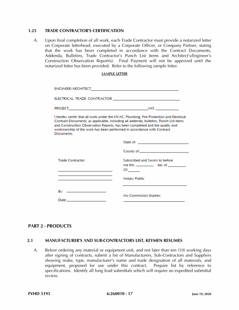
FVHD 5195 6:260010 - 17 June 19, 2020
1.25 TRADE CONTRACTOR'S CERTIFICATION
A. Upon final completion of all work, each Trade Contractor must provide a notarized letter
on Corporate letterhead, executed by a Corporate Officer, or Company Partner, stating
that the work has been completed in accordance with the Contract Documents,
Addenda, Bulletins, Trade Contractor’s Punch List items and Architect’s/Engineer’s
Construction Observation Report(s). Final Payment will not be approved until the
notarized letter has been provided. Refer to the following sample letter.
PART 2 - PRODUCTS
2.1 MANUFACTURER'S AND SUB-CONTRACTORS LIST, KEYMEN RESUMES
A. Before ordering any material or equipment unit, and not later than ten (10) working days
after signing of contracts, submit a list of Manufacturers, Sub-Contractors and Suppliers
showing make, type, manufacturer’s name and trade designation of all materials, and
equipment, proposed for use under this contract. Prepare list by reference to
specifications. Identify all long lead submittals which will require an expedited submittal
review.
FVHD 5195 6:260010 - 18 June 19, 2020
B. Refer to the Article “Proposal Preparation,” in this section. Specifically designate the
labor force required of the Electrical Trade Contractor. As part of the mobilization phase
of the work, submit resumes for each Keyman including the Project Manager and Project
Foreman.
C. These lists, when approved, will be supplementary to specifications, and no variations
therefrom will be permitted except with the approval of the Engineer.
D. Prepare the list using the “PROPOSED MANUFACTURERS AND SUB-CONTRACTORS
LIST” located at the end of this section.
E. Submittals will not be processed until the requirements of this Article are satisfactorily
completed.
2.2 SUBMITTALS
A. Provide digital submissions (.pdf format) for all material and equipment as noted in
Proposed Manufacturer's and Sub-Contractors List, except where indicated otherwise
herein.
1. Prior to submission of product data, shop drawings, and samples, notify the
Engineer/Architect of any site conditions differing from those indicated or specified.
2. Prior to submission of product data, shop drawings and samples to the design
professional, the HVAC Trade Contractor, the Plumbing Trade Contractor and the
Fire Protection Trade Contractor shall submit all submittals which require electrical
power to the Project Electrical Trade Contractor for the HVAC Trade Contractor’s,
the Plumbing Trade Contractor’s, the Fire Protection Trade Contractor’s and the
Electrical Trade Contractor’s coordination and review. The Electrical Trade
Contractor shall provide approval of electrical power requirements for the HVAC,
Plumbing and Fire Protection Trade Contractors’ proposed equipment.
3. All submittals of equipment requiring electrical power must be accompanied by the
“HVAC AND ELECTRICAL CONTRACTORS’ COORDINATION OF HVAC
EQUIPMENT ELECTRICAL REQUIREMENTS TRANSMITTAL COVER SHEET”, the
“PLUMBING AND ELECTRICAL CONTRACTORS’ COORDINATION OF
PLUMBING EQUIPMENT ELECTRICAL REQUIREMENTS TRANSMITTAL COVER
SHEET” and the “FIRE PROTECTION AND ELECTRICAL CONTRACTORS’
COORDINATION OF FIRE PROTECTION EQUIPMENT ELECTRICAL
REQUIREMENTS TRANSMITTAL COVER SHEET”, as applicable, all located at the
end of this section. Submittals without this Cover Sheet or an incomplete Cover
Sheet will be rejected without review.
4. All submittals must be accompanied by the “ELECTRICAL CONTRACTOR’S
TRANSMITTAL COVER SHEET” located at the end of this section. Submittals
without this cover sheet or with an incomplete cover sheet, will be rejected without
review.
5. All submittals must be accompanied by the “ELECTRICAL SUBMITTAL LOG”,
located at the end of this section. Submit log after final acceptance of the proposed
Manufacturer’s and Sub-Contractor’s list. Revise and update the log with each
submittal. Submittals without these logs or without an updated log will be rejected
without review.

FVHD 5195 6:260010 - 19 June 19, 2020
6. Specifically annotate and sign all exceptions, deletions and additions that vary from
the Project Contract Documents. Failing to provide signed annotations for all
deletions and additions, recognize and accept that Contract Documents will
govern, and will be used to resolve disputes.
B. Prepare submittals by careful reference to: drawings and specifications; preparatory
layout of all work; coordination with all proposed equipment; coordination with related
submittals and the work of all other Trade Contractors; space requirements; and TYPE A,
TYPE B, TYPE C, and TYPE D Utilities defined in this Section. A review of such
submittals by the Engineer/Architect, which include drawings, schedules, and catalog
cuts provided by the Trade Contractors, their Sub-Contractors, manufacturers, and
vendors, shall not relieve the Trade Contractors from the responsibility for correcting all
errors of any sort in the submittals, either identified or undetected by such review.
C. Regularly provide and update submittal log sheets listing submittal number, product,
applicable specification section, dates of submittal and receipt and status. Identify each
submittal by Job Name, log number and reference to applicable Specification Article
number.
D. All equipment submittals must include, but not be limited to, the following:
1. Manufacturers' catalog designation, photographs and specifications.
2. Full electrical data, including specifically, electrical characteristics.
3. Full General Construction data, including operating weights, dimensional data
including service access space. Data shall be given to the General Construction
Trade Contractor, where applicable, for his use in setting steel, supports, and
attachments.
4. Full wiring diagrams, including clearly identified power connections and control
connections. Data and diagrams shall be given to the Automatic Temperature
Control (ATC) Trade Sub-Contractor for their use and inclusion into their
submittals.
5. Listing of specific electrical performance, calculations and data.
6. Dimensions, capacities, ratings, material and finish.
7. Complete the submittal by listing all available options, accessories, configurations
and materials, and legibly strike out with single thin line all proposed deletions.
Clearly signify whether each and every manufacturer's option, accessory,
configuration and material choice is included and which is excluded by the
submission.
8. Annotation of equipment, devices, systems as indicated by the Contract Documents
(PNL-1, etc.).
9. Certification of testing by agencies such as ETL, ARI, UL, etc.
10. Such other detailed information as required for proper evaluation.
E. Review Time:
1. Allow two (2) weeks after Engineer’s receipt for the Engineer's processing of each
submittal, exclusive of Owner’s, or other’s review in the processing chain. Allow a
longer time period where processing must be delayed for coordination with
subsequent submittals.
FVHD 5195 6:260010 - 20 June 19, 2020
F. Submittals for electric motor starters must include a tabulation listing the following:
1. The equipment the starter is intended to control.
2. Horsepower and starter size.
3. Voltage.
4. Phase.
5. Full load amperes.
6. The manufacturer's number or type.
7. Heater numbers and amperage.
8. Quantity of auxiliary contacts required by ATC and fire alarm systems.
9. Pushbutton arrangement.
10. Pilot light arrangement if applicable.
11. Disconnect switches.
G. Submittals for automatic temperature controls must be coordinated with: 1) all electrical
equipment manufacturers’ and vendors’ submittals including review of electrical
submittals by ATC Sub-Contractor for conformance with sequences of operation for each
piece of equipment; 2) all electrical requirements of ATC System with Electrical Trade
Contractor; and 3) all fire and safety requirements of the Fire Alarm System. ATC
submittals shall include copies of all wiring diagrams for all electrical equipment with
points of connections clearly identified. ATC submittals shall be developed and
submitted to the Electrical Trade Contractor.
H. The Engineer’s recommendation of acceptance of the equipment proposed by the Trade
Contractor is conditional upon the Trade Contractor fulfilling all obligations of the
Contract Documents. By furnishing the proposed equipment, the Trade Contractor
acknowledges compliance with all of the following:
1. Field layout is completed and planning of proposed equipment has coordinated
with all related submittals, related trades and space requirements.
2. The Electrical Trade Contractor has reviewed and approved all submittals prior to
submission. Provide all submittals with a signed approval stamp, signifying the
following: 1) all field measurements, field construction criteria, materials,
dimensions, catalog numbers and similar data have been verified; 2) the
Engineer/Architect has been notified of all site conditions which affect the work,
and which require design resolution, as opposed to resolution by trade decisions;
3) all items are approved by the Electrical Trade Contractor, and have been
coordinated and checked with other applicable submittals, and contract
requirements; 4) submission is clearly marked to indicate which manufacturer’s
options are provided and which are not provided for the proposed equipment; and
5) manufacturers and/or equipment suppliers have been given a set of the contract
documents for their review and use as the basis of the submittals.
3. Any and all exceptions requested by the Electrical Trade Contractor are provided in
writing with the submittals. All exceptions, deletions and additions that vary from
the Contract Documents have been specifically annotated and initialed. Failing to
provide initialed annotations for all deletions and additions, the Electrical Trade
Contractor accepts the condition that the Contract Documents will govern, and will
be used to resolve disputes.
FVHD 5195 6:260010 - 21 June 19, 2020
4. Submittals without the Electrical Trade Contractor's signed stamp of approval will
be returned without review. Initialed approval stamps are not acceptable.
5. The Engineer’s acceptance of the proposed equipment constitutes the Engineer’s
formal approval that the engineering performance and operational utility
requirements, of the proposed equipment, match the Engineer’s specified and
designed performance requirements. By entering into this Contract, the Electrical
Trade Contractor agrees that the purpose of submittals is to demonstrate to the
Engineer that the Electrical Trade Contractor understands the design concept and
that he demonstrates his understanding by indicating which materials and
equipment he intends to furnish and install and use.
I. Secure submittals smaller than 8-1/2 x 11 to paper of this size.
J. Material and equipment fabricated, furnished and/or installed or used without the
Engineer’s review are subject to rejection by the Engineer.
K. Corrections or comments made on submittals during review by the Engineer do not
relieve the Electrical Trade Contractor from compliance with the requirements of the
Contract Documents. Such review will be only for general conformance with the design
concept, and the information given in the Contract Documents and does not include
review of quantities, dimensions, sizing, pressure drops, weights or gauges, fabrication
processes, construction methods, coordination with the work of other trades, or
construction safety precautions, all of which are the sole responsibility of the Electrical
Trade Contractor. Review of a specific item does not indicate acceptance of an
assembly of which the item is a component. The Engineer is not responsible for any
deviations from the Contract Documents that are not clearly noted by the Electrical Trade
Contractor. The Engineer will not review partial submissions or those for which
submissions for correlated items have not been received. The Electrical Trade Contractor
is responsible for: confirming and correlating all quantities, clearance, and dimensions;
selecting fabrication processes and techniques of construction; coordinating work with all
other Trades, and performing his work in a safe and satisfactory manner.
L. All submittals must be able to be reproduced. The Electrical Trade Contractor is
responsible for all reproduction and distribution to the General Construction Trade
Contractor and all other Trade Contractors as applicable.
M. If requested for the Electrical Trade Contractor’s use in the preparation of submittals, an
electronic copy (AutoCad .dwg format) of any of the Electrical Contract Drawings may be
provided by the Engineer, after receipt of a signed indemnification agreement, at a cost of
$55.00, billable to the Electrical Trade Contractor.
N. For additional requirements regarding submittals, refer to Article “Additional Trade
Contractor Paid fees and Expenses” in Part 3 of this section.
2.3 MATERIALS AND EQUIPMENT
A. All materials and equipment must be new and conform to the grade, quality and
standards specified herein.

FVHD 5195 6:260010 - 22 June 19, 2020
B. All equipment offered under these specifications is limited to products regularly produced
and recommended for service ratings in accordance with engineering data or other
comprehensive literature made available to the public and in effect at the time of opening
of bids. Testing agency seals, decals and/or nameplate shall be attached to and visible on
all equipment.
C. Items such as valves, motors, starting equipment, vibration isolating devices, and all other
equipment and material, where applicable and practicable, must each be of one
manufacturer.
D. Install equipment in strict accordance with manufacturer’s instructions for type and
capacity of each piece of equipment used. Obtain these instructions, which will be
considered part of these specifications. Type, capacity and application of equipment
must be suitable and operate satisfactorily for the purpose intended in the electrical
systems.
2.4 EQUIPMENT VARIATIONS AND SUBSTITUTIONS
A. Equipment Substitution Definition as follows:
1. A product that is neither the Basis of Design, nor one of the named Alternative
Manufacturing Sources.
2. Unless noted otherwise in the Contract Documents, substitutions may be
considered after the award of Contracts. Subsequent requests will be considered
only when, through no fault of the Electrical Trade Contractor, none of the
specified products are available.
B. Equipment Variation Definition as follows:
1. A product that is not the Basis of Design, but is named as one of the specified
Alternative Manufacturing Sources.
C. The manufacturers listed in Part 2 of all technical specifications are considered
Alternative Manufacturing Sources as described in Paragraphs A and B above.
D. “Subject to compliance”, as used in these specifications, means compliance with all the
requirements of the Contract Documents.
E. The materials and products mentioned in these Contract Documents are specified to
establish a standard of: material of manufacture; independent testing agency
certifications; quality; function; design; and performance. The phrases “Basis of Design,”
“standard of design,” and “equivalent acceptable,” are used to indicate that other similar,
comparable products may be used provided such substitutes or variations are accepted
by the Engineer as meeting all the salient characteristics and standards necessary, such
as: material of manufacture; independent testing agency certifications; quality; function;
design; and performance, to meet the Owner’s needs and meet the objectives of the
Engineer’s Project Design.
F. Where Alternative Manufacturing Sources are listed for an item:
FVHD 5195 6:260010 - 23 June 19, 2020
1. Selection must be either the Basis of Design or one of those listed Alternative
Manufacturing Sources.
2. There is no guarantee implied that each and every manufacturer listed can meet or
exceed the salient characteristics, such as: material of manufacture; independent
testing agency certifications; quality; function; design; and performance of the
product specified as Basis of Design.
G. Each Trade Contractor is responsible to contact his proposed equipment manufacturer’s
representative and confirm, prior to preparing submittals, the proposed manufacturer’s
product meets or exceeds the: material of manufacture; independent testing agency
certifications; quality; function; design; and performance of the product specified as the
Basis of Design. Final acceptance will be determined by the Engineer, whose decision is
final.
H. Submittals offered as an Equipment Variation from the Basis of Design shall include a
letter, on the product manufacturer’s letterhead, certifying that the proposed product is a
Comparable Product to the product specified as the Basis of Design and conforms to all
the salient characteristics, including: material of manufacture; quality; function; design;
and performance of the product specified as the Basis of Design. If directed by the
Engineer for Products offered as an Equipment Variation, the Offerer shall provide a Letter
of Confirmation from a Registered, Professional Engineer attesting that the Proposed
Equipment Variation conforms to all the salient characteristics, including: material of
manufacture; independent testing agency certifications; quality; function; design; and
performance of the product specified as the Basis of Design.
I. Specific products specified without use of the term: equivalent(s); comparable products;
or substitutions constitute a proprietary specification, and must be provided as specified,
unless a written request is submitted to the Engineer for approval up to ten (10) days after
the date of project award. Such requests must include a complete description of the
proposed product, along with sufficient documentation and other information necessary
for a complete evaluation of the proposed product. Such Trade Contractor Requests shall
include a letter, on the product manufacturer’s letterhead, certifying that the proposed
product is a Comparable Product and conforms to all the salient characteristics,
including: material of manufacture; independent testing agency certifications; quality;
function, design; and performance of the specified product. If approved, the proposed
product will be listed in an addendum to notify all bidders that such acceptance has been
granted by the Engineer. If not approved, provide the specified product.
J. Provide Calculations, signed and sealed by a Professional Engineer registered in the State
in which the work is taking place, engaged by the Electrical Trade Contractor, confirming
that the equipment proposed as either a Substitution, or Variation, is a Comparable
Product to the product specified as the Basis of Design and conforms to all the salient
characteristics, including: material of manufacturer; independent testing agency
certifications; quality; function; design; and performance of the product specified as the
Basis of Design. Provide such calculations for major pieces of equipment (emergency
generators, switchgear, transformers, etc.). The Engineer, whose decision will be final,
will determine which products will require calculations during the submittal review
process.
FVHD 5195 6:260010 - 24 June 19, 2020
K. The Contract Documents have been founded upon Engineering Design selection of
materials, products, and pieces of equipment listed at the Basis of Design. In the event
that the incorporation of an approved Substitution, Variation, or assembly, into the work,
requires revisions or additions to the contractual requirements of either the Trade
Contractor proposing the substitution or variation, or any other Trade Contractor, the
Trade Contractor proposing the substitution or variation, shall bear the cost of: such
revisions or additions to the work of the Trade Contractor proposing such Substitution
and/or Variation; any expenses of all affected trades; and all engineering or architectural
services required at no change in the contract sum.
L. The equipment specifications indicated on the drawings, or in Part 2 of each of the
technical specifications, may or may not indicate or include all of the required salient
characteristics, components and accessories included with the specified product. Include
cost for all such characteristics, components and accessories required to meet or exceed
the: material of manufacture; independent testing agency certifications; quality; function;
design; and performance of the product specified as the Basis of Design.
M. For requirements regarding equipment variations after bid award, refer to Article
“Additional Trade Contractor Paid Fees and Expenses” in Part 3 of this section.
N. Each Trade Contractor negotiating for pricing advantages affecting the Trade Contractor’s
Bid shall comply with the directives included herein, bear full responsibility for the
accuracy and completeness of the submissions required of the Vendor selected by the
Trade Contractor. The Proposing Trade Contractor shall bear full responsibility for all
extra costs of the Engineer shown to have resulted from inaccurate, and/or incomplete
compliance with the directives included in this Specification Article.
O. All decisions provided by the Engineer, described herein, shall be final.
2.5 VIBRATION ELIMINATION
A. Provide vibration isolation support provisions for all moving or rotating equipment,
machinery and transformers when such provisions are not furnished and/or integrally
mounted by the equipment manufacturers. Provide equipment equal to Amber/Booth
Company or Korfund Company, Inc., installed in accordance with vibration isolation
manufacturer's recommendations unless specified otherwise herein.
B. Provide all rotating or moving machinery or equipment mounted on, or suspended from,
building structure with approved resilient suspension isolation mountings.
C. Provide vibration isolating connections between all pumps and connecting piping.
Length, size, and stiffness as recommended by vibration isolator manufacturer.
D. Use flexible metallic conduit for all electrical connections to moving or vibrating
equipment, such as motors, generators, transformers, and the like.
E. Rigid pipes, conduit or other extended machine assemblies connected to vibration
isolated equipment are not permitted to be tied in directly with the building construction.
FVHD 5195 6:260010 - 25 June 19, 2020
Connect such elements to the equipment through flexible fittings, and support using
isolating equipment as required.
F. All systems must operate free from objectionable vibration and noise. Take all necessary
steps required to achieve this result without additional cost to the Project.
2.6 NOISE CONTROL
A. Noise levels in all 8 octave bands due to equipment and systems shall not exceed NC 35
within the occupied room, except as follows:
TYPE OF ROOM NC LEVEL
Audio Suites, Audio Speech Pathology, Phono/Cardiology 25
Operating Rooms 40
Offices, large open 40
Lobbies, Waiting Areas 40
Corridors (Public) 40
Corridors (Nurse Stations) 40
Bath Rooms and Toilet Rooms 40
Laboratories 45
SPD, Dining Rooms, Food Service/Serving, Therapeutic Pools 45
Kitchens, Locker Rooms, Warehouses, Shop, Laundries,
Gymnasiums, Recreation Rooms 50
X-Ray & General Work Rooms 40
B. For equipment which has no sound power ratings scheduled on the plans, select
equipment such that the fore-going noise criteria, local ordinance noise levels, and
OSHA requirements are not exceeded. Selection procedure shall be in accordance with
ASHRAE 2015 HVAC Applications Handbook, Chapter 48, NOISE AND VIBRATION
CONTROL.
C. An allowance, not to exceed 5db, may be added to the measured value to compensate
for the variation of the room attenuating effect between room test condition prior to
occupancy and design condition after occupancy which may include the addition of
sound absorbing material, such as, furniture. This allowance may not be taken after
occupancy. The room attenuating effect is defined as the difference between sound
power level emitted to room and sound pressure level in room.
D. In absence of specified measurement requirements, measure equipment noise levels three
feet from equipment and at an elevation of maximum noise generation.
E. If sound levels are exceeded, provide sound reducing devices, including, but not limited
to: sound attenuators; acoustic enclosures; additional equipment insulation or vibration
isolators to conform to these specifications. Provide required material and labor at no
additional cost to the project.
FVHD 5195 6:260010 - 26 June 19, 2020
2.7 INSERTS, HANGER SUPPORTS, CLAMPS, FASTENINGS
A. All materials, designs and types of inserts, hanger supports and clamps must meet the
requirements of the latest edition of the Manufacturers Standardization Society Document
MSS-SP-58, Underwriters Laboratories, Inc., National Electrical Code and Factory Mutual
Engineering Division Standards where applicable. Insert, hanger support and clamp
types referenced herein are shown in MSS-SP-58.
B. Provide all necessary inserts, hanger supports, fastenings, clamps and attachments
necessary for support of the electrical work. Select the types of all inserts, hanger
supports, fastenings, clamps and attachments to suit both new and existing building
construction conditions specifically for the purposes intended.
C. In new overhead cast-in-place concrete construction, provide type 19 steel concrete
inserts and fasten to form work before concrete is cast. For cast concrete floor or roof
sections too thin to permit the use of inserts, extend the hanger rod through the slab and
terminate with a nut and large washer, recessed into the top face of the slab as approved
by the Engineer.
D. Clamps and attachments to steel beams and bar joists must be made using types 20, 21,
23, 25, 27, 28, 29 or 30 as applicable to suit conditions of construction. Clamps and
attachments must be selected on the basis of the required load to be supported. Provide
all necessary steel angle iron or channel between bar joists, or steel beams where direct
attachment cannot be made. Holes are not permitted to be drilled or burned in structural
building steel for hanger rod supports. Welding of hangers or supports to structural steel
is prohibited unless approved beforehand by the Structural Engineer.
E. Metallic masonry anchors may be provided for all pre-cast concrete, masonry and cast
concrete construction as an alternate to item (C) above. Locate in pre-cast and cast-in-
place concrete as directed by the Engineer. Anchor Basis of Design: Dynabolt, Ram-In
and/or Tru-Bolt masonry anchors as manufactured by Ramset. Select and install as
recommended by the anchor manufacturer for the various applications, stresses and
services involved. Comparable products by Redhead, Hilti or Wej-It may be submitted
for review. Installation of masonry anchors must be accomplished by pre-drilling
concrete or masonry to diameters and depths required to properly accommodate anchor
bolts.
F. Toggle bolts may be used in dry wall and lath and block plaster walls. The use of toggle
bolts is restricted to the weight limitations imposed by the toggle bolt manufacturer for
the size used.
G. Except where noted otherwise herein, attachment to wood or material of similar fibrous
nature must be made with lag screws and/or wood screws of required size.
H. Screws with wooden or plastic plugs, or lead anchors are not acceptable.
FVHD 5195 6:260010 - 27 June 19, 2020
2.8 ACCESS DOORS AND PANELS
A. For projects which include the work of a General Construction Trade Contractor, furnish
and locate for installation under General Construction, all access doors and panels for
concealed portions of electrical work requiring accessibility for operation and
maintenance. If project does not include a General Construction Trade Contractor,
provide access doors as required.
B. Access panels may not be installed without specific approval of the Architect/Engineer as
to location. The proposed location of access doors and panels must be reviewed with the
Architect/Engineer and the General Construction Trade Foreman, where applicable, and
the locations indicated on the coordination drawings prior to installation of equipment,
access doors or panels. Controversies must be resolved at no cost to the Project.
C. Minimum door size of 24" x 18" unless shown, specified or approved otherwise.
D. Sixteen (16) gauge minimum doors with screw fasteners and painted finish. Basis of
Design is Milcor as follows:
WALL OR CEILING SURFACES STYLE
Drywall DW
Hard Plaster & Ceramic Type K
Unplastered Masonry & Concrete M
Acoustic Tile AT
Comparable products by Karp or MIFAB may be submitted for review.
E. Underwriters "B" label access doors where required for access to shafts, corridors, and
where located in fire walls and partitions.
2.9 EQUIPMENT ANCHOR BOLTS
A. Provide and set in place at the time concrete foundations, bases or curbs are poured or
formed, all necessary anchor bolts as required for the various equipment specified herein,
with hook type anchor bolts of proper size and length to suit the apparatus as
recommended by the equipment manufacturer. Set bolts in pipe sleeves of
approximately twice the bolt diameter and of length equal to the embedded length of the
bolt, with sleeves terminating flush with finished surfaces of foundations, bases or curbs.
B. When the equipment is set in its proper position and aligned with the anchor bolts, the
space between the anchor bolts and the inside wall of the sleeves must be completely
filled with non-shrink cementitious grout. Grout Basis of Design: Crystex as
manufactured by L & M Construction Chemicals, Inc. Comparable product by Master
Builders or BASF may be submitted for review.
FVHD 5195 6:260010 - 28 June 19, 2020
C. When a General Construction Trade Contractor provides concrete foundations, bases or
curbs, the Electrical Trade Contractor is responsible for all anchor bolts required by the
equipment he provides, under the Contract Documents. Assign a supervisory
representative to be present at the time foundations, bases or curbs are poured or formed.
For projects wherein there is no General Construction Trade Contractor, the Electrical
Trade Contractor is responsible for pouring, locating, and setting equipment foundations,
bases and curbs and the location of anchor bolts for the equipment provided or installed
by him on this Project.
D. All anchor bolts must be of sufficient strength to withstand any loading imposed by the
attached materials or equipment.
2.10 PIPING AND CONDUIT SLEEVES
A. Provide all sleeves required for electrical work and be fully responsible for the final and
permanent locations thereof.
B. Provide sleeves in the following locations:
1. All pipes and conduits passing through all cast-in-place concrete construction and
masonry walls.
2. All pipes and conduits passing through cast-in-place waterproof concrete
construction and waterproof masonry walls.
C. Extend through construction and finish flush with each surface except where noted
otherwise. Provide for a minimum ½" clearance around conduit, pipe or its covering in
the instance of pipe covered with insulation.
D. All sleeves in waterproof walls and floors must be fitted and sealed with positive
hydrostatic mechanical seals. Provide Basis of Design Product "Link Seal" as
manufactured by Thunderline Corporation or Comparable Product by Advance Products
and Systems, Inc. or Proco Products, Inc. Sleeves must be sized accordingly.
Mechanical seals must be placed around piping and/or conduit and inserted into void
between inner wall of sleeve and piping and/or conduit. Tighten mechanical seals as
required for watertight seal.
E. All sleeves must be Schedule 40 steel pipe finished with smooth edges. Sleeves in
waterproof walls and floors must be fabricated with minimum 1/4" thick rectangular steel
plate placed around mid-point of sleeve, continuously welded to sleeve and then place
the entire/plate assembly into proper position prior to erection of walls and floors.
Otherwise, provide sleeves with a minimum of three (3) lugs for anchoring.
F. Pack voids between sleeves, piping or conduit, where located in fire or smoke rated
assemblies, in accordance with UL Fire Resistance Directory.
G. Set all sleeves prior to or during erection of walls and floors. In the event that sleeves are
omitted or incorrectly located in new walls or slabs, submit a location plan and method
of cutting and installing sleeves to the Engineer for review prior to carrying out the work.
FVHD 5195 6:260010 - 29 June 19, 2020
H. If sleeves are omitted or located incorrectly, the particular Trade Contractor who is at
fault, at his own expense, must engage the trade which originally installed the work, to
cut and patch to the satisfaction of the Engineer.
I. Provide mechanical seals and insert into voids between piping and conduits that pass-
through floors, and which will be exposed in finished areas that have floor drains,
including spaces classified as “Janitors Closets,” “Toilet Rooms,” and the like.
J. Where cutting is required, use hand or small power tools designed for sawing or grinding,
not hammering and chopping. Cut through concrete and masonry using a cutting
machine, such as a masonry saw or core drill, to insure a neat hole.
2.11 SMOKE/FIRESTOPPING (MATERIALS)
A. Firestopping materials and systems must consist of commercially manufactured products
complying with the following minimum requirements and be asbestos and PCB free:
1. Flame Spread Index: Twenty-five or less when tested in accordance with ASTM E
84.
2. Smoke Density Index: Fifty or less when tested in accordance with ASTM E 84.
3. Nontoxicity: Nontoxic to human beings at all stages of application and during fire
conditions.
4. Systems shall comply with Underwriter’s Laboratory Listing Requirements.
5. Fire Resistance:
a. Materials and systems used to seal penetrations in time rated assemblies must
be capable of preventing the passage of flame and hot gases sufficient to
ignite cotton waste when subjected to ASTM E 119 time temperature fire
conditions for 3 hours.
b. Materials must not require a rise in temperature to install or activate seal.
c. Materials must not contain solvents or require hazardous waste disposal.
d. Firestop material must not dissolve in water after curing.
B. Smoke and firestopping material must be manufactured by Rectorshield, Inc., Hilti, or
3M. Refer to Division 07 of these specifications.
C. Smoke stopping materials must be approved by the authority having jurisdiction.
2.12 FIRE/SMOKE DAMPERS, SMOKE DETECTORS/SMOKE DETECTOR CONTROL
A. All fire/smoke dampers for the project will be provided by the HVAC Trade Contractor.
B. Refer to the Architectural Drawings, where applicable, for locations and classification
ratings for all smoke and fire rated walls, floors and assemblies, new and existing.
C. Duct mounted smoke detectors will be used to activate smoke dampers unless area
detectors are used to activate smoke damper. Tie detectors into the building’s fire alarm
FVHD 5195 6:260010 - 30 June 19, 2020
system. HVAC Trade Contractor will tie detectors into the Building Automation System
(BAS) where applicable.
D. Electrical Trade Contractor shall provide area smoke detectors for operation of smoke
dampers as applicable and specified. Electrical Trade Contractor shall connect, then test
and check-out smoke detectors connected to the building’s fire alarm system as specified.
Electrical Trade Contractor to check-out smoke detectors tied into the Building
Automation System.
E. All new duct mounted smoke detectors shall be furnished by the Electrical Trade
Contractor and installed by the HVAC Trade Contractor, and shall be installed generally
as located on the HVAC drawings.
F. Connections for automatic shutdown of air handling units shall be provided by the HVAC
Trade Contractor, in compliance with the ATC Section of these specifications.
Connections for fire alarm system shall be provided by the Electrical Trade Contractor.
G. HVAC Trade Contractor shall clearly indicate location of all new smoke detectors
required in ductwork on sheet metal shop drawing submissions.
H. Smoke evacuation system control and actuation shall be provided by the HVAC Trade
Contractor, with detection and signal for the fire alarm system provided by the Electrical
Trade Contractor.
I. Area actuation signals and connections for smoke dampers shall be provided by the
Electrical Trade Contractor. Locate signal where visible to Building Personnel.
PART 3 - EXECUTION
3.1 METHOD OF PROCEDURE
A. The drawings accompanying these specifications are diagrammatic and intended to cover
the approximate and relative locations of the building systems.
B. Installation, connection and interconnection of all components of these systems must be
complete and made in accordance with the manufacturers’ instructions and best trade
practices.
C. Erect all parts of equipment furnished at such time and in such manner as not to delay or
interfere with other Trade Contractors and their work.
D. Plug all piping, conduit and ductwork as required during construction to prevent entering
of dirt.
E. Before material is ordered or fabricated, or any work is performed, verify all calculations,
sizing, measurements, including lines, grades, pipes, and conduit elevations at the
building, as applicable, and be responsible for the correctness thereof. No extra
compensation will be allowed on account of differences between actual dimensions,

FVHD 5195 6:260010 - 31 June 19, 2020
routing and measurements and those indicated in the Contract Documents. Any
discrepancies discovered must be submitted to the Engineer for consideration before
proceeding with the work.
F. Lay out work and be responsible for the establishment of heights, grades, and the like, for
all interior and exterior equipment and systems as applicable, including piping, drains,
fixtures, conduit, and the like, included in Contract Documents, in strict accordance with
the intent expressed thereby; and all the physical conditions to be met at the building and
finished grade, and be responsible for accuracy thereof. The establishment of the
location of all work must be performed in consideration of the finished work. In case of
conflict, equipment and/or materials must be relocated without cost to the Project, as
directed by the Engineer, regardless of which equipment was installed first. Refer to
Article, “Coordination Drawings”, in Part 1 of this section.
G. Cooperate with other Trade Contractors for the proper securing and anchoring of all work
included within these specifications. Use extraordinary care in the erection and
installation of all equipment and materials to avoid marring surfaces of the work of other
Trade Contractors, as each Trade Contractor will be held financially responsible for all
such injury caused by the lack of precaution and due to negligence on the part of his
workmen.
H. Do not run pipe or conduit in any concrete slab three inches (3") or less in thickness. Do
not place any pipe or conduit in any slab where the outside diameter of the pipe or
conduit is more than one-quarter the thickness of the slab. The sweep of pipe or conduit
elbows emerging through concrete slabs must not create any hazard or obstructions.
I. All piping, conduit and other materials and equipment shown to be mounted below
ceilings are to be kept as close to ceiling areas as possible unless otherwise noted.
J. Install and arrange all equipment, such as junction boxes, and the like, which will be
concealed in construction, to be fully accessible for adjustment, service and
maintenance. Furnish access doors where required for installation under the General
Construction Contract, where applicable. Otherwise, furnish and install all required
access doors.
3.2 PROTECTION OF WORK
A. All piping, equipment, materials and accessories having polished or plated surfaces,
machined finishes or unpainted surfaces must be given a thick coat of a neutral
protection grease and carefully covered with thick cloth or heavy building paper held
securely in place to protect the finish against damage during the entire period of
construction. Protect equipment by the use of canvas tarps, vinyl sheeting or similar
materials held securely in place.
B. Seal all openings in pipes, fittings, conduit and all other materials to exclude dirt, sand,
and other foreign materials.
C. Exercise every precaution to exclude dust, dirt and all other foreign materials from
switchgear rooms, transformers, and all mechanical equipment rooms during
FVHD 5195 6:260010 - 32 June 19, 2020
construction. Rooms and equipment contained therein must be swept vacuum cleaned
at regular intervals. All relays, meters and electrical equipment containing electrical
components must be protected with heavy paper held in place with approved mastic tape
to exclude fine dust and particles. Install and maintain sufficient electric heaters in
equipment rooms and transformer compartments to keep equipment dry during
construction.
3.3 CUTTING AND PATCHING
A. New Construction:
1. Perform cutting and patching in accordance with Division 01.
2. Provide and set all sleeves, inserts and other items required for the installation of
the electrical work, and take responsibility for their final and permanent locations.
3. Confer with, and give the General Construction Trade Contractor, where
applicable, complete information as to size of openings in all construction, so that
such openings may be provided as the building progresses. Otherwise, provide
openings as required for the electrical work.
4. If openings are omitted or incorrect through failure to follow these instructions the
particular Trade Contractor must, at his own expense, engage the trade which
originally installed the work to cut and patch to the satisfaction of the Engineer.
B. For existing construction:
1. The General Construction Trade Contractor, where applicable, will perform all
cutting and patching required for the work of all trades. Otherwise, each Trade
Contractor is responsible for his own cutting and patching.
3.4 CONCRETE AND MASONRY
A. Provide all cast-in-place concrete, pre-cast concrete and masonry work (brick and block)
required for completion of the electrical work, including interior and exterior concrete
slabs.
B. Engineer will review and approve materials used.
C. Unless shown or specified otherwise, all equipment foundations and housekeeping pads
must be six inches (6") minimum height from floor, of sufficient mass, and secured to the
floor.
D. Refer to Division 03 for concrete specifications.
E. Unless noted otherwise, concrete bases must be 4" larger than the largest dimension of
the base of the supported equipment in both directions. Use 3000 psi, 28 day
compressive strength concrete and reinforcement.
FVHD 5195 6:260010 - 33 June 19, 2020
3.5 SUPPORTS
A. Except where noted otherwise in the specifications and shown on drawings, provide all
materials, including, but not limited to, equipment supports, supplies and labor necessary
as required to adequately support, brace and strengthen new and/or existing equipment
and materials installed under/or affected by the electrical work.
B. The design, materials, fabrication and erection of structural steel supports must conform
to "Specification for Design, Fabrication and Erection of Structural Steel for Buildings" of
the American Institute of Steel Construction, "Code of Standard Practice for Steel
Buildings and Bridges". Welding, where required, must conform to "Code of Arc and
Gas Welding in Building Construction" of the American Welding Society.
3.6 LINTELS
A. Lintel work to be performed in strict accordance with Division 01, and Architectural and
Structural drawings. Refer to Architectural and Structural Contract Documents for lintel
schedules and details.
B. Where lintels are not indicated as being provided by General Construction or Structural
Trade Contractors, the Electrical Trade Contractor must provide lintels required for the
installation and completion of electrical work.
3.7 ESCUTCHEONS
A. Except as noted otherwise, provide heavy solid pattern, steel, cast iron or malleable iron
escutcheons with set screws and prime coat of paint on all conduit exposed to view
within structure where passing through floors, partitions, walls or ceilings. Escutcheons
are not required in equipment rooms, boiler rooms or other unfinished areas.
B. Provide nickel plated cast iron escutcheons where conduits pass through toilet rooms,
walls or ceilings.
3.8 MACHINERY GUARDS
A. Provide OSHA approved expanded sheet steel metal guards over all belt drives,
couplings and other moving equipment to protect personnel from injury.
B. Machinery guards shall comply with OSHA Standards 29 CFR STANDARD NUMBER
1910.212 General Requirements for all Machines; Subpart Number 0; Subtitle -
Machinery and Machine Guarding; STANDARD NUMBER 1910.219; Standard Title -
Mechanical Power - Transmission Apparatus; Subpart Number 0; Subpart Title -
Machinery and Machine Guarding.
FVHD 5195 6:260010 - 34 June 19, 2020
3.9 ROOFING WORK
A. Refer to the Architectural Documents for roofing Manufacturer’s and Installer’s
Warranties. Electrical Trade Contractor shall have all roofing and flashing work
performed by warranted roofing installer. Contact Owner or original installer for further
information. New penetrations through the roof shall be in full warranty condition. If
required by the roof warranty, engage the original roofing installer to perform all roofing
and flashing work. Refer to Division 07 of these specifications.
3.10 PAINTING AND FINISHING
A. All painting, generally, will be provided by the General Construction Trade Contractor,
where applicable, except where specifically noted otherwise in the Electrical
Specifications. Otherwise, each Trade Contractor is responsible for his own painting and
finishing.
B. Equipment and material furnished with factory enamel finish will not be painted unless
finish has been damaged, in which case the equipment or material must be refinished by
the Trade Contractor who furnished it, to the satisfaction of the Engineer.
3.11 LUBRICATION
A. Provide proper and necessary lubrication of any items of operating, rotating or moving
equipment which is furnished, installed or which must operate as part of the electrical
system.
B. When an item of operating equipment is furnished and installed by a Trade Contractor, it
will be his responsibility to accomplish the lubrication.
C. When an item of operating equipment is furnished by one Trade Contractor and installed
by another, it is the responsibility of the Trade Contractor furnishing the equipment to
apply the lubricants.
D. All rotating or moving equipment must be lubricated prior to energizing and operating
the equipment. Should the Trade Contractor responsible for the lubrication fail to apply
lubricants prior to initial start-up and the equipment is damaged as a result of his
negligence, that Trade Contractor is required to provide all corrective action necessary
including replacement, if required, for the proper operation of equipment.
E. Lubrication must be accomplished in the manner prescribed or recommended by the
manufacturer of the specific item. For motor driven equipment this precaution of
lubrication will apply individually to the driver and the driven.
F. The lubricants must be of the type, grade, specification and manufacture as prescribed or
recommended by the manufacturer of the specific equipment item.
G. Extend lubrication fittings where required to allow maintenance personnel to lubricate
the equipment easily and efficiently.
FVHD 5195 6:260010 - 35 June 19, 2020
H. The Trade Contractor who supplies any item of rotating equipment will have the
responsibility of securing written instructions on the lubricating procedure and must
furnish not less than one year's supply of all necessary lubricants properly identified so
they can be replaced.
I. Any moving or rotating equipment furnished by the Owner that is to be installed, reused
and/or serviced must also be lubricated. Except where noted otherwise in the Contract
Documents, the Trade Contractor installing, reusing and/or servicing all such equipment
is responsible for the proper lubrication thereof, including obtaining proper lubricating
instructions from the various manufacturers involved, furnishing and applying the
necessary lubricants and leaving the Owner with a one (1) year supply of lubricant.
3.12 ELECTRICAL TRADE COORDINATION
A. Equipment by other Trade Contractors shall be furnished with electrical current
characteristics as shown on electrical drawings and specifications.
B. The nameplate voltage of all motors furnished with mechanical equipment must be
within the range of the voltage shown for use with the motor as the upper limit, and 5%
less than this voltage as the lower limit.
C. Other Trade Contractors must furnish all motors, motor starters, specialty motor
controllers, float and pressure switches, temperature control, other special automatic
controls as indicated in the Contract Documents for all equipment furnished and/or
installed under their contract except where noted otherwise.
D. All electrical equipment furnished by other Trade Contractors must be as recommended
by the equipment manufacturers, in accordance with the Electrical Specifications for
similar items, and of such type as to work properly with automatic temperature control
sequences where required.
E. The Electrical Trade Contractor must provide all push-buttons, safety switches for motors,
and wiring from starters to motors and install all starters furnished to him by other Trade
Contractors unless otherwise indicated in the Contract Documents.
F. Where controllers and/or starters are furnished as an integral part of any equipment, the
Trade Contractor supplying the equipment must furnish complete wiring between
controllers, starters and motors.
G. The Electrical Trade Contractor must provide disconnect switches for all equipment
furnished and/or installed by other Trade Contractors, except where such switches are an
integral part of equipment.
H. Other Trade Contractors must set all motors and furnish, set and pipe as necessary, float
switches, temperature control and other special automatic temperature controls.
I. Other Trade Contractors must provide all power and control wiring required by their
respective section of the specification. The Electrical Trade Contractor must provide all
other wiring required for the completion of the work of the other Trade Contractors.
FVHD 5195 6:260010 - 36 June 19, 2020
J. Other Trade Contractors must furnish the Electrical Trade Contractor with complete
wiring diagrams as required.
K. Any electrical work performed by the other Trade Contractors must be performed in
accordance with the requirements of the ELECTRICAL Section of these specifications.
L. For additional coordination items, refer to Article 2.2, “Submittals”.
3.13 ELECTRICAL MOTORS AND STARTERS
A. All motors furnished by all Trade Contractors, unless specified to the contrary in Contract
Documents, must conform to the following requirements:
1. Characteristics, dimensions, tolerances, temperature rise, insulation, rating, noise,
vibration, and all other characteristics in accordance with the latest standards of
IEEE or NEMA.
2. Unless required by the driven unit, motors must have normal starting torque,
NEMA Design B characteristics. Horsepower rating of motor must be equal to or
greater than that required by driven equipment. Current density design of motor
rating must be limited so that overload protection provided by standard motor
starters will be adequate to prevent damaging overheating during stall, single
phasing or slightly prolonged acceleration.
3. Use NEMA Class A or B insulation with motor frames amply sized to provide a
1.15 service factor at an ambient of 40 deg. C maximum. Insulation systems must
be designed for an average life of 60,000 hours.
4. All motors must be high efficiency. Meet or exceed requirements in NEMA
Standard MG1, Table 12-10.
5. Running power factor must be higher than 0.85 for motors 5 HP to 30 HP and
higher than 0.90 for motors 40 HP or larger.
6. Each motor must be mounted on the same bedplate as the equipment driven and
be complete with pulleys, slide rails or flexible couplings as required.
7. Each Trade Contractor is responsible in each instance for the proper selection of
motors of suitable characteristics with details submitted for approval to the
Engineer prior to installation.
B. All starters furnished by all Trade Contractors must conform with the following
requirements, unless specified to the contrary in the Contract Documents:
1. All starters for 3-phase equipment must be fully enclosed, across-the-line type
equipped with solid state overload protection as herein specified for all three
phases, low voltage protection, all necessary auxiliary contacts as required and
indicating pilot lights. Starters which are controlled automatically must have two-
wire control with "ON-OFF-AUTO" switches. Starters which are controlled
manually must have 3-wire control with Start-Stop pushbuttons.
2. All 3-phase starters remotely controlled must have 120-volt coils and control
transformers with disconnecting means. Starters for single phase motors shall be
manual toggle switches with thermal overload protection and pilot light. Omit
pilot light for unit heaters.
FVHD 5195 6:260010 - 37 June 19, 2020
3. General Purpose NEMA-1 enclosure for indoor use under normal atmospheric
conditions. Watertight enclosure NEMA-4 or NEMA-5 for outdoor use or where
starters are subjected to the splashing or dripping of water. Explosion-proof
enclosure NEMA-7, 9 or 12 for dusty or hazardous locations as required by Article
500 of the National Electrical Code.
4. Individually equip all starters for three phase motors with solid state adjustable
overload protection with automatic protection to prevent single phase operation
with the following features:
a. Three phase, self-powered with current sensing, phase unbalance and phase
loss protection, visible trip indication, trip test function, and power “LED.”
b. Phase loss protection to include automatic restart with a selectable manual
switch.
C. All controllers, starters and other electrical components furnished as an integral part of
any apparatus must be furnished complete with integral wiring as required.
D. So far as is practical, all motors and starters must be of one manufacturer. Basis of
Design: General Electric Co. Comparable products by Westinghouse Co., Square-D Co.,
or Allen-Bradley Co. may be submitted for review.
E. Submittals for motors and starters must be coordinated with Electrical Trade Contractor.
3.14 ELECTRICAL PROVISIONS FOR PACKAGED MECHANICAL EQUIPMENT
A. Unless otherwise noted in HVAC, Plumbing and Fire Protection Specifications, all
packaged equipment furnished by HVAC, Plumbing and Fire Protection Trade
Contractors must be complete with the following electrical provisions:
1. General compliance with provisions of the preceding Article, ELECTRICAL
MOTORS AND STARTERS.
2. Starting electrical characteristics of all motors and/or starters must be approved by
local utility company and Electrical Engineer.
B. Approved, factory installed and wired starting, operating and control equipment,
terminating in terminal strip for single point power wiring connections by Electrical Trade
Contractor must conform with the ELECTRICAL Section of these specifications and must
include approved branch fuses for branch power circuits.
3.15 EQUIPMENT IDENTIFICATION
A. Identify all equipment as to nature, service and purpose by means of permanently
attached plastic nameplates having ½” high letters, dull black outside and white core.
Nameplates of approved size, beveled edges and engraved through black to white core.
Basis of Design for nameplates is Seton Corp. Comparable products by Marking Services,
Inc. Milwaukee, WI (1-800-234-0135) or Brady Worldwide may be submitted for
review. Nameplates shall indicate equipment identification names and numbers as
approved by the Owner.

FVHD 5195 6:260010 - 38 June 19, 2020
3.16 ABANDONMENT, REMOVAL AND RELOCATION
A. Perform all abandonment, removal and relocation work required for completion of
electrical systems.
B. Removals shown on drawings are a general indication only, and may not necessarily
indicate the full extent of removals which may be required to complete this work.
C. Where existing partitions, walls, ceilings and floors are to be removed, all piping,
conduits, materials and equipment attached or fastened thereto or within, as applicable,
must be carefully removed.
D. Where work under this contract interferes with the existing construction, ductwork,
piping, conduit or equipment, remove all such materials and route new work to clear the
obstruction. Provide additional piping, conduits, and material of the same design and
quality if the piping and/or conduit is to be continued in use.
E. Disconnect and remove all accessible piping, conduit, ductwork, materials, fixtures and
equipment not required in the new systems. Plug all outlets at the main or riser
connection.
F. Removed materials not desired by the Owner and not to be reset and not specified nor
indicated to be reused, become the property of the Electrical Trade Contractor and must
be promptly removed from site.
G. All demolition work is subject to the direction and approval of the Engineer and must be
performed in such manner as not to interfere with the normal operation of the building.
H. Relocate existing utilities and/or equipment that must remain to maintain operation of
building or parts of building outside the work area.
I. Equipment Pad Removal:
1. Remove all concrete pads and equipment support structure material related to the
Electrical Trade, not indicated or specified for reuse. Remove concrete pads to one
(1) inch below adjacent concrete floor surface. Exterior slabs shall be broken and
removed as waste materials.
2. Cut-off reinforcement and anchor bolts at or below level of pad removal.
a. Resurface area level with adjacent concrete floor surface using a heavy duty
aggregate concrete topping consisting of Portland cement Type I or Type III
conforming to ASTM C150 with aggregate graded by weight to pass sieves as
follows:
Fine (Thin Coat) or Course (Heavy Coat)
3/8" 100% ½" 100%
No. 4 95-100% 3/8" 30-50%
No. 8 65-80% No. 4 0-15%
No. 16 45-65% No. 8 0-5%
FVHD 5195 6:260010 - 39 June 19, 2020
No. 30 25-45% No. 100 0-5%
b. Topping mix must contain a high range water reducing admixture (super
plasticizer) ASTM C494, Type F or Type G.
c. Coat surface with epoxy bonding agent prior to application of concrete
topping.
d. Produce a heavy duty concrete topping with the following characteristics:
Compressive Strength 5000 psi at 28 days
Slump 8" maximum
Water to Cement Ratio 0.44.
3.17 SMOKE AND FIRESTOPPING (METHODS)
A. Installation of materials must be performed by applicator/installers qualified, trained and
approved by the manufacturer of the materials, and be installed in accordance with
ASTM E 814.
B. Install smoke and firestopping at locations required, shown, or specified in accordance
with applicable codes, manufacturer's written instructions, and test report, applying to
the specific trade equipment as applicable. Cutting and patching of construction and
providing sleeves, where required, is shown on drawings or specified in other sections.
1. Filling of Voids: Smoke and firestopping materials must completely fill void spaces
regardless of geometric configuration, subject to tolerances established by the
manufacturer. Smoke and firestopping for filling voids in floors in which the
smallest dimension of the void is 4 in. or more must support the same load as the
floor is designed to support or must be protected by a permanent barrier to prevent
loading or traffic in the smoke or firestopped areas.
2. Electrical Cables or Conduits: Smoke and firestopping at penetrations of electrical
cables or conduits must comply with the requirements of NFPA No. 70.
3. Where smoke and firestopping of penetrations in floors, walls and partitions that
will be exposed in completed construction, provide protection as necessary to
prevent damage to adjacent surfaces and finishes, and provide escutcheons or
other trim.
4. Schedule the installation and required inspection of smoke and firestops for
penetrations that will be concealed in completed construction prior to erection of
floors, walls, and partitions that would permanently conceal the penetrations.
C. All areas of smoke and firestopping installation must be accessible until inspection by the
applicable code authorities.
3.18 SUBSURFACE CONCEALED UNKNOWN PHYSICAL CONDITIONS
A. Subsurface, or otherwise concealed physical conditions which (1) do not differ materially
from those indicated in the Project Contract Documents; (2) affect electrical work; (3) do
not differ materially from those ordinarily found to exist, and which are generally
recognized as inherent in the electrical construction activities of the character provided
FVHD 5195 6:260010 - 40 June 19, 2020
for in the Project Contract Documents, are to be anticipated by the Electrical Trade
Contractor, and included in the basic electrical work.
B. Unknown physical conditions: which are of an unusual nature; which are materially
different in subsurface (otherwise concealed) physical conditions; which affect
mechanical and/or electrical work; which differ materially from those ordinarily found to
exist and generally recognized as inherent in construction activities of the character
found in the Project Contract Documents, are the basis for and require notice by the
Electrical Trade Contractor, promptly, before such conditions are disturbed. Such
conditions may become the basis for a legitimate claim under “Changed Conditions,”
affecting the cost, and/or schedule of the work. During the work, the Electrical Trade
Contractor shall provide reasonable, incidental on-site review, survey and measurements
to assist in quantification of such conditions.
3.19 CONCRETE PATCHING (PROCEDURE)
A. Remove any loose debris, chipped or cracked portions of concrete, and any grease, oil,
dirt or other coating materials from the concrete to be patched.
B. Apply epoxy bonding adhesive to the clean dry surface with a brush or roller to briefly
flood the surface allowing good penetration, if completely absorbed, apply additional
material. Adhesive Basis of Design: Edison Coatings Inc. Flexi-Bond 540. Comparable
product by Sika Corp. or Euclid Chemical Co. may be submitted for review. Refer to
Division 03 of these specifications.
C. Apply new cementitious mortar patch to surface immediately after applying bonding
adhesive, bonding agent should be wet while applying concrete patch. Mortar patch
equal to Moxie International 2000 Super Patch. Comparable product by Sika Corp. or
Euclid Chemical Co. may be submitted for review. Refer to Division 03 of these
specifications.
D. Work patch into any cracks or crevices with a brush, then apply remainder of patch and
trowel until level and smooth.
E. Do not apply patch below 45 deg. F.
3.20 TEMPORARY PARTITIONS
A. Provide and maintain temporary partitions or dust barriers adequate to prevent the spread
of dust and dirt to adjacent areas. Refer to Division 01 of these specifications.
3.21 INITIAL APPLICATION FOR PAYMENT
A. Provide the following prior to the initial application for payment:
1. Copy of the Electrical Trade Contractor’s and Sub-Contractors’ license for the state
in which the work is being performed.
FVHD 5195 6:260010 - 41 June 19, 2020
2. Resumes for the designated Project Manager and Project Foreman.
3. List of independent agencies who will be engaged by the Electrical Trade
Contractor to perform tests, provide certifications, conduct inspections, etc. as
required by Contract Documents.
B. The initial application for payment will not be processed until the items above are
submitted.
C. Include line items for:
1. Coordination Drawings.
2. Lighting Control System Report.
3. Fire Alarm Testing Reports.
4. Short circuit coordination study.
3.22 FINAL APPLICATION FOR PAYMENT
A. Provide the following prior to the final application for payment:
1. Refer to Division 01 of these specifications.
2. Equipment Start-Up Reports for each piece of electrical equipment.
3. Electrical Inspection Agency’s written report.
4. Operating and Maintenance Manuals and Data.
5. Electrical systems and equipment warranties.
6. Fire Alarm Completion Documentation.
7. Lighting Control System Operational Report.
8. Electrical System Commissioning Report.
9. Electrical Contractor Closeout Checklist indicating dates of submitted requirements.
10. Electrical Trade Contractor’s Punch List of incomplete work items with reason why
each work item is not complete and anticipated schedule for completion. Submit
at least one week prior to Engineer’s final Construction Observation Report site
visit.
11. Signed and dated Engineer’s final Construction Observations Report.
12. Electrical Trade Contractor’s notarized certification letter.
13. As-built drawings as described in Part 1 of this specification section.
B. Final payment is contingent upon completion of all items listed above.
3.23 INDEMNIFICATION
A. The drawings and specifications covering the work of Division 26 shall not be interpreted
by the Electrical Trade Contractor as quantification, and/or classification of the
construction methods, and/or construction means required to carry out the required
construction. There is no explicit or implicit representation that any portion of this work
can be installed and/or constructed through any particular normal, reasonable, abnormal,
or unusual means and methods. By submission of a pricing bid for this work, the
Electrical Trade Contractor shall accept sole and individual responsibility for the
FVHD 5195 6:260010 - 42 June 19, 2020
determination and execution of the methods and means he/she selects to complete this
work.
B. The Electrical Trade Contractor, to the fullest extent permitted by law, agrees to
indemnify, hold harmless, and defend Gillan & Hartmann, Inc., its consultants, and the
employees and agents of any of them from and against any and all claims, suits,
demands, liabilities, losses, damages, and costs (“Losses”), including but not limited to
costs of reasonable defense, arising in whole or in part out of the negligence of the
Electrical Trade Contractor, his Sub-Contractors, the officers, employees, agents, and Sub-
Contractors of any of them, or anyone for whose acts any of them may be liable,
regardless of whether or not such Losses are caused in part by a party indemnified
hereunder. Specifically excluded from the foregoing are Losses arising out of (1) the
preparation or approval of maps, drawings, opinions, reports, surveys, change orders,
designs, or specifications, and (2) the giving of or failure to give directions by Gillan &
Hartmann, Inc., its consultants, and the agents and employees of any of them, provided
such giving or failure to give is the primary cause of Loss.
C. The Electrical Trade Contractor shall name Gillan & Hartmann, Inc., its agents and
consultants on the Electrical Trade Contractor’s policy or policies of comprehensive or
commercial general liability insurance. Such insurance shall include products and
completed operations and contractual liability coverages, shall be primary and
noncontributing with any insurance maintained by Gillan & Hartmann, Inc. or its agents
and consultants, and shall provide that Gillan & Hartmann, Inc. be given thirty days,
unqualified written notice prior to any cancellation thereof.
3.24 ADDITIONAL ELECTRICAL TRADE CONTRACTOR PAID FEES AND EXPENSES
A. As a material part of the Electrical Trade Contractor’s Agreement to complete the work of
this Contract, the Electrical Trade Contractor agrees to reimburse Gillan & Hartmann, Inc.
(“Engineer”) for the below listed extra engineering work under the following conditions:
1. Engineer’s hourly billing rate shall be $125.00 per hour for all related office hours,
travel time and as applicable, on-site time;
2. Electrical Trade Contractor’s request(s) for substitution;
a. When such requests for substitution are not the result of a bonafide delivery
problem or design related problem, and;
b. When such requests do not address items of equipment for which the
specifications list the basis of design with at least one comparable product,
and;
c. The Electrical Trade Contractor’s request(s) for substitution must be submitted
in writing, and;
d. The Engineer will provide the Electrical Trade Contractor with a written
budget, not to exceed quotation for the Engineer’s billing, and;
e. The Electrical Trade Contractor shall render written acceptance of the
Engineer’s extra charges, and;
f. The Electrical Trade Contractor shall pay a retainer, in advance, equal to
80% of the established budget for the Engineer’s extra work.
FVHD 5195 6:260010 - 43 June 19, 2020
g. The balance of the Engineer’s charges beyond the retainage shall be paid
upon completion of the Engineers’ extra work in reviewing the substitution(s).
Final payment is due regardless of the Engineer’s decision to accept or reject
the Electrical Trade Contractor’s substitution request(s), and;
h. Late payments shall incur an interest rate of 1½% per month compounded
from due date to date of collection, and;
i. The Electrical Trade Contractor’s balance due for his beneficial contracted
work, unpaid beyond 60 days of due date, will be deducted from progress
payments due the Electrical Trade Contractor, and will include all additional
administrative costs incurred by the Owner, in affecting such deductions.
3. Extra Engineering work created by the Electrical Trade Contractor’s failure to
resolve the Engineer’s Items listed in the Construction Observation Report(s);
a. The Engineer’s basic services rendered to the Owner include periodic visits
to the site and providing written list of items (Construction Observation
Report) requiring the Electrical Trade Contractor’s attention, reporting and
resolution;
b. The Electrical Trade Contractor shall provide written feedback and prompt
resolution of Construction Observation Items including a written schedule for
the Electrical Trade Contractor’s completion of these Items followed by a
written confirmation of closure;
c. Should the Electrical Trade Contractor fail to perform as described above,
and should such failure require, in the opinion of the Owner and the
Engineer, that the Engineer must expend extra work in bringing closure and
resolving the Electrical Trade Contractor’s open Items, the Electrical Trade
Contractor agrees pay the Engineer for all extra work required. The Engineer
will provide a written notice of the not to exceed budget for the Engineer’s
extra work in advance as a prudent notification that the extra work will be
initiated. Subsequent failure of the Electrical Trade Contractor to resolve
these outstanding issues will result in the Engineer’s completion of the extra
work, and billing the Electrical Trade Contractor accordingly. The Engineer’s
payment for this additional work shall be deducted from the Electrical Trade
Contractor’s final payment for his work under this Contract. Deductions from
the Final Payment will be made to cover all the Owner’s additional costs in
affecting such deductions.
4. The Electrical Trade Contractor’s request for substitution of specified equipment
when such specifications list a basis of design and at least one comparable product
such requests will be rejected.
5. Extra Engineering work created by the Electrical Trade Contractor’s multiple
submissions of a single material or piece of equipment;
a. The Engineer’s basic services include two reviews for each piece of
equipment or material submittal. The Engineer’s first review takes place at
the initial Electrical Trade Contractor’s submission of that submittal. The
Engineer’s second review takes place when the Engineer requires a
resubmission of that submittal.
FVHD 5195 6:260010 - 44 June 19, 2020
b. If the Engineer’s third review of a particular submittal is required for reasons
due to the Electrical Trade Contractor, the Engineer will provide the Electrical
Trade Contractor with a written budget, not to exceed quotation for the
Engineer’s extra work in reviewing the submittal.
c. The Electrical Trade Contractor shall render written acceptance of the
Engineer’s extra charges.
d. The Electrical Trade Contractor shall pay a retainer, in advance, equal to
80% of the established budget for the Engineer’s extra work.
e. The balance of the Engineer’s charges beyond the retainage shall be paid
upon completion of the Engineers’ extra work in reviewing the submittal.
f. Late payments shall incur an interest rate of 1½% per month compounded
from due date to date of collection.
g. The Electrical Trade Contractor’s balance, unpaid beyond 60 days of due
date, will be deducted from progress payments due the Electrical Trade
Contractor for work under this Contract and will include additional
administrative costs incurred by the Owner in affecting all such deductions.
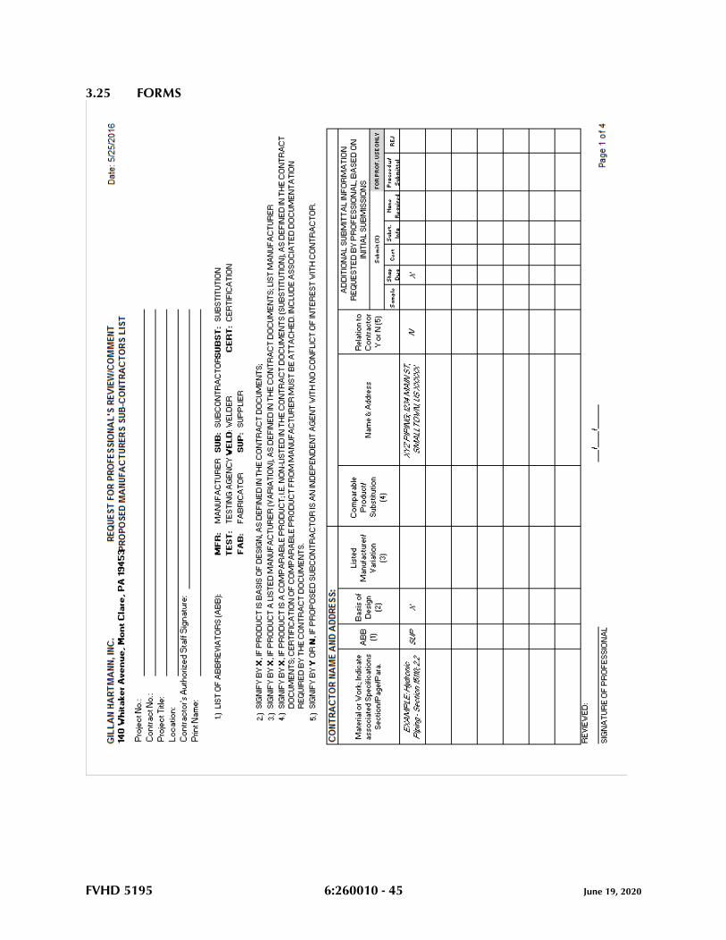
FVHD 5195 6:260010 - 45 June 19, 2020
3.25 FORMS
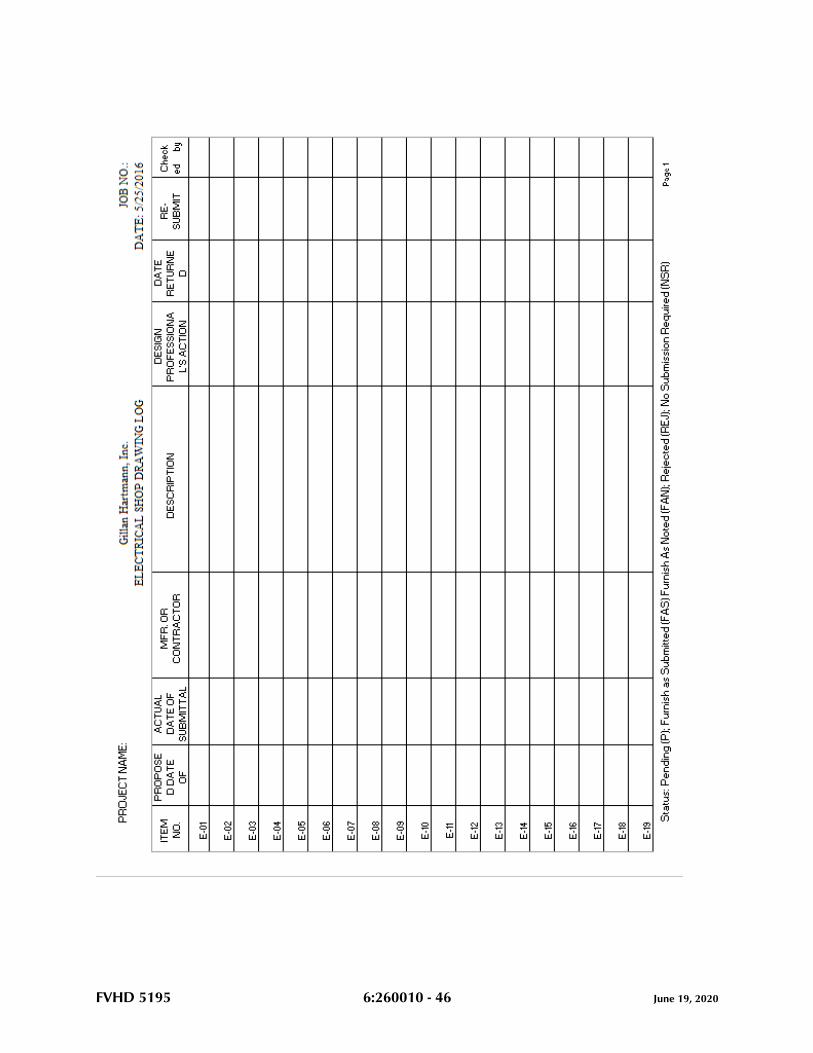
FVHD 5195 6:260010 - 46 June 19, 2020
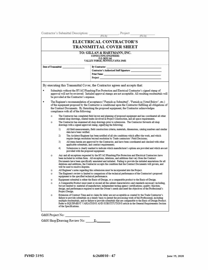
FVHD 5195 6:260010 - 47 June 19, 2020
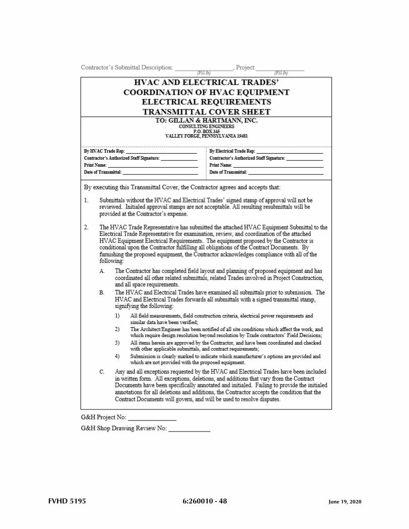
FVHD 5195 6:260010 - 48 June 19, 2020
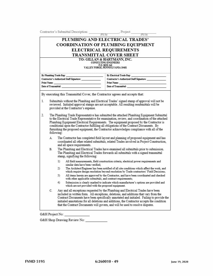
FVHD 5195 6:260010 - 49 June 19, 2020
FVHD 5195 6:260010 - 50 June 19, 2020
END OF SECTION 260010
FVHD 5195 6:260050 - 1 June 19, 2020
SECTION 260050 - BASIC ELECTRICAL MATERIALS AND METHODS
PART 1 - GENERAL
1.1 RELATED DOCUMENTS
A. Drawings and general provisions of the Contract, including General and Supplementary
Conditions and Division 01 Specification Sections, apply to this Section.
1.2 SUMMARY
A. This Section includes the following:
1. Supporting devices for electrical components.
2. Electrical identification.
3. Electricity-metering components.
4. Concrete equipment bases.
5. Electrical demolition.
6. Cutting and patching for electrical construction.
7. Touchup painting.
1.3 SUBMITTALS
A. Product Data: For electricity-metering equipment.
B. Shop Drawings: Dimensioned plans and sections or elevation layouts of electricity-
metering equipment.
C. Field Test Reports: Indicate and interpret test results for compliance with performance
requirements.
1.4 QUALITY ASSURANCE
A. Electrical Components, Devices, and Accessories: Listed and labeled as defined in
NFPA 70, Article 100, by a testing agency acceptable to authorities having jurisdiction, and
marked for intended use.
B. Comply with NFPA 70.
1.5 COORDINATION
FVHD 5195 6:260050 - 2 June 19, 2020
A. Coordinate chases, slots, inserts, sleeves, and openings with general construction work and
arrange in building structure during progress of construction to facilitate the electrical
installations that follow.
1. Set inserts and sleeves in poured-in-place concrete, masonry work, and other
structural components as they are constructed.
B. Sequence, coordinate, and integrate installing electrical materials and
equipment for efficient flow of the Work. Coordinate installing large equipment
requiring positioning before closing in the building.
C. Coordinate electrical service connections to components furnished by utility
companies.
1. Coordinate installation and connection of exterior underground and overhead utilities
and services, including provision for electricity-metering components.
2. Comply with requirements of authorities having jurisdiction and of utility
company providing electrical power and other services.
D. Coordinate location of access panels and doors for electrical items that are
concealed by finished surfaces. Access doors and panels are specified in
Division 08 Section "Access Doors."
E. Where electrical identification devices are applied to field-finished surfaces,
coordinate installation of identification devices with completion of finished
surface.
F. Where electrical identification markings and devices will be concealed by
acoustical ceilings and similar finishes, coordinate installation of these items
before ceiling installation.
G. Electrical devices and boxes are indicated on Drawings in approximate locations
unless dimensioned. Adjust box or device location up to 10 feet, if required to
accommodate intended purpose or owner request, with no additional cost to
contract.
PART 2 - PRODUCTS
2.1 SUPPORTING DEVICES
A. Material: Cold-formed steel, with corrosion-resistant coating acceptable to authorities
having jurisdiction.
B. Metal Items for Use Outdoors or in Damp Locations: Hot-dip galvanized steel.
FVHD 5195 6:260050 - 3 June 19, 2020
C. Slotted-Steel Channel Supports: Flange edges turned toward web, and 9/16-inch- (14-
mm-) diameter slotted holes at a maximum of 2 inches (50 mm) o.c., in webs.
1. Channel Thickness: Selected to suit structural loading.
2. Fittings and Accessories: Products of the same manufacturer as channel
supports.
D. Raceway and Cable Supports: Manufactured clevis hangers, riser clamps, straps,
threaded C-clamps with retainers, ceiling trapeze hangers, and wall brackets.
E. Pipe Sleeves: ASTM A 53, Type E, Grade A, Schedule 40, galvanized steel, plain
ends.
F. Cable Supports for Vertical Conduit: Factory-fabricated assembly consisting of
threaded body and insulating wedging plug for non-armored electrical cables in
riser conduits. Plugs have number and size of conductor gripping holes as
required to suit individual risers. Body constructed of malleable-iron casting with
hot-dip galvanized finish.
G. Expansion Anchors: Carbon-steel wedge or sleeve type.
H. Toggle Bolts: All-steel springhead type.
I. Powder-Driven Threaded Studs: Heat-treated steel.
2.2 ELECTRICAL IDENTIFICATION
A. Identification Devices: A single type of identification product for each application
category. Use colors prescribed by ANSI A13.1, NFPA 70, and these Specifications.
B. Raceway and Cable Labels: Comply with ANSI A13.1, Table 3, for minimum
size of letters for legend and minimum length of color field for each raceway and
cable size.
1. Type: Preprinted, flexible, self-adhesive, vinyl. Legend is over laminated
with a clear, weather- and chemical-resistant coating.
2. Color: Black letters on orange background.
3. Legend: Indicates voltage.
C. Colored Adhesive Marking Tape for Raceways, Wires, and Cables: Self-adhesive
vinyl tape, not less than 1 inch wide by 3 mils thick (25 mm wide by 0.08 mm
thick).
D. Underground Warning Tape: Permanent, bright-colored, continuous-printed,
vinyl tape with the following features:
FVHD 5195 6:260050 - 4 June 19, 2020
1. Not less than 6 inches wide by 4 mils thick (150 mm wide by 0.102 mm thick).
2. Compounded for permanent direct-burial service.
3. Embedded continuous metallic strip or core.
4. Printed legend that indicates type of underground line.
E. Tape Markers for Wire: Vinyl or vinyl-cloth, self-adhesive, wraparound type
with preprinted numbers and letters.
F. Color-Coding Cable Ties: Type 6/6 nylon, self-locking type. Colors to suit coding
scheme.
G. Engraved-Plastic Labels, Signs, and Instruction Plates: Engraving stock, melamine
plastic laminate punched or drilled for mechanical fasteners 1/16-inch (1.6-
mm) minimum thickness for signs up to 20 sq. in. (129 sq. cm) and 1/8-inch (3.2-
mm) minimum thickness for larger sizes. Engraved legend in black letters on
white background.
H. Interior Warning and Caution Signs: Comply with 29 CFR, Chapter XVII, Part
1910.145. Preprinted, aluminum, baked-enamel-finish signs, punched or
drilled for mechanical fasteners, with colors, legend, and size appropriate to the
application.
I. Exterior Warning and Caution Signs: Comply with 29 CFR, Chapter XVII, Part
1910.145. Weather-resistant, nonfading, preprinted, cellulose-acetate butyrate signs
with 0.0396-inch (1-mm), galvanized-steel backing, with colors, legend, and size
appropriate to the application. 1/4-inch (6-mm) grommets in corners for
mounting.
J. Fasteners for Nameplates and Signs: Self-tapping, stainless-steel screws or No.
10/32 stainless-steel machine screws with nuts and flat and lock washers.
2.3 CONCRETE BASES
A. Concrete Forms and Reinforcement Materials: As specified in Division 03 Section "Cast-in-
Place Concrete."
B. Concrete: 3000-psi (20.7-MPa), 28-day compressive strength as specified in Division 03
Section "Cast-in-Place Concrete."
2.4 TOUCHUP PAINT
A. For Equipment: Equipment manufacturer's paint selected to match installed equipment
finish.
B. Galvanized Surfaces: Zinc-rich paint recommended by item manufacturer.
FVHD 5195 6:260050 - 5 June 19, 2020
PART 3 - EXECUTION
3.1 ELECTRICAL EQUIPMENT INSTALLATION
A. Headroom Maintenance: If mounting heights or other location criteria are not indicated,
arrange and install components and equipment to provide the maximum possible headroom.
B. Materials and Components: Install level, plumb, and parallel and perpendicular to other
building systems and components, unless otherwise indicated.
C. Equipment: Install to facilitate service, maintenance, and repair or replacement of
components. Connect for ease of disconnecting, with minimum interference with other
installations.
D. Right of Way: Give to raceways and piping systems installed at a required slope.
3.2 ELECTRICAL SUPPORTING DEVICE APPLICATION
A. Damp Locations and Outdoors: Hot-dip galvanized materials or nonmetallic, U-channel
system components.
B. Dry Locations: Steel materials.
C. Support Clamps for PVC Raceways: Click-type clamp system.
D. Selection of Supports: Comply with manufacturer's written instructions.
E. Strength of Supports: Adequate to carry present and future loads, times a safety factor of
at least four; minimum of 200-lb (90-kg) design load.
3.3 SUPPORT INSTALLATION
A. Install support devices to securely and permanently fasten and support electrical
components.
B. Install individual and multiple raceway hangers and riser clamps to support raceways.
Provide U-bolts, clamps, attachments, and other hardware necessary for hanger assemblies
and for securing hanger rods and conduits.
C. Support parallel runs of horizontal raceways together on trapeze- or bracket-type hangers.
D. Size supports for multiple raceway installations so capacity can be increased by a 25
percent minimum in the future.
E. Support individual horizontal raceways with separate, malleable-iron pipe hangers or
clamps.
FVHD 5195 6:260050 - 6 June 19, 2020
F. Install 1/4-inch- (6-mm-) diameter or larger threaded steel hanger rods, unless otherwise
indicated.
G. Spring-steel fasteners specifically designed for supporting single conduits or tubing may
be used instead of malleable-iron hangers for 1-1/2-inch (38-mm) and smaller raceways
serving lighting and receptacle branch circuits above suspended ceilings and for fastening
raceways to slotted channel and angle supports.
H. Arrange supports in vertical runs so the weight of raceways and enclosed conductors is
carried entirely by raceway supports, with no weight load on raceway terminals.
I. Simultaneously install vertical conductor supports with conductors.
J. Separately support cast boxes that are threaded to raceways and used for fixture support.
Support sheet-metal boxes directly from the building structure or by bar hangers. If bar
hangers are used, attach bar to raceways on opposite sides of the box and support the
raceway with an approved fastener not more than 24 inches (610 mm) from the box.
K. Install metal channel racks for mounting cabinets, panelboards, disconnect switches, control
enclosures, pull and junction boxes, transformers, and other devices unless components are
mounted directly to structural elements of adequate strength.
L. Install sleeves for cable and raceway penetrations of concrete slabs and walls unless core-
drilled holes are used. Install sleeves for cable and raceway penetrations of masonry and
fire-rated gypsum walls and of all other fire-rated floor and wall assemblies. Install sleeves
during erection of concrete and masonry walls.
M. Securely fasten electrical items and their supports to the building structure, unless otherwise
indicated. Perform fastening according to the following unless other fastening methods are
indicated:
1. Wood: Fasten with wood screws or screw-type nails.
2. Masonry: Toggle bolts on hollow masonry units and expansion bolts on solid
masonry units.
3. New Concrete: Concrete inserts with machine screws and bolts.
4. Existing Concrete: Expansion bolts.
5. Instead of expansion bolts, threaded studs driven by a powder charge and provided
with lock washers may be used in existing concrete.
6. Steel: Welded threaded studs or spring-tension clamps on steel.
a. Field Welding: Comply with AWS D1.1.
7. Welding to steel structure may be used only for threaded studs, not for conduits, pipe
straps, or other items.
8. Light Steel: Sheet-metal screws.
9. Fasteners: Select so the load applied to each fastener does not exceed 25 percent of
its proof-test load.
FVHD 5195 6:260050 - 7 June 19, 2020
3.4 IDENTIFICATION MATERIALS AND DEVICES
A. Install at locations for most convenient viewing without interference with operation and
maintenance of equipment.
B. Coordinate names, abbreviations, colors, and other designations used for
electrical identification with corresponding designations indicated in the
Contract Documents or required by codes and standards. Use consistent
designations throughout Project.
C. Self-Adhesive Identification Products: Clean surfaces before applying.
D. Identify raceways and cables with color banding as follows:
1. Bands: Pretensioned, snap-around, colored plastic sleeves or colored adhesive
marking tape. Make each color band 2 inches (51 mm) wide, completely encircling
conduit, and place adjacent bands of two-color markings in contact, side by side.
2. Band Locations: At changes in direction, at penetrations of walls and floors,
at 50- foot (15-m) maximum intervals in straight runs, and at 25-foot (8-
m) maximum intervals in congested areas.
3. Apply the following colors to the systems listed below:
a. Fire Alarm System: Red.
b. Fire-Suppression Supervisory and Control System: Red and yellow.
c. Combined Fire Alarm and Security System: Red and blue.
d. Security System: Blue and yellow.
e. Mechanical and Electrical Supervisory System: Green and blue.
f. Telecommunication System: Green and yellow.
E. Tag and label circuits designated to be extended in the future. Identify source and
circuit numbers in each cabinet, pull and junction box, and outlet box. Color-
coding may be used for voltage and phase identification.
F. Install continuous underground plastic markers during trench backfilling, for
exterior underground power, control, signal, and communication lines located
directly above power and communication lines. Locate 6 to 8 inches (150 to 200
mm) below finished grade. If width of multiple lines installed in a common trench
or concrete envelope does not exceed 16 inches (400 mm), overall, use a single
line marker.
G. Color-code 208/120-V system secondary service, feeder, and branch-circuit
conductors throughout the secondary electrical system as follows:
1. Phase A: Black.
2. Phase B: Red.
3. Phase C: Blue.
4. Neutral: White.
FVHD 5195 6:260050 - 8 June 19, 2020
5. Ground: Green.
H. Color-code 480/277-V system secondary service, feeder, and branch-circuit
conductors throughout the secondary electrical system as follows:
1. Phase A: Yellow.
2. Phase B: Brown.
3. Phase C: Orange.
4. Neutral: White with a colored stripe or gray.
5. Ground: Green.
I. Install warning, caution, and instruction signs where required to comply with 29
CFR, Chapter XVII, Part 1910.145, and where needed to ensure safe operation and
maintenance of electrical systems and of items to which they connect. Install
engraved plastic-laminated instruction signs with approved legend where
instructions are needed for system or equipment operation. Install metal-
backed butyrate signs for outdoor items.
J. Install engraved-laminated emergency-operating signs with white letters on red
background with minimum 3/8-inch- (9-mm-) high lettering for emergency
instructions on power transfer, load shedding, and other emergency operations.
K. Equipment Identification Labels: Engraved plastic laminate. Install on each unit
of equipment, including central or master unit of each system. This includes
power, lighting, communication, signal, and alarm systems, unless units are specified
with their own self- explanatory identification. Unless otherwise indicated, provide a
single line of text with 1/2-inch- (13-mm-) high lettering on 1-1/2-inch- (38-mm-) high
label; where two lines of text are required, use labels 2 inches (50 mm) high. Use white
lettering on black field. Apply labels for each unit of the following categories of
equipment using mechanical fasteners:
1. Panelboards, electrical cabinets, and enclosures.
2. Access doors and panels for concealed electrical items.
3. Electrical switchboards.
4. Disconnect switches.
5. Enclosed circuit breakers.
6. Motor starters.
7. Push-button stations
8. Contactors.
9. Control devices.
10. Transformers...
L. Paths of Underground Electrical Lines: During trench backfilling, for exterior
underground power, control, signal, and communication lines, install continuous
underground plastic line marker located directly above line at 6 to 8 inches (150
to 200 mm) below finished grade. Where width of multiple lines installed in a
FVHD 5195 6:260050 - 9 June 19, 2020
common trench or concrete envelope does not exceed 16 inches (400 mm)
overall, use a single line marker.
3.5 UTILITY COMPANY ELECTRICITY-METERING EQUIPMENT
A. Install equipment according to utility company's written requirements. Provide grounding
and empty conduits as required by utility company.
3.6 FIRESTOPPING
A. Apply firestopping to cable and raceway penetrations of fire-rated floor and wall assemblies
to achieve fire-resistance rating of the assembly. Firestopping materials and installation
requirements are specified in Division 07 Section "Firestopping."
3.7 CONCRETE BASES
A. Construct concrete bases of dimensions indicated, but not less than 4 inches (100 mm)
larger, in both directions, than supported unit. Follow supported equipment manufacturer's
anchorage recommendations and setting templates for anchor-bolt and tie locations, unless
otherwise indicated. Use 3000-psi (20.7-MPa), 28-day compressive-strength concrete and
reinforcement as specified in Division 03 Section "Cast-in-Place Concrete."
3.8 DEMOLITION
A. Protect existing electrical equipment and installations indicated to remain. If damaged or
disturbed in the course of the Work, remove damaged portions and install new products of
equal capacity, quality, and functionality.
B. Accessible Work: Remove exposed electrical equipment and installations, indicated to be
demolished, in their entirety.
C. Abandoned Work: Cut and remove buried raceway and wiring, indicated to be abandoned
in place, 2 inches (50 mm) below the surface of adjacent construction. Cap raceways and
patch surface to match existing finish.
D. Remove demolished material from Project site.
E. Remove, store, clean, reinstall, reconnect, and make operational components indicated for
relocation.
3.9 CUTTING AND PATCHING
A. Cut, channel, chase, and drill floors, walls, partitions, ceilings, and other surfaces required
to permit electrical installations. Perform cutting by skilled mechanics of trades involved.
FVHD 5195 6:260050 - 10 June 19, 2020
B. Repair and refinish disturbed finish materials and other surfaces to match adjacent
undisturbed surfaces. Install new fireproofing where existing firestopping has been
disturbed. Repair and refinish materials and other surfaces by skilled mechanics of trades
involved.
3.10 FIELD QUALITY CONTROL
A. Inspect installed components for damage and faulty work, including the following:
1. Raceways.
2. Building wire and connectors.
3. Supporting devices for electrical components.
4. Electrical identification.
5. Electricity-metering components.
6. Concrete bases.
7. Electrical demolition.
8. Cutting and patching for electrical construction.
9. Touchup painting.
3.11 REFINISHING AND TOUCHUP PAINT
A. Refinish and touch up paint. Paint materials and application requirements are specified in
Division 09 Section "Painting."
1. Clean damaged and disturbed areas and apply primer, intermediate, and finish coats
to suit the degree of damage at each location.
2. Follow paint manufacturer's written instructions for surface preparation and for
timing and application of successive coats.
3. Repair damage to galvanized finishes with zinc-rich paint recommended by
manufacturer.
4. Repair damage to PVC or paint finishes with matching touchup coating
recommended by manufacturer.
3.12 CLEANING AND PROTECTION
A. On completion of installation, including outlets, fittings, and devices, inspect exposed
finish. Remove burrs, dirt, paint spots, and construction debris.
B. Protect equipment and installations and maintain conditions to ensure that coatings,
finishes, and cabinets are without damage or deterioration at time of Substantial
Completion.
END OF SECTION 260050
FVHD 5195 6:260060 - 1 June 19, 2020
SECTION 260060 - GROUNDING AND BONDING
PART 1 - GENERAL
1.1 RELATED DOCUMENTS
A. Drawings and general provisions of the Contract, including General and Supplementary
Conditions and Division 01 Specification Sections, apply to this Section.
1.2 SUMMARY
A. This Section includes grounding of electrical systems and equipment. Grounding
requirements specified in this Section may be supplemented by special requirements of
systems described in other Sections.
1.3 SUBMITTALS
A. Product Data: For each type of product indicated.
B. Product Data: For the following:
1. Ground rods.
C. Qualification Data: For firms and persons specified in “Quality Assurance” Article.
D. Field Test Reports: Submit written test reports to include the following:
1. Test procedures used.
2. Test results that comply with requirements.
3. Results of failed tests and corrective action taken to achieve test results that comply
with requirements.
1.4 QUALITY ASSURANCE
A. Testing Agency Qualifications: Testing agency as defined by OSHA in 29 CFR 1910.7 or
a member company of the InterNational Electrical Testing Association and that is
acceptable to authorities having jurisdiction.
1. Testing Agency’s Field Supervisor: Person currently certified by the InterNational
Electrical Testing Association to supervise on-site testing specified in Part 3.
B. Electrical Components, Devices, and Accessories: Listed and labeled as defined in NFPA
70, Article 100, by a testing agency acceptable to authorities having jurisdiction, and
marked for intended use.
FVHD 5195 6:260060 - 2 June 19, 2020
1. Comply with UL 467.
PART 2 - PRODUCTS
2.1 MANUFACTURERS
A. Available Manufacturers: Subject to compliance with requirements, manufacturers
offering products that may be incorporated into the Work include, but are not limited to,
the following:
1. Grounding Conductors, Cables, Connectors, and Rods:
a. Apache Grounding/Erico Inc.
b. Boggs, Inc.
c. Chance/Hubbell.
d. Copperweld Corp.
e. Dossert Corp.
f. Erico Inc.; Electrical Products Group.
g. Framatome Connectors/Burndy Electrical.
h. Galvan Industries, Inc.
i. Harger Lightning Protection, Inc.
j. Hastings Fiber Glass Products, Inc.
k. Heary Brothers Lightning Protection Co.
l. Ideal Industries, Inc.
m. ILSCO.
n. Kearney/Cooper Power Systems.
o. Korns: C. C. Korns Co.; Division of Robroy Industries.
p. Lightning Master Corp.
q. Lyncole XIT Grounding.
r. O-Z/Gedney Co.; a business of the EGS Electrical Group.
s. Raco, Inc.; Division of Hubbell.
t. Robbins Lightning, Inc.
u. Salisbury: W. H. Salisbury & Co.
v. Superior Grounding Systems, Inc.
w. Thomas & Betts, Electrical.
2.2 GROUNDING CONDUCTORS
A. For insulated conductors, comply with Division 26 Section “Conductors and Cables.”
B. Material: Cooper.
C. Equipment Grounding Conductors: Insulated with green-colored insulation.
D. Isolated Ground Conductors: Insulated with green-colored insulation with yellow stripe.
On feeders with isolated ground, use colored tape, alternating bands of green and yellow
tape to provide a minimum of three bands of green and two bands of yellow.
FVHD 5195 6:260060 - 3 June 19, 2020
E. Grounding Electrode Conductors: Stranded cable.
F. Underground Conductors: Bare, tinned, stranded, unless otherwise indicated.
G. Bare Copper Conductors:
1. Solid Conductors: ASTM B 3.
2. Assembly of Stranded Conductors: ASTM B 8.
3. Tinned Conductors: ASTM B 33.
H. Copper Bonding Conductors: As follows:
1. Bonding Cable: 28 kcmil, 14 strands of No. 17 AWG copper conductor, 1/4 inch in
diameter.
2. Bonding Conductor: No. 4 or No. 6 AWG, stranded copper conductor.
3. Bonding Jumper: Bare copper tape, braided bare copper conductors, terminated
with copper ferrules; 1-5/8 inches wide and 1/16 inch thick.
4. Tinned Bonding Jumper: Tinned-copper tape, braided copper conductors,
terminated with copper ferrules; 1-5/8 inches wide and 1/16 inch thick.
2.3 CONNECTOR PRODUCTS
A. Comply with IEEE 837 and UL 467; listed for use for specific types, sizes, and
combinations of conductors and connected items.
B. Bolted Connectors: Bolted-pressure-type connectors, or compression type.
C. Welded Connectors: Exothermic-welded type, in kit form, and selected per
manufacturer’s written instructions.
2.4 GROUNDING ELECTRODES
A. Ground Rods: Copper-clad, Stainless steel
1. Size: 3/4-inch diameter by 120 inches long
PART 3 - EXECUTION
3.1 APPLICATIONS
A. Use only copper conductors for both insulated and bare grounding conductors in direct
contact with earth, concrete, masonry, crushed stone, and similar materials.
B. In raceways, use insulated equipment grounding conductors.
C. Exothermic-Welded Connections: Use for connections to structural steel and for
underground connections, except those at test wells.
FVHD 5195 6:260060 - 4 June 19, 2020
D. Equipment Grounding Conductor Terminations: Use bolted pressure clamps.
E. Ground Rod Clamps at Test Wells: Use bolted pressure clamps with at least two bolts.
F. Grounding Bus: Install in electrical and telephone equipment rooms, in rooms housing
service equipment, and elsewhere as indicated.
1. Use insulated spacer; space 1 inch from wall and support from wall 6 inches above
finished floor, unless otherwise indicated.
2. At doors, route the bus up to the top of the door frame, across the top of the
doorway, and down to the specified height above the floor.
G. Underground Grounding Conductors: Use tinned copper conductor, No. 2/0 AWG
minimum. Bury at least 24 inches below grade or bury 12 inches above duct bank when
installed as part of the duct bank.
3.2 EQUIPMENT GROUNDING CONDUCTORS
A. Comply with NFPA 70, Article 250, for types, sizes, and quantities of equipment
grounding conductors, unless specific types, larger sizes, or more conductors than
required by NFPA 70 are indicated.
B. Install equipment grounding conductors in all feeders and circuits.
C. Nonmetallic Raceways: Install an equipment grounding conductor in nonmetallic
raceways unless they are designated for telephone or data cables.
D. Air-Duct Equipment Circuits: Install an equipment grounding conductor to duct-mounted
electrical devices operating at 120 V and more, including air cleaners and heaters. Bond
conductor to each unit and to air duct.
3.3 INSTALLATION
A. Ground Rods:
1. Drive ground rods until tops are 2 inches below finished floor or final grade, unless
otherwise indicated.
2. Interconnect ground rods with grounding electrode conductors. Use exothermic
welds, except at test wells and as otherwise indicated. Make connections without
exposing steel or damaging copper coating.
B. Grounding Conductors: Route along shortest and straightest paths possible unless
otherwise indicated. Avoid obstructing access or placing conductors where they may be
subjected to strain, impact, or damage.
FVHD 5195 6:260060 - 5 June 19, 2020
C. Bonding Straps and Jumpers: Install so vibration by equipment mounted on vibration
isolation hangers and supports is not transmitted to rigidly mounted equipment. Use
exothermic-welded connectors for outdoor locations, unless a disconnect-type
connection is required; then, use a bolted clamp. Bond straps directly to the basic
structure taking care not to penetrate any adjacent parts. Install straps only in locations
accessible for maintenance.
D. Bond interior metal piping systems and metal air ducts to equipment grounding
conductors of associated pumps, fans, blowers, electric heaters, and air cleaners. Use
braided-type bonding straps.
E. Bond each aboveground portion of gas piping system upstream from equipment shutoff
valve.
F. Install one test well for each service at the ground rod electrically closest to the service
entrance. Set top of well flush with finished grade or floor.
3.4 CONNECTIONS
A. General: Make connections so galvanic action or electrolysis possibility is minimized.
Select connectors, connection hardware, conductors, and connection methods so metals
in direct contact will be galvanically compatible.
1. Use electroplated or hot-tin-coated materials to ensure high conductivity and to
make contact points closer to order of galvanic series.
2. Make connections with clean, bare metal at points of contact.
3. Coat and seal connections having dissimilar metals with inert material to prevent
future penetration of moisture to contact surfaces.
B. Exothermic-Welded Connections: Comply with manufacturer’s written instructions.
Welds that are puffed up or that show convex surfaces indicating improper cleaning are
not acceptable.
C. Equipment Grounding Conductor Terminations: For No. 8 AWG and larger, use pressure-
type grounding lugs. No. 10 AWG and smaller grounding conductors may be terminated
with winged pressure-type connectors.
D. Noncontact Metal Raceway Terminations: If metallic raceways terminate at metal
housings without mechanical and electrical connection to housing, terminate each
conduit with a grounding bushing. Connect grounding bushings with a bare grounding
conductor to grounding bus or terminal in housing. Bond electrically noncontinuous
conduits at entrances and exits with grounding bushings and bare grounding conductors,
unless otherwise indicated.
E. Connections at Test Wells: Use compression-type connectors on conductors and make
bolted- and clamped-type connections between conductors and ground rods.
FVHD 5195 6:260060 - 6 June 19, 2020
F. Tighten screws and bolts for grounding and bonding connectors and terminals according
to manufacturer’s published torque-tightening values. If manufacturer’s torque values are
not indicated, use those specified in UL 486A.
G. Compression-Type Connections: Use hydraulic compression tools to provide correct
circumferential pressure for compression connectors. Use tools and dies recommended
by connector manufacturer. Provide embossing die code or other standard method to
make a visible indication that a connector has been adequately compressed on
grounding conductor.
H. Moisture Protection: If insulated grounding conductors are connected to ground rods or
grounding buses, insulate entire area of connection and seal against moisture penetration
of insulation and cable.
3.5 FENCE GROUNDING
A. Fences enclosing electrical generator within 100 feet of buildings, structures, walkways
and road ways: ground at maximum interval 750 feet or less if the grounding resistance is
high.
B. Metallic Fence: Comply grounding with requirements of IEEE C2.
C. Grounding Conductor: Bare tinned copper, not less than No. 6 AWG.
D. Gates: Shall be bonded between the gate post and gate frame with flexible bonding
jumper.
E. Grounding Method: At each grounding location drive a grounding rod vertically until the
top is 6 inches below finished grade. Connect rod to fence with No. 6 AWG conductor.
Connect conductor to each fence component at grounding location.
3.6 GRADING AND PLANTING
A. Restore surface features, including vegetation, at areas disturbed by Work of this Section.
Reestablish original grades, unless otherwise indicated. If sod has been removed, replace
it as soon as possible after backfilling is completed. Restore areas disturbed by trenching,
storing of dirt, cable laying, and other activities to their original condition. Include
application of topsoil, fertilizer, lime, seed, sod, sprig, and mulch. Comply with Division
02 Section “Landscaping.” Maintain restored surfaces. Restore disturbed paving as
indicated.
END OF SECTION 260060

FVHD 5195 6:260120 - 1 June 19, 2020
SECTION 260120 - CONDUCTORS AND CABLES
PART 1 - GENERAL
1.1 RELATED DOCUMENTS
A. Drawings and general provisions of the Contract, including General and Supplementary
Conditions and section 01 Specification Sections, apply to this Section.
1.2 SUMMARY
A. Section Includes:
1. Copper building wire rated 600 V or less.
2. Metal-clad cable, Type MC, rated 600 V or less.
3. Connectors, splices, and terminations rated 600 V and less.
1.3 DEFINITIONS
A. VFC: Variable-frequency controller.
1.4 ACTION SUBMITTALS
A. Product Data: For each type of product.
1.5 INFORMATIONAL SUBMITTALS
A. Field quality-control reports.
1.6 QUALITY ASSURANCE
A. Testing Agency Qualifications: Member company of NETA.
1. Testing Agency's Field Supervisor: Certified by NETA to supervise on-site testing.
PART 2 - PRODUCTS
2.1 COPPER BUILDING WIRE
A. Description: Flexible, insulated and uninsulated, drawn copper current-carrying
conductor with an overall insulation layer or jacket, or both, rated 600 V or less.
FVHD 5195 6:260120 - 2 June 19, 2020
B. Standards:
1. Listed and labeled as defined in NFPA 70, by a qualified testing agency, and
marked for intended location and use.
2. Conductor and Cable Marking: Comply with wire and cable marking according to
UL's "Wire and Cable Marking and Application Guide."
C. Conductors: Copper, complying with ASTM B 3 for bare annealed copper and with
ASTM B 8 for stranded conductors.
D. Conductor Insulation:
1. Type THHN and Type THWN-2: Comply with UL 83.
2. Type THW and Type THW-2: Comply with NEMA WC-70/ICEA S-95-658 and
UL 83.
E. Shield:
1. Type TC-ER: Cable designed for use with VFCs, with oversized crosslinked
polyethylene insulation, dual spirally wrapped copper tape shields and three bare
symmetrically applied ground wires, and sunlight- and oil-resistant outer PVC
jacket.
2.2 METAL-CLAD CABLE, TYPE MC
A. Description: A factory assembly of one or more current-carrying insulated conductors in
an overall metallic sheath.
B. Standards:
1. Listed and labeled as defined in NFPA 70, by a qualified testing agency, and
marked for intended location and use.
2. Comply with UL 1569.
3. Conductor and Cable Marking: Comply with wire and cable marking according to
UL's "Wire and Cable Marking and Application Guide."
C. Conductors: Copper, complying with ASTM B 3 for bare annealed copper and with
ASTM B 8 for stranded conductors.
D. Ground Conductor: Insulated.
E. Conductor Insulation:
1. Type TFN/THHN/THWN-2: Comply with UL 83.
F. Armor: Steel, interlocked.
FVHD 5195 6:260120 - 3 June 19, 2020
2.3 CONNECTORS AND SPLICES
A. Description: Factory-fabricated connectors, splices, and lugs of size, ampacity rating,
material, type, and class for application and service indicated; listed and labeled as
defined in NFPA 70, by a qualified testing agency, and marked for intended location and
use.
B. Lugs: One piece, seamless, designed to terminate conductors specified in this Section.
1. Material: Copper.
2. Termination: Compression.
PART 3 - EXECUTION
3.1 CONDUCTOR MATERIAL APPLICATIONS
A. Feeders: Copper; solid for No. 12 AWG and smaller; stranded for No. 10 AWG and
larger.
B. Branch Circuits: Copper. Solid for No. 12 AWG and smaller; stranded for No. 10 AWG
and larger.
C. VFC Output Circuits Cable: Extra-flexible stranded for all sizes.
D. Power-Limited Fire Alarm and Control: Solid for No. 12 AWG and smaller.
3.2 CONDUCTOR INSULATION AND MULTICONDUCTOR CABLE APPLICATIONS AND WIRING METHODS
A. Service Entrance: Type THHN/THWN-2, single conductors in raceway.
B. Feeders: Type THHN/THWN-2, single conductors in raceway.
C. Exposed Branch Circuits, Including in Crawlspaces: Type THHN/THWN-2, single
conductors in raceway.
D. Branch Circuits Concealed in Ceilings, Walls, and Partitions: Type THHN/THWN-2,
single conductors in raceway. Type MC cable can be provided in lieu of wires in
raceways where acceptable to applicable codes and to the Authority Having Jurisdiction.
E. Branch Circuits Concealed in Concrete, below Slabs-on-Grade, and Underground:
Type THHN/THWN-2, single conductors in raceway.
F. VFC Output Circuits: Type TC-ER cable with dual tape shield.
FVHD 5195 6:260120 - 4 June 19, 2020
3.3 INSTALLATION OF CONDUCTORS AND CABLES
A. Conceal cables in finished walls, ceilings, and floors unless otherwise indicated.
B. Complete raceway installation between conductor and cable termination points
according to Section 260130 "Raceways and Boxes" prior to pulling conductors and
cables.
C. Use manufacturer-approved pulling compound or lubricant where necessary; compound
used must not deteriorate conductor or insulation. Do not exceed manufacturer's
recommended maximum pulling tensions and sidewall pressure values.
D. Use pulling means, including fish tape, cable, rope, and basket-weave wire/cable grips,
that will not damage cables or raceway.
E. Install exposed cables parallel and perpendicular to surfaces of exposed structural
members, and follow surface contours where possible.
F. Support cables according to Section 260050 "Basic Electrical Materials and Methods."
3.4 CONNECTIONS
A. Tighten electrical connectors and terminals according to manufacturer's published
torque-tightening values. If manufacturer's torque values are not indicated, use those
specified in UL 486A-486B.
B. Make splices, terminations, and taps that are compatible with conductor material.
C. Wiring at Outlets: Install conductor at each outlet, with at least 6 inches of slack.
3.5 IDENTIFICATION
A. Identify and color-code conductors and cables according to Section 260050 "Basic
Electrical Materials and Methods."
B. Identify each spare conductor at each end with identity number and location of other end
of conductor, and identify as spare conductor.
3.6 SLEEVE AND SLEEVE-SEAL INSTALLATION FOR ELECTRICAL PENETRATIONS
A. Install sleeves and sleeve seals at penetrations of exterior floor and wall assemblies.
Comply with requirements in Section 260050 "Basic for Electrical Materials and
Methods."
FVHD 5195 6:260120 - 5 June 19, 2020
3.7 FIRESTOPPING
A. Apply firestopping to electrical penetrations of fire-rated floor and wall assemblies to
restore original fire-resistance rating of assembly.
3.8 FIELD QUALITY CONTROL
A. Perform tests and inspections.
1. After installing conductors and cables and before electrical circuitry has been
energized, test service entrance and feeder conductors for compliance with
requirements.
2. Perform each of the following visual and electrical tests:
a. Inspect exposed sections of conductor and cable for physical damage and
correct connection according to the single-line diagram.
b. Test bolted connections for high resistance using one of the following:
1) A low-resistance ohmmeter.
2) Calibrated torque wrench.
3) Thermographic survey.
c. Inspect compression-applied connectors for correct cable match and
indentation.
d. Inspect for correct identification.
e. Inspect cable jacket and condition.
f. Insulation-resistance test on each conductor for ground and adjacent
conductors. Apply a potential of 500-V dc for 300-V rated cable and 1000-
V dc for 600-V rated cable for a one-minute duration.
g. Continuity test on each conductor and cable.
h. Uniform resistance of parallel conductors.
3. Initial Infrared Scanning: After Substantial Completion, but before Final
Acceptance, perform an infrared scan of each splice in conductors No. 3 AWG and
larger. Remove box and equipment covers so splices are accessible to portable
scanner. Correct deficiencies determined during the scan.
a. Instrument: Use an infrared scanning device designed to measure
temperature or to detect significant deviations from normal values. Provide
calibration record for device.
b. Record of Infrared Scanning: Prepare a certified report that identifies switches
checked and that describes scanning results. Include notation of deficiencies
detected, remedial action taken, and observations after remedial action.
4. Follow-up Infrared Scanning: Perform an additional follow-up infrared scan of each
switch 11 months after date of Substantial Completion.
B. Cables will be considered defective if they do not pass tests and inspections.
FVHD 5195 6:260120 - 6 June 19, 2020
C. Prepare test and inspection reports to record the following:
1. Procedures used.
2. Results that comply with requirements.
3. Results that do not comply with requirements, and corrective action taken to
achieve compliance with requirements.
END OF SECTION 260120
FVHD 5195 6:260130 - 1 June 19, 2020
SECTION 260130 - RACEWAYS AND BOXES FOR ELECTRICAL SYSTEMS
PART 1 - GENERAL
1.1 RELATED DOCUMENTS
A. Drawings and general provisions of the Contract, including General and Supplementary
Conditions and Division 01 Specification Sections, apply to this Section.
1.2 SUMMARY
A. This Section includes raceways, fittings, boxes, enclosures, and cabinets for electrical
wiring.
B. Related Sections include the following:
1. Division 26 Section “Underground Ducts and Utility Structures” for exterior
ductbanks, manholes, and underground utility construction.
1.3 DEFINITIONS
A. EMT: Electrical metallic tubing.
B. ENT: Electrical nonmetallic tubing.
C. EPDM: Ethylene-propylene-diene terpolymer rubber.
D. FMC: Flexible metal conduit.
E. IMC: Intermediate metal conduit.
F. LFMC: Liquidtight flexible metal conduit.
G. LFNC: Liquidtight flexible nonmetallic conduit.
H. NBR: Acrylonitrile-butadiene rubber.
I. RNC: Rigid nonmetallic conduit.
1.4 SUBMITTALS
A. Product Data: For surface raceways, wireways and fittings, floor boxes, hinged-cover
enclosures, and cabinets.
FVHD 5195 6:260130 - 2 June 19, 2020
B. Shop Drawings: For the following raceway components. Include plans, elevations,
sections, details, and attachments to other work.
1. Custom enclosures and cabinets.
2. For handholes and boxes for underground wiring, including the following:
a. Duct entry provisions, including locations and duct sizes.
b. Frame and cover design.
c. Grounding details.
d. Dimensioned locations of cable rack inserts, and pulling-in and lifting irons.
e. Joint details.
1.5 QUALITY ASSURANCE
A. Electrical Components, Devices, and Accessories: Listed and labeled as defined in NFPA
70, Article 100, by a testing agency acceptable to authorities having jurisdiction, and
marked for intended use.
B. Comply with NFPA 70.
1.6 COORDINATION
A. Coordinate layout and installation of raceways, boxes, enclosures, cabinets, and
suspension systems with other construction that penetrates ceilings or is supported by
them, including but not limited to lighting fixtures, HVAC equipment, fire-suppression
system, and partition assemblies.
B. Coordinate layout and installation of raceways and boxes with other construction
elements to ensure adequate headroom, working clearance, and access.
PART 2 - PRODUCTS
2.1 METAL CONDUITS AND FITTINGS
A. Manufacturers: Subject to compliance with requirements, provide products by one of the
following:
1. Allied Tube & Conduit; a Tyco International Ltd. Co.
2. Anamet Electrical, Inc.; Anaconda Metal Hose.
3. Electri-Flex Co.
4. O-Z Gedney; a unit of General Signal.
5. Wheatland Tube Company.
B. Rigid Steel Conduit: ANSI C80.1.
C. IMC: ANSI C80.6.
FVHD 5195 6:260130 - 3 June 19, 2020
D. EMT: ANSI C80.3.
E. FMC: Zinc-coated steel.
F. LFMC: Flexible steel conduit with PVC jacket.
G. Fittings for Conduit (Including all Types and Flexible and Liquidtight), EMT, and Cable:
NEMA FB 1; listed for type and size raceway with which used, and for application and
environment in which installed.
1. Fittings for EMT: Steel, set-screw or compression type.
H. Joint Compound for Rigid Steel Conduit or IMC: Listed for use in cable connector
assemblies, and compounded for use to lubricate and protect threaded raceway joints
from corrosion and enhance their conductivity.
2.2 NONMETALLIC CONDUIT AND TUBING
A. Available Manufacturers: Subject to compliance with requirements, manufacturers
offering products that may be incorporated into the Work include, but are not limited to,
the following:
1. AFC Cable Systems, Inc.
2. Anamet Electrical, Inc.; Anaconda Metal Hose.
3. Arnco Corporation.
4. CANTEX Inc.
5. CertainTeed Corp.; Pipe & Plastics Group.
6. Condux International, Inc.
7. ElecSYS, Inc.
8. Electri-Flex Co.
9. Lamson & Sessions; Carlon Electrical Products.
10. Manhattan/CDT/Cole-Flex.
11. RACO; a Hubbell Company.
12. Thomas & Betts Corporation.
B. RNC: NEMA TC 2, Type EPC-40-PVC, unless otherwise indicated.
C. Fittings for RNC: NEMA TC 3; match to conduit or tubing type and material.
2.3 METAL WIREWAYS
A. Available Manufacturers: Subject to compliance with requirements, manufacturers
offering products that may be incorporated into the Work include, but are not limited to,
the following:
1. Cooper B-Line, Inc.
2. Hoffman.
3. Square D; Schneider Electric.
FVHD 5195 6:260130 - 4 June 19, 2020
B. Description: Sheet metal sized and shaped as indicated, NEMA 250, Type, unless
otherwise indicated.
C. Fittings and Accessories: Include couplings, offsets, elbows, expansion joints, adapters,
hold-down straps, end caps, and other fittings to match and mate with wireways as
required for complete system.
D. Wireway Covers: Hinged type Screw-cover type unless otherwise indicated.
E. Finish: Manufacturer's standard enamel finish.
2.4 SURFACE RACEWAYS
A. Surface Metal Raceways: Galvanized steel with snap-on covers. Manufacturer's standard
enamel finish in color selected by Architect.
1. Available Manufacturers: Subject to compliance with requirements, manufacturers
offering products that may be incorporated into the Work include, but are not
limited to, the following:
a. Thomas & Betts Corporation.
b. Walker Systems, Inc.; Wiremold Company (The).
c. Wiremold Company (The); Electrical Sales Division.
2.5 BOXES, ENCLOSURES, AND CABINETS
A. Available Manufacturers: Subject to compliance with requirements, manufacturers
offering products that may be incorporated into the Work include, but are not limited to,
the following:
1. Cooper Crouse-Hinds; Div. of Cooper Industries, Inc.
2. EGS/Appleton Electric.
3. Erickson Electrical Equipment Company.
4. Hoffman.
5. Hubbell Incorporated; Killark Electric Manufacturing Co. Division.
6. O-Z/Gedney; a unit of General Signal.
7. RACO; a Hubbell Company.
8. Robroy Industries, Inc.; Enclosure Division.
9. Scott Fetzer Co.; Adalet Division.
10. Spring City Electrical Manufacturing Company.
11. Thomas & Betts Corporation.
12. Walker Systems, Inc.; Wiremold Company (The).
13. Woodhead, Daniel Company; Woodhead Industries, inc. Subsidiary.
B. Sheet Metal Outlet and Device Boxes: NEMA OS 1.
C. Cast-Metal Outlet and Device Boxes: NEMA FB 1, aluminum, Type FD, with gasketed
cover.
FVHD 5195 6:260130 - 5 June 19, 2020
D. Small Sheet Metal Pull and Junction Boxes: NEMA OS 1.
E. Cast-Metal Access Pull, and Junction Boxes: NEMA FB 1, galvanized, cast-iron, unless
otherwise indicated.
F. Hinged-Cover Enclosures: NEMA 250, Type 1 with continuous-hinge cover with flush
latch unless otherwise indicated.
1. Metal Enclosures: Steel, finished inside and out with manufacturer's standard
enamel.
G. Cabinets:
1. NEMA 250, Type 1, galvanized-steel box with removable interior panel and
removable front, finished inside and out with manufacturer's standard enamel.
2. Hinged door in front cover with flush latch and concealed hinge.
3. Key latch to match panelboards.
4. Metal barriers to separate wiring of different systems and voltage.
5. Accessory feet where required for freestanding equipment.
2.6 SLEEVES FOR RACEWAYS
A. Steel Pipe Sleeves: ASTM A 53/A 53M, Type E, Grade B, Schedule 40, galvanized steel,
plain ends.
B. Cast-Iron Pipe Sleeves: Cast or fabricated “wall pipe,” equivalent to ductile-iron pressure
pipe, with plain ends and integral waterstop, unless otherwise indicated.
C. Sleeves for Rectangular Openings: Galvanized sheet steel with minimum 0.052-or-0.138
inch thickness as indicated and of length to suit application.
D. Coordinate sleeve selection and application with selection and application of firestopping
specified in Division 07 Section “Through-Penetration Firestop Systems.”
2.7 SLEEVE SEALS
A. Available Manufacturers: Subject to compliance with requirements, manufacturers
offering products that may be incorporated into the Work include, but are not limited to,
the following:
1. Advance Products & Systems, Inc.
2. Calpico, Inc.
3. Metraflex Co.
4. Pipeline Seal and Insulator, Inc.
B. Description: Modular sealing device, designed for field assembly, to fill annular space
between sleeve and cable.
FVHD 5195 6:260130 - 6 June 19, 2020
1. Sealing Elements: EPDM interlocking links shaped to fit surface of cable or conduit.
Include type and number required for material and size of raceway or cable.
2. Pressure Plates: Stainless steel. Include two for each sealing element.
3. Connecting Bolts and Nuts: Stainless steel of length required to secure pressure
plates to sealing elements. Include one for each sealing element.
PART 3 - EXECUTION
3.1 RACEWAY APPLICATION
A. Outdoors: Apply raceway products as specified below unless otherwise indicated:
1. Exposed Conduit: Rigid steel conduit or IMC.
2. Concealed Conduit, Aboveground: Rigid steel conduit or IMC.
3. Underground Conduit: RNC, Type EPC-40-PVC, direct buried.
4. Connection to Vibrating Equipment (Including Transformers and Hydraulic,
Pneumatic, Electric Solenoid, or Motor-Driven Equipment): LFMC.
5. Boxes and Enclosures, Aboveground: NEMA 250, Type 3R.
B. Comply with the following indoor applications, unless otherwise indicated:
1. Exposed: EMT
2. Exposed and Subject to Sever Physical Damage: Rigid steel conduit, IMC. Includes
raceways in the following locations:
a. Loading dock.
b. Corridors used for traffic of mechanized carts, forklifts, and pallet-handling
units.
c. Mechanical rooms.
3. Concealed in Ceilings and Interior Walls and Partitions: EMT.
4. Connection to Vibrating Equipment (Including Transformers and Hydraulic,
Pneumatic, Electric Solenoid, or Motor-Driven Equipment): FMC, except use LFMC
in damp or wet locations.
5. Damp or Wet Locations: IMC.
6. Boxes and Enclosures: NEMA 250, Type 1, except use NEMA 250, Type 4, stainless
steel in damp or wet locations.
C. Minimum Raceway Size: 3/4-inch trade size.
D. Raceway Fittings: Compatible with raceways and suitable for use and location.
1. Rigid and Intermediate Steel Conduit: Use threaded rigid steel conduit fittings
unless otherwise indicated.
FVHD 5195 6:260130 - 7 June 19, 2020
3.2 INSTALLATION
A. Comply with NECA 1 for installation requirements applicable to products specified in
Part 2 except where requirements on Drawings or in this Article are stricter.
B. Keep raceways at least 6 inches away from parallel runs of flues and steam or hot-water
pipes. Install horizontal raceway runs above water and steam piping.
C. Complete raceway installation before starting conductor installation.
D. Support raceways as specified in Division 26 Section “Basic Electrical Materials and
Methods.”
E. Arrange stub-ups so curved portions of bends are not visible above finished slab.
F. Install no more than the equivalent of three 90-degree bends in any conduit run except
for communications conduits, for which fewer bends are allowed.
G. Conceal conduit and EMT within finished walls, ceilings, and floors, unless otherwise
indicated.
H. Raceways Embedded in Slabs:
1. Run conduit larger than 1-inch trade size, parallel or at right angles to main
reinforcement. Where at right angles to reinforcement, place conduit close to slab
support.
2. Arrange raceways to cross building expansion joints at right angles with expansion
fittings.
3. Change from ENT to RNC, Type EPC-40-PVC, rigid steel conduit, or IMC before
rising above floor.
I. Threaded Conduit Joints, Exposed to Wet, Damp, Corrosive, or Outdoor Conditions:
Apply listed compound to threads of raceway and fittings before making up joints. Follow
compound manufacturer's written instructions.
J. Raceway Terminations at Locations Subject to Moisture or Vibration: Use insulating
bushings to protect conductors including conductors smaller than No. 4 AWG.
K. Install pull wires in empty raceways. Use polypropylene or monofilament plastic line
with not less than 200-lb tensile strength. Leave at least 12 inches of slack at each end of
pull wire.
L. Raceways for Optical Fiber and Communications Cable: Install raceways, metallic and
nonmetallic, rigid and flexible, as follows:
1. 1-inch Trade Size and Larger: Install raceways in maximum lengths of 75 feet.
2. Install with a maximum of two 90-degree bends or equivalent for each length of
raceway unless Drawings show stricter requirements. Separate lengths with pull or
junction boxes or terminations at distribution frames or cabinets where necessary to
comply with these requirements.
FVHD 5195 6:260130 - 8 June 19, 2020
M. Install raceway sealing fittings at suitable, approved, and accessible locations and fill
them with listed sealing compound. For concealed raceways, install each fitting in a flush
steel box with a blank cover plate having a finish similar to that of adjacent plates or
surfaces. Install raceway sealing fittings at the following points:
1. Where conduits pass from warm to cold locations, such as boundaries of
refrigerated spaces.
2. Where otherwise required by NFPA 70.
N. Flexible Conduit Connections: Use a maximum of 72 inches of flexible conduit for
recessed and semirecessed lighting fixtures, equipment subject to vibration, noise
transmission, or movement; and for transformers and motors.
1. Use LFMC in damp or wet locations.
O. Recessed Boxes in Masonry Walls: Saw-cut opening for box in center of cell of masonry
block, and install box flush with surface of wall.
3.3 INSTALLATION OF UNDERGROUND CONDUIT
A. Direct-Buried Conduit:
1. Excavate trench bottom to provide firm and uniform support for conduit. Prepare
trench bottom as specified in Division 02 Section “Earthwork” for pipe less than 6
inches in nominal diameter.
2. Install backfill as specified in Division 02 Section “Earthwork.”
3. After installing conduit, backfill and compact. Start at tie-in point, and work toward
end of conduit run, leaving conduit at end of run free to move with expansion and
contraction as temperature changes during this process. Firmly hand tamp backfill
around conduit to provide maximum supporting strength. After placing controlled
backfill to within 12 inches of finished grade, make final conduit connection at end
of run and complete backfilling with normal compaction as specified in Division
02 Section “Earthwork.”
4. Install manufactured duct elbows for stub-ups at poles and equipment and at
building entrances through floor unless otherwise indicated. Encase elbows for
stub-up ducts throughout length of elbow.
5. Install manufactured rigid steel conduit elbows for stub-ups at poles and equipment
and at building entrances through floor.
a. Couple steel conduits to ducts with adapters designed for this purpose, and
encase coupling with 3-inches of concrete.
b. For stub-ups at equipment mounted on outdoor concrete bases, extend steel
conduit horizontally a minimum of 60-inches from edge of equipment pad or
foundation. Install insulated grounding bushings on terminations at
equipment.
FVHD 5195 6:260130 - 9 June 19, 2020
3.4 SLEEVE INSTALLATION FOR ELECTRICAL PENETRATIONS
A. Coordinate sleeve selection and application with selection and application of firestopping
specified in Division 07 Section “Through-Penetration Firestop Systems.”
B. Concrete Slabs and Walls: Install sleeves for penetrations unless core-drilled holes or
formed openings are used. Install sleeves during erection of slabs and walls.
C. Use pipe sleeves unless penetration arrangement requires rectangular sleeved opening.
D. Rectangular Sleeve minimum Metal Thickness:
1. For sleeve cross-section rectangle perimeter less than 50-inches and no side greater
than 16-inches, thickness shall be 0.052 inch.
2. For sleeve cross-section rectangle perimeter equal to, or greater than, 50 inches
and 1 or more sides equal to, or greater than. 16-inches, thickness shall be 0.138
inch.
E. Fire-Rated Assemblies: Install sleeves for penetrations of fire-rated floor and wall
assemblies unless openings compatible with firestop system used are fabricated during
construction of floor or wall.
F. Cut sleeves to length for mounting flush with both surfaces of walls.
G. Extend sleeves installed in floors 2-inches above finished floor level.
H. Size pipe sleeves to provide 1/4-inch annular clear space between sleeve and raceway
unless sleeve seal is to be installed or unless seismic criteria require different clearance.
I. Seal space outside of sleeves with grout for penetrations of concrete and masonry and
with approved joint compound for gypsum board assemblies.
J. Interior Penetrations of Non-Fire-Rated Walls and Floors: Seal annular space between
sleeve and raceway, using joint sealant appropriate for size, depth, and location of joint.
Refer to Division 07 Section “Joint Sealants” for materials and installation.
K. Fire-Rated-Assembly Penetrations: Maintain indicated fire rating of walls, partitions,
ceilings, and floors at raceway penetrations. Install sleeves and seal with firestop
materials. Comply with Division 07 Section “Through-Penetration Firestop Systems.”
L. Roof-Penetrations Sleeves: Seal penetration of individual raceways with flexible, boot-
type flashing units applied in coordination with roofing work.
M. Aboveground, Exterior-Wall Penetrations: Seal penetrations using sleeves and mechanical
sleeve seals. Select sleeve size to allow for 1-inch annular clear space between pipe and
sleeve for installing mechanical sleeve seals.
N. Underground, Exterior-Wall Penetrations: Install cast-iron “wall pipes” for sleeves. Size
sleeves to allow for 1-inch annular clear space between raceway and sleeve for installing
mechanical sleeve seals.
FVHD 5195 6:260130 - 10 June 19, 2020
3.5 SLEEVE-SEAL INSTALLATION
A. Install to seal underground, exterior wall penetrations.
B. Use type and number of sealing elements recommended by manufacturer for raceway
material and size. Position raceway in center of sleeve. Assemble mechanical sleeve seals
and install in annular space between raceway and sleeve. Tighten bolts against pressure
plates that cause sealing elements to expand and make watertight seal.
3.6 FIRESTOPPING
A. Apply firestopping to electrical penetrations of fire-rated floor and wall assemblies to
restore original fire-resistance rating of assembly. Firestopping materials and installation
requirements are specified in Division 07 Section “Through-Penetration Firestop
Systems.”
3.7 PROTECTION
A. Provide final protection and maintain conditions that ensure coatings, finishes, and
cabinets are without damage or deterioration at time of Substantial Completion.
1. Repair damage to galvanized finishes with zinc-rich paint recommended by
manufacturer.
2. Repair damage to PVC or paint finishes with matching touchup coating
recommended by manufacturer.
END OF SECTION 260130
FVHD 5195 6:260140 - 1 June 19, 2020
SECTION 260140 - WIRING DEVICES
PART 1 - GENERAL
1.1 RELATED DOCUMENTS
A. Drawings and general provisions of the Contract, including General and Supplementary
Conditions and Division 01 Specification Sections, apply to this Section.
1.2 SUMMARY
A. This Section includes the following:
1. Receptacles, receptacles with integral GFCI, and associated device plates.
2. Snap switches and wall-box dimmers.
1.3 DEFINITIONS
A. EMI: Electromagnetic interference.
B. GFCI: Ground-fault circuit interrupter.
C. Pigtail: Short lead used to connect a device to a branch-circuit conductor.
D. RFI: Radio-frequency interference.
E. TVSS: Transient voltage surge suppressor.
F. UTP: Unshielded twisted pair.
1.4 SUBMITTALS
A. Product Data: For each type of product indicated.
B. Field quality-control test reports.
C. Operation and Maintenance Data: For wiring devices to include in all manufacturers’
packing label warnings and instruction manuals that include labeling conditions.
1.5 QUALITY ASSURANCE
A. Source Limitations: Obtain each type of wiring device and associated wall plate through
one source from a single manufacturer. Insofar as they are available, obtain all wiring
devices and associated wall plates from a single manufacturer and one source.
FVHD 5195 6:260140 - 2 June 19, 2020
B. Electrical Components, Devices, and Accessories: Listed and labeled as defined in NFPA
70, Article 100, by a testing agency acceptable to authorities having jurisdiction, and
marked for intended use.
C. Comply with NFPA 70.
1.6 COORDINATION
A. Receptacles for Owner-Furnished Equipment: Match plug configurations.
1. Cord and Plug Sets: Match equipment requirements.
PART 2 - PRODUCTS
2.1 MANUFACTURERS
A. Manufacturers’ Names: Shortened versions (shown in parentheses) of the following
manufacturers’ names are used in other Part 2 articles:
1. Cooper Wiring Devices; a division of Cooper Industries, Inc. (Cooper).
2. Hubbell Incorporated; Wiring Device-Kellems (Hubbell).
3. Leviton Mfg. Company Inc. (Leviton).
4. Pass & Seymour/Legrand; Wiring Devices & Accessories (Pass & Seymour).
2.2 STRAIGHT-BLADE RECEPTACLES
A. Convenience Receptacles, 125 V, 20 A: Comply with NEMA WD 1, NEMA WD 6
configuration 5-20R, and UL 498. Duplex receptacle with side terminal screws.
Receptacles with only ‘stab’ type terminals are not acceptable. Combination side terminal
screws with ‘stab’ type terminals are acceptable but use of the ‘stab’ terminals is not
acceptable.
1. Available Products: Subject to compliance with requirements, products that may be
incorporated into the Work include, but are not limited to, the following:
a. Cooper; 5352 (duplex).
b. Hubbell; CR5352 (duplex).
c. Leviton; 5352 (duplex).
d. Pass & Seymour; 5352 (duplex).
B. Tamper-Resistant Convenience Receptacles, 125 V, 20 A: Comply with NEMA WD 1,
NEMA WD 6 Configuration 5-20R, and UL 498.
1. Available Products: Subject to compliance with requirements, products that may be
incorporated into the Work include, but are not limited to, the following:
a. Cooper; TR8300.
FVHD 5195 6:260140 - 3 June 19, 2020
b. Hubbell; HBL8300SG.
c. Leviton; 8300-SGG.
d. Pass & Seymour; 63H.
2.3 GFCI RECEPTACLES
A. General Description: Straight blade, feed-through type. Comply with NEMA WD 1,
NEMA WD 6, UL 498, and UL 943, Class A, and include indicator light that is lighted
when device is tripped.
B. Duplex GFCI Convenience Receptacles, 125 V, 20 A:
1. Available Products: Subject to compliance with requirements, products that may be
incorporated into the Work include, but are not limited to, the following:
a. Cooper; GF20.
b. Pass & Seymour; 2084.
2.4 SNAP SWITCHES
A. Comply with NEMA WD 1, and UL 20.
B. Switches, 120/277 V, 20 A: Heavy-Duty grade, quiet type. Rated for 20 ampere.
1. Available Products: Subject to compliance with requirements, products that may be
incorporated into the Work include, but are not limited to, the following:
a. Cooper; 2221 (single pole), 2222 (two pole), 2223 (three way), 2224 (four
way).
b. Hubbell; CS1221 (single pole), CS1222 (two pole), CS1223 (three way),
CS1224 (four way).
c. Leviton; 1221-2 (single pole), 1222-2 (two pole), 1223-2 (three way), 1224-2
(four way).
d. Pass & Seymour; 20AC1 (single pole), 20AC2 (two pole), 20AC3 (three way),
20AC4 (four way).
C. Pilot-Light Switches: 20 A:
1. Available Products: Subject to compliance with requirements, products that may be
incorporated into the Work include, but are not limited to, the following:
a. Cooper; 2221PL for 120 V and 227 V.
b. Hubbell; HPL1221PL for 10 V and 277 V.
c. Leviton; 1221-PLR for 120 V, 1221-7PLR for 277 V.
d. Pass & Seymour; PS20AC1-PLR for 120 V.
2. Description: Single pole, with neon-lighted handle, illuminated when switch is
“ON.”.
FVHD 5195 6:260140 - 4 June 19, 2020
D. Key-Operated Switches: 120/277 V, 20 A.
1. Available Products: Subject to compliance with requirements, products that may be
incorporated into the Work include, but are not limited to, the following:
a. Cooper; 2221L.
b. Hubbell; HPL1221L.
c. Leviton; 1221-2L.
d. Pass & Seymour; PS20AC1-L.
2. Description: Single pole, with factory-supplied key in lieu of switch handle.
E. Single-Pole, Double-Throw, Momentary-Contact, Center-off Switches: 120/277 V, 20 A;
for use with mechanically held lighting contactors.
1. Available Products: Subject to compliance with requirements, products that may be
incorporated into the Work include, but are not limited to, the following:
2. Products: Subject to compliance with requirements, provide one of the following:
a. Cooper; 1995.
b. Hubbell; HPL1557.
c. Leviton; 1257.
d. Pass & Seymour; 1251.
F. Key-Operated, Single-Pole, Double-Throw, Momentary-Contact, Center-off Switches:
120/277 V, 20 A; for use with mechanically held lighting contactors, with factory-
supplied key in lieu of switch handle.
1. Available Products: Subject to compliance with requirements, products that may be
incorporated into the Work include, but are not limited to, the following:
2. Products: Subject to compliance with requirements, provide one of the following:
a. Cooper; 1995L.
b. Hubbell; HPL1557L.
c. Leviton; 1257L.
d. Pass & Seymour; 1251L.
2.5 WALL PLATES
A. Single and combination types shall match corresponding wiring devices.
1. Plate-Securing Screws: Metal with head color to match plate finish.
2. Material for Finished Spaces: 0.035-inchthick, satin-finished, Type 302 stainless
steel
3. Material for Unfinished Spaces: Galvanized steel
4. Material for Damp Locations: Cast aluminum with spring-loaded lift cover, and
listed and labeled for use in “wet locations.”
B. Wet-Location, Weatherproof Cover Plates:
FVHD 5195 6:260140 - 5 June 19, 2020
1. NEMA 250, complying with Type 3R, weather-resistant.
2. All locations: Hinged cast aluminum weatherproof cover weather protection for a
standard of GFCI type receptacle. The cover shall include a weatherproof
cover/base assembly, a gasket, mounting hardware and lockable hasp. The outlet
cover shall meet or exceed UL requirements for wet locations while in use. The
weatherproof cover shall be designed to meet requirements of NEC Article 410-
57(b) and shall be NEMA 3R rated. Basis of design: INTERMATIC catalog
#WP1010H0MC.
3. Special locations where specifically indicated: Cast aluminum with spring-loaded
lift cover, and listed and labeled for use in “wet locations.”
2.6 MULTIOUTLET ASSEMBLIES
A. Available Products: Subject to compliance with requirements, products that may be
incorporated into the Work include, but are not limited to, the following:
1. Hubbell Incorporated; Wiring Device-Kellems.
2. Wiremold Company (The).
B. Components of Assemblies: Products from a single manufacturer designed for use as a
complete, matching assembly of raceways and receptacles.
C. Raceway Material: Metal, with manufacturer's standard finish.
D. Wire: No. 12 AWG.
2.7 FINISHES
A. Color: Wiring device catalog numbers in Section Text do not designate device color.
1. Wiring Devices Connected to Normal Power System: Ivory unless otherwise
indicated or required by NFPA 70 or device listing.
2. Wiring Devices Connected to Emergency Power System: Red
PART 3 - EXECUTION
3.1 INSTALLATION
A. Comply with NECA 1, including mounting heights listed in that standard, unless
otherwise indicated.
B. Coordination with Other Trades:
1. Take steps to ensure that devices and their boxes are protected. Do not place wall
finish materials over device boxes and do not cut holes for boxes with routers that
are guided by riding against outside of boxes.
FVHD 5195 6:260140 - 6 June 19, 2020
2. Keep outlet boxes free of plaster, drywall joint compound, mortar, cement,
concrete, dust, paint, and other material that may contaminate the raceway system,
conductors, and cables.
3. Install device boxes in brick or block walls so that the cover plate does not cross a
joint unless the joint is troweled flush with the face of the wall.
4. Install wiring devices after all wall preparation, including painting, is complete.
C. Conductors:
1. Do not strip insulation from conductors until right before they are spliced or
terminated on devices.
2. Strip insulation evenly around the conductor using tools designed for the purpose.
Avoid scoring or nicking of solid wire or cutting strands from stranded wire.
3. The length of free conductors at outlets for devices shall meet provisions of
NFPA 70, Article 300, without pigtails.
4. Existing Conductors:
a. Cut back and pigtail, or replace all damaged conductors.
b. Straighten conductors that remain and remove corrosion and foreign matter.
c. Pigtailing existing conductors is permitted, provided the outlet box is large
enough.
D. Device Installation:
1. Replace devices that have been in temporary use during construction and that
show signs that they were installed before building finishing operations were
complete.
2. Keep each wiring device in its package or otherwise protected until it is time to
connect conductors.
3. Do not remove surface protection, such as plastic film and smudge covers, until the
last possible moment.
4. Connect devices to branch circuits using pigtails that are not less than 6 inches in
length.
5. When there is a choice, use side wiring with binding-head screw terminals. Wrap
solid conductor tightly clockwise, two-thirds to three-fourths of the way around
terminal screw.
6. Use a torque screwdriver when a torque is recommended or required by
manufacturer.
7. When conductors larger than No. 12 AWG are installed on 15- or 20-A circuits,
splice No. 12 AWG pigtails for device connections.
8. Tighten unused terminal screws on the device.
9. When mounting into metal boxes, remove the fiber or plastic washers used to hold
device-mounting screws in yokes, allowing metal-to-metal contact.
10. Ground equipment according to Division 26 Section “Grounding and Bonding.”
11. Wire terminations on receptacles must be on screw type terminals. Use of ‘stab’
type terminals on receptacles is not acceptable.
E. Receptacle Orientation:
FVHD 5195 6:260140 - 7 June 19, 2020
1. Install ground pin of vertically mounted receptacles up, and on horizontally
mounted receptacles to the right.
F. Device Plates: Do not use oversized or extra-deep plates. Repair wall finishes and
remount outlet boxes when standard device plates do not fit flush or do not cover rough
wall opening.
G. Arrangement of Devices: Unless otherwise indicated, mount flush, with long dimension
vertical and with grounding terminal of receptacles on top. Group adjacent switches
under single, multi-gang wall plates.
3.2 IDENTIFICATION
A. Comply with Division 26 Section "Basic Electrical Materials and Methods."
1. Receptacles: Identify panelboard and circuit number from which served. Use hot,
stamped or engraved machine printing with black-filled lettering on face of plate,
and durable wire markers or tags inside outlet boxes.
3.3 FIELD QUALITY CONTROL
A. Perform tests and inspections and prepare test reports.
1. Test Instruments: Use instruments that comply with UL 1436.
2. Test Instrument for Convenience Receptacles: Digital wiring analyzer with digital
readout or illuminated LED indicators of measurement.
B. Tests for Convenience Receptacles:
1. Line Voltage: Acceptable range is 105 to 132 V.
2. GFCI Trip: Test for tripping values specified in UL 1436 and UL 943.
3. Using the test plug, verify that the device and its outlet box are securely mounted.
4. The tests shall be diagnostic, indicating damaged conductors, high resistance at the
circuit breaker, poor connections, inadequate fault current path, defective devices,
or similar problems. Correct circuit conditions, remove malfunctioning units and
replace with new ones, and retest as specified above.
END OF SECTION 260140
FVHD 5195 6:260410 - 1 June 19, 2020
SECTION 260410 - ENCLOSED SWITCHES AND CIRCUIT BREAKERS
PART 1 - GENERAL
1.1 RELATED DOCUMENTS
A. Drawings and general provisions of the Contract, including General and Supplementary
Conditions and other Division 01 Specification Sections, apply to this Section.
1.2 SUMMARY
A. This Section includes the following individually mounted, enclosed switches and circuit
breakers:
1. Fusible switches.
2. Molded-case circuit breakers for installation in existing panels.
1.3 DEFINITIONS
A. GD: General duty.
B. GFCI: Ground-fault circuit interrupter.
C. HD: Heavy duty.
D. RMS: Root mean square.
E. SPDT: Single pole, double throw.
1.4 SUBMITTALS
A. Product Data: For each type of enclosed switch, circuit breaker, accessory, and
component indicated. Include dimensioned elevations, sections, weights, and
manufacturers' technical data on features, performance, electrical characteristics, ratings,
and finishes.
1. Enclosure types and details for types other than NEMA 250, Type 1.
2. Current and voltage ratings.
3. Short-circuit current rating.
4. Features, characteristics, ratings, and factory settings of individual overcurrent
protective devices and auxiliary components.
B. Shop Drawings: Diagram power, signal, and control wiring.
FVHD 5195 6:260410 - 2 June 19, 2020
C. Operation and Maintenance Data: For enclosed switches and circuit breakers to include
in emergency, operation, and maintenance manuals. In addition to items specified in
Division 01 Section "Project Closeout" include the following:
1. Manufacturer's written instructions for testing and adjusting enclosed switches and
circuit breakers.
2. Time-current curves, including selectable ranges for each type of circuit breaker.
1.5 QUALITY ASSURANCE
A. Electrical Components, Devices, and Accessories: Listed and labeled as defined in NFPA
70, Article 100, by a testing agency acceptable to authorities having jurisdiction, and
marked for intended use.
B. Comply with NFPA 70.
1.6 COORDINATION
A. Coordinate layout and installation of switches, circuit breakers, and components with
other construction, including conduit, piping, equipment, and adjacent surfaces.
Maintain required workspace clearances and required clearances for equipment access
doors and panels.
PART 2 - PRODUCTS
2.1 MANUFACTURERS
A. In other Part 2 articles where titles below introduce lists, the following requirements
apply to product selection:
1. Available Manufacturers: Subject to compliance with requirements.
2.2 FUSIBLE AND NONFUSIBLE SWITCHES
A. Available Manufacturers:
1. Eaton Corporation; Cutler-Hammer Products.
2. Square D/Group Schneider.
3. Siemens Energy & Automation, Inc.
4. Or approved Equal.
B. Fusible Switch, 600 A and Smaller: NEMA KS 1, Type HD, with clips or bolt pads to
accommodate specified fuses, lockable handle with capability to accept two padlocks,
and interlocked with cover in closed position.
C. Accessories:

FVHD 5195 6:260410 - 3 June 19, 2020
1. Equipment Ground Kit: Internally mounted and labeled for copper and aluminum
ground conductors.
2. Neutral Kit: Internally mounted; insulated, capable of being grounded, and
bonded; and labeled for copper and aluminum neutral conductors.
2.3 MOLDED-CASE CIRCUIT BREAKERS FOR INSTALLATION IN EXISTING PANELS
A. Manufacturers: Provide units compatible with the existing panel in which installed.
B. Molded-Case Circuit Breaker: NEMA AB 1, with interrupting capacity to meet available
fault currents.
1. Thermal-Magnetic Circuit Breakers: Inverse time-current element for low-level
overloads and instantaneous magnetic trip element for short circuits. Adjustable
magnetic trip setting for circuit-breaker frame sizes 250 A and larger.
2. Adjustable Instantaneous-Trip Circuit Breakers: Magnetic trip element with front-
mounted, field-adjustable trip setting.
3. Lugs: Mechanical style with compression lug kits suitable for number, size, trip
ratings, and conductor material.
4. Application Listing: Type SWD for switching fluorescent lighting loads; Type
HACR for heating, air-conditioning, and refrigerating equipment.
2.4 ENCLOSURES
A. NEMA AB 1 and NEMA KS 1 to meet environmental conditions of installed location
2.5 BOILER EMERGENCY OFF SWITCH
A. Provide emergency shut down switches for each boiler in accordance with NFPA
Requirements.
B. Emergency switches shall be push button type with break glass cover. Basis of Design
Square D Model No. 9001-KYK-117, Eaton Model No.10250TGR, or Pilla Model No.
ST120SNIS.
PART 3 - EXECUTION
3.1 EXAMINATION
A. Examine elements and surfaces to receive enclosed switches and circuit breakers for
compliance with installation tolerances and other conditions affecting performance.
B. Proceed with installation only after unsatisfactory conditions have been corrected.
FVHD 5195 6:260410 - 4 June 19, 2020
3.2 INSTALLATION
A. Comply with applicable portions of NECA 1, NEMA PB 1.1, and NEMA PB 2.1 for
installation of enclosed switches.
B. Mount individual wall-mounting switches with tops at uniform height, unless otherwise
indicated.
C. Temporary Lifting Provisions: Remove temporary lifting eyes, channels, and brackets and
temporary blocking of moving parts from enclosures and components.
3.3 IDENTIFICATION
A. Identify field-installed conductors, interconnecting wiring, and components; provide
warning signs as specified in Division 26 Section “260120 Conductors and Cables."
B. Enclosure Nameplates: Label each enclosure with engraved metal or laminated-plastic
nameplate as specified in Division 26 Section "260050 Basic Electrical Materials and
Methods."
3.4 FIELD QUALITY CONTROL
A. Prepare for acceptance testing as follows:
1. Inspect mechanical and electrical connections.
2. Verify switch and relay type and labeling verification.
3. Verify rating of installed fuses.
4. Inspect proper installation of type, size, quantity, and arrangement of mounting or
anchorage devices complying with manufacturer's certification.
B. Perform the following field tests and inspections and prepare test reports:
1. Perform each electrical test and visual and mechanical inspection stated in NETA
ATS, Section 7.5 for switches and Section 7.6 for molded-case circuit breakers.
Exclude electrical test in 7.5. Exclude the following NETA ATS (1999) items for
breakers with trip settings of 400A or less:7.6.1.1.2.5; 7.6.1.1.2.6; 7.6.1.1.2.7;
7.6.1.1.2.8; 7.6.1.1.2.9. Certify compliance with test parameters.
2. Correct malfunctioning units on-site, where possible, and retest to demonstrate
compliance; otherwise, replace with new units and retest.
3.5 ADJUSTING
A. Set field-adjustable switches and circuit-breaker trip ranges.
FVHD 5195 6:260410 - 5 June 19, 2020
3.6 CLEANING
A. On completion of installation, vacuum dirt and debris from interiors; do not use
compressed air to assist in cleaning.
B. Inspect exposed surfaces and repair damaged finishes.
END OF SECTION 260410
FVHD 5195 6:260442 - 1 June 19, 2020
SECTION 260442 - PANELBOARDS
PART 1 - GENERAL
1.1 RELATED DOCUMENTS
A. Drawings and general provisions of the Contract, including General and Supplementary
Conditions and Division 01 Specification Sections, apply to this Section.
1.2 SUMMARY
A. This section Includes the following:
1. Power panelboards.
2. Lighting and appliance branch-circuit panelboards.
1.3 DEFINITIONS
A. EMI: Electromagnetic interference.
B. GFCI: Ground-fault circuit interrupter.
C. RFI: Radio-frequency interference.
D. RMS: Root mean square.
E. SPDT: Single pole, double throw.
1.4 SUBMITTALS
A. Product Data: For each type of panelboard, overcurrent protective device, transient
voltage suppression device, accessory, and component indicated. Include dimensions
and manufacturers’ technical data on features, performance, electrical characteristics,
ratings, and finishes.
B. Shop Drawings: For each panelboard and related equipment.
1. Dimensioned plans, elevations, sections, and details. Show tabulations of installed
devices, equipment features, and ratings. Include the following:
a. Enclosure types and details for types other than NEMA 250, Type 1.
b. Bus configuration, current, and voltage ratings.
c. Short-circuit current rating of panelboards and overcurrent protective
devices.
d. UL listing for series rating of installed devices.
FVHD 5195 6:260442 - 2 June 19, 2020
e. Features, characteristics, ratings, and factory settings of individual
overcurrent protective devices and auxiliary components.
2. Wiring Diagrams: Power, signal, and control wiring.
C. Qualification Data: For testing agency.
D. Field quality-control test reports including the following:
1. Test procedures used.
2. Test results that comply with requirements.
3. Results of failed tests and corrective action taken to achieve test results that comply
with requirements.
E. Panelboard Schedules: For installation in panelboards. Submit final versions after load
balancing.
F. Operation and Maintenance Data: For panelboards and components to include in
emergency, operation, and maintenance manuals. In addition to items specified in
Division 01 Sections include the following:
1. Manufacturer’s written instructions for testing and adjusting overcurrent protective
devices.
2. Time-current curves, including selectable ranges for each type of overcurrent
protective device.
1.5 QUALITY ASSURANCE
A. Source Limitations: Obtain panelboards, overcurrent protective devices, components,
and accessories through one source from a single manufacturer.
B. Product Options: Drawings indicate size, profiles, and dimensional requirements of
panelboards and are based on the specific system indicated. Refer to Division 01 Section
"Product Requirements."
C. Electrical Components, Devices, and Accessories: Listed and labeled as defined in NFPA
70, Article 100, by a testing agency acceptable to authorities having jurisdiction, and
marked for intended use.
D. Comply with NEMA PB 1.
E. Comply with NFPA 70
1.6 PROJECT CONDITIONS
A. Environmental Limitations: Rate equipment for continuous operation under the following
conditions, unless otherwise indicated:
FVHD 5195 6:260442 - 3 June 19, 2020
1. Ambient Temperature: Not exceeding 104 deg F.
2. Altitude: Not exceeding 6600 feet.
B. Service Conditions: NEMA PB 1, usual service conditions, as follows:
1. Ambient temperatures within limits specified.
2. Altitude not exceeding 6600 feet.
C. Interruption of Existing Electric Service: Do not interrupt electric service to facilities
occupied by Owner or others unless permitted under the following conditions and then
only after arranging to provide temporary electric service according to requirements
indicated:
1. Notify Owner no fewer than two days in advance of proposed interruption of
electrical service.
2. Do not proceed with interruption of electrical service without Owner's written
permission.
1.7 COORDINATION
A. Coordinate layout and installation of panelboards and components with other
construction that penetrates walls or is supported by them, including electrical and other
types of equipment, raceways, piping, and encumbrances to workspace clearance
requirements.
1.8 EXTRA MATERIALS
A. Furnish extra materials described below that match products installed and that are
packaged with protective covering for storage and identified with labels describing
contents.
1. Keys: Six spares for each type of panelboard cabinet lock.
PART 2 - PRODUCTS
2.1 MANUFACTURERS
A. Available Manufacturers: Subject to compliance with requirements, manufacturers
offering products that may be incorporated into the Work include, but are not limited to,
the following:
1. Panelboards, Overcurrent Protective Devices, Contactors, and Accessories:
a. Eaton Corporation; Cutler-Hammer Products.
b. General Electric Co.; Electrical Distribution & Protection Div.
c. Siemens Energy & Automation, Inc.
FVHD 5195 6:260442 - 4 June 19, 2020
d. Square D.
2.2 MANUFACTURED UNITS
A. Enclosures: Surface-mounted cabinets. NEMA PB 1, Type 1.
1. Hinged Front Cover: Entire front trim hinged to box and with standard door within
hinged trim cover.
2. Skirt for Surface-Mounted Panelboards: Same gage and finish as panelboard front
with flanges for attachment to panelboard, wall, and ceiling or floor.
3. Gutter Extension and Barrier: Same gage and finish as panelboard enclosure;
integral with enclosure body. Arrange to isolate individual panel sections.
4. Finish: Manufacturer's standard enamel finish over corrosion-resistant treatment or
primer coat.
5. Directory Card: With transparent protective cover, mounted in metal frame, inside
panelboard door.
B. Phase and Ground Buses:
1. Material: Hard-drawn copper, 98 percent conductivity.
2. Equipment Ground Bus: Adequate for feeder and branch-circuit equipment ground
conductors; bonded to box.
3. Neutral Bus: Neutral bus rated 100 percent of phase bus.
C. Conductor Connectors: Suitable for use with conductor material.
1. Main and Neutral Lugs: Mechanical type.
2. Ground Lugs and Bus Configured Terminators: Compression type.
3. Feed-Through Lugs: Mechanical type suitable for use with conductor material.
Locate at opposite end of bus from incoming lugs or main device.
D. Future Devices: Mounting brackets, bus connections, and necessary appurtenances
required for future installation of devices.
2.3 PANELBOARDS SHORT-CIRCUIT RATING
A. Fully rated to interrupt symmetrical short-circuit current available at terminals.
2.4 POWER PANELBOARDS
A. Doors: Secured with tumbler lock; keyed alike.
B. Mains Overcurrent Protective Devices: Circuit breaker.
C. Branch Overcurrent Protective Devices:
1. For Circuit-Breaker Frame Sizes 125 A and Smaller: Bolt-on circuit breakers.
FVHD 5195 6:260442 - 5 June 19, 2020
2. For Circuit-Breaker Frame Sizes Larger Than 125 A: Bolt-on circuit breakers Plug-
in circuit breakers where individual positive-locking device requires mechanical
release for removal.
2.5 LIGHTING AND APPLIANCE BRANCH-CIRCUIT PANELBOARDS
A. Branch Overcurrent Protective Devices: Bolt-on circuit breakers, replaceable without
disturbing adjacent units.
B. Doors: Concealed hinges; secured with flush latch with tumbler lock; keyed alike.
2.6 SURGE PROTECTION DEVICES
A. Location: Provide to panels as shown on Drawings.
B. Surge Protection Device: IEEE C62.41, integrally mounted, bolt-on-style, solid-state,
parallel-connected, sine-wave tracking suppression and filtering modules.
1. Minimum Single-Impulse Current Ratings:
a. Line to Neutral: 100,000 A.
b. Line to Ground: 100,000 A.
c. Neutral to Ground: 50,000 A.
2. Protection modes shall be as follows:
a. Line to neutral.
b. Line to ground.
c. Neutral to ground.
3. EMI/RFI Noise Attenuation Using 50-ohm Insertion Loss Test: 55 dB at 100 kHz.
4. Maximum Category C Combination Wave Clamping Voltage: 600 V, line to
neutral and line to ground on 120/208 V 1000 V, line to neutral and line to ground
on 277/480 V systems.
5. Maximum UL 1449 Clamping Levels: 400 V, line to neutral and line to ground on
120/208 V 800 V, line to neutral and line to ground on 277/480 V systems.
6. Withstand Capabilities: 3000 Category C surges with less than 5 percent change in
clamping voltage.
7. Accessories:
a. Form-C contacts, one normally open and one normally closed, for remote
monitoring of system operation. Contacts to reverse position on failure of
any surge diversion module.
b. Audible alarm activated on failure of any surge diversion module.
c. Six-digit transient-counter set to total transient surges that deviate from the
sine-wave envelope by more than 125 V.
FVHD 5195 6:260442 - 6 June 19, 2020
2.7 OVERCURRENT PROTECTIVE DEVICES
A. Molded-Case Circuit Breaker: UL 489, with interrupting capacity to meet available fault
currents.
1. Thermal-Magnetic Circuit Breakers: Inverse time-current element for low-level
overloads, and instantaneous magnetic trip element for short circuits. Adjustable
magnetic trip setting for circuit-breaker frame sizes 250 A and larger.
2. Adjustable Instantaneous-Trip Circuit Breakers: Magnetic trip element with front-
mounted, field-adjustable trip setting.
3. Electronic trip-unit for circuit breakers larger than 800 A; shall have RMS sensing;
field-replaceable rating plug; and with the following field-adjustable settings:
a. Instantaneous trip.
b. Long- and short-time pickup levels.
c. Long- and short-time time adjustments.
d. Ground-fault pickup level, time delay, and I2t response.
4. GFCI Circuit Breakers: Single- and two-pole configurations with 30-mA trip
sensitivity.
B. Molded-Case Circuit-Breaker Features and Accessories: Standard frame sizes, trip ratings,
and number of poles.
1. Lugs: Mechanical style, suitable for number, size, trip ratings, and conductor
materials.
2. Application Listing: Appropriate for application; Type SWD for switching
fluorescent lighting loads; Type HACR for heating, air-conditioning, and
refrigerating equipment.
3. Multipole units enclosed in a single housing or factory-assembled to operate as a
single unit.
PART 3 - EXECUTION
3.1 INSTALLATION
A. Install panelboards and accessories according to NEMA PB 1.1.
B. Mount top of trim 74 inches above finished floor unless otherwise indicated.
C. Mount plumb and rigid without distortion of box.
D. Install overcurrent protective devices.
1. Set field-adjustable, circuit-breaker trip ranges.
E. Retrofit existing panels in accordance with new panels, provide new interiors and doors
FVHD 5195 6:260442 - 7 June 19, 2020
F. Arrange conductors in gutters into groups and bundle and wrap with wire ties after
completing load balancing.
3.2 IDENTIFICATION
A. Identify field-installed conductors, interconnecting wiring, and components; provide
warning signs.
B. Create a directory to indicate installed circuit loads after balancing panelboard loads.
Obtain approval before installing. Use a computer or typewriter to create directory;
handwritten directories are not acceptable.
C. Panelboard Nameplates: Label each panelboard with engraved metal or laminated-plastic
nameplate mounted with corrosion-resistant screws.
3.3 CONNECTIONS
A. Ground equipment according to Division 26 Section “Grounding and Bonding.”
B. Connect wiring according to Division 26 Section “Conductors and Cables.”
3.4 FIELD QUALITY CONTROL
A. Perform for acceptance tests as follows:
1. Test insulation resistance for each panelboard bus, component, connecting supply,
feeder, and control circuit.
2. Test continuity of each circuit.
B. Perform the following field tests and inspections and prepare test reports:
1. Perform each electrical test and visual and mechanical inspection stated in NETA
ATS, Section 7.5 for switches and Section 7.6 for molded-case circuit breakers.
Exclude electrical test in 7.5. Exclude the following NETA ATS (1999) items for
breakers with trip settings of 400A or less: 7.6.1.1.2.5; 7.6.1.1.2.6; 7.6.1.1.2.7;
7.6.1.1.2.8; 7.6.1.1.2.9. Certify compliance with test parameters.
2. Correct malfunctioning units on-site, where possible, and retest to demonstrate
compliance; otherwise, replace with new units and retest.
C. Load Balancing: After Substantial Completion, but not more than 60 days after Final
Acceptance, measure load balancing and make circuit changes.
1. Measure as direct during period of normal system loading.
2. Perform load-balancing circuit changes outside normal occupancy/working
schedule of the facility and at time directed. Avoid disrupting critical 24-hour
services such as fax machines and on-line data processing, computing,
transmitting, and receiving equipment.
FVHD 5195 6:260442 - 8 June 19, 2020
3. After circuit changes, recheck loads during normal load period. Record all load
readings before and after changes and submit test records.
4. Tolerance: Difference exceeding 20 percent between phase loads, within a
panelboard, is not acceptable. Rebalance and recheck as necessary to meet this
minimum requirement.
D. Infrared Scanning: After Substantial Completion, but not more than 60 days after Final
Acceptance, perform an infrared scanning of each panelboard. Remove panel fronts so
joints and connections are accessible to portable scanner.
1. Follow-up Infrared Scanning: Perform an additional follow-up infrared scan of each
panelboard 11 months after date of Substantial Completion.
2. Instrument: Use an infrared scanning device designed to measure temperature or to
detect significant deviations from normal values. Provide calibration record for
device.
3. Record of Infrared Scanning: Prepare a certified report that identifies panelboards
checked and describes scanning results. Include notation of deficiencies detected,
remedial action taken, and observations after remedial action.
3.5 CLEANING
A. On completion of installation, inspect interior and exterior of panelboards. Remove paint
splatters and other spots. Vacuum dirt and debris; do not use compressed air to assist in
cleaning. Repair exposed surfaces to match original finish.
END OF SECTION 260442
FVHD 5195 6:260573 - 1 June 19, 2020
SECTION 260573 - OVERCURRENT PROTECTIVE DEVICE FAULT CURRENT AND COORDINATION STUDY
PART 1 - GENERAL
1.1 RELATED DOCUMENTS
A. Drawings, general provisions of the Contract, including General and Supplementary Conditions and Division 01 Specification Sections, apply to this Section.
1.2 SUMMARY
A. This Section includes requirements for a computer-based, fault-current and overcurrent protective device coordination study. The study and its required shop drawings shall confirm and provide written confirmation that “Selective Coordination down to 0.1 seconds Has Been Provided” between the following circuit breakers:
1. Between the electric service normal power circuit breaker feeding the transfer switch and the branch circuit breaker in the Life Safety panelboard.
2. Between the generator power circuit breaker feeding the transfer switch and the branch circuit breaker in the Life Safety panelboard.
B. This required coordination study shall be performed by the Manufacturer of the Overcurrent Protection Devices and shall be submitted with the initial Shop Drawing submittal for Panelboards, circuit breakers and fuses. Panelboard shop drawings submitted in advance of the completion of this study and confirmation that selective coordination has been achieved, shall be rejected.
C. This study shall provide the required adjustable circuit breaker settings to achieve that coordination and comply with the code. This study shall also provide the required settings for all adjustable trip circuit breakers that are provided on this project. For circuit breakers that do not feed Life Safety panelboards (that are provided as a part of this project), provide adjustable trip settings that achieve the best possible level of selective coordination.
D. The coordination study shall confirm in writing whether selective coordination has been achieved for the Life Safety circuit breakers.
1.3 SUBMITTALS
A. Product Data: For computer software program to be used for studies.
B. Qualification Data: For coordination-study specialist.
C. All submittals shall be in digital form.
FVHD 5195 6:260573 - 2 June 19, 2020
D. Coordination Study Submittals:
1. Coordination-study input data, including completed computer program input data sheets.
2. Study and Equipment Evaluation Reports to be submitted with the Panelboard Shop Drawings.
3. Coordination-Study Report to be submitted with the Panelboard Shop Drawings. 4. Copies of the manufacturer’s time-current coordination curves for all overcurrent
protection devices requiring a manual time-current adjustment setting to be provided with the Panelboard Shop Drawings.
5. A table submitted with the Coordination Study listing each overcurrent protection device requiring manual time-current adjustments (listed for each panelboard) and the required adjustment settings as determined by the fault current and coordination study.
6. The shop drawing shall clearly state the result that selective coordination is being provided for the overcurrent protection devices used on the Life Safety Power Distribution System.
7. The Shop Drawing submittal for the Coordination Study shall be submitted simultaneously with the Circuit breaker Panelboard, Circuit Breaker, and Fuse Panelboard shop drawings.
1.4 QUALITY ASSURANCE
A. Studies shall use computer programs that are distributed nationally and are in wide use. Software algorithms shall comply with requirements of standards and guides specified in this Section. Manual and/or hand calculations are not acceptable.
B. Coordination-Study Specialist Qualifications: An entity experienced in this application of computer software used for studies, having performed successful studies of similar magnitude on electrical distribution systems using similar devices.
1. Professional engineer, licensed in the state where Project is located, shall be responsible for the study. All elements of the study shall be performed under the direct supervision and control of engineer.
C. Comply with IEEE 242 for short-circuit currents and coordination time intervals.
D. Comply with IEEE 399 for general study procedures.
E. Comply with NEC Article 700 and 701 requirements for selective coordination.
1.5 REFERENCES
A. Institute of Electrical and Electronics Engineers, Inc. (IEEE):
1. IEEE 241 – Recommended Practice for Electric Power Systems in Commercial Buildings.
2. IEEE 242 – Recommended Practice for Protection and Coordination of Industrial and Commercial Power Systems.
FVHD 5195 6:260573 - 3 June 19, 2020
3. IEEE 1015 – Recommended Practice for Applying Low-Voltage Circuit Breakers Used in Industrial and Commercial Power Systems.
B. American National Standards Institute (ANSI):
1. C37.13 – Standard for Low Voltage AC Power Circuit Breakers Used in Enclosures. 2. ANSI Z535.4 – Identification of AFIE and appropriate Personal Protective
Equipment Classes.
PART 2 - PRODUCTS
2.1 COMPUTER SOFTWARE PROGRAM REQUIREMENTS
A. Comply with IEEE 399.
B. Analytical features of fault-current-study computer software program shall include “mandatory,” “very desirable,” and “desirable” features as listed in IEEE 399.
C. Computer software program shall be capable of plotting and diagramming time-current-characteristic curves as part of its output. Computer software program shall report device settings and ratings of all overcurrent protective devices and shall demonstrate selective coordination by computer-generated, time-current coordination plots.
PART 3 - EXECUTION
3.1 EXAMINATION
A. Examine Project overcurrent protective device submittals for compliance with electrical distribution system coordination requirements and other conditions affecting performance. Devices to be coordinated include all overcurrent devices shown on the single line diagram and in panel schedules.
1. Proceed with coordination study only after relevant equipment submittals have been assembled.
3.2 POWER SYSTEM DATA
A. Gather and tabulate the following input data to support coordination study:
1. Product Data for overcurrent protective devices specified in other Division 16 Sections and involved in overcurrent protective device coordination studies. Use equipment designation tags that are consistent with electrical distribution system diagrams, overcurrent protective device submittals, input and output data, and recommended device settings.
FVHD 5195 6:260573 - 4 June 19, 2020
2. Contact the utility company to confirm actual available AIC rating of the service and obtain electrical characteristics of the utility transformer. The Coordination Study is to be based on the service entrance AIC provided by the utility company.
3. Obtain electrical characteristics of the emergency generator. 4. Electrical Distribution System Diagram: In hard-copy and electronic-copy formats,
showing the following:
a. Circuit-breaker and fuse-current ratings and types. b. Relays and associated power and current transformer ratings and ratios. c. Transformer kilovolt amperes, primary and secondary voltages, connection
type, impedance, and X/R ratios. d. Generator kilovolt amperes, size, voltage, and source impedance. e. Cables: Indicate conduit material, sizes of conductors, conductor material,
insulation, and length. f. Motor horsepower and code letter designation according to NEMA MG 1.
5. Data sheets to supplement electrical distribution system diagram, cross-referenced with tag numbers on diagram, showing the following:
a. Special load considerations, including starting inrush currents and frequent starting and stopping.
b. Transformer characteristics, including primary protective device, magnetic inrush current, and overload capability.
c. Motor full-load current, locked rotor current, service factor, starting time, type of start, and thermal-damage curve.
d. Generator thermal-damage curve. e. Ratings, types, and settings of utility company’s overcurrent protective
devices. f. Special overcurrent protective device settings or types stipulated by utility
company. g. Time-current-characteristic curves of devices indicated to be coordinated. h. Manufacturer, frame size, interrupting rating in amperes rms symmetrical,
ampere or current sensor rating, long-time adjustment range, short-time adjustment range, and instantaneous adjustment range for circuit breakers.
i. Manufacturer and type, ampere-tap adjustment range, time-delay adjustment range, instantaneous attachment adjustment range, and current transformer ratio for overcurrent relays.
j. Panelboard interrupting rating in amperes rms symmetrical.
3.3 FAULT-CURRENT STUDY
A. Calculate the maximum available short-circuit current in amperes rms symmetrical at circuit-breaker positions of the electrical power distribution system. The calculation shall be for a current immediately after initiation and for a three-phase bolted short circuit at each of the branch circuit panelboards and enclosed circuit breakers.
B. Study electrical distribution system from normal and alternate power sources throughout electrical distribution system for Project. Include studies of system-switching configurations and alternate operations that could result in maximum fault conditions.
FVHD 5195 6:260573 - 5 June 19, 2020
C. Calculate momentary and interrupting duties on the basis of maximum available fault current.
D. Calculations to verify interrupting ratings of overcurrent protective devices shall comply with IEEE 242.
1. Transformers:
a. ANSI C57.12.22. b. IEEE C57.12.00. c. IEEE C57.96.
2. Low-Voltage Circuit Breakers: IEEE 1015 and IEEE C37.20.1. 3. Low-Voltage Fuses: IEEE C37.46.
E. Study Report:
1. Show calculated X/R ratios and equipment interrupting rating (1/2 cycle) fault currents on electrical distribution system diagram.
F. Equipment Evaluation Report:
1. For 600-V overcurrent protective devices, ensure that interrupting ratings are equal to or higher than calculated 1/2-cycle symmetrical fault current.
2. For devices and equipment rated for asymmetrical fault current, apply multiplication factors listed in the standards to 1/2-cycle symmetrical fault current.
3. Verify adequacy of phase conductors at maximum three-phase bolted fault currents; verify adequacy of equipment grounding conductors and grounding electrode conductors at maximum ground-fault currents. Ensure that short-circuit withstand ratings are equal to or higher than calculated 1/2-cycle symmetrical fault current.
3.4 COORDINATION STUDY
A. Perform coordination study using approved computer software program. Prepare a written report using results of fault-current study. Comply with IEEE 399.
1. Calculate the maximum and minimum 1/2-cycle short-circuit currents. 2. Calculate the maximum and minimum interrupting duty (5 cycles to 2 seconds)
short-circuit currents. 3. Calculate the maximum and minimum ground-fault currents.
B. Comply with IEEE 242 recommendations for fault currents and time intervals.
C. Comply with NEC Article 700 for Selective Coordination for Life Safety Systems requirements. Include all components of the emergency system including the breakers in the emergency generator.
FVHD 5195 6:260573 - 6 June 19, 2020
D. Conductor Protection: Protect cables against damage from fault currents according to ICEA P-32-382, ICEA P-45-482, and conductor melting curves in IEEE 242. Demonstrate that equipment withstands the maximum short-circuit current for a time equivalent to the tripping time of the primary relay protection or total clearing time of the fuse. To determine temperatures that damage insulation, use curves from cable manufacturers or from listed standards indicating conductor size and short-circuit current.
E. Coordination-Study Report: Prepare a written report indicating the following results of coordination study:
1. Tabular Format of Settings Selected for Overcurrent Protective Devices:
a. Device tag. b. Relay-current transformer ratios; and tap, time-dial, and instantaneous-pickup
values. c. Circuit-breaker sensor rating; and long-time, short-time, and instantaneous
settings. d. Fuse-current rating and type. e. Ground-fault relay-pickup and time-delay settings.
2. Coordination Curves: Prepared to determine settings of overcurrent protective devices to achieve selective coordination. Graphically illustrate that adequate time separation exists between devices installed in series, including power utility company’s upstream devices.
a. Prepare separate sets of curves for:
1) Normal utility operation. 2) Switching schemes and for emergency periods where the power source
is local generation. 3) Separate curve for the Emergency System “Equipment Branch”
(showing NEC required selective coordination). 4) Separate curve for the Emergency System “Life Safety Branch” (showing
NEC required selective coordination).
b. Show the following information:
1) Device tag. 2) Voltage and current ratio for curves. 3) Three-phase and single-phase damage points for each transformer. 4) No damage, melting, and clearing curves for fuses. 5) Cable damage curves. 6) Transformer inrush points. 7) Maximum fault-current cutoff point.
F. Completed data sheets for setting of overcurrent protective devices.
END OF SECTION 260573

FVHD 5195 6:260923 - 1 June 19, 2020
SECTION 260923 - LIGHTING CONTROL DEVICES
PART 1 - GENERAL
1.1 RELATED DOCUMENTS
A. Drawings and general provisions of the Contract, including General and Supplementary
Conditions and Division 01 Specification Sections, apply to this Section.
1.2 SUMMARY
Section Includes:
1. Standalone daylight-harvesting switching and dimming controls.
2. Indoor occupancy and vacancy sensors.
3. Switchbox-mounted occupancy sensors.
4. High-bay occupancy sensors.
5. Emergency shunt relays.
B. Engage a factory-authorized service representative (for each of the lighting control
devices required as a part of this project, including the lighting control devices used to
perform daylight harvesting controls as well as occupancy and vacancy sensing) to
perform the following tasks:
1. Conduct a preconstruction coordination meeting to instruct the Contractors
personnel on how to properly locate, install, wire, adjust, and test each of the
devices required to perform lighting control functions.
2. Visit the construction site to inspect, adjust, test, and operate the lighting control
devices provided as a part of this project.
3. Train Owner's maintenance personnel to install, wire, adjust, operate, and
maintain lighting control devices required in this project, whether included as a
part of this specification or shown/specified on the drawings.
C. The Contractor shall obtain the services of a factory authorized representative to conduct
a minimum two hour pre-construction and pre-installation coordination and training ses-
sion to instruct the Contractor on how all of the lighting control devices provided as a
part of this project (both analog and digital lighting control devices) are required to in-
stalled, wired, programmed, and tested.
D. The Contractor shall obtain the services of a factory authorized representative to conduct
a post installation test of each of the lighting control devices provided as a part of this
project (analog and digital lighting control devices) as a part of this project. After testing is
complete and it has been confirmed that the devices fulfill the requirements listed in the
General Section of this specification, the Contractor shall provide a written report to the
Architect and Engineer confirming the results of the tests with a written description of any
necessary corrective actions.
FVHD 5195 6:260923 - 2 June 19, 2020
1.3 ACTION SUBMITTALS
A. Product Data: For each type of product.
B. Shop Drawings:
1. Show installation details for the following:
a. Occupancy sensors.
b. Vacancy sensors.
c. Dimming and Daylight harvesting control equipment, including photo
sensors, occupancy sensors, normal and emergency relay devices and
manual control switches.
2. Interconnection diagrams showing field-installed wiring.
3. Provide a lighting plan that shows the locations, orientations, and coverage area of
each sensor.
4. Include diagrams for power, signal, and control wiring.
1.4 INFORMATIONAL SUBMITTALS
A. Coordination Drawings: Reflected ceiling plan(s) and elevations, drawn to scale, on
which the following items are shown and coordinated with each other, using input from
installers of the items involved:
1. Suspended ceiling components.
2. Structural members to which equipment will be attached.
3. Items penetrating finished ceiling, including the following:
a. Luminaires.
b. Air outlets and inlets.
c. Speakers.
d. Sprinklers.
e. Access panels.
f. Control modules.
B. Field quality-control reports.
C. Sample Warranty: For manufacturer's warranties.
D. Provide Riser Diagrams for each of the rooms (Typical drawings are acceptable for class-
rooms and offices) illustrating how the lighting control system components in each room
are wired. The diagrams shall include 120V or 277V (as applicable) power wiring, dim-
ming control wiring, and the low voltage control wiring. The diagrams shall also include
the sequence of operation to confirm that the devices will provide the sequence of opera-
tions listed..
E. Provide computer generated floorplan for each of the rooms (Typical drawings are ac-
ceptable for classrooms and offices) showing the quantities and locations of the pro-
FVHD 5195 6:260923 - 3 June 19, 2020
grammed lighting control devices. Coordinate the locations of the devices with the loca-
tions of all ceiling mounted electrical devices and HVAC diffusers to insure the locations
comply with the manufacturer’s recommendations for the minimum spacing from HVAC
diffusers.
1.5 CLOSEOUT SUBMITTALS
A. Operation and Maintenance Data: For each type of lighting control device to include in
operation and maintenance manuals.
1.6 WARRANTY
A. Manufacturer's Warranty: Manufacturer and Installer agree to repair or replace lighting
control devices that fail(s) in materials or workmanship within specified warranty period.
1. Failures include, but are not limited to, the following:
a. Faulty operation of lighting control software.
b. Faulty operation of lighting control devices.
2. Warranty Period: Two year(s) from date of Substantial Completion.
PART 2 - PRODUCTS
2.1 INDOOR OCCUPANCY AND VACANCY SENSORS
A. General Requirements for Sensors:
1. Ceiling-mounted, solid-state indoor occupancy and vacancy sensors.
2. Passive infrared or Ultrasonic as described for each symbol on the drawing Symbol
Legend.with aux dry contact for HVAC connection
3. Hardwi red connection to switch.
4. Listed and labeled as defined in NFPA 70, by a qualified testing agency, and
marked for intended location and application.
5. Operation:
a. Occupancy Sensor: Unless otherwise indicated, turn lights on when coverage
area is occupied, and turn them off when unoccupied; with a time delay for
turning lights off, adjustable over a minimum range of 1 to 20 minutes.
b. Vacancy Sensor: Unless otherwise indicated, lights are manually turned on
and sensor turns lights off when the room is unoccupied; with a time delay
for turning lights off, adjustable over a minimum range of 1 to 20 minutes.
6. Mounting:
a. Sensor: Suitable for mounting in any position on a standard outlet box.
FVHD 5195 6:260923 - 4 June 19, 2020
b. Relay: Externally mounted through a 1/2-inch knockout in a standard
electrical enclosure.
c. Time-Delay and Sensitivity Adjustments: Recessed and concealed behind
hinged door.
7. Indicator: Digital display, to show when motion is detected during testing and
normal operation of sensor.
8. Provide all required equipment, labor, and material to provide an additional spare
dry contact at each occupancy sensor location that shall be used by the HVAC
contractor for HVAC controls.
B. PIR Type: Ceiling mounted; detect occupants in coverage area by their heat and
movement.
1. Detector Sensitivity: Detect occurrences of 6-inch- minimum movement of any
portion of a human body that presents a target of not less than 36 sq. in.
2. Detection Coverage (Room, Ceiling Mounted): Detect occupancy anywhere in a
circular area of 1000 sq. ft. when mounted on a 96-inch (8 foot) -high ceiling.
3. Detection Coverage (Corridor, Ceiling Mounted): Detect occupancy within 90 feet
when mounted on a 10-foot- high ceiling.
C. Ultrasonic Type: Ceiling mounted; detect occupants in coverage area through pattern
changes of reflected ultrasonic energy.
1. Detector Sensitivity: Detect a person of average size and weight moving not less
than 12 inches in either a horizontal or a vertical manner at an approximate speed
of 12 inches/s.
2. Detection Coverage (Small Room): Detect occupancy anywhere within a circular
area of 600 sq. ft. when mounted on a 96-inch-high ceiling.
3. Detection Coverage (Standard Room): Detect occupancy anywhere within a
circular area of 1000 sq. ft. when mounted on a 96-inch-high ceiling.
4. Detection Coverage (Large Room): Detect occupancy anywhere within a circular
area of 2000 sq. ft. when mounted on a 96-inch- high ceiling.
5. Detection Coverage (Corridor): Detect occupancy anywhere within 90 feet when
mounted on a 10-foot- high ceiling in a corridor not wider than 14 feet (4.3 m).
2.2 SWITCHBOX-MOUNTED OCCUPANCY SENSORS
A. Requirements for Sensors: Equal to the basis of design unit listed on the Symbol Legend
description for a Switchbox Mounted Vacancy Sensor.”
2.3 HIGH-BAY OCCUPANCY SENSORS
A. General Description: Solid-state unit. The unit is designed to operate with the lamp and
ballasts indicated.
1. Listed and labeled as defined in NFPA 70, by a qualified testing agency, and
marked for intended location and application.
FVHD 5195 6:260923 - 5 June 19, 2020
2. Operation: Turn lights on when coverage area is occupied, and to half-power when
unoccupied; with a time delay for turning lights to half-power that is adjustable
over a minimum range of 1 to 16 minutes.
3. Continuous Lamp Monitoring: When lamps are dimmed continuously for 24 hours,
automatically turn lamps on to full power for 15 minutes for every 24 hours of
continuous dimming.
4. Power: Line voltage.
5. Operating Ambient Conditions: 32 to 149 deg F.
6. Mounting: Threaded pipe.
7. Time-Delay and Sensitivity Adjustments: Recessed and concealed behind hinged
door.
8. Detector Technology: PIR.
B. Detector Coverage: User selectable by interchangeable PIR lenses, suitable for mounting
heights from 12 to 50 feet.
C. Accessories: Obtain manufacturer's installation and maintenance kit with laser alignment
tool for sensor positioning and power port connectors.
2.4 EMERGENCY SHUNT RELAY
A. Description: NC, electrically held relay, arranged for wiring in parallel with manual or
automatic switching contacts; complying with UL 924. See drawings for requirements
1. Coil Rating: 277 V.
PART 3 - EXECUTION
3.1 EXAMINATION
A. Examine lighting control devices before installation. Reject lighting control devices that
are wet, moisture damaged, or mold damaged.
B. Examine walls and ceilings for suitable conditions where lighting control devices will be
installed.
C. Proceed with installation only after unsatisfactory conditions have been corrected.
3.2 SENSOR INSTALLATION
A. Comply with NECA 1.
B. Coordinate layout and installation of ceiling-mounted devices with other construction
that penetrates ceilings or is supported by them, including light fixtures, HVAC
equipment, smoke detectors, fire-suppression systems, and partition assemblies.
FVHD 5195 6:260923 - 6 June 19, 2020
C. Install and aim sensors in locations to achieve not less than 90-percent coverage of areas
indicated. Do not exceed coverage limits specified in manufacturer's written instructions.
3.3 WIRING INSTALLATION
A. Comply with NECA 1.
B. Wiring Method: Comply with Section 260519
C. Wiring within Enclosures: Comply with NECA 1. Separate power-limited and non-power
limited conductors according to conductor manufacturer's written instructions.
D. Size conductors according to lighting control device manufacturer's written instructions
unless otherwise indicated.
E. Splices, Taps, and Terminations: Make connections only on numbered terminal strips in
junction, pull, and outlet boxes; terminal cabinets; and equipment enclosures.
3.4 IDENTIFICATION
A. Identify components and power and control wiring according to Section 260510
1. Identify circuits or luminaires controlled by photoelectric and occupancy sensors at
each sensor.
3.5 FIELD QUALITY CONTROL
A. Manufacturer's Field Service: Engage a factory-authorized service representative to test
and inspect components, assemblies, and equipment installations, including connections.
B. In addition to the requirements listed in Part 1.3 of this specification, perform the
following tests and inspections with the assistance of a factory-authorized service
representative:
1. Operational Test: After installing time switches and sensors, and after electrical
circuitry has been energized, start units to confirm proper unit operation.
2. Test and adjust controls and safeties. Replace damaged and malfunctioning
controls and equipment.
C. Lighting control devices will be considered defective if they do not pass tests and
inspections.
D. Prepare test and inspection reports.

FVHD 5195 6:260923 - 7 June 19, 2020
3.6 ADJUSTING
A. Occupancy Adjustments: When requested within 12 months from date of Substantial
Completion, provide on-site assistance in adjusting lighting control devices to suit actual
occupied conditions. Provide up to two visits to Project during other-than-normal
occupancy hours for this purpose.
1. For occupancy and motion sensors, verify operation at outer limits of detector
range. Set time delay to suit Owner's operations.
2. For daylighting controls, adjust set points and deadband controls to suit Owner's
operations.
3. Align high-bay occupancy sensors using manufacturer's laser aiming tool.
3.7 DEMONSTRATION
A. Engage a factory-authorized service representative to train the Owner's maintenance
personnel to adjust, operate, and maintain lighting control devices.
END OF SECTION 260923

FVHD 5195 6:263213 - 1 June 19, 2020
SECTION 263213 - PACKAGED ENGINE GENERATORS
PART 1 - GENERAL
1.1 STIPULATIONS
A. The specification sections “General Conditions of Contract”, “Special Conditions” and
“Division 01 – General Requirements” form a part of this section by this reference thereto
and shall have the same force and effect as if printed herewith in full.
1.2 RELATED DOCUMENTS
A. Drawings and general provisions of the Contract, including General and Supplementary
Conditions and Division 01 Specification Sections, apply to this Section.
1.3 SUMMARY
A. This Section includes requirements for exterior standby power supply generators with the
following features:
1. Natural Gas fueled engine with all required piping and accessories to automatically
transfer to a liquid propane fuel source upon loss of the natural gas utility service
fuel source.
2. The starting and running kW/kVA capacity of the generator shall be based on
natural gas fuel.
3. Refer to the drawings for additional requirements including those listed on the
single line diagram for minimum kW/kVA rating, minimum starting kVA
requirement at 30% instantaneous voltage drop.
4. Unit-mounted cooling system.
5. Provide a PMG Exciter.
6. Remote control, monitoring, and emergency stop.
7. Outdoor skintight sound attenuated enclosure that limits the average db sound
output of the generator at full load to 74dbA at 7 meters.
8. Battery charger located on the generator skid.
9. Provide 120V engine coolant block heater.
10. The engine exhaust muffler shall be internally mounted within the enclosure.
11. The generator shall include provisions to be monitored and controlled from an
Owner’s computer connected to the building’s data network using a software
package provided with the generator that allows the generator to communicate the
current generator voltage, load amperes, load kVA, load kW, load kVAR, oil
pressure, coolant temperature, RPM, battery voltage and also allow remote control
of the generator. The generator shall include provisions to connect a data network
cable at the generator with a 4-pair #24 data cable extended in raceway from the
exterior of the building into the building interior and then concealed above the
dropped ceilings and extended to the Owner’s data rack.
FVHD 5195 6:263213 - 2 June 19, 2020
B. Related Sections include the following:
1. Section 263600 “Transfer Switches” for transfer switches including sensors and
relays to initiate automatic-starting and stopping signals for engine-generator sets.
1.4 DEFINTIONS
A. Operational Bandwidth: The total variation from the lowest to highest value of a
parameter over the range of conditions indicated, expressed as a percentage of the
nominal value of the parameter.
B. LP: Liquid Petroleum.
1.5 ACTION SUBMITTALS
A. Product Data: For each type of packaged engine generator indicated. Include rated
capacities, operating characteristics, and furnished specialties and accessories. In
addition, include the following:
1. Thermal damage curve for generator.
2. Provide the Starting kVA versus Voltage Drop locked rotor curve for the Alternator
that shows the available starting kVA for the generator at 30% voltage drop.
3. Time-current characteristic curves for generator overcurrent protective devices.
4. Coordinate with the Short Circuit and Coordination Study requirements and
include a listed circuit breaker recommended in that study for the Life Safety Power
Distribution System that achieves selective coordination.
5. Include the maximum dbA output of the generator when it is installed in the sound
attenuated enclosure that wil be provided with the generator, indicating
compliance with the requirement for a maximum sound output of 74dbA at 7
meters.
6. Failure to provide any of the above items will result in a rejected shop drawing
submittal.
B. Shop Drawings: Detail equipment assemblies and indicate dimensions, weights, loads,
required clearances, method of field assembly, components, and location and size of
each field connection.
1. Dimensioned outline plan and elevation drawings of engine-generator set and
other components specified.
2. Design Calculations: Signed and sealed by a qualified professional engineer.
Calculate requirements for selecting vibration isolators and seismic restraints and
for designing vibration isolation bases.
3. Vibration Isolation Base Details: Signed and sealed by a qualified professional
engineer. Detail fabrication, including anchorages and attachments to structure and
to supported equipment. Include base weights.
4. Wiring Diagrams: Power, signal, and control wiring.
FVHD 5195 6:263213 - 3 June 19, 2020
1.6 INFORMATION SUBMITTALS
A. Qualification Data: For installer and testing agency.
B. Source quality-control test reports.
1. Certified summary of prototype-unit test report.
2. Certified Test Reports: For components and accessories that are equivalent, but not
identical, to those tested on prototype unit.
3. Report of factory test on units to be shipped for this Project, showing evidence of
compliance with specified requirements.
4. Report of sound generation.
5. Report of exhaust emissions showing compliance with applicable regulations.
6. Certified Torsional Vibration Compatibility: Comply with NFPA 110.
C. Field quality-control test reports.
D. Warranty: Special warranty specified in this Section.
1.7 CLOSEOUT SUBMITTALS
A. Operation and Maintenance Data: For packaged engine generators to include in
emergency, operation, and maintenance manuals.
1. List of tools and replacement items recommended to be stored at Project for ready
access. Include part and drawing numbers, current unit prices, and source of
supply.
1.8 MAINTENANCE MATERIAL SUBMITTALS
A. Furnish extra materials described below that match products installed and that are
packaged with protective covering for storage and identified with labels describing
contents.
1. Fuses: One for every 10 of each type and rating, but no fewer than one of each.
2. Indicator Lamps: Two for every six of each type used, but no fewer than two of
each.
3. Filters: One set each of lubricating oil, fuel, and combustion-air filters.
1.9 QUALITY ASSURANCE
A. Installer Qualifications: Manufacturer’s authorized representative who is trained and
approved for installation of units required for this Project.
1. Maintenance Proximity: Not more than four hours’ normal travel time from
Installer’s place of business to Project site.
FVHD 5195 6:263213 - 4 June 19, 2020
2. Engineering Responsibility: Preparation of data for vibration isolators, including
Shop Drawings, based on testing and engineering analysis of manufacturer’s
standard units in assemblies similar to those indicated for this Project.
B. Manufacturer Qualifications: A qualified manufacturer. Maintain, within 200 miles of
Project site, a service center capable of providing training parts, and emergency
maintenance repairs.
C. Testing Agency Qualifications: An independent agency, with the experience and
capability to conduct the testing indicated, that is a member company of the National
Electrical Testing Association or is a nationally recognized testing laboratory (NRTL), and
that is acceptable to authorities having jurisdiction.
1. Testing Agency's Field Supervisor: Person currently certified by the InterNational
Electrical Testing Association or the National Institute for Certification in
Engineering Technologies to supervise on-site testing specified in Part 3.
D. Source Limitations: Obtain packaged generator sets and auxiliary components through
one source from a single manufacturer.
E. Electrical Components, Devices, and Accessories: Listed and labeled as defined in NFPA
70, Article 100, by a testing agency acceptable to authorities having jurisdiction, and
marked for intended use.
F. Comply with ASME B15.1.
G. Comply with NFPA 37.
H. Comply with NFPA 70.
I. Comply with NFPA 110 requirements for Level 1 emergency power supply system.
J. Engine Exhaust Emissions: Comply with applicable state and local government
requirements.
1.10 PROJECT CONDITIONS
A. Interruption of Existing Electrical Service: Do not interrupt electrical service to facilities
occupied by Owner or others unless permitted under the following conditions and then
only after arranging to provide temporary electrical service according to requirements
indicated:
1. Notify Architect and Owner no fewer than three (3) days in advance of proposed
interruption of electrical service.
2. Do not proceed with interruption of electrical service without Architect’s written
permission.
FVHD 5195 6:263213 - 5 June 19, 2020
1.11 COORDINATION
A. Coordinate size and location of concrete bases for package engine generators. Cast
anchor-bolt inserts into bases. Concrete, reinforcement, and formwork requirements are
specified with concrete.
1.12 WARRANTY
A. Special Warranty: Manufacturer’s standard form in which manufacturer agrees to repair
or replace components of packaged engine generators and associated auxiliary
components that fail in materials or workmanship within specified warranty period.
1. Warranty Period: Five (5) years from date of Substantial Completion.
1.13 MAINTENANCE SERVICE
A. Initial Maintenance Service: Beginning at Substantial Completion, provide 12 months full
maintenance by skilled employees of manufacturer’s designated service organization.
Include quarterly exercising to check for proper starting, load transfer, and running under
load. Include routine preventive maintenance as recommended by manufacturer and
adjusting as required for proper operation. Provide parts and supplies same as those used
in the manufacture and installation of original equipment.
PART 2 - PRODUCTS
2.1 MANUFACTURERS
A. Manufacturers: Subject to compliance with requirements, available manufacturers are
limited to, the following:
1. MTU Onsite Energy.
2. Kohler.
3. Onan Cummins.
4. Caterpillar.
2.2 ENGINE-GENERATOR SET
A. Factory-assembled and tested, engine-generator set.
B. Mounting Frame: Maintain alignment of mounted components without depending on
concrete foundation; and have lifting attachments.
C. Capacities and Characteristics:
1. Power Output Ratings: Nominal ratings as indicated, with capacity as required to
operate as a unit as evidenced by records of prototype testing.
FVHD 5195 6:263213 - 6 June 19, 2020
2. Output Connections: Three-phase, four wire.
3. Nameplates: For each major system component to identify manufacturer’s name
and address, and model and serial number of component.
D. Generator-Set Performance:
1. Steady-State Voltage Operational Bandwidth: 3 percent of rated output voltage
from no load to full load.
2. Transient Voltage Performance: Not more than 20 percent variation for 50 percent
step-load increase or decrease. Voltage shall recover and remain within the steady-
state operating band within three seconds.
3. Steady-State Frequency Operational Bandwidth: 0.5 percent of rated frequency
from no load to full load.
4. Steady-State Frequency Stability: When system is operating at any constant load
within the rated load, there shall be no random speed variations outside the steady-
state operational band and no hunting or surging of speed.
5. Transient Frequency Performance: less than 5 percent variation for 50 percent step-
load increase or decrease. Frequency shall recover and remain within the steady-
state operating band within five seconds.
6. Output Waveform: At no load, harmonic content measured line to line or line to
neutral shall not exceed 5 percent total and 3 percent for single harmonics.
Telephone influence factor, determined according to NEMA MG 1, shall not
exceed 50 percent.
7. Sustained Short-Circuit Current: For a 3-phase, bolted short circuit at system output
terminals, system shall supply a minimum of 250 percent of rated full-load current
for not less than 10 seconds and then clear the fault automatically, without damage
to generator system components.
2.3 ENGINE
A. Fuel: Natural Gas fueled engine with all required piping and accessories to automatically
transfer to a liquid propane fuel source upon loss of the natural gas utility service fuel
source.
B. Rated Engine Speed: 1800 rpm.
C. Maximum Piston Speed for Four-Cycle Engines: 2250 fpm.
D. Lubrication System: The following items are mounted on engine or skid:
1. Filter and Strainer: Rated to remove 90 percent of particles 5 micrometers and
smaller while passing full flow.
2. Thermostatic Control Valve: Control flow in system to maintain optimum oil
temperature. Unit shall be capable of full flow and is designed to be fail-safe.
3. Crankcase Drain: Arranged for complete gravity drainage to an easily removable
container with no disassembly and without use of pumps, siphons, special tools, or
appliances.
FVHD 5195 6:263213 - 7 June 19, 2020
E. Coolant Jacket Heater: Electric-immersion type, factory installed in coolant jacket system.
Comply with NFPA 110 requirements for Level 1 equipment for heater capacity.
F. Governor: Adjustable isochronous, with speed sensing.
G. Cooling System: Closed loop, liquid cooled, with radiator factory mounted on engine-
generator-set mounting frame and integral engine-driven coolant pump.
1. Coolant: Solution of 50 percent ethylene-glycol-based antifreeze and 50 percent
water, with anticorrosion additives as recommended by engine manufacturer.
2. Size of Radiator: Adequate to contain expansion of total system coolant from cold
start to 110 percent load condition.
3. Temperature Control: Self-contained, thermostatic-control valve modulates coolant
flow automatically to maintain optimum constant coolant temperature as
recommended by engine manufacturer.
4. Coolant Hose: Flexible assembly with inside surface of nonporous rubber and outer
covering of aging, ultraviolet, and abrasion-resistant fabric.
a. Rating: 50-psig maximum working pressure with coolant at 180 deg F, and
non-collapsible under vacuum.
b. End Fittings: Flanges and steel pipe nipples with clamps to suit piping and
equipment connections.
H. Muffler/Silencer: Critical type, sized as recommended by engine manufacturer and
selected with exhaust piping system to not exceed engine manufacturer’s engine
backpressure requirements.
1. Provide sound attenuated muffler that facilitates the maximum dbA sound output
requirements of the engine and generator as listed in this specification.
I. Air-Intake Filter: Heavy-duty, engine-mounted air cleaner with replaceable dry-filter
element and “blocked filter” indicator.
J. Starting System: 12-V electric, with negative ground.
1. Components: Sized so they will not be damaged during a full engine-cranking
cycle.
2. Cranking Motor: Heavy-duty unit that automatically engages and releases from
engine flywheel without binding.
3. Cranking Cycle: As required by NFPA 110 for system level specified.
4. Battery: Adequate capacity within ambient temperature range specified in Part 1
“Project Conditions” Article to provide specified cranking cycle at least three times
without recharging.
5. Battery Cable: Size as recommended by engine manufacturer for cable length
indicated. Include required interconnecting conductors and connection
accessories.
6. Battery Compartment: Factory fabricated of metal with acid-resistant finish and
thermal insulation. Thermostatically controlled heater shall be arranged to maintain
battery above 10 deg C regardless of typical external ambient temperature range in

FVHD 5195 6:263213 - 8 June 19, 2020
the project site location. Include accessories required to support and fasten
batteries in place.
7. Battery-Charging Alternator: Factory mounted on engine with solid-state voltage
regulation and 35-A minimum continuous rating.
8. Battery Charger: Current-limiting, automatic-equalizing and float-charging type.
Unit shall comply with UL 1236 and include the following features:
a. Operation: Equalizing-charging rate of 10 A shall be initiated automatically
after battery has lost charge until an adjustable equalizing voltage is achieved
at battery terminals. Unit shall then be automatically switched to a lower
float-charging mode and shall continue to operate in that mode until battery
is discharged again.
b. Automatic Temperature Compensation: Adjust float and equalize voltages for
variations in ambient temperature from minus 40 deg C to plus 60 deg C to
prevent overcharging at high temperatures and undercharging at low
temperatures.
c. Automatic Voltage Regulation: Maintain constant output voltage regardless of
input voltage variations up to plus or minus 10 percent.
d. Ammeter and Voltmeter: Flush mounted in door. Meters shall indicate
charging rates.
e. Safety Functions: Sense abnormally low battery voltage and close contacts
providing low battery voltage indication on control and monitoring panel.
Sense high battery voltage and loss of ac input or dc output of battery
charger. Either condition shall close contacts that provide a battery-charger
malfunction indication at system control and monitoring panel.
f. Enclosure and Mounting: NEMA 250, Type 1, wall-mounted cabinet.
2.4 CONTROL AND MONITORING
A. Automatic Starting System Sequence of Operation: When mode-selector switch on the
control and monitoring panel is in the automatic position, remote-control contacts in one
or more separate automatic transfer switches initiate starting and stopping of generator
set. When mode-selector switch is switched to the on position, generator set starts. The
off position of same switch initiates generator-set shutdown. When generator set is
running, specified system or equipment failures or derangements automatically shut
down generator set and initiate alarms. Operation of a remote emergency-stop switch
also shuts down generator set.
B. Configuration: Operating and safety indications, protective devices, basic system
controls, and engine gages shall be grouped in a common control and monitoring panel
mounted on the generator set. Mounting method shall isolate the control panel from
generator-set vibration.
C. Indicating and Protective Devices and Controls: As required by NFPA 110 for Level 1
system, and the following:
1. AC voltmeter.
2. AC ammeter.
3. AC frequency meter.
FVHD 5195 6:263213 - 9 June 19, 2020
4. DC voltmeter (alternator battery charging).
5. Engine-coolant temperature gage.
6. Engine lubricating-oil pressure gage.
7. Running-time meter.
8. Ammeter-voltmeter, phase-selector switch(es).
9. Generator-voltage adjusting rheostat.
10. Start-stop switch.
11. Over speed shutdown device.
12. Coolant high-temperature shutdown device.
13. Coolant low-level shutdown device.
14. Oil low-pressure shutdown device.
D. Supporting Items: Include sensors, transducers, terminals, relays, and other devices and
include wiring required to support specified items. Locate sensors and other supporting
items on engine or generator, unless otherwise indicated.
E. Common Remote Audible Alarm: Comply with NFPA 110 requirements for Level 1
systems. Include necessary contacts and terminals in control and monitoring panel.
1. Over crank shutdown.
2. Coolant low-temperature alarm.
3. Control switch not in auto position.
4. Battery-charger malfunction alarm.
5. Battery low-voltage alarm.
F. Common Remote Audible Alarm: Signal the occurrence of any events listed below
without differentiating between event types. Connect so that after an alarm is silenced,
clearing of initiating condition will reactivate alarm until silencing switch is reset.
1. Engine high-temperature shutdown.
2. Lube-oil, low-pressure shutdown.
3. Over speed shutdown.
4. Remote emergency-stop shutdown.
5. Engine high-temperature pre-alarm.
6. Lube-oil, low-pressure pre-alarm.
7. Low coolant level.
G. Remote Alarm Annunciator: An LED labeled with proper alarm conditions shall identify
each alarm event and a common audible signal shall sound for each alarm condition.
Silencing switch in face of panel shall silence signal without altering visual indication.
Connect so that after an alarm is silenced, clearing of initiating condition will reactivate
alarm until silencing switch is reset. Cabinet and faceplate are surface- or flush-mounting
type to suit mounting conditions indicated.
H. Remote Emergency-Stop Switch: Wall mounted, unless otherwise indicated; and labeled.
Push button shall be protected from accidental operation.
FVHD 5195 6:263213 - 10 June 19, 2020
2.5 GENERATOR OVERCURRENT AND FAULT PROTECTION
A. Generator Circuit Breaker: Provide molded-case, thermal-magnetic type; 100 percent
rated; complying with NEMA AB 1 and UL 489.
1. Tripping Characteristic: Designed specifically for generator protection.
2. COMPLY WITH THE SINGLE LINE DIAGRAM REQUIREMENTS FOR THE TYPE
OF CIRCUIT BREAKER REQUIRED THAT ACHIEVES SELECTIVE COORDINATION
FOR THE LIFE SAFETY POWER DISTRIBUTION SYSTEM.
3. Trip Rating: Matched to generator rating.
4. Shunt Trip: Connected to trip breaker when generator set is shut down by other
protective devices.
5. Mounting: Adjacent to or integrated with control and monitoring panel.
2.6 GENERATOR, PMG-EXCITER, AND VOLTAGE REGULATOR
A. Comply with NEMA MG 1.
B. Drive: Generator shaft shall be directly connected to engine shaft. The PMG Exciter shall
be rotated integrally with generator rotor.
C. Electrical Insulation: Class H or Class F.
D. Stator-Winding Leads: Brought out to terminal box to permit future reconnection for other
voltages if required.
E. Construction shall prevent mechanical, electrical, and thermal damage due to vibration,
over speed up to 125 percent of rating, and heat during operation at 110 percent of rated
capacity.
F. Enclosure: Drip proof.
G. Instrument Transformers: Mounted within generator enclosure.
H. Voltage Regulator: Solid-state type, separate from exciter, providing performance as
specified.
1. Adjusting rheostat on control and monitoring panel shall provide plus or minus 5
percent adjustment of output-voltage operating band.
I. Strip Heater: Thermostatically controlled unit arranged to maintain stator windings above
dew point.
2.7 OUTDOOR GENERATOR-SET ENCLOSURE
A. Description: Outdoor skintight sound attenuated enclosure that limits the average db
sound output of the generator at full load to 74dbA at 7 meters. Vandal-resistant,
weatherproof steel housing, wind resistant up to 100 mph. multiple panels shall be
lockable and provide adequate access to components requiring maintenance. Panels
FVHD 5195 6:263213 - 11 June 19, 2020
shall be removable by one person without tools. Instruments and control shall be
mounted within enclosure.
1. Space Heater: Thermostatically controlled and sized to prevent condensation.
2. Louvers: Equipped with bird screen and filter arranged to permit air circulation
when engine is not running while excluding exterior dust, birds, and rodents.
3. Hinged Doors: With padlocking provisions.
4. Thermal Insulation: Manufacturer's standard materials and thickness selected in
coordination with space heater to maintain winter interior temperature within
operating limits required by engine-generator-set components.
5. Muffler Location: Within enclosure.
B. Engine Cooling Airflow through Enclosure: Maintain temperature rise of system
components within required limits when unit operates.
1. Louvers: Fixed-engine, cooling-air inlet and discharge. Storm-proof and drainable
louvers prevent entry of rain and snow.
2.8 FINISHES
A. Indoor and Outdoor Enclosures and Components: Manufacturer’s standard finish over
corrosion-resistant pretreatment and compatible primer.
2.9 SOURCE QUALITY CONTROL
A. Prototype Testing: Factory test engine-generator set using same engine model,
constructed of identical or equivalent components and equipped with identical or
equivalent accessories.
1. Tests: Comply with NFPA 110, Level 1 Energy Converters and with IEEE 115.
B. Project-Specific Equipment Tests: Before shipment, factory test engine-generator set and
other system components and accessories manufactured specifically for this Project.
Perform tests at rated load and power factor. Include the following tests:
1. Test components and accessories furnished with installed unit that are not identical
to those on tested prototype to demonstrate compatibility and reliability.
2. Full load run.
3. Maximum power.
4. Voltage regulation.
5. Transient and steady-state governing.
6. Single-step load pickup.
7. Safety shutdown.

FVHD 5195 6:263213 - 12 June 19, 2020
PART 3 - EXECUTION
3.1 EXAMINATION
A. Examine areas, equipment bases, and conditions, with Installer present, for compliance
with requirements for installation and other conditions affecting packaged engine-
generator performance.
B. Examine roughing-in of piping systems and electrical connections. Verify actual locations
of connections before packaged engine-generator installation.
C. Proceed with installation only after unsatisfactory conditions have been corrected.
3.2 INSTALLATION
A. Comply with packaged engine-generator manufacturer’s written installation and
alignment instructions and with NFPA 110.
B. Install packaged engine generator to provide access, without removing connections or
accessories, for periodic maintenance.
C. Install packaged engine generator on cast-in-place concrete equipment bases. Comply
with requirements for equipment bases and foundations specified in other sections.
D. Install Schedule 40, black steel piping with welded joints and connect to engine muffle.
Install thimble at wall. Piping shall be same diameter as muffle outlet.
E. Electrical Wiring: Install electrical devices furnished by equipment manufacturers but not
specified to be factory mounted.
3.3 CONNECTIONS
A. Piping installation requirements are specified in other Sections. Drawings indicate
general arrangement of piping and specialties.
B. Connect cooling-system water piping to engine-generator set and heat exchanger with
flexible connectors.
C. Connect engine exhaust pipe to engine with flexible connector.
D. Ground equipment according to Section 260060 “Grounding and Bonding.”
E. Connect wiring according to Section 260120 “Conductors and Cables.”
FVHD 5195 6:263213 - 13 June 19, 2020
3.4 IDENTIFICATION
A. Identify system components according to Division 26 Section “Basic Electrical Materials
and Methods”.
3.5 FIELD QUALITY CONTROL
A. Manufacturer’s Field Service: Engage a factory-authorized service representative to
inspect, test, and adjust components, assemblies, and equipment installations, including
connections. Report results in writing.
B. Tests and Inspections:
1. Perform tests recommended by manufacturer and each electrical test and visual
and mechanical inspection (except those indicated to be optional) for “AC
Generators and for Emergency Systems” specified in NETA Acceptance Testing
Specification. Certify compliance with test parameters.
2. NFPA 110 Acceptance Tests: Perform tests required by NFPA 110 that are
additional to those specified here including, but not limited to, single-step full-load
pickup test.
3. Battery Tests: Equalize charging of battery cells according to manufacturer’s written
instructions. Record individual cell voltages.
a. Measure charging voltage and voltages between available battery terminals
for full-charging and float-charging conditions. Check electrolyte level and
specific gravity under both conditions.
b. Test for contact integrity of all connectors. Perform an integrity load test and
a capacity load test for the battery.
c. Verify acceptance of charge for each element of the battery after discharge.
d. Verify that measurements are within manufacturer’s specifications.
4. Battery-Charger Tests: Verify specified rates of charge for both equalizing and float-
charging conditions.
5. System Integrity Tests: Methodically verify proper installation, connection, and
integrity of each element of engine-generator system before and during system
operation. Check for air, exhaust, and fluid leaks.
6. Exhaust Emissions Test: Comply with applicable government test criteria.
7. Voltage and Frequency Transient Stability Tests: Use recording oscilloscope to
measure voltage and frequency transients for 50 and 100 percent step-load
increases and decreases, and verify that performance is as specified.
8. Harmonic-Content Tests: Measure harmonic content of output voltage under 25
percent and at 100 percent of rated linear load. Verify that harmonic content is
within specified limits.
9. Noise Level Tests: Measure A-weighted level of noise emanating from generator-set
installation, including engine exhaust and cooling-air intake and discharge, at four
locations on the property line, and compare measured levels with required values.
C. Coordinate tests with tests for transfer switches and run them concurrently.
FVHD 5195 6:263213 - 14 June 19, 2020
D. Test instruments shall have been calibrated within the last 12 months, traceable to
standards of NIST, and adequate for making positive observation of test results. Make
calibration records available for examination on request.
E. Leak Test: After installation, charge system and test for leaks. Repair leaks and retest until
no leaks exist.
F. Operational Test: After electrical circuitry has been energized, start units to confirm
proper motor rotation and unit operation.
G. Test and adjust controls and safeties. Replace damaged and malfunctioning controls and
equipment.
H. Remove and replace malfunctioning units and retest as specified above.
I. Retest: Correct deficiencies identified by tests and observations and retest until specified
requirements are met.
J. Report results of tests and inspections in writing. Record adjustable relay settings and
measured insulation resistances, time delays, and other values and observations. Attach a
label or tag to each tested component indicating satisfactory completion of tests.
K. Infrared Scanning: After Substantial Completion, but not more than 60 days after Final
Acceptance, perform an infrared scan of each power wiring termination and each bus
connection. Remove all access panels so terminations and connections are accessible to
portable scanner.
1. Follow-up Infrared Scanning: Perform an additional follow-up infrared scan 11
months after date of Substantial Completion.
2. Instrument: Use an infrared scanning device designed to measure temperature or to
detect significant deviations from normal values. Provide calibration record for
device.
3. Record of Infrared Scanning: Prepare a certified report that identifies terminations
and connections checked and that describes scanning results. Include notation of
deficiencies detected, remedial action taken, and observations after remedial
action.
3.6 DEMONSTRATION
A. Engage a factory-authorized service representative to train Owner’s maintenance
personnel to adjust, operate, and maintain packaged engine generators.
END OF SECTION 263213
FVHD 5195 6:263600 - 1 June 19, 2020
SECTION 263600 - AUTOMATIC TRANSFER SWITCHES
PART 1 - GENERAL
1.1 STIPULATION
A. The specification sections “General Conditions”, “Special Requirements” and “General
Requirements” form a part of this section by this reference thereto and shall have the
same force and effect as if printed herewith in full.
1.2 RELATED DOCUMENTS
A. Drawings and general provisions of the Contract, including General and Supplementary
Conditions and Division 01 Specification Sections, apply to this Section.
1.3 SUMMARY
A. This Section includes transfer switches rated 600 V and less, including the following:
1. Provide automatic transfer switches with the interrupting rating shown on the
drawings. Provide the frame size or current limiting fuse protection as required to
achieve the required interrupting rating as shown on the drawings.
2. Provide an Ethernet Communication Module (Basis of design is an Asco 72EE2 or
equal) in the transfer switch and a 4-pair#24 data cable connected to the transfer
switch and to the owner’s Data Network System to provide transfer switch position
information to the Owner’s data network system.
1.4 SUBMITTALS
A. Product Data: Include rated capacities, operating characteristics, furnished specialties,
and accessories. Provide the Short Circuit Interrupting Rating of the Transfer Switch on
the shop drawing. Coordinate with the requirements listed in the Short Circuit and
Coordination Study and provide a Transfer Switch with a minimum interrupting rating
required in that study.
B. Wiring Diagrams: Detail wiring for transfer switches and differentiate between
manufacturer-installed and field-installed wiring. Show both power and control wiring.
C. Product Certificates: Signed by manufacturer certifying that products furnished comply
with requirements and that switches have been tested for load ratings and short-circuit
closing and withstand ratings applicable to units for Project.
D. Qualification Data: For firms and persons specified in “Quality Assurance” Article.
FVHD 5195 6:263600 - 2 June 19, 2020
E. Field Test Reports: Indicate and interpret test and inspection results for compliance with
performance requirements.
F. Maintenance Data: For each type of product to include in maintenance manuals
specified in Division 01. Include all features and operating sequences, both automatic,
and manual. List all factory settings of relays; provide relay-setting and calibration
instructions, including software, where applicable.
1.5 QUALITY CONTROL
A. Manufacturer Qualifications: Maintain a service center capable of providing emergency
maintenance repairs at Project site with an eight-hour maximum response time.
B. Electrical Components, Devices, and Accessories: Listed and labeled as defined in NFPA
70, Article 100, for emergency service under UL 1002, by a testing agency acceptable to
authorities having jurisdiction.
C. Comply with NFPA 110.
D. Comply with UL 1008 unless requirements of these Specifications are stricter.
PART 2 - PRODUCTS
2.1 MANUFACTURERS
A. Manufacturers: Subject to compliance with requirements, provide products by one of the
following:
1. Conventional Transfer Switches:
a. Emerson Electric Co.; Automatic Switch Co. Subsidiary.
b. Kohler Co.
c. Onan Corp; Electrical Products Division.
d. Russelectric, Inc.
e. Or approved equal.
2.2 GENERAL TRANSFER-SWITCH PRODUCT REQUIREMENTS
A. Indicated Current Ratings: Apply as defined in UL 1008 for continuous loading and total
system transfer, including tungsten filament lamp loads not exceeding 30 percent of
switch ampere rating, unless otherwise indicated.
B. Tested Fault-Current Closing and Withstand Ratings: Adequate for duty imposed by
protective devices at installation locations in Project under the fault conditions indicated,
based on testing according to UL 1008.
FVHD 5195 6:263600 - 3 June 19, 2020
C. Annunciation, Control, and Programming Interface Components: Devices at transfer
switches for communicating with remote programming devices, annunciators, or
annunciator and control panels have communication capability matched with remote
device.
D. Solid-State Controls: Repetitive accuracy of all settings is plus or minus 2 percent or
better over an operating temperature range of minus 20 to plus 70 deg C.
E. Resistance to Damage by Voltage Transients: Components shall meet or exceed voltage-
surge withstand capability requirements when tested according to IEEE C62.41.
Components shall meet or exceed voltage-impulse withstand test of NEMA ICS 1.
F. Neutral Terminal: Solid and fully rated, unless otherwise indicated.
G. Enclosures: Provide Nema-1 enclosure. The enclosures shall comply with NEMA ICS 6
and UL 508.
H. Factory Wiring: Train and bundle factory wiring and label, consistent with Shop
Drawings, either by color code or by numbered or lettered wire and cable tape markers
at terminations.
1. Designated Terminals: Pressure type suitable for types and sizes of field wiring
indicated.
2. Power-Terminal Arrangement and Field-Wiring Space: Suitable for top, side, or
bottom entrance of feeder conductors as indicated.
3. Control Wiring: Equipped with lugs suitable for connection to terminal strips.
I. Electrical Operation: Accomplish by a non-fused, momentarily energized solenoid or
electric-motor-operated mechanism, mechanically and electrically interlocked in both
directions.
J. Switch Characteristics: Designed for continuous-duty repetitive transfer of full-rated
current between active power sources.
2.3 AUTOMATIC TRANSFER SWITCHES
A. Comply with Level 1 equipment according to NFPA 110.
B. Switching Arrangement: Double-throw type, incapable of pauses or intermediate position
stops during normal functioning, unless otherwise indicated.
C. Manual Switch Operation: Unloaded. Control circuit automatically disconnects from
electrical operator during manual operation.
D. Digital Communication Interface: Matched to capability of remote annunciator or
annunciator and control panel.
E. In-Phase Monitor: Factory-wired, internal relay controls transfer so it occurs only when
the two sources are synchronized in phase. Relay compares phase relationship and
FVHD 5195 6:263600 - 4 June 19, 2020
frequency difference between normal and emergency sources and initiates transfer when
both sources are within 15 electrical degrees, and only is transfer can be completed
within 60 electrical degrees. Transfer is initiated only if both sources are within 2 Hz of
normal frequency and 70 percent or more of nominal voltage.
F. Provide an Ethernet Communication Module (Basis of design is an Asco 72EE2 or equal)
in the transfer switch and a 4-pair#24 data cable connected to the transfer switch and to
the owner’s Data Network System to provide transfer switch position information to the
Owner’s data network system
2.4 AUTOMATIC TRANSFER-SWITCH FEATURES
A. Undervoltage Sensing for Each Phase of Normal Source: Senses low phase-to-ground
voltage on each phase. Pickup voltage is adjustable from 85 to 100 percent of nominal,
and dropout voltage is adjustable from 75 to 98 percent of pickup value. Factory set for
pickup at 90 percent and dropout at 85 percent.
B. Time delay for override of normal-source voltage sensing delays transfer and engine start
signals. Adjustable from zero to six seconds, and factory set for one second.
C. Voltage/Frequency Lockout Relay: Prevents premature transfer to generator. Pickup
voltage is adjustable from 85 to 100 percent of nominal. Factory set for pickup at 90
percent. Pickup frequency is adjustable from 90 to 100 percent of nominal. Factory set
for pickup at 95 percent.
D. Time Delay for Retransfer to Normal Source: Adjustable from 0 to 30 minutes, and
factory set for 10 minutes. Provides automatic defeat of delay on loss of voltage or
sustained undervoltage of emergency source, provided normal supply has been restored.
E. Test Switch: Simulates normal-source failure.
F. Switch-Position Pilot Lights: Indicates source to which load is connected.
G. Source-Available Indicating Lights: Supervise sources via transfer-switch normal- and
emergency-source sensing circuits.
1. Normal Power Supervision: Green light with nameplate engraved “Normal Source
Available.”
2. Emergency Power Supervision: Red light with nameplate engraved “Emergency
Source Available.”
H. Auxiliary Contacts: Two normally open, single-pole, double-throw contacts for each
switch position, rated 10 A at 240-V ac.
I. Engine Starting Contacts: One isolated and normally closed, and one isolated and
normally open; rated 10 A at 32-V dc minimum.
J. Engine Shutdown Contacts: Instantaneous; shall initiate shutdown sequence at remote
engine-generator controls after retransfer of load to normal source.
FVHD 5195 6:263600 - 5 June 19, 2020
K. Engine Shutdown Contacts: Time delay adjustable from zero to five minutes, and factory
set for five minutes. Contacts shall initiate shutdown at remote engine-generator controls
after retransfer of load to normal source.
L. Engine-Generator Exerciser: Solid-state, programmable-time switch starts engine
generator and transfers load to it from normal source for a preset time, then retransfers
and shuts down engine after a preset cool-down period. Initiates exercise cycle at preset
intervals adjustable from 7 to 30 days. Running periods are adjustable from 10 to 30
minutes. Factory settings are for 7-day exercise cycle, 20-minute running period, and 5-
minute cool-down period. Exerciser features include the following:
1. Exerciser Transfer Selector Switch: Permits selection of exercise with and without
load transfer.
2. Push-button programming control with digital display of settings.
3. Integral battery operation of time switch when normal control power is not
available.
2.5 FINISHES
A. Enclosures: Manufacturer’s standard enamel over corrosion-resistant pretreatment and
primer.
2.6 SOURCE QUALITY CONTROL
A. Factory test and inspect components, assembled switches, and associated equipment.
Ensure proper operation. Check transfer time and voltage, frequency, and time-delay
settings for compliance with specified requirements. Perform dielectric strength test
complying with NEMA ICS 1.
PART 3 - EXECUTION
3.1 INSTALLATION
A. Wall-Mounted Switch
B. Identify components according to Division 26 Section “Basic Electrical Materials and
Methods.”
3.2 CONNECTIONS
A. Ground equipment as indicated and as required by NFPA70.
FVHD 5195 6:263600 - 6 June 19, 2020
3.3 FIELD QUALITY CONTROL
A. Testing: Perform the following field quality-control testing under the supervision of the
manufacturer’s factory-authorized service representative in addition to tests
recommended by the manufacturer:
1. Before energizing equipment, after transfer-switch products have been installed:
a. Measure insulation resistance phase-to-phase and phase-to-ground with
insulation-resistance tester. Include external annunciation and control
circuits. Use test voltages and procedure recommended by manufacturer.
Meet manufacturer’s specified minimum resistance.
b. Check for electrical continuity of circuits and for short circuits.
c. Inspect for physical damage, proper installation and connection, and integrity
of barriers, covers, and safety features.
d. Verify that manual transfer warnings are properly placed.
e. Perform manual transfer operation.
2. After energizing circuits, demonstrate interlocking sequence and operational
function for each switch at least three times.
a. Simulate power failures of normal source to automatic transfer switches and
of emergency source with normal source available.
b. Simulate loss of phase-to-ground voltage for each phase of normal source.
c. Verify time-delay settings.
d. Verify pickup and dropout voltages by data readout or inspection of control
settings.
e. Test bypass/isolation unit functional modes and related automatic transfer-
switch operations.
f. Verify proper sequence and correct timing of automatic engine starting,
transfer time delay, retransfer time delay on restoration of normal power, and
engine cool-down and shutdown.
B. Coordinate tests with tests of generator and run them concurrently.
C. Report results of tests and inspections in writing. Record adjustable relay settings and
measured insulation and contact resistances and time delays. Attach a label or tag to
each tested component indicating satisfactory completion of tests.
3.4 CLEANING
A. After completing equipment installation, inspect unit components. Remove pain splatters
and other spots, dirt, and debris. Repair damaged finish to match original finish.
B. Clean equipment internally, on completion of installation, according to manufacturer’s
written instructions.
FVHD 5195 6:263600 - 7 June 19, 2020
3.5 DEMONSTRATION
A. Engage a factory-authorized service representative to train Institution’s personnel to
adjust, operate, and maintain transfer switches and related equipment as specified below:
1. Coordinate this training with that for generator equipment.
2. Review data in maintenance manuals. Refer to the applicable Division 01 Sections.
END OF SECTION 263600
FVHD 5195 6:265119 - 1 June 19, 2020
SECTION 265119 - INTERIOR LIGHTING PART 1 – GENERAL
1.1 STIPULATIONS
A. The specifications section “General Conditions”, “Special Requirements” and
“General Requirements” form a part of this Section by this reference thereto and
shall have the same force and effect as if printed herewith in full.
B. The light fixtures provided for this project shall include a listing/approval by either
“Energy Star” or the “Design Light Consortium” so that these light fixtures are
qualified for the Owner to receive rebates from the New Jersey Smart Start program.
The proof of this listing shall be provided with the light fixture shop drawings.
1.2 RELATED DOCUMENTS
A. Drawings and general provisions of the Contract, including General and
Supplementary Conditions and Division 01 Specification Sections, apply to
this Section.
1.3 SUMMARY
A. This Section includes the following:
1. Interior LED lighting fixtures.
2. Exit signs.
3. Lighting fixture supports.
1.4 DEFINITIONS
A. BF: Ballast factor.
B. CRI: Color-rendering index.
C. CU: Coefficient of utilization.
D. LER: Luminaire efficacy rating.
E. Luminaire: Complete lighting fixture, including ballast housing if provided.
F. RCR: Room cavity ratio.
FVHD 5195 6:265119 - 2 June 19, 2020
1.5 SUBMITTALS .
A. LED Light Fixture Product Data: For each type of lighting fixture, arranged in
order of fixture designation. Include data on features, accessories, finishes, and
the following:
1. Physical description of lighting fixture including dimensions.
2. The shop drawing shall include the “L70 Rating” for each light
fixture, indicating compliance with a minimum L70 of 50,000
hours.
3. The shop drawing shall indicate, for exterior light fixtures, a rated
ambient temperature of 15 degrees-C or lower.
4. The shop drawing shall include photometric data and adjustment factors
based on laboratory tests, complying with IESNA Lighting Measurements
Testing and Calculation Guides, of each lighting fixture type. The
adjustment factors shall be for fixtures identical to those required for this
project.
5. The shop drawing shall include, for each fixture, the rated driver
current, indicating compliance with a maximum value of 2 mA.
6. The shop drawing shall indicate the minimum delivered lumens
indicating compliance with the minimum value listed in the light fixture
schedule.
7. The shop drawing shall indicate the CRI = Color Rendering Index of the
light fixture indicating compliance with the CRI value listed in the light
fixture schedule.
8. Shop drawings that do not include each of the above light fixture
ratings shall be rejected.
9. Provide information clearly showing that each light fixture includes a
listing/approval by either “Energy Star” or the “Design Light Consortium” as
required to be qualified for the Owner to receive rebates from the New
Jersey Smart Start program.
B. Coordination Drawings: Reflected ceiling plan(s) and other details, drawn to scale,
on which the following items are shown and coordinated with each other, based
on input from installers of the items involved:
1. Lighting fixtures.
2. Suspended ceiling components.
3. Structural members to which suspension systems for lighting fixtures will
be attached.
4. Other items in finished ceiling including the following:
a. Air outlets and inlets.
b. Speakers.
c. Sprinklers.
d. Smoke and fire detectors.
e. Occupancy sensors.
f. Access panels.
C. Field quality-control test reports.
D. Operation and Maintenance Data: For lighting equipment and fixtures to include
FVHD 5195 6:265119 - 3 June 19, 2020
in emergency, operation, and maintenance manuals.
E. Warranties: Special warranties specified in this Section.
1.6 QUALITY ASSURANCE
A. Electrical Components, Devices, and Accessories: Listed and labeled as defined
in NFPA 70, Article 100, by a testing agency acceptable to authorities having
jurisdiction, and marked for intended use.
B. Comply with NFPA 70.
1.7 COORDINATION
A. Coordinate layout and installation of lighting fixtures and suspension system with
other construction that penetrates ceilings or is supported by them, including
HVAC equipment, fire-suppression system, and partition assemblies.
B. The light fixture catalog number indicated on the project documents is to
establish the intent of design but does not necessarily include all required
accessories and hardware for a complete installation. Prior to shop drawing
submission and fixture purchase, coordinate the final requirements for each light
fixture with: ceiling construction; and finish types as required by the Professional
and/or the Institution. Coordination to include but not be limited to: ceiling type;
supporting methods & hardware; trim; accessories; fixture finish and color.
Submission of bid indicates inclusion of all material and installation as required
by these coordination requirements.
1.8 WARRANTY
A. Special Warranty for Fluorescent Light Fixture Ballasts: Manufacturer's
standard form in which ballast manufacturer agrees to repair or replace ballasts
that fail in materials or workmanship within specified warranty period.
1. Warranty Period for Electronic Ballasts: Five years from date of
Substantial Completion.
B. LED light fixtures provided as a part of this project shall be provided with a 5 year
warranty.
PART 2 – PRODUCTS
2.1 MANUFACTURERS
A. In other Part 2 articles where titles below introduce lists, the following
requirements apply to product selection:
1. Available Manufacturers: Subject to compliance with requirements,
manufacturers offering products that may be incorporated into the Work
FVHD 5195 6:265119 - 4 June 19, 2020
include, but are not limited to, manufacturers specified.
2. Basis-of-Design Product: The design for each lighting fixture is based on
the product named in the Lighting Fixture Schedule shown on drawings.
Subject to compliance with requirements, provide either the named
product, a comparable product by one of the other manufacturers
specified, or an approved equal.
2.2 LIGHTING FIXTURES AND COMPONENTS, GENERAL REQUIREMENTS
A. Recessed Fixtures: Comply with NEMA LE 4 for ceiling compatibility for
recessed fixtures.
B. Metal Parts: Free of burrs and sharp corners and edges.
C. Sheet Metal Components: Steel, unless otherwise indicated. Form and support to
prevent warping and sagging.
D. Doors, Frames, and Other Internal Access: Smooth operating, free of light leakage
under operating conditions, and designed to permit re-lamping without use of
tools. Designed to prevent doors, frames, lenses, diffusers, and other components
from falling accidentally during re-lamping and when secured in operating
position.
E. Reflecting surfaces shall have minimum reflectance as follows, unless
otherwise indicated:
1. White Surfaces: 85 percent.
2. Specular Surfaces: 83 percent.
3. Diffusing Specular Surfaces: 75 percent.
4. Laminated Silver Metallized Film: 90 percent.
F. Plastic Diffusers, Covers, and Globes:
1. Acrylic Lighting Diffusers: 100 percent virgin acrylic plastic. High
resistance to yellowing and other changes due to aging, exposure to heat,
and UV radiation.
a. Lens Thickness: At least 0.125 inch minimum unless different
thickness is indicated.
b. UV stabilized.
2. Glass: Annealed crystal glass, unless otherwise indicated.
2.3 EXIT SIGNS
A. Description: Comply with UL 924; for sign colors, visibility, luminance, and
lettering size, comply with authorities having jurisdiction.
B. Internally Lighted Signs:
1. Lamps for AC Operation: LEDs, 70,000 hours minimum rated lamp life.
2. See drawing light fixture schedule for requirements.
FVHD 5195 6:265119 - 5 June 19, 2020
2.4 LIGHTING FIXTURE SUPPORT COMPONENTS
A. Single-Stem Hangers: 1/2-inch steel tubing with swivel ball fittings and
ceiling canopy. Finish same as fixture.
B. Twin-Stem Hangers: Two, 1/2-inch steel tubes with single canopy designed
to mount a single fixture. Finish same as fixture.
C. Wires: ASTM A 641/A 641M, Class 3, soft temper, zinc-coated steel, 12 gage.
D. Rod Hangers: 3/16-inch minimum diameter, cadmium-plated, threaded steel rod.
E. Hook Hangers: Integrated assembly matched to fixture and line voltage and
equipped with threaded attachment, cord, and locking-type plug.
2.5 REQUIREMENTS FOR INDIVIDUAL LIGHTING FIXTURES
A. Fixtures Characteristics: As shown on Lighting Fixture Schedule.
2.6 LED LIGHT FIXTURES
A. LED light fixtures provided as a part of this project shall have a minimum L70 rated
life of 50,000 hours. The shop drawing submitted for these fixtures shall include
this information.
B. The maximum driver current for each fixture shall not exceed 2mA.
C. The power factor of the load for each light fixture shall not exceed a value to cause
a 60% loaded 277V light fixture branch circuit to have a power factor less than
0.85.
D. The LED fixtures shall be provided with the special warranty listed in
this specification.
PART 3 - EXECUTION 3.1 INSTALLATION
A. Lighting fixtures: Set level, plumb, and square with ceilings and walls. Install
lamps in each fixture.
B. Support for Lighting Fixtures in or on Grid-Type Suspended Ceilings: Use grid as
the primary support element.
1. Install a minimum of four ceiling support system rods or wires for
each fixture from the building structure to tabs on the light fixture
located not more than 6 inches from the light fixture corner. The wire
FVHD 5195 6:265119 - 6 June 19, 2020
or rod shall have a breaking strength of the weight of the fixture at a
safety factor of 3.
2. Support Clips: Fasten to lighting fixtures and to ceiling grid members at
or near each fixture corner with clips that are UL listed for the
application.
3. Fixtures of Sizes Less Than Ceiling Grid: Install as indicated on
reflected ceiling plans or center in acoustical panel, and support
fixtures independently with at least two 3/4-inch metal channels
spanning and secured to ceiling tees.
C. Suspended Lighting Fixture Support:
1. Pendants and Rods: Where longer than 48 inches, brace to limit swinging.
2. Stem-Mounted, Single-Unit Fixtures: Suspend with twin-stem hangers.
3. Continuous Rows: Use tubing or stem for wiring at one point and tubing
or rod for suspension for each unit length of fixture chassis, including one
at each end.
D. Adjust aimable lighting fixtures to provide required light intensities.
3.2 FIELD QUALITY CONTROL
A. Test for Emergency Lighting: Interrupt power supply to demonstrate proper
operation. Verify transfer from normal power to battery and retransfer to normal.
B. Prepare a written report of tests, inspections, observations, and verifications
indicating and interpreting results. If adjustments are made to lighting system,
retest to demonstrate compliance with standards.
END OF SECTION 265119
FVHD 5195 6:283111 - 1 June 19, 2020
SECTION 283111 - FIRE ALARM SYSTEM
PART 1 - GENERAL
1.1 RELATED DOCUMENTS
A. Drawings and general provisions of the Contract, including General and Supplementary
Conditions and Division 1 Specification Sections, apply to this Section.
1.2 SUMMARY
A. This Section includes requirements for fire alarm systems for Galloway New Maintenance
and Operations Building
1.3 DEFINITIONS
A. FACP: Fire alarm control panel.
B. LED: Light-emitting diode.
C. NICET: National Institute for Certification in Engineering Technologies.
D. Definitions in NFPA 72 apply to fire alarm terms used in this Section.
1.4 SYSTEMS DESCRIPTION
A. Noncoded, addressable systems; multiplexed signal transmission dedicated to fire alarm
service only.
B. Coordinate with the Owner to identify the actual room numbers for each location shown
on the floorplan. Program systems using Owner’s final room numbers and room names.
1.5 PERFORMANCE REQUIREMENTS
A. Comply with NFPA 72.
B. Fire alarm signal initiation shall be by one or more of the following devices:
1. Manual stations.
2. Heat detectors.
3. Smoke detectors.
C. Fire alarm signal shall initiate the following actions:
1. Alarm notification appliances shall operate continuously.
FVHD 5195 6:283111 - 2 June 19, 2020
2. Identify alarm at the FACP and remote annunciators.
3. Transmit an alarm signal to the remote alarm receiving station.
4. Unlock electric door locks in designated egress paths.
5. Release fire and smoke doors held open by magnetic door holders.
6. Switch heating, ventilating, and air-conditioning equipment controls to fire alarm
mode.
7. Record events in the system memory.
8. Record events by the system printer.
D. Supervisory signal initiation shall be by one or more of the following devices or actions:
1. Operation of a fire-protection system valve tamper.
E. System trouble signal initiation shall be by one or more of the following devices or
actions:
1. Open circuits, shorts and grounds of wiring for initiating device, signaling line, and
notification-appliance circuits.
2. Opening, tampering, or removal of alarm-initiating and supervisory signal-initiating
devices.
3. Loss of primary power at the FACP.
4. Ground or a single break in FACP internal circuits.
5. Abnormal ac voltage at the FACP.
6. A break in standby battery circuitry.
7. Failure of battery charging.
8. Abnormal position of any switch at the FACP or annunciator.
F. System Trouble and Supervisory Signal Actions: Ring trouble bell and annunciate at the
FACP and remote annunciators. Record the event on system printer.
1.6 SUBMITTALS
A. Product Data: For each type of product indicated.
B. Shop Drawings:
1. Shop Drawings shall be prepared by persons with the following qualifications:
a. Trained and certified by manufacturer in fire alarm system design.
b. Fire alarm certified by NICET, minimum Level III.
2. Every sheet of the fire alarm shop drawings, including the floor plans and wiring
diagrams shall be signed and sealed by a qualified Professional Engineer who is
responsible for their preparation.
3. In addition to distribution requirements for submittals specified in Division 1
Section "Submittals," submit a copy of the Shop Drawings to Authorities Having
Jurisdiction.
4. System Operation Description: Detailed description for this Project, including
method of operation and supervision of each type of circuit and sequence of

FVHD 5195 6:283111 - 3 June 19, 2020
operations for manually and automatically initiated system inputs and outputs.
Manufacturer's standard descriptions for generic systems are not acceptable.
5. Device Address List: Coordinate with final system programming.
6. System riser diagram with device addresses, conduit sizes, and cable and wire
types and sizes.
7. Wiring Diagrams: Power, signal, and control wiring. Include diagrams for
equipment and for system with all terminals and interconnections identified. Show
wiring color code.
8. Floor Plans: Indicate all final outlet locations showing address of each addressable
device. Show size and route of cable and conduits.
9. Battery Calculations: Provide detailed battery calculations indicating the types of
devices connected to each alarm indicating circuit, the individual ampere load for
each of the types of devices on each circuit, the number of each type of device on
each circuit, the no load ampere load for each circuit, the 24 hour no load amp
hour load for each circuit, the total amp hours for the 24 hour no load period and 5
minute alarm indicating period, and the amp hours of battery capacity provided for
each circuit.
10. Duct Smoke Detectors: Performance parameters and installation details for each
detector, verifying that each detector is listed for the complete range of air velocity,
temperature, and humidity possible when air-handling system is operating.
11. Ductwork Coordination Drawings: Plans, sections, and elevations of ducts, drawn
to scale and coordinating the installation of duct smoke detectors and access to
them. Show critical dimensions that relate to placement and support of sampling
tubes, the detector housing, and remote status and alarm indicators. Locate
detectors according to manufacturer's written recommendations.
12. Provide wall mounted lockable fire alarm documents enclosure/box as required by
NFPA 72 at the location designated by the Owner with a copy of the fire alarm as
built record shop drawings contained within.
C. Qualification Data: For Installer.
D. Field quality-control test reports.
E. Operation and Maintenance Data: For fire alarm system to include in emergency,
operation, and maintenance manuals. Comply with NFPA 72, Appendix A,
recommendations for Owner's manual. Include abbreviated operating instructions for
mounting at the FACP.
F. Submittals to Authorities Having Jurisdiction: In addition to distribution requirements for
submittals specified in Division 1 Section "Submittals," make an identical submittal to
Authorities Having Jurisdiction. To facilitate review, include copies of annotated
Contract Drawings as needed to depict component locations. Resubmit if required to
make clarifications or revisions to obtain approval. On receipt of comments from
Authorities Having Jurisdiction, submit them to Architect for review.
G. Documentation:
1. Approval and Acceptance: Provide the "Record of Completion" form according to
NFPA 72 to the Engineer and to the Owner.
FVHD 5195 6:283111 - 4 June 19, 2020
2. Record of Completion Documents: Provide the "Permanent Records" according to
NFPA 72 to Owner and Authorities Having Jurisdiction. Format of the written
sequence of operation shall be the optional input/output matrix.
1.7 QUALITY ASSURANCE
A. Installer Qualifications: Personnel certified by NICET as Fire Alarm Level III.
B. Electrical Components, Devices, and Accessories: Listed and labeled as defined in NFPA
70, Article 100, by a testing agency acceptable to authorities having jurisdiction, and
marked for intended use.
1.8 PROJECT CONDITIONS
A. Interruption of Existing Fire Alarm Service: Do not interrupt fire alarm service to facilities
occupied by Owner or others unless permitted under the following conditions and then
only after arranging to provide temporary guard service according to requirements
indicated:
1. Notify Owner no fewer than five days in advance of proposed interruption of fire
alarm service.
2. Do not proceed with interruption of fire alarm service without Owner's written
permission.
1.9 SEQUENCING AND SCHEDULING
A. Existing Fire Alarm Equipment: Maintain fully operational until new equipment has been
tested and accepted. As new equipment is installed, label it "NOT IN SERVICE" until it is
accepted. Remove labels from new equipment when put into service and label existing
fire alarm equipment "NOT IN SERVICE" until removed from the building.
B. Equipment Removal: After acceptance of the new fire alarm system, remove existing
disconnected fire alarm equipment.
1.10 EXTRA MATERIALS
A. Furnish extra materials described below that match products installed and that are
packaged with protective covering for storage and identified with labels describing
contents.
1. Lamps for Remote Indicating Lamp Units: Quantity equal to 10 percent of amount
installed, but not less than 1 unit.
2. Lamps for Strobe Units: Quantity equal to 5 percent of amount installed, but not
less than 1 unit.
3. Smoke and Heat Detectors: Quantity equal to 5 percent of amount of each type
installed, but not less than 1 unit of each type.
FVHD 5195 6:283111 - 5 June 19, 2020
4. Detector Bases: Quantity equal to 2 percent of amount of each type installed, but
not less than 1 unit of each type.
5. Keys and Tools: One extra set for access to locked and tamperproofed
components.
6. Audible and Visual Notification Appliances: Five of each type installed.
7. Fuses: Two of each type installed in the system.
PART 2 - PRODUCTS
2.1 MANUFACTURERS
A. Fire Alarm System Manufacturers: Subject to compliance with requirements, provide
products by one of the following:
1. Honeywell international, Inc. (Silent Knight). Basis of design
2. Edwards Systems Technology Inc.
3. Fire Control Instruments, Inc.
4. Siemens Building Technologies, Inc.
2.2 FACP
A. General Description:
1. Modular, power-limited design with electronic modules, UL 864 listed.
2. Addressable initiation devices that communicate device identity and status.
a. Smoke sensors shall additionally communicate sensitivity setting.
b. Temperature sensors shall additionally test for and communicate the
sensitivity range of the device.
3. Addressable control circuits for operation of mechanical equipment.
4. Capable of expansion to support 100% increase in the number of initiating and
notification devices.
B. Alphanumeric Display and System Controls: Arranged for interface between human
operator at the FACP and addressable system components including annunciation and
supervision. Display alarm, supervisory, and component status messages and the
programming and control menu.
1. Annunciator and Display: Liquid-crystal type.
2. Keypad: Arranged to permit entry and execution of programming, display, and
control commands.
3. Regarding alarm indication for duct mounted smoke detctors: The fire alarm system
shall be programmed to allow the remote annunciator to identify the specific
mechanical device/RTU in alarm and its location.
C. Circuits:
FVHD 5195 6:283111 - 6 June 19, 2020
1. Signaling Line Circuits: NFPA 72, Class B, Style 4.
a. System Layout: The number of addressable devices connected to each
signaling line circuit does not exceed 75% circuit capacity.
2. Notification-Appliance Circuits: NFPA 72, Class B, Style Y.
3. Actuation of alarm notification appliances, annunciation, and elevator recall shall
occur within 10 seconds after the activation of an initiating device.
4. Electrical monitoring for the integrity of wiring external to the FACP for mechanical
equipment shutdown and magnetic door-holding circuits is not required, provided
a break in the circuit will cause doors to close and mechanical equipment to shut
down.
D. Notification-Appliance Circuit: Operation shall sound in a temporal pattern, complying
with ANSI S3.41.
E. Power Supply for Supervision Equipment: Supply for audible and visual equipment for
supervision of the ac power shall be from a dedicated dc power supply, and power for
the dc component shall be from the ac supply.
F. Alarm Silencing, Trouble, and Supervisory Alarm Reset: Manual reset at the FACP after
initiating devices are restored to normal.
1. Silencing-switch operation halts alarm operation of notification appliances and
activates an "alarm silence" light. Display of identity of the alarm zone or device is
retained.
2. Subsequent alarm signals from other devices or zones reactivate notification
appliances until silencing switch is operated again.
3. When alarm-initiating devices return to normal and system reset switch is operated,
notification appliances operate again until alarm silence switch is reset.
G. Walk Test: A test mode to allow one person to test alarm and supervisory features of
initiating devices. Enabling of this mode shall require the entry of a password. The FACP
and annunciators shall display a test indication while the test is underway. If testing
ceases while in walk-test mode, after a preset delay, the system shall automatically return
to normal.
H. Transmission to Remote Alarm Receiving Station: Automatically transmit alarm, trouble,
and supervisory signals to a remote alarm station through a digital alarm communicator
transmitter and telephone lines.
I. Service Modem: Ports shall be RS-232 for system printer and for connection to a dial-in
terminal unit.
1. The dial-in port shall allow remote access to the FACP for programming changes
and system diagnostic routines. Access by a remote terminal shall be by encrypted
password algorithm.
J. Printout of Events: On receipt of signal, print alarm, supervisory, and trouble events.
Identify zone, device, and function. Include type of signal (alarm, supervisory, or
FVHD 5195 6:283111 - 7 June 19, 2020
trouble), and date and time of occurrence. Differentiate alarm signals from all other
printed indications. Also print system reset event, including the same information for
device, location, date, and time. Commands initiate the printing of a list of existing
alarm, supervisory, and trouble conditions in the system and a historical log of events.
K. Primary Power: 24-V dc obtained from 120-V ac service and a power-supply module.
Initiating devices, notification appliances, signaling lines, trouble signal, supervisory and
digital alarm communicator transmitter shall be powered by the 24-V dc source.
1. The alarm current draw of the entire fire alarm system shall not exceed 80 percent
of the power-supply module rating.
2. Power supply shall have a dedicated fused safety switch for this connection at the
service entrance equipment. Paint the switch box red and identify it with "FIRE
ALARM SYSTEM POWER."
L. Secondary Power: 24-V dc supply system with batteries and automatic battery charger
and an automatic transfer switch.
1. Batteries: Sealed, valve-regulated, recombinant lead acid.
2. Battery and Charger Capacity: Comply with NFPA 72.
M. Surge Protection:
1. Install surge protection on normal ac power for the FACP and its accessories.
N. Instructions: Computer printout or typewritten instruction card mounted behind a plastic
or glass cover in a stainless-steel or aluminum frame. Include interpretation and describe
appropriate response for displays and signals. Briefly describe the functional operation of
the system under normal, alarm, and trouble conditions.
O. Middle School FACP: Provide hardware, software and programing necessary to bring the
existing Farenhyt IFP-2000 panel in compliance with requirements of this specification.
2.3 MANUAL FIRE ALARM BOXES
A. Description: UL 38 listed; finished in red with molded, raised-letter operating
instructions in contrasting color. Station shall show visible indication of operation.
Mounted on recessed outlet box; if indicated as surface mounted, provide manufacturer's
surface back box.
1. Double-action mechanism requiring two actions to initiate an alarm, pull-lever
type. With integral addressable module, arranged to communicate manual-station
status (normal, alarm, or trouble) to the FACP.
2. Station Reset: Provide Key operated switch on all pull stations.
3. Indoor Protective Shield: At all pull station locations. Factory-fabricated clear
plastic enclosure, hinged at the top to permit lifting for access to initiate an alarm.
Lifting the cover actuates an integral battery-powered audible horn intended to
discourage false-alarm operation.
FVHD 5195 6:283111 - 8 June 19, 2020
2.4 SYSTEM SMOKE DETECTORS
A. General Description:
1. UL 268 listed, operating at 24-V dc, nominal.
2. Integral Addressable Module: Arranged to communicate detector status (normal,
alarm, or trouble) to the FACP.
3. Plug-in Arrangement: Detector and associated electronic components shall be
mounted in a plug-in module that connects to a fixed base. Provide terminals in
the fixed base for connection of building wiring.
4. Self-Restoring: Detectors do not require resetting or readjustment after actuation to
restore them to normal operation.
5. Integral Visual-Indicating Light: LED type. Indicating detector has operated and
power-on status.
6. Remote Control: Unless otherwise indicated, detectors shall be analog-addressable
type, individually monitored at the FACP for calibration, sensitivity, and alarm
condition, and individually adjustable for sensitivity from the FACP.
B. Photoelectric Smoke Detectors:
1. Sensor: LED or infrared light source with matching silicon-cell receiver.
2. Detector Sensitivity: Between 2.5 and 3.5 percent/foot (0.008 and 0.011
percent/mm) smoke obscuration when tested according to UL 268A.
C. Duct Smoke Detectors:
1. Photoelectric Smoke Detectors:
a. Sensor: LED or infrared light source with matching silicon-cell receiver.
b. Detector Sensitivity: Between 2.5 and 3.5 percent/foot smoke obscuration
when tested according to UL 268A.
2. UL 268A listed, operating at 24-V dc, nominal.
3. Integral Addressable Module: Arranged to communicate detector status (normal,
alarm, or trouble) to the FACP.
4. Plug-in Arrangement: Detector and associated electronic components shall be
mounted in a plug-in module that connects to a fixed base. The fixed base shall be
designed for mounting directly to the air duct. Provide terminals in the fixed base
for connection to building wiring.
a. Weatherproof Duct Housing Enclosure: UL listed for use with the supplied
detector. The enclosure shall comply with NEMA 250 requirements for Type
4X.
5. Self-Restoring: Detectors shall not require resetting or readjustment after actuation
to restore them to normal operation.
6. Integral Visual-Indicating Light: LED type. Indicating detector has operated and
power-on status. Provide remote status and alarm indicator and test station where
indicated.
FVHD 5195 6:283111 - 9 June 19, 2020
7. Locate duct smoke detector test/alarm indicating stations below the unit recessed in
nearest classroom, office, or corridor ceiling 10 feet high or lower. In locations
where ceilings below the unit are higher than 10 feet, provide a recessed wall
mounted device minimum 80" above finished floor.
8. Remote Control: Unless otherwise indicated, detectors shall be analog-addressable
type, individually monitored at the FACP for calibration, sensitivity, and alarm
condition, and individually adjustable for sensitivity from the FACP.
9. Sampling Tubes: Design and dimensions as recommended by manufacturer for the
specific duct size, air velocity, and installation conditions where applied.
10. Relay Fan Shutdown: Rated to interrupt fan motor-control circuit. The Contractor
shall remove and maintain the existing fan shutdown circuits from the existing duct
mounted smoke detectors and shall extend and reinstall the existing shutdown
wires to the new relays.
11. The fire alarm system shall be programmed to allow the remote annunciator to
identify the specific mechanical device/RTU in alarm and location.
2.5 HEAT DETECTORS
A. General: UL 521 listed.
B. Heat Detector, Combination Type: Actuated by either a fixed temperature of 135 deg F
or rate-of-rise of temperature that exceeds 15 deg F per minute, unless otherwise
indicated.
1. Mounting: Plug-in base, interchangeable with smoke-detector bases.
2. Integral Addressable Module: Arranged to communicate detector status (normal,
alarm, or trouble) to the FACP.
2.6 NOTIFICATION APPLICANCES
A. Description: Equipped for mounting as indicated and with screw terminals for system
connections.
1. Combination Devices: Factory-integrated audible and visible devices in a single-
mounting assembly.
2. Provide wire guards (that are listed specifically for the appliance protected) for the
pull stations and notification devices in gymnasium.
3. Provide weatherproof devices where indicated at exterior locations on the
drawings.
B. Horns: Electric-vibrating-polarized type, 24-V dc; with provision for housing the
operating mechanism behind a grille. Horns shall produce a sound-pressure level of 90
dBA, measured 10 feet from the horn.
C. Visible Alarm Devices: Xenon strobe lights listed under UL 1971, with clear or nominal
white polycarbonate lens mounted on an aluminum faceplate. The word "FIRE" is
engraved in minimum 1-inch- high letters on the lens.
FVHD 5195 6:283111 - 10 June 19, 2020
1. Rated Light Candela Output: Multiple taps for selection between 15 and 110
candela. Setting selection as required to satisfy NFPA 72 and ADA requirements for
each location.
2. Strobe Leads: Factory connected to screw terminals.
2.7 SPRINKLER SYSTEM REMOTE INDICATORS
A. Remote status and alarm indicator and test stations, with LED indicating lights. Light is
connected to flash when the associated device is in an alarm or trouble mode. Lamp is
flush mounted in a single-gang wall plate. A red, laminated, phenolic-resin identification
plate at the indicating light identifies, in engraved white letters, device initiating the
signal and room where the smoke detector or valve is located. For water-flow switches,
the identification plate also designates protected spaces downstream from the water-flow
switch.
2.8 MAGNETIC DOOR HOLDERS
A. Description: This project shall provide power to existing door holders from the fire alarm
system.
2.9 REMOTE ANNUNCIATOR
A. Description: Duplicate annunciator functions of the FACP for alarm, supervisory, and
trouble indications. Also duplicate manual switching functions of the FACP, including
acknowledging, silencing, resetting, and testing.
1. Mounting: Surface cabinet, NEMA 250, Class 1.
B. Display Type and Functional Performance: Alphanumeric display same as the FACP.
Controls with associated LEDs permit acknowledging, silencing, resetting, and testing
functions for alarm, supervisory, and trouble signals identical to those in the FACP.
2.10 ADDRESSABLE INTERFACE DEVICE
A. Description: Microelectronic monitor module listed for use in providing a system address
for listed alarm-initiating devices for wired applications with normally open contacts.
B. Integral Relay: Capable of providing a direct signal to associated control systems.
2.11 DIGITAL ALARM COMMUNICATOR TRANSMITTER
A. Listed and labeled according to UL 632.
B. Functional Performance: Unit receives an alarm, supervisory, or trouble signal from the
FACP, and automatically captures one or two telephone lines and dials a preset number
for a remote central station. When contact is made with the central station(s), the signal
FVHD 5195 6:283111 - 11 June 19, 2020
is transmitted. The unit supervises up to two telephone lines. Where supervising 2 lines,
if service on either line is interrupted for longer than 45 seconds, the unit initiates a local
trouble signal and transmits a signal indicating loss of telephone line to the remote alarm
receiving station over the remaining line. When telephone service is restored, unit
automatically reports that event to the central station. If service is lost on both telephone
lines, the local trouble signal is initiated.
C. Secondary Power: Integral rechargeable battery and automatic charger. Battery capacity
is adequate to comply with NFPA 72 requirements.
D. Self-Test: Conducted automatically every 24 hours with report transmitted to central
station.
2.12 SYSTEM PRINTER
A. Listed and labeled as an integral part of the fire alarm system.
2.13 GUARDS FOR PHYSICAL PROTECTION
A. Description: Welded wire mesh of size and shape for the manual station, smoke
detector, audio/visual alarm, or other device requiring protection.
1. Factory fabricated and furnished by manufacturer of the device.
2. Finish: Paint of color to match the protected device.
2.14 WIRE AND CABLE
A. Wire and cable for fire alarm systems shall be UL listed and labeled as complying with
NFPA 70, Article 760.
B. Fire Alarm Circuits: Wires in metallic raceway. Red colored exterior metal jacket, UL
listed for fire alarm and cable tray installation, plenum rated, MC cable may be used for
concealed wiring in lieu of wires in conduit where allowed by local and national codes.
In unconcealed locations in occupied spaces, provide wiring in surface mounted metal
raceway that is painted to match the wall or ceiling.
C. Non-Power-Limited Circuits: Solid-copper conductors in raceway with 600-V rated, 75
deg C, color-coded insulation.
1. Low-Voltage Circuits: No. 16 AWG, minimum.
2. Line-Voltage Circuits: No. 12 AWG, minimum.
3. Multiconductor Armored Cable: NFPA 70 Type MC, copper conductors,
TFN/THHN conductor insulation, copper drain wire, copper armor with outer
jacket with red identifier stripe, UL listed for fire alarm and cable tray installation.
FVHD 5195 6:283111 - 12 June 19, 2020
PART 3 - EXECUTION
3.1 EQUIPMENT INSTALLATION
A. Smoke or Heat Detector Spacing:
1. Smooth ceiling spacing shall not exceed 30 feet.
2. Spacing of heat detectors for irregular areas, for irregular ceiling construction, and
for high ceiling areas, shall be determined according to Appendix A in NFPA 72.
3. Spacing of heat detectors shall be determined based on guidelines and
recommendations in NFPA 72.
B. HVAC: Locate detectors not closer than 3 feet from air-supply diffuser or return-air
opening.
C. Duct Smoke Detectors: Comply with NFPA 72 and NFPA 90A. Install sampling tubes so
they extend the full width of the duct.
D. Remote Status and Alarm Indicators: Install near each duct detector and each sprinkler
water-flow switch and valve-tamper switch that is not readily visible from normal viewing
position.
E. Audible Alarm-Indicating Devices: Install not less than 6 inches below the ceiling.
Install horns on flush-mounted back boxes.
F. Visible Alarm-Indicating Devices: Install with bottom of the lens 80 inches above the
finished floor or 6 inches below the ceiling, whichever is lower.
G. Device Location-Indicating Lights: Locate in public space near the device they monitor.
H. FACP: Surface mount with tops of cabinets not more than 72 inches above the finished
floor.
I. Annunciator: Install with top of panel not more than 72 inches above the finished floor.
3.2 WIRING INSTALLATION
A. Install wiring according to the following:
1. NECA 1.
2. TIA/EIA 568-A.
B. Wiring Method:
1. Copper, solid insulated wire installed in metallic conduit; red MC cable with
dedicated ground wire, UL listed for use in fire alarm systems may be used in
concealed spaces.
2. Cables and raceways used for fire alarm circuits, and equipment control wiring
associated with the fire alarm system, may not contain any other wire or cable.
FVHD 5195 6:283111 - 13 June 19, 2020
3. Signaling Line Circuits: Power-limited fire alarm cables may be installed in the
same cable or raceway as signaling line circuits.
C. Wiring within Enclosures: Separate power-limited and non-power-limited conductors as
recommended by manufacturer. Install conductors parallel with or at right angles to
sides and back of the enclosure. Bundle, lace, and train conductors to terminal points
with no excess. Connect conductors that are terminated, spliced, or interrupted in any
enclosure associated with the fire alarm system to terminal blocks. Mark each terminal
according to the system's wiring diagrams. Make all connections with approved crimp-
on terminal spade lugs, pressure-type terminal blocks, or plug connectors.
D. Cable Taps: Use numbered terminal strips in junction, pull, and outlet boxes, cabinets,
or equipment enclosures where circuit connections are made.
E. Color-Coding: Color-code fire alarm conductors differently from the normal building
power wiring. Use one color-code for alarm circuit wiring and a different color-code for
supervisory circuits. Color-code audible alarm-indicating circuits differently from alarm-
initiating circuits. Use different colors for visible alarm-indicating devices. Paint fire
alarm system junction boxes and covers red.
F. Wiring to Remote Alarm Transmitting Device: 1-inch conduit between the FACP and the
transmitter. Install number of conductors and electrical supervision for connecting wiring
as needed to suit monitoring function.
3.3 IDENTIFICATION
A. Identify system components, wiring, cabling, and terminals according to Division 26
Section "Basic Electrical Materials and Methods."
B. Install instructions frame in a location visible from the FACP.
C. Paint power-supply disconnect switch red and label "FIRE ALARM."
3.4 GROUNDING
A. Ground the FACP and associated circuits; comply with IEEE 1100. Install a ground wire
from main service ground to the FACP.
3.5 FIELD QUALITY CONTROL
A. Manufacturer's Field Service: Engage a factory-authorized service representative to
inspect, test, and adjust field-assembled components and equipment installation,
including connections, and to assist in field testing. Report results in writing.
B. Testing Agency: Engage a qualified testing and inspecting agency to perform the
following field tests and inspections and prepare test reports:

FVHD 5195 6:283111 - 14 June 19, 2020
1. Before requesting final approval of the installation, submit a written statement using
the form for Record of Completion shown in NFPA 72.
2. Perform each electrical test and visual and mechanical inspection listed in NFPA
72. Certify compliance with test parameters. All tests shall be conducted under
the direct supervision of a NICET technician certified under the Fire Alarm Systems
program at Level III.
3. Visual Inspection: Conduct a visual inspection before any testing. Use as-built
drawings and system documentation for the inspection. Identify improperly
located, damaged, or nonfunctional equipment, and correct before beginning tests.
4. Testing: Follow procedure and record results complying with requirements in
NFPA 72.
5. Test and Inspection Records: Prepare according to NFPA 72, including
demonstration of sequences of operation by using the matrix-style form in
Appendix A in NFPA 70.
3.6 ADJUSTING
A. Occupancy Adjustments: When requested within 12 months of date of Substantial
Completion, provide on-site assistance in adjusting system to suit actual occupied
conditions. Provide up to two visits to Project outside normal occupancy hours for this
purpose.
B. Follow-Up Tests and Inspections: After date of Substantial Completion, test the fire alarm
system complying with testing and visual inspection requirements in NFPA 72. Perform
tests and inspections listed for three monthly, and one quarterly, periods.
C. Semiannual Test and Inspection: Six months after date of Substantial Completion, test the
fire alarm system complying with the testing and visual inspection requirements in NFPA
72. Perform tests and inspections listed for monthly, quarterly, and semiannual periods.
Use forms developed for initial tests and inspections.
D. Annual Test and Inspection: One year after date of Substantial Completion, test the fire
alarm system complying with the testing and visual inspection requirements in NFPA 72.
Perform tests and inspections listed for monthly, quarterly, semiannual, and annual
periods. Use forms developed for initial tests and inspections.
3.7 DEMONSTRATION
A. Engage a factory-authorized service representative to train Owner's maintenance
personnel to adjust, operate, and maintain the fire alarm system, appliances, and devices.
END OF SECTION 283111